Dave Fischer QED Environmental Systems Inc. Ann Arbor, MI / San Leandro, CA Copyright © QED Environmental Systems, Inc. 2007-2015; all rights reserved. Air Strippers for VOC and Dissolved Gas Removal with a focus on Water and Wastewater Applications

Welcome message from author
This document is posted to help you gain knowledge. Please leave a comment to let me know what you think about it! Share it to your friends and learn new things together.
Transcript

Dave Fischer
QED Environmental Systems Inc.
Ann Arbor, MI / San Leandro, CA
Copyright © QED Environmental Systems, Inc. 2007-2015; all rights reserved.
Air Strippers for VOC and Dissolved Gas Removal with a focus on Water and
Wastewater Applications
• Description of the Air Stripping process
• Methods of Air Stripping
• E-Z Tray product features/benefits
• Modeling the process and stripper sizing
• Disinfection by-products (DBP) stripping
• Additional design information
• System maintenance
• Operating costs
• Case Studies
Topics Overview
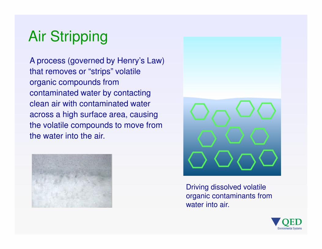
Air Stripping
A process (governed by Henry’s Law)
that removes or “strips” volatile
organic compounds from
contaminated water by contacting
clean air with contaminated water
across a high surface area, causing
the volatile compounds to move from
the water into the air.
Driving dissolved volatile organic contaminants from water into air.
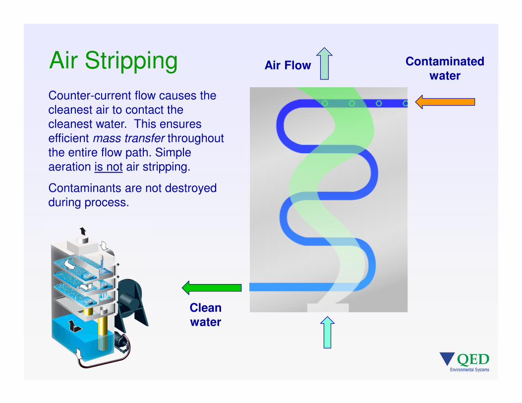
Air Stripping
Counter-current flow causes the cleanest air to contact the cleanest water. This ensures efficient mass transfer throughout the entire flow path. Simple aeration is not air stripping.
Contaminants are not destroyed during process.
Clean water
Air Flow Contaminated water

Air Stripping – Technology Overview
Higher Henry’s law constant = more volatile contaminant
Henry’s law constant is temperature dependent (increases with increasing temp).
Increasing air to water ratio (A/W) improves removal efficiency for marginally volatile contaminants.
Some contaminants will not respond to air stripping (1,4 dioxane, methanol, tert-butyl alcohol).
Easiest to strip
Hardest to strip
Dissolved gases (methane, carbon dioxide)
Chlorinated solvents
Light hydrocarbons (BTEX)
Heavy hydrocarbons (DRO, naphthalene)
MTBE
Ammonia

Air Stripping Methods
• Simple Storage Tank Aeration
• Tower Strippers
• Stacking Tray Strippers
• Sliding Tray Stripper (QED E-Z Tray)

Simple Storage Tank Aeration
Spray Nozzles
• Water is circulated within a holding tank and discharged from spray nozzles
• Nozzles develop significant back pressure (30-40psi)
• Mass transfer occurs as droplets fall through free air
• Multiple passes are needed to provide THM removal
• 8 passes required to reach 50-60% removal1. (compare to 60-80% TTHM reduction with 1 pass through an E-Z Tray stripper)
1. “Violation Prompts Treatment Change”, July 2011 Opflow

Stripping Methods
TowerThin film of water flows over a high surface area packing
Stacked TrayAir bubbles - froth and turbulent mixing creates mass transfer surface area
Sliding TrayAir bubbles - froth and turbulent mixing creates mass transfer surface area

Stripping Methods
Tower
Advantages• Lower energy use in
the air mover, due to lower overall pressure drop
Disadvantages• Flow turn-down difficult• Difficult to clean• Tall structure• Short circuiting
Sliding Tray
Advantages• Easy access• Less prone to fouling• Less intrusive at site• Wide flow turn-down
Disadvantage
• Requires higher pressure
blower (HP)

E-Z Tray Tower Stacking TrayAir Strippers Air Strippers Air Strippers----------------------------------------------------------------------------------------------------
E-Z Tray® Advantages … Cleaning
• Single person cleaning
• Packing access and removal is difficult
• Major disassembly and multi person crew needed

E-Z Tray® Advantages … Footprint
E-Z Tray Tower Stacking TrayAir Strippers Air Strippers Air Strippers----------------------------------------------------------------------------------------------------
• Reduced footprint for installation and maintenance
• Small footprint but very tall structure often required
• Lots of space needed for disassembly, lifting from all sides, pipe disconnection and tray stage stacking

E-Z Tray® Advantages … Monitoring
E-Z Tray Tower Stacking TrayAir Strippers Air Strippers Air Strippers----------------------------------------------------------------------------------------------------
• Easy process monitoring and inspection, even while in operation
• Condition of packing and air flow distribution are very difficult to observe
• Difficult or impossible to observe air and liquid flow distribution during operation

Site Data
Often the highest historical analytical result for each parameter is used for design modeling

Modeling the Process
Xin = aqueous concentration entering the air stripper
Xout = aqueous concentration exiting the air stripper
Yin = gas concentration entering the air stripper
Nth = number of theoretical trays in the air stripper
S = stripping factor
Kh = Henry’s Law constant
L = liquid flow rate
G = gas flow rate
Web based Modelhttp://www.qedenv.com/modeler
The performance modeler is based on the designprocedure discussed in -- Kibbey, T. C. G., K. F. Hayes andPennell, K.D., ‘‘Application of Sieve-Tray Air Strippers tothe Treatment of Surfactant-Containing Wastewaters’’,AIChE Journal, Vol. 47, No. 6, June 2001. Also -- Perry, R.H., and D. W. Green, Perry’s Chemical Engineer’s Hand-book, 7th ed., McGraw-Hill, New York 1997.

Henry’s Constant (H)
Larger H = more easily stripped (atm/mol-frac)
• vinyl chloride - 1245• TCE – 648• benzene - 309
• MTBE - 32• acetone - 2.4

(URL listed to allow easy remodeling)

THM (DBP) Removal
• Trihalomethanes (THMs) can form in drinking water when disinfectant (chlorine) breaks down precursor organic compounds, normally organic solids
• Air stripping is an effective way to reduce THMs
• THMs can re-form after stripping if organic precursors are still available

Henry’s Law predicts that the THM compounds will strip in the following order:
Chloroform - easiest to stripBromodichloromethaneDibromochloromethaneBromoform - hardest to strip
Haloacetic Acids (HAAs) are not removed by air stripping
THM Removal
Parameter H (atm/mol-frac)benzene 309.2chloroform 225.2bromodichloromethane 63.1dibromochloromethane 44.4MTBE 32bromoform 29.5

THM Removal – Some Pilot Data
11-2 11-3 11-4 11-5 11-911-11
11-17
11-23
12-1
% THM Reduction 90 91 90 90 88 86 88 85 84
Water temp. 55.4 55.2 54.5 52.8 52.0 52.6 49.6 50.5 42.8
40.0
42.0
44.0
46.0
48.0
50.0
52.0
54.0
56.0
58.0
82
83
84
85
86
87
88
89
90
91
92
Wa
ter
Te
mp
. (F
)
Pe
rce
nt
Percent THM reduction vs. Water Temperature
QED working with a
partner company to
conduct THM
removal studies at
several small
drinking water
treatment facilities.
Results show
consistent THM
removal of 85% or
more.

Chloroform Removal
0 5 10 15 20 25 30 35
0
5
10
15
20
25
30
35
40
45
THM Removal
CHCl3 in
CHCl3 out
In – 24 hour
Out – 24 hour
Time (days)
Ch
loro
form
(p
pb
)

THM Removal – Process Design
Successful THM removal
process design will needs
account for remaining THM
precursors, while providing
sufficient residual disinfection.
Clear well loop design, remote
reservoir loop or stripping prior
to immediate use may provide
the best solution.

Impact on Chlorine Residual
10/13/10
10/14/10
10/15/10
10/16/10
10/17/10
10/18/10
10/19/10
10/20/10
10/21/10
10/22/10
10/23/10
10/24/10
10/25/10
0
0.2
0.4
0.6
0.8
1
1.2
1.4
Chlorine Residual Change
(before / after stripping)
Influent
Effluent
Sample Date
Cl2
(p
pm
)
(Further residual reduction possible if precursors continue to be
converted to THMs)

Other Stripper Applications
• Ammonia – very hard to strip
• CO2 – somewhat easy to strip
• Hydrogen Sulfide – easy to strip
• Radon removal – extremely easy to strip
• Methane removal – extremely easy to strip
Additional Site Information for Design
• Site history of DNAPL and/or LNAPL
• Parameters that are hard to strip (DRO, etc.)
• Is O&G above detection limit (is O&G MDL low enough)
• Is there air contamination near the blower inlet
• Does stable foam form if target water is shaken in a jar
• Is there an offset between TOC and the sum of the target organics
• Is there a site history of surfactant use
• Are high shear pumps used to capture the water (stable emulsions of NAPL)

• Adjustments to unit specifications (higher air flow, slightly
higher water flow, etc.)
• Power considerations
• Operation modes (batch, extended shut-down)
• Environmental
• Strippers with a non-standard number of trays
• Blended flow calculations
• Strippers in series (use effluent from first model run as
influent for second)
Special Situations

Standard 4&6 Tray Custom 7 Tray Standard Series
Series – same air(like an 8 Tray) Parallel – different flow rates
Blended discharge
Special Situations

• Contaminants that are not listed in the model contaminant
table
• Calculation of “effective H” from field pilot data
• Results less than 1ppb
• Pilot cases where concentrations are >> 25% water
solubility
Special Situations (cont.)

Pilot Testing
• Prepackaged,
just add electricity
• Rental
• Used for scale-up
design and fouling
studies
• Allows H correction
from results when
NAPLs, surfactants,
etc. are known to be
present
Rental skids available from QED and some equipment contractors –
contact us for more information.

• Sliding Tray Stripper – $0.10-$0.35/Kgal
• Tower Stripper – $0.48/Kgal
• Activated Carbon (GAC) – $0.95-$1.57/Kgal
• Oxidation process – $0.88 – $2.42 /Kgal
Considering 10 year project life & equivalent removal efficiency – equipment
cost, install cost, operating / maintenance cost (energy, GAC replenishment),
and annual flow treated (x / 1000 gallons). Legacy & lifecycle costs are
becoming a major design requirement.
Process Economics for high efficiency VOC removal

Key Operating Considerations
• Air-to-water ratio (A/W) = controls process efficiency and performance
• Air pressure = sufficient pressure needed to hold water on tray (back pressure)
• Differential pressure = pressure drop across trays expected / excessive pressure drop restricts air flow & impacts performance
• Liquid flow rate = unit designed for maximum hydraulic capacity / high turn-down
• Liquid level in integral sump = minimum water level prevents air bypass / maximum level prevents flooding
• Seals = equal torque on front hatch to prevent leaks / trays properly latched to prevent air / water bypass / down comers in place to prevent bypass

• Temperature affects the process – higher
temperature = better stripping
• Process temperature is roughly equal to water temperature; air temperature not a big factor
• Freezing is not a concern for continuous operation
• Discharged air is saturated (high humidity) at the process temperature, so consider condensation and thermal impacts if air treatment is planned
Additional Operating Factors

Tray Fouling – What Does it Look Like?
Expected performance impact is gradual as air flow decreases, due to tray fouling.
Low Air Flow (Weeping)
Weeping is when water drops through tray sieve (air) holes

Impact on Process Performance (A/W decrease)
Aggressive iron scale formation – can be removed with mild acid or a brushDO NOT use detergents to clean trays
Scale on surface will not impact performance unless tray perforations are reduced in size –back pressure increases, lowering A/W

OPEN
CLOSED
Blower throttle controls air flow on system –expressed as differential pressure across trays(check Magnahelic)
Throttle “chokes” air output as function of the blower curve. Used for air “tuning”.
Air Flow Control

Inorganic Fouling – precipitation of inorganics which attach on air stripper surface
• Aeration increases system pH• Iron – Fe2+ into Fe(OH)2
• Hardness – Ca2+ into CaCO3
Fouling water benchmarks for air stripperso Hardness > 400 ppm; Iron > 5 ppm – accelerated cleaning frequencyo Hardness = 200 – 300 ppm; Iron = 2 – 4 ppm – regular maintenanceo Hardness < 100 ppm; Iron < 1 ppm – infrequent cleaning required
For air strippers, aggressive fouling impacts maintenance frequency and potentially process efficiency.
Stripper Fouling

Stripper Fouling Rules of Thumb
Iron <0.1ppm low fouling potential
0.1-1ppm modest fouling potential (not bio)
1-5ppm significant fouling potential (optimum for bio)
5-20ppm serious fouling potential, heavy O&M (manageable)
>20ppm extreme, control options required
Langelier Saturation Index (LSI*)
<1 no scale forming, corrosive potential
0 neutral
>1 scale forming potential
Microbial – Biological Activity Test (BART – Hach kit)
> 1000 cfu/ml – concern for bio-fouling
>10,000 cfu/ml – expect serious bio-fouling
(*calculate LSI with calcium hardness, total alkalinity, pH and water temperature)

• DO NOT use detergents for cleaning!
• Dilute acid for cleaning• We recommend dissolved citric acid
• Apply acid solution to soak and dissolve scales
• Light mechanical scrubbing and/or pressure wash• Release heavy deposits
• Open up sieve holes
• Rinse with fresh water
• Rinse A/S sump and flush
Tray cleaning

• Clean trays
– Backup tray set
• Sequestering agents (decrease cleaning frequency)
– inorganic polyphosphates
• Bio-fouling
– Ozone, etc.
• pH adjustment
– In/out
• Pre-stripper oxidation and filtration for severe cases
Tray Fouling - Preventative Measures
Oil and grease + bio-slime impacted tray from a fuel terminal site

Stripper Cleaning
• Cleaning frequency and effort is site-specific
• Example -
– 0.03 ppm iron, high hardness scales - stripper requires cleaning every 3 weeks
• Cleaning time for the largest E-Z Tray stripper
– Two 1000gpm, E-Z Tray 96.6 units (8 doors, 48 trays) takes 8-10 minutes/tray to fully remove, pressure wash and reinstall all the trays in this system (about 1/2 day per stripper)
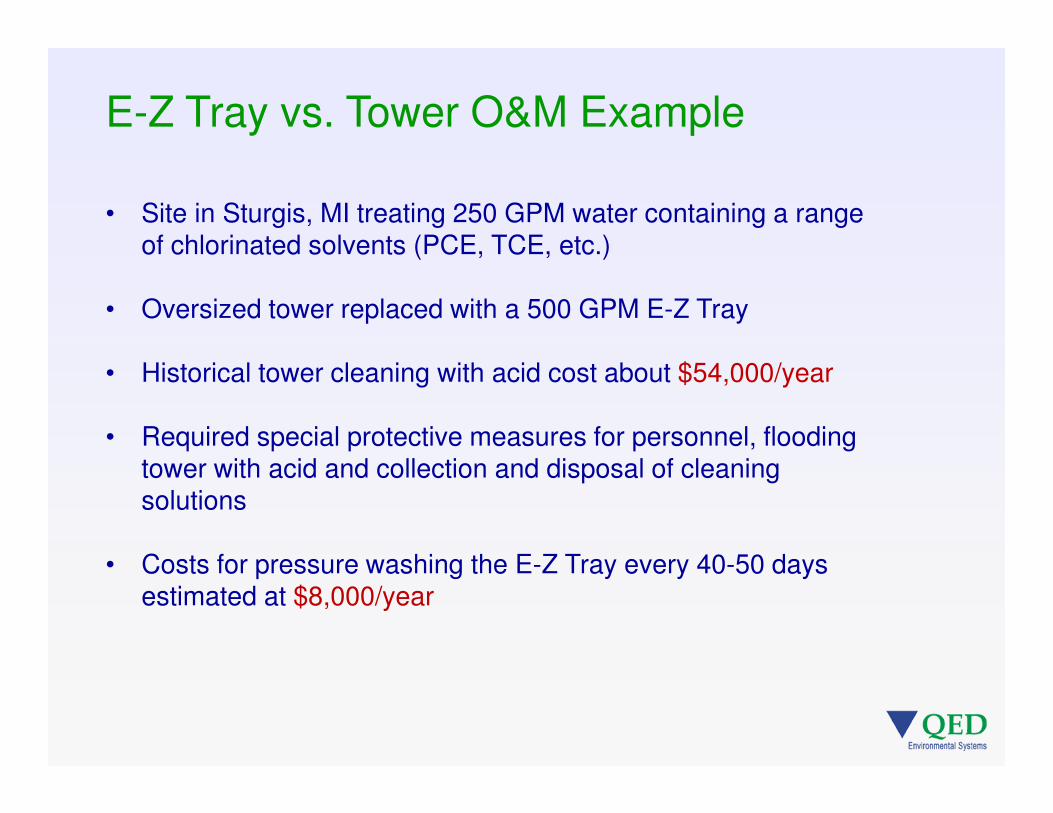
E-Z Tray vs. Tower O&M Example
• Site in Sturgis, MI treating 250 GPM water containing a range of chlorinated solvents (PCE, TCE, etc.)
• Oversized tower replaced with a 500 GPM E-Z Tray
• Historical tower cleaning with acid cost about $54,000/year
• Required special protective measures for personnel, flooding tower with acid and collection and disposal of cleaning solutions
• Costs for pressure washing the E-Z Tray every 40-50 days estimated at $8,000/year

Assume an E-Z Tray 96.X stripper (1000gpm capacity, our largest
unit), treating 800gpm, cleaned 4 times/year – this unit processes
420,500 kgal/year. Example does not include capital costs.
Cleaning – 2 person crew ($80/hr + supplies), 4-hours/event =
$3600/year
Power – 75HP = 0.75 kW running 24/7/365 at $0.10/kWh =
$49K/year
Cost =
$0.125 / 1000-gallons treated
Example O&M Cost Estimate

E-Z Tray Advantage - Safer by design
Live Safer.®
QED’s sliding tray air stripper (E-Z Tray) is the first self-container air stripper to
achieve certification from NSF International to NSF/ANSI Standard 61: Drinking
Water System Components – Health Effects
Nationally recognized health effects standard for all products that come in contact
with drinking water
All water contacting materials in the E-Z Tray units are safe for drinking water
systems use

Case Study 1 – Cheyenne, WY
• Abandoned Atlas Missile sites contaminated city wells with chlorinated solvent
• US Army Corps is QED’s customer
• Strippers treat city water during high demand, summer months (4000gpm capacity)
• Excellent equipment reliability required to ensure continuous water treatment
• System started June 2011

Case Study 2 – Cedarburg, WI
• Landfill near a 700gpm supply well causing low level vinyl chloride hits
• System modeling based on a long list of possible future contaminants, based on LF monitoring data
• City operates an older tower stripper on another well treating an unrelated TCE issue – in operation 18 years
• Sequestering agent used for tower and E-Z Tray
• E-Z Tray footprint helped to keep project costs low

Case Study 3 – Edina, MN
• Supply well impacted with low level vinyl chloride hits
• Engineer was considering a tower
• Site location issues weighed against the tower
• Creative use of the E-Z Tray footprint allowed the city to use available space below the parking garage
• Energy use was also a key design factor
• Units began operation in March of 2012
possible tower location
E-Z Tray units located in existing space within utilitygarage

Case Study 4 – CA Water Treatment Plant
• Municipal water treatment facility
• Treatment of DBPs in reclaimed water feed portion
• Pilot testing on a packed tower stripper showed gumming and fouling of packing
• Visited a nearby Army facility using an E-Z Tray for remediation – liked the ease of maintenance
• E-Z Tray footprint, NSF61 approval and on-line model are other positives of the QED system

VOC reduction prior to SBR
treatment of pharmaceutical
wastewater
Stripper air flow rate much lower
than flow from SBR – high
contaminant concentration
Allowed smaller CATOX
air treatment unit
VOC
Treatment Plant
Before
Treatment Plant
After
Thermal Oxidizer
Less VOCVOC
Thermal Ozidizer
Case Study 5 – Pre-Treatment for SBR

Copper corrosion in tanks & water lines
• AWWA study investigating reduction of copper & lead leaching from water storage tanks & lines with pH adjustment methods
• Air stripper installed to re-circulate water within tanks
• Air stripping shown effective for removing CO2 & and increasing water pH w/o chemical addition
• Air stripping provides a cost competitive platform to increase pH w/in acceptable levels (~ 1pt.) and maintain EPA compliance
Case Study 6 – Reducing Corrosion through pH Adjustment
• Air strippers are effective at removing dissolved
volatile organic compounds from water
• The primary process factor is air to water ratio
• The process can be modeled using QED’s on-
line computer tool -
http://www.qedenv.com/modeler
• Air stripping equipment needs to be maintained
to ensure continued design removals
Summary

Survey + Questions?
David FischerQED Environmental Systems, Inc.
Tel: 800-624-2026E-mails: [email protected]
WEB:www.qedenv.com
Related Documents