Engineering Manual Variable Refrigerant Flow Air-Cooled 3.0 – 4.4 Tons Air Source Heat Pump VRF System Condensing Unit

Welcome message from author
This document is posted to help you gain knowledge. Please leave a comment to let me know what you think about it! Share it to your friends and learn new things together.
Transcript
Engineering Manual
Variable Refrigerant FlowAir-Cooled
3.0 – 4.4 Tons
Air Source Heat Pump VRF System Condensing Unit

EM_MultiVMini_5_ 15
For continual product development, LG reserves the right to change specifications without notice. ©LG Electronics U.S.A., Inc.
PROPRIETARY DATA NOTICEThis document, as well as all reports, illustrations, data, information, and
other materials is the property of LG Electronics U.S.A., Inc.

About LG Electronics, Inc.LG Electronics, Inc. is a global leader and technology innovator in consumer electronics, mobile communications, and home appliances. LG Electronics comprises four business units—Home Entertainment, Mobile Communications, Home Appliance, and Air Conditioning and Energy Solutions. LG is one of the world’s leading producers of flat panel televisions, audio and video products, mobile handsets, compressors, air conditioners, and washing machines. LG’s commercial air conditioning business unit was established in 1968 and has built its lineup of residential and commercial products to include VRF, Multi-Zone systems, Duct Free Split Systems, Packaged Terminal Air Conditioners (PTACs), and room air conditioners. In 2011, the air conditioning and energy solutions business unit grew to include LED lighting and solar products. For more information visit www.lg.com.
Quality CommitmentLG is committed to the success of every Multi V project by providing the best industry technical support during project engineering, installation, and commissioning. LG offers a variety of classes designed for engineers, architects, installers, and servicers to ensure that every Multi V installation is completed successfully. Classes are conducted at LG’s training centers and in field locations at various times throughout the year and upon special request.
Variable Refrigerant Flow (VRF) Technology In the early 1980s, VRF technology was introduced to the world as an alternative method of cooling and heating in commercial structures designed to minimize energy consumption. VRF systems have become the system of choice for designers internationally because these systems offer better comfort at substantially lower operating costs when compared to traditional HVAC systems. Older systems are being replaced with newer more efficient systems making VRF a viable option. Today, VRF is gaining popularity in the United States. LG air-source systems offer the opportunity to eliminate ductwork in the same configura-tion. The systems offer zoning without the need for zone damper systems. The advanced controls provide exceptional building dehumidification and temperature control and can rapidly adapt system operating parameters to the ever changing building load.

TABLE OF CONTENTSINTRODUCTION.........................................................................................................................................................................................7
Architectural Appeal..............................................................................................................................................................................8Engineers Advantage............................................................................................................................................................................9
PRODUCT DATA.......................................................................................................................................................................................11Product Features and Benefits..............................................................................................................................................................12Unit Nomenclature...............................................................................................................................................................................13General Data......................................................................................................................................................................................14
PERFORMANCE DATA.............................................................................................................................................................................25Cooling Capacity............................................................................................................................................................................26Heating Capacity.................................................................................................................................................................................35Unit Refrigerant Flow Diagrams..........................................................................................................................................................44Outdoor Wiring Diagram......................................................................................................................................................................46
SYSTEM ENGINEERING..........................................................................................................................................................................47Building Ventilation..............................................................................................................................................................................48Equipment Selection Procedure............................................................................................................................................................51Placement Considerations...................................................................................................................................................................57Clearance Requirements.....................................................................................................................................................................59LATS Multi V Pipe System Design Tool.................................................................................................................................................61Pipe Design Parameters......................................................................................................................................................................62Pipe Layout Procedure........................................................................................................................................................................63Piping Design Guide............................................................................................................................................................................66Jobsite Connections............................................................................................................................................................................77Mini Refrigerant Charge.......................................................................................................................................................................79
CUT SHEETS............................................................................................................................................................................................81Dimensional Data and Weights.............................................................................................................................................................82Pipe and Electrical Connections............................................................................................................................................................83Y-Branch Kits......................................................................................................................................................................................84Header Kits.........................................................................................................................................................................................85
U.S. DESIGN STANDARDS......................................................................................................................................................................87ASHRAE Standards Summary..............................................................................................................................................................88ASHRAE Standard 15-2004 and ASHRAE Standard 34-2007.................................................................................................................88ASHRAE Standard 62.1-2010..............................................................................................................................................................90Building Sustainability..........................................................................................................................................................................92USGBC—LEED Green Building Rating System......................................................................................................................................93
SPECIFICATIONS...................................................................................................................................................................................95Mechanical Specifications..................................................................................................................................................................96
ACRONYMS......................................................................................................................................................................................98


INTRODUCTION"Architectural Appeal" on page 8"Engineers Advantage" on page 9

8 | INTRODUCTION
Intr
oduc
tion
Due to our policy of continuous product innovation, some specifications may change without notification. © LG Electronics U.S.A., Inc., Englewood Cliffs, NJ. All rights reserved. “LG” is a registered trademark of LG Corp.
Benefits of the Multi V Mini
• Maximum individual occupant control
• Longest refrigerant piping lengths
• Highest elevation differences
• Maximum flexibility
• Quiet and comfortable environment
• Reduced or eliminated ductwork
Convergence of Technological Innovation with Flexibility and Style
Multi V Mini Multi V Mini is among the industry’s best with vertical rise and piping lengths, so choosing the LG Multi V Mini variable refrigerant flow system provides the system designer with the most freedom and flexibility while engineering the refrigerant pipe system. Multi V Mini is a two-pipe heat pump system available in nominal capacities of 3.0, 4.0, and 4.4 tons. It is best suited for applications with zones that require heating or cooling, such as residences and small office buildings. The Multi V Mini allows the designer to accommodate up to 9 thermal zones, each controlled from a separate controller. Mini outdoor units are available in 208–230V/60Hz/1Ph.
Adaptable and FlexibleMulti V outdoor units can be adapted to a wide range of building types and sizes, such as schools, hotels, hospitals, offices, and residences. The light weight and small footprint allows the system components to be placed in the building without expensive cranes, easily fitting into most service elevators and set in place with minimal requirements for structural reinforcements. The system’s modular design means Multi V can be commissioned in stages so tenants can move in as each floor or even each room is completed.Multi V technology allows you to pipe farther by reaching areas of the building that would require the installation of a second system when using traditional direct-expansion cooling and heating equipment. Multi V provides the designer with uncompromised pipe system engineering flexibility—the longest pipe runs and the largest elevation differences. Whether your building is a high-rise condominium, a hotel, a sprawling school, an office complex or high-end residence, the Multi V family of products is best suited to reach the farthest corners and elevations of the building from a single outdoor unit location.
Smaller Chases and PlenumsThe LG Multi V system uses refrigerant piping to move heat resulting in smaller space requirements compared to water piping or air ducts. This helps reduce the overall construction and material cost of your building and gives back leasable space. Flexible and logical placement of system components, shorter pipe lengths, and fewer joints lowers installation costs.
ARCHITECTURAL APPEAL

INTRODUCTION | 9
HEAT PUMP CO
NDENSING UNIT ENG
INEERING M
ANUAL
Due to our policy of continuous product innovation, some specifications may change without notification. © LG Electronics U.S.A., Inc., Englewood Cliffs, NJ. All rights reserved. “LG" is a registered trademark of LG Corp.
System Design and Analysis Tools
Intuitive DesignThe LATS (LG Air Conditioning Technical Solution) Multi V design and layout software provides an intuitive, quick, and simple method to design a Multi V Mini refrigerant pipe system. LATS Multi V checks piping lengths and elevations, and it assists with the sizing of indoor and outdoor units by calculating component capacity based on design conditions. LATS Multi V is the industry’s only software that can import AutoCAD™ drawings and lay out the Multi V system to scale. When the designer finishes the AutoCAD system layout, all of the piping lengths will be calculated, and a drawing file with the Multi V system will be available for export and integration into the building drawing set.
Energy ModelingLG stands behind efficiency and performance. You will find Multi V in the EnergyPro building energy simulation software from EnergySoft®. EnergyPro is approved by the California Energy Commission to accurately model and provide necessary documentation to comply with the rigourous California Title 24 Standards, ASHRAE 90.1 compliance, and to calculate the number of LEED Energy and Atmosphere Credit 1 (EA-1)—Building Energy Efficiency credits earned by the design team. The software accurately models energy consumption and utility costs based on building design, orientation, location, and other design conditions.
ENGINEERS ADVANTAGE


PRODUCT DATA"Product Features and Benefits" on page 12"Unit Nomenclature" on page 13"General Data" on page 14

12 | PRODUCT DATA
Prod
uct D
ata
Due to our policy of continuous product innovation, some specifications may change without notification. © LG Electronics U.S.A., Inc., Englewood Cliffs, NJ. All rights reserved. “LG” is a registered trademark of LG Corp.
System ControlsRefrigerant Distribution BalancingBuildings with hydronic heating systems can experience low delta-T syndrome—a condition that occurs when the water distribution system is not properly balanced. Units located at the ends of the hot water piping system need boiler water while units located closer to the boiler use too much water. Low delta-T syndrome also occurs in VRF systems. To prevent this condition in Multi V installations, LG provides control algorithms that automatically monitor and balance the dis-tribution of refrigerant to indoor units during high demand periods. This allows each unit to receive an appropriate amount of refrigerant.
Low Noise LevelsLG customers often ask if the outdoor unit is running after commissioning is complete. When Multi V outdoor units operate fully loaded, they have one of the quietest noise levels in the industry. Noise is almost undetectable during off-peak operation. To promote a quiet, comfortable environment, the LG Multi V indoor units operate at sound levels as low as 23dB(A) and outdoor units as low as 50dB(A) at full load.All rotating components are soft-started by the controller using digitally-controlled inverters, which reduces undesirable noise caused by fans and compressors cycling.
Comfort Control at Its BestTight temperature control through precise load matching maximizes the time that the indoor units remove moisture. This ensures maximum comfort and delivers the industry’s best indoor humidity levels.
Precision Load MatchingUnlike traditional air conditioning control systems, which use thermostatic controls to maintain room temperatures, LG Multi V controls continuously vary the indoor unit fan speed and refrigerant flow indirectly providing lower and more consistent hu-midity levels in the conditioned space. The longer the indoor coil temperature is below the dew-point of the room in conjunction with air movement across the coil, the space humidity level will vary little compared to technologies that cycle fans and compressors multiple times per hour. The outdoor unit responds by varying the com-pressor speed and outdoor fan motors as needed to maintain system operating pressure. As a result, the Multi V system delivers precise space temperature control.
Heat Transfer EfficiencyFin DesignAll Multi V outdoor units are provided with large surface coils made of copper tubes with aluminum fins designed to maximize unit operating ef-ficiency over a wide range of ambient conditions.
GoldFin™ CoatingStandard from the factory, every LG Multi V outdoor coil fin surface is coated with LG’s exclu-sive GoldFin™ anti-corrosive protective coating designed to prevent natural surface corrosion of the aluminum fins. This maintains heat transfer properties of the coil for an extended time.A hydrophilic coating is applied to the outdoor unit coil fin surface over the GoldFin coating. This coating enhances the development of heavier water droplets gathering on the fin surface. As a result, the droplets roll off the fin surfaces delay-ing the point when frost forms on the coil surface during heating operations. This coating also makes it possible to easily clean the outdoor unit coil using mild soap.
Simplified InstallationCooling and heating systems that use the LG Multi V simplify and reduce the mechanical and control system design time. The designer no longer has to be concerned with interconnecting chilled and condenser water piping, air distribu-tion duct systems, matching and selecting chill-ers, towers, pumps, coils, fans, air handlers, or variable air volume (VAV) boxes.System integration with existing building manage-ment systems has never been easier. Since all of the Multi V system components are engineered and provided by LG, the system components and controls come pre-engineered and do not need any custom programming from third-party contractors.
Advanced Compressor TechnologyOil ManagementOil migration is no longer a concern when choos-ing Multi V. A three-stage oil management system ensures a safe level of oil in the compressor sump. An oil injection mechanism provides a consistent film of oil on moving parts, even at low speeds, which enables LG’s inverter compressor operation down to 25 Hz. 1. The compressor discharge is specially de-
signed to minimize the amount of oil leaving
the compressor. 2. An oil separator located on the discharge side
of the compressor(s) separates the majority of oil mixed with the refrigerant gas stream during compression. Oil is returned to the compressor through a gravity drain.
3. Oil return algorithms flush the oil from the distribution system back to the compressor.
Inverter DrivenThe R410A rotary compressor is optimized to maximize compressor efficiency, which reduces power consumption and monthly utility bills. The latest inverter technology allows the LG Multi V to vary the compressor motor shaft speed to deliver an appropriate amount of cooling to all indoor units. Precise refrigerant volume delivery translates into long periods of time with coil surface temperatures below dew point and minimizes compressor and fan component run time. Occupants remain comfortable while utility costs are reduced.
PRODUCT FEATURES AND BENEFITS
PRODUCT DATA | 13
HEAT PUMP CO
NDENSING UNIT ENG
INEERING M
AN
UAL
Due to our policy of continuous product innovation, some specifications may change without notification. © LG Electronics U.S.A., Inc., Englewood Cliffs, NJ. All rights reserved. “LG” is a registered trademark of LG Corp.
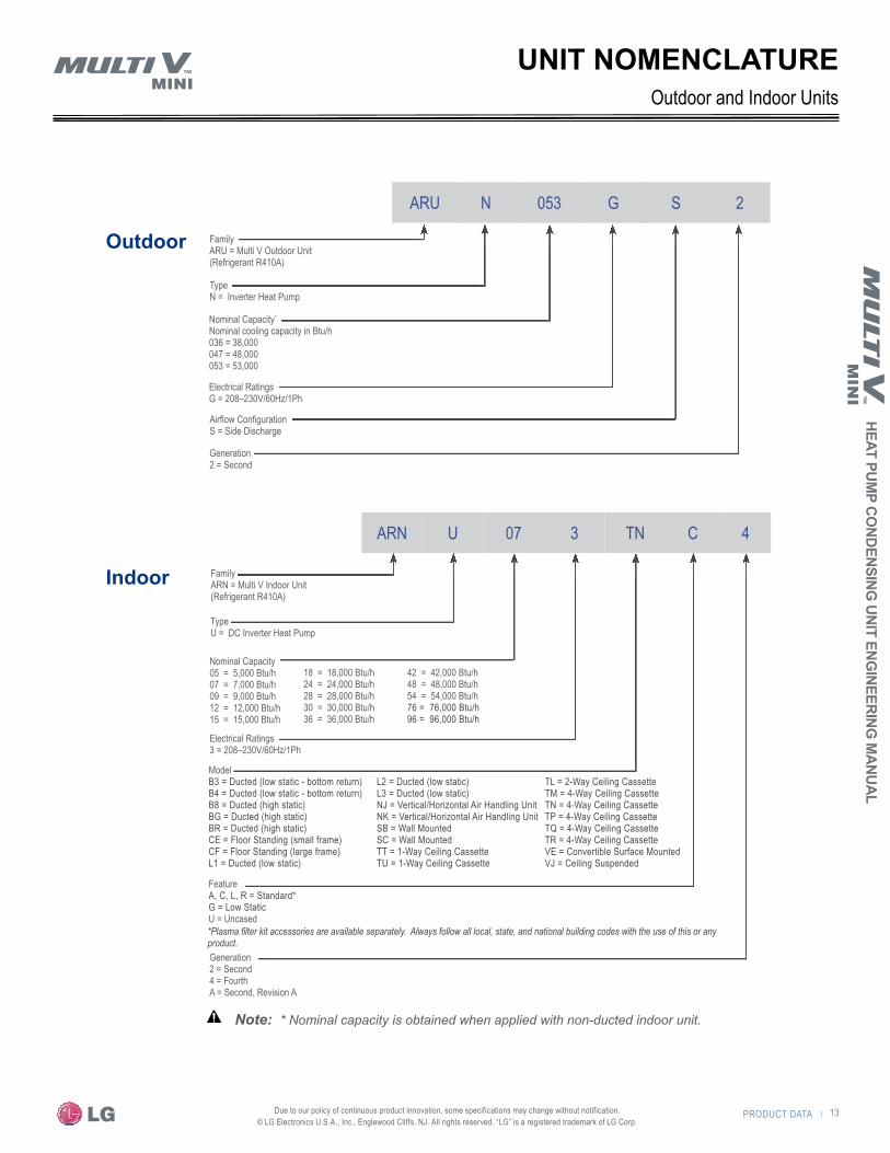
Outdoor
ARU N 053 G S 2
Generation2 = Second
Airflow ConfigurationS = Side Discharge
B3 = Ducted (low static - bottom return) B4 = Ducted (low static - bottom return) B8 = Ducted (high static) BG = Ducted (high static) BR = Ducted (high static) CE = Floor Standing (small frame) CF = Floor Standing (large frame) L1 = Ducted (low static)
L2 = Ducted (low static) L3 = Ducted (low static) NJ = Vertical/Horizontal Air Handling Unit NK = Vertical/Horizontal Air Handling Unit SB = Wall Mounted SC = Wall Mounted TT = 1-Way Ceiling Cassette TU = 1-Way Ceiling Cassette
TL = 2-Way Ceiling Cassette TM = 4-Way Ceiling Cassette TN = 4-Way Ceiling Cassette TP = 4-Way Ceiling Cassette TQ = 4-Way Ceiling Cassette TR = 4-Way Ceiling Cassette VE = Convertible Surface Mounted VJ = Ceiling Suspended
*Plasma filter kit accessories are available separately. Always follow all local, state, and national building codes with the use of this or any product.
Electrical Ratings G = 208–230V/60Hz/1Ph
Nominal Capacity*
Nominal cooling capacity in Btu/h036 = 38,000047 = 48,000053 = 53,000
TypeN = Inverter Heat Pump
FamilyARU = Multi V Outdoor Unit(Refrigerant R410A)
Indoor
ARN U 07 3 TN C
Generation2 = Second4 = FourthA = Second, Revision A
Electrical Ratings 3 = 208–230V/60Hz/1Ph
Nominal Capacity05 = 5,000 Btu/h07 = 7,000 Btu/h 09 = 9,000 Btu/h 12 = 12,000 Btu/h15 = 15,000 Btu/h
TypeU = DC Inverter Heat Pump
FamilyARN = Multi V Indoor Unit(Refrigerant R410A)
4
Model
FeatureA, C, L, R = Standard* G = Low Static U = Uncased
42 = 42,000 Btu/h48 = 48,000 Btu/h54 = 54,000 Btu/h76 = 76,000 Btu/h 96 = 96,000 Btu/h
18 = 18,000 Btu/h24 = 24,000 Btu/h28 = 28,000 Btu/h30 = 30,000 Btu/h36 = 36,000 Btu/h
Outdoor and Indoor UnitsUNIT NOMENCLATURE
�Note: � * Nominal capacity is obtained when applied with non-ducted indoor unit.

14 | PRODUCT DATA
Prod
uct D
ata
Due to our policy of continuous product innovation, some specifications may change without notification. © LG Electronics U.S.A., Inc., Englewood Cliffs, NJ. All rights reserved. “LG” is a registered trademark of LG Corp.
GENERAL DATA
Table 1a: General Data—Outdoor Units3.0 Ton
ARUN036GS24.0 Ton
ARUN047GS24.4 Ton
ARUN053GS2Cooling Mode Performance
Nominal Cooling Capacity (Btu/h) 39,500 50,000 55,500
Rated Cooling Capacity (Btu/h)3 38,000 48,000 53,000
Heating Mode PerformanceNominal Heating Capacity (Btu/h) 44,000 56,000 61,500
Rated Heating Capacity (Btu/h)3 42,000 53,500 59,000
Operating RangeCooling (°F DB) 23–118 23–118 23–118
Heating (°F) (-4)–60 (-4)–60 (-4)–60
CompressorInverter Rotary Quantity 1 1 1
Oil / Type PVE / FVC68D PVE / FVC68D PVE / FVC68D
Full Load Operating RPM 3600 3600 3600
Unit DataRefrigerant Type R410A R410A R410A
Refrigerant Control / Location EEV / Indoor Unit EEV / Indoor Unit EEV / Indoor Unit
Maximum Number Outdoor Units / System1 1 1 1
Maximum Number Indoor Units / System1 6 8 9
Minimum Number Indoor Units / System1 1 1 1
Qty Refrigeration Circuits 1 1 1
Sound Pressure Cooling / Heating dB(A)5 50 / 52 51 / 53 52 / 54
Net Unit Weight (lbs) 234 234 234
Shipping Weight (lbs) 258 258 258
Communication Cable (Qty # Wires / Gauge)2 2 / 18 2 / 18 2 / 18
FanType Propeller (BLDC) Propeller (BLDC) Propeller (BLDC)
Qty / Motor HP 2 / 0.166 2 / 0.166 2 / 0.166
Qty / Diameter (in) 2 / 20.75 2 / 20.75 2 / 20.75
Motor / Drive Brushless Digitally-Controlled / Direct Brushless Digitally-Controlled / Direct Brushless Digitally-Controlled / Direct
Operating Range (RPM) 80–950 80–950 80–950
Maximum Air Volume (CFM) 3,885 3,885 3,885
Maximum External Static Pressure (in-wg) 0.16 0.16 0.16
Airflow Direction Horizontal—Back to Front Horizontal—Back to Front Horizontal—Back to Front
Outdoor Units
1. The System Combination Ratio must be between 50–130%. See page 55 for more information.2. All communication cables must comply with applicable local codes.3. Rated using non-ducted indoor units. Rated 0 ft. above sea level with 25 ft. of refrigerant line per
indoor unit and a 0 ft. level difference between outdoor and indoor units. All capacities are net with a Combination Ratio between 95–105%. Certified under the AHRI Unitary Small Heat Pump equip-ment certification program and tested per AHRI Standard 210/240 conditions and in accordance with DOE test procedures. Nominal Cooling capacity rating obtained with air entering the indoor coil at 80°F dry bulb (DB) and 67°F wet bulb (WB) and outdoor ambient conditions of 95°F dry bulb (DB) and 75°F wet bulb (WB). Nominal Heating capacity rating obtained with air entering the indoor unit at 70°F dry bulb (DB) and 59°F wet bulb (WB) and outdoor ambient conditions of 47°F dry bulb (DB) and 43°F wet bulb (WB).
4. Unit is capable of operating outside the operating range temperature limitations. See "Select the Outdoor Unit" on page 52.
5. Sound pressure levels are tested in an anechoic chamber under ISO Standard 1996.6. Power wiring cable is field provided and must comply with the applicable local and national codes.
PRODUCT DATA | 15
HEAT PUMP CO
NDENSING UNIT ENG
INEERING M
AN
UAL
Due to our policy of continuous product innovation, some specifications may change without notification. © LG Electronics U.S.A., Inc., Englewood Cliffs, NJ. All rights reserved. “LG” is a registered trademark of LG Corp.
GENERAL DATAOutdoor Units
Refer to "Pipe Design Parameters" on page 62 and "Piping Design Guide" on page 66 for cor-rect line sizing. Designer must verify refrigerant piping design configuration using LATS Multi V software.
The factory’s refrigerant charge is sufficient when line set length does not exceed 25 ft.Estimated charge per linear foot. Actual refrigerant charge varies and can be calculated
using LG’s LATS computerized refrigerant piping software or manually using the worksheet on page 80. System must be charged using a refrigerant charging scale. Superheat method will not work.
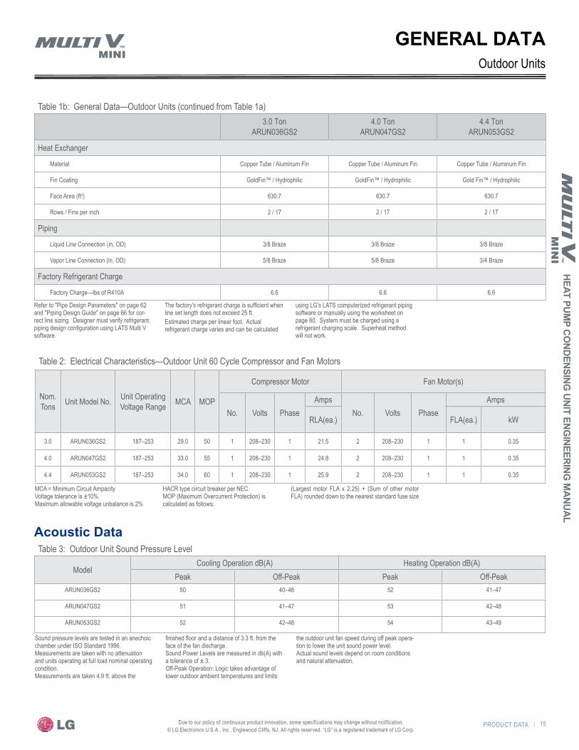
Table 1b: General Data—Outdoor Units (continued from Table 1a)3.0 Ton
ARUN036GS24.0 Ton
ARUN047GS24.4 Ton
ARUN053GS2
Heat Exchanger
Material Copper Tube / Aluminum Fin Copper Tube / Aluminum Fin Copper Tube / Aluminum Fin
Fin Coating GoldFin™ / Hydrophilic GoldFin™ / Hydrophilic Gold Fin™ / Hydrophilic
Face Area (ft2) 630.7 630.7 630.7
Rows / Fins per inch 2 / 17 2 / 17 2 / 17
Piping
Liquid Line Connection (in, OD) 3/8 Braze 3/8 Braze 3/8 Braze
Vapor Line Connection (in, OD) 5/8 Braze 5/8 Braze 3/4 Braze
Factory Refrigerant Charge
Factory Charge—lbs of R410A 6.6 6.6 6.6
Acoustic Data
Table 2: Electrical Characteristics—Outdoor Unit 60 Cycle Compressor and Fan Motors
Nom.Tons Unit Model No. Unit Operating
Voltage Range MCA MOP
Compressor Motor Fan Motor(s)
No. Volts PhaseAmps
No. Volts PhaseAmps
RLA(ea.) FLA(ea.) kW
3.0 ARUN036GS2 187–253 29.0 50 1 208–230 1 21.5 2 208–230 1 1 0.35
4.0 ARUN047GS2 187–253 33.0 55 1 208–230 1 24.8 2 208–230 1 1 0.35
4.4 ARUN053GS2 187–253 34.0 60 1 208–230 1 25.9 2 208–230 1 1 0.35
MCA = Minimum Circuit AmpacityVoltage tolerance is ±10%Maximum allowable voltage unbalance is 2%
HACR type circuit breaker per NECMOP (Maximum Overcurrent Protection) is calculated as follows:
(Largest motor FLA x 2.25) + (Sum of other motor FLA) rounded down to the nearest standard fuse size
Sound pressure levels are tested in an anechoic chamber under ISO Standard 1996. Measurements are taken with no attenuation and units operating at full load nominal operating condition.Measurements are taken 4.9 ft. above the
finished floor and a distance of 3.3 ft. from the face of the fan discharge.Sound Power Levels are measured in db(A) with a tolerance of ± 3.Off-Peak Operation: Logic takes advantage of lower outdoor ambient temperatures and limits
the outdoor unit fan speed during off peak opera-tion to lower the unit sound power level.Actual sound levels depend on room conditions and natural attenuation.
Table 3: Outdoor Unit Sound Pressure Level
ModelCooling Operation dB(A) Heating Operation dB(A)
Peak Off-Peak Peak Off-PeakARUN036GS2 50 40–46 52 41–47
ARUN047GS2 51 41–47 53 42–48
ARUN053GS2 52 42–48 54 43–49

16 | PRODUCT DATA
Prod
uct D
ata
Due to our policy of continuous product innovation, some specifications may change without notification. © LG Electronics U.S.A., Inc., Englewood Cliffs, NJ. All rights reserved. “LG” is a registered trademark of LG Corp.
Figure 1: ARUN036GS2 (Cooling)
Figure 4: ARUN036GS2 (Heating)
Figure 2: ARUN047GS2 (Cooling)
Figure 5: ARUN047GS2 (Heating)
Figure 3: ARUN053GS2 (Cooling)
Figure 6: ARUN053GS2 Heating
Acoustical Data—Outdoor Units
All data is measured in accordance with Industry Standard ISO 1996.Measurements are taken 4.9 ft. above the finished floor and a distance of 3.3 ft. from the face of the fan discharge with no attenuation.
GENERAL DATAO
ctav
e Ba
nd S
ound
Pre
ssur
e Le
vel (
dB re
20µ
Pa )
Oct
ave
Band
Sou
nd P
ress
ure
Leve
l (dB
re 2
0µPa
)
10
20
30
40
50
60
70
80
63 125 250 500 100 0 200 0 400 0 8000NC-15
NC-20
NC-25
NC-30
NC-35
NC-40
NC-45
NC-50
NC-55
NC-60
NC-65
ApproximateHearingThreshold
10
20
30
40
50
60
70
80
63 125 250 500 100 0 200 0 400 0 8000Octave Band Center Frequency (Hz)
Octave Band Center Frequency (Hz)
Oct
ave
Band
Sou
nd P
ress
ure
Leve
l (dB
re 2
0µPa
)
Oct
ave
Band
Sou
nd P
ress
ure
Leve
l (dB
re 2
0µPa
)
10
20
30
40
50
60
70
80
63 125 250 500 100 0 200 0 400 0 8000NC-15
NC-20
NC-25
NC-30
NC-35
NC-40
NC-45
NC-50
NC-55
NC-60
NC-65
ApproximateHearingThreshold
)zH( ycneuqerF retneC dnaB evatcO)zH( ycneuqerF retneC dnaB evatcO
Oct
ave
Band
Sou
nd P
ress
ure
Leve
l (dB
re 2
0µPa
)
Oct
ave
Band
Sou
nd P
ress
ure
Leve
l (dB
re 2
0µPa
)
10
20
30
40
50
60
70
80
63 125 250 500 100 0 200 0 400 0 8000NC-15
NC-20
NC-25
NC-30
NC-35
NC-40
NC-45
NC-50
NC-55
NC-60
NC-65
ApproximateHearingThreshold
)zH( ycneuqerF retneC dnaB evatcO)zH( ycneuqerF retneC dnaB evatcO
NC-15
NC-20
NC-25
NC-30
NC-35
NC-40
NC-45
NC-50
NC-55
NC-60
NC-65
ApproximateHearingThreshold
10
20
30
40
50
60
70
80
63 125 250 500 1000 2000 4000 8000
NC-15
NC-20
NC-25
NC-30
NC-35
NC-40
NC-45
NC-50
NC-55
NC-60
NC-65
Approximate Hearing Threshold
10
20
30
40
50
60
70
80
63 125 250 500 1000 2000 4000 8000
NC-15
NC-20
NC-25
NC-30
NC-35
NC-40
NC-45
NC-50
NC-55
NC-60
NC-65
Approximate Hearing Threshold
PRODUCT DATA | 17
HEAT PUMP CO
NDENSING UNIT ENG
INEERING M
AN
UAL
Due to our policy of continuous product innovation, some specifications may change without notification. © LG Electronics U.S.A., Inc., Englewood Cliffs, NJ. All rights reserved. “LG” is a registered trademark of LG Corp.
GENERAL DATAIndoor Units
Unit/Type1 ARNU*****2Dimensions (W x D x H)
(inches)
Nominal Capacity Btu/h Air Flow Rate
(CFM) (H/M/L4)
Weight (lbs.)
Pipe Connections
(inches, O.D.)(Liquid, Vapor)Cooling3 Heating3
Wall Mounted–ART COOLTM
Mirror053 SBR4
35-1/4 x 8-1/8 x 11-7/16
5,500 6,100 230/212/194
24 1/4, 1/2073 SBR4 7,500 8,500 247/230/194093 SBR4 9,600 10,900 290/247/194123 SBR4 12,300 13,600 336/290/230153 SBR4 15,400 17,100 371/318/247183 SCR4 40-9/16 x 9-11/16 x 12-13/16 19,100 21,500 441/424/399 34243 SCR4 24,200 27,300 494/449/406 3/8, 5/8
Wall Mounted–Standard 053 SBL4
35-1/4 x 8-15/16 x 11-7/16
5,500 6,100 1,120/1,080/1,050
22 1/4, 1/2073 SBL4 7,500 8,500 1,190/1,120/1,050093 SBL4 9,600 10,900 1,260/1,190/1,050123 SBL4 12,300 13,600 1,420/1,260/1,120153 SBL4 15,400 17,100 1,550/1,350/1,190183 SCL4 40-5/16 x 9-7/8 x 12-13/16 19,100 21,500 1,120/1,050/980 31243 SCL4 24,200 27,300 1,280/1,140/1,000 3/8, 5/8
Ceiling Cassette–One Way 073 TUC4 Body: 33-7/8 x 17-3/4 x 6-11/16Panel: 43-5/16 x 19-3/4 x 1-3/8
7,500 8,500 290/258/226Body: 33Panel: 10 1/4, 1/2
093 TUC4 9,600 10,900 325/304/290123 TUC4 12,300 13,600 353/325/290183 TTC4 Body: 46-1/2 x 17-3/4 x 6-7/8
Panel: 55-15/16 x 19-3/4 x 1-3/819,100 21,500 470/427/385 Body: 42
Panel: 13243 TTC4 24,200 24,200 515/470/406 3/8, 5/8Ceiling Cassette–Two Way
183 TLC4Body: 32-11/16 x 21-5/8 x 8-7/8Panel: 41-5/16 x 25-3/16 x 1-5/8
19,100 21,500 459/424/353Body: 49Panel: 11
1/4, 1/2
243 TLC4 24,200 27,300 601/530/459 3/8, 5/8
Ceiling Cassette–Four Way (2' x 2')
053 TRC4Body: 22-7/16 x 22-7/16 x 8-7/16
Panel: 27-9/16 x 27-9/16 x 7/8
5,500 6,100 265/247/212 Body: 29Panel: 7
1/4, 1/2
073 TRC4 7,500 8,500 265/247/212093 TRC4 9,600 10,900 283/265/251 Body: 32
Panel: 7123 TRC4 12,300 13,600 307/283/247153 TQC4 Body: 22-7/16 x 22-7/16 x 10-3/32
Panel: 27-9/16 x 27-9/16 x 7/815,400 17,100 388/353/328 Body: 35
Panel: 7183 TQC4 19,100 21,500 396/388/353Ceiling Cassette–Four Way (3' x 3')
243 TPC4 Body: 33-1/16 x 33-1/16 x 8Panel: 37-3/8 x 37-3/8 x 1-7/16
24,200 27,300 600/530/459 Body: 48Panel: 13
3/8, 5/8
283 TPC4 28,000 31,500 671/565/494073 TNA4
Body: 33-1/16 x 33-1/16 x 9-11/16Panel: 37-3/8 x 37-3/8 x 1-7/16
7,500 8,500 459/424/388
Body: 54Panel: 13
093 TNA4 9,600 10,900 477/424/388123 TNA4 12,300 13,600 494/459/424153 TNA4 15,400 17,100 530/459/424183 TNA4 19,100 21,500 565/530/424243 TNA4 24,200 27,300 742/671/600363 TNC4 36,200 40,600 883/777/706243 TMA4
Body: 33-1/16 x 33-1/16 x 11-5/16Panel: 37-3/8 x 37-3/8 x 1-7/16
24,200 27,300 777/706/635
Body: 59Panel: 13
283 TMA4 28,000 31,500 812/741/635363 TMA4 36,200 40,600 918/812/706423 TMC4 42,000 43,800 1,059/918/812483 TMC4 48,100 51,200 1,130/953/883
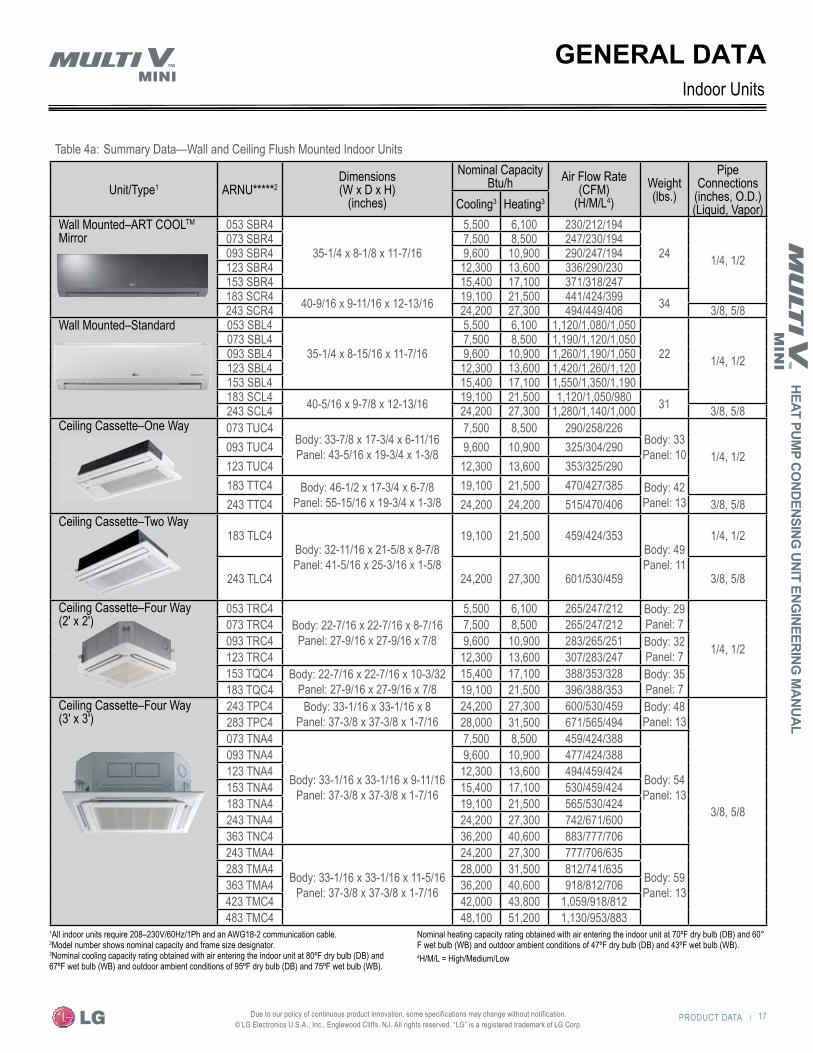
Table 4a: Summary Data—Wall and Ceiling Flush Mounted Indoor Units
1All indoor units require 208–230V/60Hz/1Ph and an AWG18-2 communication cable. 2Model number shows nominal capacity and frame size designator. 3Nominal cooling capacity rating obtained with air entering the indoor unit at 80ºF dry bulb (DB) and 67ºF wet bulb (WB) and outdoor ambient conditions of 95ºF dry bulb (DB) and 75ºF wet bulb (WB).
Nominal heating capacity rating obtained with air entering the indoor unit at 70ºF dry bulb (DB) and 60° F wet bulb (WB) and outdoor ambient conditions of 47ºF dry bulb (DB) and 43ºF wet bulb (WB).4H/M/L = High/Medium/Low

18 | PRODUCT DATA
Prod
uct D
ata
Due to our policy of continuous product innovation, some specifications may change without notification. © LG Electronics U.S.A., Inc., Englewood Cliffs, NJ. All rights reserved. “LG” is a registered trademark of LG Corp.
GENERAL DATAIndoor Units
Table 4b: Summary Data—Ducted Indoor Units
Unit/Type1 ARNU*****2Dimensions (W x D x H)
(inches)
Nominal Capacity Btu/h Air Flow Rate
(CFM) (H/M/L4)
Weight (lbs.)
Pipe Connections
(inches, O.D.)(Liquid, Vapor)
Max.ESP
(inches)Cooling3 Heating3
Ducted High Static 073 BGA4
46-1/2 x 17-3/4 x 11-3/4
7,500 8,500 441/406/332
843/8, 5/8
0.62
093 BGA4 9,600 10,900 452/406/332123 BGA4 12,300 13,600 477/427/332153 BGA4 15,400 17,100 487/417/293183 BGA4 19,100 21,500 537/487/417243 BGA4 24,200 27,300 671/537/487283 BGA4 28,000 31,500 915/851/770363 BGA4 36,200 40,600 1,141/1,024/894423 BGA4 42,000 43,800 1,218/1,141/1,084483 BRA4
48-7/16 x 23-3/8 x 1548,100 51,200 1,568/1,395/1,183
112 0.78543 BRA4 54,000 61,400 1,819/1,678/1,395763 B8A4 61-1/2 x 27-1/8 x 18-1/8 76,400 86,000 2,050/1,766/1,766 192 3/8, 3/4 0.98963 B8A4 95,900 107,500 2,542/2,260/2,260 3/8, 7/8
Ducted Low Static 073 L1G427-9/16 x 27-9/16 x 7-1/2
7,500 8,500 270/230/20039
1/4, 1/20.19
093 L1G4 9,600 10,900 320/250/200123 L2G4
35-7/16 x 27-9/16 x 7-1/212,300 13,600 360/310/250
51153 L2G4 15,400 17,100 450/360/310183 L2G4 19,100 21,500 530/450/360243 L3G4 43-5/16 x 27-9/16 x 7-1/2 24,000 27,300 710/570/430 60 3/8. 5/8
Ducted Low Static - Built In
073 B3G4
32-5/8 x 22-5/8 x 7-1/2
7,500 8,500 283/229/194
461/4, 1/2
0.15
093 B3G4 9,600 10,900 318/247/212123 B3G4 12,300 13,600 353/283/229153 B3G4 15,400 17,100 388/353/283183 B4G4
43-5/16 x 22-5/8 x 7-1/219,100 21,500 494/424/353
57243 B4G4 24,200 27,300 600/530/353 3/8, 5/8
Vertical/Horizontal AirHandling Unit
123 NJA4
18 x 21-1/4 x 48-11/16
12,000 13,500 530/480/380
1171/4, 1/2
1.0
183 NJA4 18,000 20,000 580/530/480243 NJA4 24,000 27,000 710/640/480
3/8, 5/8
303 NJA4 30,000 34,000 880/800/630363 NJA4 36,000 40,000 990/880/800 121423 NKA4
25 x 21-1/4 x 55-3/1642,000 46,000 1,250/1,100/1,000
165483 NKA4 48,000 54,000 1,400/1,260/1,000543 NKA4 54,000 60,000 1,475/1,400/1,260
1All indoor units require 208–230V/60Hz/1Ph and an AWG18-2 communication cable. 2Model number shows nominal capacity and frame size designator. 3Nominal cooling capacity rating obtained with air entering the indoor unit at 80ºF dry bulb (DB) and 67ºF wet bulb (WB) and outdoor ambient conditions of 95ºF dry bulb (DB) and 75ºF wet bulb (WB).
Nominal heating capacity rating obtained with air entering the indoor unit at 70ºF dry bulb (DB) and 60° F wet bulb (WB) and outdoor ambient conditions of 47ºF dry bulb (DB) and 43ºF wet bulb (WB).4H/M/L = High/Medium/Low
PRODUCT DATA | 19
HEAT PUMP CO
NDENSING UNIT ENG
INEERING M
AN
UAL
Due to our policy of continuous product innovation, some specifications may change without notification. © LG Electronics U.S.A., Inc., Englewood Cliffs, NJ. All rights reserved. “LG” is a registered trademark of LG Corp.
GENERAL DATAIndoor Units
Unit/Type1 ARNU****2Dimensions (W x D x H)
(inches)
Nominal Capacity Btu/h Air Flow
Rate (CFM)
(H/M/L4)
Weight (lbs.)
Pipe Connections
(inches, O.D.)(Liquid, Vapor)Cooling3 Heating3
Ceiling Suspended183VJA2
37-7/16 x 8-11/16 x 25-5/8
19,100 21,500 565/495/424
55
1/4, 1/2
243VJA2 24,200 27,300 636/565/495 3/8, 5/8
Convertible Surface Mounted093VEA2
35-7/16 x 7-7/8 x 19-5/16
9,600 10,900 268/243/219
31 1/4, 1/2
123VEA2 12,300 13,600 325/268/244
Floor Standing –Cased073 CEA4
42 x 8 x 25
7,500 8,500 300/265/229
601/4, 1/2
093 CEA4 9,600 10,900 335/300/265
123 CEA4 12,300 13,600 371/335/300
153 CEA4 15,400 17,100 406/353/335
183 CFA452-15/16 x 8 x 25
19,100 21,500 565/494/42475
243 CFA4 24,200 27,300 635/565/494 3/8, 5/8
Floor Standing – Uncased073 CEU4
38-1/2 x 7-15/16 x 25-3/16
7,500 8,500 300/265/229
461/4, 1/2
093 CEU4 9,600 10,900 335/300/265
123 CEU4 12,300 13,600 371/335/300
153 CEU4 15,400 17,100 406/353/335
183 CFU449-7/16 x 7-1/2 x 25-3/16
19,100 21,500 565/494/42458
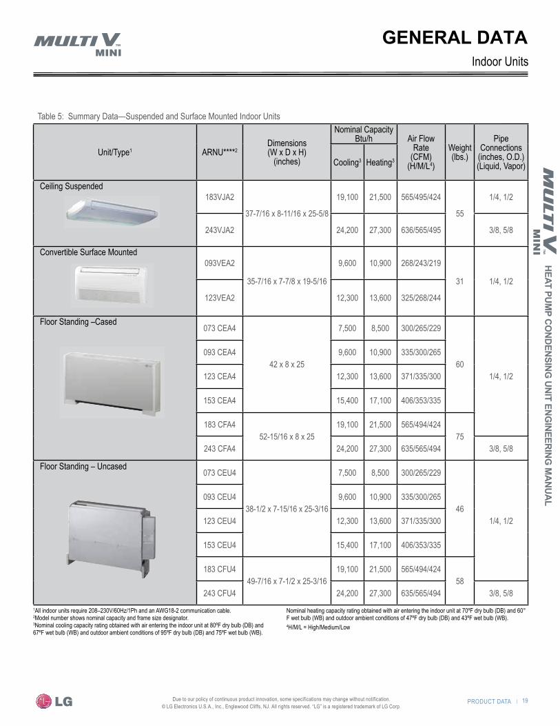
243 CFU4 24,200 27,300 635/565/494 3/8, 5/81All indoor units require 208–230V/60Hz/1Ph and an AWG18-2 communication cable. 2Model number shows nominal capacity and frame size designator. 3Nominal cooling capacity rating obtained with air entering the indoor unit at 80ºF dry bulb (DB) and 67ºF wet bulb (WB) and outdoor ambient conditions of 95ºF dry bulb (DB) and 75ºF wet bulb (WB).
Nominal heating capacity rating obtained with air entering the indoor unit at 70ºF dry bulb (DB) and 60° F wet bulb (WB) and outdoor ambient conditions of 47ºF dry bulb (DB) and 43ºF wet bulb (WB).4H/M/L = High/Medium/Low
Table 5: Summary Data—Suspended and Surface Mounted Indoor Units

20 | PRODUCT DATA
Prod
uct D
ata
Due to our policy of continuous product innovation, some specifications may change without notification. © LG Electronics U.S.A., Inc., Englewood Cliffs, NJ. All rights reserved. “LG” is a registered trademark of LG Corp.
Zone Controllers
Table 6: Summary Data—Zone Controllers
Before specifying or placing an order, refer to the V-Net Network Solution Engineering Product Data Book and review the detailed technical data provided to fully understand the capabilities and limitations of these devices.For information on controller compatibility refer to Table 11 - Indoor Unit Controls and Options.
Zone Controller Name Model No. Case Color Max Wire Length (ft) Description
Simple Controller with mode selection
PQRCVCL0Q Black164 Allows control of indoor unit on/off, operation mode, fan speed,
and temperature setpoint for up to 16 indoor units.PQRCVCL0QW White
Simple Controllerwithout mode selection
PQRCHCA0Q Black164 Allows control of indoor unit on/off, fan speed, and temperature
setpoint for up to 16 indoor units.PQRCHCA0QW White
LG Premium Controller PREMTA000 Ivory 164
Allows control of indoor unit on/off, operation mode, occupied/unoccupied temperature setpoints, fan speed, and air flow
direction for up to 16 indoor units. Programmable schedule with 5events per day with control of occupied/unoccupied, on/off, mode, setpoints and fan speed. Advanced functions includetwo setpoint autochangeover, minimum difference between
setpoints, setback, timed override, target energy consumption display, check energy display and master/slave.
LG Programmable Thermostat PREMTB10U White 164
Allows control of indoor unit on/off, operation mode, occupiedand unoccupied temperature setpoints, fan speed, and airflow
direction for up to 16 indoor units. Programmable schedule with5 events per day with control of occupied unoccupied, on/off,
mode, setpoints and fan speed. Advanced functions include two setpoint autochangeover, minimum difference between setpoints,
setback and timed override.
Wireless Handheld PQWRHQ0FDB Ivory ---- Allows control of indoor unit on/off, operation mode, fan speed,and temperature setpoint.
Wall-Mounted RemoteTemperature Sensor PQRSTA0 Ivory 50 Allows remote temperature measurement for cassette and
ducted units.

PRODUCT DATA | 21
HEAT PUMP CO
NDENSING UNIT ENG
INEERING M
AN
UAL
Due to our policy of continuous product innovation, some specifications may change without notification. © LG Electronics U.S.A., Inc., Englewood Cliffs, NJ. All rights reserved. “LG” is a registered trademark of LG Corp.
GENERAL DATACommunication Cables & Specialty Application Devices
Table 7: Summary Data—Zone Controller Communication Cables
Table 8: Summary Data—Speciality Application Devices
Before specifying or placing an order, refer to the V-Net Network Solution Engineering Product Data Book and review the detailed technical data provided to fully understand the capabilities and limitations of these devices.For information on controller compatibility refer to Table 11 - Indoor Unit Controls and Options.
Before specifying or placing an order, refer to the V-Net Network Solution Engineering Product Data Book and review the detailed technical data provided to fully understand the capabilities and limitations of these devices.For information on controller compatibility refer to Table 11 - Indoor Unit Controls and Options.
Speciality Application Device Name Model No. Connect
to ApplicationBinary Signals Input/ Output
Description
Simple Dry Contact PQDSB1
Indoor Unit
On/Off, Run Status, Error Status 1/2 Enables the indoor unit to be
controlled and monitored by third party controls using binary inputs
and outputs.
Dry Contact forEconomizer, occupied/
unoccupiedPQDSBC1
On/Off, Mode,Controller Lock, Power
Save, Run Status,Error Status
2/2
Dry Contact Unit for 24V Thermostat PDRYCB300
On/Off, Thermo On/Off, Mode, Fan Speed,
Run Status, ErrorStatus
---Enables the indoor unit to be
controlled and monitored by a third party thermostat or controller.
Digital Output (DO) Kit PQNFP00T0 Comm
Bus On/Off 0/1
One 25A DPST normally open relay. Used with central controller to control
third party device manually or by schedule.
I/O Module PEXPMB000
ACSmart IV
and ACP IV
Third party equipmentcontrol. Allows system
expansion throughDigital and Analoginputs and outputs.
---
3 Digital Inputs: Dry Contact input only3 Digital Outputs: Max. 2A@30VAC/DC4 Analog Outputs: 0 to 10 VDC,configurable; 0 to 20 mA, configurable4 Universal Inputs individuallyconfigurable as analog or digital:
Analog: Voltage. Current. Thermistor(NTC, PT, Ni)Digital for Dry Contact input only
Auxiliary Heater Relay Kit
PRARH0 Indoor Unit
Third party supplemental heat
control0/1
Adds coordinated control of an external heater with normal heat
pump operations. PRARS0
Auxiliary Two-StageHeater Relay Kit PRARH1 Indoor
Unit
Third partysupplemental heat
control0/2
Adds coordinated control of anexternal heater with normal heat
pump operations.
Power DistributionIndicator (PDI)
PremiumPQNUD1S41 Comm
Bus
Energyconsumptionmonitoring
8 WattNode
Meters
Monitors total outdoor unit powerconsumption for up to eight systems, and distributes per indoor unit based
on weighted calculation.
Mode Selector Switch PRDSBM OutdoorUnit
Multi V Heat Pump Only --- Locks outdoor unit into Heat,
Cool, or Fan Mode.
Communication Cable Name Model No. Wire Length (ft.) Description
Wired Remote Group Control Cable Assembly PZCWRCG3 33 Required when grouping multiple indoor units with a single
zone controller.
Wired Remote/Group ControlExtension Cable PZCWRC1 33 Increases the distance between a remote controller and an
indoor unit or between indoor units in a control group.

22 | PRODUCT DATA
Prod
uct D
ata
Due to our policy of continuous product innovation, some specifications may change without notification. © LG Electronics U.S.A., Inc., Englewood Cliffs, NJ. All rights reserved. “LG” is a registered trademark of LG Corp.
Central Controllers
Table 9: Summary Data—Central Controllers (connect to the outdoor unit terminals Internet A, Internet B)
Table 10: Summary Data—Integration Solutions (connect to outdoor unit terminals Internet A, Internet B)
Before specifying or placing an order, refer to the V-Net Network Solution Engineering Product Data Book and review the detailed technical data provided to fully understand the capabilities and limitations of these devices.For information on controller compatibility refer to Table 11 - Indoor Unit Controls and Options.* BACnetTM is a trademark of ASHRAE; LonWorksTM is a trademark of Echlelon Corporation.
Before specifying or placing an order, refer to the V-Net Network Solution Engineering Product Data Book and review the detailed technical data provided to fully understand the capabilities and limitations of these devices.For information on controller compatibility refer to Table 11 - Indoor Unit Controls and Options.
Central Controller Name Model No.
Devices per
Controller
Systems per Comm
Bus
Devices per Comm
Bus
No. of Comm
Bus Ports
BinarySignalsInput/ Output
Power, Conn Description
AC Smart IV PACS4B000 128 16 128 1 2 DI /2 DO 24 VAC
Monitors / operates indoor unitsthrough a touch screen. Manages
up to 128 devices. Advanced functions include programmable schedules, temperature setpoint
range lock, remote controller lock,run time limit, manual control and
scheduling of digital output kit,peak/demand control, visual floor
plan navigation, web access, operation and error history log, onedigital input and two digital outputs
for device interlocking and errore-mail notification.
AC Ez PQCSZ250S0 32 16 256 1 --- 12 VDC,ODU
Provides for scheduling in additionto basic indoor unit control and
monitoring.
Advanced Control
Platform IV (ACP IV)
PACP4B000 256 16 64 4 10/4 24 VAC
Provides for scheduling, remote controller lock, setpoint range limit,web access, peak/demand control, PDI integration, and AC Manager
Plus integration advancedfunctionality in addition to basic unit
control and monitoring.
Integration Solution Name Model No.
Devices per
Controller
Systems per
Comm Bus
Devices per Comm
Bus
No. of Comm
Bus Ports
PowerBinary Signals Input/ Output
Description
ACP IV BACnet®
Gateway*PQNFB17C1 256 16 256 4 24 VAC 10/4 Allow integration of LG equipment
for control and monitoring by open protocol BACnet® and LonWorks® building automation and controls systems.*LonWorks®
Gateway* PLNWKB100 64 16 64 1 24 VAC 2/2
PRODUCT DATA | 23
HEAT PUMP CO
NDENSING UNIT ENG
INEERING M
AN
UAL
Due to our policy of continuous product innovation, some specifications may change without notification. © LG Electronics U.S.A., Inc., Englewood Cliffs, NJ. All rights reserved. “LG” is a registered trademark of LG Corp.
GENERAL DATA

24 | PRODUCT DATA
Prod
uct D
ata
Due to our policy of continuous product innovation, some specifications may change without notification. © LG Electronics U.S.A., Inc., Englewood Cliffs, NJ. All rights reserved. “LG” is a registered trademark of LG Corp.
GENERAL DATAIndoor Units—Controls and Options
1For Heat Recovery systems only.2Primary washable filters.3Plasma filter kit accessories available separately, except for ArtCool Mirror which is included as standard.4Requires 7-day programmable zone controller.5Requires ventilation kit PTVK430 or PTVK410+PTVK420 (For TP, TN, TM frames)(Temperature, humidity, and volume limitations apply).6Heat Pump systems only.
√ = Standard featureo = Unit option
Feature Wall
Mo
unted
—
Stan
dard
Fini
sh
Wall
Mou
nted—
AR
T CO
OL™
Mirr
or
1-W
ay
Cass
ette
2-W
ay
Cass
ette
4-W
ay C
asse
tte
Ducte
d High
Stat
ic
Ducte
d Low
Stat
ic
Ducte
d Low
Stat
ic—
Botto
m Re
turn
Vert.
-Hor
iz. A
HU (N
J)
Vert.
-Hor
iz. A
HU (N
K)
Ceilin
g Su
spen
ded
Conv
ertib
le
Surfa
ce M
ount
Floor
Mou
nt—Ca
sed
Floor
Mou
nt—
Unca
sed
Nominal Chassis Size (MBh) 5–24 7–24 7–24 18–24 5–18 24–48 7–96 7–24 7–24 12-36 42-53 18–24 9–12 7–24 7–24
Airflo
w
Air supply outlets 1 1 1 2 4 4 1 1 1 1 1 1 1 1 1Airflow direction (left/right) manual auto manual manualAuto airflow direction (up/down) √ √ √ √ √ √ √ √Fan speed (Heating mode) 3 3 4 4 4 4 3 3 3 3 3 3 3 3 3Fan speed (Cooling mode) 4 4 5 5 5 5 3 3 3 3 3 4 4 3 3Fan speed (fan mode) 3 3 4 4 4 4 3 3 3 3 3 3 3 3 3Chaos swing (random louver
swing) √ √Chaos wind (random fan speed) √ √ √ √ √ √ √ √Jet-cool (power cooling) √ √ √ √ √ √ √ √
Oper
ation
E.S.P. control √ √ √ √ √ √ √ √ √High ceiling √ √ √ √ √ √ √ √ √ √ √Auto-restart after power restore √ √ √ √ √ √ √ √ √ √ √ √ √ √ √Hot start √ √ √ √ √ √ √ √ √ √ √ √ √ √ √Diagnostics √ √ √ √ √ √ √ √ √ √ √ √ √ √ √Auto changeover1 √ √ √ √ √ √ √ √ √ √ √ √ √ √ √Auto operation6 √ √ √ √ √ √ √ √Auto clean (coil dry) √ √ √ √ √ √ √ √ √Child lock √ √ √ √ √ √ √ √ √ √ √ √ √ √ √Dual thermistor control √ √ √ √ √ √ √ √ √ √ √ √ √ √ √Dual set-point control √ √ √ √ √ √ √ √ √ √ √ √ √ √ √Filter life display √ √ √ √ √ √ √ √ √ √ √ √ √ √ √Power consumption display(with PDI) √ √ √ √ √ √ √ √ √ √Forced operation √ √ √ √ √ √ √ √ √ √ √ √ √Group control – Requires theuse of one Group control cablekit (PZCWRCG3) for everyadditional indoor unit
√ √ √ √ √ √ √ √ √ √ √ √ √ √ √
Timer (on/off) √ √ √ √ √ √ √ √ √ √ √ √ √ √ √Weekly schedule √ √ √ √ √ √ √ √ √ √ √ √ √ √ √Test operation mode √ √ √ √ √ √ √ √
Filter Plasma3 o √ o o o o √ √ √ √ √
Washable anti-fungal2 √ √ √ √ √ √ √ √ o o o o o
Contr
ollers 7-day programmable controller o o o o o o o o o o o o o o o
Simple controller w/mode o o o o o o o o o o o o o o oSimple controller w/o mode o o o o o o o o o4 o o o o o4 o4
Wireless controller o o o o o o o4 o4 √
Othe
rs
Condensate lift √ √ √ √ √ √ √Ventilation air √ √5 √5 √ √ √ √ √Casing √ √ √ √ √ √Standard grille √ √ √ √Auto elevation grille o oSuction grille oSuction canvas √ √Aux. heat kit
Table 11: Indoor Units—Controls and Options
PERFORMANCE DATA"Performance Data" on page 26"Unit Refrigerant Flow Diagrams" on page 44"Outdoor Wiring Diagram" on page 157
26 | PERFORMANCE DATA
Perf
orm
ance
Dat
a
Due to our policy of continuous product innovation, some specifications may change without notification. © LG Electronics U.S.A., Inc., Englewood Cliffs, NJ. All rights reserved. “LG” is a registered trademark of LG Corp.
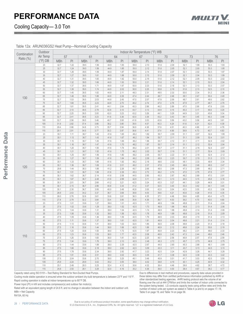
Table 12a: ARUN036GS2 Heat Pump—Nominal Cooling Capacity
Combination Ratio (%)
Outdoor Air Temp (°F) DB
Indoor Air Temperature (°F) WB57 61 64 67 70 73 76
MBh PI MBh PI MBh PI MBh PI MBh PI MBh PI MBh PI
130
23 32.7 1.22 39.5 1.56 44.9 1.83 50.0 2.10 51.6 2.04 52.1 1.99 53.3 1.93 25 32.7 1.24 39.5 1.58 44.9 1.85 50.0 2.12 51.6 2.05 52.1 2.00 53.3 1.95 30 32.7 1.26 39.5 1.59 44.9 1.87 50.0 2.14 51.6 2.07 52.1 2.02 53.3 1.97 35 32.7 1.27 39.5 1.61 44.9 1.88 50.0 2.15 51.6 2.09 52.1 2.04 53.3 1.99 40 32.7 1.31 39.5 1.65 44.9 1.92 50.0 2.19 51.6 2.12 52.1 2.09 53.3 2.02 45 32.7 1.32 39.5 1.66 44.9 1.93 50.0 2.21 51.6 2.14 52.1 2.10 53.3 2.04 50 32.7 1.37 39.5 1.71 44.9 1.97 50.0 2.23 51.6 2.18 52.1 2.13 53.3 2.07 55 32.7 1.39 39.5 1.74 44.9 2.02 50.0 2.25 50.8 2.19 51.6 2.13 52.5 2.10 60 32.7 1.45 39.5 1.82 44.9 2.11 48.3 2.31 49.5 2.33 50.0 2.34 51.2 2.36 65 32.7 1.48 39.5 1.88 44.9 2.26 47.4 2.44 48.7 2.46 49.1 2.47 50.4 2.49 70 32.7 1.53 39.5 2.03 44.9 2.45 47.0 2.57 47.9 2.59 48.7 2.61 49.5 2.62 75 32.7 1.68 39.5 2.23 44.9 2.70 46.2 2.74 47.0 2.76 47.9 2.77 48.7 2.79 80 32.7 1.81 39.5 2.41 44.1 2.84 45.3 2.86 46.2 2.89 47.0 2.90 47.9 2.93 85 32.7 2.10 39.5 2.79 42.8 3.10 43.7 3.13 44.9 3.15 45.3 3.17 46.6 3.20 90 32.7 2.25 39.5 3.00 42.0 3.23 43.2 3.26 44.1 3.29 44.9 3.31 45.8 3.34 95 32.7 2.41 39.5 3.23 41.6 3.36 42.0 3.39 43.2 3.43 44.1 3.45 45.3 3.48
100 32.7 2.58 39.5 3.46 40.7 3.50 41.6 3.53 42.8 3.56 43.2 3.58 44.5 3.61 105 31.9 2.82 37.4 3.66 38.2 3.80 39.5 4.07 40.3 4.24 41.6 4.31 42.4 4.38 110 29.4 2.88 34.8 3.73 35.7 3.94 36.9 4.38 37.8 4.51 40.3 4.68 41.1 4.78 115 29.1 2.91 34.5 3.77 35.3 3.97 36.6 4.41 37.4 4.56 39.9 4.73 40.7 4.83
120
23 30.1 1.11 36.7 1.42 41.6 1.65 46.2 1.92 50.7 2.09 51.1 2.07 52.4 1.99 25 30.1 1.13 36.7 1.43 41.6 1.67 46.2 1.94 50.7 2.11 51.1 2.09 52.4 2.01 30 30.1 1.15 36.7 1.45 41.6 1.69 46.2 1.96 50.7 2.12 51.1 2.11 52.4 2.02 35 30.1 1.16 36.7 1.47 41.6 1.70 46.2 1.97 50.7 2.14 51.1 2.12 52.4 2.04 40 30.1 1.20 36.7 1.50 41.6 1.74 46.2 2.01 50.7 2.17 51.1 2.16 52.4 2.07 45 30.1 1.21 36.7 1.52 41.6 1.75 46.2 2.02 50.7 2.19 51.1 2.17 52.4 2.09 50 30.1 1.25 36.7 1.56 41.6 1.80 46.2 2.05 50.7 2.22 51.1 2.18 52.4 2.12 55 30.1 1.27 36.7 1.59 41.6 1.84 46.2 2.09 49.9 2.23 50.7 2.19 51.5 2.13 60 30.1 1.33 36.7 1.66 41.6 1.92 46.2 2.18 48.6 2.32 49.1 2.33 49.9 2.34 65 30.1 1.36 36.7 1.69 41.6 2.01 46.2 2.37 47.8 2.45 48.6 2.46 49.5 2.47 70 29.8 1.44 36.3 1.88 41.2 2.26 45.7 2.66 46.5 2.68 47.3 2.69 48.2 2.71 75 30.1 1.51 36.7 1.99 41.6 2.39 45.3 2.72 46.2 2.74 47.0 2.75 47.8 2.77 80 30.1 1.62 36.7 2.14 41.6 2.58 44.5 2.85 45.3 2.87 46.2 2.89 47.0 2.91 85 30.1 1.87 36.7 2.48 41.6 2.99 42.9 3.11 44.1 3.13 44.5 3.15 45.8 3.18 90 30.1 2.01 36.7 2.66 41.2 3.21 42.5 3.24 43.3 3.27 44.1 3.29 44.9 3.31 95 30.1 2.15 36.7 2.86 40.8 3.34 41.2 3.37 42.5 3.40 43.3 3.42 44.1 3.45
100 30.1 2.30 36.7 3.06 40.0 3.48 40.8 3.50 42.0 3.54 42.5 3.55 43.3 3.58 105 28.9 2.53 34.2 3.37 36.7 3.68 38.8 4.05 39.6 4.21 40.8 4.28 41.6 4.35 110 28.0 2.76 32.6 3.61 33.8 3.91 36.3 4.35 37.1 4.48 39.6 4.65 40.4 4.75 115 27.8 2.79 32.2 3.64 33.4 3.95 35.9 4.39 36.7 4.53 39.2 4.70 40.0 4.80
110
23 27.5 1.01 33.6 1.27 38.0 1.51 42.5 1.71 46.9 1.94 49.8 2.11 51.4 2.04 25 27.5 1.02 33.6 1.29 38.0 1.52 42.5 1.73 46.9 1.96 49.8 2.13 51.4 2.06 30 27.5 1.04 33.6 1.31 38.0 1.54 42.5 1.74 46.9 1.98 49.8 2.14 51.4 2.08 35 27.5 1.06 33.6 1.32 38.0 1.56 42.5 1.76 46.9 1.99 49.8 2.16 51.4 2.09 40 27.5 1.09 33.6 1.36 38.0 1.59 42.5 1.79 46.9 2.03 49.8 2.19 51.4 2.13 45 27.5 1.11 33.6 1.37 38.0 1.61 42.5 1.81 46.9 2.04 49.8 2.21 51.4 2.14 50 27.5 1.13 33.6 1.41 38.0 1.63 42.5 1.85 46.9 2.08 49.8 2.23 51.4 2.18 55 27.5 1.16 33.6 1.44 38.0 1.66 42.5 1.89 46.9 2.12 49.8 2.24 50.6 2.19 60 27.5 1.20 33.6 1.50 38.0 1.73 42.5 1.97 46.9 2.23 48.2 2.31 49.0 2.33 65 27.5 1.23 33.6 1.53 38.0 1.77 42.5 2.08 46.9 2.42 47.3 2.44 48.6 2.46 70 27.5 1.26 33.6 1.60 38.0 1.91 42.5 2.25 46.1 2.56 46.9 2.57 47.8 2.59 75 27.5 1.34 33.6 1.76 38.0 2.10 42.5 2.48 45.3 2.72 45.7 2.73 46.9 2.75 80 27.5 1.44 33.6 1.89 38.0 2.26 42.5 2.67 44.5 2.85 45.3 2.86 46.1 2.89 85 27.5 1.66 33.6 2.18 38.0 2.62 42.5 3.09 43.3 3.11 43.7 3.13 44.5 3.15 90 27.5 1.78 33.6 2.34 38.0 2.82 41.7 3.22 42.5 3.24 42.9 3.26 44.1 3.28 95 27.5 1.91 33.6 2.51 38.0 3.02 40.5 3.35 41.7 3.38 42.5 3.39 43.3 3.42
100 27.5 2.04 33.6 2.70 38.0 3.25 40.1 3.48 40.9 3.51 41.7 3.53 42.5 3.55 105 25.9 2.24 29.9 3.02 35.2 3.55 38.0 4.02 38.8 4.19 40.1 4.25 40.9 4.32 110 25.1 2.48 28.3 3.25 32.4 4.12 35.6 4.32 36.4 4.46 38.8 4.62 39.7 4.72 115 24.8 2.50 28.1 3.28 32.0 4.16 35.2 4.36 36.0 4.50 38.4 4.67 39.2 4.77
PERFORMANCE DATACooling Capacity 3.0 Ton—
Capacity rated using ISO 5151—Test Rating Standard for Non-Ducted Heat Pumps.Cooling mode stable operation is ensured when the outdoor ambient dry-bulb temperature is between 23°F and 115°F.Rapid cooling operation is stable at indoor temperatures up to 80°F DB.Power Input (PI) in kW and includes compressor(s) and outdoor fan motor(s).Rated with an equivalent piping length of 24.6 ft. and no change in elevation between the indoor and outdoor unit.MBh = Net CapacityR410A, 60 Hz
Due to differences in test method and procedures, capacity data values provided in these tables may differ from certified performance information published by AHRI or other standardized testing agencies. AHRI testing protocol sets the volume of air flowing over the coil at 444 CFM/ton and limits the number of indoor units connected to the system being tested. LG conducts capacity tests using airflow rates and limits the number of indoor units per system as stated in Table 4 (a and b) on pages 17–18, Table 5 on page 19, and Table 14 on page 56.
PERFORMANCE DATA | 27
HEAT PUMP CO
NDENSING UNIT ENG
INEERING M
ANU
AL
Due to our policy of continuous product innovation, some specifications may change without notification. © LG Electronics U.S.A., Inc., Englewood Cliffs, NJ. All rights reserved. “LG” is a registered trademark of LG Corp.
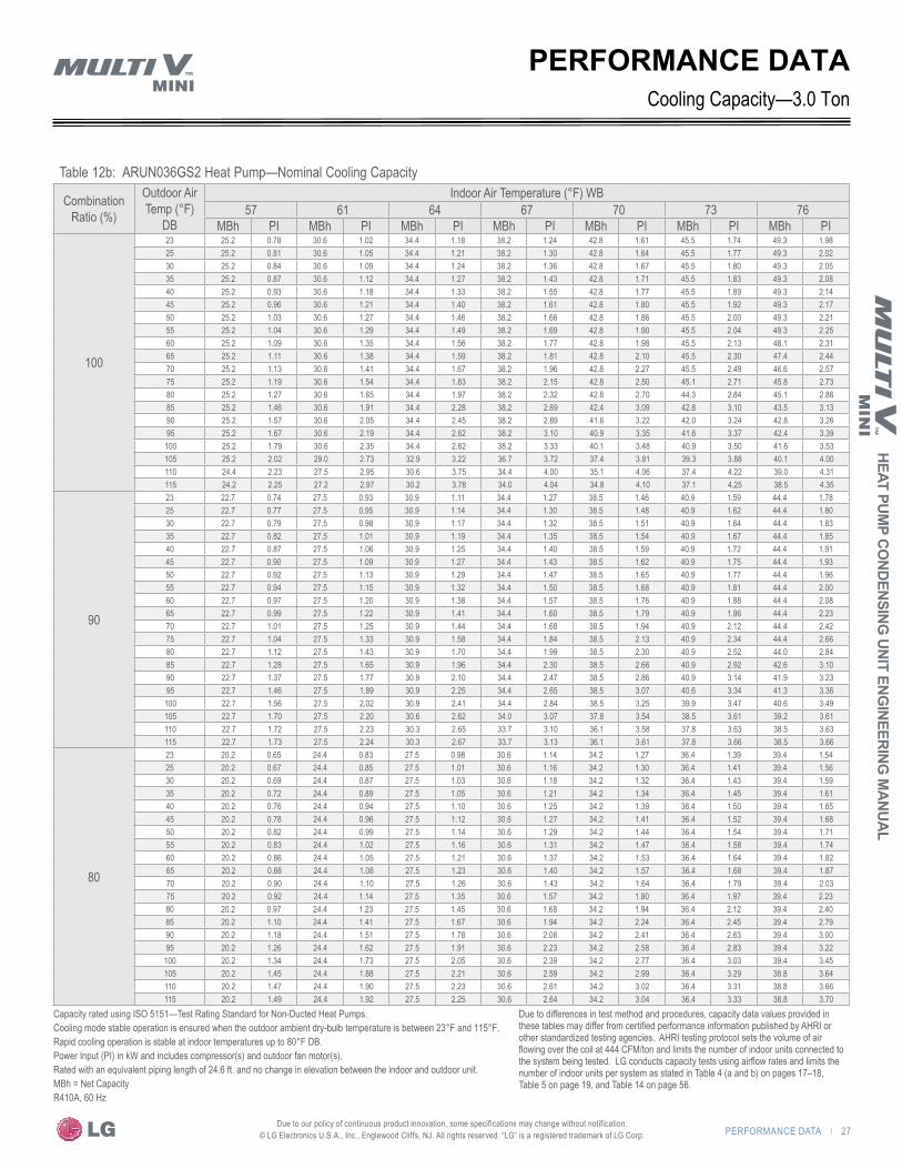
Table 12b: ARUN036GS2 Heat Pump—Nominal Cooling Capacity
Combination Ratio (%)
Outdoor Air Temp (°F)
DB
Indoor Air Temperature (°F) WB57 61 64 67 70 73 76
MBh PI MBh PI MBh PI MBh PI MBh PI MBh PI MBh PI
100
23 25.2 0.78 30.6 1.02 34.4 1.18 38.2 1.24 42.8 1.61 45.5 1.74 49.3 1.98 25 25.2 0.81 30.6 1.05 34.4 1.21 38.2 1.30 42.8 1.64 45.5 1.77 49.3 2.02 30 25.2 0.84 30.6 1.09 34.4 1.24 38.2 1.36 42.8 1.67 45.5 1.80 49.3 2.05 35 25.2 0.87 30.6 1.12 34.4 1.27 38.2 1.43 42.8 1.71 45.5 1.83 49.3 2.08 40 25.2 0.93 30.6 1.18 34.4 1.33 38.2 1.55 42.8 1.77 45.5 1.89 49.3 2.14 45 25.2 0.96 30.6 1.21 34.4 1.40 38.2 1.61 42.8 1.80 45.5 1.92 49.3 2.17 50 25.2 1.03 30.6 1.27 34.4 1.46 38.2 1.66 42.8 1.86 45.5 2.00 49.3 2.21 55 25.2 1.04 30.6 1.29 34.4 1.49 38.2 1.69 42.8 1.90 45.5 2.04 49.3 2.25 60 25.2 1.09 30.6 1.35 34.4 1.56 38.2 1.77 42.8 1.98 45.5 2.13 48.1 2.31 65 25.2 1.11 30.6 1.38 34.4 1.59 38.2 1.81 42.8 2.10 45.5 2.30 47.4 2.44 70 25.2 1.13 30.6 1.41 34.4 1.67 38.2 1.96 42.8 2.27 45.5 2.49 46.6 2.57 75 25.2 1.19 30.6 1.54 34.4 1.83 38.2 2.15 42.8 2.50 45.1 2.71 45.8 2.73 80 25.2 1.27 30.6 1.65 34.4 1.97 38.2 2.32 42.8 2.70 44.3 2.84 45.1 2.86 85 25.2 1.46 30.6 1.91 34.4 2.28 38.2 2.69 42.4 3.09 42.8 3.10 43.5 3.13 90 25.2 1.57 30.6 2.05 34.4 2.45 38.2 2.89 41.6 3.22 42.0 3.24 42.8 3.26 95 25.2 1.67 30.6 2.19 34.4 2.62 38.2 3.10 40.9 3.35 41.6 3.37 42.4 3.39 100 25.2 1.79 30.6 2.35 34.4 2.82 38.2 3.33 40.1 3.48 40.9 3.50 41.6 3.53 105 25.2 2.02 29.0 2.73 32.9 3.22 36.7 3.72 37.4 3.81 39.3 3.88 40.1 4.00 110 24.4 2.23 27.5 2.95 30.6 3.75 34.4 4.00 35.1 4.06 37.4 4.22 39.0 4.31 115 24.2 2.25 27.2 2.97 30.2 3.78 34.0 4.04 34.8 4.10 37.1 4.25 38.5 4.35
90
23 22.7 0.74 27.5 0.93 30.9 1.11 34.4 1.27 38.5 1.46 40.9 1.59 44.4 1.78 25 22.7 0.77 27.5 0.95 30.9 1.14 34.4 1.30 38.5 1.48 40.9 1.62 44.4 1.80 30 22.7 0.79 27.5 0.98 30.9 1.17 34.4 1.32 38.5 1.51 40.9 1.64 44.4 1.83 35 22.7 0.82 27.5 1.01 30.9 1.19 34.4 1.35 38.5 1.54 40.9 1.67 44.4 1.85 40 22.7 0.87 27.5 1.06 30.9 1.25 34.4 1.40 38.5 1.59 40.9 1.72 44.4 1.91 45 22.7 0.90 27.5 1.09 30.9 1.27 34.4 1.43 38.5 1.62 40.9 1.75 44.4 1.93 50 22.7 0.92 27.5 1.13 30.9 1.29 34.4 1.47 38.5 1.65 40.9 1.77 44.4 1.96 55 22.7 0.94 27.5 1.15 30.9 1.32 34.4 1.50 38.5 1.68 40.9 1.81 44.4 2.00 60 22.7 0.97 27.5 1.20 30.9 1.38 34.4 1.57 38.5 1.76 40.9 1.88 44.4 2.08 65 22.7 0.99 27.5 1.22 30.9 1.41 34.4 1.60 38.5 1.79 40.9 1.96 44.4 2.23 70 22.7 1.01 27.5 1.25 30.9 1.44 34.4 1.68 38.5 1.94 40.9 2.12 44.4 2.42 75 22.7 1.04 27.5 1.33 30.9 1.58 34.4 1.84 38.5 2.13 40.9 2.34 44.4 2.66 80 22.7 1.12 27.5 1.43 30.9 1.70 34.4 1.99 38.5 2.30 40.9 2.52 44.0 2.84 85 22.7 1.28 27.5 1.65 30.9 1.96 34.4 2.30 38.5 2.66 40.9 2.92 42.6 3.10 90 22.7 1.37 27.5 1.77 30.9 2.10 34.4 2.47 38.5 2.86 40.9 3.14 41.9 3.23 95 22.7 1.46 27.5 1.89 30.9 2.25 34.4 2.65 38.5 3.07 40.6 3.34 41.3 3.36 100 22.7 1.56 27.5 2.02 30.9 2.41 34.4 2.84 38.5 3.25 39.9 3.47 40.6 3.49 105 22.7 1.70 27.5 2.20 30.6 2.62 34.0 3.07 37.8 3.54 38.5 3.61 39.2 3.61 110 22.7 1.72 27.5 2.23 30.3 2.65 33.7 3.10 36.1 3.58 37.8 3.63 38.5 3.63 115 22.7 1.73 27.5 2.24 30.3 2.67 33.7 3.13 36.1 3.61 37.8 3.66 38.5 3.66
80
23 20.2 0.65 24.4 0.83 27.5 0.98 30.6 1.14 34.2 1.27 36.4 1.39 39.4 1.54 25 20.2 0.67 24.4 0.85 27.5 1.01 30.6 1.16 34.2 1.30 36.4 1.41 39.4 1.56 30 20.2 0.69 24.4 0.87 27.5 1.03 30.6 1.18 34.2 1.32 36.4 1.43 39.4 1.59 35 20.2 0.72 24.4 0.89 27.5 1.05 30.6 1.21 34.2 1.34 36.4 1.45 39.4 1.61 40 20.2 0.76 24.4 0.94 27.5 1.10 30.6 1.25 34.2 1.39 36.4 1.50 39.4 1.65 45 20.2 0.78 24.4 0.96 27.5 1.12 30.6 1.27 34.2 1.41 36.4 1.52 39.4 1.68 50 20.2 0.82 24.4 0.99 27.5 1.14 30.6 1.29 34.2 1.44 36.4 1.54 39.4 1.71 55 20.2 0.83 24.4 1.02 27.5 1.16 30.6 1.31 34.2 1.47 36.4 1.58 39.4 1.74 60 20.2 0.86 24.4 1.05 27.5 1.21 30.6 1.37 34.2 1.53 36.4 1.64 39.4 1.82 65 20.2 0.88 24.4 1.08 27.5 1.23 30.6 1.40 34.2 1.57 36.4 1.68 39.4 1.87 70 20.2 0.90 24.4 1.10 27.5 1.26 30.6 1.43 34.2 1.64 36.4 1.79 39.4 2.03 75 20.2 0.92 24.4 1.14 27.5 1.35 30.6 1.57 34.2 1.80 36.4 1.97 39.4 2.23 80 20.2 0.97 24.4 1.23 27.5 1.45 30.6 1.68 34.2 1.94 36.4 2.12 39.4 2.40 85 20.2 1.10 24.4 1.41 27.5 1.67 30.6 1.94 34.2 2.24 36.4 2.45 39.4 2.79 90 20.2 1.18 24.4 1.51 27.5 1.78 30.6 2.08 34.2 2.41 36.4 2.63 39.4 3.00 95 20.2 1.26 24.4 1.62 27.5 1.91 30.6 2.23 34.2 2.58 36.4 2.83 39.4 3.22 100 20.2 1.34 24.4 1.73 27.5 2.05 30.6 2.39 34.2 2.77 36.4 3.03 39.4 3.45 105 20.2 1.45 24.4 1.88 27.5 2.21 30.6 2.59 34.2 2.99 36.4 3.29 38.8 3.64 110 20.2 1.47 24.4 1.90 27.5 2.23 30.6 2.61 34.2 3.02 36.4 3.31 38.8 3.66 115 20.2 1.49 24.4 1.92 27.5 2.25 30.6 2.64 34.2 3.04 36.4 3.33 38.8 3.70
Cooling Capacity—3.0 TonPERFORMANCE DATA
Capacity rated using ISO 5151—Test Rating Standard for Non-Ducted Heat Pumps.Cooling mode stable operation is ensured when the outdoor ambient dry-bulb temperature is between 23°F and 115°F.Rapid cooling operation is stable at indoor temperatures up to 80°F DB.Power Input (PI) in kW and includes compressor(s) and outdoor fan motor(s).Rated with an equivalent piping length of 24.6 ft. and no change in elevation between the indoor and outdoor unit.MBh = Net CapacityR410A, 60 Hz
Due to differences in test method and procedures, capacity data values provided in these tables may differ from certified performance information published by AHRI or other standardized testing agencies. AHRI testing protocol sets the volume of air flowing over the coil at 444 CFM/ton and limits the number of indoor units connected to the system being tested. LG conducts capacity tests using airflow rates and limits the number of indoor units per system as stated in Table 4 (a and b) on pages 17–18, Table 5 on page 19, and Table 14 on page 56.

28 | PERFORMANCE DATA
Perf
orm
ance
Dat
a
Due to our policy of continuous product innovation, some specifications may change without notification. © LG Electronics U.S.A., Inc., Englewood Cliffs, NJ. All rights reserved. “LG” is a registered trademark of LG Corp.
PERFORMANCE DATA
Table 12c: ARUN036GS2 Heat Pump—Nominal Cooling Capacity
Combination Ratio (%)
Outdoor Air Temp (°F)
DB
Indoor Air Temperature (°F) WB57 61 64 67 70 73 76
MBh PI MBh PI MBh PI MBh PI MBh PI MBh PI MBh PI
70
23 17.6 0.59 21.4 0.74 24.1 0.85 26.7 0.98 29.9 1.11 31.8 1.19 34.5 1.34 25 17.6 0.61 21.4 0.76 24.1 0.87 26.7 1.00 29.9 1.13 31.8 1.21 34.5 1.35 30 17.6 0.63 21.4 0.78 24.1 0.89 26.7 1.02 29.9 1.15 31.8 1.22 34.5 1.37 35 17.6 0.65 21.4 0.80 24.1 0.91 26.7 1.04 29.9 1.17 31.8 1.24 34.5 1.39 40 17.6 0.69 21.4 0.84 24.1 0.95 26.7 1.08 29.9 1.21 31.8 1.28 34.5 1.43 45 17.6 0.71 21.4 0.85 24.1 0.96 26.7 1.09 29.9 1.22 31.8 1.30 34.5 1.45 50 17.6 0.72 21.4 0.87 24.1 0.99 26.7 1.11 29.9 1.24 31.8 1.33 34.5 1.46 55 17.6 0.73 21.4 0.88 24.1 1.00 26.7 1.13 29.9 1.27 31.8 1.36 34.5 1.49 60 17.6 0.76 21.4 0.92 24.1 1.04 26.7 1.18 29.9 1.32 31.8 1.41 34.5 1.56 65 17.6 0.77 21.4 0.94 24.1 1.07 26.7 1.20 29.9 1.34 31.8 1.44 34.5 1.59 70 17.6 0.79 21.4 0.95 24.1 1.09 26.7 1.23 29.9 1.38 31.8 1.48 34.5 1.67 75 17.6 0.80 21.4 0.98 24.1 1.13 26.7 1.31 29.9 1.49 31.8 1.63 34.5 1.84 80 17.6 0.83 21.4 1.04 24.1 1.22 26.7 1.41 29.9 1.61 31.8 1.75 34.5 1.98 85 17.6 0.95 21.4 1.19 24.1 1.40 26.7 1.62 29.9 1.85 31.8 2.02 34.5 2.28 90 17.6 1.01 21.4 1.28 24.1 1.49 26.7 1.73 29.9 1.99 31.8 2.17 34.5 2.45 95 17.6 1.08 21.4 1.36 24.1 1.60 26.7 1.86 29.9 2.13 31.8 2.32 34.5 2.64 100 17.6 1.15 21.4 1.45 24.1 1.71 26.7 1.98 29.9 2.28 31.8 2.49 34.5 2.82 105 17.6 1.24 21.4 1.56 24.1 1.84 26.7 2.13 29.9 2.47 31.8 2.69 34.5 3.04 110 17.6 1.26 21.4 1.58 24.1 1.86 26.7 2.15 29.9 2.49 31.8 2.71 34.5 3.06 115 17.6 1.27 21.4 1.59 24.1 1.87 26.7 2.17 29.9 2.51 31.8 2.73 34.5 3.09
60
23 15.1 0.50 18.3 0.62 20.6 0.71 22.9 0.82 25.7 0.92 27.3 0.98 29.6 1.10 25 15.1 0.51 18.3 0.64 20.6 0.73 22.9 0.83 25.7 0.94 27.3 1.00 29.6 1.12 30 15.1 0.53 18.3 0.65 20.6 0.74 22.9 0.85 25.7 0.95 27.3 1.01 29.6 1.13 35 15.1 0.56 18.3 0.68 20.6 0.77 22.9 0.88 25.7 0.98 27.3 1.04 29.6 1.16 40 15.1 0.57 18.3 0.70 20.6 0.79 22.9 0.89 25.7 1.00 27.3 1.06 29.6 1.18 45 15.1 0.57 18.3 0.70 20.6 0.79 22.9 0.89 25.7 1.00 27.3 1.06 29.6 1.18 50 15.1 0.59 18.3 0.71 20.6 0.80 22.9 0.91 25.7 1.01 27.3 1.08 29.6 1.19 55 15.1 0.60 18.3 0.72 20.6 0.82 22.9 0.92 25.7 1.03 27.3 1.10 29.6 1.22 60 15.1 0.62 18.3 0.75 20.6 0.85 22.9 0.96 25.7 1.08 27.3 1.15 29.6 1.27 65 15.1 0.63 18.3 0.76 20.6 0.87 22.9 0.98 25.7 1.10 27.3 1.18 29.6 1.30 70 15.1 0.64 18.3 0.78 20.6 0.89 22.9 1.00 25.7 1.12 27.3 1.21 29.6 1.36 75 15.1 0.66 18.3 0.80 20.6 0.92 22.9 1.07 25.7 1.22 27.3 1.33 29.6 1.50 80 15.1 0.68 18.3 0.85 20.6 0.99 22.9 1.15 25.7 1.31 27.3 1.43 29.6 1.61 85 15.1 0.82 18.3 1.04 20.6 1.22 22.9 1.41 25.7 1.62 27.3 1.77 29.6 2.00 90 15.1 0.82 18.3 1.04 20.6 1.22 22.9 1.41 25.7 1.62 27.3 1.77 29.6 2.00 95 15.1 0.88 18.3 1.11 20.6 1.30 22.9 1.51 25.7 1.74 27.3 1.89 29.6 2.15 100 15.1 0.94 18.3 1.18 20.6 1.39 22.9 1.62 25.7 1.86 27.3 2.03 29.6 2.30 105 15.1 1.01 18.3 1.27 20.6 1.50 22.9 1.74 25.7 2.01 27.3 2.19 29.6 2.48 110 15.1 1.03 18.3 1.29 20.6 1.51 22.9 1.75 25.7 2.03 27.3 2.21 29.6 2.49 115 15.1 1.04 18.3 1.30 20.6 1.52 22.9 1.77 25.7 2.04 27.3 2.04 29.6 2.52
50
23 12.6 0.39 15.3 0.48 17.2 0.55 19.1 0.64 21.4 0.72 22.7 0.77 24.6 0.87 25 12.6 0.40 15.3 0.49 17.2 0.57 19.1 0.65 21.4 0.74 22.7 0.78 24.6 0.88 30 12.6 0.41 15.3 0.51 17.2 0.58 19.1 0.66 21.4 0.75 22.7 0.80 24.6 0.89 35 12.6 0.42 15.3 0.52 17.2 0.59 19.1 0.68 21.4 0.76 22.7 0.81 24.6 0.90 40 12.6 0.45 15.3 0.54 17.2 0.61 19.1 0.70 21.4 0.78 22.7 0.83 24.6 0.93 45 12.6 0.46 15.3 0.55 17.2 0.63 19.1 0.71 21.4 0.80 22.7 0.84 24.6 0.94 50 12.6 0.47 15.3 0.56 17.2 0.64 19.1 0.72 21.4 0.81 22.7 0.86 24.6 0.95 55 12.6 0.48 15.3 0.57 17.2 0.65 19.1 0.74 21.4 0.82 22.7 0.88 24.6 0.97 60 12.6 0.49 15.3 0.60 17.2 0.68 19.1 0.77 21.4 0.86 22.7 0.92 24.6 1.01 65 12.6 0.50 15.3 0.61 17.2 0.69 19.1 0.78 21.4 0.87 22.7 0.94 24.6 1.03 70 12.6 0.51 15.3 0.62 17.2 0.71 19.1 0.80 21.4 0.89 22.7 0.96 24.6 1.08 75 12.6 0.52 15.3 0.64 17.2 0.74 19.1 0.85 21.4 0.97 22.7 1.06 24.6 1.19 80 12.6 0.54 15.3 0.68 17.2 0.79 19.1 0.91 21.4 1.05 22.7 1.14 24.6 1.28 85 12.6 0.66 15.3 0.83 17.2 0.97 19.1 1.12 21.4 1.29 22.7 1.41 24.6 1.59 90 12.6 0.66 15.3 0.83 17.2 0.97 19.1 1.12 21.4 1.29 22.7 1.41 24.6 1.59 95 12.6 0.70 15.3 0.89 17.2 1.04 19.1 1.21 21.4 1.38 22.7 1.51 24.6 1.71 100 12.6 0.75 15.3 0.94 17.2 1.11 19.1 1.29 21.4 1.48 22.7 1.62 24.6 1.84 105 12.6 0.81 15.3 1.01 17.2 1.19 19.1 1.39 21.4 1.60 22.7 1.75 24.6 1.98 110 12.6 0.82 15.3 1.02 17.2 1.21 19.1 1.40 21.4 1.62 22.7 1.76 24.6 1.99 115 12.6 0.83 15.3 1.03 17.2 1.22 19.1 1.41 21.4 1.63 22.7 1.63 24.6 2.01
Cooling Capacity—3.0 Ton
Capacity rated using ISO 5151—Test Rating Standard for Non-Ducted Heat Pumps.Cooling mode stable operation is ensured when the outdoor ambient dry-bulb temperature is between 23°F and 115°F.Rapid cooling operation is stable at indoor temperatures up to 80°F DB.Power Input (PI) in kW and includes compressor(s) and outdoor fan motor(s).Rated with an equivalent piping length of 24.6 ft. and no change in elevation between the indoor and outdoor unit.MBh = Net CapacityR410A, 60 Hz
Due to differences in test method and procedures, capacity data values provided in these tables may differ from certified performance information published by AHRI or other standardized testing agencies. AHRI testing protocol sets the volume of air flowing over the coil at 444 CFM/ton and limits the number of indoor units connected to the system being tested. LG conducts capacity tests using airflow rates and limits the number of indoor units per system as stated in Table 4 (a and b) on pages 17–18, Table 5 on page 19, and Table 14 on page 56.

PERFORMANCE DATA | 29
HEAT PUMP CO
NDENSING UNIT ENG
INEERING M
ANU
AL
Due to our policy of continuous product innovation, some specifications may change without notification. © LG Electronics U.S.A., Inc., Englewood Cliffs, NJ. All rights reserved. “LG” is a registered trademark of LG Corp.
PERFORMANCE DATACooling Capacity
Table 13a: ARUN047GS2 Heat Pump—Nominal Cooling Capacity
Combination Ratio (%)
Outdoor Air Temp (°F)
DB
Indoor Air Temperature (°F) WB57 61 64 67 70 73 76
MBh PI MBh PI MBh PI MBh PI MBh PI MBh PI MBh PI
130
23 41.0 1.67 49.4 2.14 56.2 2.51 62.5 2.88 64.6 2.79 65.1 2.72 66.7 2.65 25 41.0 1.70 49.4 2.16 56.2 2.54 62.5 2.91 64.6 2.81 65.1 2.74 66.7 2.67 30 41.0 1.72 49.4 2.19 56.2 2.56 62.5 2.93 64.6 2.84 65.1 2.77 66.7 2.70 35 41.0 1.74 49.4 2.21 56.2 2.58 62.5 2.95 64.6 2.86 65.1 2.79 66.7 2.72 40 41.0 1.79 49.4 2.26 56.2 2.63 62.5 3.00 64.6 2.91 65.1 2.86 66.7 2.77 45 41.0 1.81 49.4 2.28 56.2 2.65 62.5 3.02 64.6 2.93 65.1 2.88 66.7 2.79 50 41.0 1.87 49.4 2.34 56.2 2.71 62.5 3.06 64.6 2.99 65.1 2.92 66.7 2.84 55 41.0 1.91 49.4 2.39 56.2 2.76 62.5 3.08 63.6 3.00 64.6 2.93 65.7 2.87 60 41.0 1.99 49.4 2.50 56.2 2.89 60.4 3.17 62.0 3.20 62.5 3.21 64.1 3.24 65 41.0 2.03 49.4 2.57 56.2 3.10 59.4 3.35 60.9 3.37 61.5 3.39 63.0 3.42 70 41.0 2.10 49.4 2.78 56.2 3.36 58.8 3.52 59.9 3.55 60.9 3.57 62.0 3.60 75 41.0 2.31 49.4 3.06 56.2 3.70 57.8 3.75 58.8 3.78 59.9 3.80 60.9 3.83 80 41.0 2.49 49.4 3.30 55.2 3.90 56.7 3.93 57.8 3.96 58.8 3.98 59.9 4.01 85 41.0 2.87 49.4 3.83 53.6 4.25 54.6 4.29 56.2 4.32 56.7 4.35 58.3 4.39 90 41.0 3.08 49.4 4.11 52.5 4.43 54.1 4.47 55.2 4.51 56.2 4.53 57.3 4.57 95 41.0 3.30 49.4 4.42 52.0 4.61 52.5 4.65 54.1 4.70 55.2 4.73 56.7 4.76
100 41.0 3.54 49.4 4.75 51.0 4.79 52.0 4.84 53.6 4.88 54.1 4.90 55.7 4.95 105 39.9 3.86 46.8 5.02 47.8 5.21 49.4 5.58 50.4 5.81 52.0 5.91 53.1 6.00 110 36.8 3.95 43.6 5.12 44.7 5.40 46.2 6.00 47.3 6.19 50.4 6.42 51.5 6.56 115 36.4 3.99 43.2 5.17 44.2 5.44 45.8 6.05 46.8 6.25 49.9 6.48 51.0 6.62
120
23 37.7 1.53 45.9 1.94 52.1 2.27 57.8 2.63 63.4 2.87 64.0 2.84 65.5 2.73 25 37.7 1.55 45.9 1.96 52.1 2.29 57.8 2.66 63.4 2.89 64.0 2.87 65.5 2.75 30 37.7 1.57 45.9 1.99 52.1 2.31 57.8 2.68 63.4 2.91 64.0 2.89 65.5 2.77 35 37.7 1.59 45.9 2.01 52.1 2.33 57.8 2.70 63.4 2.94 64.0 2.91 65.5 2.80 40 37.7 1.64 45.9 2.06 52.1 2.38 57.8 2.75 63.4 2.98 64.0 2.96 65.5 2.84 45 37.7 1.66 45.9 2.08 52.1 2.40 57.8 2.77 63.4 3.00 64.0 2.98 65.5 2.87 50 37.7 1.71 45.9 2.14 52.1 2.47 57.8 2.81 63.4 3.05 64.0 2.99 65.5 2.91 55 37.7 1.75 45.9 2.18 52.1 2.52 57.8 2.87 62.4 3.06 63.4 3.00 64.5 2.92 60 37.7 1.82 45.9 2.27 52.1 2.63 57.8 3.00 60.9 3.18 61.4 3.19 62.4 3.21 65 37.7 1.86 45.9 2.32 52.1 2.75 57.8 3.25 59.8 3.35 60.9 3.37 61.9 3.39 70 37.3 1.98 45.5 2.57 51.6 3.09 57.2 3.64 58.2 3.67 59.2 3.69 60.3 3.71 75 37.7 2.07 45.9 2.73 52.1 3.28 56.7 3.73 57.8 3.75 58.8 3.77 59.8 3.80 80 37.7 2.23 45.9 2.94 52.1 3.53 55.7 3.90 56.7 3.94 57.8 3.96 58.8 3.99 85 37.7 2.56 45.9 3.40 52.1 4.10 53.6 4.26 55.2 4.29 55.7 4.32 57.3 4.35 90 37.7 2.75 45.9 3.65 51.6 4.41 53.1 4.44 54.2 4.48 55.2 4.50 56.2 4.54 95 37.7 2.95 45.9 3.92 51.1 4.58 51.6 4.62 53.1 4.66 54.2 4.69 55.2 4.73
100 37.7 3.16 45.9 4.20 50.0 4.76 51.1 4.80 52.6 4.85 53.1 4.87 54.2 4.90 105 36.1 3.47 42.8 4.62 45.9 5.04 48.5 5.55 49.5 5.78 51.1 5.87 52.1 5.96 110 35.1 3.79 40.8 4.95 42.3 5.36 45.4 5.96 46.4 6.15 49.5 6.38 50.6 6.52 115 34.7 3.82 40.3 4.99 41.8 5.41 44.9 6.02 45.9 6.20 49.0 6.44 50.0 6.58
110
23 34.4 1.38 42.0 1.75 47.6 2.07 53.2 2.34 58.7 2.66 62.3 2.89 64.3 2.80 25 34.4 1.40 42.0 1.77 47.6 2.09 53.2 2.37 58.7 2.69 62.3 2.92 64.3 2.82 30 34.4 1.42 42.0 1.79 47.6 2.11 53.2 2.39 58.7 2.71 62.3 2.94 64.3 2.85 35 34.4 1.45 42.0 1.81 47.6 2.14 53.2 2.41 58.7 2.73 62.3 2.96 64.3 2.87 40 34.4 1.49 42.0 1.86 47.6 2.18 53.2 2.46 58.7 2.78 62.3 3.01 64.3 2.92 45 34.4 1.52 42.0 1.88 47.6 2.20 53.2 2.48 58.7 2.80 62.3 3.03 64.3 2.94 50 34.4 1.55 42.0 1.94 47.6 2.23 53.2 2.54 58.7 2.85 62.3 3.06 64.3 2.99 55 34.4 1.59 42.0 1.98 47.6 2.28 53.2 2.59 58.7 2.91 62.3 3.07 63.3 3.00 60 34.4 1.65 42.0 2.06 47.6 2.38 53.2 2.71 58.7 3.06 60.3 3.17 61.3 3.19 65 34.4 1.69 42.0 2.10 47.6 2.43 53.2 2.85 58.7 3.32 59.2 3.35 60.8 3.37 70 34.4 1.73 42.0 2.19 47.6 2.62 53.2 3.09 57.7 3.51 58.7 3.52 59.8 3.55 75 34.4 1.84 42.0 2.41 47.6 2.88 53.2 3.40 56.7 3.73 57.2 3.75 58.7 3.77 80 34.4 1.98 42.0 2.59 47.6 3.10 53.2 3.67 55.7 3.91 56.7 3.93 57.7 3.96 85 34.4 2.27 42.0 2.99 47.6 3.59 53.2 4.24 54.2 4.27 54.7 4.29 55.7 4.32 90 34.4 2.44 42.0 3.21 47.6 3.86 52.2 4.41 53.2 4.45 53.7 4.47 55.2 4.50 95 34.4 2.61 42.0 3.45 47.6 4.15 50.6 4.59 52.2 4.63 53.2 4.65 54.2 4.69
100 34.4 2.79 42.0 3.70 47.6 4.45 50.1 4.77 51.1 4.81 52.2 4.84 53.2 4.87 105 32.4 3.08 37.5 4.13 44.1 4.87 47.6 5.51 48.6 5.74 50.1 5.83 51.1 5.93 110 31.4 3.40 35.4 4.46 40.5 5.65 44.6 5.93 45.6 6.11 48.6 6.34 49.6 6.48 115 31.1 3.43 35.1 4.50 40.1 5.70 44.1 5.98 45.1 6.16 48.1 6.40 49.1 6.54
4.0 Ton—
Capacity rated using ISO 5151—Test Rating Standard for Non-Ducted Heat Pumps.Cooling mode stable operation is ensured when the outdoor ambient dry-bulb temperature is between 23°F and 115°F.Rapid cooling operation is stable at indoor temperatures up to 80°F DB.Power Input (PI) in kW and includes compressor(s) and outdoor fan motor(s).Rated with an equivalent piping length of 24.6 ft. and no change in elevation between the indoor and outdoor unit.MBh = Net CapacityR410A, 60 Hz
Due to differences in test method and procedures, capacity data values provided in these tables may differ from certified performance information published by AHRI or other standardized testing agencies. AHRI testing protocol sets the volume of air flowing over the coil at 444 CFM/ton and limits the number of indoor units connected to the system being tested. LG conducts capacity tests using airflow rates and limits the number of indoor units per system as stated in Table 4 (a and b) on pages 17–18, Table 5 on page 19, and Table 14 on page 56.

30 | PERFORMANCE DATA
Perf
orm
ance
Dat
a
Due to our policy of continuous product innovation, some specifications may change without notification. © LG Electronics U.S.A., Inc., Englewood Cliffs, NJ. All rights reserved. “LG” is a registered trademark of LG Corp.
Table 13b: ARUN047GS2 Heat Pump—Nominal Cooling Capacity
Combination Ratio (%)
Outdoor Air Temp (°F) DB
Indoor Air Temperature (°F) WB57 61 64 67 70 73 76
MBh PI MBh PI MBh PI MBh PI MBh PI MBh PI MBh PI
100
23 31.5 1.06 38.2 1.40 43.0 1.62 47.8 1.70 53.5 2.21 56.9 2.38 61.7 2.72 25 31.5 1.11 38.2 1.45 43.0 1.66 47.8 1.79 53.5 2.25 56.9 2.42 61.7 2.76 30 31.5 1.15 38.2 1.49 43.0 1.70 47.8 1.87 53.5 2.30 56.9 2.47 61.7 2.81 35 31.5 1.19 38.2 1.53 43.0 1.74 47.8 1.96 53.5 2.34 56.9 2.51 61.7 2.85 40 31.5 1.28 38.2 1.62 43.0 1.83 47.8 2.13 53.5 2.42 56.9 2.59 61.7 2.93 45 31.5 1.32 38.2 1.66 43.0 1.91 47.8 2.21 53.5 2.47 56.9 2.64 61.7 2.98 50 31.5 1.41 38.2 1.74 43.0 2.00 47.8 2.27 53.5 2.55 56.9 2.74 61.7 3.03 55 31.5 1.43 38.2 1.77 43.0 2.04 47.8 2.32 53.5 2.61 56.9 2.80 61.7 3.09 60 31.5 1.49 38.2 1.85 43.0 2.13 47.8 2.42 53.5 2.72 56.9 2.92 60.2 3.17 65 31.5 1.52 38.2 1.89 43.0 2.18 47.8 2.48 53.5 2.87 56.9 3.15 59.3 3.34 70 31.5 1.55 38.2 1.93 43.0 2.28 47.8 2.68 53.5 3.11 56.9 3.41 58.3 3.52 75 31.5 1.63 38.2 2.11 43.0 2.51 47.8 2.95 53.5 3.43 56.4 3.72 57.4 3.75 80 31.5 1.75 38.2 2.26 43.0 2.70 47.8 3.18 53.5 3.70 55.4 3.90 56.4 3.92 85 31.5 2.00 38.2 2.61 43.0 3.12 47.8 3.68 53.1 4.24 53.5 4.25 54.5 4.28 90 31.5 2.15 38.2 2.80 43.0 3.35 47.8 3.96 52.1 4.42 52.6 4.44 53.5 4.47 95 31.5 2.29 38.2 3.00 43.0 3.60 47.8 4.25 51.1 4.59 52.1 4.62 53.1 4.65 100 31.5 2.46 38.2 3.22 43.0 3.86 47.8 4.56 50.2 4.77 51.1 4.80 52.1 4.83 105 31.5 2.76 36.3 3.74 41.1 4.42 45.9 5.10 46.8 5.23 49.2 5.31 50.2 5.48 110 30.6 3.06 34.4 4.04 38.2 5.14 43.0 5.48 44.0 5.57 46.8 5.78 48.8 5.91 115 30.3 3.09 34.0 4.07 37.8 5.19 42.6 5.53 43.5 5.62 46.4 5.83 48.2 5.96
90
23 28.4 1.02 34.4 1.27 38.7 1.53 43.0 1.74 48.2 2.00 51.2 2.18 55.5 2.43 25 28.4 1.05 34.4 1.31 38.7 1.56 43.0 1.78 48.2 2.03 51.2 2.22 55.5 2.47 30 28.4 1.09 34.4 1.34 38.7 1.60 43.0 1.82 48.2 2.07 51.2 2.25 55.5 2.51 35 28.4 1.13 34.4 1.38 38.7 1.63 43.0 1.85 48.2 2.11 51.2 2.29 55.5 2.54 40 28.4 1.20 34.4 1.45 38.7 1.71 43.0 1.93 48.2 2.18 51.2 2.36 55.5 2.62 45 28.4 1.24 34.4 1.49 38.7 1.74 43.0 1.96 48.2 2.22 51.2 2.40 55.5 2.65 50 28.4 1.26 34.4 1.55 38.7 1.77 43.0 2.01 48.2 2.26 51.2 2.43 55.5 2.68 55 28.4 1.28 34.4 1.58 38.7 1.81 43.0 2.05 48.2 2.31 51.2 2.48 55.5 2.74 60 28.4 1.33 34.4 1.64 38.7 1.89 43.0 2.15 48.2 2.41 51.2 2.58 55.5 2.86 65 28.4 1.36 34.4 1.68 38.7 1.93 43.0 2.19 48.2 2.46 51.2 2.69 55.5 3.06 70 28.4 1.39 34.4 1.72 38.7 1.98 43.0 2.30 48.2 2.66 51.2 2.91 55.5 3.31 75 28.4 1.43 34.4 1.83 38.7 2.17 43.0 2.53 48.2 2.93 51.2 3.21 55.5 3.65 80 28.4 1.53 34.4 1.97 38.7 2.33 43.0 2.73 48.2 3.16 51.2 3.46 55.1 3.89 85 28.4 1.75 34.4 2.26 38.7 2.69 43.0 3.15 48.2 3.65 51.2 4.01 53.3 4.25 90 28.4 1.87 34.4 2.42 38.7 2.88 43.0 3.38 48.2 3.93 51.2 4.31 52.5 4.43 95 28.4 2.00 34.4 2.59 38.7 3.09 43.0 3.63 48.2 4.22 50.8 4.58 51.6 4.61 100 28.4 2.14 34.4 2.77 38.7 3.31 43.0 3.89 48.2 4.45 49.9 4.76 50.8 4.79 105 28.4 2.32 34.4 3.01 38.3 3.60 42.6 4.21 47.3 4.86 48.2 4.95 49.0 4.95 110 28.4 2.36 34.4 3.05 37.9 3.63 42.2 4.25 45.2 4.90 47.3 4.98 48.2 4.98 115 28.4 2.38 34.4 3.08 37.9 3.66 42.2 4.29 45.2 4.94 47.3 5.02 48.2 5.02
80
23 25.2 0.89 30.6 1.13 34.4 1.35 38.2 1.56 42.8 1.75 45.5 1.90 49.3 2.11 25 25.2 0.92 30.6 1.16 34.4 1.38 38.2 1.59 42.8 1.78 45.5 1.93 49.3 2.14 30 25.2 0.95 30.6 1.19 34.4 1.41 38.2 1.62 42.8 1.81 45.5 1.96 49.3 2.18 35 25.2 0.98 30.6 1.23 34.4 1.44 38.2 1.65 42.8 1.84 45.5 1.99 49.3 2.21 40 25.2 1.04 30.6 1.29 34.4 1.50 38.2 1.72 42.8 1.90 45.5 2.05 49.3 2.27 45 25.2 1.07 30.6 1.32 34.4 1.53 38.2 1.75 42.8 1.93 45.5 2.08 49.3 2.30 50 25.2 1.12 30.6 1.36 34.4 1.56 38.2 1.76 42.8 1.98 45.5 2.12 49.3 2.34 55 25.2 1.14 30.6 1.39 34.4 1.59 38.2 1.80 42.8 2.01 45.5 2.16 49.3 2.39 60 25.2 1.18 30.6 1.45 34.4 1.66 38.2 1.88 42.8 2.10 45.5 2.25 49.3 2.49 65 25.2 1.21 30.6 1.48 34.4 1.69 38.2 1.92 42.8 2.15 45.5 2.30 49.3 2.57 70 25.2 1.23 30.6 1.50 34.4 1.73 38.2 1.96 42.8 2.25 45.5 2.45 49.3 2.78 75 25.2 1.26 30.6 1.57 34.4 1.85 38.2 2.15 42.8 2.47 45.5 2.70 49.3 3.06 80 25.2 1.33 30.6 1.69 34.4 1.99 38.2 2.31 42.8 2.66 45.5 2.91 49.3 3.29 85 25.2 1.51 30.6 1.94 34.4 2.28 38.2 2.66 42.8 3.07 45.5 3.36 49.3 3.82 90 25.2 1.62 30.6 2.07 34.4 2.45 38.2 2.86 42.8 3.30 45.5 3.61 49.3 4.11 95 25.2 1.73 30.6 2.22 34.4 2.62 38.2 3.06 42.8 3.54 45.5 3.88 49.3 4.41 100 25.2 1.84 30.6 2.37 34.4 2.80 38.2 3.28 42.8 3.79 45.5 4.16 49.3 4.74 105 25.2 1.99 30.6 2.57 34.4 3.03 38.2 3.55 42.8 4.11 45.5 4.50 48.6 4.99 110 25.2 2.02 30.6 2.60 34.4 3.06 38.2 3.58 42.8 4.14 45.5 4.53 48.6 5.02 115 25.2 2.04 30.6 2.63 34.4 3.09 38.2 3.62 42.8 4.17 45.5 4.57 48.6 5.07
PERFORMANCE DATACooling Capacity—4.0 Ton
Capacity rated using ISO 5151—Test Rating Standard for Non-Ducted Heat Pumps.Cooling mode stable operation is ensured when the outdoor ambient dry-bulb temperature is between 23°F and 115°F.Rapid cooling operation is stable at indoor temperatures up to 80°F DB.Power Input (PI) in kW and includes compressor(s) and outdoor fan motor(s).Rated with an equivalent piping length of 24.6 ft. and no change in elevation between the indoor and outdoor unit.MBh = Net CapacityR410A, 60 Hz
Due to differences in test method and procedures, capacity data values provided in these tables may differ from certified performance information published by AHRI or other standardized testing agencies. AHRI testing protocol sets the volume of air flowing over the coil at 444 CFM/ton and limits the number of indoor units connected to the system being tested. LG conducts capacity tests using airflow rates and limits the number of indoor units per system as stated in Table 4 (a and b) on pages 17–18, Table 5 on page 19, and Table 14 on page 56.

PERFORMANCE DATA | 31
HEAT PUMP CO
NDENSING UNIT ENG
INEERING M
ANU
AL
Due to our policy of continuous product innovation, some specifications may change without notification. © LG Electronics U.S.A., Inc., Englewood Cliffs, NJ. All rights reserved. “LG” is a registered trademark of LG Corp.
PERFORMANCE DATA
Table 13c: ARUN047GS2 Heat Pump—Nominal Cooling Capacity
Combination Ratio (%)
Outdoor Air Temp (°F) DB
Indoor Air Temperature (°F) WB57 61 64 67 70 73 76
MBh PI MBh PI MBh PI MBh PI MBh PI MBh PI MBh PI
70
23 22.1 0.81 26.8 1.02 30.1 1.17 33.5 1.35 37.5 1.53 39.8 1.63 43.2 1.83 25 22.1 0.84 26.8 1.04 30.1 1.20 33.5 1.37 37.5 1.55 39.8 1.65 43.2 1.86 30 22.1 0.87 26.8 1.07 30.1 1.22 33.5 1.40 37.5 1.58 39.8 1.68 43.2 1.88 35 22.1 0.89 26.8 1.09 30.1 1.25 33.5 1.42 37.5 1.60 39.8 1.70 43.2 1.91 40 22.1 0.94 26.8 1.14 30.1 1.30 33.5 1.48 37.5 1.65 39.8 1.76 43.2 1.96 45 22.1 0.97 26.8 1.17 30.1 1.32 33.5 1.50 37.5 1.68 39.8 1.78 43.2 1.98 50 22.1 0.99 26.8 1.19 30.1 1.35 33.5 1.52 37.5 1.70 39.8 1.82 43.2 2.00 55 22.1 1.00 26.8 1.21 30.1 1.38 33.5 1.55 37.5 1.74 39.8 1.86 43.2 2.05 60 22.1 1.04 26.8 1.26 30.1 1.43 33.5 1.62 37.5 1.81 39.8 1.94 43.2 2.14 65 22.1 1.06 26.8 1.28 30.1 1.46 33.5 1.65 37.5 1.84 39.8 1.98 43.2 2.18 70 22.1 1.08 26.8 1.31 30.1 1.50 33.5 1.69 37.5 1.89 39.8 2.03 43.2 2.29 75 22.1 1.10 26.8 1.34 30.1 1.55 33.5 1.79 37.5 2.05 39.8 2.23 43.2 2.52 80 22.1 1.14 26.8 1.43 30.1 1.67 33.5 1.93 37.5 2.21 39.8 2.40 43.2 2.71 85 22.1 1.30 26.8 1.64 30.1 1.92 33.5 2.22 37.5 2.54 39.8 2.77 43.2 3.13 90 22.1 1.39 26.8 1.75 30.1 2.05 33.5 2.37 37.5 2.73 39.8 2.97 43.2 3.36 95 22.1 1.48 26.8 1.87 30.1 2.19 33.5 2.54 37.5 2.92 39.8 3.19 43.2 3.61 100 22.1 1.57 26.8 1.99 30.1 2.34 33.5 2.72 37.5 3.13 39.8 3.42 43.2 3.87 105 22.1 1.70 26.8 2.14 30.1 2.52 33.5 2.93 37.5 3.38 39.8 3.69 43.2 4.17 110 22.1 1.73 26.8 2.16 30.1 2.54 33.5 2.95 37.5 3.41 39.8 3.71 43.2 4.20 115 22.1 1.74 26.8 2.18 30.1 2.57 33.5 2.98 37.5 3.44 39.8 3.75 43.2 4.23
60
23 18.9 0.68 22.9 0.85 25.8 0.97 28.7 1.12 32.1 1.26 34.1 1.35 37.0 1.51 25 18.9 0.70 22.9 0.87 25.8 1.00 28.7 1.14 32.1 1.29 34.1 1.37 37.0 1.53 30 18.9 0.73 22.9 0.89 25.8 1.02 28.7 1.16 32.1 1.31 34.1 1.39 37.0 1.55 35 18.9 0.77 22.9 0.93 25.8 1.06 28.7 1.20 32.1 1.35 34.1 1.43 37.0 1.60 40 18.9 0.79 22.9 0.95 25.8 1.08 28.7 1.22 32.1 1.37 34.1 1.45 37.0 1.62 45 18.9 0.79 22.9 0.95 25.8 1.08 28.7 1.22 32.1 1.37 34.1 1.45 37.0 1.62 50 18.9 0.80 22.9 0.97 25.8 1.10 28.7 1.24 32.1 1.39 34.1 1.48 37.0 1.63 55 18.9 0.82 22.9 0.99 25.8 1.12 28.7 1.27 32.1 1.41 34.1 1.51 37.0 1.67 60 18.9 0.85 22.9 1.03 25.8 1.17 28.7 1.32 32.1 1.47 34.1 1.58 37.0 1.74 65 18.9 0.86 22.9 1.05 25.8 1.19 28.7 1.35 32.1 1.50 34.1 1.61 37.0 1.78 70 18.9 0.88 22.9 1.07 25.8 1.22 28.7 1.37 32.1 1.54 34.1 1.65 37.0 1.87 75 18.9 0.90 22.9 1.09 25.8 1.27 28.7 1.46 32.1 1.67 34.1 1.82 37.0 2.05 80 18.9 0.93 22.9 1.16 25.8 1.36 28.7 1.57 32.1 1.80 34.1 1.96 37.0 2.21 85 18.9 1.13 22.9 1.43 25.8 1.67 28.7 1.93 32.1 2.22 34.1 2.42 37.0 2.74 90 18.9 1.13 22.9 1.43 25.8 1.67 28.7 1.93 32.1 2.22 34.1 2.42 37.0 2.74 95 18.9 1.20 22.9 1.52 25.8 1.79 28.7 2.07 32.1 2.38 34.1 2.60 37.0 2.94 100 18.9 1.28 22.9 1.62 25.8 1.91 28.7 2.22 32.1 2.55 34.1 2.78 37.0 3.16 105 18.9 1.39 22.9 1.74 25.8 2.05 28.7 2.38 32.1 2.76 34.1 3.01 37.0 3.40 110 18.9 1.41 22.9 1.76 25.8 2.07 28.7 2.40 32.1 2.78 34.1 3.03 37.0 3.42 115 18.9 1.42 22.9 1.78 25.8 2.09 28.7 2.43 32.1 2.80 34.1 2.80 37.0 3.45
50
23 15.8 0.53 19.1 0.66 21.5 0.76 23.9 0.88 26.8 0.99 28.4 1.06 30.8 1.19 25 15.8 0.55 19.1 0.68 21.5 0.78 23.9 0.89 26.8 1.01 28.4 1.07 30.8 1.21 30 15.8 0.56 19.1 0.69 21.5 0.79 23.9 0.91 26.8 1.02 28.4 1.09 30.8 1.22 35 15.8 0.58 19.1 0.71 21.5 0.81 23.9 0.93 26.8 1.04 28.4 1.11 30.8 1.24 40 15.8 0.61 19.1 0.74 21.5 0.84 23.9 0.96 26.8 1.07 28.4 1.14 30.8 1.27 45 15.8 0.63 19.1 0.76 21.5 0.86 23.9 0.98 26.8 1.09 28.4 1.16 30.8 1.29 50 15.8 0.64 19.1 0.77 21.5 0.88 23.9 0.99 26.8 1.11 28.4 1.18 30.8 1.30 55 15.8 0.65 19.1 0.79 21.5 0.89 23.9 1.01 26.8 1.13 28.4 1.21 30.8 1.33 60 15.8 0.68 19.1 0.82 21.5 0.93 23.9 1.05 26.8 1.18 28.4 1.26 30.8 1.39 65 15.8 0.69 19.1 0.83 21.5 0.95 23.9 1.07 26.8 1.20 28.4 1.29 30.8 1.42 70 15.8 0.70 19.1 0.85 21.5 0.97 23.9 1.10 26.8 1.23 28.4 1.32 30.8 1.49 75 15.8 0.72 19.1 0.87 21.5 1.01 23.9 1.17 26.8 1.33 28.4 1.45 30.8 1.64 80 15.8 0.74 19.1 0.93 21.5 1.08 23.9 1.25 26.8 1.43 28.4 1.56 30.8 1.76 85 15.8 0.90 19.1 1.14 21.5 1.33 23.9 1.54 26.8 1.77 28.4 1.93 30.8 2.18 90 15.8 0.90 19.1 1.14 21.5 1.33 23.9 1.54 26.8 1.77 28.4 1.93 30.8 2.18 95 15.8 0.96 19.1 1.21 21.5 1.42 23.9 1.65 26.8 1.90 28.4 2.07 30.8 2.35 100 15.8 1.02 19.1 1.29 21.5 1.52 23.9 1.77 26.8 2.03 28.4 2.22 30.8 2.52 105 15.8 1.11 19.1 1.39 21.5 1.64 23.9 1.90 26.8 2.20 28.4 2.40 30.8 2.71 110 15.8 1.12 19.1 1.40 21.5 1.65 23.9 1.92 26.8 2.21 28.4 2.41 30.8 2.73 115 15.8 1.13 19.1 1.42 21.5 1.67 23.9 1.94 26.8 2.23 28.4 2.23 30.8 2.75
Cooling Capacity—4.0 Ton
Capacity rated using ISO 5151—Test Rating Standard for Non-Ducted Heat Pumps.Cooling mode stable operation is ensured when the outdoor ambient dry-bulb temperature is between 23°F and 115°F.Rapid cooling operation is stable at indoor temperatures up to 80°F DB.Power Input (PI) in kW and includes compressor(s) and outdoor fan motor(s).Rated with an equivalent piping length of 24.6 ft. and no change in elevation between the indoor and outdoor unit.MBh = Net CapacityR410A, 60 Hz
Due to differences in test method and procedures, capacity data values provided in these tables may differ from certified performance information published by AHRI or other standardized testing agencies. AHRI testing protocol sets the volume of air flowing over the coil at 444 CFM/ton and limits the number of indoor units connected to the system being tested. LG conducts capacity tests using airflow rates and limits the number of indoor units per system as stated in Table 4 (a and b) on pages 17–18, Table 5 on page 19, and Table 14 on page 56.
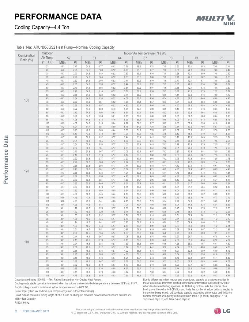
32 | PERFORMANCE DATA
Perf
orm
ance
Dat
a
Due to our policy of continuous product innovation, some specifications may change without notification. © LG Electronics U.S.A., Inc., Englewood Cliffs, NJ. All rights reserved. “LG” is a registered trademark of LG Corp.
PERFORMANCE DATA
Table 14a: ARUN053GS2 Heat Pump—Nominal Cooling Capacity
Combination Ratio (%)
Outdoor Air Temp (°F) DB
Indoor Air Temperature (°F) WB57 61 64 67 70 73 76
MBh PI MBh PI MBh PI MBh PI MBh PI MBh PI MBh PI
130
23 45.3 2.17 54.6 2.77 62.2 3.26 69.2 3.74 71.5 3.62 72.1 3.53 73.8 3.44 25 45.3 2.20 54.6 2.80 62.2 3.29 69.2 3.77 71.5 3.65 72.1 3.56 73.8 3.47 30 45.3 2.23 54.6 2.83 62.2 3.32 69.2 3.80 71.5 3.68 72.1 3.59 73.8 3.50 35 45.3 2.26 54.6 2.86 62.2 3.35 69.2 3.83 71.5 3.71 72.1 3.62 73.8 3.53 40 45.3 2.32 54.6 2.93 62.2 3.41 69.2 3.89 71.5 3.77 72.1 3.71 73.8 3.59 45 45.3 2.35 54.6 2.96 62.2 3.44 69.2 3.92 71.5 3.80 72.1 3.74 73.8 3.62 50 45.3 2.43 54.6 3.04 62.2 3.51 69.2 3.97 71.5 3.88 72.1 3.78 73.8 3.69 55 45.3 2.48 54.6 3.10 62.2 3.58 69.2 3.99 70.3 3.89 71.5 3.79 72.7 3.72 60 45.3 2.58 54.6 3.23 62.2 3.74 66.9 4.11 68.6 4.14 69.2 4.16 70.9 4.19 65 45.3 2.64 54.6 3.34 62.2 4.02 65.7 4.34 67.4 4.37 68.0 4.40 69.8 4.43 70 45.3 2.73 54.6 3.61 62.2 4.35 65.1 4.57 66.3 4.61 67.4 4.63 68.6 4.66 75 45.3 2.99 54.6 3.97 62.2 4.80 63.9 4.86 65.1 4.90 66.3 4.93 67.4 4.96 80 45.3 3.22 54.6 4.28 61.0 5.05 62.8 5.09 63.9 5.14 65.1 5.16 66.3 5.20 85 45.3 3.72 54.6 4.96 59.3 5.51 60.5 5.56 62.2 5.61 62.8 5.64 64.5 5.69 90 45.3 3.99 54.6 5.33 58.1 5.75 59.9 5.80 61.0 5.85 62.2 5.88 63.4 5.93 95 45.3 4.28 54.6 5.73 57.6 5.98 58.1 6.03 59.9 6.09 61.0 6.13 62.8 6.18
100 45.3 4.59 54.6 6.15 56.4 6.22 57.6 6.27 59.3 6.33 59.9 6.36 61.6 6.42 105 44.2 5.01 51.7 6.51 52.9 6.75 54.6 7.24 55.8 7.54 57.6 7.66 58.7 7.78 110 40.7 5.13 48.3 6.63 49.4 7.00 51.2 7.78 52.3 8.02 55.8 8.32 57.0 8.50 115 40.3 5.17 47.8 6.70 48.9 7.06 50.6 7.85 51.8 8.10 55.2 8.40 56.4 8.58
120
23 41.7 1.98 50.8 2.52 57.7 2.94 63.9 3.42 70.2 3.72 70.8 3.69 72.5 3.54 25 41.7 2.01 50.8 2.55 57.7 2.97 63.9 3.45 70.2 3.75 70.8 3.72 72.5 3.57 30 41.7 2.04 50.8 2.58 57.7 3.00 63.9 3.48 70.2 3.78 70.8 3.75 72.5 3.60 35 41.7 2.07 50.8 2.61 57.7 3.03 63.9 3.51 70.2 3.81 70.8 3.78 72.5 3.63 40 41.7 2.13 50.8 2.67 57.7 3.09 63.9 3.57 70.2 3.87 70.8 3.84 72.5 3.69 45 41.7 2.16 50.8 2.70 57.7 3.12 63.9 3.60 70.2 3.90 70.8 3.87 72.5 3.72 50 41.7 2.22 50.8 2.77 57.7 3.20 63.9 3.64 70.2 3.95 70.8 3.88 72.5 3.78 55 41.7 2.26 50.8 2.83 57.7 3.27 63.9 3.72 69.1 3.97 70.2 3.89 71.4 3.79 60 41.7 2.36 50.8 2.95 57.7 3.41 63.9 3.88 67.4 4.12 67.9 4.14 69.1 4.16 65 41.7 2.41 50.8 3.01 57.7 3.57 63.9 4.21 66.2 4.35 67.4 4.37 68.5 4.40 70 41.3 2.56 50.3 3.34 57.1 4.01 63.3 4.72 64.4 4.76 65.6 4.78 66.7 4.81 75 41.7 2.68 50.8 3.53 57.7 4.25 62.8 4.83 63.9 4.87 65.1 4.89 66.2 4.93 80 41.7 2.89 50.8 3.81 57.7 4.58 61.7 5.06 62.8 5.10 63.9 5.13 65.1 5.17 85 41.7 3.32 50.8 4.40 57.7 5.31 59.4 5.53 61.1 5.57 61.7 5.60 63.4 5.64 90 41.7 3.57 50.8 4.73 57.1 5.71 58.8 5.76 59.9 5.81 61.1 5.84 62.2 5.88 95 41.7 3.82 50.8 5.08 56.5 5.94 57.1 5.99 58.8 6.04 59.9 6.08 61.1 6.13
100 41.7 4.09 50.8 5.45 55.4 6.18 56.5 6.23 58.2 6.29 58.8 6.32 59.9 6.36 105 40.0 4.49 47.4 5.99 50.8 6.53 53.7 7.19 54.8 7.49 56.5 7.61 57.7 7.73 110 38.8 4.91 45.1 6.41 46.8 6.95 50.2 7.73 51.4 7.97 54.8 8.27 55.9 8.45 115 38.4 4.96 44.6 6.47 46.3 7.01 49.7 7.80 50.8 8.04 54.3 8.35 55.4 8.53
110
23 38.1 1.79 46.5 2.26 52.7 2.68 58.8 3.04 65.0 3.45 68.9 3.75 71.2 3.63 25 38.1 1.82 46.5 2.29 52.7 2.71 58.8 3.07 65.0 3.48 68.9 3.78 71.2 3.66 30 38.1 1.85 46.5 2.32 52.7 2.74 58.8 3.10 65.0 3.51 68.9 3.81 71.2 3.69 35 38.1 1.88 46.5 2.35 52.7 2.77 58.8 3.13 65.0 3.54 68.9 3.84 71.2 3.72 40 38.1 1.94 46.5 2.41 52.7 2.83 58.8 3.19 65.0 3.60 68.9 3.90 71.2 3.78 45 38.1 1.97 46.5 2.44 52.7 2.86 58.8 3.22 65.0 3.63 68.9 3.93 71.2 3.81 50 38.1 2.01 46.5 2.51 52.7 2.89 58.8 3.29 65.0 3.69 68.9 3.97 71.2 3.88 55 38.1 2.06 46.5 2.56 52.7 2.96 58.8 3.36 65.0 3.78 68.9 3.98 70.1 3.89 60 38.1 2.14 46.5 2.67 52.7 3.08 58.8 3.51 65.0 3.97 66.7 4.11 67.8 4.14 65 38.1 2.19 46.5 2.73 52.7 3.15 58.8 3.70 65.0 4.30 65.6 4.34 67.2 4.37 70 38.1 2.24 46.5 2.84 52.7 3.39 58.8 4.00 63.9 4.55 65.0 4.57 66.1 4.60 75 38.1 2.38 46.5 3.12 52.7 3.74 58.8 4.41 62.8 4.84 63.3 4.86 65.0 4.89 80 38.1 2.56 46.5 3.36 52.7 4.02 58.8 4.75 61.6 5.07 62.8 5.09 63.9 5.13 85 38.1 2.95 46.5 3.88 52.7 4.66 58.8 5.49 60.0 5.54 60.5 5.56 61.6 5.60 90 38.1 3.16 46.5 4.16 52.7 5.01 57.7 5.72 58.8 5.76 59.4 5.80 61.1 5.83 95 38.1 3.39 46.5 4.47 52.7 5.38 56.0 5.95 57.7 6.00 58.8 6.03 60.0 6.08
100 38.1 3.62 46.5 4.79 52.7 5.77 55.5 6.19 56.6 6.23 57.7 6.27 58.8 6.32 105 35.9 3.99 41.5 5.36 48.8 6.31 52.7 7.15 53.8 7.44 55.5 7.56 56.6 7.68 110 34.7 4.41 39.2 5.78 44.8 7.32 49.3 7.68 50.4 7.92 53.8 8.22 54.9 8.40 115 34.4 4.45 38.8 5.83 44.3 7.39 48.8 7.75 49.9 7.99 53.2 8.29 54.3 8.47
4.4 TonCooling Capacity—
Capacity rated using ISO 5151—Test Rating Standard for Non-Ducted Heat Pumps.Cooling mode stable operation is ensured when the outdoor ambient dry-bulb temperature is between 23°F and 115°F.Rapid cooling operation is stable at indoor temperatures up to 80°F DB.Power Input (PI) in kW and includes compressor(s) and outdoor fan motor(s).Rated with an equivalent piping length of 24.6 ft. and no change in elevation between the indoor and outdoor unit.MBh = Net CapacityR410A, 60 Hz
Due to differences in test method and procedures, capacity data values provided in these tables may differ from certified performance information published by AHRI or other standardized testing agencies. AHRI testing protocol sets the volume of air flowing over the coil at 444 CFM/ton and limits the number of indoor units connected to the system being tested. LG conducts capacity tests using airflow rates and limits the number of indoor units per system as stated in Table 4 (a and b) on pages 17–18, Table 5 on page 19, and Table 14 on page 56.

PERFORMANCE DATA | 33
HEAT PUMP CO
NDENSING UNIT ENG
INEERING M
ANU
AL
Due to our policy of continuous product innovation, some specifications may change without notification. © LG Electronics U.S.A., Inc., Englewood Cliffs, NJ. All rights reserved. “LG” is a registered trademark of LG Corp.
Table 14b: ARUN053GS2 Heat Pump—Nominal Cooling Capacity
Combination Ratio (%)
Outdoor Air Temp (°F) DB
Indoor Air Temperature (°F) WB57 61 64 67 70 73 76
MBh PI MBh PI MBh PI MBh PI MBh PI MBh PI MBh PI
100
23 34.9 1.38 42.3 1.82 47.6 2.09 52.9 2.20 59.2 2.87 63.0 3.09 68.2 3.53 25 34.9 1.43 42.3 1.87 47.6 2.15 52.9 2.31 59.2 2.92 63.0 3.14 68.2 3.58 30 34.9 1.49 42.3 1.93 47.6 2.20 52.9 2.42 59.2 2.98 63.0 3.20 68.2 3.64 35 34.9 1.54 42.3 1.98 47.6 2.26 52.9 2.53 59.2 3.03 63.0 3.25 68.2 3.69 40 34.9 1.65 42.3 2.09 47.6 2.37 52.9 2.76 59.2 3.14 63.0 3.36 68.2 3.80 45 34.9 1.71 42.3 2.15 47.6 2.48 52.9 2.87 59.2 3.20 63.0 3.42 68.2 3.86 50 34.9 1.82 42.3 2.25 47.6 2.59 52.9 2.95 59.2 3.31 63.0 3.55 68.2 3.93 55 34.9 1.86 42.3 2.30 47.6 2.65 52.9 3.01 59.2 3.38 63.0 3.63 68.2 4.00 60 34.9 1.93 42.3 2.40 47.6 2.76 52.9 3.14 59.2 3.53 63.0 3.79 66.7 4.11 65 34.9 1.97 42.3 2.45 47.6 2.82 52.9 3.21 59.2 3.72 63.0 4.09 65.6 4.33 70 34.9 2.01 42.3 2.50 47.6 2.96 52.9 3.48 59.2 4.03 63.0 4.42 64.5 4.56 75 34.9 2.11 42.3 2.73 47.6 3.25 52.9 3.83 59.2 4.44 62.4 4.82 63.5 4.86 80 34.9 2.26 42.3 2.94 47.6 3.50 52.9 4.12 59.2 4.79 61.4 5.05 62.4 5.08 85 34.9 2.60 42.3 3.39 47.6 4.05 52.9 4.77 58.7 5.49 59.2 5.52 60.3 5.55 90 34.9 2.78 42.3 3.64 47.6 4.35 52.9 5.13 57.7 5.73 58.2 5.75 59.2 5.79 95 34.9 2.97 42.3 3.90 47.6 4.66 52.9 5.51 56.6 5.95 57.7 5.99 58.7 6.02 100 34.9 3.18 42.3 4.17 47.6 5.01 52.9 5.92 55.5 6.19 56.6 6.22 57.7 6.27 105 34.9 3.58 40.2 4.85 45.5 5.73 50.8 6.61 51.8 6.78 54.5 6.89 55.5 7.11 110 33.9 3.97 38.1 5.23 42.3 6.67 47.6 7.11 48.7 7.22 51.8 7.49 54.0 7.66 115 33.5 4.00 37.7 5.28 41.9 6.73 47.1 7.17 48.2 7.28 51.3 7.56 53.4 7.73
90
23 31.4 1.32 38.1 1.65 42.8 1.98 47.6 2.26 53.3 2.59 56.7 2.83 61.4 3.16 25 31.4 1.37 38.1 1.70 42.8 2.02 47.6 2.31 53.3 2.64 56.7 2.87 61.4 3.20 30 31.4 1.41 38.1 1.74 42.8 2.07 47.6 2.35 53.3 2.68 56.7 2.92 61.4 3.25 35 31.4 1.46 38.1 1.79 42.8 2.12 47.6 2.40 53.3 2.73 56.7 2.97 61.4 3.30 40 31.4 1.55 38.1 1.88 42.8 2.21 47.6 2.50 53.3 2.83 56.7 3.06 61.4 3.39 45 31.4 1.60 38.1 1.93 42.8 2.26 47.6 2.54 53.3 2.87 56.7 3.11 61.4 3.44 50 31.4 1.63 38.1 2.01 42.8 2.30 47.6 2.61 53.3 2.93 56.7 3.15 61.4 3.48 55 31.4 1.67 38.1 2.05 42.8 2.35 47.6 2.66 53.3 2.99 56.7 3.21 61.4 3.55 60 31.4 1.73 38.1 2.13 42.8 2.45 47.6 2.78 53.3 3.12 56.7 3.35 61.4 3.71 65 31.4 1.76 38.1 2.17 42.8 2.50 47.6 2.84 53.3 3.19 56.7 3.49 61.4 3.97 70 31.4 1.80 38.1 2.22 42.8 2.56 47.6 2.99 53.3 3.45 56.7 3.78 61.4 4.30 75 31.4 1.85 38.1 2.37 42.8 2.81 47.6 3.28 53.3 3.79 56.7 4.16 61.4 4.73 80 31.4 1.98 38.1 2.55 42.8 3.02 47.6 3.53 53.3 4.09 56.7 4.48 60.9 5.05 85 31.4 2.27 38.1 2.93 42.8 3.48 47.6 4.09 53.3 4.73 56.7 5.20 59.0 5.51 90 31.4 2.43 38.1 3.14 42.8 3.74 47.6 4.39 53.3 5.09 56.7 5.59 58.1 5.75 95 31.4 2.59 38.1 3.36 42.8 4.00 47.6 4.71 53.3 5.47 56.2 5.94 57.1 5.97 100 31.4 2.77 38.1 3.60 42.8 4.29 47.6 5.05 53.3 5.77 55.2 6.17 56.2 6.21 105 31.4 3.01 38.1 3.91 42.4 4.66 47.1 5.46 52.4 6.30 53.3 6.42 54.3 6.42 110 31.4 3.06 38.1 3.96 41.9 4.71 46.7 5.51 50.0 6.36 52.4 6.45 53.3 6.45 115 31.4 3.08 38.1 3.99 41.9 4.75 46.7 5.56 50.0 6.41 52.4 6.51 53.3 6.51
80
23 27.9 1.15 33.9 1.47 38.1 1.75 42.3 2.03 47.4 2.26 50.4 2.46 54.6 2.74 25 27.9 1.19 33.9 1.51 38.1 1.79 42.3 2.07 47.4 2.30 50.4 2.50 54.6 2.78 30 27.9 1.23 33.9 1.55 38.1 1.83 42.3 2.11 47.4 2.34 50.4 2.54 54.6 2.82 35 27.9 1.27 33.9 1.59 38.1 1.87 42.3 2.14 47.4 2.38 50.4 2.58 54.6 2.86 40 27.9 1.35 33.9 1.67 38.1 1.95 42.3 2.22 47.4 2.46 50.4 2.66 54.6 2.94 45 27.9 1.39 33.9 1.71 38.1 1.99 42.3 2.26 47.4 2.50 50.4 2.70 54.6 2.98 50 27.9 1.45 33.9 1.77 38.1 2.02 42.3 2.29 47.4 2.56 50.4 2.75 54.6 3.03 55 27.9 1.47 33.9 1.80 38.1 2.07 42.3 2.33 47.4 2.61 50.4 2.80 54.6 3.10 60 27.9 1.53 33.9 1.87 38.1 2.15 42.3 2.43 47.4 2.73 50.4 2.92 54.6 3.23 65 27.9 1.56 33.9 1.91 38.1 2.19 42.3 2.48 47.4 2.78 50.4 2.99 54.6 3.33 70 27.9 1.60 33.9 1.95 38.1 2.24 42.3 2.54 47.4 2.91 50.4 3.18 54.6 3.60 75 27.9 1.63 33.9 2.03 38.1 2.40 42.3 2.78 47.4 3.20 50.4 3.50 54.6 3.97 80 27.9 1.72 33.9 2.19 38.1 2.57 42.3 2.99 47.4 3.44 50.4 3.77 54.6 4.27 85 27.9 1.96 33.9 2.51 38.1 2.96 42.3 3.45 47.4 3.98 50.4 4.36 54.6 4.95 90 27.9 2.10 33.9 2.68 38.1 3.17 42.3 3.71 47.4 4.28 50.4 4.68 54.6 5.33 95 27.9 2.24 33.9 2.87 38.1 3.40 42.3 3.97 47.4 4.59 50.4 5.03 54.6 5.72 100 27.9 2.39 33.9 3.07 38.1 3.64 42.3 4.25 47.4 4.92 50.4 5.39 54.6 6.14 105 27.9 2.58 33.9 3.34 38.1 3.93 42.3 4.61 47.4 5.32 50.4 5.84 53.7 6.47 110 27.9 2.62 33.9 3.38 38.1 3.97 42.3 4.65 47.4 5.36 50.4 5.88 53.7 6.51 115 27.9 2.64 33.9 3.41 38.1 4.01 42.3 4.69 47.4 5.41 50.4 5.93 53.7 6.57
PERFORMANCE DATACooling Capacity—4.4 Ton
Capacity rated using ISO 5151—Test Rating Standard for Non-Ducted Heat Pumps.Cooling mode stable operation is ensured when the outdoor ambient dry-bulb temperature is between 23°F and 115°F.Rapid cooling operation is stable at indoor temperatures up to 80°F DB.Power Input (PI) in kW and includes compressor(s) and outdoor fan motor(s).Rated with an equivalent piping length of 24.6 ft. and no change in elevation between the indoor and outdoor unit.MBh = Net CapacityR410A, 60 Hz
Due to differences in test method and procedures, capacity data values provided in these tables may differ from certified performance information published by AHRI or other standardized testing agencies. AHRI testing protocol sets the volume of air flowing over the coil at 444 CFM/ton and limits the number of indoor units connected to the system being tested. LG conducts capacity tests using airflow rates and limits the number of indoor units per system as stated in Table 4 (a and b) on pages 17–18, Table 5 on page 19, and Table 14 on page 56.
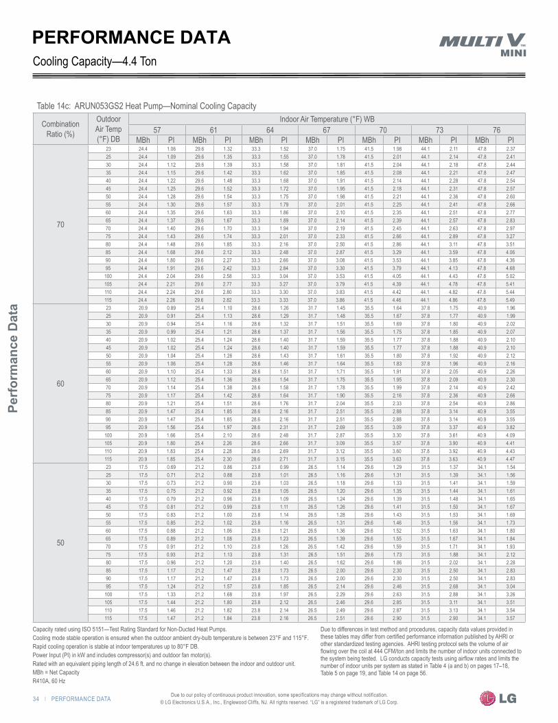
34 | PERFORMANCE DATA
Perf
orm
ance
Dat
a
Due to our policy of continuous product innovation, some specifications may change without notification. © LG Electronics U.S.A., Inc., Englewood Cliffs, NJ. All rights reserved. “LG” is a registered trademark of LG Corp.
PERFORMANCE DATA
Table 14c: ARUN053GS2 Heat Pump—Nominal Cooling Capacity
Combination Ratio (%)
Outdoor Air Temp (°F) DB
Indoor Air Temperature (°F) WB57 61 64 67 70 73 76
MBh PI MBh PI MBh PI MBh PI MBh PI MBh PI MBh PI
70
23 24.4 1.06 29.6 1.32 33.3 1.52 37.0 1.75 41.5 1.98 44.1 2.11 47.8 2.37 25 24.4 1.09 29.6 1.35 33.3 1.55 37.0 1.78 41.5 2.01 44.1 2.14 47.8 2.41 30 24.4 1.12 29.6 1.39 33.3 1.58 37.0 1.81 41.5 2.04 44.1 2.18 47.8 2.44 35 24.4 1.15 29.6 1.42 33.3 1.62 37.0 1.85 41.5 2.08 44.1 2.21 47.8 2.47 40 24.4 1.22 29.6 1.48 33.3 1.68 37.0 1.91 41.5 2.14 44.1 2.28 47.8 2.54 45 24.4 1.25 29.6 1.52 33.3 1.72 37.0 1.95 41.5 2.18 44.1 2.31 47.8 2.57 50 24.4 1.28 29.6 1.54 33.3 1.75 37.0 1.98 41.5 2.21 44.1 2.36 47.8 2.60 55 24.4 1.30 29.6 1.57 33.3 1.79 37.0 2.01 41.5 2.25 44.1 2.41 47.8 2.66 60 24.4 1.35 29.6 1.63 33.3 1.86 37.0 2.10 41.5 2.35 44.1 2.51 47.8 2.77 65 24.4 1.37 29.6 1.67 33.3 1.89 37.0 2.14 41.5 2.39 44.1 2.57 47.8 2.83 70 24.4 1.40 29.6 1.70 33.3 1.94 37.0 2.19 41.5 2.45 44.1 2.63 47.8 2.97 75 24.4 1.43 29.6 1.74 33.3 2.01 37.0 2.33 41.5 2.66 44.1 2.89 47.8 3.27 80 24.4 1.48 29.6 1.85 33.3 2.16 37.0 2.50 41.5 2.86 44.1 3.11 47.8 3.51 85 24.4 1.68 29.6 2.12 33.3 2.48 37.0 2.87 41.5 3.29 44.1 3.59 47.8 4.06 90 24.4 1.80 29.6 2.27 33.3 2.66 37.0 3.08 41.5 3.53 44.1 3.85 47.8 4.36 95 24.4 1.91 29.6 2.42 33.3 2.84 37.0 3.30 41.5 3.79 44.1 4.13 47.8 4.68
100 24.4 2.04 29.6 2.58 33.3 3.04 37.0 3.53 41.5 4.05 44.1 4.43 47.8 5.02 105 24.4 2.21 29.6 2.77 33.3 3.27 37.0 3.79 41.5 4.39 44.1 4.78 47.8 5.41 110 24.4 2.24 29.6 2.80 33.3 3.30 37.0 3.83 41.5 4.42 44.1 4.82 47.8 5.44 115 24.4 2.26 29.6 2.82 33.3 3.33 37.0 3.86 41.5 4.46 44.1 4.86 47.8 5.49
60
23 20.9 0.89 25.4 1.10 28.6 1.26 31.7 1.45 35.5 1.64 37.8 1.75 40.9 1.96 25 20.9 0.91 25.4 1.13 28.6 1.29 31.7 1.48 35.5 1.67 37.8 1.77 40.9 1.99 30 20.9 0.94 25.4 1.16 28.6 1.32 31.7 1.51 35.5 1.69 37.8 1.80 40.9 2.02 35 20.9 0.99 25.4 1.21 28.6 1.37 31.7 1.56 35.5 1.75 37.8 1.85 40.9 2.07 40 20.9 1.02 25.4 1.24 28.6 1.40 31.7 1.59 35.5 1.77 37.8 1.88 40.9 2.10 45 20.9 1.02 25.4 1.24 28.6 1.40 31.7 1.59 35.5 1.77 37.8 1.88 40.9 2.10 50 20.9 1.04 25.4 1.26 28.6 1.43 31.7 1.61 35.5 1.80 37.8 1.92 40.9 2.12 55 20.9 1.06 25.4 1.28 28.6 1.46 31.7 1.64 35.5 1.83 37.8 1.96 40.9 2.16 60 20.9 1.10 25.4 1.33 28.6 1.51 31.7 1.71 35.5 1.91 37.8 2.05 40.9 2.26 65 20.9 1.12 25.4 1.36 28.6 1.54 31.7 1.75 35.5 1.95 37.8 2.09 40.9 2.30 70 20.9 1.14 25.4 1.38 28.6 1.58 31.7 1.78 35.5 1.99 37.8 2.14 40.9 2.42 75 20.9 1.17 25.4 1.42 28.6 1.64 31.7 1.90 35.5 2.16 37.8 2.36 40.9 2.66 80 20.9 1.21 25.4 1.51 28.6 1.76 31.7 2.04 35.5 2.33 37.8 2.54 40.9 2.86 85 20.9 1.47 25.4 1.85 28.6 2.16 31.7 2.51 35.5 2.88 37.8 3.14 40.9 3.55 90 20.9 1.47 25.4 1.85 28.6 2.16 31.7 2.51 35.5 2.88 37.8 3.14 40.9 3.55 95 20.9 1.56 25.4 1.97 28.6 2.31 31.7 2.69 35.5 3.09 37.8 3.37 40.9 3.82
100 20.9 1.66 25.4 2.10 28.6 2.48 31.7 2.87 35.5 3.30 37.8 3.61 40.9 4.09 105 20.9 1.80 25.4 2.26 28.6 2.66 31.7 3.09 35.5 3.57 37.8 3.90 40.9 4.41 110 20.9 1.83 25.4 2.28 28.6 2.69 31.7 3.12 35.5 3.60 37.8 3.92 40.9 4.43 115 20.9 1.85 25.4 2.30 28.6 2.71 31.7 3.15 35.5 3.63 37.8 3.63 40.9 4.47
50
23 17.5 0.69 21.2 0.86 23.8 0.99 26.5 1.14 29.6 1.29 31.5 1.37 34.1 1.54 25 17.5 0.71 21.2 0.88 23.8 1.01 26.5 1.16 29.6 1.31 31.5 1.39 34.1 1.56 30 17.5 0.73 21.2 0.90 23.8 1.03 26.5 1.18 29.6 1.33 31.5 1.41 34.1 1.59 35 17.5 0.75 21.2 0.92 23.8 1.05 26.5 1.20 29.6 1.35 31.5 1.44 34.1 1.61 40 17.5 0.79 21.2 0.96 23.8 1.09 26.5 1.24 29.6 1.39 31.5 1.48 34.1 1.65 45 17.5 0.81 21.2 0.99 23.8 1.11 26.5 1.26 29.6 1.41 31.5 1.50 34.1 1.67 50 17.5 0.83 21.2 1.00 23.8 1.14 26.5 1.28 29.6 1.43 31.5 1.53 34.1 1.69 55 17.5 0.85 21.2 1.02 23.8 1.16 26.5 1.31 29.6 1.46 31.5 1.56 34.1 1.73 60 17.5 0.88 21.2 1.06 23.8 1.21 26.5 1.36 29.6 1.52 31.5 1.63 34.1 1.80 65 17.5 0.89 21.2 1.08 23.8 1.23 26.5 1.39 29.6 1.55 31.5 1.67 34.1 1.84 70 17.5 0.91 21.2 1.10 23.8 1.26 26.5 1.42 29.6 1.59 31.5 1.71 34.1 1.93 75 17.5 0.93 21.2 1.13 23.8 1.31 26.5 1.51 29.6 1.73 31.5 1.88 34.1 2.12 80 17.5 0.96 21.2 1.20 23.8 1.40 26.5 1.62 29.6 1.86 31.5 2.02 34.1 2.28 85 17.5 1.17 21.2 1.47 23.8 1.73 26.5 2.00 29.6 2.30 31.5 2.50 34.1 2.83 90 17.5 1.17 21.2 1.47 23.8 1.73 26.5 2.00 29.6 2.30 31.5 2.50 34.1 2.83 95 17.5 1.24 21.2 1.57 23.8 1.85 26.5 2.14 29.6 2.46 31.5 2.68 34.1 3.04
100 17.5 1.33 21.2 1.68 23.8 1.97 26.5 2.29 29.6 2.63 31.5 2.88 34.1 3.26 105 17.5 1.44 21.2 1.80 23.8 2.12 26.5 2.46 29.6 2.85 31.5 3.11 34.1 3.51 110 17.5 1.46 21.2 1.82 23.8 2.14 26.5 2.49 29.6 2.87 31.5 3.13 34.1 3.54 115 17.5 1.47 21.2 1.84 23.8 2.16 26.5 2.51 29.6 2.90 31.5 2.90 34.1 3.57
Cooling Capacity—4.4 Ton
Capacity rated using ISO 5151—Test Rating Standard for Non-Ducted Heat Pumps.Cooling mode stable operation is ensured when the outdoor ambient dry-bulb temperature is between 23°F and 115°F.Rapid cooling operation is stable at indoor temperatures up to 80°F DB.Power Input (PI) in kW and includes compressor(s) and outdoor fan motor(s).Rated with an equivalent piping length of 24.6 ft. and no change in elevation between the indoor and outdoor unit.MBh = Net CapacityR410A, 60 Hz
Due to differences in test method and procedures, capacity data values provided in these tables may differ from certified performance information published by AHRI or other standardized testing agencies. AHRI testing protocol sets the volume of air flowing over the coil at 444 CFM/ton and limits the number of indoor units connected to the system being tested. LG conducts capacity tests using airflow rates and limits the number of indoor units per system as stated in Table 4 (a and b) on pages 17–18, Table 5 on page 19, and Table 14 on page 56.

PERFORMANCE DATA | 35
HEAT PUMP CO
NDENSING UNIT ENG
INEERING M
ANU
AL
Due to our policy of continuous product innovation, some specifications may change without notification. © LG Electronics U.S.A., Inc., Englewood Cliffs, NJ. All rights reserved. “LG” is a registered trademark of LG Corp.
Table 15a: ARUN036GS2 Heat Pump—Nominal Heating Capacity
Combination Ratio (%)
Outdoor Air Temp (°F)
Indoor Air Temperature (°F) DB
59 61 64 67 70 73 76 80
DB WB MBh PI MBh PI MBh PI MBh PI MBh PI MBh PI MBh PI MBh PI
130
-4 -4.4 31.0 3.79 31.0 3.81 31.0 3.84 31.0 3.88 31.0 3.88 31.0 3.88 31.0 3.91 31.0 3.95
0 -0.4 32.6 3.85 32.1 3.85 31.5 3.85 31.5 3.88 31.5 3.88 31.5 3.91 31.5 3.91 31.5 3.91
5.0 4.5 35.2 3.85 35.2 3.88 35.2 3.91 35.2 3.91 35.2 3.95 35.2 3.95 35.2 3.98 35.2 4.01
10.0 9.0 36.8 3.91 36.8 3.91 36.8 3.91 36.8 3.95 36.8 3.95 36.8 3.98 36.8 3.98 36.8 3.98
15.0 14.0 39.9 3.95 39.9 3.95 39.9 3.95 39.3 3.98 39.3 3.98 39.3 4.01 39.3 4.01 39.3 4.01
20.0 19.0 41.5 3.98 41.5 3.98 41.5 3.98 41.5 4.01 41.5 4.01 41.5 4.01 41.5 4.05 41.5 4.08
25.0 23.0 44.7 4.00 44.7 4.00 44.7 4.00 44.7 4.04 44.7 4.04 44.7 4.08 44.7 4.08 44.7 4.08
30.0 28.0 45.6 4.04 45.6 4.04 45.6 4.04 45.6 4.08 45.6 4.08 45.6 4.12 45.6 4.12 45.6 4.12
35.0 32.0 47.8 4.08 47.8 4.08 47.8 4.08 47.8 4.12 47.8 4.12 47.8 4.16 47.8 4.08 47.8 4.00
40.0 36.0 49.9 4.04 49.9 4.08 49.9 4.12 49.9 4.16 49.9 4.16 49.9 4.08 49.9 3.96 49.9 3.84
45.0 41.0 52.5 4.08 51.9 4.12 51.4 4.16 51.4 4.06 51.4 4.04 51.4 3.96 51.4 3.79 51.4 3.64
47.0 43.0 54.1 4.24 53.5 4.20 53.0 4.16 53.0 4.12 52.5 4.08 53.0 3.79 52.5 3.67 51.9 3.55
50.0 46.0 55.1 4.21 55.1 4.08 55.1 3.96 55.1 3.79 55.1 3.75 55.1 3.67 52.5 3.51 50.0 3.35
55.0 51.0 56.7 4.13 56.7 3.96 56.7 3.79 56.7 3.67 56.7 3.63 55.7 3.51 52.5 3.39 49.6 3.27
60.0 56.0 60.4 3.92 59.8 3.79 59.3 3.67 59.3 3.51 57.7 3.47 55.7 3.39 52.5 3.26 49.6 3.15
120
-4 -4.4 30.2 3.76 30.2 3.78 30.2 3.80 30.2 3.84 30.2 3.84 30.2 3.85 30.2 3.88 30.2 3.91
0 -0.4 31.8 3.82 30.7 3.82 29.7 3.82 29.7 3.85 29.7 3.85 29.7 3.88 29.7 3.88 29.7 3.88
5.0 4.5 34.7 3.82 33.7 3.85 33.2 3.88 33.2 3.88 33.2 3.91 33.2 3.91 32.8 3.95 32.3 3.98
10.0 9.0 36.7 3.88 35.7 3.88 34.7 3.88 34.7 3.91 34.7 3.91 34.7 3.95 34.7 3.95 34.7 3.95
15.0 14.0 37.2 3.88 37.2 3.92 37.2 3.92 37.2 3.92 37.2 3.97 37.2 3.97 37.2 3.97 37.2 3.97
20.0 19.0 39.1 3.88 39.1 3.91 39.1 3.95 39.1 3.95 39.1 3.98 39.1 3.98 39.1 4.01 39.1 4.05
25.0 23.0 42.1 3.97 42.1 3.97 42.1 3.97 42.1 4.01 42.1 4.01 42.1 4.05 42.1 4.05 42.1 4.05
30.0 28.0 43.1 4.01 43.1 4.01 43.1 4.01 43.1 4.05 43.1 4.05 43.1 4.09 43.1 4.09 43.1 4.09
35.0 32.0 45.1 4.05 45.1 4.05 45.1 4.05 45.1 4.09 45.1 4.09 45.1 4.13 45.1 4.05 45.1 3.97
40.0 36.0 47.1 4.01 47.1 4.05 47.1 4.09 47.1 4.13 47.1 4.13 47.1 4.05 47.1 3.92 47.1 3.81
45.0 41.0 49.6 4.05 49.1 4.09 48.6 4.13 48.6 4.17 48.6 4.09 48.6 3.92 48.6 3.76 48.6 3.61
47.0 43.0 51.0 4.21 50.6 4.13 50.1 4.05 50.1 3.92 49.6 4.05 50.1 3.76 49.6 3.64 49.1 3.52
50.0 46.0 52.0 4.17 52.0 4.05 52.0 3.92 52.0 3.76 52.0 3.72 52.0 3.64 49.6 3.48 47.2 3.32
55.0 51.0 53.5 4.09 53.5 3.92 53.5 3.76 53.5 3.64 53.5 3.60 52.5 3.48 49.6 3.36 46.7 3.24
60.0 56.0 57.0 3.89 56.5 3.76 56.0 3.64 56.0 3.48 54.5 3.44 52.5 3.36 49.6 3.24 46.7 3.12
110
-4 -4.4 29.1 3.54 28.6 3.56 28.2 3.58 28.2 3.62 28.2 3.62 28.2 3.62 28.2 3.65 28.2 3.68
0 -0.4 29.1 3.59 29.1 3.59 29.1 3.59 29.1 3.62 29.1 3.62 29.1 3.65 28.6 3.65 28.2 3.65
5.0 4.5 32.4 3.59 32.4 3.62 32.4 3.65 32.4 3.65 32.4 3.68 32.4 3.68 32.4 3.72 32.4 3.75
10.0 9.0 34.2 3.65 34.2 3.65 34.2 3.65 34.2 3.68 34.2 3.68 34.2 3.72 33.7 3.72 33.2 3.72
15.0 14.0 36.5 3.68 36.5 3.68 36.5 3.68 36.5 3.72 36.5 3.69 36.5 3.75 36.5 3.75 36.5 3.75
20.0 19.0 38.4 3.72 38.4 3.72 38.4 3.72 38.4 3.75 38.4 3.66 38.4 3.75 38.4 3.78 38.4 3.81
25.0 23.0 40.2 3.73 40.2 3.73 40.2 3.73 40.2 3.73 40.2 3.77 40.2 3.81 40.2 3.81 40.2 3.81
30.0 28.0 41.1 3.77 41.1 3.77 41.1 3.77 41.1 3.81 41.1 3.81 41.1 3.85 41.1 3.85 41.1 3.85
35.0 32.0 42.0 3.81 42.0 3.81 42.0 3.81 42.0 3.85 42.0 3.85 42.0 3.88 41.6 3.81 41.1 3.73
40.0 36.0 43.9 3.77 43.9 3.81 43.9 3.85 43.9 3.88 43.5 3.88 43.5 3.81 42.5 3.69 41.6 3.58
45.0 41.0 46.2 3.81 45.7 3.85 45.2 3.88 45.2 3.85 45.2 3.85 44.9 3.69 42.5 3.54 40.3 3.40
47.0 43.0 46.6 3.96 46.6 3.88 46.6 3.81 46.6 3.69 46.2 3.81 44.9 3.54 42.5 3.43 40.3 3.32
50.0 46.0 48.5 3.93 48.5 3.81 48.5 3.69 48.5 3.54 46.6 3.50 44.9 3.43 42.5 3.27 40.3 3.13
55.0 51.0 49.9 3.85 49.9 3.69 49.9 3.54 48.5 3.43 46.6 3.39 44.9 3.27 42.5 3.16 40.3 3.05
60.0 56.0 54.6 3.66 52.6 3.54 50.9 3.43 48.5 3.27 47.6 3.24 44.9 3.17 42.5 3.05 40.3 2.93
PERFORMANCE DATAHeating Capacity—3.0 Ton
Capacity rated using ISO 5151—Test Rating Standard for Non-Ducted Heat Pumps.Heating mode stable operation is ensured when the outdoor ambient wet-bulb temperature is between -4°F and 60°F.Power Input (PI) in kW and includes compressor(s) and outdoor fan motor(s).Rated with an equivalent piping length of 24.6 ft. and no change in elevation between the indoor and outdoor unit.MBh = Net CapacityR410A, 60 Hz
Due to differences in test method and procedures, capacity data values provided in these tables may differ from certified performance information published by AHRI or other standardized testing agencies. AHRI testing protocol sets the volume of air flowing over the coil at 444 CFM/ton and limits the number of indoor units connected to the system being tested. LG conducts capacity tests using airflow rates and limits the number of indoor units per system as stated in Table 4 (a and b) on pages 17–18, Table 5 on page 19, and Table 14 on page 56.
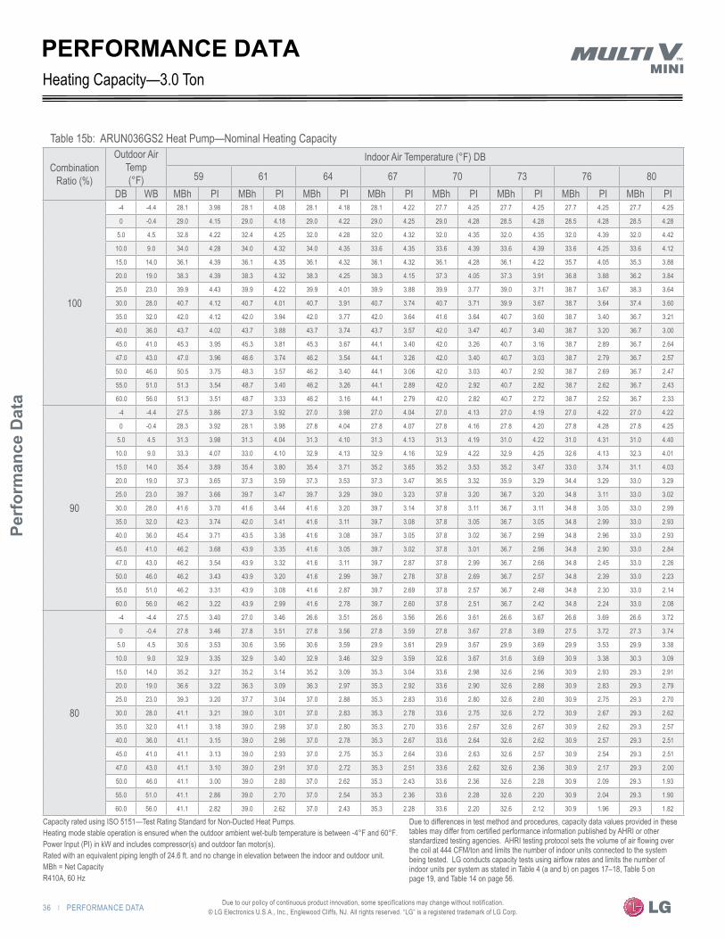
36 | PERFORMANCE DATA
Perf
orm
ance
Dat
a
Due to our policy of continuous product innovation, some specifications may change without notification. © LG Electronics U.S.A., Inc., Englewood Cliffs, NJ. All rights reserved. “LG” is a registered trademark of LG Corp.
PERFORMANCE DATA
Table 15b: ARUN036GS2 Heat Pump—Nominal Heating Capacity
Combination Ratio (%)
Outdoor Air Temp (°F)
Indoor Air Temperature (°F) DB
59 61 64 67 70 73 76 80DB WB MBh PI MBh PI MBh PI MBh PI MBh PI MBh PI MBh PI MBh PI
100
-4 -4.4 28.1 3.98 28.1 4.08 28.1 4.18 28.1 4.22 27.7 4.25 27.7 4.25 27.7 4.25 27.7 4.25
0 -0.4 29.0 4.15 29.0 4.18 29.0 4.22 29.0 4.25 29.0 4.28 28.5 4.28 28.5 4.28 28.5 4.28
5.0 4.5 32.8 4.22 32.4 4.25 32.0 4.28 32.0 4.32 32.0 4.35 32.0 4.35 32.0 4.39 32.0 4.42
10.0 9.0 34.0 4.28 34.0 4.32 34.0 4.35 33.6 4.35 33.6 4.39 33.6 4.39 33.6 4.25 33.6 4.12
15.0 14.0 36.1 4.39 36.1 4.35 36.1 4.32 36.1 4.32 36.1 4.28 36.1 4.22 35.7 4.05 35.3 3.88
20.0 19.0 38.3 4.39 38.3 4.32 38.3 4.25 38.3 4.15 37.3 4.05 37.3 3.91 36.8 3.88 36.2 3.84
25.0 23.0 39.9 4.43 39.9 4.22 39.9 4.01 39.9 3.88 39.9 3.77 39.0 3.71 38.7 3.67 38.3 3.64
30.0 28.0 40.7 4.12 40.7 4.01 40.7 3.91 40.7 3.74 40.7 3.71 39.9 3.67 38.7 3.64 37.4 3.60
35.0 32.0 42.0 4.12 42.0 3.94 42.0 3.77 42.0 3.64 41.6 3.64 40.7 3.60 38.7 3.40 36.7 3.21
40.0 36.0 43.7 4.02 43.7 3.88 43.7 3.74 43.7 3.57 42.0 3.47 40.7 3.40 38.7 3.20 36.7 3.00
45.0 41.0 45.3 3.95 45.3 3.81 45.3 3.67 44.1 3.40 42.0 3.26 40.7 3.16 38.7 2.89 36.7 2.64
47.0 43.0 47.0 3.96 46.6 3.74 46.2 3.54 44.1 3.26 42.0 3.40 40.7 3.03 38.7 2.79 36.7 2.57
50.0 46.0 50.5 3.75 48.3 3.57 46.2 3.40 44.1 3.06 42.0 3.03 40.7 2.92 38.7 2.69 36.7 2.47
55.0 51.0 51.3 3.54 48.7 3.40 46.2 3.26 44.1 2.89 42.0 2.92 40.7 2.82 38.7 2.62 36.7 2.43
60.0 56.0 51.3 3.51 48.7 3.33 46.2 3.16 44.1 2.79 42.0 2.82 40.7 2.72 38.7 2.52 36.7 2.33
90
-4 -4.4 27.5 3.86 27.3 3.92 27.0 3.98 27.0 4.04 27.0 4.13 27.0 4.19 27.0 4.22 27.0 4.22
0 -0.4 28.3 3.92 28.1 3.98 27.8 4.04 27.8 4.07 27.8 4.16 27.8 4.20 27.8 4.28 27.8 4.25
5.0 4.5 31.3 3.98 31.3 4.04 31.3 4.10 31.3 4.13 31.3 4.19 31.0 4.22 31.0 4.31 31.0 4.40
10.0 9.0 33.3 4.07 33.0 4.10 32.9 4.13 32.9 4.16 32.9 4.22 32.9 4.25 32.6 4.13 32.3 4.01
15.0 14.0 35.4 3.89 35.4 3.80 35.4 3.71 35.2 3.65 35.2 3.53 35.2 3.47 33.0 3.74 31.1 4.03
20.0 19.0 37.3 3.65 37.3 3.59 37.3 3.53 37.3 3.47 36.5 3.32 35.9 3.29 34.4 3.29 33.0 3.29
25.0 23.0 39.7 3.66 39.7 3.47 39.7 3.29 39.0 3.23 37.8 3.20 36.7 3.20 34.8 3.11 33.0 3.02
30.0 28.0 41.6 3.70 41.6 3.44 41.6 3.20 39.7 3.14 37.8 3.11 36.7 3.11 34.8 3.05 33.0 2.99
35.0 32.0 42.3 3.74 42.0 3.41 41.6 3.11 39.7 3.08 37.8 3.05 36.7 3.05 34.8 2.99 33.0 2.93
40.0 36.0 45.4 3.71 43.5 3.38 41.6 3.08 39.7 3.05 37.8 3.02 36.7 2.99 34.8 2.96 33.0 2.93
45.0 41.0 46.2 3.68 43.9 3.35 41.6 3.05 39.7 3.02 37.8 3.01 36.7 2.96 34.8 2.90 33.0 2.84
47.0 43.0 46.2 3.54 43.9 3.32 41.6 3.11 39.7 2.87 37.8 2.99 36.7 2.66 34.8 2.45 33.0 2.26
50.0 46.0 46.2 3.43 43.9 3.20 41.6 2.99 39.7 2.78 37.8 2.69 36.7 2.57 34.8 2.39 33.0 2.23
55.0 51.0 46.2 3.31 43.9 3.08 41.6 2.87 39.7 2.69 37.8 2.57 36.7 2.48 34.8 2.30 33.0 2.14
60.0 56.0 46.2 3.22 43.9 2.99 41.6 2.78 39.7 2.60 37.8 2.51 36.7 2.42 34.8 2.24 33.0 2.08
80
-4 -4.4 27.5 3.40 27.0 3.46 26.6 3.51 26.6 3.56 26.6 3.61 26.6 3.67 26.6 3.69 26.6 3.72
0 -0.4 27.8 3.46 27.8 3.51 27.8 3.56 27.8 3.59 27.8 3.67 27.8 3.69 27.5 3.72 27.3 3.74
5.0 4.5 30.6 3.53 30.6 3.56 30.6 3.59 29.9 3.61 29.9 3.67 29.9 3.69 29.9 3.53 29.9 3.38
10.0 9.0 32.9 3.35 32.9 3.40 32.9 3.46 32.9 3.59 32.6 3.67 31.6 3.69 30.9 3.38 30.3 3.09
15.0 14.0 35.2 3.27 35.2 3.14 35.2 3.09 35.3 3.04 33.6 2.98 32.6 2.96 30.9 2.93 29.3 2.91
20.0 19.0 36.6 3.22 36.3 3.09 36.3 2.97 35.3 2.92 33.6 2.90 32.6 2.88 30.9 2.83 29.3 2.79
25.0 23.0 39.3 3.20 37.7 3.04 37.0 2.88 35.3 2.83 33.6 2.80 32.6 2.80 30.9 2.75 29.3 2.70
30.0 28.0 41.1 3.21 39.0 3.01 37.0 2.83 35.3 2.78 33.6 2.75 32.6 2.72 30.9 2.67 29.3 2.62
35.0 32.0 41.1 3.18 39.0 2.98 37.0 2.80 35.3 2.70 33.6 2.67 32.6 2.67 30.9 2.62 29.3 2.57
40.0 36.0 41.1 3.15 39.0 2.96 37.0 2.78 35.3 2.67 33.6 2.64 32.6 2.62 30.9 2.57 29.3 2.51
45.0 41.0 41.1 3.13 39.0 2.93 37.0 2.75 35.3 2.64 33.6 2.63 32.6 2.57 30.9 2.54 29.3 2.51
47.0 43.0 41.1 3.10 39.0 2.91 37.0 2.72 35.3 2.51 33.6 2.62 32.6 2.36 30.9 2.17 29.3 2.00
50.0 46.0 41.1 3.00 39.0 2.80 37.0 2.62 35.3 2.43 33.6 2.36 32.6 2.28 30.9 2.09 29.3 1.93
55.0 51.0 41.1 2.86 39.0 2.70 37.0 2.54 35.3 2.36 33.6 2.28 32.6 2.20 30.9 2.04 29.3 1.90
60.0 56.0 41.1 2.82 39.0 2.62 37.0 2.43 35.3 2.28 33.6 2.20 32.6 2.12 30.9 1.96 29.3 1.82
Heating Capacity—3.0 Ton
Capacity rated using ISO 5151—Test Rating Standard for Non-Ducted Heat Pumps.Heating mode stable operation is ensured when the outdoor ambient wet-bulb temperature is between -4°F and 60°F.Power Input (PI) in kW and includes compressor(s) and outdoor fan motor(s).Rated with an equivalent piping length of 24.6 ft. and no change in elevation between the indoor and outdoor unit.MBh = Net CapacityR410A, 60 Hz
Due to differences in test method and procedures, capacity data values provided in these tables may differ from certified performance information published by AHRI or other standardized testing agencies. AHRI testing protocol sets the volume of air flowing over the coil at 444 CFM/ton and limits the number of indoor units connected to the system being tested. LG conducts capacity tests using airflow rates and limits the number of indoor units per system as stated in Table 4 (a and b) on pages 17–18, Table 5 on page 19, and Table 14 on page 56.

PERFORMANCE DATA | 37
HEAT PUMP CO
NDENSING UNIT ENG
INEERING M
ANU
AL
Due to our policy of continuous product innovation, some specifications may change without notification. © LG Electronics U.S.A., Inc., Englewood Cliffs, NJ. All rights reserved. “LG” is a registered trademark of LG Corp.
Table 15c: ARUN036GS2 Heat Pump—Nominal Heating Capacity
Combination Ratio (%)
Outdoor Air Temp (°F)
Indoor Air Temperature (°F) DB
59 61 64 67 70 73 76 80DB WB MBh PI MBh PI MBh PI MBh PI MBh PI MBh PI MBh PI MBh PI
70
-4 -4.4 26.2 3.39 26.2 3.39 25.9 3.42 25.9 3.46 25.9 3.42 25.9 3.39 25.0 3.45 23.2 3.36
0 -0.4 27.0 3.44 27.0 3.42 27.0 3.46 26.8 3.49 26.8 3.49 26.8 3.42 25.3 3.50 23.5 3.38
5.0 4.5 30.3 3.44 30.3 3.37 30.0 3.51 29.1 3.46 28.8 3.46 27.6 3.42 26.5 3.23 25.4 3.06
10.0 9.0 32.4 3.33 32.9 3.12 31.5 3.12 30.9 3.37 29.4 3.37 28.5 3.31 27.0 3.04 25.7 2.79
15.0 14.0 34.7 3.23 33.8 3.08 32.4 3.08 30.9 3.17 29.4 3.15 28.5 3.03 27.0 2.79 25.7 2.57
20.0 19.0 36.0 3.19 34.1 3.05 32.4 3.05 30.9 3.07 29.4 2.96 28.5 2.84 27.0 2.62 25.7 2.42
25.0 23.0 36.0 3.17 34.1 3.03 32.4 2.96 30.9 2.78 29.4 2.69 28.5 2.60 27.0 2.39 25.7 2.20
30.0 28.0 36.0 3.14 34.1 2.98 32.4 2.80 30.9 2.60 29.4 2.51 28.5 2.41 27.0 2.23 25.7 2.06
35.0 32.0 35.9 2.96 34.1 2.80 32.4 2.64 30.9 2.46 29.4 2.44 28.5 2.28 27.0 2.12 25.7 1.97
40.0 36.0 36.0 2.91 34.1 2.71 32.4 2.53 30.9 2.37 29.4 2.35 28.5 2.19 27.0 2.03 25.7 1.88
45.0 41.0 36.0 2.77 34.1 2.60 32.4 2.44 30.9 2.35 29.4 2.30 28.5 2.12 27.0 1.96 25.7 1.81
47.0 43.0 36.0 2.68 34.1 2.51 32.4 2.35 30.9 2.21 29.4 2.28 28.5 2.05 27.0 1.91 25.7 1.79
50.0 46.0 36.0 2.61 34.1 2.44 32.4 2.28 30.9 2.14 29.4 2.05 28.5 1.98 27.0 1.85 25.7 1.72
55.0 51.0 36.0 2.49 34.1 2.35 32.4 2.21 30.9 2.07 29.4 1.98 28.5 1.91 27.0 1.78 25.7 1.65
60.0 56.0 36.0 2.42 34.1 2.28 32.4 2.14 30.9 2.00 29.4 1.94 28.5 1.87 27.0 1.73 25.7 1.60
60
-4 -4.4 26.0 3.08 26.0 3.10 25.7 3.12 26.2 3.14 25.2 3.16 24.5 3.49 23.2 3.21 22.0 2.95
0 -0.4 27.0 3.37 27.0 3.39 26.8 3.41 26.5 3.16 25.2 3.18 24.5 3.37 23.2 3.09 22.0 2.84
5.0 4.5 30.2 3.41 29.2 3.58 27.7 3.43 26.5 3.18 25.2 3.06 24.5 2.94 23.2 2.71 22.0 2.50
10.0 9.0 30.8 3.31 29.2 3.45 27.7 3.22 26.5 2.99 25.2 2.88 24.5 2.77 23.2 2.56 22.0 2.36
15.0 14.0 30.8 3.22 29.2 3.16 27.7 2.95 26.5 2.75 25.2 2.65 24.5 2.55 23.2 2.36 22.0 2.17
20.0 19.0 30.8 3.17 29.2 2.96 27.7 2.77 26.5 2.58 25.2 2.49 24.5 2.40 23.2 2.22 22.0 2.05
25.0 23.0 30.8 2.88 29.2 2.69 27.7 2.52 26.5 2.36 25.2 2.27 24.5 2.19 23.2 2.03 22.0 1.89
30.0 28.0 30.8 2.68 29.2 2.52 27.7 2.36 26.5 2.21 25.2 2.13 24.5 2.05 23.2 1.90 22.0 1.76
35.0 32.0 30.8 2.51 29.2 2.36 27.7 2.23 26.5 2.07 25.2 2.05 24.5 1.94 23.2 1.80 22.0 1.68
40.0 36.0 30.8 2.43 29.2 2.29 27.7 2.15 26.5 2.02 25.2 2.00 24.5 1.88 23.2 1.74 22.0 1.62
45.0 41.0 30.8 2.35 29.2 2.21 27.7 2.07 26.5 1.98 25.2 1.96 24.5 1.80 23.2 1.69 22.0 1.58
47.0 43.0 30.8 2.28 29.2 2.13 27.7 2.00 26.5 1.86 25.2 1.94 24.5 1.74 23.2 1.63 22.0 1.52
50.0 46.0 30.8 2.18 29.2 2.05 27.7 1.94 26.5 1.82 25.2 1.76 24.5 1.71 23.2 1.59 22.0 1.48
55.0 51.0 30.8 2.12 29.2 2.00 27.7 1.88 26.5 1.76 25.2 1.71 24.5 1.65 23.2 1.53 22.0 1.42
60.0 56.0 30.8 2.06 29.2 1.94 27.7 1.82 26.5 1.71 25.2 1.65 24.5 1.59 23.2 1.49 22.0 1.40
50
-4 -4.4 25.7 3.04 24.4 3.04 23.1 3.02 22.0 3.02 21.0 2.91 20.4 2.80 19.3 2.58 18.3 2.38
0 -0.4 25.7 3.20 24.4 3.36 23.1 3.14 22.0 2.92 21.0 2.81 20.4 2.70 19.3 2.49 18.3 2.30
5.0 4.5 25.7 3.14 24.4 2.94 23.1 2.75 22.0 2.56 21.0 2.47 20.4 2.38 19.3 2.20 18.3 2.03
10.0 9.0 25.7 2.96 24.4 2.77 23.1 2.59 22.0 2.42 21.0 2.33 20.4 2.25 19.3 2.08 18.3 1.92
15.0 14.0 25.7 2.72 24.4 2.55 23.1 2.39 22.0 2.23 21.0 2.15 20.4 2.07 19.3 1.92 18.3 1.78
20.0 19.0 25.7 2.34 24.4 2.39 23.1 2.25 22.0 2.10 21.0 2.03 20.4 1.96 19.3 1.82 18.3 1.69
25.0 23.0 25.7 2.34 24.4 2.19 23.1 2.05 22.0 1.92 21.0 1.85 20.4 1.79 19.3 1.66 18.3 1.54
30.0 28.0 25.7 2.16 24.4 2.05 23.1 1.93 22.0 1.81 21.0 1.74 20.4 1.69 19.3 1.57 18.3 1.45
35.0 32.0 25.7 2.05 24.4 1.93 23.1 1.82 22.0 1.71 21.0 1.68 20.4 1.60 19.3 1.49 18.3 1.38
40.0 36.0 25.7 1.99 24.4 1.87 23.1 1.76 22.0 1.65 21.0 1.63 20.4 1.55 19.3 1.44 18.3 1.33
45.0 41.0 25.7 1.92 24.4 1.81 23.1 1.69 22.0 1.61 21.0 1.61 20.4 1.50 19.3 1.41 18.3 1.32
47.0 43.0 25.7 1.84 24.4 1.74 23.1 1.65 22.0 1.55 21.0 1.60 20.4 1.45 19.3 1.36 18.3 1.27
50.0 46.0 25.7 1.80 24.4 1.69 23.1 1.60 22.0 1.50 21.0 1.45 20.4 1.41 19.3 1.33 18.3 1.25
55.0 51.0 25.7 1.75 24.4 1.65 23.1 1.55 22.0 1.45 21.0 1.42 20.4 1.37 19.3 1.28 18.3 1.19
60.0 56.0 25.7 1.70 24.4 1.60 23.1 1.50 22.0 1.42 21.0 1.37 20.4 1.33 19.3 1.25 18.3 1.17
PERFORMANCE DATAHeating Capacity—3.0 Ton
Capacity rated using ISO 5151—Test Rating Standard for Non-Ducted Heat Pumps.Heating mode stable operation is ensured when the outdoor ambient wet-bulb temperature is between -4°F and 60°F.Power Input (PI) in kW and includes compressor(s) and outdoor fan motor(s).Rated with an equivalent piping length of 24.6 ft. and no change in elevation between the indoor and outdoor unit.MBh = Net CapacityR410A, 60 Hz
Due to differences in test method and procedures, capacity data values provided in these tables may differ from certified performance information published by AHRI or other standardized testing agencies. AHRI testing protocol sets the volume of air flowing over the coil at 444 CFM/ton and limits the number of indoor units connected to the system being tested. LG conducts capacity tests using airflow rates and limits the number of indoor units per system as stated in Table 4 (a and b) on pages 17–18, Table 5 on page 19, and Table 14 on page 56.

38 | PERFORMANCE DATA
Perf
orm
ance
Dat
a
Due to our policy of continuous product innovation, some specifications may change without notification. © LG Electronics U.S.A., Inc., Englewood Cliffs, NJ. All rights reserved. “LG” is a registered trademark of LG Corp.
Table 16a: ARUN047GS2 Heat Pump—Nominal Heating Capacity
Combination Ratio (%)
Outdoor Air Temp (°F)
Indoor Air Temperature (°F) DB
59 61 64 67 70 73 76c 80DB WB MBh PI MBh PI MBh PI MBh PI MBh PI MBh PI MBh PI MBh PI
130
-4 -4.4 39.8 4.79 39.8 4.82 39.8 4.86 39.8 4.91 39.8 4.91 39.8 4.91 39.8 4.95 39.8 5.00
0 -0.4 41.9 4.87 41.2 4.87 40.5 4.87 40.5 4.91 40.5 4.91 40.5 4.95 40.5 4.95 40.5 4.95
5.0 4.5 45.3 4.87 45.3 4.91 45.3 4.95 45.3 4.95 45.3 5.00 45.3 5.00 45.3 5.03 45.3 5.07
10.0 9.0 47.3 4.95 47.3 4.95 47.3 4.95 47.3 5.00 47.3 5.00 47.3 5.03 47.3 5.03 47.3 5.03
15.0 14.0 51.3 5.00 51.3 5.00 51.3 5.00 50.6 5.03 50.6 5.03 50.6 5.07 50.6 5.07 50.6 5.07
20.0 19.0 53.4 5.03 53.4 5.03 53.4 5.03 53.4 5.07 53.4 5.07 53.4 5.07 53.4 5.12 53.4 5.16
25.0 23.0 57.4 5.06 57.4 5.06 57.4 5.06 57.4 5.11 57.4 5.11 57.4 5.16 57.4 5.16 57.4 5.16
30.0 28.0 58.7 5.11 58.7 5.11 58.7 5.11 58.7 5.16 58.7 5.16 58.7 5.21 58.7 5.21 58.7 5.21
35.0 32.0 61.5 5.16 61.5 5.16 61.5 5.16 61.5 5.21 61.5 5.21 61.5 5.26 61.5 5.16 61.5 5.06
40.0 36.0 64.1 5.11 64.1 5.16 64.1 5.21 64.1 5.26 64.1 5.26 64.1 5.16 64.1 5.01 64.1 4.86
45.0 41.0 67.5 5.16 66.8 5.21 66.1 5.26 66.1 5.13 66.1 5.11 66.1 5.01 66.1 4.79 66.1 4.60
47.0 43.0 69.6 5.36 68.8 5.31 68.2 5.26 68.2 5.21 67.5 5.16 68.2 4.79 67.5 4.64 66.8 4.49
50.0 46.0 70.8 5.32 70.8 5.16 70.8 5.01 70.8 4.79 70.8 4.74 70.8 4.64 67.5 4.44 64.2 4.24
55.0 51.0 72.8 5.22 72.8 5.01 72.8 4.79 72.8 4.64 72.8 4.59 71.6 4.44 67.5 4.29 63.7 4.14
60.0 56.0 77.6 4.96 76.9 4.79 76.3 4.64 76.3 4.44 74.2 4.39 71.6 4.29 67.5 4.12 63.7 3.98
120
-4 -4.4 38.8 4.76 38.8 4.78 38.8 4.81 38.8 4.86 38.8 4.86 38.8 4.87 38.8 4.91 38.8 4.95
0 -0.4 40.8 4.83 39.5 4.83 38.2 4.83 38.2 4.87 38.2 4.87 38.2 4.91 38.2 4.91 38.2 4.91
5.0 4.5 44.6 4.83 43.4 4.87 42.7 4.91 42.7 4.91 42.7 4.95 42.7 4.95 42.1 5.00 41.5 5.03
10.0 9.0 47.2 4.91 45.9 4.91 44.6 4.91 44.6 4.95 44.6 4.95 44.6 5.00 44.6 5.00 44.6 5.00
15.0 14.0 47.8 4.91 47.8 4.96 47.8 4.96 47.8 4.96 47.8 5.02 47.8 5.02 47.8 5.02 47.8 5.02
20.0 19.0 50.3 4.91 50.3 4.95 50.3 5.00 50.3 5.00 50.3 5.03 50.3 5.03 50.3 5.07 50.3 5.12
25.0 23.0 54.1 5.02 54.1 5.02 54.1 5.02 54.1 5.07 54.1 5.07 54.1 5.12 54.1 5.12 54.1 5.12
30.0 28.0 55.4 5.07 55.4 5.07 55.4 5.07 55.4 5.12 55.4 5.12 55.4 5.17 55.4 5.17 55.4 5.17
35.0 32.0 58.0 5.12 58.0 5.12 58.0 5.12 58.0 5.17 58.0 5.17 58.0 5.22 58.0 5.12 58.0 5.02
40.0 36.0 60.6 5.07 60.6 5.12 60.6 5.17 60.6 5.22 60.6 5.22 60.6 5.12 60.6 4.96 60.6 4.82
45.0 41.0 63.7 5.12 63.1 5.17 62.5 5.22 62.5 5.27 62.5 5.17 62.5 4.96 62.5 4.76 62.5 4.57
47.0 43.0 65.6 5.32 65.0 5.22 64.4 5.12 64.4 4.96 63.7 5.12 64.4 4.76 63.7 4.60 63.1 4.45
50.0 46.0 66.9 5.27 66.9 5.12 66.9 4.96 66.9 4.76 66.9 4.70 66.9 4.60 63.7 4.40 60.7 4.20
55.0 51.0 68.8 5.17 68.8 4.96 68.8 4.76 68.8 4.60 68.8 4.55 67.5 4.40 63.7 4.25 60.1 4.10
60.0 56.0 73.2 4.92 72.6 4.76 72.0 4.60 72.0 4.40 70.1 4.35 67.5 4.25 63.7 4.10 60.1 3.95
110
-4 -4.4 37.4 4.48 36.8 4.50 36.3 4.53 36.3 4.58 36.3 4.58 36.3 4.58 36.3 4.62 36.3 4.65
0 -0.4 37.4 4.54 37.4 4.54 37.4 4.54 37.4 4.58 37.4 4.58 37.4 4.62 36.8 4.62 36.3 4.62
5.0 4.5 41.6 4.54 41.6 4.58 41.6 4.62 41.6 4.62 41.6 4.65 41.6 4.65 41.6 4.70 41.6 4.74
10.0 9.0 44.0 4.62 44.0 4.62 44.0 4.62 44.0 4.65 44.0 4.65 44.0 4.70 43.4 4.70 42.7 4.70
15.0 14.0 46.9 4.65 46.9 4.65 46.9 4.65 46.9 4.70 46.9 4.67 46.9 4.74 46.9 4.74 46.9 4.74
20.0 19.0 49.3 4.70 49.3 4.70 49.3 4.70 49.3 4.74 49.3 4.63 49.3 4.74 49.3 4.78 49.3 4.82
25.0 23.0 51.7 4.72 51.7 4.72 51.7 4.72 51.7 4.72 51.7 4.77 51.7 4.82 51.7 4.82 51.7 4.82
30.0 28.0 52.9 4.77 52.9 4.77 52.9 4.77 52.9 4.82 52.9 4.82 52.9 4.87 52.9 4.87 52.9 4.87
35.0 32.0 54.0 4.82 54.0 4.82 54.0 4.82 54.0 4.87 54.0 4.87 54.0 4.91 53.5 4.82 52.9 4.72
40.0 36.0 56.4 4.77 56.4 4.82 56.4 4.87 56.4 4.91 55.9 4.91 55.9 4.82 54.6 4.67 53.5 4.53
45.0 41.0 59.4 4.82 58.8 4.87 58.2 4.91 58.2 4.87 58.2 4.87 57.7 4.67 54.6 4.48 51.9 4.30
47.0 43.0 59.9 5.01 59.9 4.91 59.9 4.82 59.9 4.67 59.4 4.82 57.7 4.48 54.6 4.34 51.9 4.20
50.0 46.0 62.3 4.97 62.3 4.82 62.3 4.67 62.3 4.48 59.9 4.43 57.7 4.34 54.6 4.14 51.9 3.96
55.0 51.0 64.1 4.87 64.1 4.67 64.1 4.48 62.3 4.34 59.9 4.29 57.7 4.14 54.6 4.00 51.9 3.86
60.0 56.0 70.2 4.63 67.7 4.48 65.4 4.34 62.3 4.14 61.2 4.10 57.7 4.01 54.6 3.86 51.9 3.71
PERFORMANCE DATA4.0 TonHeating Capacity—
Capacity rated using ISO 5151—Test Rating Standard for Non-Ducted Heat Pumps.Heating mode stable operation is ensured when the outdoor ambient wet-bulb temperature is between -4°F and 60°F.Power Input (PI) in kW and includes compressor(s) and outdoor fan motor(s).Rated with an equivalent piping length of 24.6 ft. and no change in elevation between the indoor and outdoor unit.MBh = Net CapacityR410A, 60 Hz
Due to differences in test method and procedures, capacity data values provided in these tables may differ from certified performance information published by AHRI or other standardized testing agencies. AHRI testing protocol sets the volume of air flowing over the coil at 444 CFM/ton and limits the number of indoor units connected to the system being tested. LG conducts capacity tests using airflow rates and limits the number of indoor units per system as stated in Table 4 (a and b) on pages 17–18, Table 5 on page 19, and Table 14 on page 56.

PERFORMANCE DATA | 39
HEAT PUMP CO
NDENSING UNIT ENG
INEERING M
ANU
AL
Due to our policy of continuous product innovation, some specifications may change without notification. © LG Electronics U.S.A., Inc., Englewood Cliffs, NJ. All rights reserved. “LG” is a registered trademark of LG Corp.
PERFORMANCE DATA
Table 16b: ARUN047GS2 Heat Pump—Nominal Heating Capacity
Combination Ratio (%)
Outdoor Air Temp (°F)
Indoor Air Temperature (°F) DB
59 61 64 67 70 73 76 80DB WB MBh PI MBh PI MBh PI MBh PI MBh PI MBh PI MBh PI MBh PI
100
-4 -4.4 36.2 5.03 36.2 5.16 36.2 5.29 36.2 5.34 35.7 5.38 35.7 5.38 35.7 5.38 35.7 5.38
0 -0.4 37.3 5.25 37.3 5.29 37.3 5.34 37.3 5.38 37.3 5.41 36.7 5.41 36.7 5.41 36.7 5.41
5.0 4.5 42.1 5.34 41.6 5.38 41.1 5.41 41.1 5.46 41.1 5.50 41.1 5.50 41.1 5.55 41.1 5.59
10.0 9.0 43.8 5.41 43.8 5.46 43.8 5.50 43.3 5.50 43.3 5.55 43.3 5.55 43.3 5.38 43.3 5.21
15.0 14.0 46.4 5.55 46.4 5.50 46.4 5.46 46.4 5.46 46.4 5.41 46.4 5.34 45.9 5.12 45.4 4.91
20.0 19.0 49.2 5.55 49.2 5.46 49.2 5.38 49.2 5.25 47.9 5.12 47.9 4.95 47.3 4.91 46.5 4.86
25.0 23.0 51.3 5.60 51.3 5.34 51.3 5.07 51.3 4.91 51.3 4.77 50.2 4.69 49.7 4.64 49.2 4.60
30.0 28.0 52.4 5.21 52.4 5.07 52.4 4.95 52.4 4.73 52.4 4.69 51.3 4.64 49.7 4.60 48.1 4.55
35.0 32.0 54.0 5.21 54.0 4.98 54.0 4.77 54.0 4.60 53.5 4.60 52.4 4.55 49.7 4.30 47.2 4.06
40.0 36.0 56.1 5.08 56.1 4.91 56.1 4.73 56.1 4.52 54.0 4.39 52.4 4.30 49.7 4.05 47.2 3.79
45.0 41.0 58.3 5.00 58.3 4.82 58.3 4.64 56.7 4.30 54.0 4.12 52.4 4.00 49.7 3.66 47.2 3.34
47.0 43.0 60.4 5.01 59.9 4.73 59.4 4.48 56.7 4.12 54.0 4.30 52.4 3.83 49.7 3.53 47.2 3.25
50.0 46.0 64.9 4.74 62.1 4.52 59.4 4.30 56.7 3.87 54.0 3.83 52.4 3.69 49.7 3.40 47.2 3.12
55.0 51.0 66.0 4.48 62.6 4.30 59.4 4.12 56.7 3.66 54.0 3.69 52.4 3.57 49.7 3.31 47.2 3.07
60.0 56.0 66.0 4.44 62.6 4.21 59.4 4.00 56.7 3.53 54.0 3.57 52.4 3.44 49.7 3.19 47.2 2.95
90
-4 -4.4 35.4 4.88 35.2 4.96 34.8 5.03 34.8 5.11 34.8 5.22 34.8 5.30 34.8 5.34 34.8 5.34
0 -0.4 36.4 4.96 36.2 5.03 35.8 5.11 35.8 5.15 35.8 5.26 35.8 5.31 35.8 5.41 35.8 5.38
5.0 4.5 40.2 5.03 40.2 5.11 40.2 5.19 40.2 5.22 40.2 5.30 39.8 5.34 39.8 5.45 39.8 5.56
10.0 9.0 42.9 5.15 42.5 5.19 42.2 5.22 42.2 5.26 42.2 5.34 42.2 5.38 41.9 5.22 41.5 5.07
15.0 14.0 45.5 4.92 45.5 4.81 45.5 4.69 45.3 4.62 45.3 4.46 45.3 4.39 42.5 4.73 40.0 5.10
20.0 19.0 47.9 4.62 47.9 4.54 47.9 4.46 47.9 4.39 46.9 4.20 46.2 4.16 44.3 4.16 42.4 4.16
25.0 23.0 51.1 4.63 51.1 4.39 51.1 4.16 50.1 4.09 48.6 4.05 47.2 4.05 44.8 3.93 42.4 3.82
30.0 28.0 53.5 4.68 53.5 4.35 53.5 4.05 51.1 3.97 48.6 3.93 47.2 3.93 44.8 3.86 42.4 3.78
35.0 32.0 54.4 4.73 54.0 4.31 53.5 3.93 51.1 3.90 48.6 3.86 47.2 3.86 44.8 3.78 42.4 3.71
40.0 36.0 58.4 4.69 55.9 4.27 53.5 3.90 51.1 3.86 48.6 3.82 47.2 3.78 44.8 3.74 42.4 3.71
45.0 41.0 59.4 4.65 56.4 4.24 53.5 3.86 51.1 3.82 48.6 3.81 47.2 3.74 44.8 3.67 42.4 3.59
47.0 43.0 59.4 4.48 56.4 4.20 53.5 3.93 51.1 3.63 48.6 3.78 47.2 3.36 44.8 3.10 42.4 2.86
50.0 46.0 59.4 4.34 56.4 4.05 53.5 3.78 51.1 3.52 48.6 3.40 47.2 3.25 44.8 3.02 42.4 2.82
55.0 51.0 59.4 4.19 56.4 3.90 53.5 3.63 51.1 3.40 48.6 3.25 47.2 3.14 44.8 2.91 42.4 2.71
60.0 56.0 59.4 4.07 56.4 3.78 53.5 3.52 51.1 3.29 48.6 3.17 47.2 3.06 44.8 2.83 42.4 2.63
80
-4 -4.4 35.4 4.30 34.8 4.38 34.1 4.44 34.1 4.50 34.1 4.57 34.1 4.64 34.1 4.67 34.1 4.70
0 -0.4 35.8 4.38 35.8 4.44 35.8 4.50 35.8 4.54 35.8 4.64 35.8 4.67 35.4 4.70 35.2 4.73
5.0 4.5 39.3 4.46 39.3 4.50 39.3 4.54 38.4 4.57 38.4 4.64 38.4 4.67 38.4 4.46 38.4 4.27
10.0 9.0 42.2 4.24 42.2 4.30 42.2 4.38 42.2 4.54 41.9 4.64 40.6 4.67 39.7 4.27 39.0 3.91
15.0 14.0 45.3 4.14 45.3 3.97 45.3 3.91 45.4 3.84 43.3 3.77 41.9 3.74 39.7 3.71 37.7 3.68
20.0 19.0 47.0 4.07 46.7 3.91 46.7 3.76 45.4 3.69 43.3 3.67 41.9 3.64 39.7 3.58 37.7 3.53
25.0 23.0 50.6 4.05 48.4 3.84 47.6 3.64 45.4 3.58 43.3 3.54 41.9 3.54 39.7 3.48 37.7 3.41
30.0 28.0 52.9 4.06 50.1 3.81 47.6 3.58 45.4 3.52 43.3 3.48 41.9 3.44 39.7 3.38 37.7 3.31
35.0 32.0 52.9 4.02 50.1 3.77 47.6 3.54 45.4 3.41 43.3 3.38 41.9 3.38 39.7 3.31 37.7 3.25
40.0 36.0 52.9 3.98 50.1 3.74 47.6 3.52 45.4 3.38 43.3 3.34 41.9 3.31 39.7 3.25 37.7 3.17
45.0 41.0 52.9 3.96 50.1 3.71 47.6 3.48 45.4 3.34 43.3 3.33 41.9 3.25 39.7 3.21 37.7 3.17
47.0 43.0 52.9 3.92 50.1 3.68 47.6 3.44 45.4 3.17 43.3 3.31 41.9 2.98 39.7 2.74 37.7 2.53
50.0 46.0 52.9 3.79 50.1 3.54 47.6 3.31 45.4 3.07 43.3 2.98 41.9 2.88 39.7 2.64 37.7 2.44
55.0 51.0 52.9 3.62 50.1 3.41 47.6 3.21 45.4 2.98 43.3 2.88 41.9 2.78 39.7 2.58 37.7 2.40
60.0 56.0 52.9 3.57 50.1 3.31 47.6 3.07 45.4 2.88 43.3 2.78 41.9 2.68 39.7 2.48 37.7 2.30
Heating Capacity—4.0 Ton
Capacity rated using ISO 5151—Test Rating Standard for Non-Ducted Heat Pumps.Heating mode stable operation is ensured when the outdoor ambient wet-bulb temperature is between -4°F and 60°F.Power Input (PI) in kW and includes compressor(s) and outdoor fan motor(s).Rated with an equivalent piping length of 24.6 ft. and no change in elevation between the indoor and outdoor unit.MBh = Net CapacityR410A, 60 Hz
Due to differences in test method and procedures, capacity data values provided in these tables may differ from certified performance information published by AHRI or other standardized testing agencies. AHRI testing protocol sets the volume of air flowing over the coil at 444 CFM/ton and limits the number of indoor units connected to the system being tested. LG conducts capacity tests using airflow rates and limits the number of indoor units per system as stated in Table 4 (a and b) on pages 17–18, Table 5 on page 19, and Table 14 on page 56.

40 | PERFORMANCE DATA
Perf
orm
ance
Dat
a
Due to our policy of continuous product innovation, some specifications may change without notification. © LG Electronics U.S.A., Inc., Englewood Cliffs, NJ. All rights reserved. “LG” is a registered trademark of LG Corp.
Table 16c: ARUN047GS2 Heat Pump—Nominal Heating Capacity
Combination Ratio (%)
Outdoor Air Temp
(°F) DB
Indoor Air Temperature (°F) DB
59 61 64 67 70 73 76 80DB WB MBh PI MBh PI MBh PI MBh PI MBh PI MBh PI MBh PI MBh PI
70
-4 -4.4 33.6 4.29 33.6 4.29 33.3 4.33 33.3 4.38 33.3 4.33 33.3 4.29 32.1 4.36 29.8 4.25
0 -0.4 34.8 4.35 34.8 4.33 34.8 4.38 34.4 4.41 34.4 4.41 34.4 4.33 32.5 4.43 30.2 4.27
5.0 4.5 39.0 4.35 39.0 4.26 38.6 4.44 37.4 4.38 37.1 4.38 35.5 4.33 34.0 4.09 32.6 3.87
10.0 9.0 41.6 4.21 42.2 3.95 40.5 3.95 39.7 4.26 37.8 4.26 36.7 4.19 34.8 3.84 33.0 3.53
15.0 14.0 44.6 4.09 43.5 3.90 41.6 3.90 39.7 4.01 37.8 3.98 36.7 3.83 34.8 3.53 33.0 3.25
20.0 19.0 46.3 4.03 43.9 3.86 41.6 3.86 39.7 3.88 37.8 3.74 36.7 3.59 34.8 3.31 33.0 3.06
25.0 23.0 46.3 4.01 43.9 3.83 41.6 3.74 39.7 3.52 37.8 3.40 36.7 3.29 34.8 3.02 33.0 2.78
30.0 28.0 46.3 3.97 43.9 3.77 41.6 3.54 39.7 3.29 37.8 3.17 36.7 3.05 34.8 2.82 33.0 2.61
35.0 32.0 46.2 3.74 43.9 3.54 41.6 3.34 39.7 3.11 37.8 3.09 36.7 2.88 34.8 2.68 33.0 2.49
40.0 36.0 46.3 3.68 43.9 3.43 41.6 3.20 39.7 3.00 37.8 2.97 36.7 2.77 34.8 2.57 33.0 2.38
45.0 41.0 46.3 3.50 43.9 3.29 41.6 3.09 39.7 2.97 37.8 2.91 36.7 2.68 34.8 2.48 33.0 2.29
47.0 43.0 46.3 3.39 43.9 3.17 41.6 2.97 39.7 2.80 37.8 2.88 36.7 2.59 34.8 2.42 33.0 2.26
50.0 46.0 46.3 3.30 43.9 3.09 41.6 2.88 39.7 2.71 37.8 2.59 36.7 2.50 34.8 2.34 33.0 2.18
55.0 51.0 46.3 3.15 43.9 2.97 41.6 2.80 39.7 2.62 37.8 2.50 36.7 2.42 34.8 2.25 33.0 2.09
60.0 56.0 46.3 3.06 43.9 2.88 41.6 2.71 39.7 2.53 37.8 2.45 36.7 2.37 34.8 2.19 33.0 2.02
60
-4 -4.4 33.4 3.90 33.4 3.92 33.0 3.95 33.6 3.97 32.4 4.00 31.5 4.41 29.8 4.06 28.3 3.73
0 -0.4 34.7 4.26 34.7 4.29 34.4 4.31 34.0 4.00 32.4 4.02 31.5 4.26 29.8 3.91 28.3 3.59
5.0 4.5 38.8 4.31 37.6 4.53 35.7 4.34 34.0 4.02 32.4 3.87 31.5 3.72 29.8 3.43 28.3 3.16
10.0 9.0 39.6 4.19 37.6 4.36 35.7 4.07 34.0 3.78 32.4 3.64 31.5 3.50 29.8 3.24 28.3 2.98
15.0 14.0 39.6 4.07 37.6 4.00 35.7 3.73 34.0 3.48 32.4 3.35 31.5 3.23 29.8 2.98 28.3 2.74
20.0 19.0 39.6 4.01 37.6 3.74 35.7 3.50 34.0 3.26 32.4 3.15 31.5 3.04 29.8 2.81 28.3 2.59
25.0 23.0 39.6 3.64 37.6 3.40 35.7 3.19 34.0 2.98 32.4 2.87 31.5 2.77 29.8 2.57 28.3 2.39
30.0 28.0 39.6 3.39 37.6 3.19 35.7 2.98 34.0 2.80 32.4 2.69 31.5 2.59 29.8 2.40 28.3 2.23
35.0 32.0 39.6 3.17 37.6 2.98 35.7 2.82 34.0 2.62 32.4 2.59 31.5 2.45 29.8 2.28 28.3 2.12
40.0 36.0 39.6 3.07 37.6 2.90 35.7 2.72 34.0 2.55 32.4 2.53 31.5 2.38 29.8 2.20 28.3 2.05
45.0 41.0 39.6 2.97 37.6 2.80 35.7 2.62 34.0 2.50 32.4 2.48 31.5 2.28 29.8 2.14 28.3 2.00
47.0 43.0 39.6 2.88 37.6 2.69 35.7 2.53 34.0 2.35 32.4 2.45 31.5 2.20 29.8 2.06 28.3 1.92
50.0 46.0 39.6 2.76 37.6 2.59 35.7 2.45 34.0 2.30 32.4 2.23 31.5 2.16 29.8 2.01 28.3 1.87
55.0 51.0 39.6 2.68 37.6 2.53 35.7 2.38 34.0 2.23 32.4 2.16 31.5 2.09 29.8 1.94 28.3 1.80
60.0 56.0 39.6 2.61 37.6 2.45 35.7 2.30 34.0 2.16 32.4 2.09 31.5 2.01 29.8 1.88 28.3 1.77
50
-4 -4.4 33.0 3.84 31.4 3.84 29.7 3.82 28.3 3.82 27.1 3.68 26.2 3.54 24.8 3.26 23.5 3.01
0 -0.4 33.0 4.05 31.4 4.25 29.7 3.97 28.3 3.69 27.1 3.55 26.2 3.41 24.8 3.15 23.5 2.91
5.0 4.5 33.0 3.97 31.4 3.72 29.7 3.48 28.3 3.24 27.1 3.12 26.2 3.01 24.8 2.78 23.5 2.57
10.0 9.0 33.0 3.74 31.4 3.50 29.7 3.28 28.3 3.06 27.1 2.95 26.2 2.85 24.8 2.63 23.5 2.43
15.0 14.0 33.0 3.44 31.4 3.23 29.7 3.02 28.3 2.82 27.1 2.72 26.2 2.62 24.8 2.43 23.5 2.25
20.0 19.0 33.0 2.96 31.4 3.02 29.7 2.85 28.3 2.66 27.1 2.57 26.2 2.48 24.8 2.30 23.5 2.14
25.0 23.0 33.0 2.96 31.4 2.77 29.7 2.59 28.3 2.43 27.1 2.34 26.2 2.26 24.8 2.10 23.5 1.95
30.0 28.0 33.0 2.73 31.4 2.59 29.7 2.44 28.3 2.29 27.1 2.20 26.2 2.14 24.8 1.99 23.5 1.83
35.0 32.0 33.0 2.59 31.4 2.44 29.7 2.30 28.3 2.16 27.1 2.12 26.2 2.02 24.8 1.88 23.5 1.75
40.0 36.0 33.0 2.52 31.4 2.37 29.7 2.23 28.3 2.09 27.1 2.06 26.2 1.96 24.8 1.82 23.5 1.68
45.0 41.0 33.0 2.43 31.4 2.29 29.7 2.14 28.3 2.04 27.1 2.04 26.2 1.90 24.8 1.78 23.5 1.67
47.0 43.0 33.0 2.33 31.4 2.20 29.7 2.09 28.3 1.96 27.1 2.02 26.2 1.83 24.8 1.72 23.5 1.61
50.0 46.0 33.0 2.28 31.4 2.14 29.7 2.02 28.3 1.90 27.1 1.83 26.2 1.78 24.8 1.68 23.5 1.58
55.0 51.0 33.0 2.21 31.4 2.09 29.7 1.96 28.3 1.83 27.1 1.80 26.2 1.73 24.8 1.62 23.5 1.51
60.0 56.0 33.0 2.15 31.4 2.02 29.7 1.90 28.3 1.80 27.1 1.73 26.2 1.68 24.8 1.58 23.5 1.48
PERFORMANCE DATAHeating Capacity—4.0 Ton
Capacity rated using ISO 5151—Test Rating Standard for Non-Ducted Heat Pumps.Heating mode stable operation is ensured when the outdoor ambient wet-bulb temperature is between -4°F and 60°F.Power Input (PI) in kW and includes compressor(s) and outdoor fan motor(s).Rated with an equivalent piping length of 24.6 ft. and no change in elevation between the indoor and outdoor unit.MBh = Net CapacityR410A, 60 Hz
Due to differences in test method and procedures, capacity data values provided in these tables may differ from certified performance information published by AHRI or other standardized testing agencies. AHRI testing protocol sets the volume of air flowing over the coil at 444 CFM/ton and limits the number of indoor units connected to the system being tested. LG conducts capacity tests using airflow rates and limits the number of indoor units per system as stated in Table 4 (a and b) on pages 17–18, Table 5 on page 19, and Table 14 on page 56.
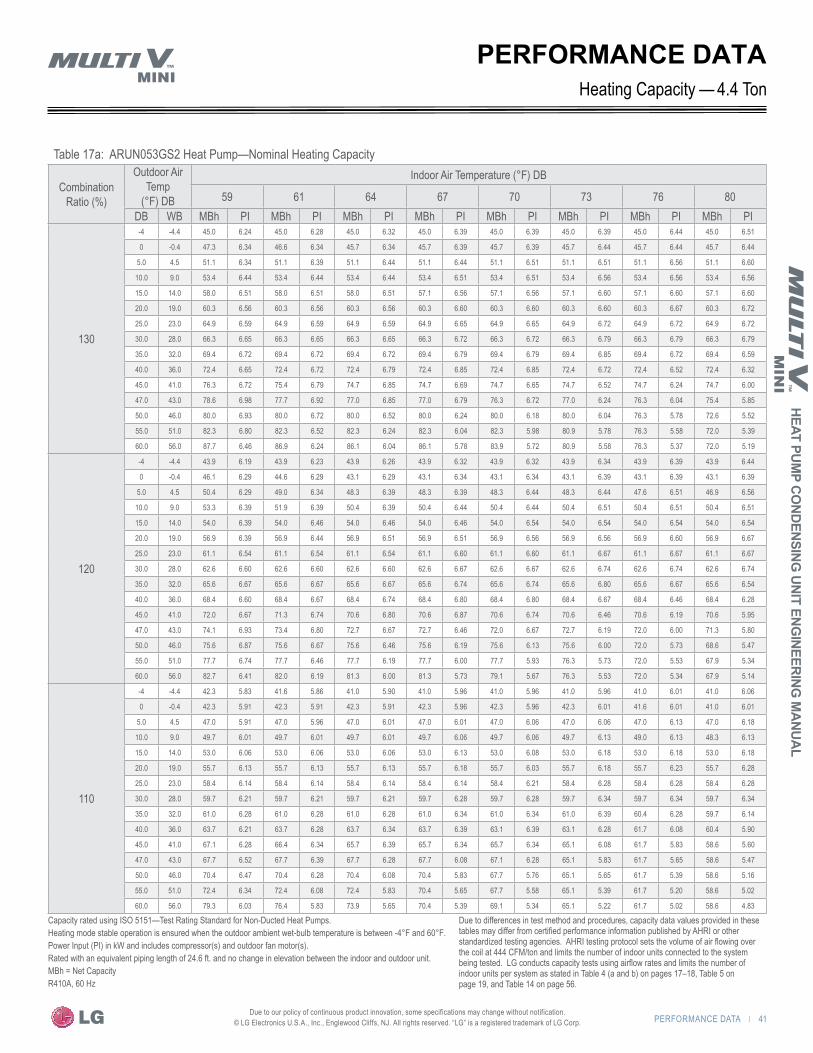
PERFORMANCE DATA | 41
HEAT PUMP CO
NDENSING UNIT ENG
INEERING M
ANU
AL
Due to our policy of continuous product innovation, some specifications may change without notification. © LG Electronics U.S.A., Inc., Englewood Cliffs, NJ. All rights reserved. “LG” is a registered trademark of LG Corp.
Table 17a: ARUN053GS2 Heat Pump—Nominal Heating Capacity
Combination Ratio (%)
Outdoor Air Temp
(°F) DB
Indoor Air Temperature (°F) DB
59 61 64 67 70 73 76 80DB WB MBh PI MBh PI MBh PI MBh PI MBh PI MBh PI MBh PI MBh PI
130
-4 -4.4 45.0 6.24 45.0 6.28 45.0 6.32 45.0 6.39 45.0 6.39 45.0 6.39 45.0 6.44 45.0 6.51
0 -0.4 47.3 6.34 46.6 6.34 45.7 6.34 45.7 6.39 45.7 6.39 45.7 6.44 45.7 6.44 45.7 6.44
5.0 4.5 51.1 6.34 51.1 6.39 51.1 6.44 51.1 6.44 51.1 6.51 51.1 6.51 51.1 6.56 51.1 6.60
10.0 9.0 53.4 6.44 53.4 6.44 53.4 6.44 53.4 6.51 53.4 6.51 53.4 6.56 53.4 6.56 53.4 6.56
15.0 14.0 58.0 6.51 58.0 6.51 58.0 6.51 57.1 6.56 57.1 6.56 57.1 6.60 57.1 6.60 57.1 6.60
20.0 19.0 60.3 6.56 60.3 6.56 60.3 6.56 60.3 6.60 60.3 6.60 60.3 6.60 60.3 6.67 60.3 6.72
25.0 23.0 64.9 6.59 64.9 6.59 64.9 6.59 64.9 6.65 64.9 6.65 64.9 6.72 64.9 6.72 64.9 6.72
30.0 28.0 66.3 6.65 66.3 6.65 66.3 6.65 66.3 6.72 66.3 6.72 66.3 6.79 66.3 6.79 66.3 6.79
35.0 32.0 69.4 6.72 69.4 6.72 69.4 6.72 69.4 6.79 69.4 6.79 69.4 6.85 69.4 6.72 69.4 6.59
40.0 36.0 72.4 6.65 72.4 6.72 72.4 6.79 72.4 6.85 72.4 6.85 72.4 6.72 72.4 6.52 72.4 6.32
45.0 41.0 76.3 6.72 75.4 6.79 74.7 6.85 74.7 6.69 74.7 6.65 74.7 6.52 74.7 6.24 74.7 6.00
47.0 43.0 78.6 6.98 77.7 6.92 77.0 6.85 77.0 6.79 76.3 6.72 77.0 6.24 76.3 6.04 75.4 5.85
50.0 46.0 80.0 6.93 80.0 6.72 80.0 6.52 80.0 6.24 80.0 6.18 80.0 6.04 76.3 5.78 72.6 5.52
55.0 51.0 82.3 6.80 82.3 6.52 82.3 6.24 82.3 6.04 82.3 5.98 80.9 5.78 76.3 5.58 72.0 5.39
60.0 56.0 87.7 6.46 86.9 6.24 86.1 6.04 86.1 5.78 83.9 5.72 80.9 5.58 76.3 5.37 72.0 5.19
120
-4 -4.4 43.9 6.19 43.9 6.23 43.9 6.26 43.9 6.32 43.9 6.32 43.9 6.34 43.9 6.39 43.9 6.44
0 -0.4 46.1 6.29 44.6 6.29 43.1 6.29 43.1 6.34 43.1 6.34 43.1 6.39 43.1 6.39 43.1 6.39
5.0 4.5 50.4 6.29 49.0 6.34 48.3 6.39 48.3 6.39 48.3 6.44 48.3 6.44 47.6 6.51 46.9 6.56
10.0 9.0 53.3 6.39 51.9 6.39 50.4 6.39 50.4 6.44 50.4 6.44 50.4 6.51 50.4 6.51 50.4 6.51
15.0 14.0 54.0 6.39 54.0 6.46 54.0 6.46 54.0 6.46 54.0 6.54 54.0 6.54 54.0 6.54 54.0 6.54
20.0 19.0 56.9 6.39 56.9 6.44 56.9 6.51 56.9 6.51 56.9 6.56 56.9 6.56 56.9 6.60 56.9 6.67
25.0 23.0 61.1 6.54 61.1 6.54 61.1 6.54 61.1 6.60 61.1 6.60 61.1 6.67 61.1 6.67 61.1 6.67
30.0 28.0 62.6 6.60 62.6 6.60 62.6 6.60 62.6 6.67 62.6 6.67 62.6 6.74 62.6 6.74 62.6 6.74
35.0 32.0 65.6 6.67 65.6 6.67 65.6 6.67 65.6 6.74 65.6 6.74 65.6 6.80 65.6 6.67 65.6 6.54
40.0 36.0 68.4 6.60 68.4 6.67 68.4 6.74 68.4 6.80 68.4 6.80 68.4 6.67 68.4 6.46 68.4 6.28
45.0 41.0 72.0 6.67 71.3 6.74 70.6 6.80 70.6 6.87 70.6 6.74 70.6 6.46 70.6 6.19 70.6 5.95
47.0 43.0 74.1 6.93 73.4 6.80 72.7 6.67 72.7 6.46 72.0 6.67 72.7 6.19 72.0 6.00 71.3 5.80
50.0 46.0 75.6 6.87 75.6 6.67 75.6 6.46 75.6 6.19 75.6 6.13 75.6 6.00 72.0 5.73 68.6 5.47
55.0 51.0 77.7 6.74 77.7 6.46 77.7 6.19 77.7 6.00 77.7 5.93 76.3 5.73 72.0 5.53 67.9 5.34
60.0 56.0 82.7 6.41 82.0 6.19 81.3 6.00 81.3 5.73 79.1 5.67 76.3 5.53 72.0 5.34 67.9 5.14
110
-4 -4.4 42.3 5.83 41.6 5.86 41.0 5.90 41.0 5.96 41.0 5.96 41.0 5.96 41.0 6.01 41.0 6.06
0 -0.4 42.3 5.91 42.3 5.91 42.3 5.91 42.3 5.96 42.3 5.96 42.3 6.01 41.6 6.01 41.0 6.01
5.0 4.5 47.0 5.91 47.0 5.96 47.0 6.01 47.0 6.01 47.0 6.06 47.0 6.06 47.0 6.13 47.0 6.18
10.0 9.0 49.7 6.01 49.7 6.01 49.7 6.01 49.7 6.06 49.7 6.06 49.7 6.13 49.0 6.13 48.3 6.13
15.0 14.0 53.0 6.06 53.0 6.06 53.0 6.06 53.0 6.13 53.0 6.08 53.0 6.18 53.0 6.18 53.0 6.18
20.0 19.0 55.7 6.13 55.7 6.13 55.7 6.13 55.7 6.18 55.7 6.03 55.7 6.18 55.7 6.23 55.7 6.28
25.0 23.0 58.4 6.14 58.4 6.14 58.4 6.14 58.4 6.14 58.4 6.21 58.4 6.28 58.4 6.28 58.4 6.28
30.0 28.0 59.7 6.21 59.7 6.21 59.7 6.21 59.7 6.28 59.7 6.28 59.7 6.34 59.7 6.34 59.7 6.34
35.0 32.0 61.0 6.28 61.0 6.28 61.0 6.28 61.0 6.34 61.0 6.34 61.0 6.39 60.4 6.28 59.7 6.14
40.0 36.0 63.7 6.21 63.7 6.28 63.7 6.34 63.7 6.39 63.1 6.39 63.1 6.28 61.7 6.08 60.4 5.90
45.0 41.0 67.1 6.28 66.4 6.34 65.7 6.39 65.7 6.34 65.7 6.34 65.1 6.08 61.7 5.83 58.6 5.60
47.0 43.0 67.7 6.52 67.7 6.39 67.7 6.28 67.7 6.08 67.1 6.28 65.1 5.83 61.7 5.65 58.6 5.47
50.0 46.0 70.4 6.47 70.4 6.28 70.4 6.08 70.4 5.83 67.7 5.76 65.1 5.65 61.7 5.39 58.6 5.16
55.0 51.0 72.4 6.34 72.4 6.08 72.4 5.83 70.4 5.65 67.7 5.58 65.1 5.39 61.7 5.20 58.6 5.02
60.0 56.0 79.3 6.03 76.4 5.83 73.9 5.65 70.4 5.39 69.1 5.34 65.1 5.22 61.7 5.02 58.6 4.83
PERFORMANCE DATA4.4 TonHeating Capacity —
Capacity rated using ISO 5151—Test Rating Standard for Non-Ducted Heat Pumps.Heating mode stable operation is ensured when the outdoor ambient wet-bulb temperature is between -4°F and 60°F.Power Input (PI) in kW and includes compressor(s) and outdoor fan motor(s).Rated with an equivalent piping length of 24.6 ft. and no change in elevation between the indoor and outdoor unit.MBh = Net CapacityR410A, 60 Hz
Due to differences in test method and procedures, capacity data values provided in these tables may differ from certified performance information published by AHRI or other standardized testing agencies. AHRI testing protocol sets the volume of air flowing over the coil at 444 CFM/ton and limits the number of indoor units connected to the system being tested. LG conducts capacity tests using airflow rates and limits the number of indoor units per system as stated in Table 4 (a and b) on pages 17–18, Table 5 on page 19, and Table 14 on page 56.
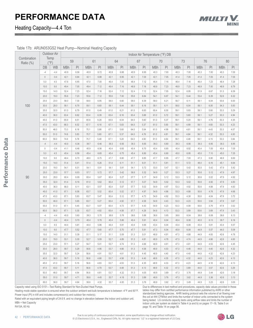
42 | PERFORMANCE DATA
Perf
orm
ance
Dat
a
Due to our policy of continuous product innovation, some specifications may change without notification. © LG Electronics U.S.A., Inc., Englewood Cliffs, NJ. All rights reserved. “LG” is a registered trademark of LG Corp.
PERFORMANCE DATA
Table 17b: ARUN053GS2 Heat Pump—Nominal Heating Capacity
Combination Ratio (%)
Outdoor Air Temp (°F)
Indoor Air Temperature (°F) DB
59 61 64 67 70 73 76 80DB WB MBh PI MBh PI MBh PI MBh PI MBh PI MBh PI MBh PI MBh PI
100
-4 -4.4 40.9 6.56 40.9 6.72 40.9 6.88 40.9 6.95 40.3 7.00 40.3 7.00 40.3 7.00 40.3 7.00
0 -0.4 42.1 6.84 42.1 6.88 42.1 6.95 42.1 7.00 42.1 7.05 41.4 7.05 41.4 7.05 41.4 7.05
5.0 4.5 47.6 6.95 47.0 7.00 46.4 7.05 46.4 7.12 46.4 7.16 46.4 7.16 46.4 7.23 46.4 7.28
10.0 9.0 49.4 7.05 49.4 7.12 49.4 7.16 48.9 7.16 48.9 7.23 48.9 7.23 48.9 7.00 48.9 6.79
15.0 14.0 52.4 7.23 52.4 7.16 52.4 7.12 52.4 7.12 52.4 7.05 52.4 6.95 51.9 6.67 51.3 6.39
20.0 19.0 55.6 7.23 55.6 7.12 55.6 7.00 55.6 6.84 54.1 6.67 54.1 6.44 53.4 6.39 52.6 6.32
25.0 23.0 58.0 7.30 58.0 6.95 58.0 6.60 58.0 6.39 58.0 6.21 56.7 6.11 56.1 6.04 55.6 6.00
30.0 28.0 59.1 6.79 59.1 6.60 59.1 6.44 59.1 6.16 59.1 6.11 58.0 6.04 56.1 6.00 54.3 5.93
35.0 32.0 61.0 6.79 61.0 6.49 61.0 6.21 61.0 6.00 60.4 6.00 59.1 5.93 56.1 5.60 53.3 5.29
40.0 36.0 63.4 6.62 63.4 6.39 63.4 6.16 63.4 5.88 61.0 5.72 59.1 5.60 56.1 5.27 53.3 4.94
45.0 41.0 65.9 6.51 65.9 6.28 65.9 6.04 64.0 5.60 61.0 5.37 59.1 5.20 56.1 4.76 53.3 4.35
47.0 43.0 68.3 6.52 67.7 6.16 67.1 5.83 64.0 5.37 61.0 5.60 59.1 4.99 56.1 4.60 53.3 4.23
50.0 46.0 73.3 6.18 70.1 5.88 67.1 5.60 64.0 5.04 61.0 4.99 59.1 4.81 56.1 4.43 53.3 4.07
55.0 51.0 74.6 5.83 70.7 5.60 67.1 5.37 64.0 4.76 61.0 4.81 59.1 4.64 56.1 4.32 53.3 4.00
60.0 56.0 74.6 5.78 70.7 5.48 67.1 5.20 64.0 4.60 61.0 4.64 59.1 4.48 56.1 4.15 53.3 3.84
90
-4 -4.4 40.0 6.36 39.7 6.46 39.3 6.56 39.3 6.65 39.3 6.80 39.3 6.90 39.3 6.95 39.3 6.95
0 -0.4 41.1 6.46 40.9 6.56 40.4 6.65 40.4 6.70 40.4 6.85 40.4 6.92 40.4 7.05 40.4 7.00
5.0 4.5 45.4 6.56 45.4 6.65 45.4 6.75 45.4 6.80 45.4 6.90 45.0 6.95 45.0 7.10 45.0 7.25
10.0 9.0 48.4 6.70 48.0 6.75 47.7 6.80 47.7 6.85 47.7 6.95 47.7 7.00 47.3 6.80 46.9 6.60
15.0 14.0 51.4 6.41 51.4 6.26 51.4 6.11 51.1 6.01 51.1 5.81 51.1 5.72 48.0 6.16 45.1 6.64
20.0 19.0 54.1 6.01 54.1 5.91 54.1 5.81 54.1 5.72 53.0 5.47 52.1 5.42 50.0 5.42 47.9 5.42
25.0 23.0 57.7 6.03 57.7 5.72 57.7 5.42 56.6 5.32 54.9 5.27 53.3 5.27 50.6 5.12 47.9 4.97
30.0 28.0 60.4 6.09 60.4 5.67 60.4 5.27 57.7 5.17 54.9 5.12 53.3 5.12 50.6 5.02 47.9 4.92
35.0 32.0 61.4 6.16 61.0 5.62 60.4 5.12 57.7 5.07 54.9 5.02 53.3 5.02 50.6 4.92 47.9 4.83
40.0 36.0 66.0 6.11 63.1 5.57 60.4 5.07 57.7 5.02 54.9 4.97 53.3 4.92 50.6 4.88 47.9 4.83
45.0 41.0 67.1 6.06 63.7 5.52 60.4 5.02 57.7 4.97 54.9 4.96 53.3 4.88 50.6 4.78 47.9 4.68
47.0 43.0 67.1 5.83 63.7 5.47 60.4 5.12 57.7 4.73 54.9 4.92 53.3 4.38 50.6 4.04 47.9 3.72
50.0 46.0 67.1 5.65 63.7 5.27 60.4 4.92 57.7 4.58 54.9 4.43 53.3 4.23 50.6 3.94 47.9 3.67
55.0 51.0 67.1 5.45 63.7 5.07 60.4 4.73 57.7 4.43 54.9 4.23 53.3 4.08 50.6 3.79 47.9 3.52
60.0 56.0 67.1 5.30 63.7 4.92 60.4 4.58 57.7 4.28 54.9 4.13 53.3 3.99 50.6 3.69 47.9 3.43
80
-4 -4.4 40.0 5.60 39.3 5.70 38.6 5.78 38.6 5.86 38.6 5.95 38.6 6.04 38.6 6.08 38.6 6.13
0 -0.4 40.4 5.70 40.4 5.78 40.4 5.86 40.4 5.91 40.4 6.04 40.4 6.08 40.0 6.13 39.7 6.16
5.0 4.5 44.4 5.81 44.4 5.86 44.4 5.91 43.4 5.95 43.4 6.04 43.4 6.08 43.4 5.81 43.4 5.57
10.0 9.0 47.7 5.52 47.7 5.60 47.7 5.70 47.7 5.91 47.3 6.04 45.9 6.08 44.9 5.57 44.0 5.09
15.0 14.0 51.1 5.39 51.1 5.17 51.1 5.09 51.3 5.01 48.9 4.91 47.3 4.88 44.9 4.83 42.6 4.79
20.0 19.0 53.1 5.30 52.7 5.09 52.7 4.89 51.3 4.81 48.9 4.78 47.3 4.74 44.9 4.66 42.6 4.60
25.0 23.0 57.1 5.27 54.7 5.01 53.7 4.74 51.3 4.66 48.9 4.61 47.3 4.61 44.9 4.53 42.6 4.45
30.0 28.0 59.7 5.29 56.6 4.96 53.7 4.66 51.3 4.58 48.9 4.53 47.3 4.48 44.9 4.40 42.6 4.32
35.0 32.0 59.7 5.24 56.6 4.91 53.7 4.61 51.3 4.45 48.9 4.40 47.3 4.40 44.9 4.32 42.6 4.23
40.0 36.0 59.7 5.19 56.6 4.88 53.7 4.58 51.3 4.40 48.9 4.35 47.3 4.32 44.9 4.23 42.6 4.13
45.0 41.0 59.7 5.16 56.6 4.83 53.7 4.53 51.3 4.35 48.9 4.33 47.3 4.23 44.9 4.18 42.6 4.13
47.0 43.0 59.7 5.11 56.6 4.79 53.7 4.48 51.3 4.13 48.9 4.32 47.3 3.89 44.9 3.57 42.6 3.29
50.0 46.0 59.7 4.94 56.6 4.61 53.7 4.32 51.3 4.00 48.9 3.89 47.3 3.76 44.9 3.44 42.6 3.18
55.0 51.0 59.7 4.71 56.6 4.45 53.7 4.18 51.3 3.89 48.9 3.76 47.3 3.62 44.9 3.36 42.6 3.13
60.0 56.0 59.7 4.64 56.6 4.32 53.7 4.00 51.3 3.76 48.9 3.62 47.3 3.49 44.9 3.23 42.6 3.00
Heating Capacity—4.4 Ton
Capacity rated using ISO 5151—Test Rating Standard for Non-Ducted Heat Pumps.Heating mode stable operation is ensured when the outdoor ambient wet-bulb temperature is between -4°F and 60°F.Power Input (PI) in kW and includes compressor(s) and outdoor fan motor(s).Rated with an equivalent piping length of 24.6 ft. and no change in elevation between the indoor and outdoor unit.MBh = Net CapacityR410A, 60 Hz
Due to differences in test method and procedures, capacity data values provided in these tables may differ from certified performance information published by AHRI or other standardized testing agencies. AHRI testing protocol sets the volume of air flowing over the coil at 444 CFM/ton and limits the number of indoor units connected to the system being tested. LG conducts capacity tests using airflow rates and limits the number of indoor units per system as stated in Table 4 (a and b) on pages 17–18, Table 5 on page 19, and Table 14 on page 56.
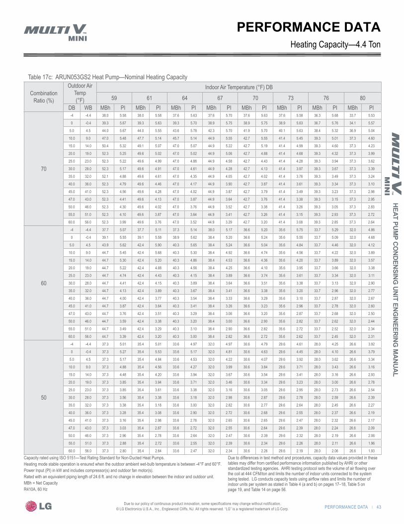
PERFORMANCE DATA | 43
HEAT PUMP CO
NDENSING UNIT ENG
INEERING M
ANU
AL
Due to our policy of continuous product innovation, some specifications may change without notification. © LG Electronics U.S.A., Inc., Englewood Cliffs, NJ. All rights reserved. “LG” is a registered trademark of LG Corp.
Table 17c: ARUN053GS2 Heat Pump—Nominal Heating Capacity
Combination Ratio (%)
Outdoor Air Temp (°F)
Indoor Air Temperature (°F) DB
59 61 64 67 70 73 76 80DB WB MBh PI MBh PI MBh PI MBh PI MBh PI MBh PI MBh PI MBh PI
70
-4 -4.4 38.0 5.58 38.0 5.58 37.6 5.63 37.6 5.70 37.6 5.63 37.6 5.58 36.3 5.68 33.7 5.53
0 -0.4 39.3 5.67 39.3 5.63 39.3 5.70 38.9 5.75 38.9 5.75 38.9 5.63 36.7 5.76 34.1 5.57
5.0 4.5 44.0 5.67 44.0 5.55 43.6 5.78 42.3 5.70 41.9 5.70 40.1 5.63 38.4 5.32 36.9 5.04
10.0 9.0 47.0 5.48 47.7 5.14 45.7 5.14 44.9 5.55 42.7 5.55 41.4 5.45 39.3 5.01 37.3 4.60
15.0 14.0 50.4 5.32 49.1 5.07 47.0 5.07 44.9 5.22 42.7 5.19 41.4 4.99 39.3 4.60 37.3 4.23
20.0 19.0 52.3 5.25 49.6 5.02 47.0 5.02 44.9 5.06 42.7 4.88 41.4 4.68 39.3 4.32 37.3 3.99
25.0 23.0 52.3 5.22 49.6 4.99 47.0 4.88 44.9 4.58 42.7 4.43 41.4 4.28 39.3 3.94 37.3 3.62
30.0 28.0 52.3 5.17 49.6 4.91 47.0 4.61 44.9 4.28 42.7 4.13 41.4 3.97 39.3 3.67 37.3 3.39
35.0 32.0 52.1 4.88 49.6 4.61 47.0 4.35 44.9 4.05 42.7 4.02 41.4 3.76 39.3 3.49 37.3 3.24
40.0 36.0 52.3 4.79 49.6 4.46 47.0 4.17 44.9 3.90 42.7 3.87 41.4 3.61 39.3 3.34 37.3 3.10
45.0 41.0 52.3 4.56 49.6 4.28 47.0 4.02 44.9 3.87 42.7 3.79 41.4 3.49 39.3 3.23 37.3 2.98
47.0 43.0 52.3 4.41 49.6 4.13 47.0 3.87 44.9 3.64 42.7 3.76 41.4 3.38 39.3 3.15 37.3 2.95
50.0 46.0 52.3 4.30 49.6 4.02 47.0 3.76 44.9 3.52 42.7 3.38 41.4 3.26 39.3 3.05 37.3 2.83
55.0 51.0 52.3 4.10 49.6 3.87 47.0 3.64 44.9 3.41 42.7 3.26 41.4 3.15 39.3 2.93 37.3 2.72
60.0 56.0 52.3 3.99 49.6 3.76 47.0 3.52 44.9 3.29 42.7 3.20 41.4 3.08 39.3 2.85 37.3 2.64
60
-4 -4.4 37.7 5.07 37.7 5.11 37.3 5.14 38.0 5.17 36.6 5.20 35.6 5.75 33.7 5.29 32.0 4.86
0 -0.4 39.1 5.55 39.1 5.58 38.9 5.62 38.4 5.20 36.6 5.24 35.6 5.55 33.7 5.09 32.0 4.68
5.0 4.5 43.9 5.62 42.4 5.90 40.3 5.65 38.4 5.24 36.6 5.04 35.6 4.84 33.7 4.46 32.0 4.12
10.0 9.0 44.7 5.45 42.4 5.68 40.3 5.30 38.4 4.92 36.6 4.74 35.6 4.56 33.7 4.22 32.0 3.89
15.0 14.0 44.7 5.30 42.4 5.20 40.3 4.86 38.4 4.53 36.6 4.36 35.6 4.20 33.7 3.89 32.0 3.57
20.0 19.0 44.7 5.22 42.4 4.88 40.3 4.56 38.4 4.25 36.6 4.10 35.6 3.95 33.7 3.66 32.0 3.38
25.0 23.0 44.7 4.74 42.4 4.43 40.3 4.15 38.4 3.89 36.6 3.74 35.6 3.61 33.7 3.34 32.0 3.11
30.0 28.0 44.7 4.41 42.4 4.15 40.3 3.89 38.4 3.64 36.6 3.51 35.6 3.38 33.7 3.13 32.0 2.90
35.0 32.0 44.7 4.13 42.4 3.89 40.3 3.67 38.4 3.41 36.6 3.38 35.6 3.20 33.7 2.96 32.0 2.77
40.0 36.0 44.7 4.00 42.4 3.77 40.3 3.54 38.4 3.33 36.6 3.29 35.6 3.10 33.7 2.87 32.0 2.67
45.0 41.0 44.7 3.87 42.4 3.64 40.3 3.41 38.4 3.26 36.6 3.23 35.6 2.96 33.7 2.78 32.0 2.60
47.0 43.0 44.7 3.76 42.4 3.51 40.3 3.29 38.4 3.06 36.6 3.20 35.6 2.87 33.7 2.68 32.0 2.50
50.0 46.0 44.7 3.59 42.4 3.38 40.3 3.20 38.4 3.00 36.6 2.90 35.6 2.82 33.7 2.62 32.0 2.44
55.0 51.0 44.7 3.49 42.4 3.29 40.3 3.10 38.4 2.90 36.6 2.82 35.6 2.72 33.7 2.52 32.0 2.34
60.0 56.0 44.7 3.39 42.4 3.20 40.3 3.00 38.4 2.82 36.6 2.72 35.6 2.62 33.7 2.45 32.0 2.31
50
-4 -4.4 37.3 5.01 35.4 5.01 33.6 4.97 32.0 4.97 30.6 4.79 29.6 4.61 28.0 4.25 26.6 3.92
0 -0.4 37.3 5.27 35.4 5.53 33.6 5.17 32.0 4.81 30.6 4.63 29.6 4.45 28.0 4.10 26.6 3.79
5.0 4.5 37.3 5.17 35.4 4.84 33.6 4.53 32.0 4.22 30.6 4.07 29.6 3.92 28.0 3.62 26.6 3.34
10.0 9.0 37.3 4.88 35.4 4.56 33.6 4.27 32.0 3.99 30.6 3.84 29.6 3.71 28.0 3.43 26.6 3.16
15.0 14.0 37.3 4.48 35.4 4.20 33.6 3.94 32.0 3.67 30.6 3.54 29.6 3.41 28.0 3.16 26.6 2.93
20.0 19.0 37.3 3.85 35.4 3.94 33.6 3.71 32.0 3.46 30.6 3.34 29.6 3.23 28.0 3.00 26.6 2.78
25.0 23.0 37.3 3.85 35.4 3.61 33.6 3.38 32.0 3.16 30.6 3.05 29.6 2.95 28.0 2.73 26.6 2.54
30.0 28.0 37.3 3.56 35.4 3.38 33.6 3.18 32.0 2.98 30.6 2.87 29.6 2.78 28.0 2.59 26.6 2.39
35.0 32.0 37.3 3.38 35.4 3.18 33.6 3.00 32.0 2.82 30.6 2.77 29.6 2.64 28.0 2.45 26.6 2.27
40.0 36.0 37.3 3.28 35.4 3.08 33.6 2.90 32.0 2.72 30.6 2.68 29.6 2.55 28.0 2.37 26.6 2.19
45.0 41.0 37.3 3.16 35.4 2.98 33.6 2.78 32.0 2.65 30.6 2.65 29.6 2.47 28.0 2.32 26.6 2.17
47.0 43.0 37.3 3.03 35.4 2.87 33.6 2.72 32.0 2.55 30.6 2.64 29.6 2.39 28.0 2.24 26.6 2.09
50.0 46.0 37.3 2.96 35.4 2.78 33.6 2.64 32.0 2.47 30.6 2.39 29.6 2.32 28.0 2.19 26.6 2.06
55.0 51.0 37.3 2.88 35.4 2.72 33.6 2.55 32.0 2.39 30.6 2.34 29.6 2.26 28.0 2.11 26.6 1.96
60.0 56.0 37.3 2.80 35.4 2.64 33.6 2.47 32.0 2.34 30.6 2.26 29.6 2.19 28.0 2.06 26.6 1.93
Heating Capacity—4.4 TonPERFORMANCE DATA
Capacity rated using ISO 5151—Test Rating Standard for Non-Ducted Heat Pumps.Heating mode stable operation is ensured when the outdoor ambient wet-bulb temperature is between -4°F and 60°F.Power Input (PI) in kW and includes compressor(s) and outdoor fan motor(s).Rated with an equivalent piping length of 24.6 ft. and no change in elevation between the indoor and outdoor unit.MBh = Net CapacityR410A, 60 Hz
Due to differences in test method and procedures, capacity data values provided in these tables may differ from certified performance information published by AHRI or other standardized testing agencies. AHRI testing protocol sets the volume of air flowing over the coil at 444 CFM/ton and limits the number of indoor units connected to the system being tested. LG conducts capacity tests using airflow rates and limits the number of indoor units per system as stated in Table 4 (a and b) on pages 17–18, Table 5 on page 19, and Table 14 on page 56.
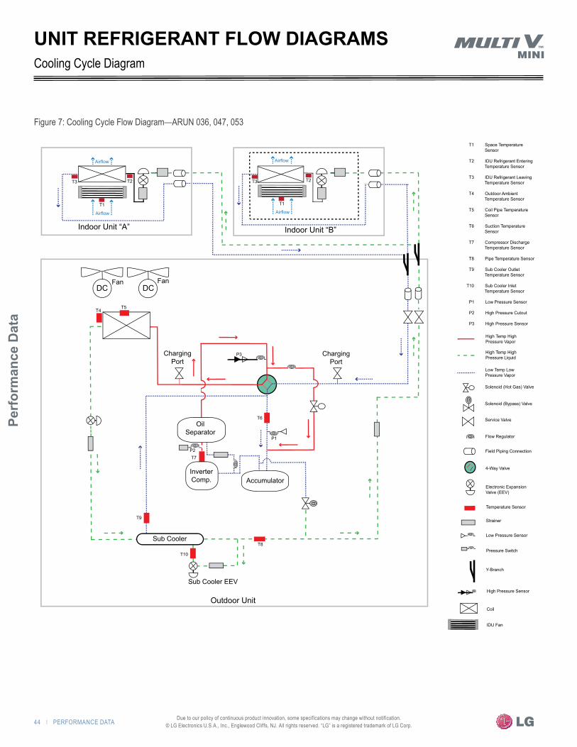
44 | PERFORMANCE DATA
Perf
orm
ance
Dat
a
Due to our policy of continuous product innovation, some specifications may change without notification. © LG Electronics U.S.A., Inc., Englewood Cliffs, NJ. All rights reserved. “LG” is a registered trademark of LG Corp.
Cooling Cycle Diagram
Figure 7: Cooling Cycle Flow Diagram—ARUN 036, 047, 053
UNIT REFRIGERANT FLOW DIAGRAMS
Indoor Unit “A” Indoor Unit “B”
Fan FanDC DC
Charging Port
Outdoor Unit
Charging Port
Accumulator
Oil Separator
Inverter Comp.
Sub Cooler
Sub Cooler EEV
T1
T2T3
T1
T2T3
T4T5
T6
T7
T8
T9
T10
P2
P1
P3
Airflow
Airflow
Airflow
Airflow
Coil
High Pressure Sensor
Y-Branch
Pressure Switch
Low Pressure Sensor
Strainer
Temperature Sensor
Electronic Expansion Valve (EEV)
4-Way Valve
Field Piping Connection
Flow Regulator
Service Valve
Solenoid (Bypass) Valve
Solenoid (Hot Gas) Valve
Low Temp Low Pressure Vapor
High Temp High Pressure Liquid
High Temp High Pressure Vapor
T1 Space Temperature Sensor T2 IDU Refrigerant Entering Temperature Sensor
T3 IDU Refrigerant Leaving Temperature Sensor
T4 Outdoor Ambient Temperature Sensor
T5 Coil Pipe Temperature Sensor T6 Suction Temperature Sensor
T7 Compressor Discharge Temperature Sensor
T8 Pipe Temperature Sensor
T9 Sub Cooler Outlet Temperature Sensor
T10 Sub Cooler Inlet Temperature Sensor
P1 Low Pressure Sensor
P2 High Pressure Cutout
P3 High Pressure Sensor
IDU Fan

PERFORMANCE DATA | 45
HEAT PUMP CO
NDENSING UNIT ENG
INEERING M
ANU
AL
Due to our policy of continuous product innovation, some specifications may change without notification. © LG Electronics U.S.A., Inc., Englewood Cliffs, NJ. All rights reserved. “LG” is a registered trademark of LG Corp.
Heating Cycle Diagram
Figure 8: Heating Cycle Flow Diagram—ARUN 036, 047, 053
UNIT REFRIGERANT FLOW DIAGRAMS
IDU Coil
High Pressure Sensor
Y-Branch
Pressure Switch
Pressure Sensor
Strainer
Temperature Sensor
Electronic Expansion Valve (EEV)
4-Way Valve
Field Piping Connection
Flow Regulator
Service Valve
Solenoid (Bypass) Valve
Solenoid (Hot Gas) Valve
Low Temp Low Pressure Vapor
High Temp High Pressure Liquid
High Temp High Pressure Vapor
T1 Space Temperature Sensor T2 IDU Refrigerant Entering Temperature Sensor
T3 IDU Refrigerant Leaving Temperature Sensor
T4 Outdoor Ambient Temperature Sensor
T5 Coil Pipe Temperature Sensor T6 Suction Temperature Sensor
T7 Compressor Discharge Temperature Sensor
T8 Pipe Temperature Sensor
T9 Sub Cooler Outlet Temperature Sensor
T10 Sub Cooler Inlet Temperature Sensor
P1 Low Pressure Sensor
P2 High Pressure Cutout
P3 High Pressure Sensor
IDU Fan
Indoor Unit “A” Indoor Unit “B”
Fan FanDC DC
Charging Port
Outdoor Unit
Charging Port
Accumulator
Oil Separator
Inverter Comp.
Sub Cooler
Sub Cooler EEV
T1
T2T3
T1
T2T3
T4T5
T6
T7
T8
T9
T10
P2
P1
P3
Airflow
Airflow
Airflow
Airflow

46 | PERFORMANCE DATA
Perf
orm
ance
Dat
a
Due to our policy of continuous product innovation, some specifications may change without notification. © LG Electronics U.S.A., Inc., Englewood Cliffs, NJ. All rights reserved. “LG” is a registered trademark of LG Corp.
Symbol DescriptionCN04 Connection for flashing system EPROM
CN05 Connection for LGMV Service Tool
CN08 Power to main board
CN09 4-way reversing valve
CN10 Inverter compressor crank case heater-A
CN11 Not Used
CN13 Hot gas bypass valve solenoid
CN 14 Not Used
CN15 Not Used
CN16 Not Used
CN17 Not Used
CN27 Not Used
CN29 Communication with inverter board
CN30 High pressure sensor
CN32 Low pressure sensor
CN33 Subcooler outlet pipe thermistor (TH-SC_OUT)
CN33 Subcooler inlet pipe thermistor (SC_IN)
CN33 Subcooler liquid pipe thermistor (SC_L)
CN34 Compressor pipe thermistor (DISCHARGE-A)
CN34 Outdoor unit pipe thermistor 1 (HEX1)
CN34 Outdoor unit pipe thermistor 2 (HEX2)
CN35 Outdoor air thermistor (AIR)
CN35 Suction pipe thermistor (SUCTION)
CN35 High pressure sensor (DISCHARGE-B)
CN38 Electric expansion valve (Outdoor Coil)
CN40 Electric expansion valve (Subcooler)
CN41 Terminal for PI45 card connection
CN43 Not Used
CN44 Inverter compressor head pressure switch
CN-FLASH-WRITER Connection for flashing inverter board EPROM
CN-INVERTER AC power to inverter
CN-LGMV Connection for LGMV service tool
CN-MAIN Communication with main microprocessor
CN-MOTOR1 Communication/power connection for motor1
CN-MOTOR2 Communication/power connection for motor2
CN-POWER AC power from noise filter
CN-UVW Power to Inverter Compressor
SW01S Control system reset button
SW02V Auto Address button
SW01V DATACONFIRM
Line (+) power connection 208–230/60/1
Neutral (-) power connection 208–230/60/1
Ground1 Reactor—Power conditioner to minimizes transient noise from the power source from entering the outdoor unit.
N
L
1
Color LegendParenthesis () Socket Color
No Parenthesis Wire Color
See Figure 61See Figure 60
Fan A Fan B
W U
V
W V U
Yellow
Black
Red
CN(N)
Red
CN-MOTOR1 (White)
CN-MOTOR2 (Blue)
CN-UVW (White)
CN-POWER (Black)
BlackRed
CN-MAIN (Red)
CN-LGMV (White)
BlackCN(L)
CN-FLASH WRITER (White)
REACTOR1
Black
L2 N2
CN-INVERTER
L1 N1
FUSE250V 35A
L N G
Green/Yellow
1Ø 208/230V 60Hz
Black
CN43 CN44 CN40 CN38 CN29
EEV EEV
CN17
CN16
CN15
CN14
CN11
CN10
CN13SV
CN094-WAY
TNR
CN08
CN27 CN32 CN30
SODU SODU IDU A IDU B INTERNET DRY1 DRY2 GND 12V
CN1
TO INDOOR UNITS
TH_SC_OUTTH_SC_INTH_SC_L
CN33
TH_DISCHARGE-ATH_HEX1TH_HEX2
CN34
TH_AIRTH_SUCTIONTH_DISCHARGE-B
CN35
Noise Filter
Inverter Board
SW01B SW02B Error Code Display
CN04
SW01SCN05 SW02V
CN41
SW01V
REACTOR1
Red
Black
Red
Black
Thermister Connections(TH)
Blue
Red
INDOOR UNIT(S)See Figure 61 on page 75 See Figure 60
on page 75
OUTDOOR WIRING DIAGRAM
Figure 9: Outdoor Unit Wiring Diagram
SYSTEM ENGINEERING"Building Ventilation" on page 48"Equipment Selection Procedure" on page 51"Placement Considerations" on page 58"Clearance Requirements" on page 59"LATS Multi V Pipe System Design Tool" on page 61"Pipe Design Parameters" on page 62"Pipe Layout Procedure" on page 63"Piping Design Guide" on page 66"Jobsite Connections" on page 77"Mini Refrigerant Charge" on page 79

Syst
em E
ngin
eerin
g
48 | SYSTEM ENGINEERING Due to our policy of continuous product innovation, some specifications may change without notification. © LG Electronics U.S.A., Inc., Englewood Cliffs, NJ. All rights reserved. “LG” is a registered trademark of LG Corp.
BUILDING VENTILATION
ASHRAE 62.1 and local codes specify the minimum volume of outdoor air that must be provided to an occupied space. Outdoor air is required to minimize adverse health effects, and it provides acceptable indoor air quality for human occupants. The five methods that can be used with Multi V systems to meet the requirements are summarized here.
�Note: �Although we believe that building these ventilation methods have been portrayed accurately, none of the methods have been tested, verified, or evaluated by LG Electronics, USA, Inc. In all cases, the designer, installer, and contractor should under-stand if the suggested method is used, it is used at their own risk. LG Electronics USA, Inc. takes no responsibility and offers no warranty, expressed or implied, of merchantability or fitness of purpose if this method fails to perform as stated or intended.
For a complete copy of Standard 62.1-2010, refer to the American Standard of Heating and Air Conditioning Engineers (ASHRAE) website at www.ashrae.org.
For more information on how to properly size a ventilation air pretreatment system, refer to the article, "Selecting DOAS Equip-ment with Reserve Capacity" by John Murphy, published in the ASHRAE Journal, April 2010.
Method 1: Decoupled Dedicated Outdoor Air (DDOAS)Provide a separate, dedicated outdoor-air system designed to filter, condition, and dehumidify ventilation air and deliver it directly to the condi-tioned space through a separate register or grille. This approach requires a separate independent ventilation duct system not associated with the Multi V system.
�Note: �In all installations, LG recommends using the DDOAS method.
�Advaovatee: �Does not add additional heating or cooling loads to indoor units.May be used with a full lineup of the indoor units.If the outdoor air unit fails, the resulting untreated air will be readily noticed by the occupants.The outdoor air unit may supply neutral air to the occupied space even when the Multi V indoor unit fan changes speed or cycles on and off. DDOAS controls do not have to be interlocked with the Multi V system.In lieu of installing localized smaller outside air treatment equipment throughout the building, this method centralizes the ventilation outside air source making service and filter changes easier and less disruptive for the building occupants.Indoor unit operation and performance will not be affected by the condition of outdoor air.Third-party demand control ventilation controls are more readily accommodated.
�DevAdvaovatee: �Ceiling space is required to accommodate ductwork between the centralized outdoor air unit and ceiling diffusers.
Outdoor Air Unit/ERV
Ceiling Diffuser Multi V Ceiling Cas-sette Indoor Unit
Outdoor Air Unit/ERV
Ceiling Diffuser Multi V Ceiling Cas-sette Indoor Unit
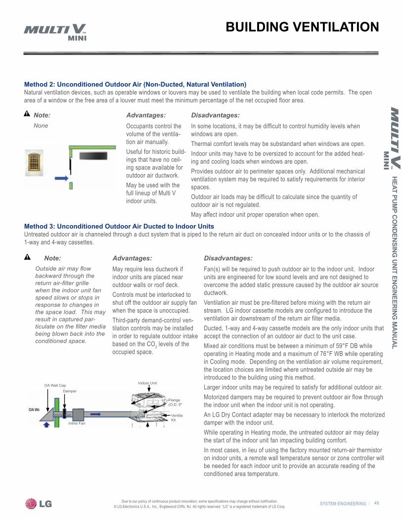
SYSTEM ENGINEERING | 49
HEAT PUMP CO
NDENSING UNIT ENG
INEERING M
ANUAL
Due to our policy of continuous product innovation, some specifications may change without notification. © LG Electronics U.S.A., Inc., Englewood Cliffs, NJ. All rights reserved. “LG” is a registered trademark of LG Corp.
Method 2: Unconditioned Outdoor Air (Non-Ducted, Natural Ventilation)Natural ventilation devices, such as operable windows or louvers may be used to ventilate the building when local code permits. The open area of a window or the free area of a louver must meet the minimum percentage of the net occupied floor area.
BUILDING VENTILATION
Method 3: Unconditioned Outdoor Air Ducted to Indoor UnitsUntreated outdoor air is channeled through a duct system that is piped to the return air duct on concealed indoor units or to the chassis of 1-way and 4-way cassettes.
�Note: �None
�Advaovatee: �Occupants control the volume of the ventila-tion air manually.Useful for historic build-ings that have no ceil-ing space available for outdoor air ductwork.May be used with the full lineup of Multi V indoor units.
�DevAdvaovatee: �In some locations, it may be difficult to control humidity levels when windows are open.Thermal comfort levels may be substandard when windows are open.Indoor units may have to be oversized to account for the added heat-ing and cooling loads when windows are open.Provides outdoor air to perimeter spaces only. Additional mechanical ventilation system may be required to satisfy requirements for interior spaces.Outdoor air loads may be difficult to calculate since the quantity of outdoor air is not regulated.May affect indoor unit proper operation when open.
�Note: �Outside air may flow backward through the return air-filter grille when the indoor unit fan speed slows or stops in response to changes in the space load. This may result in captured par-ticulate on the filter media being blown back into the conditioned space.
�Advaovatee: �May require less ductwork if indoor units are placed near outdoor walls or roof deck.Controls must be interlocked to shut off the outdoor air supply fan when the space is unoccupied.Third-party demand-control ven-tilation controls may be installed in order to regulate outdoor intake based on the CO2 levels of the occupied space.
�DevAdvaovatee: �Fan(s) will be required to push outdoor air to the indoor unit. Indoor units are engineered for low sound levels and are not designed to overcome the added static pressure caused by the outdoor air source ductwork.Ventilation air must be pre-filtered before mixing with the return air stream. LG indoor cassette models are configured to introduce the ventilation air downstream of the return air filter media.Ducted, 1-way and 4-way cassette models are the only indoor units that accept the connection of an outdoor air duct to the unit case.Mixed air conditions must be between a minimum of 59°F DB while operating in Heating mode and a maximum of 76°F WB while operating in Cooling mode. Depending on the ventilation air volume requirement, the location choices are limited where untreated outside air may be introduced to the building using this method.Larger indoor units may be required to satisfy for additional outdoor air.Motorized dampers may be required to prevent outdoor air flow through the indoor unit when the indoor unit is not operating.An LG Dry Contact adapter may be necessary to interlock the motorized damper with the indoor unit.While operating in Heating mode, the untreated outdoor air may delay the start of the indoor unit fan impacting building comfort.In most cases, in lieu of using the factory mounted return-air thermistor on indoor units, a remote wall temperature sensor or zone controller will be needed for each indoor unit to provide an accurate reading of the conditioned area temperature.
OA Wall Cap Indoor Unit
Flange(O.D. 6")
Ventilation Kit
Front Panel
Damper
Inline Fan
Inline Fan
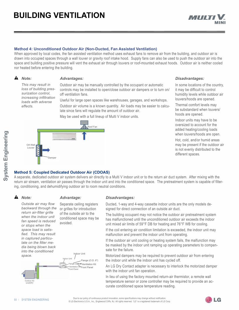
Syst
em E
ngin
eerin
g
50 | SYSTEM ENGINEERING Due to our policy of continuous product innovation, some specifications may change without notification. © LG Electronics U.S.A., Inc., Englewood Cliffs, NJ. All rights reserved. “LG” is a registered trademark of LG Corp.
Outdoor Air Unit/ERV
Indoor Unit
Flange (O.D. 6")Ventilation Kit
Front Panel
OA Wall Louver
Damper
Roof Fan
Method 5: Coupled Dedicated Outdoor Air (CDOAS)A separate, dedicated outdoor air system delivers air directly to a Multi V indoor unit or to the return air duct system. After mixing with the return air stream, ventilation air passes through the indoor unit and into the conditioned space. The pretreatment system is capable of filter-ing, conditioning, and dehumidifying outdoor air to room neutral conditions.
BUILDING VENTILATION
Method 4: Unconditioned Outdoor Air (Non-Ducted, Fan Assisted Ventilation)When approved by local codes, the fan assisted ventilation method uses exhaust fans to remove air from the building, and outdoor air is drawn into occupied spaces through a wall louver or gravity roof intake hood. Supply fans can also be used to push the outdoor air into the space and building positive pressure will vent the exhaust air through louvers or roof-mounted exhaust hoods. Outdoor air is neither cooled nor heated before entering the building.
�Note: �This may result in loss of building pres-surization control, increasing infiltration loads with adverse effects.
�Advaovatee: �Outdoor air may be manually controlled by the occupant or automatic controls may be installed to open/close outdoor air dampers or to turn on/off ventilation fans.Useful for large open spaces like warehouses, garages, and workshops.Outdoor air volume is a known quantity. Air loads may be easier to calcu-late since fans will regulate the amount of outdoor air.May be used with a full lineup of Multi V indoor units.
�DevAdvaovatee: �In some locations of the country, it may be difficult to control humidity levels while outdoor air louvers/hoods are opened.Thermal comfort levels may be substandard when louvers/hoods are opened.Indoor units may have to be oversized to account for the added heating/cooling loads when louvers/hoods are open.Hot, cold, and/or humid areas may be present if the outdoor air is not evenly distributed to the different spaces.
�Note: �Outside air may flow backward through the return air-filter grille when the indoor unit fan speed is reduced or stops when the space load is satis-fied. This may result in captured particu-late on the filter me-dia being blown back into the conditioned space.
�Advaovate: �Separate ceiling registers or grilles for introduction of the outside air to the conditioned space may be avoided.
�DevAdvaovatee: �Ducted, 1-way and 4-way cassette indoor units are the only models de-signed for direct connection of an outside air duct.The building occupant may not notice the outdoor air pretreatment system has malfunctioned until the unconditioned outdoor air exceeds the indoor unit mixed air limits of 59°F DB for heating and 76°F WB for cooling.If the coil entering air condition limitation is exceeded, the indoor unit may malfunction and prevent the indoor unit from operating.If the outdoor air unit cooling or heating system fails, the malfunction may be masked by the indoor unit ramping up operating parameters to compen-sate for the failure.Motorized dampers may be required to prevent outdoor air from entering the indoor unit while the indoor unit has cycled off.An LG Dry Contact adapter is necessary to interlock the motorized damper with the indoor unit fan operation.In lieu of using the factory mounted return-air thermistor, a remote wall temperature sensor or zone controller may be required to provide an ac-curate conditioned space temperature reading.
Indoor Unit
Flange (O.D. 6")Ventilation Kit
Front Panel

SYSTEM ENGINEERING | 51
HEAT PUMP CO
NDENSING UNIT ENG
INEERING M
ANUAL
Due to our policy of continuous product innovation, some specifications may change without notification. © LG Electronics U.S.A., Inc., Englewood Cliffs, NJ. All rights reserved. “LG” is a registered trademark of LG Corp.
ARUN 036, 047, 053
Always use LATS Multi V SoftwareTo properly select and size Multi V system components, follow these guidelines:• Zone the building• Determine the ventilation method• Select the indoor unit(s)• Select the outdoor unit• System sizing checks
- Calculate the Corrected Capacity Ratio (CCR) - Determine the system Combination Ratio (CR) - Determine the Running (indoor) Unit Ratio (RUR)
The following procedure should not replace LG’s LATS Multi V complimentary selection software, but should instead be used in conjunction with it. Contact your LG representative to obtain a copy of the software and the user’s manual.When using the LATS Multi V software, the default indoor design day conditions of 80.6°F DB / 67°F WB in cooling mode and 68°F DB / 56.7°F WB in heating mode may be adjusted to reflect the de-signer's preferred indoor room design temperature. These indoor room temperature values are the room thermostat setpoints and should not be confused with entering coil conditions.
�Note: � Data provided in the LATS tree mode diagram or report file is not valid unless the Auto-Piping and System Check routines are run without errors. Errors will be reported immediately in pop-up dialog boxes or red lines surrounding indoor unit(s) and/or along pipe segments. If errors are indicated, modify the pipe system design and re-run LATS.
Zone the BuildingMulti V Mini Heat Pump is a two-pipe heat pump system that can cool or heat, but not both simultaneously. Therefore, the designer should combine spaces with similar load profiles located near or adjacent to each other into “thermal zones.” Calculate the peak cooling and heating loads for each thermal zone.
Determine the Ventilation MethodDecide how ventilation air will be introduced to each space. Add ventilation load(s) to the appropriate indoor unit(s) design cool-ing and heating loads only if the ventilation air treatment system does not provide room neutral air. Some models of Multi V indoor units are factory provided with or have accessories available that accommodate the direct connection of ventilation ductwork to the unit. However, there are product limitations and additional considerations that may need to be understood when using direct connection accessories. For more information, contact your LG applied equipment representative. Go to www.LG-VRF.com to find your representative and technical product information.
�Note: � In all cases, LG recommends ducting pretreated, room neutral, ventilation air directly to the space. When pretreated, ventilation air is provided, remember to de-duct the ventilation airload(s) from the total load before sizing the indoor unit(s). Local codes or other profession-al design guidelines, such as ASHRAE 62.1, will dictate the volume of ventilation air required.
It may be prudent to oversize the dedicated outdoor air system considering there will be a few days of the year when weather conditions exceed the design day condi-tions. This will minimize the possibility of ventilation air conditions causing the indoor unit's entering air tem-perature to fall outside the approved design temperature range. For more information on how to properly size a ventilation air pretreatment system, refer to the article, "Selecting DOAS Equipment with Reserve Capacity" by John Murphy, published in the ASHRAE Journal, April 2010.
Select the Indoor Unit(s)Determine how many indoor units will be required. Refer to Table 1a to obtain the maximum number of indoor units allowed on a system. If an indoor unit will serve more than one space (i.e. ducted indoor unit or cassette equipped with up to two side branch ducts), combine the space and ventilation loads for all rooms served. If the quantity of indoor units exceeds the maximum allowed for the outdoor model selected, consider increasing the size of the outdoor unit or split the indoor units into two groups served by separate outdoor units.Calculate the entering mixed air conditions for each indoor unit. The mixed-air temperature must be between 57°F and 76°F WB in Cooling mode and between 59°F and 80°F DB in Heating mode.
�Note: � When the indoor unit entering air temperature is outside the cataloged operational limits, the system may continue to operate properly; however, operational abnormalities may occur. These include coil frosting, low or high suction temperature, low or high head pressure, low heating discharge temperature, or complete system shutdown.
To calculate the indoor unit entering mixed air temperature:
EQUIPMENT SELECTION PROCEDURE
Where
MAT = Mixed air temperatureRAT = Return air temperatureOAT = Outdoor air temperature%RA = Percentage of return air%OA = Percentage of outdoor air
(RAT x %RA) + (OAT x %OA)100MAT =
Syst
em E
ngin
eerin
g
52 | SYSTEM ENGINEERING Due to our policy of continuous product innovation, some specifications may change without notification. © LG Electronics U.S.A., Inc., Englewood Cliffs, NJ. All rights reserved. “LG” is a registered trademark of LG Corp.
EQUIPMENT SELECTION PROCEDUREARUN 036, 047, 053
�Note: � Avoid over-sizing indoor units in an attempt to increase the room air recirculation rate. VRF systems are designed for minimum airflow over the coil to maximize latent capacity while cooling, maintain a comfortable, consistent discharge air temperature while heating, and minimize fan motor power consumption.
To properly size indoor unit(s), begin by referring to the output report provided by LG’s LATS Multi V software and note the appropriate corrected cooling and heating capacity for each indoor unit for the cooling and heating design days.In LATS, the corrected cooling capacity is different from the nominal cooling capacity because the corrected capacity includes changes in unit performance after considering refrigerant line pres-sure drop, the system's Combination Ratio (CR), and the effect design ambient operating conditions has on the indoor unit's cooling capability.The building sensible cooling load is typically the critical load to satisfy. In coastal areas or humid applications, such as high occu-pancy spaces, both the latent and sensible cooling loads should be considered. In areas where the cooling and heating loads are similar or the heating load may exceed the total cooling load, the designer should verify the indoor unit selection satisfies both the heating and cooling requirements.
Check the indoor unit's cooling capacity. If the system is installed at a significant elevation above sea level, it may be appropriate to adjust the cooling capacity for changes in air density. Apply the appropriate altitude correction factor for the building’s location to the outdoor and indoor units. After applying the factor, verify the sensible (and total) corrected cooling capacity for each indoor unit is at least equal to the sum of the appropriate cooling design day space load(s) (plus ventilation load(s) if applicable) for the space(s) served by the indoor unit. Next, check the indoor unit heating capacity. Begin by finding the corrected heating capacity detailed in the LATS report for each in-door unit. The corrected heating capacity is again different from the nominal heating capacity because the corrected capacity includes changes in unit performance after considering refrigerant line pres-sure drop and design ambient operating conditions on the indoor unit's heating capability. If the system is installed at a significant elevation above sea level, adjust the heating capacity for changes in air density. Apply the appropriate altitude correction factor for the building’s location. Multiply the corrected heating capacity detailed in the LATS report for each indoor unit by the altitude correction fac-tor selected. Verify that the actual corrected heating capacity for each indoor unit is at least equal to the sum of the appropriate heating design day building load (plus the ventilation loads if applicable) for all spaces served by the indoor unit.
Select the Outdoor UnitTable 18: Cataloged Ambient Air Operating Temperature Range
Cooling Mode (°F DB) Heating Mode (°F WB)
Multi V Mini 23 – 115 (-4) – 60
�Note: � Multi V Mini outdoor unit(s) may have to operate in weather conditions more extreme than a typical design day. Design days are the days of the year that either cooling or heating capacity is needed the most. In light of this, it may be prudent to size the outdoor unit considering the antici-pated worst weather day conditions to ensure adequate capacity year round.
Begin the selection of the outdoor unit by selecting a size that meets the cooling capacity requirement. Then verify the selected unit meets the heating capacity requirement. Find the appropriate capac-ity table on pages 26–39 for the outdoor unit chosen. Locate the outdoor unit cooling and heating capacity values at the specified ambient design conditions.When design outdoor ambient conditions are outside the cataloged air-cooled outdoor unit operating range, the net refrigeration effect (capacity) delivered to the indoor units cannot be guaranteed. Under these conditions, the possibility exists that the liquid injection valve or hot gas bypass valve in the outdoor unit may be open. When open, the outdoor unit will sacrifice capacity to maintain operational stability. As a result, the outdoor unit’s net refrigeration effect avail-able for use by the indoor units will be slightly reduced under certain extreme ambient air conditions.Additionally, when the designer provides the LATS software with outdoor ambient air design conditions that are above or below the cataloged operational temperature range, the software will override the designers specified conditions and size the indoor and outdoor units and pipe system using the maximum or minimum cataloged ambient air operating temperature. Also, it is important to know that the report generated by LATS (.xls format) will reflect the outdoor ambient air conditions the designer provides, but the indoor and outdoor unit(s) cooling and heating cor-rected capacities calculated and shown in the report will be based on the cataloged ambient air operating temperature limits of -4°F for the heating design day and 115°F for the cooling design day. On these projects, the designer must manually estimate the corrected cooling and heating capacity of the outdoor unit when specified ambient conditions are outside the cataloged range.
�Note: � To roughly estimate outdoor unit capacity at condi-tions outside the cataloged ambient air operating tempera-ture range, manually extrapolate performance informa-tion provided in the appropriate outdoor unit engineering manual.
In lieu of designing for extreme weather conditions beyond the cataloged temperature range, consider limiting the maximum and/or minimum temperature of the air around the Multi V Mini outdoor
SYSTEM ENGINEERING | 53
HEAT PUMP CO
NDENSING UNIT ENG
INEERING M
ANUAL
Due to our policy of continuous product innovation, some specifications may change without notification. © LG Electronics U.S.A., Inc., Englewood Cliffs, NJ. All rights reserved. “LG” is a registered trademark of LG Corp.
unit or consider a Multi V water-cooled alternative. These strategies are common on air-cooled projects in northern climates to eliminate “extreme” over-sizing of the outdoor unit(s). Limit the surrounding outdoor unit air temperature by providing a ventilated equipment enclosure equipped with an auxiliary heat source. On heating days, the auxiliary heat source will provide the building engineer the ability to temper and control the minimum air temperature surrounding the outdoor unit(s). On extremely cold days, it may be more advantageous to operate the auxiliary heat-ing equipment and limit the minimum ambient temperature in the enclosure in lieu of investing additional capital to install an extremely over-sized and de-rated Multi V outdoor unit. The enclosure also eliminates the potential operational problems caused by snow and ice. During the cooling season, the outdoor unit(s) will be protected from the adverse effects of direct sunlight. After selecting an outdoor unit model and the outdoor unit's cor-rected cooling and heating capacity has been determined, there may be additional capacity correction factors to consider. In Cooling mode, two correction factors may apply—one for the ele-vation difference between the outdoor unit and the indoor unit(s) and a second for the altitude above sea level. If the corrected cooling capacity was manually calculated, apply the appropriate elevation difference factor found in either Table 15 or Table 16 on page 56 (choice of table depends on the architecture of the system design). Multiply the manually calculated outdoor unit corrected cooling ca-pacity by the elevation difference correction factor. If the corrected cooling capacity was derived from the LATS report, this elevation difference correction factor was already applied to the system design by LATS and no action will need to be taken.If the system is installed at a significant elevation above sea level, the outdoor unit capacity will be affected by air density. Apply the appropriate altitude correction factor for the building’s location to the outdoor unit capacity. The result is the actual corrected cooling capacity of the outdoor unit after all potential correction factors are considered. After applying the appropriate cooling correction factors to the outdoor unit, verify the actual cooling capacity is at least equal to the total building load (considering building diversity, if applicable). Next, determine the outdoor unit’s actual corrected heating capacity. Two correction factors may apply—one for operating the outdoor unit with frost on the coil, and one for altitude above sea level. The im-pact of frost accumulation on the outdoor unit coil can be calculated by LATS or manually by the system designer. In certain weather conditions, frost may form and accumulate on the air-cooled outdoor unit coil at design day conditions. If design day conditions are below the dew-point of the surrounding air, frost is less likely to form on the coil and a frost accumulation correction factor may not need to be
considered.When frost does accumulate on the outdoor unit coil, the outdoor unit capacity is affected and a defrost algorithm will start automati-cally. The timing between defrost periods is determined by the system's ability to achieve a target head pressure value. If frost accumulation is expected to occur at or near the winter design day conditions, LATS will automatically apply a frost accumulation factor if the check box labeled “Defrost Factor” in the outdoor unit selection dialog box is marked. The dialog box can be accessed by double-clicking on the outdoor unit image. If checked, the corrected outdoor unit capacity provided by the LATS report and displayed on the tree mode piping diagram will be automatically adjusted for outdoor unit coil frost accumulation.To manually apply the frost accumulation factor, multiply the outdoor unit’s manually calculated heating capacity or corrected heating capacity reported in LATS (verify the "Defrost Factor" check box was not marked) by the appropriate frost accumulation factor found in Table 21.If the Multi V Mini system will be installed at a significant elevation above sea level, apply the frost accumulation factor (if necessary) to the corrected Heating capacity, and then multiply the resultant by the appropriate altitude correction factor.After applying the appropriate heating correction factors, verify the outdoor unit actual corrected heating capacity is at least equal to the sum of the peak heating loads for all spaces and/or thermal zones served by the system.
System Sizing Checks
Calculate the Corrected Capacity Ratio (CCR)
The system’s CCR is defined as the building total load divided by the outdoor unit corrected capacity after all applicable correction factors are applied. Calculate this ratio for both the cooling and heating design days.
EQUIPMENT SELECTION PROCEDUREARUN 036, 047, 053
( (Heating Peak Load Actual Corrected Outdoor
Unit Heating CapacityCCR%(Htg) = x 100 ≤ 100%
( (Total Cooling Block Load Actual Corrected Outdoor
Unit Cooling CapacityCCR%(Clg) = x 100 ≤ 100%
Syst
em E
ngin
eerin
g
54 | SYSTEM ENGINEERING Due to our policy of continuous product innovation, some specifications may change without notification. © LG Electronics U.S.A., Inc., Englewood Cliffs, NJ. All rights reserved. “LG” is a registered trademark of LG Corp.
The outdoor unit selected should be large enough to offset the total cooling block load for all spaces served by the VRF system during the peak cooling load hour on the cooling design day (account for the ventilation air's cooling total load if ventilation air is not pretreated to room neutral conditions). Therefore, the corrected cooling capacity ratio (CCR%(clg)) should never exceed 100%. If the corrected cooling capacity ratio exceeds 100% (plus building diversity if considered), increase the size of the outdoor unit or change the system design by moving some of the building load and associated indoor unit(s) to another Multi V system.The outdoor unit should also be large enough to offset the sum of the building’s space heating loads without considering building diver-sity. In the heating season, it is typical that all spaces served by the system will peak simultaneously in the early morning, thus building diversity should never be considered. If the corrected heating capac-ity ratio (CCR%(htg)) exceeds 100%, increase the size of the outdoor unit , enclose the outdoor unit and provide control of the surrounding air conditions, or change the system design by moving some of the building load to another Multi V system.Understanding the Combination Ratio (CR)When first introduced to Variable Refrigerant Flow (VRF) technology, the designer often compares the system components with those of a traditional split-system. The VRF outdoor unit(s) is compared to a commercial split-system condensing units. Indoor units are com-pared with traditional fan coils and other forms of commercial and/or residential air moving products. The significant difference being a traditional heat pump system is comprised of a single air handler with a single condensing unit in a “one to one” relationship. A VRF system typically is comprised of a single frame unit (or multi-frame outdoor unit operating as a single unit) piped to numerous indoor units forming a “one to many” relationship between the outdoor and indoor units. With the introduction of the one to many relationship between VRF system ODU and IDU’s, VRF manufacturer’s intro-duced a new component relationship concept known as Combination Ratio (CR) to the industry. Calculating the operating saturated suction temperature of a tradi-tional split-system serves the same purpose as calculating the CR. Both calculations prevent mismatching system components.Properly Matching Traditional Commercial Split-System Compo-nents
To properly match a traditional split-system (or split-system heat pump) condensing unit with an air handler equipped with a direct expansion coil, the designer would generate a refrigeration system cross plot diagram to reveal the system’s balance point.To generate a refrigeration system cross plot diagram, the manufac-turer’s computerized evaporator coil selection program is used to generate a graphical representation of the evaporator performance at indoor design conditions. To generate the graph, the physical
characteristics of the evaporator coil design are entered into the selection program and frozen. The designer will typically run the pro-gram a minimum of three times, each time making a selection with a different specified evaporator coil capacity. One selection condition will be done using the engineer’s outdoor unit scheduled capacity, one at a higher and finally one at a lower capacity value. The program will return the corresponding evaporator saturated suction temperature (SST) for each capacity specification. Each evaporator performance data point (MBh vs. SST) is subsequently plotted on the outdoor unit’s capacity performance chart. A line is drawn between the plotted points. The drawn line depicts the evaporator coils capacity at various saturated suction temperatures. The condensing unit’s capacity performance lines are provided by the outdoor unit manufacturer and are graphical representations of the unit’s performance at various ambient air temperatures. The system’s balance point and operating saturated suction temperature is where the evaporator capacity performance line crosses the ap-propriate condensing unit capacity performance line. The designer then identifies the system capacity and operating saturated suction temperatures at the balance point.If the evaporator coil is too large or the condensing unit is too small, the system’s operating saturated suction temperature will be too high to adequately cool the compressor. If the evaporator coil is too small or the condensing unit is too large, the system’s operating saturated suction temperature will be too low and the possibility of slugging the compressor with liquid refrigerant exists. Therefore, if a split system is designed using mismatched components where there is an exces-sive difference in the heat transfer surface area of the evaporator coil relative to the condenser coil, the longevity of the system’s compres-sor will be at risk.
Properly Matching VRF System Components
The same refrigeration theory and component matching verification applies to VRF systems. However, instead of the designer calculat-ing the system’s saturated suction operating temperature to verify a proper size match between the evaporator and condenser coils, VRF system designers must calculate and check the system ’s CR. If the system’s CR is greater than 130%, the combined heat transfer sur-face area of all connected indoor units will be greater than the heat transfer surface of the outdoor unit(s), which under certain operating conditions, may raise the saturated suction operating temperature to an unacceptable level and result in a VRF system malfunction. If the system’s CR is less than 50%, the combined heat transfer surface area of all connected indoor units is much less than the heat transfer surface of the outdoor unit(s). Under certain operating conditions, this may lower the saturated suction operating temperature to an unacceptable level, and result in a VRF system malfunction.Compressor technology, system operational limitations, and the physical characteristics of R-410a refrigerant are very similar for
EQUIPMENT SELECTION PROCEDUREARUN 036, 047, 053
SYSTEM ENGINEERING | 55
HEAT PUMP CO
NDENSING UNIT ENG
INEERING M
ANUAL
Due to our policy of continuous product innovation, some specifications may change without notification. © LG Electronics U.S.A., Inc., Englewood Cliffs, NJ. All rights reserved. “LG” is a registered trademark of LG Corp.
all VRF systems. Manufacturers of VRF equipment set acceptable system design CR parameters. LG limits the CR of a Multi V system to be between 50% and 130%. Even though a VRF manufacturer designs a system with what could be perceived as an excessive CR, the system’s operating saturated suction temperature must be main-tained in a similar operating temperature range as a VRF system de-signed with a CR between 50% and 130%. In general, compressor failures caused by excessive component mismatch are typically not revealed until the VRF system has operated for a substantial period of time. If a failure occurs, it will likely occur at peak load conditions. How to Determine the System CRThe system's CR is determined by comparing the nominal capacity of all connected indoor units with the nominal capacity of the outdoor unit serving them. Locate nominal capacity information for indoor and outdoor units in the General Data tables of their respective engineering manuals.FNr txvmplt, If a VRF system has an outdoor unit with a nominal capacity of C and four indoor units having nominal capacity ratings of W, X, Y, and Z respectively, the CR would be determined as follows:
�Note: � Multi V systems will not start, operate, nor can they be commissioned if the CR is outside the allowable 50% to 130% range.
If the CR is over 100%, the designer is under-sizing the outdoor unit relative to the combined nominal capacity of the connected indoor units. In some applications, under-sizing of the outdoor unit is pru-dent as it reduces the initial equipment investment and will properly perform as long as the designer:1. Knows the indoor unit(s) is oversized relative to the actual load(s) in
the spaces served.2. Knows the space loads will peak at different times of the day (i.e.
building has "load diversity"). In some designs, over-sized indoor units may be unavoidable in cases where the smallest size indoor unit available from LG is larger than what is necessary to satisfy the space load. This scenario may occur when an indoor unit selection one size down from the selected unit is slightly short of fulfilling the design load requirements and the designer must choose the next largest size unit.
�Note: � If the outdoor unit is properly sized to offset the build-ing’s total cooling block load and the system's CR is above 130%, indoor units are likely oversized. In applications where all indoor units are “right-sized” and there is no building diver-sity, the system’s CR will likely be ≤100%.
If the CR is above 130%, review the indoor unit choices and down-size indoor units, or select a larger outdoor unit. Consider moving indoor units to another Multi V, Flex-Multi, or single-split system if the
outdoor unit size cannot be increased. If the CR falls below 50%, select a smaller outdoor unit or consider adding more or larger indoor unit(s) to the system. This situation is common on multi-phase projects where the design calls for the majority of indoor units to be added to the system at a later date. To raise the CR above the minimum 50% requirement:1. Consider adding additional indoor units on the first phase.2. Design two smaller systems in lieu of a single larger system.
Connect all “first phase” indoor units to the outdoor unit being installed on the first phase and delay the installation of the ad-ditional outdoor unit until a later date.
To avoid the potential of designing a system that may operate with an excessively high (or low) saturated suction temperature leading to premature compressor failure, do the following:1. Design conservatively. 2. Verify the system’s CR is between 50% and 130%.
( ( W + X + Y + Z C
CR% = x 100
EQUIPMENT SELECTION PROCEDUREARUN 036, 047, 053

Syst
em E
ngin
eerin
g
56 | SYSTEM ENGINEERING Due to our policy of continuous product innovation, some specifications may change without notification. © LG Electronics U.S.A., Inc., Englewood Cliffs, NJ. All rights reserved. “LG” is a registered trademark of LG Corp.
Table 19: Outdoor Unit Cooling Capacity Correction Factor - Indoor Units above Outdoor UnitEquivalent Pipe Length in Feet (ELF)*
Elevation Differences (ft) 25 33 66 98 131 164 197 230 263 295 328 ≥ 3610 1.00 0.99 0.97 0.95 0.93 0.91 0.88 0.87 0.85 0.83 0.83 0.82
25 1.00 0.99 0.97 0.95 0.93 0.91 0.88 0.87 0.85 0.83 0.83 0.82
33 0.99 0.97 0.95 0.93 0.91 0.88 0.86 0.85 0.83 0.82 0.82
66 0.96 0.95 0.93 0.9 0.88 0.86 0.85 0.83 0.82 0.82
98 0.94 0.92 0.9 0.88 0.86 0.84 0.83 0.82 0.82
131 0.92 0.9 0.88 0.86 0.84 0.83 0.82 0.82
164 0.9 0.88 0.86 0.84 0.83 0.82 0.82
Entering DB (ºF) 19.4 23.0 26.6 32.0 37.4 41.0 44.6De-rate Factor 0.98 0.95 0.93 0.86 0.93 0.96 1.0
At 85% outdoor air relative humidity.The frost accumulation factor does not account for effects of snow accumulation restricting airflow through the outdoor unit coil.
Table 20: Outdoor Unit Cooling Correction Factor - Outdoor Unit above Indoor UnitsEquivalent Pipe Length in Feet (ELF)*
Elevation Differences (ft) 25 33 66 98 131 164 197 230 263 295 328 ≥ 3610 1.00 0.99 0.97 0.95 0.93 0.91 0.9 0.87 0.88 0.84 0.86 0.84
25 1.00 0.99 0.97 0.95 0.93 0.91 0.9 0.87 0.88 0.84 0.86 0.84
33 0.99 0.98 0.95 0.93 0.91 0.9 0.88 0.88 0.84 0.86 0.84
66 0.98 0.95 0.93 0.91 0.9 0.88 0.88 0.84 0.86 0.84
98 0.96 0.93 0.91 0.9 0.88 0.89 0.84 0.86 0.84
131 0.93 0.91 0.9 0.88 0.89 0.84 0.86 0.84
* ELF = Equivalent Pipe Length in Feet—Sum of the actual pipe length plus allocations for pressure drop through elbows, valves, and other fittings in equivalent length.
* ELF = Equivalent Pipe Length in Feet—Sum of the actual pipe length plus allocations for pressure drop through elbows, valves, and other fittings in equivalent length.
EQUIPMENT SELECTION PROCEDUREARUN 036, 047, 053
Table 21: Outdoor Unit Frost Accumulation Factor (Heating)

SYSTEM ENGINEERING | 57
HEAT PUMP CO
NDENSING UNIT ENG
INEERING M
ANUAL
Due to our policy of continuous product innovation, some specifications may change without notification. © LG Electronics U.S.A., Inc., Englewood Cliffs, NJ. All rights reserved. “LG” is a registered trademark of LG Corp.
General MountingSecurely attach the outdoor unit to a condenser pad, base rails, or other approved mounting platform that has been securely anchored to the ground or building structure. Refer to Figures 10 through 13, and follow the applicable local code for clearance, mounting, anchor, and vibra-tion attenuation requirements set fourth by the structural engineer.
PLACEMENT CONSIDERATIONSOutdoor Unit Minimum Clearance
Figure 10: Outdoor Unit—Mounting and Service Clearances (Plan View)1
Figure 11: Outdoor Unit—Mounting and Service Clearances (Elevation View)
Figure 13: Mounting Method #22
�Note: �1. Minimum airflow clearance specifications are based on a single unit installation without obstructions. Refer to "Clear-
ance Requirements" on page 59 for specific airflow clearance requirements when obstructions are present.2. All referenced materials are to be field-supplied.3. Images are not to scale. All dimensions ±0.25 inches.
Figure 12: Mounting Method #12
See Figure 12 See Figure 13
Min. 8”4”
4”
LG Anti-vibration material
Anchor Bolt
Anti-vibration material
Concrete base
Anti-vibration material
Anchor Bolt
Nut
3Ó
Spring washerFrame
Anti-vibrationmaterials
Minimum3 thread ridges I-Beam
Concretebase
3”
3”
3”
24-3/8
Bolt Diameter - 1/2” (typical of 4)
12” Min. Maintenance
Clearance
Compressor and control component
access
24” Min. Maintenance Clearance
14-3/8
Base pan drain holes (Typical of 5)
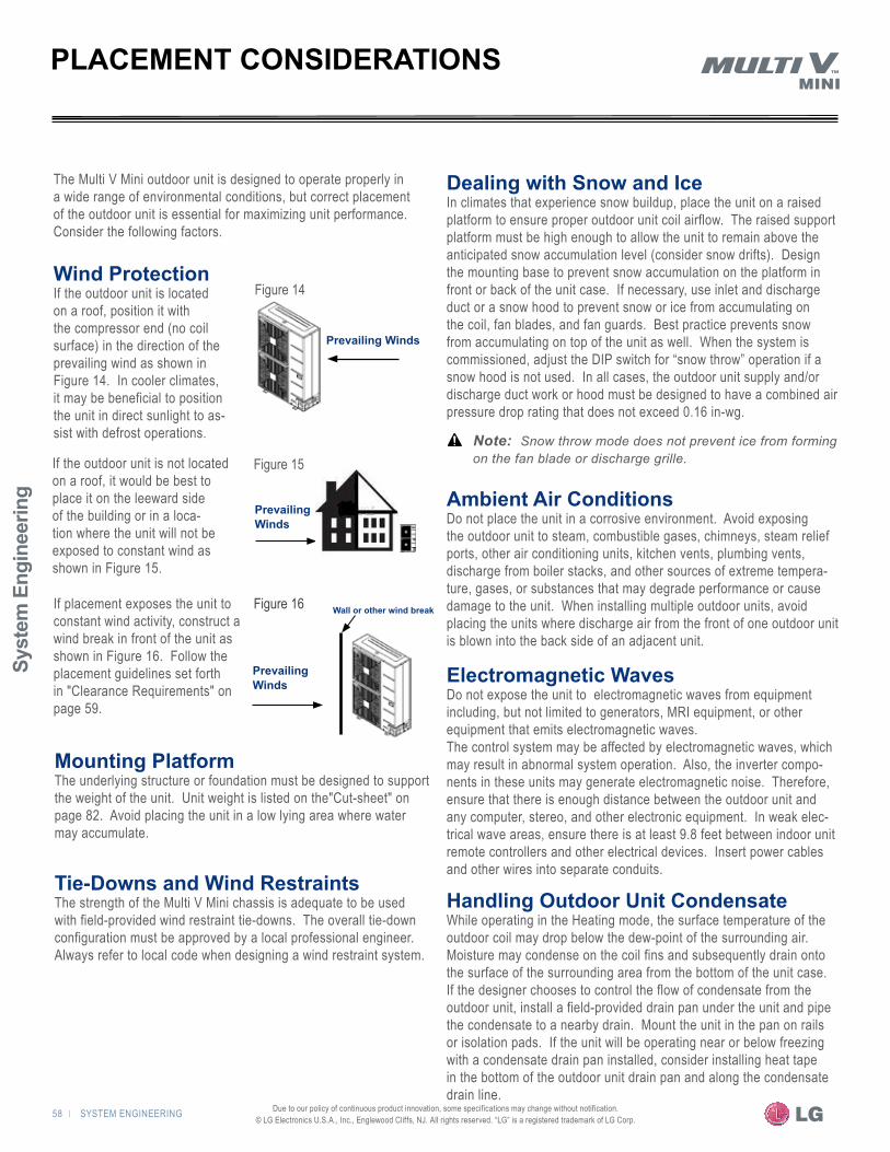
Syst
em E
ngin
eerin
g
58 | SYSTEM ENGINEERING Due to our policy of continuous product innovation, some specifications may change without notification. © LG Electronics U.S.A., Inc., Englewood Cliffs, NJ. All rights reserved. “LG” is a registered trademark of LG Corp.
The Multi V Mini outdoor unit is designed to operate properly in a wide range of environmental conditions, but correct placement of the outdoor unit is essential for maximizing unit performance. Consider the following factors.
PLACEMENT CONSIDERATIONS
Figure 14
Prevailing Winds
Figure 15
Figure 16
Dealing with Snow and IceIn climates that experience snow buildup, place the unit on a raised platform to ensure proper outdoor unit coil airflow. The raised support platform must be high enough to allow the unit to remain above the anticipated snow accumulation level (consider snow drifts). Design the mounting base to prevent snow accumulation on the platform in front or back of the unit case. If necessary, use inlet and discharge duct or a snow hood to prevent snow or ice from accumulating on the coil, fan blades, and fan guards. Best practice prevents snow from accumulating on top of the unit as well. When the system is commissioned, adjust the DIP switch for “snow throw” operation if a snow hood is not used. In all cases, the outdoor unit supply and/or discharge duct work or hood must be designed to have a combined air pressure drop rating that does not exceed 0.16 in-wg.
�Note: � Snow throw mode does not prevent ice from forming on the fan blade or discharge grille.
Ambient Air ConditionsDo not place the unit in a corrosive environment. Avoid exposing the outdoor unit to steam, combustible gases, chimneys, steam relief ports, other air conditioning units, kitchen vents, plumbing vents, discharge from boiler stacks, and other sources of extreme tempera-ture, gases, or substances that may degrade performance or cause damage to the unit. When installing multiple outdoor units, avoid placing the units where discharge air from the front of one outdoor unit is blown into the back side of an adjacent unit.
Electromagnetic WavesDo not expose the unit to electromagnetic waves from equipment including, but not limited to generators, MRI equipment, or other equipment that emits electromagnetic waves. The control system may be affected by electromagnetic waves, which may result in abnormal system operation. Also, the inverter compo-nents in these units may generate electromagnetic noise. Therefore, ensure that there is enough distance between the outdoor unit and any computer, stereo, and other electronic equipment. In weak elec-trical wave areas, ensure there is at least 9.8 feet between indoor unit remote controllers and other electrical devices. Insert power cables and other wires into separate conduits.
Handling Outdoor Unit CondensateWhile operating in the Heating mode, the surface temperature of the outdoor coil may drop below the dew-point of the surrounding air. Moisture may condense on the coil fins and subsequently drain onto the surface of the surrounding area from the bottom of the unit case. If the designer chooses to control the flow of condensate from the outdoor unit, install a field-provided drain pan under the unit and pipe the condensate to a nearby drain. Mount the unit in the pan on rails or isolation pads. If the unit will be operating near or below freezing with a condensate drain pan installed, consider installing heat tape in the bottom of the outdoor unit drain pan and along the condensate drain line.
Mounting PlatformThe underlying structure or foundation must be designed to support the weight of the unit. Unit weight is listed on the"Cut-sheet" on page 82. Avoid placing the unit in a low lying area where water may accumulate.
Tie-Downs and Wind RestraintsThe strength of the Multi V Mini chassis is adequate to be used with field-provided wind restraint tie-downs. The overall tie-down configuration must be approved by a local professional engineer. Always refer to local code when designing a wind restraint system.
If placement exposes the unit to constant wind activity, construct a wind break in front of the unit as shown in Figure 16. Follow the placement guidelines set forth in "Clearance Requirements" on page 59.
Prevailing Winds
Wall or other wind break
Prevailing Winds
If the outdoor unit is not located on a roof, it would be best to place it on the leeward side of the building or in a loca-tion where the unit will not be exposed to constant wind as shown in Figure 15.
Wind Protection If the outdoor unit is located on a roof, position it with the compressor end (no coil surface) in the direction of the prevailing wind as shown in Figure 14. In cooler climates, it may be beneficial to position the unit in direct sunlight to as-sist with defrost operations.

SYSTEM ENGINEERING | 59
HEAT PUMP CO
NDENSING UNIT ENG
INEERING M
ANUAL
Due to our policy of continuous product innovation, some specifications may change without notification. © LG Electronics U.S.A., Inc., Englewood Cliffs, NJ. All rights reserved. “LG” is a registered trademark of LG Corp.
Clearance Requirements—GeneralProper airflow through the outdoor unit coil is critical for proper unit operation. Figures 17 through 32 illustrate minimum space requirements for various installation scenarios for the ARUN036GS2 (3.0 ton), ARUN047GS2 (4.0 ton), and ARUN053GS2 (4.4 ton). Use the hot isle/cold isle (back to back or face to face) approach when placing multiple units in close proximity to each other. Outdoor unit fans draw air from the back of the unit and discharges out the front.
Figure 19: Single Unit—high rear wall with or without high side walls
Figure 18: Single Unit—high rear wall and low front wall with no side walls
CLEARANCE REQUIREMENTS
Figure 21: Side by Side—high rear and side walls
Outdoor Unit Minimum Clearance
Figure 24: Single Unit—high rear wall and low front wall with building overhang and no side walls
�tataAe: �LR = Rear wall heightLF = Front wall heightH = Unit height
Figure 20: Single Unit—high rear and front walls with no side walls
Figure 23: Single Unit— high front and rear walls with building overhang and no side walls
Figure 17: Single Unit—high front wall with building overhang and no side walls
�Note: �Installation clearances must comply with local building codes.All figures not to scale. Never place multiple units facing back to front or front to back as shown below.High and low system pressure problems may occur.
Airflow
Min. 6" "6
.niM
"02 xa M
Air�ow
M
in. 4
0"
Min. 6"
Figure 22: Single Unit—high rear and side walls with building overhang
H ≤ L
L
Max 20”
Min 40”Min 12”
Min
40”
Air�ow
H
Min. 20"
Min. 20"
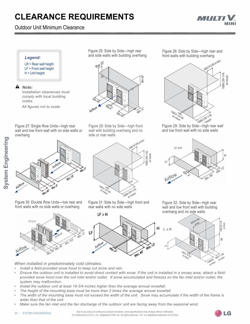
Syst
em E
ngin
eerin
g
60 | SYSTEM ENGINEERING Due to our policy of continuous product innovation, some specifications may change without notification. © LG Electronics U.S.A., Inc., Englewood Cliffs, NJ. All rights reserved. “LG” is a registered trademark of LG Corp.
Figure 26: Side by Side—high rear and front walls with building overhang
�Note: �Installation clearances must comply with local building codes. All figures not to scale.
�tataAe: �LR = Rear wall heightLF = Front wall heightH = Unit height
Figure 29: Side by Side—high rear wall and low front wall with no side walls
Figure 30: Double Row Units—low rear and front walls with no side walls or overhang
Figure 32: Side by Side—high rear wall and low front wall with building overhang and no side walls
Figure 28: Side by Side—high front wall with building overhang and no side or rear walls
Figure 31: Side by Side—high front and rear walls with no side walls
CLEARANCE REQUIREMENTSOutdoor Unit Minimum Clearance
Airflow
Figure 27: Single Row Units—high rear wall and low front wall with no side walls or overhang
Max 20”
Min
40”
Min 4”Min 40”
Min 40”
Min 12”Air�ow
1000 (39-1/4)
or more
100(3-15/16) or more
1000
(39-
1/4)
or m
ore
500(19-5/8) or less
Airflow
Airflow
Airflow
Airflow
1000 (39-1/4)
or more
100(3-15/16) or more
1000
(39-
1/4)
or m
ore
500(19-5/8) or less
Airflow
Airflow
H ≤ L
300(11-7/8)
or more
500(19-5/8)
or less10
00 (3
9-1/4
) or
mor
eH
L
1500(59)
or more
100(3-15/16) or more
When installed in predominately cold climates:• Install a field-provided snow hood to keep out snow and rain.• Ensure the outdoor unit is installed to avoid direct contact with snow. If the unit is installed in a snowy area, attach a field-
provided snow hood over the coil inlet and/or outlet. If snow accumulated and freezes on the fan inlet and/or outlet, the system may malfunction.
• Install the outdoor unit at least 19-3/4 inches higher than the average annual snowfall.• The height of the mounting base must be more than 2 times the average annual snowfall.• The width of the mounting base must not exceed the width of the unit. Snow may accumulate if the width of the frame is
wider than that of the unit.• Make sure the fan inlet and the fan discharge of the outdoor unit are facing away from the seasonal wind.
Figure 25: Side by Side—high rear and side walls with building overhang

SYSTEM ENGINEERING | 61
HEAT PUMP CO
NDENSING UNIT ENG
INEERING M
ANUAL
Due to our policy of continuous product innovation, some specifications may change without notification. © LG Electronics U.S.A., Inc., Englewood Cliffs, NJ. All rights reserved. “LG” is a registered trademark of LG Corp.
LATS MULTI V PIPE SYSTEM DESIGN TOOL
LATS Multi VThe proper design and installation of the refrigerant piping system is a critical element of the Multi V system. Multi V Mini requires two pipes between system components—a liquid line and a vapor line. A properly designed refrigerant piping system ensures that refriger-ant is delivered to the evaporator coil’s electronic expansion valve (EEV) in a pure liquid state free of gas bubbles. A proper design also ensures a sufficient refrigerant gas flow rate in the vapor line that eliminates the possibility of refrigeration oil from collecting in the vapor line. The piping system can be engineered manually using the procedure outlined in the "Pipe Layout Procedure" on page 63; however, the preferred method is to design the system using LG’s LATS Multi V software.
LATS Multi V is a Windows-based application that assists the engineer in the design of the refrigeration distribution pipe system, verifies the design complies with most pipe design limitations, ap-plies selected capacity correction factors, and calculates the system refrigerant charge.
Adjusting LATS Multi V Output for AltitudeWhen a system is installed at elevations significantly above sea level, the designer must also consider the impact air density has on the capacity of the indoor and outdoor units. An altitude correction factor must be manually applied to the indoor and outdoor unit data provided in the LATS report or tree diagram. Refer to the "Select the Outdoor Unit" procedure on page 52 for more information.
Design ChoicesLATS Multi V is flexible, offering the HVAC system engineer a choice of two design methods:1. Using the CAD mode, the refrigerant pipe design and layout
work is performed concurrently. Simply import a copy of a plan view drawing (.dwg format) for each floor of the structure into LATS Multi V. Select and place system components on the floor plan drawing(s), and draft interconnecting pipe between system components and riser pipe segments between floors. Once the layout is complete, use the export feature to create a file (.dxf for-mat) that can subsequently be imported into the building design drawings.
�Note: � On multiple story buildings, all floor drawings must have the same reference point relative to each other.
2. Using the TREE mode, the engineer can quickly create a one-line schematic drawing of the Multi V system and create an export file of the tree diagram in .dxf format. Integration of the engineered pipe system layout into the building drawings is done at a later date by the drafts person using standard drafting software tools.
In either case, LATS Multi V generates a report file (.xls format) containing project design parameters, cooling and heating design day system component performance, and capacity data. The report calculates the system CR, calculates the system refrigerant charge, and provides detailed bill of material information including a list of Multi V outdoor units, indoor units, control devices, accessories, and refrigerant pipe sizes segregated by building, by system, by pipe size, and by pipe segments.
CAD mode
• Imports the building’s architectural CAD drawing (.dwg format)• Imports building loads from an external file (.xls format)• Lays out refrigerant piping directly onto an overlay of the building
drawing• Assigns room loads to indoor units• Automatically calculates pipe segment lengths based on drawing
layout• Creates an export image file for import to the building drawing set
(.dxf format)• Generates a system engineering report (.xls format)
Tree mode
• Imports building loads from an external file (.xls format)• Selects system component using an easy drag and drop process• Automatically analyzes and checks the design complies with
most piping design limitations• Assigns room loads to indoor units• Sizes refrigerant piping• Generates a system engineering report (.xls format)• Generates a picture of the piping tree diagram (.dxf format)
Figure 33: Screenshot of LATS Pipe System Design Tool Displaying a Tree Mode Piping Diagram
Syst
em E
ngin
eerin
g
62 | SYSTEM ENGINEERING Due to our policy of continuous product innovation, some specifications may change without notification. © LG Electronics U.S.A., Inc., Englewood Cliffs, NJ. All rights reserved. “LG” is a registered trademark of LG Corp.
Figure 34: Multi V Mini Pipe Configuration Limitations
Table 22: Multi V Mini Liquid-Line Pipe-Design ParametersPipe Length* Total System 984 ELF
Longest distance from ODU to IDU
492 feet (Actual)574 feet (Equivalent)
Distance between fittings and IDUs ≥ 20” ELF
Minimum distance between IDU to any Y-Branch ≤ 131 ELF
Maximum distance between first Y-Branch to farthest IDU 131 feet
Minimum distance from IDU to Y-Branch 3 feet
Elevation If ODU is above IDU 164 feet
If ODU is below IDU 131 feet
Between any two IDUs 49 feet
b. If the outdoor unit is mounted above the indoor unit(s)
a. If the outdoor unit is mounted below the indoor unit(s)Liquid Line Pipe Design ParametersDevice Connection Limitations• Minimum number of connected indoor units per system = 1.• Minimum number of operating indoor units per system = 1.• Maximum number of indoor units on a system is: ARUN036 = 6 ARUN047 = 8 ARUN053 = 9
PIPE DESIGN PARAMETERS
IDU = Indoor UnitODU = Outdoor UnitAll elevation limitations are measured in actual feetELF = Equivalent length of pipe in feet* Limitations refer to the liquid line length (not the sum of the liquid and vapor)
Table 23: Field-Supplied Refrigerant Fittings—Liquid Line Equivalent Pipe Length
Copper Tubing Size (OD)Equivalent Pipe Length*
3/8 1/2 5/8 3/4 7/8 1-1/8Standard 90O Elbow 0.6 0.9 1.3 1.6 1.9 2.5
Long Radius 90O Elbow 0.4 0.6 0.8 1.0 1.3 1.7
Street 90O Elbow 1.0 1.6 2.1 2.6 3.1 4.2
Standard 45O Elbow 0.3 0.5 0.7 0.8 1.0 1.3
Street 45O Elbow 0.5 0.8 1.1 1.4 1.6 2.2
Y-Branch 1.6 1.6 1.6 1.6 1.6 1.6
Header 3.3 3.3 3.3 3.3 3.3 3.3
Ball Valve The equivalent length of a FULL port ball valve is the physical length of the valve. Ignore the valves and treat as straight pipe. A full port ball has the same bore diameter as the connected pipe.
* Equivalent pipe length in feet—The sum of the actual pipe length plus allocations for pressure drop through elbows and valves located in the liquid line.Values are calculated based on formula and factors from www.sporlanonline.com. LG supplied Y-Branch and Header fittings must be used. Field-built Y-Branch and Header fittings are not permitted.
Total piping length cannot exceed 984 feetLongest piping length after first branch
Max 131 feet
Level difference between IDU’ and IDU’
Max 49 feet
Total piping length cannot exceed 984 feet
Level difference between ODU’ and IDU’Max 164 feet
Longest piping length
Max 492 feet (Actual)
Max 574 feet (Equivalent)
Outdoor Unit
Longest piping lengthMax 492 feet (Actual)Max 574 feet (Equivalent)
Level difference between IDU’ and IDU’
Max 49 feet
Actual pipe length—Actual physical length of a pipe
Outdoor Unit
Longest piping length after first branch
Max 131 feet
SYSTEM ENGINEERING | 63
HEAT PUMP CO
NDENSING UNIT ENG
INEERING M
ANUAL
Due to our policy of continuous product innovation, some specifications may change without notification. © LG Electronics U.S.A., Inc., Englewood Cliffs, NJ. All rights reserved. “LG” is a registered trademark of LG Corp.
b. If the outdoor unit is mounted above the indoor unit(s)
Creating a Balanced Piping SystemBalancing dampers, ball valves, orifices, circuit setters, or other flow control devices cannot be used to modify or balance the flow of refrigerant in a VRF piping system. Therefore, variable refrigerant flow systems must be designed to be “self balanced.” Pipe sizing considerations include pipe length, pipe segment pressure drop relative to other pipe segments in the system, type and quantity of elbows, bends present, fitting installation orientation, and indoor unit elevation differences. Balanced liquid refrigerant distribution is solely dependent on the designer choosing the correct pipe size for each segment.It is imperative the designer avoids creating excessive pressure drop. In the liquid line, the pipe system must be designed in a manner that avoids the creation of unwanted vapor. When liquid re-frigerant is subjected to excessive pressure drop, the refrigerant will change state and “flash” to vapor. If vapor bubbles form in a stream of liquid refrigerant before reaching the electronic expansion valve (EEV), loss of system temperature control and EEV valve damage may occur.
Handling Field Piping ChangesAny field changes, such as rerouting, shortening or lengthening a pipe segment, adding or eliminating elbows and/or fittings, re-sizing, adding, or eliminating indoor units, changing the mounting height, or moving the location of a device or fitting during installation should be done with caution and always verified in LATS Multi V before piping supplies are purchased or installed. Doing so may have a positive effect on job profit, eliminate rework, and may avoid unexpected necessary pipe changes before commissioning.
Layout ProcedureWhen this procedure is complete, the liquid line working drawing should contain the information for each pipe segment and others entities depicted in Figure 35 on page 65.1. Choose the location of the indoor units and draw them on the
building drawing. 2. Choose the location of all Y-Branch and Header fittings and add
them to the drawings. Verify that all fittings are positioned per the guideline limitations set forth in "Y-Branch Kits" on page 66 and "Header Kits" on page 67.
3. Plan the route for interconnecting piping. Draw a one-line depic-tion of the pipe route chosen on the building drawings.
4. Calculate the actual length of each pipe segment and note it on the drawing next to each segment.
5. Using the data obtained while selecting the system components from the "Equipment Selection Procedure" on page 51, list the nominal cooling capacity next to each indoor unit on the drawing.
6. Starting at the runout segment servicing the indoor unit located farthest from the outdoor unit, note the connected nominal capacity of the indoor unit served by the pipe segment. Record these values next to each segment on the drawing.
7. At the branch or pipe segment upstream of the farthest Y-Branch or Header fitting from the outdoor unit, note the downstream connected nominal capacity of all indoor units served by the pipe segment. Record these values next to the segment on the drawing. Repeat the same procedure for each branch and main pipe segment woking your way up the liquid line back toward the outdoor unit for each leg of the piping system. When completed, all segments will be noted with the nominal capacity of the downstream indoor units served by each segment.
8. Use Table 24 to select the correct pipe size for both the liquid and vapor lines. Note the chosen line sizes next to each seg-ment.
9. Size Y-Branch and Header fittings. Refer to Cut-Sheets for "Y-Branch Kits" on page 4 and "Header Kits" on page 5 to determine the part number of each LG Y-Branch and/or Header based on the connected downstream nominal capacity served. Record the part number next to each fitting.
10. Calculate the equivalent pipe length in feet of the branch and main pipe segments. Y-Branch and Header equivalent lengths should be included with the upstream segment only. Use equivalent pipe length data provided with purchased fittings. If unavailable, use the data provided in Table 24. Y-Branch and Header equivalent lengths are found in the Cut-Sheets on pages 4 and 85. Equivalent length values will be used to calculate the system refrigerant charge.
11. Verify the actual and/or equivalent pipe length complies with the limitations listed in Table 23. If the limitations are exceeded, ei-ther reroute the pipe or change the location of selected Y-Branch fittings, Header fittings, and/or indoor unit locations so the design conforms with all limitations.
12. Verify the manually sized pipe design is acceptable using LATS Multi V. Using the LATS tree mode modeling option, enter the actual pipe length of each pipe segment. Account for the ad-ditional pressure drop created by elbows by double-clicking on the segment length text in LATS Multi V. In the dialog box, enter the elbow count.
13. After entering all necessary information into LATS, click on the "Auto Pipe" button on the left followed by the "System Check" button located under the "Auto Pipe" button. If no dialog boxes pop up indicating an error and none of the entities on the tree mode diagram have a red box around or along them, the pipe design is acceptable and the layout work is complete. If errors were indicated, modify the pipe design as needed. For assis-tance, contact the applied product representative in your area.
PIPE LAYOUT PROCEDURE

Syst
em E
ngin
eerin
g
64 | SYSTEM ENGINEERING Due to our policy of continuous product innovation, some specifications may change without notification. © LG Electronics U.S.A., Inc., Englewood Cliffs, NJ. All rights reserved. “LG” is a registered trademark of LG Corp.
Table 24: Pipe Segment Sizing— All pipe dimensions are inches OD
ModelMain Pipe Segment1 Branch and Run-Out Segments2,3
< 295 feet equivalent ≥ 295 feet equivalent ≤ 19.1 MBh downstream capacity
> 19.1 MBh < 54.6 MBhdownstream capacity
≥ 54.6 MBh ≤ 68.9 MBh downstream capacity
Liquid Vapor Liquid Vapor Liquid Vapor Liquid Vapor Liquid VaporARUN036GS2 3/8 5/8 3/8 3/4 1/4 1/2 3/8 5/8 – –
ARUN047GS2 3/8 5/8 3/8 3/4 1/4 1/2 3/8 5/8 – –
ARUN053GS2 3/8 3/4 3/8 3/4 3/8 3/4 3/8 3/4 3/8 3/4
1. Select the equivalent length of the longest pipe run between the outdoor unit and the furthest indoor unit.2. Capacity (MBh) = The sum of the nominal capacity of all connected indoor units served by the pipe segment.3. If the sum of the nominal cooling capacity of all connected indoor units served by a branch or run-out segment is greater than the capacity of the outdoor unit, size the pipe segment based on the
outdoor unit nominal capacity.
PIPE LAYOUT PROCEDURE
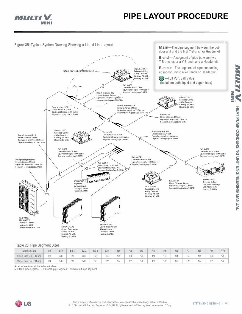
SYSTEM ENGINEERING | 65
HEAT PUMP CO
NDENSING UNIT ENG
INEERING M
ANUAL
Due to our policy of continuous product innovation, some specifications may change without notification. © LG Electronics U.S.A., Inc., Englewood Cliffs, NJ. All rights reserved. “LG” is a registered trademark of LG Corp.
Figure 35: Typical System Drawing Showing a Liquid Line Layout
Table 25: Pipe Segment SizesSegment Tag M1 B1.1 B2.1 B2.2 B2.3 B2.4 R1 R2 R3 R4 R5 R6 R7 R8 R9 R10
Liquid Line Dia. OD (in) 3/8 3/8 3/8 3/8 3/8 1/4 1/4 1/4 1/4 1/4 1/4 1/4 1/4 1/4 1/4 1/4
Vapor Line Dia. OD (in) 3/4 5/8 5/8 5/8 5/8 1/2 1/2 1/2 1/2 1/2 1/2 1/2 1/2 1/2 1/2 1/2
All sizes are internal diameter in inches.M = Main pipe segment, B = Branch pipe segment, R = Run-out pipe segment
PIPE LAYOUT PROCEDURE
Main—The pipe segment between the out-door unit and the first Y-Branch or Header kit
Branch—A segment of pipe between two Y-Branches or a Y-Branch and a Header kitRun-out—The segment of pipe connecting an indoor unit to a Y-Branch or Header kit —Full Port Ball Valve (Install on both liquid and vapor lines)
ARNU073TEC2Recessed Ceiling4-Way CassetteCooling: 7.5 MBhHeating: 8.5 MBh
ARNU073TEC2Recessed Ceiling4-Way CassetteCooling: 7.5 MBhHeating: 8.5 MBh
ARNU073TEC2Recessed Ceiling4-Way CassetteCooling: 7.5 MBhHeating: 8.5 MBh
ARNU073CEA2Cased - Floor Mount4-Way CassetteCooling: 7.5 MBhHeating: 8.5 MBh
ARNU073CEA2Cased - Floor Mount4-Way CassetteCooling: 7.5 MBhHeating: 8.5 MBh
ARNU073B1G2Recessed CeilingLow Static DischargeCooling: 7.5 MBhHeating: 8.5 MBh
ARNU073TEC2Recessed Ceiling4-Way CassetteCooling: 7.5 MBhHeating: 8.5 MBh
ARNU073SEL2High WallSurface MountCooling: 7.5 MBhHeating: 8.5 MBh
Multi V MiniARUN047GS2Cooling: 47.8 MBhHeating: 54.6 MBhCombination Ratio: 125%
Future IDU (to be installed later)
Cap here Run-out R1Linear distance: 35 feetEquivalent length: <<XX feet>>Segment cooling cap: 7.5 MBh
Branch segment B2.1Linear distance: 24 feetEquivalent length: <<XX feet>>Segment cooling cap: 37.5 MBh
Branch segment B2.2Linear distance: 24 feetEquivalent length: <<XX feet>>Segment cooling cap: 30.0 MBh
Main pipe segment M1Linear distance: 18 feetEquivalent length: <<XX feet>>Segment cooling cap: 60.0 MBh
Branch segment B1.1Linear distance: 18 feetEquivalent length: <<XX feet>>Segment cooling cap: 22.5 MBh
Run-out R6Linear distance: 18 feetEquivalent length: <<XX feet>>Segment cooling cap: 7.5 MBh
Branch segment B2.3Linear distance: 24 feetEquivalent length: <<XX feet>>Segment cooling cap: 22.5 MBh
Run-out R3Linear distance: 35 feetEquivalent length: <<XX feet>>Segment cooling cap: 7.5 MBh
Branch segment B2.4Linear distance: 24 feetEquivalent length: <<XX feet>>Segment cooling cap: 15.0 MBh
Run-out R6Linear distance: 18 feetEquivalent length: <<XX feet>>Segment cooling cap: 7.5 MBhRun-out R8
Linear distance: 18 feetEquivalent length: <<XX feet>>Segment cooling cap: 7.5 MBh
Run-out R2Linear distance: 20 feetEquivalent length: <<XX feet>>Segment cooling cap: 7.5 MBh
Run-out R9Linear Distance: 14 feetEquivalent Length: 14.4 feetSegment Cooling Cap: 7.5 MBh
Run-out R10Linear Distance: 8.5 feetEquivalent Length: 9.7 feetSegment Cooling Cap: 7.5 MBh

Syst
em E
ngin
eerin
g
66 | SYSTEM ENGINEERING Due to our policy of continuous product innovation, some specifications may change without notification. © LG Electronics U.S.A., Inc., Englewood Cliffs, NJ. All rights reserved. “LG” is a registered trademark of LG Corp.
Figure 36: Connecting Y-Branch Kits
PIPING DESIGN GUIDE
General:The Y-Branch and Header kits are used to join one pipe segment to two or more segments. See Cut-Sheets: "Y-Branch Kits" on page 80 and "Header Kits" on page 81 for sizes and dimensions.
a. Vertical Up Configuration
b. Vertical Down Configuration
c. Horizontal Configuration End View
LG Engineered Y-Branch and Header Kits
LG Y-Branch kits consists of:
• Two Y-Branches (one liquid line, one vapor line)• Reducer fittings as applicable• Molded clam-shell type insulation covers
LG Header kits consists of:
• Two Headers (one liquid line, one vapor line)• Reducer fittings as applicable• Molded clam-shell type insulation covers
Y-Branch Kits
Y-Branch InsulationEach Y-Branch kit comes with two clam-shell type peel and stick insulation jackets molded to fit the Y-Branch fittings as shown in Figure 39—one for the liquid line, one for the vapor line. 1. Check the fit of the Y-Branch clam-shell insula-
tion jacket after the Y-Branch is installed. 2. Verify there will be no exposed pipe between
the end of the Y-Branch, jacket, and adjacent pipe insulation.
3. Mark the pipe where the insulation jacket ends. 4. Remove the jacket.
�Note: � Only LG supplied Y-Branch and Header fittings can be used to join one pipe segment to two or more segments.
LG Y-Branch and Header kits are precision engineered devices designed to evenly divide the flow of refrigerant. Third-party or field fabricated Tee’s, Y-fittings, Head-ers, or other branch fittings are not qualified for use with LG Multi V systems. The only field-provided fittings allowed in a Multi V piping system are 45° and 90° elbows and full-port ball valves.
There is no limitation on the number of Y-Branches that can be installed, but there is a limita-tion on the number of indoor units connected to a single outdoor unit. See Table 1a on page 14.
Avoid installing Y-Branches back-wards as shown in Figure 36. Re-frigerant flow cannot make U-turns through Y-Branches.
The pipe coming from the outdoor unit should always connect to the single port end of the Y-Branch as shown in Figure 37.Y-Branches may be installed in a horizontal or vertical configuration. When installed in the horizontal configuration, position the fitting so the take-off leg shares the same horizontal plane as the straight-thru leg ±10° as shown in Figure 38c. When installed in a vertical configuration, position the fitting so the straight-thru leg is ±3° of plum. See Figure 38 (a and b).The first Y-Branch kit must be located at least 3 feet from the outdoor unit. Provide a minimum of 20 inches between a branch fit-ting and any other fitting or indoor unit piped in series to avoid generating refrigerant flow noise into the system.It is recommended that when a Y-Branch is located in a pipe chase or other concealed space, access doors should be provided for access and inspection.See "Refrigerant Pipe System Insulation" on page 76 for pipe system insulation information.
5. Install field-provided insulation on the 3 pipes first.
6. Peel the adhesive glue protector slip and install the clam-shell jacket over the fitting.
To ODU
To IDU
To IDU
-3° +3°
-3° +3°
Straight Through Leg Branch Leg10°
-10°
Horizontal Plane
Y-Branch Inlet
Field-Supplied Insulation
LG-Supplied Y-Branch Fitting
LG-Supplied Insulation JacketField-Supplied Insulation
Field-Supplied Copper Pipe
To next branch
To indoor unit
Figure 37: Y-Branch Connections
Figure 38: Y-Branch insulation alignment specification
Figure 39: Y-Branch insulation and pipe detail
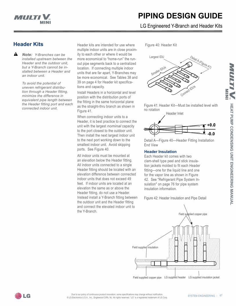
SYSTEM ENGINEERING | 67
HEAT PUMP CO
NDENSING UNIT ENG
INEERING M
ANUAL
Due to our policy of continuous product innovation, some specifications may change without notification. © LG Electronics U.S.A., Inc., Englewood Cliffs, NJ. All rights reserved. “LG” is a registered trademark of LG Corp.
PIPING DESIGN GUIDE
Header Fitting Installation End View
Header Inlet
Detail A (Figure 15)Detail A—Figure 40—Header Fitting Installation End View
Header Inlet
Figure 42: Header Insulation and Pipe Detail
Figure 40: Header Kit
LG Engineered Y-Branch and Header Kits
Header Kits
�Note: � Y-Branches can be installed upstream between the Header and the outdoor unit, but a Y-Branch cannot be in-stalled between a Header and an indoor unit.
To avoid the potential of uneven refrigerant distribu-tion through a Header fitting, minimize the difference in equivalent pipe length between the Header fitting port and each connected indoor unit.
Header InsulationEach Header kit comes with two clam-shell type peel and stick insula-tion jackets molded to fit each Header fitting—one for the liquid line and one for the vapor line as shown in Figure 42. See "Refrigerant Pipe System In-sulation" on page 76 for pipe system insulation information.
LG supplied insulation jacketLG supplied headerField supplied copper pipe
Field supplied insulation
Field supplied copper pipe
Header kits are intended for use where multiple indoor units are in close proxim-ity to each other or where it would be more economical to “home-run” the run-out pipe segments back to a centralized location. If connecting multiple indoor units that are far apart, Y-Branches may be more economical. See Tables 38 and 39 on page 4 for Header kit specifica-tions and capacity.Install Headers in a horizontal and level position with the distribution ports of the fitting in the same horizontal plane as the straight-thru branch as shown in Figure 41.When connecting indoor units to a Header, it is best practice to connect the unit with the largest nominal capacity to the port closest to the outdoor unit. Then install the next largest indoor unit to the next port working down to the smallest indoor unit. Avoid skipping ports. See Figure 40.All indoor units must be mounted at an elevation below the Header fitting. All indoor units connected to a single Header fitting should be located with an elevation difference between connected indoor units that does not exceed 49 feet. If indoor units are located at an elevation the same as or above the Header fitting, do not use a Header. Instead install a Y-Branch fitting between the outdoor unit and the Header fitting and connect the elevated indoor unit to the Y-Branch.
Connect IDUs
Detail A (Figure 41)
Largest IDU
Smaller IDUs
Figure 41: Header Kit—Must be installed level with no rotation
Syst
em E
ngin
eerin
g
68 | SYSTEM ENGINEERING Due to our policy of continuous product innovation, some specifications may change without notification. © LG Electronics U.S.A., Inc., Englewood Cliffs, NJ. All rights reserved. “LG” is a registered trademark of LG Corp.
PIPING DESIGN GUIDE
Engineering for Future Indoor Units Commissioning in StagesBegin with the end in mind to avoid system downtime, unneces-sary costs, and the replacement of installed pipe segments when adding subsequent indoor units and/or changing the location or size of existing units after the system is initially designed and com-missioned. Complete the following at the same time the initially installed portion of the system is complete: • Placement decisions for all future indoor units• Piping plan for future piping• Sizing of future pipe segments In these applications, the future pipe design must be verified using LG’s LATS Multi V software to confirm the pipe design complies with LG’s design limitations after all future indoor unit additions and planned pipe system changes are made. Install isolation ball valves on the liquid and vapor lines near the Y-Branch or Header on each leg where the future run-out piping and unit will be con-nected. If possible, avoid installing the pipe segment between the ball valve and the location of the future indoor unit during the initial phase of the project. Cap the future pipe segment 3 to 6 inches from the ball valve discharge and open the valve before system evacuation and charging. Close the valve after charging the system. Doing so ensures that refrigeration oil will return to the compressor sump and not be trapped in future-use pipe segments. For example, refer to Figure 35 and review the drawing of the run-out segment tagged R1. It is very important to verify the system’s CR is at least 50% initially and that it does not exceed 130% after all future indoor unit changes and/or additions are completed. See "How to Determine the System Combination Ratio (CR)" on page 55 for more information. Verify the anticipated RUR is within the limitations listed on page 55.
Using ElbowsThird-party elbows are allowed as long as they are designed for use with R410A refrigerant. The designer and installer should use a minimum number of fittings since they must consider the pressure drop each creates measured in equivalent length of pipe in feet. When using the LATS Multi V software or when performing manual calculations, the additional equivalent pipe length of all fit-tings must be accounted for in the respective segments. See Table 23 on page 62.
Field-Provided Isolation ValvesLG neither provides nor requires isolation ball valves on indoor units for proper system operation. If isolation is desired, full-port isolation ball valves with Schrader ports (positioned between valve and indoor unit) rated for use with R410A refrigerant should be used on the liquid and vapor lines. Position the valves so they are easily accessible for service. If necessary, install drywall access doors or removable ceiling panels. Position valves with 3 to 6 inches of pipe on either side. Position valves with adequate clear-ance for applying field insulation. If valves are not installed and a single indoor unit needs to be removed or repaired, the entire system must be shut down and evacuated. If isolation ball valves are installed, the unaffected indoor units may be operated after the control system is rebooted if the system CR (excluding the disconnected unit) remains between 50% and 130%. See "How to Determine the System Combination Ratio (CR)" on page 55.
Refrigerant SpecialtiesIn-line refrigeration components, such as solenoid valves, filter-dryers, sight glasses, tee fittings, and after-market refrigerant pipe system accessories are prohibited and cannot be used with the Multi V Mini. Sight-glasses, solenoid valves, and tee fittings may cause gas bubbles to form in the liquid line. Over time, dryers may deteriorate and introduce debris into the system.
Oil TrapsOil traps are not permitted. The Multi V system is engineered with redundant systems that ensure oil is properly returned to the com-pressor. The designer and installer should verify that the refriger-ant piping system is free of oil traps. For instructions on routing a pipe segment around an obstacle, see "Handling Obstacles" on page 74.
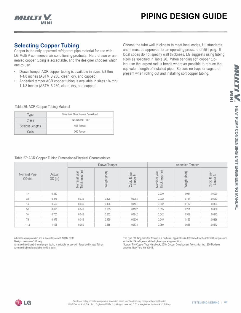
SYSTEM ENGINEERING | 69
HEAT PUMP CO
NDENSING UNIT ENG
INEERING M
ANUAL
Due to our policy of continuous product innovation, some specifications may change without notification. © LG Electronics U.S.A., Inc., Englewood Cliffs, NJ. All rights reserved. “LG” is a registered trademark of LG Corp.
Nominal Pipe OD (in)
Actual OD (in)
Drawn Temper Annealed Temper
Nomi
nal W
all
Thick
ness
(in)
Weig
ht (lb
/ft)
Cubic
ft. pe
r Lin
ear f
t.
Nomi
nal W
all
Thick
ness
(in)
Weig
ht (lb
/ft)
Cubic
ft. pe
r Lin
ear f
t.
1/4 0.250 – – – 0.030 0.081 .00020
3/8 0.375 0.030 0.126 .00054 0.032 0.134 .00053
1/2 0.500 0.035 0.198 .00101 0.032 0.182 .00103
5/8 0.625 0.040 0.285 .00162 0.035 0.251 .00168
3/4 0.750 0.042 0.362 .00242 0.042 0.362 .00242
7/8 0.875 0.045 0.455 .00336 0.045 0.455 .00336
1-1/8 1.125 0.050 0.655 .00573 0.050 0.655 .00573
All dimensions provided are in accordance with ASTM B280.Design pressure = 551 psig.Annealed (soft) and drawn temper tubing is suitable for use with flared and brazed fittings.Annealed tubing is available in 50 ft. coils.
The type of tubing selected for use in a particular application is determined by the internal fluid pressure of the R410A refrigerant at the highest operating condition.Source: The Copper Tube Handbook, 2010, Copper Development Association Inc., 260 Madison Avenue, New York, NY 10016.
PIPING DESIGN GUIDE
Type Seamless Phosphorous Deoxidized
Class UNS C12200 DHP
Straight Lengths H58 Temper
Coils O60 Temper
Selecting Copper TubingCopper is the only approved refrigerant pipe material for use with LG Multi V commercial air conditioning products. Hard-drawn or an-nealed copper tubing is acceptable, and the designer chooses which one to use.• Drawn temper ACR copper tubing is available in sizes 3/8 thru
1-1/8 inches (ASTM B 280, clean, dry, and capped). • Annealed temper ACR copper tubing is available in sizes 1/4 thru
1-1/8 inches (ASTM B 280, clean, dry, and capped).
Choose the tube wall thickness to meet local codes, UL standards, and it must be approved for an operating pressure of 551 psig. If local codes do not specify wall thickness, LG suggests using tubing sizes as specified in Table 26. When bending soft copper tub-ing, use the largest radius bends wherever possible to reduce the equivalent length of installed pipe. Be sure no traps or sags are present when rolling out and installing soft copper tubing.
Table 26: ACR Copper Tubing Material
Table 27: ACR Copper Tubing Dimensions/Physical Characteristics

Syst
em E
ngin
eerin
g
70 | SYSTEM ENGINEERING Due to our policy of continuous product innovation, some specifications may change without notification. © LG Electronics U.S.A., Inc., Englewood Cliffs, NJ. All rights reserved. “LG” is a registered trademark of LG Corp.
Copper Expansion and ContractionUnder normal operating conditions, the vapor pipe temperature of a Multi V Mini system can vary as much as 280°F. With this large variance in pipe temperature combined with a potential straight run pipe of up to 492 feet and a segment length between fittings of up to 131 feet, the designer must consider pipe expansion and contraction to avoid potential pipe and fitting fatigue failures.Refrigerant pipe along with the insulation jacket form a cohesive unit that expands and contracts together. During system operation, thermal heat transfer occurs between the pipe and the surrounding insulation. If the pipe is mounted in free air space, no natural restriction to movement is present if mounting clamps are properly spaced and installed. When the refrigerant pipe is mounted underground in a utility duct stacked among other pipes, natural restriction to linear movement is present. In extreme cases, the restrictive force of surface friction between insulating jackets could become so great that natural expansion ceases and the pipe is “fixed” in place. In this situation, opposing force caused by the change in refrigerant fluid/vapor temperature can lead to pipe/fitting stress failure.The refrigerant pipe support system must be engineered to allow free expansion to occur. When a segment of pipe is mounted between two fixed points, provisions must be provided to allow pipe expan-sion to naturally occur. The most common method is the inclusion of expansion Loop or U-bends. See Figure 43 on page 72. Each segment of pipe has a natural fixed point where no movement oc-curs. This fixed point is located at the center point of the segment assuming the entire pipe is insulated in a similar fashion. The natu-ral fixed point of the pipe segment is typically where the expansion Loop or U-bend should be placed. Linear pipe expansion can be calculated using the following formula:
Refer to Table 28 and 29 for anticipated expansion distances for copper pipe.1. From Table 28, find the row corresponding with the actual length
of the straight pipe segment.2. Estimate the minimum and maximum temperature of the pipe.3. In the column showing the minimum pipe temperature, look up
the anticipated expansion distance. Do the same for the maxi-mum pipe temperature.
4. Calculate the difference in the two expansion distance values. The resultant will be the anticipated change in pipe length.
For example,A Multi V Mini heat pump system is installed and the design shows that there is a 260 feet straight segment of tubing between a Y-Branch and an indoor unit. In Heating mode, this pipe transports hot gas vapor to the indoor units at 120°F. In Cooling mode, the same tube is a suction line returning refrigerant vapor to the outdoor unit at 40°F. Look up the copper tubing expansion at each temperature and calculate the difference. Vapor LineTransporting Hot Vapor: 260 ft. pipe at 120°F = 3.64 in.Transporting Suction Vapor: 260 ft. pipe at 40°F = 1.04 in.Anticipated change in length: 3.64 in. – 1.04 in. = 2.60 in.
Liquid LineThe liquid pipe temperature will not vary significantly. Only the direc-tion of flow will change.
Creating an Expansion JointWhen creating an expansion joint, the joint height should be a minimum of two times the joint width. Although different types of ex-pansion arrangements are available, the data for correctly sizing an expansion loop is provided. Use soft copper with long radius bends on longer runs or long radius elbows for shorter pipe segments. Use the anticipated linear expansion (LE) distance calculated, and look up the Loop or U-bend minimum design dimensions. If you choose other types of expansion joints, design per ASTM B-88 standards.
PIPING DESIGN GUIDE
LE = C x L x (Tr – Ta) x 12
Where
LE = Anticipated linear tubing expansion (in.)C = Constant (For copper = 9.2 x 10⁻⁶ in./in.°F)L = Length of pipe (ft.)Tr = Refrigerant pipe temperature (°F)Ta = Ambient air temperature (°F)12 = Inches to feet conversion (12 in/ft.)

SYSTEM ENGINEERING | 71
HEAT PUMP CO
NDENSING UNIT ENG
INEERING M
ANUAL
Due to our policy of continuous product innovation, some specifications may change without notification. © LG Electronics U.S.A., Inc., Englewood Cliffs, NJ. All rights reserved. “LG” is a registered trademark of LG Corp.
Table 28: Linear Thermal Expansion of Copper Tubing in Inches
Pipe Length
Fluid Temperature OF35° 40° 45° 50° 55° 60° 65° 70° 75° 80° 85° 90° 95° 100° 105° 110° 115° 120° 125° 130°
10 0.04 0.04 0.05 0.06 0.06 0.07 0.08 0.08 0.09 0.09 0.10 0.10 0.11 0.11 0.11 0.12 0.13 0.14 0.15 0.15
20 0.08 0.08 0.10 0.12 0.13 0.14 0.15 0.16 0.17 0.18 0.19 0.20 0.21 0.22 0.22 0.23 0.26 0.28 0.29 0.30
30 0.12 0.12 0.15 0.18 0.20 0.21 0.23 0.24 0.26 0.27 0.29 0.30 0.32 0.33 0.32 0.35 0.39 0.42 0.44 0.45
40 0.16 0.16 0.20 0.24 0.26 0.28 0.30 0.32 0.34 0.36 0.38 0.40 0.42 0.44 0.43 0.46 0.52 0.56 0.58 0.60
50 0.20 0.20 0.25 0.30 0.33 0.35 0.38 0.40 0.43 0.45 0.48 0.50 0.53 0.55 0.54 0.58 0.65 0.70 0.73 0.75
60 0.24 0.24 0.30 0.36 0.39 0.42 0.45 0.48 0.51 0.54 0.57 0.60 0.63 0.66 0.65 0.69 0.78 0.84 0.87 0.90
70 0.28 0.28 0.35 0.42 0.46 0.49 0.53 0.56 0.60 0.63 0.67 0.70 0.74 0.77 0.76 0.81 0.91 0.98 1.02 1.05
80 0.32 0.32 0.40 0.48 0.52 0.56 0.60 0.64 0.68 0.72 0.76 0.80 0.84 0.88 0.86 0.92 1.04 1.12 1.16 1.20
90 0.36 0.36 0.45 0.54 0.59 0.63 0.68 0.72 0.77 0.81 0.86 0.90 0.95 0.99 0.97 1.04 1.17 1.26 1.31 1.35
100 0.40 0.40 0.50 0.60 0.65 0.70 0.75 0.80 0.85 0.90 0.95 1.00 1.05 1.10 1.08 1.15 1.30 1.40 1.45 1.50
120 0.48 0.48 0.60 0.72 0.78 0.84 0.90 0.96 1.02 1.08 1.14 1.20 1.26 1.32 1.30 1.38 1.56 1.68 1.74 1.80
140 0.56 0.56 0.70 0.84 0.91 0.98 1.05 1.12 1.19 1.26 1.33 1.40 1.47 1.54 1.51 1.61 1.82 1.96 2.03 2.10
160 0.64 0.64 0.80 0.96 1.04 1.12 1.20 1.28 1.36 1.44 1.52 1.60 1.68 1.76 1.73 1.84 2.08 2.24 2.32 2.40
180 0.72 0.72 0.90 1.08 1.17 1.26 1.35 1.44 1.53 1.62 1.71 1.80 1.89 1.98 1.94 2.07 2.34 2.52 2.61 2.70
200 0.80 0.80 1.00 1.20 1.30 1.40 1.50 1.60 1.70 1.80 1.90 2.00 2.10 2.20 2.16 2.30 2.60 2.80 2.90 3.00
220 0.88 0.88 1.10 1.32 1.43 1.54 1.65 1.76 1.87 1.98 2.09 2.20 2.31 2.42 2.38 2.53 2.86 3.08 3.19 3.30
240 0.96 0.96 1.20 1.44 1.56 1.68 1.80 1.92 2.04 2.16 2.28 2.40 2.52 2.64 2.59 2.76 3.12 3.36 3.48 3.60
260 1.04 1.04 1.30 1.56 1.69 1.82 1.95 2.08 2.21 2.34 2.47 2.60 2.73 2.86 2.81 2.99 3.38 3.64 3.77 3.90
280 1.12 1.12 1.40 1.68 1.82 1.96 2.10 2.24 2.38 2.52 2.66 2.80 2.94 3.08 3.02 3.22 3.64 3.92 4.06 4.20
300 1.20 1.20 1.50 1.80 1.95 2.10 2.25 2.40 2.55 2.70 2.85 3.00 3.15 3.30 3.24 3.45 3.90 4.20 4.35 4.50
320 1.28 1.28 1.60 1.92 2.08 2.24 2.40 2.56 2.72 2.88 3.04 3.20 3.36 3.52 3.46 3.68 4.16 4.48 4.64 4.80
340 1.36 1.36 1.70 2.04 2.21 2.38 2.55 2.72 2.89 3.06 3.23 3.40 3.57 3.74 3.67 3.91 4.42 4.76 4.93 5.10
360 1.44 1.44 1.80 2.16 2.34 2.52 2.70 2.88 3.06 3.24 3.42 3.60 3.78 3.96 3.89 4.14 4.68 5.04 5.22 5.40
380 1.52 1.52 1.90 2.28 2.47 2.66 2.85 3.04 3.23 3.42 3.61 3.80 3.99 4.18 4.10 4.37 4.94 5.32 5.51 5.70
400 1.60 1.60 2.00 2.40 2.60 2.80 3.00 3.20 3.40 3.60 3.80 4.00 4.20 4.40 4.32 4.60 5.20 5.60 5.80 6.00
420 1.68 1.68 2.10 2.52 2.73 2.94 3.15 3.36 3.57 3.78 3.99 4.20 4.41 4.62 4.54 4.83 5.46 5.88 6.09 6.30
440 1.76 1.76 2.20 2.64 2.86 3.08 3.30 3.52 3.74 3.96 4.18 4.40 4.62 4.84 4.75 5.06 5.72 6.16 6.38 6.60
460 1.84 1.84 2.30 2.76 2.99 3.22 3.45 3.68 3.91 4.14 4.37 4.60 4.83 5.06 4.97 5.29 5.98 6.44 6.67 6.90
480 1.92 1.92 2.40 2.88 3.12 3.36 3.60 3.84 4.08 4.32 4.56 4.80 5.04 5.28 5.18 5.52 6.24 6.72 6.96 7.20
500 2.00 2.00 2.50 3.00 3.25 3.50 3.75 4.00 4.25 4.50 4.75 5.00 5.25 5.50 5.40 5.75 6.50 7.00 7.25 7.50
Pipe length baseline temperature = 0°FPipe length in feetThe Engineers Toolbox (www.engineeringtoolbox.com)—Expansion of Carbon, Copper and Stainless Steel Pipe
PIPING DESIGN GUIDE

Syst
em E
ngin
eerin
g
72 | SYSTEM ENGINEERING Due to our policy of continuous product innovation, some specifications may change without notification. © LG Electronics U.S.A., Inc., Englewood Cliffs, NJ. All rights reserved. “LG” is a registered trademark of LG Corp.
Table 29: Radii of Coiled Expansion Loops and Developed Lengths of Expansion OffsetsAnticipated Linear Expansion (LE) (in)
Nominal Tube Size (OD) inches1/4 3/8 1/2 3/4 1 1-1/4 1-1/2
1/2R1 6 7 8 9 11 12 13
L2 38 44 50 59 67 74 80
1R1 9 10 11 13 15 17 18
L2 54 63 70 83 94 104 113
1-1/2R1 11 12 14 16 18 20 22
L2 66 77 86 101 115 127 138
2R1 12 14 16 19 21 23 25
L2 77 89 99 117 133 147 160
2-1/2R1 14 16 18 21 24 26 29
L2 86 99 111 131 149 165 179
3R1 15 17 19 23 26 29 31
L2 94 109 122 143 163 180 196
3-1/2R1 16 19 21 25 28 31 34
L2 102 117 131 155 176 195 212
4R1 17 20 22 26 30 33 36
L2 109 126 140 166 188 208 226
R = Centerline Minimum Radius (inches)L = Centerline Length of PipeThe Engineers Toolbox (www.engineeringtoolbox.com)—Expansion of Carbon, Copper and Stainless Steel Pipe
Figure 43: Coiled Expansion Loops and Offsets
PIPING DESIGN GUIDE
a. Large Tubing U-Bend (>3/4 in.) b. Loop c. Small Tubing U-Bend (<3/4 in.)
R
L
RL
L

SYSTEM ENGINEERING | 73
HEAT PUMP CO
NDENSING UNIT ENG
INEERING M
ANUAL
Due to our policy of continuous product innovation, some specifications may change without notification. © LG Electronics U.S.A., Inc., Englewood Cliffs, NJ. All rights reserved. “LG” is a registered trademark of LG Corp.
Refrigerant Pipe Connections�Note: � When routing field-provided tubing inside the out-door unit case, take care to avoid vibration damage to the tubing. Mount the tubing so it does not make contact with the compressor, unit casing, terminal cover, or mounting bolts. Allow room for field installation. Properly insulate field-provided tubing inside the confines of the unit casing.Refer to Figure 44 for unit pipe connection options and Table 27 for outdoor unit connection types.
Pipe SupportsA properly installed pipe system should be adequately supported to avoid pipe sagging. Sagging pipes become oil traps that could lead to equipment malfunction. Field-provided pipe supports should be designed to meet local codes. If allowed by code, use fiber straps or split-ring hangers suspended from the ceiling on all-thread rods. Supports should never touch the pipe wall. Insulate the pipe first. Place a second layer of insulation over the pipe insulation jacket to prevent chafing and compression of the primary insulation within the confines of the support pipe clamp. Pipe and insulation should be allowed to move linearly as pipe temperature changes.• Straight segments up to 3/4 inch OD should be supported at
least every 5 feet or per local codes if more stringent.• Straight segments of 1 inch OD and larger copper pipe should
be supported every 6 feet or per local codes if more stringent.• A properly installed pipe system will have sufficient supports
to keep pipes from sagging during the life of the system. As necessary, place supports closer for segments where potential sagging could occur.
Wherever the pipe changes direction, place a hanger within 12 inches on one side and within 12 to 19 inches of the bend on the other side as shown in Figure 45. Support piping at indoor units as shown in Figure 46. Support Y-Branch and Header fittings as shown in Figure 47 and Figure 48.
Figure 44: Outdoor Unit—Refrigerant Pipe Connections Options
Table 30: Outdoor Unit Refrigerant Pipe Connections
Model Liquid Conn (inches) Type Vapor Conn
(inches) Type
ARUN036GS2 3/8 Braze 5/8 Braze
ARUN047GS2 3/8 Braze 5/8 Braze
ARUN053GS2 3/8 Braze 3/4 Braze
Figure 47: Pipe Support at Y-Branch Fitting
PIPING DESIGN GUIDE
Figure 46: Pipe Sup-port at Indoor Unit
Figure 45: Typical Pipe Sup-port—Change in Pipe Direction
Figure 48: Pipe Support at Header
~12"–19"
Max. 12"Max. 12”
~ 12” – 19”
A+B ~ 12” – 19”
Max. 12” Max. 12”
Max. 12”
A
A+B ~ 12"–19"
B
Max. 12" Max. 12"
Max. 12"
Max. 12"
Max. 12"
Max. 12”
~ 12” – 19”
A+B ~ 12” – 19”
Max. 12” Max. 12”
Max. 12”
Max. 12”
~ 12” – 19”
A+B ~ 12” – 19”
Max. 12” Max. 12”
Max. 12”

Syst
em E
ngin
eerin
g
74 | SYSTEM ENGINEERING Due to our policy of continuous product innovation, some specifications may change without notification. © LG Electronics U.S.A., Inc., Englewood Cliffs, NJ. All rights reserved. “LG” is a registered trademark of LG Corp.
Figure 49: Single outdoor unit—suggested arrangement of refrigerant pipe and cable
Handling ObstaclesWhen an obstacle, such as an I-Beam or Concrete T, is in the path of the planned refrigerant pipe run, it is best practice to route the pipe over the obstacle. If adequate space is not available to route the insulated pipe over the obstacle, route the pipe under the obstacle. In ei-ther case, it is imperative the horizontal section of pipe above or below the obstacle be a minimum of 3 times greater than the longest verticalrise (or fall) distance.
Figure 51: Installing piping above and below an obstacle
b. Below an obstacle
a. Above an obstacle
3X
PIPING DESIGN GUIDE
Routing / Protecting Refrigerant Pipe�Note: � Power cables and low voltage control wiring should be separated a minimum of 2 inches to avoid Electro-Magnetic Field (EMF) effects on communications. See Figure 49 and Figure 50.
When placing multiple outdoor units in the same vicinity, a multiple tier pipe/cable tray similar to the one shown in Figure 50 may be a good option. Position refrigerant pipe, power cables, and communication cables so they do not impede walking access to the unit or the removal of service access panels. Best practice dictates that insulated piping and cables should be properly supported and protected from natural ele-ments to prevent deterioration. Place pipes, cables, and wires in a cable/pipe tray equipped with a removable weather tight cover. Consider "Copper Expansion and Contraction" on page 70.The minimum size wall sleeve or utility conduit should be sized using the data in Table 28, local code, and NEC regulations. Size using the most conservative data.
A Power Cable
B Liquid Line
C Vapor Line
D Control Wire(s)
AB
C D
Covered Pipe& Cable Tray
Min.8"
Min.2"
Max.4"Min.8"
E Power Cable
F Control Wiring
G Refrigerant Piping
E F G
Power CableE
Control WiringF
Refrigerant PipingG
Min 2”
Figure 50: Multiple outdoor unit installation—suggested arrangement of refrigerant pipe and cables using a multi-tier tray system
Pipe rack with cover
A Power Cable
B Liquid Line
C Vapor Line
D Control Wire(s)
AB
C D
Covered Pipe& Cable Tray
Min.8"
Min.2"
Max.4"Min.8"
E Power Cable
F Control Wiring
G Refrigerant Piping
E F G
Power Cable
Liquid Line
Vapor Line
Control Wire(s)
A
B
C
DMinimum Spacing Required(See Table 29)
Minimum Spacing Required(See Table 29)

SYSTEM ENGINEERING | 75
HEAT PUMP CO
NDENSING UNIT ENG
INEERING M
ANUAL
Due to our policy of continuous product innovation, some specifications may change without notification. © LG Electronics U.S.A., Inc., Englewood Cliffs, NJ. All rights reserved. “LG” is a registered trademark of LG Corp.
1. OD Pipe diameter in inches.2. Values in parenthesis () indicate OD of pipe with insulation jacket.3. Diameter of pipe with insulation. Thickness of pipe insulation is typical. Actual required
thickness may vary based on surrounding ambient conditions and should be calculated and specified by the design engineer.
4. Liquid line with 3/8" thick insulation.5. Liquid line with 1/2" thick insulation.
Figure 52: Typical arrangement of refrigerant pipe and cable(s) in a utility conduit
Underground Refrigerant PipingRefrigerant pipe installed underground should be routed inside a vapor tight protective sleeve to prevent insulation deterioration and water infiltration. Refrigerant pipe installed inside under-ground casing should be continuous without joints. Under-ground refrigerant pipe and conduit must be located at a level below the frost line.
No Pipe Size SubstitutionsUse only the pipe size selected by LATS Multi V software. See "LATS Multi V" on page 61. Installing a different size than specified by LATS is prohibited and may result in a system malfunction or failure to work at all.
Pipe BendsUse long radius bends when bending soft copper. Refer to Table 28 on page 72 for minimum radius specifications.
Pipe Sleeves and Wall PenetrationsLG requires that all pipe penetrations through walls and floors must be properly insulated. Route pipe through a wall using an appropriately sized wall sleeve. A properly sized sleeve prevents the compression of refrigerant pipe insulation and allows the pipe to move freely within the sleeve.
Installation of Refrigerant Pipe/Brazing Practices1. LG indoor and outdoor units contain capillary tubes, orifices,
electronic controlled expansion valves, oil separators, and heat exchangers that can easily become blocked if debris, such as copper burrs, slag, and carbon dust is introduced to the pipe system during installation. Keep the piping system free of contaminants. Filter dryers cannot be used.a. Store pipe stock in a dry place.b. Keep stored pipe capped and clean.c. Blow all pipe sections clean with dry nitrogen prior to assembly. d. De-bur and clean all cuts before assembly.
2. Proper system operation depends on the installer using best prac-tices and the utmost care while assembling the piping system.a. Use adapters to assemble different sizes of pipe.b. Do not use flux, soft solder, or anti-oxidant agents.c. Use a tubing cutter. Do not use a hacksaw to cut pipe.
3. When brazing, always use a dry nitrogen purge and maintain a steady flow while brazing.
4. When brazing, use a 15% silver phosphorous copper brazing alloy, such as Stay-Silv 15, to avoid overheating and produce good flow.
5. Protect heat sensitive components while brazing. Use a wet rag or a Cool Gel™ type product when located near brazing operations.
Figure 53: Typical pipe penetrationSealant
Pipe Insulation
Wall Sleeve
PIPING DESIGN GUIDE
Table 31: Utility Conduit SizesVapor Pipe
1/21 (2.02,5) 5/81 (2-1/82,5) 3/41 (2-1/42,5)
Liquid
Pipe
1/41 (1.03) 4 4 4
3/81 (1-1/83) 4 4 5
1/21 (1-1/24) 5 5 5
5/81 (1-5/84) 5 5 5
3/41 (1-3/44) 5 5 5
Vapor LinePower Cable
Liquid Line
Pipe Sleeve
Min. to Gauge Communication Cable
Min. spacing required (See Table 31)
Table 32: Required Separation Between Power and Control WiringCurrent capacity of power line Spacing
100V or more
10A 11-7/8 inch
50A 19-5/8 inch
100A 39-1/4 inch
Exceed 100A 59 inches
Based on a maximum 328 foot power cable. Increase spacing proportionally for cables beyond 328 feet.If power is known to be dirty, the recommended spacing in the table should be increased.
If the lines are laid inside a multi-conduit chase, consider these factors when grouping various elements together:
• Power lines (including power supply to air conditioner) and communication cables must not be laid inside the same conduit.
• In the same way, when grouping, power and communica-tion cables should not be bunched together.

Syst
em E
ngin
eerin
g
76 | SYSTEM ENGINEERING Due to our policy of continuous product innovation, some specifications may change without notification. © LG Electronics U.S.A., Inc., Englewood Cliffs, NJ. All rights reserved. “LG” is a registered trademark of LG Corp.
Refrigerant Pipe System InsulationThe liquid and vapor lines must be insulated separately. All refriger-ant piping, including Y-Branch and Header fittings, field-provided isolation ball valves, service valves, elbows, and other specialties must be thoroughly insulated using a closed-cell insulation, such as Armaflex or equivalent. All joints must be glued with no air gaps. In-sulation material must fit snugly against the refrigeration pipe with no air space between the pipe and insulation material. Insulation pass-ing through pipe hangers, inside conduit and/or wall sleeves should not be compressed. Protect insulation inside hangers and supports with a second layer of insulation. All pipe insulation exposed to direct sun light and/or deterioration producing elements should be covered with a PVC or aluminum vapor barrier jacket, or alternatively placed in a weather resistant enclosure, such as a pipe rack with a top cover. See Figures 49 and 50 on page 74.
The design engineer should perform calculations to determine if the factory supplied insulation jackets have sufficient thickness to meet local codes and avoid sweating at jobsite conditions. Technical data on factory insulation can be found in the Cut Sheet section—"Y-Branch Kits" on page 84 and "Header Kits" on page 5. Add addi-tional insulation if necessary. Check the fit of the insulation jacket provided with the LG Y-Branch and Header kits after all pipes are brazed to fittings. Mark all pipes at the point where the insulation jacket ends. Remove the jacket. Install field-provided insulation on pipes segments first. Then install the LG provided insulation plugs on the ends of all unused Header ports. Then apply clamshell insulation on jackets to Y-Branches and Header fittings. Peel the adhesive glue protector strips from the insulation jacket and install the clam-shell jacket over the fitting.
PIPING DESIGN GUIDE

SYSTEM ENGINEERING | 77
HEAT PUMP CO
NDENSING UNIT ENG
INEERING M
ANUAL
Due to our policy of continuous product innovation, some specifications may change without notification. © LG Electronics U.S.A., Inc., Englewood Cliffs, NJ. All rights reserved. “LG” is a registered trademark of LG Corp.
JOBSITE CONNECTIONSARUN 036, 047, 053
�Note: �1. For detailed information, refer to "Dimensional Data and Weights" on page 3 and "Pipe and Electrical Connections" on page 4
for exact location of pipe and electrical connections.2. Minimum 18 AWG, shielded, stranded, 2 conductor or size per local code (whichever is larger).3. Refer to Table 2 on page 15 for full load ampere ratings. Size all wiring and field-provided components per local codes.
Power WiringRoute control wiring and power wir-ing in separate conduits.All wiring must conform to NEC and local codes.Unit disconnect and wiring is field supplied.
Communication CablesSee Figure 55, Figure 56, and Figure 57.See page 74 for all low voltage wiring termination details.
Lightning ProtectionField-supplied where applicable. Installed per local code.
Fused Disconnect provided by others
Figure 54: System Control Board
Figure 55: Communication Ground Termination2
Figure 56: Power Wire TerminationsL1 = left L2 = center Earth Gnd = right
Figure 57:Communication Cable Separated from Power Wiring
Figure 58: Refrigerant Pipe Connection Point1
Figure 59: Refrigerant Pipe and Electrical Knockouts

Syst
em E
ngin
eerin
g
78 | SYSTEM ENGINEERING Due to our policy of continuous product innovation, some specifications may change without notification. © LG Electronics U.S.A., Inc., Englewood Cliffs, NJ. All rights reserved. “LG” is a registered trademark of LG Corp.
A. Use 2-conductor stranded and shielded wire with the shield grounded at the outdoor unit.
B. Connect the communications cable between indoor units using a daisy chain configura- tion only. “Star” or “home run” control wiring connections involving soldering or wire caps are not permitted.
C. Minimum 18 AWG, 2 conductor stranded shielded copper cable only.
D. Provide separate conduits for control wiring and power wiring.
E. Power and communications cables must not be routed in the same conduit and must be routed in a manner that does not cause communication problems. For more information, refer to Table 29 on page 75.
F. Connect outdoor unit terminal IDU-A to the odd numbered indoor unit terminal. Terminal “A” on the indoor units may be tagged 3(A) or 5(A).
G. Connect outdoor unit terminal IDU-B to in- door unit terminal “B”. Terminal “B” on the indoor units may be tagged 3(B) or 5(B).
H. Maximum allowed length of indoor unit com- munication cable is 984 feet.
1
2
3
4
5
6
7
8
9
10
GND
DRY 2
DRY 1
Internet A
Internet B
IDU-A
IDU-B
SODU-A
SODU-B
Fan Only/Cool/HeatSelector Switch or customer supplied system shutdown switch—See the "Controls" section starting on page 83 for more information
Central Control and Build-ing Automation System Communication Buss Connection—Connect LG Central Controller and/or BMS gateway products
Indoor Unit(s)— Communication Buss Con-nection—See Figure 61
Not used with Multi V Mini
12V
JOBSITE CONNECTIONS
IDU-A IDU-B
5A 6B 5A 6B 5A 6B
3A 4B 3A 4B 3A 4B
Figure 73 – MultiV System – Daisy-Chain Communications Cable Wiring Figure 61: Multi V System—Daisy-Chain Communications Cable Wiring
Power source for selected controllers
�Note: �1. Communications cable shield is grounded at ODU only.2. Maintain polarity throughout the communication network.
Low Voltage Wiring
Figure 60: Communications Wiring Terminals
Ground

SYSTEM ENGINEERING | 79
HEAT PUMP CO
NDENSING UNIT ENG
INEERING M
ANUAL
Due to our policy of continuous product innovation, some specifications may change without notification. © LG Electronics U.S.A., Inc., Englewood Cliffs, NJ. All rights reserved. “LG” is a registered trademark of LG Corp.
MINI REFRIGERANT CHARGEGeneral
Consider refrigerant safety in all designs. Refer to "ASHRAE Standards Summary" on page 88 for information on how to meet the requirements of ASHRAE Standard 15 and 34.To properly charge a Multi V Mini system, it is imperative to know the “as-built” physical length of each segment of the liquid line. The installer must also have an accurate count of the types and sizes of refrigerant pipe fittings used to build the system’s liquid line.1. Make a copy of Table 30.2. Create an as-built drawing of the system’s liquid line or mark
up a tree mode piping diagram from LATS Multi V. Document the linear feet of straight pipe and the quantity and type of each fitting by pipe diameter.
3. Calculate the total linear feet of liquid line tubing in the system. Record the values using lines 1–3 in Table 30.
4. Count the number of indoor units. Group them by model type and nominal capacity.
5. Group indoor units by size as indicated in the description fields on lines 4–29 of Table 30. Record the quantity of units in each group on the appropriate lines.
6. If the outdoor unit is a nominal 36k, record a negative 1.1 lbs in the “Total” field on line 31.
Calculate the System Refrigerant Charge7. Sum the Total column values on lines 1-31 and place in the
field labeled System Trim Charge.8. If the value of the trim charge is positive, add refrigerant. If
negative, remove refrigerant.9. Add the Outdoor Unit Factory Charge to the Trim Charge. This
is the System Charge. Record in the appropriate field.

Syst
em E
ngin
eerin
g
80 | SYSTEM ENGINEERING Due to our policy of continuous product innovation, some specifications may change without notification. © LG Electronics U.S.A., Inc., Englewood Cliffs, NJ. All rights reserved. “LG” is a registered trademark of LG Corp.
Refrigerant Charge—ARUN 036, 047, 053MINI REFRIGERANT CHARGE
1. For charging purposes, consider only the liquid line, ignore the vapor line. 3. If trim charge is negative, remove refrigerant.2. Maximum quantity of indoor units allowed:
ARUN 036 = 6ARUN 047 = 8ARUN 053 = 9
4. If trim charge is positive, add refrigerant.5. Take appropriate actions at the end of the equipment's
useful life to recover, recycle, reclaim, or destroy R410A refrigerant according to applicable US EPA rules.
CUT SHEETS
Table 33: System Refrigerant Charge Calculator (lbs.)
System Tag or ID____________________________________
Job Name_______________________________________
Project Manager__________________________________
Date___________________________________________Line # Description Chassis I.D. Size Quantity CF (Ref.)1 Total (lbs.)
1 Linear feet of 1/4" liquid line tubing2 — — 0.0152 Linear feet of 3/8" liquid line tubing2 — — 0.0413 Linear feet of 1/2" liquid line tubing2 — — 0.0794 Wall Mounted + Art Cool Mirror SB, SE 5k to 15k 0.535 Wall Mounted + Art Cool Mirror SC, S8 18k to 24k 0.626 1-Way Cassette TU 7k to 12k 0.447 1-Way Cassette TT 18k to 24k 0.648 2-Way Cassette TL 18k to 24k 0.359 4-Way 2' x 2' Cassette TR 5k to 7k 0.40
10 4-Way 2' x 2' Cassette TR 9k to 12k 0.5511 4-Way 2' x 2' Cassette TQ 15k to 18k 0.7112 4-Way 3’ x 3’ Cassette TNA 7k to 24k 0.8913 4-Way 3' x 3' Cassette TPC 24k to 28k 1.0614 4-Way 3’ x 3’ Cassette TMA 24k to 36k 1.0815 4-Way 3' x 3' Cassette TNC 36k 1.4116 4-Way 3' x 3' Cassette TMC 42k to 48k 1.4117 High Static Ducted BG 7k to 42k 0.9718 High Static Ducted BR 48k 1.3419 Low Static Ducted L1 7k to 9k 0.3120 Low Static Ducted L2 12k to 18k 0.4221 Low Static Ducted L3 24k 0.5522 Low Static Ducted Bottom Return B3 7k to 15k 0.3723 Low Static Ducted Bottom Return B4 18k to 24k 0.8224 Vertical / Horizontal Air Handling Unit NJ 12k to 30k 1.0425 Vertical / Horizontal Air Handling Unit NJ 36k 1.5726 Vertical / Horizontal Air Handling Unit NK 42k to 54k 2.0027 Ceiling Suspended VJ 18k to 24k 0.7728 Convertible Surface Mount—Ceiling / Wall VE 9k to 12k 0.2229 Floor Standing CE (U) 7k to 15k 0.3730 Floor Standing CF (U) 18k to 24k 0.82
31 Outdoor Unit Factory Refrigerant Charge (Choose One)ARUN 036 ODU -1.1ARUN 047 ODU 0ARUN 053 ODU 0
Trim Charge (lbs.) (sum lines 1-30)ODU Factory Charge ARUN 036, 047, 053 6.6
SYstem Charge, Total of Trim and Factory Chage (lbs.)

CUT SHEETS"Dimensional Data and Weights" on page 82"Pipe and Electrical Connections" on page 83"Y-Branch Kits" on page 82"Header Kits" on page 83
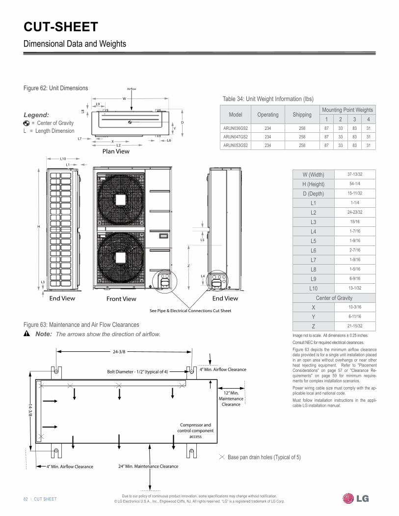
82 | CUT SHEETDue to our policy of continuous product innovation, some specifications may change without notification.
© LG Electronics U.S.A., Inc., Englewood Cliffs, NJ. All rights reserved. “LG” is a registered trademark of LG Corp.
W
L7
Y
D
L9
8L
XL2
L6
L1
L10
L3
H
Plan View
Front View
End View End View
Z
See Pipe & Electrical Connections Cut Sheet
L4
L5
Front View
CUT-SHEETDimensional Data and Weights
W (Width) 37-13/32
H (Height) 54-1/4
D (Depth) 15-11/32
L1 1-1/4
L2 24-23/32
L3 15/16
L4 1-7/16
L5 1-9/16
L6 2-7/16
L7 1-9/16
L8 1-5/16
L9 6-9/16
L10 13-1/32
Center of GravityX 10-3/16
Y 6-11/16
Z 21-15/32
Table 34: Unit Weight Information (lbs)
Model Operating ShippingMounting Point Weights
1 2 3 4ARUN036GS2 234 258 87 33 83 31
ARUN047GS2 234 258 87 33 83 31
ARUN053GS2 234 258 87 33 83 31
Image not to scale. All dimensions ± 0.25 inches.Consult NEC for required electrical clearances.Figure 63 depicts the minimum airflow clearance data provided is for a single unit installation placed in an open area without overhangs or near other heat rejecting equipment. Refer to "Placement Considerations" on page 57 or "Clearance Re-quirements" on page 59 for minimum require-ments for complex installation scenarios.Power wiring cable size must comply with the ap-plicable local and national code.Must follow installation instructions in the appli-cable LG installation manual.
Figure 63: Maintenance and Air Flow Clearances
Figure 62: Unit Dimensions
�Note: � The arrows show the direction of airflow.
24-3/8
Bolt Diameter - 1/2” (typical of 4)
12” Min. Maintenance
Clearance
Compressor and control component
access
24” Min. Maintenance Clearance
14-3/8
Base pan drain holes (Typical of 5)
= Center of GravityL = Length Dimension
�tataAe: �
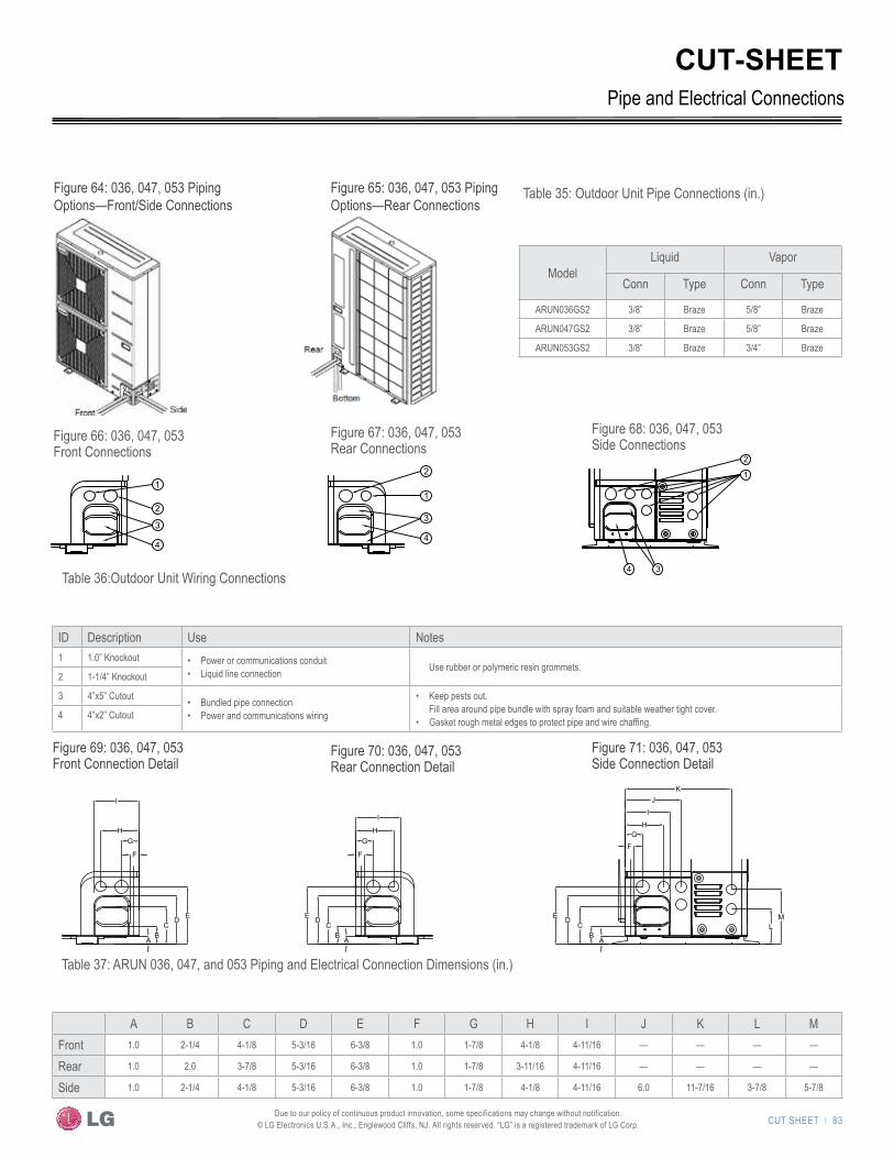
CUT SHEET | 83 Due to our policy of continuous product innovation, some specifications may change without notification. © LG Electronics U.S.A., Inc., Englewood Cliffs, NJ. All rights reserved. “LG” is a registered trademark of LG Corp.
AB
CD E
F
GH
I
AB
CDE
F
GH
I
A B
CDE
FG
H
I
JK
LM
1
2
3
4
2
1
4 3
2
1
3
4
AB
CD E
F
GH
I
AB
CDE
F
GH
I
A B
CDE
FG
H
I
JK
LM
1
2
3
4
2
1
4 3
2
1
3
4
Figure 66: 036, 047, 053 Front Connections
Figure 69: 036, 047, 053 Front Connection Detail
Figure 67: 036, 047, 053 Rear Connections
Figure 70: 036, 047, 053 Rear Connection Detail
Figure 68: 036, 047, 053 Side Connections
Figure 71: 036, 047, 053 Side Connection Detail
ID Description Use Notes1 1.0” Knockout • Power or communications conduit
• Liquid line connection Use rubber or polymeric resin grommets.2 1-1/4” Knockout
3 4”x5” Cutout • Bundled pipe connection• Power and communications wiring
• Keep pests out. Fill area around pipe bundle with spray foam and suitable weather tight cover.
• Gasket rough metal edges to protect pipe and wire chaffing.4 4”x2” Cutout
CUT-SHEET
Figure 64: 036, 047, 053 Piping Options—Front/Side Connections
Figure 65: 036, 047, 053 Piping Options—Rear Connections
ModelLiquid Vapor
Conn Type Conn Type
ARUN036GS2 3/8” Braze 5/8” Braze
ARUN047GS2 3/8” Braze 5/8” Braze
ARUN053GS2 3/8” Braze 3/4” Braze
Pipe and Electrical Connections
A B C D E F G H I J K L MFront 1.0 2-1/4 4-1/8 5-3/16 6-3/8 1.0 1-7/8 4-1/8 4-11/16 — — — —
Rear 1.0 2.0 3-7/8 5-3/16 6-3/8 1.0 1-7/8 3-11/16 4-11/16 — — — —
Side 1.0 2-1/4 4-1/8 5-3/16 6-3/8 1.0 1-7/8 4-1/8 4-11/16 6.0 11-7/16 3-7/8 5-7/8
Table 35: Outdoor Unit Pipe Connections (in.)
Table 36:Outdoor Unit Wiring Connections
Table 37: ARUN 036, 047, and 053 Piping and Electrical Connection Dimensions (in.)

84 | CUT SHEETDue to our policy of continuous product innovation, some specifications may change without notification.
© LG Electronics U.S.A., Inc., Englewood Cliffs, NJ. All rights reserved. “LG” is a registered trademark of LG Corp.
CUT-SHEET
Table 39: Y-Branch Dimensions (in) (Reference Figure 74)Model Y-Branch Type A B C D E
ARBLN01621Liquid 2-29/32 6-9/16 8.0 11-1/16 11-1/2
Vapor 2-29/32 4-1/2 8.0 11-1/16 11-1/2
ARBLN03321Liquid 2-29/32 4-1/2 8.0 12-5/8 13-1/16
Vapor 3-9/32 6-29/32 10-29/32 15-11/32 16-1/4
Table 40: Reducer Diameters (in) (Reference Figure 73)
Model Qty/Kit Reducer typePort Identifier
10 11 12 Length
ARBLN01621 2Liquid 1/2 ID 3/8 OD — 2-3/4
Vapor 3/4 ID 5/8 OD — 2-3/4
ARBLN03321 3
Liquid — — — —
Vapor1-1/8 ID 1 OD — 3-5/32
7/8 ID 3/4 OD — 2-3/4
1 ID 7/8 ID 3/4 OD 4-11/32
Y-Branch Kits
The Y-Branch kits include a Polyolefin foam, clam shell, peel and stick, insulation jacket for each Y-Branch.LG Y-Branch fittings must be used. Field-sup-plied branch fittings are not permitted.
Kit components must be kept free of debris and dry before installation.ID = Internal Diameter, OD = Outside DiameterAll dimensions in inches. Tolerance ± 0.25 inch.
Images are not to scale.Must follow installation instructions in the ap-plicable LG installation manual.
1110
Figure 74: Y-Branch connection dimensions (Table 36)
Fitting PropertiesMaterial Copper
Design Pressure 551 psig
Insulation Jacket PropertiesMaterial Polyolefin Foam
UL94 Flame Classification HF-1
Density 1.84 lbm/ft3
Thermal Conductivity .0208 Btuh/ft ºR
Thickness 0.5 Inches
Table 38: Y-Branch Connection Diameters (in-ID) (Reference Figure 72)
Model Y-Branch TypePort Identifier
1 2 3 4 5 6 7 8 9
ARBLN01621Liquid — 1/4 3/8 3/8 1/4 — 3/8 1/4 —
Vapor — 5/8 1/2 1/2 5/8 — 1/2 5/8 —
ARBLN03321Liquid — 1/2 3/8 3/8 1/2 1/4 3/8 1/2 1/4
Vapor 1 7/8 3/4 5/8 3/4 1/2 5/8 3/4 1/2
Figure XX - Y-branch and adapter connections
Adapter (A) 11 10
7 8 9
Outlet ports 5 6
E
A
B
D C
Figure XX - Y-branch dimensions
4
1 2 3Inlet ports
Outlet ports
Figure 73: Reducer parts (Table 37)
A
B
ED
C
10 11 12
Nominal Capacity Range (Values expressed in BTUs)Model Fitting Capacity
ARBLN1621 ≤ 54,600 connected capacity
ARBLN03321 ≤ 76,400 connected capacity
ID = Inside Diameter
Values expressed in BTUs
Figure XX - Y-branch and adapter connections
Adapter (A) 11 10
7 8 9
Outlet ports 5 6
E
A
B
D C
Figure XX - Y-branch dimensions
4
1 2 3Inlet ports
Outlet ports
Figure 72: Y-Branch connectors (Table 35)
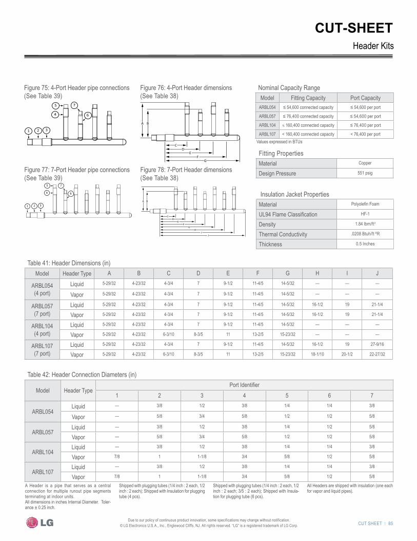
CUT SHEET | 85 Due to our policy of continuous product innovation, some specifications may change without notification. © LG Electronics U.S.A., Inc., Englewood Cliffs, NJ. All rights reserved. “LG” is a registered trademark of LG Corp.
CUT-SHEET
Figure 75: 4-Port Header pipe connections(See Table 39)
Figure 77: 7-Port Header pipe connections(See Table 39)
Table 41: Header Dimensions (in)Model Header Type A B C D E F G H I J
ARBL054(4 port)
Liquid 5-29/32 4-23/32 4-3/4 7 9-1/2 11-4/5 14-5/32 — — —
Vapor 5-29/32 4-23/32 4-3/4 7 9-1/2 11-4/5 14-5/32 — — —
ARBL057(7 port)
Liquid 5-29/32 4-23/32 4-3/4 7 9-1/2 11-4/5 14-5/32 16-1/2 19 21-1/4
Vapor 5-29/32 4-23/32 4-3/4 7 9-1/2 11-4/5 14-5/32 16-1/2 19 21-1/4
ARBL104(4 port)
Liquid 5-29/32 4-23/32 4-3/4 7 9-1/2 11-4/5 14-5/32 — — —
Vapor 5-29/32 4-23/32 6-3/10 8-3/5 11 13-2/5 15-23/32 — — —
ARBL107(7 port)
Liquid 5-29/32 4-23/32 4-3/4 7 9-1/2 11-4/5 14-5/32 16-1/2 19 27-9/16
Vapor 5-29/32 4-23/32 6-3/10 8-3/5 11 13-2/5 15-23/32 18-1/10 20-1/2 22-27/32
Header Kits
Table 42: Header Connection Diameters (in)
Model Header TypePort Identifier
1 2 3 4 5 6 7
ARBL054Liquid — 3/8 1/2 3/8 1/4 1/4 3/8
Vapor — 5/8 3/4 5/8 1/2 1/2 5/8
ARBL057Liquid — 3/8 1/2 3/8 1/4 1/2 5/8
Vapor — 5/8 3/4 5/8 1/2 1/2 5/8
ARBL104Liquid — 3/8 1/2 3/8 1/4 1/4 3/8
Vapor 7/8 1 1-1/8 3/4 5/8 1/2 5/8
ARBL107Liquid — 3/8 1/2 3/8 1/4 1/4 3/8
Vapor 7/8 1 1-1/8 3/4 5/8 1/2 5/8
A Header is a pipe that serves as a central connection for multiple runout pipe segments terminating at indoor units.All dimensions in inches Internal Diameter. Toler-ance ± 0.25 inch.
Shipped with plugging tubes (1/4 inch : 2 each, 1/2 inch : 2 each); Shipped with Insulation for plugging tube (4 pcs).
Shipped with plugging tubes (1/4 inch : 2 each, 1/2 inch : 2 each; 3/5 : 2 each); Shipped with Insula-tion for plugging tube (6 pcs).
All Headers are shipped with insulation (one each for vapor and liquid pipes).
Figure 76: 4-Port Header dimensions(See Table 38)
Figure 78: 7-Port Header dimensions(See Table 38)
Fitting PropertiesMaterial Copper
Design Pressure 551 psig
Insulation Jacket PropertiesMaterial Polyolefin Foam
UL94 Flame Classification HF-1
Density 1.84 lbm/ft3
Thermal Conductivity .0208 Btuh/ft ºR
Thickness 0.5 Inches
3
321
5
4
7
6
A B
CD
EF
GH
IJ
Nominal Capacity RangeModel Fitting Capacity Port Capacity
ARBL054 ≤ 54,600 connected capacity ≤ 54,600 per port
ARBL057 ≤ 76,400 connected capacity ≤ 54,600 per port
ARBL104 ≤ 160,400 connected capacity ≤ 76,400 per port
ARBL107 < 160,400 connected capacity < 76,400 per port Values expressed in BTUs
A B
CD
EF
G
321
5
4
7
6

86 | CUT SHEETDue to our policy of continuous product innovation, some specifications may change without notification.
© LG Electronics U.S.A., Inc., Englewood Cliffs, NJ. All rights reserved. “LG” is a registered trademark of LG Corp.

U.S. DESIGN STANDARDS"ASHRAE Standards Summary" on page 88"Building Sustainability" on page 92

88 | U.S. DESIGN STANDARDS
U.S
. Des
ign
Stan
dard
s
Due to our policy of continuous product innovation, some specifications may change without notification. © LG Electronics U.S.A., Inc., Englewood Cliffs, NJ. All rights reserved. “LG” is a registered trademark of LG Corp.
ASHRAE STANDARDS SUMMARY
Members of the American Society of Heating, Refrigerating, and Air Conditioning Engineers (ASHRAE) have collaborated to develop voluntary standards to assist design professionals with:• Industry best practices to safely use refrigerants• Guidelines to properly ventilate commercial buildings using various technologies• Proper control of building temperature and relative humidity• Design building systems to minimize energy and water consumption
Designing for Refrigerant Safety with Multi V—ASHRAE Standards 15 and 34Standards 15-2004 and 34-2007 were developed to educate the design community on the safe use of refrigerants in commercial buildings and to address the classification of refrigerants. All Multi V systems use R410A refrigerant, which ASHRAE Standard 15-2004 and ASHRAE Standard 34-2007 classify in Safety Group “A1” and rate it as “neither” in the toxicity category titled “highly toxic or toxic under code clas-sification.” These are the same ratings given to refrigerants R22, R134A, and R407C and are the safest ratings given in the standards to any refrigerant.
Table 43: ASHRAE Publications
Standard 15-2004 Safety Standard for Refrigeration Systems
Standard 34-2007 Designation and Safety Classification of Refrigerants
Standard 62.1-2010 Ventilation for Acceptable Indoor Air Quality
*American Society of Heating, Refrigeration and Air Conditioning Engineers, Inc. (ASHRAE) Standard 15. 2007. Atlanta, GA. ASHRAE, Inc. Section 7.3.
The displacement of oxygen in an occupied space could lead to occupant asphyxiation in the event of a catastrophic release of the entire system’s refrigerant charge. The standard allows a Refrigerant Concentration Limit (RCL) of 0.025 lbs/ft3 for R410A in most applications (refer to the standard for exceptions). The RCL rating indicates the allowable concentration (by weight) of refrigerant per cubic foot of room volume to avoid escape-impairing effects, such as oxygen deprivation, flammability, and cardiac sensitization.
�Note: � This designation does not indicate that R410A is non-toxic. With high enough concentration levels, all refrigerants can be hazardous.
The standards are written to cover worst case scenarios and assume that the complete system charge is released into a confined space over a short period of time. If a refrigerant leak occurs, the actual concentration level in the confined space is dependent on the quantity of refrigerant in the equipment and the volume of air available for dispersion and dilution. The total estimated charge of the refrigeration system is calculated by either LG’s LATS Multi V (see "LATS Multi V" on page 61) refriger-ant piping design software or manually by following the procedure titled "Mini Refrigerant Charge" on page 76 and the "System Refrigerant Charge Calculator" worksheet on page 80. To apply the standard, the designer must first determine the occupied space with the smallest cubic volume served by the system.
ASHRAE Standard 15-2004 and ASHRAE Standard 34-2007
�Note: � We are providing a summary of the standards impacting the design of the Multi V system or the safety of building oc-cupants. Refer to the ASHRAE Standards for detailed design information.
U.S DESIGN STANDARDS | 89
HEAT PUMP CO
NDENSING UNIT ENG
INEERING M
ANUAL
Due to our policy of continuous product innovation, some specifications may change without notification. © LG Electronics U.S.A., Inc., Englewood Cliffs, NJ. All rights reserved. “LG” is a registered trademark of LG Corp.
Nonconnected Spaces Where a refrigerating system or a part thereof is located in one or more enclosed occupied spaces that do not connect through permanent openings or HVAC ducts. Where different stories and floor levels connect through an open atrium or mezzanine arrangement, the volume used is determined by multiplying the floor area of the lowest space by 8.25 feet.*
Ventilated Spaces Where a refrigerating system or a part thereof is located within an air handler, an air distribution duct system, or an occupied space served by a mechanical ventilation system, the entire air distribution system shall be analyzed to determine the smallest volume area.*
Closure Closures in the air distribution system shall be considered. If one or more spaces of several arranged in paral-lel can be closed off from the source of the refrigerant leak, the volume(s) shall not be used in the calculation.*
Closure exceptions include smoke and fire dampers or combinations thereof that shut in an emergency and are not associated with a refrigerant leak, and dampers where airflow is never reduced below 10% of its maxi-mum with the fan running.
Plenums The space above a suspended ceiling shall not be included in calculating the refrigerant quantity limit in the system unless such space is part of the air supply or return system.*
Supply/Return Ducts The volume of the supply and return ducts and plenums shall be included when calculating the refrigerant quantity limit in the system.*
ASHRAE STANDARDS SUMMARY
Calculate the volume of air in each occupied space using the following guidelines to determine the dimensions of each space:
ASHRAE Standard 15-2004 and ASHRAE Standard 34-2007
Follow these steps to calculate the potential refrigerant concentration level:1. Measure the occupied space dimensions (in feet).2. Calculate the cubic foot volume of air in the smallest occupied space.3. Divide the refrigerant charge of the Multi V system serving the area (lbs) by the results of step 2.4. If the calculation indicates that the potential refrigerant concentration level is higher than the allowed RCL, increase the cubic volume of the
smallest occupied space or modify the piping system design.5. The allowable RCL limit for most applications must be equal to or less than 0.025 lbs/ft3. However, in special occupied spaces, such as
hospitals and nursing homes, where occupants may have limited mobility, the allowable RCL limit is cut in half. See ASHRAE Standard 34-2007 and local code for detailed information.*
To determine the volume of an occupied space, the designer must determine which spaces are connected, not connected, or ventilated. Refer to Standard 34-2007 for help.If the calculated RCL is above the allowable limit, there are two primary methods used to lower the RCL: 1. Increase the volume of the occupied space.2. Decrease the size of the refrigerant charge.
Per Standard 34-2007, acceptable methods used to increase the volume of an occupied space include:*• Install transfer ducts between rooms.• Undercut doors.• Include ventilation grilles in doors.• Include the area above the ceiling as part of the return or supply air path.
RCL (lbs/ft3) =System refrigerant charge (lbs)
Volume of smallest occupied space (ft3)
* Amercian Society of Heating, Refrigeration and Air Conditioning Engineers, Inc. (ASHRAE) 62.1-2010, sections 6.2 and 6.3
90 | U.S. DESIGN STANDARDS
U.S
. Des
ign
Stan
dard
s
Due to our policy of continuous product innovation, some specifications may change without notification. © LG Electronics U.S.A., Inc., Englewood Cliffs, NJ. All rights reserved. “LG” is a registered trademark of LG Corp.
ASHRAE STANDARDS SUMMARY
ASHRAE 62.1-2010—Ventilation for Acceptable Indoor Air QualityOver the past twenty years, publications have documented that the occupant's well being, productivity, and comfort is significantly impacted if the building is not properly ventilated. Providing proper ventilation air directly and significantly increases a building’s overall energy consumption and operating costs. In an effort to reduce medical and legal costs as well as the cost associated with personnel turnover, occupant companies and human resource personnel today consider the lease premium associated with tempering and cleaning ventilation air relatively insignificant. Standard 62.1-2010 is known as the Indoor Air Quality (IAQ) Performance Standard. The standard documents key strategies for maintaining minimum IAQ, including limiting the introduction of potential contaminants into the occupied areas originating from indoor and outdoor sources. The standard also addresses the proper introduction of ventilation (outdoor) air into the building using two methods:1. The Ventilation Rate Procedure (VRP) is a prescriptive approach that sets minimum design requirements when sizing the building’s venti-
lation equipment including:• Outdoor air quality requirements• Treatment procedures used if the outdoor air is deemed contaminated• Volume of outdoor air that must be introduced to the occupied areas of commercial, institutional, vehicular, industrial, and residen-
tial buildings2. The IAQ compliance procedures:
The standard, under section 6.3, allows the designer to significantly reduce the ventilation air volume required using the VRP procedure when high efficiency air filtration products designed to remove particulate and gas phase contaminates are specified. This procedure is a performance-based design approach where the indoor air quality in the occupied areas is actively monitored using sensing devices. When the IAQ falls below specified levels, the volume of outside air introduced into the building is modified.*
There are three methods used for ventilating buildings:1. Mechanical “active” ventilation2. Natural “passive” ventilation3. Mixed-mode “active and passive” ventilation
The intent of this discussion is to provide guidance for the designer when applying active mechanical ventilation methods in conjunction with Multi V variable refrigerant flow equipment. Multi V indoor units are designed for quiet operation and room air recirculation. Inherently, quiet fans cannot produce a significant amount of static pressure. Thus, Multi V indoor units do not have the capability to “draw” ventilation air. Ventilation air must be “pushed” to the indoor unit. In all designs, the outside air must be introduced using a separate fan that is specifically designed for the task.There are three methods to mechanically introduce outside air into individually occupied areas and rooms. When considering which method to use, the designer should choose a design that minimizes potential maintenance costs and operational problems.
USGBC. 2009. Green Building Design & Construction. Washington, DC. USGBC Staff. Page 535* Amercian Society of Heating, Refrigeration and Air Conditioning Engineers, Inc. (ASHRAE) 62.1-2010, sections 6.2 and 6.3
ASHRAE Standard 62.1-2010
Method 1: Decoupled Ventilation Air: This is the preferred method to use with all LG air conditioning products. From a common outside air inlet, filter and pre-treat the air temperature to room neutral conditions, and duct the ventilation air to the ceiling or wall registers in each breathing zone. Use this method when cost and operational problems are a priority. It can be used in all applications and in conjunction with any type of Multi V indoor unit. When using Method 1 and the outside air pre-treatment device experiences component failure due to filtering, heating, or cooling, the occupant will readily notice the resulting untreated air and can notify the building engineer of the problem. More importantly, the failure is less likely to impact the Multi V system.
U.S DESIGN STANDARDS | 91
HEAT PUMP CO
NDENSING UNIT ENG
INEERING M
ANUAL
Due to our policy of continuous product innovation, some specifications may change without notification. © LG Electronics U.S.A., Inc., Englewood Cliffs, NJ. All rights reserved. “LG” is a registered trademark of LG Corp.
ASHRAE STANDARDS SUMMARY
Method 2:
Method 3: Introduce Untreated Ventilation Air: From an outside air opening, duct filtered, untreated ventilation air to Multi V indoor units. This method can be employed in limited regions of the country where year round ambient conditions and air quality would provide the indoor unit mixed air within LG’s published acceptable conditions. Refer to the "Building Ventilation" on page 48 for more information.
Coupled Pre-Treated Ventilation Air: From a common outside air inlet, filter and pre-treat the air temperature to room neutral conditions, and duct the ventilation air to the ceiling cassette or recessed-ducted Multi V indoor units. Multi V indoor units are designed for quiet operation and room air recirculation. Inherently, quiet fans cannot produce a significant amount of static pressure. Thus, Multi V indoor units do not have the capability to “draw” ventilation air. Ventilation air must be “pushed” to the indoor unit. Also, in the event the ventilation air is outside the indoor unit design parameters and the return and ventilation air streams fail to mix properly before entering the indoor unit coil, air stratification may occur causing er-ratic behavior of the Multi V indoor unit.Operationally, the designer must consider many “what if” failure scenarios and understand the impact on building HVAC system operations. Negative building pressure conditions may impact the indoor unit fan’s ability to pass the proper amount of air over the indoor unit coil. This could occur if the ventilation system supply fan is disabled or ventilation damp-ers malfunction while the building exhaust fans continue to operate. In this case, the indoor unit coil may desperately need air as negative static pressure builds at the inlet of the indoor unit. On the other hand, when using non-ducted indoor unit models in conjunction with a constant flow of ventilation air and the Multi V indoor unit supply air volume is reduced below the ventilation air volume (the space temperature is satisfied), the ventilation air may flow backwards through the filter media and return air grille. Captured particulate from the filter media may discharge into the room.
ASHRAE Standard 62.1-2010
USGBC. 2009. Green Building Design & Construction. Washington, DC. USGBC Staff. Page 535* Amercian Society of Heating, Refrigeration and Air Conditioning Engineers, Inc. (ASHRAE) 62.1-2010, sections 6.2 and 6.3
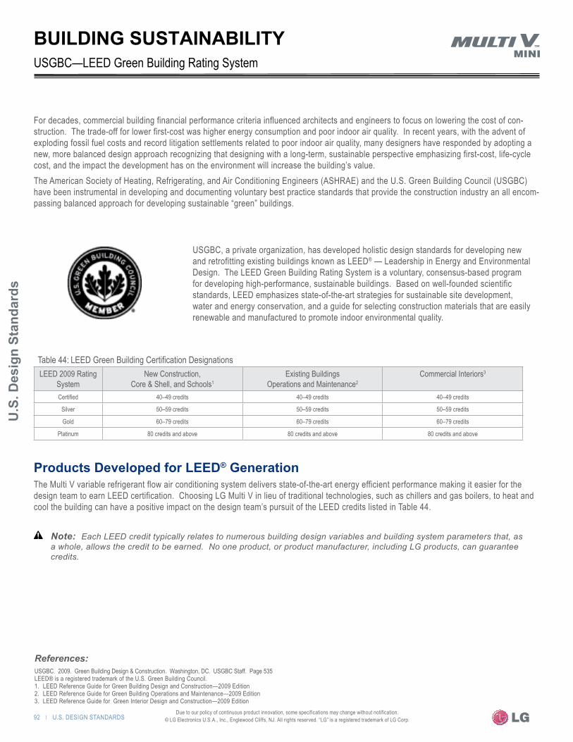
92 | U.S. DESIGN STANDARDS
U.S
. Des
ign
Stan
dard
s
Due to our policy of continuous product innovation, some specifications may change without notification. © LG Electronics U.S.A., Inc., Englewood Cliffs, NJ. All rights reserved. “LG” is a registered trademark of LG Corp.
Products Developed for LEED® GenerationThe Multi V variable refrigerant flow air conditioning system delivers state-of-the-art energy efficient performance making it easier for the design team to earn LEED certification. Choosing LG Multi V in lieu of traditional technologies, such as chillers and gas boilers, to heat and cool the building can have a positive impact on the design team’s pursuit of the LEED credits listed in Table 44.
For decades, commercial building financial performance criteria influenced architects and engineers to focus on lowering the cost of con-struction. The trade-off for lower first-cost was higher energy consumption and poor indoor air quality. In recent years, with the advent of exploding fossil fuel costs and record litigation settlements related to poor indoor air quality, many designers have responded by adopting a new, more balanced design approach recognizing that designing with a long-term, sustainable perspective emphasizing first-cost, life-cycle cost, and the impact the development has on the environment will increase the building’s value.The American Society of Heating, Refrigerating, and Air Conditioning Engineers (ASHRAE) and the U.S. Green Building Council (USGBC) have been instrumental in developing and documenting voluntary best practice standards that provide the construction industry an all encom-passing balanced approach for developing sustainable “green” buildings.
�tetrtantee: �USGBC. 2009. Green Building Design & Construction. Washington, DC. USGBC Staff. Page 535LEED® is a registered trademark of the U.S. Green Building Council. 1. LEED Reference Guide for Green Building Design and Construction—2009 Edition2. LEED Reference Guide for Green Building Operations and Maintenance—2009 Edition3. LEED Reference Guide for Green Interior Design and Construction—2009 Edition
USGBC, a private organization, has developed holistic design standards for developing new and retrofitting existing buildings known as LEED® — Leadership in Energy and Environmental Design. The LEED Green Building Rating System is a voluntary, consensus-based program for developing high-performance, sustainable buildings. Based on well-founded scientific standards, LEED emphasizes state-of-the-art strategies for sustainable site development, water and energy conservation, and a guide for selecting construction materials that are easily renewable and manufactured to promote indoor environmental quality.
BUILDING SUSTAINABILITY
Table 44: LEED Green Building Certification DesignationsLEED 2009 Rating
SystemNew Construction,
Core & Shell, and Schools1Existing Buildings
Operations and Maintenance2Commercial Interiors3
Certified 40–49 credits 40–49 credits 40–49 credits
Silver 50–59 credits 50–59 credits 50–59 credits
Gold 60–79 credits 60–79 credits 60–79 credits
Platinum 80 credits and above 80 credits and above 80 credits and above
USGBC—LEED Green Building Rating System
�Note: � Each LEED credit typically relates to numerous building design variables and building system parameters that, as a whole, allows the credit to be earned. No one product, or product manufacturer, including LG products, can guarantee credits.

U.S DESIGN STANDARDS | 93
HEAT PUMP CO
NDENSING UNIT ENG
INEERING M
ANUAL
Due to our policy of continuous product innovation, some specifications may change without notification. © LG Electronics U.S.A., Inc., Englewood Cliffs, NJ. All rights reserved. “LG” is a registered trademark of LG Corp.
USGBC—LEED Green Building Rating System
Table 45: Potential LEED Credits using LG Multi V
Category Point IDCertification Paths
Point DescriptionNC CS K12 Cl O&M
WE CR-4 – – 0 1 1–2 Process water reduction
EA PR-1 0 0 0 0 – Basic building commissioning
EA PR-3 0 0 0 0 0 Refrigerant has no CFC’s (R410A)
EA CR-1 1–19 3–21 1–19 – 1–18 Optimize energy performance
EA CR-1.3 – – – 5–10 – Optimize energy performance—HVAC
EA CR-2 – – – 5 – Enhanced commissioning
EA CR-2.3 – – – – 2 Exist bldg.—Ongoing commissioning
EA CR-3 2 2 2 – – Enhanced commissioning
EA CR-3.1 – – – – 1 Perf. measurement—bldg. automation
EA CR-3.2 – – – – 1–2 Perf. measurement—Sys. level metering
EA CR-4 2 2 1 – – Enhanced refrigerant management
EA CR-5 – – – – 1 Enhanced refrigerant management
EA CR-3 – – – 2–5 – Measure and verify—Tenant submetering
EA CR-5.1 – 3 – – – Measure and verify—Base building
EA CR-5.2 – 3 – – – Measure and verify—Tenant submetering
MR CR-1.1 – – – 1 – Tenant space—Long-term commitment
MR CR-1 – 1–5 – – – Maintain exterior walls, floor, roof
MR CR-1.1 1–3 – 1–2 – – Maintain exterior walls, floor, roof
MR CR-1.1 – – – 1–2 – Maintain non-structural elements
MR CR-1.2 1 – 1 – – Maintain non-structural elements
IEQ PR-2 – – Yes – – Minimum acoustical performance
IEQ 1.4 – – – – 1 Reduce particulates—Occupied space
IEQ 1.5 – – – – 1 Reduce particulates—Construction area
IEQ 3.1 – – – 1 – Reduce particulates in air distribution
IEQ CR-6 – 1 – – – Controllability—Thermal comfort
IEQ CR-6.2 1 – 1 1 – Controllability—Thermal comfort
IEQ CR-7 – 1 – – – Thermal comfort design
IEQ CR-7.1 1 – 1 1 – Thermal comfort design
IEQ CR-7.2 1 – 1 1 – Thermal comfort verification
IEQ CR-9 – – 1 – – Enhanced acoustical performance
IEQ CR-10 – – 1 – – Mold prevention
ID 1–5 1–5 1–5 1–4 1–5 1–4 Innovations in design or operations
BUILDING SUSTAINABILITY
No credits offered on prerequisite requirements. However, before any credits can be earned, prerequisite requirements must be met.
�teDaDoDNaee: �
CI = Commercial Interiors EA = Energy and Atmosphere K12 = SchoolsPR = Prerequisite CR = Credit ID = Innovations in DesignMR = Materials and Resources RP = Regional Priority CS = Core and ShellIEQ = Indoor Air Quality NC = New Construction WE = Water EfficiencyO&M = Existing Building Operations and Maintenance

94 | U.S. DESIGN STANDARDS
U.S
. Des
ign
Stan
dard
s
Due to our policy of continuous product innovation, some specifications may change without notification. © LG Electronics U.S.A., Inc., Englewood Cliffs, NJ. All rights reserved. “LG” is a registered trademark of LG Corp.
"VRF Multi V™ Mini Air Source Units (036, 047, 053)" on page 96
MECHANICALSPECIFICATIONS
96 | SPECIFICATIONS
Specificatio
ns
Due to our policy of continuous product innovation, some specifications may change without notification. © LG Electronics U.S.A., Inc., Englewood Cliffs, NJ. All rights reserved. “LG” is a registered trademark of LG Corp.
VRF Multi V™ Mini Air Source Units—ARUN 036, 047, 053MECHANICAL SPECIFICATIONS
VRF Multi V™ Mini Air Source Units (036, 047, 053)General The LG Multi V Mini heat pump system consists of an outdoor unit, one or more indoor units, integrated system controls, and interconnecting field-provided refrigerant pipe containing vari-ous fittings including Y-Branch kits and Header kits supplied by LG. LG components are manufactured in a facility that meets or exceeds International Organization for Standardization (ISO) 9001 and 14001. The units are listed by Intertek (ETL) and bear the ETL listed mark.CasingThe outdoor unit case is constructed from 22-gauge coated metal. Exterior panels are cleaned and finished with a weather resistant baked enamel finish. An easily removable front corner panel is provided to allow access to major components and control devices. Outdoor unit fans are covered with guards made of heavy gauge, heavy duty polymeric resin. The outdoor unit coil is protected with a heavy gauge steel wire guard finished with baked enamel. Paint color is “warm gray.“
Refrigeration SystemThe refrigeration system consists of a single refrigeration circuit and uses refrigerant R410A. The outdoor unit is provided with fac-tory installed components, including a refrigerant strainer, check valves, oil separator, accumulator, hot gas bypass valve, liquid injection valve, 4-way reversing valve, electronic controlled expan-sion valve (EEV), high and low side charging ports, service valves, and interconnecting piping. Also included is an integral subcooler assembly consisting of a double spiral tube type heat exchanger and EEV providing refrigerant subcooling modulation up to 23°F. The unit comes factory charged with 6.6 pounds of refrigerant.
Refrigeration Oil ControlThe refrigeration oil level in the compressor is maintained using a two-stage oil control system. The compressor discharge port is equipped with an oil filtering device designed to restrict oil loss from the compressor. The high-pressure discharge vapor leaves the compressor and immediately enters a centrifugal oil separator that has no moving parts designed to extract oil from the refrigerant gas stream. A gravity drain returns captured oil back to the compressor sump. The outdoor unit microprocessor is programmed to flush the refrigerant piping system for a minimum period of three minutes after six hours of compressor operation.
Single Inverter/CompressorThe outdoor unit is equipped with one hermetic, digitally-con-
trolled, inverter driven, rotary compressor. The compressor is spe-cifically designed for the refrigerant provided and is manufactured by LG. The frequency inverter is designed by LG and is capable of providing a modulation range from 25Hz–90Hz in Cooling mode and 25Hz–100Hz in Heating mode. The compressor motor is suc-tion gas-cooled and has an acceptable voltage range of ±10% of nameplate voltage. The compressor is equipped with a crankcase heater and back seated service valves. External suction and discharge temperature and pressure sensors are provided to protect the compressor from damage caused by over/under temperature or over/under pressure conditions. The compressor is provided with a positive displacement oil pump providing sufficient oil film on all bearing surfaces across the entire inverter modulation range. The compressor is factory charged with Polyvinylether (PVE) refrigeration oil having no hygroscopic properties. Compressor bearings are Teflon® coated. The compressor is wrapped with a heat resistant, sound attenuating blanket and mounted on rubber isolation grommets.Outdoor Unit CoilOutdoor unit coils are a minimum of two rows, 17 fins per inch, and manufactured using copper tubes with mechanically bonded aluminum louvered fins. Fin surfaces are coated with Gold-Fin™ corrosion resistant hydrophilic silica gel coating. Coils are pres-sure tested at a minimum of 551 psig.
Fans & MotorsUnits are furnished with two direct-drive propeller fans providing horizontal airflow from the rear and discharging from the front of the unit. Fan blades are 20-½ inch diameter, balanced, and made of durable Lupos (ABS) polymeric resin. Motors are designed to operate between 430 and 700 RPM in Cooling mode and be-tween 500 and 750 RPM in Heating mode. Both fans are driven by digitally-controlled inverters that vary the fan speed. Motors are brushless, digitally-controlled (BLDC) and have permanently lubricated and sealed ball bearings. All outdoor unit fans are con-trolled by an inverter drive mounted near the main microprocessor. The outdoor unit fan speed is controlled using an algorithm that provides three pre-programmed fan speeds. DIP switch adjust-able settings limit night time (off peak) fan speed to reduce fan generated noise by up to 10 dB(A).Outdoor Unit ControlsOutdoor units are factory wired with necessary electrical control components, printed circuit boards, thermistors, sensors, terminal blocks, and lugs for power wiring. The control wiring circuit is low voltage and includes a control power transformer, fuses, and inter-connecting wiring harness with plug connectors. Microprocessor-based algorithms provide component protection, soft-start capabil-ity, refrigeration system pressure and temperature control, defrost,

SPECIFICATIONS | 97
HEAT PUMP CO
NDENSING UNIT ENG
INEERING M
ANUAL
Due to our policy of continuous product innovation, some specifications may change without notification. © LG Electronics U.S.A., Inc., Englewood Cliffs, NJ. All rights reserved. “LG” is a registered trademark of LG Corp.
and ambient control. The unit is designed to provide continuous compressor operation from -4°F to 118°F. When the system is started, the connected indoor units are automatically assigned an electronic address by the outdoor unit’s microprocessor. Addition-ally, each indoor unit is capable of accepting a manual assignment of a secondary electronic address that, if used, provides unit tag identification when integrating with LG VNet control devices. While operating in the Heating mode, the outdoor unit has a demand-based defrost control algorithm and a refrigeration system pump-down cycle designed to store up to 6.6 lbs of the system refrigerant charge in the outdoor unit. In Heating mode, a cooperative-control algorithm automatically balances, in real-time, the distribution of refrigerant to the indoor units when the system’s refrigerant mass flow is insufficient to satisfy the demand of all indoor units when the system is called on to operate outside the system design param-eters. In 10-second intervals, the outdoor unit microprocessor will record the last three minutes of system run-time data in non-volatile memory. Upon unit malfunction, or a power outage that results in a system shutdown, the stored system operational data may be re-trieved and analyzed to assist in diagnosing a system malfunction. The outdoor unit microprocessor is provided with a three-digit, LED display that communicates active system information and/or mal-function codes. The microprocessor has an algorithm that actively verifies the operational condition of system sensors and thermis-tors. A refrigerant auto-trim-charge algorithm assists the installer with properly charging the system. A power conditioning circuit is provided and designed to protect the unit’s inverter compressor and outdoor unit fan motors from phase failure, phase reversal, sense an under-voltage or over-voltage condition, and to prevent trans-mission of power irregularities to the supply power source. A snow throw algorithm is provided designed to reduce snow buildup on the discharge side louvers grille at regular intervals.
MECHANICAL SPECIFICATIONSVRF Multi V™ Mini Air Source Units—ARUN 036, 047, 053
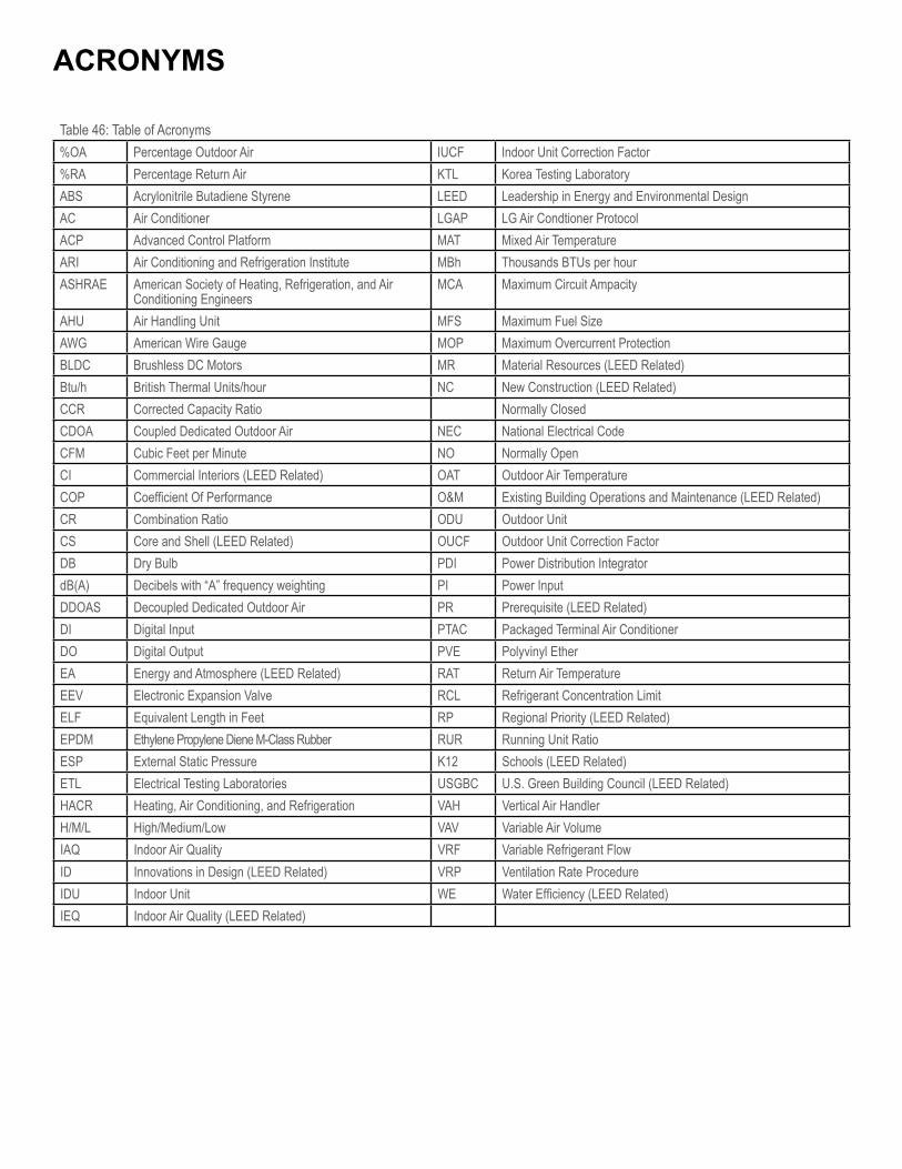
ACRONYMS
Table 46: Table of Acronyms%OA Percentage Outdoor Air IUCF Indoor Unit Correction Factor%RA Percentage Return Air KTL Korea Testing LaboratoryABS Acrylonitrile Butadiene Styrene LEED Leadership in Energy and Environmental DesignAC Air Conditioner LGAP LG Air Condtioner ProtocolACP Advanced Control Platform MAT Mixed Air TemperatureARI Air Conditioning and Refrigeration Institute MBh Thousands BTUs per hourASHRAE American Society of Heating, Refrigeration, and Air
Conditioning EngineersMCA Maximum Circuit Ampacity
AHU Air Handling Unit MFS Maximum Fuel SizeAWG American Wire Gauge MOP Maximum Overcurrent ProtectionBLDC Brushless DC Motors MR Material Resources (LEED Related)Btu/h British Thermal Units/hour NC New Construction (LEED Related)CCR Corrected Capacity Ratio Normally ClosedCDOA Coupled Dedicated Outdoor Air NEC National Electrical CodeCFM Cubic Feet per Minute NO Normally OpenCI Commercial Interiors (LEED Related) OAT Outdoor Air TemperatureCOP Coefficient Of Performance O&M Existing Building Operations and Maintenance (LEED Related)CR Combination Ratio ODU Outdoor UnitCS Core and Shell (LEED Related) OUCF Outdoor Unit Correction FactorDB Dry Bulb PDI Power Distribution IntegratordB(A) Decibels with “A” frequency weighting PI Power InputDDOAS Decoupled Dedicated Outdoor Air PR Prerequisite (LEED Related)DI Digital Input PTAC Packaged Terminal Air ConditionerDO Digital Output PVE Polyvinyl EtherEA Energy and Atmosphere (LEED Related) RAT Return Air TemperatureEEV Electronic Expansion Valve RCL Refrigerant Concentration LimitELF Equivalent Length in Feet RP Regional Priority (LEED Related)EPDM Ethylene Propylene Diene M-Class Rubber RUR Running Unit RatioESP External Static Pressure K12 Schools (LEED Related)ETL Electrical Testing Laboratories USGBC U.S. Green Building Council (LEED Related)HACR Heating, Air Conditioning, and Refrigeration VAH Vertical Air HandlerH/M/L High/Medium/Low VAV Variable Air VolumeIAQ Indoor Air Quality VRF Variable Refrigerant FlowID Innovations in Design (LEED Related) VRP Ventilation Rate ProcedureIDU Indoor Unit WE Water Efficiency (LEED Related)IEQ Indoor Air Quality (LEED Related)

LG Electronics Commercial Air Conditioning Division11405 Old Roswell RoadAlpharetta, Georgia 30009www.lg-vrf.com
Document Number: EM_MultiVMini_5_ 15Supersedes: VRF-EM-BB-US-013E03
VRF-EM-BB-001-US-012M27VRF-EM-BB-001-US-012D20
Related Documents