AIR / HYDRAULIC ABS TRAILER KIT INSTALLATION INSTRUCTIONS BLUDOT, INC. SOUTH BEND, IN 46628 (574) 277-2306 1

Welcome message from author
This document is posted to help you gain knowledge. Please leave a comment to let me know what you think about it! Share it to your friends and learn new things together.
Transcript
AIR / HYDRAULIC ABS TRAILER KIT INSTALLATION INSTRUCTIONS
BLUDOT, INC. SOUTH BEND, IN 46628 (574) 277-2306
1
AIR / HYDRAULIC ABS TRAILER KIT INSTALLATION INSTRUCTIONS
BLUDOT, INC. SOUTH BEND, IN 46628 (574) 277-2306 2
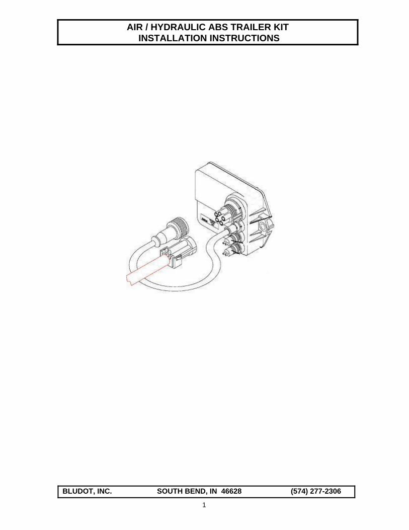
OVERVIEW A typical Air-Over-Hydraulic (A/H) Anti-Lock Brake System (ABS) consists of wheel speed sensors, an ABS relay valve, an integral Electronic Control Unit (ECU), and an A/H booster. The ECU monitors wheel speeds through the use of two wheel speed sensors mounted on the hubs of the trailer axle. An exciter ring, also referred to as a tone ring, is a required component of the wheel speed sensing system and is usually included on the axle as received from the axle manufacturer. When the ECU detects that a sensed wheel has locked up during brake application, the air pressure in the brake chamber on the A/H booster is reduced via the ABS relay valve, allowing the wheel to recover. The ECU then commands the ABS relay valve to apply additional pressure until maximum braking potential is produced. This ABS “cycle” is repeated approximately five times per second as required, or until the trailer is traveling at less than 6 MPH. The TH series of Air-over-Hydraulic ABS trailer brake systems can be purchased in the following configurations: 1) TH-6000 series – This system is designed conform to all current FMVSS 571.121 regulations
for air-over-hydraulic trailer brake systems. However, it is the trailer manufacturer’s responsibility to certify that their trailer meets these regulations.
2) TH-5000 series – This system does not meet all FMVSS regulations. Specifically, although
ABS braking is provided, provisions are not made for the automatic application of mechanical parking brakes.
The TH-6000 system requires all hydraulic brakes to be equipped with a mechanical parking brake. The axle manufacturer can supply their axles with a parking brake feature. The mechanical brakes are linked to a spring brake actuator via a series of cables and are controlled by the ABS relay valve. The hydraulic brakes are used for normal braking and the mechanical brakes are used for emergency braking and parking. The air actuating portion of this system is shown on page 13. The TH-5000 system provides ABS braking via the hydraulic brakes. Emergency braking is provided via an emergency valve to the hydraulic brakes but mechanical parking brake capabilities are not provided. It is possible to install mechanical brakes at a later date after the trailer is manufactured but not without considerable additional cost in materials and labor. The air actuating portion of this system is shown on page 14. Both systems are what are normally referred to as 2S/1M meaning 2 Sensor / 1 Modulating valve. This is the minimum configuration required by FMVSS 571.121. A 2S/1M system will only sense wheel lockup on one axle on the trailer (the sensed axle). If wheel lockup is detected all brakes are modulated via the ABS relay valve until normal braking is achieved. Because only one axle has ABS sensors, wheel lockup can occur on an unsensed axle and never be detected. The location of the sensed axle is determined based on the number of axles and the type of suspension used. While it is possible to design an air-over-hydraulic trailer brake system with sensors on more than one axle (a 4S/2M system), this would get quite expensive because each axle would require it’s own ABS valve, air tank, and air/hydraulic booster. Please refer to the included Haldex Trailer ABS Installation/Service Manual for additional details regarding these systems
AIR / HYDRAULIC ABS TRAILER KIT INSTALLATION INSTRUCTIONS
BLUDOT, INC. SOUTH BEND, IN 46628 (574) 277-2306 3
EMERGENCY / PARKING BRAKE CABLE DESIGN The TH-6000 series kits require the automatic application of the emergency/parking brakes upon loss of air in the trailer supply line. This is accomplished by linking the mechanical parking brakes on each wheel to a spring brake actuator via a series of brake cables. When the supply air is lost, the spring brake actuator shifts positions, pulling on the brake cables and applying the brakes. A general layout of this concept is shown on page 9. However, because this brake system can be installed on a variety of trailers, it is often necessary to have the brake cables and terminating hardware custom designed for each trailer or model of trailers. The layouts and charts on pages 8 & 9 are intended to assist in the design of these cables. A brake cable manufacturer should be contacted for design assistance and procurement of the actual cables, if desired. A source for these cables is given. Be advised that each parking brake requires approximately 300 pounds of force to actuate. This means that the spring brake actuator could be generating up to 1 ton of force for a triple axle trailer. The trailer frame must be designed to allow for this force so that the frame member that the actuator is mounted to does not flex under load. ABS WHEEL SPEED SENSOR LOCATION The decision on which axle to install the two wheel speed sensors is based on the type of trailer suspension and the number of axles. In general, trailers with spring or torsion suspensions should have the wheel speed sensors on the front axle. Trailers with air suspensions should have the wheel speed sensors on the rear axle of a tandem axle trailer or on the middle axle of a triple axle trailer. The wheel speed sensors should be installed on the axle that is most likely to experience lock-up. AIR / HYDRAULIC ACTUATOR LOCATION Optimum performance of the air/hydraulic trailer brake system is accomplished when the control and supply lines to the brake actuator are as short as possible. Therefore, the air/hydraulic actuator and relay valve should be mounted as close to the front of the trailer as possible. The construction of individual trailers and the need to mount these components in a protected location should also be considered. Additionally, the brake actuator should be located at a higher elevation than the axles in order to avoid brake bleeding problems. INSTALLATION PROCEDURE - AIR ACTUATING COMPONENTS USE PIPE SEALANT ON ALL THREADED CONNECTIONS. TEFLON TAPE IS NOT RECOMMENDED AND MAY VOID YOUR WARRANTY. TH-6000 series – Page 14 1. Mount the ABS relay valve to the ¾” port on the side of the air tank. Install a ¾ pipe plug on the unused valve port. Install a 3/8 pipe plug on each end of the tank. Install the drain valve in the drain port on the bottom of the tank. Do not tighten the valve by holding the valve body. Tighten the valve at the ¾” nipple to 50 ft-lbs. 2. Mount the air tank/relay valve assembly using the mounting hardware provided following the location guidelines discussed above. Mount the air/hydraulic booster in the same general area as the tank. The brake fluid reservoir should be easily accessible for bleeding and maintenance.
AIR / HYDRAULIC ABS TRAILER KIT INSTALLATION INSTRUCTIONS
BLUDOT, INC. SOUTH BEND, IN 46628 (574) 277-2306 4
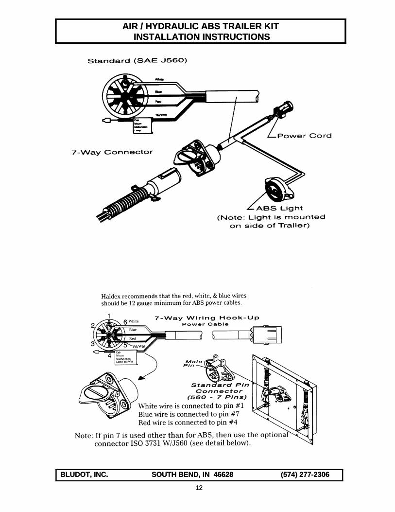
3. Mount the spring brake actuator at the location selected on the trailer where the terminating ends of the mechanical parking brake cables are located. Route the cables from the brakes to the cable terminating bracket on the spring brake actuator. 4. Mount the bulkhead fittings to the trailer frame. Install the gladhands onto the bulkhead fittings. 5. Using the supplied air brake fittings and nylon air brake tubing, connect the gladhands to the relay valve, and the relay valve to the air/hydraulic booster and spring brake actuator. Do not overtighten connections to plastic ports. Hand tighten fittings then rotate 2-3 additional turns. Make sure that all unused ports are plugged. Refer to the supplied drawings for air line routing information. TH-5000 series – Page 15 1. Mount the ABS relay valve to the ¾” port on the side of the air tank using the supplied ¾ x ½ hex nipple. Install a ¾ pipe plug on the unused valve port. Install a 3/8 pipe plug on one end of the tank. Install the drain valve in the drain port on the bottom of the tank. Do not tighten the valve by holding the valve body. Tighten the valve at the ¾” nipple to 50 ft-lbs. 2. Mount the air tank/relay valve assembly using the mounting hardware provided following the location guidelines discussed above. Mount the air/hydraulic booster in the same general area as the tank. The brake fluid reservoir should be easily accessible for bleeding and maintenance. 3. Mount the emergency control valve at a location on the trailer frame near the ABS relay valve. This valve is required to provide brake application in the event of a break away condition. 4. Mount the bulkhead fittings to the trailer frame. Install the gladhands onto the bulkhead fittings. 5. Using the supplied air brake fittings and nylon air brake tubing, connect the gladhands to the emergency control valve, the emergency control valve to the ABS relay valve and air tank, and the ABS relay valve to the air/hydraulic booster. Make sure that all unused ports are plugged. Refer to the supplied drawings for air line routing information. INSTALLATION PROCEDURE – SYSTEM WIRING REFER TO THE ATTACHED SYSTEM WIRING ROUTING DRAWINGS – Pages 10-12 1. A main power wiring harness is required and may be purchased separately or fabricated using the supplied terminal connector kit and properly sized cable. Refer to page 12 for instructions on fabricating a power harness. 2. Referring to page 10, connect the main power connector to its corresponding 5-pin connector on the ECU on the relay valve. The relay valve cable connects directly to the valve solenoid. The sensor connectors on the ECU mate with the supplied sensor extension cables. The free end of the sensor extension cable mates with the ABS sensors supplied with the axle. 3. Mount the supplied ABS warning lamp at the rear of the trailer on the driver’s side. Refer to page 10 for location requirements. 4. Secure all wiring with cable ties or clamps as needed.
AIR / HYDRAULIC ABS TRAILER KIT INSTALLATION INSTRUCTIONS
BLUDOT, INC. SOUTH BEND, IN 46628 (574) 277-2306 5
INSTALLATION PROCEDURE-HYDRAULIC LINES AND FITTINGS The routing of the hydraulic lines should be chosen to provide protection from any potential road hazards. This generally means that the main hydraulic line from the actuator to the front axle should be run alongside or inside a side frame member and the axle lines should be located on top of the axle. The location of the hydraulic hose brackets should be chosen to assure that the hydraulic hoses, when installed, will not be stretched or pulled when the trailer suspension is at its maximum travel. NOTE: THE FOLLOWING PROCEDURES REFER TO THE ATTACHED BRAKE LINE KIT DRAWINGS ON PAGES 15 & 16. THE SPECIFIC DRAWING USED WILL DEPEND ON THE TYPE OF SUSPENSION OR BRAKES USED. 1. Weld the brake hose brackets to the proper locations on the frame or axle. 2. Installation of the hydraulic tees will differ somewhat depending on the type of trailer. For spring suspensions, weld the hydraulic axle tees to suitable locations on the trailer axles. For trailers with torsion suspensions or disc brakes, the hydraulic tees will be installed when the other lines are assembled. 3. Route and connect all hydraulic axle lines, hoses and tees as shown on the applicable installation drawing. Use hose clips to secure the hydraulic hoses to the hose brackets. 4. For tandem or triple axle trailers with spring suspensions, connect the male end of the hydraulic tee to the female end of the brake hose located at the first axle drop. Route the hydraulic line from the top female port on the hydraulic tee to the female port on the hydraulic hose located at the second axle drop. Repeat for the third axle if required. 5. Route the main hydraulic line from the output of the brake actuator to the available female port at the first axle drop. Make sure that this line is run as straight as possible and that it never runs higher in elevation than the actuator output. This line should also not have rise and fall in the routing which could cause air pockets to develop that are difficult to remove. 6. Double check the installation making sure that all hose clamps are tight and that all hydraulic connections are secure. 7. The brake system is now ready for bleeding. SYSTEM BLEEDING PROCEDURE In order to be effective, a hydraulic brake system must be completely purged of air. Although it may be possible to bleed the trailer brake system by connecting the trailer to a properly equipped tow vehicle and using the tow vehicle brakes to bleed the trailer brakes, this method is not very reliable and is not recommended. Therefore, power bleeding is recommended. A brake power bleeder should be available at a well-stocked automotive supply house. 1. Attach the power bleeder to the air/hydraulic actuator fluid reservoir following the manufacturer's instructions. Open the bleed screw at the wheel nearest the brake actuator and bleed at this location first. Close the bleed screw when the fluid flow is purged of air. This is more easily determined if a small hose is attached to the bleed screw and the fluid is allowed to flow into a bottle partially filled with DOT3 brake fluid. All air is purged when no air bubbles are present in the fluid. 2. Bleed the rest of the system from the bleed screw at each wheel location starting with the next wheel and ending with the wheel furthest from the actuator.

AIR / HYDRAULIC ABS TRAILER KIT INSTALLATION INSTRUCTIONS
BLUDOT, INC. SOUTH BEND, IN 46628 (574) 277-2306 6
3. After the system is completely purged of air, remove the power bleeder from the brake fluid reservoir and fill the reservoir to the fill line with clean DOT3 brake fluid. 4. Test the trailer brake system using the procedure outlined below. After this initial test, the
trailer should be tested under actual towing conditions as a final test before being allowed to proceed.
SYSTEM TESTING 1. Connect the trailer to a properly equipped tow vehicle or to a test stand consisting of a 12 Vdc
power supply (not a battery charger), power cable, and supply and control air lines. An ABS system diagnostic unit (PLC Info Center) is also recommended. Although the PLC Info Center is not essential if the system is working correctly, it is required if the ABS system is malfunctioning. The PLC Info Center plugs into the diagnostic port of a diagnostic interface cable. It provides test codes that aid in system troubleshooting. The PLC Info Center and interface cable can be purchased separately.
2. Charge the trailer supply line and apply power to the system. 3. The ABS valve should “blow down” a brief shot of air. 4. The ABS light on the side of the trailer should flash on and then go off. If the ABS light on the side of the trailer does not light at all or stays illuminated during testing, a PLC Info Center may be required to troubleshoot the system. Most problems can be traced back to faulty wiring or incorrect clearance between the wheel speed sensor the exciter ring. TECHNICAL DESCRIPTION GENERAL The Air/Hydraulic (A/H) brake actuating system derives its power solely from compressed air from the tow vehicle. The tow vehicle can have either air or hydraulic brakes but must be properly equipped to provide actuation of the trailer brakes. The (A/H) brake actuating system consists of two basic elements: the control or synchronizing valve mounted in the engine compartment of the tow vehicle (if the vehicle has hydraulic brakes) or the foot operated control valve (if the vehicle has air brakes), and the air/hydraulic booster and ABS relay valve mounted on the trailer. These two elements act together so that trailer brake effort is automatically proportioned to the pedal force exerted by the driver of the tow vehicle. Upon application of the tow vehicle brakes by the driver, the same air (or hydraulic) pressure used to apply the tow vehicle brakes is received by the control valve. The control valve creates a "control" air signal, which is routed through the tractor protection valve to the control gladhand. The magnitude of the control air is dependent upon the magnitude of the air (or hydraulic) pressure input. OPERATION-TOW VEHICLE The components required to equip a tow vehicle to allow it to provide control of a trailer with (A/H) brakes are the same for vehicles with air or hydraulic brakes. The only exception is the control valve used to sense that the tow vehicle's brakes have been applied.

AIR / HYDRAULIC ABS TRAILER KIT INSTALLATION INSTRUCTIONS
BLUDOT, INC. SOUTH BEND, IN 46628 (574) 277-2306 7
On a vehicle with hydraulic brakes, a hydraulic/air synchronizing valve is required. With no hydraulic input to the synchronizing valve, the valve is in its rest position and no control air is permitted to flow from the delivery port of the valve. When the tow vehicle brakes are applied, hydraulic pressure causes the hydraulic module on the top of the valve to depress the valve diaphragm. This causes the supply air to be modulated by the hydraulic input. The resulting control air is proportional to the hydraulic input signal. On a vehicle with air brakes, control and supply air from the existing foot control valve is used to provide control of the trailer brakes. The control air from the foot valve is proportional to the control air used to actuate the tow vehicle's brakes. When a trailer is attached to the towing vehicle the push-pull valve on the dash is pushed in. This allows supply air to flow into the emergency line and pressurize the air tank on the trailer. The trailer brakes can be applied in one of two ways: by normally braking the tow vehicle with it's foot pedal, or by braking the trailer independently of the tow vehicle using the hand control valve on the steering column. A two-way check valve is used to route control air from either the air generated by normal braking or air from the hand control valve, whichever is greater. The push-pull valve requires a minimum pressure (usually 40-50 psi) in order to allow supply air to flow through it. If the pressure drops below this level, the valve will automatically close which causes the brakes to be applied on the trailer. The tractor protection valve, generally located at the rear of the tow vehicle, is used to protect the vehicle's air system if a trailer break away has occurred. When the emergency line is pressurized by engaging the push-pull valve, the air acts on a diaphragm in the valve, causing it to open the service line. This allows the control air to pass through when the brakes are applied in the tow vehicle. If the emergency line loses air pressure, as in the case of a trailer break away, the valve will automatically shut, closing off the service line. The control and the supply air are delivered from the towing vehicle to the relay valve/booster on the trailer where these relatively small pneumatic forces are boosted to much higher hydraulic pressures suitable for braking the trailer. OPERATION-TRAILER BRAKE SYSTEM Under normal conditions, with the trailer attached to a towing vehicle and the system fully charged, supply air pressure is present in the emergency line and atmospheric air pressure exists in the control line. The air relay valve is actuated by the control air generated by the towing vehicle, either by the brake pedal or the hand control valve. The air relay valve then delivers air pressure, which is proportional to the braking force applied to the towing vehicle, from the air tank to the air chamber on the back of the (A/H) booster. The control air in the booster strokes the hydraulic piston in the master cylinder, developing hydraulic pressure in the brake lines and applying the trailer brakes. The trailer brakes are applied in proportion to the tow vehicle brakes. The fluid reservoir on the booster exists to replenish the fluid in the system due to leakage losses and to compensate for fluid volume changes from variations in ambient temperature. A valve element within the hydraulic piston assembly provides a free fluid passage when the trailer brakes are in the released position. When the trailer brakes are applied, initial stroking of the piston serves to seal the passage and permit the development of pressure in the brake lines. If a break away condition occurs, loss of pressure in the emergency line causes the emergency brakes to be applied automatically. The two systems differ somewhat in how this is accomplished.

AIR / HYDRAULIC ABS TRAILER KIT INSTALLATION INSTRUCTIONS
BLUDOT, INC. SOUTH BEND, IN 46628 (574) 277-2306 8
For the TH-6000 system, loss of pressure in the emergency line causes the spring brake section of the FFABS valve to vent the pressure in the spring brake control line, causing the spring brake actuator to apply the mechanical parking brakes via the brake cables. Loss of pressure in the emergency line of the TH-5000 system causes the emergency valve to shift positions, allowing air from the reservoir to be routed to the relay valve control port, causing the hydraulic brakes to be applied via the (A/H) booster. The breakaway function requires no power (either air or electric) from the towing vehicle in order to operate other than the system must be initially pressurized.
PARKING BRAKE CABLE SPECIFICATIONS
AIR / HYDRAULIC ABS TRAILER KIT INSTALLATION INSTRUCTIONS
BLUDOT, INC. SOUTH BEND, IN 46628 (574) 277-2306 9
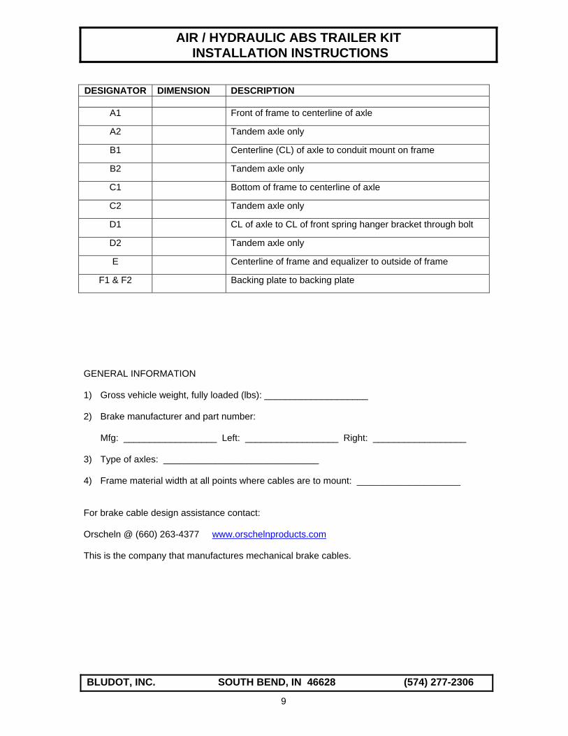
DESIGNATOR DIMENSION DESCRIPTION
A1 Front of frame to centerline of axle
A2 Tandem axle only
B1 Centerline (CL) of axle to conduit mount on frame
B2 Tandem axle only
C1 Bottom of frame to centerline of axle
C2 Tandem axle only
D1 CL of axle to CL of front spring hanger bracket through bolt
D2 Tandem axle only
E Centerline of frame and equalizer to outside of frame
F1 & F2 Backing plate to backing plate
GENERAL INFORMATION 1) Gross vehicle weight, fully loaded (lbs): ____________________ 2) Brake manufacturer and part number:
Mfg: __________________ Left: __________________ Right: __________________
3) Type of axles: ______________________________ 4) Frame material width at all points where cables are to mount: ____________________ For brake cable design assistance contact: Orscheln @ (660) 263-4377 www.orschelnproducts.com This is the company that manufactures mechanical brake cables.

AIR / HYDRAULIC ABS TRAILER KIT INSTALLATION INSTRUCTIONS
BLUDOT, INC. SOUTH BEND, IN 46628 (574) 277-2306
MECHANICAL PARKING BRAKES MUST BE INSTALLED ON ALL WHEELS TO MEET FMVSS REGULATIONS
Typical installation – single axle
Typical installation – tandem axle
10

AIR / HYDRAULIC ABS TRAILER KIT INSTALLATION INSTRUCTIONS
BLUDOT, INC. SOUTH BEND, IN 46628 (574) 277-2306
ABS System Wiring Diagram
11
AIR / HYDRAULIC ABS TRAILER KIT INSTALLATION INSTRUCTIONS
AIR / HYDRAULIC ABS TRAILER KIT INSTALLATION INSTRUCTIONS
BLUDOT, INC. SOUTH BEND, IN 46628 (574) 277-2306 12
BLUDOT, INC. SOUTH BEND, IN 46628 (574) 277-2306
12
AIR / HYDRAULIC ABS TRAILER KIT INSTALLATION INSTRUCTIONS
BLUDOT, INC. SOUTH BEND, IN 46628 (574) 277-2306
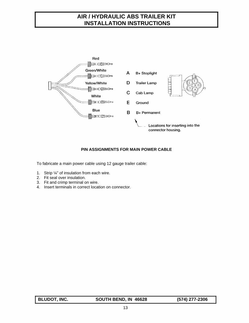
PIN ASSIGNMENTS FOR MAIN POWER CABLE To fabricate a main power cable using 12 gauge trailer cable: 1. Strip ¼” of insulation from each wire. 2. Fit seal over insulation. 3. Fit and crimp terminal on wire. 4. Insert terminals in correct location on connector.
13

AIR / HYDRAULIC ABS TRAILER KIT INSTALLATION INSTRUCTIONS
BLUDOT, INC. SOUTH BEND, IN 46628 (574) 277-2306
SCALE: NONE
DATE:
DRAWING NUMBER
SERVICE / CONTROL
EMERGENCY / SUPPLY
1
2
ITEM PART NO. DESCRIPTION1
2
3
4
5
6
7
8
9
10
11
12
13
14
15
16
17
18
1
1
78850
78851
5499
1468X6
GLADHAND-EMERGENCY
GLADHAND-SERVICE
1/2" BULKHEAD COUPLING 2
1
3/8" X 1/4" MALE CONNECTORAIR-OVER-HYDRAULIC ABSBRAKE ACTUATING KIT
34
43
CONTROL LINE
SUPPLY LINE
C-145
1469X6X6
1468X6X6
1/4" DRAIN VALVE
3/8" MALE ELBOW
3/8" MALE CONNECTOR
2
4
1
QTY
2S/1M
NOTES
A
B
CONFORMS TO FMVSS 571.121 SPECIFICATIONS
56
12
12
AT-1488 AIR TANK - 1488 cu. in. 1
1
1
AB-1000 AIR/HYDRAULIC ACTUATOR
3159X6 3/8" PIPE PLUG 4RV-4307D FULL FUNCTION ABS VALVE-2 PORT
BLUDOT INCORPORATEDSOUTH BEND, IN 46628(219) 277-2306
13
10
11
8
9
3179X12 3/4" PIPE PLUG
15
9
115654 SPRING BRAKE ACTUATOR
12 9
9
14
10
1469X6 1/4" X 3/8" MALE ELBOW 1
14

AIR / HYDRAULIC ABS TRAILER KIT INSTALLATION INSTRUCTIONS
BLUDOT, INC. SOUTH BEND, IN 46628 (574) 277-2306
SCALE: NONE
DATE:
DRAWING NUMBER
SERVICE / CONTROL
EMERGENCY / SUPPLY
1
2
ITEM PART NO. DESCRIPTION1
2
3
4
5
6
7
8
9
10
11
12
13
14
15
16
17
18
1
1
78850
78851
5499
1468X6
GLADHAND-EMERGENCY
GLADHAND-SERVICE
1/2" BULKHEAD COUPLING 2
1
3/8" X 1/4" MALE CONNECTORAIR-OVER-HYDRAULIC ABSBRAKE ACTUATING KIT
34
43
CONTROL LINE
SUPPLY LINE
C-145
1469X6X6
1468X6X6
1/4" DRAIN VALVE
3/8" MALE ELBOW
3/8" MALE CONNECTOR
2
7
1
QTY
2S/1M
NOTES
A
B
THIS SYSTEM DOES NOT COMPLY WITH FMVSS 571.121 SPECIFICATIONS
56
12
9
AT-1488 AIR TANK - 1488 cu. in. 1
1
1
AB-1000 AIR/HYDRAULIC ACTUATOR
3159X6 3/8" PIPE PLUG 2RV-4002 ABS RELAY VALVE W/ ECU-2 PORT
BLUDOT INCORPORATEDSOUTH BEND, IN 46628(219) 277-2306
13
10
11
8
3179X12 3/4" PIPE PLUG
15
9
9
12
9
9
9
9
16
1EM-1103 EMERGENCY CONTROL VALVE
13069X12X8 1/2 X 3/4 HEX NIPPLE
C
15
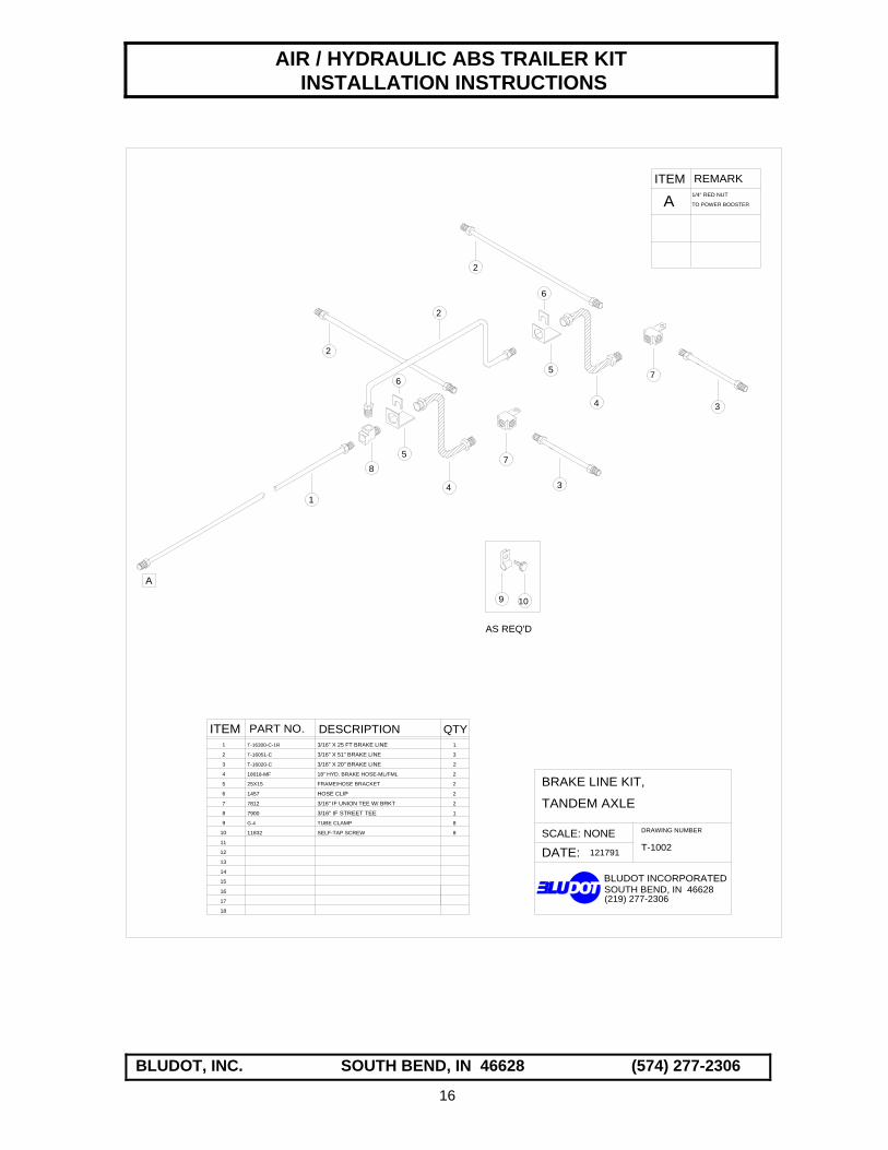
AIR / HYDRAULIC ABS TRAILER KIT INSTALLATION INSTRUCTIONS
BLUDOT, INC. SOUTH BEND, IN 46628 (574) 277-2306
SCALE: NONE
DATE:
DRAWING NUMBER
BRAKE LINE KIT,
121791
ITEM PART NO. DESCRIPTIONT-16300-C-1R1
2
3
4
5
6
7
8
9
10
11
12
13
14
15
16
17
18
T-16051-C
T-16020-C
18018-MF
25X15
1457
7812
QTY3/16" X 25 FT BRAKE LINE
3/16" X 51" BRAKE LINE
3/16" X 20" BRAKE LINE
18" HYD. BRAKE HOSE-ML/FML
FRAME/HOSE BRACKET
HOSE CLIP
3/16" IF UNION TEE W/ BRKT
1
T-1002
TANDEM AXLE
3
2
2
2
2
2
1
8
8
7900
G-4
11832
3/16" IF STREET TEE
TUBE CLAMP
SELF-TAP SCREW
85
6
4
7
3
5
6
2
2
2
4
7
3
1
AS REQ'D
A
1/4" RED NUT
TO POWER BOOSTER
ITEM REMARK
A
9 10
BLUDOT INCORPORATEDSOUTH BEND, IN 46628(219) 277-2306
16

AIR / HYDRAULIC ABS TRAILER KIT INSTALLATION INSTRUCTIONS
BLUDOT, INC. SOUTH BEND, IN 46628 (574) 277-2306
SCALE: NONE
DATE:
DRAWING NUMBER
BRAKE LINE KIT,
0698
ITEM PART NO. DESCRIPTIONT-16300-C-1R1
2
3
4
5
6
7
8
9
10
11
12
13
14
15
16
17
18
T-16051-C
25X15
1457
QTY3/16" X 25 FT BRAKE LINE
3/16" X 51" BRAKE LINE
18" HYD. BRAKE HOSE-SWVL/FML
FRAME/HOSE BRACKET
HOSE CLIP
1
1
1
8
T-16060-C 3/16" X 60" BRAKE LINE
7900 3/16" IF STREET TEE
2
44
4
3
G-4 TUBE CLAMP 8
11832 SELF-TAP SCREW 8
3
TANDEM AXLE
9 10
AS REQ'D
T-1002T
, TORSION
18018-SF
A
1/4" RED NUT
TO POWER BOOSTER
ITEM REMARK
A
5
5
6
6
7
7
5
3
2
5
6
67
7
8
8
BLUDOT INCORPORATEDSOUTH BEND, IN 46628(219) 277-2306
17
Related Documents


