AIR HANDLING UNITS SERIES: INSTALLATION USE AND MAINTENANCE MANUAL CTA STS ESA TVH

Welcome message from author
This document is posted to help you gain knowledge. Please leave a comment to let me know what you think about it! Share it to your friends and learn new things together.
Transcript
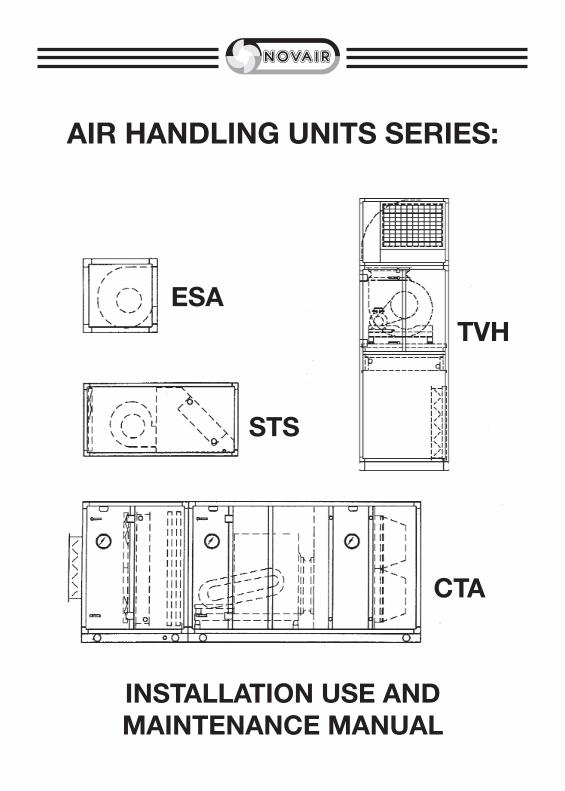
AIR HANDLING UNITS SERIES:
INSTALLATION USE ANDMAINTENANCE MANUAL
CTA
STS
ESATVH
�
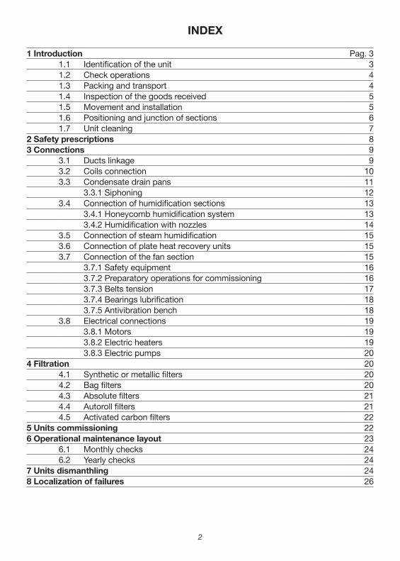
INDEX
1 Introduction Pag. 31.1 Identification of the unit 31.2 Check operations 41.3 Packing and transport 41.4 Inspection of the goods received 51.5 Movement and installation 51.6 Positioning and junction of sections 61.7 Unit cleaning 7
2 Safety prescriptions 83 Connections 9
3.1 Ducts linkage 93.2 Coils connection 103.3 Condensate drain pans 11
3.3.1 Siphoning 123.4 Connection of humidification sections 13
3.4.1 Honeycomb humidification system 133.4.2 Humidification with nozzles 14
3.5 Connection of steam humidification 153.6 Connection of plate heat recovery units 153.7 Connection of the fan section 15
3.7.1 Safety equipment 163.7.2 Preparatory operations for commissioning 163.7.3 Belts tension 173.7.4 Bearings lubrification 183.7.5 Antivibration bench 18
3.8 Electrical connections 193.8.1 Motors 193.8.2 Electric heaters 193.8.3 Electric pumps 20
4 Filtration 204.1 Synthetic or metallic filters 204.2 Bag filters 204.3 Absolute filters 214.4 Autoroll filters 214.5 Activated carbon filters 22
5 Units commissioning 226 Operational maintenance layout 23
6.1 Monthly checks 246.2 Yearly checks 24
7 Units dismanthling 248 Localization of failures 26
�
I INTRODUCTION
This manual gathers important indications on the safety of installation, the use regu‑lations and the list of the correct maintenances that can be made only by qualified personnel on theAir Handling Units of NOVAIR production.
The correct working of the plant during time as well as the product guarantee are strictly subordinated to the observance of all the rules showed in this manual. These have to be integrated by the legislative directions and by the technical regulations in force and they don’t replace any plant rule and possible prescriptions issued to assure safety.
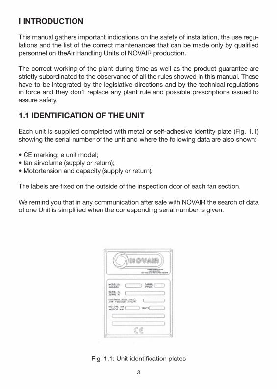
1.1 IDENTIFICATION OF THE UNIT
Each unit is supplied completed with metal or self‑adhesive identity plate (Fig. 1.1) showing the serial number of the unit and where the following data are also shown:
• CE marking; e unit model;• fan airvolume (supply or return);• Motortension and capacity (supply or return).
The labels are fixed on the outside of the inspection door of each fan section.
We remind you that in any communication after sale with NOVAIR the search of data of one Unit is simplified when the corresponding serial number is given.
Fig. 1.1: Unit identification plates
�
1.2 CHECK OPERATIONS
NOVAIR product is checked at each production cycle and is finally submited to the following inspection shecks:• outside dimensions check (length, height, width) of each section;• check of panels location and of the correct application of airtight gaskets;• check of drain pans watertightness;• check of coils and filters airtightness; check of the correct application of identity and warning plates;• finisch check.
1.3 PACKING AND TRANSPORT
The Units are supplied completely mounted as regards to the internal components and if necessary they are manufactured in serveral separated sections, when agreed with the customer, or in special cases:• difficult transport conditions;• difficulty of access into the rooms of destination.The positioning of the Units on the Units on the truck is carefully made by our techni‑cal staff that fastens and protect all parts against any damage risk. In particular, the units are fastened with metallic plates to the truck platform.The parking with thermoshrinking nylon is made only on small units (ESA, UTS).all additional critical components (filters, humidifiers, etc.) are packed with a protec‑tion wrappage.The different sections have to be loaded and unloaded taking care to he juts that the unit may have, especially:• handles;• hydraulic coils connections;• dampers;• protections roof;• drains, etc.
Before unloading the unit from the truck, make sure that all the fastening plates have been taken off from the platform.
�
1.4 INSPECTION OF THE GOODS RECEIVED
When the Unit is delivered in the yard, the installerwill check that the material received complies with the specifications shown in the transport document and that I has not been damaged because of further wrong movements, especially:
• check the structure integrity;• checkthe integrity ofpaneling and ofthe covering roof, if existing.
In case of anomalies or transport damages, these have to be im-mediately pointed out to the truck driver and underlined on the transport document.
Besides the installerwill carefully check all the components, especially:• checkthe integrityofdampers (pivots and blades);• checkthe integrityofcoils headers;• check the fastening of the fan‑motor setto its basement;• chepkthe quantity and the type offilters supplied.
Any anomaly noticed must be immediately notified to NOVAIR offices.
1.5 MOVEMENTAND INSTALLATION
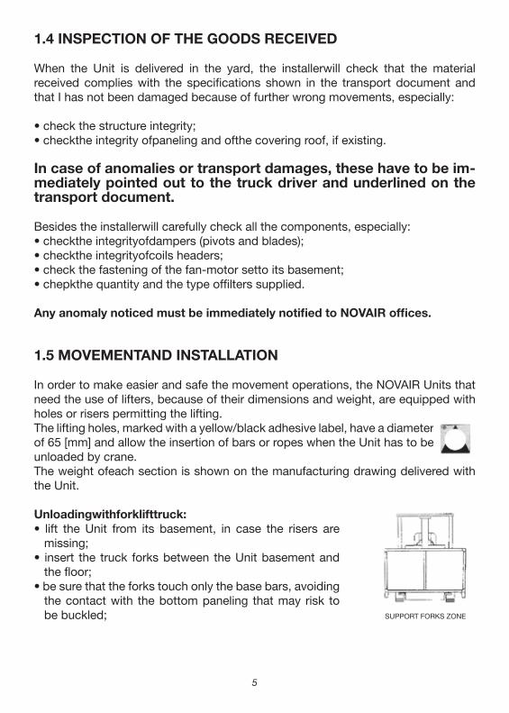
In order to make easier and safe the movement operations, the NOVAIR Units that need the use of lifters, because of their dimensions and weight, are equipped with holes or risers permitting the lifting.The lifting holes, marked with a yellow/black adhesive label, have a diameter of 65 [mm] and allow the insertion of bars or ropes when the Unit has to be unloaded by crane.The weight ofeach section is shown on the manufacturing drawing delivered with the Unit.
Unloadingwithforklifttruck:• lift the Unit from its basement, in case the risers are
missing;• insert the truck forks between the Unit basement and
the floor;• be sure that the forks touch only the base bars, avoiding
the contact with the bottom paneling that may risk to be buckled; SUPPORT FORKS ZONE
�
• slowly lift and check that the load is made in a statically correct way (it is possible to considerthe barycenterofeach section as its centerline).
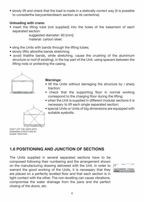
Unloading with crane:• insert the lifting tube (not supplied) into the holes of the basement of each
separated section:suggested diameter: 60 [mm];material: carbon steel.
• sling the Units with bands through the lifting tubes;• slowly liftto allowthe bands stretching;• avoid thatthe bands, while stretching, cause the crushing of the aluminium
structure or roof (if existing), in the top part of the Unit, using spacers between the lifting rods or protecting the casing.
Warnings:• lift the Units without damaging the structure by i sharp
traction;• check that the supporting floor in normal working
correspond to the charging floor during the lifting;• when the Unit is supplied in different modular sections it is
necessary to lift each single separated section;• special Units or Units of big dimensions are equipped with
suitable eyebolts.
1.6 POSITIONING AND JUNCTION OF SECTIONS
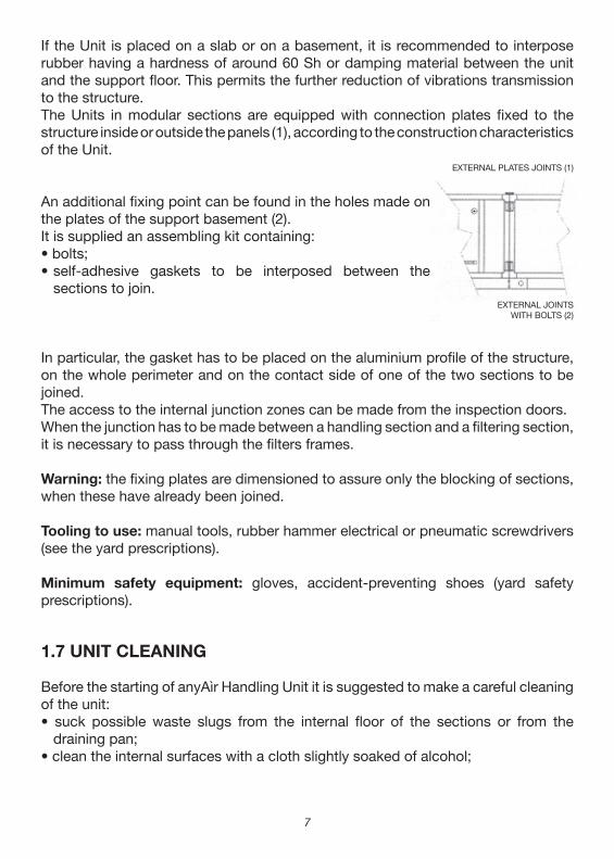
The Units supplied in several separated sections have to be composed following their numbering and the arrangement shown on the manufacturing drawing delivered with the Unit. In order to warrant the good working of the Units, it is necessary that they are placed on a perfectly levelled floor and that each section is in tight contact with the other. The non‑levelling can cause vibrations, compromise the water drainage from the pans and the perfect closing of the doors, etc.
DON’T LIFT THE UNITS WITH DAMAGING STRUCTURE BY SHARP TRACTION
�
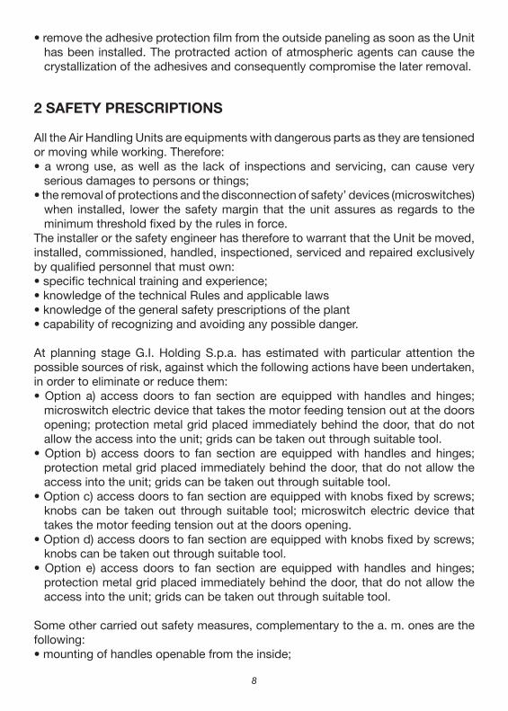
If the Unit is placed on a slab or on a basement, it is recommended to interpose rubber having a hardness of around 60 Sh or damping material between the unit and the support floor. This permits the further reduction of vibrations transmission to the structure.The Units in modular sections are equipped with connection plates fixed to the structure inside or outside the panels (1), according to the construction characteristics of the Unit.
An additional fixing point can be found in the holes made on the plates of the support basement (2).It is supplied an assembling kit containing:• bolts;• self‑adhesive gaskets to be interposed between the
sections to join.
In particular, the gasket has to be placed on the aluminium profile of the structure, on the whole perimeter and on the contact side of one of the two sections to be joined.The access to the internal junction zones can be made from the inspection doors.When the junction has to be made between a handling section and a filtering section, it is necessary to pass through the filters frames.
Warning: the fixing plates are dimensioned to assure only the blocking of sections, when these have already been joined.
Tooling to use: manual tools, rubber hammer electrical or pneumatic screwdrivers (see the yard prescriptions).
Minimum safety equipment: gloves, accident‑preventing shoes (yard safety prescriptions).
1.7 UNIT CLEANING
Before the starting of anyAìr Handling Unit it is suggested to make a careful cleaning of the unit:• suck possible waste slugs from the internal floor of the sections or from the
draining pan;• clean the internal surfaces with a cloth slightly soaked of alcohol;
EXTERNAL PLATES JOINTS (1)
EXTERNAL JOINTSWITH BOLTS (2)
�
• remove the adhesive protection film from the outside paneling as soon as the Unit has been installed. The protracted action of atmospheric agents can cause the crystallization of the adhesives and consequently compromise the later removal.
2 SAFETY PRESCRIPTIONS
All the Air Handling Units are equipments with dangerous parts as they are tensioned or moving while working. Therefore:• a wrong use, as well as the lack of inspections and servicing, can cause very
serious damages to persons or things;• the removal of protections and the disconnection of safety’ devices (microswitches)
when installed, lower the safety margin that the unit assures as regards to the minimum threshold fixed by the rules in force.
The installer or the safety engineer has therefore to warrant that the Unit be moved, installed, commissioned, handled, inspectioned, serviced and repaired exclusively by qualified personnel that must own:• specific technical training and experience;• knowledge of the technical Rules and applicable laws• knowledge of the general safety prescriptions of the plant• capability of recognizing and avoiding any possible danger.
At planning stage G.I. Holding S.p.a. has estimated with particular attention the possible sources of risk, against which the following actions have been undertaken, in order to eliminate or reduce them:• Option a) access doors to fan section are equipped with handles and hinges;
microswitch electric device that takes the motor feeding tension out at the doors opening; protection metal grid placed immediately behind the door, that do not allow the access into the unit; grids can be taken out through suitable tool.
• Option b) access doors to fan section are equipped with handles and hinges; protection metal grid placed immediately behind the door, that do not allow the access into the unit; grids can be taken out through suitable tool.
• Option c) access doors to fan section are equipped with knobs fixed by screws; knobs can be taken out through suitable tool; microswitch electric device that takes the motor feeding tension out at the doors opening.
• Option d) access doors to fan section are equipped with knobs fixed by screws; knobs can be taken out through suitable tool.
• Option e) access doors to fan section are equipped with handles and hinges; protection metal grid placed immediately behind the door, that do not allow the access into the unit; grids can be taken out through suitable tool.
Some other carried out safety measures, complementary to the a. m. ones are the following:• mounting of handles openable from the inside;
�
3 CONNECTIONS
3.1 DUCTS LINKAGE
Warning: It is forbidden to commission the Air Handling Unit when the fan outlets are not connected to ducts or protected with accidentpreventing net.
• the linkage ofsupply and return ducts has to be done using suitable flanges that, normally, are not supplied with theAir Handling Unit;
• it is always advisable to interpose a flexible joint between the duct and the Unit, in orderto minimize the transmission of vibrations;
• mounting of light points (where foreseen) inside the inspectionable sections;• elimination of sharp edges in the inspectionable sections;• mounting of fans on antivibration supports;• execution of holes and/or risers for lifting;• mounting of round windows (when required);• installation of warning labels;• supply of the use and maintenance manual.
At the utilization stage of the Units it is necessary to observe the following prescriptions:• do not start service and cleaning works before switching off the tension from the
electric panel and make sure that the moving parts are firm;• carefully observe the opening procedure of the supply fan section door or doors
under pressure (as, per par. 3.7.1);• retain the anti‑intrusion barrier installed in the fan section;• absolutely avoid to touch moving parts;• connect and do not tamper with the safety microswitches installed in the fan
sections:• do not enter the inspectionable sections with lights out.
The servicing works on each Unit have to be made under authorization of the safety engineer, on steady unit, electrically disconnected from the network. As the Units supplied are a product used in industrial areas, additional protection measures have to be taken and warranted by the person in charge of the installation in case more restrictive conditions of protection are required.In case of dismantlement of the Unit, follow the antipollution regulations provided and the prescriptions shown at par. 6.
In case the Unit shows anomalous working characteristics (bigger absorptions, temperatures increasings, noise, vibrations), promptly advise the personnel in charge of servicing.
10
• the sections of air crossing are dimensioned in order to guarantee a correct dynamicworking and a reduced noise level; therefore it is not convenient to reduce the passage sections near the suction and exhaust zones.
Attention:• the dampers installed on the Unit do not bear any load; therefore the ducts have
to be hold with suitable external supports;• do not trample on the top paneling of the Unit or on the covering roof in order
to avoid irreversible bucklings. lfnecessary, it is possible, to use as a precaution wood boards placed on the bearing profiles of the Unit; anyway we dissuade this operation.
Tooling to use: manual tools, electrical or pneumatic screwdrivers (see the yard prescriptions).Minìmum safety equipment: scaffold or moving lifter with cage, gloves, acci‑dent‑preventing shoes (yard safety prescriptions).
3.2 COILS CONNECTION
• the connection of the water coils has to foresee a hydraulic plant with automatic vent and the possibility of draining them from the inlet or outlet header of the liquid;
• take into account the pipeline path in order to keep the accessibility to coils and to the other inspectionable sections of the Unit. The coils installed inside NOVAIR Air Handling Units can be removed also from the back panel, opposite to connections;
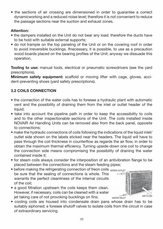
• make the hydraulic connections of coils following the indications of the liquid inlet/outlet side shown on the labels sticked near the headers. The liquid will have to pass through the coil thickness in counterflow as regards the air flow, in order to obtain the maximum thermal efficiency. Turning upside‑down one coil to change the connection side means compromising the possibility of draining the water contained inside it;
• for steam coils always consider the interposition of an antivibration flange to be placed between the connections and the steam feeding pipes;
• before making the refrigerating connection of freon coils be sure that the sealing of connections is whole. This warrants the perfect cleanliness of the internal circuits of the coil;
• a good filtration upstream the coils keeps them clean. However, if necessary, coils can be cleaned with a water jet taking care of not provoking bucklings on fins;
• cooling coils are housed into condensate drain pans whose drain has to be suitably siphoned; e foresee shutoff valves to isolate coils from the circuit in case of extraordinary servicing.
WATER OUTLET
WATER INLETAIR FLOW
11
Attention:• when the Unit is working with hot water or steam coils, therefore with working
temperatures beyond 90 [°C], consider the accidental arrest of fan. This situation may cause the consequent overheating of the air stagnating inside the Unit provoking damages to the motor, bearings, insulation and to the plastic parts. Therefore it is necessary that the plant is equipped of suitable regulation and control devices that can shut off the passage of hot water or steam to the coil when the fan is still. At these conditions it is preferable notto exceed the temperature of 50[0C];
• while tightening the pipes, limit the strain on headers in order to avoid the risk of fissurations on seams. Then make the tightening following the scheme shown on the adhesive label sticked near the headers. Besides check that the plant doesn’t transmit vibrations;
• do not let weigh heavily the connecting pipes directly on coil headers but foresee suitable holders;
• during the testing operations carefully check íf there are leakages from the coil;• do not leave the coils out in all weathers without hermetically sealing the
headers;• when there is the possibility of freezing inside the hydraulic circuit it is necessary
to mix the feeding liquid of coils with antifreezing liquid or making the emptying of those not used. Provide antifreezing devices on the Units with fresh air intake when the airtemperature drops below 3 [°C].
3.3 CONDENSATE DRAIN PANS
They are supplied of drain pipes made of iron or plastic material. Each drain must be suitably siphoned observing the height shown on the adhesìve label sticked near it.
Attention:
• while tightening the pipes, block with tools the sleeve coming out of the Unit in order to prevent its torsion and consequently the damaging of the pan;
• check the cleanliness of drain pans and pipes before commissioning the Unit and afterwards keep a periodical check;
1�
• when there is a water recirculating pump, this is placed in a drain pan made in a small‑well shape; e when the Units are installed outside, it ís advisable to keep the drain closed during winter time and open it in summer time. This device permits to have always moving water inside the pan and therefore prevents freezing dangers.
3.3.1 SIPHONING
A good drain system must be equipped with a suitable siphon, in order to:• allowthe condensate drain;• prevent the undesired air entering into the systems in depression;• preventthe air outletfrom the systems in pressure;• prevent the infiltration of insects and undesired smells.
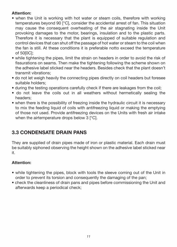
A) inlet fan
A correct dimensioning of siphons assumes to comply with the following ratios:
H1 = 2P H2= P
where P (expressed in mm of water column) indicates the maximum negative pressure that the fan can generate, which means all the pressure drops upstream the pan.
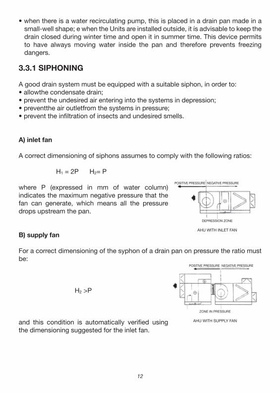
B) supply fan
For a correct dimensioning of the syphon of a drain pan on pressure the ratio must be:
H2 >P
and this condition is automatically verified using the dimensioning suggested for the inlet fan.
DEPRESSION ZONE
AHU WITH INLET FAN
POSITIVE PRESSURE NEGATIVE PRESSURE
POSITIVE PRESSURE NEGATIVE PRESSURE
ZONE IN PRESSURE
AHU WITH SUPPLY FAN
1�
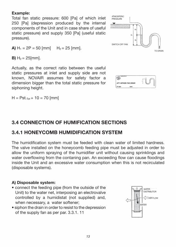
Example:Total fan static pressure: 600 [Pa] of which inlet 250 [Pa] (depression produced by the internal components of the Unit and in case share of useful static pressure) and supply 350 [Pa] (useful static pressure).
A) H1 = 2P = 50 [mm] H2 = 25 [mm].
B) H2 = 25[mm].
Actually, as the correct ratio between the useful static pressures at inlet and supply side are not known, NOVAIR assumes for safety factor a dimension bigger than the total static pressure for siphoning height.
H = Pst.Tot + 10 = 70 [mm]
3.4 CONNECTION OF HUMIFICATION SECTIONS
3.4.1 HONEYCOMB HUMIDIFICATION SYSTEM
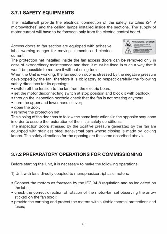
The humidification system must be feeded with clean water of limited hardness. The valve installed on the honeycomb feeding pipe must be adjusted in order to allow the uniform spraying of the humidifier unit without causing sprinklings and water overflowing from the contaning pan. An exceeding flow can cause floodings inside the Unit and an excessive water consumption when this is not recirculated (disposable systems).
A) Disposable system:• connect the feeding pipe (from the outside of the
Unit) to the water net, interposing an electrovalve controlled by a humidistat (not supplied) and, when necessary, a water softener;
• siphon the drain in order to resist to the depression of the supply fan as per par. 3.3.1. 11
WATERDISTRIBUTOR
WATER
AIR FLOW
TO DRAIN
SWITCH OFF FAN
ATMOSFERICPRESSURE
1�
B) Recirculated water system:• connect the reintegrating pipe (from the outside of the Unit)to the water net
interposing, when necessary, a water softener;• siphon the drain and the over‑flow in order to resist to the depression of the supply
fan as per par. 3.3. I;• electrically connect the pump, controlled by a humidistat, with thermal protection
or fuses;• after some minutes of working check that the honeycomb is completely wet,
without causing sprinklings;• when the honeycomb shows limestone coatings, replace it and clean the water
distribution system;• the honeycomb humidifier units housed inside the Unit have a pre‑settled location
allowing to respect the air and water direction in counterflow. The wrong position compromises the correct working and causes the risk of water flooding inside the Unit;
• in these systems it is a good rule to replace often the water contained in the pan or to let it drain constantly in small quantities (bleed‑off system), in order not to help the circulation of bacteriologically impure water and prevent the deposit of salty limings;
• when the Units are installed outside, it is advisable to keep the drain closed during wintertime and open it in summertime. This device permits to have always moving water inside the pan and therefore prevents freezing dangers.
Attention:• do not let the pump run before checking the cleanliness of the pan and filled it
with water;• before commissioning the system check the setting of the float and the over‑flow
pipe. To raise or drop the float, lightly bend the stick bearing the ball fixed to the valve or, for bigger valves, act on the fixing screw of the stick, making the float slide along the stick.
3.4.2 HUMIDIFICATION WITH NOZZLES BENCH
• the system must be feeded with clean water having a low hardness;• connect the feeding pipe (outside the Unit) to the water network interposing, when
necessary, a water softener;• siphon the drain and the over‑flow in order to contrast the depression made by the
supply fan as per par. 3.3. 1;• install a cock on the draining collar ofthe pan

1�
• electrically connectthe pumpwith thermal protection and fuses;• do not let the pump run before checking the cleanliness of the pan and filled it
wíth water;• to obtain the best atomization of the sprinkled water it is necessary to feed the
nozzles with water at a pressure of 2.5 [bar] (different instructions excepted);• monthly check the regular sprinkling of the nozzles and clean the pan.
Attention:
• before commissioning the system check the setting of the float and the over‑flow pipe. To raise or drop the float, lightly bend the stick bearing the ball fixed to the valve or, for bigger valves, act on the fixing screw of the stick, making the float slide along the stick.
• in the recirculated water systems it is a good rule to let the water drain constantly in small quantities in order to reduce the impurities that are present in the circuit and avoid the nozzles clogging. To clean the nozzles, screw them off and clean them by compressed air.
3.5 CONNECTION OF STEAM HUMIDIFICATION
The steam humidification system foresees the connection of the steam feeding pipe and the condensate drain pipe. For any type of regulation (centralized production or by steam producer) refer to the respective use and maintenance manuals.
3.6 CONNECTION OF PLATE HEAT RECOVERY UNITS
For these equipments the installer only has to take care of the condensate drain pan siphoning. As for the coils, a good filtration before the recovery units keeps them clean. Nevertheless, if necessary the cleanliness of the exchangers can be made by waterjettaking care of do not cause the buckling of the fins.
3.7 CONNECTION OF THE FAN SECTION
While commissioning for the first time one Unit, it is necessary to check carefully the mounting of the motor‑fan set and the correct installation of the safety devices.
1�
3.7.1 SAFETY EQUIPMENTS
The installerwill provide the electrical connection of the safety switches (24 V microswitches) and the ceiling lamps installed inside the sections. The supply of motor current will have to be foreseen only from the electric control board.
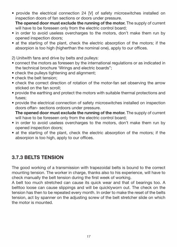
Access doors to fan section are equipped with adhesive label warning danger for moving elements and electric current.The protection net installed inside the fan access doors can be removed only in case of extraordinary maintenance and then it must be fixed in such a way that it won’t be possible to remove it without using tools.When the Unit is working, the fan section door is stressed by the negative pressure developped by the fan, therefore it is obligatory to respect carefully the following safety directions for its opening:• switch off the tension to the fan from the electric board;• set the motor disconnecting switch at stop position and block it with padlock;• through the inspection porthole check that the fan is not rotating anymore;• turn the upper and lower handle lever;• open the door;• remove the protection net.The closing of the door has to follow the same instructions in the opposite sequence in order to assure the restoration of the initial safety conditions.The inspection doors stressed by the positive pressure generated by the fan are equipped with stainless steel transversal bars whose closing is made by locking knobs. The safety directions for the opening are the same described above.
3.7.2 PREPARATORY OPERATIONS FOR COMMISSIONING
Before starting the Unit, it is necessary to make the following operations:
1) Unit with fans directly coupled to monophasicortriphasic motors:
• Connect the motors as foreseen by the IEC 34‑8 regulation and as indicated on the label;
• check the correct direction of rotation of the motor‑fan set observing the arrow sticked on the fan scroll;
• provide the earthing and protect the motors with suitable thermal protections and fuses;
1�
• provide the electrical connection 24 [V] of safety microswitches installed on inspection doors of fan sections or doors under pressure.
The opened door must exclude the running of the motor. The supply of current will have to be foreseen only from the electric control board;
• in order to avoid useless overcharges to the motors, don’t make them run by opened inspection doors;
• at the starting of the plant, check the electric absorption of the motors; if the absorpion is too high (hígherthan the nominal one), apply to our offices.
2) Unitwith fans and drive by belts and pulleys:• connect the motors as foreseen by the international regulations or as indicated in
the technical brochure ‘Wrings and electric boards”;• check the pulleys tightening and alignment;• check the belt tension;• check the correct direction of rotation of the motor‑fan set observing the arrow
sticked on the fan scroll;• provide the earthing and protect the motors with suitable thermal protections and
fuses;• provide the electrical connection of safety microswitches installed on inspection
doors offan‑ sections ordoors under pressure. The opened door must exclude the running of the motor. The supply of current
will have to be foreseen only from the electric control board;• in order to avoid useless overcharges to the motors, don’t make them run by
opened inspection doors;• at the starting of the plant, check the electric absorption of the motors; if the
absorpion is too high, apply to our offices.
3.7.3 BELTS TENSION
The good working of a transmission with trapezoidal belts is bound to the correct mounting tension. The worker in charge, thanks also to his experience, will have to check manually the belt tension during the first week of working.A belt too much stretched can cause its quick wear and that of bearings too. A belttoo loose can cause slippings and will be quicklyworn out. The check on the tension has then to be repeated every month. In order to make the reset of the belts tension, act by spanner on the adjusting screw of the belt stretcher slide on which the motor is mounted.
1�
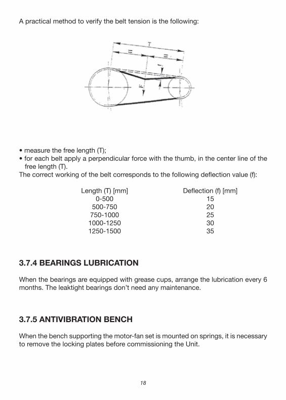
A practical method to verify the belt tension is the following:
• measure the free length (T);• for each belt apply a perpendicular force with the thumb, in the center line of the
free length (T).The correct working of the belt corresponds to the following deflection value (f):
Length (T) [mm] Deflection (f) [mm] 0‑500 15 500‑750 20 750‑1000 25 1000‑1250 30 1250‑1500 35
3.7.4 BEARINGS LUBRICATION
When the bearings are equipped with grease cups, arrange the lubrication every 6 months. The leaktight bearings don’t need any maintenance.
3.7.5 ANTIVIBRATION BENCH
When the bench supporting the motor‑fan set is mounted on springs, it is necessary to remove the locking plates before commissioning the Unit.
1�
3.8 ELECTRICAL CONNECTIONS
3.8.1 MOTORS
The electric motors used have the following features:• complying with CEI‑UNEL regulations and IEC international regulations;• closed construction and external ventilation;• squirrel cage rotor;• three‑phase asynchronous with winding: 2301400 [Volt] 50 [ Hz] Eurotension up to capacity of 5,5 [kVVI included; 4001690[Volt] 50[ Hz] Eurotension for bigger capacities;• single polarity (usually 4 poles) or, unless different request: 2 poles for fans with rotation frequency higher than 2.800 [Rpm] 6 poles for fans with rotation frequency lower than 400 [Rpm]• B3 shape horizontal shaft application;• Class F;• IP55 insulation.
Usually the triphasic motors single speed can be connected by two voltages. The most common method is the star or delta connection of the three phases of the statoric winding.
Motor23O/400 [V] Eurotension:delta connection for current 230 [V]star connection for current 400 [V]
Motor400/690 [V] Eurotension:delta connection for current 400 [V]
For the connection of double polarity motors please refer to the technical brochure “Wirings and Electrical Boards”.
3.8.2 ELECTRIC HEATERS
• electrically connect the heaters following the instructions of the charts supplied with them;
• adjust the temperature of maximum utilization acting on the thermostat placed on the heater frame;
• the overheating inside the unit damages the motor, the fan bearings and the insulation. Therefore it is advisable to limit the working temperature of the electric heater to 50 160 [°C] in case of standard motors and 40 [°C] in case of directly coupled motors;
�0
4 FILTRATION
When the Unit ís equipped with panel prefilters and bag filters, these are supplied not mounted and kept into boxes in order to prevent an untimely deterioration caused by weathering.Before installing the filters ontheframe, check thewholeness of the adhesive tightening gasket and, if necessary, restore it with the foamed gasket supplied in the kit.
4.1 SYNTHETIC OR METALLIC FILTERS
They are regenerable filters made of synthetic fiber or metallic mesh and metallic frame. They are directly mounted on sliding guides or counterframes with locking springs.The check of the clogging level can be visual or controlled by manometer or differential pressure gauge. The filters cleaning or replacement is suggested when the pressure drop is around 120 [Pa]. The cleaning can be made washing the panel with warm water and soap or common domestic detergents. It is also possible to use a compressed airjet at low pressure with contrary direction to the normal air flow in the Unit.
4.2 BAG FILTERS
Bag filters are not regenerable, therefore when they are clogged they must be replaced. These are mounted on counterframes with locking springs.
• foresee suitable electrical protections;• make the possible cleaning of the resistors by vacuum cleaner.
3.8.3 ELECTRIC PUMPS
• read carefully the use and maintenance manual of the electric pump before connecting it
• electrically connectthe pump following the instructions enclosed to it• do not let the electric pump run at dry conditions to avoid the quick wear of the
mechanical tightness• any service operation must be done only after having switched the current off.

�1
The check of the clogging level can be made by manometer or differential pressure gauge with alarm. The pressure drop by clogged filter is variable according to the model and the efficiency of the filter installed.Usually the bag filters are supplied not mounted and packed into boxes.At the first starting, let the Unit run for some hours without bag filters but with prefilters. This allows the cleaning of the aeraulic circuit avoiding a quick clogging of the high efficiency filters. At each filters replacement check the wholeness of the stop gaskets mounted on the containing frames and the perfect adhesion of filters to the gasket.When in one Unit there is only one frame containing both bag and panel filters, it is necessary to install first the bag modules as final filters and then the panel filters as prefilters (i.e. upstream the bag filters). Their locking is made using the springs supplied, that have to be inserted into the hooks obtained in the frames (farther hook from the stop edge) and blocked to the pressed flanging.When the position of the containing frame allows it, it is advisable to install the bag filters with vertical orientation (i.e. perpendicular to the Unit floor) so that their capacity of bearing the dust load will be increased.The filters must be replaced by stopped fan.
4.3 ABSOLUTE FILTERS
Absolute filters are not regenerable so, when they are clogged, they must be replaced.They are mounted on counterframes using bars or locking tie rods.The check of the clogging level can be made by manometer or differential pressure gauge with alarm. The pressure drop by clogged filter is variable according to the model and the efficiency of the filter installed.Usually the absolute filters are supplied not mounted and packed into boxes.At the first starting, let the Unit run for some hours without absolute filters but with prefilters. This allows the cleaning of the aeraulic circuit avoiding a quick clogging of the high efficiency filters. At each filters replacement check the wholeness of the stop gaskets mounted on the containing frames and the perfect adhesion of filters to the gasket.The filters must be replaced by stopped fan.
4.4 AUTOROLL FILTERS
They are filters of continuous regeneration, equipped with pressure gauge control automatically renewing the filter when it is clogged. The filter is
��
5 UNITS COMMISSIONING
Before starting the Units:
• check the correct working of the electrical components (each electric item must be connected to earth as well as each section of the Unit);
• check the free rotation ofthe dampers blades;• check the free rotation of the motor and fan as well as the direction of rotation.
Then be sure to comply with all the following conditions:• opened dampers;• installed and blocked filters;• closed doors;• correctly connected motors;• correctly tensioned belts;• siphoned drains.
Verify that the electrical absorption of motors is lower than the one of the specification tag. In case the absorption is higher, immediately inform NOVAIR customer setvice and stop the working of the Unit or temporarily make artificial pressure drops in order to avoid the motor overloading (for example partial closing of one damper).
equipped with its electric control board, wired and fixed to the Unit, having the controls of stop, manual feed and optical alarm indicating the complete winding offofthefiltering medium.The filter must be replaced when on the control panel the alarm indicates its exhaustion.
4.5 ACTIVATED CARBON FILTERS
They are filters regenerable only by chemical process. For small quantities of carbon it is convenient to replace it when it is soaked. The replacement is made removing the cartridges from their housing and, after the removal of the closing caps, emptying them of the exhausted carbon. It is necessary to keep the fresh carbon in dry places and install it only atthe starting of the Unit.The exhausted carbon must be cleared by authorized Companies.
��
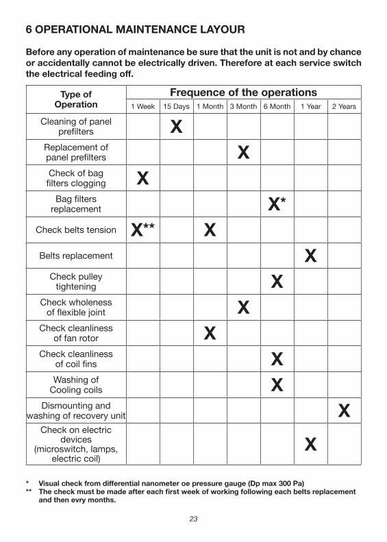
Type ofOperation
Frequence of the operations1 Week 15 Days 1 Month 3 Month 6 Month 1 Year 2 Years
Cleaning of panelprefilters X
Replacement ofpanel prefilters XCheck of bagfilters clogging X
Bag filtersreplacement X*
Check belts tension X** XBelts replacement X
Check pulleytightening X
Check wholenessof flexible joint X
Check cleanlinessof fan rotor X
Check cleanlinessof coil fins XWashing of
Cooling coils XDismounting and
washing of recovery unit XCheck on electric
devices(microswitch, lamps,
electric coil)X
* Visual check from differential nanometer oe pressure gauge (Dp max 300 Pa)** The check must be made after each first week of working following each belts replacement and then evry months.
6 OPERATIONAL MAINTENANCE LAYOUR
Before any operation of maintenance be sure that the unit is not and by chance or accidentally cannot be electrically driven. Therefore at each service switch the electrical feeding off.

��
7 UNITS DISMANTLING
• before dismantling the Unit, be sure that the disconnecting switch of the electric board is in “OFF” position;
• empty and hydraulically disconnect the coils;• dismount the accessories, such as the lamps, microswitch, pressure gauges,
etc.;• electrically disconnect the motors, pumps, resistors if any, ecc.;• dismount the side panels and the top panels using normal tools;
6.1 MONTHLY CHECKS
A) FAN ROTOR CHECK
Check the cleanliness of the fan rotor. Otherwise clean it by compressed air jetwithout damaging it.
B) BELT CHECK
• check the correct belt tension following the procedure described at par, 3.7.3. If it is necessary to tension it, act on the screw of the motor slide;
• checkthe beltwear.
6.2 YEARLY CHECKS
• check the whole electric equipment and especially the perfect tightening of the electric connections;
• check the tightening of all those connections that could be loosed by the vibrations;
• check the wearing condition of belts (if installed) that must be uniform on both sides. If it is necessary the replacement of only one belt, replace also the others at the same time. In this case the belts must have the same length;
• check the alignment between the two pulleys (if installed) and in case restore it;• check that the motor doesn’t show traces of dust, dirt or other impurities. Check
that it runs without vibrations or anomalous noises, that the entrance of the ventilation circuit isn’t clogged, with consequent possibility of overheating of the windings;
• check that the fan scroll is free from dirt or any foreign body.
��
• some panels (zones under pressure) could be sealed with silicone and therefore it will be necessary to apply a pressure in order to remove them;
• some panels are fastened with screws from the inside of the Units, therefore it is necessary to start their dismantling reaching the inspectionable sections;
• dismount the filters frames, the ventilation units, the recovery units, etc.. All the components installed inside the NOVAIR Units are screwed to the bearing struc‑ture and they don’t need special tools to be dismounted;
• remove the coils. They are mounted on guides and locked by screws and can be reached through the inspectionable sections. In case of reutilization, take great care to the fins and to the water tubes which must not be buckled or crushed;
• dismount the sliding guides and, if existing, the water and humidification drain pans;
• the profiles forming the bearing structure are mounted by rabbet on 3.‑ways cor‑ners, while the middle profiles are fixed by screws to the bearing structure. Once the panels have been removed, it is possible to dismount the bearing structure re‑moving the middle profiles and, forcing by a rubber hammer, the perimeter frame on the corners;
• the supporting basements of the Units are usually made of sectional frames easy to transport by hand or on pallet trucks;
• if cutting operations by disks are needed, be sure that there aren’t inflammable substances nearby;
• in case the Unit has to be afterwards reassembled, all the operations have to be made taking a great care of each component that must not be damaged. In this case it is suggested to ask the specialized assìstance of NOVAIR.
Further informations on components that have not been quoted in this manual can be found on technical catalogues or manuals, labels or brochures enclosed to the Units. Novair offices are at your disposal for any information or clarification.
The Company Novair Clima S.r.l. declines all responsibility for faults or troubles duetotampering of the Units from not authorized personnel.
��
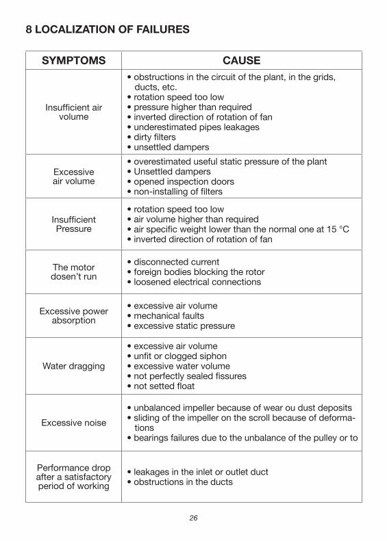
SYMPTOMS CAUSE
Insufficient airvolume
• obstructions in the circuit of the plant, in the grids, ducts, etc.
• rotation speed too low • pressure higher than required• inverted direction of rotation of fan• underestimated pipes leakages• dirty filters• unsettled dampers
Excessiveair volume
• overestimated useful static pressure of the plant• Unsettled dampers• opened inspection doors• non‑installing of filters
InsufficientPressure
• rotation speed too low• air volume higher than required• air specific weight lower than the normal one at 15 °C• inverted direction of rotation of fan
The motordosen’t run
• disconnected current• foreign bodies blocking the rotor• loosened electrical connections
Excessive powerabsorption
• excessive air volume• mechanical faults• excessive static pressure
Water dragging
• excessive air volume• unfit or clogged siphon• excessive water volume• not perfectly sealed fissures• not setted float
Excessive noise
• unbalanced impeller because of wear ou dust deposits• sliding of the impeller on the scroll because of deforma‑
tions• bearings failures due to the unbalance of the pulley or to
Performance dropafter a satisfactoryperiod of working
• leakages in the inlet or outlet duct• obstructions in the ducts
8 LOCALIZATION OF FAILURES

��
NOTES:
G.I. HOLDING S.p.A. ‑ Via Max Piccini, 11/1333050 Rivignano (UD) ‑ ITALY
Tel. +39 0432 773067 r.a. Fax +39 0432 773855http://www.novairclima.com ‑ E‑mail: [email protected]
ED
IZIO
NE
04.
07 M
AN
. IN
GLE
SE
CTA
RE
V 0
1
Related Documents


