Air Handling Units Pos: 2 /Layout/Titel_Montage Inbetriebnahme Wartung @ 0\mod_1257953072735_2008.docx @ 2125 @ @ 1 Installation Commissioning Maintenance Pos: 3 /Layout/Hinweis_Deckblatt @ 0\mod_1257492952667_2008.docx @ 2064 @ @ 1 Translation of the original instructions Englische Version – English Version Keep for future use === Ende der Liste für Textmarke Inhalt2 ===

Welcome message from author
This document is posted to help you gain knowledge. Please leave a comment to let me know what you think about it! Share it to your friends and learn new things together.
Transcript

Air Handling Units
Pos: 2 /Layout/Titel_Montage Inbetriebnahme Wartung @ 0\mod_1257953072735_2008.docx @ 2125 @ @ 1
Installation Commissioning Maintenance
Pos: 3 /Layout/Hinweis_Deckblatt @ 0\mod_1257492952667_2008.docx @ 2064 @ @ 1
Translation of the original instructions Englische Version – English Version Keep for future use
=== Ende der Liste für Textmarke Inhalt2 ===

Copyright by
robatherm GmbH + Co. KG
Industriestrasse 26
89331 Burgau
Germany
Pos: 5 /Layout/Rechtlicher_Hinweis @ 1\mod_1264667669971_2008.docx @ 3187 @ @ 1
This manual accords with current technology at the time of writing. As the printed version is not regularly updated, please obtain the latest version before using it, by downloading from www.robatherm.com or on request from robatherm.
The copyright to this work, including all illustrations, is reserved. No use which exceeds the limits of copyright law is allowable without our permission, and such use will be prosecuted. This applies, in particular to duplication, translation, microfilming and storage and processing in electronic systems.
Subject to modifications.
=== Ende der Liste für Textmarke Inhalt3 ===
03 / 2018
Contents
Introduction 1 General 1 Safety Instructions 3 Emergency Provisions 4 Maintenance and Cleaning Instructions 4
Installation 6 Delivery 6 Unloading and Transport 6 Assembly and Installation 9 Sealing of the Roof of Weatherproof Units 18
Commissioning and Maintenance 20 Damper 20 Fan and Motor 22 Filters 29 Silencer 31 Heating Coil (Hot Water, Steam) 32 Electric Heater 36 Cooling Coil (CW – DX Coil) 38 Refrigeration Installations and Heat Pump 41 Rotary Heat Exchanger 43 Plate Heat Exchangers 46 Heat Pipe 47 Desiccant Rotor 48 Combustion Chamber 50 Gas Surface Burner 55 Spray Humidifier 61 High Pressure Spray Humidifier 68 Pressure Relief Damper 70 Controlling Systems 72 Hydraulic Set 75
Shut Down 78 Shut Down 78 Disassembly, Disposal 78


Introduction
© robatherm 1
Pos: 7.1 /Überschriften/_Einleitung @ 0\mod_1256570106184_2008.docx @ 2009 @ @ 1 Pos: 7.2 /Überschriften/__Allgemeines @ 0\mod_1256636424157_2008.docx @ 2033 @ @ 1
General Pos: 7.3 /Sicherheitshinweise/!Allgemeines_Achtung @ 0\mod_1256570744025_2008.docx @ 2013 @ @ 1
Attention
These installation, commissioning and maintenance instructions must be read and observed by all people who carry out work on the unit. For components which are not described, the individual instructions are to be observed (request if required). robatherm will not be held liable for damage or faults which result from non-observance of these instructions. The manufacturer’s warranty and the certificate of installation/conformity do not apply for unofficial or unapproved conversions and changes to the appliance.
Pos: 7.4 /Einleitung/Bestimmungsgemäße Verwendung @ 0\mod_1256571195178_2008.docx @ 2014 @ @ 1
Use for Intended Purpose
The unit supplied by robatherm must only be used for air handling. This includes filtering, heating, cooling, humidifying, dehumidifying and transporting of air. robatherm expressly forbids any other use.
Pos: 7.5 /Sicherheitshinweise/!Allgemeines_ATEX @ 0\mod_1256571433810_2008.docx @ 2015 @ @ 1
Units with the „Ex“-mark (subsequently described as ATEX-units) are to be used in accordance with the unit identification on the nameplate and on the technical data sheet in accordance with the ATEX directive. Be sure to observe any restrictions on use. ATEX units must not be used near: High frequency sources (e.g. transmitters) Strong light sources (e.g. lasers) Ionising radiation sources (e.g. X-ray tubes) Ultrasound sources (e.g. ultrasound echo testing equipment)
Pos: 7.6 /Einleitung/Technikzentrale @ 0\mod_1256574615063_2008.docx @ 2016 @ @ 1
Mechanical Equipment Room
The requirements of mechanical equipment rooms must be observed in accordance with the VDI 2050 for operations and maintenance. This also includes sufficient maintenance space, ventilation as well as compliance with the temperature and humidity requirements. In front of heating and cooling coils, it is recommended to allow an obstacle-free area, at least as wide as the AHU’s depth for maintaining those coils.
Pos: 7.7 /Einleitung/Transport und Lagerung @ 0\mod_1256574654560_2008.docx @ 2017 @ @ 1
Transport and Storage
All units and components must be transported and stored in such a way that damage, adverse effects through weather factors, condensation (ensure sufficient rear ventilation within the packaging) or contamination are avoided. When storing for over 3 months, loosen belt drives and turn rotating components such as e.g. on ventilators, motors, pumps, HRS rotors on a monthly basis.
Pos: 7.8 /Einleitung/Montage_allgemeiner Hinweis @ 0\mod_1256574700385_2008.docx @ 2018 @ @ 1
Installation
If units are supplied in separate sections, these shall be assembled in accordance with these assembly instructions and professionally connected to the ductwork. All protective devices shall be applied. The person responsible for assembly on site and changing non-runable components to complete ready to operate units is also responsible for issuing the certificate of conformity and the CE marking.
Pos: 7.9 /Einleitung/Vor_Inbetriebnahme @ 0\mod_1256574745225_2008.docx @ 2019 @ @ 1
Before Commissioning
The unit can only be taken into operation if it has been assembled in accordance with these instructions. All protective devices must be effective. A lockable service switch must be installed near the fan unit access door.
Introduction

Introduction
2 © robatherm
Pos: 7.10 /Einleitung/Brandschutz @ 2\mod_1334559332779_2008.docx @ 22440 @ @ 1
Fire Protection
Possible spreading of fire between supply- and exhaust air sections of the AHU (e.g. via the heat recovery system or recirculating air) must be prevented by appropriate precautionary measures in the building site’s system (e.g. fire dampers) by others. A possibly required down gradient grid, according to DIN EN 1886 and AHU-Guideline 01, must be installed within the system to prevent any carry-over of flammable parts from filters, mist eliminators or contact humidifiers into the supply air duct.
Pos: 7.11 /Einleitung/Übergabe @ 2\mod_1334559030399_2008.docx @ 22410 @ @ 1
Handover
AHUs with integrated control technology may only be taken into operation after to robatherm’s initial commissioning and after handover and customer’s briefing has been concluded.
Pos: 7.12 /Einleitung/Einfrierschutz @ 2\mod_1334559151487_2008.docx @ 22425 @ @ 1
Freeze Protection
In case of ambient temperatures below the freezing point, it can make sense not to switch down the unit, e.g. in order to prevent dampers from freezing or to avoid any failures during a later restart.
Pos: 8 /Layout/Seitenumbruch @ 0\mod_1256628615637_0.docx @ 2284 @ @ 1

Introduction
© robatherm 3
Pos: 9.1 /Überschriften/__Sicherheitshinweis @ 0\mod_1256636566416_2008.docx @ 2035 @ @ 1
Safety Instructions Pos: 9.2 /Sicherheitshinweise/!Sicherheitshinweise_Vorsicht @ 0\mod_1256628078402_2008.docx @ 2020 @ @ 1
Caution
Serious bodily injuries and even loss of life and material damage can result from non-observation of the following instructions of the valid national and international safety regulations. References in this document to technical rules (e.g. BGR, BGV, DVGW, TRBS, TRGI) are subject to the relevant local health and safety regulations regarding installation and operation of the unit. Even if the unit is switched off, certain regulating functions can lead to sudden switching on of unit components such as e.g. resumption of power supply, compressor pump-out, fan overshoot, frost protection, timer programs. When the fan is in operation, there is perilous voltage on the permanent-magnet synchronous motor --> danger to life.
Pos: 9.3 /Sicherheitshinweise/!Sicherheitshinweise_ATEX @ 0\mod_1256628255350_2008.docx @ 2021 @ @ 1
Do not commission ATEX units until the following requirements are met: Conditions of use in accordance with the purpose for which the unit is intended. No substances nearby that are prone to spontaneous combustion e.g. pyrophoric
substances under EN 1127-1.
Constant and adequate ventilation of the installation site (mechanical equipment room) in the case of ATEX units without a specified exterior ex zone so that unavoidable leakage to the exterior of the unit does not result in an explosive atmosphere.
Pos: 9.4 /Einleitung/Sicherheitshinweise @ 0\mod_1256628399834_2008.docx @ 2022 @ @ 1
Only enter the unit or work on it when the following conditions are met: All-pole disconnection of power supply. Minimum waiting period of frequency converter 15 minutes (due to remaining voltage). Protected against switching on by installations in accordance with DIN EN 60204 (VDE
0113) (e.g. lockable service switch). Standstill of all moving parts, especially fan impeller, belt drive, motor, rotary heat
exchanger. Heat exchanger and hydraulic systems adapted to ambient temperature. Pressure bearing systems must be free of pressure. Wear protective clothing. No explosive atmosphere present. (rinse unit beforehand if necessary) The following requirements must be met before the unit is switched on: Protective devices must be fitted and effective in accordance with DIN EN ISO 12100
(e.g. protective grille). Check that no persons are in the danger area, e.g. inside the unit. Work must only be carried out by a qualified expert. The floor loading in the AHU must not exceed 100 kg/m² of floor surface. Basically, the units’ roof is not designed to any additional load. In case of need, please contact robatherm directly.
Pos: 10 /Layout/Leerzeile @ 0\mod_1256628654328_0.docx @ 2285 @ @ 1
Pos: 11 /Layout/Seitenumbruch @ 0\mod_1256628615637_0.docx @ 2284 @ @ 1

Introduction
4 © robatherm
Pos: 12.1 /Überschriften/__Notfallmaßnahmen @ 0\mod_1256636564353_2008.docx @ 2034 @ @ 1
Emergency Provisions Pos: 12.2 /Einleitung/Gerätebrand @ 0\mod_1256628787763_2008.docx @ 2023 @ @ 1
Fire
The local fire provisions must generally be complied with. If there is a fire, disconnect all-pole power supply to the unit immediately. Close dampers and fire dampers in order to stop the oxygen supply and the spread of fire. Direct fire-fighting and first aid measures immediately. Inform the fire brigade. Protection of people has priority over protection of property.
Pos: 12.3 /Sicherheitshinweise/!Notfallmaßnahmen_Vorsicht @ 0\mod_1256628896167_2008.docx @ 2024 @ @ 1
Caution
Serious damage to health or even loss of life if fire gases are breathed in. In a fire building materials used may generate toxic substances. Use heavy duty breathing protection!
Serious damage may be caused to health and property by bursting of pressure vessels or pipelines during a fire. Keep away from danger area!
Pos: 13.1 /Überschriften/__Wartungs-und Reinigungshinweise @ 0\mod_1256636568963_2008.docx @ 2036 @ @ 1
Maintenance and Cleaning Instructions Pos: 13.2 /Sicherheitshinweise/!Wartung&Reinigung_ATEX_Ausrüstung @ 0\mod_1256629369286_2008.docx @ 2025 @ @ 1
Equipment
When performing maintenance and cleaning work in explosion hazard zones, only suitable tools which e.g. prevent sparks may be used in accordance with EN 1127-1 . Conductive footwear must be used to prevent personnel from accumulating static charge in accordance with TRBS 2153.
Pos: 13.3 /Einleitung/Wartungsintervalle @ 0\mod_1256629463823_2008.docx @ 2026 @ @ 1
Maintenance Intervals
AHUs are machines which require regular maintenance. The maintenance intervals given are approximate and relate to normally polluted air according to VDI 6022. If air is heavily polluted, the maintenance intervals must be shortened accordingly. Regular maintenance does not absolve the operator from his duty of care which involves checking the unit for function and damage on a daily basis.
Pos: 13.4 /Einleitung/Reinigung und Wartung des Gehäuses @ 0\mod_1256629499461_2008.docx @ 2027 @ @ 1
Cleaning and Maintenance of the Casing (including Pans)
Coarse contamination must be removed dry with an industrial vacuum cleaner. Other fouling: Use damp cloth; with grease and oil dissolving cleaners if necessary
(neutral cleaner with pH value between 7 and 9 in the concentrate). To completely clean pans with limited accessibility, (eg. under coils) obstructive elements
might have to be disassembled prior to cleaning. Treat galvanized parts with preservative spray. All moving parts such as door handles, hinges must be treated with lubricating spray
regularly. Check sealings, especially door sealings regularly for damage and function. Immediately eliminate damage to the coating or traces of corrosion by using touch up
paint. Remove pollution and dirt in gaps or grooves using damp cloth with applicable cleansers
or a vacuum cleaner.

Introduction
© robatherm 5
Pos: 13.5 /Sicherheitshinweise/!Wartung&Reinigung_ATEX_Oberflächenreinigung @ 0\mod_1256629592875_2008.docx @ 2028 @ @ 1
To prevent danger of ignition due to electrostatic charge, all surfaces of ATEX units may only be cleaned with a damp cloth.
Pos: 13.6 /Einleitung/Desinfektionsmittel @ 0\mod_1256629666223_2008.docx @ 2029 @ @ 1
Disinfectants
Only use disinfectants with an alcohol base with country specific approval (e.g. RKI, VAH, DGKH).
Pos: 13.7 /Einleitung/Wiederinbetriebnahme @ 0\mod_1256629689396_2008.docx @ 2030 @ @ 1
Recommissioning
After carrying out maintenance or disinfecting measures, ensure the unit is sufficiently clean before returning to operation. Toxic or odorous substances must not come into the supply air.
Pos: 13.8 /Einleitung/Dichtheitsprüfung @ 0\mod_1256629717554_2008.docx @ 2031 @ @ 1
Leak Test
In clean areas where there must be no transfer of particles from exhaust air to supply air, the relevant parts must be tested for leakage annually or following any servicing (e.g. by means of a suitable test gas). Observe manufacturer’s safety instructions! If necessary take suitable measures to eliminate any leaks in consultation with the manufacturer.
Pos: 13.9 /Sicherheitshinweise/!Wartung&Reinigung_ATEX_Ersatzteillieferung @ 0\mod_1256630224350_2008.docx @ 2032 @ @ 1
Supply of Spare Parts / Customer Service / Repair
Changes to the unit must only be carried out by qualified personnel. After carrying out changes (e.g. installation of spare parts) a new assessment of conformity must be carried out in accordance with the health and safety requirements of the ATEX guideline by a qualified person with the relevant documentation before the unit is switched back on. Spare parts must meet the specific requirements of the ATEX classification applied (category, atmosphere, temperature classification). It is preferable to use identical original components. If inappropriate changes are made to the unit by third parties, the robatherm declaration of conformity ceases to apply.
Pos: 14 /Layout/Seitenumbruch @ 0\mod_1256628615637_0.docx @ 2284 @ @ 1

Installation
6 © robatherm
Pos: 15 /Überschriften/_Montage @ 0\mod_1256570138603_2008.docx @ 2010 @ 1 @ 1 Pos: 16.1 /Überschriften/__Anlieferung @ 0\mod_1257341267133_2008.docx @ 2037 @ @ 1
Delivery Pos: 16.2 /Montage/Warenprüfung @ 0\mod_1257499303681_2008.docx @ 2066 @ @ 1
Goods Inspection
On receipt of the goods they must be checked for damage and completeness. Missing parts and damage must be noted immediately on the consignment note and be confirmed by the driver. Details relating to procedures when damage is discovered are noted in detail on the delivery note. If no such procedures are followed, no liability for defects will be accepted.
Pos: 17.1 /Überschriften/__Entladung und Transport @ 0\mod_1257341364587_2008.docx @ 2038 @ @ 1
Unloading and Transport Pos: 17.2 /Montage/Entladung und Transport @ 0\mod_1257499397431_2008.docx @ 2067 @ @ 1
All units are equipped with lifting eyes or transport loops. Units without their own base frame are equipped for transportation with expendable pallets. Only transport unit in usage position (not inclined or lying). Unloading and transport should preferably be carried out with a crane or fork lift truck.
Pos: 17.3 /Sicherheitshinweise/Montage/!Montage_Entladung_Vorsicht @ 0\mod_1257499569021_2008.docx @ 2068 @ @ 1
Caution
Serious bodily damage or material damage may be caused by falling loads. Observe the safety instructions of the transporting vehicles. Do not stop under an airborne load!
Pos: 17.4 /Montage/_Kran-Entladung und Transport @ 0\mod_1257499685775_2008.docx @ 2069 @ @ 1
Installation

Installation
© robatherm 7
Unloading and Transport by Crane
Pos: 17.5 /Sicherheitshinweise/Montage/!Montage_Entladung-Kran_Achtung @ 0\mod_1257499754847_2008.docx @ 2070 @ @ 1
Attention
Only use suitable and approved slinging devices (ropes, chains, lifting belts) for unloading and transporting the units and only fasten them to the lifting eyes or transportation loops in accordance with BGV D6.
Pos: 17.6 /Montage/Entladung und Transport_Kran-Entladung @ 0\mod_1257499861415_2008.docx @ 2071 @ @ 1
Unloading by Means of Lifting Eyes (image to left)
Fasten slinging device to lifting eyes. If the angle of inclination between the slinging device and load is less than 45°, then a lifting harness is to be used. Unloading by Means of Transport Loops (image to right)
The transport loops must be used for unit parts which are fully mounted on a DIN-frame. For DIN-frame units with six transport shackles and by means of a suitable onsite lifting equipment (e.g. cargo gear), it is imperative that an even load distribution on all transport shackles must be ensured.
Pos: 17.7 /Montage/_Gabelstapler-Entladung und Transport @ 0\mod_1257500058891_2008.docx @ 2072 @ @ 1

Installation
8 © robatherm
Unloading and Transport by Fork Lift Truck Pos: 17.8 /Sicherheitshinweise/Montage/!Montage_Entladung-Gabelstapler_Achtung @ 0\mod_1257500068027_2008.docx @ 2073 @ @ 1
Attention
When unloading and transporting with fork lift trucks, use forks which go fully underneath the unit. Only transport units on the base frame or on the pallet.
Pos: 17.9 /Montage/Entladung und Transport_Gabelstapler @ 0\mod_1257500079444_2008.docx @ 2074 @ @ 1
Unloading Fork Lift Truck
Pos: 18 /Layout/Seitenumbruch @ 0\mod_1256628615637_0.docx @ 2284 @ @ 1

Installation
© robatherm 9
Pos: 19 /Überschriften/__Montage und Aufstellung @ 0\mod_1257341366915_2008.docx @ 2039 @ @ 1
Assembly and Installation Pos: 20.1 /Montage/_Geräteaufstellung @ 0\mod_1257504279322_2008.docx @ 2075 @ @ 1
Unit Installation
Pos: 20.2 /Sicherheitshinweise/Montage/!Montage_Montage&Aufstellung_Geräteaufstellung_Achtung @ 0\mod_1257504329495_2008.docx @ 2076 @ @ 1
Attention
robatherm units must not take on any functions of the building itself. If a unit is misused, for example by substituting base of unit for building roof or by allocating static functions to the unit, all warranty obligations on the part of robatherm will lapse. Observe the notes in VDI 3803.
Pos: 20.3 /Montage/Montage&Aufstellung_Fundament @ 0\mod_1257504447012_2008.docx @ 2077 @ @ 1
Foundation
Install units on a firm and flat foundation. Any unevenness, leading to non-parallel frames of connecting parts, must be flattened out with suitable supports (metal strips or equivalent). Maximum tolerance to the horizontal is s = 0.5 % (max angle of inclination: 0.3°).
The foundation must conform to the building requirements in terms of statics, acoustics and proper water drainage (drip pan, air humidifier, etc.). Structural beams must be one single piece over their entire length. The maximum beam distortion is 1/1000 of the beam length. The distance between horizontal beams may not exceed 24 modules (2.5 m) (see robatherm planning recommendations). The natural frequency of the supporting structure, especially steel supports, must be separated adequately from the exciter frequency of rotating components of e.g. fans, motors, pumps, compressors etc, Standing Safety
Units installed outside must be secured to the foundations in accordance with the expected wind speed at the place of installation. This applies for all units with integrated motor extraction device.
Pos: 20.4 /Montage/Montage&Aufstellung_Hebezeuge @ 0\mod_1257505057509_2008.docx @ 2079 @ @ 1
Lifting Gear
Only use suitable and permitted lifting gear for assembly. Only apply lifting gear at the top edge of the base frame to avoid any deformations.
Pos: 20.5 /Einleitung/Technikzentrale @ 0\mod_1256574615063_2008.docx @ 2016 @ @ 1
Mechanical Equipment Room
The requirements of mechanical equipment rooms must be observed in accordance with the VDI 2050 for operations and maintenance. This also includes sufficient maintenance space, ventilation as well as compliance with the temperature and humidity requirements. In front of heating and cooling coils, it is recommended to allow an obstacle-free area, at least as wide as the AHU’s depth for maintaining those coils.

Installation
10 © robatherm
Pos: 20.6 /Montage/Montage&Aufstellung_Schallreduzierung @ 0\mod_1260971583282_2008.docx @ 2279 @ @ 1
Note
Check arrangement of functional components and unit design in accordance with data sheet and drawing prior to starting unit installation. Sound Reduction
In order to adhere to the permissible sound emission values, sound reducing components are to be installed at suction and pressure points or on the unit housing (e.g. duct sound damper, sound proofing walls) if they are not or insufficiently integrated into the unit. Structure Borne Sound Insulation
Unit bases for structure borne sound insulation e.g. Mafund, Silomer or Ilmod Kompri Band are to be used in a lengthways and downwards direction.
Pos: 20.7 /Montage/Montage&Aufstellung_Thermisch entkoppelter Grundrahmen @ 0\mod_1257505039352_2008.docx @ 2078 @ @ 1
Base Frame with Thermal Break
Misalignment of the casing connecting holes through different compression of the decoupling profile on the basis of weight differences of neighbouring appliance parts must be balanced out for unit installation e.g. by means of suitable lifting gear. Lifting Eyes / Transport Loops
Following assembly remove the lifting eyes / transport loops and seal the openings by means of plugs.
Pos: 21.1 /Montage/_Geräteverbindung @ 0\mod_1257763850787_2008.docx @ 2080 @ @ 1
Unit Connection
Pos: 21.2 /Montage/Geräteverbindung @ 0\mod_1257763904011_2008.docx @ 2081 @ @ 1
All connecting parts such as screws, sealing tapes and roofing strips (only for weatherproof units) are included in the units – mostly in the fan unit. The unit sections are connected by bolts used through the inside. If no access doors are provided at connection points, the marked covering panels must be removed for better access. If unit sections are only accessible from one side, there will be threaded bushes in the frame. For the stainless steel version only use stainless steel connecting elements.
Pos: 21.3 /Montage/Geräteverbindung_Durchgangsverschraubung @ 0\mod_1257764025285_2008.docx @ 2082 @ @ 1
Through Bolt Connection
1 – Self-adhesive sealing

Installation
© robatherm 11
Pos: 21.4 /Montage/Geräteverbindung_Gewindebuchsen @ 0\mod_1257764027379_2008.docx @ 2083 @ @ 1
Bolt with Thread Bushes
1 – Self-adhesive sealing In order to connect the unit parts, proceed as follows: Stick self-adhesive sealing along the circumference of the section frame at each division
area of a unit Note
The sealing must be stuck between the covering panel and the row of holes. Cut out holes or threaded bushes in the sealing. If necessary remove marked covering panels. If necessary press unit parts together with screw clamps. Connect components. Refit covering panels which have been removed.
Pos: 22.1 /Montage/_Abdichtung Gerätetrennstellen @ 0\mod_1257768286834_2008.docx @ 2084 @ @ 1
Sealing of Unit Section Joints Pos: 22.2 /Montage/Geräte_Hygiene @ 0\mod_1257768863473_2008.docx @ 2095 @ @ 1
For residue free cleaning of the unit, all unit casing splits in the base area are to be sealed with microbially inert PU jointing compound.
Pos: 23.1 /Montage/_Geräte in wetterfester Ausführung @ 0\mod_1257768292864_2008.docx @ 2085 @ @ 1
Units in Weatherproof Version Pos: 23.2 /Montage/Geräte_Wetterfest @ 0\mod_1257768946442_2008.docx @ 2096 @ @ 1
All unit openings (e.g. duct discharge, electrical connecting box etc.) must be sealed or equipped with weather protection in order to prevent water ingress into the unit. Do not position the suction and discharge openings in the main wind direction. Plan the installation height of the unit in accordance with max. snow level. Connected ducts must be drained professionally on site.
Pos: 24 /Layout/Seitenumbruch @ 0\mod_1256628615637_0.docx @ 2284 @ @ 1

Installation
12 © robatherm
Pos: 25.1 /Montage/_Anschluss Luftkanal @ 0\mod_1257768295614_2008.docx @ 2086 @ @ 1
Connection Air Duct
Pos: 25.2 /Montage/Anschluss Luftkanal @ 0\mod_1257769336789_2008.docx @ 2097 @ @ 1
All air ducts shall be installed stress-free. Any flexible connectors must not be extended to their max length. Adjust its installation length at 100 to 120 mm. Air ducts including connection profiles and flexible connectors should be professionally insulated and protected from the elements. Provide the same to the units’ frames.
Pos: 25.3 /Montage/Anschluss Luftkanal_Elastischer Stutzen @ 0\mod_1257769400823_2008.docx @ 2098 @ @ 1
Flexible Connection
1 – Unit frame, 2 – Flexible connection, 3 – Building duct
Pos: 25.4 /Montage/Anschluss Luftkanal_Entkoppelter Profilrahmen @ 0\mod_1257769402745_2008.docx @ 2099 @ @ 1
Decoupled Section Frame
1 – Unit frame, 2 – Decoupled section frame, 3 – Building duct, 4 – Sealing
Pos: 26 /Layout/Seitenumbruch @ 0\mod_1256628615637_0.docx @ 2284 @ @ 1

Installation
© robatherm 13
Pos: 27.1 /Montage/_Potentialausgleich @ 0\mod_1257768300769_2008.docx @ 2087 @ @ 1
Equipotential Bonding
Pos: 27.2 /Sicherheitshinweise/Montage/!Montage_Montage&Aufstellung_Potentialausgleich_Achtung @ 0\mod_1261390492326_2008.docx @ 2281 @ @ 1
Attention
To prevent ignition through electrostatic charge all electrically non-conductive connection points must be by-passed with equipotential bonding, e.g. decoupled section frame, flexible connections, vibration isolation. All metallic parts of the units must be included in the local equipotential bonding measures. The unit must be earthed on the base frame in accordance with current best practice (foundation electrode). For this purpose a bore hole at the base frame or a rivet on the floor (for units without base frame) is provided for ATEX units and marked with an earthing sticker. All connections must be secured against coming loose.
Pos: 28.1 /Montage/_Blitzschutz bei Außenaufstellung @ 0\mod_1257768302065_2008.docx @ 2088 @ @ 1
Lightning Protection of Outdoor Installations
Pos: 28.2 /Montage/Blitzschutz bei Außenaufstellung @ 0\mod_1257769743445_2008.docx @ 2101 @ @ 1
For reasons of operating safety a suitable lightning conductor system must be provided in accordance with local regulations (e.g. DIN VDE 0185).
Pos: 29.1 /Montage/_Anschluss von Wärmeübertragern @ 0\mod_1257768303284_2008.docx @ 2089 @ @ 1
Connection of Heat Exchangers
Pos: 29.2 /Montage/Anschluss von Wärmeübertragern @ 0\mod_1257769824179_2008.docx @ 2102 @ @ 1
When connecting heating and cooling water piping (inlet and outlet), care must be taken to ensure that the inlet and outlet connections are not confused (counterflow principle with water inlet and air outlet side). Connection of the Heating and Cooling Water Piping – Example
1 – Inlet, 2 – Outlet, Arrow – Direction of Air

Installation
14 © robatherm
Pos: 29.3 /Sicherheitshinweise/Montage/!Montage_Montage&Aufstellung_Anschluss von Wärmeübertragern_Achtung @ 0\mod_1257770028125_2008.docx @ 2103 @ @ 1
Attention
Plan and fit pipework to and from the unit so that the heat exchanger is not subject to stress and strain e.g. as a result of heavy weights, vibration, tensional forces, heat expansion etc. Use compensators if necessary. When tightening the threaded connections of the heat exchanger on site use e.g. a pipe wrench for counter pressure as the inner pipes may otherwise be twisted and damaged.
Pos: 29.4 /Montage/Anschluss von Wärmeübertragern_Kältemittelleitung @ 0\mod_1257770122341_2008.docx @ 2104 @ @ 1
The pipes must be flanged in such a way that problem free removal of the heat exchangers for maintenance or exchange purposes is possible. Connection of Refrigerating Piping
Prior to connection check the heat exchangers and pipes for leaks, i.e. whether the inert gas charge on the operation side is still under pressure.
Pos: 30.1 /Montage/_Anschluss der Kondensat- sowie Ab- und Überlaufleitungen @ 0\mod_1257768304534_2008.docx @ 2090 @ @ 1
Connection of the Condensate, Discharge and Overflow Piping
Pos: 30.2 /Montage/Anschluss der Kondensat- sowie Ab- und Überlaufleitungen @ 0\mod_1257770291293_2008.docx @ 2105 @ @ 1
Provide all outlets with a siphon (with non-return valve and self-filling device) and remove waste water appropriately. The height of the siphon must be set in accordance with the low pressure or overpressure of the ventilation unit so that suction or blowing out of the air in relation to the connected waste water pipe is prevented. The water must flow directly from the siphon into a catch pit or funnel. Do not under any circumstances connect the siphon directly to the sewage network. Connection Siphon
1 – Opening for recharge, 2 – Do not connect any horizontal extension

Installation
© robatherm 15
Calculation of Siphon Trap
The height of the siphon is determined as follows: Under pressure in the device: H1 (mm) = p/10 HS (mm) = p x 0.075 Overpressure in the device: H1 (mm) = 35 mm HS (mm) = (p/10) + 50 p = Unit pressure in Pa (always enter positive value) Connect siphon directly to appropriate connection and fill with water. Connection Air Washer
Separately connect drainage pipe of washer and outflow of pan at the front at the waste water duct.
Pos: 31.1 /Montage/_Elektroanschluss @ 0\mod_1257768637782_2008.docx @ 2091 @ @ 1
Electrical Connection
Pos: 31.2 /Sicherheitshinweise/Montage/!Montage_Montage&Aufstellung_Elektroanschluss_Achtung @ 0\mod_1257776387491_2008.docx @ 2106 @ @ 1
Attention
Electrical work must only be carried out by a qualified expert. Make sure that the electrical connection of weatherproof units is water tight. Connection from below or waterproof unions (at least protection rating IP 65, use sealings) with sufficient cable radius. Check all electrical connections (switch cabinet, frequency converter, motor etc.) for correct seating and retighten if necessary (see also DIN 46200).
Pos: 31.3 /Montage/Elektroanschluss @ 0\mod_1257776449698_2008.docx @ 2107 @ @ 1
Electrical components such as electric air heaters, electric motors, actuators, etc. should be connected and grounded according to manufacturer’s specifications, local electrical regulations as well as general recommendations concerning the prevention of electromagnetic interferences (grounding, cable lengths, cable shields, etc.). The connection tags are attached in the terminal box. All existing ground straps (equipotential bondings) shall be inspected and, if necessary, readjusted/retightened. Electrical safety inspections should take place in accordance with DIN EN 60204 (VDE 0113) and by adhering to all required safety precautions. The on-site power supply must fulfill the requirements cited in DIN EN 60204, Table 10. According to nationally valid regulations, the operator is obligated to repeat these inspections on a regular basis. In Germany, the periodic intervals of the repeated inspections according to BGV A3 §5 Table 1A (Repeated inspections of stationary electrical units and equipment) must be observed.
Pos: 32.1 /Montage/_Motorschutz @ 0\mod_1257768639610_2008.docx @ 2092 @ @ 1

Installation
16 © robatherm
Motor Protection
Pos: 32.2 /Montage/Motorschutz @ 0\mod_1257776730284_2008.docx @ 2108 @ @ 1
Protect motors against overload in accordance with DIN EN 60204 (VDE 0113). Provide motor protection switch and adjust to the motor nominal current (see nameplate).
A higher set value is not permissible! Protect motors with integrated PTC thermistor sensors via a PTC release device. Motors with a nominal power up to 3 kW can generally be switched on directly (observe
power limitations of the responsible energy supply company). For larger motors provide star-delta circuit or soft start up.
Permanent-magnet synchronous motors must not be operated directly on the net without extra motor electronic (e.g. appropriate frequency converter) (net-bypass-operation is not possible).
Pos: 32.3 /Sicherheitshinweise/Montage/!Montage_Montage&Aufstellung_Motorschutz_ATEX @ 0\mod_1257776793960_2008.docx @ 2109 @ @ 1
Motors which are operated in an explosive atmosphere and with a frequency converter must be equipped with an ATEX tested PTC control element. The correct connection of the motor and with it the application of a tested monitoring element must be assured by the customer/operator.
Pos: 32.4 /Sicherheitshinweise/Montage/!Montage_Montage&Aufstellung_Motorschutz_Achtung @ 0\mod_1257776862618_2008.docx @ 2110 @ @ 1
Attention
Fuses and circuit breakers are not sufficient motor protection. For damage due to insufficient motor protection the manufacturer’s warranty lapses.

Installation
© robatherm 17
Pos: 33.1 /Montage/_Endreinigung @ 0\mod_1257768641641_2008.docx @ 2093 @ @ 1
Clean Up
Pos: 33.2 /Montage/Endreinigung @ 0\mod_1257776956366_2008.docx @ 2111 @ @ 1
When assembly is complete all components must be inspected for contamination and cleaned if necessary in accordance with VDI 6022. Metal swarf in particular must be removed carefully as it can lead to corrosion.
Pos: 33.3 /Sicherheitshinweise/!Vorsicht_Sicherheitshinweise beachten_Querverweis @ 0\mod_1257777093652_2008.docx @ 2112 @ @ 1
Caution
Observe general safety instructions on page 3!
Pos: 34.1 /Montage/_Revisionstür @ 0\mod_1257768797923_2008.docx @ 2094 @ @ 1
Access Door
Pos: 34.2 /Montage/Revisionstür @ 0\mod_1257777383347_2008.docx @ 2113 @ @ 1
On completion of the assembly work all access doors must be checked for freedom of movement. Depending on the operating conditions it can be necessary to align the access doors accordingly. Bolt torque: 3 Nm. Hinge side (image left): The long holes in the hinge carrier enable vertical alignment of
the door leaf, the long holes in the hinge bracket allow horizontal alignment. Lock side (image right): Following alignment of the door leaf on the hinge side, an
adjustment of the outer lock may be necessary. For this purpose the ramp of the closing cam can be adjusted vertically and the closing housing horizontally.
Pos: 35.1 /Montage/_Rotor-WRG @ 0\mod_1257777507166_2008.docx @ 2114 @ @ 1
Rotary Heat Exchanger
Pos: 35.2 /Montage/Rotor-WRG @ 0\mod_1257777544362_2008.docx @ 2115 @ @ 1
For rotor housings which are supplied separately the rotor housing must be bolted in position as instructed by the rotor manufacturer prior to installation of thermal mass. For this it is necessary to lower the upper rotor housing accordingly. Assembly of Rotors
In case assembly of a rotor is provided by the customer, the client is responsible that the connection between rotor and unit casing will be professionally made and tightened (e.g. with elastic joint seal).
Pos: 36 /Layout/Seitenumbruch @ 0\mod_1256628615637_0.docx @ 2284 @ @ 1

Installation
18 © robatherm
Pos: 37.1 /Überschriften/__Verschließen des Daches von wetterfesten Geräten @ 0\mod_1257341368337_2008.docx @ 2040 @ @ 1
Sealing of the Roof of Weatherproof Units Pos: 37.2 /Montage/_Allgemeines @ 0\mod_1258017127628_2008.docx @ 2141 @ @ 1
General Pos: 37.3 /Montage/Verschließung des Daches_Allgemeines @ 0\mod_1258017035841_2008.docx @ 2140 @ @ 1
The roofs of the weatherproof units are covered with plastic strips. If units are supplied separately for easier transportation, division areas must be sealed as instructed in the following work sequence. The following material is supplied: Plastic roofing strips. Solvent welding material (adhesive). PVC solution (sealing). Pieces of coated sheet metal for overlaps.
Pos: 37.4 /Montage/_Sicherheitsbestimmungen @ 0\mod_1258017271870_2008.docx @ 2143 @ @ 1
Safety Regulations
Pos: 37.5 /Sicherheitshinweise/Montage/!Montage_Verschließung des Daches_Sicherheit_Vorsicht @ 0\mod_1258017181193_2008.docx @ 2142 @ @ 1
Caution
Solvent welding material and PVC solution are slightly volatile and flammable. The following regulations are compulsory while using them: Injuries caused by fire or deflagration! Naked flame and smoking are forbidden. Damage to health caused by solvent vapours. Avoid inhaling! Solvent welding material and PVC solution are to be kept in hermetically sealed vessels
and open containers must be used quickly. Storage must be frost free and protected from light.
Pos: 37.6 /Montage/_Arbeitsablauf @ 0\mod_1258017275917_2008.docx @ 2144 @ @ 1
Work Process
Pos: 37.7 /Montage/Verschließung des Daches_Arbeitsablauf @ 0\mod_1258017699532_2008.docx @ 2145 @ @ 1
Laying of Roofing Strip
1 – Roofing strip; 2 – Flat brush; 3 – Overlap; 4 – Division area; 5 – Solvent welding material; 6 – Roof cover sheet; 7 – Abutting edge Remove lifting eyes and seal hole with plugs (if required shift the base profile in the roof
panel a little). Laying temperature ≥+10 °C; pre-heat with industrial blower for temperatures <+10 °C. The roofing strip must be clean and absolutely dry alongside the division area. Dry damp roofing strips with industrial blow drier. Place the overlapping pieces (3) on division area (4) above the drip nose and bolt or rivet
on.

Installation
© robatherm 19
Seal sections of max. 100 mm, for this: Apply solvent welding material (5) with a flat brush (2) in direction of laying directly in
front of the roofing strip (1) approx 5 to 10 cm on the roof to the right and left of the division area.
Immediately press on the roofing strip with the flat of your hand and place heavy weight (e.g. sand bag) on adhesion points.
Repeat work process. The weight need not be left on the adhesion points for a long time.
Seal the abutment edges (7) of the roofing strip with the PVC solution, for this: Squeeze the plastic bottle and press the PVC solution continuously into the edge as a
thin strand. The solution quickly dries into a compact film. Close transport lug openings as described. Note
If it rains during unit assembly the roof must be covered with a tarpaulin for example.
Pos: 38 /Layout/Seitenumbruch @ 0\mod_1256628615637_0.docx @ 2284 @ @ 1

Commissioning and Maintenance
20 © robatherm
Pos: 39 /Überschriften/_Inbetriebnahme und Wartung @ 0\mod_1256570167929_2008.docx @ 2011 @ @ 1 Pos: 40.1 /Überschriften/__Gliederklappe @ 0\mod_1257341369525_2008.docx @ 2041 @ @ 1
Damper Pos: 40.2 /Inbetriebnahme und Wartung/_Inbetriebnahme @ 0\mod_1257929574289_2008.docx @ 2116 @ @ 1
Commissioning
Pos: 40.3 /Sicherheitshinweise/!Vorsicht_Sicherheitshinweise beachten_Querverweis @ 0\mod_1257777093652_2008.docx @ 2112 @ @ 1
Caution
Observe general safety instructions on page 3!
Pos: 40.4 /Sicherheitshinweise/IBN&Wartung/!IBN&Wartung_Gliederklappe_IBN_Vorsicht @ 0\mod_1257929842885_2008.docx @ 2118 @ @ 1
Caution
Do not grip into damper as there is a danger of crushing to limbs! Protection devices such as e.g. duct connection, protective grille etc. must be present in accordance with DIN EN ISO 12100.
Pos: 40.5 /Sicherheitshinweise/IBN&Wartung/!IBN&Wartung_Gliederklappe_IBN_ATEX @ 0\mod_1257929977593_2008.docx @ 2119 @ @ 1
Only use approved actuators with ATEX units. All electrical parts must be earthed.
Pos: 40.6 /Sicherheitshinweise/IBN&Wartung/!IBN&Wartung_Gliederklappe_IBN_Achtung @ 0\mod_1257930080991_2008.docx @ 2120 @ @ 1
Attention
Do not switch on fan before checking that the appropriate damper is open or that its opening is indicated by a position switch Provide a control linkage so that when a damper closes, the fans affected are switched off immediately. robatherm accepts no liability for damage due to incorrect operation. Provide pressure relief dampers to prevent damage from pressure spikes due to fire dampers in the system.
Pos: 40.7 /Inbetriebnahme und Wartung/Gliederklappe/Gliederklappe_IBN @ 0\mod_1257930172641_2008.docx @ 2121 @ @ 1
Coupled Dampers
If dampers are coupled, check friction locking and proper functioning linkage, i.e. direction of rotation and end position of dampers. Check for proper tightening of all screws and connections. Motor Driven Dampers
For drive by servo motor: Set linkage so that there is a rotational angle of 90 degrees and the dampers reach their end position on closing.
Pos: 40.8 /Inbetriebnahme und Wartung/_Wartung @ 0\mod_1257929585257_2008.docx @ 2117 @ @ 1
Commissioning and Maintenance

Commissioning and Maintenance
© robatherm 21
Maintenance Pos: 40.9 /Inbetriebnahme und Wartung/Wartungsintervall_3Monate/ATEX monatlich @ 0\mod_1257930528679_2008.docx @ 2122 @ @ 1
Maintenance Interval
Every three months. ATEX units every month.
Pos: 40.10 /Sicherheitshinweise/!Vorsicht_Sicherheitshinweise beachten_Querverweis @ 0\mod_1257777093652_2008.docx @ 2112 @ @ 1
Caution
Observe general safety instructions on page 3!
Pos: 40.11 /Sicherheitshinweise/IBN&Wartung/!IBN&Wartung_Gliederklappe_IBN_Vorsicht @ 0\mod_1257929842885_2008.docx @ 2118 @ @ 1
Caution
Do not grip into damper as there is a danger of crushing to limbs! Protection devices such as e.g. duct connection, protective grille etc. must be present in accordance with DIN EN ISO 12100.
Pos: 40.12 /Inbetriebnahme und Wartung/Gliederklappe/Gliederklappe_Wartung @ 0\mod_1257930610235_2008.docx @ 2123 @ @ 1
Dampers – Periodic Maintenance Check dampers for function, contamination, damage and corrosion Check effectiveness of protective device Dampers – Maintenance when necessary Clean dampers and rectify any damage and corrosion Dampers with Linkage Drive – Periodic Maintenance Check secure seating and easy movement of linkage Check adjustment Dampers with Linkage Drive – Maintenance when necessary Grease brass bearings (plastic bearings do not need to be greased) Grease linkage Note
Do not grease or oil dampers with a toothed drive.
Pos: 41 /Layout/Seitenumbruch @ 0\mod_1256628615637_0.docx @ 2284 @ @ 1

Commissioning and Maintenance
22 © robatherm
Pos: 42.1 /Überschriften/__Ventilator und Motor @ 0\mod_1257341370681_2008.docx @ 2042 @ @ 1
Fan and Motor Pos: 42.2 /Inbetriebnahme und Wartung/_Inbetriebnahme @ 0\mod_1257929574289_2008.docx @ 2116 @ @ 1
Commissioning
Pos: 42.3 /Sicherheitshinweise/!Vorsicht_Sicherheitshinweise beachten_Querverweis @ 0\mod_1257777093652_2008.docx @ 2112 @ @ 1
Caution
Observe general safety instructions on page 3!
Pos: 42.4 /Sicherheitshinweise/IBN&Wartung/!IBN&Wartung_Ventilator_IBN_Vorsicht @ 0\mod_1257956996526_2008.docx @ 2127 @ @ 1
Caution
Serious bodily injuries or even loss of life and material damage can be caused by the breakage of the impeller. Do not exceed maximum fan speed as per nameplate and technical data sheet. Do not operate fan if there are abnormal vibrations. There is a danger of fire through grinding impeller, belt, hot running bearings. Danger to health through noise (up to approx. 110 dB).
Pos: 42.5 /Sicherheitshinweise/IBN&Wartung/!IBN&Wartung_ATEX-Bauteile erden @ 0\mod_1257956926546_2008.docx @ 2126 @ @ 1
Only use approved parts with ATEX units. All electrical parts must be earthed.
Pos: 42.6 /Inbetriebnahme und Wartung/Ventilator/Ventilator_IBN_Transportsicherung @ 0\mod_1257957230386_2008.docx @ 2128 @ @ 1
Transportation Safety Device
Remove transportation safety devices (wooden wedges or locking plates) from base frame of fan. Avoid pulling vibration isolators.
Pos: 42.7 /Sicherheitshinweise/IBN&Wartung/!IBN&Wartung_Ventilator_IBN_Achtung @ 0\mod_1257957311881_2008.docx @ 2129 @ @ 1
Attention
Before commissioning check unit and duct system for foreign bodies (tools, small parts, building dust) and clean if necessary. Rotate impeller by hand to check for free running.
Pos: 42.8 /Inbetriebnahme und Wartung/Ventilator/Ventilator_IBN_Freilaufende Räder @ 0\mod_1257957381674_2008.docx @ 2130 @ 4 @ 1
Plug Fans
During transportation the circumferential gap between the impeller and inlet nozzle may change. Measure the gap width before commissioning. The gap must be the same width round the whole circumference; if necessary correct the gap at the vibration damper using lock nut and adjusting nut (1). The overlap (R) must be about 1% of the impeller diameter. There is no need to perform this check for an open impeller with flexible connection.

Commissioning and Maintenance
© robatherm 23
1 – Adjusting/locking nut; S – Gap width; R – Overlap
Pos: 42.9 /Inbetriebnahme und Wartung/Ventilator/Ventilator_IBN_Antrieb @ 0\mod_1257957509056_2008.docx @ 2131 @ @ 1
Drive
Check friction locking of bushes and hubs (see torque settings). Check V-belt drive and adjust if necessary Belt tension (see page 27). Alignment of belt pulleys (tolerance < 0.4°; d.h. < 7 mm/m). After a running in phase of 1 to 2 hours: Retighten V-belt (see page 27). When retightening check for exact alignment of the belt
pulleys and adjust if necessary. Check the securing screws of bushes and hubs for correct seating and retighten if
necessary (see torque settings). Direction of Rotation
Check fan direction of rotation is in line with direction arrow on casing by switching on the motor briefly. If the fan rotates in the wrong direction, reverse polarity of the motor in accordance with the safety regulations.
Commissioning and Maintenance
24 © robatherm
Current Consumption
After reaching the fan operating speed immediately measure the current consumption of all three phases with closed inspection openings. The measurement values must not exceed the rated values on the nameplate (and with it the motor nominal power) and only vary slightly from one another. If there is a current overload switch off immediately and check external pressures, airflow rate and rotational speed. If phase current is unequal, check motor connection.
Pos: 42.10 /Sicherheitshinweise/IBN&Wartung/!IBN&Wartung_Ventilator_IBN_Achtung2 @ 0\mod_1257957742150_2008.docx @ 2132 @ @ 1
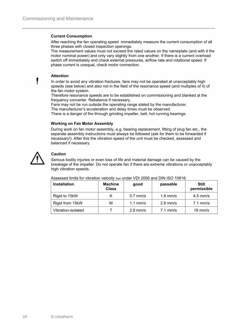
Attention
In order to avoid any vibration fractures, fans may not be operated at unacceptably high speeds (see below) and also not in the field of the resonance speed (and multiples of it) of the fan motor system. Therefore resonance speeds are to be established on commissioning and blanked at the frequency converter. Rebalance if necessary. Fans may not be run outside the operating range stated by the manufacturer. The manufacturer’s acceleration and delay times must be observed. There is a danger of fire through grinding impeller, belt, hot running bearings.
Pos: 42.11 /Inbetriebnahme und Wartung/Ventilator/Ventilator_IBN_Ventilator-Motor-Einbau @ 0\mod_1257957859487_2008.docx @ 2133 @ @ 1
Working on Fan Motor Assembly
During work on fan motor assembly, e.g. bearing replacement, fitting of plug fan etc., the separate assembly instructions must always be followed (ask for them to be forwarded if necessary!). After this the vibration speed of the unit must be checked, assessed and balanced if necessary.
Pos: 42.12 /Sicherheitshinweise/IBN&Wartung/!IBN&Wartung_Ventilator_IBN_Vorsicht2 @ 0\mod_1257957945231_2008.docx @ 2134 @ @ 1
Caution
Serious bodily injuries or even loss of life and material damage can be caused by the breakage of the impeller. Do not operate fan if there are extreme vibrations or unacceptably high vibration speeds. Assessed limits for vibration velocity veff under VDI 2056 and DIN ISO 10816:
Installation Machine Class
good passable Still permissible
Rigid to 15kW K 0.7 mm/s 1.8 mm/s 4.5 mm/s
Rigid from 15kW M 1.1 mm/s 2.8 mm/s 7.1 mm/s
Vibration-isolated T 2.8 mm/s 7.1 mm/s 18 mm/s
Pos: 42.13 /Inbetriebnahme und Wartung/_Wartung @ 0\mod_1257929585257_2008.docx @ 2117 @ @ 1

Commissioning and Maintenance
© robatherm 25
Maintenance Pos: 42.14 /Inbetriebnahme und Wartung/Wartungsintervall_3Monate/ATEX monatlich @ 0\mod_1257930528679_2008.docx @ 2122 @ @ 1
Maintenance Interval
Every three months. ATEX units every month.
Pos: 42.15 /Inbetriebnahme und Wartung/Ventilator/Ventilator_Wartung_Wartungshinweis @ 0\mod_1257958089160_2008.docx @ 2135 @ @ 1
Maintenance Instruction
The maintenance interval must be shortened accordingly if there is a multi-shift operation and/or special operating conditions such as fluid temperature > 40 °C, appearance of dust etc. If one or more V-belts fail in a multiple groove drive, then a new V-belt set must be fitted. Prior to fitting the V-belts, the axle base must be reduced so that the belts can be placed in the grooves without force. Forcible fitting by means of a screwdriver etc. is in any case not permitted as it can lead to damage.
Pos: 42.16 /Sicherheitshinweise/!Vorsicht_Sicherheitshinweise beachten_Querverweis @ 0\mod_1257777093652_2008.docx @ 2112 @ @ 1
Caution
Observe general safety instructions on page 3!
Pos: 42.17 /Inbetriebnahme und Wartung/Ventilator/Ventilator_Reinigungsmittel @ 2\mod_1329137958035_2008.docx @ 20480 @ @ 1
Cleaning Agent
Cleaning agent shall have a pH value between pH 7 – pH 9.
Pos: 42.18 /Inbetriebnahme und Wartung/Ventilator/Ventilator_Wartung @ 0\mod_1257958205121_2008.docx @ 2136 @ @ 1
Fan – Periodic Maintenance Check fan for hygiene, contamination, damage, corrosion and fastening Check impeller for imbalance and vibrations; balance if necessary Check bearings for noise, vibration and heat Check flexible connection for leaks Check functioning of vibration dampers Check function of protective devices Check function of inlet vane control Check functioning of dehydration equipment Check gap width of open impellers (see page 22); correct if necessary Pollution and dirt on flex connector shall be removed with a vacuum cleaner, and, in a
second step, wiped with a with damp cloth Fan – Maintenance when necessary Replace bearings (no later than the end of the theoretical service life) Grease bearing. Follow manufacturer’s instructions! Clean fan, rectify any damage and corrosion, retighten fastenings Electric Motor – Periodic Maintenance Check electric motor for contamination, damage, corrosion, fastening, smooth running,
heating and direction of rotation Check bearings for noise, vibration and heat Clean electric motor and rectify any damage and corrosion Measure tension, current input and phase symmetry Check firm seating of terminals in terminal block; retighten if necessary Check protective conductor; retighten or replace if necessary Check cable rails. Clean it if necessary with vacuum cleaner and, if necessary with damp
cloth

Commissioning and Maintenance
26 © robatherm
Electric Motor – Maintenance when necessary Replace bearings (no later than the end of the theoretical service life) Grease bearing. Follow manufacturer’s instructions! Belt Drive – Periodic Maintenance Check belt drive for contamination, damage, wear, tension, alignment of motor and fan
pulley (tolerance < 0.4°; d.h. < 7 mm/m), check function and fastening (see torque settings)
Check protective device for damage, fastening and functioning Belt Drive – Maintenance when necessary Replace belt set Adjust alignment of motor and fan pulley Adjust belt tension (see page 27) Clean belt drive Drive Clutch – Periodic Maintenance Follow manufacturer’s instructions! Check drive clutch for function, contamination, damage, corrosion and fastening Check temperature Drive Clutch – Maintenance when necessary Follow manufacturer’s instructions! Change oil Clean drive clutch
Pos: 42.19 /Layout/Seitenumbruch @ 0\mod_1256628615637_0.docx @ 2284 @ @ 1

Commissioning and Maintenance
© robatherm 27
Pos: 42.20 /Inbetriebnahme und Wartung/Ventilator/Ventilator_Wartung_Schrauben-Anzugsdrehmomente @ 0\mod_1257958686778_2008.docx @ 2137 @ @ 1
Bolt Torques for Locking Bushes
Bush type
1008 1108
1210 1215
1610 1615
2012 2017
2517 2525
3020 3030
3525 3535
4030 4040
4535 4545
5040 5050
Torque [Nm]
6 20 20 30 50 90 115 170 190 270
Motor Removal
When removing the motor only use suitable and permitted load bearing equipment. When using an integrated motor removal device ensure that the unit is sufficiently stable e.g. by fixing to the foundation. Shut Down
Remove V-belts for down times of more than 3 months to avoid concentrated stress on bearings. Replace bearings before recommissioning if out of operation for periods of one year or longer, or remove grease if bearings have a regreasing device and grease bearings again. Observe fan manufacturer's instructions.
Pos: 42.21 /Inbetriebnahme und Wartung/Ventilator/_Bestimmung Riemenvorspannkraft @ 0\mod_1257958887377_2008.docx @ 2138 @ @ 1
Determination of Belt Pretensioning Force for V-belts DIN 7753 Pos: 42.22 /Inbetriebnahme und Wartung/Ventilator/Ventilator_Riemenspannung @ 0\mod_1257958956797_2008.docx @ 2139 @ @ 1
Belt Tension
The belt tension is measured with a suitable measuring instrument in line with instructions (e.g. belt pretensioning force measuring instrument) and adjusted. Observe operating instructions for measurement instrument. Measure axle base A of the belt pulleys (in metres). Multiply axle base by 16. The result is the belt deflection (S) in millimetres. Apply enough force to the belt in the middle of the axle base (A) so that the calculated
deflection is reached. Measure deflection force. Compare deflection force (F) with table values. Set higher values for the start up phase of new drives. Test deflection force (F) after several hours of operation and adjust if necessary.
A – Axle base; S – Belt deflection; F – Deflection force

Commissioning and Maintenance
28 © robatherm
Note
For one-groove drives it is easier to use a ruler to set deflection. The values shown below only apply to narrow V-belts DIN 7753. If other V-belts are used, the manufacturer should be consulted. Force (F) for Deflection (S) = 16 mm per metre of axle base (A)
Profile Effective diameter d of the small belt pulley [mm]
Deflection force F [N]
SPZ 67
100
to
to
95
140
10
15
to
to
15
20
SPA 100
140
224
to
to
to
132
200
250
20
28
40
to
to
to
27
35
45
SPB 160
236
to
to
224
315
35
50
to
to
50
65
SPC 224
375
to
to
355
560
60
90
to
to
90
120
Pos: 43 /Layout/Seitenumbruch @ 0\mod_1256628615637_0.docx @ 2284 @ @ 1

Commissioning and Maintenance
© robatherm 29
Pos: 44.1 /Überschriften/__Luftfilter @ 0\mod_1257341371650_2008.docx @ 2043 @ @ 1
Filters Pos: 44.2 /Inbetriebnahme und Wartung/_Inbetriebnahme @ 0\mod_1257929574289_2008.docx @ 2116 @ @ 1
Commissioning
Pos: 44.3 /Sicherheitshinweise/!Vorsicht_Sicherheitshinweise beachten_Querverweis @ 0\mod_1257777093652_2008.docx @ 2112 @ @ 1
Caution
Observe general safety instructions on page 3!
Pos: 44.4 /Inbetriebnahme und Wartung/Luftfilter/Luftfilter_IBN_Einbau Filtereinsätze @ 0\mod_1258365811110_2008.docx @ 2146 @ @ 1
Installation of Filter Cartridges
Carefully fix filter elements to the frames with tension springs or anchor wailers respectively, cartridge filters to be fastened to bayonet joints hand tight.
Do not shut or damage filter cartridges. Check air proof seating of the filter cartridges in the frame.
Pos: 44.5 /Sicherheitshinweise/IBN&Wartung/!IBN&Wartung_Luftfilter_ATEX @ 0\mod_1258365944257_2008.docx @ 2147 @ @ 1
Only use approved filter media with ATEX units.
Pos: 44.6 /Inbetriebnahme und Wartung/Luftfilter/Luftfilter_IBN_Filterüberwachung @ 0\mod_1258366009246_2008.docx @ 2148 @ @ 1
Filter Monitoring
In order to check the degree of contamination of the filters (except activated carbon filters), the fitting of a differential pressure manometer on the access side of the unit is recommended. Filter End Resistances
Filter Class Rec. End resistance
G1 - G4
M5 - M6, F7
F8 - F9
E10 - E12, H13
150 Pa
200 Pa
300 Pa
500 Pa
Roll Filter
For roll filters the operating and servicing instructions supplied by the manufacturer must be followed.
Pos: 44.7 /Inbetriebnahme und Wartung/_Wartung @ 0\mod_1257929585257_2008.docx @ 2117 @ @ 1

Commissioning and Maintenance
30 © robatherm
Maintenance Pos: 44.8 /Inbetriebnahme und Wartung/Wartungsintervall_3Monate/ATEX monatlich @ 0\mod_1257930528679_2008.docx @ 2122 @ @ 1
Maintenance Interval
Every three months. ATEX units every month.
Pos: 44.9 /Sicherheitshinweise/!Vorsicht_Sicherheitshinweise beachten_Querverweis @ 0\mod_1257777093652_2008.docx @ 2112 @ @ 1
Caution
Observe general safety instructions on page 3!
Pos: 44.10 /Sicherheitshinweise/IBN&Wartung/!IBN&Wartung_Luftfilter_Wartung_Vorsicht @ 0\mod_1258366415225_2008.docx @ 2149 @ @ 1
Caution
Allergic reactions on the skin, eyes or breathing organs can be caused by contact with filter dusts. For maintenance and replacement works on filter cartridges wear protective clothing and, if necessary, a respirator. Avoid contamination of the surrounding area and new filters.
Pos: 44.11 /Inbetriebnahme und Wartung/Luftfilter/Luftfilter_Wartung_Ersatzfilter @ 0\mod_1258366506833_2008.docx @ 2150 @ @ 1
Replacement Filters
Keep at least one set of replacement filters in stock. Store in a dry and dust free area. Avoid contamination and damage. Do not use filters beyond minimum durability.
Pos: 44.12 /Sicherheitshinweise/IBN&Wartung/!IBN&Wartung_Luftfilter_ATEX @ 0\mod_1258365944257_2008.docx @ 2147 @ @ 1
Only use approved filter media with ATEX units.
Pos: 44.13 /Inbetriebnahme und Wartung/Luftfilter/Luftfilter_Wartung @ 0\mod_1258366603769_2008.docx @ 2151 @ @ 1
Filters – Periodic Maintenance Check filter cartridges for hygiene, contamination, odors, damage and corrosion Particle filters: Check differential pressure with manometer Activated carbon filters: Usually, it is enough to check the filter’s odor. (For a reliable
determination of the remaining lifetime, the manufacturer may check the filter coal’s saturation in his lab in order to appoint proper service intervals.) Weighing of the cartridges does not deliver feasible results, since most of the additional weight is caused by the air’s humidity.
Check filter seat for leakage Filters – Maintenance when necessary Replace filter cartridges immediately if there is noticeable contamination, odor, damage
or leakage, when reaching the recommended end resistance or time interval: 1. Filter cartridge after 12 months at the latest 2. Filter cartridge after 24 months at the latest
An earlier filter change may be essential if building or conversion measures result in significant strain on the filter or following a hygiene inspection. The change of single filter elements is only permissible in the case of damage to individual elements provided that the last change does not date back more than 6 months. When changing the filter cartridges observe the local environmental protection regulations.
Pos: 45 /Layout/Seitenumbruch @ 0\mod_1256628615637_0.docx @ 2284 @ @ 1

Commissioning and Maintenance
© robatherm 31
Pos: 46.1 /Überschriften/__Schalldämpfer @ 0\mod_1257341372962_2008.docx @ 2044 @ @ 1
Silencer Pos: 46.2 /Inbetriebnahme und Wartung/_Inbetriebnahme @ 0\mod_1257929574289_2008.docx @ 2116 @ @ 1
Commissioning
Pos: 46.3 /Sicherheitshinweise/!Vorsicht_Sicherheitshinweise beachten_Querverweis @ 0\mod_1257777093652_2008.docx @ 2112 @ @ 1
Caution
Observe general safety instructions on page 3!
Pos: 46.4 /Inbetriebnahme und Wartung/Schalldämpfer/Schalldämpfer_IBN_Prüfung @ 0\mod_1258367412290_2008.docx @ 2152 @ @ 1
Inspection
Check silencers for damage and contamination; for repair and cleaning see below.
Pos: 46.5 /Inbetriebnahme und Wartung/_Wartung @ 0\mod_1257929585257_2008.docx @ 2117 @ @ 1
Maintenance Pos: 46.6 /Inbetriebnahme und Wartung/Wartungsintervall_3Monate/ATEX monatlich @ 0\mod_1257930528679_2008.docx @ 2122 @ @ 1
Maintenance Interval
Every three months. ATEX units every month.
Pos: 46.7 /Sicherheitshinweise/!Vorsicht_Sicherheitshinweise beachten_Querverweis @ 0\mod_1257777093652_2008.docx @ 2112 @ @ 1
Caution
Observe general safety instructions on page 3!
Pos: 46.8 /Inbetriebnahme und Wartung/Schalldämpfer/Schalldämpfer_Wartung @ 0\mod_1258367626564_2008.docx @ 2153 @ @ 1
Silencer – Periodic Maintenance Check silencers for hygiene, contamination, damage and corrosion Silencers – Maintenance when necessary Clean silencers (see below), repair them with repair kit and rectify corrosion; take contact
samples if necessary
Pos: 46.9 /Inbetriebnahme und Wartung/Schalldämpfer/Schalldämpfer_Reinigung @ 0\mod_1258367796596_2008.docx @ 2154 @ @ 1
Cleaning
Use vacuum cleaner to clean surfaces.
Pos: 46.10 /Sicherheitshinweise/IBN&Wartung/!IBN&Wartung_Schalldämpfer_Wartung_Achtung @ 0\mod_1258367854283_2008.docx @ 2155 @ @ 1
Attention
Do not damage absorption material.
Pos: 47 /Layout/Seitenumbruch @ 0\mod_1256628615637_0.docx @ 2284 @ @ 1

Commissioning and Maintenance
32 © robatherm
Pos: 48.1 /Überschriften/__Lufterwärmer @ 0\mod_1257341374509_2008.docx @ 2045 @ @ 1
Heating Coil (Hot Water, Steam) Pos: 48.2 /Inbetriebnahme und Wartung/_Inbetriebnahme @ 0\mod_1257929574289_2008.docx @ 2116 @ @ 1
Commissioning
Pos: 48.3 /Sicherheitshinweise/!Vorsicht_Sicherheitshinweise beachten_Querverweis @ 0\mod_1257777093652_2008.docx @ 2112 @ @ 1
Caution
Observe general safety instructions on page 3!
Pos: 48.4 /Sicherheitshinweise/IBN&Wartung/!IBN&Wartung_Vorsicht_heißes Medium @ 0\mod_1258373301319_2008.docx @ 2157 @ @ 1
Caution
Do not use any hot medium while filling, bleeding air or removing as there is a danger of scalding.
Pos: 48.5 /Sicherheitshinweise/IBN&Wartung/!IBN&Wartung_Vorsicht_heiße Flächen @ 0\mod_1258373421988_2008.docx @ 2158 @ @ 1
Caution
To avoid burns, do not touch hot surfaces.
Pos: 48.6 /Sicherheitshinweise/IBN&Wartung/!IBN&Wartung_Vorsicht_Kontakt mit Sole @ 0\mod_1258373184697_2008.docx @ 2156 @ @ 1
Caution
Avoid any contact with brine while charging or venting. Danger of poisoning and acid burns! Observe manufacturer’s instructions.
Pos: 48.7 /Sicherheitshinweise/IBN&Wartung/!IBN&Wartung_Lufterwärmer_IBN_Achtung @ 0\mod_1258374753313_2008.docx @ 2163 @ @ 1
Attention
Do not exceed permissible pressure range (see design data sheet). To avoid freezing of the heating coil: Add anti-freeze agent or install frost protection control on air, water or condensate side depending on unit design. To avoid any overheating damage to the unit, run steam coil only when fan is running Provide air flow control or temperature limiter.
Pos: 48.8 /Sicherheitshinweise/IBN&Wartung/!IBN&Wartung_Lufterwärmer_IBN_ATEX @ 0\mod_1258374903528_2008.docx @ 2164 @ @ 1
Ensure sufficient distance between max. surface temperature of the heat exchanger due to temperature of the medium and minimum ignition temperature of any flammable mixture which may be present in accordance with EN 1127.
Pos: 48.9 /Inbetriebnahme und Wartung/Lufterwärmer/Lufterwärmer_Prüfung @ 0\mod_1258374972714_2008.docx @ 2165 @ @ 1
Inspection
Check inlet outlet connections for function (counter flow principle). Charging
The system must be rinsed (removal of contaminations) according to VDI 2035 and should be filled with the heat exchanger fluid named in the design data sheet to the correct concentration. Water quality to VDI 2035. Too high a concentration of glycol leads to reduced performance, too low a concentration of glycol can lead to frost damage.

Commissioning and Maintenance
© robatherm 33
Venting
When charging the system according to VDI 2035 the heating coil and the system should be vented carefully at the highest point of the system. For this purpose open the venting screw at the top connection or open separate venting screw. If incorrect venting takes place, heating coils develop air locks which lead to a reduction in capacity. Recommendation: Venting recovery system (stop-cock with hose nozzle). After Commissioning
After commissioning check the screw fittings of the flange for leakage and retighten if necessary (see page 13).
Pos: 48.10 /Layout/Seitenumbruch @ 0\mod_1256628615637_0.docx @ 2284 @ @ 1

Commissioning and Maintenance
34 © robatherm
Pos: 48.11 /Inbetriebnahme und Wartung/_Wartung @ 0\mod_1257929585257_2008.docx @ 2117 @ @ 1
Maintenance Pos: 48.12 /Inbetriebnahme und Wartung/Wartungsintervall_3Monate/ATEX monatlich @ 0\mod_1257930528679_2008.docx @ 2122 @ @ 1
Maintenance Interval
Every three months. ATEX units every month.
Pos: 48.13 /Sicherheitshinweise/!Vorsicht_Sicherheitshinweise beachten_Querverweis @ 0\mod_1257777093652_2008.docx @ 2112 @ @ 1
Caution
Observe general safety instructions on page 3!
Pos: 48.14 /Sicherheitshinweise/IBN&Wartung/!IBN&Wartung_Vorsicht_heiße Flächen @ 0\mod_1258373421988_2008.docx @ 2158 @ @ 1
Caution
To avoid burns, do not touch hot surfaces.
Pos: 48.15 /Sicherheitshinweise/IBN&Wartung/!IBN&Wartung_Vorsicht_Temperieren auf Umgebungstemperatur @ 0\mod_1258373503611_2008.docx @ 2159 @ @ 1
Caution
Before starting work allow components to cool/warm up to the ambient temperature.
Pos: 48.16 /Sicherheitshinweise/IBN&Wartung/!IBN&Wartung_Vorsicht_Kontakt mit Sole @ 0\mod_1258373184697_2008.docx @ 2156 @ @ 1
Caution
Avoid any contact with brine while charging or venting. Danger of poisoning and acid burns! Observe manufacturer’s instructions.
Pos: 48.17 /Inbetriebnahme und Wartung/Lufterwärmer/Lufterwärmer_Wartung @ 0\mod_1258375212161_2008.docx @ 2166 @ @ 1
Heating Coil – Periodic Maintenance Check heating coil for hygiene, contamination on air side, damage, leaks and corrosion Vent heating coil Check inlet/outlet for function Check frost protection for function (determine anti-freeze concentration or thermostat by
means of cooling spray) Heating Coil – Maintenance when necessary Clean the heating coil on the air side (see below), rectify damage, leakage and corrosion
Pos: 48.18 /Inbetriebnahme und Wartung/Lufterwärmer/Lufterwärmer_Reinigung @ 0\mod_1258375355516_2008.docx @ 2167 @ @ 1
Cleaning
Clean coils already assembled or if not accessible pull them out for cleaning. Contamination which has been removed must not enter adjoining unit parts. Remove dirt and contaminated water carefully. Observe the following points: Avoid bending plate fins Blow out with compressed air in the opposite direction Do not use a high pressure cleaner or a high pressure steam cleaner Clean with water and low pressure Cleaning Agents
Use cleaning agents with a pH-value between 7 and 9 if required.
Pos: 48.19 /Inbetriebnahme und Wartung/IBN&Wartung_Lufterwärmerund-kühler_Wartung_Außerbetriebsetzung @ 0\mod_1261391266177_2008.docx @ 2282 @ @ 1

Commissioning and Maintenance
© robatherm 35
Shut Down
If out of operation for some time, especially if there is a danger of freezing, the heat exchanger must be emptied completely if no anti-freezing agent was added. For this purpose remove all purging and discharging screws. Then for complete emptying blow air (compressed air, fan etc) through each heat exchanger as up to 50% fluid may remain in the heat exchanger during free purging which results in a higher danger of damage during frost. Remove brine following manufacturer information. Removal / Installation After decommissioning the heat exchanger and disassembling the control group, unscrew the front panel with Torx (T25) or flat-tip screwdriver. (Air cooler: Unscrew the condensate deflector plate from the housing frame.) Pull out the heat exchanger including the front panel to the front (support the heat exchanger if necessary). Check seals for damage and replace them if necessary. Installation has to be done in reverse order.
Pos: 49 /Layout/Seitenumbruch @ 0\mod_1256628615637_0.docx @ 2284 @ @ 1

Commissioning and Maintenance
36 © robatherm
Pos: 50.1 /Überschriften/__Elektro-Lufterwärmer @ 0\mod_1257341375744_2008.docx @ 2046 @ @ 1
Electric Heater Pos: 50.2 /Inbetriebnahme und Wartung/_Inbetriebnahme @ 0\mod_1257929574289_2008.docx @ 2116 @ @ 1
Commissioning
Pos: 50.3 /Sicherheitshinweise/!Vorsicht_Sicherheitshinweise beachten_Querverweis @ 0\mod_1257777093652_2008.docx @ 2112 @ @ 1
Caution
Observe general safety instructions on page 3!
Pos: 50.4 /Sicherheitshinweise/IBN&Wartung/!IBN&Wartung_Vorsicht_heiße Flächen @ 0\mod_1258373421988_2008.docx @ 2158 @ @ 1
Caution
To avoid burns, do not touch hot surfaces.
Pos: 50.5 /Sicherheitshinweise/IBN&Wartung/!IBN&Wartung_ATEX-Bauteile erden @ 0\mod_1257956926546_2008.docx @ 2126 @ @ 1
Only use approved parts with ATEX units. All electrical parts must be earthed.
Pos: 50.6 /Inbetriebnahme und Wartung/Elektro-Lufterwärmer/Elektro-Lufterwärmer_Sicherheits-Temperaturbegrenzer @ 0\mod_1258387695243_2008.docx @ 2168 @ @ 1
Safety Temperature Limiter
Each electric heater must be equipped with a fully tested safety temperature limiter with manual reset. Test function with hot air drier. Recommendation
Triple thermostat mounted directly downstream from electric heater: “Fan” setting: 40 °C. “Safety temperature limiter” setting: 70 °C.
Pos: 50.7 /Sicherheitshinweise/IBN&Wartung/!IBN&Wartung_Elektro-Lufterwärmer_IBN_Achtung @ 0\mod_1258387913996_2008.docx @ 2170 @ @ 1
Attention
Electric heaters may only be operated if flow control is present. Overheating damage may occur to the electric heater, housing and other fitted parts if the system is run with insufficient cooling (e.g. system switched off at the main switch when the electric air heater is still on) or in the event of an emergency system shut down triggered by safety devices.
Pos: 50.8 /Inbetriebnahme und Wartung/Elektro-Lufterwärmer/Elektro-Lufterwärmer_Strömungs-Überwachung @ 0\mod_1258387809768_2008.docx @ 2169 @ @ 1
Flow Control
The airflow is monitored by measurement of the pressure difference at the fan unit, using an air pressure gauge Functioning must be checked during commissioning. Current Consumption
The current consumption is to be checked at all phases by measuring all phases. For rated data see nameplate. If the rated values are exceeded, the robatherm Technical Service must be informed.
Pos: 50.9 /Inbetriebnahme und Wartung/_Wartung @ 0\mod_1257929585257_2008.docx @ 2117 @ @ 1

Commissioning and Maintenance
© robatherm 37
Maintenance Pos: 50.10 /Inbetriebnahme und Wartung/Wartungsintervall_3Monate/ATEX monatlich @ 0\mod_1257930528679_2008.docx @ 2122 @ @ 1
Maintenance Interval
Every three months. ATEX units every month.
Pos: 50.11 /Sicherheitshinweise/!Vorsicht_Sicherheitshinweise beachten_Querverweis @ 0\mod_1257777093652_2008.docx @ 2112 @ @ 1
Caution
Observe general safety instructions on page 3!
Pos: 50.12 /Sicherheitshinweise/IBN&Wartung/!IBN&Wartung_Vorsicht_heiße Flächen @ 0\mod_1258373421988_2008.docx @ 2158 @ @ 1
Caution
To avoid burns, do not touch hot surfaces.
Pos: 50.13 /Sicherheitshinweise/IBN&Wartung/!IBN&Wartung_Vorsicht_Temperieren auf Umgebungstemperatur @ 0\mod_1258373503611_2008.docx @ 2159 @ @ 1
Caution
Before starting work allow components to cool/warm up to the ambient temperature.
Pos: 50.14 /Inbetriebnahme und Wartung/Elektro-Lufterwärmer/Elektro-Lufterwärmer_Wartung @ 0\mod_1258387999663_2008.docx @ 2171 @ @ 1
Electric Heater – Periodic Maintenance Check functioning of airflow control; for this remove pressure measurement tubes from air
pressure gauge. A switching operation must take place Check electric heater for function, hygiene, contamination, damage, corrosion and
fastening Check function of safety temperature limiter (see Commissioning) Electric Heater – Maintenance when necessary Clean electric heater, rectify scaling, damage, corrosion, retighten fastenings
Pos: 51 /Layout/Seitenumbruch @ 0\mod_1256628615637_0.docx @ 2284 @ @ 1

Commissioning and Maintenance
38 © robatherm
Pos: 52.1 /Überschriften/__Luftkühler @ 0\mod_1257341710373_2008.docx @ 2047 @ @ 1
Cooling Coil (CW – DX Coil) Pos: 52.2 /Inbetriebnahme und Wartung/_Inbetriebnahme @ 0\mod_1257929574289_2008.docx @ 2116 @ @ 1
Commissioning
Pos: 52.3 /Sicherheitshinweise/!Vorsicht_Sicherheitshinweise beachten_Querverweis @ 0\mod_1257777093652_2008.docx @ 2112 @ @ 1
Caution
Observe general safety instructions on page 3!
Pos: 52.4 /Sicherheitshinweise/IBN&Wartung/!IBN&Wartung_Vorsicht_Kontakt mit Sole @ 0\mod_1258373184697_2008.docx @ 2156 @ @ 1
Caution
Avoid any contact with brine while charging or venting. Danger of poisoning and acid burns! Observe manufacturer’s instructions.
Pos: 52.5 /Sicherheitshinweise/IBN&Wartung/!IBN&Wartung_Vorsicht_heiße/kalten Flächen @ 0\mod_1258374632300_2008.docx @ 2162 @ @ 1
Caution
To avoid burns, do not touch hot/cold surfaces.
Pos: 52.6 /Sicherheitshinweise/IBN&Wartung/!IBN&Wartung_Luftkühler_IBN_Achtung @ 0\mod_1258388509696_2008.docx @ 2172 @ @ 1
Attention
Do not exceed permissible pressure range. To avoid freezing of the cooling coil: Add anti-freeze agent or mount the cooling coil downstream from the pre-heater.
Pos: 52.7 /Inbetriebnahme und Wartung/Luftkühler/Luftkühler_Prüfung @ 0\mod_1258388563834_2008.docx @ 2173 @ @ 1
Inspection
Check inlet outlet connections for function (counter flow principle). In the case of direct expansion coils, the nitrogen protection gas must escape with a hissing noise following opening of the heat exchanger connections. Otherwise there is a leakage; please inform our technical service. Charging
The system must be rinsed (removal of contaminations) according to VDI 2035 and should be filled with the heat exchanger fluid named in the design data sheet to the correct concentration. Water quality to VDI 2035. Too high a concentration of glycol leads to reduced performance, too low a concentration of glycol can lead to frost damage. Venting
When charging the system according to VDI 2035 the air cooler and the system should be vented carefully at the highest point of the system. For this purpose open the venting screw at the top connection or open separate venting screw. If incorrect venting takes place, cooling coils develop air locks which lead to a reduction in capacity. Recommendation: Venting recovery system (stop-cock with hose nozzle). After Commissioning
After commissioning check the screw fittings of the flange for leakage and retighten if necessary (see page 13).
Pos: 52.8 /Inbetriebnahme und Wartung/_Wartung @ 0\mod_1257929585257_2008.docx @ 2117 @ @ 1

Commissioning and Maintenance
© robatherm 39
Maintenance Pos: 52.9 /Inbetriebnahme und Wartung/Wartungsintervall_3Monate/ATEX monatlich @ 0\mod_1257930528679_2008.docx @ 2122 @ @ 1
Maintenance Interval
Every three months. ATEX units every month.
Pos: 52.10 /Sicherheitshinweise/!Vorsicht_Sicherheitshinweise beachten_Querverweis @ 0\mod_1257777093652_2008.docx @ 2112 @ @ 1
Caution
Observe general safety instructions on page 3!
Pos: 52.11 /Sicherheitshinweise/IBN&Wartung/!IBN&Wartung_Vorsicht_Kontakt mit Sole @ 0\mod_1258373184697_2008.docx @ 2156 @ @ 1
Caution
Avoid any contact with brine while charging or venting. Danger of poisoning and acid burns! Observe manufacturer’s instructions.
Pos: 52.12 /Sicherheitshinweise/IBN&Wartung/!IBN&Wartung_Vorsicht_heiße/kalten Flächen @ 0\mod_1258374632300_2008.docx @ 2162 @ @ 1
Caution
To avoid burns, do not touch hot/cold surfaces.
Pos: 52.13 /Sicherheitshinweise/IBN&Wartung/!IBN&Wartung_Vorsicht_Temperieren auf Umgebungstemperatur @ 0\mod_1258373503611_2008.docx @ 2159 @ @ 1
Caution
Before starting work allow components to cool/warm up to the ambient temperature.
Pos: 52.14 /Inbetriebnahme und Wartung/Luftkühler/Luftkühler_Wartung @ 0\mod_1258388701310_2008.docx @ 2174 @ @ 1
Cooling Coil – Periodic Maintenance Check cooling coil for hygiene, contamination on air side, damage, leaks and corrosion Vent cooling coil Check drip pan for contamination, clean if necessary Check water outlet and siphon function, clean if necessary Check water level in siphon refill if necessary Check inlet / outlet for function Check frost protection for function (determine anti-freeze concentration or thermostat by
means of cooling spray) Check direct expansion for icing Cooling Coil – Maintenance when necessary Clean the cooling coil on the air side (see below), rectify damage, leakage and corrosion Drop Eliminator – Periodic Maintenance Check drop eliminator for hygiene, contamination, encrustation, damage, drip erosion and
corrosion Drop Eliminator – Maintenance when necessary Clean and service eliminator: Pull out cassette, disassemble and clean profiles
separately; rectify damage and corrosion
Pos: 52.15 /Inbetriebnahme und Wartung/Luftkühler/Luftkühler_Wartung_Reinigung @ 0\mod_1258389000184_2008.docx @ 2175 @ @ 1
Cleaning
Clean heat exchangers already assembled or if not accessible pull them out for cleaning. Contamination which has been removed must not enter adjoining unit parts. Remove dirt and contaminated water carefully. Observe the following points: Avoid bending plate fins Blow out with compressed air in the opposite direction Do not use a high pressure cleaner or a high pressure steam cleaner Clean with water and low pressure

Commissioning and Maintenance
40 © robatherm
Cleaning Agents
Use cleaning agents with a pH-value between 7 and 9 if required.
Pos: 52.16 /Inbetriebnahme und Wartung/IBN&Wartung_Lufterwärmerund-kühler_Wartung_Außerbetriebsetzung @ 0\mod_1261391266177_2008.docx @ 2282 @ @ 1
Shut Down
If out of operation for some time, especially if there is a danger of freezing, the heat exchanger must be emptied completely if no anti-freezing agent was added. For this purpose remove all purging and discharging screws. Then for complete emptying blow air (compressed air, fan etc) through each heat exchanger as up to 50% fluid may remain in the heat exchanger during free purging which results in a higher danger of damage during frost. Remove brine following manufacturer information. Removal / Installation After decommissioning the heat exchanger and disassembling the control group, unscrew the front panel with Torx (T25) or flat-tip screwdriver. (Air cooler: Unscrew the condensate deflector plate from the housing frame.) Pull out the heat exchanger including the front panel to the front (support the heat exchanger if necessary). Check seals for damage and replace them if necessary. Installation has to be done in reverse order.
Pos: 53 /Layout/Seitenumbruch @ 0\mod_1256628615637_0.docx @ 2284 @ @ 1

Commissioning and Maintenance
© robatherm 41
Pos: 54.1 /Überschriften/__Kälteanlage und Wärmepumpe @ 0\mod_1257341719170_2008.docx @ 2055 @ @ 1
Refrigeration Installations and Heat Pump Pos: 54.2 /Sicherheitshinweise/!Vorsicht_Sicherheitshinweise beachten_Querverweis @ 0\mod_1257777093652_2008.docx @ 2112 @ @ 1
Caution
Observe general safety instructions on page 3!
Pos: 54.3 /Sicherheitshinweise/IBN&Wartung/!IBN&Wartung_Kälteanlage_Vorsicht @ 0\mod_1258389691566_2008.docx @ 2178 @ @ 1
Caution
Avoid any physical contact with the refrigerant as this may cause frostbite to the skin and limbs or retinal damage. Use personal protection equipment against effects of refrigerants BGV D4 (goggles, gloves, etc.)! Refrigerant (odourless and tasteless) ejects atmospheric oxygen and can cause suffocation. TLV values (for R407C: 1,000 ppm in 8h) and practical value limit DIN 8960 (for R407C: 0.31 kg/m³ area) must be observed. If refrigerant does escape only enter the machine room with heavy duty respiratory protective gear. Observe the safety data sheet. Refrigerants and compressor oil develop toxic, noxious substances in tandem with naked flame. Do not inhale! Do not smoke in the machine room! There may be an allergic reaction if compressor oil is touched or swallowed. Avoid physical contact! Observe safety data sheet.
Pos: 54.4 /Sicherheitshinweise/IBN&Wartung/!IBN&Wartung_ATEX-Bauteile erden @ 0\mod_1257956926546_2008.docx @ 2126 @ @ 1
Only use approved parts with ATEX units. All electrical parts must be earthed.
Pos: 54.5 /Sicherheitshinweise/IBN&Wartung/!IBN&Wartung_Kälteanlage_Achtung1 @ 0\mod_1258389597665_2008.docx @ 2177 @ @ 1
Attention
Completion and commissioning of refrigeration installations may only be carried out by the manufacturer or another expert assigned by the manufacturer; maintenance and servicing work only by qualified personnel. For all work the requirements of the service booklet (request if required), and the valid standards and guidelines (e.g. DIN EN 378, BGR 500 and EC-F Gas Directive) must be adhered to.
Pos: 54.6 /Inbetriebnahme und Wartung/Kälteanlage/Kälteanlage_Wiederkehrende Prüfungen @ 0\mod_1258389415926_2008.docx @ 2176 @ @ 1
Recurring Inspections
According to §15 of the German Industrial Safety Regulation (BetrSichV), the units and unit parts underlie recurring inspections by an authorized person respectively accredited inspection agency. Further applicable statutory provisions of the respective location are to be observed. Commissioning Requirements
All construction requirements such as access, completed unit and duct installation and uninterrupted availability of all supply facilities must be met. In addition there must be a possibility of operating the system in the required working phases. Basis for Warranty
The basis for the warranty is built on a maintenance contract with a qualified company specialised in refrigeration engineering together with records of performance of maintenance work.

Commissioning and Maintenance
42 © robatherm
System Operation
Operation of the refrigeration unit is only permissible when the AHU is running. Breakdowns of faults of the refrigerating unit are displayed on the switch cabinet. According to the German Industrial Safety Regulation (BetrSichV), such units require special supervision; including specific operator-related requirements that are to be fulfilled according to §14 of the German Industrial Safety Regulation. Further applicable statutory provisions of the respective location are to be observed. Maintenance and Inspection
For requirements see service booklet for refrigeration installations. Recurring inspections
According to §15 of the German Ordinance on Industrial Safety and Health (BetrSichV), the system and the system components are subject to partially recurring inspections by a qualified person or authorized inspection body. Further applicable legal regulations of the respective country of installation have to be taken into consideration.
Pos: 54.7 /Sicherheitshinweise/IBN&Wartung/!IBN&Wartung_Kälteanlage_Achtung2 @ 0\mod_1258389909549_2008.docx @ 2180 @ @ 1
Attention
Only use oil approved by the compressor manufacturer (see information on the compressor) as there may otherwise be damage to the unit.
Pos: 54.8 /Inbetriebnahme und Wartung/Kälteanlage/Kälteanlage_Außerbetriebsetzung @ 0\mod_1258389848494_2008.docx @ 2179 @ @ 1
Shut Down
For requirements see service booklet for refrigeration installations. Heed the relevant environmental regulations when disposing of refrigerant or compressor oil.
Pos: 55 /Layout/Seitenumbruch @ 0\mod_1256628615637_0.docx @ 2284 @ @ 1

Commissioning and Maintenance
© robatherm 43
Pos: 56.1 /Überschriften/__Rotor-WRG @ 0\mod_1257341711498_2008.docx @ 2048 @ @ 1
Rotary Heat Exchanger Pos: 56.2 /Inbetriebnahme und Wartung/_Inbetriebnahme @ 0\mod_1257929574289_2008.docx @ 2116 @ @ 1
Commissioning
Pos: 56.3 /Sicherheitshinweise/!Vorsicht_Sicherheitshinweise beachten_Querverweis @ 0\mod_1257777093652_2008.docx @ 2112 @ @ 1
Caution
Observe general safety instructions on page 3!
Pos: 56.4 /Sicherheitshinweise/IBN&Wartung/!IBN&Wartung_Rotor-WRG_Vorsicht @ 0\mod_1258390168851_2008.docx @ 2181 @ @ 1
Caution
When current feed is not disconnected at all poles, there is a risk of crushing and scraping to the limbs through sudden running of the rotor caused by an automatic cleaning run or automatic re-start after power failure.
Pos: 56.5 /Sicherheitshinweise/IBN&Wartung/!IBN&Wartung_ATEX-Bauteile erden @ 0\mod_1257956926546_2008.docx @ 2126 @ @ 1
Only use approved parts with ATEX units. All electrical parts must be earthed.
Pos: 56.6 /Inbetriebnahme und Wartung/Rotor-WRG/Rotor-WRG_Prüfung @ 0\mod_1258390251930_2008.docx @ 2182 @ @ 1
Inspection
Before commissioning ensure that no objects obstruct the free running of the rotor. Remove any foreign bodies and contamination. Sealing Strips
Check contact pressure of sealing strips. They must be placed as close as possible to the thermal mass and direct dragging must be avoided even under operating pressure. Bearing
In principle the bearing of the rotor is aligned in the factory. Depending on installation conditions some rework may be necessary. Please observe the manufacturer’s instructions. Drive
Open inspection cover at marked rotor corner and check whether V-belt has enough tension from tensioning device, shorten V-belt if necessary: Open hinged lock Shorten endless belt as required Close hinged lock Close inspection cover As the V-belt is subject to natural stretching, the tension of the V-belt should be regularly checked in the first 400 operating hours in particular. Put drive motor into operation. For rotor controller observe the manufacturer’s operating instructions. Check pre-defined rotor speed (e.g. 10 rpm for 10 V input signal). Direction of Rotation
Check rotational direction of rotor (arrow), if necessary change electrical connections of motor. If a washing zone is installed the storage mass must turn from extract air via the washing chamber into the supply air.

Commissioning and Maintenance
44 © robatherm
Pressure Drop
In order to avoid contamination of the supply air with the extract air, the pressure potential of the fans should be selected in such a way that the system related leakage from the supply air side flows into the extract air side.
Pos: 56.7 /Inbetriebnahme und Wartung/Adiabate Abluftbefeuchtung @ 2\mod_1378803158959_2008.docx @ 32953 @ @ 1
Adiabatic Humidification of Extract Air
Excessive humidity shall be avoided upstream of the rotor to prevent its matrix from over-wetting. If ever possible, permeate from the reverse osmosis should be used to operate the humidifier.
Pos: 56.8 /Sicherheitshinweise/IBN&Wartung/!IBN&Wartung_ATEX_Zonenverschleppung @ 0\mod_1258390480461_2008.docx @ 2183 @ @ 1
Zone crossing must be avoided with ATEX units in all circumstances.
Pos: 56.9 /Inbetriebnahme und Wartung/_Wartung @ 0\mod_1257929585257_2008.docx @ 2117 @ @ 1

Commissioning and Maintenance
© robatherm 45
Maintenance Pos: 56.10 /Inbetriebnahme und Wartung/Wartungsintervall_3Monate/ATEX monatlich @ 0\mod_1257930528679_2008.docx @ 2122 @ @ 1
Maintenance Interval
Every three months. ATEX units every month.
Pos: 56.11 /Sicherheitshinweise/!Vorsicht_Sicherheitshinweise beachten_Querverweis @ 0\mod_1257777093652_2008.docx @ 2112 @ @ 1
Caution
Observe general safety instructions on page 3!
Pos: 56.12 /Sicherheitshinweise/IBN&Wartung/!IBN&Wartung_Rotor-WRG_Vorsicht @ 0\mod_1258390168851_2008.docx @ 2181 @ @ 1
Caution
When current feed is not disconnected at all poles, there is a risk of crushing and scraping to the limbs through sudden running of the rotor caused by an automatic cleaning run or automatic re-start after power failure.
Pos: 56.13 /Sicherheitshinweise/IBN&Wartung/!IBN&Wartung_Achtung_Reinigung Wärmeübertrager @ 0\mod_1258373727824_2008.docx @ 2160 @ @ 1
Attention
In order to avoid damage when cleaning, air or water jet should only be directed onto the surfaces of the heat exchanger at a right angle.
Pos: 56.14 /Inbetriebnahme und Wartung/Rotor-WRG/Rotor-WRG_Wartung @ 0\mod_1258390577014_2008.docx @ 2184 @ @ 1
Rotary Heat Exchanger – Periodic Maintenance Check rotary heat exchanger for hygiene, foreign bodies, contamination, damage and
corrosion Check sealing strips for contamination, foreign bodies and contact pressure (see above) Check drive belt for wear and tension, shorten (see above) or change if necessary Check rotor for imbalance and lateral trueness Check bearing for incorrect heating, vibrations or running noises and change if necessary
(no later than the end of the theoretical service life) Check water outlet and siphon function clean if necessary Check water level of siphon, top up if necessary Check functioning of rotor control, align sensor if necessary Rotary Heat Exchanger – Maintenance when necessary Rectify foreign bodies, contamination, damage and corrosion Clean rotor body with compressed air or high pressure cleaner (only water without
additives); remove dirty water carefully Clean sealing strips, change if there is abrasion Adjust contact pressure of sealing strips (see above) Balance or align rotor
Pos: 56.15 /Inbetriebnahme und Wartung/Rotor-WRG/Rotor-WRG_Wartung_Außerbetriebsetzung @ 0\mod_1258390878692_2008.docx @ 2185 @ @ 1
Shut Down
If rotor is out of action for a longer period (e.g. summer), turn it on intermittently to maintain self-cleaning function.
Pos: 57 /Layout/Seitenumbruch @ 0\mod_1256628615637_0.docx @ 2284 @ @ 1

Commissioning and Maintenance
46 © robatherm
Pos: 58.1 /Überschriften/__Platten-WRG @ 0\mod_1257341722904_2008.docx @ 2058 @ @ 1
Plate Heat Exchangers Pos: 58.2 /Inbetriebnahme und Wartung/_Inbetriebnahme @ 0\mod_1257929574289_2008.docx @ 2116 @ @ 1
Commissioning
Pos: 58.3 /Sicherheitshinweise/!Vorsicht_Sicherheitshinweise beachten_Querverweis @ 0\mod_1257777093652_2008.docx @ 2112 @ @ 1
Caution
Observe general safety instructions on page 3!
Pos: 58.4 /Sicherheitshinweise/IBN&Wartung/!IBN&Wartung_Platten-WRG_IBN_Achtung @ 0\mod_1258391161268_2008.docx @ 2186 @ @ 1
Attention
In order to avoid damage to the heat exchanger, do not exceed the maximum permissible pressure drop SUPPLY/EXTRACT (depending on type approx. 1,000 Pa). Observe notes for closing dampers (see page 20)
Pos: 58.5 /Sicherheitshinweise/IBN&Wartung/!IBN&Wartung_ATEX_Zonenverschleppung @ 0\mod_1258390480461_2008.docx @ 2183 @ @ 1
Zone crossing must be avoided with ATEX units in all circumstances.
Pos: 58.6 /Inbetriebnahme und Wartung/Platten-WRG/Platten-WRG_Prüfung @ 0\mod_1258391245747_2008.docx @ 2187 @ @ 1
Inspection
Check (and clean if necessary) plate heat exchanger for foreign particles and contamination (see below).
Pos: 58.7 /Inbetriebnahme und Wartung/_Wartung @ 0\mod_1257929585257_2008.docx @ 2117 @ @ 1
Maintenance Pos: 58.8 /Inbetriebnahme und Wartung/Wartungsintervall_3Monate/ATEX monatlich @ 0\mod_1257930528679_2008.docx @ 2122 @ @ 1
Maintenance Interval
Every three months. ATEX units every month.
Pos: 58.9 /Sicherheitshinweise/!Vorsicht_Sicherheitshinweise beachten_Querverweis @ 0\mod_1257777093652_2008.docx @ 2112 @ @ 1
Caution
Observe general safety instructions on page 3!
Pos: 58.10 /Sicherheitshinweise/IBN&Wartung/!IBN&Wartung_Achtung_Reinigung Wärmeübertrager @ 0\mod_1258373727824_2008.docx @ 2160 @ @ 1
Attention
In order to avoid damage when cleaning, air or water jet should only be directed onto the surfaces of the heat exchanger at a right angle.
Pos: 58.11 /Inbetriebnahme und Wartung/Platten-WRG/Platten-WRG_Wartung @ 0\mod_1258391302056_2008.docx @ 2188 @ @ 1
Plate Heat Exchanger – Periodic Maintenance Check plate heat exchanger for hygiene, foreign bodies, contamination, damage and
corrosion Check water outlet and siphon function, clean if necessary Check water level of siphon, top up if necessary Plate Heat Exchanger – Maintenance when necessary Rectify foreign bodies, contamination, damage and corrosion Clean with compressed air or high pressure cleaner (only water without additives);
remove dirty water carefully
Pos: 59 /Layout/Seitenumbruch @ 0\mod_1256628615637_0.docx @ 2284 @ @ 1

Commissioning and Maintenance
© robatherm 47
Pos: 60.1 /Überschriften/__Wärmerohr-WRG @ 0\mod_1257341712576_2008.docx @ 2049 @ @ 1
Heat Pipe Pos: 60.2 /Inbetriebnahme und Wartung/_Inbetriebnahme @ 0\mod_1257929574289_2008.docx @ 2116 @ @ 1
Commissioning
Pos: 60.3 /Sicherheitshinweise/!Vorsicht_Sicherheitshinweise beachten_Querverweis @ 0\mod_1257777093652_2008.docx @ 2112 @ @ 1
Caution
Observe general safety instructions on page 3!
Pos: 60.4 /Inbetriebnahme und Wartung/Wärmerohr-WRG/Wärmerohr-WRG_Prüfung @ 0\mod_1258443318168_2008.docx @ 2189 @ @ 1
Inspection
Check (and clean if necessary) heat pipe for foreign particles and contamination (see below).
Pos: 60.5 /Inbetriebnahme und Wartung/_Wartung @ 0\mod_1257929585257_2008.docx @ 2117 @ @ 1
Maintenance Pos: 60.6 /Inbetriebnahme und Wartung/Wartungsintervall_3Monate/ATEX monatlich @ 0\mod_1257930528679_2008.docx @ 2122 @ @ 1
Maintenance Interval
Every three months. ATEX units every month.
Pos: 60.7 /Sicherheitshinweise/!Vorsicht_Sicherheitshinweise beachten_Querverweis @ 0\mod_1257777093652_2008.docx @ 2112 @ @ 1
Caution
Observe general safety instructions on page 3!
Pos: 60.8 /Sicherheitshinweise/IBN&Wartung/!IBN&Wartung_Wärmerohr-WRG_Vorsicht @ 0\mod_1258443402736_2008.docx @ 2190 @ @ 1
Caution
There is a danger to life when charging gas under high pressure! Do not damage or overheat pipes (e.g. by means of welding torch).
Pos: 60.9 /Inbetriebnahme und Wartung/Wärmerohr-WRG/Wärmerohr-WRG_Wartung @ 0\mod_1258443481790_2008.docx @ 2191 @ @ 1
Heat Pipe-HRS – Periodic Maintenance Check heat pipe for hygiene, contamination, damage and corrosion Check water outlet and siphon function, clean if necessary Check water level of siphon, top up if necessary Heat Pipe-HRS – Maintenance when necessary Clean the heat pipe on the air side (see below), rectify damage and corrosion
Pos: 60.10 /Inbetriebnahme und Wartung/Wärmerohr-WRG/Wärmerohr-WRG_Reinigung @ 0\mod_1258443605956_2008.docx @ 2192 @ @ 1
Cleaning
Observe the following points: Avoid bending plate fins. Blow out with compressed air in the opposite direction. Do not use a high pressure cleaner or a high pressure steam cleaner. Clean with water and low pressure. Cleaning Agents
Use cleaning agents with a pH-value between 7 and 9 if required.
Pos: 61 /Layout/Seitenumbruch @ 0\mod_1256628615637_0.docx @ 2284 @ @ 1
Commissioning and Maintenance
48 © robatherm
Pos: 62.1 /Überschriften/__Entfeuchtungsrotor @ 0\mod_1257341713529_2008.docx @ 2050 @ @ 1
Desiccant Rotor Pos: 62.2 /Inbetriebnahme und Wartung/_Inbetriebnahme @ 0\mod_1257929574289_2008.docx @ 2116 @ @ 1
Commissioning
Pos: 62.3 /Sicherheitshinweise/!Vorsicht_Sicherheitshinweise beachten_Querverweis @ 0\mod_1257777093652_2008.docx @ 2112 @ @ 1
Caution
Observe general safety instructions on page 3!
Pos: 62.4 /Sicherheitshinweise/IBN&Wartung/!IBN&Wartung_Rotor-WRG_Vorsicht @ 0\mod_1258390168851_2008.docx @ 2181 @ @ 1
Caution
When current feed is not disconnected at all poles, there is a risk of crushing and scraping to the limbs through sudden running of the rotor caused by an automatic cleaning run or automatic re-start after power failure.
Pos: 62.5 /Sicherheitshinweise/IBN&Wartung/!IBN&Wartung_Entfeuchtungsrotor_Achtung @ 0\mod_1258443758050_2008.docx @ 2193 @ @ 1
Attention
If commissioning is not undertaken correctly, overheating, frost damage, erosions of the rotor body or odor problems may occur depending on the type of rotor. It is compulsory to observe the rotor manufacturer’s information (request if necessary)! Do not operate LICI-rotors with e.g. supersaturated air or clean wet. The commissioning must be carried out in accordance with the rotor manufacturer’s instructions and the commissioning described by robatherm (see page 43).
Pos: 62.6 /Inbetriebnahme und Wartung/Entfeuchtungsrotor/Entfeuchtungsrotor_Rotordrehzahl @ 0\mod_1258443875981_2008.docx @ 2194 @ @ 1
Rotor Speed
The desiccant rotor requires a much lower speed during dehumidification than during HRS operation. The defined rotor speeds have to be checked, e.g. during dehumidification 10 1/h for 2 V input signal (or the priority contact is closed) and in HRS operation 10 1/min for 10 V input signal. Pressure Drop
In order to avoid contamination of the supply air with the humid regeneration air, the pressure potential of the fans should be selected in such a way that the system related leakage from the supply air side flows into the regeneration air side.
Pos: 62.7 /Sicherheitshinweise/IBN&Wartung/!IBN&Wartung_ATEX_Zonenverschleppung @ 0\mod_1258390480461_2008.docx @ 2183 @ @ 1
Zone crossing must be avoided with ATEX units in all circumstances.
Pos: 62.8 /Inbetriebnahme und Wartung/_Wartung @ 0\mod_1257929585257_2008.docx @ 2117 @ @ 1

Commissioning and Maintenance
© robatherm 49
Maintenance Pos: 62.9 /Inbetriebnahme und Wartung/Wartungsintervall_3Monate/ATEX monatlich @ 0\mod_1257930528679_2008.docx @ 2122 @ @ 1
Maintenance Interval
Every three months. ATEX units every month.
Pos: 62.10 /Sicherheitshinweise/!Vorsicht_Sicherheitshinweise beachten_Querverweis @ 0\mod_1257777093652_2008.docx @ 2112 @ @ 1
Caution
Observe general safety instructions on page 3!
Pos: 62.11 /Sicherheitshinweise/IBN&Wartung/!IBN&Wartung_Rotor-WRG_Vorsicht @ 0\mod_1258390168851_2008.docx @ 2181 @ @ 1
Caution
When current feed is not disconnected at all poles, there is a risk of crushing and scraping to the limbs through sudden running of the rotor caused by an automatic cleaning run or automatic re-start after power failure.
Pos: 62.12 /Inbetriebnahme und Wartung/Entfeuchtungsrotor/Entfeuchtungsrotor_Wartung @ 0\mod_1258444066338_2008.docx @ 2195 @ @ 1
Maintenance Work
The maintenance work must be carried out in line with the instructions of the rotor manufacturer (ask if required). Desiccant Rotor HRS – Periodic Maintenance Check rotor for hygiene, foreign bodies, contamination, damage and corrosion Check sealing strips for contamination, foreign bodies and contact pressure (see above) Check drive belt for wear and tension, shorten (see above) or change if necessary Check rotor for imbalance and lateral trueness Check bearing for incorrect heating, vibration or running noises and change if necessary
(no later than the end of the theoretical service life) Check functioning of rotor control, align sensor if necessary Desiccant Rotor HRS – Maintenance when necessary Rectify foreign bodies, contamination, damage and corrosion Clean body of rotor in line with rotor manufacturer's instructions. Depending on the rotor
type, wet cleaning may lead to the destruction of the rotor! Clean sealing strips, change if there is abrasion Adjust contact pressure of sealing strips (see above) Balance or align rotor
Pos: 62.13 /Inbetriebnahme und Wartung/Entfeuchtungsrotor/Entfeuchtungsrotor_Außerbetriebsetzung @ 0\mod_1258444668801_2008.docx @ 2196 @ @ 1
Shut Down
If standstill is for a longer period, put the rotor intermittently into operation in line with the manufacturer’s instructions to maintain self purification of the rotor.
Pos: 63 /Layout/Seitenumbruch @ 0\mod_1256628615637_0.docx @ 2284 @ @ 1

Commissioning and Maintenance
50 © robatherm
Pos: 64.1 /Überschriften/__Brennkammer @ 0\mod_1257341714560_2008.docx @ 2051 @ @ 1
Combustion Chamber Pos: 64.2 /Inbetriebnahme und Wartung/_Inbetriebnahme @ 0\mod_1257929574289_2008.docx @ 2116 @ @ 1
Commissioning
Pos: 64.3 /Sicherheitshinweise/!Vorsicht_Sicherheitshinweise beachten_Querverweis @ 0\mod_1257777093652_2008.docx @ 2112 @ @ 1
Caution
Observe general safety instructions on page 3!
Pos: 64.4 /Sicherheitshinweise/IBN&Wartung/!IBN&Wartung_Vorsicht_heiße Flächen @ 0\mod_1258373421988_2008.docx @ 2158 @ @ 1
Caution
To avoid burns, do not touch hot surfaces.
Pos: 64.5 /Sicherheitshinweise/IBN&Wartung/!IBN&Wartung_Brennkammer_IBN_Vorsicht @ 0\mod_1258444793747_2008.docx @ 2197 @ @ 1
Caution
Observe requirements in line with DIN 4794, DIN 4755 and DVGW-worksheet (German Technical and Scientific Association for Gas and Water) G600. There is a danger of fire if flammable materials come into contact with the combustion chamber.
Pos: 64.6 /Sicherheitshinweise/IBN&Wartung/!IBN&Wartung_Brennkammer/Gasflächenbrenner_IBN_ATEX @ 0\mod_1258444798263_2008.docx @ 2198 @ @ 1
Operation in explosion hazard zones not permitted. Flush to ensure that no explosive atmosphere is present before the burner ignites.
Pos: 64.7 /Sicherheitshinweise/IBN&Wartung/!IBN&Wartung_Brennkammer_IBN_Achtung @ 0\mod_1258444898137_2008.docx @ 2199 @ @ 1
Attention
First commissioning of a combustion chamber or the associated system must be carried out by the manufacturer or a specialist appointed by the manufacturer following DIN 4794.
Pos: 64.8 /Inbetriebnahme und Wartung/Brennkammer/Brennkammer_Flammtopf @ 0\mod_1258445003949_2008.docx @ 2200 @ 4 @ 1
Flame Pot (refers to RWE substitute combustion chamber)
Check position of flame pot; it must be positioned vertically by the back wall. Emission values
Maximum exhaust gas temperature: approx. 210 °C for combustion chambers of the RWE series. Round about 270-290 °C with maximum capacity for condensate combustion chambers
Nominal flue gas temperature: approx. 200-220 °C at nominal capacity for condensate combustion chambers
Minimum flue gas temperature: approx. 120 °C for combustion chambers of the RWE series. 120-140 °C with minimum power for condensate combustion chambers
Connection
Installation of oil or gas burner in accordance with manufacturer's instructions. Connect burner to oil or gas line. The operating instructions of the oil or gas burner manufacturer must be followed exactly. Install and wire all sensors and thermostats.

Commissioning and Maintenance
© robatherm 51
Pos: 64.9 /Sicherheitshinweise/IBN&Wartung/!IBN&Wartung_Brennkammer_IBN_Achtung2 @ 0\mod_1258445096156_2008.docx @ 2201 @ @ 1
Attention
Every system must be equipped with an emergency switch. Overheating damage of combustion chamber, casing, components etc. may occur when the unit is operated with insufficient cooling (e.g. the unit is switched off via crash switch and burner is still running) or the units are switched off via safety bodies. There is a danger of fire if flammable materials come into contact with the combustion chamber. Check that there is a good distribution of the airflow at the inlet and outlet of the combustion chamber!
Pos: 64.10 /Inbetriebnahme und Wartung/Brennkammer/Brennkammer_Verbrennungsluft @ 0\mod_1258445162394_2008.docx @ 2202 @ @ 1
Combustion Air
The required combustion air (environmentally compatible) amounts to approx 1 m³/h per kW installed burner capacity. The intakes should be designed inside the building following TRGI, in the unit to a max. of 1 m/s, min. 150 cm². Chimney
Make connection to chimney in accordance with applicable regulations. The exhaust system must meet the civil engineering and official regulations. Readiness for Operation
Make ready for operation: Vent oil or gas line. Check adjustment values of the triple thermostat:
Burner: approx. 70 °C Fan: approx. 40 °C Position of sensor approx. 10 cm downstream from combustion chamber
For 2 stage burner check set values of single thermostat: approx. 60 °C. Burner
Put burner into operation. The commissioning instructions of the burner manufacturer must be followed precisely. Please ensure that the fan is in constant operation. The fuel supply must be set in such a way that the rated capacity QN is not exceeded. For this it is essential to use a gas meter for a gas burner. Check the flame; it must not touch the combustion chamber walls. Use flame head extension or other nozzle angle.
Pos: 64.11 /Inbetriebnahme und Wartung/Brennkammer/Brennkammer_Regel-und Sicherheitsorgane @ 0\mod_1258445298181_2008.docx @ 2203 @ @ 1
Control and Safety Bodies
Check triple thermostat: The fan should start at set “fan” value = 40 °C. Functional test by means of e.g. hot air
drier. The burner should switch off at set “burner” value = 70 °C. Functional test by means of
e.g. hot air drier. For functional test of the safety temperature limiter, heat the capillary by means of hot air
drier for example. Burner must switch off at approx. 100 °C and the safety temperature limiter must lock. If this does not happen automatically, stop burner, replace triple thermostat and repeat whole test.
Unlock safety temperature limiter manually by reset button. The single thermostat is to be tested in the same way as the triple thermostat. The second burner stage must be switched on or off at approx. 60 °C.
Commissioning and Maintenance
52 © robatherm
Damper Regulation
For combustion chambers with bypass, the active direction of the dampers must be checked. If necessary reverse direction of rotation of servo motor by adjusting the slide switch. For further information see page 20. Combustion chamber temperature regulation: If the heating requirement increases, the combustion chamber damper must open and
the bypass damper close. The dampers do the opposite when there is a reduced heating requirement.
In order to guarantee adequate cooling of the combustion chamber, the combustion chamber damper may be closed no further than 10 mm of free opening cross section between the damper blades. Provide a limit switch to switch off the burner.
Temperature control of flue gas: When under-running the set minimum temperature of the flue gas the combustion
chamber damper (if present) must close and the bypass damper must open. When the set flue gas maximum temperature is exceeded, the burner capacity must be reduced.
Pos: 64.12 /Inbetriebnahme und Wartung/Brennkammer/Brennkammer_Abgaswerte @ 0\mod_1258445465032_2008.docx @ 2204 @ @ 1
Emission Values
Establish emission value following DIN 4794. Maximum emission temperature: approx. 210 °C (protection regulations, observe newest
version). Minimum emission temperature: approx. 150 °C (to reduce formation of condensate).
Observe minimum operation time of burner. All settings must be documented and filed in the setting records. Condensate
Condensate piping must be professionally connected and incidental condensate must be disposed of in line with the local regulations (e.g. ATV information sheet).
Pos: 64.13 /Inbetriebnahme und Wartung/_Wartung @ 0\mod_1257929585257_2008.docx @ 2117 @ @ 1

Commissioning and Maintenance
© robatherm 53
Maintenance Pos: 64.14 /Inbetriebnahme und Wartung/Wartungsintervall_Schichtbetrieb @ 0\mod_1258445554940_2008.docx @ 2205 @ @ 1
Maintenance Interval
One shift operation: Min. 1 x per year Two shift operation: Min. 2 x per year Three shift operation or other modes of operation: Min. 3 x per year
Pos: 64.15 /Sicherheitshinweise/!Vorsicht_Sicherheitshinweise beachten_Querverweis @ 0\mod_1257777093652_2008.docx @ 2112 @ @ 1
Caution
Observe general safety instructions on page 3!
Pos: 64.16 /Sicherheitshinweise/IBN&Wartung/!IBN&Wartung_Vorsicht_heiße Flächen @ 0\mod_1258373421988_2008.docx @ 2158 @ @ 1
Caution
To avoid burns, do not touch hot surfaces.
Pos: 64.17 /Sicherheitshinweise/IBN&Wartung/!IBN&Wartung_Vorsicht_Temperieren auf Umgebungstemperatur @ 0\mod_1258373503611_2008.docx @ 2159 @ @ 1
Caution
Before starting work allow components to cool/warm up to the ambient temperature.
Pos: 64.18 /Sicherheitshinweise/IBN&Wartung/!IBN&Wartung_Brennkammer_Wartung_Vorsicht @ 0\mod_1258445621242_2008.docx @ 2206 @ @ 1
Caution
Observe requirements in line to DIN 4794, DIN 4755 and DVGW-worksheet (German Technical and Scientific Association for Gas and Water) G600. When working on the flame pot, wear protective clothing (skin, eye and inhalation protection). Observe safety data sheet (ask if required). There is a danger of fire if flammable materials come into contact with the combustion chamber.
Pos: 64.19 /Inbetriebnahme und Wartung/Brennkammer/Brennkammer_Wartung @ 0\mod_1258445672953_2008.docx @ 2207 @ @ 1
Combustion Chamber – Periodic Maintenance Dismantle burner. Check combustion chamber for contamination, damage and leaks. If
damage or leaks are found the manufacturer must be informed immediately in order to effect appropriate repairs. The burner may not be operated until the damage is rectified.
Combustion Chamber – Maintenance when necessary Following cleaning of the ancillary surface, vacuum the combustion chamber if
necessary. Flame Pot – Periodic Maintenance Check flame pot for damage. Slight cracking is normal. Replace if there is damage or
deformation or after 5,000 operating hours. To do this remove burner plate and cylinder cover.
Reheating Surface – Periodic Maintenance Remove inspection cover and cleaning cover of the combustion chamber. Remove all
turbulators and check for general condition. Replace if there is heavy corrosion. Check drainage device and clean if necessary. Reheating Surface – Maintenance when necessary Clean all reheating surface pipes with a stainless steel brush and vacuum the collector.

Commissioning and Maintenance
54 © robatherm
Burner – Periodic Maintenance On completion of combustion chamber cleaning, the burner maintenance is to be carried
out in accordance with the instructions of the burner manufacturer (in line with DIN 4755 or DVGW-worksheet G600).
Establish exhaust gas values as per Federal Emissions Protection Act. A record is to be established of all work and forwarded to the manufacturer automatically. Check gas pipes, connections and gas control system for leaks and eliminate any leaks
found. Control and Safety Bodies – Periodic Maintenance Inspection according to commissioning. Bypass- and Combustion Chamber Damper – Periodic Maintenance For maintenance see chapter “dampers”. Checking of active direction: See commissioning. In general the chimney sweep is responsible for the maintenance of the exhaust pipe (chimney).
Pos: 65 /Layout/Seitenumbruch @ 0\mod_1256628615637_0.docx @ 2284 @ @ 1

Commissioning and Maintenance
© robatherm 55
Pos: 66.1 /Überschriften/__Gasflächenbrenner @ 0\mod_1257341715607_2008.docx @ 2052 @ @ 1
Gas Surface Burner Pos: 66.2 /Inbetriebnahme und Wartung/_Inbetriebnahme @ 0\mod_1257929574289_2008.docx @ 2116 @ @ 1
Commissioning
Pos: 66.3 /Sicherheitshinweise/!Vorsicht_Sicherheitshinweise beachten_Querverweis @ 0\mod_1257777093652_2008.docx @ 2112 @ @ 1
Caution
Observe general safety instructions on page 3!
Pos: 66.4 /Sicherheitshinweise/IBN&Wartung/!IBN&Wartung_Gasflächenbrenner_IBN_Vorsicht @ 0\mod_1258446710420_2008.docx @ 2208 @ @ 1
Caution
The CO2 concentration of the indoor air must not exceed locally prescribed value limits! Recirculation air operation is not permissible! Do not enter running unit due to danger of burns.
Pos: 66.5 /Sicherheitshinweise/IBN&Wartung/!IBN&Wartung_Brennkammer/Gasflächenbrenner_IBN_ATEX @ 0\mod_1258444798263_2008.docx @ 2198 @ @ 1
Operation in explosion hazard zones not permitted. Flush to ensure that no explosive atmosphere is present before the burner ignites.
Pos: 66.6 /Sicherheitshinweise/IBN&Wartung/!IBN&Wartung_Gasflächenbrenner_IBN_Achtung @ 0\mod_1258446787601_2008.docx @ 2209 @ @ 1
Attention
First commissioning of a gas surface burner or the associated system must be carried out by the manufacturer or a specialist appointed by the manufacturer following DIN 4794. This person must be approved by the DVGW as a gas expert. There is a danger of fire if flammable materials come into contact with the flame.
Pos: 66.7 /Inbetriebnahme und Wartung/Gasflächenbrenner/Gasflächenbrenner_Vorschriften @ 0\mod_1258446867162_2008.docx @ 2210 @ @ 1
Regulations
When the unit is installed, the points here must be followed together with any conditions imposed by the certifying authority, all local regulations and the DVGW and TRGI requirements must be adhered to precisely. Connections
Connect controlled gas system to the gas pipe. Ensure that there is no stress on connections. Type of gas and gas pressure must be suitable for the control system. Install blow valve outside the building. Install and wire all sensors and thermostats (room thermostats etc.). Leak Test
Check gas pipe, connections and gas control system for leaks via testing instrument.
Pos: 66.8 /Sicherheitshinweise/IBN&Wartung/!IBN&Wartung_Brennkammer_IBN_Achtung2 @ 0\mod_1258445096156_2008.docx @ 2201 @ @ 1
Attention
Every system must be equipped with an emergency switch. Overheating damage of combustion chamber, casing, components etc. may occur when the unit is operated with insufficient cooling (e.g. the unit is switched off via crash switch and burner is still running) or the units are switched off via safety bodies. There is a danger of fire if flammable materials come into contact with the combustion chamber. Check that there is a good distribution of the airflow at the inlet and outlet of the combustion chamber!
Pos: 66.9 /Inbetriebnahme und Wartung/Gasflächenbrenner/Gasflächenbrenner_Betriebsbereitschaft @ 0\mod_1258447018456_2008.docx @ 2212 @ @ 1
Readiness for Operation
Make ready for operation: Vent gas line. Check setting of limit value of safety temperature limiter: 60 °C as standard. Suction and
blow openings must be open during operation.

Commissioning and Maintenance
56 © robatherm
Burner
Put burner into operation. Observe continuous operation of supply and extract fan without any recirculation air. This work is only to be performed by the robatherm customer service unless an alternative agreement has been made. The numbers shown below refer to the figures on page 58: Open stopcock (1), check pressure at manometer (11). It must correspond to the rated
pressure in accordance with nameplate. Set gas pressure gauge min (9) at lowest value. Set gas pressure gauge max (10) at highest value. Set air pressure gauge on burner panel at lowest value. For units with combustion air blower: Set air pressure gauge of supporting blower at
lowest value. Set desired value of duct and room sensor and thermostats above the respective ambient
temperature. Set control switch on switch cabinet to “heating”. Unit will now start burner. If there is a fault shutdown repeat start up several times (remaining air). If there is no flame although there is gas at the burner: Check correct venting of the gas pipe. Check control units (6, 9, 10, 15, 16) electrically. Check fine wire fuse of control unit. Check electrical wiring in the switch cabinet and wiring of field units, correct if necessary. Check ignition electrodes. If there is only a short flame although there is gas at the burner: Check UV diode for correct connection and discolouring, replace if necessary. For units with ionisation control: Check ionisation rod. Where appropriate remove
contamination. Rod may not have any contact with metal parts. Check insulation body. For units with combustion air blowers check direction of rotation of the ventilator and
reverse electrical connections if necessary.
Pos: 66.10 /Inbetriebnahme und Wartung/Gasflächenbrenner/Gasflächenbrenner_IBN-und Wartungsarbeiten @ 0\mod_1258447177708_2008.docx @ 2213 @ @ 1
Commissioning and Maintenance Work
The points listed below must also be included in maintenance work. For testing of the safety temperature limiter (STL), heat the capillary by means of hot air drier for example. Burner must switch off at set value limit and the safety temperature limiter must lock. If this does not happen automatically, stop burner, replace STL and repeat whole test. Unlock safety temperature limiter manually by reset button. Check whether defined nominal airflow is set; adjust if necessary. Adjust gas supply with on site gas meter by turning the setting screw on the pressure regulator (3) (control damper with servo motor (7) must be fully open). At full load (control damper (7) fully open) the pressure on the manometer must match the rated pressure as per nameplate. The rated value of the duct sensors or room sensor must be set lower than actual value. Control damper (7) must close.

Commissioning and Maintenance
© robatherm 57
Set minimum gas throughput using control damper (7). For this set control signal to 0 % and to smallest possible throughput by means of limit switch in actuator at which a homogeneous flame pattern is still available. Check via sight glass. Set unit back to max. capacity (open control damper (7)). Turn down gas pressure gauge max. (10) until it switches off. Set value: Switch off value + approx. 20 % Gas pressure gauge min. (9) remains at lowest setting. Check direction of rotation of servo motor (7). If the room sensor is set above tist, the servo motor (7) must open the control damper and vice versa. Test the function of the controls. Set sensors and thermostats to rated value. The whole gas piping must be checked carefully for leakages with a leak indicator spray. If leakages are found, undertake appropriate repair work. For units with combustion air blower, set combustion air pressure by adjusting suction restrictor; instructions of burner manufacturer must be followed exactly. Set air pressure gauge on combustion air blower: Set value: Switch off value – 20 % Setting of burner slit: Nominal pressure loss at burner slit should be approx. 180 to 250 Pa. Set pressure switch on burner slit: Set value: Nominal pressure drop at burner slit – 40 % All settings must be documented and filed in the setting records.
Pos: 66.11 /Inbetriebnahme und Wartung/_Wartung @ 0\mod_1257929585257_2008.docx @ 2117 @ @ 1

Commissioning and Maintenance
58 © robatherm
Maintenance Pos: 66.12 /Inbetriebnahme und Wartung/Wartungsintervall_Schichtbetrieb @ 0\mod_1258445554940_2008.docx @ 2205 @ @ 1
Maintenance Interval
One shift operation: Min. 1 x per year Two shift operation: Min. 2 x per year Three shift operation or other modes of operation: Min. 3 x per year
Pos: 66.13 /Sicherheitshinweise/!Vorsicht_Sicherheitshinweise beachten_Querverweis @ 0\mod_1257777093652_2008.docx @ 2112 @ @ 1
Caution
Observe general safety instructions on page 3!
Pos: 66.14 /Sicherheitshinweise/IBN&Wartung/!IBN&Wartung_Gasflächenbrenner_Wartung_Vorsicht @ 0\mod_1258447370135_2008.docx @ 2214 @ @ 1
Caution
Do not enter running unit due to danger of burns. There is a danger of fire if flammable materials come into contact with the flame.
Pos: 66.15 /Inbetriebnahme und Wartung/Gasflächenbrenner/Gasflächenbrenner_Wartung @ 0\mod_1258447409059_2008.docx @ 2215 @ @ 1
Gas Surface Burner – Periodic Maintenance Check gas pipes, connections and gas control system for leaks and eliminate any leaks
found. All maintenance work must be performed as shown for commissioning. Clean off dirt with a brush; ensure that all air holes are clear. Check gas outlets, clean
with injector needle if necessary. Do not touch with ignition electrode or controls. Check distance of the ignition electrodes; adjust if necessary. For UV monitoring: Unscrew UV cell. Clean with soft cloth, refit. Change if discoloured. For ionisation monitoring: Unscrew ionisation rod, clean with soft cloth, refit. Gas Surface Cleaner – Maintenance when necessary The exchange of defective parts should only be carried out by a specialist in accordance
with the procedure described (see page 55). Spare parts must be appropriate for the unit! Pos: 66.16 /Inbetriebnahme und Wartung/Gasflächenbrenner/_Aufbau der Gasregelstrecke @ 0\mod_1258447614268_2008.docx @ 2216 @ @ 1
Structure of the Gas System Pos: 66.17 /Inbetriebnahme und Wartung/Gasflächenbrenner/Gasflächenbrenner_Aufbau Gasregelstrecke @ 0\mod_1258447659685_2008.docx @ 2217 @ @ 1
Pos: 66.18 /Inbetriebnahme und Wartung/Gasflächenbrenner/_Bestandteile der Gasregelstrecke @ 0\mod_1258448543027_2008.docx @ 2219 @ @ 1

Commissioning and Maintenance
© robatherm 59
Components of the Gas System
Pos: 66.19 /Inbetriebnahme und Wartung/Gasflächenbrenner/Gasflächenbrenner_Bestandteile der Gasregelstrecke @ 0\mod_1258447757174_2008.docx @ 2218 @ @ 1
Item Component Low Pressure
ND*
Medium Pressure
MD**
France
F
Designation Function
1 x x x Stop-cock Manual shut off
2 x x x Gas filter Protection from dirt particles
3 x x x Pressure controller
Pressure reduction and stabilisation
4 - x o Safety shut off valve
Closes mechanically at p2 ≥ p2soll; hand unlocking
5 - x o Safety shut off valve
Opens at p2 ≥ p2rated
6 x x x Magnetic valve Closes and opens gas supply
7 x x x Control damper with servo motor
Controls gas quantity and thus heating capacity
8 x x x Ignition gas valve Closes and opens ignition gas supply
9 x x x Gas pressure gauge min.
Monitors gas pressure; burner switches off if value limits are fallen below
10 x x x Gas pressure gauge max.
Monitors gas pressure; burner switches off if value limits are exceeded
11 x x x Manometer with button valve
Pressure check
12 o o o Manometer with button valve
Pressure check
13 - - x Leakage gas valve
Open at zero current (at unit standstill)

Commissioning and Maintenance
60 © robatherm
14 o o o Flow meter Gas meter; Measurement of Vgas (only install adaptor if applicable)
15 o o o Magnetic valve For 2 pass burner
16 o o o Leakage control device
Checks magnetic valves for leaks
* (< 0.1 bar) ** (> 0.1 - 4 bar) X Installation mandatory following DIN and TRGI - Not required o Special equipment
Pos: 67 /Layout/Seitenumbruch @ 0\mod_1256628615637_0.docx @ 2284 @ @ 1
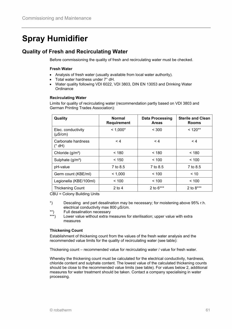
Commissioning and Maintenance
© robatherm 61
Pos: 68.1 /Überschriften/__Sprühbefeuchter @ 0\mod_1257341717060_2008.docx @ 2053 @ @ 1
Spray Humidifier Pos: 68.2 /Inbetriebnahme und Wartung/Überdruckklappe/_Beschaffenheit von Frisch- und Umlaufwasser @ 0\mod_1258474965883_2008.docx @ 2220 @ @ 1
Quality of Fresh and Recirculating Water Pos: 68.3 /Inbetriebnahme und Wartung/Sprühbefeuchter/Sprühbefeuchter_Frisch/Umlaufwasser @ 0\mod_1258475050116_2008.docx @ 2221 @ @ 1
Before commissioning the quality of fresh and recirculating water must be checked. Fresh Water
Analysis of fresh water (usually available from local water authority). Total water hardness under 7° dH. Water quality following VDI 6022, VDI 3803, DIN EN 13053 and Drinking Water
Ordinance Recirculating Water
Limits for quality of recirculating water (recommendation partly based on VDI 3803 and German Printing Trades Association):
Quality
Normal Requirement
Data Processing Areas
Sterile and Clean Rooms
Elec. conductivity (µS/cm)
< 1,000* < 300 < 120**
Carbonate hardness (° dH)
< 4 < 4 < 4
Chloride (g/m³) < 180 < 180 < 180
Sulphate (g/m³) < 150 < 100 < 100
pH-value 7 to 8.5 7 to 8.5 7 to 8.5
Germ count (KBE/ml) < 1,000 < 100 < 10
Legionella (KBE/100ml) < 100 < 100 < 100
Thickening Count 2 to 4 2 to 6*** 2 to 8***
CBU = Colony Building Units *) Descaling and part desalination may be necessary; for moistening above 95% r.h.
electrical conductivity max 800 µS/cm. **) Full desalination necessary ***) Lower value without extra measures for sterilisation; upper value with extra
measures
Pos: 68.4 /Inbetriebnahme und Wartung/Sprühbefeuchter/Sprühbefeuchter_Eindickungszahl @ 0\mod_1258475685116_2008.docx @ 2222 @ @ 1
Thickening Count
Establishment of thickening count from the values of the fresh water analysis and the recommended value limits for the quality of recirculating water (see table): Thickening count – recommended value for recirculating water / value for fresh water. Whereby the thickening count must be calculated for the electrical conductivity, hardness, chloride content and sulphate content. The lowest value of the calculated thickening counts should be close to the recommended value limits (see table). For values below 2, additional measures for water treatment should be taken. Contact a company specialising in water processing.

Commissioning and Maintenance
62 © robatherm
Pos: 68.5 /Inbetriebnahme und Wartung/Sprühbefeuchter/Sprühbefeuchter_Einstellwert @ 0\mod_1258475857461_2008.docx @ 2223 @ @ 1
Set Value
Setting values for hygienic monitoring can be established from the lowest thickening count: Value limit for electrical conductivity = Lowest thickening count x electrical conductivity of fresh water (Rated value for blow down device or for monitoring with HYGIENECONTROL) Cleaning interval = Sump capacity x (thickening count – 1)/ evaporated water quantity (Setting value for time clock of HYGIENECONTROL) Note
These settings values are approximations and do not replace the additional monitoring of germ counts. We recommend the use of test systems (Dip-Slides). Follow instructions for use. Fresh Water Pressure
The ball valve is acceptable up to an operating pressure of max. 6 bar. We recommend a fresh water pressure of at least 3 bar; if necessary install booster system.
Pos: 68.6 /Inbetriebnahme und Wartung/Adiabate Abluftbefeuchtung @ 2\mod_1378803158959_2008.docx @ 32953 @ @ 1
Adiabatic Humidification of Extract Air
Excessive humidity shall be avoided upstream of the rotor to prevent its matrix from over-wetting. If ever possible, permeate from the reverse osmosis should be used to operate the humidifier.
Pos: 68.7 /Inbetriebnahme und Wartung/_Inbetriebnahme @ 0\mod_1257929574289_2008.docx @ 2116 @ @ 1
Commissioning
Pos: 68.8 /Sicherheitshinweise/!Vorsicht_Sicherheitshinweise beachten_Querverweis @ 0\mod_1257777093652_2008.docx @ 2112 @ @ 1
Caution
Observe general safety instructions on page 3!
Pos: 68.9 /Sicherheitshinweise/IBN&Wartung/!IBN&Wartung_ATEX-Bauteile erden @ 0\mod_1257956926546_2008.docx @ 2126 @ @ 1
Only use approved parts with ATEX units. All electrical parts must be earthed.
Pos: 68.10 /Inbetriebnahme und Wartung/Sprühbefeuchter/Sprühbefeuchter_IBN_Reinigung @ 0\mod_1258475963254_2008.docx @ 2224 @ @ 1
Cleaning
Clean foreign bodies out of humidifier sump, clean contamination with water and cleaning agent (non-foaming, pH-value 7 - 9). Note
Remove swarf thoroughly, otherwise there is a risk of pitting! Filling
Fill humidifier sump up to 10 to 20 mm below the overflow connector and set ball valve at this level by adjusting the knurled screw.

Commissioning and Maintenance
© robatherm 63
Note
When operating the spray humidifier there must be an airflow of at least 1 m/s (related to inside cross section of casing) against the spraying direction in order to avoid rectifier breakdown. Treated water must be removed from galvanized parts immediately. White rust formation! Pump
Put pump into operation. Follow instructions of the pump manufacturer.
Pos: 68.11 /Sicherheitshinweise/IBN&Wartung/!IBN&Wartung_Sprühbefeuchter_IBN_Achtung @ 0\mod_1258476159696_2008.docx @ 2226 @ @ 1
Attention
Pump may only be operated if the sump is sufficiently filled. Check pump direction of rotation, if it is incorrect swap electrical connections.
Pos: 68.12 /Inbetriebnahme und Wartung/Sprühbefeuchter/Sprühbefeuchter_IBN_Trockenlaufschutz @ 0\mod_1258476068976_2008.docx @ 2225 @ @ 1
Dry Running Protection
Set dry running protection. The pump must switch off when the water level drops below 20 mm over the suction line, otherwise pull floating switch cables in or out as required. Ball Valve
Check ball valve. At a maximum water level 10 to 20 mm below the overflow connector the fresh water supply must switch off. Adjustability
For adjustable humidifiers the pump must switch off at a nozzle pressure of less than 0.3 bar. Setting of control valve or frequency converter as per manufacturer’s operating instructions. Shut Down
The humidifier must be switched off automatically as soon as the AHU is switched off or fails. Leak Testing
Test external piping for leakage, tighten if necessary. Brand new eliminator profiles do not reach their full elimination capacity until approx 3 operating days have passed (weathering effect).
Pos: 68.13 /Inbetriebnahme und Wartung/Sprühbefeuchter/Sprühbefeuchter_IBN_Hygieneüberwachung @ 0\mod_1258476226451_2008.docx @ 2227 @ @ 1
Hygiene Control
Sedimentation device: Adjust rated value for conductivity in accordance with manufacturer’s operating instructions (see page 61). HYGIENECONTROL: Setting of the cleaning interval (see page 61) and value limit of the conductivity control. Disinfection
UV rays (with self-controlling UV selective sensors) may be appropriate for continuous disinfection. Only use chemical disinfection agents (biocides) if their harmlessness to health in the application concentration is proven. Following commissioning the germ count of recirculating water should be checked on a weekly basis for a while. If necessary the setting values of the hygiene control may be adjusted.

Commissioning and Maintenance
64 © robatherm
Pos: 68.14 /Sicherheitshinweise/IBN&Wartung/!IBN&Wartung_Sprühbefeuchter_IBN_Vorsicht @ 0\mod_1258476346057_2008.docx @ 2228 @ @ 1
Caution
Increased quantities of germs can cause infections or allergic reactions. If germ counts are over the recommended limits, clean or service system immediately. If in doubt or if germ counts again rise rapidly, you are recommended to have examination and advice from a qualified body. If the results are below limits (see page 61), then see maintenance.
Pos: 68.15 /Inbetriebnahme und Wartung/_Wartung @ 0\mod_1257929585257_2008.docx @ 2117 @ @ 1

Commissioning and Maintenance
© robatherm 65
Maintenance Pos: 68.16 /Sicherheitshinweise/!Vorsicht_Sicherheitshinweise beachten_Querverweis @ 0\mod_1257777093652_2008.docx @ 2112 @ @ 1
Caution
Observe general safety instructions on page 3!
Pos: 68.17 /Inbetriebnahme und Wartung/Sprühbefeuchter/Sprühbefeuchter_Wartung @ 0\mod_1258476479278_2008.docx @ 2230 @ @ 1
Maintenance Work
Only fill the humidifier sump with fresh water if humidifying is required. The humidifier sump must be cleaned and dried when it is not operating and for standstill of over 48 hours. Spray Humidifier – Weekly Maintenance* Empty humidifier sump and clean with fresh water** Spray Humidifier – Two Weekly Maintenance* Check germ count of recirculating water and compare with permissible values (see page
61). If recommended germ count is exceeded, clean and disinfect immediately***. Examine inner surface for visible or tangible biological film (slimy covering),
contamination, germs, damage or corrosion; if necessary service, scrub manually with a high pressure cleaner and disinfect***. If there are deposits through scaling then the recirculating water must have a commercially available descaling agent ***mixed into it; with the fan at a standstill, it must be allowed to take effect for several hours, the sump must then be emptied and cleaned with fresh water. If necessary remove drop eliminator and straightener profiles for cleaning.
Spray Humidifier – Half Yearly Maintenance Check mudflap, pump and pipes for dirt, coating, condition and function; if necessary
clean with fresh water; if necessary service Check pump incl. bearings for quiet, vibration free running, heating and noises; perform
corrective maintenance if necessary Check proper functioning of and clean the conductivity electrodes in line with
manufacturer’s information, service if necessary Unscrew caps of atomizer nozzles and examine for deposits, clean with commercially
available descaling agent*** if necessary Check dry running protection and ball valve and adjust if necessary (see page 63) Check function of the deconcentration device, water conditioning, sterilisation plant, water
drain and overflow; service if necessary. Check shut off installations for function; service and adjust if necessary Spray Humidifier – Maintenance when necessary Drying by fan slow down ** Lubricate pump motor bearings in line with manufacturer’s instructions. Replace bearings
(no later than the end of the theoretical service life) If the water conditioning or sterilisation plant breaks down all unit parts must be cleaned. Refill the humidifier sump with fresh water** *) Quarterly maintenance for extract air humidifiers that do not influence the ventilation
air quality. **) Is performed automatically in units with HYGIENECONTROL, depending on the
cleaning interval. ***) Observe manufacturer’s instructions.
Pos: 68.18 /Inbetriebnahme und Wartung/Sprühbefeuchter/Sprühbefeuchter_Wartung_Hinweis @ 0\mod_1258477010841_2008.docx @ 2231 @ @ 1
Note
Treated water must be removed from galvanized parts immediately. White rust formation!

Commissioning and Maintenance
66 © robatherm
Shut Down
Humidifier sump, siphon and pump (with drain plug or valve) should be completely drained.
Remove drop eliminator and straightener profiles for cleaning. Clean spray humidifier completely with commercially available cleaning agents, if
necessary descalers (follow manufacturer’s instructions). Dry inner surfaces by fan slow down. Do not refill humidifier sump until humidification is needed.
Pos: 68.19 /Layout/Seitenumbruch @ 0\mod_1256628615637_0.docx @ 2284 @ @ 1

Commissioning and Maintenance
© robatherm 67
Pos: 68.20 /Inbetriebnahme und Wartung/Überdruckklappe/_Beschreibung @ 0\mod_1258477130769_2008.docx @ 2233 @ @ 1
Description Pos: 68.21 /Inbetriebnahme und Wartung/Sprühbefeuchter/Sprühbefeuchter_Beschreibung @ 0\mod_1258477124848_2008.docx @ 2232 @ @ 1
Equipment depending on scope of customer order:
1 Drainage 9 Level control 2 Overflow with external siphon 10 Immersion heater 3 Rapid filling 11 PTC Thermistor 4 Manual cleaning 12 Drain plug or valve 5 Floating valve 13 Drain plug of drip pan 6 Cleaning nozzle bank 14 Conductivity electrode 6.2 Cleaning nozzle bank 2 (>T33) 15 Straightener 7 Pump dry-run protection 16 Drop eliminator 8 Suction basket 17 Nozzle bank with vaporizer nozzle
Note
Drinking water connections shall be equipped with pipe isolators according to EN 1717. Connect discharge (1) and outflow of the front sump (13) separately to the waste system. Do not discharge humidifier into the casing sloping pan!
Pos: 69 /Layout/Seitenumbruch @ 0\mod_1256628615637_0.docx @ 2284 @ @ 1

Commissioning and Maintenance
68 © robatherm
Pos: 70.1 /Überschriften/__Hochdruck-Sprühbefeuchter @ 0\mod_1257341717967_2008.docx @ 2054 @ @ 1
High Pressure Spray Humidifier Pos: 70.2 /Inbetriebnahme und Wartung/_Inbetriebnahme @ 0\mod_1257929574289_2008.docx @ 2116 @ @ 1
Commissioning
Pos: 70.3 /Sicherheitshinweise/!Vorsicht_Sicherheitshinweise beachten_Querverweis @ 0\mod_1257777093652_2008.docx @ 2112 @ @ 1
Caution
Observe general safety instructions on page 3!
Pos: 70.4 /Sicherheitshinweise/IBN&Wartung/!IBN&Wartung_Hochdruck-Sprühbefeuchter_IBN_Vorsicht @ 0\mod_1258477857280_2008.docx @ 2234 @ @ 1
Caution
For further information the individual commissioning instructions must be observed!
Pos: 70.5 /Sicherheitshinweise/IBN&Wartung/!IBN&Wartung_ATEX-Bauteile erden @ 0\mod_1257956926546_2008.docx @ 2126 @ @ 1
Only use approved parts with ATEX units. All electrical parts must be earthed.
Pos: 70.6 /Inbetriebnahme und Wartung/Hochdruck-Sprühbefeuchter/Hochdruck-Sprühbefeuchter_IBN @ 0\mod_1258477938884_2008.docx @ 2235 @ @ 1
Fresh Water
Completely desalinated water (permeate from reverse osmosis) with max. 20 µS/cm and total water hardness max. 1 °dH.
Water quality following VDI 6022, VDI 3803, DIN EN 13053 and Drinking Water Ordinance
Water supply pressure: 2 to 8 bar Drinking water connections shall be equipped with pipe isolators according to EN 1717. High Pressure Connection
Check that high pressure hose is routed so that it is not subject to stretching or chafing; correct if necessary.
Check threaded connections to humidifier and pump station for leaks; tighten if necessary. Use a second wrench for counter tightening.
Internal bolts must not be retightened. Pump Station
Check oil level through sight glass or with a dipstick; if necessary top up with required type of oil (see information on pump station).
Check tension of drive belt; retension with pulley if necessary. Check discharging screw for leaks; retighten if necessary. For this use a second wrench
to counter turn. Set system in motion manually and check basic functions. Check pump direction of rotation, if it is incorrect swap electrical connections. Check protective devices as instructed. Control Unit
Commission control unit as instructed.
Pos: 70.7 /Inbetriebnahme und Wartung/_Wartung @ 0\mod_1257929585257_2008.docx @ 2117 @ @ 1

Commissioning and Maintenance
© robatherm 69
Maintenance Pos: 70.8 /Inbetriebnahme und Wartung/Wartungsintervall_siehe Tabelle @ 0\mod_1258476435501_2008.docx @ 2229 @ @ 1
Maintenance Interval
See table.
Pos: 70.9 /Sicherheitshinweise/!Vorsicht_Sicherheitshinweise beachten_Querverweis @ 0\mod_1257777093652_2008.docx @ 2112 @ @ 1
Caution
Observe general safety instructions on page 3!
Pos: 70.10 /Sicherheitshinweise/IBN&Wartung/!IBN&Wartung_Hochdruck-Sprühbefeuchter_Wartung_Vorsicht @ 0\mod_1258478100794_2008.docx @ 2236 @ @ 1
Caution
For further information the individual maintenance instructions must be observed!
Pos: 70.11 /Inbetriebnahme und Wartung/Hochdruck-Sprühbefeuchter/Hochdruck-Sprühbefeuchter_Wartung @ 0\mod_1258478151244_2008.docx @ 2237 @ @ 1
High Pressure Spray Humidifier – Bi-weekly Maintenance Check pump station, hose connections, grating, nozzle blocks and nozzles, drop
eliminator, humidifier pan and casing sides for function, foreign bodies, contamination, damage and corrosion; clean and service if necessary*
Check for bacterial contamination of the humidifier pan floor, clean and disinfect if necessary.
Check oil level; if necessary top up or change oil* Manually reverse filter element* High Pressure Spray Humidifier – Half Yearly Maintenance Check shut off installations for function; service and adjust if necessary High Pressure Spray Humidifier – Maintenance when necessary Replace wearing parts* *) Observe manufacturer’s instructions
Pos: 70.12 /Inbetriebnahme und Wartung/Hochdruck-Sprühbefeuchter/Hochdruck-Sprühbefeuchter_Wartung_Hinweis @ 0\mod_1258478375712_2008.docx @ 2238 @ @ 1
Note
Treated water must be removed from galvanised parts immediately. White rust formation! Shut Down
Empty and dry out all water filled parts. Clean entire spray humidifier (observe manufacturer’s information).
Pos: 71 /Layout/Seitenumbruch @ 0\mod_1256628615637_0.docx @ 2284 @ @ 1

Commissioning and Maintenance
70 © robatherm
Pos: 72.1 /Überschriften/__Überdruckklappe @ 0\mod_1257341720154_2008.docx @ 2056 @ @ 1
Pressure Relief Damper Pos: 72.2 /Inbetriebnahme und Wartung/_Inbetriebnahme @ 0\mod_1257929574289_2008.docx @ 2116 @ @ 1
Commissioning
Pos: 72.3 /Sicherheitshinweise/!Vorsicht_Sicherheitshinweise beachten_Querverweis @ 0\mod_1257777093652_2008.docx @ 2112 @ @ 1
Caution
Observe general safety instructions on page 3!
Pos: 72.4 /Sicherheitshinweise/IBN&Wartung/!IBN&Wartung_Überdruckklappe_IBN_Vorsicht @ 0\mod_1258478732281_2008.docx @ 2240 @ @ 1
Caution
There is a possibility of damage to persons or property as a result of impact or air jet under high pressure through unexpected release of the pressure relief damper! Protective devices must be fitted and effective in accordance with DIN EN ISO 12100.
Pos: 72.5 /Inbetriebnahme und Wartung/Überdruckklappe/Überdruckklappe_IBN_Einstellung @ 0\mod_1258478593416_2008.docx @ 2239 @ @ 1
Setting
The release or application pressure of the pressure relief damper against the unit or duct wall can be varied by height adjustment , and altering the number and distance of weights (see characteristics). The presetting is made by means of the indicated a-dimension. By simulating maximum pressure in the network by using dampers which are as a rule present in every system, release pressure must be tested and weights adjusted if necessary.
Pos: 72.6 /Sicherheitshinweise/IBN&Wartung/!IBN&Wartung_Überdruckklappe_IBN_Vorsicht2 @ 0\mod_1258478789230_2008.docx @ 2241 @ @ 1
Caution
Damage to persons or property may occur if the maximum pressure for the system is exceeded!

Commissioning and Maintenance
© robatherm 71
Pos: 72.7 /Inbetriebnahme und Wartung/Überdruckklappe/Überdruckklappe_IBN_Kennlinie Auslösedruck @ 0\mod_1258478840914_2008.docx @ 2242 @ @ 1
Characteristic Release and Application Pressure
A Release pressure (Pa) B Number of weight plates (pcs) C a-distances (mm)
Pos: 72.8 /Inbetriebnahme und Wartung/_Wartung @ 0\mod_1257929585257_2008.docx @ 2117 @ @ 1
Maintenance Pos: 72.9 /Inbetriebnahme und Wartung/Wartungsintervall_1Jahr/ATEX monatlich @ 0\mod_1258478957281_2008.docx @ 2243 @ @ 1
Maintenance Interval
Every year. ATEX units every month.
Pos: 72.10 /Sicherheitshinweise/!Vorsicht_Sicherheitshinweise beachten_Querverweis @ 0\mod_1257777093652_2008.docx @ 2112 @ @ 1
Caution
Observe general safety instructions on page 3!
Pos: 72.11 /Inbetriebnahme und Wartung/Überdruckklappe/Überdruckklappe_Wartung @ 0\mod_1258478999684_2008.docx @ 2244 @ @ 1
Pressure Relief Damper – Periodic Maintenance Check pressure relief damper for function, foreign bodies, contamination, damage and
corrosion Treat all moving parts with lubricating and preserving spray Treat sealing with Vaseline Check release pressure, adjust if necessary. Pressure Relief Damper – Maintenance when necessary Clean pressure relief damper and rectify any damage and corrosion Clean with a wet cloth, use grease or oil dissolving agents if necessary
Pos: 73 /Layout/Seitenumbruch @ 0\mod_1256628615637_0.docx @ 2284 @ @ 1

Commissioning and Maintenance
72 © robatherm
Pos: 74.1 /Überschriften/__MSR-Technik @ 0\mod_1257341721201_2008.docx @ 2057 @ @ 1
Controlling Systems Pos: 74.2 /Inbetriebnahme und Wartung/_Inbetriebnahme @ 0\mod_1257929574289_2008.docx @ 2116 @ @ 1
Commissioning
Pos: 74.3 /Sicherheitshinweise/!Vorsicht_Sicherheitshinweise beachten_Querverweis @ 0\mod_1257777093652_2008.docx @ 2112 @ @ 1
Caution
Observe general safety instructions on page 3!
Pos: 74.4 /Sicherheitshinweise/IBN&Wartung/!IBN&Wartung_ATEX-Bauteile erden @ 0\mod_1257956926546_2008.docx @ 2126 @ @ 1
Only use approved parts with ATEX units. All electrical parts must be earthed.
Pos: 74.5 /Inbetriebnahme und Wartung/MSR-Technik/MSR-Technik_IBN_Voraussetzungen @ 0\mod_1258540333940_2008.docx @ 2245 @ @ 1
Requirements
All construction requirements such as access, completed unit and duct installation and uninterrupted availability of all supply facilities must be met. In addition there must be a possibility of operating the system in the required working phases. The commissioning may only be undertaken by a qualified company which specialises in process measurement and control technology. At the start of the commissioning work, the commissioning engineer will be shown the system specific locations by a person nominated by the customer. Work
The following work must be carried out: Check correct installation of the field units Check the electrical connections on the switchgear cabinet and the field units Functional test of sensors, transducers and actuators included in the supply package Configuration of control and/or DDC substations including loading of project specific
control and SPS programmes Commissioning with all connected data stations Adjustment of the parameters to the operating conditions of the technical system, setting
and regulation to the specified rated values and reference variables Testing of the control programmes Briefing nominated operating staff during the course of commissioning work
Pos: 74.6 /Inbetriebnahme und Wartung/_Wartung @ 0\mod_1257929585257_2008.docx @ 2117 @ @ 1

Commissioning and Maintenance
© robatherm 73
Maintenance Pos: 74.7 /Inbetriebnahme und Wartung/MSR-Technik/MSR-Technik_Wartung_Wartungspersonal @ 0\mod_1258540467905_2008.docx @ 2246 @ @ 1
Maintenance Staff
Maintenance work must only be carried out by a qualified expert. Maintenance Contract
A maintenance contract with a company which specializes in process measuring and control technology is recommended.
Pos: 74.8 /Inbetriebnahme und Wartung/Wartungsintervall_1Jahr/ATEX monatlich @ 0\mod_1258478957281_2008.docx @ 2243 @ @ 1
Maintenance Interval
Every year. ATEX units every month.
Pos: 74.9 /Sicherheitshinweise/!Vorsicht_Sicherheitshinweise beachten_Querverweis @ 0\mod_1257777093652_2008.docx @ 2112 @ @ 1
Caution
Observe general safety instructions on page 3! os: 74.10 /Layout/Leerzeile @ 0\mod_1256628654328_0.docx @ 2285 @ @ 1
Pos: 74.11 /Inbetriebnahme und Wartung/MSR-Technik/MSR-Technik_Wartung @ 0\mod_1258540543637_2008.docx @ 2247 @ @ 1
Switch Cabinets, Control Panels, controls – Periodic Maintenance Check for proper and functionally correct installation and ambient conditions Check for contamination, corrosion and damage Check protective coverings are complete Check electrical/mechanical function of the connections, especially protective conductors Check functional elements (e.g. operating - and display devices) Check input signals (e.g. sensor, reference variable) match with rated value Check optical and acoustic control devices Check contactors and relays for wear and damage (e.g. contact erosion) Check switching and control processes (e.g. anti-freeze function) Check safety devices (e.g. thermal trips) Check setting of switch cabinet components (e.g. time relays) Check manual, automatic and remote control functions Change switch cabinet filter Switch Cabinets, Control Panels, Controls – Maintenance as required Clean to maintain functioning Set, adjust, tighten functional elements (e.g. operating and display devices) Compensate signals Readjust Transducers, Safety and Monitoring Equipment, – Periodic Maintenance Check for proper and functionally correct installation and ambient conditions Check for contamination, corrosion and damage Check electrical/mechanical function of the connections, especially protective conductors Measure and record measurable quantities at measurement point Check electrical, electronic and pneumatic measurement signals Transducers, Safety and Monitoring Equipment – Maintenance as required Clean to maintain functioning Readjust, regenerate

Commissioning and Maintenance
74 © robatherm
Pos: 74.12 /Inbetriebnahme und Wartung/MSR-Technik/MSR-Technik_Wartung_Regler und Zusatzmodul @ 0\mod_1258541799396_2008.docx @ 2249 @ @ 1
Controllers and Supplementary Modules – Periodic Maintenance Check for proper and functionally correct installation and ambient conditions Check for contamination, corrosion and damage Check natural voltage (e.g. buffer batteries, storage batteries) Check electrical/mechanical function of the connections, especially protective conductors Check functional elements (e.g. operating - and display devices) Check electrical, electronic and pneumatic input signals (e.g. sensors, remote adjustment
devices, reference variables) Check controller functioning and actuating signal Check control loop as per setting parameters including all supplementary functions Controllers and Supplementary Modules – Maintenance when necessary Exchange storage batteries Clean to maintain functioning Set, adjust, tighten functional elements (e.g. operating and display devices) Compensate signals Adjust controller functioning and actuating signal Adjust control loop as per setting parameters including all supplementary functions
Pos: 74.13 /Inbetriebnahme und Wartung/MSR-Technik/MSR-Technik_Wartung_Stellgeräte @ 0\mod_1258541790365_2008.docx @ 2248 @ @ 1
Actuators – Periodic Maintenance Check for proper and functionally correct installation and ambient conditions Check for contamination, corrosion and damage Check for external leakage (e.g. valve packing bushes) Check electrical/mechanical function of the connections, especially protective conductors Check electrical, electronic and pneumatic input signals and operating range Check functioning of position sensors, alarm actuators and limit switches Readjust Actuators – Maintenance when necessary Lubricate (e.g. valve stem) Clean to maintain functioning Software – Periodic Maintenance Perform data back up Keep most recent copies of programmes and data Software – Maintenance when necessary Load most recent copies of programmes and data
Pos: 75 /Layout/Seitenumbruch @ 0\mod_1256628615637_0.docx @ 2284 @ @ 1

Commissioning and Maintenance
© robatherm 75
Pos: 76.1 /Überschriften/__Hydraulische-Regelgruppe @ 0\mod_1257342098024_2008.docx @ 2059 @ @ 1
Hydraulic Set Pos: 76.2 /Inbetriebnahme und Wartung/_Inbetriebnahme @ 0\mod_1257929574289_2008.docx @ 2116 @ @ 1
Commissioning
Pos: 76.3 /Sicherheitshinweise/!Vorsicht_Sicherheitshinweise beachten_Querverweis @ 0\mod_1257777093652_2008.docx @ 2112 @ @ 1
Caution
Observe general safety instructions on page 3!
Pos: 76.4 /Sicherheitshinweise/IBN&Wartung/!IBN&Wartung_Vorsicht_Medium mit Umgebungstemperatur @ 0\mod_1258374559693_2008.docx @ 2161 @ @ 1
Caution
Only use fluid with ambient temperature when charging or purging as there is a risk of scalding/frostbite.
Pos: 76.5 /Sicherheitshinweise/IBN&Wartung/!IBN&Wartung_Vorsicht_heiße/kalten Flächen @ 0\mod_1258374632300_2008.docx @ 2162 @ @ 1
Caution
To avoid burns, do not touch hot/cold surfaces.
Pos: 76.6 /Sicherheitshinweise/IBN&Wartung/!IBN&Wartung_ATEX-Bauteile erden @ 0\mod_1257956926546_2008.docx @ 2126 @ @ 1
Only use approved parts with ATEX units. All electrical parts must be earthed.
Pos: 76.7 /Sicherheitshinweise/IBN&Wartung/!IBN&Wartung_Hydraulische Regelgruppe_IBN_ATEX @ 0\mod_1258546300982_2008.docx @ 2251 @ @ 1
Ensure sufficient distance between max. surface temperature of the heat exchanger due to temperature of the medium and minimum ignition temperature of any flammable mixture which may be present in accordance with EN 1127.
Pos: 76.8 /Sicherheitshinweise/IBN&Wartung/!IBN&Wartung_Hydraulische Regelgruppe_IBN_Achtung @ 0\mod_1258546384854_2008.docx @ 2252 @ @ 1
Attention
Do not exceed permissible pressure range. Observe design data sheet. In HRS control equipment (e.g. run around coils heat recovery system) the quantity of anti-freeze is to be determined in relation to the lowest outside temperature (note manufacturer’s information).
Pos: 76.9 /Inbetriebnahme und Wartung/Hydraulische Regelgruppe/Hydraulische Regelgruppe_Prüfungen @ 0\mod_1258546078597_2008.docx @ 2250 @ @ 1
Inspections
Check: Correct installation of all components. Inlet outlet connections for function (counter flow principle). Firm seating of all bolts and glands. Easy movement of all valves, slide dampers and baffles. Charging
The system must be rinsed (removal of contaminations) according to VDI 2035 and should be filled with the heat exchanger fluid named in the design data sheet to the correct concentration. Water quality to VDI 2035. This control equipment charging process can also occur together with the charging of the piping system. During charging check connection points for leakage; retighten screws and glands if necessary.

Commissioning and Maintenance
76 © robatherm
Venting
When charging the system according to VDI 2035 the control equipment and the system should be vented carefully at the highest point of the system. Open the venting recovery device provided for this purpose. This is also valid for pumps with venting devices (e.g. high pressure centrifugal pumps in high efficiency run around heat recovery systems). Observe manufacturer’s instructions. In incompletely vented systems with pumps, air pockets may cause capacity reduction and severe damages of the pump. Pressure Check
Carry out as an option following DIN 4753, part 1.
Pos: 76.10 /Sicherheitshinweise/IBN&Wartung/!IBN&Wartung_Hydraulische Regelgruppe_IBN_Achtung2 @ 0\mod_1258546503850_2008.docx @ 2253 @ @ 1
Attention
When doing this observe the permissible pressure stage.
Pos: 76.11 /Inbetriebnahme und Wartung/Hydraulische Regelgruppe/Hydraulische Regelgruppe_Drehrichtung @ 0\mod_1258546576270_2008.docx @ 2254 @ @ 1
Direction of Rotation
Check direction of rotation of pumps and servo motor. Change electrical connections if incorrect. Hydraulics
Optional performance of hydraulic commissioning with setting and compensation of pressures (e.g. by using pressure regulating device). Steam
In control equipment for steam the unobstructed discharge of condensate must also be checked (all condensate shut off valves must be open).
Pos: 76.12 /Inbetriebnahme und Wartung/_Wartung @ 0\mod_1257929585257_2008.docx @ 2117 @ @ 1

Commissioning and Maintenance
© robatherm 77
Maintenance Pos: 76.13 /Inbetriebnahme und Wartung/Hydraulische Regelgruppe/Hydraulische Regelgruppe_Entlüftung @ 2\mod_1346745015107_2008.docx @ 25240 @ @ 1
Venting
Pumps with venting devices (e.g. high pressure centrifugal pumps in high efficiency run around heat recovery systems) shall be vented again 2 weeks after commissioning. Observe manufacturer’s instructions. Otherwise, bearings and shaft seals might be damaged.
Pos: 76.14 /Inbetriebnahme und Wartung/Wartungsintervall_3Monate/ATEX monatlich @ 0\mod_1257930528679_2008.docx @ 2122 @ @ 1
Maintenance Interval
Every three months. ATEX units every month.
Pos: 76.15 /Sicherheitshinweise/!Vorsicht_Sicherheitshinweise beachten_Querverweis @ 0\mod_1257777093652_2008.docx @ 2112 @ @ 1
Caution
Observe general safety instructions on page 3!
Pos: 76.16 /Sicherheitshinweise/IBN&Wartung/!IBN&Wartung_Vorsicht_heiße/kalten Flächen @ 0\mod_1258374632300_2008.docx @ 2162 @ @ 1
Caution
To avoid burns, do not touch hot/cold surfaces.
Pos: 76.17 /Sicherheitshinweise/IBN&Wartung/!IBN&Wartung_Vorsicht_Temperieren auf Umgebungstemperatur @ 0\mod_1258373503611_2008.docx @ 2159 @ @ 1
Caution
Before starting work allow components to cool/warm up to the ambient temperature.
Pos: 76.18 /Sicherheitshinweise/IBN&Wartung/!IBN&Wartung_Vorsicht_Kontakt mit Sole @ 0\mod_1258373184697_2008.docx @ 2156 @ @ 1
Caution
Avoid any contact with brine while charging or venting. Danger of poisoning and acid burns! Observe manufacturer’s instructions.
Pos: 76.19 /Inbetriebnahme und Wartung/Hydraulische Regelgruppe/Hydraulische Regelgruppe_Wartung @ 0\mod_1258546687891_2008.docx @ 2255 @ @ 1
Hydraulic Control Equipment – Periodic Maintenance Check control equipment for contamination, damage, corrosion and leaks Vent pump and hydraulic set Check filtering systems, clean if necessary Check easy movement of all valves, slide dampers and baffles; if necessary lubricate
stems in accordance with manufacturer’s instructions. Check release pressure of pressure relief devices Service pumps, control valves and servo motors in accordance with manufacturer’s
information Hydraulic Control Equipment – Maintenance when necessary Clean control equipment and rectify any damage, leakage and corrosion Retighten bolts and glands
Pos: 76.20 /Inbetriebnahme und Wartung/Hydraulische Regelgruppe/Hydraulische Regelgruppe_Wartung_Außerbetriebsetzung @ 0\mod_1258546892681_2008.docx @ 2256 @ @ 1
Shut Down
If out of operation for some time, especially if there is a risk of freezing, the control equipment must be emptied completely. For this purpose open all purging and discharging devices. Then blow air (compressed air, fan etc) through the control equipment for complete purging.
Pos: 77 /Layout/Seitenumbruch @ 0\mod_1256628615637_0.docx @ 2284 @ @ 1

Shut Down
78 © robatherm
Pos: 78 /Überschriften/_Stilllegung @ 0\mod_1256570208285_2008.docx @ 2012 @ @ 1 Pos: 79 /Überschriften/__Außerbetriebsetzung @ 0\mod_1257342099134_2008.docx @ 2060 @ @ 1
Shut Down Pos: 80 /Sicherheitshinweise/!Vorsicht_Sicherheitshinweise beachten_Querverweis @ 0\mod_1257777093652_2008.docx @ 2112 @ @ 1
Caution
Observe general safety instructions on page 3!
Pos: 81 /Stilllegung/Außerbetriebsetzung @ 0\mod_1260807151804_2008.docx @ 2277 @ @ 1
If the system is to be shut down for a longer period the instructions for the individual components must be observed. Additionally it is compulsory to observe the individual component manufacturer’s information (request if necessary)! Take the risk of freezing in winter into account in particular.
Pos: 82 /Überschriften/__Abbau, Entsorgung @ 0\mod_1257342100383_2008.docx @ 2061 @ @ 1
Disassembly, Disposal Pos: 83 /Sicherheitshinweise/!Vorsicht_Sicherheitshinweise beachten_Querverweis @ 0\mod_1257777093652_2008.docx @ 2112 @ @ 1
Caution
Observe general safety instructions on page 3!
Pos: 84 /Stilllegung/Abbau und Entsorgung @ 0\mod_1260807197583_2008.docx @ 2278 @ @ 1
Only an authorised company is allowed to disassemble the unit after the service life has expired. Please observe the safety regulations for every component as well as the component manufacturer’s instructions to avoid any damage to persons or property. All components and resources (e.g. oils, refrigerant, brine, batteries) must be disposed of in line with local regulations. All metal and plastic parts should be separated and sent for recycling. Injection moulding parts are provided with material identification; plastic extrusions are usually made of polyvinyl chloride (PVC).
=== Ende der Liste für Textmarke Inhalt ===
Shut Down

Index directory
© robatherm 79
absorption material ................................................................ 31
access door ............................................................................ 17
adiabatic humidification of extract air ............................... 44, 62
air duct ................................................................................... 12
air flow control ........................................................................ 32
air heater
electric-air heater ............................................................... 36
air humidifier ............................................................................ 9
air pressure gauge ........................................................... 36, 56
air washer .............................................................................. 15
anti-freeze function ................................................................ 73
assembly .................................................................................. 9
assessment of conformity ........................................................ 5
ATEX
zone crossing ........................................................ 44, 46, 48
ATEX directive ......................................................................... 1
ATEX-guideline ........................................................................ 5
axle base .......................................................................... 25, 27
bacterial contamination .......................................................... 69
baffles .................................................................................... 77
base frame ............................................................................... 6
bean distorsion ......................................................................... 9
bearing replacement .............................................................. 24
belt deflection ......................................................................... 27
belt pretensioning force.......................................................... 27
belt pulleys ....................................................................... 23, 27
belt tension ................................................................. 23, 26, 27
BGR 500 ................................................................................ 41
BGV D4 .................................................................................. 41
BGV D6 .................................................................................... 7
blow down .............................................................................. 62
bolt
through bolt connection ..................................................... 10
with thread bushes ............................................................ 11
booster system ....................................................................... 62
burner ..................................................................................... 51
casing ....................................................................................... 4
certificate of conformity ............................................................ 1
charging
cooling coil ......................................................................... 38
chimney .................................................................................. 51
clean up ................................................................................. 17
cleaning
cooling coil ......................................................................... 39
heat exchanger ............................................................ 45, 46
heat exchanger .................................................................. 39
heating coil ........................................................................ 34
pressure relief valve .......................................................... 71
silencer .............................................................................. 31
spray humidifier ................................................................. 62
cleaning agent ........................................................................ 25
cleaning and maintenance ....................................................... 4
combustion air ........................................................................ 51
combustion chamber........................................................ 50, 53
temperature regulation ....................................................... 52
combustion chamber damper ................................................. 54
combustion chamber walls ..................................................... 51
commissioning and maintenance work .................................. 56
compressor oil .................................................................. 41, 42
condensate ............................................................................. 52
conductivity ............................................................................ 61
connection .............................................................................. 15
air duct ............................................................................... 12
air washer .......................................................................... 15
burner ................................................................................ 50
condensate piping .............................................................. 14
discharge piping ................................................................. 14
electrical connection .......................................................... 15
flexible ................................................................................ 12
gas control system ............................................................. 55
heat exchanger .................................................................. 13
heating and cooling water piping ....................................... 13
motor .................................................................................. 24
overflow piping ................................................................... 14
refrigerating piping ............................................................. 14
siphon ................................................................................ 14
contamination ................................................................... 30, 44
control panels ......................................................................... 73
control unit .............................................................................. 68
controlling systems ................................................................. 72
cooling coil
CW ..................................................................................... 38
DX-coil ............................................................................... 38
damper ................................................................................... 20
damper regulation .................................................................. 52
dampers
coupled .............................................................................. 20
linkage drive ....................................................................... 21
motor driven ....................................................................... 20
danger of fire .............................................................. 22, 24, 53
data back up ........................................................................... 74
DDC-substations .................................................................... 72
deconcentration ...................................................................... 65
decoupled section frame ........................................................ 12
deflection ................................................................................ 28
deflection force ....................................................................... 27
dehumidification operation ..................................................... 48
dehydration ............................................................................ 25
delivery ..................................................................................... 6
deposits .................................................................................. 65
descaling ................................................................................ 61
descaling agent ...................................................................... 65
desiccant rotor ........................................................................ 48
DGKH ....................................................................................... 5
DIN 46200 .............................................................................. 15
DIN 4753 ................................................................................ 76
DIN 4755 .................................................................... 50, 53, 54
DIN 4794 .............................................................. 50, 52, 53, 55

Index Directory
80 © robatherm
DIN 7753 ................................................................................ 27
DIN EN 13053 .................................................................. 61, 68
DIN EN 378 ............................................................................ 41
DIN EN 60204 .................................................................... 3, 16
DIN EN ISO 12100 ..................................................... 20, 21, 70
DIN VDE 0185 ....................................................................... 13
DIN-frame ................................................................................ 7
disassembly ........................................................................... 78
disassembly of coils ......................................................... 35, 40
discharge piping ..................................................................... 14
disinfectants ............................................................................. 5
disposal .................................................................................. 78
door sealings ............................................................................ 4
drainage ................................................................................. 67
drainage device ...................................................................... 53
drinking water ordinance .................................................. 61, 68
drip pan .............................................................................. 9, 39
drive ................................................................................. 23, 25
rotor ................................................................................... 43
duct sensor ............................................................................ 56
DVGW .................................................................................... 55
DVGW-worksheet ...................................................... 50, 53, 54
DX-coil ................................................................................... 38
EC-F Gas directive ................................................................. 41
electric motor ......................................................................... 25
electric-air heater ................................................................... 36
electrical connection .............................................................. 15
electrostatic charge ............................................................ 5, 13
emergency provisions .............................................................. 4
emergency switch ............................................................ 51, 55
emission temperature ............................................................ 52
emission values ..................................................................... 52
emptying .......................................................................... 34, 40
EN 1127 ................................................................................. 32
EN 1127-1 ............................................................................ 3, 4
environmental protection regulations ..................................... 30
environmental regulations ...................................................... 42
equipotential bonding ............................................................. 13
exhaust pipe ........................................................................... 54
fan .......................................................................................... 22
fan overshoot ........................................................................... 3
fan slow down .................................................................. 65, 66
fault shutdown ........................................................................ 56
filling
heating coil ........................................................................ 32
filter end resistances .............................................................. 29
filter media ....................................................................... 29, 30
filter monitoring ...................................................................... 29
filters ...................................................................................... 29
fire dampers ........................................................................... 20
flame head extension ............................................................. 51
flame pot .......................................................................... 50, 53
flexible connection ................................................................. 12
flow control ............................................................................. 36
flow meter .............................................................................. 60
foundation ................................................................................ 9
frame ...................................................................................... 29
frequency converter ............................................................... 24
fresh water pressure .............................................................. 62
frost damage .............................................................. 32, 38, 48
frost protection control ............................................................ 32
fully desalinated water ............................................................ 68
gap width .......................................................................... 22, 25
gas burner ........................................................................ 50, 51
gas control system ................................................................. 54
gas surface burner ................................................................. 55
gas system
components ....................................................................... 59
structure ............................................................................. 58
general ..................................................................................... 1
germ count ............................................................................. 64
germs ..................................................................................... 65
glycol concentration ............................................................... 32
heat pipe HRS ........................................................................ 47
heat pump .............................................................................. 41
heating and cooling water piping ............................................ 13
heating coil ............................................................................. 32
hot water ............................................................................ 32
steam ................................................................................. 32
height adjustment ................................................................... 70
high pressure connection ....................................................... 68
high pressure-spray humidifier ............................................... 68
HRS
heat pipe ............................................................................ 47
rotor HRS ........................................................................... 43
rotor-HRS ............................................................................. 3
humidifier pan ......................................................................... 69
humidifier sump ................................................................ 62, 66
hydraulic set ........................................................................... 75
Hygienecontrol ....................................................................... 62
icing ........................................................................................ 39
imbalance ................................................................... 25, 45, 49
impeller ................................................................................... 22
inert gas charge ..................................................................... 14
inlet nozzle ............................................................................. 22
input signals ........................................................................... 73
inspection
heating coil ......................................................................... 32
inspection cover ..................................................................... 53
inspection openings ............................................................... 24
installation ................................................................................ 9
filter cartridges ................................................................... 29
installation height ................................................................... 11
lateral trueness ................................................................. 45, 49
leak test .............................................................................. 5, 55
leakage gas valve .................................................................. 59
LICl-rotors............................................................................... 48
lifting eyes .......................................................................... 7, 18
lifting gear ................................................................................. 9
lightning protection ................................................................. 13
limit switch ........................................................................ 52, 57
maintenance

© robatherm 81
rotary heat exchanger ....................................................... 45
maintenance and cleaning instructions .................................... 4
maintenance contract ....................................................... 41, 73
maintenance staff ................................................................... 73
maintenance work
belt drive ............................................................................ 26
burner ................................................................................ 54
bypass ............................................................................... 54
combustion chamber ......................................................... 53
control and safety bodies .................................................. 54
control systems ................................................................. 73
dampers ............................................................................ 21
desiccant rotor ................................................................... 49
drive clutch ........................................................................ 26
drop eliminator ................................................................... 39
electric heater .................................................................... 37
electric motor ..................................................................... 25
fan ..................................................................................... 25
filters .................................................................................. 30
flame pot ............................................................................ 53
gas surface burner ............................................................ 58
heat pipe HRS ................................................................... 47
heating coil ........................................................................ 34
high pressure-spray humidifier .......................................... 69
hydraulic control equipment .............................................. 77
plate heat exchanger ......................................................... 46
pressure relief damper ...................................................... 71
reheating surface ............................................................... 53
silencer .............................................................................. 31
spray humidifier ................................................................. 65
switch cabinet .................................................................... 73
maintenance work cooling coil ............................................... 39
motor ...................................................................................... 22
motor nominal power ............................................................. 24
motor protection ..................................................................... 16
motor removal ........................................................................ 27
mudflap .................................................................................. 65
nameplate ........................................................ 1, 22, 24, 36, 56
natural frequency ..................................................................... 9
odor problems ........................................................................ 48
oil burner ................................................................................ 50
operating devices ................................................................... 73
operating pressure ................................................................. 62
operating speed ..................................................................... 24
outdoor installation ................................................................. 13
part desalination ..................................................................... 61
personal protection equipment .............................................. 41
pH-value ..................................................... 4, 34, 40, 47, 61, 62
plastic roofing strips ............................................................... 18
plate heat exchangers............................................................ 46
plug fan .................................................................................. 22
position switch ........................................................................ 20
power failure ........................................................ 43, 45, 48, 49
pressure check ....................................................................... 76
pressure controller ................................................................. 59
pressure drop ................................................................... 44, 46
pressure range ....................................................................... 32
pressure regulator .................................................................. 56
pressure relief damper ........................................................... 70
pressure relief dampers ......................................................... 20
protection regulations ............................................................. 52
protective clothing .................................................................... 3
protective conductor ......................................................... 25, 73
protective equipment .............................................................. 53
rapid filling .............................................................................. 67
readiness for operation .................................................... 51, 55
reassembly of coils ........................................................... 35, 40
recirculating water ...................................................... 61, 63, 65
recommissioning ...................................................................... 5
refrigerating piping ................................................................. 14
refrigeration installations ........................................................ 41
reheating surface ................................................................... 53
release pressure ........................................................ 70, 71, 77
remote control function ........................................................... 73
resonance speeds .................................................................. 24
respiratory protective gear ..................................................... 41
reverse osmosis ..................................................................... 68
risk of freezing ........................................................................ 77
RKI ........................................................................................... 5
roll filter ................................................................................... 29
roof cover sheet ..................................................................... 18
roofing strip ............................................................................ 18
roofing strips ........................................................................... 10
rotary heat exchanger ...................................................... 17, 43
rotor
desiccant rotor ................................................................... 48
LICI .................................................................................... 48
rotor body ......................................................................... 45, 48
rotor controller ........................................................................ 43
rotor speed ....................................................................... 43, 48
running noises ........................................................................ 45
safety data sheet .............................................................. 41, 53
safety instructions .................................................................... 3
safety regulations ................................................................... 18
safety temperature limiter ....................................................... 36
scaling .................................................................................... 65
sealing of the roof ................................................................... 18
sealing of unit section joints ................................................... 11
sealing strips .......................................................................... 43
section frame .......................................................................... 11
decoupled .......................................................................... 12
service booklet ................................................................. 41, 42
service switch ........................................................................... 1
setting parameters ................................................................. 74
setting records .................................................................. 52, 57
shut down ......................................................................... 49, 78
desiccant rotor ................................................................... 49
fan ...................................................................................... 27
heating coil/air cooler ................................................... 34, 40
high pressure spray humidifier ........................................... 69
refrigeration unit ................................................................. 42
spray humidifier ................................................................. 66

Index Directory
82 © robatherm
silencer ................................................................................... 31
siphon ............................................................ 14, 39, 45, 66, 67
solvent welding material......................................................... 18
sound reduction ..................................................................... 10
spare parts ............................................................................... 5
spray humidifier ...................................................................... 61
high pressure-spray humidifier .......................................... 68
stability ................................................................................... 27
standing safety ......................................................................... 9
steam coil ............................................................................... 32
sterilisation ............................................................................. 61
structure borne sound insulation ............................................ 10
suction restrictor ..................................................................... 57
sulphate ................................................................................. 61
supporting blower ................................................................... 56
supporting structure ................................................................. 9
terminal block ......................................................................... 25
thermal mass ......................................................................... 43
thickening count ..................................................................... 61
TLV values ............................................................................. 41
top connection ........................................................................ 33
total water hardness ............................................................... 61
transport ....................................................................... 1, 6, 7, 8
transport loops ................................................................... 7, 10
transportation safety device ................................................... 22
TRBS 2153 .............................................................................. 4
treated water .............................................................. 63, 65, 69
TRGI .......................................................................... 51, 55, 60
turbulators .............................................................................. 53
unit
weatherproof ..................................................................... 18
unit connection ....................................................................... 10
unit frame ............................................................................... 12
unit installation ......................................................................... 9
unit openings .......................................................................... 11
units
weatherproof ................................................................ 10, 11
without base frame .............................................................. 6
unloading .......................................................................... 6, 7, 8
by means of lifting eyes ....................................................... 7
by means of transport loops ................................................ 7
VAH .......................................................................................... 5
V-belt drive ............................................................................. 23
V-belts .................................................................................... 27
VDE 0113 ........................................................................... 3, 16
VDI 2035 .................................................................... 32, 38, 75
VDI 3803 ...................................................................... 9, 61, 68
VDI 6022 ................................................................ 4, 17, 61, 68
venting .............................................................................. 76, 77
cooling coil ......................................................................... 38
heating coil ......................................................................... 33
venting recovery system .................................................. 33, 38
venting screw ......................................................................... 33
vibration .................................................................................. 49
vibration dampers ................................................................... 25
vibration isolators ................................................................... 22
vibrations .................................................................... 24, 25, 45
washing chamber ................................................................... 43
waste water pipe .................................................................... 14
water level .............................................................................. 39
weatherproof unit ................................................................... 11
zone crossing ............................................................. 44, 46, 48


robatherm
Industriestrasse 26
89331 Burgau, Germany
Tel. +49 8222 999-0
Fax +49 8222 999-222
www.robatherm.com
Related Documents