Air Cylinder: With End Lock Series CBA2 ø40, ø50, ø63, ø80, ø100 How to Order With auto switch Without auto switch With auto switch Bore size 40 50 63 80 100 40 mm 50 mm 63 mm 80 mm 100 mm Number of auto switches Nil S n 2 pcs. 1 pc. “n” pcs. Auto switch Nil Without auto switch Mounting style B L F G C D T Basic style Axial foot style Rod side flange style Head side flange style Single clevis style Double clevis style Center trunnion style Cylinder stroke (mm) For more information, please refer to the next page. Cylinder suffix Without rod boot Nylon tarpaulin Heat resistant tarpaulin With cushion on both sides Without cushion Rod boot Cushion Nil J K Nil N Cylinders with Built-in Magnets L L 150 150 Y7BW 50 50 H H N N Tube material Nil F ∗ Aluminum tube Steel tube Manual release type N L Non-lock type Lock type Lock position H R W Head side end lock Rod side end lock Double end lock Rc NPT G Port thread type Nil TN TF ∗ Types with auto switch are not available. ∗ Lead wire length symbols: 0.5 m ········· Nil (Example) A54 3 m ·········· L (Example) A54L 5 m ·········· Z (Example) A54Z • In addition to the models in the above table, there are some other auto switches that are applicable. For more information, refer to page 6-8-16. ∗ Solid state switches marked with “” are produced upon receipt of order. CBA2 CDBA2 ∗ Select an applicable auto switch part number from the table below. ∗ D-Z7/Z80/Y59/Y69/Y7 are not mounted and are supplied loose. (Only the switch mounting brackets for these models are mounted.) ∗ When more than one symbol is to be specified, indicate them in alphabetical order. Applicable Auto Switch/Refer to page 6-16-1 for further information on auto switches. If built-in magnet type is ordered without auto switch, leave the field for the auto switch type blank. (Example) CDBA2L40-100-HN Special function Type Electrical entry Grommet Grommet Grommet Grommet Indicator light Wiring (Output) 2-wire 3-wire (NPN equiv.) Load voltage — — AC DC Auto switch model Lead wire length (m) ∗ 0.5 (Nil) 3 (L) 5 (Z) — — IC circuit Applicable load Tie-rod mount — 5 V — 100 V, 200 V 100 V 12 V 5 V, 12 V 12 V 5 V, 12 V 5 V, 12 V 12 V — — — — 24 V Yes Diagnostic indication (2-color indication) With diagnostic output (2-color indication) Magnetic field resistant (2-color indication) Water resistant (2-color indication) Diagnostic indication (2-color indication) — — Yes 2-wire 3-wire (NPN) 3-wire (PNP) 2-wire 2-wire 3-wire (NPN) 3-wire (PNP) 4-wire (NPN) 24 V — IC circuit — — IC circuit IC circuit Relay, PLC Relay, PLC Reed switch Pre-wire connector — — — — — — — — 100 V, 200 V — — 24 V Z76 Z73 A54 A59W Y59A Y7P J51 Y59B Y7NW Y7PW Y7BW Y7BA F59F P5DW Solid state switch 6-8-41 CJ1 CJP CJ2 CM2 CG1 MB MB1 CA2 CS1 C76 C85 C95 CP95 NCM NCA D- -X 20- Data

Welcome message from author
This document is posted to help you gain knowledge. Please leave a comment to let me know what you think about it! Share it to your friends and learn new things together.
Transcript

Air Cylinder: With End Lock
Series CBA2ø40, ø50, ø63, ø80, ø100
How to Order
With auto switch
Without auto switch
With auto switch
Bore size40506380
100
40 mm50 mm63 mm80 mm
100 mm
Number of autoswitchesNilSn
2 pcs.1 pc.
“n” pcs.
Auto switchNil Without auto switch
Mounting styleBLFGCDT
Basic styleAxial foot style
Rod side flange styleHead side flange style
Single clevis styleDouble clevis style
Center trunnion style
Cylinder stroke (mm)For more information, please refer to the next page.
Cylinder suffixWithout rod bootNylon tarpaulin
Heat resistant tarpaulinWith cushion on both sides
Without cushion
Rod boot
Cushion
NilJK
NilN
Cylinders with Built-in Magnets
LL
150150 Y7BW
5050
HH
NN
Tube materialNilF ∗
Aluminum tubeSteel tube
Manual release typeNL
Non-lock typeLock type
Lock positionHRW
Head side end lockRod side end lockDouble end lock
RcNPT
G
Port thread typeNilTNTF
∗ Types with auto switch are not available.
∗ Lead wire length symbols: 0.5 m ········· Nil (Example) A543 m ·········· L (Example) A54L5 m ·········· Z (Example) A54Z
• In addition to the models in the above table, there are some other auto switches that are applicable. For more information, refer to page 6-8-16.
∗ Solid state switches marked with “�” are produced upon receipt of order.
CBA2CDBA2
∗ Select an applicable auto switch part number from the table below.
∗ D-Z7�/Z80/Y59�/Y69�/Y7�� are not mounted and are supplied loose. (Only the switch mounting brackets for these models are mounted.)
∗ When more than one symbol is to be specified, indicate them in alphabetical order.
Applicable Auto Switch/Refer to page 6-16-1 for further information on auto switches.
If built-in magnet type is ordered without auto switch, leave the field for the auto switch type blank. (Example) CDBA2L40-100-HN
Special functionTypeElectrical
entry
Grommet
Grommet
Grommet
Grommet
Indi
cato
r lig
ht
Wiring(Output)
2-wire
3-wire(NPN equiv.)
Load voltage
—
—
ACDC
Auto switch model Lead wire length (m)∗
0.5(Nil)
3(L)
5(Z)
�
����������—�
—
IC circuit
Applicable loadTie-rod mount
—
5 V
—
100 V, 200 V
100 V12 V
5 V, 12 V
12 V
5 V, 12 V
5 V, 12 V
12 V—
—
—
—
24 VYes
Diagnostic indication (2-color indication)
With diagnostic output (2-color indication)Magnetic field resistant
(2-color indication)
Water resistant (2-color indication)
Diagnostic indication(2-color indication)
—
—
Yes
2-wire
3-wire (NPN) 3-wire (PNP)
2-wire
2-wire
3-wire (NPN) 3-wire (PNP)
4-wire (NPN)
24 V
—
IC circuit
—
—
IC circuit
IC circuit Relay, PLC
Relay, PLCR
eed
switc
h
Pre-wireconnector
—�
������������
�
—
��—�
�
�
�
�
�
�
�
�
�
—
———�
�
—�
�
�
�
�
�
�
100 V, 200 V
—
—
24 V
Z76
Z73A54
A59WY59AY7PJ51
Y59BY7NWY7PWY7BWY7BAF59F
P5DW
Sol
id s
tate
sw
itch
6-8-41
CJ1
CJP
CJ2
CM2
CG1
MB
MB1
CA2
CS1
C76
C85
C95
CP95
NCM
NCA
D-
-X
20-
Data

Accessory/For more information, refer to page 6-8-13.
Specifications
Lock Specifications
Rod Boot Material
Symbol
JK
Rod boot materials
Nylon tarpaulin
Neoprene cross
Max. ambient temperature
70°C110°C∗
Fluid
Proof pressure
Maximum operating pressure
Minimum operating pressure
Ambient and fluid temperature
Piston speed
Cushion
Thread tolerance
Stroke length tolerance
Lubrication
Mounting
∗ 0.05 MPa except locking parts.
Air
1.5 MPa
1.0 MPa
0.15 MPa∗
Without auto switch: –10 to 70°C (With no freezing)
With auto switch: –10 to 60°C (With no freezing)
50 to 500 mm/s
Interchangeable
JIS Class 2
Not required (Non-lube)
Basic style, Axial foot style, Rod side flange style, Head side flange style,
Single clevis style, Double clevis style, Center trunnion style
To 250 st : 251 to 1000 st : 1001 to 1500 st :+1.00
+1.40
+1.80
Lock position
Holding force (Max.) (N)
Backlash
Manual release
Head side end, Rod side end, Double end
2 mm or less
Non-lock type, Lock type
ø40
860
ø50
1340
ø63
2140
ø80
3450
ø100
5390
Accessory
Mounting
Basic style
Axial foot style
Rod side flange style
Head side flange style
Single clevis style
Double clevis style ∗
Center trunnion style
Standard
Rod end
nut
�
�
�
�
�
�
�
Clevis
pin
—
—
—
—
—
�
—
Lock release bolt
(N type only)
�
�
�
�
�
�
�
Single knuckle
joint
�
�
�
�
�
�
�
Double knuckle
joint (With pin)
�
�
�
�
�
�
�
Rod boot
�
�
�
�
�
�
�
Option
∗ Double clevis and double knuckle joint types are packed with pin, cotter pin and flat washer.
Standard Stroke
Bore size(mm)
40
50, 63
80, 100
Standard stroke (mm)
-XA�-XB5 ∗1
-XB6-XC4 ∗1
-XC6 ∗1
-XC7
-XC8 ∗1
-XC9 ∗2
-XC14-XC15-XC22
-XC27
-XC28-XC29-XC35 ∗1
Change of rod end shape
Oversized rod
Heat resistant (150°C)
With heavy duty scraper
Piston rod, rod end nut made of stainless
steel
Tie-rod, cushion valve, and tie-rod
nut made of stainless steel
Adjustable stroke/Extension adjustment
Adjustable stroke/Retraction adjustment
Change of trunnion bracket mounting position
Change of tie-rod length
Fluoro rubber seal
Double clevis pin and double knuckle pin
made of stainless steel
Compact flange made of SS400
Double knuckle joint with spring pin
With coil scraper
Symbol Specifications
Made to Order Specifications(For details, refer to page 6-8-63.)
∗1: For head side end lock type only∗2: For rod side end lock type only
Maintains the cylinder’s original position even if the air supply is interrupted.
Same dimensions as those of the standard cylinder (Series CA2)
Non-lock and lock types are standard for manual release.
When air is discharged at the stroke end position, the lock engages to maintain the rod in that position.
CautionMinimum Stroke for Auto Switch Mounting
1.The minimum stroke for mounting varies with the auto switch type and mounting style of the cylinder. In particular, the center trunnion style needs careful attention. (For more information, please refer to page 6-8-14.)
25, 50, 75, 100, 125, 150, 175, 200, 250,
300, 350, 400, 450, 500
25, 50, 75, 100, 125, 150, 175, 200, 250,
300, 350, 400, 450, 500, 600
25, 50, 75, 100, 125, 150, 175, 200, 250,
300, 350, 400, 450, 500, 600, 700
∗ Maximum ambient temperature for the rod boot itself.
∗ Types with auto switch have different minimum strokes. Please refer to page 6-8-14.
6-8-42
Series CBA2
Lock Unit Additional Weight
Weight/Aluminum Tube (Steel tube)
(kg)
Bore size (mm)
Basic weight
Additional weight per each 50 mm stroke
Accessory
Basic style
Axial foot style
Flange style
Single clevis style
Double clevis style
Trunnion style
All mounting brackets(Except steel tube trunnion)
Steel tube trunnion
Single knuckle
Double knuckle (With pin)
40 50 63 80 100
0.89(0.94)
1.36(1.40)
2.00(2.04)
3.48(3.63)
4.87(5.07)
1.08(1.13)
1.58(1.62)
2.34(2.38)
4.15(4.30)
5.86(6.06)
1.26(1.30)
1.81(1.86)
2.79(2.84)
4.93(5.08)
6.79(6.99)
1.12(1.17)
1.70(1.74)
2.63(2.67)
4.59(4.74)
6.65(6.86)
1.16(1.21)
1.79(1.84)
2.79(2.83)
4.88(5.03)
7.17(7.38)
1.25(1.35)
1.84(1.94)
2.80(3.00)
5.03(5.32)
7.15(7.54)
0.22(0.28)
0.28(0.35)
0.37(0.43)
0.52(0.70)
0.65(0.87)
(0.36)
0.23
0.37
(0.46)
0.26
0.43
(0.65)
0.26
0.43
(0.86)
0.60
0.87
(1.07)
0.83
1.27
Calculation: (Example) CBA2L40-100-HN• Basic weight············· 1.08kg (ø40 Axial foot style)• Additional weight······ 0.22/50 st
• Cylinder stroke········· 100 st
• Lock weight·············· 0.02 kg(Head side end lock, Manual release, Non-lock)1.08 + 0.22 x 100/50 + 0.02 = 1.54 kg
(kg)
Bore size (mm)
Manual releaseNon-lock type (N)
Manual releaselock type (L)
Head side end lock (H)
Rod side end lock (R)
Double end lock (W)
Head side end lock (H)
Rod side end lock (R)
Double end lock (W)
400.02
0.02
0.04
0.04
0.04
0.08
500.03
0.02
0.05
0.05
0.04
0.09
630.03
0.02
0.05
0.05
0.04
0.09
800.10
0.07
0.17
0.13
0.10
0.23
1000.12
0.06
0.18
0.15
0.09
0.24
∗ Values inside the parentheses are those for the steel tube type.
The minimum stroke for auto switch mounting, proper auto switch mounting position and height, operating range, applicable auto switches, auto switch mounting brackets and their part numbers, and bracket part numbers are the same as those for the double acting single rod type of Series CA2.
6-8-43
CJ1
CJP
CJ2
CM2
CG1
MB
MB1
CA2
CS1
C76
C85
C95
CP95
NCM
NCA
D-
-X
20-
Data
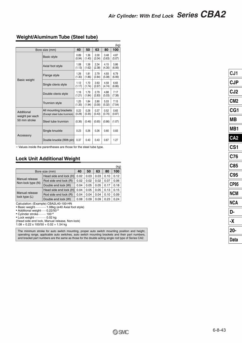
Series CBA2Air Cylinder: With End Lock
Construction
Head side end lock
Component PartsNo.
q
w
e
r
t
y
u
i
o
!0
!1
!2
!3
!4
!5
!6
!7
!8
!9
@0
@1
@2
@4
@5
@6
@7
@8
@9
#0
#1
#2
#3
#4
#5
#6
Zinc die-casted
Chromium molybdenum steel
Steel wire
Carbon steel
NBR
Rolled steel
NBR
NBR
NBR
NBR
NBR
Resin
NBR
Black coated
Black zinc chromated
Zinc chromated
Zinc chromated
Nickel plated
Material
Aluminum die-casted
Aluminum die-casted
Aluminum alloy
Aluminum alloy
Carbon steel
Lead-bronze casted
Rolled steel
Carbon steel
Rolled steel
Steel wire
Spring steel
Steel wire
NBR
Carbon steel
Lead-bronze casted
Stainless steel
Urethane
Steel wire
Rolled steel
Chromium molybdenum steel
Chromium molybdenum steel
Chloroprene rubber
Aluminum casted
Carbon steel
Note
Metallic painted
Metallic painted
Hard anodized
Chromated
Hard chromium electroplated
Electroless nickel plated
Corrosion resistant chromated
Nickel plated
Chromated
Nickel plated
With auto switch∗
Quench hard chrome plated
Zinc chromated
Zinc chromated
Quench hard chrome plated
Black zinc chromated
Black coated
Black coated, Tufftride
Description
Rod cover
Head cover
Cylinder tube
Piston
Piston rod
Bushing
Cushion ring A
Tie-rod
Tie-rod nut
Spring washer
Snap ring
Cushion valve
Rubber magnet*
Lock piston
Lock bushing
Lock spring
Bumper
C-ring
Seal retainer
Cushion ring nut
Hexagon socket head cap screw
Rubber cap
Cap A
Cap B
M/O knob
M/O bolt
M/O spring
Stopper ring
Cushion valve seal
Rod end nut
Rod seal
Piston seal
Cylinder tube gasket
Piston gasket
Cushion seal
Wear ring
Lock piston seal
No. Material NoteDescription
Replacement Parts: Seal Kit
Manual release non-lock type: Suffix N
Manual release lock type: Suffix L
q
w
e rt y u
i
o!0
!1
!2
!3
!4!5
!6 !7!8!9
@0
@1@2
@4 @5@6@7
@8
@9 #0 #1#2 #3#4 #5#6
Bore size(mm)
40506380
100
Seal kit no.Single end lock Double end lock
Content
MBB40-PS
MBB50-PS
MBB63-PS
MBB80-PS
MBB100-PS
MBB40-PS-W
MBB50-PS-W
MBB63-PS-W
MBB80-PS-W
MBB100-PS-W
Consists of numbers #0, #1, #2, #4, and #6 above.
23A
23B The seal kits consist of items #0, #1, #2, #4 and #6. Please order them by using the seal kit number corresponding to each bore size.
6-8-44
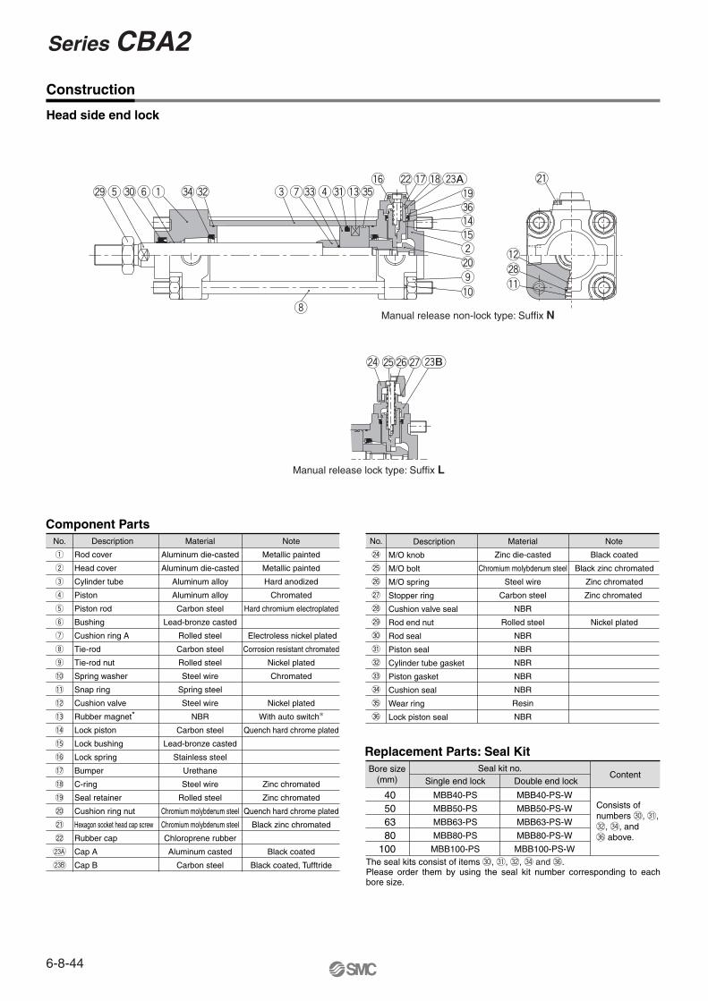
Series CBA2
Basic Style (Dimensions are common to rear end lock, front end lock and double end lock types.)
Head side end lock: CBA2B Bore size -HNStroke
Rod side end lock: CBA2B Bore size -RNStroke
Double lock: CBA2B
With rod boot
Bore size -WNStroke
Strokerange
40506380
100
40506380
100
up to 500
up to 600
up to 600
up to 750
up to 750
A
30
35
35
40
40
AL
27
32
32
37
37
60
70
85
102
116
�B B1
22
27
27
32
41
�C
44
52
64
78
92
D
16
20
20
25
30
13
13
15.5
18.5
20
DL E
32
40
40
52
52
F
10
12
10
14
14
G
15
17
17
21
21
H
51
58
58
71
72
8
11
11
13
16
H1 HR
42.3
47.3
54.8
65.8
72.8
56
61
68.5
80.5
87.5
J
M8 x 1.25
M8 x 1.25
M10 x 1.25
M12 x 1.75
M12 x 1.75
6
7
7
11
11
K KA
14
18
18
22
26
M
11
11
14
17
17
MM
M14 x 1.5
M18 x 1.5
M18 x 1.5
M22 x 1.5
M26 x 1.5
MO
19
19
19
23
23
N
27
30
31
37
40
RF
17
17
17
21
21
84
90
98
116
126
S
2.5
2.5
4
4
4
WB WL
25
25
25
40
40
ZZ
146
159
170
204
215
Stroke range (mm)
20 to 500
20 to 600
20 to 600
20 to 750
20 to 750
Bore size (mm) e43
52
52
65
65
11.2
11.2
11.2
12.5
14
f h59
66
66
80
81
ZZ154
167
178
213
224
Bore size(mm)
With Rod Boot
HN(MAX) P
1/4
3/8
3/8
1/2
1/2∗ For more information about the rod end nut and accessories, refer to page 6-8-13.
l1/4 stroke
1/4 stroke
1/4 stroke
1/4 stroke
1/4 stroke
Dimensions of the mounting brackets are the same as those of the standard double acting single rod type. Refer to pages 6-8-8 to 11.
9 l f
øe
h + lZZ + l + Stroke
H1
DLG
øE
HR
�B�C
N
HN
DLøMO
øMO
øMO
øRFWL
øE
G
øD
FKALA N
MH S + StrokeZZ + Stroke
Width across flats of hexagon hole WB2-cushion valve
Manual release (Lock type):Suffix L
Manual release (Non-lock type):Suffix N
Width across flats KA
MM
J
HR
�B�C
øRFWL
øE
J
H1
HN
DL
DLG
øE
N
G
øD
FKALA N
MH S + StrokeZZ + Stroke
Width across flats of hexagon hole WB
Width across flats B1
2-cushion valve
Manual release (Lock type):Suffix L
Manual release (Non-lock type):Suffix N
Width across flats KA
MM
H1
DLG
DLG
øE
HR
�B�C
N
HN
DL
øRFWL
øE
øD
FKALA N
MH S + StrokeZZ + Stroke
Width across flats of hexagon hole WB2-cushion valve
Manual release (Lock type):Suffix L
Manual release (Non-lock type):Suffix N
Width across flats KA J
MM
Width across flats B1
Width across flats B1
2-P(Rc, NPT, G)
2-P(Rc, NPT, G)
2-P(Rc, NPT, G)
6-8-45
CJ1
CJP
CJ2
CM2
CG1
MB
MB1
CA2
CS1
C76
C85
C95
CP95
NCM
NCA
D-
-X
20-
Data
Series CBA2Air Cylinder: With End Lock
Caution Caution
Caution
Caution
Caution
Caution
Caution
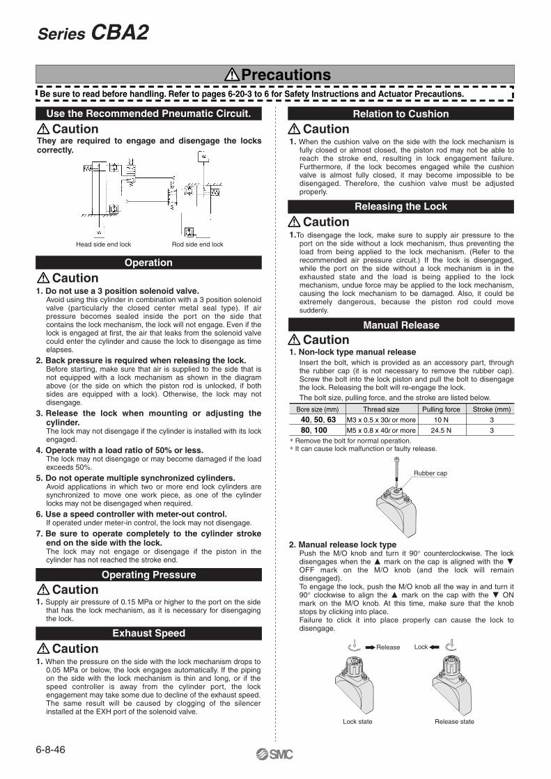
Use the Recommended Pneumatic Circuit.
Operation
They are required to engage and disengage the locks correctly.
Operating Pressure
1. Supply air pressure of 0.15 MPa or higher to the port on the side that has the lock mechanism, as it is necessary for disengaging the lock.
Exhaust Speed
1. When the pressure on the side with the lock mechanism drops to 0.05 MPa or below, the lock engages automatically. If the piping on the side with the lock mechanism is thin and long, or if the speed controller is away from the cylinder port, the lock engagement may take some due to decline of the exhaust speed. The same result will be caused by clogging of the silencer installed at the EXH port of the solenoid valve.
Relation to Cushion
1. When the cushion valve on the side with the lock mechanism is fully closed or almost closed, the piston rod may not be able to reach the stroke end, resulting in lock engagement failure. Furthermore, if the lock becomes engaged while the cushion valve is almost fully closed, it may become impossible to be disengaged. Therefore, the cushion valve must be adjusted properly.
Releasing the Lock
1.To disengage the lock, make sure to supply air pressure to the port on the side without a lock mechanism, thus preventing the load from being applied to the lock mechanism. (Refer to the recommended air pressure circuit.) If the lock is disengaged, while the port on the side without a lock mechanism is in the exhausted state and the load is being applied to the lock mechanism, undue force may be applied to the lock mechanism, causing the lock mechanism to be damaged. Also, it could be extremely dangerous, because the piston rod could move suddenly.
PrecautionsBe sure to read before handling. Refer to pages 6-20-3 to 6 for Safety Instructions and Actuator Precautions.
Head side end lock Rod side end lock
1. Do not use a 3 position solenoid valve.Avoid using this cylinder in combination with a 3 position solenoid valve (particularly the closed center metal seal type). If air pressure becomes sealed inside the port on the side that contains the lock mechanism, the lock will not engage. Even if the lock is engaged at first, the air that leaks from the solenoid valve could enter the cylinder and cause the lock to disengage as time elapses.
2. Back pressure is required when releasing the lock.Before starting, make sure that air is supplied to the side that is not equipped with a lock mechanism as shown in the diagram above (or the side on which the piston rod is unlocked, if both sides are equipped with a lock). Otherwise, the lock may not disengage.
3. Release the lock when mounting or adjusting the cylinder.The lock may not disengage if the cylinder is installed with its lock engaged.
4. Operate with a load ratio of 50% or less.The lock may not disengage or may become damaged if the load exceeds 50%.
5. Do not operate multiple synchronized cylinders.Avoid applications in which two or more end lock cylinders are synchronized to move one work piece, as one of the cylinder locks may not be disengaged when required.
6. Use a speed controller with meter-out control.If operated under meter-in control, the lock may not disengage.
7. Be sure to operate completely to the cylinder stroke end on the side with the lock. The lock may not engage or disengage if the piston in the cylinder has not reached the stroke end.
Manual Release
1. Non-lock type manual releaseInsert the bolt, which is provided as an accessory part, through the rubber cap (it is not necessary to remove the rubber cap). Screw the bolt into the lock piston and pull the bolt to disengage the lock. Releasing the bolt will re-engage the lock.The bolt size, pulling force, and the stroke are listed below.
2. Manual release lock typePush the M/O knob and turn it 90° counterclockwise. The lock disengages when the � mark on the cap is aligned with the � OFF mark on the M/O knob (and the lock will remain disengaged).To engage the lock, push the M/O knob all the way in and turn it 90° clockwise to align the � mark on the cap with the � ON mark on the M/O knob. At this time, make sure that the knob stops by clicking into place.Failure to click it into place properly can cause the lock to disengage.
∗ Remove the bolt for normal operation.∗ It can cause lock malfunction or faulty release.
Bore size (mm)
40, 50, 6380, 100
Thread size
M3 x 0.5 x 30l or more
M5 x 0.8 x 40l or more
Pulling force
10 N
24.5 N
Stroke (mm)
3
3
LockRelease
Lock state Release state
Rubber cap
6-8-46
Series CBA2

Air Cylinder: With End Lock
Series CBJ2ø16
How to Order
200 V
200 V24 V
24 V
5 V IC circuit
—
—
—
Replay,PLC
Replay,PLC
IC circuit
IC circuit
IC circuit
12 V
12 V
12 V
5 V,12 V
5 V,12 V
—
——
—
—
—
—
—
—
5 V,12 V
AC Bandmounting In-line
Rail mountingApplicable loadPre-wire
connector0.5(Nil)
�
�
�
�
�
�
�
�
�
�
�
�
——�
�
�
�
�
�
�
�
�
�
�
�
�
�
�
�
3(L)
5(Z)
—
—�
�
—�
�
�
�
�
�
�
�
�
�
None(N)
—
——�
————�
——————
—
————�
— �
—�
�
�
�
—�
C76
—
C73C73C
—
H7A1H7A2H7BH7C
H7NWH7PWH7BWH7BA
—H7NF
—
Perpendicular
A72A73
A73C A79W ∗∗
F7NVF7PVF7BVJ79C
F7NWV—
F7BWV—
F7BAV—
A76H
A72HA73H
——
F79F7PJ79—
F79WF7PWJ79WF7BA
—F79F
CBJ2
CDBJ2 L 16 60 H N J79W
L 16 60 H N
Built-in magnet Auto switchNumber ofauto switches
Cylinder stroke (mm)
Lock position
Mounting Style
Manual release
BLFD
Basic styleAxial foot style
Rod side flange style Double clevis style Note) H
RHead end lockRod end lock
NilSN
2 pcs.1 pc.
“n” pcs.N Non-locking type
ø16 15, 30, 45, 60, 75, 100, 125, 150, 175, 200
Note) Front end lock only.
∗ Intermediate strokes are available in 1 mm increments without stroke adjustment with a spacer.
∗ For types with auto switch, refer to Minimum Strokes for Auto Switch Mounting on page 6-3-78.
∗ Refer to the table below for applicable auto switch.
∗ Rail mounting type auto switches are not mounted and are supplied loose at the time of shipment.
∗∗ For cylinders with built-in magnet and without auto switch, refer to How to Order for cylinders with built-in magnet.
Type Special function
Ele
ctric
alen
try Wiring
(Output) DC
Load voltage Auto switch model Lead wire length (m)
Indi
cato
r lig
ht
Ree
d sw
itch
Sol
id s
tate
sw
itch
3-wire(Equiv. to NPN)
2-wire
3-wire (NPN)
3-wire (PNP)
2-wire
3-wire (NPN)
3-wire (PNP)
2-wire
Diagnostic indication (2-color)
Diagnostic indication(2-color)
GrommetYes
Yes
ConnectorGrommet
Connector
Grommet
Grommet
Water resistant(2-color)
Diagnostic output (2-color)
∗ Solid state switches marked with “�” are manufactured upon receipt of order.∗∗ Model D-A79W cannot be mounted on a ø10 cylinder with air cushion.
• In addition to the models in the above table, there are some other auto switches that are applicable. For more information, refer to page 6-3-78.
With auto switch
Without auto switch
Applicable Auto Switch/Refer to page 6-16-1 for further information on auto switches.
∗ Lead wire length symbols: 0.5 m ········· Nil (Example) C73C3 m ·········· L (Example) C73CL5 m ·········· Z (Example) C73CZ
None ··········N (Example) C73CN
Built-in Magnet Cylinder Model
CDJ2B16-45-A
CDJ2B16-60-BExample
Rail mounting style
Band mounting style
Suffix the symbol “-A” (Rail mounting style) or “-B” (Band mounting style) to the end of part number for cylinder with auto switch.
∗ For rail mounting style, screws and nuts for 2 pcs. switches come with the rail.
6-3-77
CJ1
CJP
CJ2
CM2
CG1
MB
MB1
CA2
CS1
C76
C85
C95
CP95
NCM
NCA
D-
-X
20-
Data
∗ Intermediate strokes are available in 1 mm increments without stroke adjustment with a spacer.
+1.0 0
Bore size (mm)
16
3 (Same side)3 (Different sides)2 (Same side)
2 (Different sides)1
3 (Same side)3 (Different sides)2 (Same side)
2 (Different sides)1
3 (Same side)3 (Different sides)2 (Same side)
2 (Different sides)1
9055501510
10560601510
10565651510
3510
54510
540151045
55
3055
551510401510
321321321321321321321
D-H7�D-H7�WD-H7BALD-H7NF
D-C73CD-C80CD-H7C
D-A7�D-A80
D-A73CD-A80C
D-A7�HD-A80H
D-A79W
D-F7�W D-J79WD-F7BALD-F79F
D-F7�D-J79
D-F7�VD-J79C
D-F7�WVD-F7BAVL
Type Model Features
Without indicatorlight
With timer
Electrical entry
D-A80
D-A80H
D-A80C
D-C80
D-C80C
D-F7NTL
Grommet
Connector
Grommet
Connector
Grommet
Reed switch
Solid state switch
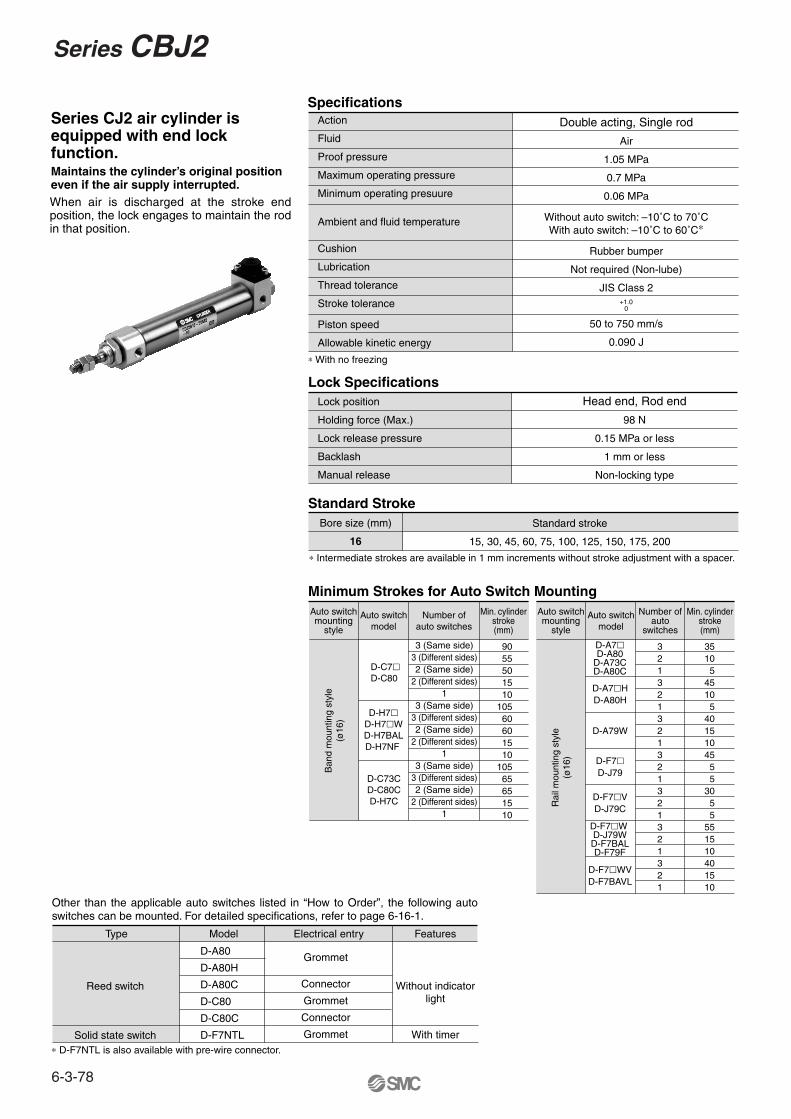
Maintains the cylinder’s original positioneven if the air supply interrupted.When air is discharged at the stroke end position, the lock engages to maintain the rod in that position.
Specifications
Lock Specifications
Standard Stroke
Minimum Strokes for Auto Switch Mounting
Action
Fluid
Proof pressure
Maximum operating pressure
Minimum operating presuure
Ambient and fluid temperature
Cushion
Lubrication
Thread tolerance
Stroke tolerance
Piston speed
Allowable kinetic energy
Double acting, Single rod
Air
1.05 MPa
0.7 MPa
0.06 MPa
Without auto switch: –10˚C to 70˚CWith auto switch: –10˚C to 60˚C∗
Rubber bumper
Not required (Non-lube)
JIS Class 2
Lock position
Holding force (Max.)
Lock release pressure
Backlash
Manual release
Head end, Rod end
98 N
0.15 MPa or less
1 mm or less
Non-locking type
∗ With no freezing
Standard stroke
15, 30, 45, 60, 75, 100, 125, 150, 175, 200
Auto switchmounting
style
Auto switchmodel
Number ofauto switches
Min. cylinderstroke(mm)
Auto switchmounting
style
Auto switchmodel
Number ofauto
switches
Min. cylinderstroke(mm)
Ban
d m
ount
ing
styl
e(ø
16)
D-C7�D-C80
∗ D-F7NTL is also available with pre-wire connector.
50 to 750 mm/s
0.090 J
Rai
l mou
ntin
g st
yle
(ø16
)
Series CJ2 air cylinder is equipped with end lock function.
Other than the applicable auto switches listed in “How to Order”, the following auto switches can be mounted. For detailed specifications, refer to page 6-16-1.
6-3-78
Series CBJ2

Basic styleWith rod end lock: C�BJ2B16- -RN
With head end lock: C�BJ2B16- -HN
M5 x 0.8
M10 x 1 Piping port 2-M5 x 0.8
0–0.3�18.3
ø20
83.5 + Stroke
28
15 8
55.5 + Stroke
9.5
0h8
–0.0
22ø
10
5
14.5
21
20.3
ø6
M5 x 0.8
2-M10 x 1 Piping port 2-M5 x 0.8
0-0.3�18.3
ø20
28
15 8 12.5
0h8
-0.0
22ø
10
8
12.5
50 + Stroke 8
86 + Stroke
6
19.8
Dimensions
ø5
6-3-79
CJ1
CJP
CJ2
CM2
CG1
MB
MB1
CA2
CS1
C76
C85
C95
CP95
NCM
NCA
D-
-X
20-
Data
Series CBJ2Air Cylinder: With End Lock
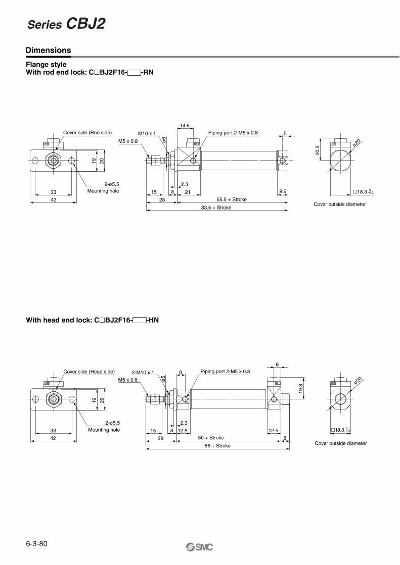
With head end lock: C�BJ2F16- -HN
Flange styleWith rod end lock: C�BJ2F16- -RN
M5 x 0.8
M10 x 1Cover side (Rod side)
2-ø5.5Mounting hole
Cover outside diameter
Cover outside diameter
Piping port 2-M5 x 0.8
28
15 8
2.3
33
42
19 20
0–0.3�18.3
ø20
83.5 + Stroke
55.5 + Stroke
9.5
5
14.5
21
20.3
ø6
Piping port 2-M5 x 0.8
M5 x 0.8
2-M10 x 1Cover side (Head side)
2-ø5.5Mounting hole 12.5
8
12.550 + Stroke 8
86 + Stroke
6
19.8
28
15
ø5
8
2.3
33
42
19 20
0–0.3�18.3
ø20
Dimensions
6-3-80
Series CBJ2
Cover side (Rod side)
Cover side (Head side)
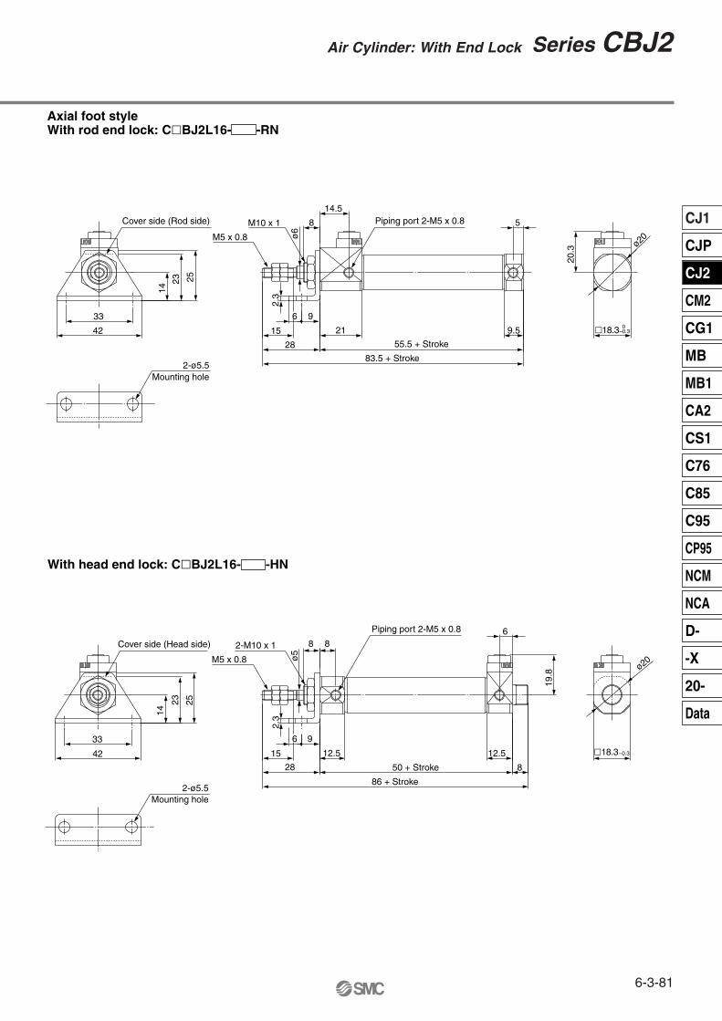
Axial foot styleWith rod end lock: C�BJ2L16- -RN
With head end lock: C�BJ2L16- -HN
M5 x 0.8
2-ø5.5Mounting hole
M10 x 1 Piping port 2-M5 x 0.8
15
8
96
2.3
42
33
14
23 25
28
83.5 + Stroke
55.5 + Stroke
9.5
5
14.5
21 0–0.3�18.3
ø20
20.3
ø6
M5 x 0.8
2-ø5.5Mounting hole
2-M10 x 1
Piping port 2-M5 x 0.8
15
8
50 + Stroke
12.5
ø5
8
96
2.3
42
33
14
23 25
ø20
28 8
6
19.8
12.5
86 + Stroke
–0.3�18.3
6-3-81
CJ1
CJP
CJ2
CM2
CG1
MB
MB1
CA2
CS1
C76
C85
C95
CP95
NCM
NCA
D-
-X
20-
Data
Series CBJ2Air Cylinder: With End Lock
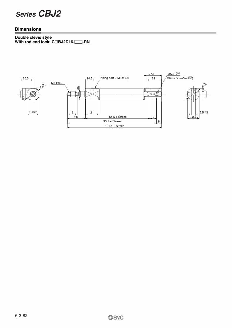
Double clevis styleWith rod end lock: C�BJ2D16- -RN
M5 x 0.8
+0.030ø5H9 0
Clevis pin (ø5d9–0.060)Piping port 2-M5 x 0.8
28
15 0–0.318.3
ø20
23
27.5
101.5 + Stroke
93.5 + Stroke 8
55.5 + Stroke 10
+0.2+0.16.5
14.5
21�18.3
ø20
20.3ø
6
Dimensions
–0.030
6-3-82
Series CBJ2

Be sure to read before handling. Please consult with SMC for products outside these specifications.
Caution
Operating Precautions
Caution1. Do not use a 3 position solenoid valve.
Avoid using this cylinder in combination with a 3 position solenoid valve (particularly the closed center metal seal type). If air pressure becomes sealed inside the port on the side that contains the lock mechanism, the lock will not engage. Even if the lock is engaged at first, the air that leaks from the solenoid valve could enter the cylinder and cause the lock to disengage as time elapses.
2. Back pressure is necessary for unlocking.Before starting, make sure that air is supplied to the side that is not equipped with a lock mechanism as shown in the diagram above. Otherwise, the lock may not disengage.(Refer to “Rock Disengagement”.)
3. Disengage the lock before installing or adjusting the cyliner.The lock could become damaged if the cylinder is installed with its lock engaged.
4. Operate the cylinder at a load ratio of 50% or less.The lock might not disengage or might become damaged if a load ratio of 50% is exceeded.
5. Do not synchronize multiple cylinders.Do not operate two or more end lock cylinders synchronized to move a single workpiece because one of the cylinder locks may not be able to disengage when required.
6. Operate the speed controller under meter-out control.If operated under meter-in control, the lock might not disengage.
7. On the side that has a lock, make sure to operate at the stroke end of the cylinder.The lock might not engage or disengage if the piston of the cylinder has not reached the stroke end.
8. The position adjustment of the auto switch should be performed at two positions; a position determined by the stroke and a position after the backlash movement (by 1 mm).When a 2-color indication switch is adjusted to show green at the stroke end, the indication may turn red when the cylinder returns by the backlash. This, however, is not an error.
• It is necessary for proper locking and unlocking.
Operating Pressure
CautionSupply air pressure of 0.15 MPa or higher to the port on the side that has the lock mechanism, as it is necessary for disengaging the lock.
Exhaust Air Speed
CautionThe lock will engage automatically if the air pressure at the port on the side that has the lock mechanism becomes 0.05 MPa or less. Be aware that if the piping on the side that has the lock mechanism is narrow and long, or if the speed controller is located far from the cylinder port, the exhaust air speed could become slower, involving a longer time for the lock to engage. A similar result will ensure if the silencer that is installed on the exhaust port of the solenoid valve becomes clogged.
Lock Disengagement
Warning
Manual Disengagement
CautionNon-locking style manual releaseInsert the bolt, which is provided as an accessory part, through the rubber cap (it is not necessary to remove the rubber cap). Screw the bolt into the lock piston and pull the bolt to disengage the lock. Releasing the bolt will re-engage the lock.The bolt size, pulling force, and the stroke are listed below.
Precautions
With rear lock With front lock
To disengage the lock, make sure to supply air pressure to the port on the side without a lock mechanism, thus preventing the load from being applied to the lock mechanism. (Refer to the recommended air pressure circuit.) If the lock is disengaged when the port on the side that does not contain a lock mechanism is in the exhausted state and the load is being applied to the lock mechanism, undue force will be applied to the lock mechanism, and it may damage the lock mechanism. Also, it could be extremely dangerous, because the piston rod could move suddenly.
Bolt should be detached under normal operation, otherwise it may cause malfunction of the locking feature.
Bore size(mm)
16 2
Thread size
M2.5 x 0.45 x 25l or more
Pulling force
4.9
Stroke(mm)
Rubber cap
Use Recommended Air Pressure Circuit.
6-3-83
CJ1
CJP
CJ2
CM2
CG1
MB
MB1
CA2
CS1
C76
C85
C95
CP95
NCM
NCA
D-
-X
20-
Data
Series CBJ2Air Cylinder: With End Lock

∗ Lead wire length symbols: 0.5 m ·······Nil (Example) C73C3 m ······· L (Example) C73CL5 m ······· Z (Example) C73CZ
None ······· N (Example) C73CN
How to Order
CBM2
CDBM2
Built-in magnet
Bore size20253240
20 mm25 mm32 mm40 mm
Number of auto switches
NilSn
2 pcs.1 pc.
“n” pcs.
Auto switchNil Without auto switch
Mounting styleBLFGCDUT
Basic styleAxial foot style
Rod side flange styleHead side flange style
Single clevis styleDouble clevis style
Rod side trunnion styleHead side trunnion style
Cylinder stroke (mm)(Refer to “Standard Stroke” on page 6-4-92.)
N
L
L
150
150 H7BW
40
40
H
H
N
Manual release typeNL
Non-lock typeLock type
Lock positionHRW
Head end lockRod end lock
Double end lockBuilt-in Magnet Cylinder ModelIf a built-in magnet cylinder without auto switch is required, there isno need to enter the symbol for auto switch. Example) CDBM2L40-100-HN
Rod bootNilJK
NoneNylon tarpaulin
Heat resistant tarpaulin
CushionNilA
Rubber bumperAir cushion
Type Special function Wiring(Output)
3-wire(NPN equivalent)
2-wire 24 V
5 V
5 V, 12 V
5 V, 12 V
5 V, 12 V
5 V, 12 V
12 V
12 V
12 V
12 V
�
���———
�
����——���
—
�
�
���———
�
����——���
�
�
—
���———
—
����——���
�
�
—
——����
—
———���———
—
—
—
——————
—
���———���
�
�
C76
C73B54
C73CA33AA34AA44A
B59W
H7A1H7A2H7BH7C
G39AK39AH7NWH7PWH7BW
H7BA
H7NF
100 V, 200 V
100 V, 200 V
100 V
24 V
Load voltage
3-wire (NPN)3-wire (PNP)
2-wire
3-wire (NPN)2-wire
2-wire
3-wire (NPN)3-wire (PNP)
3-wire (NPN)
Electricalentry
Auto switchmodel
Pre-wireconnector Applicable load
Grommet
Grommet
Grommet
Diagnostic indication(2-color indication)
Diagnostic indication(2-color indication)
Water resistant(2-color indication)
Water Diagnostic output(2-color indication)
Applicable Auto Switch/Refer to page 6-16-1 for further information on auto switches.
Ree
d sw
itch
Sol
id s
tate
sw
itch
Connector
Connector
Grommet
DIN terminal
Terminalconduit
Terminalconduit
Yes
Yes
DC AC
Lead wire length (m) ∗
0.5(Nil)
3(L)
5(Z)
None(N)
IC circuit
IC circuit
IC circuit
IC circuit
IC circuit
Relay,PLC
Relay,PLC
PLC
Relay,PLC
∗∗
∗∗∗∗∗∗
∗∗∗∗
Air Cylinder: With End Lock
Series CBM2ø20, ø25, ø32, ø40
With auto switch
∗ For the applicable auto switch model, refer to the table below.
Indi
cato
rlig
ht
∗ Solid state switches marked with “�” are produced upon receipt of order. ∗ Do not indicate suffix “N” for no lead wire on D-A3�A/A44A/G39A/K39A models. ∗∗ D-A3�A/A44A/G39A/K39A/B54 cannot be mounted on bore sizes ø20 and ø25
cylinder with air cushion.
• Since there are other applicable auto switches than listed above, refer to page 6-4-24 for details.• For details about auto switches with pre-wire connector, refer to page 6-16-60.
—
—
—
—
—
—
——
— —
—
—
—
—
Without auto switch
6-4-91
CJ1
CJP
CJ2
CM2
CG1
MB
MB1
CA2
CS1
C76
C85
C95
CP95
NCM
NCA
D-
-X
20-
Data

Made to Order Specifications(For details, refer to page 6-17-1.)
Holds the cylinder’s home position even if the air supply is cut off.When air is discharged at the stroke end position, the lock engages to maintain the rod in that position.
Non-lock type and lock type are standardized for manual release.Auto switch is mountable.
Basic style, Axial foot style, Rod side flange style, Head side flange style, Single clevis style, Double clevis style,
Rod side trunnion style, Head side trunnion style
Specifications
Lock Specifications
BacklashManual release
Lock position
Holding force (Max.) (N)
Head end, Rod end, Double end
1 mm or lessNon-lock type, Lock type
ø20215
ø25330
ø32550
ø40860
TypeActionFluidProof pressureMaximum operating pressureMinimum operating pressure
Ambient and fluid temperature
CushionLubricationThread toleranceStroke length tolerance
Piston speed
Mounting
PneumaticDouble acting, Single rod
Air1.5 MPa1.0 MPa
0.15 MPa ∗Without auto switch: –10 to 70°C (No freezing)
With auto switch: –10 to 60°C (No freezing)
Rubber bumper, Air cushionNot required (Non-lube)
JIS Class 2+1.4 0 mm
∗ 0.05 MPa for other part than the lock unit
Allowable Kinetic EnergyBore size (mm)
Rubbercushion
Air cushion
Allowable kinetic energy (J)
Effective cushion length (mm)
Cushion sectional area (cm2)
Kinetic energy absorbable (J)
20
0.27
11.0
2.09
0.54
25
0.4
11.0
3.30
0.78
32
0.65
11.0
5.86
1.27
40
1.2
11.8
9.08
2.35
Standard Stroke
20253240
Bore size(mm)
Standard stroke(mm)
25, 50, 75, 100, 125, 150, 200, 250300
400
450450500
Long stroke ∗(mm)
1000
Maximum manufacturablestroke (mm)
Minimum Stroke for Auto Switch Mounting (mm)
Auto switchmodel
D-C7�D-C80
No. of auto switches mounted2 n
Different sides
15
15
15
15
20
35
Same side Different sides Same side
10
10
10
10
15
10
15 + 45 (n – 2)(n = 2, 4, 6...)
2
15 + 50 (n – 2)(n = 2, 4, 6...)
2
15 + 50 (n – 2)(n = 2, 4, 6...)
2
20 + 50 (n – 2)(n = 2, 4, 6...)
2
35 + 30 (n – 2)
50 + 45 (n – 2)
60 + 45 (n – 2)
65 + 50 (n – 2)
75 + 55 (n – 2)
100 + 100 (n – 2)
Rubber bumperAir cushion
50 to 750 mm/s50 to 1000 mm/s
-XA�
-XB6
-XB9
-XC3
-XC4 ∗
-XC8 ∗
-XC13
-XC22
-XC35
-XC52
Change of rod end shape
Heat resistant cylinder (150°C)
Low speed cylinder (10 to 50 mm/s)
Special port location
With heavy duty scraper
Adjustable stroke cylinder/Adjustable extension type
Auto switch mounting rail style
Fluoro rubber seals
With coil scraper
Mounting nut with set screw
Symbol Specifications
∗ Available only for locking at head end
∗ Long stroke applies to the axial foot style and the rod side flange style only. When using other types of mounting brackets or exceeding the long stroke limit, the maximum allowable stroke will be determined by the stroke selection table listed on page 6-1-9.
D-B5/B6D-G5NTL
D-A3�AD-G39AD-K39AD-A44A
D-C73CD-C80CD-H7C
D-H7�D-H7�WD-H7BALD-H7NF
D-B59W
50
60
65
75
75
100
1
Series CBM2
6-4-92

Weight (kg)
Bore size (mm)
Basicweight
Basic style
Axial foot style
Flange style
Single clevis
Double clevis style
Trunnion style
Clevis bracket (With pin)
Single knuckle joint
Double knuckle joint (With pin)
20
0.14
0.29
0.20
0.18
0.19
0.18
0.04
0.07
0.06
0.07
25
0.21
0.37
0.30
0.25
0.27
0.28
0.06
0.07
0.06
0.07
32
0.28
0.44
0.37
0.32
0.33
0.34
0.08
0.14
0.06
0.07
40
0.56
0.83
0.68
0.65
0.69
0.66
0.13
0.14
0.23
0.20
20
0.02
0.01
0.03
0.03
0.02
0.05
25
0.02
0.01
0.03
0.03
0.02
0.05
32
0.02
0.01
0.03
0.03
0.02
0.05
40
0.04
0.02
0.06
0.06
0.04
0.10
Calculation: (Example) CBM2L32-100-HN � Basic weight··················· 0.44 (Foot style, ø32) � Additional weight············ 0.08/50 stroke � Cylinder stroke··············· 100 stroke � Locking weight··············· 0.02 (Locking at head end, Manual release non-locking type) 0.44 + 0.08 x 100/50 + 0.02 = 0.62 kg
Accessory/For details, refer to pages 6-4-21 to 22, since it is the same as Series CM2 standard type.
Option
Mounting nut, Rod end nut, Clevis pin, Lock release bolt (N type only)
Single knuckle joint, Double knuckle joint (With pin)
∗ Mounting nuts are not equipped to single clevis and double clevis.
Additional weight per each 50 mm of stroke
Lock Unit Additional Weight (kg)
Bore size (mm)
Manual release
non-lock type (N)
Manual release
lock type (L)
Head end lock (H)
Rod end lock (R)
Double end lock (W)
Head end lock (H)
Rod end lock (R)
Double end lock (W)
Auto Switch Mounting Bracket Part No.Auto switch
model
D-A3�A/A44AD-G39A/K39A
Bore size (mm)20
BM2-020
BA2-020
BM3-020
25
BM2-025
BA2-025
BM3-025
32
BM2-032
BA2-032
BM3-032
40
BM2-040
BA2-040
BM3-040
D-C7�/C80D-H7�D-B5�/B64D-G5NTL
Rod Boot MaterialSymbol
J
K
Rod boot material
Nylon tarpaulin
Heat resistant tarpaulin
Max. ambient temperature
60°C
110°C *∗ Maximum ambient temperature for the rod boot itself.
Mounting Bracket Part No.Bore size (mm) 20
CM-L020B
CM-F020B
CM-C020B
CM-D020B
CM-T020B
25 32 40
CM-L040B
CM-F040B
CM-C040B
CM-D040B
CM-T040B
Axial foot ∗
Flange
Single clevis
Double clevis (With pin) ∗∗
Trunnion (With nut)
CM-L032B
CM-F032B
CM-C032B
CM-D032B
CM-T032B
Mounting screws set made of stainless steelUse the following mounting screw set made of stainless steel according to operating environment.(A switch mounting band is not included, so please order it separately.) BBA4: For D-C7/C8/H7 BBA3: For D-B5/B6/G5• “D-H7BAL” switch is set on the cylinder with the stainless steel screws above when shipped. When only a switch is shipped independently, “BBA4” screws are attached.
∗ Two foot brackets and a mounting nut are attached.Order two foot brackets per cylinder.
∗∗ Clevis pin and snap ring are shipped together with double clevis style.
Standardequipment
Accessory
6-4-93
Series CBM2Air Cylinder: With End Lock
CJ1
CJP
CJ2
CM2
CG1
MB
MB1
CA2
CS1
C76
C85
C95
CP95
NCM
NCA
D-
-X
20-
Data

Component PartsNo. Description
q
w
e
r
t
y
u
i
Rod cover
Head cover
Cylinder tube
Piston
Piston rod
Bushing
Seal retainer
Snap ring
Material
Aluminum alloy
Aluminum alloy
Stainless steel
Aluminum alloy
Carbon steel
Oil-impregnated sintered alloy
Rolled steel plate
Carbon steel
Note No. Description Material Note
Clear anodized
Clear anodized
Chromated
Hard chrome plated
Nickel plated
Nickel plated
@6
@7
#3
#4
#5
Rod seal
Lock piston seal
Cushion valve seal
Snap ring
Steel balls
NBR
NBR
NBR
Stainless steel
Stainless steel
Replacement Parts: Seal Kit (With lock in single end)
CBM2-20-PS
20
Kit no.
Bore size(mm)
CBM2-25-PS
25
CBM2-32-PS
32
CBM2-40-PS
40
Double End LockCBM2-20-PS-WKit no. CBM2-25-PS-W CBM2-32-PS-W CBM2-40-PS-W
How to Change Seal Kit
14A
14B
∗ Seal kit includes @6 and @7. Order the seal kit, based on each bore size. (Except #3.)
Head end lock
<Removal>�Remove the snap ring A by using a tool for installing a type C snap
ring for hole. Shut off the port on the rod cover by finger and then pull out the piston rod, and the seal retainer B and the rod seal C are removed.
<Mounting>�After applying enough grease on the rod seal, attach in this order, rod seal C, seal retainer and snap ring.
Port
Construction
(A) Snap ring
(B) Seal retainer
(C) Rod seal
Manual release (Lock type): Suffix LManual release (Non-lock type): Suffix N
Rod end lock With air cushion
Hard chrome plated, Heat treated
Black zinc chromated
Black painted
Oxide film treated
Black painted
Black zinc chromated
Zinc chromated
Zinc chromated
Nickel plated
Nickel plated
Electroless nickel plated
Electroless nickel plated
!5
!6
!7
!8
!9
@0
@1
@2
@3
@4
@5
@8
@9
#0
#1
#2
Carbon steelLock piston
Hexagon sockethead cap screw
Cap A
Cap B
Rubber cap
M/O knob
M/O bolt
M/O spring
Stopper ring
Bumper A
Bumper B
Snap ring
Piston seal
Piston gasket
Wear ring
Mounting nut
Rod end nut
Cushion ring
Cushion valve
Cushion seal
Alloy steel
Aluminum die-casted
Carbon steel
Synthetic rubber
Zinc die-casted
Alloy steel
Steel wire
Carbon steel
Urethane
Urethane
Stainless steel
NBR
NBR
Resin
Carbon steel
Carbon steel
Rolled steel
Rolled steel
Urethane
Lead-bronze casted
Stainless steel
Urethane
Lock bushing
Lock spring
Bumper
o
!0
!1
!2
!3
Series CBM2
6-4-94

ø
1
ø
ø
ø
ø
Width across flats B3
ZZ + Strokeh
f
øe
9
l9
Basic Style (Dimensions are common irrespective of the lock position; rod end, head end, or double end.)
Head end lock: CBM2B Bore size -HNStroke
Rod end lock: CBM2B Bore size -RNStroke
Double end lock: CBM2B Bore size -WNStroke
With rod boot
Manual release (Non-lock type): Suffix N
Manual release (Lock type): Suffix L
Strokerange
20253240
Up to 300
Up to 300
Up to 300
Up to 300
A
18
22
22
24
AL
15.5
19.5
19.5
21
B1
13
17
17
22
B2
26
32
32
41
D
8
10
12
14
DL
7.5
7.5
7.5
10.7
F
13
13
13
16
G
8
8
8
11
H
41
45
45
50
H1
5
6
6
8
H2
8
8
8
10
HR
22.3
25.3
27.6
33.6
34
37
39.3
47.8
I
28
33.5
37.5
46.5
K
5
5.5
5.5
7
MM
M8 x 1.25
M10 x 1.25
M10 x 1.25
M14 x 1.5
MO
15
15
15
19
N
15
15
15
21.5
NA
24
30
34.5
42.5
P
1/81/81/81/4
S
62
62
64
88
ZZ
116
120
122
154
NN
M20 x 1.5
M26 x 1.5
M26 x 1.5
M32 x 2
20253240
e
36
36
36
46
B3
30
32
32
41
f
17
17
17
19
1 to 50
68
72
72
77
51 to 100
81
85
85
90
101 to 150
93
97
97
102
151 to 200
106
110
110
115
h
201 to 300
131
135
135
140
301 to 400
156
160
160
165
401 to 500
181
185
185
190
1 to 50
12.5
12.5
12.5
12.5
51 to 100
25
25
25
25
101 to 150
37.5
37.5
37.5
37.5
151 to 200
50
50
50
50
l201 to 300
75
75
75
75
301 to 400
100
100
100
100
401 to 500
125
125
125
125
Symbol
Symbol
Bore size (mm)
Bore size (mm)
E
20
26
26
32
0–0.033
0–0.033
0–0.033
0–0.039
HN(Max.)
∗ For details about the rod end nut and accessory, refer to pages 6-4-21 to 6-4-22.
With Rod Boot
With Rod Boot
1 to 50
143
147
149
181
51 to 100
156
160
162
194
101 to 150
168
172
174
206
151 to 200
181
185
187
219
ZZ
201 to 300
206
210
212
244
301 to 400
231
235
237
269
401 to 500
256
260
262
294
(mm)
Width across flats B1
Width across flats B2 2-Rc P
S + StrokeZZ + Stroke
ø20
6-4-95
Series CBM2Air Cylinder: With End Lock
CJ1
CJP
CJ2
CM2
CG1
MB
MB1
CA2
CS1
C76
C85
C95
CP95
NCM
NCA
D-
-X
20-
Data
øø
ø
ø ø
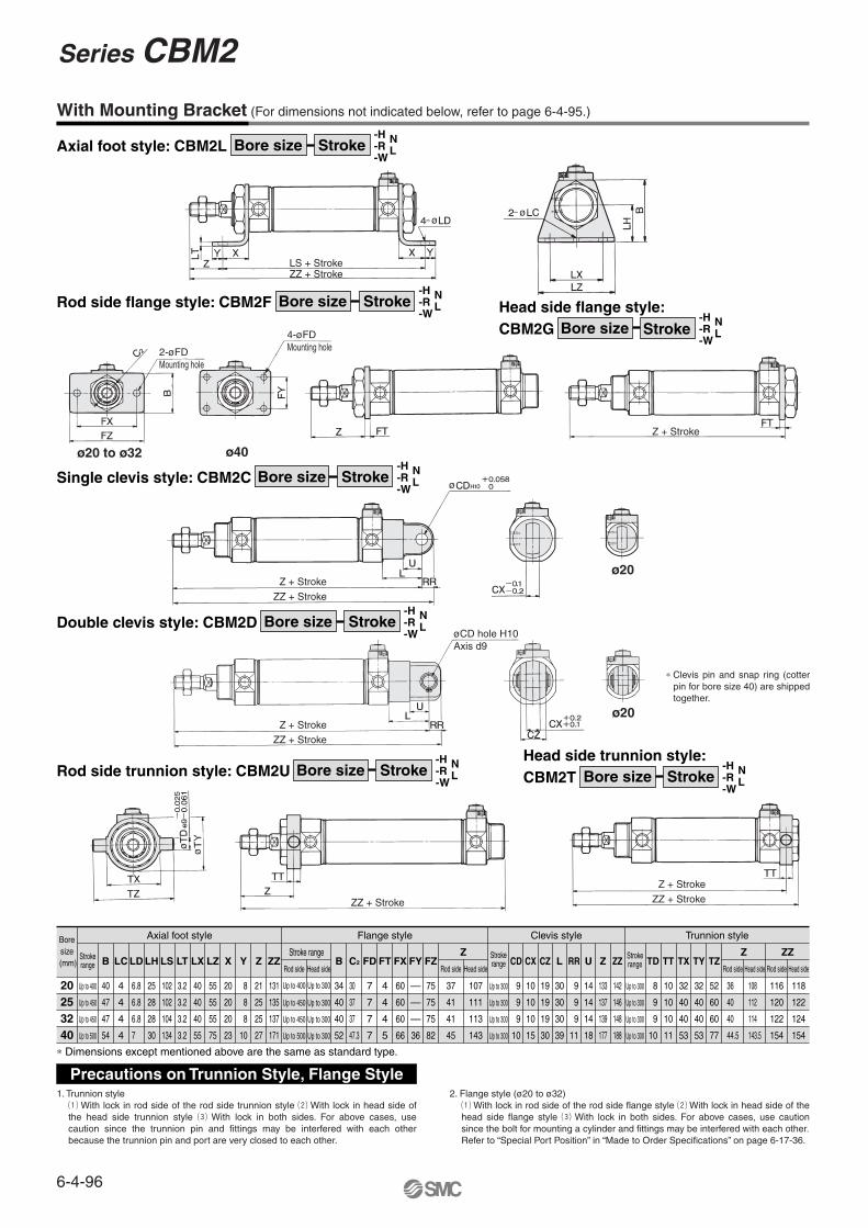
With Mounting Bracket (For dimensions not indicated below, refer to page 6-4-95.)
Axial foot style: CBM2L Bore size-H-R-W
NLStroke
Rod side flange style: CBM2F Bore size-H-R-W
NLStroke
CBM2G Bore size-H-R-W
NLStroke
Head side flange style:
Single clevis style: CBM2C Bore size-H-R-W
NLStroke
Double clevis style: CBM2D Bore size-H-R-W
NLStroke
CBM2T Bore size-H-R-W
NLStroke
Head side trunnion style: Rod side trunnion style: CBM2U Bore size
-H-R-W
NLStroke
∗ Clevis pin and snap ring (cotter pin for bore size 40) are shipped together.
ø20
ø20
ø40ø20 to ø32
20253240
Up to 400
Up to 450
Up to 450
Up to 500
B
40
47
47
54
Up to 300
Up to 300
Up to 300
Up to 300
TD
8
9
9
10
TT
10
10
10
11
TX
32
40
40
53
TY
32
40
40
53
TZ
52
60
60
77
LC
4
4
4
4
LD
6.8
6.8
6.8
7
LH
25
28
28
30
LS
102
102
104
134
LT
3.2
3.2
3.2
3.2
LX
40
40
40
55
LZ
55
55
55
75
X
20
20
20
23
Y
8
8
8
10
Z
21
25
25
27
ZZ
131
135
137
171
Rod side
Up to 400
Up to 450
Up to 450
Up to 500
Head side
Up to 300
Up to 300
Up to 300
Up to 300
B
34
40
40
52
C2
30
37
37
47.3
FD
7
7
7
7
FT
4
4
4
5
FX
60
60
60
66
FY
—
—
—
36
FZ
75
75
75
82
Axial foot style Trunnion style
Up to 300
Up to 300
Up to 300
Up to 300
CD
9
9
9
10
CX
10
10
10
15
CZ
19
19
19
30
L
30
30
30
39
RR
9
9
9
11
U
14
14
14
18
Z
133
137
139
177
ZZ
142
146
148
188
Clevis styleFlange style
∗ Dimensions except mentioned above are the same as standard type.
Boresize
(mm)Strokerange
Strokerange
Strokerange
Stroke range
Rod side
37
41
41
45
Head side
107
111
113
143
Z
Rod side
36
40
40
44.5
Head side
108
112
114
143.5
Z
Rod side
116
120
122
154
Head side
118
122
124
154
ZZ
1. Trunnion stylea With lock in rod side of the rod side trunnion style s With lock in head side of the head side trunnion style d With lock in both sides. For above cases, use caution since the trunnion pin and fittings may be interfered with each other because the trunnion pin and port are very closed to each other.
2. Flange style (ø20 to ø32)a With lock in rod side of the rod side flange style s With lock in head side of the head side flange style d With lock in both sides. For above cases, use caution since the bolt for mounting a cylinder and fittings may be interfered with each other.Refer to “Special Port Position” in “Made to Order Specifications” on page 6-17-36.
Precautions on Trunnion Style, Flange Style
LS + StrokeZZ + Stroke
Z + Stroke
2-øFDMounting hole
4-øFDMounting hole
Z + Stroke
ZZ + Stroke
Z + Stroke
ZZ + Stroke
ZZ + Stroke
Z + Stroke
ZZ + Stroke
øCD hole H10Axis d9
Series CBM2
6-4-96

With Air Cushion (Dimensions not mentioned in the below table are the same as the above table.)
Head end lock: CBM2B Bore size A-HNStrokeBasic style
Axial foot style: CBM2L Bore size AStroke-H-R-W
NL
Manual release (Non-lock type): Suffix N
Rod side flange style: CBM2F Bore size AStroke-H-R-W
NL CBM2G Bore size Stroke
Head side flange style:A
-H-R-W
NL
Single clevis style: CBM2C Bore size Stroke A-H-R-W
NL Double clevis style: CBM2D Bore size Stroke A
-H-R-W
NL
CBM2U Bore size StrokeRod side trunnion style:
A-H-R-W
NL CBM2T Bore size Stroke
Head side trunnion style: A
-H-R-W
NL
Bore size(mm)
20253240
Head end lock112112112139
Rod end lock113113115142
Double end lock123123123147
Head end lock141145145176
Rod end lock142146148179
LS ZZDouble end lock
152156156184
Head end lock117121121148
Rod end lock118122124151
ZAxial foot style Head side flange style
Double end lock128132132156
Bore size(mm)
20253240
Head end lock143147147182
Rod end lock144148150185
Double end lock154158158190
Head end lock152156156193
Rod end lock153157159196
Z ZZDouble end lock
163167167201
Head end lock118 122 122 148.5
Rod end lock119 123 125 151.5
ZClevis style Head side trunnion style
Double end lock129 133 133 156.5
Head end lock128132132159
Rod end lock129133135162
ZZDouble end lock
139143143167
Bore size(mm)20253240
Head end lock72727293
Rod end lock73737596
Double end lock 83 83 83101
WA
13131316
WB
8.510.511.515
Head end lock126130130159
Rod end lock127131133162
S ZZDouble end lock
137141141167
With Air Cushion
ø20
∗ R Cushion valveWidth across hexagon socket hole 1.5
S + Stroke
LS + Stroke
ZZ + Stroke
ZZ + StrokeZ + Stroke
ZZ + Stroke
ZZ + StrokeZ + Stroke
ZZ + StrokeZ + Stroke
Z + Stroke
∗∗
6-4-97
Series CBM2Air Cylinder: With End Lock
CJ1
CJP
CJ2
CM2
CG1
MB
MB1
CA2
CS1
C76
C85
C95
CP95
NCM
NCA
D-
-X
20-
Data

Reed switch
D-C7�/C80
D-B5�/B64/B59W
D-A33A/A34A
D-A44A
D-C73C/C80C
D-H7C
D-G39A/K39A
D-G5NTL
D-H7�/H7�W/H7NF/H7BAL
Solid state switch
Proper Auto Switch Mounting Position (Detection at stroke end) and Its Mounting Height
Proper Auto Switch Mounting Position
Auto Switch Mounting Height
Auto switchmodel
Bore size(mm)
20253240
D-B5�D-B64
A1(—)1(—)2(0)
7
B0(—)0(—)1(0)
6
A7(5)7(5)8(6)13
B6(4)6(4)7(5)12
A4(2)4(2)5(3)10
B3(1)3(1)4(2)
9
A0.5(—)0.5(—)1.5(0)
6.5
B0(—)0(—)0.5(0)
5.5
A6(4)6(4)7(5)12
B5(3)5(3)6(4)11
A2.5(0.5)2.5(0.5)3.5(1.5)
8.5
B1.5(0)1.5(0)
2.5(0.5)7.5
D-C7�D-C80D-C73CD-C80C
D-B59W
D-A3�AD-G39AD-K39AD-A44A
D-H7�D-H7CD-H7�WD-H7BALD-H7NF
D-G5NTL
D-B5�D-B64D-B59WD-G5NTLD-H7C
Hs25.528 31.535.5
Hs22.525 28.532.5
Hs25 27.531 35
Hs60 62.566 70
Hs69.572 75.579.5
D-C7�D-C80D-H7�D-H7�WD-H7BALD-H7NF
D-C73CD-C80C
D-A3�AD-G39AD-K39A
D-A44A
≅ Hs
≅ Hs
≅ Hs
≅ Hs
≅ Hs
Auto switch
Auto switch
Auto switch
Auto switch
Auto switch
≅ Hs
≅ Hs
≅ Hs
≅ Hs
Auto switch
Auto switch
Auto switch
Auto switch
G 1/2 (Applicable cable O.D.ø6.8 to ø9.6)
G 1/2 (Applicable cable O.D.ø6.8 to ø9.6)
∗ ( ): Denotes the values with air cushion “D-B5/B6/A3�A/A44A/G39A and K39A” cannot be mounted on bore size ø20 and ø25 cylinder with air cushion.
Series CBM2
6-4-98
Auto switch modelBore size (mm)
20 25 32 40
7 8 8 8
8
12
4
7
8
4
12
4
8.5
9
4
13
4.5
9
9
4.5
13
4.5
10
9
4.5
8 9 9
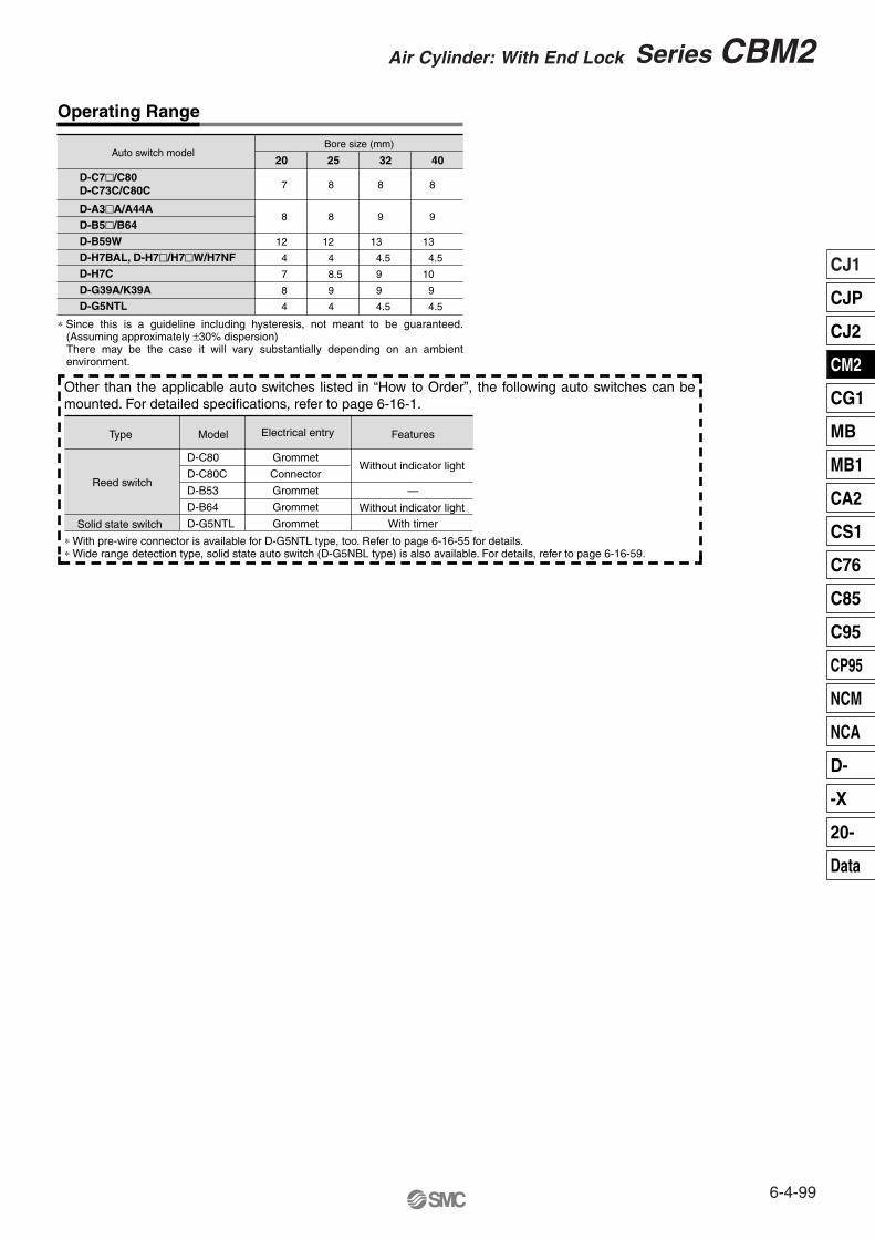
Type Model Features
Without indicator light
Without indicator light
—
With timer
Electrical entry
D-C80
D-C80C
D-B53
D-B64
D-G5NTL
Grommet
Connector
Grommet
Grommet
Grommet
∗ With pre-wire connector is available for D-G5NTL type, too. Refer to page 6-16-55 for details.∗ Wide range detection type, solid state auto switch (D-G5NBL type) is also available. For details, refer to page 6-16-59.
Reed switch
Solid state switch
Operating Range
D-A3�A/A44AD-B5�/B64D-B59WD-H7BAL, D-H7�/H7�W/H7NFD-H7CD-G39A/K39AD-G5NTL
D-C7�/C80D-C73C/C80C
∗ Since this is a guideline including hysteresis, not meant to be guaranteed. (Assuming approximately ±30% dispersion)There may be the case it will vary substantially depending on an ambient environment.
Other than the applicable auto switches listed in “How to Order”, the following auto switches can be mounted. For detailed specifications, refer to page 6-16-1.
6-4-99
Series CBM2Air Cylinder: With End Lock
CJ1
CJP
CJ2
CM2
CG1
MB
MB1
CA2
CS1
C76
C85
C95
CP95
NCM
NCA
D-
-X
20-
Data

Caution
Caution Caution
Caution
Caution
Warning
Use the Recommended Pneumatic Circuit Operating Pressure
Be sure to read before handling. For Safety Instructions and Actuator Precautions, refer to pages 6-20-3 to 6.
� This is necessary for proper operation and release of the lock.
Operating Precautions
1. Do not use 3 position solenoid valves.Avoid use in combination with 3 position solenoid valves (especially closed center metal seal types). If pressure is trapped in the port on the lock mechanism side, the cylinder cannot be locked. Furthermore, even after being locked, the lock may be released after some time, due to air leaking from the solenoid valve and entering the cylinder.
2. Back pressure is required to release end lock.Be sure air is supplied to side of cylinder without the locking mechanism, as above, prior to supplying air pressure to the side with end lock or lock may not be released. (Refer to “Releasing the Lock”.)
3. Release the lock when mounting or adjusting the cylinder.If mounting or other work is performed when the cylinder is locked, the lock unit may be damaged.
4. Operate with a load ratio of 50% or less.If the load ratio exceeds 50%, this may cause problems such as failure of the lock to release, or damage to the lock unit.
5. Do not operate multiple cylinders in synchronization. Avoid applications in which two or more end lock cylinders are synchronized to move one workpiece, as one of the cylinder locks may not be able to release when required.
6. Use a speed controller with meter-out control.Lock cannot be released occasionally by meter-in control.
7. Be sure to operate completely to the cylinder stroke end on the side with the lock.If the cylinder piston does not reach the end of the stroke, locking might not work or locking might not be released.
Head end lock
1. Use pressures over 0.15 MPa at port with locking mechanism.
Exhaust Speed
1. Locking will occur automatically if the pressure applied to the port on the lock mechanism side falls to 0.05 MPa or less. In cases where the piping on the lock mechanism side is long and thin, or the speed controller is separated at some distance from the cylinder port, the exhaust speed will be reduced. Take note that some time may be required for the lock to engage. In addition, clogging of a silencer mounted on the solenoid valve exhaust port can produce the same effect.
Relation to Cushion
1. When cushion valve at side with locking mechanism is fully opened or closed, piston rod may reached at stroke end. Thus lock is not established. And when locking is done at cushion valve fully closed, adjust cushion valve since lock may not be released.
Releasing the Lock
1. Before releasing the lock, be sure to supply air to the side without the lock mechanism, so that there is no load applied to the lock mechanism when it is released. (Refer to the recommended pneumatic circuits.) If the lock is released when the port on the other side is in an exhaust state, and with a load applied to the lock unit, the lock unit may be subjected to an excessive force and be damaged. Furthermore, sudden movement of the piston rod is very dangerous.
Rod end lock
Precautions
Series CBM2
6-4-100

CautionManual Release
1. Manual release (Non-lock type)Insert the accessory bolt from the top of the rubber cap (it is not necessary to remove the rubber cap), and after screwing it into the lock piston, pull it to release the lock. If you stop pulling the bolt, the lock will return to an operational state. Thread sizes, pulling forces and strokes are as shown below.
Bore size (mm)
20, 25, 3240, 50, 6380, 100
Thread size
M2.5 x 0.45 x 25l or more
M3 x 0.5 x 30l or more
M5 x 0.8 x 40l or more
Pulling force
4.9 N
10 N
24.5 N
Stroke (mm)
2
3
3
Remove the bolt for normal operation. It can cause lock malfunction or faulty release.
2. Manual release (Lock type)While pushing the M/O knob, turn it 90° counterclockwise. The lock is released (and remains in a released state) by aligning the � mark on the cap with the � OFF mark on the M/O knob.When locking is desired, turn M/O button clockwise 90° while pushing fully, correspond � on cap and � ON mark on M/O button. The correct position is confirmed by a click sound “click”.If not confirmed, locking is not done.
Locked Released
� Head end lock (Rod end lock is the same, too.)1. When the piston rod is getting closer to the stroke end, the
taper part (∗) of the piston rod edge will push the lock piston up.
Working Principle
4. When pressure is supplied in the head side, lock piston will be pushed up to release the lock.
5. Lock will be released, then cylinder will move forward.
2. Lock piston is pushed up further.
3. Lock piston is pushed up into the groove of piston rod to lock it. (Lock piston is pushed up by spring force.) At this time, it is exhausted from port in head side and introduced to atmosphere.
Locked
Released
PrecautionsBe sure to read before handling. For Safety Instructions and Actuator Precautions, refer to pages 6-20-3 to 6.
Rubber cap
UnlockLock
Spring
Lock piston
Pressure
Piston rod∗
Back pressure
Pressure
Exhaust
Pressure
6-4-101
Series CBM2Air Cylinder: With End Lock
CJ1
CJP
CJ2
CM2
CG1
MB
MB1
CA2
CS1
C76
C85
C95
CP95
NCM
NCA
D-
-X
20-
Data
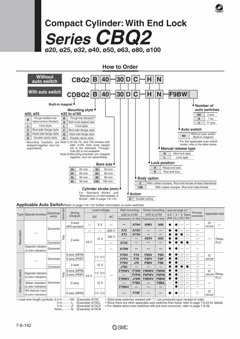
How to Order
Compact Cylinder: With End Lock
Series CBQ2ø20, ø25, ø32, ø40, ø50, ø63, ø80, ø100
CBQ2
CDBQ2
B
B
� Lock positionHR
Head end lockRod end lock
F9BW
40
40
30
30
D
D
C
CBuilt-in magnet �
� Auto switch
NilWithout auto switch
(Built-in magnet)
� ActionD Double acting
Mounting style �
B
LFGD
Through-hole/Both ends tapped common (Standard)
Foot styleRod side flange styleHead side flange styleDouble clevis style
∗ Mounting brackets are shipped together, (but not assembled).
Note 1) At the 75, and 100 strokes with ø80, ø100, both ends tapped (A) is the standard. Through-hole (B) is not available.
Note 2) Mounting brackets are shipped together, (but not assembled).
BALFGD
Through-hole (Standard)Both ends tapped style
Foot styleRod side flange styleHead side flange styleDouble clevis style
Bore size �
506380
100
50 mm63 mm80 mm
100 mm
20253240
20 mm25 mm32 mm40 mm
Cylinder stroke (mm) �
� Number of auto switches
NilSn
2 pcs.1 pc.
“n” pcs.
� Body optionC
CMWith rubber bumper, Rod end female thread (Standard)
With rubber bumper, Rod end male thread
� Manual release typeNL
Non-lock typeLock type
ø20, ø25 ø32 to ø100(1)
H N
H N
Special functionType Electricalentry
Grommet
Grommet
Grommet
Grommet
Indi
cato
r lig
ht
Wiring(Output)
2-wire
3-wire(NPN equivalent)
Load voltage
—
ACDC
Direct mounting
A96V
——
A93V—
—
F9NVF9PVF9BV
—F9NWVF9PWVF9BWV
——
—
Lead wire length (m) ∗
0.5(Nil)
3(L)
5(Z)
�
�
�
�
�
�
�
�
�
�
�
�
�
——
�
�
�
�
�
�
�
�
�
�
�
�
�
�
�
�
�
—
—�
—�
—
�
�
�
�
�
�
�
�
�
�
ICcircuit
Relay, PLC
Applicable load
Applicable Auto Switch/Refer to page 7-9-1 for further information on auto switches.
Rail mounting
Perpendicular
A96
——
A93—
—
F9NF9PF9B—
F9NWF9PWF9BWF9BA
—
—
In-line
—
A72A73—
A73C
A79W
F7NVF7PVF7BVJ79C
F7NWV—
F7BWV—
F7BAV
—
Perpendicular
A76H
A72HA73H
——
—
F79F7PJ79—
F79WF7PWJ79WF7BA
—
F79F
In-line
—
5 V
200 V—
100 V
—
—12 V
5 V, 12 V
12 V
5 V, 12 V
12 V
5 V, 12 V
—
—
—
—
24 V
Yes
Connector
Connector
Diagnostic indication(2-color indication)
With diagnostic output
(2-color indication)
Water resistant(2-color indication)
Diagnostic indication(2-color indication)
—
—
Yes
2-wire
3-wire (NPN)3-wire (PNP)
2-wire
3-wire (NPN)3-wire (PNP)
4-wire (NPN)
24 V
ICcircuit
—
ICcircuit
—
ICcircuit
Relay, PLC
ø20 to ø100ø32 to ø100
Ree
d sw
itch
Sol
id s
tate
sw
itch
None(N)
Pre-wire connector
—
———�
—
———�
—————
—
—
————
—
�
�
�
—�
�
�
�
—
�
—
∗ Lead wire length symbols: 0.5 m··········Nil (Example) A73C 3 m···········L (Example) A73CL 5 m···········Z (Example) A73CZ None···········N (Example) A73CN
For “Standard Stroke” and “Manufacture of intermediate of Stroke”, refer to page 7-6-143.
∗ For the applicable auto switch model, refer to the table below.
∗ Solid state switches marked with “�” are produced upon receipt of order.• Since there are other applicable auto switches than listed, refer to page 7-6-23 for details.• For details about auto switches with pre-wire connector, refer to page 7-9-36.
With auto switch
Withoutauto switch
7-6-142
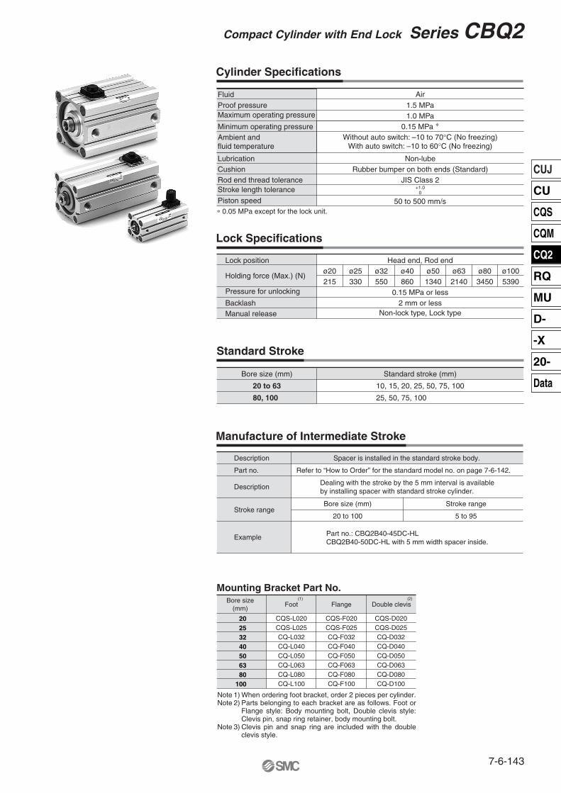
Standard Stroke
Bore size (mm)
80, 100
20 to 63
Standard stroke (mm)
10, 15, 20, 25, 50, 75, 100
25, 50, 75, 100
Cylinder Specifications
Lock Specifications
Manufacture of Intermediate Stroke
Spacer is installed in the standard stroke body.
Refer to “How to Order” for the standard model no. on page 7-6-142.
Part no.: CBQ2B40-45DC-HLCBQ2B40-50DC-HL with 5 mm width spacer inside.
Stroke range
Example
Stroke range
5 to 95
Bore size (mm)
20 to 100
Description
Part no.
Description
ø25 ø32 ø40 ø50 ø63 ø80 ø100330 550 860 1340 2140 3450 5390
Holding force (Max.) (N)
Pressure for unlocking
BacklashManual release
Head end, Rod endø20215
0.15 MPa or less2 mm or less
Non-lock type, Lock type
Lock position
Minimum operating pressure
Proof pressure 1.5 MPaAirFluid
0.15 MPa ∗1.0 MPaMaximum operating pressure
Without auto switch: –10 to 70°C (No freezing)With auto switch: –10 to 60°C (No freezing)
Rod end thread toleranceCushion
Stroke length tolerance
Piston speed
JIS Class 2Rubber bumper on both ends (Standard)
Lubrication Non-lube
+1.00
50 to 500 mm/s
Ambient and fluid temperature
∗ 0.05 MPa except for the lock unit.
Mounting Bracket Part No.
Foot Flange
CQS-L020CQS-L025CQ-L032CQ-L040CQ-L050CQ-L063CQ-L080CQ-L100
CQS-F020CQS-F025CQ-F032CQ-F040CQ-F050CQ-F063CQ-F080CQ-F100
CQS-D020CQS-D025CQ-D032CQ-D040CQ-D050CQ-D063CQ-D080CQ-D100
Double clevis(2)(1)Bore size
(mm)
Note 1) When ordering foot bracket, order 2 pieces per cylinder.Note 2) Parts belonging to each bracket are as follows. Foot or
Flange style: Body mounting bolt, Double clevis style: Clevis pin, snap ring retainer, body mounting bolt.
Note 3) Clevis pin and snap ring are included with the double clevis style.
20253240506380
100
Dealing with the stroke by the 5 mm interval is availableby installing spacer with standard stroke cylinder.
Compact Cylinder with End Lock Series CBQ2
7-6-143
CUJ
CU
CQS
CQM
CQ2
RQ
MU
D-
-X
20-
Data

Caution
Caution
Caution
Caution
Caution
Use the Recommended Pneumatic Circuit
Caution
Operating Precautions
1. Do not use 3 position solenoid valves.Avoid use in combination with 3 position solenoid valves (especially closed center metal seal types). If pressure is trapped in the port on the lock mechanism side, the cylinder cannot be locked. Furthermore, even after being locked, the lock may be released after some time, due to air leaking from the solenoid valve and entering the cylinder.
2. Back pressure is required when releasing the lock.Before starting operation, be sure to control the system so that air is supplied to the side without the lock mechanism as shown in the figure above. There is a possibility that the lock may not be released. (Refer to the section on releasing the lock.)
3. Release the lock when mounting or adjusting the cylinder.If mounting or other work is performed when the cylinder is locked, the lock unit may be damaged.
4. Operate with a load ratio of 50% or less.If the load ratio exceeds 50%, this may cause problems such as failure of the lock to release, or damage to the lock unit.
5. Do not operate multiple cylinders in synchronization. Avoid applications in which two or more end lock cylinders are synchronized to move one workpiece, as one of the cylinder locks may not be able to release when required.
6. Use a speed controller with meter-out control.Lock cannot be released occasionally by meter-in control.
7. Be sure to operate completely to the cylinder stroke end on the side with the lock.If the cylinder piston does not reach the end of stroke, locking and unlocking may not be possible.
8. Adjust the position of an auto switch, so that it could work at the both positions where it is distanced from the stroke and a backlash (2 mm) . When a 2-color indication switch is adjusted for green indication at the stroke end, it may change to red for the backlash return, but this is not abnormal.
� This is necessary for the correct locking and unlocking actions.
Operating Pressure
1. Supply air pressure of 0.15 MPa or higher to the port on the side that has the lock mechanism, as it is necessary for disengaging the lock.
Exhaust Speed
1. When the pressure on the side with the lock mechanism drops to 0.05 MPa or below, the lock engages automatically. If the piping on the side with the lock mechanism is thin and long, or if the speed controller is away from the cylinder port, the lock engagement may take some due to decline of the exhaust speed. The same result will be caused by clogging of the silencer installed at the EXH port of the solenoid valve.
Releasing the Lock
Manual Release
1. Manual release (Non-lock type)Insert the accessory bolt from the top of the rubber cap (it is not necessary to remove the rubber cap), and after screwing it into the lock piston, pull it to release the lock. If you stop pulling the bolt, the lock will return to an operational state. Thread sizes, pulling forces and strokes are as shown below.
2. Manual release (Lock type)While pushing the M/O knob, turn it 90° counterclockwise. The lock is released (and remains in a released state) by aligning the � mark on the cap with the � OFF mark on the M/O knob.When locking is desired, turn M/O button clockwise 90° while pushing fully, correspond � on cap and � ON mark on M/O button. The correct position is confirmed by a click sound “click”. If not confirmed, locking is not done.
Precautions
Head end lock Rod end lock
1. Before releasing the lock, be sure to supply air to the side without the lock mechanism, so that there is no load applied to the lock mechanism when it is released. If the lock is released when the port on the other side is in an exhaust state, and with a load applied to the lock unit, the lock unit may be subjected to an excessive force and be damaged. Also, it is very dangerous because the piston rod will be rushed to move.
Rubber cap
Release
Manually locked state
Lock
Manually unlocked state
Remove the bolt for normal operation. It can cause lock malfunction or faulty release.
Bore size(mm)
20, 25, 32
40, 50, 63
80, 100
Thread size
M2.5 x 0.45 x 25l or more
M3 x 0.5 x 30l or more
M5 x 0.8 x 40l or more
Pulling force(N)
4.9
10
24.5
Stroke(mm)
2
3
3
Be sure to read before handling. For Safety Instructions and Actuator Precautions, refer to pages 7-13-3 to 7-13-6.
Series CBQ2
7-6-144

Component PartsMaterialPart
Cylinder tubePistonPiston rod
Aluminum alloyAluminum alloyCarbon steel
Carbon tool steel
Hard anodizedChromated
Hard chrome plated
Phosphate coated
With auto switch
NoteNo.qwe
@0@1@2@3A@3B@4@5@6@7@8
t
y
uio!0!1!2!33!4!55!6!7!8!9
Snap ring
MagnetBumper ABumper BPiston sealRod sealTube gasketLock piston sealPiston gasketLock pistonGasketLock springBumperHead coverLock boltHexagon socket head cap screwRubber capCap ACap BM/O knobM/O boltM/O springStopper ringHexagon socket head cap screw
—UrethaneUrethane
NBRNBRNBRNBRNBR
Carbon steelNBR
Stainless steelUrethane
Aluminum alloyCarbon steelAlloy steel
Synthetic rubber Aluminum casted
Carbon steelZinc die-casted
Alloy steelSteel wire
Rolled steelAlloy steel
Using 4 pcs. for ø80, 100
Nothing for ø20, 25Quenched, hard chrome plated
AnodizedQuenched, Electroless nickel plated
Black zinc chromated
Black paintedOxide film treated
Black paintedRed painted
Zinc chromatedZinc chromated
Nickel plated
Aluminum bearing alloyAluminum alloy casting
R�
H�
R�
H�
Aluminum alloyø 40 or less, Anodized
ø50 or more, Painted after chromated
AnodizedCollarr
Bushing Lead-bronze casted Used for ø40 and largerUsed for all bore sizes
23A 21
14
20
19
15
1317182291072181265
4
11
3
23B24 25 2726
Manual release (Lock type): Suffix L
16
12
Cylinder tube form for ø63 or moreCylinder tube form for ø25 or lessRod end lock
Head end lock
ø20, 25
ø32 to ø63
Cylinder tube form for ø32 to ø63
28
16 ø80, 100
16
12
Construction
Compact Cylinder with End Lock Series CBQ2
7-6-145
CUJ
CU
CQS
CQM
CQ2
RQ
MU
D-
-X
20-
Data
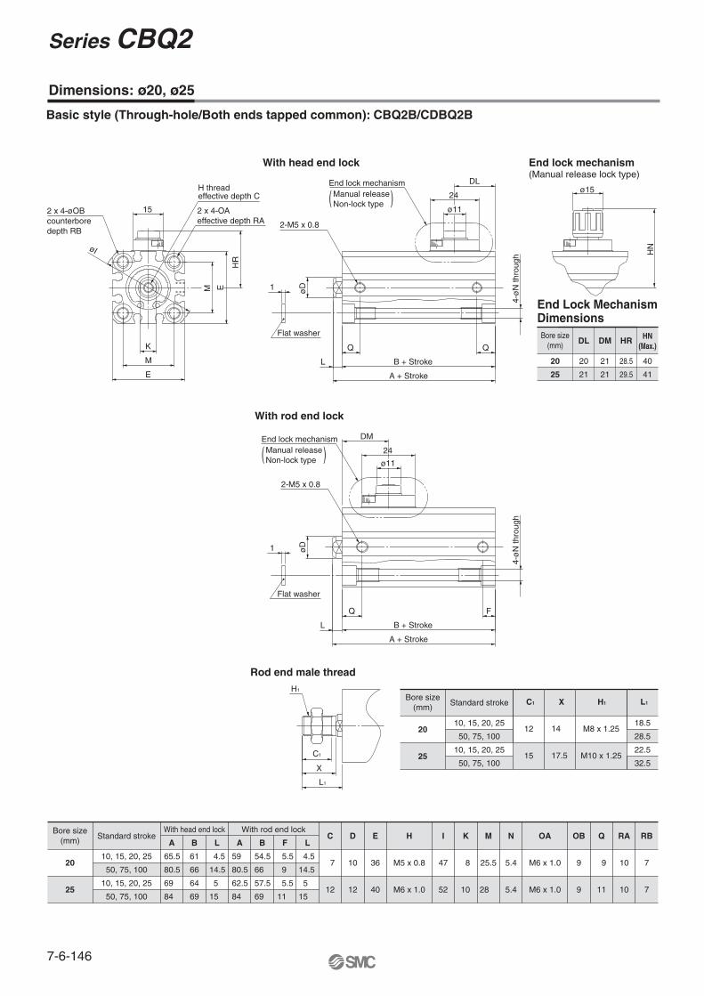
Dimensions: ø20, ø25
C1
X
L1
H1
With head end lock
Basic style (Through-hole/Both ends tapped common): CBQ2B/CDBQ2B
With rod end lock
End lock mechanism (Manual release lock type)
ø15
HN
K
E
M
EM
øI
H thread effective depth C
2 x 4-øOBcounterbore depth RB
15
HR
A + Stroke
B + StrokeL
øD
4-ø
N th
roug
h
1
Flat washer
ø11
24
DL
2-M5 x 0.8
End lock mechanismManual releaseNon-lock type( )
2 x 4-OAeffective depth RA
End Lock Mechanism Dimensions
20
25
DL
20
21
DM
21
21
HR
28.5
29.5
Bore size (mm)
HN(Max.)
40
41
20
25
Standard stroke
10, 15, 20, 25
50, 75, 100
10, 15, 20, 25
50, 75, 100
With head end lock
A
65.5
80.5
69
84
B
61
66
64
69
L
4.5
14.5
5
15
With rod end lock
A
59
80.5
62.5
84
B
54.5
66
57.5
69
F
5.5
9
5.5
11
L
4.5
14.5
5
15
C
7
12
D
10
12
E
36
40
H
M5 x 0.8
M6 x 1.0
I
47
52
K
8
10
M
25.5
28
N
5.4
5.4
OA
M6 x 1.0
M6 x 1.0
OB
9
9
Q
9
11
RA
10
10
RB
7
7
Bore size(mm)
Rod end male thread
A + Stroke
B + StrokeL
FQ
4-ø
N th
roug
h
2-M5 x 0.8
1
Flat washer
ø11
24
DMEnd lock mechanismManual releaseNon-lock type )(
øD
M8 x 1.25
H1
18.5
32.5M10 x 1.25
22.5
L1
12
15
C1
14
17.5
X
28.520
25
Standard stroke
10, 15, 20, 25
50, 75, 100
10, 15, 20, 25
50, 75, 100
Bore size (mm)
Series CBQ2
7-6-146
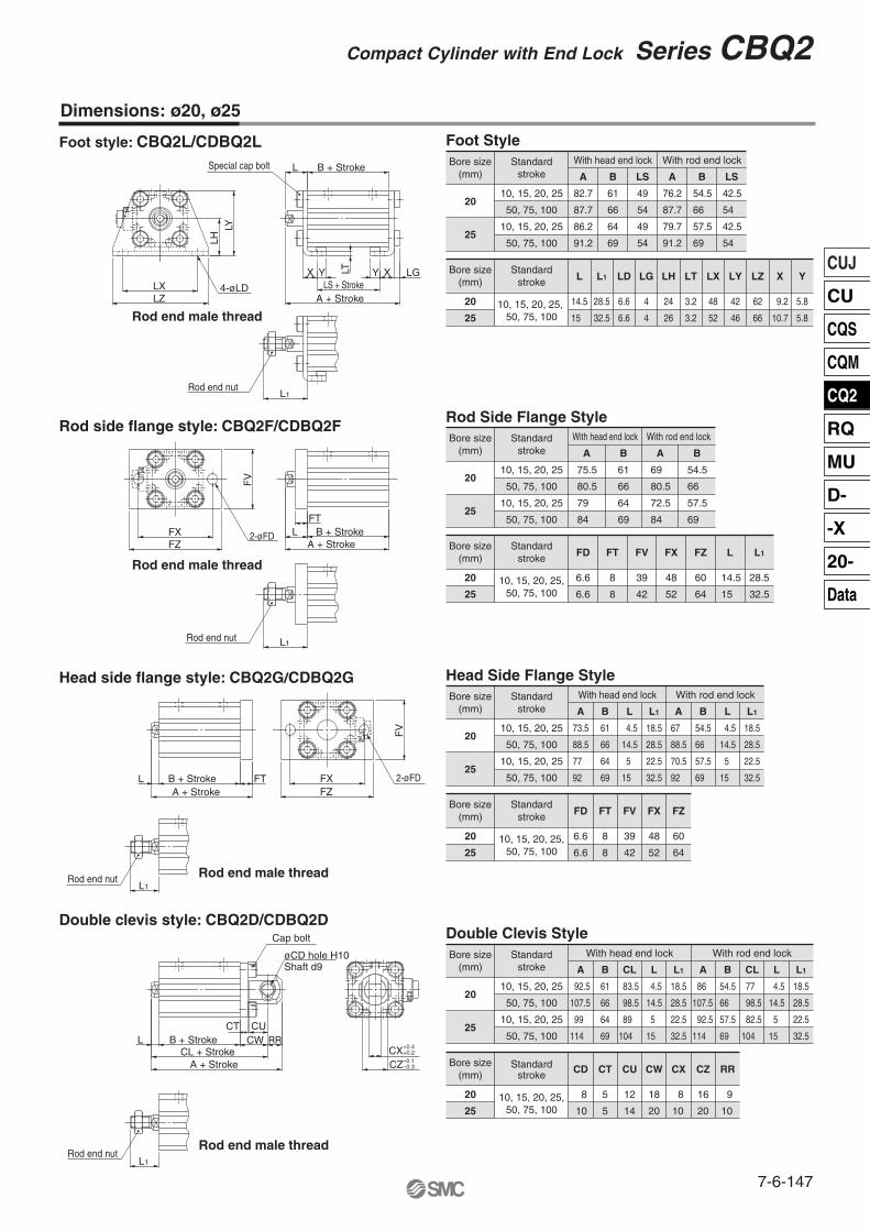
A + Stroke
B + StrokeL
LXLZ
LHLY
LS + StrokeX Y Y X LG
4-øLD
LT
Special cap bolt
L1Rod end nut
Rod end male thread
Rod end nut
A + StrokeB + StrokeL
FTFXFZ
FV
2-øFD
2-øFD
L1
Rod end male thread
Rod end nut
A + StrokeB + StrokeL FX
FZ
FV
FT
L1
Rod end male thread
Rod end male thread
+0.4+0.2–0.1–0.3
Rod end nutL1
CXCZ
CL + StrokeB + StrokeL
CT CUCW
A + Stroke
RR
øCD hole H10Shaft d9
Cap bolt
Foot Style
Double Clevis Style
Rod Side Flange Style
Head Side Flange Style
Foot style: CBQ2L/CDBQ2L
Rod side flange style: CBQ2F/CDBQ2F
Head side flange style: CBQ2G/CDBQ2G
Double clevis style: CBQ2D/CDBQ2D
20
25
Standardstroke
10, 15, 20, 25
50, 75, 100
10, 15, 20, 25
50, 75, 100
With head end lock
A
92.5
107.5
99
114
B
61
66
64
69
CL
83.5
98.5
89
104
L
4.5
14.5
5
15
L1
18.5
28.5
22.5
32.5
With rod end lock
A
86
107.5
92.5
114
B
54.5
66
57.5
69
CL
77
98.5
82.5
104
L
4.5
14.5
5
15
L1
18.5
28.5
22.5
32.5
Bore size (mm)
20
25
Standardstroke
10, 15, 20, 25,50, 75, 100
CD
8
10
CT
5
5
CU
12
14
CW
18
20
CX
8
10
CZ
16
20
RR
9
10
Bore size (mm)
20
25
Standardstroke
10, 15, 20, 25
50, 75, 100
10, 15, 20, 25
50, 75, 100
With head end lock
A
73.5
88.5
77
92
B
61
66
64
69
L
4.5
14.5
5
15
L1
18.5
28.5
22.5
32.5
With rod end lock
A
67
88.5
70.5
92
B
54.5
66
57.5
69
L
4.5
14.5
5
15
L1
18.5
28.5
22.5
32.5
Bore size (mm)
20
25
Standardstroke
10, 15, 20, 25,50, 75, 100
FD
6.6
6.6
FT
8
8
FV
39
42
FX
48
52
FZ
60
64
Bore size (mm)
20
25
Standardstroke
10, 15, 20, 25
50, 75, 100
10, 15, 20, 25
50, 75, 100
With head end lock
A
82.7
87.7
86.2
91.2
B
61
66
64
69
LS
49
54
49
54
With rod end lock
A
76.2
87.7
79.7
91.2
B
54.5
66
57.5
69
LS
42.5
54
42.5
54
Bore size (mm)
20
25
Standardstroke
10, 15, 20, 25, 50, 75, 100
L
14.5
15
L1
28.5
32.5
LD
6.6
6.6
LG
4
4
LH
24
26
LT
3.2
3.2
LX
48
52
LY
42
46
LZ
62
66
X
9.2
10.7
Y
5.8
5.8
Bore size (mm)
20
25
Standardstroke
10, 15, 20, 25,50, 75, 100
FD
6.6
6.6
FT
8
8
FV
39
42
FX
48
52
FZ
60
64
L
14.5
15
L1
28.5
32.5
Bore size (mm)
20
25
Standardstroke
10, 15, 20, 25
50, 75, 100
10, 15, 20, 25
50, 75, 100
With head end lock
A
75.5
80.5
79
84
B
61
66
64
69
With rod end lock
A
69
80.5
72.5
84
B
54.5
66
57.5
69
Bore size (mm)
Dimensions: ø20, ø25
Compact Cylinder with End Lock Series CBQ2
7-6-147
CUJ
CU
CQS
CQM
CQ2
RQ
MU
D-
-X
20-
Data

40
Dimensions: ø32 to ø100
End Lock Mechanism Dimensions
M6 x 1.0M6 x 1.0
M8 x 1.25M10 x 1.5
O1
10101418
R1
3240
Bore size (mm)
5063
M12 x 1.75M12 x 1.75
2222
80100
Both ends tapped style: CBQ2A/CDBQ2AR1 R1O1 thread
ø63, ø80, ø100 Cylinder tube form
Basic style (Through-hole): CBQ2B/CDBQ2B
32405063
DL
252929.528.5
DM
22262425
HR
33.538.54550
HN(Max.)4552.559 64
LL
15212121
15191919
Bore size (mm)
80100
4548
45.549
6271.5
76.586
3030
2323
WLMO
24242424
40
RF
111111112121
Rod end lockDM
Q
A + StrokeB + Stroke
F
C1
XL1
H1
Rod end male thread
HN
øMO
End lock mechanism (Manual release lock type)
With Rod End Lock
KME
H thread effective depth C
J
M EZ
WL 2 x 4- øO counterbore depth R
HR
øI
4- øN through
W A + Stroke
B + StrokeLQ Q
øRF
øD
End lock mechanism
Manual releaseNon-lock type
LL
DL
Head end lock
( )
2-P(Port size)
M14 x 1.5M14 x 1.5M18 x 1.5M18 x 1.5
H1
28.528.533.533.5
L1
20.520.52626
C1
23.523.528.528.5
X
M22 x 1.5
M26 x 1.5
43.553.543.553.5
32.5
32.5
35.5
35.5
32405063
80
100
Standard stroke
10, 15, 20, 2550, 75, 100
25, 5075, 10025, 50
75, 100
Bore size (mm)
14141919
Z
34405060
M
5.55.56.69
N
99
11 14
O
Rc 1/8Rc 1/8Rc 1/4Rc 1/4
P
778
10.5
R
49.5577184
W
14141717
K
10, 15, 20, 2550, 75, 100
25, 50, 75, 100
Standard stroke C
16162020
D
45526477
E
M8 x 1.25M8 x 1.25M10 x 1.5M10 x 1.5
H
606986
103
I
4.5577
J
3240
Bore size (mm)
506380
100
13131515
2626
7794
1111
17.517.5
Rc 3/8Rc 3/8
13.513.5
104123.5
2227
2530
98117
M16 x 2.0M20 x 2.5
132156
66.5
2127
32405063
80
100
Standard stroke
10, 15, 20, 2550, 75, 100
25, 5075, 10025, 5075, 100
A
72.5
8283.585
121 136132.5147.5
B
65.57575.577
111 116120.5125.5
L
7788
10201222
Bore size (mm)
Q
12.514 14 15.518 192223
With Head End Lock
32405063
80
100
Standard stroke
10, 15, 20, 2550, 75, 100
25, 5075, 10025, 50
75, 100
A
65
71.573.579
113.5136125147.5
B
58 64.565.571
103.5116113125.5
F
7.58
10.510.512.5191323
Bore size (mm)
Q
10.511 10.51516192323
L
7788
10201222
∗∗
∗∗
∗ At the 75, and 100 strokes with ø80, 100, both ends tapped (A) is the standard. Through-hole (B) is not available.
Series CBQ2
7-6-148
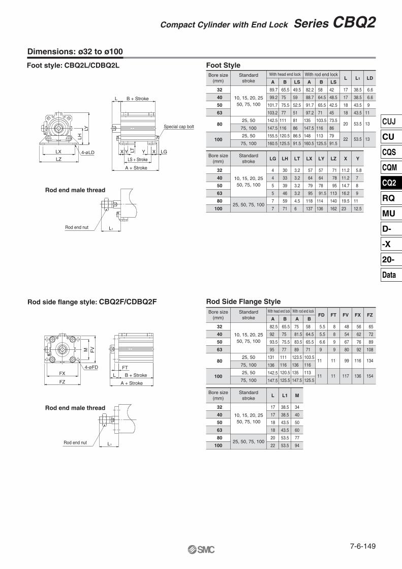
32
40
50
63
80
100
Standardstroke
10, 15, 20, 2550, 75, 100
25, 50, 75, 100
LG
4
4
5
5
7
7
LH
30
33
39
46
59
71
LT
3.2
3.2
3.2
3.2
4.5
6
LX
57
64
79
95
118
137
LY
57
64
78
91.5
114
136
LZ
71
78
95
113
140
162
X
11.2
11.2
14.7
16.2
19.5
23
Y
5.8
7
8
9
11
12.5
Bore size (mm)
Foot Style
LTSpecial cap bolt
4-øLD
B + Stroke
LS + Stroke
A + Stroke
L
LGXX YYLX
LZ
LHLY
L1Rod end nut
Rod end nut
Rod end male thread
4-øFDFX
FZ
FV
FT
L B + Stroke
A + Stroke
L1
Rod end male thread
M
Foot style: CBQ2L/CDBQ2L
Rod side flange style: CBQ2F/CDBQ2F
Dimensions: ø32 to ø100
32
40
50
63
80
100
Standardstroke
10, 15, 20, 2550, 75, 100
25, 50
75, 100
25, 50
75, 100
With head end lock
A
89.7
99.2
101.7
103.2
147.5
160.5
142.5
155.5
B
65.5
75
75.5
77
116
125.5
LS
49.5
59
52.5
51
86
91.5
111
120.5
81
86.5
With rod end lock
A
82.2
88.7
91.7
97.2
135
147.5
148
160.5
B
58
64.5
65.5
71
103.5
116
113
125.5
LS
42
48.5
42.5
45
73.5
86
79
91.5
L
17
17
18
18
20
22
L1
38.5
38.5
43.5
43.5
53.5
53.5
LD
6.6
6.6
9
11
13
13
Bore size (mm)
32
40
50
63
80
100
Standardstroke
10, 15, 20, 2550, 75, 100
25, 50
75, 100
25, 50
75, 100
With head end lock
A
82.5
92
93.5
131
136
142.5
147.5
95
B
65.5
75
75.5
77
With rod end lock
A
75
81.5
83.5
89
123.5
136
135
147.5
B
58
64.5
65.5
71
103.5
116
113
125.5
111
116
120.5
125.5
FV
48
54
67
80
99
117
FT
8
8
9
9
11
11
FD
5.5
5.5
6.6
9
11
11
FX
56
62
76
92
116
136
FZ
65
72
89
108
134
154
Bore size (mm)
32
40
50
63
80
100
Standardstroke
10, 15, 20, 2550, 75, 100
25, 50, 75, 100
L
17
17
18
18
20
22
L1
38.5
38.5
43.5
43.5
53.5
53.5
M
34
40
50
60
77
94
Bore size (mm)
Rod Side Flange Style
Compact Cylinder with End Lock Series CBQ2
7-6-149
CUJ
CU
CQS
CQM
CQ2
RQ
MU
D-
-X
20-
Data

Rod end nut
Rod end nut
B + Stroke
B + Stroke
CL + Stroke
A + Stroke
A + Stroke
L1
L1
Rod end male thread
Rod end male thread
4-øFDFTL
FV
FZ
FX
M
4-NCap bolt
CX
øCD hole H10Shaft d9
RRCW
CU
CT
L
Head side flange style: CBQ2G/CDBQ2G
+0.4+0.2
CZ -0.1-0.3
Dimensions: ø32 to ø100
Double clevis style: CBQ2D/CDBQ2D
32
40
50
63
80
100
Standardstroke
10, 15, 20, 2550, 75, 100
25, 50, 75, 100
CW
20
22
28
30
38
45
CX
18
18
22
22
28
32
CZ
36
36
44
44
56
64
N
M6 x 1.0
M6 x 1.0
M8 x 1.25
M10 x 1.5
M12 x 1.75
M12 x 1.75
RR
10
10
14
14
18
22
Bore size (mm)
32
40
50
63
80
100
Standardstroke
10, 15, 20, 2550, 75, 100
25, 50
75, 100
25, 50
75, 100
With head end lock
A
102.5
114
125.5
129
B
65.5
75
75.5
77
CL
92.5
104
111.5
115
With rod end lock
A
95
103.5
115.5
123
169.5
192192
199.5
214.5
177 111 159
116 174
120.5 177.5
125.5 192.5
192
214.5
B
58
64.5
65.5
71
103.5
116
113
125.5
CL
85
93.5
101.5
109
151.5
174
170
192.5
CD
10
10
14
14
18
22
CT
5
6
7
8
10
13
CU
14
14
20
20
27
31
Bore size (mm) L
7
7
8
8
10
20
L1
28.5
28.5
33.5
33.5
43.5
53.5
12
22
43.5
53.5
Double Clevis Style
Standardstroke
10, 15, 20, 25,50, 75, 100
FD
5.5
5.5
FT
8
8
FV
48
54
FX
56
62
FZ
65
72
32
40
Bore size (mm)
50
63
80
100
6.6 9 67 76 89
9 9 80 92 108
11 11 99 116 134
11 11 117 136 154
M
34
40
50
60
77
94
Head Side Flange Style
32
40
50
63
80
100
Standardstroke
10, 15, 20, 2550, 75, 100
25, 50
75, 100
25, 50
75, 100
Bore size (mm)
With head end lock
A
80.5
90
92.5
94
B
65.5
75
75.5
77
L
7
7
8
8
L1
28.5
28.5
33.5
33.5
With rod end lock
A
73
79.5
82.5
88
B
58
64.5
65.5
71
L
7
7
8
8
L1
28.5
28.5
33.5
33.5
132 111 10 43.5 124.5 103.5 10 43.5
147 116 20 53.5 147 116 20 53.5
143.5 120.5 12 43.5 136 113 12 43.5
158.5 125.5 22 53.5 158.5 125.5 22 53.5
Series CBQ2
7-6-150
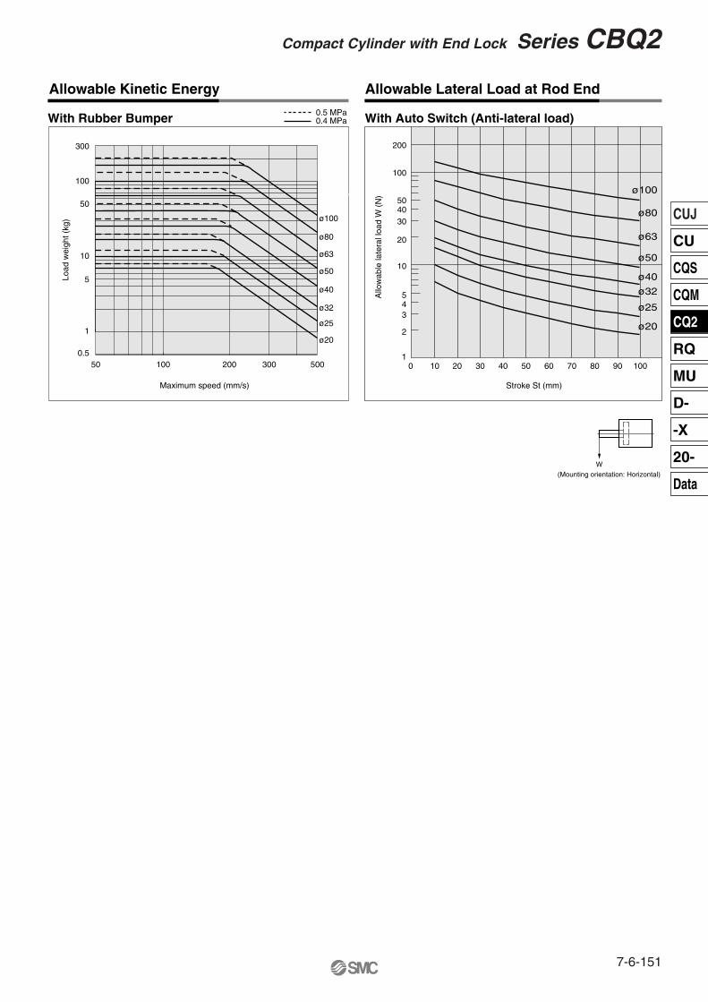
W(Mounting orientation: Horizontal)
Allo
wab
le la
tera
l loa
d W
(N
)Stroke St (mm)
With Auto Switch (Anti-lateral load)
200
100
504030
20
10
543
2
10 10 20 30 40 50 60 70 80 90 100
Allowable Kinetic Energy Allowable Lateral Load at Rod End
With Rubber Bumper 0.5 MPa0.4 MPa
ø100
ø80
ø63
ø50
ø40
ø32
ø25
ø20
Maximum speed (mm/s)
Load
wei
ght (
kg)
ø32
ø25
ø20
ø40
ø63
ø50
ø80
ø100
50
5
1
0.5
10
50
100
300
100 200 500300
Compact Cylinder with End Lock Series CBQ2
7-6-151
CUJ
CU
CQS
CQM
CQ2
RQ
MU
D-
-X
20-
Data
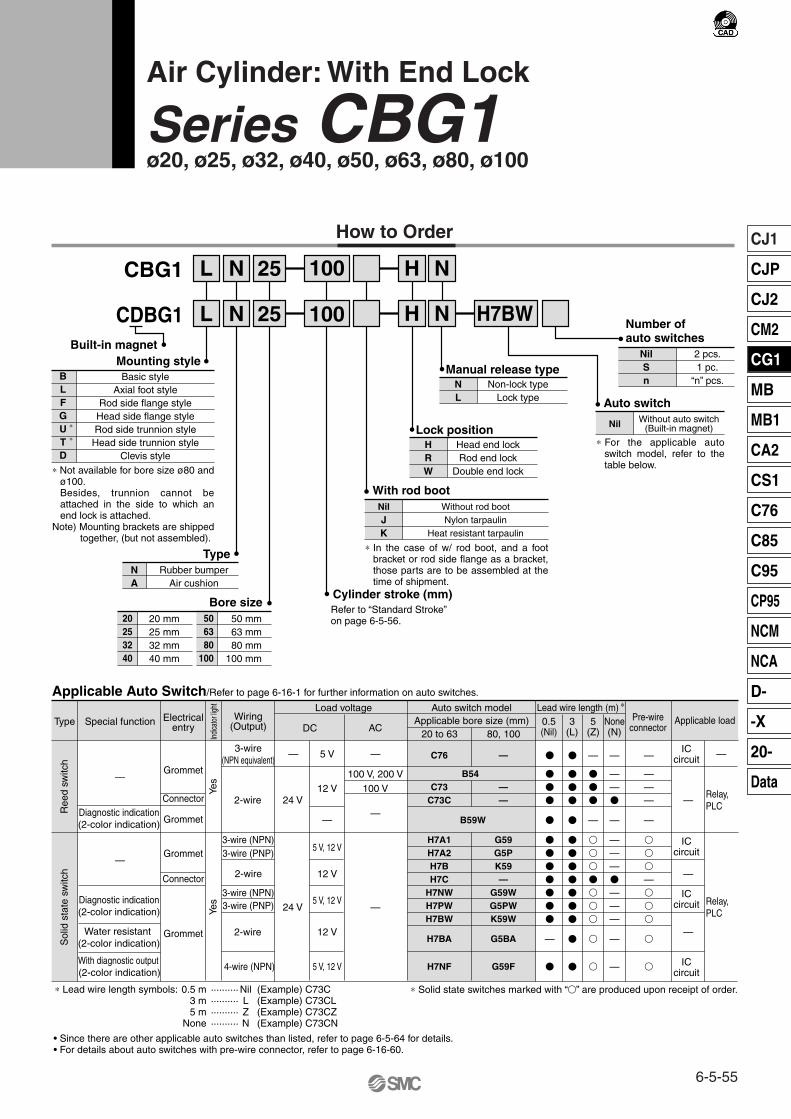
CDBG1
L 25
L
N
N 25 H
H
N H7BW
N
Built-in magnet
20253240
506380
100
Bore size20 mm25 mm32 mm40 mm
50 mm63 mm80 mm
100 mm
Number ofauto switches
NilSn
2 pcs.1 pc.
“n” pcs.
Nil Without auto switch(Built-in magnet)
Auto switch
Cylinder stroke (mm)
CBG1
Basic styleAxial foot style
Rod side flange styleHead side flange styleRod side trunnion styleHead side trunnion style
Clevis style
Mounting styleBLFGUTD
100
100
Refer to “Standard Stroke” on page 6-5-56.
Lock positionHRW
Head end lockRod end lock
Double end lock
Manual release typeNL
Non-lock typeLock type
NilJK
With rod bootWithout rod bootNylon tarpaulin
Heat resistant tarpaulin
TypeNA
Rubber bumperAir cushion
∗
∗
∗ In the case of w/ rod boot, and a foot bracket or rod side flange as a bracket, those parts are to be assembled at the time of shipment.
Special functionType Electricalentry
Grommet
Grommet
Grommet
Grommet
Indic
ator
light
Wiring(Output)
2-wire
3-wire(NPN equivalent)
Load voltage
—
ACDC
Auto switch model
C76
B54C73
C73C
B59W
H7A1H7A2H7BH7C
H7NWH7PWH7BW
H7BA
H7NF
Lead wire length (m) ∗
0.5(Nil)
3(L)
5(Z)
�
�
�
�
�
�
�
�
�
�
�
�
—
�
�
�
�
�
�
�
�
�
�
�
�
�
�
�
—
�
�
�
—
�
�
�
�
�
�
�
�
�
ICcircuit
Relay,PLC
Applicable load
Applicable Auto Switch/Refer to page 6-16-1 for further information on auto switches.
• Since there are other applicable auto switches than listed, refer to page 6-5-64 for details.• For details about auto switches with pre-wire connector, refer to page 6-16-60.
20 to 63
—
——
G59G5PK59—
G59WG5PWK59W
G5BA
G59F
80, 100
—
5 V
100 V, 200 V
100 V
—
12 V
—
5 V, 12 V
12 V
5 V, 12 V
12 V
5 V, 12 V
—
—
24 V
Yes
Yes
Connector
Connector
Diagnostic indication(2-color indication)
With diagnostic output (2-color indication)
Water resistant (2-color indication)
Diagnostic indication(2-color indication)
—
—
2-wire
3-wire (NPN) 3-wire (PNP)
2-wire
3-wire (NPN) 3-wire (PNP)
4-wire (NPN)
24 V
ICcircuit
—
ICcircuit
ICcircuit
—
Relay, PLC
Applicable bore size (mm)
Ree
d sw
itch
Sol
id s
tate
sw
itch
None(N)
Pre-wireconnector
—
——�
—
———�
———
—
—
—
———
—
�
�
�
—�
�
�
�
�
∗ Solid state switches marked with “�” are produced upon receipt of order.
—
How to Order
∗ Not available for bore size ø80 and ø100.Besides, trunnion cannot be attached in the side to which an end lock is attached.
Note) Mounting brackets are shipped together, (but not assembled).
∗ For the applicable auto switch model, refer to the table below.
∗ Lead wire length symbols: 0.5 m ·········· Nil (Example) C73C 3 m ·········· L (Example) C73CL5 m ·········· Z (Example) C73CZ
None ·········· N (Example) C73CN
Air Cylinder: With End Lock
Series CBG1ø20, ø25, ø32, ø40, ø50, ø63, ø80, ø100
6-5-55
CJ1
CJP
CJ2
CM2
CG1
MB
MB1
CA2
CS1
C76
C85
C95
CP95
NCM
NCA
D-
-X
20-
Data

Rod Boot Material
Specifications
Lock Specifications
Up to 1500 mm
Up to 1000 mm
50 to 1000 mm/s
Up to 1000 mm, Up to 1200 mm
Standard Stroke
Action
Type
Fluid
Proof pressure
Maximum operating pressure
Minimum operating pressure
Ambient and fluid temperature
Piston speed
Stroke length tolerance
Thread tolerance
Cushion
Mounting ∗∗
Double acting, Single rod
Non-lube
Air
1.5 MPa
1.0 MPa
0.15 MPa ∗
Without auto switch: –10 to 70°C (No freezing)
With auto switch: –10 to 60°C (No freezing)
JIS Class 2
Rubber bumper, Air cushion
st +1.4 0
st +1.4 0st +1.8
0st +1.8 0
Lock position Head end, Rod end, Double end
2 mm or less
Non-lock type, Lock type
Holding force (Max.)(N)
Backlash
Manual release
ø20
215
ø25
330
ø32
550
ø40
860
ø50
1340
ø63
2140
ø80
3450
ø100
5390
Bore size(mm)
20
25
32
40
50, 63
80
100
Standard stroke (mm) (1)
25, 50, 75, 100, 125, 150, 200
25, 50, 75, 100, 125, 150, 200, 250, 300
Long stroke(mm)
Maximummanufacturable
stroke(mm)
201 to 350
301 to 400
301 to 450
301 to 800
301 to 1200
301 to 1400
301 to 1500
1500
Symbol
J
K
Rod boot material
Nylon tarpaulin
Heat resistant tarpaulin
Maximum operating temperature
70°C
110°C ∗
Model2
15 mm
20 mm
20 mm
1
10 mm
15 mm
10 mm
D-C7/C8D-B5/B6D-H7D-G5/K5
D-B59W
D-H7LF
No. of auto switches mounted
20 25 32 40 50 63 80 100
50 to 700 mm/s
Minimum Stroke forAuto Switch Mounting
-XA� Change of rod end shape
Symbol Specifications
Made to Order Specifications(For details, refer to page 6-17-1.)
Basic style, Axial foot style, Rod side flange styleHead side flange style, Rod side trunnion style
Head side trunnion style, Clevis style (Used for changing the port location by 90°.)
∗ 0.05 MPa except locking parts.∗∗ Rod/Head side trunnion styles are not available for bore sizes ø80 and ø100.
Trunnion is not attached for a cover on which lock mechanism is equipped.
Note 1) Intermediate strokes other than the above are produced upon receipt of order. Spacers are not used for intermediate strokes.
Note 2) Long stroke applies to the axial foot style and the rod side flange style. If other mounting brackets are used, or the length exceeds the long stroke limit, the stroke should be determined based on the stroke selection table in the technical data.
Bore size (mm)
Adjust the switch position so that it operates upon movement to both the stroke end and backlash (2 mm) positions.
∗ Maximum ambient temperature for the rod boot itself.
Series CBG1
6-5-56

Use the Recommended Pneumatic Circuit
Be sure to read before handling. For Safety Instructions and Actuator Precautions, refer to pages 6-20-3 to 6-20-6.
Caution
Caution
Caution
Caution
Warning
Caution
Warning
Caution1. Do not use 3 position solenoid valves.
Avoid use in combination with 3 position solenoid valves (especially closed center metal seal types). If pressure is trapped in the port on the lock mechanism side, the cylinder cannot be locked. Furthermore, even after being locked, the lock may be released after some time, due to air leaking from the solenoid valve and entering the cylinder.
2. Back pressure is required when releasing the lock.Be sure air is supplied to side of cylinder without the locking mechanism, as above, prior to supplying air pressure to the side with end lock or lock may not be released. ( Refer to “Releasing the Lock”.)
3. Release the lock when mounting or adjusting the cylinder.If mounting or other work is performed when the cylinder is locked, the lock unit may be damaged.
4. Operate with a load ratio of 50% or less.If the load ratio exceeds 50%, this may cause problems such as failure of the lock to release, or damage to the lock unit.
5. Do not operate multiple cylinders in synchronization. Avoid applications in which two or more end lock cylinders are synchronized to move one workpiece, as one of the cylinder locks may not be able to release when required.
6. Use a speed controller with meter-out control.Lock cannot be released occasionally by meter-in control.
7. Be sure to operate completely to the cylinder stroke end on the side with the lock.If the cylinder piston does not reach the end of the stroke, locking and unlocking may not be possible.
8. Do not use an air cylinder as an air-hydro cylinder. This could result in leakage of oil.
9. Install a rod boot without twisting.If the cylinder is installed with its bellows twisted, it could damage the bellows.
10. Adjust an auto switch position so that it operates for movement to both the stroke end and backlash (2 mm) positions.When a 2-color indication switch is adjusted for green indication at the stroke end, it may change to red for the backlash return, but this is not abnormal.
• This is necessary for proper operation and release of the lock.
Operating Pressure
1. Use pressures over 0.15 MPa at port with locking mechanism.
1. Locking will occur automatically if the pressure applied to the port on the lock mechanism side falls to 0.05 MPa or less. In cases where the piping on the lock mechanism side is long and thin, or the speed controller is separated at some distance from the cylinder port, the exhaust speed will be reduced. Take note that some time may be required for the lock to engage. In addition, clogging of a silencer mounted on the solenoid valve exhaust port can produce the same effect.
1. When cushion valve at side with locking mechanism is fully opened or closed, piston rod may reached at stroke end. Thus lock is not established. And when locking is done at cushion valve fully closed, adjust cushion valve since lock may not be released.
1. Do not replace the bushings or the cushion seals.The bushings and the cushion seals are press-fit. To replace them, they must be replaced together with the cover assembly.
2. To replace a seal, apply grease to the new seal before installing it.If the cylinder is put into operation without applying grease to the seal, it could cause the seal to wear significantly, leading to premature air leakage.
3. Those with a bore of ø50 or more cannot be disassembled.When disassembling cylinders with bore sizes of ø20 through ø40, grip the double flat part of either the head cover or the rod cover with a vise and loosen the other side with a wrench or a monkey wrench, etc., and then remove the cover. When re-tightening, tighten approximately 2 degrees more than the original position. (Cylinders with ø50 or larger bore sizes are tightened with a large tightening torque and cannot be disassembled. Please contact SMC when disassembly is required.)
Precautions
Head end lock Rod end lock
1. Do not operate the cushion valve in the fully closed or fully opened state.Using it in the fully closed state will cause the cushion seal to be damaged. Using it in the fully opened state will cause the piston rod assembly or the cover to be damaged.
2. Operate within the specified cylinder speed.Otherwise, cylinder and seal damage may occur.
1. Before releasing the lock, be sure to supply air to the side without the lock mechanism, so that there is no load applied to the lock mechanism when it is released. (Refer to the recommended pneumatic circuits.) If the lock is released when the port on the other side is in an exhaust state, and with a load applied to the lock unit, the lock unit may be subjected to an excessive force and be damaged. Furthermore, sudden movement of the piston rod is very dangerous.
Operating Precautions
Operating Precautions
Exhaust Speed
Relation to Cushion
Releasing the Lock
Disassembly/Replacement
6-5-57
Air Cylinder: With End Lock Series CBG1
CJ1
CJP
CJ2
CM2
CG1
MB
MB1
CA2
CS1
C76
C85
C95
CP95
NCM
NCA
D-
-X
20-
Data

Construction: With Rubber Bumper
1 94 56 7 8 210 11 1213A
13B
14
151617 18
29 20 2125 27 22 26 23 28
ø80, ø100 ø80, ø100
Long stroke
20
24
Head end lock
Rod end lock 3
19
19
2
Manual release (Non-lock type): Suffix N Manual release (Lock type): Suffix L
Component Parts
Replacement Parts:Seal Kit (With lock at single end)
MaterialDescriptionRod coverHead coverTube coverCylinder tubePiston Piston rodBushingLock pistonLock bushingLock springBumperHexagon socket head cap screwCap ACap BRubber capM/O knobM/O boltM/O springStopper ringBumper ABumper B
Aluminum alloyAluminum alloyAluminum alloyAluminum alloyAluminum alloyCarbon steel ∗
Oil-impregnated sintered alloyCarbon steelCopper alloy
Stainless steelUrethaneAlloy steel
Aluminum die-castedCarbon steel
Synthetic rubber Zinc die-casted
Alloy steelSteel wire
Carbon steelUrethaneUrethane
Clear hard anodizedClear hard anodizedClear hard anodized
Hard anodizedChromated
Hard chrome platedø40 and larger are lead-bronze castedHard chrome plated, Heat treated
Black zinc chromatedBlack painted
Oxide film treated
Black paintedBlack zinc chromated, Red painted
Zinc chromatedZinc chromated
ø40 or larger: the same as bumper A
Note
ContentsSeries Bore size (mm) Kit no.
CBG1�NRubber bumpertype
Set of nos. above @5, @6, @7, @8
and grease pack
20253240506380
100
CBG1N20-PSCBG1N25-PSCBG1N32-PSCBG1N40-PSCBG1N50-PSCBG1N63-PSCBG1N80-PSCBG1N100-PS
Replacement Parts:Seal Kit (With lock at double end)
ContentsSeries Bore size (mm) Kit no.
CBG1�NRubber bumpertype
Set of nos. above @5, @6, @7, @8
and grease pack
20253240506380
100
CBG1N20-PS-WCBG1N25-PS-WCBG1N32-PS-WCBG1N40-PS-WCBG1N50-PS-WCBG1N63-PS-WCBG1N80-PS-WCBG1N100-PS-W
Order seal kit in accordance with the bore size. Order seal kit in accordance with the bore size.
No.qwertyuio!0!1!2!3A!3B!4!5!6!7!8!9@0
MaterialDescriptionSnap ringPiston gasketWear ringRod end nutRod sealPiston sealCylinder tube gasketLock piston sealPiston holder
Stainless steelNBRResin
Rolled steelNBRNBRNBRNBR
Urethane
None for ø80, ø100
Nickel plated
1 pc. when using tube cover2 pcs. for with locks in both sides
ø40 to ø100 only
NoteNo.@1@2@3@4@5@6@7@8@9
Note) In the case of cylinders with auto switches, magnets are installed in the piston.
∗ The material is stainless steel on auto switch equipped styles ø20 and ø25.
Series CBG1
6-5-58

Construction: With Air Cushion
Long stroke
With air cushionHead end lock
Rod end lock
1 94 56 7 8 210 1113A 1429 37 3125 27 22 26 23 2824
3
12
2
3036 38 39
3241
35
33
34
40
Manual release (Non-lock type): Suffix N
Replacement Parts:Seal Kit (With lock at single end)
ContentsSeries Bore size (mm) Kit no.
CBG1�ARubber bumpertype
Set of nos. above @5, @6, @7, @8, $0
and grease pack
20253240506380
100
CBG1A20-PSCBG1A25-PSCBG1A32-PSCBG1A40-PSCBG1A50-PSCBG1A63-PSCBG1A80-PSCBG1A100-PS
Replacement Parts:Seal Kit (With lock at double end)
ContentsSeries Bore size (mm) Kit no.
CBG1�ARubber bumpertype
Set of nos. above @5, @6, @7, @8, $0
and grease pack
20253240506380
100
CBG1A20-PS-WCBG1A25-PS-WCBG1A32-PS-WCBG1A40-PS-WCBG1A50-PS-WCBG1A63-PS-WCBG1A80-PS-WCBG1A100-PS-W
Order seal kit in accordance with the bore size. Order seal kit in accordance with the bore size.
Component PartsMaterialDescription
Rod coverHead coverTube coverCylinder tubePiston Piston rodBushingLock pistonLock bushingLock springBumperHexagon socket head cap screwCap ACap BRubber capM/O knobM/O boltM/O springStopper ring
Aluminum alloyAluminum alloyAluminum alloyAluminum alloyAluminum alloyCarbon steel ∗
Oil-impregnated sintered alloyCarbon steelCopper alloy
Stainless steelUrethaneAlloy steel
Aluminum die-castedCarbon steel
Synthetic rubber Zinc die-casted
Alloy steelSteel wire
Carbon steel
Clear hard anodizedClear hard anodizedClear hard anodized
Hard anodizedChromated
Hard chrome platedø40 and larger are lead-bronze castedHard chrome plated, Heat treated
Black zinc chromatedBlack painted
Oxide film treated
Black paintedBlack zinc chromated, Red painted
Zinc chromatedZinc chromated
NoteNo.qwertyuio!0!1!2!3A!3B!4!5!6!7!8
MaterialDescriptionPiston gasketWear ringRod end nutRod sealPiston sealCylinder tube gasketLock piston sealPiston holderCushion ring ACushion ring BSeal retainerCushion valveValve retainerLock nutCushion seal ACushion seal BCushion ring gasket ACushion ring gasket BValve sealValve retaining gasket
NBRResin
Rolled steelNBRNBRNBRNBR
UrethaneBrassBrass
Rolled steelRolled steelRolled steelRolled steelUrethaneUrethane
NBRNBRNBRNBR
Nickel plated1 pc. when using tube cover
2 pcs. for with locks in both sides
ø40 to ø100 only
Only when using nickel plated, tube cover
Electroless nickel platedElectroless nickel plated
Nickel plated
ø32 or larger: The same as A
ø32 or larger: The same as A
NoteNo.@2@3@4@5@6@7@8@9#0#1#2#3#4#5#6#7#8#9$0$1Note) In the case of cylinders with auto switches, magnets are installed in
the piston.∗ The material is stainless steel on auto switch equipped styles ø20 and
ø25.
6-5-59
Air Cylinder: With End Lock Series CBG1
CJ1
CJP
CJ2
CM2
CG1
MB
MB1
CA2
CS1
C76
C85
C95
CP95
NCM
NCA
D-
-X
20-
Data

Rubber Bumper Type: CBG1BN
Bore size
2-Rc P 2-TC
TE
TFTG
NA
TA cross section
Manual release (Non-lock type): Suffix N Manual release (Lock type): Suffix L
HN
8-JNA
HR
�C±0.1
MM H GA GBWidth acrossflats B1
AL
KA
A
H
K F TA DL2
F
2-TC
S + Stroke
ZZ + Stroke
øD
øI
øT
D
øE
0 –0.0
5
øE
øM
O
øR
F
WL
WL
0 –0.0
5
StrokerangeBore size (mm)
Up to 350
Up to 400
Up to 450
Up to 800
Up to 1200
Up to 1200
Up to 1400
Up to 1500
A
18
22
22
30
35
35
40
40
AL B1
13
17
17
19
27
27
32
41
C D DL2 E
12
14
18
25
30
32
40
50
F
2
2
2
2
2
2
3
3
GA
12
12
12
13
14
14
20
20
GB
12
12
12
13
14
14
20
20
H
35
40
40
50
58
58
71
71
H1 HR HN (Max.) I J
M4 x 0.7 depth 7
M5 x 0.8 depth 7.5
M5 x 0.8 depth 8
M6 x 1 depth 12
M8 x 1.25 depth 16
M10 x 1.5 depth 16
M10 x 1.5 depth 22
M12 x 1.75 depth 22
Bore size (mm) K KA MM
M8 x 1.25
M10 x 1.25
M10 x 1.25
M14 x 1.5
M18 x 1.5
M18 x 1.5
M22 x 1.5
M26 x 1.5
MO
15
15
15
19
19
19
23
23
NA P
1/8
1/8
1/8
1/8
1/4
1/4
3/8
1/2
RF
11
11
11
11
11
11
21
21
S TA
11
11
11
12
13
13
—
—
TC
M5 x 0.8
M6 x 0.75
M8 x 1.0
M10 x 1.25
M12 x 1.25
M14 x 1.5
—
—
TDH9
—
—
TE
—
—
TF
—
—
TG
—
—
WL
15
15
24
24
24
24
40
40
ZZ
118
123
123
144
167
167
204
204
Head end lock: CBG1BN Stroke H�
20
25
32
40
50
63
80
100
20
25
32
40
50
63
80
100
5
5.5
5.5
6
7
7
10
10
6
8
10
14
18
18
22
26
24
29
35.5
44
55
69
80
100
81
81
81
92
107
107
130
130
0.5
1
1
1.25
2
3
4
5
5.5
6
7.5
11.5
5.5
6.5
7.5
8.5
10
14.5
15.5
19.5
19.5
27
32
32
37
37
14
16.5
20
26
32
38
50
60
8
10
12
16
20
20
25
30
12.5
12.5
12
15
16.5
16.5
19
20
5
6
6
8
11
11
13
16
25.3
28.3
31.3
38.3
44.5
45
53.5
64.5
37
40
43
52.5
58.5
59
68
79
26
31
38
47
58
72
89
110
+0.080
+0.080
+0.080
+0.080
+0.080
+0.0808
10
12
14
16
18
Series CBG1
6-5-60

Double end lock: CBG1BN
e
30
30
35
35
40
40
52
62
f h
55
62
62
70
78
78
80
80
IJ
27
32
38
48
59
72
59
71
JH
(14.5)
(17.5)
(19.5)
(22.5)
(25)
(25)
—
—
JW
(11.5)
(11.5)
(11.5)
(13)
(13)
(13)
—
—
l
Bore size(mm) DL1 S
80(88)
80(88)
81(89)
87(96)
102(114)
102(114)
124(138)
124(138)
TB
11
11
10(11)
10(12)
12(13)
12(13)
—
—
GB
10(12)
10(12)
10(12)
10(13)
12(14)
12(14)
16(20)
16(20)
ZZ
117(125)
122(130)
123(131)
139(148)
162(174)
162(174)
198(212)
198(212)
S ZZ
129
134
133
153
179
179
220
220
∗ ( ): Denotes the dimensions for long stroke.
Bore size(mm)
∗ ( ): Denotes the dimensions for long strokes. ∗∗ The minimum stroke with rod boot is 20 mm.
0.25
str
oke
With rod boot
JW
8 l
h + l
f
ZZ + l + Stroke
øeøIJ
JH
Bore size
Bore size(mm)
ZZ + Stroke
TB
GB
S + Stroke
DL1
S + Stroke
ZZ + Stroke
Rubber Bumper Type: CBG1BN
Rod end lock: CBG1BN Stroke R�
Bore size Stroke W�
20
25
32
40
50
63
80
100
20
25
32
40
50
63
80
100
19.5
19.5
20
19
23.5
23.5
27
30
92
92
91
101
119
119
146
146
20
25
32
40
50
63
80
100
16
17
17
17
17
18
10
7
Rod end lock (-R�)ZZ
137(145)
144(152)
145(153)
159(168)
182(194)
182(194)
207(221)
207(221)
ZZ149
156
155
173
199
199
229
229
138
145
145
164
187
187
213
213
ZZHead end lock (-H�) Double end lock (-W�)
6-5-61
Air Cylinder: With End Lock Series CBG1
CJ1
CJP
CJ2
CM2
CG1
MB
MB1
CA2
CS1
C76
C85
C95
CP95
NCM
NCA
D-
-X
20-
Data

Air Cushion Type: CBG1BA
Wθ
Max
. WH
WA WB
2-P10°
P
M5 x 0.8
M5 x 0.8
Rc 1/8
Rc 1/8
Rc 1/4
Rc 1/4
Rc 3/8
Rc 1/2
WA
16
16
16
16
18
18
22
22
WB
16
16
16
16
18
18
22
22
WH Wθ
30°30°25°20°20°20°20°20°
Head end lock: CBG1BA
Bore size(mm)
Head End Lock: -H�
P
M5 x 0.8
M5 x 0.8
Rc 1/8
Rc 1/8
Rc 1/4
Rc 1/4
Rc 3/8
Rc 1/2
WA
16
16
16
16
18
18
22
22
WB
15(16)
15(16)
15(16)
15(16)
17(18)
17(18)
22
22
WH Wθ
30°30° 25°20°20°20°20°20°
Bore size(mm)
Rod End Lock: -R�
StrokeBore size H�Bore sizeRod end lock: CBG1BA Stroke R�
23
25
28.5
33
40.5
47.5
60.5
71
20
25
32
40
50
63
80
100
20
25
32
40
50
63
80
100
23
25
28.5
33
40.5
47.5
60.5
71
∗ For dimensions other than listed above, refer to the dimensions with rubber bumper.
∗ ( ): Denotes the dimensions for long strokes.∗∗ For dimensions other than the listed above, refer to the
dimensions with rubber bumper.
Series CBG1
6-5-62
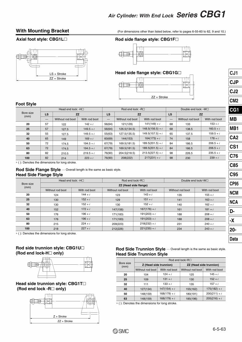
With Mounting Bracket (For dimensions other than listed below, refer to pages 6-55-60 to 62, 9 and 10.)
Head end lock: -H�
LS
—
57
57
55
65
72
72
82
82
ZZ
Without rod boot With rod boot
Rod end lock: -R�
LS
—
56(64)
56(64)
55(63)
60(69)
67(79)
67(79)
76(90)
76(90)
ZZ
Without rod boot
121(129)
126.5(134.5)
127.5(135.5)
144(153)
169.5(181.5)
169.5(181.5)
204.5(218.5)
208(222)
With rod boot
Double end lock: -W�
LS
—
68
68
65
74
84
84
98
98
ZZ
Without rod boot With rod boot
Bore size(mm)
∗ ( ): Denotes the dimensions for long stroke.
Foot Style
Head side flange style: CBG1G�
Head side trunnion style: CBG1T� (Rod end lock -R� only)
Axial foot style: CBG1L� Rod side flange style: CBG1F�
Rod side trunnion style: CBG1U�(Rod end lock-H� only)
ZZ + Stroke
Z + Stroke
ZZ + Stroke
LS + Stroke
ZZ + Stroke
Bore size(mm)
20
25
32
40
50
63
Rod end lock/-R�
Without rod boot
104
109
111
127(134)
148(159)
148(159)
With rod boot
Z (Head side trunnion)
Without rod boot
125
130
135
155(162)
180(191)
185(196)
With rod boot
ZZ (Head side trunnion)
Rod Side Trunnion Style ···· Overall length is the same as basic style.
Head Side Trunnion Style
∗ ( ): Denotes the dimensions for long stroke.
Bore size(mm)
Head end lock: -H�
Without rod boot
124
130
130
152
176
176
215
218
With rod boot
Rod end lock/-R�
Without rod boot
123
129
130
147(156)
171(183)
171(183)
209(223)
212(226)
With rod boot
Double end lock/-W�
ZZ (Head side flange)
Without rod boot
135
141
140
161
188
188
231
234
With rod boot
∗ ( ): Denotes the dimensions for long stroke.
Rod Side Flange Style ···· Overall length is the same as basic style.
Head Side Flange Style
142 + l
149.5 + l
149.5 + l
169 + l
194.5 + l
194.5 + l
219.5 + l
223 + l
122
127.5
127.5
149
174.5
174.5
210.5
214
141(149) + l
148.5(156.5) + l
149.5(157.5) + l
164(173) + l
189.5(201.5) + l
189.5(201.5) + l
213.5(227.5) + l
217(231) + l
133
138.5
137.5
158
186.5
186.5
226.5
230
153 + l
160.5 + l
159.5 + l
178 + l
206.5 + l
206.5 + l
235.5 + l
239 + l
155 + l
163 + l
162 + l
181 + l
208 + l
208 + l
240 + l
243 + l
143 + l
151 + l
152 + l
167(176) + l
191(203) + l
191(203) + l
218(232) + l
221(235) + l
144 + l
152 + l
152 + l
172 + l
196 + l
196 + l
224 + l
227 + l
20
25
32
40
50
63
80
100
20
25
32
40
50
63
80
100
124 + l
131 + l
133 + l
147(154) + l
168(179) + l
168(179) + l
145 + l
152 + l
157 + l
175(182) + l
200(211) + l
205(216) + l
6-5-63
Air Cylinder: With End Lock Series CBG1
CJ1
CJP
CJ2
CM2
CG1
MB
MB1
CA2
CS1
C76
C85
C95
CP95
NCM
NCA
D-
-X
20-
Data
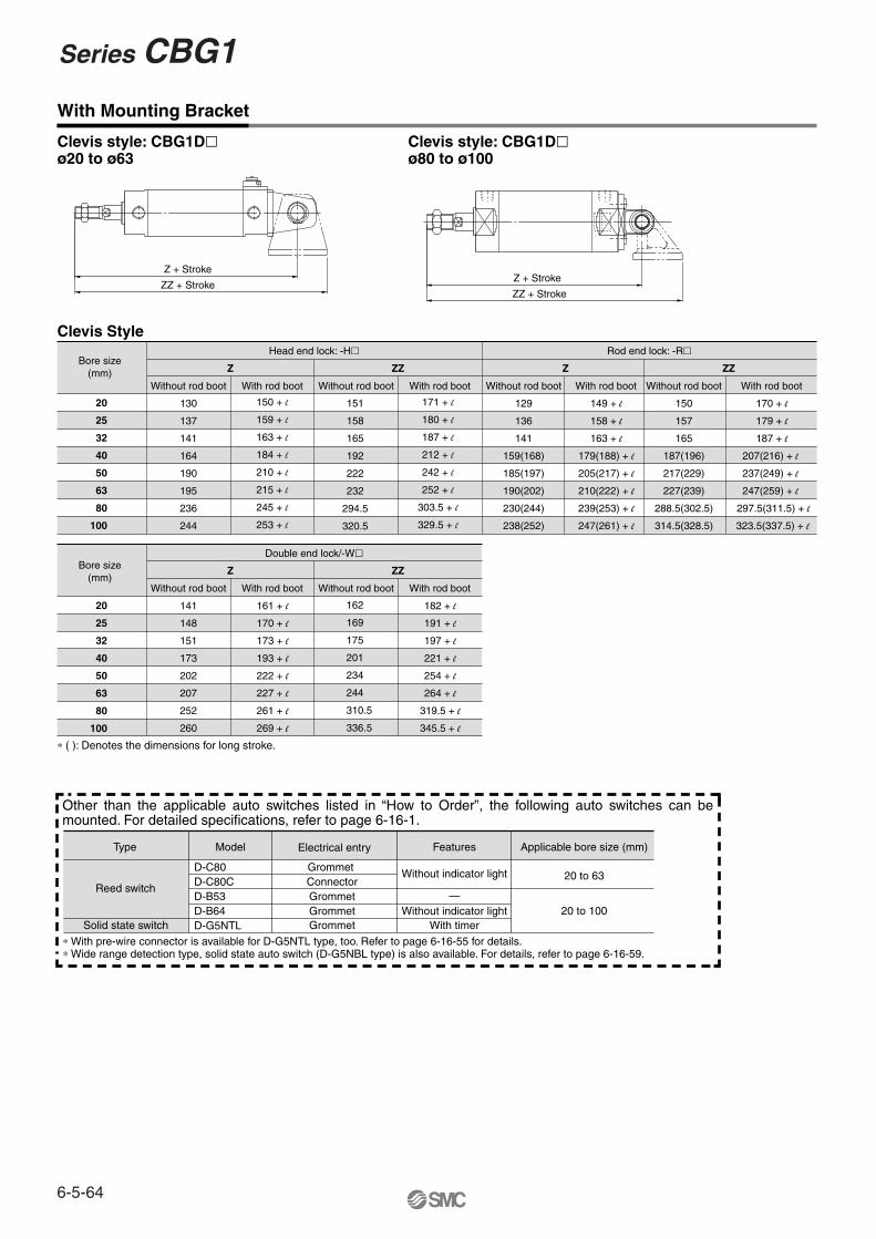
Bore size(mm)
Bore size(mm)
Z
Head end lock: -H�
Without rod boot
130
137
141
164
190
195
236
244
With rod boot
ZZ
Without rod boot With rod boot
Z
Rod end lock: -R�
Without rod boot
129
136
141
159(168)
185(197)
190(202)
230(244)
238(252)
With rod boot
149 + l
158 + l
163 + l
179(188) + l
205(217) + l
210(222) + l
239(253) + l
247(261) + l
ZZ
Without rod boot
150
157
165
187(196)
217(229)
227(239)
288.5(302.5)
314.5(328.5)
With rod boot
170 + l
179 + l
187 + l
207(216) + l
237(249) + l
247(259) + l
297.5(311.5) + l
323.5(337.5) + l
Z
Double end lock/-W�
Without rod boot
141
148
151
173
202
207
252
260
With rod boot
161 + l
170 + l
173 + l
193 + l
222 + l
227 + l
261 + l
269 + l
ZZ
Without rod boot With rod boot
182 + l
191 + l
197 + l
221 + l
254 + l
264 + l
319.5 + l
345.5 + l
∗ ( ): Denotes the dimensions for long stroke.
Clevis Style
Clevis style: CBG1D�ø80 to ø100
ZZ + Stroke
Z + Stroke
Clevis style: CBG1D�ø20 to ø63
ZZ + Stroke
Z + Stroke
With Mounting Bracket
Type Model Features
Without indicator light
—Without indicator light
With timer
Applicable bore size (mm)
20 to 63
20 to 100
Electrical entry
D-C80D-C80CD-B53D-B64D-G5NTL
Grommet ConnectorGrommetGrommet
∗ With pre-wire connector is available for D-G5NTL type, too. Refer to page 6-16-55 for details.∗ Wide range detection type, solid state auto switch (D-G5NBL type) is also available. For details, refer to page 6-16-59.
Reed switch
Solid state switch Grommet
150 + l
159 + l
163 + l
184 + l
210 + l
215 + l
245 + l
253 + l
171 + l
180 + l
187 + l
212 + l
242 + l
252 + l
303.5 + l
329.5 + l
162
169
175
201
234
244
310.5
336.5
20
25
32
40
50
63
80
100
20
25
32
40
50
63
80
100
151
158
165
192
222
232
294.5
320.5
Other than the applicable auto switches listed in “How to Order”, the following auto switches can be mounted. For detailed specifications, refer to page 6-16-1.
Series CBG1
6-5-64
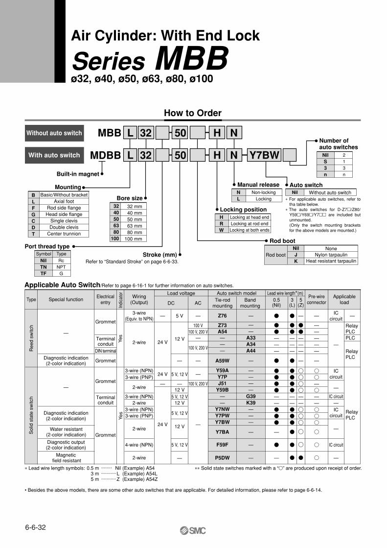
How to Order
Built-in magnet
MDBB
Air Cylinder: With End Lock
Series MBBø32, ø40, ø50, ø63, ø80, ø100
MBB L 32 50
Y7BW
H N
H NL 32 50
Special functionTypeElectrical
entry
Grommet
Grommet
Grommet
Indi
cato
r
Wiring(Output)
2-wire
3-wire(Equiv. to NPN)
Load voltage
—
ACDC
Lead wire length∗(m)
ICcircuit
RelayPLC
RelayPLC
PLC
Applicableload
• Besides the above models, there are some other auto switches that are applicable. For detailed information, please refer to page 6-6-14.
Z76
P5DW
Z73A54———
A59W
Y59AY7PJ51
Y59B——
Y7NWY7PWY7BW
Y7BA
F59F
——
A33A34A44
—
————
G39K39———
—
—
—
—
—
5 V
100 V100 V, 200 V
100 V, 200 V
100 V, 200 V
12 V —
—
—5 V, 12 V
12 V
12 V
5 V, 12 V
5 V, 12 V
12 V
5 V, 12 V
—
—
—
—
—
Yes
Grommet
Diagnostic output(2-color indication)
Magnetic field resistant
Diagnostic indication(2-color indication)
Water resistant(2-color indication)
Diagnostic indication(2-color indication)
—
—
Yes
2-wire
2-wire
3-wire (NPN)3-wire (PNP)
2-wire
3-wire (NPN)3-wire (PNP)
4-wire (NPN)
24 V
24 V
—
24 V
ICcircuit
—
IC circuit—IC
circuit
IC circuit
—
—
RelayPLC
Auto switch model
—
—————
—
—
——
—
3-wire (NPN)2-wire
0.5(Nil)
3(L)
5(Z)
———
——
—
—
———
——
—
———
—
——
Port thread type
NilTNTF
RcNPT
G
MountingBLFGCDT
Basic/Without bracketAxial foot
Rod side flangeHead side flange
Single clevisDouble clevis
Center trunnion
Bore size3240506380
100
32 mm 40 mm 50 mm 63 mm 80 mm100 mm
Stroke (mm) Refer to “Standard Stroke” on page 6-6-33.
NL
Non-lockingLocking
Manual release
HRW
Locking at head endLocking at rod end
Locking at both ends
Locking position
NilS3n
213n
Number of auto switches
Auto switchNil Without auto switch
Rod bootNilJK
NoneNylon tarpaulin
Heat resistant tarpaulinRod boot
Ree
d sw
itch
Sol
id s
tate
sw
itch
∗∗ Solid state switches marked with a “�” are produced upon receipt of order.∗ Lead wire length symbols: 0.5 m ········ Nil (Example) A543 m ··········· L (Example) A54L5 m ···········Z (Example) A54Z
DIN terminal
Terminalconduit
Terminalconduit
Tie-rodmounting
Bandmounting
Pre-wireconnector
Symbol Type
With auto switch
Without auto switch
Applicable Auto Switch/Refer to page 6-16-1 for further information on auto switches.
∗ For applicable auto switches, refer to tha table below.
∗ The auto switches for D-Z7�/Z80/ Y59�/Y69�/Y7�� are included but unmounted.(Only the switch mounting brackets for the above models are mounted.)
6-6-32
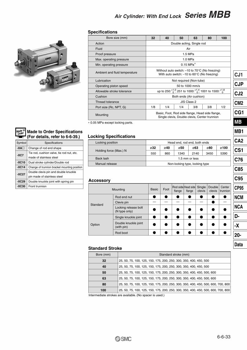
Accessory
MountingCenter
trunnion
Specifications Bore size (mm)
Action
Fluid
Proof pressure
Max. operating pressure
Min. operating pressure
Lubrication
Operating piston speed
Allowable stroke tolerance
Cushion
Thread tolerance
Port size (Rc, NPT, G)
Double acting, Single rod
Air
1.5 MPa
1.0 MPa
0.15 MPa∗
Without auto switch: –10 to 70°C (No freezing)With auto switch: –10 to 60°C (No freezing)
Not required (Non-lube)
50 to 1000 mm/s
up to 250: , 251 to 1000: , 1001 to 1500:
Both ends (Air cushion)
JIS Class 2
—
Mounting
32 40 50 63 80 100
1/8 1/4 1/4 3/8 3/8 1/2
Basic, Foot, Rod side flange, Head side flange,Single clevis, Double clevis, Center trunnion
Doubleclevis
Singleclevis
—
Head sideflange
—
Rod sideflange
——
Basic
—
Rod end nut
Clevis pin
Double knuckle joint(with pin)
Standard
Option
∗ 0.05 MPa except locking parts.
Locking Specifications
Holding force (Max.) N
Head end, rod end, both ends
1.5 mm or less
Non-locking type, locking type
ø32 ø40 ø50 ø63 ø80 ø100
Locking position
Back lash
Manual release
550 860 1340 2140 3450 5390
Single knuckle joint
Rod boot
Locking release bolt(N type only)
Foot
Ambient and fluid temperature
-XA�
-XC7
-XC10
-XC14
-XC27
-XC29
-XC30
Change of rod end shape
Tie rod, cushion valve, tie rod nut, etc.
made of stainless steel
Dual stroke cylinder/Double rod
Change of trunnion bracket mounting position
Double clevis pin and double knuckle
pin made of stainless steel
Double knuckle joint with spring pin
Front trunnion
Symbol Specifications
Standard StrokeBore (mm) Standard stroke (mm)
32
40
50
63
80
100
25, 50, 75, 100, 125, 150, 175, 200, 250, 300, 350, 400, 450, 500
25, 50, 75, 100, 125, 150, 175, 200, 250, 300, 350, 400, 450, 500, 600
25, 50, 75, 100, 125, 150, 175, 200, 250, 300, 350, 400, 450, 500
25, 50, 75, 100, 125, 150, 175, 200, 250, 300, 350, 400, 450, 500, 600, 700, 800
25, 50, 75, 100, 125, 150, 175, 200, 250, 300, 350, 400, 450, 500, 600
25, 50, 75, 100, 125, 150, 175, 200, 250, 300, 350, 400, 450, 500, 600, 700, 800
Intermediate strokes are available. (No spacer is used.)
+1.0 0
+1.4 0
+1.8 0
Made to Order Specifications(For details, refer to 6-6-39.)
6-6-33
CJ1
CJP
CJ2
CM2
CG1
MB
MB1
CA2
CS1
C76
C85
C95
CP95
NCM
NCA
D-
-X
20-
Data
Series MBBAir Cylinder: With End Lock
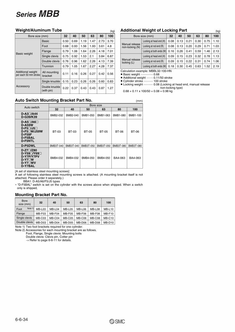
Mounting Bracket Part No.
32
MB-L03
MB-F03
MB-C03
MB-D03
40
MB-L04
MB-F04
MB-C04
MB-D04
50
MB-L05
MB-F05
MB-C05
MB-D05
63
MB-L06
MB-F06
MB-C06
MB-D06
80
MB-L08
MB-F08
MB-C08
MB-D08
100
MB-L10
MB-F10
MB-C10
MB-D10
Auto Switch Mounting Bracket Part No.
Auto switchBore size
32 40 50 63 80 100
BMB2-032 BMB2-040 BMB1-050 BMB1-063 BMB1-080 BMB1-100
BMB4-032 BMB4-032 BMB4-050 BMB4-050 BA4-063 BA4-063
BMB3T-040 BMB3T-040 BMB3T-050 BMB3T-050 BMB3T-080 BMB3T-080
BT-03 BT-03 BT-05 BT-05 BT-06 BT-06
D-A3�/A44D-G39/K39
D-A5�/A6�D-A59WD-F5�/J5�D-F5�W/J59WD-F59FD-F5BALD-F5NTL
D-P5DWLD-Z7�/Z80D-Y59�/Y69�D-Y7P/Y7PVD-Y7�WD-Y7�WVD-Y7BAL
(mm)
Weight/Aluminum TubeBore size (mm)
Basic
Foot
Flange
Single clevis
Double clevis
Trunnion
Single knuckle
Double knuckle(with pin)
32
0.50
0.68
0.79
0.75
0.76
0.79
0.15
0.22
40
0.69
0.93
1.06
0.92
0.96
1.05
0.23
0.37
50
1.19
1.56
1.64
1.53
1.62
1.67
0.26
0.43
63 80
2.73
3.61
4.18
3.84
4.13
4.28
0.60
0.87
3.70
4.8
7.01
6.87
7.39
7.37
0.83
1.27
100
Basic weight
Additional weightper each 50 mm stroke
Accessory
All mountingbracket
0.11 0.16 0.26
1.47
1.93
2.26
2.1
2.26
2.27
0.26
0.43
0.27 0.42 0.56
(kg) Additional Weight of Locking PartBore size (mm)
Locking at head end (H)
Locking at rod end (R)
Locking at both ends (W)
Locking at head end (H)
Locking at rod end (R)
Locking at both ends (W)
32
0.08
0.08
0.16
0.09
0.09
0.18
40
0.13
0.13
0.26
0.15
0.15
0.30
50
0.21
0.20
0.41
0.23
0.22
0.45
63
0.30
0.29
0.59
0.32
0.31
0.63
80
0.75
0.71
1.46
0.78
0.74
1.52
100
1.10
1.03
2.13
1.13
1.06
2.19
Manual releasenon-locking (N)
Calculation example: MBBL32-100-HN� Basic weight ··············· 0.68� Additional weight ········ 0.11/50 stroke� Cylinder stroke ··········· 100 stroke� Locking weight ··········· 0.08 (Locking at head end, manual release
non-locking type) 0.68 + 0.11 x 100/50 + 0.08 = 0.98 kg
(kg)
Manual releaselocking (L)
Note 1) Two foot brackets required for one cylinder.Note 2) Accessories for each mounting bracket are as follows.
Foot, Flange, Single clevis: Mounting boltsDouble clevis: Clevis pin, Cotter pin→ Refer to page 6-6-11 for details.
Foot
Flange
Single clevis
Double clevis
Note 1)
Boresize (mm)
[A set of stainless steel mounting screws] A set of following stainless steel mounting screws is attached. (A mounting bracket itself is not attached. Please order it separately.) BBA1: D-A5/A6/F5/J5 types∗ “D-F5BAL” switch is set on the cylinder with the screws above when shipped. When a switch
only is shipped,
6-6-34
Series MBB
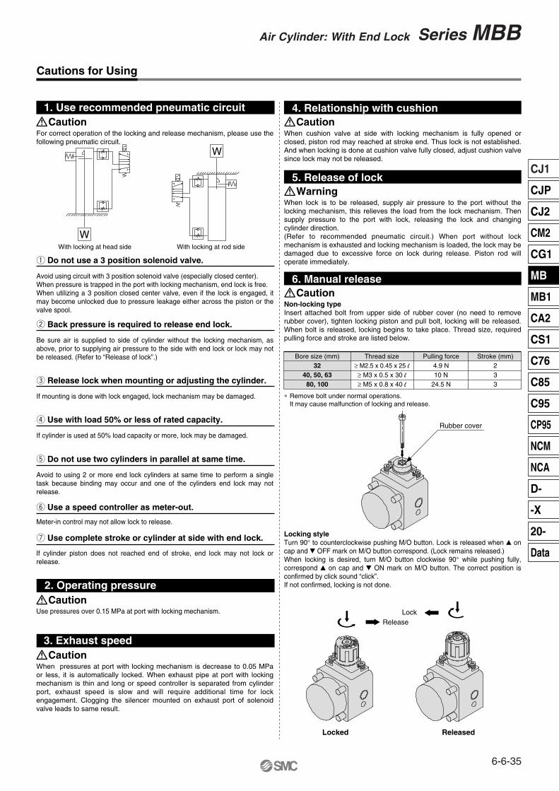
Cautions for Using
For correct operation of the locking and release mechanism, please use the following pneumatic circuit.
When cushion valve at side with locking mechanism is fully opened or closed, piston rod may reached at stroke end. Thus lock is not established. And when locking is done at cushion valve fully closed, adjust cushion valve since lock may not be released.
Avoid using circuit with 3 position solenoid valve (especially closed center).When pressure is trapped in the port with locking mechanism, end lock is free.When utilizing a 3 position closed center valve, even if the lock is engaged, it may become unlocked due to pressure leakage either across the piston or the valve spool.
q Do not use a 3 position solenoid valve.
4. Relationship with cushion1. Use recommended pneumatic circuit
Be sure air is supplied to side of cylinder without the locking mechanism, as above, prior to supplying air pressure to the side with end lock or lock may not be released. (Refer to “Release of lock”.)
w Back pressure is required to release end lock.
If mounting is done with lock engaged, lock mechanism may be damaged.
e Release lock when mounting or adjusting the cylinder.
If cylinder is used at 50% load capacity or more, lock may be damaged.
r Use with load 50% or less of rated capacity.
Avoid to using 2 or more end lock cylinders at same time to perform a single task because binding may occur and one of the cylinders end lock may not release.
t Do not use two cylinders in parallel at same time.
Meter-in control may not allow lock to release.
y Use a speed controller as meter-out.
If cylinder piston does not reached end of stroke, end lock may not lock or release.
u Use complete stroke or cylinder at side with end lock.
Use pressures over 0.15 MPa at port with locking mechanism.
2. Operating pressure
When pressures at port with locking mechanism is decrease to 0.05 MPa or less, it is automatically locked. When exhaust pipe at port with locking mechanism is thin and long or speed controller is separated from cylinder port, exhaust speed is slow and will require additional time for lock engagement. Clogging the silencer mounted on exhaust port of solenoid valve leads to same result.
3. Exhaust speed
When lock is to be released, supply air pressure to the port without the locking mechanism, this relieves the load from the lock mechanism. Then supply pressure to the port with lock, releasing the lock and changing cylinder direction.(Refer to recommended pneumatic circuit.) When port without lock mechanism is exhausted and locking mechanism is loaded, the lock may be damaged due to excessive force on lock during release. Piston rod will operate immediately.
5. Release of lock
Non-locking typeInsert attached bolt from upper side of rubber cover (no need to remove rubber cover), tighten locking piston and pull bolt, locking will be released. When bolt is released, locking begins to take place. Thread size, required pulling force and stroke are listed below.
6. Manual release
Bore size (mm)32
40, 50, 6380, 100
Thread size≥ M2.5 x 0.45 x 25 l≥ M3 x 0.5 x 30 l≥ M5 x 0.8 x 40 l
Pulling force4.9 N10 N
24.5 N
Stroke (mm)233
∗ Remove bolt under normal operations.It may cause malfunction of locking and release.
Locking styleTurn 90° to counterclockwise pushing M/O button. Lock is released when � on cap and � OFF mark on M/O button correspond. (Lock remains released.)When locking is desired, turn M/O button clockwise 90° while pushing fully, correspond � on cap and � ON mark on M/O button. The correct position is confirmed by click sound “click”.If not confirmed, locking is not done.
Locked Released
LockRelease
Rubber cover
W
WWith locking at head side With locking at rod side
Caution
Caution
Caution
Caution
Warning
Caution
6-6-35
CJ1
CJP
CJ2
CM2
CG1
MB
MB1
CA2
CS1
C76
C85
C95
CP95
NCM
NCA
D-
-X
20-
Data
Series MBBAir Cylinder: With End Lock
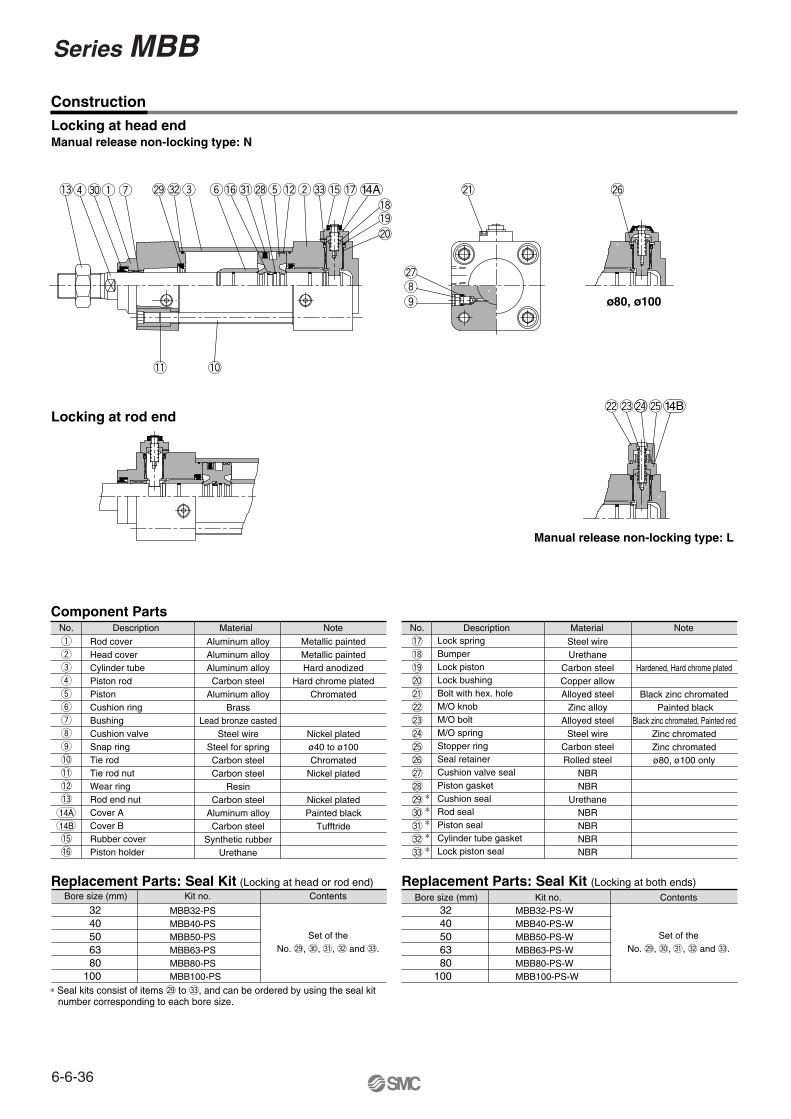
Construction
r!3 q u @9
!1 !0
Locking at rod end
#0 #2e y!6#1@8t!2w#3!5!7!8!9@0
@1 @6
@7io
@2@3 N@4@5
14A
ø80, ø100
Manual release non-locking type: L
Replacement Parts: Seal Kit (Locking at both ends)
MBB32-PS-WMBB40-PS-WMBB50-PS-WMBB63-PS-WMBB80-PS-WMBB100-PS-W
3240506380
100
Kit no.Bore size (mm) Contents
Locking at head endManual release non-locking type: N
No.
q
w
e
r
t
y
u
i
o
!0
!1
!2
!3
14A14B!5
!6
Description
Rod coverHead coverCylinder tubePiston rodPistonCushion ringBushingCushion valveSnap ringTie rodTie rod nutWear ringRod end nutCover ACover BRubber coverPiston holder
Aluminum alloyAluminum alloyAluminum alloyCarbon steel
Aluminum alloyBrass
Lead bronze castedSteel wire
Steel for springCarbon steelCarbon steel
ResinCarbon steel
Aluminum alloyCarbon steel
Synthetic rubberUrethane
Material Note
Component Parts
Replacement Parts: Seal Kit (Locking at head or rod end)
MBB32-PSMBB40-PSMBB50-PSMBB63-PSMBB80-PSMBB100-PS
3240506380
100
Kit no.
Metallic paintedMetallic paintedHard anodized
Hard chrome platedChromated
Nickel platedø40 to ø100Chromated
Nickel plated
Nickel platedPainted black
Tufftride
Bore size (mm) Contents
Set of theNo. @9, #0, #1, #2 and #3.
Set of theNo. @9, #0, #1, #2 and #3.
∗ Seal kits consist of items @9 to #3, and can be ordered by using the seal kit number corresponding to each bore size.
No.
!7
!8
!9
@0
@1
@2
@3
@4
@5
@6
@7
@8
@9
#0
#1
#2
#3
DescriptionLock springBumperLock pistonLock bushingBolt with hex. holeM/O knobM/O boltM/O springStopper ringSeal retainerCushion valve sealPiston gasketCushion sealRod sealPiston sealCylinder tube gasketLock piston seal
Steel wireUrethane
Carbon steelCopper allowAlloyed steel
Zinc alloyAlloyed steel
Steel wireCarbon steelRolled steel
NBRNBR
UrethaneNBRNBRNBRNBR
Material Note
Hardened, Hard chrome plated
Black zinc chromated Painted black
Black zinc chromated, Painted redZinc chromatedZinc chromatedø80, ø100 only
∗∗∗∗∗
14B
6-6-36
Series MBB

Basic: (B)
øE
HN
øM
O
Manual release non-locking type: N Manual release locking type: L
�B
�C
HR
W V Port
øR
F
Width across flats MB
MA
FKA N
H
ZZ + Stroke
NB
LL
DL
S + Stroke
2 x 4-J
2-PG
MMGB
øDøE
Cushion valve
WL
Locking at head end: MBBB
Bore size Stroke
Bore size Stroke
Bore size Stroke H�
Locking at rod end: MBBB R�
Locking at both ends: MBBB W�
Effectivethread
101418182226
3240506380
100
to 500to 500to 600to 600to 800to 800
Stroke range(mm)
Effectivethreadlength
Widthacrossflats
Bore size(mm)
Stroke range(mm)
Bore size(mm)
-H�/-R�
19.52732323737
223035354040
A
4652657595
114
B
32.53846.556.57289
C
121620202530
D
91213131616
DL
303540454555
E
131314142020
F
131415.516.51919
G
212727.528.53737
GB
475158587272
H
33.538.545506271.5
HR
4552.5596476.586
HN
M6 x 1.0M6 x 1.0
M8 x 1.25M8 x 1.25M10 x 1.5M10 x 1.5
J
6677
1010
K
152121213030
LL
161616161616
MA
445555
MB
M10 x 1.25M14 x 1.5M18 x 1.5M18 x 1.5M22 x 1.5M26 x 1.5
MM
3240506380
100
to 500to 500to 600to 600to 800to 800
191919192323
MO
272731.531.53838
N
354043.543.55656
NB
1/81/41/43/83/81/2
P
111111112121
RF
9297
106106132132
S
4 4 5 911.517
V
6.5 910.5121415
W
242424244040
WL
143152168168208208
ZZ
100110118118150150
S
151165180180226226
ZZ
-W�
(mm)
6-6-37
CJ1
CJP
CJ2
CM2
CG1
MB
MB1
CA2
CS1
C76
C85
C95
CP95
NCM
NCA
D-
-X
20-
Data
Series MBBAir Cylinder: With End Lock

With Mounting Bracket
Foot(L)/Locking at head end (-H�)
LY
X
LS + Stroke
ZZ + Stroke
Y X Y
4-øLD LH
LX
LZ
PortCushion valve
Front flange(F)/Locking at head end (-H�)
Port
Cushion valve4-øFD
FYB
FX
FZ
FE FT
øF
d
Rear flange(G)/Locking at head end (-H�)Cushion valve
FT
ZZ + Stroke
B
Port4-øFD
FX
FZ
FY
Single clevis(C)/Locking at head end (-H�)
øCDH10
Z + Stroke
U
L RR
ZZ + Stroke
PortCushion valve
CX
Double clevis(D)/Locking at head end (-H�)
CX
CZ
PortCushion valve
Z + StrokeL RR
ZZ + Stroke
U
øCDH10
Center trunnion(T)/Locking at head end (-H�)
PortCushion valve
TXTZ
øT
De8
TY
TT
Z + 1/2 + Stroke
3240506380
100
to 500to 500to 600to 600to 800to 800
121616202025
TDe8
172222283440
TT
50637590
110132
TX
49587187
110136
TY
7495
107130150182
TZ
8993
105105129129
Z
97106117117147147
Z
3240506380
100
to 500to 500to 600to 600to 800to 800
232330304242
L
10.51115152323
RR
131317172626
U
101014142222
CDH10
141420203030
CX
282840406060
CZ
162171194194246246
Z
172.5182209209269269
ZZ
170184206206264264
Z
180.5195221221287287
ZZ
3240506380
100
to 500to 500to 600to 600to 800to 800
232330304242
L
10.51115152323
RR
131317172626
U
101014142222
CDH10
141420203030
CX
162171194194246246
Z
172.5182209209269269
ZZ
170184206206264264
Z
180.5195221221287287
ZZ
3240506380
100
to 500to 500to 600to 600to 800to 800
50557080
100120
B
7999
1214
FD
101012121616
FT
647290
100126150
FX
323645506375
FY
7990
110120153178
FZ
149158176176220220
ZZ
157171188188238238
ZZ
-W�
3240506380
100
to 700to 800to 1000to 1000to 1000to 1000
50557080
100120
B
7999
1214
FD
332244
FE
101012121616
FT
647290
100126150
FX
323645506375
FY
7990
110120153178
FZ
253138.539.545.554
Fd
3240506380
100
to 700to 800to 1000to 1000to 1000to 1000
Strokerange
Bore size(mm)
Strokerange
Bore size(mm)
Strokerange
Bore size(mm)
Strokerange
Bore size(mm)
Strokerange
Bore size(mm)
Strokerange
Bore size(mm)
222427273032
X
91111141416
Y
799
121214
LD
303340455565
LH
136145160160192196
LS
3.23.23.23.64.54.5
LT
323846567289
LX
535972.582.5102.5122
LY
50557080
100120
LZ
170183202205248252
ZZ
144158172172210214
LS
178196214217266270
ZZ
-W�
-H�/ -R�
-W�-H�/ -R�
-H�/ -R�/ -W�
-H�/ -R�
-0.1-0.3
+0.3+0.1
(mm)
(mm)
(mm)
(mm)
-W�-H�/ -R�
-H� -R�/ -W�
(mm)
(mm)
6-6-38
Series MBB
Related Documents