Maximum allowable stroke when using clevis bracket Mounting angle (DEG.) Stroke (mm) Allowable lateral load equal to the CS1 series Even if rod diameter is changed to suit various needs, function remains equal to the CS1 series. Allowable lateral load of CS1 and CS2 100 0 200 300 400 Stroke (mm) Allowable lateral load (N) 160 125&140 Double Rod Type Smooth Cylinder Standard Weight Maximum stroke when using rotating bracket Expanded by 1.6 times (compared to the CS1 series) Lighter cylinder reduces self-weight deflection. Stroke range extended to widen use. 400 0 800 1200 1600 CS1 27.2 kg CS2 11.3 kg 1.6 times 35 30 25 20 15 10 5 0 Double Rod Type 30.1 13.1 CS1W CS2W Standard 27.2 11.3 CS1 CS2 58% Reduction Weight (kg) 57% Reduction 0 500 1,000 1,200 1,500 0 15 30 45 60 75 90 CS2 CS1 CS2 CS1 Mounting angle 45° 650 410 Series CS2 Series Air Cylinder ø125, ø140, ø160 CS1 CS2 Weight Comparison (Basic Type ø160-100st) Mounting angle Lighter installation achieved by reducing weight. Die cast rod cover and head cover used to achieve greater weight reduction. Rod bore size changed to suit uses, achieving greater weight reduction. Reduced by Max. 565 CJ1 CJP CJ2 JCM CM2 CM3 CG1 CG3 MB JMB MB1 CA2 CS1 D- -X Technical Data CS2

Welcome message from author
This document is posted to help you gain knowledge. Please leave a comment to let me know what you think about it! Share it to your friends and learn new things together.
Transcript
Maximum allowable stroke when using clevis bracket
Mounting angle (DEG.)
Str
oke
(mm
)
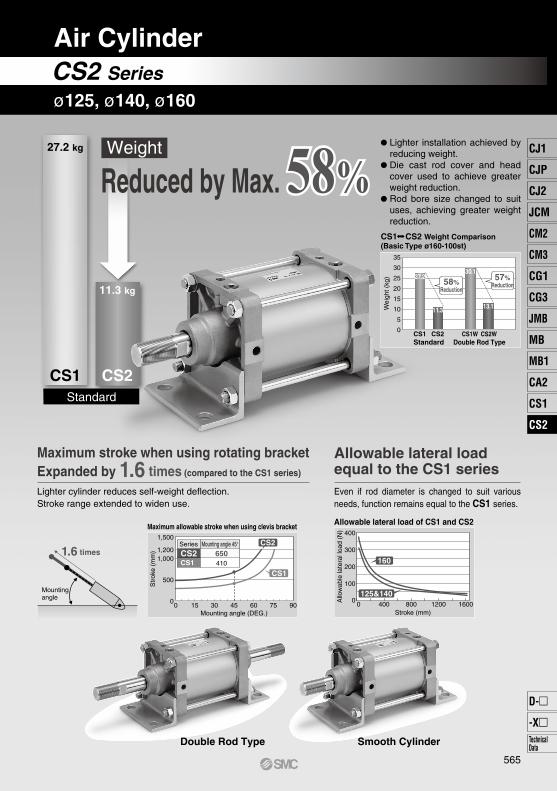
Allowable lateral loadequal to the CS1 seriesEven if rod diameter is changed to suit various needs, function remains equal to the CS1 series.
Allowable lateral load of CS1 and CS2
100
0
200
300
400
Stroke (mm)
Allo
wab
le la
tera
l loa
d (N
)
160
125&140
Double Rod Type Smooth Cylinder
Standard
Weight
Maximum stroke when using rotating bracketExpanded by 1.6 times (compared to the CS1 series)
Lighter cylinder reduces self-weight deflection.Stroke range extended to widen use.
4000 800 1200 1600
CS1
27.2 kg
CS2
11.3 kg
1.6 times
35
30
25
20
15
10
5
0
Double Rod Type
30.1
13.1
CS1W CS2WStandard
27.2
11.3
CS1 CS2
58%Reduction
Wei
ght (
kg) 57%
Reduction
0
500
1,0001,200
1,500
0 15 30 45 60 75 90
CS2
CS1
CS2CS1
Mounting angle 45°650410
Series
CS2 Series
Air Cylinder
ø125, ø140, ø160
CS1 CS2 Weight Comparison (Basic Type ø160-100st)
Mountingangle
Lighter installation achieved by reducing weight.Die cast rod cover and head cover used to achieve greater weight reduction.Rod bore size changed to suit uses, achieving greater weight reduction.
Reduced by Max.
565
CJ1
CJP
CJ2
JCM
CM2
CM3
CG1
CG3
MB
JMB
MB1
CA2
CS1
CS2
D-
-XTechnicalData
CS2
Air Cylinder
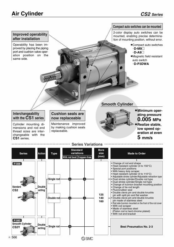
Operability has been im-proved by placing the piping port and cushion valve oper-ation position on the same side.
Improved operabilityafter installation
Cylinder mounting di-mensions and rod end thread sizes are inter-changeable with the CS1 series.
Interchangeabilitywith the CS1 series
Maintenance improved by making cushion seals replaceable.
Cushion seals arenow replaceable
Smooth Cylinder
Minimum oper-ating pressure
0.005 MPaRealize stable, low speed op-eration at even
5 mm/s
Series Action TypeStandard variations
With rod boot Copper-free
Boresize(mm)
Made to Order
Series Variations
CS2 Series
Compact auto switches·D-M9·D-A9Magnetic field resistantauto switch·D-P3DWA
• Change of rod end shape• Heat-resistant cylinder (0 to 150°C)• Special port positions• With heavy duty scraper• Heat resistant cylinder (0 to 110°C)• Adjustable stroke cylinder/Adjustable retraction type• Dual stroke cylinder/Double rod type• Dual stroke cylinder/Single rod type• Change of trunnion bracket mounting position• Change of tie-rod length• Fluororubber seal• Double clevis pin and double knuckle
pin with split pin and flat washer• Double clevis pin and double knuckle
pin made of stainless steel• Rod side trunnion mounted on the front of the rod cover• With coil scraper• Made of stainless steel (Piston rod is hard chrome plated)• With rod end bracket
2-color display auto switches can be mounted, enabling precise determina-tion of mounting position, without error.
Compact auto switches can be mounted
StandardCS2
Smooth CylinderCS2Y Best Pneumatics No. 2-3
P.568
P.583
Doubleacting
Doubleacting
Single rod
Single rod
Double rod125140160
566A
CS2 Series
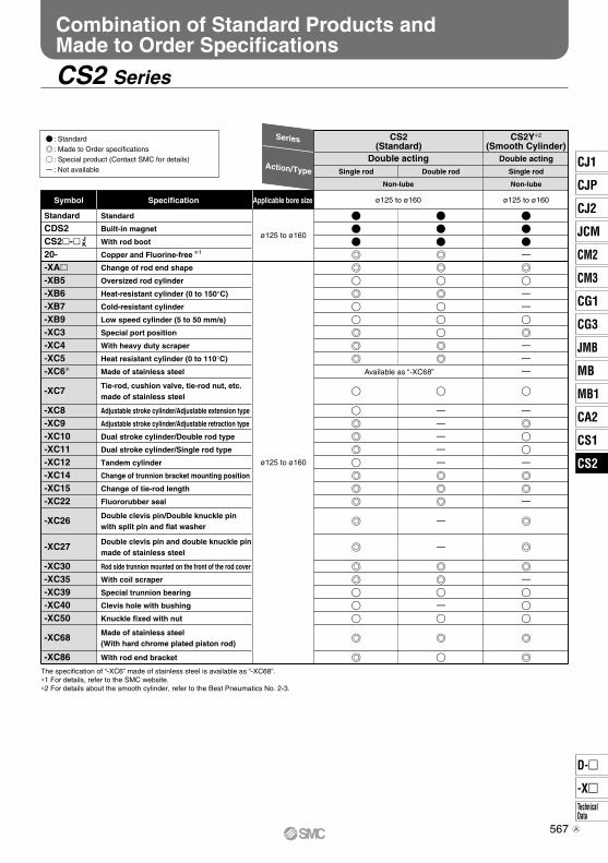
Combination of Standard Products and Made to Order Specifications
: Standard: Made to Order specifications: Special product (Contact SMC for details): Not available
Symbol
Series CS2(Standard)
Action/Type Single rod
Non-lube
Double acting Double acting
Applicable bore sizeSpecification
Standard
Built-in magnet
With rod boot
Copper and Fluorine-free ∗1
Change of rod end shape
Oversized rod cylinder
Heat-resistant cylinder (0 to 150°C)
Cold-resistant cylinder
Low speed cylinder (5 to 50 mm/s)
Special port position
With heavy duty scraper
Heat resistant cylinder (0 to 110°C)
Made of stainless steel
Tie-rod, cushion valve, tie-rod nut, etc. made of stainless steel
Adjustable stroke cylinder/Adjustable extension type
Adjustable stroke cylinder/Adjustable retraction type
Dual stroke cylinder/Double rod type
Dual stroke cylinder/Single rod type
Tandem cylinder
Change of trunnion bracket mounting position
Change of tie-rod length
Fluororubber seal
Double clevis pin/Double knuckle pin
with split pin and flat washer
Double clevis pin and double knuckle pin made of stainless steel
Rod side trunnion mounted on the front of the rod cover
With coil scraper
Special trunnion bearing
Clevis hole with bushing
Knuckle fixed with nut
Made of stainless steel(With hard chrome plated piston rod)
With rod end bracket
ø125 to ø160
JK
Double rod
Non-lube
CS2Y∗2
(Smooth Cylinder)
Single rod
ø125 to ø160
ø125 to ø160
ø125 to ø160
Available as “-XC68”
The specification of “-XC6” made of stainless steel is available as “-XC68”.∗1 For details, refer to the SMC website.∗2 For details about the smooth cylinder, refer to the Best Pneumatics No. 2-3.
Standard
CDS2CS2-20--XA-XB5-XB6-XB7-XB9-XC3-XC4-XC5-XC6∗
-XC7
-XC8-XC9-XC10-XC11-XC12-XC14-XC15-XC22
-XC26
-XC27
-XC30-XC35-XC39-XC40-XC50
-XC68
-XC86
567
CJ1
CJP
CJ2
JCM
CM2
CM3
CG1
CG3
MB
JMB
MB1
CA2
CS1
CS2
D-
-XTechnicalData
CS2
A
CDS2
CS2
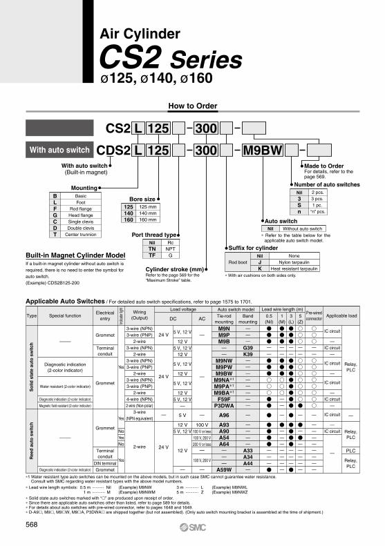
300125L M9BW
300125L
Built-in Magnet Cylinder ModelIf a built-in magnet cylinder without auto switch is required, there is no need to enter the symbol for auto switch. (Example) CDS2B125-200
Air Cylinder
CS2 Seriesø125, ø140, ø160
How to Order
With auto switch
With auto switch(Built-in magnet)
MountingBasicFoot
Rod flangeHead flangeSingle clevisDouble clevis
Center trunnion
BLFGCDT
Bore size125140160
125 mm140 mm160 mm
Port thread typeNilTNTF
RcNPT
G
Made to OrderFor details, refer to the page 569.
Auto switchNil Without auto switch
∗ Refer to the table below for the applicable auto switch model.
Number of auto switchesNil3Sn
2 pcs.3 pcs. 1 pc.
“n” pcs.
Suffix for cylinder
∗ With air cushions on both sides only.
NilJK
NoneNylon tarpaulin
Heat resistant tarpaulinRod boot
Cylinder stroke (mm)Refer to the page 569 for the“Maximum Stroke” table.
Applicable Auto Switches / For detailed auto switch specifications, refer to page 1575 to 1701.
A96
A93A90A54A64———
A59W
M9NM9PM9B
——
M9NWM9PWM9BW
M9NA∗1
M9PA∗1
M9BA∗1
F59FP3DWA
—
24 V
24 V
24 V
DC AC
—
—
PLC
5 V
12 V5 V, 12 V
12 V
—
5 V, 12 V
12 V5 V, 12 V
12 V
5 V, 12 V
12 V
5 V, 12 V
12 V5 V, 12 V
—
Type Special function
Diagnostic indication(2-color indicator)
Water resistant (2-color indicator)
Diagnostic indication (2-color indicator)
Magnetic field resistant (2-color indicator)
Diagnostic indication (2-color indicator)
—
—
So
lid s
tate
au
to s
wit
chR
eed
au
to s
wit
ch Grommet
Yes
Yes
Yes
Yes
No
No
Grommet
Terminalconduit
Grommet
Electricalentry
Terminalconduit
DIN terminalGrommet
Indica
tor lig
ht
3-wire (NPN)3-wire (PNP)
2-wire3-wire (NPN)
2-wire3-wire (NPN)3-wire (PNP)
2-wire3-wire (NPN)3-wire (PNP)
2-wire4-wire (NPN)2-wire (Non-polar)
3-wire(NPN equivalent)
2-wire
Wiring(Output)
—
—
100 V100 V or less100 V, 200 V200 V or less
—
100 V, 200 V
—
Load voltagePre-wiredconnector
Applicable loadAuto switch model Lead wire length (m)
Tie-rodmounting
Bandmounting
0.5(Nil)
3(L)
5(Z)
1(M)
———
G39K39————————
—
————
A33A34A44—
IC circuit
—IC circuit
—
IC circuit
—
IC circuit
—IC circuit
—
IC circuit
—IC circuit
—
Relay,PLC
Relay,PLC
Relay,PLC
∗ Lead wire length symbols: 0.5 m ·········· Nil (Example) M9NW 1 m ··········· M (Example) M9NWM
3 m ··········· L (Example) M9NWL5 m ··········· Z (Example) M9NWZ
∗1 Water resistant type auto switches can be mounted on the above models, but in such case SMC cannot guarantee water resistance. Consult with SMC regarding water resistant types with the above model numbers.
∗ Solid state auto switches marked with “” are produced upon receipt of order.∗ Since there are applicable auto switches other than listed, refer to page 589 for details.∗ For details about auto switches with pre-wired connector, refer to pages 1648 and 1649.∗ D-A9, M9, M9W, M9A, P3DWA are shipped together (but not assembled). (Only auto switch mounting bracket is assembled at the time of shipment.)
568
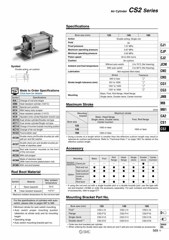
SymbolDouble acting, air cushion
Double acting, Single rod
Air
Bore size (mm) 125 140 160Action
Fluid
Proof pressure
Maximum operating pressure
Minimum operating pressure
Piston speed
Cushion
Ambient and fluid temperature
Lubrication
Mounting
Stroke length tolerance (mm)
1.57 MPa
0.97 MPa
0.05 MPa
50 to 500 mm/s
Air cushion
Not required (Non-lube)
Stroke
250 or less
251 to 1000
1001 to 1500
1501 to 1600
Basic, Foot, Rod flange, Head flange,
Single clevis, Double clevis, Center trunnion
Tolerance
+1.8 0
+2.2 0
+1.0 0
+1.4 0
Without auto switch
With auto switch
0 to 70°C (No freezing)
0 to 60°C (No freezing)
Air Cylinder CS2 Series
Made to Order SpecificationsClick here for details
Specifications
Maximum Stroke
125
140
160
Mountingbracket
Bore size
1000 or less1600 or less
Maximum stroke
Basic, Head flange,Single clevis, Double clevis,
Center trunnionFoot, Rod flange
(mm)
1200 or less
Accessory
BasicMounting Centertrunnion
Doubleclevis
Singleclevis
Head flange
Rod flange
Standard equipment Clevis pin
Rod end nut
Single knuckle joint
Rod boot
Foot
Option Double knuckle joint(Knuckle pin, Split pin)
∗ If using the rod end nut with a single knuckle joint or a double knuckle joint, use the type with rod end bracket (-XC86) or order the accessory separately. For part numbers and dimensions of accessories, refer to page 577.
Mounting Bracket Part No.
Foot∗
Flange
Single clevis
Double clevis∗∗
Bore size (mm) 125
CS2-L12
CS2-F12
CS2-C12
CS2-D12
140
CS2-L14
CS2-F14
CS2-C14
CS2-D14
160
CS2-L16
CS2-F16
CS2-C16
CS2-D16
∗ Order two foot brackets per cylinder.∗∗ When ordering the double clevis type, the clevis pin and 2 split pins are included as accessories.
Rod Boot Material
• Minimum stroke for auto switch mounting• Auto switch proper mounting position
(detection at stroke end) and its mounting height
• Operating range• Auto switch mounting bracket part no.
For the specifications of cylinders with auto-switch, please refer to pages 587 to 589.
∗ Maximum ambient temperature for the rod boot itself.
J
K
Nylon tarpaulin
Heat resistant tarpaulin
Symbol MaterialMax. ambienttemperature
70°C
110°C∗
Change of rod end shape
Heat-resistant cylinder (150°C)
Special port position
With heavy duty scraper
Heat resistant cylinder (110°C)
Adjustable stroke cylinder/Adjustable retraction type
Dual stroke cylinder/Double rod type
Dual stroke cylinder/Single rod type
Change of trunnion bracket mounting position
Change of tie-rod length
Fluororubber seal
With coil scraper
With rod end bracket
Symbol Specifications
Double clevis pin and double knuckle pinmade of stainless steel
Made of stainless steel(With hard chrome plated piston rod)
Double clevis pin/Double knuckle pin withsplit pin and flat washer
Rod side trunnion mounted on the front of the rod cover
-XA-XB6-XC3-XC4-XC5-XC9-XC10-XC11-XC14-XC15-XC22
-XC26
-XC27
-XC30
-XC35
-XC68
-XC86
∗ Using a stroke of a length which is smaller than the effective cushion length may result in reduced air cushion performance. Refer to “Technical Data 1” on page 1901 for details on the effective cushion length.
569
CJ1
CJP
CJ2
JCM
CM2
CM3
CG1
CG3
MB
JMB
MB1
CA2
CS1
CS2
D-
-XTechnicalData
CS2
B

Weight
(kg)
Bore size (mm)
Basicweight
Additional weight per each 100 mm of stroke
Additional weight with magnet(With built-in magnet and auto switch)
Accessorybracket
Basic
Foot
Rod flange
Head flange
Single clevis
Double clevis
Trunnion
Single knuckle
Rod end nut
125 140 160
Calculation: (Example) CS2L160-500• Basic weight ······················· 12.45 (kg)• Additional weight ················ 2.23 (kg/100 mm)• Cylinder stroke ··················· 500 (mm)
12.45 + 2.23 x 500/100 = 23.60 (kg)
5.46
7.49
8.51
8.51
8.53
8.99
9.59
0.07
1.55
0.91
1.37
0.16
6.50
9.50
12.03
12.03
10.79
11.54
12.23
0.07
1.67
1.16
1.81
0.16
9.07
12.45
15.80
15.80
14.56
15.41
15.47
0.08
2.23
1.56
2.48
0.23
Double knuckle (With Knuckle pin, Split pin)
OUT IN
Theoretical Output / Double Acting
Unit: N
Bore size(mm)
125
140
160
32
32
38
OUT
IN
OUT
IN
OUT
IN
12300
11500
15400
14600
20100
19000
Rod size(mm)
Piston area(mm2)
Operatingdirection
Operating pressure (MPa)
0.2 0.3 0.4 0.5 0.6 0.7 0.8 0.9 1.0
2460
2300
3080
2920
4020
3800
3690
3450
4620
4380
6030
5700
4920
4600
6160
5840
8040
7600
6150
5750
7700
7300
10100
9500
7380
6900
9240
8760
12100
11400
8610
8050
10800
10200
14100
13300
9840
9200
12300
11700
16100
15200
11100
10400
13900
13100
18100
17100
12300
11500
15400
14600
20100
19000
CS2 Series
1. Do not use the cylinder as a shock absorber.Using the cylinder as a shock absorber may cause damage.
2. Do not open the cushion valve beyond the stopper.As a retaining mechanism for the cushion valve, retaining ring is installed, and the cushion valve should not be opened beyond that point.If not operated in accordance with the above precautions, the cushion valve may be ejected from the cover when air pressure is supplied.To adjust the cushion valve, use the JIS B 4648 hexagon wrench key 4 (width across flats of cushion valve: 4).
3. Use the air cushion at the end of cylinder stroke.
Warning
Bore size(mm)
125, 140
160
1/2
3/428 to 30
Connecting threadnominal size
Proper tighteningtorque N·m
1. Regarding the installation of a knuckle jointPlease contact SMC if a knuckle joint must be installed on the piston rod by using the rod end nut.
2. Regarding the screw-in of fittings when pipingWhen ports and fittings are screwed in, tighten them with the proper tightening torque below.
3. Do not deform cushion rings when removing and assembling.Cushion rings are press molded products. If a cushion ring bumps with something when removing and assembling, the air cushion may not function properly due to cushion ring deformation.
4. Do not place tape or other objects onto the painted surface of the unit.The paint of the CS cylinder is dried naturally, so it may peel off if tape or another object is placed onto it.
Caution
570
L, F
G
C, D
T
L, F
G
L, F
G
P
(cm)
Air Cylinder CS2 Series
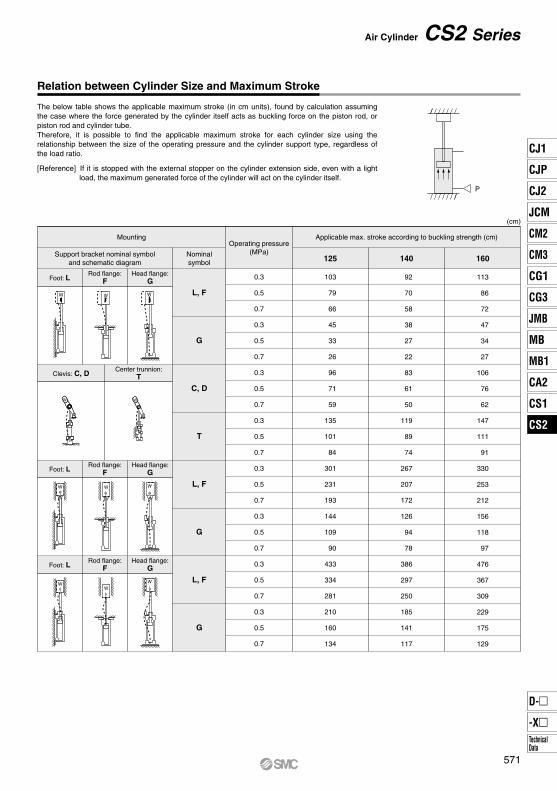
Relation between Cylinder Size and Maximum Stroke
[Reference] If it is stopped with the external stopper on the cylinder extension side, even with a light load, the maximum generated force of the cylinder will act on the cylinder itself.
The below table shows the applicable maximum stroke (in cm units), found by calculation assuming the case where the force generated by the cylinder itself acts as buckling force on the piston rod, or piston rod and cylinder tube.Therefore, it is possible to find the applicable maximum stroke for each cylinder size using the relationship between the size of the operating pressure and the cylinder support type, regardless of the load ratio.
Mounting Applicable max. stroke according to buckling strength (cm)Operating pressure
(MPa)Support bracket nominal symboland schematic diagram
Nominalsymbol 125 140 160
Foot: LRod flange:
FHead flange:
G
W W W
Foot: LRod flange:
FHead flange:
G
Foot: LRod flange:
FHead flange:
G
Center trunnion:TClevis: C, D
WW W
W W
WW
W
0.3
0.5
0.7
0.3
0.5
0.7
0.3
0.5
0.7
0.3
0.5
0.7
0.3
0.5
0.7
0.3
0.5
0.7
0.3
0.5
0.7
0.3
0.5
0.7
103
79
66
45
33
26
96
71
59
135
101
84
301
231
193
144
109
90
433
334
281
210
160
134
92
70
58
38
27
22
83
61
50
119
89
74
267
207
172
126
94
78
386
297
250
185
141
117
113
86
72
47
34
27
106
76
62
147
111
91
330
253
212
156
118
97
476
367
309
229
175
129
571
CJ1
CJP
CJ2
JCM
CM2
CM3
CG1
CG3
MB
JMB
MB1
CA2
CS1
CS2
D-
-XTechnicalData
CS2
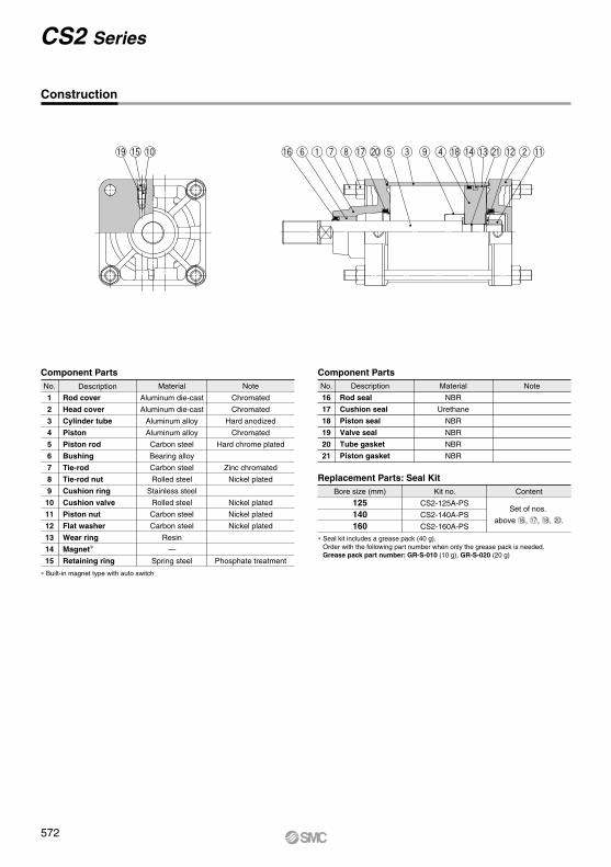
i!6 y q u !7 @0 t e o r !4!3@1 !2 w !1!8!9 !5 !0
CS2 Series
Construction
No.
1
2
3
4
5
6
7
8
9
10
11
12
13
14
15
Rod cover
Head cover
Cylinder tube
Piston
Piston rod
Bushing
Tie-rod
Tie-rod nut
Cushion ring
Cushion valve
Piston nut
Flat washer
Wear ring
Magnet∗
Retaining ring
Description
Component PartsMaterial
Aluminum die-cast
Aluminum die-cast
Aluminum alloy
Aluminum alloy
Carbon steel
Bearing alloy
Carbon steel
Rolled steel
Stainless steel
Rolled steel
Carbon steel
Carbon steel
Resin
—
Spring steel
Note
Chromated
Chromated
Hard anodized
Chromated
Hard chrome plated
Zinc chromated
Nickel plated
Nickel plated
Nickel plated
Nickel plated
Phosphate treatment
∗ Built-in magnet type with auto switch
125140160
Bore size (mm)
Replacement Parts: Seal KitKit no.
CS2-125A-PS
CS2-140A-PS
CS2-160A-PS
Content
∗ Seal kit includes a grease pack (40 g).Order with the following part number when only the grease pack is needed.Grease pack part number: GR-S-010 (10 g), GR-S-020 (20 g)
Component PartsNo.
16
17
18
19
20
21
Description Material
NBR
Urethane
NBR
NBR
NBR
NBR
Note
Rod seal
Cushion seal
Piston seal
Valve seal
Tube gasket
Piston gasket
Set of nos.
above !6, !7, !8, @0.
572
Width across flats KA
øe
f
Width across flats KA
MM
øE
øD
AAL
HK
F N
ZZ + Stroke
S + Stroke MN
G2 x P(Rc, NPT, G)
G Port VW
Cushion valve
øe
f
MM
øE
øD
HK
AAL
F G2 x P(Rc, NPT, G)
S + Stroke
G
LT NXY
ZZ + Stroke
LS + StrokeYN X
4 x øLD
Port
4 x J
VW
Cushion valve
LH
LY
B
LX
4 x J
B
C
BC
ZZ1 + l + Stroke
h + l
l
ZZ1 + l + Stroke
h + ll
(mm)
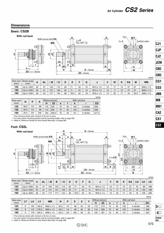
Bore size(mm)
Stroke range(mm)
125140160
Up to 1000
Up to 1000
Up to 1200
A
50
50
56
AL
47
47
53
143
157
177
115
128
144
D
32
32
38
E
71
71
78.5
F
43
43
42
G
15
15
18
J
M14 x 1.5
M14 x 1.5
M16 x 1.5
V
15
15
15
W
17
17
20
K
15
15
17
KA
27
27
34
M
27
27
30.5
MM
M30 x 1.5
M30 x 1.5
M36 x 1.5
N
30.5
30.5
34.5
P
1/2
1/2
3/4
S
98
98
106
(mm)
Bore size(mm)
Without rod boot With rod boot
125140160
H110
110
120
ZZ235
235
256.5
e75
75
75
f40
40
40
h133
133
141
1/5 stroke1/5 stroke1/5 stroke
ZZ1
258
258
277.5
∗ The minimum stroke with rod boot is 30 mm or more.∗∗ For auto switch mounting position and its mounting height, refer to page 587.
∗∗∗ Refer to “Minimum Stroke for Auto Switch Mounting” on page 588.
Dimensions
Basic: CS2BWith rod boot
Foot: CS2LWith rod boot
Air Cylinder CS2 Series
(mm)
Bore size(mm)
Stroke range(mm)
125140160
Up to 1600
Up to 1600
Up to 1600
A
50
50
56
AL
47
47
53
B
143
157
177
115
128
144
143
157
177
D
32
32
38
E
71
71
78.5
F
43
43
42
G
15
15
18
LH
85
100
106
LS
188
188
206
J
M14 x 1.5
M14 x 1.5
M16 x 1.5
V
15
15
15
W
17
17
20
K
15
15
17
KA
27
27
34
LD
19
19
19
LT LY
8
9
9
LX
100
112
118
(mm)
Bore size(mm)
Without rod boot With rod boot
125140160
H45
45
50
156.5
178.5
194.5
MM
M30 x 1.5
M30 x 1.5
M36 x 1.5
P
1/2
1/2
3/4
N
30.5
30.5
34.5
S
98
98
106
X
110
110
120
Y
20
30
25
ZZ273
283
301
e75
75
75
f40
40
40
h133
133
141
1/5 stroke1/5 stroke1/5 stroke
ZZ1
296
306
322
∗ The minimum stroke with rod boot is 30 mm or more.∗∗ For auto switch mounting position and its mounting height, refer to page 587.
∗∗∗ Refer to “Minimum Stroke for Auto Switch Mounting” on page 588.
B C
CB
l
l
573
CJ1
CJP
CJ2
JCM
CM2
CM3
CG1
CG3
MB
JMB
MB1
CA2
CS1
CS2
D-
-XTechnicalData
CS2
øe
f
Width across flats KA
MM
øD
øE
FTF
HK
AAL
N
ZZ + StrokeS + Stroke
G2 x P(Rc, NPT, G)
M
N
G
4 x øFD4 x J
PortVW
Cushion valve
FZFX
B FY
øe
f
Width across flats KA
MM
øE
øD
AAL
HK
F N
ZZ + Stroke
S + Stroke FTN
GG2 x P(Rc, NPT, G) 4 x øFD
4 x J
B FY
Port
VW
Cushion valve
FZFX
BC
BC
ZZ1 + l + Stroke
h + l
l
ZZ1 + l + Stroke
h + l
l
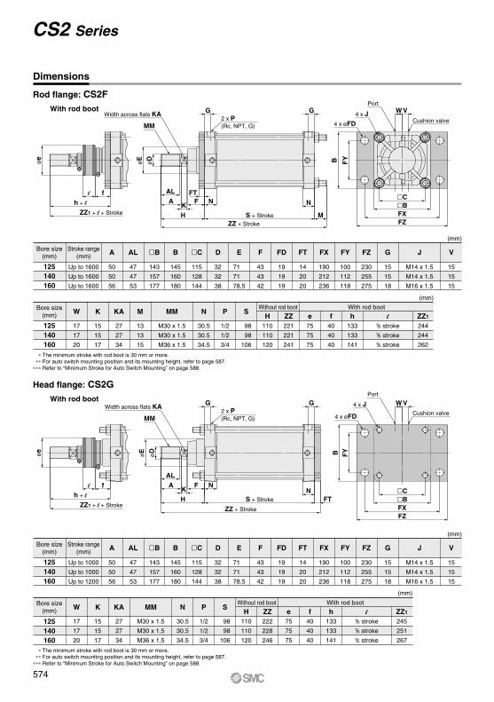
(mm)
(mm)
Bore size(mm)
Stroke range(mm)
125140160
Up to 1000
Up to 1000
Up to 1200
A
50
50
56
AL
47
47
53
B
143
157
177
B
145
160
180
C
115
128
144
D
32
32
38
E
71
71
78.5
F
43
43
42
FD
19
19
19
FT
14
20
20
FX
190
212
236
FY
100
112
118
FZ
230
255
275
G
15
15
18
V
15
15
15
J
M14 x 1.5
M14 x 1.5
M16 x 1.5
W K KA N P S
17
17
20
15
15
17
27
27
34
30.5
30.5
34.5
MM
M30 x 1.5
M30 x 1.5
M36 x 1.5
1/2
1/2
3/4
98
98
106
Bore size(mm)
Without rod boot With rod boot
125140160
H110
110
120
ZZ222
228
246
e75
75
75
f40
40
40
h133
133
141
1/5 stroke1/5 stroke1/5 stroke
ZZ1
245
251
267
∗ The minimum stroke with rod boot is 30 mm or more.∗∗ For auto switch mounting position and its mounting height, refer to page 587.
∗∗∗ Refer to “Minimum Stroke for Auto Switch Mounting” on page 588.
(mm)
(mm)
Bore size(mm)
Stroke range(mm)
125140160
Up to 1600
Up to 1600
Up to 1600
A
50
50
56
AL
47
47
53
143
157
177
B
145
160
180
115
128
144
D
32
32
38
E
71
71
78.5
F
43
43
42
FD
19
19
19
FT
14
20
20
FX
190
212
236
FY
100
112
118
FZ
230
255
275
G
15
15
18
V
15
15
15
J
M14 x 1.5
M14 x 1.5
M16 x 1.5
W
17
17
20
K KA M MM N P S
15
15
17
Bore size(mm)
Without rod boot With rod boot
125140160
H110
110
120
98
98
106
1/2
1/2
3/4
30.5
30.5
34.5
M30 x 1.5
M30 x 1.5
M36 x 1.5
13
13
15
27
27
34
ZZ221
221
241
e75
75
75
f40
40
40
h133
133
141
ZZ1
244
244
262
1/5 stroke1/5 stroke1/5 stroke
∗ The minimum stroke with rod boot is 30 mm or more.∗∗ For auto switch mounting position and its mounting height, refer to page 587.
∗∗∗ Refer to “Minimum Stroke for Auto Switch Mounting” on page 588.
Dimensions
Rod flange: CS2FWith rod boot
Head flange: CS2GWith rod boot
CS2 Series
B C
l
l
574
2 x P(Rc, NPT, G)
øe
f
Width across flats KA
MM
øD
øE
F
H
KA
ALN
G2 x P(Rc, NPT, G)
ZZ + Stroke
Z + Stroke
S + Stroke
GøCDH10
U
CTN
LRR
4 x J
Port VW
Cushion valve
CX
Cushion valve
VWPort
4 x J
CZ
CX
GøCD hole H10
Shaft d9
U
CT
L
N
RRZZ + Stroke
Z + Stroke
S + Stroke
GWidth across flats KA
MM
øE
øD
AAL
K
H
F N
øe
f
CBC
B
CB
C
B
ZZ1 + l + Stroke
Z1 + l + Stroke
h + l
l
ZZ1 + l + Stroke
Z1 + l + Stroke
h + l
l
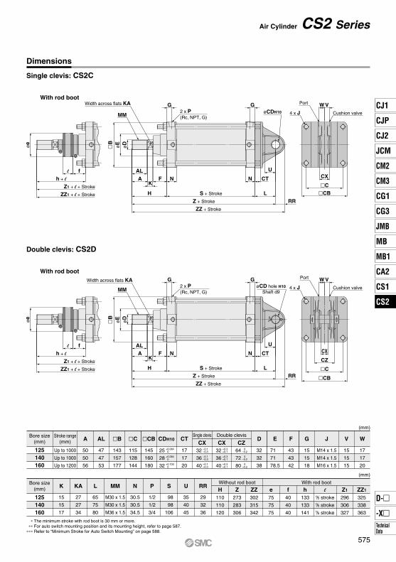
Dimensions
Single clevis: CS2C
With rod boot
Air Cylinder CS2 Series
Double clevis: CS2D
With rod boot
(mm)
Bore size(mm)
Stroke range(mm)
125140160
Up to 1000
Up to 1000
Up to 1200
A
50
50
56
AL
47
47
53
143
157
177
115
128
144
145
160
180
CDH10 CT
17
17
20
CXD
32
32
38
E
71
71
78.5
V
15
15
15
F
43
43
42
W
17
17
20
G
15
15
18
J
M14 x 1.5
M14 x 1.5
M16 x 1.5
K KA L N P S U RR
15
15
17
27
27
34
65
75
80
MM
M30 x 1.5
M30 x 1.5
M36 x 1.5
30.5
30.5
34.5
1/2
1/2
3/4
98
98
106
35
40
45
29
32
36
(mm)
Bore size(mm)
Without rod boot
Single clevis Double clevis
With rod boot
125140160
H110
110
120
Z273
283
306
ZZ302
315
342
e40
40
40
f75
75
75
h133
133
141
1/5 stroke1/5 stroke1/5 stroke
ZZ1
325
338
363
Z1
296
306
327
∗ The minimum stroke with rod boot is 30 mm or more.∗∗ For auto switch mounting position and its mounting height, refer to page 587.
∗∗∗ Refer to “Minimum Stroke for Auto Switch Mounting” on page 588.
25
28
32
+0.0840
+0.0840
+0.1000
CX–0.1–0.3
–0.1–0.3
–0.1–0.3
32
36
40
+0.3+0.1
+0.3+0.1
+0.3+0.1
32
36
40
CZ0
–0.2
0–0.2
0–0.2
64
72
80
B C CB
l
575
CJ1
CJP
CJ2
JCM
CM2
CM3
CG1
CG3
MB
JMB
MB1
CA2
CS1
CS2
D-
-XTechnicalData
CS2
øe
f
MM
øE
øD
A
AL
H
K
F N TT N
ZZ + Stroke
S + Stroke M
G
Z + 1/2 stroke
Width across flats KA
G2 x P(Rc, NPT, G)
Port
4 x JVW
Cushion valve
øT
De8
R
TY
TZ
TX
B
C
Z1 + l + 1/2 stroke
ZZ1 + l + Stroke
h + l
l
MM
M30 x 1.5
M30 x 1.5
M36 x 1.5
M
13
13
15
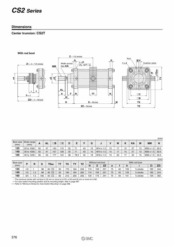
(mm)
Bore size(mm)
Stroke range(mm)
125140160
25 to 1000
30 to 1000
35 to 1200
A
50
50
56
AL
47
47
53
143
157
177
115
128
144
D
32
32
38
E
71
71
78.5
F
43
43
42
G
15
15
18
J
M14 x 1.5
M14 x 1.5
M16 x 1.5
V
15
15
15
W
17
17
20
K
15
15
17
KA
27
27
34
N
P R TDe8 TT TX TY TZ
30.5
30.5
34.5
1/2
1/2
3/4
1
1.5
1.5
S
98
98
106
(mm)
Bore size(mm)
Without rod boot With rod boot
125140160
H Z ZZ e f h1/5 stroke1/5 stroke1/5 stroke
ZZ1
244
244
262
Z1
182
182
194
∗ The minimum stroke with rod boot is 30 mm or more for ø125, ø140 and 35 mm or more for ø160.∗∗ For auto switch mounting position and its mounting height, refer to page 587.
∗∗∗ Refer to “Minimum Stroke for Auto Switch Mounting” on page 588.
32
36
40
–0.050–0.089
–0.050–0.089
–0.050–0.089
50
55
60
170
190
212
164
184
204
234
262
292
110
110
120
159
159
173
221
221
241
75
75
75
40
40
40
133
133
141
Dimensions
Center trunnion: CS2T
CS2 Series
With rod boot
B C
l
576
H
αA
L1
H1
øND hole H10Shaft d9
ø
ø x
ø
ø
ø
l
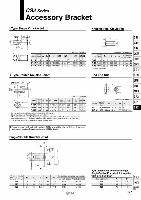
Part no.
Y-12AY-14AY-16A
125140160
A1
8
8
8
E1
46
48
55
L1
100
105
110
MM
M30 x 1.5
M30 x 1.5
M36 x 1.5
RR1
27
30
34
U1
42
47
46
Applicablebore size
(mm)NDH10
25
28
32
+0.0840
+0.0840
+0.10
NX
32
36
40
+0.3+0.1
+0.3+0.1
+0.3+0.1
NZ
64
72
80
–0.1–0.3
–0.1–0.3
–0.1–0.3
Material: Cast iron
Material: Rolled steel
NT-12NT-16
125, 140160
M30 x 1.5
M36 x 1.5
18
21
46
55
53.1
63.5
44
53
Part no.Applicablebore size
(mm)d H B C D
Bore size (mm)
125140160
A65
65
76
H125
125
140
A, H Dimensions when Mounting a Single/Double Knuckle Joint together with a Rod End Nut
CS2 Series
Accessory BracketI Type Single Knuckle Joint∗ Knuckle Pin / Clevis Pin
Rod End NutY Type Double Knuckle Joint∗
Single/Double Knuckle Joint
Part no.
I-12AI-14AI-16A
125140160
A1
8
8
8
A2
54
54
60
E1
46
48
55
L1
100
105
110
MM
M30 x 1.5
M30 x 1.5
M36 x 1.5
RR1
27
30
34
U1
33
39
39
Applicablebore size
(mm)NDH10
25
28
32
+0.0840
+0.0840
+0.10
NX
32
36
40
–0.1–0.3
–0.1–0.3
–0.1–0.3
Material: Cast ironApplicablebore size
(mm)
Material: Carbon steel
IY-12IY-14IY-16
125140160
79.5
86.5
94.5
69.5
76.5
84.5
5
5
5
4
4
4
ø4 x 40
ø4 x 40
ø4 x 40
Dd9
25
28
32
–0.065–0.117
–0.065–0.117
–0.080–0.142
d(Drill through)
Applicablesplit pin
∗ Split pin is included.
Part no. L m
∗ Use a single knuckle joint or a double knuckle joint individually. (Screw it entirely over the rod end threads and tighten it.)
∗ Extend the dimensions of A, H. when using a single/double knuckle joint together with a rod end nut.(To extend dimensions A, H, refer to the below table, and specify the product as made-to-order -XA0.)
∗ A pin and split pin are included with the double knuckled joint.
125140160
H
110
110
120
A
50
50
56
α
3.5
3.5
3.5
L1
100
105
110
H1
156.5
161.5
170.5
I type single knuckle
I-12A
I-14A
I-16A
Applicable knuckle joint part number
Y type double knuckle
Y-12A
Y-14A
Y-16A
SymbolBore size (mm)
“Made to order” with rod end bracket (-XC86) is available when ordering cylinders and accessories together. Please refer to page 1855 for details.
l
577
CJ1
CJP
CJ2
JCM
CM2
CM3
CG1
CG3
MB
JMB
MB1
CA2
CS1
CS2
D-
-XTechnicalData
CS2
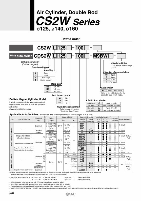
Air Cylinder, Double Rod
CS2W Seriesø125, ø140, ø160
CS2W
CDS2WWith auto switch
L
L
100
100With auto switch
(Built-in magnet)
125
125
Mounting
M9BW
Double rod type
Cylinder stroke (mm)Refer to page 579 for the“Maximum Stroke” table.
BasicFoot
Rod flangeCenter trunnion
BLFT
Bore size125 mm140 mm160 mm
125140160
Built-in Magnet Cylinder Model
Number of auto switchesNil
3Sn
2 pcs.3 pcs.1 pc.
“n” pcs.
Suffix for cylinderJKJJKK
Nylon tarpaulinHeat resistant tarpaulin
Nylon tarpaulinHeat resistant tarpaulin
Single siderod boot
Both siderod boot
Port thread typeRc
NPTG
Nil
TNTF
Made to OrderFor details, refer to page 579.
Applicable Auto Switches / For detailed auto switch specifications, refer to pages 1575 to 1701.
A96A93A90A54A64———
A59W
M9NM9PM9B
——
M9NWM9PWM9BW
M9NA∗1
M9PA∗1
M9BA∗1
F59FP3DWA
—————
A33A34A44—
———
G39K39————————
Type Special function
—
Grommet
24 V
24 V
24 V
3-wire (NPN)3-wire (PNP)
2-wire3-wire (NPN)
2-wire3-wire (NPN)3-wire (PNP)
2-wire3-wire (NPN)3-wire (PNP)
2-wire4-wire (NPN)2-wire (Non-polar)
2-wire
Yes
Yes
Yes
NoYesNo
Grommet
Terminalconduit
Grommet
Diagnostic indication(2-color indicator)
Water resistant (2-color indicator)
Diagnostic indication (2-color indicator)
Magnetic field resistant (2-color indicator)
Electricalentry
Load voltageWiring
(Output)Applicable load
DC AC
Auto switch model
Diagnostic indication (2-color indicator)
Terminalconduit
—100 V
100 V or less100 V, 200 V200 V or less
—
100 V, 200 V
—
—
IC circuit
—
—
IC circuit
IC circuit
—
IC circuit
—
—IC circuit
—IC circuit
IC circuit—
—
PLC
Relay,PLC
Relay,PLC
Relay,PLC
—
—
DIN terminalGrommet
5 V12 V
5 V, 12 V
12 V
5 V, 12 V
12 V5 V, 12 V
12 V
5 V, 12 V
12 V
5 V, 12 V
12 V5 V, 12 V
—
— —
How to Order
If a built-in magnet cylinder without auto switch is required, there is no need to enter the symbol for auto switch. (Example) CDS2WB125-100
Auto switchNil Without auto switch
∗ Refer to the table below for the applicable auto switch model.
So
lid s
tate
au
to s
wit
chR
eed
au
to s
wit
ch
Indica
tor lig
ht
3-wire(NPN equivalent)
Pre-wiredconnector
Lead wire length (m)Tie-rod
mountingBand
mounting0.5(Nil)
3(L)
5(Z)
1(M)
∗ Lead wire length symbols: 0.5 m ·········· Nil (Example) M9NW 1 m ··········· M (Example) M9NWM
3 m ··········· L (Example) M9NWL5 m ··········· Z (Example) M9NWZ
∗1 Water resistant type auto switches can be mounted on the above models, but in such case SMC cannot guarantee water resistance. Consult with SMC regarding water resistant types with the above model numbers.
∗ Solid state auto switches marked with “” are produced upon receipt of order.∗ Since there are applicable auto switches other than listed, refer to page 589 for details.∗ For details about auto switches with pre-wired connector, refer to pages 1648 and 1649.∗ D-A9, M9, M9W, M9A, P3DWA are shipped together (but not assembled). (Only auto switch mounting bracket is assembled at the time of shipment.)
578
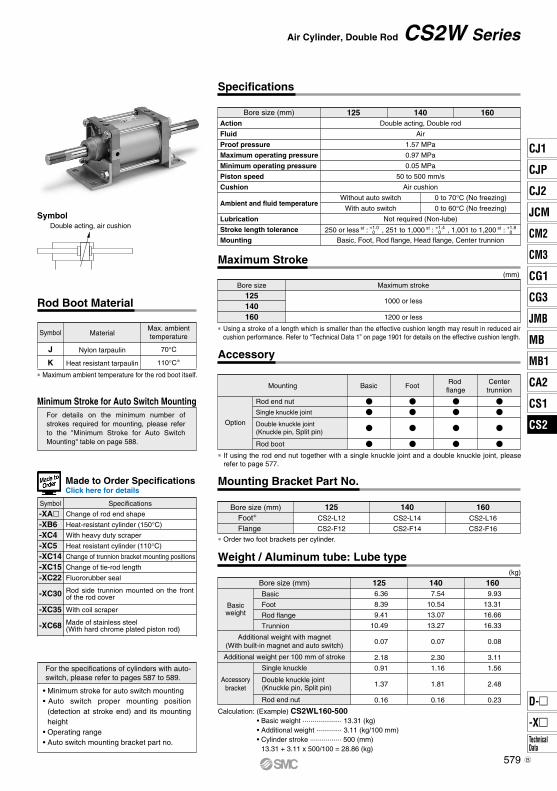
Symbol
Specifications
Double acting, air cushion
Air Cylinder, Double Rod CS2W Series
Bore size (mm)Action
Fluid
Proof pressure
Maximum operating pressure
Minimum operating pressure
Piston speed
Cushion
Ambient and fluid temperature
Lubrication
Double acting, Double rod
Air
1.57 MPa
0.97 MPa
0.05 MPa
50 to 500 mm/s
Air cushion
Not required (Non-lube)
Without auto switch
With auto switch
0 to 70°C (No freezing)
0 to 60°C (No freezing)
Stroke length tolerance
Mounting
125 140 160
250 or less st : , 251 to 1,000
st : , 1,001 to 1,200 st : +1.0
+0+1.4+0
+1.8+0
Basic, Foot, Rod flange, Head flange, Center trunnion
Maximum Stroke(mm)
Bore size
125140160
Maximum stroke
1000 or less
1200 or less
Accessory
Rod Boot Material
Change of rod end shape
Heat-resistant cylinder (150°C)
With heavy duty scraper
Heat resistant cylinder (110°C)
Change of trunnion bracket mounting positions
Change of tie-rod length
Fluororubber seal
Rod side trunnion mounted on the front of the rod cover
With coil scraper
Made of stainless steel(With hard chrome plated piston rod)
Symbol Specifications
Minimum Stroke for Auto Switch Mounting
∗ Maximum ambient temperature for the rod boot itself.
J
K
Nylon tarpaulin
Heat resistant tarpaulin
Symbol MaterialMax. ambienttemperature
70°C
110°C∗
Made to Order SpecificationsClick here for details
For details on the minimum number of strokes required for mounting, please refer to the "Minimum Stroke for Auto Switch Mounting" table on page 588.
For the specifications of cylinders with auto-switch, please refer to pages 587 to 589.
Mounting Basic FootRod
flangeCenter
trunnion
Option
Rod end nut
Single knuckle joint
Rod boot
∗ If using the rod end nut together with a single knuckle joint and a double knuckle joint, please refer to page 577.
Double knuckle joint(Knuckle pin, Split pin)
• Minimum stroke for auto switch mounting• Auto switch proper mounting position
(detection at stroke end) and its mounting height
• Operating range• Auto switch mounting bracket part no.
Mounting Bracket Part No.
Bore size (mm) 125CS2-L12
CS2-F12
140CS2-L14
CS2-F14
160CS2-L16
CS2-F16
∗ Order two foot brackets per cylinder.
Foot∗
Flange
Weight / Aluminum tube: Lube type(kg)
Bore size (mm)
Additional weight with magnet(With built-in magnet and auto switch)
Additional weight per 100 mm of stroke
Basic
Foot
Rod flange
Trunnion
Single knuckle
125 6.36
8.39
9.41
10.49
0.07
2.18
0.91
1.37
0.16
140 7.54
10.54
13.07
13.27
0.07
2.30
1.16
1.81
0.16
160 9.93
13.31
16.66
16.33
0.08
3.11
1.56
2.48
0.23
Calculation: (Example) CS2WL160-500 • Basic weight ···················· 13.31 (kg) • Additional weight ············· 3.11 (kg/100 mm) • Cylinder stroke ················ 500 (mm) 13.31 + 3.11 x 500/100 = 28.86 (kg)
Double knuckle joint(Knuckle pin, Split pin)
Basicweight
Accessorybracket
Rod end nut
-XA-XB6-XC4-XC5-XC14-XC15-XC22
-XC30
-XC35
-XC68
∗ Using a stroke of a length which is smaller than the effective cushion length may result in reduced air cushion performance. Refer to “Technical Data 1” on page 1901 for details on the effective cushion length.
579
CJ1
CJP
CJ2
JCM
CM2
CM3
CG1
CG3
MB
JMB
MB1
CA2
CS1
CS2
D-
-XTechnicalData
CS2
B
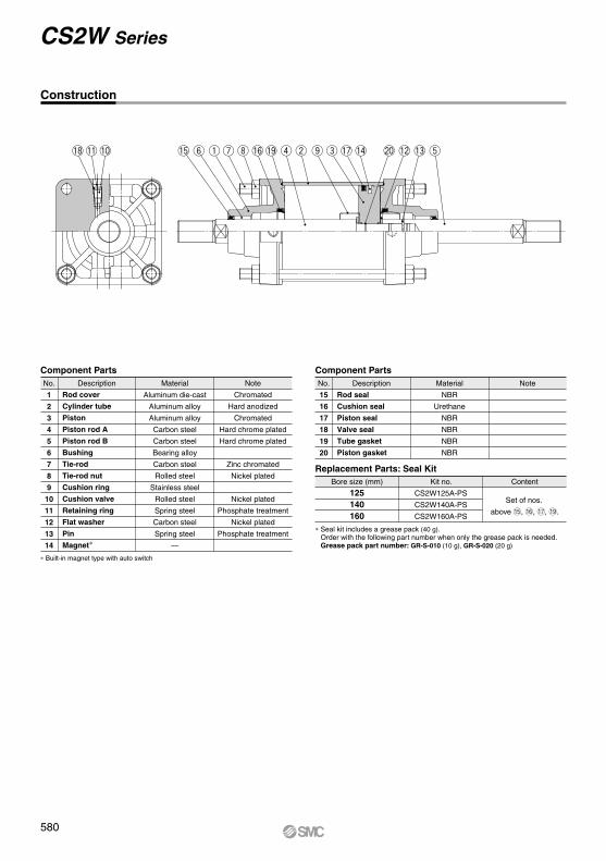
!8!1 !0 !5 y q u i !6 !9 r w o e !7 !4 !2 !3 t@0
Construction
CS2W Series
Component PartsNo.
1
2
3
4
5
6
7
8
9
10
11
12
13
14
Description Material
Aluminum die-cast
Aluminum alloy
Aluminum alloy
Carbon steel
Carbon steel
Bearing alloy
Carbon steel
Rolled steel
Stainless steel
Rolled steel
Spring steel
Carbon steel
Spring steel
—
Note
Chromated
Hard anodized
Chromated
Hard chrome plated
Hard chrome plated
Zinc chromated
Nickel plated
Nickel plated
Phosphate treatment
Nickel plated
Phosphate treatment
Rod cover
Cylinder tube
Piston
Piston rod A
Piston rod B
Bushing
Tie-rod
Tie-rod nut
Cushion ring
Cushion valve
Retaining ring
Flat washer
Pin
Magnet∗
∗ Built-in magnet type with auto switch
Component PartsNo.
15
16
17
18
19
20
Description Material
NBR
Urethane
NBR
NBR
NBR
NBR
Note
Rod seal
Cushion seal
Piston seal
Valve seal
Tube gasket
Piston gasket
Bore size (mm)
125140160
Kit no.
CS2W125A-PS
CS2W140A-PS
CS2W160A-PS
Content
Replacement Parts: Seal Kit
∗ Seal kit includes a grease pack (40 g).Order with the following part number when only the grease pack is needed.Grease pack part number: GR-S-010 (10 g), GR-S-020 (20 g)
Set of nos.
above !5, !6, !7, !9.
580
øe
h + L
ZZ + L + 2 x strokes
L f
Cushion valve
WVPort
4 x J
C B
CB
V W
Cushion valvePort
4 x JC B
CB
øD
øE
MM
AL
AK
HNF
S + Stroke
ZZ + 2 x strokes
N FH + Stroke
AL
AK
MG2 x P(Rc, NPT, G)
G
MM
øD
øE
Width across flats KAWidth across flats KA
MM
øDøe
AL
A K NfS + Stroke
2 x P(Rc, NPT, G)
G
øE
MG
N f
AL
AK
øD øe
MM
øE
Width across flats KA Width across flats KA
Width across flats KA
MM
øD
øE
LT
Y X N
F
AL
AK
HG
S + Stroke
2 x P(Rc, NPT, G)
FG
H + Stroke
ALAK
MMøD
øE
4 x øLD
XN Y
ZZ + 2 x strokes
LS + StrokeWidth across
flats KA
øe
f
Cushion valve
WVPort
4 x J
CL
H
LY
CB
LX B
lh + l
ZZ + 2 x l + 2 x strokes (with rod boot on both sides)
ZZ + l + 2 x strokes (with rod boot on one side)
l
h + l h + l + Stroke
ZZ + 2 x l + 2 x strokes
l + Stroke
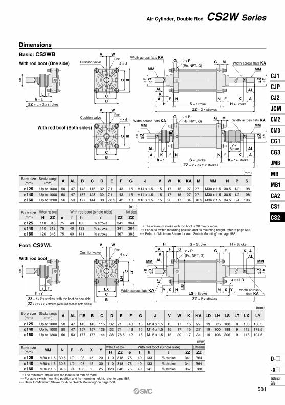
Foot: CS2WL
With rod boot
With rod boot (Both sides)
Bore size(mm)
ø125ø140ø160
MM
M30 x 1.5
M30 x 1.5
M36 x 1.5
N
30.5
30.5
34.5
P
1/2
1/2
3/4
S
98
98
106
X
45
45
50
Y
20
30
25
(mm)
Without rod boot With rod boot (Single side) (Both sides)
H110
110
120
ZZ318
318
346
e75
75
75
f40
40
40
h133
133
141
ZZ341
341
367
ZZ364
364
388
∗ The minimum stroke with rod boot is 30 mm or more.∗∗ For auto switch mounting position and its mounting height, refer to page 587.
∗∗∗ Refer to “Minimum Stroke for Auto Switch Mounting” on page 588.
Bore size(mm)
ø125ø140ø160
Stroke range(mm)
Up to 1000
Up to 1000
Up to 1200
A
50
50
56
AL
47
47
53
B
143
157
177
C
115
128
144
D
32
32
38
E
71
71
78.5
F
43
43
42
G
15
15
18
J
M14 x 1.5
M14 x 1.5
M16 x 1.5
V
15
15
15
K
15
15
17
W
17
17
20
KA
27
27
34
LD
19
19
19
LH
85
100
106
LS
188
188
206
LX
100
112
118
LY
156.5
178.5
194.5
LT
8
9
9
Air Cylinder, Double Rod CS2W Series
Dimensions
Basic: CS2WB
With rod boot (One side)
(mm)
Bore size(mm)
ø125ø140ø160
Stroke range(mm)
Up to 1000
Up to 1000
Up to 1200
A
50
50
56
AL
47
47
53
B
143
157
177
C
115
128
144
D
32
32
38
E
71
71
78.5
F
43
43
42
G
15
15
18
J
M14 x 1.5
M14 x 1.5
M16 x 1.5
V
15
15
15
W
17
17
20
KA
27
27
34
K
15
15
17
M
27
27
30.5
MM
M30 x 1.5
M30 x 1.5
M36 x 1.5
N
30.5
30.5
34.5
S
98
98
106
P
1/2
1/2
3/4
(mm)
Bore size(mm)
ø125ø140ø160
Without rod boot With rod boot (single side) (Both sides)
H110
110
120
ZZ318
318
346
e75
75
75
f40
40
40
h133
133
141
ZZ341
341
367
ZZ364
364
388
∗ The minimum stroke with rod boot is 30 mm or more.∗∗ For auto switch mounting position and its mounting height, refer to page 587.
∗∗∗ Refer to “Minimum Stroke for Auto Switch Mounting” on page 588.
(mm)
B
143
157
177
l1/5 stroke1/5 stroke1/5 stroke
l1/5 stroke1/5 stroke1/5 stroke
581
CJ1
CJP
CJ2
JCM
CM2
CM3
CG1
CG3
MB
JMB
MB1
CA2
CS1
CS2
D-
-XTechnicalData
CS2
øe
f
V WPortCushion valve
4 x J4 x øFD
FY C B
CFXFZ
Width across flats KA
MM
øD
øE
AL
AK
NH
F
FT
ZZ + 2 x strokes
S + Stroke
2 x P(Rc, NPT, G)
GWidth across flats KA
G
MM
øD
øE
AL
AKH + Stroke
FN
M
øe
f
Cushion valve
WV
4 x JPort
R
C B TY
øT
De8C
BTXTZ
Width across flats KA
MM
øD
øE
AL
AH
K
F N
G 2 x P(Rc, NPT, G)
Z + 1/2 stroke
S + Stroke
ZZ + 2 x strokes
TTH + Stroke
N F
AL
AK
MG
MM
øD
øE
Width across flats KA
Bl
h + l
ZZ + 2 x l + 2 x strokes(with rod boot on both sides)
ZZ + l + 2 x strokes(with rod boot on one side)
l
h + l
Z + l + 1/2 stroke
ZZ + 2 x l + 2 x strokes(with rod boot on both sides)
ZZ + l + 2 x strokes(with rod boot on one side)
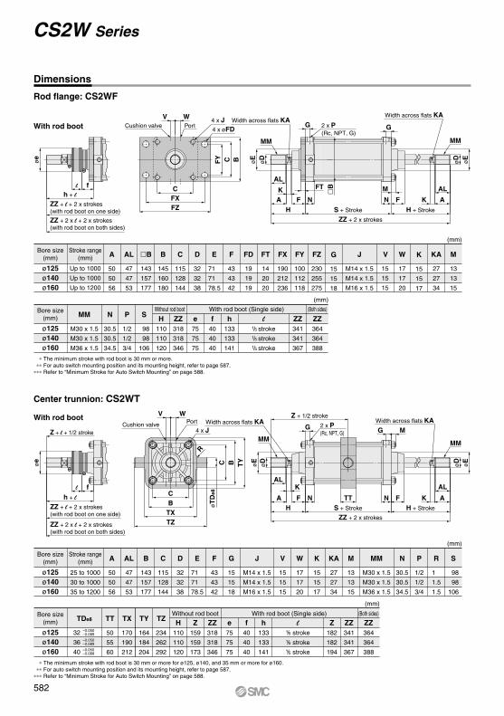
With rod boot
Center trunnion: CS2WT
Bore size(mm)
ø125ø140ø160
MM
M30 x 1.5
M30 x 1.5
M36 x 1.5
N
30.5
30.5
34.5
P
1/2
1/2
3/4
S
98
98
106
(mm)
Without rod boot With rod boot (Single side) (Both sides)
H110
110
120
ZZ318
318
346
e75
75
75
f40
40
40
h133
133
141
ZZ341
341
367
ZZ364
364
388
∗ The minimum stroke with rod boot is 30 mm or more.∗∗ For auto switch mounting position and its mounting height, refer to page 587.
∗∗∗ Refer to “Minimum Stroke for Auto Switch Mounting” on page 588.
(mm)
Bore size(mm)
ø125ø140ø160
Stroke range(mm)
Up to 1000
Up to 1000
Up to 1200
A
50
50
56
AL
47
47
53
B
145
160
180
C
115
128
144
D
32
32
38
E
71
71
78.5
F
43
43
42
FD
19
19
19
FT
14
20
20
FX
190
212
236
FY
100
112
118
G
15
15
18
FZ
230
255
275
J
M14 x 1.5
M14 x 1.5
M16 x 1.5
W
17
17
20
V KA
27
27
34
M
13
13
15
K
15
15
17
15
15
15
CS2W Series
Rod flange: CS2WF
With rod boot
Dimensions
(mm)
Bore size(mm)
ø125ø140ø160
Stroke range(mm)
25 to 1000
30 to 1000
35 to 1200
A
50
50
56
AL
47
47
53
B
143
157
177
C
115
128
144
D
32
32
38
E
71
71
78.5
F
43
43
42
G
15
15
18
J
M14 x 1.5
M14 x 1.5
M16 x 1.5
V
15
15
15
W
17
17
20
KA
27
27
34
K
15
15
17
M
13
13
15
N
30.5
30.5
34.5
MM
M30 x 1.5
M30 x 1.5
M36 x 1.5
R
1
1.5
1.5
S
98
98
106
P
1/2
1/2
3/4
∗ The minimum stroke with rod boot is 30 mm or more for ø125, ø140, and 35 mm or more for ø160.∗∗ For auto switch mounting position and its mounting height, refer to page 587.
∗∗∗ Refer to “Minimum Stroke for Auto Switch Mounting” on page 588.
Bore size(mm)
ø125ø140ø160
TDe8 TT
50
55
60
TX
170
190
212
TY
164
184
204
TZ
234
262
292
(mm)
Without rod boot With rod boot (Single side) (Both sides)
H110
110
120
Z159
159
173
ZZ318
318
346
e75
75
75
f40
40
40
h133
133
141
ZZ341
341
367
Z182
182
194
ZZ364
364
388
–0.050–0.089
–0.050–0.089
–0.050–0.089
32
36
40
B
143
157
177
l1/5 stroke1/5 stroke1/5 stroke
l1/5 stroke1/5 stroke1/5 stroke
582
583
CJ1
CJP
CJ2
JCM
CM2
CM3
CG1
CG3
MB
JMB
MB1
CA2
CS1
CS2
D-
-XTechnicalData
CS2
A

584B

585
CJ1
CJP
CJ2
JCM
CM2
CM3
CG1
CG3
MB
JMB
MB1
CA2
CS1
CS2
D-
-XTechnicalData
CS2
A

586A
A 49
36
Auto switch
B
Applicable cable O.D.ø6.8 to ø9.6G1/2
≈ Hs
34
A Auto switch
B
≈ Hs
≈ H
t
33A Auto switch
B
≈ H
t≈
Ht
≈ Hs34.5A
36
Auto switch
B
G1/2Applicable cable O.D.ø6.8 to ø11.5
≈ Hs
56
30AAuto switch
B
≈ H
t≈
Ht
≈ Hs ≈ Hs
≈ H
t
Auto switchA
B
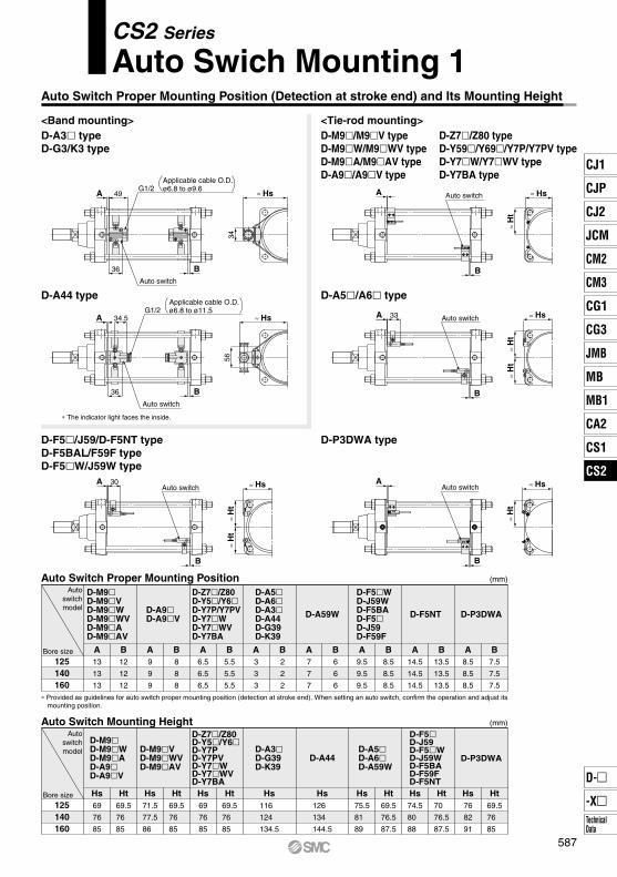
<Band mounting> <Tie-rod mounting>
CS2 Series
Auto Swich Mounting 1Auto Switch Proper Mounting Position (Detection at stroke end) and Its Mounting Height
D-A44 type
∗ The indicator light faces the inside.
D-A3 typeD-G3/K3 type
D-Z7/Z80 typeD-Y59/Y69/Y7P/Y7PV typeD-Y7W/Y7WV typeD-Y7BA type
D-M9/M9V typeD-M9W/M9WV typeD-M9A/M9AV typeD-A9/A9V type
D-A5/A6 type
D-F5/J59/D-F5NT typeD-F5BAL/F59F typeD-F5W/J59W type
D-P3DWA type
Auto Switch Mounting Height
Bore size
Autoswitchmodel
D-M9D-M9WD-M9AD-A9D-A9V
Hs69
76
85
Ht69.5
76
85
D-M9VD-M9WVD-M9AV
Hs71.5
77.5
86
Ht69.5
76
85
D-Z7/Z80D-Y5/Y6D-Y7PD-Y7PVD-Y7WD-Y7WVD-Y7BA
Hs69
76
85
Ht69.5
76
85
D-A3D-G39D-K39
Hs116
124
134.5
D-A44
Hs126
134
144.5
D-A5D-A6D-A59W
Hs75.5
81
89
Ht69.5
76.5
87.5
D-F5D-J59D-F5WD-J59WD-F5BAD-F59FD-F5NTHs74.5
80
88
Ht70
76.5
87.5
D-P3DWA
Hs76
82
91
Ht69.5
76
85
125140160
(mm)
Auto Switch Proper Mounting Position
Bore size
Autoswitchmodel D-A9
D-A9V
A9
9
9
B8
8
8
D-M9D-M9VD-M9WD-M9WVD-M9AD-M9AV
A13
13
13
B12
12
12
D-Z7/Z80D-Y5/Y6D-Y7P/Y7PVD-Y7WD-Y7WVD-Y7BA
A6.5
6.5
6.5
B5.5
5.5
5.5
D-A5D-A6D-A3D-A44D-G39D-K39
A3
3
3
B2
2
2
D-A59W
A7
7
7
B6
6
6
D-F5WD-J59WD-F5BAD-F5D-J59D-F59F
A9.5
9.5
9.5
B8.5
8.5
8.5
D-F5NT
A14.5
14.5
14.5
B13.5
13.5
13.5
D-P3DWA
A8.5
8.5
8.5
B7.5
7.5
7.5
125140160
(mm)
∗ Provided as guidelines for auto switch proper mounting position (detection at stroke end). When setting an auto switch, confirm the operation and adjust its mounting position.
587
CJ1
CJP
CJ2
JCM
CM2
CM3
CG1
CG3
MB
JMB
MB1
CA2
CS1
CS2
D-
-XTechnicalData
CS2
10015
10
15
10
(n = 2, 4, 6, 8···) Note 1)
15 + 40(n – 2)2
(n = 4, 8, 12, 16···) Note 2)
100 + 40(n – 4)2
75
(n = 4, 8, 12, 16···) Note 2)
75 + 30(n – 4)2
105
(n = 4, 8, 12, 16···) Note 2)
105 + 40(n – 4)2
80
(n = 4, 8, 12, 16···) Note 2)
80 + 30(n – 4)2
105
(n = 4, 8, 12, 16···) Note 2)
105 + 40(n – 4)2
80
(n = 4, 8, 12, 16···) Note 2)
80 + 30(n – 4)2
110
(n = 4, 8, 12, 16···) Note 2)
110 + 40(n – 4)2
110
12525
(n = 2, 4, 6, 8···) Note 1)
25 + 55(n – 2)2
(n = 4, 8, 12, 16···) Note 2)
125 + 55(n – 4)2
135
(n = 4, 8, 12, 16···) Note 2)
135 + 55(n – 4)2
14535
(n = 2, 4, 6, 8···) Note 1)
35 + 55(n – 2)2
(n = 4, 8, 12, 16···) Note 2)
145 + 55(n – 4)2
155
(n = 4, 8, 12, 16···) Note 2)
155 + 55(n – 4)2
10515
(n = 2, 4, 6, 8···) Note 1)
15 + 40(n – 2)2
(n = 4, 8, 12, 16···) Note 2)
105 + 40(n – 4)2
110
(n = 4, 8, 12, 16···) Note 2)
110 + 40(n – 4)2
115
(n = 4, 8, 12, 16···) Note 2)
115 + 40(n – 4)2
9010
(n = 2, 4, 6, 8···) Note 1)
10 + 30(n – 2)2
(n = 4, 8, 12, 16···) Note 2)
90 + 30(n – 4)2
95
(n = 4, 8, 12, 16···) Note 2)
95 + 30(n – 4)2
100
(n = 4, 8, 12, 16···) Note 2)
100 + 30(n – 4)2
11520
(n = 2, 4, 6, 8···) Note 1)
20 + 45(n – 2)2
(n = 4, 8, 12, 16···) Note 2)
115 + 45(n – 4)2
120
(n = 4, 8, 12, 16···) Note 2)
120 + 45(n – 4)2
125
85
115
85
(n = 4, 8, 12, 16···) Note 2)
85 + 30(n – 4)2
90
(n = 2, 4, 6, 8···) Note 1)
10 + 30(n – 2)2
(n = 2, 4, 6, 8···) Note 1)
15 + 40(n – 2)2
(n = 2, 4, 6, 8···) Note 1)
10 + 30(n – 2)2
35100
15
110 + 30(n – 2)(n = 2, 4, 6, 8···) Note 1)
110 + 100(n – 2)(n = 2, 4, 6, 8···) Note 1)
110
1103555
15
110 + 30(n – 2)(n = 2, 4, 6, 8···) Note 1)
110 + 50(n – 2)(n = 2, 4, 6, 8···) Note 1)
110
110
(n = 4, 8, 12, 16···) Note 2)
110 + 40(n – 4)2
(n = 4, 8, 12, 16···) Note 2)
85 + 30(n – 4)2
(n = 4, 8, 12, 16···) Note 2)
115 + 40(n – 4)2
(n = 4, 8, 12, 16···) Note 2)
90 + 30(n – 4)2
(n = 4, 8, 12, 16···) Note 2)
125 + 45(n – 4)2
20 115
(n = 4, 8, 12, 16···) Note 2)
115 + 40(n – 4)2
120
(n = 4, 8, 12, 16···) Note 2)
120 + 40(n – 4)2
(n = 2, 4, 6, 8···) Note 1)
20 + 40(n – 2)2
15 90
(n = 4, 8, 12, 16···) Note 2)
90 + 30(n – 4)2
95
(n = 4, 8, 12, 16···) Note 2)
95 + 30(n – 4)2
(n = 2, 4, 6, 8···) Note 1)
15 + 30(n – 2)2
With n pcs.
With n pcs.
With n pcs.
With n pcs.
With n pcs. (Same surface)
With n pcs. (Same surface)
With n pcs.
With n pcs.
With n pcs.
Different surfaces
Same surface
With 1 pc.
Different surfaces
Same surface
Different surfacesSame surface
With 1 pc.
Different surfaces
Same surface
With n pcs.
With 2 pcs. (Different surfaces, Same surface), With 1 pc.
With 2 pcs. (Different surfaces, Same surface), With 1 pc.
With 2 pcs. (Different surfaces, Same surface), With 1 pc.
With 2 pcs. (Different surfaces, Same surface), With 1 pc.
With 2 pcs. (Different surfaces, Same surface), With 1 pc.
With 2 pcs. (Different surfaces, Same surface), With 1 pc.
With 2 pcs. (Different surfaces, Same surface), With 1 pc.
With 2 pcs. (Different surfaces, Same surface), With 1 pc.
With 2 pcs. (Different surfaces, Same surface), With 1 pc.
With 2 pcs. (Different surfaces, Same surface), With 1 pc.
With 2 pcs. (Different surfaces, Same surface), With 1 pc.
With n pcs.
With
2 pc
s.W
ith n
pcs
.W
ith2
pcs.
With
n p
cs.
35 + 30(n – 2)(n = 2, 3, 4, 5···)
100 + 100(n – 2)(n = 2, 3, 4, 5···)
35 + 30(n – 2)(n = 2, 3, 4, 5···)
55 + 55(n – 2)(n = 2, 3, 4, 5···)
10520
(n = 2, 4, 6, 8···) Note 1)
20 + 50(n – 2)2
(n = 4, 8, 12, 16···) Note 2)
105 + 50(n – 4)2
110
(n = 4, 8, 12, 16···) Note 2)
110 + 50(n – 4)2
115
(n = 4, 8, 12, 16···) Note 2)
115 + 50(n – 4)2With n pcs.
With 2 pcs. (Different surfaces, Same surface), With 1 pc.
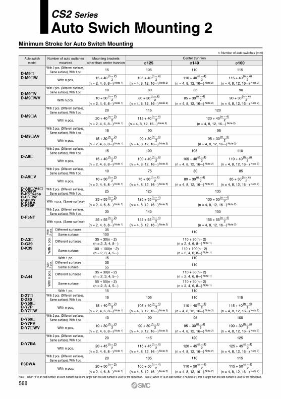
Minimum Stroke for Auto Switch Mounting
Note 1) When “n” is an odd number, an even number that is one larger than this odd number is used for the calculation. Note 2) When “n” is an odd number, a multiple of 4 that is larger than this odd number is used for the calculation.
CS2 Series
Auto Swich Mounting 2n: Number of auto switches (mm)
Auto switchmodel
Center trunnion
ø125 ø140 ø160Number of auto switches
mountedMounting brackets
other than center trunnion
D-F5NT
D-A44
D-Y7BA
D-A9
D-A9V
D-M9D-M9W
D-M9VD-M9WV
D-M9A
D-M9AV
D-A3D-G39D-K39
D-Z7D-Z80D-Y59D-Y7PD-Y7W
D-Y69D-Y7PVD-Y7WV
D-A5/A6D-A59WD-F5/J59D-F5WD-J59WD-F5BAD-F59F
P3DWA
588
Bore sizeAuto switch model
D-A59W
D-G39/K39P3DWA
6
12
14
10
17
12
5
11
7
6.5
12.5
14.5
10
17
13
5
11
7
6.5
11.5
13
10
17
7
5.5
10
7
125 140 160
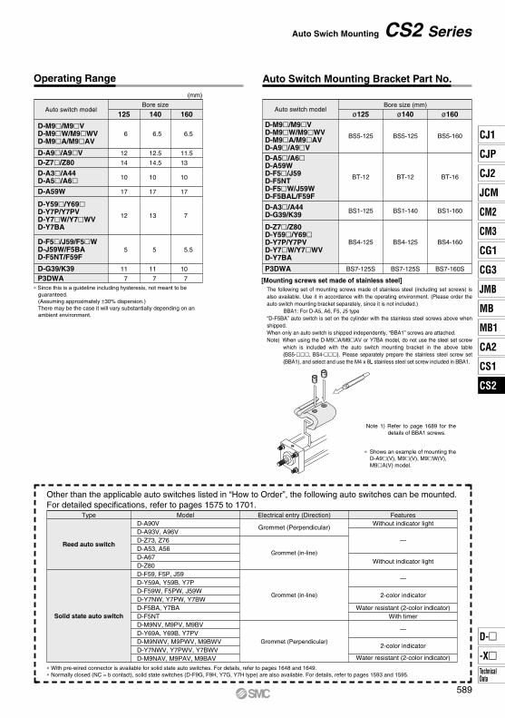
(mm)
∗ Since this is a guideline including hysteresis, not meant to be guaranteed. (Assuming approximately ±30% dispersion.)There may be the case it will vary substantially depending on an ambient environment.
Bore size (mm)Auto switch model
BS5-125
ø125
BS5-125
ø140
BS5-160
ø160
BT-12
BS4-125
BT-12
BS4-125
BT-16
BS4-160
BS1-125 BS1-140 BS1-160
∗ With pre-wired connector is available for solid state auto switches. For details, refer to pages 1648 and 1649.∗ Normally closed (NC = b contact), solid state switches (D-F9G, F9H, Y7G, Y7H type) are also available. For details, refer to pages 1593 and 1595.
Other than the applicable auto switches listed in “How to Order”, the following auto switches can be mounted.For detailed specifications, refer to pages 1575 to 1701.
D-A90VD-A93V, A96VD-Z73, Z76D-A53, A56D-A67D-Z80D-F59, F5P, J59D-Y59A, Y59B, Y7PD-F59W, F5PW, J59WD-Y7NW, Y7PW, Y7BWD-F5BA, Y7BAD-F5NTD-M9NV, M9PV, M9BVD-Y69A, Y69B, Y7PVD-M9NWV, M9PWV, M9BWVD-Y7NWV, Y7PWV, Y7BWVD-M9NAV, M9PAV, M9BAV
Model FeaturesElectrical entry (Direction)Without indicator light
—
Without indicator light
—
2-color indicator
Water resistant (2-color indicator)With timer
—
2-color indicator
Water resistant (2-color indicator)
Grommet (Perpendicular)
Grommet (in-line)
Grommet (in-line)
Grommet (Perpendicular)
Type
Reed auto switch
Solid state auto switch
Auto Swich Mounting CS2 Series
Operating Range Auto Switch Mounting Bracket Part No.
Note 1) Refer to page 1689 for the details of BBA1 screws.
D-A9/A9V
D-M9/M9VD-M9W/M9WVD-M9A/M9AV
D-Z7/Z80D-A3/A44D-A5/A6
D-Y59/Y69D-Y7P/Y7PVD-Y7W/Y7WVD-Y7BA
D-F5/J59/F5WD-J59W/F5BAD-F5NT/F59F
D-M9/M9VD-M9W/M9WVD-M9A/M9AVD-A9/A9VD-A5/A6D-A59WD-F5/J59D-F5NTD-F5W/J59WD-F5BAL/F59F
D-A3/A44D-G39/K39
P3DWA
D-Z7/Z80D-Y59/Y69D-Y7P/Y7PVD-Y7W/Y7WVD-Y7BA
[Mounting screws set made of stainless steel]The following set of mounting screws made of stainless steel (including set screws) is also available. Use it in accordance with the operating environment. (Please order the auto switch mounting bracket separately, since it is not included.)
BBA1: For D-A5, A6, F5, J5 type“D-F5BA” auto switch is set on the cylinder with the stainless steel screws above when shipped. When only an auto switch is shipped independently, “BBA1” screws are attached.Note) When using the D-M9A/M9AV or Y7BA model, do not use the steel set screw
which is included with the auto switch mounting bracket in the above table(BS5-, BS4-). Please separately prepare the stainless steel screw set(BBA1), and select and use the M4 x 8L stainless steel set screw included in BBA1.
∗ Shows an example of mounting the D-A9(V), M9(V), M9W(V), M9A(V) model.
BS7-125S BS7-125S BS7-160S
589
CJ1
CJP
CJ2
JCM
CM2
CM3
CG1
CG3
MB
JMB
MB1
CA2
CS1
CS2
D-
-XTechnicalData
CS2
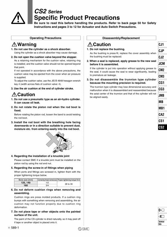
CautionWarning
Caution
589-1
1. Do not use a pneumatic type as an air-hydro cylinder.It can cause oil leak.
2. Do not rotate the piston rod when the rod boot is fixed.Before rotating the piston rod, loosen the band to avoid twisting the rod boot.
3. Install the rod boot with the breathing hole facing downwards or in a direction suitable to prevent dust, moisture etc. from entering easily into the rod boot.
4. Regarding the installation of a knuckle jointPlease contact SMC if a knuckle joint must be installed on the piston rod by using the rod end nut.
5. Regarding the screw-in of fittings when pipingWhen ports and fittings are screwed in, tighten them with the proper tightening torque below.
6. Do not deform cushion rings when removing and assembling.Cushion rings are press molded products. If a cushion ring bumps with something when removing and assembling, the air cushion may not function properly due to cushion ring deformation.
7. Do not place tape or other objects onto the painted surface of the unit.The paint of the CS cylinder is dried naturally, so it may peel off if tape or another object is placed onto it.
1. Do not use the cylinder as a shock absorber.Using the cylinder as a shock absorber may cause damage.
2. Do not open the cushion valve beyond the stopper.As a retaining mechanism for the cushion valve, retaining ring is installed, and the cushion valve should not be opened beyond that point.If not operated in accordance with the above precautions, the cushion valve may be ejected from the cover when air pressure is supplied.To adjust the cushion valve, use the JIS B 4648 hexagon wrench key 4 (width across flats of cushion valve: 4).
3. Use the air cushion at the end of cylinder stroke.
1. Do not replace the bushing.As the bushing is press-fit, replace the cover assembly when the bushing must be replaced.
2. When a seal is replaced, apply grease to the new seal before it is assembled.If the cylinder is put into operation without applying grease to the seal, it could cause the seal to wear significantly, leading to premature air leakage.
3. Do not disassemble the trunnion type cylinder because the mounting precision is required.The trunnion type cylinder may lose dimensional accuracy and malfunction when it is disassembled and reassembled because the axial center of the trunnion and that of the cylinder will not be aligned easily.
Operating Precautions Disassembly/Replacement
Bore size [mm] Connecting thread nominal size Proper tightening torque N·m125, 140 1/2
28 to 30160 3/4
CS2 SeriesSpecific Product PrecautionsBe sure to read this before handling the products. Refer to back page 50 for Safety Instructions and pages 3 to 12 for Actuator and Auto Switch Precautions.
CJ1
CJP
CJ2
JCM
CM2
CM3
CG1
CG3
MB
JMB
MB1
CA2
CS1
CS2
D-
-XTechnicalData
CS2
A
Related Documents