Liebert HPC--L Air Cooled Chillers with Double Screw Compressors Precision Cooling for Business -Critical Continuity PRODUCT DOCUMENTATION LiebertHPC--L -- PD -- 273510 -- 14.02.2008

Welcome message from author
This document is posted to help you gain knowledge. Please leave a comment to let me know what you think about it! Share it to your friends and learn new things together.
Transcript
Liebert HPC--LAir Cooled Chillers with Double Screw Compressors
Precision Cooling forBusiness--Critical Continuity
PRODUCT DOCUMENTATION
LiebertH
PC--L
--PD--273510
--14.02.2008
Liebert HPC--L
Liebert HPC---L---PD---273510---14.02.2008
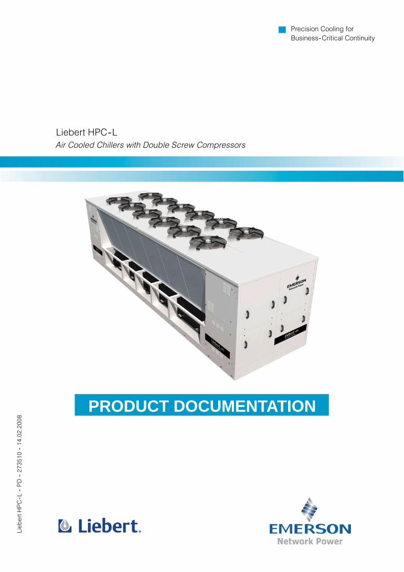
Liebert HPC---LThe water chiller market hasmet in the latest years stricter and stricter challenges due to the indus-trial society evolution and to technological developments, even if it is experiencing a full maturityphase.Tomeet themost different requirements, depending on the several application places, themodernwater chiller must thus be highly flexible, so as to suit to the surrounding environment.Here comes Liebert HPC---L, the innovative range of air---cooled water chillers by Emerson Net-work Power, covering a power range from 700 to 1600 kW.Over 60 models, 4 sound emission versions, one chiller and one freecooling configurations, twotypes of environment---friendly refrigerants, a wide range of options and accessories --- such aseconomizer and electronic expansion valve, just to name two --- Liebert HPC---L can be a leaderin the chiller world, both in its natural position for brand belonging --- the technological market ---and in other sectors such as high power commercial and industrial sectors.Besides its high flexibility Liebert HPC---L --- loyal to the tradition by Emerson Network Power ---is featured by efficiencies among the highest on the market, which are more and more neededto face the challenges of energy saving and environment protection of today, as well as by the low-est sound emissions in its category, above all in the Quiet version.Structure sturdiness and high reliability complete the features of the whole range.
Liebert HPC---LSolutions Committed to your Business
Liebert HPC--L
Liebert HPC---L---PD---273510---14.02.2008
Liebert HPC---L
Contents1 Features and Benefits
2 Model Number Description
3 Operating Range
4 Technical Data
5 Mechanical Specifications
6 Controls
7Cooling CapacityPerformance
8Hydraulic Features andPerformance AdjustmentFactors
9 Sound Levels
10 Electrical Data
11 Application Considerations
12 Dimensional Data
13 Refrigerant Circuit
14 Hydraulic CircuitThe product conforms to European Union directives 98/37/CE(89/392/CEE; 91/368/CEE; 93/68/CEE), 89/336/CEE;73/23/CEE; 97/23/CE.
Units are supplied complete with a test certificateand conformity declaration and control componentlist.
Liebert HPC--L units are CE marked as they complywith the European directives concerningmechanical, electrical, electromagnetic andpressure equipment safety.
The Quality ManagementSystem of Emerson NetworkPower S.r.l. High PerformanceAir Conditioning has beenapproved by Lloyd's RegisterQuality Assurance to thequality management systemstandard ISO 9001:2000
1 Features and Benefits
1 -- 1Liebert HPC---L---PD---273510---14.02.2008
Features and Benefits
Integration with Indoor Air Conditioners
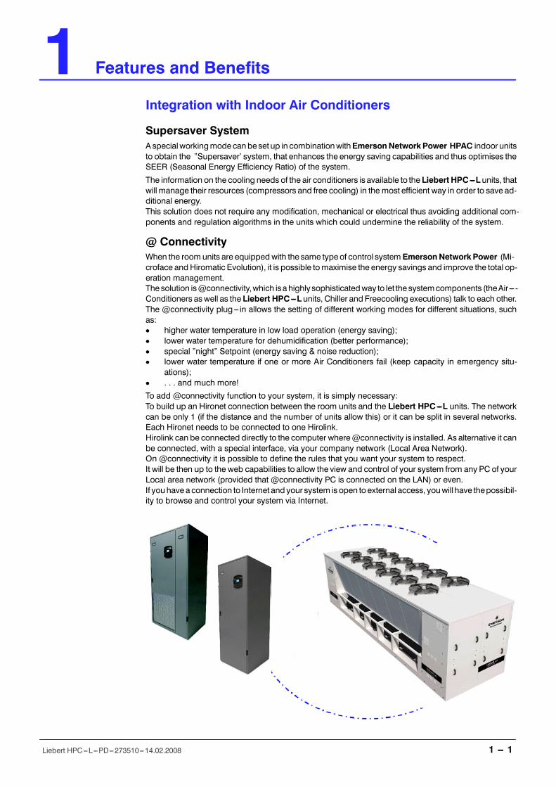
Supersaver SystemA specialworkingmodecanbeset up in combinationwithEmersonNetworkPower HPAC indoor unitsto obtain the �Supersaver� system, that enhances the energy saving capabilities and thus optimises theSEER (Seasonal Energy Efficiency Ratio) of the system.
The information on the cooling needs of the air conditioners is available to the Liebert HPC---L units, thatwill manage their resources (compressors and free cooling) in the most efficient way in order to save ad-ditional energy.This solution does not require any modification, mechanical or electrical thus avoiding additional com-ponents and regulation algorithms in the units which could undermine the reliability of the system.
@ ConnectivityWhen the room units are equippedwith the same typeof control system EmersonNetworkPower (Mi-croface andHiromatic Evolution), it is possible tomaximise the energy savings and improve the total op-eration management.The solution is@connectivity,which isa highly sophisticatedway to let the systemcomponents (theAir--- -Conditioners aswell as the Liebert HPC---L units, Chiller and Freecooling executions) talk to each other.The @connectivity plug--- in allows the setting of different working modes for different situations, suchas:D higher water temperature in low load operation (energy saving);D lower water temperature for dehumidification (better performance);D special �night� Setpoint (energy saving & noise reduction);D lower water temperature if one or more Air Conditioners fail (keep capacity in emergency situ-
ations);D . . . and much more!
To add @connectivity function to your system, it is simply necessary:To build up an Hironet connection between the room units and the Liebert HPC---L units. The networkcan be only 1 (if the distance and the number of units allow this) or it can be split in several networks.Each Hironet needs to be connected to one Hirolink.Hirolink can be connected directly to the computer where@connectivity is installed. As alternative it canbe connected, with a special interface, via your company network (Local Area Network).On @connectivity it is possible to define the rules that you want your system to respect.It will be then up to the web capabilities to allow the view and control of your system from any PC of yourLocal area network (provided that @connectivity PC is connected on the LAN) or even.If youhavea connection to Internet and your system isopen toexternal access, youwillhave thepossibil-ity to browse and control your system via Internet.
Features and Benefits
1 -- 2Liebert HPC---L---PD---273510---14.02.2008
Reliability and Low Environmental Impact
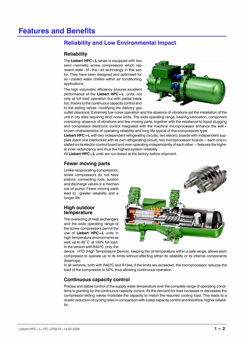
ReliabilityThe Liebert HPC---L series is equipped with twosemi---hermetic screw compressors which rep-resent state---of --- the---art technology in this sec-tor. They have been designed and optimised forair ---cooled water chillers within air conditioningapplications.
The high volumetric efficiency ensures excellentperformance of the Liebert HPC---L units, notonly at full load operation but with partial loadstoo, thanks to the continuouscapacity control andto the sliding valves, modifying the delivery gasoutlet clearance. Extremely low noise operation and the absence of vibrations aid the installation of theunit in city sites requiring strict noise limits. The wide operating range, bearing lubrication, componentoversizing, absence of vibrations and few moving parts, together with the resistance to liquid sluggingand compressor electronic control integrated with the machine microprocessor enhance the well --- -known characteristics of operating reliability and long life typical of this compressors type.Liebert HPC---L with two independent refrigerating circuits, two electric boards with independent sup-plies (each one interlocked with its own refrigerating circuit), twomicroprocessor boards --- each one in-stalledon its electric control board and evenoperating independently of eachother --- features thehighe-st inner redundancy and thus the highest system reliability.All Liebert HPC---L units are run tested at the factory before shipment.
Fewer moving partsUnlike reciprocating compressors,screw compressors do not havepistons, connecting rods, suctionand discharge valves or a mechan-ical oil pump. Fewer moving partslead to greater reliability and alonger life.
High outdoortemperatureThe oversizing of heat axchangersand the wide operating range ofthe screw compressors permit theuse of Liebert HPC---L units inhigh temperature environments aswell, up to 46ûC at 100% full load.In the version withR407C, only, thedevice HTD (High Temperature Device), keeping the oil temperature within a safe range, allows eachcompressor to operate up to its limits without affecting either its reliability or its internal components(bearings).In all versions, both with R407C and R134a, if the limits are exceeded, the microprocessor reduces theload of the compressor to 50%, thus allowing continuous operation.
Continuous capacity controlPrecise and stable control of the supply water temperature over the complete range of operating condi-tions is granting by the continuous capacity control. As the demand for load increases or decreases thecompressor sliding valves modulate the capacity to match the required cooling load. This leads to adrastic reductionof cycling rates in comparisonwith a step capacity control and therefore, higher reliabil-ity.
80,00070,00060,00050,00040,00030,00020,00010,000
0-6 -4 -2 0 2 4 6 8 10 12 14 16 18 20 22 24 26 28 30 32
Outdoor temperature (oC)
AnnualPowerconsumption(kWh)
VENICE
HAMBURG
80,00070,00060,00050,00040,00030,00020,00010,000
0
Outdoor temperature (oC)-18 -16 -14 -12 -10 -8 -6 -4 -2 0 2 4 6 8 10 12 14 16 18 20 22 24 26 28 30 32An
nualPowerconsumption(kWh)
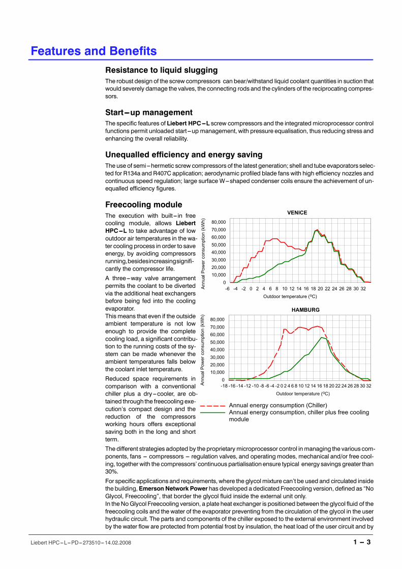
Annual energy consumption (Chiller)Annual energy consumption, chiller plus free coolingmodule
Features and Benefits
1 -- 3Liebert HPC---L---PD---273510---14.02.2008
Resistance to liquid sluggingThe robust design of the screw compressors can bear/withstand liquid coolant quantities in suction thatwould severely damage the valves, the connecting rods and the cylinders of the reciprocating compres-sors.
Start---up managementThe specific features of Liebert HPC---L screw compressors and the integrated microprocessor controlfunctions permit unloaded start---up management, with pressure equalisation, thus reducing stress andenhancing the overall reliability.
Unequalled efficiency and energy savingThe use of semi---hermetic screw compressors of the latest generation; shell and tube evaporators selec-ted for R134a and R407C application; aerodynamic profiled blade fans with high efficiency nozzles andcontinuous speed regulation; large surface W---shaped condenser coils ensure the achievement of un-equalled efficiency figures.
Freecooling moduleThe execution with built --- in freecooling module, allows LiebertHPC---L to take advantage of lowoutdoor air temperatures in the wa-ter cooling process in order to saveenergy, by avoiding compressorsrunning,besidesincreasingsignifi-cantly the compressor life.
A three---way valve arrangementpermits the coolant to be divertedvia the additional heat exchangersbefore being fed into the coolingevaporator.This means that even if the outsideambient temperature is not lowenough to provide the completecooling load, a significant contribu-tion to the running costs of the sy-stem can be made whenever theambient temperatures falls belowthe coolant inlet temperature.
Reduced space requirements incomparison with a conventionalchiller plus a dry---cooler, are ob-tained through the freecooling exe-cution�s compact design and thereduction of the compressorsworking hours offers exceptionalsaving both in the long and shortterm.
The different strategies adopted by the proprietarymicroprocessor control inmanaging the variouscom-ponents, fans --- compressors --- regulation valves, and operating modes, mechanical and/or free cool-ing, together with the compressors� continuous partialisation ensure typical energy savings greater than30%.
For specific applications and requirements, where the glycolmixture can�t be used and circulated insidethe building,Emerson Network Power has developed a dedicated Freecooling version, defined as �NoGlycol, Freecooling�, that border the glycol fluid inside the external unit only.In theNoGlycol Freecooling version, a plate heat exchanger is positioned between the glycol fluid of thefreecooling coils and the water of the evaporator preventing from the circulation of the glycol in the userhydraulic circuit. The parts and components of the chiller exposed to the external environment involvedby the water flow are protected from potential frost by insulation, the heat load of the user circuit and by
Features and Benefits
1 -- 4Liebert HPC---L---PD---273510---14.02.2008
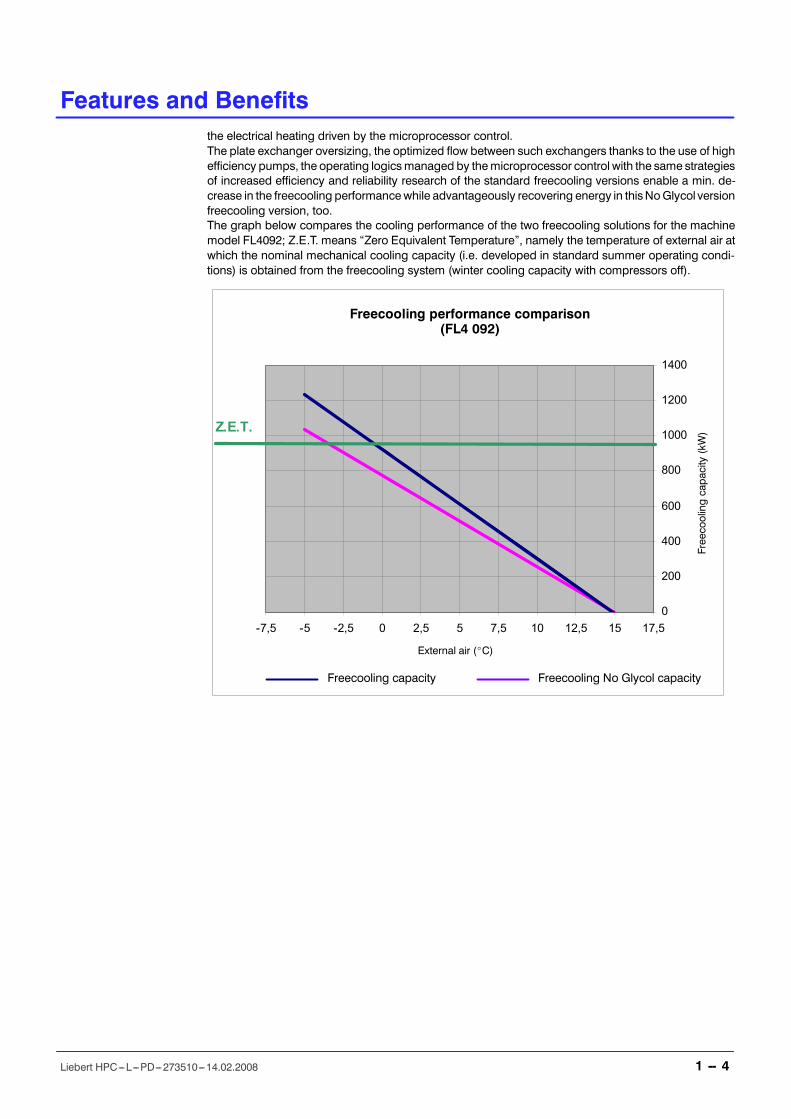
the electrical heating driven by the microprocessor control.The plate exchanger oversizing, the optimized flow between such exchangers thanks to the use of highefficiency pumps, the operating logicsmanaged by themicroprocessor control with the same strategiesof increased efficiency and reliability research of the standard freecooling versions enable a min. de-crease in the freecooling performancewhile advantageously recovering energy in thisNoGlycol versionfreecooling version, too.The graph below compares the cooling performance of the two freecooling solutions for the machinemodel FL4092; Z.E.T. means �Zero Equivalent Temperature�, namely the temperature of external air atwhich the nominal mechanical cooling capacity (i.e. developed in standard summer operating condi-tions) is obtained from the freecooling system (winter cooling capacity with compressors off).
0
200
400
600
800
1000
1200
1400
-7,5 -5 -2,5 0 2,5 5 7,5 10 12,5 15 17,5
Z.E.T.
Freecooling capacity Freecooling No Glycol capacity
Freecoolingcapacity
(kW)
External air (_C)
Freecooling performance comparison(FL4 092)
Features and Benefits
1 -- 5Liebert HPC---L---PD---273510---14.02.2008
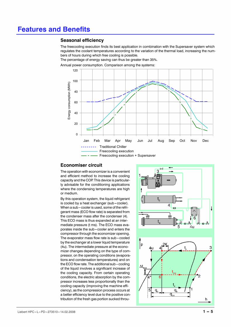
Seasonal efficiencyThe freecooling execution finds its best application in combination with the Supersaver system whichregulates the coolant temperatures according to the variation of the thermal load, increasing the num-bers of hours during which free cooling is possible.The percentage of energy saving can thus be greater than 35%.
Annual power consumption. Comparison among the systems:
120
100
40
60
40
20
0
Energyconsumption(MWh)
Jan Feb Mar Apr May Jun Jul Aug Sep Oct Nov Dec
Traditional ChillerFreecooling execution
- Freecooling execution + Supersaver
Economiser circuitThe operation with economizer is a convenientand efficient method to increase the coolingcapacity and theCOP. This device is particular-ly advisable for the conditioning applicationswhere the condensing temperatures are highor medium.
By this operation system, the liquid refrigerantis cooled by a heat exchanger (sub---cooler).When a sub---cooler is used, some of the refri-gerant mass (ECO flow rate) is separated fromthe condenser mass after the condenser (4).This ECO mass is thus expanded at an inter-mediate pressure (t ms). The ECO mass eva-porates inside the sub---cooler and enters thecompressor through the economizer opening.The evaporator mass flow rate is sub---cooledby the exchanger at a lower liquid temperature(4u). The intermediate pressure at the econo-mizer changes depending on the type of com-pressor, on the operating conditions (evapora-tions and condensation temperatures) and onthe ECO flow rate. The additional sub---coolingof the liquid involves a significant increase ofthe cooling capacity. From certain operatingconditions, the electric absorption by the com-pressor increases less proportionally than thecooling capacity (improving the machine effi-ciency), as the compression process occurs ata better efficiency level due to the positive con-tribution of the fresh gas portion sucked throu-
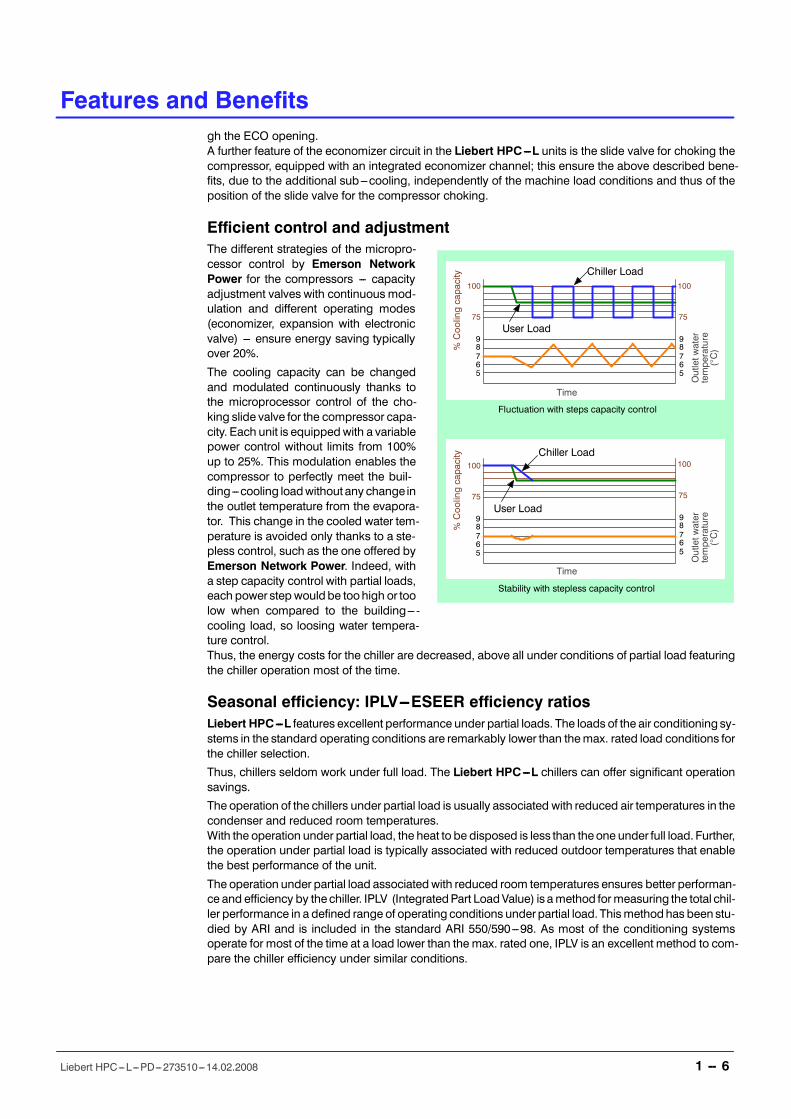
Chiller Load
User Load
Fluctuation with steps capacity control
Outletw
ater
temperature
(°C)%
Coolingcapacity
Time
100
75
98765
98765
100
75
Time
Outletw
ater
temperature
(°C)%
Coolingcapacity Chiller Load
User Load
100
75
98765
Stability with stepless capacity control
98765
100
75
Features and Benefits
1 -- 6Liebert HPC---L---PD---273510---14.02.2008
gh the ECO opening.A further feature of the economizer circuit in the Liebert HPC---L units is the slide valve for choking thecompressor, equipped with an integrated economizer channel; this ensure the above described bene-fits, due to the additional sub---cooling, independently of the machine load conditions and thus of theposition of the slide valve for the compressor choking.
Efficient control and adjustmentThe different strategies of the micropro-cessor control by Emerson NetworkPower for the compressors --- capacityadjustment valves with continuousmod-ulation and different operating modes(economizer, expansion with electronicvalve) --- ensure energy saving typicallyover 20%.
The cooling capacity can be changedand modulated continuously thanks tothe microprocessor control of the cho-king slide valve for the compressor capa-city. Each unit is equippedwith a variablepower control without limits from 100%up to 25%. This modulation enables thecompressor to perfectly meet the buil-ding---cooling loadwithout any change inthe outlet temperature from the evapora-tor. This change in the cooled water tem-perature is avoided only thanks to a ste-pless control, such as the one offered byEmerson Network Power. Indeed, witha step capacity control with partial loads,each power step wouldbe toohigh or toolow when compared to the building--- -cooling load, so loosing water tempera-ture control.Thus, the energy costs for the chiller are decreased, above all under conditions of partial load featuringthe chiller operation most of the time.
Seasonal efficiency: IPLV---ESEER efficiency ratiosLiebert HPC---L features excellent performance under partial loads. The loads of the air conditioning sy-stems in the standard operating conditions are remarkably lower than themax. rated load conditions forthe chiller selection.
Thus, chillers seldom work under full load. The Liebert HPC---L chillers can offer significant operationsavings.
The operation of the chillers under partial load is usually associated with reduced air temperatures in thecondenser and reduced room temperatures.With the operation under partial load, the heat to be disposed is less than theone under full load. Further,the operation under partial load is typically associated with reduced outdoor temperatures that enablethe best performance of the unit.
The operation under partial load associated with reduced room temperatures ensures better performan-ce and efficiency by thechiller. IPLV (IntegratedPart LoadValue) is amethod formeasuring the total chil-ler performance in a defined range of operating conditions underpartial load. Thismethodhas been stu-died by ARI and is included in the standard ARI 550/590---98. As most of the conditioning systemsoperate for most of the time at a load lower than the max. rated one, IPLV is an excellent method to com-pare the chiller efficiency under similar conditions.
Features and Benefits
1 -- 7Liebert HPC---L---PD---273510---14.02.2008
The formula to calculate IPLV is:IPLV = 0.01A + 0.42B + 0.45C + 0.12DWhere:A = EER at 100%, load point at 35.0 °C condenser air inletB = EER at 75%, load point at 26.7 °CC = EER at 50%, load point at 18.3 °CD = EER at 25%, load point at 12.8 °CAn alternative seasonal efficiency ratio has been defined for Europe, which is more suitable for the loadconditions, the outdoor air temperatures and the building principles typical of European countries. It isdefined by the acronym ESEER (European Seasonal Energy Efficiency Ratio), as specified here below:
ESEER = 0.03A + 0.33B + 0.41C + 0.23DWhere:A = EER at 100%, load point at 35 °C condenser air inletB = EER at 75%, load point at 30.0 °CC = EER at 50%, load point at 25.0 °CD = EER at 25%, load point at 20.0 °CSuch ratios are really useful to calculate the energy consumption, when the load distribution requiredby the chiller in one year of operation follows the same percentage subdivisions considered in theabovementioned formulas.Absorbed energy = Required energy / Efficiency ratio
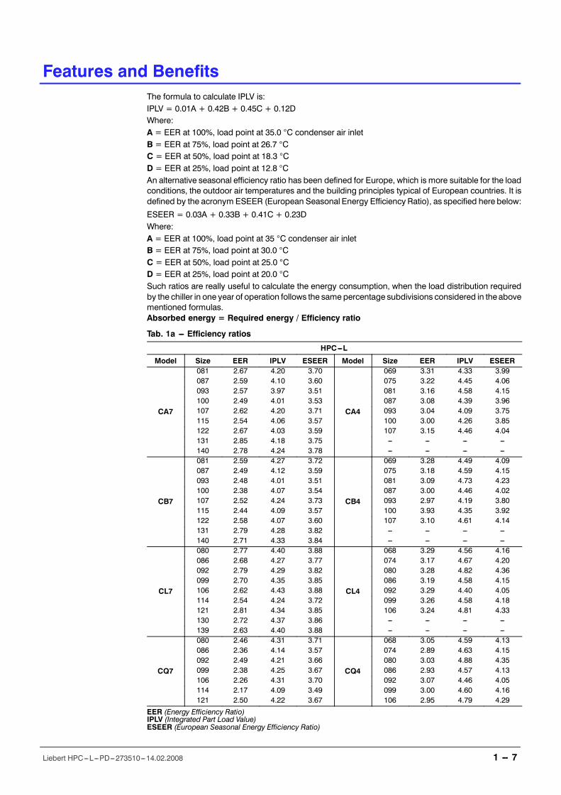
Tab. 1a --- Efficiency ratios
HPC---L
Model Size EER IPLV ESEER Model Size EER IPLV ESEER
CA7
081 2.67 4.20 3.70
CA4
069 3.31 4.33 3.99087 2.59 4.10 3.60 075 3.22 4.45 4.06093 2.57 3.97 3.51 081 3.16 4.58 4.15100 2.49 4.01 3.53 087 3.08 4.39 3.96107 2.62 4.20 3.71 093 3.04 4.09 3.75115 2.54 4.06 3.57 100 3.00 4.26 3.85122 2.67 4.03 3.59 107 3.15 4.46 4.04131 2.85 4.18 3.75 --- --- --- ---140 2.78 4.24 3.78 --- --- --- ---
CB7
081 2.59 4.27 3.72
CB4
069 3.28 4.49 4.09087 2.49 4.12 3.59 075 3.18 4.59 4.15093 2.48 4.01 3.51 081 3.09 4.73 4.23100 2.38 4.07 3.54 087 3.00 4.46 4.02107 2.52 4.24 3.73 093 2.97 4.19 3.80115 2.44 4.09 3.57 100 3.93 4.35 3.92122 2.58 4.07 3.60 107 3.10 4.61 4.14131 2.79 4.28 3.82 --- --- --- ---140 2.71 4.33 3.84 --- --- --- ---
CL7
080 2.77 4.40 3.88
CL4
068 3.29 4.56 4.16086 2.68 4.27 3.77 074 3.17 4.67 4.20092 2.79 4.29 3.82 080 3.28 4.82 4.36099 2.70 4.35 3.85 086 3.19 4.58 4.15106 2.62 4.43 3.88 092 3.29 4.40 4.05114 2.54 4.24 3.72 099 3.26 4.58 4.18121 2.81 4.34 3.85 106 3.24 4.81 4.33130 2.72 4.37 3.86 --- --- --- ---139 2.63 4.40 3.88 --- --- --- ---
CQ7
080 2.46 4.31 3.71
CQ4
068 3.05 4.59 4.13086 2.36 4.14 3.57 074 2.89 4.63 4.15092 2.49 4.21 3.66 080 3.03 4.88 4.35099 2.38 4.25 3.67 086 2.93 4.57 4.13106 2.26 4.31 3.70 092 3.07 4.46 4.05114 2.17 4.09 3.49 099 3.00 4.60 4.16121 2.50 4.22 3.67 106 2.95 4.79 4.29
EER (Energy Efficiency Ratio)IPLV (Integrated Part Load Value)ESEER (European Seasonal Energy Efficiency Ratio)
Features and Benefits
1 -- 8Liebert HPC---L---PD---273510---14.02.2008
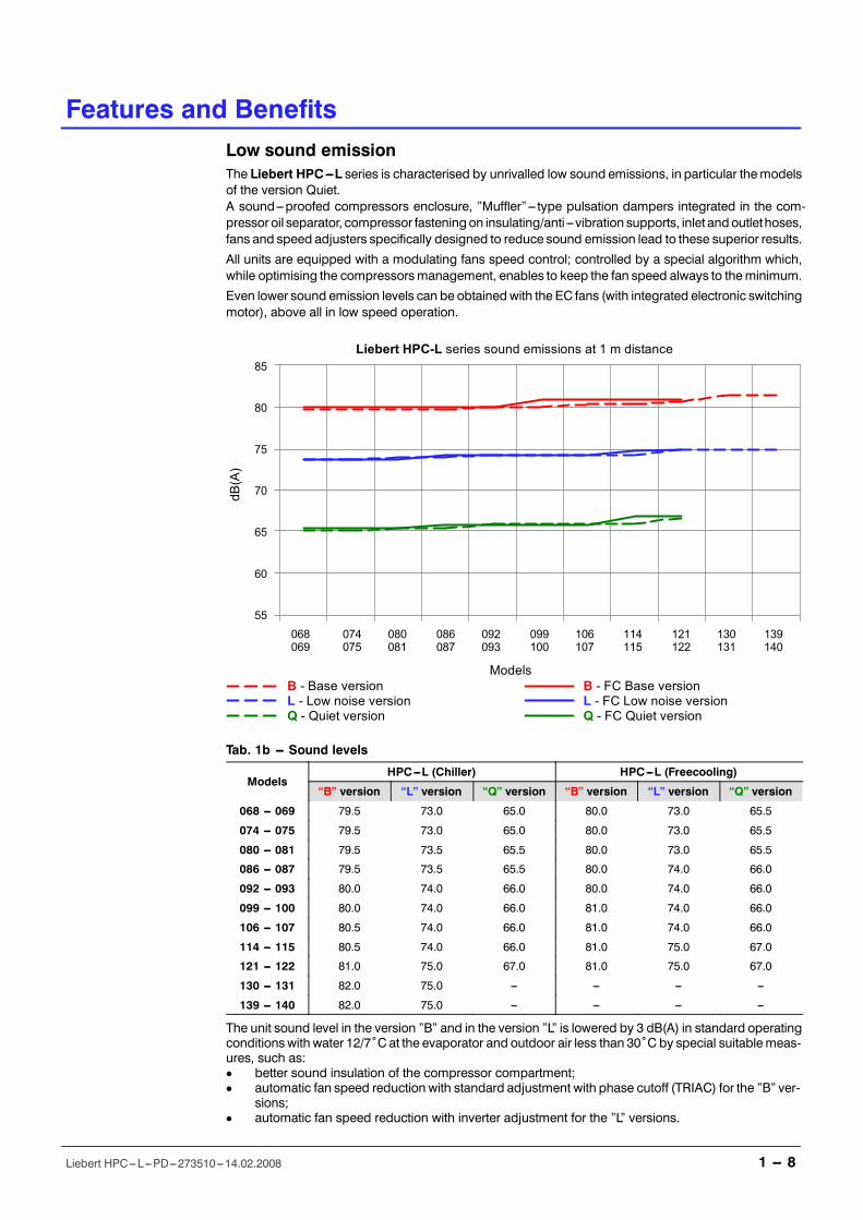
Low sound emissionThe Liebert HPC---L series is characterised by unrivalled low sound emissions, in particular themodelsof the version Quiet.A sound---proofed compressors enclosure, �Muffler�--- type pulsation dampers integrated in the com-pressor oil separator, compressor fasteningon insulating/anti ---vibration supports, inlet andoutlethoses,fans and speed adjusters specifically designed to reduce sound emission lead to these superior results.
All units are equipped with a modulating fans speed control; controlled by a special algorithm which,while optimising the compressorsmanagement, enables to keep the fan speed always to theminimum.
Even lower sound emission levels can be obtainedwith the EC fans (with integrated electronic switchingmotor), above all in low speed operation.
B - Base versionL - Low noise versionQ - Quiet version
Models
Liebert HPC-L series sound emissions at 1 m distance
068 074 080 086 092 099 106 114 121 130 139069 075 081 087 093 100 107 115 122 131 140
85
80
75
70
65
60
55
dB(A)
B - FC Base versionL - FC Low noise versionQ - FC Quiet version
Tab. 1b --- Sound levels
ModelsHPC---L (Chiller) HPC---L (Freecooling)
�B� version �L� version �Q� version �B� version �L� version �Q� version
068 --- 069 79.5 73.0 65.0 80.0 73.0 65.5
074 --- 075 79.5 73.0 65.0 80.0 73.0 65.5
080 --- 081 79.5 73.5 65.5 80.0 73.0 65.5
086 --- 087 79.5 73.5 65.5 80.0 74.0 66.0
092 --- 093 80.0 74.0 66.0 80.0 74.0 66.0
099 --- 100 80.0 74.0 66.0 81.0 74.0 66.0
106 --- 107 80.5 74.0 66.0 81.0 74.0 66.0
114 --- 115 80.5 74.0 66.0 81.0 75.0 67.0
121 --- 122 81.0 75.0 67.0 81.0 75.0 67.0
130 --- 131 82.0 75.0 --- --- --- ---
139 --- 140 82.0 75.0 --- --- --- ---
The unit sound level in the version �B� and in the version �L� is lowered by 3 dB(A) in standard operatingconditionswith water 12/7ûCat the evaporator and outdoor air less than 30ûC by special suitablemeas-ures, such as:D better sound insulation of the compressor compartment;D automatic fan speed reduction with standard adjustment with phase cutoff (TRIAC) for the �B� ver-
sions;D automatic fan speed reduction with inverter adjustment for the �L� versions.
2 Model Number Description
2 -- 1Liebert HPC---L---PD---273510---14.02.2008
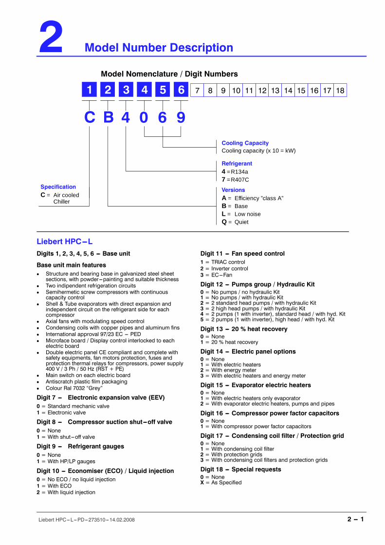
Model Number Description
Model Nomenclature / Digit Numbers
1 2 3 4 5 6 7 8 9 10 11 12 13 14 15 16 17 18
B 4 0 6C 9Cooling CapacityCooling capacity (x 10 = kW)
Refrigerant4 =R134a7 =R407C
VersionsA = Efficiency ”class A”B = BaseL = Low noiseQ = Quiet
SpecificationC = Air cooled
Chiller
Liebert HPC---LDigits 1, 2, 3, 4, 5, 6 --- Base unit
Base unit main featuresD Structure and bearing base in galvanized steel sheet
sections, with powder---painting and suitable thicknessD Two indipendent refrigeration circuitsD Semihermetic screw compressors with continuous
capacity controlD Shell & Tube evaporators with direct expansion and
independent circuit on the refrigerant side for eachcompressor
D Axial fans with modulating speed controlD Condensing coils with copper pipes and aluminum finsD International approval 97/23 EC --- PEDD Microface board / Display control interlocked to each
electric boardD Double electric panel CE compliant and complete with
safety equipments, fan motors protection, fuses andprotection thermal relays for compressors, power supply400 V / 3 Ph / 50 Hz (RST + PE)
D Main switch on each electric boardD Antiscratch plastic film packagingD Colour Ral 7032 �Grey�
Digit 7 --- Electronic expansion valve (EEV)0 = Standard mechanic valve1 = Electronic valve
Digit 8 --- Compressor suction shut---off valve0 = None1 = With shut---off valve
Digit 9 --- Refrigerant gauges0 = None1 = With HP/LP gauges
Digit 10 --- Economiser (ECO) / Liquid injection0 = No ECO / no liquid injection1 = With ECO2 = With liquid injection
Digit 11 --- Fan speed control1 = TRIAC control2 = Inverter control3 = EC---Fan
Digit 12 --- Pumps group / Hydraulic Kit0 = No pumps / no hydraulic Kit1 = No pumps / with hydraulic Kit2 = 2 standard head pumps / with hydraulic Kit3 = 2 high head pumps / with hydraulic Kit4 = 2 pumps (1 with inverter), standard head / with hyd. Kit5 = 2 pumps (1 with inverter), high head / with hyd. Kit
Digit 13 --- 20 % heat recovery0 = None1 = 20 % heat recovery
Digit 14 --- Electric panel options0 = None1 = With electric heaters2 = With energy meter3 = With electric heaters and energy meter
Digit 15 --- Evaporator electric heaters0 = None1 = With electric heaters only evaporator2 = With evaporator electric heaters, pumps and pipes
Digit 16 --- Compressor power factor capacitors0 = None1 = With compressor power factor capacitors
Digit 17 --- Condensing coil filter / Protection grid0 = None1 = With condensing coil filter2 = With protection grids3 = With condensing coil filters and protection grids
Digit 18 --- Special requests0 = NoneX = As Specified
Model Number Description
2 -- 2Liebert HPC---L---PD---273510---14.02.2008
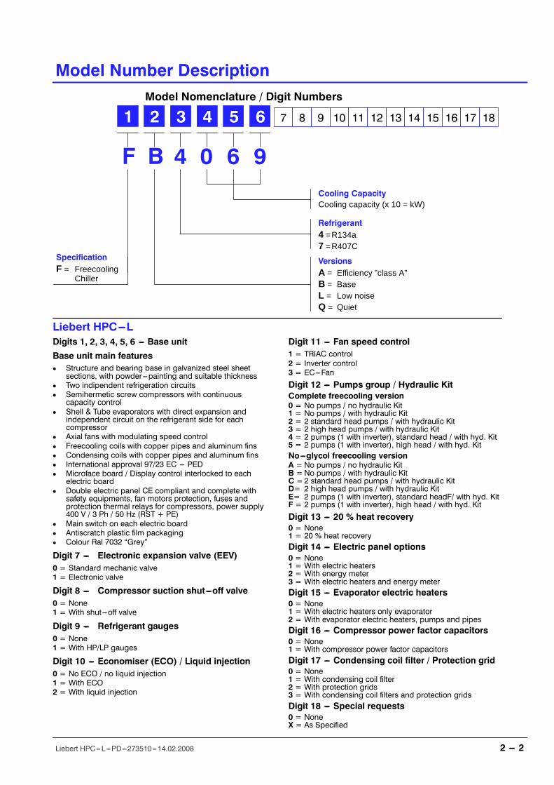
Model Nomenclature / Digit Numbers
1 2 3 4 5 6 7 8 9 10 11 12 13 14 15 16 17 18
B 4 0 6F 9Cooling CapacityCooling capacity (x 10 = kW)
Refrigerant4 =R134a7 =R407C
VersionsA = Efficiency ”class A”B = BaseL = Low noiseQ = Quiet
SpecificationF = Freecooling
Chiller
Liebert HPC---LDigits 1, 2, 3, 4, 5, 6 --- Base unit
Base unit main featuresD Structure and bearing base in galvanized steel sheet
sections, with powder---painting and suitable thicknessD Two indipendent refrigeration circuitsD Semihermetic screw compressors with continuous
capacity controlD Shell & Tube evaporators with direct expansion and
independent circuit on the refrigerant side for eachcompressor
D Axial fans with modulating speed controlD Freecooling coils with copper pipes and aluminum finsD Condensing coils with copper pipes and aluminum finsD International approval 97/23 EC --- PEDD Microface board / Display control interlocked to each
electric boardD Double electric panel CE compliant and complete with
safety equipments, fan motors protection, fuses andprotection thermal relays for compressors, power supply400 V / 3 Ph / 50 Hz (RST + PE)
D Main switch on each electric boardD Antiscratch plastic film packagingD Colour Ral 7032 �Grey�
Digit 7 --- Electronic expansion valve (EEV)0 = Standard mechanic valve1 = Electronic valve
Digit 8 --- Compressor suction shut---off valve0 = None1 = With shut---off valve
Digit 9 --- Refrigerant gauges0 = None1 = With HP/LP gauges
Digit 10 --- Economiser (ECO) / Liquid injection0 = No ECO / no liquid injection1 = With ECO2 = With liquid injection
Digit 11 --- Fan speed control1 = TRIAC control2 = Inverter control3 = EC---Fan
Digit 12 --- Pumps group / Hydraulic KitComplete freecooling version0 = No pumps / no hydraulic Kit1 = No pumps / with hydraulic Kit2 = 2 standard head pumps / with hydraulic Kit3 = 2 high head pumps / with hydraulic Kit4 = 2 pumps (1 with inverter), standard head / with hyd. Kit5 = 2 pumps (1 with inverter), high head / with hyd. KitNo---glycol freecooling versionA =No pumps / no hydraulic KitB =No pumps / with hydraulic KitC =2 standard head pumps / with hydraulic KitD= 2 high head pumps / with hydraulic KitE= 2 pumps (1 with inverter), standard headF/ with hyd. KitF = 2 pumps (1 with inverter), high head / with hyd. Kit
Digit 13 --- 20 % heat recovery0 = None1 = 20 % heat recoveryDigit 14 --- Electric panel options0 = None1 = With electric heaters2 = With energy meter3 = With electric heaters and energy meterDigit 15 --- Evaporator electric heaters0 = None1 = With electric heaters only evaporator2 = With evaporator electric heaters, pumps and pipesDigit 16 --- Compressor power factor capacitors0 = None1 = With compressor power factor capacitorsDigit 17 --- Condensing coil filter / Protection grid0 = None1 = With condensing coil filter2 = With protection grids3 = With condensing coil filters and protection gridsDigit 18 --- Special requests0 = NoneX = As Specified
3 Operating Range
3 -- 1Liebert HPC---L---PD---273510---14.02.2008
Operating Range
Working LimitsMinimum temperature of outdoor air entering condenser coils (with standard operating unit):
---25 ûC for freecooling models;
---10 ûC for Chiller models.
Maximum outdoor air temperature is in relation to eachmodel, as indicated in the following tables. In anycase outdoor temperatures over 46ûC are not admitted; such limits are determined by electrical andelectronic components fitted on units. Maximum flow rates are indicated in the following tables.Higher flow values may cause corrosions and vibrations inside the shell and tube heat exchanger.The Minimum water flow allowed corresponds to a maximum temperature difference of 8ûC. Moreextreme operating conditions would active safety devices and the unit would be stopped.Outlet water temperature from 4 to 15 ûC.The maximum allowed water return temperature when the unit is in full operation is 20 ûC; returntemperatures in excess of 20 ûC are allowed only during start---up.The maximum glycol percentage permitted is 50% (35% with standard pump sets fitted)
The minimum glycol percentage necessary is in relation to the minimum ambient air temperatureconditions referred to the place of installation.The maximum hydraulic working pressure is 6 Barg (Safety valve setting is 5 Barg with the optionalhydraulic kit).Nominal power supply tolerance: 400V +/--- 10%; max. voltage drop: 3%.See operation range Table in which eachmodel�s limits are indicated; for different valuesask your agent.
Unit storage conditions:D Between ---20 ûC and + 45 ûC for all models.
Technical Data
4 -- 7Liebert HPC---L---PD---273510---14.02.2008
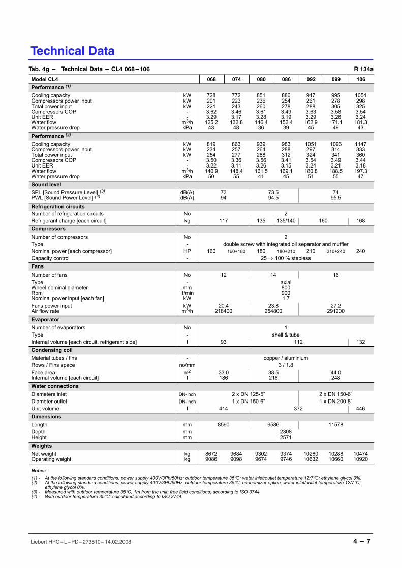
Tab. 4g --- Technical Data --- CL4 068---106 R 134a
Model CL4 068 074 080 086 092 099 106Performance (1)
Cooling capacityCompressors power inputTotal power inputCompressors COPUnit EERWater flowWater pressure drop
kWkWkW--
m3/hkPa
7282012213.623.29125.243
7722232433.463.17132.848
8512362603.613.28146.436
8862542783.493.19152.439
9472612883.633.29162.945
9952783053.583.26171.149
10542983253.543.24181.343
Performance (2)
Cooling capacityCompressors power inputTotal power inputCompressors COPUnit EERWater flowWater pressure drop
kWkWkW--
m3/hkPa
8192342543.503.22140.950
8632572773.363.11148.455
9392642883.563.26161.541
9832883123.413.15169.145
10512973243.543.24180.851
10963143413.493.21188.555
11473333603.443.18197.347
Sound levelSPL [Sound Pressure Level] (3)PWL [Sound Power Level] (4)
dB(A)dB(A)
7394
73.594.5
7495.5
Refrigeration circuitsNumber of refrigeration circuits No 2Refrigerant charge [each circuit] kg 117 135 135/140 160 168CompressorsNumber of compressors No 2Type - double screw with integrated oil separator and mufflerNominal power [each compressor] HP 160 160+180 180 180+210 210 210+240 240Capacity control - 25⇒ 100 % steplessFansNumber of fans No 12 14 16TypeWheel nominal diameterRpmNominal power input [each fan]
-mm1/minkW
axial8009001.7
Fans power inputAir flow rate
kWm3/h
20.4218400
23.8254800
27.2291200
EvaporatorNumber of evaporators No 1Type - shell & tubeInternal volume [each circuit, refrigerant side] l 93 112 132Condensing coilMaterial tubes / fins - copper / aluminiumRows / Fins space no/mm 3 / 1.8Face areaInternal volume [each circuit]
m2l
33.0186
38.5216
44.0248
Water connectionsDiameters inlet DN-inch 2 x DN 125-5� 2 x DN 150-6�Diameter outlet DN-inch 1 x DN 150-6� 1 x DN 200-8�Unit volume l 414 372 446DimensionsLength mm 8590 9586 11578DepthHeight
mmmm
23082571
WeightsNet weightOperating weight
kgkg
86729086
96849098
93029674
93749746
1026010632
1028810660
1047410920
Notes:(1) - At the following standard conditions: power supply 400V/3Ph/50Hz; outdoor temperature 35°C; water inlet/outlet temperature 12/7°C; ethylene glycol 0%.(2) - At the following standard conditions: power supply 400V/3Ph/50Hz; outdoor temperature 35°C; economizer option; water inlet/outlet temperature 12/7°C;
ethylene glycol 0%.(3) - Measured with outdoor temperature 35°C; 1m from the unit; free field conditions; according to ISO 3744.(4) - With outdoor temperature 35°C; calculated according to ISO 3744.
5 Mechanical Specifications
5 -- 1Liebert HPC---L---PD---273510---14.02.2008
Mechanical Specifications
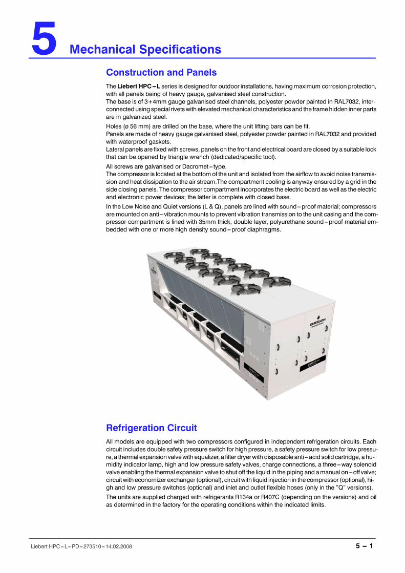
Construction and PanelsThe Liebert HPC---L series is designed for outdoor installations, havingmaximum corrosion protection,with all panels being of heavy gauge, galvanised steel construction.The base is of 3+4mm gauge galvanised steel channels, polyester powder painted in RAL7032, inter-connectedusing special rivetswith elevatedmechanical characteristics and the framehidden inner partsare in galvanized steel.
Holes (ø 56 mm) are drilled on the base, where the unit lifting bars can be fit.Panels are made of heavy gauge galvanised steel, polyester powder painted in RAL7032 and providedwith waterproof gaskets.Lateral panels are fixed with screws, panels on the front and electrical board are closed by a suitable lockthat can be opened by triangle wrench (dedicated/specific tool).
All screws are galvanised or Dacromet--- type.The compressor is located at the bottom of the unit and isolated from the airflow to avoid noise transmis-sion and heat dissipation to the air stream.The compartment cooling is anyway ensured by a grid in theside closing panels. The compressor compartment incorporates the electric board as well as the electricand electronic power devices; the latter is complete with closed base.
In the Low Noise and Quiet versions (L & Q), panels are lined with sound---proof material; compressorsare mounted on anti ---vibration mounts to prevent vibration transmission to the unit casing and the com-pressor compartment is lined with 35mm thick, double layer, polyurethane sound---proof material em-bedded with one or more high density sound---proof diaphragms.
Refrigeration CircuitAll models are equipped with two compressors configured in independent refrigeration circuits. Eachcircuit includes double safety pressure switch for high pressure, a safety pressure switch for low pressu-re, a thermal expansion valvewith equalizer, a filter dryerwith disposable anti ---acid solid cartridge, a hu-midity indicator lamp, high and low pressure safety valves, charge connections, a three---way solenoidvalve enabling the thermal expansion valve to shut off the liquid in the piping and amanual on---off valve;circuitwith economizer exchanger (optional), circuitwith liquid injection in the compressor (optional),hi-gh and low pressure switches (optional) and inlet and outlet flexible hoses (only in the �Q� versions).
The units are supplied charged with refrigerants R134a or R407C (depending on the versions) and oilas determined in the factory for the operating conditions within the indicated limits.
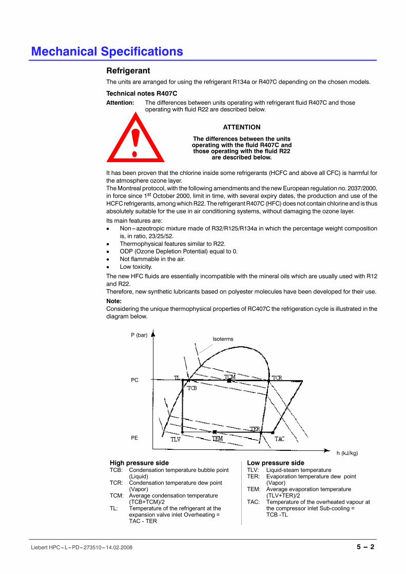
IsotermsP (bar)
h (kJ/kg)
PC
PE
High pressure sideTCB: Condensation temperature bubble point
(Liquid)TCR: Condensation temperature dew point
(Vapor)TCM: Average condensation temperature
(TCB+TCM)/2TL: Temperature of the refrigerant at the
expansion valve inlet Overheating =TAC - TER
Low pressure sideTLV: Liquid-steam temperatureTER: Evaporation temperature dew point
(Vapor)TEM: Average evaporation temperature
(TLV+TER)/2TAC: Temperature of the overheated vapour at
the compressor inlet Sub-cooling =TCB -TL
Mechanical Specifications
5 -- 2Liebert HPC---L---PD---273510---14.02.2008
RefrigerantThe units are arranged for using the refrigerant R134a or R407C depending on the chosen models.
Technical notes R407CAttention: The differences between units operating with refrigerant fluid R407C and those
operating with fluid R22 are described below.
ATTENTION
The differences between the unitsoperating with the fluid R407C andthose operating with the fluid R22
are described below.
It has been proven that the chlorine inside some refrigerants (HCFC and above all CFC) is harmful forthe atmosphere ozone layer.TheMontreal protocol, with the following amendments and thenewEuropean regulation no. 2037/2000,in force since 1st October 2000, limit in time, with several expiry dates, the production and use of theHCFC refrigerants, amongwhichR22. The refrigerantR407C (HFC)doesnot contain chlorine and is thusabsolutely suitable for the use in air conditioning systems, without damaging the ozone layer.
Its main features are:D Non---azeotropic mixture made of R32/R125/R134a in which the percentage weight composition
is, in ratio, 23/25/52.D Thermophysical features similar to R22.D ODP (Ozone Depletion Potential) equal to 0.D Not flammable in the air.D Low toxicity.
The new HFC fluids are essentially incompatible with the mineral oils which are usually used with R12and R22.Therefore, new synthetic lubricants based on polyester molecules have been developed for their use.
Note:Considering the unique thermophysical properties of RC407C the refrigeration cycle is illustrated in thediagram below.
11
4
12 92 141
563
1310
Mechanical Specifications
5 -- 3Liebert HPC---L---PD---273510---14.02.2008
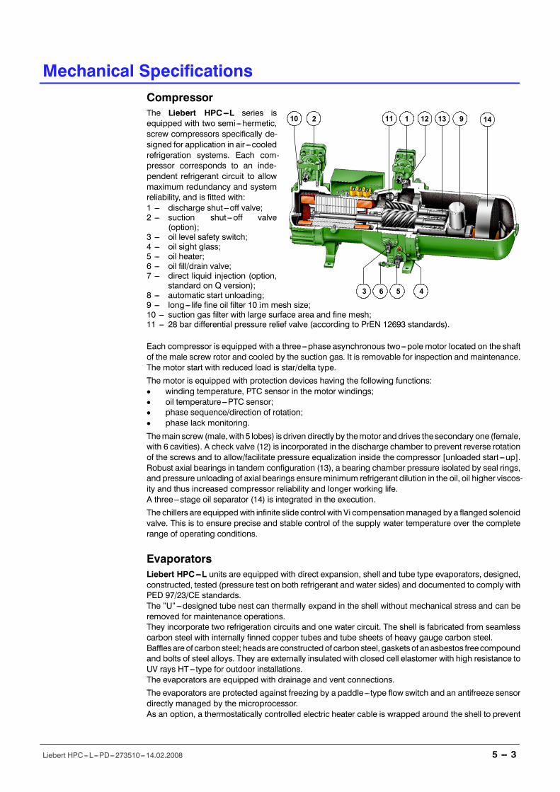
CompressorThe Liebert HPC---L series isequipped with two semi---hermetic,screw compressors specifically de-signed for application in air ---cooledrefrigeration systems. Each com-pressor corresponds to an inde-pendent refrigerant circuit to allowmaximum redundancy and systemreliability, and is fitted with:1 --- discharge shut---off valve;2 --- suction shut---off valve
(option);3 --- oil level safety switch;4 --- oil sight glass;5 --- oil heater;6 --- oil fill/drain valve;7 --- direct liquid injection (option,
standard on Q version);8 --- automatic start unloading;9 --- long--- life fine oil filter 10 ìm mesh size;10 --- suction gas filter with large surface area and fine mesh;11 --- 28 bar differential pressure relief valve (according to PrEN 12693 standards).
Each compressor is equipped with a three---phase asynchronous two---pole motor located on the shaftof the male screw rotor and cooled by the suction gas. It is removable for inspection and maintenance.The motor start with reduced load is star/delta type.
The motor is equipped with protection devices having the following functions:D winding temperature, PTC sensor in the motor windings;D oil temperature---PTC sensor;D phase sequence/direction of rotation;D phase lack monitoring.
Themain screw (male,with 5 lobes) is driven directly by themotor anddrives the secondary one (female,with 6 cavities). A check valve (12) is incorporated in the discharge chamber to prevent reverse rotationof the screws and to allow/facilitate pressure equalization inside the compressor [unloaded start---up].Robust axial bearings in tandem configuration (13), a bearing chamber pressure isolated by seal rings,and pressure unloading of axial bearings ensureminimum refrigerant dilution in the oil, oil higher viscos-ity and thus increased compressor reliability and longer working life.A three---stage oil separator (14) is integrated in the execution.
The chillers are equippedwith infinite slide control with Vi compensationmanaged by a flanged solenoidvalve. This is to ensure precise and stable control of the supply water temperature over the completerange of operating conditions.
EvaporatorsLiebert HPC---L units are equipped with direct expansion, shell and tube type evaporators, designed,constructed, tested (pressure test on both refrigerant and water sides) and documented to comply withPED 97/23/CE standards.The �U�---designed tube nest can thermally expand in the shell without mechanical stress and can beremoved for maintenance operations.They incorporate two refrigeration circuits and one water circuit. The shell is fabricated from seamlesscarbon steel with internally finned copper tubes and tube sheets of heavy gauge carbon steel.Baffles areof carbon steel; headsare constructedof carbon steel, gasketsof anasbestos freecompoundand bolts of steel alloys. They are externally insulated with closed cell elastomer with high resistance toUV rays HT---type for outdoor installations.The evaporators are equipped with drainage and vent connections.
The evaporators are protected against freezing by a paddle--- type flow switch and an antifreeze sensordirectly managed by the microprocessor.As an option, a thermostatically controlled electric heater cable is wrapped around the shell to prevent

Mechanical Specifications
5 -- 4Liebert HPC---L---PD---273510---14.02.2008
freezing with outdoor temperatures below 0ûC.Temperature and pressure working limits and pressure test values are indicated below:
Tab. 5a --- Evaporator working limits
Design temperature Design pressure Test pressure
Min. / Max. Refrigerant(R407C) Water Refrigerant
(R407C) Water
-10 / +90 °C 30.0 bar 10.0 bar 33.0 bar 11.0 bar
Design temperature Design pressure Test pressure
Min. / Max. Refrigerant(R134a) Water Refrigerant
(R134a) Water
-10 / +90 °C 16.5 bar 10.0 bar 18.2 bar 11.0 bar
CondensersThe condensing coils are made of copper tubes and aluminium fins and are mounted in double V (W)configuration to provide a larger heat exchange surface.Copper tubes in staggered rows are mechanical expanded in order to have the best contact with fins;the tubes are grooved type (KME Crossfin) to increase the thermal exchange. The Aluminium fins aremanufactured with a special high efficiency rusticate surface that increases the thermal exchange.The condenser coils are tested at a pressure of 30bar.
�HTD� High outdoor temperature device:liquid injection (versions R407C only)The over---sizing of the heat exchangers and thewide operating range of the new generation screw com-pressors enable use in very hot climates, too. The compressor liquid injection device is available as anoption (HTD) as an alternative to the economizer; this options keeps the oil temperature within largelytolerated temperature values, and enables the compressor to run up its operating limits without jeopard-ising its reliability or the life of its components (bearings).
The machine�s continuity of service is even ensured when exceeding the maximum operating limits, asthe microprocessor limits the compressor load (before locking it out), reducing its capacity to 50%.Suchdevice is not recommended in theunitswithR134a; only if theunit it operating under very hard con-ditions (e.g brine operation) such option can be actually used; for this reason, in case of doubt get in tou-ch with your dealer.
Hydraulic CircuitThe hydraulic circuit utilises carbon steel pipes connected withgrooved---end (Victaulic) fittings and couplings; gaskets are madeof EPDM. This arrangement permits compensation for thermal ex-pansion, reduces noise and vibrations propagating through hy-draulic pipelines and facilitates ease of maintenance. Insulation ofthe hydraulic circuit is by closed cell synthetic elastomer with highresistance to UV rays HT type for outdoor installations.
Hydraulic Kit (Option)Il comprises an expansion vessel (charged at 1.5 bar, max. operat-ing pressure 10 bar) and a safety valve set at 5 bar. Their installationpositions are indicated in the hydraulic circuit schematic.The components are installed on themachine but the hydraulic connection as indicated in the hydrauliccircuit scheme must be carried out by the installer.
Such kit is always supplied together with the pump option.
Expansion vessel volumes: 2 x 12 lt
It is recommended that the total expansion vessel capacity required is always checked, depending onthe unit volume, the circuit volume, the glycol percentage in themixture and theexpectedmaximum tem-perature variation of the mixture.
Mechanical Specifications
5 -- 5Liebert HPC---L---PD---273510---14.02.2008
Superchiller executionLiebert HPC---Lmodels in the �Freecooling execution� are designed with an integrated freecooling sy-stem consisting of:D cooling coils with copper tubes and aluminium fins, mounted in double V (W) configuration to
provide a larger heat exchange surfaceD vent and drainage valves on the freecooling coilsD low pressure drop three---way valve with modulating servo---control
All the freecooling functions are managed by the microprocessor controls, according to ambient condi-tions and thermal load:D direct Expansion with compressor operation only; 100 % coolant flow through the evaporatorD direct Expansion and Freecooling; 100% coolant flow first through the free cooling coils and then
the evaporators, with partial compressor operationD freecooling; 100% coolant flow through the free cooling coils and then the evaporators, without
compressor operation
Fan speedcontrol, compressor starting andcompressorpartialisation, aremanaged by the controlswithdifferent strategies in order to increase the energy saving to the maximum possible.
Superchiller No Glycol executionThemodels Liebert HPC---L in the �No Glycol Freecooling version� are designed with a freecooling sy-stem composed of two sections: the first inside the chiller, the second in a separated module.The following equipment is installed inside the chiller:D Cooling coils with copper pipes and aluminum fins, installed in W configuration to ensure a large
heat exchange surface.D Vent and unloading valves on the freecooling coils.D Entirely insulated evaporator water circuit, coated with heaters.D Arrangement for the hydraulic and electric connection with the separate module.D Transducers andmicroprocessor control to manage the freecoolingmode and the components in-
stalled in the separate module.
The following equipment is installed inside the separate module (N.G. module):D Plate exchanger, recovering the freecooling capacity and separating the user water circuit from the
freecooling glycol fluid circuit.D Glycol fluid circulation pump complete with shut---off valves.D Three---way valve for switching between freecooling and no freecooling operation.D Hydraulic circuit complete with expansion tank, safety valve, vent valve, loading and unloading
valves, tray for accidental glycol spilling collection.D Heaters to protect the piping and the heat exchanger.D Electricboardcompletewithswitch for thepump, three---wayvalve, heatercontrol thermostats, ter-
minal board for the connection of the transducers and for the connection with the machine controlelectric board.
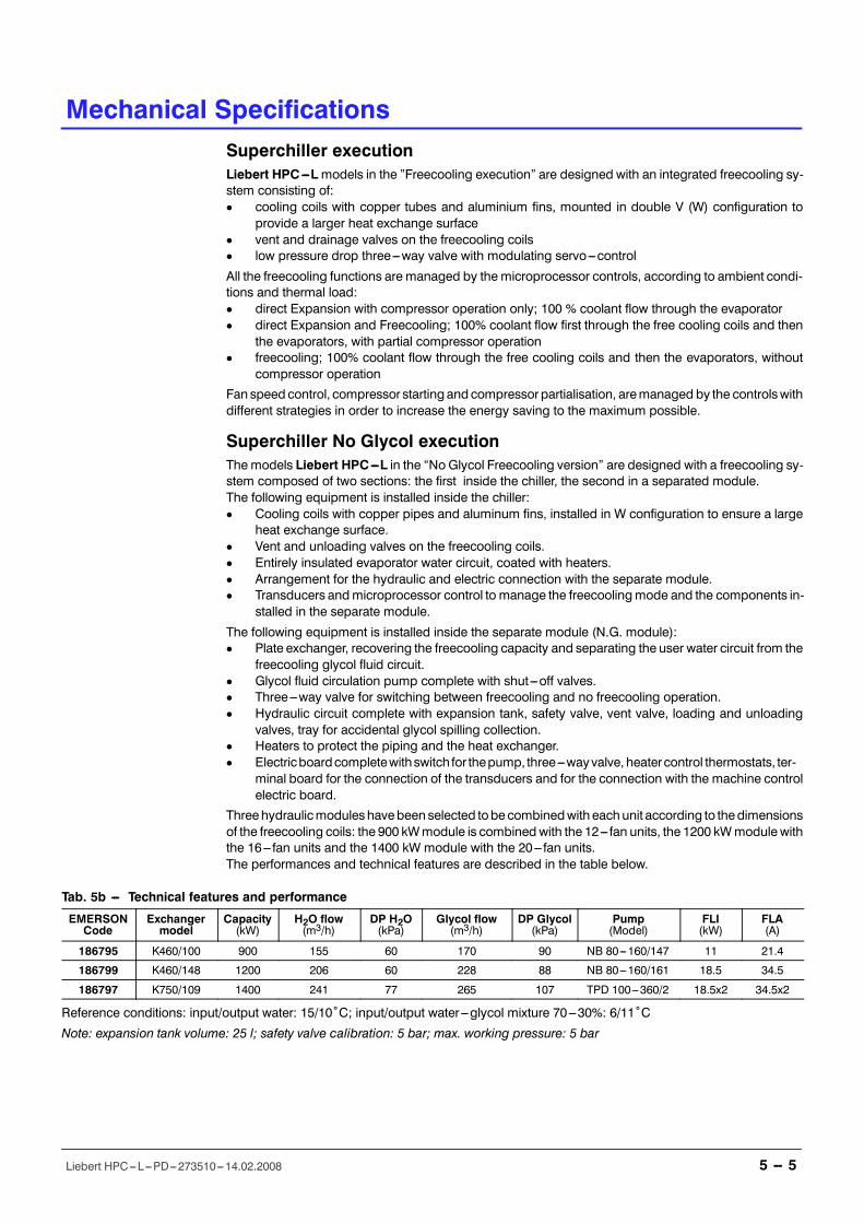
Threehydraulicmoduleshavebeen selected tobecombinedwith eachunit according to thedimensionsof the freecooling coils: the 900 kWmodule is combinedwith the 12--- fan units, the 1200 kWmodule withthe 16--- fan units and the 1400 kW module with the 20--- fan units.The performances and technical features are described in the table below.
Tab. 5b --- Technical features and performance
EMERSONCode
Exchangermodel
Capacity(kW)
H2O flow(m3/h)
DP H2O(kPa)
Glycol flow(m3/h)
DP Glycol(kPa)
Pump(Model)
FLI(kW)
FLA(A)
186795 K460/100 900 155 60 170 90 NB 80---160/147 11 21.4
186799 K460/148 1200 206 60 228 88 NB 80---160/161 18.5 34.5
186797 K750/109 1400 241 77 265 107 TPD 100---360/2 18.5x2 34.5x2
Reference conditions: input/output water: 15/10ûC; input/output water---glycol mixture 70---30%: 6/11ûC
Note: expansion tank volume: 25 l; safety valve calibration: 5 bar; max. working pressure: 5 bar
Mechanical Specifications
5 -- 6Liebert HPC---L---PD---273510---14.02.2008
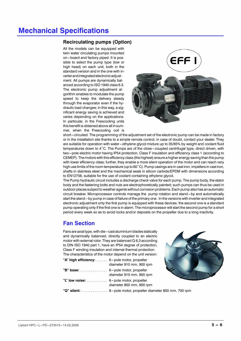
Recirculating pumps (Option)All the models can be equipped withtwin water circulating pumps mountedon---board and factory piped. It is pos-sible to select the pump type (low orhigh head) on each unit, both in thestandard version and in the one with in-verterandintegratedelectronicadjust-ment. All pumps are dynamically bal-anced according to ISO 1940 class 6.3.The electronic pump adjustment al-gorithm enables to modulate the pumpspeed to keep the delivery steadythrough the evaporator even if the hy-draulic load changes; in this way, a sig-nificant energy saving is achieved andvaries depending on the applications.In particular, in the Freecooling unitsthis benefit is obtainedaboveall insum-mer, when the Freecooling coil isshort---circuited. The programming of the adjustment set of the electronic pump can bemade in factoryor in the installation site thanks to a simple remote control; in case of doubt, contact your dealer. Theyare suitable for operation with water---ethylene glycol mixture up to 35/65% by weight and coolant fluidtemperatures down to 4ûC. The Pumps are of the close---coupled centrifugal type, direct driven, withtwo---pole electric motor having IP54 protection, Class F insulation and efficiency class 1 (according toCEMEP). Themotorswith this efficiency class (thehighest) ensure ahigher energy saving than thepumpwith lower efficiency class; further, they enable a more silent operation of the motor and can reach veryhighuse limits of the room temperature (up to60ûC). Pumpcasings are in cast iron, impellers in cast iron,shafts in stainless steel and the mechanical seals in silicon carbide/EPDM with dimensions accordingto EN12756, suitable for the use of coolant containing ethylene glycol.The Pump hydraulic circuit includes a discharge check valve for each pump. The pump body, the statorbody and the fastening bolts and nuts are electrophoretically painted; such pumps can thus be used inoutdoorplaces subject toweather agentswithout corrosionproblems.Eachpumpalsohasanautomaticcircuit breaker. Microprocessor controls manage the pump rotation and stand---by and automaticallystart the stand---by pump in case of failure of the primary one. In the versionswith inverter and integratedelectronic adjustment only the first pump is equipped with these devices: the second one is a standardpump operating only if the first one is in alarm. Themicroprocessor will start the second pump for a shortperiod every week so as to avoid locks and/or deposits on the propeller due to a long inactivity.
Fan SectionFansare axial type,with die---castaluminiumbladesstaticallyand dynamically balanced, directly coupled to an electricmotor with external rotor. They are balancedQ 6,3 accordingto DIN ISO 1940 part 1, have an IP54 degree of protection,Class F winding insulation and internal thermal protection.The characteristics of the motor depend on the unit version:
�A� high efficiency: 6---pole motor, propeller. . . . . .diameter 910 mm, 900 rpm
�B� base: 6---pole motor, propeller. . . . . . . . . . . . . . .diameter 910 mm, 900 rpm
�L� low noise: 6---pole motor, propeller. . . . . . . . . . .diameter 800 mm, 900 rpm
�Q� silent: 8---pole motor, propeller diameter 800 mm, 700 rpm. . . . . . . . . . . . . .
Mechanical Specifications
5 -- 7Liebert HPC---L---PD---273510---14.02.2008
The fans are complete with safety protection grilles and high efficiency nozzles.
Except the �A� versions, die---cast aluminum blades with sickle---shaped profile have been used to im-prove the sound deadening. The fan speed control, except in the �Q� versions, is carried out by an ad-juster with speed continuous modulation, phase cutoff type (TRIAC). In the �Q� versions, the fan speedis controlled by an adjuster with speed continuous modulation, inverter type, to get the max. sound re-duction even while modulating (such adjustment is available as option on the �L� versions, too).
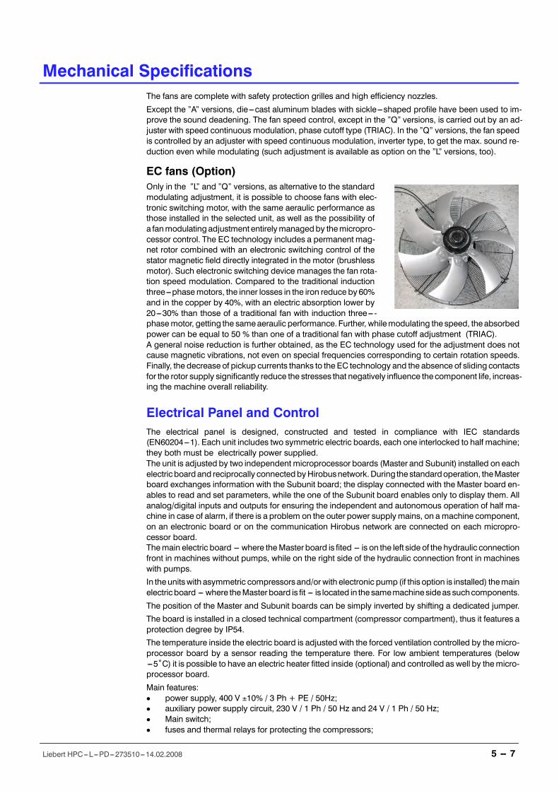
EC fans (Option)Only in the �L� and �Q� versions, as alternative to the standardmodulating adjustment, it is possible to choose fans with elec-tronic switching motor, with the same aeraulic performance asthose installed in the selected unit, as well as the possibility ofa fanmodulating adjustment entirelymanagedby themicropro-cessor control. The EC technology includes a permanent mag-net rotor combined with an electronic switching control of thestator magnetic field directly integrated in the motor (brushlessmotor). Such electronic switching device manages the fan rota-tion speed modulation. Compared to the traditional inductionthree---phasemotors, the inner losses in the iron reduce by 60%and in the copper by 40%, with an electric absorption lower by20---30% than those of a traditional fan with induction three--- -phasemotor, getting the sameaeraulic performance. Further, whilemodulating the speed, theabsorbedpower can be equal to 50 % than one of a traditional fan with phase cutoff adjustment (TRIAC).A general noise reduction is further obtained, as the EC technology used for the adjustment does notcause magnetic vibrations, not even on special frequencies corresponding to certain rotation speeds.Finally, the decrease of pickup currents thanks to the EC technology and the absence of sliding contactsfor the rotor supply significantly reduce the stresses that negatively influence thecomponent life, increas-ing the machine overall reliability.
Electrical Panel and ControlThe electrical panel is designed, constructed and tested in compliance with IEC standards(EN60204---1). Each unit includes two symmetric electric boards, each one interlocked to half machine;they both must be electrically power supplied.The unit is adjusted by two independent microprocessor boards (Master and Subunit) installed on eachelectric board and reciprocally connectedbyHirobusnetwork.During the standardoperation, theMasterboard exchanges information with the Subunit board; the display connected with the Master board en-ables to read and set parameters, while the one of the Subunit board enables only to display them. Allanalog/digital inputs and outputs for ensuring the independent and autonomous operation of half ma-chine in case of alarm, if there is a problem on the outer power supplymains, on a machine component,on an electronic board or on the communication Hirobus network are connected on each micropro-cessor board.Themain electric board --- where theMaster board is fited --- is on the left side of the hydraulic connectionfront in machines without pumps, while on the right side of the hydraulic connection front in machineswith pumps.
In theunitswith asymmetric compressors and/or with electronic pump (if this option is installed) themainelectric board --- where theMaster board is fit --- is located in the samemachine sideas suchcomponents.
The position of the Master and Subunit boards can be simply inverted by shifting a dedicated jumper.
The board is installed in a closed technical compartment (compressor compartment), thus it features aprotection degree by IP54.
The temperature inside the electric board is adjusted with the forced ventilation controlled by themicro-processor board by a sensor reading the temperature there. For low ambient temperatures (below---5ûC) it is possible to have an electric heater fitted inside (optional) and controlled as well by themicro-processor board.
Main features:D power supply, 400 V ±10% / 3 Ph + PE / 50Hz;D auxiliary power supply circuit, 230 V / 1 Ph / 50 Hz and 24 V / 1 Ph / 50 Hz;D Main switch;D fuses and thermal relays for protecting the compressors;
Mechanical Specifications
5 -- 8Liebert HPC---L---PD---273510---14.02.2008
D contactors for the compressors with timers for star---delta starting;D fuses, contactors and thermal relays for protecting the pumps (optional);D MCBs for fans with modulating speed control;D manual operation through Microface controller;D volt --- free contacts for remote indication of:
--- compressors in operation;--- pump(s) in operation;--- general alarm.
PackingUnits are shipped with plastic film protection.
Warranty ClausesThewarranty does not apply for any damage ormalfunction thatmay occurduring or as a result of opera-tion outside of the application range. Thewarranty does not apply for freecooling units damaged by frostif the hydraulic circuit has not been chargedwith a water---glycolmixture with suitable percentage for themin. temperatures in the installation site. The company is not responsible for damage due to incorrector improper use of the product and it reserves the right to change technical specifications without anyprior notice.
Final Tests and Reference StandardsThe units are designed, manufactured and tested in compliance with the European directives 98/37/CE(89/392/CEE; 91/368/CEE; 93/68/CEE), 89/336/CEE; 73/23/CEE; 97/23/CE. The Quality managementsystem of the HPAC division is approved by LRQA in conformity with the norms ISO 9001:2000 and theproduct is the result of the activities performed according to the provisions in the processes, proceduresand plans for the quality.
The machine is supplied with a final test certificate and a declaration of conformity with the norms.
All Liebert HPC---L units are � � marked.

Mechanical Specifications
5 -- 9Liebert HPC---L---PD---273510---14.02.2008
AccessoriesPumps groupAvailable head pressure values are declared atthe unit�s hydraulic connections and are referredto the nominal working conditions of each unit.Please contact us for different fluid flow rates orhead pressures. All pumps can work with up to35% ethylene glycol percentage by weight
In all chiller versions and most freecooling mod-els one pump is operating and one is in stand--- -by, as indicated by (1+1); in some freecoolingmodels both pumps can be operating simultan-eously, as indicated by (2). In the version �Invert-er pump�, (inverter pumpavailable up to themax.power of 22 kW) one inverter pump is operatingand a traditional pump is in stand---by (1+1). Theindicated hydraulic performance refers to the in-verter pump in their max. capacities (if available); obviously, they will adapt from such values to the hy-draulic load required by the user circuit and by the chiller inner circuit; in case of freecooling unit, theywill adapt their performance so as to keep the flow rate crossing the evaporator steady with relevant en-ergy saving.
Tab. 5c - Standard head pressure (Chiller) R407CModel 081/080 087/086 093/092 100/099 107/106 115/114 122/121 131/130 140/139
CA7Water flow m3/h 152.2 159.6 171.3 179.7 199 208.3 227.4 251.5 263Available pressure head kPa 112 101 84 70 59 44 106 74 107
CB7Water flow m3/h 148.3 155 166.2 173.9 193.5 202.1 221.2 246.1 257.1Available pressure head kPa 119 107 92 80 66 54 115 81 114
CL7Water flow m3/h 153.4 160.8 176.3 185.1 195.9 204.7 229.8 240.6 251.3Available pressure head kPa 111 99 76 61 63 50 103 88 123
CQ7Water flow m3/h 142.9 149 164.3 171.8 180.8 188 214.3 --- ---Available pressure head kPa 126 117 95 83 85 76 125 --- ---
Pump rotor model --- 80---160/147 (1+1) 80---160/151 (1+1)80---160/161(1+1)
Nominal motor power kW 11 15 18.5
Noise level (*) dB(A) 65 66
Each pump weight kg 175 183 206
(*) --- According to ISO 3744
Tab. 5d - High head pressure (Chiller) R407CModel 081/080 087/086 093/092 100/099 107/106 115/114 122/121 131/130 140/139
CA7Water flow m3/h 152.2 159.6 171.3 179.7 199 208.3 227.4 251.5 263Available pressure head kPa 179 167 148 133 118 102 159 123 131
CB7Water flow m3/h 148.3 155 166.2 173.9 193.5 202.1 221.2 246.1 257.1Available pressure head kPa 186 173 157 143 127 113 168 131 142
CL7Water flow m3/h 153.4 160.8 176.3 185.1 195.9 204.7 229.8 240.6 251.3Available pressure head kPa 177 165 139 123 123 108 155 139 153
CQ7Water flow m3/h 142.9 149 164.3 171.8 180.8 188 214.3 --- ---Available pressure head kPa 194 184 160 148 147 138 177 --- ---
Pump rotor model --- 80---160/151 (1+1) 80---160/161 (1+1)80---160/167(1+1)
Nominal motor power kW 15 18.5 22
Noise level (*) dB(A) 65 66 68
Each pump weight kg 183 206 243
(*) --- According to ISO 3744
Mechanical Specifications
5 -- 10Liebert HPC---L---PD---273510---14.02.2008
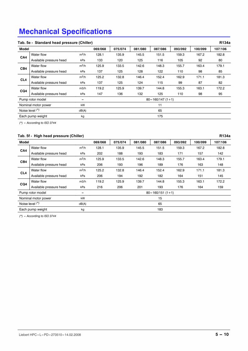
Tab. 5e - Standard head pressure (Chiller) R134aModel 069/068 075/074 081/080 087/086 093/092 100/099 107/106
CA4Water flow m3/h 128.1 135.9 145.5 151.5 159.3 167.2 182.8
Available pressure head kPa 133 120 125 116 105 92 80
CB4Water flow m3/h 125.9 133.5 142.6 148.3 155.7 163.4 179.1
Available pressure head kPa 137 125 128 122 110 98 85
CL4Water flow m3/h 125.2 132.8 146.4 152.4 162.9 171.1 181.3
Available pressure head kPa 137 125 124 115 99 87 82
CQ4Water flow m3/h 119.2 125.9 139.7 144.8 155.3 163.1 172.2
Available pressure head kPa 147 136 132 125 110 98 95
Pump rotor model --- 80---160/147 (1+1)
Nominal motor power kW 11
Noise level (*) dB(A) 65
Each pump weight kg 175
(*) --- According to ISO 3744
Tab. 5f - High head pressure (Chiller) R134aModel 069/068 075/074 081/080 087/086 093/092 100/099 107/106
CA4Water flow m3/h 128.1 135.9 145.5 151.5 159.3 167.2 182.8
Available pressure head kPa 202 188 193 183 171 157 142
CB4Water flow m3/h 125.9 133.5 142.6 148.3 155.7 163.4 179.1
Available pressure head kPa 206 193 196 189 176 163 148
CL4Water flow m3/h 125.2 132.8 146.4 152.4 162.9 171.1 181.3
Available pressure head kPa 206 194 192 182 164 151 145
CQ4Water flow m3/h 119.2 125.9 139.7 144.8 155.3 163.1 172.2
Available pressure head kPa 216 206 201 193 176 164 159
Pump rotor model --- 80---160/151 (1+1)
Nominal motor power kW 15
Noise level (*) dB(A) 65
Each pump weight kg 183
(*) --- According to ISO 3744
Mechanical Specifications
5 -- 13Liebert HPC---L---PD---273510---14.02.2008
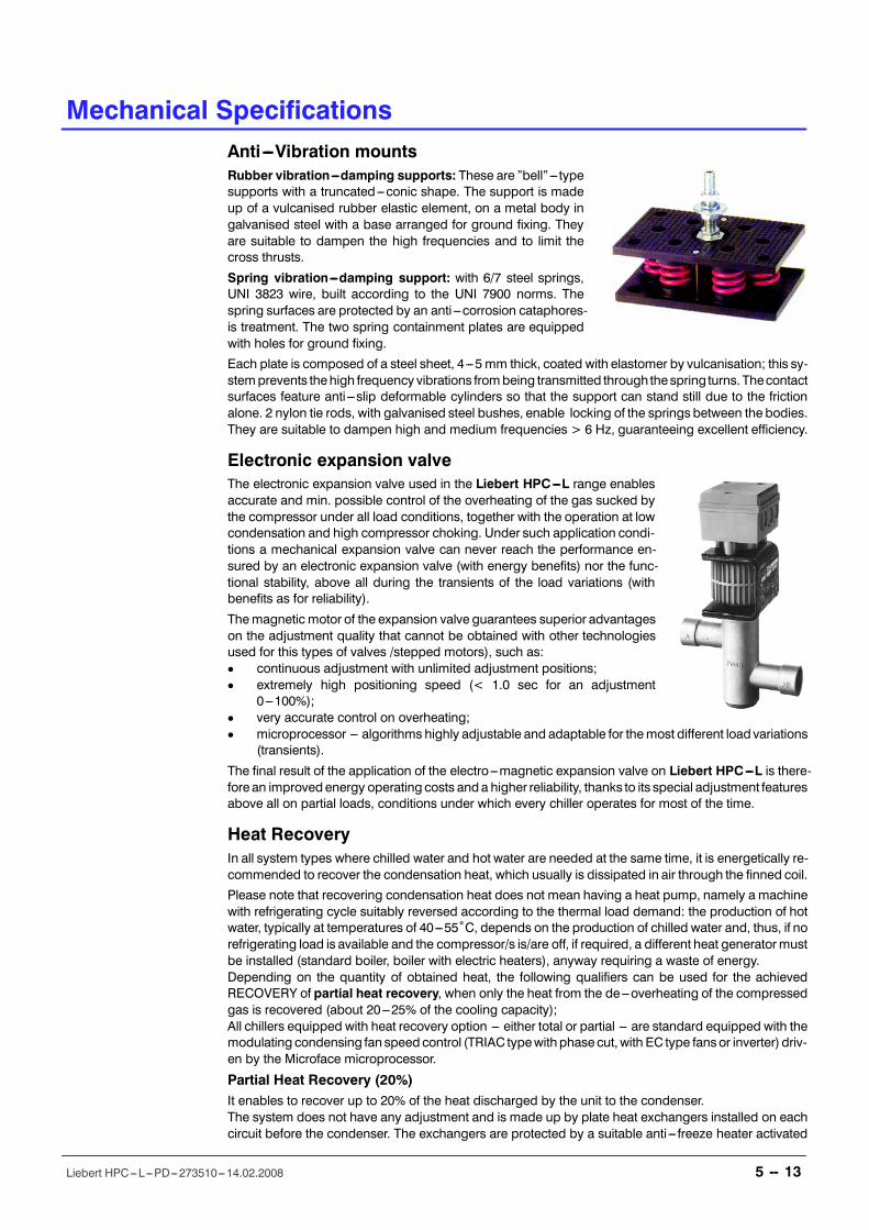
Anti ---Vibration mountsRubber vibration---damping supports: These are �bell�--- typesupports with a truncated---conic shape. The support is madeup of a vulcanised rubber elastic element, on a metal body ingalvanised steel with a base arranged for ground fixing. Theyare suitable to dampen the high frequencies and to limit thecross thrusts.
Spring vibration---damping support: with 6/7 steel springs,UNI 3823 wire, built according to the UNI 7900 norms. Thespring surfaces are protected by an anti ---corrosion cataphores-is treatment. The two spring containment plates are equippedwith holes for ground fixing.
Each plate is composed of a steel sheet, 4---5 mm thick, coated with elastomer by vulcanisation; this sy-stemprevents thehigh frequency vibrations frombeing transmitted through the spring turns. Thecontactsurfaces feature anti ---slip deformable cylinders so that the support can stand still due to the frictionalone. 2 nylon tie rods, with galvanised steel bushes, enable locking of the springs between the bodies.They are suitable to dampen high and medium frequencies > 6 Hz, guaranteeing excellent efficiency.
Electronic expansion valveThe electronic expansion valve used in the Liebert HPC---L range enablesaccurate and min. possible control of the overheating of the gas sucked bythe compressor under all load conditions, together with the operation at lowcondensation and high compressor choking. Under such application condi-tions a mechanical expansion valve can never reach the performance en-sured by an electronic expansion valve (with energy benefits) nor the func-tional stability, above all during the transients of the load variations (withbenefits as for reliability).
Themagnetic motor of the expansion valve guarantees superior advantageson the adjustment quality that cannot be obtained with other technologiesused for this types of valves /stepped motors), such as:D continuous adjustment with unlimited adjustment positions;D extremely high positioning speed (< 1.0 sec for an adjustment
0---100%);D very accurate control on overheating;D microprocessor --- algorithms highly adjustable and adaptable for themost different load variations
(transients).
The final result of the application of the electro---magnetic expansion valve on Liebert HPC---L is there-fore an improvedenergy operating costs anda higher reliability, thanks to its special adjustment featuresabove all on partial loads, conditions under which every chiller operates for most of the time.
Heat RecoveryIn all system types where chilled water and hot water are needed at the same time, it is energetically re-commended to recover the condensation heat, which usually is dissipated in air through the finned coil.
Please note that recovering condensation heat does not mean having a heat pump, namely a machinewith refrigerating cycle suitably reversed according to the thermal load demand: the production of hotwater, typically at temperatures of 40---55ûC, depends on the production of chilled water and, thus, if norefrigerating load is available and the compressor/s is/are off, if required, a different heat generatormustbe installed (standard boiler, boiler with electric heaters), anyway requiring a waste of energy.Depending on the quantity of obtained heat, the following qualifiers can be used for the achievedRECOVERY of partial heat recovery, when only the heat from the de---overheating of the compressedgas is recovered (about 20---25% of the cooling capacity);All chillers equipped with heat recovery option --- either total or partial --- are standard equipped with themodulating condensing fan speedcontrol (TRIAC typewith phasecut,with EC type fansor inverter) driv-en by the Microface microprocessor.
Partial Heat Recovery (20%)It enables to recover up to 20% of the heat discharged by the unit to the condenser.The system does not have any adjustment and is made up by plate heat exchangers installed on eachcircuit before the condenser. The exchangers are protected by a suitable anti --- freeze heater activated
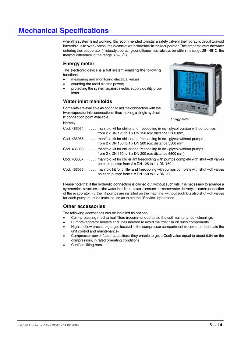
Energy meter
Mechanical Specifications
5 -- 14Liebert HPC---L---PD---273510---14.02.2008
when the system isnotworking. It is recommended to install a safety valve in the hydraulic circuit to avoidhazardsdue toover---pressures in caseofwater flow lack in the recuperator. The temperatureof thewaterentering the recuperator (in steady operating conditions)must always bewithin the range 25---45ûC, thethermal difference in the range 3.5---8ûC.
Energy meterThe electronic device is a full system enabling the followingfunctions:D measuring and monitoring electrical values;D counting the used electric power;D protecting the system against electric supply quality prob-
lems.
Water inlet manifoldsSome kits are available as option to aid the connection with thetwoevaporator inlet connections, thusmakinga single hydraul-ic connection point available.
Namely:
Cod. 486064 manifold kit for chiller and freecooling in no---glycol version without pumps. . . . . .from 2 x DN 125 to 1 x DN 150 (c/c distance 5500 mm)
Cod. 486065 manifold kit for chiller and freecooling in no---glycol without pumps. . . . . .from 2 x DN 150 to 1 x DN 200 (c/c distance 5500 mm)
Cod. 486066 manifold kit for chiller and freecooling in no---glycol without pumps. . . . . .from 2 x DN 150 to 1 x DN 200 (c/c distance 6500 mm)
Cod. 486067 manifold kit for chiller anf freecooling with pumps complete with shut---off valves. . . . . .on each pump: from 2 x DN 125 to 1 x DN 150
Cod. 486068 manifold kit for chiller and freecooling with pumps complete with shut---off valves. . . . . .on each pump: from 2 x DN 150 to 1 x DN 200
Please note that if the hydraulic connection is carried out without such kits, it is necessary to arrange asymmetrical structureon thewater inlet lines, soas toensure the samewater deliveryoneachconnectionof the evaporator. Further, if pumps are installed on the machine, without such kits also shut---off valvesfor each pump must be installed, so as to aid the �Service� operations.
Other accessoriesThe following accessories can be installed as options:D Coil ---protecting mechanical filters (recommended to aid the coil maintenance---cleaning).D Pump/evaporator heaters and lines needed to avoid the frost risk on such components.D High and low pressure gauges located in the compressor compartment (recommended to aid the
unit control and maintenance).D Compressor power factor capacitors: they enable to get a Cosfì value equal to about 0.94 on the
compressors, in rated operating conditions.D Certified lifting bars.

MICROFACE & HIROMATIC
6 Controls
6 -- 1Liebert HPC---L---PD---273510---14.02.2008
Controls
Microprocessor Controls
Microface EvolutionMicroface is the standard on---board control and its advan-ced features secure system optimisation and energy sav-ings. Full management of the Liebert HPC---L units isgranted by the on board control Microface Evolution, whichallows the programming of temperature and pressurethresholdsaswell as the teamwork functionality through theproprietary Hirobus system. All the set---up can be donewith a simple Operating Display that, through symbols andcodes, ensures a reliable and flexible man---machine inter-face.D The standard software of the Liebert HPC---LUnits in-
cludes special control algorithms that ensure real en-ergy savings and enhance the reliability of the full sy-stem.
D Immediate set---up can be available through the �UnitCode� system. In case of re---configuration needs, thefull configuration of the unit and recalculation of all the thresholds levels (which depend on the re-frigerant type) are available by simply enabling the configuration Unit Code.
D Sequential auto---restart timer allows phased units restart after power failure.D Pumps� durability is granted by a special auto---rotation start---up function.D The record of the working hours of compressors, pumps and freecooling is easily available via the
local Microface display.D Auto---selection of the best control strategy at different ambient temperatures is implemented in
order to assure an optimised usage of the compressors and condensers fans.D The �Ambient compensation� function canbeenabled tomake theunitset---point riseautomatically
during warm periods, permitting energy savings.D For low noise versions with fanspeed control there is a special algorithm which, together with the
compressor management, enables to keep the fan speed always to the minimum.D Compressors� Run/Stop time management is implemented in order to obtain the optimisation of
compressors� operations either within the unit, or, in case of networking via Hirobus, within thewhole of the Liebert HPC---L Units system.
D A special workingmode can be established in combination withEmerson Network Power HPACUnits to obtain the so called �Supersaver� system, that enhances the energy saving capabilities.Through a simple 2---wires connection the information on the cooling needs of the air conditionersis available to the Liebert HPC---L units, that will manage its resources (compressors and freecoo-ling) in the most efficient way in order to save additional energy.
D All settings are protected through a 3---Level Password system.D Input for Remote on---off and Volt--- free contacts for simple remote monitoring of alarms and warn-
ings are available.D Up to 16 Liebert HPC---L units can be easily linked together on a network to provide teamwork
mode, stand---by operation and duty cycling without additional hardware. Reliability is not affectedif there are problems on the data communication buses, because the units return automatically tothe stand---alone mode.
Technical data Microface EvolutionD E2prom: 64 Kbit;. . . . . . . . . . . . . . . . . . . . . .D Eprom/Flash memory: 1, 2 or 4 Mbit;. . . . . . . . . .D RAM memory space: 256 Kbit;. . . . . . . . . . . .D Analog Input: 3 x Analog 0---10V;. . . . . . . . . . . . . . . . . .D Digital Input: 8 x Flexible Analog multi input;. . . . . . . . . . . . . . . . . . .D Analog Output: 2 x Analog 0---10V;. . . . . . . . . . . . . . . . .D Digital output: 7 triacs output and 2+1 relay output;. . . . . . . . . . . . . . . . . .D Time and date function buffered by an LI ---battery;D Hirobus LAN connectors: 3 RJ45 sockets (to Microface and Hiromatic. . . . . . . .
LAN and Slave---Board and Microface Display);D Hironet connectors: 1 RJ9 socket for RS485 (direct connection to. . . . . . . . . . . . .
Emerson Network Power supervision systems).
Controls
6 -- 2Liebert HPC---L---PD---273510---14.02.2008
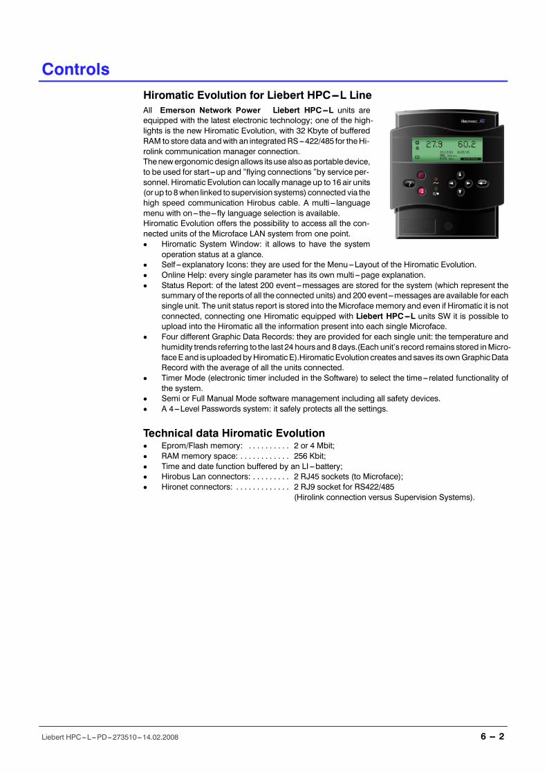
Hiromatic Evolution for Liebert HPC---L LineAll Emerson Network Power Liebert HPC---L units areequipped with the latest electronic technology; one of the high-lights is the new Hiromatic Evolution, with 32 Kbyte of bufferedRAM to store data andwith an integrated RS---422/485 for theHi-rolink communication manager connection.Thenewergonomicdesign allows itsusealsoasportabledevice,to be used for start ---up and �flying connections �by service per-sonnel. Hiromatic Evolution can locally manage up to 16 air units(or up to8when linked tosupervision systems) connected via thehigh speed communication Hirobus cable. A multi --- languagemenu with on--- the--- fly language selection is available.Hiromatic Evolution offers the possibility to access all the con-nected units of the Microface LAN system from one point.D Hiromatic System Window: it allows to have the system
operation status at a glance.D Self ---explanatory Icons: they are used for the Menu---Layout of the Hiromatic Evolution.D Online Help: every single parameter has its own multi ---page explanation.D Status Report: of the latest 200 event---messages are stored for the system (which represent the
summary of the reports of all the connected units) and 200 event---messages are available for eachsingle unit. The unit status report is stored into theMicroface memory and even if Hiromatic it is notconnected, connecting one Hiromatic equipped with Liebert HPC---L units SW it is possible toupload into the Hiromatic all the information present into each single Microface.
D Four different Graphic Data Records: they are provided for each single unit: the temperature andhumidity trends referring to the last 24 hours and 8days.(Each unit�s record remains stored inMicro-faceE and is uploadedbyHiromaticE).HiromaticEvolution creates and saves its ownGraphicDataRecord with the average of all the units connected.
D Timer Mode (electronic timer included in the Software) to select the time---related functionality ofthe system.
D Semi or Full Manual Mode software management including all safety devices.D A 4---Level Passwords system: it safely protects all the settings.
Technical data Hiromatic EvolutionD Eprom/Flash memory: 2 or 4 Mbit;. . . . . . . . . .D RAM memory space: 256 Kbit;. . . . . . . . . . . .D Time and date function buffered by an LI ---battery;D Hirobus Lan connectors: 2 RJ45 sockets (to Microface);. . . . . . . . .D Hironet connectors: 2 RJ9 socket for RS422/485. . . . . . . . . . . . .
(Hirolink connection versus Supervision Systems).
CONNECTIVITY
Controls
6 -- 3Liebert HPC---L---PD---273510---14.02.2008
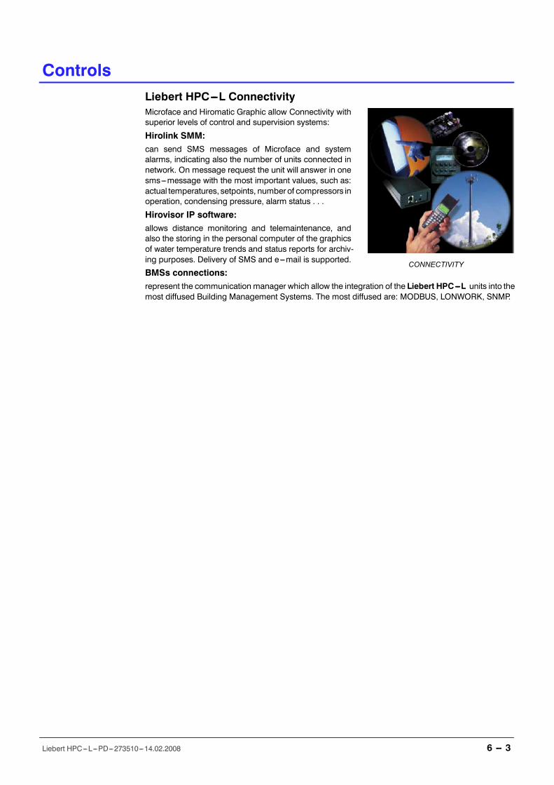
Liebert HPC---L ConnectivityMicroface and Hiromatic Graphic allow Connectivity withsuperior levels of control and supervision systems:
Hirolink SMM:can send SMS messages of Microface and systemalarms, indicating also the number of units connected innetwork. On message request the unit will answer in onesms---message with the most important values, such as:actual temperatures, setpoints, numberof compressors inoperation, condensing pressure, alarm status . . .
Hirovisor IP software:allows distance monitoring and telemaintenance, andalso the storing in the personal computer of the graphicsof water temperature trends and status reports for archiv-ing purposes. Delivery of SMS and e---mail is supported.
BMSs connections:represent the communication manager which allow the integration of the Liebert HPC---L units into themost diffused Building Management Systems. The most diffused are: MODBUS, LONWORK, SNMP.
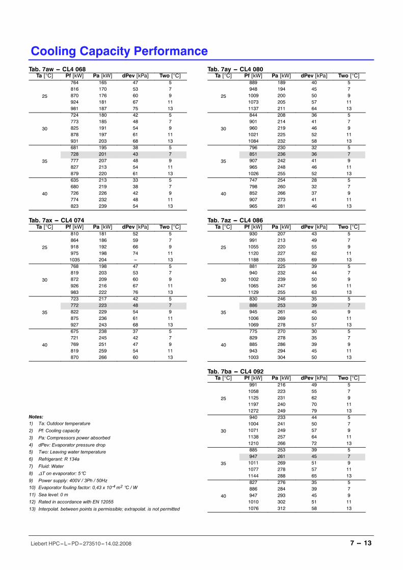
Cooling Capacity Performance
7 -- 13Liebert HPC---L---PD---273510---14.02.2008
Tab. 7aw --- CL4 068Ta [°C] Pf [kW] Pa [kW] dPev [kPa] Two [°C]
25
764 165 47 5816 170 53 7870 176 60 9924 181 67 11981 187 75 13
30
724 180 42 5773 185 48 7825 191 54 9878 197 61 11931 203 68 13
35
681 195 38 5728 201 43 7777 207 48 9827 213 54 11879 220 61 13
40
635 213 33 5680 219 38 7726 226 42 9774 232 48 11823 239 54 13
Tab. 7ax --- CL4 074Ta [°C] Pf [kW] Pa [kW] dPev [kPa] Two [°C]
25
810 181 52 5864 186 59 7918 192 66 9975 198 74 111035 204 --- 13
30
768 198 47 5819 203 53 7872 209 60 9926 216 67 11983 222 76 13
35
723 217 42 5772 223 48 7822 229 54 9875 236 61 11927 243 68 13
40
675 238 37 5721 245 42 7769 251 47 9819 259 54 11870 266 60 13
Notes:1) Ta: Outdoor temperature2) Pf: Cooling capacity3) Pa: Compressors power absorbed4) dPev: Evaporator pressure drop5) Two: Leaving water temperature6) Refrigerant: R 134a7) Fluid: Water8) nT on evaporator: 5°C9) Power supply: 400V / 3Ph / 50Hz10) Evaporator fouling factor: 0,43 x 10⁻⁴ m2 °C / W11) Sea level: 0 m12) Rated in accordance with EN 1205513) Interpolat. between points is permissible; extrapolat. is not permitted
Tab. 7ay --- CL4 080Ta [°C] Pf [kW] Pa [kW] dPev [kPa] Two [°C]
25
889 189 40 5948 194 45 71009 200 50 91073 205 57 111137 211 64 13
30
844 208 36 5901 214 41 7960 219 46 91021 225 52 111084 232 58 13
35
796 230 32 5851 236 36 7907 242 41 9965 248 46 111026 255 52 13
40
747 254 28 5798 260 32 7852 266 37 9907 273 41 11965 281 46 13
Tab. 7az --- CL4 086Ta [°C] Pf [kW] Pa [kW] dPev [kPa] Two [°C]
25
930 207 43 5991 213 49 71055 220 55 91120 227 62 111188 235 69 13
30
881 225 39 5940 232 44 71002 239 50 91065 247 56 111129 255 63 13
35
830 246 35 5886 253 39 7945 261 45 91006 269 50 111069 278 57 13
40
775 270 30 5829 278 35 7885 286 39 9943 294 45 111003 304 50 13
Tab. 7ba --- CL4 092Ta [°C] Pf [kW] Pa [kW] dPev [kPa] Two [°C]
25
991 216 49 51058 223 55 71125 231 62 91197 240 70 111272 249 79 13
30
940 233 44 51004 241 50 71071 249 57 91138 257 64 111210 266 72 13
35
885 253 39 5947 261 45 71011 269 51 91077 278 57 111144 288 65 13
40
827 276 35 5886 284 39 7947 293 45 91010 302 51 111076 312 58 13
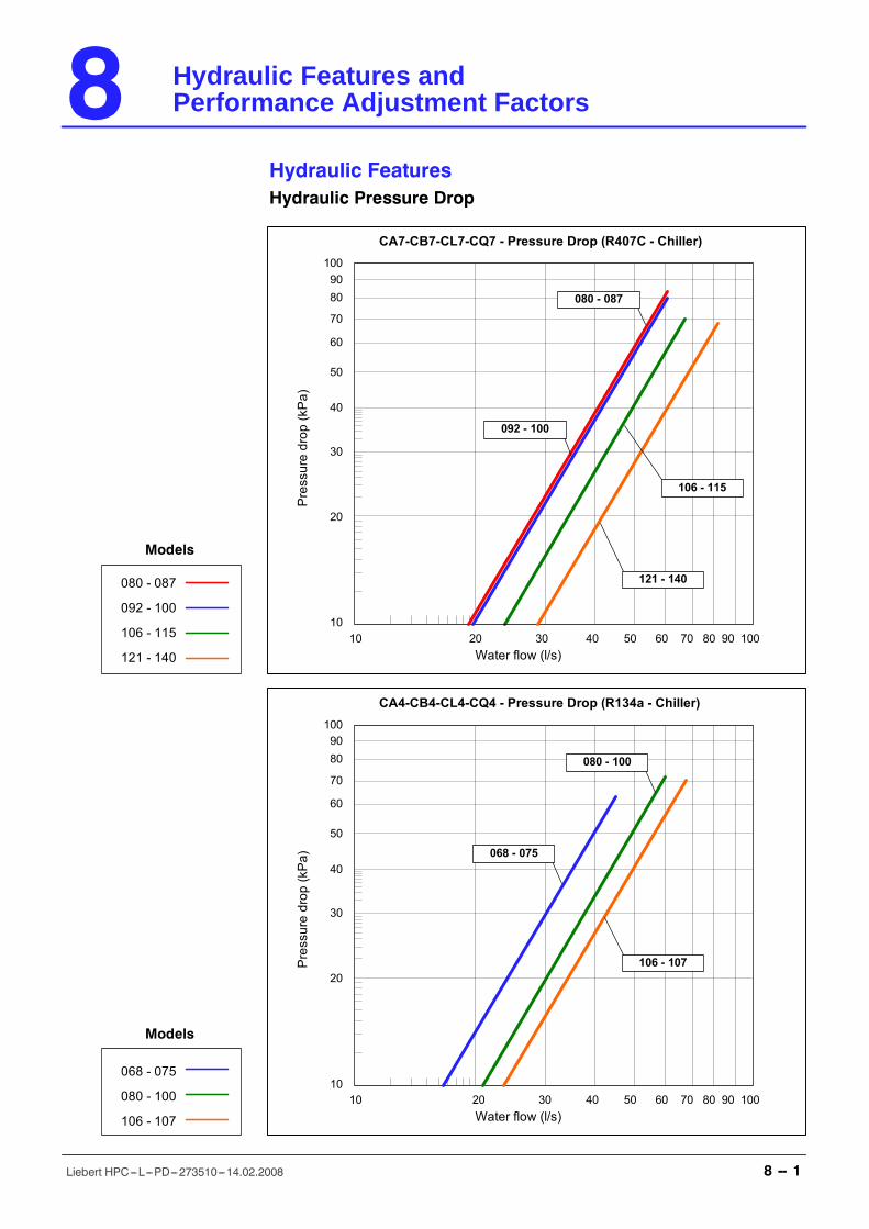
Models
080 - 087
092 - 100
106 - 115
121 - 140
100
10
20
30
40
50
60
70
8090
Water flow (l/s)
Pressuredrop(kPa)
10 20 30 40 50 60 70 80 90 100
CA7-CB7-CL7-CQ7 - Pressure Drop (R407C - Chiller)
121 - 140
080 - 087
092 - 100
106 - 115
068 - 075
080 - 100
106 - 107
Models
100
10
20
30
40
50
60
70
8090
Water flow (l/s)
Pressuredrop(kPa)
10 20 30 40 50 60 70 80 90 100
106 - 107
080 - 100
068 - 075
CA4-CB4-CL4-CQ4 - Pressure Drop (R134a - Chiller)
8 Hydraulic Features andPerformance Adjustment Factors
8 -- 1Liebert HPC---L---PD---273510---14.02.2008
Hydraulic Features and Performance Adjustment Factors
Hydraulic FeaturesHydraulic Pressure Drop

Hydraulic Features and Performance Adjustment Factors
8 -- 5Liebert HPC---L---PD---273510---14.02.2008
0
5
10
15
20
25
30
80 90 100 110 120 130 140 150 160 170 180 190 200 210 220 230 240 250 260
068-075
080-100
106-107
0
5
10
15
20
25
80 90 100 110 120 130 140 150 160 170 180 190 200 210 220 230 240
068-075
080-100
106-107
Water flow (mc/h)
Water flow (mc/h)
Availablenetpressure(m)
Availablenetpressure(m)
Mod. R134a - CA4 - CB4 - CL4 - CQ4
Standard pressure pump (R134a - Chiller version)
High pressure pump (R134a - Chiller version)
Mod. R134a - CA4 - CB4 - CL4 - CQ4

Hydraulic Features and Performance Adjustment Factors
8 -- 10Liebert HPC---L---PD---273510---14.02.2008
Hydraulic Features and Performance Adjustment Factors
Correction FactorsGlycol mixture correction factorsThe water glycol mixtures are used as a thermal carrier fluid, in very cold climates with temperatures be-low 0 ûC. The use of low freezing pointmixtures causes a modification in themain thermodynamic prop-erties of the units.The main parameters affected by the use of glycol mixtures are the following:D Cooling capacityD Mixture volumetric flowD Pressure dropD Compressor power inputIn the table below are reported correction factors referred to themost common ethylene glycolmixtures.
Tab. 8a --- Chiller table
Ethylene glycol [% in weight] 0 10 20 30 40 50
Freezing temperatureRefrigeration capacity correcting factorMixture volume flow rate correcting factorMixture side pressure drop correcting factorCompressor power input correcting factor
°CF3F4F5F6
01111
---4,40,9871,0461,0530,955
---9,90,9771,0801,1090,990
---16,60,9691,0981,1680,990
---25,20,9581,1501,2340,985
---37,20,9501,2101,3110,975
Tab. 8b --- Superchiller table
Ethylene glycol [% in weight] 0 10 20 30 40 50
Freezing temperatureRefrigeration capacity correcting factorMixture volume flow rate correcting factorMixture side pressure drop correcting factorCompressor power input correcting factor
°CF3F4F5F6
01,0320,9110,8561,010
---4,41,0230,9260,9021,010
---9,91,0130,9560,9501,005
---16,61111
---25,20,9891,0481,0560,995
---37,20,9811,1021,1220,985
We indicate asR0, V0, P0 respectively theunit capacity, volumetric flow rate andcompressor power inputwith 0% ethylene glycol on Chiller models or 30% ethylene glycol on Superchiller models; when we useglycolmixtureswith different%with the same inlet andoutlet temperaturesat theevaporator, theperfor-mance will vary as follows:D Refrigeration capacity = R0 x F3D Volumetric flow rate = V0 x F3 x F4D Mixturepressuredrop=DP1 x F5, whereDP1 is the unitwater pressuredrop for the newvolumetric
mixture flow rateD Compressor power input = P0 x F6
Fouling: Correction factorsTab. 8c --- Fouling correction factors
Fouling factors [10---4 m2 °C/W] Correction factors
F1a refrigeration capacitycorrection factor
F2a compressor power inputcorrection factor
00,430,880,1760,352
1,0151
0,9850,9600,915
1,0051
0,9950,9850,965
Unit performance reported in the tables are given for the condition exchanger with fouling factor corre-sponding at 0,43 10---4 m2 ûC / W. For different fouling factor values, performances should be correctedwith the correction factors shown above.
Sea level: Correction factorsTab. 8d --- Sea level correction factors
Elevation above sea level [meters] Correction factors
F1b refrigeration capacitycorrection factor
F2b compressor power inputcorrection factor
060012001800
10,9970,9930,988
11,0041,0071,015
Unit performance reported in the tables are given for sea level conditions.For different altitude, performances should be corrected with the correction factors shown above.
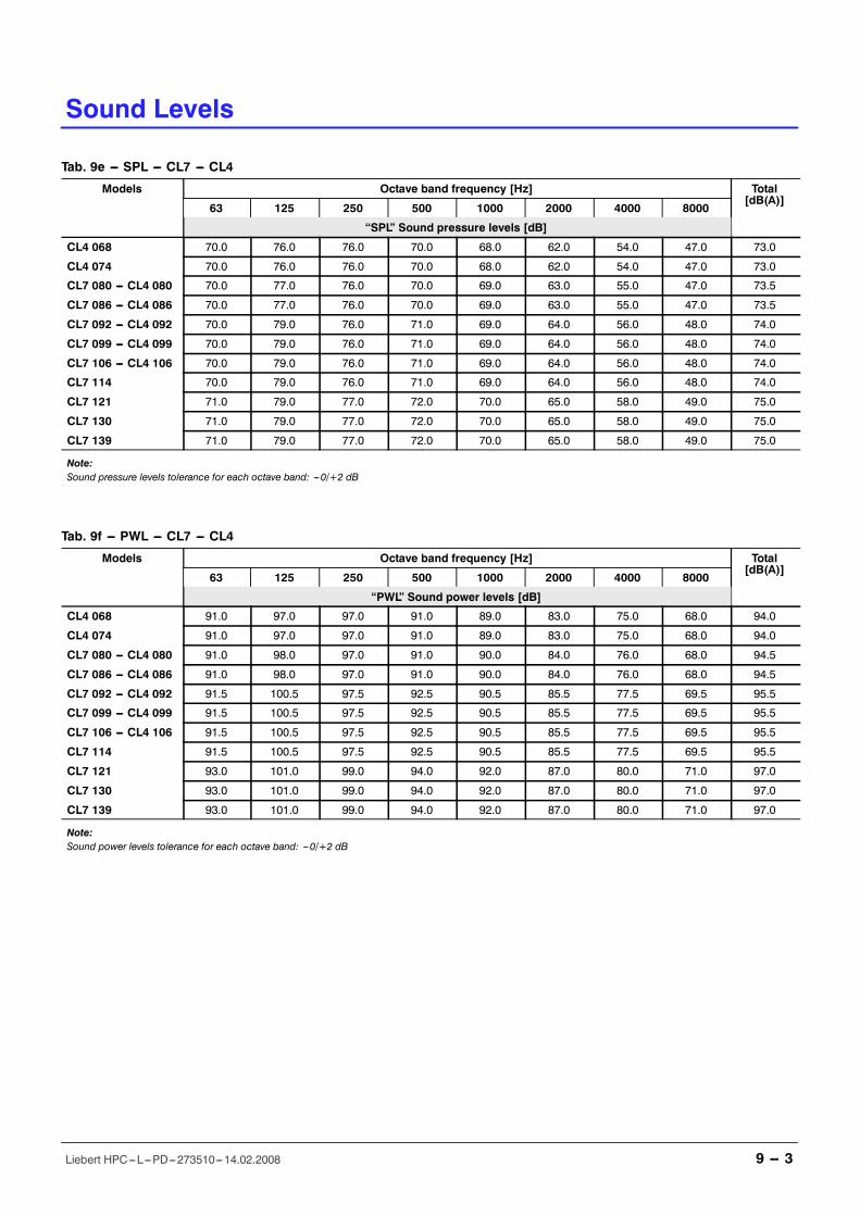
Sound Levels
9 -- 3Liebert HPC---L---PD---273510---14.02.2008
Tab. 9e --- SPL --- CL7 --- CL4
Models Octave band frequency [Hz] Total[dB(A)]
63 125 250 500 1000 2000 4000 8000
�SPL� Sound pressure levels [dB]
CL4 068 70.0 76.0 76.0 70.0 68.0 62.0 54.0 47.0 73.0
CL4 074 70.0 76.0 76.0 70.0 68.0 62.0 54.0 47.0 73.0
CL7 080 --- CL4 080 70.0 77.0 76.0 70.0 69.0 63.0 55.0 47.0 73.5
CL7 086 --- CL4 086 70.0 77.0 76.0 70.0 69.0 63.0 55.0 47.0 73.5
CL7 092 --- CL4 092 70.0 79.0 76.0 71.0 69.0 64.0 56.0 48.0 74.0
CL7 099 --- CL4 099 70.0 79.0 76.0 71.0 69.0 64.0 56.0 48.0 74.0
CL7 106 --- CL4 106 70.0 79.0 76.0 71.0 69.0 64.0 56.0 48.0 74.0
CL7 114 70.0 79.0 76.0 71.0 69.0 64.0 56.0 48.0 74.0
CL7 121 71.0 79.0 77.0 72.0 70.0 65.0 58.0 49.0 75.0
CL7 130 71.0 79.0 77.0 72.0 70.0 65.0 58.0 49.0 75.0
CL7 139 71.0 79.0 77.0 72.0 70.0 65.0 58.0 49.0 75.0
Note:Sound pressure levels tolerance for each octave band: ---0/+2 dB
Tab. 9f --- PWL --- CL7 --- CL4
Models Octave band frequency [Hz] Total[dB(A)]
63 125 250 500 1000 2000 4000 8000
�PWL� Sound power levels [dB]
CL4 068 91.0 97.0 97.0 91.0 89.0 83.0 75.0 68.0 94.0
CL4 074 91.0 97.0 97.0 91.0 89.0 83.0 75.0 68.0 94.0
CL7 080 --- CL4 080 91.0 98.0 97.0 91.0 90.0 84.0 76.0 68.0 94.5
CL7 086 --- CL4 086 91.0 98.0 97.0 91.0 90.0 84.0 76.0 68.0 94.5
CL7 092 --- CL4 092 91.5 100.5 97.5 92.5 90.5 85.5 77.5 69.5 95.5
CL7 099 --- CL4 099 91.5 100.5 97.5 92.5 90.5 85.5 77.5 69.5 95.5
CL7 106 --- CL4 106 91.5 100.5 97.5 92.5 90.5 85.5 77.5 69.5 95.5
CL7 114 91.5 100.5 97.5 92.5 90.5 85.5 77.5 69.5 95.5
CL7 121 93.0 101.0 99.0 94.0 92.0 87.0 80.0 71.0 97.0
CL7 130 93.0 101.0 99.0 94.0 92.0 87.0 80.0 71.0 97.0
CL7 139 93.0 101.0 99.0 94.0 92.0 87.0 80.0 71.0 97.0
Note:Sound power levels tolerance for each octave band: ---0/+2 dB
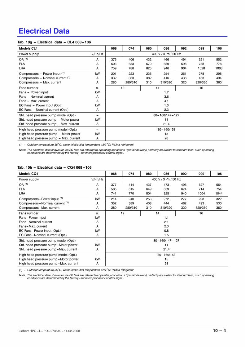
Electrical Data
10 -- 4Liebert HPC---L---PD---273510---14.02.2008
Tab. 10g --- Electrical data --- CL4 068---106
Models CL4 068 074 080 086 092 099 106
Power supply V/Ph/Hz 400 V / 3 Ph / 50 Hz
OA (1) A 375 406 432 466 494 521 552FLA A 603 633 670 680 698 738 778LRA A 759 788 825 946 964 1028 1068
Compressors --- Power input (1) kW 201 223 236 254 261 278 298Compressors --- Nominal current (1) A 332 363 382 416 436 463 494Compressors --- Max. current A 280 280/310 310 310/320 320 320/360 360
Fans number n. 12 14 16Fans --- Power input kW 1.7Fans --- Nominal current A 3.6Fans --- Max. current A 4.1EC Fans --- Power input (Opt.) kW 1.3EC Fans --- Nominal current (Opt.) A 2.3
Std. head pressure pump model (Opt.) --- 80---160/147---127Std. head pressure pump --- Motor power kW 11Std. head pressure pump --- Max. current A 21.4
High head pressure pump model (Opt.) --- 80---160/153High head pressure pump --- Motor power kW 15High head pressure pump --- Max. current A 28
(1) --- Outdoor temperature 35ûC; water inlet/outlet temperature 12/7ûC; R134a refrigerant
Note: The electrical data shown for the EC fans are referred to operating conditions (rpm/air delivery) perfectly equivalent to standard fans; such operatingconditions are determined by the factory ---set microprocessor control signal.
Tab. 10h --- Electrical data --- CQ4 068---106
Models CQ4 068 074 080 086 092 099 106
Power supply V/Ph/Hz 400 V / 3 Ph / 50 Hz
OA (1) A 377 414 437 473 496 527 564FLA A 585 615 649 659 674 714 754LRA A 741 770 804 925 940 1004 1044
Compressors---Power input (1) kW 214 240 253 272 277 298 322Compressors---Nominal current (1) A 352 389 408 444 462 493 530Compressors---Max. current A 280 280/310 310 310/320 320 320/360 360
Fans number n. 12 14 16Fans---Power input kW 1.1Fans---Nominal current A 2.1Fans---Max. current A 2.3EC Fans---Power input (Opt.) kW 0.8EC Fans---Nominal current (Opt.) A 1.5
Std. head pressure pump model (Opt.) --- 80---160/147---127Std. head pressure pump---Motor power kW 11Std. head pressure pump---Max. current A 21.4
High head pressure pump model (Opt.) --- 80---160/153High head pressure pump---Motor power kW 15High head pressure pump---Max. current A 28
(1) --- Outdoor temperature 35ûC; water inlet/outlet temperature 12/7ûC; R134a refrigerant
Note: The electrical data shown for the EC fans are referred to operating conditions (rpm/air delivery) perfectly equivalent to standard fans; such operatingconditions are determined by the factory ---set microprocessor control signal.
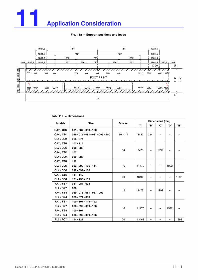
11 Application Consideration
11 -- 1Liebert HPC---L---PD---273510---14.02.2008
Application Consideration
Fig. 11a --- Support positions and loads
Ø 20
W1 W2 W3 W4 W5 W6 W7 W8 W9 W10 W11 W12 W13
W14 W15 W16 W17 W18 W19 W20 W21 W22 W23 W24 W25 W26
103 842,5 1801,5 1992 996 �E� 996 1992 1801,5 842,5 103
1801,5 1992 �D� 1992 1801,5
1801,5 1801,5
1024,5 �B� �B� 1024,5
�A�
602140
60
2260
240
830
120830
240
�C� �C�
FOOT PRINT
Tab. 11a --- Dimensions
Models Size Fans nr.Dimensions (mm)
�A� �B� �C� �D� �E�
CA7 / CB7 081---087---093---100
10 --- 12 8482 2271 --- --- ---CA4 / CB4 069---075---081---087---093---100
CL4 / CQ4 068---074
CA7 / CB7 107---115
14 9478 --- 1992 --- ---CL7 / CQ7 080---086
CA4 / CB4 107
CL4 / CQ4 080---086
CA7 / CB7 122
16 11470 --- --- 1992 ---CL7 / CQ7 092---099---106---114
CL4 / CQ4 092---099---106
CA7 / CB7 131---14020 13462 --- --- --- 1992
CL7 / CQ7 121---130---139
FA7 / FB7 081---087---093
12 9478 --- 1992 --- ---FL7 / FQ7 080
FA4 / FB4 069---075---081---087---093
FL4 / FQ4 068---074---080
FA7 / FB7 100---107---115---122
16 11470 --- --- 1992 ---FL7 / FQ7 086---092---099---106
FA4 / FB4 100---107
FL4 / FQ4 086---092---099---106
FL7 / FQ7 114---121 20 13462 --- --- --- 1992
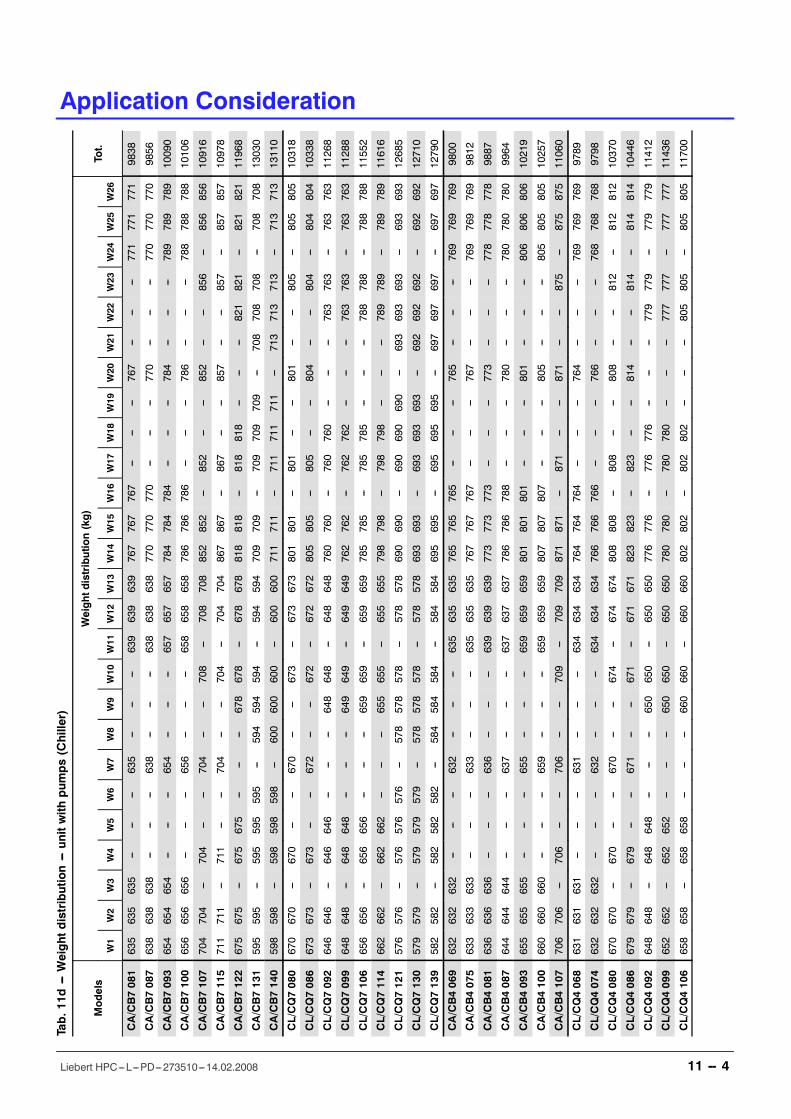
Application Consideration
11 -- 4Liebert HPC---L---PD---273510---14.02.2008
Tab.11d
---Weight
distribution---unitwith
pum
ps(Chiller)
Models
Weightdistribution(kg)
Tot.
W1
W2
W3
W4
W5
W6
W7
W8
W9
W10
W11
W12
W13
W14
W15
W16
W17
W18
W19
W20
W21
W22
W23
W24
W25
W26
CA/CB7081
635
635
635
------
---635
------
---639
639
639
767
767
767
------
---767
------
---771
771
771
9838
CA/CB7087
638
638
638
------
---638
------
---638
638
638
770
770
770
------
---770
------
---770
770
770
9856
CA/CB7093
654
654
654
------
---654
------
---657
657
657
784
784
784
------
---784
------
---789
789
789
10090
CA/CB7100
656
656
656
------
---656
------
---658
658
658
786
786
786
------
---786
------
---788
788
788
10106
CA/CB7107
704
704
---704
------
704
------
708
---708
708
852
852
---852
------
852
------
856
---856
856
10916
CA/CB7115
711
711
---711
------
704
------
704
---704
704
867
867
---867
------
857
------
857
---857
857
10978
CA/CB7122
675
675
---675
675
------
---678
678
---678
678
818
818
---818
818
------
---821
821
---821
821
11968
CA/CB7131
595
595
---595
595
595
---594
594
594
---594
594
709
709
---709
709
709
---708
708
708
---708
708
13030
CA/CB7140
598
598
---598
598
598
---600
600
600
---600
600
711
711
---711
711
711
---713
713
713
---713
713
13110
CL/CQ7080
670
670
---670
------
670
------
673
---673
673
801
801
---801
------
801
------
805
---805
805
10318
CL/CQ7086
673
673
---673
------
672
------
672
---672
672
805
805
---805
------
804
------
804
---804
804
10338
CL/CQ7092
646
646
---646
646
------
---648
648
---648
648
760
760
---760
760
------
---763
763
---763
763
11268
CL/CQ7099
648
648
---648
648
------
---649
649
---649
649
762
762
---762
762
------
---763
763
---763
763
11288
CL/CQ7106
656
656
---656
656
------
---659
659
---659
659
785
785
---785
785
------
---788
788
---788
788
11552
CL/CQ7114
662
662
---662
662
------
---655
655
---655
655
798
798
---798
798
------
---789
789
---789
789
11616
CL/CQ7121
576
576
---576
576
576
---578
578
578
---578
578
690
690
---690
690
690
---693
693
693
---693
693
12685
CL/CQ7130
579
579
---579
579
579
---578
578
578
---578
578
693
693
---693
693
693
---692
692
692
---692
692
12710
CL/CQ7139
582
582
---582
582
582
---584
584
584
---584
584
695
695
---695
695
695
---697
697
697
---697
697
12790
CA/CB4069
632
632
632
------
---632
------
---635
635
635
765
765
765
------
---765
------
---769
769
769
9800
CA/CB4075
633
633
633
------
---633
------
---635
635
635
767
767
767
------
---767
------
---769
769
769
9812
CA/CB4081
636
636
636
------
---636
------
---639
639
639
773
773
773
------
---773
------
---778
778
778
9887
CA/CB4087
644
644
644
------
---637
------
---637
637
637
786
786
788
------
---780
------
---780
780
780
9964
CA/CB4093
655
655
655
------
---655
------
---659
659
659
801
801
801
------
---801
------
---806
806
806
10219
CA/CB4100
660
660
660
------
---659
------
---659
659
659
807
807
807
------
---805
------
---805
805
805
10257
CA/CB4107
706
706
---706
------
706
------
709
---709
709
871
871
---871
------
871
------
875
---875
875
11060
CL/CQ4068
631
631
631
------
---631
------
---634
634
634
764
764
764
------
---764
------
---769
769
769
9789
CL/CQ4074
632
632
632
------
---632
------
---634
634
634
766
766
766
------
---766
------
---768
768
768
9798
CL/CQ4080
670
670
---670
------
670
------
674
---674
674
808
808
---808
------
808
------
812
---812
812
10370
CL/CQ4086
679
679
---679
------
671
------
671
---671
671
823
823
---823
------
814
------
814
---814
814
10446
CL/CQ4092
648
648
---648
648
------
---650
650
---650
650
776
776
---776
776
------
---779
779
---779
779
11412
CL/CQ4099
652
652
---652
652
------
---650
650
---650
650
780
780
---780
780
------
---777
777
---777
777
11436
CL/CQ4106
658
658
---658
658
------
---660
660
---660
660
802
802
---802
802
------
---805
805
---805
805
11700
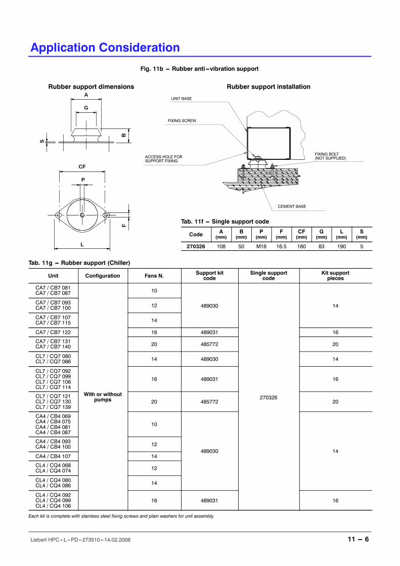
Rubber support installationRubber support dimensions
Fig. 11b --- Rubber anti ---vibration support
CF
A
B
S
L
F
P
G
UNIT BASE
FIXING SCREW
FIXING BOLT(NOT SUPPLIED)
CEMENT BASE
ACCESS HOLE FORSUPPORT FIXING
Application Consideration
11 -- 6Liebert HPC---L---PD---273510---14.02.2008
Application Consideration
Tab. 11f --- Single support code
Code A(mm)
B(mm)
P(mm)
F(mm)
CF(mm)
G(mm)
L(mm)
S(mm)
270326 108 50 M16 16.5 160 83 190 5
Tab. 11g --- Rubber support (Chiller)
Unit Configuration Fans N. Support kitcode
Single supportcode
Kit supportpieces
CA7 / CB7 081CA7 / CB7 087
With or withoutpumps
10
489030
270326
14CA7 / CB7 093CA7 / CB7 100 12
CA7 / CB7 107CA7 / CB7 115 14
CA7 / CB7 122 16 489031 16
CA7 / CB7 131CA7 / CB7 140 20 485772 20
CL7 / CQ7 080CL7 / CQ7 086 14 489030 14
CL7 / CQ7 092CL7 / CQ7 099CL7 / CQ7 106CL7 / CQ7 114
16 489031 16
CL7 / CQ7 121CL7 / CQ7 130CL7 / CQ7 139
20 485772 20
CA4 / CB4 069CA4 / CB4 075CA4 / CB4 081CA4 / CB4 087
10
489030 14
CA4 / CB4 093CA4 / CB4 100 12
CA4 / CB4 107 14
CL4 / CQ4 068CL4 / CQ4 074 12
CL4 / CQ4 080CL4 / CQ4 086 14
CL4 / CQ4 092CL4 / CQ4 099CL4 / CQ4 106
16 489031 16
Each kit is complete with stainless steel fixing screws and plain washers for unit assembly.
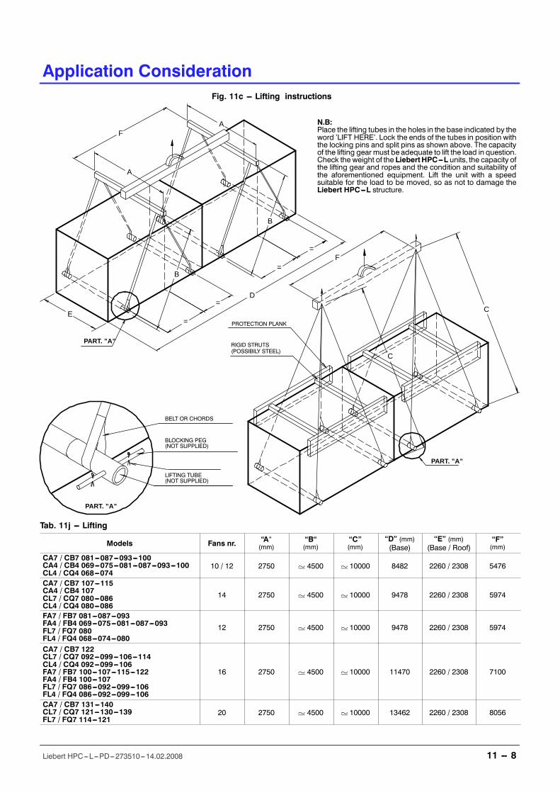
Application Consideration
11 -- 8Liebert HPC---L---PD---273510---14.02.2008
LIFTING TUBE(NOT SUPPLIED)
BLOCKING PEG(NOT SUPPLIED)
D
A
A
=
=
=
=
E
F
F
Fig. 11c --- Lifting instructions
N.B:Place the lifting tubes in the holes in the base indicated by theword �LIFT HERE�. Lock the ends of the tubes in position withthe locking pins and split pins as shown above. The capacityof the lifting gear must be adequate to lift the load in question.Check the weight of the LiebertHPC---L units, the capacity ofthe lifting gear and ropes and the condition and suitability ofthe aforementioned equipment. Lift the unit with a speedsuitable for the load to be moved, so as not to damage theLiebert HPC---L structure.
PART. ”A”
PART. ”A”
PART. ”A”
BELT OR CHORDS
PROTECTION PLANK
RIGID STRUTS(POSSIBILY STEEL)
B
B
C
C
Tab. 11j --- Lifting
Models Fans nr. �A�(mm)
�B�(mm)
�C�(mm)
�D� (mm)(Base)
�E� (mm)(Base / Roof)
�F�(mm)
CA7 / CB7 081---087---093---100CA4 / CB4 069---075---081---087---093---100CL4 / CQ4 068---074
10 / 12 2750 ' 4500 ' 10000 8482 2260 / 2308 5476
CA7 / CB7 107---115CA4 / CB4 107CL7 / CQ7 080---086CL4 / CQ4 080---086
14 2750 ' 4500 ' 10000 9478 2260 / 2308 5974
FA7 / FB7 081---087---093FA4 / FB4 069---075---081---087---093FL7 / FQ7 080FL4 / FQ4 068---074---080
12 2750 ' 4500 ' 10000 9478 2260 / 2308 5974
CA7 / CB7 122CL7 / CQ7 092---099---106---114CL4 / CQ4 092---099---106FA7 / FB7 100---107---115---122FA4 / FB4 100---107FL7 / FQ7 086---092---099---106FL4 / FQ4 086---092---099---106
16 2750 ' 4500 ' 10000 11470 2260 / 2308 7100
CA7 / CB7 131---140CL7 / CQ7 121---130---139FL7 / FQ7 114---121
20 2750 ' 4500 ' 10000 13462 2260 / 2308 8056
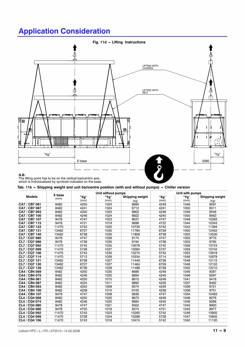
Application Consideration
11 -- 9Liebert HPC---L---PD---273510---14.02.2008
Fig. 11d --- Lifting Instructions
N.B:The lifting point has to be on the vertical baricentric axis,which is individualized by symbols indicated on the base.
�Yg��Xg�
2260X base
LIFTING WITHCHORDS
LIFTING WITHBELT
Tab. 11k --- Shipping weight and unit baricentre position (with and without pumps) --- Chiller version
Models X base(mm)
Unit without pumps Unit with pumps�Xg�(mm)
�Yg�(mm)
Shipping weight(kg)
�Xg�(mm)
�Yg�(mm)
Shipping weight(kg)
CA7 / CB7 081 8482 4250 1024 8690 4249 1049 9291CA7 / CB7 087 8482 4241 1024 8712 4241 1050 9311CA7 / CB7 093 8482 4250 1023 8902 4249 1049 9546CA7 / CB7 100 8482 4246 1024 8922 4245 1050 9563CA7 / CB7 107 9478 4747 1023 9637 4747 1048 10283CA7 / CB7 115 9478 4721 1019 9698 4722 1044 10343CA7 / CB7 122 11470 5743 1020 10730 5742 1043 11394CA7 / CB7 131 13462 6727 1030 11784 6728 1050 12452CA7 / CB7 140 13462 6738 1030 11809 6738 1052 12530CL7 / CQ7 080 9478 4747 1029 9174 4747 1053 9775CL7 / CQ7 086 9478 4738 1030 9194 4738 1053 9795CL7 / CQ7 092 11470 5743 1035 10078 5742 1058 10724CL7 / CQ7 099 11470 5738 1037 10094 5737 1059 10742CL7 / CQ7 106 11470 5743 1030 10270 5742 1053 10918CL7 / CQ7 114 11470 5712 1026 10334 5714 1049 10978CL7 / CQ7 121 13462 6738 1027 11449 6738 1048 12112CL7 / CQ7 130 13462 6727 1027 11464 6728 1048 12132CL7 / CQ7 139 13462 6738 1028 11489 6738 1050 12210CA4 / CB4 069 8482 4250 1020 8686 4249 1046 9287CA4 / CB4 075 8482 4246 1020 8694 4245 1046 9297CA4 / CB4 081 8482 4250 1015 8815 4249 1041 9416CA4 / CB4 087 8482 4224 1011 8892 4226 1037 9492CA4 / CB4 093 8482 4250 1009 9074 4249 1036 9721CA4 / CB4 100 8482 4238 1010 9105 4238 1036 9751CA4 / CB4 107 9478 4747 1009 9836 4747 1034 10483CL4 / CQ4 068 8482 4250 1020 8672 4249 1046 9276CL4 / CQ4 074 8482 4246 1020 8684 4245 1046 9286CL4 / CQ4 080 9478 4747 1021 9302 4747 1045 9900CL4 / CQ4 086 9478 4720 1018 9374 4721 1042 9977CL4 / CQ4 092 11470 5743 1023 10260 5742 1046 10905CL4 / CQ4 099 11470 5728 1024 10288 5728 1047 10935CL4 / CQ4 106 11470 5743 1016 10474 5742 1040 11120
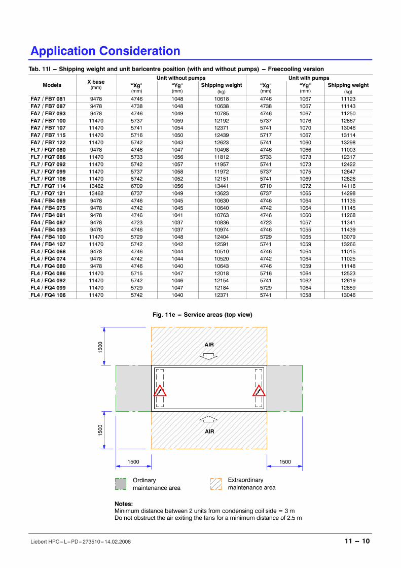
Application Consideration
11 -- 10Liebert HPC---L---PD---273510---14.02.2008
Tab. 11l --- Shipping weight and unit baricentre position (with and without pumps) --- Freecooling version
ModelsX base(mm)
Unit without pumps Unit with pumps�Xg�(mm)
�Yg�(mm)
Shipping weight(kg)
�Xg�(mm)
�Yg�(mm)
Shipping weight(kg)
FA7 / FB7 081 9478 4746 1048 10618 4746 1067 11123FA7 / FB7 087 9478 4738 1048 10638 4738 1067 11143FA7 / FB7 093 9478 4746 1049 10785 4746 1067 11250FA7 / FB7 100 11470 5737 1059 12192 5737 1076 12867FA7 / FB7 107 11470 5741 1054 12371 5741 1070 13046FA7 / FB7 115 11470 5716 1050 12439 5717 1067 13114FA7 / FB7 122 11470 5742 1043 12623 5741 1060 13298FL7 / FQ7 080 9478 4746 1047 10498 4746 1066 11003FL7 / FQ7 086 11470 5733 1056 11812 5733 1073 12317FL7 / FQ7 092 11470 5742 1057 11957 5741 1073 12422FL7 / FQ7 099 11470 5737 1058 11972 5737 1075 12647FL7 / FQ7 106 11470 5742 1052 12151 5741 1069 12826FL7 / FQ7 114 13462 6709 1056 13441 6710 1072 14116FL7 / FQ7 121 13462 6737 1049 13623 6737 1065 14298FA4 / FB4 069 9478 4746 1045 10630 4746 1064 11135FA4 / FB4 075 9478 4742 1045 10640 4742 1064 11145FA4 / FB4 081 9478 4746 1041 10763 4746 1060 11268FA4 / FB4 087 9478 4723 1037 10836 4723 1057 11341FA4 / FB4 093 9478 4746 1037 10974 4746 1055 11439FA4 / FB4 100 11470 5729 1048 12404 5729 1065 13079FA4 / FB4 107 11470 5742 1042 12591 5741 1059 13266FL4 / FQ4 068 9478 4746 1044 10510 4746 1064 11015FL4 / FQ4 074 9478 4742 1044 10520 4742 1064 11025FL4 / FQ4 080 9478 4746 1040 10643 4746 1059 11148FL4 / FQ4 086 11470 5715 1047 12018 5716 1064 12523FL4 / FQ4 092 11470 5742 1046 12154 5741 1062 12619FL4 / FQ4 099 11470 5729 1047 12184 5729 1064 12859FL4 / FQ4 106 11470 5742 1040 12371 5741 1058 13046
Fig. 11e --- Service areas (top view)
Ordinarymaintenance area
Extraordinarymaintenance area
AIR
1500 1500
1500
1500 AIR
Notes:Minimum distance between 2 units from condensing coil side = 3 mDo not obstruct the air exiting the fans for a minimum distance of 2.5 m
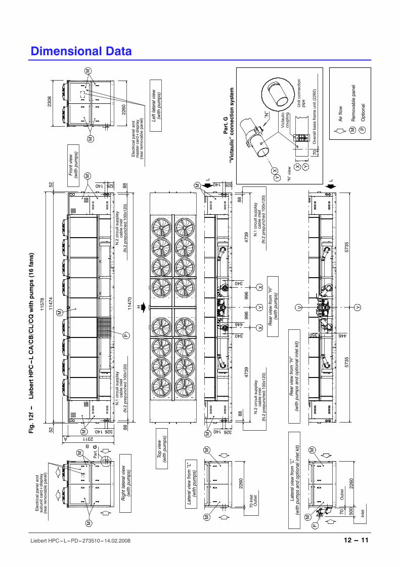
Dimensional Data
12 -- 11Liebert HPC---L---PD---273510---14.02.2008
DimensionalData
Fig.12f
---LiebertHPC---LCA/CB/CL/CQwith
pum
ps(16fans)
5211474
52
326140
326140
8888
11470
2311A2260
2308
11578
B
8888
4739
996
996
4739
340
340
446
326140
326140
70
2260
5735
5735
446350
500
2260
Frontview
(with
pumps)
H
LL
Topview
(with
pumps)
Lateralviewfrom�L�
(with
pumps)
Lateralviewfrom�L�
(with
pumps
andoptionalinletkit)
Rearviewfrom�H�
(with
pumps)
Rearviewfrom�H�
(with
pumps
andoptionalinletkit)
M
M
Part.G
MM M
P
M
MM
M
P
MM
XY
X
V Y
M
M
Inlet
Outlet
N.1circuitsupplay
cableinlet
(N.2prepunched
100x120)
N.1circuitsupplay
cableinlet
(N.2prepunched
100x120)
N.2circuitsupplay
cableinlet
(N.2prepunched
100x120)
N.2circuitsupplay
cableinlet
(N.2prepunched
100x120)
Electricalpaneland
mastercard+display
(rearremovablepanel)
Electricalpaneland
subunitcard+display
(rearremovablepanel)
Rightlateralview
(with
pumps)
Leftlateralview
(with
pumps)
Airflow
Rem
ovablepanel
M POptional
�N�
70
Victaulic
coupling
Unitconnection
pipe
Overallbaseframeunit(2260)
�N�view
Part.G
�Victaulic�connectionsystem
YX
YX
70Inlet
Outlet
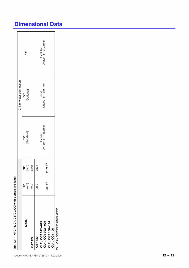
Dimensional Data
12 -- 12Liebert HPC---L---PD---273510---14.02.2008
Tab.12f
---HPC---LCA/CB/CL/CQwith
pum
ps(16fans)
Chillerw
aterconnection
Mod
el�A�
(mm)
�B�
(mm)
�X�
(Standard)
�V�
(Optional)
�Y�
CA7122
252
2563
2xInlet
DN150---6�---168.3m
m1xInlet
DN200---8�---219.1m
m1xOutlet
DN200---8�---219.1m
m
CB7122
260
2571
CL7
/CQ7092---099
CL4
/CQ4092---099
260(*)
2571
(*)
CL7
/CQ7106---114
CL4
/CQ4106
(*)
InEC
fans
versionadded30
mm
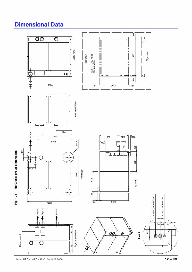
Dimensional Data
12 -- 33Liebert HPC---L---PD---273510---14.02.2008
DimensionalData
2108090
121
125125
601880
60
2000
2240 1450
497
796
1510
1745
875
125
125
930
308
102
414
121
2086
875
1200
520 102
Fig.12q
---NoGlycolgroup
dimensions
Glycol
Glycol
Water
Water
Powerpanel
N.54---∅20
holes
forsupports
CableglandDG48
CableglandDG29
Rightlateralview
Frontview
Leftlateralview
Rearview
Topview
Part.L
Part.L
Topview
Topview
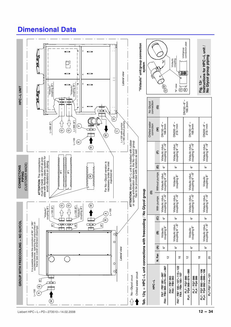
Fig.12r
---Instructions
forHPC---Lunit/
NoGlycolgroup
piping
�N�
Victaulic
coupling Unit/group
connectionpipe
�N�view
�Victaulic�unit/groupconnection
system
GW
WG
AB
BA
WG G
W
W
G G
W
CD
EF
GROUPWITHFREECOOLING---NOGLYCOL
Lateralview
�Victaulic�
coupling(6�)
�Victaulic�
coupling(6�)
L=395(6�)
L=395(6�)
L=100with
pum
ps
L=180withoutpum
ps
L=100
ATTE
NTION:W
henHPC---Lunitisinstalledwith
rubber
orspringantivibrationdampers,the
No---Glycolgroup
hastobe
provided
with
isolatorsas
well
ForNo---Glycolversion
isnecessaryordertheinlet
manifoldkit
W
(6�)
(6�)
ATTE
NTION:The
connections
mustbemade---as
shortaspos-
siblewith
flexiblepipessystem
for
avoidvibrations
onpiping
Lateralview
HPC---LUNIT
CONNECTIONS
PIPING
(CUSTO
MERMADE)
Itispossiblerotatethisconnctionof90_or180_
counterclockwise,openingtheprepunched
on
fram
e(see
overalldimensiondrawings)
�Victaulic�
coupling(6�)
L=100(6�)
(6�)
�Victaulic�
coupling(6�)
L=100(6�)
(6�)
(6�)
L=100
(6�)
No---Glycolcircuit
Chilledwatercircuit
L=100
Dimensional Data
12 -- 34Liebert HPC---L---PD---273510---14.02.2008
Tab.12q
---HPC---Lunitconnections
with
freecooling/NoGlycolgroup
HPC---L
(D)
Chilledwater
connction
NoGlycol
connection
N.Fan
(A)
(B)
(C)
With
pumps
Withoutpum
ps(E)
(F)
(W)
(G)
FA7/FB7081---087
FA4/FB4069---075---081---087
12
6�Victaulic
coupling6�
6�Victaulicriduc.
coupling5�---6�
Victaulicriduc.
coupling6�---8�
6�Victaulicriduc.
coupling5�---6�
DN150---6�---
168.3m
m
DN150---6�---
168.3m
m
FA7/FB7093
FA4/FB4093
8�Victaulicriduc.
coupling6�---8�
8�Victaulicriduc.
coupling6�---8�
Victaulic
coupling8�
8�Victaulicriduc.
coupling6�---8�
DN200---8�---
219.1m
mFA
7/FB7100---107---115---122
FA4/FB4100---107
16
FL7/FQ7080
FL4/FQ4068---074---080
12
6�Victaulic
coupling6�
6�Victaulicriduc.
coupling5�---6�
Victaulicriduc.
coupling6�---8�
6�Victaulicriduc.
coupling5�---6�
DN150---6�---
168.3m
mFL7/FQ7086
FL4/FQ4086
16FL7/FQ7092---099---106
FL4/FQ4092---099---106
8�Victaulicriduc.
coupling6�---8�
8�Victaulicriduc.
coupling6�---8�
Victaulic
coupling8�
8�Victaulicriduc.
coupling6�---8�
DN200---8�---
219.1m
mFL7FQ
7114---121
20
Related Documents