Abstract

AIR-CONDITIONING CALCULATIONS - PRESENTATION.ppt
Dec 11, 2015
hvac
Welcome message from author
This document is posted to help you gain knowledge. Please leave a comment to let me know what you think about it! Share it to your friends and learn new things together.
Transcript

Abstract

ABSTRACT
The increasing demand for comfort air-conditioning has brought with in the need for greater numbers of practical,
technical & sales personal who have should training in basic principles and applications of modern air-conditioning.The technical information presented in this work is intended
to satisfy the immediate and fundamental concepts in this work is intended to satisfy the immediate and fundamental
concepts and relevant principles in the field of air-conditioning .The subject of air-conditioning has come
to stay with the universities in the country .

The industries and commercial establishment are experiencing the need of air-conditioning as an instrument and commercial
establishment are experiencing the need of air-conditioning as in instrument of efficiency and increased output rather
than of comfort alone. The practice of air-conditioning is making rapid strides
and its increase practical use has brought in new problems, which is required to be tackled by scientific research.
As a thumb rule practice in air-conditioning do not lead to thorough understanding or correct solution of new problems.
The project material has been prepared to help to meet this by providing the fundamental process and procedures .
For the completion of this project an easy and simple methodology is adapted by preparing a met lab program to generalize and making it simple for any multistory building
cooling/heating load estimation. For estimation ,first work sheets are prepared for different existing conditions .
Then by using this program the total cooling/heating load for the entire complex has been easily calculated.

CHAPTER-1
(Introduction)

1 .Definition of Air Conditioning:Air conditioning is defined as the "the process of treating air so as to
control simultaneously temperature, humidity ,cleanliness and distribution to meet the requirements
of the conditioned space".As indicated in the definition, the important actions involved
in the operation of Air conditioning systems are:

Temperature control - Room temperature is controlled to the pre designed dry bulb temperature by cooling or heating room air.
Humidity control – Room air is controlled to the pre designed relative humidity by humidifying or
dehumidifying the room air.Air filtering, cleaning and purification – Room air is cleaned
by removing dust and dirt from the air.Air movement and circulation – Air which is controlled
in temperature and humidity and cleaned is distributed evenly throughout in a room. As a result, room air
can be maintained evenly in temperature humidity conditions.

Temperature, humidity, cleanliness and distribution of air are called "four elements of air conditioning". By controlling
these four elements, room air can be comfortably maintained regardless of outdoor temperature. Should these four elements can be replaced with the work of air conditioner, the room air is drawn in the air conditioners, where dust and dirt are removed
from the air by the air filter (cleanness of air) and it is sent to evaporator,
where temperature of the air is reduced by evaporation of the refrigerant (temperature), and at the same time, humidity in the air is removed as condensation (humidity). As a result, the air distributed from the air conditioner is cool and crisp and can
be distributed throughout the room by the evaporatorfan (distribution of air system). Such works are
repeated so as to perform air conditioning.

1.1 COMFORTABLE AIR:The heat and coldness that the men feel depend not only on air temperature (dry bulb temperature), but also on humidity
and distribution of air.In addition the general comfortable zone air conditions
are within the comfortable zone, the room air is not always optimum. For example, if temperature differs between indoor
and outdoor is nearly 10oC because room air controlled so as to be within this is my computer zone, one feels coolness
and heat strongly when he enters in and out of a room ,which makes him feel uncomfortable.
Such uncomfortable ness is called "cold shock" consequently ,it is important to control room air temperature so as not
to feel "clock shock" during cooling by adjusting the thermostat .The optimum temperature difference between indoor
and outdoor is from 3 to 6oC in consideration with health and economy.

1.2 .NEED OF ACCURATE HEAT LOAD ESTIMATION:The primary function of air-conditioning is to maintain conditions that are:
Conductive to human comfort.Required by a product, or process within space.
To perform this function, equipment of the proper capacity must be installed and controlled throughout the year.
The equipment capacity is determined by the actual instantaneous speak load requirement; type of
control is determined by the conditions to be maintained during peak and partial load. Generally ,
it is impossible to measure either the actual peak or the partial in any given space; these loads must be estimated.

CHAPTER-2
(Cooling and Heating Load Considerations)

2 :PRELIMINARY CONSIDERATIONS:The importance of accurate load calculations for air-
conditioning design and selection of equipment can never be overemphasized. In fact, it is on the precision and care exercised by the designer in the calculations of the cooling
load for summer and the heating load for winter that a trouble-free successful operation of an air-conditioning plant
after installation would depend.An important consideration in this exercise is the date and
time for which these calculations are made. The date would depend on the local climatic conditions. Although the
longest day in summer is June 21, hottest and most humid day may occur in July. Similarly, the coldest day may occur
in January or even February instead of on December 21.

Again, though the maximum temperature may occur outside at 1or 2 p.m. the maximum heat gain of the room may occur at 3 or 4 p.m. due to the direct solar radiation through glass
on the west side, or even later due to the time lag for the heat transfer through the structure .
Further, the application for which the building is intended to be used would also govern the choice of time. For example, for an office building in winter that is not used at night, the
time for load calculations may be taken during the early hours of the morning, although the maximum heating load may
occur at night. Similarly, an office building in summer may have the maximum cooling load at 7 p.m. due to the time lag,
but since no occupants would be present at that time, the time for load calculations may be taken as 4 or 5 p.m.

The major components of load in buildings are due to the direct solar radiation through the west glass, transmission through the
building fabric or structure and fresh air for ventilation. In the case of applications such as theatres and auditoriums, the occupancy
load is predominant.A detailed discussion of the solar radiation incident on a surface
and its transmission through glass has been given in the literature1 .
Further, in literature2, we have studied the methods of calculating heat transmission and infiltration through structures. These form
the components of load on the building from the external environment. The internal and system heat gains or losses also
form the major components of other loads.In this chapter, the methods for the evaluation of the above
mentioned and other individual loads are first presented, followed by a summary of all loads at the end along with an example and a
calculation sheet illustrating the procedure that is followed by practicing engineers. In the first instance here cooling load
estimation is given followed by that of the heating load.

2.1 :INTERNAL HEAT GAINS: The sensible and latent heat gains due to occupants, lights. appliances, machines, piping, etc., within
the conditional space. form the components of the internal heat gains.
2-2 :Occupancy Load The occupants in a conditioned space give out heat at a metabolic rate that more or less depends on their rate of working. The relative
proportion of the sensible and latent heats given out, however, depends un the ambient dry bulb temperature. The lower the dry bulb temperature, the greater the heat given out as sensible heat.The values for restaurants include the heat given out by food as well. It will be seen that the sensible heat (S) gain does not vary much with activity, more and more heat being liberated as latent
heat (L) thus making up for total heat .The usual problem in calculating the occupancy load lies in the
estimation of the exact number of people present.

Table 2.1:1 Heat liberated due to occupancy
Metabolic Heat liberated , W------------------------------------------------------------------
Activity Rate Room dry Bulb temp. Cº------------------------------------------------------------------
W 20 22 24 26
_____________________________________________ S L S L S L S L
Seated at rest 115 90 25 80 35 75 40 65 50
Office work 140 100 40 90 50 80 40 70 70Standing 150 105 45 95 55 82 68 72
78Eating in
restaurant 160 110 50 100 60 85 75 75 85
light work in factory 235 130 105 115 120 100 135 80
155Dancing 265 140 125 125 140 105 160 90
175
2.3 :Lighting LoadElectric lights generate a sensible heat equal to the amount of the
electric power consumed. Most of the energy is liberated as heat and the rest as light which also eventually becomes heat after multiple
reflections .Lighting manufacturers give some guidance as to the requirement of
power for different fittings to produce varying standards of illumination. In connection with fluorescent tubes, it may be stated that the electric power absorbed at the fitting is about 25 percent more than necessary to produce the required lighting. Thus a 60 W tube will need 75 W at the fitting. The excess of 15 W is liberated at the control gear of the
fitting.As a rough calculation one may use the lighting load equal to 33.5 W/m2 to produce a lighting standard of 540 lumens/m2 in an office
space.After the wattage is known, the calculation of the heat gain is done as
follows:Fluorescent: Q = Total watts × 1.25
Incandescent: Q = Total watts
2.4 :Appliances LoadMost appliances contribute both sensible and latent heats. The latent heat produced depends on the function the appliances perform, such as drying, cooking, etc. Gas appliances produce additional moisture
as a product of combustion. Such loads can be considerably reduced by providing properly designed hoods with a positive exhaust system
or suction over the appliances.Electric motors contribution sensible heat to the conditioned space. A
part of the power input is directly converted into heat due to the inefficiency of the motor and is dissipated through the frame of the
motor. This power is Power (W) = (Input) (I -motor efficiency)
The rest of the power input is utilized by the driven mechanism for doing work which may or may not result in a heat gain to the space.
Thesedepend on whether the energy input goes to the conditioned space
or outside it.
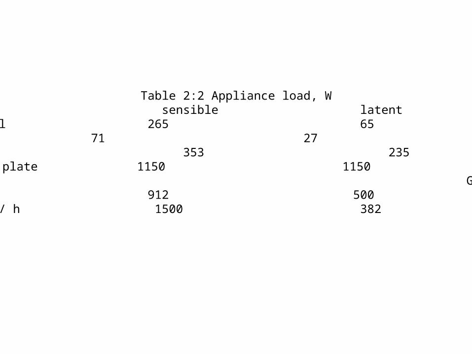
Table 2:2 Appliance load, WAppliance sensible latent totalCoffee brewer 0.5 gal 265 65 329
Warmer 0.5 gal 71 27 98Egg boiler 353 235 60
Food warmer /m² of plate 1150 1150 2300Griddle frying with frying
top of 46 cm *36 cm 912 500 1412Toaster, 360 slices / h 1500 382 1882
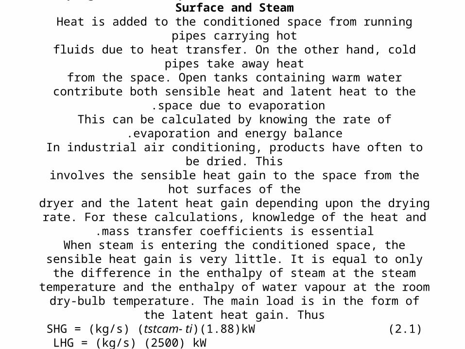
2.5 :Piping, Tanks, Evaporation of Water from a Free Surface and SteamHeat is added to the conditioned space from running pipes carrying hot
fluids due to heat transfer. On the other hand, cold pipes take away heatfrom the space. Open tanks containing warm water contribute both sensible
heat and latent heat to the space due to evaporation .This can be calculated by knowing the rate of evaporation and energy
balance.In industrial air conditioning, products have often to be dried. This
involves the sensible heat gain to the space from the hot surfaces of thedryer and the latent heat gain depending upon the drying rate. For these
calculations, knowledge of the heat and mass transfer coefficients is essential.
When steam is entering the conditioned space, the sensible heat gain is very little. It is equal to only the difference in the enthalpy of steam at the steam
temperature and the enthalpy of water vapour at the room dry-bulb temperature. The main load is in the form of the latent heat gain. Thus
SHG = (kg/s) (tstcam- ti)(1.88)kW (2.1)LHG = (kg/s) (2500) kW (2.2)

2.6 :Product LoadIn the case of cold storages. the enclosures are insulated
with at least 10 - 15 cm of thermocole and are almost completely sealed. Thus, many of the loads present in
buildings for comfort air conditioning are either absent or lessened in the case of cold storages. However, in
addition to the heat removed from products at the time of initial loading, there is also the heat produced by the commodities during storage. This heat of respiration
forms a sizable product load even at a storage temperature of 0'C .
At higher temperatures, it is more. The approximate rate of evolution of heat by various products at different
temperatures .

Table 2.3: Heat of respiration of products in J/kg per 24 hoursProduct storage Temp .
----------------------------------------------------------------------- 0 Cº 4.4 Cº 15.6 Cº
Apples 312-1560 625-2810 2390-8215Bananas- - -
Cabbage 1248 1770 4265Carrots 2183 3640 8420
Cauliflower - 4680 10500Cherries 1352-1871 - 11440-13725Cucumbers - - 2290-6860Grape fruit 416-1040 730-1350 2290-4160Grapes, American 624 1250 3640
Grapes, European 312-416 - 2290-2705Lemons 520-936 625-1975 2390-5200Melons 1350 2080 8840
Mushrooms 6446- - Onions 728-1144 830 2495Oranges 416-1040 1350-1665 3850-5405
Peaches 936-1456 Pears 728-936 - 9150-13725Peas 8526-8733 13520-16635 40860-46265Plums 416-728 935-1560 2495-2910Potatoes, immature - 2705 3015-7070Potatoes, mature - 1350-1870 1560-2705Strawberries 2807-3950 3745-7070 16220-21105Tomatoes, green 625 1145 6445
Tomatoes, ripe 1040 1350 5820Turnips 1975 2290 5510
2.7 :Process load:The procedure of calculating the cooling and heating load for various industrial air-conditioning processes is specific for each process. The requirements for the process may involve the control of one or more of the following factors:
Regain of moisture content by hygroscopic materials, such as cotton. silk, tobacco, etc., and the accompanying heat
liberated.Drying
load.Rate of chemical and biochemical reactions.
Rate of crystallization, freezing, freeze-drying, etc.Sensible cooling load.
For details of these loads, one may refer to the ASHRAE Handbook

2.8 :SYSTEM HEAT GAINS The system heat gain is the heat gain (or loss) of an air-conditioning system
comprising its components, viz., ducts, piping, air-conditioning fan, pumps, etc. This heat gain is to be initially estimated and included in the total heat load for the air-conditioning plant. The same should be checked after the whole plant
has been designed2.9 :Supply Air Duct Heat Gain and Leakage Loss
The supply air normally has a temperature of 10 to 15°C. The duct may pass through an unconditioned space having an ambient temperature of 40°C. This results in a significant heat gain till the air reaches the conditioned space even
though the duct may be insulated.The heat gain can be calculated using the following expression
Q = UA (ta- ts) (2.3)
Where U is the overall heat-transfer coefficient and A is the surface area of the duct system exposed to the ambient temperature ta.
As a rough estimate. a value of the order of 5 percent of the room sensible heat may be added to the total sensible heat if the whole supply duct is outside
the conditioned space, and proportionately less if some of it is within the conditioned space.

It has been found that duct leakages are of the order of 5 to 30 percent depending on the workmanship. Air
leakages from supply ducts result in a serious loss of the cooling capacity unless the leakages take place within
the conditioned space.If all ducts are outside the conditioned space, a 10 percent leakage is to be assumed which should be
considered as a complete loss. When only a part of the supply duct is outside the conditioned space, then only
the leakage loss of this portion is to be included .The fraction of 10 percent to be added in such a case is equal to the ratio of the length outside the conditioned
space to the total length of the supply duct.

2.10 :Heat Gain from Air-Conditioning Fan :The heat equivalent of an air-conditioning fan horsepower is added as the sensible heat to the system. If the fan motor is outside the air stream, the
energy lost due to the inefficiency of the motor is not added to the air. There are two types of air supply systems.
1-Draw-through systemIn the draw-through system, the fan is drawing air through the cooling coil
and supplying it to the conditioned space. This is the most common system. In this system, the fan heat is in addition to the supply air heat gain. The
heat should therefore be added to the room sensible heat.2-Blow-through system
In the blow-through system, fan blows air through the cooling coil before being supplied to the conditioned space. In this system, the fan heat is
added after the room to the return air. Thus the fan heat is a load on the cooling coil. The heat should therefore be added to the grand total heat.
The fan efficiencies are of the order of 70 percent for central air conditioning plant fans and about 50 percent for package air-conditioner fans.
The fan horsepower depends on the quantity of air supplied and the pressure rise. The supply air quantity in turn depends on the dehumidified
rise, which is of the order

of 8 to 14°C. The fan total pressure depends on the system pressure loss which comprises the pressure drop through the duct-work, grilles, filters, cooling, etc.Once the supply air-rate and pressure developed are known, the fan power can be calculated. But these
cannot be known until the load calculations have been completed. Hence the procedure is to initially assume
fan heat between 2.5 and 7.5 percent of the room sensible heat and check the value after the design has
been completed

2.11 :Return Air Duct Heat and Leakage Gain:The calculation of the heat gain for return air ducts is done in exactly the same way as for
supply air ducts. But the leakage in this case is that of the hot and humid outside air into the duct
because of suction within the duct. If the ducts are outside the conditioned space, an in leakage up to 3 per cent may be assumed depending on
the length of the duct. If there is only a short connection between the conditioning equipment and the space, this leakage may be neglected

2.12 :Heat Gain from Dehumidifier Pump and Piping:The horsepower required to pump water through the dehumidifier adds heat to the system and is to be considered like that of other
electric motors.For this purpose pump efficiencies may be assumed as 50 percent
for small pumps and 70 percent for large pumps.The heat gain of dehumidifier piping may be calculated as a
percentage of the grand total heat as follows:)i (Very little external piping: 1 % of GTH)ii (Average external piping: 20% of GTH)iii (Extensive external piping: 4% of GTH.
Note: Percent Addition to Grand Total Heat: It is to be noted that all heat gains after the room are not to be added to room heat gains but
to the grand total heat load that directly falls on the conditioning equipment. These include the return air duct heat

and leakage gain, dehumidifier pump power, dehumidifier and piping losses, as out- lined above and the fan
sensible heat in the case of the blow-through system.2.13 :Safety Factor
Safety factor is strictly a factor of probable error, in the estimation of the load. For the purpose, additional 5
percent heat should be added to the room sensible and latent heats.

CHAPTRER-3
(BUILDING SURVEY)

Introduction
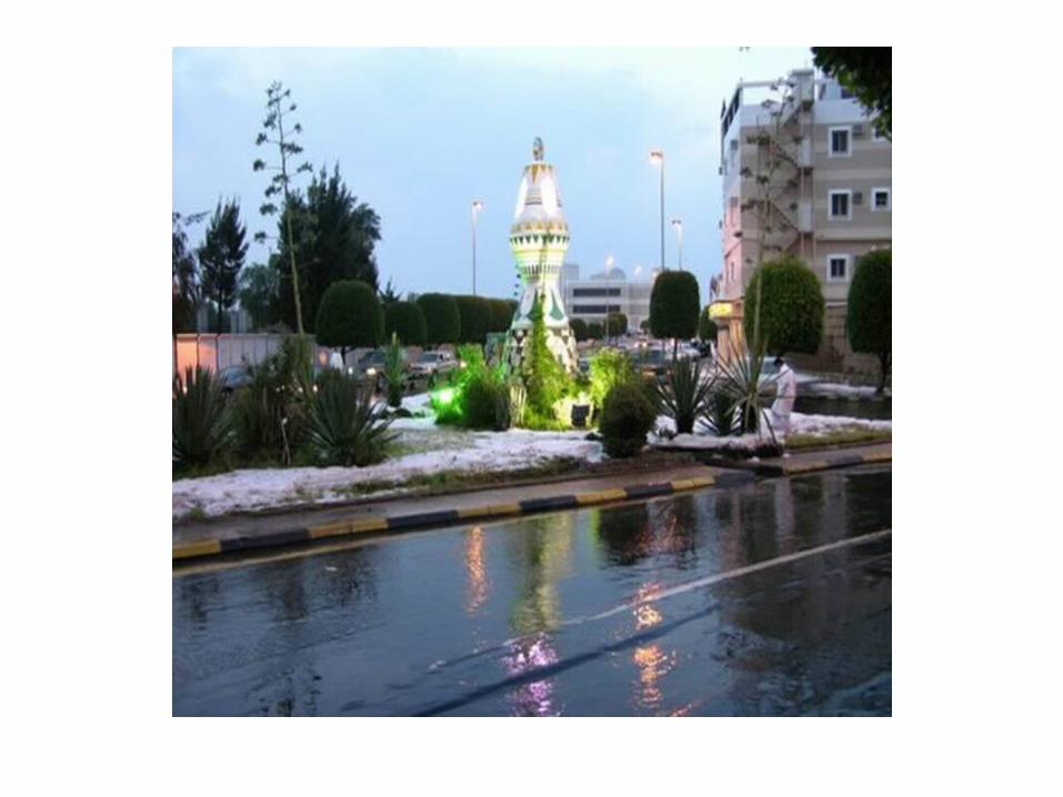
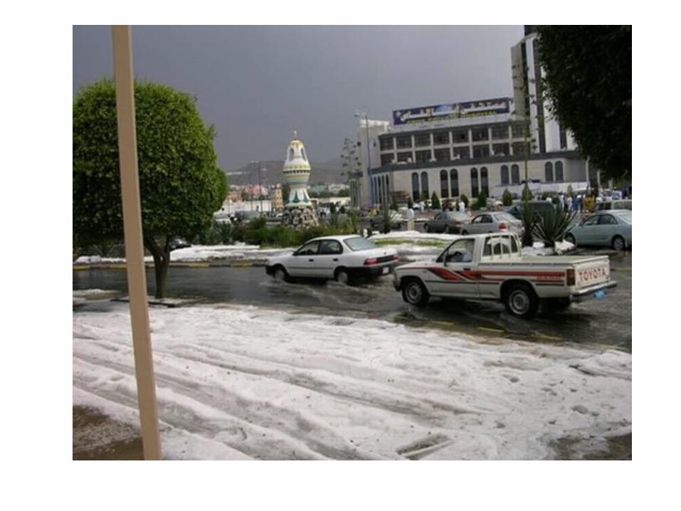
Abha, the city in kingdom of Saudi Arabia is situated at 18.23 N latitude and 42.65 E longitudes in the south west of the
kingdom .Its height from sea level is 1,500 meter. Here the weather
condition is very good. The average temp. round the year is about 26 ºC.So throughout the year, it is very comfortable. But
due to global change in weather condition the weather is becoming sour and hot .For human comfort we need to air-
condition our residential and commercial places. For the air-conditioning we have selected the workshop complex of
Mechanical Engg. Department of KKU, ABHA .


3 .BUILDING SURVEY:An accurate survey of the load components of the space to
be air-conditioned is a basic requirement for a realistic estimate of cooling and heating loads. The completeness
and accuracy of this is my computer survey is the very foundation of the estimate, and its importance cannot be overemphasized. Mechanical and architectural drawings, complete field sketches and in some cases, photographs of import aspects are part of a good survey. The following
physical aspects must be considered.


3.1:Orientation of building – Location of the space to nbr air conditioned with respect to:
Compass points – sun and wind effects.Nearby permanent structures – shading effects.
Reflective surfaces – water, sand, parking lots etc.3.2:Use of space )s( – Office, hospital, department store, specialty shop,
machine shop, factory, assembly plant etc.3.3:Physical dimensions of space )S( Length, width and height .3.4:Ceiling height – Floor to floor height, floor to ceiling, clearance between
suspended ceiling and beams.3.5:Columns and beams – Size depth also knee braces.
3.6:Construction materials – Materials and thickness of walls, roof, ceiling, floors and partitions and their relative position in the structure.
Surrounding conditions – Exterior color of walls and roof, shaded by adjacent building or sunlit. Attic spaces – invented or vented. Surrounding space
conditioned or unconditioned – temperature of non – conditioned adjacent spaces such as furnace or boiler room and kitchens, floor on ground, crawl
spaces, and basement.
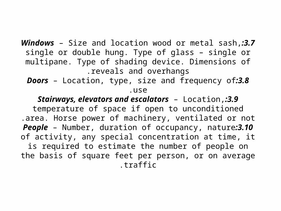
3.7:Windows – Size and location wood or metal sash, single or double hung. Type of glass – single or multipane. Type of shading
device. Dimensions of reveals and overhangs.3.8:Doors – Location, type, size and frequency of use.
3.9:Stairways, elevators and escalators – Location, temperature of space if open to unconditioned area. Horse power of machinery,
ventilated or not.3.10:People – Number, duration of occupancy, nature of activity,
any special concentration at time, it is required to estimate the number of people on the basis of square feet per person, or on
average traffic.

3.11:Lighting – Wattage at peak. Type – incandescent, fluorescent, recessed, exposed. If the lights are recessed, the type of airflow over the
lights, exhaust, return or supply, should be anticipated. At time, it is required to estimate the wattage on a basis of watts per sq. due to lack of exact
information.3.12:Motors – Location, nameplate and brake horsepower and usage. The
latter is of great significance and should be carefully evaluated. The power input to electric motors is not necessarily equal to the rated horsepower
divided by the motor efficiency. Frequently these motors may be operating under a continuous overload, or may be operating at less than rated
capacity. It is always advisable to measure the power input whenever possible. This is my computer is especially important in estimates for
industrial installations where the motor machine load is normally major portion of the cooling load.
3.13:Appliance, business machines, electronic equipment – Location, rated wattage, steam or gas consumption, exhaust air quantity installed or
required and usage. Avoid pyramiding the head gains from various appliances and business machines. For examples, a toaster or a waffle iron may not be used during the evening, or the fry kettle may not be used during moming, or not all business machines in a given space may be used at the
same time.

3.14:Ventilation – CFM per person, CFM per Esq. ft. Scheduled ventilation (agreement with purchaser) Excessive smoking, floor
orders, code requirement. Exhaust fan-type, size, speed, and CFM delivery.
3.15:Thermal storage – includes system operating schedule (12, 16 or 24 hours per ay. Specifically during peak out door conditions, permissible temperature swing in space during a design day, rugs
on floor.3.16:Continuous or intermittent operation – Whether system be
required to operate every business day during cooling season, or only occasionally, such as churches and ballrooms. If intermittent operation, determine duration of time available for precooling or
pull down.

CHAPTER-4
(DESIGN CONDITIONS(

4 .DESIGN CONDITIONS:Since the need of air conditioning is primarily a function of our body's reaction to the climate, we will begin our study of load estimating by looking at outdoor and indoor design
conditions. Establishing these conditions for a specific application, locality, and time will fix the magnitude of
head gain or loss essentially establishes the potential for head to flow and can be equated to establish the voltage
for an electrical circuit.

4.1:OUTDOOR DESIGN CONDITIONS:There are several sources of data that can be secured to establish outdoor
design. Three common ones are.ASHRAE Handbook of Fundamentals.
Engineering Weather Data.Carrier System Design Manual.
Each source contains data based on average weather conditions available at the time of publication.
It is commonly acknowledged that ASHRAE has come to be regarded as the industry standard when it comes to outside design data for abha. ASHRAE data is based on detailed records from official weather stations of the abha. Weather
Bureau, abha.To illustrate the outdoor design data is taken from carrier system design manual.
New Delhi will be used to illustrate the values published.

4.2:USE OF OUTDOORS DESIGN CONDITIONSSummer design condition in ABHA)KINDOM OF SAUDI ARABIA(
Summer DB34oCSummer WB21oCDaily Range12oC
4.3:INSIDE DESIGN CONDITIONS:The human body considers itself comfortable it can maintain an
average body temperature between 360C and 37.70C. To accomplish this is my computer body exchanges heat with its environment by
evaporating body fluids and

exchanging heat thru stable body temperature, and the mind perceives itself as comfortable when body temperature can easily maintained. It becomes the task of air-conditioning to maintain the environment around the body within this is my
computer comfort zone of conditions.The following variables, all of which affect the ability of body
to exchange heat with surrounding and perceive itself comfortable.
Surrounding Dry Bulb TemperatureSurrounding Relative Humidity
Surrounding Mean Radiant TemperatureSurrounding Air Velocity

4.4 :DESIGN CONDITIONSAt this point we have sufficient information to complete the
design portion of the calculation sheet form for our workshop complex building in the department of
Mechanical Engineering ,KKU ,Abha . Assuming we are going to do a block load for our selected building for May at 4 P.M. the outdoor design conditions from table 1 has been determined to 340C DB and 21oC WB. Plotting this
point on the psychometric chart results in finding a corresponding 74 GR/LB moisture content of the air.
Considering the ASHRAE comfort zone, let's pick inside design conditions of 22 oC DB and 50% RH (relative
humidity). The difference between outdoor air DB of 34oC and room (indoor) DB of 22oC IS 12oC. This indicates for
each CFM of outdoor air entering the building for ventilation purposes, the OA must be cooled 12oC.

4.5:LOAD COMPONENTS:The load components are one of the two general types:
SensibleLatent
4.5.1:A Sensible Load result when heat entering the conditioned space causes a dry bulb temperature increase.
4.5.2: A Latent Load result when moisture entering the space causes the humidity to increase. A load component may be all sensible, all latent or a
combination of two.Additionally load components can be classified into one of the following three
categories.SKIN LOAD
INTERNAL LOADSOTHER LOADS
Skin loads originate from heat sources outside or external to the conditioned space. Internal loads have their sources within the space itself. Other Loads
occur from head gains or losses associated with moving cool fluids to and from the conditioned Space design conditions.

4.5.3:SKIN LOADS:4.6:SOLAR GAIN THRU GLASS:
The sun rays pass through the glass windows as radiant energy and are absorbed within the space. Solar head gain typically reduced by the space. Solar heat fain is typically
reduced by the use of internal or external-shadin g devices, reveals, overhangs or shadows cost by adjacent buildings.
4.6.1:SOLAR AND TRANSMISSION GAIN THRU WALLS AND ROOF:
Heat is caused to flow through external wall and roofs by two sources:
Sun rays striking the external surfaces.The high outdoor air temperatures.

4.6.2:TRANSMISSION THRU GLASS, PARTITIONS, CEILING AND FLOORS:
When an adjacent area is at a temperature higher than the space to be air conditioned, heat will flow through windows,
ceilings, partitions, or floors by means of transmission.4.6.3:INFILTERATION:
Wind blowing against the side of building causes the outdoor air, which is higher in temperature and moisture
content, to infiltrate thru the cracks around doors and windows. This results in localized sensible and latent heat
gains.4.6.4;VENTILATION:
Should ventilation air for odor removal be introduced directly into the space, it will appear as load in the space. It could be considered as forced infiltration and would result in localized
sensible and latent heat gain.

4.7:INTERNAL LOADS:4.7.1:PEOPLE:
The human body through metabolism generates heat within itself and releases it by radiation,
convection, evaporation from the surface, and by convection and evaporation in the respiratory tract.
The amount of eat generated and released depends on surrounding temperatures and the activity level of the person. Both sensible and latent heat loads
will enter the space.4.7.2:LIGHTS:
Illuminates convert electrical power into light and sensible heat. Lighting is either fluorescent or
incandescent.

4.7.2:LIGHTS:Illuminates convert electrical power into light and sensible
heat. Lighting is either fluorescent or incandescent.4.7.3:EQUIPMENT:
Within the conditioned spaced powered equipment can produce localized sensible and / or latent loads. Such devices would include calculators, computers, motors,
popes, tanks, or product from a process.4.7.4:ROOM LOADS:
The room includes the entire space inside the building. Adding all the sensible loads together results in the room
sensible heat gain (RSH). Similarly, the sum of all the latent heat gain (RLH). Finally the sum of RSH and RLH is the
room total (RTH).

4.8:OTHER LOADS – SUPPLY AIR SIDE:If there was no heat gained or lost between the coil of the air handling unit and supply air terminal, the temperature of the
air leaving the coil would be the same as that of the air entering the room. In a real system the following losses
exists.4.8.1:SUPPLY DUCT HEAT GAIN:
Should be supply air duct pass thru a space whose temperature is higher than that of the air being transmitted, a
sensible heat gain will be experienced.4.8.2:SUPPLY DUCT LEACKAGE LOSS:
The supply air is transmitted under to the room. Depending on the quantity of ductwork installation, leaks at the joints will exits to some degree resulting in a loss of sensible as well as
latent capacity.

4.8.3:SUPPLY AIR HEAT:In air handling units whose fan is located downstream of the coil, the
does the work on the air resulting in a sensible heat gain to supply air. In addition the motor losses could show up on the supply air of the
motor is located on the air stream.4.9:BYPASSED OUTDOOR AIR:
Because the coil is not a perfect device, a position of the entering air passes through the coil completely unaltered in temperature or
humidity, resulting in a sensible and latent loss of supply air.4.10 :EFFECTIVE LOADS:
Adding the supply air sensible losses to the RSH results in air load laving the coil referred to as effective room sensible heat (ERSH). In
similar manner latent losses of the supply air plus RLH results in effective room latent heat by the coil. These loads are referred to as
effective since both the coil leaving air temperature and humidity level must effectively be lower than conditions required at the room on order
to:Absorb the losses along the way and
Absorb the room loads

4.11 :EQUIVALENT TEMPERATURE DIFFERENCE:Heat flow though an exterior wall is due to the combined effect of two
heat sources:Sun's rays striking the wall resulting in solar insert gain.
Outside air temperature higher than the inside temperature resulting in transmission thru the wall.
Since the wall has mass, the storage, affect of wall makes the flow of heat through it time related. Determination of actual amount of eats
entering the space is therefore a rather complex calculation. To get a look for the movement of heat thru wall under these circumstances a look at time related temperature profiles across a wall is beneficial.
Assume air temp. on both sides of a walls maintained at 23.88oC. With no sun shining on the wall temp thru wall is constant. As sun shines on
wall, radiant energy is converted to heat at surface to outdoor air and into wall. With time the surface temp. rises as well as temp in the wall, as
heat flows into wall and then on to the interior .

With continued sun shining on the wall, a steady state heat flow situation will occur where amount of energy striking the surface equals the amount of heat given off to outdoor air plus the amount of heat entering the interior. When sun
cease to shine on the wall, stored energy in wall continues to flow to the outside and inside until temp. Throughout the wall
equalizes. Whether the sun is shining on the wall heat is always flowing in two directions. Transmission heat flow thru wall behaves in a manner similar to solar flow of heat. As the
outdoor temperature rises-causing heat to flow into wall. If outdoors temp. remained at 34oC for a long time a steady
state heat transfer condition would exist. Under this condition heat entering the indoor space would define by equation:
Q = U*A* (Temperature Difference)

Should the outdoor air temp. fall quickly, energy stored in wall quickly flow outward in both directions . Under these conditions the
flow of heat is no longer steady state and above equation no longer applies. Since the
solar intensity striking the outside air temperature is continually changing, simple heat transmission equation cannot be used.
The equivalent temperature difference is a factious number used to describe the flow of
heat thru the wall at a given point in time.

4.12 :INFILTRATION, VENTILATION AND EXHAUST:Infiltration is leakage of untreated outdoor air through porous exterior
walls, floors, roofs etc. the amount of leakage is not controllable by the occupants in the building, and can results in rather large heat gains or
losses.The rate of which the leakage takes place is dependent upon the
pressure differential across the exterior surface. The pressure difference is in turn caused by wind velocity, difference in air density, or
pressurization caused by mechanical supply and exhaust systems.Due to the tremendous variability in building geometry, wind patterns, and construction quality, accurate evaluation becomes the task of the
designer to use his educated judgment based on the information available to provide for this potential load source.
The following text provides a partial in sight into this phenomenon, however, further research by the reader is necessary to properly
evaluate infiltration-particularly in tall building (i.e. those over 30 m high).

4.13:VENTILATION:The introduction of outdoor air for ventilation of conditioned
spaces is necessary to dilute odors given off by people, smoking, or other internal air contaminants. Local codes
usually determine the minimum amount of ventilation required, and may be specified either as CFM / person or
CFM/Ft2 of net floor area.It is customary to minimize the amount of outdoor air
introduced into the space since this can result in a substantial heating or cooling load. With high-energy costs
this can translate into significant operating costs. The people density of the building is 50 sq. ft. / person/ as we know that 15 CFM / Person is a good minimum ventilation
rate. Thus the building requires.
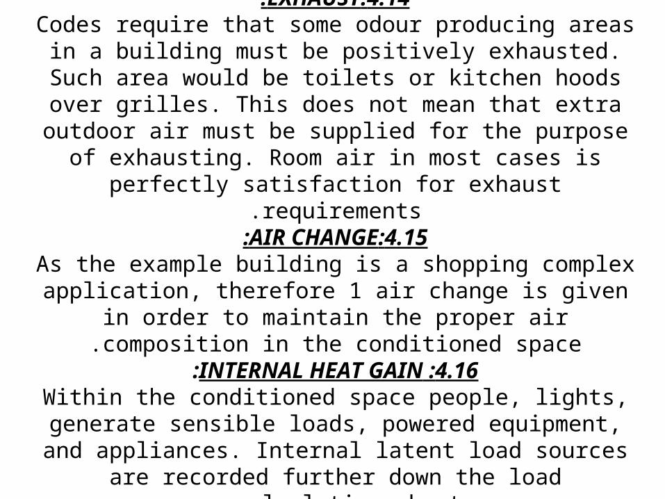
4.14:EXHAUST:Codes require that some odour producing areas in a building must be positively exhausted. Such area would be toilets or
kitchen hoods over grilles. This does not mean that extra outdoor air must be supplied for the purpose of exhausting. Room air in most cases is perfectly satisfaction for exhaust
requirements.4.15:AIR CHANGE:
As the example building is a shopping complex application, therefore 1 air change is given in order to maintain the proper
air composition in the conditioned space.4.16 :INTERNAL HEAT GAIN:
Within the conditioned space people, lights, generate sensible loads, powered equipment, and appliances. Internal latent
load sources are recorded further down the load calculation sheet.
4.16.1:PEOPLE:Heat is generated within the human body by
oxidation – commonly called metabolic rate. This heat is carried to the surface of the body and
dissipated by:Radiation from the body to the surrounding colder
surfaces.Convection from the body and respiratory tract to
the surrounding air.Evaporation of moisture from the body surface and
in the surrounding air.from the carrier system design manual shows
average dissipation of Sensible and latent heat from people at different level of activity.

4.16.2:LIGHTS:Lights generate sensible heat by the conversion of electrical power into
light and heat. The heat is then dissipated by radiation to the surrounding surfaces, by Conduction into adjacent materials, and by convection to the surrounding air. Lights are typically specified as lamp watts/ Ft2 of floor
area.Incandescent lights convert approximately 10% of the power input into light. The rest appears as heat within the bulb. The heat then makes its
way into the space 80% by radiation and 10% by conduction and convection florescent lights are more commonly used in commercial buildings. About 20% of the input power(E) is converted to light by
florescent bulbs – thus they are more efficient than incandescent lights. 20% of the power input (E) is dissipated by convection and conduction to the space. Additionally, 20% of the input power is generated as heat in the ballast of the lamps. The above values very from manufacturer to manufacturer and more efficient lights significantly reduce the ballast
loss. Generally, however, the following equations are used to give a good approximation of the heat gain to the space.

TYPE:HEAT GAIN TO THE SPACE:FLORESCENT:RATED LAMP WATTS x 1.25 X 3.413 BTUH / WATT
INCANDESCENT:RATED LAMP WATTS X 3.143 BTUH / WATT 1.25 ACCOUNTS FOR BALLAST HEAT GAIN
4.16.3:STORED EVERGY FROM LIGHTS:The radiant energy from lights has the potential to be
stored in the mass of the building and appear as a load later in the space. This is the same process that occurs
with solar radiant energy.It is normal practice to neglect the storage impact when calculating the space load due to lights. Most comfort
applications result in less than 2% reduction in the load, and therefore, storage is neglected. The basic reason
behind this practice is as follows:Carpeting is widely used. The primary target for radiant energy from the lights is the floor. Carpet insulates the
floor from the radiant light rays. The radiant energy strikes the carpet and is converted into heat. The heat is then
dissipated almost immediately into the space. Only a small portion of the energy is stored in the floor.

Unless the air conditioning equipment is run for an hour or two before the light are turned on, the mass of the building will already be
saturated with stored heat from the night before, therefore, as light heat is observed in the mass, the equivalent amount of energy is
almost simultaneously released to the space:In order to see a significant reduction in heat of lights due to storage
the following Condition should be present.The air conditioning equipment should be run longer then 12 hours per
day to remove solar energy from the mass of the building, and also reduce or eliminate morning pull down loads.
The lights should be turned on 1 (preferably 2) hours after the air conditioning equipment in the morning. Determining the storage impact can be done by the use of tables 12 in the carrier system
design manual.

4.17:BYPASSED OUTDOOR AIR:Since the cooling coil is not a perfect heat exchanger device, some of
the air entering the coil passes through the coil untreated. This represents a loss air leaving the coil must overcome before entering the
room. It is a load equivalent to an infiltration load in the room, and is calculated in that manner. The percentage of air (expressed as a
decimal) that passes through the coil untreated is referred to as the bypass factor and is typically figured at 0.5. it is really a function of the
type of the coil and equipment used. A more accurate value can be assigned, as the designer becomes more familiar with cooling coil used
in air conditioning equipment.
4.18:EFFECTIVE ROOM SENSIBLE HEAT )ERSH(:Adding the supply duct sensible losses to the room sensible
heat (RSH) results in a load known as the effective room sensible heat (ERSH). This load is used in determining the CFM of air required across the cooling coil the air must be effectively higher than the normal quantity to absorb the
room load and the losses encountered along the way from the cooling coil to the room.
4.19 :LATENT LOADS:The latent counterparts of infiltration, internal loads are now calculated order to determine the room latent heat
(RLH) and effective room latent heat (ERLH). Vapor transmission is one new load source encountered.
4.20:VAPOUR TRANSMISSION:Water vapor flows thru building structures, resulting in a latent load whenever a vapor pressure difference exists across the structure. The latent load from this source is usually insignificant in comfort application and need be
considered only in low or high dew point applications.

Water vapor flows from high to lower vapor pressure at rate determined by the permeability of the structure. Further details on this subject can be found in the
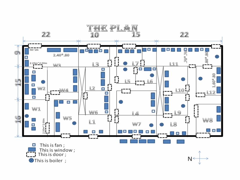
carrier system design manual.For the air conditioning the available plan of the workshop complex building of Mechanical Engineering,KKU,ABHA,KINDOM OF SAUDI ARABIA has been selected for cooling load calculation .The plan of the complex as shown in
fig.1.The other details for the building are taken as below .Building located at 18.2o N Latitude, the following data are given
Plaster on inside wall =1.25 cmOut side wall construction=20 cm concrete block
=10 cm brick veneerPartion wall construction =33 cm brick
Roof construction =20 cm RCC slab with 4 cm asbestos cement boardFloor construction =20 cm concrete
Densties, brick =2000kg/ m Concrete =1900kg/m Plaster =1885kg/m Asbestos board =520kg/m

Fenestration (weather-stripped, =2mx1.5m glasses loose fitl U=5,9wm k
doors 1.5mx2 m wood panels U=.63w m k
out door design condition =34C DBT,22C WBTIndoor design condtion 25 DBT, 50% RH
Daily rang 220C TO 34 ºC =12 ºCOccupancy =200
Light 15000 w fluorescent 4,000 w tungsten
Assume bypass factor of cooling coil =0.15Find room sensible and latent heat load and also the grand total heat load.
Related Documents