AC3S1-02 I11181 I11182 I11200 Register Knob Center Cluster Integration Panel Connector Heater Control Housing Airbag Indicator Circuit Lens Bulb (Clock Lighting) Bulb (Panel Lighting) Integration Circuit Integration Panel Access Cab, Standard Cab: - AIR CONDITIONING AIR CONDITIONING CONTROL ASSEMBLY (Center Cluster Integration) AC-87 5114 Author: Date: COMPONENTS

Welcome message from author
This document is posted to help you gain knowledge. Please leave a comment to let me know what you think about it! Share it to your friends and learn new things together.
Transcript
AC3S1-02
I11181
I11182
I11200
Register
Knob
Center ClusterIntegration Panel
Connector
Heater Control HousingAirbag Indicator Circuit
Lens
Bulb (Clock Lighting)
Bulb (Panel Lighting)
IntegrationCircuit
Integration Panel
Access Cab, Standard Cab:
-AIR CONDITIONING AIR CONDITIONING CONTROL ASSEMBLY (Center Cluster Integration)
AC-87
5114Author: Date:
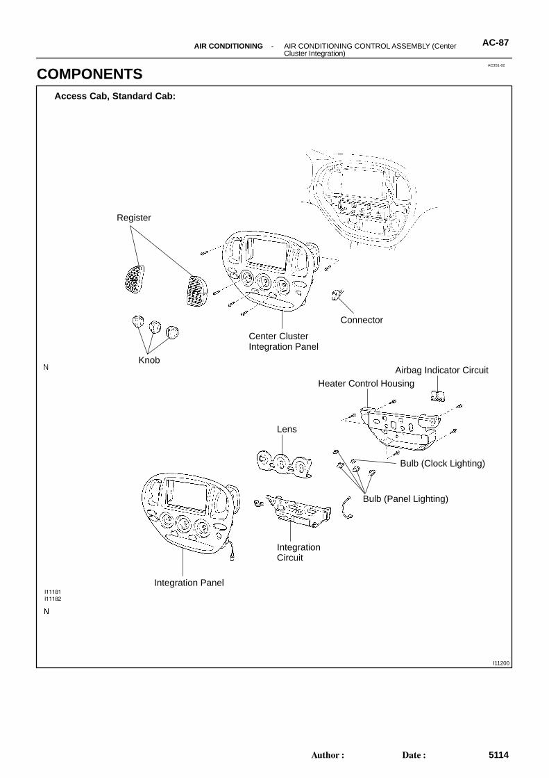
COMPONENTS
I27026
Register
Knob
Center ClusterIntegration Panel
Connector
Heater Control Housing
Lens
Bulb
Integration Circuit
Integration Panel
Double Cab:
AC-88 -AIR CONDITIONING AIR CONDITIONING CONTROL ASSEMBLY (Center Cluster Integration)
5115Author: Date:
I11188
AC3S2-02
I11189
I27027 I27949
Access Cab, Standard Cab:
Double Cab:
I11190
Access Cab, Standard Cab:
I27028
Double Cab:
AC-90 -AIR CONDITIONING AIR CONDITIONING CONTROL ASSEMBLY (Center Cluster Integration)
5117Author: Date:
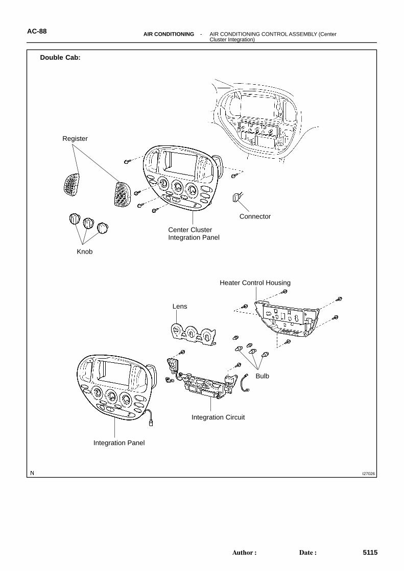
DISASSEMBLY1. Access cab, Standard cab:
REMOVE AIRBAG INDICATOR CIRCUITRelease the 2 claws and remove the indicator circuit, then dis-connect the connector.
2. REMOVE BULBS(a) Access cab, standard cab:
Remove the 5 bulbs.(b) Double cab:
Remove the 6 bulbs.
3. Access cab, Standard cab: REMOVE HEATER CONTROL HOUSING
(a) Remove the 5 screws.(b) Remove the heater control housing.
4. Double cab: REMOVE HEATER CONTROL HOUSING
(a) Remove the 5 screws.(b) Remove the heater control housing.
I11191
Access Cab, Standard Cab:
I27162
Double Cab:
I11192
I27161I27950
Double Cab:
Access Cab, Standard Cab:
-AIR CONDITIONING AIR CONDITIONING CONTROL ASSEMBLY (Center Cluster Integration)
AC-91
5118Author: Date:
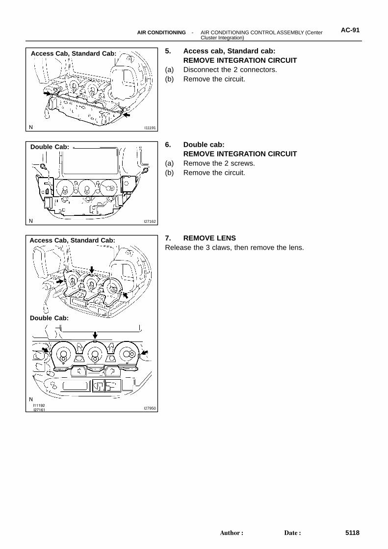
5. Access cab, Standard cab: REMOVE INTEGRATION CIRCUIT
(a) Disconnect the 2 connectors.(b) Remove the circuit.
6. Double cab: REMOVE INTEGRATION CIRCUIT
(a) Remove the 2 screws.(b) Remove the circuit.
7. REMOVE LENSRelease the 3 claws, then remove the lens.
I11193
: Bulb
A8B7
AC3S3-02
I27863
: Bulb
B2
B11
I07872
AC-92 -AIR CONDITIONING AIR CONDITIONING CONTROL ASSEMBLY (Center Cluster Integration)
5119Author: Date:
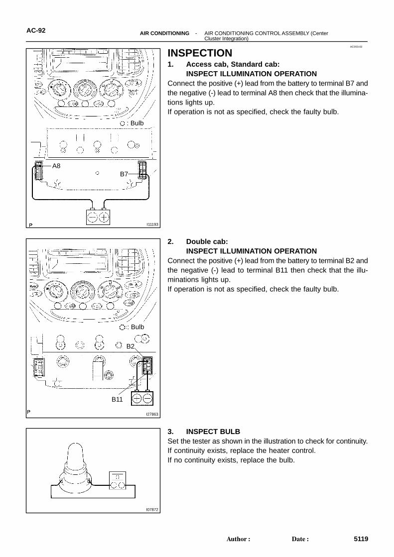
INSPECTION1. Access cab, Standard cab:
INSPECT ILLUMINATION OPERATIONConnect the positive (+) lead from the battery to terminal B7 andthe negative (-) lead to terminal A8 then check that the illumina-tions lights up.If operation is not as specified, check the faulty bulb.
2. Double cab: INSPECT ILLUMINATION OPERATION
Connect the positive (+) lead from the battery to terminal B2 andthe negative (-) lead to terminal B11 then check that the illu-minations lights up.If operation is not as specified, check the faulty bulb.
3. INSPECT BULBSet the tester as shown in the illustration to check for continuity.If continuity exists, replace the heater control.If no continuity exists, replace the bulb.
I11194
ONOFF
A9A1
A12
I27864
ONOFF
A17
A18
I12235
Connector ”A” A1
A12
-AIR CONDITIONING AIR CONDITIONING CONTROL ASSEMBLY (Center Cluster Integration)
AC-93
5120Author: Date:
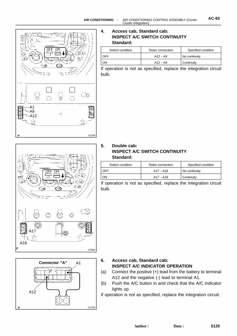
4. Access cab, Standard cab: INSPECT A/C SWITCH CONTINUITYStandard:
Switch condition Tester connection Specified condition
OFF A12 - A9 No continuity
ON A12 - A9 Continuity
If operation is not as specified, replace the integration circuitbulb.
5. Double cab: INSPECT A/C SWITCH CONTINUITYStandard:
Switch condition Tester connection Specified condition
OFF A17 - A18 No continuity
ON A17 - A18 Continuity
If operation is not as specified, replace the integration circuitbulb.
6. Access cab, Standard cab: INSPECT A/C INDICATOR OPERATION
(a) Connect the positive (+) lead from the battery to terminalA12 and the negative (-) lead to terminal A1.
(b) Push the A/C button in and check that the A/C indicatorlights up.
If operation is not as specified, replace the integration circuit.
I12236
Connector ”A” A1
A12
A11
A10
I27865
Connector ”A”
A17 A10
I11195
OFF ON
A1
A4B13
AC-94 -AIR CONDITIONING AIR CONDITIONING CONTROL ASSEMBLY (Center Cluster Integration)
5121Author: Date:
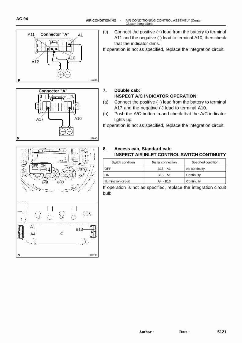
(c) Connect the positive (+) lead from the battery to terminalA11 and the negative (-) lead to terminal A10, then checkthat the indicator dims.
If operation is not as specified, replace the integration circuit.
7. Double cab:INSPECT A/C INDICATOR OPERATION
(a) Connect the positive (+) lead from the battery to terminalA17 and the negative (-) lead to terminal A10.
(b) Push the A/C button in and check that the A/C indicatorlights up.
If operation is not as specified, replace the integration circuit.
8. Access cab, Standard cab: INSPECT AIR INLET CONTROL SWITCH CONTINUITY
Switch condition Tester connection Specified condition
OFF B13 - A1 No continuity
ON B13 - A1 Continuity
Illumination circuit A4 - B13 Continuity
If operation is not as specified, replace the integration circuitbulb
I27866
OFF ON
A10
A14
B8
I12237
Connector ”A” A1A4
I12238
Connector ”A” A1A4
A10A11
I27867
Connector ”A”
A10A14
-AIR CONDITIONING AIR CONDITIONING CONTROL ASSEMBLY (Center Cluster Integration)
AC-95
5122Author: Date:
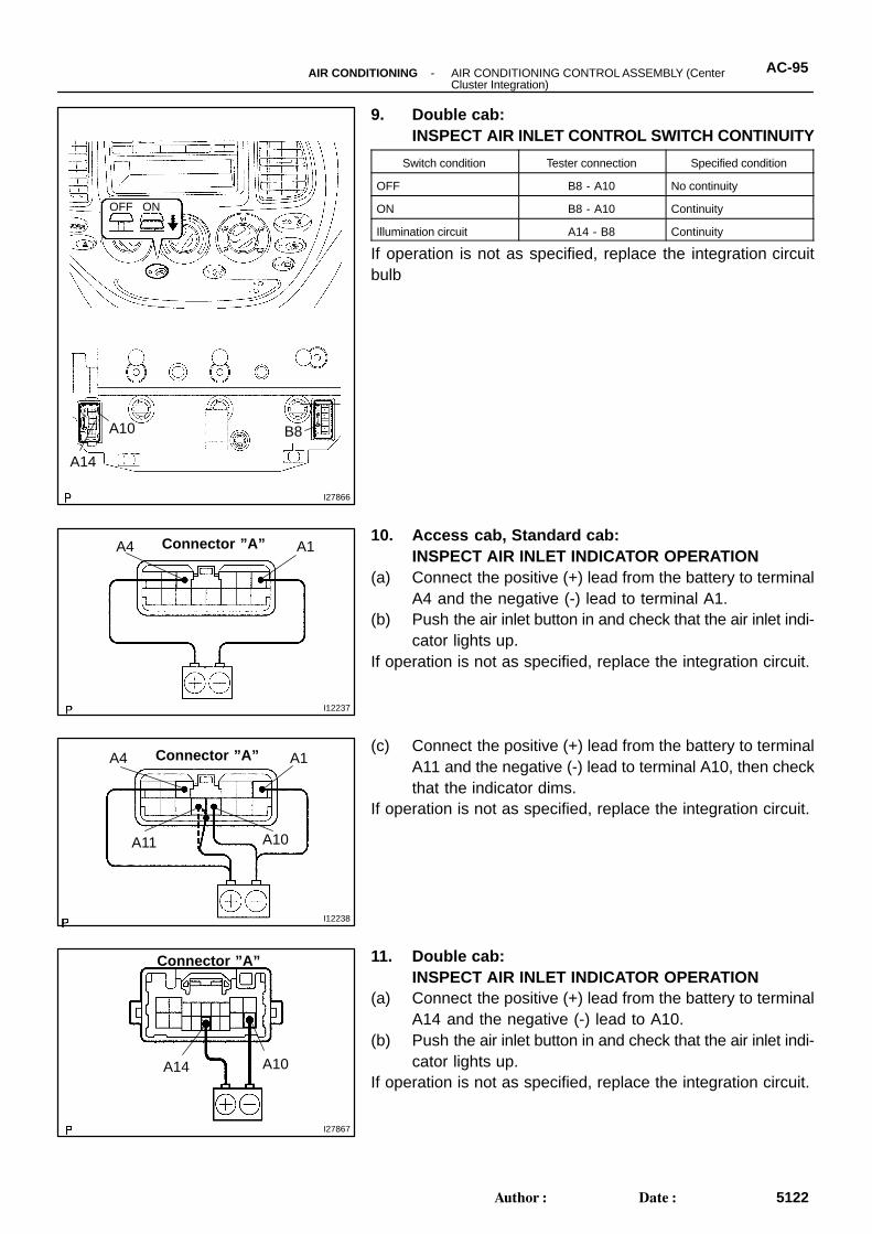
9. Double cab: INSPECT AIR INLET CONTROL SWITCH CONTINUITY
Switch condition Tester connection Specified condition
OFF B8 - A10 No continuity
ON B8 - A10 Continuity
Illumination circuit A14 - B8 Continuity
If operation is not as specified, replace the integration circuitbulb
10. Access cab, Standard cab: INSPECT AIR INLET INDICATOR OPERATION
(a) Connect the positive (+) lead from the battery to terminalA4 and the negative (-) lead to terminal A1.
(b) Push the air inlet button in and check that the air inlet indi-cator lights up.
If operation is not as specified, replace the integration circuit.
(c) Connect the positive (+) lead from the battery to terminalA11 and the negative (-) lead to terminal A10, then checkthat the indicator dims.
If operation is not as specified, replace the integration circuit.
11. Double cab: INSPECT AIR INLET INDICATOR OPERATION
(a) Connect the positive (+) lead from the battery to terminalA14 and the negative (-) lead to A10.
(b) Push the air inlet button in and check that the air inlet indi-cator lights up.
If operation is not as specified, replace the integration circuit.
AC27I-02
AC-98 -AIR CONDITIONING AIR CONDITIONING CONTROL ASSEMBLY (Center Cluster Integration)
5125Author: Date:
INSTALLATIONThe installation procedures are the removal procedures in reverse order (see page AC-89 ).
I11149
I11150 I11198
Wire harness side
Connector ”A” Connector ”B”
AC3S0-02
-AIR CONDITIONING AIR CONDITIONING CONTROL ASSEMBLY (Center Cluster Integration)
AC-83
5110Author: Date:
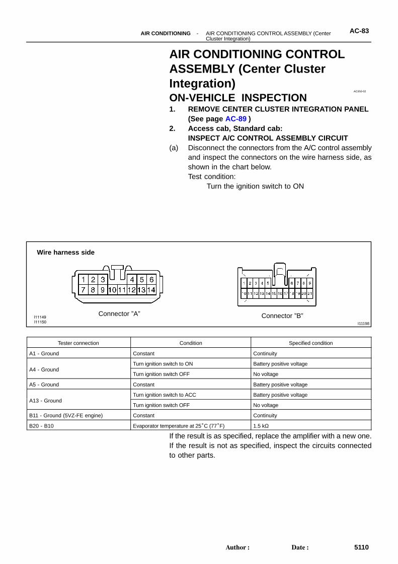
AIR CONDITIONING CONTROLASSEMBLY (Center ClusterIntegration)ON-VEHICLE INSPECTION1. REMOVE CENTER CLUSTER INTEGRATION PANEL
(See page AC-89 )2. Access cab, Standard cab:
INSPECT A/C CONTROL ASSEMBLY CIRCUIT(a) Disconnect the connectors from the A/C control assembly
and inspect the connectors on the wire harness side, asshown in the chart below.Test condition:
Turn the ignition switch to ON
Tester connection Condition Specified condition
A1 - Ground Constant Continuity
A4 G dTurn ignition switch to ON Battery positive voltage
A4 - GroundTurn ignition switch OFF No voltage
A5 - Ground Constant Battery positive voltage
A13 G dTurn ignition switch to ACC Battery positive voltage
A13 - GroundTurn ignition switch OFF No voltage
B11 - Ground (5VZ-FE engine) Constant Continuity
B20 - B10 Evaporator temperature at 25°C (77°F) 1.5 kΩ
If the result is as specified, replace the amplifier with a new one.If the result is not as specified, inspect the circuits connectedto other parts.
I28084
Connector ”A”Connector ”B”
123456
7891011121314
123456789
101112131415161718192021
AC-84 -AIR CONDITIONING AIR CONDITIONING CONTROL ASSEMBLY (Center Cluster Integration)
5111Author: Date:
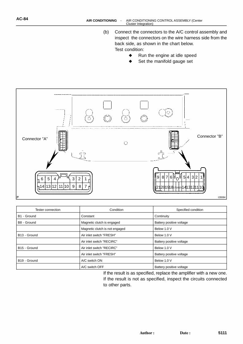
(b) Connect the connectors to the A/C control assembly andinspect the connectors on the wire harness side from theback side, as shown in the chart below.Test condition:
Run the engine at idle speed Set the manifold gauge set
Tester connection Condition Specified condition
B1 - Ground Constant Continuity
B8 - Ground Magnetic clutch is engaged Battery positive voltage
Magnetic clutch is not engaged Below 1.0 V
B13 - Ground Air inlet switch ”FRESH” Below 1.0 V
Air inlet switch ”RECIRC” Battery positive voltage
B15 - Ground Air inlet switch ”RECIRC” Below 1.0 V
Air inlet switch ”FRESH” Battery positive voltage
B19 - Ground A/C switch ON Below 1.0 V
A/C switch OFF Battery positive voltage
If the result is as specified, replace the amplifier with a new one.If the result is not as specified, inspect the circuits connectedto other parts.
I27431
I27444
I28026
Wire harness side
Connector ”A” Connector ”B”
-AIR CONDITIONING AIR CONDITIONING CONTROL ASSEMBLY (Center Cluster Integration)
AC-85
5112Author: Date:
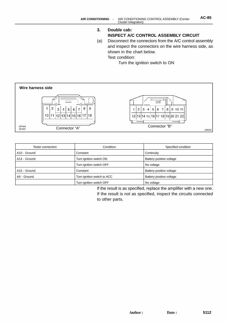
3. Double cab: INSPECT A/C CONTROL ASSEMBLY CIRCUIT
(a) Disconnect the connectors from the A/C control assemblyand inspect the connectors on the wire harness side, asshown in the chart below.Test condition:
Turn the ignition switch to ON
Tester connection Condition Specified condition
A10 - Ground Constant Continuity
A14 - Ground Turn ignition switch ON Battery positive voltage
Turn ignition switch OFF No voltage
A15 - Ground Constant Battery positive voltage
A9 - Ground Turn ignition switch to ACC Battery positive voltage
Turn ignition switch OFF No voltage
If the result is as specified, replace the amplifier with a new one.If the result is not as specified, inspect the circuits connectedto other parts.
I27862
Connector ”A”Connector ”B”
AC-86 -AIR CONDITIONING AIR CONDITIONING CONTROL ASSEMBLY (Center Cluster Integration)
5113Author: Date:
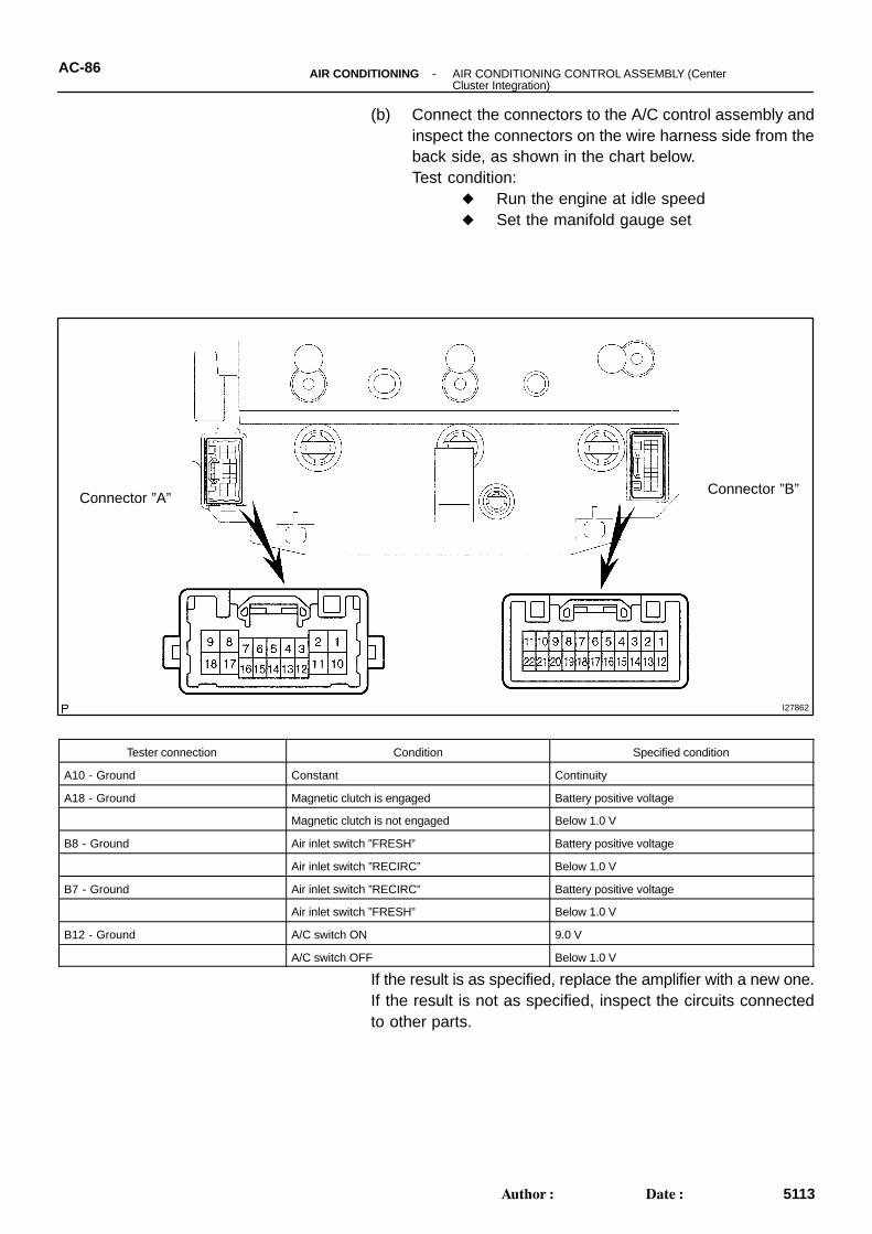
(b) Connect the connectors to the A/C control assembly andinspect the connectors on the wire harness side from theback side, as shown in the chart below.Test condition:
Run the engine at idle speed Set the manifold gauge set
Tester connection Condition Specified condition
A10 - Ground Constant Continuity
A18 - Ground Magnetic clutch is engaged Battery positive voltage
Magnetic clutch is not engaged Below 1.0 V
B8 - Ground Air inlet switch ”FRESH” Battery positive voltage
Air inlet switch ”RECIRC” Below 1.0 V
B7 - Ground Air inlet switch ”RECIRC” Battery positive voltage
Air inlet switch ”FRESH” Below 1.0 V
B12 - Ground A/C switch ON 9.0 V
A/C switch OFF Below 1.0 V
If the result is as specified, replace the amplifier with a new one.If the result is not as specified, inspect the circuits connectedto other parts.
I11192
I27161I27950
Double Cab:
Access Cab, Standard Cab:AC3S4-02
I11191
Access Cab, Standard Cab:
I27162
Double Cab:
I11190
Access Cab, Standard Cab:
AC-96 -AIR CONDITIONING AIR CONDITIONING CONTROL ASSEMBLY (Center Cluster Integration)
5123Author: Date:
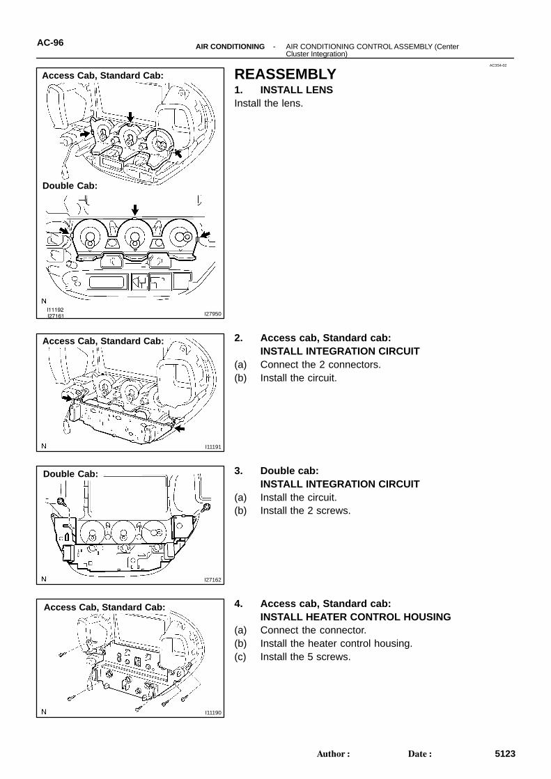
REASSEMBLY1. INSTALL LENSInstall the lens.
2. Access cab, Standard cab: INSTALL INTEGRATION CIRCUIT
(a) Connect the 2 connectors.(b) Install the circuit.
3. Double cab: INSTALL INTEGRATION CIRCUIT
(a) Install the circuit.(b) Install the 2 screws.
4. Access cab, Standard cab: INSTALL HEATER CONTROL HOUSING
(a) Connect the connector.(b) Install the heater control housing.(c) Install the 5 screws.
I27028
Double Cab:
I11189
I27027 I27949
Access Cab, Standard Cab:
Double Cab:
I11188
Access Cab, Standard Cab:
-AIR CONDITIONING AIR CONDITIONING CONTROL ASSEMBLY (Center Cluster Integration)
AC-97
5124Author: Date:
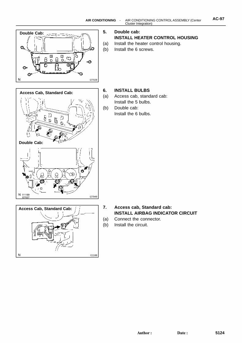
5. Double cab: INSTALL HEATER CONTROL HOUSING
(a) Install the heater control housing.(b) Install the 6 screws.
6. INSTALL BULBS(a) Access cab, standard cab:
Install the 5 bulbs.(b) Double cab:
Install the 6 bulbs.
7. Access cab, Standard cab: INSTALL AIRBAG INDICATOR CIRCUIT
(a) Connect the connector.(b) Install the circuit.
H111757 Clips
AC27E-03
-AIR CONDITIONING AIR CONDITIONING CONTROL ASSEMBLY (Center Cluster Integration)
AC-89
5116Author: Date:
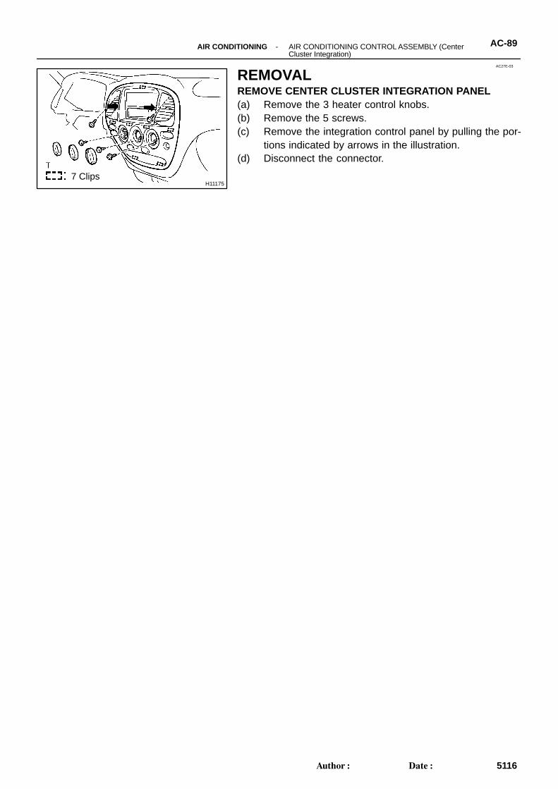
REMOVALREMOVE CENTER CLUSTER INTEGRATION PANEL(a) Remove the 3 heater control knobs.(b) Remove the 5 screws.(c) Remove the integration control panel by pulling the por-
tions indicated by arrows in the illustration.(d) Disconnect the connector.
AC22G-08
N13793
Charging Cylinder
High PressureService Valve
Low PressureService Valve
PushAir
N13792
Gas LeakDetector
-AIR CONDITIONING AIR CONDITIONING SYSTEMAC-1 1
5038Author: Date:
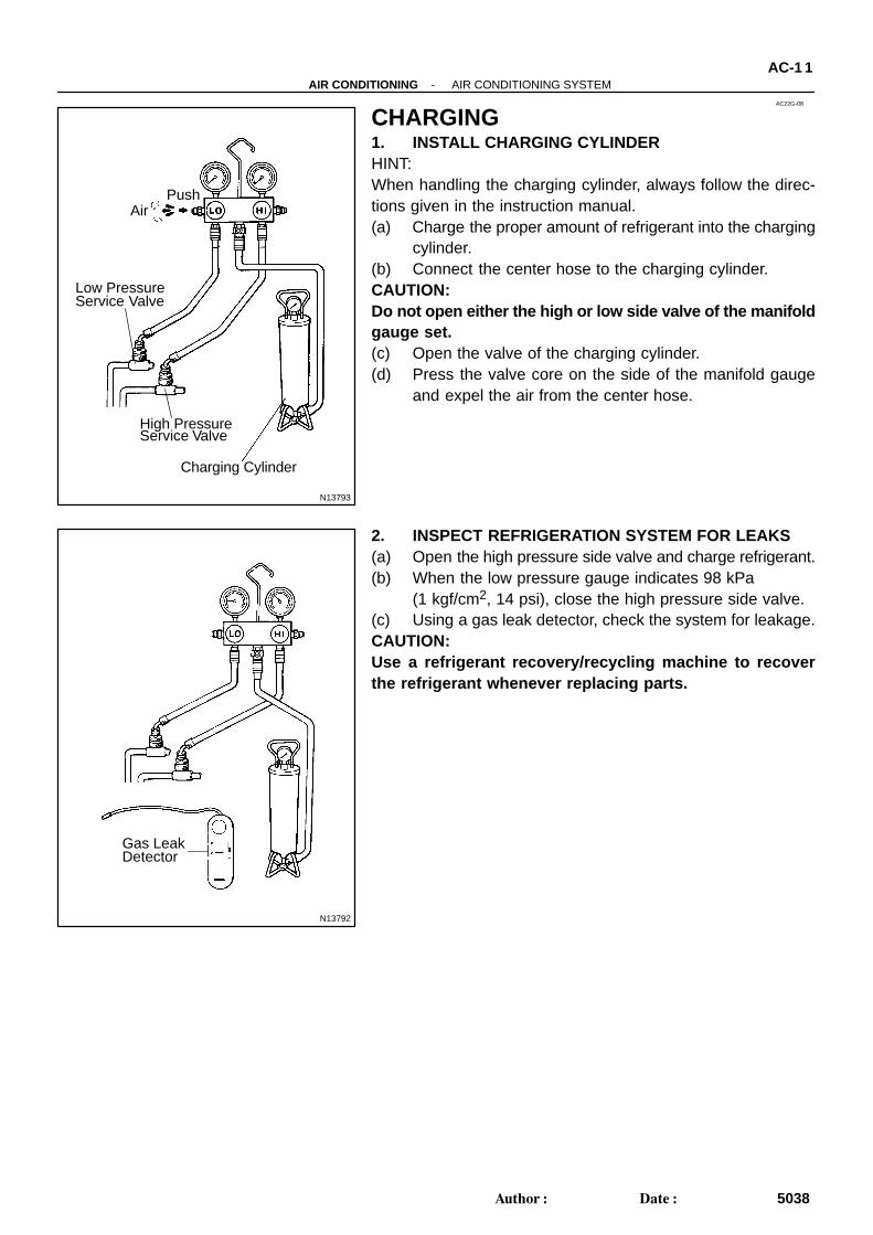
CHARGING1. INSTALL CHARGING CYLINDERHINT:When handling the charging cylinder, always follow the direc-tions given in the instruction manual.(a) Charge the proper amount of refrigerant into the charging
cylinder.(b) Connect the center hose to the charging cylinder.CAUTION:Do not open either the high or low side valve of the manifoldgauge set.(c) Open the valve of the charging cylinder.(d) Press the valve core on the side of the manifold gauge
and expel the air from the center hose.
2. INSPECT REFRIGERATION SYSTEM FOR LEAKS(a) Open the high pressure side valve and charge refrigerant.(b) When the low pressure gauge indicates 98 kPa
(1 kgf/cm2, 14 psi), close the high pressure side valve.(c) Using a gas leak detector, check the system for leakage.CAUTION:Use a refrigerant recovery/recycling machine to recoverthe refrigerant whenever replacing parts.
N13790
Low PressureService Valve
High PressureService Valve
I11172
ProperlyCharged
InsufficientlyCharged
AC-12-AIR CONDITIONING AIR CONDITIONING SYSTEM
5039Author: Date:
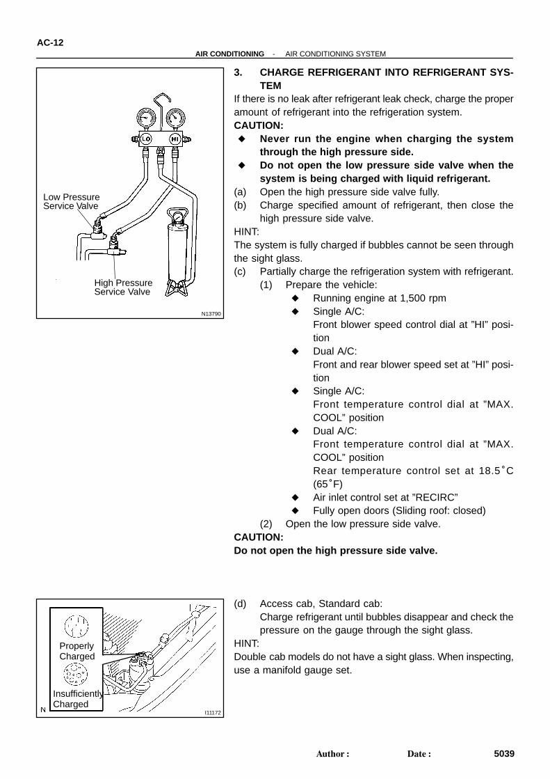
3. CHARGE REFRIGERANT INTO REFRIGERANT SYS-TEM
If there is no leak after refrigerant leak check, charge the properamount of refrigerant into the refrigeration system.CAUTION: Never run the engine when charging the system
through the high pressure side. Do not open the low pressure side valve when the
system is being charged with liquid refrigerant.(a) Open the high pressure side valve fully.(b) Charge specified amount of refrigerant, then close the
high pressure side valve.HINT:The system is fully charged if bubbles cannot be seen throughthe sight glass.(c) Partially charge the refrigeration system with refrigerant.
(1) Prepare the vehicle: Running engine at 1,500 rpm Single A/C:
Front blower speed control dial at ”HI” posi-tion
Dual A/C:Front and rear blower speed set at ”HI” posi-tion
Single A/C:Front temperature control dial at ”MAX.COOL” position
Dual A/C:Front temperature control dial at ”MAX.COOL” positionRear temperature control set at 18.5°C(65°F)
Air inlet control set at ”RECIRC” Fully open doors (Sliding roof: closed)
(2) Open the low pressure side valve.CAUTION:Do not open the high pressure side valve.
(d) Access cab, Standard cab:Charge refrigerant until bubbles disappear and check thepressure on the gauge through the sight glass.
HINT:Double cab models do not have a sight glass. When inspecting,use a manifold gauge set.
AC0C4-12
N13795
Quick DisconnectAdapter
Charging
Service Valve
Hose
N13794
Vacuum Pump
Vacuum Pump Adapter
N13791
Low PressureService Valve
Vacuum Pump Adapter
High PressureService Valve
ManifoldGaugeSet
AC-10-AIR CONDITIONING AIR CONDITIONING SYSTEM
5037Author: Date:
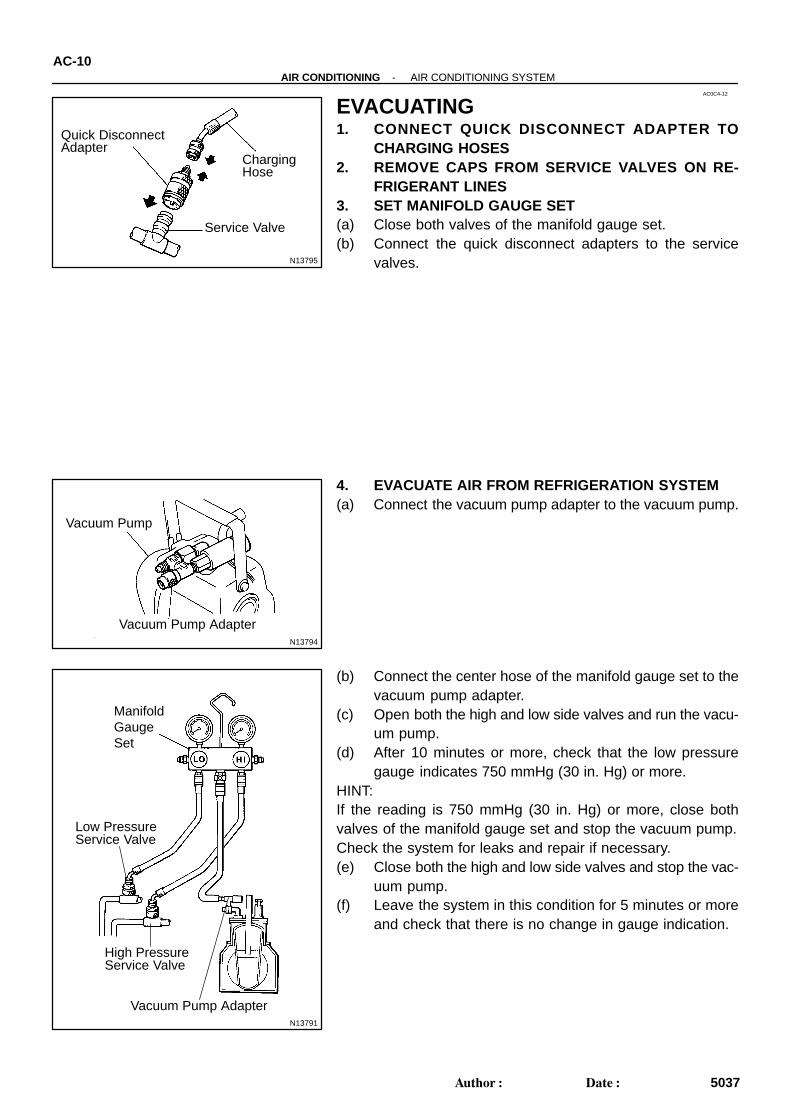
EVACUATING1. CONNECT QUICK DISCONNECT ADAPTER TO
CHARGING HOSES2. REMOVE CAPS FROM SERVICE VALVES ON RE-
FRIGERANT LINES3. SET MANIFOLD GAUGE SET(a) Close both valves of the manifold gauge set.(b) Connect the quick disconnect adapters to the service
valves.
4. EVACUATE AIR FROM REFRIGERATION SYSTEM(a) Connect the vacuum pump adapter to the vacuum pump.
(b) Connect the center hose of the manifold gauge set to thevacuum pump adapter.
(c) Open both the high and low side valves and run the vacu-um pump.
(d) After 10 minutes or more, check that the low pressuregauge indicates 750 mmHg (30 in. Hg) or more.
HINT:If the reading is 750 mmHg (30 in. Hg) or more, close bothvalves of the manifold gauge set and stop the vacuum pump.Check the system for leaks and repair if necessary.(e) Close both the high and low side valves and stop the vac-
uum pump.(f) Leave the system in this condition for 5 minutes or more
and check that there is no change in gauge indication.
AC3RP-02
I11116
I11117
I29016
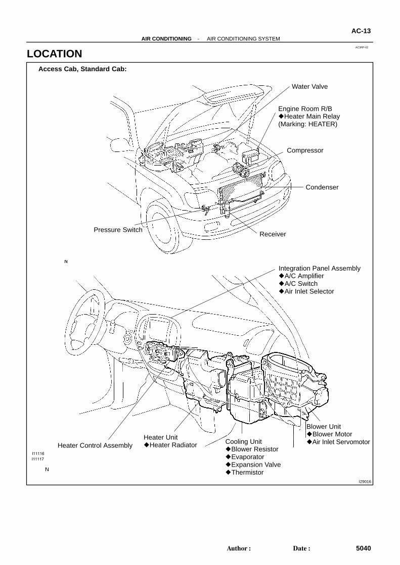
Engine Room R/B Heater Main Relay(Marking: HEATER)
Compressor
Condenser
ReceiverPressure Switch
Integration Panel Assembly A/C Amplifier A/C Switch Air Inlet Selector
Heater Control AssemblyHeater Unit Heater Radiator Cooling Unit
Blower Resistor Evaporator Expansion Valve Thermistor
Blower Unit Blower Motor Air Inlet Servomotor
Water Valve
Access Cab, Standard Cab:
-AIR CONDITIONING AIR CONDITIONING SYSTEMAC-13
5040Author: Date:
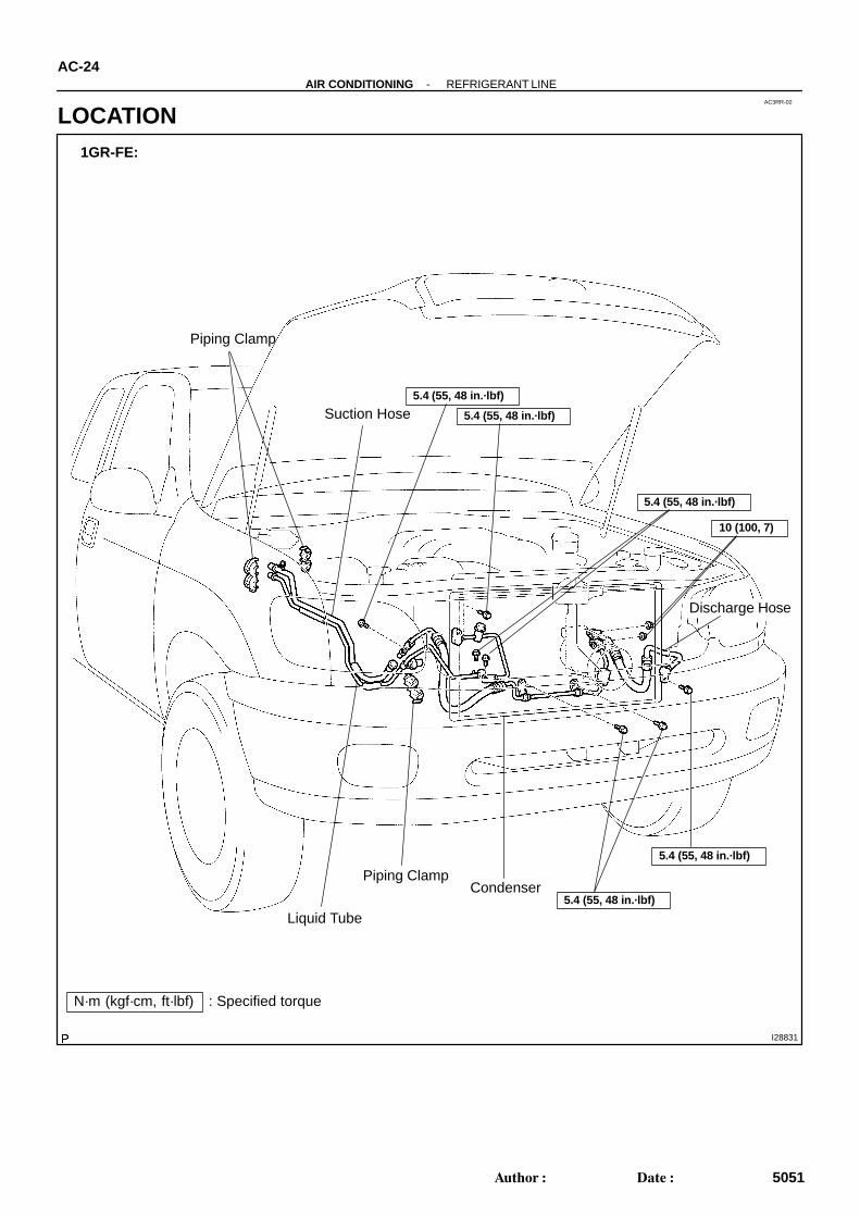
LOCATION
H23499
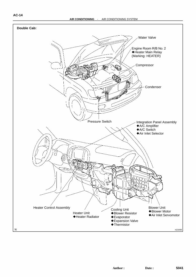
Double Cab:
Engine Room R/B No. 2 Heater Main Relay(Marking: HEATER)
Compressor
Condenser
Pressure Switch Integration Panel Assembly A/C Amplifier A/C Switch Air Inlet Selector
Heater Control Assembly
Heater Unit Heater Radiator
Cooling Unit Blower Resistor Evaporator Expansion Valve Thermistor
Blower Unit Blower Motor Air Inlet Servomotor
Water Valve
AC-14-AIR CONDITIONING AIR CONDITIONING SYSTEM
5041Author: Date:
I11115
Sight Glass
AC22F-09
-AIR CONDITIONING AIR CONDITIONING SYSTEMAC-3
5030Author: Date:
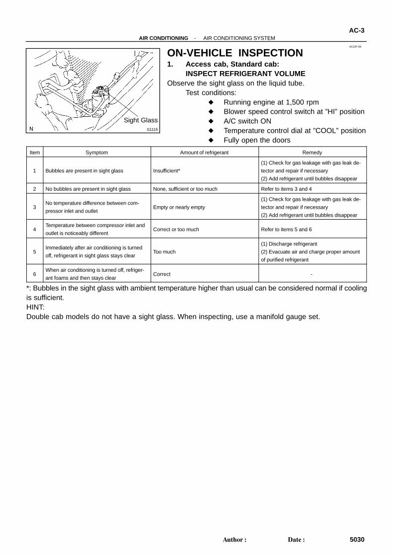
ON-VEHICLE INSPECTION1. Access cab, Standard cab:
INSPECT REFRIGERANT VOLUMEObserve the sight glass on the liquid tube.
Test conditions: Running engine at 1,500 rpm Blower speed control switch at ”HI” position A/C switch ON Temperature control dial at ”COOL” position Fully open the doors
Item Symptom Amount of refrigerant Remedy
1 Bubbles are present in sight glass Insufficient*
(1) Check for gas leakage with gas leak de-
tector and repair if necessary
(2) Add refrigerant until bubbles disappear
2 No bubbles are present in sight glass None, sufficient or too much Refer to items 3 and 4
3No temperature difference between com-
pressor inlet and outletEmpty or nearly empty
(1) Check for gas leakage with gas leak de-
tector and repair if necessary
(2) Add refrigerant until bubbles disappear
4Temperature between compressor inlet and
outlet is noticeably differentCorrect or too much Refer to items 5 and 6
5Immediately after air conditioning is turned
off, refrigerant in sight glass stays clearToo much
(1) Discharge refrigerant
(2) Evacuate air and charge proper amount
of purified refrigerant
6When air conditioning is turned off, refriger-
ant foams and then stays clearCorrect -
*: Bubbles in the sight glass with ambient temperature higher than usual can be considered normal if coolingis sufficient.HINT:Double cab models do not have a sight glass. When inspecting, use a manifold gauge set.
I01386
I01387
Condition : Periodically cools and then fails to cool
AC-4-AIR CONDITIONING AIR CONDITIONING SYSTEM
5031Author: Date:
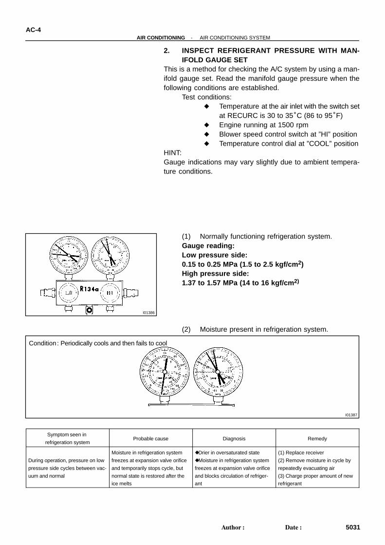
2. INSPECT REFRIGERANT PRESSURE WITH MAN-IFOLD GAUGE SET
This is a method for checking the A/C system by using a man-ifold gauge set. Read the manifold gauge pressure when thefollowing conditions are established.
Test conditions: Temperature at the air inlet with the switch set
at RECURC is 30 to 35°C (86 to 95°F) Engine running at 1500 rpm Blower speed control switch at ”HI” position Temperature control dial at ”COOL” position
HINT:Gauge indications may vary slightly due to ambient tempera-ture conditions.
(1) Normally functioning refrigeration system.Gauge reading:Low pressure side:0.15 to 0.25 MPa (1.5 to 2.5 kgf/cm 2)High pressure side:1.37 to 1.57 MPa (14 to 16 kgf/cm 2)
(2) Moisture present in refrigeration system.
Symptom seen in
refrigeration systemProbable cause Diagnosis Remedy
During operation, pressure on low
pressure side cycles between vac-
uum and normal
Moisture in refrigeration system
freezes at expansion valve orifice
and temporarily stops cycle, but
normal state is restored after the
ice melts
Drier in oversaturated state
Moisture in refrigeration system
freezes at expansion valve orifice
and blocks circulation of refriger-
ant
(1) Replace receiver
(2) Remove moisture in cycle by
repeatedly evacuating air
(3) Charge proper amount of new
refrigerant
I01388
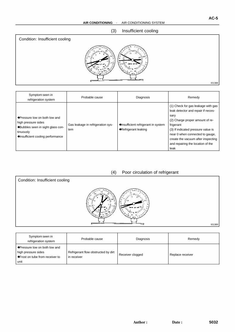
Condition: Insufficient cooling
I01389
Condition: Insufficient cooling
-AIR CONDITIONING AIR CONDITIONING SYSTEMAC-5
5032Author: Date:
(3) Insufficient cooling
Symptom seen in
refrigeration systemProbable cause Diagnosis Remedy
Pressure low on both low and
high pressure sides
Bubbles seen in sight glass con-
tinuously
Insufficient cooling performance
Gas leakage in refrigeration sys-
tem
Insufficient refrigerant in system
Refrigerant leaking
(1) Check for gas leakage with gas
leak detector and repair if neces-
sary
(2) Charge proper amount of re-
frigerant
(3) If indicated pressure value is
near 0 when connected to gauge,
create the vacuum after inspecting
and repairing the location of the
leak
(4) Poor circulation of refrigerant
Symptom seen in
refrigeration systemProbable cause Diagnosis Remedy
Pressure low on both low and
high pressure sides
Frost on tube from receiver to
unit
Refrigerant flow obstructed by dirt
in receiverReceiver clogged Replace receiver
I01449
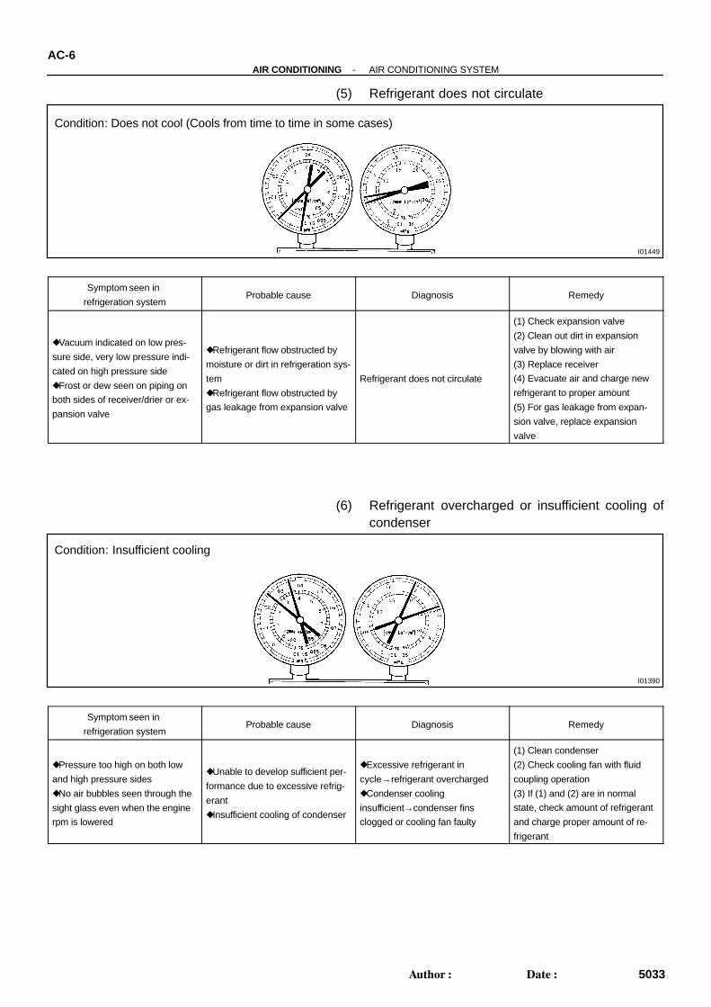
Condition: Does not cool (Cools from time to time in some cases)
I01390
Condition: Insufficient cooling
AC-6-AIR CONDITIONING AIR CONDITIONING SYSTEM
5033Author: Date:
(5) Refrigerant does not circulate
Symptom seen in
refrigeration systemProbable cause Diagnosis Remedy
Vacuum indicated on low pres-
sure side, very low pressure indi-
cated on high pressure side
Frost or dew seen on piping on
both sides of receiver/drier or ex-
pansion valve
Refrigerant flow obstructed by
moisture or dirt in refrigeration sys-
tem
Refrigerant flow obstructed by
gas leakage from expansion valve
Refrigerant does not circulate
(1) Check expansion valve
(2) Clean out dirt in expansion
valve by blowing with air
(3) Replace receiver
(4) Evacuate air and charge new
refrigerant to proper amount
(5) For gas leakage from expan-
sion valve, replace expansion
valve
(6) Refrigerant overcharged or insufficient cooling ofcondenser
Symptom seen in
refrigeration systemProbable cause Diagnosis Remedy
Pressure too high on both low
and high pressure sides
No air bubbles seen through the
sight glass even when the engine
rpm is lowered
Unable to develop sufficient per-
formance due to excessive refrig-
erant
Insufficient cooling of condenser
Excessive refrigerant in
cycle→refrigerant overcharged
Condenser cooling
insufficient→condenser fins
clogged or cooling fan faulty
(1) Clean condenser
(2) Check cooling fan with fluid
coupling operation
(3) If (1) and (2) are in normal
state, check amount of refrigerant
and charge proper amount of re-
frigerant
I01392
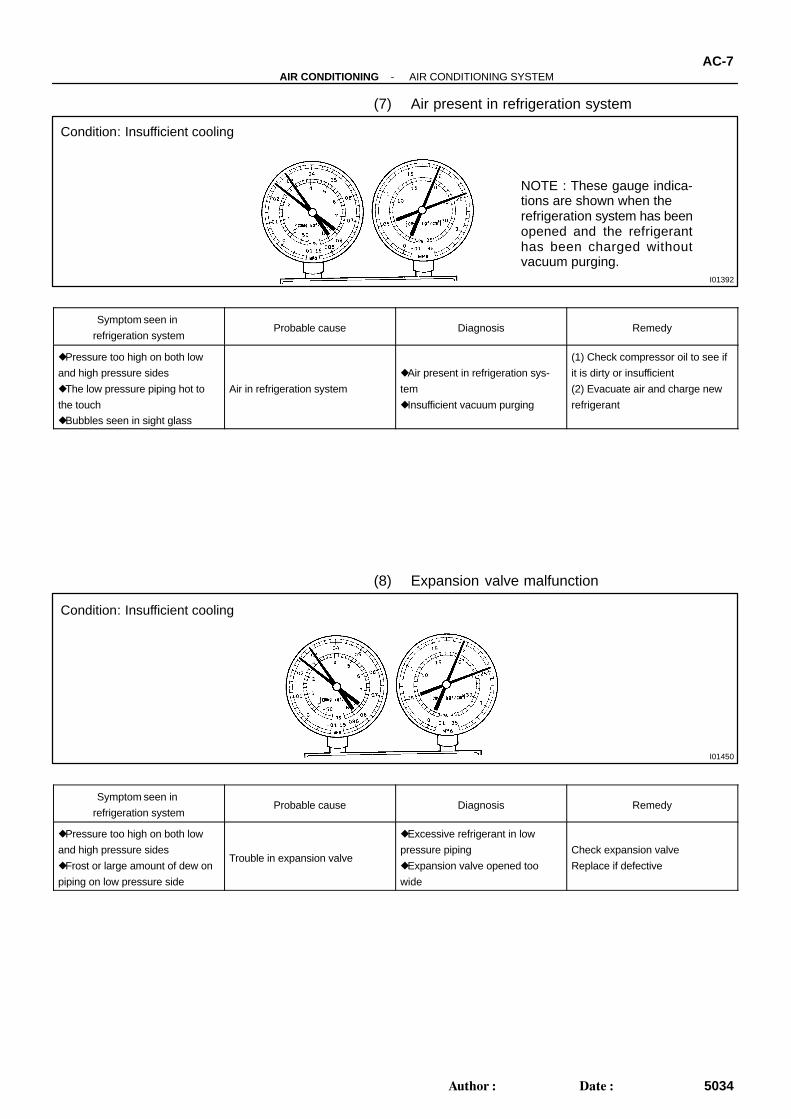
Condition: Insufficient cooling
NOTE : These gauge indica-tions are shown when therefrigeration system has beenopened and the refrigeranthas been charged withoutvacuum purging.
I01450
Condition: Insufficient cooling
-AIR CONDITIONING AIR CONDITIONING SYSTEMAC-7
5034Author: Date:
(7) Air present in refrigeration system
Symptom seen in
refrigeration systemProbable cause Diagnosis Remedy
Pressure too high on both low
and high pressure sides
The low pressure piping hot to
the touch
Bubbles seen in sight glass
Air in refrigeration system
Air present in refrigeration sys-
tem
Insufficient vacuum purging
(1) Check compressor oil to see if
it is dirty or insufficient
(2) Evacuate air and charge new
refrigerant
(8) Expansion valve malfunction
Symptom seen in
refrigeration systemProbable cause Diagnosis Remedy
Pressure too high on both low
and high pressure sides
Frost or large amount of dew on
piping on low pressure side
Trouble in expansion valve
Excessive refrigerant in low
pressure piping
Expansion valve opened too
wide
Check expansion valve
Replace if defective
I01393
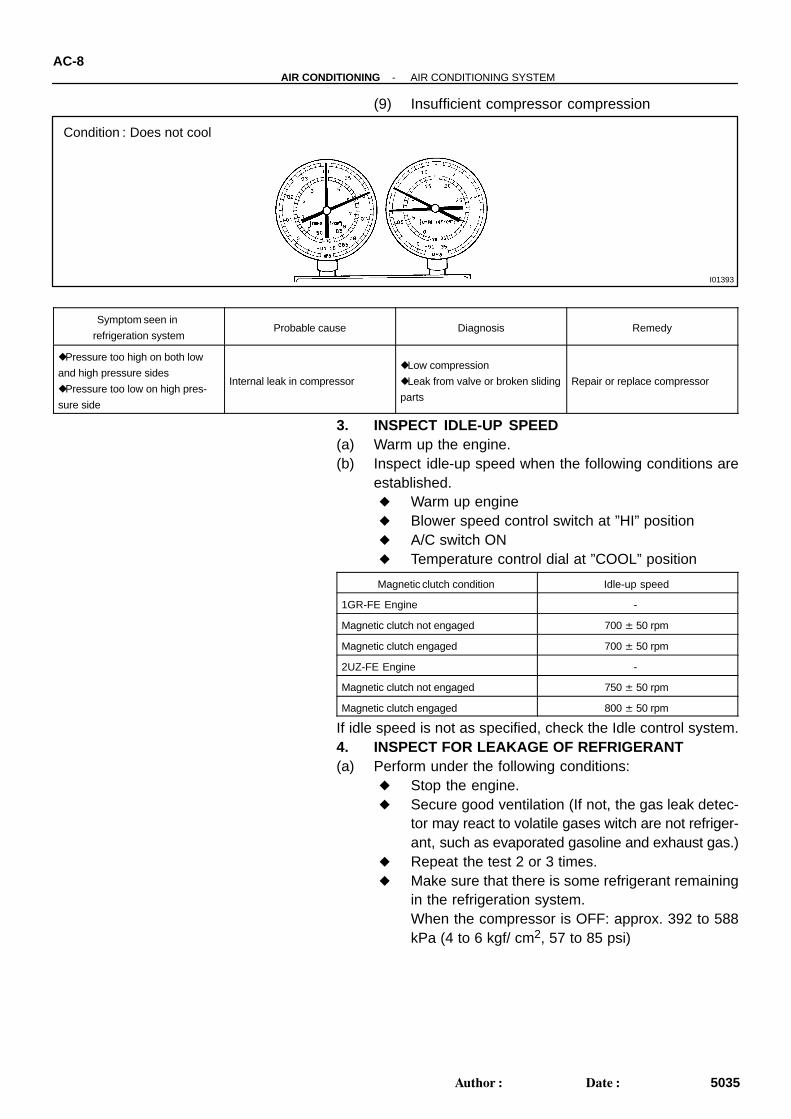
Condition : Does not cool
AC-8-AIR CONDITIONING AIR CONDITIONING SYSTEM
5035Author: Date:
(9) Insufficient compressor compression
Symptom seen in
refrigeration systemProbable cause Diagnosis Remedy
Pressure too high on both low
and high pressure sides
Pressure too low on high pres-
sure side
Internal leak in compressor
Low compression
Leak from valve or broken sliding
parts
Repair or replace compressor
3. INSPECT IDLE-UP SPEED(a) Warm up the engine.(b) Inspect idle-up speed when the following conditions are
established. Warm up engine Blower speed control switch at ”HI” position A/C switch ON Temperature control dial at ”COOL” position
Magnetic clutch condition Idle-up speed
1GR-FE Engine -
Magnetic clutch not engaged 700 ± 50 rpm
Magnetic clutch engaged 700 ± 50 rpm
2UZ-FE Engine -
Magnetic clutch not engaged 750 ± 50 rpm
Magnetic clutch engaged 800 ± 50 rpm
If idle speed is not as specified, check the Idle control system.4. INSPECT FOR LEAKAGE OF REFRIGERANT(a) Perform under the following conditions:
Stop the engine. Secure good ventilation (If not, the gas leak detec-
tor may react to volatile gases witch are not refriger-ant, such as evaporated gasoline and exhaust gas.)
Repeat the test 2 or 3 times. Make sure that there is some refrigerant remaining
in the refrigeration system.When the compressor is OFF: approx. 392 to 588kPa (4 to 6 kgf/ cm2, 57 to 85 psi)
-AIR CONDITIONING AIR CONDITIONING SYSTEMAC-9
5036Author: Date:
(b) Bring the gas leak detector close to the drain hose beforeperforming the test.
HINT: After the blower motor stopped, leave the cooling unit for
more than 15 minutes. Bring the gas leak detector sensor under the drain hose. When bringing the gas leak detector close to the drain
hose, make sure that the gas leak detector does not reactto the volatile gases.
If such reaction is unavoidable, the vehicle must be lifted up.(c) If gas leak is not detected on the drain hose, remove the
blower motor linear controller from the cooling unit. Theninsert the gas leak detector sensor into the unit and per-form the test.
(d) Disconnect the connector and leave the pressure switchfor approx. 20 minutes. Then bring the gas leak detectorclose to the pressure switch and perform the test.
(e) Bring the gas leak detector close to the refrigerant linesand perform the test.
AC2810
AC0C1-14
AC2811
N11084
Wrong Okay
HILO HILO
-AIR CONDITIONING AIR CONDITIONING SYSTEMAC-1
5028Author: Date:
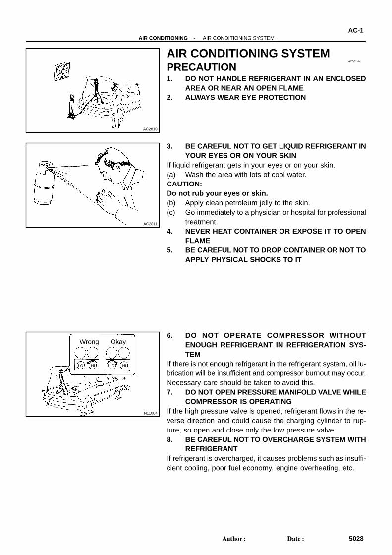
AIR CONDITIONING SYSTEMPRECAUTION1. DO NOT HANDLE REFRIGERANT IN AN ENCLOSED
AREA OR NEAR AN OPEN FLAME2. ALWAYS WEAR EYE PROTECTION
3. BE CAREFUL NOT TO GET LIQUID REFRIGERANT INYOUR EYES OR ON YOUR SKIN
If liquid refrigerant gets in your eyes or on your skin.(a) Wash the area with lots of cool water.CAUTION:Do not rub your eyes or skin.(b) Apply clean petroleum jelly to the skin.(c) Go immediately to a physician or hospital for professional
treatment.4. NEVER HEAT CONTAINER OR EXPOSE IT TO OPEN
FLAME5. BE CAREFUL NOT TO DROP CONTAINER OR NOT TO
APPLY PHYSICAL SHOCKS TO IT
6. DO NOT OPERATE COMPRESSOR WITHOUTENOUGH REFRIGERANT IN REFRIGERATION SYS-TEM
If there is not enough refrigerant in the refrigerant system, oil lu-brication will be insufficient and compressor burnout may occur.Necessary care should be taken to avoid this.7. DO NOT OPEN PRESSURE MANIFOLD VALVE WHILE
COMPRESSOR IS OPERATINGIf the high pressure valve is opened, refrigerant flows in the re-verse direction and could cause the charging cylinder to rup-ture, so open and close only the low pressure valve.8. BE CAREFUL NOT TO OVERCHARGE SYSTEM WITH
REFRIGERANTIf refrigerant is overcharged, it causes problems such as insuffi-cient cooling, poor fuel economy, engine overheating, etc.
AC-2-AIR CONDITIONING AIR CONDITIONING SYSTEM
5029Author: Date:
9. SUPPLEMENTAL RESTRAINT SYSTEM (SRS)The TOYOTA TUNDRA is equipped with an SRS (Supplemen-tal Restraint System) such as the driver and front passenger air-bags. Failure to carry out service operation in the correct se-quence could cause the SRS to unexpectedly deploy duringservicing, possibly leading to a serious accident. Before servic-ing (including removal or installation of parts, inspection or re-placement), be sure to read the precautionary notices in the RSsection.
I11143
AC3RY-02
I04551
2 1
I28079
2 1
I11143
-AIR CONDITIONING BLOWER MOTORAC-77
5104Author: Date:
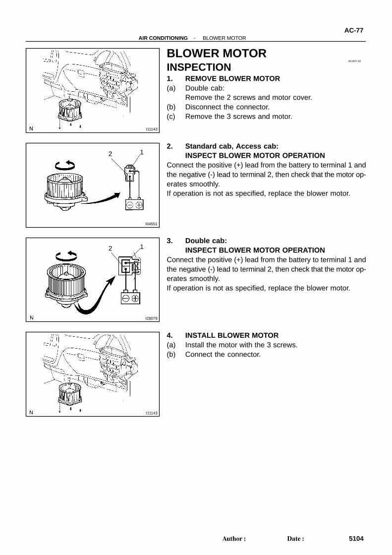
BLOWER MOTORINSPECTION1. REMOVE BLOWER MOTOR(a) Double cab:
Remove the 2 screws and motor cover.(b) Disconnect the connector.(c) Remove the 3 screws and motor.
2. Standard cab, Access cab:INSPECT BLOWER MOTOR OPERATION
Connect the positive (+) lead from the battery to terminal 1 andthe negative (-) lead to terminal 2, then check that the motor op-erates smoothly.If operation is not as specified, replace the blower motor.
3. Double cab:INSPECT BLOWER MOTOR OPERATION
Connect the positive (+) lead from the battery to terminal 1 andthe negative (-) lead to terminal 2, then check that the motor op-erates smoothly.If operation is not as specified, replace the blower motor.
4. INSTALL BLOWER MOTOR(a) Install the motor with the 3 screws.(b) Connect the connector.
AC23E-05
I11127
N09039
2 1
34
I11127
AC-78-AIR CONDITIONING BLOWER RESISTOR
5105Author: Date:
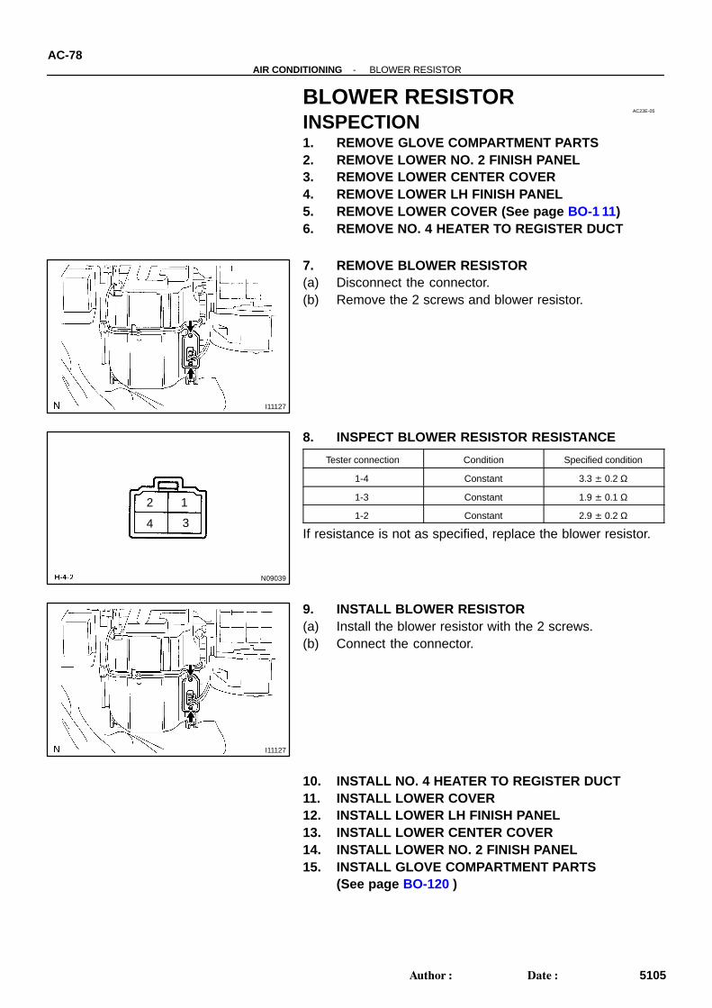
BLOWER RESISTORINSPECTION1. REMOVE GLOVE COMPARTMENT PARTS2. REMOVE LOWER NO. 2 FINISH PANEL3. REMOVE LOWER CENTER COVER4. REMOVE LOWER LH FINISH PANEL5. REMOVE LOWER COVER (See page BO-1 11)6. REMOVE NO. 4 HEATER TO REGISTER DUCT
7. REMOVE BLOWER RESISTOR(a) Disconnect the connector.(b) Remove the 2 screws and blower resistor.
8. INSPECT BLOWER RESISTOR RESISTANCE
Tester connection Condition Specified condition
1-4 Constant 3.3 ± 0.2 Ω
1-3 Constant 1.9 ± 0.1 Ω
1-2 Constant 2.9 ± 0.2 Ω
If resistance is not as specified, replace the blower resistor.
9. INSTALL BLOWER RESISTOR(a) Install the blower resistor with the 2 screws.(b) Connect the connector.
10. INSTALL NO. 4 HEATER TO REGISTER DUCT11. INSTALL LOWER COVER12. INSTALL LOWER LH FINISH PANEL13. INSTALL LOWER CENTER COVER14. INSTALL LOWER NO. 2 FINISH PANEL15. INSTALL GLOVE COMPARTMENT PARTS
(See page BO-120 )
AC3RW-02
I11132
I11157
I11178
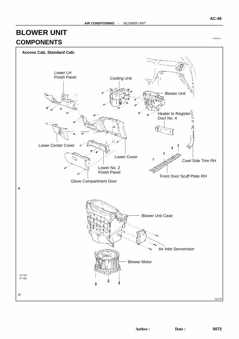
Lower LHFinish Panel Cooling Unit
Blower Unit
Lower Cover
Lower Center Cover
Heater to RegisterDuct No. 4
Cowl Side Trim RH
Front Door Scuff Plate RH
Lower No. 2Finish Panel
Glove Compartment Door
Blower Unit Case
Air Inlet Servomotor
Blower Motor
Access Cab, Standard Cab:
-AIR CONDITIONING BLOWER UNITAC-45
5072Author: Date:
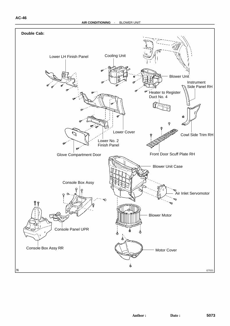
BLOWER UNITCOMPONENTS
I27021
Lower LH Finish Panel Cooling Unit
Blower Unit
Lower Cover
Heater to RegisterDuct No. 4
Cowl Side Trim RH
Lower No. 2Finish Panel
Glove Compartment Door
Air Inlet Servomotor
Blower Motor
Double Cab:
Blower Unit Case
Front Door Scuff Plate RH
Instrument Side Panel RH
Console Box Assy
Console Panel UPR
Console Box Assy RR Motor Cover
AC-46-AIR CONDITIONING BLOWER UNIT
5073Author: Date:
AC0CW-05
AC-48-AIR CONDITIONING BLOWER UNIT
5075Author: Date:
DISASSEMBLY1. REMOVE BLOWER MOTOR(a) Double cab:
Remove the 2 screws and motor cover.(b) Remove the 3 screws and blower motor.2. REMOVE AIR INLET SERVOMOTORRemove the 3 screws and servomotor.
I28077
To ”FRESH”
2
5
AC274-03
I28078
To ”RECIRC”1
5
-AIR CONDITIONING BLOWER UNITAC-49
5076Author: Date:
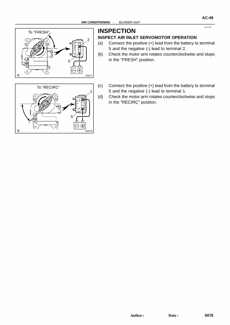
INSPECTIONINSPECT AIR INLET SERVOMOTOR OPERATION(a) Connect the positive (+) lead from the battery to terminal
5 and the negative (-) lead to terminal 2.(b) Check the motor arm rotates counterclockwise and stops
in the ”FRESH” position.
(c) Connect the positive (+) lead from the battery to terminal5 and the negative (-) lead to terminal 1.
(d) Check the motor arm rotates counterclockwise and stopsin the ”RECIRC” position.

AC0CX-02
-AIR CONDITIONING BLOWER UNITAC-51
5078Author: Date:
INSTALLATIONThe installation procedures are the removal procedures in reverse order (see page AC-47 ).

AC0CY-03
AC-50-AIR CONDITIONING BLOWER UNIT
5077Author: Date:
REASSEMBLYThe reassembly procedures are the disassembly procedures in reverse order (see page AC-48 ).
AC0CV-05
-AIR CONDITIONING BLOWER UNITAC-47
5074Author: Date:
REMOVAL1. REMOVE COOLING UNIT (See page AC-31 )2. REMOVE BLOWER UNIT(a) Double cab:
Remove the 2 screws and motor cover.(b) Disconnect the connector from the blower motor.(c) Disconnect the air inlet damper control cable from the blower unit.HINT:At the time of installation, refer to the following:After connection, adjust the control cable.(d) Remove the nut, bolt and blower unit.
AC3SE-01
I28952
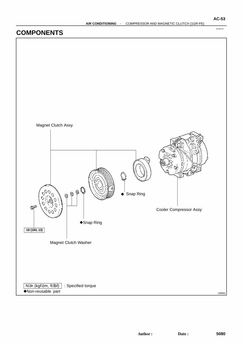
N⋅m (kgf⋅cm, ft⋅lbf) : Specified torqueNon-reusable part
Magnet Clutch Assy
Magnet Clutch Washer
Snap Ring
Cooler Compressor Assy
Snap Ring
18 (183, 13)
-AIR CONDITIONING COMPRESSOR AND MAGNETIC CLUTCH (1GR-FE)AC-53
5080Author: Date:
COMPONENTS
I28956
SST
AC3SG-01
E37447 I28957
E37448 I28958
-AIR CONDITIONING COMPRESSOR AND MAGNETIC CLUTCH (1GR-FE)AC-55
5082Author: Date:
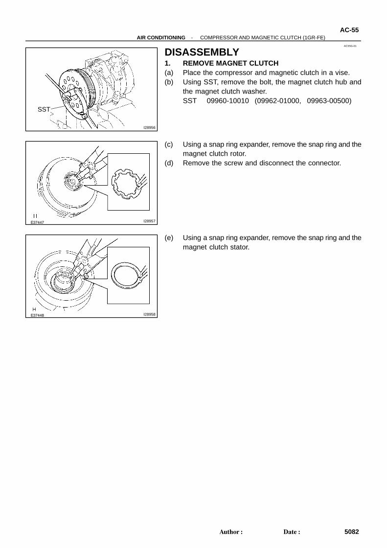
DISASSEMBLY1. REMOVE MAGNET CLUTCH(a) Place the compressor and magnetic clutch in a vise.(b) Using SST, remove the bolt, the magnet clutch hub and
the magnet clutch washer.SST 09960-10010 (09962-01000, 09963-00500)
(c) Using a snap ring expander, remove the snap ring and themagnet clutch rotor.
(d) Remove the screw and disconnect the connector.
(e) Using a snap ring expander, remove the snap ring and themagnet clutch stator.
I28955
AC3SI-01
I28954
I28953
AC-58-AIR CONDITIONING COMPRESSOR AND MAGNETIC CLUTCH (1GR-FE)
5085Author: Date:
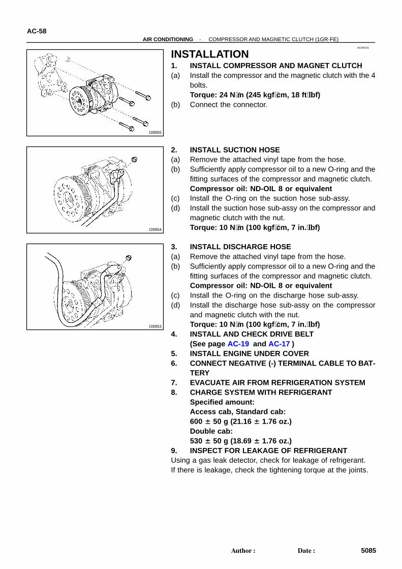
INSTALLATION1. INSTALL COMPRESSOR AND MAGNET CLUTCH(a) Install the compressor and the magnetic clutch with the 4
bolts.Torque: 24 N ⋅m (245 kgf ⋅cm, 18 ft ⋅lbf)
(b) Connect the connector.
2. INSTALL SUCTION HOSE(a) Remove the attached vinyl tape from the hose.(b) Sufficiently apply compressor oil to a new O-ring and the
fitting surfaces of the compressor and magnetic clutch.Compressor oil: ND-OIL 8 or equivalent
(c) Install the O-ring on the suction hose sub-assy.(d) Install the suction hose sub-assy on the compressor and
magnetic clutch with the nut.Torque: 10 N ⋅m (100 kgf ⋅cm, 7 in. ⋅lbf)
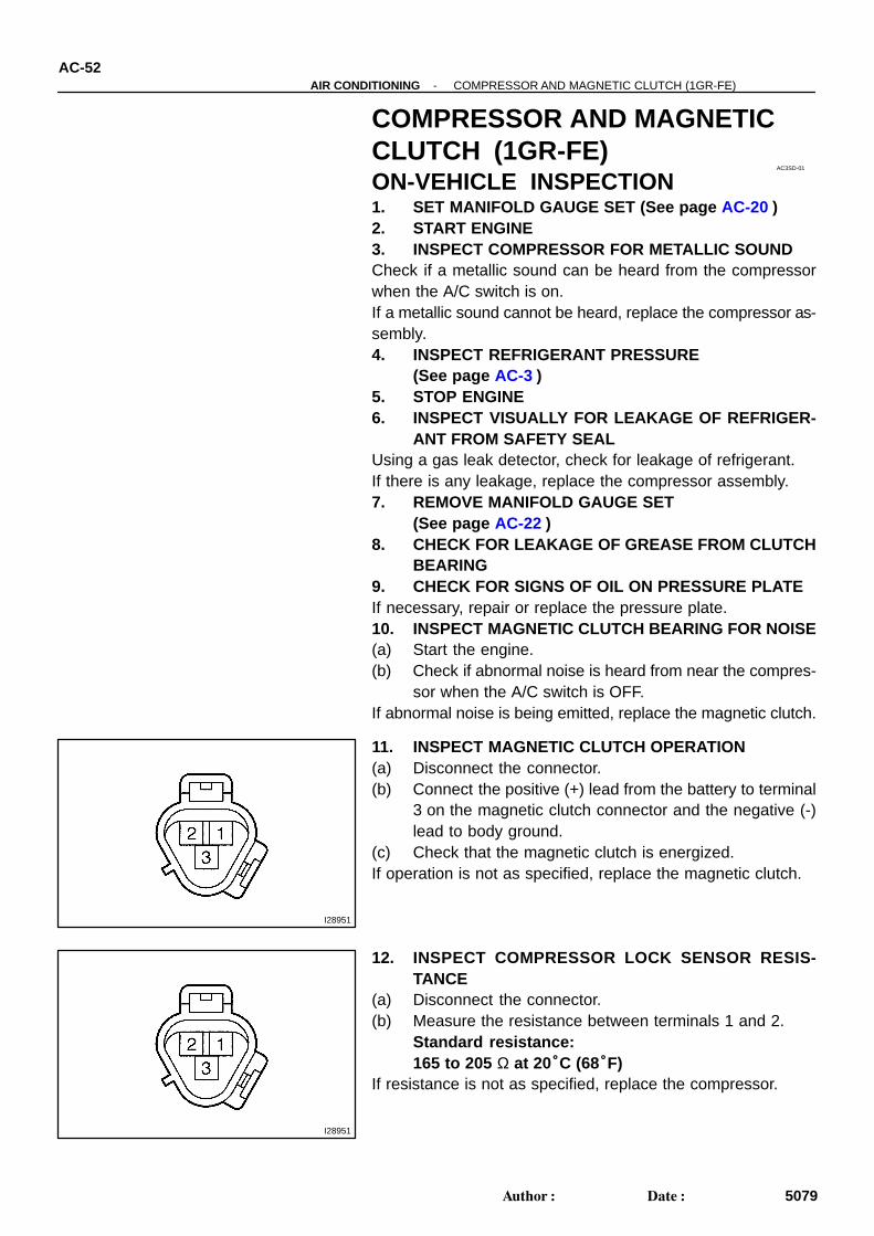
3. INSTALL DISCHARGE HOSE(a) Remove the attached vinyl tape from the hose.(b) Sufficiently apply compressor oil to a new O-ring and the
fitting surfaces of the compressor and magnetic clutch.Compressor oil: ND-OIL 8 or equivalent
(c) Install the O-ring on the discharge hose sub-assy.(d) Install the discharge hose sub-assy on the compressor
and magnetic clutch with the nut.Torque: 10 N ⋅m (100 kgf ⋅cm, 7 in. ⋅lbf)
4. INSTALL AND CHECK DRIVE BELT(See page AC-19 and AC-17 )
5. INSTALL ENGINE UNDER COVER6. CONNECT NEGATIVE (-) TERMINAL CABLE TO BAT-
TERY7. EVACUATE AIR FROM REFRIGERATION SYSTEM8. CHARGE SYSTEM WITH REFRIGERANT
Specified amount: Access cab, Standard cab:600 ± 50 g (21.16 ± 1.76 oz.)Double cab:530 ± 50 g (18.69 ± 1.76 oz.)
9. INSPECT FOR LEAKAGE OF REFRIGERANTUsing a gas leak detector, check for leakage of refrigerant.If there is leakage, check the tightening torque at the joints.
AC3SD-01
I28951
I28951
AC-52-AIR CONDITIONING COMPRESSOR AND MAGNETIC CLUTCH (1GR-FE)
5079Author: Date:
COMPRESSOR AND MAGNETICCLUTCH (1GR-FE)ON-VEHICLE INSPECTION1. SET MANIFOLD GAUGE SET (See page AC-20 )2. START ENGINE3. INSPECT COMPRESSOR FOR METALLIC SOUNDCheck if a metallic sound can be heard from the compressorwhen the A/C switch is on.If a metallic sound cannot be heard, replace the compressor as-sembly.4. INSPECT REFRIGERANT PRESSURE
(See page AC-3 )5. STOP ENGINE6. INSPECT VISUALLY FOR LEAKAGE OF REFRIGER-
ANT FROM SAFETY SEALUsing a gas leak detector, check for leakage of refrigerant.If there is any leakage, replace the compressor assembly.7. REMOVE MANIFOLD GAUGE SET
(See page AC-22 )8. CHECK FOR LEAKAGE OF GREASE FROM CLUTCH
BEARING9. CHECK FOR SIGNS OF OIL ON PRESSURE PLATEIf necessary, repair or replace the pressure plate.10. INSPECT MAGNETIC CLUTCH BEARING FOR NOISE(a) Start the engine.(b) Check if abnormal noise is heard from near the compres-
sor when the A/C switch is OFF.If abnormal noise is being emitted, replace the magnetic clutch.
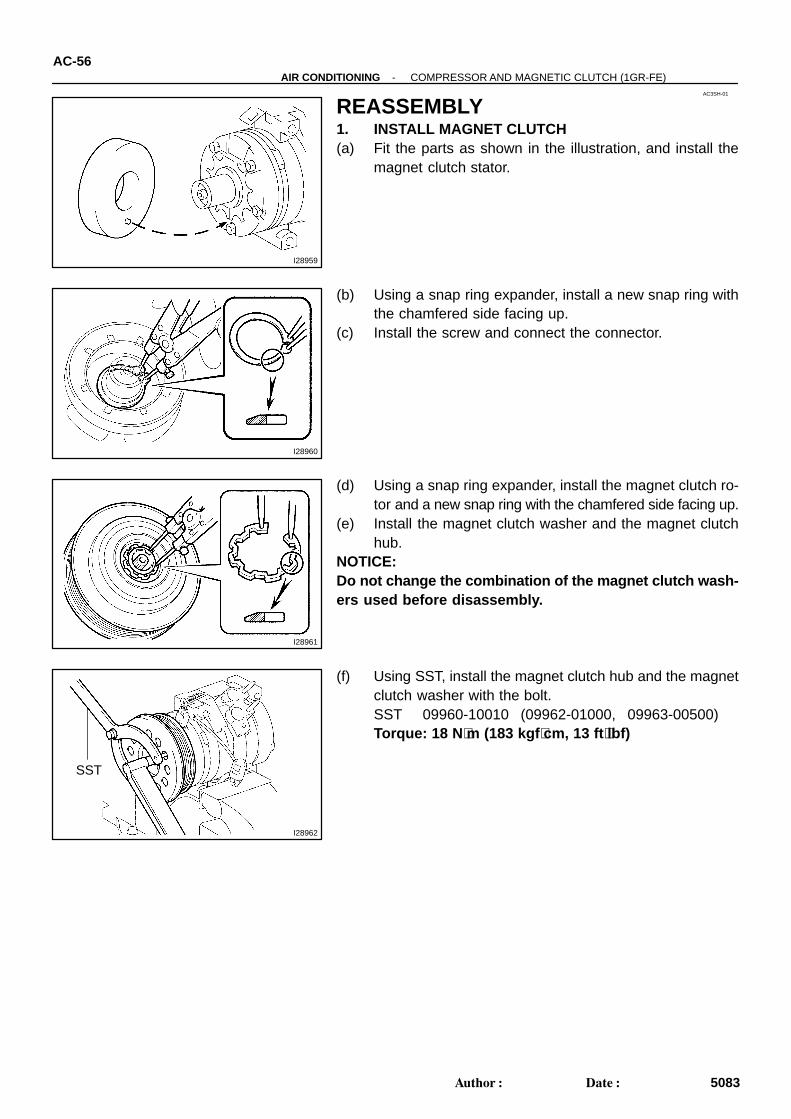
11. INSPECT MAGNETIC CLUTCH OPERATION(a) Disconnect the connector.(b) Connect the positive (+) lead from the battery to terminal
3 on the magnetic clutch connector and the negative (-)lead to body ground.
(c) Check that the magnetic clutch is energized.If operation is not as specified, replace the magnetic clutch.
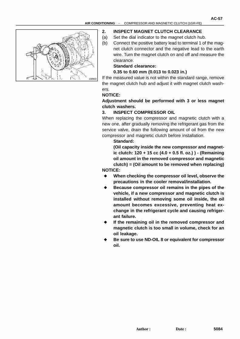
12. INSPECT COMPRESSOR LOCK SENSOR RESIS-TANCE
(a) Disconnect the connector.(b) Measure the resistance between terminals 1 and 2.
Standard resistance:165 to 205 Ω at 20°C (68°F)
If resistance is not as specified, replace the compressor.
I28959
AC3SH-01
I28960
I28961
I28962
SST
AC-56-AIR CONDITIONING COMPRESSOR AND MAGNETIC CLUTCH (1GR-FE)
5083Author: Date:
REASSEMBLY1. INSTALL MAGNET CLUTCH(a) Fit the parts as shown in the illustration, and install the
magnet clutch stator.
(b) Using a snap ring expander, install a new snap ring withthe chamfered side facing up.
(c) Install the screw and connect the connector.
(d) Using a snap ring expander, install the magnet clutch ro-tor and a new snap ring with the chamfered side facing up.
(e) Install the magnet clutch washer and the magnet clutchhub.
NOTICE:Do not change the combination of the magnet clutch wash-ers used before disassembly.
(f) Using SST, install the magnet clutch hub and the magnetclutch washer with the bolt.SST 09960-10010 (09962-01000, 09963-00500)Torque: 18 N ⋅m (183 kgf ⋅cm, 13 ft ⋅lbf)
I28963
-AIR CONDITIONING COMPRESSOR AND MAGNETIC CLUTCH (1GR-FE)AC-57
5084Author: Date:
2. INSPECT MAGNET CLUTCH CLEARANCE(a) Set the dial indicator to the magnet clutch hub.(b) Connect the positive battery lead to terminal 1 of the mag-
net clutch connector and the negative lead to the earthwire. Turn the magnet clutch on and off and measure theclearance.Standard clearance:0.35 to 0.60 mm (0.013 to 0.023 in.)
If the measured value is not within the standard range, removethe magnet clutch hub and adjust it with magnet clutch wash-ers.NOTICE:Adjustment should be performed with 3 or less magnetclutch washers.3. INSPECT COMPRESSOR OILWhen replacing the compressor and magnetic clutch with anew one, after gradually removing the refrigerant gas from theservice valve, drain the following amount of oil from the newcompressor and magnetic clutch before installation.
Standard:(Oil capacity inside the new compressor and magnet-ic clutch: 120 + 15 cc (4.0 + 0.5 fl. oz.) ) - (Remainingoil amount in the removed compressor and magneticclutch) = (Oil amount to be removed when replacing)
NOTICE: When checking the compressor oil level, observe the
precautions in the cooler removal/installation. Because compressor oil remains in the pipes of the
vehicle, if a new compressor and magnetic clutch isinstalled without removing some oil inside, the oilamount becomes e xcessive, preventing heat ex-change in the refrigerant cycle and causing refriger-ant failure.
If the remaining oil in the removed compressor andmagnetic clutch is too small in volume, check for anoil leakage.
Be sure to use ND-OIL 8 or equivalent for compressoroil.
AC3SF-01
I28953
I28954
I28955
AC-54-AIR CONDITIONING COMPRESSOR AND MAGNETIC CLUTCH (1GR-FE)
5081Author: Date:
REMOVAL1. RUN ENGINE AT IDLE SPEED WITH A/C ON FOR
APPROX. 10 MINUTES2. STOP ENGINE3. DISCONNECT NEGATIVE (- ) TERMINAL CABLE
FROM BATTERY4. DISCHARGE REFRIGERANT FROM REFRIGERATION
SYSTEM5. REMOVE ENGINE UNDER COVER
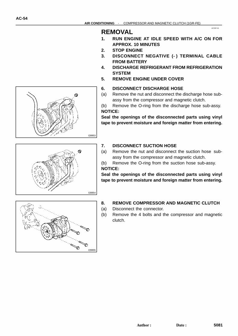
6. DISCONNECT DISCHARGE HOSE(a) Remove the nut and disconnect the discharge hose sub-
assy from the compressor and magnetic clutch.(b) Remove the O-ring from the discharge hose sub-assy.NOTICE:Seal the openings of the disconnected parts using vinyltape to prevent moisture and foreign matter from entering.
7. DISCONNECT SUCTION HOSE(a) Remove the nut and disconnect the suction hose sub-
assy from the compressor and magnetic clutch.(b) Remove the O-ring from the suction hose sub-assy.NOTICE:Seal the openings of the disconnected parts using vinyltape to prevent moisture and foreign matter from entering.
8. REMOVE COMPRESSOR AND MAGNETIC CLUTCH(a) Disconnect the connector.(b) Remove the 4 bolts and the compressor and magnetic
clutch.
AC3SK-01
I28850
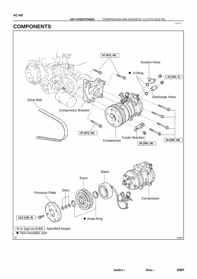
Suction Hose
O-Ring
Compressor Bracket
47 (475, 34)
47 (475, 34)
10 (100, 7)
Discharge Hose
Cooler BracketCompressor
Drive Belt
Stator
Rotor
Pressure PlateShim
Snap Ring
Compressor
N·m (kgf·cm,ft·lbf) Non-reusable part
: Specified torque
25 (250, 18)25 (250, 18)
13.2 (135, 9)
AC-60-AIR CONDITIONING COMPRESSOR AND MAGNETIC CLUTCH (2UZ-FE)
5087Author: Date:
COMPONENTS
AC0943
SST
AC3SM-01
AC0944
SST
AC0945
SST
AC0946
Shim
PressurePlate
AC0947
SST
AC-62-AIR CONDITIONING COMPRESSOR AND MAGNETIC CLUTCH (2UZ-FE)
5089Author: Date:
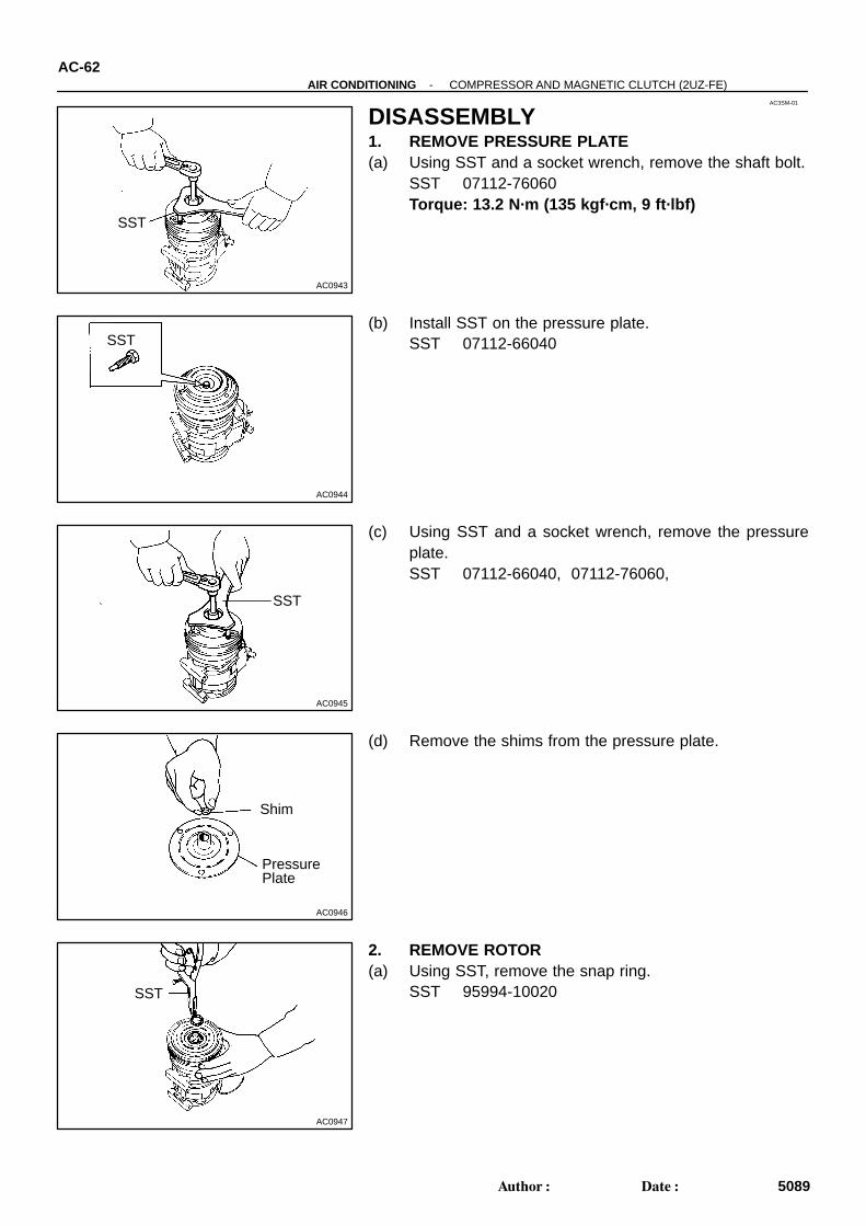
DISASSEMBLY1. REMOVE PRESSURE PLATE(a) Using SST and a socket wrench, remove the shaft bolt.
SST 07112-76060Torque: 13.2 N·m (135 kgf·cm, 9 ft·lbf)
(b) Install SST on the pressure plate.SST 07112-66040
(c) Using SST and a socket wrench, remove the pressureplate.SST 07112-66040, 07112-76060,
(d) Remove the shims from the pressure plate.
2. REMOVE ROTOR(a) Using SST, remove the snap ring.
SST 95994-10020
N20013
R-Shape Rotor
Snap Ring
Compressor
AC1743
AC1744
AC0950
SST
N20012
R-ShapeSnap Ring
Compressor
Stator
-AIR CONDITIONING COMPRESSOR AND MAGNETIC CLUTCH (2UZ-FE)AC-63
5090Author: Date:
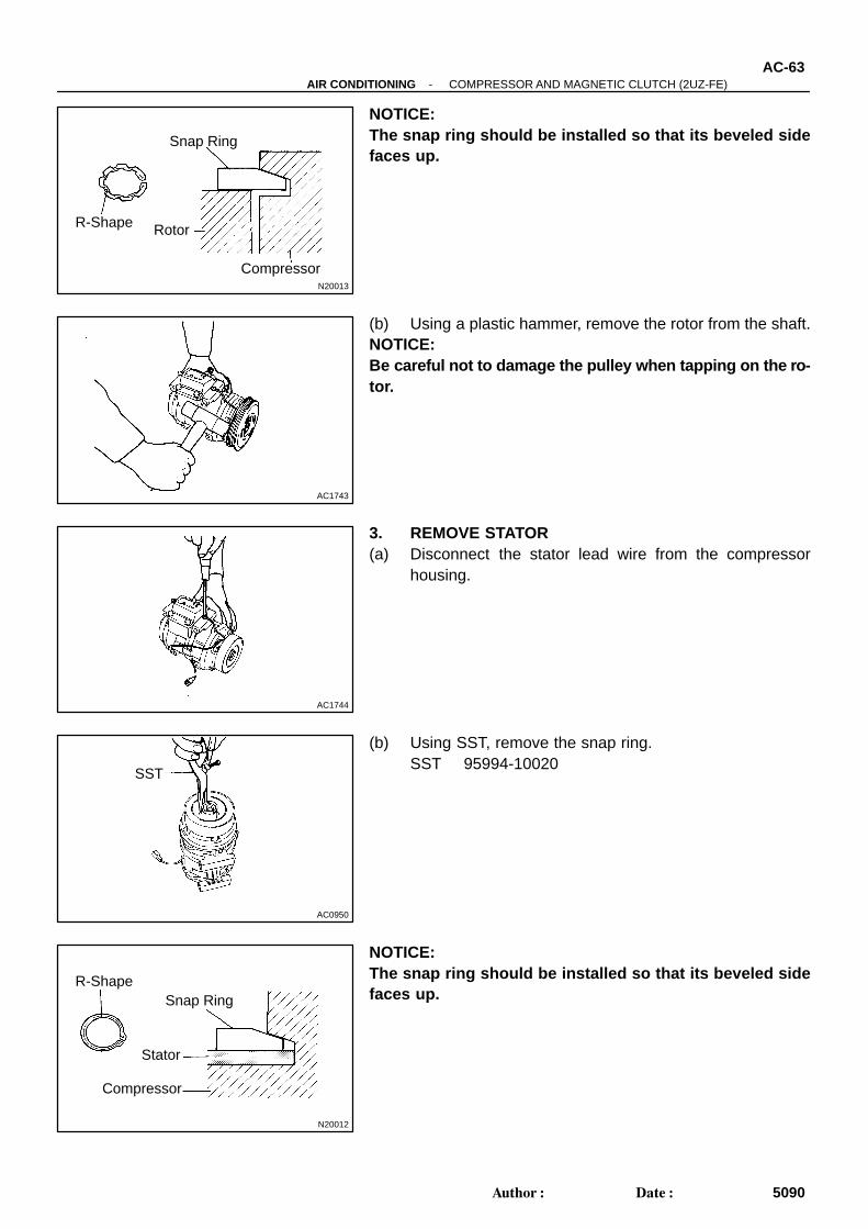
NOTICE:The snap ring should be installed so that its beveled sidefaces up.
(b) Using a plastic hammer, remove the rotor from the shaft.NOTICE:Be careful not to damage the pulley when tapping on the ro-tor.
3. REMOVE STATOR(a) Disconnect the stator lead wire from the compressor
housing.
(b) Using SST, remove the snap ring.SST 95994-10020
NOTICE:The snap ring should be installed so that its beveled sidefaces up.

AC0951
Stator
AC-64-AIR CONDITIONING COMPRESSOR AND MAGNETIC CLUTCH (2UZ-FE)
5091Author: Date:
(c) Remove the stator.
AC3SO-01
AC-66-AIR CONDITIONING COMPRESSOR AND MAGNETIC CLUTCH (2UZ-FE)
5093Author: Date:
INSTALLATION1. INSTALL COMPRESSOR(a) Install the compressor with the cooler bracket with the 4 bolts and nut.
Torque: 25 N·m (250 kgf·cm, 18 in.·lbf)(b) Connect the connector.2. CONNECT DISCHARGE AND SUCTION HOSESConnect both hoses with the 2 nuts.
Torque: 10 N·m (100 kgf·cm, 7 in.·lbf)NOTICE:Hoses should be connected immediately after the caps have been removed.HINT:Lubricate 2 new O-rings with compressor oil and install them to the hoses.3. INSTALL AND CHECK DRIVE BELT (See page AC-19 and AC-17 )4. CONNECT NEGATIVE (-) TERMINAL CABLE TO BATTERY5. EVACUATE AIR FROM REFRIGERATION SYSTEM6. CHARGE SYSTEM WITH REFRIGERANT
Specified amount: Access cab, Standard cab: 600 ± 50 g (21.16 ± 1.76 oz.)Double cab: 530 ± 50 g (18.69 ± 1.76 oz.)
7. INSPECT FOR LEAKAGE OF REFRIGERANTUsing a gas leak detector, check for leakage of refrigerant.If there is leakage, check the tightening torque at the joints.
AC3SJ-01
I11134
3
I11133
1
2
-AIR CONDITIONING COMPRESSOR AND MAGNETIC CLUTCH (2UZ-FE)AC-59
5086Author: Date:
COMPRESSOR AND MAGNETICCLUTCH (2UZ-FE)ON-VEHICLE INSPECTION1. SET MANIFOLD GAUGE SET (See page AC-20 )2. START ENGINE3. INSPECT COMPRESSOR FOR METALLIC SOUNDCheck if a metallic sound can be heard from the compressorwhen the A/C switch is on.If a metallic sound cannot be heard, replace the compressor as-sembly.4. INSPECT REFRIGERANT PRESSURE
(See page AC-3 )5. STOP ENGINE6. INSPECT VISUALLY FOR LEAKAGE OF REFRIGER-
ANT FROM SAFETY SEALUsing a gas leak detector, check for leakage of refrigerant.If there is any leakage, replace the compressor assembly.7. REMOVE MANIFOLD GAUGE SET
(See page AC-22 )8. CHECK FOR LEAKAGE OF GREASE FROM CLUTCH
BEARING9. CHECK FOR SIGNS OF OIL ON PRESSURE PLATEIf necessary, repair or replace.10. INSPECT MAGNETIC CLUTCH BEARING FOR NOISE(a) Start the engine.(b) Check if abnormal noise is heard from near the compres-
sor when the A/C switch is OFF.If abnormal noise is being emitted, replace the magnetic clutch.
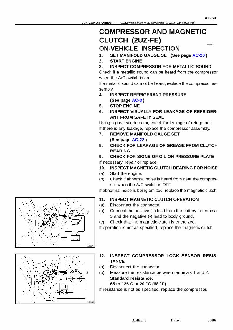
11. INSPECT MAGNETIC CLUTCH OPERATION(a) Disconnect the connector.(b) Connect the positive (+) lead from the battery to terminal
3 and the negative (-) lead to body ground.(c) Check that the magnetic clutch is energized.If operation is not as specified, replace the magnetic clutch.
12. INSPECT COMPRESSOR LOCK SENSOR RESIS-TANCE
(a) Disconnect the connector.(b) Measure the resistance between terminals 1 and 2.
Standard resistance:65 to 125 Ω at 20 °C (68 °F)
If resistance is not as specified, replace the compressor.
AC3SN-01
N04963
Dial Indicator
-AIR CONDITIONING COMPRESSOR AND MAGNETIC CLUTCH (2UZ-FE)AC-65
5092Author: Date:
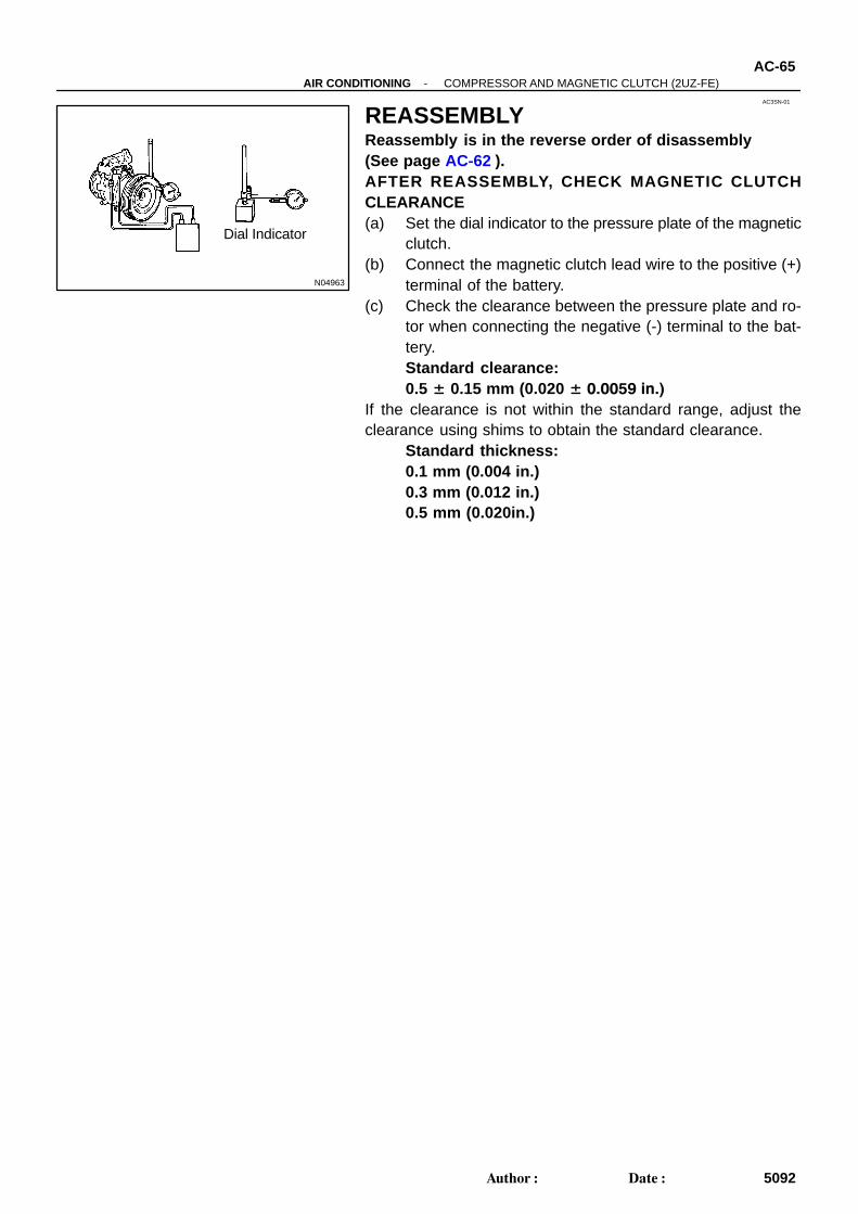
REASSEMBLYReassembly is in the reverse order of disassembly(See page AC-62 ).AFTER REASSEMBLY, CHECK MAGNETIC CLUTCHCLEARANCE(a) Set the dial indicator to the pressure plate of the magnetic
clutch.(b) Connect the magnetic clutch lead wire to the positive (+)
terminal of the battery.(c) Check the clearance between the pressure plate and ro-
tor when connecting the negative (-) terminal to the bat-tery.Standard clearance:0.5 ± 0.15 mm (0.020 ± 0.0059 in.)
If the clearance is not within the standard range, adjust theclearance using shims to obtain the standard clearance.
Standard thickness:0.1 mm (0.004 in.)0.3 mm (0.012 in.)0.5 mm (0.020in.)
AC3SL-01
-AIR CONDITIONING COMPRESSOR AND MAGNETIC CLUTCH (2UZ-FE)AC-61
5088Author: Date:
REMOVAL1. RUN ENGINE AT IDLE SPEED WITH A/C ON FOR APPROX. 10 MINUTES2. STOP ENGINE3. DISCONNECT NEGATIVE (-) TERMINAL CABLE FROM BATTERY4. DISCHARGE REFRIGERANT FROM REFRIGERATION SYSTEM5. DISCONNECT DISCHARGE AND SUCTION HOSESRemove the 2 nuts and disconnect both hoses.NOTICE:Cap the openings immediately to keep moisture or dirt out of the system.6. REMOVE DRIVE BELT (See page AC-18 )7. REMOVE COMPRESSOR(a) Disconnect the connector.(b) Remove the 4 bolts and nut.(c) Remove the cooler bracket.(d) Remove the compressor.
AC0DA-02
-AIR CONDITIONING CONDENSERAC-73
5100Author: Date:
INSTALLATIONThe installation procedures are the removal procedures in reverse order (see page AC-71 ).
AC0D8-01
AC-70-AIR CONDITIONING CONDENSER
5097Author: Date:
CONDENSERON-VEHICLE INSPECTION1. INSPECT CONDENSER FINS FOR BLOCKAGE OR DAMAGEIf the fins are clogged, wash them with water and dry with compressed air.NOTICE:Be careful not to damage the fins.If the fins are bent, straighten them with a screwdriver or pliers.2. INSPECT CONDENSER AND FITTINGS FOR LEAKAGEUsing a gas leak detector, check for leakage of refrigerant.If there is leakage, check the tightening torque at the joints.
AC3SP-01
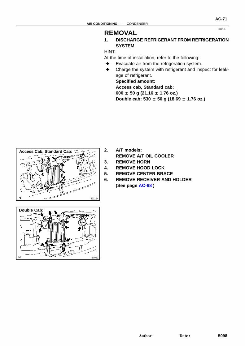
I11184
Access Cab, Standard Cab:
I27022
Double Cab:
-AIR CONDITIONING CONDENSERAC-71
5098Author: Date:
REMOVAL1. DISCHARGE REFRIGERANT FROM REFRIGERATION
SYSTEMHINT:At the time of installation, refer to the following: Evacuate air from the refrigeration system. Charge the system with refrigerant and inspect for leak-
age of refrigerant.Specified amount: Access cab, Standard cab: 600 ± 50 g (21.16 ± 1.76 oz.)Double cab: 530 ± 50 g (18.69 ± 1.76 oz.)
2. A/T models:REMOVE A/T OIL COOLER
3. REMOVE HORN4. REMOVE HOOD LOCK5. REMOVE CENTER BRACE6. REMOVE RECEIVER AND HOLDER
(See page AC-68 )
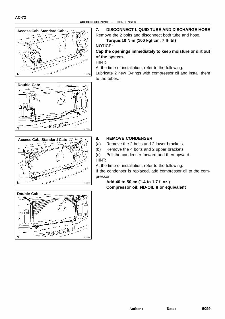
I11186
Access Cab, Standard Cab:
I27023
Double Cab:
I11187
Access Cab, Standard Cab:
I27024
Double Cab:
AC-72-AIR CONDITIONING CONDENSER
5099Author: Date:
7. DISCONNECT LIQUID TUBE AND DISCHARGE HOSERemove the 2 bolts and disconnect both tube and hose.
Torque:10 N·m (100 kgf·cm, 7 ft·lbf)NOTICE:Cap the openings immediately to keep moisture or dirt outof the system.HINT:At the time of installation, refer to the following:Lubricate 2 new O-rings with compressor oil and install themto the tubes.
8. REMOVE CONDENSER(a) Remove the 2 bolts and 2 lower brackets.(b) Remove the 4 bolts and 2 upper brackets.(c) Pull the condenser forward and then upward.HINT:At the time of installation, refer to the following:If the condenser is replaced, add compressor oil to the com-pressor.
Add 40 to 50 cc (1.4 to 1.7 fl.oz.)Compressor oil: ND-OIL 8 or equivalent
AC3RS-02
I28072
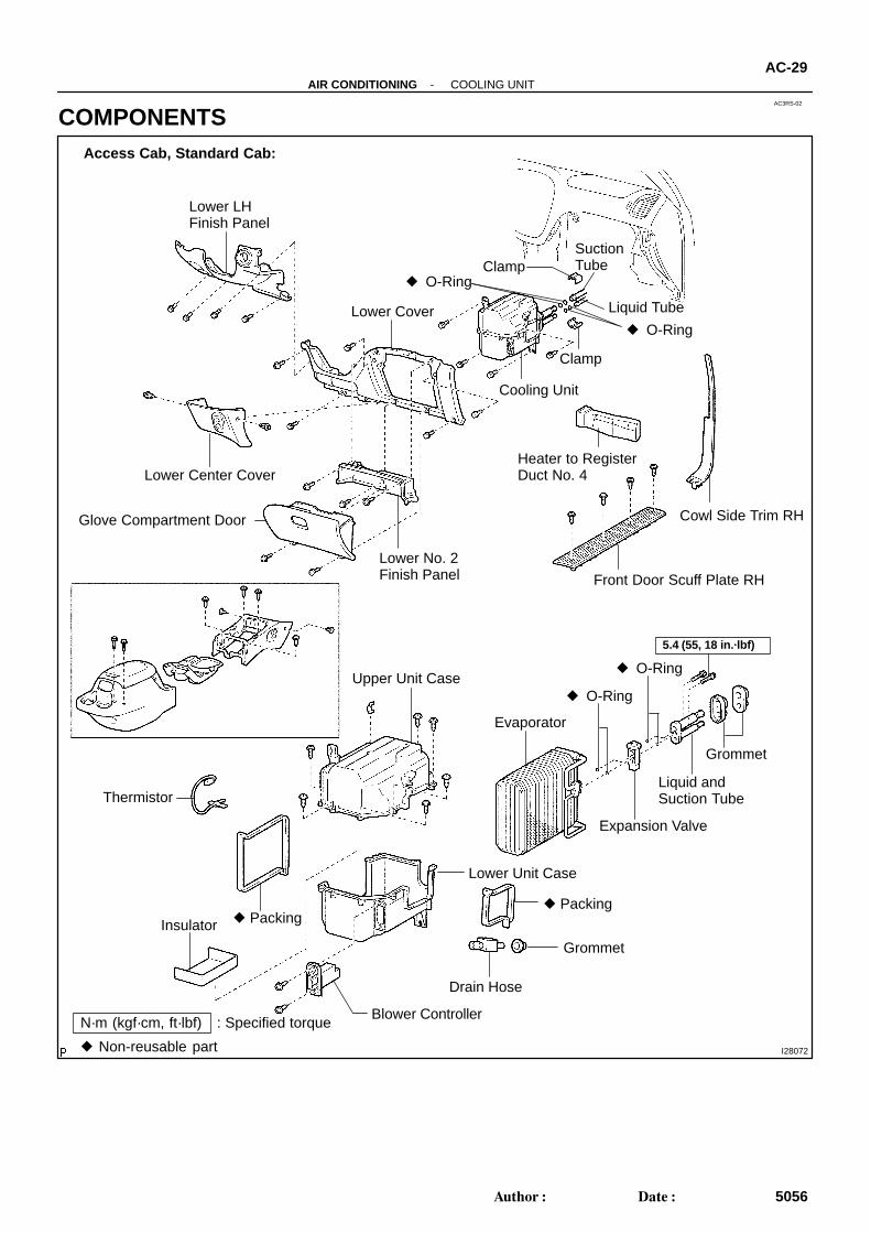
Lower LHFinish Panel
Lower Center Cover
Lower Cover
O-Ring
SuctionTube
Liquid Tube
O-Ring
Clamp
Cooling Unit
Heater to RegisterDuct No. 4
Cowl Side Trim RH
Front Door Scuff Plate RH
Lower No. 2Finish Panel
Glove Compartment Door
Upper Unit Case
Evaporator
Thermistor
5.4 (55, 18 in.·lbf)
Expansion Valve
O-Ring
Grommet
Liquid andSuction Tube
Drain Hose
Packing
Blower ControllerN·m (kgf·cm, ft·lbf) : Specified torque
Non-reusable part
PackingInsulator
Grommet
O-Ring
Lower Unit Case
Access Cab, Standard Cab:
Clamp
-AIR CONDITIONING COOLING UNITAC-29
5056Author: Date:
COMPONENTS
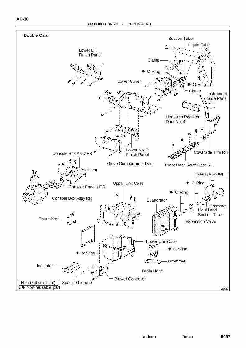
I27029
Lower LHFinish Panel
Lower Cover
O-Ring
Suction Tube
Liquid Tube
O-Ring
Clamp
Heater to RegisterDuct No. 4
Front Door Scuff Plate RH
Lower No. 2Finish Panel
Upper Unit Case
Evaporator
Thermistor
5.4 (55, 48 in.·lbf)
Expansion Valve
O-Ring
Grommet
Liquid andSuction Tube
Drain Hose
Packing
Blower ControllerN·m (kgf·cm, ft·lbf) : Specified torque Non-reusable part
Packing
Insulator
Grommet
O-Ring
Lower Unit Case
Instrument Side Panel RH
Cowl Side Trim RHConsole Box Assy FR
Console Panel UPR
Console Box Assy RR
Glove Compartment Door
Double Cab:
Clamp
AC-30-AIR CONDITIONING COOLING UNIT
5057Author: Date:
AC272-03
I28074
I28075
-AIR CONDITIONING COOLING UNITAC-33
5060Author: Date:
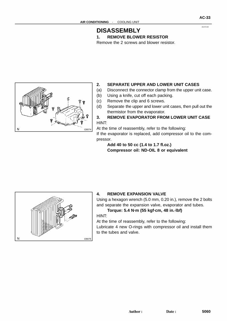
DISASSEMBLY1. REMOVE BLOWER RESISTORRemove the 2 screws and blower resistor.
2. SEPARATE UPPER AND LOWER UNIT CASES(a) Disconnect the connector clamp from the upper unit case.(b) Using a knife, cut off each packing.(c) Remove the clip and 6 screws.(d) Separate the upper and lower unit cases, then pull out the
thermistor from the evaporator.3. REMOVE EVAPORATOR FROM LOWER UNIT CASEHINT:At the time of reassembly, refer to the following:If the evaporator is replaced, add compressor oil to the com-pressor.
Add 40 to 50 cc (1.4 to 1.7 fl.oz.)Compressor oil: ND-OIL 8 or equivalent
4. REMOVE EXPANSION VALVEUsing a hexagon wrench (5.0 mm, 0.20 in.), remove the 2 boltsand separate the expansion valve, evaporator and tubes.
Torque: 5.4 N·m (55 kgf·cm, 48 in.·lbf)HINT:At the time of reassembly, refer to the following:Lubricate 4 new O-rings with compressor oil and install themto the tubes and valve.
AC22L-04
E50650
I28118
AC-34-AIR CONDITIONING COOLING UNIT
5061Author: Date:
INSPECTION1. CHECK EVAPORATOR FINS FOR BLOCKAGEIf the fins are clogged, clean them with compressed air.2. CHECK FITTING FOR CRACKS OR SCRATCHESIf necessary, repair or replace.
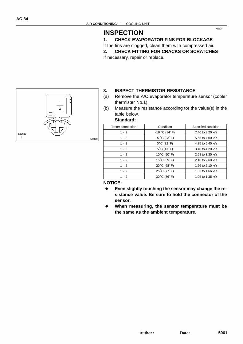
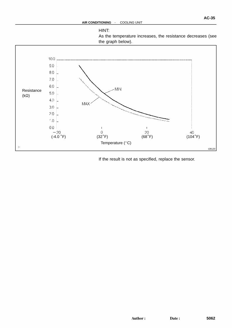
3. INSPECT THERMISTOR RESISTANCE(a) Remove the A/C evaporator temperature sensor (cooler
thermister No.1).(b) Measure the resistance according tor the value(s) in the
table below.Standard:
Tester connection Condition Specified condition
1 - 2 -10 °C (14°F) 7.40 to 9.20 kΩ
1 - 2 -5 °C (23°F) 5.65 to 7.00 kΩ
1 - 2 0°C (32°F) 4.35 to 5.40 kΩ
1 - 2 5°C (41°F) 3.40 to 4.20 kΩ
1 - 2 10°C (50°F) 2.68 to 3.30 kΩ
1 - 2 15°C (59°F) 2.10 to 2.60 kΩ
1 - 2 20°C (68°F) 1.66 to 2.10 kΩ
1 - 2 25°C (77°F) 1.32 to 1.66 kΩ
1 - 2 30°C (86°F) 1.05 to 1.35 kΩ
NOTICE: Even slightly touching the sensor may change the re-
sistance value. Be sure to hold the connector of thesensor.
When measuring, the sensor temperature must bethe same as the ambient temperature.
I28120
Temperature (C)
Resistance (kΩ)
(32°F) (68°F) (104°F)(-4.0 °F)
-AIR CONDITIONING COOLING UNITAC-35
5062Author: Date:
HINT:As the temperature increases, the resistance decreases (seethe graph below).
If the result is not as specified, replace the sensor.
AC0CJ-02
-AIR CONDITIONING COOLING UNITAC-37
5064Author: Date:
INSTALLATIONThe installation procedures are the removal procedures in reverse order (see page AC-31 ).
AC271-03
I11127
I11171
AC-28-AIR CONDITIONING COOLING UNIT
5055Author: Date:
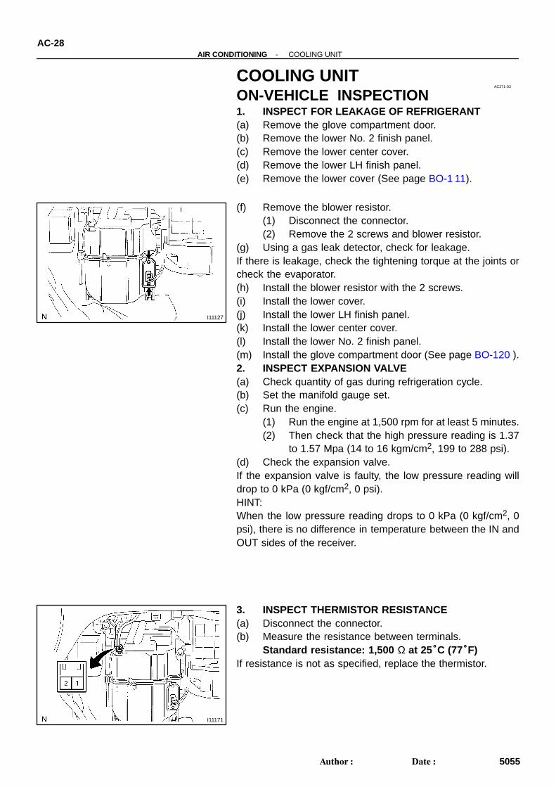
COOLING UNITON-VEHICLE INSPECTION1. INSPECT FOR LEAKAGE OF REFRIGERANT(a) Remove the glove compartment door.(b) Remove the lower No. 2 finish panel.(c) Remove the lower center cover.(d) Remove the lower LH finish panel.(e) Remove the lower cover (See page BO-1 11).
(f) Remove the blower resistor.(1) Disconnect the connector.(2) Remove the 2 screws and blower resistor.
(g) Using a gas leak detector, check for leakage.If there is leakage, check the tightening torque at the joints orcheck the evaporator.(h) Install the blower resistor with the 2 screws.(i) Install the lower cover.(j) Install the lower LH finish panel.(k) Install the lower center cover.(l) Install the lower No. 2 finish panel.(m) Install the glove compartment door (See page BO-120 ).2. INSPECT EXPANSION VALVE(a) Check quantity of gas during refrigeration cycle.(b) Set the manifold gauge set.(c) Run the engine.
(1) Run the engine at 1,500 rpm for at least 5 minutes.(2) Then check that the high pressure reading is 1.37
to 1.57 Mpa (14 to 16 kgm/cm2, 199 to 288 psi).(d) Check the expansion valve.If the expansion valve is faulty, the low pressure reading willdrop to 0 kPa (0 kgf/cm2, 0 psi).HINT:When the low pressure reading drops to 0 kPa (0 kgf/cm2, 0psi), there is no difference in temperature between the IN andOUT sides of the receiver.
3. INSPECT THERMISTOR RESISTANCE(a) Disconnect the connector.(b) Measure the resistance between terminals.
Standard resistance: 1,500 Ω at 25°C (77°F)If resistance is not as specified, replace the thermistor.
AC0CI-02
AC-36-AIR CONDITIONING COOLING UNIT
5063Author: Date:
REASSEMBLYThe reassembly procedures are the disassembly procedures in reverse order (see page AC-33 ).
AC3RT-02
I28855
I03838
SST
I03839
SSTPush
SST
Pull
ReleaseLever
-AIR CONDITIONING COOLING UNITAC-31
5058Author: Date:
REMOVAL1. DISCHARGE REFRIGERANT FROM REFRIGERATION
SYSTEMHINT:At the time of installation, refer to the following: Evacuate air from the refrigeration system. Charge system with refrigerant and inspect for leakage of
refrigerant.Specified amount: Access cab, Standard cab: 600 ± 50 g (21.16 ± 1.76 oz.)Double cab: 530 ± 50 g (18.69 ± 1.76 oz.)
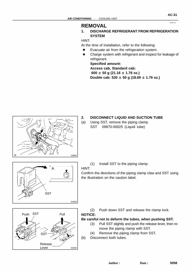
2. DISCONNECT LIQUID AND SUCTION TUBE(a) Using SST, remove the piping clamp.
SST 09870-00025 (Liquid tube)
(1) Install SST to the piping clamp.HINT:Confirm the directions of the piping clamp claw and SST usingthe illustration on the caution label.
(2) Push down SST and release the clamp lock.NOTICE:Be careful not to deform the tubes, when pushing SST.
(3) Pull SST slightly and push the release lever, then re-move the piping clamp with SST.
(4) Remove the piping clamp from SST.(b) Disconnect both tubes.
I06919
Disconnect the tube by hand
Screwdriver
Tube
I06878
Connect WrongGap
I11125
AC-32-AIR CONDITIONING COOLING UNIT
5059Author: Date:
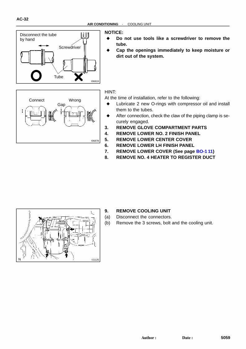
NOTICE: Do not use tools like a screwdriver to remove the
tube. Cap the openings immediately to keep moisture or
dirt out of the system.
HINT:At the time of installation, refer to the following: Lubricate 2 new O-rings with compressor oil and install
them to the tubes. After connection, check the claw of the piping clamp is se-
curely engaged.3. REMOVE GLOVE COMPARTMENT PARTS4. REMOVE LOWER NO. 2 FINISH PANEL5. REMOVE LOWER CENTER COVER6. REMOVE LOWER LH FINISH PANEL7. REMOVE LOWER COVER (See page BO-1 11)8. REMOVE NO. 4 HEATER TO REGISTER DUCT
9. REMOVE COOLING UNIT(a) Disconnect the connectors.(b) Remove the 3 screws, bolt and the cooling unit.
I28949
1GR-FE:
AC3SC-01
I28950
1GR-FE:P/S Pump
Water PumpIdler No.2
Generator
Tensioner
A/C CompressorIdler No.1
Crankshaft
Idler No.2
EM6656
2UZ-FE:
-AIR CONDITIONING DRIVE BELTAC-19
5046Author: Date:
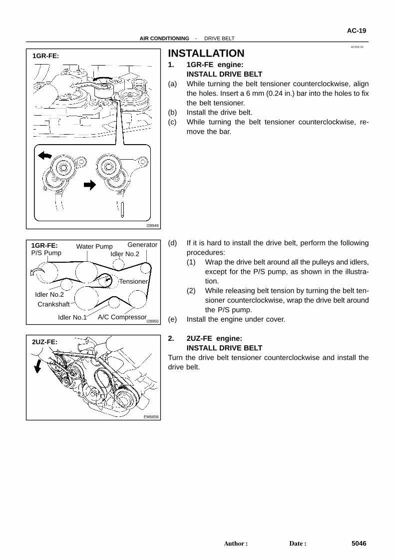
INSTALLATION1. 1GR-FE engine:
INSTALL DRIVE BELT(a) While turning the belt tensioner counterclockwise, align
the holes. Insert a 6 mm (0.24 in.) bar into the holes to fixthe belt tensioner.
(b) Install the drive belt.(c) While turning the belt tensioner counterclockwise, re-
move the bar.
(d) If it is hard to install the drive belt, perform the followingprocedures:(1) Wrap the drive belt around all the pulleys and idlers,
except for the P/S pump, as shown in the illustra-tion.
(2) While releasing belt tension by turning the belt ten-sioner counterclockwise, wrap the drive belt aroundthe P/S pump.
(e) Install the engine under cover.
2. 2UZ-FE engine:INSTALL DRIVE BELT
Turn the drive belt tensioner counterclockwise and install thedrive belt.
CH0086
Correct Wrong
AC3SB-01
B00808
2UZ-FE: AB
-AIR CONDITIONING DRIVE BELTAC-17
5044Author: Date:
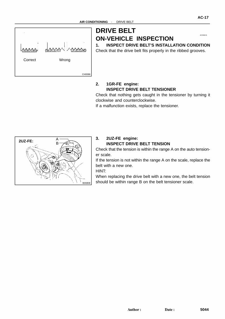
DRIVE BELTON-VEHICLE INSPECTION1. INSPECT DRIVE BELT’S INSTALLATION CONDITIONCheck that the drive belt fits properly in the ribbed grooves.
2. 1GR-FE engine:INSPECT DRIVE BELT TENSIONER
Check that nothing gets caught in the tensioner by turning itclockwise and counterclockwise.If a malfunction exists, replace the tensioner.
3. 2UZ-FE engine:INSPECT DRIVE BELT TENSION
Check that the tension is within the range A on the auto tension-er scale.If the tension is not within the range A on the scale, replace thebelt with a new one.HINT:When replacing the drive belt with a new one, the belt tensionshould be within range B on the belt tensioner scale.
I28948
1GR-FE:
AC26X-03
EM6656
2UZ-FE:
AC-18-AIR CONDITIONING DRIVE BELT
5045Author: Date:
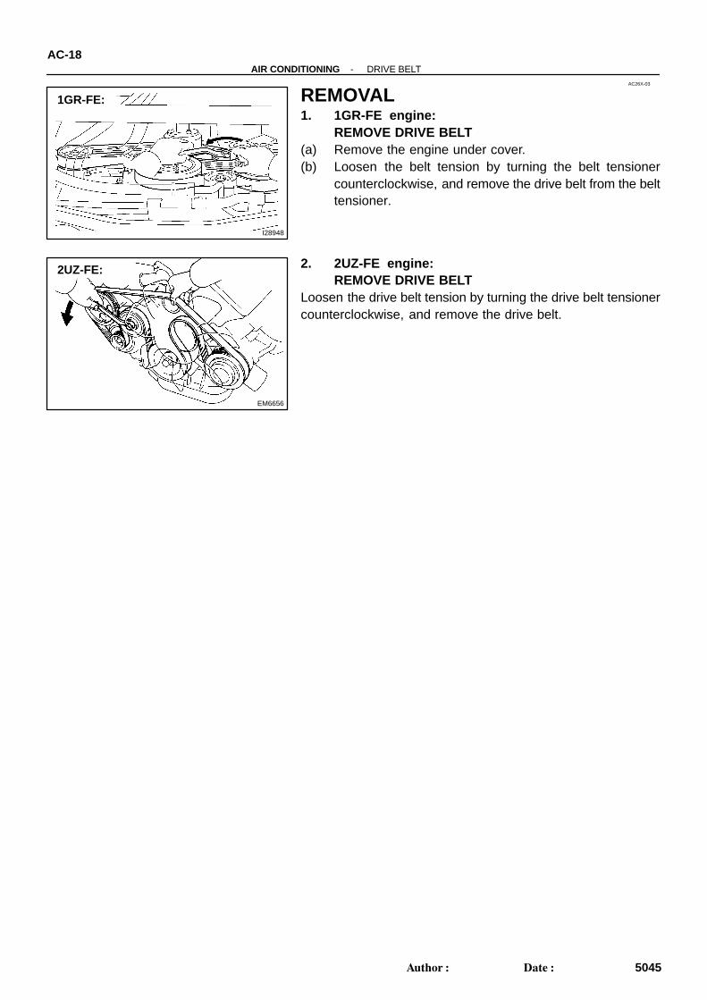
REMOVAL1. 1GR-FE engine:
REMOVE DRIVE BELT(a) Remove the engine under cover.(b) Loosen the belt tension by turning the belt tensioner
counterclockwise, and remove the drive belt from the belttensioner.
2. 2UZ-FE engine:REMOVE DRIVE BELT
Loosen the drive belt tension by turning the drive belt tensionercounterclockwise, and remove the drive belt.
AC06V-04
I11156
I11155
I11180
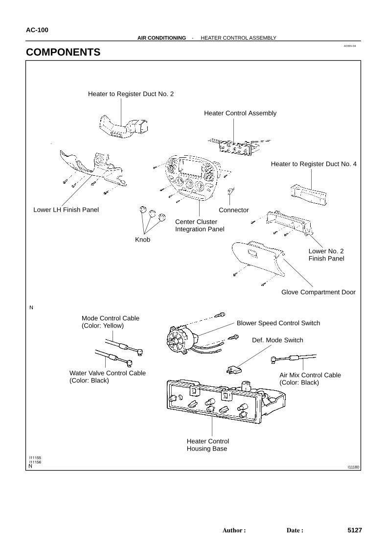
Heater Control Assembly
Connector
Center ClusterIntegration Panel
Knob
Mode Control Cable(Color: Yellow)
Water Valve Control Cable(Color: Black)
Blower Speed Control Switch
Air Mix Control Cable(Color: Black)
Heater ControlHousing Base
Def. Mode Switch
Heater to Register Duct No. 2
Lower LH Finish Panel
Heater to Register Duct No. 4
Lower No. 2 Finish Panel
Glove Compartment Door
AC-100-AIR CONDITIONING HEATER CONTROL ASSEMBLY
5127Author: Date:
COMPONENTS
AC27K-03
I11162
(a)
(b)
(c)
(a)
I11163
I11164
AC-102-AIR CONDITIONING HEATER CONTROL ASSEMBLY
5129Author: Date:
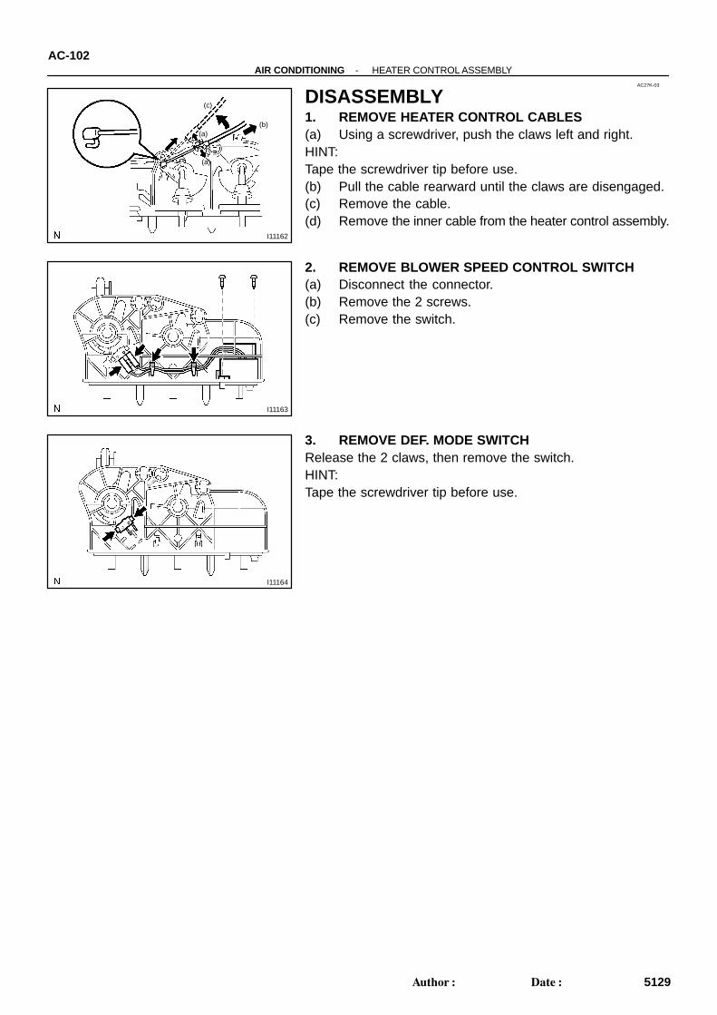
DISASSEMBLY1. REMOVE HEATER CONTROL CABLES(a) Using a screwdriver, push the claws left and right.HINT:Tape the screwdriver tip before use.(b) Pull the cable rearward until the claws are disengaged.(c) Remove the cable.(d) Remove the inner cable from the heater control assembly.
2. REMOVE BLOWER SPEED CONTROL SWITCH(a) Disconnect the connector.(b) Remove the 2 screws.(c) Remove the switch.
3. REMOVE DEF. MODE SWITCHRelease the 2 claws, then remove the switch.HINT:Tape the screwdriver tip before use.
I11165
OFFLO M1 M2
HI
AC27L-03
I11166
To ”DEF. or F/DEF.”
I11167
ONOFF
-AIR CONDITIONING HEATER CONTROL ASSEMBLYAC-103
5130Author: Date:
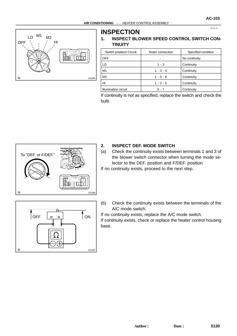
INSPECTION1. INSPECT BLOWER SPEED CONTROL SWITCH CON-
TINUITY
Switch position/ Circuit Tester connection Specified condition
OFF - No continuity
LO 1 - 3 Continuity
M1 1 - 3 - 4 Continuity
M2 1 - 3 - 8 Continuity
HI 1 - 3 - 5 Continuity
Illumination circuit 6 - 7 Continuity
If continuity is not as specified, replace the switch and check thebulb.
2. INSPECT DEF. MODE SWITCH(a) Check the continuity exists between terminals 1 and 3 of
the blower switch connector when turning the mode se-lector to the DEF. position and F/DEF. position.
If no continuity exists, proceed to the next step.
(b) Check the continuity exists between the terminals of theA/C mode switch.
If no continuity exists, replace the A/C mode switch.If continuity exists, check or replace the heater control housingbase.
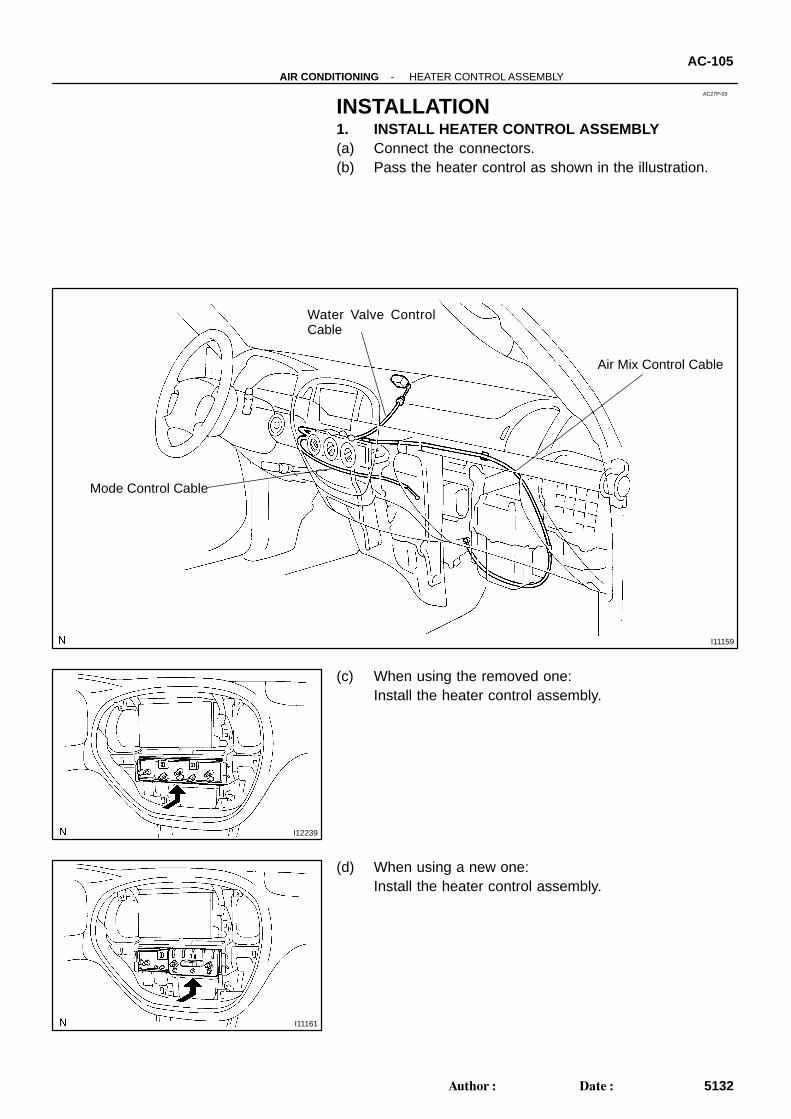
I11159
Mode Control Cable
Water Valve ControlCable
Air Mix Control Cable
AC27P-03
I12239
I11161
-AIR CONDITIONING HEATER CONTROL ASSEMBLYAC-105
5132Author: Date:
INSTALLATION1. INSTALL HEATER CONTROL ASSEMBLY(a) Connect the connectors.(b) Pass the heater control as shown in the illustration.
(c) When using the removed one:Install the heater control assembly.
(d) When using a new one:Install the heater control assembly.
I28081
To ”FACE”
I11169
To ”COOL”
I11170
To ”COOL”
AC-106-AIR CONDITIONING HEATER CONTROL ASSEMBLY
5133Author: Date:
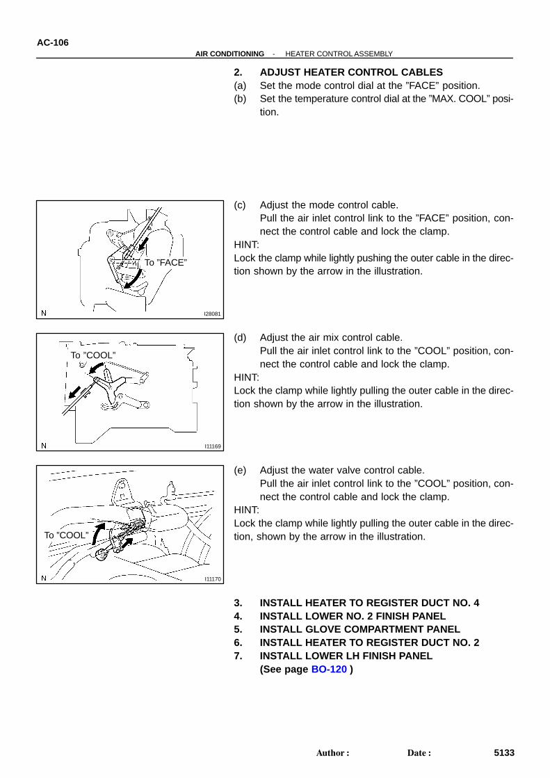
2. ADJUST HEATER CONTROL CABLES(a) Set the mode control dial at the ”FACE” position.(b) Set the temperature control dial at the ”MAX. COOL” posi-
tion.
(c) Adjust the mode control cable.Pull the air inlet control link to the ”FACE” position, con-nect the control cable and lock the clamp.
HINT:Lock the clamp while lightly pushing the outer cable in the direc-tion shown by the arrow in the illustration.
(d) Adjust the air mix control cable.Pull the air inlet control link to the ”COOL” position, con-nect the control cable and lock the clamp.
HINT:Lock the clamp while lightly pulling the outer cable in the direc-tion shown by the arrow in the illustration.
(e) Adjust the water valve control cable.Pull the air inlet control link to the ”COOL” position, con-nect the control cable and lock the clamp.
HINT:Lock the clamp while lightly pulling the outer cable in the direc-tion, shown by the arrow in the illustration.
3. INSTALL HEATER TO REGISTER DUCT NO. 44. INSTALL LOWER NO. 2 FINISH PANEL5. INSTALL GLOVE COMPARTMENT PANEL6. INSTALL HEATER TO REGISTER DUCT NO. 27. INSTALL LOWER LH FINISH PANEL
(See page BO-120 )
H111757 Clips
-AIR CONDITIONING HEATER CONTROL ASSEMBLYAC-107
5134Author: Date:
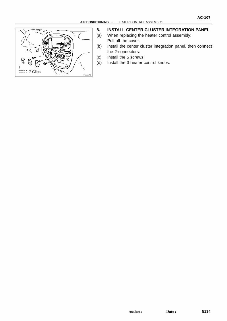
8. INSTALL CENTER CLUSTER INTEGRATION PANEL(a) When replacing the heater control assembly:
Pull off the cover.(b) Install the center cluster integration panel, then connect
the 2 connectors.(c) Install the 5 screws.(d) Install the 3 heater control knobs.
I11154
AC27J-03
-AIR CONDITIONING HEATER CONTROL ASSEMBLYAC-99
5126Author: Date:
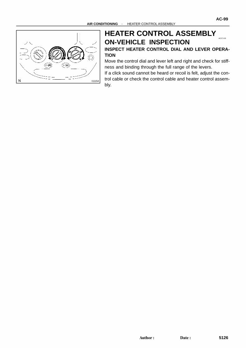
HEATER CONTROL ASSEMBLYON-VEHICLE INSPECTIONINSPECT HEATER CONTROL DIAL AND LEVER OPERA-TIONMove the control dial and lever left and right and check for stiff-ness and binding through the full range of the levers.If a click sound cannot be heard or recoil is felt, adjust the con-trol cable or check the control cable and heater control assem-bly.
I11164
AC27M-03
I11163
AC-104-AIR CONDITIONING HEATER CONTROL ASSEMBLY
5131Author: Date:
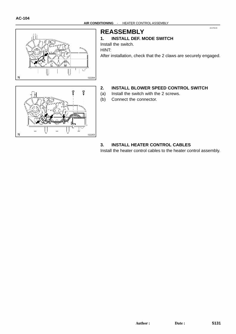
REASSEMBLY1. INSTALL DEF. MODE SWITCHInstall the switch.HINT:After installation, check that the 2 claws are securely engaged.
2. INSTALL BLOWER SPEED CONTROL SWITCH(a) Install the switch with the 2 screws.(b) Connect the connector.
3. INSTALL HEATER CONTROL CABLESInstall the heater control cables to the heater control assembly.
H111757 Clips
I28080
Mode Control Cable
Water Valve ControlCable
Air Mix Control Cable
AC27O-03
I11160
-AIR CONDITIONING HEATER CONTROL ASSEMBLYAC-101
5128Author: Date:
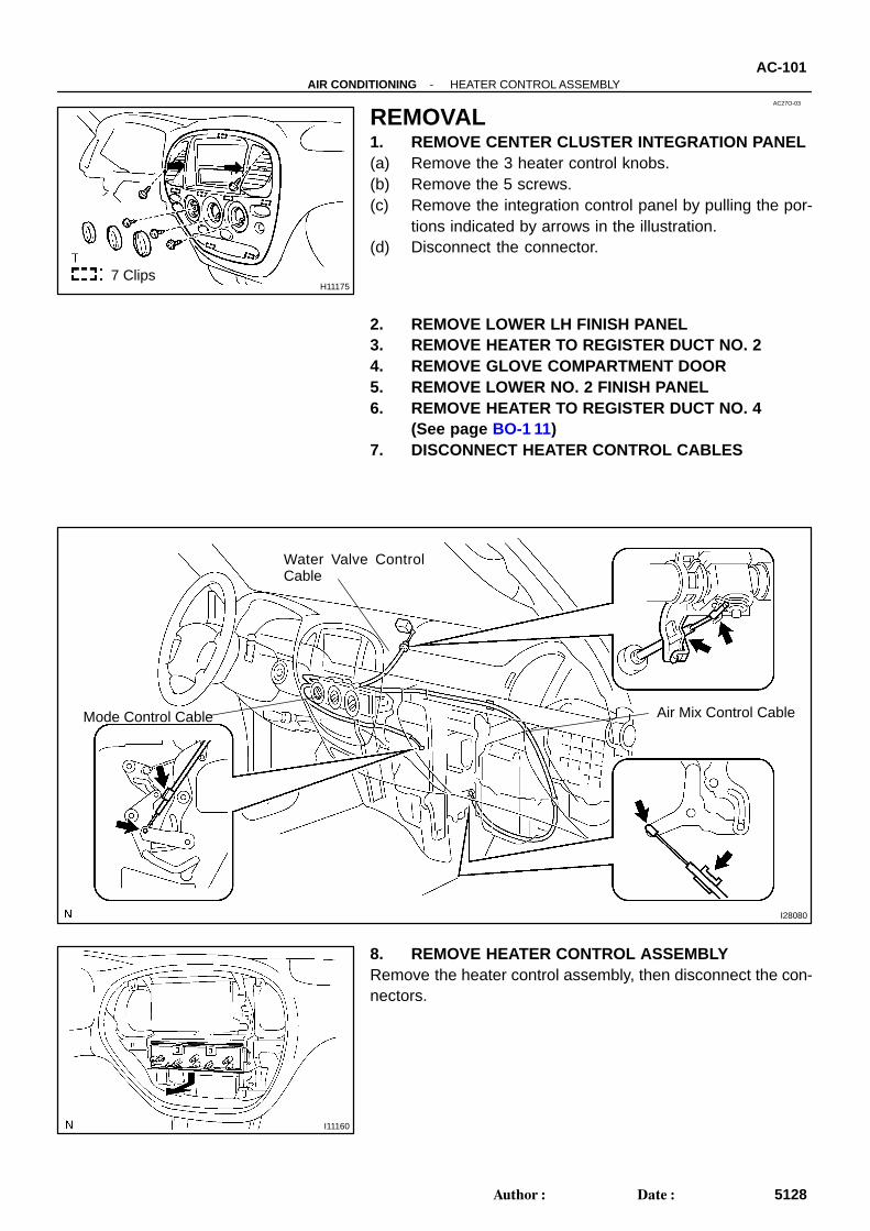
REMOVAL1. REMOVE CENTER CLUSTER INTEGRATION PANEL(a) Remove the 3 heater control knobs.(b) Remove the 5 screws.(c) Remove the integration control panel by pulling the por-
tions indicated by arrows in the illustration.(d) Disconnect the connector.
2. REMOVE LOWER LH FINISH PANEL3. REMOVE HEATER TO REGISTER DUCT NO. 24. REMOVE GLOVE COMPARTMENT DOOR5. REMOVE LOWER NO. 2 FINISH PANEL6. REMOVE HEATER TO REGISTER DUCT NO. 4
(See page BO-1 11)7. DISCONNECT HEATER CONTROL CABLES
8. REMOVE HEATER CONTROL ASSEMBLYRemove the heater control assembly, then disconnect the con-nectors.
AC3RU-02
I11128
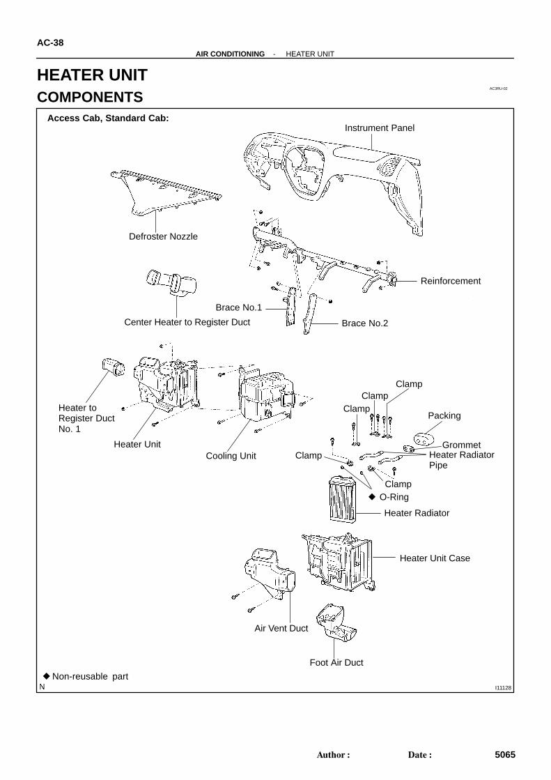
Non-reusable part
Instrument Panel
Reinforcement
Defroster Nozzle
Center Heater to Register Duct
Brace No.1
Brace No.2
Heater to Register Duct No. 1
Heater UnitCooling Unit
Heater Radiator
Foot Air Duct
Air Vent Duct
Heater Unit Case
O-RingClamp
GrommetHeater RadiatorPipe
Packing
ClampClamp
Clamp
Clamp
Access Cab, Standard Cab:
AC-38-AIR CONDITIONING HEATER UNIT
5065Author: Date:
HEATER UNITCOMPONENTS
I27019
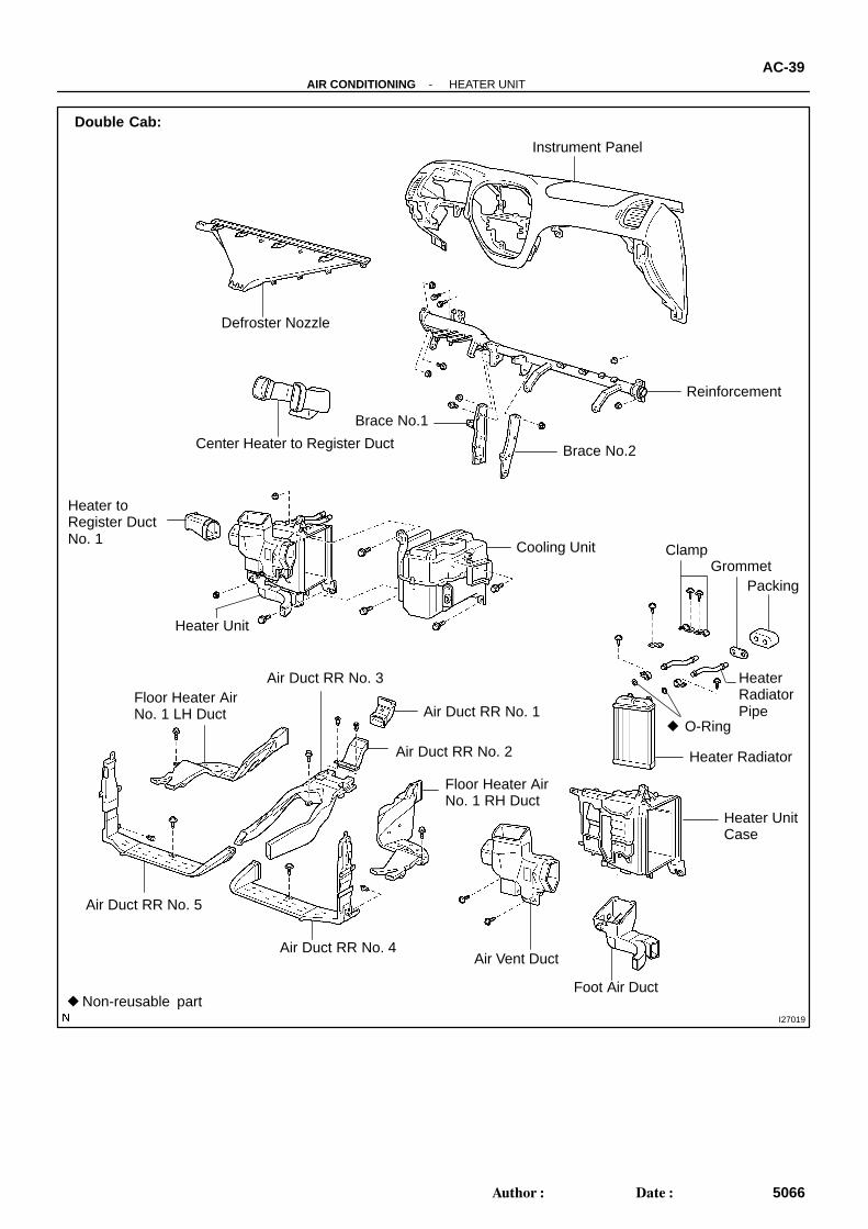
Non-reusable part
Instrument Panel
Reinforcement
Defroster Nozzle
Center Heater to Register Duct
Brace No.1
Brace No.2
Heater to Register Duct No. 1
Heater Unit
Cooling Unit
Heater Radiator
Air Vent Duct
Heater Unit Case
O-Ring
Grommet
Heater Radiator Pipe
Clamp
Double Cab:
Foot Air Duct
Packing
Floor Heater Air No. 1 LH Duct
Air Duct RR No. 3
Air Duct RR No. 1
Air Duct RR No. 2
Floor Heater Air No. 1 RH Duct
Air Duct RR No. 4
Air Duct RR No. 5
-AIR CONDITIONING HEATER UNITAC-39
5066Author: Date:
I28076
AC22M-05
-AIR CONDITIONING HEATER UNITAC-41
5068Author: Date:
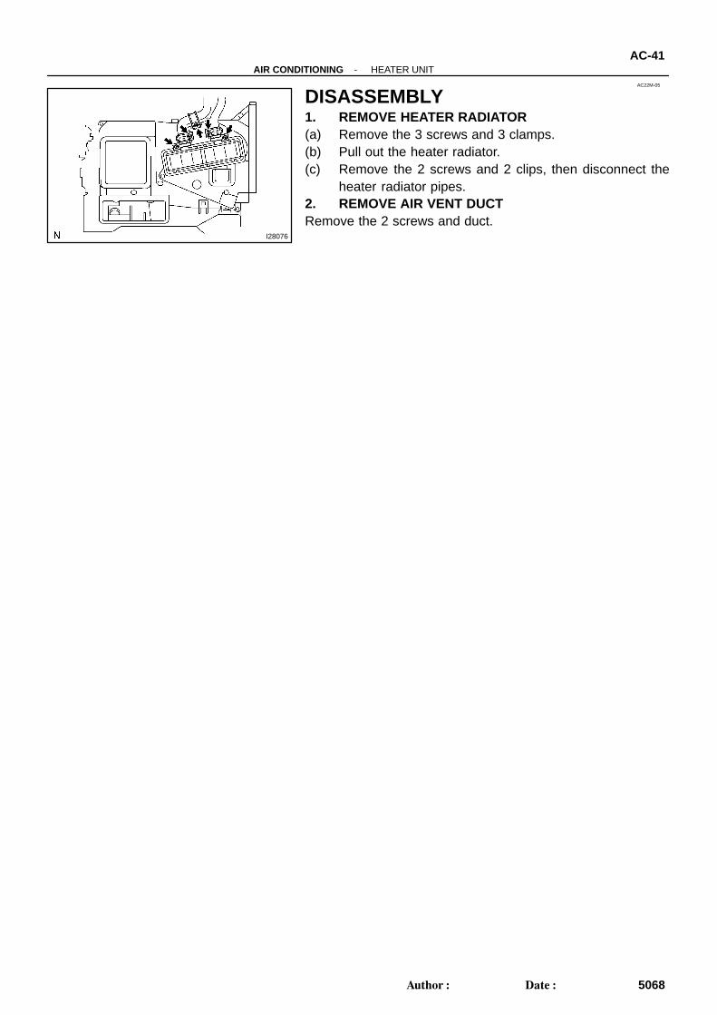
DISASSEMBLY1. REMOVE HEATER RADIATOR(a) Remove the 3 screws and 3 clamps.(b) Pull out the heater radiator.(c) Remove the 2 screws and 2 clips, then disconnect the
heater radiator pipes.2. REMOVE AIR VENT DUCTRemove the 2 screws and duct.
AC22N-02
AC-42-AIR CONDITIONING HEATER UNIT
5069Author: Date:
INSPECTIONINSPECT FINS FOR BLOCKAGEIf the fins are clogged, clean them with compressed air.

AC0CO-02
AC-44-AIR CONDITIONING HEATER UNIT
5071Author: Date:
INSTALLATIONThe installation procedures are the removal procedures in reverse order (see page AC-40 ).
AC0CN-02
-AIR CONDITIONING HEATER UNITAC-43
5070Author: Date:
REASSEMBLYThe reassembly procedures are the disassembly procedures in reverse order (see page AC-41 ).
AC3RV-02
I28830
I11197
Water Hose
Heater RadiatorPipe
Upper
LH RH
45 ± 10°LowerHose Clip
Second Ridge
LH RH
I11130
Access Cab, Standard Cab:
I27020
Double Cab:
AC-40-AIR CONDITIONING HEATER UNIT
5067Author: Date:
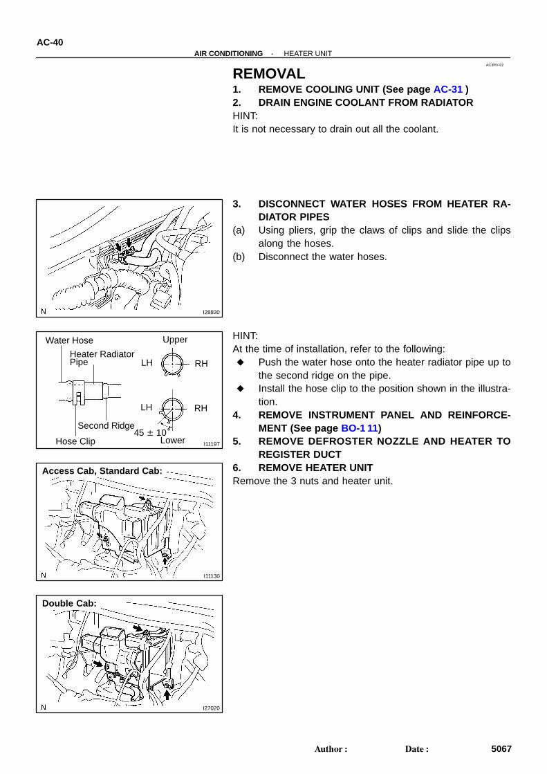
REMOVAL1. REMOVE COOLING UNIT (See page AC-31 )2. DRAIN ENGINE COOLANT FROM RADIATORHINT:It is not necessary to drain out all the coolant.
3. DISCONNECT WATER HOSES FROM HEATER RA-DIATOR PIPES
(a) Using pliers, grip the claws of clips and slide the clipsalong the hoses.
(b) Disconnect the water hoses.
HINT:At the time of installation, refer to the following: Push the water hose onto the heater radiator pipe up to
the second ridge on the pipe. Install the hose clip to the position shown in the illustra-
tion.4. REMOVE INSTRUMENT PANEL AND REINFORCE-
MENT (See page BO-1 11)5. REMOVE DEFROSTER NOZZLE AND HEATER TO
REGISTER DUCT6. REMOVE HEATER UNITRemove the 3 nuts and heater unit.
I28082
Heater Main RelayAC3RZ-02
I27025Heater Main Relay
Z19533
3 4 5
21
3 4 5
1 2
AC-82-AIR CONDITIONING HEATER MAIN RELAY
5109Author: Date:
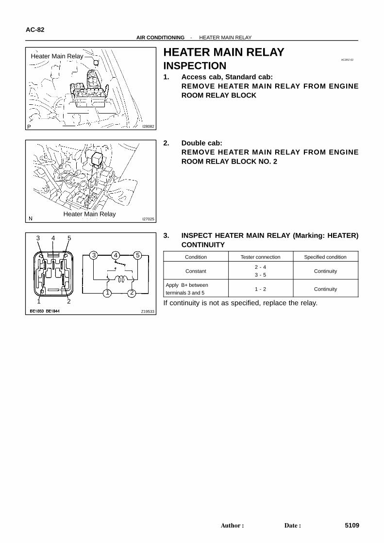
HEATER MAIN RELAYINSPECTION1. Access cab, Standard cab:
REMOVE HEATER MAIN RELAY FROM ENGINEROOM RELAY BLOCK
2. Double cab:REMOVE HEATER MAIN RELAY FROM ENGINEROOM RELAY BLOCK NO. 2
3. INSPECT HEATER MAIN RELAY (Marking: HEATER)CONTINUITY
Condition Tester connection Specified condition
Constant2 - 4
3 - 5Continuity
Apply B+ between
terminals 3 and 51 - 2 Continuity
If continuity is not as specified, replace the relay.
AC0CB-12
N06553
AC-22-AIR CONDITIONING MANIFOLD GAUGE SET
5049Author: Date:
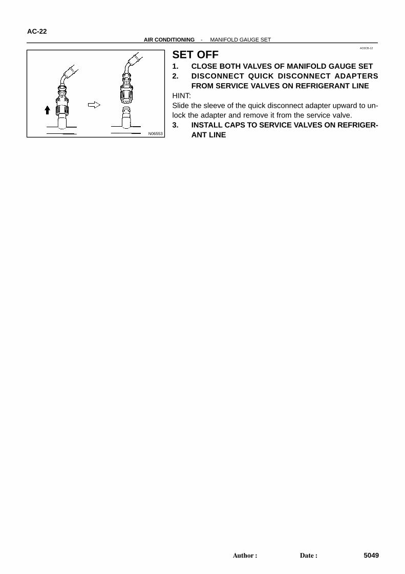
SET OFF1. CLOSE BOTH VALVES OF MANIFOLD GAUGE SET2. DISCONNECT QUICK DISCONNECT ADAPTERS
FROM SERVICE VALVES ON REFRIGERANT LINEHINT:Slide the sleeve of the quick disconnect adapter upward to un-lock the adapter and remove it from the service valve.3. INSTALL CAPS TO SERVICE VALVES ON REFRIGER-
ANT LINE
I28849
Low Pressure Charging Hose
High PressureCharging Hose
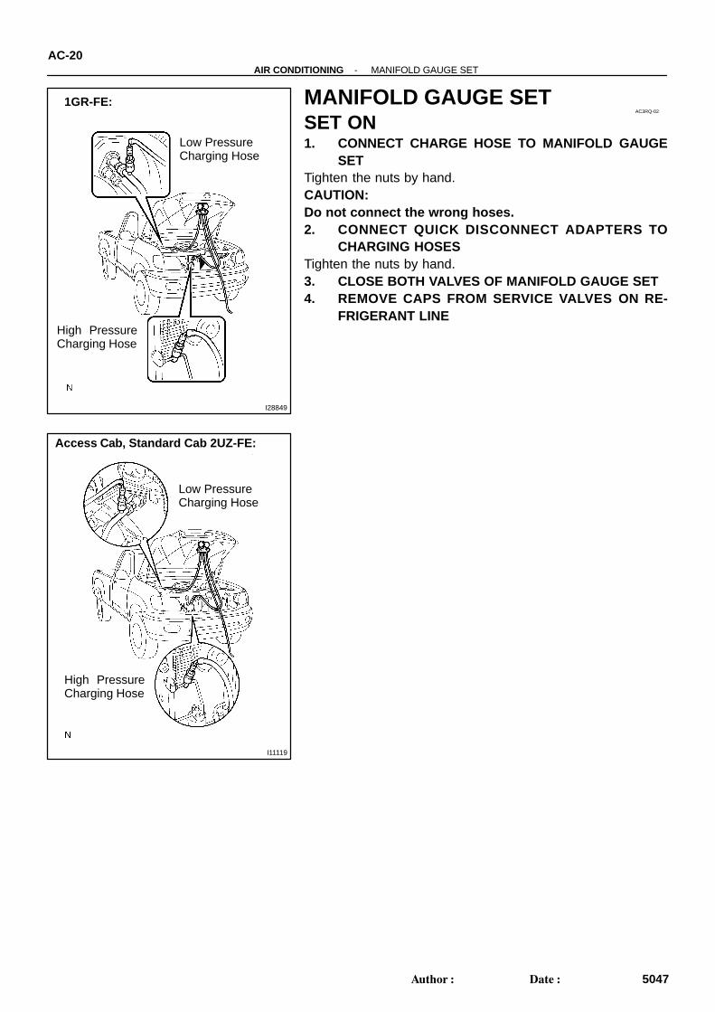
1GR-FE:
I11119
Low Pressure Charging Hose
High PressureCharging Hose
Access Cab, Standard Cab 2UZ-FE:
AC3RQ-02
AC-20-AIR CONDITIONING MANIFOLD GAUGE SET
5047Author: Date:
MANIFOLD GAUGE SETSET ON1. CONNECT CHARGE HOSE TO MANIFOLD GAUGE
SETTighten the nuts by hand.CAUTION:Do not connect the wrong hoses.2. CONNECT QUICK DISCONNECT ADAPTERS TO
CHARGING HOSESTighten the nuts by hand.3. CLOSE BOTH VALVES OF MANIFOLD GAUGE SET4. REMOVE CAPS FROM SERVICE VALVES ON RE-
FRIGERANT LINE
I27018
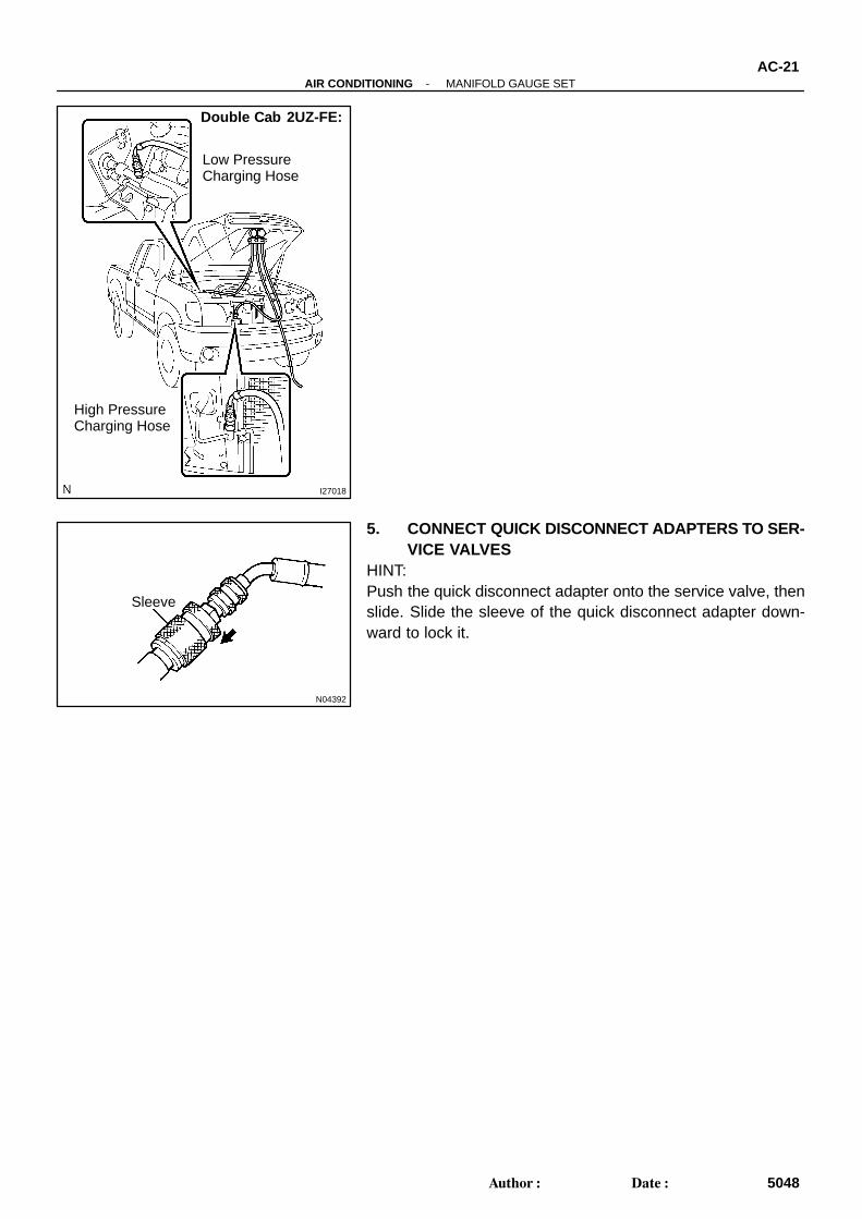
Double Cab 2UZ-FE:
Low Pressure Charging Hose
High Pressure Charging Hose
N04392
Sleeve
-AIR CONDITIONING MANIFOLD GAUGE SETAC-21
5048Author: Date:
5. CONNECT QUICK DISCONNECT ADAPTERS TO SER-VICE VALVES
HINT:Push the quick disconnect adapter onto the service valve, thenslide. Slide the sleeve of the quick disconnect adapter down-ward to lock it.

AC0E9-03
-AIR CONDITIONING PRESSURE SWITCHAC-81
5108Author: Date:
INSTALLATIONThe installation procedures are the removal procedures in reverse order (see page AC-80 ).
I11146
2 1
Z13470
Low pressure High pressuresideside
ON (Continuity)
3,140 kpa196 kpa(2.0 kgf/cm2, 28psi)OFF (No Continuity)
(32.0 kgf/cm2, 455psi)OFF (No Continuity)
AC0E7-05
-AIR CONDITIONING PRESSURE SWITCHAC-79
5106Author: Date:
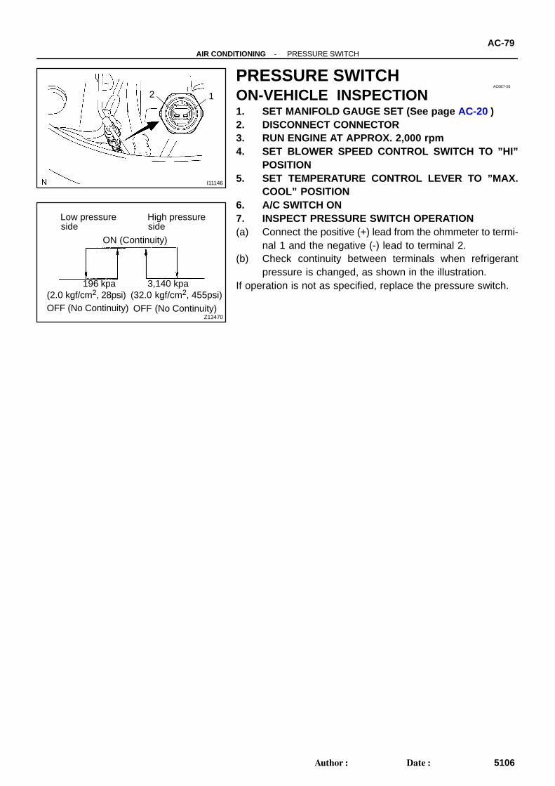
PRESSURE SWITCHON-VEHICLE INSPECTION1. SET MANIFOLD GAUGE SET (See page AC-20 )2. DISCONNECT CONNECTOR3. RUN ENGINE AT APPROX. 2,000 rpm4. SET BLOWER SPEED CONTROL SWITCH TO ”HI”
POSITION5. SET TEMPERATURE CONTROL LEVER TO ”MAX.
COOL” POSITION6. A/C SWITCH ON7. INSPECT PRESSURE SWITCH OPERATION(a) Connect the positive (+) lead from the ohmmeter to termi-
nal 1 and the negative (-) lead to terminal 2.(b) Check continuity between terminals when refrigerant
pressure is changed, as shown in the illustration.If operation is not as specified, replace the pressure switch.
AC0E8-09
I11147
AC-80-AIR CONDITIONING PRESSURE SWITCH
5107Author: Date:
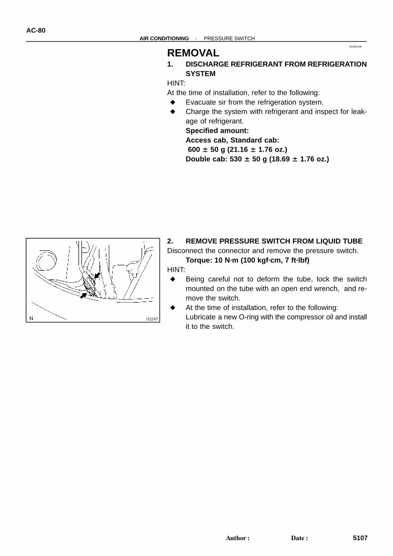
REMOVAL1. DISCHARGE REFRIGERANT FROM REFRIGERATION
SYSTEMHINT:At the time of installation, refer to the following: Evacuate sir from the refrigeration system. Charge the system with refrigerant and inspect for leak-
age of refrigerant.Specified amount: Access cab, Standard cab: 600 ± 50 g (21.16 ± 1.76 oz.)Double cab: 530 ± 50 g (18.69 ± 1.76 oz.)
2. REMOVE PRESSURE SWITCH FROM LIQUID TUBEDisconnect the connector and remove the pressure switch.
Torque: 10 N·m (100 kgf·cm, 7 ft·lbf)HINT: Being careful not to deform the tube, lock the switch
mounted on the tube with an open end wrench, and re-move the switch.
At the time of installation, refer to the following:Lubricate a new O-ring with the compressor oil and installit to the switch.
AC278-02
-AIR CONDITIONING RECEIVERAC-69
5096Author: Date:
INSTALLATIONThe installation procedures are the removal procedures in reverse order (see page AC-68 ).
AC276-01
-AIR CONDITIONING RECEIVERAC-67
5094Author: Date:
RECEIVERON-VEHICLE INSPECTIONINSPECT FITTINGS FOR LEAKAGEUsing a gas leak detector, check for leakage.If there is leakage, check the tightening toque at the joints.
AC277-03
I11138
AC-68-AIR CONDITIONING RECEIVER
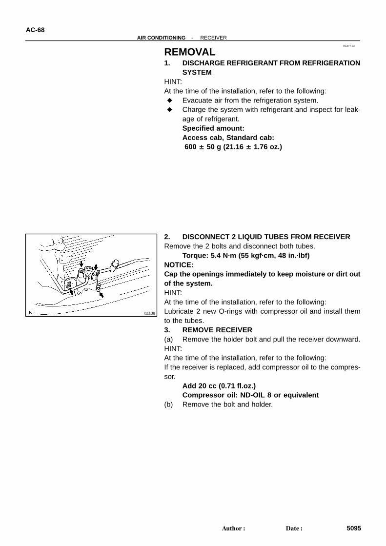
5095Author: Date:
REMOVAL1. DISCHARGE REFRIGERANT FROM REFRIGERATION
SYSTEMHINT:At the time of the installation, refer to the following: Evacuate air from the refrigeration system. Charge the system with refrigerant and inspect for leak-
age of refrigerant.Specified amount: Access cab, Standard cab: 600 ± 50 g (21.16 ± 1.76 oz.)
2. DISCONNECT 2 LIQUID TUBES FROM RECEIVERRemove the 2 bolts and disconnect both tubes.
Torque: 5.4 N·m (55 kgf·cm, 48 in.·lbf)NOTICE:Cap the openings immediately to keep moisture or dirt outof the system.HINT:At the time of the installation, refer to the following:Lubricate 2 new O-rings with compressor oil and install themto the tubes.3. REMOVE RECEIVER(a) Remove the holder bolt and pull the receiver downward.HINT:At the time of the installation, refer to the following:If the receiver is replaced, add compressor oil to the compres-sor.
Add 20 cc (0.71 fl.oz.)Compressor oil: ND-OIL 8 or equivalent
(b) Remove the bolt and holder.
AC3RR-02
I28831
10 (100, 7)
Suction Hose
Discharge Hose
5.4 (55, 48 in.·lbf)
Liquid Tube
Condenser
N·m (kgf·cm, ft·lbf) : Specified torque
1GR-FE:
Piping Clamp
5.4 (55, 48 in.·lbf)
5.4 (55, 48 in.·lbf)
5.4 (55, 48 in.·lbf)
5.4 (55, 48 in.·lbf)
Piping Clamp
AC-24-AIR CONDITIONING REFRIGERANT LINE
5051Author: Date:
LOCATION
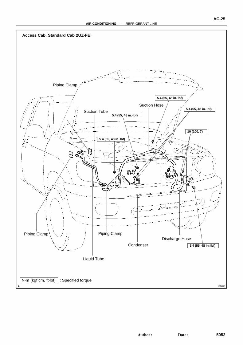
I28071
Access Cab, Standard Cab 2UZ-FE:
Suction Tube
Suction Hose5.4 (55, 48 in.·lbf)
10 (100, 7)
Liquid Tube
Discharge Hose
N·m (kgf·cm, ft·lbf) : Specified torque
Condenser
Piping Clamp
Piping Clamp
Piping Clamp
5.4 (55, 48 in.·lbf)
5.4 (55, 48 in.·lbf)
5.4 (55, 48 in.·lbf)
5.4 (55, 48 in.·lbf)
-AIR CONDITIONING REFRIGERANT LINEAC-25
5052Author: Date:
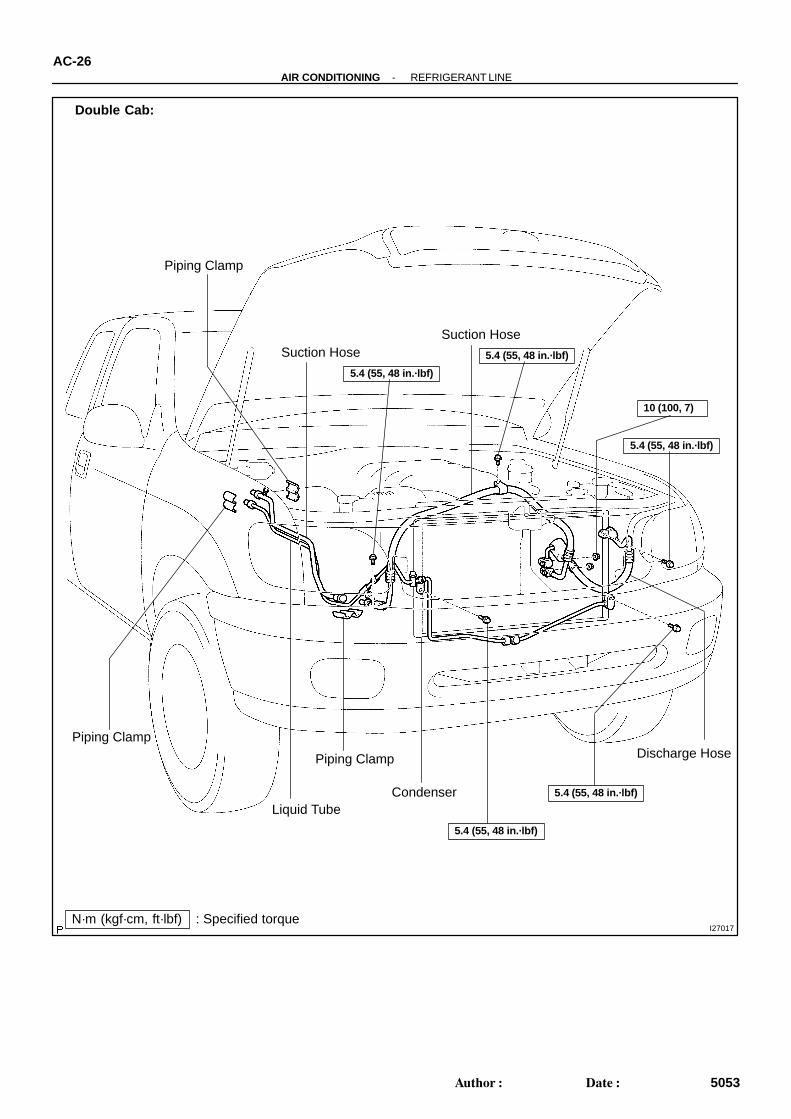
I27017
Suction Hose
10 (100, 7)
Liquid Tube
Discharge Hose
N·m (kgf·cm, ft·lbf) : Specified torque
Suction Hose
5.4 (55, 48 in.·lbf)
Double Cab:
Condenser
Piping Clamp
Piping Clamp
Piping Clamp
5.4 (55, 48 in.·lbf)
5.4 (55, 48 in.·lbf)
5.4 (55, 48 in.·lbf)
5.4 (55, 48 in.·lbf)
AC-26-AIR CONDITIONING REFRIGERANT LINE
5053Author: Date:
AC0CC-03
-AIR CONDITIONING REFRIGERANT LINEAC-23
5050Author: Date:
REFRIGERANT LINEON-VEHICLE INSPECTION1. INSPECT HOSE AND TUBE CONNECTIONS FOR LOOSENESS2. INSPECT HOSES AND TUBES FOR LEAKAGEUsing a gas leak detector, check for leakage of refrigerant.
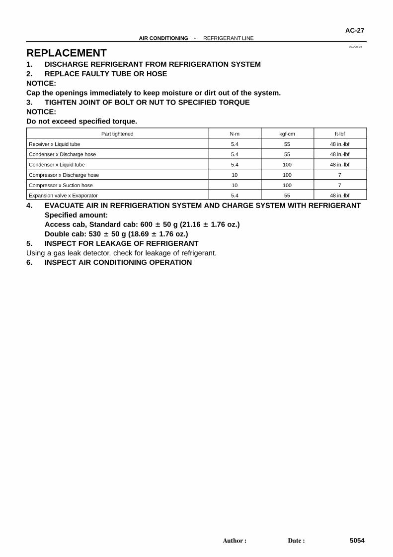
AC0CE-08
-AIR CONDITIONING REFRIGERANT LINEAC-27
5054Author: Date:
REPLACEMENT1. DISCHARGE REFRIGERANT FROM REFRIGERATION SYSTEM2. REPLACE FAULTY TUBE OR HOSENOTICE:Cap the openings immediately to keep moisture or dirt out of the system.3. TIGHTEN JOINT OF BOLT OR NUT TO SPECIFIED TORQUENOTICE:Do not exceed specified torque.
Part tightened N·m kgf·cm ft·lbf
Receiver x Liquid tube 5.4 55 48 in.·lbf
Condenser x Discharge hose 5.4 55 48 in.·lbf
Condenser x Liquid tube 5.4 100 48 in.·lbf
Compressor x Discharge hose 10 100 7
Compressor x Suction hose 10 100 7
Expansion valve x Evaporator 5.4 55 48 in.·lbf
4. EVACUATE AIR IN REFRIGERATION SYSTEM AND CHARGE SYSTEM WITH REFRIGERANTSpecified amount: Access cab, Standard cab: 600 ± 50 g (21.16 ± 1.76 oz.)Double cab: 530 ± 50 g (18.69 ± 1.76 oz.)
5. INSPECT FOR LEAKAGE OF REFRIGERANTUsing a gas leak detector, check for leakage of refrigerant.6. INSPECT AIR CONDITIONING OPERATION
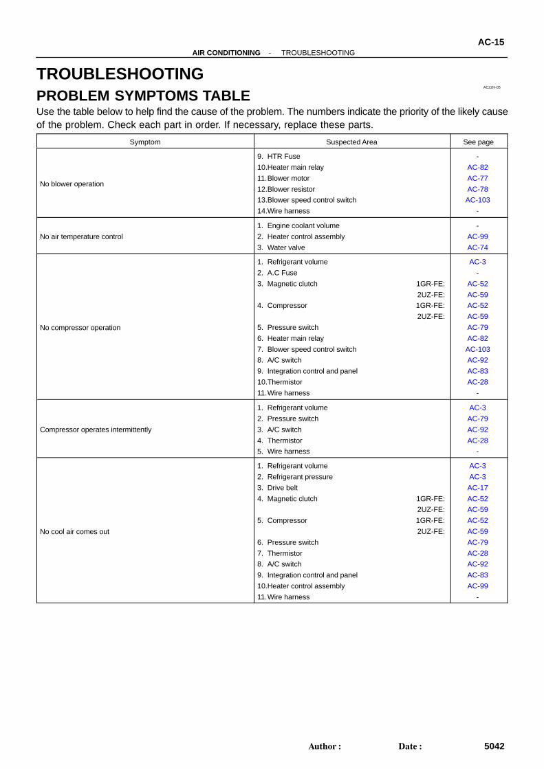
AC22H-05
-AIR CONDITIONING TROUBLESHOOTINGAC-15
5042Author: Date:
TROUBLESHOOTINGPROBLEM SYMPTOMS TABLEUse the table below to help find the cause of the problem. The numbers indicate the priority of the likely causeof the problem. Check each part in order. If necessary, replace these parts.
Symptom Suspected Area See page
No blower operation
9. HTR Fuse
10.Heater main relay
11.Blower motor
12.Blower resistor
13.Blower speed control switch
14.Wire harness
-
AC-82
AC-77
AC-78
AC-103
-
No air temperature control
1. Engine coolant volume
2. Heater control assembly
3. Water valve
-
AC-99
AC-74
No compressor operation
1. Refrigerant volume
2. A.C Fuse
3. Magnetic clutch 1GR-FE:
2UZ-FE:
4. Compressor 1GR-FE:
2UZ-FE:
5. Pressure switch
6. Heater main relay
7. Blower speed control switch
8. A/C switch
9. Integration control and panel
10.Thermistor
11.Wire harness
AC-3
-
AC-52
AC-59
AC-52
AC-59
AC-79
AC-82
AC-103
AC-92
AC-83
AC-28
-
Compressor operates intermittently
1. Refrigerant volume
2. Pressure switch
3. A/C switch
4. Thermistor
5. Wire harness
AC-3
AC-79
AC-92
AC-28
-
No cool air comes out
1. Refrigerant volume
2. Refrigerant pressure
3. Drive belt
4. Magnetic clutch 1GR-FE:
2UZ-FE:
5. Compressor 1GR-FE:
2UZ-FE:
6. Pressure switch
7. Thermistor
8. A/C switch
9. Integration control and panel
10.Heater control assembly
11.Wire harness
AC-3
AC-3
AC-17
AC-52
AC-59
AC-52
AC-59
AC-79
AC-28
AC-92
AC-83
AC-99
-
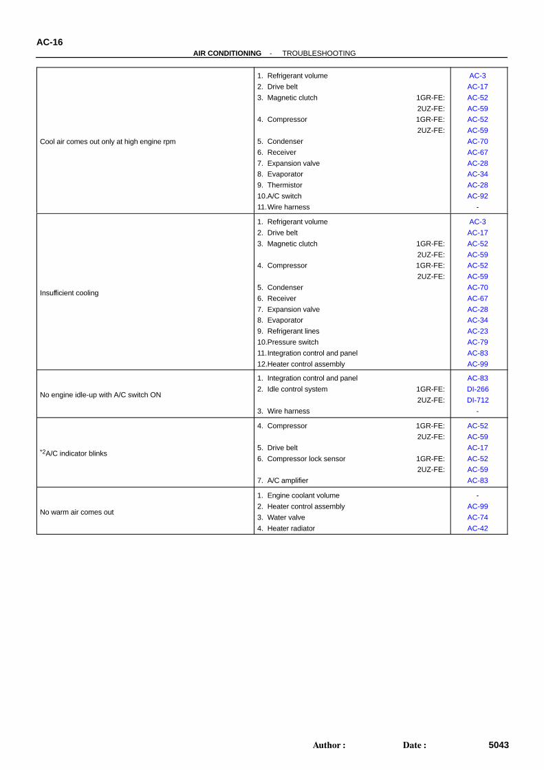
AC-16-AIR CONDITIONING TROUBLESHOOTING
5043Author: Date:
Cool air comes out only at high engine rpm
1. Refrigerant volume
2. Drive belt
3. Magnetic clutch 1GR-FE:
2UZ-FE:
4. Compressor 1GR-FE:
2UZ-FE:
5. Condenser
6. Receiver
7. Expansion valve
8. Evaporator
9. Thermistor
10.A/C switch
11.Wire harness
AC-3
AC-17
AC-52
AC-59
AC-52
AC-59
AC-70
AC-67
AC-28
AC-34
AC-28
AC-92
-
Insufficient cooling
1. Refrigerant volume
2. Drive belt
3. Magnetic clutch 1GR-FE:
2UZ-FE:
4. Compressor 1GR-FE:
2UZ-FE:
5. Condenser
6. Receiver
7. Expansion valve
8. Evaporator
9. Refrigerant lines
10.Pressure switch
11.Integration control and panel
12.Heater control assembly
AC-3
AC-17
AC-52
AC-59
AC-52
AC-59
AC-70
AC-67
AC-28
AC-34
AC-23
AC-79
AC-83
AC-99
No engine idle-up with A/C switch ON
1. Integration control and panel
2. Idle control system 1GR-FE:
2UZ-FE:
3. Wire harness
AC-83
DI-266
DI-712
-
*2A/C indicator blinks
4. Compressor 1GR-FE:
2UZ-FE:
5. Drive belt
6. Compressor lock sensor 1GR-FE:
2UZ-FE:
7. A/C amplifier
AC-52
AC-59
AC-17
AC-52
AC-59
AC-83
No warm air comes out
1. Engine coolant volume
2. Heater control assembly
3. Water valve
4. Heater radiator
-
AC-99
AC-74
AC-42
AC27C-02
AC-76-AIR CONDITIONING WATER VALVE
5103Author: Date:
INSTALLATIONThe installation procedures are the removal procedures in reverse order (see page AC-75 ).
AC27A-02
AC-74-AIR CONDITIONING WATER VALVE
5101Author: Date:
WATER VALVEON-VEHICLE INSPECTION1. WARM UP ENGINE2. DISCONNECT WATER VALVE CONTROL CABLE3. INSPECT WATER VALVE OPERATION(a) Check that warm air comes out from the vent when the water valve lever is moved to the ”WARM” posi-
tion.(b) Check that cool air comes out when the water valve is moved to the ”COOL” position.If operation is not as specified, replace the water valve.4. CONNECT WATER VALVE CONTROL CABLE
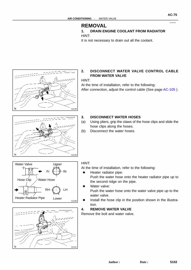
AC27B-03
I11139
I11140
I11199
Hose Clip
Water Valve
Heater Radiator Pipe Lower
Upper
RrFr
LHRH
Water Hose
I11141
-AIR CONDITIONING WATER VALVEAC-75
5102Author: Date:
REMOVAL1. DRAIN ENGINE COOLANT FROM RADIATORHINT:It is not necessary to drain out all the coolant.
2. DISCONNECT WATER VALVE CONTROL CABLEFROM WATER VALVE
HINT:At the time of installation, refer to the following:After connection, adjust the control cable (See page AC-105 ).
3. DISCONNECT WATER HOSES(a) Using pliers, grip the claws of the hose clips and slide the
hose clips along the hoses.(b) Disconnect the water hoses.
HINT:At the time of installation, refer to the following: Heater radiator pipe:
Push the water hose onto the heater radiator pipe up tothe second ridge on the pipe.
Water valve:Push the water hose onto the water valve pipe up to thewater valve.
Install the hose clip in the position shown in the illustra-tion.
4. REMOVE WATER VALVERemove the bolt and water valve.
Related Documents