AHCI 1.3.1 Technical Proposal AHCI 1_3_1 TP001v8_11112011.doc AHCI Confidential i AHCI 1.3.1 Device Sleep Technical Proposal AHCI 1_3_1 TP001v8.doc Please send comments to James Boyd [email protected]

AHHCCII .11 .33.11 De evicce SSll eeepp …...De evicce SSll eeepp aTTeecchhnniiccall PPrrooppoossaall AHCI 1_3_1 TP001v8.doc Please send comments to James Boyd [email protected]
May 31, 2020
Welcome message from author
This document is posted to help you gain knowledge. Please leave a comment to let me know what you think about it! Share it to your friends and learn new things together.
Transcript

AHCI 1.3.1 Technical Proposal AHCI 1_3_1 TP001v8_11112011.doc
AHCI Confidential i
AAHHCCII 11..33..11
DDeevviiccee SSlleeeepp TTeecchhnniiccaall PPrrooppoossaall
AHCI 1_3_1 TP001v8.doc
Please send comments to James Boyd [email protected]
AHCI 1_3_1 TP001v8_11112011.doc AHCI 1.3.1 TR001v8
AHCI Confidential ii
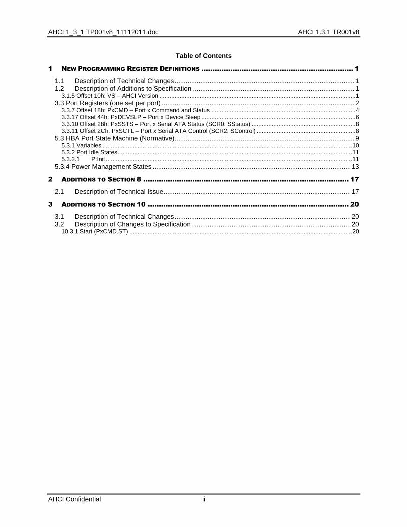
Table of Contents
1 NEW PROGRAMMING REGISTER DEFINITIONS .................................................................... 1
1.1 Description of Technical Changes .................................................................................................. 1 1.2 Description of Additions to Specification ........................................................................................ 1
3.1.5 Offset 10h: VS – AHCI Version ..................................................................................................................... 1 3.3 Port Registers (one set per port) ......................................................................................................... 2
3.3.7 Offset 18h: PxCMD – Port x Command and Status ...................................................................................... 4 3.3.17 Offset 44h: PxDEVSLP – Port x Device Sleep ............................................................................................ 6 3.3.10 Offset 28h: PxSSTS – Port x Serial ATA Status (SCR0: SStatus) .............................................................. 8 3.3.11 Offset 2Ch: PxSCTL – Port x Serial ATA Control (SCR2: SControl) ........................................................... 8
5.3 HBA Port State Machine (Normative) .................................................................................................. 9 5.3.1 Variables ..................................................................................................................................................... 10 5.3.2 Port Idle States ............................................................................................................................................ 11 5.3.2.1 P:Init ................................................................................................................................................... 11
5.3.4 Power Management States ............................................................................................................ 13
2 ADDITIONS TO SECTION 8 ............................................................................................ 17
2.1 Description of Technical Issue ...................................................................................................... 17
3 ADDITIONS TO SECTION 10 .......................................................................................... 20
3.1 Description of Technical Changes ................................................................................................ 20 3.2 Description of Changes to Specification ....................................................................................... 20
10.3.1 Start (PxCMD.ST) ..................................................................................................................................... 20

AHCI 1.3.1 Technical Proposal AHCI 1_3_1 TP001v8_11112011.doc
1
1 New Programming Register Definitions
1.1 Description of Technical Changes
To support the Device Sleep feature, AHCI requires the definition of new bits in existing registers and the definition of an additional register. Device Sleep is a feature that allows the host and device to coordinate turning off their respective PHYs (in order to conserve power). The additions to AHCI outline a method to detect support (CAP2.SDS), for direct software control of this feature (via PxCMD.ICC), and a method for HW to autonomously enter and exit DevSleep (PxDEVSLP.ADSE). Due to timing requirements of entering and exiting DevSleep (to coordinate PHYs), programmable timing registers have also been added to aid in optimizing resume latencies. PxDEVSLP.DITO is the time a given port must be idle before HW may enter DevSleep autonomously. PxDEVSLP.DETO is the time reported by the device before it can accept OOB signaling after the de-assertion of the DEVSLP signal from the host (software or HW automated).
1.2 Description of Additions to Specification
Update sections as indicated in red
3.1.5 Offset 10h: VS – AHCI Version
This register indicates the major and minor version of the AHCI specification that the HBA implementation supports. The upper two bytes represent the major version number, and the lower two bytes represent the minor version number. Example: Version 3.12 would be represented as 00030102h. Three versions of the specification are valid: 0.95, 1.0, 1.1, 1.2, 1.3, and 1.3.1.
3.1.5.1 VS Value for 0.95 Compliant HBAs Bit Type Reset Description
31:16 RO 0000h Major Version Number (MJR): Indicates the major version is “0”
15:00 RO 0905h Minor Version Number (MNR): Indicates the minor version is “95”.
3.1.5.2 VS Value for 1.0 Compliant HBAs Bit Type Reset Description
31:16 RO 0001h Major Version Number (MJR): Indicates the major version is “1”
15:00 RO 0000h Minor Version Number (MNR): Indicates the minor version is “0”.
3.1.5.3 VS Value for 1.1 Compliant HBAs Bit Type Reset Description
31:16 RO 0001h Major Version Number (MJR): Indicates the major version is “1”
15:00 RO 0100h Minor Version Number (MNR): Indicates the minor version is “10”.
3.1.5.4 VS Value for 1.2 Compliant HBAs Bit Type Reset Description
31:16 RO 0001h Major Version Number (MJR): Indicates the major version is “1”
15:00 RO 0200h Minor Version Number (MNR): Indicates the minor version is “20”.
3.1.5.5 VS Value for 1.3 Compliant HBAs Bit Type Reset Description
31:16 RO 0001h Major Version Number (MJR): Indicates the major version is “1”
15:00 RO 0300h Minor Version Number (MNR): Indicates the minor version is “30”.
3.1.5.6 VS Value for 1.3.1 Compliant HBAs Bit Type Reset Description
31:16 RO 0001h Major Version Number (MJR): Indicates the major version is “1”
15:00 RO 0301h Minor Version Number (MNR): Indicates the minor version is “31”.
AHCI 1_3_1 TP001v8_11112011.doc AHCI 1.3.1 TR001v8
AHCI Confidential 2
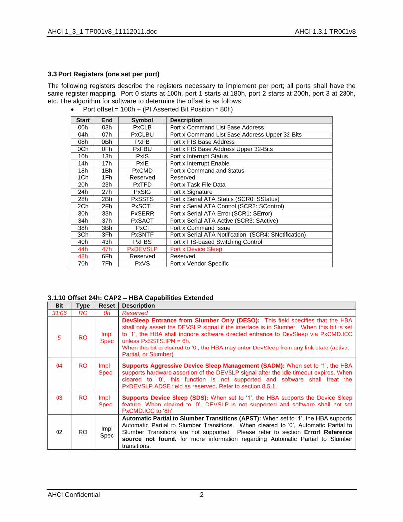
3.3 Port Registers (one set per port)
The following registers describe the registers necessary to implement per port; all ports shall have the same register mapping. Port 0 starts at 100h, port 1 starts at 180h, port 2 starts at 200h, port 3 at 280h, etc. The algorithm for software to determine the offset is as follows:
Port offset = 100h + (PI Asserted Bit Position * 80h)
Start End Symbol Description
00h 03h PxCLB Port x Command List Base Address
04h 07h PxCLBU Port x Command List Base Address Upper 32-Bits
08h 0Bh PxFB Port x FIS Base Address
0Ch 0Fh PxFBU Port x FIS Base Address Upper 32-Bits
10h 13h PxIS Port x Interrupt Status
14h 17h PxIE Port x Interrupt Enable
18h 1Bh PxCMD Port x Command and Status
1Ch 1Fh Reserved Reserved
20h 23h PxTFD Port x Task File Data
24h 27h PxSIG Port x Signature
28h 2Bh PxSSTS Port x Serial ATA Status (SCR0: SStatus)
2Ch 2Fh PxSCTL Port x Serial ATA Control (SCR2: SControl)
30h 33h PxSERR Port x Serial ATA Error (SCR1: SError)
34h 37h PxSACT Port x Serial ATA Active (SCR3: SActive)
38h 3Bh PxCI Port x Command Issue
3Ch 3Fh PxSNTF Port x Serial ATA Notification (SCR4: SNotification)
40h 43h PxFBS Port x FIS-based Switching Control
44h 47h PxDEVSLP Port x Device Sleep
48h 6Fh Reserved Reserved
70h 7Fh PxVS Port x Vendor Specific
3.1.10 Offset 24h: CAP2 – HBA Capabilities Extended Bit Type Reset Description
31:06 RO 0h Reserved
5 RO Impl Spec
DevSleep Entrance from Slumber Only (DESO): This field specifies that the HBA shall only assert the DEVSLP signal if the interface is in Slumber. When this bit is set to „1‟, the HBA shall ingnore software directed entrance to DevSleep via PxCMD.ICC unless PxSSTS.IPM = 6h. When this bit is cleared to „0‟, the HBA may enter DevSleep from any link state (active, Partial, or Slumber).
04 RO Impl Spec
Supports Aggressive Device Sleep Management (SADM): When set to „1‟, the HBA supports hardware assertion of the DEVSLP signal after the idle timeout expires. When cleared to „0‟, this function is not supported and software shall treat the PxDEVSLP.ADSE field as reserved. Refer to section 8.5.1.
03 RO Impl Spec
Supports Device Sleep (SDS): When set to „1‟, the HBA supports the Device Sleep feature. When cleared to „0‟, DEVSLP is not supported and software shall not set PxCMD.ICC to „8h‟
02 RO Impl Spec
Automatic Partial to Slumber Transitions (APST): When set to „1‟, the HBA supports Automatic Partial to Slumber Transitions. When cleared to „0‟, Automatic Partial to Slumber Transitions are not supported. Please refer to section Error! Reference source not found. for more information regarding Automatic Partial to Slumber transitions.
AHCI 1.3.1 Technical Proposal AHCI 1_3_1 TP001v8_11112011.doc
3
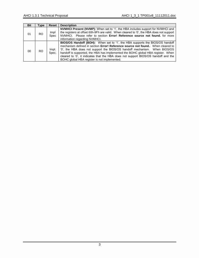
Bit Type Reset Description
01 RO Impl Spec
NVMHCI Present (NVMP): When set to „1‟, the HBA includes support for NVMHCI and the registers at offset 60h-9Fh are valid. When cleared to „0‟, the HBA does not support NVMHCI. Please refer to section Error! Reference source not found. for more information regarding NVMHCI.
00 RO Impl. Spec.
BIOS/OS Handoff (BOH): When set to „1‟, the HBA supports the BIOS/OS handoff mechanism defined in section Error! Reference source not found.. When cleared to „0‟, the HBA does not support the BIOS/OS handoff mechanism. When BIOS/OS handoff is supported, the HBA has implemented the BOHC global HBA register. When cleared to „0‟, it indicates that the HBA does not support BIOS/OS handoff and the BOHC global HBA register is not implemented.
AHCI 1_3_1 TP001v8_11112011.doc AHCI 1.3.1 TR001v8
AHCI Confidential 4
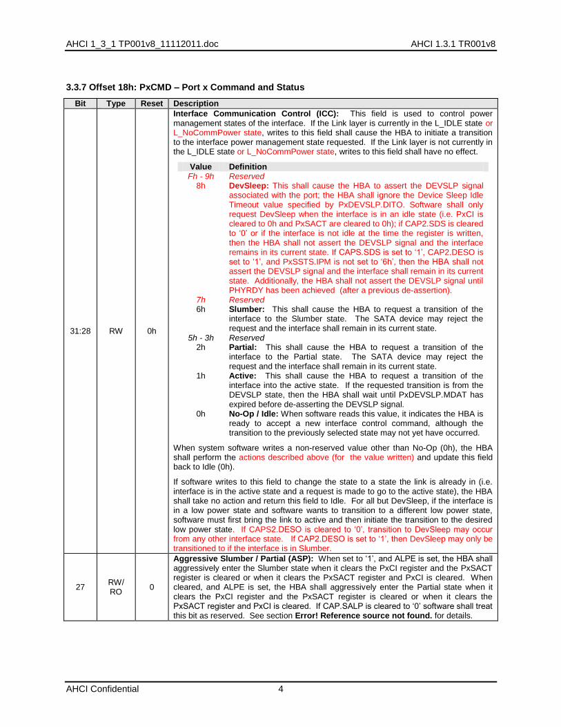
3.3.7 Offset 18h: PxCMD – Port x Command and Status
Bit Type Reset Description
31:28 RW 0h
Interface Communication Control (ICC): This field is used to control power management states of the interface. If the Link layer is currently in the L_IDLE state or L_NoCommPower state, writes to this field shall cause the HBA to initiate a transition to the interface power management state requested. If the Link layer is not currently in the L_IDLE state or L_NoCommPower state, writes to this field shall have no effect.
Value Definition Fh - 9h
8h Reserved DevSleep: This shall cause the HBA to assert the DEVSLP signal associated with the port; the HBA shall ignore the Device Sleep Idle Timeout value specified by PxDEVSLP.DITO. Software shall only request DevSleep when the interface is in an idle state (i.e. PxCI is cleared to 0h and PxSACT are cleared to 0h); if CAP2.SDS is cleared to „0‟ or if the interface is not idle at the time the register is written, then the HBA shall not assert the DEVSLP signal and the interface remains in its current state. If CAPS.SDS is set to „1‟, CAP2.DESO is set to „1‟, and PxSSTS.IPM is not set to „6h‟, then the HBA shall not assert the DEVSLP signal and the interface shall remain in its current state. Additionally, the HBA shall not assert the DEVSLP signal until PHYRDY has been achieved (after a previous de-assertion).
7h Reserved 6h Slumber: This shall cause the HBA to request a transition of the
interface to the Slumber state. The SATA device may reject the request and the interface shall remain in its current state.
5h - 3h Reserved 2h Partial: This shall cause the HBA to request a transition of the
interface to the Partial state. The SATA device may reject the request and the interface shall remain in its current state.
1h Active: This shall cause the HBA to request a transition of the interface into the active state. If the requested transition is from the DEVSLP state, then the HBA shall wait until PxDEVSLP.MDAT has expired before de-asserting the DEVSLP signal.
0h No-Op / Idle: When software reads this value, it indicates the HBA is ready to accept a new interface control command, although the transition to the previously selected state may not yet have occurred.
When system software writes a non-reserved value other than No-Op (0h), the HBA shall perform the actions described above (for the value written) and update this field back to Idle (0h).
If software writes to this field to change the state to a state the link is already in (i.e. interface is in the active state and a request is made to go to the active state), the HBA shall take no action and return this field to Idle. For all but DevSleep, if the interface is in a low power state and software wants to transition to a different low power state, software must first bring the link to active and then initiate the transition to the desired low power state. If CAPS2.DESO is cleared to „0‟, transition to DevSleep may occur from any other interface state. If CAP2.DESO is set to „1‟, then DevSleep may only be transitioned to if the interface is in Slumber.
27 RW/ RO
0
Aggressive Slumber / Partial (ASP): When set to „1‟, and ALPE is set, the HBA shall aggressively enter the Slumber state when it clears the PxCI register and the PxSACT register is cleared or when it clears the PxSACT register and PxCI is cleared. When cleared, and ALPE is set, the HBA shall aggressively enter the Partial state when it clears the PxCI register and the PxSACT register is cleared or when it clears the PxSACT register and PxCI is cleared. If CAP.SALP is cleared to „0‟ software shall treat this bit as reserved. See section Error! Reference source not found. for details.

AHCI 1.3.1 Technical Proposal AHCI 1_3_1 TP001v8_11112011.doc
5
Bit Type Reset Description
26 RW/ RO
0
Aggressive Link Power Management Enable (ALPE): When set to „1‟, the HBA shall aggressively enter a lower link power state (Partial or Slumber) based upon the setting of the ASP bit. Software shall only set this bit to „1‟ if CAP.SALP is set to „1‟; if CAP.SALP is cleared to „0‟ software shall treat this bit as reserved. See section Error! Reference source not found. for details.
25 RW 0
Drive LED on ATAPI Enable (DLAE): When set to „1‟, the HBA shall drive the LED pin active for commands regardless of the state of PxCMD.ATAPI. When cleared, the HBA shall only drive the LED pin active for commands if PxCMD.ATAPI set to „0‟. See section Error! Reference source not found. for details on the activity LED.
24 RW 0
Device is ATAPI (ATAPI): When set to „1‟, the connected device is an ATAPI device. This bit is used by the HBA to control whether or not to generate the desktop LED when commands are active. See section Error! Reference source not found. for details on the activity LED.
23 RW 0
Automatic Partial to Slumber Transitions Enabled (APSTE): When set to „1‟, the HBA may perform Automatic Partial to Slumber Transitions. When cleared to „0‟ the port shall not perform Automatic Partial to Slumber Transitions. Software shall only set this bit to „1‟ if CAP2.APST is set to „1‟; if CAP2.APST is cleared to „0‟ software shall treat this bit as reserved.
22 RO HwInit
FIS-based Switching Capable Port (FBSCP): When set to „1‟, indicates that this port supports Port Multiplier FIS-based switching. When cleared to „0‟, indicates that this port does not support FIS-based switching. This bit may only be set to „1‟ if both CAP.SPM and CAP.FBSS are set to „1‟.
21 RO HwInit
External SATA Port (ESP): When set to '1', indicates that this port‟s signal connector is externally accessible on a signal only connector (e.g. eSATA connector). When set to '1', CAP.SXS shall be set to '1'. When cleared to „0‟, indicates that this port‟s signal connector is not externally accessible on a signal only connector. ESP is mutually exclusive with the HPCP bit in this register. If ESP is set to „1‟, then the port may experience hot plug events.
20 RO HwInit
Cold Presence Detection (CPD): If set to „1‟, the platform supports cold presence detection on this port. If cleared to „0‟, the platform does not support cold presence detection on this port. When this bit is set to „1‟, PxCMD.HPCP should also be set to „1‟.
19 RO HwInit
Mechanical Presence Switch Attached to Port (MPSP): If set to „1‟, the platform supports an mechanical presence switch attached to this port. If cleared to „0‟, the platform does not support a mechanical presence switch attached to this port. When this bit is set to „1‟, PxCMD.HPCP should also be set to „1‟.
18 RO HwInit
Hot Plug Capable Port (HPCP): When set to „1‟, indicates that this port‟s signal and power connectors are externally accessible via a joint signal and power connector for blinMDATe device hot plug. When cleared to „0‟, indicates that this port‟s signal and power connectors are not externally accessible via a joint signal and power connector. HPCP is mutually exclusive with the ESP bit in this register.
17 RW/ RO
0
Port Multiplier Attached (PMA): This bit is read/write for HBAs that support a Port Multiplier (CAP.SPM = „1‟). This bit is read-only for HBAs that do not support a port Multiplier (CAP.SPM = „0‟). When set to „1‟ by software, a Port Multiplier is attached to the HBA for this port. When cleared to „0‟ by software, a Port Multiplier is not attached to the HBA for this port. Software is responsible for detecting whether a Port Multiplier is present; hardware does not auto-detect the presence of a Port Multiplier. Software shall only set this bit to „1‟ when PxCMD.ST is cleared to „0‟.
16 RO See Desc
Cold Presence State (CPS): The CPS bit reports whether a device is currently detected on this port via cold presence detection. If CPS is set to „1‟, then the HBA detects via cold presence that a device is attached to this port. If CPS is cleared to „0‟ , then the HBA detects via cold presence that there is no device attached to this port.
15 RO 0 Command List Running (CR): When this bit is set, the command list DMA engine for the port is running. See the AHCI state machine in section Error! Reference source not found. for details on when this bit is set and cleared by the HBA.
14 RO 0 FIS Receive Running (FR): When set, the FIS Receive DMA engine for the port is running. See section Error! Reference source not found. for details on when this bit is set and cleared by the HBA.

AHCI 1_3_1 TP001v8_11112011.doc AHCI 1.3.1 TR001v8
AHCI Confidential 6
Bit Type Reset Description
13 RO See Desc
Mechanical Presence Switch State (MPSS): The MPSS bit reports the state of a mechanical presence switch attached to this port. If CAP.SMPS is set to „1‟ and the mechanical presence switch is closed then this bit is cleared to „0‟. If CAP.SMPS is set to „1‟ and the mechanical presence switch is open then this bit is set to „1‟. If CAP.SMPS is set to „0‟ then this bit is cleared to „0‟. Software should only use this bit if both CAP.SMPS and PxCMD.MPSP are set to „1‟.
12:08 RO 0h
Current Command Slot (CCS): This field is valid when PxCMD.ST is set to „1‟ and shall be set to the command slot value of the command that is currently being issued by the HBA. When PxCMD.ST transitions from „1‟ to „0‟, this field shall be reset to „0‟. After PxCMD.ST transitions from „0‟ to „1‟, the highest priority slot to issue from next is command slot 0. After the first command has been issued, the highest priority slot to issue from next is PxCMD.CCS + 1. For example, after the HBA has issued its first command, if CCS = 0h and PxCI is set to 3h, the next command that will be issued is from command slot 1.
07:05 RO 0 Reserved
04 RW 0
FIS Receive Enable (FRE): When set, the HBA may post received FISes into the FIS receive area pointed to by PxFB (and for 64-bit HBAs, PxFBU). When cleared, received FISes are not accepted by the HBA, except for the first D2H register FIS after the initialization sequence, and no FISes are posted to the FIS receive area.
System software must not set this bit until PxFB (PxFBU) have been programmed with a valid pointer to the FIS receive area, and if software wishes to move the base, this bit must first be cleared, and software must wait for the FR bit in this register to be cleared. Refer to section Error! Reference source not found. for important restrictions on when FRE can be set and cleared.
03 RW1 0
Command List Override (CLO): Setting this bit to „1‟ causes PxTFD.STS.BSY and PxTFD.STS.DRQ to be cleared to „0‟. This allows a software reset to be transmitted to the device regardless of whether the BSY and DRQ bits are still set in the PxTFD.STS register. The HBA sets this bit to „0‟ when PxTFD.STS.BSY and PxTFD.STS.DRQ have been cleared to „0‟. A write to this register with a value of „0‟ shall have no effect. This bit shall only be set to „1‟ immediately prior to setting the PxCMD.ST bit to „1‟ from a previous value of „0‟. Setting this bit to „1‟ at any other time is not supported and will result in indeterminate behavior. Software must wait for CLO to be cleared to „0‟ before setting PxCMD.ST to „1‟.
02 RW/ RO
0/1
Power On Device (POD): This bit is read/write for HBAs that support cold presence detection on this port as indicated by PxCMD.CPD set to „1‟. This bit is read only „1‟ for HBAs that do not support cold presence detect. When set, the HBA sets the state of a pin on the HBA to „1‟ so that it may be used to provide power to a cold-presence detectable port.
01 RW/ RO
0/1
Spin-Up Device (SUD): This bit is read/write for HBAs that support staggered spin-up via CAP.SSS. This bit is read only „1‟ for HBAs that do not support staggered spin-up. On an edge detect from „0‟ to „1‟, the HBA shall start a COMRESET initializatoin sequence to the device. Clearing this bit to „0‟ does not cause any OOB signal to be sent on the interface. When this bit is cleared to „0‟ and PxSCTL.DET=0h, the HBA will enter listen mode as detailed in section Error! Reference source not found..
00 RW 0
Start (ST): When set, the HBA may process the command list. When cleared, the HBA may not process the command list. Whenever this bit is changed from a „0‟ to a „1‟, the HBA starts processing the command list at entry „0‟. Whenever this bit is changed from a „1‟ to a „0‟, the PxCI register is cleared by the HBA upon the HBA putting the controller into an idle state. This bit shall only be set to „1‟ by software after PxCMD.FRE has been set to „1‟. Refer to section 0 for important restrictions on when ST can be set to „1‟.
3.3.17 Offset 44h: PxDEVSLP – Port x Device Sleep
Bit Type Reset Description
31:29 RO 0 Reserved
AHCI 1.3.1 Technical Proposal AHCI 1_3_1 TP001v8_11112011.doc
7
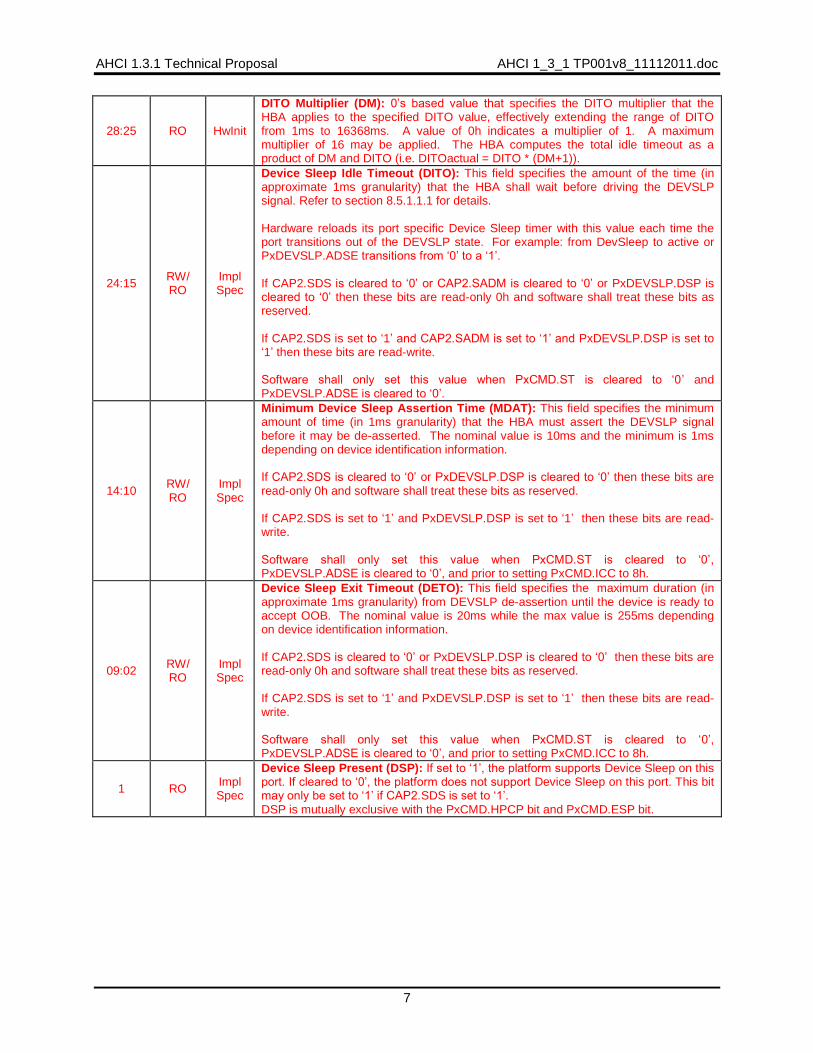
28:25 RO HwInit
DITO Multiplier (DM): 0‟s based value that specifies the DITO multiplier that the HBA applies to the specified DITO value, effectively extending the range of DITO from 1ms to 16368ms. A value of 0h indicates a multiplier of 1. A maximum multiplier of 16 may be applied. The HBA computes the total idle timeout as a product of DM and DITO (i.e. DITOactual = DITO * (DM+1)).
24:15 RW/ RO
Impl Spec
Device Sleep Idle Timeout (DITO): This field specifies the amount of the time (in approximate 1ms granularity) that the HBA shall wait before driving the DEVSLP signal. Refer to section 8.5.1.1.1 for details. Hardware reloads its port specific Device Sleep timer with this value each time the port transitions out of the DEVSLP state. For example: from DevSleep to active or PxDEVSLP.ADSE transitions from „0‟ to a „1‟. If CAP2.SDS is cleared to „0‟ or CAP2.SADM is cleared to „0‟ or PxDEVSLP.DSP is cleared to „0‟ then these bits are read-only 0h and software shall treat these bits as reserved. If CAP2.SDS is set to „1‟ and CAP2.SADM is set to „1‟ and PxDEVSLP.DSP is set to „1‟ then these bits are read-write. Software shall only set this value when PxCMD.ST is cleared to „0‟ and PxDEVSLP.ADSE is cleared to „0‟.
14:10 RW/ RO
Impl Spec
Minimum Device Sleep Assertion Time (MDAT): This field specifies the minimum amount of time (in 1ms granularity) that the HBA must assert the DEVSLP signal before it may be de-asserted. The nominal value is 10ms and the minimum is 1ms depending on device identification information. If CAP2.SDS is cleared to „0‟ or PxDEVSLP.DSP is cleared to „0‟ then these bits are read-only 0h and software shall treat these bits as reserved. If CAP2.SDS is set to „1‟ and PxDEVSLP.DSP is set to „1‟ then these bits are read-write. Software shall only set this value when PxCMD.ST is cleared to „0‟, PxDEVSLP.ADSE is cleared to „0‟, and prior to setting PxCMD.ICC to 8h.
09:02 RW/ RO
Impl Spec
Device Sleep Exit Timeout (DETO): This field specifies the maximum duration (in approximate 1ms granularity) from DEVSLP de-assertion until the device is ready to accept OOB. The nominal value is 20ms while the max value is 255ms depending on device identification information. If CAP2.SDS is cleared to „0‟ or PxDEVSLP.DSP is cleared to „0‟ then these bits are read-only 0h and software shall treat these bits as reserved. If CAP2.SDS is set to „1‟ and PxDEVSLP.DSP is set to „1‟ then these bits are read-write. Software shall only set this value when PxCMD.ST is cleared to „0‟, PxDEVSLP.ADSE is cleared to „0‟, and prior to setting PxCMD.ICC to 8h.
1 RO Impl Spec
Device Sleep Present (DSP): If set to „1‟, the platform supports Device Sleep on this port. If cleared to „0‟, the platform does not support Device Sleep on this port. This bit may only be set to „1‟ if CAP2.SDS is set to „1‟. DSP is mutually exclusive with the PxCMD.HPCP bit and PxCMD.ESP bit.
AHCI 1_3_1 TP001v8_11112011.doc AHCI 1.3.1 TR001v8
AHCI Confidential 8
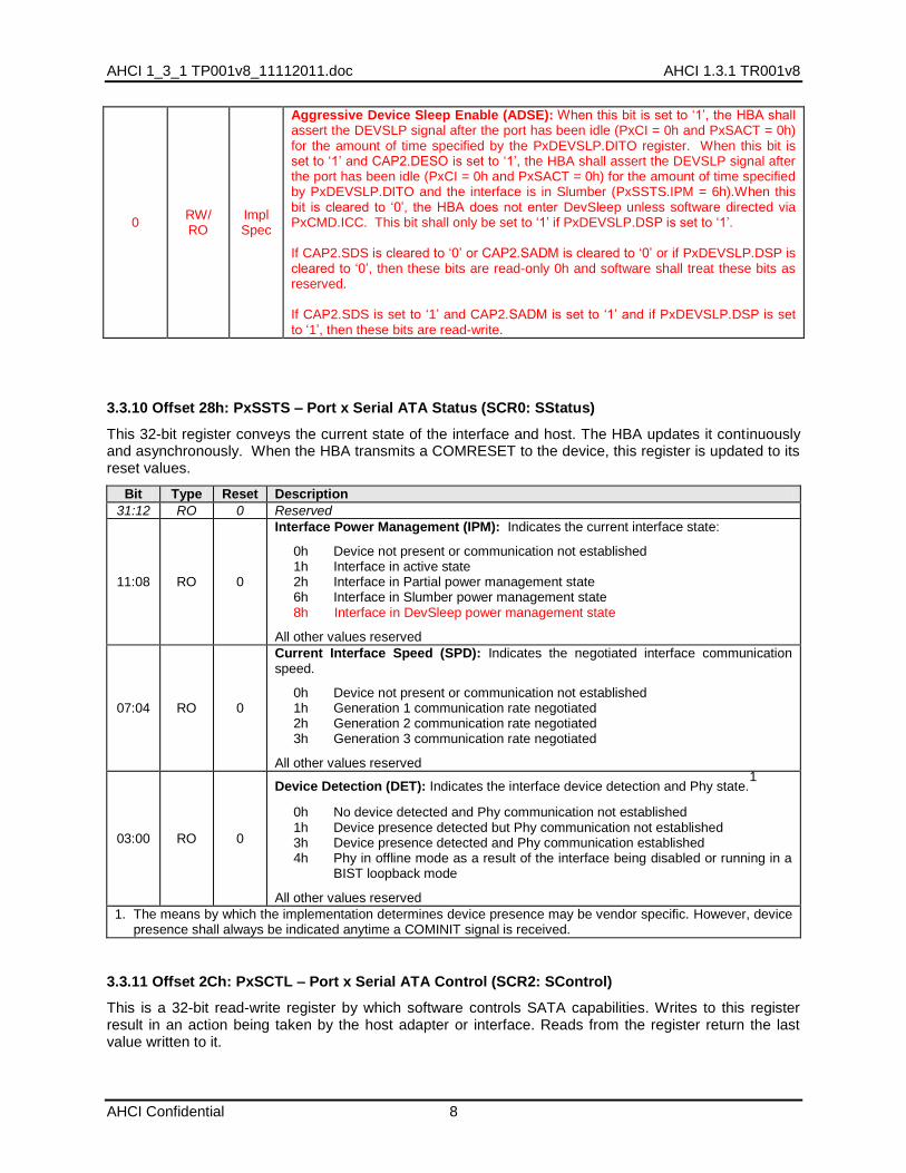
0 RW/ RO
Impl Spec
Aggressive Device Sleep Enable (ADSE): When this bit is set to „1‟, the HBA shall assert the DEVSLP signal after the port has been idle (PxCI = 0h and PxSACT = 0h) for the amount of time specified by the PxDEVSLP.DITO register. When this bit is set to „1‟ and CAP2.DESO is set to „1‟, the HBA shall assert the DEVSLP signal after the port has been idle (PxCI = 0h and PxSACT = 0h) for the amount of time specified by PxDEVSLP.DITO and the interface is in Slumber (PxSSTS.IPM = 6h).When this bit is cleared to „0‟, the HBA does not enter DevSleep unless software directed via PxCMD.ICC. This bit shall only be set to „1‟ if PxDEVSLP.DSP is set to „1‟. If CAP2.SDS is cleared to „0‟ or CAP2.SADM is cleared to „0‟ or if PxDEVSLP.DSP is cleared to „0‟, then these bits are read-only 0h and software shall treat these bits as reserved. If CAP2.SDS is set to „1‟ and CAP2.SADM is set to „1‟ and if PxDEVSLP.DSP is set to „1‟, then these bits are read-write.
3.3.10 Offset 28h: PxSSTS – Port x Serial ATA Status (SCR0: SStatus)
This 32-bit register conveys the current state of the interface and host. The HBA updates it continuously and asynchronously. When the HBA transmits a COMRESET to the device, this register is updated to its reset values.
Bit Type Reset Description
31:12 RO 0 Reserved
11:08 RO 0
Interface Power Management (IPM): Indicates the current interface state:
0h Device not present or communication not established 1h Interface in active state 2h Interface in Partial power management state 6h Interface in Slumber power management state 8h Interface in DevSleep power management state
All other values reserved
07:04 RO 0
Current Interface Speed (SPD): Indicates the negotiated interface communication speed.
0h Device not present or communication not established 1h Generation 1 communication rate negotiated 2h Generation 2 communication rate negotiated 3h Generation 3 communication rate negotiated
All other values reserved
03:00 RO 0
Device Detection (DET): Indicates the interface device detection and Phy state.1
0h No device detected and Phy communication not established 1h Device presence detected but Phy communication not established 3h Device presence detected and Phy communication established 4h Phy in offline mode as a result of the interface being disabled or running in a
BIST loopback mode
All other values reserved
1. The means by which the implementation determines device presence may be vendor specific. However, device presence shall always be indicated anytime a COMINIT signal is received.
3.3.11 Offset 2Ch: PxSCTL – Port x Serial ATA Control (SCR2: SControl)
This is a 32-bit read-write register by which software controls SATA capabilities. Writes to this register result in an action being taken by the host adapter or interface. Reads from the register return the last value written to it.

AHCI 1.3.1 Technical Proposal AHCI 1_3_1 TP001v8_11112011.doc
9
Bit Type Reset Description
31:20 RO 0 Reserved
19:16 RO 0h Port Multiplier Port (PMP): This field is not used by AHCI.
15:12 RO 0h Select Power Management (SPM): This field is not used by AHCI
11:08 RW 0h
Interface Power Management Transitions Allowed (IPM): Indicates which power states the HBA is allowed to transition to. If an interface power management state is disabled, the HBA is not allowed to initiate that state and the HBA must PMNAKP any request from the device to enter that state.
0h No interface restrictions 1h Transitions to the Partial state disabled 2h Transitions to the Slumber state disabled 3h Transitions to both Partial and Slumber states disabled 4h Transitions to the DevSleep power management state are disabled 5h Transitions to the Partial and DevSleep power management states are disabled 6h Transitions to the Slumber and DevSleep power management states are disabled 7h Transitions to the Partial, Slumber and DevSleep power management states are disabled All other values reserved
07:04 RW 0h
Speed Allowed (SPD): Indicates the highest allowable speed of the interface.
0h No speed negotiation restrictions 1h Limit speed negotiation to Generation 1 communication rate 2h Limit speed negotiation to a rate not greater than Generation 2
communication rate 3h Limit speed negotiation to a rate not greater than Generation 3
communication rate
All other values reserved
03:00 RW 0h
Device Detection Initialization (DET): Controls the HBA‟s device detection and interface initialization.
0h No device detection or initialization action requested 1h Perform interface communication initialization sequence to establish
communication. This is functionally equivalent to a hard reset and results in the interface being reset and communications reinitialized. While this field is 1h, COMRESET is transmitted on the interface. Software should leave the DET field set to 1h for a minimum of 1 millisecond to ensure that a COMRESET is sent on the interface.
4h Disable the Serial ATA interface and put Phy in offline mode.
All other values reserved
This field may only be modified when PxCMD.ST is „0‟. Changing this field while the PxCMD.ST bit is set to „1‟ results in undefined behavior. When PxCMD.ST is set to „1‟, this field should have a value of 0h.Note: It is permissible to implement any of the Serial ATA defined behaviors for transmission of COMRESET when DET=1h.
5.3 HBA Port State Machine (Normative)
The state machine arcs are in priority order and are not required to be mutually exclusive. For example, if both the first arc and second arc of a state are true, the first arc is always taken. Subsequent arcs are not evaluated until the previous arc is determined to be false.
Implementation Note: HBA state variables are used to describe the required externally visible behavior.
Implementations are not required to have internal state values that directly correspond to these variables.
AHCI 1_3_1 TP001v8_11112011.doc AHCI 1.3.1 TR001v8
AHCI Confidential 10
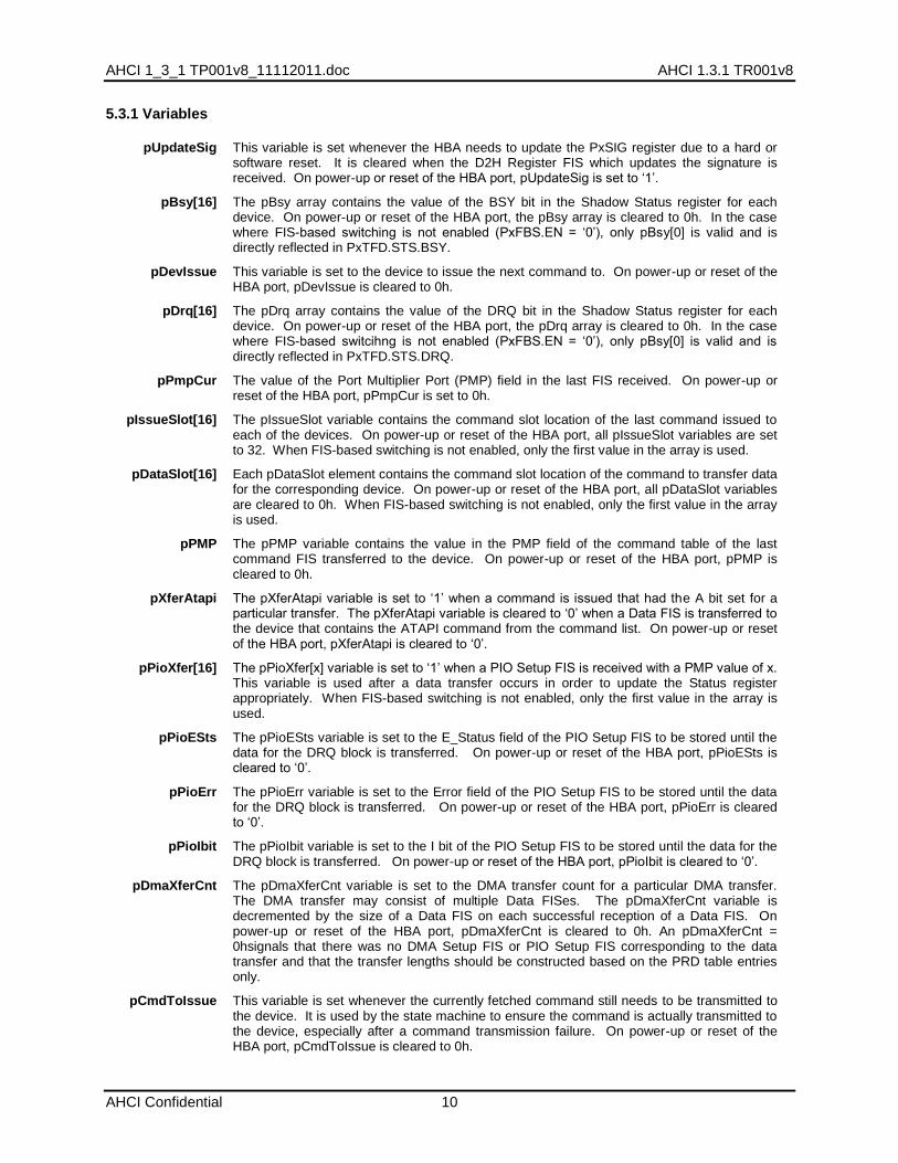
5.3.1 Variables
pUpdateSig This variable is set whenever the HBA needs to update the PxSIG register due to a hard or software reset. It is cleared when the D2H Register FIS which updates the signature is received. On power-up or reset of the HBA port, pUpdateSig is set to „1‟.
pBsy[16] The pBsy array contains the value of the BSY bit in the Shadow Status register for each device. On power-up or reset of the HBA port, the pBsy array is cleared to 0h. In the case where FIS-based switching is not enabled (PxFBS.EN = „0‟), only pBsy[0] is valid and is directly reflected in PxTFD.STS.BSY.
pDevIssue This variable is set to the device to issue the next command to. On power-up or reset of the HBA port, pDevIssue is cleared to 0h.
pDrq[16] The pDrq array contains the value of the DRQ bit in the Shadow Status register for each device. On power-up or reset of the HBA port, the pDrq array is cleared to 0h. In the case where FIS-based switcihng is not enabled (PxFBS.EN = „0‟), only pBsy[0] is valid and is directly reflected in PxTFD.STS.DRQ.
pPmpCur The value of the Port Multiplier Port (PMP) field in the last FIS received. On power-up or reset of the HBA port, pPmpCur is set to 0h.
pIssueSlot[16] The pIssueSlot variable contains the command slot location of the last command issued to each of the devices. On power-up or reset of the HBA port, all pIssueSlot variables are set to 32. When FIS-based switching is not enabled, only the first value in the array is used.
pDataSlot[16] Each pDataSlot element contains the command slot location of the command to transfer data for the corresponding device. On power-up or reset of the HBA port, all pDataSlot variables are cleared to 0h. When FIS-based switching is not enabled, only the first value in the array is used.
pPMP The pPMP variable contains the value in the PMP field of the command table of the last command FIS transferred to the device. On power-up or reset of the HBA port, pPMP is cleared to 0h.
pXferAtapi The pXferAtapi variable is set to „1‟ when a command is issued that had the A bit set for a particular transfer. The pXferAtapi variable is cleared to „0‟ when a Data FIS is transferred to the device that contains the ATAPI command from the command list. On power-up or reset of the HBA port, pXferAtapi is cleared to „0‟.
pPioXfer[16] The pPioXfer[x] variable is set to „1‟ when a PIO Setup FIS is received with a PMP value of x. This variable is used after a data transfer occurs in order to update the Status register appropriately. When FIS-based switching is not enabled, only the first value in the array is used.
pPioESts The pPioESts variable is set to the E_Status field of the PIO Setup FIS to be stored until the data for the DRQ block is transferred. On power-up or reset of the HBA port, pPioESts is cleared to „0‟.
pPioErr The pPioErr variable is set to the Error field of the PIO Setup FIS to be stored until the data for the DRQ block is transferred. On power-up or reset of the HBA port, pPioErr is cleared to „0‟.
pPioIbit The pPioIbit variable is set to the I bit of the PIO Setup FIS to be stored until the data for the DRQ block is transferred. On power-up or reset of the HBA port, pPioIbit is cleared to „0‟.
pDmaXferCnt The pDmaXferCnt variable is set to the DMA transfer count for a particular DMA transfer. The DMA transfer may consist of multiple Data FISes. The pDmaXferCnt variable is decremented by the size of a Data FIS on each successful reception of a Data FIS. On power-up or reset of the HBA port, pDmaXferCnt is cleared to 0h. An pDmaXferCnt = 0hsignals that there was no DMA Setup FIS or PIO Setup FIS corresponding to the data transfer and that the transfer lengths should be constructed based on the PRD table entries only.
pCmdToIssue This variable is set whenever the currently fetched command still needs to be transmitted to the device. It is used by the state machine to ensure the command is actually transmitted to the device, especially after a command transmission failure. On power-up or reset of the HBA port, pCmdToIssue is cleared to 0h.

AHCI 1.3.1 Technical Proposal AHCI 1_3_1 TP001v8_11112011.doc
11
pPrdIntr[16] This pPrdIntr[x] variable is set whenever the HBA completes a PRD in either the data transmission or data reception states for the device with a PMP value of x. It is used to generate a PRD interrupt at the end of a successful data FIS. On power-up or reset of the HBA port, pPrdIntr is cleared to 0h. When FIS-based switching is not enabled, only the first value in the array is used.
pSActive This variable is set to the value of the SActive field in a received Set Device Bits FIS. On power-up or reset of the HBA port, pSActive is cleared to 0h.
pSlotLoc This variable is used to track the command slot location the HBA will issue a command from next if one is available in that slot for issue. On power-up or reset of the HBA port, pSlotLoc is cleared to 0h.
pDitoTimeout This variable is set when the HBA port specific DITO timer (PxDEVSLP.DITO* (PxDEVSLP.DM+1)) has reached zero. pDitoTimeout is used by the HBA port to determine if it‟s allowed to assert the DEVSLP signal when it‟s idle. This variable is cleared when the HBA port‟s DEVSLP signal is asserted or when the HBA„s port idle timer is reloaded. On power-up or reset of the HBA port, pDitotimeout is cleared to 0h.
pMdatTimeout This variable is set when the HBA port specific minimum DEVSLP singal assertion time (PxDEVSLP.MDAT) has reached zero. pMdatTimeout is used by the HBA port to determine if it‟s allowed to de-assert the DEVSLP signal. This variable is cleared when the HBA port‟s DEVSLP signal is de-asserted or when the HBA„s MDAT timer is reloaded. On power-up or reset of the HBA port, pMdatTimeout is cleared to 0h.
5.3.2 Port Idle States
5.3.2.1 P:Init
P:Init The HBA performs the following actions: 1. Resets all port state machine variables to their reset values, as specified in
section 0. 2. Resets all port specific register fields (for all ports) except those fields marked
as HwInit and the PxFB/PxFBU/PxCLB/PxCLBU/PxDEVSLP registers. 3. Clears pBsy[0] to „0‟ and sets pDrq[0] to „1‟. 4. Resets PxTFD.STS to 7Fh and sets pUpdateSig to „1‟. 5. Transmits COMRESET to the device if PxCMD.SUD=‟1‟.
1. Unconditional P:NotRunning
The P:Init state is entered after a controller reset is completed. P:Init initializes all of the state machine variables and port specific registers. If cold presence detect is supported as specified in PxCMD.CPD, the power to the port is off by default and remains off until software enables power to the port.
5.3.2.3 P:NotRunning
P:NotRunning HBA sets all pIssueSlot array variables to 32. HBA sets pSlotLoc = CAP.NCS. For devices, where x is 1 to 15, pBsy[x] and pDrq[x] variables are cleared to 0h.
1. GHC.AE is cleared to „0‟ P:NotRunning
2. PxCMD.POD written to „1‟ from a „0‟ P:PowerOn
3. PxCMD.POD written to „0‟ from a „1‟ P:PowerOff
4. PxSCTL.DET written to „4h‟ from any other value P:Offline
5. PxSCTL.DET written to 1h from any other value and PxCMD.SUD = „1‟
P:StartComm
6. PxCMD.SUD written to „1‟ from „0‟ and PxSCTL.DET = „0h‟ P:StartComm
7. PxCMD.SUD written to „0‟ from „1‟ and PxSCTL.DET = „0h‟ P:PhyListening
8. PxCMD.FRE written to „1‟ from a „0‟ and previously processed Register FIS is in receive FIFO and PxSERR.DIAG.X = „0‟
P:RegFisPostToMem
AHCI 1_3_1 TP001v8_11112011.doc AHCI 1.3.1 TR001v8
AHCI Confidential 12
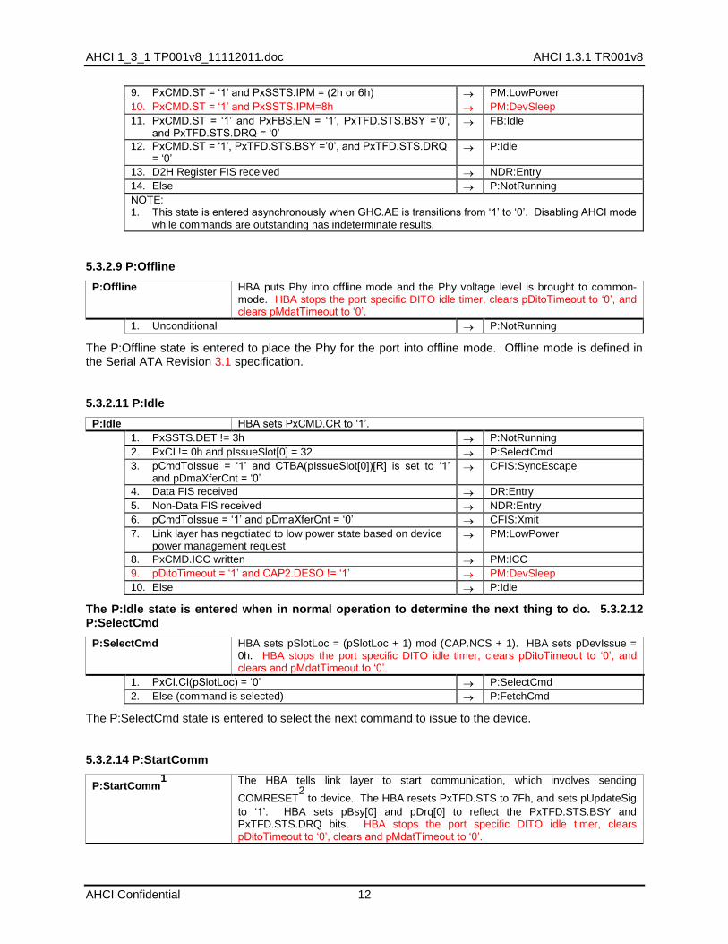
9. PxCMD.ST = „1‟ and PxSSTS.IPM = (2h or 6h) PM:LowPower
10. PxCMD.ST = „1‟ and PxSSTS.IPM=8h PM:DevSleep
11. PxCMD.ST = „1‟ and PxFBS.EN = „1‟, PxTFD.STS.BSY =‟0‟, and PxTFD.STS.DRQ = „0‟
FB:Idle
12. PxCMD.ST = „1‟, PxTFD.STS.BSY =‟0‟, and PxTFD.STS.DRQ = „0‟
P:Idle
13. D2H Register FIS received NDR:Entry
14. Else P:NotRunning
NOTE: 1. This state is entered asynchronously when GHC.AE is transitions from „1‟ to „0‟. Disabling AHCI mode
while commands are outstanding has indeterminate results.
5.3.2.9 P:Offline
P:Offline HBA puts Phy into offline mode and the Phy voltage level is brought to common-mode. HBA stops the port specific DITO idle timer, clears pDitoTimeout to „0‟, and clears pMdatTimeout to „0‟.
1. Unconditional P:NotRunning
The P:Offline state is entered to place the Phy for the port into offline mode. Offline mode is defined in the Serial ATA Revision 3.1 specification.
5.3.2.11 P:Idle
P:Idle HBA sets PxCMD.CR to „1‟.
1. PxSSTS.DET != 3h P:NotRunning
2. PxCI != 0h and pIssueSlot[0] = 32 P:SelectCmd
3. pCmdToIssue = „1‟ and CTBA(pIssueSlot[0])[R] is set to „1‟ and pDmaXferCnt = „0‟
CFIS:SyncEscape
4. Data FIS received DR:Entry
5. Non-Data FIS received NDR:Entry
6. pCmdToIssue = „1‟ and pDmaXferCnt = „0‟ CFIS:Xmit
7. Link layer has negotiated to low power state based on device power management request
PM:LowPower
8. PxCMD.ICC written PM:ICC
9. pDitoTimeout = „1‟ and CAP2.DESO != „1‟ PM:DevSleep
10. Else P:Idle
The P:Idle state is entered when in normal operation to determine the next thing to do. 5.3.2.12 P:SelectCmd
P:SelectCmd HBA sets pSlotLoc = (pSlotLoc + 1) mod (CAP.NCS + 1). HBA sets pDevIssue = 0h. HBA stops the port specific DITO idle timer, clears pDitoTimeout to „0‟, and clears and pMdatTimeout to „0‟.
1. PxCI.CI(pSlotLoc) = „0‟ P:SelectCmd
2. Else (command is selected) P:FetchCmd
The P:SelectCmd state is entered to select the next command to issue to the device.
5.3.2.14 P:StartComm
P:StartComm1
The HBA tells link layer to start communication, which involves sending
COMRESET2 to device. The HBA resets PxTFD.STS to 7Fh, and sets pUpdateSig
to „1‟. HBA sets pBsy[0] and pDrq[0] to reflect the PxTFD.STS.BSY and PxTFD.STS.DRQ bits. HBA stops the port specific DITO idle timer, clears pDitoTimeout to „0‟, clears and pMdatTimeout to „0‟.
AHCI 1.3.1 Technical Proposal AHCI 1_3_1 TP001v8_11112011.doc
13
1. PxSCTL.DET = 1h P:StartComm
2. Unconditional P:NotRunning
NOTE: 1. Hardware polling to determine if a device is present is an implementation specific detail. A polling
strategy is not specified in AHCI. 2. It is permissible to implement any of the Serial ATA defined behaviors for transmission of COMRESET
when DET=1h.
The P:StartComm state is entered to start communication with the device by issuing a COMRESET.
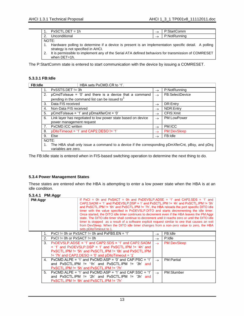
5.3.3.1 FB:Idle
FB:Idle HBA sets PxCMD.CR to „1‟.
1. PxSSTS.DET != 3h P:NotRunning
2. pCmdToIssue = „0‟ and there is a device that a command
pending in the command list can be issued to1
FB:SelectDevice
3. Data FIS received DR:Entry
4. Non-Data FIS received NDR:Entry
5. pCmdToIssue = „1‟ and pDmaXferCnt = „0‟ CFIS:Xmit
6. Link layer has negotiated to low power state based on device power management request
PM:LowPower
7. PxCMD.ICC written PM:ICC
8. pDitoTimeout = „1‟ and CAP2.DESO != „1‟ PM:DevSleep
9. Else FB:Idle
NOTE: 1. The HBA shall only issue a command to a device if the corresponding pDmXferCnt, pBsy, and pDrq
variables are zero.
The FB:Idle state is entered when in FIS-based switching operation to determine the next thing to do.
5.3.4 Power Management States
These states are entered when the HBA is attempting to enter a low power state when the HBA is at an idle condition.
5.3.4.1 PM:Aggr PM:Aggr If PxCI = 0h and PxSACT = 0h and PxDEVSLP.ADSE = „1‟ and CAP2.SDS = „1‟ and
CAP2.SADM = „1‟ and PxDEVSLP.DSP = 1‟ and PxSCTL.IPM != „4h‟ and PxSCTL.IPM != „5h‟ and PxSCTL.IPM != „6h‟ and PxSCTL.IPM != „7h‟, the HBA reloads the port specific DITO idle timer with the value specified in PxDEVSLP.DITO and starts decrementing the idle timer. Once started, the DITO idle timer continues to decrement even if the HBA leaves the PM:Aggr state. The DITO idle timer shall continue to decrement until it reachs zero or until the DITO idle timer is stopped as a result of a software explicit request similar to one that causes an exit from DevSleep. When the DITO idle timer changes from a non-zero value to zero, the HBA sets pDitoTimeout to 1.
1. PxCI != 0h or PxSACT != 0h and PxFBS.EN = „1‟ FB:Idle
2. PxCI != 0h or PxSACT != 0h P:Idle
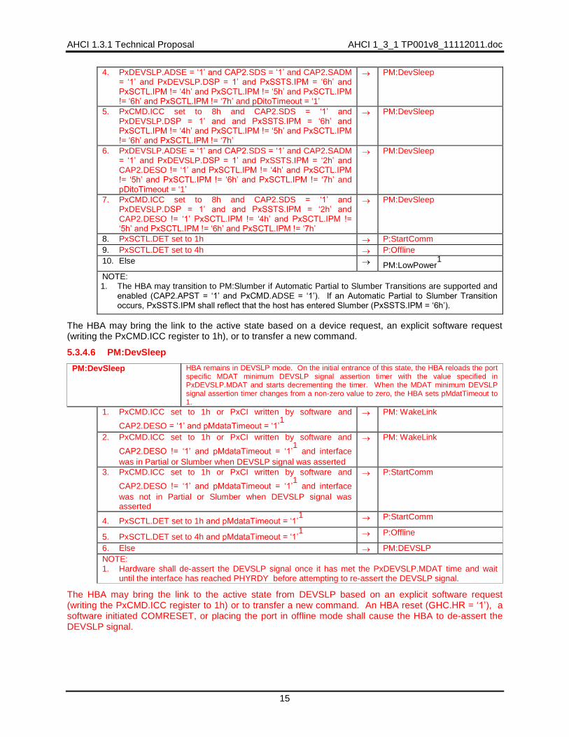
3. PxDEVSLP.ADSE = „1‟ and CAP2.SDS = „1‟ and CAP2.SADM = „1‟ and PxDEVSLP.DSP = 1‟ and PxSCTL.IPM != „4h‟ and PxSCTL.IPM != „5h‟ and PxSCTL.IPM != „6h‟ and PxSCTL.IPM != „7h‟ and CAP2.DESO = „0‟ and pDitoTimeout = „1‟
PM:DevSleep
4. PxCMD.ALPE = „1‟ and PxCMD.ASP = „0‟ and CAP.PSC = „1‟ and PxSCTL.IPM != „1h‟ and PxSCTL.IPM != „3h‟ and PxSCTL.IPM != „5h‟ and PxSCTL.IPM != „7h‟
PM:Partial
5. PxCMD.ALPE = „1‟ and PxCMD.ASP = „1‟ and CAP.SSC = „1‟ and PxSCTL.IPM != „2h‟ and PxSCTL.IPM != „3h‟ and PxSCTL.IPM != „6h‟ and PxSCTL.IPM != „7h‟
PM:Slumber

AHCI 1_3_1 TP001v8_11112011.doc AHCI 1.3.1 TR001v8
AHCI Confidential 14
6. PxFBS.EN = „1‟ FB:Idle
7. Else P:Idle
In this state, the HBA determines whether it can place the link into a low power state if aggressive power management is enabled or the HBA determines whether it can assert DEVSLP signaling if aggressive DEVSLP management is enabled and the DEVSLP timer has expired (PxDEVSLP.DITO). The link can only be placed into a low power state if both the PxCI and the PxSACT registers are cleared to zero which indicates there are no commands outstanding.
5.3.4.2 PM:ICC
PM:ICC If the value written by software to PxCMD.ICC was 1h, the HBA stops the port specific DITO idle timer and clears pDitoTimeout to „0‟.
1. Value written by software to PxCMD.ICC was 8h and CAP2.SDS = „1‟ and PxDEVSLP.DSP = 1‟ and PxSCTL.IPM != „4h‟ and PxSCTL.IPM != „5h‟ and PxSCTL.IPM != „6h‟ and PxSCTL.IPM != „7h‟ and CAP2.DESO = „1‟ and PxSSTS.IPM = „6h‟
PM:DevSleep
2. Value written by software to PxCMD.ICC was 8h and CAP2.SDS = „1‟ and PxDEVSLP.DSP = 1‟ and PxSCTL.IPM != „4h‟ and PxSCTL.IPM != „5h‟ and PxSCTL.IPM != „6h‟ and PxSCTL.IPM != „7h‟ and CAP2.DESO != „1‟
PM:DevSleep
3. Value written by software to PxCMD.ICC was 6h PM:Slumber
4. Value written by software to PxCMD.ICC was 2h PM:Partial
5. PxFBS.EN = „1‟ FB:Idle
6. Else P:Idle
The HBA enters this state when PxCMD.ICC is written when the HBA is idle. If software has requested a Slumber or Partial power management request, the HBA will attempt to bring the link to that power state.
5.3.4.3 PM:Partial
PM:Partial HBA attempts to place the link in the Partial interface power management state
1. Transition to Partial successful PM:LowPower
2. PxFBS.EN = „1‟ FB:Idle
3. Else P:Idle
The HBA is not guaranteed to succeed in placing the link in the Partial interface power management state due to a number of reasons including the current value of the PxSSTS.IPM field and whether the device responds with PMNAKP to the request.
5.3.4.4 PM:Slumber
PM:Slumber HBA attempts to place the link in the Slumber interface power management state
1. Transition to Slumber successful PM:LowPower
2. PxFBS.EN = „1‟ FB:Idle
3. Else P:Idle
The HBA is not guaranteed to succeed in placing the link in the Slumber power management state due to a number of reasons including the current value of the PxSSTS.IPM field and whether the device responds with PMNAKP to the request.
5.3.4.5 PM:LowPower
PM:LowPower HBA remains in low power state negotiated (Partial or Slumber). If PxCMD.ICC is set
to 1h, the HBA stops the port specific DITO idle timer and clears pDitoTimeout to „0‟.
1. COMWAKE received from the device PM:WakeLink
2. PxCMD.ICC set to 1h PM:WakeLink
3. PxCI written by software PM:WakeLink
AHCI 1.3.1 Technical Proposal AHCI 1_3_1 TP001v8_11112011.doc
15
4. PxDEVSLP.ADSE = „1‟ and CAP2.SDS = „1‟ and CAP2.SADM = „1‟ and PxDEVSLP.DSP = 1‟ and PxSSTS.IPM = „6h‟ and PxSCTL.IPM != „4h‟ and PxSCTL.IPM != „5h‟ and PxSCTL.IPM != „6h‟ and PxSCTL.IPM != „7h‟ and pDitoTimeout = „1‟
PM:DevSleep
5. PxCMD.ICC set to 8h and CAP2.SDS = „1‟ and PxDEVSLP.DSP = 1‟ and and PxSSTS.IPM = „6h‟ and PxSCTL.IPM != „4h‟ and PxSCTL.IPM != „5h‟ and PxSCTL.IPM != „6h‟ and PxSCTL.IPM != „7h‟
PM:DevSleep
6. PxDEVSLP.ADSE = „1‟ and CAP2.SDS = „1‟ and CAP2.SADM = „1‟ and PxDEVSLP.DSP = 1‟ and PxSSTS.IPM = „2h‟ and CAP2.DESO != „1‟ and PxSCTL.IPM != „4h‟ and PxSCTL.IPM != „5h‟ and PxSCTL.IPM != „6h‟ and PxSCTL.IPM != „7h‟ and pDitoTimeout = „1‟
PM:DevSleep
7. PxCMD.ICC set to 8h and CAP2.SDS = „1‟ and PxDEVSLP.DSP = 1‟ and and PxSSTS.IPM = „2h‟ and CAP2.DESO != „1‟ PxSCTL.IPM != „4h‟ and PxSCTL.IPM != „5h‟ and PxSCTL.IPM != „6h‟ and PxSCTL.IPM != „7h‟
PM:DevSleep
8. PxSCTL.DET set to 1h P:StartComm
9. PxSCTL.DET set to 4h P:Offline
10. Else PM:LowPower1
NOTE: 1. The HBA may transition to PM:Slumber if Automatic Partial to Slumber Transitions are supported and
enabled (CAP2.APST = „1‟ and PxCMD.ADSE = „1‟). If an Automatic Partial to Slumber Transition occurs, PxSSTS.IPM shall reflect that the host has entered Slumber (PxSSTS.IPM = „6h‟).
The HBA may bring the link to the active state based on a device request, an explicit software request (writing the PxCMD.ICC register to 1h), or to transfer a new command.
5.3.4.6 PM:DevSleep
PM:DevSleep HBA remains in DEVSLP mode. On the initial entrance of this state, the HBA reloads the port specific MDAT minimum DEVSLP signal assertion timer with the value specified in PxDEVSLP.MDAT and starts decrementing the timer. When the MDAT minimum DEVSLP signal assertion timer changes from a non-zero value to zero, the HBA sets pMdatTimeout to 1.
1. PxCMD.ICC set to 1h or PxCI written by software and
CAP2.DESO = „1‟ and pMdataTimeout = „1‟1
PM: WakeLink
2. PxCMD.ICC set to 1h or PxCI written by software and
CAP2.DESO != „1‟ and pMdataTimeout = „1‟1
and interface
was in Partial or Slumber when DEVSLP signal was asserted
PM: WakeLink
3. PxCMD.ICC set to 1h or PxCI written by software and
CAP2.DESO != „1‟ and pMdataTimeout = „1‟1
and interface
was not in Partial or Slumber when DEVSLP signal was asserted
P:StartComm
4. PxSCTL.DET set to 1h and pMdataTimeout = „1‟
1 P:StartComm
5. PxSCTL.DET set to 4h and pMdataTimeout = „1‟
1 P:Offline
6. Else PM:DEVSLP
NOTE: 1. Hardware shall de-assert the DEVSLP signal once it has met the PxDEVSLP.MDAT time and wait
until the interface has reached PHYRDY before attempting to re-assert the DEVSLP signal.
The HBA may bring the link to the active state from DEVSLP based on an explicit software request (writing the PxCMD.ICC register to 1h) or to transfer a new command. An HBA reset (GHC.HR = „1‟), a software initiated COMRESET, or placing the port in offline mode shall cause the HBA to de-assert the DEVSLP signal.
AHCI 1_3_1 TP001v8_11112011.doc AHCI 1.3.1 TR001v8
AHCI Confidential 16
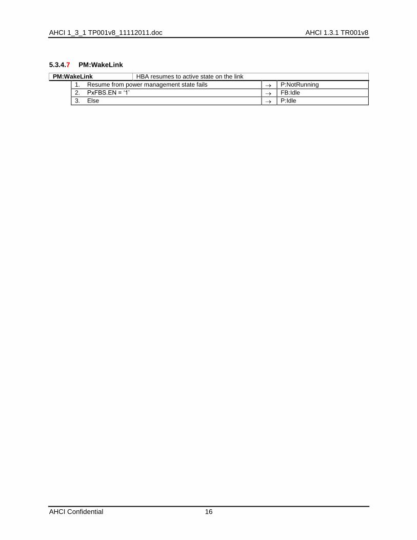
5.3.4.7 PM:WakeLink
PM:WakeLink HBA resumes to active state on the link
1. Resume from power management state fails P:NotRunning
2. PxFBS.EN = „1‟ FB:Idle
3. Else P:Idle

AHCI 1.3.1 Technical Proposal AHCI 1_3_1 TP001v8_11112011.doc
17
2 Additions to Section 8
2.1 Description of Technical Issue
The following section is added to the specification to describe how the Device Sleep feature may be utilized by the host:
8.5.1 Device Sleep (DEVSLP) Feature
Device Sleep is an optional feature as described in the Serial ATA Technical Proposal TP 038 specification. This feature enables an HBA and SATA storage device to enter the DevSleep interface state, enabling lower power SATA-based systems. For a system to support Device Sleep, the device, the HBA and the system BIOS/driver all need to support Device Sleep.
In systems that support Device Sleep, an HBA may individually initiate Device Sleep to those devices that support the capability. Entry to the DevSleep interface state may be accomplished autonomously by the HBA via the aggressive Device Sleep mechanism or through software utilizing the PxCMD.ICC field (similar to how Partial and Slumber are managed). Device Sleep is never initiated by the device.
Software shall check CAP2.SDS to determine if the HBA supports the Device Sleep feature. Before software programs the HBA to assert the DEVSLP signal (either autonomously or through software) on a Device Sleep capable port (PxDEVSLP.DSP = „1‟), software shall first determine if the attached device supports the Device Sleep feature. Only ATA devices support Device Sleep. Software shall set PxDEVSLP.MDAT to the minimum duration the HBA must assert the DEVSLP signal and PxDEVSLP.DETO to the maximum duration from DEVSLP signal de-assertion until the device is ready to start OOB negotiations based on the values reported by the device. Refer to the Serial ATA Technical Proposal TP 038 for further details.
The current state of an interface‟s DevSleep state is reflected to software in PxSSTS.IPM.
Note: Native hot plug shall not be used in combination with DEVSLP, as the host is not aware of unplug events during the DEVSLP state.
8.5.1.1 Aggressive Device Sleep Management
The HBA may implement aggressive Device Sleep management, as indicated in CAP2.SADM. Aggressive Device Sleep enables the HBA to assert the DEVSLP signal as soon as there are no commands outstanding to the device and the port specific Device Sleep idle timer has expired. This enables autonomous entry into the DevSleep interface state without waiting for software in power sensitive systems. The PxDEVSLP.ADSE bit defines whether the feature is enabled and the combination of PxDEVSLP.DITO and PxDEVSLP.DM values controls the amount of hysteresis to apply before the HBA asserts the DEVSLP signal.
When PxDEVSLP.ADSE is set to „1‟ and CAP2.DESO is cleared to „0‟, if the HBA recognizes that there are no commands to process and the port specific Device Sleep idle timer has expired, the HBA shall assert the DEVSLP signal. When PxDEVSLP.ADSE is set to „1‟ and CAP2.DESO is set to „1‟, if the HBA recognizes that there are no commands to process, the interface is in Slumber (PxSSTS.IPM = „6h‟), and the port specific Device Sleep idle timer has expired, the HBA shall assert the DEVSLP signal. The HBA begins decrementing the Device Sleep idle timer anytime the HBA has no commands to process. The HBA recognizes no commands to process as either:
PxSACT is set to 0h, and the HBA updates PxCI from a non-zero value to 0h.
PxCI is set to 0h, and a Set Device Bits FIS is received that updates PxSACT from a non-zero value to 0h.
There is no requirement that the interface be in the Partial or Slumber state prior to assertion of DEVSLP signal unless CAP2.DESO is set to „1‟; The DEVSLP signal may be asserted by the HBA at anytime provided that the link is idle (or in low power state) and no commands are outstanding. If CAP2.DESO is set to „1‟, The DEVSLP signal may only be asserted by the HBA if the interface is in Slumber (PxSSTS.IPM = „6h‟).
AHCI 1_3_1 TP001v8_11112011.doc AHCI 1.3.1 TR001v8
AHCI Confidential 18
Software shall check CAP2.SDS to determine if the HBA supports the Device Sleep feature and CAP2.SADM to determine if the HBA supports the aggressive Device Sleep management feature. If the HBA does not support Device Sleep or a port does not support Device Sleep, then software shall not enable the aggressive Device Sleep management capability.
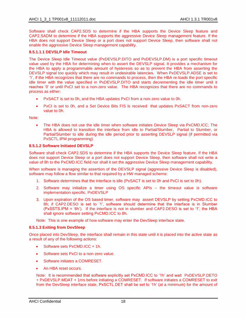
8.5.1.1.1 DEVSLP Idle Timeout
The Device Sleep Idle Timeout value (PxDEVSLP.DITO and PxDEVSLP.DM) is a port specific timeout value used by the HBA for determining when to assert the DEVSLP signal. It provides a mechanism for the HBA to apply a programmable amount of hysteresis so as to prevent the HBA from asserting the DEVSLP signal too quickly which may result in undesirable latencies. When PxDEVSLP.ADSE is set to „1‟, if the HBA recognizes that there are no commands to process, then the HBA re-loads the port specific idle timer with the value specified in PxDEVSLP.DITO and starts decrementing the idle timer until it reaches „0‟ or until PxCI set to a non-zero value. The HBA recognizes that there are no commands to process as either:
PxSACT is set to 0h, and the HBA updates PxCI from a non-zero value to 0h.
PxCI is set to 0h, and a Set Device Bits FIS is received that updates PxSACT from non-zero value to 0h.
Note:
The HBA does not use the idle timer when software initiates Device Sleep via PxCMD.ICC; The HBA is allowed to transition the interface from idle to Partial/Slumber, Partial to Slumber, or Partial/Slumber to idle during the idle period prior to asserting DEVSLP signal (if permitted via PxSCTL.IPM programming).
8.5.1.2 Software Initiated DEVSLP
Software shall check CAP2.SDS to determine if the HBA supports the Device Sleep feature. If the HBA does not support Device Sleep or a port does not support Device Sleep, then software shall not write a value of 8h to the PxCMD.ICC field nor shall it set the aggressive Device Sleep management capability.
When software is managing the assertion of the DEVSLP signal (aggressive Device Sleep is disabled), software may follow a flow similar to that required by a HW managed scheme:
1. Software determines that the interface is idle (PxSACT is set to 0h and PxCI is set to 0h).
2. Software may initialize a timer using OS specific APIs – the timeout value is software implementation specific. PxDEVSLP
3. Upon expiration of the OS based timer, software may assert DEVSLP by setting PxCMD.ICC to 8h; if CAP2.DESO is set to „1‟, software should determine that the interface is in Slumber (PxSSTS.IPM = „6h‟). If the interface is not in slumber and CAP2.DESO is set to „1‟, the HBA shall ignore software setting PxCMD.ICC to 8h.
Note: This is one example of how software may enter the DevSleep interface state.
8.5.1.3 Exiting from DevSleep
Once placed into DevSleep, the interface shall remain in this state until it is placed into the active state as a result of any of the following actions:
Software sets PxCMD.ICC = 1h.
Software sets PxCI to a non-zero value.
Software initiates a COMRESET.
An HBA reset occurs.
Note: It is recommended that software explicitly set PxCMD.ICC to „1h‟ and wait PxDEVSLP.DETO + PxDEVSLP.MDAT + 1ms before initiating a COMRESET. If software initiates a COMRESET to exit from the DevSleep interface state, PxSCTL.DET shall be set to „1h‟ (at a minimum) for the amount of
AHCI 1.3.1 Technical Proposal AHCI 1_3_1 TP001v8_11112011.doc
19
time specified by PxDEVSLP.DETO + PxDEVSLP.MDAT + 1ms. If software places the port in Offline mode while in the DevSleep interface state, PxSCTL.DET shall be set to „4h‟ (at a minimum) for the amount of time specified by PxDEVSLP.DETO + PxDEVSLP.MDAT + 1ms.
When the HBA exits the DevSleep interface power state due to software setting PxCI to a non-zero value and:
a) the interface was not in Partial or Slumber prior to entering the DevSleep interface power state or;
b) the device does not support exiting DevSleep with COMWAKE; resulting in a COMINIT;
this shall result in a transition to StartComm (COMRESET) either by the HBA or software response to PxIS.PCS being set to „1‟. Software should take appropriate action to retry the command(s) that originally resulted in setting PxCI to a non-zero value.
8.5.1.4 Device Sleep and Automatic Partial to Slumber Transition Support
Automatic Partial to Slumber Transitions may be supported with Device Sleep by the host and/or the device if CAP2.DESO is cleared to „0‟. If CAP2.DESO = „1‟ then HBA based Automatic Partial to Slumber Transitions shall be enabled (PxCMD.APSTE = „1‟), if device based Automatic Partial to Slumber Transitions are enabled. Software should not enable Automatic Partial to Slumber Transitions on the device if CAP2.DESO = „1‟ and Automatic Partial to Slumber Transitions on the HBA are not enabled.
8.5.1.5 Device Sleep and Mechanical Interlock Switch Support
If the DEVSLP signal is asserted on a port that provides mechanical interlock switch support, it shall be software‟s responsibility to de-assert and/or disable the DEVSLP signal when it has been determined that the mechanical interlock switch has been opened:
When the HBA is autonomously managing Device Sleep (CAP2.SADM is set to „1‟ and PxDEVSLP.ADSE is set to „1‟) on the port, software shall clear the port specific aggressive DEVSLP enable bit (PxDEVSLP.ADSE) to „0‟ and shall write a value of „1h‟ to PxCMD.ICC to de-assert the DEVSLP signal on the port..
When software is managing Device Sleep on the port (PxDEVSLP.ADSE is cleared to „0‟), software shall write a value of „1h‟ to PxCMD.ICC to de-assert the DEVSLP signal on the port.

AHCI 1_3_1 TP001v8_11112011.doc AHCI 1.3.1 TR001v8
AHCI Confidential 20
3 Additions to Section 10
3.1 Description of Technical Changes
Add details for DEVSLP support.
3.2 Description of Changes to Specification
Update sections as indicated in red
10.1.1 Firmware Specific Initialization
To aid system software during runtime, the BIOS shall ensure that the following registers are initialized to values that are reflective of the capabilities supported by the platform. Firmware shall always initialize the following registers and values:
CAP.SSS (support for staggered spin-up)
CAP.SMPS (support for mechanical presence switches)
PI (ports implemented)
PxCMD.HPCP (whether port is hot plug capable). Firmware shall initialize the HPCP bit for each port implemented on the platform (as defined by the PI register). The PxCMD.HPCP should be set to „1‟ if PxCMD.MPSP or PxCMD.CPD is set to „1‟ for the port.
PxCMD.MPSP (whether mechanical presence switch is attached to the port). Firmware shall initialize the MPSP bit for each port implemented on the platform (as defined by the PI register).
PxCMD.CPD (whether cold presence detect logic is attached to the port). Firmware shall initialize the CPD bit for each port implemented on the platform (as defined by the PI register).
PxDEVSLP.DSP (whether the port supports the DEVSLP logic). Firmware shall initialize the DSP bit for each port implemented on the platform (as defined by the PI register).
10.3.1 Start (PxCMD.ST)
When PxCMD.ST is set to „1‟, software is limited in what actions it is allowed to perform on the port (refer to section 0).
It shall not manipulate PxCMD.POD to power on or off a device through cold presence detect logic (if supported by the HBA).
It shall not manipulate PxSCTL.DET to change the Phy state
It shall not manipulate PxCMD.SUD to spin-up the device (if supported by the HBA)
The above actions are only allowed while the HBA is idle, indicated by both PxCMD.ST and PxCMD.CR being equal to „0‟. This is noted by the HBA state machine H:NotRunning state. If software performs any of the above actions while the port is not idle (PxCMD.ST or PxCMD.CR are set to „1‟), indeterminate results may occur.
Software shall not set PxCMD.ST to „1‟ until it verifies that PxCMD.CR is „0‟ and has set PxCMD.FRE to „1‟. Additionally, software shall not set PxCMD.ST to „1‟ until a functional device is present on the port (as determined by PxTFD.STS.BSY = „0‟, PxTFD.STS.DRQ = „0‟, and (PxSSTS.DET = 3h, or PxSSTS.IPM = 2h or 6h or 8h)) and PxCLB/PxCLBU are programmed to valid values.
Before the HBA enters the low power D3 state, software shall clear PxCMD.ST to „0‟.
Related Documents


![]w ‡z«Ób ‡Úô« l‡ «]d« =n]BK · A rrOO dd «« ssLL dd «« tt]]KK «« rr˝˝ ÔÔWW‡‡‡‡‡‡‡‡‡‡ÓÓ ==bb‡‡‡‡‡‡ÓÓIIÚÚ**«« Ub?O vÓKÓ](https://static.cupdf.com/doc/110x72/5bfb4e2409d3f25f758c6f4c/w-zob-uo-l-d-nbk-a-rroo-dd-ssll-dd-ttkk.jpg)