User’s Guide Agilent Technologies E7495A/B Option 330 Nortel CDMA Base Station Test Software Base Station Test Set E7495A/B Firmware Version: A.03.20 and later Option 330 Software Version: A.01.00 and later Manufacturing Part Number: E7495-90037 Printed in USA January 2005 © Copyright 2004-2005 Agilent Technologies, Inc.

Welcome message from author
This document is posted to help you gain knowledge. Please leave a comment to let me know what you think about it! Share it to your friends and learn new things together.
Transcript
User’s Guide
Agilent Technologies E7495A/B Option 330Nortel CDMA Base Station Test Software
Base Station Test Set
E7495A/B Firmware Version: A.03.20 and laterOption 330 Software Version: A.01.00 and later
Manufacturing Part Number: E7495-90037
Printed in USA
January 2005
© Copyright 2004-2005 Agilent Technologies, Inc.
The information contained in this document is subject to change without notice.
Agilent Technologies makes no warranty of any kind with regard to this material, including but not limited to, the implied warranties of merchantability and fitness for a particular purpose. Agilent Technologies shall not be liable for errors contained herein or for incidental or consequential damages in connection with the furnishing, performance, or use of this material.
Technology Licenses The hardware and/or software described in this document are furnished under a license and may be used or copied only in accordance with the terms of such license.
Restricted Rights LegendIf software is for use in the performance of a U.S. Government prime contract or subcontract, Software is delivered and licensed as “Commercial computer software” as defined in DFAR 252.227-7014 (June 1995), or as a “commercial item” as defined in FAR 2.101(a) or as “Restricted computer software” as defined in FAR 52.227-19 (June 1987) or any equivalent agency regulation or contract clause. Use, duplication or disclosure of Software is subject to Agilent Technologies’ standard commercial license terms, and non-DOD Departments and Agencies of the U.S. Government will receive no greater than Restricted Rights as defined in FAR 52.227-19(c)(1-2) (June 1987). U.S. Government users will receive no greater than Limited Rights as defined in FAR 52.227-14 (June 1987) or DFAR 252.227-7015 (b)(2) (November 1995), as applicable in any technical data.
Safety NoticesA CAUTION notice denotes a hazard. It calls attention to an operating procedure, practice, or the like that, if not correctly performed or adhered to, could result in damage to the product or loss of important data. Do not proceed beyond a CAUTION notice until the indicated conditions are fully understood and met.
2
A WARNING notice denotes a hazard. It calls attention to an operating procedure, practice, or the like that, if not correctly performed or adhered to, could result in personal injury or death. Do not proceed beyond a WARNING notice until the indicated conditions are fully understood and met.
RESTRICTED RIGHTS LEGENDUse, duplication or disclosure by the U. S. Government is subject to restrictions as set forth in subparagraph (c) (1) (ii) of the Rights in Technical Data and Computer Software Clause in DFARS 252.227-7013.
Rights for non-DOD U. S. Government Departments and Agencies are as set forth in FAR 52.227-19 (c) (1, 2).
3
Conventions Used Special presentations of text in this manual reflect the appearance of the referenced item. Examples of these special presentations are:
Procedure: – This font is used to indicate characters displayed on the Test Set screen.
Title – Titles of documentation are printed in italics.
Test Set – Refers to the Agilent Technologies E7495A/B Base Station Test Set.
Test Software – Refers to the Agilent Technologies Nortel CDMA Base Station Test Software.
TEST – Refers to the one of the individual test modules that is part of a test procedure.
Procedure – A test procedure is a collection of channel information, test parameters (configuration information), and pass/fail limits saved in a file. This file might be one of the default procedures that is supplied with the Test Software, or it might be an application specific procedure that customizes the Test Software to a specific application.
PC card / SRAM Card – Refers to the type of PC card that is shipped with the Test Set for storing screen captures and data files. This card is a PCMCIA 64 MB Flash memory card. The PC card is an industry standard term that refers to one type of information storage card. Which meets the specifications of the Personal Computer Memory Card International Association (PCMCIA).
BTS – Refers to the Base Transceiver Station.
In procedural steps in this manual, the following words are used to describe cursor and entry actions:
• Select refers to scrolling the cursor to a field and pressing the [select] key.
• Enter means to use the numeric keypad, and the Enter key or measurement units keys to make entries to fields. In some procedures, enter is used to describe the action of entering characters into a field.
4
In This ManualThis manual consists of the following chapters:
• Chapter 1 – Product Description
This chapter provides a description of the Agilent Technologies E7495A/B Option 330 Nortel Base Station Test Software.
• Chapter 2 – Introduction to Testing
This chapter provides information on loading the Test Software, setting up the Test Software, starting the tests, and the appropriate user responses to Test Software actions.
• Chapter 3 – Connections
This chapter provides information on equipment required for Base Station testing, and connections for cell site equipment.
• Chapter 4 – Reference
This chapter provides detailed descriptions of the general features and functions of the Test Software. Topics are arranged alphabetically for quick and easy reference.
• Chapter 5 – Tests and Specifications
This chapter describes each test and related pass/fail limit.
5

6
Table o
f Co
nten
tsContents
1. Product Description Agilent Technologies Nortel CDMA Base Station Test Software . . . . . . . . . . . . . . . . . .12Items Required . . . . . . . . . . . . . . . . . . . . . . . . . . . . . . . . . . . . . . . . . . . . . . . . . . . . . . . . .13Contacting Agilent Technologies. . . . . . . . . . . . . . . . . . . . . . . . . . . . . . . . . . . . . . . . . . . .14
More Information from Agilent . . . . . . . . . . . . . . . . . . . . . . . . . . . . . . . . . . . . . . . . . . .14E7495A/B Base Station Test Set Product Updates. . . . . . . . . . . . . . . . . . . . . . . . . . . .14
2. Introduction to Testing Overview . . . . . . . . . . . . . . . . . . . . . . . . . . . . . . . . . . . . . . . . . . . . . . . . . . . . . . . . . . . . . .16Loading and Running the Test Software . . . . . . . . . . . . . . . . . . . . . . . . . . . . . . . . . . . . .17
Loading the Test Software . . . . . . . . . . . . . . . . . . . . . . . . . . . . . . . . . . . . . . . . . . . . . .17Running the Test Software . . . . . . . . . . . . . . . . . . . . . . . . . . . . . . . . . . . . . . . . . . . . . .17
Using the Main Software Menu Screen . . . . . . . . . . . . . . . . . . . . . . . . . . . . . . . . . . . . . .18Configuration Menu . . . . . . . . . . . . . . . . . . . . . . . . . . . . . . . . . . . . . . . . . . . . . . . . . . . .18Calibration Menu . . . . . . . . . . . . . . . . . . . . . . . . . . . . . . . . . . . . . . . . . . . . . . . . . . . . .18Test Menu . . . . . . . . . . . . . . . . . . . . . . . . . . . . . . . . . . . . . . . . . . . . . . . . . . . . . . . . . . .18Utilities Menu . . . . . . . . . . . . . . . . . . . . . . . . . . . . . . . . . . . . . . . . . . . . . . . . . . . . . . . .18
Using the Configuration Menu Screen . . . . . . . . . . . . . . . . . . . . . . . . . . . . . . . . . . . . . .19Digital Gains . . . . . . . . . . . . . . . . . . . . . . . . . . . . . . . . . . . . . . . . . . . . . . . . . . . . . . . . .19Channel . . . . . . . . . . . . . . . . . . . . . . . . . . . . . . . . . . . . . . . . . . . . . . . . . . . . . . . . . . . . .20Channel STD (Channel Standard) . . . . . . . . . . . . . . . . . . . . . . . . . . . . . . . . . . . . . . . .20Base Station PN Offset . . . . . . . . . . . . . . . . . . . . . . . . . . . . . . . . . . . . . . . . . . . . . . . . .20Sector . . . . . . . . . . . . . . . . . . . . . . . . . . . . . . . . . . . . . . . . . . . . . . . . . . . . . . . . . . . . . . .20Base Station Power Out . . . . . . . . . . . . . . . . . . . . . . . . . . . . . . . . . . . . . . . . . . . . . . . .20Carrier Power Out . . . . . . . . . . . . . . . . . . . . . . . . . . . . . . . . . . . . . . . . . . . . . . . . . . . . .20RF IN Path Loss . . . . . . . . . . . . . . . . . . . . . . . . . . . . . . . . . . . . . . . . . . . . . . . . . . . . . .20RF Out Path Loss . . . . . . . . . . . . . . . . . . . . . . . . . . . . . . . . . . . . . . . . . . . . . . . . . . . . . .21Power Meter Path Loss . . . . . . . . . . . . . . . . . . . . . . . . . . . . . . . . . . . . . . . . . . . . . . . . .21Base Station Type . . . . . . . . . . . . . . . . . . . . . . . . . . . . . . . . . . . . . . . . . . . . . . . . . . . . .21Cabinet . . . . . . . . . . . . . . . . . . . . . . . . . . . . . . . . . . . . . . . . . . . . . . . . . . . . . . . . . . . . . .22Carrier Configuration . . . . . . . . . . . . . . . . . . . . . . . . . . . . . . . . . . . . . . . . . . . . . . . . . .22RX Configuration . . . . . . . . . . . . . . . . . . . . . . . . . . . . . . . . . . . . . . . . . . . . . . . . . . . . . .22TX Configuration . . . . . . . . . . . . . . . . . . . . . . . . . . . . . . . . . . . . . . . . . . . . . . . . . . . . . .22Site Name . . . . . . . . . . . . . . . . . . . . . . . . . . . . . . . . . . . . . . . . . . . . . . . . . . . . . . . . . . . .22Show Drawings with Test . . . . . . . . . . . . . . . . . . . . . . . . . . . . . . . . . . . . . . . . . . . . . . .22RX Receive Power Upper Limit . . . . . . . . . . . . . . . . . . . . . . . . . . . . . . . . . . . . . . . . . . .22
7
Tab
le o
f C
on
ten
tsContents
RX Receive Power Lower Limit . . . . . . . . . . . . . . . . . . . . . . . . . . . . . . . . . . . . . . . . . . 23RX Receive FER Upper Limit. . . . . . . . . . . . . . . . . . . . . . . . . . . . . . . . . . . . . . . . . . . . 23RX Receive FER Lower Limit. . . . . . . . . . . . . . . . . . . . . . . . . . . . . . . . . . . . . . . . . . . . 23Power Meter Reference Cal Factor. . . . . . . . . . . . . . . . . . . . . . . . . . . . . . . . . . . . . . . . 23Power Meter Cal Factor for Americas Cellular Band (824 – 895 MHz) . . . . . . . . . . . 24Power Meter Cal Factor for Americas PCS Band (1.85 – 1.9 GHz) . . . . . . . . . . . . . . 24Power Meter Cal Factor for Korean PCS Band (1.75 – 1.9 GHz) . . . . . . . . . . . . . . . . 24Power Meter Cal Factor for NMT-450 Band (450 – 500 MHz) . . . . . . . . . . . . . . . . . . 24
Using the Test Menu Screen . . . . . . . . . . . . . . . . . . . . . . . . . . . . . . . . . . . . . . . . . . . . . . 25Initiating Testing . . . . . . . . . . . . . . . . . . . . . . . . . . . . . . . . . . . . . . . . . . . . . . . . . . . . . . . 26
3. ConnectionsEquipment Required . . . . . . . . . . . . . . . . . . . . . . . . . . . . . . . . . . . . . . . . . . . . . . . . . . . . 28
Accessory Kit Cables, Connectors, and Small Accessories . . . . . . . . . . . . . . . . . . . . . 28Base Station to Test Set Connections . . . . . . . . . . . . . . . . . . . . . . . . . . . . . . . . . . . . . . . 30
4. Reference Customizing Test Procedures . . . . . . . . . . . . . . . . . . . . . . . . . . . . . . . . . . . . . . . . . . . . . 34
Changing Pass/Fail Limits . . . . . . . . . . . . . . . . . . . . . . . . . . . . . . . . . . . . . . . . . . . . . . 34Saving/Deleting/Loading User Configurations . . . . . . . . . . . . . . . . . . . . . . . . . . . . . . 34Importing and Exporting User Configuration Files . . . . . . . . . . . . . . . . . . . . . . . . . . 35
Storing Test Results . . . . . . . . . . . . . . . . . . . . . . . . . . . . . . . . . . . . . . . . . . . . . . . . . . . . 36Sending Test Results to a Card . . . . . . . . . . . . . . . . . . . . . . . . . . . . . . . . . . . . . . . . . . 36
Operating the Test Set . . . . . . . . . . . . . . . . . . . . . . . . . . . . . . . . . . . . . . . . . . . . . . . . . . 37Calibration Menu Screen . . . . . . . . . . . . . . . . . . . . . . . . . . . . . . . . . . . . . . . . . . . . . . . . . 38
RF IN Path Loss Calibration . . . . . . . . . . . . . . . . . . . . . . . . . . . . . . . . . . . . . . . . . . . . 38RF OUT Path Loss Calibration . . . . . . . . . . . . . . . . . . . . . . . . . . . . . . . . . . . . . . . . . . 38Power Meter Path Loss Calibration . . . . . . . . . . . . . . . . . . . . . . . . . . . . . . . . . . . . . . . 39
Utilities Menu Screen . . . . . . . . . . . . . . . . . . . . . . . . . . . . . . . . . . . . . . . . . . . . . . . . . . . 40Measure Device Loss 1 (2, 3, 4) . . . . . . . . . . . . . . . . . . . . . . . . . . . . . . . . . . . . . . . . . . 40RX0/RX1 Receive Path Gain Troubleshooting. . . . . . . . . . . . . . . . . . . . . . . . . . . . . . . 40Spectral Interference Evaluation . . . . . . . . . . . . . . . . . . . . . . . . . . . . . . . . . . . . . . . . . 40
5. Test Descriptions Test Descriptions . . . . . . . . . . . . . . . . . . . . . . . . . . . . . . . . . . . . . . . . . . . . . . . . . . . . . . . 44
Blossoming the Base Station . . . . . . . . . . . . . . . . . . . . . . . . . . . . . . . . . . . . . . . . . . . . 45
8
Table o
f Co
nten
tsContents
Testing MFRM Metro Cell Base Stations . . . . . . . . . . . . . . . . . . . . . . . . . . . . . . . . . . .45Test Menu. . . . . . . . . . . . . . . . . . . . . . . . . . . . . . . . . . . . . . . . . . . . . . . . . . . . . . . . . . . . . .48
Power Sensor Verification (HIP-D or MCPA) . . . . . . . . . . . . . . . . . . . . . . . . . . . . . . . .48OCNS Channels Code Domain Measurements. . . . . . . . . . . . . . . . . . . . . . . . . . . . . . .51Adjacent Channel Power Test . . . . . . . . . . . . . . . . . . . . . . . . . . . . . . . . . . . . . . . . . . . .52Spectral Regrowth Test . . . . . . . . . . . . . . . . . . . . . . . . . . . . . . . . . . . . . . . . . . . . . . . . .53RX0 Receive Power Test . . . . . . . . . . . . . . . . . . . . . . . . . . . . . . . . . . . . . . . . . . . . . . . . .54RX0 Receive FER Test . . . . . . . . . . . . . . . . . . . . . . . . . . . . . . . . . . . . . . . . . . . . . . . . . .55RX1 Receive Power Test . . . . . . . . . . . . . . . . . . . . . . . . . . . . . . . . . . . . . . . . . . . . . . . . .56RX1 Receive FER Test . . . . . . . . . . . . . . . . . . . . . . . . . . . . . . . . . . . . . . . . . . . . . . . . . .57MFRM Multi Carrier Total Output Power Test . . . . . . . . . . . . . . . . . . . . . . . . . . . . . .58MFRM Multi Carrier Spectral Regrowth Test . . . . . . . . . . . . . . . . . . . . . . . . . . . . . . .61MFRM Multi Carrier OCNS Channels Under Test Code Domain Measurements. . .62
Calibration Menu. . . . . . . . . . . . . . . . . . . . . . . . . . . . . . . . . . . . . . . . . . . . . . . . . . . . . . . .63Power Meter Path Loss Calibration, RF In Path Loss Calibration, RF Out Path Loss Calibration . . . . . . . . . . . . . . . . . . . . . . . . . . . . . . . . . . . . . . . . . . . . . . . . . . . . . . . . . . .63
Utilities Menu . . . . . . . . . . . . . . . . . . . . . . . . . . . . . . . . . . . . . . . . . . . . . . . . . . . . . . . . . .64Measure Device Loss (1 through 4) . . . . . . . . . . . . . . . . . . . . . . . . . . . . . . . . . . . . . . . .64RX0 Receive Path Gain Troubleshooting, RX1 Receive Path Gain Troubleshooting . . . . . . . . . . . . . . . . . . . . . . . . . . . . . . . . . . .65Spectral Interference Evaluation . . . . . . . . . . . . . . . . . . . . . . . . . . . . . . . . . . . . . . . . .69
9
Tab
le o
f C
on
ten
tsContents
10

Pro
du
ct Descrip
tion
1 Product Description
This chapter provides a description of the Agilent Technologies E7495A/B Option 330 Nortel CDMA Base Station Test Software.
11
Product DescriptionAgilent Technologies Nortel CDMA Base Station Test Software
Pro
du
ct D
escr
ipti
on
Agilent Technologies Nortel CDMA Base Station Test Software The Test Software performs automated tests to verify CDMA base station RF performance.
Specifically, this test software may be used for the installation, maintenance, and/or repair of the following Base Stations:
• Nortel Metro Cell SFRM 800 MHz = CDMA 800 SFRM = 800 MetroCell (Classic)
• Nortel Metro Cell MFRM 800 MHz = CDMA 800 MFRM/MFRM-2 = 800 MetroCell
• Nortel Metro Cell MFRM 800 MHz - High Power = CDMA 800 MFRM/MFRM-2 High Power = 800 High Power MetroCell
• Nortel Compact Cell MFRM 800 MHz = CDMA 800 cBTS/CMO RM = 800 Compact
• Nortel Compact Cell MFRM 800 MHz - High Power = CDMA 800 cBTS/CMO RM High Power
• Nortel Metro Cell SFRM 1900 MHz = CDMA 1900 SFRM = 1900 MetroCell (Classic)
• Nortel Metro Cell MFRM 1900 MHz = CDMA 1900 MFRM/MFRM-2 = 1900 MetroCell
• Nortel Metro Cell MFRM 1900 MHz - High Power = CDMA 1900 MFRM/MFRM-2 High Power = 1900 High Power MetroCell
• Nortel Compact Cell MFRM 1900 MHz = CDMA 1900 CMO RM = 1900 Compact Metrocell Outdoor
• Nortel Cell MFRM 450 MHz = CDMA 450 MFRM-2 = 450 MetroCell
• Nortel Cell MFRM 450 MHz - High Power = CDMA 450 MFRM-2 High Power = 450 High Power MetroCell
• CDMA 450 MFRM-2 = 450 MetroCell
• CDMA 450 MFRM-2 High Power = 450 High Power MetroCell
NOTE The acronym MFRM stands for Multi-carrier Flexible Radio Module.
The acronym SFRM stands for Single-carrier Flexible Radio Module.
In this manual, the term Metro Cell refers to both MFRM and SFRM Base Station types.
This document is best used in conjunction with the Nortel CDMA Metro Cell or Compact Metro Cell BTS Commissioning document dated August 20, 2004.
Power settings based on Nortel’s Vortex software Version 3.2 or higher and NBSS 11.0. software.
12 Chapter 1
Product DescriptionItems Required
Pro
du
ct Descrip
tion
Items Required The equipment required to operate the Test Software is as follows:
• Agilent Technologies E7495A/B Base Station Test Set
• Agilent Technologies E7495A/B firmware revision A.03.20 or later.
• Options required:
— E7495A/B Options:
— Option 200 - cdmaOne/CDMA 2000 analyzer
— Option 330 - Nortel CDMA base station test software
— Option 510 - CW and CDMA source
— Option 600 - Power Meter
— Option 800 - Accessory package
— 8482A Power sensor
Chapter 1 13
Product DescriptionContacting Agilent Technologies
Pro
du
ct D
escr
ipti
on
Contacting Agilent TechnologiesFor help with product selection and configuration, technical and application assistance, consulting and integration services, rental and leasing options, refurbished equipment, product purchases, repair, calibration, education and training please go to http://www.agilent.com/find/assist
If you do not have access to the Internet, call the appropriate number shown in below or contact your local Agilent Technologies Sales and Service Office.
Americas +1-800-829-4444
Australia +1-800-629-485
Europe, Africa, Middle East +32 (0)2 404-9340
Singapore +1-800-375-8100
More Information from Agilent
For more information about Agilent’s E7495A/B Base Station Test Set, go to http://www.agilent.com/find/e7495b
For more information about Agilent’s solutions for the communications industry, visit our web site at http://www.agilent.com/comms/industry
E7495A/B Base Station Test Set Product Updates
For information about E7495A/B Base Station Test Set updates, go to http://www.agilent.com/find/e7495b
14 Chapter 1
Intro
du
ction
to Testin
g
2 Introduction to Testing
This chapter provides information on loading the Test Software, setting up the Test Software, starting the test, and the appropriate user responses to Test Software actions.
15
Introduction to TestingOverview
Intr
od
uct
ion
to
Tes
tin
g
Overview The Test Software is designed for both ease of use and comprehensive testing. Operating the Test Software consists basically of a four-part process:
1. Selecting the Test Software, which consists of turning on the Test Set, inserting the Test Software card (if this is the first time software is installed), and selecting a procedure.
2. Setting up the Test Software for test operations.
3. Initiating the tests.
4. Responding to Test Set and Test Software actions.
This process is described in detail in the following sections.
16 Chapter 2
Introduction to TestingLoading and Running the Test Software
Intro
du
ction
to Testin
g
Loading and Running the Test Software
Loading the Test Software
(Field Upgrade Only)
Before you begin testing, Option 330 needs to be installed into the test set. You can load the Test Software into the Test Set internal memory and run it from the internal memory, or run the software directly from the PCMCIA or CF card. The software package can be acquired at the following URL: http://www.agilent.com/find/e7495_software, there is no charge to download the software.
To load the Test Software into the Test Set’s internal Memory:
1. Insert the compact flash or PCMCIA flash memory card containing the unzipped Test Software into the compact flash or PCMCIA card slot of the E7495A/B.
2. Press Mode, select [Test Software], [Software Utilities], [Install Test Software]; and then choose either [from PCMCIA] or [from CF]; depending on which memory card you are using.
NOTE When you insert the PC card with the Test Software on it and install the Software for the first time, the install could require several minutes. The Test Software will remain in the Test Set Flash memory (power for which is backed up by a battery) after a power-off/power-on cycle unless it is deleted manually or a new revision of the program is loaded.
Running the Test Software
1. From the Mode screen select [Test Software].
When pressed, it will bring up a menu on the right side that contains all the available software packages. These buttons are enabled or disabled according to whether the corresponding option has been licensed on the Test Set.
2. Select the desired software option.
When a button on the right menu is selected, the test set will look for the correct Test Software File on the Media Card(s) or internal memory. The Test Set will try the Media Cards first and then the internal memory. After locating the correct Test Software File, it will load the program into internal ram, run the software and indicate on the screen if the program is running from Internal Storage or one of the Media Cards. If the correct Test Software File is not found on either the Test Set’s Internal Memory or the Media Cards, a message will be displayed telling you that the Test Software File was not found.
NOTE The test set will always look to the card slots first to run the software. If the software in not on a card, the test set will then look to the internal memory to run the software.
Chapter 2 17
Introduction to TestingUsing the Main Software Menu Screen
Intr
od
uct
ion
to
Tes
tin
g
Using the Main Software Menu ScreenIf you select Test Software then the Nortel CDMA Tests, the Test Software will display the Main Software Menu screen upon initiation of the software and prior to running any procedure. All Test Software operations are started from this screen.
This screen will display the Software Option number and revision number of the software package currently running.
The Main Software Menu Screen displays the following information:
• Name of the Test Software Package
• Software Id (option) number
• Revision of the Software package
• Where the Test Software is running from, Internal Memory, or the PCMCIA or CF media cards
The functions of the menu keys on the Main Software Menu screen are as follows:
• (Select) – Select to choose the menu screen highlighted
• (Cancel) – Select to return to the E7495 Main Screen (same as pressing the Mode key).
Configuration Menu
Select the Configuration Menu field to display the Configuration Menu screen. For more information on the configuration menu, refer to “Using the Configuration Menu Screen” on page 19.
Calibration Menu
Select the Calibration Menu field to display the Calibration Menu screen. For more information on the Calibration menu, refer to “Calibration Menu Screen” on page 38 and “Calibration Menu” on page 63.
Test Menu
Select the Test Menu field to display the Test Menu screen. For more information on the test menu, refer to “Test Menu” on page 48.
Utilities Menu
Select the Utilities Menu field to display the Utilities Menu screen. For more information on the Utilities menu, refer to “Utilities Menu Screen” on page 40 and “Utilities Menu” on page 64.
18 Chapter 2
Introduction to TestingUsing the Configuration Menu Screen
Intro
du
ction
to Testin
g
Using the Configuration Menu Screen The Configuration Menu allows you to change the parameters in the default configuration file to customize it to an individual Base Station. Once the proper changes have been made, the configuration file can be stored so that you can load it later. This feature allows you to customize a test software configuration for each of the Base Stations you maintain, and save it in memory so that it can be quickly loaded when needed.
The functions of the menu keys on the Configuration Menu screen are as follows:
• (Load Config) – Select to load a user saved configuration.
• (Save Config) – Select to save user defined configurations.
• (Delete Config) – Select to delete user saved configurations.
• (Select) – Select to enter values and/or make selections within the configuration menu screen.
• (FR/Time Ref) – Select to choose your time base reference signal.
• (Digital Gains) – Select to go to Digital Gains screen to view and set recommended Base Station digital gains and OCNS channels.
• (Test Menu) – Select to go to the Test Menu Screen.
• (Main Menu) – Select to return to the Main Software Screen.
Digital Gains
Selecting this menu key displays the Digital Gains screen. This screen shows the recommended Base Station digital gains and OCNS channels and the resulting Base Station power output. The screen also includes a calculator that allows you to input alternate digital gains and OCNS channels and derive the resulting output power.
NOTE The Base Station power output is dependent on the digital gain settings of the pilot channel, paging channel, sync channel, and OCNS channel. It is also dependent upon the number of OCNS channels that are active, if using OCNS Channels. Once a Base Station is in service, the gains will be set to optimize the wireless network performance. During testing, there are recommended gain settings that are more than likely different than the in-service gain settings. These recommended settings result in a desired Base Station power output for testing. Ideally, you should change the Base Station gain settings when you test the Base Station. However, this might not always be practical. Therefore, you may use the Digital Gain screen to determine the new Base Station power output based on the gain settings in the Base Station.
You may use the Vortex PC Power Palette Window to set the digital gains in the Base Station.
The function of the Configuration setting fields on the Configuration Screen are as follows:
Chapter 2 19
Introduction to TestingUsing the Configuration Menu Screen
Intr
od
uct
ion
to
Tes
tin
g
Channel
Select the Channel field to enter the channel number to be tested.
Channel STD (Channel Standard)
Select the Channel STD field to enter the choice for band from the Choices: list.
If the Test Suite selected in the Base Station Type field is that of a 1900-MHz type Base Station, the choices available are North American PCS and Korean PCS.
If the Test Suite selected in the Base Station Type field is that of an 800-MHz type Base Station, the choice available is North American Cell.
If the Test Suite selected in the Base Station Type field is that of an 450-MHz type Base Station, the choice available is NMT-450.
Base Station PN Offset
Select the Base Station PN Offset field to enter the PN offset for the Base Station to be tested.
Sector
Select the Sector field to enter the choice for the sector to be tested from the Choices: list.
Base Station Power Out
Select the Base Station Power Out field to enter in dBm the value to be used in the Base Station power output testing. In the instance of an MFRM Base Station, enter the total power output of all three MFRM carriers.
NOTE The Base Station power out is dependent on the digital gain settings and the number of active OCNS channels. If you wish to determine the power output based on the digital gain settings in the Base Station, select (Dig Gains) in the Configuration Menu Screen. This will display a screen on which you may calculate the power output.
Carrier Power Out
This field is applicable only to MFRM Base Stations. Select the Carrier Power Out field to enter in dBm the value (of the power output of each individual carrier) to be used in testing the absolute power value in the MFRM Total Power Test.
RF IN Path Loss
Select the RF IN Path Loss field to enter in dB the measured value of the loss through the input path to the test set.
The “RF In Path Loss” value is typically measured using the calibration routines found on the Calibration Menu. After the Path Loss measurement is
20 Chapter 2
Introduction to TestingUsing the Configuration Menu Screen
Intro
du
ction
to Testin
g
made, the RF In Path Loss Value is automatically updated on the configuration menu.
NOTE Changing the RF In Loss value on any of the Measurement screens such as Spectrum Analyzer or the Tx Analyzer will be reflected on the RF In Path Loss value on the Configuration Screen. Anytime you run the software, make sure you verify the RF In Path Loss value on the Configuration Screen or reload the desired Configuration File.
RF Out Path Loss
Select the RF Out Path Loss field to enter in dB the measured value of the loss through the output path from the test set.
The “RF Out Path Loss” value is typically measured using the calibration routines found on the Calibration Menu. After the Path Loss measurement is made, the RF Out Path Loss Value is automatically updated on the configuration menu.
NOTE Changing the RF Out Loss value on any of the Measurement screens such as Signal Generator or Spectrum Analyzer, will change the RF Out Path Loss value on the Configuration Screen. Anytime you run the software, make sure you verify the RF Out Path Loss value on the Configuration Screen or reload the desired Configuration File.
Power Meter Path Loss
Select the Power Meter Path Loss field to enter in dB the measured value of the loss through the through the input path to the power meter sensor.
The “Power Meter Path Loss” value is typically measured using the calibration routines found on the Calibration Menu. After the Path Loss measurement is made, the Power Meter Path Loss Value is automatically updated on the configuration menu.
NOTE Changing the PM Loss value on the Power Meter screen will change the Power Meter Path Loss value on the Configuration Screen. Anytime you run the software, make sure you verify the Power Meter Path Loss value on the Configuration Screen or reload the desired Configuration File.
CAUTION The external attenuator is used for testing Base Stations. Tests on Metro Cell Base Stations are performed at > 20 dBm (100 mW), which does exceed the maximum level. Thus, the attenuator is required for testing.
Base Station Type
Select the Base Station Type field to enter the choice for the type of Base Station you will be testing from the Choices: list. The Channel STD and Carrier Configuration available selections are dependant upon the Base Station Type selected.
Chapter 2 21
Introduction to TestingUsing the Configuration Menu Screen
Intr
od
uct
ion
to
Tes
tin
g
Cabinet
Select the Cabinet field to enter the choice for the cabinet style (indoor or outdoor) from the Choices: list. You can make this selection for any Base Station Type selected, however, the Compact 1900 is Outdoor only.
Carrier Configuration
Select the Carrier Configuration field to enter the choice for the carrier configuration of the Base Station from the Choices: list. The field selection is applicable to Metro Cell Base Stations only.
NOTE Metro Cell Base Stations (except MFRM types) are of four basic configurations: 1-carrier, 2-carrier, 3-carrier, and 4-carrier. For example, the carriers in a 4-carrier configuration in the Choices: list are identified as 1st, 2nd, 3rd, and 4th.
Metro Cell MFRM Base Stations occur in a broader variety of configurations in the Choices: list.
RX Configuration
Select the RX Configuration field to enter the choice for configuration regarding a receiver splitter from the Choices: list. The field selection is applicable to 800-MHz SFRM Metro Cell, and MFRM Metro Cell Base Stations only.
NOTE If only one splitter is listed, it is the splitter for both the RX0 and RX1 paths.
If two splitters are listed, the first is for the RX0 (main) path, and the second is for the RX1 (diversity) path.
TX Configuration
Select the TX Configuration field to enter the choice for configuration regarding an IMF or Combiner from the Choices: list. The field selection is applicable for Metro Cell 800-MHz Base Stations.
Site Name
Select the Site Name field to enter the name of the cell site. Enter the characters in the cell site name from those available in the list. Select OK when finished. The text entered in this field will be displayed on the test report and the Stored Test Data file.
Show Drawings with Test
Select the Show Drawings with Tests field to select whether connection diagrams will be displayed during the testing process.
RX Receive Power Upper Limit
Select the RX Receive Power Upper Limit field to enter the maximum upper
22 Chapter 2
Introduction to TestingUsing the Configuration Menu Screen
Intro
du
ction
to Testin
g
power limit used for receiver testing, typically 25 dB. Enter the pass/fail limits in dB.
RX Receive Power Lower Limit
Select the RX Receive Power Lower Limit field to enter the minimum lower power limit used for receiver testing, typically 15 dB. Enter the pass/fail limits in dB.
RX Receive FER Upper Limit
Select the RX Receive FER Upper Limit field to enter the maximum upper FER limit used for receiver testing, typically 1%. Enter the pass/fail limits in percentage for the acceptable rates.
RX Receive FER Lower Limit
Select the RX Receive FER Lower Limit field to enter the minimum lower FER limit used for receiver testing, typically 0%. Enter the pass/fail limits in percentage for the acceptable rates.
NOTE Select and enter the Power Sensors Cal Factor for each of the following Cal Factor fields. This value will be automatically entered and used as the Cal Factor for the power sensor anytime a measurement is made using the Power Meter. These values should be updated anytime a new power sensor is used on the Test Set or after the sensor has been returned from being calibrated. This will ensure the power meter is using the correct cal factor to maintain the required power meter accuracy.
To determine the Cal Factor value to enter, a list of cal factors is printed on the label of the power sensor. Select a Cal Factor that is within the operating frequency range for each of the bands. Depending on the power sensor, you may have to interpolate the Cal Factor from the frequency range provided on the power sensor. For example, for the North American Cellular CDMA Band (824-895 MHz): If your power sensor’s calibration table shows a calibration factor of 98.0 for 300 MHz, and 98.7 for 1000 MHz, you would use 98.6 for the frequency range of 824 to 895 MHz. See the Making a Basic Average Power Measurement Help Topic in the Online Help Screen or the E7495A/B Measurement Guide for more information.
Power Meter Reference Cal Factor
Select the Power Meter Reference Cal Factor field to enter the Ref CF % listed at the top of the list on the power sensor. The value you enter here will automatically be entered into the Ref CF field on the Power Meter screen. This is the cal factor used for the power sensor when performing a zero or calibration of the power meter. See the Making a Basic Average Power Measurement Help Topic in the online help screen or the E7495A/B Measurement Guide for more information.
Chapter 2 23
Introduction to TestingUsing the Configuration Menu Screen
Intr
od
uct
ion
to
Tes
tin
g
Power Meter Cal Factor for Americas Cellular Band (824 – 895 MHz)
Select and enter the Power Sensors Cal Factor for North American Cellular CDMA Band. This value will be used as the Cal Factor for the power sensor anytime a measurement is made using the Power Meter for the 824-895 MHz band.
Power Meter Cal Factor for Americas PCS Band (1.85 – 1.9 GHz)
Select and enter the Power Sensors Cal Factor for North American Cellular CDMA Band. This value will be used as the Cal Factor for the power sensor anytime a measurement is made using the Power Meter for the 1.85 – 1.9 GHz band.
Power Meter Cal Factor for Korean PCS Band (1.75 – 1.9 GHz)
Select and enter the Power Sensors Cal Factor for North American Cellular CDMA Band. This value will be used as the Cal Factor for the power sensor anytime a measurement is made using the Power Meter for the 1.75 – 1.9 GHz band.
Power Meter Cal Factor for NMT-450 Band (450 – 500 MHz)
Select and enter the Power Sensors Cal Factor for North American Cellular CDMA Band. This value will be used as the Cal Factor for the power sensor anytime a measurement is made using the Power Meter for the 450 – 500 MHz band.
24 Chapter 2
Introduction to TestingUsing the Test Menu Screen
Intro
du
ction
to Testin
g
Using the Test Menu ScreenIf you select Test Menu, the Test Software will display a Test Menu screen. The content of that screen will depend upon the particular Base Station Test Suite selected, but it will include all of the TESTs required for that particular Base Station type. For test procedures for this test software, refer to “Test Menu” on page 48.
Chapter 2 25
Introduction to TestingInitiating Testing
Intr
od
uct
ion
to
Tes
tin
g
Initiating TestingAfter setting all relevant fields on the Configuration Menu screen to appropriate values and settings, prepare to select the TESTs by selecting the Test Menu field. Select the desired TEST from the Test Menu screen. For test procedures for this test software, refer to “Test Menu” on page 48.
26 Chapter 2
Co
nn
ection
s
3 Connections
This chapter provides information on equipment required for Base Station testing, and connections for cell site equipment, serial port, and printer.
27
ConnectionsEquipment Required
Co
nn
ecti
on
s
Equipment Required The following equipment is required for testing:
• Nortel CDMA Base station
• Agilent Technologies E7495A/B Base Station Test Set.
• Agilent Technologies E7495A/B standard/optional accessories.
Accessory Kit Cables, Connectors, and Small Accessories
CAUTION The Test Set and other equipment in this test system are susceptible to damage by transient RF power, continuous RF power, high voltage, electrostatic discharge from cables and other sources, and transients caused by lightning. Connections to equipment, switch settings, and power-on conditions must be selected and accomplished carefully to reduce the risk of damage to the equipment.
Some of the cables, connectors, and small accessories listed in Table 3-1 are standard items shipped with an E7495, some are necessary options, refer to the table for descriptions. Some of the parts may also be purchased separately through a local vendor.
Table 3-1 Accessory Kit Contents
Description Purpose Quantity Part Number
Standard Coax Accessories shipped with each E7495
Open, 50 ohm, N-type male Accessory, Return Loss Calibration
1 1250-3421
Short, 50 ohm, N-type male Accessory, Return Loss Calibration
1 1250-3424
Load, 50 ohm, N-type male Accessory, Return Loss Calibration
1 1250-3423
Attenuator, fixed 6 GHZ max 10 dB N type
Accessory, cable loss test 2 0955-1534
Adapter, 50 ohm, N-type F-F Accessory 2 1250-3422
Cable, 2 ft N (m) - N (m) Accessory 2 8120-8862
GPS antenna, SMA M Used for Timing source 1 1150-2085
High power attenuator (E7495A Only), 40 dB 100 W
Used in High Power Testing 1 0955-1458
PCMCIA 64 MB Flash memory card
Media used for saving test results
1 0950-4409
Optioned Coax/Test Accessories
28 Chapter 3
ConnectionsEquipment Required
Co
nn
ection
s
E7495B, option 800 BSTS accessories: 40 dB attenuator
Used in High Power Testing 1 0955-1599
E7495A/B, option 200, includes: CA-ASSY RF 50 ohm, BNC, male to male cable 10 ft
Connects Test Set RF IN or RF OUT connector to Base Station TX output connector.
1 8121-1230
8482A (requires E7495A/B, option 600)
Power Sensor for setting power levels
1 8482A
Table 3-1 Accessory Kit Contents
Description Purpose Quantity Part Number
Chapter 3 29
ConnectionsBase Station to Test Set Connections
Co
nn
ecti
on
s
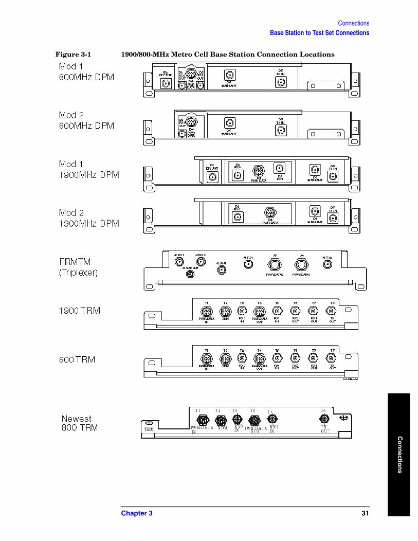
Base Station to Test Set Connections Since many combinations of test equipment and base stations exist, it is important to understand that you must calibrate some system components before initiating testing. More specifically, after calibration, tests must be performed with the equipment connected in the same way that it was connected when calibrated.
Note, due to the many configurations of Nortel Metro Cell Base Stations, no full connection diagram is provided in the test software. Instead, Figure 3-1 assists in illustrating different Metro Cell connection locations.
30 Chapter 3
ConnectionsBase Station to Test Set Connections
Co
nn
ection
s
Figure 3-1 1900/800-MHz Metro Cell Base Station Connection Locations
Chapter 3 31
ConnectionsBase Station to Test Set Connections
Co
nn
ecti
on
s
32 Chapter 3
Referen
ce
4 Reference
This chapter provides detailed descriptions of the general features and functions of the Test Software. Topics are arranged alphabetically for quick and easy reference.
33
ReferenceCustomizing Test Procedures
Ref
eren
ce
Customizing Test Procedures
Changing Pass/Fail Limits
Pass/Fail limits define the values with which a measurement result is compared to determine if the system under test meets specified standards. Default values are set in the Test Software. These default values may be changed to meet the requirements of the particular application. Changing pass/fail limits is accomplished from each measurement screen, with the exception of the RX Power and RX FER limits found on the main Configuration Screen.
While running the software package these limits can be changed in the measurement screen used for a specific automated test. Then once all limits are adjusted to new user set levels, the user needs to select Save Configuration, in the main Configuration Screen, see Saving/Deleting/Loading User Configurations.
NOTE Only measurement failures are flagged in the far right hand column on the test record.
Saving/Deleting/Loading User Configurations
A test procedure is a collection of channel information, test parameters, and pass/fail limits saved in a saved in a User Configuration file. This file might be one of the default procedures that is supplied with the Test Software, or it might be an application specific procedure that customizes the Test Software to a specific application. When you save a custom procedure, it consists of channel information, configuration information, pass/fail limits.
Custom procedures can be saved on a PCMCIA card, CF media card, or if running the software without a PC Card, saved in internal memory. Selecting Output Media for PC Card-PCMCIA Card or Compact Flash Card: Press System key, then [Save Data Setup], then select the File Location, ([CF] or [PCMCIA])
To save or delete Procedures from a PCMCIA Card or a CF media card requires a that a Media Card be inserted into the test set with the Nortel Test Package on it, see “Loading the Test Software” on page 17.
• To save a user procedure, select the [Save Config] key in the Configuration Screen.
• To delete a user procedure, select the [Delete Config] key in the Configuration Screen.
• To load a user procedure, select the [Load Config] key in the Configuration Screen.
To save or delete Procedures from internal memory requires the Nortel Software package be installed into the Test Set, see “Loading the Test Software” on page 17.
• To save a user procedure, select the [Save Config] key in the Configuration Screen.
34 Chapter 4
ReferenceCustomizing Test Procedures
Referen
ce
• To delete a user procedure, select the [Delete Config] key in the Configuration Screen.
• To load a user procedure, select the [Load Config] key in the Configuration Screen.
Importing and Exporting User Configuration Files
If running the software from internal memory, User Configuration files will be loaded/saved to internal memory in the E7495. If running the software from a PCMCIA/CF memory card, User Configuration files will be loaded/saved to the card media in the E7495. To share saved configuration files between test sets, the user can import/export saved files into and from the internal memory.
To Export all user procedures from the test set to a memory card:
1. Select the [Mode] key, [Test Software] key
2. Select the [Software Utilities] key
3. Select [Export Config Files]
4. Choose the location from which the Config files will be exported to (PCMCIA or Compact Flash).
To Import all user procedures from the a memory card to the test set internal memory:
1. Select the [Mode] key, [Test Software] key
2. Select the [Software Utilities] key
3. Select [Import Config Files]
4. Choose the location from which the Config files will be imported from (PCMCIA or Compact Flash).
Chapter 4 35
ReferenceStoring Test Results
Ref
eren
ce
Storing Test Results It is often desirable to record test results for future reference or evaluation. The Test Software provides the capability to save test results. To save the results you will need:.
• A PCMCIA or CF Card
Sending Test Results to a Card
To send test results to a card, you must select PCMCIA or CF (Compact Flash) from the Save Data Setup menu key under the System key. The Test Software will create test result files on the card automatically, based on the name that you enter at the start of testing. The Test Software will append .html to the file name so that the files will be recognized on the card and can be viewed on a PC with a PCMCIA card slot.
NOTE Do not remove the card or stop the test during testing operations while sending test results to an card. If you do so, the files will not be closed properly and the test results will be lost.
Once testing is completed for each selected test, the user must select the Save Data key in the measurement screen the test is using. When all testing is completed, from the main Test Screen, the user can select the View Test Data key prior to saving or just select the Save Test Data’ key to save all the test results currently saved in a temporary file to a PC Card.
36 Chapter 4
ReferenceOperating the Test Set
Referen
ce
Operating the Test Set For detailed information on the operation of the display and the various keys and other controls, see the Agilent Technologies E7495A/B Base Station Test Set Measurement Guide, as appropriate.
Access the Main Software Menu screen, from which all operations inside the Test Software are invoked, from the Test Software Key screen by selecting the Nortel Software Option key. For detailed information on this screen, see “Using the Main Software Menu Screen” on page 18.
Chapter 4 37
ReferenceCalibration Menu Screen
Ref
eren
ce
Calibration Menu ScreenSelect the Calibration Menu field to display the Calibration Menu screen. The Calibration Menu screen fields are described in the paragraphs below. For calibration procedures for this test software, refer to “Calibration Menu” on page 63.
The functions of the menu keys on the Calibration & Utilities Menu screen are as follows:
• (Select) – Select to enter values and/or make selections within the calibration and utilities menu screen.
• (View Test Data) – When all testing is completed, from the main Test Screen, you view the test results by selecting the View Test Data prior to saving.
• (Store Test Data) – Once testing is completed for each selected test, you must select the Save Data in the measurement screen the test is using. When all testing is completed, from the main Test Screen, you can select the Save Test Data to save all the test results currently saved in a temporary file to a PC Card.
• (Config Menu) – Select to go to the Configuration Menu Screen.
• (Main Menu) – Select to return to the Main Software Screen.
RF IN Path Loss Calibration
Select the RF In Path Loss Calibration field to initiate the measurement. The Test Software will display instructions and calibration the Path Loss on the 2-port Insertion Loss measurement screen. The Software will automatically enter the proper Start and Stop Frequencies based upon the Channel Standard setting on the Configuration Screen. It will then display the cable / device connection diagrams for normalization and measurement of the RF In Cable setup. Make the necessary connections as displayed and press Proceed when prompted. At the end of the measurement the RF In Path loss value will be displayed. Press the Proceed key to save the value for the RF In Path Loss Calibration field on the Configuration Screen. The software will then return to the Calibration menu. Once all of your Calibrations are complete you must save the configuration file so that the Path Loss Calibration values are retained.
RF OUT Path Loss Calibration
Select the RF OUT Path Loss Calibration field to initiate the measurement. The Test Software will display instructions and calibration the Path Loss on the 2-port Insertion Loss measurement screen. The Software will automatically enter the proper Start and Stop Frequencies based upon the Channel Standard setting on the Configuration Screen. It will then display the cable / device connection diagrams for normalization and measurement of the RF In Cable setup. Make the necessary connections as displayed and press Proceed when prompted. At the end of the measurement the RF In Path loss value will be displayed. Press the Proceed key to save the value for the RF In Path Loss Calibration field on the Configuration Screen. The software will then return to the Calibration menu. Once all of your Calibrations are
38 Chapter 4
ReferenceCalibration Menu Screen
Referen
ce
complete you must save the configuration file so that the Path Loss Calibration values are retained.
Power Meter Path Loss Calibration
Select the Power Meter Path Loss Calibration field to initiate the measurement. The Test Software will display instructions and calibration the Path Loss on the 2-port Insertion Loss measurement screen. The Software will automatically enter the proper Start and Stop Frequencies based upon the Channel Standard setting on the Configuration Screen. It will then display the cable / device connection diagrams for normalization and measurement of the RF In Cable setup. Make the necessary connections as displayed and press Proceed when prompted. At the end of the measurement the RF In Path loss value will be displayed. Press the Proceed key to save the value for the RF In Path Loss Calibration field on the Configuration Screen. The software will then return to the Calibration menu. Once all of your Calibrations are complete you must save the configuration file so that the Path Loss Calibration values are retained.
Chapter 4 39

ReferenceUtilities Menu Screen
Ref
eren
ce
Utilities Menu ScreenSelect the Utilities Menu field to display the Utilities Menu screen. The Utilities Menu screen fields are described in the paragraphs below. For utilities procedures for this test software, refer to “Utilities Menu” on page 64.
The functions of the menu keys on the Utilities Menu screen are as follows:
• (Select) – Select to enter values and/or make selections within the calibration and utilities menu screen.
• (View Test Data) – When all testing is completed, from the main Test Screen, you view the test results by selecting the View Test Data prior to saving.
• (Store Test Data) – Once testing is completed for each selected test, you must select the Save Data in the measurement screen the test is using. When all testing is completed, from the main Test Screen, you can select the Save Test Data to save all the test results currently saved in a temporary file to a PC Card.
• (Config Menu) – Select to go to the Configuration Menu Screen.
• (Main Menu) – Select to return to the Main Software Screen.
Measure Device Loss 1 (2, 3, 4)
Select the appropriate Measure Device Loss field to initiate the measurement. The Test Software will display instructions and measure the loss or gain of the device on the 2-port Insertion Loss measurement screen. The Software will automatically enter the proper Start and Stop Frequencies based upon the Channel Standard setting on the Configuration Screen. It will then display the connection diagrams for normalization and measurement of the Device. Make the necessary connections as displayed and press Proceed when prompted. At the end of the measurement, the Device loss value will be displayed. Press the Proceed key to save the value for the Device Loss on the Test Report. The software will then return to the Utilities Menu screen. You can view the measured value of the device on the Test Report by pressing the View Test Data menu key on the Utilities Menu screen.
RX0/RX1 Receive Path Gain Troubleshooting
Select the RX0 Receive Path Gain Troubleshooting or RX1 Receive Path Gain Troubleshooting field to initiate the measurement. The Test Software will display instructions and an example connection picture. Pressing Proceed will take you to a TEST that verifies that all components in the receive path are operating within prescribed limits for amplification and attenuation. To save the measurement result, press the Proceed key. The software will save the results to the Test Report and return the to the Utilities Menu screen. You can view the measured value of the device on the Test Report by pressing the View Test Data menu key on the Utilities Menu screen.
Spectral Interference Evaluation
Select the Spectral Interference Evaluation field to initiate the measurement. The Test Software will display instructions for this test.
40 Chapter 4
ReferenceUtilities Menu Screen
Referen
ce
Pressing Proceed will take you to a TEST that verifies there are no interfering signals on either the forward or reverse link channels. You can then select the Proceed key, the software will then return the to the Utilities menu.
Chapter 4 41
ReferenceUtilities Menu Screen
Ref
eren
ce
42 Chapter 4
Test Descrip
tion
s
5 Test Descriptions
This chapter provides descriptions of each of the procedures, tests, parameters, and pass/fail limits contained in the Test Software.
43
Test DescriptionsTest Descriptions
Test
Des
crip
tio
ns
Test Descriptions Each TEST consists of one measurement or more. In most instances, you may change the values of the specifications (pass/fail limits) that are used in a TEST, but you may not change the measurements that the TEST will perform.
Generally, the order in which you perform the TESTs is not important. However, for the greatest efficiency, you should perform the TESTs in the order shown on the Test Menu screen. For instance, the transmit TESTs are listed together on the screen. This provides for blossoming the Base Station at the start of the transmit test sequence, then not wilting the Base Station until after all of the transmit TESTs have been performed. This prevents wasting time in needlessly blossoming and wilting the Base Station.
The TESTs are derived from the Nortel Cellular Handbook and include the following:
• “Test Menu” on page 48
— “Power Sensor Verification (HIP-D or MCPA)” on page 48
— “OCNS Channels Code Domain Measurements” on page 51
— “Adjacent Channel Power Test” on page 52
— “Spectral Regrowth Test” on page 53
— “RX0 Receive Power Test” on page 54
— “RX0 Receive FER Test” on page 55
— “RX1 Receive Power Test” on page 56
— “RX1 Receive FER Test” on page 57
— “MFRM Multi Carrier Total Output Power Test” on page 58
— “MFRM Multi Carrier Spectral Regrowth Test” on page 61
— “MFRM Multi Carrier OCNS Channels Under Test Code Domain Measurements” on page 62
• “Calibration Menu” on page 63
— “Power Meter Path Loss Calibration, RF In Path Loss Calibration, RF Out Path Loss Calibration” on page 63
• “Utilities Menu” on page 64
— “Measure Device Loss (1 through 4)” on page 64
— “RX0 Receive Path Gain Troubleshooting, RX1 Receive Path Gain Troubleshooting” on page 65
— “Spectral Interference Evaluation” on page 69
These TESTs are described on succeeding pages.
NOTE It is important to remember that, of the specifications listed in each TEST description, not all are necessarily used for each Base Station type.
44 Chapter 5
Test DescriptionsTest Descriptions
Test Descrip
tion
s
Blossoming the Base Station
When you are prompted to blossom the Base Station, dependent upon the Base Station type, configure the Base Station code channels and gain as listed in the following paragraphs. For information on configuring the channels and gains for particular Base Stations, refer to the appropriate Nortel CDMA Testing Installation Method.
For Metro Cell IS-95 Base Stations:
• Pilot Channel – 254
• Sync Channel – 123
• Paging Channel – 245
• 6 OCNS Channels – 174
For Metro Cell IS-2000 1xRTT Base Stations:
• Pilot Channel – 254
• Sync Channel – 123
• Paging Channel – 245
• 5 OCNS Radio Configuration 3 (RC3) Fundamental Channels – 174
• 1 OCNS Radio Configuration 3 (RC3) 16x Supplemental Channels – 174
Testing MFRM Metro Cell Base Stations
It is also important to remember that the MFRM Metro Cell Base Station can transmit as many as three carriers or more. In order to test this Base Station properly, all carriers must be checked. Following is the recommended test sequence for a three carrier MFRM Metro Cell Base Stations. The MFRM Test Menu is arranged so as to repeat the sequence on the menu three times, one for each carrier in this example. If testing a two carrier Compact MFRM then the sequence is repeated only twice.
Test the three carriers on the Base Station on adjacent CDMA channels. For instance, in the cellular band, the channels might be 384, 425, and 466. In the PCS band, the channels might be 500, 525, and 550. You must use three adjacent channels appropriate to the frequency band. Start the sequence of TESTs on the lowest carrier channel selected. Set up the Base Station and the Test Software to perform TESTs on the lower carrier channel. Perform the following TESTs:
Test Set Calibration; calibrate the path loss for the cables to be used (Under the Calibration Menu: measure the Power Meter Path Loss, RF In Path Loss, and RF Out Path Loss
Run the following Tests (Under the Test Menu):
• Power Sensor Verification
• OCNS Channels Code Domain
• Spectral Regrowth Test
• Adjacent Channel Power Test
Chapter 5 45
Test DescriptionsTest Descriptions
Test
Des
crip
tio
ns
• • MFRM Multi Carrier Total Output Power Test – (Blossom all three carriers during
this test)
• MFRM Multi Carrier OCNS Channel Under Test Code Domain Measurement – (All three carriers blossom during this test)
• MFRM Multi Carrier Spectral Regrowth Test – (All three carriers blossom during this test)
(Wilt all three carriers in the Base Station.)
• RX0 Receive Power Test
• RX0 Receive FER Test
(Wilt the Base Station.)
• RX1 Receive Power Test – (Change connections and blossom the Base Station.)
• RX1 Receive FER Test
(Wilt the Base Station.)
Change the Base Station and the Test Software to perform TESTs on the middle carrier channel. Perform the following TESTs:
• Power Sensor Verification
• OCNS Channels Code Domain
• Spectral Regrowth Test
• Adjacent Channel Power Test
• • MFRM Multi Carrier Total Output Power Test – (Blossom all three carriers during
this test)
• MFRM Multi Carrier OCNS Channel Under Test Code Domain Measurement – (All three carriers blossom during this test)
• MFRM Multi Carrier Spectral Regrowth Test – (All three carriers blossom during this test)
(Wilt all three carriers in the Base Station.)
• RX0 Receive Power Test
• RX0 Receive FER Test
(Wilt the Base Station.)
• RX1 Receive Power Test – (Change connections and blossom the Base Station.)
• RX1 Receive FER Test
(Wilt the Base Station.)
Change the Base Station and the Test Software to perform TESTs on the upper carrier channel. Perform the following TESTs:
46 Chapter 5
Test DescriptionsTest Descriptions
Test Descrip
tion
s
• Power Sensor Verification
• OCNS Channels Code Domain Measurements
• Spectral Regrowth Test
• Adjacent Channel Power Test
• • MFRM Multi Carrier Total Output Power Test – (Blossom all three carriers during
this test)
• MFRM Multi Carrier OCNS Channel Under Test Code Domain Measurement – (All three carriers blossom during this test)
• MFRM Multi Carrier Spectral Regrowth Test – (All three carriers blossom during this test)
(Wilt all three carriers in the Base Station.)
• RX0 Receive Power Test
• RX0 Receive FER Test
(Wilt the Base Station.)
• RX1 Receive Power Test – (Change connections and blossom the Base Station.)
• RX1 Receive FER Test
(Wilt the Base Station.)
Chapter 5 47
Test DescriptionsTest Menu
Test
Des
crip
tio
ns
Test Menu
Power Sensor Verification (HIP-D or MCPA)
NOTE When testing MFRM Base Stations, this test should be used only for testing a single carrier. If you wish to test all three carriers, use the MFRM Multi Carrier Total Output Power Test.
This TEST verifies that the accuracy of the Base Station RF power sensor is within specified limits.
The Base Station power output Carrier Output Power are dependent on the digital gain settings of the pilot channel, paging channel, sync channel, and OCNS channel. It is also dependent upon the number of OCNS channels that are active. Once a Base Station is in service, the gains will be set to optimize the wireless network performance. During testing, there are recommended gain settings that are more than likely different than the in-service gain settings. These recommended settings result in a desired Base Station or carrier power output, and are as shown in Table 5-1.
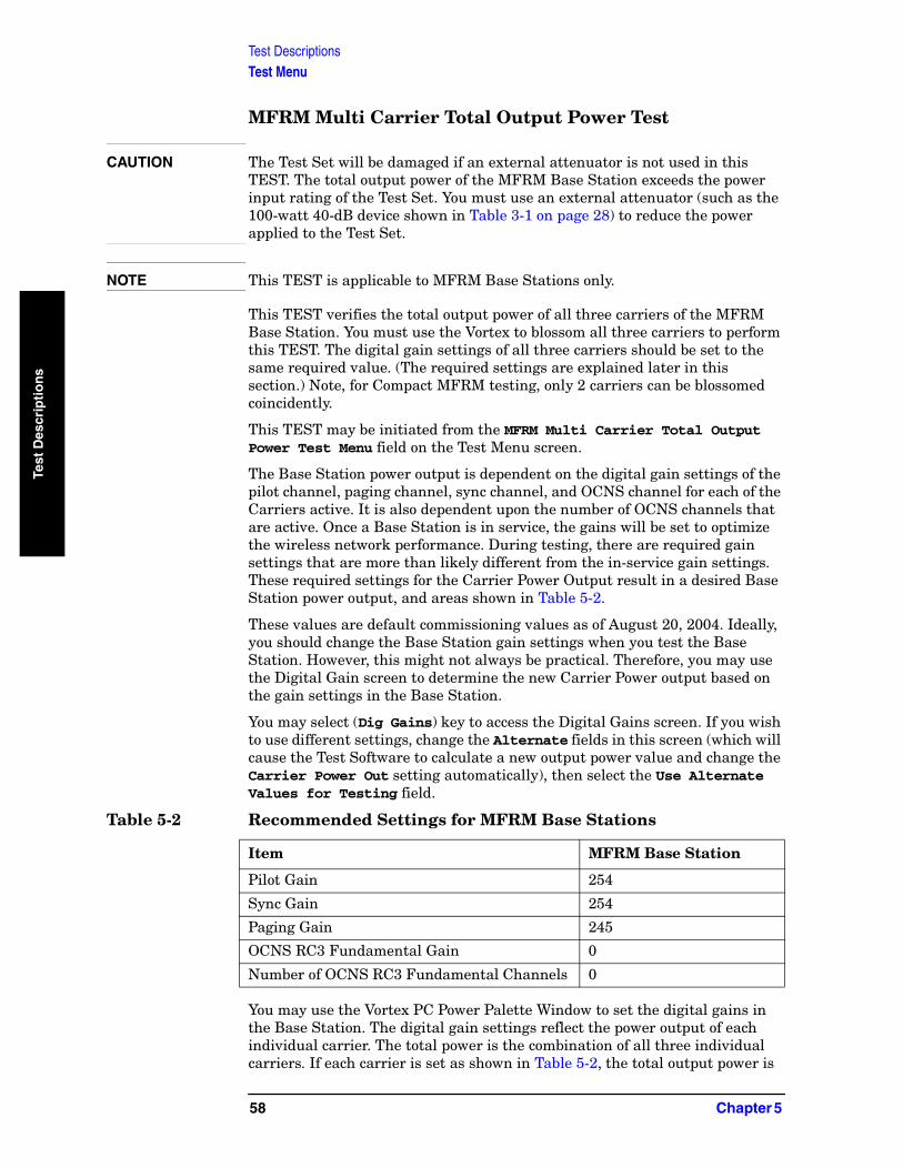
Ideally, you should change the Base Station gain settings when you test the Base Station. However, this might not always be practical. Therefore, you may use the Digital Gain screen to determine the new Base Station power output based on the gain settings in the Base Station.
You may access the Digital Gains screen from the Configuration Menu by selecting the Digital Gains menu key. If you wish to use different settings, change the Alternate fields in this screen (which will cause the Test Software to calculate a new output power value and change the Base Station Power Out setting automatically), then select the Use Alt Values to have the new Base Station Power Output value updated on the configuration screen. The Digital Gains screen adjust the Carrier output power for MFRM stations and Base Station Power Out for Non MFRM stations.
You may use the Vortex PC Power Palette Window to set the digital gains in the Base Station.
The digital gain settings reflect the power output of each individual carrier. If each carrier is set as shown in Table 5-1, the output power is as follows:
• For Metro Cell 1900-MHz Base Stations, the power is 38.50 dBm with pilot, paging, and sync only.
• For Metro Cell 800-MHz Base Stations, the power is 41.12 dBm with pilot,
Table 5-1 Recommended Settings for Base Stations
Item Base Station
Pilot Gain 254
Sync Gain 254
Paging Gain 245
OCNS RC3 Fundamental Gain 0
Number of OCNS RC3 Fundamental Channels 0
48 Chapter 5
Test DescriptionsTest Menu
Test Descrip
tion
s
paging, and sync only.
• For 800 MHz High Power Base Station, the power is 41.56 dBm with pilot, paging, and sync only.
NOTE The Test Set is also affected by temperature. If the Test Set is moved from a sheltered environment to an exposed one, it must be allowed to reach thermal equilibrium (even if it has not been unplugged from the power source). This will require 15 minutes.
CAUTION Before disconnecting any Base Station cables, verify that the site is wilted and is not producing RF power.
Step 1. Select the (Test Software and Nortel CDMA Tests) keys. The Test Software will display the Main Software Menu screen.
Step 2. Select the Test Menu and then the Power Sensor Verification field.
Step 3. Follow the on-screen directions.
The following paragraphs provide the upper and lower limit equations for the various types of Base Stations. The definitions for terms used in those equations are as follows:
• UL – Upper pass/fail limit. • LL – Lower pass/fail limit.
• Power – The setting of the Carrier Power Out field on the Configuration Menu screen. This is the basic figure shown on the power meter. It is always present in the equation.
• Limits:
— For Metro Cell 1900-MHz Base Stations, the carrier power is 38.50 dBm with pilot, paging, and sync only.
— For Metro Cell 1900-MHz High Power Base Stations, the carrier power is 43.0 dBm with pilot, paging, and sync only.
— For Metro Cell 800-MHz Base Stations, the power is 41.125 dBm with pilot, paging, and sync only.
— For Metro Cell 800-MHz High Power Base Stations, the power is 45.625 dBm with pilot, paging, and sync only.
— For Metro Cell 450-MHz Base Stations, the power is 41.5625 dBm with pilot, paging, and sync only.
— For Metro Cell 450-MHz High Power Base Stations, the power is 46.0625 dBm with pilot, paging, and sync only.
The upper and lower limits are always present in the equation
for these Base Stations:
— 1.3 dB - The basic upper or lower limit for Metro Cell MFRM.
— 1.27 dB is the limits for MRFM 800, compact MFRM 800, MFRM 1900, MFRM 1900 high power, compact MFRM 1900, Metro Cell SRFM 1900, MFRM 450
Chapter 5 49
Test DescriptionsTest Menu
Test
Des
crip
tio
ns
— 1.0 dB is the limits for MRFM 800 high power, MFRM 800 high power, MFRM 450 High Power
— 1.5 dB is the limits for Meto Cell SRFM 800
The specifications shown in italics are optional.
Indoor: LL = Power – Limit – IMF – Combiner
UL = Power + Limit – IMF – Combiner
Outdoor: LL = Power - Limit – LPP – IMF – Combiner
UL = Power + Limit – LPP – IMF – Combiner
NOTE The next two items allow for four combinations of Combiner and IMF: both, IMF, Combiner, neither. Dependent upon the setting of the Configuration Menu screen TX Conf field, these items will appear singly, in combination, or not at all.
The last item is the loss through a Lightning Protector Plate used only with Outdoor Cabinets.
• 0.505 dB - The loss associated with a Base Station with a Combiner. It is present for that configuration only. Its presence is determined by the setting of the TX Conf field on the Configuration Menu screen.
• 0.80 dB - The loss associated with a Base Station with an IMF. It is present for that configuration only. Its presence is determined by the setting of the TX Conf field on the Configuration Menu screen.
• 0.25 dB - The loss associated with an LPP and the cables for Metro Cell. It is present in the equation only if the Base Station is an outdoor type. Its presence is determined by the setting of the Cabinet field on the Configuration Menu screen.
50 Chapter 5
Test DescriptionsTest Menu
Test Descrip
tion
s
OCNS Channels Code Domain Measurements
This TEST verifies that the estimated rho, frequency error, time offset, and carrier feedthrough values of the transmitted RF signal from the Base Station are within the prescribed limits. All measured Channel levels in the Test Report are relative to the Channel Power.
The Pass/Fail Limits used in this TEST are:
• Pilot Power Delta Limit - Delta Limit: –30 dBm
NOTE Pilot Power is recorded as a Delta Power measurement relative to Channel Power in the test report
• Delta Sync Power Limit - Delta Limit: –30 dB• Delta Page Limit - Delta Limit: –30 dB
NOTE The above three level checks are just to verify these channels are up and active.
• Frequency Error Limits - High Limit: 25 Hz, Low Limit: –25 Hz • Time Offset Limits - High Limit: 3.5 us; Low Limit: –3.5 us • Est Rho Limit - Low Limit: 0.96 • Carrier Feedthru - High Limit: –20 dBc • Noise Floor - High Limit: –33 dB
CAUTION Before disconnecting any Base Station cables, verify that the site is wilted and is not producing RF power.
Step 1. Press the (Test Software and Nortel CDMA Tests) keys. The Test Software will display the Main Software Menu screen.
Step 2. Select the Test Menu and then the OCNS Channels Code Domain Measurements field.
Step 3. Follow the on-screen directions. (See “Blossoming the Base Station” on page 45 for detailed information on channels and gains.)
Chapter 5 51

Test DescriptionsTest Menu
Test
Des
crip
tio
ns
Adjacent Channel Power Test
This TEST verifies power in a 30-kHz adjacent channel relative to the 1.23-MHz channel of the carrier. The offset is 885 kHz for 1900-MHz Base Stations and 750 kHz for 800-MHz Base Stations. The Test Software examines the 30-kHz channels at 885 (or 750) kHz above and below the center frequency.
In more detail, it verifies that the 1.23-MHz transmit signal is adequately filtered (reduced) at the adjacent channel frequencies.
The Pass/Fail Limits used in this TEST are:
• –45 dBc
CAUTION Before disconnecting any Base Station cables, verify that the site is wilted and is not producing RF power.
Step 1. Press the (Test Software and Nortel CDMA Tests) keys. The Test Software will display the Main Software Menu screen.
Step 2. Select the Test Menu and then the Adjacent Channel Power Test field from the Configuration Menu screen.
Step 3. Follow the on-screen directions. (See “Blossoming the Base Station” on page 45 for detailed information on channels and gains.)
52 Chapter 5
Test DescriptionsTest Menu
Test Descrip
tion
s
Spectral Regrowth Test
This TEST verifies that the Base Station is within its 1.23-MHz bandwidth and is not generating any undesired out-of-channel power.
The Pass/Fail Limits used in this TEST are:
• Cellular band: 750 kHz offset to 1.98 MHz, –45 dBc; 1.98 MHz to 2.5 MHz, –60 dBc
• Cellular band & NMT450 band:
— Center Segment: Span 1.50 MHz, Level 50 dBm
— 1st Segment:Span 1.23 MHz, Level –45 dB (both upper and lower segments)
— 2nd Segment: Span N/A, Level –60 dB (both upper and lower segments)
• PCS Bands: 885 kHz offset to 1.98 MHz, –45 dBc; 1.98 MHz to 2.25 MHz, –55 dBc.
• PCS Band
— Center Segment: Span 1.77 MHz, Level 50 dBm
— 1st Segment:Span 1.095 MHz, Level –45 dB (both upper and lower segments)
— 2nd Segment: Span N/A, Level –55 dB (both upper and lower segments)
CAUTION Before disconnecting any Base Station cables, verify that the site is wilted and is not producing RF power.
Step 1. Press the (Test Software and Nortel CDMA Tests) keys. The Test Software will display the Main Software Menu screen.
Step 2. Select the Test Menu and then the Spectral Regrowth Test field from the Test Menu screen.
Step 3. Follow the on-screen directions. (See “Blossoming the Base Station” on page 45 for detailed information on channels and gains.)
Chapter 5 53
Test DescriptionsTest Menu
Test
Des
crip
tio
ns
RX0 Receive Power Test
This TEST verifies the difference between the receive power reported by the Base Station Maintenance Unit (BMU) or the Vortex with no signal present and receive power reported when a −90-dBm signal is injected into the RX0 receiver. The measurement, which is a measure of the increase in receive power, is compared with the pass/fail limit.
Pass/Fail Limits is used in this TEST are:
• Lower Limit 15 dB Gain
• Upper Limit 25 dB Gain
CAUTION Before disconnecting any Base Station cables, verify that the site is wilted and is not producing RF power.
Step 1. From the Configuration Menu screen, press the (Test Software and Nortel CDMA Tests) keys. The Test Software will display the Main Software Menu screen.
Step 2. Select the Test Menu and then the RX0 Receive Power Test field.
Step 3. Follow the on-screen directions. (See “Blossoming the Base Station” on page 45 for detailed information on channels and gains.)
54 Chapter 5
Test DescriptionsTest Menu
Test Descrip
tion
s
RX0 Receive FER Test
NOTE This TEST does not operate with all versions of Vortex. Contact Nortel to determine the required version.
This TEST is used in conjunction with the Vortex to measure the reverse channel frame (FER) of the Base Station. The TEST injects a CDMA reverse link signal into the Base Station receiver. The Vortex then reports the percentage of frame error rate of the CDMA signal. The initial RF level of the CDMA signal is -119 dBm.
The RF level may be adjusted in the TEST for troubleshooting. Increasing the level will improve the FER; decreasing the level will degrade the FER.
The Test Software will prompt you to enter the %FER from the Vortex in order to compare the value with the set pass/fail limit shown on the Configuration screen.
NOTE Setting up the Vortex to report FER is somewhat complicated. The Test Software will supply prompts for the setup. If you require further assistance, refer to the Installation Method from Nortel.
• • Upper Limit 1% FER
• • Lower Limit 0% FER
CAUTION Before disconnecting any Base Station cables, verify that the site is wilted and is not producing RF power.
Step 1. From the Configuration Menu screen, press the (Test Software and Nortel CDMA Tests) keys. The Test Software will display the Main Software Menu screen.
Step 2. Select the Test Menu and then the RX0 Receive FER Test field.
Step 3. Follow the on-screen directions. (See “Blossoming the Base Station” on page 45 for detailed information on channels and gains.)
Chapter 5 55
Test DescriptionsTest Menu
Test
Des
crip
tio
ns
RX1 Receive Power Test
This TEST is the same as the RX0 Receive Power Test, except that it applies to the RX1 receiver.
In this Test, select the RX1 Receive Power Test field in step 2.
56 Chapter 5
Test DescriptionsTest Menu
Test Descrip
tion
s
RX1 Receive FER Test
This TEST is the same as the RX0 Receive FER Test, except that it applies to the RX1 receiver.
In this Test, select the RX1 Receive FER Test field in step 2.
Chapter 5 57
Test DescriptionsTest Menu
Test
Des
crip
tio
ns
MFRM Multi Carrier Total Output Power Test
CAUTION The Test Set will be damaged if an external attenuator is not used in this TEST. The total output power of the MFRM Base Station exceeds the power input rating of the Test Set. You must use an external attenuator (such as the 100-watt 40-dB device shown in Table 3-1 on page 28) to reduce the power applied to the Test Set.
NOTE This TEST is applicable to MFRM Base Stations only.
This TEST verifies the total output power of all three carriers of the MFRM Base Station. You must use the Vortex to blossom all three carriers to perform this TEST. The digital gain settings of all three carriers should be set to the same required value. (The required settings are explained later in this section.) Note, for Compact MFRM testing, only 2 carriers can be blossomed coincidently.
This TEST may be initiated from the MFRM Multi Carrier Total Output Power Test Menu field on the Test Menu screen.
The Base Station power output is dependent on the digital gain settings of the pilot channel, paging channel, sync channel, and OCNS channel for each of the Carriers active. It is also dependent upon the number of OCNS channels that are active. Once a Base Station is in service, the gains will be set to optimize the wireless network performance. During testing, there are required gain settings that are more than likely different from the in-service gain settings. These required settings for the Carrier Power Output result in a desired Base Station power output, and areas shown in Table 5-2.
These values are default commissioning values as of August 20, 2004. Ideally, you should change the Base Station gain settings when you test the Base Station. However, this might not always be practical. Therefore, you may use the Digital Gain screen to determine the new Carrier Power output based on the gain settings in the Base Station.
You may select (Dig Gains) key to access the Digital Gains screen. If you wish to use different settings, change the Alternate fields in this screen (which will cause the Test Software to calculate a new output power value and change the Carrier Power Out setting automatically), then select the Use Alternate Values for Testing field.
You may use the Vortex PC Power Palette Window to set the digital gains in the Base Station. The digital gain settings reflect the power output of each individual carrier. The total power is the combination of all three individual carriers. If each carrier is set as shown in Table 5-2, the total output power is
Table 5-2 Recommended Settings for MFRM Base Stations
Item MFRM Base Station
Pilot Gain 254
Sync Gain 254
Paging Gain 245
OCNS RC3 Fundamental Gain 0
Number of OCNS RC3 Fundamental Channels 0
58 Chapter 5
Test DescriptionsTest Menu
Test Descrip
tion
s
as follows:
• For Metro Cell MFRM 1900-MHz Base Stations, the power is 43.312 dBm with pilot, paging, and sync only.
• For Metro Cell MFRM 800-MHz Base Stations, the power is 45.937 dBm with pilot, paging, and sync only.
• For Metro Cell MFRM 450-MHz Base Stations, the power is 46.312 dBm with pilot, paging, and sync only.
CAUTION Before disconnecting any Base Station cables, verify that the site is wilted and is not producing RF power.
Step 1. In the Base Station Type field on the Configuration Menu screen, select Nortel Metro Cell MFRM 1900 MHZ, Nortel Metro Cell MFRM 800 MHz, or Nortel Metro Cell MFRM 450 MHz as appropriate.
Step 2. Select the (Test Software and Nortel CDMA Tests) key. The Test Software will display the Main Software Menu screen.
Step 3. Select the MFRM Total Output Power Test field.
Step 4. Follow the on-screen directions.
The following paragraphs provide the upper and lower limit equations for the various types of Base Stations. The definitions for terms used in those equations are as follows:
• UL – Upper pass/fail limit. • LL – Lower pass/fail limit.
• Power – The setting of the Base Station Power Out field on the Configuration Menu screen. This is the basic figure shown on the power meter. It is always present in the equation.
• Limits:
— 1.3 dB - The basic upper or lower limit for Metro Cell MFRM. It is always present in the equation for those Base Stations.
— 1.27 dB is the limits for MRFM 800, compact MFRM 800, MFRM 1900, MFRM 1900 high power, compact MFRM 1900, Metro Cell SRFM 1900, MFRM 450
— 1.0 dB is the limits for MRFM 800 high power, MFRM 800 high power. MFRM 450 High Power
— 1.5 dB is the limits for Meto Cell SRFM 800
The specifications shown in italics are optional.
Indoor: LL = Power – Limit – IMF – Combiner
UL = Power + Limit – IMF – Combiner
Outdoor: LL = Power - Limit – LPP – IMF – Combiner
UL = Power + Limit – LPP – IMF – Combiner
NOTE The next two items allow for four combinations of Combiner and IMF: both, IMF, Combiner, neither. Dependent upon the setting of the Configuration
Chapter 5 59
Test DescriptionsTest Menu
Test
Des
crip
tio
ns
Menu screen TX Conf field, these items will appear singly, in combination, or not at all.
The last item is the loss through a Lighting Protector Plate used only with Outdoor Cabinets.
• 0.505 dB - The loss associated with a Base Station with a Combiner. It is present for that configuration only. Its presence is determined by the setting of the TX Conf field on the Configuration Menu screen.
• 0.80 dB - The loss associated with a Base Station with an IMF. It is present for that configuration only. Its presence is determined by the setting of the TX Conf field on the Configuration Menu screen.
• 0.25 dB - The loss associated with an LPP and the cables for Metro Cell. It is present in the equation only if the Base Station is an outdoor type. Its presence is determined by the setting of the Cabinet field on the Configuration Menu screen.
60 Chapter 5
Test DescriptionsTest Menu
Test Descrip
tion
s
MFRM Multi Carrier Spectral Regrowth Test
This TEST verifies that a Multi Carrier outputs from the MFRM Base Station are within their bandwidth and are not generating any undesired out-of-channel power. Cellular band channels need to have a 41 channel spacing and PCS band channels need to have a 25 channel spacing. For example Cellular channels 384, 425, and 466; PCS channels 500, 525, and 550.
The Pass/Fail Limits used in this TEST are:
• • Cellular band: 750 kHz offset to 1.98 MHz, –45 dBc; 1.98 MHz to 4.0 MHz, –60 dBc
• • Cellular band & NMT450 band:
— Center Segment: Span 4.02 MHz, Level 50 dBm
— 1st Segment:Span 1.23 MHz, Level –45 dB (both upper and lower segments)
— 2nd Segment: Span N/A, Level –60 dB (both upper and lower segments)
• • PCS Bands: 885 kHz offset to 1.98 MHz, –45 dBc; 1.98 MHz to 3 MHz, –55 dBc.
• • PCS Band
— Center Segment: Span 4.27 MHz, Level 50 dBm
— 1st Segment:Span 1.74 MHz, Level –45 dB (both upper and lower segments)
— 2nd Segment: Span N/A, Level –55 dB (both upper and lower segments)
CAUTION Before disconnecting any Base Station cables, verify that the site is wilted and is not producing RF power.
Step 1. Press the (Test Software and Nortel CDMA Tests) keys. The Test Software will display the Main Software Menu screen.
Step 2. Select the Test Menu and then the MFRM Multi Carrier Spectral Regrowth Test field from the Test Menu screen.
Step 3. Follow the on-screen directions. (See “Blossoming the Base Station” on page 45 for detailed information on channels and gains.)
Chapter 5 61
Test DescriptionsTest Menu
Test
Des
crip
tio
ns
MFRM Multi Carrier OCNS Channels Under Test Code Domain Measurements
NOTE This TEST is applicable to MFRM Base Stations only.
This test is performed with multiple adjacent carriers blossomed.
Multiple Cellular band channels need to have a 41 channel spacing and PCS band channels need to have a 25 channel spacing. For example Cellular channels 384, 425, and 466; PCS channels 500, 525, and 550.
The below measurements are performed on the channel under test.
• The TEST checks the channel power level of the CDMA carrier under test in dBm.
• The TEST checks the relative power level in dB as compared with the channel power of the pilot, paging, and sync channels.
• The TEST checks the relative power level and spread factor of the fundamental traffic channels.
• The TEST checks the relative power level and spread factor of the supplemental channels.
• The TEST reports the noise level in dB as compared with the channel power of the highest unused Walsh code.
• This TEST verifies that the estimated rho, frequency error, time offset, and carrier feedthrough values of the transmitted RF signal from the Base Station are within the prescribed limits.
The Pass/Fail Limits used in this TEST are:
• Frequency Error Limits - High Limit: 25 Hz, Low Limit: –25 Hz • Time Offset Limits - High Limit: 3.5 us; Low Limit: –3.5 us • Est Rho Limit - Low Limit: 0.96 • Carrier Feedthru - High Limit: –20 dBc
CAUTION Before disconnecting any Base Station cables, verify that the site is wilted and is not producing RF power.
Step 1. Press the (Test Software and Nortel CDMA Tests) keys. The Test Software will display the Main Software Menu screen.
Step 2. Select the Test Menu and then the MFRM OCNS Channels Under Test Code Domain Measurements field from the Test Menu screen.
Step 3. Follow the on-screen directions. (See “Blossoming the Base Station” on page 45 for detailed information on channels and gains.)
62 Chapter 5
Test DescriptionsCalibration Menu
Test Descrip
tion
s
Calibration MenuThe functions of the menu keys on the Calibration Menu screen are as follows:
• (View Test Data) – When all testing is completed, from the main Test Screen, you view the test results by selecting the View Test Data prior to saving.
• (Store Test Data) – Once testing is completed for each selected test, you must select the Save Data in the measurement screen the test is using. When all testing is completed, from the main Test Screen, you can select the Save Test Data to save all the test results currently saved in a temporary file to a PC Card.
• (Select) – Select to enter values and/or make selections within the calibration and utilities menu screen.
• (Config Menu) – Select to go to the Configuration Menu Screen.
• (Main Menu) – Select to return to the Main Software Screen.
Power Meter Path Loss Calibration, RF In Path Loss Calibration, RF Out Path Loss Calibration
These tests verify that no cable damage or attenuator damage has occurred since the last testing procedure. (Test cable loss factors must be determined each time testing is started.) These values allow the Test Software to provide accurate, repeatable measurements for installing and maintaining a Base Station. Measuring cable loss also allows you to determine when it is necessary to replace worn or faulty cables that could be damaged internally but show no signs of wear or damage.
NOTE All losses must be saved after each measurement is completed. To enter the loss automatically on the Configuration Menu screen follow the below steps.
NOTE The Path Loss calibrations are performed across the frequency band determined by the setting of the Channel Standard setting. Anytime the Base Station Type is changed to where a different Channel Standard is used, the Path Loss calibrations need to be re-run and stored. (i.e., changing to or from the following bands; Cellular band, NA PCS Band, Korean PCS, or NMT-450).
No Pass/Fail Limits are used in this TEST.
Step 1. Select the Calibration Menu field from the Main Software Menu.
Step 2. Select the proper calibration routine field from the Calibration Menu screen.
Choices are: RF In Path Loss, RF Out Path Loss, and Power Meter Path Loss.
Step 3. Follow the on-screen directions for the test selected.
Step 4. At the end of the measurement press Proceed to store the measured loss value in the related Loss Field: RF IN Loss, RF Out Loss, or PM Loss.
Step 5. Repeat step 3 through 5 for each related measured loss value.
Chapter 5 63
Test DescriptionsUtilities Menu
Test
Des
crip
tio
ns
Utilities MenuThe functions of the menu keys on the Utilities Menu screen are as follows:
• (View Test Data) – When all testing is completed, from the main Test Screen, you view the test results by selecting the View Test Data prior to saving.
• (Store Test Data) – Once testing is completed for each selected test, you must select the Save Data in the measurement screen the test is using. When all testing is completed, from the main Test Screen, you can select the Save Test Data to save all the test results currently saved in a temporary file to a PC Card.
• (Config Menu) – Select to go to the Configuration Menu Screen.
• (Main Menu) – Select to return to the Main Software Screen.
Measure Device Loss (1 through 4)
This TEST measures the insertion loss of the TX IMF filter and the RX splitter. Because the IMF filter and the splitter are passive devices that do not report either presence or losses, the Base Station neither recognizes nor compensate for the losses through these devices. Thus, the losses must be measured and supplied to the Base Station for compensation to take place.
NOTE As many as four losses may be saved by selecting the appropriate test key.
No Pass/Fail Limits are used in this TEST.
Step 1. Select the Utilities Menu field from the Main Software Menu. The Test Software will display the Utilities Menu screen.
Step 2. Select the Measure Device Loss Loss 1 - 4 field from the Calibration Utilities Menu screen.
Step 3. Follow the on-screen directions.
64 Chapter 5
Test DescriptionsUtilities Menu
Test Descrip
tion
s
RX0 Receive Path Gain Troubleshooting, RX1 Receive Path Gain Troubleshooting
NOTE The RX0 Receive Path Gain Test checks the gain through only receiver RX0. The RX1 Receive Path Gain Test checks the gain through only receiver RX1. The RX0 and RX1 Tests are applicable to Metro Cell and 800 MHz High Power Base Station.
This TEST verifies that all components in the receive path are operating within prescribed limits for amplification and attenuation.
CAUTION Before disconnecting any Base Station cables, verify that the site is wilted and is not producing RF power.
Step 1. Select the Utilities Menu field from the Main Software Menu.
. The Test Software will display the Calibration & Utilities Menu screen.
Step 2. Select the RX0 Receive Path Gain Troubleshooting field or RX1 Receive Path Gain Troubleshooting field, as applicable to the TEST, from the Test Menu screen.
Step 3. Follow the on-screen directions. (See “Blossoming the Base Station” on page 45 for detailed information on channels and gains.)
The following paragraphs provide the upper and lower limit equations for the various types of Base Stations. The definitions for terms used in those equations are as follows:
• UL - Upper pass/fail limit• LL - Lower pass/fail limit.
• UL: 36.8/LL: 31.8 Spec (6) - The upper or lower limit for Metro Cell 1900-MHz Base Station gain from the DPM input to the cable connected to the RX0/RX1 input of the TRM.
• UL: 31.5/LL: 25.5 Spec (7) - The upper or lower limit for Metro Cell 1900-MHz Base Station gain from the DPM input through one TRM to the RX0/RX1 output of the TRM.
• UL: 20.5/LL: 14.5 Spec (8) - The upper or lower limit for Metro Cell 1900-MHz Base Station gain from the DPM input through three TRMs to the RX0/RX1 output of the third TRM.
• UL: 26.0/LL: 20.0 Spec (9) - The upper or lower limit for Metro Cell 1900-MHz Base Station gain from the DPM input through two TRMs to the RX0/RX1 output of the second TRM.
• UL: 29.4/LL: 23.4 Spec (10) - The upper or lower limit for Metro Cell 800-MHz or Rural Cell Base Station gain from the DPM input thorough one TRM to the RX0/RX1 output of the TRM.
• UL: 36.2/LL: 30.2 Spec (11) - The upper or lower limit for Metro Cell 800-MHz or Rural Cell Base Station gain from the DPM input through the cable connected to the RX0/RX1 input of the TRM.
• UL: 3.8/LL: 3.5 Spec (12) - The upper or lower limit for the external 1:2 splitter in the Metro Cell 1900-MHz Base Station.
Chapter 5 65
Test DescriptionsUtilities Menu
Test
Des
crip
tio
ns
• UL: 3.8/LL: 3.5 Spec (13) - The upper or lower limit for the external 1:2 splitter in the Metro Cell 800-MHz Base Station.
• UL: 6.8/LL: 6.5 Spec (14) - The upper or lower limit for losses through the 1:4 external splitter for Metro Cell 800-MHz or 800 MHz High Power Base Station.
• UL: 8.8/LL: 8.5 Spec (15) - The upper or lower limit for losses through the 1:6 external splitter for Metro Cell 800-MHz or 800 MHz High Power Base Station.
• UL: 0.30/LL: 0.30 Spec (16) - The upper or lower limit for losses of the LPP and cables for 800-MHz and Metro Cell 1900-MHz Base Stations.
• UL: 5.30/LL: 5.30 Spec (17) - The upper or lower limit for the TRM splitter in the Metro Cell 1900-MHz Base Station.
For indoor Metro Cell 800-MHz or 800 MHz High Power Base Station, the upper and lower limit equations for gain in dB from the DPM to the cable connected to the TRM RX0/RX1 input are as follows:
• No External Splitter (1 Carrier):
UL = UL Spec (11)
LL = LL Spec (11)
• No External Splitter (2 Carriers):
UL = UL Spec (10)
LL = LL Spec (10)
• 1:4 External Splitter (All Carriers):
UL = UL Spec (11) − LL Spec (14)
LL = LL Spec (11) − UL Spec (14)
• 1:6 External Splitter (All Carriers):
UL = UL Spec (11) − LL spec (15)
LL = LL Spec (11) − UL spec (15)
For outdoor Metro Cell 800-MHz or 800 MHz High Power Base Station, the upper and lower limit equations for gain in dB from the LPP to the cable connected to the TRM RX0/RX1 input are as follows
• No External Splitter (1 Carrier):
UL = UL Spec (11) − LL Spec (16)
LL = LL Spec (11) − UL Spec (16)
• No External Splitter (2 Carriers):
UL = UL Spec (10) − LL Spec (16)
LL = LL Spec (10) − UL Spec (16)
• 1:4 External Splitter (All Carriers):
UL = UL Spec (11) − LL spec (15) - LL Spec (16)
LL = LL Spec (11) − UL Spec (14) - UL Spec (16)
• 1:6 External Splitter (All Carriers):
66 Chapter 5
Test DescriptionsUtilities Menu
Test Descrip
tion
s
UL = UL Spec (11) − LL spec (15) - LL Spec (16)
LL = LL Spec (11) − UL spec (15) - UL Spec (16)
For indoor Metro Cell 1900-MHz Base Stations, the upper and lower limit equations for RX0 gain in dB from the DPM to the TRM splitter RX0 output are as follows:
• All Carriers:
UL = UL Spec (7)
LL = LL Spec (7)
For outdoor Metro Cell 1900-MHz Base Stations, the upper and lower limit equations for RX0 gain in dB from the LPP to the TRM splitter RX0 output are as follows:
• All Carriers:
UL = UL Spec (7) − LL Spec (16)
LL = LL Spec (7) − UL Spec (16)
For indoor Metro Cell 1900-MHz Base Stations, the upper and lower limit equations for RX1 gain in dB from the DPM to the TRM splitter RX1 output are as follows:
• 1 Carrier:
UL = UL Spec (7)
LL = LL Spec (7)
• 2 Carriers, 3 Carriers (1st and 2nd), or 4 Carriers (1st and 2nd):
UL = UL Spec (9)
LL = LL Spec (9)
• 3 Carriers (3rd), or 4 Carriers (3rd and 4th):
UL = UL Spec (8)
LL = LL Spec (8)
For outdoor Metro Cell 1900-MHz Base Stations, the upper and lower limit equations for RX1 gain in dB from the LPP to the TRM splitter RX1 output are as follows:
• 1 Carrier:
UL = UL Spec (7) − LL Spec (16)
LL = LL Spec (7) − UL Spec (16)
• 2 Carriers, 3 Carriers (1st and 2nd), or 4 Carriers (1st and 2nd):
UL = UL Spec (9) − LL Spec (16)
LL = LL Spec (9) − UL Spec (16)
• 3 Carriers (3rd), or 4 Carriers (3rd and 4th):
UL = UL Spec (8) − LL Spec (16)
LL = LL Spec (8) − UL Spec (16)
Chapter 5 67
Test DescriptionsUtilities Menu
Test
Des
crip
tio
ns
For indoor MFRM Metro Cell 1900-MHz Base Stations, the upper and lower limit equations are as follows:
UL = UL Spec (6) − LL Spec (12) and/or LL Spec (17)
LL = LL Spec (6) − UL Spec (12) and/or UL Spec (17)
For outdoor MFRM Metro Cell 1900-MHz Base Stations, the upper and lower limit equations are as follows:
UL = UL Spec (6) − LL Spec (16) − LL Spec (12) and/or LL Spec (17)
LL = LL Spec (6) − UL Spec (16) − UL Spec (12) and/or UL Spec (17)
For indoor MFRM Metro Cell 800-MHz Base Stations, the upper and lower limit equations are as follows:
UL = UL Spec (11) − LL Spec (13), or LL Spec (14), or LL Spec (15)(Use of Spec 13, 14, or 15 is dependent upon the setting of the RX Conf field on the Configuration screen.)
LL = LL Spec (11) − UL Spec (13), or UL Spec (14), or UL Spec (15)(Use of Spec 13, 14, or 15 is dependent upon the setting of the RX Conf field on the Configuration screen.)
For outdoor MFRM Metro Cell 800-MHz Base Stations, the upper and lower limit equations are as follows:
UL = UL Spec (11) − LL Spec (16) − LL Spec (13), or LL Spec (14), or LL Spec (15)(Use of Spec 13, 14, or 15 is dependent upon the setting of the RX Conf field on the Configuration screen.)
LL = LL Spec (11) − UL Spec (16) − UL Spec (13), or UL Spec (14), or UL Spec (15)(Use of Spec 13, 14, or 15 is dependent upon the setting of the RX Conf field on the Configuration screen.)
68 Chapter 5
Test DescriptionsUtilities Menu
Test Descrip
tion
s
Spectral Interference Evaluation
This TEST verifies that there are no interfering signals on either the forward or reverse link channels.
No Pass/Fail Limits are used in this TEST.
CAUTION Before disconnecting any Base Station cables, verify that the site is wilted and is not producing RF power.
Step 1. Select the Utilities Menu field from the Main Software Menu.
Step 2. Select the Spectral Interference Evaluation field from the Test Menu screen. The Test Software will display the Spectral Interference Evaluation Menu screen.
Step 3. Select the Analyze Forward Link Channel field, the Analyze Reverse Link Channel field, or the Analyze Diversity Reverse Link Channel field, as appropriate.
Step 4. Follow the on-screen directions.
Chapter 5 69
Test DescriptionsUtilities Menu
Test
Des
crip
tio
ns
70 Chapter 5
Ind
exIndex
DANL floor
Aaccessory kit cables, connectors,
and small accessories, 28Agilent
customer assistance, 14sales offices, 14
Bbase station to test set
connections, 30blossoming the base station, 45
Ccalibration menu, 38
main software menu screen fields, 18
calibration screen fieldspower meter path loss
calibration, 39RF IN path loss calibration, 38RF OUT path loss calibration,
38changing pass/fail limits, 34configuration menu
main software menu screen fields, 18
configuration menu screen fieldsbase station PN offset, 20base station power out, 20base station type, 21cabinet, 22carrier configuration, 22carrier power out, 20channel, 20channel std (standard), 20digital gains, 19external attenuator Loss, 21power meter cal factor
americas cellular band, 24americas PCS band, 24
Index
korean PCS band, 24NMT-450 band, 24
power meter path loss, 21power meter reference cal
factor, 23RF IN path loss, 20RF Out path loss, 21RX configuration, 22RX receive FER upper limit, 23RX receive power lower limit,
23RX receive power upper limit,
22sector, 20test cable 1 (TC1) loss, 20test cable 2 (TC2) loss, 21TX configuration, 22
configuration screen fieldsshow drawings with tests, 22site name, 22
connectionsbase station to test set, 30
customizing test procedures, 34
Ddescription
test software, 12destination devices, 36
Eequipment required, 28
Hhandling test results, 36
Iinitiating testing, 26items required, 13
Lloading the test software, 17
Mmain software menu screen
fieldscalibration menu, 18configuration menu, 18test menu, 18utilities menu, 18
Ooperating the test set, 37overview
test software, 16
Ppart number
base station connection kit, 13pass/fail limits
changing, 34procedures
saving/deleting/loading to/from an SRAM card, 34
saving/deleting/loading to/from memory, 34
Rrunning the test software, 17
Ssales and service offices, 14saving/deleting/loading
procedures to/from an SRAM card, 34
saving/deleting/loading procedures to/from memory, 34
sending test results to an SRAM card, 36
service offices, 14setting up the test software, 19
71
Ind
exIndex
Ttest descriptions, 44test menu
main software menu screen fields, 18
test procedurescustomizing, 34
test resultshandling, 36sending to an SRAM card, 36
test setoperating, 37
test softwareloading, 17overall description, 12running, 17setting up, 19
test software overview, 16testing
initiating, 26testing MFRM metro cell base
stations, 45
Uusing the calibration menu
screen, 38using the configuration menu
screen, 19using the main software menu
screen, 18using the test menu screen, 25using the utilities menu screen,
40utilities, 40
description, 40utilities menu, 40
main software menu screen fields, 18
utilities screen fieldsmeasure device loss one (two,
three, four), 40
72
RX0/RX1 receive path gain troubleshooting, 40
spectral interference evaluation, 40
Index
Related Documents