Agilent Technologies Agilent G2855A Deans Switching System Installation and Operation

Welcome message from author
This document is posted to help you gain knowledge. Please leave a comment to let me know what you think about it! Share it to your friends and learn new things together.
Transcript

Agilent Technologies
Agilent G2855A Deans Switching System
Installation and Operation

2 Deans Switching System
Notices© Agilent Technologies, Inc. 2006
No part of this manual may be reproduced in any form or by any means (including elec-tronic storage and retrieval or translation into a foreign language) without prior agree-ment and written consent from Agilent Technologies, Inc. as governed by United States and international copyright laws.
Manual Part NumberG2855-90100
EditionFirst edition, January 2003
Second edition, November 2006
Printed in USA
Agilent Technologies, Inc.2850 Centerville RoadWilmington, DE 19808-1610 USA
WarrantyThe material contained in this docu-ment is provided “as is,” and is sub-ject to being changed, without notice, in future editions. Further, to the max-imum extent permitted by applicable law, Agilent disclaims all warranties, either express or implied, with regard to this manual and any information contained herein, including but not limited to the implied warranties of merchantability and fitness for a par-ticular purpose. Agilent shall not be liable for errors or for incidental or consequential damages in connec-tion with the furnishing, use, or per-formance of this document or of any information contained herein. Should Agilent and the user have a separate written agreement with warranty terms covering the material in this document that conflict with these terms, the warranty terms in the sep-arate agreement shall control.
Safety Notices
CAUTION
A CAUTION notice denotes a haz-ard. It calls attention to an operat-ing procedure, practice, or the like that, if not correctly performed or adhered to, could result in damage to the product or loss of important data. Do not proceed beyond a CAUTION notice until the indicated conditions are fully understood and met.
WARNING
A WARNING notice denotes a hazard. It calls attention to an operating procedure, practice, or the like that, if not correctly per-formed or adhered to, could result in personal injury or death. Do not proceed beyond a WARNING notice until the indicated condi-tions are fully understood and met.
Deans Switching System 3
Contents
1 Introduction
How it works 6
GC requirements 7
Other requirements 8
Parts supplied 9
Parts identification 11
2 Installing the Deans Switching System
Safety 13
Installing the solenoid valve 15
Assembling the pneumatic coupler 21
Selecting and installing the Shunt Restrictor 28
Installing the columns 29
Calculating and installing the Restrictor tubing 31
3 Operating the Deans Switching System
Column considerations 38
Inlet considerations 40
Detector considerations 41
Column flow rates 42
Oven temperature program 44
Pressure setpoints for primary and secondary columns 45

4 Deans Switching System
Determining the switching times 48
Backflushing to save time 54
A Using Valco FSR adapters
Index

5
Agilent G2855A Deans Switching SystemInstallation and Operation
Agilent Technologies
1Introduction
GC requirements 7
Other requirements 8
Parts supplied 9
Parts identification 11
The Deans Switching System kit enables you to perform ‘heart’ cutting of samples from one column to another. A secondary column is used to separate components that are unresolved on the primary column.

6 Deans Switching System
Introduction
How it works
Figure 1 shows the basic layout.
The sample is injected onto the Primary column. The effluent from this column normally goes to the Primary Detector via the Restrictor, a length of deactivated tubing.
When the solenoid valve is actuated, gas pressure from the Pressure Control Module (PCM) switches to the other side of the pneumatic coupler, forcing the effluent of the primary column to go to the Secondary column. This column has different separation properties, so that compounds that do not separate on the primary column may separate on the secondary column.
Very short switch times can be used because of the low internal volume of the pneumatic coupler.
Figure 1 Gas flows
Primary detector
S/S inlet
Secondary detector
Restrictor
Primary column
Secondary column
Shuntrestrictor
Solenoid valve
PCMEquivalentrestrictor
Pneumatic coupler

Introduction
Deans Switching System 7
GC requirements
The system uses an Agilent 6890 gas chromatograph with:
• Two detectors
• Split/splitless capillary inlet
• Pneumatics control module (PCM)
The top of the oven must be clear, except for inlets and detectors. If a valve box is present, it must be removed.
The PCM module is the preferred switching gas source, as it automatically compensates for changes in atmospheric pressure. Even small changes in the weather can effect the retention times and hence the cut times on the system.
If the GC has two inlets, the PCM cannot be built-in. The three channel Aux Pressure controller can be used instead. However, this unit does not compensate for atmospheric pressure. A macro that can compensate for changes in atmospheric pressure before each run is available for the GC ChemStation.
WARNING Hydrogen gas is flammable and potentially explosive when accumu-lated inside the oven. For this reason, Hydrogen should not be used as carrier gas with this product due to possibility of tube breakage.

8 Deans Switching System
Introduction
Other requirements
You will need the materials listed in Table 1.
If you supply the switching gas from an Auxiliary Pressure controller, you will need a cutter or needle file to cut 1/16-inch steel tubing. The part number 19231-60610 restrictor should also be available. This is supplied in the kit which is shipped with every Auxiliary Pressure controller.
Software is provided to calculate the length of the Restrictor tubing that you will be installing. It requires a personal computer with a CD-ROM drive.
Table 1 Tools and materials
Torx T-20 screwdriver
Side (diagonal) cutter, heavy duty
Two ¼-inch wrenches
The two capillary columns you will be using
Column nuts and ferrules to connect the columns to the inlets and detectors
Capillary column cutter
Ruler with metric markings

Introduction
Deans Switching System 9
Parts supplied
The parts in the accessory kit are listed in Table 2.
Table 2 Accessory kit G2855A
Part number Description Quantity
0100-0680 Tee, union, 1/16 inch brass 2
0100-1511 FSR counterbored nut 3
0100-1512 FSR polyimide ferrule 5
0100-1513 FSR liner, megabore column 5
0100-1514 FSR liner, 0.32 mm column 5
0100-2022 Male connector, 1/16 x 10-32 3
0100-2323 FSR liner, 0.25 mm column 5
0100-2324 Sulfinert treated tube, 5 cm 2
0100-2325 Sulfinert micro-volume tee 3
0100-2352 Tube, coiled, 50 cm 1
0100-2353 Tube, coiled, 30 cm 1
0100-2354 Tube, coiled, 100 cm 2
0101-1366 Solenoid valve 1
0380-4910 Standoff, hex female 2
0380-4911 Standoff, M4 1
0515-1051 Cap screw, M3 2
0100-0124 Union, stainless steel, 1/16-inch tubing 1
0515-2755 Screw, T-20, M4 x 8 mm 7
160-2255-5 Fused silica tube, deactivated, 0.25 mm 1
160-2635-5 Fused silica tube, deactivated, 0.1 mm x 5 m 1
18900-2080 Tube, assembly tool 1
19251-20510 Tube, stainless steel, 610 mm x 0.04 inch 2

10 Deans Switching System
Introduction
2190-0646 Washer, lock 2
2510-0502 Screw, T-20, 8-32 3
3050-0139 Washer, flat 3
7157-0707 Tube, 1/16 inch x 5 cm 1
7157-0708 Tube, 1/16 inch x 10 cm 1
G1530-01340 Capillary column spring clip 4
G1580-00130 Valve box blanking plate 1
G1580-00140 Deans bracket 1
G2399-00010 Valve bracket 1
G2399-60530 Valve driver cable 1
G2399-60550 Valve jumper cable 1
G2855-80010 Calculator CD 1
Table 2 Accessory kit G2855A (continued)
Part number Description Quantity

Introduction
Deans Switching System 11
Parts identification
Most of the parts in the kit are easily recognized. However, several of them are unique to this kit. They are identified in Figure 2.
Figure 2 Unique parts
Deans bracket,
Valve blanking plate
Valve driver (left) and
as mounted
Valco FSR fittingsand installation tool
Solenoid valve andmounting bracket
jumper (right) cables

12 Deans Switching System
Introduction

13
Agilent G2855A Deans Switching SystemInstallation and Operation
Agilent Technologies
2Installing the Deans Switching System
Safety 13
Installing the solenoid valve 15
Assembling the pneumatic coupler 21
Selecting and installing the Shunt Restrictor 28
Installing the columns 29
Calculating and installing the Restrictor tubing 31
This chapter contains step-by-step instructions for installing a Deans Switching System on an Agilent 6890 GC.
Safety
Many areas and parts of the GC operate at temperatures high enough to cause serious burns. These include, but are not limited to:
• Inside the oven, and components exposed within the oven:
• The inlet
• The detectors
• Any nut attaching a column to an inlet, to a detector, or to the Deans Switch splitter plate
Cool these areas to room temperature before working on or around them.

14 Deans Switching System
Installing the Deans Switching System
The inlet and detector cool faster if you set their temperatures off and set oven temperature to room temperature (which keeps the oven fan and exhaust flaps in operation). Turn the oven off when room temperature is attained.
Also, be careful when working behind the instrument. During oven cooldown, the GC emits hot air exhaust which can cause burns.
If you must perform maintenance on hot parts, use a wrench and wear suitable gloves to avoid skin contact.

Installing the Deans Switching System
Deans Switching System 15
Installing the solenoid valve
1 Raise the GC top cover to expose the oven lid.
2 Remove the valve box cutout using a side cutter (Figure 3).
3 This exposes a layer of soft insulation. Remove it to expose the hard oven insulation. Remove the pre-cut insulation piece at the location shown in Figure 4.
WARNING To avoid shock hazard, turn the power switch off and disconnect the power cord before continuing.
Figure 3 Remove the valve box cutout
Figure 4 Remove the insulation cutout
Cut tabsaround edgesand remove
Removethiscutout

16 Deans Switching System
Installing the Deans Switching System
4 Replace the soft insulation. Install the valve box blanking plate, using one screw in the front position to secure it . The back end will be secured later. See Figure 5.
Figure 5 Install valve box blanking plate
Screw
Installing the Deans Switching System
Deans Switching System 17
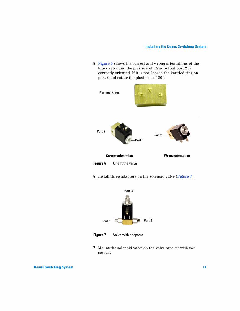
5 Figure 6 shows the correct and wrong orientations of the brass valve and the plastic coil. Ensure that port 2 is correctly oriented. If it is not, loosen the knurled ring on port 3 and rotate the plastic coil 180°.
6 Install three adapters on the solenoid valve (Figure 7).
7 Mount the solenoid valve on the valve bracket with two screws.
Figure 6 Orient the valve
Figure 7 Valve with adapters
Port markings
Correct orientation Wrong orientation
Port 2Port 2
Port 3
Port 3
Port 2Port 1

18 Deans Switching System
Installing the Deans Switching System
8 Mount the valve and bracket on the oven top as shown in Figure 8. Note that this secures the back of the panel.
9 Connect the valve driver cable to the valve (Figure 8).
10 Remove the right side panel. The main board will resemble either Figure 9 (no valve bracket) or Figure 10 (valve bracket present), except that the valve cables will not be present.
Figure 8 Mount valve and connect driver cable
Figure 9 Main board without valve bracket
Valve jumper cable
Connector P22
Valve driver cable

Installing the Deans Switching System
Deans Switching System 19
11 Is a valve bracket installed on the main board?
• No (Figure 9): Connect the free end of the valve driver cable to the valve jumper cable. Connect the other end of the valve jumper cable to connector P22 at the top of the main board.
• Yes (Figure 10): Connect the free end of the valve driver cable to socket V1 on the valve bracket.
12 Connect the switching gas supply.
• To supply the switching gas from a Pneumatics Control Module (PCM): Connect one of the 100 cm coiled lengths of tubing to port 2 of the solenoid valve (see Figure 11). Connect the stainless steel union to the other end.
Figure 10 Main board with valve bracket
Valve bracket
Socket V1
Valve driver cable
NOTE You can use any of sockets V1 through V4 to control the valve, but must configure the selected valve as a switching valve and must refer to it when entering the cut time commands. This discussion assumes V1.

20 Deans Switching System
Installing the Deans Switching System
Cut the line from the PCM module so that is about 15 cm (6 inches) long. Connect it to the stainless steel union.
Figure 11 Pneumatics Control Module
• To supply the switching gas from an Auxiliary Pressure controller (Figure 12): Ensure that the restrictor with the brown dot (19231-60610) is installed in the Aux 3 channel outlet fitting.
Remove the 1/8-inch end of the tubing using cutters or a file. Connect the tube to port 2 of the solenoid valve.
Figure 12 Auxiliary Pressure controller

Installing the Deans Switching System
Deans Switching System 21
Assembling the pneumatic coupler
1 Install a micro-volume tee in the center position of the Deans bracket, using an 8-32 screw and a flat washer. Orient the tee to the bracket as shown in Figure 13.
2 Install 5 cm lengths of the Sulfinert-treated metal tubing into the top and bottom connections (Figure 13). Finger-tighten the nuts. Tighten ¼-turn more with a wrench.
3 Slide a second micro-volume tee onto the top position. Finger-tighten the nut. Tighten ¼-turn more with a wrench. Fasten the tee to the bracket with an 8-32 screw and a flat washer.
4 Slide the third micro-volume tee onto the bottom position. Finger-tighten the nut. Tighten ¼-turn more with a wrench. Fasten the tee to the bracket with an 8-32 screw and a flat washer.
Figure 13 Adding tubing
Micro-volume tee
Top of bracket

22 Deans Switching System
Installing the Deans Switching System
5 Install the four column clips on the oven shroud (Figure 15).
Figure 14 Completed pneumatic coupler assembly

Installing the Deans Switching System
Deans Switching System 23
6 Install a screw and a lock washer in a female-female standoff as shown in Figure 16. Repeat this to make two assemblies.
7 Install the two female-female standoff assemblies into the cut-out ‘tees” on the left inside wall of the oven (Figure 17).
Figure 15 Oven clips
Figure 16 Standoff assemblies
Ovenshroud
Clip(1 of 4)
Standoff
ScrewLock-washer

24 Deans Switching System
Installing the Deans Switching System
When you install, be sure that the lock-washer is behind the oven wall and that the standoff is at the bottom of the tee.
8 Install the threaded standoff on the screw thread in the left side wall of the oven (Figure 18).
Figure 17 Mounting a standoff in a tee slot
Figure 18 Standoff in screw mount
Threaded standoff

Installing the Deans Switching System
Deans Switching System 25
9 Mount the pneumatic coupler assembly on these three standoffs as shown in Figure 19.
10 Connect one end of a 610 mm (24 inch) length of stainless steel tubing to the bottom connector of the bottom micro-volume tee inside the oven.
Protect the other end of the tubing with a plastic end cap and push it up through the top oven wall so that the end of the tubing comes out in the hole of the valve box blanking plate.
Figure 19 Installing the pneumatic coupler assembly
26 Deans Switching System
Installing the Deans Switching System
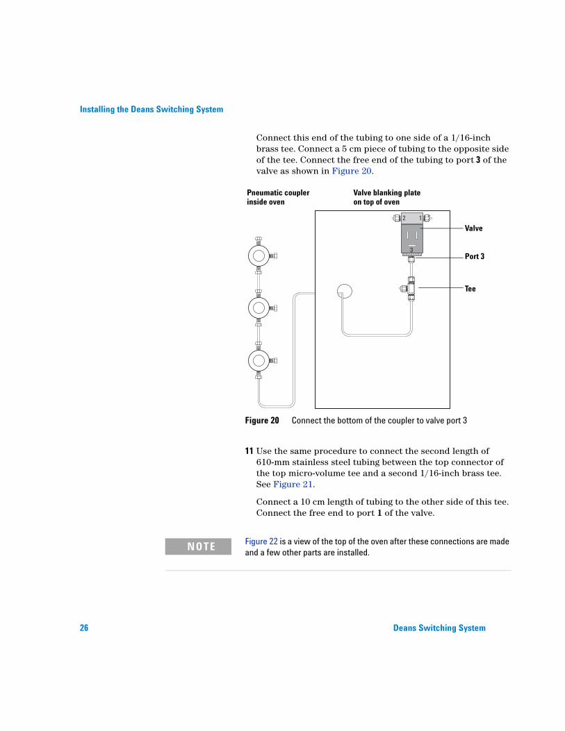
Connect this end of the tubing to one side of a 1/16-inch brass tee. Connect a 5 cm piece of tubing to the opposite side of the tee. Connect the free end of the tubing to port 3 of the valve as shown in Figure 20.
11 Use the same procedure to connect the second length of 610-mm stainless steel tubing between the top connector of the top micro-volume tee and a second 1/16-inch brass tee. See Figure 21.
Connect a 10 cm length of tubing to the other side of this tee. Connect the free end to port 1 of the valve.
Figure 20 Connect the bottom of the coupler to valve port 3
12
3
Pneumatic coupler Valve blanking plateinside oven on top of oven
Port 3
Valve
Tee
NOTE Figure 22 is a view of the top of the oven after these connections are made and a few other parts are installed.

Installing the Deans Switching System
Deans Switching System 27
Figure 21 Connect the top of the coupler to valve port 1
Valve
Pneumatic coupler Valve blanking plateinside oven on top of oven
Port 1
Tee
12
3

28 Deans Switching System
Installing the Deans Switching System
Selecting and installing the Shunt Restrictor
A Shunt Restrictor prevents sample diffusing into the unswitched control lines. The restrictor length depends on the types of columns and detectors that are used.
• For megabore (530 µ) columns with flows above 10 mL/min, use the 30 cm length of restrictor tubing.
• For 250 µ or 320 µ columns, use the 50 cm length of restrictor tubing.
• For 100 µ columns or 250 µ columns at low flows (as with a mass spectrometer), use the 100 cm length of restrictor tubing.
Install the selected coil between the free ends of the two tees (Figure 22).
Figure 22 Install the Shunt Restrictor coil
ShuntRestrictorconnections
ShuntRestrictorcoil
From topof coupler
From bottomof coupler

Installing the Deans Switching System
Deans Switching System 29
Installing the columns
1 Clip the baskets of the two capillary columns together using the hooks on the column baskets.
2 Install this columns assembly onto the capillary clips previously installed. Center the assembly in the oven. Adjust the clips so that the column assembly is tightly held to the oven shroud.
We will be using the terms primary column and secondary column. The primary column is the column into which the sample will be injected.
3 Connect one end of the primary column to the capillary inlet. See the appropriate sections of the 6890 user documentation for correct installation of a capillary column to the inlet.
4 Connect the other end of the primary column to the middle micro-volume tee in the pneumatic assembly using Valco FSR fittings.
a Remove the stainless steel nut and ferrule from the middle tee.
b Select the appropriate FSR liner for the column. Use the smallest one that will slide onto the column.
•0100-1513 for 530 columns
•0100-1514 for 320 columns
•0100-2323 for 250 columns
c Use the counterbored nut, a polyimide ferrule, and the selected liner to connect the column to the tee.
5 Connect one end of the secondary column to the secondary detector. Connect the other end of the secondary column to the bottom micro-volume tee in the same way that you
CAUTION If you have not used Valco FSR fittings before, read Appendix A before continuing.

30 Deans Switching System
Installing the Deans Switching System
connected the primary column. Figure 23 summarizes the coupler connections.
Figure 23 Coupler connections
Tube to tee toPort 3 connectshere
Tube to tee toPort 1 connectshere
Primary columnconnects here
Secondary columnconnects here
Restrictor (seenext section)will connect here

Installing the Deans Switching System
Deans Switching System 31
Calculating and installing the Restrictor tubing
The last step of hardware installation is to connect the Restrictor tubing from the Deans switch to the primary detector. This tube must have the same pneumatic resistance as the secondary column, but the transit (holdup) time must be much shorter. This is done using a short length of narrow bore uncoated deactivated fused silica tubing.
For a given tubing diameter, the length is calculated based on the dimensions of the secondary column and the operating pressures of the two detectors. (If you are developing a new method, you may want to skip to the next section and decide what your method conditions will be before installing the restrictor.)
Choose the smallest diameter that gives a length of at least 0.3 m for conventional detectors or 0.5 m for Mass Selective Detectors (MSDs). For most applications using 0.25 mm id columns and conventional detectors, 0.1 mm id tubing (supplied with the kit) is used. Systems with larger diameter columns or with MSDs may require larger diameter tubes (0.18, 0.2, or 0.25 mm id).
The Deans switch calculator software takes the desired method parameters (column dimensions, temperature, flows, etc.) and calculates the required restrictor length and pressure setpoints to operate the system. Before the calculator can be used, the method parameters must be chosen. As an example, we will use the method parameters shown in Table 3.

32 Deans Switching System
Installing the Deans Switching System
1 Load the software into your PC. Insert the CD into the drive and click the Start icon in the bottom left of the screen. Select Run and type X:\ Setup, where X is the letter assigned to the CD drive.
Table 3 Example method parameters
Primary column Secondary column
Type HP1-MS Innowax
Diameter (mm) 0.25 0.25
Length (m) 15 15
Film (µm) 0.25 0.25
Detector FID FID
Column flow (mL/min) 2 3
Initial oven temperature 40 °C
Carrier gas Helium

Installing the Deans Switching System
Deans Switching System 33
2 Click Start, then select Programs and the Deans Switch Calculator. The calculator screen opens (Figure 24).
For this example, fill in the parameter shown in brackets,[].
3 Define the Carrier Gas. [Helium]
4 Enter the Pressure Units you will use. [psi]
5 Enter the starting temperature (degC) of the analysis. [40]
6 Enter the Primary Detector type. If this is a non-Agilent detector, choose Other and set the Primary Detector Outlet Pressure. This must be in absolute units. [FID]
Figure 24 Calculating the Restrictor length

34 Deans Switching System
Installing the Deans Switching System
7 Enter the Secondary Detector type. If this is a non-Agilent detector, choose Other and set the Secondary Detector Outlet Pressure. This must be in absolute units. [FID]
8 Enter the Primary Column Length in meters. [15]
9 Enter the Primary Column Diameter (id) in mm. [0.25]
10 Enter the Primary Flow in mL/min. This should be chosen for maximum column efficiency. [2.0]
11 Enter the Secondary Column Length in meters. [15]
12 Enter the Secondary Column Diameter (id) in mm. [0.25]
13 Enter the Secondary Flow in mL/min. This should be about 50 percent greater than the Primary Flow. The difference between the primary and secondary flows must be at least 1 mL/min.
If the resulting flow is too high for the secondary detector (such as a mass spectrometer), set the secondary flow to a value that the detector can handle and then adjust the primary flow to keep the ratio of the flows correct (Secondary flow = Primary flow + 50%). [3.0]
14 Enter the Restrictor Diameter (id) in mm. The tubing supplied has an internal diameter of 0.1 mm. [0.1]
15 Read the Restrictor Length in meters. In this example, 0.384 m of 0.1 mm id restrictor tubing is required.
If a diameter larger than 0.1 mm id is required, these are the Agilent part numbers:
• 0.18 mm id x 10 m, 160-2615-10
• 0.20 mm id x 10 m, 160-2205-10
• 0.25 mm id x 10 m, 160-2255-10
16 Cut this length of tubing from the 5-meter length of restrictor tubing supplied.
17 Connect one end of this restrictor tube to the top tee of the pneumatics switch using a Valco fitting (see Appendix A).
18 Connect the other end to the Primary Detector using the appropriate nut and ferrule.

Installing the Deans Switching System
Deans Switching System 35
NOTE If the secondary column is ever changed in length or internal diameter, or if a detector of different operating pressure is used, you will need to recalculate the dimensions of the restrictor tube.

36 Deans Switching System
Installing the Deans Switching System

37
Agilent G2855A Deans Switching SystemInstallation and Operation
Agilent Technologies
3Operating the Deans Switching System
Column considerations 38
Inlet considerations 40
Detector considerations 41
Column flow rates 42
Oven temperature program 44
Pressure setpoints for primary and secondary columns 45
Determining the switching times 48
Backflushing to save time 54
This chapter discusses selecting the method parameters for a Deans switch method and using the calculator software to set up the analysis. An example method will be developed for the analysis of methyl tertiary-butyl ether (MTBE), benzene, and toluene in gasoline.

38 Deans Switching System
Operating the Deans Switching System
Column considerations
The primary and secondary column phases are chosen to have different selectivity. The analyte(s) of interest are separated on the first column from at least the bulk of the sample matrix. The analyte(s) and any co-eluting matrix interferences are then cut onto the second column. Because the phase of the second column has a different selectivity, the analyte(s) are (hopefully) separated from the matrix interferences.
Some phase combinations that have been used effectively are:
• DB-1 (non-polar) with HP-Innowax (polar). This is a good choice for general analytical separations. It is limited by the upper temperature limit of Innowax (260 °C).
• DB-5 (low polarity) with DB-17MS (medium polarity). This is a good choice for separations that require higher temperatures (up to 320 °C). It works well for cutting organophosphorus pesticides from difficult matrices like essential oils.
• DB-5 (low polarity) with Cyclosil (chiral). This pair is useful for resolving enantiomers that are overlapped with matrix interferences in, for example, flavors and fragrances.
• HP-Innowax (polar) with HP-Plot Q. This combination works well for cutting trace thiophene from benzene.
Which column should be the primary column? Two useful rules are:
• Choose the phase which separates the analytes from the largest matrix interferences.
• Choose the more robust phase, since the primary column receives the bulk of the sample loading.
For the example gasoline method, the DB-1MS will be the primary column. This is a nonpolar, rugged, low-bleed phase that spreads out the components of gasoline approximately in boiling point order.

Operating the Deans Switching System
Deans Switching System 39
Since most of the matrix interferences will be hydrocarbons and the three analytes are polar, HP-Innowax will be used as the secondary column. The HP-Innowax will retain the polar analytes relative to the coeluting hydrocarbons.
Column dimensions are selected with the same considerations used in any gas chromatographic method, where tradeoffs between speed, resolution and capacity are made.
In the gasoline method, the analytes are present in percent concentrations. The method should have just enough resolution to separate the three analytes and do so in the fastest way possible. A good starting point is to select columns with a relatively small diameter, thin film, and short length. Since the Deans switch has a small but finite dead volume, it is suggested that columns of diameter smaller than 0.2 mm id be avoided.
The primary column will be a 15 m x 0.25 mm id x 0.25 µm film thickness DB-1MS and the secondary column will be a 15 m x 0.25 mm id x 0.25 µm HP-Innowax.

40 Deans Switching System
Operating the Deans Switching System
Inlet considerations
There are no inherent limitations on the inlets that can be used for Deans switch analyses. Choose the inlet type using the same considerations as with conventional GC methods.
In the gasoline example, the analytes are at high concentrations. To prevent peak overloading, we will use a split injection. The split ratio must be high because of the chosen column dimensions; we will use 150:1. A small (0.2 µL) injection will reduce column loading and save carrier gas.
Operating the Deans Switching System
Deans Switching System 41
Detector considerations
The detectors are selected based on the needs of detection limit, dynamic range, selectivity, ease of use, etc. As long as the detector can accept the flow rate of carrier gas from the column or restrictor to which it is connected, it can be used. Since Deans switch methods are run in constant pressure mode, the detector must also be compatible with column flows changing during temperature programmed runs. If MSDs are used, the column sizes and carrier flow rates must be chosen to match the pumping capacity of the system.
The flame ionization detector (FID) is a good starting point. Due to the high resolving power of 2-D GC methods, analytes are often separated completely. If so, the FID is the easiest and most cost effective detector. If the matrix is very complex, selective detectors can be used to measure the analytes.
FIDs will be used for the gasoline example method.

42 Deans Switching System
Operating the Deans Switching System
Column flow rates
In a Deans switch method, the flow from the primary column plus a switching flow go through the secondary column. The primary column flow is usually chosen to be at or near the optimum for that column. This prevents the flow through the secondary column from exceeding the optimum to such an extent that there is a significant loss in resolution.
Table 4 gives suggested flows for different column diameters and carrier gases. Two flows are listed for each combination. Best efficiency gives approximately the optimum resolution. Fast analysis yields a faster chromatogram with only a small reduction in chromatographic resolution.
For the example gasoline method, the Fast analysis flow will be chosen. The primary column flow will be set to 2.0 mL/min of helium (at the initial oven temperature).
Table 4 Suggested column flows (mL/min)
Column diameter (mm)
Helium Hydrogen Nitrogen Argon
Best efficiency
Fast analysis
Best efficiency
Fast analysis
Best efficiency
Fast analysis
Best efficiency
Fast analysis
0.10 0.40 0.80 0.50 1.00 0.13 0.25 0.11 0.22
0.18 0.72 1.44 0.90 1.80 0.23 0.45 0.20 0.40
0.20 0.80 1.60 1.00 2.00 0.25 0.50 0.22 0.44
0.25 1.00 2.00 1.25 2.50 0.31 0.63 0.28 0.55
0.32 1.28 2.56 1.60 3.20 .040 0.80 0.35 0.70
0.45 1.80 3.60 2.25 4.50 0.56 1.13 .050 0.99
0.53 2.12 4.24 2.65 5.30 0.66 1.33 0.58 1.17

Operating the Deans Switching System
Deans Switching System 43
The flow for the secondary column is determined by taking the flow from the primary column and increasing it by about 50 percent, with a minimum increase of 1.0 mL/min. The difference between the two flows reflects the switching flow. It must be large enough to prevent tailing in the switch.
In the gasoline example, the primary column flow is 2.0 mL/min. Increasing this by 50 percent gives 3.0 mL/min, which meets the 1.0 mL/min difference requirement. The flow for the HP-Innowax column will be set to 3.0 mL/min.
Deans switch methods are run in constant pressure mode. Since the Deans switch must be operated at constant pressure, by definition the secondary column will be in constant pressure mode.
The primary column could, in theory, be operated in constant flow mode. However, in practice it cannot be because the 6890 firmware, the GC ChemStation software, and the GC/MS ChemStation software will not allow the outlet pressure for the primary column to be set greater than 4.0 psi. Since the outlet pressure of the primary column is the inlet pressure for the secondary column, it will in most cases exceed 4.0 psi. Thus the flow calculated by the firmware and/or software for the primary column will be incorrect because the outlet pressure will be incorrect. This is why constant pressure mode is required for the primary column.
A second consequence of the firmware and/or software using the incorrect outlet pressure for the primary column is that for split injections, the split ratio calculation will also be incorrect. If a split injection is being used, the split flow must be calculated separately to give the desired split ratio. The Deans switch software calculates the correct split flow to enter to obtain the desired split ratio.

44 Deans Switching System
Operating the Deans Switching System
Oven temperature program
The oven temperature program is chosen in the normal way. For the example gasoline method, the oven will be programmed at 40 °C for 1 minute, 10 °C/min to 250 °C, and held for 5 minutes.
The low initial temperature is needed to separate the MTBE and the high final temperature is required to elute all of the highest boiling gasoline components. To determine the temperature program rate, a useful guideline is to program at approximately 10 °C/holdup time of the column. For the primary column, the holdup time is close to 1 minute, thus it will be programmed at 10 °C/min.
Note that the holdup time for the primary column cannot be calculated until after the Deans Switch Calculator is used to determine all the pressure setpoints, as shown in the next section.
The holdup times for each column are printed when the calculator results are printed.

Operating the Deans Switching System
Deans Switching System 45
Pressure setpoints for primary and secondary columns
At this point, all of the method parameters have been decided. It it now time to calculate the pressure setpoints for the primary column inlet and for the PCM (or Aux EPC) modules to obtain the desired flows.
Run the calculator program (Figure 25).
Figure 25 Calculating pressures

46 Deans Switching System
Operating the Deans Switching System
Enter the parameters for the example gasoline method, shown in square brackets.
1 Define the Carrier Gas. [He]
2 Enter the Pressure Units that you will use. [psi]
3 Enter the starting temperature (degC) of the analysis. [40]
4 Enter the Primary Detector Type. If this is a non-Agilent detector, choose Other and set the Primary Detector Outlet Pressure. This must be in absolute units. [FID]
5 Enter the Secondary Detector Type. If this is a non-Agilent detector, choose Other and set the Secondary Detector Outlet Pressure. This must be in absolute units. [FID]
6 Enter the Primary Column Length in meters. [15]
7 Enter the Primary Column Diameter (id) in mm. [0.25]
8 Enter the Primary Flow in mL/min. This should be chosen for maximum column efficiency. [2.0]
9 Enter the Secondary Column Length in meters. [15]
10 Enter the Secondary Column Diameter (id) in mm. [0.25]
11 Enter the Secondary Flow in mL/min. This should be about 50 per cent greater than the Primary flow, with at least 1 mL/min difference between the primary and secondary flows.
If the resulting flow is too high for the secondary detector (such as a mass spectrometer), set the secondary flow to a value that the detector can handle and then adjust the primary flow to keep the ratio of the flows correct (Secondary flow = Primary flow + 50%). [3.0]
12 Enter the Restrictor Diameter (id), in mm. The tubing supplied has an internal diameter of 0.1 mm. [0.1]
13 Enter the Equivalent Restrictor Length in meters. This restrictor is a length of tubing or a frit used to dampen pressure oscillations from the Aux EPC or PCM module. It will normally be a 1.0 m length of 0.25 mm id stainless steel tubing. If it is the FID air frit, enter 1.16 m for the length and 0.32 mm id for the diameter. The calculator will account for this restriction when calculating the pressures. [1.0]

Operating the Deans Switching System
Deans Switching System 47
14 Enter the Equivalent Restrictor Diameter in mm (see previous item). This will normally be 0.25 mm.[0.25]
15 Read the pressure (16.79 psi) for the switching gas under the PCM dial. Set the PCM or Aux EPC pressure to this value.
16 Read the pressure (22.86 psi) for the inlet under the Inlet Pressure dial. Set the inlet pressure to this value.
17 You can enter the dimensions of the Shunt restrictor into the boxes labeled Shunt Restrictor Diameter and Shunt Restrictor Length. These entries are optional, since they are not used in the calculations. They are provided for record keeping purposes.
18 If the Split item in the Inlet field is selected, two fields appear labelled Desired Split Ratio and Set Split Flow. As mentioned previously, the split ratio calculation in the 6890 GC will not be correct.
If the method calls for a split injection, enter the Desired Split Ratio. Read the calculated Set Split Flow value and enter it into the 6890 setpoints to obtain the Desired Split Ratio.
Enter [150] for the Desired Split Ratio. Read 300 mL/min at the Set Split Flow window and enter it into the GC.
19 There is a field for optional Comment.
20 To save the calculations, type a name into the box labeled Method and select Save method from the File menu. Use Load method to reload the method at a later date. To print the current calculation results, select Print current method in the File menu.
21 Ensure that the valve you are using, usually Valve 1, on the GC is configured as a Switching Valve.

48 Deans Switching System
Operating the Deans Switching System
Determining the switching times
Prepare a calibration sample that contains the compounds that you wish to switch. The analytes should be at the maximum concentration that will be encountered in real samples. This is important with high concentration analytes, because if they overload on the primary column, the peak width will increase and the switching time range will need to be widened. If the analyte peaks are too overloaded, the split ratio and/or amount injected should be adjusted to improve the peak shape.
For the example gasoline method, the calibration standard consists of 12% (v/v) ethanol, 20% MTBE, 6% benzene, and 20% toluene in iso-octane. Before running the calibration sample, you must know the order of elution from the primary column. For the example, the elution order is: ethanol, MTBE, benzene, iso-octane, and toluene.
Make sure that Valve 1 is turned OFF and that there are no entries in the time table for Valve 1 (so that no switching will take place).
Inject the calibration sample and start the run. All of the peaks will elute to the primary detector. The chromatogram is shown in Figure 26.
Figure 26 Calibration chromatogram

Operating the Deans Switching System
Deans Switching System 49
The retention times are: ethanol (0.981 min), MTBE (1.219 min), benzene (1.618 min), iso-octane (1.937 min), and toluene (2.573 min).
To set the switching times for MTBE, determine the times just before and just after the peak. Figure 27 shows these for MTBE.
To switch the MTBE peak, insert entries into the GC time table to turn Valve 1, which controls the Deans switch, ON at 1.20 min and OFF at 1.24 min. This will cut the MTBE onto the Innowax column.
Figure 27 MTBE times

50 Deans Switching System
Operating the Deans Switching System
Make a second injection, now switching the MTBE peak to the Innowax column. Figure 28 shows the result.
Note that the MTBE peak is now absent from the primary column chromatogram (top) and appears in the secondary column chromatogram (bottom).
Once the method is determined to work with the calibration standard, it should be checked with a sample that has the same matrix interferences as the real samples for which the method is intended.
Figure 28 MTBE cut to Innowax column

Operating the Deans Switching System
Deans Switching System 51
Figure 29 shows the uncut chromatogram of RFA, a reference gasoline. Note that there is a serious overlap of an interference with the MTBE peak.
Figure 30 shows the separation with the MTBE cut to the Innowax column.
The separation is much better with the 2-D method. There still remains some overlap. If this is unacceptable, using longer columns would improve the separation.
Figure 29 Uncut RFA chromatogram
Figure 30 RFA with MTBE cut to Innowax

52 Deans Switching System
Operating the Deans Switching System
Cut times for benzene and toluene were selected using the same procedure as for MTBE. Benzene was cut from 1.60 to 1.65 minutes and toluene from 2.51 to 2.62 min.
Figure 31 shows the test mix run with MTBE, benzene, and toluene cut to the Innowax column.
To check for matrix interference problems, a sample of local pump gasoline was run (Figure 32).
Figure 31 Multiple cuts
Figure 32 Local pump gasoline

Operating the Deans Switching System
Deans Switching System 53
In all three cases the interfering compounds elute before the analyte. Benzene and toluene are completely separated from interferences.
Make sure that compounds from one cut do not interfere with those from another. If there is interference between two cuts, then run two methods on the sample, cutting only one compound per method. In the current example there are no such interferences, so one method will suffice.

54 Deans Switching System
Operating the Deans Switching System
Backflushing to save time
For the example gasoline method, the three analytes are completely eluted from both columns by 4 minutes. However, the method must be run until about 22 minutes to flush all of the gasoline components from the column (Figure 33).
To shorten the analysis time, the temperature and/or pressure could be ramped after 4 minutes to push the remaining gasoline components out of the column more rapidly.
If a split/splitless inlet is used, backflushing is another alternative with the Deans switching system.
In the example gasoline method, the oven is programmed at 40 °C for 1 minute, ramped at 10 °C/min to 250 °C, and held for 5 minutes. Since all the analyte peaks are out by 4 minutes, which corresponds to an oven temperature of 70 °C, the column controls can be set to backflush beginning at 4 minutes.
To do this, starting at 4.00 minutes program the split inlet pressure to decrease at 90 psi/min from 22.86 psi down to 0.5 psi. At the same time, program the PCM (or Aux EPC) module to increase in pressure at 90 psi/min from 16.26 psi up to 60 psi.
Figure 33 Eluting gasoline

Operating the Deans Switching System
Deans Switching System 55
These pressure changes reverse the carrier flow in the primary column and increase the carrier flow in the secondary column. Heavy components in the primary column are backflushed out the split vent.
Backflushing removes heavier components rapidly. In this example, backflushing for only 2 minutes completely clears both columns. The run time is reduced to 6 minutes.
Figure 34 shows the chromatogram of the pump gasoline, but now with backflushing. The run is over in 6 minutes.
Check to see if the backflushing time is sufficient by running a blank run (without backflushing) after running a backflush method. If the backflushing time is too short, heavy peaks will remain in the column and appear in the blank run. If they do, extend the backflushing time.
Figure 34 Gasoline with backflushing

56 Deans Switching System
Operating the Deans Switching System

57
Agilent G2855A Deans Switching SystemInstallation and Operation
Agilent Technologies
AUsing Valco FSR adapters
The following is adapted from technical note 501 from Valco Instruments. It explains how to install capillary columns using Valco FSR adapters.
The FSR adapter consists of three components: a polyimide ferrule, a special counterbored nut, and a polyimide liner which slides over the fused silica tube. The liner is stepped at one end so that it is retained by the nut, insuring that the liner and the tube within are removed as the nut is unscrewed from the valve.
An installation tool is supplied. The tool consists essentially of a cutaway length of 1/16-inch TFE tubing and provides a means of pushing the liner to the bottom of the nut and keeping it there against the frictional forces generated while tightening the nut.
1 Slide the liner over the column end, large end first (Figure 35).
2 Cut off a small amount of the column to expose a fresh end and to minimize the risk of contaminating the column with particles scraped from the inside of the liner.
Figure 35 Liner and tube

58 Deans Switching System
Using Valco FSR adapters
3 Slide the small end of the liner into the nut, making sure that the step of the liner goes all the way to the bottom of the counterbore in the nut (Figure 36).
4 Slide the ferrule over the liner, using the installation tool to keep the liner all the way into the nut (Figure 37).
5 Continue to hold the liner in place with the tool. Pull the column back until its end is flush with the liner (Figure 38).
Figure 36 Adding the nut
Figure 37 Add the ferrule
Figure 38 Position the column

Using Valco FSR adapters
Deans Switching System 59
6 The column and liner must be pushed in as a unit while the nut is screwed into the matching fitting. Use one hand to hold the column against the tool so that the column is supported while it is being pushed. With the other hand, screw the nut into the matching fitting until it is finger-tight.
7 Use a wrench to tighten the nut in 15° increments until the ferrules starts to grip the column, then tighten it an additional 15°. (The fitting may need to be retightened after the first time it is heated above 250°C.)
For customer convenience, Valco sells a 3/16-inch x 1/4-inch open-end wrench, Product Number OEW, that fits both 1/16-inch and 1/32-inch fittings.
8 Leak check with H2 and a hydrogen leak detector or with H2 or helium using a thermal conductivity type leak detector. If a small leak is observed, an additional 10° to 15° tightening should produce a tight seal.

60 Deans Switching System
Using Valco FSR adapters

Deans Switching System 61
Index
Aatmospheric pressure, 7Aux Pressure controller, 7Auxiliary Pressure controller, 20
Ccalculator, 31, 33Carrier Gas, 33column
primary, 29secondary, 29, 31
column clips, 22Column considerations, 38column installation, 29constant pressure, 41
DDeans bracket, 21Deans switch, 31degC, 33detector
primary, 31secondary, 29
Detector considerations, 41
Iinlet, 29Inlet considerations, 40
Lliner, 29
Mmicro-volume tee, 21, 25, 26, 29
Ooven shroud, 22, 29
PPCM, 6, 7, 19pneumatic coupler, 6, 21, 25Pneumatics Control Module, 19, 20Pressure Control Module, 6Pressure Units, 33primary column, 6, 29, 38, 42Primary Column Diameter, 34Primary Column Length, 34Primary Detector, 6, 33, 34primary detector, 31Primary Detector Outlet Pressure, 33Primary Flow, 34
Rresolution, 39Restrictor, 6, 31Restrictor Diameter, 34Restrictor Length, 34
SSafety, 13Secondary column, 6secondary column, 29, 31, 39Secondary Column Diameter, 34Secondary Column Length, 34Secondary Detector, 34secondary detector, 29Secondary Detector Outlet Pressure, 34Secondary Flow, 34Shunt Restrictor, 28solenoid valve, 6, 15, 20standoff, 23
Ttee, 26
micro-volume, 21, 26, 29
VValco FSR fittings, 29valve box, 15valve box blanking plate, 16, 25valve bracket, 17, 19valve driver cable, 18, 19valve jumper cable, 19

62 Deans Switching System
Index

Agilent Technologies
© Agilent Technologies, Inc.
Printed in USA, November 2006
G2855-90100
Related Documents


![Graduate School Task Force Stakeholder Presentation...stakeholders [e.g. faculty senate, council of deans, GOC Deans, URC Deans, graduate students, CPI, etc.] on the establishment](https://static.cupdf.com/doc/110x72/5f30c04147fbe01b060051d8/graduate-school-task-force-stakeholder-presentation-stakeholders-eg-faculty.jpg)