Contents Section 1—Introduction . . . . . . . . . . . . . . . . . . . . . . . . . . . . . . . . . . 1 Test Parameters . . . . . . . . . . . . . . . . . . . . . . . . . . . . . . . . . . . . . . 2 Base Station (Test Set) Power Transitions . . . . . . . . . . . . . . . . 2 References . . . . . . . . . . . . . . . . . . . . . . . . . . . . . . . . . . . . . . . . . . 2 Section 2—Test Equipment . . . . . . . . . . . . . . . . . . . . . . . . . . . . . . . 3 Section 3—Connecting the Equipment . . . . . . . . . . . . . . . . . . . . . 4 References . . . . . . . . . . . . . . . . . . . . . . . . . . . . . . . . . . . . . . . . . . 4 Section 4—Test Procedure . . . . . . . . . . . . . . . . . . . . . . . . . . . . . . . 5 Section 5—Configuring the Test Set . . . . . . . . . . . . . . . . . . . . . . . 8 Setting the RF Level Offset . . . . . . . . . . . . . . . . . . . . . . . . . . . . . 8 Setting the Pilot and Traffic Channels . . . . . . . . . . . . . . . . . . . . 8 Setting the Channel and Protocol . . . . . . . . . . . . . . . . . . . . . . . 10 Setting the CDMA Transmitter Power Test Mode . . . . . . . . . . . . . . . . . . . . . . . . . . . . . . . . . . . . . . . . . . 11 Section 6—Setting Up a 20 dB Increment on the Test Set . . . . 12 Section 7—Determining the Test Set’s Trigger Time Delay . . . 12 Section 8—Configuring the Spectrum Analyzer and Software . . . . . . . . . . . . . . . . . . . . . . . . . . . . . . . . . . . . . . . . . . 14 Setting “CDMA Config” Options . . . . . . . . . . . . . . . . . . . . . . . 14 Setting the RF Channel Function . . . . . . . . . . . . . . . . . . . . . . . 15 Setting the Time Response Function . . . . . . . . . . . . . . . . . . . . 15 Appendix 1—Background on Open and Closed Loop Power Control . . . . . . . . . . . . . . . . . . . . . . . . . . . . . . . . . . . . . . . . . 16 Open Loop . . . . . . . . . . . . . . . . . . . . . . . . . . . . . . . . . . . . . . . . . . 16 Closed Loop . . . . . . . . . . . . . . . . . . . . . . . . . . . . . . . . . . . . . . . . 16 Appendix 2—The Effect of Closed Loop Control on the Open Loop Test . . . . . . . . . . . . . . . . . . . . . . . . . . . . . . . . . . 17 Appendix 3—Determining Cable Connection Losses . . . . . . . . 18 External Power Meter Method . . . . . . . . . . . . . . . . . . . . . . . . . 18 Using the Agilent 8924C Test Set . . . . . . . . . . . . . . . . . . . . . . . 18 Appendix 4—Trigger Signal Description . . . . . . . . . . . . . . . . . . . 19 Making a Trigger Cable . . . . . . . . . . . . . . . . . . . . . . . . . . . . . . . 20 Trigger Signal Description . . . . . . . . . . . . . . . . . . . . . . . . . . . . . 19 Reference . . . . . . . . . . . . . . . . . . . . . . . . . . . . . . . . . . . . . . . . . . 19 Open Loop Power-Control Time-Response Test This product note will help you measure the “time response of open loop power control” for a CDMA mobile cellular telephone. The equipment and pro- cedures in this document apply to CDMA mobile cellular telephones based on TIA/EIA/IS-95-A, or related industry standards. Section 1—Introduction The open loop power control time-response is defined as the amount of time (t) it takes the mobile phone to respond to and acquire equilib- rium following a step increase in base station power, ∆P in . This test verifies that the mobile is capable of adjusting its transmit power throughout its dynamic range of transmission within a power versus time mask determined by applicable standards. An example of this mask, with a ∆P in = 20 dB and ∆t = 100 ms, is shown in Figure 1. For TIA/EIA/IS- 95-A, the upper and lower limits of this mask are determined by the equations shown on the follow- ing page. Agilent 8924C CDMA Mobile Station Test Set Product Note

Welcome message from author
This document is posted to help you gain knowledge. Please leave a comment to let me know what you think about it! Share it to your friends and learn new things together.
Transcript
ContentsSection 1—Introduction . . . . . . . . . . . . . . . . . . . . . . . . . . . . . . . . . . 1
Test Parameters . . . . . . . . . . . . . . . . . . . . . . . . . . . . . . . . . . . . . . 2Base Station (Test Set) Power Transitions . . . . . . . . . . . . . . . . 2References . . . . . . . . . . . . . . . . . . . . . . . . . . . . . . . . . . . . . . . . . . 2
Section 2—Test Equipment . . . . . . . . . . . . . . . . . . . . . . . . . . . . . . . 3
Section 3—Connecting the Equipment . . . . . . . . . . . . . . . . . . . . . 4References . . . . . . . . . . . . . . . . . . . . . . . . . . . . . . . . . . . . . . . . . . 4
Section 4—Test Procedure . . . . . . . . . . . . . . . . . . . . . . . . . . . . . . . 5
Section 5—Configuring the Test Set . . . . . . . . . . . . . . . . . . . . . . . 8Setting the RF Level Offset . . . . . . . . . . . . . . . . . . . . . . . . . . . . . 8Setting the Pilot and Traffic Channels . . . . . . . . . . . . . . . . . . . . 8Setting the Channel and Protocol . . . . . . . . . . . . . . . . . . . . . . . 10Setting the CDMA Transmitter Power Test Mode . . . . . . . . . . . . . . . . . . . . . . . . . . . . . . . . . . . . . . . . . . 11
Section 6—Setting Up a 20 dB Increment on the Test Set . . . . 12
Section 7—Determining the Test Set’s Trigger Time Delay . . . 12
Section 8—Configuring the Spectrum Analyzer and Software . . . . . . . . . . . . . . . . . . . . . . . . . . . . . . . . . . . . . . . . . . 14
Setting “CDMA Config” Options . . . . . . . . . . . . . . . . . . . . . . . 14Setting the RF Channel Function . . . . . . . . . . . . . . . . . . . . . . . 15Setting the Time Response Function . . . . . . . . . . . . . . . . . . . . 15
Appendix 1—Background on Open and Closed Loop Power Control . . . . . . . . . . . . . . . . . . . . . . . . . . . . . . . . . . . . . . . . . 16
Open Loop . . . . . . . . . . . . . . . . . . . . . . . . . . . . . . . . . . . . . . . . . . 16Closed Loop . . . . . . . . . . . . . . . . . . . . . . . . . . . . . . . . . . . . . . . . 16
Appendix 2—The Effect of Closed Loop Control on the Open Loop Test . . . . . . . . . . . . . . . . . . . . . . . . . . . . . . . . . . 17
Appendix 3—Determining Cable Connection Losses . . . . . . . . 18External Power Meter Method . . . . . . . . . . . . . . . . . . . . . . . . . 18Using the Agilent 8924C Test Set . . . . . . . . . . . . . . . . . . . . . . . 18
Appendix 4—Trigger Signal Description . . . . . . . . . . . . . . . . . . . 19Making a Trigger Cable . . . . . . . . . . . . . . . . . . . . . . . . . . . . . . . 20Trigger Signal Description . . . . . . . . . . . . . . . . . . . . . . . . . . . . . 19Reference . . . . . . . . . . . . . . . . . . . . . . . . . . . . . . . . . . . . . . . . . . 19
Open Loop Power-Control Time-Response TestThis product note will help you measure the “timeresponse of open loop power control” for a CDMAmobile cellular telephone. The equipment and pro-cedures in this document apply to CDMA mobilecellular telephones based on TIA/EIA/IS-95-A, orrelated industry standards.
Section 1—IntroductionThe open loop power control time-response isdefined as the amount of time (t) it takes themobile phone to respond to and acquire equilib-rium following a step increase in base stationpower, ∆Pin.
This test verifies that the mobile is capable ofadjusting its transmit power throughout its dynamicrange of transmission within a power versus timemask determined by applicable standards.
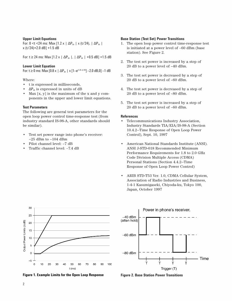
An example of this mask, with a ∆Pin = 20 dB and∆t = 100 ms, is shown in Figure 1. For TIA/EIA/IS-95-A, the upper and lower limits of this mask aredetermined by the equations shown on the follow-ing page.
Agilent 8924C
CDMA Mobile Station Test SetProduct Note
2
Upper Limit EquationsFor: 0 <t <24 ms: Max [1.2 x | ∆Pin | x (t/24), | ∆Pin | x (t/24)+2.0 dB] +1.5 dB
For: t ≥ 24 ms: Max [1.2 x | ∆Pin |, | ∆Pin | +0.5 dB] +1.5 dB
Lower Limit EquationFor: t ≥ 0 ms: Max [0.8 x | ∆Pin | x [1–e(1.25–t)/36] –2.0 dB,0] –1 dB
Where:• t is expressed in milliseconds,• ∆Pin is expressed in units of dB• Max [x, y] is the maximum of the x and y com-
ponents in the upper and lower limit equations.
Test ParametersThe following are general test parameters for theopen loop power control time-response test (fromindustry standard IS-98-A, other standards shouldbe similar).
• Test set power range into phone’s receiver: –25 dBm to –104 dBm
• Pilot channel level: –7 dB• Traffic channel level: –7.4 dB
Base Station (Test Set) Power Transitions1. The open loop power control time-response test
is initiated at a power level of –60 dBm (basestation). See Figure 2.
2. The test set power is increased by a step of 20 dB to a power level of –40 dBm.
3. The test set power is decreased by a step of 20 dB to a power level of –60 dBm.
4. The test set power is decreased by a step of 20 dB to a power level of –80 dBm.
5. The test set power is increased by a step of 20 dB to a power level of –60 dBm.
References• Telecommunications Industry Association,
Industry Standards TIA/EIA/IS-98-A (Section10.4.2—Time Response of Open Loop PowerControl), Sept. 10, 1997
• American National Standards Institute (ANSI).ANSI J-STD-018 Recommended MinimumPerformance Requirements for 1.8 to 2.0 GHzCode Division Multiple Access (CDMA)Personal Stations (Section 4.4.2—TimeResponse of Open Loop Power Control)
• ARIB STD-T53 Ver. 1.0, CDMA Cellular System,Association of Radio Industries and Business,1-4-1 Kasumigaseki, Chiyoda-ku, Tokyo 100,Japan, October 1997
Figure 2. Base Station Power TransitionsFigure 1. Example Limits for the Open Loop Response
3
Section 2—Test Equipment
Equipment Notes
8924C CDMA Mobile Station Test Set The Test Set must be equipped with electronic attenuators. NOTE: To determine if theAgilent 8924C Test Set is equipped with an electronic attenuator, access the Test Set’sTESTS screen (this procedure will erase any other IBASIC program stored in the test set):
1. Press the TEST key.
2. Select Procedure Location: ROM.
3. Select Procedure Filename: ICONFIG3.
4. Press k1 (Run Test) and look for A5 Input with Electronic Attenuator.
83236B PCS Interface This PCS interface is needed if performing PCS band tests
MINIMUM REQUIRED OPTIONS for 85725C open loop measurements:
• Option 004—Precision Frequency Reference (or equivalent external 10 MHz precisionfrequency reference)
• Option 101—Fast Time Domain Sweeps (if Option 151 is installed DO NOT INSTALLOption 101)
PREFERRED and RECOMMENDED OPTIONS for 85725C:
• Option 140—Narrow Resolution Bandwidth and Precision Frequency Reference (narrowbandwidth for ACPR measurements; includes precision reference same as Option 004)
• Option 053—Improved CDMA Amplitude Accuracy (for cellular and PCS bands)
• Option 151—DSP, Fast ADC, and Digital Demodulator (provides faster CDMA measurements)
• Option 160—CDMA firmware (for use with option 151)
OTHER SUGGESTED OPTIONS:
• Option 041—GPIB and Parallel Interface
• Option 105—Time-Gated Spectrum Analysis
To determine which spectrum analyzer option is installed in the spectrum analyzers:
1. Press CONFIG key.
2. Press More 1 of 3 softkey.
3. Press SHOW OPTIONS softkey.
85725C CDMA Measurements Personality This assembly is installed in the 859XE spectrum analyzer.
CDMA Mobile Phone An appropriate antenna connector or cable is required for the phone.
Shielded RF Isolation Box This item is optional but recommended.
Power Splitter A resistive or transformer-coupled power splitter is acceptable. It must be able to handlethe output power of the phone (approximately 25 dBm max). Example: Mini-Circuits resis-tive power splitter/combiner, p/n ZFRSC-2050 (dc to 2 GHz).
Trigger Cable Use a 15-pin male D-connector to BNC male connector cable. This cable is used to sendtrigger signals to the 859XE Spectrum Analyzer from the 8924C Test Set. NOTE: SeeAppendix 5 in this document for instructions on how to build this cable.
RF Cable Three low-loss shielded RF cables with type-N (male) connectors to mate with the powersplitter, RF shielded box, and CDMA telephone.
One of the following Agilent Technologiesspectrum analyzers is needed:
• 8593E Spectrum Analyzer
• 8594E Spectrum Analyzer
• 8595E Spectrum Analyzer
• 8596E Spectrum Analyzer
4
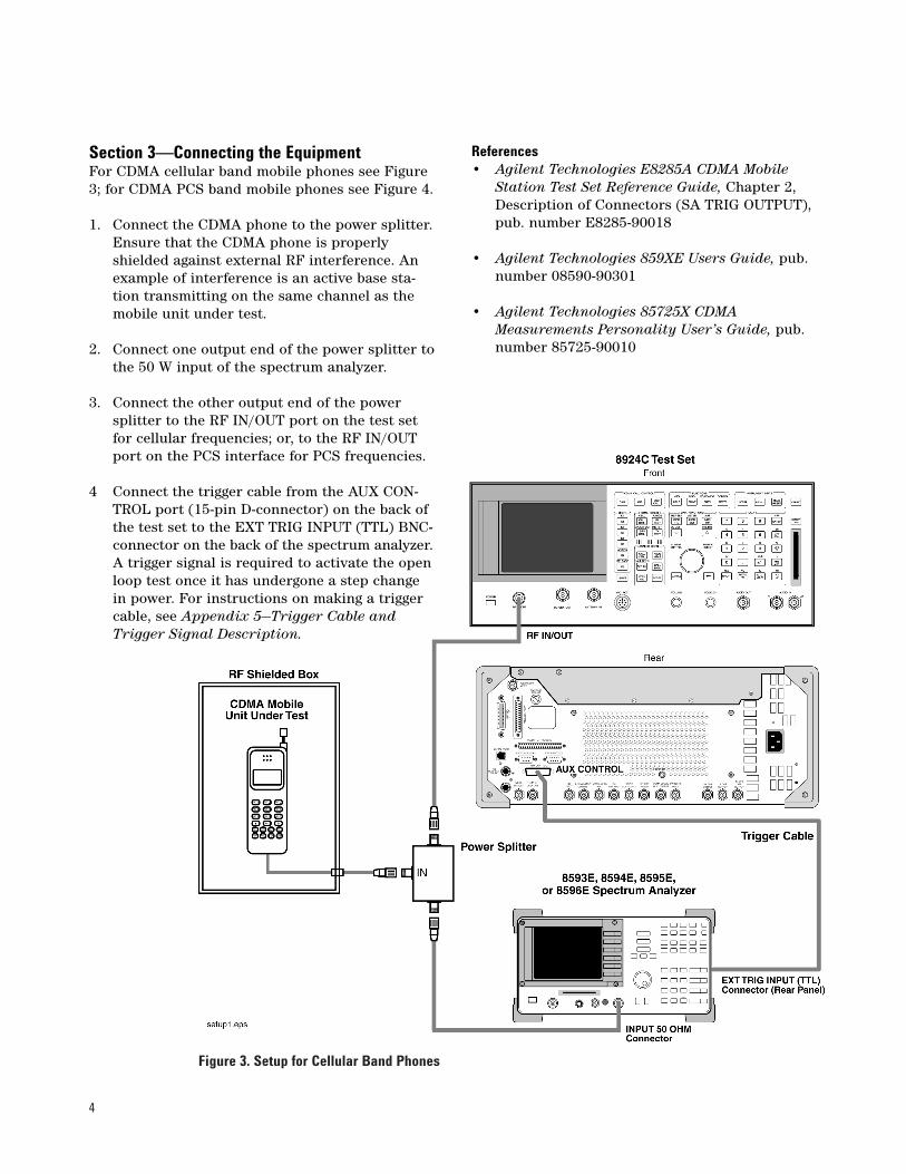
Figure 3. Setup for Cellular Band Phones
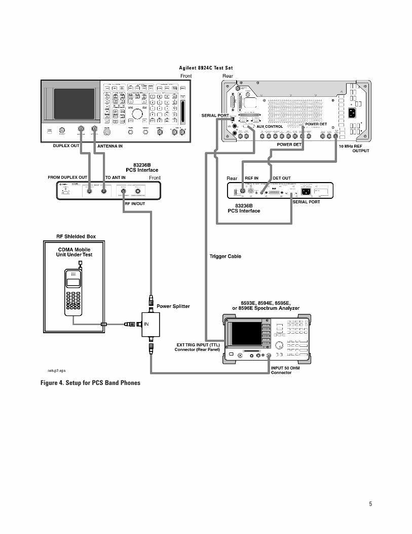
Section 3—Connecting the EquipmentFor CDMA cellular band mobile phones see Figure3; for CDMA PCS band mobile phones see Figure 4.
1. Connect the CDMA phone to the power splitter.Ensure that the CDMA phone is properlyshielded against external RF interference. Anexample of interference is an active base sta-tion transmitting on the same channel as themobile unit under test.
2. Connect one output end of the power splitter tothe 50 W input of the spectrum analyzer.
3. Connect the other output end of the powersplitter to the RF IN/OUT port on the test setfor cellular frequencies; or, to the RF IN/OUTport on the PCS interface for PCS frequencies.
4 Connect the trigger cable from the AUX CON-TROL port (15-pin D-connector) on the back ofthe test set to the EXT TRIG INPUT (TTL) BNC-connector on the back of the spectrum analyzer.A trigger signal is required to activate the openloop test once it has undergone a step changein power. For instructions on making a triggercable, see Appendix 5—Trigger Cable andTrigger Signal Description.
References• Agilent Technologies E8285A CDMA Mobile
Station Test Set Reference Guide, Chapter 2,Description of Connectors (SA TRIG OUTPUT),pub. number E8285-90018
• Agilent Technologies 859XE Users Guide, pub.number 08590-90301
• Agilent Technologies 85725X CDMAMeasurements Personality User’s Guide, pub.number 85725-90010
5
Figure 4. Setup for PCS Band Phones
6
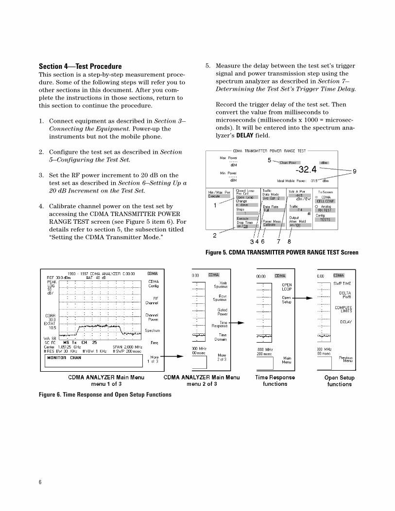
Figure 6. Time Response and Open Setup Functions
Figure 5. CDMA TRANSMITTER POWER RANGE TEST Screen
Section 4—Test ProcedureThis section is a step-by-step measurement proce-dure. Some of the following steps will refer you toother sections in this document. After you com-plete the instructions in those sections, return tothis section to continue the procedure.
1. Connect equipment as described in Section 3—Connecting the Equipment. Power-up theinstruments but not the mobile phone.
2. Configure the test set as described in Section5—Configuring the Test Set.
3. Set the RF power increment to 20 dB on thetest set as described in Section 6—Setting Up a20 dB Increment on the Test Set.
4. Calibrate channel power on the test set byaccessing the CDMA TRANSMITTER POWERRANGE TEST screen (see Figure 5 item 6). Fordetails refer to section 5, the subsection titled“Setting the CDMA Transmitter Mode.”
5. Measure the delay between the test set’s triggersignal and power transmission step using thespectrum analyzer as described in Section 7—Determining the Test Set’s Trigger Time Delay.
Record the trigger delay of the test set. Thenconvert the value from milliseconds tomicroseconds (milliseconds x 1000 = microsec-onds). It will be entered into the spectrum ana-lyzer’s DELAY field.
6. Configure the spectrum analyzer and softwareas described in Section 8—Configuring theSpectrum Analyzer and Software. Enter therecorded delay time into the DELAY field of theTime Response/Open Setup function, see Figure 6.
7. Turn on the CDMA phone. On the test set’sCDMA TRANSMITTER POWER RANGE TESTscreen, set the following:
7a. Set Closed Loop Pwr Cntl field to Closed Loop(see Figure 5, item 1).
7b. Set Sctr A Pwr field set –40 dBm (see Figure5, item 7).
7c. Set Output Atten Hold field (see Figure 5,item 8) to Off.
7d. Set Traffic Data Mode to Svc Opt 1 (see Figure4, item 3, this will be changed to Svc Opt 2in step 9), or to normal voice-call serviceoption for the phone type.
8. Select the test set’s CDMA CALL CONTROLscreen. After the phone indicates service, dial anumber and place a call from the phone to thetest set. Wait until the call is connected.
9. Press the test set’s END CALL key.
9a. Set the Traffic Data Mode to Svc Opt 2
9b. Press the test set’s CALL key to connect acall in data loopback mode at full rate.(The phone will usually display a messageindicating LOOP MODE.)
10. Once a call is connected, go to the CDMATRANSMITTER POWER RANGE TEST screenon the test set and:
10a. Change the Closed Loop Pwr Cntl field fromClose Loop to Open Loop (see Figure 5, item 1).
10b.Change the Output Atten Hold field to on (seeFigure 5, item 8).
10c. Change the Sctr A Pwr field to –60 dBm (seeFigure 5, item 7). Remember to use up anddown arrows.
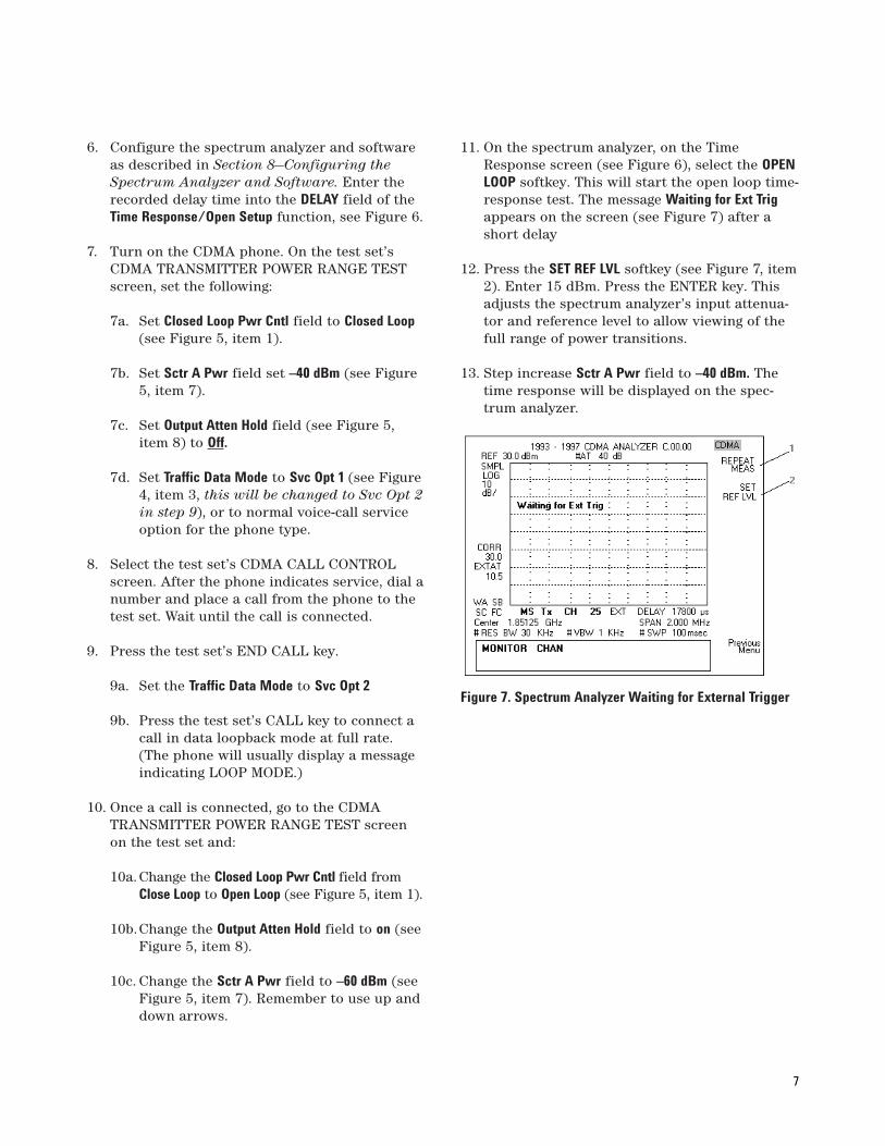
11. On the spectrum analyzer, on the TimeResponse screen (see Figure 6), select the OPENLOOP softkey. This will start the open loop time-response test. The message Waiting for Ext Trigappears on the screen (see Figure 7) after ashort delay
12. Press the SET REF LVL softkey (see Figure 7, item2). Enter 15 dBm. Press the ENTER key. Thisadjusts the spectrum analyzer’s input attenua-tor and reference level to allow viewing of thefull range of power transitions.
13. Step increase Sctr A Pwr field to –40 dBm. Thetime response will be displayed on the spec-trum analyzer.
Figure 7. Spectrum Analyzer Waiting for External Trigger
7
8
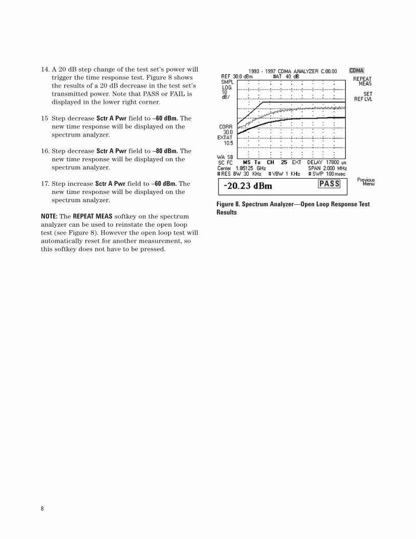
14. A 20 dB step change of the test set’s power willtrigger the time response test. Figure 8 showsthe results of a 20 dB decrease in the test set’stransmitted power. Note that PASS or FAIL isdisplayed in the lower right corner.
15 Step decrease Sctr A Pwr field to –60 dBm. Thenew time response will be displayed on thespectrum analyzer.
16. Step decrease Sctr A Pwr field to –80 dBm. Thenew time response will be displayed on thespectrum analyzer.
17. Step increase Sctr A Pwr field to –60 dBm. Thenew time response will be displayed on thespectrum analyzer.
NOTE: The REPEAT MEAS softkey on the spectrumanalyzer can be used to reinstate the open looptest (see Figure 8). However the open loop test willautomatically reset for another measurement, sothis softkey does not have to be pressed.
Figure 8. Spectrum Analyzer—Open Loop Response TestResults
9
Figure 9. CONFIGURE Screen
Figure 10. CDMA GENERATOR CONTROL Screen
Section 5—Configuring the Test SetAs an example, the following test set screens showthe appropriate settings for testing a U.S. PCSphone. The screens presented are accurate withrespect to firmware revision A.05.30. Future revi-sions will be similar but are not guaranteed to bethe same.
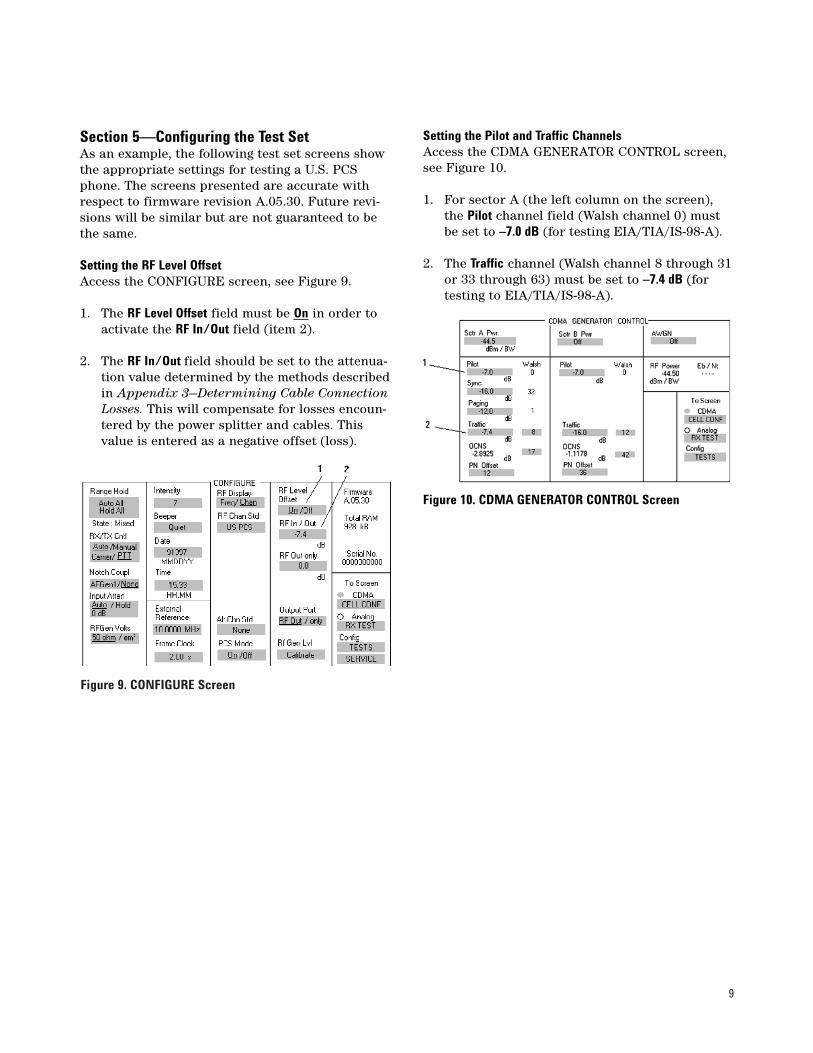
Setting the RF Level OffsetAccess the CONFIGURE screen, see Figure 9.
1. The RF Level Offset field must be On in order toactivate the RF In/Out field (item 2).
2. The RF In/Out field should be set to the attenua-tion value determined by the methods describedin Appendix 3—Determining Cable ConnectionLosses. This will compensate for losses encoun-tered by the power splitter and cables. Thisvalue is entered as a negative offset (loss).
Setting the Pilot and Traffic ChannelsAccess the CDMA GENERATOR CONTROL screen,see Figure 10.
1. For sector A (the left column on the screen),the Pilot channel field (Walsh channel 0) mustbe set to –7.0 dB (for testing EIA/TIA/IS-98-A).
2. The Traffic channel (Walsh channel 8 through 31or 33 through 63) must be set to –7.4 dB (fortesting to EIA/TIA/IS-98-A).
10
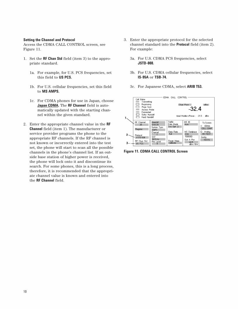
Setting the Channel and ProtocolAccess the CDMA CALL CONTROL screen, seeFigure 11.
1. Set the RF Chan Std field (item 3) to the appro-priate standard.
1a. For example, for U.S. PCS frequencies, setthis field to US PCS.
1b. For U.S. cellular frequencies, set this fieldto MS AMPS.
1c. For CDMA phones for use in Japan, chooseJapan CDMA. The RF Channel field is auto-matically updated with the starting chan-nel within the given standard.
2. Enter the appropriate channel value in the RFChannel field (item 1). The manufacturer orservice provider programs the phone to theappropriate RF channels. If the RF channel isnot known or incorrectly entered into the testset, the phone will start to scan all the possiblechannels in the phone’s channel list. If an out-side base station of higher power is received,the phone will lock onto it and discontinue itssearch. For some phones, this is a long process,therefore, it is recommended that the appropri-ate channel value is known and entered intothe RF Channel field.
3. Enter the appropriate protocol for the selectedchannel standard into the Protocol field (item 2).For example:
3a. For U.S. CDMA PCS frequencies, selectJSTD-008.
3b. For U.S. CDMA cellular frequencies, selectIS-95A or TSB-74.
3c. For Japanese CDMA, select ARIB T53.
Figure 11. CDMA CALL CONTROL Screen
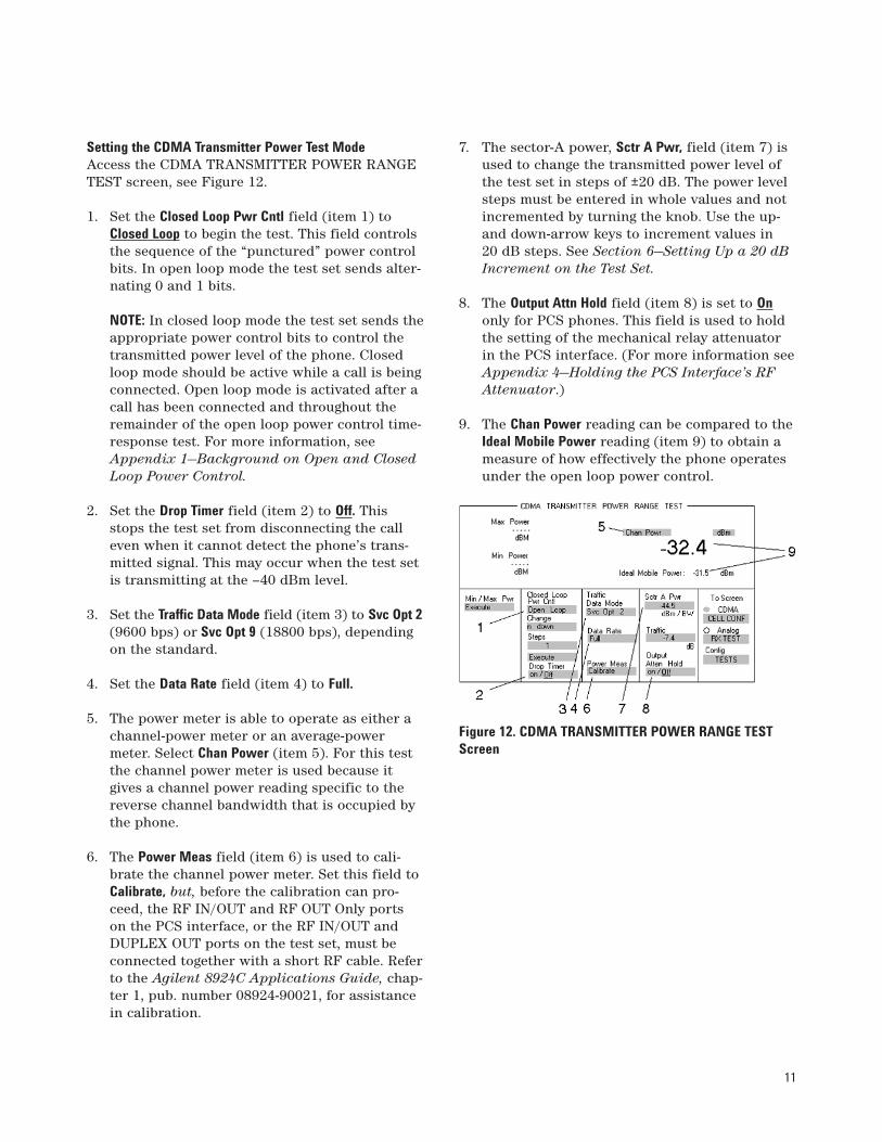
Setting the CDMA Transmitter Power Test ModeAccess the CDMA TRANSMITTER POWER RANGETEST screen, see Figure 12.
1. Set the Closed Loop Pwr Cntl field (item 1) toClosed Loop to begin the test. This field controlsthe sequence of the “punctured” power controlbits. In open loop mode the test set sends alter-nating 0 and 1 bits.
NOTE: In closed loop mode the test set sends theappropriate power control bits to control thetransmitted power level of the phone. Closedloop mode should be active while a call is beingconnected. Open loop mode is activated after acall has been connected and throughout theremainder of the open loop power control time-response test. For more information, seeAppendix 1—Background on Open and ClosedLoop Power Control.
2. Set the Drop Timer field (item 2) to Off. Thisstops the test set from disconnecting the calleven when it cannot detect the phone’s trans-mitted signal. This may occur when the test setis transmitting at the –40 dBm level.
3. Set the Traffic Data Mode field (item 3) to Svc Opt 2(9600 bps) or Svc Opt 9 (18800 bps), dependingon the standard.
4. Set the Data Rate field (item 4) to Full.
5. The power meter is able to operate as either achannel-power meter or an average-powermeter. Select Chan Power (item 5). For this testthe channel power meter is used because itgives a channel power reading specific to thereverse channel bandwidth that is occupied bythe phone.
6. The Power Meas field (item 6) is used to cali-brate the channel power meter. Set this field toCalibrate, but, before the calibration can pro-ceed, the RF IN/OUT and RF OUT Only portson the PCS interface, or the RF IN/OUT andDUPLEX OUT ports on the test set, must beconnected together with a short RF cable. Referto the Agilent 8924C Applications Guide, chap-ter 1, pub. number 08924-90021, for assistancein calibration.
7. The sector-A power, Sctr A Pwr, field (item 7) isused to change the transmitted power level ofthe test set in steps of ±20 dB. The power levelsteps must be entered in whole values and notincremented by turning the knob. Use the up-and down-arrow keys to increment values in 20 dB steps. See Section 6—Setting Up a 20 dBIncrement on the Test Set.
8. The Output Attn Hold field (item 8) is set to Ononly for PCS phones. This field is used to holdthe setting of the mechanical relay attenuatorin the PCS interface. (For more information seeAppendix 4—Holding the PCS Interface’s RFAttenuator.)
9. The Chan Power reading can be compared to theIdeal Mobile Power reading (item 9) to obtain ameasure of how effectively the phone operatesunder the open loop power control.
11
Figure 12. CDMA TRANSMITTER POWER RANGE TESTScreen
12
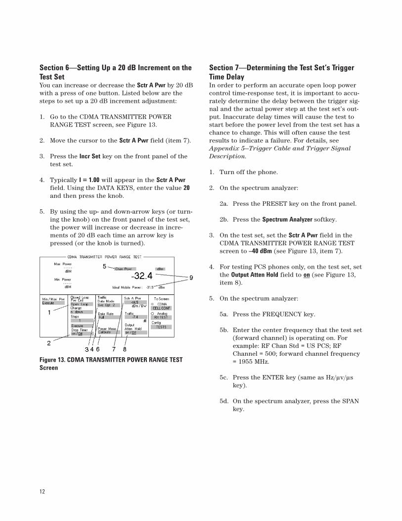
Section 6—Setting Up a 20 dB Increment on theTest SetYou can increase or decrease the Sctr A Pwr by 20 dBwith a press of one button. Listed below are thesteps to set up a 20 dB increment adjustment:
1. Go to the CDMA TRANSMITTER POWERRANGE TEST screen, see Figure 13.
2. Move the cursor to the Sctr A Pwr field (item 7).
3. Press the Incr Set key on the front panel of thetest set.
4. Typically I = 1.00 will appear in the Sctr A Pwrfield. Using the DATA KEYS, enter the value 20and then press the knob.
5. By using the up- and down-arrow keys (or turn-ing the knob) on the front panel of the test set,the power will increase or decrease in incre-ments of 20 dB each time an arrow key ispressed (or the knob is turned).
Section 7—Determining the Test Set’s TriggerTime DelayIn order to perform an accurate open loop powercontrol time-response test, it is important to accu-rately determine the delay between the trigger sig-nal and the actual power step at the test set’s out-put. Inaccurate delay times will cause the test tostart before the power level from the test set has achance to change. This will often cause the testresults to indicate a failure. For details, seeAppendix 5—Trigger Cable and Trigger SignalDescription.
1. Turn off the phone.
2. On the spectrum analyzer:
2a. Press the PRESET key on the front panel.
2b. Press the Spectrum Analyzer softkey.
3. On the test set, set the Sctr A Pwr field in theCDMA TRANSMITTER POWER RANGE TESTscreen to –40 dBm (see Figure 13, item 7).
4. For testing PCS phones only, on the test set, setthe Output Atten Hold field to on (see Figure 13,item 8).
5. On the spectrum analyzer:
5a. Press the FREQUENCY key.
5b. Enter the center frequency that the test set(forward channel) is operating on. Forexample: RF Chan Std = US PCS; RFChannel = 500; forward channel frequency= 1955 MHz.
5c. Press the ENTER key (same as Hz/µv/µskey).
5d. On the spectrum analyzer, press the SPANkey.
Figure 13. CDMA TRANSMITTER POWER RANGE TESTScreen
13
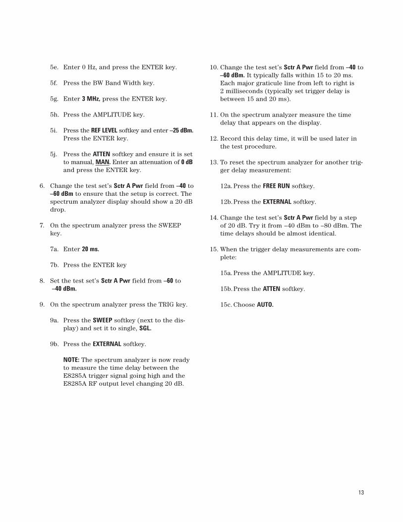
5e. Enter 0 Hz, and press the ENTER key.
5f. Press the BW Band Width key.
5g. Enter 3 MHz, press the ENTER key.
5h. Press the AMPLITUDE key.
5i. Press the REF LEVEL softkey and enter –25 dBm.Press the ENTER key.
5j. Press the ATTEN softkey and ensure it is setto manual, MAN. Enter an attenuation of 0 dBand press the ENTER key.
6. Change the test set’s Sctr A Pwr field from –40 to–60 dBm to ensure that the setup is correct. Thespectrum analyzer display should show a 20 dBdrop.
7. On the spectrum analyzer press the SWEEPkey.
7a. Enter 20 ms.
7b. Press the ENTER key
8. Set the test set’s Sctr A Pwr field from –60 to–40 dBm.
9. On the spectrum analyzer press the TRIG key.
9a. Press the SWEEP softkey (next to the dis-play) and set it to single, SGL.
9b. Press the EXTERNAL softkey.
NOTE: The spectrum analyzer is now readyto measure the time delay between theE8285A trigger signal going high and theE8285A RF output level changing 20 dB.
10. Change the test set’s Sctr A Pwr field from –40 to–60 dBm. It typically falls within 15 to 20 ms.Each major graticule line from left to right is 2 milliseconds (typically set trigger delay isbetween 15 and 20 ms).
11. On the spectrum analyzer measure the timedelay that appears on the display.
12. Record this delay time, it will be used later inthe test procedure.
13. To reset the spectrum analyzer for another trig-ger delay measurement:
12a. Press the FREE RUN softkey.
12b.Press the EXTERNAL softkey.
14. Change the test set’s Sctr A Pwr field by a stepof 20 dB. Try it from –40 dBm to –80 dBm. Thetime delays should be almost identical.
15. When the trigger delay measurements are com-plete:
15a. Press the AMPLITUDE key.
15b.Press the ATTEN softkey.
15c. Choose AUTO.
14
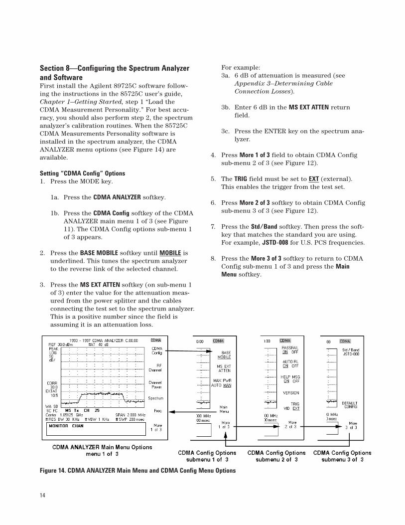
Section 8—Configuring the Spectrum Analyzerand SoftwareFirst install the Agilent 89725C software follow-ing the instructions in the 85725C user’s guide,Chapter 1—Getting Started, step 1 “Load theCDMA Measurement Personality.” For best accu-racy, you should also perform step 2, the spectrumanalyzer’s calibration routines. When the 85725CCDMA Measurements Personality software isinstalled in the spectrum analyzer, the CDMAANALYZER menu options (see Figure 14) are available.
Setting “CDMA Config” Options1. Press the MODE key.
1a. Press the CDMA ANALYZER softkey.
1b. Press the CDMA Config softkey of the CDMAANALYZER main menu 1 of 3 (see Figure11). The CDMA Config options sub-menu 1of 3 appears.
2. Press the BASE MOBILE softkey until MOBILE isunderlined. This tunes the spectrum analyzerto the reverse link of the selected channel.
3. Press the MS EXT ATTEN softkey (on sub-menu 1of 3) enter the value for the attenuation meas-ured from the power splitter and the cablesconnecting the test set to the spectrum analyzer.This is a positive number since the field isassuming it is an attenuation loss.
For example: 3a. 6 dB of attenuation is measured (see
Appendix 3—Determining CableConnection Losses).
3b. Enter 6 dB in the MS EXT ATTEN returnfield.
3c. Press the ENTER key on the spectrum ana-lyzer.
4. Press More 1 of 3 field to obtain CDMA Configsub-menu 2 of 3 (see Figure 12).
5. The TRIG field must be set to EXT (external).This enables the trigger from the test set.
6. Press More 2 of 3 softkey to obtain CDMA Configsub-menu 3 of 3 (see Figure 12).
7. Press the Std/Band softkey. Then press the soft-key that matches the standard you are using.For example, JSTD-008 for U.S. PCS frequencies.
8. Press the More 3 of 3 softkey to return to CDMAConfig sub-menu 1 of 3 and press the MainMenu softkey.
Figure 14. CDMA ANALYZER Main Menu and CDMA Config Menu Options
15
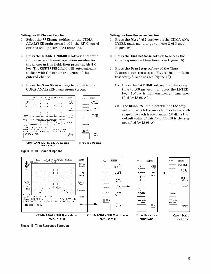
Figure 16. Time Response Function
Setting the RF Channel Function1. Select the RF Channel softkey on the CDMA
ANALYZER main menu 1 of 3, the RF Channeloptions will appear (see Figure 15).
2. Press the CHANNEL NUMBER softkey and enterin the correct channel operation number forthe phone in this field, then press the ENTERkey. The CENTER FREQ field will automaticallyupdate with the center frequency of theentered channel.
3. Press the Main Menu softkey to return to theCDMA ANALYZER main menu screen.
Setting the Time Response Function1. Press the More 1 of 3 softkey on the CDMA ANA-
LYZER main menu to go to menu 2 of 3 (seeFigure 16).
2. Press the Time Response softkey to access thetime response test functions (see Figure 16).
3. Press the Open Setup softkey of the TimeResponse functions to conFigure the open looptest setup functions (see Figure 16):
3a. Press the SWP TIME softkey. Set the sweeptime to 100 ms and then press the ENTERkey. (100 ms is the measurement time spec-ified by IS-98-A.)
3b. The DELTA PWR field determines the stepvalue at which the mask limits change withrespect to each trigger signal. 20 dB is thedefault value of this field (20 dB is the stepspecified by IS-98-A).
Figure 15. RF Channel Options
16
3c. Press the DELAY softkey. Enter the triggerdelay time measured in Section 8—Determining Trigger Time Delay. Thedelay time is entered in microseconds, forexample: 17 ms delay time = 17,000 µs.Press the ENTER key twice. It is importantto enter an accurate delay time in order toobtain accurate test results. The test mayfail frequently if the trigger does not occurat the time of power transitions.
3d. Press the Previous Menu softkey to return tothe Time Response menu screen.
References • Agilent Technologies 89725C Measurements
Personality User’s Guide, pub. number 85725-90010
• For Agilent Technologies 859XE setup and con-figuration refer to the User’s Guide, pub. num-ber 08590-90301.
17
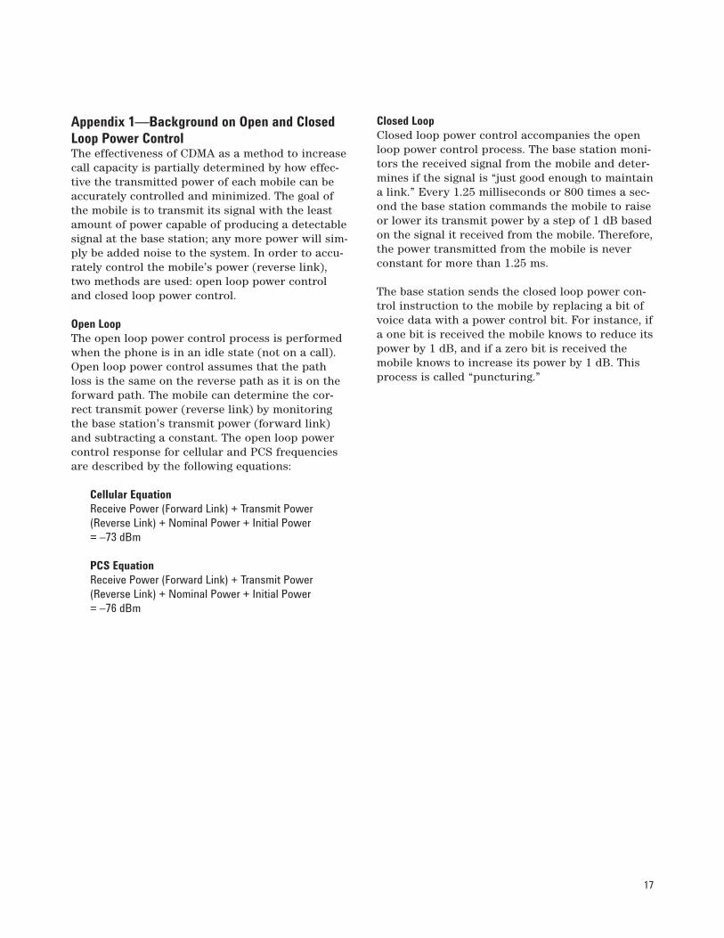
Appendix 1—Background on Open and ClosedLoop Power ControlThe effectiveness of CDMA as a method to increasecall capacity is partially determined by how effec-tive the transmitted power of each mobile can beaccurately controlled and minimized. The goal ofthe mobile is to transmit its signal with the leastamount of power capable of producing a detectablesignal at the base station; any more power will sim-ply be added noise to the system. In order to accu-rately control the mobile’s power (reverse link),two methods are used: open loop power controland closed loop power control.
Open LoopThe open loop power control process is performedwhen the phone is in an idle state (not on a call).Open loop power control assumes that the pathloss is the same on the reverse path as it is on theforward path. The mobile can determine the cor-rect transmit power (reverse link) by monitoringthe base station’s transmit power (forward link)and subtracting a constant. The open loop powercontrol response for cellular and PCS frequenciesare described by the following equations:
Cellular EquationReceive Power (Forward Link) + Transmit Power(Reverse Link) + Nominal Power + Initial Power = –73 dBm
PCS Equation Receive Power (Forward Link) + Transmit Power(Reverse Link) + Nominal Power + Initial Power = –76 dBm
Closed LoopClosed loop power control accompanies the openloop power control process. The base station moni-tors the received signal from the mobile and deter-mines if the signal is “just good enough to maintaina link.” Every 1.25 milliseconds or 800 times a sec-ond the base station commands the mobile to raiseor lower its transmit power by a step of 1 dB basedon the signal it received from the mobile. Therefore,the power transmitted from the mobile is neverconstant for more than 1.25 ms.
The base station sends the closed loop power con-trol instruction to the mobile by replacing a bit ofvoice data with a power control bit. For instance, ifa one bit is received the mobile knows to reduce itspower by 1 dB, and if a zero bit is received themobile knows to increase its power by 1 dB. Thisprocess is called “puncturing.”
18
Appendix 2—The Effect of Closed Loop Controlon the Open Loop TestSince this test is only concerned with the openloop response it would be ideal to eliminate theeffects of the closed loop power control on thereverse power transmission. This is not entirelypossible. Due to the various design limitations thatphone manufacturers have in their products, thetest set is unable to tell the phone to turn off theclosed loop control.
The open loop test that is described in this paperis not exclusively open loop controlled, the closedloop control is still present because the phone ison a call. The test set has the capability of goinginto a “virtual open loop mode” by alternating thepower control bits (between digital 0 and 1). Thisgives the appearance of being exclusively in openloop power control mode, but with an error of ±1 dBat best.
This can cause a problem when the base station istransmitting near the noise floor. Since there is noform of error correction associated with the “punc-tured” power control bits, they are easily receivedin error. Once the forward link approaches thenoise floor, the Frame Error Rate (FER) increases,which will increase the probability of receivingconsecutive similar power-control bits. At such lowsignal levels this error could be enough to cause adropped call or failure of the open loop time-response test.
Simply by monitoring the FER you can tell whenthe noise floor is compromising your measure-ments. The noise floor is not standard, it can varyfrom time to time and location to location. Justbecause your phone passes the tests in one loca-tion doesn’t mean that the phone will pass in a dif-ferent location or at a different time. Therefore, itis very important to have your phone properlyshielded from outside noise and interference dur-ing testing.
19
Appendix 3—Determining Cable ConnectionLossesIn order to obtain accurate power measurements afew steps need to be taken. First, always calibratethe channel power on the test set when you havepowered down the test set or if significant changeshave been made to the configuration of the test set(channel changes, cellular to PCS operation, and soforth).
Second, you must account for losses that haveoccurred through the transmission mediumbetween the connected devices. Since you areusing a power splitter and two cables, these lossesneed to be taken out of the power transmissionprocess. The test set allows you to enter an RFlevel offset. The test set transmits its signal at alevel above or below the entered sector power,depending on the sign (+ or –) of the attenuationentered into the RF Level Offset field. (Refer toSection 6—Setting Up a 20 dB Increment on theTest Set; and Section 7—Determining Test SetTrigger Time Delay.)
External Power Meter MethodIn order to determine the attenuation of the powersplitter and the two cables, an external powermeter can be used. Listed below are the steps youneed to take to find your RF power compensation:
1. Zero the power meter.
2. Connect the power meter directly to the testset’s DUPLEX OUT port; or, the PCS interface’sRF OUT Only port.
3. On the CONFIGURE screen:
3a. Set RF Level Offset field to Off.
3b. Set the Output Port field to Duplex for cellu-lar band, or only for PCS.
4. Go to the CDMA CALL CONTROL screen:
4a. If no PCS interface is used, set Sctr A Pwrfield to dBm.
4b. If a PCS interface is used, set to –11 dBm.
5. With the power meter, measure the power outof the test set.
6. Connect the cables and splitter to the DUPLEXport, or RF OUT Only for the PCS interface.Include every connection from the test set upto but not including the cellular phone. Thisincludes a car kit or break out box if used.
7. With the power meter, measure the power atthe end of the cables and splitter.
8. Subtract the second measurement from thefirst to obtain your RF level offset.
Using the Agilent 8924C Test SetTo determine the attenuation of the power splitterand the cables, the test set can be used. Refer to“Determining RF Path Loss” in Chapter 1 of theAgilent Technologies 8924C Application Guide,pub. number 08924-90021.
20
Appendix 4—Holding the PCS Interface’s RFAttenuatorThis appendix applies only if an Agilent 83236BPCS Interface is used.
A mechanical attenuator is used in the PCS inter-face. Mechanical attenuators when switched in andout of operation can produce transient responsesas they are relays that open and close. While arelay is in an open state, the open loop power con-trol of the mobile notices a loss of power from thebase station and starts transmitting the reversesignal at a higher power level.
When the mechanical attenuator completes itstransition (typically 10 ms to 50 ms) the forwardpower returns to a higher value and the mobile’sopen loop power control notices that it is transmit-ting the reverse signal at too high a power andstarts to lower its signal strength. This variation isundesirable for the open loop timing measurement.
To correct this problem, the mechanical attenuatorin the PCS interface is set in a fixed state, and theRF output level is varied using the transit-free elec-tronic attenuator in the test set. (The fixed state isselected when the Output Atten Hold field in theCDMA TRANSMITTER POWER RANGE TESTscreen is set to on.)
The maximum power that the test set and the PCS interface will be transmitting in this test willbe –40 dBm so that is the attenuator hold level.Once held, RF output levels down to approximately50 dB lower than the “hold” level are accurate.However, output levels higher than the “hold” levelare inaccurate.
21
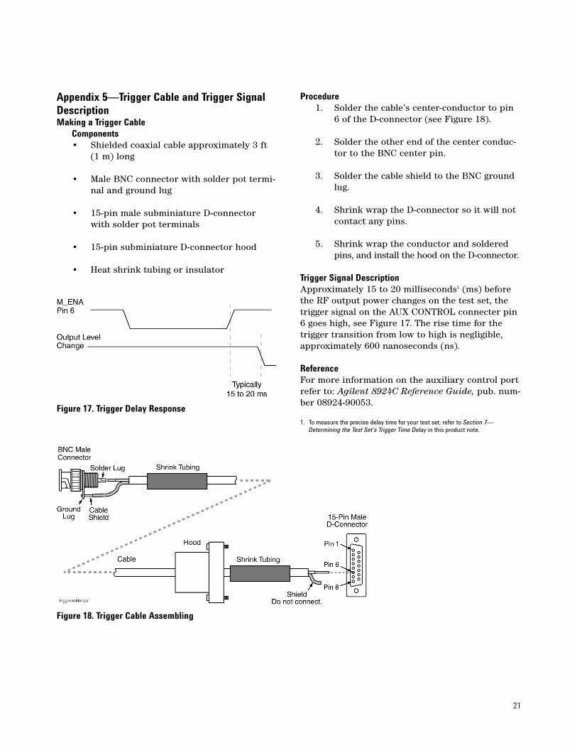
Figure 17. Trigger Delay Response
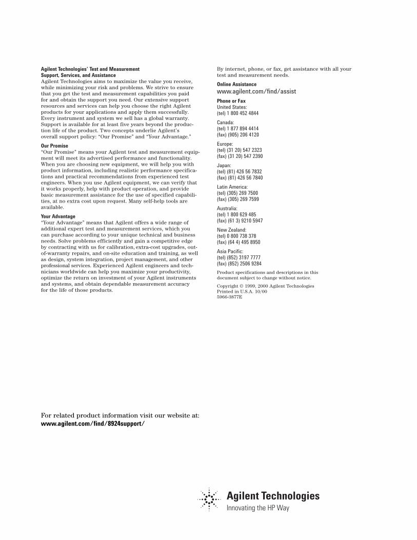
Appendix 5—Trigger Cable and Trigger SignalDescriptionMaking a Trigger Cable
Components• Shielded coaxial cable approximately 3 ft
(1 m) long
• Male BNC connector with solder pot termi-nal and ground lug
• 15-pin male subminiature D-connectorwith solder pot terminals
• 15-pin subminiature D-connector hood
• Heat shrink tubing or insulator
Procedure1. Solder the cable’s center-conductor to pin
6 of the D-connector (see Figure 18).
2. Solder the other end of the center conduc-tor to the BNC center pin.
3. Solder the cable shield to the BNC groundlug.
4. Shrink wrap the D-connector so it will notcontact any pins.
5. Shrink wrap the conductor and solderedpins, and install the hood on the D-connector.
Trigger Signal Description Approximately 15 to 20 milliseconds1 (ms) beforethe RF output power changes on the test set, thetrigger signal on the AUX CONTROL connecter pin6 goes high, see Figure 17. The rise time for thetrigger transition from low to high is negligible,approximately 600 nanoseconds (ns).
ReferenceFor more information on the auxiliary control portrefer to: Agilent 8924C Reference Guide, pub. num-ber 08924-90053.
1. To measure the precise delay time for your test set, refer to Section 7—Determining the Test Set’s Trigger Time Delay in this product note.
Figure 18. Trigger Cable Assembling
Agilent Technologies’ Test and Measurement Support, Services, and AssistanceAgilent Technologies aims to maximize the value you receive,while minimizing your risk and problems. We strive to ensurethat you get the test and measurement capabilities you paid for and obtain the support you need. Our extensive supportresources and services can help you choose the right Agilentproducts for your applications and apply them successfully.Every instrument and system we sell has a global warranty.Support is available for at least five years beyond the produc-tion life of the product. Two concepts underlie Agilent’s overall support policy: “Our Promise” and “Your Advantage.”
Our Promise“Our Promise” means your Agilent test and measurement equip-ment will meet its advertised performance and functionality.When you are choosing new equipment, we will help you withproduct information, including realistic performance specifica-tions and practical recommendations from experienced testengineers. When you use Agilent equipment, we can verify thatit works properly, help with product operation, and providebasic measurement assistance for the use of specified capabili-ties, at no extra cost upon request. Many self-help tools areavailable.
Your Advantage“Your Advantage” means that Agilent offers a wide range of additional expert test and measurement services, which you can purchase according to your unique technical and businessneeds. Solve problems efficiently and gain a competitive edge by contracting with us for calibration, extra-cost upgrades, out-of-warranty repairs, and on-site education and training, as well as design, system integration, project management, and otherprofessional services. Experienced Agilent engineers and tech-nicians worldwide can help you maximize your productivity,optimize the return on investment of your Agilent instrumentsand systems, and obtain dependable measurement accuracy for the life of those products.
By internet, phone, or fax, get assistance with all your test and measurement needs.
Online Assistancewww.agilent.com/find/assistPhone or FaxUnited States:(tel) 1 800 452 4844
Canada:(tel) 1 877 894 4414(fax) (905) 206 4120
Europe:(tel) (31 20) 547 2323(fax) (31 20) 547 2390
Japan:(tel) (81) 426 56 7832(fax) (81) 426 56 7840
Latin America:(tel) (305) 269 7500(fax) (305) 269 7599
Australia:(tel) 1 800 629 485 (fax) (61 3) 9210 5947
New Zealand:(tel) 0 800 738 378 (fax) (64 4) 495 8950
Asia Pacific:(tel) (852) 3197 7777(fax) (852) 2506 9284
Product specifications and descriptions in this document subject to change without notice.
Copyright © 1999, 2000 Agilent TechnologiesPrinted in U.S.A. 10/005966-3877E
For related product information visit our website at:www.agilent.com/find/8924support/
Related Documents


