Agilent Technologies Test & Measurement Catalog 2003/04 1 2 3 4 5 6 7 8 9 10 11 12 13 14 15 16 1 Introduction, Table of Contents, Web Site Highlights and Index 2 New Products New Product Highlights 2 3 Support and Services Support Services 22 Education and Consulting Services 30 Channel Partners 34 4 General Purpose Instruments Oscilloscopes 38 Oscilloscope Probes & Accessories 57 Modulation Domain Analyzers 67 Electronic Counters 69 Digital Multimeters 76 Data Acquisition & Switching 85 Function/Arbitrary Waveform Generators 89 DC Electronic Loads 96 Power Supplies 100 AC Source/Analyzers 126 5 RF & Microwave Instruments Signal Generators 130 Signal Analyzers 167 EMI/EMC Test Systems 200 Cable TV Regulatory Test Equipment 203 Network Analyzers 205 Power Meters 242 Noise Figure Analyzers 247 Impedance Measuring Instruments 256 Materials Test Equipment 258 LCR & Resistance Meters 262 VCO/PLL Signal System 269 RF & Microwave Test Accessories 272 6 Digital Design and Test Logic Analyzers and Accessories 290 Pulse/Pattern Generators 302 Data Generators/Analyzers 307 PCI/PCI-X Exerciser and Analyzers 309 7 Software and Connectivity Software and Connectivity 312 8 RF Design Software RF Design Software 320 9 Test Systems Electronic Functional Test System 328 Phase Noise Test System 333 Satellite Payload Test Solutions 334 VXIbus Products 335 Cabinets & Cabinet Accessories 345 10 Lightwave Test Lightwave Test Solutions 354 Tunable Lasers Modules 361 Lightwave Test Modules 365 Loss and Dispersion Test Solutions 371 Optical Spectrum Analyzer 376 Error Performance Analyzer 382 Optical Wavelength Meter 383 Lightwave Test System 388 11 Wireless Communications One Box Test Sets and Test Applications 392 Wireless Test Manager Software 401 Lab Applications 402 Wireless Protocol Test Set and Software 408 Bluetooth Test Set 411 Base Station Test Set 413 Wireless Network Optimization Platform 416 Air Interface Remote Monitoring System 417 Wireless Network Planning and Design Software 418 Wireless Test Systems and Solutions 419 Advanced Test Equipment Rentals www.atecorp.com 800-404-ATEC (2832) ® E s t a blishe d 1 9 8 1

Welcome message from author
This document is posted to help you gain knowledge. Please leave a comment to let me know what you think about it! Share it to your friends and learn new things together.
Transcript

Agilent Technologies Test & Measurement Catalog 2003/04
1
2
3
4
5
6
7
8
9
10
11
12
13
14
15
16
1 Introduction, Table of Contents, Web Site Highlights and Index
2 New Products
New Product Highlights 2
3 Support and Services
Support Services 22
Education and Consulting Services 30
Channel Partners 34
4 General Purpose Instruments
Oscilloscopes 38
Oscilloscope Probes & Accessories 57
Modulation Domain Analyzers 67
Electronic Counters 69
Digital Multimeters 76
Data Acquisition & Switching 85
Function/Arbitrary Waveform Generators 89
DC Electronic Loads 96
Power Supplies 100
AC Source/Analyzers 126
5 RF & Microwave Instruments
Signal Generators 130
Signal Analyzers 167
EMI/EMC Test Systems 200
Cable TV Regulatory Test Equipment 203
Network Analyzers 205
Power Meters 242
Noise Figure Analyzers 247
Impedance Measuring Instruments 256
Materials Test Equipment 258
LCR & Resistance Meters 262
VCO/PLL Signal System 269
RF & Microwave Test Accessories 272
6 Digital Design and Test
Logic Analyzers and Accessories 290
Pulse/Pattern Generators 302
Data Generators/Analyzers 307
PCI/PCI-X Exerciser and Analyzers 309
7 Software and Connectivity
Software and Connectivity 312
8 RF Design Software
RF Design Software 320
9 Test Systems
Electronic Functional Test System 328
Phase Noise Test System 333
Satellite Payload Test Solutions 334
VXIbus Products 335
Cabinets & Cabinet Accessories 345
10 Lightwave Test
Lightwave Test Solutions 354
Tunable Lasers Modules 361
Lightwave Test Modules 365
Loss and Dispersion Test Solutions 371
Optical Spectrum Analyzer 376
Error Performance Analyzer 382
Optical Wavelength Meter 383
Lightwave Test System 388
11 Wireless Communications
One Box Test Sets and Test Applications 392
Wireless Test Manager Software 401
Lab Applications 402
Wireless Protocol Test Set and Software 408
Bluetooth Test Set 411
Base Station Test Set 413
Wireless Network Optimization Platform 416
Air Interface Remote Monitoring System 417
Wireless Network Planning and Design Software 418
Wireless Test Systems and Solutions 419
Advanced Test Equipment Rentalswww.atecorp.com 800-404-ATEC (2832)
®
Established 1981
Brigitte A Vachon
Brigitte A Vachon

RF & Microwave 5Instruments 129
Signal Generators 130
Signal Analyzers 167
Millimeter Mixers 198
Amplifiers 199
EMI/EMC Test Systems 200
Cable TV Regulatory Test Equipment 203
Network Analyzers 205
Power Meters 242
Noise Figure Analyzers 247
Impedance Measuring Instruments 256
Materials Test Equipment 258
LCR & Resistance Meters 262
VCO/PLL Signal Test System 269
RF & Microwave Test Accessories 272

English URL www.agilent.com/find/products Korean URL www.agilent.co.kr/find/products
Overview
130 Overview
Signal Generators
Agilent Technologies offers the widest selection of high-performance signalsources from dc to 110 GHz. They coverevery application range from low-frequencynavigation signals, through cellular mobileradio, to millimeter wave satellite systems.Each offers synthesized frequency accuracyand stability as well as calibrated level andremote programmability.
Modulation capabilities range fromgeneral purpose AM, M, FM, pulse, andI/Q modulation to specific formats such asGSM, EDGE, W-CDMA and cdma2000.
For more information, visit our web site:http://www.agilent.com/find/signalgenerator
Signal SourcesVector Signal Generators
Model Frequency Range Key Feature/Application Page
E4438C ESG 250 kHz to 1, 2, 3, 4, 6 GHz High performance RF vector signal generator with wide RF modulation bandwidth, 131improved internal baseband generator with more comprehensive capability for 3G (W-CDMA, 1xEV-DO, cdma2000, etc.) and adds GPS, WLAN formats.Works with Baseband Studio applications and accessories to provide fading, streaming of virtually unlimited length waveform files, and digital I/Q outputs.
E4430B/31B/32B/33B ESG 250 kHz to 1, 2, 3, 4 GHz Internal baseband generator for arbitrary waveform and real-time signal generation 147of 2G, 3G (W-CDMA, 1xEV-DO, cdma2000, etc.), Bluetooth, and custom I/Q formats.
E4434B/35B/36B/37B ESG 250 kHz to 1, 2, 3, 4 GHz Same as the E4430B/31B/32B/33B ESG, adds enhanced phase noise performance. 147
E8267C PSG 250 kHz to 20 GHz Microwave custom I/Q modulation, complex pulse generation, two-tone, 140multi-tone, and Noise Power Ratio (NPR) tests. Works with Baseband Studio applications and accessories to provide streaming of virtually unlimited length waveform files and digital I/Q outputs.
Analog Signal Generators
Model Frequency Range Key Feature/Application Page
E4400B/20B/21B/22B ESG 250 kHz to 1, 2, 3, 4 GHz Superior level accuracy, wideband FM and phase modulation, electronic attenuator. 151Reliable and repeatable receiver and component test.
E4423B/24B/25B/26B ESG 250 kHz to 1, 2, 3, 4 GHz Same as the E4400B/20B/21B/22B ESG, adds enhanced phase noise performance. 151
E8257C PSG 250 kHz to 20, 40 GHz Low phase noise, high output power for component and receiver test (in channel 154and out of channel).
8648A/B/C/D 9 kHz to 1, 2, 3, 4 GHz General purpose, low-cost receiver (including pager test) and component test. 158Semi-automated and automated manufacturing test with remote interface.
8644B/64A/65B 100 kHz to 2 GHz Low phase noise at wide offsets for out of channel receiver tests. 160252 kHz to 4, 6 GHz
8645A 252 kHz to 2 GHz Fast frequency switching for frequency agile radios. 162
83650B 10 MHz to 50 GHz 50 GHz receiver test. 164
CW Signal Generators
Model Frequency Range Key Feature/Application Page
E8247C PSG 250 kHz to 20, 40 GHz Low phase noise, LO substitution, stimulus response test. 154
83650L 10 MHz to 50 GHz 50 GHz LO substitution and stimulus response test. 164
Millimeter-Wave Source Modules
Model Frequency Range Key Feature/Application Page
83554A to 83558A 26.5 GHz to 110 GHz Frequency extension to 110 GHz for the E8247C PSG, E8257C PSG, 83650B, 83650L. 166
5

5
E4438C ESG
131Vector Signal Generators
Signal Generators
E4438C RF Vector Signal Generator
The Agilent E4438C ESG vector signal generator meets the needs ofengineers who are designing and developing the next generation ofwireless communication systems and is well suited for productiontest environments. An assortment of standards-based receiver andcomponent test personalities for 3G and emerging communicationsformats are available to simplify the signal configuration process.The E4438C ESG vector signal generator’s improved performance,extended frequency range, increased memory for waveform play-back and storage, and application-specific personalities make it theclear choice for development and manufacturing from the compo-nent to the system level.
6 GHz Frequency Range
E4438C ESG provides different frequency options to suit your need: • 1, 2, 3, 4 or 6 GHz
160 MHz RF Modulation Bandwidth
• Ideal for multi-carrier signals• Up to 160 MHz RF modulation bandwidth using external I/Q
inputs• 80 MHz RF modulation bandwidth using internal baseband
generator
320 Mbytes Baseband Memory
• 64 Msamples (320 Mbytes) for waveform playback• 64x the memory of the previous generation• Build longer, more complex waveforms
6 Gbytes Non-Volatile Memory
• 1.2 Gsamples (6 Gbytes) for storing waveforms and instrumentstates
• Eliminate waveform build times in manufacturing and development
Modulation Formats & Applications tailored for BothComponent Testing as well as Receiver Testing• TD-SCDMA (TSM) • GPS• W-CDMA • 802.11a/b/g WLAN• EDGE/GSM • Bluetooth™• 1xEV-DO/1xEV-DV • AWGN• cdma2000/cdmaOne • Enhanced multitone• NADC/PDC • Custom• PHS • Pulse• DECT • M/AM/FM• TETRA • Noise power ratio
Powerful Standard Features• Excellent spectral purity• Electronic attenuator• Simple softkey menu structure allows access to sophisticated
features• Built-in help• Differential and single-ended I/Q outputs• Suite of I/Q adjustments: gain, DC offsets, quadrature skew• Save and recall instrument settings• IntuiLink software allows easy data exchange from Microsoft®
applications• 10BaseT LAN and GPIB interfaces
Superior Dual Mode Baseband Generator• Dual mode capability supports both waveform playback and
real-time signal generation• 80 MHz RF modulation bandwidth• 64 Msamples (320 Mbytes) of waveform playback memory• Generate waveforms at up to 100 Msamples/s• Hardware resampling technology eliminates need for multiple
reconstruction filters• 16-bit DAC for improved dynamic range• Flexible baseband reference clock 250 kHz to 100 MHz• Industry standard filters or user-definable FIR filters• Set Eb/No or C/N ratio for W-CDMA and cdma2000• Generate AWGN with up to 80 MHz bandwidth
Baseband StudioBaseband Studio is a suite of baseband signal applications andaccessories that currently work with the E4438C ESG vector signalgenerator to emulate real-world signal conditions. The N5102ABaseband Studio digital signal interface module delivers ESG base-band signals as digital I/Q or IF data. A PC equipped with theN5101A Baseband Studio PCI card enables two new software appli-cations. N5110 Baseband Studio for streaming lets you playbackunique baseband waveform data of virtually unlimited length from aPC hard drive through the ESG for RF signal generation. N5115ABaseband Studio for fading provides digitally integrated fading ofESG baseband signals and calibrated noise in a single easy-to-setupsolution.
For more info: www.agilent.com/find/basebandstudio
Signal StudioSignal Studio is a collection of independent software applicationsthat enable users to create waveform files for specific communica-tions formats. The intuitive, easy-to-use graphical interface allowsvarious signal parameters to be set for flexible waveform genera-tion. Supported formats include:• 802.11a/b/g WLAN • Noise power ratio• 1xEV-DO/1xEV-DV • TD-SCDMA (TSM)• Bluetooth • Enhanced multitone
Traditional Chinese URL www.agilent.com.tw/find/products Simplified Chinese URL www.agilent.com.cn/find/products
• 6 GHz frequency range• 160 MHz RF modulation bandwidth• 320 Mbytes baseband memory• 6 Gbyte non-volatile waveform storage
5
E4438C ESG
132 Vector Signal Generators (cont.)
Signal Generators
Specifications For Frequency and Power CharacteristicsFrequencyFrequency RangeOption1
• 501 250 kHz to 1 GHz• 502 250 kHz to 2 GHz• 503 250 kHz to 3 GHz• 504 250 kHz to 4 GHz• 506 250 kHz to 6 GHz (requires Option UNJ)Frequency Minimum100 kHz2
Frequency Resolution0.01 HzFrequency Switching Speed5
Standard With Option UNJ With Option 506Freq.3 Freq./Amp.4 Freq.3 Freq./Amp.4 Freq.3 Freq./Amp.4
Digital modulationon (<35 ms) (<49 ms) (<35 ms) (<52 ms) (<41 ms) (<57 ms)off (<9 ms) (<9 ms) (<9 ms) (<9 ms) (<16 ms) (<17 ms)
[For hops <5 MHz within a band]Digital modulationon (<9 ms) (<9 ms) (<9 ms) (<9 ms) (<33 ms) (<53 ms)off (<9 ms) (<9 ms) (<9 ms) (<9 ms) (<12 ms) (<14 ms)
Phase Offset Phase is adjustable remotely (LAN, GPIB, RS-232) or via front panel innominal 0.1° increments
Sweep ModesOperating ModesFrequency step, amplitude step and arbitrary listDwell Time1 ms to 60 sNumber of Points2 to 401
Internal Reference OscillatorStability5
Standard With Option UNJ or 1E5
Aging rate <±1 ppm/yr <±0.1 ppm/yr or<±0.0005 ppm/day after 45 days
Temp [0 to 55° C] (<±1 ppm) (<±0.05 ppm)Line voltage (<±0.1 ppm) (<±0.002 ppm)Line voltage range (+5% to –10%) (+5% to –10%)
RF Reference Output• Frequency: 10 MHz• Amplitude: 4 dBm ±2 dBRF Reference Input Requirements
Standard With Option UNJ or 1E5
Frequency 1, 2, 5, 10 MHz ±10 ppm 1, 2, 5, 10 MHz ±1 ppmAmplitude –3.5 dBm to 20 dBmInput impedance 50
Output PowerPower
Standard With Option UNB With Option 506
250 kHz to 250 MHz +11 to –136 dBm +15 to –136 dBm +12 to –136 dBm>250 MHz to 1 GHz +13 to –136 dBm +17 to –136 dBm +14 to –136 dBm>1 to 3 GHz +10 to –136 dBm +16 to –136 dBm +13 to –136 dBm>3 to 4 GHz +7 to –136 dBm +13 to –136 dBm +10 to –136 dBm>4 to 6 GHz N/A N/A +10 to –136 dBm
Level Resolution0.02 dBLevel Range with Attenuator Hold Active
Standard With Option UNB With Option 506
250 kHz to 1 GHz 23 dB 27 dB 24 dB>1 to 3 GHz 20 dB 26 dB 23 dB>3 to 4 GHz 17 dB 23 dB 20 dB>4 to 6 GHz N/A N/A 20 dB
Level Accuracy [dB]Standard6, 7
Power Level
+7 to –50 to –120 to <–127 dBm–50 dBm –120 dBm –127 dBm
250 kHz to 2.2 GHz ±0.5 ±0.5 ±0.6 (±1.5)2.2 to 3 GHz ±0.5 ±0.6 ±0.7 (±2.5)3 to 4 GHz ±0.6 ±0.7 ±0.8 (±2.5)
With Option UNB7, 8
Power Level
+10 to –50 to –120 to <–127 dBm–50 dBm –120 dBm –127 dBm
250 kHz to 2.2 GHz ±0.5 ±0.5 ±0.6 (±1.5)2.2 to 3 GHz ±0.6 ±0.7 ±0.9 (±2.5)3 to 4 GHz ±0.8 ±0.9 ±1.5 (±2.5)
With Option 5067, 9
Power Level
+7 to –50 to –110 to <–127 dBm–50 dBm –110 dBm –127 dBm
250 kHz to 2.2 GHz ±0.6 ±0.6 ±0.7 (±1.5)2.2 to 3 GHz ±0.6 ±0.7 ±1.0 (±2.5)3 to 4 GHz ±0.8 ±0.9 ±1.5 (±2.5)4 to 6 GHz ±0.8 ±0.9 (±2.5)
Level Accuracy with Digital Modulation Turned On (relative to CW)Conditions: (with PRBS modulated data; if using I/Q inputs, √ I2 + Q2 = 0.5 Vrms, nominal)10
Level Accuracy with ALC on/4 DQPSK or QPSK formatsConditions: With raised cosine or root-raised cosine filter and ≥0.35;with 10 kHz ≤symbol rate ≤1 MHz; at RF freq ≥25 MHz; power ≤max specified –3 dB ±0.25 dBConstant amplitude formats (FSK, GMSK, etc)Standard With Option 506±0.15 dB ±0.20 dBLevel Accuracy with ALC off 10, 11 (±0.20 dB) (relative to ALC on)Conditions: After power search is executed, with burst off.Level Switching Speed10
Standard With Option UNB With Option 506
Normal operation [ALC on] (<15 ms) (<21 ms) (<21 ms)When using power search manual (<83 ms) (<95 ms) (<95 ms)When using power search auto (<103 ms) (<119 ms) (<119 ms)
Spectral PuritySSB Phase Noise (at 20 kHz offset)12
Standard With Option UNJ
at 500 MHz (<–124 dBc/Hz) <–136 dBc/Hz, (<–139 dBc/Hz)at 1 GHz (<–118 dBc/Hz) <–130 dBc/Hz, (<–133 dBc/Hz)at 2 GHz (<–112 dBc/Hz) <–124 dBc/Hz, (<–127 dBc/Hz)at 3 GHz (<–106 dBc/Hz) <–120 dBc/Hz, (<–123 dBc/Hz)at 4 GHz (<–106 dBc/Hz) <–118 dBc/Hz, (<–121 dBc/Hz)at 6 GHz N/A <–114 dBc/Hz, (<–117 dBc/Hz)
Residual FM12 (CW mode, 0.3 to 3 kHz BW, CCITT, rms)• Option UNJ <N x 1 Hz (<N x 0.5 Hz)13
• Standard– Phase noise mode 1 <N x 2 Hz– Phase noise mode 2 <N x 4 Hz
1 The E4438C is available as a vector platform only. For analog models refer to the E4420B thru E4426B.
2 Performance below 250 kHz not guaranteed.3 To within 0.1 ppm of final frequency above 250 MHz or within 100 Hz below 250 MHz.4 Frequency switching time with the amplitude settled within ±0.1 dB.5 Parentheses denote typical performance.6 Quoted specifications for 23˚C ± 5˚C. Accuracy degrades by less than 0.03 dB/˚C over full
temperature range. Accuracy degrades by 0.3 dB above +7 dBm, and by 0.8 dB above +10 dBm.7 Parentheses denote typical performance.8 Quoted specifications for 23˚C ± 5˚C. Accuracy degrades by less than 0.01 dB/˚C over full
temperature range. Accuracy degrades by 0.2 dB above +10 dBm, and by 0.8 dB above +13 dBm.9 Quoted specifications for 23˚C ± 5˚C. Accuracy degrades by less than 0.02 dB/˚C over
full temperature range. Accuracy degrades by 0.2 dB above +7 dBm.10Parentheses denote typical performance.11When applying external I/Q signals with ALC off, output level will vary directly with I/Q
input level.12Parentheses denote typical performance.13Refer to frequency bands on next page for N values.
English URL www.agilent.com/find/products Korean URL www.agilent.co.kr/find/products

5
E4438C ESG
133Vector Signal Generators (cont.)
Signal Generators
Specifications For Analog ModulationFrequency Bands
Band Frequency Range N #
1 250 kHz to ≤250 MHz 12 >250 MHz to ≤500 MHz 0.53 >500 MHz to ≤1 GHz 14 >1 to ≤2 GHz 25 >2 to ≤4 GHz 46 >4 to ≤6 GHz 8
Frequency Modulation1,4
Maximum DeviationStandard2 With Option UNJN x 8 MHz N x 1 MHzResolution0.1% of deviation or 1 Hz, whichever is greaterModulation Frequency Rate5 (deviation = 100 kHz)
Coupling 1 dB bandwidth 3 dB bandwidth
FM path 1[DC] DC to 100 kHz (DC to 10 MHz)FM path 2 [DC] DC to 100 kHz (DC to 0.9 MHz)FM path 1 [AC] 20 Hz to 100 kHz (5 Hz to 10 MHz)FM path 2 [AC] 20 Hz to 100 kHz (5 Hz to 0.9 MHz)
Deviation Accuracy2 (1 kHz rate, deviation <N x 100 kHz)<±3.5% of FM deviation + 20 Hz
Phase Modulation6, 10
Resolution0.1% of set deviationModulation frequency response7, 12
Standard
Mode Maximum Allowable rates (3 dB BW)Deviation M path 1 M path 2
Normal BW N x 80 rad DC to 100 kHz DC to 100 kHzHigh BW11 N x 8 rad (DC to 1 MHz) (DC to 0.9 MHz)
N x 1.6 rad (DC to 10 MHz) (DC to 0.9 MHz)
With Option UNJ
Mode Maximum Allowable rates (3 dB BW)Deviation M path 1 M path 2
Normal BW N x 10 radians DC to 100 kHz DC to 100 kHzHigh BW N x 1 radians (DC to 1 MHz) (DC to 0.9 MHz)
Deviation Accuracy (1 kHz rate, Normal BW mode)<±5% of deviation + 0.01 radiansDistortion7 (1 kHz rate, deviation <80 radians on standard model, <10N radians on Option UNJ models, Normal BW mode) <1%
Amplitude Modulation6, 8 (fc >500 kHz)Range0 to 100%Resolution0.1%Rates (3 dB bandwidth)• DC coupled: 0 to 10 kHz• AC coupled: 10 Hz to 10 kHzAccuracy9, 12 1 kHz rate <±(6% of setting + 1%)Distortion9, 12 (1 kHz rate, THD)
Standard/Option UNJ Option 50630% AM <1.5% <1.5%90% AM (<4%) (<5%)
Wideband AMRates (1 dB bandwidth)12
ALC on (400 Hz to 40 MHz)ALC off (DC to 40 MHz)
Pulse ModulationOn/Off Ratio12
<2.8 GHz >80 dB≤2.8 GHz (>64 dB)Rise/Fall Times12
(150 ns)Minimum Width12
ALC on (2 µs)ALC off (0.4 µs)Pulse Repetition Frequency12
ALC on (10 Hz to 250 kHz)ALC off (DC to 1.0 MHz)
Level Accuracy12, 13 (relative to CW at ≤4 dBm standard, ≤7.5 dBm OptionUNB, ≤4.5 dBm Option 506) (<±1 dB)Internal Pulse Generator• Square wave rate: 0.1 Hz to 20 kHz• Pulse
Period: 8 µs to 30 secondsWidth: 4 µs to 30 secondsResolution: 2 µs
Internal Analog Modulation Source(Provides FM, AM, pulse, and phase modulation signals and LF audio out)Waveformssine, square, ramp, triangle, pulse, noiseRate RangeSine 0.1 Hz to 100 kHzSquare, ramp, triangle 0.1 Hz to 20 kHzResolution0.1 HzFrequency Accuracysame as RF reference sourceSwept Sine Mode (frequency, phase continuous)Operating modes Triggered or continuous sweepsFrequency range 0.1 Hz to 100 kHzSweep time 1 ms to 65 secResolution 1 msDual Sinewave ModeFrequency range 0.1 Hz to 100 kHzAmplitude ratio 0 to 100%Amplitude ratio Resolution 0.1%
External Modulation InputsModulation TypesExt 1 FM, M, AM, pulse, and burst envelopeExt 2 FM, M, AM, and pulseHigh/Low Indicator (100 Hz to 10 MHz BW, AC coupled inputs only).Activated when input level error exceeds 3% (nominal).
External Burst EnvelopeInput VoltageRF On: 0 VRF Off: –1.0 VLinear Control Range: 0 to –1 VOn/Off Ratio12
Condition: Vin below –1.05 V<2.3 GHz >75 dB≥2.3 GHz (>64 dB)Rise/Fall Time12
Condition: With rectangular input (<2 µs)Minimum Burst Repetition Frequency12
ALC on (10 Hz)ALC off DCInput PortExternal 1Input Impedance50 , nominal
Composite ModulationAM, FM, and M each consist of two modulation paths which aresummed internally for composite modulation. The modulation sourcesmay be any two of the following: Internal, External 1, External 2.
Simultaneous ModulationMultiple modulation types may be simultaneously enabled with someexceptions. Two modulation types cannot be generated simultaneously bythe same modulation source.1 All analog performance above 4 GHz is typical.2 Refer to frequency bands on this page to compute specifications.3 At the calibrated deviation and carrier frequency, within 5°C of ambient temperature at
time of calibration.4 For non-Option UNJ units, specifications apply in phase noise mode 2 (default).5 Parentheses denote typical performance.6 All analog performance above 4 GHz is typical.7 Refer to frequency bands on this page for N.3 AM is typical above 3 GHz or if wideband AM or I/Q modulation is simultaneously
enabled.9 Peak envelope power of AM must be 3 dB less than maximum output power below 250 MHz.10For non-Option UNJ units, specifications apply in phase noise mode 2 (default).11Bandwidth is automatically selected based on deviation.12Parentheses denote typical performance.13With ALC off, specifications apply after the execution of power search. With ALC on,
specifications apply for pulse repetition rates ≤10 kHz and pulse widths ≥5 µs.
Traditional Chinese URL www.agilent.com.tw/find/products Simplified Chinese URL www.agilent.com.cn/find/products

5
E4438C ESG
134 Vector Signal Generators (cont.)
Signal Generators
Specifications For I/Q CharacteristicsI/Q Modulation BandwidthI/Q InputsInput impedance 50 or 600 Full scale input1 √ I2 + Q2 = 0.5 Vrms
I/Q Adjustments
Source Parameter Range
I/Q baseband inputs Impedance 50 or 600 I offset (600 only) ±5 VQ offset (600 only) ±5 V
I/Q baseband outputs I/Q offset adjustment ±3 VI/Q offset resolution 1 mVI/Q gain balance ±4 dBI/Q attenuation 0 to 40 dBI/Q low pass filter 40 MHz, thru
RF output I/Q offset adjustment ±50%I/Q gain balance ±4 dBI/Q attenuation 0 to 40 dBI/Q quad skew
(≤3.3 GHz) ±10˚(>3.3 GHz) ±5˚
I/Q low pass filter 2.1 MHz, 40 MHz, thru
English URL www.agilent.com/find/products Korean URL www.agilent.co.kr/find/products
[dB
]
-100 0-50
Frequency offset from carrier [MHz]
50-150 150100
3.00
1.00
-1.00
-3.00
-5.00
-7.00
-9.00
-11.00
-13.00
-15.00
1800 MHz carrier
850 MHz carrier
1900 MHz carrier2200 MHz carrier
I/Q Bandwidth Using External I/Q Source (ALC off)2
dB
3.00
1.00
-1.00
-3.00
-5.00
-7.00
-9.00
-11.00
-13.00
-15.00
Frequency offset from carrier [MHz]
-50 -30 -10 10 30 50
850 MHz1800 MHz1900 MHz2200 MHz5700 MHz
I/Q Bandwidth Using Internal I/Q Source
Baseband Generator (arbitrary waveform mode) (Option 601 or 602)Channels 2 (I and Q)Resolution 16 bits (1/65,536)Arbitrary Waveform Memory• Maximum playback capacity
– 8 Msamples/channel (Option 601) – 64 Msamples/channel (Option 602)
• Maximum storage capacity– Gsamples (Option 005) – 1Msample (Standard)
Waveform Segments• Segment length: 60 samples to 8 Msamples or 32 Msamples• Maximum number of segments
– 1,024 (8 Msamples volatile memory) – 8,192 (64 Msamples volatile memory)
• Minimum memory allocation: 256 samples or 1 kbyte blocksWaveform Sequences• Maximum total number of segment files stored in the non-volatile
file system: 16,384• Sequencing: Continuously repeating• Maximum number of sequences 16,384 (shared with number of segments)• Maximum segments/sequence: 32,768 (including nested segments)• Maximum segment repetitions: 65,536ClockSample rate: 1 Hz to 100 MHzResolution: 0.001 HzAccuracy: same as timebase +2–42 (in non-integer applications)Baseband Filters40 MHz: used for spur reduction2.1 MHz: used for ACPR reductionThrough: used for maximum bandwidthReconstruction Filter: (fixed)50 MHz: (used for all symbol rates)TriggersTypes: Continuous, single, gated, segment advanceSource: Trigger key, external, remote (LAN, GPIB, RS-232)External polarity: Negative, positiveExternal delay time: 10 ns to 40 sec plus latencyExternal delay resolution: 10 nsMarkers(Markers are defined in a segment during the waveform generationprocess, or from the ESG front panel. A marker can also be tied to the RFblanking feature of the ESG.)Marker polarity: Negative, positiveNumber of markers: 4MulticarrierNumber of carriers: Up to 100 (limited by a max bandwidth of 80 MHzdepending on symbol rate and modulation type)Frequency offset (per carrier): –40 MHz to +40 MHzPower offset (per carrier): 0 dB to –40 dBModulationPSK: BPSK, QPSK, OQPSK, /4DQPSK, 8PSK, 16PSK, D8PSKQAM: 4, 16, 32, 64, 256FSK: Selectable: 2, 4, 8, 16MSKDataRandom ONLYMultitoneNumber of tones: 2 to 64, with selectable on/off state per toneFrequency spacing: 100 Hz to 80 MHzPhase (per tone): Fixed or random
Baseband Generator (real-time mode) (Option 601 or 602)Basic Modulation Types (custom format)• PSK: BPSK, QPSK, OQPSK, /4DQPSK, 8PSK, 16PSK, D8PSK• MSK: User-defined phase offset from 0 to 100˚• QAM: 4, 16, 32, 64, 256• FSK
– Selectable: 2, 4, 8, 16 level symmetric, C4FM– User defined: Custom map of up to 16 deviation levels:
Symbol rate Maximum Deviation<5 MHz 4 times symbol rate>5 MHz, <50 MHz 20 MHzResolution: 0.1 Hz
1The optimum I/Q input level is √ I2 + Q2 = 0.5 Vrms , I/Q drive level affects EVM, origin offset, spectral regrowth, and noise floor. Typical, level accuracy with ALC on will be maintained with drive levels between 0.25 and 1.0 Vrms .
2Parentheses denote typical performance.
5
E4438C ESG
135Vector Signal Generators (cont.)
Signal Generators
I/QCustom map of 256 unique valuesFIR FilterNyquist, root Nyquist, Gaussian, rectangular, APCO 25, Custom FIR : 0 to1, BbT: 0.1 to 1Symbol RateAdjustable up to 50 Mbits/secData Types• Internally generated data
Pseudo-random patterns– PN9, PN11, PN15, PN20, PN23
Repeating sequence– Any 4-bit sequence– Other fixed patterns
• Direct-pattern RAM (PRAM)Max size
– Option 601 8 Mbits– Option 602 64 Mbits (each bit uses an entire sample space)
Use – Non-standard framing
• User FileMax size
– Option 601 800 kbytes– Option 602 6.4 Mbytes
Use– Continuous modulation or internally generated TDMA standard
• Externally Generated DataType
– Serial dataInputs
– Data, bit clock, symbol sync– Accepts data rates ±5% of specified data rate
Internal Burst Shape ControlRise/fall time range: Up to 30 bitsRise/fall delay range: 0 to 63.5 bits
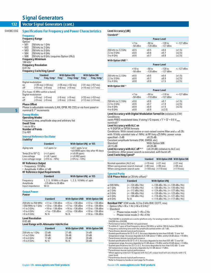
Signal Studio for 802.11 WLAN (Option 417)Signal Studio for 802.11 WLAN simplifies your role in creating 802.11a/b/g test signals for use with the E4438C ESG vector signal generator.Rather than spending valuable time creating your own 802.11 waveforms,use the software to create fully-coded, standards-based 802.11 framesand modulated data streams. Waveforms can easily be configured in anintuitive graphical interface and downloaded to the ESG to perform various receiver and component tests at RF and baseband.
Signal Studio for 802.11 WLAN, Option 417, replaces options 405,410 and 415.
Signal Studio for 802.11 WLAN Features1
WLAN Formats Supported802.11a, 802.11b, and 802.11gFraming Framed: bursted framed data includes preamble and header fieldsNon-framed: non-bursted continuous dataModulation Formats DBPSK, DQPSK, BPSK, QPSK, 8-PSK, 16-QAM, 64-QAMData Rates 1, 2, 5.5, 6, 9, 11, 12, 18, 22, 24, 33, 36, 48, 54, customData Source 1s, 0s, 01s, 10s, PN9, PN15, user filePayload Data Length Maximum: 2346 bytes (with MAC header and MAC FCS)Minimum: 0 byteEncoding Rates 1/2, 2/3, 3/4Idle Interval 0 to 100,000 µsOversample Ratio 2 to 9Baseband Filtering None, Gaussian, root cosine, ideal low pass, and user definedWindowing for OFDM Modes Raised cosine windowing for each OFDM symbolPower Ramping for DSSS Modes None, linear, cosineRamp time: 0 to 100,000 µsScrambler On, off, preamble onlySubcarrier Setup for OFDM Modes Subcarriers are individually selectableService Field 0 to FFFF Hex (16 bits: First 7 LSB are masked to 0)Scrambler Seed Initialization Value 0 to 7F HexMultipoint Reflection Paths: 12Delay: 0 to 10 µs (Resolution: 0.1 ns)Attenuation: 0 to –60 dBPhase: ±180ºMultiframe Maximum no. of frames: Up to 2000, depends ondata rate, OSR, idle interval, and payload lengthSegment field: 0 to 15Sequence field: 0 to 40951Features subject to change.
Traditional Chinese URL www.agilent.com.tw/find/products Simplified Chinese URL www.agilent.com.cn/find/products

5
E4438C ESG
136 Vector Signal Generators (cont.)
Signal Generators
Signal Studio for 1xEV-DV and cdma2000 (option 414)Signal Studio for 1xEV-DV and cdma2000 is a flexible software applicationfor configuring 3GPP2 standards-based signals. The software worksseamlessly with the E4438C ESG vector signal generator to generate RFtest signals with the highest standards of performance. These test signalsare available at RF, and also at baseband using the single-ended and differential I/Q outputs.
Agilent’s first-to-market solution enables you to meet your marketwindows with confidence in your design. You save valuable time usingSignal Studio to configure test signals rather than hand-coding your own.You can be confident your designs and devices are tested with standards-based signals, no matter which one of the over 100 possible configura-tions you choose. Be assured that the high level of signal coding enablesthorough evaluation of receiver demodulation capabilities at variousdesign stages, from baseband to RF.
FeaturesBTS/Mobile SetupSpread Rate: SR1Chip Rate: 1 kcps to 1.3 McpsVoice Channel Power: –40 dBm to 0 dBmPDCH & PDCCH Channel Power: –60 dBm to 0 dBmPN Offset: 0 to 511Even Second Delay: 0.5 to 128 chipsTrigger (reverse link): Trigger advance: 1 to 2457599. rising or falling edgeLong Code State: 0 to 3FF FFFF FFFF HexPhase Polarity: Normal or invertESG Baseband Generator Reference Clock: Internal or externalInput/Output: • (AUX): Data out, Data clock out, Symbol sync out, Alt power in,
Event 3 out, Event 4 out • (BNC): Event 1 out, Event 2 out, Pattern trigger in, Single-ended Analog
I/Q out, Differential Analog I/Q outFilters: IS-95, IS-95 with equalizer, IS-95 modified (MOD), IS-95 MOD withequalizer, Rectangular, Nyquist, Root Nyquist, Gaussian, UN3/4 GSMGaussian, APCO 25 C4FM
Forward LinkForward Link Channels: Pilot (F-PICH), synchronization (F-SYNC), quickpaging (F-QPCH), paging (F-PCH), fundamental (F-FCH), supplemental 1and 2 (F-SCH1, F-SCH2), orthogonally coded noise simulator (OCNS),packet data 1 & 2 (F-PDCH1, F-PDCH2), packet data control 1 and 2 (F-PDCCH1, F-PDCCH2)
Reverse LinkReverse Link Channels: Pilot (R-PICH), access (R-ACH), enhanced access(R-EACH), dedicated control (R-DDCH), common control (R-CCCH), supplemental 1 and 2 (R-SCH1, R-SCH2)Eb/No (Requires Option 403)• Minimum: –30 dB + normalized channel power + 10 log10 (chip rate/
bit rate)• Maximum: +30 dB + normalized channel power + 10 log10 (chip rate/
bit rate)
3 GPP W-CDMA Firmware Personality (option 400)
The 3GPP W-CDMA firmware option for the Agilent E4438C ESG VectorSignal Generator provides a broad collection of W-CDMA test signals.Combining the 3GPP W-CDMA waveform playback and real-time personalities into a single firmware option provides a viable test solutionfor evolving 3G mobile radio networks – from the component to the system level. This simplifies the ordering process and provides a flexibletest solution for both development and manufacturing engineers.
Key FeaturesW-CDMA real-time signal generation• Transmit Diversity• Fully Coded Compressed mode• Multiple PRACH• Set AWGN using C/N, Eb/No, or Ec/No• Closed loop power control• 16 OCNS channels in the downlink• Adjust channel powers in real-time• Preconfigured 3GPP W-CDMA tests
W-CDMA waveform playback• HSDPA support• Fast waveform build times• Generate up to 16 carriers• Multi-carrier timing and phase offsets• Multi-carrier clipping
Feature W-CDMA Arbitrary W-CDMA Real-Time SignalWaveform Playback Generation
Access Method Frequency Division Duplex [FDD] W-CDMASupported
Compliant to Sept 2002 3GPP W-CDMA Specifications
Primary Application Component testing Receiver testing & ASICand baseband verification
Example, testing ACPR Example testing BER andand EVM where frames with full channelspectrally correct coding are neededsignals are needed
Coding Level Partially coded Fully codedSupports physical layer Supports transport &coding, i.e. spreading physical layer coding, i.e.and scrambling only CRC, convolutional/turbo
coding, interleaving, ratematching, etc.
Waveform Length 10 ms continuously Infiniterepeated
Filters Standards based and Standards based and customcustom
Baseband Clipping Yes No
Differential Outputs Yes YesAvailable
Number of DPCH 512 2Channels
Number of OCNS 512 16
Data Types PN9, random, 8 bit PN9, PN15, User File, 4 bit pattern pattern
Standards Based Test models 1 through 4 Reference measurementSetups channels
Conformance tests
Multi-Carrier 16 Carriers 1
Compressed Mode No Yes
Set C/N, Ec/No or No YesEb/No
Waveform Build Times Seconds Milliseconds
Downlink Channels C-PICH, P-SCH, S-SCH, C-PICH, P-SCH, S-SCH,P-CCPCH, S-CCPCH, P-CCPH, PICH, DPCH, OCNSPICH, DPCH, OCNS,HS-SCCH, HS-PDSCH
Uplink Channels DPCCH, DPDCH DPCCH, DPDCH, PRACH
Please refer to the opt 400 Product Overview for detailed specification.
English URL www.agilent.com/find/products Korean URL www.agilent.co.kr/find/products

5
E4438C ESG
137Vector Signal Generators (cont.)
Signal Generators
cdma2000 and IS-95A personalities (Option 401)
Feature IS-95A Arbitrary cdma2000 Arbitrary cdma2000 Real-TimeWaveform Playback Waveform Playback Signal Generation
Primary Application Component testing Component testing Receiver testing and ASIC baseband verification
Signal Coding Level Partially coded Partially coded Fully codedSupports physical layer Supports physical layer Supports CRC, convolutional/coding, i.e. spreading coding, i.e. spreading turbo coding, interleaving, powerand scrambling only and scrambling only control and complex scrambling
Waveform Length 26.67 ms 26.67 ms Infinite
Number of Carriers Up to 12 Up to 12 1
Number of Channels per Carrier Up to 256 Up to 256 Up to 8 forward linkUp to 5 reverse link
Set Eb/No and C/N No No Yes
Please refer to the option 401 Product Overview for detailed specification.
Signal Studio for 1xEV-DO (Option 404)
Forward Link
Pilot Channel PN offset index: 0 to 511Selectable mode: continuous or bursted
MAC ChannelReverse activity Data: 0 or 1
Gain relative to pilot: –30 dB to +30 dBReverse power control Data: 0 or 1
Gain relative to pilot: –30 dB to +30 dB
Traffic Channel Data bitstream: 0s, 1s, 01s, 10s, PN9, PN15Modulation type: QPSK, 8-PSK, 16-QAM
Idle Slot Gain Noise level relative to pilot: 0 dB to –80 dB
Filter Types Rectangular, IS-95 standard, IS-95 modified (improved ACP), phase equalization
Oversampling Ratio Valid range: 2 to 30
Forward Link FTM (factory test mode)
Pilot Channel PN offset index: 0 to 511
MAC Channel I/Q data: all zeros
Traffic Channel Number of packets: 1 to 32Preamble MAC index: 5 to 63Packet payload: 0s, 1s, 01s, 10s, PN9, PN15Data rate: 38.4, 76.8, 153.6, 307.2, 614.4, 921.6, 1228.8, 1843.2, 2457.6 kbpsEncoding rate: 1/5 or 1/3 (automatically set)Modulation type: QPSK, 8-PSK, 16-QAM
Control Channel Data rate: 38.4 and 76.8 kbps
Filter Types Rectangular, IS-95 standard, IS-95 modified (improved ACP), phase equalization
Oversampling Ratio Valid range: 2 to 30
Reverse Link
Pilot Channel
Reverse Rate Data: 0 to 7 OctalIndicator Channel
Data Rate Data: 0 to F HexadecimalControl Channel Walsh Cover Index: 0 to 7
Gain relative to pilot: –30 dB to +30 dB
Data Channel Data Bitstream: 0s, 1s, 01s, 10s, PN9, PN15Data rate: 9.6, 19.2, 38.4, 76.8, 153.6 kbpsEncoding rate: 1/4 rate @ 9.6, 19.2, 38.4, 76.8 kbps
1/2 rate @ 153.6 kbpsModulation type: BPSK
I/Q Mask (42-bit) Valid Rage: 00000000000 to 3FFFFFFFFFF
Filter Types Rectangular, IS-95 standard, IS-95 modified (improved ACP)
Oversampling Ratio Valid range: 2 to 30
Traditional Chinese URL www.agilent.com.tw/find/products Simplified Chinese URL www.agilent.com.cn/find/products
Signal Studio for TD-SCDMA (TSM) (Option 411)
General Configuration
Specification Version CWTS TSM 05.02 V3.0.0 (2002-08)CWTS TSM 05.03 V3.0.0 (2002-08)CWTS TSM 05.04 V3.0.0 (2002-08)
Scramble Code 0 to 127
Midamble Base 0 to 127
Max Users 2, 4, 6, 8, 10, 12, 14, or 16
Baseband Filtering Root Nyquist and Nyquist with adjustable filter alpha, Gaussian, or rectangle
Filter Optimization ACP or EVM
IQ Phase Normal or inverted
Number of Uplink Slots 1 to 6(switch point)
Chip Clock Internal or external
Chip Rate 320 kcps to 1.408 Mcps
Graphic Displays Frame timeslot structure
Pilot Signal Configuration
DwPTS (downlink pilot timeslot physical channel)Downlink SYNC code 0 to 31Power 0 to –40 dBPhase pattern S1, S2, or none
UpPTS (uplink pilot timeslot physical channel)Uplink SYNCH code 0 to 255UpPTS power 0 to –40 dBTime offset –5 to 5 chips
Resources Unit (RU) Configuration (Uplink and Downlink)
Physical Channel Type DPCH
Number of Channels Up to 16 channels per timeslot
Slot Number 0 to 6
Spread Factor 1, 2, 4, 8, or 16
Channelization Code 0 to 15
User Number 1 to 16
Data Type Fixed 4-bit pattern, PN9, PN15
Time Offset –5 to 5 chips
Power Level 0 to –60 dB

5
E4438C ESG
138 Vector Signal Generators (cont.)
Signal Generators
Option 411 (cont.)
Transport Layer Coding (Uplink and Downlink)
Number of Fully-Coded 8 channels that can be independentlyTransport Channels allocated to any timeslot
Spread Factor 8 or 16
Channelization Code 0 to 15
Transport Channel Uncoded, TCH-T/EFS, TCH-T/F9.6M, TCH-T/F9.6, Types TCH-T/HS, TCH-T/F14.4M, TCH-T/F14.4, FACCH-
T/F, FACCH-T/H, BCCH-T, PCH-T, AGCH-T, NCH-T, CBCH-T, RACH-T, FACH-T, HOACH-T, FNICH-T
Data Source for Fixed 4-bit pattern, PN9, PN15, user fileTransport Channel1
Error Insertion BLER, BER, or none for either data field
User Number 1 to 16
Time Offset –5 to 5 chips (uplink)
Power Level 0 to –60 dB
GPS Personality (Option 409)
Ranging Code Choice of code: C/A, P, C/A+PPreset: C/A
Satellite ID Valid range: 1 to 37Preset: 1
Carrier Frequency User-settable for 250 kHz up to 6 GHz depending on purchase of option 501, 502, 503, 504 or 506 for the ESG
Doppler Shift Valid range: –125 kHz to +125 kHzPreset: 0.0
Data Modes for C/A Choice of mode: telemetry, raw, encodedCode Only Preset: rawTLM Choice of data: not user-selectableRaw Choice of data: PN9, PN15, fix-4, user file
Preset: PN9Encoded Choice of data: PN9, PN15, fix-4, user file
GPS Reference Valid range: 1 kcps to 12.5 McpsFrequency (f0) Preset: 10.23 Mcps
Chip Rate C/A chip rate is automatically set equal to one-tenth of f0-value; P chip rate set equal to f0-valuePreset: C/A chip rate 1.023 Mcps, P chip rate 10.23 Mcps
GPS Reference Clock Choice of internal (equal to f0) or external (user supplied) clock sourcePreset: internal
Relative P Code Power Valid range: 0 to –40 dB
Filter Types Rectangular, IS-95 standard, IS-95 modified (improved ACP), IS-2000, root Nyquist, Nyquist, Gaussian, user FIRPreset: rectangular
I/Q Code Phase Choice of normal (P code phase lags C/A code phase) or invertedPreset: normal
Signal Studio for Noise Power Ratio (Option 421)
Noise Bandwidth 80 MHz (maximum)
Notch Width 0.001% to 20% relative to noise bandwidth
Notch Center ±50% relative to noise bandwidth center frequency
Notch Suppression1,2
ESG/PSG integrated NPR –66 dBc (typical for 2001 tones)–61 dBc (typical for 8001 tones)
ESG/PSG notch IMD tones3 –60 dBc (typical for 2001 tones)–55 dBc (typical for 8001 tones)
Temperature Stability2
ESG/PSG 1 dB/°C (typical for integrated NPR)1 dB/°C (typical for notch IMD tones)
Amplitude Accuracy ±0.5 dB over noise BW (typical)
1Depends on number of tones and available calibration time.2<= 8001 tones (with random phase relationships), 80 MHz noise bandwidth, 1% to 10% notch width, notch offsets <= 8 MHz. Carrier feedthrough is ignored.
3For best performance, use notch offsets to avoid placing notch within 100 kHz from carrier.
Signal Studio for Bluetooth (Option 406)
Data Streams 0s, 1s, 01s, 10s, 8-bit pattern, PN9, PN15
Packet TypesACL DH1, DH3, DH5, DM1, DM3, DM5, AUX1SCO HV1, HV2, HV3, DM1Control NULL, POLL, ID
Bluetooth Device Address Valid range: 0000 0000 0000 to FFFF FFFF FFFF Hex
Active Member Address Valid range: 0 to 7
Payload Data Patterns 0s, 1s, 01s, 10s, 8-bit pattern, PN9, PN15, user file
Burst Power Ramp Power ramp valid range: 1 to 10 µsRamp settling valid range: 1 to 20 µs (cannot be more than 10 µs greater than the power ramp setting)Dirty transmitter test menu• Power ramp valid range: 1 to 100 µs• Ramp settling valid range: 1 to 120 µs (cannot be
more than 20 µs greater than the power ramp setting)Resolution: 1 µs
ImpairmentsFrequency Offset Valid range: –100 kHz to 100 kHz
Dirty transmitter test valid range: –150 to 150 kHzResolution: 1 kHz
Frequency DriftLinear Valid range: –100 kHz to 100 kHz
Resolution: 1 kHzSinusoidal Valid range: –100 kHz to 100 kHz
Resolution: 1 kHzRate: 300 Hz, 500 Hz, 1.6 kHz
Modulation Index Valid range: 0.250 to 0.400Dirty transmitter test valid range: 0.200 to 0.400Resolution: 0.001
Symbol Timing Error Valid range: –50 ppm to 50 ppmDirty transmitter test valid range: –150 ppm to 150 ppmResolution: 1 ppm
AWGN C/N valid range: 10 dB to 40 dBResolution: 1 dBSeed valid range: 1 to 65535
Clock and Gate Delay Valid range: 0 to 100 µsResolution: (1 µs/oversampling ratio)
Oversampling Ratio Valid range: 2 to 20
Signal Studio for Enhanced Multitone1 (Option 408)
Number of Tones 2 to 64
Tone Spacing 1 kHz to 50 MHz, limited by 80 MHz I/Q bandwidth
Tone Power (relative) 0 to –50 dB
Phase Distribution Fixed, random or parabolic
Suppression Level –50 to –90 dBc, depending on number of tones and available calibration time. Expected suppression = 80 dBc – 10 log (N/8), where N is the number of tones
Calibration Interval 8 hours
Calibration Time 10 minutes (8 tones, –80 dBc suppression)
Temperature Stability 1 dB/°C (typical for IMD products) 5 dB/°C(worst case for LO feedthrough and unbalanced images)
AWGN (real-time mode) (Option 403)
Crest Factor (output power set at least 16 dB below maximum power)>16 db
Randomness 89 bit pseudo-random generation, repetition period3 x 109 years
Carrier to Noise Ratio Magnitude error ≤0.2 dB at baseband I/Q outputs.1All values typical.
English URL www.agilent.com/find/products Korean URL www.agilent.co.kr/find/products

5
E4438C ESG
139Vector Signal Generators (cont.)
Signal Generators
TDMA Personalities (Option 402)1
The following formats are included with option 402: NADC, PDC, PHS,TETRA, DECT, GSM, GPRS, EDGE, EGPRS
Bit Error Rate (BER) Analyzer (Option UN7)
Clock Rate 100 Hz to 60 MHz
Supported Data Patterns PN9, 11, 15, 20, 23
Resolution 10 digits
Bit Sequence Length 100 bits to 4.294 Gbits after synchronization
General CharacteristicsOperating Characteristics
Power Requirements 90 to 254 V; 50, or 60 Hz; 300 W maximum, power factor corrected. Not for 400 MHz use.4
Operating Temperature 0 to 55°CRange3
Shock and Vibration Meets MIL-STD-28800E Type III, Class 3.
Leakage Conducted and radiated interference meetsMIL-STD-461C CE02 Part 2 and CISPR 11. Leakage is typically <1 µV (nominally 0.1 µV with a 2-turn loop) at ≤1000 MHz, measured with a resonant dipole antenna, one inch from any surface with output level <0 dBm (all inputs/outputs properly terminated).
Storage Registers Memory is shared by instrument states, user data files, sweep list files and waveform sequences. Depending on the number and size of these files, up to 100 storage registers and 1000 register sequences (10 per register) are available.
Weight <16 kg (35 lb.) net, <23 kg (50 lb.) shipping
Dimensions 133 mm H x 426 mm W x 432 mm D(5.25 in H x 16.8 in W x 17 in D)
Remote ProgrammingInterface GPIB (IEEE-488.2-1987) with listen and talk,
RS-232, LAN (10BaseT).Control languages2 SCPI version 1996.0, also compatible with 8656B
and 8657A/B/C/D/J1 mnemonics.Functions controlled All front panel functions except power switch
and knob.
Key LiteratureE4438C ESG Vector Signal Generator, Datasheet, literature number 5988-4093ENAgilent E4438C ESG Vector Signal Generator, Brochure, literature number5988-3935ENE4438C ESG Vector Signal Generator, Configuration Guide, literature number 5988-4085EN
For more information, visit our web site: www.agilent.com/find/esg
Ordering InformationFrequency Options
E4438C-501 1 GHz frequency rangeE4438C-502 2 GHz frequency rangeE4438C-503 3 GHz frequency rangeE4438C-504 4 GHz frequency rangeE4438C-506 6 GHz frequency range (requires option UNJ, includes mechanical attenuator)
Hardware OptionsE4438C-UNB High output power with mechanical attenuator (included with 506)E4438C-UNJ Enhanced phase noise performance (includes 1E5)E4438C-1E5 High-stability time baseE4438C-1EM Moves all front panel connectors to rearE4438C-601 Internal baseband generator with 8 Msamples with digital bus capabilityE4438C-602 Internal baseband generator with 64 Msamples with digital bus capabilityE4438C-005 6 Gbyte internal hard drive, requires option 601 or 602E4438C-003 Enables digital output connectivity with N5102AE4438C-UN7 Internal bit-error-rate analyzerE4438C-300 GSM/EDGE base station loopback BERT
Firmware OptionsE4438C-400 3GPP W-CDMA FDD personalitiesE4438C-401 cdma2000 and IS-95A personalitiesE4438C-402 TDMA personalities (includes GSM, EDGE, NADC, PDC, PHS, TETRA, DECT)E4438C-403 Calibrated noise personalityE4438C-409 GPS personality
Signal Studio Software Options5
E4438C-404 1xEV-DOE4438C-414 1xEV-DVE4438C-406 BluetoothE4438C-408 Enhanced MultitoneE4438C-411 TD-SCDMA (TSM)E4438C-417 802.11 WLANE4438C-421 Noise power ratio (NPR)
N5101A Baseband Studio PCI cardN5110A Baseband Studio for waveform streaming
N5110A-120 Hard drive waveform streaming up to 20 MSa/sN5110A-121 Extend hard drive streaming bandwidth from 20 up to 40 MSa/sN5110A-125 Signal generator hard drive streaming connectivity
N5115A Baseband Studio for fadingN5115A-160 One fading channel with up to 17 MHz RFBWN5115A-161 Extend one fading channel from 17 up to 30 MHz RFBW N5115A-168 Add AWGN to one fading channelN5115A-170 ESG signal generator connectivity for one fading channel
N5102A Baseband Studio digital signal interface module 1Parentheses denote typical performance.2ESG series does not implement 8657A/B “Standby” or “On” (R0 or R1, respectively) mnemonics.
3Save and recall of user files and instrument states from non-volatile storage is guaranteed only over the range 0 to 40°C.
4For 400 MHz systems, order transformer 70001-60066.5Requires either Option 001 or 002 (baseband generator) to function.
Traditional Chinese URL www.agilent.com.tw/find/products Simplified Chinese URL www.agilent.com.cn/find/products

English URL www.agilent.com/find/products Korean URL www.agilent.co.kr/find/products
5
E8267C
140 Vector Signal Generators (cont.)
Signal Generators
The Agilent PSG signal generators offer the features you need to be successful in today’s complex technical environment. Whether working onaerospace and defense applications such as radar systems and satellitecommunications, terrestrial microwave radio for broadband wirelessaccess, or performing component tests, the PSG is the solution for you.
E8267C Realistic Signal Simulation for Radar, Satellite Communication and Broadband Wireless
• Integrated microwave vector signal generator operating up to 20 GHz
• Internal baseband generator achieves 80 MHz RF modulationbandwidth
• External I/Q inputs achieves 160 MHz RF modulation bandwidth
• Optional extended bandwidth to 1 GHz• Flexible waveform sequencing• Flexible analog modulation formats: AM, FM, M, and pulse• Narrow pulse modulation (20 ns) down to 10 MHz• Industry leading high output power• Enhanced phase noise
The new PSG Vector Signal Generator can Help youSimulate Real-World EnvironmentsMany systems that operate at microwave frequencies need widemodulation bandwidths ranging from tens to hundreds of mega-hertz, whether they are pulsed radar sets or broadband wirelesscommunication systems. The E8267C has features that enable thegeneration of vector modulated signals and include:• Internal I/Q modulation capability• Optional wideband I/Q inputs supporting RF modulation
bandwidth of 1 GHz• Optional internal baseband generator, which operates in dual
mode, combining the capabilities of a 64 Msample, deep memoryarbitrary waveform generator with the sophisticated codingpower of a real-time baseband generator
• Standard two-tone and multitone applications are built into theoptional internal baseband generator of the PSG vector signalgenerator. Users can press a few simple soft keys to quickly generate multitone waveforms, and define relative tone spacing,relative tone power and phase relationships. These capabilitieseliminate the issues associated with combining multiple continuous wave signal generators, and significantly reduce test costs
• Compatibility with industry-standard software packages –including Agilent’s Advanced Design System (ADS) software andother industry standard software packages such as MATLAB and Excel® – which makes it easy to generate and download customized arbitrary waveform files
• First microwave signal generator with integrated vector modulation up to 20 GHz
• Frequency coverage up to 110 GHz for analog and CW applications
• Highest output power in the industry• Excellent phase noise performance• Ramp sweep and scalar analyzer interface now available
Signal Studio for Enhanced Multitone (Option 408)Signal Studio for Enhanced Multitone is a powerful tool for creatingmultitone I/Q waveforms. It uses pre-distortion to provide multipletones from a single signal generator, virtually free of IMD products.This software works with the Agilent E8267C PSG vector signal gen-erator and the E4440A series PSA spectrum analyzers.
Features• Intuitive user interface• Up to 64 tones• Adjustable relative tone power• Wide correction bandwidth• IMD suppression >70 dBC• CCDF plot• 10B/T LAN and GPIB connectivity• Automate with your test executive• Programming examples in Visual Basic and LabVIEW• User’s Guide and examples available in the software’s built-in
HELP system
Baseband StudioBaseband Studio is a suite of baseband signal applications andaccessories that currently work with the E8267C PSG vector signalgenerator to emulate real-world signal conditions. The N5102ABaseband Studio digital signal interface module delivers PSG base-band signals as digital I/Q or IF data. A PC equipped with theN5101A Baseband Studio PCI card enables a new software applica-tion. N5110 Baseband Studio for streaming lets you playback uniquebaseband waveform data of virtually unlimited length from a PChard drive through the ESG for RF signal generation.
For more info: www.agilent.com/find/basebandstudio
Signal StudioSignal Studio is a collection of independent software applicationsthat enable users to create waveform files for specific applications.The intuitive, easy-to-use graphical interface allows various signalparameters to be set for flexible waveform generation.

Traditional Chinese URL www.agilent.com.tw/find/products Simplified Chinese URL www.agilent.com.cn/find/products
5
E8267C
141Vector Signal Generators (cont.)
Signal Generators
Signal Studio for Pulse Building (Option 420)Signal Studio for Pulse Building is a flexible software application forcreating complex pulse patterns. The software provides manysophisticated features to configure single emitter test patterns forradar receiver test. Custom pulse shaping, intra-pulse modulation,and user-defined pulse patterns can all be easily achieved with thestraightforward graphical user interface or with your own test exec-utive using the COM-based application programming interface(API). When coupled with an ESA or ISA spectrum analyzer, thesoftware performs corrections to improve pulse flatness and rejec-tion of sampling images.
Features• Create a library of custom pulse shapes by configuring or
importing pulses• Apply intra-pulse modulation to built-in and imported pulses• Build a library of complex pulse pattern for radar receiver test• Enhance signal quality using baseband pre-distortion• Automate signal configuration and generation using the COM
based application programming interface (API)• Connect to the PSG using 10 Base T LAN and GPIB• Utilize built-in help with pulse and pattern configuration
examples
Signal Studio for Noise Power Ratio (Option 421)Signal Studio for Noise Power Ratio (NPR) is a powerful tool thatcreates I/Q waveforms to generate a NPR test stimulus. Typicallyused to characterize in-band nonlinear distortion of wideband com-ponents and systems, a NPR test stimulus simulates worst-case load-ing conditions for the device under test (DUT). The softwareprovides many flexible features to configure a wideband noise signalwith a user-defined notch placed within the noise bandwidth. Usethe Signal Studio graphical interface or the COM-based applicationprogramming interface (API) to control the software. This softwareuses a PSA spectrum analyzer to create the notch and improve theflatness of the wideband noise signal.
Please refer to the option 421 Technical Overview for details.
SpecificationsFrequencyRange1
Option 520: 250 kHz to 20 GHzResolution2
CW: 0.001 HzAll Sweep modes: 0.01 HzAccuracyAging rate ± temperature effects ± line voltage effectsSwitching Speed3
<15 ms (typical)Phase Offset Adjustable in nominal 0.1˚ increments
Frequency Bands
Band Frequency Range N #
1 250 kHz to 250 MHz 1/82 >250 to 500 MHz 1/163 >500 MHz to 1 GHz 1/84 >1 to 2 GHz 1/45 >2 to 3.2 GHz 1/26 >3.2 to 10 GHz 17 >10 to 20 GHz 2
Internal Timebase Reference Oscillator
Standard Option UNR
Aging Rate <±1 x 10⁻⁷/year or <±3 x 10⁻⁸/year or<±4.5 x 10⁻⁹/day after 45 days <±2.5 x 10⁻¹⁰/day after 30 days
Temperature Effects (typical)<±5 x 10⁻⁸ 0 to 55˚C<±4.5 x 10⁻⁹ 0 to 55˚CLine Voltage Effects (typical) <±2 x 10⁻⁹ for +5% –10% change <±2 x 10⁻¹⁰ for ±10% changeExternal Reference Frequency 1, 2, 2.5, 5, 10 MHz (within 1 ppm) 10 MHz only (within 1 ppm)
Digital SweepOperating Modes Step sweep of frequency or amplitude or both (start to stop)List sweep of frequency or amplitude or both (arbitrary list)Sweep RangeFrequency sweep: Within instrument frequency rangeAmplitude sweep: Within attenuator hold rangeDwell Time 1 ms to 60 sFrequency settling time: 28 ms (typical)Amplitude settling time: 10 ms (typical)Number of Points 2 to 1601Triggering Auto, external, single, or GPIB
Ramp (analog) Sweep (Option 007)4
Operating Modes • Synthesized frequency sweep
(start/stop), (center/span), (swept CW)• Power (amplitude) sweep (start/stop)• Manual sweep
RPG control between start and stop frequencies• Alternate sweep
Alternates successive sweeps between current and stored statesSweep Span Range Settable from minimum5 to full range1 Useable to 100 kHz.2 In ramp sweep mode (Option 007), resolution is limited with narrow spans and slow sweep speeds. Refer to ramp sweep specifications for more information.
3 To within 0.1 ppm of final frequency above 250 MHz or within 100 Hz below 250 MHz4 During Ramp sweep operation, AM and Pulse Modulation are useable but not specified; FM, Phase Modulation, Wideband AM and I/Q modulation are not useable.
5 Minimum settable sweep span is proportional to carrier frequency and sweep time. Actual sweep span may be slightly different than desired setting for spans less than [0.00004% of carrier frequency or 140 Hz] x [sweep time in seconds]. Actual span will always be displayed correctly.

English URL www.agilent.com/find/products Korean URL www.agilent.co.kr/find/products
Output Impedance50 Ω (nominal)SWR (internally leveled) (typical)250 kHz to 2 GHz <1.4:1>2 GHz to 20 GHz <1.6:1Leveling ModesInternal leveling, external detector leveling, millimeter source module,ALC OffExternal Detector LevelingRange: –0.2 mV to –0.5 V (nominal) (–36 dBm to +4 dBm using Agilent33330D/E detector)Bandwidth: 10 kHz (typical) (Note: not intended for pulsed operation)Maximum Reverse Power1/2 Watt (nominal)
Spectral Purity3/Harmonics14 (dBc at +10 dBm or maximum specified output power,whichever is lower)<1 MHz –27 dBc (typical)1 MHz to 2 GHz –27 dBc>2 GHz to 20 GHz –55 dBc
SSB Phase Noise (CW)Offset from Carrier (dBc/Hz)
Frequency 20 kHz 20 kHz (typical)
250 kHz to 250 MHz –130 –134>250 to 500 MHz –136 –140>500 MHz to 1 GHz –130 –134>1 to 2 GHz –124 –128>2 to 3.2 GHz –120 –124>3.2 to 10 GHz –110 –113>10 to 20 GHz –104 –108
Option UNR: Enhanced SSB Phase Noise (CW)Offset from carrier (dBc/Hz)
Frequency 100 Hz 1 kHz 10 kHz 100 kHzspec (typical) spec (typical) spec (typical) spec (typical)
250 kHz to 250 MHz –94 (–115) –110 (–123) –128 (–132) –130 (–133)>250 to 500 MHz –100 (–110) –124 (–130) –132 (–136) –136 (–141)>500 MHz to 1 GHz –94 (–104) –118 (–126) –130 (–135) –130 (–135)>1 to 2 GHz –88 (–98) –112 (–120) –124 (–129) –124 (–129)>2 to 3.2 GHz –84 (–94) –108 (–116) –120 (–125) –120 (–125)>3.2 to 10 GHz –74 (–84) –98 (–106) –110 (–115) –110 (–115)>10 to 20 GHz –68 (–78) –92 (–100) –104 (–107) –104 (–109)1 Typical accuracy for sweep times >100 ms can be calculated from the equation:
[(0.005% of span) + (sweep time in seconds)] ± timebase. Accuracy is not specified for sweep times <100 ms.
2 For Master/Slave operation use Agilent Technologies part #8120-8806 Master/Slave interface cable.
3 When measuring low-pass devices in AC mode, dynamic range may be reduced up to 10 dB below 3.2 GHz.
4 GPIB system interface is not supported with 8757A/C/E, only with 8757D. As a result, some features of 8757A/C/E, such as frequency display, pass-through mode, and alternate sweep, do not function with PSG signal generators.
5 Maximum power specification is warranted from 15 to 35ºC, and is typical from 0 to 15ºC. Maximum power over the 35 to 55ºC range typically degrades less than 2 dB.
6 With I/Q modulation on, maximum power specification is typical. With external inputs enabled, √(I2 + Q2) >0.2 Vrms.
7 With I/Q modulation on, maximum power specification is typically +15 dBm. With external inputs enabled, √(I2 + Q2) >0.2 Vrms.
8To within 0.1 dB of final amplitude within one attenuator range.9Specifications apply in CW and list/step sweep modes over the 15 to 35ºC temperature
range, with attenuator hold off (normal operating mode). Degradation outside this range, for ALC power levels >–5 dBm, is typically <0.3 dB. In Ramp sweep mode (with Option 007), specifications are typical. For instruments with Type-N connectors (Option 1ED), specifications are degraded typically 0.2 dB above 18 GHz. Level accuracy is not specified below –110 dBm.
10 If external inputs are used, specification applies with input level √(I 2 + Q2) = 0.3 Vrms and I/Q modulator attenuation = 10 dB.
11 Measured with symbol rate >10 kHz and power ≤0 dBm.12Relative to ALC on, after power search is executed. When applying external I/Q signals
with ALC off, output level will vary directly with I/Q input level.13 Compatible with Agilent Technologies EPM Series (E4418B and E4419B) power meters.14Specifications for harmonics beyond maximum instrument frequencies are typical.
5
E8267C
142 Vector Signal Generators (cont.)
Signal Generators
Maximum Sweep Rate
Start Frequency Maximum Sweep Rate Max Span for 100 ms Sweep
250 kHz to <0.5 GHz 25 MHz/ms 2.5 GHz0.5 to <1 GHz 50 MHz/ms 5 GHz1 to <2 GHz 100 MHz/ms 10 GHz2 to <3.2 GHz 200 MHz/ms 20 GHz≥3.2 GHz 400 MHz/ms 20 GHz
Frequency Accuracy ±0.05% of span ±timebase (at 100 ms sweep time, for sweep spans lessthan maximum values given above)Accuracy improves proportionally as sweep time increases1
Sweep Time (forward sweep, not including bandswitch and retrace intervals)Resolution: 1 msManual mode: Settable 10 ms to 99 secondsAuto mode: Set to minimum value determined by maximum sweep rateand 8757D settingTriggering Auto, external, single, or GPIBMarkers (10 independent continuously variable frequency markers)Display: Z-axis intensity or RF amplitude pulseFunctions: M1 to center, M1/M2 to start/stop, marker deltaTwo-Tone (master/slave) Measurements2
Two PSG’s can synchronously track each other, with independent controlof start/stop frequenciesNetwork Analyzer Compatibility Fully compatible with Agilent 8757D scalar network analyzer3
Also useable with Agilent 8757A/C/E scalar network analyzers for making basic swept measurements4
OutputPower5 (dBm)Frequency Range 250 kHz to 3.2 GHz6: –130 to +13250 kHz to 3.2 GHz (with Option 1E6)6: –130 to +10>3.2 to 20 GHz7: –130 to +18Step Attenuator0 to 115 dB in 5 dB stepsAttenuator Hold Range Minimum (Same as max power sweep range)From –15 dBm to maximum specified output power with step attenuatorin 0 dB position. Can be offset using step attenuator.Amplitude Switching Speed8
CW or analog modulation: <5 ms (typical)When using power search: <25 ms (typical)
Level Accuracy9 (dB)
Frequency >+10 dBm +10 to –10 to –70 to –90 to –10 dBm –70 dBm –90 dBm –110 dBm
250 kHz to 2 GHz ±0.6 ±0.6 ±0.7 ±0.8 ±1.4>2 to 20 GHz ±0.8 ±0.8 ±0.9 ±1.0 ±1.7
CW Level Accuracy with I/Q modulation (relative to CW)10
(With PRBS modulated data)With ALC On:QAM or QPSK formats11: ±0.2 dBConstant-amplitude formats (FSK, GMSK, etc): ±0.2 dBWith ALC Off 12 : ±0.2 dB (typical)
Resolution0.01 dBTemperature Stability 0.01 dB/°C (typical)User Flatness CorrectionNumber of points: 2 to 1601 points/tableNumber of tables: Up to 10,000, memory limitedPath loss: Arbitrary, within attenuator rangeEntry modes: Remote power meter13, remote bus, manual (user edit/view)

Traditional Chinese URL www.agilent.com.tw/find/products Simplified Chinese URL www.agilent.com.cn/find/products
5
E8267C
143Vector Signal Generators (cont.)
Signal Generators
Residual FMCW mode: <N x 8 Hz (typical)Option UNR: <N x 4 Hz (typical)Ramp sweep mode: <N x 1 kHz (typical) (rms, 50 Hz to 15 kHz bandwidth)Broadband Noise(CW mode at +10 dBm output, for offsets >10 MHz)>2.4 to 20 GHz <–148 dBc/Hz (typical)
Frequency ModulationMaximum DeviationN x 8 MHzResolution0.1% of deviation or 1 Hz, whichever is greaterDeviation Accuracy<±3.5% of FM deviation + 20 Hz (1 kHz rate, deviations <N x 800 kHz)
Modulation Frequency Response
Path Rates (at 100 kHz deviation)1 dB Bandwidth 3 dB Bandwidth (typical)
FM 1 dc/20 Hz to 100 kHz dc/5 Hz to 10 MHzFM 2 dc/20 Hz to 100 kHz dc/5 Hz to 1 MHz
dc FM1 Carrier Offset ±0.1% of set deviation + (N x 8 Hz)Distortion <1% (1 kHz rate, deviations <N x 800 kHz)Sensitivity ±1 Vpeak for indicated deviation
Phase ModulationMaximum Deviation N x 80 radians (N x 8 radians in high-bandwidth mode)Resolution 0.1% of set deviationDeviation Accuracy <±5% of deviation + 0.01 radians (1 kHz rate, normal BW mode)
Modulation Frequency ResponseMode Maximum Deviation Rates (3 dB BW)
Normal BW N x 80 rad dc –100 kHzHigh BW N x 8 rad dc –1 MHz (typical)
Distortion <1 % (1 kHz rate, THD, dev <N x 80 rad, normal BW mode)Sensitivity ±1 Vpeak for indicated deviation
Amplitude Modulation (fc >2 MHz)2 (typical)
Depth Linear Mode Exponential (log) Mode (Downward modulation only)
Maximum >90% >20 dB
Settable3 0 to 100 % 0 to 40 dB
Resolution 0.1% 0.01 dB
Accuracy (1 kHz rate) <±(6 % of setting + 1 %) <±(2% of setting + 0.2 dB)
Ext Sensitivity Line Mode: ±1 Vpeak for indicated depthExponential (log) Mode: –1 V for indicated depthRates (3 dB bandwidth, 30% depth) dc/10 Hz to 100 kHz (typical) (useable to 1 MHz)Distortion (1 kHz rate, linear mode, THD)30% AM <1.5%90% AM <4 %
Wide Band AMRate (typical 1 dB bandwidth)ALC on: 1 kHz to 80 MHzALC off: DC to 80 MHzExternal I inputSensitivity: 0.5 V = 100%Input impedance: 50 Ω (nominal)
External Modulation Inputs (Ext1 & Ext2)Modulation Types AM, FM, and MInput Impedance 50 or 600 Ω (nominal) switchedHigh/low Indicator (100 Hz to 10 MHz BW, ac coupled inputs only) Activated when input level error exceeds 3% (nominal)
Simultaneous ModulationAll modulation types may be simultaneously enabled except: FM withM, linear AM with exponential AM, and Wideband AM with I/Q. AM,FM, and M can sum simultaneous inputs from any two sources (Ext1,Ext2, internal1, or internal2). Any given source (Ext1, Ext2, internal1, orinternal2) may be routed to only one activated modulation type.
Internal Modulation SourceDual function generators provides two independent signals (internal1 andinternal2) for use with AM, FM, M, or LF Out. WaveformsSine, square, positive ramp, negative ramp, triangle, Gaussian noise, uniform noise, swept sine, dual sine4
Rate RangeSine: 0.5 Hz to 1 MHzSquare, ramp, triangle: 0.5 Hz to 100 kHzResolution: 0.5 HzAccuracy: Same as timebaseLF OutOutput: Internal1 or internal2. Also provides monitoring of internal1 orinternal2 when used for AM, FM, or M.Amplitude: 0 to 3 Vpeak , into 50 Ω (nominal) Output impedance: 50 Ω (nominal)Swept Sine Mode: (frequency, phase continuous)Operating modes: Triggered or continuous sweepsFrequency range: 1 Hz to 1 MHzSweep rate: 0.5 Hz to 100 kHz sweeps/s, equivalent to sweep times 10 usto 2 sResolution: 0.5 Hz (0.5 sweep/s)1At the calibrated deviation and carrier frequency, within 5°C of ambient temperature at time of user calibration.
2For fc <2 MHz AM is usable but not specified. AM specifications apply with ALC on, and envelope peaks <maximum specified power.
3For AM depth settings >90% or >20 dB, deep AM mode or 1 kHz ALC BW is recommended.4Internal2 is not available when using swept sine or dual sine modes.
English URL www.agilent.com/find/products Korean URL www.agilent.co.kr/find/products
I/Q Adjustments• I & Q offsets
– External inputs (600 Ω) ±5 Volts– External inputs (50 Ω) ±50 %
• Internal baseband generator ±50 %• I/Q attenuation: 0 to 40 dB• I/Q gain balance: ±4 dB• I/Q quadrature skew: ±10˚ range (typical)• Low pass filter: Selectable 40 MHz or throughI/Q Baseband OutputsDifferential: I, I bar, Q, Q barSingle ended: I, QFrequency range: DC to 40 MHzOutput voltage into 50 W: 1.5 Vp-p (typical)DC offset adjustments: ±3 VDC offset resolution: 1 mVLow pass filter: Selectable 40 MHz or though
I/Q Baseband Generator (arbitrary waveform mode)(Option 602)Channels2 [I and Q]Resolution16 bits [1/65,536]Baseband Waveform MemoryLength (playback): 64 Msamples/channelLength (storage): 1.2 Gsamples on 6 GB hard drive (Option 005)Waveform SegmentsSegment length: 60 samples to 64 MsamplesMaximum number of segments: 8,192Minimum memory allocation: 256 samples or 1 kbyte blocksWaveform SequencesMaximum total number of segments: 16,384Sequencing: Continuously repeatingMaximum number of sequences: 16,384Maximum segments/sequence: 1 to 32,768Maximum segment repetitions: 1 to 65,536ClockSample rate: 1 Hz to 100 MHzResolution: 0.001 HzAccuracy: Same as timebase +2–42 [in non-integer applications]Reconstruction Filter: [fixed] 50 MHz [used for all symbol rates]Baseband Spectral Purity [full scale sinewave]Harmonic distortion: 100 kHz to 2 MHz: <–65 dBc (typical)Phase noise: <–127 dBc/Hz (typical) (baseband output of 10 MHzsinewave at 20 kHz offset)IM performance: <–74 dB (typical) (two sinewaves at 950 kHz and 1050 kHz at baseband)TriggersTypes: Continuous, single, gated, segment advanceSource: Trigger key, external, remote [LAN, GPIB, RS-232]External polarity: Negative, positiveExternal delay time: 10 ns to 40 sec plus latencyExternal delay resolution: 10 nsMarkers(Markers are defined in a segment during the waveform generationprocess, or from the PSG front panel. A marker can also be tied to the RFblanking feature of the PSG.)Marker polarity: Negative, positiveNumber of markers: 41With ALC off, specs apply after the execution of power search. Specs apply with Atten Hold off (default mode), or ALC level between 0 and +10 dBm.
2Power search is a calibration routine that improves level accuracy in ALC-off mode. Un-pulsed RF power will be present typically up to 50 ms when executing power search.
3With attenuator in 0 dB position. Video feed-through decreases with attenuator setting.4For optimum signal quality, the I and Q inputs should be 0.7 Vpeak, with √(I2 + Q2) + 150 mVrms. Different RMS levels are accommodated by adjusting the internal I/Q modulator attenuator, which may be either manually or automatically set. The minimum input level required to maintain RF level accuracy is √(I 2 + Q2) = 0.1 Vrms.
5Measured with Agilent 89441A Vector Signal Analyzer. Valid after executing I/Q calibration, and instrument is maintained within ±5°C of calibration temperature. RF power <0 dBm. External I/Q input level √(I 2 + Q2) = 0.3 Vrms, I/Q modulator attenuator = 10 dB.
5
E8267C
144 Vector Signal Generators (cont.)
Signal Generators
Pulse Modulation1
Standard Standard Option 1E6 >3.2 GHz ≥500 MHz ≥10 MHz
to ≤3.2 GHz to ≤3.2 GHz
On/Off Ratio 80 dB 80 dB (typical) 80 dB
Rise/Fall Times 10 ns 100 ns 10 ns (Tr, Tf ) (6 ns typical) (typical) (8 ns typical)
Pulse WidthInternally leveled ≥1µs ≥2 µs (typical) ≥1µs Level hold (ALC Off ≥20 ns (typical) ≥0.5 µs (typical) ≥20 ns (typical) with power search)2
Repetition FrequencyInternally leveled 10 Hz to 500 kHz 10 Hz to 250 kHz 10 Hz to 500 kHz
(typical) (typical) (typical)Level hold (ALC Off dc to 10 MHz dc to 1 MHz dc to 10 MHz with power search)2 (typical) (typical) (typical)
Level Accuracy(relative to CW)Internally leveled ±0.5 dB ±0.5 dB ±0.5 dB
±0.15 (typical)Level hold (ALC Off ≤20 GHz ±0.8 dB ±0.5 dB (typical) ±1.0 dB (typical) with power search)2 (typical)
Width Compression ±5 ns (typical) ±50 ns (typical) ±5 ns (typical)
Video Feed-Through3 <2 mV (typical) <200 mV (typical) <125 mV (typical)
Video Delay(Ext input to Video) 40 ns (nominal) 40 ns (nominal) 40 ns (nominal)
RF Delay (Tm)(Video to RF output) 35 ns (nominal) 280 ns (nominal) 45 ns (nominal)
Pulse Overshoot <10% (typical) <10% (typical) <1 GHz 20% (Vor) (typical)
≥1 GHz 10% (typical)
Input Level +1 Vpeak = RF On +1 Vpeak = RF On +1 Vpeak = RF On
Input Impedance 50 Ω (nominal) 50 Ω (nominal) 50 Ω (nominal)
Internal Pulse Generator ModesFree-run, triggered, triggered with delay, doublet, and gated. Triggeredwith delay, doublet, and gated require external trigger source.Period (PRI) (Tp ) 70 ns to 42 s (Repetition frequency: 0.024 Hz to 14.28 MHz)Pulse Width (Tw ) 10 ns to 42 sDelay (Td )Free-run mode: 0 to ±42 sTriggered with delay and doublet modes: 75 ns to 42 s with ±10 ns jitterResolution10 ns (width, delay, and PRI)
Vector ModulationExternal I/Q InputsInput impedance: switched 50 or 600 W (nominal)Input range4: Minimum 0.1 Vrms, maximum 1Vpeak
Flatness: ±1 dB within ±40 MHz of carrier (with ALC off) (typical)Vector Accuracy5
Formats: BPSK, QPSK, 16-256QAM (= 0.3, Root Nyquist filter, symbolrate 4 Msyms/s)• EVM: <1.2% RMS, <0.8% RMS (typical)• Origin offset
250 kHz to 3.2 GHz: –45 dBc (typical)3.2 to 20 GHz: –50 dBc (typical)
Traditional Chinese URL www.agilent.com.tw/find/products Simplified Chinese URL www.agilent.com.cn/find/products
5
E8267C
145Vector Signal Generators (cont.)
Signal Generators
Multi-CarrierNumber of carriers: Up to 100 (limited by a max bandwidth of 80 MHzdepending on symbol rate and modulation type)Frequency offset (per carrier): –40 MHz to +40 MHzPower offset (per carrier): 0 dB to –40 dBModulationPSK: BPSK, QPSK, OQPSK, £k/4DQPSK, 8PSK,16PSK, D8PSKQAM: 4, 16, 32, 64, 256FSK: Selectable: 2, 4, 8, 16MSKData: Random ONLYTwo-ToneFrequency spacing: 100 Hz to 80 MHz (symmetrical about carrier)IM distortion250 kHz to 3.2 GHz: <–45 dBc for RF levels <0 dBm (typical)>3.2 GHz to 20 GHz: <–55 dBc for RF levels <0 dBm (typical)
I/Q Baseband Generator (real-time mode) (Option 602)Basic Modulation Types (custom format)PSK: BPSK, QPSK, OQPSK, /4DQPSK, 8PSK, 16PSK, D8PSKMSK: User-defined phase offset from 0 to 100˚QAM: 4, 16, 32, 64, 256FSK: Selectable: 2, 4, 8, 16 level symmetricUser defined: Custom map of up to 16 deviation levelsSymbol rate: Maximum deviation<5 MHz: 4 times symbol rate5 MHz to 50 MHz: 20 MHzResolution: 0.1 HzI/Q Custom map of 256 unique valuesFIR FilterSelectable: Nyquist, root Nyquist, Gaussian, Rectangular, Custom FIR : 0 to 1, BbT: 0.1 to 1Symbol RateFor external serial data: Adjustable from 1000 symbols/sec to a maximumsymbol rate of 50 Mbits/sec ÷ #bits/symbolFor internally generated data: Adjustable from 1000 symbols/sec to 50Msymbols/sec. and a maximum of 8 bits per symbol. Modulation qualitymay be degraded at high symbol rates.Data Types• Internally generated data
Pseudo-random patterns: PN9, PN11, PN15, PN20, PN23Repeating sequence: Any 4-bit sequence, Other fixed patterns
• Direct-pattern RAM [PRAM]Max size: 64 Mbits (each bit uses an entire sample space)Use: Non-standard framing
• User fileMax size: 3.2 MbytesUse: Continuous modulation or internally generated TDMA standard
• Externally generated dataType: Serial dataInputs: Data, bit clock, symbol sync Accepts data rates ±5% of specified data rate
Wideband external I/Q inputs (Option 015)RF Output Frequency Range3.2 to 20 GHzInputInput (baseband) frequency range: DC to >500 MHz (nominal)I/Q Offset Adjustments ±50%RF Path Filters5
Carrier Frequency Low-pass 3 dB cutoff frequency (nominal)>3.2 to 5 GHz 5.5 GHz>5 to 8 GHz 8.9 GHz>8 to 12.8 GHz 13.9 GHz>12.8 GHz 22.5 GHz
Signal Studio for Enhanced Multitone1, 3 (Option 408)Number of Tones2 to 64Tone Spacing1 kHz to 50 MHz, limited by 80 MHz I/Q bandwidth. Spacing is linear, however individual tones may be disabled.Tone Power (relative)0 to –50 dBPhase DistributionFixed, random or parabolicSuppression BandsSet up to 10 different suppression levels over different band segmentsSuppression level2
–50 to –90 dBc, depending on number of tones and available calibrationtime.Estimated suppression = 80 dBc – 10 log (N/8), where N is the number oftones.Calibration Interval8 hours (recommended)Calibration Time (typical)10 minutes ( 8 tones, –80 dBc suppression)2
Temperature Stability3 dB/°C (typical for IMD products)5 dB/°C (worst case for LO feedthrough and images)Amplitude Accuracy ±0.2 dB (typical)4
Connections 10 baseT LAN or IEEE-488 GPIBInstrument SettingsPSG Frequency, amplitude, markersPSA Span, RBW, VBW, attenuator setting, detector type, number of averages, trigger sourceGraphic Displays Tone settings and suppression bands, CCDFApplication Programming InterfaceCOM object
Signal Studio for Pulse Building (Option 420)Pulse PropertiesTrapezoidal and Raised CosineRise time (0 to 100 percent) Minimum: 25 ns (typical)Fall time (100 to 0 percent) Minimum: 25 ns (typical)Pulse width (100 to 100 percent) Minimum: 10 ns (typical)Pulse width jitter Type: Gaussian or uniform
Deviation resolution: 10 nsCustom I/Q and Custom ProfileI and Q scale factor 1/(max (sqrt(I2 + Q2))Intra-Pulse ModulationAM Step Amplitude range: 0 to –55 dB (typical)
Step size: user-definedBarker Barker code 2, 3, 4, 5, 7, 11, 13BPSK Bit pattern: alternating 01
Phase shift: 0 = 0° and 1 = 180°Step size: user-defined
Custom BPSK Bit pattern: user-definedPhase shift: 0 = 0° and 1 = 180°Step size: depends on number of bits in bit pattern
FM chirp Maximum deviation: ±40 MHzMaximum rate: 80 MHz/µs
FM Step Frequency offset: ±40 MHz from carrierStep size: user-defined
QPSK Phase pattern: 45°, 135°, 225°, 315°Step size: user-defined
1Subject to change.2Spectrum analyzer averaging set to four.3For best performance, use an odd number of tones symmetrically placed around the center frequency in a stable temperature environment.
4With amplitude accuracy adjustment enabled.5Save and recall of user filters and instrument states from Option 005 Hard Drive is guaranteed only over the range 0 to 40ºC.

English URL www.agilent.com/find/products Korean URL www.agilent.co.kr/find/products
SecurityDisplay blanking.Compatibility Agilent Technologies 83550 Series millimeter heads (not for use with I/Qmodulation), Agilent Technologies 8757D scalar network analyzers,Agilent Technologies EPM Series power Meters.Self-Test Internal diagnostic routine tests most modules (including microcircuits) in a preset condition. For each module, if its node voltages are withinacceptable limits, then the module “passes” the test.Weight <25 kg (54 lb.) net, <33 kg (74 lb.) shipping.Dimensions 178 mm H x 426 mm W x 498 mm D (7” H x 16.8” W x 19.6” D in.)
Key LiteraturePSG Signal Generator, Brochure Literature number: 5988-7538ENAgilent E8267C PSG Vector Signal Generator Data Sheet Literature number 5988-6632ENPSG Configuration Guide Literature number 5988-7541EN
www.agilent.com/find/psg
Ordering InformationAgilent Microwave Vector Signal Generators OptionsFrequency Range (required option)
E8267C-520 250 kHz to 20 GHz
Enhanced Phase NoiseE8267C-UNR Enhanced phase noise performance
Narrow Pulse ModulationE8267C-1E6 Provides narrow pulse modulation below 3.2 GHz
Analog (ramp) SweepE8267C-007 Provides analog (ramp) sweep and scalar network analyzer interface
ConnectorsE8267C-1ED Type-N (f) connectorE8267C-1EM Moves all connector to rear panel
Power SupplyE8267C-UNS External module allows operation at 400 Hz
Internal Baseband Generator with MemoryE8267C-602 Internal baseband generator with 64 Msample memoryE8267C-005 6 GB internal hard driveE8267C-003 Enables digital output connectivity with N5102A
Wideband External I/QE8267C-015 Wideband external I/Q inputs
Signal Studio SoftwareE8267C-408 Enhanced MultitoneE8267C-420 Pulse BuildingE8267C-421 Noise Power Ratio (NPR)
N5101A Baseband Studio PCI cardN5110A Baseband Studio for waveform streaming
N5110A-120 Hard drive waveform streaming up to 20 MSa/sN5110A-121 Extend hard drive streaming bandwidth from 20 up to 40 MSa/sN5110A-125 Signal generator hard drive streaming connectivity
N5115A Baseband Studio for fadingN5115A-160 One fading channel with up to 17 MHz RFBWN5115A-161 Extend one fading channel from 17 up to 30 MHz RFBW N5115A-168 Add AWGN to one fading channelN5115A-170 ESG signal generator connectivity for one fading channel
N5102A Baseband Studio digital signal interface module 1Save and recall of user filters and instrument states from Option 005 Hard Drive is guaranteed only over the range 0 to 40ºC.
2Typical performance after corrections are applied to the baseband signal by the Signal Studio for pulse building software.
3Storage below –20°C Instrument states may be lost.
5
E8267C
146 Vector Signal Generators (cont.)
Signal Generators
Signal Studio for Noise Power Ratio (Option 421)
Noise Bandwidth 80 MHz (maximum)
Notch Width 0.001% to 20% relative to noise bandwidth
Notch Center ±50% relative to noise bandwidth center frequency
Notch Suppression1,2
ESG/PSG integrated NPR –66 dBc (typical for 2001 tones)–61 dBc (typical for 8001 tones)
ESG/PSG notch IMD tones3 –60 dBc (typical for 2001 tones)–55 dBc (typical for 8001 tones)
Temperature Stability2
ESG/PSG 1 dB/°C (typical for integrated NPR)1 dB/°C (typical for notch IMD tones)
Amplitude Accuracy ±0.5 dB over noise BW (typical)
1Depends on number of tones and available calibration time.2<= 8001 tones (with random phase relationships), 80 MHz noise bandwidth, 1% to 10% notch width, notch offsets <= 8 MHz. Carrier feedthrough is ignored.
3For best performance, use notch offsets to avoid placing notch within 100 kHz from carrier.
Pattern PropertiesPattern objects Pulse, pattern, or off-timeRepetition interval Minimum: object length (does not apply to off-time)Repetition interval jitter Type: Gaussian or uniform
Deviation resolution: 10 nsNumber of repetitions Maximum per pattern object: 65,535
(or up to 64 k* 16k if same pattern object is re-used)Frequency offset Range: 0 to ±40 MHz (with no modulation)Phase offset Range: ± π radiansScale Range: 0 to –55 dB (typical)Pattern length Unique pulses: up to 16,000
Unique playback memory: 64 Msamples
Markers/TriggersSignal start, Pulse start, Pulse gateMaximum delay: ±50 ns
Signal QualityOn/Off ratio ≥55 dB with pulse modulator disabled (typical)
≥80 dB with pulse modulator enabled (typical)Image rejection2 ≤–40 dBc at ±40 MHz from carrier (typical)RF modulation flatness2 ±0.5 dB over 80 MHz RF modulation
bandwidth (typical)Carrier suppression2 ≤–60 dBc (time and temperature dependent)
(typical with I/Q adjustments)
Remote ProgrammingInterfacesGPIB (IEEE-488.2,1987) with listen and talk, RS-232, and 10BaseT LANinterface.Control Languages SCPI version 1997.0. Also will emulate most applicable Agilent 836xxB,Agilent 837xxB, and Agilent 8340/41B commands, providing general compatibility with ATE systems which include these signal generators.IEEE-488 Functions SH1, AH1, T6, TE0, L4, LE0, SR1, RL1, PP0, DC1, DT0, C0, E2.
GeneralPower Requirements 90 to 267 Vac 50 to 60 Hz, (automatically selected), 650 W maximum.Option UNS: External module allows operation at 400 HzOperating Temperature Range 0 to 55°C1
Storage Temperature Range3
–40 to 71°CWith Option 005: –4° to 65°C, gradient less than 20°C/hourShock and Vibration Meets MIL-STD-28800E Type III, Class 3.EMC Conducted and radiated interference and immunity meets IEC/EN 61326-1 and MIL-STD-461C Part 2, RE02. Meets radiated emission requirementsof CISPR Pub 11/1997 Group 1 class A.Storage RegistersUp to 800 storage registers and 10 register sequences are available.
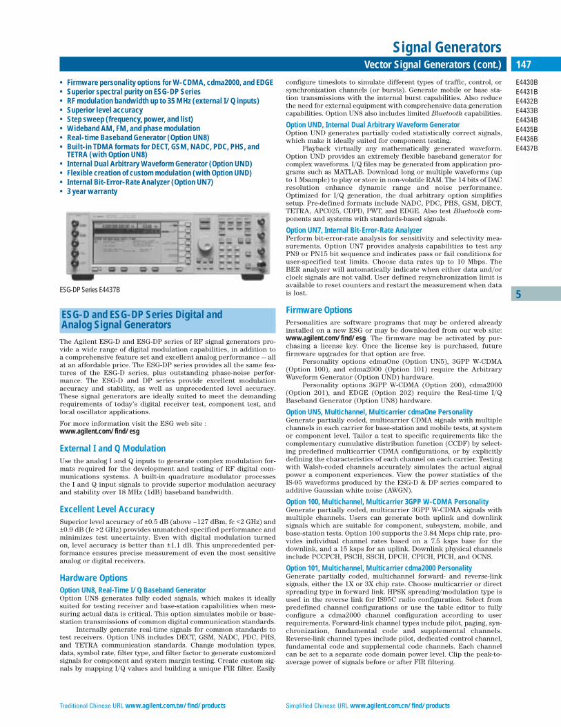
Traditional Chinese URL www.agilent.com.tw/find/products Simplified Chinese URL www.agilent.com.cn/find/products
5
E4430BE4431BE4432BE4433BE4434BE4435BE4436BE4437B
147Vector Signal Generators (cont.)
Signal Generators
ESG-D and ESG-DP Series Digital and Analog Signal Generators
The Agilent ESG-D and ESG-DP series of RF signal generators pro-vide a wide range of digital modulation capabilities, in addition toa comprehensive feature set and excellent analog performance — allat an affordable price. The ESG-DP series provides all the same fea-tures of the ESG-D series, plus outstanding phase-noise perfor-mance. The ESG-D and DP series provide excellent modulationaccuracy and stability, as well as unprecedented level accuracy.These signal generators are ideally suited to meet the demandingrequirements of today’s digital receiver test, component test, andlocal oscillator applications.
For more information visit the ESG web site :www.agilent.com/find/esg
External I and Q ModulationUse the analog I and Q inputs to generate complex modulation for-mats required for the development and testing of RF digital com-munications systems. A built-in quadrature modulator processesthe I and Q input signals to provide superior modulation accuracyand stability over 18 MHz (1dB) baseband bandwidth.
Excellent Level AccuracySuperior level accuracy of ±0.5 dB (above –127 dBm, fc <2 GHz) and±0.9 dB (fc >2 GHz) provides unmatched specified performance andminimizes test uncertainty. Even with digital modulation turnedon, level accuracy is better than ±1.1 dB. This unprecedented per-formance ensures precise measurement of even the most sensitiveanalog or digital receivers.
Hardware OptionsOption UN8, Real-Time I/Q Baseband GeneratorOption UN8 generates fully coded signals, which makes it ideallysuited for testing receiver and base-station capabilities when mea-suring actual data is critical. This option simulates mobile or base-station transmissions of common digital communication standards.
Internally generate real-time signals for common standards totest receivers. Option UN8 includes DECT, GSM, NADC, PDC, PHS,and TETRA communication standards. Change modulation types,data, symbol rate, filter type, and filter factor to generate customizedsignals for component and system margin testing. Create custom sig-nals by mapping I/Q values and building a unique FIR filter. Easily
configure timeslots to simulate different types of traffic, control, orsynchronization channels (or bursts). Generate mobile or base sta-tion transmissions with the internal burst capabilities. Also reducethe need for external equipment with comprehensive data generationcapabilities. Option UN8 also includes limited Bluetooth capabilities.
Option UND, Internal Dual Arbitrary Waveform Generator Option UND generates partially coded statistically correct signals,which make it ideally suited for component testing.
Playback virtually any mathematically generated waveform.Option UND provides an extremely flexible baseband generator forcomplex waveforms. I/Q files may be generated from application pro-grams such as MATLAB. Download long or multiple waveforms (upto 1 Msample) to play or store in non-volatile RAM. The 14 bits of DACresolution enhance dynamic range and noise performance.Optimized for I/Q generation, the dual arbitrary option simplifiessetup. Pre-defined formats include NADC, PDC, PHS, GSM, DECT,TETRA, APC025, CDPD, PWT, and EDGE. Also test Bluetooth com-ponents and systems with standards-based signals.
Option UN7, Internal Bit-Error-Rate AnalyzerPerform bit-error-rate analysis for sensitivity and selectivity mea-surements. Option UN7 provides analysis capabilities to test anyPN9 or PN15 bit sequence and indicates pass or fail conditions foruser-specified test limits. Choose data rates up to 10 Mbps. TheBER analyzer will automatically indicate when either data and/orclock signals are not valid. User defined resynchronization limit isavailable to reset counters and restart the measurement when datais lost.
Firmware OptionsPersonalities are software programs that may be ordered alreadyinstalled on a new ESG or may be downloaded from our web site:www.agilent.com/find/esg. The firmware may be activated by pur-chasing a license key. Once the license key is purchased, futurefirmware upgrades for that option are free.
Personality options cdmaOne (Option UN5), 3GPP W-CDMA(Option 100), and cdma2000 (Option 101) require the ArbitraryWaveform Generator (Option UND) hardware.
Personality options 3GPP W-CDMA (Option 200), cdma2000(Option 201), and EDGE (Option 202) require the Real-time I/QBaseband Generator (Option UN8) hardware.
Option UN5, Multichannel, Multicarrier cdmaOne PersonalityGenerate partially coded, multicarrier CDMA signals with multiplechannels in each carrier for base-station and mobile tests, at systemor component level. Tailor a test to specific requirements like thecomplementary cumulative distribution function (CCDF) by select-ing predefined multicarrier CDMA configurations, or by explicitlydefining the characteristics of each channel on each carrier. Testingwith Walsh-coded channels accurately simulates the actual signalpower a component experiences. View the power statistics of the IS-95 waveforms produced by the ESG-D & DP series compared toadditive Gaussian white noise (AWGN).
Option 100, Multichannel, Multicarrier 3GPP W-CDMA PersonalityGenerate partially coded, multicarrier 3GPP W-CDMA signals withmultiple channels. Users can generate both uplink and downlinksignals which are suitable for component, subsystem, mobile, andbase-station tests. Option 100 supports the 3.84 Mcps chip rate, pro-vides individual channel rates based on a 7.5 ksps base for thedownlink, and a 15 ksps for an uplink. Downlink physical channelsinclude PCCPCH, PSCH, SSCH, DPCH, CPICH, PICH, and OCNS.
Option 101, Multichannel, Multicarrier cdma2000 PersonalityGenerate partially coded, multichannel forward- and reverse-linksignals, either the 1X or 3X chip rate. Choose multicarrier or directspreading type in forward link. HPSK spreading/modulation type isused in the reverse link for IS95C radio configuration. Select frompredefined channel configurations or use the table editor to fullyconfigure a cdma2000 channel configuration according to userrequirements. Forward-link channel types include pilot, paging, syn-chronization, fundamental code and supplemental channels.Reverse-link channel types include pilot, dedicated control channel,fundamental code and supplemental code channels. Each channelcan be set to a separate code domain power level. Clip the peak-to-average power of signals before or after FIR filtering.
• Firmware personality options for W-CDMA, cdma2000, and EDGE• Superior spectral purity on ESG-DP Series• RF modulation bandwidth up to 35 MHz (external I/Q inputs)• Superior level accuracy• Step sweep (frequency, power, and list)• Wideband AM, FM, and phase modulation• Real-time Baseband Generator (Option UN8)• Built-in TDMA formats for DECT, GSM, NADC, PDC, PHS, and
TETRA (with Option UN8)• Internal Dual Arbitrary Waveform Generator (Option UND)• Flexible creation of custom modulation (with Option UND)• Internal Bit-Error-Rate Analyzer (Option UN7)• 3 year warranty
ESG-DP Series E4437B
English URL www.agilent.com/find/products Korean URL www.agilent.co.kr/find/products
5
E4430BE4431BE4432BE4433BE4434BE4435BE4436BE4437B
148 Vector Signal Generators (cont.)
Signal Generators
Option 200, Real-Time 3GPP W-CDMA PersonalityGenerate fully coded real-time W-CDMA uplink and downlink signals.By utilizing the real-time I/Q baseband generator of Option UN8 (Rev Cor higher) and Option UN9, this firmware option provides fully codedreference measurement channels to perform BERT and baseband test-ing on mobile receiver and base-station designs. This complements theexisting Option 100, which provides a partially coded multichannelmulticarrier W-CDMA signal used for component test only. Option 200gives the user the capability to generate custom physical, control, sync,and transport channels while supporting adjustments of the channelparameters. This flexibility combined with the ability to insert data bitsat the transport or physical layer is ideal for different stages of testing.
Option 201, Real-Time cdma2000 Personality Generate fully coded IS-2000 (SR1) signals for mobile receivertests. Conduct frame or bit error tests and functional tests of themobile unit’s protocol handling. Option 201 is backward compati-ble with IS-95 systems using Radio Configurations 1 or 2. Fullycoded channels include pilot, sync, paging, quick paging, funda-mental, and supplemental traffic channels plus OCNS and QOF.Channels are easily configurable using the built-in table editor,with control over power level, FIR filter type, PN offset, EvenSecond delay, and others, depending upon channel type.
Option 202, Real-Time EDGE Personality Generate continuous or framed signals. Produce fully coded signalsusing internally or externally generated data. Option 202 uses 3π/8-rotating 8PSK, and a “linearized” Gaussian Tx filter. Edit framedata fields and use custom filtering to customize your signal.Synchronize two ESGs to combine EDGE (8PSK) and GSM (GMSK)timeslots. Upload externally defined burst shape waveforms.
Other Options AvailableOther options are available to improve output power (Option UNB),to extend memory (Option UN9), and to vary timeslot power levels(Option UNA). There is a wide range of special options availablethat are not listed. If interested in any special options, please con-tact your Agilent sales representative.
SpecificationsAnalog, Remote Programming, and General SpecificationsFor analog, remote programming, and general specifications, pleaserefer to the ESG-A & AP specifications located on page 151. ESG-Aand ESG-D, and ESG-AP and DP have the same analog specificationsexcept for: • high performance pulse modulation, option 1E6, is not available
on the ESG-D & DP • frequency switching speed for Modulation on: ESG-D: <90 ms
ESG-DP: <100 msMore specification differences, in addition to those listed
above for the ESG-D and DP, are listed below.
FrequencyFrequency Range ESG-D Series ESG-DP Series
(enhanced phase noise)
250 kHz – 1000 MHz E4430B E4434B
250 kHz – 2000 MHz E4431B E4435B
250 kHz – 3000 MHz E4432B E4436B
250 kHz – 4000 MHz E4433B E4437B
Level Accuracy with Digital Modulation(After power search is executed; relative to CW level accuracy with ALC on; with burst off;if external I/Q is enabled: √I2 + Q2 = 0.5 V rms )
Level Accuracy with ALC Off: ±0.3 dB, typical (With ALC on; relative to CW; with PRBS-modulated data; if using I/Q inputs, √I2 + Q2 = 0.5 V rmsnominal)
π/4 DQPSK or QPSK FormatsESG-D ESG-DP
±0.15 dB ±0.20 dB
(Relative to CW; with raised cosine or root-raised cosine filter and ≥0.35; with 10 kHz≤symbol rate ≤1 MHz; at RF freq. ≥25 MHz; power ≤max.specified –3 dBm or –6 dBm withOption UNB.)
Constant Amplitude Formats (FSK, GMSK, etc.)ESG-D ESG-DP
No degradation in power level accuracy ±0.10 dB
I/Q ModulationI & Q Inputs • Input Impedance: 50 Ω• Full Scale Input: √I2 + Q2 = 0.5 V rms Adjustments/Impairments (nominal)• DC Offset: (I and Q independently adjustable) ±100%• I/Q Gain Ratio: ±4 dB• I/Q Quadrature: ±10˚ (for fc ≤3.3 GHz)DC Vector Accuracy (Relative to full scale, power ≤+7 dBm (≤+10 dBm for Option UNB))
Frequency (GHz) <0.6 0.6 to 2 2 to 3.7 ≤4
Static EVM (rms) <0.75% <0.5% <0.75% <1%
Magnitude Error (rms) <0.5% <0.35% <0.5% <0.75%
Phase Error (rms) <0.35˚ <0.25˚ <0.35˚ <0.5˚
Origin Offset (dBc) <–46 <–46 <–40 <–40
External Burst Envelope ControlInput VoltageRF On O VRF Off –1 VOn/Off Ratio:≤3 GHz: >75 dB>3 GHz: >60 dBRise/Fall Time: <2 µs with rectangular input, typicalMinimum Burst Rate ALC On: 10 Hz, typicalALC Off: dcInput Impedance: 50 Ω, nominal
Coherent Carrier OutRange: 250 MHz to maximum carrier frequencyLevel: 0 dBm ±5 dB, typicalImpedance: 50 Ω
Option Specifications Option UN8, Real-Time I/Q Baseband GeneratorThe following formats are included with option UN8:NADC, PDC, PHS, TETRA, DECT, and GSM.Modulation Formats• PSK: BPSK, QPSK, OQPSK, π/4DQPSK, 8PSK, 16PSK, D8PSK• MSK: User-defined phase offset• QAM: 4, 16, 32, 64, 256• FSK: Selectable: 2, 4, 8, 16 level symmetric• Custom I/Q: Map of 16 unique values for I and QFilters: Nyquist, root Nyquist, Gaussian, Custom FIR, rectangularFilter Rate: : 0 to 1; BbT: 0.1 to 1Symbol Rate: Adjustable up to 12.5 Msymbols/sec
TDMA Data StructureFrames and timeslots may be configured as different types of traffic orcontrol channels. The data field of a timeslot can accept user file, PRBS(PN9 or PN15) or external data with the appropriate clock.Internally Generated DataPseudo-Random Patterns: Continuous PN9, PN11, PN15, PN20 or PN23Repeating Sequence: Any 4-bit sequenceDownloadable Data• Direct-pattern RAM (PRAM)
Max size: 1 Mbytes (std.); 8 Mbytes (Option UN9)• User File max. size: 128 kbytesExternally Generated Data• Inputs: Data, bit/symbol clocks (accepts rates ±5% of specified
data rate)• Reference Frequency
Internal or external: 1, 2, 5, 10 MHz reference. Data clock can be locked to an external 13 MHz (GSM) reference
Frame Trigger Delay Control• Range: 0 to 65,535 bits• Resolution: 1 bitInternal Burst Shape Control (varies with standards and bit rates)• Rise/Fall Time Range: Up to 30 bits• Rise/Fall Delay Range: 0 to 63.5 bitsI/Q Outputs• EVM (NADC, PDC, PHS, TETRA): 1% rms• Global Phase Error (GSM): 0.75˚ rms• Deviation Accuracy (DECT): 1 kHz rms

Traditional Chinese URL www.agilent.com.tw/find/products Simplified Chinese URL www.agilent.com.cn/find/products
5
E4430BE4431BE4432BE4433BE4434BE4435BE4436BE4437B
149Vector Signal Generators (cont.)
Signal Generators
Option UND, Dual Internal Arbitrary Waveform Generator The following predefined formats are included with option UND:NADC, PDC, PHS, GSM, DECT, TETRA, APC025, CDPD, PWT, EDGEChannels: 2Resolution: 14 bits (1/16384)Waveform Memory• Playback: 1 Msample/channel• Storage (non-volatile RAM): 1 Msample/channelWaveform Segments• Length: 16 samples to 1 Msample• Number of Segments: 1 to 128Waveform Sequences• Sequencing: Continuously repeating• Number of Sequences: 1 to 128Sample Rate: 1 Hz to 40 MHzOutput Reconstruction Filters• Type: Elliptic• Fcutoff (nominal, 3 dB): 250 kHz, 2.5 MHz, 8 MHz and throughBaseband Spectral Purity(typical, full scale sinewave, >20 x oversampling)Harmonic Distortion• ≤100 kHz: ≤–80 dBc• 100 kHz to 2 MHz: <–65 dBcNon-Harmonic Spurious: <–80 dBcPhase Noise: <–120 dBc/Hz(baseband output of 1 MHz sinewave at 20 kHz offset)IM Performance: <–69 dB(two sinewaves at 950 kHz and 1050 kHz at baseband, full scale)
Option UN7, Bit-Error-Rate Analyzer Clock Rate: 100 Hz to 10 MHzSupported Data Patterns: PN9, PN15Resolution: 10 digits (6 digits for BER (exponential display))Minimum Synchronization Length• 2 Mbps Mode: 9 bits (PN9), 15 bits (PN15)• 10 Mbps Mode: 43 bits (PN9), 48 bits (PN15)Bit Sequence Length: 100 bits to 4.294 Gbits after synchronization
Features
2 Mbps Mode 10 Mbps Mode
Bit count X X
Error-bit-count X
Bit-Error-Rate X
Pass/fail indication X X
Valid data and clock detection X X
Automatic re-synchronization X
Special pattern ignore X
Option UN5, Multichannel, Multicarrier cdmaOnePersonality Chip (symbol) Rate: 1.2288 MHz (default) Adjustable to 1 Hz to 10 MHzwith 4x oversamplingModulation• QPSK (forward): With Walsh and short code spreading• Offset QPSK (reverse): With short code spreading of random dataPredefined Channel Configurations (power levels per IS-97-A)• Pilot Channel: Incl. IS-95 modified filter, with equalizer• 9 Channel: Incl. pilot, paging, sync, 6 traffic and IS-95 modified filter,
with equalizer• 32 Channel: Incl. pilot, paging, sync, 29 traffic and IS-95 modified filter,
with equalizer• 64 Channel: Incl. pilot, 7 paging, sync, 55 traffic and IS-95 modified filter,
with equalizer• Reverse Channel: Incl. IS-95 filterRho• 0.9996 (≤4 dBm, IS-95 filter, ≤2 GHz, typical)
Option 100, Multichannel 3GPP W-CDMA Personality (Supports R99 December 2001 3GPP W-CDMA Standard)
Provides partially coded data for component test applications.Chip Rates: 3.84 Mchips/sec ±10 %Downlink• Modulation: QPSK• Predefined channel configurations (partially coded)
1 DPCH3 DPCH
– PCCPCH + SCH– PCCPCH + SCH + 1 DPCH– PCCPCH + SCH + 3 DPCH
• Test Model 1: with 16, 32, or 64 DPCH• Test Model 2• Test Model 3: with 16 or 32 DPCH• Test Model 4Channel Types• (downlink) PICH, OCNS, PCCPCH, PSCH, SSCH, CPICH, DPCH• (uplink) DPCCH,DPDCHMulticarrier• Number of carriers: Up to 4 (user defined, individually configurable)• Frequency offset (per carrier): Up to ±7.5 MHz• Offset resolution: <1 HzUplink• Modulation: OCQPSK (HPSK)Predefined Channel Configurations (partially coded)1 DPCCH 15 ksps, spread code 0DPCCH + 1 DPDCH 960 ksps, spread code 1DPCCH + 2 DPDCH 960 ksps, spread code 1DPCCH + 3 DPDCH 960 ksps, spread code 2DPCCH + 4 DPDCH 960 ksps, spread code 2DPCCH + 5 DPDCH 960 ksps, spread code 3
Option 200, Real-Time W-CDMA Personality(Supports R99 December 2000 3GPP W-CDMA Standard)
Downlink SpecificationsChannel Types GeneratedPrimary Synchronization (PSCH), Secondary Synchronization (SSCH),Primary Common Control (P-CCPCH), Common Pilot (CPICH), DedicatedPhysical (DPCH), Page Indication (PICH), Acquisition Indication (AICH),Physical Downlink Shared (PDSCH), OCNS DPCCH, PDCH
Downlink Channel Configurations• PSCH
Power: –40 to 0 dB• SSCH
Power: –40 to 0 dBSecondary Scramble Code Group: 0 to 63
• P-CCPCHPower: –40 to 0 dBOVSF: 0 to 255Data: PN9, FIX4, User File, PN15Transport Channel: BCH CodingSystem Frame Number (SFN): Incrementing
• CPICHPower: –40 to 0 dB
• DPCHReference Measurement Setup: 12.2, 64, 144, 384 kbps
– Physical Layer Control:Configurable parameters: Power, OVSF, Slot Format, TPC, TFICSymbol Rate: 7.5 – 960 kspsDPCH Offset: 0 to 149Secondary Scramble Code Offset: 0 to 15Data: PN9, PN15, 4-bit repeating pattern, User File, Transport Channel
– Transport Layer (DCH) Control:(Up to 6 DCH’s for each DPCH)Block Size, Transport Time Interval (TTI), Rate Matching, CRC Size, Transport Channel NumberData: PN9, FIX4, User FileCoding: None, Convolutional 1/2, Convolutional 1/3, Turbo
• PICHPower: –40 to 0 dBOVSF: 0 to 511
Uplink SpecificationsSee ESG Technical Specifications, p/n 5965-3096E and ConfigurationGuide, p/n 5965-4973E for details
English URL www.agilent.com/find/products Korean URL www.agilent.co.kr/find/products
5
E4430BE4431BE4432BE4433BE4434BE4435BE4436BE4437B
150 Vector Signal Generators (cont.)
Signal Generators
Option 101, Multichannel cdma2000 PersonalitySpreading Rate: SR1,SR3Multicarrier: Up to 12 (user defined, individually configured)Frequency Offset (per carrier): –7.5 MHz to +7.5 MHzPower Offset: 0 dB to –40 dBForward Link• Spreading Type: Direct spread (DS), multicarrierUser-defined cdma2000 (Channel types)(partially coded) Pilot, paging (SR1 only), sync, fundamental, and supplementalRadio Configuration:• SR1: 1 to 5• SR3: 6 to 9Data Rate: 1.2 kpbs to 1036.8 kbps, depends on the selected radio configurationWalsh Code: Pilot and sync have fixed codes, Walsh 0 and 32. Channel Power: 0 to –40 dBPN Offsets: 0 to 511Data Pattern: 00-FF(HEX) or randomReverse Link• Spreading Type: Direct spread onlyUser-defined cdma2000 (Channel types)(partially coded) Pilot, dedicated control channel, fundamental, and supplementalRadio Configuration: 1 to 6Data Rate: 1.2 kbps to 1036.8 kbps, depends on radio config.Channel Power: 0 to –40 dBData Pattern: 00-FF(HEX) or random
Option 201, Real-Time cdma2000 PersonalityChannel Types Generated Up to four channels of any of the following:Pilot, Paging, Quick Paging, Sync, F-Fundamental, F-Supplemental, OCNSGlobal Controls Across All Channels• Channel Power: 0 to –40 dB• Filters: IS95, IS95 w/eq, IS95 mod, IS95 mod w/eq, Root Nyquist,
Nyquist, Gaussian, user-defined FIR, Rectangle, APCO 25 C4FMSpread Rate: 1PN Offset: 0 to 511Chip Rate: 50 Hz to 1.3 MHzEven Second Delay: 0.5 to 128 chipsI/Q Voltage Scale: 0 to –40 dBCode Domain Power: Equal powers or scale to 0 dBPilot Channel• Walsh: 0 (non-adjustable)Sync Channel• Walsh: 0 to 63• Data: Free editing of the following: SID, NID, F-synch type,
Sys_Time, PRAT, LTM_Off, Msg_Type, P_REV, MIN_P_REV, LP_SEC, DAYLT, CDMA Freq, ext CDMA freq, and Reserved
Paging Channel• Walsh: 0 to 63• Data: Default paging message or Userfile• Long Code Mask: 0-3FFFFFFFFFF (HEX)• Rate: 4.8 or 9.6 kbpsQuick Paging Channel• Power: 0 to –40 dB• Walsh: 0 to 127• Data rate: 2.4 kbps to 4.8 kbps• Config. change: 0 to 3• Paging indicator: –1 to 383Fundamental Channel• Radio Config.: 1 to 5• Walsh: 0 to 63• Data Rate: 1.2 to 14.4 kbps, depending on radio configuration data
PN9, PN15, userfile, external serial data, or predefined bit patterns• Long Code Mask: 0-3FFFFFFFFFF (HEX)• Power Control: N up/down, “N” may be set from 1 to 80• Power Puncture: 0n/Off• Frame Offset: 0 to 15• Frame Length: 20 ms (non-adjustable)• QOF: 0 to 3
Supplemental Channel (Same channel configuration as Fundamental, except)• Radio Config.: 3 to 5• Walsh: 0 to 63, depending on RC and Data Rate• Data Rate: 19.2 to 307.2 kbps, depending on radio configuration• Turbo Coding: May be selected for data rates from 28.8 to 153.6 kbpsOCNS ChannelWalsh: 0 to 63
Option 202, Real-Time EDGE Personality Modulation3π/8-rotating 8PSK (per EDGE specifications) User-selectable (see Modulation under Option UN8)Filter“Linearized” Gaussian (per EDGE specifications)User-selectable (see Filter under Option UN8)Symbol RateUser-adjustable (see Symbol rate under Option UN8)270.833 kHz (default)Burst ShapeDefaults to EDGE standard power vs. time mask with user definable burstshape. Alternatively, upload externally defined burst shape waveformsData StructureTime slots may be configured as normal or custom. The data field of a time slot can accept a user file, PRBS (PN9 or PN15), a fixed sequence or external data. All other fields in a timeslot areeditable. Conforms to 8.3.0 Release 99
Key LiteratureESG Family RF Signal Generators (brochure), p/n 5968-4313EESG Family RF Signal Generators Data Sheet, p/n 5965-3096EESG Family RF Signal Generators Configuration Guide, p/n 5965-4973E
For additional information, visit our web site: www.agilent.com/find/esg
Ordering InformationESG-D Series
E4430B 1 GHz Signal GeneratorE4431B 2 GHz Signal GeneratorE4432B 3 GHz Signal GeneratorE4433B 4 GHz Signal Generator
ESG-DP SeriesE4434B 1 GHz Signal GeneratorE4435B 2 GHz Signal GeneratorE4436B 3 GHz Signal GeneratorE4437B 4 GHz Signal Generator
ESG-D Series Options Opt 1E5 Add high-stability timebase
ESG-D and ESG DP Series Options Opt UNA Alternate time slot level control (for Option UN8) Opt UNB High power with mechanical attenuator
Hardware Options Opt UND Internal dual arbitrary waveform generatorOpt UN7 Internal Bit-Error-Rate AnalyzerOpt UN8 Real-time I/Q baseband generatorOpt UN9 Add 7 M RAM to Opt UN8
Firmware OptionsOpt UN5 Multicarrier, multichannel cdmaOnePersonality for Option UNDOpt 100 Multicarrier, multichannel W-CDMAPersonality for Option UNDOpt 101 Multicarrier, multichannel W-CDMA Personality for Option UNDOpt 200 Real-time W-CDMA Personality for Option UN8/UN9Opt 201 Real-time cdma2000 Personality for Option UN8/UN9Opt 202 Real-time EDGE Personality for Option UN8/UN9

Traditional Chinese URL www.agilent.com.tw/find/products Simplified Chinese URL www.agilent.com.cn/find/products
5
E4400BE4420BE4421BE4422BE4423BE4424BE4425BE4426B
151Analog & CW Signal Generators
Signal Generators
ESG-A and ESG-AP Series Analog Signal Generators
The Agilent ESG-A & AP series of analog RF signal generators offerexcellent in-channel performance with superior quality and relia-bility, at an affordable price. The ESG-AP series provides all of thefeatures of ESG-A, plus enhanced phase-noise performance. TheESG-A & AP series provide superb frequency and level control, andwide modulation capabilities. They are ideally suited to meet thedemanding requirements of today’s receiver test, component testand local oscillator applications.
For more information, visit the ESG web site: www.agilent.com/find/esg
Low Cost of OwnershipLow initial cost, three-year warranty and a two-year calibrationcycle, are all features that help minimize the cost of ownership. TheESG-A and AP RF signal generators are designed for long-termdependability, maximizing production throughput and uptime.
Excellent Level AccuracySuperior level accuracy of ±0.5 dB (above –127 dBm, fc <2 GHz) and±0.9 dB (fc >2 GHz) provides unmatched performance and mini-mizes test uncertainty. This unprecedented performance ensuresprecise measurement of even the most sensitive analog receivers.
High-Stability Timebase The high stability timebase, Option 1E5, for the ESG-A series andstandard on the ESG-AP series, provides increased frequency stability and accuracy, which results in reduced drift and phasenoise. The high-stability timebase improves measurement repeata-bility and reliability.
High-Performance Pulse Modulation, Option 1E6The high performance pulse modulation, Option 1E6, for the ESG-Aand AP series provides improved pulse rise and fall times, plusexceptional on/off ratios. Option 1E6 improves radar and pulse carrier measurements.
SpecificationsFrequency
Range ESG-A series ESG-AP series(Enhanced Phase Noise)
250 kHz – 1000 MHz E4400B E4423B250 kHz – 2000 MHz E4420B E4424B250 kHz – 3000 MHz E4421B E4425B250 kHz – 4000 MHz E4422B E4426B
Resolution: 0.01 HzFrequency Accuracy: fc x timebase accuracy
Switching Speed (typical)
ESG-A ESG-AP
Modulation On <50 ms <65 msModulation Off <40 ms <55 ms
Sweep Modes: Step: frequency and power, and arbitrary list• Dwell Time: 1 ms to 60 sec • Number of points: 2 to 401
Internal Reference OscillatorTimebase Stability
ESG-A Opt 1E5 ESG-A (Standard on ESG-AP)
Aging Rate <±1 ppm/yr. <±0.1 ppm/yr. or<±0.0005 ppm/day after 45 days
Temperature <±1 ppm, typical <±0.05 ppm, typical(0˚C to 55˚C)
Line Voltage <±0.1 ppm <±0.002 ppm, typical(+5%, –10%), typical (+5%, –10%)
Time-base Accuracy: = ± aging rate ± temperature effects ± line voltage effects.Timebase Reference Output:• Frequency: 10 MHz• Amplitude: >0.35 V rms into 50 Ω loadExternal Reference Input:Frequency: 1, 2, 5, 10 MHz, ±typ. 10 ppm (typical 1 ppm, ESG-AP andOption 1E5 for ESG-A)Amplitude: >0.15 V rmsInput Impedance: 50 Ω
OutputPower
Range Standard Option UNB
250 kHz to 1000 MHz +13 to –136 dBm +17 to –136 dBm >1000 MHz to 3000 MHz +10 to –136 dBm +16 to –136 dBm>3000 MHz to 4000 MHz +7 to –136 dBm +13 to –136 dBm
Resolution: 0.02 dB
Level Accuracy (at 23˚C ±5˚C)
Output Power/ +7 to –120 dBm –120 to –127 dBm <–127 dBmFrequency Range (+10 to –120 dBm,
Opt UNB )
250 kHz to 2 GHz ±0.5 dB ±0.5 dB ±1.5 dB>2000 MHz to 3 GHz ±0.9 dB ±0.9 dB ±2.5 dB>3000 MHz to 4 GHz ±0.9 dB ±0.9 dB (±1.5 dB, ±2.5 dB
Opt UNB)
Amplitude Switching Speed: <30 ms, typical • With Power Search Mode: <300 ms, typical Reverse Power Protection: • 250 kHz to 2000 MHz: 50 watts• >2000 MHz to 4000 MHz: 25 watts• Max. DC Voltage: 50 V
SWR (typical)
Frequency Range Standard Option UNB
250 kHz to 2000 MHz <1.4:1 <1.25:1>2000 to 4000 MHz <1.9:1 <1.35:1
Output Impedance: 50 Ω
• Flexible architecture, upgrade paths for options• Superior spectral purity on ESG-AP series• 4 GHz electronic attenuator for reliability and repeatability• Superior level accuracy• Wideband FM and phase modulation• Step sweep (frequency, power and list)• Built-in function generator• 3 year warranty
ESG-A series E4421B
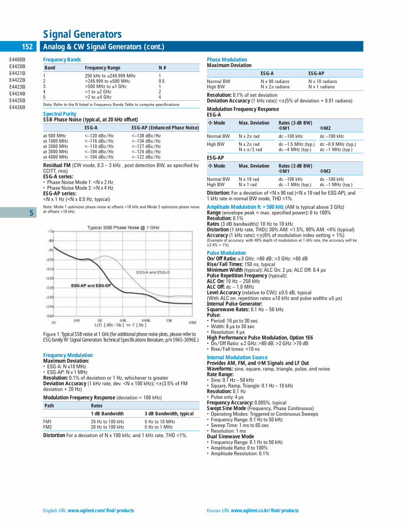
English URL www.agilent.com/find/products Korean URL www.agilent.co.kr/find/products
Frequency Bands
Band Frequency Range N #
1 250 kHz to ≤249.999 MHz 12 >249.999 to ≤500 MHz 0.53 >500 MHz to ≤1 GHz 14 >1 to ≤2 GHz 25 >2 to ≤4 GHz 4
Note: Refer to the N listed in Frequency Bands Table to compute specifications
Spectral PuritySSB Phase Noise (typical, at 20 kHz offset)
ESG-A ESG-AP (Enhanced Phase Noise)
at 500 MHz <–120 dBc/Hz <–138 dBc/Hzat 1000 MHz <–116 dBc/Hz <–134 dBc/Hzat 2000 MHz <–110 dBc/Hz <–127 dBc/Hzat 3000 MHz <–104 dBc/Hz <–124 dBc/Hzat 4000 MHz <–104 dBc/Hz <–122 dBc/Hz
Residual FM (CW mode, 0.3 – 3 kHz , post detection BW, as specified byCCITT, rms)ESG-A series:• Phase Noise Mode 1: <N x 2 Hz• Phase Noise Mode 2: <N x 4 HzESG-AP series:<N x 1 Hz (<N x 0.5 Hz, typical)Note: Mode 1 optimizes phase noise at offsets <10 kHz and Mode 2 optimizes phase noiseat offsets >10 kHz.
Frequency ModulationMaximum Deviation: • ESG-A: N x10 MHz• ESG-AP: N x 1 MHzResolution: 0.1% of deviation or 1 Hz, whichever is greaterDeviation Accuracy (1 kHz rate, dev. <N x 100 kHz): <±(3.5% of FM deviation + 20 Hz)
Modulation Frequency Response (deviation = 100 kHz)
Path Rates
1 dB Bandwidth 3 dB Bandwidth, typical
FM1 20 Hz to 100 kHz 5 Hz to 10 MHzFM2 20 Hz to 100 kHz 5 Hz to 1 MHz
Distortion For a deviation of N x 100 kHz, and 1 kHz rate, THD <1%.
5
E4400BE4420BE4421BE4422BE4423BE4424BE4425BE4426B
152 Analog & CW Signal Generators (cont.)
Signal Generators
Figure 1: Typical SSB noise at 1 GHz (for additional phase noise plots, please refer toESG family RF Signal Generators Technical Specifications literature, p/n 5965-3096E.)
Phase ModulationMaximum Deviation
ESG-A ESG-AP
Normal BW N x 90 radians N x 10 radiansHigh BW N x 2π radians N x 1 radians
Resolution: 0.1% of set deviationDeviation Accuracy (1 kHz rate): <±(5% of deviation + 0.01 radians)
Modulation Frequency ResponseESG-A
Φ Mode Max. Deviation Rates (3 dB BW)ΦM1 ΦM2
Normal BW N x 2π rad dc –100 kHz dc –100 kHz
High BW N x 2π rad dc –1.5 MHz (typ.) dc –0.9 MHz (typ.)N x π/2 rad dc –4 MHz (typ.) dc –1 MHz (typ.)
ESG-AP
Φ Mode Max. Deviation Rates (3 dB BW)ΦM1 ΦM2
Normal BW N x 10 rad dc –100 kHz dc –100 kHzHigh BW N x 1 rad dc –1 MHz (typ.) dc –1 MHz (typ.)
Distortion: For a deviation of <N x 90 rad (<N x 10 rad for ESG-AP), and 1 kHz rate in normal BW mode, THD <1%.
Amplitude Modulation fc >500 kHz (AM is typical above 3 GHz)Range (envelope peak = max. specified power): 0 to 100%Resolution: 0.1%Rates (3 dB bandwidth): 10 Hz to 10 kHzDistortion (1 kHz rate, THD): 30% AM: <1.5%, 90% AM: <4% (typical)Accuracy (1 kHz rate): <±(6% of modulation index setting + 1%)(Example of accuracy: with 40% depth of modulation at 1 kHz rate, the accuracy will be±2.4% + 1%)
Pulse ModulationOn/Off Ratio: ≤3 GHz: >80 dB; >3 GHz: >60 dBRise/Fall Times: 150 ns, typicalMinimum Width (typical): ALC On: 2 µs; ALC Off: 0.4 µsPulse Repetition Frequency (typical):ALC On: 10 Hz – 250 kHzALC Off: dc – 1.0 MHzLevel Accuracy (relative to CW): ±0.5 dB, typical(With ALC on, repetition rates ≤10 kHz and pulse widths ≥5 µs)Internal Pulse Generator:Squarewave Rates: 0.1 Hz – 50 kHzPulse:• Period: 16 µs to 30 sec• Width: 8 µs to 30 sec• Resolution: 4 µsHigh Performance Pulse Modulation, Option 1E6• On/Off Ratio: ≤2 GHz: >80 dB; >2 GHz: >70 dB• Rise/Fall times: <10 ns
Internal Modulation SourceProvides AM, FM, and ΦM Signals and LF OutWaveforms: sine, square, ramp, triangle, pulse, and noiseRate Range:• Sine: 0.1 Hz – 50 kHz• Square, Ramp, Triangle: 0.1 Hz – 10 kHzResolution: 0.1 Hz• Pulse only: 4 µsFrequency Accuracy: 0.005%, typicalSwept Sine Mode (Frequency, Phase Continuous)• Operating Modes: Triggered or Continuous Sweeps• Frequency Range: 0.1 Hz to 50 kHz• Sweep Time: 1 ms to 65 sec• Resolution: 1 msDual Sinewave Mode• Frequency Range: 0.1 Hz to 50 kHz• Amplitude Ratio: 0 to 100%• Amplitude Resolution: 0.1%
Traditional Chinese URL www.agilent.com.tw/find/products Simplified Chinese URL www.agilent.com.cn/find/products
5
E4400BE4420BE4421BE4422BE4423BE4424BE4425BE4426B
153Analog & CW Signal Generators (cont.)
Signal Generators
Low Frequency Out (Internal Modulation Source)Amplitude: 0 to 3 V peak into 50 ΩOutput Impedance: <1Ω
External Modulation InputsModulation Types:• Ext1: ΦM, FM, AM, and Burst Envelope• Ext2: ΦM, FM, AM, and PulseHigh/Low Indicator (100 Hz to 10 MHz BW, AC coupled inputs only):Activated when input level error exceeds 3% (nominal)
Simultaneous ModulationAll modulation types may be simultaneously enabled, except:FM with ΦM; AM with Burst Envelope; Wideband AM with I/Q. AM, ΦM and FM can sum simultaneous inputs from any two sources: EXT 1 and EXT 2, INT and EXT 1, INT and EXT 2. Any given source (INT, EXT 1 or EXT 2) may only be routed to one activated modulation type.
Remote ProgrammingInterface: GPIB (IEEE-488.2-1987) with Listen and Talk. RS-232.Control Languages: SCPI version 1992.0, also compatible with 8656Band 8657A/B/D/J mnemonicsFunctions Controlled: All front-panel functions except power switchand knobs
GeneralPower Requirements: 90 to 254 V; 50, 60, or 400 Hz; 200 W maximumOperating Temperature Range: 0˚C to 55˚CLeakage: Conducted and radiated interference meets MIL-STD-461CCE02 Part 2 and CISPR 11Storage Registers: Up to 800 storage registers, up to 10 sequences availableWeight: <12.7 kg (28 lb) net, <21 kg (46 lb) shippingDimensions: 133 mm H x 426 mm W x 432 mm D (5.25 in H x 16.8 in W x 17 in D)
Key LiteratureESG Family RF Signal Generators (brochure), p/n 5968-4313EESG Family RF Signal Generators Technical Specifications, p/n 5965-3096EESG Family RF Signal Generators Configuration Guide, p/n 5965-4973E
For additional information, visit the ESG web site:www.agilent.com/find/esg
Ordering Information
ESG-A SeriesE4400B 1 GHz Signal GeneratorE4420B 2 GHz Signal GeneratorE4421B 3 GHz Signal GeneratorE4422B 4 GHz Signal Generator
ESG-AP SeriesE4423B 1 GHz Signal GeneratorE4424B 2 GHz Signal GeneratorE4425B 3 GHz Signal GeneratorE4426B 4 GHz Signal Generator
ESG-A Series Hardware OptionsOpt 1E5 Add high-stability timebase
ESG-A and ESG AP Series Hardware OptionsOpt 1E6 High performance pulse modulationOpt UNB High power with mechanical attenuator
Documentation, support, and mechanical options available with any ESG model
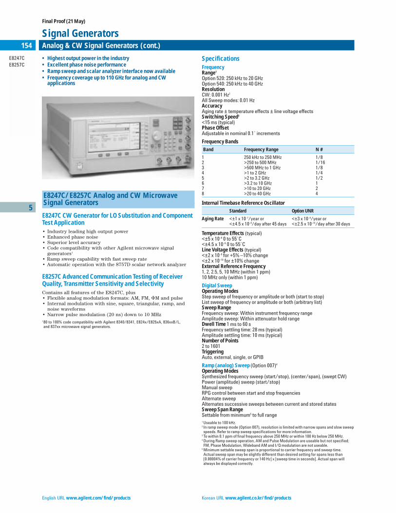
English URL www.agilent.com/find/products Korean URL www.agilent.co.kr/find/products
SpecificationsFrequencyRange1
Option 520: 250 kHz to 20 GHzOption 540: 250 kHz to 40 GHzResolutionCW: 0.001 Hz2
All Sweep modes: 0.01 HzAccuracyAging rate ± temperature effects ± line voltage effectsSwitching Speed3
<15 ms (typical)Phase Offset Adjustable in nominal 0.1˚ increments
Frequency Bands
Band Frequency Range N #
1 250 kHz to 250 MHz 1/82 >250 to 500 MHz 1/163 >500 MHz to 1 GHz 1/84 >1 to 2 GHz 1/45 >2 to 3.2 GHz 1/26 >3.2 to 10 GHz 17 >10 to 20 GHz 28 >20 to 40 GHz 4
Internal Timebase Reference Oscillator
Standard Option UNR
Aging Rate <±1 x 10⁻⁷/year or <±3 x 10⁻⁸/year or<±4.5 x 10⁻⁹/day after 45 days <±2.5 x 10⁻¹⁰/day after 30 days
Temperature Effects (typical)<±5 x 10⁻⁸ 0 to 55˚C<±4.5 x 10⁻⁹ 0 to 55˚CLine Voltage Effects (typical) <±2 x 10⁻⁹ for +5% –10% change <±2 x 10⁻¹⁰ for ±10% changeExternal Reference Frequency 1, 2, 2.5, 5, 10 MHz (within 1 ppm) 10 MHz only (within 1 ppm)
Digital SweepOperating Modes Step sweep of frequency or amplitude or both (start to stop)List sweep of frequency or amplitude or both (arbitrary list)Sweep RangeFrequency sweep: Within instrument frequency rangeAmplitude sweep: Within attenuator hold rangeDwell Time 1 ms to 60 sFrequency settling time: 28 ms (typical)Amplitude settling time: 10 ms (typical)Number of Points 2 to 1601Triggering Auto, external, single, or GPIB
Ramp (analog) Sweep (Option 007)4
Operating Modes Synthesized frequency sweep (start/stop), (center/span), (swept CW)Power (amplitude) sweep (start/stop)Manual sweep RPG control between start and stop frequenciesAlternate sweepAlternates successive sweeps between current and stored statesSweep Span Range Settable from minimum5 to full range1 Useable to 100 kHz.2 In ramp sweep mode (Option 007), resolution is limited with narrow spans and slow sweep speeds. Refer to ramp sweep specifications for more information.
3 To within 0.1 ppm of final frequency above 250 MHz or within 100 Hz below 250 MHz.4 During Ramp sweep operation, AM and Pulse Modulation are useable but not specified; FM, Phase Modulation, Wideband AM and I/Q modulation are not useable.
5 Minimum settable sweep span is proportional to carrier frequency and sweep time. Actual sweep span may be slightly different than desired setting for spans less than [0.00004% of carrier frequency or 140 Hz] x [sweep time in seconds]. Actual span will always be displayed correctly.
5
E8247CE8257C
154 Analog & CW Signal Generators (cont.)
Signal Generators
E8247C/E8257C Analog and CW Microwave Signal Generators
E8247C CW Generator for LO Substitution and ComponentTest Application• Industry leading high output power• Enhanced phase noise• Superior level accuracy• Code compatibility with other Agilent microwave signal
generators1
• Ramp sweep capability with fast sweep rate• Automatic operation with the 8757D scalar network analyzer
E8257C Advanced Communication Testing of ReceiverQuality, Transmitter Sensitivity and SelectivityContains all features of the E8247C, plus• Flexible analog modulation formats: AM, FM, M and pulse• Internal modulation with sine, square, triangular, ramp, and
noise waveforms• Narrow pulse modulation (20 ns) down to 10 MHz180 to 100% code compatibility with Agilent 8340/8341, E824x/E825xA, 836xxB/L, and 837xx microwave signal generators.
• Highest output power in the industry• Excellent phase noise performance• Ramp sweep and scalar analyzer interface now available• Frequency coverage up to 110 GHz for analog and CW
applications
Final Proof (21 May)

Traditional Chinese URL www.agilent.com.tw/find/products Simplified Chinese URL www.agilent.com.cn/find/products
5
E8247CE8257C
155Analog & CW Signal Generators (cont.)
Signal Generators
Maximum Sweep Rate
Start Frequency Maximum Sweep Rate Max Span for 100 ms Sweep
250 kHz to <0.5 GHz 25 MHz/ms 2.5 GHz0.5 to <1 GHz 50 MHz/ms 5 GHz1 to <2 GHz 100 MHz/ms 10 GHz2 to <3.2 GHz 200 MHz/ms 20 GHz≥3.2 GHz 400 MHz/ms 36.8 GHz
Frequency Accuracy ±0.05% of span ± timebase (at 100 ms sweep time, for sweep spans lessthan maximum values given above)Accuracy improves proportionally as sweep time increases1
Sweep Time (forward sweep, not including bandswitch and retrace intervals)Resolution: 1 msManual mode: Settable 10 ms to 99 secondsAuto mode: Set to minimum value determined by maximum sweep rateand 8757D settingTriggering Auto, external, single, or GPIBMarkers 10 independent continuously variable frequency markersDisplay: Z-axis intensity or RF amplitude pulseFunctions: M1 to center, M1/M2 to start/stop, marker deltaTwo-tone (master/slave) measurements2
Two PSG’s can synchronously track each other, with independent controlof start/stop frequenciesNetwork Analyzer Compatibility Fully compatible with Agilent 8757D scalar network analyzer3
Also useable with Agilent 8757A/C/E scalar network analyzers for making basic swept measurements4
OutputPower5 (dBm)
Frequency Range Standard Option 1EA
20 GHz Models250 kHz to 3.2 GHz –20 to +13 –20 to +16250 kHz to 3.2 GHz (with Option 1E6) –20 to +13 –20 to +13>3.2 to 20 GHz –20 to +13 –20 to +20
40 GHz Models250 kHz to 3.2 GHz –20 to +9 –20 to +15250 kHz to 3.2 GHz (with Option 1E6) –20 to +9 –20 to +12>3.2 to 20 GHz –20 to +9 –20 to +18>20 to 40 GHz –20 to +9 –20 to +14
20 GHz Models with Step Attenuator(Option 1E1)250 kHz to 3.2 GHz –135 to +11 –135 to +15250 kHz to 3.2 GHz (with Option 1E6) –135 to +11 –135 to +12>3.2 to 20 GHz –135 to +11 –135 to +18
40 GHz Models with Step Attenuator(Option 1E1)250 kHz to 3.2 GHz –135 to +7 –135 to +14250 kHz to 3.2 GHz (with Option 1E6) –135 to +7 –135 to +11>3.2 to 20 GHz –135 to +7 –135 to +16>20 to 40 GHz –135 to +7 –135 to +12
Step Attenuator0 dB and 5 to 115 dB in 10 dB stepsAttenuator Hold Range Minimum (Same as max power sweep range)From –20 dBm to maximum specified output power with step attenuatorin 0 dB position. Can be offset using Option 1E1 attenuatorAmplitude switching speed6
CW or analog modulation: <5 ms (typical)When using power search: <25 ms (typical)
Level Accuracy7 (dB)
Frequency >+10 dBm +10 to –10 dBm –10 to –20 dBm
250 kHz to 2 GHz ±0.6 ±0.6 ±1.42 GHz to 20 GHz ±0.8 ±0.8 ±1.2>20 to 40 GHz ±1.0 ±0.9 ±1.3
Level Accuracy with Step Attenuator8 (dB)
Frequency >+10 dBm +10 to –10 to –70 to –90 to –10 dBm –70 dBm –90 dBm –110 dBm
250 kHz to 2 GHz ±0.6 ±0.6 ±0.7 ±0.8 ±1.4>2 to 20 GHz ±0.8 ±0.8 ±0.9 ±1.0 ±1.7>20 to 40 GHz ±1.0 ±0.9 ±1.0 ±2.0
Resolution0.01 dBTemperature Stability 0.01 dB/°C (typical)User Flatness CorrectionNumber of points: 2 to 1601 points/tableNumber of tables: Up to 10,000, memory limitedPath loss: Arbitrary, within attenuator rangeEntry modes (user edit/view): Remote power meter9, remote bus, manualOutput Impedance50 Ω (nominal)SWR (internally leveled) (typical)250 kHz to 2 GHz <1.4:1>2 GHz to 20 GHz <1.6:1>20 GHz to 40 GHz <1.8:1Leveling ModesInternal leveling, external detector leveling, millimeter source module,ALC OffExternal Detector LevelingRange: –0.2 mV to –0.5 V (nominal) (–36 dBm to +4 dBm using Agilent33330D/E detector)Bandwidth: 10 kHz (typical) (Note: not intended for pulsed operation)Maximum Reverse Power1/2 Watt (nominal)
Spectral PurityHarmonics10 (dBc at +10 dBm or maximum specified output power,whichever is lower)<1 MHz –28 dBc (typical)1 MHz to 2 GHz –28 dBc>2 GHz to 20 GHz –55 dBc>20 GHz to 40 GHz –50 dBc (typical)
SSB Phase Noise (CW) Offset from Carrier (dBc/Hz)
Frequency 20 kHz 20 kHz (typical)
250 kHz to 250 MHz –130 –134>250 to 500 MHz –136 –140>500 MHz to 1 GHz –130 –134>1 to 2 GHz –124 –128>2 to 3.2 GHz –120 –124>3.2 to 10 GHz –110 –113>10 to 20 GHz –104 –108>20 to 40 GHz –98 –1021 Typical accuracy for sweep times >100 ms can be calculated from the equation:
[(0.005% of span) + (sweep time in seconds)] ± timebase. Accuracy is not specified for sweep times <100 ms.
2 For Master/Slave operation use Agilent Technologies part #8120-8806 Master/Slave interface cable.
3 When measuring low-pass devices in AC mode, dynamic range may be reduced up to 10 dB below 3.2 GHz
4 GPIB system interface is not supported with 8757A/C/E, only with 8757D. As a result, some features of 8757A/C/E, such as frequency display, pass-through mode, and alternate sweep, do not function with PSG signal generators.
5 Maximum power specification is warranted from 15 to 35ºC, and is typical from 0 to 15ºC. Maximum power over the 35 to 55ºC range typically degrades less than 2 dB.
6 To within 0.1 dB of final amplitude within one attenuator range.7 Specifications apply in CW and List/Step sweep modes over the 15 to 35ºC temperature
range. Degradation outside this range, for power levels >–10 dBm, is typically <0.3 dB. In Ramp sweep mode (with Option 007), specifications are typical. For instruments with Type-N connectors (Option 1ED), specifications are degraded typically 0.2 dB above 18 GHz.
8 Specifications apply in CW and List/Step sweep modes over the 15 to 35ºC temperature range, with attenuator hold off (normal operating mode). Degradation outside this range, for ALC power levels >–10 dBm, is typically <0.3 dB. In Ramp sweep mode (with Option 007), specifications are typical. For instruments with type-N connectors (Option 1ED), specifications are degraded typically 0.2 dB above 18 GHz. Level accuracy is not specified below –110 dBm.
9 Compatible with Agilent Technologies EPM Series (E4418B and E4419B) power meters.10 Specifications for harmonics beyond maximum instrument frequencies are typical.
English URL www.agilent.com/find/products Korean URL www.agilent.co.kr/find/products
Amplitude Modulation (fc >2 MHz)2 (typical)
Depth Linear Mode Exponential (log) Mode (Downward modulation only)
Maximum >90% >20 dB
Settable3 0 to 100 % 0 to 40 dB
Resolution 0.1% 0.01 dB
Accuracy (1 kHz rate) <±(6 % of setting + 1 %) <±(2% of setting + 0.2 dB)
Ext Sensitivity Line Mode: ±1 Vpeak for indicated depthExponential (log) Mode: –1 V for indicated depthRates (3 dB bandwidth, 30% depth) dc/10 Hz to 100 kHz (typical) (useable to 1 MHz)Distortion (1 kHz rate, linear mode, THD)30% AM <1.5%90% AM <4 %
External Modulation Inputs (Ext1 & Ext2)Modulation Types AM, FM, and MInput Impedance 50 or 600 Ω (nominal) switchedHigh/low Indicator (100 Hz to 10 MHz BW, ac coupled inputs only) Activated when input level error exceeds 3% (nominal)
Simultaneous ModulationAll modulation types may be simultaneously enabled except: FM withM, and linear AM with exponential AM. AM, M, and FM can sumsimultaneous inputs from any two sources (Ext1, Ext2, internal1, or inter-nal2) Any given source (Ext1, Ext2, internal1, or internal2) may be routedto only one activated modulation type.
Internal Modulation SourceDual function generators provides two independent signals (internal1 andinternal2) for use with AM, FM, M, or LF Out.Waveforms Sine, square, positive ramp, negative ramp, triangle, Gaussian noise, uniform noise, swept sine, dual sine21
Rate RangeSine: 0.5 Hz to 1 MHzSquare, ramp, triangle: 0.5 Hz to 100 kHzResolution: 0.5 HzAccuracy: Same as timebaseLF OutOutput : Internal1 or internal2. Also provides monitoring of internal1 or internal2 when used for AM, FM, or M.Amplitude: 0 to 3 Vpeak , (nominal) into 50 ΩOutput impedance: 50 W (nominal)Swept Sine Mode: (frequency, phase continuous)Operating modes: Triggered or continuous sweepsFrequency range: 1 Hz to 1 MHzSweep rate: 0.5 Hz to 100 kHz sweeps/s, equivalent to sweep times 10 usto 2 sResolution: 0.5 Hz (0.5 sweep/s)1At the calibrated deviation and carrier frequency, within 5°C of ambient temperature at time of user calibration.
2For fc <2 MHz AM is usable but not specified. AM specifications apply with ALC on, and envelope peaks <maximum specified power. For instruments without Option 1E1 attenuator, specs apply for carrier amplitude >–2 dBm.
3For AM depth settings >90% or >20 dB, deep AM mode or 1 kHz ALC BW is recommended.
5
E8247CE8257C
156 Analog & CW Signal Generators (cont.)
Signal Generators
Option UNR: Enhanced SSB Phase Noise (CW) Offset from carrier (dBc/Hz)
Frequency 100 Hz 1 kHz 10 kHz 100 kHzspec (typical) spec (typical) spec (typical) spec (typical)
250 kHz to 250 MHz –94 (–115) –110 (–123) –128 (–132) –130 (–133)>250 to 500 MHz –100 (–110) –124 (–130) –132 (–136) –136 (–141)>500 MHz to 1 GHz –94 (–104) –118 (–126) –130 (–135) –130 (–135)>1 to 2 GHz –88 (–98) –112 (–120) –124 (–129) –124 (–129)>2 to 3.2 GHz –84 (–94) –108 (–116) –120 (–125) –120 (–125)>3.2 to 10 GHz –74 (–84) –98 (–106) –110 (–115) –110 (–115)>10 to 20 GHz –68 (–78) –92 (–100) –104 (–107) –104 (–109)>20 to 40 GHz –62 (–72) –86 (–94) –98 (–101) –98 (–103)
Residual FMCW mode: <N x 6 Hz (typical)Option UNR: <N x 4 Hz (typical)Ramp sweep mode: <N x 1 kHz (typical) (rms, 50 Hz to 15 kHz bandwidth)Broadband Noise (CW mode at +10 dBm output, for offsets >10 MHz)>2.4 to 20 GHz <–148 dBc/Hz (typical)>20 to 40 GHz <–141 dBc/Hz (typical)
Frequency ModulationMaximum DeviationN x 8 MHzResolution0.1% of deviation or 1 Hz, whichever is greaterDeviation Accuracy<±3.5% of FM deviation + 20 Hz (1 kHz rate, deviations <N x 800 kHz)
Modulation Frequency ResponsePath Rates (at 100 kHz deviation)
1 dB Bandwidth 3 dB Bandwidth (typical)
FM 1 dc/20 Hz to 100 kHz dc/5 Hz to 10 MHzFM 2 dc/20 Hz to 100 kHz dc/5 Hz to 1 MHz
dc FM1 Carrier Offset ±0.1% of set deviation + (N x 8 Hz)Distortion <1% (1 kHz rate, deviations <N x 800 kHz)Sensitivity ±1 Vpeak for indicated deviation
Phase ModulationMaximum Deviation N x 80 radians (N x 8 radians in high-bandwidth mode)Resolution 0.1% of set deviationDeviation Accuracy <±5% of deviation + 0.01 radians (1 kHz rate, normal BW mode)
Modulation Frequency ResponseMode Maximum Deviation Rates (3 dB BW)
Normal BW N x 80 rad dc to 100 kHzHigh BW N x 8 rad dc to 1 MHz (typical)
Distortion <1 % (1 kHz rate, THD, dev <N x 80 rad, normal BW mode)Sensitivity ±1 Vpeak for indicated deviation

Traditional Chinese URL www.agilent.com.tw/find/products Simplified Chinese URL www.agilent.com.cn/find/products
5
E8247CE8257C
157Analog & CW Signal Generators (cont.)
Signal Generators
Pulse Modulation1
Standard Standard Option 1E6 >3.2 GHz ≥500 MHz ≥10 MHz
to ≤3.2 GHz to ≤3.2 GHz
On/off Ratio 80 dB (typical) 80 dB 80 dB
Rise/Fall Times 10 ns 100 ns 10 ns (Tr, Tf ) (6 ns typical) (typical) (8 ns typical)
Pulse WidthInternally leveled ≥1µs ≥2 µs (typical) ≥1µs Level hold ≥20 ns (typical) ≥0.5 µs (typical) ≥20 ns (typical) (ALC Off with power search)2
Repetition FrequencyInternally leveled 10 Hz to 500 kHz 10 Hz to 250 kHz 10 Hz to 500 kHz
(typical) (typical) (typical)Level hold dc to 10 MHz dc to 1 MHz dc to 10 MHz (ALC Off with (typical) (typical) (typical)power search)2
Level Accuracy(relative to CW)Internally leveled ±0.5 dB ±0.5 dB ±0.5 dB
±0.15 (typical)Level hold ≤20 GHz ±0.8 dB ±0.5 dB (typical) ±1.0 dB (typical) (ALC Off with (typical)power search)2 ≤40 GHz ±1.2 dB
(typical)
Width Compression ±5 ns (typical) ±50 ns (typical) ±5 ns (typical)
Video Feed-Through3 <2 mV (typical) <200 mV (typical) <125 mV (typical)
Video Delay(Ext input to Video) 40 ns (nominal) 40 ns (nominal) 40 ns (nominal)
RF Delay (Tm)(Video to RF output) 35 ns (nominal) 280 ns (nominal) 45 ns (nominal)
Pulse Overshoot <10% (typical) <10% (typical) <1 GHz 20% (Vor) (typical)
≥1 GHz 10% (typical)
Input Level +1 Vpeak = RF On +1 Vpeak = RF On +1 Vpeak = RF On
Input Impedance 50 Ω (nominal) 50 Ω (nominal) 50 Ω (nominal)
Internal Pulse GeneratorModesFree-run, triggered, triggered with delay, doublet, and gated. Triggeredwith delay, doublet, and gated require external trigger source.Period (PRI) (Tp )70 ns to 42 s (Repetition frequency: 0.024 Hz to 14.28 MHz)Pulse Width (Tw ) 10 ns to 42 sDelay (Td )Free-run mode: 0 to ±42 sTriggered with delay and doublet modes: 75 ns to 42s with ±10 ns jitterResolution 10 ns (width, delay, and PRI)
Remote ProgrammingInterfacesGPIB (IEEE-488.2,1987) with listen and talk, RS-232, and 10BaseT LANinterface.Control Languages SCPI version 1997.0. Also will emulate most applicable Agilent 836xxB,Agilent 837xxB, and Agilent 8340/41B commands, providing general compatibility with ATE systems which include these signal generators. IEEE-488 Functions SH1, AH1, T6, TE0, L4, LE0, SR1, RL1, PP0, DC1, DT0, C0, E2.
GeneralPower Requirements 90 to 132 Vac 50 to 60 Hz, or 195 to 267 Vac 50 to 60 or 400 Hz, (automati-cally selected), 300 W maximum.Operating Temperature Range 0 to 55 °CStorage Temperature Range4
–40 to 71 °CShock and Vibration Meets MIL-STD-28800E Type III, Class 3.EMC Conducted and radiated interference and immunity meets IEC/EN 61326-1 and MIL-STD-461C Part 2, RE02. Meets radiated emission requirementsof CISPR Pub 11/1997 Group 1 class A.Storage Registers Up to 800 storage registers and 10 register sequences are available.Security Display blanking.Compatibility Agilent Technologies 83550 Series millimeter heads, Agilent Technologies8757D Scalar Network Analyzers, Agilent Technologies EPM Series PowerMeters.Weight <22 kg (48 lb.) net, <30 kg (68 lb.) shipping.Dimensions 178 mm H x 426 mm W x 498 mm D (7” H x 16.8” W x 19.6” D in.)
Key LiteraturePSG Signal Generator, Brochure Literature number 5988-7538ENAgilent E8247/57C PSG CW and Analog Signal Generators Data SheetLiterature number 5988-7454ENPSG Configuration Guide Literature number 5988-7541EN
www.agilent.com/find/psg
Ordering InformationE8247C PSG CW Signal GeneratorE8257C PSG Analog Signal Generator
Frequency Range (required option)Option 520 250 kHz to 20 GHzOption 540 250 kHz to 40 GHz
Step AttenuatorOption 1E1 Adds output step attenuator
High Output PowerOption 1EA High RF output power
Enhanced Phase NoiseOption UNR Enhanced phase noise performance
Narrow Pulse ModulationOption 1E6 Provides narrow pulse modulation below 3.2 GHz
Analog (Ramp) SweepOption 007 Provides analog (ramp) sweep and scalar network analyzer interface
ConnectorsOption 1ED Type-N (f) connectorOption 1EM Moves all connector to rear panel
1With ALC off, specs apply after the execution of power search. For instruments without a step attenuator, specs apply between 0 and +10 dBm. For instruments with the step attenuator, specs apply with Atten Hold Off, or ALC level between 0 and +10 dBm.
2Power search is a calibration routine that improves level accuracy in ALC-off mode. Un-pulsed RF power will be present typically up to 50 ms when executing power search.
3With attenuator in 0 dB position. Video feed-through decreases with attenuator setting.4Storage below –20°C Instrument states may be lost.

English URL www.agilent.com/find/products Korean URL www.agilent.co.kr/find/products
5
8648A8648B8648C8648D
158 Analog & CW Signal Generators (cont.)
Signal Generators
8648A/B/C/D Synthesized Signal Generators
Superior Value in Economy Signal GeneratorsThe 8648A/B/C/D family of synthesized signal generators deliverssolid performance and reliability at an affordable price. These signalgenerators provide the features and performance needed for semi-automated receiver testing and for use in a variety of general-purposeapplications over a 9 kHz to 4000 MHz frequency range.
High Reliability and SimplicityDesigned to Agilent’s stringent quality specifications, these signalgenerators provide consistent performance. The all-electronic at-tenuator in the 8648A easily handles millions of amplitude cycleswith highly repeatable output levels.
An easy-to-use front panel interface shortens the operator’slearning curve and increases productivity. A front panel organizedin functional blocks speeds identification of the task and simplifiesoperation.
Ideal for Manufacturing and Semi-Automated TestThe 8648 series are ideal for manufacturing high-volume productssuch as cordless telephones, pagers and two-way radios. The Agilent8648 series provides good frequency range coverage, residual FM,level accuracy and phase noise, in addition to optional high power,pulse modulation and waveform modulation. The Agilent 8648 seriesprovides ±1 dB absolute amplitude accuracy up to 2.5 GHz. All of themodels offer ultra stable dc FM, with ±500 Hz carrier frequencyaccuracy below frequencies of 1001 MHz, and low RF leakage.
Applications such as receiver tuning and alignment benefit fromthe simple user interface. These signal generators are so easy to learnand use that experienced operators are no longer required. With 300full storage registers and ten user-definable sequences, the signal gen-erator easily adapts to any test procedure. Once setups are stored inregisters, operators can quickly sequence through them, either fromthe front panel or through a remote keypad (83300A). In addition, the83301A memory interface provides the means to transfer registerinformation from one 8648 to another.
For automated test applications, the 8648 offers full GPIBprogrammability and uses SCPI programming codes. In addition,the 8648 series reduces software development costs by providingfull GPIB code compatibility with the 8656B and 8657A/B signalgenerators.
New Cost-Effective Pager TestingThe 8648A with Option 1EP provides an economical, one-box solutionfor pager test. Option 1EP adds the pager encoding capability for POC-SAG, FLEX, and FLEX-TD formats to the 8648A. Ideal for pager testapplications, the 8648A with Option 1EP offers superior frequencyaccuracy, deviation accuracy, and dc FM performance.
SpecificationsFrequency8648A: 100 kHz to 1000 MHz8648B: 9 kHz to 2000 MHz8648C: 9 kHz to 3200 MHz8648D: 9 kHz to 4000 MHz
Resolution 8648A/B/C/D: 0.001 HzDisplay: 10 HzSwitching Speed (typical) 8648A/B/C/D: <1001 MHz: <75 ms; ≥1001 MHz: <100 msAccuracy (after one hour warm-up and within one year calibration):Typically ±3 x 10 –6 x carrier frequency in Hz, ±0.15 x 10 –6 x carrier frequency in Hz for Option 1E5 (typically ±0.072 x 10 –6 x fc)
Internal Reference OscillatorAccuracy and Stability (calibration adjustment dependent; after one hour warm-up and within one year of calibration),± aging rate ± temperature effects ± line voltage effects
Standard Timebase Option 1E5
Aging <±2 ppm/yr <±0.1 ppm/yr; <±0.0005 ppm/day
Temperature <±1 ppm <±0.01 ppm (typ.)
Line Voltage (±5%) <±0.5 ppm N/A
Output: 10 MHz, typically >0.5 V rms into 50 ΩExternal Reference Oscillator Input: Accepts 2, 5, 10 MHz ± 5 ppm and a level range of 0.5 V to 2 V rms into 50 Ω
Spectral PurityHarmonics (output ≤4 dBm): <–30 dBcSubharmonics (output ≤+4 dBm) <1001 MHz: –60 dBc; ≥1001 MHz: –50 dBc; >3200 MHz: –40 dBcNonharmonics (≥5 kHz offset, ≤+4 dBm output level)• 8648A/B/C/D
<249 MHz: <–55 dBc; <2001 MHz: <–54 dBc <1001 MHz: <–60 dBc; ≤4000 MHz: <–48 dBc
Residual FM (CCITT, rms)• 8648A/B/C/D
<249 MHz: <7 Hz, typically <4 Hz <501 MHz: <4 Hz, typically <2 Hz <1001 MHz: <7 Hz, typically <4 Hz <2001 MHz: <14 Hz, typically <8 Hz ≤4000 MHz: <28 Hz, typically <12 Hz
SSB Phase Noise (at 20 kHz offset, typical)• 8648A/B/C/D
@ fc 500 MHz: <–120 dBc/Hz; @ fc 3000 MHz: <–106 dBc/Hz @ fc 1000 MHz: <–116 dBc/Hz; @ fc 4000 MHz: <–104 dBc/Hz @ fc 2000 MHz: <–110 dBc/Hz
OutputRange• 8648A: +10 to –136 dBm• 8648B/C/D: ≤2500 MHz: +13 to –136 dBm; >2500 MHz: +10 to –136 dBm
Max. Power with Option 1EA (High Power) on 8648B/C/D only
Freq. (MHz) <0.1 ≤1000 ≤1500 ≤2100 ≤2500 ≤4000
Power (dBm) +17 +20 +19 +17 +15 +13
Display Resolution: 0.1 dBAccuracy (specified power <13 dBm to –127 dBm)• 8648A/B/C/D (applies at 25˚ ±5˚C):≤2500 MHz: ±1.0 dB≤3200 MHz: ±1.5 dB (≥–100 dBm; ±3.0 dB <–100 dBm)≤4000 MHz: ±2.0 dB (≥–100 dBm; ±3.0 dB <–100 dBm)
Reverse Power Protection (watts into 50 Ω)• 8648A/B: 50 watts• 8648C/D: 50 watts ≤2000 MHz; 25 watts >2000 MHz
• ±1 dB level accuracy through 2.5 GHz• 4 Hz residual FM at 500 MHz• Electronic attenuator (1 GHz models)• +10/+13 to –136 dBm output power• Simple, dependable operation• Pager signaling (8648A Option 1EP)
8648A/B/C/D

Traditional Chinese URL www.agilent.com.tw/find/products Simplified Chinese URL www.agilent.com.cn/find/products
5
8648A8648B8648C8648D
159Analog & CW Signal Generators (cont.)
Signal Generators
SWR: (output <–6 dBm, typical)• 8648A/B/C/D:
<249 kHz: <2.5:1≤2500 MHz: <1.5:1≤3200 MHz: <2.0:1
Output Impedance: Nominally 50 Ω
Frequency Modulation
Peak Deviation (rates >25 Hz ac FM) 8648A/B/C/D
<249 MHz 0 to 200 kHz <501 MHz 0 to 100 kHz <1001 MHz 0 to 200 kHz <2001 MHz 0 to 400 kHz ≤4000 MHz 0 to 800 kHz
Resolution• For ≤10% peak deviation
<2001 MHz: 10 Hz≥2001 MHz: 20 Hz
• For >10% to maximum peak deviation<2001 MHz: 100 Hz≥2001 MHz: 200 Hz
Deviation Accuracy (internal 1 kHz rate)• 8648A/B/C/D
<1001 MHz: ±3% of deviation ±30 Hz<2001 MHz: ±3% of deviation ±60 Hz≤4000 MHz: ±3% of deviation ±120 Hz
• 8648A Option 1EP only:50 Hz at 276 to 284 MHz, 406 to 512 MHz, and 929 to 932 MHz
Rates• 8648A/B/C/D
Internal: 400 Hz to 1 kHz (10 Hz to 20 kHz for Option 1E2)External dc: dc to 150 kHz (typical, 3 dB BW)External ac: 1 Hz to 150 kHz (typical, 3 dB BW)
Distortion (1 kHz rate, THD + N, 0.3 to 3 kHz BW)<1001 MHz: <1% at deviations >4 kHz<2001 MHz: <1% at deviations >8 kHz≤4000 MHz: <1% at deviations >16 kHz8648A/B/C/D 88 to 108 MHz: <0.5% at deviations ≥75 kHz
Carrier Frequency Accuracy (relative to CW in dc FM, at 25˚ ± 5˚C)<1001 MHz: ±100 (typ. 40*) Hz, deviations <10 kHz<2001 MHz: ±200 (typ. 80*) Hz, deviations <20 kHz≤4000 MHz: ±400 (typ. 160*) Hz, deviations <40 kHz
FM + FM: Internal 1 kHz to 400 Hz source plus external. In internal plusexternal FM mode, the internal source produces the set level of deviation.The external input should be set to ≤±0.5 V peak or 0.5 Vdc (one-half theset deviation).
Phase ModulationPeak Deviation
<249 MHz: 0 to 10 radians <501 MHz: 0 to 5 radians <1001 MHz: 0 to 10 radians<2001 MHz: 0 to 20 radians≤4000 MHz: 0 to 40 radians
Resolution<2001 MHz: 0.01 radian≥2001 MHz: 0.02 radian
Deviation Accuracy (internal 1 kHz rate, typical)• 8648A/B/C/D
<1001 MHz: ±3% of deviation ±0.05 radians<2001 MHz: ±3% of deviation ±0.1 radians≤4000 MHz: ±3% of deviation ±0.2 radians
RatesInternal: 400 Hz or 1 kHz (10 Hz to 20 kHz for Option 1E2, 8648A/B/C/D only)External: 20 Hz to 10 kHz (typical, 3 dB BW)
Distortion (1 kHz rate)• 8648A/B/C/D
<1001 MHz: <1% at deviations ≥3 radians<2001 MHz: <1% at deviations ≥6 radians≤4000 MHz: <1% at deviations ≥2 radians
*Within one hour after dc FM calibration
Amplitude Modulation(AM is not specified below 1.5 MHz and is typical above 1001 MHz.)Range: 0 to 100%; output ≤+4 dBmResolution: 0.1%Accuracy (1 kHz rate): ±5% of setting ±1.5% (for 8648B/C/D, specification is applicable at 25˚ ±5˚C and <70% depth)RatesInternal: 400 Hz or 1 kHz (10 Hz to 20 kHz for Option 1E2, 8648A/B/C/D only)External dc: dc to 25 kHz (typical, 3 dB BW)External ac: 1 Hz to 25 kHz (typical, 3 dB BW)Distortion (1 kHz rate, THD+ N, 0.3 to 3 kHz BW)• 8648A: @ 30% AM: <2%; @ 90% AM: <3%• 8648B/C/D: @ 30% AM: <2%; @ 70% AM: <3%Pager Test Option 1EP (8648A only)Signaling Formats: POCSAG, FLEX, and FLEX-TD (RCR-43)Pulse Option 1E6 (8648B/C/D only)On/Off Ratio: >80 dB <2000 MHz; >70 dB ≥2000 MHzRise/Fall Times: <10 nsModulation Generator Option 1E2 (8648A/B/C/D only)Adds variable frequency modulation generatorFrequency Range• Sine: 10 Hz to 20 kHz• Square, Triangle, Sawtooth: 100 Hz to 2 kHzFrequency Accuracy: ±0.01% typicalFrequency Resolution: 1 Hz (3 digits displayed)Modulation Source• Internal: 400 Hz or 1 kHz, front panel BNC connector provided at
nominally 1 V (p-p) into 600 Ω• External: 1 V peak into 600 Ω (nominal) required for full scale
modulation. (High/Low indicator provided for external signals ≤10 kHz.)
Remote ProgrammingInterface: GPIB (IEEE-488.2-1987) with Listen and TalkControl Languages: SCPI version 1992.0. The 8648A/B/C/D are codecompatible with the 8656B and 8657A/B.Functions Controlled: All front panel functions except power switch and knobsIEEE-488: SH1, AH1, T6, TE0, L4, LE0, SR1, RL1, PP0, DC1, DT0, C0, E2
GeneralPower Requirements: 90 to 264 V, 48 to 440 Hz; 170 VA maxOperating Temperature: 0˚C to 50˚CLeakage: Conducted and radiated interference meets MIL-STD-461BRE02 and FTZ 1046. Typically <1 µV
Key Literature8648A/B/C/D Data Sheet, p/n 5965-3432ESignal Generator Selection Guide, p/n 5965-3094E8648A/B/C Brochure, p/n 5962-6191E8648A Option 1EP Pager Encoder Datasheet, p/n 5964-4116E
Ordering Information8648A Synthesized Signal Generator 8648B Synthesized Signal Generator 8648C Synthesized Signal Generator 8648D Synthesized Signal Generator
8648D-1EA High Power (8648B/C/D only) 8648D-1EP Pager Encoder (8648A only) 8648D-1E6 Pulse (8648B/C/D only) 8648D-1E2 Modulation Generator 8648D-1E5 High-Stability Timebase
83301A Memory Interface

English URL www.agilent.com/find/products Korean URL www.agilent.co.kr/find/products
5
8644B8664A8665B
160 Analog & CW Signal Generators (cont.)
Signal Generators
These signal generators offer RF designers and manufacturers a selectionof frequency range and high performance. They are well suited for traditional out-of-channel receiver test applications.
8644B 1 GHz/2 GHz High-Performance Signal Generator
The 8644B offers high performance in the 1 to 2 GHz frequencyrange. It has low SSB phase noise even at wide offsets from the car-rier (–150 dBc/Hz, >100 kHz offset). This makes it ideal for the tradi-tional out-of-channel or selectivity tests such as, spurious responseand adjacent channel selectivity.
8664A 3 GHz and 8665B6 GHz High-Performance Signal Generators
The 8664A and 8665B are suited for out-of-channel receiver mea-surements through the use of Option 004 (low-noise enhancement)and for such applications as radar testing through the use of Option008 (pulse modulation) and spurious testing of receivers.
Wideband FM and Optional Pulse ModulationFM rates of up to 2 MHz and deviations to 20 MHz peak are suitable formany applications such as higher-rate digital communications. Anoptional pulse modulator with on/off ratio of >80 dB and rise/falltimes of <5 ns is available. Pulse width and delay can be internallyadjusted between 50 ns and 999 ms, eliminating the need for an exter-nal pulse generator.
• Frequency ranges of 1 GHz, 2 GHz, 3 GHz, or 6 GHz • Low noise and spurious performance • AM, FM, and pulse modulation • Lowest specified leakage (optional) • Internal modulation source for complex waveforms • On-site repair and calibration
8644B, 8665A, 8665B
Typical SSB Phase Noise, at 1 GHz Carrier, in a 1 Hz BW
Specifications
8644B 8664A; 8665B
FrequencyRange 0.252 to 1030 MHz 0.1 to 3000 MHz (8664A)
0.252 to 2060 MHz (Option 002) 0.1 to 6000 MHz (8665B)Resolution 0.01 Hz 0.01 HzAccuracy Timebase stability x f c Timebase stability x f c
Switching speed (typical) <350 ms <100 ms (Option 004)
Internal Reference OscillatorOutput: 10 MHz, >0.15 V rms into 50 Ω; (Option 001) >I V rms into 50 Ω
Timebase Stability
Standard Timebase High Stability (Opt. 001)
Aging Rate 1.5 x 10 –8/day 3 x 10 –10/day
Temperature Effects 7 x 10 –10 6 x 10 –10
Line Voltage Effects 2 x 10 –10 1 x 10 –10

Traditional Chinese URL www.agilent.com.tw/find/products Simplified Chinese URL www.agilent.com.cn/find/products
5
8644B8664A8665B
161Analog & CW Signal Generators (cont.)
Signal Generators
Specifications (cont.)
8644B 8664A; 8665B
Spectral PuritySSB phase noise @ 1 GHz (20 kHz offset) –136 dBc/Hz –117 dBc/Hz; –134 dBc/Hz (Option 004)Nonharmonics: (>10 kHz offset) <–105 dBc, 0.252 to 1030 MHz <–100 dBc, 187.5 to 2060 MHz
<–100 dBc, 1030 to 2060 MHz <–90 dBc, 2060 to 6000 1 MHz, 0.1 to 187.5 MHzHarmonics <–30 dBc, output ≤+8 dBm (with Option) <–25 dBc, output ≤+10 dBm <–30 dBc, output ≤+10 dBmSubharmonics None, 0.252 to 515 MHz <–75 dBc, 0.1 to 1500 MHz
<–52 dBc, 515 to 1030 MHz <–40 dBc, 1500 to 3000 MHz<–40 dBc, 1030 to 2060 MHz <–50 dBc, 3000 to 6000 1 MHz
Residual FM @ 1 GHz: 0.3 to 3 kHz post det. BW <1 Hz rms <7.5 Hz rms; <1.2 Hz rms (Option 004)
Output LevelRange +16 to –137 dBm, +13 dBm (Option 002, 005) +13 to –139.9 dBm, +9 dBm (Option 008)Resolution 0.1 dB 0.1 dBAbsolute accuracy ±1 dB, output ≥–127 dBm ±1 dB, output ≥–119.9 dBm, 1 to 1000 MHz
±1.5 dB, output ≥–119.9 dBm, 1000 to 3000 MHz±2 dB, output ≥–119.9 dBm, >3000 1 MHz, <1 MHz
Reverse power protection 50 W 25 W2, 0.1 to 2060 MHz; 1 W, >20601 MHz
Amplitude ModulationDepth: (@ ≤+7 dBm) 0 to 100% 0 to 100%Resolution 0.1% 0.1%Bandwidth (3 dB) ≤+7 dBm dc to 100 kHz, 128 MHz <f c <1030 MHz dc to >10 kHz, >10 MHzAccuracy: 1 kHz rate ±(7% of setting + 1%) up to 80% depth ±(6% of setting + 1%) up to 90% depth Distortion: 30% depth, 1 kHz rate <2%; <4% (Option 002) <4%
Frequency ModulationMaximum peak deviation (Deviation halves per lower octave) 20 MHz/200 kHz3, >1030 MHz; 10 MHz/100 kHz3, >515 MHz 20 MHz, 3000 to 60001 MHz; 10 MHz, 1500 to 3000 MHzResolution 2.5% of setting 2.5% of settingBandwidth (3 dB) dc to 100 kHz dc to 800 kHzCarrier accuracy in FM ±0.5% of setting ±0.6% of settingIndicator accuracy <5%, <30 kHz rates; <10%, <100 kHz rates ±9%, <20 kHz ratesDistortion <5%, 20 Hz to 100 kHz rates <1%, 20 Hz to 20 kHz rates
Pulse Modulation Option 008On/off ratio >35 dB; >80 dB, >1030 MHz >80 dBRise/fall time, 10 to 90% <100 ns <8 nsRepetition rate dc to 1 MHz dc to 10 MHzInternal width/delay N/A Variable, 50 ns to 1 s
Internal Modulation SourceWaveforms and rates Sine; white Gaussian noise (0.1 Hz to 400 kHz); Triangle, sawtooth, square (0.1 Hz to 50 kHz)Frequency accuracy Same as timebaseOutput level (into 600 Ω) 1 V pk, 2 V pk 8644BOutput resolution 2 mV pk
Frequency SweepDigital sweep Digitally stepped sweep over entire frequency range. Linear/log selection. 0.5 to 1000 s sweeps.Markers/Z-axis output 3 markers available/Z-axis output nominally + 5 V/X-axis output nominally 0 to 10 VPhase continuous sweep 40 MHz of span available at maximum carrier frequency. 20 ms to 10 s sweep times
Remote ProgrammingInterface GPIB (IEEE 488.2-1987)Control language Hewlett-Packard Systems Language (HP-SL). All functions controlled except powerIEEE-488 functions SH1, AH1, T6, TE0, L4, LE0, SR1, RL1, PP0, DC1, DT0, C0, E2
GeneralPower requirements ±10% of 100 V, 120 V, 220 V, or 240 V; 48 to 440 Hz; 500 VA (except 8644B: 400 VA)Operation temperature 0˚C to 55˚CLeakage Conducted and radiated interference meets MIL-STD-461B RE02 and FTZ 1046Calibration interval Recommended 3 years (MTBC)Weight 8644B: 30 kg (67 lb). 8664A/65B: 35 kg (78 lb)Size 177 mm H x 426 mm W x 624 mm D (7 in x 16.8 in x 24.6 in). Option 010 adds 35 mm (1.4 in) to D13000 MHz for 8664A, 6000 MHz for 8665B2N/A to 8665B3Low-noise mode
Ordering Information
8644B 8664A 8665B
Options001 High-Stability Timebase 002 2 GHz Doubled Output N/A N/A004 Low-Noise Option standard 005 Electronic Attenuator (N/A with Option 002) N/A N/A008 Pulse Modulation standard 009 Specified VOR/ILS 2 N/A N/A011 2 GHz Internal Frequency Counter N/A N/AService Kit (08645-61116) (08665-61116) (08665-61116)003 Rear-Panel Input/Output 010 Reduced-Leakage Configuration 907 Front-Handle Kit (5062-3990) 908 Rack Flange Kit (5062-3978) 909 Combined Front/Rack Flange Kit (5061-9684)
1See Specifications 2Not compatible with Options 002 or 005
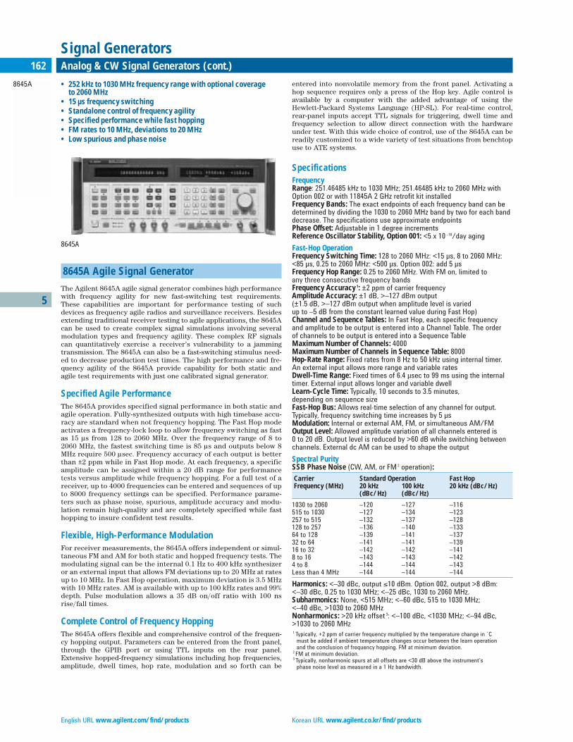
English URL www.agilent.com/find/products Korean URL www.agilent.co.kr/find/products
5
8645A
162 Analog & CW Signal Generators (cont.)
Signal Generators
8645A Agile Signal Generator
The Agilent 8645A agile signal generator combines high performancewith frequency agility for new fast-switching test requirements.These capabilities are important for performance testing of suchdevices as frequency agile radios and surveillance receivers. Besidesextending traditional receiver testing to agile applications, the 8645Acan be used to create complex signal simulations involving severalmodulation types and frequency agility. These complex RF signalscan quantitatively exercise a receiver’s vulnerability to a jammingtransmission. The 8645A can also be a fast-switching stimulus need-ed to decrease production test times. The high performance and fre-quency agility of the 8645A provide capability for both static andagile test requirements with just one calibrated signal generator.
Specified Agile PerformanceThe 8645A provides specified signal performance in both static andagile operation. Fully-synthesized outputs with high timebase accu-racy are standard when not frequency hopping. The Fast Hop modeactivates a frequency-lock loop to allow frequency switching as fastas 15 µs from 128 to 2060 MHz. Over the frequency range of 8 to2060 MHz, the fastest switching time is 85 µs and outputs below 8MHz require 500 µsec. Frequency accuracy of each output is betterthan ±2 ppm while in Fast Hop mode. At each frequency, a specificamplitude can be assigned within a 20 dB range for performancetests versus amplitude while frequency hopping. For a full test of areceiver, up to 4000 frequencies can be entered and sequences of upto 8000 frequency settings can be specified. Performance parame-ters such as phase noise, spurious, amplitude accuracy and modu-lation remain high-quality and are completely specified while fasthopping to insure confident test results.
Flexible, High-Performance ModulationFor receiver measurements, the 8645A offers independent or simul-taneous FM and AM for both static and hopped frequency tests. Themodulating signal can be the internal 0.1 Hz to 400 kHz synthesizeror an external input that allows FM deviations up to 20 MHz at ratesup to 10 MHz. In Fast Hop operation, maximum deviation is 3.5 MHzwith 10 MHz rates. AM is available with up to 100 kHz rates and 99%depth. Pulse modulation allows a 35 dB on/off ratio with 100 nsrise/fall times.
Complete Control of Frequency HoppingThe 8645A offers flexible and comprehensive control of the frequen-cy hopping output. Parameters can be entered from the front panel,through the GPIB port or using TTL inputs on the rear panel.Extensive hopped-frequency simulations including hop frequencies,amplitude, dwell times, hop rate, modulation and so forth can be
entered into nonvolatile memory from the front panel. Activating ahop sequence requires only a press of the Hop key. Agile control isavailable by a computer with the added advantage of using theHewlett-Packard Systems Language (HP-SL). For real-time control,rear-panel inputs accept TTL signals for triggering, dwell time andfrequency selection to allow direct connection with the hardwareunder test. With this wide choice of control, use of the 8645A can bereadily customized to a wide variety of test situations from benchtopuse to ATE systems.
SpecificationsFrequencyRange: 251.46485 kHz to 1030 MHz; 251.46485 kHz to 2060 MHz with Option 002 or with 11845A 2 GHz retrofit kit installedFrequency Bands: The exact endpoints of each frequency band can bedetermined by dividing the 1030 to 2060 MHz band by two for each banddecrease. The specifications use approximate endpointsPhase Offset: Adjustable in 1 degree incrementsReference Oscillator Stability, Option 001: <5 x 10 –10/day aging
Fast-Hop OperationFrequency Switching Time: 128 to 2060 MHz: <15 µs, 8 to 2060 MHz: <85 µs, 0.25 to 2060 MHz: <500 µs. Option 002: add 5 µsFrequency Hop Range: 0.25 to 2060 MHz. With FM on, limited to any three consecutive frequency bandsFrequency Accuracy 1: ±2 ppm of carrier frequencyAmplitude Accuracy: ±1 dB, >–127 dBm output (±1.5 dB, >–127 dBm output when amplitude level is varied up to –5 dB from the constant learned value during Fast Hop)Channel and Sequence Tables: In Fast Hop, each specific frequency and amplitude to be output is entered into a Channel Table. The order of channels to be output is entered into a Sequence TableMaximum Number of Channels: 4000Maximum Number of Channels in Sequence Table: 8000Hop-Rate Range: Fixed rates from 8 Hz to 50 kHz using internal timer. An external input allows more range and variable ratesDwell-Time Range: Fixed times of 6.4 µsec to 99 ms using the internaltimer. External input allows longer and variable dwellLearn-Cycle Time: Typically, 10 seconds to 3.5 minutes, depending on sequence sizeFast-Hop Bus: Allows real-time selection of any channel for output.Typically, frequency switching time increases by 5 µsModulation: Internal or external AM, FM, or simultaneous AM/FMOutput Level: Allowed amplitude variation of all channels entered is 0 to 20 dB. Output level is reduced by >60 dB while switching betweenchannels. External dc AM can be used to shape the output
Spectral PuritySSB Phase Noise (CW, AM, or FM 2 operation):
Carrier Standard Operation Fast HopFrequency (MHz) 20 kHz 100 kHz 20 kHz (dBc/Hz)
(dBc/Hz) (dBc/Hz)
1030 to 2060 –120 –127 –116515 to 1030 –127 –134 –123257 to 515 –132 –137 –128128 to 257 –136 –140 –13364 to 128 –139 –141 –13732 to 64 –141 –141 –13916 to 32 –142 –142 –1418 to 16 –143 –143 –1424 to 8 –144 –144 –143Less than 4 MHz –144 –144 –144
Harmonics: <–30 dBc, output ≤10 dBm. Option 002, output >8 dBm: <–30 dBc, 0.25 to 1030 MHz; <–25 dBc, 1030 to 2060 MHz.Subharmonics: None, <515 MHz; <–60 dBc, 515 to 1030 MHz; <–40 dBc, >1030 to 2060 MHzNonharmonics: >20 kHz offset 3: <–100 dBc, <1030 MHz; <–94 dBc,>1030 to 2060 MHz1 Typically, +2 ppm of carrier frequency multiplied by the temperature change in ˚C
must be added if ambient temperature changes occur between the learn operation and the conclusion of frequency hopping. FM at minimum deviation.
2 FM at minimum deviation.3 Typically, nonharmonic spurs at all offsets are <30 dB above the instrument’s
phase noise level as measured in a 1 Hz bandwidth.
• 252 kHz to 1030 MHz frequency range with optional coverage to 2060 MHz
• 15 µs frequency switching• Standalone control of frequency agility• Specified performance while fast hopping• FM rates to 10 MHz, deviations to 20 MHz• Low spurious and phase noise
8645A
Traditional Chinese URL www.agilent.com.tw/find/products Simplified Chinese URL www.agilent.com.cn/find/products
5
8645A
163Analog & CW Signal Generators (cont.)
Signal Generators
Residual AM: <0.01% AM rms, 0.3 to 3 kHz post detection BWTypical SSB AM Noise Floor, Offsets >100 kHz: <–157 dBc/Hz at +16 dBm output, 0.25 to 1030 MHz. <–150 dBc/Hz at +13 dBm output, 1030 to 2060 MHz
OutputMaximum Level: +16 dBm, 0.25 to 1030 MHz; Option 002: +14 dBm, 0.25 to 1030 MHz. +13 dBm, above 1030 MHz.Minimum Level: –137 dBmAbsolute Accuracy: ±1 dB, output ≥–127 dBmReverse Power Protection: 50 watts from a 50 Ω source, 25 VdcTypical Third Order Intermodulation: <– 50 dBc, outputs <8 dBmTypical Output Level Overrange: 2 dB more than maximum levelTypical SWR and Output Impedance: <1.7:1 at <– 2 dBm; 50 Ω
ModulationExternal Modulation Input: Coupling is ac or dc for AM, FM, and phasemodulation. Pulse modulation input is dc coupled. Displayed deviation or depth corresponds to ±1 V external input.Simultaneous Modulation: AM/FM, AM/Phase, AM/Pulse, FM/Pulse,Phase/Pulse, AM/FM/Pulse, AM/Phase/PulseSimultaneous Internal/External Modulation: FM and Phase
Amplitude ModulationDepth: 0 to 99.9%, for output <±7 dBmAM Indicator Accuracy: ±(6% of setting + 2%, AM), up to 90% depth and 1 kHz rate for carrier frequencies >1 MHz. When amplitude level is varied up to –5 dB from the constant learned value during Fast Hop: ±(7% of setting + 1% AM) up to 80% depth, 1 kHz rate
Distortion, at 400 Hz and 1 kHz Rates:
Carrier Frequency
Depth 0.25 to 1030 MHz 1030 to 2060 MHz
0 to 30% <2% <5% 30 to 70% <3% <5% 70 to 90% <5% <8%
3 dB Bandwidth 3: >5 kHz, 0.25 to 8 MHz. >50 kHz, 8 to 128 MHz; >100 kHz, 128 to 2060 MHzIncidental Phase Modulation: <0.2 rad peak, at 30% depth and 1 kHzTypical External Input Impedance: 600 Ω
Frequency ModulationFM Deviation and Rate: In the highest frequency band of 1030 to 2060MHz, the maximum FM peak deviation is 20 MHz for standard operationand 3.52 MHz for Fast Hop. Maximum FM rate (3 dB bandwidth) in the 515to 1030 MHz band and above is 10 MHz. Divide rate and deviation by twofor each frequency band decrease.
FM Indicator Accuracy: ±10%, <50 kHz rate and <10% of maximum deviation (<50% of maximum deviation in Fast Hop)FM Distortion: Rates 20 Hz to 100 kHz: <2.7%, deviation <2% of maximum available (Fast Hop: <10% of maximum deviation)Carrier Frequency Accuracy in FM: ±0.4% of deviation setting, ac- or dc-coupled. Typically add 1% of deviation in Fast HopIncidental AM: <0.5%, deviation limited to <6% of max. or 20 kHzTypical External FM Group Delay: 30 µs for rates 20 Hz to 20 kHz, decreases to <1 µs at rates >200 kHz. Fast Hop: <1 µsTypical External FM Input Impedance: 50 or 600 Ω
Pulse ModulationOn/Off Ratio: >35 dBRise/Fall Time: <100 ns, between 10% and 90% response pointsMaximum Pulse Repetition Frequency: 1 MHzMinimum Pulse Width: 0.5 µsTypical Output Level Accuracy: ±2 dBTypical External Input Levels and Impedance: On: >3.0 V peak; Off: <0.8 V peak. Damage level: ≥±10 V peak. 600 Ω.
Internal Modulation SourceWaveforms: Sine, square, sawtooth, and white Gaussian noiseFrequency Range: Sine, white Gaussian noise: 0.1 Hz to 400 kHz. Square, sawtooth: 0.1 Hz to 50 kHz.Frequency Accuracy: Same as internal reference oscillatorOutput Level: Typically, 1 V pk max. into 600 Ω. Accuracy: ±20 mV.Output Level Resolution: 2 mV. Typical impedance: 600 Ω.Distortion: <0.1%, output at 1 V peak and ≤15 kHz
Frequency SweepPhase Continuous Sweep: Linear sweep with times from 10 ms to10 s, not dependent on span. Maximum span is 40 MHz from 1030 to 2060 MHzfrequency band, divided by two for each band decrease.Fast Hop Sweep: Linear or log stepped with times from 10 ms to 100 s.Number of steps varies with time selected. Typical time per step is 30 µs for outputs within 128 to 2060 MHz, 170 µs for 8 to 2060 MHz, and 650 µs for 0.25 to 2060 MHz.Sweep Control and Markers: X-axis: 0 to +10 V. Z-axis: +5 V retrace, +1 V trace, 0 V markers. Three markers available.
GeneralRemote Control: GPIB (IEEE-488.2-1987). The control language used is theHewlett-Packard Systems Language (HP-SL). All front-panel functionsexcept power switch and knob. A unique Fast Hop bus interface acceptsTTL levels for frequency agile control.Operating Temperature Range: 0˚F to +55˚FLeakage: Meets MIL-STD-461B-RE02 and FTZ 1046Storage Registers: 10 full function and 40 freq./ampl. locationsMemory Erasure: All memory contents according to MIL-STD-380-380Size: 177 mm H x 426 mm W x 624 mm D (7 in x 16.8 in x 24.6 in)Weight: Net, 31 kg (69 lb); shipping, 42 kg (95 lb)
Key Literature8645A Agile Signal Generator Data Sheet, p/n 5953-8498E8645-1 Communications-Agile Operation of the 8645A Product Note, p/n 5951-6711
Ordering Information8645A Agile Signal Generator
8645A-001 High-Stability Timebase 8645A-002 2 GHz Output 8645A-003 RF Connectors on Rear Panel Only 8645A-907 Front Handle Kit (5062-3990) 8645A-908 Rack Flange Kit (5062-3978) 8645A-909 Rack Flange Kit with Front Handles (5062-3984)8645A-910 Provides an additional operation/calibration manual (08645-90023) and 2 service manuals8645A-915 Add Service Manual (08645-90104)
1 Specified for 48 to 63 Hz power line. Typical for 400 Hz power line and Fast Hop operation.2 Deviation <0.1% of maximum available.3 Lower 3 dB bandwidth limit is 0 Hz for dc coupling and typically 20 Hz for ac coupling.
Residual FM 1 (CW, AM, FM 2 operation):
Post Detection Bandwidth
Carrier 0.3 to 3 kHz 0.05 to 15 kHzFrequency (MHz) (Hz rms) (Hz rms)
0.25 to 257 <1 <1.2 257 to 515 <1.2 <2 515 to 1030 <2 <4 1030 to 2060 <4 <8
Typical SSB Phase Noise and Spurs at 1 GHz:
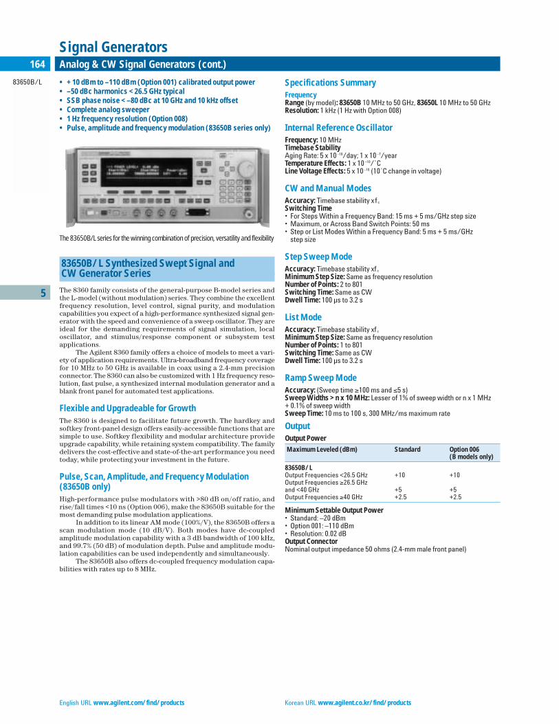
English URL www.agilent.com/find/products Korean URL www.agilent.co.kr/find/products
5
83650B/L
164 Analog & CW Signal Generators (cont.)
Signal Generators
• +10 dBm to –110 dBm (Option 001) calibrated output power• –50 dBc harmonics <26.5 GHz typical• SSB phase noise <–80 dBc at 10 GHz and 10 kHz offset• Complete analog sweeper• 1 Hz frequency resolution (Option 008)• Pulse, amplitude and frequency modulation (83650B series only)
83650B/L Synthesized Swept Signal and CW Generator Series
The 8360 family consists of the general-purpose B-model series andthe L-model (without modulation) series. They combine the excellentfrequency resolution, level control, signal purity, and modulationcapabilities you expect of a high-performance synthesized signal gen-erator with the speed and convenience of a sweep oscillator. They areideal for the demanding requirements of signal simulation, localoscillator, and stimulus/response component or subsystem testapplications.
The Agilent 8360 family offers a choice of models to meet a vari-ety of application requirements. Ultra-broadband frequency coveragefor 10 MHz to 50 GHz is available in coax using a 2.4-mm precisionconnector. The 8360 can also be customized with 1 Hz frequency reso-lution, fast pulse, a synthesized internal modulation generator and ablank front panel for automated test applications.
Flexible and Upgradeable for GrowthThe 8360 is designed to facilitate future growth. The hardkey andsoftkey front-panel design offers easily-accessible functions that aresimple to use. Softkey flexibility and modular architecture provideupgrade capability, while retaining system compatibility. The familydelivers the cost-effective and state-of-the-art performance you needtoday, while protecting your investment in the future.
Pulse, Scan, Amplitude, and Frequency Modulation (83650B only)High-performance pulse modulators with >80 dB on/off ratio, andrise/fall times <10 ns (Option 006), make the 83650B suitable for themost demanding pulse modulation applications.
In addition to its linear AM mode (100%/V), the 83650B offers ascan modulation mode (10 dB/V). Both modes have dc-coupledamplitude modulation capability with a 3 dB bandwidth of 100 kHz,and 99.7% (50 dB) of modulation depth. Pulse and amplitude modu-lation capabilities can be used independently and simultaneously.
The 83650B also offers dc-coupled frequency modulation capa-bilities with rates up to 8 MHz.
Specifications SummaryFrequencyRange (by model): 83650B 10 MHz to 50 GHz, 83650L 10 MHz to 50 GHzResolution: 1 kHz (1 Hz with Option 008)
Internal Reference OscillatorFrequency: 10 MHzTimebase StabilityAging Rate: 5 x 10 –10/day; 1 x 10 –7/yearTemperature Effects: 1 x 10 –10/˚CLine Voltage Effects: 5 x 10 –10 (10˚C change in voltage)
CW and Manual ModesAccuracy: Timebase stability xf c
Switching Time• For Steps Within a Frequency Band: 15 ms + 5 ms/GHz step size• Maximum, or Across Band Switch Points: 50 ms• Step or List Modes Within a Frequency Band: 5 ms + 5 ms/GHz
step size
Step Sweep ModeAccuracy: Timebase stability xf c
Minimum Step Size: Same as frequency resolutionNumber of Points: 2 to 801Switching Time: Same as CWDwell Time: 100 µs to 3.2 s
List ModeAccuracy: Timebase stability xf c
Minimum Step Size: Same as frequency resolutionNumber of Points: 1 to 801Switching Time: Same as CWDwell Time: 100 µs to 3.2 s
Ramp Sweep ModeAccuracy: (Sweep time ≥100 ms and ≤5 s)Sweep Widths >n x 10 MHz: Lesser of 1% of sweep width or n x 1 MHz + 0.1% of sweep widthSweep Time: 10 ms to 100 s, 300 MHz/ms maximum rate
OutputOutput Power
Maximum Leveled (dBm) Standard Option 006(B models only)
83650B/LOutput Frequencies <26.5 GHz +10 +10Output Frequencies ≥26.5 GHzand <40 GHz +5 +5Output Frequencies ≥40 GHz +2.5 +2.5
Minimum Settable Output Power• Standard: –20 dBm• Option 001: –110 dBm• Resolution: 0.02 dBOutput ConnectorNominal output impedance 50 ohms (2.4-mm male front panel)
The 83650B/L series for the winning combination of precision, versatility and flexibility

Traditional Chinese URL www.agilent.com.tw/find/products Simplified Chinese URL www.agilent.com.cn/find/products
5
83650B/L
165Analog & CW Signal Generators (cont.)
Signal Generators
Spectral PuritySpurious Signals (dBc)
Output Frequencies 83650B/L
Harmonics<2.0 GHzStandard –30 1
Option 006 –30 1
≥2.0 GHz and<26.5 GHzStandard –50Option 006 –50≥26.5 GHzStandard –40Option 006 –40
Subharmonics<7 GHz None≥7 and ≤20 GHz –50≥20 GHz and≤40 GHz –40 2
>40 GHz –35 2
Nonharmonically Related10 MHz to <2.0 GHz 3: –60≥2.0 to <20 GHz: –60>20 GHz to ≤26.5 GHz: –58>26.5 to ≤40 GHz: –54≥40 GHz to ≤50 GHz: –52
Single-Sideband Phase Noise (dBc/Hz)
Offset from Carrier
Frequency Range 100 Hz 1 kHz 10 kHz 100 kHz
10 MHz to <7 GHz – 70 – 78 – 86 –1077 GHz to <13.5 GHz – 64 – 72 – 80 –10113.5 GHz to 20 GHz – 60 – 68 – 76 – 97>20 GHz to <26.5 GHz – 58 – 66 – 74 – 9526.5 GHz to <38 GHz – 54 – 62 – 70 – 9138 GHz to 50 GHz – 52 – 60 – 68 – 89
Modulation (83650B only)All modulation specifications are only applicable to the 83650B. Pulsemodulation specifications apply for output frequencies 400 MHz and above.
Pulse (83650B only) Standard Option 006
On/Off Ratio 80 dB 80 dBRise/Fall Times 25 ns 10 nsMinimum WidthInternally Leveled 1 µs 1 µsSearch ModeOutput Frequencies <2.0 GHz 50 ns 50 nsOutput Frequencies ≥2.0 GHz 50 ns 15 nsALC Off ModeOutput Frequencies <2.0 GHz 50 ns 50 nsOutput Frequencies ≥2.0 GHz 50 ns 15 ns
AM and Scan (83650B only)Bandwidth (3 dB, 30% depth, modulation peaks 3 dB below maximumrated power): dc to 100 kHzModulation Depth• Normal Mode: –20 dBm to maximum available power• Deep Mode: 50 dB below maximum available powerSensitivity• Linear: 100%/volt• Exponential: 10 dB/volt
FM (83650B only)Locked Mode• Maximum Deviation: ±8 MHz• Rates (3 dB bandwidth, 500 kHz deviation): 100 kHz to 8 MHz
Unlocked ModeMaximum Deviation• At rates ≤100 Hz: ±75 MHz• At rates >100 Hz: ±8 MHzRates (3 dB bandwidth, 500 kHz deviation): dc to 8 MHzSensitivity: 100 kHz, 1 MHz, or 10 MHz/volt, switchableAccuracy (1 MHz rate, 1 MHz deviation): 10%
Internal Modulation Generator (Option 002)AM, FM Modulation Signals (83650B only)Internal Waveforms: Sine, square, triangle, ramp, noise
RateRange:• Sine: 1 Hz to 1 MHz• Square, triangle, ramp: 1 Hz to 100 kHzResolution: 1 Hz
Depth, deviationRange: Same as the base instrumentResolution: 0.1%Accuracy: Same as the base instrument
Pulse (83650B only)Modes: Free-run, gated, triggered, delayedPeriod Range: 300 ns to 400 msWidth Range: 25 ns to 400 msResolution: 25 nsAccuracy: 5 ns
Video DelayInternal Sync Pulse: 0 to 400 msExternally-supplied Sync Pulse: 225 ns to 400 ms
Weight and DimensionsNet Weight: 27 kg (60 lb)Dimensions: 178 mm H x 425 mm W x 648 mm D (7.0 in x 16.75 in x 25.5 in)
Key LiteratureBrochure, p/n 5964-6793E Technical Specifications, p/n 5964-6162E Configuration Guide, p/n 5964-6062E
Ordering Information83650B 10 MHz to 50 GHz83650L 10 MHz to 50 GHzThe following options apply to all models:
Option 001 Adds Step AttenuatorOption 002 Adds Internal Modulation Generator (83650B only)Option 004 Rear-Panel RF OutputOption 006 Fast-Pulse Modulation (83650B only)Option 008 1 Hz Frequency Resolution Option 700 MATE System CompatibilityOption 806 Rack Slide Kit Option 908 Rack Flange KitOption 910 Extra Operating and Service ManualsOption 913 Rack Flange Kit
UpgradesModel and frequency upgrades are available. Please contact your Agilent sales representative for details.Dedicated 8510 System Source Models 4
83621B 45 MHz to 20 GHz83631B 45 MHz to 26.5 GHz83651B 45 MHz to 50 GHz1 Specification is –20 dBc below 50 MHz.2 Specifications typical below 0 dBm.3 Specification applies at output levels 0 dBm and below.4 No modulation, no front panel.

English URL www.agilent.com/find/products Korean URL www.agilent.co.kr/find/products
5
83554A83555A83556A83557A83558A
166 Millimeter-Wave Source Modules
Signal Generators
83550 Series Millimeter-Wave Source Modules
The five 83550 series millimeter-wave source modules provide a simple approach to extend the frequency range of 11 to 20 GHzsources to cover 26.5 to 40 GHz (83554A), 33 to 50 GHz (83555A), 40 to60 GHz (83556A), 50 to 75 GHz (83557A) and 75 to 110 GHz (83558A)bands. The 83550 series source modules offer leveled high outputpower, full waveguide band frequency coverage and the high-frequen-cy accuracy and resolution of the driving microwave source.
High-Output PowerLeveled-output power from the source modules is rated at +9 dBmfor the 83554A, +3 dBm for the 83555A, +3 dBm for the 83556A, +3 dBm for the 83557A, and 0 dBm for the 83558A. This high-outputpower can permit the source module to serve as a mixer LO in someapplications and also expands the available dynamic range in frequency response measurements.
83554Amm-Wave 26.5 to 40 GHzSource Module
83555Amm-Wave 33 to 50 GHzSource Module
83556AE8247C/57C-1EA mm-Wave 40 to 60 GHz
Source Module
83557Amm-Wave 50 to 75 GHzSource Module
83558Amm-Wave 75 to 110 GHzSource Module
All at a Lower CostThe 83550 series source modules combine performance and qualitywith a low cost of entry. This is possible because the source modulesare backward-compatible with existing Agilent microwave sources.Thus you can generate a full waveguide band of millimeter-wave fre-quencies for just the cost of a source module. Also, the cost of own-ership is reduced even further by the two-year warranty on themicrocircuits of the 83550 series source modules.
General SpecificationsWaveguide Output Connector83554A: EIA size WR 28 waveguide; JAN UG-599 flange83555A: EIA size WR 22 waveguide; JAN UG-383 flange83556A: EIA size WR 19 waveguide; JAN UG-383 (mod.) flange83557A: EIA Size WR 15 waveguide; JAN UG-385 flange83558A: EIA Size WR 10 waveguide; JAN UG-387 flangeWeight: Net, 1.7 kg (4 lb)Size: Module, 80 mm H x 80 mm W x 210 mm D (3.15 in x 3.15 in x 8.27 in)Furnished with Each Source Module: Operating and Service Manual,Modification Procedures for 0.5 V/GHz Output, Type-N RF Cable, ModuleBase Assembly, Synthesizer Interface Cable
Key Literature83557A/83558A Data Sheet, p/n 5958-039883554A/83555A/83556A, MM-Wave Source Modules Data Sheet, p/n 5954-8364D
www.agilent.com/find/signalgenerator
Ordering Information83554A 26.5 to 40.0 GHz mm-Wave Source Module 83555A 33.0 to 50.0 GHz mm-Wave Source Module 83556A 40.0 to 60.0 GHz mm-Wave Source Module 83557A 50.0 to 75.0 GHz mm-Wave Source Module 83558A 75.0 to 110.0 GHz mm-Wave Source Module
• 26.5 to 110 GHz frequency range • Leveled high output power • Can be driven by many Agilent microwave sources • Source module remotable up to one meter length • Low entry cost
83558A mm-wave source module. 75 GHz to 110 GHz
83550 Series Millimeter-Wave Source Modules
Agilent PSG Signal Generators 83554A 83555A 83556A 83557A 83558A
Frequency CharacteristicsRange 26.5 – 40 GHz 33 – 50 GHz 40 – 60 GHz 50 – 75 GHz 75 – 110 GHzMaximum leveled power 9 dBm 3 dBm 3 dBm 3 dBm 0 dBmPower level accuracy at 0dBm ±2.0 dB ±2.0 dB ±2.0 dB ±2.0 dB ±2.0 dBPower flatness (maximum leveled power) ±1.5 dB ±1.5 dB ±1.5 dB ±2.0 dB ±2.0 dB
Source Output SWRLeveled ≤2.0 dB ≤2.0 dB ≤2.0 dB ≤2.0 dB ≤2.0 dB
External Pulse ModulationRise/fall time (typical) 40 ns 40 ns 50 ns 50 ns 50 ns
Minimum RF Pulse Width(typical) 500 ns 500 ns 500 ns 1 us 1 usOn/off ratio (typical) >80 dB >80 dB >80 dB >80 dB >80 dB
Pulse Repetition FrequencyLeveled (typical) 100 Hz – 500 kHz 100 Hz – 500 kHz 100 Hz – 500 kHz 100 Hz – 500 kHz 100 Hz – 500 kHzUnleveled (typical) 100 Hz – 5 MHz 100 Hz – 5 MHz 100 Hz – 5 MHz 100 Hz – 5 MHz 100 Hz – 5 MHz
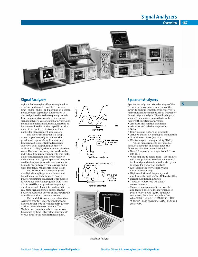
Traditional Chinese URL www.agilent.com.tw/find/products Simplified Chinese URL www.agilent.com.cn/find/products
167Overview
Signal Analyzers
5Signal AnalyzersAgilent Technologies offers a complete lineof signal analyzers to provide frequency-, time-, order-, angle-, and modulation-domainmeasurement capability. This section isdevoted primarily to the frequency domain.It includes spectrum analyzers, dynamic signal analyzers, vector signal analyzers, andmodulation domain analyzers. Each type ofinstrument has distinctive capabilities thatmake it the preferred instrument for a particular measurement application.
The spectrum analyzer is a swept-tuned, super heterodyne receiver that provides a display of amplitude versus frequency. It is essentially a frequency-selective, peak-responding voltmeter calibrated to display the rms value of a sinewave. The spectrum analyzer can show theindividual frequency components that makeup a complex signal. The swept receiver technique used in Agilent spectrum analyzersenables frequency-domain measurements tobe made over a large dynamic range and awide frequency range (3 Hz to 325 GHz).
The Fourier and vector analyzers use digital sampling and mathematicaltransformation techniques to form aFourier spectrum of a signal. This method is useful for measuring signals from a fewµHz to >6 GHz, and provides frequency, amplitude, and phase information. With itsreal-time signal analysis capability, theFourier analyzer is able to capture periodicas well as random transient events.
The modulation analyzer is based onAgilent’s counter/timer technology andoffers another way of looking at frequencyor time interval measurements. TheModulation Domain analyzer shows you frequency or time-interval measurementsversus time in the Modulation Domain.
Spectrum AnalyzersSpectrum analyzers take advantage of thefrequency-conversion properties of theswept-tuned super heterodyne receiver tomake significant contributions to frequency-domain signal analysis. The following aresome of the measurements that can bemade with spectrum analyzers:• Absolute and relative frequency• Absolute and relative amplitude• Noise• Spurious and distortion products• AM, FM, pulsed RF and digital modulation• Stimulus-response (scalar)• Electromagnetic compatibility (EMC)
These measurements are possiblebecause spectrum analyzers have the following characteristics available:• Broad frequency coverage from 3 Hz to
325 GHz• Wide amplitude range from –168 dBm to
+30 dBm provides excellent sensitivityfor low signal detection and wide dynam-ic range for distortion analysis
• Excellent frequency stability and amplitude accuracy
• High resolution of frequency and amplitude through digital IF bandwidths
• Digital modulation analysis • Tracking generators for scalar
measurements• Measurement personalities provide
application specific measurements ofphase noise, noise figure, spuriousresponses, fault location, cdmaOne,cdma2000, 1xEV-DO, GSM/GPRS/EDGE,W-CDMA, EVM analysis, NADC, PDC andBluetooth.
Modulation Analyzer
Overview
168 Overview (cont.)
Signal Analyzers
These capabilities allow spectrum analyzers to provide frequency-domain signal analysis for numerous applications,including the manufacture and maintenanceof digital wireless equipment, microwavecommunication links, radar, telecommunica-tions equipment, CATV systems and broad-cast equipment, mobile communication systems, EMI diagnostic testing, componenttesting, lightwave measurements and signalsurveillance.
In addition to the swept-tuned frequency mode, spectrum analyzers canalso be used in the fixed-tuned mode (zerospan) to provide time-domain measurementcapability much like that of an oscilloscope.
With the addition of computers, thecapability of spectrum analyzers can begreatly enhanced. Computers can be usedto directly control the operation of spectrum analyzers over GPIB or LAN.
Application areas that require accurate,high-speed, repetitive measurements, physical separation of the operator and theanalyzer, unattended operation or operationby personnel with limited technical skillsare all candidates for automation.
Areas that benefit significantly fromautomated spectrum analysis include:• EMC testing• Frequency spectrum monitoring• Production testing of RF or microwave
components, subsystems, or systems• Remote-site testing
The basic measurement capabilities of the spectrum analyzer, combined withits ability to automate and interface withother GPIB instruments and peripherals,make this instrument ideal for many general-purpose and specialized applications.
EMC AnalyzersBased on a spectrum analyzer platform, the E7400A series of EMI/EMC analyzers provide the functionality required for pre-compliance EMI measurements to 26.5 GHzfor conducted and radiated emissions.Quasi-peak detectors and compliance basedEMI bandwidths along with a suite of built-inEMI measurements facilitate the evaluation
of EMI performance on products duringtheir development phase. Troubleshootingdesigns is enhanced through the E7400Aspectrum analyzer functionality along with accessories like the 11940A/11941Aclose-field probes.
Dynamic Signal (Fourier)AnalyzersFourier analyzers offer fast, high-resolutionspectrum and network analysis. Unlike conventional swept analyzers, Fourier-basedanalyzers can measure dynamic signalsbecause they measure all frequencies simultaneously, not one at a time.
Fourier analyzers characterize signalsusing digital signal-processing techniquesbased on the Discrete Fourier Transform.For a complete description of these techniques, see Application Note 243, The Fundamentals of Signal Analysis.
Fourier analyzers are especially usefulon low-frequency signals (<100 kHz) orwhere very fast measurements are desired.They can improve measurement speed froma factor of 10 to 100, and allow accuratemeasurements on frequencies as low as a few µHz. Signal components as closelyspaced as 20 µHz can be clearly resolvedand accurately measured.
Since both the magnitude and phase ofeach frequency component are measured,the Fourier analyzer can measure the statistical properties of signals, or the jointproperties or relationships of two or moresignals. Applications include acoustic,modal, vibration, or rotating machine analysis. In addition, various types of modulation can be detected and measured.
Simultaneous measurement of magnitude and phase on two or more channels provides high-quality network measurements. Transfer functions or frequency response can be easily measured,and the use of band-limited or band-translated random noise as the stimulusallows the entire frequency span of interest tobe measured at once. Measurement of the coherence function can provide an indicationof the validity of many network measurements.
Vector Signal AnalyzersVector signal analyzers extend the capabili-ties available in a spectrum analyzer.Though similar to Fourier analyzers, vectorsignal analyzers provide capabilitiesthroughout the RF range, offering fast, high-resolution spectrum measurements,demodulation, and advanced time-domainanalysis. They are especially useful forcharacterizing complex signals such asburst, transient, or modulated signals usedin communications, video, broadcast, sonar,and ultrasound imaging applications.
The vector signal analyzer is also capa-ble of in-depth modulation analysis. Since itcaptures signal phase along with magnitudeit is particularly well suited to analyzing digitally modulated signals. This capabilityis available in several forms. It can be ingeneral-purpose flexible demodulation suited to demodulating a wide range of modulation signal types. It can be in wirelesscommunication standards based tests alongwith additional diagnostic capabilities. And, it can be in pass/fail testing to a communication standard. Vector signal analyzers are especially useful when abroad range of measurements are required,for example in the development of digitalcommunication systems.
Modulation Domain AnalyzersModulation-domain analyzers represent an extension of Agilent’s counter/timertechnology. They provide helpful views ofthe frequency, phase, or timing of a signalversus time. They also provide histogramsand statistical analyzes, making it easy toquickly analyze measurement data.Modulation-domain analyzers allow you todirectly view frequency switching and settling of VCOs, PLLs and synthesizers.They also make it easy to analyze complexphase and frequency modulations found incommunications systems.
5
English URL www.agilent.com/find/products Korean URL www.agilent.co.kr/find/products
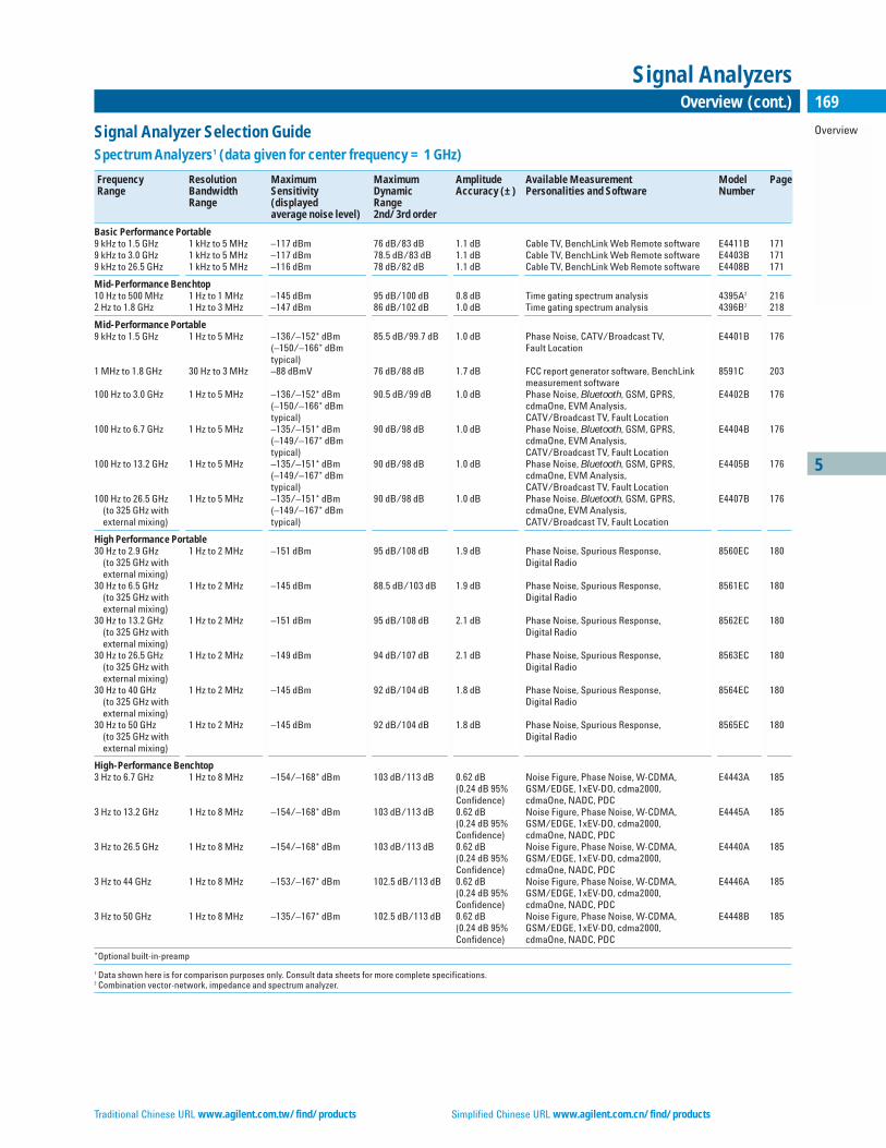
Traditional Chinese URL www.agilent.com.tw/find/products Simplified Chinese URL www.agilent.com.cn/find/products
Overview
169Overview (cont.)
Signal Analyzers
5
Signal Analyzer Selection GuideSpectrum Analyzers1 (data given for center frequency = 1 GHz)
Frequency Resolution Maximum Maximum Amplitude Available Measurement Model PageRange Bandwidth Sensitivity Dynamic Accuracy (±) Personalities and Software Number
Range (displayed Rangeaverage noise level) 2nd/3rd order
Basic Performance Portable9 kHz to 1.5 GHz 1 kHz to 5 MHz –117 dBm 76 dB/83 dB 1.1 dB Cable TV, BenchLink Web Remote software E4411B 1719 kHz to 3.0 GHz 1 kHz to 5 MHz –117 dBm 78.5 dB/83 dB 1.1 dB Cable TV, BenchLink Web Remote software E4403B 1719 kHz to 26.5 GHz 1 kHz to 5 MHz –116 dBm 78 dB/82 dB 1.1 dB Cable TV, BenchLink Web Remote software E4408B 171
Mid-Performance Benchtop10 Hz to 500 MHz 1 Hz to 1 MHz –145 dBm 95 dB/100 dB 0.8 dB Time gating spectrum analysis 4395A2 2162 Hz to 1.8 GHz 1 Hz to 3 MHz –147 dBm 86 dB/102 dB 1.0 dB Time gating spectrum analysis 4396B2 218
Mid-Performance Portable9 kHz to 1.5 GHz 1 Hz to 5 MHz –136/–152* dBm 85.5 dB/99.7 dB 1.0 dB Phase Noise, CATV/Broadcast TV, E4401B 176
(–150/–166* dBm Fault Locationtypical)
1 MHz to 1.8 GHz 30 Hz to 3 MHz –88 dBmV 76 dB/88 dB 1.7 dB FCC report generator software, BenchLink 8591C 203measurement software
100 Hz to 3.0 GHz 1 Hz to 5 MHz –136/–152* dBm 90.5 dB/99 dB 1.0 dB Phase Noise, Bluetooth, GSM, GPRS, E4402B 176(–150/–166* dBm cdmaOne, EVM Analysis,typical) CATV/Broadcast TV, Fault Location
100 Hz to 6.7 GHz 1 Hz to 5 MHz –135/–151* dBm 90 dB/98 dB 1.0 dB Phase Noise, Bluetooth, GSM, GPRS, E4404B 176(–149/–167* dBm cdmaOne, EVM Analysis,typical) CATV/Broadcast TV, Fault Location
100 Hz to 13.2 GHz 1 Hz to 5 MHz –135/–151* dBm 90 dB/98 dB 1.0 dB Phase Noise, Bluetooth, GSM, GPRS, E4405B 176(–149/–167* dBm cdmaOne, EVM Analysis,typical) CATV/Broadcast TV, Fault Location
100 Hz to 26.5 GHz 1 Hz to 5 MHz –135/–151* dBm 90 dB/98 dB 1.0 dB Phase Noise, Bluetooth, GSM, GPRS, E4407B 176(to 325 GHz with (–149/–167* dBm cdmaOne, EVM Analysis,external mixing) typical) CATV/Broadcast TV, Fault Location
High Performance Portable30 Hz to 2.9 GHz 1 Hz to 2 MHz –151 dBm 95 dB/108 dB 1.9 dB Phase Noise, Spurious Response, 8560EC 180
(to 325 GHz with Digital Radioexternal mixing)
30 Hz to 6.5 GHz 1 Hz to 2 MHz –145 dBm 88.5 dB/103 dB 1.9 dB Phase Noise, Spurious Response, 8561EC 180(to 325 GHz with Digital Radioexternal mixing)
30 Hz to 13.2 GHz 1 Hz to 2 MHz –151 dBm 95 dB/108 dB 2.1 dB Phase Noise, Spurious Response, 8562EC 180(to 325 GHz with Digital Radioexternal mixing)
30 Hz to 26.5 GHz 1 Hz to 2 MHz –149 dBm 94 dB/107 dB 2.1 dB Phase Noise, Spurious Response, 8563EC 180(to 325 GHz with Digital Radioexternal mixing)
30 Hz to 40 GHz 1 Hz to 2 MHz –145 dBm 92 dB/104 dB 1.8 dB Phase Noise, Spurious Response, 8564EC 180(to 325 GHz with Digital Radioexternal mixing)
30 Hz to 50 GHz 1 Hz to 2 MHz –145 dBm 92 dB/104 dB 1.8 dB Phase Noise, Spurious Response, 8565EC 180(to 325 GHz with Digital Radioexternal mixing)
High-Performance Benchtop3 Hz to 6.7 GHz 1 Hz to 8 MHz –154/–168* dBm 103 dB/113 dB 0.62 dB Noise Figure, Phase Noise, W-CDMA, E4443A 185
(0.24 dB 95% GSM/EDGE, 1xEV-DO, cdma2000,Confidence) cdmaOne, NADC, PDC
3 Hz to 13.2 GHz 1 Hz to 8 MHz –154/–168* dBm 103 dB/113 dB 0.62 dB Noise Figure, Phase Noise, W-CDMA, E4445A 185(0.24 dB 95% GSM/EDGE, 1xEV-DO, cdma2000,Confidence) cdmaOne, NADC, PDC
3 Hz to 26.5 GHz 1 Hz to 8 MHz –154/–168* dBm 103 dB/113 dB 0.62 dB Noise Figure, Phase Noise, W-CDMA, E4440A 185(0.24 dB 95% GSM/EDGE, 1xEV-DO, cdma2000,Confidence) cdmaOne, NADC, PDC
3 Hz to 44 GHz 1 Hz to 8 MHz –153/–167* dBm 102.5 dB/113 dB 0.62 dB Noise Figure, Phase Noise, W-CDMA, E4446A 185(0.24 dB 95% GSM/EDGE, 1xEV-DO, cdma2000,Confidence) cdmaOne, NADC, PDC
3 Hz to 50 GHz 1 Hz to 8 MHz –135/–167* dBm 102.5 dB/113 dB 0.62 dB Noise Figure, Phase Noise, W-CDMA, E4448B 185(0.24 dB 95% GSM/EDGE, 1xEV-DO, cdma2000,Confidence) cdmaOne, NADC, PDC
*Optional built-in-preamp
1 Data shown here is for comparison purposes only. Consult data sheets for more complete specifications. 2 Combination vector-network, impedance and spectrum analyzer.

English URL www.agilent.com/find/products Korean URL www.agilent.co.kr/find/products
5
Overview
170 Overview (cont.)
Signal Analyzers
Dynamic Signal Analyzers
Frequency Range Channel Frequency Real-time Dynamic Range Amplitude Model PageMatch Resolution in Lines Bandwidth Accuracy* (±) Number
0.000122 Hz to 102.4 kHz ±0.04 dB, ±0.5˚ 100 to 1600 25.6 kHz 80 dB (90 dB typical) 0.15 dB 35670A 344
*Relative accuracy = relative frequency response + lesser of either scale fidelity or IF gain accuracy.
Vector Signal Analyzers
Frequency Range Maximum Sensitivity Dynamic Modulation Analysis Signal Model PageAnalysis (displayed Range Capture NumberBandwidth average noise level) (3rd order IMD) Memory
7 MHz to 4 GHz 10 MHz –136 dBm/Hz –68 dBc 9 standards-based measurement personalities Not applicable E4406A 192(at 1 GHz) (W-CDMA ACPR) personalities with setups, tests and pass/fail
limits for digital wireless communications
3 Hz to 50 GHz* Up to 6.0 GHz* –168 dBm/Hz* –70 dBc* PC software linked to ESA,PSA, E4406A Up to 1.2 GB 89601A 195(at 1 GHz) analyzers or Infiniium series oscilloscopes. (384 Msa,
Flexible, in-depth digital demodulation complex)(24 demodulators) and 25 wireless format-based measurement setups.
dc to 40 MHz 39 MHz –151 dBm/Hz –70 dBc** Flexible, in-depth digital demodulation Up to 1.2 GB 89610A 195(24 demodulators) and 25 wireless format- (384 Msa, based measurement setups complex)
52 to 88 MHz 36 MHz –159 dBm/Hz –70 dBc** Flexible, in-depth digital demodulation Up to 1.2 GB 89611A 195(or frequency range (24 demodulators) and 25 wireless format- (384 Msa, of external tuner) based measurement setups complex)
dc to 2.7 GHz 36 MHz –158 dBm/Hz –70 dBc** Flexible, in-depth digital demodulation Up to 1.2 GB 89640A 195(at 1 GHz) (24 demodulators) and 25 wireless format- (384 Msa,
based measurement setups complex)
dc to 6 GHz 36 MHz –157 dBm/Hz –70 dBc** Flexible, in-depth digital demodulation Up to 1.2 GB 89641A 195(at 1 GHz) (24 demodulators) and 25 wireless format- (384 Msa,
based measurement setups complex)
dc to 10 MHz 10 MHz –144 dBm/Hz –75 dBc** Flexible, in-depth digital demodulation Up to 1 Msa 89410A 197(13 demodulators) and >8 wireless format- (complex) based measurement setups
dc to 2.65 GHz 8 MHz –159 dBm/Hz –75 dBc** Flexible, in-depth digital demodulation Up to 1 Msa 89441A 197(13 demodulators) and >8 wireless format- (complex) based measurement setups
dc to 2.65 GHz 8 MHz –159 dBm/Hz –75 dBc** Flexible, in-depth digital demodulation Up to 1 Msa 89441V 197(8 demodulators) and >5 video format-based (complex) measurement setups
*Depends on analyzers or oscilloscopes linked to 89601A PC software.**2 tones at 6 dB below full scale (–31 dBm at input)
Modulation Domain Analyzers
Frequency Resolution Sample Memory Analysis and Displays Model PageRange freq./time Rate Size Number
10 Hz to 200 MHz 10 digits/200 ps 2.5 M 8 K Frequency and time interval vs. time, histograms, 53310A 68(2.5 GHz option) (8 M rep.) (32 K option) statistics (digital RF communications option)
VCO/PPL Signal Test System
Frequency Maximum Sensitivity Functions Available Model PageRange (depends on offset frequency) Number
10 MHz to 12.6 GHz –147 dBc/Hz @ offset freq. 100 kHz to 10 MHz Frequency, power level, C/N ratio (phase noise), 4352S VCO/PLL 269(as phase noise measurement performance) FM deviation and dc consumption current Signal Test System
EMI/EMC Analyzers
Frequency Maximum Maximum Amplitude Resolution Bandwidth Range Model PageRange Sensitivity Dynamic Accuracy (±) Number
(displayed average Rangenoise level) 3rd order
9 kHz to 1.5 GHz ≤–150 dBm +13.5 dBm TOI 1.0 dB 1 Hz2 to 5 MHz (including 200 Hz, 9 kHz, 120 kHz, 1 MHz EMI BW) E7401A 200
100 Hz1 to 3.0 GHz ≤–150 dBm +12.5 dBm TOI 1.0 dB 1 Hz2 to 5 MHz (including 200 Hz, 9 kHz, 120 kHz, 1 MHz EMI BW) E7402A 200
100 Hz1 to 6.7 GHz ≤–150 dBm +12.5 dBm TOI 1.0 dB 1 Hz2 to 5 MHz (including 200 Hz, 9 kHz, 120 kHz, 1 MHz EMI BW) E7403A 200
100 Hz1 to 13.2 GHz ≤–150 dBm +12.5 dBm TOI 1.0 dB 1 Hz2 to 5 MHz (including 200 Hz, 9 kHz, 120 kHz, 1 MHz EMI BW) E7404A 200
100 Hz1 to 26.5 GHz ≤–150 dBm +12.5 dBm TOI 1.0 dB 1 Hz2 to 5 MHz (including 200 Hz, 9 kHz, 120 kHz, 1 MHz EMI BW) E7405A 200
1With the Option UKB2With the Option 1D5

Traditional Chinese URL www.agilent.com.tw/find/products Simplified Chinese URL www.agilent.com.cn/find/products
5
ESA-L SeriesE4411BE4403BE4408B
171Basic Performance Spectrum Analyzers, Portable
Signal Analyzers
ESA-L Series Spectrum Analyzers
Now get quick and accurate results every time, at an affordableprice. It has the performance of a high-quality spectrum analyzerand the rugged ease of use expected in a field instrument.
Fast MeasurementsThe ESA-L Series gives you ≥28 measurement updates/second to thedisplay and ≥30 measurement updates/second over GPIB. Also, thestate-of-the-art 4 ms sweep time reduces test time and increasesthroughput.
Accurate ResultsThe continuously phase-locked synthesizer adds stability andrepeatability to frequency measurements, and the automatic back-ground alignment offers continuous calibration. Plus, you'll havespecified performance only 5 minutes after power-up. This includes±1.1 dB absolute amplitude accuracy up to 3.0 GHz and ±2.6 dB up to26.5 GHz.
Portable OperationOptional snap-on battery eliminates the restrictions of power cords.The optional 12 V-dc power cable allows direct operation from auto-motive and truck batteries.
Rugged Packaging and ConstructionIdeal for field environments, the ESA-L Series instruments have asealed front panel, louvered air vents and side-mounted fan to pro-tect the instrument in a wide range of weather conditions. Rubber-encased front and rear frames resist the rigors of transportation.
Easy to UseThe built-in help button gives key function and remote programmingcommands which eliminates the need to carry manuals. In addition,testing is simplified with built-in limit lines and pass/fail messages.The built-in disk drive makes saving and moving measurementresults to your PC quick and easy.
Low CostAll this at a very affordable price, with a standard 3 year global warranty.
PC Software for the ESA-L SeriesIntuiLink PC software provides easy transfer of ESA measurementtrace data directly into MS Excel spreadsheets or screen images intoMS Word documents for analysis, archiving, presentations, or print-ing. Transfer measurement results over GPIB, RS232, or LAN (usingtwo PCs or an E2050A GPIB/LAN adapter). Save and restore analyzer states. Unattended operation with repetitive sequence ofmeasurement transfers by date and time. IntuiLink is included standard in all ESA-L Series.
Frequency SpecificationsFrequency RangeE4411B: 50 ohms: 9 kHz to 1.5 GHzE4411B: 75 ohms (Option 1DP): 1 MHz to 1.5 GHzE4403B: 9 kHz to 3.0 GHzE4408B: 9 kHz to 26.5 GHz
Band LO harmonic-N Center Frequency
0 1– 9 kHz to 3.0 GHz1 1– 2.85 GHz to 6.7 GHz2 2– 6.2 GHz to 13.2 GHz3 4– 12.8 GHz to 19.2 GHz4 4– 18.7 GHz to 26.5 GHz
Frequency ReferenceAging: ±2 x 10⁻⁶/yearSettability: ±5 x 10⁻⁷
Temperature Stability: ±5 x 10⁻⁶
Frequency Readout Accuracy(Start, Stop, Center, Marker): ±(frequency readout x frequencyreference error1 + 0.75% of span + 15% of RBW + 10 Hz + 1 Hz x N2)
Marker Frequency CounterResolution: Selectable from 1 Hz to 100 kHzAccuracy: ±(marker frequency x frequency reference error1 + counter resolution)
Frequency SpanRange: 0 Hz (zero span), andE4411B: 100 Hz to 1.5 GHzE4403B: 100 Hz to 3.0 GHzE4408B: 100 Hz to 26.5 GHzResolution: 2 Hz x N2
Accuracy: ±1% of span
Sweep TimeRange: 4 ms to 4000 sAccuracy: ±1%Sweep Trigger: Free Run, Single, Line, Video, External, Delayed, OffsetOffset Trigger Range: ±327 ms to ±323 ksSweep (Trace) Points: 401
Resolution BandwidthRange:(–3 dB bandwidth): 1 kHz to 3 MHz, in 1-3-10 sequence, and 5 MHz.(–6 dB bandwidth, EMI): 9 kHz, 120 kHzAccuracy:(1 kHz to 3 MHz RBW): ±15%(5 MHz RBW): ±30%Selectivity (60 dB/3 dB bandwidth ratio): <15:1, characteristic
Video Bandwidth Range (–3 dB)30 Hz to 1 MHz in 1-3-10 sequence. 3 MHz, characteristic.
StabilityNoise Sidebands (offset from CW signal, 1 kHz RBW, 30 Hz VBW and sample detector)≥10 kHz: ≤–90 dBc/Hz + (20 Log N2 for frequencies >6.7 GHz)≥20 kHz: ≤–100 dBc/Hz + (20 Log N2 for frequencies >6.7 GHz)≥30 kHz: ≤–106 dBc/Hz + (20 Log N2 for frequencies >6.7 GHz)≥100 kHz: ≤–113 dBc/Hz + (20 Log N2 for frequencies >6.7 GHz)Residual FM1 kHz RBW, 1 kHz VBW: ≤150 Hz peak-to-peak x N2 in 100 msSystem-Related Sidebands, offset from CW signal≥30 kHz: ≤–65 dBc + (20 Log N2 for frequencies >6.7 GHz)
Amplitude SpecificationsAbsolute Amplitude AccuracyOverall Amplitude Accuracy4: ±(0.6 dB + absolute frequency response)At reference settings5: ±0.4 dB
Measurement RangeDisplayed average noise level to maximum safe input levelInput Attenuator Range:E4411B: 0 to 60 dB, in 5 dB stepsE4403B, E4408B: 0 to 65 dB, in 5 dB steps
• Frequency range of 9 kHz to 1.5 GHz, 3.0 GHz, and 26.5 GHz• ±1.1 dB absolute amplitude accuracy• Rugged, portable package follows you from lab, to factory, to field• ≥28 measurement updates/second to the display, >30 measure-
ment updates/second over GPIB• Affordable, basic performance
E4403B

5
ESA-L SeriesE4411BE4403BE4408B
172 Basic Performance Spectrum Analyzers, Portable (cont.)
Signal Analyzers
Maximum Safe Input Average Continuous Power:E4411B: (≥15 dB attenuation): +30 dBm(1 W)E4403B, E4408B: (≥5 dB attenuation): +30 dBm(1 W)Peak Pulsed Power:E4411B: (≥15 dB attenuation): +30 dBm (1 W)E4403B, E4408B: (≥30 dB attenuation): +50 dBm (100 W)
1 dB Gain Compression: (Total power at input mixer)3
E4411B, E4403B: 0 dBm; E4408B: (50 MHz to 6.7 GHz):0 dBm, (6.7 GHz to 13.2 GHz): –3 dBm, (13.2 GHz to 26.5 GHz): –5 dBm
Displayed Average Noise Level (Input terminated, 0 dB attenuation, 30 Hz VBW, sample detector, 1 kHz RBW, reference level = –70 dBm)E4411B: 400 kHz to 10 MHz: ≤–115 dBm10 MHz to 500 MHz: ≤–119 dBm500 MHz to 1.0 GHz: ≤–117 dBm1.0 GHz to 1.5 GHz: ≤–113 dBmE4403B: 10 MHz to 1GHz: ≤–117 dBm1 GHz to 2.0 GHz: ≤–116 dBm2.0 GHz to 3.0 GHz: ≤–114 dBmE4408B: 10 MHz to 1.0 GHz: ≤–116 dBm1.0 GHz to 2.0 GHz: ≤–115 dBm2.0 GHz to 6.0 GHz: ≤–112 dBm6.0 GHz to 12.0 GHz: ≤–110 dBm12.0 GHz to 22.0 GHz: ≤–107 dBm22.0 GHz to 26.5 GHz: ≤–101 dBm
Display RangeLog Scale: 0 to –85 dB from reference level is calibrated; 0.1, 0.2, 0.5dB/division and 1 to 20 dB/division in 1 dB steps; ten divisions displayedLinear Scale: ten divisionsScale Units: dBm, dBmV, dBµV, V, and W
Absolute Frequency Response (Referenced to 50 MHz, 10 dB attenuation,20˚C to 30˚C)9 kHz to 3.0 GHz: ±0.5 dB3.0 GHz to 6.7 GHz: ±1.5 dB6.7 GHz to 26.5 GHz: ±2.0 dB
Resolution Bandwidth Switching Uncertainty (at reference level and 1 kHz RBW)3 kHz to 3 MHz RBW: ±0.3 dB5 MHz RBW: ±0.6 dB
Reference LevelRange: –149 dBm to maximum mixer level + attenuator settingResolutionLog Scale: ±0.1 dBLinear Scale: ±0.12% of reference levelAccuracy: (at a fixed frequency, a fixed attenuation, and referenced to –35 dBm )Reference Level – Input Attenuator Setting:–10 dBm to >–60 dBm: ±0.3 dB–60 dBm to >–85 dBm: ±0.5 dB–85 dBm to >–90 dBm: ±0.7 dB
Display Scale Switching UncertaintyLinear to Log Switching: ±0.15 dB at reference levelLog Scale Switching: No error
Display Scale FidelityLog Maximum Cumulative0 to –80 dB from reference level: ±(0.3 dB + 0.01 x dB from reference level)Log Incremental Accuracy 0 to –80 dB from reference level: ±0.4 dB/4 dBLinear Accuracy: ±2% of reference level
Spurious ResponsesSecond Harmonic DistortionE4411B:2 MHz to 750 MHz <–75 dBc for –40 dBm signal at input mixer3
E4403B, E4408B:10 MHz to 500 MHz <–60 dBc for –30 dBm signal at input mixer3
500 MHz to 1.5 GHz <–70 dBc for –30 dBm signal at input mixer3
1.5 GHz to 2.0 GHz <–80 dBc for –10 dBm signal at input mixer3
2.0 GHz to 13.25 GHz <–95 dBc for –10 dBm signal at input mixer3
Maximum Achievable Second Order Dynamic RangeE4411B: (at 1 GHz) 76 dB (+35 dBm, SHI)E4403B: (at 1 GHz) 78.5 dB (+40 dBm, SHI)E4408B: (at 1 GHz) 78 dB (+40 dBm, SHI)Third Order Intermodulation DistortionE4411B:10 MHz to 1.5 GHz <–75 dBc for two –30 dBm signals at input mixer3, >50 kHz separationE4403B, E4408B:100 MHz to 6.7 GHz <–75 dBc for two –30 dBm signals at input mixer3, >50 kHz separation6.7 GHz to 26.5 GHz <–70 dBc for two –30 dBm signals at input mixer3, >50 kHz separationMaximum Achievable Third Order Dynamic RangeE4411B: (at 1 GHz) 83 dB (+7.5 dBm TOI)E4403B: (at 1 GHz) 83 dB (+7.5 dBm TOI)E4408B: (at 1 GHz) 82 dB (+7.5 dBm TOI)Other Input-Related SpuriousE4411B: <–65 dBc, 30 kHz ≤ offset ≤1.2 GHz,for –20 dBm signal at input mixer3
E4403B, E4408B: <–65 dBc, >30 kHz offset, for –20 dBm signal at input mixer3
Residual Responses (Input terminated and 0 dB attenuation): <–90 dBmAM Demod: Tune and listen to AM signals
OptionsTracking Generator Specifications (Option 1DN or IDQ)Output Frequency RangeE4411B: 50 Ω (Option 1DN): 9 kHz to 1.5 GHzE4411B: 75 Ω (Option 1DQ): 1 MHz to 1.5 GHzE4403B, E4408B: (Option 1DN): 9 kHz to 3.0 GHzOutput Power Level RangeE4411B: 50 Ω (Option 1DN): 0 to –70 dBm (20˚C to 30˚C)E4411B: 75 Ω (Option 1DQ): +42.75 to –27.25 dBmVE4403B, E4408B: 50 Ω (Option 1DN): –2 to –66 dBmDynamic Range: Output power level – displayed average noise level
General SpecificationsMeasurement Speed (Characteristic)
E4411B E4403B E4408B
Local measurement and ≥35/sec ≥30/sec ≥28/secdisplay update rate6
Remote measurement and ≥30/sec ≥30/sec ≥30/secGPIB transfer rate7
RF center frequency ≤90 ms ≤90 ms ≤90 mstuning time8
Temperature RangeOperating: 0˚C to + 55˚CDisk Drive: 10˚C to 40˚CStorage: –40˚C to + 75˚CAudible Noise (ISO 7779)Sound pressure at 25˚C: <40 dBa (<5.3 Bels power)Military Specification: Has been type tested to the environmental specifications of MIL-PRF-28800F Class 3EMI Compatibility: Conducted and radiated emission is in compliancewith CISPR Pub.11/1990 Group 1 Class APower Requirements ac Voltage: 90 to 132 Vrms, 195 to 250 Vrms Frequency: 47 to 440 Hz, 47 to 66 HzPower Consumption, On: <300 WPower Consumption, Standby: <5 Wdc Voltage: 12 to 20 VdcPower Consumption: <200 WWeight (without options)E4411B: 13.2 kg (29.1 lb), characteristicE4403B: 15.5 kg (34.2 lb), characteristicE4408B: 17.1 kg (37.7 lb), characteristicDimensionsHeight: 222 mm (8.75 in)Width: 373 mm (14.7 in) w/o handle, 408 mm (16.1 in) w/handleDepth: 409 mm (16.1 in) w/o handle, 516 mm (20.3 in) w/handle
English URL www.agilent.com/find/products Korean URL www.agilent.co.kr/find/products

5
ESA-L SeriesE4411BE4403BE4408BE4444A
173Basic Performance Spectrum Analyzers, Portable (cont.)
Signal Analyzers
Ordering InformationE4411B 9 kHz to 1.5 GHz ESA-L Portable Spectrum AnalyzerE4403B 9 kHz to 3.0 GHz ESA-L Portable Spectrum AnalyzerE4408B 9 kHz to 26.5 GHz ESA-L Portable Spectrum Analyzer
OptionsTo add options to a product, use the following ordering scheme:Model: E44xxB (xx = 11, 03 or 08)Example options: E4411B-1DN, E4408B-230
E44xxB-A4H GPIB and parallel (Centronics) interfacesE44xxB-1AX RS-232 and parallel (Centronics) interfacesE44xxB-A4J IF, Sweep, and Video PortsE44xxB-1DN 50-Ohm tracking generator (9 kHz to 1.5 GHz for E4411B)(9 kHz to 3.0 GHz for E4403B and E4408B)E44xxB-1DP 75 Ohm Input Impedance (1 MHz to 1.5 GHz)(E4411B only)E44xxB-1DQ 75 Ohm Tracking Generator (1 MHz to 1.5 GHz) (requires Option 1DP)E44xxB-A5D 12 Vdc power cableE44xxB-1D7 50 to 75 Ohm matching pad (type N(m) to BNC (f))E44xxB-UK9 Front panel protective coverE44xxB-1CP Rackmount kit with handles and slidesE44xxB-0BW Assembly level service guide and CD-ROMwith adjustmentsE44xxB-UK6 Commercial calibration certificate with dataE44xxB-0B0 Delete manuals, keep CD-ROM manualE44xxB-0BV Component level service documentationE44xxB-AXT Add hard transit caseE44xxB-AYT Grey soft carrying/operating caseE44xxB-AYU Yellow soft carrying/operating caseE44xxB-042 Custom Analyzer backpack (grey)E44xxB-044 Custom Analyzer backpack (yellow)E44xxB-BAB 3.5 mm Input connector (E4408B only)E44xxB-230 BenchLink web remote control software E44xxB-290 8590 series programming code compatibility
Accessories87405A Preamplifier (10 MHz to 3 GHz, 24 dB gain)(fastened to RF input, powered from analyzer)85905A 75 Ohm preamplifier (45 MHz to 1 GHz, 20 dB gain) (powered from analyzer)41800A Active probe (5 Hz to 500 MHz)85024A High frequency active probe (300 kHz to 3 GHz)E1779A Snap-on battery pack
E4444A BenchLink Spectrum
Analyzer SoftwareAgilent BenchLink Spectrum Analyzer provides an easy-to-use com-munications link between your PC and the 8560-series, 8590-series,ESA-E/L series portable spectrum analyzers and E7400 series EMCanalyzers. BenchLink Spectrum Analyzer is a member of the AgilentBenchLink family of PC/basic instrument connectivity solutions, andtakes full advantage of the Windows interface to easily transferscreen images or trace data via GPIB or RS-232 interfaces.
BenchLink Spectrum Analyzer makes it easy to capture, ana-lyze and document measurement results in your PC. Agilent hasdone all the programming for you.
You’ll be able to transfer:• Screen images – you can transfer a picture of the spectrum
analyzer screen to your PC for viewing, annotation, storage, orprinting. BenchLink Spectrum Analyzer provides convenientannotation tools, and Windows makes it easy to cut and pasteyour annotated image into other applications like word process-ing, presentation, and graphics packages or e-mail. You can alsosave your image in PCX, TIF, GIF, and BMP formats. You’ll finddocumenting measurement results to be fast and simple
• Trace data – BenchLink Spectrum Analyzer transfers the tracefrequency/amplitude pairs of data from your spectrum analyzerto your PC for further review and analysis. Once the trace data is captured, you can use pan and zoom and trace markers in BenchLink to analyze the trace. Additionally, the frequency/amplitude pairs of trace data can be easily copied as comma-separated-values to spreadsheets or other analysis programs using files or the Windows clipboard
The software runs on MS Windows 3.1, Windows 3.11, Windows95, Windows 98, Windows NT 4.0, Windows 2000, and Windows XPand includes a complete context-sensitive on-line help system.System requirements are IBM PC compatible with at least 486-25MHz processor, 8 MB ram, and 3 MB disk space available.
Ordering InformationE4444A BenchLink Spectrum Analyzer Software
Remote Operation Software for the 8590 SeriesiPanels software for MS Windows 95/NT provides remote operationfor 8590 series spectrum analyzers (with GPIB or RS-232 interface).The virtual 8590 series instrument panel created on your PC moni-tor is easily controlled with a mouse as if you were sitting in front ofthe analyzer. Remote functionality through modem or LAN varies fordifferent analyzer models and options. Contact Hamilton Softwarefor analyzer compatibility and product details.
Hamilton SoftwareSanta Rosa, CA, USA(707) 542-2700http://www.hamsoft.com
Traditional Chinese URL www.agilent.com.tw/find/products Simplified Chinese URL www.agilent.com.cn/find/products
1Frequency reference error = (aging rate x period of time since adjustment + settability + temperature stability).
2 N = Harmonic mixing mode. N = 1 for E4411B and E4403B.3Mixer Power Level (dBm) = Input Power (dBm) – Input Attenuator. (dB). For RBW ≤30 kHz,maximum input signal amplitude must be ≤reference level + 10 dB.
4For reference level 0 to –50 dBm: input attenuation, 10 dB; 50 MHz; RBW, 1 kHz; VBW, dc coupled, 1 kHz; log range 0 to –50 dB; sweep time coupled, signal input, 0 to –50 dBm;span, ≤20 kHz, 20˚C to 30˚C.
5For reference level –25 dBm for E4411B, –20 dBm for E4403B and E4408B; input attenuation10 dB; center frequency 50 MHz; resolution bandwidth 1 kHz; video bandwidth 1 kHz; span 2 kHz; sweep time coupled; signal at reference level.
6Factory preset, auto align Off, segmented sweep Off, fixed center frequency, RBW = 1 MHzand spans >10 MHz and ≤600 MHz (>102 MHz and ≤400 MHz E4401B).
7Factory preset, display Off, single sweep, markers Off, auto align Off, segmented sweepOff, fixed center frequency, RBW = 1 MHz, span = 20 MHz, and stop frequency ≤3 GHz.
8Factory preset, display Off, markers Off, single sweep, auto align Off, segmented sweepOff, RBW = 1 MHz, sweep points = 101, span = 20 MHz, stop frequency ≤3 GHz, and centerfrequency tune step size = 50 MHz.

5
ESA-E Series
174 Mid-Performance Spectrum Analyzers, Portable
Signal Analyzers
ESA-E Series Spectrum Analyzers
The Agilent ESA-E Series general purpose, portable spectrum analyz-ers offer a wide range of performance, features, and flexibility previ-ously unavailable in this price range. Five models offer frequencyranges starting at 9 kHz and ending between 1.5 GHz and 26.5 GHz.
Fast Measurement SpeedThe 1 ms RF sweep time and up to 40 measurements per second givesyou virtual real-time measurement response. This means you spendless time testing or tuning circuits. High-speed remote measurementsand data transfer of up to 40 measurements per second reduce criticaltest time in automatic test environments. Optional 25 ns time-domainsweep time illuminates fast changing signals in the time domain.
Highly AccurateA continuously phase-locked synthesizer operating over the entiresweep provides improved frequency accuracy, stability, and repeata-bility. The outstanding amplitude accuracy of ±1 dB up to 3 GHz and±2.5 dB up to 26.5 GHz adds measurement confidence, improvedyield and reduced test margins. The amplitude correction factorcapability lets users remove frequency-related effects.
Automatic background alignment provides continuous calibra-tion between sweeps, which means the full accuracy is maintainedwithout operator intervention.
Digital Resolving PowerWith the optional digital resolution bandwidth (RBW) filters (1 Hzto 300 Hz), you obtain finer resolving power to separate and measureclosely spaced signals. A narrow shape factor (5:1) aids measure-ment of small signals close to the carrier. These digital RBW filterssweep up to 220 times faster than their analog equivalents, whileimproving sensitivity.
Wide Dynamic Range108 dB maximum 3rd order dynamic range (+12 dBm TOI) and the 5 dB step attenuator let you see low-level distortion. Spur searchingis enhanced with the –166 dBm sensitivity, optional built-in preamp, and the fast measurement speed. Up to 120 dB of calibrateddisplay range allows simultaneous display of large and small signals.
Rugged PortabilityTake the analyzer’s lab grade performance into the field protectedby rubber encased frames, rain-resistant front panel, and shieldedvents. A snap on battery provides up to 1.9 hours of cordless opera-tion and 12 Vdc capability allows operation with automotive electri-cal systems. Five-minute warm-up offers full measurement accuracywithout waiting. And, automatic background alignment maintainsthe full measurement accuracy over time and varying temperatures.
Flexible PlatformThe ESA-E Series can be configured specifically for your applicationas well as protect your investment into the future. The six-slot optioncard cage allows you to choose only the performance you need nowand upgrade in the future. This scalable performance in combinationwith Agilent measurement personalities, downloaded into the inter-nal memory, can transform the analyzer into an application focusedsolution, for example, cdmaOne or GSM measurements.
A wide variety of plug-in option boards provide even moremeasurement capability. Most option boards are easily installed intothe built-in card cage and are retrofittable.
Options include:• Digital narrow resolution bandwidth filters of 1, 3, 10, 30, 100,
200 EMI and 300 Hz• Time-gated spectrum analysis• FM demodulation/deviation plus tune and listen• TV trigger with color picture on screen• 1.5/3.0 GHz built-in tracking generators• Pre-amplifier (1.5/3.0 GHz fully calibrated)• 100 Hz low frequency operation• High stability frequency reference• Fast time-domain sweeps to 25 ns• Battery pack/12 VDC operation• External mixing capability to 325 GHz• Digital demodulation communication hardware• 75 Ω input• Web remote connectivity software
Features• Segmented sweep saves measurement and setup time by viewing,
in one sweep, only the frequency spans of interest. Paste togetherup to 32 discontinuous frequency or zero spans in one sweepEliminate the need for sweeping through unwanted frequenciesand for multiple setups
• Variable sweep (trace) points, ranging from 101 to 8192 points,optimize measurements for frequency resolution and accuracyversus speed
• Multiple detector types including peak, negative peak, sample,rms and average
• 16.8 cm, high-resolution color display with wide viewing anglemake it easy to identify signals of interest
• The next generation user interface improves ease-of-use. Built-inhelp gives immediate assistance without manuals. When manualsare needed they are provided in printed form, on CD-ROM and onthe Internet
• One-button RF power measurements with preset radio standardsetups for channel power, ACP, OBW, CCDF, harmonic distortionand spurious emissions providing fast repeatable measurements
• Multiple limit lines with margins and pass/fail messages simplify production testing. Built-in frequency counter with 1 Hz resolution precisely measures individual signals
• 3 year global warranty lowers cost of ownership
PC ConnectivityStore up to 200 traces or states or multiple measurement person-alities in user memory. Use the floppy disk drive or IntuiLink forstoring and transferring measurement results to a PC. SCPI remotecontrol language, IVI-COM drivers and VXIplug&play driversenhance remote program development.
IntuiLink PC software provides easy transfer of ESA measure-ment trace data directly into MS Excel spreadsheets or screenimages into MS Word documents for analysis, archiving, presenta-tions, or printing. Transfer measurement results over GPIB, RS232,or LAN (using two PCs or an E2050A GPIB/LAN adapter). Save andrestore analyzer states. Unattended operation with repetitive sequenceof measurement transfers by date and time. IntuiLink is includedstandard.
English URL www.agilent.com/find/products Korean URL www.agilent.co.kr/find/products
• 40 updates/sec measurement speed• ±1 dB amplitude accuracy• Optional 1 Hz resolution bandwidth filter• 108 dB third order dynamic range• Field rugged portability• Six-slot option card cage• Mid-performance analyzers
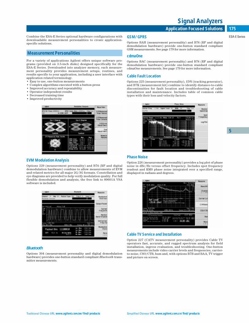
5
ESA-E Series
175Application Focused Solutions
Signal Analyzers
Combine the ESA-E Series optional hardware configurations withdownloadable measurement personalities to create application-specific solutions.
Measurement Personalities
For a variety of applications Agilent offers unique software pro-grams (provided on 3.5-inch disks) designed specifically for theESA-E Series. Downloaded into analyzer memory, each measure-ment personality provides measurement setups, routines, andresults specific to your application, including a user interface withapplication related terminology.• Easy to use, one-button measurements• Complex algorithms executed with a button press• Improved accuracy and repeatability• Operator independent results• Decreased training time• Improved productivity
EVM Modulation AnalysisOptions 229 (measurement personality) and B74 (RF and digitaldemodulation hardware) combine to allow measurements of EVMand related metrics for all major 2G/3G formats. Constellation andeye diagrams are provided to help verify modulation quality. For fullflexible demodulation and analysis, the free link to 89601A VSAsoftware is included.
BluetoothOptions 304 (measurement personality and digital demodulationhardware) provides one-button standard compliant Bluetooth trans-mitter measurements.
GSM/GPRS Options BAH (measurement personality) and B74 (RF and digitaldemodulation hardware) provide one-button standard compliantGSM measurements. See page 179 for more information.
cdmaOne Options BAC (measurement personality) and B74 (RF and digitaldemodulation hardware) provide one-button standard compliantcdmaOne measurements. See page 179 for more information.
Cable Fault LocationOptions 225 (measurement personality), 1DN (tracking generator),and B7K (measurement kit) combine to identify distance-to-cablediscontinuities for fault location and troubleshooting of cableinstallation and maintenance. Includes table of common cabletypes with their loss and velocity factors.
Phase NoiseOption 226 (measurement personality) provides a log plot of phasenoise in dBc/Hz versus offset frequency. Includes spot frequencyreadout and RMS phase noise integrated over a specified range, displayed in radians and degrees.
Cable TV Service and InstallationOption 227 (CATV measurement personality) provides Cable TVoperators fast, accurate, and rugged spectrum analysis for fieldinstallation, ingress evaluation, and troubleshooting. One-buttonmeasurements include video carrier levels and frequencies, carrier-to-noise, CSO/CTB, hum and, with options B7B and BAA, TV triggerand picture on screen.
Traditional Chinese URL www.agilent.com.tw/find/products Simplified Chinese URL www.agilent.com.cn/find/products
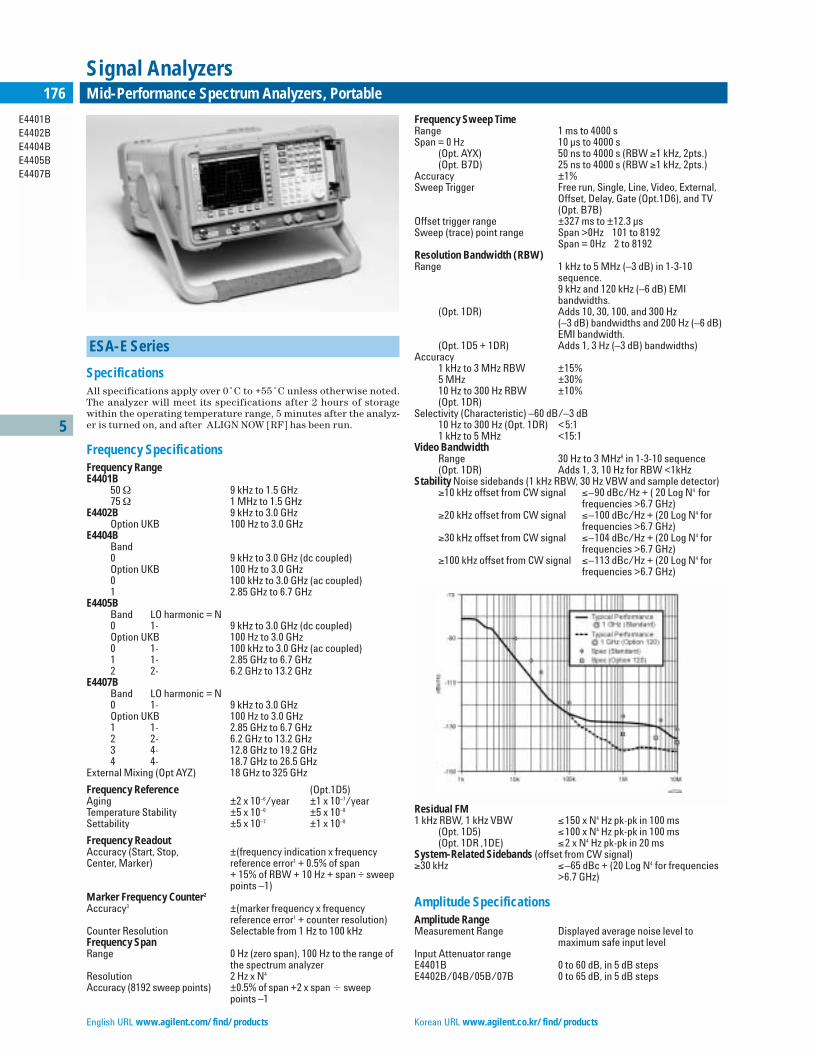
5
E4401BE4402BE4404BE4405BE4407B
176 Mid-Performance Spectrum Analyzers, Portable
Signal Analyzers
ESA-E Series
SpecificationsAll specifications apply over 0˚C to +55˚C unless otherwise noted.The analyzer will meet its specifications after 2 hours of storagewithin the operating temperature range, 5 minutes after the analyz-er is turned on, and after ALIGN NOW [RF] has been run.
Frequency SpecificationsFrequency RangeE4401B
50 Ω 9 kHz to 1.5 GHz75 Ω 1 MHz to 1.5 GHz
E4402B 9 kHz to 3.0 GHzOption UKB 100 Hz to 3.0 GHz
E4404BBand0 9 kHz to 3.0 GHz (dc coupled)Option UKB 100 Hz to 3.0 GHz0 100 kHz to 3.0 GHz (ac coupled)1 2.85 GHz to 6.7 GHz
E4405BBand LO harmonic = N0 1- 9 kHz to 3.0 GHz (dc coupled)Option UKB 100 Hz to 3.0 GHz0 1- 100 kHz to 3.0 GHz (ac coupled)1 1- 2.85 GHz to 6.7 GHz2 2- 6.2 GHz to 13.2 GHz
E4407BBand LO harmonic = N0 1- 9 kHz to 3.0 GHzOption UKB 100 Hz to 3.0 GHz1 1- 2.85 GHz to 6.7 GHz2 2- 6.2 GHz to 13.2 GHz3 4- 12.8 GHz to 19.2 GHz4 4- 18.7 GHz to 26.5 GHz
External Mixing (Opt AYZ) 18 GHz to 325 GHz
Frequency Reference (Opt.1D5)Aging ±2 x 10⁻⁶/year ±1 x 10⁻⁷/yearTemperature Stability ±5 x 10⁻⁶ ±5 x 10⁻⁸
Settability ±5 x 10⁻⁷ ±1 x 10⁻⁸
Frequency Readout Accuracy (Start, Stop, ±(frequency indication x frequency Center, Marker) reference error1 + 0.5% of span
+ 15% of RBW + 10 Hz + span ÷ sweeppoints –1)
Marker Frequency Counter2
Accuracy3 ±(marker frequency x frequency reference error1 + counter resolution)
Counter Resolution Selectable from 1 Hz to 100 kHzFrequency SpanRange 0 Hz (zero span), 100 Hz to the range of
the spectrum analyzerResolution 2 Hz x N4
Accuracy (8192 sweep points) ±0.5% of span +2 x span sweep points –1
Frequency Sweep TimeRange 1 ms to 4000 sSpan = 0 Hz 10 µs to 4000 s
(Opt. AYX) 50 ns to 4000 s (RBW ≥1 kHz, 2pts.)(Opt. B7D) 25 ns to 4000 s (RBW ≥1 kHz, 2pts.)
Accuracy ±1%Sweep Trigger Free run, Single, Line, Video, External,
Offset, Delay, Gate (Opt.1D6), and TV(Opt. B7B)
Offset trigger range ±327 ms to ±12.3 µsSweep (trace) point range Span >0Hz 101 to 8192
Span = 0Hz 2 to 8192Resolution Bandwidth (RBW)Range 1 kHz to 5 MHz (–3 dB) in 1-3-10
sequence.9 kHz and 120 kHz (–6 dB) EMI bandwidths.
(Opt. 1DR) Adds 10, 30, 100, and 300 Hz (–3 dB) bandwidths and 200 Hz (–6 dB)EMI bandwidth.
(Opt. 1D5 + 1DR) Adds 1, 3 Hz (–3 dB) bandwidths)Accuracy
1 kHz to 3 MHz RBW ±15%5 MHz ±30%10 Hz to 300 Hz RBW ±10%(Opt. 1DR)
Selectivity (Characteristic) –60 dB/–3 dB10 Hz to 300 Hz (Opt. 1DR) <5:11 kHz to 5 MHz <15:1
Video BandwidthRange 30 Hz to 3 MHz6 in 1-3-10 sequence(Opt. 1DR) Adds 1, 3, 10 Hz for RBW <1kHz
Stability Noise sidebands (1 kHz RBW, 30 Hz VBW and sample detector)≥10 kHz offset from CW signal ≤–90 dBc/Hz + ( 20 Log N4 for
frequencies >6.7 GHz)≥20 kHz offset from CW signal ≤–100 dBc/Hz + (20 Log N4 for
frequencies >6.7 GHz)≥30 kHz offset from CW signal ≤–104 dBc/Hz + (20 Log N4 for
frequencies >6.7 GHz)≥100 kHz offset from CW signal ≤–113 dBc/Hz + (20 Log N4 for
frequencies >6.7 GHz)
Residual FM1 kHz RBW, 1 kHz VBW ≤150 x N4 Hz pk-pk in 100 ms
(Opt. 1D5) ≤100 x N4 Hz pk-pk in 100 ms(Opt. 1DR ,1DE) ≤2 x N4 Hz pk-pk in 20 ms
System-Related Sidebands (offset from CW signal)≥30 kHz ≤–65 dBc + (20 Log N4 for frequencies
>6.7 GHz)
Amplitude SpecificationsAmplitude RangeMeasurement Range Displayed average noise level to
maximum safe input levelInput Attenuator range E4401B 0 to 60 dB, in 5 dB stepsE4402B/04B/05B/07B 0 to 65 dB, in 5 dB steps
English URL www.agilent.com/find/products Korean URL www.agilent.co.kr/find/products
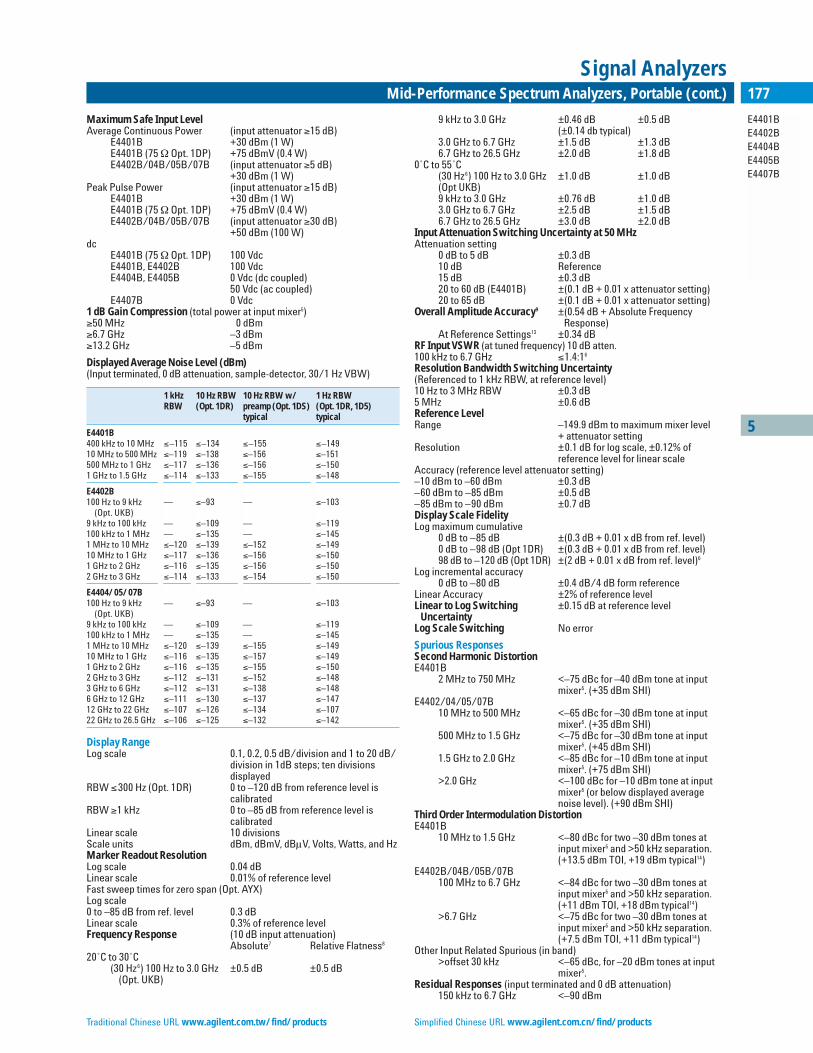
5
E4401BE4402BE4404BE4405BE4407B
177Mid-Performance Spectrum Analyzers, Portable (cont.)
Signal Analyzers
Maximum Safe Input LevelAverage Continuous Power (input attenuator ≥15 dB)
E4401B +30 dBm (1 W)E4401B (75 Ω Opt. 1DP) +75 dBmV (0.4 W)E4402B/04B/05B/07B (input attenuator ≥5 dB)
+30 dBm (1 W)Peak Pulse Power (input attenuator ≥15 dB)
E4401B +30 dBm (1 W) E4401B (75 Ω Opt. 1DP) +75 dBmV (0.4 W)E4402B/04B/05B/07B (input attenuator ≥30 dB)
+50 dBm (100 W) dc
E4401B (75 Ω Opt. 1DP) 100 VdcE4401B, E4402B 100 VdcE4404B, E4405B 0 Vdc (dc coupled)
50 Vdc (ac coupled)E4407B 0 Vdc
1 dB Gain Compression (total power at input mixer5)≥50 MHz 0 dBm ≥6.7 GHz –3 dBm≥13.2 GHz –5 dBm
Displayed Average Noise Level (dBm) (Input terminated, 0 dB attenuation, sample-detector, 30/1 Hz VBW)
1 kHz 10 Hz RBW 10 Hz RBW w/ 1 Hz RBW RBW (Opt. 1DR) preamp (Opt. 1DS) (Opt. 1DR, 1D5)
typical typical
E4401B 400 kHz to 10 MHz ≤–115 ≤–134 ≤–155 ≤–14910 MHz to 500 MHz ≤–119 ≤–138 ≤–156 ≤–151500 MHz to 1 GHz ≤–117 ≤–136 ≤–156 ≤–1501 GHz to 1.5 GHz ≤–114 ≤–133 ≤–155 ≤–148
E4402B100 Hz to 9 kHz — ≤–93 — ≤–103
(Opt. UKB)9 kHz to 100 kHz — ≤–109 — ≤–119100 kHz to 1 MHz — ≤–135 — ≤–1451 MHz to 10 MHz ≤–120 ≤–139 ≤–152 ≤–14910 MHz to 1 GHz ≤–117 ≤–136 ≤–156 ≤–1501 GHz to 2 GHz ≤–116 ≤–135 ≤–156 ≤–1502 GHz to 3 GHz ≤–114 ≤–133 ≤–154 ≤–150
E4404/05/07B100 Hz to 9 kHz — ≤–93 — ≤–103
(Opt. UKB)9 kHz to 100 kHz — ≤–109 — ≤–119100 kHz to 1 MHz — ≤–135 — ≤–1451 MHz to 10 MHz ≤–120 ≤–139 ≤–155 ≤–14910 MHz to 1 GHz ≤–116 ≤–135 ≤–157 ≤–1491 GHz to 2 GHz ≤–116 ≤–135 ≤–155 ≤–1502 GHz to 3 GHz ≤–112 ≤–131 ≤–152 ≤–1483 GHz to 6 GHz ≤–112 ≤–131 ≤–138 ≤–1486 GHz to 12 GHz ≤–111 ≤–130 ≤–137 ≤–14712 GHz to 22 GHz ≤–107 ≤–126 ≤–134 ≤–10722 GHz to 26.5 GHz ≤–106 ≤–125 ≤–132 ≤–142
Display RangeLog scale 0.1, 0.2, 0.5 dB/division and 1 to 20 dB/
division in 1dB steps; ten divisions displayed
RBW ≤300 Hz (Opt. 1DR) 0 to –120 dB from reference level is calibrated
RBW ≥1 kHz 0 to –85 dB from reference level is calibrated
Linear scale 10 divisionsScale units dBm, dBmV, dBµV, Volts, Watts, and HzMarker Readout ResolutionLog scale 0.04 dB Linear scale 0.01% of reference levelFast sweep times for zero span (Opt. AYX)Log scale0 to –85 dB from ref. level 0.3 dB Linear scale 0.3% of reference levelFrequency Response (10 dB input attenuation)
Absolute7 Relative Flatness8
20˚C to 30˚C(30 Hz6) 100 Hz to 3.0 GHz ±0.5 dB ±0.5 dB
(Opt. UKB)
9 kHz to 3.0 GHz ±0.46 dB ±0.5 dB(±0.14 db typical)
3.0 GHz to 6.7 GHz ±1.5 dB ±1.3 dB6.7 GHz to 26.5 GHz ±2.0 dB ±1.8 dB
0˚C to 55˚C(30 Hz6) 100 Hz to 3.0 GHz ±1.0 dB ±1.0 dB(Opt UKB)9 kHz to 3.0 GHz ±0.76 dB ±1.0 dB3.0 GHz to 6.7 GHz ±2.5 dB ±1.5 dB6.7 GHz to 26.5 GHz ±3.0 dB ±2.0 dB
Input Attenuation Switching Uncertainty at 50 MHzAttenuation setting
0 dB to 5 dB ±0.3 dB10 dB Reference15 dB ±0.3 dB20 to 60 dB (E4401B) ±(0.1 dB + 0.01 x attenuator setting)20 to 65 dB ±(0.1 dB + 0.01 x attenuator setting)
Overall Amplitude Accuracy9 ±(0.54 dB + Absolute Frequency Response)
At Reference Settings13 ±0.34 dBRF Input VSWR (at tuned frequency) 10 dB atten.100 kHz to 6.7 GHz ≤1.4:16
Resolution Bandwidth Switching Uncertainty(Referenced to 1 kHz RBW, at reference level)10 Hz to 3 MHz RBW ±0.3 dB5 MHz ±0.6 dBReference LevelRange –149.9 dBm to maximum mixer level
+ attenuator settingResolution ±0.1 dB for log scale, ±0.12% of
reference level for linear scaleAccuracy (reference level attenuator setting)–10 dBm to –60 dBm ±0.3 dB –60 dBm to –85 dBm ±0.5 dB–85 dBm to –90 dBm ±0.7 dBDisplay Scale FidelityLog maximum cumulative
0 dB to –85 dB ±(0.3 dB + 0.01 x dB from ref. level)0 dB to –98 dB (Opt 1DR) ±(0.3 dB + 0.01 x dB from ref. level)98 dB to –120 dB (Opt 1DR) ±(2 dB + 0.01 x dB from ref. level)6
Log incremental accuracy0 dB to –80 dB ±0.4 dB/4 dB form reference
Linear Accuracy ±2% of reference levelLinear to Log Switching ±0.15 dB at reference level
Uncertainty Log Scale Switching No error
Spurious ResponsesSecond Harmonic DistortionE4401B
2 MHz to 750 MHz <–75 dBc for –40 dBm tone at inputmixer5. (+35 dBm SHI)
E4402/04/05/07B10 MHz to 500 MHz <–65 dBc for –30 dBm tone at input
mixer5. (+35 dBm SHI)500 MHz to 1.5 GHz <–75 dBc for –30 dBm tone at input
mixer5. (+45 dBm SHI)1.5 GHz to 2.0 GHz <–85 dBc for –10 dBm tone at input
mixer5. (+75 dBm SHI)>2.0 GHz <–100 dBc for –10 dBm tone at input
mixer5 (or below displayed averagenoise level). (+90 dBm SHI)
Third Order Intermodulation DistortionE4401B
10 MHz to 1.5 GHz <–80 dBc for two –30 dBm tones atinput mixer5 and >50 kHz separation.(+13.5 dBm TOI, +19 dBm typical14)
E4402B/04B/05B/07B100 MHz to 6.7 GHz <–84 dBc for two –30 dBm tones at
input mixer5 and >50 kHz separation.(+11 dBm TOI, +18 dBm typical14)
>6.7 GHz <–75 dBc for two –30 dBm tones atinput mixer5 and >50 kHz separation.(+7.5 dBm TOI, +11 dBm typical14)
Other Input Related Spurious (in band) >offset 30 kHz <–65 dBc, for –20 dBm tones at input
mixer5.Residual Responses (input terminated and 0 dB attenuation)
150 kHz to 6.7 GHz <–90 dBm
Traditional Chinese URL www.agilent.com.tw/find/products Simplified Chinese URL www.agilent.com.cn/find/products
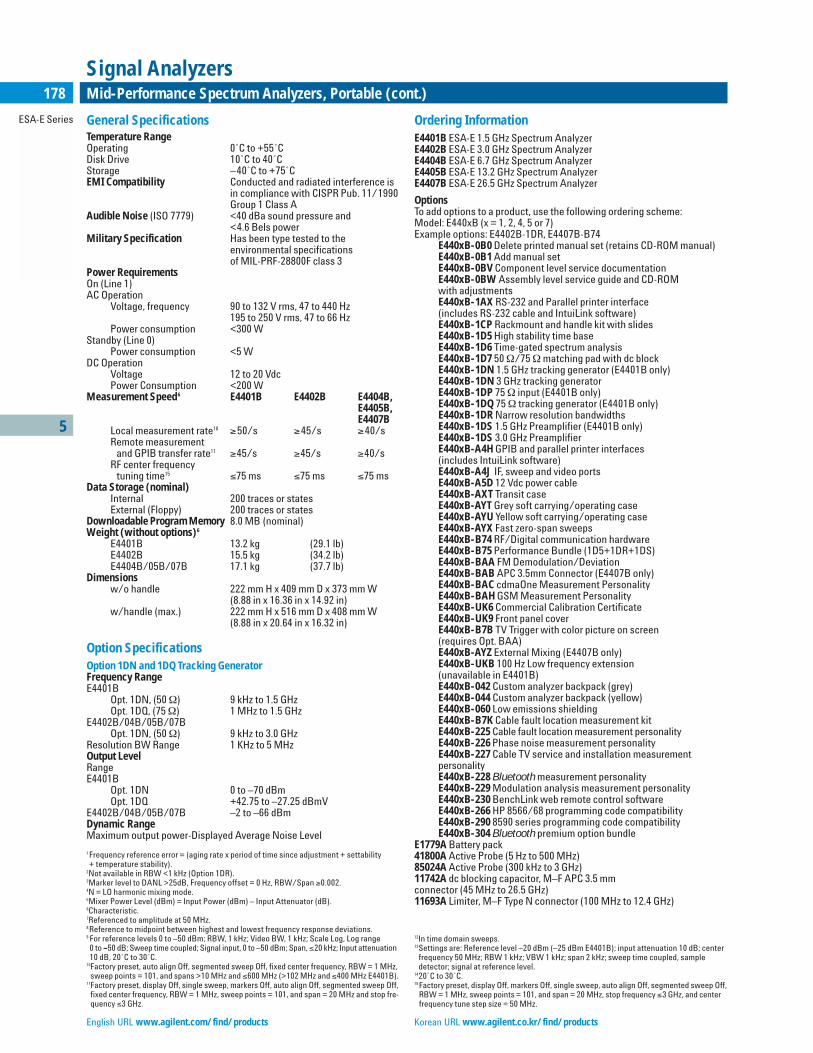
5
ESA-E Series
178 Mid-Performance Spectrum Analyzers, Portable (cont.)
Signal Analyzers
General SpecificationsTemperature RangeOperating 0˚C to +55˚CDisk Drive 10˚C to 40˚CStorage –40˚C to +75˚CEMI Compatibility Conducted and radiated interference is
in compliance with CISPR Pub. 11/1990Group 1 Class A
Audible Noise (ISO 7779) <40 dBa sound pressure and <4.6 Bels power
Military Specification Has been type tested to the environmental specifications of MIL-PRF-28800F class 3
Power RequirementsOn (Line 1)AC Operation
Voltage, frequency 90 to 132 V rms, 47 to 440 Hz195 to 250 V rms, 47 to 66 Hz
Power consumption <300 WStandby (Line 0)
Power consumption <5 WDC Operation
Voltage 12 to 20 VdcPower Consumption <200 W
Measurement Speed6 E4401B E4402B E4404B, E4405B, E4407B
Local measurement rate10 ≥50/s ≥45/s ≥40/sRemote measurement
and GPIB transfer rate11 ≥45/s ≥45/s ≥40/sRF center frequency
tuning time15 ≤75 ms ≤75 ms ≤75 msData Storage (nominal)
Internal 200 traces or statesExternal (Floppy) 200 traces or states
Downloadable Program Memory 8.0 MB (nominal)Weight (without options)6
E4401B 13.2 kg (29.1 lb)E4402B 15.5 kg (34.2 lb)E4404B/05B/07B 17.1 kg (37.7 lb)
Dimensionsw/o handle 222 mm H x 409 mm D x 373 mm W
(8.88 in x 16.36 in x 14.92 in)w/handle (max.) 222 mm H x 516 mm D x 408 mm W
(8.88 in x 20.64 in x 16.32 in)
Option SpecificationsOption 1DN and 1DQ Tracking GeneratorFrequency RangeE4401B
Opt. 1DN, (50 Ω) 9 kHz to 1.5 GHzOpt. 1DQ, (75 Ω) 1 MHz to 1.5 GHz
E4402B/04B/05B/07BOpt. 1DN, (50 Ω) 9 kHz to 3.0 GHz
Resolution BW Range 1 KHz to 5 MHzOutput LevelRangeE4401B
Opt. 1DN 0 to –70 dBmOpt. 1DQ +42.75 to –27.25 dBmV
E4402B/04B/05B/07B –2 to –66 dBmDynamic Range Maximum output power-Displayed Average Noise Level
1Frequency reference error = (aging rate x period of time since adjustment + settability + temperature stability).
2Not available in RBW <1 kHz (Option 1DR).3Marker level to DANL >25dB, Frequency offset = 0 Hz, RBW/Span ≥0.002. 4N = LO harmonic mixing mode.5Mixer Power Level (dBm) = Input Power (dBm) – Input Attenuator (dB).6Characteristic.7Referenced to amplitude at 50 MHz.8Reference to midpoint between highest and lowest frequency response deviations. 9 For reference levels 0 to –50 dBm; RBW, 1 kHz; Video BW, 1 kHz; Scale Log, Log range 0 to –50 dB; Sweep time coupled; Signal input, 0 to –50 dBm; Span, ≤20 kHz; Input attenuation10 dB, 20˚C to 30˚C.
10Factory preset, auto align Off, segmented sweep Off, fixed center frequency, RBW = 1 MHz,sweep points = 101, and spans >10 MHz and ≤600 MHz (>102 MHz and ≤400 MHz E4401B).
11Factory preset, display Off, single sweep, markers Off, auto align Off, segmented sweep Off,fixed center frequency, RBW = 1 MHz, sweep points = 101, and span = 20 MHz and stop fre-quency ≤3 GHz.
Ordering InformationE4401B ESA-E 1.5 GHz Spectrum AnalyzerE4402B ESA-E 3.0 GHz Spectrum AnalyzerE4404B ESA-E 6.7 GHz Spectrum AnalyzerE4405B ESA-E 13.2 GHz Spectrum AnalyzerE4407B ESA-E 26.5 GHz Spectrum Analyzer
OptionsTo add options to a product, use the following ordering scheme:Model: E440xB (x = 1, 2, 4, 5 or 7)Example options: E4402B-1DR, E4407B-B74
E440xB-0B0 Delete printed manual set (retains CD-ROM manual)E440xB-0B1 Add manual setE440xB-0BV Component level service documentationE440xB-0BW Assembly level service guide and CD-ROMwith adjustmentsE440xB-1AX RS-232 and Parallel printer interface (includes RS-232 cable and IntuiLink software)E440xB-1CP Rackmount and handle kit with slidesE440xB-1D5 High stability time baseE440xB-1D6 Time-gated spectrum analysisE440xB-1D7 50 Ω/75 Ωmatching pad with dc blockE440xB-1DN 1.5 GHz tracking generator (E4401B only)E440xB-1DN 3 GHz tracking generatorE440xB-1DP 75 Ω input (E4401B only)E440xB-1DQ 75 Ω tracking generator (E4401B only)E440xB-1DR Narrow resolution bandwidthsE440xB-1DS 1.5 GHz Preamplifier (E4401B only)E440xB-1DS 3.0 GHz PreamplifierE440xB-A4H GPIB and parallel printer interfaces(includes IntuiLink software)E440xB-A4J IF, sweep and video portsE440xB-A5D 12 Vdc power cableE440xB-AXT Transit caseE440xB-AYT Grey soft carrying/operating caseE440xB-AYU Yellow soft carrying/operating caseE440xB-AYX Fast zero-span sweepsE440xB-B74 RF/Digital communication hardwareE440xB-B75 Performance Bundle (1D5+1DR+1DS) E440xB-BAA FM Demodulation/DeviationE440xB-BAB APC 3.5mm Connector (E4407B only)E440xB-BAC cdmaOne Measurement PersonalityE440xB-BAH GSM Measurement PersonalityE440xB-UK6 Commercial Calibration CertificateE440xB-UK9 Front panel coverE440xB-B7B TV Trigger with color picture on screen(requires Opt. BAA)E440xB-AYZ External Mixing (E4407B only)E440xB-UKB 100 Hz Low frequency extension(unavailable in E4401B)E440xB-042 Custom analyzer backpack (grey)E440xB-044 Custom analyzer backpack (yellow)E440xB-060 Low emissions shieldingE440xB-B7K Cable fault location measurement kitE440xB-225 Cable fault location measurement personalityE440xB-226 Phase noise measurement personalityE440xB-227 Cable TV service and installation measurement personalityE440xB-228 Bluetooth measurement personalityE440xB-229 Modulation analysis measurement personalityE440xB-230 BenchLink web remote control softwareE440xB-266 HP 8566/68 programming code compatibilityE440xB-290 8590 series programming code compatibilityE440xB-304 Bluetooth premium option bundle
E1779A Battery pack41800A Active Probe (5 Hz to 500 MHz)85024A Active Probe (300 kHz to 3 GHz)11742A dc blocking capacitor, M–F APC 3.5 mm connector (45 MHz to 26.5 GHz)11693A Limiter, M–F Type N connector (100 MHz to 12.4 GHz)
12In time domain sweeps.13Settings are: Reference level –20 dBm (–25 dBm E4401B); input attenuation 10 dB; center
frequency 50 MHz; RBW 1 kHz; VBW 1 kHz; span 2 kHz; sweep time coupled, sampledetector; signal at reference level.
1420˚C to 30˚C.15Factory preset, display Off, markers Off, single sweep, auto align Off, segmented sweep Off,
RBW = 1 MHz, sweep points = 101, and span = 20 MHz, stop frequency ≤3 GHz, and centerfrequency tune step size = 50 MHz.
English URL www.agilent.com/find/products Korean URL www.agilent.co.kr/find/products
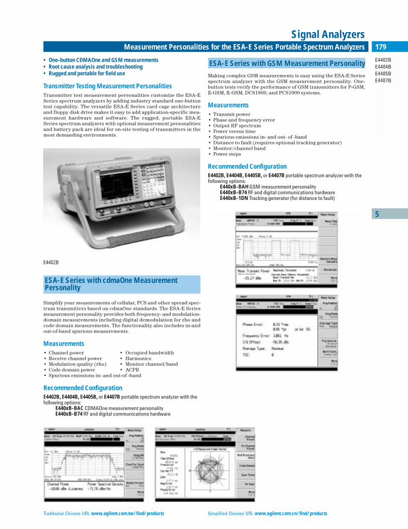
5
E4402BE4404BE4405BE4407B
179Measurement Personalities for the ESA-E Series Portable Spectrum Analyzers
Signal Analyzers
• One-button CDMAOne and GSM measurements• Root cause analysis and troubleshooting• Rugged and portable for field use
Transmitter Testing Measurement PersonalitiesTransmitter test measurement personalities customize the ESA-ESeries spectrum analyzers by adding industry standard one-buttontest capability. The versatile ESA-E Series card cage architectureand floppy disk drive makes it easy to add application-specific mea-surement hardware and software. The rugged, portable ESA-ESeries spectrum analyzers with optional measurement personalitiesand battery pack are ideal for on-site testing of transmitters in themost demanding environments.
E4402B
ESA-E Series with cdmaOne Measurement Personality
Simplify your measurements of cellular, PCS and other spread spec-trum transmitters based on cdmaOne standards. The ESA-E Seriesmeasurement personality provides both frequency- and modulation-domain measurements including digital demodulation for rho andcode domain measurements. The functionality also includes in-andout-of-band spurious measurements.
Measurements• Channel power • Occupied bandwidth• Receive channel power • Harmonics• Modulation quality (rho) • Monitor channel/band • Code domain power • ACPR• Spurious emissions in- and out-of -band
Recommended ConfigurationE4402B, E4404B, E4405B, or E4407B portable spectrum analyzer with thefollowing options:
E440xB-BAC CDMAOne measurement personalityE440xB-B74 RF and digital communications hardware
ESA-E Series with GSM Measurement Personality
Making complex GSM measurements is easy using the ESA-E Seriesspectrum analyzer with the GSM measurement personality. One-button tests verify the performance of GSM transmitters for P-GSM,E-GSM, R-GSM, DCS1800, and PCS1900 systems.
Measurements• Transmit power • Phase and frequency error • Output RF spectrum• Power versus time• Spurious emissions in- and out- of -band • Distance to fault (requires optional tracking generator)• Monitor/channel band• Power steps
Recommended ConfigurationE4402B, E4404B, E4405B, or E4407B portable spectrum analyzer with thefollowing options:
E440xB-BAH GSM measurement personalityE440xB-B74 RF and digital communications hardwareE440xB-1DN Tracking generator (for distance to fault)
Traditional Chinese URL www.agilent.com.tw/find/products Simplified Chinese URL www.agilent.com.cn/find/products
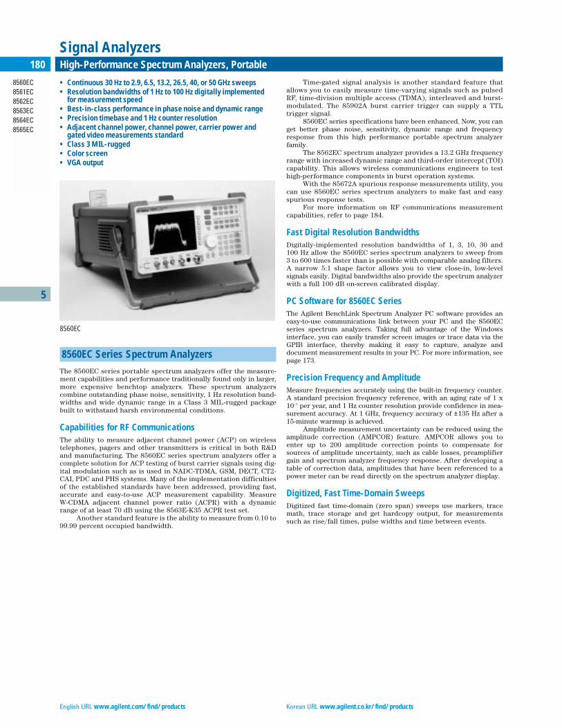
English URL www.agilent.com/find/products Korean URL www.agilent.co.kr/find/products
5
8560EC 8561EC 8562EC 8563EC 8564EC 8565EC
180 High-Performance Spectrum Analyzers, Portable
Signal Analyzers
8560EC Series Spectrum Analyzers
The 8560EC series portable spectrum analyzers offer the measure-ment capabilities and performance traditionally found only in larger,more expensive benchtop analyzers. These spectrum analyzerscombine outstanding phase noise, sensitivity, 1 Hz resolution band-widths and wide dynamic range in a Class 3 MIL-rugged packagebuilt to withstand harsh environmental conditions.
Capabilities for RF CommunicationsThe ability to measure adjacent channel power (ACP) on wirelesstelephones, pagers and other transmitters is critical in both R&Dand manufacturing. The 8560EC series spectrum analyzers offer acomplete solution for ACP testing of burst carrier signals using dig-ital modulation such as is used in NADC-TDMA, GSM, DECT, CT2-CAI, PDC and PHS systems. Many of the implementation difficultiesof the established standards have been addressed, providing fast,accurate and easy-to-use ACP measurement capability. Measure W-CDMA adjacent channel power ratio (ACPR) with a dynamicrange of at least 70 dB using the 8563E-K35 ACPR test set.
Another standard feature is the ability to measure from 0.10 to99.99 percent occupied bandwidth.
Time-gated signal analysis is another standard feature thatallows you to easily measure time-varying signals such as pulsedRF, time-division multiple access (TDMA), interleaved and burst-modulated. The 85902A burst carrier trigger can supply a TTLtrigger signal.
8560EC series specifications have been enhanced. Now, you canget better phase noise, sensitivity, dynamic range and frequencyresponse from this high performance portable spectrum analyzerfamily.
The 8562EC spectrum analyzer provides a 13.2 GHz frequencyrange with increased dynamic range and third-order intercept (TOI)capability. This allows wireless communications engineers to testhigh-performance components in burst operation systems.
With the 85672A spurious response measurements utility, youcan use 8560EC series spectrum analyzers to make fast and easyspurious response tests.
For more information on RF communications measurementcapabilities, refer to page 184.
Fast Digital Resolution BandwidthsDigitally-implemented resolution bandwidths of 1, 3, 10, 30 and 100 Hz allow the 8560EC series spectrum analyzers to sweep from 3 to 600 times faster than is possible with comparable analog filters.A narrow 5:1 shape factor allows you to view close-in, low-level signals easily. Digital bandwidths also provide the spectrum analyzerwith a full 100 dB on-screen calibrated display.
PC Software for 8560EC Series The Agilent BenchLink Spectrum Analyzer PC software provides aneasy-to-use communications link between your PC and the 8560ECseries spectrum analyzers. Taking full advantage of the Windowsinterface, you can easily transfer screen images or trace data via theGPIB interface, thereby making it easy to capture, analyze and document measurement results in your PC. For more information, seepage 173.
Precision Frequency and AmplitudeMeasure frequencies accurately using the built-in frequency counter.A standard precision frequency reference, with an aging rate of 1 x10⁻⁷ per year, and 1 Hz counter resolution provide confidence in mea-surement accuracy. At 1 GHz, frequency accuracy of ±135 Hz after a 15-minute warmup is achieved.
Amplitude measurement uncertainty can be reduced using theamplitude correction (AMPCOR) feature. AMPCOR allows you toenter up to 200 amplitude correction points to compensate forsources of amplitude uncertainty, such as cable losses, preamplifiergain and spectrum analyzer frequency response. After developing atable of correction data, amplitudes that have been referenced to apower meter can be read directly on the spectrum analyzer display.
Digitized, Fast Time-Domain SweepsDigitized fast time-domain (zero span) sweeps use markers, tracemath, trace storage and get hardcopy output, for measurementssuch as rise/fall times, pulse widths and time between events.
• Continuous 30 Hz to 2.9, 6.5, 13.2, 26.5, 40, or 50 GHz sweeps • Resolution bandwidths of 1 Hz to 100 Hz digitally implemented
for measurement speed • Best-in-class performance in phase noise and dynamic range • Precision timebase and 1 Hz counter resolution • Adjacent channel power, channel power, carrier power and
gated video measurements standard • Class 3 MIL-rugged• Color screen• VGA output
8560EC
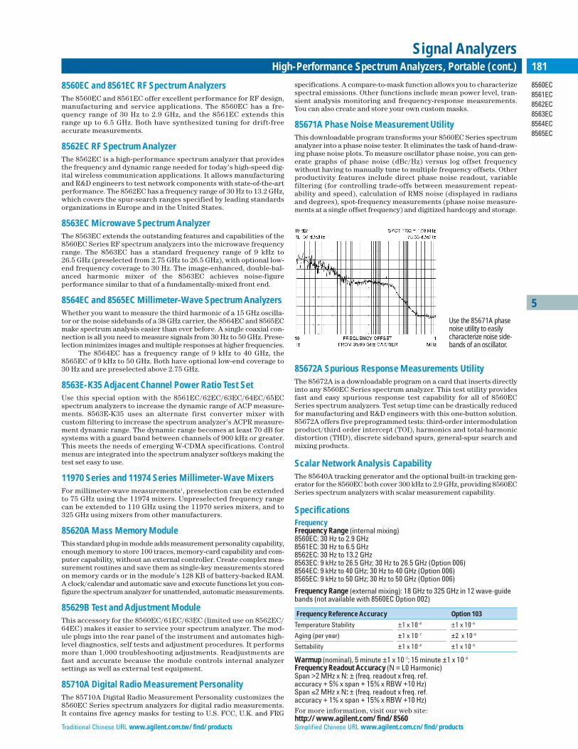
Traditional Chinese URL www.agilent.com.tw/find/products Simplified Chinese URL www.agilent.com.cn/find/products
5
8560EC 8561EC 8562EC 8563EC 8564EC 8565EC
181High-Performance Spectrum Analyzers, Portable (cont.)
Signal Analyzers
8560EC and 8561EC RF Spectrum AnalyzersThe 8560EC and 8561EC offer excellent performance for RF design,manufacturing and service applications. The 8560EC has a fre-quency range of 30 Hz to 2.9 GHz, and the 8561EC extends thisrange up to 6.5 GHz. Both have synthesized tuning for drift-freeaccurate measurements.
8562EC RF Spectrum AnalyzerThe 8562EC is a high-performance spectrum analyzer that providesthe frequency and dynamic range needed for today’s high-speed dig-ital wireless communication applications. It allows manufacturingand R&D engineers to test network components with state-of-the-artperformance. The 8562EC has a frequency range of 30 Hz to 13.2 GHz,which covers the spur-search ranges specified by leading standardsorganizations in Europe and in the United States.
8563EC Microwave Spectrum AnalyzerThe 8563EC extends the outstanding features and capabilities of the8560EC Series RF spectrum analyzers into the microwave frequencyrange. The 8563EC has a standard frequency range of 9 kHz to 26.5 GHz (preselected from 2.75 GHz to 26.5 GHz), with optional low-end frequency coverage to 30 Hz. The image-enhanced, double-bal-anced harmonic mixer of the 8563EC achieves noise-figureperformance similar to that of a fundamentally-mixed front end.
8564EC and 8565EC Millimeter-Wave Spectrum AnalyzersWhether you want to measure the third harmonic of a 15 GHz oscilla-tor or the noise sidebands of a 38 GHz carrier, the 8564EC and 8565ECmake spectrum analysis easier than ever before. A single coaxial con-nection is all you need to measure signals from 30 Hz to 50 GHz. Prese-lection minimizes images and multiple responses at higher frequencies.
The 8564EC has a frequency range of 9 kHz to 40 GHz, the 8565EC of 9 kHz to 50 GHz. Both have optional low-end coverage to30 Hz and are preselected above 2.75 GHz.
8563E-K35 Adjacent Channel Power Ratio Test SetUse this special option with the 8561EC/62EC/63EC/64EC/65ECspectrum analyzers to increase the dynamic range of ACP measure-ments. 8563E-K35 uses an alternate first converter mixer with custom filtering to increase the spectrum analyzer’s ACPR measure-ment dynamic range. The dynamic range becomes at least 70 dB forsystems with a guard band between channels of 900 kHz or greater.This meets the needs of emerging W-CDMA specifications. Controlmenus are integrated into the spectrum analyzer softkeys making thetest set easy to use.
11970 Series and 11974 Series Millimeter-Wave MixersFor millimeter-wave measurements1, preselection can be extendedto 75 GHz using the 11974 mixers. Unpreselected frequency rangecan be extended to 110 GHz using the 11970 series mixers, and to325 GHz using mixers from other manufacturers.
85620A Mass Memory ModuleThis standard plug-in module adds measurement personality capability,enough memory to store 100 traces, memory-card capability and com-puter capability, without an external controller. Create complex mea-surement routines and save them as single-key measurements storedon memory cards or in the module’s 128 KB of battery-backed RAM.A clock/calendar and automatic save and execute functions let you con-figure the spectrum analyzer for unattended, automatic measurements.
85629B Test and Adjustment ModuleThis accessory for the 8560EC/61EC/63EC (limited use on 8562EC/64EC) makes it easier to service your spectrum analyzer. The mod-ule plugs into the rear panel of the instrument and automates high-level diagnostics, self tests and adjustment procedures. It performsmore than 1,000 troubleshooting adjustments. Readjustments arefast and accurate because the module controls internal analyzer settings as well as external test equipment.
85710A Digital Radio Measurement PersonalityThe 85710A Digital Radio Measurement Personality customizes the8560EC Series spectrum analyzers for digital radio measurements. It contains five agency masks for testing to U.S. FCC, U.K. and FRG
specifications. A compare-to-mask function allows you to characterizespectral emissions. Other functions include mean power level, tran-sient analysis monitoring and frequency-response measurements.You can also create and store your own custom masks.
85671A Phase Noise Measurement UtilityThis downloadable program transforms your 8560EC Series spectrumanalyzer into a phase noise tester. It eliminates the task of hand-draw-ing phase noise plots. To measure oscillator phase noise, you can gen-erate graphs of phase noise (dBc/Hz) versus log offset frequencywithout having to manually tune to multiple frequency offsets. Otherproductivity features include direct phase noise readout, variable filtering (for controlling trade-offs between measurement repeat-ability and speed), calculation of RMS noise (displayed in radiansand degrees), spot-frequency measurements (phase noise measure-ments at a single offset frequency) and digitized hardcopy and storage.
85672A Spurious Response Measurements UtilityThe 85672A is a downloadable program on a card that inserts directlyinto any 8560EC Series spectrum analyzer. This test utility providesfast and easy spurious response test capability for all of 8560ECSeries spectrum analyzers. Test setup time can be drastically reducedfor manufacturing and R&D engineers with this one-button solution.85672A offers five preprogrammed tests: third-order intermodulationproduct/third order intercept (TOI), harmonics and total-harmonicdistortion (THD), discrete sideband spurs, general-spur search andmixing products.
Scalar Network Analysis CapabilityThe 85640A tracking generator and the optional built-in tracking gen-erator for the 8560EC both cover 300 kHz to 2.9 GHz, providing 8560ECSeries spectrum analyzers with scalar measurement capability.
SpecificationsFrequencyFrequency Range (internal mixing)8560EC: 30 Hz to 2.9 GHz8561EC: 30 Hz to 6.5 GHz8562EC: 30 Hz to 13.2 GHz 8563EC: 9 kHz to 26.5 GHz; 30 Hz to 26.5 GHz (Option 006)8564EC: 9 kHz to 40 GHz; 30 Hz to 40 GHz (Option 006)8565EC: 9 kHz to 50 GHz; 30 Hz to 50 GHz (Option 006)
Frequency Range (external mixing): 18 GHz to 325 GHz in 12 wave-guidebands (not available with 8560EC Option 002)
Frequency Reference Accuracy Option 103
Temperature Stability ±1 x 10⁻⁸ ±1 x 10⁻⁶
Aging (per year) ±1 x 10⁻⁷ ±2 x 10⁻⁶
Settability ±1 x 10⁻⁸ ±1 x 10⁻⁶
Warmup (nominal), 5 minute ±1 x 10⁻⁷; 15 minute ±1 x 10⁻⁸
Frequency Readout Accuracy (N = L0 Harmonic)Span >2 MHz x N: ± (freq. readout x freq. ref.accuracy + 5% x span + 15% x RBW +10 Hz)Span ≤2 MHz x N: ± (freq. readout x freq. ref.accuracy + 1% x span + 15% x RBW +10 Hz)For more information, visit our web site:http://www.agilent.com/find/8560
Use the 85671A phasenoise utility to easilycharacterize noise side-bands of an oscillator.
English URL www.agilent.com/find/products Korean URL www.agilent.co.kr/find/products
Marker Count Accuracy (S/N ≥25 dB): ±(marker freq. x freq. ref.accuracy +2 Hz x N +1 LSD)Counter Resolution: Selectable from 1 Hz to 1 MHzFrequency Span • Range: 0 Hz, 100 Hz to maximum frequencySweep Time • Range
– Span = 0 Hz: 50 µs to 6,000 s– Span ≥100 Hz: 50 ms to 100 ks
Accuracy (span = 0 Hz)• Sweep Time >30 ms: ±1% digital• Sweep Time <30 ms: ±10% analog; ±0.1% digitalSweep Trigger: Delayed, free run, single, line, video, externalResolution Bandwidth:• Range (–3 dB): 1 Hz to 1 MHz in a 1, 3, 10 sequence and 2 MHz• Accuracy
– 1 Hz to 300 kHz: ±10%; 1 MHz: ±25%; 2 MHz: +50%, –25%• Selectivity (–60 dB/–3 dB)
– RBW ≥300 Hz: <15:1; RBW ≤100 Hz: <5:1Video Bandwidth Range: 1 Hz to 3 MHz in a 1, 3, 10 sequence
Noise Sidebands (center frequency ≤1 GHz)
Offset Non-Option 103 Option 103
100 Hz <–88 dBc/Hz <–70 dBc/Hz1 kHz <–97 dBc/Hz <–90 dBc/Hz10 kHz <–113 dBc/Hz <–113 dBc/Hz100 kHz <–117 dBc/Hz <–117 dBc/Hz
Residual FM (zero span): <1 Hz p-p in 20 ms; <0.25 Hz p-p in 20 ms (nominal); <10 Hz p-p in 20 µs (Option 103)
AmplitudeRange: Displayed average noise level to +30 dBmMaximum Safe Input Level• Average Continuous Power: +30 dBm (1W, input atten. ≥10 dB)• Peak Pulse Power (<10 µs pulse width and <1% duty cycle):
+50 dBm (100 W, input atten. ≥30 dB)• DC Volts: <±0.2 V (dc-coupled); <±50 V (ac-coupled, 8560EC,
8561EC and 8562EC only)1 dB Gain Compression• 10 MHz to 2.9 GHz: mixer level ≤–5 dBm• 2.9 to 6.5 GHz (8561EC): mixer level ≤–3 dBm• 2.9 to 6.5 GHz (8562EC/63EC/64EC/65EC): mixer level ≤0 dBm• >6.5 GHz: ≤–3 dBm (8562EC/63EC); ≤0 dBm (8564EC/65EC)
Displayed Average Noise Level (0 dB input atten., 1 Hz RBW 1)
Frequency 8560EC/ 8562EC 8563EC 8564EC/61EC 65EC
30 Hz –90 dBm –90 dBm –90 dBm –90 dBm1 kHz –105 dBm –105 dBm –105 dBm –105 dBm10 kHz –120 dBm –120 dBm –120 dBm –120 dBm100 kHz –120 dBm –120 dBm –120 dBm –120 dBm1 to 10 MHz –140 dBm –140 dBm –140 dBm –140 dBm10 MHz to 2.9 GHz –149 dBm8 –149 dBm –149 dBm –145 dBm2.9 to 6.5 GHz –145 dBm2 –148 dBm –148 dBm –147 dBm6.5 to 13.2 GHz — –145 dBm –145 dBm –143 dBm13.2 to 22.0 GHz — — –140 dBm –140 dBm22.0 to 26.5 GHz — — –139 dBm –136 dBm26.5 to 31.15 GHz — — — –139 dBm31.15 to 40.0 GHz — — — –130 dBm40.0 to 50.0 GHz — — — –127 dBm3
1 10 Hz RBW (Min. RBW with Option 103) add 10 dB to noise floor2 8561EC only3 8565EC only4 8563EC/64EC/65EC only5 8563EC only6 8564EC/65EC only7 Except 8561EC 8 For 8561EC: –145 dBm 9 TOI reference to single tone
Spurious Responses Mixer Level Distortion
General Spurious –40 dBm <(–75+20 log N) dBc
Second Harmonic Dist.20 MHz to 1.45 GHz 7 –40 dBm <–79 dBc1 MHz to 1.45 GHz –40 dBm <–72 dBc1.45 GHz to 3.25 GHz 2 –20 dBm <–72 dBc1.45 GHz to 2.0 GHz 4 –10 dBm <–85 dBc2 GHz to 6.6 GHz 7 –10 dBm <–100 dBc2.0 GHz to 13.25 GHz 5 –10 dBm <–100 dBc2.0 GHz to 20 GHz 6 –10 dBm <–90 dBc20 GHz to 25 GHz 3 –10 dBm <–90 dBc
3rd Order Intermodulation 9
20 MHz to 2.9 GHz 7 –30 dBm <–82 dBc1 MHz to 2.9 GHz –30 dBm <–78 dBc2.9 GHz to 6.5 GHz –30 dBm <–90 dBc6.5 GHz to 26.5 GHz –30 dBm <–75 dBc26.5 GHz to 40 GHz 6 –30 dBm <–85 dBc (nominal)40 GHz to 50 GHz 3 –30 dBm ≤–85 dBc (nominal)
Images10 MHz to 26.5 GHz –10 dBm <–80 dBc26.5 GHz to 50 GHz –30 dBm <–60 dBc
Multiples and Out-of-Band Responses10 MHz to 26.5 GHz –10 dBm <–80 dBc26.5 GHz to 50 GHz –30 dBm <–55 dBc
Residual Responses (>200 kHz, N=1): <–90 dBmDisplay• Viewing area: Approx. 7 cm (V) x 9 cm (H)• Scale calibration: 10 x 10 divisions• Log scale: 10, 5, 2, 1 dB per division• Linear scale: 10% of ref. level per divisionDisplay Scale Fidelity• Log: ±0.1 dB/dB to a maximum of ±0.85 dB, 0 to –90 dB; maximum of
±1.5 dB, 0 to –100 dB (RBW ≤100 Hz)• Linear: ±3 % of reference levelReference Level Range: Log = –120 to +30 dBm in 0.1 dB steps; • Linear = 2.2 µV to 7.07 V in 1% steps
Frequency Response, Relative (10 dB input atten.)
Frequency 8560EC 8561EC 8562EC 8563EC 8564EC/65EC
100 MHz to 2.0 GHz ±0.7 dB ±1.0 dB ±0.9 dB ±1.0 dB ±0.9 dB30 Hz to 2.9 GHz ±1.0 dB ±1.0 dB ±1.25 dB ±1.25 dB ±1.0 dB2.9 GHz to 6.5 GHz — ±1.5 dB ±1.5 dB ±1.5 dB ±1.7 dB6.5 GHz to 13.2 GHz — — ±2.2 dB ±2.2 dB ±2.6 dB13.2 GHz to 22.0 GHz — — — ±2.5 dB ±2.5 dB22.0 GHz to 26.5 GHz — — — ±3.3 dB ±3.3 dB26.5 GHz to 31.15 GHz — — — — ±3.1 dB31.15 GHz to 40.0 GHz — — — — ±2.6 dB40.0 GHz to 50.0 GHz — — — — ±3.2 dB3
Calibrator Output: 300 MHz x (1 ±freq. ref. acc’y), –10 dBm: <±0.3 dBInput Attenuator• Range
– 8560EC/61EC/62EC/63EC: 0 to 70 dB in 10 dB steps – 8564EC/65EC: 0 to 60 dB in 10 dB steps
• Switching Uncertainty (ref. to 10 dB, 30 Hz to 2.9 GHz):<±0.6 dB/10 dB step, ±1.8 dB max.
• Repeatability: ±0.1 dB (nominal)IF Gain Uncertainty (10 dB atten., 0 to –80 dBm ref. level): <±1 dBResolution Bandwidth Switching Uncertainty: <±0.5 dBPulse Digitization Uncertainty (pulse response mode, PRF ≥720/sweeptime, RBW ≤1 MHz): <1.25 dB pk-pk (Log); <4 % of reference level pk-pk(Linear)
Time-Gated Spectrum AnalysisGate Delay Edge Mode Level Mode
Range 3 µs to 65.535 ms ≤0.5 µs Resolution 1 µsAccuracy (from gate trigger input to pos. edge of gate output): <±1 µs
Gate LengthRange: 1 µs to 65.535 msResolution: 1 µsAccuracy (from pos. edge to neg. edge of gate output): <±1 µs
1 Millimeter-wave coverage is not available with Option 002 on the 8560EC.
5
8560EC 8561EC 8562EC 8563EC 8564EC 8565EC
182 High-Performance Spectrum Analyzers, Portable (cont.)
Signal Analyzers
Traditional Chinese URL www.agilent.com.tw/find/products Simplified Chinese URL www.agilent.com.cn/find/products
5
8560EC 8561EC 8562EC 8563EC 8564EC 8565EC
183High-Performance Spectrum Analyzers, Portable (cont.)
Signal Analyzers
Delayed SweepTrigger Modes: Free run, line, external, videoRange: 2 µs to 65.535 µs; Option 007, Sweeptime <30 µs; –9.9 µs to +65.535 µs; Sweeptime ≥30 µs, +2 µs to +65.535 µsResolution: 1 µsAccuracy: ±1 µs
Demodulation (Spectrum)
Modulation Type: AM and FMAudio Output: Speaker and phone jack with volume control
Inputs and Outputs (All values nominal)
Front-Panel ConnectorsRF Input (50 Ω) 8560EC/61EC/62EC/63EC, Type-N female8563EC Option 026, APC-3.5 male8564EC/65EC, 2.4-mm maleVSWR (≥10 dB atten.): <1.5:1 below 2.9 GHz; <2.3:1, ≥2.9 GHzLO Emission Level (average with 10 dB atten.): <– 80 dBmSecond IF Input (SMA female, 50 Ω)• Frequency: 310.7 MHz• Full Screen Level: –30 dBm• Gain Compression: –20 dBmFirst LO Output (SMA female, 50 Ω)• Frequency: 3.0 to 6.8107 GHz• Amplitude: 16.5 dBm ±2 dB; +14.5 dBm ±3 dB (Option 002)Cal Output: BNC female, 50 ΩProbe Power: +15 Vdc, –12.6 Vdc, and GND (150 mA maximum each)
Rear Panel Connectors10 MHz Reference In/Out (shared BNC female, 50 Ω)• Output Freq. Accuracy: 10 MHz ± (10 x MHz freq. ref. acc’y)• Output Amplitude: 0 dBm• Input Amplitude: –2 to +10 dBmVideo Output (BNC, 50 Ω)• Amplitude (RBW ≥300 Hz): 0 to +1 V full scaleLO Sweep I FAV Output (shared BNC female, 2 kΩ)• Amplitude (LO sweep): 0 to 10 V, no loadBlanking/Gate Output: Shared BNC female, 50 Ω, TTL outputExternal/Gate Trigger Input (shared BNC female, >10 kΩ): settable tohigh TTL or low TTLGPIB (IEEE-488 bus connector)Interface Functions: SH1, AH1, T6, L4, SR1, RL1, PP0, DC1, DT0, C1, C28, E1Interface Functions (For 8562EC): SH1, AH1, T6, LE0, RL1, PP1, DC1, DT1,C1, C28, TE0, SR1
General SpecificationsEnvironmental• Military Specs: Class 3 MIL-rugged• Calibration Interval: Two years (8560EC/61EC/62EC/63EC);
One year (8564EC/65EC)• Warmup Time: 5 minutes in ambient conditions• Temperature: 0˚ to +55˚C (operating); –40˚ to +71˚C (not operating)• Humidity: 95% at 40˚C for five days• Rain Resistance: Drip-proof at 16 liters/hour/sq. ft.• Altitude: 15,000 ft. (operating); 50,000 ft. (not operating)• Pulse Shock (half sine): 30 g for 11 ms duration• Transit Drop: 8-inch drop on six faces and eight cornersElectromagnetic Compatibility: Conducted and radiated interference in compliance with CISPR Pub. 11 (1990). Meets MIL-STD-461C, part 4,with certain exceptions.Power Requirements• 115 Vac Operation: 90 to 140 V rms, 3.2 A rms max., 47 to 440 Hz• 230 Vac Operation: 180 to 250 V rms, 1.8 A rms max., 47 to 66 HzMaximum Power Dissipation: 180 W (8560EC/61EC/62EC/63EC); 260 W (8564EC/65EC)Audible Noise (nominal): <5.0 Bels power at room temp. (ISO DP7779)Dimensions (w/o handle, feet, cover): 187 mm H x 337 mm W x 461 mm D(7.48 in x 13.34 in x 18.44 in)Weight (carrying, nominal)• Agilent 8560EC/61EC/62EC/63EC: 16.3 kg (36 lbs)• Agilent 8564EC/65EC: 17.3 kg (38 lbs)
Option 002 Built-in Tracking Generator (8560EC only)FrequencyRange: 300 kHz to 2.9 GHzAccuracy (after peaking): ± (freq. ref. accuracy x tuned freq. +5% x span +295 Hz)Tracking Drift (nominal): Usable in 1 kHz RBW after 5-min. warmup;usable in 300 Hz RBW after 30-min. warmupMinimum RBW: 300 Hz
AmplitudeOutput Level: –10 to +1 dBm; –10 to 2.8 dBm, typicalResolution: 0.1 dBAccuracy (25˚C ± 10˚C)• Vernier: ±0.2 dB/dB, ±0.5 dB max.• Absolute: ±0.75 dB• Level Flatness: ±2.0 dBDynamic Range: 95 dB at 300 kHz to 1 MHz; 115 dB at 1 MHz to 2.0 GHz;110 dB at 2.0 GHz to 2.9 GHzPower Sweep: 10 dB range, 0.1 dB resolution
Inputs/OutputsRF Output (front panel): Type-N female, 50 Ω (nominal)Ext. ALC Input (rear panel): BNC female; use with negative detector
Key Literature8560EC Series Configuration Guide, p/n 5968-8155E8560EC Series Brochure, p/n 5968-9328E8563E-K35 Product Overview, p/n 5966-2913E8560EC Series Technical Specifications, p/n 5968-8156E85671A Product Overview, p/n 5091-7089E85672A Product Overview, p/n 5965-1337E85710A Technical Data, p/n 5952-1452For more information on compatible printers, visit our web site:http://www.agilent.com/find/pcg
Ordering Information8560EC Spectrum Analyzer, 30 Hz to 2.9 GHz 8561EC Spectrum Analyzer, 30 Hz to 6.5 GHz 8562EC Spectrum Analyzer, 30 Hz to 13.2 GHz8563EC Spectrum Analyzer, 9 kHz to 26.5 GHz 8564EC Spectrum Analyzer, 9 kHz to 40 GHz 8565EC Spectrum Analyzer, 9 kHz to 50 GHz
OptionsTo add options to a product, use the following ordering scheme:Model: 856xEC (x = 0, 1, 2, 3, 4 or 5)Example options: 8563EC-006, 8560EC-002
856xEC-001 Add Second IF Output (310.7 MHz); Rear Panel Connector 856xEC-002 Built-In Tracking Generator (8560EC) 856xEC-005 Add Alternate Sweep Out (cannot be used with Opt 002)856xEC-006 Low End Range to 30 Hz (8563EC/64EC/65EC)856xEC-008 Add Signal Identification 856xEC-026 APC-3.5 mm Input Connector (8563EC) 856xEC-042 Gray Spectrum Analyzer Backpack 856xEC-044 Yellow Spectrum Analyzer Backpack 856xEC-103 Delete Precision Frequency Reference856xEC-104 Do Not Include Mass Memory Module 856xEC-B70 BenchLink Spectrum Analyzer Software 856xEC-908 Rackmount Kit without Handles 856xEC-909 Rackmount Kit with Handles 856xEC-910 Extra Manual Set 856xEC-915 Service Guide 856xEC-916 Extra Quick Reference Guide (English) 856xEC-1BP MIL-STD-45662A Calibration with test data856xEC-UK6 Commercial Calibration (with data)856xE-K35 ACPR Test Set (8561EC/62EC/63EC/64EC/65EC)
Accessories85629B Test and Adjustment Module 85640A Tracking Generator (300 kHz to 2.9 GHz) 8449B 1 to 26.5 GHz Preamplifier 85700A 32 KB RAM Memory Card 85702A 128 KB RAM Memory Card 85671A Phase Noise Measurements Utility 85672A Spurious Response Measurements Utility85710A Digital Radio Measurement Personality 85901A Portable AC Power Source 85902A Burst Carrier Trigger
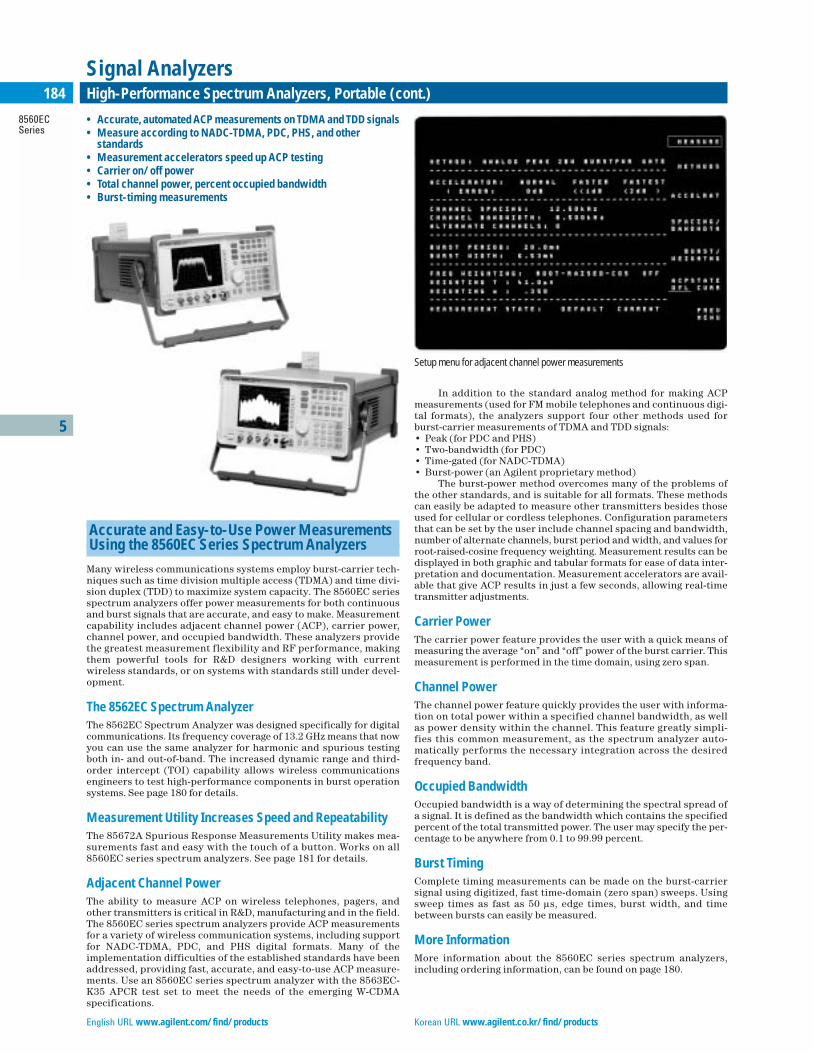
English URL www.agilent.com/find/products Korean URL www.agilent.co.kr/find/products
5
8560ECSeries
184 High-Performance Spectrum Analyzers, Portable (cont.)
Signal Analyzers
Accurate and Easy-to-Use Power Measurements Using the 8560EC Series Spectrum Analyzers
Many wireless communications systems employ burst-carrier tech-niques such as time division multiple access (TDMA) and time divi-sion duplex (TDD) to maximize system capacity. The 8560EC seriesspectrum analyzers offer power measurements for both continuousand burst signals that are accurate, and easy to make. Measurementcapability includes adjacent channel power (ACP), carrier power,channel power, and occupied bandwidth. These analyzers providethe greatest measurement flexibility and RF performance, makingthem powerful tools for R&D designers working with current wireless standards, or on systems with standards still under devel-opment.
The 8562EC Spectrum AnalyzerThe 8562EC Spectrum Analyzer was designed specifically for digitalcommunications. Its frequency coverage of 13.2 GHz means that nowyou can use the same analyzer for harmonic and spurious testingboth in- and out-of-band. The increased dynamic range and third-order intercept (TOI) capability allows wireless communicationsengineers to test high-performance components in burst operationsystems. See page 180 for details.
Measurement Utility Increases Speed and RepeatabilityThe 85672A Spurious Response Measurements Utility makes mea-surements fast and easy with the touch of a button. Works on all8560EC series spectrum analyzers. See page 181 for details.
Adjacent Channel PowerThe ability to measure ACP on wireless telephones, pagers, andother transmitters is critical in R&D, manufacturing and in the field.The 8560EC series spectrum analyzers provide ACP measurementsfor a variety of wireless communication systems, including supportfor NADC-TDMA, PDC, and PHS digital formats. Many of the implementation difficulties of the established standards have beenaddressed, providing fast, accurate, and easy-to-use ACP measure-ments. Use an 8560EC series spectrum analyzer with the 8563EC-K35 APCR test set to meet the needs of the emerging W-CDMAspecifications.
In addition to the standard analog method for making ACPmeasurements (used for FM mobile telephones and continuous digi-tal formats), the analyzers support four other methods used forburst-carrier measurements of TDMA and TDD signals:• Peak (for PDC and PHS) • Two-bandwidth (for PDC) • Time-gated (for NADC-TDMA) • Burst-power (an Agilent proprietary method)
The burst-power method overcomes many of the problems ofthe other standards, and is suitable for all formats. These methodscan easily be adapted to measure other transmitters besides thoseused for cellular or cordless telephones. Configuration parametersthat can be set by the user include channel spacing and bandwidth,number of alternate channels, burst period and width, and values forroot-raised-cosine frequency weighting. Measurement results can bedisplayed in both graphic and tabular formats for ease of data inter-pretation and documentation. Measurement accelerators are avail-able that give ACP results in just a few seconds, allowing real-timetransmitter adjustments.
Carrier PowerThe carrier power feature provides the user with a quick means ofmeasuring the average “on” and “off” power of the burst carrier. Thismeasurement is performed in the time domain, using zero span.
Channel PowerThe channel power feature quickly provides the user with informa-tion on total power within a specified channel bandwidth, as wellas power density within the channel. This feature greatly simpli-fies this common measurement, as the spectrum analyzer auto-matically performs the necessary integration across the desiredfrequency band.
Occupied BandwidthOccupied bandwidth is a way of determining the spectral spread ofa signal. It is defined as the bandwidth which contains the specifiedpercent of the total transmitted power. The user may specify the per-centage to be anywhere from 0.1 to 99.99 percent.
Burst TimingComplete timing measurements can be made on the burst-carriersignal using digitized, fast time-domain (zero span) sweeps. Usingsweep times as fast as 50 µs, edge times, burst width, and timebetween bursts can easily be measured.
More InformationMore information about the 8560EC series spectrum analyzers,including ordering information, can be found on page 180.
• Accurate, automated ACP measurements on TDMA and TDD signals • Measure according to NADC-TDMA, PDC, PHS, and other
standards • Measurement accelerators speed up ACP testing • Carrier on/off power • Total channel power, percent occupied bandwidth • Burst-timing measurements
Setup menu for adjacent channel power measurements

5
E4440AE4443AE4445AE4446AE4448A
185Highest Performance Spectrum Analyzers, PSA Series
Signal Analyzers
PSA Series High-Performance Spectrum Analyzer
The Agilent PSA series offers high-performance spectrum analysisup to 50 GHz with powerful one-button measurements, a versatilefeature set, and a leading-edge combination of flexibility, speed,accuracy, and dynamic range.
Measurement AccuracyThe PSA Series’ modern instrument architecture features an all-digital IF section, a highly accurate internal reference signal, andautomatic internal alignment processes to achieve unsurpassedaccuracy, guaranteed by Agilent’s high standards for meeting ourpublished specifications.
Measurement Speed and Dynamic RangeThe PSA Series spectrum analyzer is designed to optimize measure-ments for speed and dynamic range. With a 2-dB step attenuator and160 resolution bandwidth settings (in 10% steps), you can customizeeach of your measurements to achieve the best combination of speedand dynamic range.
Swept Tuned or FFT AnalysisWith the all-digital IF, the PSA can perform both swept or FFT mea-surements. FFT capability can significantly reduce the sweep timein narrow span measurements and low-level spur searches.
Phase Noise OptimizationIncrease the dynamic range of your close-to-carrier measurementswith the phase noise optimization feature of the PSA Series.Depending on how close to or far from the carrier you are measur-ing, the PSA has different LO phase lock loop configurations toreduce phase noise and therefore increase the dynamic range ofyour measurement.
Gated SweepAnalyzer time varying signals such as pulsed RF, time division mul-tiple access (TDMA), interleaved and burst-modulated with gatedsweep capability. This type of time gating makes fast spectrum mea-surements on burst signals without interference from switching thecarrier on and off.
One-Button Power MeasurementsThe PSA Series offers a standard suite of flexible, one-button RF andmicrowave power measurements with format based setups. WithPower Suite, measurements that were once difficult and tedious tomake are now executed with a single button press and provide easy-to-read results.
One-button measurements include:• channel power• occupied bandwidth• adjacent channel power (ACP)• multi-carrier ACP• power statistics (CCDF)• harmonic distortion• burst power• third order intercept (TOI)• spurious emissions• spectrum emission mask
Format-based setups for:• IS-95A • J-STD-008• IS-95C • GSM/EDGE• 3GPP W-CDMA • cdma2000 • NADC • PDC• Bluetooth • TETRA• W-LAN (802.11a/b/g) • W-LAN HiperLAN/2• DVB-T
Measurements Beyond Spectrum AnalysisThe PSA Series offers a variety of optional measurement personali-ties to expand measurement capability. A measurement personalityis a software program that can transform the spectrum analyzer intoanother type of test instrument, essentially giving it another “per-sonality”. You can make the most challenging measurements veryeasily and with the same instrument you use for spectrum analysis.Perform phase noise measurements for oscillator tests, measure thenoise figure of your amplifier, or even perform modulation analysison your 2G or 3G signal. If you have a proprietary modulated signalthat you want to test, you can link the PSA to the 89601A vector sig-nal analysis software for flexible demodulation and analysis.
ConnectivityThe PSA Series has built-in capability to network with PCs, printers,software programs, and test systems. Features include IVI-COM dri-vers for developing measurement routines and collecting results,IntuiLink connectivity software to transfer measurement resultsand screen captures directly into Microsoft® Excel and Word, a flop-py disk drive to store results and display data, and GPIB and 10baseT LAN for SCPI programming. You can also operate the analyz-er remotely, anywhere in the world, using our BenchLink WebRemote control software (Option 230).
Upgrade from the HP8566B or HP8568B AnalyzerThe PSA Series spectrum analyzers now offer programming codecompatibility with the HP 8566/68B legacy spectrum analyzers.Option 266 was created to allow users with those legacy instrumentsto upgrade their automated test equipment (ATE) systems withmodern and supportable ESA-E or PSA Series spectrum analyzersas the HP 8566/68B instruments reach the end of their formal sup-port lives.
Traditional Chinese URL www.agilent.com.tw/find/products Simplified Chinese URL www.agilent.com.cn/find/products
• Exceptionally fast low-level spur search• All-digital IF gives superior accuracy and linearity• One-button RF power measurements with format-based setups• Optional built-in phase noise and noise figure measurement
personalities• Optional measurement personalities for digital modulation
analysis for 2G/3G applications
PSA Series Spectrum Analyzer
English URL www.agilent.com/find/products Korean URL www.agilent.co.kr/find/products
5
E4440AE4443AE4445AE4446AE4448A
186 Highest Performance Spectrum Analyzers, PSA Series (cont.)
Signal Analyzers
GSM with EDGEThis option includes both Global System for Mobile Communications(GSM) and Enhanced Data Rates for GSM Evolution (EDGE) mea-surements. The following measurements are quick, easy to make, andstandards-based:• transmit power• power versus time (PvT)• phase and frequency error• EDGE EVM• output RF spectrum (ORFS)• transmitter band spurious
cdma2000The cdma2000 measurement personality offers the logical upgradepath from IS-95 to IS-2000 testing. Measurements support the for-ward and reverse links:• code domain analysis• QPSK EVM• modulation accuracy (composite rho and EVM)• channel power• adjacent channel power ratio• intermodulation distortion• spectrum emission mask• occupied bandwidth• CCDF
1xEV-DOThe evolution to cdma2000 with 1xEV-DO introduces unique mea-surement capability. The following measurements are based onTIA/EIA/IS-2000.2 standards and are available for the forward andreverse link signals:• code domain power• modulation accuracy (composite rho)• QPSK EVM• PvT• channel power• intermodulation distortion• spurious emissions and ACP• occupied bandwidth• CCDF
cdmaOneBuilt on Agilent’s pioneering efforts in CDMA measurement tech-niques, this personality provides quick and easy measurement setupsfor the TIA/EIA/IS-95 standards:• modulation accuracy (rho)• code domain analysis• channel power• adjacent channel power ratio• close-in spurious
NADC/PDCBoth the North American Digital Cellular (NADC) and PersonalDigital Cellular (PDC) measurement personalities are included in thisoption. The NADC measurements are structured according to the IS-136 TDMA standard. Measurements included in this option are:• adjacent channel power• error vector magnitude• occupied bandwidth (for PDC)
Measurement Personalities
Phase Noise (Option 226)This optional, built-in measurement personality consolidatesadvanced spectrum analysis capability and phase noise measure-ments into a single oscillator test. This flexible tool can quickly andeasily generate plots of phase noise in dBc/Hz versus log offset fre-quency or measure jitter or make continuous spot frequency phasenoise measurements.
Noise Figure (Option 219)The noise figure measurement personality provides fast, one-buttonnoise figure and gain measurements from 200 kHz up to 26.5 GHz.DUT setup menus help guide you easily through amplifier and mixermeasurements, and a built-in measurement uncertainty calculatormakes it easy to qualify your measurement system. An optionalinternal preamplifier (Option 1DS) improves instrument uncertain-ty to ±0.05 dB for frequencies up to 3 GHz, so you can convenientlyand accurately measure devices with low noise figure.
Digital Demodulation Hardware (Option B7J)This option is required for all the cellular communications measure-ment personalities. It supplies a 1-dB electronic step attenuator forautomatic optimization of speed and dynamic range and the basicmeasurement personality that provides spectrum and waveformanalysis and I/Q pairs (10 MHz, 3 dB bandwidth) over GPIB or LAN.
W-CDMA (Option BAF)The complexity of W-CDMA demands the flexibility and depth ofdemodulation capability provided by this measurement personality.Perform the following measurements on the HPSK uplink or down-link QPSK signals:• code domain analysis• QPSK EVM• modulation accuracy (composite rho and EVM)• channel power• adjacent channel power leakage ratio (ACLR)• intermodulation distortion• multi-carrier power• spectrum emission mask• occupied bandwidth• CCDF
5
E4440AE4443AE4445AE4446AE4448A
187Highest Performance Spectrum Analyzers, PSA Series (cont.)
Signal Analyzers
Frequency SpecificationsFrequency RangeE4443A (DC coupled) 3 Hz to 6.7 GHz
(AC coupled) 10 MHz to 6.7 GHzE4445A (DC coupled) 3 Hz to 13.2 GHz
(AC coupled) 10 MHz to 13.2 GHzE4440A (DC coupled) 3 Hz to 26.5 GHz
(AC coupled) 10 MHz to 26.5 GHzE4446A (DC coupled) 3 Hz to 44 GHzE4448A (DC coupled) 3 Hz to 50 GHzBand Harmonic
Mixing Mode (N)0 1– 3 Hz to 3 GHz1 1– 2.85 GHz to 6.6 GHz2 2– 6.2 GHz to 13.2 GHz3 4– 12.8 GHz to 19.2 GHz4 4– 18.7 GHz to 26.8 GHz5 4+ 26.4 GHz to 31.15 GHz6 8– 31.0 GHz to 50.0 GHz
Frequency ReferenceAccuracy ±[(time since last adjustment x aging rate)
+ temperature stability + calibration accuracy]Aging rate ±1 x 10⁻⁷/yearTemperature stability ±1 x 10⁻⁸ (20˚C to 30˚C)
±5 x 10⁻⁸ (0˚C to 55˚C) Calibration accuracy ±7 x 10⁻⁸
Frequency Readout Accuracy (start, stop, center, marker)±(marker frequency x frequency reference accuracy + 0.25 percentx span + 5 percent x RBW + 2 Hz + 0.5 x horizontal resolution*)*Horizontal resolution is span/(sweep points –1)
Marker Frequency CounterAccuracy ±(marker frequency x frequency
reference accuracy + 0.100 Hz)Delta counter accuracy ±(delta frequency x frequency
reference accuracy + 0.141 Hz)Counter resolution 0.001 Hz
Frequency Span (FFT and swept mode)Range 0 Hz (zero span), 10 Hz to maximum frequency
of modelResolution 2 HzAccuracy ±[0.2 percent x span + span/(sweep points –1)]
Sweep Time and TriggeringRange:
Span = 0 Hz 1 µs to 6000 sSpan ≥10 Hz 1 ms to 2000 s
AccuracySpan ≥10 Hz, sweep ±0.01 % nominalSpan ≥10 Hz, FFT ±40 % nominalSpan = 0 Hz ±0.01 % nominal
Trigger Free run, line, video, RF burst, external front, external rear
Trigger delaySpan = 0 Hz, or FFT –150 ms to +500 msSpan ≥10 Hz, swept 1 µs to 500 msResolution 0.1 µs
Sweep (trace) Point RangeSpan = 0 Hz 2 to 8192Span ≥10 Hz 101 to 8192
Gated FFTMaximum span 10 MHzDelay range –150 to +500 msDelay resolution 100 ns or 4 digits whichever is moreGate duration 1.83/RBW ±2 % nominal
Resolution Bandwidth (RBW)Range (–3.01 dB bandwidth) 1 Hz to 3 MHz (10 % steps), 4, 5, 6, 8 MHzBandwidth accuracy (power):
RBW range:1 Hz to 51 kHz ±0.5 % (±0.022 dB)56 kHz to 75 kHz ±1.0 % (±0.044 dB)82 kHz to 330 kHz ±0.5 % (±0.022 dB)360 kHz to 1.2 MHz (<3 GHz CF) ±1.0 % (±0.044 dB)1.3 MHz to 2.0 MHz (<3 GHz CF) ±0.07 dB nominal2.2 MHz to 6.0 MHz (<3 GHz CF) ±0.02 dB nominal
Bandwidth accuracy (–3.01 dB):RBW range 8 MHz (<3 GHz CF) ±15 % nominal
Selectivity (–60 dB/–3 dB) 4.1:1 nominal
Information BandwidthsMaximum FFT width 10 MHzI/Q waveform digital outputbandwidth (Option E444xA-B7J) 10 MHz321.4 MHz IF output:
–1 dB bandwidth 20 to 30 MHz nominal–3 dB bandwidth 30 to 60 MHz nominal
70 MHz IF output (Option E444xA-H70):–1 dB bandwidth 20 to 30 MHz nominal–3 dB bandwidth 30 to 60 MHz nominal
Video Bandwidth (VBW)Range 1 Hz to 3 MHz (10 % steps),
4, 5, 6, 8 MHz and wide openAccuracy ±6 % nominal
StabilityNoise sidebands (20˚C to 30˚C, CF = 1 GHz)Offset Specification Typical100 Hz –91 dBc/Hz –97 dBc/Hz1 kHz –103 dBc/Hz –107 dBc/Hz10 kHz –114 dBc/Hz –117 dBc/Hz30 kHz –114 dBc/Hz –117 dBc/Hz100 kHz –120 dBc/Hz –123 dBc/Hz1 MHz –144 dBc/Hz –146 dBc/Hz
–148 dBc/Hz nominal6 MHz –151 dBc/Hz –152 dBc/Hz
–156 dBc/Hz nominal10 MHz –151 dBc/Hz –152 dBc/Hz
–157.5 dBc/Hz nominalResidual FM <(1 Hz X N) p-p in 1 s
See frequency range for N (harmonic number)
Amplitude SpecificationsAmplitude RangeMeasurement range Displayed average noise level
(DANL) to maximum safe input levelInput attenuator range 0 to 70 dB in 2 dB steps
Maximum Safe Input LevelAverage total power +30 dBm (1 W)
Preamp (Option E444xA-1DS) +25 dBmPeak pulse power
<10 µs pulse width, <1 % duty cycle and input attenuation ≥30 dB +50 dBm (100 W)
DC volts:DC coupled <±0.2 VdcAC coupled (E4443A, E4445A, ±100 VdcE4440A only)
1 dB Gain Compression (Two-Tone)Total Power at Input Mixer
20 MHz to 200 MHz 0 dBm+3 dBm nominal
200 MHz to 3 GHz +3 dBm+7 dBm nominal
3 GHz to 6.6 GHz +3 dBm+4 dBm nominal
6.6 GHz to 26.5 GHz –2 dBm0 dBm nominal
26.5 GHz to 50 GHz 0 dBm nominalPreamp on (Option E444xA-1DS):10 MHz to 200 MHz –30 dBm nominal200 MHz to 3 GHz –25 dBm nominal
Typical Gain Compression (Two-Tone)Mixer CompressionLevel
20 MHz to 200 MHz 0 dBm <0.5 dB200 MHz to 6.6 GHz +3 dBm <0.5 dB6.6 GHz to 26.5 GHz –2 dBm <0.4 dB
Traditional Chinese URL www.agilent.com.tw/find/products Simplified Chinese URL www.agilent.com.cn/find/products

5
E4440AE4443AE4445AE4446AE4448A
188 Highest Performance Spectrum Analyzers, PSA Series (cont.)
Signal Analyzers
Displayed Average Noise Level (DANL)(Input terminated, sample or average detector, averaging type = Log, 20 to30˚C, zero span, swept normalized to 1 Hz RBW, 0 dB attenuation)
E4443A/E4445A/E4440A Typical3 Hz to 1 kHz — –110 dBm nominal1 kHz to 10 kHz — –130 dBm nominal10 kHz to 100 kHz –135 dBm –142 dBm100 kHz to 1 MHz –145 dBm –149 dBm1 MHz to 10 MHz –150 dBm –153 dBm10 MHz to 1.2 GHz –155 dBm –156 dBm1.2 GHz to 2.5 GHz –154 dBm –155 dBm2.5 GHz to 3.0 GHz –153 dBm –154 dBm3 GHz to 6.6 GHz –152 dBm –153 dBm6.6 GHz to 13.2 GHz –150 dBm –152 dBm13.2 GHz to 20 GHz –147 dBm –149 dBm20 GHz to 26.5 GHz –143 dBm –145 dBm
Preamp ON (Option E4443/5/0A-1DS)100 kHz to 200 kHz –161 dBm –164 dBm200 kHz to 500 kHz –164 dBm –167 dBm500 kHz to 10 MHz –166 dBm –168 dBm10 MHz to 1.1 GHz –169 dBm –170 dBm1.1 GHz to 2.5 GHz –168 dBm –169 dBm2.5 GHz to 3.0 GHz –166 dBm –167 dBm
E4446A/E4448A3 Hz to 1 kHz — –110 dBm nominal1 kHz to 10 kHz — –130 dBm nominal10 kHz to 100 kHz –140 dBm –143 dBm100 kHz to 1 MHz –145 dBm –150 dBm1 MHz to 10 MHz –150 dBm –155 dBm10 MHz to 1.2 GHz –154 dBm –155 dBm1.2 GHz to 2.2 GHz –153 dBm –154 dBm2.2 GHz to 3 GHz –152 dBm –153 dBm3 GHz to 6.6 GHz –151 dBm –152 dBm6.6 GHz to 13.2 GHz –146 dBm –149 dBm13.2 GHz to 20 GHz –145 dBm –147 dBm20 GHz to 22.5 GHz –143 dBm –146 dBm22.5 GHz to 26.8 GHz –140 dBm –144 dBm26.8 GHz to 31.15 GHz –142 dBm –145 dBm31.15 GHz to 36 GHz –134 dBm –136 dBm36 GHz to 38 GHz –129 dBm –132 dBm38 GHz to 44 GHz –131 dBm –134 dBm44 GHz to 49 GHz –128 dBm –131 dBm49 GHz to 50 GHz –127 dBm –130 dBm
Preamp ON (Option E4446/8A-1DS)100 kHz to 200 kHz –160 dBm –164 dBm200 kHz to 500 kHz –163 dBm –167 dBm500 kHz to 10 MHz –164 dBm –168 dBm1 MHz to 10 MHz –167 dBm –169 dBm10 MHz to 1.2 GHz –167 dBm –169 dBm1.2 GHz to 2.2 GHz –166 dBm –168 dBm2.2 GHz to 3.0 GHz –164 dBm –166 dBm
Display RangeLog scale 0.1 to 1 dB/division in 0.1 dB steps
1 to 20 dB/division in 1 dB steps(10 display divisions)
Linear scale 10 divisionsScale units dBm, dBmV, dBuV, V, and W
Frequency Response(10 dB input attenuation, 20 to 30˚C, preselector centering applied)E4443A/E4445A/E4440A Typical3 Hz to 3 GHz ±0.38 dB ±0.11 dB3 GHz to 6.6 GHz ±1.50 dB ±0.6 dB6.6 GHz to 22 GHz ±2.00 dB ±1.0 dB22 GHz to 26.5 GHz ±2.50 dB ±1.3 dBE4446A/E4448A3 Hz to 3 GHz ±0.38 dB ±0.15 dB3 GHz to 6.6 GHz ±1.50 dB ±0.6 dB6.6 GHz to 22 GHz ±2.00 dB ±1.2 dB22 GHz to 26.8 GHz ±2.50 dB ±1.3 dB26.4 GHz to 31.15 GHz ±1.75 dB ±0.6 dB31.15 GHz to 50 GHz ±2.50 dB ±1.0 dBFrequency response at attenuation ≠ 10 dB(Atten = 20, 30, or 40 dB)10 MHz to 2.2 GHz ±0.53 dB2.2 GHz to 3 GHz ±0.69 dBPreamp on (Option E444xA-1DS), (for all models)100 kHz to 3 GHz ±0.70 dB <(±0.30 dB typical)
Input Attenuation Switching Uncertainty(Attenuator setting ≥2 dB)At 50 MHz ±0.18 dB3 Hz to 3 GHz ±0.3 dB nominal3 GHz to 13.2 GHz ±0.5 dB nominal13.2 GHz to 26.5 GHz ±0.7 dB nominal26.5 GHz to 50 GHz ±1.0 dB nominal
Absolute Amplitude Accuracy(10 dB attenuation, 20 to 30˚C, 10 Hz ≤RBW ≤1 MHz, input signal–10 to –50 dBm, all settings auto-coupled except Auto Swp Time = Accy,any reference level, any scale)At 50 MHz ±0.24 dB (±0.06 dB typical)At all frequencies ±(0.24 dB + frequency response)
±(0.06 dB + frequency response) typical3 Hz to 3 GHz (95 % confidence) ±0.24 dBPreamp on (Option E444xA-1DS) ±(0.36 dB + frequency response)
±(0.09 dB + frequency response) typical
Input Voltage Standing Wave Ratio (VSWR)(≥8 dB input attenuation)50 MHz to 3 GHz <1.2:1 nominal3 GHz to 18 GH <1.6:1 nominal18 GHz to 26.5 GHz <1.9:1 nominal26.5 GHz to 50 GHz <1.6:1 nominalPreamp on (50 MHz to 3 GHz)(≥10 dB attenuation) <1.2:1 nominal
Resolution Bandwidth Switching Uncertainty(referenced to 30 kHz RBW)1 Hz to 1 MHz RBW ±0.03 dB1.1 MHz to 3 MHz RBW ±0.05 dB4, 5, 6, 8 MHz RBW ±1.0 dB
Reference LevelRange:
Log scale –170 dBm to +30 dBm in 0.01 dB stepsLinear scale 707 pV to 7.07 V in 0.1 % steps
Accuracy 0 dB
Display Scale Switching UncertaintySwitching between linear and log 0 dBLog scale/div switching 0 dB
Display Scale Fidelity≤–20 dBm input mixer level ±0.07 dB total–20 dBm<mixer level≤–10 dBm ±0.13 dB total
Spurious Response (mixer level = –40 dBm)General spurious:f <10 MHz from carrier (–73 + 20 log N) dBcf ≥10 MHz from carrier (–80 + 20 log N) dBc
(–90 + 20 log N) dBc typicalSee frequency range for N
English URL www.agilent.com/find/products Korean URL www.agilent.co.kr/find/products
5
E4440AE4443AE4445AE4446AE4448A
189Highest Performance Spectrum Analyzers, PSA Series (cont.)
Signal Analyzers
Second Harmonic Distortion (SHI)E4443A, E4445A, E4440A Distortion (dBc) SHI (dBm)10 MHz to 400 MHz –82 +42(–40 dBm mixer level)400 MHz to 1.25 GHz –92 +52(–40 dBm mixer level)1.25 GHz to 1.5 GHz –82 +42(–40 dBm mixer level)1.5 GHz to 2.0 GHz –90 +80(–10 dBm mixer level)2.0 GHz to 13.25 GHz –100 +90(–10 dBm mixer level)E4446A, E4448A Distortion (dBc) SHI (dBm)10 MHz to 400 MHz –82 +42(–40 dBm mixer level)400 MHz to 1.25 GHz –91 +51(–40 dBm mixer level)1.25 GHz to 1.5 GHz –81 +41(–40 dBm mixer level)1.5 GHz to 2.0 GHz –90 +80(–10 dBm mixer level)2.0 GHz to 3.25 GHz –94 +84(–10 dBm mixer level)3.25 GHz to 13.25 GHz –96 +86(–10 dBm mixer level)13.25 GHz to 25 GHz –100 nominal +90 nominal(–10 dBm mixer level)Preamp on (Option E444xA-1DS), (for all models, input preamp level =–45 dBm)10 MHz to 1.5 GHz –60 nominal +15 nominal
Third-Order Intermodulation Distortion (TOI)(two –30 dBm tones at input mixer with tone separation >15 kHz, 20 to 30˚C )E4443A/E4445A/E4440A Distortion (dBc) TOI (dBm)10 MHz to 100 MHz –88 +14 (+17 typical)100 MHz to 400 MHz –90 +15 (+18 typical)400 MHz to 1.7 GHz –92 +16 (+19 typical)1.7 GHz to 3.0 GHz –94 +17 (+19 typical)3.0 GHz to 6.0 GHz –90 +15 (+18 typical)6.0 GHz to 16 GHz –76 +8 (+11 typical)16 GHz to 26.5 GHz –84 +12 (+14 typical)E4446A/E4448A Distortion (dBc) TOI (dBm)10 MHz to 100 MHz –90 +15 (+20 typical)100 MHz to 400 MHz –92 +16 (+21 typical)400 MHz to 1.7 GHz –94 +17 (+20 typical)1.7 GHz to 3.0 GHz –96 +18 (+21 typical)3.0 GHz to 6.0 GHz –92 +16 (+21 typical)6.0 GHz to 16 GHz –84 +12 (+15 typical)16.0 GHz to 26.5 GHz –84 +12 (+16 typical)26.5 GHz to 50 GHz –85 nominal +12.5 nominalPreamp on (Option E444xA-1DS, for all models, two –45 dBm tones atpreamp input)10 MHz to 500 MHz –15 nominal500 MHz to 3 GHz –13 nominal
Residual ResponsesInput terminated and 0 dB attenuation200 kHz to 6.6 GHz –100 dBm6.6 GHz to 26.8 GHz –100 dBm nominal26.8 GHz to 50 GHz –90 dBm nominal
Trace DetectorsNormal, peak, sample, negative peak, log power average,RMS average, and voltage average
Option E444xA-1DS, PreamplifierFrequency range 100 kHz to 3 GHzGain 28 dB nominalNoise figure 7 dB nominal
Measurement SpeedLocal measurement and display update rate ≥50/s nominalRemote measurement and GPIB transfer rate
101 sweep points ≥45/s nominal401 sweep points ≥30/s nominal601 sweep points ≥25/s nominal
Power Suite Measurement SpecificationsChannel PowerAmplitude accuracy, W-CDMA or IS95 (20 to 30 °C, mixer level <–20 dBm) ±0.68 dB (±0.21 dB typical)
Occupied BandwidthFrequency accuracy ± [span/600] nominal
Adjacent Channel PowerAccuracy, W-CDMA (ACLR) (at specific mixer levels and ACLR ranges):
Adjacent AlternateMS ±0.12 dB ±0.17 dBBTS ±0.22 dB ±0.22 dB
Dynamic range (typical):w/o noise correction –74.5 dB –82 dBw/noise correction –81 dB –88 dBOffset channel pairs measured 1 to 6
Multi-Carrier Power and ACPACPR dynamic range, W-CDMA (5 MHz offset, RRC weighted,3.84 MHz noise bandwidth):
Two carriers –70 dB nominalFour carriers –68 dB nominal
ACPR accuracy (two carriers, 5 MHz offset, –48 dBc ACPR) ±0.38 dB nominalMultiple number ofcarriers measured Up to 12
Power Statistics CCDFHistogram resolution 0.1 dB
Harmonic DistortionMaximum harmonic number 10th
Results Fundamental power (dBm), relative harmonics power (dBc), total harmonic distortion in percent
Intermod (TOI)Measure the third-order products and intercepts from two tones
Burst PowerMethods Power above threshold, power within
burst widthResults Single burst output power, average output
power, maximum power, minimum power within burst, burst width
Spurious Emissioncdma2000 or W-CDMA (1980 MHz region, 1.2 MHz RBW)Table driven spurious signals; search across regions.Relative dynamic range 80.6 dB (82.4 dB typical)Absolute sensitivity –89.7 dBm (–91.7 dBm typical)
Spectrum Emission Mask (SEM)cdma2000 (750 kHz offset):
Relative dynamic range 85.3 dB (88.3 dB typical) (30 kHz RBW)
Absolute sensitivity –105.7 dBm (–107 dBm typical)Relative accuracy ±0.09 dB
3GPP W-CDMA (2.515 MHz offset):Relative dynamic range 87.3 dB (89.5 dB typical)
(30 kHz RBW)Absolute sensitivity –105.7 dBm (–107.7 dBm typical)Relative accuracy ±0.10 dB
Traditional Chinese URL www.agilent.com.tw/find/products Simplified Chinese URL www.agilent.com.cn/find/products

English URL www.agilent.com/find/products Korean URL www.agilent.co.kr/find/products
5
E4440AE4443AE4445AE4446AE4448A
190 Highest Performance Spectrum Analyzers, PSA Series (cont.)
Signal Analyzers
Input and OutputsFront PanelRF InputConnector:
E4443A/E4445A Type-N female, 50 ΩE4440A Type-N female, 50 Ω
E4440A-BAB APC 3.5 maleE4446A/E4448A 2.4 mm male, 50 Ω
Probe PowerVoltage/current (nominal) +15 Vdc, ±7 % at 150 mA max
–12.6 Vdc, ±10 % at 150 mA max GNDHeadphone Reserved for future applicationsExt Trigger InputConnector BNC femaleImpedance 10 kΩ nominalTrigger level 5 V TTL nominal
Rear Panel10 MHz OUT (switched)Connector BNC female, 50 ΩOutput amplitude ≥0 dBm nominalFrequency accuracy 10 MHz ±(10 MHz x frequency
reference accuracy)Ext Ref InConnector BNC female, 50 ΩInput amplitude range –5 to +10 dBm nominalInput frequency 1 to 30 MHz nominalFrequency lock range ±5 x 10⁻⁶ of specified external
reference input frequencyTrigger InConnector BNC femaleExternal trigger input:
Impedance >10 kΩ nominalTrigger level 5 V TTL
Trigger 1 and Trigger 2 OutputsConnector BNC femaleTrigger 1 output: HSWP (high = sweeping)
Impedance 50 Ω nominalLevel 5 V TTL
Trigger 2 output Reserved for future applicationsMonitor OutputConnector VGA compatible, 15-pin mini D-SUBFormat VGA (31.5 kHz horizontal, 60 Hz vertical
sync rates, non-interlaced)Analog RGB
Resolution 640 X 480Noise Source Drive OutputConnector BNC femaleOutput voltage
On 28.0 ±0.1 V (60 mA maximum)Off <1 V
Remote ProgrammingGPIB interface:
Connector IEEE-488 bus connectorGPIB codes SH1, AH1, T6, SR1, RL1, PP0, DC1,
C1, C2, C3, and C28, DT1, L4, C0Serial interface connector 9-pin D-SUB male (factory use only)LAN TCP/IP interface RJ45 EthertwistParallel Printer Interface Connector25-pin D-SUB female321.4 MHz IF OutputConnector SMA female, 50 Ω nominalFrequency 321.4 MHz nominalConversion gain +2 to +4 dB nominal
General SpecificationsTemperature RangeOperating 0˚C to +55˚CStorage –40˚C to +75˚C
EMI CompatibilityConducted interference is in compliance with CISPR Pub 11/1990 Group 1 Class ARadiated emission is in compliance with CISPR Pub 11/1990 Group 1 Class B
Audio NoiseISO 7779 LNPE <5.0 BELS at 25˚C
Military SpecificationType tested to environmental specifications MIL-PRF-28800F Class 4
Power RequirementsVoltage and frequency:
100 to 132 Vrms, 47 to 66 Hz/360 to 440 Hz195 to 250 Vrms, 47 to 66 Hz
Power consumption:On <260 watts, no options
(<450 watts, all options)Standby <20 watts
Weight (without options)E4443A, E4445A, E4440ANet 23 kg (50 lbs) nominalShipping 33 kg (73 lbs) nominalE4446A, E4448ANet 24 kg (53 lbs) nominalShipping 34 kg (76 lbs) nominal
DimensionsHeight 177 mm (7.0 in)Width 426 mm (16.8 in)Length 483 mm (19 in)
WarrantyThe E4440A, E4443A, E4445A, E4446A and E4448A are suppliedwith a three-year warranty.
Calibration CycleThe recommended calibration cycle is one year. Calibration servicesare available through Agilent service centers.

Traditional Chinese URL www.agilent.com.tw/find/products Simplified Chinese URL www.agilent.com.cn/find/products
5
E4440AE4443AE4445AE4446AE4448A
191Highest Performance Spectrum Analyzers, PSA Series (cont.)
Signal Analyzers
Ordering InformationPSA Series Spectrum AnalyzerE4443A 3 Hz to 6.7 GHzE4445A 3 Hz to 13.2 GHzE4440A 3 Hz to 26.5 GHzE4446A 3 Hz to 44 GHzE4448A 3 Hz to 50 GHz
OptionsTo add options to a product, use the following ordering scheme:Model: E444xA (x = 0, 3, 5, 6 or 8)Example options: E4440A-B7J, E4448A-1DSDigital Demodulation HardwareE444xA-B7J: Digital demodulation hardware (required for digitaldemodulation measurement personalities)
Digital Demodulation MeasurementsE444xA-BAF W-CDMA measurement personalityE444xA-202 GSM w/ EDGE measurement personalityE444xA-B78 cdma2000 measurement personalityE444xA-204 1xEV-DO measurement personalityE444xA-BAC cdmaOne measurement personalityE444xA-BAE NADC, PCD measurement personality
General Purpose MeasurementsE444xA-226 Phase noise measurement personalityE444xA-219 Noise figure measurement personality
AmplifiersE444xA-1DS 100 kHz to 3 GHz built-in preamplifier
Inputs and OutputsE4440A-BAB Replaces type “N” input connector with APC 3.5 connector
Connectivity SoftwareE444xA-230 BenchLink Web Remote Control Software
Code CompatibilityE444xA-266 HP 8566B/8568B code compatibility measurement personality
AccessoriesE444xA-1CM Rackmount kitE444xA-1CN Front handle kitE444xA-1CP Rackmount with handlesE444xA-1CR Rack slide kitE444xA-045 Millimeter wave accessory kitE444xA-0B1 Extra manual set including CD ROM
Warranty and ServiceStandard warranty is 3 years. For warranty and service of 5 years, please order R-51B-001-5F: “3 year Return-to-Agilent warranty extendedto 5 years” (quantity = 1).
Calibration1
For 3 years, order 36 months of the appropriate calibration plan shownbelow. For 5 years, specify 60 months.R-50C-001 Standard calibrationR-50C-002 Standards compliant calibrationE444xA-OBW Service manual and calibration softwareE444xA-UK6 Commercial calibration certificate with test data1Options not available in all countries
Key Literature & Web LinkProduct LiteraturePSA Series, brochure, literature number 5980-1283EPSA Series, data sheet, literature number 5980-1284ESelf-Guided Demonstration for Spectrum Analysis, product note, literature number 5988-0735ENPhase Noise Measurement Personality, technical overview, literature number 5988-3698ENNoise Figure Measurement Personality, technical overview, literature number 5988-7884ENW-CDMA Measurement Personality, technical overview, literature number 5988-2388ENGSM with EDGE Measurement Personality, technical overview, literature number 5988-2389ENcdma2000 Measurement Personality, technical overview, literature number 5988-3694EN1xEV-DO Measurement Personality, technical overview, literature number 5988-4828ENcdmaOne Measurement Personality, technical overview, literature number 5988-3695ENNADC/PDC Measurement Personality, technical overview, literature number 5988-3697ENOptimizing Dynamic Range for Distortion Measurements, product note, literature number 5980-3079ENPSA Series Amplitude Accuracy, product note, literature number 5980-3080ENPSA Series Swept and FFT Analysis, product note, literature number 5980-3081ENPSA Series Measurement Innovations and Benefits, product note, literature number 5980-3082EN8 Hints for Millimeter Wave Spectrum Measurements, application note,literature number 5988–5680ENPSA Series Spectrum Analyzers, Option H70, 70 MHz IF Output, productoverview, literature number 5988-5261ENPSA Series Spectrum Analyzer Performance Guide Using 89601A VectorSignal Analysis Software, product note, literature number 5988-5015EN89600 Series + PSA, 802.11A and HiperLAN2 ODFM Measurements, product note, literature number 5988-4094EN
Related LiteratureSelecting the Right Signal Analyzer for Your Needs, selection guide, literature number 5968-3413EBenchLink Web Remote Control Software, product overview, literature number 5988-2610ENIntuiLink Software, Data Sheet, Literature Number 5980-3115EN
For more information on the PSA Series, please visit:www.agilent.com/find/psa
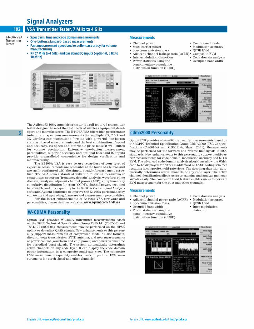
5
E4406A VSATransmitterTester
192 VSA Transmitter Tester, 7 MHz to 4 GHz
Signal Analyzers
The Agilent E4406A transmitter tester is a full-featured transmittertester designed to meet the test needs of wireless equipment devel-opers and manufacturers. The E4406A VSA offers high performancein-band and spectrum measurements for multiple 2G, 2.5G and 3G wireless communications formats with powerful one-button standard-based measurements, and the best combination of speedand accuracy. Its speed and affordable price make it well suited for volume production. Extensive one-button measurement personalities, superior accuracy and optional baseband IQ inputsprovide unparalleled convenience for design verification and manufacturing.
The E4406A VSA is easy to use regardless of your level ofexpertise. Measurements are accessible at the touch of a button andare easily configured with the simple, straightforward menu struc-ture. The VSA comes standard with the following measurementcapabilities: spectrum (frequency domain) analysis, waveform (timedomain) analysis, adjacent channel power (ACP), complimentarycumulative distribution function (CCDF), channel power, occupiedbandwidth, and link capability to the 89601A Vector Signal Analysissoftware. Agilent continues to improve the E4406A performance byenhancing and upgrading firmware and measurement personalities.
For the latest enhancements of E4406A VSA firmware and personalities, please visit our web site: www.agilent.com/find/vsa
W-CDMA Personality
Option BAF provides W-CDMA transmitter measurements based on the 3GPP Technical Specification Group TS25.141 (2002-06) andTS34.121 (2002-06). Measurements may be performed on the HPSKuplink or downlink QPSK signals. New enhancements to this person-ality support measurements of compressed mode, all slot formats,discontinuous transmission, STTD antenna, and new measurementsof power control (waveform and chip power) and power versus timefor periodical burst signals. The system automatically determinesactive channels on any code layer. It can display the code domainpower information in a composite multi-rate view. The compositeEVM measurement capability enables users to perform EVM mea-surements for perch signal and other channels.
Measurements• Channel power • Compressed mode• Multi-carrier power • Modulation accuracy• Spectrum emission mask • QPSK EVM• Adjacent channel leakage ratio (ACLR)• Composite EVM• Inter-modulation distortion • Code domain analysis• Power statistics using the • Occupied bandwidth
complimentary cumulative distribution function (CCDF)
cdma2000 Personality
Option B78 provides cdma2000 transmitter measurements based onthe 3GPP2 Technical Specification Group CDMA2000 (TSG-C) speci-fications (C.S0010-A and C.S0011-A, March 2001). Measurementsmay be performed for the forward and reverse link signals IS-2000standards. New enhancements to this personality support multi-car-rier measurements for code domain, modulation accuracy and QPSKEVM. The advanced code domain analysis algorithms allow the Walshcode to be displayed for either Haddamard or OVSF coding schemesresulting in composite multi-rate views. The decoding algorithm auto-matically determines active channels of any code layer. The activechannel identification allows users to examine and analyze unknownsignals easily. The composite EVM feature enables users to performEVM measurement for the pilot and other channels.
Measurements• Channel power • Code domain analysis• Adjacent channel power ratio (ACPR) • Modulation accuracy• Spectrum emission mask • QPSK EVM• Occupied bandwidth • Inter-modulation • Power statistics using the distortion
complimentary cumulative distribution function (CCDF)
English URL www.agilent.com/find/products Korean URL www.agilent.co.kr/find/products
• Spectrum, time and code domain measurements• One-button, standard-based measurements • Fast measurement speed and excellent accuracy for volume
manufacturing• RF (7 MHz to 4 GHz) and baseband IQ inputs (optional, 5 Hz to
10 MHz)
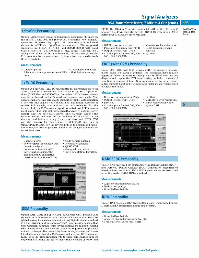
5
E4406A VSATransmitterTester
193VSA Transmitter Tester, 7 MHz to 4 GHz (cont.)
Signal Analyzers
cdmaOne Personality
Option BAC provides cdmaOne transmitter measurements based onthe IS-95A, J-STD-008, and IS-97D/98D standards. New enhance-ments to this personality support all radio standards and bandclasses for ACPR and SpurClose measurements. The supportedstandards are IS-95A, J-STD-008 and IS-97D IS-98D with BandClass 0 (800 MHz), 1 (1900 MHz), 3 (JTACS) and 4 (Korean PCS).Along with the fast ACPR measurements, this personality featuresPN (pseudo-noise sequence) search, time offset, and carrier feed-through analysis.
Measurements• Channel power • Code domain analysis• Adjacent channel power ratio (ACPR) • Modulation accuracy• Spur
1xEV-DO Personality
Option 204 provides 1xEV-DO transmitter measurements based on3GPP2 Technical Specification Group cdma2000 (TSG-C) specifica-tions (C.S0032-A and C.S0033-A, December 2001). Measurementsmay be performed on the forward and reverse link signals. Newenhancements to this personality support preamble auto detectionof forward link signals, code domain and modulation accuracy ofreverse link signals, and multi-carrier measurements. For the forward link, the PvT mask and spurious emissions/ ACP measure-ment support both idle slot (burst signal) and active slot (full powersignal). With the auto-burst search function, users can see the standard-based time mask for the 1xEV-DO idle slot in PvT. Codedomain, modulation accuracy (composite rho), and QPSK EVM can also measure for each channel’s pilot, MAC, and Data inQPSK/8PSK/16QAM. For the reverse link, code domain and modu-lation analysis provide powerful modulation analysis functions fortransmitter tests.
Measurements• Channel power • Code domain analysis• Power versus time mask Code • Modulation analysis
domain analysis • QPSK EVM• Spurious emission & ACP • Occupied bandwidth• Power statistics using the • Inter-modulation distortion
complimentary cumulative distribution function (CCDF)
GSM Personality
Option BAH (GSM) and option 202 (EDGE with GSM) provide GSMtransmitter measurements based on latest ETSI standards. The GSM(global system for mobile communications) digital cellular standardis a time division multiple access (TDMA) multiplexing scheme thatuses Gaussian minimum shift keying (GMSK) modulation. MakingGSM measurements and meeting standards requirements presentsunique challenges. The personality features easy channel and times-lot selections, configurable PvT masks, and a typical ORFS dynamicrange of 90 dB. New enhancements to these personalities supportbaseband I/Q inputs and faster measurement speed of ORFS and
PFER. The E4406A VSA with option 300 (341.4 MHz IF output)becomes the down converter for ESG (E4438C) with option 300 toperform GSM/EDGE bit error rate test.
Measurements• GMSK power versus time • Mean transmit carrier power• Phase and frequency error (PFER) • GMSK transmitter band • Output RF spectrum (ORFS) spurious• Channel plans for 400, 700, 800, • IQ offset
900, 1800, 1900 MHz
EDGE (with GSM) Personality
Option 202 (EDGE with GSM) provides EDGE transmitter measure-ments based on latest standards. The advanced demodulation algorithms allow the users to rapidly view an EDGE constellationdiagram and display the EVM results using the industry standardspecified measurement filter. New enhancements to these person-alities support baseband I/Q input and faster measurement speedof ORFS and PFER.
Measurements• Error vector magnitude (EVM) • IQ offset• Output RF spectrum (ORFS) • Multi slot power versus time • IQ offset • All GSM measurement of• Channel plans for 400, 700, 800, option BAH
900, 1800, 1900 MHz
NADC/PDC Personality
Option BAE provides both North American Digital Cellular (NADC)and Personal Digital Cellular (PDC) transmitter measurementbased on latest standards. The NADC measurements are structuredaccording to the IS-136 TDMA standard.
Measurements• Adjacent channel power (ACP)• Modulation quality• Occupied bandwidth
iDEN Personality
Option HN1 provides iDEN transmitter measurement based on theMotorola iDEN specialized mobile radio format.
Measurements• Occupied bandwidth• Adjacent channel power ratio (ACPR)• Transmitter bit error rate (BER)
Traditional Chinese URL www.agilent.com.tw/find/products Simplified Chinese URL www.agilent.com.cn/find/products

5
E4406A VSATransmitterTester
194 VSA Transmitter Tester, 7 MHz to 4 GHz (cont.)
Signal Analyzers
Baseband IQ Inputs
The option B7C baseband IQ inputs enables users to measure thecomplete path of a receiver or transmitter and directly compare sig-nals both before and after frequency conversion and IQ (de)modu-lation. Ideally suited for R&D engineers and manufacturing environments, this option allows measurement of baseband I and Q signals in either balanced or unbalanced systems. Input configura-tion includes 50 unbalanced, 600 balanced, and 1 M balancedor unbalanced – enabling a variety of systems to be directly testedwithout cumbersome and error-including conversion networks.Applicable in-band 3GPP W-CDMA, cdma2000, EDGE/GSM, andBasic mode measurements are supported via RF and IQ inputs,enabling users to track down signal degradation both before andafter RF/IF conversion.
E4406A VSA Transmitter Tester Key Features
• One-button, standard-based measurements for W-CDMA,cdma2000, cdmaOne, 1xEV-DO, GSM, EDGE, NADC, PDC andiDEN
• Pass/fail test with built-in test limits • Baseband I/Q inputs (option) • Link to 89601A Vector Signal Analysis software• GPIB, LAN and parallel interfaces standard• Built-in 3.5-inch disk drive• SCPI instrument command• VXIplug&play drivers• User upgradeable firmware• Large high-resolution color LCD display
Frequency SpecificationsFrequency Range RF input 7 MHz to 314 MHz, 329 MHz to 4 GHzBaseband IQ input 5 Hz to 5 MHzComposite IQ input 5 Hz to 10 MHzFrequency setting resolution 1 HzPhase noise (960 MHz)1 kHz offset ≤–87 dBc/Hz10 kHz offset ≤–96 dBc/Hz
Amplitude SpecificationsMaximum input power +35 dBm (3.16 W)Input attenuator 0 to +40 dB, 1 dB steps Third order intermodulation distortion (50 MHz to 4 GHz, two –10 dBm tones) Tone separation ≥5 MHz <–56 dBc (TOI +18 dBm, + 23 dBm typical)Tone separation ≥50 kHz <–54 dBc (TOI +17 dBm, +21 dBm typical)1 dB gain compression2 tones separation ≥3 MHz +2 dBm, +6 dBm (typical)2 tones separation ≥40 MHz +5 dBm, +10 dBm ( typical)Absolute power measurement accuracy, RF input810 MHz to 960 MHz ±0.6 dB, ±0.4 dB (typical)1710 MHz to 2205 MHz ±0.6 dB, ±0.4 dB (typical)1428 MHz to 1503 MHz ±0.6 dB, ±0.6 dB (typical)Displayed average noise level(Input terminated in 50 , 0 dB attenuation, 1 kHz RBW, 10 kHz span)20 MHz to 2000 MHz –106 dBm, –111 dBm (typical)2000 MHz to 2700 MHz –103 dBm, –108 dBm (typical)2700 MHz to 4000 MHz –98 dBm, –104 dBm (typical)
Physical SpecificationsPower requirements 90 to 132 Vrms, 47 to 440 Hz
195 to 250 Vrms, 47 to 66 HzPower consumption <350 W (ON), <20 W (Standby)Weight (without options) 19 kg (42 lb) netDimensions 177 mm H x 426 mm W x 432 mm D
(7.0 in H x 16.8 in W x 17 in D)
W-CDMA (Option BAF)Channel power absolute accuracy ±0.63 dB, ±0.41 dB (typical)Adjacent channel power ratio (ACPR): Accuracy (RRC weighted, 3.84 MHz noise bandwidth)MS, 5 MHz/10 MHz offset ±0.2 dB/±0.3 dBBTS, 5 MHZ.10 MHz offset ±0.93 dB/±0.82 dB Dynamic range, 5 MHz/10 MHz offset 68 dB (nominal)/72 dB (nominal)Multi-carrier power:ACPR accuracy, two carriers, ±0.70 dB (nominal)5 MHz offset, –48 dBc ACPRACPR dynamic range, two carriers, –64 dBm (nominal) 5 MHz offset
–68 dBm (nominal) 10 MHz offsetPower statistics CCDF histogram 0.01 dBresolutionOccupied bandwidth frequency 100 HzresolutionSpectrum emission mask (SEM)Dynamic range, 2.515 MHz offset –77.9 dB, –82.8 dB (typical)Sensitivity, 2.515 MHz offset –88.9 dBm, –93.9 dBm (typical)Relative accuracy, ±0.60 dB, ±0.40 dB (typical)display = Abs Peak PwrCode domain power relative accuracy ±0.08 dB (95 %)(Test Model 1 with 32 DPCH, 0 to –30 dBc) Symbol power versus time relative ±0.10 dB (95 %)accuracy (Test Model 1 with 32 DPCH, 0 to –25 dBc)Symbol EVM accuracy (Test Model 1 ±1.0 % (95 %)with 32 DPCH, 0 to –25 dBc)QPSK downlink EVM accuracy ±1.0 % (nominal, at EVM of 10 %)Power control & power vs.time ±0.7 dB (nominal)absolute power accuracy, 0 to –20 dBmComposite EVM accuracy ±1.0 %(Test Model 4)
Key Literature & Web LinkE4406A VSA Transmitter Tester Data Sheet, p/n 5968-3030EE4406A VSA Transmitter Tester Brochure, p/n 5968-7618EE4406A Vector Signal Analyzer Performance Guide using 89601A VectorSignal Analyzer SoftwareSpectrum Analyzer Selection Guide, p/n 5968-3413EW-CDMA Measurement Personality, technical overview, literature number 5988-2388ENGSM with EDGE Measurement Personality, technical overview, literature number 5988-2389ENcdma2000 Measurement Personality, technical overview, literature number 5988-3694EN1xEV-DO Measurement Personality, technical overview, literature number 5988-4828ENcdmaOne Measurement Personality, technical overview, literature number 5988-3695ENNADC/PDC Measurement Personality, technical overview, literature number 5988-3697EN
Ordering InformationE4406A VSA Transmitter Tester, 7 MHz to 4 GHz
E4406A-202 EDGE with GSM measurement personalityE4406A-204 1xEV-DO measurement personalityE4406A-B78 cdma2000 measurement personalityE4406A-BAC cdmaOne measurement personalityE4406A-BAE NADC, PDC measurement personalityE4406A-BAF W-CDMA measurement personalityE4406A-BAH GSM measurement personalityE4406A-HN1 iDEN measurement personality E4406A-300 321.4 MHz IF outputE4406A-B7C Baseband I/Q input, 5 Hz to 10 MHzE4406A-UK6 Commercial calibration certificate with test dataE4406A-1CM Rackmount kitE4406A-1CN Handle kitE4406A-1CP Rackmount kit with handle kit E4406A-1CR Rack slide kitE4406A-OBV Service documentation, component levelE4406A-OBW Service documentation, assembly level
English URL www.agilent.com/find/products Korean URL www.agilent.co.kr/find/products
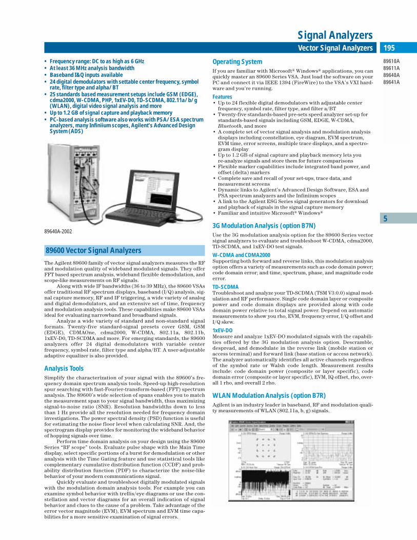
5
89610A89611A89640A89641A
195Vector Signal Analyzers
Signal Analyzers
89600 Vector Signal Analyzers
The Agilent 89600 family of vector signal analyzers measures the RFand modulation quality of wideband modulated signals. They offerFFT based spectrum analysis, wideband flexible demodulation, andscope-like measurements on RF signals.
Along with wide IF bandwidths (36 to 39 MHz), the 89600 VSAsoffer traditional RF spectrum displays, baseband (I/Q) analysis, sig-nal capture memory, RF and IF triggering, a wide variety of analogand digital demodulators, and an extensive set of time, frequencyand modulation analysis tools. These capabilities make 89600 VSAsideal for evaluating narrowband and broadband signals.
Analyze a wide variety of standard and non-standard signalformats. Twenty-five standard-signal presets cover GSM, GSM(EDGE), CDMAOne, cdma2000, W-CDMA, 802.11a, 802.11b, 1xEV-D0, TD-SCDMA and more. For emerging standards, the 89600 analyzers offer 24 digital demodulators with variable center frequency, symbol rate, filter type and alpha/BT. A user-adjustableadaptive equalizer is also provided.
Analysis ToolsSimplify the characterization of your signal with the 89600’s fre-quency domain spectrum analysis tools. Speed-up high-resolutionspur searching with fast-Fourier-transform-based (FFT) spectrumanalysis. The 89600’s wide selection of spans enables you to matchthe measurement span to your signal bandwidth, thus maximizingsignal-to-noise ratio (SNR). Resolution bandwidths down to lessthan 1 Hz provide all the resolution needed for frequency domaininvestigations. The power spectral density (PSD) function is usefulfor estimating the noise floor level when calculating SNR. And, thespectrogram display provides for monitoring the wideband behaviorof hopping signals over time.
Perform time domain analysis on your design using the 89600Series “RF scope” tools. Evaluate pulse shape with the Main Timedisplay, select specific portions of a burst for demodulation or otheranalysis with the Time Gating feature and use statistical tools likecomplementary cumulative distribution function (CCDF) and prob-ability distribution function (PDF) to characterize the noise-likebehavior of your modern communications signal.
Quickly evaluate and troubleshoot digitally modulated signalswith the modulation domain analysis tools. For example you canexamine symbol behavior with trellis/eye diagrams or use the con-stellation and vector diagrams for an overall indication of signalbehavior and clues to the cause of a problem. Take advantage of theerror vector magnitude (EVM), EVM spectrum and EVM time capa-bilities for a more sensitive examination of signal errors.
Operating SystemIf you are familiar with Microsoft® Windows® applications, you canquickly master an 89600 Series VSA. Just load the software on yourPC and connect it via IEEE 1394 (FireWire) to the VSA’s VXI hard-ware and you’re running.
Features • Up to 24 flexible digital demodulators with adjustable center
frequency, symbol rate, filter type, and filter a/BT • Twenty-five standards-based pre-sets speed analyzer set-up for
standards-based signals including GSM, EDGE, W-CDMA,Bluetooth, and more
• A complete set of vector signal analysis and modulation analysisdisplays including constellation, eye diagram, EVM spectrum,EVM time, error screens, multiple trace displays, and a spectro-gram display
• Up to 1.2 GB of signal capture and playback memory lets you re-analyze signals and store them for future comparisons
• Flexible marker capabilities include integrated band power, andoffset (delta) markers
• Complete save and recall of your set-ups, trace data, and measurement screens
• Dynamic links to Agilent’s Advanced Design Software, ESA andPSA spectrum analyzers and the Infiniium scopes
• A link to the Agilent ESG Series signal generators for downloadand playback of signals in the signal capture memory
• Familiar and intuitive Microsoft® Windows®
3G Modulation Analysis (option B7N)Use the 3G modulation analysis option for the 89600 Series vectorsignal analyzers to evaluate and troubleshoot W-CDMA, cdma2000,TD-SCDMA, and 1xEV-DO test signals.
W-CDMA and CDMA2000 Supporting both forward and reverse links, this modulation analysisoption offers a variety of measurements such as code domain power;code domain error; and time, spectrum, phase, and magnitude codeerror.
TD-SCDMA Troubleshoot and analyze your TD-SCDMA (TSM V3.0.0) signal mod-ulation and RF performance. Single code domain layer or compositepower and code domain displays are provided along with codedomain power relative to total signal power. Depend on automaticmeasurements to show you rho, EVM, frequency error, I/Q offset andI/Q skew.
1xEV-DO Measure and analyze 1xEV-DO modulated signals with the capabili-ties offered by the 3G modulation analysis option. Descramble,despread, and demodulate in the reverse link (mobile station oraccess terminal) and forward link (base station or access network).The analyzer automatically identifies all active channels regardlessof the symbol rate or Walsh code length. Measurement resultsinclude: code domain power (composite or layer specific), codedomain error (composite or layer specific), EVM, IQ offset, rho, over-all 1 rho, and overall 2 rho.
WLAN Modulation Analysis (option B7R)Agilent is an industry leader in baseband, RF and modulation quali-ty measurements of WLAN (802.11a, b, g) signals.
• Frequency range: DC to as high as 6 GHz • At least 36 MHz analysis bandwidth• Baseband I&Q inputs available• 24 digital demodulators with settable center frequency, symbol
rate, filter type and alpha/BT • 25 standards based measurement setups include GSM (EDGE),
cdma2000, W-CDMA, PHP, 1xEV-D0, TD-SCDMA, 802.11a/b/g(WLAN), digital video signal analysis and more
• Up to 1.2 GB of signal capture and playback memory• PC-based analysis software also works with PSA/ESA spectrum
analyzers, many Infiniium scopes, Agilent’s Advanced DesignSystem (ADS)
89640A-2002
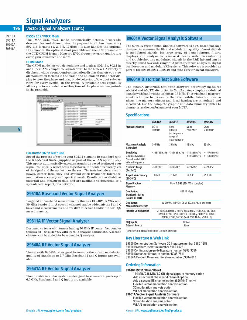
5
89610A89611A89640A89641A
196 Vector Signal Analyzers (cont.)
Signal Analyzers
DSSS/CCK/PBCC ModeThe DSSS/CCK/PBCC mode automatically detects, despreads,descrambles and demodulates the payload in all four mandatory802.11b formats (1, 2, 5.5, 11Mbps). It also handles the optionalPBCC modes, the optional short preamble and the CCK preamble ofthe CCK-OFDM format. Measure EVM, frequency error, quadratureerror, gain imbalance and more.
OFDM Mode The OFDM mode lets you demodulate and analyze 802.11a, 802.11g,and HiperLAN2 compatible signals down to the bit level. A variety ofdisplays include a compound constellation display that lets you viewall modulation formats in the frame and a Common Pilot Error dis-play to view the phase and magnitude behavior of the pilot sub-car-riers for every symbol in the frame. A preamble test capabilityallows you to evaluate the settling time of the phase and magnitudein the preamble.
One Button 802.11 Test Suite Speed the process of testing your 802.11 signal to its standard withthe WLAN Test Suite (supplied as part of the WLAN option B7R).This applet automatically executes standards based testing of yoursignal. You specify which tests to perform, the center frequency, etcof the signal and the applet does the rest. The tests include: transmitpower, center frequency and symbol clock frequency tolerance,modulation accuracy and spectral mask. Results are available aspass/fail and measured data and are available to download to aspreadsheet, report, or a network.
89610A Baseband Vector Signal Analyzer
Targeted at baseband measurements this is a DC-40MHz VSA with39 MHz bandwidth. A second channel can be added giving I and Qbaseband measurements and 78 MHz effective bandwidth for I+jQmeasurements.
89611A IF Vector Signal Analyzer
Designed to team with tuners having 70 MHz IF center frequenciesthis is a 52 – 88 MHz VSA with 36 MHz analysis bandwidth. A secondchannel can be added for baseband I&Q analysis.
89640A RF Vector Signal Analyzer
The versatile 89640A is designed to measure the RF and modulationquality of signals up to 2.7 GHz. Baseband I and Q inputs are avail-able.
89641A RF Vector Signal Analyzer
This flexible modular system is designed to measure signals up to6.0 GHz. Baseband I and Q inputs are available.
89601A Vector Signal Analysis Software
The 89601A vector signal analysis software is a PC based packagedesigned to measure the RF and modulation quality of most digital-ly modulated signals. Its large array of demodulators, filters, displays, and analysis tools make it ideally suited to evaluating and troubleshooting modulated signals in the R&D lab and can bedirectly linked to a wide range of Agilent spectrum analyzers, digitaloscilloscopes and modular VXI systems. This software is provided aspart of the 89610, 89611, 89640 and 89641 vector signal analyzers.
89604A Distortion Test Suite Software
The 89604A distortion test suite software accurately measuresAM/AM and AM/PM distortion in MCPAs using complex modulatedsignals with bandwidths as high as 36 MHz. This wideband measure-ment technique helps assure that even subtle distortion mecha-nisms like memory effects and local heating are stimulated andmeasured. Use the complete graphic and data summary tables tocharacterize the performance of your MCPA.
Specifications
89610A 89611A 89640A 89641A
Frequency Range DC to 52 to DC to DC to 40 MHz 88 MHz 2700 MHz 6000 MHz
(or frequency range of external tuner)
Maximum Analysis 39 MHz 36 MHz 36 MHz 36 MHzBandwidth
Sensitivity <–151 dBm/Hz <–159 dBm/Hz <–158 dBm/Hz <–157 dBm/HzDisplayed Average <–156 dBm/Hz <–153 dBm/HzNoise Level at 1 GHzat Max Frequency
Dynamic Range <–70 dBc1 <–70 dBc1 <–70 dBc1 <–70 dBc1
(3rd IMD)
Amplitude Accuracy ±0.8 dB ±0.8 dB ±2.0 dB ±2.0 dB(20-30ºC)
Signal Capture Up to 1.2 GB (384 MSa, complex)Memory
One Button, 802.11 (Opt)Standards-Based Pass/Fail Tests
One Button W-CDMA, 1xEVD0, GSM, 802.11a/b/g, and moreMeasurement Setups
Flexible Demodulation 24 demodulators, 7 filters, equalizer (2-16 FSK, GFSK, MSK, GMSK, BPSK, QPSK, OQPSK, DQPSK, p/4 DQPSK, 8PSK,
D8PSK, EDGE, 16-256 QAM, DVB 16-64, VSB 8-16)
I&Q Inputs, OptionInternal Source N/A
1tones @ 6 dB below full scale (–31 dBm at input)
Key Literature & Web Link89600 Demonstration Software CD literature number 5980-198989600 Brochure literature number 5980-072389600 Configuration guide literature number 5968-935089600 Datasheet literature number 5988-781189604A Product Overview literature number 5988-7812
Ordering Information89610/89611/8964/89641
144 MB/288 MB/1.2 GB signal capture memory optionAdd a second IF/baseband channel optionAdd a second RF channel option (89640/41 only)Flexible vector modulation analysis option3G modulation analysis optionWLAN modulation analysis option
89601A Vector Signal Analysis SoftwareFlexible vector modulation analysis option3G modulation analysis optionWLAN modulation analysis option
English URL www.agilent.com/find/products Korean URL www.agilent.co.kr/find/products
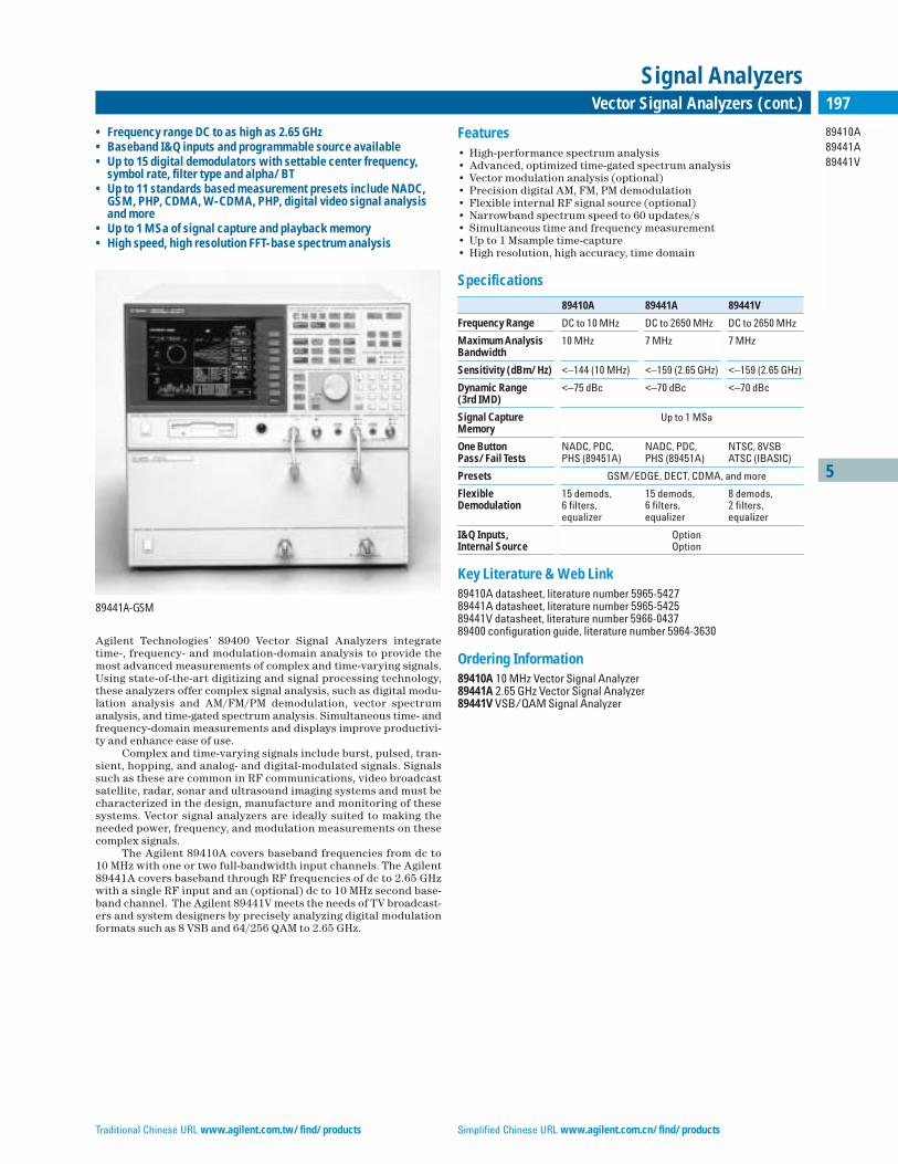
Traditional Chinese URL www.agilent.com.tw/find/products Simplified Chinese URL www.agilent.com.cn/find/products
5
89410A89441A89441V
197Vector Signal Analyzers (cont.)
Signal Analyzers
Agilent Technologies’ 89400 Vector Signal Analyzers integrate time-, frequency- and modulation-domain analysis to provide themost advanced measurements of complex and time-varying signals.Using state-of-the-art digitizing and signal processing technology,these analyzers offer complex signal analysis, such as digital modu-lation analysis and AM/FM/PM demodulation, vector spectrumanalysis, and time-gated spectrum analysis. Simultaneous time- andfrequency-domain measurements and displays improve productivi-ty and enhance ease of use.
Complex and time-varying signals include burst, pulsed, tran-sient, hopping, and analog- and digital-modulated signals. Signalssuch as these are common in RF communications, video broadcastsatellite, radar, sonar and ultrasound imaging systems and must becharacterized in the design, manufacture and monitoring of thesesystems. Vector signal analyzers are ideally suited to making theneeded power, frequency, and modulation measurements on thesecomplex signals.
The Agilent 89410A covers baseband frequencies from dc to 10 MHz with one or two full-bandwidth input channels. The Agilent89441A covers baseband through RF frequencies of dc to 2.65 GHzwith a single RF input and an (optional) dc to 10 MHz second base-band channel. The Agilent 89441V meets the needs of TV broadcast-ers and system designers by precisely analyzing digital modulationformats such as 8 VSB and 64/256 QAM to 2.65 GHz.
Features• High-performance spectrum analysis • Advanced, optimized time-gated spectrum analysis • Vector modulation analysis (optional) • Precision digital AM, FM, PM demodulation • Flexible internal RF signal source (optional) • Narrowband spectrum speed to 60 updates/s • Simultaneous time and frequency measurement • Up to 1 Msample time-capture • High resolution, high accuracy, time domain
Specifications
89410A 89441A 89441V
Frequency Range DC to 10 MHz DC to 2650 MHz DC to 2650 MHz
Maximum Analysis 10 MHz 7 MHz 7 MHzBandwidth
Sensitivity (dBm/Hz) <–144 (10 MHz) <–159 (2.65 GHz) <–159 (2.65 GHz)
Dynamic Range <–75 dBc <–70 dBc <–70 dBc(3rd IMD)
Signal Capture Up to 1 MSaMemory
One Button NADC, PDC, NADC, PDC, NTSC, 8VSBPass/Fail Tests PHS (89451A) PHS (89451A) ATSC (IBASIC)
Presets GSM/EDGE, DECT, CDMA, and more
Flexible 15 demods, 15 demods, 8 demods, Demodulation 6 filters, 6 filters, 2 filters,
equalizer equalizer equalizer
I&Q Inputs, OptionInternal Source Option
Key Literature & Web Link89410A datasheet, literature number 5965-542789441A datasheet, literature number 5965-542589441V datasheet, literature number 5966-043789400 configuration guide, literature number 5964-3630
Ordering Information89410A 10 MHz Vector Signal Analyzer89441A 2.65 GHz Vector Signal Analyzer89441V VSB/QAM Signal Analyzer
• Frequency range DC to as high as 2.65 GHz • Baseband I&Q inputs and programmable source available• Up to 15 digital demodulators with settable center frequency,
symbol rate, filter type and alpha/BT • Up to 11 standards based measurement presets include NADC,
GSM, PHP, CDMA, W-CDMA, PHP, digital video signal analysisand more
• Up to 1 MSa of signal capture and playback memory• High speed, high resolution FFT-base spectrum analysis
89441A-GSM

English URL www.agilent.com/find/products Korean URL www.agilent.co.kr/find/products
5
11974x11970x
198 Millimeter Mixers
Signal Analyzers, Mixers
11974 Series Preselected Millimeter Mixers
Eliminate the need for signal identification at millimeter frequencies.The Agilent 11974 series mixers are preselected from 26.5 to 75 GHzfor faster, easier testing of millimeter devices and systems. Pre-selection reduces mixer overload from broadband signals and reducesradiation of local oscillator harmonics back to the device under test.Equipment operators can quickly locate true signals, and softwaredevelopment for automated measurements is greatly simplified.
These mixers feature advanced barium-ferrite technology andcome with a standalone power supply. They are particularly useful for broadband millimeter signal analysis, millimeter electromagnet-ic interference (EMI) measurements, and unattended monitoring of millimeter signals.
11974 series preselected mixers are available in four bands
Agilent Frequency Sensitivity1 Calibration Image 1 dBModel Range (displayed avg. Accuracy1 Rejection1 Gain
(GHz) noise level/10 Hz) (dB) (dB) Compression(dBm) (dBm)
11974A 26.5 to 40 –111 <±2.3 –54 +611974Q 33 to 50 –106 <±2.3 –50 +011974U 40 to 60 –109 <±2.6 –50 +011974V 50 to 75 –100 <±4.5 –40 +31 Specifications apply when connected to the 8566B or 70000 series spectrum analyzers.
CompatibilityUpgrade kits are available to assure the compatibility of 8566A/Bspectrum analyzers and the 70907A external mixer interface module.Consult your Agilent sales representative to determine requirements.All 8560EC series spectrum analyzers and the 70907B external mixerinterface modules are fully compatible with the 11974 series.
11970 Series Harmonic Mixers
The 11970 series waveguide mixers are general-purpose harmonicmixers. They employ a dual-diode design to achieve flat-frequencyresponse and low conversion loss. These are achieved without exter-nal dc bias or tuning stubs. Manual operation and computer-controlled hardware operation are simplified because mixer biasand tuning adjustments are not required.
11970 series harmonic mixers are available in six bands (15 to 17 dBm LO)
Agilent Frequency LO Conversion Noise Freq.1 GainModel Range Harm Loss (dB) Level (dB) Response Compres-
(GHz) Number 1 kHz (dB) sionRBW (dBm)
11970K 18 to 26.5 6+ 24 –105 ±1.9 –311970A 26.5 to 40 8+ 26 –102 ±1.9 –511970Q 33 to 50 10+ 28 –101 ±1.9 –711970U 40 to 60 10+ 28 –101 ±1.9 –711970V 50 to 75 14+ 40 –92 ±2.1 –311970W 75 to 110 18+ 47 –85 ±3.0 –11 Frequency response of the mixers is reduced by 1 dB for LO range of 14 to 18 dBm.
CompatibilityThe 11970 series mixers extend the frequency range of the 8560ECseries portable spectrum analyzers, the 8566B spectrum analyzer(used with the 11975A amplifier), and the 70000 modular measure-ment system (used with the 70907A/B external mixer interfacemodules).
11970 and 11974 Series SpecificationsIF Range: dc to 1.3 GHzLO Amplitude Range: +14 dB to +16 dB; +16 dB optimumCalibration Accuracy: ±2 dB for 11970 series with optimum LO amplitudeTypical RF Input SWR: <2.2:1, <3.0:1 for 11974 seriesBias Requirements: NoneTypical Odd-Order Harmonic Suppression: >20 dB (does not apply to 11974 series)Maximum CW RF Input Level: +20 dBm (100 mW), +25 dBm for 11974 seriesMaximum Peak Pulse Power: 24 dBm (250 mW) with <1 µs pulse (avg. power = +20 dBm)Bandwidth: 100 MHz minimum (11974 series only)Environmental: Meets MIL-T-28800, Type III, Class 3, Style CIF/LO Connectors: SMA (female)TUNE IN Connector: BNCLO Range: 3 to 6.1 GHz
Key Literature11970 Series Technical Data, p/n 5968-1445E11974 Series Technical Data, p/n 5952-2748
Ordering Information11974A 26.5 to 40 GHz Preselected Mixer11974Q 33 to 50 GHz Preselected Mixer 11974U 40 to 60 GHz Preselected Mixer 11974V 50 to 75 GHz Preselected Mixer
11974V-003 Delete Power Supply (11974 series only) 11970K 18 to 26.5 GHz Mixer 11970A 26.5 to 40 GHz Mixer 11970Q 33 to 50 GHz Mixer 11970U 40 to 60 GHz Mixer 11970V 50 to 75 GHz Mixer 11970W 75 to 110 GHz Mixer 11970
11970-009 Mixer Connection Set adds three 1-m low-loss SMA cables, wrench, Allen driver for any 11970 series mixer
11975A 2 to 8 GHz Amplifier 281A/B Coaxial to Waveguide Adapters
R281A 26.5 to 40 GHz, 2.4 mm (f) R281B 26.5 to 40 GHz, 2.4 mm (m)Q281A 33 to 50 GHz, 2.4 mm (f) Q281B 33 to 50 GHz, 2.4 mm (m)
• Preselected mixers to eliminate signal identification • State-of-the-art technology • Easier automated measurements • Low conversion loss • Individually amplitude calibrated • No bias or tuning adjustments • High 100 mW safe input level
11970, 11974 Series Mixers
50 to 75 GHz Sweep WithoutPreselection
50 to 75 GHz Sweep Using 11974 Series Mixer

5
11867A11693A11694A8447A8447D8449B
199Spectrum Analyzer Accessories, RF and Microwave Preamplifiers
Signal Analyzers, Amplifiers
11867A and 11693A Limiters
Protect the input circuits of spectrum analyzers, counters, amplifiersand other instruments from high power levels with minimal effect onmeasurement performance. The 11867A RF limiter (dc to 1.8 GHz)reflects signals up to 10 W average power and 100 W peak power. In-sertion loss is less than 0.75 dB. The 11693A microwave limiter (100MHz to 12.4 GHz, usable to 18 GHz) guards against input signals over 1 mW up to 1 W average power and 10 W peak power.
11694A 75 Ω Matching Transformer
From 3 to 500 MHz, this transformer allows measurements in 75 Ωsystems while retaining amplitude calibration with a 50 Ω spectrumanalyzer input. VSWRs are less than 1.2; insertion loss is less than0.75 dB.
8447A and 8447D Amplifiers
Specifications
8447A Preamplifier 8447D Preamplifier
Frequency Range 0.1 to 400 MHz 100 kHz to 1.3 GHz
Typical 3 dB Bandwidth 50 kHz to 700 MHz 75 kHz to 1.7 GHz
Maximum Leveled — —Output Power
Output Power Leveling — —Range
Gain (mean, per channel) 20 dB ±1.0 dB at 10 MHz >25 dB (20° to 30°C)(20° to 30°C)
Gain Flatness Across Full ±1.8 dB (0° to 55°C) ±1.5 dBFrequency Range ±0.7 dB (20° to 30°C)
characteristic
Noise Figure <7 dB <8.5 dB
Output Power for 1 dB >+6 dBm >+7 dBm typicalGain Compression
Third-Order Intercept — —
Harmonic Distortion –32 dB for 0 dBm output –30 dB for 0 dBm output (typical)
Maximum Input for — —Minimum Internally Leveled Output
Output for <–60 dB –25 dBm (characteristic) –30 dBmHarmonic Distortion
VSWR <1.7 <2.0 input<2.2 output1 to 1300 MHz
Reverse Isolation >30 dB >40 dB
Maximum dc Voltage ±10 V ±10 VOutput
Size 85.8 mm H x 85.8 mm H x 130 mm W x 261 mm D 130 mm W x 216 mm D(3.4 in x 5.1 in x 8.5 in) (3.4 in x 5.1 in x 8.5 in)
Weight Net, 1.56 kg (3.4 lb); Net, 1.56 kg (3.4 lb); Shipping, 2.3 kg (5.1 lb) Shipping, 2.3 kg (5.1 lb)
Power Requirements 110 or 230 Vac + 10 %, 110 or 230 Vac + 10 %, 48 to 440 Hz, 15 W 48 to 440 Hz, 15 W
Options Available Option 001: Option 001:Dual-channel amp, Dual-channel amp, BNC (f) connectors BNC (f) connectors
Option 010:Single-channel amp, Type-N (f) connectorsOption 011:Dual-channel amp, Type-N (f) connectors
Ordering Information8447A Preamplifier8447D Preamplifier
8449B Preamplifier
Specifications
Frequency Range 1.0 to 26.5 GHz
Gain ≥26 dB(mean, per channel) (20˚C to 30˚C)
Gain Flatness Across 1 to 26.5 GHz ±4.5 dB (0˚C to 55˚C);Full Freq. Range 2 to 22 GHz ±2.4 dB (20˚C to 30˚C)
Noise Figure Band Typical1.0 to 12.7 GHz ≤8.5 dB 7 dB12.7 to 22.0 GHz 12.5 dB 9 dB22.0 to 26.5 GHz ≤14.5 dB 12 dB
Output Power for 1 dB ≤+7 dBm (characteristic)Gain Compression
Harmonic Distortion –30 dB for 0 dBm output (characteristic)
Output for <–60 dB –30 dBm (characteristic)Harmonic Distortion
VSWR Input 1.0 to 2.0 GHz 2.0:12.0 to 12.5 GHz 1.5:112.5 to 26.5 GHz 2.0:1
Output 1.0 to 26.5 GHz 2.0:1
Reverse Isolation >75 dB
Maximum dc Voltage ±20 V
Displayed Average Noise Level, 0 dB atten. (characteristic)
8563EC (1 Hz RBW) 8566B (10 Hz RBW)
1.0 to 6.46 GHz, –165 dBm 1.0 to 2.5 GHz, –55 dBm5.86 to 13.0 GHz, –163 dBm 2.0 to 5.8 GHz, –154 dBm12.4 to 26.5 GHz, –160 dBm 5.8 to 12.5 GHz, –150 dBm
12.5 to 18.6 GHz, –144 dBm18.6 to 22 GHz, –140 dBm
Size: 102 mm H x 213 mm W x 297 mm D (4.0 in x 8.4 in x 11.7 in)Weight: Net, 4 kg (8.8 lb) nominalPower: 100, 120, 220, or 240 V, ±10 %; 47 to 63 Hz
Ordering Information8449B 1 to 26.5 GHz Preamplifier
8449B-907 Front Handle Kit8449B-908 Rackmount Kit (half-rack width)

English URL www.agilent.com/find/products Korean URL www.agilent.co.kr/find/products
5
E740xA
200 EMI Receivers
EMI/EMC Test Systems
E7400A Series EMC Analyzers
Whether your industry is information technology, automotive, com-munications, or medical electronics, you need to evaluate the EMIperformance of your products during the development phase. WithAgilent’s E7400A Series EMC analyzers, you can evaluate perfor-mance quickly and easily.
Radiated Emissions When combined with a broadband antenna, the E7400A Series ana-lyzer provides the capabilities to check for radiated emissions coming from your DUT. This is best done in an area that is free fromreflective objects such as an open area or EMI chamber.
Conducted Emissions Test for noise or interference placed on power or data lines by cou-pling the E7400A series instrument to the power or data linethrough a line impedance stabilization network (LISN) device orabsorbing clamp.
Diagnostics and Problem IsolationIf you have an emissions problem, you can use the E7400A with an11940A or 11941A close field probe to isolate and diagnose thesource of the problem.
The E7400A Series EMC analyzers have the following function-ality and features to speed you through measurements:• Detectors to perform peak, quasi-peak, and average measurements • Complete measurement setups including span and EMI bandwidths• Display two limit lines and margins• Corrections for antennas, cables, and amplifiers• Measure peak, quasi-peak, and average amplitudes of 2000 signals
and store the results into the internal list• Use the “Zone” feature to zoom in on a signal while viewing
the broad spectrum• Built-in 3.5 inch disk drive• Large, crisp color display• Built-in preamplifier with 20 dB nominal gain• Sort, remeasure, mark, and delete signals in the internal list• Standard GPIB and parallel ports• Battery pack available• Edit or customize and store limit lines and correction factors• Optional built-in tracking generator to 3 GHz
Ordering InformationE7401A EMC analyzer 9 kHz to 1.5 GHzE7402A EMC analyzer 9 kHz to 3.0 GHzE7403A EMC analyzer 9 kHz to 6.7 GHzE7404A EMC analyzer 9 kHz to 13.2 GHzE7405A EMC analyzer 9 kHz to 26.5 GHzStandard options included in an EMC analyzer:
E740xA-AYQ EMI detectors / FM demodE740xA-1DS RF preamplifier (20 dB gain, 1 MHz to 3.0 GHz)E740xA-1DR Narrow resolution bandwidths to 10 HzE740xA-A4H GPIB/parallel port (includes IntuiLink PC connectivity software)E740xA-B72 Memory extension to 10 MBE740xA-060 Low emissions shielding
Orderable Options E740xA-1AX Replaces GPIB with RS-232 (includes RS-232 cable and IntuiLink PC connectivity software)E740xA-1CP Rackmount and handle kitE740xA-UKB Low frequency extension (100 Hz)E740xA-1D5 Adds high stability time base (includes 1 Hz and 3 Hz RBW)E740xA-1D6 Time gated sweepE740xA-1DN Tracking generatorE740xA-A4J IF and sweep portsE740xA-A5D 12 Vdc power cableE740xA-AXT Transit caseE740xA-AYT Grey soft carrying caseE740xA-AYU Yellow soft carrying caseE740xA-AYX Fast time domain sweepE740xA-BAB 3.5 mm RF input (E7405A only)E740xA-HYZ External mixing (E7405A only) E740xA-UK6 Commercial calibration certificateE740xA-UK9 Front panel cover
Product Comparison
Product/ Frequency Range Displayed Average 3rd Order RBW Service Noise Level Dynamic Range
E7401A 9 kHz to 1.5 GHz ≤–150 dBm +13.5 dBm TOI 1 Hz2 to 5 MHz (including 200 Hz, 9 kHz, 120 kHz, 1 MHz EMI BW)
E7402A 100 Hz1 to 3.0 GHz ≤–150 dBm +12.5 dBm TOI 1 Hz2 to 5 MHz (including 200 Hz, 9 kHz, 120 kHz, 1 MHz EMI BW)
E7403A 100 Hz1 to 6.7 GHz ≤–150 dBm +12.5 dBm TOI 1 Hz2 to 5 MHz (including 200 Hz, 9 kHz, 120 kHz, 1 MHz EMI BW)
E7404A 100 Hz1 to 13.2 GHz ≤–150 dBm +12.5 dBm TOI 1 Hz2 to 5 MHz (including 200 Hz, 9 kHz, 120 kHz, 1 MHz EMI BW)
E7405A 100 Hz1 to 26.5 GHz ≤–150 dBm +12.5 dBm TOI 1 Hz2 to 5 MHz (including 200 Hz, 9 kHz, 120 kHz, 1 MHz EMI BW) 1With the Option UKB2With the Option 1D5
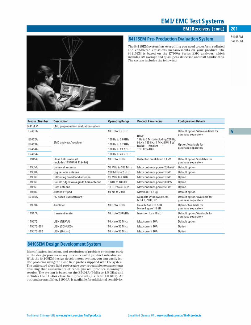
Traditional Chinese URL www.agilent.com.tw/find/products Simplified Chinese URL www.agilent.com.cn/find/products
5
84105EM84115EM
201EMI Receivers (cont.)
EMI/EMC Test Systems
84115EM Pre-Production Evaluation System
The 84115EM system has everything you need to perform radiatedand conducted emissions measurements on your product. The84115EM is based on the E7400A Series EMC analyzer, whichincludes EM average and quasi-peak detection and EMI bandwidths.The system includes the following:
Product Number Description Operating Range Product Parameters Configuration Details
84115EM EMC preproduction evaluation system
E7401A 9 kHz to 1.5 GHz Default option/Also available forpurchase separately
E7402A 100 Hz to 3.0 GHz
E7403A 100 Hz to 6.7 GHz
E7404A 100 Hz to 13.2 GHz
E7405A 100 Hz to 26.5 GHz
11945A Close field probe set 9 kHz to 1 GHz Dielectric breakdown ±1 kV Default option/available for (includes 11940A & 11941A) purchase separately
11955A Biconical antenna 30 MHz to 300 MHz Max continuos power 250 mW Default option
11956A Log periodic antenna 200 MHz to 2 GHz Max continuos power 1 kW Default option
11966P BiConiLog broadband antenna 26 MHz to 2 GHz Max continuos power 1 kW Option
11966E Double ridged waveguide horn antenna 1 GHz to 18 GHz Max continuos power 300 W Option
11966J Horn antenna 18 GHz to 40 GHz Max continuos power 50 W Option
11968C Antenna tripod 94 cm to 2.0 m Max load 11.8 kg Default option
E7415A PC-based EMI software Supports Windows 95, 98, Default option/Available for NT 4.0, 2000, XP purchase separately
11909A Amplifier 9 kHz to 1 GHz Gain 32.5 dB ±1.5dB Option/Available for Noise Figure 1.8 dB purchase separately
11947A Transient limiter 9 kHz to 200 MHz Insertion loss 10 dB Default option/Available for purchase separately
11967D LISN (NEMA) 9 kHz to 30 MHz Max current 10A Default option
11967D-001 LISN (SCHUKO) 9 kHz to 30 MHz Max current 10A Option
11967D-002 LISN (British) 9 kHz to 30 MHz Max current 10A Option
EMC analyzer/receiver
RBW:1 Hz to 5 MHz (including 200 Hz,9 kHz, 120 kHz, 1 MHz EMI BW)DANL: –150 dBmTOI: 12.5 dBm
Option/Available for purchase separately
84105EM Design Development System
Identification, isolation, and resolution of problem emissions earlyin the design process is key to a successful product introduction.With the 84105EM design development system, you can easily iso-late problems using the close field probes supplied with the system.The calibrated close field probes give very repeatable measurementsensuring that assessments of redesigns will produce meaningfulresults. The system is based on the E7401A (9 kHz to 1.5 GHz) andincludes the 11945A close field probe set (9 kHz to 1.0 GHz). Anoptional preamplifier, 11909A, is available for additional sensitivity.
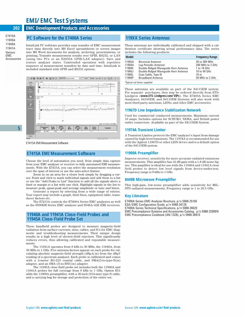
English URL www.agilent.com/find/products Korean URL www.agilent.co.kr/find/products
5
E7415A11945A11940A11941AVariousEMCAccessories
202 EMC Development Products and Accessories
EMI/EMC Test Systems
PC Software for the E7400A Series
IntuiLink PC software provides easy transfer of EMC measurementtrace data directly into MS Excel spreadsheets or screen imagesinto MS Word documents for analysis, archiving, presentations, orprinting. Transfer measurement results over GPIB, RS232, or LAN(using two PCs or an E2050A GPIB/LAN adapter). Save andrestore analyzer states. Unattended operation with repetitivesequence of measurement transfers by date and time. IntuiLink isincluded standard with GPIB and RS232 options.
E7415A EMI Measurement Software
Choose the level of automation you need, from simple data capturefrom your EMC analyzer or receiver to fully automated EMI measure-ments. With the E7415A, you can select the measurement resolutionover the span of interest or use the auto-select feature.
Zoom in on an area for a closer look simply by dragging a cur-sor. Point and click to mark individual signals and add them to a listor use the “Add Peaks to List” function to add all the signals above alimit or margin to a list with one click. Highlight signals in the list tomeasure peak, quasi-peak and average amplitude or tune and listen.
Generate a report by selecting from a wide range of entries.Your report may include a graph, limit lines, equipment table, trans-ducer factors etc.
The E7415A controls the E7400A Series EMC analyzers as wellas the 8590EM Series EMC analyzer and 8546A/42E EMI receivers.
11940A and 11941A Close-Field Probes and 11945A Close-Field Probe Set
These handheld probes are designed to measure magnetic-fieldradiation from surface currents, slots, cables, and ICs for EMC diag-nostic and troubleshooting measurements. Their unique designresults in a high level of electric-field rejection. This significantlyreduces errors, thus allowing calibrated and repeatable measure-ments.
The 11941A operates from 9 kHz to 30 MHz, the 11940A, from30 MHz to 1 GHz. Five antenna factors appear on each probe for cal-culating absolute magnetic-field strength (dBµA/m) from the dBµVreading of a spectrum analyzer. Each probe is calibrated and comeswith a 2-meter RG-223 coaxial cable, and SMA(f)-to-type-N(m)adapter, and an SMA (f)-to-BNC(m) adapter.
The 11945A close field probe set includes both the 11940A and11941A probes for full coverage from 9 kHz to 1 GHz. Option E51adds the 11909A preamplifier, with a 36-inch (914-mm) type-N cable,and a carrying bag for storage and protection of the entire set.
119XX Series Antennas
These antennas are individually calibrated and shipped with a cal-ibration certificate showing actual performance data. The seriesincludes the following products:
Model Frequency Range
11955A Biconical Antenna1 30 to 300 MHz11956A Log Periodic Antenna1 200 MHz to 2 GHz11966E Double-Ridged Waveguide Horn Antenna 1 to 18 GHz11966J Double-Ridged Waveguide Horn Antenna 18 to 40 GHz11966L Coax Cable, Type-N 10 m11966P Broadband Antenna 30 MHz to 2 GHz1Typical cal factor supplied
These antennas are available as part of the 84115EM system. For separate purchases, they may be ordered directly from ETS-Lindgren (www.ETS-Lindgren.com/VIPs). The E7400A Series EMCAnalyzers, 84105EM, and 84115EM Systems will also work withmost third party antennas, LISNs, and other EMC accessories.
11967D Line Impedance Stabilization NetworkUsed for commercial conducted measurements. Maximum current 10 amps. Includes options for SCHUKO, NEMA, and British poweroutlet connectors. Available as part of the 84115EM System.
11974A Transient LimiterA Transient Limiter protects the EMC analyzer’s input from damagecaused by high-level transients. The 11974A is recommended for usewith the Agilent 11967D or other LISN device and is a default optionof the 84115EM system.
11909A PreamplifierImprove receiver, sensitivity for more accurate radiated emissionsmeasurements. This amplifier has 32 dB gain with a 1.8 dB noise fig-ure. This amplifier is ideal for use with the 11940A and 11941A closefield probes to detect low level signals from device-under-test.Frequency range is 9 kHz to 1 GHz.
8449B Microwave PreamplifierThis high-gain, low-noise preamplifier adds sensitivity for MIL-STD radiated measurements. Frequency range is 1 to 26.5 GHz.
Key LiteratureE7400A Series EMC Analyzer Brochure, p/n 5968-2516EESA/EMC Configuration Guide, p/n 5968-3412EE7400A Series Technical Specifications, p/n 5968-3662EEMC Precompliance Systems and Accessories Catalog, p/n 5988-3290ENEMC Precompliance Cookbook (AN 1328), p/n 5968-3661E
E7415A EMI Measurement Software

Traditional Chinese URL www.agilent.com.tw/find/products Simplified Chinese URL www.agilent.com.cn/find/products
5
8591C85901A85905A
203Cable TV Analyzers, Accessories
Cable TV Regulatory Test Equipment
8591C Cable TV Analyzer
Industry’s Only Cable TV Analyzer That Keeps Pace with Changing RegulationsThe 8591C cable TV analyzer (1 MHz to 1.8 GHz) is the first economical,portable, one-box solution for making automatic, non-interfering cableTV RF and video measurements. The analyzer features a flexible hard-ware and software architecture that can be upgraded easily to protectyour investment as new test requirements are introduced.
Included in the cable TV analyzer are the features you need forcable TV testing compatible with worldwide formats and standards,including all FCC proof-of-performance tests:• Cable TV RF/video measurements personality to simplify
channel and system cable TV measurements • 75 Ω input matches analyzer to cable TV impedance• Built-in, internally switched preamplifier for improved
carrier-to-noise measurements • Precision frequency reference to accurately measure
carrier frequency • Fast time-domain sweeps for displaying individual TV lines • TV trigger for selecting TV lines by number • RS-232 and parallel interfaces for PC and printer operation,
respectively • 85702A 128K RAM card for storing test data • Rugged, yellow, soft carrying case
Options add even greater measurement capability to the analy-zer. These include a 75 Ω tracking generator, narrow resolution bandwidths, and non-interfering RF and video measurements.
Non-Interfering MeasurementsOption 107 for the 8591C adds the hardware needed to make non-interfering RF and video measurements. Non-interfering measure-ments let you perform required tests on multiple channels atmultiple locations with no impact on customer programming. Thevideo measurement capability allows you to perform required FCC color tests. Option 107 also enables simultaneous viewing of TVpictures and listening to program sound. The hardware demodulatesNTSC-format television signals as well as versions of PAL andSECAM.
Measurements for RF and Video TestingThe cable TV measurement personality card (included with the8591C) customizes the analyzer for easy, non-interfering proof-of-per-formance measurements on NTSC-, PAL-, or SECAM-format signals.This software adds dedicated cable TV test functions and measurements that you can perform with the push of single keys.Measurements include the following functions and tests:• Automatic tuning of cable TV and TV broadcast carriers • Visual and aural carrier levels and frequencies • Digital carrier power• System channel survey • Depth of modulation • TV aural and FM broadcast carrier deviation • Carrier-to-noise ratio (C/N) • In-channel frequency response • Hum/low frequency disturbances • System frequency response • Baseband TV line and field viewing • TV aural and FM broadcast carrier demodulation • Distortion (CSO/CTB) • Crossmodulation • Ingress and co-channel viewing
System monitor capability automates measurements, allowingthe analyzer to test without assistance from the operator. It also allowsyou to design test plans and to turn test data into reports instantly.With Option 107 added to the cable TV analyzer, non-interferingmeasurements of carrier-to-noise, in-channel frequency responseand distortions can be made, as well as video measurements:• Differential gain • Differential phase • Chrominance-luminance delay inequality
Painless Reports and Data ArchivingTake the pain out of cable TV reports with option 030 cable TV datamanagement software. Running on IBM compatible PCs, it down-loads test data from your 8591C1, into a PC database for makingreports and archiving data. The software compares measurementresults to your specifications and displays pass/fail messages foreach test. Test data can also be exported to a word processor orspreadsheet for other analysis.
You can print the results of every test run at each specified loca-tion in the cable system. The printout will list all the channels tested,as well as additional required information such as the date of the testing, the name and qualifications of the person who ran the test,and the serial number of the equipment used. Add Option 032 to automatically generate reports in a format compliant with the FCCregulations. All RF and video tests (except leakage) currently requiredby the FCC are included.1 Option 030 accepts system mode-acquired data from the cable TV measurement personality for the NTSC format only.
• Dedicated cable TV analyzer • Portable and easy to use • Non-interfering RF and video measurements • Digital carrier power measurements• Cable TV data management software
8591C
Digital Carrier Power Measurement on 8591C

English URL www.agilent.com/find/products Korean URL www.agilent.co.kr/find/products
5
8591C85901A85905A
204 Cable TV Analyzers, Accessories (cont.)
Cable TV Regulatory Test Equipment
Specification SummarySpecifications apply to the 8591C cable TV analyzer with preloaded CableTV measurement personality.
GeneralChannel Selection: Analyzer tunes to specified channelsInput: 75 Ω, BNCFrequency Range: 5 to 1002 MHz for channel mode;54 to 896 MHz for system mode;1 MHz to 1.8 GHz for spectrum analyzer modeAmplitude Range: –15 to +70 dBm V for S/N >30 dBDisplayed Average Noise Level (1 kHz RBW, 0 dB atten.)• Without Preamplifier: ≤–63 dBmV (1 to 1500 MHz)• With Internal Preamplifier: ≤–83 dBmV (1 to 1000 MHz)• With External Preamplifier: ≤–83 dBmV (1 to 1000 MHz)
Cable TV MeasurementsVisual Carrier Frequency (visual carrier frequency is counted)Precision Frequency Reference• Resolution: 100 Hz• Accuracy: ±(1.2 x 10⁻⁷ x carrier freq. +110 Hz)• At 55.25 MHz (ch. 2): ±117 Hz• At 325.25 MHz (ch. 41): ±149 Hz• At 643.25 MHz (ch. 94): ±187 HzVisual-to-Aural Carrier Frequency Difference [counted frequency difference between visual (vision) and aural (sound) carriers]• Difference Range: 4.1 to 4.9 MHz• Resolution: 100 Hz• Accuracy: ±221 Hz for precision frequency reference (std)Visual Carrier Peak Level (measured to an absolute standard)• Amplitude: –15 to +70 dBm V• Resolution: 0.1 dB• Absolute Accuracy: ±2.0 dB for S/N >30 dB• Relative Accuracy: ±1.0 dB relative to adjacent channels in
frequency; ±1.5 dB relative to all other channelsVisual-to-Aural Carrier Level Difference [measured difference betweenpeak amplitudes of visual (vision) and aural (sound) carriers]• Difference Range: 0 to 25 dB• Resolution: 0.1 dB• Accuracy: ±0.75 dB for S/N >30 dBDigital Carrier Power• Accuracy (characteristic) : ±0.75 dB • Readout Resolution: 0.1 dBDepth of Modulation, Characteristic (percent difference from horizontal sync tip to max. video level)• AM Range: 50 to 93 %• Resolution: 0.1 %• Accuracy: ±2.0 % for C/N >40 dBFM Deviation, Characteristic (peak reading of FM deviation)• Range: ±100 kHz• Resolution: 100 Hz• Accuracy: ±1.5 kHzHum/Low Frequency Disturbance (measured for power-line frequencyand low-frequency disturbance)• AM range: 0.5 to 10 %• Resolution: 0.1 %• Accuracy: ±0.7 % for hum ≤5 %Visual Carrier-to-Noise Ratio, C/N (calculated from visual-carrier peak level; min. noise level normalized to 4 MHz for NTSC format)• Range (input level dependent): 63 dB max. for +25 dBmV inputC/N Resolution: 0.1 dBC/N Accuracy (input level and measured C/N dependent): <±1 dB for 50 dB C/N and +25 dBmV input with external preselector filterComposite Second Order and Composite Triple Beat Distortion (CSO and CTB measured relative to visual-carrier peak)• Range (input level dependent): 77 dB max. for 25 dBm V input• Resolution: 0.1 dB• Accuracy (input-level, measured-CSO/CTB dependent):
<±1.5 dB for 60 dB CSO/CTB and +25 dBm V input
Crossmodulation Characteristic (15.7 kHz horizontal-line related AMmeasured on unmodulated visual carrier)• Range: 60 dB, usable to 65 dB• Resolution: 0.1 dB• Accuracy: ±2.6 dB for xmod <50 dB, C/N >40 dBSystem Frequency Response (system amplitude variations measured relative to a reference trace stored during the setup)• Frequency Response Setup: Reference-trace storage for
50 traces including analyzer states• Frequency Response Test: Trace-flatness accuracy is ±0.1 dB
per dB deviation from a flat line and ±0.75 dB maximum cumulative error
Option 107 Operation (for video and non-interfering measurements)TV Receiver Input• Frequency Range: 50 to 850 MHz• Amplitude Range: 0 to 40 dBm VNon-interfering Color Test (requires FCC composite or NTC-7 test signalfor NTSC format)• Differential Gain Accuracy: ≤±4 %1
• Differential Phase Accuracy: ≤±3˚1
• Chrominance-luminance Delay Inequality Accuracy: ≤±45 ns, ±32 ns typical
Non-interfering Tests with Gate ON2
• C/N and CSO: Quiet line must be selected• In-channel Frequency Response Accuracy: <±0.5 dB within
channel (requires sin x/x, Philips ghost canceling reference, or FCC/NTC-7 multiburst test signal for NTSC format)
Preamplifiers85905A 75 Ω Preamplifier (external)• Frequency Range: 45 to 1000 MHz• Gain: 20 dB ±1.0 dB• Noise Figure: 7 dB maximum at midband8591C 75 Ω Preamplifier (internal) (std)• Frequency Range: 1 to 1000 MHz• Gain: ≥24 dB• Noise Figure: ≤10 dB
Ordering Information 8591C Cable TV Analyzer (includes NTSC format only) 3
8591C-1074 TV Receiver/Video Tester (includes 75 Ω coupler and cables)8591C-011 75 Ω Tracking Generator8591C-015 Change Yellow to Tan Soft Carrying Case 8591C-030 Cable TV Data Management Softwarewith FCC Reports8591C-040 Front-Panel Cover (used without soft carrying case) 8591C-0415 GPIB and Parallel6 Interfaces 8591C-119 Noise Figure Card 8591C-130 Narrow Resolution Bandwidths 8591C-1807 TV Picture Display 8591C-701 Delete TV Trigger, AM/FM Demodulator, Fast Time-Domain Sweeps 8591C-704 Delete Precision Frequency Reference 8591C-908 Rackmount without Handles 8591C-909 Rackmount with Handles 8591C-915 Component Level Info. and Service Guide 8591CU-R07 Retrofit Kit for Option 107
Recommended Accessories85702A 128 K RAM Card (Additional)85901A Portable AC Power Source 85905A 75 Ω Preamplifier 24542U RS-232 Nine-Pin Cable (analyzer to PC) 24542G RS-232 Nine-Pin to 25-Pin Cable (analyzer to PC) C2950A Parallel Cable (analyzer to printer) 10833A GPIB Cable 1 20˚C to 30˚C, ≥20 dBm V input.2 Gate ON synchronizes the measurement to the TV line selected.3 Worldwide format options available.4 Not compatible with Option 180.5 Replaces standard RS-232 and parallel interfaces.6 Print and plot control only.7 Not compatible with Option 107.

5
Overview
205Complete Characterization of Linear Networks
Network Analyzers
Why Network Analysis?Characterizing the behavior of linear electrical networks that will be stimulated by arbitrary signals and interfaced with a variety of other networks is a fundamentalproblem in both synthesis and test processes.For example, the engineer designing a multi-component network must predict with some certainty, from knowledge of the individualcomponents, the final network performance.Similarly, a production manager must knowallowable tolerances on the products manu-factured and whether the final products meetthe specified tolerances. Network analysisoffers a solution to these problems throughcomplete description of linear network behavior in the frequency domain. Additionally, some network analyzers offerthe capability to transform measurementdata, taken in the frequency domain, to thetime domain, providing further insight intothe behavior of linear networks.
Network analysis accomplishes the description of both active and passive networks by creating a data model of suchcomponent parameters as impedances andtransfer functions. However, these parameters not only vary as a function offrequency but are also complex variables inthat they have both magnitude and phase(see Figure 1). Swept network analyzersnow measure magnitude and phase (thetotal complex quantity) as a function of frequency with less difficulty than conventional CW measurements. Impedance and transfer functions then canbe displayed conveniently on an internaldisplay, or on peripherals such as a printerand/or a plotter.
Thus, network analysis satisfies theengineering need to characterize the behavior of linear networks quickly, accu-rately, and completely over broad frequencyranges. Agilent Technologies manufacturesa full line of scalar network analyzers (magnitude only) and vector network analyzers (both magnitude and phase).
What is Network Analysis?Network analysis is the process of creatinga data model of the transfer and/or impedance characteristics of a linear network through stimulus-response testingover the frequency range of interest. All network analyzers in the Agilent productline operate according to this definition.
At frequencies above 1 MHz, lumpedelements actually become “circuits” consisting of the basic elements plus parasitics like stray capacitance, leadinductance, and unknown absorptive losses.Since parasitics depend on the individualdevice and its construction, they are almostimpossible to predict. Above 1 GHz component geometries are comparable to asignal wavelength, intensifying the variancein circuit behavior due to device construction.
Network analysis has classically beenlimited to the definition of linear networks.Since linearity constrains networks stimulated by a sine wave to produce a sine-wave output, sine-wave testing is anideal method for characterizing magnitudeand phase response as a function of frequency.While modern network analyzers use sine-wave power sweeps to characterizecertain parameters of nonlinear behavior,such as gain compression and AM-to-PMconversion, this discussion will be limitedto linear characterization of devices. For amore complete discussion of nonlinear
measurements, refer to the sections onspectrum analyzers, wave analyzers (signalanalyzers) and vector modulation productsin this catalog.
Network AnalyzersAgilent network analyzers are instrumentsthat measure transfer and/or impedancefunctions of linear networks through sine-wave testing (see Figure 2). A network analyzer system accomplishes these mea-surements by configuring its various compo-nents around the device-under-test. The firstrequirement of the measurement system is asine-wave signal source to stimulate thedevice-under-test. Since transfer and impedance functions are ratios of variousvoltages and currents, a means of separatingthe appropriate signals from the measure-ment ports of the device-under-test isrequired. Finally, the network analyzer itselfmust detect the separated signals, form thedesired signal ratios and display the results.
Figure 1: 45 MHz to 18 GHz measurement of magni-tude and phase in a single sweep.
Figure 2: Input impedance of microcircuit amplifier isread directly with Smith Chart overlay for polar display.
Signal Sources and Signal SeparationIn the general case, any sine-wave sourcemeeting the network analyzer’s specifications can be used to stimulate thedevice-under-test. If the analyzer is capableof swept measurements, great economies intime can be achieved by stimulating thedevice-under-test with a sweep oscillator orsynthesized sweeper. Many Agilent networkanalyzers contain internal, synthesizedsources with excellent frequency resolution. Swept measurements allowquick and easy characterization of devicesover broad frequency ranges.
At high frequencies the problem of signal separation usually involves travelingwaves on transmission lines and becomescorrespondingly more difficult. Agilent network analyzers employ both internaland external test sets applicable for separating the appropriate traveling waves in a variety of high-frequency measurements.

English URL www.agilent.com/find/products Korean URL www.agilent.co.kr/find/products
5
206
Overview
Complete Characterization of Linear Networks (cont.)
Network Analyzers
Broadband and Narrowband DetectionAfter the desired signals have beenobtained from the test set, they must bedetected by the network analyzer; Agilentnetwork analyzers can use one of two detection methods. Broadband detectionaccepts the full-frequency spectrum of theinput signal, while narrowband detectioninvolves tuned receivers that convert CW orswept-RF signals to a constant-IF signal.There are certain advantages to each detection scheme.
Scalar analyzers usually employbroad- band detection techniques.Broadband detection reduces instrumentcost by eliminating the IF section requiredby narrowband analyzers but sacrificesnoise and harmonic rejection. However,noise is not a factor in many applications.Finally, broadband systems can make measurements where the input and output signals are not of the same frequency, as inthe measurement of the insertion loss ofmixers and frequency doublers.
Vector network analyzers normallyemploy narrowband detection techniques.Narrowband detection makes a more sensitive low noise detection of the constant IF possible. This allows increased accuracyand dynamic range for frequency-selectivemeasurements (as compared to broadbandsystems).
Vector network analyzers can vary withtheir employment of broadband, narrow-band, or both types of detection. When bothtypes of detection are available, the userselects the detection method, which allowsoptimization of the device measurements.
Signal Processing and DisplayOnce the RF has been detected, the networkanalyzer must process the detected signalsand display the measured quantities (seeFigure 3). All Agilent network analyzers aremulti-channel receivers utilizing a refer-ence channel and at least one test channel;absolute signal levels in the channels, relative signal level (ratios) between thechannels, or relative phase differencebetween channels can be measured,depending on the analyzer.
Relative ratio measurements are usually made in dB, which is the log ratio ofan unknown signal (Test Channel) with achosen reference signal (ReferenceChannel). This allows the full dynamic rangeof the instrumentation to be used in measur-ing variations of both high- and low-level circuit responses. For example, 0 dB impliesthe two signal levels have a ratio of unity,while ± 20 dB implies a 10:1 voltage ratiobetween two signals.
All network analyzer phase measure-ments are relative measurements with thereference channel signal considered to havezero phase. The analyzer then measures thephase difference of the test channel withrespect to the reference channel.
Phase information complements amplitude data in the measurement of device parameters. Phase is more sensitive to networkbehavior and it is a required component ofcomplex impedance and transfer functions.
Phase data is also required to measuredelay distortion or group delay of networks.Delay distortion occurs when different fre-quency components of a complex waveformexperience nonlinear phase shifts as theyare transmitted through a network. Groupdelay (see Figure 4) is a measure of this distortion and is defined as:
An alternative method for measuringphase distortion is deviation from linearphase or differential phase. Deviations from linear phase can be measured by introducing enough electrical length in thenetwork analyzer’s reference channel to linearize a device’s phase shift. This is usually accomplished by using the electrical-delay feature of the network analyzer, whichcancels the average electrical length of adevice mathematically.
Figure 3: Simultaneous measurement of transmissionresponse and passband reflection coefficient.
Scattering parameters, or S-parameters,were developed to characterize linear networks at high frequencies. S-parametersdefine the ratios of reflected and transmittedtraveling waves measured at the networkports. A two-port device is modeled with S-parameters (see Figure 5). S11 is the complex reflection coefficient at port 1, and is
the ratio of b1/a1, if a2 = 0 (port 2 terminatedin its characteristic impedance). S21 is thecomplex transmission coefficient from port1 to port 2, b2/a1, if a2 = 0. The “a’’ and “b’’ signals represent the amplitude and phase ofthe incident and emerging or reflected traveling waves. By reversing the ports andterminating port 1 in its characteristicimpedance, S22 and S12 can be similarlydefined.
Additional CapabilitiesPrecision design work and manufacturingtolerances demand highly accurate measurements, but most errors in network measurements are complex quantities thatvary as a function of frequency. By characterizing and virtually removing thesesystematic errors, measurement accuraciesare improved by several orders of magnitude.Agilent network analyzers contain built-in,high-speed computational hardware that canperform the complex mathematics requiredfor sophisticated error correction.
Computer-controlled network analyzers can be programmed to set up andmake many measurements automatically.The measurement process is further accelerated by the computer’s ability tostore, transform, summarize, and outputdata in a variety of formats to a number ofperipherals. These capabilities make thecomputer-controlled network analyzer idealfor both computer-aided design or automaticproduction testing. Several products havebuilt-in automation features, includingsequencing and GP Instrument BASIC.
Figure 5: S-parameter model for a two-port linear network.
Tgd = d
d
–
Figure 4: Direct measurement of group delay withdigital readout at marker.

Traditional Chinese URL www.agilent.com.tw/find/products Simplified Chinese URL www.agilent.com.cn/find/products
5
Overview
207Complete Characterization of Linear Networks (cont.)
Network Analyzers
• Excellent measurement accuracy• Fast, precise, integrated synthesized sources• Choice of integrated S-parameter or T/R test sets• Advanced automation and flexible options to boost capabilities
Tackle the Most DemandingActive and Passive DevicesFrom precision design work to high-volumemanufacturing, component test manufac-tures demand fast, accurate measurements.Agilent offers a host of RF and microwavevector network analyzers that are ready totackle the most challenging active and passive networks, devices, components andsubsystems.
Squeeze more performance from yourdesigns with the exceptional accuracy.Wide dynamic range and low trace noisemake it easy to see the stopband and passband of even the highest-rejection filters.
On the production line, advanced productivity features such as automatedpass/fail testing and segmented sweeps helpaccelerate test throughput. Built-in sequencing, programming and connectivity capabilities increase the flexibility of yourtest systems, and can decrease the cost of test.
Selection Guide for Agilent Network Analyzers
Frequency Range Number Balanced System ECal Measurement Speedof Ports Measurements* Impedance Support (1 sweep, 201 points)
Vector E5100A 10 kHz to 300 MHz 2 No 50 ohm No 8 ms (1-port cal, ramp-sweep)64 ms (1-port cal, step-sweep)
Combination 165 ms (response cal, gain,Network/spectrum/ 30 kHz BW) impedance4395A & 4396B 10 Hz to 1.8 GHz 2 No 50 or 75 ohms No 215 ms (response cal, gain
and phase, 30 kHz BW)
Vector 300 kHz to 3 GHz 2 No 50 or 75 ohms No 72 ms (1-port cal, 6.5 kHz BW)8712ES/ET; 119 ms (1-port cal, 4.0 kHz BW)8714ES/ET 240 ms (2-port cal, 4.0 kHz BW,
ES model only)
Vector 30 kHz to 6 GHz 2 No 50 or 75 ohms Yes 70 ms (1-port cal)8753ES/ET 139 ms (2-port cal, ES model only)
(6 kHz BW)
Vector 300 kHz to 8.5 GHz 2, 3, or 4 Yes 50 ohms Yes 8 ms (2-port cal)E5070B; E5071B (100 kHz BW)
Vector 300 kHz to 9 GHz 2 or 3 No 50 ohms Yes 29 ms (2-port cal)E8356/7/8A; (35 kHz BW)E8801/2/3A;N3381/2/3A
Vector 50 MHz to 40 GHz 2 No 50 ohms Yes 65 ms (1-port cal)8719ES/ET; 158 ms (2-port cal, ES model only) 8720ES/ET; (6 kHz BW)8722ES/ET
Vector 10 MHz to 67 GHz 2 No 50 ohms Yes 38 ms (2-port cal)E8362/3/4B; E8361A (35 kHz BW)
Vector 10 MHz to 110 GHz 2 No 50 ohmsN5250A
Vector 10 MHz to 110 GHz 2 No 50 ohms No 470 ms (2-port cal)8757D (10 kHz BW)
* Table shows the capabilities of the stand-alone instrument, possible to add balanced capability with an external test set
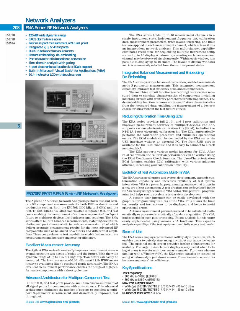
English URL www.agilent.com/find/products Korean URL www.agilent.co.kr/find/products
5
E5070BE5071BE5091A
208 ENA Series RF Network Analyzers
Network Analyzers
E5070B/E5071B ENA Series RF Network Analyzers
The Agilent ENA Series Network Analyzers perform fast and accu-rate RF component measurements for both R&D evaluations andproduction testing. Both the E5070B (300 kHz to 3 GHz) and theE5071B (300 kHz to 8.5 GHz) models offer integrated 2, 3, or 4 testports, enabling the measurement of various components from 2-portfilters to multiport devices like duplexers and couplers. The ENAseries offers built-in balanced measurements, matching circuit sim-ulation and port characteristic impedance conversion, all of whichdeliver accurate measurement results for the most advanced RFcomponents such as balanced SAW filters and differential ampli-fiers. These comprehensive test capabilities enable fast and accuratemeasurements and increase engineering efficiency.
Excellent Measurement AccuracyThe Agilent ENA series dramatically improves measurement accura-cy and meets the test needs of today and the future. With the widedynamic range of up to 125 dB, high rejection filters can easily bemeasured. The low trace noise of 0.001 dBrms at 3 kHz IFBW makesit easy to evaluate a filter’s passband ripple accurately. The ENA’sexcellent measurement performance enables the design of high per-formance components with a short cycle time.
Advanced Architecture for Multiport Component TestBuilt-in 2, 3, or 4 test ports provide simultaneous measurement ofall signal paths for components with up to 4 ports. This advancedarchitecture minimizes the number of sweeps to complete a multi-port S-parameter measurement and dramatically improves testthroughput.
The ENA series holds up to 16 measurement channels in a single instrument state. Independent frequency list, calibrationdata, measurement parameters, trace layout, triggering, and limittest are applied in each measurement channel, which acts as if it isan independent network analyzer. This multi-channel capabilityeliminates recall time for sequencing multiple instrument setupstates. Up to 16 display windows representing each measurementchannel may be observed simultaneously. Within each window, it ispossible to display up to 16 traces. The layout of display windowsand traces are easily selected from the various preset states.
Integrated Balanced Measurement and Embedding/De-EmbeddingThe ENA series provides balanced conversion, and delivers mixed-mode S-parameter measurements. This integrated measurementcapability improves test efficiency of balanced components.
The matching circuit function (embedding) re-calculates mea-sured data to simulate characteristics of components includingmatching circuits with arbitrary port characteristic impedance. Thede-embedding function removes additional fixture characteristicsfrom the measured data, enabling the measurement of a device’scharacteristics without the test fixture effects.
Reducing Calibration Time Using ECalThe ENA series provides full 2-, 3-, and 4-port calibration andimproves measurement accuracy of multiport devices. The ENA supports various electronic calibration kits (ECal), including theN4431A 4-port electronic calibration kit. The ECal automaticallyperforms the calibration procedure and minimizes operationalerrors. The ECal module can be controlled by the ENA series viaUSB interface without an external PC. The front USB port is available for the ECal module and it is easy to connect to a rackmounted ENA.
The ENA supports various useful functions for ECal. AfterECal calibration, the calibration performance can be verified usingthe ECal Confidence Check function. The User-CharacterizationECal function enables ECal calibration with various adaptersattached, increasing your calibration flexibility.
Evolution of Test Automation, Built-In VBAThe ENA series accelerates test system development, expands cus-tomization capability and increases flexibility of test system integration. VBA is a powerful programming language that brings ina new era of test automation. A test program can be developed in theENA Series by using the built-in VBA editor. This powerful program-ming tool helps you to accelerate test system development.
A custom user interface can be easily developed with thegraphical programming features of the VBA. This allows the limittest results and instructions to be displayed and helps to avoid operational errors.
At times measurement parameters need to be calculated math-ematically or processed statistically after data acquisition. The VBAis also useful for such post processing. Unique analysis functions areeasily implemented using various VBA functions. This expandsanalysis capability of the test equipment and fully meets test needs.
Ease-of-UseThe ENA series employs conventional softkey-style operation, whichenables users to quickly start using it without any intensive learn-ing. The optional touch screen provides further enhancement forusability. The large 10.4-inch color display is very useful when look-ing at many traces for multiport measurements. For those who arefamiliar with a Windows® PC, the ENA series can also be controlledusing Windows-style pull down menus. These ease-of-use featuresincrease engineers’ test efficiency.
Key SpecificationsTest Frequency:• 300 kHz to 3 GHz (E5070B)• 300 kHz to 8.5 GHz (E5071B)Max Port Output Power:• With Opt E5070B/E5071B 213/313/413, –15 to 10 dBm• With Opt E5070B/E5071B 214/314/414, –50 to 10 dBmNumber of Test Ports: 2, 3, or 4
• 125 dB wide dynamic range • 0.001 dBrms trace noise• Fast multiport measurement of 9.6 us/point• Integrated 2, 3, or 4 test ports• Built-in balanced measurements• Fixture embedding/de-embedding• Port characteristic impedance conversion• Time domain analysis with gating• 4-port electronic calibration kit (ECal) support• Built-in Microsoft® Visual Basic® for Applications (VBA)• 10.4-inch color LCD with touch screen

Traditional Chinese URL www.agilent.com.tw/find/products Simplified Chinese URL www.agilent.com.cn/find/products
5
E5070BE5071BE5091A
209ENA Series RF Network Analyzers (cont.)
Network Analyzers
IFBW: 10 Hz to 100 kHz (1, 1.5, 2, 3, 4, 5, 7 step)Number of Points: 2 to 1601System Dynamic Range:• 123 dB@10 Hz IFBW (3 MHz to 1.5 GHz)• 125 dB@10 Hz IFBW (1.5 GHz to 4 GHz)• 120 dB@10 Hz IFBW (4 GHz to 6 GHz)• 116 dB@10 Hz IFBW (6 GHz to 7.5 GHz)• 109 dB@10 Hz IFBW (7.5 GHz to 8.5 GHz)
(Response & isolation calibration)Trace Noise (magnitude):• 0.001 dBrms @3 kHz IFBW (3 MHz to 4.25 GHz)• 0.003 dBrms @3 kHz IFBW (4.25 GHz to 7.5 GHz)• 0.005 dBrms @3 kHz IFBW (7.5 GHz to 8.5 GHz)
(Response calibration)
Ordering InformationE5070B 300 kHz to 3 GHz RF Network AnalyzerE5071B 300 kHz to 8.5 GHz RF Network Analyzer
E507xB-010 Time Domain Analysis CapabilityE507xB-213 2-port S-parameter Test set, Standard Power Range (–15 to 10 dBm)E507xB-214 2-port S-parameter Test Set, Extended Power Range (–50 to 10 dBm)E507xB-313 3-port S-parameter Test Set, Standard Power Range (–15 to 10 dBm)E507xB-314 3-port S-parameter Test Set, Extended Power Range (–50 to 10 dBm)E507xB-413 4-port S-parameter Test Set, Standard Power Range (–15 to 10 dBm)E507xB-414 4-port S-parameter Test Set, Extended Power Range (–50 to 10 dBm)E507xB-016 Touch Screen Color LCDE507xB-1E5 High Stability Frequency Reference
E5091A Multiport Test Set
The E5091A is a multiport test set used with the 4-port ENA Seriesnetwork analyzer to expand the number of test ports up to 9. This isan ideal solution for testing antenna switch modules for mobilehandsets, particularly those modules with balanced ports, althoughit can be used in a wide range of multiport measurement applica-tions. The test set is available in 7- and 9-port configurations and iscontrolled as if it were a part of the analyzer rather than a separatetest set.
With up to 16 channels, each of which can measure up to 16measurement parameters, the ENA multiport test solution can mea-sure all the measurement paths required for antenna switch moduletesting. The signal paths of each measurement channel can also bedisplayed to help identify complex connections to the device. Thesecapabilities ensure a single connection, single-set-up measurementthat reduces test time.
Key LiteratureENA Series Product Brochure, literature number 5988-3765ENENA Series Data Sheet, literature number 5988-3780ENENA Series Configuration Guide, literature number 5988-4926ENIntroduction to the Fixture Simulator Function of the ENA Series RFNetwork Analyzers, Product Note E5070/71-1, literature number 5988-4923EN Evolution of Test Automation Using the Built-In VBA with the ENA SeriesRF Network Analyzers, Product Note E5070/71-2, literature number 5988-6192ENOn-wafer Multiport Calibration using the ENA Series RF Network Analyzerwith the Cascade Microtech Probing System, Product Note E5070/71-3,literature number 5988-5886EN
Ordering InformationE5091A Multiport Test Set
E5091A-007 7-port Test Set ConfigurationE5091A-009 9-port Test Set Configuration
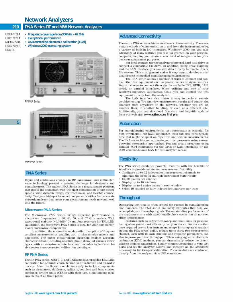
English URL www.agilent.com/find/products Korean URL www.agilent.co.kr/find/products
5
E8356/7/8AE8801/2/3AN3381/2/3AE8362/3/4BE8361A
210 PNA Series RF and MW Network Analyzers
Network Analyzers
• Frequency coverage from 300 kHz – 67 GHz• Exceptional performance• USB controlled electronic calibration (ECal)• Windows 2000 operating system
PNA Series
Rapid and continuous changes in RF, microwave, and millimeter-wave technology present a growing challenge for designers andmanufacturers. The Agilent PNA Series is a measurement platformthat meets the challenge; with the right combination of fast sweepspeeds, wide dynamic range, low trace noise, and flexible connec-tivity. Test your high-performance components with a fast, accuratenetwork analyzer that meets your measurement needs now and wellinto the future.
Microwave PNA SeriesThe Microwave PNA Series brings superior performance tomicrowave frequencies in 20, 40, 50, and 67 GHz models. Withexceptional stability (<0.06dB/˚C) and four receivers for TRL/LRM calibration, the Microwave PNA Series is ideal for your high-perfor-mance microwave components.
In addition, the microwave models offer the option of frequen-cy-offset measurements, enabling you to characterize mixers andamplifiers. The mixer measurement algorithm enables accuratecharacterization (including absolute group delay) of various mixertypes, with an easy-to-use interface, and includes Agilent’s exclu-sive vector error-corrected calibration technique.
RF PNA SeriesThe RF PNA series, with 3, 6, and 9 GHz models, provides TRL/LRMcalibration for accurate characterization of in-fixture and on-waferdevices. Also, the 3-port models are ready to tackle componentssuch as circulators, duplexers, splitters, couplers and base stationcombiner/divider units (CDUs) with their fast, simultaneous mea-surements of all three paths.
Advanced Connectivity
The entire PNA series achieves new levels of connectivity. There aremany methods of communication to and from the instrument, usinga variety of built-in I/O interfaces. Windows® 2000 lets you takeadvantage of many features you take for granted on your personalcomputer, helping you attain a new level of integration for yourdevice-measurement purposes.
For local storage, use the analyzer’s internal hard disk drive orconnect a compatible CD drive. In addition, using drive mappingand the LAN interface, you can save data directly to remote PCs orfile servers. This arrangement makes it very easy to develop statis-tical-process-controlled manufacturing environments.
The PNA series allows a number of ways to connect and con-trol other test equipment such as power meters or signal sources.You can choose to connect them via the available USB, GPIB, LAN,serial, or parallel interfaces. When utilizing any one of yourWindows-supported automation tools, you can control the testequipment directly from the analyzer.
The LAN interface also makes it easy to perform remote troubleshooting. You can view measurement results and control theanalyzer from anywhere on the network, whether you are on another floor, in another building, or even at a different site.Additionally, you can download firmware and help-file updatesfrom our web site: www.agilent.com/find/pna
Automation
For manufacturing environments, test automation is essential forhigh throughput. For R&D, automated tests can save considerabletime that might be spent on repetitive and tedious measurements.The PNA series lets you automate your test processes using severalpowerful automation approaches. You can create programs usingfamiliar SCPI commands via the GPIB or LAN interfaces, or useCOM commands over LAN for fast analyzer access.
Flexibility
The PNA series combines powerful features with the benefits ofWindows to provide maximum measurement flexibility:• Configure up to 32 independent measurement channels to
eliminate the need for multiple instrument state recalls• 16,001 points per channel • Display up to 16 windows• Display up to 4 active traces in each window• Select 10 coupled or fully-independent markers per trace
Throughput
Decreasing test time is often critical for success in manufacturingenvironments. The PNA series has many attributes that help youaccomplish your throughput goals. The outstanding performance ofthe analyzers starts with exceptionally fast sweeps that do not sac-rifice performance.
Features such as segmented sweep and limit lines for pass/failtesting allow you to most efficiently test your device. For devices thatonce required two to four instrument setups for complete character-ization, the PNA series’ ability to have up to thirty-two-measurementchannel, each with its own stimulus and response parameters, canalso improve your test throughput. When using Agilent’s electroniccalibration (ECal) modules, you can dramatically reduce the time ittakes to perform calibrations. Simply connect the module to your testports and let the analyzer control and measure all the standards necessary for full two-port calibration. These modules are controlleddirectly from the analyzer via a USB connection.
RF PNA Series
MW PNA Series

Traditional Chinese URL www.agilent.com.tw/find/products Simplified Chinese URL www.agilent.com.cn/find/products
5
E8356/7/8AE8801/2/3AN3381/2/3AE8362/3/4BE8361A
211PNA Series RF and MW Network Analyzers (cont.)
Network Analyzers
Key SpecificationsRF PNA Series
Model E8356/7/8A E8801/2/3A N3381/2/3A
Frequency Range 300 kHz to 300 kHz to 300 kHz to3/6/9 GHz 3/6/9 GHz 3/6/9 GHz
Number of Ports 2 2 3
Measurement Receivers1 4 3 4
Configurable Test Set
Receiver Attenuators
Extended Power Range
High Stability Timebase
Bias-Tees — —
Time Domain
ECal Support Yes Yes Yes
Dynamic Range Port 1/Port 2, 3(at test port) 300 kHz to 1 MHz 125 dB 125 dB 125/123 dB1 MHz to 3 GHz 128 dB 128 dB 128/126 dB3 to 6 GHz 118 dB 118 dB 118/116 dB6 to 9 GHz 113 dB 113 dB 113/113 dB
Dynamic Range Port 1/Port 2, 3(receiver access)300 kHz to 1 MHz 140 dB 140 dB 140/138 dB1 MHz to 3 GHz 143 dB 143 dB 143/141 dB3 to 6 GHz 133 dB 133 dB 133/131 dB6 to 9 GHz 128 dB 128 dB 128/128 dB
Trace Noise (1 kHz IF BW)300 kHz to 9 GHz <0.002 dB <0.002 dB <0.002 dB
<0.010 deg rms <0.010 deg rms <0.010 deg rms
Maximum Output Power Port 1/Port 2, 3300 kHz to 6 GHz +10 dBm +10 dBm +10/+8 dBm6 to 9 GHz +5 dBm +5 dBm +5/+5 dBm
Standard Optional — Not available
MW PNA Series
Model E8362/3/4/B E8361A
Frequency Range 10 MHz to 10 MHz to20/40/50 GHz 67 GHz
Number of Ports 2 2
Measurement Receivers 4 4
Configurable Test Set
Receiver Attenuators
Extended Power Range
High Stability Timebase
Bias-Tees
Frequency-Offset Mode
Reference Channel Switch
Frequency ConverterMeasurement Application
Time Domain
ECal Support Yes Yes
Dynamic Range (at test port)2
10 to 45 MHz 78 dB 70 dB45 MHz to 2 GHz 94 to 119 dB 89 to 114 dB2 to 20 GHz 122 dB 118 dB20 to 40 GHz 110 dB 106 dB40 to 50 GHz 104 dB 98 dB50 to 60 GHz — 97 dB60 to 70 GHz — 93 dB
Dynamic Range (receiver access)2
10 to 45 MHz 130 dB 104 dB45 MHz to 2 GHz 132 dB 101 to 125 dB2 to 20 GHz 136 dB 127 dB20 to 40 GHz 119 dB 114 dB40 to 50 GHz 111 dB 105 dB50 to 60 GHz — 102 dB60 to 70 GHz — 96 dB
Trace Noise (1 kHz IF BW)2
10 MHz to 50 GHz <0.006 dB <0.006 dB<0.1 deg rms <0.1 deg rms
Maximum Output Power2
10 to 45 MHz +2 dBm –10 dBm45 MHz to 10 GHz +5 dBm 0 dBm10 to 20 GHz +3 dBm +1 dBm20 to 40 GHz –4 dBm –2 dBm40 to 45 GHz –5 dBm –4 dBm45 to 50 GHz –10 dBm –5 dBm50 to 60 GHz — –6 dBm60 to 70 GHz — –10 dBm
Standard Optional — Not available
Measurement Speed (35 kHz IF bandwidth)
Model Frequency Points Cycle Time (ms)3 µs/Point Updates/Second
All 1.8 GHz to 2 GHz 101 9 89 111
All 1.8 GHz to 2 GHz 1601 56 26 18
All 300 kHz to 9 GHz 201 57 284 18
E8361A/2/3/4B 10 MHz to 20/40/50/67 GHz 201 126/185/210/244 627/920/1045/1214 8/6/5/4
E8361A 10 MHz to 67 GHz 16,001 645 40 1.5
Data transfer Speed, 32-bit Binary (ms)4
201 points 16,001 points
COM5 2 6
SCPI5 3 30
DCOM6 3 121
SCPI over GPIB6 9 4351TRL calibration not available on 3-port.2Typical performance below 45 MHz and above 67 GHz.3Typical performance includes retrace and band-switching times with response calibration. Two-port calibration approximately doubles cycle time.
4Typical performance.5Program executed in PNA.6Program executed on an external PC.
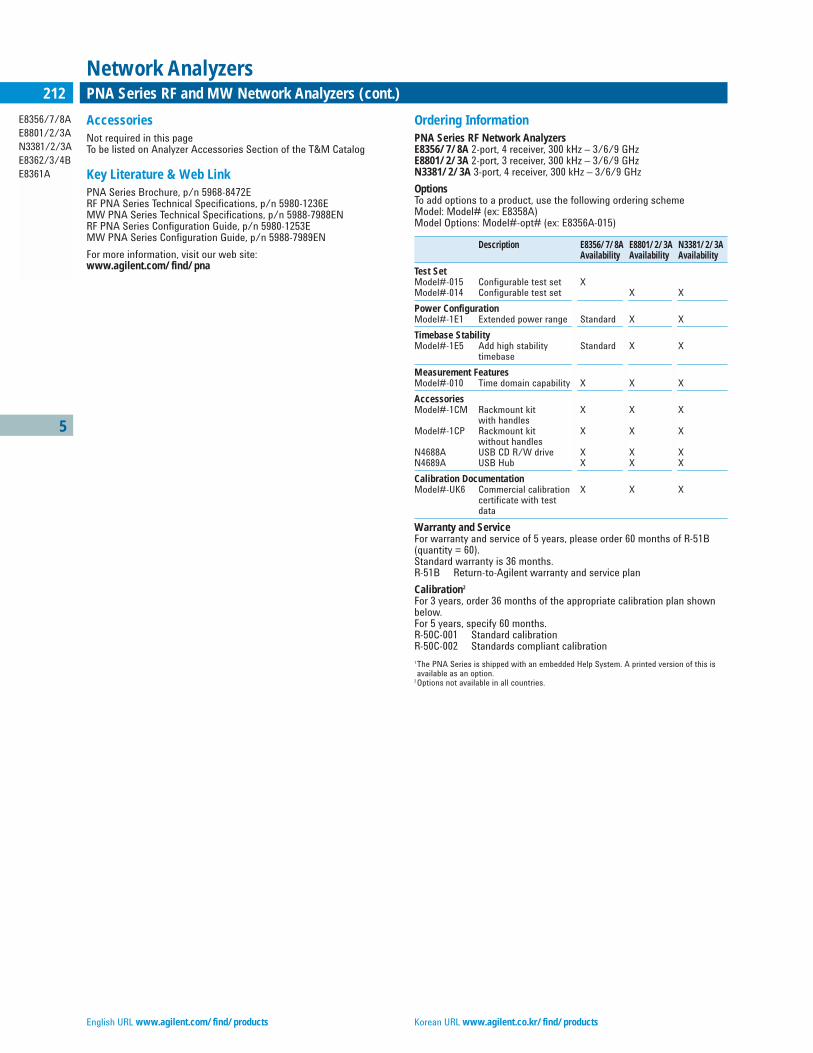
English URL www.agilent.com/find/products Korean URL www.agilent.co.kr/find/products
5
E8356/7/8AE8801/2/3AN3381/2/3AE8362/3/4BE8361A
212 PNA Series RF and MW Network Analyzers (cont.)
Network Analyzers
AccessoriesNot required in this pageTo be listed on Analyzer Accessories Section of the T&M Catalog
Key Literature & Web LinkPNA Series Brochure, p/n 5968-8472ERF PNA Series Technical Specifications, p/n 5980-1236EMW PNA Series Technical Specifications, p/n 5988-7988ENRF PNA Series Configuration Guide, p/n 5980-1253EMW PNA Series Configuration Guide, p/n 5988-7989EN
For more information, visit our web site:www.agilent.com/find/pna
Ordering InformationPNA Series RF Network AnalyzersE8356/7/8A 2-port, 4 receiver, 300 kHz – 3/6/9 GHzE8801/2/3A 2-port, 3 receiver, 300 kHz – 3/6/9 GHzN3381/2/3A 3-port, 4 receiver, 300 kHz – 3/6/9 GHz
OptionsTo add options to a product, use the following ordering schemeModel: Model# (ex: E8358A)Model Options: Model#-opt# (ex: E8356A-015)
Description E8356/7/8A E8801/2/3A N3381/2/3AAvailability Availability Availability
Test SetModel#-015 Configurable test set XModel#-014 Configurable test set X X
Power ConfigurationModel#-1E1 Extended power range Standard X X
Timebase StabilityModel#-1E5 Add high stability Standard X X
timebase
Measurement FeaturesModel#-010 Time domain capability X X X
AccessoriesModel#-1CM Rackmount kit X X X
with handlesModel#-1CP Rackmount kit X X X
without handlesN4688A USB CD R/W drive X X XN4689A USB Hub X X X
Calibration DocumentationModel#-UK6 Commercial calibration X X X
certificate with test data
Warranty and ServiceFor warranty and service of 5 years, please order 60 months of R-51B (quantity = 60).Standard warranty is 36 months.R-51B Return-to-Agilent warranty and service plan
Calibration2
For 3 years, order 36 months of the appropriate calibration plan shownbelow.For 5 years, specify 60 months.R-50C-001 Standard calibrationR-50C-002 Standards compliant calibration1The PNA Series is shipped with an embedded Help System. A printed version of this is available as an option.
2Options not available in all countries.

Traditional Chinese URL www.agilent.com.tw/find/products Simplified Chinese URL www.agilent.com.cn/find/products
5
E8356/7/8AE8801/2/3AN3381/2/3AE8362/3/4BE8361A
213PNA Series RF and MW Network Analyzers (cont.)
Network Analyzers
Ordering Guide For PNA Series Network AnalyzersThis guide is intended to assist you in the ordering process. Additionalinformation and products (such as calibration kits and cables) aredescribed throughout this document.
PNA Series Microwave Network AnalyzersE8362B 10 MHz to 20 GHzE8363B 10 MHz to 40 GHzE8364B 10 MHz to 50 GHzE8361A 10 MHz to 67 GHz
OptionsTo add options to a product, order the corresponding item number.
Description For E8362B For E8363B For E8364B For E8361A AdditionalItem Number Item Number Item Number Item Number Information
Test SetOption 014 Configurable test set E8362B-014 E8363B-014 E8364B-014 E8361A-014
Power ConfigurationOption UNL Extended power range and bias-tees E8362B-UNL E8364B-UNL E8364B-UNL E8361A-UNLOption 016 Add receiver attenuators E8362A-016 E8364A-016 E8364A-016 E8361A-016
CPU RAMOption 022 Extended memory E8362A-022 E8364A-022 E8364A-022 E8361A-022
Non-Linear MeasurementsOption 080 Frequency offset E8362A-080 E8364A-080 E8364A-080 E8361A-080 Requires 014Option 081 Reference receiver switch E8362A-081 E8364A-081 E8364A-081 E8361A-081 Requires 014, 080Option 083 Frequency-converter E8362A-083 E8364A-083 E8364A-083 E8361A-083 Requires 014, 080,
measurement application and 081(E8361A onlyrequires 014, 080)includes GPIB to USBinterface (82357A)
Measurement FeaturesOption 010 Time-domain capability E8362A-010 E8363A-010 E8364A-010 E8361A-010
AccessoriesOption 1CM Rackmount kit without handles E8362A-1CM E8363A-1CM E8364A-1CM E8361A-1CMOption 1CP Rackmount kit with handles E8362A-1CP E8363A-1CP E8364A-1CP E8361A-1CPN4688A USB CD R/W drive N4688A N4688A N4688A N4688AN4689A USB Hub N4689A N4689A N4689A N4689A
Calibration DocumentationOption 1A7 ISO 17025 compliant calibration E8362B-1A7 E8363B-1A7 E8364B-1A7 E8361A-1A7Option UK6 Commercial calibration certificate E8362A-UK6 E8363A-UK6 E8364A-UK6 E8361A-UK6
with test data
Note: Item numbers may not correspond to product model number. For example, to order the time-domain option on the E8362B, the correct item number to order is E8362A-010.
Warranty and ServiceFor warranty and service of 5 years, please order 60 months of R-51B(quantity = 60). Standard warranty is 36 months.R-51B Return-to-Agilent warranty and service plan
Calibration2
For 3 years, order 36 months of the appropriate calibration plan shownbelow.For 5 years, specify 60 months.R-50C-001 Standard calibrationR-50C-002 Standards compliant calibration1Options not available in all countries.2Printed version of on-line help has translations up to firmware revision 1.0.
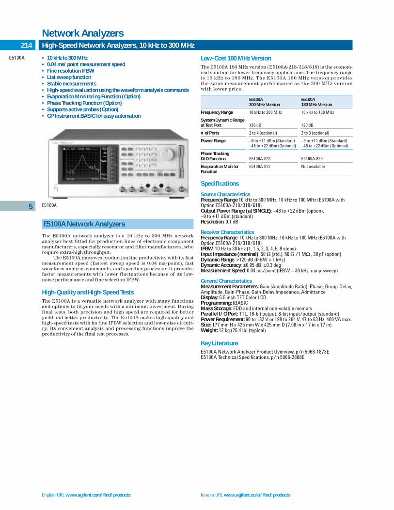
English URL www.agilent.com/find/products Korean URL www.agilent.co.kr/find/products
5
E5100A
214 High-Speed Network Analyzers, 10 kHz to 300 MHz
Network Analyzers
E5100A Network Analyzers
The E5100A network analyzer is a 10 kHz to 300 MHz networkanalyzer best fitted for production lines of electronic componentmanufacturers, especially resonator and filter manufacturers, whorequire extra-high throughput.
The E5100A improves production line productivity with its fastmeasurement speed (fastest sweep speed is 0.04 ms/point), fastwaveform analysis commands, and speedier processor. It providesfaster measurements with lower fluctuations because of its low-noise performance and fine selection IFBW.
High-Quality and High-Speed TestsThe E5100A is a versatile network analyzer with many functionsand options to fit your needs with a minimum investment. Duringfinal tests, both precision and high speed are required for betteryield and better productivity. The E5100A makes high-quality andhigh-speed tests with its fine IFBW selection and low-noise circuit-ry. Its convenient analysis and processing functions improve theproductivity of the final test processes.
Low-Cost 180 MHz VersionThe E5100A 180 MHz version (E5100A-218/318/618) is the econom-ical solution for lower frequency applications. The frequency rangeis 10 kHz to 180 MHz. The E5100A 180 MHz version providesthe same measurement performance as the 300 MHz versionwith lower price.
E5100A E5100A300 MHz Version 180 MHz Version
Frequency Range 10 kHz to 300 MHz 10 kHz to 180 MHz
System Dynamic Rangeat Test Port 120 dB 120 dB
# of Ports 2 to 4 (optional) 2 to 3 (optional)
Power Range –9 to +11 dBm (Standard) –9 to +11 dBm (Standard)–48 to +22 dBm (Optional) –48 to +22 dBm (Optional)
Phase TrackingDLD Function E5100A-023 E5100A-823
Evaporation Monitor E5100A-022 Not availableFunction
Specifications
Source CharacteristicsFrequency Range:10 kHz to 300 MHz, 10 kHz to 180 MHz (E5100A withOption E5100A-218/318/618)Output Power Range (at SINGLE): –48 to +22 dBm (option), –9 to +11 dBm (standard)Resolution: 0.1 dB
Receiver CharacteristicsFrequency Range: 10 kHz to 300 MHz, 10 kHz to 180 MHz (E5100A withOption E5100A-218/318/618)IFBW: 10 Hz to 30 kHz (1, 1.5, 2, 3, 4, 5, 8 steps)Input Impedance (nominal): 50 Ω (std.), 50 Ω /1 MΩ , 30 pF (option)Dynamic Range: >120 dB (IFBW = 1 kHz)Dynamic Accuracy: ±0.05 dB, ±0.3 degMeasurement Speed: 0.04 ms/point (IFBW = 30 kHz, ramp-sweep)
General CharacteristicsMeasurement Parameters: Gain (Amplitude Ratio), Phase, Group-Delay,Amplitude, Gain-Phase, Gain-Delay Impedance, AdmittanceDisplay: 6.5 inch TFT Color LCDProgramming: IBASICMass Storage: FDD and internal non-volatile memoryParallel I/O Port: TTL, 16-bit output, 8-bit input/output (standard)Power Requirement: 90 to 132 V or 198 to 264 V, 47 to 63 Hz, 400 VA max.Size: 177 mm H x 425 mm W x 425 mm D (7.08 in x 17 in x 17 in)Weight: 12 kg (26.4 lb) (typical)
Key LiteratureE5100A Network Analyzer Product Overview, p/n 5968-1873EE5100A Technical Specifications, p/n 5966-2888E
• 10 kHz to 300 MHz• 0.04 ms/point measurement speed• Fine resolution IFBW• List sweep function• Stable measurements• High-speed evaluation using the waveform analysis commands• Evaporation Monitoring Function (Option)• Phase Tracking Function (Option)• Supports active probes (Option)• GP Instrument BASIC for easy automation
E5100A
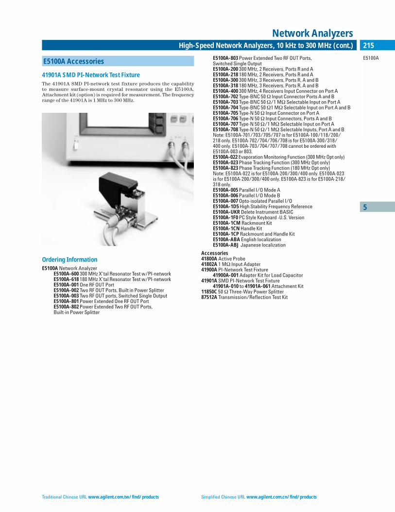
Traditional Chinese URL www.agilent.com.tw/find/products Simplified Chinese URL www.agilent.com.cn/find/products
5
E5100A
215High-Speed Network Analyzers, 10 kHz to 300 MHz (cont.)
Network Analyzers
E5100A Accessories
41901A SMD PI-Network Test FixtureThe 41901A SMD PI-network test fixture produces the capability to measure surface-mount crystal resonator using the E5100A.Attachment kit (option) is required for measurement. The frequencyrange of the 41901A is 1 MHz to 300 MHz.
Ordering InformationE5100A Network Analyzer
E5100A-600 300 MHz X’tal Resonator Test w/PI-networkE5100A-618 180 MHz X’tal Resonator Test w/PI-networkE5100A-001 One RF OUT PortE5100A-002 Two RF OUT Ports, Built in Power SplitterE5100A-003 Two RF OUT ports, Switched Single OutputE5100A-801 Power Extended One RF OUT PortE5100A-802 Power Extended Two RF OUT Ports, Built-in Power Splitter
E5100A-803 Power Extended Two RF OUT Ports, Switched Single OutputE5100A-200 300 MHz, 2 Receivers, Ports R and AE5100A-218 180 MHz, 2 Receivers, Ports R and AE5100A-300 300 MHz, 3 Receivers, Ports R, A and BE5100A-318 180 MHz, 3 Receivers, Ports R, A and BE5100A-400 300 MHz, 4 Receivers Input Connector on Port AE5100A-702 Type-BNC 50 Ω Input Connector Ports A and BE5100A-703 Type-BNC 50 Ω/1 MΩ Selectable Input on Port AE5100A-704 Type-BNC 50 Ω1 MΩ Selectable Input on Port A and BE5100A-705 Type-N 50 Ω Input Connector on Port AE5100A-706 Type-N 50 Ω Input Connectors, Ports A and BE5100A-707 Type-N 50 Ω/1 MΩ Selectable Input on Port AE5100A-708 Type-N 50 Ω/1 MΩ Selectable Inputs, Port A and BNote: E5100A-701/703/705/707 is for E5100A-100/118/200/218 only. E5100A-702/704/706/708 is for E5100A-300/318/400 only. E5100A-703/704/707/708 cannot be ordered with E5100A-003 or 803.E5100A-022 Evaporation Monitoring Function (300 MHz Opt only)E5100A-023 Phase Tracking Function (300 MHz Opt only)E5100A-823 Phase Tracking Function (180 MHz Opt only)Note: E5100A-022 is for E5100A-200/300/400 only. E5100A-023 is for E5100A-200/300/400 only. E5100A-823 is for E5100A-218/318 only.E5100A-005 Parallel I/O Mode AE5100A-006 Parallel I/O Mode BE5100A-007 Opto-isolated Parallel I/OE5100A-1D5 High Stability Frequency ReferenceE5100A-UKR Delete Instrument BASICE5100A-1F0 PC Style Keyboard -U.S. VersionE5100A-1CM Rackmount KitE5100A-1CN Handle KitE5100A-1CP Rackmount and Handle KitE5100A-ABA English localizationE5100A-ABJ Japanese localization
Accessories41800A Active Probe41802A 1 MΩ Input Adapter41900A PI-Network Test Fixture
41900A-001 Adapter Kit for Load Capacitor41901A SMD PI-Network Test Fixture
41901A-010 to 41901A-061 Attachment Kit11850C 50 Ω Three-Way Power Splitter87512A Transmission/Reflection Test Kit

English URL www.agilent.com/find/products Korean URL www.agilent.co.kr/find/products
5
4395A
216 Baseband, IF Network/Spectrum/Impedance Analyzer, 10 Hz to 500 MHz/10 Hz to 500 MHz/100 kHz to 500 MHz
Network/Spectrum Analyzers
4395A Network/Spectrum/Impedance Analyzer
The 4395A provides excellent vector network, spectrum and option-al impedance measurements for audio, baseband, HF, VHF, and IFapplications. When combined with a test set, the 4395A providesreflection measurements, such as return loss, and SWR, and S para-meters. Gain, phase, group delay, distortion, spurious, CN ratio, andnoise measurements often required for evaluating components andcircuits can be measured using one instrument. As a vector networkanalyzer, the 4395A operates from 10 Hz to 500 MHz with 1 mHz resolution and its integrated synthesized source provides –50 to +15 dBm of output power with 0.1 dB resolution. The dynamic mag-nitude and phase accuracy are ±0.05 dB and ±0.3˚ so that it canaccurately measure gain and group delay flatness, which are becom-ing more important in modern electronics systems.
As a spectrum analyzer, the 4395A operates from 10 Hz to 500 MHz with resolution bandwidths (RBWs) spanning 1 Hz to 1 MHz in a 1-3-10 steps. A fully-synthesized local oscillator allowsstable and accurate frequency analysis. Direct A/D conversion (noLOG amplifier is used) results in ±0.8 dB level accuracy (@ 50 MHz,–20 dBm). Noise sidebands fall below –110 dBc/Hz @ 100 kHz offsetfrom carriers, while sensitivity is –145 dBm/Hz at 10 MHz.
Extremely Fast Spectrum MeasurementThe 4395A features Fast Fourier Transform (FFT) digital-signal-processing (DSP) technique for 20 to 100 times faster narrowbandspectrum measurement than swept-tuned spectrum analyzers. Thestepped FFT is performed for all RBW settings. For example, with 100 Hz RBW and 100 kHz span, the 4395A has a sweep time of 300 ms,while swept-tuned spectrum analyzers take a few tens of seconds. Thestepped FFT can greatly improve the efficiency of narrowband spec-trum measurement.
Time-Gated Spectrum AnalysisWith Option 4395A-1D6, the 4395A offers time-gated spectrum analy-sis capability to capture and measure repetitive burst signals in video,disk drives, communication equipment, and more. The minimum gatelength is 6µ sec so that even narrow-burst signals can be analyzed.
Impedance Measurement Function and RF Impedance Test KitA full-featured impedance measurement function (useful for quick-check general-purpose impedance applications) can be added to the4395A by adding Option 4395A-010 and the 43961A RF impedancetest kit. Covering from 100 kHz to 500 MHz, impedance parameters|Z|, , C, L, Q, D, and more, are directly measured and displayed onthe TFT color display. The basic impedance measurement accuracy is3%. A 7 mm connector is mounted on this kit for easy connection toan appropriate impedance test fixture. A wide variety of fixtures canbe used with this test kit, including the surface-mount-device (SMD)fixtures. The Option 4395A-001 DC source is useful in applying DCvoltage to the device up to 40 V.
4395A Specifications SummaryNetwork MeasurementFrequency Characteristics• Range: 10 Hz to 500 MHz• Resolution: 1 mHz• Accuracy: <±5.5 ppm (Option 4395A-1D5: <±0.13 ppm)Output Characteristics• Power Range: –50 to +15 dBm• Resolution: 0.1 dB• Level Accuracy: ±1.0 dB @ 0 dBm, 50 MHzReceiver Characteristics• Frequency Range: 10 Hz to 500 MHz• Noise Level (referenced to full scale input level, 23 ± 5˚C):
–85 dB (typical) @ 10 Hz ≤ f <100 Hz, IFBW = 2 Hz–85 dB @ 100 Hz ≤ f <100 kHz, IFBW = 10 Hz(–115 + f/100 MHz) dB @ 100 kHz ≤ f, IFBW = 10 Hz
• IF Bandwidth (Hz): 2, 10, 30, 100, 300, 1 k, 3 k, 10 k, 30 k
• Full-vector network and spectrum measurement and analysis• Wide dynamic range network measurement with fast
sweep speeds• ±0.05 dB/±0.3˚ dynamic magnitude/phase accuracy• Extremely fast narrowband spectrum measurement• Impedance analysis option and test kit available• –145 dBm/Hz sensitivity for spectrum analysis• Built-in IBASIC for easy test automation• Time-gated spectrum analysis option• Color TFT display and built-in disk drive/RAM disk
4395A with 87511A
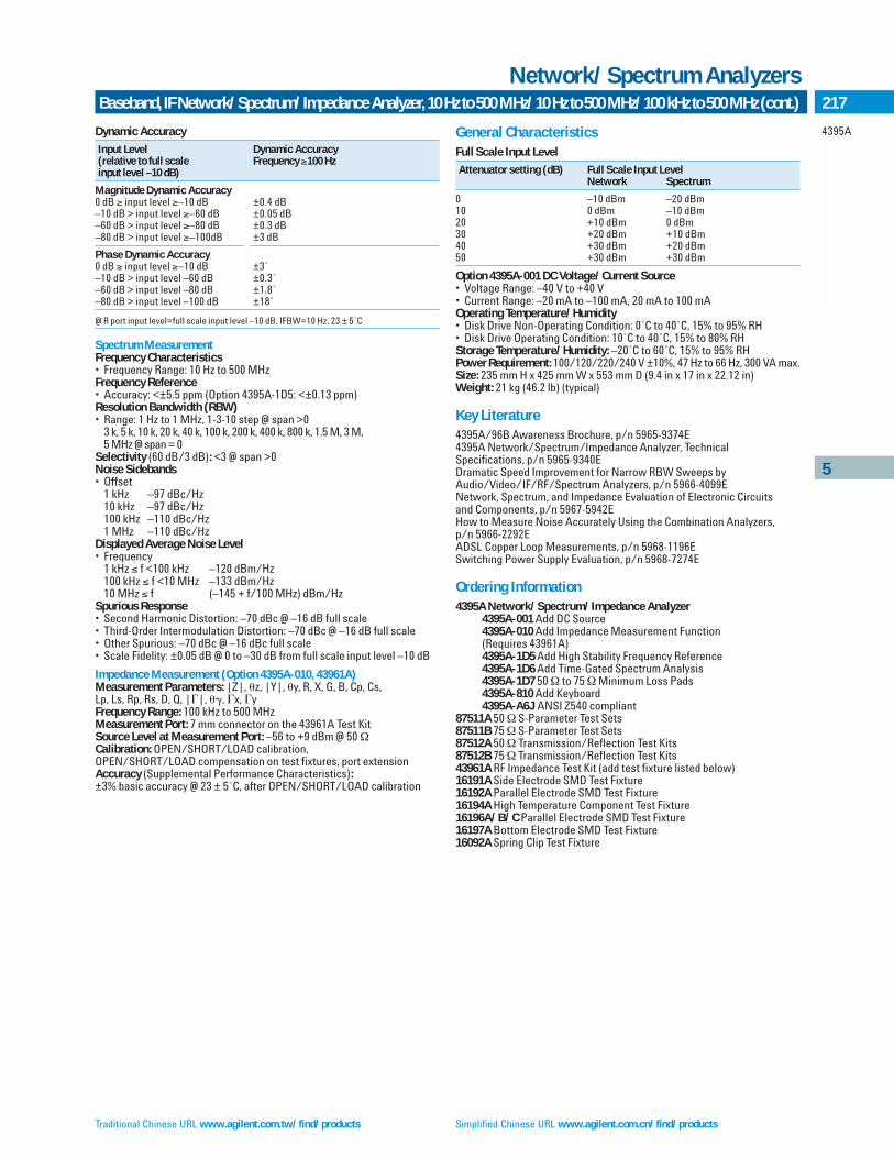
Traditional Chinese URL www.agilent.com.tw/find/products Simplified Chinese URL www.agilent.com.cn/find/products
5
4395A
217Baseband, IF Network/Spectrum/Impedance Analyzer, 10 Hz to 500 MHz/10 Hz to 500 MHz/100 kHz to 500 MHz (cont.)
Network/Spectrum Analyzers
Dynamic Accuracy
Input Level Dynamic Accuracy(relative to full scale Frequency ≥100 Hzinput level –10 dB)
Magnitude Dynamic Accuracy0 dB ≥ input level ≥–10 dB ±0.4 dB–10 dB > input level ≥–60 dB ±0.05 dB–60 dB > input level ≥–80 dB ±0.3 dB–80 dB > input level ≥–100dB ±3 dB
Phase Dynamic Accuracy0 dB ≥ input level ≥–10 dB ±3˚–10 dB > input level –60 dB ±0.3˚–60 dB > input level –80 dB ±1.8˚–80 dB > input level –100 dB ±18˚
@ R port input level=full scale input level –10 dB, IFBW=10 Hz, 23 ± 5˚C
Spectrum MeasurementFrequency Characteristics• Frequency Range: 10 Hz to 500 MHzFrequency Reference• Accuracy: <±5.5 ppm (Option 4395A-1D5: <±0.13 ppm)Resolution Bandwidth (RBW)• Range: 1 Hz to 1 MHz, 1-3-10 step @ span >0
3 k, 5 k, 10 k, 20 k, 40 k, 100 k, 200 k, 400 k, 800 k, 1.5 M, 3 M, 5 MHz @ span = 0
Selectivity (60 dB/3 dB): <3 @ span >0Noise Sidebands• Offset
1 kHz –97 dBc/Hz10 kHz –97 dBc/Hz100 kHz –110 dBc/Hz1 MHz –110 dBc/Hz
Displayed Average Noise Level• Frequency
1 kHz ≤ f <100 kHz –120 dBm/Hz100 kHz ≤ f <10 MHz –133 dBm/Hz10 MHz ≤ f (–145 + f/100 MHz) dBm/Hz
Spurious Response• Second Harmonic Distortion: –70 dBc @ –16 dB full scale• Third-Order Intermodulation Distortion: –70 dBc @ –16 dB full scale• Other Spurious: –70 dBc @ –16 dBc full scale• Scale Fidelity: ±0.05 dB @ 0 to –30 dB from full scale input level –10 dB
Impedance Measurement (Option 4395A-010, 43961A)Measurement Parameters: |Z|, z, |Y|, y, R, X, G, B, Cp, Cs, Lp, Ls, Rp, Rs, D, Q, ||, , x, yFrequency Range: 100 kHz to 500 MHzMeasurement Port: 7 mm connector on the 43961A Test KitSource Level at Measurement Port: –56 to +9 dBm @ 50 ΩCalibration: OPEN/SHORT/LOAD calibration,OPEN/SHORT/LOAD compensation on test fixtures, port extensionAccuracy (Supplemental Performance Characteristics):±3% basic accuracy @ 23 ± 5˚C, after OPEN/SHORT/LOAD calibration
General CharacteristicsFull Scale Input Level
Attenuator setting (dB) Full Scale Input LevelNetwork Spectrum
0 –10 dBm –20 dBm10 0 dBm –10 dBm20 +10 dBm 0 dBm30 +20 dBm +10 dBm40 +30 dBm +20 dBm50 +30 dBm +30 dBm
Option 4395A-001 DC Voltage/Current Source• Voltage Range: –40 V to +40 V• Current Range: –20 mA to –100 mA, 20 mA to 100 mAOperating Temperature/Humidity• Disk Drive Non-Operating Condition: 0˚C to 40˚C, 15% to 95% RH• Disk Drive Operating Condition: 10˚C to 40˚C, 15% to 80% RHStorage Temperature/Humidity: –20˚C to 60˚C, 15% to 95% RHPower Requirement: 100/120/220/240 V ±10%, 47 Hz to 66 Hz, 300 VA max.Size: 235 mm H x 425 mm W x 553 mm D (9.4 in x 17 in x 22.12 in)Weight: 21 kg (46.2 lb) (typical)
Key Literature4395A/96B Awareness Brochure, p/n 5965-9374E4395A Network/Spectrum/Impedance Analyzer, TechnicalSpecifications, p/n 5965-9340EDramatic Speed Improvement for Narrow RBW Sweeps by Audio/Video/IF/RF/Spectrum Analyzers, p/n 5966-4099ENetwork, Spectrum, and Impedance Evaluation of Electronic Circuits and Components, p/n 5967-5942EHow to Measure Noise Accurately Using the Combination Analyzers, p/n 5966-2292EADSL Copper Loop Measurements, p/n 5968-1196ESwitching Power Supply Evaluation, p/n 5968-7274E
Ordering Information4395A Network/Spectrum/Impedance Analyzer
4395A-001 Add DC Source4395A-010 Add Impedance Measurement Function (Requires 43961A)4395A-1D5 Add High Stability Frequency Reference4395A-1D6 Add Time-Gated Spectrum Analysis4395A-1D7 50 Ω to 75 ΩMinimum Loss Pads4395A-810 Add Keyboard4395A-A6J ANSI Z540 compliant
87511A 50 Ω S-Parameter Test Sets87511B 75 Ω S-Parameter Test Sets87512A 50 Ω Transmission/Reflection Test Kits87512B 75 Ω Transmission/Reflection Test Kits43961A RF Impedance Test Kit (add test fixture listed below)16191A Side Electrode SMD Test Fixture16192A Parallel Electrode SMD Test Fixture16194A High Temperature Component Test Fixture16196A/B/C Parallel Electrode SMD Test Fixture16197A Bottom Electrode SMD Test Fixture16092A Spring Clip Test Fixture
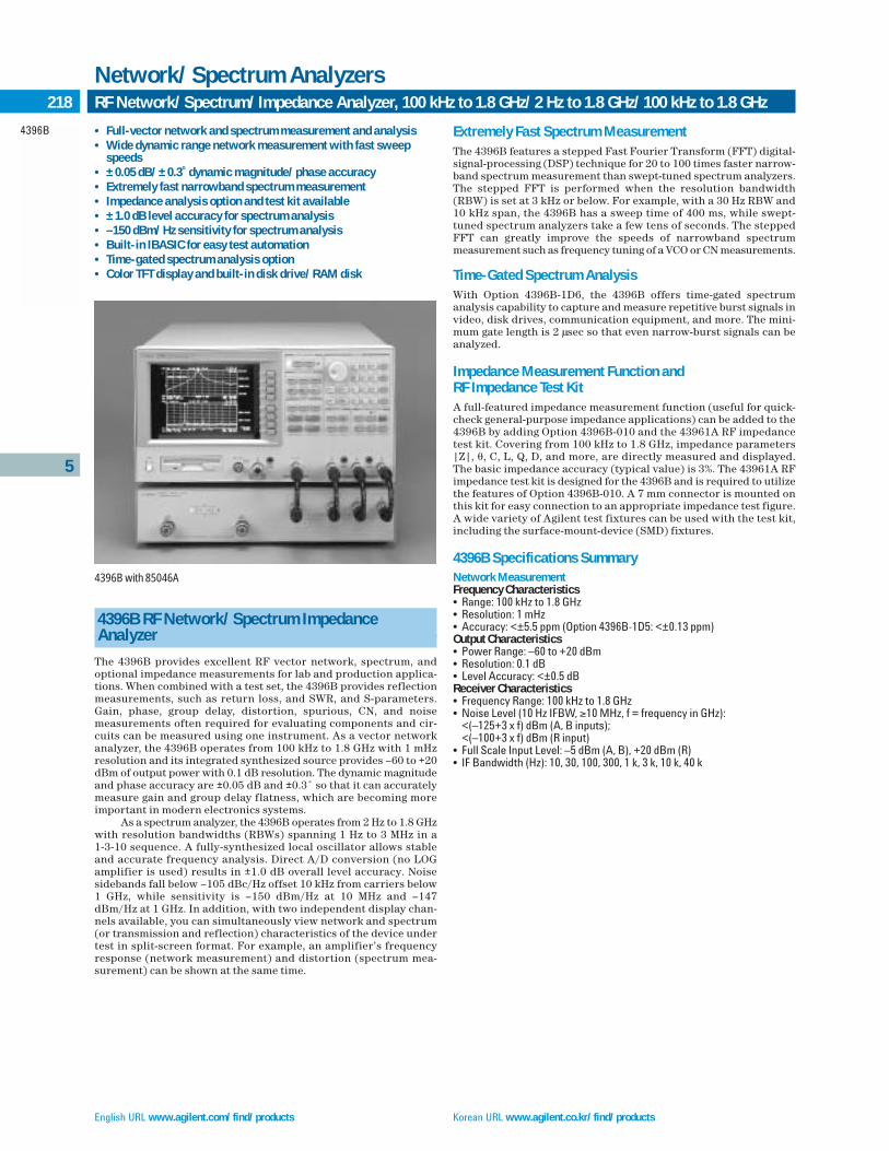
English URL www.agilent.com/find/products Korean URL www.agilent.co.kr/find/products
5
4396B
218 RF Network/Spectrum/Impedance Analyzer, 100 kHz to 1.8 GHz/2 Hz to 1.8 GHz/100 kHz to 1.8 GHz
Network/Spectrum Analyzers
4396B RF Network/Spectrum Impedance Analyzer
The 4396B provides excellent RF vector network, spectrum, andoptional impedance measurements for lab and production applica-tions. When combined with a test set, the 4396B provides reflectionmeasurements, such as return loss, and SWR, and S-parameters.Gain, phase, group delay, distortion, spurious, CN, and noise measurements often required for evaluating components and cir-cuits can be measured using one instrument. As a vector networkanalyzer, the 4396B operates from 100 kHz to 1.8 GHz with 1 mHzresolution and its integrated synthesized source provides –60 to +20dBm of output power with 0.1 dB resolution. The dynamic magnitudeand phase accuracy are ±0.05 dB and ±0.3˚ so that it can accuratelymeasure gain and group delay flatness, which are becoming moreimportant in modern electronics systems.
As a spectrum analyzer, the 4396B operates from 2 Hz to 1.8 GHzwith resolution bandwidths (RBWs) spanning 1 Hz to 3 MHz in a 1-3-10 sequence. A fully-synthesized local oscillator allows stableand accurate frequency analysis. Direct A/D conversion (no LOGamplifier is used) results in ±1.0 dB overall level accuracy. Noisesidebands fall below –105 dBc/Hz offset 10 kHz from carriers below 1 GHz, while sensitivity is –150 dBm/Hz at 10 MHz and –147dBm/Hz at 1 GHz. In addition, with two independent display chan-nels available, you can simultaneously view network and spectrum(or transmission and reflection) characteristics of the device undertest in split-screen format. For example, an amplifier’s frequencyresponse (network measurement) and distortion (spectrum mea-surement) can be shown at the same time.
Extremely Fast Spectrum MeasurementThe 4396B features a stepped Fast Fourier Transform (FFT) digital-signal-processing (DSP) technique for 20 to 100 times faster narrow-band spectrum measurement than swept-tuned spectrum analyzers.The stepped FFT is performed when the resolution bandwidth(RBW) is set at 3 kHz or below. For example, with a 30 Hz RBW and10 kHz span, the 4396B has a sweep time of 400 ms, while swept-tuned spectrum analyzers take a few tens of seconds. The steppedFFT can greatly improve the speeds of narrowband spectrum measurement such as frequency tuning of a VCO or CN measurements.
Time-Gated Spectrum AnalysisWith Option 4396B-1D6, the 4396B offers time-gated spectrum analysis capability to capture and measure repetitive burst signals invideo, disk drives, communication equipment, and more. The mini-mum gate length is 2 µsec so that even narrow-burst signals can beanalyzed.
Impedance Measurement Function and RF Impedance Test KitA full-featured impedance measurement function (useful for quick-check general-purpose impedance applications) can be added to the 4396B by adding Option 4396B-010 and the 43961A RF impedancetest kit. Covering from 100 kHz to 1.8 GHz, impedance parameters|Z|, , C, L, Q, D, and more, are directly measured and displayed.The basic impedance accuracy (typical value) is 3%. The 43961A RFimpedance test kit is designed for the 4396B and is required to utilizethe features of Option 4396B-010. A 7 mm connector is mounted onthis kit for easy connection to an appropriate impedance test figure.A wide variety of Agilent test fixtures can be used with the test kit,including the surface-mount-device (SMD) fixtures.
4396B Specifications SummaryNetwork MeasurementFrequency Characteristics• Range: 100 kHz to 1.8 GHz• Resolution: 1 mHz• Accuracy: <±5.5 ppm (Option 4396B-1D5: <±0.13 ppm)Output Characteristics• Power Range: –60 to +20 dBm• Resolution: 0.1 dB• Level Accuracy: <±0.5 dBReceiver Characteristics• Frequency Range: 100 kHz to 1.8 GHz• Noise Level (10 Hz IFBW, ≥10 MHz, f = frequency in GHz):
<(–125+3 x f) dBm (A, B inputs);<(–100+3 x f) dBm (R input)
• Full Scale Input Level: –5 dBm (A, B), +20 dBm (R)• IF Bandwidth (Hz): 10, 30, 100, 300, 1 k, 3 k, 10 k, 40 k
• Full-vector network and spectrum measurement and analysis• Wide dynamic range network measurement with fast sweep
speeds• ±0.05 dB/±0.3˚ dynamic magnitude/phase accuracy• Extremely fast narrowband spectrum measurement• Impedance analysis option and test kit available• ±1.0 dB level accuracy for spectrum analysis• –150 dBm/Hz sensitivity for spectrum analysis• Built-in IBASIC for easy test automation• Time-gated spectrum analysis option• Color TFT display and built-in disk drive/RAM disk
4396B with 85046A
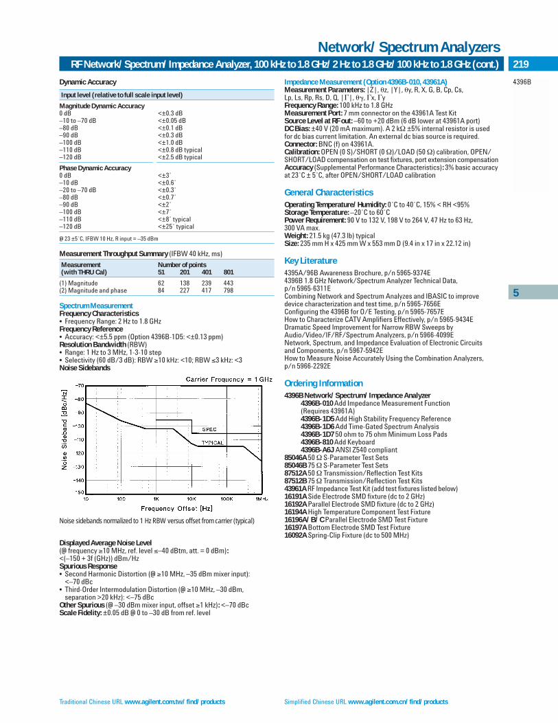
Traditional Chinese URL www.agilent.com.tw/find/products Simplified Chinese URL www.agilent.com.cn/find/products
5
4396B
219RF Network/Spectrum/Impedance Analyzer, 100 kHz to 1.8 GHz/2 Hz to 1.8 GHz/100 kHz to 1.8 GHz (cont.)
Network/Spectrum Analyzers
Dynamic Accuracy
Input level (relative to full scale input level)
Magnitude Dynamic Accuracy0 dB <±0.3 dB–10 to –70 dB <±0.05 dB–80 dB <±0.1 dB–90 dB <±0.3 dB–100 dB <±1.0 dB–110 dB <±0.8 dB typical–120 dB <±2.5 dB typical
Phase Dynamic Accuracy0 dB <±3˚–10 dB <±0.6˚–20 to –70 dB <±0.3˚–80 dB <±0.7˚–90 dB <±2˚–100 dB <±7˚–110 dB <±8˚ typical–120 dB <±25˚ typical
@ 23 ±5˚C, IFBW 10 Hz, R input = –35 dBm
Measurement Throughput Summary (IFBW 40 kHz, ms)
Measurement Number of points(with THRU Cal) 51 201 401 801
(1) Magnitude 62 138 239 443(2) Magnitude and phase 84 227 417 798
Spectrum MeasurementFrequency Characteristics• Frequency Range: 2 Hz to 1.8 GHzFrequency Reference• Accuracy: <±5.5 ppm (Option 4396B-1D5: <±0.13 ppm)Resolution Bandwidth (RBW)• Range: 1 Hz to 3 MHz, 1-3-10 step• Selectivity (60 dB/3 dB): RBW ≥10 kHz: <10; RBW ≤3 kHz: <3Noise Sidebands
Displayed Average Noise Level (@ frequency ≥10 MHz, ref. level ≤–40 dBtm, att. = 0 dBm):<(–150 + 3f (GHz)) dBm/HzSpurious Response• Second Harmonic Distortion (@ ≥10 MHz, –35 dBm mixer input):
<–70 dBc• Third-Order Intermodulation Distortion (@ ≥10 MHz, –30 dBm,
separation >20 kHz): <–75 dBcOther Spurious (@ –30 dBm mixer input, offset ≥1 kHz): <–70 dBc Scale Fidelity: ±0.05 dB @ 0 to –30 dB from ref. level
Noise sidebands normalized to 1 Hz RBW versus offset from carrier (typical)
Impedance Measurement (Option 4396B-010, 43961A)Measurement Parameters: |Z|, z, |Y|, y, R, X, G, B, Cp, Cs, Lp, Ls, Rp, Rs, D, Q, ||, , x, yFrequency Range: 100 kHz to 1.8 GHzMeasurement Port: 7 mm connector on the 43961A Test KitSource Level at RF out: –60 to +20 dBm (6 dB lower at 43961A port)DC Bias: ±40 V (20 mA maximum). A 2 kΩ ±5% internal resistor is used for dc bias current limitation. An external dc bias source is required. Connector: BNC (f) on 43961A.Calibration: OPEN (0 S)/SHORT (0 Ω)/LOAD (50 Ω) calibration, OPEN/SHORT/LOAD compensation on test fixtures, port extension compensationAccuracy (Supplemental Performance Characteristics): 3% basic accuracyat 23˚C ± 5˚C, after OPEN/SHORT/LOAD calibration
General CharacteristicsOperating Temperature/Humidity: 0˚C to 40˚C, 15% < RH <95%Storage Temperature: –20˚C to 60˚CPower Requirement: 90 V to 132 V, 198 V to 264 V, 47 Hz to 63 Hz, 300 VA max.Weight: 21.5 kg (47.3 lb) typicalSize: 235 mm H x 425 mm W x 553 mm D (9.4 in x 17 in x 22.12 in)
Key Literature4395A/96B Awareness Brochure, p/n 5965-9374E4396B 1.8 GHz Network/Spectrum Analyzer Technical Data, p/n 5965-6311ECombining Network and Spectrum Analyzes and IBASIC to improve device characterization and test time, p/n 5965-7656EConfiguring the 4396B for O/E Testing, p/n 5965-7657EHow to Characterize CATV Amplifiers Effectively, p/n 5965-9434EDramatic Speed Improvement for Narrow RBW Sweeps by Audio/Video/IF/RF/Spectrum Analyzers, p/n 5966-4099ENetwork, Spectrum, and Impedance Evaluation of Electronic Circuits and Components, p/n 5967-5942EHow to Measure Noise Accurately Using the Combination Analyzers, p/n 5966-2292E
Ordering Information4396B Network/Spectrum/Impedance Analyzer
4396B-010 Add Impedance Measurement Function (Requires 43961A)4396B-1D5 Add High Stability Frequency Reference4396B-1D6 Add Time-Gated Spectrum Analysis4396B-1D7 50 ohm to 75 ohm Minimum Loss Pads4396B-810 Add Keyboard4396B-A6J ANSI Z540 compliant
85046A 50 Ω S-Parameter Test Sets85046B 75 Ω S-Parameter Test Sets87512A 50 Ω Transmission/Reflection Test Kits87512B 75 Ω Transmission/Reflection Test Kits43961A RF Impedance Test Kit (add test fixtures listed below)16191A Side Electrode SMD fixture (dc to 2 GHz)16192A Parallel Electrode SMD fixture (dc to 2 GHz)16194A High Temperature Component Test Fixture16196A/B/C Parallel Electrode SMD Test Fixture16197A Bottom Electrode SMD Test Fixture16092A Spring-Clip Fixture (dc to 500 MHz)

English URL www.agilent.com/find/products Korean URL www.agilent.co.kr/find/products
5
43961A87511A87511B87512A87512B41800A
220 Test Kits, Active Probe
Network/Spectrum Analyzers
43961A RF Impedance Test Kit
The 43961A RF impedance test kit provides the capability to mea-sure impedance parameters of 1-port devices with the 4395A withOption 4395A-010 (100 kHz to 500 MHz) or the 4396B with Option4396B-010 (100 kHz to 1.8 GHz). The test port of the 43961A is a 7 mmconnector and can be used with the 16196A/B/C, 16197A, or 7 mmtype test fixtures. The 43961A includes open/short/load calibrationstandards, and the test fixtures such as 16197A are optional.
Frequency Range: 100 kHz to 1.8 GHz (100 kHz to 500 MHz with 4395A)Measurement Parameters: |Z|,|Y|, , R, X, G, B, Cp, Cs, Lp, Ls, Rp, Rs, D, Q, ||
87511A
87511A/B S-Parameter Test Sets
The 87511A/B S-parameter test sets provide the capability to measure S-parameters of 2-port devices from 100 kHz to 500 MHzwith an network analyzer. The test ports of the 87511A are 50 Ω con-nectors (Option 87511A-008: 7 mm or Option 87511A-001: type N(f)),and the test ports of the 87511B are 75 Ω type N(f) connectors.Calibration kits are not included.
Frequency Range: 100 kHz to 500 MHzTest Port Impedance: 87511A, 50 Ω; 87511B, 75 Ω
87511A 87511B
Directivity100 kHz to 300 kHz 30 dB 30 dB300 kHz to 200 MHz 40 dB 33 dB200 MHz to 500 MHz 35 dB 33 dB
Nominal Insertion LossRF IN to port 1, 2 13 dB 19 dBRF IN to R, A, B 19 dB 31 dB
Size: 90 mm H x 432 mm W x 495 mm D (3.6 in x 17.28 in x 19.8 in)Weight: 5.7 kg (12.54 lb) (typical)
87512A
87512A/B Transmission/Reflection Test Kits
87512A/B transmission/reflection test kits provide the capability tomeasure the reflection and transmission characteristics of 50 Ω or75 Ω devices up to 2 GHz with an Agilent network analyzer. The testport of the 87512A is a 50 Ω type N(f) connector, and the test port ofthe 87512B is a 75 Ω type N(f) connector. The 87512A/B include pre-cision short/load termination for calibration.
Frequency Range: DC to 2 GHzTest Port Impedance: 87512A, 50 Ω; 87512B, 75 ΩEquivalent Directivity: 40 dB (typical)Insertion Loss: 10 dB ± 1 dB
41800A
41800A Active Probe
The 41800A active probe provides high input impedance from 5 Hzto 500 MHz. The 41800A is a valuable tool when used with a networkand spectrum analyzer for circuit signal analysis.
SpecificationsBandwidth: 5 Hz to 500 MHzOutput Connector: 50 Ω type N maleInput R,C (typical):100 k Ω, 3 pF (probe alone);1 MΩ, 1 pF (with 10:1, 100:1 divider)Frequency Response relative to 50 MHz: ±1 dB @ 50 Hz to 200 MHzAverage Noise Level: 10 nV/√Hz @ ≥300 kHzSecond Harmonic Distortion: <–50 dBc @ 20 dBm (250 MHz) input (typical)Third-Order Intermodulation Distortion: <–70 dBc @ –26 dBm two signalinput (typical)1 dB Gain Compression: >+3 dBm input @ 500 MHz
43961A

Traditional Chinese URL www.agilent.com.tw/find/products Simplified Chinese URL www.agilent.com.cn/find/products
5
8712ET8712ES8714ET8714ES
221RF Network Analyzers, 300 kHz to 3 GHz
Network Analyzers
8712E RF Network Analyzer Series
Designed for ManufacturingThe 8712E Series of economical RF network analyzers providesspeed, accuracy, and automation features in compact, integratedinstruments for high-volume RF component manufacturing. Theseanalyzers help reduce tune and test times, increase throughput, andlower your overall cost per component. A choice of transmission/reflection analyzers (ET models) or S-parameter analyzers (ES mod-els) allows you to choose the the optimum level of performance versus price to meet your measurement needs.
Standard Family FeaturesThe 8712ET and 8714ET feature built-in transmission/reflectiontest sets with a full range of magnitude and phase measurements.These analyzers also employ advanced vector-error correction tech-niques to enhance measurement accuracy.
The 8712ES and 8714ES feature S-parameter test sets with fulltwo-port vector-error correction, providing the highest level of mea-surement accuracy.
All these analyzers provide fast, complete swept-frequency andswept-power characterization of RF components. In addition:• 300 kHz to 1.3 or 3 GHz models are available in both 50 Ω or 75 Ω
options• A synthesized source provides fast, stable, high-resolution (1 Hz)
stimulus for accurate measurements on a variety of RF components• Power sweeps enable testing of amplifier gain compression and
AM-PM conversion• A 60 dB step attenuator (standard on ES models, optional on ET
models) provides a wide range of output power levels for testingactive devices
• Real-time sweep speeds with better than 10 updates per second facilitate high device throughput and increase tuning efficiency
• A built-in 3.5-inch DOS-format disk drive provides unlimiteddata storage
• Serial, parallel, LAN and GPIB interfaces make it easy to print orplot data to all printers and plotters
Flexible, sensitive receivers offer a choice between narrow-band and broadband detection. Broadband detection allows scalarcharacterization of frequency-translating devices, while narrow-band detection provides up to 100 dB of dynamic range for vectormeasurements of high-rejection devices.
The instruments are equipped with a large, 9-inch mono-chrome display for clear view of measurement data, softkey func-tions, IBASIC programs, and markers. Display pass/fail indicatorsand trace data in color by connecting any VGA-compatible monitor.Two independent measurement channels let you display transmis-sion and reflection data simultaneously. Each channel can haveindependent measurement parameters such as frequency range, IFbandwidth, number of points, and display formats. Display formatsinclude SWR, linear and log magnitude, phase and group delay,Smith chart, polar, real and imaginary, dBW, dBm, dBµW, dBV,dBmV, and dBµV.
Manufacturing FeaturesA network connection provides an efficient and reliable way to com-municate with your test systems. The standard TCP/IP-compliantEthertwist LAN interface makes connecting to a factory-wide network easy. Use a variety of standard protocols, such as ftp, http,bootp, telnet, sockets, and network file system (NFS) to simultane-ously distribute new test programs, test parameters, limit lines, andcustom interfaces to all of the instruments on your production lines.With LAN capability, data can be directly imported into your PCapplications, such as Microsoft Word, and Excel, or sent to a networked printer. You can also remotely troubleshoot test stationproblems from anywhere on the network by using any standard webbrowser.
With Instrument BASIC programming language (IBASIC), youcan easily create custom test applications and user interfaces thatinclude:• Special softkey labels, graphical setup diagrams, and tailored
user prompts• Bar-code-reading capability for efficient tracking and documen-
tation of individual device performance • Control other test instruments via the LAN, GPIB, serial, or
parallel interfaces• For simpler applications, even those without programming
expertise can use IBASIC as a keystroke recorder, to easily automate manual measurements
Many manufacturing tests can be accomplished by merelyrecalling the appropriate instrument state, eliminating the need tochange measurement parameters manually. Hundreds of instru-ment states can be programmed for a variety of uses. With Agilent’s“fast-recall” feature, one of seven instrument states can be quicklyrecalled with a single softkey, or with a foot switch for hands-freeswitching during aligning or assembly operations.
Instrument states can include user-defined limit lines that letyou easily and consistently compare measured data to test limits,providing automated pass/fail testing. The pass/fail results are displayed clearly on the instrument screen or external monitor tominimize operator errors or misinterpretation. Automatedpass/fail testing eliminates the guesswork from your test processesand helps ensure that your components are aligned and tested tothe same specifications at all test stations.
Speed up component test times by using the power of built-indata markers. Use the eight markers per channel to display data inabsolute or relative terms. Or, perform automatic, real-time calcula-tions of device characteristics such as maximum/minimum, centerfrequency, mean and standard deviation, peak-to-peak excursion,gain, slope and flatness, and filter 3-dB bandwidth, loss, and Q.
Comprehensive, Fast Cable TestOption 100 adds fault-location and structural-return-loss (SRL)measurement capability for characterizing 50 Ω or 75 Ω cables thatare still on a spool in a warehouse, or already installed on a cellulartower.
Agilent’s fault-location option is easy to use and has manyadvantages over traditional time-domain reflectometry (TDR) tech-niques. You can also use the option to easily characterize the lossand velocity factors of your cables, and to accurately check the effectof cable damage by measuring SRL. Option 101 combines Option 100with a rugged transport case to protect your instrument in the fieldduring transport and operation.
• 300 kHz to 1.3 GHz (8712ET/ES) or 3 GHz (8714ET/ES) • S-parameter measurements (ES models)• Up to 100 dB dynamic range• Narrowband and broadband detection• Real-time sweep speeds • 50 Ω or 75 Ω system impedance• 1 Hz resolution synthesized source• Standard LAN interface• Standard GP Instrument BASIC (IBASIC)• Optional fault-location and SRL measurements • Standard multiport test sets available
8712E RF Network Analyzer Series
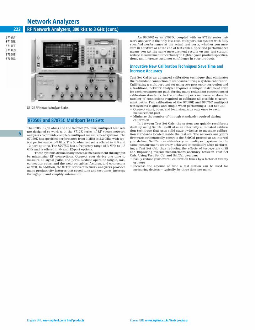
English URL www.agilent.com/find/products Korean URL www.agilent.co.kr/find/products
5
8712ET8712ES8714ET8714ES87050E87075C
222 RF Network Analyzers, 300 kHz to 3 GHz (cont.)
Network Analyzers
87050E and 87075C Multiport Test Sets
The 87050E (50 ohm) and the 87075C (75 ohm) multiport test setsare designed to work with the 8712E series of RF vector networkanalyzers to provide complete multiport measurement systems. The87050E has specified performance from 3 MHz to 2.2 GHz, with typ-ical performance to 3 GHz. The 50 ohm test set is offered in 4, 8 and12-port options. The 87075C has a frequency range of 3 MHz to 1.3GHz and is offered in 6- and 12-port options.
These systems dramatically increase measurement throughputby minimizing RF connections. Connect your device one time tomeasure all signal paths and ports. Reduce operator fatigue, mis-connection rates, and the wear on cables, fixtures, and connectorsas well. In addition, the 8712E series of network analyzers providesmany productivity features that speed tune and test times, increasethroughput, and simplify automation.
An 87050E or an 87075C coupled with an 8712E series net-work analyzer is the only low-cost, multiport test system with fullyspecified performance at the actual test ports, whether you mea-sure in a fixture or at the end of test cables. Specified performancesmeans you get the same measurement results on any test station,reduce measurement uncertainty to tighten your product specifica-tions, and increase customer confidence in your products.
Innovative New Calibration Techniques Save Time andIncrease Accuracy
Test Set Cal is an advanced calibration technique that eliminatesthe redundant connection of standards during a system calibration.Calibrating a multiport test set using two-port error correction anda traditional network analyzer requires a unique instrument statefor each measurement path, forcing many redundant connections ofcalibration standards. As the number of ports increases, so does thenumber of connections required to calibrate all possible measure-ment paths. Full calibration of the 87050E and 87075C multiporttest systems is quick and simple when performing a Test Set Cal:• Connect short, open, and load standards only once to each
measurement port• Minimize the number of through standards required during
calibrationIn between Test Set Cals, the system can quickly recalibrate
itself by using SelfCal. SelfCal is an internally automated calibra-tion technique that uses solid-state switches to measure calibra-tion standards located inside the test set. The network analyzer’sfirmware automatically controls the SelfCal process at an intervalyou define. SelfCal re-calibrates your multiport system to thesame measurement accuracy achieved immediately after perform-ing a Test Set Cal, thus reducing the effects of test-system driftand improving overall measurement accuracy between Test SetCals. Using Test Set Cal and SelfCal, you can:• Easily reduce your overall calibration times by a factor of twenty
or more• Increase the amount of time a test station can be used for
measuring devices — typically, by three days per month
8712E RF Network Analyzer Series

Traditional Chinese URL www.agilent.com.tw/find/products Simplified Chinese URL www.agilent.com.cn/find/products
5
8712ET8712ES8714ET8714ES
223RF Network Analyzers, 300 kHz to 3 GHz (cont.)
Network Analyzers
Detectors and Bridges
External detectors (50 Ω and 75 Ω ) are available for remote devicemeasurements.
86200B 50 Ω Scalar DetectorAn external scalar detector for measuring 50 Ω devices.
86201B 75 Ω Scalar DetectorAn external scalar detector for measuring 75 Ω devices.
Upgrade Kits
The following upgrade kits add optional measurement capability toexisting 8712E series RF network analyzers.
To order, add a “U” to the end of the model number of the instru-ment to be upgraded, and specify one or more of these options:
Option 1E1 50 Ω Step Attenuator Provides the necessary components to retrofit an 8712ET or 8714ETwith a 60 dB step attenuator (for 50 ohm models only). Does notinclude installation. Requires recalibration.
Option UNE 75 Ω Step Attenuator Provides the necessary components to retrofit an 8712ET or 8714ETwith a 60 dB step attenuator (for 75 ohm models only). Does notinclude installation. Requires recalibration.
Option 099 Firmware Upgrade Upgrade to the latest version of firmware. Does not include instal-lation.
Option 100 Fault Location/SRL Provides cable-measurement software. Does not include transportcase. Does not include installation.
Option 101 Transport and Operating Case and Fault Location/SRL Combines transport and operation case with Option 100. Does notinclude installation.
Transit CasesAgilent offers a complete line of sturdy transit cases in Valise andTote styles. The cases protect your instrument from shock, vibration,moisture, impact, and contamination, providing a secure enclosurefor shipping. Model 9211-2656 (standard) or model 9211-7481 (tote)fit the 8712ET/ES and 8714ET/ES.
Key Literature8712ET/ES and 8714ET/ES Brochure, p/n 5967-6316E 8712ET/ES and 8714ET/ES Technical Specifications, p/n 5967-6314E8712ET/ES and 8714ET/ES Configuration Guide, p/n 5967-6315E87050E Brochure, p/n 5968-4763E 87050E Technical Specifications, p/n 5968-4764E 87050E Configuration Guide, p/n 5968-4765E87075C Brochure, p/n 5968-4766E87075C Technical Specifications, p/n 5968-4767E87075C Configuration Guide, p/n 5968-4768E
For more information, visit our web site:http://www.agilent.com/find/8712
8712ET 8714ET8712ES 8714ES
Impedance 50 ohm 75 ohm (Option 1EC) 50 ohm 75 ohm (Option 1EC)
Minimum Frequency 300 kHz 300 kHz 300 kHz 300 kHz
Maximum Frequency 1.3 GHz 1.3 GHz 3.0 GHz 3.0 GHz
Frequency Resolution 1 Hz 1 Hz 1 Hz 1 Hz
Max. Source PowerET (<1 GHz/>1 GHz) 16 dBm/13 dBm 13 dBm/10dBm 11 dBm/10 dBm 8 dBm/7 dBm
with Option 1E1 15 dBm/12 dBm 12 dBm/9 dBm 10 dBm/9 dBm 7 dBm/6 dBmES (<1 GHz/>1 GHz) 13 dBm/10 dBm 10 dBm/7dBm 9 dBm/7dBm 6 dBm/4 dBm
Min. Source PowerET 0 dBm –3 dBm –5 dBm –8 dBm
with Option 1E1 –60 dBm –60 dBm –60 dBm –60 dBmES –60 dBm –60 dBm –60 dBm –60 dBm
Power Resolution 0.01 dBm 0.01 dBm 0.01 dBm 0.01 dBm
Power FlatnessET ±1.0 dB ±1.5 dB ±1.0 dB ±1.5 dB
with Option 1E1 ±2.0 dB ±3.0 dB ±2.0 dB ±3.0 dBES ±2.0 dB ±3.0 dB ±2.0 dB ±3.0 dB
Power Sweep Range 13 dB 13 dB 15 dB 15 dB
System Dynamic RangeET (narrowband/broadband) >115 dB/>62 dB >113 dB/>56 dB >114 dB/>59 dB >110 dB/>53 dB
with Option 1E1 >115 dB/>60 dB >110 dB/>53 dB >112 dB/>57dB >107 dB/>50 dBES (narrowband/broadband) >104 dB/>46 dB >99 dB/>39 dB >101 dB/>43 dB >96 dB/>36 dB
Test Port Connector Type-N (f) Type-N (f) Type-N (f) Type-N (f)
Data applies at 25˚C ± 5˚C. See product literature for more complete specifications and for total measurement uncertainty after error correction.
Size: 179 mm H x 425 mm W x 514 mm D (7.0 in x 16.75 in x 20.25 in)Weight: 20.5 kg (45 lb) net; 27 kg (59 lb) shipping
English URL www.agilent.com/find/products Korean URL www.agilent.co.kr/find/products
5
8712ET8712ES8714ET8714ES87050E87075C
224 RF Network Analyzers, 300 kHz to 3 GHz (cont.)
Network Analyzers
Ordering InformationNote: A complete system consists of a network analyzer, calibration kit,and cables. Calibration kits and cables can be found in the Accessoriessection beginning on page 238.
8712ET Network Analyzer8712ES Network Analyzer8714ET Network Analyzer8714ES Network AnalyzerThe following options apply to all three network analyzers:
Option 050 50 Ω ImpedanceOption 1EC 75 Ω ImpedanceOption 1E1 60 dB Attenuator (ET models only)Option 1CL DIN KeyboardOption 1CM Rackmount KitOption 100 Fault Location/SRL Option 101 Transport and Operating Caseplus Fault Location/SRLOption AFN 50 Ω Economy CableOption AFP 75 Ω Economy CableOption B20 50 Ω Precision CableOption B21 75 Ω Precision Cable
87050E Multiport Test Sets87050E-004 4 ports87050E-008 8 ports87050E-012 12 ports
87075C Multiport Test Sets87075C-006 6 ports87075C-012 12 ports
Upgrades for ET and ES models (Add ”U“ to model number)Option 1E1 50 Ω Step Attenuator (ET only)Option UNE 75 Ω step attenuator (ET only)Option 100 FL/SRL Upgrade KitOption 101 Transport Operating Caseplus FL/SRL Upgrade Kit
Upgrades for C models86226C Firmware Upgrade Kit86227C LAN Upgrade Kit
Accessories86200B 50 Ω Scalar Detector86201B 75 Ω Scalar Detector
Transit Cases9211-2656 Standard Transit Case9211-7481 Tote-Style Transit Case

Traditional Chinese URL www.agilent.com.tw/find/products Simplified Chinese URL www.agilent.com.cn/find/products
5
8753ET8753ES
2258753ET and 8753ES RF Network Analyzers
Network Analyzers
• 30 kHz to 3 or 6 GHz frequency range• Integrated T/R or S-parameter test set • Up to 110 dB dynamic range• Large LCD display with VGA output for external monitors• Display up to four parameters at the same time• Save/recall instrument states and data to built-in floppy-disk
drive• Optional time-domain and swept-harmonic measurements
The 8753ET and 8753ES RF network analyzers offer an unbeatable combina-tion of speed, performance, and ease of use to meet your measurementneeds, whether in the R&D laboratory or on the production floor. With anintegrated test set covering to 3 or 6 GHz, up to 110 dB of dynamic range, andboth frequency and power sweeps, the 8753ET and 8753ES give you a pow-erful solution for characterizing the linear and nonlinear behavior of activeand passive networks, devices, components, and subsystems.
Family Features
Selecting the transmission/reflection analyzers (ET model) or S-parameter analyzers (ES model) allows you to choose the opti-mum level of performance versus cost for your application. The net-work analyzers feature two independent measurement channelsthat can measure and display up to four parameters simultaneous-ly. You can choose to display any combination of reflection andtransmission parameters, with magnitude, phase, group-delay,Smith-chart, polar, SWR, or time-domain formats. Easy-to-use soft-keys let you access measurement functions quickly, and you canview results in overlay or split-screen format on the crisp, LCDcolor display using up to four graticules. A VGA-compatible outputhas been added to drive larger external monitors for enhancedviewing.
Test sequencing allows rapid, repeated execution of complexmeasurements with a single keystroke. In test-sequence mode, youmake a measurement once from the front panel, and the analyzerstores the keystrokes so that the measurement can be repeated with-out any additional programming. You can also use a test sequence tocontrol external devices through the parallel or GPIB port.
For measurements of mixers, tuners, and other frequency-translating devices, the frequency-offset mode allows the networkanalyzer source to be tuned independently from the receiver.Measurements of conversion loss, phase, group-delay, and mixer-tracking can easily be done, with either fixed or swept-IF testing.1
Power-meter calibration provides leveled absolute power todevices that are sensitive to absolute input or output levels. The8753ET/ES automatically controls an 436A, 437B, 438A, E4418B orE4419B power meter to set the power anywhere in the test setupwith power-meter accuracy, or to calibrate the network analyzerreceivers for accurate absolute-power measurements.
Other productivity features include a built-in floppy-disk drivesupporting LIF, DOS, JPEG, and comma separated variable (CSV)formats, non-volatile memory, serial and parallel interfaces, a DINkeyboard interface, and a real-time clock for time-stamping of print-
outs and files. Limit testing, arbitrary frequency testing, and mark-er-tracking functions are included. You can reduce measurementtime by using swept-list mode to choose specific frequencies to test,and to set independent IF bandwidths and power levels in each frequency range. Segmented calibration and interpolated error correction allow you to apply vector-accuracy enhancement over asubset of the analyzer’s calibrated frequency range. The 8753ET/EScode compatibility with the 8753D/E enables you to leverage yourexisting software.
With Option 010, you can view reflection or transmissionresponses in the time domain. The analyzer computes the inverseFFT of the frequency-domain data to display the reflection or trans-mission coefficient versus time. Two time-domain analysis modesenable you to view the step or impulse response of your device.Time gating can be used to remove unwanted responses such asconnector mismatch, and the gated results can be displayed ineither the time or frequency domains.
Combine an S-parameter network analyzer with the timedomain capability to provide a simple, deterministic method fortuning cavity-resonator bandpass filters. Comparing the filter’sreflection response in time-domain with the response of a properlytuned filter reveals which resonators or coupling adjustments needto be tuned. With time-domain filter tuning, you can easily trainnew personnel for this complex task and greatly simplify fine-tun-ing and troubleshooting procedures.
For more advanced characterization of devices, Option 002adds harmonic-measurement capability. Swept second and third-harmonic levels of an amplifier can be displayed absolutely or indBc relative to the fundamental. With the press of a button, you canmeasure harmonics down to –40 dBc.
A high-stability frequency reference, Option lD5, improves thefrequency accuracy of measurements of high-Q devices such as SAWand crystal resonators or dielectric-resonance filters.
ET ModelsThe 8753ET features a built-in 50-ohm transmission/reflection(T/R) test set providing a full range of magnitude and phase mea-surements. Frequency coverage is from 300 kHz to 3 or 6 GHz. TheT/R capability provides a very high level of accuracy and conve-nience in making forward measurements of the device under test.Enhanced response calibration corrects for the effects of sourcematch in a transmission measurement. Option 004 extends thestandard –20 to +5 dBm source power range to –85 to +10 dBm.
ES ModelsThe 8753ES features a built-in 50-ohm or 75-ohm S-parameter testset providing a full range of magnitude and phase measurements.Full two-port error correction capability provides the highest levelof accuracy and the S-parameter test set provides the convenienceof making both forward and reverse sweep measurements withoutreversing the device under test. For configuration flexibility, Option011 deletes the built-in test set so that you can select your own. The8753ES-011 works with the 85046A/B and 85047A S-parameter testsets, and other specialized test sets for specific applications. Option014 provides a configurable test set for maximum flexibility. Forconvenient, accurate measurements in noncoaxial environments,TRL*/LRM*2 calibration is available. Highly accurate measurementsof non-insertable devices can also be achieved using the built-inadapter-removal calibration technique.
Agilent-qualified Channel Partners provide measurementhardware and software solutions that combine with Agilent’s network analyzer products to offer a complete solution for yourtesting needs. For additional information, please refer to page 34.1Phase measurements require reference mixer.2 TRL* and LRM* are three-sampler implementations of the through-reflect-line and line-reflect-match calibration techniques.
Powerful measurement solutions

English URL www.agilent.com/find/products Korean URL www.agilent.co.kr/find/products
5
8753ET8753ES
226 8753ET and 8753ES RF Network Analyzers (cont.)
Network Analyzers
Specifications SummaryTest Sets8753ET provides an integrated transmission/reflection test set with complete forward measurements in 50 ohm. 8753ES provides an integratedS-parameter test set with complete forward and reverse measurements in50-ohm (standard) or 75-ohm (Option 075). External test sets supportedwith the 8753ES-011.
Upgrade Kits for the 8753ET and 8753ESUpgrade kits retrofit the latest operating system or add optional measure-ment capability to existing network analyzers. To order, add a “U” to theend of the model number of the instrument to be upgraded, and specifythe desired option(s):
Option 002 Harmonic-Measurements UpgradeThis upgrade kit adds harmonic-measurement capability (Option 002) toan 8753ET or 8753ES network analyzer. This kit includes installation at anAgilent service center.
Option 004 Step Attenuator UpgradeThis upgrade kit adds a step attenuator to the 8753ET network analyzer.This enables the output power range to operate from –85 to +10 dBminstead of the standard –20 to +5 dBm. This kit includes installation at anAgilent Service Center.
Option 006 6 GHz Upgrade for Standard UnitsThis kit extends the operating frequency range of the standard 8753ET or8753ES from 3 GHz to 6 GHz. Includes installation at an Agilent servicecenter. Not compatible with 8753ES-075 or -011.
Option 611 6 GHz Upgrade for Option 011 UnitsThis kit extends the operating frequency range of the 8753ES-011 from 3 GHz to 6 GHz. Includes installation at an Agilent service center.
Option 010 Time-Domain UpgradeThis upgrade kit adds time-domain-analysis capability (Option 010) to anexisting 8753ET or 8753ES network analyzer. This kit is user-installable.
Option 099 Firmware Upgrade KitThis kit provides the latest version of firmware for the 8753ET or 8753ESnetwork analyzer. The kit is user-installable. This kit may be optionallydownloaded from Agilent’s web site: www.agilent.com/find/firmware
Option 1D5 High-Stability Frequency Reference UpgradeThis option adds a high-stability frequency reference (Option 1D5) to an8753ET or 8753ES network analyzer. Includes installation at an Agilentservice center.
Key Literature8753ET/ES Network Analyzer Brochure, p/n 5968-5159E 8753ET/ES Network Analyzer Technical Specifications, p/n 5968-5160E8753ET/ES Network Analyzer Configuration Guide, p/n 5968-5158E
For more information, visit our web site: www.agilent.com/find/8753
8753ET 8753ES 8753ES Option 011
Impedance 50 ohm (standard) 50 ohm (standard) Depends on test set75 ohm (Option 075)
Minimum Frequency 300 kHz 30 kHz 300 kHz (30 kHz with Option 006)
Maximum Frequency 3 GHz (6 GHz with Option 006) 3 GHz (6 GHz with Option 006) 3 GHz (6 GHz with Option 006)
Frequency Resolution 1 Hz 1 Hz 1 Hz
Max. Source Power 5 dBm (10 dBm with Option 004) 10 dBm (8 dBm with Option 075 20 dBm (18 dBm between 3 to 6 GHz or Option 014) with Option 006)
Min. Source Power –20 dBm (–85 dBm with Option 004) –85 dBm –5 dBm
Power Resolution 0.01 dB 0.01 dB 0.01 dB
Power Flatness <±0.5 dB ±1 dB ±1 dB
Power Sweep Range 25 dB 25 dB 25 dB
System Dynamic Range (>300kHz) 100 dB to 110 dB 100 dB to 110 dB Depends on test set
Test Port Connector Type-N (f) 7 mm Depends on test set(75 ohm Type-N (f) with Option 075)
Data applies at 25˚C ± 5˚C. See product literature for more complete specifications and for total measurement uncertainty after error correction.
Size: 222 mm H x 425 mm W x 457 mm D (8.75 in x 16.75 in x 18 in)Weight: 21 kg (46 lb) net; 35 kg (77 lb) shipping
Traditional Chinese URL www.agilent.com.tw/find/products Simplified Chinese URL www.agilent.com.cn/find/products
5
85046A/B85047A
227Test Sets
Network Analyzers
External S-Parameter Test Sets
The S-parameter test sets provide the capability to measure reflec-tion and transmission characteristics (including S-parameters) oftwo-port devices in either direction with a single connection. Thetest sets are controlled from the analyzer and include programmablestep attenuators. These test sets are used with the 8753A/B/C or the8753D/E/ES-011 only.
85046A/B S-Parameter Test Sets
The 85046A/B test sets provide the capability to simultaneouslymeasure the transmission and reflection characteristics of 50-ohmand 75-ohm devices, respectively.
Specifications Summary
85046A 85046B
Impedance 50 Ω 75 Ω
Frequency Range 300 kHz to 3 GHz 300 kHz to 2 GHz
Directivity 35 dB to 1.3 GHz 35 dB to 1.3 GHz30 dB to 3.0 GHz 30 dB to 2.0 GHz
Typical Tracking Transmission Magnitude, Phase 1, 2, 3
0.3 MHz to 2.0 MHz ±1.5 dB, ±20˚ ±1.5 dB, ±20˚2.0 MHz to Fmax ±1.5 dB, ±10˚ ±1.5 dB, ±10˚
Reflection Magnitude, Phase 1, 2, 3
0.3 MHz to 2.0 MHz ±1.5 dB, ±25˚ ±1.5 dB, ±25˚2.0 MHz to Fmax ±1.5 dB, ±10˚ ±1.5 dB, ±10˚
Effective Source Match3
(test ports)0.3 MHz to 2.0 MHz 14 dB 14 dB2.0 MHz to 1.3 GHz 20 dB 17 dB2.0 MHz to Fmax 16 dB 16 dB
RF ConnectorsTest Ports Precision 7 mm 75 Ω Type-N (female)All Others 50 Ω Type-N (female) 50 Ω Type-N (female)1Degrees, specified as deviation from linear phase.2Fmax is the upper frequency limit of the associated test set.3Can be improved through accuracy enhancement.
Includes: Four 190-mm (7.5 in) cables with Type-N (male) connectorsfor connection to the 8753. One 8753 test set interconnect cable.
Physical CharacteristicsSize: 90 mm H x 426 mm W x 508 mm D (3.5 in x 16.75 in x 20 in)Weight: Net, 6.8 kg (15 lb); shipping, 9.1 kg (20 lb)
85047A S-Parameter Test Set
The 85047A test set includes a frequency doubler that can be switchedin to measure 3 MHz to 6 GHz in a single sweep or switched out tomeasure 300 kHz to 3 GHz in a single sweep. The 8753B/C controlsthe frequency doubler. (The 8753D/E/ES-006 and 011 with built-in 6 GHz source does not use the frequency doubler, but are still com-patible with the 85047A.) Option 006 (6 GHz receiver) is required toactivate the 85047A.
Specifications SummaryImpedance: 50 ΩFrequency Ranges• 300 kHz to 3 GHz and 3 MHz to 6 GHz (8753B/C);• 300 kHz to 6 GHz (8753D/E/ES Options 006 and 011)Directivity• 300 kHz to 1.3 GHz: 35 dB;• 1.3 GHz to 3 GHz: 30 dB• 3 GHz to 6 GHz: 25 dB
Typical TrackingTransmission Magnitude, Phase• 300 kHz to 3 GHz: ±1.5 dB, ±10˚;• 3 GHz to 6 GHz: +0.5, – 2.5 dB, ±20˚Reflection Magnitude, Phase• 300 kHz to 3 GHz: ±1.5 dB, ±10˚;• 3 GHz to 6 GHz: ±1.5 dB, ±20˚Effective Source Match• 300 kHz to 1.3 GHz: 20 dB;• 1.3 GHz to 3 GHz: 16 dB• 3 GHz to 6 GHz: 14 dB
RF ConnectorsTest Ports: Precision 7 mmAll Others: 50 Ω Type-N (female)Includes: Four 190 mm (7.5 in) cables with Type-N (male) connectors forconnection to the 8753, one 8753 test set interconnect cable.
Physical CharacteristicsSize: 90 mm H x 426 mm W x 508 mm D (3.5 in x 16.75 in x 20 in)Weight: Net, 10 kg (22 lb); shipping, 15 kg (33 lb)
External Test Set Switching
Option 009 replaces the standard solid-state RF test port switchwith a mechanical RF switch. 8753 system specifications for stan-dard and Option 009 test sets are identical. Nominal insertion loss ofthe solid-state switch is less than 2 dB (at 3 GHz) or 3 dB (at 6 GHz),relative to a mechanical switch.
Special Test SetsSpecial test sets are available to configure the 8753ES for specific applications. Some examples are listed below. Contact Agilent for detailsabout these products or for information about additional special optionsfor 8753 network analyzers.
Option H16 Low Noise FloorAdds the ability to reverse the port 2 coupler to increase the forwarddynamic range by about 13 dB.
Option H39 Three-Port Test SetAdds a third test port and switching to provide all transmission and reflection measurements for three-port devices.
Option H68 Extended Frequency Range above 6 GHzAllows characterization of components up to 6.8 GHz.
Option H85 High Power Test SetAdds access to signal paths to allow the addition of an external amplifier,high power attenuators or isolators for handling up to 20 Watts of powerat the test ports. Standard solid-state transfer switch is replaced bymechanical switch and internal attenuators are added.
English URL www.agilent.com/find/products Korean URL www.agilent.co.kr/find/products
5
8753ET/ES85046A/B85047A
228 Accessories
Network Analyzers
Transit CasesAgilent offers a complete line of sturdy transit cases in valise and totestyles. The cases protect your instrument from shock, vibration, moisture,impact, and contamination, providing a secure enclosure for shipping.Model 9211-2651 (standard) or model 9211-7522 (tote) fit the 8753ET/ES.
Key Literature8753ET/ES Network Analyzer Brochure, p/n 5968-5159E8753ET/ES Network Analyzer Technical Specifications, p/n 5968-5160E8753ET/ES Network Analyzer Configuration Guide, p/n 5968-5158E
For more information, visit our web site: www.agilent.com/find/8753
Ordering InformationNote: A complete system consists of a network analyzer, calibration kit,and cables. Calibration kits and cables can be found in the Accessoriessection beginning on page 238.
8753ET Network Analyzer, 300 kHz to 3 GHz8753ET-002 Harmonic Measurement Capability8753ET-003 36 Hz Frequency8753ET-004 Built-in Step Attenuator (Extended power range)8753ET-005 Standard power range8753ET-006 6 GHz Frequency Extension8753ET-010 Time-Domain Capability8753ET-1D5 High-Stability Frequency Reference
8753ES Network Analyzer, 30 kHz to 3 GHz8753ES-002 Harmonic Measurement Capability8753ES-003 36 Hz Frequency8753ES-006 6 GHz Frequency Extension8753ES-010 Time-Domain Capability8753ES-011 Delete Built-in Test Set8753ES-014 Configurable Test Set 8753ES-075 75 Ω Impedance8753ES-1D5 High-Stability Frequency Reference
85047A 50 Ω S-Parameter Test Set, 6 GHz85047A-009 Mechanical Test Port Switch85047A-913 Rackmount Kit (5062-4069)
85046A 50 Ω S-Parameter Test Set, 3 GHz85046A-001 Solid State Switch85046A-009 Mechanical Test Port Switch85046A-913 Rackmount Kit (5062-4069)
85046B 75 Ω S-Parameter Test Set, 300 kHz, 2 GHz85046B-001 Solid State Switch85046B-009 Mechanical Test Port Switch85046B-913 Rackmount Kit (5062-4069)
Options may be added to an 8753E family analyzer after initial purchase by ordering one of the following upgrade kits. To order an upgrade kit, specify the instrument’s model number followed by a “U” to indicate upgrade, along with the option(s) you want to retrofit.8753ET Upgrade Kits
8753ET-002 Harmonic Measurements Upgrade8753ET-004 Step Attenuator Upgrade8753ET-006 6 GHz Upgrade for Standard Units8753ET-010 Time-Domain Upgrade8753ET-099 Firmware Upgrade Kit8753ET-1D5 High-Stability Frequency Reference Upgrade
8753ES Upgrade Kits 8753ES-002 Harmonic Measurements Upgrade8753ES-006 6 GHz Upgrade for Standard Units8753ES-010 Time-Domain Upgrade8753ES-099 Firmware Upgrade Kit8753ES-1D5 High-Stability Frequency Reference Upgrade8753ES-611 6 GHz Upgrade for Option 011 Units
Transit Cases9211-2651 Standard Transit Case9211-7522 Tote-Style Transit Case
For more information on compatible printers, visit our web site:www.agilent.com/find/pcg
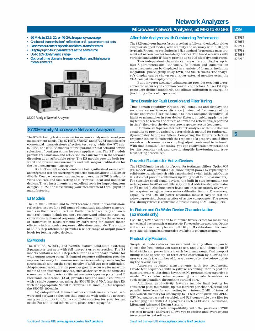
Traditional Chinese URL www.agilent.com.tw/find/products Simplified Chinese URL www.agilent.com.cn/find/products
5
8719ET8720ET8722ET8719ES8720ES8722ES
229Microwave Network Analyzers, 50 MHz to 40 GHz
Network Analyzers
• 50 MHz to 13.5, 20, or 40 GHz frequency coverage• Choice of transmission/reflection or S-parameter test sets• Fast measurement speeds and data-transfer rates• Display up to four parameters at the same time• Up to 105 dB dynamic range• Optional time domain, frequency offset, and high power
measurements
8720E Family Microwave Network Analyzers
The 8720E family features six vector network analyzers to meet yourmeasurement needs. The 8719ET, 8720ET, and 8722ET models offereconomical transmission/reflection test sets, while the 8719ES,8720ES, and 8722ES models offer S-parameter test sets and a wideselection of configurations for your applications. The ET modelsprovide transmission and reflection measurements in the forwarddirection at an affordable price. The ES models provide both for-ward and reverse measurements and full two-port calibration forthe best measurement accuracy.
Both ET and ES models combine a fast, synthesized source withan integrated test set covering frequencies from 50 MHz to 13.5, 20, or40 GHz. Compact, economical, and easy to use, the 8720E family pro-vides accurate and fast testing of microwave linear and nonlineardevices. These instruments are excellent tools for improving yourdesigns in R&D or maximizing your measurement throughput inmanufacturing.
ET ModelsThe 8719ET, 8720ET, and 8722ET feature a built-in transmission/reflection test set for a full range of magnitude and phase measure-ments in the forward direction. Built-in vector accuracy enhance-ment techniques include one-port, response, and enhanced responsecalibrations. Enhanced response calibration improves the accuracyof transmission measurements by correcting for source matcheffects, which a regular response calibration cannot do. The option-al 55-dB step attenuator provides a wider range of output power levels for testing active devices.
ES ModelsThe 8719ES, 8720ES, and 8722ES feature solid-state switching S-parameter test sets with full two-port error correction. The ESmodels contain a 55-dB step attenuator as a standard feature forwide output power range. Enhanced response calibration providesimproved accuracy for transmission measurements by correcting forsource match without the speed penalty of a full two-port calibration.Adapter-removal calibration provides greater accuracy for measure-ments of non-insertable devices, such as devices with the same sexconnectors on both ports or different connector types on ports 1 and 2.Electronic calibration (ECal) provides fast and simple calibrationwith a single connection, using the 85097B ECal VNA Interface Kitwith the appropriate N4690 microwave ECal module. This requiresthe 85097B-100 cable.
Agilent-qualified Channel Partners provide measurement hard-ware and software solutions that combine with Agilent’s networkanalyzer products to offer a complete solution for your testingneeds. For additional information, please refer to page 34.
Affordable Analyzers with Outstanding PerformanceThe 8720 analyzers have a fast source that is fully synthesized, in eitherswept or stepped modes, with stability and accuracy within 10 ppm(typical). Frequency resolution is 1 Hz standard for accurate measure-ments of narrowband or long-delay devices. The tuned receivers withvariable bandwidth IF filters provide up to 105 dB of dynamic range.
Two independent channels can measure and display up to four S-parameters simultaneously. Reflection and transmissionmeasurements can be displayed in a variety of formats, includingmagnitude, phase, group delay, SWR, and Smith charts. The analyz-er’s display can be shown on a larger external monitor using theVGA-compatible display output.
Built-in vector accuracy enhancement provides excellent error-corrected accuracy in common coaxial connectors. A user kit sup-ports user-defined standards, and allows calibration in waveguide(including effects of dispersion).
Time Domain for Fault Location and Filter TuningTime domain capability (Option 010) computes and displays the response versus time or distance (instead of frequency) of thedevice under test. Use time domain to locate and quantify individualfaults or mismatches in your device, fixture, or cable. Apply the gat-ing feature to remove the effects of unwanted reflections (separatedin time), then view the device’s true response versus frequency.
Combine an S-parameter network analyzer with time domaincapability to provide a simple, deterministic method for tuning cav-ity-resonator bandpass filters. Comparing the filter’s reflectionresponse in time-domain with the response of a properly tuned filterreveals which resonators or coupling adjustments need to be tuned.With time-domain filter tuning, you can easily train new personnelfor this complex task and greatly simplify fine-tuning and trou-bleshooting procedures.
Powerful Features for Active DevicesThe 8720E family has plenty of power for testing amplifiers. Option 007(ES models only) provides 5 dB more output power by replacing thesolid-state transfer switch with a mechanical switch (although Option007 does not provide continuous updating of all four S-parameters).For sensitive small-signal devices, the built-in step attenuator canreduce power to –65 or –70 dBm (Option 004 adds the step attenuatoron ET models). Absolute power levels can be set accurately anywherein the system, using the power meter calibration feature. Power-sweepcapability and 0.01 dB power resolution make it easy to test the gain-compression characteristics of active components. The powerlevel during retrace is controllable for safe testing of AGC amplifiers.
In-Fixture and On-Wafer Device Characterization (ES models only)Use TRL*/LRM* calibration to minimize fixture errors for measuringnon-coaxial devices such as microstrip. For even better accuracy, Option400 adds a fourth sampler and full TRL/LRM calibration. Electronicport extensions and gating are also available to enhance accuracy.
Productivity FeaturesSwept-list mode reduces measurement time by allowing you tochoose the frequencies you want to test, and to set independent IFbandwidths and power levels in each frequency range. Fast two-porttuning mode speeds up 12-term error correction by allowing theuser to specify the number of forward sweeps to take before updat-ing the reverse sweep.
Automate repeated measurements with test sequencing.Create test sequences with keystroke recording, then repeat themeasurements with a single keystroke. No programming expertise isneeded. You can also use test sequencing to control external devicessuch as part handlers through the parallel port.
Additional productivity features include limit testing for consistent pass/fail results, up to 5 markers per channel, serial andparallel interfaces for connecting to printers, 2 MB of internal non-volatile memory for storing up to 31 test configurations, JPEG,CSV (comma separated variable), and S2P-compatible data files forexchanging data with CAD programs such as EEsof’s Touchstone,Libra, and Advanced Design System.
Programming code compatibility with the previous 8720Dseries of network analyzers allows you to protect and leverage yourinvestment in test software.
8720E Family of Network Analyzers

English URL www.agilent.com/find/products Korean URL www.agilent.co.kr/find/products
5
8719ET8720ET8722ET8719ES8720ES8722ES
230 Microwave Network Analyzers, 50 MHz to 40 GHz (cont.)
Network Analyzers
Flexible Configuration for ApplicationsOption 004 adds a 55 dB step attenuator to expand the output powerrange. (ET models only; step attenuator is included in all ES models)Option 007 replaces the standard solid-state transfer switch with amechanical switch to provide 5 dB more power at the test port, and 5 dB more dynamic range. The mechanical transfer switch does not provide continuous updating of all four S-parameters for full two-port calibration. (ES models only)Option 010 adds time-domain capability, which allows fault location and gating of fixture responses. (ET and ES models)Option 012 provides direct sampler access, enabling the user to elimi-nate coupler loss and increase sensitivity by 16 dB. Option 012 allowsfilter rejection measurements to greater than –120 dB and allowsinsertion of attenuation between coupler and sampler. By using separate transmit and receive antennae, Option 012 can improve signal-to-noise in free-space measurements. (ES models only)Option 085 is a high-power S-parameter test set modification allowingdevice test up to +43 dBm (20 Watts) input and output. It deletes thebias tees, replaces the solid-state switch with a mechanical switch,and adds internal attenuators. It also includes the direct sampleraccess provided by Option 012. (ES models only)Option 089 offers a frequency offset mode for simple mixer conver-sion loss measurements without the need for a reference mixer. (ESmodels only)Option 1D5 adds a high-stability frequency reference to improvemeasurement accuracy of narrowband or high-Q devices. (ET andES models)Option 400 adds a fourth sampler to the receiver and improves TRL calibration accuracy for in-fixture and on-wafer applications. Not compatible with Option 007 or 085. (ES models only)
Upgrade Kits for the 8720E FamilyOptions may be added to an 8720E family analyzer after initial pur-chase by ordering the instrument’s model number followed by a “U”to indicate an upgrade, along with the option(s) you want to retrofit.See “Ordering Information” for available upgrade options.
Upgrading the 8720D FamilyCustomers with 8719D, 8720D, or 8722D analyzers can upgradetheir analyzers to include the firmware features of the ES modelswith one of the following upgrades.
8719DU, 8720DU, or 8722DU-099 Firmware UpgradeCustomers who have analyzers with firmware revision above 7.0 canorder the latest firmware with this upgrade. The firmware can alsobe downloaded from Agilent’s web site: www.agilent.com/find/firmware
8719DU, 8720DU, or 8722DU-000 Performance UpgradeCustomers who have analyzers with firmware revisions below 7.0can install the updated CPU board to provide significant measure-ment and data-transfer speed improvements and the latest firmwarefeatures.
Key Literature8720E Family Microwave Network Analyzers Brochure, p/n 5968-5161E8720E Family Microwave Network Analyzers Technical Specifications, p/n 5968-5163E8720E Family Microwave Network Analyzers Configuration Guide, p/n 5968-5162E
For more information, visit our web site: www.agilent.com/find/8720
Specifications Summary
8719ET 8720ET 8722ET8719ES 8720ES 8722ES
Minimum Frequency 50 MHz 50 MHz 50 MHz
Maximum Frequency 13.5 GHz 20 GHz 40 GHz
Frequency Resolution 1 Hz 1 Hz 1 Hz
Frequency Accuracy 10 ppm 10 ppm 10 ppm
Max. Source Power:ET models +10 dBm +10 dBm 0 dBm, <20 GHz; –5 dBm, 20 to 40 GHzES models (std) +5 dBm +5 dBm –5 dBm, <20 GHz; –10 dBm, 20 to 40 GHzES models with Option 007 +10 dBm +10 dBm 0 dBm, <20 GHz; –5 dBm, 20 to 40 GHz
Min. Source Power:ET models (std) –10 dBm –10 dBm –15 dBmET models with Option 004 –65 dBm –65 dBm –70 dBm ES models (std) –70 dBm –70 dBm –75 dBmES models with Option 007 –65 dBm –65 dBm –70 dBm
Power Resolution 0.01 dB 0.01 dB 0.01 dB
Power Flatness ±2 dB ±2 dB ±3 dB
Power Sweep Range 20 dB 20 dB 15 dB to 20 GHz; 10 dB, 20 – 40 GHz
System Dynamic Range (>2 GHz) ET 104 dB 104 dB 84 to 97 dBES 100 dB 100 dB 80 to 93 dBES with Option 007 105 dB 105 dB 85 to 98 dB
Test Port Connector 3.5 mm (m) 3.5 mm (m) 2.4 mm (m)
Data applies at 23˚C ± 3˚C. See product literature for more complete specifications and for total measurement uncertainty after error correction.
Size: 222 mm H x 425 mm W x 457 mm D (8.75 in x 16.750 in x 18.00 in)Weight: Net, 22.7 to 27.7 kg (50 to 60 lb); shipping, 31.8 to 36.7 kg (70 to 81 lb)
Traditional Chinese URL www.agilent.com.tw/find/products Simplified Chinese URL www.agilent.com.cn/find/products
5
8719ET8720ET8722ET8719ES8720ES8722ES
231Microwave Network Analyzers, 50 MHz to 40 GHz (cont.)
Network Analyzers
Ordering Information Note: A complete system consists of a network analyzer, calibration kit,and cables. Calibration kits and cables can be found in the Accessoriessection beginning on page 238.
8719ET Network Analyzer, 50 MHz to 13.5 GHz 8720ET Network Analyzer, 50 MHz to 20 GHz8722ET Network Analyzer, 50 MHz to 40 GHz The following options apply to all three network analyzers:
Option 004 Step Attenuator (Extended power range) Option 005 Standard Power Range Option 010 Time Domain Capability Option 1D5 High-Stability Frequency Reference Option 1CM Rackmount Kit Option 1CP Rackmount and Handle Kit
8719ES Network Analyzer, 50 MHz to 13.5 GHz 8720ES Network Analyzer, 50 MHz to 20 GHz8722ES Network Analyzer, 50 MHz to 40 GHz The following options apply to all three network analyzers:
Option 007 Mechanical Transfer Switch Option 010 Time Domain Capability Option 012 Direct Sampler Access Option 050 Standard Test Set Option 085 High-Power Test Set Option 089 Frequency Offset Mode Option 1D5 High-Stability Frequency Reference Option 701 Three-Sampler Test Set Option 400 Four-Sampler Test Set Option 1CM Rackmount Kit Option 1CP Rackmount and Handle Kit
Upgrades and Retrofit KitsTo add options to an 8720E family analyzer after initial purchase, order theanalyzer’s model number followed by a “U” with one of the followingupgrade options. All upgrade/retrofit kits include installation at an Agilentservice center or the factory.The following upgrade options are available for the 8719ET, 8720ET, and 8722ET.
Option 099 Firmware Upgrade Option 004 Add Step AttenuatorOption 010 Add Time Domain Capability Option 1D5 Add High-Stability Frequency Reference
The following upgrade options are available for the 8719ES, 8720ES, and 8722ES.
Option 099 Firmware Upgrade Option 007 Add Mechanical Transfer Switch Option 010 Add Time Domain Capability Option 012 Add Direct Sampler Access Option 085 Add High-Power Test Capability Option 089 Add Frequency Offset Mode Option 1D5 Add High-Stability Frequency ReferenceOption 489 Add Frequency Offset for Opt 400 AnalyzersOption 589 Add Frequency Offset for Opt 085 AnalyzersOption 400 Add Four-Sampler Test Set
The following upgrades are only available for the specified models. For 8719ET only:
Option 020 Upgrades 8719ET to 8720ET Option 040 Upgrades 8719ET to 8722ET
For 8720ET only:Option 040 Upgrades 8720ET to 8722ET
For 8719ES only:Option 020 Upgrades 8719ES to 8720ES Option 040 Upgrades 8719ES to 8722ES
For 8720ES only:Option 040 Upgrades 8720ES to 8722ES
The following kits offer upgrades for older 8720 family network analyzers. Installation is not included.8719DU, 8720DU, or 8722DU Option 099 Firmware Upgrade8719DU, 8720DU, or 8722DU Option 000 Performance Upgrade
Transit CasesAgilent offers a complete line of sturdy transit cases in valise and tote styles. The cases protect your instrument from shock, vibration, moisture, impact, and contamination, providing a secure enclosure for shipping. Model 9211-2651 (standard) or model 9211-7522 (tote) fit the 8719ET/ES, 8720ET/ES, and 8722ET/ES.9211-2651 Standard Case 9211-7522 Tote-style Case

English URL www.agilent.com/find/products Korean URL www.agilent.co.kr/find/products
5
8757D
232 Scalar Network Analyzer, 10 MHz to 110 GHz
Network Analyzers
8757D Scalar Network Analyzers
Measure insertion loss, gain, return loss, SWR, and power quickly andaccurately with the 8757D scalar network analyzer. With high-perfor-mance detectors and directional bridges, and a companion source anddigital plotter, the 8757D is the basis of a complete measurement system with superb performance.
The 8757D features three detector inputs and two independentdisplay channels, allowing simultaneous ratioed or non-ratioedmeasurement of your device’s transmission and reflection charac-teristics, 75 dB dynamic range (+20 to –55 dBm) for measuring high-rejection devices, and a choice between ac (square wave modu-lated) or dc detection techniques. The internal plotter/printerbuffer allows you to send your measurement data directly to a plotter and then proceed to the next measurement, typically in lessthan five seconds. The 8757D includes a user-friendly interface, andmenu-driven, direct-access softkeys, which simplify its operation.
It offers limit testing, external disk save/recall, and a color dis-play. Limit testing reduces test time by letting the analyzer makequick and objective pass/fail decisions. External disk save/recallallows your measurement state to be preconfigured by an engineeror skilled specialist and then automatically recalled by productiontechnicians. The result is reduced set-up time and greater testintegrity at each production station. The precision color displaysimplifies the separation of measurement information while provid-ing a pleasant display for the technician.
Increase Absolute Power Measurement AccuracyFor near power meter measurement accuracy, configure a systemthat includes the 8757D Option 002 and the 85037 series precisiondetectors. Option 002 on the 8757D adds an internal power calibra-tor used to characterize the 85037 series detectors’ accuracy versuspower. In addition, each 85037 series precision detector incorporatesa dual-diode detector to improve power measurement accuracy whenharmonics are present, plus internal frequency correction factors,read by the 8757D, for more accurate power versus frequency measurements. The result is a system optimized for swept absolutepower measurements.
Feature 8757D
Display ColorDisplay channels 4Detector inputs 3 standard
4 with Option 001Dynamic range 75 dBAC/DC detection mode YesMeasurement points:
Selectable values 101, 201, 401, 801, 1601Channels displayed 3 or 4 2 1Max. points per channel 401 801 1601
Plotter/printer buffer YesNoise figure display capability* YesExternal disk save/recall YesInternal save/recall registers 9Limit testing (channels 1 and 2 ) YesAdaptive normalization YesCursor search functions Max., Min.,
bandwidth, n dBSWR display mode YesNon-standard sweep mode YesAuxiliary voltage display mode YesOptional power calibrator YesCompatible with 85037
series precision detectors Yes
*Product Note 8970 B/S-4, Agilent Literature 5959-8742
Size: 178 mm H x 425 m W x 445 mm D (7 in x 16.75 in x 17.5 in)Weight: 22 kg (48 lb) net; 28 kg (61.5 lb) shipping
Transit CasesAgilent offers a complete line of sturdy transit cases in Valise andTote styles. The cases protect your instrument from shock, vibration, moisture, impact, and contamination, providing a secureenclosure for shipping. Model 9211-2650 (standard) or model 9211-7521 (tote) fit the 8757D/E.
• 75 dB dynamic range • Optional power calibrator • 40 dB directivity bridges • 40 GHz in coax, 110 GHz in waveguide• Buffered plotter/printer output • External disk and internal register save/recall • Built-in limit testing • Color display
8757D-001 & -002

Traditional Chinese URL www.agilent.com.tw/find/products Simplified Chinese URL www.agilent.com.cn/find/products
5
85037A 85037B85025A85025B85025D85025E
2338757 System Accessories
Network Analyzers
85037 Series Precision Detectors (ac/dc)The 85037 series precision detectors are designed specifically foroperation with the 8757D scalar network analyzer and may be usedin either ac or dc detection modes. These dual diode detectors con-tain internal frequency correction factors in an internal EE PROM(read automatically by the 8757D) for improved measurement accu-racy versus frequency. When used in conjunction with the 8757D’sinternal power calibrator (Option 002), these detectors provide themaximum absolute power measurement accuracy. The 85037 seriesdetector is not compatible with the 8757E.
Absolute Power Measurement Uncertainty ExamplesAssumptions:• Measurement frequency = 10 GHz • DUT input/output SWR = 1.5 • Measured power = 0 dBm
Uncertainty 85037B 85025EComponent Detector Detector
Absolute poweraccuracy at 50 MHz (±dB) 0.11 0.40
Frequency response (±dB) 0.18 0.50Mismatch (±dB) 0.18 0.10Uncertainty Total (±dB) 0.47 1.00
Reflection Measurement AccuracyUncertainties due to calibration error and the frequency response ofthe source, detectors, and bridges are removed via open/short aver-aging. The remaining uncertainties are primarily the sum of direc-tivity uncertainty, effective source match uncertainty and dynamicpower accuracy. See Technical Data Sheet for further information.
Precision Detector Summary, 85037 Series For use with the 8757D in either ac or dc detection modes
Model Frequency Connector Dynamic Frequency Return Frequency Power Dynamic AbsoluteRange Type Range Loss Response (at 50 MHz) Accuracy4 Accuracy5
85037A1 10 MHz to Type-N (m) ac mode 0.01 to 0.04 GHz 10 dB ±0.35 dB 20 dBm ±0.25 dB ±0.25 dB18 GHz 7 mm2 +20 to –55 dBm 0.04 to 18.0 GHz 20 dB ±0.18 dB 10 dBm ±0.11 dB ±0.11 dB
dc mode –30 dBm ±0.11 dB ±0.11 dB+20 to –50 dBm –50 dBm ±0.85 dB ±0.85 dB
85037B1 10 MHz to 3.5 mm (m) ac mode 0.01 to 0.04 GHz 10 dB ±0.35 dB 20 dBm ±0.25 dB ±0.25 dB26.5 GHz +20 to –55 dBm 0.04 to 18.0 GHz 20 dB ±0.18 dB 10 dBm ±0.11 dB ±0.11 dB
dc mode 18 to 26.5 GHz 18 dB ±0.22 dB –30 dBm ±0.11 dB ±0.11 dB+20 to –50 dBm –50 dBm ±0.85 dB ±0.85 dB
85025 and 85026 Series Detectors (ac/dc)The 85025 and 85026 series detectors are designed specifically foroperation with the 8757 scalar network analyzer. The 85025/26 detec-tors detect either a modulated (ac) or an unmodulated (dc) microwavesignal.
85025C Detector AdaptersThe 85025C adapter matches the scalar analyzer display to moststandard crystal, silicon and gallium arsenide detectors. Thisenables the user to operate up to 110 GHz with the 8757. The 85025Cdetector adapter is designed for use with the 8757 only, and canoperate in either ac or dc detection modes.
Coaxial Detector Summary, 85025 Series For use with the 8757 only in either ac or dc detection modes
Model Frequency Connector Dynamic Frequency Return Frequency Power Dynamic AbsoluteRange Type Range Loss Response (at 50 Mhz) Accuracy4 Accuracy5
85025A3 10 MHz to Type-N (m) ac mode 0.01 to 0.04 GHz 10 dB ±0.8 dB 16 dBm ±0.8 dB ±0.8 dB18 GHz 7 mm2 +16 to –55 dBm 0.04 to 4 GHz 20 dB ±0.5 dB 6 dBm ±0.4 dB ±0.4 dB
dc mode 4 to 18 GHz 17 dB ±0.5 dB –35 dBm ±0.4 dB ±0.4 dB+16 to –50 dBm –50 dBm ±1.3 dB ±1.3 dB
85025B3 10 MHz to 3.5 mm (m) ac mode 0.01 to 0.04 GHz 10 dB ±0.8 dB 16 dBm ±0.8 dB ±0.8 dB26.5 GHz +16 to –55 dBm 0.04 to 4 GHz 20 dB ±0.5 dB 6 dBm ±0.4 dB ±0.4 dB
dc mode 4 to 18 GHz 17 dB ±0.5 dB –35 dBm ±0.4 dB ±0.4 dB+16 to –50 dBm 18 to 26.5 GHz 12 dB ±2.0 dB –50 dBm ±1.3 dB ±1.3 dB
85025D3 10 MHz to 2.4 mm (m) ac mode 0.01 to 0.1 GHz 10 dB ±0.8 dB 16 dBm ±1.0 dB ±1.0 dB50 GHz +16 to –55 dBm 0.1 to 20 GHz 20 dB ±0.5 dB 6 dBm ±0.4 dB ±0.4 dB
dc mode 20 to 26.5 GHz 20 dB ±1.0 dB –35 dBm ±0.4 dB ±0.4 dB+16 to –50 dBm 26.5 to 40 GHz 15 dB ±2.5 dB –50 dBm ±1.3 dB ±1.3 dB
40 to 50 GHz 9 dB ±3.0 dB
85025E3 10 MHz to 3.5 mm (m) ac mode 0.01 to 0.1 GHz 10 dB ±0.8 dB 16 dBm ±1.0 dB ±1.0 dB26.5 GHz +16 to –55 dBm 0.1 to 18 GHz 25 dB ±0.5 dB 6 dBm ±0.4 dB ±0.4 dB
dc mode 18 to 25 GHz 25 dB ±0.5 dB –35 dBm ±0.4 dB ±0.4 dB+16 to –50 dBm 25 to 26.5 GHz 23 dB ±1.4 dB –50 dBm ±1.3 dB ±1.3 dB
Basic scalar coaxial system configured for ratio reflection and transmission measurements.
1The 85037A/B specifications are applicable when used with the 8757D scalar networkanalyzer. The absolute power accuracy and dynamic power accuracy specifications applyafter a calibration via the 8757D Option 002’s internal power calibrator.
2Option 001 changes to a 7-mm connector.
3The 85025 and 85026 series detectors and the 85025C detector adapter require 8757Afirmware revision 2.0 or higher. To upgrade previous revisions, order the 11614A firmwareenhancement.
4Dynamic accuracy refers to measurement accuracy as power varies (in dB) from a 0 dBm reference. 25˚ ± 5˚C, 50 MHz.
5DC mode, 25˚ ± 5˚C.
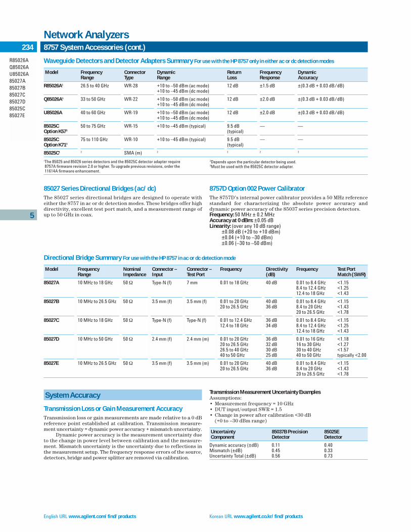
English URL www.agilent.com/find/products Korean URL www.agilent.co.kr/find/products
5
R85026AQ85026AU85026A85027A85027B85027C85027D85025C85027E
234 8757 System Accessories (cont.)
Network Analyzers
8757D Option 002 Power CalibratorThe 8757D’s internal power calibrator provides a 50 MHz referencestandard for characterizing the absolute power accuracy anddynamic power accuracy of the 85037 series precision detectors.Frequency: 50 MHz ± 0.2 MHzAccuracy at 0 dBm: ±0.05 dBLinearity: (over any 10 dB range)
±0.08 dB (+20 to +10 dBm)±0.04 (+10 to –30 dBm)±0.06 (–30 to –50 dBm)
Waveguide Detectors and Detector Adapters Summary For use with the HP 8757 only in either ac or dc detection modes
Model Frequency Connector Dynamic Return Frequency DynamicRange Type Range Loss Response Accuracy
R85026A1 26.5 to 40 GHz WR-28 +10 to –50 dBm (ac mode) 12 dB ±1.5 dB ±(0.3 dB + 0.03 dB/dB)+10 to –45 dBm (dc mode)
Q85026A1 33 to 50 GHz WR-22 +10 to –50 dBm (ac mode) 12 dB ±2.0 dB ±(0.3 dB + 0.03 dB/dB)+10 to –45 dBm (dc mode)
U85026A 40 to 60 GHz WR-19 +10 to –50 dBm (ac mode) 12 dB ±2.0 dB ±(0.3 dB + 0.03 dB/dB)+10 to –45 dBm (dc mode)
85025C 50 to 75 GHz WR-15 +10 to –45 dBm (typical) 9.5 dB — —Option K573 (typical)
85025C 75 to 110 GHz WR-10 +10 to –45 dBm (typical) 9.5 dB — —Option K713 (typical)
85025C1 2 SMA (m) 2 2 2 2
System Accuracy
Transmission Loss or Gain Measurement AccuracyTransmission loss or gain measurements are made relative to a 0 dBreference point established at calibration. Transmission measure-ment uncertainty = dynamic power accuracy + mismatch uncertainty.
Dynamic power accuracy is the measurement uncertainty dueto the change in power level between calibration and the measure-ment. Mismatch uncertainty is the uncertainty due to reflections inthe measurement setup. The frequency response errors of the source,detectors, bridge and power splitter are removed via calibration.
2Depends upon the particular detector being used.3Must be used with the 85025C detector adapter.
1The 85025 and 85026 series detectors and the 85025C detector adapter require 8757A firmware revision 2.0 or higher. To upgrade previous revisions, order the 11614A firmware enhancement.
Directional Bridge Summary For use with the HP 8757 in ac or dc detection mode
Model Frequency Nominal Connector – Connector – Frequency Directivity Frequency Test PortRange Impedance Input Test Port (dB) Match (SWR)
85027A 10 MHz to 18 GHz 50 Ω Type-N (f) 7 mm 0.01 to 18 GHz 40 dB 0.01 to 8.4 GHz <1.158.4 to 12.4 GHz <1.2512.4 to 18 GHz <1.43
85027B 10 MHz to 26.5 GHz 50 Ω 3.5 mm (f) 3.5 mm (f) 0.01 to 20 GHz 40 dB 0.01 to 8.4 GHz <1.1520 to 26.5 GHz 36 dB 8.4 to 20 GHz <1.43
20 to 26.5 GHz <1.78
85027C 10 MHz to 18 GHz 50 Ω Type-N (f) Type-N (f) 0.01 to 12.4 GHz 36 dB 0.01 to 8.4 GHz <1.1512.4 to 18 GHz 34 dB 8.4 to 12.4 GHz <1.25
12.4 to 18 GHz <1.43
85027D 10 MHz to 50 GHz 50 Ω 2.4 mm (f) 2.4 mm (m) 0.01 to 20 GHz 36 dB 0.01 to 16 GHz <1.1820 to 26.5 GHz 32 dB 16 to 30 GHz <1.2726.5 to 40 GHz 30 dB 30 to 40 GHz <1.5740 to 50 GHz 25 dB 40 to 50 GHz typically <2.00
85027E 10 MHz to 26.5 GHz 50 Ω 3.5 mm (f) 3.5 mm (m) 0.01 to 20 GHz 40 dB 0.01 to 8.4 GHz <1.1520 to 26.5 GHz 36 dB 8.4 to 20 GHz <1.43
20 to 26.5 GHz <1.78
Transmission Measurement Uncertainty ExamplesAssumptions:• Measurement frequency = 10 GHz • DUT input/output SWR = 1.5 • Change in power after calibration <30 dB
(+0 to –30 dBm range)
Uncertainty 85037B Precision 85025EComponent Detector Detector
Dynamic accuracy (±dB) 0.11 0.40Mismatch (±dB) 0.45 0.33Uncertainty Total (±dB) 0.56 0.73
85027 Series Directional Bridges (ac/dc)The 85027 series directional bridges are designed to operate witheither the 8757 in ac or dc detection modes. These bridges offer highdirectivity, excellent test port match, and a measurement range ofup to 50 GHz in coax.

Traditional Chinese URL www.agilent.com.tw/find/products Simplified Chinese URL www.agilent.com.cn/find/products
5
11679A11679B85022A8757D11636A11636B11852B11667A11667B11667C
2358757 System Accessories (cont.)
Network Analyzers
11679A/B Extension Cables
FunctionThese cables extend the distance between the scalar network ana-lyzer and the detector or bridge to a maximum of 200 feet withoutdegradation of performance.
11679A: 7.6 m (25 ft) extension cable11679B: 61 m (200 ft) extension cable
85022A System Cable KitThe 85022A contains all the BNC and GPIB cables to connect anAgilent sweep oscillator (8360 series, 83750, or 83751 synthesizedsweepers), an HP computer and a printer to the 8757. This kit containsthree one-meter GPIB cables (10833A), three two-foot BNC (m-m)cables (11170B) and one four-foot BNC (m-m) cable (11170C).
BNC Impedance: 50 ΩWeight: Net, 0.5 kg (1.2 lb); shipping, 1.2 kg (2.9 lb)
11636A/B Power DividersThe 11636A/B power dividers/combiners are recommended whenmaking wideband comparison measurements without ratioing.
11613B CalibratorThe 11613B is a dedicated transfer standard for calibration of the8757D/E scalar network analyzers. The 11613B provides a standard,a 27.778 kHz source and a series of precision attenuators. The cali-brator includes software that verifies (and adjusts if necessary) theinternal calibration parameters stored in the nonvolatile memory ofthe analyzer.
An HP Series 200 or 300 computer is required for operation.The computer must have BASIC 2.0 or greater and 512 K bytes ofRAM. For use with the 8756A Scalar Analyzer, the computer alsorequires the HP 98622A 16-bit GPIO card.
11852B 50 Ω/75 Ω Minimum-Loss PadThe 11852B is a low SWR minimum-loss pad required between 75 Ω devices and 50 Ω sources and detectors.
11667A/B/C Power SplittersThe 11667A/B/C power splitters are recommended when makingwideband ratio measurements using the 8757 scalar network ana-lyzer. These two-resistor type splitters provide excellent output SWRat the auxiliary arm when used for source leveling or ratio measure-ment applications. The tracking between output arms over a frequency range from dc to 50 GHz allows wideband measurementsto be made with a minimum of uncertainty.
Frequency Range11667A: DC to 18 GHz11667B: DC to 26.5 GHz11667C: DC to 50 GHz
Impedance: 50 Ω nominalInsertion Loss
11667A/B: 6 dB nominal11667C: 8.5 dB nominal
Max. Input Power: +27 dBmConnectors
11667A: N-female on all ports11667B: 3.5-mm female on all ports11667C: 2.4-mm female on all ports
8757D Upgrade KitsIncrease your analyzer’s measurement capability and performancewith an 8757 upgrade kit.
The 86383C upgrade kit allows you to add the fourth detectorinput to your 8757D (86383C-001) and/or the internal power calibrator (86383C-002). Installation is not included with this kit.
Key Literature8757D Scalar Network Analyzer Brochure, p/n 5091-2469E8757D Scalar Network Analyzer Technical Data, p/n 5091-2471E8757D Scalar Network Analyzer Configuration Guide, p/n 5967-6177E
11679A 85022A 11667A 11667C

English URL www.agilent.com/find/products Korean URL www.agilent.co.kr/find/products
5
8757System8757XC
236 Scalar Network Analyzers/Ordering Information
Network Analyzers
The 8757 scalar network analyzer is ordered with multiple line itemsto give you maximum flexibility in specifying a system that meetsyour needs. Consult your local Agilent Technologies sales office ifyou would like assistance.
Ordering InformationAnalyzer8757D Scalar Network Analyzer
8757D-001 Fourth Detector Input 8757D-002 Internal Power Calibrator 8757D-W30 Two-Year Extended Service 8757D-1BN MIL-STD-45662A Calibration Certificate8757D-1BP MIL-STD-45662A Calibration with Test Data8757D-UK6 Commercial Calibration Certificate w/data
SweepersChoose the E8247C/57C synthesized sweepers for applications from 10 MHz to 40 GHz, or the 8360 series synthesized sweepers for measurements up to 50 GHz in coax or 110 GHz in waveguide.
Precision Detectors85037A 0.01 to 18 GHz, Type-N(m)
85037A-001 7-mm Connector 85037B 0.01 to 26.5 GHz, 3.5 mm(m)
Directional Bridges85027A 0.01 to 18 GHz, 7 mm, 50 Ω85027B 0.01 to 26.5 GHz, 3.5 mm (f), 50 Ω85027C 0.01 to 18 GHz, Type-N (f), 50 Ω85027D 0.01 to 50 GHz, 2.4 mm (m), 50 Ω85027E 0.01 to 26.5 GHz, 3.5 mm (m), 50 Ω
Detectors85025A 0.01 to 18 GHz, Type-N (m)
85025A-001 7-mm Connector 85025B 0.01 to 26.5 GHz, 3.5 mm (m) 85025D 0.01 to 50 GHz, 2.4 mm (m) 85025E 0.01 to 26.5 GHz, 3.5 mm (m) R85026A 26.5 to 40 GHz, WR-28 Waveguide Q85026A 33 to 50 GHz, WR-22 Waveguide U85026A 40 to 60 GHz, WR-19 Waveguide 85025C Detector Adapter
System Cable Kit85022A System Cable Kit
Optional Accessories(For ratio and/or modulation measurements)11636A Power Divider dc to 18 GHz11636B Power Divider dc to 26.5 GHz 11667A Power Splitter dc to 18 GHz
11667A-001 N-male on Input Port; N-female on Output Ports11667A-002 N-female on Input Port; 7 mm on Output Ports
11667B Power Splitter dc to 26.5 GHz 11667C Power Splitter dc to 50 GHz 11679A Detector Extension Cable, 7.6 m (25 ft) 11679B Detector Extension Cable, 61 m (200 ft) 11852B 50 to 75 ΩMinimum Loss Pad
Upgrade Kits86383C Upgrade Kit for 8757D
86383C-001 Adds Fourth Detector Input 86383C-002 Adds Internal Power Calibrator
Transit Cases9211-2650 Standard Transit Case9211-7521 Tote-Style Transit Case
For information on compatible printers, visit our web site: http://www.agilent.com/find/pcg

Traditional Chinese URL www.agilent.com.tw/find/products Simplified Chinese URL www.agilent.com.cn/find/products
5
8720D Opt K22Z5621AOpt H3687050BOpt H378753ESOpt H85
237Custom Test Sets
Network Analyzers
• RF voltage and phase measurements• 100 kHz to 1 GHz high-impedance probe inputs• 300 kHz to 2 GHz 50 Ω inputs
Let Agilent Design and Build You a Custom Test Set
If your application requires a special configuration, ask us aboutour special options, which offer nonstandard specifications.
A Special Twenty-Two Port Test Set
Special 8720D option K22The 8720D K22 is a multifunction box with four ports in the for-ward path and four ports in the reverse path. Two ports allow theuser to connect the 8720D/ES directly to the 8720D K22 for a full 12port matrix. The additional forward and reverse ports can be con-nected to additional test equipment for custom configurations.
Duplexer Test Set Adapter
Special Z5621A option H36This test set adapter provides three ports to allow direct testing ofduplexers. The test set adapter contains a solid-state switch. Theconnectors are 50 ohm Type-N. The transmitter-to-antenna andreceiver-to-antenna paths can be measured; the transmitter-to-receiver path cannot be measured.
Duplexer Test Set
Special 87050B option H37The 87050B option H37 is a duplexer test set designed for use with astandard 8753D/E/ES network analyzer. The duplexer test set usessolid-state switching for port connections. The test set has sevenports located on the front panel. Two of these ports are APC-7 andmate with port 1 and port 2 of the network analyzer. The other fiveports, labeled ANT, TX1,TX2, RX1, and RX2 are 50 ohm Type-N con-nectors and connect to the device under test.
High-Power Test Set
Special 8753ES option H85The 8753ES option H85 provides a built in high power test set. Highpower measurements can be made up to 20 watts (+43 dBm) eachtest port. Frequency range of H85 is 50 MHz to 3 GHz or 6 GHz, withstandard option 006. Test port connectors are NMD 3.5 mm male.Option H85 uses a mechanical transfer switch.
For more information, contact the Agilent Call Center in your region.
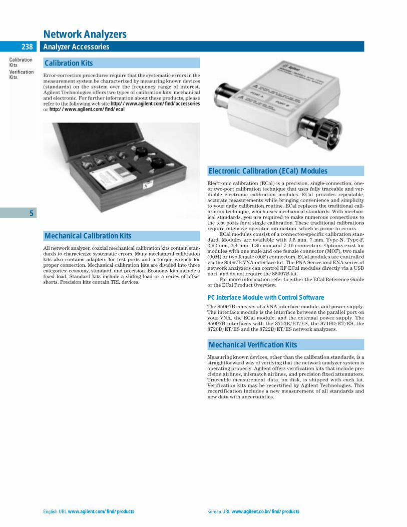
English URL www.agilent.com/find/products Korean URL www.agilent.co.kr/find/products
5
CalibrationKitsVerification Kits
238 Analyzer Accessories
Network Analyzers
Calibration Kits
Error-correction procedures require that the systematic errors in themeasurement system be characterized by measuring known devices(standards) on the system over the frequency range of interest.Agilent Technologies offers two types of calibration kits: mechanicaland electronic. For further information about these products, pleaserefer to the following web site http://www.agilent.com/find/accessoriesor http://www.agilent.com/find/ecal
Mechanical Calibration Kits
All network analyzer, coaxial mechanical calibration kits contain stan-dards to characterize systematic errors. Many mechanical calibrationkits also contains adapters for test ports and a torque wrench forproper connection. Mechanical calibration kits are divided into threecategories: economy, standard, and precision. Economy kits include afixed load. Standard kits include a sliding load or a series of offsetshorts. Precision kits contain TRL devices.
Electronic Calibration (ECal) Modules
Electronic calibration (ECal) is a precision, single-connection, one-or two-port calibration technique that uses fully traceable and ver-ifiable electronic calibration modules. ECal provides repeatable,accurate measurements while bringing convenience and simplicityto your daily calibration routine. ECal replaces the traditional cali-bration technique, which uses mechanical standards. With mechan-ical standards, you are required to make numerous connections tothe test ports for a single calibration. These traditional calibrationsrequire intensive operator interaction, which is prone to errors.
ECal modules consist of a connector-specific calibration stan-dard. Modules are available with 3.5 mm, 7 mm, Type-N, Type-F, 2.92 mm, 2.4 mm, 1.85 mm and 7-16 connectors. Options exist formodules with one male and one female connector (MOF), two male(00M) or two female (00F) connectors. ECal modules are controlled via the 85097B VNA interface kit. The PNA Series and ENA series ofnetwork analyzers can control RF ECal modules directly via a USBport, and do not require the 85097B kit.
For more information refer to either the ECal Reference Guideor the ECal Product Overview.
PC Interface Module with Control SoftwareThe 85097B consists of a VNA interface module, and power supply.The interface module is the interface between the parallel port onyour VNA, the ECal module, and the external power supply. The85097B interfaces with the 8753E/ET/ES, the 8719D/ET/ES, the8720D/ET/ES and the 8722D/ET/ES network analyzers.
Mechanical Verification Kits
Measuring known devices, other than the calibration standards, is astraightforward way of verifying that the network analyzer system isoperating properly. Agilent offers verification kits that include pre-cision airlines, mismatch airlines, and precision fixed attenuators.Traceable measurement data, on disk, is shipped with each kit.Verification kits may be recertified by Agilent Technologies. Thisrecertification includes a new measurement of all standards andnew data with uncertainties.

Traditional Chinese URL www.agilent.com.tw/find/products Simplified Chinese URL www.agilent.com.cn/find/products
5
CalibrationKitsVerification Kits
239Analyzer Accessories (cont.)
Network Analyzers
Coaxial Mechanical Calibration KitsLegend: O = open S = short L = load SL = sliding load TRL = TRL adapter
Device Frequency Included Available ModelConnector Type Upper Limit1 Options
Type-F (75 ohm) 3 GHz O, S, L (m) and 00M, 00F 85039B(f), adapters
Type-N (75 ohm) 3 GHz O, S, L (m) 85036E
Type-N (75 ohm) 3 GHz O, S, L (m) and 85036B(f), adapters
Type-N (50 ohm) 6 GHz O, S, L (m) 85032E
Type-N (50 ohm) 9 GHz O, S, L (m) and (f) 100, 200, 85032F300, 500
Type-N (50 ohm) 18 GHz O, S, L, SL (m) and 85054B(f), adapters
Type-N (50 ohm) 18 GHz O, S, L (m) and 85054D(f), adapters
7-16 7.5 GHz O, S, L (m) and 85038A(f), adapters
7 mm 6 GHz O, S, L 85031B
7 mm 18 GHz O, S, L 85050D
7 mm 18 GHz O, S, L, SL 85050B
7 mm 18 GHz O, S, L, TRL 85050C
3.5 mm 9 GHz O, S, L (m) and (f) 100, 200, 85033E300, 400, 500
3.5 mm 26.5 GHz O, S, L (m) and 85052D(f), adapters
3.5 mm 26.5 GHz O, S, L, SL (m) and 85052B(f), adapters
3.5 mm 26.5 GHz O, S, L (m) and 85052C(f), TRL adapters
2.92 mm 50 GHz O, S, L, SL (m) and 001* 85056K(f), adapters
2.4 mm 50 GHz O, S, L (m) and 85056D(f), adapters
2.4 mm 50 GHz O, S, L, SL (m) and 85056A(f), adapters
1.85 mm 67 GHz Offset, S, L (m) and 85058B(f), adapters
1.85 mm 67 GHz O, S, L (m) and 85058E(f), adapters
1 mm 110 GHz O, S, L (m) and 85059A(f), adapters
1All coaxial calibration kits are specified from DC to their upper frequency limit.
Waveguide Mechanical Calibration Kits
Device Connector Frequency Type ModelType Range (GHz)
WR-90 8.2 to 12.4 Precision X11644A
WR-62 12.4 to 18 Precision P11644A
WR-42 18 to 26.5 Precision K11644A
WR-28 26.5 to 40 Precision R11644A
WR-22 33 to 50 Precision Q11644A
WR-19 40 to 60 Precision U11644A
WR-15 50 to 75 Precision V11644A
WR-10 75 to 110 Precision W11644A
Electronic Calibration Modules (ECal)
Device Connector Frequency Available ModelType Range Options
Type-F (75 ohm)1 300 kHz to 3 GHz 00A, 00F, 00M, MOF, UK6 85099C
Type-N (75 ohm)1 300 kHz to 3 GHz 00A, 00F, 00M, MOF, UK6 85096C
Type-N (50 ohm)1 300 kHz to 9 GHz 00A, 00F, 00M, MOF, UK6 85092C
Type-N (50 ohm) 10 MHz to 18 GHz 00A, 00F, 00M, MOF, UK6 N4690A
7-161 300 kHz to 7.5 GHz 00A, 00F, 00M, MOF, UK6 85098C
7 mm1 300 kHz to 9 GHz 85091C
7 mm 10 MHz to 18 GHz N4696A
3.5 mm1 30 kHz to 9 GHz 00A, 00F, 00M, MOF, UK6 85093C
3.5 mm 10 MHz to 26.5 GHz 00A, 00F, 00M, MOF, UK6 N4691A
PC Interface kit2 N/A N/A 85097B
2.92 mm 10 MHz to 40 GHz 00A, 00F, 00M, MOF N4692A
2.4 mm 10 MHz to 50 GHz 00A, 00F, 00M, MOF N4693A
1.85 mm 10 MHz to 67 GHz 00A, 00F, 00M, MOF N4694A
3.5 mm, Type-N 50 ohm 300 kHz to 9 GHz 010, 020, UK6 N4431A(4-port)
1Modules have both USB and parallel connectors. A USB cable is supplied with the module.2The VNA Interface Unit is connected to the ECal module(s) via another parallel cable. The VNA Interface kit is not needed with the PNA Series (E8356A, E8357A, E8358A) networkanalyzers. These analyzers control the modules directly.
Mechanical Verification Kits
Device Frequency Type Available Compatible ModelConnector Range Options Network Type (GHz) Analyzers
Type-N 30 kHz to 18 Precision 8719, 8720, 85055A8510, PNA
7 mm DC to 6 Precision 001** 8753 85029B
7 mm 0.045 to 18 Precision 8719, 8720, 85051B8510, PNA
3.5 mm 30 kHz to 26.5 Precision 8719, 8720, 85053B8510, PNA
2.4 mm 0.045 to 50 Precision 8722, 8510, 85057BPNA
1.85 mm 0.010 to 67 Hz Precision 8510, PNA 85058V
WR-28 26.5 to 40 Precision 8510, 85106 R11645A
WR-22 33 to 50 Precision 8510, 85106 Q11645A
WR-19 40 to 60 Precision 8510, PNA U11645A
WR-15 50 to 75 Precision 8510, 85106 V11645A
WR-10 75 to 110 Precision 8510, 85106 W11645A
Options apply to mechanical calibration, ECal, and verification kits
Option 001*: Adds 2.4 mm sliding load and 2.4 mm gaugesOption 001**: Adds data for 8702 lightwave component analyzer Option 00A Adds male to male and female to female adaptersOption MOF Ecal module with one male and one female connectorOption OOF Ecal module with two female connectorsOption OOM Ecal module with two male connectorsOption 100 Adds female to female adapterOption 200 Adds male to male adapterOption 300 Adds male to female adapterOption 400 Adds series of 3.5 mm to Type-N adaptersOption 500 Adds series of 3.5 mm (or Type-N) to 7 mm adapters
UK6 Commercial calibration with measured data010 Four female, 3.5 mm connector020 Four female, Type-N 50 ohm connectors

English URL www.agilent.com/find/products Korean URL www.agilent.co.kr/find/products
5
CablesAccessoryKitsAdapter Kits
240 Analyzer Accessories (cont.)
Network Analyzers
Cables
Test port cables provide the connection required when using net-work analyzers with various test devices and equipment. Test portcables are available for two test configurations as shown below.Configuration A utilizes a single test port cable for use when thedevice under test (DUT) is connected directly to the port on thetest set. Configuration B utilizes two test port cables; which pro-vides more flexibility since the DUT is connected between the testport cables.
In order to select a cable, find the table below that corresponds to the connector type of your network analyzer. Then, search thattable for your device’s connector type. If the device’s connector typeis not present in the table, an adapter needs to be selected to matethe test port cable to your device. Adapters may be provided in a calibration kit, or ordered separately. A full detailed list of calibra-tion kit contents is available from the web site: www.agilent.com/find/accessories
50-ohm, Type-N Test Set Ports
Device Cable Connector Description ModelConnectorType
Type-N Type-N (m) to Type-N (m), 24 in (61 cm) N6314A
Type-N Type-N (m) to Type-N (f) N6315A
Type-N Type-N (m) to Type-N (m), 16 in (40.6 cm) N3839A
Type-N Type-N (m) to Type-N (m), 24 in (610 mm), qty 3 11851BType-N (m) to Type-N (m), 34 in (860 mm)
75-ohm, Type-N Test Set Ports
Device Connector Type Cable Connector Description Model
Type-N 75 ohm, Type-N (m) to Type-N (m) 11857B75 ohm, Type-N (m) to Type-N (f)
Type-F 75 ohm, Type-N (m) to Type-F (m) 11857F75 ohm, Type-N (m) to Type-F (f)
7-mm Test Set Ports
Device Connector Type Cable Connector Description Model
7 mm 7 mm to 7 mm, qty 2 11857D
3.5-mm Test Set Ports
Device Connector Cable Type Cable Connector ModelType Description
7 mm Semi-rigid 3.5 mm (f) NMD to 7 mm 85132C7 mm adapter set 85130B
7 mm Semi-rigid 3.5 mm (f) NMD to 7 mm 85132D3.5 mm (f) NMD to 7 mm
7 mm Flexible 3.5 mm (f) NMD to 7 mm 85132E7 mm adapter set 85130B
7 mm Flexible 3.5 mm (f) NMD to 7 mm 85132F3.5 mm (f) NMD to 7 mm
3.5 mm Semi-rigid 3.5mm (f) NMD to 3.5 mm (f) 85131C3.5 mm adapter set 85130D
3.5 mm Semi-rigid 3.5 mm (f) NMD to 3.5 mm (f) 85131D3.5 mm (f) NMD to 3.5 mm (m)
3.5 mm Flexible 3.5 mm (f) NMD to 3.5 mm (f) 85131E3.5 mm adapter set 85130D
3.5 mm Flexible 3.5 mm (f) NMD to 3.5 mm (f) 85131F3.5 mm (f) NMD to 3.5 mm (m)
Type-N NMD to Use with 7 mm to Type N 7 mm adapters
Type N adapter set 85130C
NMD is a connector type designed to mate only with the 8510, 8720 and PNA series network analyzer test ports.
2.4-mm Test Set PortsDevice Connector Cable Type Cable Connector ModelType Description
7 mm Semi-rigid 2.4 mm (f) NMD to 7 mm 85135C7 mm adapter set 85130E
7 mm Semi-rigid 2.4 mm (f) NMD to 7 mm 85135D2.4 mm (f) NMD to 7 mm
7 mm Flexible 2.4 mm (f) NMD to 7 mm 85135E7 mm adapter set 85130E
7 mm Flexible 2.4 mm (f) NMD to 7 mm 85135F2.4 mm (f) NMD to 7 mm
3.5 mm Semi-rigid 2.4 mm (f) NMD to 3.5 mm (f) 85134C3.5 mm adapter set 85130F
3.5 mm Semi-rigid 2.4 mm (f) NMD to 3.5 mm (f) 85134D2.4 mm (f) NMD to 3.5 mm (m)
3.5 mm Flexible 2.4 mm (f) NMD to 3.5 mm (f) 85134E3.5 mm adapter set 85130F
3.5 mm Flexible 2.4 mm (f) NMD to 3.5 mm (f) 85134F2.4 mm (f) NMD to 3.5 mm (m)
2.4 mm Semi-rigid 2.4 mm (f) NMD to 2.4 mm (f) 85133C2.4 mm adapter set 85130G
2.4 mm Semi-rigid 2.4 mm (f) NMD to 2.4 mm (f) 85133D2.4 mm (f) NMD to 2.4 mm (m)
2.4 mm Flexible 2.4 mm (f) NMD to 2.4 mm (f) 85133E2.4 mm adapter set 85130G
2.4 mm Flexible 2.4 mm (f) NMD to 2.4 mm (f) 85133F2.4 mm (f) NMD to 2.4 mm (m)
NMD is a connector type designed to mate only with the 8510, 8720 and PNA series network analyzer test ports.
1.85-mm Test Set PortsDevice Connector Cable Type Cable Connector ModelType Description
1.85 mm Flexible 1.85 mm (f) to 1.85 mm (f) N4697C1.85 mm adapter set 85130H
1.85 mm Flexible 1.85 mm (f) to 1.85 mm (f) N4697F1.85 mm (f) to 1.85 mm (m)
1.0-mm Test Set PortsDevice Connector Type Cable Connector Description Model
1.0 mm 1.0 mm (f) to 1.0 mm (f) 11500I
1.0 mm 1.0 mm (f) to 1.0 mm (m), 16 cm 11500J
1.0 mm 1.0 mm (f) to 1.0 mm (m), 20 cm 11500K
1.0 mm 1.0 mm (f) to 1.0 mm (m), 24 cm 11500L
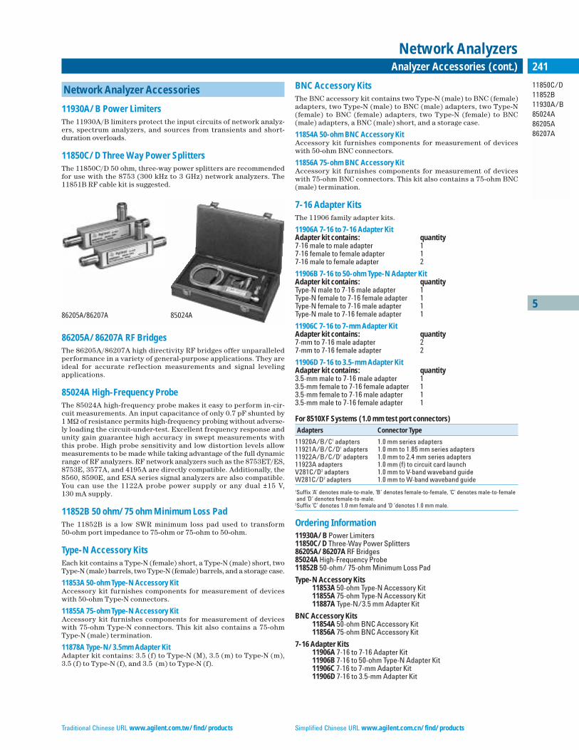
Traditional Chinese URL www.agilent.com.tw/find/products Simplified Chinese URL www.agilent.com.cn/find/products
5
11850C/D11852B11930A/B85024A86205A86207A
241Analyzer Accessories (cont.)
Network Analyzers
Network Analyzer Accessories
11930A/B Power LimitersThe 11930A/B limiters protect the input circuits of network analyz-ers, spectrum analyzers, and sources from transients and short-duration overloads.
11850C/D Three Way Power SplittersThe 11850C/D 50 ohm, three-way power splitters are recommendedfor use with the 8753 (300 kHz to 3 GHz) network analyzers. The11851B RF cable kit is suggested.
86205A/86207A RF Bridges The 86205A/86207A high directivity RF bridges offer unparalleledperformance in a variety of general-purpose applications. They areideal for accurate reflection measurements and signal levelingapplications.
85024A High-Frequency ProbeThe 85024A high-frequency probe makes it easy to perform in-cir-cuit measurements. An input capacitance of only 0.7 pF shunted by1 MΩ of resistance permits high-frequency probing without adverse-ly loading the circuit-under-test. Excellent frequency response andunity gain guarantee high accuracy in swept measurements withthis probe. High probe sensitivity and low distortion levels allowmeasurements to be made while taking advantage of the full dynamicrange of RF analyzers. RF network analyzers such as the 8753ET/ES,8753E, 3577A, and 4195A are directly compatible. Additionally, the8560, 8590E, and ESA series signal analyzers are also compatible.You can use the 1122A probe power supply or any dual ±15 V, 130 mA supply.
11852B 50 ohm/75 ohm Minimum Loss PadThe 11852B is a low SWR minimum loss pad used to transform 50-ohm port impedance to 75-ohm or 75-ohm to 50-ohm.
Type-N Accessory KitsEach kit contains a Type-N (female) short, a Type-N (male) short, twoType-N (male) barrels, two Type-N (female) barrels, and a storage case.
11853A 50-ohm Type-N Accessory KitAccessory kit furnishes components for measurement of deviceswith 50-ohm Type-N connectors.
11855A 75-ohm Type-N Accessory KitAccessory kit furnishes components for measurement of deviceswith 75-ohm Type-N connectors. This kit also contains a 75-ohmType-N (male) termination.
11878A Type-N/3.5mm Adapter KitAdapter kit contains: 3.5 (f) to Type-N (M), 3.5 (m) to Type-N (m), 3.5 (f) to Type-N (f), and 3.5 (m) to Type-N (f).
BNC Accessory KitsThe BNC accessory kit contains two Type-N (male) to BNC (female)adapters, two Type-N (male) to BNC (male) adapters, two Type-N(female) to BNC (female) adapters, two Type-N (female) to BNC(male) adapters, a BNC (male) short, and a storage case.
11854A 50-ohm BNC Accessory KitAccessory kit furnishes components for measurement of deviceswith 50-ohm BNC connectors.
11856A 75-ohm BNC Accessory KitAccessory kit furnishes components for measurement of deviceswith 75-ohm BNC connectors. This kit also contains a 75-ohm BNC(male) termination.
7-16 Adapter KitsThe 11906 family adapter kits.
11906A 7-16 to 7-16 Adapter KitAdapter kit contains: quantity7-16 male to male adapter 17-16 female to female adapter 17-16 male to female adapter 2
11906B 7-16 to 50-ohm Type-N Adapter KitAdapter kit contains: quantityType-N male to 7-16 male adapter 1Type-N female to 7-16 female adapter 1Type-N female to 7-16 male adapter 1Type-N male to 7-16 female adapter 1
11906C 7-16 to 7-mm Adapter KitAdapter kit contains: quantity7-mm to 7-16 male adapter 27-mm to 7-16 female adapter 2
11906D 7-16 to 3.5-mm Adapter KitAdapter kit contains: quantity3.5-mm male to 7-16 male adapter 13.5-mm female to 7-16 female adapter 13.5-mm female to 7-16 male adapter 13.5-mm male to 7-16 female adapter 1
For 8510XF Systems (1.0 mm test port connectors)
Adapters Connector Type
11920A/B/C1 adapters 1.0 mm series adapters11921A/B/C/D1 adapters 1.0 mm to 1.85 mm series adapters11922A/B/C/D1 adapters 1.0 mm to 2.4 mm series adapters11923A adapters 1.0 mm (f) to circuit card launchV281C/D2 adapters 1.0 mm to V-band waveband guideW281C/D2 adapters 1.0 mm to W-band waveband guide
1Suffix ‘A’ denotes male-to-male, ‘B’ denotes female-to-female, ‘C’ denotes male-to-femaleand ‘D’ denotes female-to-male.
2Suffix ‘C’ denotes 1.0 mm female and ‘D ’denotes 1.0 mm male.
Ordering Information11930A/B Power Limiters11850C/D Three-Way Power Splitters86205A/86207A RF Bridges85024A High-Frequency Probe11852B 50-ohm/ 75-ohm Minimum Loss Pad
Type-N Accessory Kits11853A 50-ohm Type-N Accessory Kit11855A 75-ohm Type-N Accessory Kit11887A Type-N/3.5 mm Adapter Kit
BNC Accessory Kits11854A 50-ohm BNC Accessory Kit11856A 75-ohm BNC Accessory Kit
7-16 Adapter Kits11906A 7-16 to 7-16 Adapter Kit11906B 7-16 to 50-ohm Type-N Adapter Kit11906C 7-16 to 7-mm Adapter Kit11906D 7-16 to 3.5-mm Adapter Kit
86205A/86207A 85024A
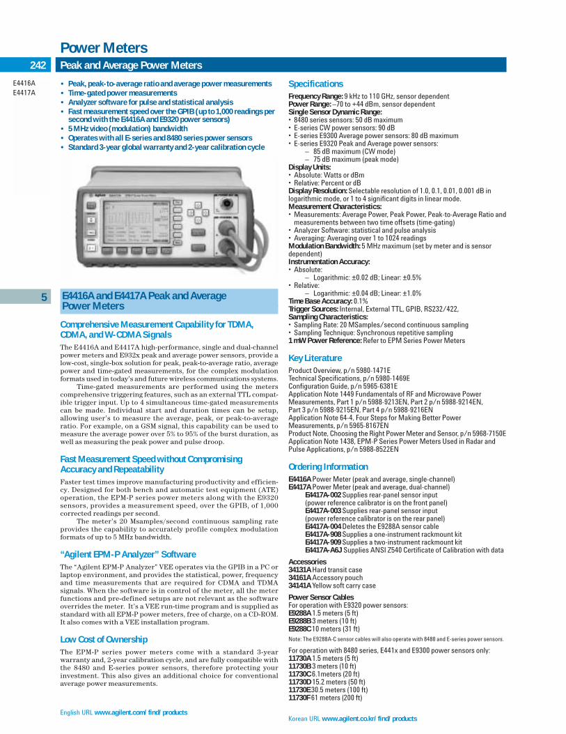
English URL www.agilent.com/find/productsKorean URL www.agilent.co.kr/find/products
5
E4416AE4417A
242 Peak and Average Power Meters
Power Meters
SpecificationsFrequency Range: 9 kHz to 110 GHz, sensor dependentPower Range: –70 to +44 dBm, sensor dependentSingle Sensor Dynamic Range:• 8480 series sensors: 50 dB maximum• E-series CW power sensors: 90 dB • E-series E9300 Average power sensors: 80 dB maximum• E-series E9320 Peak and Average power sensors:
– 85 dB maximum (CW mode)– 75 dB maximum (peak mode)
Display Units:• Absolute: Watts or dBm• Relative: Percent or dBDisplay Resolution: Selectable resolution of 1.0, 0.1, 0.01, 0.001 dB in logarithmic mode, or 1 to 4 significant digits in linear mode.Measurement Characteristics:• Measurements: Average Power, Peak Power, Peak-to-Average Ratio and
measurements between two time offsets (time-gating)• Analyzer Software: statistical and pulse analysis• Averaging: Averaging over 1 to 1024 readings Modulation Bandwidth: 5 MHz maximum (set by meter and is sensordependent)Instrumentation Accuracy:• Absolute:
– Logarithmic: ±0.02 dB; Linear: ±0.5%• Relative:
– Logarithmic: ±0.04 dB; Linear: ±1.0%Time Base Accuracy: 0.1%Trigger Sources: Internal, External TTL, GPIB, RS232/422,Sampling Characteristics:• Sampling Rate: 20 MSamples/second continuous sampling• Sampling Technique: Synchronous repetitive sampling1 mW Power Reference: Refer to EPM Series Power Meters
Key LiteratureProduct Overview, p/n 5980-1471ETechnical Specifications, p/n 5980-1469EConfiguration Guide, p/n 5965-6381EApplication Note 1449 Fundamentals of RF and Microwave Power Measurements, Part 1 p/n 5988-9213EN, Part 2 p/n 5988-9214EN, Part 3 p/n 5988-9215EN, Part 4 p/n 5988-9216ENApplication Note 64-4, Four Steps for Making Better Power Measurements, p/n 5965-8167ENProduct Note, Choosing the Right Power Meter and Sensor, p/n 5968-7150EApplication Note 1438, EPM-P Series Power Meters Used in Radar andPulse Applications, p/n 5988-8522EN
Ordering InformationE4416A Power Meter (peak and average, single-channel)E4417A Power Meter (peak and average, dual-channel)
E4417A-002 Supplies rear-panel sensor input(power reference calibrator is on the front panel)E4417A-003 Supplies rear-panel sensor input(power reference calibrator is on the rear panel)E4417A-004 Deletes the E9288A sensor cableE4417A-908 Supplies a one-instrument rackmount kitE4417A-909 Supplies a two-instrument rackmount kitE4417A-A6J Supplies ANSI Z540 Certificate of Calibration with data
Accessories34131A Hard transit case34161A Accessory pouch34141A Yellow soft carry case
Power Sensor CablesFor operation with E9320 power sensors:E9288A 1.5 meters (5 ft)E9288B 3 meters (10 ft)E9288C 10 meters (31 ft)Note: The E9288A-C sensor cables will also operate with 8480 and E-series power sensors.
For operation with 8480 series, E441x and E9300 power sensors only:11730A 1.5 meters (5 ft)11730B 3 meters (10 ft)11730C 6.1meters (20 ft)11730D 15.2 meters (50 ft)11730E 30.5 meters (100 ft)11730F 61 meters (200 ft)
• Peak, peak-to-average ratio and average power measurements• Time-gated power measurements• Analyzer software for pulse and statistical analysis• Fast measurement speed over the GPIB (up to 1,000 readings per
second with the E4416A and E9320 power sensors)• 5 MHz video (modulation) bandwidth• Operates with all E-series and 8480 series power sensors• Standard 3-year global warranty and 2-year calibration cycle
E4416A and E4417A Peak and Average Power Meters
Comprehensive Measurement Capability for TDMA,CDMA, and W-CDMA SignalsThe E4416A and E4417A high-performance, single and dual-channelpower meters and E932x peak and average power sensors, provide alow-cost, single-box solution for peak, peak-to-average ratio, averagepower and time-gated measurements, for the complex modulation formats used in today’s and future wireless communications systems.
Time-gated measurements are performed using the meterscomprehensive triggering features, such as an external TTL compat-ible trigger input. Up to 4 simultaneous time-gated measurementscan be made. Individual start and duration times can be setup,allowing user’s to measure the average, peak, or peak-to-averageratio. For example, on a GSM signal, this capability can be used tomeasure the average power over 5% to 95% of the burst duration, aswell as measuring the peak power and pulse droop.
Fast Measurement Speed without Compromising Accuracy and Repeatability Faster test times improve manufacturing productivity and efficien-cy. Designed for both bench and automatic test equipment (ATE)operation, the EPM-P series power meters along with the E9320 sensors, provides a measurement speed, over the GPIB, of 1,000 corrected readings per second.
The meter’s 20 Msamples/second continuous sampling rateprovides the capability to accurately profile complex modulationformats of up to 5 MHz bandwidth.
“Agilent EPM-P Analyzer” SoftwareThe “Agilent EPM-P Analyzer” VEE operates via the GPIB in a PC orlaptop environment, and provides the statistical, power, frequencyand time measurements that are required for CDMA and TDMA signals. When the software is in control of the meter, all the meterfunctions and pre-defined setups are not relevant as the softwareoverrides the meter. It’s a VEE run-time program and is supplied asstandard with all EPM-P power meters, free of charge, on a CD-ROM.It also comes with a VEE installation program.
Low Cost of OwnershipThe EPM-P series power meters come with a standard 3-year warranty and, 2-year calibration cycle, and are fully compatible withthe 8480 and E-series power sensors, therefore protecting yourinvestment. This also gives an additional choice for conventionalaverage power measurements.

Traditional Chinese URL www.agilent.com.tw/find/products Simplified Chinese URL www.agilent.com.cn/find/products
5
E9321AE9322AE9323AE9325AE9326AE9327A
243Peak and Average Power Meters (cont.)
Power Meters
E9320 Family Peak and Average Power Sensors
The E9320 power sensors must be used with an E9288A, B or C sen-sor cable and only operate with the EPM-P series power meters(E4416A and E4417A). These sensors have two measurement paths,one for peak and time-gated measurements (a fast sampled path)and another for stable, low-level average power measurements.
High Performance SensorsThe E932x sensors have two frequency ranges, from 50 MHz to 6 GHz to cover most wireless communications applications, and ahigher frequency range 50 MHz to 18 GHz. Each frequency range hasa choice of 3 different video bandwidth sensors:• 300 kHz for TDMA signals, for example GSM• 1.5 MHz for cdmaOne• 5 MHz for W-CDMA and cdma2000
Using just one sensor, user’s can measure W-CDMA, cdmaOneand TDMA as each sensor provides a high, medium and low videobandwidth setting, selectable by the meter. So user’s can select themodulation bandwidth required for their application, while main-taining the maximum dynamic range.
Fast Measurement SpeedThe E9320 power sensors provide fast measurement speed, over theGPIB, up to 1,000 corrected readings per second, with the E4416Apower meter.
Optimum Measurement Accuracy and RepeatabilityTo minimize the sensor and source mismatch, one of the main con-tributors to the overall measurement uncertainty, the E9320 sensorshave a low SWR specification (1.15 for signals <+10 dBm, 50 MHz to2 GHz). Comprehensive error correction is also provided as the cali-bration factors, linearity, and temperature compensation data areall stored within the E9320 sensor’s EEPROM.
Specifications
Sensor Max. Meas. Frequency Power Max. Model Bandwidth Range Range Power
E9321A 300 kHz 50 MHz to –65 to +20 dBm (max.) +23 dBm 6 GHz average
E9322A 1.5 MHz 50 MHz to –60 to +20 dBm (max.) +23 dBm6 GHz average
E9323A 5 MHz 50 MHz to –60 to +20 dBm (max.) +23 dBm6 GHz average
E9325A 300 kHz 50 MHz to –65 to +20 dBm (max.) +23 dBm18 GHz average
E9326A 1.5 MHz 50 MHz to –60 to +20 dBm (max.) +23 dBm18 GHz average
E9327A 5 MHz 50 MHz to –60 to +20 dBm (max.) +23 dBm18 GHz average
Key LiteratureProduct Overview, p/n 5980-1471ETechnical Specifications, p/n 5980-1469EConfiguration Guide, p/n 5965-6381EApplication Note 1449 Fundamentals of RF and Microwave Power Measurements, Part 1 p/n 5988-9213EN, Part 2 p/n 5988-9214EN, Part 3 p/n 5988-9215EN, Part 4 p/n 5988-9216ENApplication Note 64-4, Four Steps for Better Power Measurements, p/n 5965-8167ENProduct Note, Choosing the Right Power Meter and Sensor, p/n 5968-7150EApplication Note 1438, EPM-P Series Power Meters Used in Radar andPulse Applications, p/n 5988-8522EN
Ordering InformationE9321A Power Sensor, 50 MHz to 6 GHz, 300 kHz bandwidth
E9321A-A6J Supplies ANSI Z540 Certificate of Calibration with dataE9322A Power Sensor, 50 MHz to 6 GHz, 1.5 MHz bandwidth
E9322A-A6J Supplies ANSI Z540 Certificate of Calibration with dataE9323A Power Sensor, 50 MHz to 6 GHz, 5 MHz bandwidth
E9323A-A6J Supplies ANSI Z540 Certificate of Calibration with dataE9325A Power Sensor, 50 MHz to 18 GHz, 300 kHz bandwidth
E9325A-A6J Supplies ANSI Z540 Certificate of Calibration with dataE9326A Power Sensor, 50 MHz to 18 GHz, 1.5 MHz bandwidth
E9326A-A6J Supplies ANSI Z540 Certificate of Calibration with dataE9327A Power Sensor, 50 MHz to 18 GHz, 5 MHz bandwidth
E9327A-A6J Supplies ANSI Z540 Certificate of Calibration with data
• Operates with the new EPM-P Series Power Meters (E4416A and E4417A)
• Provides peak and average power measurements • Fast measurement speed over the GPIB (up to 1,000 readings
per second) • 300 kHz, 1.5 MHz and 5 MHz video (modulation) bandwidths• Wide dynamic range sensors• Calibration factors stored in EEPROM
E9320 Family Peak and Average Power Sensors

English URL www.agilent.com/find/products Korean URL www.agilent.co.kr/find/products
E4418B Single-Channel Power Meter
The E4418B is a low-cost, high-performance, single-channel, pro-grammable power meter. It is fully compatible with the 8480 seriesand E-series power sensors, (except the E9320A family). Dependingupon which sensor is used, the E4418B can measure from –70 dBmto +44 dBm at frequencies from 9 kHz to 110 GHz. Designed forbench and automatic test equipment (ATE) use, the E4418B makesfast (up to 200 readings per second with E-series sensors), accurateand repeatable power measurements.
The E4418B power meter has a high-resolution LCD displaywith LED backlighting and contrast control. This allows users to seethe power readings from a distance, at a wide viewing angle and in avariety of lighting conditions. The user interface is easy to learn anduse, with hardkeys for the most frequently used functions, and softkey menus to simplify instrument configuration for differentapplications. Ten instrument configurations can be saved andrecalled, reducing the need to repeat setup sequences.
The E4418B is ideal for service and maintenance applications.The internal rechargeable battery option (option 001), which pro-vides up to 5.5 hours of continuous operation, brings Agilent’s accu-racy to field applications. Front and rear panel bumpers protect theE4418B from everyday knocks. The meter weighs only 4 kg (9 lbs),and a bail handle makes it easy to carry.
Because the E4418B power meter is designed to be code-com-patible with the previous-generation 436A and 437B power meters,a user’s investment in automatic-test procedures, software genera-tion and verification is protected.
E4419B Dual-Channel Power Meter
The E4419B is a low-cost, high-performance, dual-channel, pro-grammable power meter. It is fully compatible with the 8480 seriesand the E-series power sensors, (except the E9320A family).Depending upon which sensor is used, the E4419B can measurefrom –70 dBm to +44 dBm at frequencies from 9 kHz to 110 GHz.
Designed for bench and automatic test equipment use (ATE),the E4419B makes fast (up to 100 readings per second with E-seriessensors), accurate and repeatable power measurements. The E4419Bis a true dual-channel power meter, which means that you get twosimultaneous power readings on the display.
The E4419B power meter has a high-resolution LCD displaywith LED backlighting and contrast control. This allows users to seethe power readings from a distance, at a wide viewing angle and in a
variety of lighting conditions. Users can display both the digital andanalog types of readout on the meter’s split screen facility. The ana-log peaking meter allows users to make accurate adjustments.
The user interface is easy to learn and use, with hardkeys for themost frequently used functions, and softkey menus to simplify instru-ment configuration for different applications. Difference (A-B, B-A)and ratio (A/B, B/A) functions are provided, and ten instrument con-figurations can be saved and recalled, reducing the need to repeat set-up sequences.
Because the E4419B power meter is code compatible with the438A and is the same height (88.5 mm /3.5 in) and width (212.6 mm/8.5 in) as the 438A, this makes it easy to substitute into rackmountautomatic-test-equipment systems.
SpecificationsFrequency Range: 9 kHz to 110 GHz, sensor dependentPower Range: –70 dBm to +44 dBm (100 pW to 25 W), sensor dependentPower Sensors: Compatible with all 8480 series and E-series sensorsexcept the E9320A familySingle Sensor Dynamic Range:• 90 dB maximum (E-series sensors)• 50 dB maximum (8480 series sensors)Display Units:• Absolute: Watts or dBm• Relative: Percent or dBDisplay Resolution: Selectable resolution of 1.0, 0.1, 0.01, and 0.001 dB in log mode, or 1 to 4 digits in linear modeDefault Resolution: 0.01 dB in log mode, 3 digits in linear modeAccuracy Instrumentation:• Absolute: ±0.02 dB (log) or ±0.5% (linear). Add the corresponding
power sensor linearity percentage• Relative: ±0.04 dB (log) or ±1.0% (linear). Add the corresponding
power sensor linearity percentage
Power ReferencePower Output: 1.00 mW (0.0 dBm). Factory set to ±0.4% traceable to theNational Physical Laboratory (NPL), UK. Accuracy:For two years:• ±0.5% (23 ± 3ºC)• ±0.6% (25 ± 10ºC)• ±0.9% (0 to 55ºC)Frequency: 50 MHz nominalSWR: 1.06 maximum (1.08 maximum for option 003)Connector Type: Type N (f), 50 ohms
Key LiteratureBrochure, p/n 5965-6380ETechnical Specifications, p/n 5965-6382EConfiguration Guide, p/n 5965-6381EApplication Note 1449 Fundamentals of RF and Microwave Power Measurements, Part 1 p/n 5988-9213EN, Part 2 p/n 5988-9214EN, Part 3 p/n 5988-9215EN, Part 4 p/n 5988-9216ENApplication Note 64-4, Four Steps for Making Better Power Measurements, p/n 5965-8167ENProduct Note, Choosing the Right Power Meter and Sensor,p/n 5968-7150E
Ordering InformationE4418B Power MeterE4419B Power Meter
E4419B-001 Supplies internal rechargeable batteryE4419B-002 Supplies rear-panel sensor input (power reference calibrator is on front panel)E4419B-003 Supplies rear-panel sensor input (power reference calibrator is on rear panel)E4419B-004 Deletes the 11730A sensor cableE4419B-908 Supplies a one-instrument rackmount kitE4419B-909 Supplies a two-instrument rackmount kitE4419B-A6J Supplies ANSI Z540 Certificate of Calibrationwith data (E4418B/E4419B)
EPM Series Power Meters
Single- and Dual-Channel Power Meters
Power Meters
5
244
E4418BE4419B
• Fast measurement speed (up to 200 readings per second with theE4418B, and 100 readings per second with the E4419B, over theGPIB, with E-series sensors)
• Speed improvement of x2 using the 8480-series power sensor (compared to 437B)
• Code-compatible with the 436A and 437B (E4418B) and 438A(E4419B)
• Operates with the 8480 series and E-series (except the E9320Afamily) plus all 8480 series power sensors
• No range-switching delays with 8480-series sensors (over a 50 dB range), and only one fast-range switch point with E-seriessensors (over a 90 dB range)
• Standard 3-year global warranty and 2-year calibration cycle• Internal rechargeable battery option
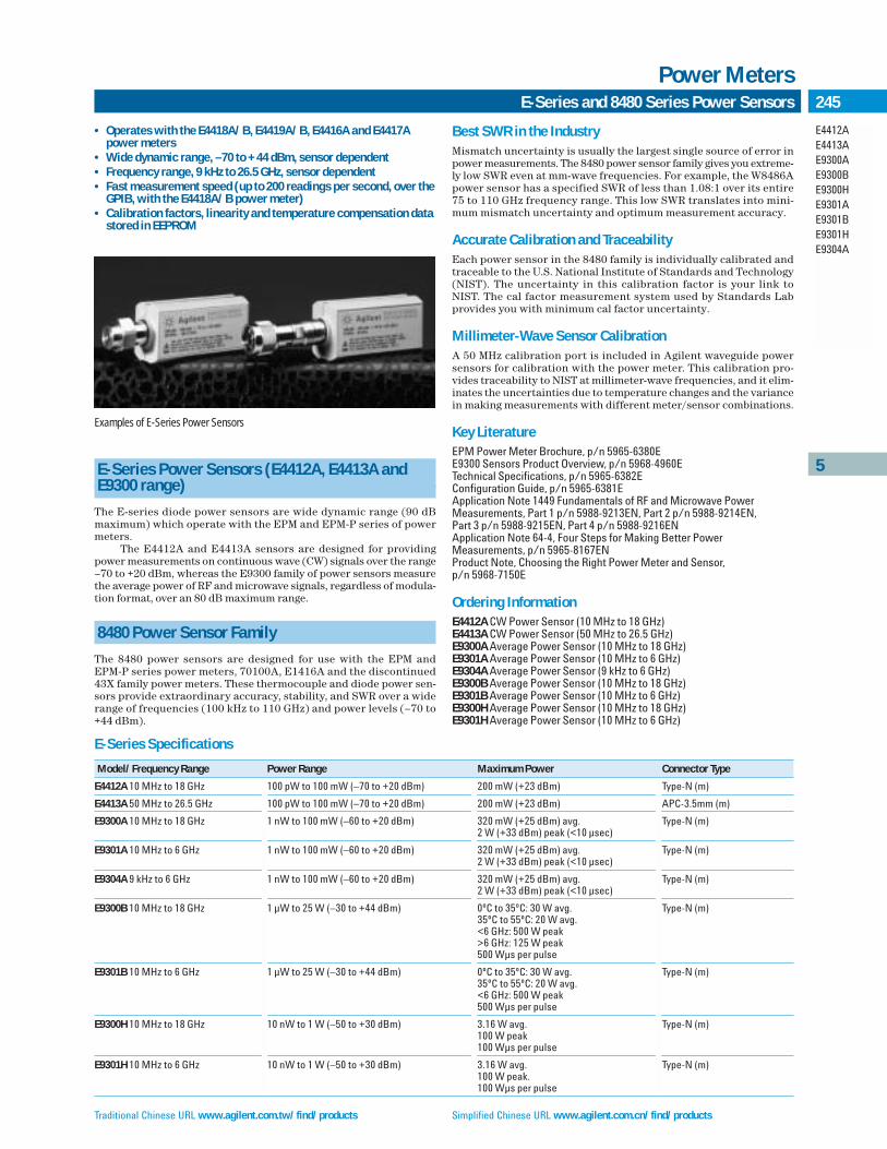
E-Series and 8480 Series Power Sensors
Power Meters
5
245
E4412AE4413AE9300AE9300BE9300HE9301AE9301BE9301HE9304A
E-Series Power Sensors (E4412A, E4413A and E9300 range)
The E-series diode power sensors are wide dynamic range (90 dB maximum) which operate with the EPM and EPM-P series of powermeters.
The E4412A and E4413A sensors are designed for providingpower measurements on continuous wave (CW) signals over the range–70 to +20 dBm, whereas the E9300 family of power sensors measurethe average power of RF and microwave signals, regardless of modula-tion format, over an 80 dB maximum range.
8480 Power Sensor Family
The 8480 power sensors are designed for use with the EPM and EPM-P series power meters, 70100A, E1416A and the discontinued43X family power meters. These thermocouple and diode power sen-sors provide extraordinary accuracy, stability, and SWR over a widerange of frequencies (100 kHz to 110 GHz) and power levels (–70 to+44 dBm).
Best SWR in the IndustryMismatch uncertainty is usually the largest single source of error inpower measurements. The 8480 power sensor family gives you extreme-ly low SWR even at mm-wave frequencies. For example, the W8486Apower sensor has a specified SWR of less than 1.08:1 over its entire75 to 110 GHz frequency range. This low SWR translates into mini-mum mismatch uncertainty and optimum measurement accuracy.
Accurate Calibration and TraceabilityEach power sensor in the 8480 family is individually calibrated andtraceable to the U.S. National Institute of Standards and Technology(NIST). The uncertainty in this calibration factor is your link toNIST. The cal factor measurement system used by Standards Labprovides you with minimum cal factor uncertainty.
Millimeter-Wave Sensor CalibrationA 50 MHz calibration port is included in Agilent waveguide powersensors for calibration with the power meter. This calibration pro-vides traceability to NIST at millimeter-wave frequencies, and it elim-inates the uncertainties due to temperature changes and the variancein making measurements with different meter/sensor combinations.
Key LiteratureEPM Power Meter Brochure, p/n 5965-6380EE9300 Sensors Product Overview, p/n 5968-4960ETechnical Specifications, p/n 5965-6382EConfiguration Guide, p/n 5965-6381EApplication Note 1449 Fundamentals of RF and Microwave Power Measurements, Part 1 p/n 5988-9213EN, Part 2 p/n 5988-9214EN, Part 3 p/n 5988-9215EN, Part 4 p/n 5988-9216ENApplication Note 64-4, Four Steps for Making Better Power Measurements, p/n 5965-8167ENProduct Note, Choosing the Right Power Meter and Sensor, p/n 5968-7150E
Ordering InformationE4412A CW Power Sensor (10 MHz to 18 GHz)E4413A CW Power Sensor (50 MHz to 26.5 GHz)E9300A Average Power Sensor (10 MHz to 18 GHz)E9301A Average Power Sensor (10 MHz to 6 GHz)E9304A Average Power Sensor (9 kHz to 6 GHz)E9300B Average Power Sensor (10 MHz to 18 GHz)E9301B Average Power Sensor (10 MHz to 6 GHz)E9300H Average Power Sensor (10 MHz to 18 GHz)E9301H Average Power Sensor (10 MHz to 6 GHz)
• Operates with the E4418A/B, E4419A/B, E4416A and E4417Apower meters
• Wide dynamic range, –70 to +44 dBm, sensor dependent• Frequency range, 9 kHz to 26.5 GHz, sensor dependent• Fast measurement speed (up to 200 readings per second, over the
GPIB, with the E4418A/B power meter)• Calibration factors, linearity and temperature compensation data
stored in EEPROM
Examples of E-Series Power Sensors
E-Series Specifications
Model/Frequency Range Power Range Maximum Power Connector Type
E4412A 10 MHz to 18 GHz 100 pW to 100 mW (–70 to +20 dBm) 200 mW (+23 dBm) Type-N (m)
E4413A 50 MHz to 26.5 GHz 100 pW to 100 mW (–70 to +20 dBm) 200 mW (+23 dBm) APC-3.5mm (m)
E9300A 10 MHz to 18 GHz 1 nW to 100 mW (–60 to +20 dBm) 320 mW (+25 dBm) avg. Type-N (m)2 W (+33 dBm) peak (<10 µsec)
E9301A 10 MHz to 6 GHz 1 nW to 100 mW (–60 to +20 dBm) 320 mW (+25 dBm) avg. Type-N (m) 2 W (+33 dBm) peak (<10 µsec)
E9304A 9 kHz to 6 GHz 1 nW to 100 mW (–60 to +20 dBm) 320 mW (+25 dBm) avg. Type-N (m)2 W (+33 dBm) peak (<10 µsec)
E9300B 10 MHz to 18 GHz 1 µW to 25 W (–30 to +44 dBm) 0ºC to 35ºC: 30 W avg. Type-N (m)35ºC to 55ºC: 20 W avg.<6 GHz: 500 W peak>6 GHz: 125 W peak500 Wµs per pulse
E9301B 10 MHz to 6 GHz 1 µW to 25 W (–30 to +44 dBm) 0ºC to 35ºC: 30 W avg. Type-N (m)35ºC to 55ºC: 20 W avg.<6 GHz: 500 W peak500 Wµs per pulse
E9300H 10 MHz to 18 GHz 10 nW to 1 W (–50 to +30 dBm) 3.16 W avg. Type-N (m)100 W peak100 Wµs per pulse
E9301H 10 MHz to 6 GHz 10 nW to 1 W (–50 to +30 dBm) 3.16 W avg. Type-N (m)100 W peak.100 Wµs per pulse
Traditional Chinese URL www.agilent.com.tw/find/products Simplified Chinese URL www.agilent.com.cn/find/products

1 Negligible deviation except for those power ranges noted.2 For pulses greater than 30 W the maximum average power (Pa) is limited by the energy
per pulse (E) in W – µs according to Pa = 30 – 0.02E.
3 Includes 11708A 30 dB attenuator for calibrating against a 0 dBm, 50 MHz power reference. 11708A is factory set to 30 dB ± 0.05 dB at 50 MHz, traceable to NIST. SWR <1.05 at 50 MHz.
4 This sensor directly replaces the popular 8484A power sensor.
8480 Series Specifications
Model Frequency Range Maximum SWR Power Linearity1 Maximum Power Connector Type Weight
25 Watt Sensors 1 mW to 25 W (0 to +44 dBm)
8481B 10 MHz to 18 GHz 10 MHz to 2 GHz: 1.10 +35 to +44 dBm; 0º to 35ºC: 30 W avg2 Type-N (m) Net 0.8 kg (1.75 lb)2 to 12.4 GHz: 1.18 ±4% 35º to 55ºC: 25 W avg Shipping 1.5 kg(3.25 lb)12.4 to 18 GHz: 1.28 0.01 to 5.8 GHz: 500 W pk
8482B 100 kHz to 4.2 GHz 100 kHz to 2 GHz: 1.10 5.8 to 18 GHz: 125 W pk Type-N (m)2 to 4.2 GHz: 1.18 500 W-µs per pulse
3 Watt Sensors 100 µW to 3 W (–10 to +35 dBm)
8481H 10 MHz to 18 GHz 10 MHz to 8 GHz: 1.20 +25 to +35 dBm; 3.5 W avg, 100 W pk Type-N (m) Net 0.2 kg (0.38 lb)8 to 12.4 GHz: 1.25 ±5% 100 W-µs per pulse Shipping 0.5 kg (1 lb)12.4 to 18 GHz: 1.30
8482H 100 kHz to 4.2 GHz 100 kHz to 4.2 GHz: 1.20 Type-N (m)
100 mW Sensors 1 µW to 100 mW (–30 to +20 dBm)
8485A 50 MHz to 26.5 GHz 50 to 100 MHz: 1.15 +10 to +20 dBm; 300 mW avg, 15 W pk APC-3.5 mm (m) Net 0.2 kg (0.38 lb)100 MHz to 2 GHz: 1.10 ±3% 30 W-µs per pulse Shipping 0.5 kg (1 lb)2 to 2.4 GHz: 1.1512.4 to 18 GHz: 1.2018 to 26.5 GHz: 1.25
Option 033 50 MHz to 33 GHz 26.5 to 33 GHz: 1.40
8481A 10 MHz to 18 GHz 10 to 30 MHz: 1.40 Type-N (m)30 to 50 MHz: 1.1850 MHz to 2 GHz: 1.102 to 12.4 GHz: 1.1812.4 to 18 GHz: 1.28
8482A 100 kHz to 4.2 GHz 100 to 300 kHz: 1.60 Type-N (m)0.3 to 1 MHz: 1.201 MHz to 2 GHz: 1.102 to 4.2 GHz: 1.30
8483A 100 kHz to 2 GHz 100 to 600 kHz: 1.80 300 mW avg, 10 W pk Type-N (m)(75 Ω) 600 kHz to 2 GHz: 1.18 75 Ω
R8486A 26.5 to 40 GHz 1.4 +10 to +20 dBm; 300 mW avg, 15 W pk Waveguide Flange Net 0.26 kg (0.53 lb)±3% 30 W-µs per pulse UG-599/U Shipping 0.66 kg (1.3 lb)
Q8486A 33 to 50 GHz 1.5 Waveguide FlangeUG-383/U
V8486A 50 to 75 GHz 1.04 +10 to +20 dBm; 200 mV avg Waveguide Flange Net 0.4 kg (0.91 lb)±2% 40 W pk UG-385/U Shipping 1kg(2.11lb)–30 to +10 dBm 10 us pulse<±1% 0.5% duty cycle
W8486A 75 to 110 GHz 1.08 ±2% 200 mW avg Waveguide Flange Net 0.4 kg (0.9 lb)40 W peak UG-387/U Shipping 1.0 kg (2.1 lb)
8487A 50 MHz to 50 GHz 50 to 100 MHz: 1.15 +10 to +20 dBm; 300 mW avg, 15 W pk 2.4 mm (m) Net 0.14 kg (0.28 lb)100 MHz to 2 GHz: 1.10 ±3% 30 W-µs per pulse Shipping 0.5 kg (1 lb)2 to 12.4 GHz: 1.1512.4 to 18 GHz: 1.2018 to 26.5 GHz: 1.2526.5 to 40 GHz: 1.3040 to 50 GHz: 1.50
High Sensitivity Sensors 100 pW to 10 µW (–70 to –20 dBm)
8481D3,4 10 MHz to 18 GHz 10 to 30 MHz: 1.40 –30 to –20 dBm; 100 mW avg Type-N (m) Net 0.18 kg (0.41 lb)30 MHz to 4 GHz: 1.15 ±1% 100 mW pk Shipping 0.9 kg (2 lb)4 to 10 GHz: 1.2010 to 15 GHz: 1.3015 to 18 GHz: 1.35
8485D3 50 MHz to 26.5 GHz 0.05 to 0.1 GHz: 1.19 –30 to –20 dBm; 100 mW avg APC-3.5 mm (m) Net 0.2 kg (0.38 lb)0.1 to 4 GHz: 1.15 ±2% 100 mW pk Shipping 0.5 kg (1 lb)4 to 12 GHz: 1.1912 to 18 GHz: 1.2518 to 26.5 GHz: 1.29
Option 033 50 MHz to 33 GHz 26.5 to 33 GHz: 1.35
8487D3 50 MHz to 50 GHz 0.05 to 0.1 GHz: 1.19 –30 to –20 dBm; 100 mW avg 2.4 mm (m) Shipping 0.5 kg (1 lb)0.1 to 2 GHz: 1.15 ±2% 100 mW pk Net 0.2 kg (0.38 lb)2 to 12.4 GHz: 1.2012.4 to 18 GHz: 1.2918 to 34 GHz: 1.3734 to 40 GHz: 1.6140 to 50 GHz: 1.89
R8486D3 26.5 to 40 GHz 1.4 –30 to –25 dBm; 100 mW avg or pk Waveguide Flange Net 0.26 kg (0.53lb)±3% 40 Vdc max UG-599/U Shipping 0.66 kg (1.3lb)
Q8486D3 33 to 50 GHz 1.4 –25 to –20 dBm; Waveguide Flange±5% UG-383/U
Power Sensor Selection Guide
Power Meters
5
8481A 8481B8481D 8481H 8482A8482B 8482H 8483A 8485A8485DR8486AQ8486AR8486DQ8486DW8486A8487A8487DV8486A
246
English URL www.agilent.com/find/products Korean URL www.agilent.co.kr/find/products
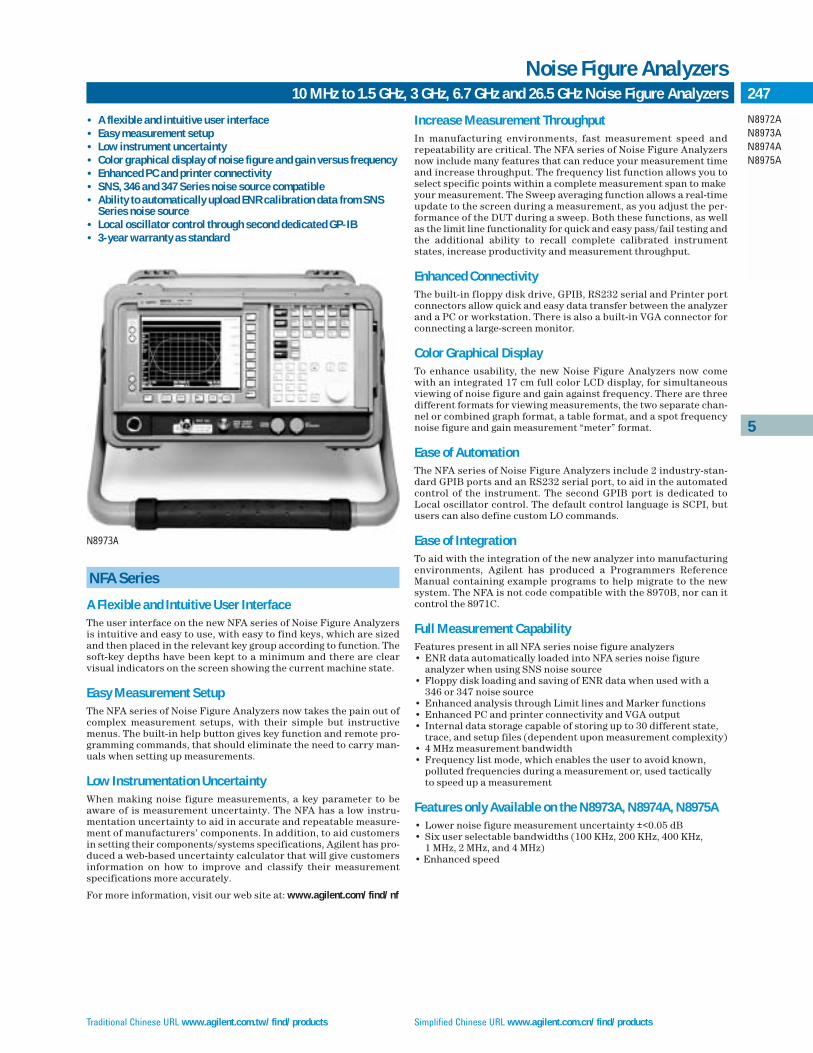
Traditional Chinese URL www.agilent.com.tw/find/products Simplified Chinese URL www.agilent.com.cn/find/products
10 MHz to 1.5 GHz, 3 GHz, 6.7 GHz and 26.5 GHz Noise Figure Analyzers
Noise Figure Analyzers
5
N8972AN8973AN8974AN8975A
247
NFA Series
A Flexible and Intuitive User InterfaceThe user interface on the new NFA series of Noise Figure Analyzersis intuitive and easy to use, with easy to find keys, which are sizedand then placed in the relevant key group according to function. Thesoft-key depths have been kept to a minimum and there are clearvisual indicators on the screen showing the current machine state.
Easy Measurement SetupThe NFA series of Noise Figure Analyzers now takes the pain out ofcomplex measurement setups, with their simple but instructivemenus. The built-in help button gives key function and remote pro-gramming commands, that should eliminate the need to carry man-uals when setting up measurements.
Low Instrumentation UncertaintyWhen making noise figure measurements, a key parameter to beaware of is measurement uncertainty. The NFA has a low instru-mentation uncertainty to aid in accurate and repeatable measure-ment of manufacturers’ components. In addition, to aid customersin setting their components/systems specifications, Agilent has pro-duced a web-based uncertainty calculator that will give customersinformation on how to improve and classify their measurementspecifications more accurately.
For more information, visit our web site at: www.agilent.com/find/nf
Increase Measurement ThroughputIn manufacturing environments, fast measurement speed and repeatability are critical. The NFA series of Noise Figure Analyzersnow include many features that can reduce your measurement timeand increase throughput. The frequency list function allows you toselect specific points within a complete measurement span to makeyour measurement. The Sweep averaging function allows a real-timeupdate to the screen during a measurement, as you adjust the per-formance of the DUT during a sweep. Both these functions, as wellas the limit line functionality for quick and easy pass/fail testing andthe additional ability to recall complete calibrated instrumentstates, increase productivity and measurement throughput.
Enhanced ConnectivityThe built-in floppy disk drive, GPIB, RS232 serial and Printer portconnectors allow quick and easy data transfer between the analyzerand a PC or workstation. There is also a built-in VGA connector forconnecting a large-screen monitor.
Color Graphical DisplayTo enhance usability, the new Noise Figure Analyzers now comewith an integrated 17 cm full color LCD display, for simultaneousviewing of noise figure and gain against frequency. There are threedifferent formats for viewing measurements, the two separate chan-nel or combined graph format, a table format, and a spot frequencynoise figure and gain measurement “meter” format.
Ease of AutomationThe NFA series of Noise Figure Analyzers include 2 industry-stan-dard GPIB ports and an RS232 serial port, to aid in the automatedcontrol of the instrument. The second GPIB port is dedicated toLocal oscillator control. The default control language is SCPI, butusers can also define custom LO commands.
Ease of IntegrationTo aid with the integration of the new analyzer into manufacturingenvironments, Agilent has produced a Programmers ReferenceManual containing example programs to help migrate to the newsystem. The NFA is not code compatible with the 8970B, nor can itcontrol the 8971C.
Full Measurement CapabilityFeatures present in all NFA series noise figure analyzers• ENR data automatically loaded into NFA series noise figure
analyzer when using SNS noise source• Floppy disk loading and saving of ENR data when used with a
346 or 347 noise source• Enhanced analysis through Limit lines and Marker functions• Enhanced PC and printer connectivity and VGA output• Internal data storage capable of storing up to 30 different state,
trace, and setup files (dependent upon measurement complexity)• 4 MHz measurement bandwidth• Frequency list mode, which enables the user to avoid known,
polluted frequencies during a measurement or, used tactically to speed up a measurement
Features only Available on the N8973A, N8974A, N8975A• Lower noise figure measurement uncertainty ±<0.05 dB• Six user selectable bandwidths (100 KHz, 200 KHz, 400 KHz,
1 MHz, 2 MHz, and 4 MHz)• Enhanced speed
• A flexible and intuitive user interface• Easy measurement setup• Low instrument uncertainty• Color graphical display of noise figure and gain versus frequency• Enhanced PC and printer connectivity• SNS, 346 and 347 Series noise source compatible• Ability to automatically upload ENR calibration data from SNS
Series noise source• Local oscillator control through second dedicated GP-IB• 3-year warranty as standard
N8973A

English URL www.agilent.com/find/products Korean URL www.agilent.co.kr/find/products
10 MHz to 1.5 GHz, 3 GHz, 6.7 GHz and 26.5 GHz Noise Figure Analyzers (cont.)
Noise Figure Analyzers
5
N8972AN8973AN8974AN8975A
248
NFA Series Key Specifications Specifications apply over 0°C to +55°C unless otherwise noted. Theanalyzer will meet its specifications after 2 hours of storage withinthe operating temperature range, 60 minutes after the analyzer isturned on, with Alignment running. A user calibration is requiredbefore corrected measurements can be made.
Frequency RangeNFA Series:N8972A 10 MHz to 1.5 GHzN8973A 10 MHz to 3 GHzN8974A 10 MHz to 6.7 GHzN8975A 10 MHz to 26.5 GHz
Measurement Speed (nominal)8 Averages 64 Averages
N8972A: <100 ms/measurement <80 ms/measurement N8973A: <50 ms/measurement <42 ms/measurement N8974A: <70 ms/measurement <50 ms/measurementN8975A: <70 ms/measurement <50 ms/measurement
Measurement Bandwidth (nominal)N8972A: 4 MHzN8973A, N8974A, N8975A: 4 MHz, 2 MHz, 1 MHz, 400 kHz, 200 kHz, 100 kHz
Noise Figure and Gain(Performance is dependent upon ENR of noise source used)
N8972A Noise Source ENR4 – 7 dB 12 – 17 dB 20 – 22 dB
Noise FigureMeasurement range 0 to 20 dB 0 to 30 dB 0 to 35 dBInstrument uncertainty ±<0.1 dB ±<0.1 dB ±<0.15 dB
GainMeasurement range –20 to +40 dBInstrument uncertainty ±<0.17 dB
N8973A, N8974A and Noise Source ENRN8975A(10 MHz to 3.0 GHz) 4 – 7 dB 12 – 17 dB 20 – 22 dB
Noise FigureMeasurement range 0 to 20 dB 0 to 30 dB 0 to 35 dBInstrument uncertainty ±<0.05 dB ±<0.05 dB ±<0.1 dB
GainMeasurement range –20 to +40 dBInstrument uncertainty ±<0.17 dB
N8974A and N8975A Noise Source ENR(>3.0 GHz) 4 – 7 dB 12 – 17 dB 20 – 22 dB
Noise FigureMeasurement range 0 to 20 dB 0 to 30 dB 0 to 35 dBInstrument uncertainty ±<0.15 dB ±<0.15 dB ±<0.2 dB
GainMeasurement range –20 to +40 dBInstrument uncertainty ±<0.17 dB
Characteristic1 Noise figure at 23ºC ± 3ºC (10 MHz to 3.0 GHz)
Characteristic1 Noise figure at 23ºC ± 3ºC (3.0 GHz to 26.5 GHz)
Characteristic values are met or bettered by 90% of instruments with 90%confidence.
Frequency Reference
Standard Opt.1D5Aging ±<2 ppm1/year ±<0.1 ppm/yearTemperature stability ±<6 ppm ±<0.01 ppmSettability ±<0.5 ppm ±<0.01 ppm
Tuning Accuracy (Start, Stop, Center, Marker)4 MHz Measurement Bandwidth (default on all models of Noise FigureAnalyzer)
Frequency Error10 MHz – 3.0 GHz ±<Reference error + 100 kHz3.0 GHz – 26.5 GHz ±<Reference error + 400 kHz
<4MHz Measurement Bandwidth (functionality not present in N8972A)
Frequency Error10 MHz – 3.0 GHz ±<Reference error + 20 kHz3.0 GHz – 26.5 GHz ±<Reference error + 20% of measurement
bandwidth1 Parts Per Million (10e-6)
10
8
6
4
2
010 500 1000 1500 2000 2500 3000
Frequency (MHz)
Noi
se F
igur
e (d
B)
89
1011
12
Frequency (MHz)
Noi
se F
igur
e (d
B)
3000
3883
4707
5651
7418
8303
8187
9187
1007
210
956
1181
012
724
1360
814
492
1537
616
260
1714
518
029
1891
318
797
1068
121
565
2241
923
334
2421
025
102
2598
626
500
Traditional Chinese URL www.agilent.com.tw/find/products Simplified Chinese URL www.agilent.com.cn/find/products
10 MHz to 1.5 GHz, 3 GHz, 6.7 GHz and 26.5 GHz Noise Figure Analyzers (cont.)
Noise Figure Analyzers
5
N8972AN8973AN8974AN8975A
249
General SpecificationsDimensionsWithout handle: 222 mm H x 375 mm W x 410 mm DWith handle (max): 222 mm H x 409 mm W x 515 mm D
Weight (typical, without options)N8972A: 15.3 kg N8973A: 15.5 kg N8974A: 17.5 kg N8975A: 17.5 kg
Data Storage (nominal)Internal drive: 30 traces, states or ENR tablesFloppy disk: 30 traces, states or ENR tables
Power RequirementsOn (line 1): 90 to 132 V rms, 47 to 440 Hz, 195 to 250 V rms, 47 to 66 HzPower consumption: <300 WStandby (line 0): <5 W
Temperature RangeOperating: 0ºC to +55ºCStorage: –40ºC to +70ºC
Humidity RangeOperating: Up to 95% relative humidity to 40ºC (non-condensing)Altitude range: Operating to 4,600 meters
Calibration Interval1-year minimum recommended
Electromagnetic CompatibilityComplies with the requirements of the EMC directive 89/336/EEC. Thisincludes Generic Immunity Standard EN 50082-1:1992 and RadiatedInterference Standard CISPR 11:1990/EN 55011:1991, Group 1 Class A.The conducted and radiated emissions performance typically meetsCISPR 11:1990/EN 55011:1991 Group 1 Class B limits.
Warranty3-Year warranty as standard
Key LiteratureNoise Figure Analyzers, NFA Series, Brochure, p/n 5980-0166ENoise Figure Analyzers, NFA Series, Data Sheet, p/n 5980-0164ENoise Figure Analyzers, NFA Series, Configuration Guide, p/n 5980-0163EFundamentals of RF and Microwave Noise Figure Measurements, App note 57-1, p/n 5952-8255ENoise Figure Measurement Accuracy, App note 57-2, p/n 5952-370610 Hints for Making Successful Noise Figure Measurements, p/n 5980-0228EN8972A and N8973A, NFA Series, Noise Figure Analyzer ProgrammingExamples, p/n 5968-9498E
Ordering InformationN8972A 10 MHz to 1.5 GHz NFA Series Noise Figure AnalyzerN8973A 10 MHz to 3.0 GHz NFA Series Noise Figure AnalyzerN8974A 10 MHz to 6.7 GHz NFA Series Noise Figure AnalyzerN8975A 10 MHz to 26.5 GHz NFA Series Noise Figure Analyzer
All options, other than those marked with *, can be ordered at any time foruse with an instrument.
Frequency ReferenceN897xA-1D5 NFA series high stability frequency reference*
Calibration DocumentationN897xA-A6J NFA series ANSI Z540 compliant calibration with test data*
AccessoriesN897xA-1CP NFA series rackmount and handle kitN897xA-UK9 NFA series front panel coverN897xA-1FP NFA series calibration, performance verification and adjustment software
DocumentationA hard copy and CD version of the English language Quick ReferenceGuide, User’s Guide, Programmers Reference, and Calibration andPerformance Verification Manual are included with the NFA as standard.Selections can be made to change the localization of the manual set or todelete the hardcopy.N897xA-AB0 NFA series manual set for Taiwan – Chinese localizationN897xA-AB1 NFA series manual set – Korean localizationN897xA-AB2 NFA series manual set – Chinese localizationN897xA-ABE NFA series manual set – Spanish localizationN897xA-ABF NFA series manual set – French localizationN897xA-ABZ NFA series manual set – Italian localizationN897xA-ABD NFA series manual set – German localizationN897xA-ABJ NFA series manual set – Japanese localizationN897xA-0B0 Delete hardcopy manual set*Note: The localized options will include a localized version of the Quick Reference Guideand User Guide, and an English language version of the Programmers Reference, andCalibration and Performance Verification Manual.
Additional DocumentationN897xA-0B1 NFA series manual set (English version)N897xA-0B2 NFA series user manual (English version)N897xA-0BF NFA series programmers reference (English version)
Service Options:Warranty and ServiceStandard warranty is 3 years. For warranty and service of 5 years, please order R-51B-001-5F: “3 yearReturn-to Agilent warranty extended to 5 years” (quantity = 1).
Calibration2
For 3 years, order 36 months of the appropriate calibration plan shownbelow. For 5 years, specify 60 months.R-50C-001 Standard calibration plan*R-50C-002 Standard compliant calibration plan*2 Options not available in all countries
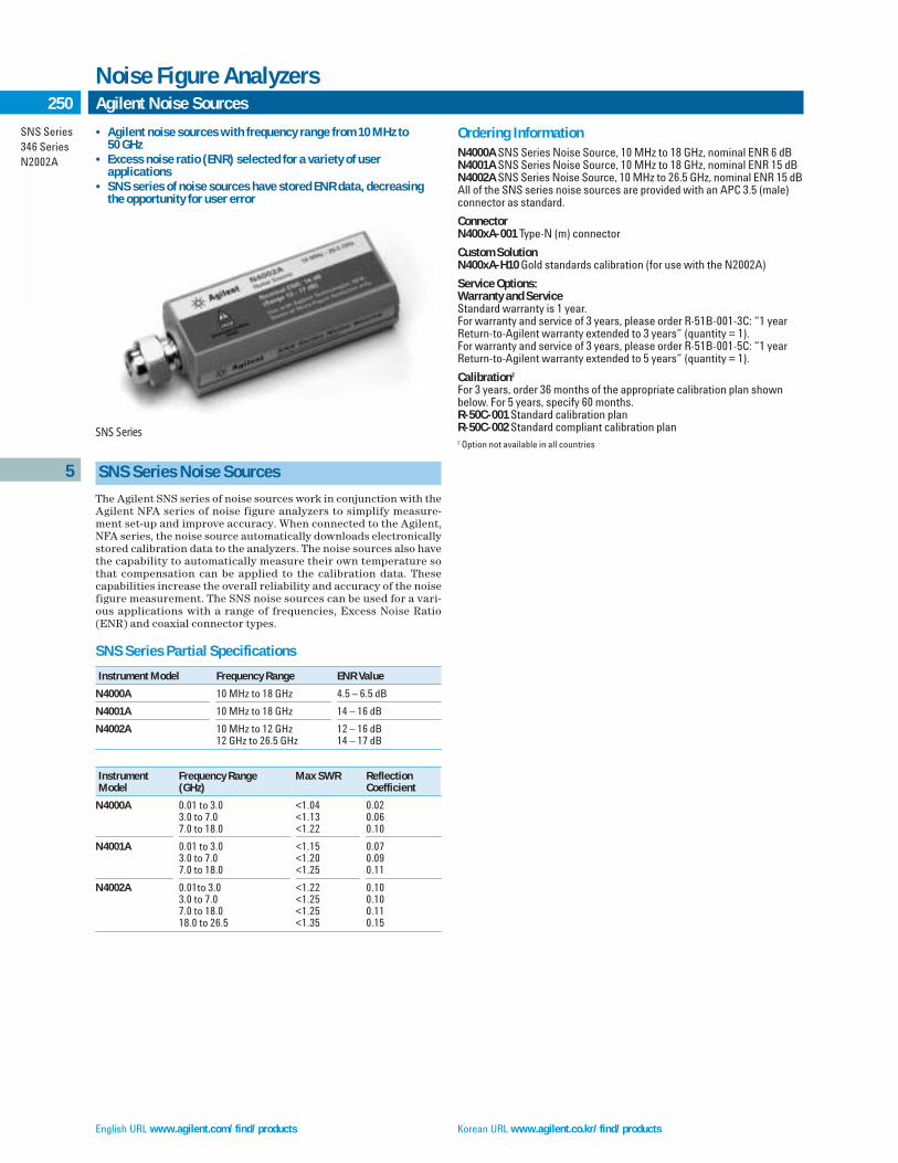
English URL www.agilent.com/find/products Korean URL www.agilent.co.kr/find/products
Agilent Noise Sources
Noise Figure Analyzers
5
SNS Series346 SeriesN2002A
250
SNS Series Noise Sources
The Agilent SNS series of noise sources work in conjunction with theAgilent NFA series of noise figure analyzers to simplify measure-ment set-up and improve accuracy. When connected to the Agilent,NFA series, the noise source automatically downloads electronicallystored calibration data to the analyzers. The noise sources also havethe capability to automatically measure their own temperature sothat compensation can be applied to the calibration data. Thesecapabilities increase the overall reliability and accuracy of the noisefigure measurement. The SNS noise sources can be used for a vari-ous applications with a range of frequencies, Excess Noise Ratio(ENR) and coaxial connector types.
SNS Series Partial Specifications
Instrument Model Frequency Range ENR Value
N4000A 10 MHz to 18 GHz 4.5 – 6.5 dB
N4001A 10 MHz to 18 GHz 14 – 16 dB
N4002A 10 MHz to 12 GHz 12 – 16 dB12 GHz to 26.5 GHz 14 – 17 dB
Instrument Frequency Range Max SWR Reflection Model (GHz) Coefficient
N4000A 0.01 to 3.0 <1.04 0.023.0 to 7.0 <1.13 0.067.0 to 18.0 <1.22 0.10
N4001A 0.01 to 3.0 <1.15 0.073.0 to 7.0 <1.20 0.097.0 to 18.0 <1.25 0.11
N4002A 0.01to 3.0 <1.22 0.103.0 to 7.0 <1.25 0.107.0 to 18.0 <1.25 0.11 18.0 to 26.5 <1.35 0.15
Ordering InformationN4000A SNS Series Noise Source, 10 MHz to 18 GHz, nominal ENR 6 dBN4001A SNS Series Noise Source, 10 MHz to 18 GHz, nominal ENR 15 dBN4002A SNS Series Noise Source, 10 MHz to 26.5 GHz, nominal ENR 15 dBAll of the SNS series noise sources are provided with an APC 3.5 (male)connector as standard.
ConnectorN400xA-001 Type-N (m) connector
Custom SolutionN400xA-H10 Gold standards calibration (for use with the N2002A)
Service Options:Warranty and ServiceStandard warranty is 1 year.For warranty and service of 3 years, please order R-51B-001-3C: “1 yearReturn-to-Agilent warranty extended to 3 years” (quantity = 1).For warranty and service of 3 years, please order R-51B-001-5C: “1 yearReturn-to-Agilent warranty extended to 5 years” (quantity = 1).
Calibration2
For 3 years, order 36 months of the appropriate calibration plan shownbelow. For 5 years, specify 60 months.R-50C-001 Standard calibration planR-50C-002 Standard compliant calibration plan2 Option not available in all countries
SNS Series
• Agilent noise sources with frequency range from 10 MHz to 50 GHz
• Excess noise ratio (ENR) selected for a variety of user applications
• SNS series of noise sources have stored ENR data, decreasingthe opportunity for user error

Traditional Chinese URL www.agilent.com.tw/find/products Simplified Chinese URL www.agilent.com.cn/find/products
5
SNS Series346 SeriesN2002A
251Agilent Noise Sources (cont.)
Noise Figure Analyzers
346 Series Noise Sources
The Agilent 346 series of noise sources work in conjunction withthe Agilent NFA series noise figure analyzer and the PSA seriesspectrum analyzer to make accurate and reliable noise figure mea-surements. Each 346 noise source has individually calibrated ENRvalues at specific frequencies. The calibration data is printed onthe label of the noise source and can be manually entered into theNFA or PSA. A floppy disk is also provided with the calibrationdata, for rapid entry of ENR data into the NFA or PSA. The 346noise sources are designed for a broad range of measurementapplications, with a range of frequencies, Excess Noise Ratio(ENR) and coaxial connector types.
Customer Solution Noise Sources346B with option 346B-H01 High ENR Noise SourceThe 346B-H01 has high ENR (21 dB typical), suitable for measuringhigh noise figure devices.*
346B with option 346B-H42 DBS Noise SourceThe 346B-H42 was developed especially to test low noise block convert-ers (LNB) used for Direct Broadcast Satellite (DBS). WR75 wave-guideoutput, 5 dB ENR, low ENR calibration uncertainty, and low SWR improvethe noise figure measurement accuracy of DBS LNBs.*
346CK01 Broadband Noise SourceThis coaxial noise source features coverage from 1 to 50 GHz with the 2.4 mm coaxial connector. ENR is nominally 20 dB at 1 GHz and 7 dB at 50 GHz.**Contact Agilent for technical specifications
346 Series Partial Specifications
Instrument Model Frequency Range ENR Value
346A 10 MHz to 18 GHz 4.5 – 6.5 dB
346B 10 MHz to 18 GHz 14 – 16 dB
346C 10 MHz to 12 GHz 12 – 16 dB12 GHz to 26.5 GHz 14 – 17 dB
Instrument Frequency Range Max SWR ReflectionModel (GHz) Coefficient
346A/B 0.01 to 3.0 1.3 0.133.0 to 5.0 1.15 0.075.0 to 18.0 1.25 0.11
346C 0.01to 18.0 1.25 0.1118.0 to 26.5 1.35 0.15
Ordering Information346A 10 MHz to 18 GHz 346 Series Noise Source nominal ENR 5 dB346B 10 MHz to 18 GHz 346 Series Noise Source nominal ENR 15 dB346C 10 MHz to 26.5 GHz 346 Series Noise Source nominal ENR 15 dBAll of the 346 series noise sources are provided with an APC 3.5 (male)connector as standard.
Connectors (excludes 346C)346x-001 Type N (male) connector346x-002 APC-7mm connector346x-004 Type N (female) connector
Calibration Documentation346x-A6J ANSI Z540 compliant calibration with test data
Additional Documentation346x-910 Extra operation manual
Custom Solution Options346x-H10 Gold standards calibration (for use with the N2002A)346B-H01 APC 3.5(m) connector with 21 dB nominal ENR346B-H42 DBS Waveguide adapter and nominal ENR 5 dB346CK01 1 GHz to 50 GHz 346 Series Noise Source nominal ENR 21 dB
Service Options:Warranty and ServiceStandard warranty is 1 year.For warranty and service of 3 years, please order R-51B-001-3C: “1 yearReturn-to-Agilent warranty extended to 3 years” (quantity = 1).For warranty and service of 3 years, please order R-51B-001-5C: “1 yearReturn-to-Agilent warranty extended to 5 years” (quantity = 1).
Calibration2
For 3 years, order 36 months of the appropriate calibration plan shownbelow. For 5 years, specify 60 months.R-50C-001 Standard calibration planR-50C-002 Standard compliant calibration plan2 Option not available in all countries
R347B and Q347B Noise Sources
This series of broadband noise sources has been designed to coverhigh frequency waveguide measurement applications.
Agilent 347 Partial Specifications
Instrument Model Frequency Range ENR Value
R347B 26.5 to 44 GHz 10 – 13 dB
Q347B 33 to 42 GHz 10 – 13 dB42 to 50 GHz 6 – 12.5 dB
Instrument Frequency Range Max SWR ReflectionModel (GHz) Coefficient
R347B 26 to 44 <1.42 0.17
Q347B 33 to 50 <1.57 0.22
Warranty1-Year warranty as standard
346A/B/C Broadband Noise Sources

English URL www.agilent.com/find/products Korean URL www.agilent.co.kr/find/products
5
SNS Series346 SeriesN2002A
252 Agilent Noise Sources (cont.)
Noise Figure Analyzers
N2002A Noise Source Test Set
The N2002A Noise Source Test Set offers customers the opportunityto calibrate their own noise sources with minimal levels of uncer-tainty. With simple straightforward operations and low cost ofequipment it is now viable that this process can occur “in-house”and thus drastically reduces downtime.
For engineers that currently run their own noise source cali-bration service, the N2002A noise source test set is an ideal additionto their test equipment. By incorporating this low-cost, self-contained unit into a wider noise source calibration system, highquality calibrations of noise sources can be made. When used withina noise source calibration system the N2002A and Agilent N8975ANFA series noise figure analyzer can also drastically reduce the calibration time.
• Simple calibration of noise sources with reduced uncertainty• Traceable results to a national standard• Availability for engineers who require on-site calibration
Key LiteratureN2002A Noise Source Test Set 10 MHz to 26.5 GHz, Product Overview ,p/n 5988-7228ENAgilent Noise Source Calibration, Using the Agilent N8975A Noise FigureAnalyzer and the N2002A Noise Source Test Set, p/n 5988-7229EN
Ordering InformationN2002A Noise source test set
AccessoriesN2002A-001
Accessory cable and adaptersCable (x1): 11500E3.5 mm female to female adapter (x 3): 1250-17493.5 mm female to type-N (female) adapter (x1): 1250-1745
Warranty1-Year warranty as standard

Traditional Chinese URL www.agilent.com.tw/find/products Simplified Chinese URL www.agilent.com.cn/find/products
5
253Overview
Component Test Instruments
Component Measurement
Today’s electronic components are designedfor higher performance, while being reducedin size, power consumption, and cost. Efficient and accurate component characterization, design evaluation, andmanufacturing test are critical to the successof component users and suppliers. AgilentTechnologies offers the industry’s broadestline of component test instruments for pas-sive as well as active components. The prod-ucts in this section are designed to measurefundamental impedance-related parametersof electronic components and materials.
Impedance Measuring InstrumentsImpedance measuring instruments can bedivided into two general categories: LCRmeters and impedance analyzers. LCRmeters primarily measure inductance,
capacitance, and resistance of the test deviceat spot frequencies. Impedance analyzers, inaddition to all the functions of the LCRmeter, measure impedance, phase, andsometimes transmission parameters. Theseanalyzers have extended frequency range, asynthesized source, swept frequency capability, and excellent frequency resolution.Combination network/spectrum/impedanceanalyzers offer the benefits of impedanceanalysis as well as vector-network and spectrum analysis. See the Selection Guidesthat follow for general instrument capabilities. For higher frequencies (above 3 GHz) in a 50 Ω environment, a dedicated vector-network analyzer is the best solutionfor impedance measurements. See NetworkAnalyzers.
Selecting a test fixture is as importantas selecting the right instrument. Agilentoffers a wide range of accessories for axial,radial, and SMD chip devices. See page 253.
Materials MeasurementsMaterials have two properties that determine how they interact with electro-magnetic fields:• Permittivity () or dielectric constant for
electric fields• Permeability (µ) for magnetic fields
Permittivity (*= ’ -j ”) and permeability (µ*=µ’- j µ”) are complex values.The real part (’ or µ’) is a measure of howmuch energy is stored in a material. Theimaginary part (”or µ”) is a measure of howmuch energy is lost in a material. Theseproperties are not constant and may changewith frequency or temperature, for example.Accurate measurements of these materialproperties during characterization orinspection help to achieve the best perfor-mance for a given application while short-ening design cycles and minimizing scrap.
A materials measurement system consists of an instrument, a fixture to hold the material, and software or firmware to calculate complex permittivity or permeability values and display the results.For material testing applications, Agilentcurrently offers three types of solutions: LCRmeter-based, impedance analyzer-based, andnetwork analyzer-based systems.
Agilent offers fixture accessories basedon the open-ended coaxial probe, the trans-mission line measurement, the parallel platecapacitance, and the inductor impedancetechnique. These choices allow you to bestmatch the fixture, frequency range, and measurement technique with your material’sphysical and electrical test requirements.The chart of material test applications andsolutions is shown in the next page.
Other Component TestAgilent provides other high performance testsolutions for specific applications such asVCO/PLL signal measurements, and resonator, and filter measurements. Seepages 269, 270 and 271 for VCO/PLL signal measurements, pages 214 and 215 forresonator and filter measurements.
Impedance Analyzer Selection Guide
Model Frequency Range Impedance Range/Other Additional Information Page
4294A 40 Hz to 110 MHz 25 mΩ to 40 MΩ* Color display, equivalent circuit analysis, 260, 261IBASIC, LAN I/F, SMD fixtures
4395A** 100 kHz to 500 MHz 2 Ω to 5 kΩ* Color display, equivalent circuit analysis, 216, 217S-parameters, gain-phase SMD fixture vector-network and spectrum
analysis , IBASIC
4396B** 100 kHz to 1.8 GHz 2 Ω to 5 kΩ* Color display, equivalent circuit analysis, 218, 219S-parameters, gain-phase SMD fixture vector-network and spectrum
analysis , IBASIC
E4991A 1 MHz to 3 GHz 0.1 Ω to 20 kΩ* Color display, VBA, SMD fixtures, equivalent 256, 257circuit analysis, material, LAN I/F, temperaturecharacteristic measurement
* 10% accuracy range** with 4395A/4396B-010 and 43961A

English URL www.agilent.com/find/products Korean URL www.agilent.co.kr/find/products
5
254 Overview (cont.)
Component Test Instruments
Other Component Test Solutions
Model Frequency Range Brief Description Page
Resonator/Filter Test E5100A 10 kHz to 180/300 MHz Network analyzer best fitted for production line especially for resonator 214 – 215and filter manufacturer with fast measurement speed, low noise floor and powerful dedicated commands.
LCR and Resistance Meter Selection Guide
Model Frequency Range Impedance Range/ Additional Information PageOther
4263B 100 Hz to 100 kHz (5 test frequencies) 1 mΩ to 100 MΩ Optional transformer test 264
4268A 120 Hz/1 kHz 0.0001 nF to 10 mF High-value ceramic capacitor test 262
4284A 20 Hz to 1 MHz (8610 freq. points) 0.01 mΩ to 100 MΩ 42841A for high-current dc bias 266, 267
4285A 75 kHz to 30 MHz (100 Hz steps) 0.01 mΩ to 100 MΩ 42842C for high-current dc bias 266, 267
4287A 1 MHz to 3 GHz (100 kHz steps) 200 mΩ to 3 kΩ Higher-accuracy, higher-speed RF LCR meter 263
4279A 1 MHz 0.00001 pF to 1280 pF C-V meter, DC bias level 0 to ±38 V
4288A 1 kHz/1 MHz 0.00001 pF to 20 µF High-speed capacitor test 262
4339B dc 1 kΩ to 1.6 x 10 16 Ω High-resistance meter, volume and 265surface resistivity, current
4338B 1 kHz test signal 10 µΩ to 100 kΩ Milliohmmeter 268
Material Test Applications and Solutions
DC Dielectric Liquid Dielectric and Magnetic Dielectric Agilent MaterialResistivity Test Dielectric Test Fixtures Probe MeasurementCell Fixture Test Fixture (16453A) System Software(16008B) (16451B) (16452A) (16454A) (85070M) (85071B)Page 265 Page 259 Page 259 Page 258
Absorber • •
Ceramic • • • •
Fermentation •
Film (thin) • •
Food •
Gel, semi-solid •
Liquid • •
Loss • • • •
Permeability • •
Permittivity (dielectrics) • • • • •
Plastic • • • •
Powder •
Printed circuit board • •
Resistivity •
Rubber • • • •
Solid • • • •
Substrate • • • •

5
255Overview (cont.)
Component Test Instruments
Traditional Chinese URL www.agilent.com.tw/find/products Simplified Chinese URL www.agilent.com.cn/find/products
4263
B
4268
A
4279
A
4284
A
4285
A
4287
A
4288
A
4294
A
4294
A w
ith42
942A
4395
A w
ith 4
395A
-010
and
43
961A
4396
B w
ith 4
396B
-010
and
43
961A
E499
1A
16196A/B/C
16047E 16044A16034G
16089E
Test Accessories/Fixtures16034E SMD/Chip Test Fixtures DC – 40 MHz • • • • • • •16034G SMD/Chip Test Fixture, Small DC – 110 MHz • • • • • • •16034H SMD/Chip Test Fixture, General DC – 110 MHz • • • • • • •16043A/B 3-Terminal SMD Test Fixture DC – 110 MHz • • • • • • •16044A SMD/Chip Test Fixture, Four-Terminal, 10 MHz DC – 10 MHz • • • • • • •16047A Axial and Radial Test Fixture DC – 13 MHz • • • • • • •16047D Axial and Radial Test Fixture DC – 40 MHz • • • • • • •16047E Axial and Radial Test Fixture, 110 MHz DC – 110 MHz • • • • • • •16048A One Meter Test Leads, BNC DC – 30 MHz • • • • • •16048B One Meter Test Leads, SMC DC – 30 MHz • • • • • •16048D Two Meter Test Leads, BNC DC – 30 MHz • • • • • •16048E Four Meter Test Leads, BNC DC – 1 MHz • •16048G One Meter Test Leads, BNC, 110 MHz DC – 110 MHz •16048H Two Meter Test Leads, BNC, 110 MHz DC – 110 MHz •16060A Transformer Test Fixture DC – 100 KHz •16065A Ext. Voltage Bias with Safety Cover (<=200 Vdc) 50 Hz – 2 MHz • • • • • • •16065C External Bias Adapter (<=40 Vdc) 50 Hz – 1 Mz • • •16085B 4-Terminal Pair to 7 mm Adapter DC – 40 MHz • • • • • •16089A/B/C/D/E Kelvin Clip Leads 5 Hz – 100 KHz • • • • • •16092A RF Spring Clip: Axial, Radial and SMD DC – 500 MHz •1 •1 •1 •1 •1 •4 •1 • • • •16093A RF Two Terminal Binding Post DC – 250 MHz •1 •1 •1 •1 •1 •4 •1 • • • •16093B RF Three Terminal Binding Post DC – 250 MHz •1 •1 •1 •1 •1 •4 •1 • • • •16094A RF Probe Tip/Adapter DC – 125 MHz •1, 2 •1, 2 •1, 2 •1, 2 •1, 2 •4, 2 •1, 2 •2 •2 •2 •2
16095A LF Impedance Probe DC – 13 MHz •3 •3 •3 •3 •3 •3
16191A Side (Bottom) Electrode SMD Test Fixture DC – 2 GHz •1 •1 •1 •1 •1 •4 •1 • • • •16192A Parallel Electrode SMD Test Fixture DC – 2 GHz •1 •1 •1 •1 •1 •4 •1 • • • •16194A High Temperature Component Text Fixture DC – 2 GHz •1 •1 •1 •1 •1 •4 •1 • • • •16196A/B/C Parallel Electrode SMD Test Fixture DC – 3 GHz •1 •1 •1 •1 •1 •4 •1 • • • •16197A Bottom Electrode SMD Test Fixture DC – 3 GHz •1 •1 •1 •1 •1 •4 •1 • • • •16200B External DC Bias Adapter 1 MHz – 1 GHz •4 • • • •16314A 4-Terminal Balun (50 ΩBal. to 50 Ω Unbal.) 100 Hz – 10 MHz • • • • • • •16315A 1-Terminal Balun (50 ΩBal. to 50 Ω Unbal.) 100 Hz – 10 MHz • •16316A 1-Terminal Balun (50 ΩBal. to 100 Ω Unbal.) 100 Hz – 10 MHz • •16317A 1-Terminal Balun (50 ΩBal. to 600 Ω Unbal.) 100 Hz – 3 MHz • •16334A SMD/Chip Tweezers DC – 15 MHz • • • • • • •16451B Dielectric Material Test Fixture 5 Hz – 30 MHz • • • • • • •16452A Liquid Test Fixture 20 Hz – 30 MHz • • •16453A Dielectric Material Test Fixture 1 MHz – 1 GHz •16454A Magnetic Material Test Fixture 1 kHz – 1 GHz • •42842A/B High Bias Current 20 A/40 A Test Fixture 20 Hz – 1 MHz •42842C High Bias Current 10 A Test Fixture 75 kHz – 30 MHz •42941A Impedance Probe Kit DC – 110 MHz •42942A 4-Terminal Pair to 7 mm Adapter DC – 110 MHz •
Note : Refer to the accessory descriptions for frequency and operational limits.1Compatible when used in conjunction with 16085B. 3Do not connect the ground lead to the instrument.27 mm cable is required. 4 3.5 mm(m) to 7 mm Adapter is required.

English URL www.agilent.com/find/products Korean URL www.agilent.co.kr/find/products
5
E4991A
256 RF Impedance/Material Analyzer, 1 MHz to 3 GHz
Impedance Measuring Instruments
• Basic accuracy ±0.8%• 3 GHz impedance direct read-out• Windows-styled user interface• Sweep parameters (frequency, ac level, dc bias)• Built-in VBA programming function• Various test fixture for components• Data transfer through the LAN interface• Direct read-out permittivity, permeability [Option]• Temperature characteristic measurement
E4991A RF Impedance/Material Analyzer
The new Agilent E4991A RF impedance/material analyzer offers ulti-mate impedance measurement performance and powerful built-inanalysis function. It will provide innovations in R&D of componentsand circuit designers who evaluate components in the range of 3 GHz.The E4991A uses an RF-IV technique, as opposed to the reflectionmeasurement technique, for more accurate impedance measurementover wide impedance range. Basic impedance accuracy is ±0.8%.High Q accuracy enables low-loss component analysis. The internalsynthesizer sweeps frequency from 1 MHz to 3 GHz with 1 mHz resolution.
Versatile AnalysisThe E4991A enables display up to 3 scalar and 2 complex parame-ters. Engineer can easily observe the various impedance parameters.The list-sweep function improves test throughput by segmenting thesweep includes only necessary measurement frequencies. Test signal level ranges enable device evaluation under actual operatingconditions. The DC bias, AC signal level swept measurement, andthe monitor of test signal functions are available to the E4991A.
Internal VBA programming function is also useful for R&D inorder to analyze component or material by using own analysismethod. Furthermore, the built-in Equivalent Circuit Analysis Func-tion automatically calculates the circuit constant values of five circuit models. These functions will drastically improve engineeringproductivity.
Material EvaluationThe E4991A provides the total dielectric/magnetic material mea-surement solutions in wide frequency range (1 MHz to 1 GHz). Seepage 258 for more information.
Ease of UseThe 8.4-inch color display and Windows-styled user interface isemployed in the E4991A. Color display brings a clear view of mea-surement settings and results. Windows-styled menu gives you easyaccess to advanced features. The standard TCP/IP-compliant LANinterface realizes seamless connectivity with PC. With LAN capabil-ity, PC can directly read out measurement data from E4991A. It helpsyou to make documentation and share your test results with others.
Test FixturesVarious test fixtures are available for the E4991A. Especially the16196x family, Parallel electrode SMD test fixture, and 16197A, Bottomelectrode SMD test fixture, are the new test fixtures for surface mountdevices (SMDs) component. These fixtures are covering 3 GHz fre-quency range. (See page 257 for more information.) The E4991Areplaces existing RF impedance material analyzer, 4291B. The E4991Ais succeeding most of fundamental features of 4291B and additionalnew features are significantly improved usability.
Temperature Characteristic Test Solution is ReadyThe E4991A provides a temperature characteristic measurementsolution for components and materials. This solution provides high-ly accurate temperature characteristic analysis capability within thewide temperature range from –55˚C to +150˚C. The E4991A coversthe wide impedance measurement range with a single test head.Also, the temperature drift compensation function enables you toperform open/short compensation at pre-defined temperaturepoints so that temperature drift error can be drastically reduced.
Accurate Impedance Measurement with Probe StationWhen connecting the E4991A to a probe station, accuracy degrada-tion caused by port extension and improper calibration, is a signifi-cant concern. E4991A-010, Probe Station Connection Kit, providesall necessary parts in one option and solves this problem. Thisoption includes extension cables, a connecting plate, and detailedinstallation procedures. Cascade Microtech is an Agilent channelpartner and they provide RF probe stations. By combining E4991A-010 with a Cascade Microtech RF probe station, you can create anaccurate on-wafer characterization system.
SpecificationsMeasurement Parameters:|Z|,z,|Y|,y, R, X, G, B, Cs, Cp, Ls, Lp, Rp, Rs, D, Q, ||, , x, yMaterial Parameters: |r|, r’, r”, |µr|, µr’, µr”, tanBasic Impedance Accuracy: 0.8%Operating Frequency: 1 MHz to 3 GHz Frequency Resolution: 1 mHzFrequency Reference Accuracy: <±10 ppm @ 23˚C ± 5˚CPrecision Frequency Reference: (E4991A-1D5)Accuracy: <±1 Vppm/year @ 0˚C to 55˚C, referenced to 23˚C
Source CharacteristicsOSC Level: 4.47 mV to 477 mVrms 89.4 µA to 8.94 mArms Display Level Unit: V, I, dBmLevel Monitor Function: Voltage, Current Connector: 7 mm Output Impedance (nominal value): 50 Ω
DC Bias (E4991A-001)DC Level: 0 V to ±40 V, 0 mA to ±50 mADC Level Monitor Function: Voltage, Current
Sweep CharacteristicsSweep Parameter: Frequency, AC signal level, DC bias level
Calibration/CompensationCalibration: Open/Short/Load/Low-loss capacitorCompensation: Open/Short, Port extension, Fixture electrical length
Key Specifications of Test Fixtures
Type of Operating Operating DUT SizeFixture Freq. (typ.) Temperature (L x W: mm)
16191A DC to 2 GHz –55˚C to +85˚C 2.0 to 12.016192A DC to 2 GHz –55˚C to +85˚C 1.0 to 20.016194A DC to 2 GHz –55˚C to +200˚C 2.0 to 15.016196A DC to 3 GHz –55˚C to +85˚C 1.6 x 1.8 only16196B DC to 3 GHz –55˚C to +85˚C 1.0 x 0.5 only16196C DC to 3 GHz –55˚C to +85˚C 0.6 x 0.3 only16197A DC to 3 GHz –55˚C to +85˚C 0.6 to 3.2
Display CRT: 8.4-inch color LCD displayNumber of Display Channel: 1Format: Single, dual, active + memory, graphic, and tabular
E4991A
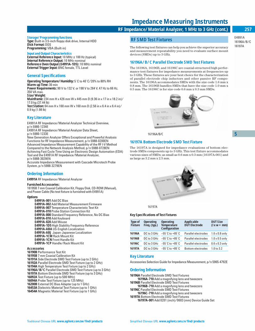
Traditional Chinese URL www.agilent.com.tw/find/products Simplified Chinese URL www.agilent.com.cn/find/products
5
E4991A16196A/B/C16197A
257RF Impedance/Material Analyzer, 1 MHz to 3 GHz (cont.)
Impedance Measuring Instruments
Storage/Programming functionsType: Built-in 3.5-inch floppy disk drive, Internal HDDDisk Format: DOSProgramming: VBA (Built-in)
Input and Output CharacteristicsExternal Reference Input: 10 MHz ± 100 Hz (typical)Internal Reference Output: 10 MHz nominalReference Oven Output (E4991A-1D5): 10 MHz nominalExternal Trigger Input: BNC female, TTL Level
General Specifications Operating Temperature/Humidity: 5˚C to 40˚C/20% to 80% RHWarm-up Time: 30 minPower Requirements: 90 V to 132 V, or 198 V to 264 V, 47 Hz to 66 Hz, 350 VA max.Size/Weight:Mainframe: 234 mm H x 426 mm W x 445 mm D (9.36 in x 17 in x 18.2 in)/17.0 kg (37.44 lb)Test Station: 64 mm H x 160 mm W x 160 mm D (2.56 in x 6.4 in x 6.4 in)/0.9 kg (1.98 lb)
Key LiteratureE4991A RF Impedance/Material Analyzer Technical Overview, p/n 5980-1234EE4991A RF Impedance/Material Analyzer Data Sheet, p/n 5980-1233ENew Generation Analyzer Offers Exceptional and Powerful Analysis Functions for RF Impedance Measurement, p/n 5988-0200ENAdvanced Impedance Measurement Capability of the RF I-V Method Compared to the Network Analysis Method, p/n 5988-0728ENAchieving Fast Cycle Time Using an Electronic Design Automation (EDA)Tool and the E4991A RF Impedance/Material Analyzer, p/n 5988-3029ENAccurate Impedance Measurement with Cascade Microtech Probe System, p/n 5988-3279EN
Ordering InformationE4991A RF Impedance/Material Analyzer
Furnished Accessories:16195B 7 mm Coaxial Calibration Kit, Floppy Disk, CD-ROM (Manual),and Power Cable (No test fixture is furnished with E4991A)
OptionsE4991A-001 Add DC BiasE4991A-002 Add Material Measurement FirmwareE4991A-007 Temperature Characteristic Test KitE4991A-010 Probe Station Connection KitE4991A-800 Standard Frequency Reference, No DC BiasE4991A-810 Add Keyboard E4991A-820 Add MouseE4991A-1D5 High Stability Frequency ReferenceE4991A-ABA US-English LocalizationE4991A-ABJ Japan-Japanese LocalizationE4991A-1CM Rack Mount KitE4991A-1CN Front Handle KitE4991A-1CP Handle/Rack Mount Kit
Accessories16190B Performance Test Kit16195B 7 mm Coaxial Calibration Kit16191A Side Electrode SMD Test Fixture (up to 2 GHz)16192A Parallel Electrode SMD Test Fixture (up to 2 GHz)16194A High Temperature Test Fixture (up to 2 GHz)16196A/B/C Parallel Electrode SMD Test Fixture (up to 3 GHz)16197A Bottom Electrode SMD Test Fixture (up to 3 GHz)16092A Test Fixture (up to 500 MHz)16094A Probe Test Fixture (up to 125 MHz)16200B External DC Bias Adapter (up to 1 GHz)16453A Dielectric Material Test Fixture (up to 1 GHz)16454A Magnetic Material Test Fixture (up to 1 GHz)
RF SMD Test Fixtures
The following test fixtures can help you achieve the superior accuracyand measurement repeatability you need to evaluate surface mountdevices (SMDs) up to 3 GHz.
16196A/B/C Parallel Electrode SMD Test FixturesThe 16196A, 16196B, and 16196C are coaxial-structured high perfor-mance test fixtures for impedance measurements at frequencies upto 3 GHz. These fixtures are your best choice for the characterizationof parallel electrode chip inductors and other passive RF compo-nents. The 16196A accommodates SMDs with the size code 1.6 mm x0.8 mm. The 16196B handles SMDs that have the size code 1.0 mm x0.5 mm. The 16196C is for size code 0.6 mm x 0.3 mm SMDs.
16196A/B/C
16197A Bottom Electrode SMD Test FixtureThe 16197A is designed for impedance evaluations of bottom elec-trode SMDs components up to 3 GHz. This test fixture accommodatesvarious sizes of SMDs; as small as 0.6 mm x 0.3 mm (16197A-001) andas large as 3.2 mm x 2.5 mm.
16197A
Key Specifications of Test Fixtures
Type of Operating Operating Applicable DUT SizeFixture Freq. (typ.) Temperature DUT Electrode (l x w = mm)
Configuration
16196A DC to 3 GHz –55˚C to +85˚C Parallel electrodes 1.6 x 0.8 only
16196B DC to 3 GHz –55˚C to +85˚C Parallel electrodes 1.0 x 0.5 only
16196C DC to 3 GHz –55˚C to +85˚C Parallel electrodes 0.6 x 0.3 only
16197A DC to 3 GHz –55˚C to +85˚C Bottom electrodes 1.0 to 3.2
Key LiteratureAccessories Selection Guide for Impedance Measurement, p/n 5965-4792E
Ordering Information16196A Parallel Electrode SMD Test Fixtures
16196A-710 Add a magnifying lens and tweezers16196B Parallel Electrode SMD Test Fixtures
16196B-710 Add a magnifying lens and tweezers16196C Parallel Electrode SMD Test Fixtures
16196C-710 Add a magnifying lens and tweezers16197A Bottom Electrode SMD Test Fixtures
16197A-001 Add 0201 (inch)/0603 (mm) Device Guide Set
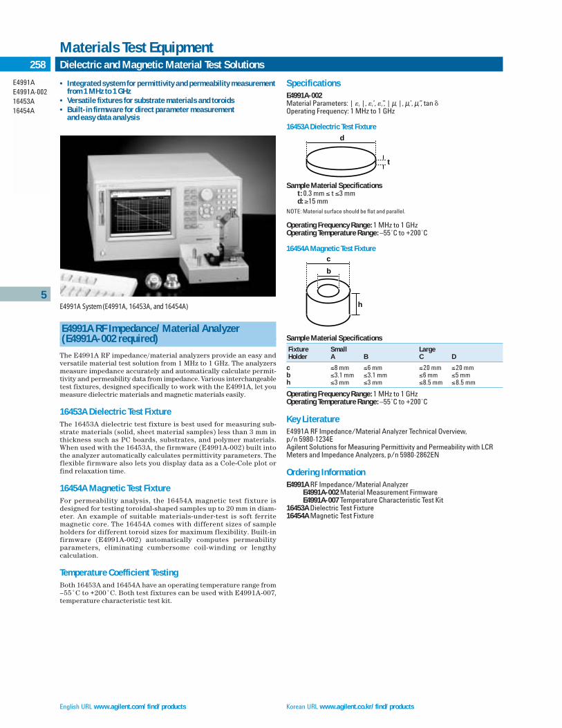
English URL www.agilent.com/find/products Korean URL www.agilent.co.kr/find/products
5
E4991AE4991A-00216453A16454A
258 Dielectric and Magnetic Material Test Solutions
Materials Test Equipment
Sample Material Specifications
Fixture Small LargeHolder A B C D
c ≤8 mm ≤6 mm ≤20 mm ≤20 mmb ≤3.1 mm ≤3.1 mm ≤6 mm ≤5 mmh ≤3 mm ≤3 mm ≤8.5 mm ≤8.5 mm
Operating Frequency Range: 1 MHz to 1 GHzOperating Temperature Range: –55˚C to +200˚C
Key LiteratureE4991A RF Impedance/Material Analyzer Technical Overview, p/n 5980-1234EAgilent Solutions for Measuring Permittivity and Permeability with LCR Meters and Impedance Analyzers, p/n 5980-2862EN
Ordering InformationE4991A RF Impedance/Material Analyzer
E4991A-002 Material Measurement FirmwareE4991A-007 Temperature Characteristic Test Kit
16453A Dielectric Test Fixture 16454A Magnetic Test Fixture
• Integrated system for permittivity and permeability measurementfrom 1 MHz to 1 GHz
• Versatile fixtures for substrate materials and toroids • Built-in firmware for direct parameter measurement
and easy data analysis
E4991A System (E4991A, 16453A, and 16454A)
E4991A RF Impedance/Material Analyzer(E4991A-002 required)
The E4991A RF impedance/material analyzers provide an easy andversatile material test solution from 1 MHz to 1 GHz. The analyzersmeasure impedance accurately and automatically calculate permit-tivity and permeability data from impedance. Various interchangeabletest fixtures, designed specifically to work with the E4991A, let youmeasure dielectric materials and magnetic materials easily.
16453A Dielectric Test FixtureThe 16453A dielectric test fixture is best used for measuring sub-strate materials (solid, sheet material samples) less than 3 mm inthickness such as PC boards, substrates, and polymer materials.When used with the 16453A, the firmware (E4991A-002) built intothe analyzer automatically calculates permittivity parameters. Theflexible firmware also lets you display data as a Cole-Cole plot orfind relaxation time.
16454A Magnetic Test Fixture For permeability analysis, the 16454A magnetic test fixture isdesigned for testing toroidal-shaped samples up to 20 mm in diam-eter. An example of suitable materials-under-test is soft ferritemagnetic core. The 16454A comes with different sizes of sampleholders for different toroid sizes for maximum flexibility. Built-infirmware (E4991A-002) automatically computes permeabilityparameters, eliminating cumbersome coil-winding or lengthy calculation.
Temperature Coefficient TestingBoth 16453A and 16454A have an operating temperature range from–55˚C to +200˚C. Both test fixtures can be used with E4991A-007,temperature characteristic test kit.
SpecificationsE4991A-002Material Parameters: | r |, r’, r”, | µr |, µr’, µr”, tan Operating Frequency: 1 MHz to 1 GHz
16453A Dielectric Test Fixture
Sample Material Specificationst: 0.3 mm ≤ t ≤3 mmd: ≥15 mm
NOTE: Material surface should be flat and parallel.
Operating Frequency Range: 1 MHz to 1 GHzOperating Temperature Range: –55˚C to +200˚C
16454A Magnetic Test Fixture
d
t
h
c
b
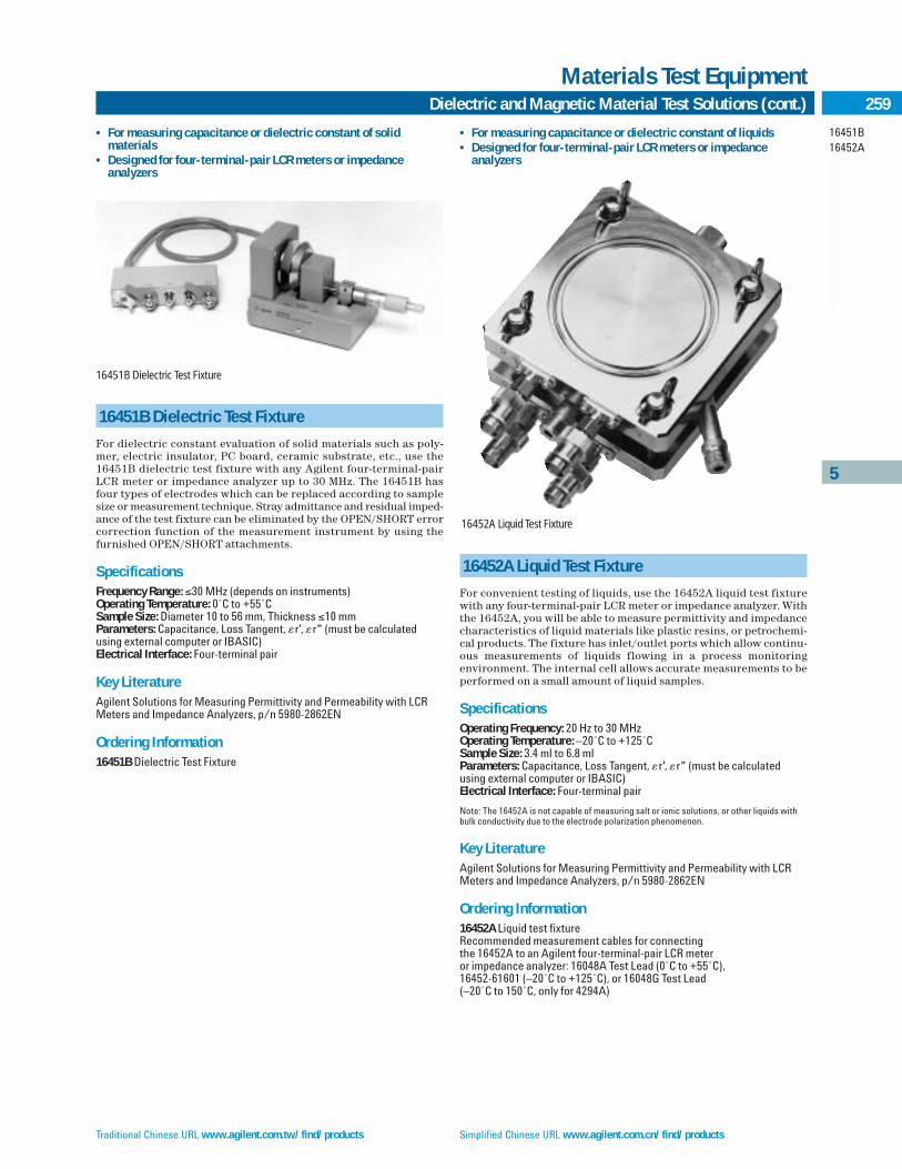
Traditional Chinese URL www.agilent.com.tw/find/products Simplified Chinese URL www.agilent.com.cn/find/products
5
16451B16452A
259Dielectric and Magnetic Material Test Solutions (cont.)
Materials Test Equipment
16452A Liquid Test Fixture
For convenient testing of liquids, use the 16452A liquid test fixturewith any four-terminal-pair LCR meter or impedance analyzer. Withthe 16452A, you will be able to measure permittivity and impedancecharacteristics of liquid materials like plastic resins, or petrochemi-cal products. The fixture has inlet/outlet ports which allow continu-ous measurements of liquids flowing in a process monitoringenvironment. The internal cell allows accurate measurements to beperformed on a small amount of liquid samples.
SpecificationsOperating Frequency: 20 Hz to 30 MHzOperating Temperature: –20˚C to +125˚CSample Size: 3.4 ml to 6.8 mlParameters: Capacitance, Loss Tangent, r', r" (must be calculatedusing external computer or IBASIC)Electrical Interface: Four-terminal pair
Note: The 16452A is not capable of measuring salt or ionic solutions, or other liquids withbulk conductivity due to the electrode polarization phenomenon.
Key LiteratureAgilent Solutions for Measuring Permittivity and Permeability with LCR Meters and Impedance Analyzers, p/n 5980-2862EN
Ordering Information 16452A Liquid test fixture Recommended measurement cables for connecting the 16452A to an Agilent four-terminal-pair LCR meter or impedance analyzer: 16048A Test Lead (0˚C to +55˚C), 16452-61601 (–20˚C to +125˚C), or 16048G Test Lead (–20˚C to 150˚C, only for 4294A)
16451B Dielectric Test Fixture
For dielectric constant evaluation of solid materials such as poly-mer, electric insulator, PC board, ceramic substrate, etc., use the16451B dielectric test fixture with any Agilent four-terminal-pairLCR meter or impedance analyzer up to 30 MHz. The 16451B hasfour types of electrodes which can be replaced according to samplesize or measurement technique. Stray admittance and residual imped-ance of the test fixture can be eliminated by the OPEN/SHORT errorcorrection function of the measurement instrument by using the furnished OPEN/SHORT attachments.
SpecificationsFrequency Range: ≤30 MHz (depends on instruments)Operating Temperature: 0˚C to +55˚CSample Size: Diameter 10 to 56 mm, Thickness ≤10 mmParameters: Capacitance, Loss Tangent, r', r" (must be calculatedusing external computer or IBASIC)Electrical Interface: Four-terminal pair
Key LiteratureAgilent Solutions for Measuring Permittivity and Permeability with LCR Meters and Impedance Analyzers, p/n 5980-2862EN
Ordering Information16451B Dielectric Test Fixture
• For measuring capacitance or dielectric constant of liquids • Designed for four-terminal-pair LCR meters or impedance
analyzers
• For measuring capacitance or dielectric constant of solid materials
• Designed for four-terminal-pair LCR meters or impedance analyzers
16451B Dielectric Test Fixture
16452A Liquid Test Fixture

English URL www.agilent.com/find/products Korean URL www.agilent.co.kr/find/products
5
4294A
260 Precision Impedance Analyzer
Impedance Measuring Instruments
• Accurate measurement over wide impedance range andwide frequency range
• Basic impedance accuracy: ±0.08%• 40 Hz to 110 MHz, 3 mΩ to 500 MΩ• Powerful impedance analysis function• Ease of use and versatile PC connectivity
4294A
4294A Precision Impedance Analyzer
The Agilent 4294A precision impedance analyzer is an integratedsolution for efficient impedance measurement and analysis of com-ponents and circuits. The 4294A covers a broader test-frequencyrange (40 Hz to 110 MHz) with Basic impedance accuracy: ±0.08%.Excellent High Q/Low D accuracy enables analysis of low-loss compo-nents. The wide signal-level ranges enable device evaluation underactual operating conditions. The test signal level range is 5 mV to 1 Vrms or 200 µA to 20 mArms, and the DC bias range is 0 V to ±40 Vor 0 mA to ±100 mA. Advanced calibration and error compensationfunctions eliminate measurement error factors when performingmeasurements on in-fixture devices. The 4294A is a powerful toolfor design, qualification and quality control, and production testingof electronic components. Circuit designers and developers can alsobenefit from the performance/functionality offered.
Wide-Range Accurate MeasurementThe 4294A enables impedance measurement using the auto-balancingbridge technique over the frequency range 40 Hz to 110 MHz. The basicimpedance accuracy is ±0.08%, and the typical Q accuracy is ±3% @Q = 100, ≤10 MHz. This advantage permits accurate evaluations ofimpedance characteristics for a wide variety of electronic devices as wellas electronic and non-electronic material within a wide frequency range.
Versatile AnalysisThe 4294A graphically displays impedance measurement results.This permits easy analysis of the resonant frequency and impedancevalues of electronic components using the marker functions. Themarker functions offer a simple method to pinpoint the resonant frequency of components, as well, these functions assist users inmany other observations. The combination of the accumulate mode(to superimpose traces) and the list sweep functions permits obser-vation of the change in a DUT’s characteristics due to a change in themeasurement condition. Versatile and high-speed automatic testingis possible using the list sweep function in conjunction with the limitline function. The list-sweep function provides the ability to enhancetest throughput by segmenting the sweep to include only necessarymeasurement frequencies, while the limit-line function (for Go/No-Go Testing) provides the ability to apply test limits within eachsegment. These functions greatly support the quality and performancerequired evaluating modern and improved electronic components,equipment and materials.
Equivalent Circuit AnalysisThe equivalent-circuit analysis function provides advanced model-ing (three and four element models) based on circuit constant valuesof five available circuit models. This function simulates the frequen-cy characteristics of components by using derived circuit values oruser-specified values. Comparison of design values to measurementvalues can assist with efficient component design.
ProgrammingFull programmability is provided using built-in Instrument (IBASIC).Desired measurements and computations, including graphicsanalysis, can be programmed simply by storing front-panel key-stroke operations. The one-key execution function allows easy selec-tion and execution of customized IBASIC programs. Several forms of storage are built-in (10 Mbyte no-volatile memory, RAM disk orFloppy Disk).
Good PC ConnectivityFeatures fit to the latest PC environment include LAN (Local AreaNetwork) capability, VGA monitor output, and the TIFF file format.LAN capability permits simplified networking ability when collecting,sharing and analyzing data. VGA monitor output improves produc-tivity and reduces eyestrain. TIFF file format allows easy transfer ofgraphics to a PC.
Abundance of AccessoriesVarious Four-terminal-pair test fixtures can be used with the4294A. The 42941A impedance probe kit (1.5 m), which covers 40 Hz to 110 MHz, enables in-circuit impedance measurement ofelectronic circuits or components. Grounded devices can also bemeasured. The 42942A terminal adapter, which covers 40 Hz to110 MHz, converts the 4-terminal-pair port configuration to a 7 mm test port. This adapter permits the use of familiar 7 mm testfixtures. Again, grounded measurement is available.
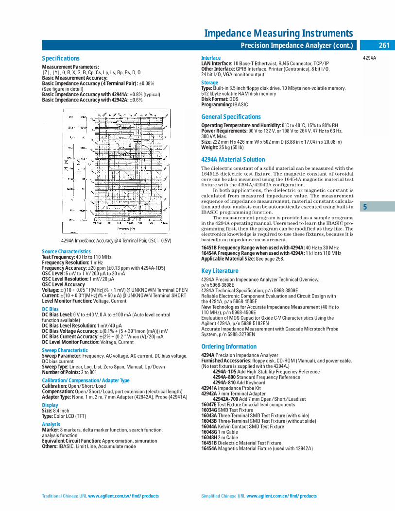
Traditional Chinese URL www.agilent.com.tw/find/products Simplified Chinese URL www.agilent.com.cn/find/products
5
4294A
261Precision Impedance Analyzer (cont.)
Impedance Measuring Instruments
SpecificationsMeasurement Parameters:|Z|, |Y|, , R, X, G, B, Cp, Cs, Lp, Ls, Rp, Rs, D, QBasic Measurement Accuracy:Basic Impedance Accuracy (4 Terminal Pair): ±0.08% (See figure in detail)Basic Impedance Accuracy with 42941A: ±0.8% (typical)Basic Impedance Accuracy with 42942A: ±0.6%
4294A Impedance Accuracy @ 4-Terminal-Pair, OSC = 0.5V)
Source CharacteristicsTest Frequency: 40 Hz to 110 MHzFrequency Resolution: 1 mHzFrequency Accuracy: ±20 ppm (±0.13 ppm with 4294A-1D5)OSC Level: 5 mV to 1 V/200 µA to 20 mAOSC Level Resolution: 1 mV/20 µAOSC Level AccuracyVoltage: ±((10 + 0.05 * f(MHz))% + 1 mV) @ UNKNOWN Terminal OPENCurrent: ±(10 + 0.3*f(MHz))% + 50 µA) @ UNKNOWN Terminal SHORTLevel Monitor Function: Voltage, Current
DC BiasDC Bias Level: 0 V to ±40 V, 0 A to ±100 mA (Auto level control function available)DC Bias Level Resolution: 1 mV/40 µADC Bias Voltage Accuracy: ±(0.1% + (5 + 30*Imon (mA))) mVDC Bias Current Accuracy: ±(2% + (0.2 * Vmon (V)/20) mA DC Level Monitor Function: Voltage, Current
Sweep CharacteristicSweep Parameter: Frequency, AC voltage, AC current, DC bias voltage,DC bias currentSweep Type: Linear, Log, List, Zero Span, Manual, Up/DownNumber of Points: 2 to 801
Calibration/Compensation/Adapter TypeCalibration: Open/Short/LoadCompensation: Open/Short/Load, port extension (electrical length)Adapter Type: None, 1 m, 2 m, 7 mm Adapter (42942A), Probe (42941A)
DisplaySize: 8.4 inch Type: Color LCD (TFT)
AnalysisMarker: 8 markers, delta marker function, search function, analysis functionEquivalent Circuit Function: Approximation, simurationOthers: IBASIC, Limit Line, Accumulate mode
InterfaceLAN Interface: 10 Base-T Ethertwist, RJ45 Connector, TCP/IPOther Interface: GPIB Interface, Printer (Centronics), 8 bit I/O, 24 bit I/O, VGA monitor output
StorageType: Built-in 3.5 inch floppy disk drive, 10 Mbyte non-volatile memory,512 kbyte volatile RAM disk memoryDisk Format: DOSProgramming: IBASIC
General SpecificationsOperating Temperature and Humidity: 0˚C to 40˚C, 15% to 80% RHPower Requirements: 90 V to 132 V, or 198 V to 264 V, 47 Hz to 63 Hz, 300 VA Max.Size: 222 mm H x 426 mm W x 502 mm D (8.88 in x 17.04 in x 20.08 in)Weight: 25 kg (55 lb)
4294A Material SolutionThe dielectric constant of a solid material can be measured with the16451B dielectric test fixture. The magnetic constant of toroidalcore can be also measured using the 16454A magnetic material test fixture with the 4294A/42942A configuration.
In both applications, the dielectric or magnetic constant iscalculated from measured impedance value. The measurementsequence of impedance measurement, material constant calcula-tion and data analysis can be automatically executed using built-inIBASIC programming function.
The measurement program is provided as a sample programsin the 4294A operating manual. Users need to learn the IBASIC pro-gramming first, then the program can be modified as they like. Theelectronics knowledge is required to use these fixtures, because it isbasically an impedance measurement.
16451B Frequency Range when used with 4294A: 40 Hz to 30 MHz16454A Frequency Range when used with 4294A: 1 kHz to 110 MHzApplicable Material Size: See page 258.
Key Literature4294A Precision Impedance Analyzer Technical Overview, p/n 5968-3808E4294A Technical Specification, p/n 5968-3809EReliable Electronic Component Evaluation and Circuit Design with the 4294A, p/n 5968-4505ENew Technologies for Accurate Impedance Measurement (40 Hz to 110 MHz), p/n 5968-4506EEvaluation of MOS Capacitor Oxide C-V Characteristics Using the Agilent 4294A, p/n 5988-5102ENAccurate Impedance Measurement with Cascade Microtech Probe System, p/n 5988-3279EN
Ordering Information4294A Precision Impedance AnalyzerFurnished Accessories: floppy disk, CD-ROM (Manual), and power cable. (No test fixture is supplied with the 4294A.)
4294A-1D5 Add High-Stability Frequency Reference4294A-800 Standard Frequency Reference4294A-810 Add Keyboard
42941A Impedance Probe Kit42942A 7 mm Terminal Adapter
42942A-700 Add 7 mm Open/Short/Load set16047E Test Fixture for axial lead components16034G SMD Test Fixture16043A Three-Terminal SMD Test Fixture (with slide)16043B Three-Terminal SMD Test Fixture (without slide)16044A Kelvin Contact SMD Test Fixture16048G 1 m Cable16048H 2 m Cable16451B Dielectric Material Test Fixture16454A Magnetic Material Fixture (used with 42942A)
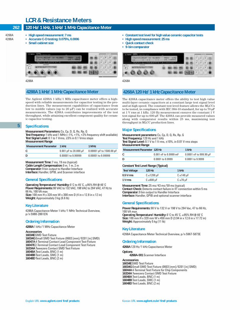
English URL www.agilent.com/find/products Korean URL www.agilent.co.kr/find/products
5
4268A4288A
262 120 Hz/1 kHz, 1 kHz/1 MHz Capacitance Meter
LCR & Resistance Meters
4288A 1 kHz/1 MHz Capacitance Meter
The Agilent 4288A 1 kHz/1 MHz capacitance meter offers a high-speed with reliable measurements for capacitor testing in the pro-duction lines. The measurement capabilities of capacitance fromlow to middle values (up to 20 µF) can be realized with accuratemeasurements. The 4288A contributes improvements of the testthroughput, while attaining excellent component quality for ceram-ic capacitor testing.
SpecificationsMeasurement Parameters: Cs, Cp, D, Q, Rs, Rp, GTest Frequency: 1 kHz and 1 MHz (–1%, +1%, +2% frequency shift available)Test Signal Level: 0.1 to 1 Vrms, ±5% in 0.1 Vrms stepsMeasurement Range
Measurement Parameter 1 kHz 1 MHz
C 0.001 pF to 20.000 µF 0.00001 pF to 1500.00 pF
D 0.00001 to 9.99999 0.00001 to 9.99999
Measurement Time: 7 ms, 19 ms (typical)Cable Length Compensation: 0 m, 1 m, 2 mComparator: 9 bin output to Handler InterfaceInterface: Handler, GPIB, and Scanner interface
General SpecificationsOperating Temperature/Humidity: 0˚C to 45˚C, ≤95% RH @ 40˚CPower Requirements: 90 VAC to 132 VAC, 198 VAC to 264 VAC, 47 Hz to 66 Hz, 100 VA max.Size: 100 mm H x 320 mm W x 300 mm D (4 in x 12.8 in x 12 in)Weight: Approximately 3 kg (6.6 lb)
Key Literature4288A Capacitance Meter 1 kHz/1 MHz Technical Overview, p/n 5980-2861EN
Ordering Information4288A 1 kHz/1 MHz Capacitance Meter
Accessories16034E SMD Test Fixture16034G Small SMD Test Fixture (0603 [mm]/0201 [in] SMD)16047A 4-Terminal Contact Lead Component Test Fixture16047E 2-Terminal Contact Lead Component Test Fixture16334A Tweezers Contact SMD Test Fixture16048A Test Leads, BNC (1 m)16048B Test Leads, SMC (1 m)16048D Test Leads, BNC (2 m)
4268A 120 Hz/1 kHz Capacitance Meter
The 4268A capacitance meter offers the ability to test high valuemulti-layer ceramic capacitors at a constant large test signal leveland at high speed. The constant test level feature allows the MLCCsto be tested, in compliance with IEC 384-10 standard, for up to 70 µFat 1 V rms at 1 kHz. 120 Hz measurement ensures the constant 1 Vtest signal for up to 600 µF. The 4268A can provide measured valuesalong with comparator results within 25 ms, maximizing testthroughput in MLCC production lines.
Major SpecificationsMeasurement parameters: Cs, Cp, D, Q, Rs, Rp, GTest Frequency: 120 Hz and 1 kHzTest Signal Level: 0.1 V to 1 V rms, ±10%, in 0.01 V rms stepsMeasurement Range
Measurement Parameter 120 Hz 1 kHz
C 0.001 nF to 9.9999 mF 0.0001 nF to 999.99 µF
D 0.0001 to 9.9999 0.0001 to 9.9999
Constant Test Level Range (Typical)
Test Voltage 120 Hz 1 kHz
0.5 V rms C ≤1200 µF C ≤140 µF
1 V rms C ≤600 µF C ≤70 µF
Measurement Time: 25 ms/43 ms/59 ms (typical)Contact Check: Detects contact failure in 4T connection within 5 msComparator: 9 bin output to Handler InterfaceInterface: Handler, GPIB and optional scanner interface
General SpecificationsPower Requirements: 90 V to 132 V or 198 V to 264 Vac, 47 to 66 Hz,100 VA max.Operating Temperature/Humidity: 0˚C to 45˚C, ≤95% RH @ 40˚CSize: 100 mm H x 320 mm W x 450 mm D (3.94 in x 12.6 in x 17.72 in)Weight: Approximately 5 kg (11 lb)
Key Literature4268A Capacitance Meter Technical Overview, p/n 5967-5873E
Ordering Information4268A 120 Hz/1 kHz Capacitance Meter
Options4268A-001 Scanner Interface
Accessories16034E SMD Test Fixture16034G Small SMD Test Fixture (0603 [mm]/0201 [in] SMD)16044A 4-Terminal Test Fixture for Chip Components16334A Tweezers Contact SMD Test Fixture16048A Test Leads, BNC (1 m)16048B Test Leads, SMC (1 m)16048D Test Leads, BNC (2 m)
• High speed measurement: 7 ms• Accurate C-D testing: 0.075%, 0.0006• Small cabinet size
• Constant test level for high value ceramic capacitor tests• High speed measurement: 25 ms • Quick contact check• 9-bin comparator
4288A 4268A

Traditional Chinese URL www.agilent.com.tw/find/products Simplified Chinese URL www.agilent.com.cn/find/products
5
4287A
263RF LCR Meter 1 MHz to 3 GHz
LCR & Resistance Meters
4287A RF LCR Meter
The Agilent 4287A RF LCR meter offers accurate, reliable and fastmeasurements from 1 MHz to 3 GHz to improve quality and through-put of electronic component testing in production lines. The 4287Aemploys the direct-current voltage-measurement technique, asopposed to the reflection-measurement technique, which yieldsaccurate measurements over a wide impedance range.
High Throughput and Reliable MeasurementThe 4287A is suitable for testing electronic components in the RF range. The 4287A’s measurement speed is remarkably fast. Inaddition, the superior measurement repeatability at low test cur-rents such as 100 µA provides a fast throughput since less averagingis required.
Simplified System IntegrationThe test head cable (1 m or 2 m by using an extension cable) can beeasily connected closely to the tip of the device-under-test (of thecomponent handler) without any increase in error. The built-in com-parator function, a high-speed GPIB interface, and an handler inter-face, are available for simple integration with the component handlerand PC. The enhanced comparator function makes sophisticated binning possible for multi-frequency or array chip testing.
Ease of UseThe 8.4-inch color display provides a clear view of measurement set-tings and results. The newly developed user interface makes oper-ability easy and error-free. The built-in statistical analysis functionsprovide a process for monitoring test quality and efficiency. TheLAN interface helps centralize production control and monitor.Also, a number of 7 mm SMD test fixtures can be used with the4287A’s furnished fixture stand and 3.5 mm-to-7 mm adapter, eliminating the need to build custom fixtures.
Specifications(Refer to Data Sheet for complete specifications)Measurement Parameters: |Z|, |Y|, -z (deg/rad), -y (deg/rad), G, B,Ls, Lp, Cs, Cp, Rs, Rp, Q, D (Four Meas.Parameters can be displayed at thesame time.)Test Frequency: 1 MHz to 3 GHzFrequency Resolution: 100 kHzTest Signal:• V: 4.47 mV to 502 mV @ f ≤1 GHz, 4.47 mV to 447 mV @ f >1 GHz• I: 0.0894 mA to 10 mA @ f ≤1 GHz, 0.0894 mA to 8.94 mA @ f >1 GHzLevel Monition Function: Voltage, CurrentBasic Z Accuracy: ±1.0%Measurement Range: 200 mΩ to 3 kΩ (@ 1 MHz, accuracy ≤10%)Measurement Time: 9 msec per point (max.speed)Rdc Measurement: Available for contact checkCalibration: Open/Short/Load/Low Loss CapacitorCompensation: Open/Short, Electrical LengthMass Storage Function: 30 MB solid-state mass-storage or 2 GB HDD(Option Selection)Interface: GPIB, LAN (10 Base-T/100 Base-Tx Automatic Selection),Handler InterfaceDisplay: 8.4 inch color LCD display
General SpecificationsPower Requirements: 90 V to 132 V, or 198 V to 264 V, 47 Hz to 63 Hz, 350 VA max.Operating Temperature/Humidity: 5˚C to 40˚C/20% RH to 80% RHSize: 234 mm H x 425 mm W x 445 mm D (9.36 in x 17 in x 17.8 in) (Main Frame)Weight: 16 kg/0.3 kg (35.2 lb/.66 lb) (typical) (Main Frame/Test Head)
Key Literature4287A RF LCR Meter Technical Overview, p/n 5968-5443E4287A Technical Specifications, p/n 5968-5758ELCR Meters, Impedance Analyzers, and Test Fixtures Selection Guide, p/n 5952-1430E
Ordering Information4287A RF LCR MeterFurnished Accessories: Test Head (1 m), CD-ROM (Manual), and PowerCable. (No test fixture is supplied with the 4287A)
Options4287A-004 Add Working Standard Set4287A-010 Hard-Disk Drive Mass Storage4287A-011 Solid-State Mass Storage4287A-020 Add Test Fixture Extension Cable Set4287A-700 16195B Calibration Kit4287A-710 Test Fixture Stand
Accessories16190B Performance Test Kit16195B 7 mm Coaxial Calibration Kit16191A Side Electrode SMD Test Fixture (up to 2 GHz)16192A Parallel Electrode SMD Test Fixture (up to 2 GHz)16194A High Temperature Test Fixture (up to 2 GHz)16092A Test Fixture (up to 500 MHz)16094A Probe Test Fixture (up to 125 MHz)16200B External DC Bias Adapter (up to 1 GHz)
4287A with the 16196A
• 1 MHz to 3 GHz, with 100 kHz steps• Wide impedance measurement range from 200 mΩ to 3 kΩ• Superior measurement repeatability at low test signal level• 1% basic accuracy• High-speed measurements: 9 ms

5
4263B
264 LCR Meter
LCR & Resistance Meters
4263B
4263B LCR Meter
The 4263B LCR meter is Agilent Technologies’ most cost-effectivelow-end LCR meter, designed for both component evaluation on theproduction line and fundamental impedance testing for bench-topapplications. The 4263B has five test frequencies that allow you tosimulate testing under the correct conditions: 100 Hz, 120 Hz, 1 kHz,10 kHz, and 100 kHz. An optional 20 kHz test frequency can beadded to those five frequencies (4263B-002).
High-Speed MeasurementsThe 4263B can boost throughput with a measurement speed of 25 msat any test frequency. This ability improves the throughput of elec-trolytic capacitor and transformer testing. The 4263B can check thecontact condition between the test terminals and the device-under-test (DUT). This function ensures the reliability of PASS/FAIL testingwith automatic handlers in production. The quick recovery system ofthe 4263B improves throughput. Normal operation is resumed theinstant a faulty DUT is removed from the handler, so the handler canalways be operated at its full speed.
Electrolytic Capacitor MeasurementsThe 4263B’s accuracy and wide measurement range are the righttools to make precise measurements of electrolytic capacitors.Charged capacitors can discharge through the front end and destroyan instrument. The 4263B’s front end is designed for protection andmaintains test integrity.
Transformer Parameter MeasurementsWith the 4263B’s ability to make turns ratio (N), mutual inductance(M), and dc resistance (DCR) measurements, data calculations andchanging test setups are no longer time-consuming tasks (4263B-001).The flexible signal level setting and the voltage-and-current monitorfunction facilitate the use of the 4263B for level dependent DUTs, suchas core inductors.
Specifications (Refer to Technical Overview for complete specifications.)Measurement Functions• Measurement Parameters: |Z|, |Y|, u, R, X, G, B, L, C, Q, D, ESR
– 4263B-001: Add DCR (dc resistance), N (turns ratio), and M (mutual inductance) measurement
• Measurement Circuit Mode: Series and parallelMathematical Functions: Deviation and percent deviationTest Cable Lengths: 0 m, 1 m, 2 m, 4 m (freq. = 100/120/1 kHz); 0 m,1 m, 2 m (freq. = 10 k/20 kHz); 0 m, 1 m (freq. = 100 kHz)Test Signal Information• Test Frequency: 100 Hz, 120 Hz, 1 kHz, 10 kHz, and 100 kHz
– 4263B-002: Add 20 kHz test frequency• Frequency Accuracy: ±0.01% (freq. = 100 Hz, 1 kHz, 10 kHz,
(20 kHz, 100 kHz), ±1% (freq. = 120 Hz)• Output Impedance: 100 Ω ±10%, 25 Ω ±10% (≤1 Ω range)• AC Test Signal Level: 20 mV to 1 Vrms in 5 mVrms steps• Accuracy: ±(10% + 10 mV)• Internal dc Bias
– Level: 1.5 and 2 V; Accuracy: ±(5% + 2 mV)• External dc Bias: 0 V to +2.5 V
Measurement Range
Parameter Measurement Range
Z , R, X 1 mΩ to 100 MΩY , G, B 10 nS to 1000 SC 1 pF to 1 FL 10 nH to 100 kHD 0.0001 to 9.9999Q 0.1 to 9999.9 –180˚ to +180˚DCR 1 mΩ to 100 MΩN 0.9 to 200 (unspecified)L, M 1 µH to 100 H (unspecified)% –999.99% to +999.99%
Measurement Accuracy: ±0.1% (basic) (for Z, R, X, Y, G, B,C, L)Measurement Time
Mode Time (typical)
SHORT 25 msMEDIUM 65 msLONG 500 ms
Test Signal Level Monitor: Voltage and currentFront-End Protection: Internal circuit protection when a charged capacitoris connected to the input terminals. The maximum capacitor voltage is:Vmax = √(8/C) (typical) @ Vmax ≤250 V; Vmax = √(2/C) (typical) @ Vmax ≤1000 V, C is in FaradsDisplay Digits: 3, 4, or 5 (selectable)Correction Function• PEN/SHORT/LOAD: Eliminates measurement errors due to stray
parasitic impedances in the test fixturesComparator Function: HIGH/IN/LOW for each primary measurementparameter and secondary measurement parameterContact Check Function: Contact failure between the test fixture anddevice can be detected. Additional time for contact check: 5 msOther Functions• Save/Recall: Ten instrument setups can be saved/recalled from
the internal nonvolatile memory• Continuous Memory Capability: If the instrument is turned off,
or if a power failure occurs, instrument settings (except dc bias on/off) are automatically memorized (≤72 hours at 23˚C ± 5˚C)
• GPIB Interface: All control settings, measured values, and comparator information
• Handler Interface: All output signals are negative-logic, optically isolated open collectors. Output signals include HIGH/IN/LOW, no contact, index, end of measurement, and alarm. Input signals include keylock and external trigger
General SpecificationsPower Requirements: 90 to 132 V or 198 to 264 V, 47 to 66 Hz, 45 VA max.Operating Temperature: 0˚C to 45˚CSize: 100 mm H x 320 mm W x 300 mm D (3.94 in x 12.6 in x 11.81 in)Weight: 4.5 kg (9.9 lb)
Key Literature 4263B LCR Meter Technical Overview, p/n 5964-6181EEffective Electrolytic Capacitors Testing, p/n 5967-5378EEffective Transformer/LF Coil Testing, p/n 5967-5377EEffective Multi-tap Transformer Measurement using a Scanner and theAgilent 4263B LCR Meter, p/n 5091-6310E
Ordering Information4263B LCR Meter
Options4263B-001 Add Transformer Parameter Measurement Function4263B-002 Add 20 kHz Test Frequency 4263B-ABA US-English Localization4263B-ABJ Japan-Japanese Localization
Accessories16060A Transformer Test Fixture (4263B-001 Required)16065C External Bias Adapter (up to 40 Vdc)16034G Small SMD Test Fixture (0603 [mm]/0201 [in] SMD)16044A Kelvin Contact SMD Test Fixture16047A 4-Terminal Contact Lead Component Test Fixture16047E 2-Terminal Contact Lead Component Test Fixture16334A Tweezers Contact SMD Test Fixture16064B Comparator LED Display/Trigger Box
• 0.1% basic accuracy • 100 Hz, 120 Hz, 1 kHz, 10 kHz, 100 kHz test frequencies • 20 mV to 1 Vrms in 5 mVrms steps• Test signal level monitor function• High-speed measurement: 25 ms• High-speed contact check• Wide capacitance test range• Transformer parameter measurements (optional)

Traditional Chinese URL www.agilent.com.tw/find/products Simplified Chinese URL www.agilent.com.cn/find/products
5
4339B
265High-Resistance Meter
LCR & Resistance Meters
4339B High-Resistance Meter
The 4339B high-resistance meter is Agilent Technologies’ most ad-vanced tool for making precision high-resistance measurements.
Precise and Stable MeasurementThe measurement range is from 1 x 10 3 Ω to 1.6 x 10 16 Ω, with a basicaccuracy of 0.6%. This wide range allows accurate, high-resistancemeasurement of capacitors, relays, switches, connectors, materials,cables, and PC boards. The grounded device-under-test (DUT) mea-surement capability of the 4339B gives you the ability to evaluatecables and transformers under grounded conditions. The 16008Bresistivity cell and the 16339A component test fixture are designed forstable and safe measurements of materials or components.
Simple OperationThe test-sequence program function allows you to control a series ofresistance measurements in a sequence (charge-measure-discharge).You can set the charge time, measurement interval time, and number ofmeasurements in a sequence through the front panel. The remainingtime can be displayed when executing the sequence measurements.Surface resistivity (s) and volume resistivity (v) functions can becalled to act upon measurement data. Calculated results are then auto-matically displayed, saving you time and effort.
High-Test ThroughputThe 10 ms measurement time, 2 ms high-speed contact check func-tion, built-in comparator, and GPIB/handler interfaces deliver high-speed test throughput for production environments.
Specifications (Refer to Technical Overview for complete specifications.)Measurement Parameters: R (dc resistance), I (dc current), s (surface resistivity), v (volume resistivity)Mathematical Functions: Deviation and percent deviationDisplay Digits: 3, 4, or 5 (selectable)Test Voltage: 0.1 Vdc to 1000 Vdc, 0.1 V steps @ 0.1 V to 200 V, 1 V steps @ 200 V to 1000 VVoltage Accuracy: (0.16% + 100 mV) @ ≤200 V,(0.16% + 500 mV) @ >200 VMaximum Current: 10 mA @ ≤100 V, 5 mA @ ≤250 V,2 mA @ ≤500 V, 1 mA @ ≤1 kVCurrent Compliance Setting: 0.5 mA, 1 mA, 2 mA, 5 mA, 10 mAOutput Resistance: 1 kΩ ± 10%Input Resistance: 1 kΩ ± 10%Test Cable Lengths: 2 m maximum
Measurement Range/Accuracy
Parameter Measurement Range Basic Accuracy
I 60 fA to 100 µA ±0.4%R (Ω) 1 x 10 3 Ω to 1.6 x 10 16 ±0.6%
Measurement Time: Time interval from a trigger command to the end of measurement (EOM) signal output at the handler interface port (range:hold, display, off)
Mode Time (typical)
SHORT 10 msMEDIUM 30 msLONG 390 ms
Correction Function• Zero OPEN: Eliminates measurement errors due to stray parasitic
resistance in the test fixturesTest Sequence Program: Controls a series of resistance measurements. Charge time, measurement internal time, and measurement number canbe programmedComparator Function: HIGH/IN/LOW for the measurement parameterContact Check FunctionContact failure between the test fixture and device can be detected• Available DUT Type: Capacitive DUTs only
– DUT Capacitance: ≥1 pF + 5% of residual stray capacitance– Residual Stray Capacitance of the Fixture: ≤50 pF
• Additional Measurement Time for Contact Check: 2 msOther Functions• Save/Recall: Ten instrument setups can be saved/recalled from
the internal nonvolatile memory• Continuous Memory Capability: If the instrument is turned off, or
if a power failure occurs, instrument settings are automatically memorized (≤72 hours at 23˚C ± 5˚C)
• GPIB Interface: All control settings, measured values, and comparator information
• Handler Interface: All output signals are negative-logic, optically isolated open collectors. Output signals include: HIGH/IN/LOW, no contact, index, end of measurement, and alarm. Input signals include: high voltage off, keylock, and external trigger
General SpecificationsPower Requirements: 90 V to 132 V or 198 V to 264 V, 47 Hz to 66 Hz, 45 VA max.Operating Temperature: 0˚C to 45˚CSize: 100 mm H x 320 mm W x 450 mm D (3.94 in x 12.6 in x 17.72 in)Weight: 6.5 kg (14.3 lb)Complies with 73/23/EEC and 92/68/EEC safety standard EN61010-1
Furnished AccessoriesOperation manual, shunt connector, power cable (test fixtures and/or testleads must be ordered separately.)
Key Literature4339B/4349B High Resistance Meters Technical Overview, p/n 5964-6182EInsulation Resistance Measurement of Plate Type Materials, p/n 5968-3400EInsulation Resistance Measurements of Electromechanical Components,p/n 5968-0325EAgilent Solutions for Measuring Permittivity and Permeability with LCR Meters and Impedance Analyzers, p/n 5980-2862EN
Ordering Information4339B High-Resistance Meter
4339B-ABA US-English Localization4339B-ABJ Japan-Japanese Localization
16339A Component Test Fixture 16008B Resistivity Cell (50 mm Diameter Electrode)
16008B-001 Add 26/76 mm Diameter Electrodes 16008B-002 Add 26 mm Diameter Electrode
16117B Low-Noise Test Leads 16117B-001 Add Pin Probes16117B-002 Add Soldering Sockets16117B-003 Add Alligator Clips
16117C Low-Noise Test Leads (1 m, connectors) 16118A Tweezer Test Fixture 16064B LED Display/Trigger Box
• Wide measurement range: 1 x 10³ Ω to 1.6 x 10¹⁶ Ω• Stable test fixtures: resistivity cell, component test fixture• High-speed measurement: 10 ms• Test sequence programming• Resistivity calculations• Grounded DUT measurement
4339B
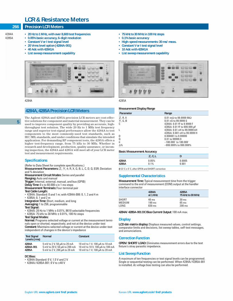
English URL www.agilent.com/find/products Korean URL www.agilent.co.kr/find/products
5
4284A4285A
266 Precision LCR Meters
LCR & Resistance Meters
4284A, 4285A Precision LCR Meters
The Agilent 4284A and 4285A precision LCR meters are cost-effec-tive solutions for component and material measurement. They can beused to improve component quality by providing an accurate, high-throughput test solution. The wide 20 Hz to 1 MHz test frequencyrange and superior test-signal performance allow the 4284A to testcomponents to the most commonly-used test standards, such asIEC/MIL standards, and under conditions that simulate the intendedapplication. For demanding RF component tests, the 4285A offers ahigher test-frequency range, from 75 kHz to 30 MHz. Whether inresearch and development, production, quality assurance, or incom-ing inspection, the 4284A and 4285A will meet all of your LCR metertest and measurement requirements.
Specifications (Refer to Data Sheet for complete specifications.)Measurement Parameters: Z, Y, , R, X, G, B, L, C, D, Q, ESR; Deviationand % deviationMeasurement Circuit Modes: Series and parallelRanging: Auto and manualTrigger: Internal, external, manual, and bus (GPIB)Delay Time: 0 s to 60.000 s in 1 ms stepsMeasurement Terminals: Four-terminal pairTest Cable Length:• 4284A: Standard: 0 and 1 m; with 4284A-006: 0, 1, 2 and 4 m• 4285A: 0, 1 and 2 mIntegration Time: Short, medium, and longAveraging: 1 to 256, programmableTest Signal:• 4284A: 20 Hz to 1 MHz ± 0.01%, 8610 selectable frequencies• 4285A: 75 kHz to 30 MHz ± 0.01%, 100 Hz stepsTest Signal Modes:Normal: Programs selected voltage or current at the measurement termi-nals open or shorted, respectively, and not at the device-under-testConstant: Maintains selected voltage or current at the device-under-testindependent of changes in the device’s impedance
Test Signal Normal ConstantLevels (rms)
4284A 5 mV to 2 V, 50 µA to 20 mA 10 mV to 1 V, 100 µA to 10 mA4284A-001 5 mV to 20 V, 50 µA to 200 mA 10 mV to 10 V, 100 µA to 100 mA4285A 5 mV to 2 V, 200 µA to 20 mA 10 mV to 1 V, 100 µA to 20 mA
DC Bias:• 4284A Standard: 0 V, 1.5 V and 2 V• 4284A/4285A-001: 0 V to ±40 V
Measurement Display Range
Parameter Range
Z, R, X 0.01 mΩ to 99.9999 MΩY, G, B 0.01 nS to 99.9999 SC 4284A: 0.01 fF to 9.9999 F
4285A: 0.01 fF to 999.999 µFL 4284A: 0.01 nH to 99.9999 kH
4285A: 0.001 nH to 99.9999 HD 0.000001 to 9.99999Q 0.01 to 99999.9 –180.000˚ to 180.000˚% –999.999% to 999.999%
Basic Measurement Accuracy
Z, C, L D
4284A 0.05% 0.00054285A 0.1% 0.001
@ 23˚C ± 5˚C, after OPEN and SHORT correction
Supplemental CharacteristicsMeasurement Time: Typical measurement time from the trigger command to the end of measurement (EOM) output at the handler interface connector
4284A 4285Aat 1 KHz 75 kHz to 30 MHz
SHORT 40 ms 30 msMEDIUM 190 ms 65 msLONG 830 ms 200 ms
4284A/4285A-001 DC Bias Current Output: 100 mA max.
DisplayLCD dot-matrix display: Displays measured values, control settings, comparator limits and decisions, list sweep tables, self-test messages,and annunciations.
Correction FunctionOPEN/SHORT/LOAD: Eliminates measurement errors due to the test fixture’s stray parasitic impedance.
List Sweep FunctionA maximum of ten frequencies or test signal levels can be programmed.Single or sequential testing can be performed. When 4284A/4285A-001 is installed, dc voltage bias testing can also be performed.
• 20 Hz to 1 MHz, with over 8,600 test frequencies • 0.05% basic accuracy, 6-digit resolution • Constant V or I test signal level• 20 Vrms level option (4284A-001)• 40 Adc with 42841A• List sweep measurement capability
• 75 kHz to 30 MHz in 100 Hz steps • 0.1% basic accuracy • High-speed measurements: 30 ms/meas.• Constant V or I test signal level• 10 Adc with 42841A• List sweep measurement capability
4284A 4285A
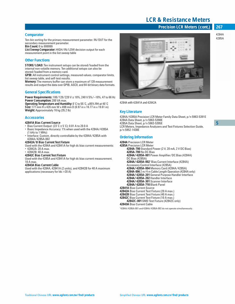
Traditional Chinese URL www.agilent.com.tw/find/products Simplified Chinese URL www.agilent.com.cn/find/products
5
4284A4285A
267Precision LCR Meters (cont.)
LCR & Resistance Meters
ComparatorTen-bin sorting for the primary measurement parameter. IN/OUT for thesecondary measurement parameter. Bin Count: 0 to 999999List Sweep Comparator: HIGH/IN/LOW decision output for each measurement point in the list sweep table
Other FunctionsSTORE/LOAD: Ten instrument setups can be stored/loaded from theinternal non-volatile memory. Ten additional setups can also bestored/loaded from a memory card.GPIB: All instrument control settings, measured values, comparator limits,list sweep table, and self-test results. Memory: The memory buffer can store a maximum of 128 measurementresults and output the data over GPIB, ASCII, and 64-bit binary data formats.
General SpecificationsPower Requirements: 100/120/220 V ± 10%, 240 V 5%/–10%, 47 to 66 HzPower Consumption: 200 VA max.Operating Temperature and Humidity: 0˚C to 55˚C, ≤95% RH at 40˚CSize: 177 mm H x 426 mm W x 498 mm D (6.97 in x 16.77 in x 19.61 in)Weight: Approximately 16 kg (35.2 lb)
Accessories42841A Bias Current Source• Bias Current Output: (23˚C ± 5˚C); 0.01 A to 20.0 A• Basic Impedance Accuracy: 1% when used with the 4284A/4285A
(1 kHz to 1 MHz)• Interface: Custom, directly controllable by the 4284A/4285A with
4284A/4285A-00242842A/B Bias Current Test FixtureUsed with the 4284A and 42841A for high dc bias current measurements:• 42842A: 20 A max.• 42842B: 40 A max.42842C Bias Current Test FixtureUsed with the 4285A and 42841A for high dc bias current measurement.10 A max.42843A Bias Current CableUsed with the 4284A, 42841A (2 units), and 42842B for 40 A maximumapplications (necessary for Idc >20 A)
Key Literature4284A/4285A Precision LCR Meter Family Data Sheet, p/n 5963-5391E4284A Data Sheet, p/n 5963-5390E4285A Data Sheet, p/n 5963-5395ELCR Meters, Impedance Analyzers and Test Fixtures Selection Guide, p/n 5952-1430E
Ordering Information4284A Precision LCR Meter4285A Precision LCR Meter
4284A-700 Standard Power (2 V, 20 mA, 2 V DC Bias)4285A-700 No DC Bias4284A/4285A-001 Power Amplifier/DC Bias (4284A) DC Bias (4285A)4284A/4285A-0021 Bias Current Interface (4284A)Accessory Control Interface (4285A)4284A/4285A-004 Memory Card (4284A/4285A)4284A-006 2 m/4 m Cable Length Operation (4284A only)4284A/4285A-201 General Purpose Handler Interface4284A/4285A-202 Handler Interface4284A/4285A-301 Scanner Interface4284A/4285A-710 Blank Panel
42841A Bias Current Source 42842A Bias Current Test Fixture (20 A max.) 42842B Bias Current Test Fixture (40 A max.)42842C Bias Current Test Fixture (10 A max.)
42842C-001 SMD Test Fixture (42842C only) 42843A Bias Current Cable 14284A/4285A-001 and 4284A/4285A-002 do not operate simultaneously.
4284A with 42841A and 42842A

English URL www.agilent.com/find/productsKorean URL www.agilent.co.kr/find/products
5
4338B
268 Milliohmmeter
LCR & Resistance Meters
4338B Milliohmmeter
The 4338B milliohmmeter is a precise, reliable, high-speed test toolfor measurements of low resistance.
Precise, Low-Resistance MeasurementContact failure of electromechanical components in a low-current cir-cuit is a key issue for component reliability. The 4338B offers selec-table low ac test signals (1 µA to 10 mA). Users can now characterizelow resistances of electromechanical components under low-currentconditions. A high resolution of 10 µΩ allows you to determine theslightest differences in contact resistance testing of relays, switches,connectors, PC board traces and cables. The 1 kHz test signal elimi-nates potential errors introduced by thermoelectric effects on thedevice-under-test (DUT) contacts. The 1 kHz ac test signal is the bestsolution to evaluate the internal resistance of batteries, because itavoids dc energy consumption.
High-Speed MeasurementsThe high-speed (34 ms), built-in comparator and GPIB/handlerinterfaces make it possible to construct a measurement systemusing an automatic handler and external computer to minimize pro-duction test time.
Auto-Measurement ModeWhen performing gross continuity testing where the test signal levelis not a significant factor in the test, the auto-measurement functionallows the instrument to select an appropriate test signal and mea-surement range setting.
Specifications(Refer to Technical Overview for complete specifications.)Measurement FunctionMeasurement Parameters: R (ac resistance), X (reactance), L (inductance), Z (impedance), (phase [˚])Combinations: R, R–X, R–L, Z – (series mode only)Mathematical Functions: Deviation and percent deviationDisplay Digits: 3, 4, or 5 (selectable)Test Signal Characteristics• Test Frequency: 1 kHz• Frequency Accuracy: ±0.1%• Test Signal Level: 1 µA, 10 µA, 100 µA, 1 mA, 10 mA rms• Level Accuracy: ±(10% + 0.2 µA)• Maximum Voltage Across Sample: 20 mV peak in any case
Measurement Range
Parameter Measurement Range
R 10 µΩ to 100 kΩX, Z 10 µΩ to 100 kΩ (typical)L 10 nH to 10 H (typical) –180˚ to +180˚ (typical)
Measurement Accuracy: ±0.4% Basic for R
Measurement Time: Time interval from a trigger command to the end ofmeasurement (EOM) signal output at the handler interface port
Mode Time (typical)
SHORT 34 msMEDIUM 70 msLONG 900 ms
Correction Function• Zero SHORT: Eliminates measurement errors due to parasitic
impedances in the test fixtureComparator FunctionHIGH/IN/LOW for each primary measurement parameter and the secondary measurement parameterContact Check FunctionContact failure between the test fixture and device can be detectedOther Functions• Superimposed dc: ±42 Vdc maximum may be present on measure-
ment terminals• Save/Recall: Ten instrument setups can be saved/recalled from
the internal nonvolatile memory• Continuous Memory Capability: If the instrument is turned off,
or if a power failure occurs, instrument settings are automatically memorized (≤72 hours at 23˚C ± 5˚C)
• GPIB Interface: All control settings, measured values, and com-parator information
• Handler Interface: All output signals are negative-logic, optically isolated open collectors
• Output Signals Include: HIGH/IN/LOW, index, end of measure-ment, and alarm. Input signals are keylock and external trigger
General SpecificationsPower Requirements: 90 V to 132 V or 198 V to 264 V, 47 Hz to 66 Hz, 45 VA max.Operating Temperature: 0˚C to 45˚CSize: 100 mm H x 320 mm W x 300 mm D (3.94 in x 12.6 in x 11.81 in)Weight: 4.5 kg (9.9 lb)
Key Literature4338B Milliohmmeter Technical Overview, p/n 5964-6183E
Furnished AccessoriesOperation manual, power cable (mating cable and test leads, or 16338Atest lead set, must be ordered separately)
Ordering Information4338B MilliohmmeterFurnished Accessories: CD-ROM (manual), power cable (mating cable andtest leads, or 16338A test lead kit, must be ordered separately)
Options4338B-ABA US-English Localization4338B-ABJ Japan-Japanese Localization
Accessories16064B LED Display/Trigger Box16338A Test Lead KitThe 16338A contains the following accessories.
16005B Kelvin Clip Lead (large, 2 ea)16005C Kelvin IC Clip Lead (red, 1 ea)16005D Kelvin IC Clip Lead (black, 1 ea)16006A Pin-Type Probe Lead (2 ea)16007A Alligator Clip Leads (red, 1 ea)16007B Alligator Clip Leads (black, 1 ea)16143B Mating Cable (1 ea)
• Low and selectable test signal current: 1 µA to 10 mA• Wide measurement range: 10 µΩ to 100 kΩ• 10 µΩ resolution• Contact check function• 1 kHz ac measurement• High-speed measurement: 34 ms• Built-in comparator• Auto-measurement mode
4338B
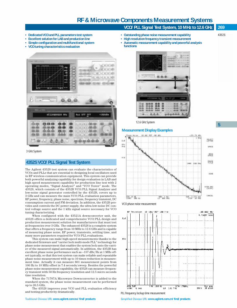
Traditional Chinese URL www.agilent.com.tw/find/products Simplified Chinese URL www.agilent.com.cn/find/products
5
4352S
269VCO/PLL Signal Test System, 10 MHz to 12.6 GHz
RF & Microwave Components Measurement Systems
• Dedicated VCO and PLL parameters test system• Excellent solution for LAB and production line• Simple configuration and multifunctional system• VCO tuning characteristics evaluation
4352S VCO/PLL Signal Test System
The Agilent 4352S test system can evaluate the characteristics ofVCOs and PLLs that are essential to designing local oscillators usedin RF wireless communication equipment. This system can provideboth powerful analyzing capability for design evaluation in LAB andhigh speed measurement capability for production line test with 2operating modes, “Signal Analyzer” and “VCO Tester” mode. The4352S, which consists of the 4352B VCO/PLL Signal Analyzer andlow-noise signal generator controlled by the 4352B, covers up to 3 GHz and can measure the main VCO/PLL evaluation parameters,RF power, frequency, phase noise, spectrum, frequency transient, DCconsumption current and FM deviation. In addition, the 4352B pro-vides and controls the DC power supply, the ultra low-noise DC con-trol voltage source and the 1 kHz signal source necessary for VCOtuning characterizing.
When configured with the 43521A downconverter unit, the4352S offers a dedicated and comprehensive VCO/PLL design andproduction measurement solution for manufacturers that must testat frequencies over 3 GHz. The enhanced 4352S is a complete systemthat offers a frequency range from 10 MHz to 12.6 GHz and is capableof measuring phase noise, RF power, transients, settling time, andmany more parameters required for VCO/PLL evaluations.
This system can make high-speed measurements thanks to thededicated firmware and “carrier lock multi-mode PLL” technology forphase noise measurement that enables the system lock unto the carri-er of the measured signal automatically. In addition, the 4352B hasexcellent phase noise performance such as –157 dBc/Hz at 1 MHz off-set typically, so that this test system can make reliable and repeatablephase noise measurement with up to 10 times reduction in measure-ment time. Actually it can measure 801 measurement points from 100 Hz to 10 MHz offset in 7.4 seconds/sweep. Besides the powerfulphase noise measurement capability, the 4352S can measure frequen-cy transient with 50 Hz frequency resolution and 12.5 micro secondstime resolution.
When the 71707A Microwave Downconverter is added to thestandard system, the phase noise measurement can be performedup to 26.5 GHz.
The 4352S improves your VCO and PLL evaluation efficiencyand testing productivity dramatically.
• Outstanding phase noise measurement capability• High resolution frequency transient measurement• Automatic measurement capability and powerful analysis
functions
VCO phase noise measurement
12.6 GHz System
3 GHz System
Measurement Display Examples
PLL frequency lockup time measurement

English URL www.agilent.com/find/products Korean URL www.agilent.co.kr/find/products
5
4352S
270 VCO/PLL Signal Test System, 10 MHz to 12.6 GHz (cont.)
RF & Microwave Components Measurement Systems
Efficient Evaluation in Oscillator Circuit DesignThe 4352S can measure the following characteristics:
For VCO Evaluation • RF power vs. tuning voltage • Frequency vs. tuning voltage • Tuning sensitivity • Phase noise (Carrier-to-Noise)• Harmonics • FM deviation • DC power consumption current
For PLL Evaluation • RF power • Phase noise (Carrier-to-Noise)• Frequency and Frequency transient • Spurious • Harmonics
Each parameter can be measured without changing any cableconnections. So, you can easily evaluate a VCO/PLL with powerfulanalysis functions such as marker or limit line.
High Throughput and Easy Test AutomationThanks to the high-speed phase noise measurement capability, itonly takes about 2.5 seconds to measure five VCO parameters (RFpower, frequency, phase noise, DC power consumption current andFM deviation) by using “VCO Tester” mode. The 4352S has theInstrument BASIC programming functions, built-in 3.5 inch diskdrive (LIF/DOS format) and a 24-bit I/O. These capabilities allowyou to interface to an automatic handler so that you can achieveautomatic production-line testing without an external computer.
SpecificationsSource CharacteristicsDC Power Voltage: 0 to +15.5 V with 1 mV step, 50 mA max.DC Control Voltage: 0 to +20 V with 100 µV step, 20 mA max.• 4352S-001: –15 to +35 V• Accuracy: ±(0.1% + 2 mV)• Settling Time: <20 ms @ 0.1% error (typical)• Noise Density: <1 nV/√Hz @ 10 kHz offset (typical)• FM Signal: 1 kHz, 0 to 1 Vrms with 1 mV step @ open loadReceiver Characteristics• Measurement Frequency Range: 10 MHz to 3 GHz/12.6 GHz (with
43521A/refer to 43521A)/26.5 GHz (with 71707A/phase noise measurement only)
• Input Power Level: –10 to +20 dBm• Input Impedance: 50 Ω• SWR: <1.2 (@ <2 GHz); <1.3 RF Power Measurement• Accuracy ±0.2 dB (@ 1 GHz, –5 dBm, typical); ±1 dB• Resolution: 0.01 dB Frequency Measurement• Frequency Resolution: 1 kHzFrequency Transient Measurement• Accuracy: ±(1 kHz + time base accuracy of the external signal
generator)• Minimum Frequency Resolution: 50 Hz• Maximum Sweep Time: 10 sec.• Minimum Time Resolution: 12.5 µsec.Phase Noise (Carrier-to-Noise Ratio) Measurement• Offset Frequency Range: 100 Hz to 10 MHz
System Noise Level
Offset Specification (dBc/Hz) Typical (dBc/Hz)
100 Hz –85 –901 kHz –110 –11710 kHz –130 –137100 kHz –140 –1471 MHz –150 –157
Spectrum Measurement• Absolute Level Accuracy: 2 dB (–5 dBm input, @ ATT = 0 dB, typical)• Relative Level Accuracy: 0.5 dB (typical)FM Deviation Measurement• Measurement Range: 2 kHz, 20 kHz, 200 kHz (peak)• Accuracy: ±(2% + 0.1% of measurement range) @ 1 kHz FM rate;
±0.8% (typical)• Residual FM: <3 Hzrms (@ 300 Hz to 3 kHz BW)DC Consumption Current Measurement• Measurement Range: 0 to 50 mA• Accuracy: ±(0.2% ± 100 µA)Storage3.5-inch FDD: LIF/DOS format, 2DD/2HDInternal RAM Disk: LIF/DOS format, 512 kB max.InterfacesGPIB I/F, 24-bit parallel I/O I/F
General CharacteristicsDisplay: 8.5-inch color LCDOperating Temperature: 0 to +40˚COperating Humidity: 15 to 95% RHStorage Temperature/Humidity: 0 to +40˚C/15 to 95% RHPower Requirements: 90 to 132 V or 198 to 264 V, 47 to 66 Hz, 300 VA max.Size: 235 mm H x 425 mm W x 553 mm D (9.4 in x 17 in x 22.12 in)Weight: 21.5 kg (47.3 lb) (typical)
Key LiteratureSignal Generators RF and Microwave Models, p/n 5965-3094E 71707A Microwave Downconverter Technical Data, p/n 5091-4435E
Ordering Information4352S VCO/PLL Signal Test SystemAgilent 4352B VCO/PLL Signal Analyzer
4352B-700 Standard DC Control Voltage4352B-001 Expand DC Control Voltage4352B-810 Add Keyboard4352B-1CM Rack Mount Kit4352B-1CN Handle Kit4352B-1CP Rack Mount & Handle Kit4352B-ABA English Localization4352B-ABJ Japan Localization
43521A Downconverter UnitRecommended Signal Generators8664A Synthesized Signal Generator with 8664A-0048644B Synthesized Signal Generator with 8664B-00271707A 26.5 GHz Microwave DownconverterE8247C PSG Series Microwave Signal Generator with Option 1ED and UNRE8257C PSG Series Microwave Signal Generator with Option 1ED and UNRE8267C PSG Series Microwave Signal Generator with Option 1ED and UNR
See Signal Sources section for more details. When using the other signalgenerators, please contact the Agilent Call Center in your region for details.
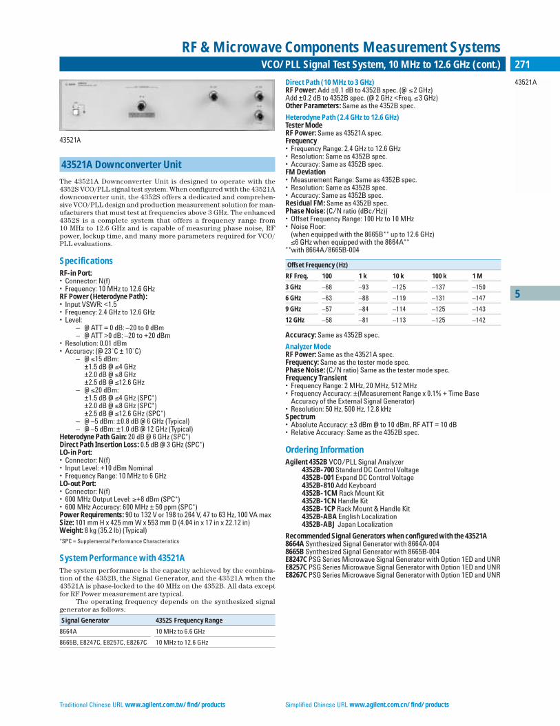
5
43521A
271VCO/PLL Signal Test System, 10 MHz to 12.6 GHz (cont.)
RF & Microwave Components Measurement Systems
Traditional Chinese URL www.agilent.com.tw/find/products Simplified Chinese URL www.agilent.com.cn/find/products
43521A
43521A Downconverter Unit
The 43521A Downconverter Unit is designed to operate with the4352S VCO/PLL signal test system. When configured with the 43521Adownconverter unit, the 4352S offers a dedicated and comprehen-sive VCO/PLL design and production measurement solution for man-ufacturers that must test at frequencies above 3 GHz. The enhanced4352S is a complete system that offers a frequency range from 10 MHz to 12.6 GHz and is capable of measuring phase noise, RFpower, lockup time, and many more parameters required for VCO/PLL evaluations.
SpecificationsRF-in Port:• Connector: N(f)• Frequency: 10 MHz to 12.6 GHzRF Power (Heterodyne Path):• Input VSWR: <1.5• Frequency: 2.4 GHz to 12.6 GHz • Level:
– @ ATT = 0 dB: –20 to 0 dBm– @ ATT >0 dB: –20 to +20 dBm
• Resolution: 0.01 dBm• Accuracy: (@ 23˚C ± 10˚C)
– @ ≤15 dBm:±1.5 dB @ ≤4 GHz±2.0 dB @ ≤8 GHz±2.5 dB @ ≤12.6 GHz
– @ ≤20 dBm:±1.5 dB @ ≤4 GHz (SPC*)±2.0 dB @ ≤8 GHz (SPC*)±2.5 dB @ ≤12.6 GHz (SPC*)
– @ –5 dBm: ±0.8 dB @ 6 GHz (Typical)– @ –5 dBm: ±1.0 dB @ 12 GHz (Typical)
Heterodyne Path Gain: 20 dB @ 6 GHz (SPC*)Direct Path Insertion Loss: 0.5 dB @ 3 GHz (SPC*)LO-in Port:• Connector: N(f)• Input Level: +10 dBm Nominal• Frequency Range: 10 MHz to 6 GHz LO-out Port:• Connector: N(f)• 600 MHz Output Level: ≥+8 dBm (SPC*)• 600 MHz Accuracy: 600 MHz ± 50 ppm (SPC*)Power Requirements: 90 to 132 V or 198 to 264 V, 47 to 63 Hz, 100 VA maxSize: 101 mm H x 425 mm W x 553 mm D (4.04 in x 17 in x 22.12 in)Weight: 8 kg (35.2 lb) (Typical)*SPC = Supplemental Performance Characteristics
System Performance with 43521AThe system performance is the capacity achieved by the combina-tion of the 4352B, the Signal Generator, and the 43521A when the43521A is phase-locked to the 40 MHz on the 4352B. All data exceptfor RF Power measurement are typical.
The operating frequency depends on the synthesized signalgenerator as follows.
Signal Generator 4352S Frequency Range
8664A 10 MHz to 6.6 GHz
8665B, E8247C, E8257C, E8267C 10 MHz to 12.6 GHz
Direct Path (10 MHz to 3 GHz)RF Power: Add ±0.1 dB to 4352B spec. (@ ≤2 GHz)Add ±0.2 dB to 4352B spec. (@ 2 GHz <Freq. ≤3 GHz)Other Parameters: Same as the 4352B spec.
Heterodyne Path (2.4 GHz to 12.6 GHz)Tester ModeRF Power: Same as 43521A spec.Frequency• Frequency Range: 2.4 GHz to 12.6 GHz• Resolution: Same as 4352B spec.• Accuracy: Same as 4352B spec.FM Deviation• Measurement Range: Same as 4352B spec.• Resolution: Same as 4352B spec.• Accuracy: Same as 4352B spec.Residual FM: Same as 4352B spec.Phase Noise: (C/N ratio (dBc/Hz))• Offset Frequency Range: 100 Hz to 10 MHz• Noise Floor:
(when equipped with the 8665B** up to 12.6 GHz) ≤6 GHz when equipped with the 8664A**
**with 8664A/8665B-004
Offset Frequency (Hz)
RF Freq. 100 1 k 10 k 100 k 1 M
3 GHz –68 –93 –125 –137 –150
6 GHz –63 –88 –119 –131 –147
9 GHz –57 –84 –114 –125 –143
12 GHz –58 –81 –113 –125 –142
Accuracy: Same as 4352B spec.
Analyzer ModeRF Power: Same as the 43521A spec.Frequency: Same as the tester mode spec.Phase Noise: (C/N ratio) Same as the tester mode spec.Frequency Transient• Frequency Range: 2 MHz, 20 MHz, 512 MHz • Frequency Accuracy: ±(Measurement Range x 0.1% + Time Base
Accuracy of the External Signal Generator)• Resolution: 50 Hz, 500 Hz, 12.8 kHzSpectrum• Absolute Accuracy: ±3 dBm @ to 10 dBm, RF ATT = 10 dB• Relative Accuracy: Same as the 4352B spec.
Ordering InformationAgilent 4352B VCO/PLL Signal Analyzer
4352B-700 Standard DC Control Voltage4352B-001 Expand DC Control Voltage4352B-810 Add Keyboard4352B-1CM Rack Mount Kit4352B-1CN Handle Kit4352B-1CP Rack Mount & Handle Kit4352B-ABA English Localization4352B-ABJ Japan Localization
Recommended Signal Generators when configured with the 43521A8664A Synthesized Signal Generator with 8664A-0048665B Synthesized Signal Generator with 8665B-004E8247C PSG Series Microwave Signal Generator with Option 1ED and UNRE8257C PSG Series Microwave Signal Generator with Option 1ED and UNRE8267C PSG Series Microwave Signal Generator with Option 1ED and UNR
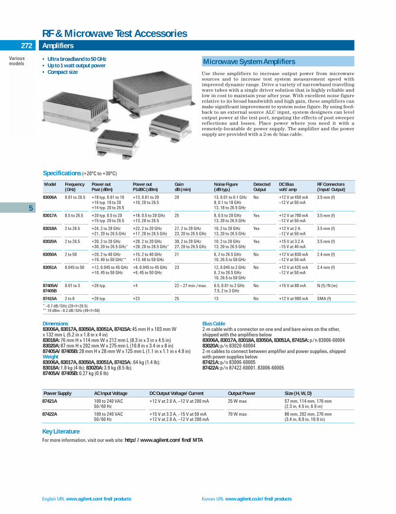
English URL www.agilent.com/find/products Korean URL www.agilent.co.kr/find/products
5
Variousmodels
272 Amplifiers
RF & Microwave Test Accessories
Specifications (+20ºC to +30ºC)
Model Frequency Power out Power out Gain Noise Figure Detected DC Bias RF Connectors(GHz) Psat (dBm) P1dBC (dBm) dB (min) (dB typ.) Output volt/amp (Input/Output)
83006A 0.01 to 26.5 +18 typ. 0.01 to 10 +13, 0.01 to 20 20 13, 0.01 to 0.1 GHz No +12 V at 450 mA 3.5 mm (f)+16 typ. 10 to 20 +10, 20 to 26.5 8, 0.1 to 18 GHz –12 V at 50 mA+14 typ. 20 to 26.5 13, 18 to 26.5 GHz
83017A 0.5 to 26.5 +20 typ. 0.5 to 20 +18, 0.5 to 20 GHz 25 8, 0.5 to 20 GHz Yes +12 V at 700 mA 3.5 mm (f)+15 typ. 20 to 26.5 +13, 20 to 26.5 13, 20 to 26.5 GHz –12 V at 50 mA
83018A 2 to 26.5 +24, 2 to 20 GHz +22, 2 to 20 GHz 27, 2 to 20 GHz 10, 2 to 20 GHz Yes +12 V at 2 A 3.5 mm (f)+21, 20 to 26.5 GHz +17, 20 to 26.5 GHz 23, 20 to 26.5 GHz 13, 20 to 26.5 GHz –12 V at 50 mA
83020A 2 to 26.5 +30, 2 to 20 GHz +28, 2 to 20 GHz 30, 2 to 20 GHz 10, 2 to 20 GHz Yes +15 V at 3.2 A 3.5 mm (f)+30, 20 to 26.5 GHz* +28, 20 to 26.5 GHz* 27, 20 to 26.5 GHz 13, 20 to 26.5 GHz –15 V at 40 mA
83050A 2 to 50 +20, 2 to 40 GHz +15, 2 to 40 GHz 21 6, 2 to 26.5 GHz No +12 V at 830 mA 2.4 mm (f)+19, 40 to 50 GHz** +13, 40 to 50 GHz 10, 26.5 to 50 GHz –12 V at 50 mA
83051A 0.045 to 50 +12, 0.045 to 45 GHz +8, 0.045 to 45 GHz 23 12, 0.045 to 2 GHz No +12 V at 425 mA 2.4 mm (f)+10, 45 to 50 GHz +6, 45 to 50 GHz 6, 2 to 26.5 GHz –12 V at 50 mA
10, 26.5 to 50 GHz
87405A/ 0.01 to 3 +26 typ. +4 22 – 27 min./max. 6.5, 0.01 to 2 GHz No +15 V at 80 mA N (f)/N (m)87405B 7.5, 2 to 3 GHz
87415A 2 to 8 +26 typ. +23 25 13 No +12 V at 900 mA SMA (f)
* –0.7 dB/GHz (20<f<26.5)** 19 dBm –0.2 dB/GHz (40<f<50)
Microwave System Amplifiers
Use these amplifiers to increase output power from microwavesources and to increase test system measurement speed withimproved dynamic range. Drive a variety of narrowband travellingwave tubes with a single driver solution that is highly reliable andlow in cost to maintain year after year. With excellent noise figurerelative to its broad bandwidth and high gain, these amplifiers canmake significant improvement to system noise figure. By using feed-back to an external source ALC input, system designers can leveloutput power at the test port, negating the effects of post sweeperreflections and losses. Place power where you need it with a remotely-locatable dc power supply. The amplifier and the powersupply are provided with a 2-m dc bias cable.
Dimensions83006A, 83017A, 83050A, 83051A, 87415A: 45 mm H x 103 mm W x 132 mm L (5.2 in x 1.8 in x 4 in)83018A: 76 mm H x 114 mm W x 212 mm L (8.3 in x 3 in x 4.5 in)83020A: 87 mm H x 202 mm W x 275 mm L (10.8 in x 3.4 in x 8 in)87405A/87405B: 28 mm H x 28 mm W x 125 mm L (1.1 in x 1.1 in x 4.9 in)Weight83006A, 83017A, 83050A, 83051A, 87415A: .64 kg (1.4 lb); 83018A: 1.8 kg (4 lb); 83020A: 3.9 kg (8.5 lb); 87405A/87405B: 0.27 kg (0.6 lb)
Bias Cable2-m cable with a connector on one end and bare wires on the other,shipped with the amplifiers below83006A, 83017A, 83018A, 83050A, 83051A, 87415A: p/n 83006-6000483020A: p/n 83020-600042-m cables to connect between amplifier and power supplies, shippedwith power supplies below87421A: p/n 83006-6000587422A: p/n 87422-60001, 83006-60005
Power Supply AC Input Voltage DC Output Voltage/Current Output Power Size (H, W, D)
87421A 100 to 240 VAC +12 V at 2.0 A, –12 V at 200 mA 25 W max 57 mm, 114 mm, 176 mm50/60 Hz (2.3 in, 4.5 in, 6.9 in)
87422A 100 to 240 VAC +15 V at 3.3 A, –15 V at 50 mA 70 W max 86 mm, 202 mm, 276 mm50/60 Hz +12 V at 2.0 A, –12 V at 200 mA (3.4 in, 8.0 in, 10.9 in)
Key LiteratureFor more information, visit our web site: http://www.agilent.com/find/MTA
• Ultra broadband to 50 GHz • Up to 1 watt output power • Compact size

Traditional Chinese URL www.agilent.com.tw/find/products Simplified Chinese URL www.agilent.com.cn/find/products
5
11713A70611A87130A84940A84941AE1368AE1369AE1370A
273Custom Switch Interfaces
RF & Microwave Test Accessories
11713A Attenuator/Switch Driver
The 11713A attenuator/switch driver provides simple GPIB controlof up to ten, 24 Vdc solenoid-activated switch or attenuator sections.The 11713A supplies 24 Vdc common and ten pairs of current sinking contacts to achieve control of up to ten relays. Each 11713Ais supplied with two plug-in drive cables to simplify connection toprogrammable attenuators.
70611A Attenuator/Switch Driver for MMS
The 70611A is a one-slot MMS module capable of driving up to 248electromechanical switches or attenuator switch sections. The70611A is MSIB, SCPI, and GPIB compatible. In addition to beingprogrammable, the 70611A features an extremely user-friendly man-ual interface via any MMS display unit. The highlight of the manualinterface is the operator’s ability to customize groups of switch control lines and their settings, then identify these switch settingswith user-defined alphanumeric labels. In this manner, end users ofthe 70611A can define custom menus with their own identificationlabels for simplified manual control.
The 70611A can store up to 256 user-defined labeled paths.Path definitions can be stored in non-volatile EEROM. Groups ofpaths can be stored in directories for easy access to similar pathcommands. The 70612A/C and 70613A/C offer compatible capacitywith built-in RF switches. (Configurations vary and custom configu-rations are available.)
87130A Attenuator/Switch Driver
The 87130A is a 3.5-inch, full rack width attenuator/switch drivercapable of driving up to 248 electromechanical switch or attenuatorsections. The 87130A is controlled over GPIB via Standard Com-mands for Programmable Instruments (SCPI) commands. The87130A has been designed for use in both ATE switching systemsand computer-controlled bench top applications.
The 87130A is electronically identical to the 70611A andshares its performance characteristics, with the exception of themanual control method. The 87130A has no front panel controls.Manual control of the 87130A is realized through its ITG driver anda computer controller. The 87130A can drive 31 switch or attenuatorsections directly, and up to an additional 217 switches via sevenadditional 84940A driver cards.
E1368A, E1369A and E1370A VXI Attenuator/Switch Drivers
Agilent’s VXI family of instrumentation includes modules formicrowave switching and attenuation control up to 18.0 GHz.E1368A contains three factory-installed SPDT switches such as the8762B which features all-port termination, dc to 18.0 GHz. E1369Ais identical to the E1368A except the switches are not included. Thisallows user-substitution of 8763 or 8764 transfer switches. E1370Aallows the user to customize the internal configuration for 8766series multi-port switches or 8494/95/96/97 step attenuators.
84940A Switch Driver and 84941A Distribution Card
The 84940A is an expansion driver card for the 70611A family ofMMS attenuator/switch drivers and the 87130A attenuator/switch driver. The 84940A has been designed for incorporation intolarge interfaces located remotely from their controller. A single 84940A can control up to 31 switches when located up to 150 feet(45 m) from an 70611A or 87130A. The physical interconnection tothe switches or attenuators is realized via 31 four-pin output con-nectors, which permit quick connection and disconnection of theswitches or attenuators.
Key LiteratureFor more information, visit our web site:http://www.agilent.com/find/accessories
Ordering Information11713A Attenuator/Switch Driver11761A; 8765 to 11713A Adapter Cable44476B Microwave Switch Module for 3488A(Holds up to two 8762/3/4 Option 011 Switches)70611A MMS Switch Driver84940A Attenuator/Switch Driver Expansion Card84941A Distribution Expansion Card87130A Attenuator/Switch DriverE1368A 18 GHz Microwave SwitchE1369A Microwave Switch Driver E1370A Microwave Switch/Step Attenuator Driver
RF & Microwave Test AccessoriesThe complete line of Agilent’s microwave accessories – from adapters towaveguides and everything between, it’s all here. Amplifiers, detectors,filters, step and fixed attenuators, switches and switch drivers – the entireAgilent Technologies product line, with all the technical specs.To receive your free copy in the U.S., call 800-452-4844 and ask for the RF & Microwave Test Accessories Catalog, p/n 5968-4314E, contact your local Agilent representative, or order on the Internet. The entire RF & Microwave Test Accessories can be accessed at:http://www.get.agilent.com/accessories
87130A
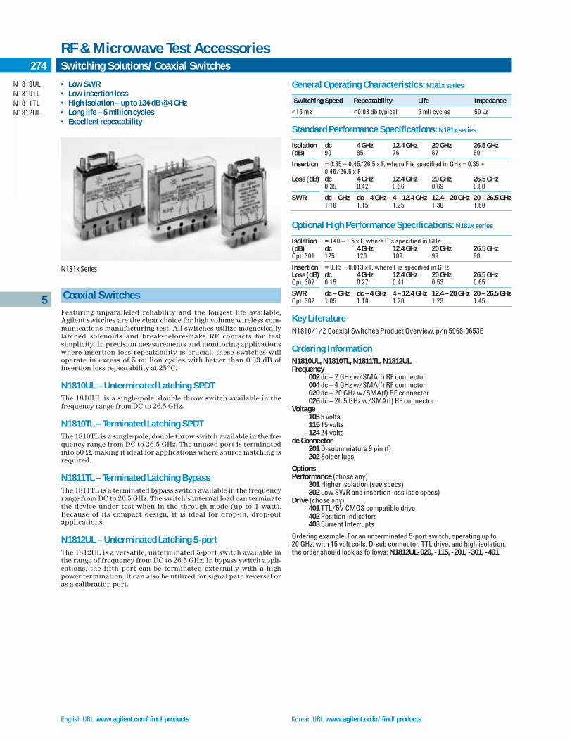
English URL www.agilent.com/find/products Korean URL www.agilent.co.kr/find/products
General Operating Characteristics: N181x series
Switching Speed Repeatability Life Impedance
<15 ms <0.03 db typical 5 mil cycles 50 Ω
Standard Performance Specifications: N181x series
Isolation dc 4 GHz 12.4 GHz 20 GHz 26.5 GHz(dB) 90 85 76 67 60
Insertion = 0.35 + 0.45/26.5 x F, where F is specified in GHz = 0.35 + 0.45/26.5 x F
Loss (dB) dc 4 GHz 12.4 GHz 20 GHz 26.5 GHz0.35 0.42 0.56 0.69 0.80
SWR dc – GHz dc – 4 GHz 4 – 12.4 GHz 12.4 – 20 GHz 20 – 26.5 GHz1.10 1.15 1.25 1.30 1.60
Optional High Performance Specifications: N181x series
Isolation = 140 – 1.5 x F, where F is specified in GHz(dB) dc 4 GHz 12.4 GHz 20 GHz 26.5 GHzOpt. 301 125 120 109 99 90
Insertion = 0.15 + 0.013 x F, where F is specified in GHzLoss (dB) dc 4 GHz 12.4 GHz 20 GHz 26.5 GHzOpt. 302 0.15 0.27 0.41 0.53 0.65
SWR dc – GHz dc – 4 GHz 4 – 12.4 GHz 12.4 – 20 GHz 20 – 26.5 GHzOpt. 302 1.05 1.10 1.20 1.23 1.45
Key LiteratureN1810/1/2 Coaxial Switches Product Overview, p/n 5968-9653E
Ordering InformationN1810UL, N1810TL, N1811TL, N1812ULFrequency
002 dc – 2 GHz w/SMA(f) RF connector004 dc – 4 GHz w/SMA(f) RF connector020 dc – 20 GHz w/SMA(f) RF connector026 dc – 26.5 GHz w/SMA(f) RF connector
Voltage105 5 volts115 15 volts124 24 volts
dc Connector201 D-subminiature 9 pin (f)202 Solder lugs
OptionsPerformance (chose any)
301 Higher isolation (see specs)302 Low SWR and insertion loss (see specs)
Drive (chose any)401 TTL/5V CMOS compatible drive402 Position Indicators403 Current Interrupts
Ordering example: For an unterminated 5-port switch, operating up to 20 GHz, with 15 volt coils, D-sub connector, TTL drive, and high isolation,the order should look as follows: N1812UL-020, -115, -201, -301, -401
Coaxial Switches
Featuring unparalleled reliability and the longest life available,Agilent switches are the clear choice for high volume wireless com-munications manufacturing test. All switches utilize magneticallylatched solenoids and break-before-make RF contacts for test simplicity. In precision measurements and monitoring applicationswhere insertion loss repeatability is crucial, these switches willoperate in excess of 5 million cycles with better than 0.03 dB ofinsertion loss repeatability at 25°C.
N1810UL – Unterminated Latching SPDTThe 1810UL is a single-pole, double throw switch available in thefrequency range from DC to 26.5 GHz.
N1810TL – Terminated Latching SPDTThe 1810TL is a single-pole, double throw switch available in the fre-quency range from DC to 26.5 GHz. The unused port is terminatedinto 50 Ω, making it ideal for applications where source matching isrequired.
N1811TL – Terminated Latching BypassThe 1811TL is a terminated bypass switch available in the frequencyrange from DC to 26.5 GHz. The switch’s internal load can terminatethe device under test when in the through mode (up to 1 watt). Because of its compact design, it is ideal for drop-in, drop-outapplications.
N1812UL – Unterminated Latching 5-portThe 1812UL is a versatile, unterminated 5-port switch available inthe range of frequency from DC to 26.5 GHz. In bypass switch appli-cations, the fifth port can be terminated externally with a highpower termination. It can also be utilized for signal path reversal oras a calibration port.
N181x Series
5
N1810ULN1810TLN1811TLN1812UL
274 Switching Solutions/Coaxial Switches
RF & Microwave Test Accessories
• Low SWR• Low insertion loss• High isolation – up to 134 dB @ 4 GHz• Long life – 5 million cycles• Excellent repeatability

Traditional Chinese URL www.agilent.com.tw/find/products Simplified Chinese URL www.agilent.com.cn/find/products
5
275Switching Solutions – Coaxial Switches
RF & Microwave Test Accessories
87618762876387648765 Series
Coaxial Switches
Agilent coaxial switches feature low SWR, low insertion loss, andexcellent isolation. Agilent offers a broad line of coaxial switches,covering up to 40 GHz, for use in test and measurement applications.All switches use magnetically-latched solenoids and break-before-make RF contacts for test simplicity.
8761 Series8761A/B is a SPDT switch which operates up to 18 GHz. Each portfeatures six connector options plus 50 Ω termination for design flex-ibility. These switches offer exceptional repeatability of 0.03 dB over1 million switching cycles.
8762 Series8762A/B/C switches operate up to 26.5 GHz. These switches offerexceptional repeatability of 0.03 dB over 1 million switching cycles.They also provide excellent isolation of 90 dB to 18 GHz and all-portswitched terminations, so that all ports maintain a 50 Ω match.Internal loads are rated at 1 watt average (100 W peak, 10 µsec pulsewidth). Control voltage options T15 and T24 are compatible withTTL/5 V CMOS drive circuitry. Another model, 8762F is designed for75 Ω transmission lines, making it valuable for commercial commu-nication applications up to 4 GHz.
8763 Series8763A/B/C switches operate up to 26.5 GHz. These switches offerexceptional repeatability of 0.03 dB over 1 million switching cycles.They are preferred for drop-out or drop-in applications due to theircompact design. These switches are used to automatically insert orremove a test component from a signal path. Because of their excel-lent isolation, they can also be used as the intersection (crosspoint)switch in full-access matrix switching applications. One port isinternally terminated. Options T15 and T24 are available for TTL/5 VCMOS compatibility.
8764 Series8764A/B/C switches are available in three models up to 26.5 GHz.These switches offer exceptional repeatability of 0.03 dB over 1 mil-lion switching cycles. These switches are similar to the 8763, butwith the internal termination replaced with a fifth port. The fifthport can be utilized for signal path reversal or as a calibration port.Options T15 and T24 offer TTL/5 V CMOS compatibility.
8765 Series8765A/B/C/D/F are available in four models up to 40 GHz, as well asa 75 Ω model to 4 GHz. These SPDT switches offer exceptionalrepeatability of 0.03 dB over 5 million switching cycles. Unlike the8762 switches, they do not have internal, switched RF loads or dccurrent interrupts. Coil voltage options cover the complete rangefrom 5 Vdc to 24 Vdc. Since the coils are not interrupted, the coilvoltage may be continuous or may be switched off after 15 ms.
The 8765 comes with either ribbon cables or solder terminals. The ribbon cable also connects with the 11761ACable/Adapter, which permits direct connection to the 11713AAttenuator/Switch Driver. The 8765 can also be driven by the87130A driver, but position monitoring and reporting are not available.
Key Literaturehttp://www.get.agilent.com/accessories
Ordering Information8761A/B Coaxial SwitchesSpecify voltage and connectors (including built-in 50 Ω terminations) byalphabetic suffix on the switch model number and the appropriate 3-digitoption number. Specify all connectors.8761A 12 to 15 V Supply Voltage8761B 24 to 30 V Supply VoltageConnector Options (Port 1, Port 2, Port C):
Option Code Connector Type100/200/300 Type-N Female101/201/301 Type-N Male102/202/302 7-mm Threaded Sleeve (APC-7)3
103/203/303 7-mm Coupling Nut (APC-7)3
104/204/304 7-mm for UT-250 Coax105/205/305 3-mm Female (SMA)106/206/306 3-mm Male (SMA)107/207/307 50-ohm Termination
8762, 8763, 8764 Coaxial SwitchesSpecify the frequency and voltage by the alphabetic suffix and option number. The standard model has 24 V supply voltage. 8762A SPDT, DC to 4 GHz 8762B SPDT, DC to 18 GHz 8762C SPDT, DC to 26.5 GHz 8762F SPDT, DC to 4 GHz, 75 Ω8763A 4-Port, DC to 4 GHz 8763B 4-Port, DC to 18 GHz 8763C 4-Port, DC to 26.5 GHz 8764A 5-Port, DC to 4 GHz 8764B 5-Port, DC to 18 GHz 8764C 5-Port, DC to 26.5 GHz 8765 Coaxial SwitchesA voltage option must be ordered with the switch. Specify frequency, voltage, dc connectors, and ribbon cable extension options by alphabeticsuffix and option number.8765A SPDT, DC to 4 GHz 8765B SPDT, DC to 20 GHz 8765C SPDT, DC to 26.5 GHz 8765D SPDT, DC to 40 GHz 8765F SPDT, DC to 4 GHz, 75 Ω1Option 292 available for 8765D only.28765D-292 and 8765F do not have Option UK6.3Either option will connect to a standard, sexless, 7-mm connector. To daisy-chain two8761A’s you must use one option 102, 202, or 302 and one option 103, 203, or 303 on thetwo mating connectors. If you have two of the same options, you will need to use a cablewith two standard 7-mm connectors.
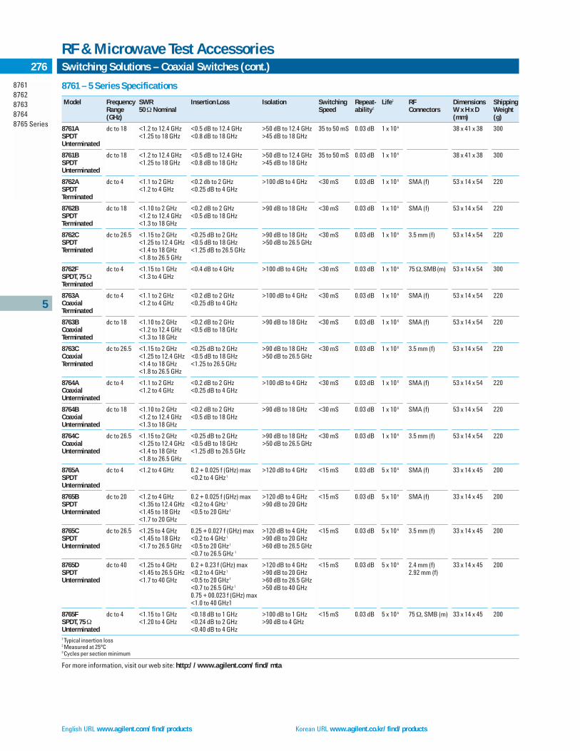
English URL www.agilent.com/find/products Korean URL www.agilent.co.kr/find/products
8761 – 5 Series Specifications
Model Frequency SWR Insertion Loss Isolation Switching Repeat- Life3 RF Dimensions ShippingRange 50 ΩNominal Speed ability 2 Connectors W x H x D Weight(GHz) (mm) (g)
8761A dc to 18 <1.2 to 12.4 GHz <0.5 dB to 12.4 GHz >50 dB to 12.4 GHz 35 to 50 mS 0.03 dB 1 x 10 6 38 x 41 x 38 300SPDT <1.25 to 18 GHz <0.8 dB to 18 GHz >45 dB to 18 GHz Unterminated
8761B dc to 18 <1.2 to 12.4 GHz <0.5 dB to 12.4 GHz >50 dB to 12.4 GHz 35 to 50 mS 0.03 dB 1 x 10 6 38 x 41 x 38 300SPDT <1.25 to 18 GHz <0.8 dB to 18 GHz >45 dB to 18 GHz Unterminated
8762A dc to 4 <1.1 to 2 GHz <0.2 db to 2 GHz >100 dB to 4 GHz <30 mS 0.03 dB 1 x 10 6 SMA (f) 53 x 14 x 54 220SPDT <1.2 to 4 GHz <0.25 dB to 4 GHz Terminated
8762B dc to 18 <1.10 to 2 GHz <0.2 dB to 2 GHz >90 dB to 18 GHz <30 mS 0.03 dB 1 x 10 6 SMA (f) 53 x 14 x 54 220SPDT <1.2 to 12.4 GHz <0.5 dB to 18 GHz Terminated <1.3 to 18 GHz
8762C dc to 26.5 <1.15 to 2 GHz <0.25 dB to 2 GHz >90 dB to 18 GHz <30 mS 0.03 dB 1 x 10 6 3.5 mm (f) 53 x 14 x 54 220SPDT <1.25 to 12.4 GHz <0.5 dB to 18 GHz >50 dB to 26.5 GHz Terminated <1.4 to 18 GHz <1.25 dB to 26.5 GHz
<1.8 to 26.5 GHz
8762F dc to 4 <1.15 to 1 GHz <0.4 dB to 4 GHz >100 dB to 4 GHz <30 mS 0.03 dB 1 x 10 6 75 Ω, SMB(m) 53 x 14 x 54 300SPDT, 75 Ω <1.3 to 4 GHz Terminated
8763A dc to 4 <1.1 to 2 GHz <0.2 dB to 2 GHz >100 dB to 4 GHz <30 mS 0.03 dB 1 x 10 6 SMA (f) 53 x 14 x 54 220Coaxial <1.2 to 4 GHz <0.25 dB to 4 GHz Terminated
8763B dc to 18 <1.10 to 2 GHz <0.2 dB to 2 GHz >90 dB to 18 GHz <30 mS 0.03 dB 1 x 10 6 SMA (f) 53 x 14 x 54 220Coaxial <1.2 to 12.4 GHz <0.5 dB to 18 GHz Terminated <1.3 to 18 GHz
8763C dc to 26.5 <1.15 to 2 GHz <0.25 dB to 2 GHz >90 dB to 18 GHz <30 mS 0.03 dB 1 x 10 6 3.5 mm (f) 53 x 14 x 54 220Coaxial <1.25 to 12.4 GHz <0.5 dB to 18 GHz >50 dB to 26.5 GHz Terminated <1.4 to 18 GHz <1.25 to 26.5 GHz
<1.8 to 26.5 GHz
8764A dc to 4 <1.1 to 2 GHz <0.2 dB to 2 GHz >100 dB to 4 GHz <30 mS 0.03 dB 1 x 10 6 SMA (f) 53 x 14 x 54 220Coaxial <1.2 to 4 GHz <0.25 dB to 4 GHz Unterminated
8764B dc to 18 <1.10 to 2 GHz <0.2 dB to 2 GHz >90 dB to 18 GHz <30 mS 0.03 dB 1 x 10 6 SMA (f) 53 x 14 x 54 220Coaxial <1.2 to 12.4 GHz <0.5 dB to 18 GHz Unterminated <1.3 to 18 GHz
8764C dc to 26.5 <1.15 to 2 GHz <0.25 dB to 2 GHz >90 dB to 18 GHz <30 mS 0.03 dB 1 x 10 6 3.5 mm (f) 53 x 14 x 54 220Coaxial <1.25 to 12.4 GHz <0.5 dB to 18 GHz >50 dB to 26.5 GHz Unterminated <1.4 to 18 GHz <1.25 dB to 26.5 GHz
<1.8 to 26.5 GHz
8765A dc to 4 <1.2 to 4 GHz 0.2 + 0.025 f (GHz) max >120 dB to 4 GHz <15 mS 0.03 dB 5 x 10 6 SMA (f) 33 x 14 x 45 200SPDT <0.2 to 4 GHz 1
Unterminated
8765B dc to 20 <1.2 to 4 GHz 0.2 + 0.025 f (GHz) max >120 dB to 4 GHz <15 mS 0.03 dB 5 x 10 6 SMA (f) 33 x 14 x 45 200SPDT <1.35 to 12.4 GHz <0.2 to 4 GHz 1 >90 dB to 20 GHz Unterminated <1.45 to 18 GHz <0.5 to 20 GHz 1
<1.7 to 20 GHz
8765C dc to 26.5 <1.25 to 4 GHz 0.25 + 0.027 f (GHz) max >120 dB to 4 GHz <15 mS 0.03 dB 5 x 10 6 3.5 mm (f) 33 x 14 x 45 200SPDT <1.45 to 18 GHz <0.2 to 4 GHz 1 >90 dB to 20 GHzUnterminated <1.7 to 26.5 GHz <0.5 to 20 GHz 1 >60 dB to 26.5 GHz
<0.7 to 26.5 GHz 1
8765D dc to 40 <1.25 to 4 GHz 0.2 + 0.23 f (GHz) max >120 dB to 4 GHz <15 mS 0.03 dB 5 x 10 6 2.4 mm (f) 33 x 14 x 45 200SPDT <1.45 to 26.5 GHz <0.2 to 4 GHz 1 >90 dB to 20 GHz 2.92 mm (f)Unterminated <1.7 to 40 GHz <0.5 to 20 GHz 1 >60 dB to 26.5 GHz
<0.7 to 26.5 GHz 1 >50 dB to 40 GHz 0.75 + 00.023 f (GHz) max<1.0 to 40 GHz1
8765F dc to 4 <1.15 to 1 GHz <0.18 dB to 1 GHz >100 dB to 1 GHz <15 mS 0.03 dB 5 x 10 6 75 Ω, SMB (m) 33 x 14 x 45 200SPDT, 75 Ω <1.20 to 4 GHz <0.24 dB to 2 GHz >90 dB to 4 GHz Unterminated <0.40 dB to 4 GHz 1 Typical insertion loss2 Measured at 25ºC3 Cycles per section minimum
For more information, visit our web site: http://www.agilent.com/find/mta
87618762876387648765 Series
Switching Solutions – Coaxial Switches (cont.)
RF & Microwave Test Accessories
5
276

Traditional Chinese URL www.agilent.com.tw/find/products Simplified Chinese URL www.agilent.com.cn/find/products
8710487106 Series8720487206 Series8722287406876068766876787688769 Series
Switching Solutions – Multiport Coaxial Switches
RF & Microwave Test Accessories
5
277
Transfer Switches – High Performance
The 87222C/E 4-port, coaxial transfer switches offer versatility in anumber of applications from drop-out to signal reversal. They pro-vide exceptional repeatability <0.03 dB, a low insertion loss andhigh isolation. The 87222C operates from dc-26.5 GHz, 87222D to 40GHz, and are warranted for 5 million cycles. The 87222E operatesfrom dc-50 GHZ. The option 161 87222C/D/E provides a 10-pin con-nector while Option 100 includes solder terminals. Option 201 pro-vides a mounting bracket.
Matrix Switches – High Performance, Terminated
87406/606 SeriesThe 87406B and 87606B 6-port, coaxial matrix switches will providea valuable tool for 3 x 3, 2 x 4, and 1 x 5 configurations. These highperformance matrix switches offer excellent repeatability and lifegreater than 5 million cycles. The 87406B, 87606B operate from dc to20 GHz with excellent isolation, VSWR <2.0:1, and with an inputpower of 1 W avg./50 W peak (10 s max). Option 161 for the87406B/606B provides a 16-pin connector while Option 100 pro-vides solder terminals. Option T24 is available which provides inter-nal circuits that are compatible with external TTL/5 V CMOS digitalICs while 024 provides 24 Vdc without TTL.
Multiport – High Performance, Terminated
87104/106 and 87204/206 Series87104A/B/C and 87106A/B/C multiport switches are available in 3 models up to 26.5 GHz. These switches offer exceptional repeata-bility of 0.03 dB over 5 million switching cycles. 87104 is a Single-Pole-4-throw (SP4T) and 87106 is a SP6T function. Both switcheshave internal solid-state logic that automatically programs the non-used ports to a matched load when any one port is programmed to“on.” This relieves the user from having to provide external logicdrive pulses.
87204A/B/C and 87206A/B/C switches are fully equivalent tomodels 87104/06 in their RF switching performance. However, theirdrive circuits are primarily designed to work with the 87130A/11760A switch drivers. These switches do not provide independentposition indicators. Option 161 87204/06 provides a 16-pin connec-tor while Option 100 provides solder terminals.
Multiport – Low Profile, Unterminated
8766/67/68/69K Series8766/67/68/69K series switches are modified versions of the 8494/95/96/97 series step attenuators (dc – 26.5 GHz) for applica-tions requiring a single-pole, 3-throw, 4-throw, 5-throw or 6-throwcoaxial switch. The switch ports are unterminated. These switchesoffer exceptional repeatability of 0.03 dB over 5 million switchingcycles. The switches are available with several optional cables andconnectors to make them compatible with standard 14-pin DIP sock-ets. Isolation and insertion loss vary with frequency, and dependupon the port selected.
Key LiteratureFor more information, visit our web site:http://www.agilent.com/find/mta
Ordering Information87104A SP4T, DC to 4 GHz 87104B SP4T, DC to 20 GHz 87104C SP4T, DC to 26.5 GHz 87106A SP6T, DC to 4 GHz 87106B SP6T, DC to 20 GHz 87106C SP6T, DC to 26.5 GHz 87204A1 SP4T, DC to 4 GHz87204B1 SP4T, DC to 20 GHz87204C1 SP4T, DC to 26.5 GHz87206A1 SP6T, DC to 4 GHz87206B1 SP6T, DC to 20 GHz87206C1 SP6T, DC to 26.5 GHz87222C Transfer, DC to 26.5 GHz 87222D Transfer, DC to 40 GHz 87222E Transfer, DC to 50 GHz
87222E-2013 Mounting Bracket87406B Matrix, DC to 20 GHz87606B Matrix, DC to 20 GHz
87606B-100 Solder Terminals87606B-161 16-pin DIP with Ribbon Cable87606B-T244 TTL/5 V CMOS Compatible Logic87606B-0242 24 Vdc without TTL Logic87606B-UK6 Commercial Calibration Test Data with Certificate
8766K, 8767K, 8768K, 8769K Coaxial SwitchesSpecify RF connectors (and frequency), supply voltages, dc connectors by option number. Standard unit is 24 Vdc, 3.5-mm (f) RF connectors (dc to 26.5 GHz), and Viking-type dc connector.8766K SP3T Multi-Port Switch 8767K SP4T Multi-Port Switch 8768K SP5T Multi-Port Switch 8769K SP6T Multi-Port Switch
8769K-002 SMA (f) Connectors 8769K-004 3.5 mm (f)8769K-008 8-inch Ribbon Cable w/DIP Connector 8769K-011 5 Vdc Supply Voltages8769K-015 15 Vdc Supply Voltages8769K-016 16-inch Ribbon Cable w/DIP Connector8769K-024 24 V Solenoids 8769K-060 5 foot dc Control Cable, 12 pin “Viking” 8769K-UK6 Commercial Calibration Test Data with Certificate
1 Provides sensing capability with 87130A and 70611A2 87406B only3 87222C/D/E only4 Not available with 87204, 87206, or 87606 switches
87222C/D/E 87406B 87204B 8766
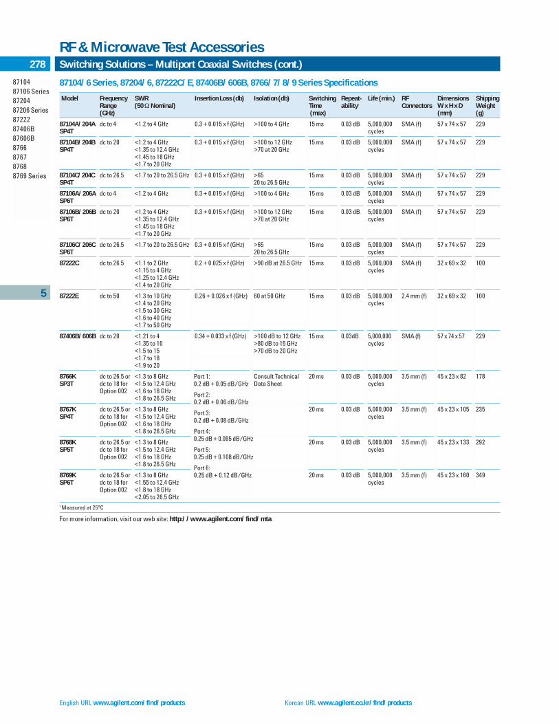
English URL www.agilent.com/find/products Korean URL www.agilent.co.kr/find/products
87104/6 Series, 87204/6, 87222C/E, 87406B/606B, 8766/7/8/9 Series Specifications
Model Frequency SWR Insertion Loss (db) Isolation (db) Switching Repeat- Life (min.) RF Dimensions ShippingRange (50 ΩNominal) Time ability1 Connectors W x H x D Weight(GHz) (max) (mm) (g)
87104A/204A dc to 4 <1.2 to 4 GHz 0.3 + 0.015 x f (GHz) >100 to 4 GHz 15 ms 0.03 dB 5,000,000 SMA (f) 57 x 74 x 57 229SP4T cycles
87104B/204B dc to 20 <1.2 to 4 GHz 0.3 + 0.015 x f (GHz) >100 to 12 GHz 15 ms 0.03 dB 5,000,000 SMA (f) 57 x 74 x 57 229SP4T <1.35 to 12.4 GHz >70 at 20 GHz cycles
<1.45 to 18 GHz<1.7 to 20 GHz
87104C/204C dc to 26.5 <1.7 to 20 to 26.5 GHz 0.3 + 0.015 x f (GHz) >65 15 ms 0.03 dB 5,000,000 SMA (f) 57 x 74 x 57 229SP4T 20 to 26.5 GHz cycles
87106A/206A dc to 4 <1.2 to 4 GHz 0.3 + 0.015 x f (GHz) >100 to 4 GHz 15 ms 0.03 dB 5,000,000 SMA (f) 57 x 74 x 57 229SP6T cycles
87106B/206B dc to 20 <1.2 to 4 GHz 0.3 + 0.015 x f (GHz) >100 to 12 GHz 15 ms 0.03 dB 5,000,000 SMA (f) 57 x 74 x 57 229SP6T <1.35 to 12.4 GHz >70 at 20 GHz cycles
<1.45 to 18 GHz<1.7 to 20 GHz
87106C/206C dc to 26.5 <1.7 to 20 to 26.5 GHz 0.3 + 0.015 x f (GHz) >65 15 ms 0.03 dB 5,000,000 SMA (f) 57 x 74 x 57 229SP6T 20 to 26.5 GHz cycles
87222C dc to 26.5 <1.1 to 2 GHz 0.2 + 0.025 x f (GHz) >90 dB at 26.5 GHz 15 ms 0.03 dB 5,000,000 SMA (f) 32 x 69 x 32 100<1.15 to 4 GHz cycles<1.25 to 12.4 GHz<1.4 to 20 GHz
87222E dc to 50 <1.3 to 10 GHz 0.26 + 0.026 x f (GHz) 60 at 50 GHz 15 ms 0.03 dB 5,000,000 2.4 mm (f) 32 x 69 x 32 100<1.4 to 20 GHz cycles<1.5 to 30 GHz<1.6 to 40 GHz<1.7 to 50 GHz
87406B/606B dc to 20 <1.21 to 4 0.34 + 0.033 x f (GHz) >100 dB to 12 GHz 15 ms 0.03dB 5,000,000 SMA (f) 57 x 74 x 57 229<1.35 to 10 >80 dB to 15 GHz cycles<1.5 to 15 >70 dB to 20 GHz<1.7 to 18<1.9 to 20
8766K dc to 26.5 or <1.3 to 8 GHz Consult Technical 20 ms 0.03 dB 5,000,000 3.5 mm (f) 45 x 23 x 82 178SP3T dc to 18 for <1.5 to 12.4 GHz Data Sheet cycles
Option 002 <1.6 to 18 GHz<1.8 to 26.5 GHz
8767K dc to 26.5 or <1.3 to 8 GHz 20 ms 0.03 dB 5,000,000 3.5 mm (f) 45 x 23 x 105 235SP4T dc to 18 for <1.5 to 12.4 GHz cycles
Option 002 <1.6 to 18 GHz<1.8 to 26.5 GHz
8768K dc to 26.5 or <1.3 to 8 GHz 20 ms 0.03 dB 5,000,000 3.5 mm (f) 45 x 23 x 133 292SP5T dc to 18 for <1.5 to 12.4 GHz cycles
Option 002 <1.6 to 18 GHz<1.8 to 26.5 GHz
8769K dc to 26.5 or <1.3 to 8 GHz 20 ms 0.03 dB 5,000,000 3.5 mm (f) 45 x 23 x 160 349 SP6T dc to 18 for <1.55 to 12.4 GHz cycles
Option 002 <1.8 to 18 GHz<2.05 to 26.5 GHz
1 Measured at 25ºC
For more information, visit our web site: http://www.agilent.com/find/mta
5
8710487106 Series8720487206 Series8722287406B87606B8766876787688769 Series
278 Switching Solutions – Multiport Coaxial Switches (cont.)
RF & Microwave Test Accessories
Port 1:0.2 dB + 0.05 dB/GHz
Port 2:0.2 dB + 0.06 dB/GHz
Port 3:0.2 dB + 0.08 dB/GHz
Port 4:0.25 dB + 0.095 dB/GHz
Port 5:0.25 dB + 0.108 dB/GHz
Port 6:0.25 dB + 0.12 dB/GHz

Traditional Chinese URL www.agilent.com.tw/find/products Simplified Chinese URL www.agilent.com.cn/find/products
5
84904K84906K84907K84904L84906L84907L84904M84905M84908M
279High-Performance Programmable Step Attenuators
RF & Microwave Test Accessories
High-Performance Programmable Step Attenuators – dc to 50 GHz
84904K/L/M (0 – 11, 1 dB steps)
84905M (0 – 60, 10 dB steps)
84906K/L (0 – 90, 10 dB steps)
84907K/L (0 – 70, 10 dB steps)
84908M (0 – 65, 5 dB steps)
The 84904/905/906/907/908 family of programmable step attenuatorsoffers unmatched attenuation performance to 50 GHz. The K modelbrings superior accuracy and reliability to 26.5 GHz, while the L modeloffers unparalleled performance to 40 GHz and the M to 50 GHz.
Agilent step attenuators consist of 3 or 4 cascaded sections ofspecific attenuation values, e.g., 1, 2, 4, 5, 10, 20 and 40 dB. Thesefamilies offer the selection, performance, accuracy and reliabilityexpected from Agilent attenuators: attenuation ranges of 11, 70, or90 dB, 1 dB and 10 dB step sizes, 5 million cycles per section, betterthan 0.03 dB repeatability, connector size options and the choice ofmale or female connectors. RF connector choices include precision3.5-mm or 2.92-mm on the 26.5 GHz K model, and precision 2.4-mmor 2.92-mm on the L model. While the 2.92-mm connector format is compatible with both 3.5-mm and SMA connectors, Agilent rec-ommends the more rugged 2.4-mm and 3.5-mm connectors. The M models offer 2.4 mm (f) connectors.
Programmable step attenuators feature electromechanicaldesigns which achieve 20 milliseconds switching time, including set-tling time. The permanent magnet latching allows automatic inter-ruption of the dc drive voltage to cut power consumption andsimplify circuit design. They are equipped with 10-pin DIP sockets(m) with interconnect cables available.
Programmable Driver InstrumentsDrive options include the 11713A and 87130A attenuator/switchdrivers, which permit users to easily integrate the attenuator intoGPIB compatible automatic test systems, and the 70611 MMS atten-uator/switch driver. Cabling options include a 5-foot InterconnectCable with 10-pin DIP socket (f), and a “Viking” connector for the11713A driver, and a 5-foot Interconnect Cable (11764B) with a 10-pin DIP socket (f) and bare leads for custom applications.
Attenuation Accuracy 26.5 to 40 GHzDC to 26.5 GHz
1 dB: 0.4 dB 1 dB: 0.6 dB2 dB: 0.5 dB 2 dB: 0.6 dB3 dB: 0.7 dB 3 dB: 0.8 dB4 dB: 0.7 dB 4 dB: 0.8 dB5 dB: 0.7 dB 5 dB: 0.8 dB6 dB: 0.7 dB 6 dB: 0.9 dB7 dB: 0.8 dB 7 dB: 1.1 dB8 dB: 0.8 dB 8 dB: 1.1 dB9 dB: 0.85 dB 9 dB: 1.2 dB10 dB: 0.9 dB 10 dB: 1.3 dB11 dB: 1.10 dB 11 dB: 1.5 dB
10 dB: 0.5 dB 10 dB: 0.5 dB20 dB: 0.6 dB 20 dB: 0.6 dB30 dB: 0.7 dB 30 dB: 0.7 dB40 dB: 1.0 dB 40 dB: 1.0 dB50 dB: 1.2 dB 50 dB: 1.2 dB60 dB: 1.6 dB 60 dB: 1.6 dB70 dB: 1.9 dB 70 dB: 1.9 dB80 dB: 2.7 dB 80 dB: 2.7 dB90 dB: 2.9 dB 90 dB: 2.9 dB
84904/6/7K/L Specifications
Model Frequency Attenuation Maximum Insertion Repeat- Life2 ShippingRange Range SWR Loss ability1 Weight(GHz) Std (Option 006) 0 dB Setting
84904K dc to 26.5 0 to 11 dB 1.3 (1.5) to 12.4 GHz 0.8 dB + 0.03 dB 5 x 10⁶ 291 g84904L dc to 40 1 dB steps 1.7 (1.9) to 34 GHz 0.04 dB/GHz (10.3 oz)
1.8 (2.0) to 40 GHz
84906K dc to 26.5 0 to 90 dB 1.3 (1.5) to 12.4 GHz 0.8 dB + 0.03 dB 5 x 10⁶ 291 g10 dB steps 1.7 (1.9) to 34 GHz 0.04 dB/GHz (10.3 oz)
84906L dc to 40 1.8 (2.0) to 40 GHz
84907K dc to 26.5 0 to 70 dB 1.25 (1.4) to 12.4 GHz 0.6 dB + 0.03 dB 5 x 10⁶ 229 g10 dB steps 1.5 (1.7) to 34 Gz 0.03 dB/GHz (8.1 oz)
84907L dc to 40 1.7 (1.9) to 40 GHz
Sensitivity power: dB/watt (temperature dB/ºC): 0.001 (0.0001)Power rating: 1 W ave, 50 W peak, 10 µs max. pulse widthSupply voltage/speed/power: 20 to 30 V/<20 ms/2.7 W1 Measured at 25ºC2 Cycles per section minimum
84904/6/7K and L

English URL www.agilent.com/find/products Korean URL www.agilent.co.kr/find/products
Agilent 84904/5/8 M Attenuation Data Uncertainties
Attenuation (dB) DC to 2 GHz 2 to 20 GHz 20 to 40 GHz 40 to 50 GHz
0 ±0.0305 ±0.0546 ±0.1256 ±0.15971 – 11 ±0.0297 ±0.0515 ±0.1238 ±0.169915 ±0.0342 ±0.0516 ±0.1263 ±0.196820 ±0.0334 ±0.0521 ±0.1240 ±0.184925 ±0.0358 ±0.0522 ±0.1251 ±0.199730 ±0.0432 ±0.0535 ±0.1283 ±0.221935 ±0.0729 ±0.1050 ±0.2521 ±0.391840 ±0.0729 ±0.1050 ±0.2521 ±0.391845 ±0.0774 ±0.1051 ±0.2546 ±0.418750 ±0.0766 ±0.1056 ±0.2523 ±0.406855 ±0.0790 ±0.1057 ±0.2534 ±0.421660 ±0.0864 ±0.1070 ±0.2566 ±0.443865 ±0.1161 ±0.1585 ±0.3804 ±0.6137
Attenuation SettingAttenuation Accuracy (±–dB; referenced from 0 dB setting):Model Number 84904M
Attenuator Setting (dB): 1 2 3 4 5 6 7 8 9 10 11
Frequency RangeDC to 18 GHz 0.35 0.45 0.55 0.55 0.55 0.55 0.60 0.60 0.65 0.70 0.8018 to 26.5 GHz 0.40 0.50 0.70 0.70 0.70 0.70 0.80 0.80 0.85 0.90 1.1026.5 GHz to 40 GHz 0.60 0.60 0.80 0.80 0.80 0.90 1.10 1.10 1.20 1.30 1.5040 to 50 GHz 0.60 0.70 0.80 0.80 0.80 0.90 1.10 1.10 1.20 1.30 1.50
Model Number 84905M
Attenuator Setting (dB): 10 20 30 40 50 60
DC to 40 GHz 0.5 0.6 0.7 1.0 1.2 1.640 to 50 GHz 0.7 0.8 1.0 1.3 1.5 1.8
Model Number 84908M
Attenuator Setting (dB): 5 10 15 20 25 30 35 40 45 50 55 60 65
DC to 40 GHz 0.5 0.5 0.6 0.6 0.7 0.7 1.0 1.0 1.2 1.2 1.6 1.6 1.840 to 50 GHz 0.7 0.7 0.8 0.8 1.0 1.0 1.3 1.3 1.5 1.5 1.8 1.8 2.0
1 Step-to-step accuracy is the maximum variation from the nominal step size when changing attenuation values. It is a second specification on accuracy, and is used in combination withthe absolute accuracy specifications to limit maximum allowable variation from nominal. Typical step-to-step accuracy for the 84905M and 84908M is ±1.0 dB to 50 GHz; for the 84904M is±0.5 to 50 GHz.
5
84904K84906K84907K84904L84906L84907L84904M84905M84908M
280 High-Performance Programmable Step Attenuators (cont.)
RF & Microwave Test Accessories
Specifications
Maximum insertion loss 84904M 84905M 84908M
DC to 40 GHz (in dB 0 dB position, (0.8 + 0.04*f) (0.6 + 0.03*f) (0.8 + 0.04*f)f = frequency in GHz)
40 to 50 GHz 3.0 2.6 3.0
Note: At 75ºC, increase insertion loss by 0.006*f (where f = frequency in GHz)
SWR
DC to 12.4 GHz 1.3 1.25 1.312.4 to 34 GHz 1.7 1.5 1.734 to 40 GHz 1.8 1.7 1.840 to 50 GHz 3.0 2.6 3.0
Attenuation Temperature Coefficient: Less than 0.0001 dB/dB/ºCPower Sensitivity: 0.001 dB/WattRF Input Power (Maximum): 1 Watt average, 50 Watts peak (10 microseconds max. pulse width)Life (Minimum): 2 million cycles per sectionRepeatability: 0.03 dB, typicalEnvironmental Capabilities: (Up to 2 million cycles)Temperature, Operating: –20ºC to +75ºCTemperature, Non-operating: –55ºC to +85ºCAltitude, Operating: 4,570 meters (15,000 feet)Altitude, Non-operating: 137,000 meters (50,000 feet)Humidity: Cycling 10 days, 65ºC at 95% RHShock, Operating: 10 Gs, 6 ms, on six sides, three blowsShock, Non-operating: 500 Gs, 0.5 ms, in six directionsVibration, Operating: 5 Gs, 34 – 500 Hz; 2 Gs, 500 – 2000Hz
EMC: Radiated interference is within the requirements of MIL-STD-461method RE02, VDE 0871 and CISPR Publication II

Traditional Chinese URL www.agilent.com.tw/find/products Simplified Chinese URL www.agilent.com.cn/find/products
5
84904K84906K84907K84904L84906L84907L84904M84905M84908M
281High-Performance Programmable Step Attenuators (cont.)
RF & Microwave Accessories
Mechanical Information
Net Weight 84904M: 291 grams (10.3 oz) 84905M: 229 grams (8.1 oz) 84908M: 291 grams (10.3 oz)
Mounting Position (any)RF Connectors2.4 mm female connectors (Option 101)2.4 mm female and 2.4 mm male (Option 100)
Switching SpeedMaximum 20 milliseconds including settling time
Solenoids Coil Voltage Switching Current Nominal Coil Impedance
Option 024 24 V (20 to 30 V) 125 mA (at 24 V) 185 Ohms
Option 015 15 V (13 to 22 V) 188 mA (at 15 V) 80 Ohms
Option 011 5 V (4.5 to 7 V) 325 mA (at 5 V) 17 Ohms
Switching current is current per section; approximately 10 ms durationbefore internal contacts open the coil circuit
Key LiteratureFor more information, visit our web site: http://www.agilent.com/find/mta
Ordering InformationAttenuators84904K 0 to 11 dB, 1 dB steps, 26.5 GHz84904L 0 to 11 dB, 1 dB steps, 40 GHz 84904M 0 to 11 dB, 1 dB steps, 50 GHz84905M 0 to 60 dB, 10 dB steps, 50 GHz84908M 0 to 65 dB, 5 dB steps, 50 GHz84906K 0 to 90 dB, 10 dB steps, 26.5 GHz 84906L 0 to 90 dB, 10 dB steps, 40 GHz 84907K 0 to 70 dB, 10 dB steps, 26.5 GHz 84907L 0 to 70 dB, 10 dB steps, 40 GHz
84907L-006 Female 2.92-mm Connectors (L models only) 84907L-011 5 Vdc Supply Voltage84907L-015 15 Vdc Supply Voltage84907L-024 24 Vdc Supply Voltage84907L-100 Male 2.4-mm Connector (L models only) 84907L-104 Male 3.5-mm Connector (K models only) 84907L-106 Male 2.92-mm Connector (L models only) 84907L-UK6 Commercial Calibration Test Data with Certificate

English URL www.agilent.com/find/products Korean URL www.agilent.co.kr/find/products
Programmable and Manual Step AttenuatorsDC – 1000 MHz
Manual355C (0 – 12 dB, 1 dB steps)355D (0 – 120 dB, 10 dB steps)
Programmable355E (0 – 12 dB, 1 dB steps)355F (0 – 120 dB, 10 dB steps)
The manual and programmable 355 C/D/E/F attenuators offerexceptional attenuation accuracy to 1 GHz; +0.1 dB to 1 kHz, 0.25 dBto 500 MHz, 0.35 to 1 GHz. They feature BNC (f) RF connectors, withoptional type-N (Option 001) and TNC (Option 005) also available. Toachieve 1 dB steps to 132 dB range, serially connect two attenuatorsusing a standard UG-491A/U BNC (m)-to-BNC (m) adapter. Program-mable 355 E/F models feature a 7-pin connector (supplied). To protectyour transistor driver against transients during the switching cycle,order Option 007 to install a protective diode between each solenoidand driver.
Programmable and Manual Step AttenuatorsDC – 26.5 GHz
8494A/B/G/H (0 – 11 dB, 1 dB steps)8495A/B/D/G/H/K (0 – 70 dB, 10 dB steps)8496A/B/G/H (0 – 110 dB, 10 dB steps)8497K (0 – 90 dB, 10 dB steps)
The 8494/95/96/97 family of step attenuators offer fast, precisesignal level control in three frequency ranges, dc to 4 GHz, dc to 18 GHz and dc to 26.5 GHz. They feature exceptional repeatabilityand reliability in a wide range of frequency, attenuation and con-nector options.
Attenuation repeatability is specified to be less than 0.03 dB (0.05 dB, 18 – 26.5 GHz) for 5 million cycles per section. This assureslow measurement uncertainty and high user confidence whendesigned into automatic test systems. Electromechanical step atten-uators offer low SWR, low insertion loss and high accuracy requiredby high-performance test and measurement equipment.
Precision plated leaf-spring contacts remove attenuator sections(miniature tantalum nitride thin-film T-pads on sapphire and alumi-na substrates) from the signal path. Unique process controls andmaterial selection ensure unmatched life and contact repeatability.
Programmable Models
Miniature drive solenoids in the programmable models keep switch-ing time, including settling, down to less than 20 milliseconds. Onceswitched, strong permanent magnets hold the solenoids (and atten-uation value) in place. Current interrupts automatically disconnectsolenoid current, simplifying driver circuit design and minimizingheat dissipation. Programming is done through a 12-pin Viking socket or optional ribbon cables with DIP plugs.
To simplify connecting programmable attenuators to the drivecircuit, each unit is supplied with a 5-ft. cable assembly. With an11713A attenuator driver, 87130A attenuator driver, or an 70611Adriver for MMS-based systems, automatic drive control is easy usingthe Agilent Technologies Interface Bus (GPIB) automated system.
11716A/C Attenuator Interconnect Kits
Quickly and conveniently connect 1 dB step and 10 dB step attenua-tors together to achieve greater dynamic range with 1 dB steps. The11716A/C interconnect kits contain a rigid RF cable, mountingbracket, and necessary hardware to connect any pair of 8494/95/96/97 attenuators in series (see photo above). Attenuators mustbe ordered separately.
Key LiteratureLatest RF & Microwave Test Accessories Catalog, p/n 5968-4314E
For more information, visit our web site: http://www.agilent.com/find/mta
Ordering Information11716A Interconnect Kit (Type-N)11716C Interconnect Kit (SMA)
8495D
5
355 Series8494849584968497 Series11716Series
282 Coaxial Step Attenuators
RF & Microwave Accessories
8495K 11716A

5
283
355 Series8494849584968497
Coaxial Step Attenuators (cont.)
RF & Microwave Test Accessories
How to Order the 8494/5/6/7 Series AttenuatorsEach order must include basic model number, suffix letter, and connector option.
Ordering example: 8494 A Option 001
4 A 001
4 (1 dB step, 11 dB max) A (Manual, dc to 4 GHz) 001 (N female)5 (10 dB step, 70 dB max) B (Manual, dc to 18 GHz) 002 (SMA female)6 (10 dB step, 110 dB max) D (Manual, dc to 26.5 GHz)1 003 (APC-7)7 (10 dB step, 90 dB max) G (Programmable, dc to 4 GHz) 004 (3.5 mm female)1
H (Programmable, dc to 18 GHz)K (Programmable, dc to 26.5 GHz)1
1 Option 004 is only available on D and K models, other options not available on D/K models.
Note 1: 355C/D/E/F connector options:Option 001 N(f)Option 005 TNC(f)Option 007 Transistor protection (355E/F only)Option 101 BNC (355C/E/F only)Option 002 BNC (355D only))Option 201No protection
Note 2: 8494/5/6/7 orders must specify connector option. See ordering example.Option 001 N(f)Option 002 SMA(f)Option 003 APC-7Option 004 3.5 mm (8495D/K, 8497K only)Option UK6 Commercial Calibration Test Data with Certificate
355 Series, 8494/5/6/7 Series Specifications
Model Frequency Attenuation Maximum Insertion Attenuation Power Solenoid Size, Connector(Switching Range Range SWR Loss Accuracy Rating, Voltage Shipping Weight OptionsMode) (GHz) (dB) @ 0 dB Minimum Speed
Life Power
355C dc to 1 0 to 12 1.2 to 250 MHz 0.2 dB + ±0.1 dB @ 1000 Hz 0.5 W avg. — 70 mm W x 67 mm H x 152 mm D 001(Manual) 1 dB steps 1.3 to 500 MHz 2.3 dB/GHz ±0.25 dB: dc to 0.5 GHz 350 W peak (2.75 in x 2.6 in x 6 in) 005
1.5 to 1 GHz ±0.35 dB: dc to 1.0 GHz 0.5 million 1.4 kg (3 lb) 101355E cycles per 15 to 18 V See Note 1(Programmable) section <65 ms
3.0 W
355D dc to 1 0 to 120 1.2 to 0.25 GHz 0.2 dB + ±0.3 dB @ 1000 Hz 0.5 W avg. — 70 mm W x 67 mm H x 152 mm D 001(Manual) 10 dB steps 1.3 to 0.5 GHz 2.3 dB/GHz ±1.5 dB to 90 dB, and 350 W peak (2.75 in x 2.6 in x 6 in) 002
1.5 to 1 GHz ±3 dB to 120 dB @ 1 GHz 0.5 million 1.4 kg (3 lb) See Note 1355F cycles per 15 to 18 V (Programmable) section <65 ms
3.0 W
8494A dc to 4 0 to 11 1.5 0.6 dB + ±0.2 dB: 1 to 2 dB 1 W avg. — 73 mm W x 43 mm H x 159 mm D 001(Manual) 1 dB steps 0.09 dB/GHz ±0.3 dB: 3 to 6 dB 100 W peak (2.9 in x 1.7 in x 6.2 in) 002
±0.4 dB: 7 to 10 dB 10 µs max. 0.9 kg (2 lb) 0038494G ±0.5 dB: 11 dB 5 million 20 to 30 V 79 mm W x 43 mm H x 168 mm D See Note 2(Programmable) cycles per <20 ms (3.1 in x 1.7 in x 6.6 in)
section 2.7 W 0.9 kg (2 lb)
8494B dc to 18 0 to 11 1.5 to 8 GHz 0.6 dB + dc to 12.4 GHz 1 W avg. — 73 mm W x 43 mm H x 159 mm D 001(Manual) 1 dB steps 1.6 to 12.4 GHz 0.09 dB/GHz ±0.3 dB: 1 to 2 dB 100 W peak (2.9 in x 1.7 in x 6.2 in) 002
1.9 to 18 GHz ±0.4 dB: 3 to 4 dB 10 µs max. 0.9 kg (2 lb) 003±0.5 dB: 5 to 6 dB 5 million See Note 2±0.6 dB: 7 to 10 dB cycles per±0.7 dB: 11 dB section
8494H dc to 18 GHz 20 to 30 V 79 mm W x 43 mm H x 168 mm D(Programmable) ±0.7 dB: 1 to 5 dB <20 ms (3.1 in x 1.7 in x 6.6 in)
±0.8 dB: 6 to 9 dB 2.7 W 0.9 kg (2 lb)±0.9 dB: 10 to 11 dB
8495A dc to 4 0 to 70 1.35 0.4 dB + ±1.7 dB of setting or 0.4 dB, 1 W avg. — 73 mm W x 43 mm H x 130 mm D 001(Manual) 10 dB steps 0.07 dB/GHz whichever is greater 100 W peak (2.9 in x 1.7 in x 5.1 in) 002
10 µs max. 0.9 kg (2 lb) 0038495G 5 million 20 to 30 V 79 mm W x 43 mm H x 141 mm D See Note 2(Programmable) cycles per <20 ms (3.1 in x 1.7 in x 5.5 in)
section 2.7 W 0.9 kg (2 lb)
8495B dc to 18 0 to 70 1.35 to 8 GHz 0.4 dB + ±3dB: dc to 12.4 GHz 1 W avg. — 73 mm W x 43 mm H x 130 mm D 001(Manual) 10 dB steps 1.5 to 12.4 GHz 0.07 dB/GHz ±4dB: dc to 18 GHz 100 W peak (2.9 in x 1.7 in x 5.1 in) 002
1.7 to 18 GHz 10 µs max. 0.9 kg (2 lb) 0038495H 5 million 20 to 30 V 79 mm W x 43 mm H x 141 mm D See Note 2(Programmable) cycles per <20 ms (3.1 in x 1.7 in x 5.5 in)
section 2.7 W 0.9 kg (2 lb)
8495D dc to 26.5 0 to 70 1.25 to 6 GHz 0.5 dB + ±0.3 dB at 6 GHz 10 dB 1 W avg. — 52 mm W x 43 mm H x 159 mm D 004(Manual) 10 dB steps 1.45 to 12.4 GHz 0.13 dB/GHz attenuation to 100 W peak (2.1 in x 1.7 in x 6.2 in) 3.5 mm
1.6 to 18.0 GHz ±2.8 dB at 26.5 GHz 10 µs max. 0.9 kg (2 lb) See Note 28495K 1.8 to 26.5 GHz 70 dB attenuation 5 million 20 to 30 V 52 mm W x 43 mm H x 168 mm D(Programmable) cycles per <20 ms (2.1 in x 1.7 in x 6.6 in)
section 2.7 W 0.9 kg (2 lb)
8496A dc to 4 0 to 110 1.5 0.6 dB + ±1.8 dB of setting 1 W avg. — 73 mm W x 43 mm H x 159 mm D 001(Manual) 10 dB steps 0.09 dB/GHz 100 W peak (2.9 in x 1.7 in x 6.2 in) 002
10 µs max. 0.9 kg (2 lb) 0038496G 5 million 20 to 30 V 79 mm W x 43 mm H x 168 mm D See Note 2(Programmable) cycles per <20 ms (3.1 in x 1.7 in x 6.6 in)
section 2.7 W 0.9 kg (2 lb)
8496B dc to 18 0 to 110 1.5 to 8 GHz 0.6 dB + ±3 dB: dc to 12.4 GHz 1 W avg. — 73 mm W x 43 mm H x 159 mm D 001(Manual) 10 dB steps 1.6 to 12.4 GHz 0.09 dB/GHz ±4 dB: dc to 18 GHz 100 W peak (2.9 in x 1.7 in x 6.2 in) 002
1.9 to 18 GHz 10 µs max. 0.9 kg (2 lb) 0038496H 5 million 20 to 30 V 79 mm W x 43 mm H x 168 mm D See Note 2(Programmable) cycles per <20 ms (3.1 in x 1.7 in x 6.6 in)
section 2.7 W 0.9 kg (2 lb)
8497K dc to 26.5 0 to 90 1.25 to 6 GHz 0.4 dB + ±0.3 dB at 6 GHz 10 dB 1 W avg. 5 V or 24 V 52 mm W x 43 mm H x 143 mm D 004(Programmable) 10 dB steps 1.45 to 12.4 GHz 0.09 dB/GHz attenuation to 100 W peak (2.1 in x 1.7 in x 5.6 in) 3.5 mm
1.6 to 18.0 GHz ±2.8 dB at 26.5 GHz 10 µs max. 0.9 kg (2 lb) See Note 21.8 to 26.5 GHz 90 dB attenuation 5 million
cycles persection
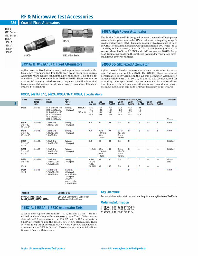
English URL www.agilent.com/find/products Korean URL www.agilent.co.kr/find/products
5
284
8491A/B, 8493A/B/C Fixed Attenuators
Agilent coaxial fixed attenuators provide precise attenuation, flatfrequency response, and low SWR over broad frequency ranges.Attenuators are available in nominal attenuations of 3 dB and 6 dB,as well as 10 dB increments from 10 dB to 60 dB. These attenuatorsare swept-frequency tested to ensure they meet specifications at allfrequencies. Calibration points are provided on a nameplate chartattached to each unit.
8498A High Power Attenuator
The 8498A Option 030 is designed to meet the needs of high-powerattenuation applications in the RF and microwave frequency range. Itis a 25-watt average, 30 dB fixed attenuator with a frequency of dc to18 GHz. The maximum peak power specification is 500 watts (dc to 5.8 GHz) and 125 watts (5.8 to 18 GHz). Available only in a 30 dB version, the unit offers a 1.3 SWR and ±1 dB accuracy at 18 GHz. Largeheat-dissipating fins keep the unit cool even under continuous maxi-mum input power conditions.
8490D 50-GHz Fixed Attenuator
Agilent coaxial fixed attenuators have been the standard for accu-rate flat response and low SWR. The 8490D offers exceptional performance to 50 GHz using the 2.4-mm connector. Attenuationvalues available are 3, 6, 10, 20, 30 and 40 dB. Ideally suited forextending the range of sensitive power meters, or for use as calibra-tion standards, these broadband attenuators are manufactured withthe same meticulous care as their lower frequency counterparts.
Models Options UK6
8491A, 8491B, 8492A, Opt UK6-Commercial Calibration8493A, 8493B, 8493C, 8498A Test Data with Certificate
11581A, 11582A, 11583C Attenuator Sets
A set of four Agilent attenuators — 3, 6, 10, and 20 dB — are fur-nished in a handsome walnut accessory case. The 11581A set con-sists of 8491A attenuators; the 11582A set, 8491B attenuators;8492A attenuators; and the 11583C set, 8493C attenuators. Thesesets are ideal for calibration labs or where precise knowledge ofattenuation and SWR is desired. Also includes commercial calibra-tion certificate with test data.
8490D, 8491A/B/C, 8492A, 8493A/B/C, 8498A, Specifications
Model Frequency SWR Input Attenuation Accuracy (+dB) ConnectorsRange (max.) Power 3 dB 6 dB 10 dB 20 dB 30 dB 40 dB 50 dB 60 dB(GHz) (max.) Opt 003 Opt 006 Opt 010 Opt 020 Opt 030 Opt 040 Opt 050 Opt 060
8490D dc to 50 dc to 26.5 GHz: 1.15 2 W avg. dc to 26.5 +0.9 +0.9 +0.9 +1.3 +1.3 +2.5(1.08 Opt 040 only) 100 W peak –0.5 –0.6 –0.6 –0.8 –0.8 –1.826.5 to 40 GHz: 1.25 26.5 to 50 +1.8 +1.8 +1.3 +1.7 +1.7 +2.5(1.15 Opt 040 only) –0.5 –0.6 –0.6 –0.8 –0.8 –1.840 to 50 GHz: 1.45(1.25 Opt 040 only) 2.4 mm
8491A dc to 12.4 1.2 to 8 GHz 2 W avg. 0.3 0.3 0.5 0.5 1.0 1.5 1.5 2 N (m,f)3 to 30 dB 1.3 to 12.4 GHz 100 W peak40 to 60 dB
8491B dc to 18 1.2 to 8 GHz 2 W avg. 0.3 0.3 to 0.6 0.6 to 1.0 1.5 1.5 2 N (m,f)3 to 30 dB 1.3 to 12.4 GHz 100 W peak 12.4 GHz 12.4 GHz40 to 60 dB 1.5 to 18 GHz 0.4 to 1.0 to
18 GHz 18 GHz
8493A dc to 12.4 1.2 to 8 GHz 2 W avg. 0.3 0.3 0.5 0.5 1.0 — — — SMA (m,f)3 to 20 dB 1.3 to 12.4 GHz 100 W peak30 dB
8493B dc to 18 1.2 to 8 GHz 2 W avg. +0.3 dB 0.3 to 0.6 0.6 to 1.0 — — — SMA (m,f)3 to 20 dB 1.3 to 12.4 GHz 100 W peak 12.4 GHz 12.4 GHz30 dB 1.5 to 18 GHz 0.4 to 1.0 to
18 GHz 18 GHz
8493C dc to 26.5 1.1 to 8 GHz 2 W avg. 0.5 to 0.6 0.3 0.5 0.7 1.0 — — 3.5 mm3 to 30 dB 1.15 to 12.4 GHz 100 W peak 18 GHz (m,f)
1.25 to 26.5 GHz 1.0 to 40 dB 26.5 GHz 0.6 0.5 0.6 1 1.3 — —
8498A dc to 18 1.15 to 8 GHz 25 W avg. — — — — 1.0 — — — N (m,f)30 dB 1.25 to 12.4 GHz 500 W peak
1.30 to 18 GHz (dc to 5.8 GHz)125 W peak500 W/msmax. per pulse(5.8 to 18 GHz)
Key LiteratureFor more information, visit our web site: http://www.agilent.com/find/mta
Ordering Information11581A 3, 6, 10, 20 dB 8491A Set 11582A 3, 6, 10, 20 dB 8491B Set 11583C 3, 6, 10, 20 dB 8493C Set
8492A
8490D8491 Series8493 Series8498A11581A11582A11583A11583C
Coaxial Fixed Attenuators
RF & Microwave Test Accessories
8490D 8493A/B/C Series

Traditional Chinese URL www.agilent.com.tw/find/products Simplified Chinese URL www.agilent.com.cn/find/products
5
285
423B8470 Series83036C
Coaxial Detectors
RF & Microwave Test Accessories
Low-Barrier Schottky Diode Detectors
423B, 8470B, 8472B, 8473B/CThese Low-Barrier Schottky Diode (LBSD) detectors have been wide-ly used for many years in a variety of applications including levelingand power sensing. They offer good performance and ruggedness.Matched pairs (Option 001) offer very good detector tracking. A videoload option (Option 002) extends the square-law region to at least 0.1 mW(–10 dBm).
Planar-Doped Barrier Detectors
8471D/EThe 8471D/E are economy detectors based on the Planar-DopedBarrier (PDB) diodes. The PDB diodes give them superior frequencyresponse, square-law response, and temperature performance. The8471D has a BNC (m) input connector and a frequency range of 100 kHzto 2 GHz, making it ideal for use in RF and low microwave applica-tions. The 8471E has a SMA (m) input connector and a SMC (m) output connector. Its frequency range is 10 MHz to 12 GHz. Bothmodels come with a negative polarity output, option 301; a positivepolarity output can be specified as Option 103.
8473DThe 8473D detector was the first gallium arsenide PDB diode intro-duced. It features broadband performance and excellent flatnessvs. frequency, along with superior temperature stability. The 8473Dis available with a 3.5-mm (m) RF connector and a BNC (f) outputconnector.
High-Performance Planar-Doped BarrierDetectors
8474B/C/E Utilizing a gallium arsenide PDB diode as the detecting element,these detectors offer superior performance when compared to earli-er detector designs. They feature extremely flat frequency responseover their entire band of operation (typically better than ±1 dB to 50 GHz) and very good frequency response stability versus tempera-ture. For applications where broadband frequency coverage is notrequired, octave band options are available in specific bands.
The 8474 detectors are available with BNC(f) (0.01 to 18 GHz),Type N (0.01 to 18 GHz), 3.5 mm (mates with SMA, 0.01 to 33 GHz),or 2.4 mm (0.01 to 50 GHz) connectors. These detectors are offeredwith options for optimal square-law loads (Option 102) and for pos-itive polarity output (Option 103). Because the unit-to-unit frequen-cy response tracking of these devices is typically better than ±0.3 dB,no matched response option is offered.
Broadband Directional Detector
83036CThe 83036C is a broadband microwave power sampler that operatesin much the same way as a directional coupler and detector combi-nation. It is composed of a resistive bridge and PDB diode that yieldsa very broadband device with excellent frequency response, superiortemperature response and square-law response characteristics. Witha 10 MHz to 26.5 GHz frequency range, a single 83036C can be used inmany applications where two directional couplers and detectorswere once required, such as in broadband power monitoring andsource leveling.
The maximum SWR is 1.7 above 50 MHz on both the input andoutput ports. Directivity of 14 dB matches that of most miniaturecouplers currently available. The maximum insertion loss is 2.2 dB.
The 83036C has been used with great success as the samplingelement for external leveling of broadband swept frequency sources.The extended frequency range increases the usable band from 100MHz to 26 GHz, giving the user full use of the broadband source withexternal leveling. Other uses include the internal leveling elementfor sources, and forward/reverse power monitoring.
Key LiteratureFor more information, visit our web site: http://www.agilent.com/find/mta
8474 Series 8471D/E 83036C

English URL www.agilent.com/find/products Korean URL www.agilent.co.kr/find/products
5
286
Planar-Doped Barrier Diode Detectors Specifications
Model Freq. Freq. Max. SWR Low-level Max. Input Short-term 102 Opt. 103/301 Input/Range Response Sensitivity (Peak or Max. Input Optimum Positive Output(GHz) (dB) Average) (<1 min.) Square- Polarity Connector
Law Load Output
8471D 0.0001 to 2 ±0.2 to 1 GHz 1.23 to 1 GHz >0.5 mV/µW 100 mW 0.7 W Opt. 102 Opt. 103 BNC (m)±0.4 to 2 GHz 1.46 to 2 GHz Opt. 301 BNC (f)
8471E 0.01 to 12 ±0.23 to 4 GHz 1.2 to 4 GHz >0.4 mV/µW 200 mW 0.75 W No Opt. 103 SMA (m)±0.6 to 8 GHz 1.7 to 8 GHz Opt. 301 SMC (m)±0.85 to 12 GHz 2.4 to 12 GHz
8473D 0.01 to 33 ±0.25 to 14 GHz 1.2 to 14 GHz >0.4 mV/µW 200 mW 1 W Note 1 Opt. 003 3.5 mm (m)±0.40 to 26.5 GHz 1.36 to 26.5 GHz Opt. 301 BNC (f)±1.25 to 33 GHz 2.96 to 33 GHz
8474B1 0.01 to 18 ±0.35 to 18 GHz 1.3 to 18 GHz >0.4 mV/µW 200 mW 0.75 W Note 1 Opt. 103 Type N (m)Opt. 301 BNC (f)Note 1
8474C1 0.01 to 33 ±0.45 to 26.5 GHz 1.4 to 26.5 GHz >0.4 mV/µW 200 mW 0.75 W No Opt. 103 3.5 mm (m)±0.70 to 33 GHz 2.2 to 33 GHz Opt. 301 SMC (m)
Note 1
8474E1 0.01 to 50 ±0.4 to 26.5 GHz 1.2 to 26.5 GHz >0.4 mV/µW 200 mW 0.75 W No No 2.4 mm (m)±0.6 to 40 GHz 1.6 to 40 GHz Note 1 SMC (m)±1.0 to 50 GHz 2.8 to 50 GHz
1 Octave band options available (see Data Sheet).
Broadband Directional Detector Specifications
Model Freq. Freq. Max. SWR Max. Low-level Min. Max. Input Max. Input Input/Range Response Input/Output Thru Line Sensitivity Directivity (Into 50 Ω Load) w/ (Into Open) w/ Output(GHz) (dB) (50 ΩNom.) Loss (dB) (dB) 2:1 Source Match 2:1 Source Match Connector
83036C 0.01 to 26.5 ±1.0 1.7 2.2 18 mV/µW 14 32 dBm 21 dBm 3.5 mm (f)
Low-Barrier Schottky Diode Detectors Specifications
Model Freq. Freq. Max. SWR Low-level Max. Short-term Matched Optimum Positive Input/Range Response (50 ΩNom.) Sensitivity Input Max. Response Square-law Polarity Output(GHz) (dB) (mV/µW) (Peak or Input Opt. 001 Load 1 Output Connector
Average) (<1 min.)
423B 0.01 to 12.4 ±0.3 to 12.4 GHz 1.15 to 4 GHz >0.5 200 mW 1 W ±0.2 dB to Opt. 002 Opt. 003 N (m)1.3 to 12.4 GHz (typical) 12.4 GHz BNC (f)
8470B 0.01 to 18 ±0.3 to 12.4 GHz 1.15 to 4 GHz >0.5 200 mW 1 W ±0.2 dB to Opt. 002 Opt. 003 APC-7±0.5 to 15 GHz 1.3 to 15 GHz (typical) 12.4 GHz BNC (f)±0.6 to 18 GHz 1.7 to 18 GHz ±0.3 to N (m)
18 GHz BNC (f)
8472B 0.01 to 18 ±0.3 to 12.4 GHz 1.15 to 4.5 GHz >0.5 200 mW 1 W ±0.2 dB to Opt. 002 Opt. 003 SMA (m)±0.5 to 15 GHz 1.35 to 7 GHz (typical) 12.4 GHz BNC (f)±0.6 to 18 GHz 1.5 to 12.4 GHz ±0.3 to SMA (m)
1.7 to 18 GHz 18 GHz OSSM (f)
8473B 0.01 to 18 ±0.3 to 12.4 GHz 1.2 to 4 GHz >0.5 200 mW 1 W ±0.2 dB to Opt. 002 Opt. 003 3.5 mm (m)±0.6 to 18 GHz 1.5 to 18 GHz (typical) 12.4 GHz BNC (f)
±0.3 to18 GHz
8473C 0.01 to 26.5 ±0.3 to 12.4 GHz 1.2 to 4 GHz >0.5 200 mW 1 W ±0.2 dB to Opt. 002 Opt. 003 3.5 mm (m)±0.6 to 20 GHz 1.5 to 18 GHz (typical) 12.4 GHz BNC (f)±1.5 to 26.5 GHz 2.2 to 26.5 GHz ±0.3 to
18 GHz±0.5 to26.5 GHz
1 Defined as ±0.5 from ideal square law response.
For more information, visit our web site: http://www.agilent.com/find/mta
423B8470 Series83036C
Coaxial Detectors (cont.)
RF & Microwave Test Accessories
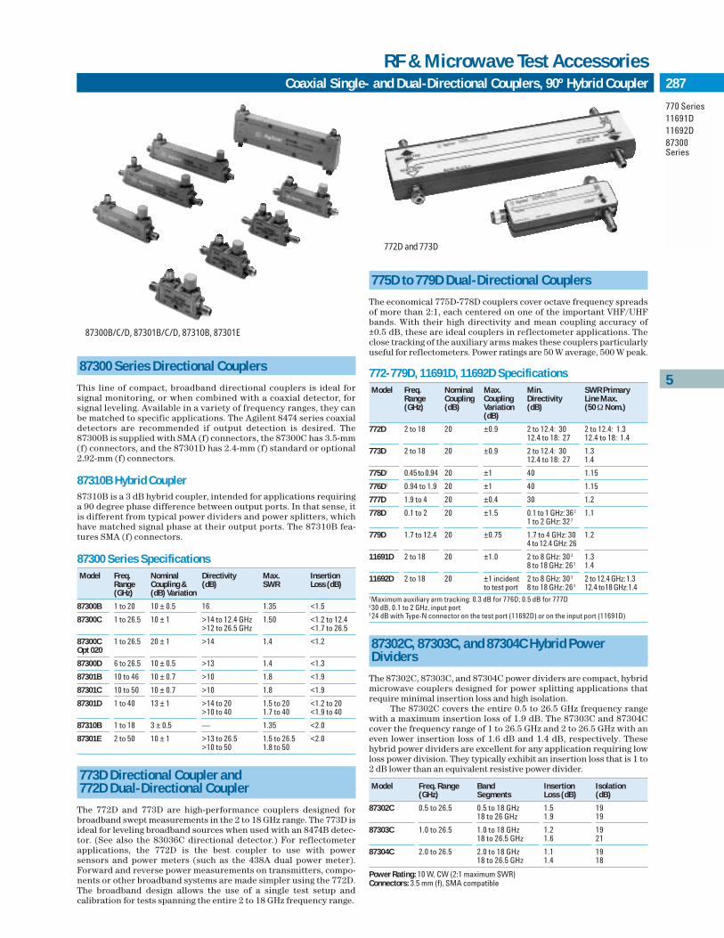
5
287
770 Series11691D11692D87300Series
Coaxial Single- and Dual-Directional Couplers, 90º Hybrid Coupler
RF & Microwave Test Accessories
87300 Series Directional Couplers
This line of compact, broadband directional couplers is ideal for signal monitoring, or when combined with a coaxial detector, for signal leveling. Available in a variety of frequency ranges, they canbe matched to specific applications. The Agilent 8474 series coaxialdetectors are recommended if output detection is desired. The87300B is supplied with SMA (f) connectors, the 87300C has 3.5-mm(f) connectors, and the 87301D has 2.4-mm (f) standard or optional2.92-mm (f) connectors.
87310B Hybrid Coupler 87310B is a 3 dB hybrid coupler, intended for applications requiringa 90 degree phase difference between output ports. In that sense, itis different from typical power dividers and power splitters, whichhave matched signal phase at their output ports. The 87310B fea-tures SMA (f) connectors.
87300 Series SpecificationsModel Freq. Nominal Directivity Max. Insertion
Range Coupling & (dB) SWR Loss (dB)(GHz) (dB) Variation
87300B 1 to 20 10 ± 0.5 16 1.35 <1.5
87300C 1 to 26.5 10 ± 1 >14 to 12.4 GHz 1.50 <1.2 to 12.4>12 to 26.5 GHz <1.7 to 26.5
87300C 1 to 26.5 20 ± 1 >14 1.4 <1.2Opt 020
87300D 6 to 26.5 10 ± 0.5 >13 1.4 <1.3
87301B 10 to 46 10 ± 0.7 >10 1.8 <1.9
87301C 10 to 50 10 ± 0.7 >10 1.8 <1.9
87301D 1 to 40 13 ± 1 >14 to 20 1.5 to 20 <1.2 to 20>10 to 40 1.7 to 40 <1.9 to 40
87310B 1 to 18 3 ± 0.5 — 1.35 <2.0
87301E 2 to 50 10 ± 1 >13 to 26.5 1.5 to 26.5 <2.0>10 to 50 1.8 to 50
773D Directional Coupler and 772D Dual-Directional Coupler
The 772D and 773D are high-performance couplers designed forbroadband swept measurements in the 2 to 18 GHz range. The 773D isideal for leveling broadband sources when used with an 8474B detec-tor. (See also the 83036C directional detector.) For reflectometerapplications, the 772D is the best coupler to use with power sensors and power meters (such as the 438A dual power meter).Forward and reverse power measurements on transmitters, compo-nents or other broadband systems are made simpler using the 772D.The broadband design allows the use of a single test setup and calibration for tests spanning the entire 2 to 18 GHz frequency range.
775D to 779D Dual-Directional Couplers
The economical 775D-778D couplers cover octave frequency spreadsof more than 2:1, each centered on one of the important VHF/UHFbands. With their high directivity and mean coupling accuracy of ±0.5 dB, these are ideal couplers in reflectometer applications. Theclose tracking of the auxiliary arms makes these couplers particularlyuseful for reflectometers. Power ratings are 50 W average, 500 W peak.
772-779D, 11691D, 11692D SpecificationsModel Freq. Nominal Max. Min. SWR Primary
Range Coupling Coupling Directivity Line Max.(GHz) (dB) Variation (dB) (50 ΩNom.)
(dB)
772D 2 to 18 20 ±0.9 2 to 12.4: 30 2 to 12.4: 1.312.4 to 18: 27 12.4 to 18: 1.4
773D 2 to 18 20 ±0.9 2 to 12.4: 30 1.312.4 to 18: 27 1.4
775D1 0.45 to 0.94 20 ±1 40 1.15
776D1 0.94 to 1.9 20 ±1 40 1.15
777D 1.9 to 4 20 ±0.4 30 1.2
778D 0.1 to 2 20 ±1.5 0.1 to 1 GHz: 362 1.11 to 2 GHz: 32 2
779D 1.7 to 12.4 20 ±0.75 1.7 to 4 GHz: 30 1.24 to 12.4 GHz: 26
11691D 2 to 18 20 ±1.0 2 to 8 GHz: 30 3 1.38 to 18 GHz: 263 1.4
11692D 2 to 18 20 ±1 incident 2 to 8 GHz: 30 3 2 to 12.4 GHz:1.3to test port 8 to 18 GHz: 263 12.4 to18 GHz:1.4
1Maximum auxiliary arm tracking: 0.3 dB for 776D; 0.5 dB for 777D230 dB, 0.1 to 2 GHz, input port3 24 dB with Type-N connector on the test port (11692D) or on the input port (11691D)
87302C, 87303C, and 87304C Hybrid Power Dividers
The 87302C, 87303C, and 87304C power dividers are compact, hybridmicrowave couplers designed for power splitting applications thatrequire minimal insertion loss and high isolation.
The 87302C covers the entire 0.5 to 26.5 GHz frequency rangewith a maximum insertion loss of 1.9 dB. The 87303C and 87304Ccover the frequency range of 1 to 26.5 GHz and 2 to 26.5 GHz with aneven lower insertion loss of 1.6 dB and 1.4 dB, respectively. Thesehybrid power dividers are excellent for any application requiring lowloss power division. They typically exhibit an insertion loss that is 1 to2 dB lower than an equivalent resistive power divider.
Model Freq. Range Band Insertion Isolation(GHz) Segments Loss (dB) (dB)
87302C 0.5 to 26.5 0.5 to 18 GHz 1.5 1918 to 26 GHz 1.9 19
87303C 1.0 to 26.5 1.0 to 18 GHz 1.2 1918 to 26.5 GHz 1.6 21
87304C 2.0 to 26.5 2.0 to 18 GHz 1.1 1918 to 26.5 GHz 1.4 18
Power Rating: 10 W, CW (2:1 maximum SWR)Connectors: 3.5 mm (f), SMA compatible
772D and 773D
87300B/C/D, 87301B/C/D, 87310B, 87301E

288
6 Digital Design and TestDebug, Verification & Characterization
Related Documents