Agenda Item 650-641 1/30/09 Page 1 of 2 API AGENDA ITEM 650-641 Appendix J Revisons for Materials and Weld Spacing Revision 0 (January 30, 2009) HANDLED BY : Steve Braune, [email protected] Tank Industry Consultants 14241 Midlothian Turnpike, #312 Midlothian, Virginia 23113 804.897.7176 Office 804.897.7178 Fax 804.307.5609 Mobile PURPOSE : This agenda item will clarify nozzle weld spacing and modify the material toughness requirements in Appendix J, Shop-Assembled Storage Tanks ORIGIN : This item originated as a result of Spring 2007 SGF meeting regarding shell nozzle weld spacing requirements. This item was later expanded to include clarification of toughness requirements as a result of discussion at Fall 2007 SGF meeting and Inquiry 650-I- 17/07. STATUS : - Originated at Spring 2007 SGF meeting - MS&P to SCLB Fall 2008 SGF meeting BUSINESS IMPACT : This agenda is business-neutral. It clarifies important technical issues, but does not affect the overall costs of shop-built storage tanks.

Welcome message from author
This document is posted to help you gain knowledge. Please leave a comment to let me know what you think about it! Share it to your friends and learn new things together.
Transcript

Agenda Item 650-641 1/30/09 Page 1 of 2
API AGENDA ITEM 650-641
Appendix J Revisons for Materials and Weld Spacing
Revision 0
(January 30, 2009)
HANDLED BY: Steve Braune, [email protected]
Tank Industry Consultants 14241 Midlothian Turnpike, #312
Midlothian, Virginia 23113 804.897.7176 Office
804.897.7178 Fax 804.307.5609 Mobile
PURPOSE: This agenda item will clarify nozzle weld spacing and modify the material toughness requirements in Appendix J, Shop-Assembled Storage Tanks ORIGIN: This item originated as a result of Spring 2007 SGF meeting regarding shell nozzle weld spacing requirements. This item was later expanded to include clarification of toughness requirements as a result of discussion at Fall 2007 SGF meeting and Inquiry 650-I-17/07. STATUS: - Originated at Spring 2007 SGF meeting - MS&P to SCLB Fall 2008 SGF meeting BUSINESS IMPACT: This agenda is business-neutral. It clarifies important technical issues, but does not affect the overall costs of shop-built storage tanks.

Agenda Item 650-641 1/30/09 Page 2 of 2 TECHNICAL JUSTIFICATION:
Weld Spacing Requirements…
As currently written, Appendix J is silent on the requirements of weld spacing around shell openings. As such, the requirements of Section 5.7 2 of the Standard must be applied. This is far too conservative for tanks which are typically smaller that an Appendix A tank. This revision to the Standard will make the weld spacing requirements Appendix A and J identical.
Material Selection Requirements…
As currently written, Appendix J requires that materials be selected by the Section 4 of the Standard. This is considered to be overly conservative for tanks that are much smaller and thinner than a typical Appendix A tank. This revision will require that the rules of Appendix A be used for the selection of materials when stressed components do not exceed 13mm (1/2”) in thickness.
Although not common, it is possible that the shell or bottom plate thickness may exceed 13mm (1/2”). This may occur due to a high corrosion allowance, design for vacuum or support on a grillage. When the shell or bottom plate thickness exceeds 13mm (1/2”), the selection of materials must satisfy the requirements of Section 4 of the Standard.

•
08
08
Agenda Item 650-641 1/30/09 Page 3 of 6
APPENDIX J—SHOP-ASSEMBLED STORAGE TANKS
J.1 ScopeJ.1.1 This appendix provides requirements for the design and fabrication of vertical storage tanks in sizes that permit completeshop assembly and delivery to the installation site in one piece. Storage tanks designed according to this appendix shall not exceed6 m (20 ft) in diameter.
J.1.2 The application of this appendix to the design and fabrication of shop-assembled storage tanks shall be mutually agreedupon by the Purchaser and the Manufacturer.
J.2 MaterialsThe material requirements of Section 4 of this Standard are applicable.
J.3 DesignJ.3.1 JOINTS
J.3.1.1 Joints shall be designed as specified in 5.1; however, lap-welded joints in bottoms are not permissible. In addition, themodifications given in J.3.1.2 through J.3.1.5 are applicable.
J.3.1.2 All shell joints shall be butt-welded so that full penetration is produced without the use of back-up bars.
J.3.1.3 Shell plates shall be sized to limit the number of plates to the smallest practical number consistent with sound economicpractice. Each course should preferably be constructed of one plate.
J.3.1.4 Top angles are not required for flanged-roof tanks.
J.3.1.5 Joints in bottom plates shall be butt-welded. The welding shall produce complete penetration of the parent metal.
J.3.2 BOTTOMSJ.3.2.1 All bottom plates shall have a minimum nominal thickness of 6 mm (0.236 in.) (49.8 kg/m2 [10.2 lbf/ft2], see 2.2.1.2and 3.4.1).
J.3.2.2 Bottoms shall be constructed of a minimum number of pieces; wherever feasible they shall be constructed of one piece.
J.3.2.3 Bottoms may be flat or flat flanged. A flat-bottom shall project at least 25 mm (1 in.) beyond the outside diameter of theweld attaching the bottom to the shell plate. A flat-flanged bottom shall have an inside corner radius that is not less than threetimes the bottom thickness and a straight flange that is a minimum of 19 mm (3/4 in.).
J.3.2.4 For flat bottoms, the attachment between the bottom edges of the lowest course shell plate and the bottom plate shall bea continuous fillet weld laid on each side of the shell plate. Each fillet weld shall be sized in accordance with 5.1.5.7. A flat-flanged bottom shall be attached to the shell by full-penetration butt-welds.
J.3.3 SHELLS
Shell plates shall be designed in accordance with the formula given in A.4.1, but the nominal thickness of shell plates shall not beless than the following:
a. For tanks with a diameter less than or equal to 3.2 m (10.5 ft) – 4.8 mm (3/16 in.).b. For tanks with a diameter greater than 3.2 m (10.5 ft) – 6 mm (0.236 in.).
J.3.4 WIND GIRDERS FOR OPEN-TOP TANKS
Open-top tanks shall be provided with wind girders as specified in 5.9.
J.3.5 ROOFS
J.3.5.1 General
Roofs for tanks constructed in accordance with this appendix shall be of the self-supporting type and shall conform to eitherJ.3.5.2 or J.3.5.3.
J-1
braune
Line
braune
Callout
Editorial correction to 4.2.1.2
braune
Line
braune
Callout
Editorial correction to 5.4.1
braune
Line
braune
Line
braune
Callout
NEW J.2.1 The material requirements of Appendix A of this Standard are applicable, except as noted in J.2.2. NEW J.2.2 The selection of shell or bottom plate materials exceeding a nominal thickness of 13 mm (1/2 inch) shall be based upon the requirements of Section 4 of this Standard.

J-2 API STANDARD 650
•
08
Agenda Item 650-641 1/30/09 Page 4 of 6
J.3.5.2 Cone Roofs
Self-supporting cone roofs shall be designed as specified in 5.10.5, except they may be provided with a flange that will permitbutt-welded attachment to the shell (see J.3.1.4). Flanges shall be formed with a minimum inside corner radius of three times theroof thickness or 19 mm (3/4 in.), whichever is larger.
J.3.5.3 Dome and Umbrella Roofs
Self-supporting dome and umbrella roofs shall be designed as specified in 5.10.6, except they may be flanged as described in J.3.5.2.For dome roofs that are flanged, the radius of curvature shall not be limited to the maximum requirements given in 5.10.6; instead,the curvature shall be limited by the depth of the roof, including the crown and knuckle depth, as listed in Tables J-1a and J-1b.
J.3.5.4 Top Angles
When top angles are required, they shall be attached as specified in 5.10.7.
J.3.6 TANK CONNECTIONS AND APPURTENANCES
J.3.6.1 Manholes, nozzles, and other connections in the shell shall be constructed and attached as specified in 5.7, but it isunlikely that reinforcing plates will be required for manholes and nozzles in the tank shell. The need for reinforcement shall bechecked according to the procedure given in 5.7.2. Since the minimum shell-plate thicknesses given in J.3.3 will normally exceedthe calculated thickness, the excess material in the shell should satisfy the reinforcement requirements in nearly all cases.
J.3.6.2 The roofs of tanks constructed in accordance with this appendix will be inherently strong because of the limitations indiameter required for shipping clearances. Thus, reinforcement of roof manholes and nozzles is not required unless specificallyrequested by the Purchaser or unless roof loads exceed 1.2 kPa (25 lbf/ft2), in which case the amount and type of reinforcementshall be agreed upon by the Purchaser and the Manufacturer.
Table J-1a—(SI) Maximum Roof Depths for Shop-Assembled Dome-Roof Tanks
Diameter Depth
m mm
≤ 1.8 50
≤ 2.4 90
≤ 3.0 140
≤ 3.7 200
≤ 4.3 275
≤ 4.9 375
≤ 6.0 500
Table J-1b—(USC) Maximum Roof Depths for Shop-Assembled Dome-Roof Tanks
Diameter Depth
ft in.
6 2
8 31/210 51/212 8
14 11
16 15
20 20
braune
Callout
NEW J.3.6.2... J.3.6.2 The requirements of 5.7.3 for the spacing of welds do not apply except for the requirement that the spacing between the toes of welds around a connection shall not be less than 2.5 times the shell thickness at the connection. (NOTE TO BALLOTER... This statement is identical to A.5.2)
braune
Callout
Renumber as J.3.6.3
braune
Line
WELDED TANKS FOR OIL STORAGE J-3
•
•
•
07
•
Agenda Item 650-641 1/30/09 Page 5 of 6
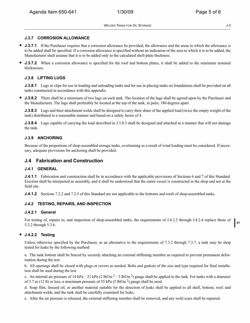
J.3.7 CORROSION ALLOWANCE
J.3.7.1 If the Purchaser requires that a corrosion allowance be provided, the allowance and the areas to which the allowance isto be added shall be specified. If a corrosion allowance is specified without an indication of the area to which it is to be added, theManufacturer shall assume that it is to be added only to the calculated shell-plate thickness.
J.3.7.2 When a corrosion allowance is specified for the roof and bottom plates, it shall be added to the minimum nominalthicknesses.
J.3.8 LIFTING LUGS
J.3.8.1 Lugs or clips for use in loading and unloading tanks and for use in placing tanks on foundations shall be provided on alltanks constructed in accordance with this appendix.
J.3.8.2 There shall be a minimum of two lugs on each tank. The location of the lugs shall be agreed upon by the Purchaser andthe Manufacturer. The lugs shall preferably be located at the top of the tank, in pairs, 180 degrees apart.
J.3.8.3 Lugs and their attachment welds shall be designed to carry their share of the applied load (twice the empty weight of thetank) distributed in a reasonable manner and based on a safety factor of 4.
J.3.8.4 Lugs capable of carrying the load described in J.3.8.3 shall be designed and attached in a manner that will not damagethe tank.
J.3.9 ANCHORING
Because of the proportions of shop-assembled storage tanks, overturning as a result of wind loading must be considered. If neces-sary, adequate provisions for anchoring shall be provided.
J.4 Fabrication and ConstructionJ.4.1 GENERAL
J.4.1.1 Fabrication and construction shall be in accordance with the applicable provisions of Sections 6 and 7 of this Standard.Erection shall be interpreted as assembly, and it shall be understood that the entire vessel is constructed in the shop and not at thefield site.
J.4.1.2 Sections 7.2.2 and 7.2.5 of this Standard are not applicable to the bottoms and roofs of shop-assembled tanks.
J.4.2 TESTING, REPAIRS, AND INSPECTION
J.4.2.1 General
For testing of, repairs to, and inspection of shop-assembled tanks, the requirements of J.4.2.2 through J.4.2.4 replace those of5.3.2 through 5.3.6.
J.4.2.2 Testing
Unless otherwise specified by the Purchaser, as an alternative to the requirements of 7.3.2 through 7.3.7, a tank may be shoptested for leaks by the following method:
a. The tank bottom shall be braced by securely attaching an external stiffening member as required to prevent permanent defor-mation during the test.b. All openings shall be closed with plugs or covers as needed. Bolts and gaskets of the size and type required for final installa-tion shall be used during the test.c. An internal air pressure of 14 kPa – 21 kPa (2 lbf/in.2 – 3 lbf/in.2) gauge shall be applied to the tank. For tanks with a diameterof 3.7 m (12 ft) or less, a maximum pressure of 35 kPa (5 lbf/in.2) gauge shall be used.d. Soap film, linseed oil, or another material suitable for the detection of leaks shall be applied to all shell, bottom, roof, andattachment welds, and the tank shall be carefully examined for leaks.e. After the air pressure is released, the external stiffening member shall be removed, and any weld scars shall be repaired.

J-4 API STANDARD 650
Agenda Item 650-641 1/30/09 Page 6 of 6
J.4.2.3 Repairs
All weld defects found by the leak test or by radiographic examination shall be repaired as specified in Section 8.
J.4.2.4 Inspection
The Purchaser’s inspector shall have free entry to the Manufacturer’s shop at all times. The Manufacturer shall afford the Pur-chaser’s inspector reasonable facilities to assure the inspector that the work is being performed in accordance with the require-ments of this Standard. All material and workmanship shall be subject to the replacement requirements of 6.2.3.
J.5 Inspection of Shell JointsThe methods of inspecting shell joints described in Section 8 apply to shop-assembled tanks, but spot radiography may be omittedwhen a joint efficiency of 0.70 is used (see A.3.4).
J.6 Welding Procedure and Welder QualificationsThe requirements for qualification of welding procedures and welders given in Section 9 apply to shop-assembled tanks.
J.7 MarkingShop-assembled tanks shall be marked in accordance with Section 10, except that 10.1.4 and 10.2 are not applicable. The name-plate (see Figure 10-1) shall indicate that the tank has been designed in accordance with this appendix.
Related Documents