! WARNING Pour Votre Sécurité Si vous sentez le gaz: • Fenêtres ouvertes. • Ne touchez pas d’échanges électriques. • Éteignez n’importe quelle flamme ouverte. • N’essayez pas d’éclairer d’appareils. • Appelez immédiatement votre fournisseur de gaz d’a les voisins téléphonent. Brant Radiant Heaters, Ltd. LIOAG1-REV-00 03-16 AG1 Series Gas-Fired Infrared Agricultural Tube Heater WARNING: Improper installation, adjustment, alteration, service or maintenance can cause property damage, injury or death. Read the installation, operating and maintence instructions thoroughly before installing or servicing this equipment. AVERTISSEMENT: Une installation, un réglage, une modification, une réparation ou un entretien incorrect peut entraîner des dommages matériel, des blessures ou la mort. lisez attentivement les instructions d’installation, de fonctionnement et d’entretien avant de procéder à l’installation ou à l’entretien de cet équipement. INSTALLER: Present this manual to the end user. Keep these instructions in a clean and dry place for future reference. Model#: Serial #: (located on rating label) This heater must be installed and serviced by trained gas installation and service personnel only. Failure to comply could result in personal injury, asphyxiation, death, fire or property damage. In locations used for the storage of combustible materials, signs must be posted to specify the maximum permissible stacking height to maintain the required clearances from the heater to the combustibles. Signs must either be posted adjacent to the heater thermostats or in the absence of such thermostats, in a conspicuous location. Not for residential use! Do not use this heater in the home, sleeping quarters, attached garages, etc. Installation of a commercial tube heater system in residential indoor spaces may result in property damage, serious injury, asphyxiation or death. Cet appareil de chauffage doit être installé et entretenu par l’installation à gaz formée et le personnel de service seulement. L’échec de se soumettre pourrait aboutir à la blessure personnelle, l’asphyxie, la mort, le feu ou des dégâts de propriété. Dans des emplacements utilisés pour le stockage de matériels combustibles, les signes doivent être postés pour spécifier la hauteur d’entassement permise maximale pour maintenir les dégagements exigés de l’appareil de chauffage au combustibles. Les signes doivent ou être postés adjacents aux thermostats d’appareil de chauffage ou en absence de tels thermostats, dans un emplacement remarquable. Pas pour utilisation résidentielle! N’utilisez pas cet appareil de chauffage dans la maison, des chambres à coucher, des garages attachés, etc. L’installation d’un système d’appareil de chauffage de tube commercial dans des espaces intérieurs résidentiels peut aboutir aux dégâts de propriété, la blessure grave, l’asphyxie ou la mort. ! AVERTISSEMENT For Your Safety If you smell gas: • Open windows. • Do not touch electrical switches. • Extinguish any open flame. • Do not try to light any appliances. • Immediately call your gas supplier from a neighbours phone.

Welcome message from author
This document is posted to help you gain knowledge. Please leave a comment to let me know what you think about it! Share it to your friends and learn new things together.
Transcript
! WARNING
Pour Votre SécuritéSi vous sentez le gaz: • Fenêtres ouvertes.• Ne touchez pas d’échanges électriques.• Éteignez n’importe quelle flamme ouverte.• N’essayez pas d’éclairer d’appareils. • Appelez immédiatement votre fournisseur de gaz d’a les voisins téléphonent.
Brant Radiant Heaters, Ltd.
LIOAG1-REV-00 03-16
AG1 Series Gas-Fired Infrared Agricultural Tube Heater
WARNING: Improper installation, adjustment, alteration, service or maintenance can cause property damage, injury or death. Read the installation, operating and maintence instructions thoroughly before installing or servicing this equipment.
AVERTISSEMENT: Une installation, un réglage, une modification, une réparation ou un entretien incorrect peut entraîner des dommages matériel, des blessures ou la mort. lisez attentivement les instructions d’installation, de fonctionnement et d’entretien avant de procéder à l’installation ou à l’entretien de cet équipement.
INSTALLER: Present this manual to the end user. Keep these instructions in a clean and dry place for future reference.
Model#: Serial #: (located on rating label)
This heater must be installed and serviced by trained gas installation and service personnel only. Failure to comply could result in personal injury, asphyxiation, death, fire or property damage.
In locations used for the storage of combustible materials, signs must be posted to specify the maximum permissible stacking height to maintain the required clearances from the heater to the combustibles. Signs must either be posted adjacent to the heater thermostats or in the absence of such thermostats, in a conspicuous location.
Not for residential use! Do not use this heater in the home, sleeping quarters, attached garages, etc. Installation of a commercial tube heater system in residential indoor spaces may result in property damage, serious injury, asphyxiation or death.
Cet appareil de chauffage doit être installé et entretenu par l’installation à gaz formée et le personnel de service seulement. L’échec de se soumettre pourrait aboutir à la blessure personnelle, l’asphyxie, la mort, le feu ou des dégâts de propriété.
Dans des emplacements utilisés pour le stockage de matériels combustibles, les signes doivent être postés pour spécifier la hauteur d’entassement permise maximale pour maintenir les dégagements exigés de l’appareil de chauffage au combustibles. Les signes doivent ou être postés adjacents aux thermostats d’appareil de chauffage ou en absence de tels thermostats, dans un emplacement remarquable.
Pas pour utilisation résidentielle! N’utilisez pas cet appareil de chauffage dans la maison, des chambres à coucher, des garages attachés, etc. L’installation d’un système d’appareil de chauffage de tube commercial dans des espaces intérieurs résidentiels peut aboutir aux dégâts de propriété, la blessure grave, l’asphyxie ou la mort.
! AVERTISSEMENT
For Your SafetyIf you smell gas: • Open windows.• Do not touch electrical switches.• Extinguish any open flame.• Do not try to light any appliances. • Immediately call your gas supplier from a neighbours phone.

2
AG1 Series
3
AG1 Series
Contents
1.0 Introduction . . . . . . . . . . . . . . . . . . . . . . . . . . . . . . . . . . . . . . . . . . . . . . . . . . . . . . . . . . . . . . . . . . . . . 4 Overview . . . . . . . . . . . . . . . . . . . . . . . . . . . . . . . . . . . . . . . . . . . . . . . . . . . . . . . . . . . . . . . . . . 4 Heater Components. . . . . . . . . . . . . . . . . . . . . . . . . . . . . . . . . . . . . . . . . . . . . . . . . . . . . . . . . . 4 Product Specifications. . . . . . . . . . . . . . . . . . . . . . . . . . . . . . . . . . . . . . . . . . . . . . . . . . . . . . . . 5
2.0 Safety . . . . . . . . . . . . . . . . . . . . . . . . . . . . . . . . . . . . . . . . . . . . . . . . . . . . . . . . . . . . . . . . . . . . . . . . . . 6 Safety Labels and Locations . . . . . . . . . . . . . . . . . . . . . . . . . . . . . . . . . . . . . . . . . . . . . . . . . . 6 Warning Symbols. . . . . . . . . . . . . . . . . . . . . . . . . . . . . . . . . . . . . . . . . . . . . . . . . . . . . . . . . . . . 8 Applications . . . . . . . . . . . . . . . . . . . . . . . . . . . . . . . . . . . . . . . . . . . . . . . . . . . . . . . . . . . . . . . . 8 Standards, Certifications and Government Regulations. . . . . . . . . . . . . . . . . . . . . . . . . . . . . . 9 Clearance to Combustibles . . . . . . . . . . . . . . . . . . . . . . . . . . . . . . . . . . . . . . . . . . . . . . . . . . . . 11
3.0 Installation . . . . . . . . . . . . . . . . . . . . . . . . . . . . . . . . . . . . . . . . . . . . . . . . . . . . . . . . . . . . . . . . . . . . . . 13 Design Considerations and Prechecks . . . . . . . . . . . . . . . . . . . . . . . . . . . . . . . . . . . . . . . . . . . 13 Recommended Mounting Heights and Coverages . . . . . . . . . . . . . . . . . . . . . . . . . . . . . . . . . . 15 Hanger Placement and Suspension . . . . . . . . . . . . . . . . . . . . . . . . . . . . . . . . . . . . . . . . . . . . . 16 Radiant Tube Assembly. . . . . . . . . . . . . . . . . . . . . . . . . . . . . . . . . . . . . . . . . . . . . . . . . . . . . . . 20 Optional Elbow or U-Bend Accessory Configuration . . . . . . . . . . . . . . . . . . . . . . . . . . . . . . . . 21 Burner Control Box Suspension . . . . . . . . . . . . . . . . . . . . . . . . . . . . . . . . . . . . . . . . . . . . . . . . 23 Reflector Assembly . . . . . . . . . . . . . . . . . . . . . . . . . . . . . . . . . . . . . . . . . . . . . . . . . . . . . . . . . . 24 Baffle Assembly and Placement . . . . . . . . . . . . . . . . . . . . . . . . . . . . . . . . . . . . . . . . . . . . . . . . 26 Final Heater Assembly . . . . . . . . . . . . . . . . . . . . . . . . . . . . . . . . . . . . . . . . . . . . . . . . . . . . . . . 27 Venting . . . . . . . . . . . . . . . . . . . . . . . . . . . . . . . . . . . . . . . . . . . . . . . . . . . . . . . . . . . . . . . . . . . 28 Combustion Air Requirements . . . . . . . . . . . . . . . . . . . . . . . . . . . . . . . . . . . . . . . . . . . . . . . . . 35 Separated Combustion Systems . . . . . . . . . . . . . . . . . . . . . . . . . . . . . . . . . . . . . . . . . . . . . . . 36 Combustion Air Supply - Room Air . . . . . . . . . . . . . . . . . . . . . . . . . . . . . . . . . . . . . . . . . . . . . . 37 Optional Unvented Operation . . . . . . . . . . . . . . . . . . . . . . . . . . . . . . . . . . . . . . . . . . . . . . . . . . 38 Gas Supply Installation Instructions . . . . . . . . . . . . . . . . . . . . . . . . . . . . . . . . . . . . . . . . . . . . . 39 Leak Testing. . . . . . . . . . . . . . . . . . . . . . . . . . . . . . . . . . . . . . . . . . . . . . . . . . . . . . . . . . . . . . . . 44 Electrical Requirements. . . . . . . . . . . . . . . . . . . . . . . . . . . . . . . . . . . . . . . . . . . . . . . . . . . . . . . 45 Thermostat. . . . . . . . . . . . . . . . . . . . . . . . . . . . . . . . . . . . . . . . . . . . . . . . . . . . . . . . . . . . . . . . . 46 Wiring. . . . . . . . . . . . . . . . . . . . . . . . . . . . . . . . . . . . . . . . . . . . . . . . . . . . . . . . . . . . . . . . . . . . . 47 Unit-Start-Up (Commissioning) . . . . . . . . . . . . . . . . . . . . . . . . . . . . . . . . . . . . . . . . . . . . . . . . . 50 High Altitude Operation . . . . . . . . . . . . . . . . . . . . . . . . . . . . . . . . . . . . . . . . . . . . . . . . . . . . . . . 51
4.0 Operation . . . . . . . . . . . . . . . . . . . . . . . . . . . . . . . . . . . . . . . . . . . . . . . . . . . . . . . . . . . . . . . . . . . . . . . 52 Operating Instructions . . . . . . . . . . . . . . . . . . . . . . . . . . . . . . . . . . . . . . . . . . . . . . . . . . . . . . . . 52 Sequence of Operation . . . . . . . . . . . . . . . . . . . . . . . . . . . . . . . . . . . . . . . . . . . . . . . . . . . . . . . 53 Diagnostics . . . . . . . . . . . . . . . . . . . . . . . . . . . . . . . . . . . . . . . . . . . . . . . . . . . . . . . . . . . . . . . . 54
5.0 Troubleshooting Guide. . . . . . . . . . . . . . . . . . . . . . . . . . . . . . . . . . . . . . . . . . . . . . . . . . . . . . . . . . . . 56
6.0 Maintenance . . . . . . . . . . . . . . . . . . . . . . . . . . . . . . . . . . . . . . . . . . . . . . . . . . . . . . . . . . . . . . . . . . . . 60 Routine Inspection. . . . . . . . . . . . . . . . . . . . . . . . . . . . . . . . . . . . . . . . . . . . . . . . . . . . . . . . . . . 60 Heater Components and Parts List . . . . . . . . . . . . . . . . . . . . . . . . . . . . . . . . . . . . . . . . . . . . . . 62
7.0 Limited Warranty . . . . . . . . . . . . . . . . . . . . . . . . . . . . . . . . . . . . . . . . . . . . . . . . . . . . . . . . . . . . . . . . . 64
8.0 Kit Contents Check List . . . . . . . . . . . . . . . . . . . . . . . . . . . . . . . . . . . . . . . . . . . . . . . . . . . . . . . . . . . 68
4
AG1 Series1.0 Introduction • Overview • Heater Components
1.0 Introduction
Tube Hanger
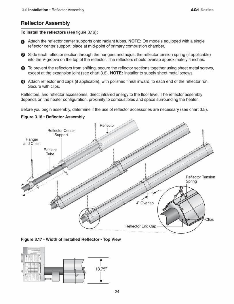
Reflector
Reflector Center Support
10’ Primary/ Secondary Combustion Chamber(s)
Baffles
Reflector End Cap with Clips*
Tube Clamp
Burner Control Box
Type 1 Rubber Hose*
Radiant Tube(s)
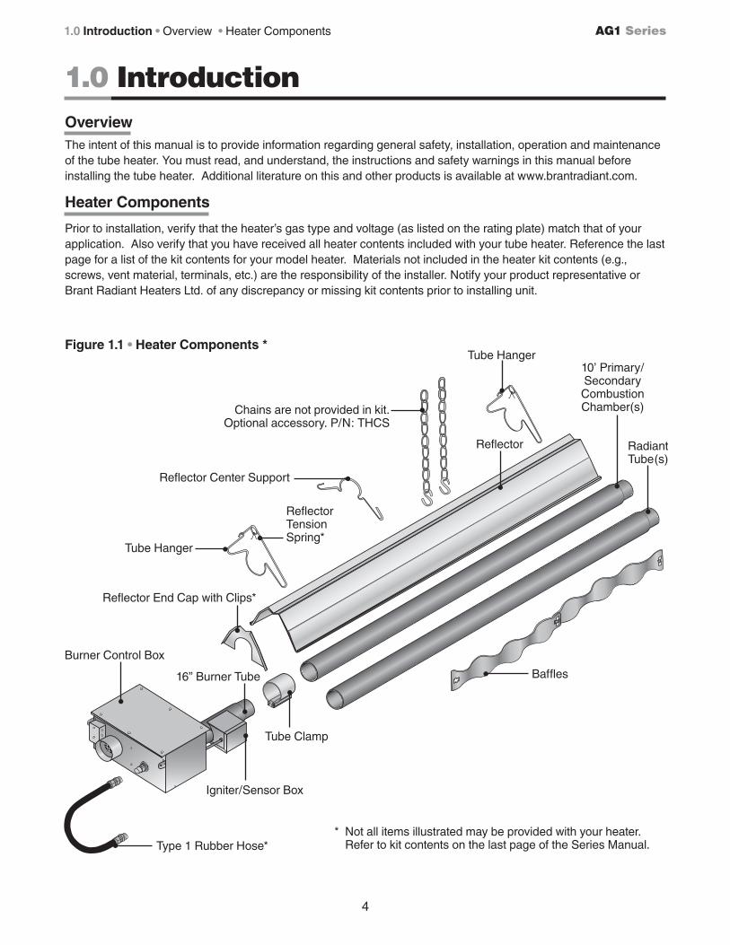
Figure 1.1 • Heater Components *
Igniter/Sensor Box
Chains are not provided in kit. Optional accessory. P/N: THCS
16” Burner Tube
* Not all items illustrated may be provided with your heater. Refer to kit contents on the last page of the Series Manual.
Tube Hanger
Reflector Tension Spring*
OverviewThe intent of this manual is to provide information regarding general safety, installation, operation and maintenance of the tube heater. You must read, and understand, the instructions and safety warnings in this manual before installing the tube heater. Additional literature on this and other products is available at www.brantradiant.com.
Heater Components
Prior to installation, verify that the heater’s gas type and voltage (as listed on the rating plate) match that of your application. Also verify that you have received all heater contents included with your tube heater. Reference the last page for a list of the kit contents for your model heater. Materials not included in the heater kit contents (e.g., screws, vent material, terminals, etc.) are the responsibility of the installer. Notify your product representative or Brant Radiant Heaters Ltd. of any discrepancy or missing kit contents prior to installing unit.
5
AG1 Series
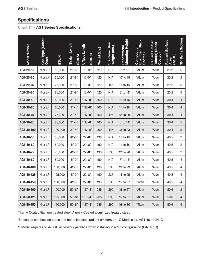
Specifications
Mod
el N
umbe
r
Gas
Typ
e (S
elec
t O
ne)
BTU
/H
Str
aigh
t Len
gth
(Dim
A)
U-T
ube
Leng
th
(Dim
. B)
Wei
ght (
lbs.
)
Sta
inle
ss S
teel
W
eig
ht (
lbs.
)
Rec
om
men
dM
ou
nti
ng
Hei
gh
t
Co
mb
ust
ion
C
ham
ber
(B
lack
C
oat
ed)
Rad
ian
t Em
itte
r Tu
be
(s) (
Bla
ck
Co
ated
)
Rad
ian
t Su
rfac
e A
rea
(sq
. ft.
)
36”
Baf
fle S
ectio
ns
AG1-20-50 N or LP 50,000 21’-8” 13’-0” 120 N/A 9’ to 15’ *Alum *Alum 20.2 5
AG1-20-60 N or LP 60,000 21’-8” 13’-0” 120 N/A 10’ to 15’ *Alum *Alum 20.2 5
AG1-20-75 N or LP 75,000 21’-8” 13’-0” 120 145 11’ to 18’ *Alum *Alum 20.2 5
AG1-20-80 N or LP 80,000 21’-8” 13’-0” 120 N/A 8’ to 14’ *Alum *Alum 20.2 5
AG1-30-50 N or LP 50,000 31’-4” **17’-8” 160 N/A 10’ to 15’ *Alum *Alum 30.4 4
AG1-30-60 N or LP 60,000 31’-4” **17’-8” 160 N/A 11’ to 18’ *Alum *Alum 30.4 4
AG1-30-75 N or LP 75,000 31’-4” **17’-8” 160 195 12’ to 20’ *Alum *Alum 30.4 4
AG1-30-80 N or LP 80,000 31’-4” **17’-8” 160 N/A 8’ to 14’ *Alum *Alum 30.4 5
AG1-30-100 N or LP 100,000 31’-4” **17’-8” 160 195 13’ to 23’ *Alum *Alum 30.4 5
AG1-40-50 N or LP 50,000 41’-0” 22’-8” 190 N/A 11’ to 18’ *Alum *Alum 40.5 2
AG1-40-60 N or LP 60,000 41’-0” 22’-8” 190 N/A 11’ to 18’ *Alum *Alum 40.5 2
AG1-40-75 N or LP 75,000 41’-0” 22’-8” 190 235 12’ to 20’ *Alum *Alum 40.5 2
AG1-40-80 N or LP 80,000 41’-0” 22’-8” 190 N/A 8’ to 14’ *Alum *Alum 40.5 4
AG1-40-100 N or LP 100,000 41’-0” 22’-8” 190 235 13’ to 23’ *Alum *Alum 40.5 4
AG1-40-125 N or LP 125,000 41’-0” 22’-8” 190 235 14’ to 25’ *Alum *Alum 40.5 4
AG1-40-150 N or LP 150,000 41’-0” 22’-8” 190 235 15’ to 27’ *Titan *Alum 40.5 4
AG1-50-100 N or LP 100,000 50’-8” **27’-4” 235 290 15’ to 27’ *Alum *Alum 50.6 2
AG1-50-125 N or LP 125,000 50’-8” **27’-4” 235 290 15’ to 27’ *Alum *Alum 50.6 4
AG1-50-150 N or LP 150,000 50’-8” **27’-4” 235 290 16’ to 30’ *Titan *Alum 50.6 4
Titan = Coated titanium treated steel. Alum = Coated aluminized treated steel.
*Uncoated combustion tubes and hot rolled steel radiant emitters on _C Models ex. AG1-40-100N_C
** Model requires 5EA-SUB accessory package when installing in a “U” configuration (P/N TF1B).
1.0 Introduction • Product Specifications
Chart 1.1 • AG1 Series Specifications
Volts AC:
AMPS - Starting:
AMPS - Running:
Combustion Chamber:
120V - 60Hz
4.8
1.1
4” Coated Aluminized
DESIGN COMPLIES WITH:ANSI Z83.20-2008-GAS FIRED LOW INTENSITY INFRA-RED HTR.
Manifold Pressure:
Maximum Inlet Pressure:
Minimum Inlet Pressure:
MODEL NO.
AG1- 40 - 125N
Heater Type
Minimum Mounting Angle:
Maximum Mounting Angle:
C1
0
45
DEGREES
DEGREES
INPUT BTU/H
125,000 FOR USE WITH
Natural Gas
3.5 Inches
14 Inches
5.0 Inches
W.C.
W.C.
W.C.
BRANT RADIANT HEATERS LIMITED34 SCOTT AVE., PARIS, ONTARIOTEL: 1-519-442-7823 WWW.BRANTRADIANT.COM
SERIAL NO. 0870 XXXX XXXX 0001
RADIATEUR A INFRAROUGE A FAIBLE INTENSITERE-VERBER-RAY LOW INTENSITY INFRARED HEATER
FOR INDOOR INSTALLATION ONLY. NOT FOR USE IN RESIDENTIAL DWELLING.INSTALLATION À L’EXTÉRIEUR SEULEMENT. NE PAS INSTALLER DANS UN LOGEMENT.
.
MODEL /MODELE NO. INPUT BTU/H FOR USE WITHNATURAL GAS
RADIATEUR A INFRAROUGE A FAIBLE INTENSITE
VOLTS A.C.
STARTING AMPS.
RUNNING AMPS.
120~60Hz
4.8
1.1
MANIFOLD PRESSURE
MIN. INLET PRESSURE
ORIFICE SIZE
3.5” WC
5.0” WC
#19 D.M.S
HEATER TYPE
VERSION
MIN. MOUNTING ANGLE:
COMBUSTION CHAMBER:4” BC ALUMINUM
FOR INDOOR USE
BRANT RADIANT HEATERS LIMITED34 SCOTT AVE., PARIS, ONTARIOTEL: 1-519-442-7823 WWW.BRANTRADIANT.COM
ANSI Z83.20b - 2011 CSA 2.32b - 2011 Low - Intensity Infrared Htr. ANS Z83.20b - 2011 CSA - 2011 Low - Intensity Infrared Htr.
SERIAL NO. 0870 XXXX XXXX 0001
RE-VERBER-RAY LOW INTENSITY INFRARED HEATER
FOR INDOOR INSTALLATION ONLY. NOT FOR USE IN RESIDENTIAL DWELLING.INSTALLATION À L’EXTÉRIEUR SEULEMENT. NE PAS INSTALLER DANS UN LOGEMENT.
MAX. MOUNTING ANGLE:
0 DEGREES
45 DEGREESFOR STAINLESS STEEL UPGRADES THE
COMBUSTION TUBE IS UPGRADED TO 409 STAINLESS STEEL.
C1
10/11
DX2-40-125N 125,000NEUTRAL
EARTH
HOT
- 120V HEATER INPUT -
120V
***IMPORTANT***OBSERVE PROPER
ELECTRICAL POLARITY
SAMPLE
Do not Rotate/ Gas Hose LabelLLTCL001-1M-8/13 (CDS)
! !DANGER WARNINGImproper installation, adjustment, alteration,service or maintenance can cause property damage, injury or death.
This is NOT an explosion-proof heater. Where there is the possibility of exposure to flammable vapors or dusts, consult the local fire marshall, your insurance carrier or authorities for approval of the proposed installation. Do NOT install in residential or explosive environments.
This heater must be installed and serviced by trained gas installation and service personnel only. The installation of this heater must conform with local building codes or, in the absence of such codes, the National Fuel Gas Code (NFPA 54).
GAS CONNECTIONAllowances must be made for the system to expand. A flexible gas connection of approved type is required. The connector shall be of Type 1 hose per Exhibit “A” Section B.4., and Figure 1 and 2. Consult manual for further instructions.
Read and understand the installation, operating and maintenance instructions thoroughly before installing or servicing this equipment.
Des installation réglage, modification, maintenance ou entretien inappropriés peuvent causer des dommages matériels, des blessures ou la mort.
Ceci nest PAS un radiateur antidéflagrant. En présence possible de vapeurs ou de poussires inflammables, consulter le commissaire des incendies local, votre compagnie dassurance ou les autorités compétentes pour lapprobation de linstallation projetée. NE CNIENT PAS aux applications résidentielles ou tout environnement sujet explosion.
Ce radiateur ga ne doit tre installé et entretenu que par dupersonnel formé et qualifié cette fin. installation de ce radiateur doit tre conforme aux codes locaux du btiment ou, en labsence de tels codes, du National Fuel Gas Code (NFPA 54)
RACCORDEMENT AU GAZPrévoir du jeu pour la dilatation du systme. n raccordement partube flexible approuvé pour le ga est nécessaire. e raccord flexible devra tre de type 1 tel quindiqué au schéma A, section B.4., et aux figures 1 et 2 Se référer au manuel pour plus dinformation.
ire et comprendre les directives dinstallation, de fonctionnement et dentretien avant dinstaller ou dentretenir cet équipement.
!
WARNING. To ensure system performance and safety, this unit must be properly vented.
Improper installation, adjustment, alteration, service or maintenance can cause property damage, injury or death.Des installation, réglage, modification,maintenance ou entretien inappropriés peuvent causer des dommages matériels, des blessures ou la mort.
This heater can be installed in various configurations as specified in the manual.
AIRCRAFT HANGARS. This heater must be installed in accordance with the latest edition of the Standard for Aircraft angars, ANSINFPA 4.
PUBLIC GARAGES. This heater must be installed in accordance with the latest edition of the Standard for Paring Structures, ANSINFPA A, or the Code for Repair Garages, ANSINFPA A or the Canadian Natural Gas and Propane Installation Code, CSA B14.1. as per Clause 1.1.4.
VENTING. This heaters venting system must comply with the following requirements Do not exceed 2 feet vent length or place more than two (2) elbows in the venting system. se 4-DS ent it for single sidewall venting Common vented models (with -fitting) must be wired on the same control. A minimum ventilation rate of 4. cfm1 Btu is required for unvented operation.
Ce radiateur peut tre installé dans différentes configurations tel que spécifié dans le manuel.
HANGARS À AVIONS. Ce radiateur doit tre installé en conformité avec a dernire édition de la norme Standard for Aircraft angars, ANSINFPA 4.
GARAGES PUBLICS. Ce radiateur doit tre installé en conformité avec la dernire édition de la norme Standard for Paring Structures, ANSINFPA , ou du Code for Repair Garages, ANSINFPA A ou, au Canada, du Code dinstallation du ga naturel et du propane, CSA B14.1., article 1.1.4.
ÉVACUATION. e systme dévacuation de ce radiateur doi tsatisfaire aux exigences suivantes Ne pas dépasser 2 pi en longueur de conduit ou utiliser plus de 2 coudes dans le systme dévacuation. tilise lensemble dévacuation R TP-4 pour une évacuation murale unique. es modles avec évacuation commne (avec raccord en ) doivent tre reliés une mme commande. n taux de ventilation minimal de 4 pcm1 Btu est nécessaire pour un fonctionnement sans systme dévacuation
AVERTISSEMENT. Pour assurer le rendement et le fonctionnement sécuritaire du systme, cet appareil doit tre ventilé de faon appropriée.
65,000* - 75,000*
W1 side shieldW2 side shields2 ft. from burner
50,000* - 60,000*
W1 side shieldW2 side shields2 ft. from burner
105,000* - 125,000*
W1 side shieldW2 side shields2 ft. from burner
80,000* - 100,000*
W1 side shieldW2 side shields2 ft. from burner
155,000* - 175,000*
W1 side shieldW2 side shields2 ft. from burner
130,000* - 150,000*
W1 side shieldW2 side shields2 ft. from burner
180,000* - 200,000*
W1 side shieldW2 side shields2 ft. from burner
45
45
45
45
45
45
45
152.4152.4152.4152.4
.2
11.411.411.411.4
.2
1111.2
1.1.1..1.
.2
2.2.2.2.111.
25.25.25.25.111.
2.2.2.2.111.
CLEARANCE TO COMBUSTIBLES
FIRE HAZARD. Always maintain published clearance to combustibles. In locations used for the storage of combustible materials, signs must be posted. Consult manual for additional guidelines.
MODEL BTU/h RANGE
MOUNTING ANGLEFRONT
SIDEBEHINDTOPBELOW
SIDESIDE
TOP
BELOW0° MOUNTING ANGLE
FRONTBEHIND
BELOW45° MOUNTING ANGLE
TOP
BELOW
BEHIND FRONT
0° W/1 SIDE SHIELD
TOP
SIDESIDE
BELOW
0° W/2 SIDE SHIELDS
TOP
IMPORTANT:. se high BT output when determining clearances. inimum end clearance for all models is 12 inches. aximum mounting angle is 45. eep cover in place.
22..1.22.1.
22..1.22.1.
5.14.1.5.1.
5..1.4.1.
.4112.22.
114.1.5.42.
14.111.2.22.
cmin.2
2
142125422
24
112425
54
4111
1154
22.2.2.22.1.
22.2.2.22.1.
5.2.2.5.1.
5.2.2.4.1.
.42.2..22.
12.2.5.42.
14.12.2..22.
cmin.
14
224221
11
411
41
11
15.225.415.215.215.2
15.225.415.215.215.2
15.225.415.215.215.2
15.225.415.215.215.2
15.225.415.215.215.2
15.225.415.215.215.2
15.225.415.215.215.2
cmin.
11
1
1
1
1
1
cmin.44
44
441111
22
44
444
22
444
RISQUE D’INCENDIE. Toujours respecter les dégagements prescrits de tout matériau combustible. Dans les endroits servant au stocage de matériaux combustibles, des écriteaux doivent en avertir. Se référer au manuel pour des directives supplémentaires.
*IMPORTANT: Déterminer les dégagements en fonction de la capacité nette de Btu maximale. e dégagement minimal lextrémité est de 12 po pour tous les modles. angle dinclinaison maximal est de 45. Garder le couvercle en place.
(cm & in.)
!CAUTION
ATTE
NTIO
N VE
NTIL
ATIO
N RE
QUIR
EMEN
TSBE
SUR
E TH
E AI
R IN
LET
GRIL
LS, L
OUVE
RS A
ND D
AMPE
RS A
RE IN
SPEC
TED
REGU
LARL
Y AN
D TH
AT T
HEY
ARE
CLEA
R AN
D FR
EE O
F DU
ST, D
IRT,
SNO
W, I
CE, F
ROST
AND
OTH
ER F
OREI
GN M
ATER
IAL
SO T
HAT
AIR
MAY
FRE
ELY
ENTE
R IN
TO T
HE
BUIL
DING
TO
PROV
IDE
ADEQ
UATE
COM
BUST
ION
AND
VENT
ILAT
ING
AIR.
FOR
PROP
ER A
ND S
AFE
OPER
ATIO
N OF
THE
BRO
ODER
INST
ALLA
TION
, THE
RE S
HALL
BE
PROV
IDED
A C
OMBI
NED
INFI
LTRA
TION
AND
NAT
URAL
AND
MEC
HANI
CAL
VENT
ILAT
ION
RATE
OF
NOT
LESS
THA
N 1/
4 S.
C.F.
M. (
stan
dard
cub
ic fo
ot
per m
inut
e) P
ER B
IRD.
NOTE
: OTH
ER A
NIM
AL C
ONFI
NEM
ENT
APPL
ICAT
IONS
-MUS
T RE
FER
TO IN
STAL
LATI
ON/O
PERA
TION
MAN
UAL
FOR
UNVE
NTED
HE
ATER
MIN
IMUM
VEN
TILA
TION
REQ
UIRE
MEN
TS.
ATTE
NTIO
N: E
XIGE
NCES
CON
CERN
ANT
LA V
ENTI
LATI
ONS’
ASSU
RER
QUE
LES
GRIL
LES,
VOL
ETS
ET C
LAPE
TS D
ES P
RISE
S D’
AIR
SONT
INSP
ECTÉ
S RÉ
GULÈ
REM
ENT
ET Q
U’IL
S SO
NT
DÉGA
GÉES
ET
EXEM
PTS
DE P
OUSS
IÈRE
, DE
SALE
TÉ, D
E NE
IGE,
DE
GLAC
E, D
E GE
LÉE
OU D
’AUT
RES
MAT
IÈRE
S ÉT
RANG
ÈRES
, DE
SOR
TE Q
UE L
’AIR
PUI
SSE
ENTR
ER D
ANS
LE B
ÂTIM
ENT
LIBR
EMEN
T ET
EN
QUAN
TITÉ
SUF
FISA
NTE
POUR
PER
MET
TRE
UNE
COM
BUST
ION
ET U
NE V
ENTI
LATI
ON S
ATIS
FAIS
ANTE
S.
AFIN
QU’
UN A
PPAR
EIL
INST
ALLÉ
DAN
S UN
COU
VOIR
FON
CTIO
NNE
NORM
ALEM
ENT
ET S
ANS
DANG
ER, O
N DE
VRAI
FAI
RE E
N SO
RTE
QUE
LE D
ÉBIT
D’A
IR T
OTAL
, PRO
VENA
NT A
UTAN
T DE
L’IN
FILT
RATI
ON Q
UE D
EL’A
ÉRAG
E NA
TURE
L ET
L’A
ÉRAG
E M
ÉCAN
IQUE
, SOI
T D’
AU M
OINS
1/4
P.C
.S.M
. (pi
ed c
ube
stan
ard
par m
inut
e) P
AR O
ISEA
U.
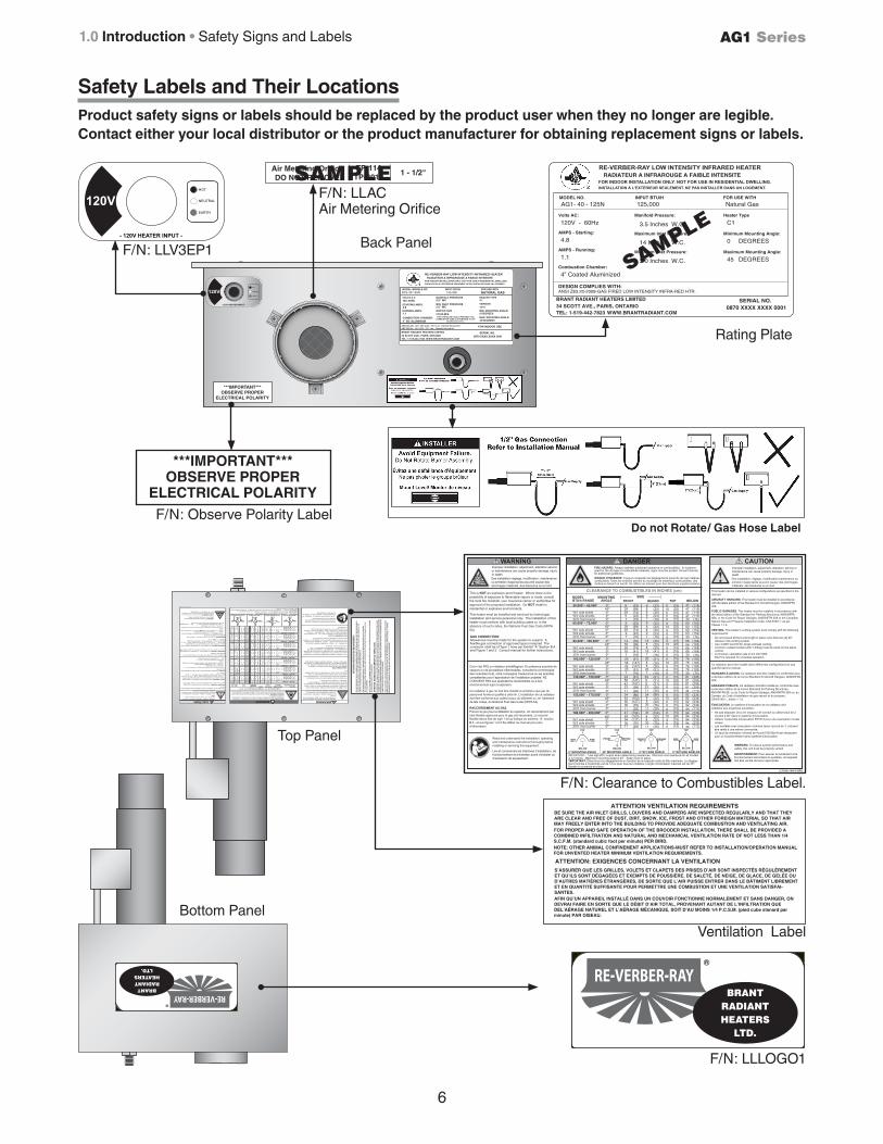
Top Panel
F/N: Clearance to Combustibles Label.
F/N: LLLOGO1
Bottom Panel
ATTENTION VENTILATION REQUIREMENTSBE SURE THE AIR INLET GRILLS, LOUVERS AND DAMPERS ARE INSPECTED REGULARLY AND THAT THEY ARE CLEAR AND FREE OF DUST, DIRT, SNOW, ICE, FROST AND OTHER FOREIGN MATERIAL SO THAT AIR MAY FREELY ENTER INTO THE BUILDING TO PROVIDE ADEQUATE COMBUSTION AND VENTILATING AIR. FOR PROPER AND SAFE OPERATION OF THE BROODER INSTALLATION, THERE SHALL BE PROVIDED A COMBINED INFILTRATION AND NATURAL AND MECHANICAL VENTILATION RATE OF NOT LESS THAN 1/4 S.C.F.M. (standard cubic foot per minute) PER BIRD. NOTE: OTHER ANIMAL CONFINEMENT APPLICATIONS-MUST REFER TO INSTALLATION/OPERATION MANUAL FOR UNVENTED HEATER MINIMUM VENTILATION REQUIREMENTS.
S’ASSURER QUE LES GRILLES, VOLETS ET CLAPETS DES PRISES D’AIR SONT INSPECTÉS RÉGULÈREMENT ET QU’ILS SONT DÉGAGÉES ET EXEMPTS DE POUSSIÈRE, DE SALETÉ, DE NEIGE, DE GLACE, DE GELÉE OU D’AUTRES MATIÈRES ÉTRANGÈRES, DE SORTE QUE L’AIR PUISSE ENTRER DANS LE BÂTIMENT LIBREMENT ET EN QUANTITÉ SUFFISANTE POUR PERMETTRE UNE COMBUSTION ET UNE VENTILATION SATISFAI-SANTES. AFIN QU’UN APPAREIL INSTALLÉ DANS UN COUVOIR FONCTIONNE NORMALEMENT ET SANS DANGER, ON DEVRAI FAIRE EN SORTE QUE LE DÉBIT D’AIR TOTAL, PROVENANT AUTANT DE L’INFILTRATION QUE DEL’AÉRAGE NATUREL ET L’AÉRAGE MÉCANIQUE, SOIT D’AU MOINS 1/4 P.C.S.M. (pied cube stanard par minute) PAR OISEAU.
ATTENTION: EXIGENCES CONCERNANT LA VENTILATION
LLTCL001-1M-4/15 (BRH)
!!! CAUTIONDANGERWARNINGImproper installation, adjustment, alteration,service or maintenance can cause property damage, injury or death.
This is NOT an explosion-proof heater. Where there is the possibility of exposure to flammable vapors or dusts, consult the local fire marshall, your insurance carrier or authorities for approval of the proposed installation. Do NOT install in residential or explosive environments.
This heater must be installed and serviced by trained gas installation and service personnel only. The installation of this heater must conform with local building codes or, in the absence of such codes, the National Fuel Gas Code (NFPA 54).
GAS CONNECTIONAllowances must be made for the system to expand. A flexible gas connection of approved type is required. The connector shall be of Type 1 hose per Exhibit “A” Section B.4., and Figure 1 and 2. Consult manual for further instructions.
Read and understand the installation, operating and maintenance instructions thoroughly before installing or servicing this equipment.
Des installation réglage, modification, maintenance ou entretien inappropriés peuvent causer des dommages matériels, des blessures ou la mort.
Ceci n’est PAS un radiateur antidéflagrant. En présence possible de vapeurs ou de poussières inflammables, consulter le commissaire des incendies local, votre compagnie d’assurance ou les autorités compétentes pour l’approbation de l’installation projetée. NE CONVIENT PAS aux applications résidentielles ou à tout environnement sujet à explosion.
Ce radiateur à gaz ne doit être installé et entretenu que par dupersonnel formé et qualifié à cette fin. L’installation de ce radiateur doit être conforme aux codes locaux du bâtiment ou, en l’absence de tels codes, du National Fuel Gas Code (NFPA 54)
RACCORDEMENT AU GAZPrévoir du jeu pour la dilatation du système. Un raccordement partube flexible approuvé pour le gaz est nécessaire. Le raccord flexible devra être de type 1 tel qu’indiqué au schéma ‘A’, section B.4., et aux figures 1 et 2 Se référer au manuel pour plus d’information.
Lire et comprendre les directives d’installation, de fonctionnement et d’entretien avant d’installer ou d’entretenir cet équipement.
!
WARNING. To ensure system performance and safety, this unit must be properly vented.
Improper installation, adjustment, alteration, service or maintenance can cause property damage, injury or death.Des installation, réglage, modification,maintenance ou entretien inappropriés peuvent causer des dommages matériels, des blessures ou la mort.
This heater can be installed in various configurations as specified in the manual.
AIRCRAFT HANGARS. This heater must be installed in accordance with the latest edition of the Standard for Aircraft Hangars, ANSI/NFPA 409.
PUBLIC GARAGES. This heater must be installed in accordance with the latest edition of the Standard for Parking Structures, ANSI/NFPA 88A, or the Code for Repair Garages, ANSI/NFPA 30A or the Canadian Natural Gas and Propane Installation Code, CSA B149.1. as per Clause 1.1.4.
VENTING. This heater’s venting system must comply with the following requirements:• Do not exceed 20 feet vent length or place more than two (2) 90° elbows in the venting system.• Use 4-DSK Vent Kit for single sidewall venting; • Common vented models (with Y-fitting) must be wired on the same control.• A minimum ventilation rate of 4.0 cfm/1000 Btu/H is required for unvented operation.
Ce radiateur peut être installé dans différentes configurations tel que spécifié dans le manuel.
HANGARS À AVIONS. Ce radiateur doit être installé en conformité avec a dernière édition de la norme Standard for Aircraft Hangars, ANSI/NFPA 409.
GARAGES PUBLICS. Ce radiateur doit être installé en conformité avec la dernière édition de la norme Standard for Parking Structures, ANSI/NFPA 88, ou du Code for Repair Garages, ANSI/NFPA 30A ou, au Canada, du Code d’installation du gaz naturel et du propane, CSA B149.1., article 1.1.4.
ÉVACUATION. Le système d’évacuation de ce radiateur doitsatisfaire aux exigences suivantes: • Ne pas dépasser 20 pi en longueur de conduit ou utiliser plus de 2 coudes à 90° dans le système d’évacuation.• Utilisez l’ensemble d’évacuation RTVP-4 pour une évacuation murale unique. • Les modèles avec évacuation commne (avec raccord en Y ) doivent être reliés à une même commande.• Un taux de ventilation minimal de 4 pcm/1000 Btu/H est nécessaire pour un fonctionnement sans système d’évacuation
AVERTISSEMENT. Pour assurer le rendement et le fonctionnement sécuritaire du système, cet appareil doit être ventilé de façon appropriée.
65,000* - 75,000*
W/1 side shieldW/2 side shields20 ft. from burner
50,000* - 60,000*
W/1 side shieldW/2 side shields20 ft. from burner
105,000* - 125,000*
W/1 side shieldW/2 side shields20 ft. from burner
80,000* - 100,000*
W/1 side shieldW/2 side shields20 ft. from burner
155,000* - 175,000*
W/1 side shieldW/2 side shields20 ft. from burner
130,000* - 150,000*
W/1 side shieldW/2 side shields20 ft. from burner
180,000* - 200,000*
W/1 side shieldW/2 side shields20 ft. from burner
0º45º0º0º0º
0º45º0º0º0º
0º45º0º0º0º
0º45º0º0º0º
0º45º0º0º0º
0º45º0º0º0º
0º45º0º0º0º
(152)(152)(152)(152)(76)
(119)(119)(119)(119)(76)
(193)(193)(193)(193)(76)
(168)(168)(168).(168)
(76)
(234)(234)(234)(234)(112)
(206)(206)(206)(206)(112)
(239)(239)(239)(239)(112)
CLEARANCE TO COMBUSTIBLES IN INCHES (cm)
FIRE HAZARD. Always maintain published clearance to combustibles. In locations used for the storage of combustible materials, signs must be posted. Consult manual for additional guidelines.
MODEL BTU/h RANGE
MOUNTING ANGLE FRONT
SIDEBEHIND TOP BELOW
SIDE SIDE
TOP
BELOW0° MOUNTING ANGLE
FRONT BEHIND
BELOW45° MOUNTING ANGLE
TOP
BELOW
BEHINDFRONT
0° W/1 SIDE SHIELD
TOP
SIDE SIDE
BELOW
0° W/2 SIDE SHIELDS
TOP
IMPORTANT:. *Use high BTU output when determining clearances. Minimum end clearance for all models is 12 inches. Maximum mounting angle is 45°. Keep cover in place.
(23)(99)(74)(23)(18)
(23)(99)(74)(23)(18)
(51)(147)(107)(51)(18)
(35)(99)(74)(41)(18)
(86)(160)(127)(76)(28)
(61)(147)(107)(58)(28)
(104)(160)(137)(76)(28)
93929979
392997
143929167205842207
24
11234258
30506334
634111
113054
(23)(20)(20)(23)(18)
(23)(20)(20)(23)(18)
(51)(20)(20)(51)(18)
(35)(20)(20)(41)(18)
(86)(20)(20)(76)(28)
(61)(21)(21)(58)(28)
(104)(20)(20)(76)(28)
9
9
8897
88
81479
23882472088207168
113088
3411
8841
1130
(15)(25)(15)(15)(15)
(15)(25)(15)(15)(15)
(15)(25)(15)(15)(15)
(15)(25)(15)(15)(15)
(15)(25)(15)(15)(15)
(15)(25)(15)(15)(15)
(15)(25)(15)(15)(15)
6
10666610
66
66
6610
6
6666
106
666
10
666
106
666
106
4747
304747
60
30606060
7676
30
30
6666
76
6666
76
4481818181
9292
44
4494
9292
949494
RISQUE D’INCENDIE. Toujours respecter les dégagements prescrits de tout matériau combustible. Dans les endroits servant au stockage de matériaux combustibles, des écriteaux doivent en avertir. Se référer au manuel pour des directives supplémentaires.
*IMPORTANT: Déterminer les dégagements en fonction de la capacité nette de Btu maximale. Le dégage-ment minimal à l’extrémité est de 12 po pour tous les modèles. L’angle d’inclinaison maximal est de 45°. Garder le couvercle en place.
Ventilation Label
***IMPORTANT***OBSERVE PROPER
ELECTRICAL POLARITY
6
AG1 Series1.0 Introduction • Safety Signs and Labels
Safety Labels and Their Locations
Back Panel
Rating Plate
Product safety signs or labels should be replaced by the product user when they no longer are legible. Contact either your local distributor or the product manufacturer for obtaining replacement signs or labels.
NEUTRAL
EARTH
HOT
- 120V HEATER INPUT -
120V
F/N: LLV3EP1
F/N: LLAC Air Metering Orifice
F/N: Observe Polarity Label
Air Metering OrificeDO NOT REMOVE
TP-114TP-3014
1 - 1/2"SAMPLE
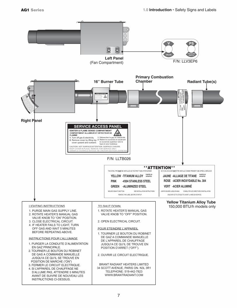
F/N LLTB026
VALVE
PS
PRESSURESWITCH
V
SERVICE ACCESS PANELIGNITER & FLAME SENSE COMPARTMENT
1. Turn off gas & electricity.2. e o e co er y lifting to co er u ar an out ar .
CAUTION: HOT SURFACE. . .
7
AG1 Series
Radiant Tube(s)Primary Combustion Chamber16” Burner Tube
Left Panel (Fan Compartment) F/N: LLV3EP6
Yellow Titanium Alloy Tube150,000 BTU/h models only
Right Panel
1.0 Introduction • Safety Signs and Labels
8
AG1 Series
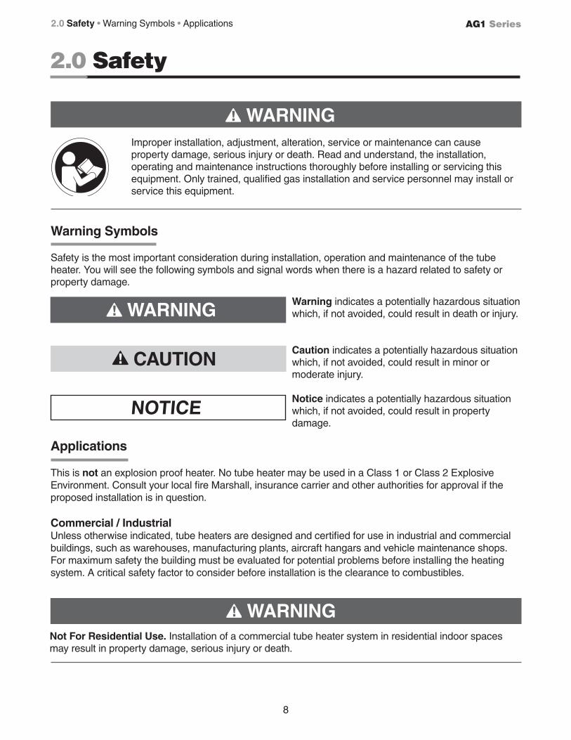
2.0 Safety
Warning indicates a potentially hazardous situation which, if not avoided, could result in death or injury.
Caution indicates a potentially hazardous situation which, if not avoided, could result in minor or moderate injury.
Notice indicates a potentially hazardous situation which, if not avoided, could result in property damage.
NOTICE
WARNING
!
!
CAUTION!
WARNING
!
!
WARNING
!
!
Warning Symbols
Safety is the most important consideration during installation, operation and maintenance of the tube heater. You will see the following symbols and signal words when there is a hazard related to safety or property damage.
Improper installation, adjustment, alteration, service or maintenance can cause property damage, serious injury or death. Read and understand, the installation, operating and maintenance instructions thoroughly before installing or servicing this equipment. Only trained, qualified gas installation and service personnel may install or service this equipment.
Applications
This is not an explosion proof heater. No tube heater may be used in a Class 1 or Class 2 Explosive Environment. Consult your local fire Marshall, insurance carrier and other authorities for approval if the proposed installation is in question.
Commercial / IndustrialUnless otherwise indicated, tube heaters are designed and certified for use in industrial and commercial buildings, such as warehouses, manufacturing plants, aircraft hangars and vehicle maintenance shops. For maximum safety the building must be evaluated for potential problems before installing the heating system. A critical safety factor to consider before installation is the clearance to combustibles.
Not For Residential Use. Installation of a commercial tube heater system in residential indoor spaces may result in property damage, serious injury or death.
2.0 Safety • Warning Symbols • Applications
9
AG1 Series 2.0 Safety • Standards, Certifications and Government Regulations
BuildingType
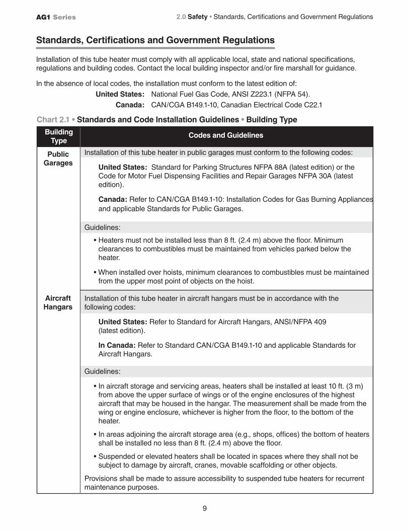
Installation of this tube heater in public garages must conform to the following codes:
United States: Standard for Parking Structures NFPA 88A (latest edition) or the Code for Motor Fuel Dispensing Facilities and Repair Garages NFPA 30A (latest edition).
Canada: Refer to CAN/CGA B149.1-10: Installation Codes for Gas Burning Appliances and applicable Standards for Public Garages.
Guidelines:
• Heaters must not be installed less than 8 ft. (2.4 m) above the floor. Minimum clearances to combustibles must be maintained from vehicles parked below the heater.
• When installed over hoists, minimum clearances to combustibles must be maintained from the upper most point of objects on the hoist.
Installation of this tube heater in aircraft hangars must be in accordance with the following codes:
United States: Refer to Standard for Aircraft Hangars, ANSI/NFPA 409 (latest edition).
In Canada: Refer to Standard CAN/CGA B149.1-10 and applicable Standards for Aircraft Hangars.
Guidelines:
• In aircraft storage and servicing areas, heaters shall be installed at least 10 ft. (3 m) from above the upper surface of wings or of the engine enclosures of the highest aircraft that may be housed in the hangar. The measurement shall be made from the wing or engine enclosure, whichever is higher from the floor, to the bottom of the heater.
• In areas adjoining the aircraft storage area (e.g., shops, offices) the bottom of heaters shall be installed no less than 8 ft. (2.4 m) above the floor.
• Suspended or elevated heaters shall be located in spaces where they shall not be subject to damage by aircraft, cranes, movable scaffolding or other objects.
Provisions shall be made to assure accessibility to suspended tube heaters for recurrent maintenance purposes.
Standards, Certifications and Government Regulations
Installation of this tube heater must comply with all applicable local, state and national specifications, regulations and building codes. Contact the local building inspector and/or fire marshall for guidance.
In the absence of local codes, the installation must conform to the latest edition of:
United States: National Fuel Gas Code, ANSI Z223.1 (NFPA 54).
Canada: CAN/CGA B149.1-10, Canadian Electrical Code C22.1
Public Garages
Aircraft Hangars
Chart 2.1 • Standards and Code Installation Guidelines • Building Type
Codes and Guidelines
10
AG1 Series
Applicable authorities governing the manufacturing or installation of this infrared heater include (but are not limited to) the following organizations:
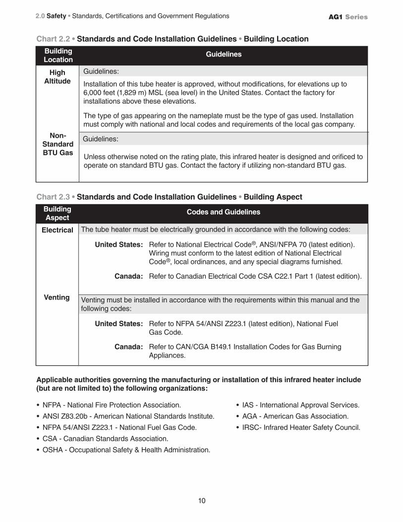
The tube heater must be electrically grounded in accordance with the following codes:
United States: Refer to National Electrical Code®, ANSI/NFPA 70 (latest edition). Wiring must conform to the latest edition of National Electrical Code®, local ordinances, and any special diagrams furnished.
Canada: Refer to Canadian Electrical Code CSA C22.1 Part 1 (latest edition).
Venting must be installed in accordance with the requirements within this manual and the following codes:
United States: Refer to NFPA 54/ANSI Z223.1 (latest edition), National Fuel Gas Code.
Canada: Refer to CAN/CGA B149.1 Installation Codes for Gas Burning Appliances.
High Altitude
Electrical
Venting
BuildingLocation
Guidelines
Chart 2.2 • Standards and Code Installation Guidelines • Building Location
Installation of this tube heater is approved, without modifications, for elevations up to 6,000 feet (1,829 m) MSL (sea level) in the United States. Contact the factory for installations above these elevations.
The type of gas appearing on the nameplate must be the type of gas used. Installation must comply with national and local codes and requirements of the local gas company.
Guidelines:
BuildingAspect
Codes and Guidelines
Chart 2.3 • Standards and Code Installation Guidelines • Building Aspect
Non-StandardBTU Gas Unless otherwise noted on the rating plate, this infrared heater is designed and orificed to
operate on standard BTU gas. Contact the factory if utilizing non-standard BTU gas.
Guidelines:
• IAS - International Approval Services.
• AGA - American Gas Association.
• IRSC- Infrared Heater Safety Council.
• NFPA - National Fire Protection Association.
• ANSI Z83.20b - American National Standards Institute.
• NFPA 54/ANSI Z223.1 - National Fuel Gas Code.
• CSA - Canadian Standards Association.
• OSHA - Occupational Safety & Health Administration.
2.0 Safety • Standards, Certifications and Government Regulations
11
AG1 Series 2.0 Safety • Clearance to Combustibles
Clearance to Combustibles
• Paint • Parked vehicles • Gasoline • Storage racks
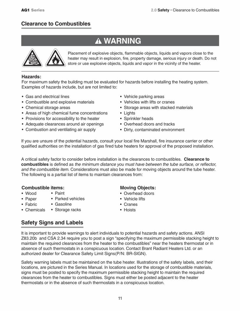
Combustible items: Moving Objects: • Wood • Overhead doors• Paper • Vehicle lifts• Fabric • Cranes• Chemicals • Hoists
A critical safety factor to consider before installation is the clearances to combustibles. Clearance to combustibles is defined as the minimum distance you must have between the tube surface, or reflector, and the combustible item. Considerations must also be made for moving objects around the tube heater. The following is a partial list of items to maintain clearances from:
• Vehicle parking areas• Vehicles with lifts or cranes• Storage areas with stacked materials• Lights• Sprinkler heads• Overhead doors and tracks• Dirty, contaminated environment
• Gas and electrical lines• Combustible and explosive materials• Chemical storage areas• Areas of high chemical fume concentrations• Provisions for accessibility to the heater• Adequate clearances around air openings• Combustion and ventilating air supply
Hazards:For maximum safety the building must be evaluated for hazards before installing the heating system. Examples of hazards include, but are not limited to:
If you are unsure of the potential hazards, consult your local fire Marshall, fire insurance carrier or other qualified authorities on the installation of gas fired tube heaters for approval of the proposed installation.
Safety Signs and Labels
It is important to provide warnings to alert individuals to potential hazards and safety actions. ANSI Z83.20b and CSA 2.34 require you to post a sign “specifying the maximum permissible stacking height to maintain the required clearances from the heater to the combustibles” near the heaters thermostat or in absence of such thermostats in a conspicuous location. Contact Brant Radiant Heaters Ltd. or an authorized dealer for Clearance Safety Limit Signs(P/N: BR-SIGN).
Safety warning labels must be maintained on the tube heater. Illustrations of the safety labels, and their locations, are pictured in the Series Manual. In locations used for the storage of combustible materials, signs must be posted to specify the maximum permissible stacking height to maintain the required clearances from the heater to combustibles. Signs must either be posted adjacent to the heater thermostats or in the absence of such thermostats in a conspicuous location.
WARNING!
Placement of explosive objects, flammable objects, liquids and vapors close to the heater may result in explosion, fire, property damage, serious injury or death. Do not store or use explosive objects, liquids and vapor in the vicinity of the heater.
12
AG1 Series
Model Number Mounting Angle*
SidesFront Behind Top** Below
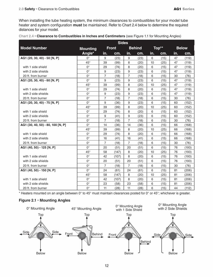
in. cm. in. cm. in. cm. in. cm.AG1 (20, 30, 40) - 50 [N, P] 0° 9 (23) 9 (23) 6 (15) 47 (119)
45° 39 (99) 8 (20) 10 (25) 47 (119) with 1 side shield 0° 29 (74) 8 (20) 6 (15) 47 (119) with 2 side shields 0° 9 (23) 9 (23) 6 (15) 47 (119) 20 ft. from burner 0° 7 (18) 7 (18) 6 (15) 30 (76)AG1 (20, 30, 40) - 60 [N, P] 0° 9 (23) 9 (23) 6 (15) 47 (119)
45° 39 (99) 8 (20) 10 (25) 47 (119) with 1 side shield 0° 29 (74) 8 (20) 6 (15) 47 (119) with 2 side shields 0° 9 (23) 9 (23) 6 (15) 47 (119) 20 ft. from burner 0° 7 (18) 7 (18) 6 (15) 30 (76)AG1 (20, 30, 40) - 75 [N, P] 0° 9 (36) 9 (23) 6 (15) 60 (152)
45° 39 (99) 8 (20) 10 (25) 60 (152) with 1 side shield 0° 29 (74) 8 (20) 6 (15) 60 (152) with 2 side shields 0° 9 (41) 9 (23) 6 (15) 60 (152) 20 ft. from burner 0° 7 (18) 7 (18) 6 (15) 30 (76)AG1 (30, 40, 50) - 80, 100 [N, P] 0° 14 (36) 14 (36) 6 (15) 66 (168)
45° 39 (99) 8 (20) 10 (25) 66 (168) with 1 side shield 0° 29 (74) 8 (20) 6 (15) 66 (168) with 2 side shields 0° 16 (41) 16 (41) 6 (15) 66 (168)
20 ft. from burner 0° 7 (18) 7 (18) 6 (15) 30 (76)
AG1 (40, 50) - 125 [N, P] 0° 20 (51) 20 (51) 6 (15) 76 (193)45° 58 (147) 8 (20) 10 (25) 76 (193)
with 1 side shield 0° 42 (107) 8 (20) 6 (15) 76 (193)
with 2 side shields 0° 20 (51) 20 (51) 6 (15) 76 (193)
20 ft. from burner 0° 7 (18) 7 (18) 6 (15) 30 (76)
AG1 (40, 50) - 150 [N, P] 0° 24 (61) 24 (61) 6 (15) 81 (206)45° 58 (147) 8 (20) 10 (25) 81 (206)
with 1 side shield 0° 42 (107) 8 (20) 6 (15) 81 (206) with 2 side shields 0° 23 (58) 23 (58) 6 (15) 81 (206) 20 ft. from burner 0° 11 (28) 11 (28) 6 (15) 44 (112)
Chart 2.4 • Clearance to Combustibles in Inches and Centimeters (see Figure 1.1 for Mounting Angles)
Figure 2.1 • Mounting Angles
0° Mounting Angle 45° Mounting Angle0° Mounting Anglewith 1 Side Shield
0° Mounting Anglewith 2 Side Shields
Side Side
Below
Top
Front Behind Front
Behind
Side Side
Top Top Top
Below Below Below
2.0 Safety • Clearance to Combustibles
When installing the tube heating system, the minimum clearances to combustibles for your model tube heater and system configuration must be maintained. Refer to Chart 2.4 below to determine the required distances for your model.
* Heaters mounted on an angle between 0° to 45° must maintain clearances posted for 0° or 45°; whichever is greater.
13
AG1 Series 3.0 Installation • Design Considerations and Prechecks
3.0 Installation
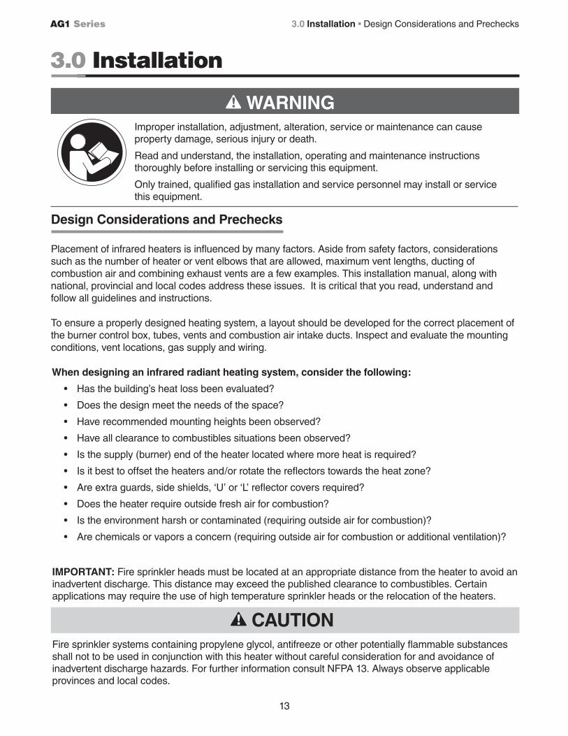
WARNING!
Improper installation, adjustment, alteration, service or maintenance can cause property damage, serious injury or death.
Read and understand, the installation, operating and maintenance instructions thoroughly before installing or servicing this equipment.
Only trained, qualified gas installation and service personnel may install or service this equipment.
Design Considerations and Prechecks
Placement of infrared heaters is influenced by many factors. Aside from safety factors, considerations such as the number of heater or vent elbows that are allowed, maximum vent lengths, ducting of combustion air and combining exhaust vents are a few examples. This installation manual, along with national, provincial and local codes address these issues. It is critical that you read, understand and follow all guidelines and instructions.
To ensure a properly designed heating system, a layout should be developed for the correct placement of the burner control box, tubes, vents and combustion air intake ducts. Inspect and evaluate the mounting conditions, vent locations, gas supply and wiring.
When designing an infrared radiant heating system, consider the following:
• Has the building’s heat loss been evaluated?
• Does the design meet the needs of the space?
• Have recommended mounting heights been observed?
• Have all clearance to combustibles situations been observed?
• Is the supply (burner) end of the heater located where more heat is required?
• Is it best to offset the heaters and/or rotate the reflectors towards the heat zone?
• Are extra guards, side shields, ‘U’ or ‘L’ reflector covers required?
• Does the heater require outside fresh air for combustion?
• Is the environment harsh or contaminated (requiring outside air for combustion)?
• Are chemicals or vapors a concern (requiring outside air for combustion or additional ventilation)?
IMPORTANT: Fire sprinkler heads must be located at an appropriate distance from the heater to avoid an inadvertent discharge. This distance may exceed the published clearance to combustibles. Certain applications may require the use of high temperature sprinkler heads or the relocation of the heaters.
Fire sprinkler systems containing propylene glycol, antifreeze or other potentially flammable substances shall not to be used in conjunction with this heater without careful consideration for and avoidance of inadvertent discharge hazards. For further information consult NFPA 13. Always observe applicable provinces and local codes.
CAUTION!
14
AG1 Series
Design Scenario:
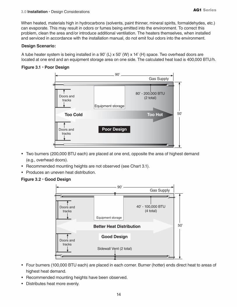
A tube heater system is being installed in a 90’ (L) x 50’ (W) x 14’ (H) space. Two overhead doors are located at one end and an equipment storage area on one side. The calculated heat load is 400,000 BTU/h.
Figure 3.1 • Poor Design
Figure 3.2 • Good Design
Doors and tracks
Too Cold Too Hot
Equipment storage
50’
80’ - 200,000 BTU (2 total)Doors and
tracks
90’
Doors and tracks
Doors and tracks
Equipment storage
Sidewall Vent (2 total)
• Two burners (200,000 BTU each) are placed at one end, opposite the area of highest demand
(e.g., overhead doors).
• Recommended mounting heights are not observed (see Chart 3.1).
• Produces an uneven heat distribution.
• Four burners (100,000 BTU each) are placed in each corner. Burner (hotter) ends direct heat to areas of
highest heat demand.
• Recommended mounting heights have been observed.
• Distributes heat more evenly.
Gas Supply
50’
90’Gas Supply
40’ - 100,000 BTU (4 total)
Poor Design
Good Design
When heated, materials high in hydrocarbons (solvents, paint thinner, mineral spirits, formaldehydes, etc.) can evaporate. This may result in odors or fumes being emitted into the environment. To correct this problem, clean the area and/or introduce additional ventilation. The heaters themselves, when installed and serviced in accordance with the installation manual, do not emit foul odors into the environment.
Better Heat Distribution
3.0 Installation • Design Considerations
15
AG1 Series 3.0 Installation • Design Considerations and Prechecks
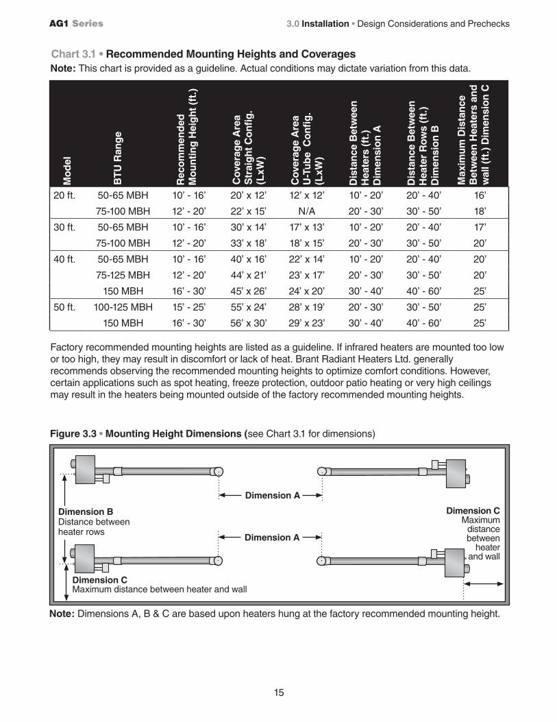
Factory recommended mounting heights are listed as a guideline. If infrared heaters are mounted too low or too high, they may result in discomfort or lack of heat. Brant Radiant Heaters Ltd. generally recommends observing the recommended mounting heights to optimize comfort conditions. However, certain applications such as spot heating, freeze protection, outdoor patio heating or very high ceilings may result in the heaters being mounted outside of the factory recommended mounting heights.
Dimension CMaximum
distance between
heater and wall
Chart 3.1 • Recommended Mounting Heights and CoveragesNote: This chart is provided as a guideline. Actual conditions may dictate variation from this data.
Mo
del
BT
U R
ang
e
Cov
erag
e A
rea
Str
aig
ht C
on
fig
. (L
xW)
Cov
erag
e A
rea
U-T
ub
e C
on
fig
. (L
xW)
Rec
om
men
ded
M
ou
ntin
g H
eig
ht (
ft.)
Dis
tan
ce B
etw
een
H
eate
rs (
ft.)
Dim
ensi
on
A
Dis
tan
ce B
etw
een
H
eate
r R
ows
(ft.
)D
imen
sio
n B
Max
imu
m D
ista
nce
B
etw
een
Hea
ters
an
d
wal
l (ft
.) D
imen
sio
n C
Figure 3.3 • Mounting Height Dimensions (see Chart 3.1 for dimensions)
Dimension A
Dimension BDistance between heater rows
Dimension CMaximum distance between heater and wall
Dimension A
Note: Dimensions A, B & C are based upon heaters hung at the factory recommended mounting height.
20 ft. 50-65 MBH 10’ - 16’ 20’ x 12’ 12’ x 12’ 10’ - 20’ 20’ - 40’ 16’
75-100 MBH 12’ - 20’ 22’ x 15’ N/A 20’ - 30’ 30’ - 50’ 18’
30 ft. 50-65 MBH 10’ - 16’ 30’ x 14’ 17’ x 13’ 10’ - 20’ 20’ - 40’ 17’
75-100 MBH 12’ - 20’ 33’ x 18’ 18’ x 15’ 20’ - 30’ 30’ - 50’ 20’
40 ft. 50-65 MBH 10’ - 16’ 40’ x 16’ 22’ x 14’ 10’ - 20’ 20’ - 40’ 20’
75-125 MBH 12’ - 20’ 44’ x 21’ 23’ x 17’ 20’ - 30’ 30’ - 50’ 20’
150 MBH 16’ - 30’ 45’ x 26’ 24’ x 20’ 30’ - 40’ 40’ - 60’ 25’
50 ft. 100-125 MBH 15’ - 25’ 55’ x 24’ 28’ x 19’ 20’ - 30’ 30’ - 50’ 25’
150 MBH 16’ - 30’ 56’ x 30’ 29’ x 23’ 30’ - 40’ 40’ - 60’ 25’
16
AG1 Series
WARNING!
Suspension of the heater must conform to applicable codes referenced in the Safety section and these instructions.
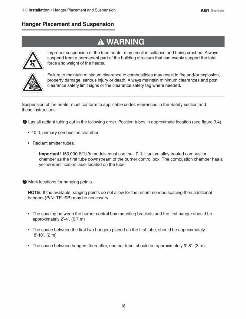
Lay all radiant tubing out in the following order. Position tubes in approximate location (see figure 3.4). • 10 ft. primary combustion chamber.
• Radiant emitter tubes.
Important! 150,000 BTU/h models must use the 10 ft. titanium alloy treated combustion chamber as the first tube downstream of the burner control box. The combustion chamber has a yellow identification label located on the tube.
2 Mark locations for hanging points.
NOTE: If the available hanging points do not allow for the recommended spacing then additional hangers (P/N: TP-19B) may be necessary.
• The spacing between the burner control box mounting brackets and the first hanger should be approximately 2’-4”. (0.7 m)
• The space between the first two hangers placed on the first tube, should be approximately 8’-10”. (2 m) • The space between hangers thereafter, one per tube, should be approximately 9’-8”. (3 m)
Hanger Placement and Suspension
Improper suspension of the tube heater may result in collapse and being crushed. Always suspend from a permanent part of the building structure that can evenly support the total force and weight of the heater.
Failure to maintain minimum clearance to combustibles may result in fire and/or explosion, property damage, serious injury or death. Always maintain minimum clearances and post clearance safety limit signs or the clearance safety tag where needed.
1
3.0 Installation • Hanger Placement and Suspension
17
AG1 Series
16” Burner Tube
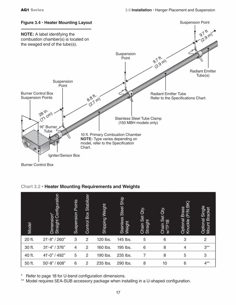
Chart 3.2 • Heater Mounting Requirements and Weights
Figure 3.4 • Heater Mounting Layout
10 ft. Primary Combustion ChamberNOTE: Type varies depending on model, refer to the Specification Chart.
Radiant Emitter TubeRefer to the Specifications Chart.
28 in.
(71 cm)
8.8 ft.
(2.7 m)
9.7 ft.
(2.9 m)
9.7 ft
(2.9 m)
Burner Control Box
Radiant Emitter Tube(s)
SuspensionPoint
Burner Control Box Suspension Points
SuspensionPoint
Suspension Point
Igniter/Sensor Box
Stainless Steel Tube Clamp (150 MBH models only)
* Refer to page 18 for U-bend configuration dimensions.** Model requires 5EA-SUB accessory package when installing in a U-shaped configuration.
Mod
el
Dim
ensi
on*
Str
aigh
t Con
figur
atio
n
Sus
pens
ion
Poi
nts
Con
trol
Box
Sta
biliz
er
Shi
ppin
g W
eigh
t
Sta
inle
ss S
teel
Shi
p W
eigh
t
Cha
in S
et Q
ty.
Str
aigh
t
Cha
in S
et Q
ty.
w/T
F1B
Opt
iona
l Bra
ss
Knu
ckle
(P
/N:B
K)
Opt
iona
l Sin
gle
Mou
nt B
rack
et
20 ft. 21’-8” / 260” 3 2 120 lbs. 145 lbs. 5 6 3 2
30 ft. 31’-4” / 376” 4 2 160 lbs. 195 lbs. 6 8 4 3**
40 ft. 41’-0” / 492” 5 2 190 lbs. 235 lbs. 7 8 5 3
50 ft. 50’-8” / 608” 6 2 235 lbs. 290 lbs. 8 10 6 4**
3.0 Installation • Hanger Placement and Suspension
NOTE: A label identifying the combustion chamber(s) is located on the swaged end of the tube(s).
18
AG1 Series
S-Hook and #1 Double-Loop Chain
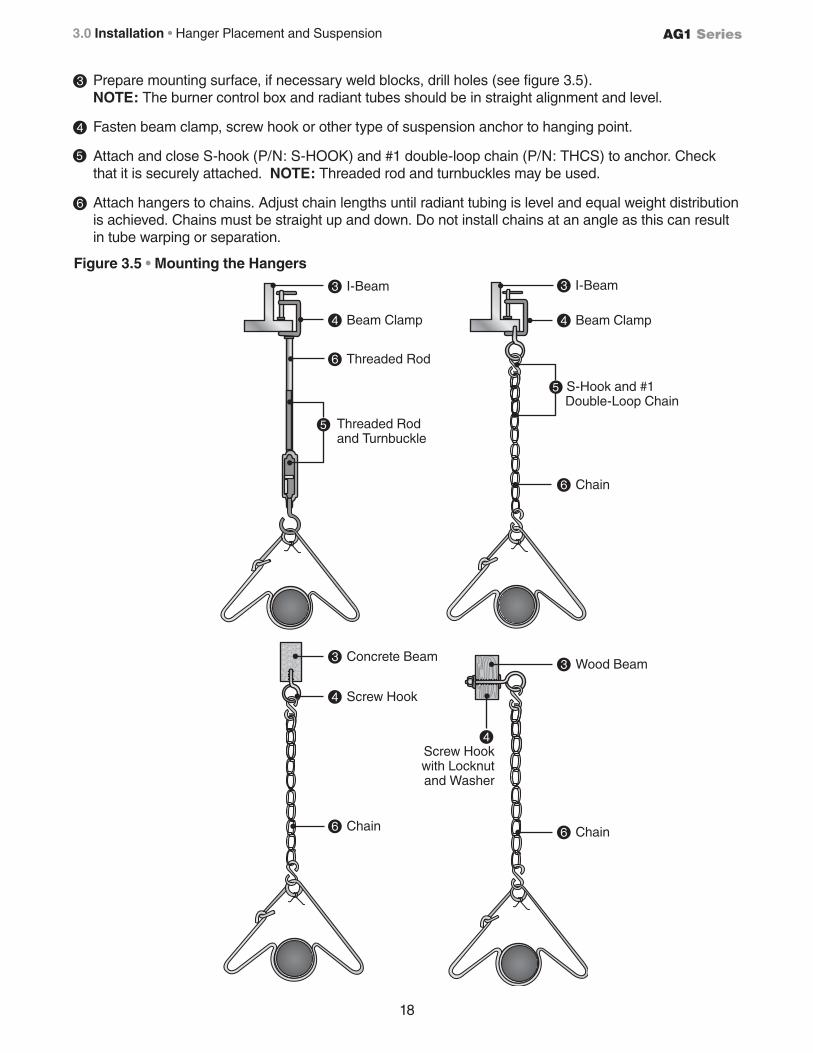
3 Prepare mounting surface, if necessary weld blocks, drill holes (see figure 3.5). NOTE: The burner control box and radiant tubes should be in straight alignment and level.
4 Fasten beam clamp, screw hook or other type of suspension anchor to hanging point.
Attach and close S-hook (P/N: S-HOOK) and #1 double-loop chain (P/N: THCS) to anchor. Check that it is securely attached. NOTE: Threaded rod and turnbuckles may be used.
6 Attach hangers to chains. Adjust chain lengths until radiant tubing is level and equal weight distribution is achieved. Chains must be straight up and down. Do not install chains at an angle as this can result in tube warping or separation.
Figure 3.5 • Mounting the Hangers
3 Wood Beam3 Concrete Beam
4 Beam Clamp
4 Screw Hook
4 Screw Hook
with Locknut and Washer
Threaded Rod and Turnbuckle
6 Threaded Rod
6 Chain
3 I-Beam
4 Beam Clamp
6 Chain6 Chain
3 I-Beam
5
5
5
3.0 Installation • Hanger Placement and Suspension
19
AG1 Series
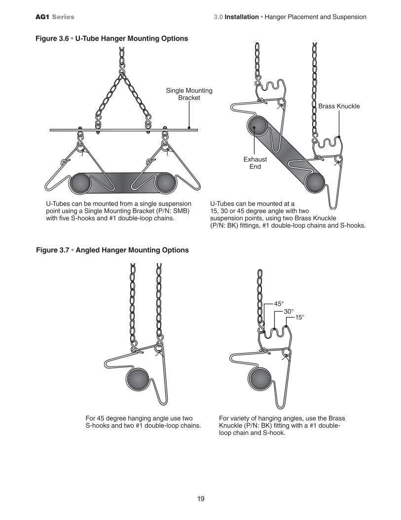
For 45 degree hanging angle use two S-hooks and two #1 double-loop chains.
For variety of hanging angles, use the Brass Knuckle (P/N: BK) fitting with a #1 double-loop chain and S-hook.
45°30°
15°
U-Tubes can be mounted at a 15, 30 or 45 degree angle with two suspension points, using two Brass Knuckle (P/N: BK) fittings, #1 double-loop chains and S-hooks.
U-Tubes can be mounted from a single suspension point using a Single Mounting Bracket (P/N: SMB) with five S-hooks and #1 double-loop chains.
Figure 3.6 • U-Tube Hanger Mounting Options
Figure 3.7 • Angled Hanger Mounting Options
Exhaust End
Single Mounting Bracket
Brass Knuckle
3.0 Installation • Hanger Placement and Suspension
20
AG1 Series
Radiant Tube Assembly
To install the radiant tubes:
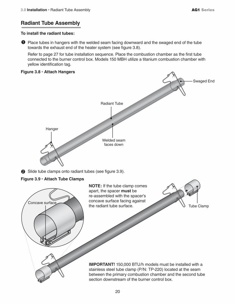
Place tubes in hangers with the welded seam facing downward and the swaged end of the tube towards the exhaust end of the heater system (see figure 3.8).
Refer to page 27 for tube installation sequence. Place the combustion chamber as the first tube connected to the burner control box. Models 150 MBH utilize a titanium combustion chamber with yellow identification tag.
2 Slide tube clamps onto radiant tubes (see figure 3.9).
Figure 3.8 • Attach Hangers
Figure 3.9 • Attach Tube Clamps
Hanger
Welded seam faces down
Swaged End
Tube Clamp
Radiant Tube
IMPORTANT! 150,000 BTU/h models must be installed with a stainless steel tube clamp (P/N: TP-220) located at the seam between the primary combustion chamber and the second tube section downstream of the burner control box.
NOTE: If the tube clamp comes apart, the spacer must be re-assembled with the spacer’s concave surface facing against the radiant tube surface.
Concave surface
1
3.0 Installation • Radiant Tube Assembly
21
AG1 Series
Optional Elbow or U-Bend Accessory Configuration
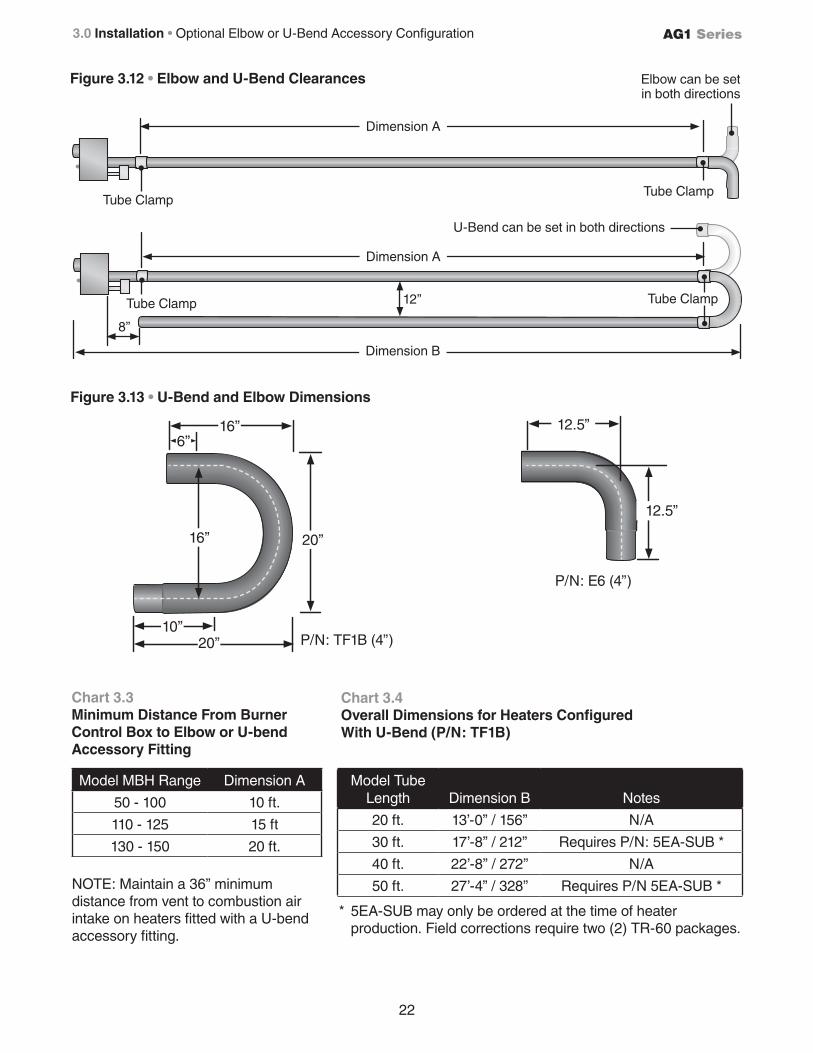
A 90 degree elbow or 180 degree U-bend accessory fitting may be installed in the radiant tube heating system. Refer to Chart 3.3 on page 22 for minimum distance requirements from the burner control box.
When installing an Elbow or U-Bend Accessory Fitting:• The top clearance of an uncovered (no reflector) elbow or U-bend accessory fitting to combustibles is 18 in.
• If operating the heater unvented, separate the intake air to the heater from its exhaust products a minimum of 4 ft., further separation may be necessary. Combustion air may also be supplied.
• A maximum of two 90° elbows or one 180° U-bend can be installed on a heater.
• Omit one 36 in. section of turbulator baffle. Refer to Baffle Assembly section.
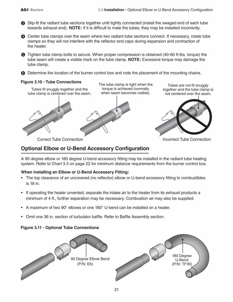
3 Slip-fit the radiant tube sections together until tightly connected (install the swaged end of each tube towards exhaust end). NOTE: If it is difficult to mate the tubes, they may be installed incorrectly.
4 Center tube clamps over the seam where two radiant tube sections connect. If necessary, rotate tube clamps so they will not interfere with the reflector end caps during expansion and contraction of
the heater.
Tighten tube clamp bolts to secure. When proper compression is obtained (40-60 ft-lbs. torque) the tube seam will create a visible mark on the tube clamp. NOTE: Excessive torque may damage the
tube clamp.
6 Determine the location of the burner control box and note the placement of the mounting chains.
Figure 3.10 • Tube Connections
Tubes fit snuggly together and the tube clamp is centered over the seam.
Tubes are not fit snuggly together and the tube clamp is not centered over the seam.
The tube clamp is tight when the torque is achieved (normally
when seam becomes visible).
Correct Tube Connection Incorrect Tube Connection
90 Degree Elbow Bend180 Degree
U-Bend
Figure 3.11 • Optional Tube Connections
(P/N: TF1B)(P/N: E6)
5
3.0 Installation • Optional Elbow or U-Bend Accessory Configuration
22
AG1 Series
* 5EA-SUB may only be ordered at the time of heater production. Field corrections require two (2) TR-60 packages.
Figure 3.12 • Elbow and U-Bend Clearances
Chart 3.3Minimum Distance From Burner Control Box to Elbow or U-bend Accessory Fitting
Dimension A
U-Bend can be set in both directions
12”
Figure 3.13 • U-Bend and Elbow Dimensions
Chart 3.4Overall Dimensions for Heaters Configured With U-Bend (P/N: TF1B)
Elbow can be set in both directions
Tube ClampTube Clamp
Dimension A
Dimension B
P/N: TF1B (4”)
P/N: E6 (4”)
8”
Model Tube Length Dimension B Notes
20 ft. 13’-0” / 156” N/A
30 ft. 17’-8” / 212” Requires P/N: 5EA-SUB *
40 ft. 22’-8” / 272” N/A
50 ft. 27’-4” / 328” Requires P/N 5EA-SUB *
Model MBH Range Dimension A
50 - 100 10 ft.
110 - 125 15 ft
130 - 150 20 ft.
16”
16”6”
20”
10”20”
Tube Clamp Tube Clamp
12.5”
12.5”
3.0 Installation • Optional Elbow or U-Bend Accessory Configuration
NOTE: Maintain a 36” minimum distance from vent to combustion air intake on heaters fitted with a U-bend accessory fitting.
23
AG1 Series
NEUTRAL
EART
T
- 120V HEATER INPUT -
120V
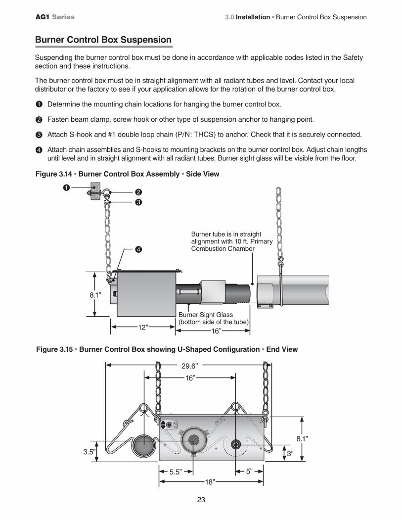
Burner Control Box Suspension
Suspending the burner control box must be done in accordance with applicable codes listed in the Safety section and these instructions.
The burner control box must be in straight alignment with all radiant tubes and level. Contact your local distributor or the factory to see if your application allows for the rotation of the burner control box.
Determine the mounting chain locations for hanging the burner control box.
2 Fasten beam clamp, screw hook or other type of suspension anchor to hanging point.
3 Attach S-hook and #1 double loop chain (P/N: THCS) to anchor. Check that it is securely connected.
4 Attach chain assemblies and S-hooks to mounting brackets on the burner control box. Adjust chain lengths until level and in straight alignment with all radiant tubes. Burner sight glass will be visible from the floor.
Figure 3.14 • Burner Control Box Assembly • Side View
2
3
4
Burner Sight Glass(bottom side of the tube)
Burner tube is in straight alignment with 10 ft. Primary Combustion Chamber
Figure 3.15 • Burner Control Box showing U-Shaped Configuration • End View
1
1
12” 16”
29.6”
16”
5.5” 5”
18”
3.5” 3”
8.1”
8.1”
3.0 Installation • Burner Control Box Suspension
24
AG1 Series
!!
DA
NG
ERW
AR
NIN
GIm
proper installation, adjustment, alteration,service
or maintenance can cause property dam
age, injury or death.
This is NO
T an explosion-proof heater. Where there is the
possibility of exposure to flamm
able vapors or dusts, consult the local fire m
arshall, your insurance carrier or authorities for approval of the proposed installation. D
o NO
T install in residential or explosive environm
ents.
This heater must be installed and serviced by trained gas
installation and service personnel only. The installation of this heater m
ust conform w
ith local building codes or, in the absence of such codes, the N
ational Fuel Gas C
ode (NFPA
54).
GA
S CO
NN
ECTIO
NA
llowances m
ust be made for the system
to expand. A flexible gas connection of approved type is required. The connector shall be of Type 1 hose per E
xhibit “A” S
ection B.4.,
and Figure 1 and 2. Consult m
anual for further instructions.
Read and understand the installation, operating
and maintenance instructions thoroughly before
installing or servicing this equipment.
Des installation réglage, m
odification, maintenance
ou entretien inappropriés peuvent causer des dom
mages m
atériels, des blessures ou la mort.
Ceci n
est PAS un radiateur antidéflagrant. En présence possible de vapeurs ou de poussi
res inflamm
ables, consulter le comm
issaire des incendies local, votre com
pagnie dassurance ou les autorités
compétentes pour l
approbation de linstallation projetée. N
E C
N
IENT PAS aux applications résidentielles ou
tout environnem
ent sujet explosion.
Ce radiateur
ga ne doit
tre installé et entretenu que par dupersonnel form
é et qualifié cette fin.
installation de ce radiateur doit
tre conforme aux codes locaux du b
timent ou, en l
absence de tels codes, du N
ational Fuel Gas C
ode (NFPA 54)
RA
CC
OR
DEM
ENT A
U G
AZ
Prévoir du jeu pour la dilatation du systm
e. n raccordem
ent partube flexible approuvé pour le ga
est nécessaire. e raccord
flexible devra tre de type 1 tel qu
indiqué au schéma
A
, section B.4., et aux figures 1 et 2 Se référer au m
anuel pour plus d
information.
ire et com
prendre les directives dinstallation, de
fonctionnement et d
entretien avant dinstaller ou
dentretenir cet équipem
ent.
!
WA
RN
ING
. To ensure system perform
ance and safety, this unit m
ust be properly vented.
Improper installation, adjustm
ent, alteration, service or m
aintenance can cause property damage, injury or
death.D
es installation, réglage, modification,m
aintenance ou entretien inappropriés peuvent causer des dom
mages
matériels, des blessures ou la m
ort.
This heater can be installed in various configurations as specified in the m
anual.
AIR
CR
AFT H
AN
GA
RS. This heater m
ust be installed in accordance w
ith the latest edition of the Standard for Aircraft angars, AN
SIN
FPA 4
.
PUB
LIC G
AR
AG
ES. This heater must be installed in accordance w
ith the latest edition of the S
tandard for Par
ing Structures, AN
SI
NFPA
A, or the C
ode for Repair G
arages, ANS
IN
FPA
A or the Canadian
Natural G
as and Propane Installation C
ode, CS
A B14
.1. as per C
lause 1.1.4.
VENTIN
G. This heater
s venting system m
ust comply w
ith the following
requirements
D
o not exceed 2 feet vent length or place m
ore than two (2)
elbows in the venting system
.
se 4-D
S
ent it for single sidew
all venting
C
omm
on vented models (w
ith -fitting) must be w
ired on the same
control.
A m
inimum
ventilation rate of 4. cfm
1
B
tu
is required for unvented operation.
Ce radiateur peut
tre installé dans différentes configurations tel que spécifié dans le m
anuel.
HA
NG
AR
S À AVIO
NS. C
e radiateur doit tre installé en conform
ité avec a derni
re édition de la norme S
tandard for Aircraft
angars, AN
SI
NFPA
4.
GA
RA
GES PU
BLIC
S. Ce radiateur doit
tre installé en conformité avec
la dernire édition de la norm
e Standard for P
aring S
tructures, A
NS
IN
FPA
, ou du Code for R
epair Garages, AN
SI
NFPA
A ou, au
Canada, du C
ode dinstallation du ga
naturel et du propane, C
SA B
14.1., article 1.1.4.
ÉVAC
UATIO
N.
e systm
e dévacuation de ce radiateur doi
tsatisfaire aux exigences suivantes
Ne pas dépasser 2
pi en longueur de conduit ou utiliser plus de 2 coudes
dans le syst
me d
évacuation.
tilise
lensem
ble dévacuation R
TP
-4 pour une évacuation murale
unique.
es m
odles avec évacuation com
mne (avec raccord en ) doivent
tre reliés
une m
me com
mande.
n taux de ventilation minim
al de 4 pcm
1
B
tu
est nécessaire pour un fonctionnem
ent sans systm
e dévacuation
AVERTISSEM
ENT. P
our assurer le rendement et le
fonctionnement sécuritaire du syst
me, cet appareil
doit tre ventilé de fa
on appropriée.
65,000* - 75,000*
W
1 side shieldW
2 side shields
2 ft. from
burner
50,000* - 60,000*
W
1 side shieldW
2 side shields
2 ft. from
burner
105,000* - 125,000*
W
1 side shieldW
2 side shields
2 ft. from
burner
80,000* - 100,000*
W
1 side shieldW
2 side shields
2 ft. from
burner
155,000* - 175,000*
W
1 side shieldW
2 side shields
2 ft. from
burner
130,000* - 150,000*
W
1 side shieldW
2 side shields
2 ft. from
burner
180,000* - 200,000*
W
1 side shieldW
2 side shields
2 ft. from
burner
45
45
45
45
45
45
45
152.4152.4152.4152.4
.2
11.4
11.4
11.4
11.4
.2
1111
.2
1
.1
.
1
..1
.
.2
2
.2
.
2
.2
.
111.
25.
25.
25.
25.
111.
2
.2
.
2
.2
.
111.
CLEA
RA
NC
E TO C
OM
BU
STIBLES
FIRE H
AZA
RD
. Alw
ays maintain published clearance to com
bustibles. In locations used for the storage of com
bustible materials, signs m
ust be posted. Consult m
anual for additional guidelines.
MO
DEL
BTU
/h RA
NG
EM
OU
NTIN
G
AN
GLE
FRO
NT
SIDE
BEH
IND
TOP
BELO
W
SIDE
SIDE
TOP
BELO
W0° M
OU
NTIN
G A
NG
LE
FRO
NT
BEH
IND
BELO
W45° M
OU
NTIN
G A
NG
LE
TOP
BELO
W
BEH
IND
FRO
NT
0° W/1 SID
E SHIELD
TOP
SIDE
SIDE
BELO
W
0° W/2 SID
E SHIELD
S
TOP
IMPO
RTA
NT:.
se high BT
output when determ
ining clearances. inim
um end clearance for all m
odels is 12 inches.
aximum
mounting angle is 45
. eep cover in place.
22.
.1
.22.1
.
22.
.1
.22.1
.
5.
14.
1
.5
.1
.
5.
.1
.
4.
1.
.4112
.2
2.
1
14.
1
.5
.42
.
14.1
11
.2
.22
.
cmin
.
2
214
21254222411 2 42 5
5
4
41 1111
54
22.2
.2
.22.1
.
22.2
.2
.22.1
.
5.
2.
2.
5.
1.
5.
2.
2.
4.
1.
.42
.2
.
.2
2.
1
2.
2.
5.4
2.
14.1
2.
2.
.22
.
cmin
. 14 2 24 2 2 1 11 4
11 4111
15.225.415.215.215.2
15.225.415.215.215.2
15.225.415.215.215.2
15.225.415.215.215.2
15.225.415.215.215.2
15.225.415.215.215.2
15.225.415.215.215.2
cmin
.1 1 1 1 1 1 1
cmin
.44
4 4
44 1
1
1
1
2
2
44 444
2
2
4
4
4
RISQ
UE D
’INC
END
IE. Toujours respecter les dégagements prescrits de tout m
atériau com
bustible. Dans les endroits servant au stoc
age de matériaux com
bustibles, des écriteaux doivent en avertir. S
e référer au manuel pour des directives supplém
entaires.
*IMPO
RTA
NT: D
éterminer les dégagem
ents en fonction de la capacité nette de Btu m
aximale.
e dégagem
ent minim
al l
extrémité est de 12 po pour tous les m
odles. angle d
inclinaison maxim
al est de 45
. Garder le couvercle en place.
(cm &
in.)
!C
AU
TION
ATTENTION VENTILATION REQUIREMENTSBE SURE THE AIR INLET GRILLS, LOUVERS AND DAMPERS ARE INSPECTED REGULARLY AND THAT THEY ARE CLEAR AND FREE OF DUST, DIRT, SNOW, ICE, FROST AND OTHER FOREIGN MATERIAL SO THAT AIR MAY FREELY ENTER INTO THE BUILDING TO PROVIDE ADEQUATE COMBUSTION AND VENTILATING AIR.
FOR PROPER AND SAFE OPERATION OF THE BROODER INSTALLATION, THERE SHALL BE PROVIDED A COMBINED INFILTRATION AND NATURAL AND MECHANICAL VENTILATION RATE OF NOT LESS THAN 1/4 S.C.F.M. (standard cubic foot per minute) PER BIRD.
NOTE: OTHER ANIMAL CONFINEMENT APPLICATIONS-MUST REFER TO INSTALLATION/OPERATION MANUAL FOR UNVENTED HEATER MINIMUM VENTILATION REQUIREMENTS.
ATTENTION: EXIGENCES CONCERNANT LA VENTILATIONS’ASSURER QUE LES GRILLES, VOLETS ET CLAPETS DES PRISES D’AIR SONT INSPECTÉS RÉGULÈREMENT ET QU’ILS SONT DÉGAGÉES ET EXEMPTS DE POUSSIÈRE, DE SALETÉ, DE NEIGE, DE GLACE, DE GELÉE OU D’AUTRES MATIÈRES ÉTRANGÈRES, DE SORTE QUE L’AIR PUISSE ENTRER DANS LE BÂTIMENT LIBREMENT ET EN QUANTITÉ SUFFISANTE POUR PERMETTRE UNE COMBUSTION ET UNE VENTILATION SATISFAISANTES.
AFIN QU’UN APPAREIL INSTALLÉ DANS UN COUVOIR FONCTIONNE NORMALEMENT ET SANS DANGER, ON DEVRAI FAIRE EN SORTE QUE LE DÉBIT D’AIR TOTAL, PROVENANT AUTANT DE L’INFILTRATION QUE DEL’AÉRAGE NATUREL ET L’AÉRAGE MÉCANIQUE, SOIT D’AU MOINS 1/4 P.C.S.M. (pied cube stanard par minute) PAR OISEAU.
Figure 3.16 • Reflector Assembly
Reflector Assembly
Reflector
4” Overlap
Reflector Center Support
Radiant Tube
Hanger and Chain
Reflector End Cap
Reflector Tension Spring
Clips
To install the reflectors (see figure 3.16):
Attach the reflector center supports onto radiant tubes. NOTE: On models equipped with a single reflector center support, place at mid-point of primary combustion chamber.
2 Slide each reflector section through the hangers and adjust the reflector tension spring (if applicable) into the V-groove on the top of the reflector. The reflectors should overlap approximately 4 inches.
3 To prevent the reflectors from shifting, secure the reflector sections together using sheet metal screws, except at the expansion joint (see chart 3.6). NOTE: Installer to supply sheet metal screws.
4 Attach reflector end caps (if applicable), with polished finish inward, to each end of the reflector run. Secure with clips.
Reflectors, and reflector accessories, direct infrared energy to the floor level. The reflector assembly depends on the heater configuration, proximity to combustibles and space surrounding the heater.
Before you begin assembly, determine if the use of reflector accessories are necessary (see chart 3.5).
13.75”
Figure 3.17 • Width of Installed Reflector - Top View
1
3.0 Installation • Reflector Assembly
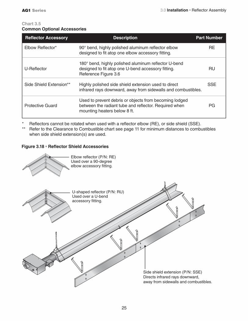
25
AG1 Series
Chart 3.5Common Optional Accessories
Figure 3.18 • Reflector Shield Accessories
Side shield extension (P/N: SSE)Directs infrared rays downward, away from sidewalls and combustibles.
Elbow reflector (P/N: RE)Used over a 90-degree elbow accessory fitting.
U-shaped reflector (P/N: RU) Used over a U-bend accessory fitting.
3.0 Installation • Reflector Assembly
Elbow Reflector* 90° bend, highly polished aluminum reflector elbow RE designed to fit atop one elbow accessory fitting.
180° bend, highly polished aluminum reflector U-bend U-Reflector designed to fit atop one U-bend accessory fitting. RU Reference Figure 3.6
Side Shield Extension** Highly polished side shield extension used to direct SSE infrared rays downward, away from sidewalls and combustibles. Used to prevent debris or objects from becoming lodged Protective Guard between the radiant tube and reflector. Required when PG mounting heaters below 8 ft.
Reflector Accessory Description Part Number
* Reflectors cannot be rotated when used with a reflector elbow (RE), or side shield (SSE).** Refer to the Clearance to Combustible chart see page 11 for minimum distances to combustibles when side shield extension(s) are used.
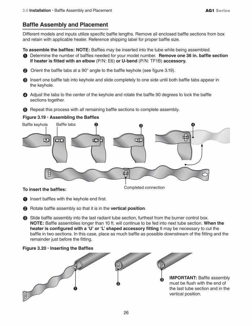
26
AG1 Series3.0 Installation • Baffle Assembly and Placement
Baffle keyhole Baffle tabs
Completed connection
Different models and inputs utilize specific baffle lengths. Remove all enclosed baffle sections from box and retain with applicable heater. Reference shipping label for proper baffle size. To assemble the baffles: NOTE: Baffles may be inserted into the tube while being assembled.
1 Determine the number of baffles needed for your model number. Remove one 36 in. baffle section if heater is fitted with an elbow (P/N: E6) or U-bend (P/N: TF1B) accessory.
2 Orient the baffle tabs at a 90° angle to the baffle keyhole (see figure 3.19).
3 Insert one baffle tab into keyhole and slide completely to one side until both baffle tabs appear in the keyhole.
4 Adjust the tabs to the center of the keyhole and rotate the baffle 90 degrees to lock the baffle sections together.
5 Repeat this process with all remaining baffle sections to complete assembly.
Figure 3.19 • Assembling the Baffles
Figure 3.20 • Inserting the Baffles
To insert the baffles:
1 Insert baffles with the keyhole end first.
2 Rotate baffle assembly so that it is in the vertical position.
3 Slide baffle assembly into the last radiant tube section, furthest from the burner control box. NOTE: Baffle assemblies longer than 10 ft. will continue to be fed into next tube section. When the heater is configured with a ‘U’ or ‘L’ shaped accessory fitting It may be necessary to cut the baffle in two sections. In this case, place as much baffle as possible downstream of the fitting and the remainder just before the fitting.
IMPORTANT: Baffle assembly must be flush with the end of the last tube section and in the vertical position.
Baffle Assembly and Placement
2 3 4
1
23
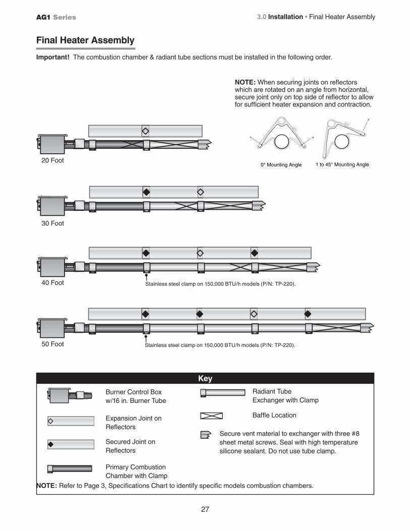
27
AG1 Series
Final Heater Assembly
20 Foot
50 Foot
30 Foot
40 Foot
3.0 Installation • Final Heater Assembly
Burner Control Box w/16 in. Burner Tube
Key
Expansion Joint on Reflectors
Secured Joint on Reflectors
Primary Combustion Chamber with Clamp
Radiant Tube Exchanger with Clamp
Baffle Location
Secure vent material to exchanger with three #8 sheet metal screws. Seal with high temperature silicone sealant. Do not use tube clamp.
Stainless steel clamp on 150,000 BTU/h models (P/N: TP-220).
NOTE: Refer to Page 3, Specifications Chart to identify specific models combustion chambers.
Stainless steel clamp on 150,000 BTU/h models (P/N: TP-220).
Important! The combustion chamber & radiant tube sections must be installed in the following order.
0° Mounting Angle 1 to 45° Mounting Angle
NOTE: When securing joints on reflectors which are rotated on an angle from horizontal, secure joint only on top side of reflector to allow for sufficient heater expansion and contraction.
28
AG1 Series3.0 Installation • Venting • Replacing Existing Equipment
Venting
The AG1 Series tube heater must be vented as described here to properly direct flue gases from the unit to the outside atmosphere. The venting can terminate vertically through the roof (up) or horizontally through a sidewall (sideways).
Follow these guidelines and all applicable codes for all models prior to installing the vent material. Local codes may vary.
In the absence of local codes, refer to:
United States: NFPA 54/ANSI Z223.1 (latest edition), National Fuel Gas Code. Canada: CAN/CGA B149.1 Installation Codes for Gas Burning Appliances.
Replacing Existing Equipment
If the heater is replacing existing equipment and using an existing vent system, inspect the venting for proper size and horizontal pitch as directed in these instructions and the latest edition of the National Fuel Gas Code, ANSI Z223.1 (NFPA 54) or CSA B149.1 Installation Code.
Determine that there is not blockage or restriction, leakage, corrosion or other deficiencies that can cause hazards. The vent pipe should be corrosion-resistant galvanized steel of a thickness that meets the National Fuel Gas Code. Minimum thickness for connectors varies depending on the pipe diameter. Never vent the AG1 Series with PVC or plastic pipe.
Gas-fired heaters must be vented. A built in power exhauster is provided. Additional external power exhausters are not required or permitted.
Insufficient ventilation and/or improperly sealed vents may release gas into the building which could result in health problems, carbon monoxide poisoning or death. Improper venting may result in fire, explosion, injury or death.
WARNING!
Do not vent this appliance into another heater’s vents or through a masonry chimney.
Do not use dampers in the heater vent pipe.
Single Wall vent pipe must not pass through any unoccupied attic, inside wall, concealed space, or floor.
Un-insulated single wall vent pipe must not be used outdoors for venting appliances in regions where winter design temperature is below freezing.
WARNING!
If replacing an existing heater, vents may require re-sizing. Improperly sized venting systems can result in vent gas leakage or condensation. Refer to the National Fuel Gas Code ANSI Z223.1 (NFPA 54) or CSA B149.1 - latest edition. Failure to follow these instructions can result in serious injury or death.
WARNING!
29
AG1 Series 3.0 Installation • General Venting Requirements
General Venting Requirements
The venting system for AG1 Series heaters may terminate horizontally through a sidewall or vertically through the roof, and may be individually or commonly vented. Configuration of the vent termination determines the category type. All model heaters must be installed in accordance to the requirements of this section, as well as the requirements of its category determination, as described in this manual. To determine your applications category type, review ‘Vertical Venting’ (Category I) and ‘Horizontal Venting’ (Category III) sections of this manual.
All AG1 Series Model Requirements:
• Exhaust vent pipe must be 4 inch nominal size.
• Use vent pipe material that is corrosion-resistant galvanized steel of a thickness that meets the National Fuel Gas Code.
• Do not exceed a maximum vent length of 20 feet, and 2, 90° elbows.
• Maintain a minimum vent length of 3 feet.
• Maintain a minimum 12 inches of straight pipe from the flue outlet before any directional changes are made in the venting system.
• Have all vent pipe seams or connectors fastened together with at least three corrosion resistant sheet metal screws (field supplied).
• Maintain a 6 inch clearance around all single wall vent pipe from any combustible materials. For double wall vent pipe (type B) follow the vent manufacturer’s clearance to combustibles.
• Avoid using more than two 90° directional changes in the venting system.
• The equivalent length for a 4 inch 90° elbow is 5 feet.
• Horizontal sections of the vent pipe must be installed with an upward slope from the appliance at a pitch of ¼ inch per foot.
• Suspend and secure all horizontal runs at points no greater than 3 feet apart.
• Vent termination must maintain a minimum distance of 6 feet from any mechanical air supply inlet.
• Vent must terminate a minimum of 4 feet below, 4 feet horizontally from, or 1 foot above any window or door that may be opened or gravity air inlet into the building.
• Vent must terminate a minimum of 4 feet above grade level and must extend beyond any combustible overhang. Vents adjacent to the public walkways must terminate a minimum of 7 feet above grade level.
• The vent terminal must be installed to prevent any blockage by snow and protect building material from degradation by flue gases.
• The vent cap must be a minimum of 6 inches from the sidewall of the building.
• Vent must be a minimum of 36 inches below or extend beyond any combustible overhang.
• Consult NFPA ANSI Z223.1 Gas Vent Termination criteria for vents that terminate on a roof pitch that exceeds 9:12.
• Canada: Vents must terminate a minimum of 3 feet from a window or door that may be opened, and a non-mechanical air supply inlet or combustion air inlet into the building.
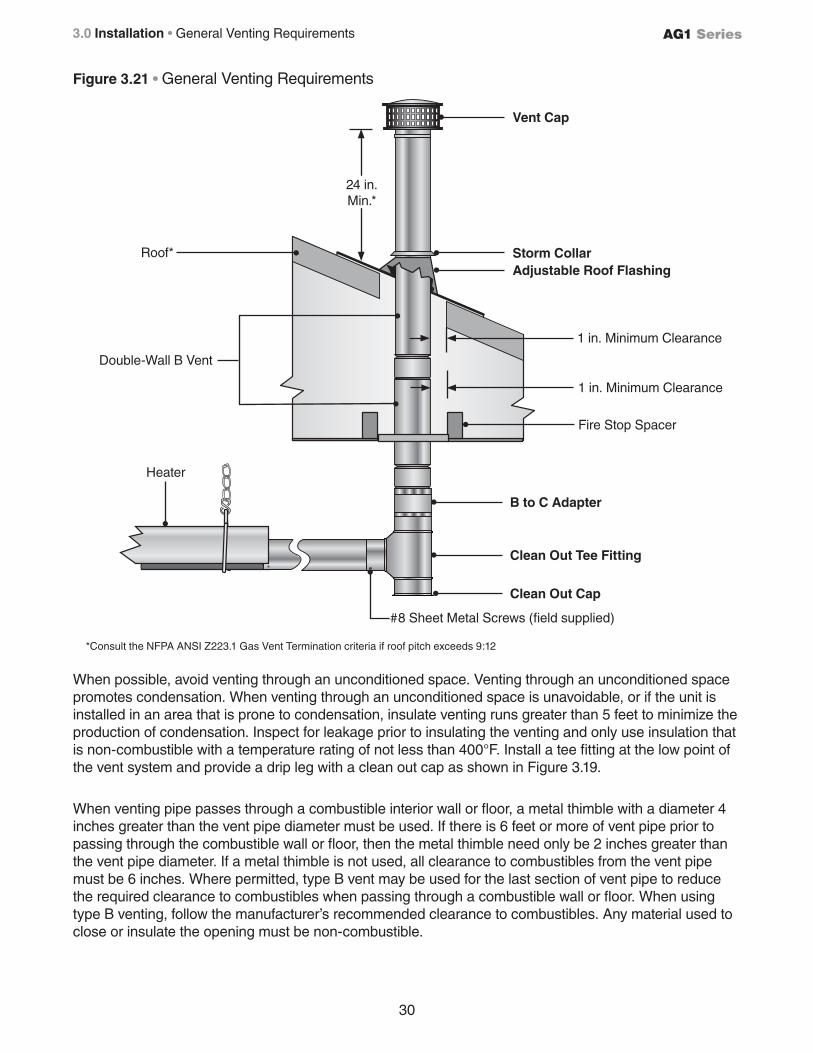
30
AG1 Series3.0 Installation • General Venting Requirements
Figure 3.21 • General Venting Requirements
When possible, avoid venting through an unconditioned space. Venting through an unconditioned space promotes condensation. When venting through an unconditioned space is unavoidable, or if the unit is installed in an area that is prone to condensation, insulate venting runs greater than 5 feet to minimize the production of condensation. Inspect for leakage prior to insulating the venting and only use insulation that is non-combustible with a temperature rating of not less than 400°F. Install a tee fitting at the low point of the vent system and provide a drip leg with a clean out cap as shown in Figure 3.19.
When venting pipe passes through a combustible interior wall or floor, a metal thimble with a diameter 4 inches greater than the vent pipe diameter must be used. If there is 6 feet or more of vent pipe prior to passing through the combustible wall or floor, then the metal thimble need only be 2 inches greater than the vent pipe diameter. If a metal thimble is not used, all clearance to combustibles from the vent pipe must be 6 inches. Where permitted, type B vent may be used for the last section of vent pipe to reduce the required clearance to combustibles when passing through a combustible wall or floor. When using type B venting, follow the manufacturer’s recommended clearance to combustibles. Any material used to close or insulate the opening must be non-combustible.
*Consult the NFPA ANSI Z223.1 Gas Vent Termination criteria if roof pitch exceeds 9:12
24 in.Min.*
Double-Wall B Vent
Roof*
Heater
1 in. Minimum Clearance
1 in. Minimum Clearance
Fire Stop Spacer
#8 Sheet Metal Screws (field supplied)
Adjustable Roof FlashingStorm Collar
B to C Adapter
Clean Out Tee Fitting
Vent Cap
Clean Out Cap
31
AG1 Series 3.0 Installation • Vertical Venting (Category I)
Vertical Venting (Category I)
An appliance that operates with a non-positive vent static pressure and with a vent gas temperature that avoids excessive condensate production in the vent is said to be ‘Category I’. The AG1 Series heater is considered a Category I appliance if the venting system meets all of the following criteria:
• The vent system terminates vertically (up).
• The length of the horizontal portion of the vent run is less than 75% of the vertical rise length. (e.g.- If the vertical vent height is 10 feet, the horizontal run is less than 7-1/2 feet).
• The vent terminates a minimum of 5 feet above the vent connection on the unit.
For vertical vent termination, the venting must comply with all parts of this section, in addition to the requirements of the general venting.
Category I (Vertical) venting is venting at a non-positive pressure. An appliance vented as a Category I is considered a fan-assisted appliance and the vent system does not have to be ‘gas tight’. It is recommended that the venting system is installed with a tee, drip leg, and clean-out cap as shown in Figure 3.21.
Vent Locations and Clearances:
• Separate air intake duct from vent pipe by a minimum of 4 feet by placing vent pipes higher than adjacent air intake ducts.
• Utilize a listed type B vent termination cap.
• The vent terminal must extend a minimum of 2 feet above the roof.
• Vent caps should be located a minimum of 2 feet away from adjoining structures.
All vertically vented heaters that are Category I must be connected to a chimney or vent complying with a recognized Standard, or lined masonry (or concrete) chimney with a material acceptable to the authority having jurisdiction. Venting into an unlined masonry chimney is not permitted. Refer to the National Fuel Gas Code and page 28 of this manual.
Use a listed vent terminal to reduce down drafts and moisture in the vent.
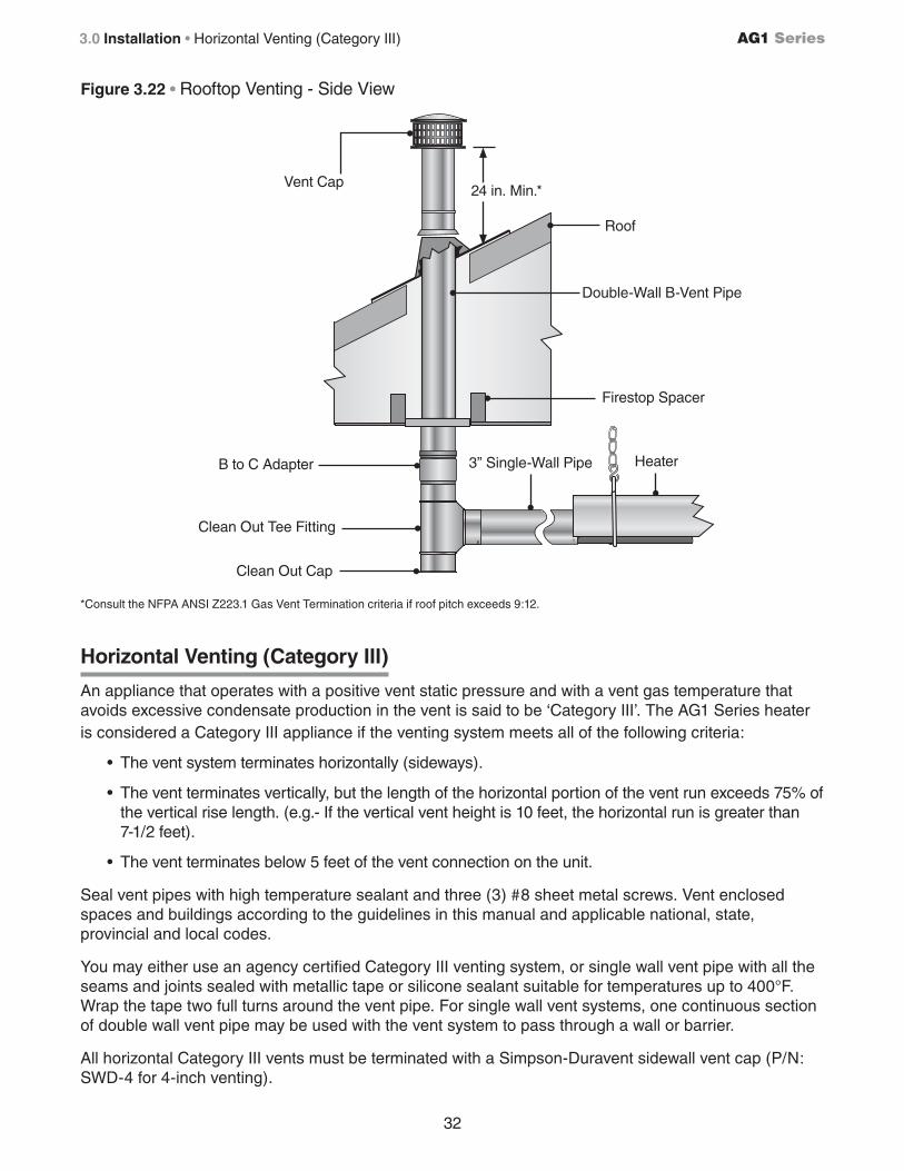
32
AG1 Series3.0 Installation • Horizontal Venting (Category III)
Figure 3.22 • Rooftop Venting - Side View
*Consult the NFPA ANSI Z223.1 Gas Vent Termination criteria if roof pitch exceeds 9:12.
Vent Cap
Double-Wall B-Vent Pipe
Firestop Spacer
B to C Adapter
Roof
24 in. Min.*
Heater
Clean Out Tee Fitting
Clean Out Cap
Horizontal Venting (Category III)
An appliance that operates with a positive vent static pressure and with a vent gas temperature that avoids excessive condensate production in the vent is said to be ‘Category III’. The AG1 Series heater is considered a Category III appliance if the venting system meets all of the following criteria:
• The vent system terminates horizontally (sideways).
• The vent terminates vertically, but the length of the horizontal portion of the vent run exceeds 75% of the vertical rise length. (e.g.- If the vertical vent height is 10 feet, the horizontal run is greater than 7-1/2 feet).
• The vent terminates below 5 feet of the vent connection on the unit.
Seal vent pipes with high temperature sealant and three (3) #8 sheet metal screws. Vent enclosed spaces and buildings according to the guidelines in this manual and applicable national, state, provincial and local codes.
You may either use an agency certified Category III venting system, or single wall vent pipe with all the seams and joints sealed with metallic tape or silicone sealant suitable for temperatures up to 400°F. Wrap the tape two full turns around the vent pipe. For single wall vent systems, one continuous section of double wall vent pipe may be used with the vent system to pass through a wall or barrier.
All horizontal Category III vents must be terminated with a Simpson-Duravent sidewall vent cap (P/N: SWD-4 for 4-inch venting).
3” Single-Wall Pipe
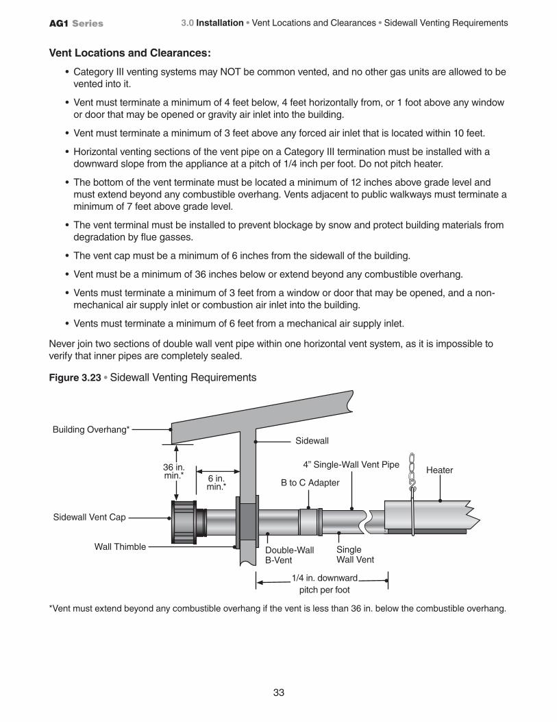
33
AG1 Series 3.0 Installation • Vent Locations and Clearances • Sidewall Venting Requirements
Vent Locations and Clearances:
• Category III venting systems may NOT be common vented, and no other gas units are allowed to be vented into it.
• Vent must terminate a minimum of 4 feet below, 4 feet horizontally from, or 1 foot above any window or door that may be opened or gravity air inlet into the building.
• Vent must terminate a minimum of 3 feet above any forced air inlet that is located within 10 feet.
• Horizontal venting sections of the vent pipe on a Category III termination must be installed with a downward slope from the appliance at a pitch of 1/4 inch per foot. Do not pitch heater.
• The bottom of the vent terminate must be located a minimum of 12 inches above grade level and must extend beyond any combustible overhang. Vents adjacent to public walkways must terminate a minimum of 7 feet above grade level.
• The vent terminal must be installed to prevent blockage by snow and protect building materials from degradation by flue gasses.
• The vent cap must be a minimum of 6 inches from the sidewall of the building.
• Vent must be a minimum of 36 inches below or extend beyond any combustible overhang.
• Vents must terminate a minimum of 3 feet from a window or door that may be opened, and a non-mechanical air supply inlet or combustion air inlet into the building.
• Vents must terminate a minimum of 6 feet from a mechanical air supply inlet.
Never join two sections of double wall vent pipe within one horizontal vent system, as it is impossible to verify that inner pipes are completely sealed.
Figure 3.23 • Sidewall Venting Requirements
*Vent must extend beyond any combustible overhang if the vent is less than 36 in. below the combustible overhang.
Building Overhang*Sidewall
Double-Wall B-Vent
Single Wall Vent
Wall Thimble
Sidewall Vent Cap
6 in. min.* B to C Adapter
Heater
1/4 in. downwardpitch per foot
36 in. min.*
4” Single-Wall Vent Pipe
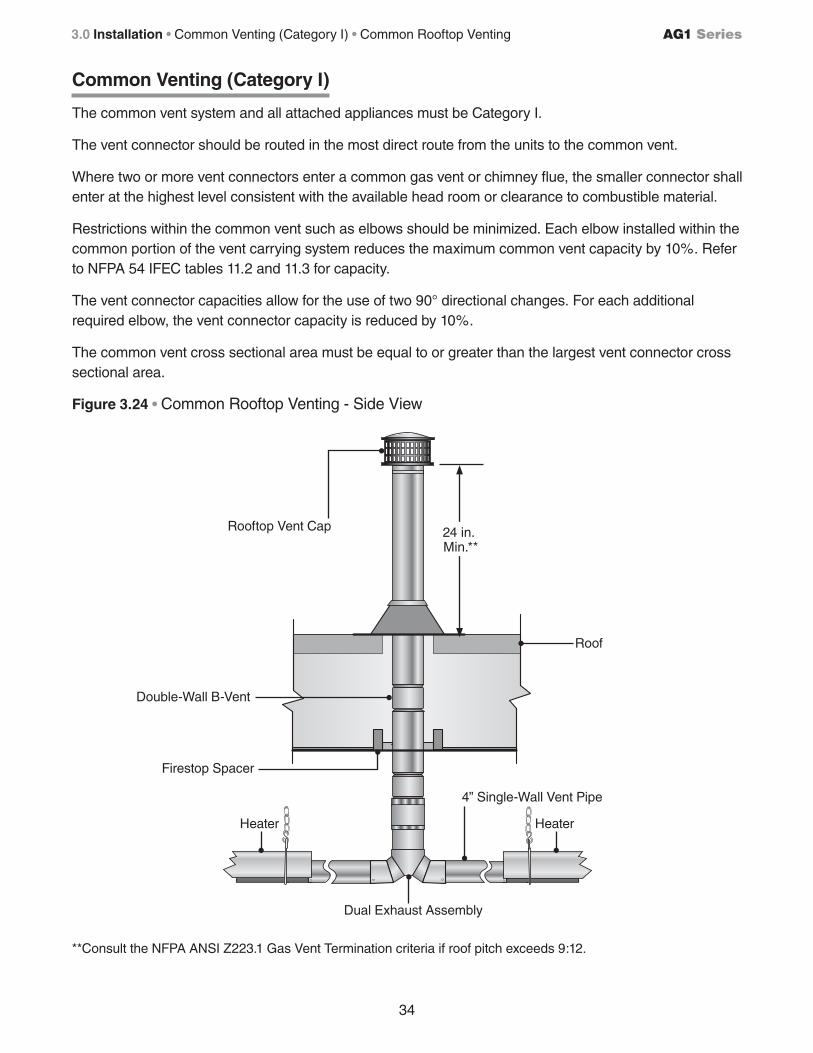
34
AG1 Series3.0 Installation • Common Venting (Category I) • Common Rooftop Venting
Common Venting (Category I)
The common vent system and all attached appliances must be Category I.
The vent connector should be routed in the most direct route from the units to the common vent.
Where two or more vent connectors enter a common gas vent or chimney flue, the smaller connector shall enter at the highest level consistent with the available head room or clearance to combustible material.
Restrictions within the common vent such as elbows should be minimized. Each elbow installed within the common portion of the vent carrying system reduces the maximum common vent capacity by 10%. Refer to NFPA 54 IFEC tables 11.2 and 11.3 for capacity.
The vent connector capacities allow for the use of two 90° directional changes. For each additional required elbow, the vent connector capacity is reduced by 10%.
The common vent cross sectional area must be equal to or greater than the largest vent connector cross sectional area.
Figure 3.24 • Common Rooftop Venting - Side View
**Consult the NFPA ANSI Z223.1 Gas Vent Termination criteria if roof pitch exceeds 9:12.
Rooftop Vent Cap
Roof
Dual Exhaust Assembly
Heater
Firestop Spacer
Double-Wall B-Vent
24 in. Min.**
Heater
4” Single-Wall Vent Pipe
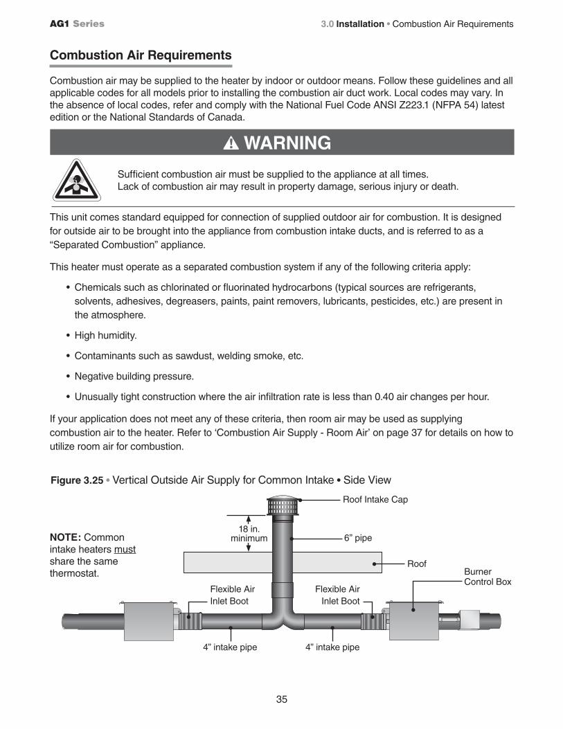
35
AG1 Series 3.0 Installation • Combustion Air Requirements
Figure 3.25 • Vertical Outside Air Supply for Common Intake • Side View
Roof
Flexible Air Inlet Boot
Roof Intake Cap
18 in. minimum 6” pipe
4” intake pipe
NOTE: Common intake heaters must share the same thermostat.
4” intake pipe
Burner Control Box
Flexible Air Inlet Boot
This unit comes standard equipped for connection of supplied outdoor air for combustion. It is designed for outside air to be brought into the appliance from combustion intake ducts, and is referred to as a “Separated Combustion” appliance.
This heater must operate as a separated combustion system if any of the following criteria apply:
• Chemicals such as chlorinated or fluorinated hydrocarbons (typical sources are refrigerants, solvents, adhesives, degreasers, paints, paint removers, lubricants, pesticides, etc.) are present in the atmosphere.
• High humidity.
• Contaminants such as sawdust, welding smoke, etc.
• Negative building pressure.
• Unusually tight construction where the air infiltration rate is less than 0.40 air changes per hour.
If your application does not meet any of these criteria, then room air may be used as supplying combustion air to the heater. Refer to ‘Combustion Air Supply - Room Air’ on page 37 for details on how to utilize room air for combustion.
Sufficient combustion air must be supplied to the appliance at all times. Lack of combustion air may result in property damage, serious injury or death.
WARNING!
Combustion Air Requirements
Combustion air may be supplied to the heater by indoor or outdoor means. Follow these guidelines and all applicable codes for all models prior to installing the combustion air duct work. Local codes may vary. In the absence of local codes, refer and comply with the National Fuel Code ANSI Z223.1 (NFPA 54) latest edition or the National Standards of Canada.
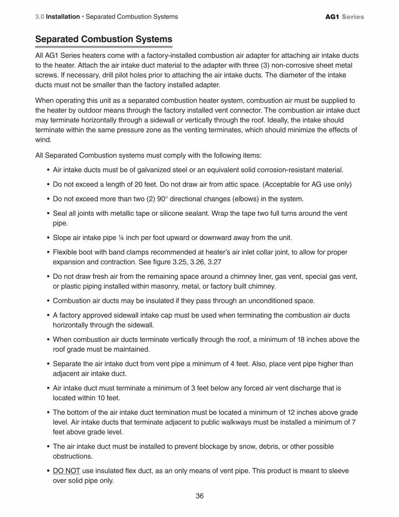
36
AG1 Series3.0 Installation • Separated Combustion Systems
Separated Combustion Systems
All AG1 Series heaters come with a factory-installed combustion air adapter for attaching air intake ducts to the heater. Attach the air intake duct material to the adapter with three (3) non-corrosive sheet metal screws. If necessary, drill pilot holes prior to attaching the air intake ducts. The diameter of the intake ducts must not be smaller than the factory installed adapter.
When operating this unit as a separated combustion heater system, combustion air must be supplied to the heater by outdoor means through the factory installed vent connector. The combustion air intake duct may terminate horizontally through a sidewall or vertically through the roof. Ideally, the intake should terminate within the same pressure zone as the venting terminates, which should minimize the effects of wind.
All Separated Combustion systems must comply with the following items:
• Air intake ducts must be of galvanized steel or an equivalent solid corrosion-resistant material.
• Do not exceed a length of 20 feet. Do not draw air from attic space. (Acceptable for AG use only)
• Do not exceed more than two (2) 90° directional changes (elbows) in the system.
• Seal all joints with metallic tape or silicone sealant. Wrap the tape two full turns around the vent pipe.
• Slope air intake pipe ¼ inch per foot upward or downward away from the unit.
• Flexible boot with band clamps recommended at heater’s air inlet collar joint, to allow for proper expansion and contraction. See figure 3.25, 3.26, 3.27
• Do not draw fresh air from the remaining space around a chimney liner, gas vent, special gas vent, or plastic piping installed within masonry, metal, or factory built chimney.
• Combustion air ducts may be insulated if they pass through an unconditioned space.
• A factory approved sidewall intake cap must be used when terminating the combustion air ducts horizontally through the sidewall.
• When combustion air ducts terminate vertically through the roof, a minimum of 18 inches above the roof grade must be maintained.
• Separate the air intake duct from vent pipe a minimum of 4 feet. Also, place vent pipe higher than adjacent air intake duct.
• Air intake duct must terminate a minimum of 3 feet below any forced air vent discharge that is located within 10 feet.
• The bottom of the air intake duct termination must be located a minimum of 12 inches above grade level. Air intake ducts that terminate adjacent to public walkways must be installed a minimum of 7 feet above grade level.
• The air intake duct must be installed to prevent blockage by snow, debris, or other possible obstructions.
• DO NOT use insulated flex duct, as an only means of vent pipe. This product is meant to sleeve over solid pipe only.
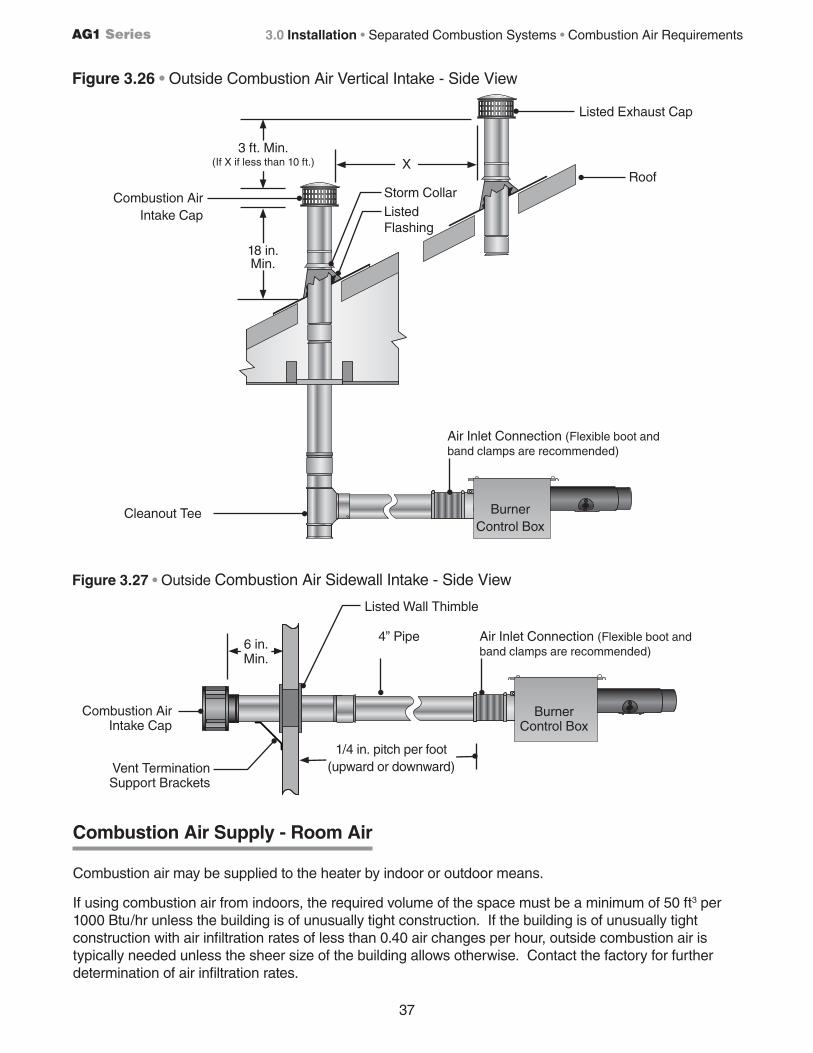
37
AG1 Series 3.0 Installation • Separated Combustion Systems • Combustion Air Requirements
Combustion Air Supply - Room Air
Combustion air may be supplied to the heater by indoor or outdoor means.
If using combustion air from indoors, the required volume of the space must be a minimum of 50 ft3 per 1000 Btu/hr unless the building is of unusually tight construction. If the building is of unusually tight construction with air infiltration rates of less than 0.40 air changes per hour, outside combustion air is typically needed unless the sheer size of the building allows otherwise. Contact the factory for further determination of air infiltration rates.
Figure 3.26 • Outside Combustion Air Vertical Intake - Side View
Roof
Listed Exhaust Cap
18 in. Min.
Combustion Air Intake Cap
BurnerControl Box
X3 ft. Min.
(If X if less than 10 ft.)
Storm CollarListed Flashing
Cleanout Tee
Figure 3.27 • Outside Combustion Air Sidewall Intake - Side View
Burner Control Box
Air Inlet Connection (Flexible boot and band clamps are recommended)
Combustion Air Intake Cap
Vent Termination Support Brackets
1/4 in. pitch per foot (upward or downward)
6 in. Min.
Listed Wall Thimble
4” Pipe
Air Inlet Connection (Flexible boot and band clamps are recommended)
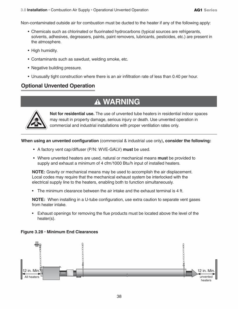
38
AG1 Series3.0 Installation • Combustion Air Supply • Operational Unvented Operation
Figure 3.28 • Minimum End Clearances
12 in. Min. 12 in. Min.
unvented heaters
All heaters
Non-contaminated outside air for combustion must be ducted to the heater if any of the following apply:
• Chemicals such as chlorinated or fluorinated hydrocarbons (typical sources are refrigerants, solvents, adhesives, degreasers, paints, paint removers, lubricants, pesticides, etc.) are present in the atmosphere.
• High humidity.
• Contaminants such as sawdust, welding smoke, etc.
• Negative building pressure.
• Unusually tight construction where there is an air infiltration rate of less than 0.40 per hour.
When using an unvented configuration (commercial & industrial use only), consider the following:
• A factory vent cap/diffuser (P/N: WVE-GALV) must be used.
• Where unvented heaters are used, natural or mechanical means must be provided to supply and exhaust a minimum of 4 cfm/1000 Btu/h input of installed heaters.
NOTE: Gravity or mechanical means may be used to accomplish the air displacement. Local codes may require that the mechanical exhaust system be interlocked with the electrical supply line to the heaters, enabling both to function simultaneously.
• The minimum clearance between the air intake and the exhaust terminal is 4 ft.
NOTE: When installing in a U-tube configuration, use extra caution to separate vent gases from heater intake.
• Exhaust openings for removing the flue products must be located above the level of the heater(s).
WARNING!
Optional Unvented Operation
Not for residential use. The use of unvented tube heaters in residential indoor spaces may result in property damage, serious injury or death. Use unvented operation in commercial and industrial installations with proper ventilation rates only.
39
AG1 Series 3.0 Installation • Combustion Air Requirements • Gas Supply
WARNING!
Improperly connected gas lines may result in serious injury and death, explosion, poisonous fumes, toxic gases or asphyxiation. Connect gas lines in accordance to national, state, provincial and local codes.
Gas pressure to the appliance controls must never exceed 1/2 PSI (14” W.C.). Damage to the controls may result.
Gas lines should be purged of air as described in ANSI Z223.1 (NFPA 54) or CSA-B149.1– latest version. Installation of the piping must also conform with the local building codes, or in the absence of local codes, with the latest edition of the National Fuel Gas Code (NFPA 54). In Canada, installation must be in accordance with CSA-B149.1
CAUTION!
Gas Supply Installation Instructions
The gas supply to the tube heater must be connected and tested in accordance with national, state, provincial, and local codes along with guidelines in this manual. In the United States refer to the latest edition of the ANSI Z223.1 (NFPA54) Standard and in Canada refer to the latest edition of the CAN/CGA B149.1 Standard.
Supply gas piping to the unit should conform with the local and national requirements for type and volume of gas handled, and pressure drop allowed in the line. Avoid pipe sizes smaller than 1/2”. The installation must conform with local building codes or, in the absence of such codes, the National Fuel Code (NFPA 54) and in conjunction with ANSI Z21.24/CSA 6.10 “Connectors for Gas Appliances”.
NOTICEThe total input to the appliance must fall within +/- 5% of the rated input as indicated on the rating plate. Otherwise the heat exchanger may prematurely fail.
IMPORTANT! The heating system will expand and contract during operation. Allowances for expansion must be made between the connection to the heater and the gas supply. A flexible gas connection of approved type is required. Flexible Type 1 gas connectors installed in one plane, without any sharp bends, kinks or twists.
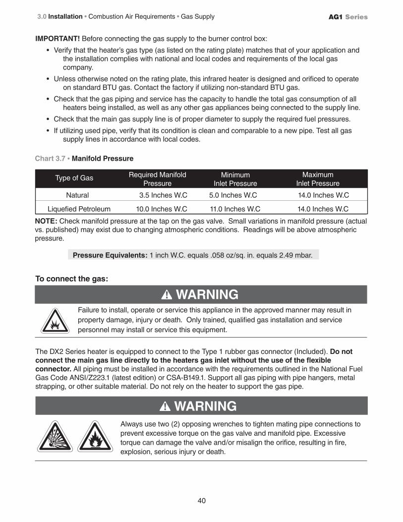
40
AG1 Series3.0 Installation • Combustion Air Requirements • Gas Supply
Chart 3.7 • Manifold Pressure
Pressure Equivalents: 1 inch W.C. equals .058 oz/sq. in. equals 2.49 mbar.
NOTE: Check manifold pressure at the tap on the gas valve. Small variations in manifold pressure (actual vs. published) may exist due to changing atmospheric conditions. Readings will be above atmospheric pressure.
IMPORTANT! Before connecting the gas supply to the burner control box:
• Verify that the heater’s gas type (as listed on the rating plate) matches that of your application and the installation complies with national and local codes and requirements of the local gas company.
• Unless otherwise noted on the rating plate, this infrared heater is designed and orificed to operate on standard BTU gas. Contact the factory if utilizing non-standard BTU gas.
• Check that the gas piping and service has the capacity to handle the total gas consumption of all heaters being installed, as well as any other gas appliances being connected to the supply line.
• Check that the main gas supply line is of proper diameter to supply the required fuel pressures.
• If utilizing used pipe, verify that its condition is clean and comparable to a new pipe. Test all gas supply lines in accordance with local codes.
To connect the gas:
The DX2 Series heater is equipped to connect to the Type 1 rubber gas connector (Included). Do not connect the main gas line directly to the heaters gas inlet without the use of the flexible connector. All piping must be installed in accordance with the requirements outlined in the National Fuel Gas Code ANSI/Z223.1 (latest edition) or CSA-B149.1. Support all gas piping with pipe hangers, metal strapping, or other suitable material. Do not rely on the heater to support the gas pipe.
WARNING!Failure to install, operate or service this appliance in the approved manner may result in property damage, injury or death. Only trained, qualified gas installation and service personnel may install or service this equipment.
WARNING!
Always use two (2) opposing wrenches to tighten mating pipe connections to prevent excessive torque on the gas valve and manifold pipe. Excessive torque can damage the valve and/or misalign the orifice, resulting in fire, explosion, serious injury or death.
Natural 3.5 Inches W.C 5.0 Inches W.C 14.0 Inches W.C
Liquefied Petroleum 10.0 Inches W.C 11.0 Inches W.C 14.0 Inches W.C
Type of Gas Required ManifoldPressure
MinimumInlet Pressure
MaximumInlet Pressure
41
AG1 Series 3.0 Installation • Gas Supply
CAUTION!When using a Type 1 flexible gas connector, do not attach the connector nuts directly to the gas pipe supply. Connector nuts must be installed to an approved adapter.
When connecting piping to the unit, the use of a thread joint compound is required. The thread compound (pipe dope) shall be resistant to the action of liquefied petroleum gas or any other chemical constituents of the gas to be conducted through piping. Use of Teflon® tape is not permitted.
Install ground joint union with a brass seat and a manual shut-off valve adjacent to the unit for emergency shut-off and easy servicing of controls. A 1/8” NPT plugged tap that is accessible for a test gauge connection is also recommended, as illustrated in Figure 3.31.
A sediment trap must be installed in the supply line in the lowest spot prior to connecting to the heater. The trap length shall be at least three inches long. Ideally, the trap would be installed as close as possible to the shut-off, as shown in Figure 3.31.
Connect the main gas supply line with an approved flexible connector or, if the authority having jurisdiction requires rigid piping, the use of approved swing joints may be used. If swing joints are utilized, the heater must be allowed to freely expand and contract without causing undue stress on the gas pipe.
The heater shall not be connected to the building piping system with rigid pipe or semi-rigid metallic tubing, including copper. When using such material, an intermediate connection device that allows for the heater expansion must be used.
The gas outlet must be in the same room as the appliance is installed, and must be accessible. It may not be concealed within or run through any wall, floor or partition. When installing the heater in a corrosive environment (or near corrosive substances), use a gas connector suitable for the environment. Do not use the gas piping to electrically ground the heater.
Installation of the Gas Line to the Heater
1 Install a sediment trap / drip leg if condensation may occur at any point of the gas supply line. This will decrease the possibility of loose scale or dirt in the supply line entering the heater’s control system and causing a malfunction. NOTE: High pressure gas above 14 Inches W.C. (water column pressure) requires a high pressure regulator and ball valve (optional).
2 Form the Type 1 hose connector (supplied) into a smooth U-shape allowing a maximum of 14 in. between the flexible connector’s end nuts (see Figure 3.31).
3 Attach the ball valve (optional) to the gas supply pipe. Apply pipe compound to NPT adapter threads to seal the joint. Use only a pipe compound resistant to LP. NOTE: Provide a 1/8 in. (.31 cm) NPT plugged tapping accessible for test gauge connection
immediately upstream of gas connection to the heater (provided an optional ball valve).
4 Attach the Type 1 hose connector to the adapter and burner control box inlet. Seal the joints. NOTE: Excessive torque on the manifold may misalign the orifice. Always use two wrenches to tighten mating pipe connections.
5 Final assembly must be tested for gas leaks according to CAN/CSA B149.1 Code and all local codes and/or Standards.
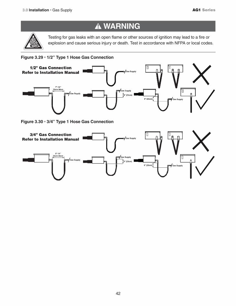
42
AG1 Series3.0 Installation • Gas Supply
WARNING!
Testing for gas leaks with an open flame or other sources of ignition may lead to a fire or explosion and cause serious injury or death. Test in accordance with NFPA or local codes.
9”-14”23cm-36cm
Gas SupplyGas Supply
9” (23cm)
9” (23cm) Gas Supply
Gas Supply
3/4” Gas ConnectionRefer to Installation Manual
Figure 3.29 • 1/2” Type 1 Hose Gas Connection
Figure 3.30 • 3/4” Type 1 Hose Gas Connection
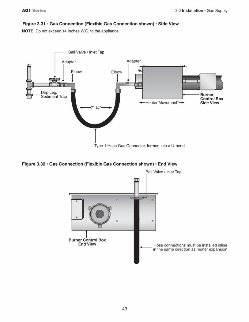
43
AG1 Series 3.0 Installation • Gas Supply
Figure 3.31 • Gas Connection (Flexible Gas Connection shown) • Side View
Figure 3.32 • Gas Connection (Flexible Gas Connection shown) • End View
NOTE: Do not exceed 14 Inches W.C. to the appliance.
Ball Valve / Inlet Tap
7”-14”
Type 1 Hose Gas Connector, formed into a U-bend
Adapter
Drip Leg/Sediment Trap
Heater Movement*
Elbow
Burner Control Box Side View
Adapter
Elbow
Ball Valve / Inlet Tap
Hose connections must be installed inline in the same direction as heater expansion
Burner Control BoxEnd View
44
AG1 Series3.0 Installation • Leak Testing
Leak Testing
Use a soap solution or equivalent for leak testing. Leak testing solution must be non-corrosive, and be rinsed off immediately after the leak test. Never test for leak with an open flame. Failure to comply could result in personal injury, property damage or death.
Always leak test final gas assembly for gas leaks according to the procedures outlined in NFPA 54 and all local codes and/or Standards.
For leak testing on pressures below 1/2 PSIBefore leak testing, close the field installed manual shut off valve shown on Figure 3.31 on the supply line to isolate the gas valve from the pressure. NOTE: All factory installed gas connections have passed an approved leak test.
For leak testing on pressures above 1/2 PSIWhen leak testing with pressures above 1/2 PSI (14 inches W.C.), the unit must be isolated from the supply pipe. Close the field installed manual shut off valve, disconnect the supply line to the unit, and temporarily cap the supply line for testing purposes.
WARNING!Gas pressures to the appliance controls must never exceed 14 inches W.C. (1/2 PSI). Supply pressures greater than 14” W.C. can damage the controls, resulting in personal injury, property damage, or death.
WARNING!
Testing for gas leaks with an open flame or other sources of ignition may lead to a fire or explosion and cause serious injury or death. Test in accordance with NFPA or local codes.
45
AG1 Series 33.0 Installation • Electrical Requirements
• 120VAC-60 Hz, single-phase, 3-wire. • 120VAC thermostat connection; 24VAC with optional relay transformer. • Starting current 1.7 amps • Running current 1.1 amps
Electrical Requirements
WARNING!Improper installation, adjustment, alteration, service or maintenance can cause property damage, serious injury or death. Read and understand, the installation, operating and maintenance instructions thoroughly before installing or servicing this equipment. Only trained, qualified gas installation and service personnel may install or service this equipment.
Not for residential use! Do not use this heater in the home, sleeping quarters, attached garages, etc. Installation of a commercial tube heater system in residential indoor spaces may result in property damage, serious injury or death.
All field installed wiring to the tube heater must be done in accordance with the national, state, provincial, local codes and to the guidelines in this manual. In the United States, refer to the most current revisions to the Electrical Code ANSI/NFPA 70 and in Canada refer to the most current revisions to the Canadian Electrical Code CSA C22.1 Part 1. The unit must be electrically grounded according to these codes. Line polarity must be observed when making field connections.
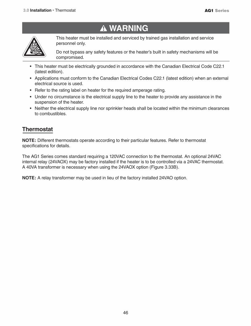
46
AG1 Series3.0 Installation • Thermostat
Thermostat
NOTE: Different thermostats operate according to their particular features. Refer to thermostat specifications for details.
The AG1 Series comes standard requiring a 120VAC connection to the thermostat. An optional 24VAC internal relay (24VAOX) may be factory installed if the heater is to be controlled via a 24VAC thermostat. A 40VA transformer is necessary when using the 24VAOX option (Figure 3.33B).
NOTE: A relay transformer may be used in lieu of the factory installed 24VAO option.
WARNING!This heater must be installed and serviced by trained gas installation and service personnel only.
Do not bypass any safety features or the heater’s built in safety mechanisms will be compromised.
• This heater must be electrically grounded in accordance with the Canadian Electrical Code C22.1 (latest edition).
• Applications must conform to the Canadian Electrical Codes C22.1 (latest edition) when an external electrical source is used.
• Refer to the rating label on heater for the required amperage rating.
• Under no circumstance is the electrical supply line to the heater to provide any assistance in the suspension of the heater.
• Neither the electrical supply line nor sprinkler heads shall be located within the minimum clearances to combustibles.
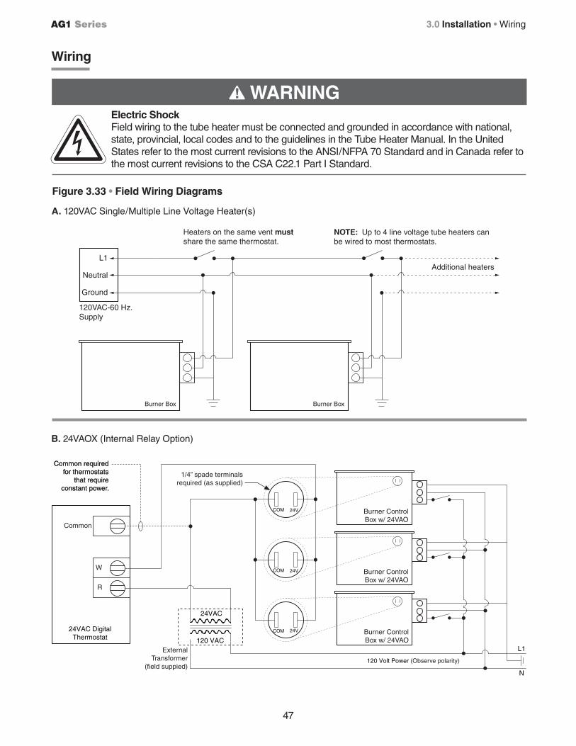
47
AG1 Series 3.0 Installation • Wiring
WARNING!
120VAC-60 Hz.Supply
NOTE: Up to 4 line voltage tube heaters can be wired to most thermostats.
L1
Neutral
Ground
Heaters on the same vent must share the same thermostat.
Additional heaters
Burner BoxBurner Box
Electric ShockField wiring to the tube heater must be connected and grounded in accordance with national, state, provincial, local codes and to the guidelines in the Tube Heater Manual. In the United States refer to the most current revisions to the ANSI/NFPA 70 Standard and in Canada refer to the most current revisions to the CSA C22.1 Part I Standard.
Wiring
Figure 3.33 • Field Wiring Diagrams
A. 120VAC Single/Multiple Line Voltage Heater(s)
B. 24VAOX (Internal Relay Option)
COM 24V
Burner Control Box w/ 24VAO
L1
N
120 Volt Power (Observe polarity)
24VAC DigitalThermostat 120 VAC
24VAC
Common
W
R
COM 24V
COM 24V
Burner Control Box w/ 24VAO
Burner Control Box w/ 24VAO
Common required for thermostats
that require constant power.
Common required for thermostats
that require constant power.
1/4” spade terminals required (as supplied)
ExternalTransformer
(field suppied)
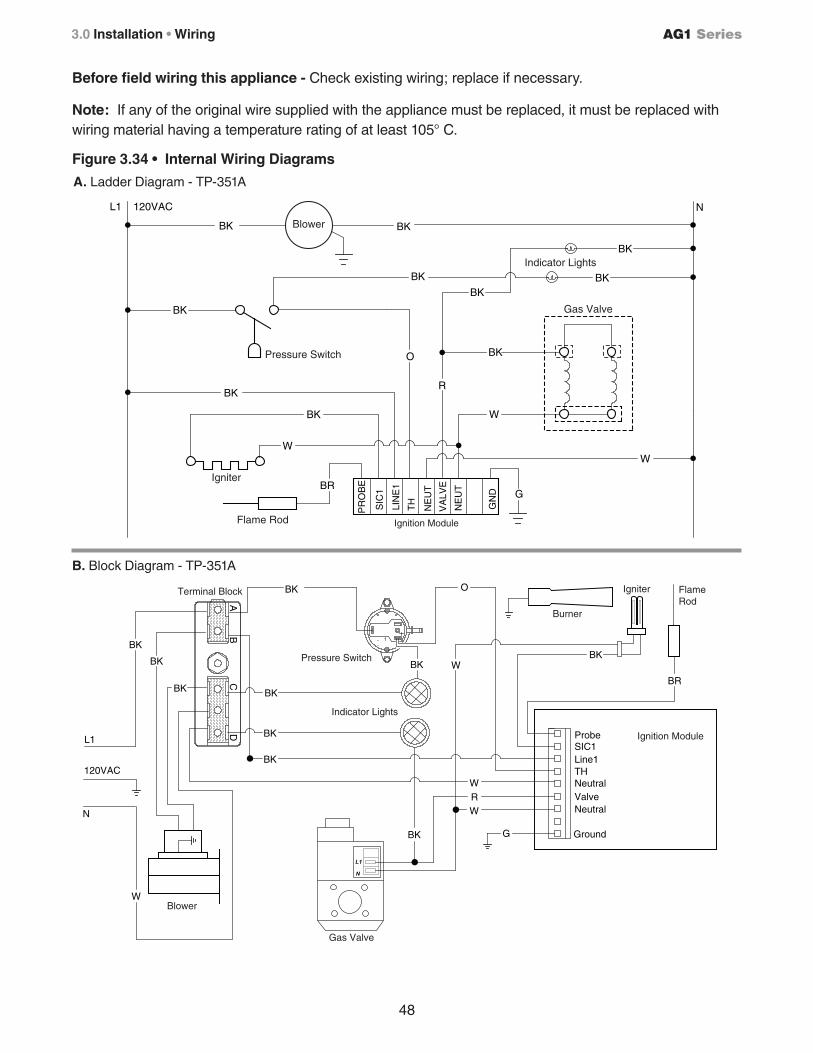
48
AG1 Series3.0 Installation • Wiring
Before field wiring this appliance - Check existing wiring; replace if necessary.
Note: If any of the original wire supplied with the appliance must be replaced, it must be replaced with wiring material having a temperature rating of at least 105° C.
Figure 3.34 • Internal Wiring Diagrams
A. Ladder Diagram - TP-351A
B. Block Diagram - TP-351A
W R
BK
BK
BK
Ground
NeutralValveNeutralTHLine1SIC1Probe
W
BK
BKBK
BK
BK
BR
W
G
120VAC
N
L1
OBK
W
BK
Terminal Block
Pressure Switch
Indicator Lights
Blower
Burner
Igniter Flame Rod
Ignition Module
Gas Valve
SIC
1
LIN
E1
NE
UT
GN
D
NE
UT
TH
PR
OB
E
VA
LVE
BK
BKBK
BK
GBR
W
BK
BK
W
W
N
R
BK
O
BK
BK
120VACL1
Blower
Indicator Lights
Pressure Switch
Igniter
Ignition Module
Gas Valve
Flame Rod
BK
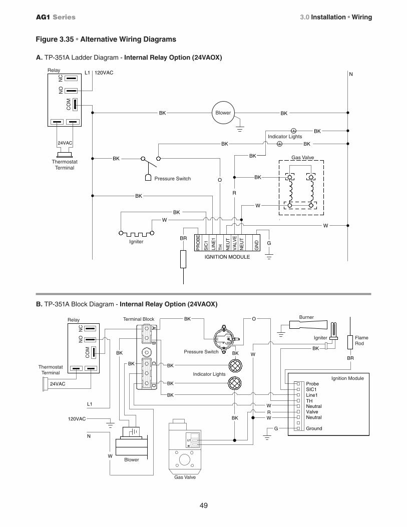
49
AG1 Series 3.0 Installation • Wiring
W
BK
LIN
E1
IGNITION MODULE
BR
SIC
1
PR
OB
E
BK
NE
UT
NE
UT
VA
LVE
TH
GN
D
R
O
W
BK
120VACL1
BK
BK
G
W
N
BK
BK
BK
24VAC
Blower
Indicator Lights
Gas Valve
Pressure Switch
Igniter
Thermostat Terminal
NO
NC
CO
MRelay
BK
BK
W
BK W R
Ground
NeutralValveNeutralTHLine1SIC1Probe
G
BK
24VAC
BKBKBR
BK
BK
W
L1
120VAC
N
BK O
BK WBK
Ignition Module
Pressure Switch
Indicator Lights
Blower
Burner
Igniter FlameRod
Terminal Block
Thermostat Terminal
NO
NC
CO
M
Relay
Gas Valve
Figure 3.35 • Alternative Wiring Diagrams
A. TP-351A Ladder Diagram - Internal Relay Option (24VAOX)
B. TP-351A Block Diagram - Internal Relay Option (24VAOX)
50
AG1 Series3.0 Installation • Unit Start-up (Commissioning) • Pre-Start Up Checks
Unit Start-up (Commissioning)
Pre-Start Up Checks
Verify that the installation conforms to all of the specifications of the manual, as well as with local, state, national, and provincial codes. In absence of local codes, the unit heater must be installed according to the current National Fuel Gas Code ANSI Z223.1 (NFPA 54). In Canada, the installation must conform to the current National Standard of Canada CSA-B149 Sections 1.
Prior to starting up the unit, verify that:
9 The gas type listed on the rating label matches that of your application.
9 The gas connections have been purged of air and properly leak tested.
9 The voltage type and frequency listed on the rating label matches that of your application.
9 The unit is properly grounded as per the National Electrical Code, ANSI/NFPA 70 or Canadian Electrical code CSA C22.1 Part 1.
9 The unit is properly mounted to a permanent structure able to bear the weight of the unit.
9 The proper mounting height is observed for the application.
9 All clearance to combustible distances or service clearances are maintained.
9 The unit is properly isolated or installed to prevent excessive vibration.
9 The unit is level horizontally.
9 Venting is properly installed in accordance with this manual and any applicable codes.
9 Combustion air supply is sufficient to support proper operation at all times.
WARNING!
Improper installation, adjustment, alteration, service or maintenance can cause property damage, serious injury, or death. This heater must be installed and serviced by a trained gas installation and service personnel only.
Shock Hazard.
Before attempting to perform any service or maintenance, turn electrical power to unit OFF at disconnect switch.
CAUTION!
51
AG1 Series 3.0 Installation • High Altitude Operation
Prior to leaving the Job Site
Prior to leaving the job site, verify that:
9 Service access door is properly secured to the unit.
9 The heater is clear of any objects that would interfere with the proper air circulation or that violate the listed clearance to combustibles.
9 Manual gas shut off is ON.
9 Electrical power is ON.
9 Thermostat is set to desired temperature.
9 Properly dispose of all packaging materials.
9 Check to be sure you have all of your tools.
9 Leave the Manual with the owner or end user.
High Altitude Operation
High altitude operation of this tube heater is approved, without modification, for elevations up to 6,000 feet (1,829 m) above MSL (sea level) in the United States. If the heater is being installed at an elevation above 6,000 ft, the input rate will have to be de-rated to ensure proper operation. The deration is achieved by a gas orifice change. Contact the factory for installations above these elevations.
WARNING!
Explosion hazard. This heater must be converted by a trained gas installation and service personnel only. Failure to comply could result in personal injury, asphyxiation, death, and fire or property damage.
52
AG1 Series
4.0 Operation
LIGHTING PROCEDURES:
1 Verify that service lid is secured.
2 Open (turn on) gas supply to the heater.
3 Close (turn on) electrical circuit (typically thermostat).
4 If the heater fails to light, turn off gas, open electrical circuit (set thermostat to lowest setting or to off). Wait five (5) minutes before repeating above steps.
SHUTDOWN PROCEDURES:
1 Open (turn off) electrical circuit.
2 Close (turn off) gas supply to the heater.
3 Wait five (5) minutes before relighting heater.
WARNING!
BEFORE OPERATING, smell all around the appliance area for gas. Be sure to smell next to the floor because some gas is heavier than air and will settle to the floor. Refer to page 1 “If you smell gas” and on safety label affixed to the heater.
Do not use this appliance if any part has been under water. Immediately call a qualified service technician to inspect the appliance and to replace any part of the control system and any gas control which has been under water.
This appliance does not have a pilot ignition. It is equipped with an ignition device which
automatically lights the burner. Do not attempt to light the system by hand.
Operating Instructions
WARNING!
Use only your hand to turn the manual shutoff. Never use tools. If the
knob will not turn by hand, don’t try to repair it; call a qualified technician.
Force or attempted repair may result in a fire or explosion.
4.0 Operation • Operating Instructions
53
AG1 Series
WARNING!
Sequence of Operation
Starting Circuit: Upon a call for heat, the fan is energized. Once operational static pressure is achieved, the differential switch will close initiating the ignition sequence. After a 5-second delay, the Glo-bar™ is energized for 45 seconds and the control allows the gas valve to open.
The trial for ignition is 8 seconds. If flame sense is not established within 8.5 seconds, the heater will attempt two (2) additional ignition sequences before proceeding to soft lockout. Soft lockout automatically retries after one (1) hour or the control can be reset by briefly interrupting the power source.
Running Circuit: After ignition, the flame rod monitors burner flame. If sense of flame is lost, the control immediately acts to reignite the gas-air mixture (identical to the starting sequence). If flame sense is not established within 8.5 seconds, the heater will attempt two (2) additional ignition sequences before proceeding to soft lockout. The control can be reset by briefly interrupting the power source.
This heater must be installed and serviced by trained gas installation and service personnel only.
Do not bypass any safety features or the heater’s built in safety mechanisms will be compromised.
4.0 Operation • Sequence of Operation
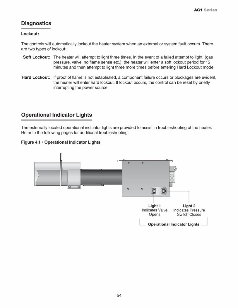
54
AG1 Series
VALVE
PS
PRESSURESWITCH
V
Figure 4.1 • Operational Indicator Lights
Light 1Indicates Valve
Opens
Light 2 Indicates Pressure
Switch Closes
Operational Indicator Lights
Operational Indicator Lights
The externally located operational indicator lights are provided to assist in troubleshooting of the heater. Refer to the following pages for additional troubleshooting.
Diagnostics
Lockout:
The controls will automatically lockout the heater system when an external or system fault occurs. There are two types of lockout:
Soft Lockout: The heater will attempt to light three times. In the event of a failed attempt to light, (gas pressure, valve, no flame sense etc.), the heater will enter a soft lockout period for 15 minutes and then attempt to light three more times before entering Hard Lockout mode.
Hard Lockout: If proof of flame is not established, a component failure occurs or blockages are evident, the heater will enter hard lockout. If lockout occurs, the control can be reset by briefly interrupting the power source.
55
AG1 Series
This page intentionally left blank.
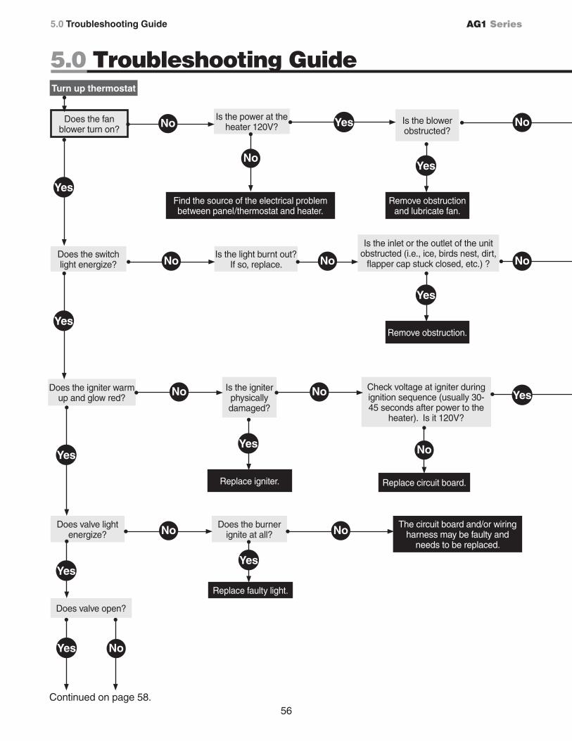
56
AG1 Series
Continued on page 58.
5.0 Troubleshooting Guide
Is the blower obstructed?
Replace circuit board.
Does the igniter warm up and glow red?
Is the igniter physically damaged?
Check voltage at igniter during ignition sequence (usually 30-45 seconds after power to the
heater). Is it 120V?
Is the inlet or the outlet of the unit obstructed (i.e., ice, birds nest, dirt,
flapper cap stuck closed, etc.) ?
Turn up thermostat
Does the fan blower turn on?
Is the power at the heater 120V?
Find the source of the electrical problem between panel/thermostat and heater.
No
Yes
Remove obstruction and lubricate fan.
No
Yes
Does the switch light energize?
Yes
Is the light burnt out? If so, replace.No No
Yes
Remove obstruction.
No
No No
No
Yes
Yes
Replace igniter.
Does valve light energize?
Yes
Does the burner ignite at all?No
The circuit board and/or wiring harness may be faulty and
needs to be replaced.
No
Yes
Replace faulty light.
Does valve open?
Yes
Yes No
No
Yes
5.0 Troubleshooting Guide
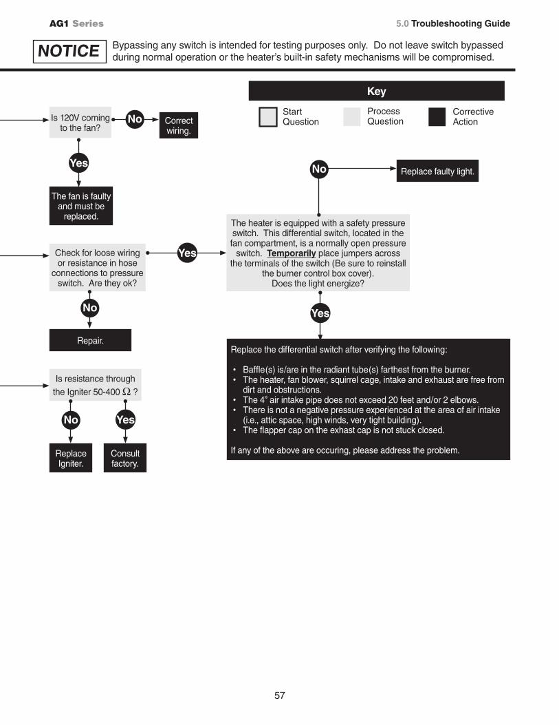
NOTICE Bypassing any switch is intended for testing purposes only. Do not leave switch bypassed during normal operation or the heater’s built-in safety mechanisms will be compromised.
57
AG1 Series
Is 120V coming to the fan?
Check for loose wiring or resistance in hose
connections to pressure switch. Are they ok?
The heater is equipped with a safety pressure switch. This differential switch, located in the fan compartment, is a normally open pressure
switch. Temporarily place jumpers across the terminals of the switch (Be sure to reinstall
the burner control box cover). Does the light energize?
Key
Start Question
ProcessQuestion
CorrectiveAction
Yes
No
The fan is faulty and must be
replaced.
Correct wiring.
Repair.
No
Yes
Yes
Replace faulty light.No
Replace the differential switch after verifying the following:
• Baffle(s) is/are in the radiant tube(s) farthest from the burner.• The heater, fan blower, squirrel cage, intake and exhaust are free from
dirt and obstructions.• The 4” air intake pipe does not exceed 20 feet and/or 2 elbows.• There is not a negative pressure experienced at the area of air intake
(i.e., attic space, high winds, very tight building).• The flapper cap on the exhast cap is not stuck closed.
If any of the above are occuring, please address the problem.
Is resistance through the Igniter 50-400 Ω ?
Replace Igniter.
No
Consult factory.
Yes
5.0 Troubleshooting Guide
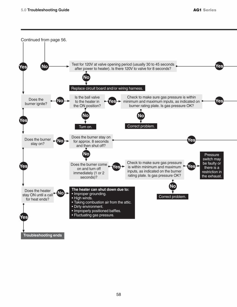
58
AG1 Series
Does the heater stay ON until a call
for heat ends?
Continued from page 56.
Does the burner ignite?
Test for 120V at valve opening period (usually 30 to 45 seconds after power to heater). Is there 120V to valve for 8 seconds?
Replace circuit board and/or wiring harness.
Does the burner stay on?
Is the ball valveto the heater in
the ON position?
Check to make sure gas pressure is within minimum and maximum inputs, as indicated on
burner rating plate. Is gas pressure OK?
Does the burner stay on for approx. 8 seconds
and then shut off?
Does the burner come on and turn off
immediately (1 or 2 seconds)?
Check to make sure gas pressure is within minimum and maximum inputs, as indicated on the burner rating plate. Is gas pressure OK?
Pressure switch may be faulty or there is a
restriction in the exhaust.
Troubleshooting ends
The heater can shut down due to: • Improper grounding. • High winds. • Taking combustion air from the attic. • Dirty environment. • Improperly positioned baffles. • Fluctuating gas pressure.
No
Yes
No Yes
No
Correct problem.
Yes
No
Yes
No
Yes
No
Yes
No
Turn on.
Yes
Correct problem.
No
NoYes
Yes
Yes
5.0 Troubleshooting Guide
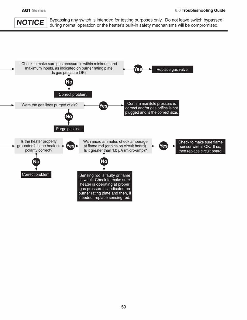
59
AG1 Series
Check to make sure gas pressure is within minimum and maximum inputs, as indicated on burner rating plate.
Is gas pressure OK?
Were the gas lines purged of air?
Is the heater properly grounded? Is the heater’s
polarity correct?
With micro ammeter, check amperage at flame rod (or pins on circuit board). Is it greater than 1.0 µA (micro-amp)?
Check to make sure flame sensor wire is OK. If so,
then replace circuit board.
Sensing rod is faulty or flame is weak. Check to make sure heater is operating at proper gas pressure as indicated on burner rating plate and then, if needed, replace sensing rod.
Replace gas valve.Yes
Correct problem.
Correct problem.
No
No
Yes Yes
No
Purge gas line.
No
Yes Confirm manifold pressure is correct and/or gas orifice is not plugged and is the correct size.
6.0 Troubleshooting Guide
NOTICE Bypassing any switch is intended for testing purposes only. Do not leave switch bypassed during normal operation or the heater’s built-in safety mechanisms will be compromised.
60
AG1 Series6.0 Maintenance • Routine Inspection
6.0 Maintenance
WARNING!
Personal injury or death may result if maintenance is not performed by properly trained gas installer or service personnel. Contact the installing distributor or place of purchase for service. Do not operate heating system if repairs are necessary.
Allow heater to cool prior to servicing.
Disconnect power to heater before servicing.
Use protective glasses when maintaining the heater.
Routine Inspection:
At least once per year, the heating system should be inspected and serviced by trained gas installation and service personnel only. This inspection should be performed at the beginning of the heating season to insure that all heater components are in proper working order and that the heating system operates at peak performance. Particular attention should be paid to the following items.
• Blower Motor: Annual oiling of the blower motor with SAE oil will extend bearing life significantly. Motors with sealed ball bearings (no oil ports) do not require oiling. Ensure that the squirrel cage in the blower is kept clean. If dirt becomes a problem, installation of outside air intake ducts for combustion is recommended.
Check lubrication instructions on motor. If oiling is required, add three to four drops of SAE 20 electric motor oil:
• After three years or 25,000 hours of operation (light-duty) • After two years or 8,000 hours of operation (medium-duty)• Annually or after 1,500 hours of operation (heavy-duty)
• Vent pipe system: Check the outside termination and the connections at the heater. Inspect the vent exhausts for leakage, damage, fatigue, corrosion and obstructions. If dirt becomes a problem, installation of outside air intake ducts for combustion is recommended.
• Combustion air intake system (when applicable): Check for blockage and/or leakage. Check the outside termination and the connection at the heater.
• Heat exchangers: Check the integrity of the heat exchangers. Replace if there are signs of structural failure. Check for corrosion and/or buildup within the tube exchanger passageways.
• Burner: Check for proper ignition, burner flame and flame sense. Flame should extend directly outward from burner without floating or lifting.
• Wiring: Check electrical connections for tightness and/or corrosion. Check wires for damage.
• Gas Connection: Inspect the integrity of the gas connection to the heater. Check for leaks, damage, fatigue or corrosion. Do not operate if repairs are necessary and turn off gas supply to the heater. Contact service personnel.
• Reflectors: Inspect the integrity of the reflectors for damage, separation, missing or misaligned sections. Do not operate if repairs are necessary. Repair or replace as required per the general installation manual. To maintain effective infrared heating, always keep both sides of the reflector clean. Dirt and dust can be vacuumed up or wiped with a soap and water solution. Use metal polish if the reflectors are severely dirty.
Contact service personnel if repairs are necessary. Do not operate unit.
Never over-oil the motor, or premature failure may occur.
NOTICE
61
AG1 Series
This page was intentionally left blank.
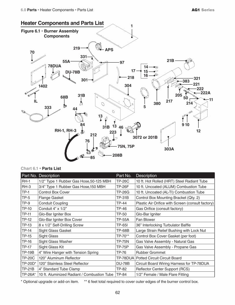
205
383221
222
1150
321
RH-1, RH-3
62
AG1 Series
Figure 6.1 • Burner Assembly Components
Chart 6.1 • Parts List
Heater Components and Parts List1
APS
97
218
219
55A
1402
78DUA
DU-78B
70
IL
44
31B
212
208B
75N, 75P
22346
3072 or 201B
303A
12
9 10
2175
380
1514
16
21B
222A
214
304
76
* Optional upgrade or add-on item. ** 6 feet total required to cover outer edges of the burner control box.
31B
13
13
17
301
333
68B
331
84
85
6.0 Parts • Heater Components • Parts List
Part No. Description Part No. DescriptionRH-1 1/2” Type 1 Rubber Gas Hose,50-125 MBH TP-26C 10 ft. Hot Rolled (HRT) Steel Radiant TubeRH-3 3/4” Type 1 Rubber Gas Hose,150 MBH TP-26F 10 ft. Uncoated (ALUM) Combustion TubeTP-1 Control Box Cover TP-26G 10 ft. Uncoated (AL-TI) Combustion TubeTP-5 Flange Gasket TP-31B Control Box Mounting Bracket (Qty. 2)TP-9 Conduit Coupling TP-44 Plastic Air Orifice with Screen (consult factory)TP-10 Conduit 4” x 1/2” TP-46 Gas Orifice (consult factory)TP-11 Glo-Bar Igniter Box TP-50 Glo-Bar IgniterTP-12 Glo-Bar Igniter Box Cover TP-55A Fan BlowerTP-13 8 x 1/2” Self-Drilling Screw TP-65I 36” Interlocking Turbulator BaffleTP-14 Sight Glass Gasket TP-68B Large Strain Relief Bushing with Lock NutTP-15 Sight Glass TP-70** Control Box Cover Gasket (per foot)TP-16 Sight Glass Washer TP-75N Gas Valve Assembly - Natural GasTP-17 Sight Glass Kit TP-75P Gas Valve Assembly - Propane GasTP-19B 4” Wire Hanger with Tension Spring TP-76 Rubber Grommet
TP-20C 120” Aluminum Reflector TP-78DUA Potted Circuit Circuit BoardTP-20D* 120” Stainless Steel Reflector DU-78B Circuit Board Wiring Harness for TP-78DUATP-21B 4” Standard Tube Clamp TP-82 Reflector Center Support (RCS)TP-26A* 10 ft. Aluminized Radiant / Combustion Tube TP-84 1/2” Female / Male Flare Fitting
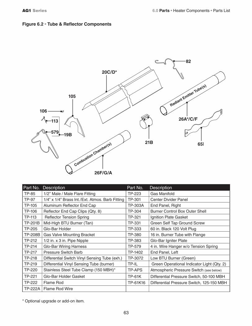
106
105
26F/G/A
21B
20C/D*
82
26A*/C/F
65I
19B
113
579
63
AG1 Series
Figure 6.2 • Tube & Reflector Components
Combustion Chamber(s
)
Radiant Emitte
r Tube(s)
6.0 Parts • Heater Components • Parts List
* Optional upgrade or add-on item.
Part No. Description Part No. DescriptionTP-85 1/2” Male / Male Flare Fitting TP-223 Gas ManifoldTP-97 1/4” x 1/4” Brass Int./Ext. Atmos. Barb Fitting TP-301 Center Divider PanelTP-105 Aluminum Reflector End Cap TP-303A End Panel, RightTP-106 Reflector End Cap Clips (Qty. 8) TP-304 Burner Control Box Outer ShellTP-113 Reflector Tension Spring TP-321 Ignition Plate GasketTP-201B Mid-High BTU Burner (Tan) TP-331 Green Self Tap Ground ScrewTP-205 Glo-Bar Holder TP-333 60 in. Black 120 Volt PlugTP-208B Gas Valve Mounting Bracket TP-380 16 in. Burner Tube with FlangeTP-212 1/2 in. x 3 in. Pipe Nipple TP-383 Glo-Bar Igniter PlateTP-214 Glo-Bar Wiring Harness TP-579 4 in. Wire Hanger w/o Tension SpringTP-217 Pressure Switch Barb TP-1402 End Panel, LeftTP-218 Differential Switch Vinyl Sensing Tube (exh.) TP-3072 Low BTU Burner (Green)TP-219 Differential Vinyl Sensing Tube (burner) TP-IL Green Operational Indicator Light (Qty. 2)TP-220 Stainless Steel Tube Clamp (150 MBH)* TP-APS Atmospheric Pressure Switch (see below)
TP-221 Glo-Bar Holder Gasket TP-61K Differential Pressure Switch, 50-100 MBH
TP-222 Flame Rod TP-61K16 Differential Pressure Switch, 125-150 MBH
TP-222A Flame Rod Wire
64
AG1 Series
7.0 Limited WarrantyOne-Year Limited Warranty. Radiant Tube Heaters covered in this manual, are warranted by Brant Radiant Heaters Limited to the original user against defects in workmanship or materials under normal use for one year after date of purchase. Any part which is determined to be defective in material or workmanship and returned to an authorized service location, as Brant Radiant Heaters Limited designates, shipping costs prepaid, will be, as the exclusive remedy, repaired or replaced at Brant Radiant Heaters Limited’s option. For limited warranty claim procedures, see PROMPT DISPOSITION below. This limited warranty givespurchasers specific legal rights which vary from jurisdiction to jurisdiction.
Additional Limited Warranty. In addition to the above mentioned one-year warranty, Brant Radiant Heaters Limited warrants the original purchaser an additional extension on the combustion chamber, radiant tubes and stainless steel burner. This extension excludes electrical/purchased components. See specific product warranties on last page of the Series Manual.
General Conditions. The Company will not be responsible for labor charges for the analysis of a detective condition of the heater or of the installation of replacement parts. The warranties provided herein will not apply if the input of the heater exceeds the rated input at time of manufacturing or if the heater in the judgement of the Company has been subjected to misuse, excessive dust, improper conversion, negligence, accident, corrosive atmospheres, excessive thermal shock, excessive vibration, physical damage to the heater, alterations by unauthorized service personnel , operation contrary to the Company’s instructions or if the serial number has been altered, defected, or removed. The Company shall not be liable for any default or delay in the performance of these warranties caused by contingency beyond its control, including war, government restriction or restraints, strikes, fire, flood, short or reduced supply of raw materials, or parts.
The warranties herein shall be null and void if the heater is not installed by a competent heating contractor and/or if the heater is not installed according to Company instructions, normal industry practices and/or if the heater is not maintained and repaired according to Company instructions. Normal product degradation and wear (rust, oxidation, etc.) does not constitute a material defect and applicable warranty claim.
Limitation of Liability. To the extent allowable under applicable law, Brant Radiant Heaters Limited’s liability for consequential and incidental damages is expressly disclaimed. Brant Radiant Heaters Limited’s liability in all events is limited to and shall not exceed the purchase price paid.
Warranty Disclaimer. Brant Radiant Heaters Limited has made a diligent effort to provide product information and illustrate the products in this literature accurately; however, such information and illustrations are for the sole purpose of identification, and do not express or imply a warranty that the products are merchantable, or fit for a particular purpose, or that the products will necessarily conform to the illustrations or descriptions. Except as provided below, no warranty or affirmation of fact, expressed or implied, other than as stated in the “LIMITED WARRANTY” above is made or authorized by Brant Radiant Heaters Limited.
Product Suitability. Many jurisdictions have codes and regulations governing sales, construction, installation, and/or use of products for certain purposes, which may vary from those in neighboring areas. While Brant Radiant Heaters Limited attempts to assure that its products comply with as many codes, it cannot guarantee compliance, and cannot be responsible for how the product is installed or used. Before purchase and use of the product, installation, and use will comply with them. Certain aspects of disclaimers are not applicable to consumer products: e.g.,(a) some jurisdictions do not allow the exclusion or limitation of incidental or consequential damages, so the above limitation or exclusion may not apply to you: (b) also, some jurisdictions do not allow a limitation on how long an implied warranty lasts, consequently the above limitation may not apply to you: and (c) by law, during the period of this limited warranty, any implied warranties of implied merchantability or fitness for a particular purpose applicable to consumer products purchased by consumers, may not be excluded or otherwise disclaimed.
Prompt Disposition. Brant Radiant Heaters Limited will make a good faith effort for prompt correction or other adjustment with respect to any product which proves to be defective within limited warranty. For any product believed to be defective within limited warranty, first write or call dealer from whom the product was purchased. Dealer will give additional directions. If unable to resolve satisfactorily, write to Brant Radiant Heaters Limited at address below, giving dealer’s name, address, date and number of the dealer’s invoice, and describe the nature of the defect. Title and risk of loss pass to buyer on delivery to common carrier. If product was damaged in transit to you file claim with carrier.
© 2014 Brant Radiant Heaters Limited34 Scott Avenue • Paris, Ontario, Canada N3L 3R1
Phone (519) 442-7823 Fax (519) 442-7321www.brantradiant.com • [email protected]
7.0 Limited Warranty
65
AG1 Series
___________________________________________________________________________________
___________________________________________________________________________________
___________________________________________________________________________________
___________________________________________________________________________________
___________________________________________________________________________________
___________________________________________________________________________________
___________________________________________________________________________________
___________________________________________________________________________________
___________________________________________________________________________________
___________________________________________________________________________________
___________________________________________________________________________________
___________________________________________________________________________________
___________________________________________________________________________________
___________________________________________________________________________________
___________________________________________________________________________________
___________________________________________________________________________________
___________________________________________________________________________________
___________________________________________________________________________________
___________________________________________________________________________________
___________________________________________________________________________________
___________________________________________________________________________________
___________________________________________________________________________________
___________________________________________________________________________________
___________________________________________________________________________________
___________________________________________________________________________________
___________________________________________________________________________________
___________________________________________________________________________________
___________________________________________________________________________________
___________________________________________________________________________________
___________________________________________________________________________________
___________________________________________________________________________________
___________________________________________________________________________________
___________________________________________________________________________________
___________________________________________________________________________________
___________________________________________________________________________________
Notes
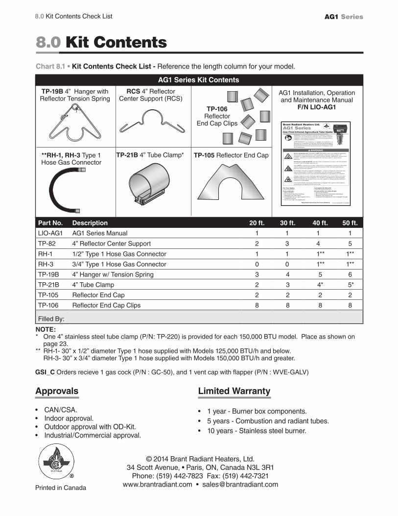
AG1 Series
Printed in Canada
Part No. Description 20 ft. 30 ft. 40 ft. 50 ft.
LIO-AG1 AG1 Series Manual 1 1 1 1
TP-82 4” Reflector Center Support 2 3 4 5
RH-1 1/2” Type 1 Hose Gas Connector 1 1 1** 1**
RH-3 3/4” Type 1 Hose Gas Connector 0 0 1** 1**
TP-19B 4” Hanger w/ Tension Spring 3 4 5 6
TP-21B 4” Tube Clamp 2 3 4* 5*
TP-105 Reflector End Cap 2 2 2 2
TP-106 Reflector End Cap Clips 8 8 8 8
Filled By:
Chart 8.1 • Kit Contents Check List - Reference the length column for your model.
TP-19B 4” Hanger with Reflector Tension Spring
TP-105 Reflector End CapTP-21B 4” Tube Clamp*
TP-106 Reflector
End Cap Clips
**RH-1, RH-3 Type 1Hose Gas Connector
AG1 Series Kit Contents
RCS 4” Reflector Center Support (RCS)
NOTE:* One 4” stainless steel tube clamp (P/N: TP-220) is provided for each 150,000 BTU model. Place as shown on
page 23.** RH-1- 30” x 1/2” diameter Type 1 hose supplied with Models 125,000 BTU/h and below. RH-3- 30” x 3/4” diameter Type 1 hose supplied with Models 150,000 BTU/h and greater.
© 2014 Brant Radiant Heaters, Ltd.34 Scott Avenue, • Paris, ON, Canada N3L 3R1
Phone: (519) 442-7823 Fax: (519) 442-7321 www.brantradiant.com • [email protected]
Approvals • CAN/CSA.• Indoor approval.• Outdoor approval with OD-Kit.• Industrial/Commercial approval.
Limited Warranty • 1 year - Burner box components.• 5 years - Combustion and radiant tubes.• 10 years - Stainless steel burner.
AG1 Installation, Operation and Maintenance Manual
F/N LIO-AG1
8.0 Kit Contents
Form#:LM-TA-R1-12/12-BRH
! WARNING
For Your Safety
If you smell gas: • Open windows.• Do not touch electrical switches.• Extinguish any open flame.• Immediately call your gas supplier from a neighbours phone.• Do not try to light any appliances.
Not for residential use! This heater is NOT approved for use in any residential application. This includes, but is not limited to, attached garages, solariums, living quarters, etc. Installation in residential spaces may result in property damage, asphyxiation, serious injury or death. Consult your local fire marshall and/or insurance carrier if unsure of your application.
Interdit pour usage résidentiel. Ne pas utiliser cet appareil à la maison, dan les chambres à coucher, dan les harages attenants, etc.
This is NOT an explosion proof heater. Where there is a possibility of exposure to flammable vapors, consult the local fire marshall, the fire insurance carrier and other authorities for approval of proposed installation.
Cet émetteur n’est pas un appareil antideflagrant. Lorsqu’il y a risque de contact avec des vapeurs inflammables, consulter le commissaire local des incendies, la compagnie d’assurance incendie ou tout autre authorité compétente pour approbation de l’installation.
Storage of gasoline or other flammable vapors and liquids in the vicinity of this or any other appliance may result in fire or explosion. Do not store or use gasoline or other flammable vapors and liquids in the vicinity of this or any other appliance. Always maintain published clearance to combustibles.
Il est interdit d’utiliser des liquides inflammables ou degagent des vapeors inflammabled a proximaite de tout appareil fonctionnant au gaz.
Brant Radiant Heaters Ltd.
AG1 Series Gas-Fired Infrared Agricultural Tube Heater
Consignes De Sécurité
Si vous sentez une odeur de gaz: • Ouvrez les fenêtres.• Ne touches pas aux interrupters électriques.• Éteignez toute flamme nue.• Contactez immediatement votre compagnie de gaz.
WARNING: Improper installation, adjustment, alteration, service or maintenance can cause property damage, injury or death. Read the installation, operating and maintence instructions thoroughly before installing or servicing this equipment.
AVERTISSEMENT. Une installation, un réglage, une modification, une réparation ou un entretien incorrect peut entraîner des dommages matériel, des blessures ou la mort. lisez attentivement les instructions d’installation, de fonctionnement et d’entretien avant de procéder à l’installation ou à l’entretien de cet équipement.
Keep these instructions for future reference.
8.0 Kit Contents Check List
GSI_C Orders recieve 1 gas cock (P/N : GC-50), and 1 vent cap with flapper (P/N : WVE-GALV)
Related Documents