SIMATIC PXI inductive proximity switches Introduction 2/132 Siemens FS 10 · 2009 2 Inductive proximity switches – rugged, accurate and reliable For contact-free detection of metal objects, proximity switches are quite simply the most cost-effective solution. If an excellent wire of electricity or magnetism moves towards the sensor or away from it, the signal automatically changes. With their excellent repeat accuracy, they are extremely reliable. And thanks to their wear-free operation and insensitivity to tem- perature, noise, light and water, they have a long service life. We have covered the complete application spectrum with a wide range of different types and ranges. Configurator A configurator for inductive proximity switches is available in the Mall. Based on the technical features required, the desired product can be quickly and easily selected, placed in the shop- ping cart and ordered. The configurator can be reached by the following link: www.siemens.com/simatic-sensors/px PXI series The inductive proximity switches are organized in different prod- uct families in accordance with their technical design: ■ Application Inductive proximity switches are the low-cost solution for non- contact detection of metal objects. They are used in sectors in which metal components play an important role, e.g. • In the automotive industry • In mechanical engineering • In the robotics industry • In conveyor systems • In the paper and printing industry The induction principle and the experience gained by Siemens over many years have made the inductive proximity switches what they are: extremely reliable with a very high repeat accu- racy and long service life thanks to a lack of wearing parts as well as their insensitivity to temperature, noise, light and water. Approvals 3RG40, 3RG41 devices with M 12 or M 18 connectors as well as terminal compartments are UL and CSA listed. For a complete overview, see the Appendix in the FS 10 Catalog. Sensors for Ex Zone 2/22 The PXI600 inductive proximity switches are ap- proved according to EU Guideline 94/9/EG (ATEX) Appendix VIII The approval is for: • Gas EX II 3G EEx nA II T6x and • Dust EX II 3D IP65 T 80 °C The functionality of the inductive proximity switches with ATEX approval is identical to that of the standard proximity switches. Sensors with e1 type approval In the product family SIMATIC PXI, proximity switches with e1 type approval according to the guideline 72/245/EEC are used in motor vehicles. The functionality of proximity switches with e1 approval is identical to that of standard proximity switches. Highlights • Extremely compact and rugged • High degree of protection (IP67/IP68/IP69K) • Correction factor 1 • High sensing ranges • Fast switching frequencies • Flexible mounting • Especially suitable for small spaces • Can be used all over the world: UL/CSA approvals SIMATIC sensors product family Version PXI200 Sensors for standard applications, typical values: • Operating voltage up to 34 V DC • Degree of protection up to IP67 • Operating distance acc. to standard PXI300 Sensors for applications with special requirements: • Increased operating voltages • Higher degrees of protection • Above-standard operating distance PXI400 Sensors without reduction factor PXI600 Sensors with special approvals: • ATEX sensors for hazardous area Zone 2 • Sensors with e1 type approval PXI900 • Pressure-resistant sensors up to 500 bar • Sensors with analog output © Siemens AG 2008

Welcome message from author
This document is posted to help you gain knowledge. Please leave a comment to let me know what you think about it! Share it to your friends and learn new things together.
Transcript
SIMATIC PXI inductive proximity switchesIntroduction
2/132 Siemens FS 10 · 2009
2
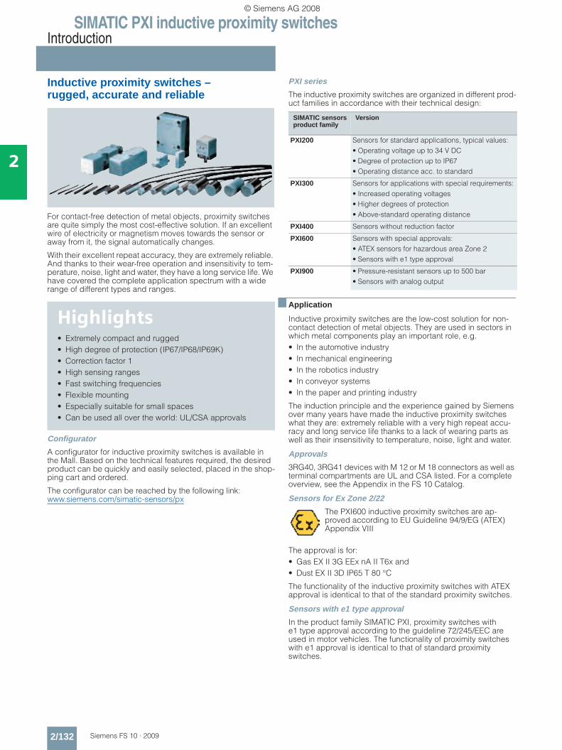
Inductive proximity switches – rugged, accurate and reliable
For contact-free detection of metal objects, proximity switches are quite simply the most cost-effective solution. If an excellent wire of electricity or magnetism moves towards the sensor or away from it, the signal automatically changes.
With their excellent repeat accuracy, they are extremely reliable. And thanks to their wear-free operation and insensitivity to tem-perature, noise, light and water, they have a long service life. We have covered the complete application spectrum with a wide range of different types and ranges.
Configurator
A configurator for inductive proximity switches is available in the Mall. Based on the technical features required, the desired product can be quickly and easily selected, placed in the shop-ping cart and ordered.
The configurator can be reached by the following link:www.siemens.com/simatic-sensors/px
PXI series
The inductive proximity switches are organized in different prod-uct families in accordance with their technical design:
■ Application
Inductive proximity switches are the low-cost solution for non-contact detection of metal objects. They are used in sectors in which metal components play an important role, e.g.• In the automotive industry • In mechanical engineering • In the robotics industry • In conveyor systems • In the paper and printing industry
The induction principle and the experience gained by Siemens over many years have made the inductive proximity switches what they are: extremely reliable with a very high repeat accu-racy and long service life thanks to a lack of wearing parts as well as their insensitivity to temperature, noise, light and water.
Approvals
3RG40, 3RG41 devices with M 12 or M 18 connectors as well as terminal compartments are UL and CSA listed. For a complete overview, see the Appendix in the FS 10 Catalog.
Sensors for Ex Zone 2/22
The PXI600 inductive proximity switches are ap-proved according to EU Guideline 94/9/EG (ATEX) Appendix VIII
The approval is for:• Gas EX II 3G EEx nA II T6x and• Dust EX II 3D IP65 T 80 °C
The functionality of the inductive proximity switches with ATEX approval is identical to that of the standard proximity switches.
Sensors with e1 type approval
In the product family SIMATIC PXI, proximity switches with e1 type approval according to the guideline 72/245/EEC are used in motor vehicles. The functionality of proximity switches with e1 approval is identical to that of standard proximity switches.
Highlights• Extremely compact and rugged• High degree of protection (IP67/IP68/IP69K)• Correction factor 1• High sensing ranges• Fast switching frequencies• Flexible mounting• Especially suitable for small spaces• Can be used all over the world: UL/CSA approvals
SIMATIC sensors product family
Version
PXI200 Sensors for standard applications, typical values:• Operating voltage up to 34 V DC• Degree of protection up to IP67• Operating distance acc. to standard
PXI300 Sensors for applications with special requirements:• Increased operating voltages• Higher degrees of protection• Above-standard operating distance
PXI400 Sensors without reduction factor
PXI600 Sensors with special approvals:• ATEX sensors for hazardous area Zone 2• Sensors with e1 type approval
PXI900 • Pressure-resistant sensors up to 500 bar• Sensors with analog output
© Siemens AG 2008
SIMATIC PXI inductive proximity switchesIntroduction
2/133Siemens FS 10 · 2009
2
Personal safety
Use of the inductive proximity switches is not permissible for applications in which the safety of persons is dependent on the function of the proxim-ity switch.
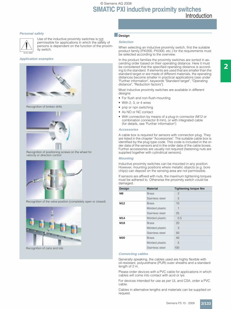
Application examples
■ Design
Selection
When selecting an inductive proximity switch, first the suitable product family (PXI200, PXI300, etc.) for the requirements must be selected according to the overview.
In the product families the proximity switches are sorted in as-cending order based on their operating distance. Here it must be considered that the specified operating distance is accord-ing to the standard. If elements are used that are smaller than the standard target or are made of different materials, the operating distances become smaller in practical applications (see under "Further information", keywords "Standard target", "Operating distance", "Reduction factors").
Most inductive proximity switches are available in different designs:• For flush and non-flush-mounting• With 2, 3, or 4 wires• pnp or npn switching• As NO or NC contact• With connection by means of a plug-in connector (M12 or
combination connector 8 mm), or with integrated cable (for details, see "Further information")
Accessories
A cable box is required for sensors with connection plug. They are listed in the chapter "Accessories". The suitable cable box is identified by the plug type code. This code is included in the or-der data of the sensors and in the order data of the cable boxes. Further accessories are usually not required (fastening nuts are supplied together with cylindrical sensors).
Mounting
Inductive proximity switches can be mounted in any position. However, mounting positions where metallic objects (e.g. bore chips) can deposit on the sensing area are not permissible.
If sensors are affixed with nuts, the maximum tightening torques must be adhered to. Otherwise the proximity switch could be damaged.
Connecting cables
Generally speaking, the cables used are highly flexible with oil-resistant, polyurethane (PUR) outer sheaths and a standard length of 2 m.
Please order devices with a PVC cable for applications in which cables will come into contact with acid or lye.
For devices intended for use as per UL and CSA, order a PVC cable.
Cables in alternative lengths and materials can be supplied on request.
NSD0_00801
Recognition of broken drills
Recognition of positioning screws on the wheel for velocity or direction control
Recognition of the valve position (completely open or closed)
Recognition of cans and lids
Design Material Tightening torque Nm
M8 Brass 2
Stainless steel 5
M12 Brass 10
Molded plastic 1
Stainless steel 25
M14 Molded plastic 0.5
M18 Brass 20
Molded plastic 3
Stainless steel 50
M30 Brass 40
Molded plastic 5
Stainless steel 100
© Siemens AG 2008
SIMATIC PXI inductive proximity switchesIntroduction
2/134 Siemens FS 10 · 2009
2
Do not route proximity switch connecting cables in a cable duct that runs parallel to cables that are used to switch inductive loads (e.g. contactor coils, solenoid valves, motors) or to con-duct currents from electronic motorized operating mechanisms.
Keep cables as short as possible; however, when routed under ideal conditions (low coupling capacitance, minimal interfer-ence voltages), they may have a length of up to 300 m.
The following measures may be taken to reduce the effect of interference:• Distance from cables causing interference > 100 mm• Shields• Coils (of contactors, relays, solenoid valves) are wired with
RC elements or varistors.
Electrical connection
See under "Circuit diagrams", page 2/242. This number of the respective associated circuit diagram is listed in the selection tables of the proximity switches. For further circuits, refer to "Typical circuit diagrams".
Minimum clearances
To prevent the proximity switches from switching without object, it is absolutely essential that the clearances around the sensing area of metallic objects are unobstructed. Furthermore, the min-imum clearance to adjacent inductive sensors must be ensured (see diagrams in the selection tables).
Degrees of protection
See "Further information".
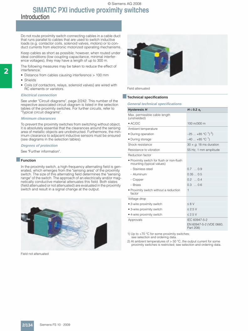
■ Function
In the proximity switch, a high-frequency alternating field is gen-erated, which emerges from the "sensing area" of the proximity switch. The size of this alternating field determines the "sensing range" of the switch. The approach of an electrically and/or mag-netically conductive material attenuates this field. Both states (field attenuated or not attenuated) are evaluated in the proximity switch and result in a signal change at the output.
Field not attenuated
Field attenuated
■ Technical specifications
General technical specifications
1) Up to +70 °C for some proximity switches; see selection and ordering data.
2) At ambient temperatures of > 50 °C, the output current for some proximity switches is restricted; see selection and ordering data.
Hysteresis H H ≤ 0.2 sr
Max. permissible cable length (unshielded)
• AC/DC 100 m/300 m
Ambient temperature
• During operation –25 ... +85 °C 1) 2)
• During storage –40 ... +85 °C 1)
Shock resistance 30 × g, 18 ms duration
Resistance to vibration 55 Hz, 1 mm amplitude
Reduction factor
• Proximity switch for flush or non-flush mounting (typical values)
- Stainless steel 0.7 ... 0.9
- Aluminum 0.35 ... 0.5
- Copper 0.2 ... 0.4
- Brass 0.3 ... 0.6
• Proximity switch without a reduction factor
1
Voltage drop
• 2-wire proximity switch ≤ 8 V
• 3-wire proximity switch ≤ 2.5 V
• 4-wire proximity switch ≤ 2.5 V
Approvals IEC 60947-5-2EN 60947-5-2 (VDE 0660, Part 208)
© Siemens AG 2008

SIMATIC PXI inductive proximity switchesIntroduction
2/135Siemens FS 10 · 2009
2
■ Notes
© Siemens AG 2008
SIMATIC PXI inductive proximity switchesIntroduction
2/136 Siemens FS 10 · 2009
2
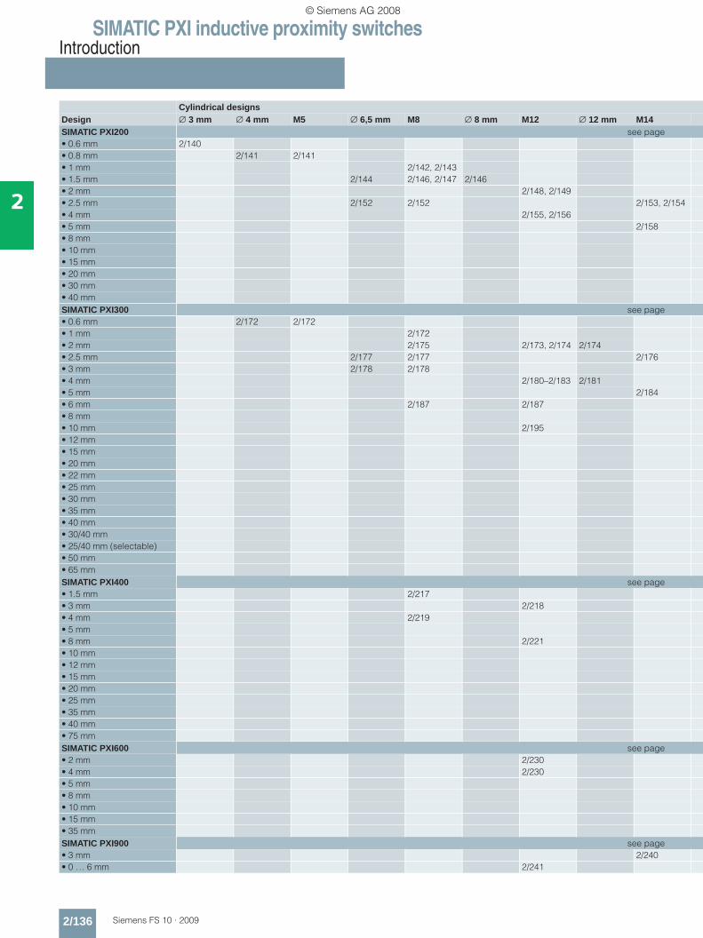
Cylindrical designsDesign ∅ 3 mm ∅ 4 mm M5 ∅ 6,5 mm M8 ∅ 8 mm M12 ∅ 12 mm M14SIMATIC PXI200 see page• 0.6 mm 2/140• 0.8 mm 2/141 2/141• 1 mm 2/142, 2/143• 1.5 mm 2/144 2/146, 2/147 2/146• 2 mm 2/148, 2/149• 2.5 mm 2/152 2/152 2/153, 2/154• 4 mm 2/155, 2/156• 5 mm 2/158• 8 mm• 10 mm• 15 mm• 20 mm• 30 mm• 40 mmSIMATIC PXI300 see page• 0.6 mm 2/172 2/172• 1 mm 2/172• 2 mm 2/175 2/173, 2/174 2/174• 2.5 mm 2/177 2/177 2/176• 3 mm 2/178 2/178• 4 mm 2/180–2/183 2/181• 5 mm 2/184• 6 mm 2/187 2/187• 8 mm• 10 mm 2/195• 12 mm• 15 mm• 20 mm• 22 mm• 25 mm• 30 mm• 35 mm• 40 mm• 30/40 mm• 25/40 mm (selectable)• 50 mm• 65 mmSIMATIC PXI400 see page• 1.5 mm 2/217• 3 mm 2/218• 4 mm 2/219• 5 mm• 8 mm 2/221• 10 mm• 12 mm• 15 mm• 20 mm• 25 mm• 35 mm• 40 mm• 75 mmSIMATIC PXI600 see page• 2 mm 2/230• 4 mm 2/230• 5 mm• 8 mm• 10 mm• 15 mm• 35 mmSIMATIC PXI900 see page• 3 mm 2/240• 0 … 6 mm 2/241
© Siemens AG 2008
SIMATIC PXI inductive proximity switchesIntroduction
2/137Siemens FS 10 · 2009
2
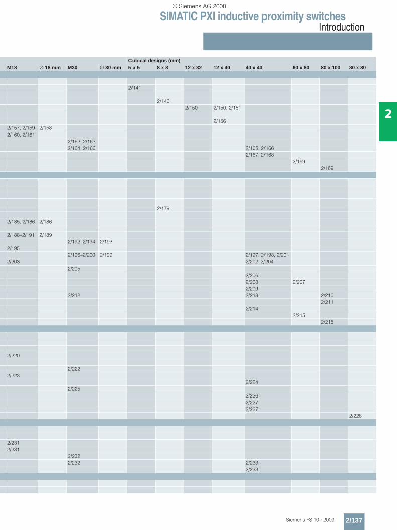
Cubical designs (mm)M18 ∅ 18 mm M30 ∅ 30 mm 5 x 5 8 x 8 12 x 32 12 x 40 40 x 40 60 x 80 80 x 100 80 x 80
2/141
2/1462/150 2/150, 2/151
2/1562/157, 2/159 2/1582/160, 2/161
2/162, 2/1632/164, 2/166 2/165, 2/166
2/167, 2/1682/169
2/169
2/179
2/185, 2/186 2/186
2/188–2/191 2/1892/192–2/194 2/193
2/1952/196–2/200 2/199 2/197, 2/198, 2/201
2/203 2/202–2/2042/205
2/2062/208 2/2072/209
2/212 2/213 2/2102/211
2/2142/215
2/215
2/220
2/2222/223
2/2242/225
2/2262/2272/227
2/228
2/2312/231
2/2322/232 2/233
2/233
© Siemens AG 2008

SIMATIC PXI inductive proximity switchesSIMATIC PXI200
2/138 Siemens FS 10 · 2009
2
■ Overview
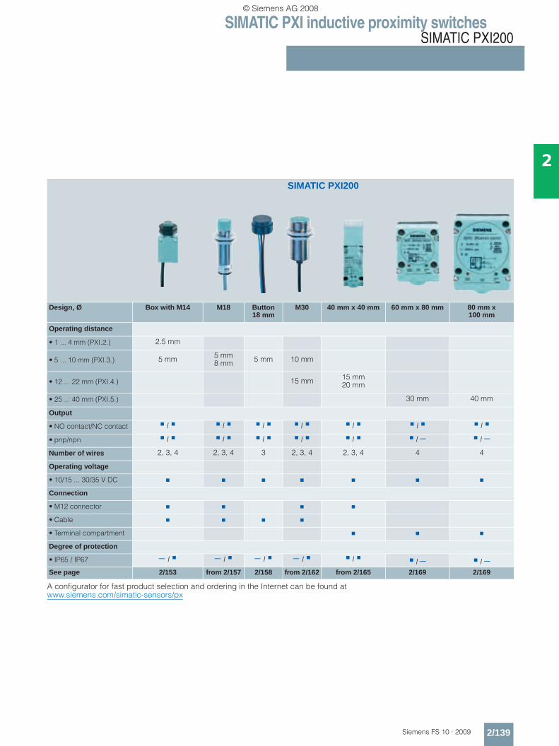
SIMATIC sensors PXI200
Sensors for standard applications. Typical values:• Operating voltage up to 34 V DC• Degree of protection up to IP67• Operating distance acc. to standard
■ Selection table
A configurator for fast product selection and ordering in the Internet can be found atwww.siemens.com/simatic-sensors/px
SIMATIC PXI200
Design, Ø 3 mm 4 mm M5 5 mm x 5 mm
M8 6.5 mm 8 mm x 8 mm
M12 12 mm x 40 mm
12 mm x 32 mm
Operating distance
• 0 ... 0.8 mm (PXI.1.) 0.6 mm 0.8 mm 0.8 mm 0.8 mm
• 1 ... 4 mm (PXI.2.)1 mm
1.5 mm2.5 mm
1.5 mm2.5 mm 1.5 mm 2 mm
4 mm2 mm4 mm 2 mm
Output
• NO contact/NC contact / − / / / − / / / / / /
• pnp/npn / − / − / / / / / / / − / −Number of wires 3 3 3 3 2, 3, 4 3 3 2, 3, 4 3, 4 4
Operating voltage
• 10/15 ... 30/35 V DC
Connection
• M8 connector
• M12 connector
• Cable
Degree of protection
• IP65 / IP67 − / − / − / − / − / − / − / − / − / − / See page 2/140 2/141 2/141 2/141 from 2/142 from 2/144 2/146 from 2/148 2/150 2/150
© Siemens AG 2008
SIMATIC PXI inductive proximity switchesSIMATIC PXI200
2/139Siemens FS 10 · 2009
2
A configurator for fast product selection and ordering in the Internet can be found atwww.siemens.com/simatic-sensors/px
SIMATIC PXI200
Design, Ø Box with M14 M18 Button18 mm
M30 40 mm x 40 mm 60 mm x 80 mm 80 mm x 100 mm
Operating distance
• 1 ... 4 mm (PXI.2.) 2.5 mm
• 5 ... 10 mm (PXI.3.) 5 mm 5 mm8 mm 5 mm 10 mm
• 12 ... 22 mm (PXI.4.) 15 mm 15 mm20 mm
• 25 ... 40 mm (PXI.5.) 30 mm 40 mm
Output
• NO contact/NC contact / / / / / / /
• pnp/npn / / / / / / − / −Number of wires 2, 3, 4 2, 3, 4 3 2, 3, 4 2, 3, 4 4 4
Operating voltage
• 10/15 ... 30/35 V DC
Connection
• M12 connector
• Cable
• Terminal compartment
Degree of protection
• IP65 / IP67 − / − / − / − / / / − / −See page 2/153 from 2/157 2/158 from 2/162 from 2/165 2/169 2/169
© Siemens AG 2008

SIMATIC PXI inductive proximity switchesSIMATIC PXI200
Operating distance 0.6 mm
2/140 Siemens FS 10 · 2009
2
■ Technical specifications
■ Selection and Ordering data
■ Dimensions
Class Standard dutyNumber of wires 3-wireDesign Ø 3 mm, miniInstallation in metal FlushRated operating distance sn 0.6 mmEnclosure material Stainless steelOperational voltage (DC) V 10 ... 30No-load supply current I0 mA ≤ 10Rated operational current Ie mA 100Switching frequency f Hz 5000Repeat accuracy R mm 0.01Power-up delay tv ms 10Switching status display Yellow LEDPrecautions• Spurious signal suppression •• Short-circuit-proof/overload-proof •• Reverse-polarity protection •• Wire-break protection –• Inductive interference protection •• Radio interference protection •Degree of protection IP67
Switching output Circuit diagram number1)
1) See page 2/242.} Preferred type, available from stock.
Order No.
With 2 m cable, PUR 3 × 0.055 mm2
NO contact, pnp 11 } 3RG46 03–2AB00
Mounting instructions
Dimension depending on formA = active surfaceB = metal-free area
3RG46 03–2AB00
A
B
NS
D00
302
6
1,5
A
B4,5
NS
D00
298
22
16
LED
3
© Siemens AG 2008
SIMATIC PXI inductive proximity switchesSIMATIC PXI200
Operating distance 0.8 mm
2/141Siemens FS 10 · 2009
2
■ Technical specifications
■ Selection and Ordering data
■ Dimensions
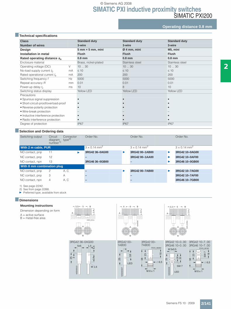
Class Standard duty Standard duty Standard duty
Number of wires 3-wire 3-wire 3-wire
Design 5 mm × 5 mm, mini Ø 4 mm, mini M5, mini
Installation in metal Flush Flush Flush
Rated operating distance sn 0.8 mm 0.8 mm 0.8 mmEnclosure material Brass, nickel-plated Stainless steel Stainless steelOperating voltage (DC) V 10 ... 30 10 ... 30 10 ... 30No-load supply current I0 mA ≤ 10 ≤ 10 ≤ 10Rated operational current Ie mA 200 200 200Switching frequency f Hz 5000 5000 5000Repeat accuracy R mm 0.01 0.01 0.01Power-up delay tv ms 10 8 10Switching status display Yellow LED Yellow LED Yellow LEDPrecautions• Spurious signal suppression • • •• Short-circuit-proof/overload-proof • • •• Reverse-polarity protection • • •• Wire-break protection – – –• Inductive interference protection • • •• Radio interference protection • • •Degree of protection IP67 IP67 IP67
Switching output Circuit diagram number1)
1) See page 2/242.
Connector type2)
2) See from page 2/268.} Preferred type, available from stock
Order No. Order No. Order No.
With 2 m cable, PUR 3 × 0.14 mm2 3 × 0.14 mm2 3 × 0.14 mm2
NO contact, pnp 11 } 3RG42 36–0AG00 } 3RG42 00–1AB00 } 3RG42 10–0AG00
NC contact, pnp 12 – 3RG42 00–1AA00 } 3RG42 10–0AF00
NO contact, npn 13 3RG46 36–0GB00 – } 3RG46 10–0GB00
With 8 mm combination plugNO contact, pnp 2 A, C – } 3RG42 00–7AB00 } 3RG42 10–7AG00
NC contact, pnp 3 A – – 3RG42 10–7AF00
NO contact, npn 4 A, C – – 3RG46 10–7GB00
Mounting instructions
Dimension depending on formA = active surfaceB = metal-free area
3RG42 36–0AG00 3RG42 00–1AB00
3RG42 00–7AB00
3RG42 10–0..003RG46 10–0..00
3RG42 10–7..003RG46 10–7..00
NSD0_0311a
5
2,4
A
B
A
B
3,3
A
B
NS
D00
304
8
2,4
A
B6
A
B
NS
D0_
0030
6a
5
2,4
A
B3,3
3
5x5 1,5
5,5
14
M 1,6
NS
D00
310
25
NS
D0
03
07
25
18
LED
4 � � � � � � � � �
�
� � � � �
��
��
� � �
25
SW 7
NS
D00
308
18
M 5x0,5
LED
20
� � � � � � � � � �
����
�
� � � � �
��
��
� � �
© Siemens AG 2008
SIMATIC PXI inductive proximity switchesSIMATIC PXI200
Operating distance 1 mm
2/142 Siemens FS 10 · 2009
2
■ Technical specifications
■ Selection and Ordering data
■ Dimensions
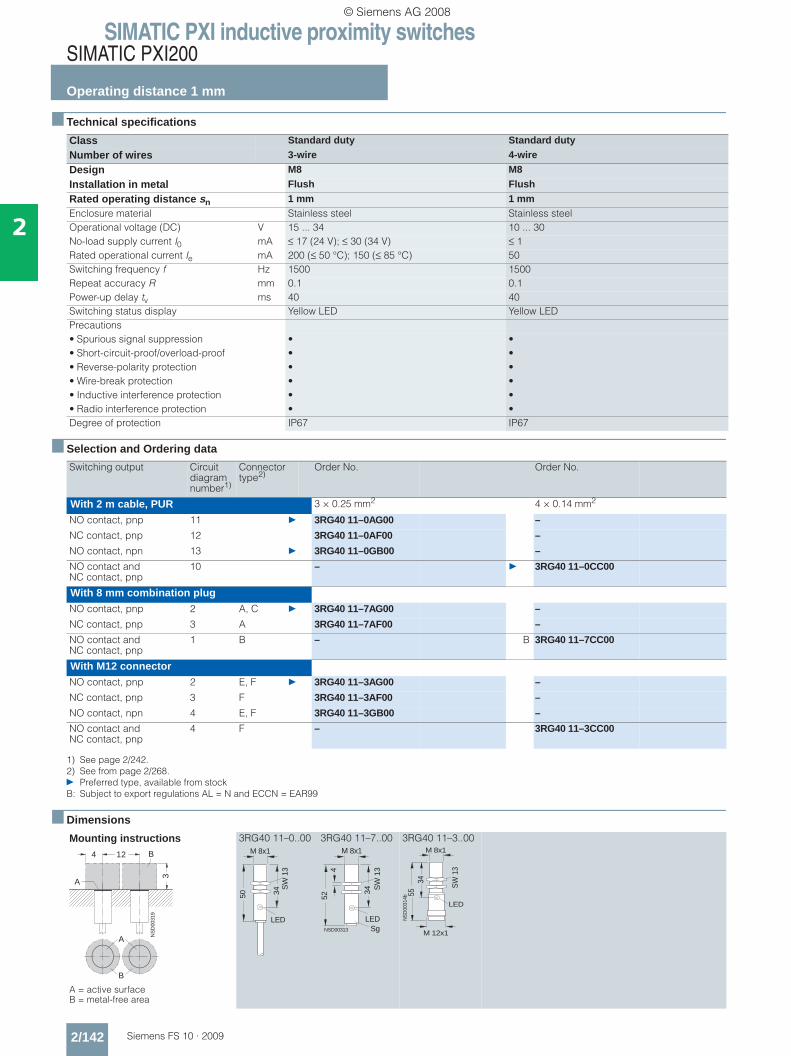
Class Standard duty Standard duty
Number of wires 3-wire 4-wire
Design M8 M8
Installation in metal Flush Flush
Rated operating distance sn 1 mm 1 mmEnclosure material Stainless steel Stainless steelOperational voltage (DC) V 15 ... 34 10 ... 30No-load supply current I0 mA ≤ 17 (24 V); ≤ 30 (34 V) ≤ 1Rated operational current Ie mA 200 (≤ 50 °C); 150 (≤ 85 °C) 50Switching frequency f Hz 1500 1500Repeat accuracy R mm 0.1 0.1Power-up delay tv ms 40 40Switching status display Yellow LED Yellow LEDPrecautions• Spurious signal suppression • •• Short-circuit-proof/overload-proof • •• Reverse-polarity protection • •• Wire-break protection • •• Inductive interference protection • •• Radio interference protection • •Degree of protection IP67 IP67
Switching output Circuit diagram number1)
1) See page 2/242.
Connector type2)
2) See from page 2/268.} Preferred type, available from stockB: Subject to export regulations AL = N and ECCN = EAR99
Order No. Order No.
With 2 m cable, PUR 3 × 0.25 mm2 4 × 0.14 mm2
NO contact, pnp 11 } 3RG40 11–0AG00 –
NC contact, pnp 12 3RG40 11–0AF00 –
NO contact, npn 13 } 3RG40 11–0GB00 –
NO contact and NC contact, pnp
10 – } 3RG40 11–0CC00
With 8 mm combination plugNO contact, pnp 2 A, C } 3RG40 11–7AG00 –
NC contact, pnp 3 A 3RG40 11–7AF00 –
NO contact and NC contact, pnp
1 B – B 3RG40 11–7CC00
With M12 connectorNO contact, pnp 2 E, F } 3RG40 11–3AG00 –
NC contact, pnp 3 F 3RG40 11–3AF00 –
NO contact, npn 4 E, F 3RG40 11–3GB00 –
NO contact and NC contact, pnp
4 F – 3RG40 11–3CC00
Mounting instructions
A = active surfaceB = metal-free area
3RG40 11–0..00 3RG40 11–7..00 3RG40 11–3..00
A
B
NS
D00
319
4 12
3
A
B
LED
50
M 8x1
34S
W 1
3
LED
M 8x1
SW
13
NSD00313
34
452
Sg
LED
M 8x1
SW
13
NS
D00
314b
3455
M 12x1
© Siemens AG 2008
SIMATIC PXI inductive proximity switchesSIMATIC PXI200
Operating distance 1 mm
2/143Siemens FS 10 · 2009
2
■ Technical specifications
■ Selection and Ordering data
■ Dimensions
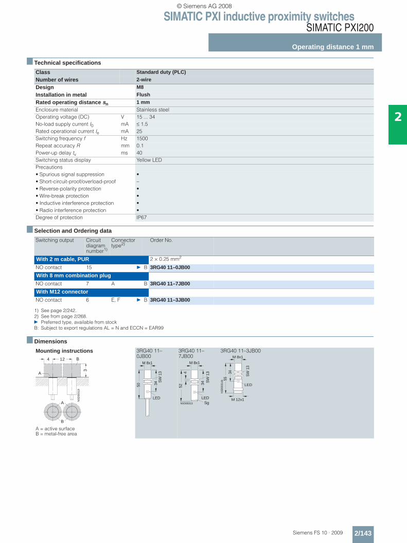
Class Standard duty (PLC)
Number of wires 2-wire
Design M8
Installation in metal Flush
Rated operating distance sn 1 mmEnclosure material Stainless steelOperating voltage (DC) V 15 ... 34No-load supply current I0 mA ≤ 1.5Rated operational current Ie mA 25Switching frequency f Hz 1500Repeat accuracy R mm 0.1Power-up delay tv ms 40Switching status display Yellow LEDPrecautions• Spurious signal suppression •• Short-circuit-proof/overload-proof –• Reverse-polarity protection •• Wire-break protection •• Inductive interference protection •• Radio interference protection •Degree of protection IP67
Switching output Circuit diagram number1)
1) See page 2/242.
Connector type2)
2) See from page 2/268.} Preferred type, available from stockB: Subject to export regulations AL = N and ECCN = EAR99
Order No.
With 2 m cable, PUR 2 × 0.25 mm2
NO contact 15 } B 3RG40 11–0JB00
With 8 mm combination plugNO contact 7 A B 3RG40 11–7JB00
With M12 connectorNO contact 6 E, F } B 3RG40 11–3JB00
Mounting instructions
A = active surfaceB = metal-free area
3RG40 11–0JB00
3RG40 11–7JB00
3RG40 11–3JB00
A
B
NS
D00
319
4 12
3
A
B
LED
50
M 8x1
34S
W 1
3
LED
M 8x1
SW
13
NSD00313
34
452
Sg
LED
M 8x1
SW
13
NS
D00
314b
3455
M 12x1
© Siemens AG 2008
SIMATIC PXI inductive proximity switchesSIMATIC PXI200
Operating distance 1.5 mm
2/144 Siemens FS 10 · 2009
2
■ Technical specifications
■ Selection and Ordering data
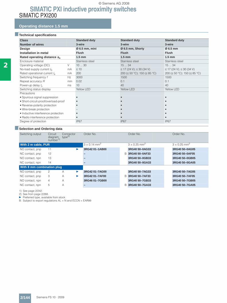
Class Standard duty Standard duty Standard duty
Number of wires 3-wire 3-wire 3-wire
Design Ø 6.5 mm, mini Ø 6.5 mm, Shorty Ø 6.5 mm
Installation in metal Flush Flush Flush
Rated operating distance sn 1.5 mm 1.5 mm 1.5 mmEnclosure material Stainless steel Stainless steel Stainless steelOperating voltage (DC) V 10 ... 30 15 ... 34 15 ... 34No-load supply current I0 mA ≤ 10 ≤ 17 (24 V); ≤ 30 (34 V) ≤ 17 (24 V); ≤ 30 (34 V)Rated operational current Ie mA 200 200 (≤ 50 °C); 150 (≤ 85 °C) 200 (≤ 50 °C); 150 (≤ 85 °C)Switching frequency f Hz 3000 1500 1500Repeat accuracy R mm 0.02 0.1 0.1Power-up delay tv ms 10 40 40Switching status display Yellow LED Yellow LED Yellow LEDPrecautions• Spurious signal suppression • • •• Short-circuit-proof/overload-proof • • •• Reverse-polarity protection • • •• Wire-break protection – • •• Inductive interference protection • • •• Radio interference protection • • •Degree of protection IP67 IP67 IP67
Switching output Circuit diagram number1)
1) See page 2/242.
Connector type2)
2) See from page 2/268.} Preferred type, available from stockB: Subject to export regulations AL = N and ECCN = EAR99
Order No. Order No. Order No.
With 2 m cable, PUR 3 × 0.14 mm2 3 × 0.25 mm2 3 × 0.25 mm2
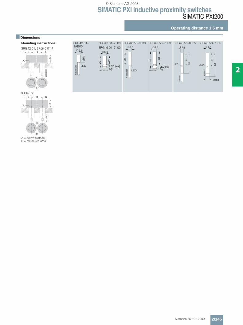
NO contact, pnp 11 } 3RG42 01–1AB00 3RG40 50–0AG33 3RG40 50–0AG05
NC contact, pnp 12 – B 3RG40 50–0AF33 3RG40 50–0AF05
NO contact, npn 13 – 3RG40 50–0GB33 3RG40 50–0GB05
NC contact, npn 14 – 3RG40 50–0GA33 3RG40 50–0GA05
With 8 mm combination plugNO contact, pnp 2 A } 3RG42 01–7AG00 3RG40 50–7AG33 3RG40 50–7AG05
NC contact, pnp 3 A } 3RG42 01–7AF00 B 3RG40 50–7AF33 3RG40 50–7AF05
NO contact, npn 4 A 3RG46 01–7GB00 3RG40 50–7GB33 3RG40 50–7GB05
NC contact, npn 5 A – B 3RG40 50–7GA33 3RG40 50–7GA05
© Siemens AG 2008
SIMATIC PXI inductive proximity switchesSIMATIC PXI200
Operating distance 1.5 mm
2/145Siemens FS 10 · 2009
2
■ Dimensions
Mounting instructions
3RG42 01, 3RG46 01-7
3RG42 01–1AB00
3RG42 01–7..003RG46 01–7..00
3RG40 50–0..33 3RG40 50–7..33 3RG40 50–0..05 3RG40 50–7..05
3RG40 50
A = active surfaceB = metal-free area
A
B
NS
D00
332
4 134,
5
A
B
16
6,5
NS
D00
328 LED
20
29
LED (4x)NSD00329
6,5
Sg
35N
SD
0032
6 LED
6,5
NSD00327
45
LED (4x)
33
6,5
Sg
3450LED
NS
D00
335
Æ 6,5
3452LED
NS
D00
336
M 8x1
6,5
A
B
NS
D00
319
4 12
3
A
B
© Siemens AG 2008
SIMATIC PXI inductive proximity switchesSIMATIC PXI200
Operating distance 1.5 mm
2/146 Siemens FS 10 · 2009
2
■ Technical specifications
■ Selection and Ordering data
■ Dimensions
Class Standard duty Standard duty Standard dutyNumber of wires 3-wire 3-wire 3-wireDesign M8, mini Ø 8 mm, Shorty 8 mm × 8 mmInstallation in metal Flush Flush FlushRated operating distance sn 1.5 mm 1.5 mm 1.5 mmEnclosure material Brass, nickel-plated Stainless steel Brass, nickel-platedOperating voltage (DC) V 10 ... 30 15 ... 34 10 ... 30No-load supply current I0 mA ≤ 10 ≤ 17 (24 V); ≤ 30 (34 V) ≤ 10Rated operational current Ie mA 200 200 (≤ 50 °C); 150 (≤ 85 °C) 200Switching frequency f Hz 3000 1500 1000Repeat accuracy R mm 0.01 0.1 0.07Power-up delay tv ms 10 40 10Switching status display Yellow LED Yellow LED Yellow LEDPrecautions• Spurious signal suppression • • •• Short-circuit-proof/overload-proof • • •• Reverse-polarity protection • • •• Wire-break protection – • –• Inductive interference protection • • •Radio interference protection • • •Degree of protection IP67 IP67 IP67
Switching output Circuit diagram number1)
1) See page 2/242. } Preferred type, available from stock.
Connector type2)
2) See from page 2/268.B: Subject to export regulations AL = N and ECCN = EAR99
Order No. Order No. Order No.
With 2 m cable, PUR 3 × 0.14 mm2 3 × 0.25 mm2 3 × 0.14 mm2
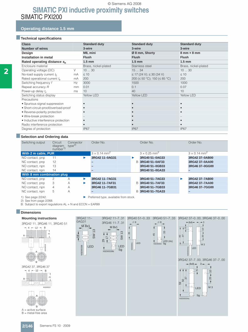
NO contact, pnp 11 } 3RG42 11–0AG31 } 3RG40 51–0AG33 3RG42 37–0AB00NC contact, pnp 12 – B 3RG40 51–0AF33 3RG42 37–0AA00NO contact, npn 13 – 3RG40 51–0GB33 3RG46 37–0GG00NC contact, npn 14 – 3RG40 51–0GA33 –With 8 mm combination plugNO contact, pnp 2 A } 3RG42 11–7AG31 3RG40 51–7AG33 } 3RG42 37–7AB00NC contact, pnp 3 A } 3RG42 11–7AF31 B 3RG40 51–7AF33 3RG42 37–7AA00NO contact, npn 4 A 3RG46 11–7GB31 3RG40 51–7GB33 3RG46 37–7GG00NC contact, npn 5 A – B 3RG40 51–7GA33 –
Mounting instructions
3RG42 11, 3RG46 11, 3RG40 51
3RG42 11–0AG31
3RG42 11–7..313RG46 11–7..31
3RG40 51–0..33 3RG40 51–7..33 3RG42 37–0..00, 3RG46 37–0..00
3RG42 37–7..00, 3RG46 37–7..00
3RG42 37, 3RG46 37
A = active surfaceB = metal-free area
A
B
NS
D00
319
4 12
3
A
BM 8x1
16N
SD
0033
8 LED
SW
13
M 8x1
1729
SW
13
NSD00339b
LED Sg
35N
SD
0035
1 LED
8
NSD00352
45
LED (4x)
33
8
Sg
NS
D0
03
33
a
37
8x8
5
3
10
20
M 3
LED
40
NSD00334a
5
1020
M 3
8x8 3
Sg
5059
37
LED NSD00337
4 12
3
A
B
A
B
© Siemens AG 2008
SIMATIC PXI inductive proximity switchesSIMATIC PXI200
Operating distance 1.5 mm
2/147Siemens FS 10 · 2009
2
■ Technical specifications
■ Selection and Ordering data
■ Dimensions
Class Standard duty Standard duty Standard dutyNumber of wires 3-wire 3-wire 4-wireDesign M8, Shorty M8 M8Installation in metal Flush Flush FlushRated operating distance sn 1.5 mm 1.5 mm 1.5 mmEnclosure material Stainless steel Stainless steel Stainless steelOperating voltage (DC) V 15 ... 34 15 ... 34 10 ... 30No-load supply current I0 mA ≤ 17 (24 V); ≤ 30 (34 V) ≤ 17 (24 V); ≤ 30 (34 V) ≤ 1.0Rated operational current Ie mA 200 (≤ 50 °C); 150 (≤ 85 °C) 200 (≤ 50 °C); 150 (≤ 85 °C) 50Switching frequency f Hz 1500 1500 1500Repeat accuracy R mm 0.1 0.1 0.1Power-up delay tv ms 40 40 40Switching status display Yellow LED Yellow LED Yellow LEDPrecautions• Spurious signal suppression • • •• Short-circuit-proof/overload-proof • • •• Reverse-polarity protection • • •• Wire-break protection • • •• Inductive interference protection • • •• Radio interference protection • • •Degree of protection IP67 IP67 IP67
Switching output Circuit diagram number1)
1) See page 2/242.
Connector type2)
2) See from page 2/268.} Preferred type, available from stockB: Subject to export regulations AL = N and ECCN = EAR99
Order No. Order No. Order No.
With 2 m cable, PUR 3 × 0.25 mm2 3 × 0.25 mm2 4 × 0.14 mm2
NO contact, pnp 11 } 3RG40 11–0AG33 } 3RG40 11–0AG05 –NC contact, pnp 12 } B 3RG40 11–0AF33 3RG40 11–0AF05 –NO contact, npn 13 3RG40 11–0GB33 3RG40 11–0GB05 –NC contact, npn 14 3RG40 11–0GA33 3RG40 11–0GA05 –NO contact and NC contact, pnp
10 – – } 3RG40 11–0CC05
With 8 mm combination plugNO contact, pnp 2 A } 3RG40 11–7AG33 } 3RG40 11–7AG05 –NC contact, pnp 3 A } B 3RG40 11–7AF33 3RG40 11–7AF05 –NO contact, npn 4 A 3RG40 11–7GB33 – –NC contact, npn 5 A B 3RG40 11–7GA33 – –NO contact and NC contact, pnp
1 F – – B 3RG40 11–7CC05
With M12 connectorNO contact, pnp 2 E, F – } 3RG40 11–3AG05 –NC contact, pnp 3 F – 3RG40 11–3AF05 –NO contact, npn 4 E, F – 3RG40 11–3GB05 –NC contact, npn 5 F – 3RG40 11–3GA05 –NO contact and NC contact, pnp
1 F – – 3RG40 11–3CC05
Mounting instructions
A = active surface; B = metal-free area
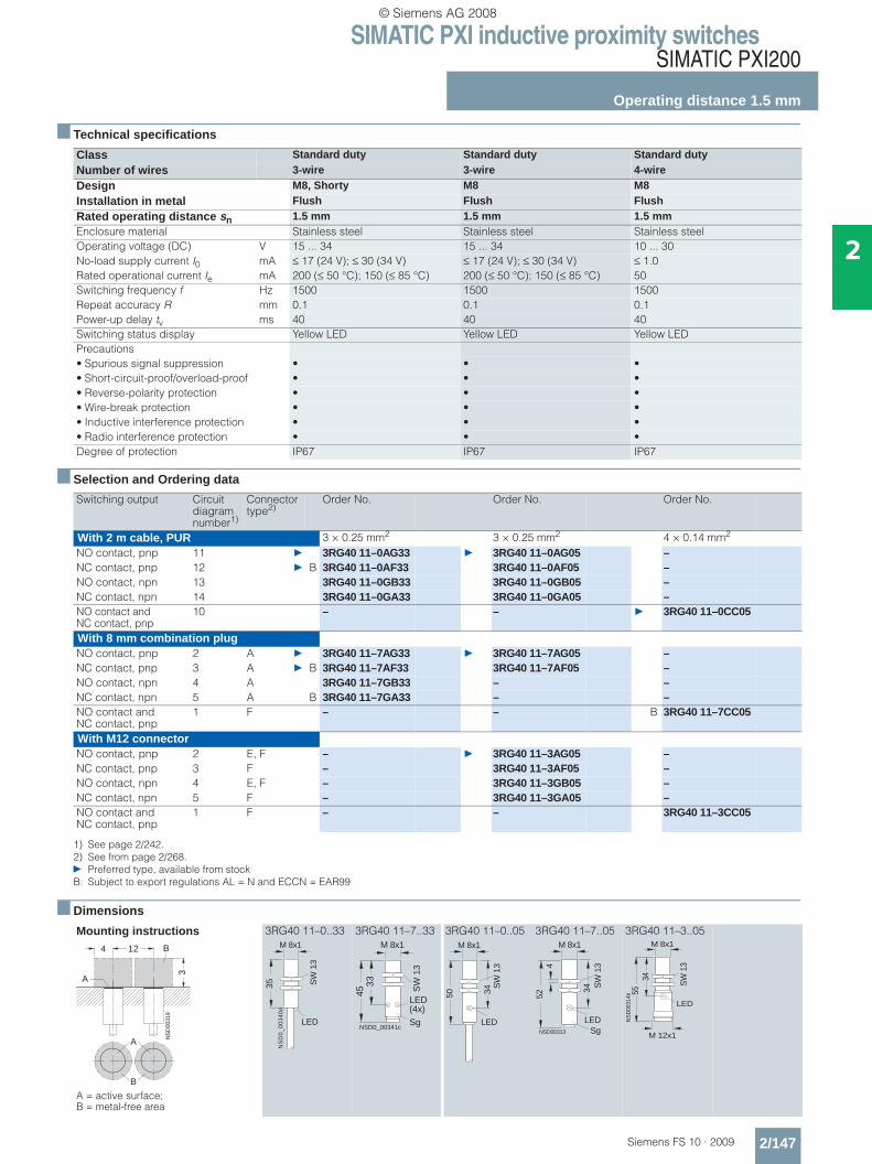
3RG40 11–0..33 3RG40 11–7..33 3RG40 11–0..05 3RG40 11–7..05 3RG40 11–3..05
A
B
NS
D00
319
4 12
3
A
B
35
M 8x1
NS
D0
_0
03
40
a
LED
SW
13
33
M 8x1
LED(4x)
45 SW
13
SgNSD0_00341c
LED
50
M 8x1
34S
W 1
3
LED
M 8x1
SW
13
NSD00313
34
452
Sg
LED
M 8x1
SW
13
NS
D00
314b
3455
M 12x1
© Siemens AG 2008
SIMATIC PXI inductive proximity switchesSIMATIC PXI200
Operating distance 2 mm
2/148 Siemens FS 10 · 2009
2
■ Technical specifications
■ Selection and Ordering data
■ Dimensions
Class Standard dutyNumber of wires 3-wire 4-wire 3-wire 4-wireDesign M12, Shorty M12, Shorty M12 M12Installation in metal Flush Flush Flush FlushRated operating distance sn 2 mm 2 mm 2 mm 2 mmEnclosure material Brass, nickel-plated Brass, nickel-plated Brass, nickel-plated Brass, nickel-platedOperating voltage (DC) V 15 ... 34 15 ... 34 15 ... 34 15 ... 34No-load supply current I0 mA ≤ 17 (24 V); ≤ 30 (34 V) ≤ 1.0 ≤ 17 (24 V); ≤ 30 (34 V) ≤ 25 (24 V); ≤ 40 (34 V)Rated operational current Ie mA 200 (≤ 50 °C);
150 (≤ 85 °C)50 200 (≤ 50 °C);
150 (≤ 85 °C)200 (≤ 50 °C); 150 (≤ 85 °C)
Switching frequency f Hz 1200 800 1200 1200Repeat accuracy R mm 0.1 0.1 0.1 0.1Power-up delay tv ms 40 3 40 40Switching status display Yellow LED Yellow LED Yellow LED Yellow LEDPrecautions• Spurious signal suppression • • • •• Short-circuit-proof/overload-proof • • • •• Reverse-polarity protection • • • •• Wire-break protection • – • •• Inductive interference protection • • • •• Radio interference protection • • • •Degree of protection IP67 IP67 IP67 IP67Type 3RG40 12–.A.33
3RG40 12–.G.333RG40 12–0CD10 3RG40 12–3CD11
3RG40 12–.A.01 3RG40 12–.G.00
3RG40 12–0CD00 3RG40 12–3CD00
Switching output Circuit diagram number1)
1) See page 2/242. } Preferred type, available from stock.
Connector type2)
2) See from page 2/268. B: Subject to export regulations AL = N and ECCN = EAR99
Order No. Order No.
With 2 m cable, PUR 3 × 0.25 mm2 3 × 0.25 mm2
NO contact, pnp 11 } 3RG40 12–0AG33 } B 3RG40 12–0AG01NC contact, pnp 12 B 3RG40 12–0AF33 B 3RG40 12–0AF01NO contact, npn 13 } B 3RG40 12–0GB33 } B 3RG40 12–0GB00NC contact, npn 14 3RG40 12–0GA33 B 3RG40 12–0GA00
4 × 0.14 mm2 4 × 0.14 mm2
NO contact and NC contact, pnp
10 3RG40 12–0CD10 } B 3RG40 12–0CD00
With M12 connector 3-wire 3-wireNO contact, pnp 2 E, F } 3RG40 12–3AG33 } B 3RG40 12–3AG01NC contact, pnp 3 F B 3RG40 12–3AF33 } B 3RG40 12–3AF01NO contact, npn 4 E, F B 3RG40 12–3GB33 } B 3RG40 12–3GB00NC contact, npn 5 F 3RG40 12–3GA33 –
4-wire 4-wireNO contact and NC contact, pnp
1 F 3RG40 12–3CD11 } B 3RG40 12–3CD00
Mounting instructions
A = active surface B = metal-free area
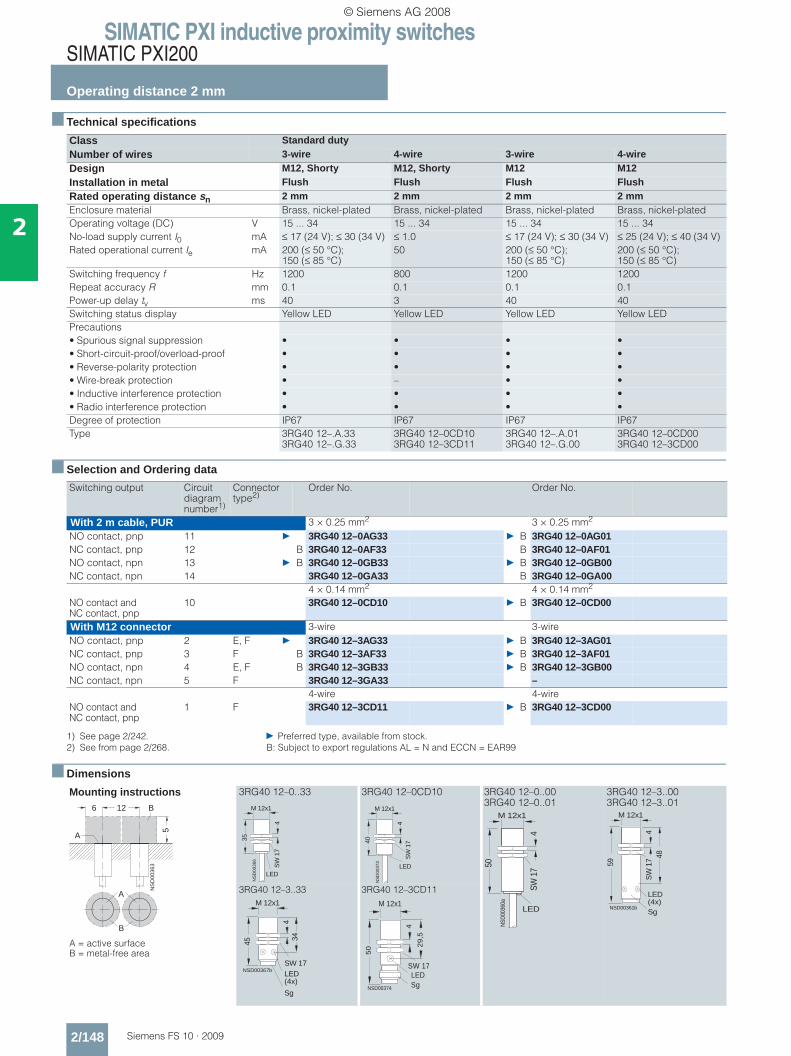
3RG40 12–0..33 3RG40 12–0CD10 3RG40 12–0..00 3RG40 12–0..01
3RG40 12–3..00 3RG40 12–3..01
3RG40 12–3..33 3RG40 12–3CD11A
B
NS
D00
363
6 12
5
A
B
NS
D00
366
35
M 12x1
SW
17
LED
4
NS
D00
373
40
M 12x1
LED
SW
17
4
LED
NSD
0036
0a
50
4
M 12x1
SW 1
7
NSD00361b
59
M 12x1
48S
W 1
74
Sg
LED(4x)
NSD00367b
M 12x1
45
34
SW 17
4
Sg
LED(4x)
4
LEDSg
M 12x1
NSD00374
29,5
50
SW 17
© Siemens AG 2008
SIMATIC PXI inductive proximity switchesSIMATIC PXI200
Operating distance 2 mm
2/149Siemens FS 10 · 2009
2
■ Technical specifications
■ Selection and Ordering data
■ Dimensions
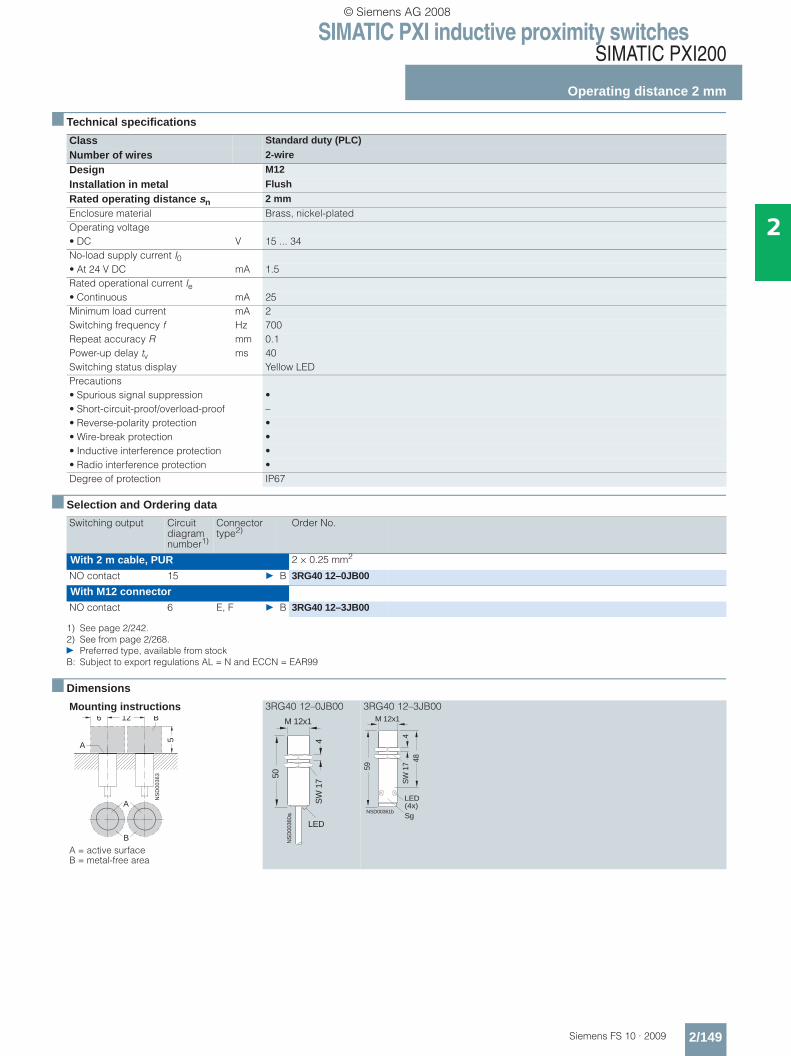
Class Standard duty (PLC)
Number of wires 2-wire
Design M12
Installation in metal Flush
Rated operating distance sn 2 mmEnclosure material Brass, nickel-platedOperating voltage• DC V 15 ... 34No-load supply current I0• At 24 V DC mA 1.5Rated operational current Ie• Continuous mA 25Minimum load current mA 2Switching frequency f Hz 700Repeat accuracy R mm 0.1Power-up delay tv ms 40Switching status display Yellow LEDPrecautions• Spurious signal suppression •• Short-circuit-proof/overload-proof –• Reverse-polarity protection •• Wire-break protection •• Inductive interference protection •• Radio interference protection •Degree of protection IP67
Switching output Circuit diagram number1)
1) See page 2/242.
Connector type2)
2) See from page 2/268.} Preferred type, available from stockB: Subject to export regulations AL = N and ECCN = EAR99
Order No.
With 2 m cable, PUR 2 × 0.25 mm2
NO contact 15 } B 3RG40 12–0JB00
With M12 connectorNO contact 6 E, F } B 3RG40 12–3JB00
Mounting instructions
A = active surface B = metal-free area
3RG40 12–0JB00 3RG40 12–3JB00
A
B
NS
D00
363
6 12
5
A
B
LED
NS
D00
360a
50
4
M 12x1
SW
17
NSD00361b
59
M 12x1
48S
W 1
74
Sg
LED(4x)
© Siemens AG 2008

SIMATIC PXI inductive proximity switchesSIMATIC PXI200
Operating distance 2 mm
2/150 Siemens FS 10 · 2009
2
■ Technical specifications
■ Selection and Ordering data
■ Dimensions
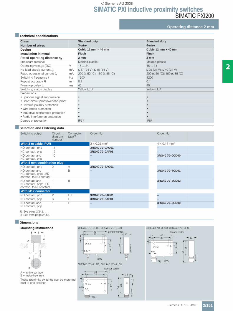
Class Standard duty Standard duty Standard duty
Number of wires 3-wire 4-wire 4-wire
Design Cubic 12 mm × 40 mm Cubic 12 mm × 40 mm Cubic 12 mm × 32 mm
Installation in metal Flush Flush Flush
Rated operating distance sn 2 mm 2 mm 2 mmEnclosure material Molded plastic Molded plastic Molded plasticOperating voltage (DC) V 15 ... 34 15 ... 34 15 ... 34No-load supply current I0 mA ≤ 17 (24 V); ≤ 30 (34 V) ≤ 25 (24 V); ≤ 40 (34 V) ≤ 1.0Rated operational current Ie mA 200 (≤ 50 °C); 150 (≤ 85 °C) 50 200 (≤ 50 °C); 150 (≤ 85 °C)Switching frequency f Hz 800 1200 1200Repeat accuracy R mm 0.2 0.1 0.1Power-up delay tv ms 40 40 40Switching status display Yellow LED Yellow LED –Precautions• Spurious signal suppression • • •• Short-circuit-proof/overload-proof • • •• Reverse-polarity protection • • •• Wire-break protection • • –• Inductive interference protection • • •• Radio interference protection • • •Degree of protection IP67 IP67 IP67
Switching output Circuit diagram number1)
1) See page 2/242.
Connector type2)
2) See from page 2/268.} Preferred type, available from stock
Order No. Order No. Order No.
With 2 m cable, PUR 3 × 0.25 mm2 3 × 0.25 mm2 4 × 0.14 mm2
NO contact, pnp 11 3RG40 70–0AG45 – –
NO contact and NC contact, pnp
10 – – } 3RG40 71–0CD00
With 8 mm combination plugNO contact, pnp 2 A 3RG40 70–7AG45 – –
NO contact and NC contact, pnp
1 F 3RG40 70–7CD45 –
Mounting instructions
A = active surface B = metal-free area
These proximity switches can be mounted next to one another.
3RG40 70–0..45 3RG40 71–0CD00
3RG40 70–7..45
NS
D00
378
6
5
A
B
A
B
2618 4
32
44
0
3,2x5
16
10M3
6
LED
NSD00376b
Ø 3,2
12Sensor center
NSD00382
32
12,6
Æ 2,6
278
13
2,4
2618 4
32
44
0
NSD0 00377b
M33,2x5
Ø 3,2
12
16
10
M 8x1
6
LEDSensor center
© Siemens AG 2008
SIMATIC PXI inductive proximity switchesSIMATIC PXI200
Operating distance 2 mm
2/151Siemens FS 10 · 2009
2
■ Technical specifications
■ Selection and Ordering data
■ Dimensions
Class Standard duty Standard dutyNumber of wires 3-wire 4-wireDesign Cubic 12 mm × 40 mm Cubic 12 mm × 40 mmInstallation in metal Flush FlushRated operating distance sn 2 mm 2 mmEnclosure material Molded plastic Molded plasticOperating voltage (DC) V 15 ... 34 15 ... 34No-load supply current I0 mA ≤ 17 (24 V); ≤ 40 (34 V) ≤ 25 (24 V); ≤ 40 (34 V)Rated operational current Ie mA 200 (≤ 50 °C); 150 (≤ 85 °C) 200 (≤ 50 °C); 150 (≤ 85 °C)Switching frequency f Hz 1200 1200Repeat accuracy R mm 0.1 0.1Power-up delay tv ms 40 40Switching status display Yellow LED Yellow LEDPrecautions• Spurious signal suppression • •• Short-circuit-proof/overload-proof • •• Reverse-polarity protection • •• Wire-break protection • •• Inductive interference protection • •• Radio interference protection • •Degree of protection IP67 IP67
Switching output Circuit diagram number1)
1) See page 2/242.
Connector type2)
2) See from page 2/268.
Order No. Order No.
With 2 m cable, PUR 3 × 0.25 mm2 4 × 0.14 mm2
NO contact, pnp 11 3RG40 70–0AG01 –NC contact, pnp 12 3RG40 70–0AF01 –NO contact and NC contact, pnp
10 – 3RG40 70–0CD00
With 8 mm combination plugNO contact, pnp 2 A 3RG40 70–7AG01 –NO contact and NC contact, pnp; LED corresp. to NO contact
1 B – 3RG40 70–7CD01
NO contact and NC contact, pnp; LED corresp. to NC contact
1 B – 3RG40 70–7CD02
With M12 connectorNO contact, pnp 2 E, F 3RG40 70–3AG01 –NC contact, pnp 3 F 3RG40 70–3AF01 –NO contact and NC contact, pnp
1 F – 3RG40 70–3CD00
Mounting instructions
A = active surface B = metal-free area
These proximity switches can be mounted next to one another.
3RG40 70–0..00, 3RG40 70–0..01
3RG40 70–7..01, 3RG40 70–7..02
3RG40 70–3..00, 3RG40 70–3..01
NS
D00
378
6
5
A
B
A
B
4
4
6
17
3240
12
26
6,5 NS
D00
379b
LED
Ø 3,2
Sensor center
Sg
4
4
6
17
3240
12
26
6,5
NS
D00
38034
10
Ø 3,2
LED
Sensor center
Sg
4
4
6
17
3240
12
26
6,5
NS
D00
381
36
LED
Ø 3,2
Sensor center
© Siemens AG 2008

SIMATIC PXI inductive proximity switchesSIMATIC PXI200
Operating distance 2.5 mm
2/152 Siemens FS 10 · 2009
2
■ Technical specifications
■ Selection and Ordering data
■ Dimensions
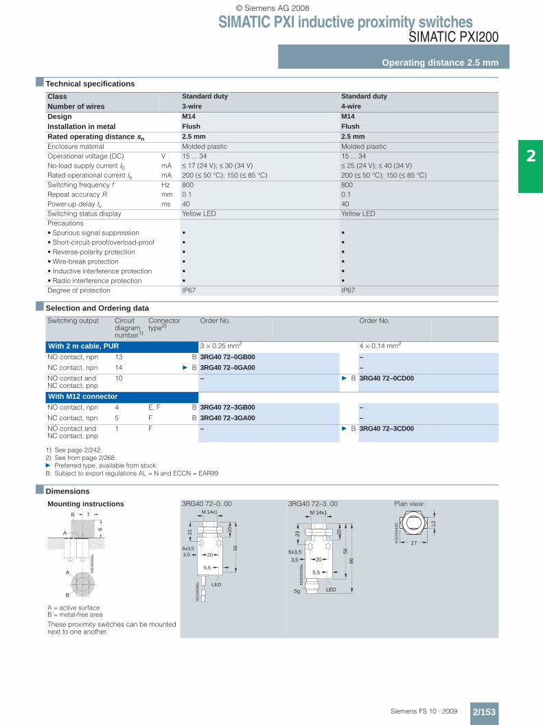
Class Standard duty Standard duty
Number of wires 3-wire 3-wire
Design Ø 6.5 mm M8
Installation in metal Not flush Not flush
Rated operating distance sn 2.5 mm 2.5 mmEnclosure material Stainless steel Stainless steelOperational voltage (DC) V 15 ... 34 15 ... 34No-load supply current I0 mA ≤ 17 (24 V); ≤ 30 (34 V) ≤ 17 (24 V); ≤ 30 (34 V)Rated operational current Ie mA 200 (≤ 50 °C); 150 (≤ 85 °C) 200 (≤ 50 °C); 150 (≤ 85 °C)Switching frequency f Hz 900 1200Repeat accuracy R mm 0.08 0.1Power-up delay tv ms 40 40Switching status display Yellow LED Yellow LEDPrecautions• Spurious signal suppression • •• Short-circuit-proof/overload-proof • •• Reverse-polarity protection • •• Wire-break protection • •• Inductive interference protection • •• Radio interference protection • •Degree of protection IP67 IP67
Switching output Circuit diagram number1)
1) See page 2/242.
Connector type2)
2) See from page 2/268.B: Subject to export regulations AL = N and ECCN = EAR99
Order No. Order No.
With 2 m cable, PUR 3 × 0.25 mm2 3 × 0.25 mm2
NO contact, pnp 11 3RG40 60–0AG33 3RG40 21–0AG33
NC contact, pnp 12 B 3RG40 60–0AF33 B 3RG40 21–0AF33
NO contact, npn 13 B 3RG40 60–0GB33 3RG40 21–0GB33
NC contact, npn 14 B 3RG40 60–0GA33 3RG40 21–0GA33
With 8 mm combination plugNO contact, pnp 2 A 3RG40 60–7AG33 3RG40 21–7AG33
NC contact, pnp 3 A B 3RG40 60–7AF33 B 3RG40 21–7AF33
NO contact, npn 4 A 3RG40 60–7GB33 3RG40 21–7GB33
NC contact, npn 5 A B 3RG40 60–7GA33 B 3RG40 21–7GA33
Mounting instructions
A = active surface B = metal-free area
3RG40 60–0..33 3RG40 60–7..33 3RG40 21–0..33 3RG40 21–7..33
A
B
NS
D00
391
10 20
866
A
B
4
6,5
NS
D00
386 LED
35 4
NSD00387
LED (4x)
33
45
Sg
ø 6,5
4 SW
13
M 8x1
NS
D00
388 LED
35 4
NSD00389a
M 8x1
4533
LED (4x)
SW
13
Sg
© Siemens AG 2008
SIMATIC PXI inductive proximity switchesSIMATIC PXI200
Operating distance 2.5 mm
2/153Siemens FS 10 · 2009
2
■ Technical specifications
■ Selection and Ordering data
■ Dimensions
Class Standard duty Standard duty
Number of wires 3-wire 4-wire
Design M14 M14
Installation in metal Flush Flush
Rated operating distance sn 2.5 mm 2.5 mmEnclosure material Molded plastic Molded plasticOperational voltage (DC) V 15 ... 34 15 ... 34No-load supply current I0 mA ≤ 17 (24 V); ≤ 30 (34 V) ≤ 25 (24 V); ≤ 40 (34 V)Rated operational current Ie mA 200 (≤ 50 °C); 150 (≤ 85 °C) 200 (≤ 50 °C); 150 (≤ 85 °C)Switching frequency f Hz 800 800Repeat accuracy R mm 0.1 0.1Power-up delay tv ms 40 40Switching status display Yellow LED Yellow LEDPrecautions• Spurious signal suppression • •• Short-circuit-proof/overload-proof • •• Reverse-polarity protection • •• Wire-break protection • •• Inductive interference protection • •• Radio interference protection • •Degree of protection IP67 IP67
Switching output Circuit diagram number1)
1) See page 2/242.
Connector type2)
2) See from page 2/268.} Preferred type, available from stock.B: Subject to export regulations AL = N and ECCN = EAR99
Order No. Order No.
With 2 m cable, PUR 3 × 0.25 mm2 4 × 0.14 mm2
NO contact, npn 13 B 3RG40 72–0GB00 –
NC contact, npn 14 } B 3RG40 72–0GA00 –
NO contact and NC contact, pnp
10 – } B 3RG40 72–0CD00
With M12 connectorNO contact, npn 4 E, F B 3RG40 72–3GB00 –
NC contact, npn 5 F B 3RG40 72–3GA00 –
NO contact and NC contact, pnp
1 F – } B 3RG40 72–3CD00
Mounting instructions
A = active surface B = metal-free area
These proximity switches can be mounted next to one another.
3RG40 72–0..00 3RG40 72–3..00 Plan view:
NS
D00
402a
7
6
A
B
A
B
23
203,5
M 14x1
2056
NS
D00
398a
6x3,5
LED
5,5
NS
D00
399a
23
203,5
M 14x1
2056
66
Sg
6x3,5
LED
5,5
NS
D0
04
00 12
27
© Siemens AG 2008
SIMATIC PXI inductive proximity switchesSIMATIC PXI200
Operating distance 2.5 mm
2/154 Siemens FS 10 · 2009
2
■ Technical specifications
■ Selection and Ordering data
■ Dimensions
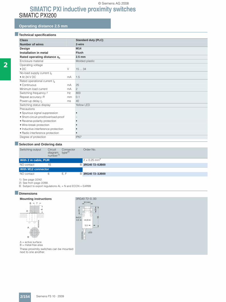
Class Standard duty (PLC)
Number of wires 2-wire
Design M14
Installation in metal Flush
Rated operating distance sn 2.5 mmEnclosure material Molded plasticOperating voltage• DC V 15 ... 34No-load supply current I0• At 24 V DC mA 1.5Rated operational current Ie• Continuous mA 25Minimum load current mA 2Switching frequency f Hz 800Repeat accuracy R mm 0.1Power-up delay tv ms 40Switching status display Yellow LEDPrecautions• Spurious signal suppression •• Short-circuit-proof/overload-proof –• Reverse-polarity protection •• Wire-break protection •• Inductive interference protection •• Radio interference protection •Degree of protection IP67
Switching output Circuit diagram number1)
1) See page 2/242.
Connector type2)
2) See from page 2/268.B: Subject to export regulations AL = N and ECCN = EAR99
Order No.
With 2 m cable, PUR 2 × 0.25 mm2
NO contact 15 B 3RG40 72–0JB00
With M12 connectorNO contact 6 E, F B 3RG40 72–3JB00
Mounting instructions
A = active surface B = metal-free area
These proximity switches can be mounted next to one another.
3RG40 72–0..00
NS
D00
402a
7
6
A
B
A
B
23
203,5
M 14x1
2056
NS
D00
398a
6x3,5
LED
5,5
© Siemens AG 2008

SIMATIC PXI inductive proximity switchesSIMATIC PXI200
Operating distance 4 mm
2/155Siemens FS 10 · 2009
2
■ Technical specifications
■ Selection and Ordering data
■ Dimensions
Class Standard dutyNumber of wires 3-wire 4-wire 3-wire 4-wireDesign M12, Shorty M12, Shorty M12 M12Installation in metal Not flush Not flush Not flush Not flushRated operating distance sn 4 mm 4 mm 4 mm 4 mmEnclosure material Brass, nickel-plated Brass, nickel-plated Brass, nickel-plated Brass, nickel-platedOperational voltage (DC) V 15 ... 34 15 ... 34 15 ... 34 15 ... 34No-load supply current I0 mA ≤ 17 (24 V); ≤ 30 (34 V) 1.0 ≤ 17 (24 V); ≤ 30 (34 V) ≤ 25 (24 V); ≤ 40 (34 V)Rated operational current Ie mA 200 (≤ 50 °C);
150 (≤ 85 °C)50 200 (≤ 50 °C);
150 (≤ 85 °C)200 (≤ 50 °C); 150 (≤ 85 °C)
Switching frequency f Hz 800 800 800 800Repeat accuracy R mm 0.2 0.2 0.2 0.2Power-up delay tv ms 40 40 40 40Switching status display Yellow LED Yellow LED Yellow LED Yellow LEDPrecautions• Spurious signal suppression • • • •• Short-circuit-proof/overload-proof • • • •• Reverse-polarity protection • • • •• Wire-break protection • – • –• Inductive interference protection • • • •• Radio interference protection • • • •Degree of protection IP67 IP67 IP67 IP67Type 3RG40 22–.A.33
3RG40 22–.G.333RG40 22–0CD10 3RG40 22–3CD11
3RG40 22–.A.01 3RG40 22–.G.00
3RG40 22–0CD00 3RG40 22–3CD00
Switching output Circuit diagram number1)
1) See page 2/242. } Preferred type, available from stock.
Connector type2)
2) See from page 2/268. B: Subject to export regulations AL = N and ECCN = EAR99
Order No. Order No.
With 2 m cable, PUR 3 × 0.25 mm2 3 × 0.25 mm2
NO contact, pnp 11 } 3RG40 22–0AG33 } B 3RG40 22–0AG01NC contact, pnp 12 B 3RG40 22–0AF33 } B 3RG40 22–0AF01NO contact, npn 13 B 3RG40 22–0GB33 } B 3RG40 22–0GB00NC contact, npn 14 3RG40 22–0GA33 B 3RG40 22–0GA00
4 × 0.14 mm2 4 × 0.14 mm2
NO contact and NC contact, pnp
10 3RG40 22–0CD10 } B 3RG40 22–0CD00
With M12 connector 3-wire 3-wireNO contact, pnp 2 E, F } 3RG40 22–3AG33 } B 3RG40 22–3AG01NC contact, pnp 3 F B 3RG40 22–3AF33 } B 3RG40 22–3AF01NO contact, npn 4 E, F B 3RG40 22–3GB33 } B 3RG40 22–3GB00NC contact, npn 5 F 3RG40 22–3GA33 B 3RG40 22–3GA00
4-wire 4-wireNO contact and NC contact, pnp
1 F 3RG40 22–3CD11 B 3RG40 22–3CD00
Mounting instructions
A = active surface B = metal-free area
3RG40 22–0..33 3RG40 22–0CD10 3RG40 22–0..00 3RG40 22–0..01
3RG40 22–3..00 3RG40 22–3..01
3RG40 22–3..33 3RG40 22–3CD11
NS
D00
423
15 27
889
A
B
A
B
LED
6,5
SW
17
35
NS
D0_
0042
7a
M 12x1
4
LED
6,5
40
NS
D0_
0044
4a
M 12x1
SW
17
4
NS
D0_
0042
0a
4
6,5
56
SW
17
LED
M 12x1
NSD0_00421a
65
LED(4x)
54
M 12x1
6,5
4S
W 1
7
Sg
LED (4x)
NSD00428
6,545
34
M 12x1
4S
W 1
7
Sg LED (4x)
NSD0_00448c
6,5
50
39
M 12x1
4S
W 1
7
Sg
© Siemens AG 2008
SIMATIC PXI inductive proximity switchesSIMATIC PXI200
Operating distance 4 mm
2/156 Siemens FS 10 · 2009
2
■ Technical specifications
■ Selection and Ordering data
■ Dimensions
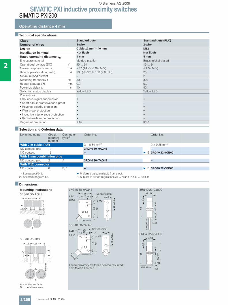
Class Standard duty Standard duty (PLC)Number of wires 3-wire 2-wireDesign Cubic 12 mm × 40 mm M12Installation in metal Not flush Not flushRated operating distance sn 4 mm 4 mmEnclosure material Molded plastic Brass, nickel-platedOperational voltage (DC) V 15 ... 34 15 ... 34No-load supply current I0 mA ≤ 17 (24 V); ≤ 30 (34 V) ≤ 1.5 (24 V)Rated operational current Ie mA 200 (≤ 50 °C); 150 (≤ 85 °C) 25Minimum load current – 2Switching frequency f Hz 800 300Repeat accuracy R mm 0.2 0.2Power-up delay tv ms 40 40Switching status display Yellow LED Yellow LEDPrecautions• Spurious signal suppression • •• Short-circuit-proof/overload-proof • –• Reverse-polarity protection • •• Wire-break protection • •• Inductive interference protection • •• Radio interference protection • •Degree of protection IP67 IP67
Switching output Circuit diagram number1)
1) See page 2/242. } Preferred type, available from stock.
Connector type2)
2) See from page 2/268. B: Subject to export regulations AL = N and ECCN = EAR99.
Order No. Order No.
With 2 m cable, PUR 3 × 0.34 mm2 2 × 0.25 mm2
NO contact, pnp 11 3RG40 80–0AG45 –NO contact 15 – } B 3RG40 22–0JB00With 8 mm combination plugNO contact, pnp 2 A 3RG40 80–7AG45 –With M12 connectorNO contact 6 E, F – } B 3RG40 22–3JB00
Mounting instructions3RG40 80-.AG45
3RG40 22-.JB00
A = active surface B = metal-free area
3RG40 80–0AG45
3RG40 80–7AG45
These proximity switches can be mounted next to one another.
3RG40 22–0JB00
3RG40 22–3JB00
NSD01073
27
889
A
B
A
B
15
NS
D00
423
15 27
889
A
B
A
B
2618 4
32
44
0
3,2x5
16
10M3
6
LED
NSD00376b
Ø 3,2
12Sensor center
2618 4
32
44
0
NSD0 00377b
M33,2x5
Ø 3,2
12
16
10
M 8x1
6
LEDSensor center N
SD
0_00
420a
4
6,5
56
SW
17
LED
M 12x1
NSD0_00421a
65
LED(4x)
54
M 12x1
6,5
4S
W 1
7
Sg
© Siemens AG 2008
SIMATIC PXI inductive proximity switchesSIMATIC PXI200
Operating distance 5 mm
2/157Siemens FS 10 · 2009
2
■ Technical specifications
■ Selection and Ordering data
■ Dimensions
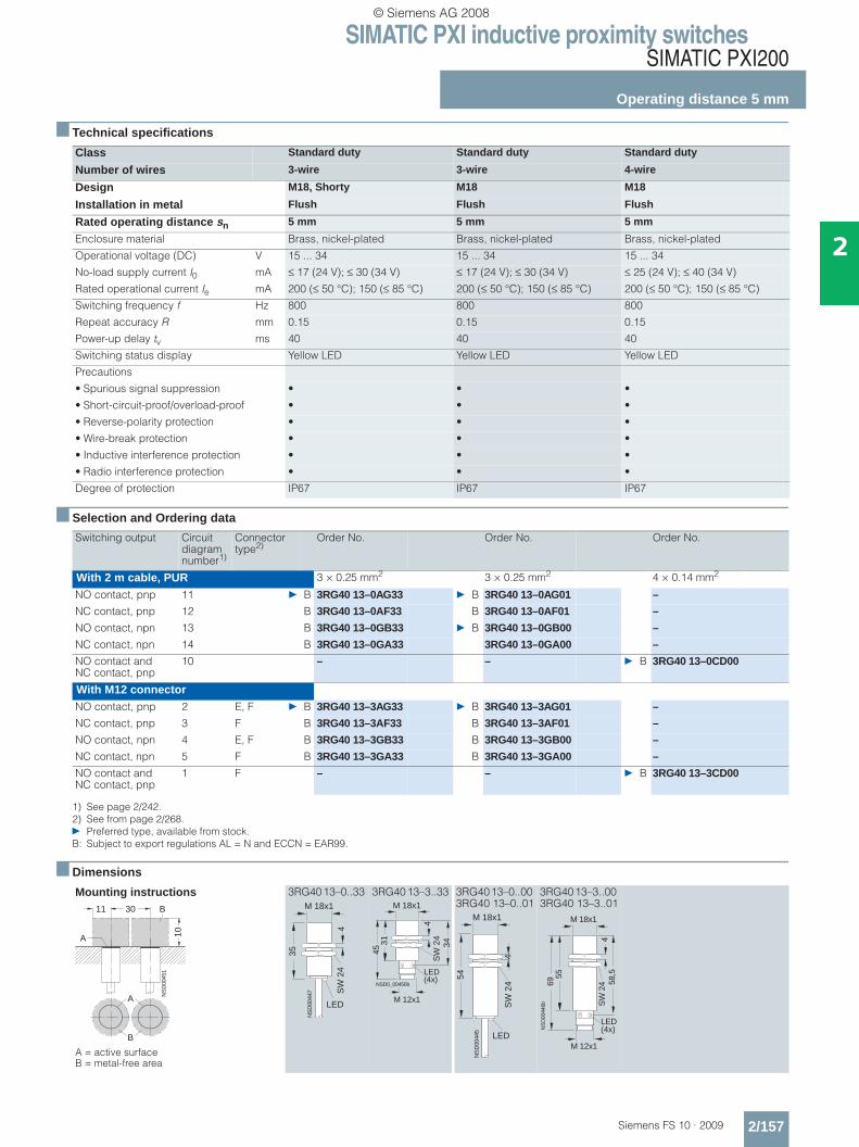
Class Standard duty Standard duty Standard duty
Number of wires 3-wire 3-wire 4-wire
Design M18, Shorty M18 M18
Installation in metal Flush Flush Flush
Rated operating distance sn 5 mm 5 mm 5 mm
Enclosure material Brass, nickel-plated Brass, nickel-plated Brass, nickel-plated
Operational voltage (DC) V 15 ... 34 15 ... 34 15 ... 34
No-load supply current I0 mA ≤ 17 (24 V); ≤ 30 (34 V) ≤ 17 (24 V); ≤ 30 (34 V) ≤ 25 (24 V); ≤ 40 (34 V)
Rated operational current Ie mA 200 (≤ 50 °C); 150 (≤ 85 °C) 200 (≤ 50 °C); 150 (≤ 85 °C) 200 (≤ 50 °C); 150 (≤ 85 °C)
Switching frequency f Hz 800 800 800
Repeat accuracy R mm 0.15 0.15 0.15
Power-up delay tv ms 40 40 40
Switching status display Yellow LED Yellow LED Yellow LED
Precautions
• Spurious signal suppression • • •
• Short-circuit-proof/overload-proof • • •
• Reverse-polarity protection • • •
• Wire-break protection • • •
• Inductive interference protection • • •
• Radio interference protection • • •
Degree of protection IP67 IP67 IP67
Switching output Circuit diagram number1)
1) See page 2/242.
Connector type2)
2) See from page 2/268.} Preferred type, available from stock.B: Subject to export regulations AL = N and ECCN = EAR99.
Order No. Order No. Order No.
With 2 m cable, PUR 3 × 0.25 mm2 3 × 0.25 mm2 4 × 0.14 mm2
NO contact, pnp 11 } B 3RG40 13–0AG33 } B 3RG40 13–0AG01 –
NC contact, pnp 12 B 3RG40 13–0AF33 B 3RG40 13–0AF01 –
NO contact, npn 13 B 3RG40 13–0GB33 } B 3RG40 13–0GB00 –
NC contact, npn 14 B 3RG40 13–0GA33 3RG40 13–0GA00 –
NO contact and NC contact, pnp
10 – – } B 3RG40 13–0CD00
With M12 connectorNO contact, pnp 2 E, F } B 3RG40 13–3AG33 } B 3RG40 13–3AG01 –
NC contact, pnp 3 F B 3RG40 13–3AF33 B 3RG40 13–3AF01 –
NO contact, npn 4 E, F B 3RG40 13–3GB33 B 3RG40 13–3GB00 –
NC contact, npn 5 F B 3RG40 13–3GA33 B 3RG40 13–3GA00 –
NO contact and NC contact, pnp
1 F – – } B 3RG40 13–3CD00
Mounting instructions
A = active surface B = metal-free area
3RG40 13–0..33 3RG40 13–3..33 3RG40 13–0..00 3RG40 13–0..01
3RG40 13–3..00 3RG40 13–3..01
A
B
NS
D00
451
11 30
10A
B M 18x1
NS
D00
447
35
LED
SW
24
4
M 18x1
31
NSD0_00456b
34
45
SW
24
4
LED(4x)
M 12x1
M 18x1
NS
D00
445
54
LED
SW
24
4
LED(4x)
55
58,5
69
M 18x1
SW
24
4
M 12x1
NS
D00
446b
© Siemens AG 2008
SIMATIC PXI inductive proximity switchesSIMATIC PXI200
Operating distance 5 mm
2/158 Siemens FS 10 · 2009
2
■ Technical specifications
■ Selection and Ordering data
■ Dimensions
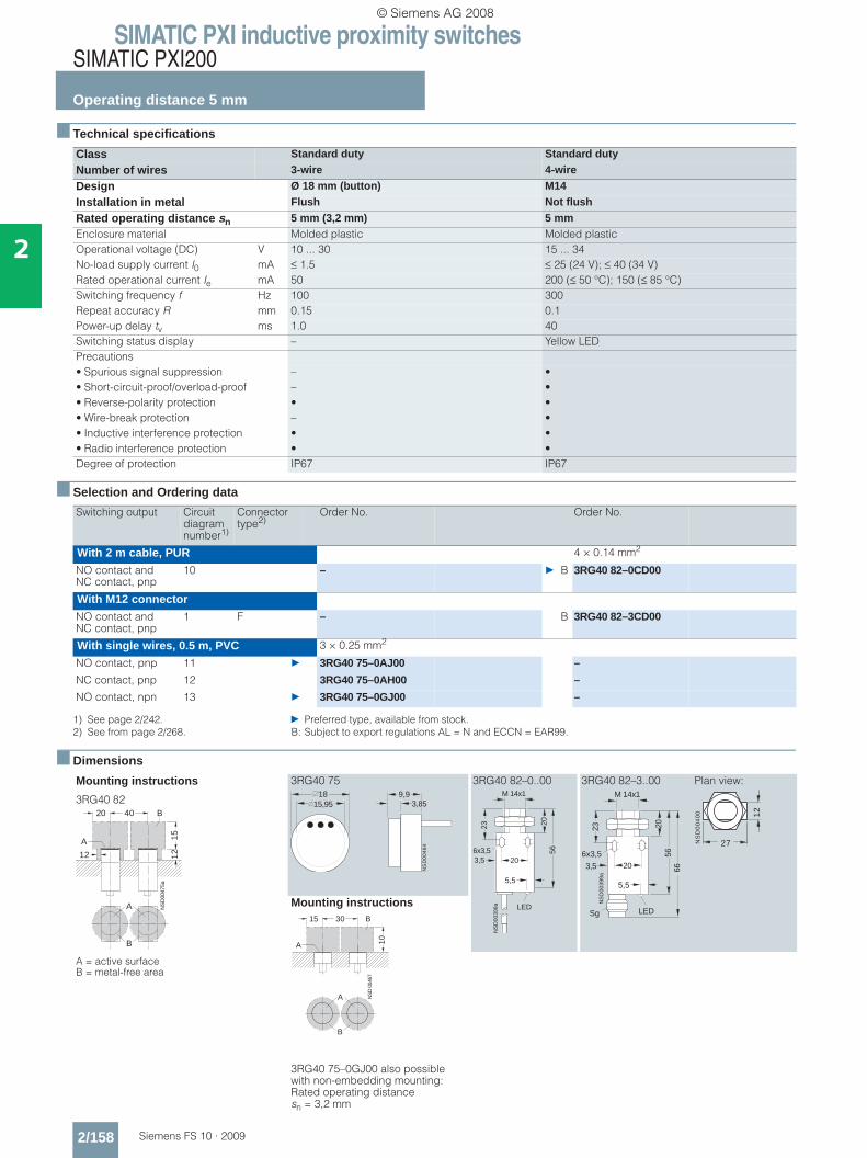
Class Standard duty Standard duty
Number of wires 3-wire 4-wire
Design Ø 18 mm (button) M14
Installation in metal Flush Not flush
Rated operating distance sn 5 mm (3,2 mm) 5 mmEnclosure material Molded plastic Molded plasticOperational voltage (DC) V 10 ... 30 15 ... 34No-load supply current I0 mA ≤ 1.5 ≤ 25 (24 V); ≤ 40 (34 V)Rated operational current Ie mA 50 200 (≤ 50 °C); 150 (≤ 85 °C)Switching frequency f Hz 100 300Repeat accuracy R mm 0.15 0.1Power-up delay tv ms 1.0 40Switching status display – Yellow LEDPrecautions• Spurious signal suppression – •• Short-circuit-proof/overload-proof – •• Reverse-polarity protection • •• Wire-break protection – •• Inductive interference protection • •• Radio interference protection • •Degree of protection IP67 IP67
Switching output Circuit diagram number1)
1) See page 2/242. } Preferred type, available from stock.
Connector type2)
2) See from page 2/268. B: Subject to export regulations AL = N and ECCN = EAR99.
Order No. Order No.
With 2 m cable, PUR 4 × 0.14 mm2
NO contact and NC contact, pnp
10 – } B 3RG40 82–0CD00
With M12 connectorNO contact and NC contact, pnp
1 F – B 3RG40 82–3CD00
With single wires, 0.5 m, PVC 3 × 0.25 mm2
NO contact, pnp 11 } 3RG40 75–0AJ00 –
NC contact, pnp 12 3RG40 75–0AH00 –
NO contact, npn 13 } 3RG40 75–0GJ00 –
Mounting instructions
3RG40 82
A = active surface B = metal-free area
3RG40 75 3RG40 82–0..00 3RG40 82–3..00 Plan view:
Mounting instructions
3RG40 75–0GJ00 also possible with non-embedding mounting: Rated operating distance sn = 3,2 mm
NS
D00
475a
20 40
15
1212
A
B
A
B
18
NS
D0
04
64
9,93,8515,95
23
203,5
M 14x1
2056
NS
D00
398a
6x3,5
LED
5,5
NS
D00
399a
23
203,5
M 14x1
2056
66
Sg
6x3,5
LED
5,5
NS
D0
04
00 12
27
A
B
NS
D 0
0467
15 30
10
A
B
© Siemens AG 2008
SIMATIC PXI inductive proximity switchesSIMATIC PXI200
Operating distance 5 mm
2/159Siemens FS 10 · 2009
2
■ Technical specifications
■ Selection and Ordering data
■ Dimensions
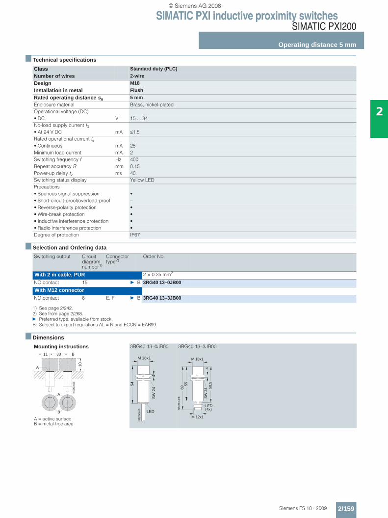
Class Standard duty (PLC)
Number of wires 2-wire
Design M18
Installation in metal Flush
Rated operating distance sn 5 mmEnclosure material Brass, nickel-platedOperational voltage (DC)• DC V 15 ... 34No-load supply current I0• At 24 V DC mA ≤1.5Rated operational current Ie• Continuous mA 25Minimum load current mA 2Switching frequency f Hz 400Repeat accuracy R mm 0.15Power-up delay tv ms 40Switching status display Yellow LEDPrecautions• Spurious signal suppression •• Short-circuit-proof/overload-proof –• Reverse-polarity protection •• Wire-break protection •• Inductive interference protection •• Radio interference protection •Degree of protection IP67
Switching output Circuit diagram number1)
1) See page 2/242.
Connector type2)
2) See from page 2/268.} Preferred type, available from stock.B: Subject to export regulations AL = N and ECCN = EAR99.
Order No.
With 2 m cable, PUR 2 × 0.25 mm2
NO contact 15 } B 3RG40 13–0JB00
With M12 connectorNO contact 6 E, F } B 3RG40 13–3JB00
Mounting instructions
A = active surface B = metal-free area
3RG40 13–0JB00 3RG40 13–3JB00
A
B
NS
D00
451
11 30
10A
BM 18x1
NS
D00
445
54
LED
SW
24
4
LED(4x)
55
58,5
69
M 18x1
SW
24
4
M 12x1
NS
D00
446b
© Siemens AG 2008
SIMATIC PXI inductive proximity switchesSIMATIC PXI200
Operating distance 8 mm
2/160 Siemens FS 10 · 2009
2
■ Technical specifications
■ Selection and Ordering data
■ Dimensions
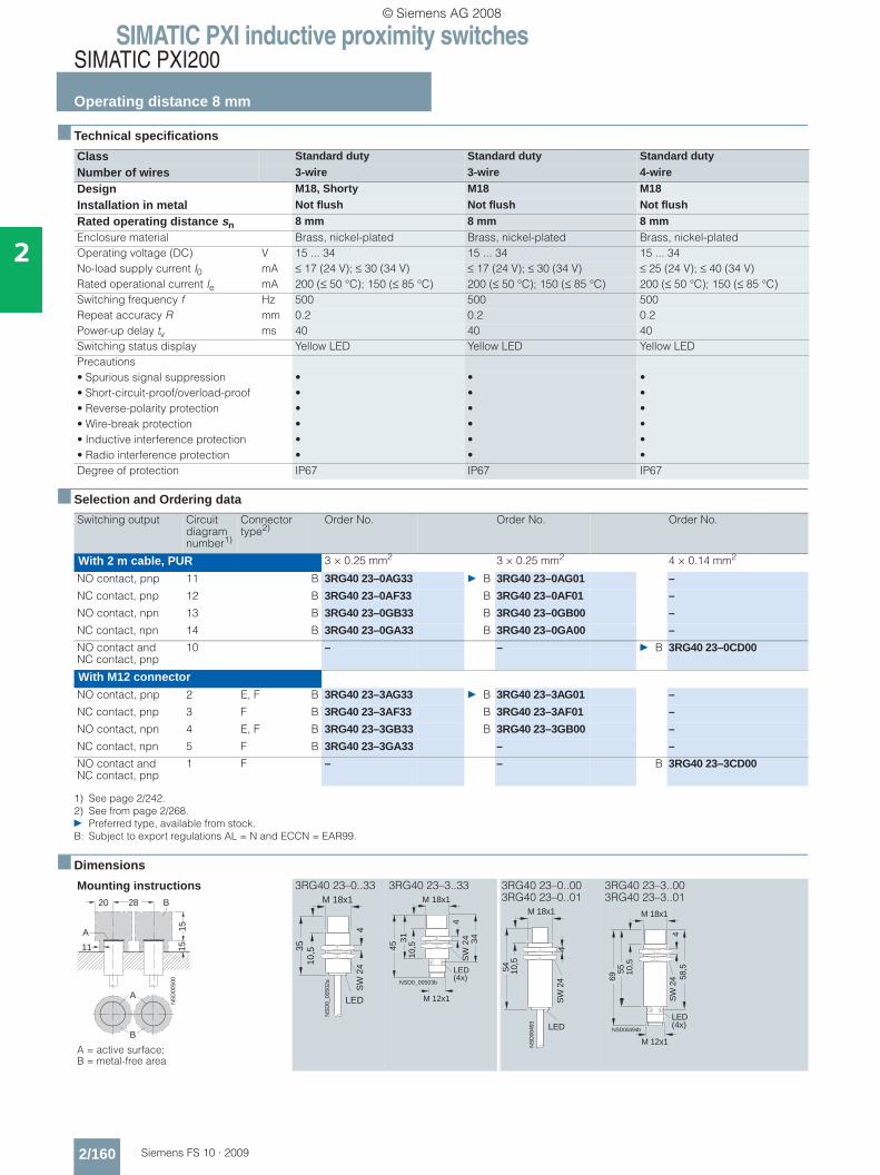
Class Standard duty Standard duty Standard duty
Number of wires 3-wire 3-wire 4-wire
Design M18, Shorty M18 M18
Installation in metal Not flush Not flush Not flush
Rated operating distance sn 8 mm 8 mm 8 mmEnclosure material Brass, nickel-plated Brass, nickel-plated Brass, nickel-platedOperating voltage (DC) V 15 ... 34 15 ... 34 15 ... 34No-load supply current I0 mA ≤ 17 (24 V); ≤ 30 (34 V) ≤ 17 (24 V); ≤ 30 (34 V) ≤ 25 (24 V); ≤ 40 (34 V)Rated operational current Ie mA 200 (≤ 50 °C); 150 (≤ 85 °C) 200 (≤ 50 °C); 150 (≤ 85 °C) 200 (≤ 50 °C); 150 (≤ 85 °C)Switching frequency f Hz 500 500 500Repeat accuracy R mm 0.2 0.2 0.2Power-up delay tv ms 40 40 40Switching status display Yellow LED Yellow LED Yellow LEDPrecautions• Spurious signal suppression • • •• Short-circuit-proof/overload-proof • • •• Reverse-polarity protection • • •• Wire-break protection • • •• Inductive interference protection • • •• Radio interference protection • • •Degree of protection IP67 IP67 IP67
Switching output Circuit diagram number1)
1) See page 2/242.
Connector type2)
2) See from page 2/268.} Preferred type, available from stock.B: Subject to export regulations AL = N and ECCN = EAR99.
Order No. Order No. Order No.
With 2 m cable, PUR 3 × 0.25 mm2 3 × 0.25 mm2 4 × 0.14 mm2
NO contact, pnp 11 B 3RG40 23–0AG33 } B 3RG40 23–0AG01 –
NC contact, pnp 12 B 3RG40 23–0AF33 B 3RG40 23–0AF01 –
NO contact, npn 13 B 3RG40 23–0GB33 B 3RG40 23–0GB00 –
NC contact, npn 14 B 3RG40 23–0GA33 B 3RG40 23–0GA00 –
NO contact and NC contact, pnp
10 – – } B 3RG40 23–0CD00
With M12 connectorNO contact, pnp 2 E, F B 3RG40 23–3AG33 } B 3RG40 23–3AG01 –
NC contact, pnp 3 F B 3RG40 23–3AF33 B 3RG40 23–3AF01 –
NO contact, npn 4 E, F B 3RG40 23–3GB33 B 3RG40 23–3GB00 –
NC contact, npn 5 F B 3RG40 23–3GA33 – –
NO contact and NC contact, pnp
1 F – – B 3RG40 23–3CD00
Mounting instructions
A = active surface; B = metal-free area
3RG40 23–0..33 3RG40 23–3..33 3RG40 23–0..00 3RG40 23–0..01
3RG40 23–3..00 3RG40 23–3..01
NS
D00
500
20 28
151511
A
B
A
B
NS
D0_
0050
2a
LED
M 18x1
3510
,5
SW
24
4
NSD0_00503b
M 18x1
45
10,5
3431
SW
24
4
LED(4x)
M 12x1
NS
D00
493
LED
M 18x1
54 10,5
SW
24
4
LED(4x)
55
58,5
69
M 18x1
10,5
SW
24
4
M 12x1
NSD00494b
© Siemens AG 2008
SIMATIC PXI inductive proximity switchesSIMATIC PXI200
Operating distance 8 mm
2/161Siemens FS 10 · 2009
2
■ Technical specifications
■ Selection and Ordering data
■ Dimensions
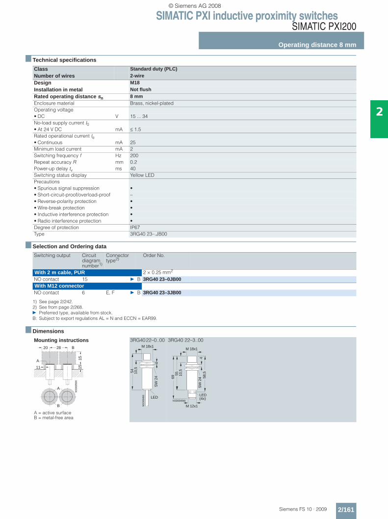
Class Standard duty (PLC)Number of wires 2-wireDesign M18Installation in metal Not flushRated operating distance sn 8 mmEnclosure material Brass, nickel-platedOperating voltage• DC V 15 ... 34No-load supply current I0• At 24 V DC mA ≤ 1.5Rated operational current Ie• Continuous mA 25Minimum load current mA 2Switching frequency f Hz 200Repeat accuracy R mm 0.2Power-up delay tv ms 40Switching status display Yellow LEDPrecautions• Spurious signal suppression •• Short-circuit-proof/overload-proof –• Reverse-polarity protection •• Wire-break protection •• Inductive interference protection •• Radio interference protection •Degree of protection IP67Type 3RG40 23–.JB00
Switching output Circuit diagram number1)
1) See page 2/242.
Connector type2)
2) See from page 2/268.} Preferred type, available from stock.B: Subject to export regulations AL = N and ECCN = EAR99.
Order No.
With 2 m cable, PUR 2 × 0.25 mm2
NO contact 15 } B 3RG40 23–0JB00With M12 connectorNO contact 6 E, F } B 3RG40 23–3JB00
Mounting instructions
A = active surface B = metal-free area
3RG40 22–0..00 3RG40 22–3..00
NS
D00
500
20 28
151511
A
B
A
B NS
D00
493
LED
M 18x1
54 10,5
SW
24
4
LED(4x)
55
58,5
69
M 18x1
10,5
SW
24
4
M 12x1
NSD00494b
© Siemens AG 2008
SIMATIC PXI inductive proximity switchesSIMATIC PXI200
Operating distance 10 mm
2/162 Siemens FS 10 · 2009
2
■ Technical specifications
■ Selection and Ordering data
■ Dimensions
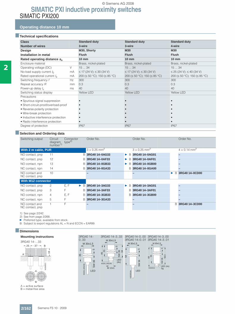
Class Standard duty Standard duty Standard duty
Number of wires 3-wire 3-wire 4-wire
Design M30, Shorty M30 M30
Installation in metal Flush Flush Flush
Rated operating distance sn 10 mm 10 mm 10 mmEnclosure material Brass, nickel-plated Brass, nickel-plated Brass, nickel-platedOperating voltage (DC) V 15 ... 34 15 ... 34 15 ... 34No-load supply current I0 mA ≤ 17 (24 V); ≤ 30 (34 V) ≤ 17 (24 V); ≤ 30 (34 V) ≤ 25 (24 V); ≤ 40 (34 V)Rated operational current Ie mA 200 (≤ 50 °C); 150 (≤ 85 °C) 200 (≤ 50 °C); 150 (≤ 85 °C) 200 (≤ 50 °C); 150 (≤ 85 °C)Switching frequency f Hz 300 300 300Repeat accuracy R mm 0.3 0.3 0.3Power-up delay tv ms 40 40 40Switching status display Yellow LED Yellow LED Yellow LEDPrecautions• Spurious signal suppression • • •• Short-circuit-proof/overload-proof • • •• Reverse-polarity protection • • •• Wire-break protection • • •• Inductive interference protection • • •• Radio interference protection • • •Degree of protection IP67 IP67 IP67
Switching output Circuit diagram number1)
1) See page 2/242.
Connector type2)
2) See from page 2/268.} Preferred type, available from stock.B: Subject to export regulations AL = N and ECCN = EAR99.
Order No. Order No. Order No.
With 2 m cable, PUR 3 × 0.25 mm2 3 × 0.25 mm2 4 × 0.14 mm2
NO contact, pnp 11 B 3RG40 14–0AG33 } B 3RG40 14–0AG01 –
NC contact, pnp 12 B 3RG40 14–0AF33 } B 3RG40 14–0AF01 –
NO contact, npn 13 B 3RG40 14–0GB33 } B 3RG40 14–0GB00 –
NC contact, npn 14 B 3RG40 14–0GA33 B 3RG40 14–0GA00 –
NO contact and NC contact, pnp
10 – – } B 3RG40 14–0CD00
With M12 connectorNO contact, pnp 2 E, F } B 3RG40 14–3AG33 } B 3RG40 14–3AG01 –
NC contact, pnp 3 F B 3RG40 14–3AF33 B 3RG40 14–3AF01 –
NO contact, npn 4 E, F B 3RG40 14–3GB33 B 3RG40 14–3GB00 –
NC contact, npn 5 F B 3RG40 14–3GA33 – –
NO contact and NC contact, pnp
1 F – – B 3RG40 14–3CD00
Mounting instructions
3RG40 14–...33
A = active surface B = metal-free area
3RG40 14–0..33
3RG40 14–3..33 3RG40 14–0..00 3RG40 14–0..01
3RG40 14–3..00 3RG40 14–3..01
A
B
NS
D00
521
25 37
16
A
B
NS
D0_
0052
3b
M 30x1,5
LED
35
SW
36
5
NSD0_00524b
M 30x1,5
3145
34S
W 3
65
LED(4x)
M 12x1
NS
D00
518a
M 30x1,5
LED
54
SW
36
5
NSD00519
M 30x1,5
5569
LED (4x)
58,5
SW
36
5
Sg
© Siemens AG 2008
SIMATIC PXI inductive proximity switchesSIMATIC PXI200
Operating distance 10 mm
2/163Siemens FS 10 · 2009
2
■ Technical specifications
■ Selection and Ordering data
■ Dimensions
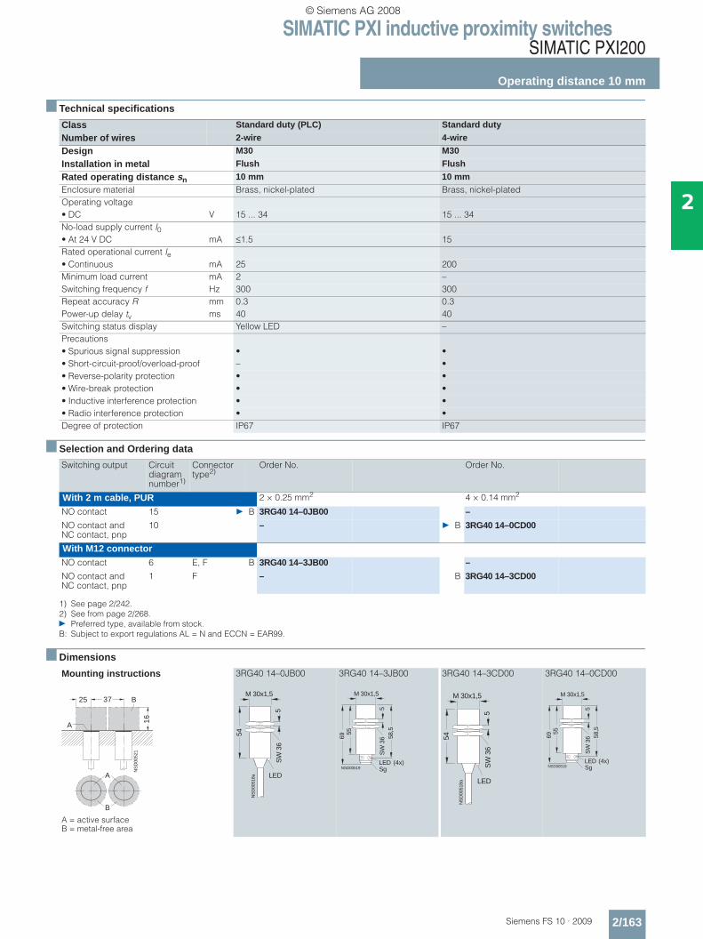
Class Standard duty (PLC) Standard duty
Number of wires 2-wire 4-wire
Design M30 M30
Installation in metal Flush Flush
Rated operating distance sn 10 mm 10 mmEnclosure material Brass, nickel-plated Brass, nickel-platedOperating voltage• DC V 15 ... 34 15 ... 34No-load supply current I0• At 24 V DC mA ≤1.5 15Rated operational current Ie• Continuous mA 25 200Minimum load current mA 2 –Switching frequency f Hz 300 300Repeat accuracy R mm 0.3 0.3Power-up delay tv ms 40 40Switching status display Yellow LED –Precautions• Spurious signal suppression • •• Short-circuit-proof/overload-proof – •• Reverse-polarity protection • •• Wire-break protection • •• Inductive interference protection • •• Radio interference protection • •Degree of protection IP67 IP67
Switching output Circuit diagram number1)
1) See page 2/242.
Connector type2)
2) See from page 2/268.} Preferred type, available from stock.B: Subject to export regulations AL = N and ECCN = EAR99.
Order No. Order No.
With 2 m cable, PUR 2 × 0.25 mm2 4 × 0.14 mm2
NO contact 15 } B 3RG40 14–0JB00 –
NO contact and NC contact, pnp
10 – } B 3RG40 14–0CD00
With M12 connectorNO contact 6 E, F B 3RG40 14–3JB00 –
NO contact and NC contact, pnp
1 F – B 3RG40 14–3CD00
Mounting instructions
A = active surface B = metal-free area
3RG40 14–0JB00 3RG40 14–3JB00 3RG40 14–3CD00 3RG40 14–0CD00
A
B
NS
D00
521
25 37
16
A
B
NS
D00
518a
M 30x1,5
LED
54
SW
36
5
NSD00519
M 30x1,5
5569
LED (4x)
58,5
SW
36
5
Sg
NS
D00
518a
M 30x1,5
LED
54
SW
36
5
NSD00519
M 30x1,5
5569
LED (4x)
58,5
SW
36
5
Sg
© Siemens AG 2008

SIMATIC PXI inductive proximity switchesSIMATIC PXI200
Operating distance 15 mm
2/164 Siemens FS 10 · 2009
2
■ Technical specifications
■ Selection and Ordering data
■ Dimensions
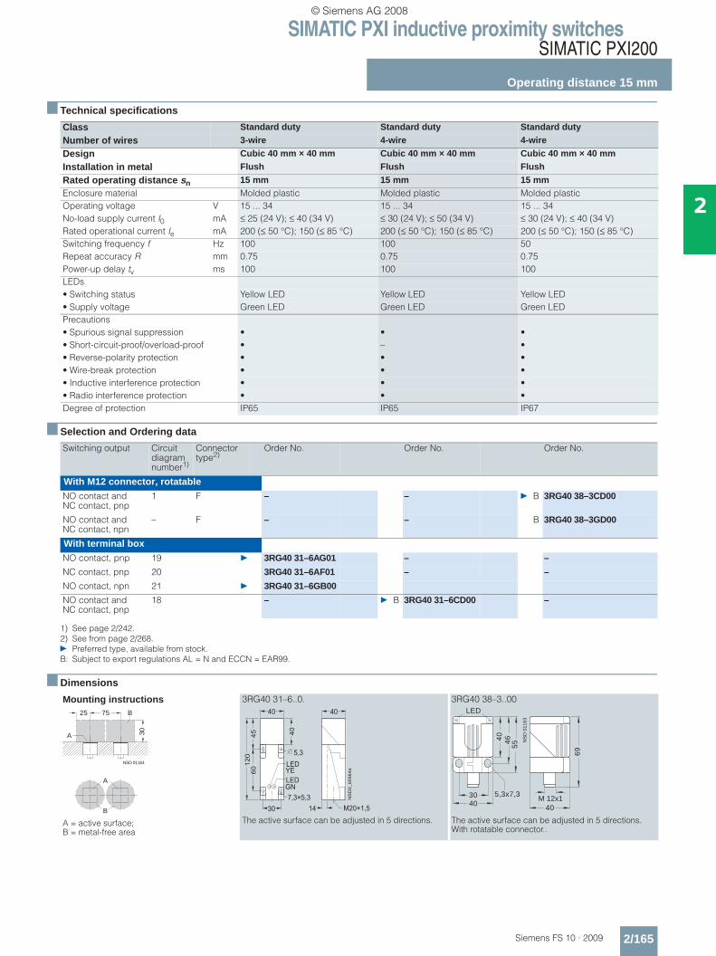
Class Standard duty Standard duty Standard duty
Number of wires 3-wire 3-wire 4-wire
Design M30, Shorty M30 M30
Installation in metal Not flush Not flush Not flush
Rated operating distance sn 15 mm 15 mm 15 mmEnclosure material Brass, nickel-plated Brass, nickel-plated Brass, nickel-platedOperating voltage (DC) V 15 ... 34 15 ... 34 15 ... 34No-load supply current I0 mA ≤ 17 (24 V); ≤ 30 (34 V) ≤ 17 (24 V); ≤ 30 (34 V) ≤ 25 (24 V); ≤ 40 (34 V)Rated operational current Ie mA 200 (≤ 50 °C); 150 (≤ 85 °C) 200 (≤ 50 °C); 150 (≤ 85 °C) 200 (≤ 50 °C); 150 (≤ 85 °C)Switching frequency f Hz 300 300 300Repeat accuracy R mm 0.4 0.4 0.4Power-up delay tv ms 40 40 40Switching status display Yellow LED Yellow LED Yellow LEDPrecautions• Spurious signal suppression • • •• Short-circuit-proof/overload-proof • • •• Reverse-polarity protection • • •• Wire-break protection • • •• Inductive interference protection • • •• Radio interference protection • • •Degree of protection IP67 IP67 IP67
Switching output Circuit diagram number1)
1) See page 2/242.
Connector type2)
2) See from page 2/268.} Preferred type, available from stock.B: Subject to export regulations AL = N and ECCN = EAR99.
Order No. Order No. Order No.
With 2 m cable, PUR 3 × 0.25 mm2 3 × 0.25 mm2 4 × 0.14 mm2
NO contact, pnp 11 B 3RG40 24–0AG33 } B 3RG40 24–0AG01 –
NC contact, pnp 12 B 3RG40 24–0AF33 B 3RG40 24–0AF01 –
NO contact, npn 13 B 3RG40 24–0GB33 B 3RG40 24–0GB00 –
NC contact, npn 14 B 3RG40 24–0GA33 B 3RG40 24–0GA00 –
NO contact and NC contact, pnp
10 – – } B 3RG40 24–0CD00
With M12 connectorNO contact, pnp 2 E, F B 3RG40 24–3AG33 } B 3RG40 24–3AG01 –
NC contact, pnp 3 F B 3RG40 24–3AF33 B 3RG40 24–3AF01 –
NO contact, npn 4 E, F B 3RG40 24–3GB33 B 3RG40 24–3GB00 –
NC contact, npn 5 F B 3RG40 24–3GA33 – –
NO contact and NC contact, pnp
1 F – – B 3RG40 24–3CD00
Mounting instructions
A = active surface B = metal-free area
3RG40 24–0..33
3RG40 24–3..33 3RG40 24–0..00 3RG40 24–0..01
3RG40 24–3..00 3RG40 24–3..01
A
B
NS
D00
548
30 80
25
1515
A
B
35
M 30x1,5
16N
SD
0_00
551a
SW
36
5
LEDLED(4x)
31
M 30x1,5
16
NSD0_00552b
45
35
SW 36
5
M 12x1
54
M 30x1,5
16
NS
D0_
0054
4b
LED
SW
36
5
LED(4x)
55
M 30x1,5
16
NSD00545b
69 58,5
SW
36
5
M 12x1
© Siemens AG 2008
SIMATIC PXI inductive proximity switchesSIMATIC PXI200
Operating distance 15 mm
2/165Siemens FS 10 · 2009
2
■ Technical specifications
■ Selection and Ordering data
■ Dimensions
Class Standard duty Standard duty Standard duty
Number of wires 3-wire 4-wire 4-wire
Design Cubic 40 mm × 40 mm Cubic 40 mm × 40 mm Cubic 40 mm × 40 mm
Installation in metal Flush Flush Flush
Rated operating distance sn 15 mm 15 mm 15 mmEnclosure material Molded plastic Molded plastic Molded plasticOperating voltage V 15 ... 34 15 ... 34 15 ... 34No-load supply current I0 mA ≤ 25 (24 V); ≤ 40 (34 V) ≤ 30 (24 V); ≤ 50 (34 V) ≤ 30 (24 V); ≤ 40 (34 V)Rated operational current Ie mA 200 (≤ 50 °C); 150 (≤ 85 °C) 200 (≤ 50 °C); 150 (≤ 85 °C) 200 (≤ 50 °C); 150 (≤ 85 °C)Switching frequency f Hz 100 100 50Repeat accuracy R mm 0.75 0.75 0.75Power-up delay tv ms 100 100 100LEDs• Switching status Yellow LED Yellow LED Yellow LED• Supply voltage Green LED Green LED Green LEDPrecautions• Spurious signal suppression • • •• Short-circuit-proof/overload-proof • – •• Reverse-polarity protection • • •• Wire-break protection • • •• Inductive interference protection • • •• Radio interference protection • • •Degree of protection IP65 IP65 IP67
Switching output Circuit diagram number1)
1) See page 2/242.
Connector type2)
2) See from page 2/268.} Preferred type, available from stock.B: Subject to export regulations AL = N and ECCN = EAR99.
Order No. Order No. Order No.
With M12 connector, rotatableNO contact and NC contact, pnp
1 F – – } B 3RG40 38–3CD00
NO contact and NC contact, npn
– F – – B 3RG40 38–3GD00
With terminal boxNO contact, pnp 19 } 3RG40 31–6AG01 – –
NC contact, pnp 20 3RG40 31–6AF01 – –
NO contact, npn 21 } 3RG40 31–6GB00
NO contact and NC contact, pnp
18 – } B 3RG40 31–6CD00 –
Mounting instructions
A = active surface; B = metal-free area
3RG40 31–6..0.
The active surface can be adjusted in 5 directions.
3RG40 38–3..00
The active surface can be adjusted in 5 directions. With rotatable connector..
NSD 01164
25 75 B
A 30
A
B
��
��
��
� �
� � � � � � �
� � �
��
� �
� � �
� �
�����������
� � �
� � � � �� �
� �
� �
4030 5,3x7,3
46
55
40
NS
D 0
1163
LED
69
40
M 12x1
© Siemens AG 2008
SIMATIC PXI inductive proximity switchesSIMATIC PXI200
Operating distance 15 mm
2/166 Siemens FS 10 · 2009
2
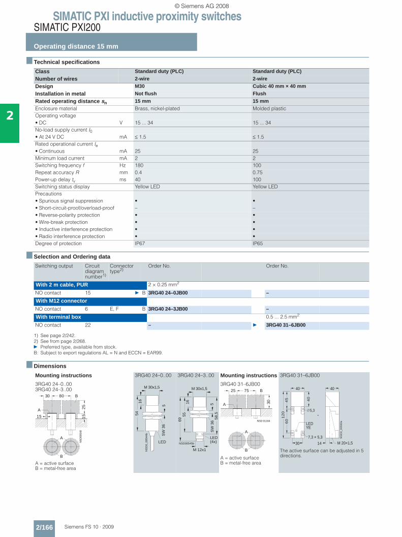
■ Technical specifications
■ Selection and Ordering data
■ Dimensions
Class Standard duty (PLC) Standard duty (PLC)
Number of wires 2-wire 2-wire
Design M30 Cubic 40 mm × 40 mm
Installation in metal Not flush Flush
Rated operating distance sn 15 mm 15 mmEnclosure material Brass, nickel-plated Molded plasticOperating voltage• DC V 15 ... 34 15 ... 34No-load supply current I0• At 24 V DC mA ≤ 1.5 ≤ 1.5Rated operational current Ie• Continuous mA 25 25Minimum load current mA 2 2Switching frequency f Hz 180 100Repeat accuracy R mm 0.4 0.75Power-up delay tv ms 40 100Switching status display Yellow LED Yellow LEDPrecautions• Spurious signal suppression • •• Short-circuit-proof/overload-proof – –• Reverse-polarity protection • •• Wire-break protection • •• Inductive interference protection • •• Radio interference protection • •Degree of protection IP67 IP65
Switching output Circuit diagram number1)
1) See page 2/242.
Connector type2)
2) See from page 2/268.} Preferred type, available from stock.B: Subject to export regulations AL = N and ECCN = EAR99.
Order No. Order No.
With 2 m cable, PUR 2 × 0.25 mm2
NO contact 15 } B 3RG40 24–0JB00 –
With M12 connectorNO contact 6 E, F B 3RG40 24–3JB00 –
With terminal box 0.5 ... 2.5 mm2
NO contact 22 – } 3RG40 31–6JB00
Mounting instructions
3RG40 24–0..003RG40 24–3..00
A = active surface B = metal-free area
3RG40 24–0..00 3RG40 24–3..00 Mounting instructions
3RG40 31–6JB00
A = active surface B = metal-free area
3RG40 31–6JB00
The active surface can be adjusted in 5 directions.
A
B
NS
D00
548
30 80
25
1515
A
B
54
M 30x1,5
16
NS
D0_
0054
4b
LED
SW
36
5
LED(4x)
55
M 30x1,5
16
NSD00545b
69 58,5
SW
36
5
M 12x1
NSD 01164
25 75 B
A 30
A
B
45
60
12
0
30
40
40 40
NS
D0
_0
05
60
a
LED
14
5,3
7,3 × 5,3M 20×1,5
YE
© Siemens AG 2008

SIMATIC PXI inductive proximity switchesSIMATIC PXI200
Operating distance 20 mm
2/167Siemens FS 10 · 2009
2
■ Technical specifications
■ Selection and Ordering data
■ Dimensions
Class Standard duty Standard duty
Number of wires 3-wire 4-wire
Design Cubic 40 mm × 40 mm Cubic 40 mm × 40 mm
Installation in metal Not flush Not flush
Rated operating distance sn 20 mm 20 mmEnclosure material Molded plastic Molded plasticOperating voltage V 15 ... 34 15 ... 34No-load supply current I0 mA ≤ 25 (24 V); ≤ 40 (34 V) ≤ 30 (24 V); ≤ 50 (34 V)Rated operational current Ie mA 200 (≤ 50 °C); 150 (≤ 85 °C) 200 (≤ 50 °C); 150 (≤ 85 °C)Switching frequency f Hz 75 75Repeat accuracy R mm 0.75 0.75Power-up delay tv ms 100 100LEDs• Switching status Yellow LED Yellow LED• Supply voltage Green LED Green LEDPrecautions• Spurious signal suppression • •• Short-circuit-proof/overload-proof • –• Reverse-polarity protection • •• Wire-break protection • •• Inductive interference protection • •• Radio interference protection • •Degree of protection IP65 IP65
Switching output Circuit diagram number1)
1) See page 2/242.} Preferred type, available from stock.B: Subject to export regulations AL = N and ECCN = EAR99.
Order No. Order No.
With terminal boxNO contact, pnp 19 } 3RG40 41–6AG01 –
NC contact, pnp 20 3RG40 41–6AF01 –
NO contact, npn 21 3RG40 41–6GB00 –
NO contact and NC contact, pnp
18 – } B 3RG40 41–6CD00
Mounting instructions
A = active surface B = metal-free area
3RG40 41–6..0.
The active surface can be adjusted in 5 directions.
NS
D00
583
100
40
4050
A
B
A
B
70
��
��
��
� �
� � � � � � �
� � �
��
� �
� � �
� �
�����������
� � �
� � � � �� �
� �
� �
© Siemens AG 2008
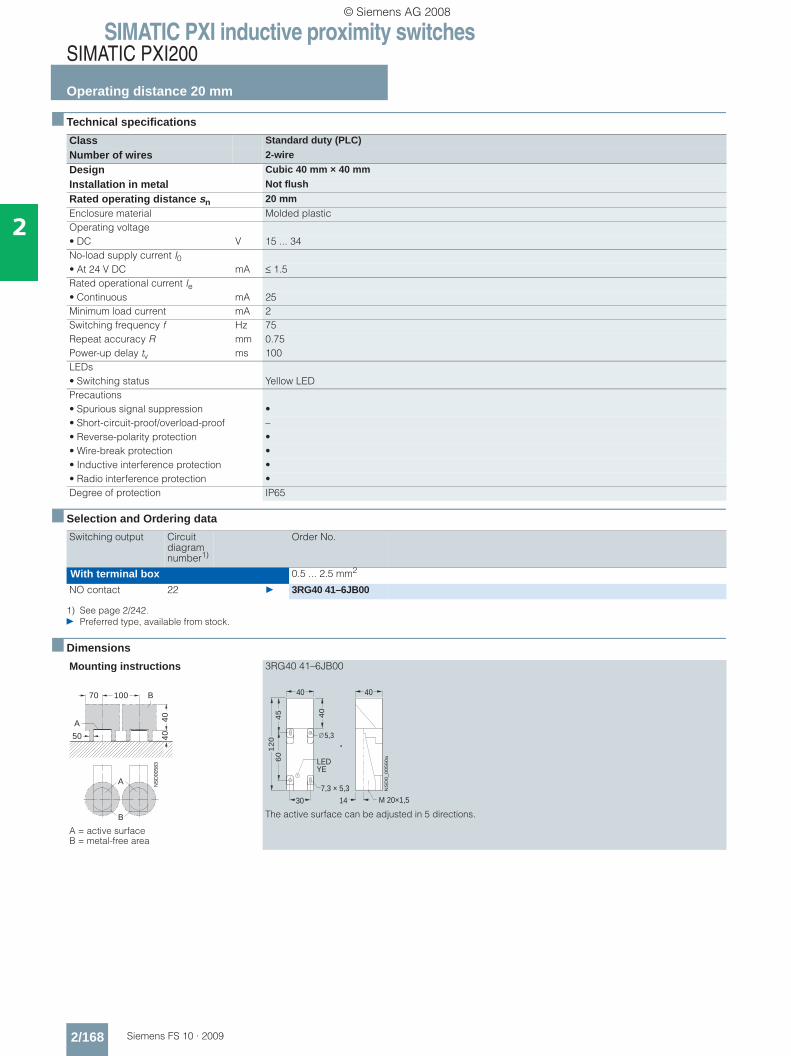
SIMATIC PXI inductive proximity switchesSIMATIC PXI200
Operating distance 20 mm
2/168 Siemens FS 10 · 2009
2
■ Technical specifications
■ Selection and Ordering data
■ Dimensions
Class Standard duty (PLC)
Number of wires 2-wire
Design Cubic 40 mm × 40 mm
Installation in metal Not flush
Rated operating distance sn 20 mmEnclosure material Molded plasticOperating voltage• DC V 15 ... 34No-load supply current I0• At 24 V DC mA ≤ 1.5Rated operational current Ie• Continuous mA 25Minimum load current mA 2Switching frequency f Hz 75Repeat accuracy R mm 0.75Power-up delay tv ms 100LEDs• Switching status Yellow LEDPrecautions• Spurious signal suppression •• Short-circuit-proof/overload-proof –• Reverse-polarity protection •• Wire-break protection •• Inductive interference protection •• Radio interference protection •Degree of protection IP65
Switching output Circuit diagram number1)
1) See page 2/242.} Preferred type, available from stock.
Order No.
With terminal box 0.5 ... 2.5 mm2
NO contact 22 } 3RG40 41–6JB00
Mounting instructions
A = active surface B = metal-free area
3RG40 41–6JB00
The active surface can be adjusted in 5 directions.
NS
D00
583
100
40
4050
A
B
A
B
70
45
60
12
0
30
40
40 40
NS
D0
_0
05
60
a
LED
14
5,3
7,3 × 5,3M 20×1,5
YE
© Siemens AG 2008

SIMATIC PXI inductive proximity switchesSIMATIC PXI200
Operating distance 30 mmOperating distance 40 mm
2/169Siemens FS 10 · 2009
2
■ Technical specifications
■ Selection and Ordering data
■ Dimensions
Class Standard duty Standard duty
Number of wires 4-wire 4-wire
Design Cubic 60 mm × 80 mm Cubic 80 mm × 100 mm
Installation in metal Not flush Not flush
Rated operating distance sn 30 mm 40 mmEnclosure material Molded plastic Molded plasticOperating voltage• DC V 15 ... 34 15 ... 34No-load supply current I0• At 24 V DC mA ≤ 30 (24 V); ≤ 50 (34 V) ≤ 30 (24 V); ≤ 50 (34 V)Rated operational current Ie• Continuous mA 200 (≤ 50 °C); 150 (≤ 85 °C) 200 (≤ 50 °C); 150 (≤ 85 °C)Switching frequency f Hz 50 10Repeat accuracy R mm 1.0 1.0Power-up delay tv ms 100 200LEDs• Switching status Yellow LED Yellow LED• Supply voltage Green LED Green LEDPrecautions• Spurious signal suppression • •• Short-circuit-proof/overload-proof • •• Reverse-polarity protection • •• Wire-break protection • •• Inductive interference protection • •• Radio interference protection • •Degree of protection IP65 IP65
Switching output Circuit diagram number1)
1) See page 2/242.B: Subject to export regulations AL = N and ECCN = EAR99.
Order No. Order No.
With terminal box 0.5 ... 2.5 mm2 0.5 ... 2.5 mm2
NO contact and NC contact, pnp
18 B 3RG40 42–6CD00 B 3RG40 43–6CD00
Mounting instructions3RG40 42–6CD00
3RG40 43–6CD00
A = active surface B = metal-free area
3RG40 42–6CD00 3RG40 43–6CD00
NSD00608
90 210
90
4060
A
B
A
B
NSD00613
80 160
90
4015
A
B
A
B
���
��
� � �
� � � � � �
����
������
��
� �
� �
� �
� � �
� �
� � �
� �
27,5
100
5,3
Pg 13,5
NS
D00
625LED
YE
LED GN
65
65
41,5
80,3
© Siemens AG 2008
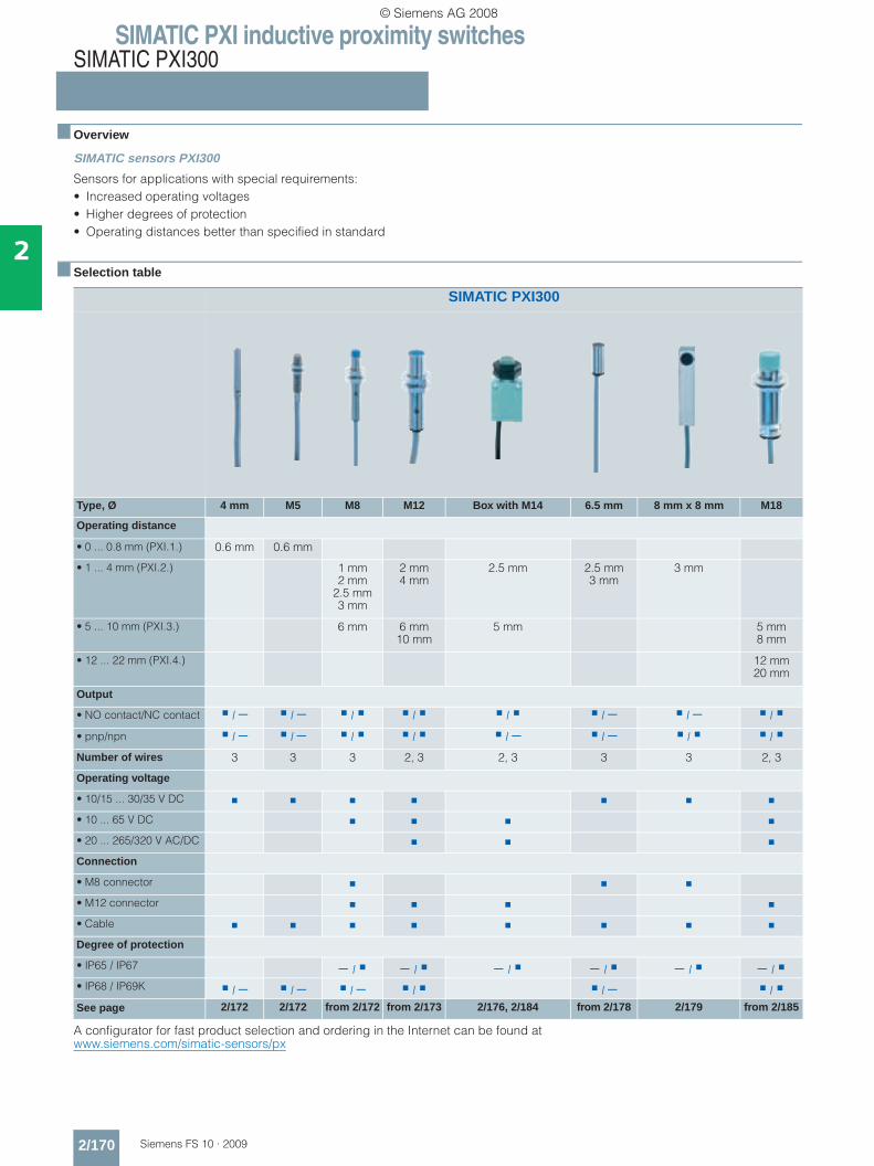
SIMATIC PXI inductive proximity switchesSIMATIC PXI300
2/170 Siemens FS 10 · 2009
2
■ Overview
SIMATIC sensors PXI300
Sensors for applications with special requirements:• Increased operating voltages• Higher degrees of protection• Operating distances better than specified in standard
■ Selection table
A configurator for fast product selection and ordering in the Internet can be found atwww.siemens.com/simatic-sensors/px
SIMATIC PXI300
Type, Ø 4 mm M5 M8 M12 Box with M14 6.5 mm 8 mm x 8 mm M18
Operating distance
• 0 ... 0.8 mm (PXI.1.) 0.6 mm 0.6 mm
• 1 ... 4 mm (PXI.2.) 1 mm2 mm
2.5 mm 3 mm
2 mm4 mm
2.5 mm 2.5 mm3 mm
3 mm
• 5 ... 10 mm (PXI.3.) 6 mm 6 mm10 mm
5 mm 5 mm8 mm
• 12 ... 22 mm (PXI.4.) 12 mm20 mm
Output
• NO contact/NC contact / − / − / / / / − / − /
• pnp/npn / − / − / / / − / − / /
Number of wires 3 3 3 2, 3 2, 3 3 3 2, 3
Operating voltage
• 10/15 ... 30/35 V DC
• 10 ... 65 V DC
• 20 ... 265/320 V AC/DC
Connection
• M8 connector
• M12 connector
• Cable
Degree of protection
• IP65 / IP67 − / − / − / − / − / − / • IP68 / IP69K / − / − / − / / − /
See page 2/172 2/172 from 2/172 from 2/173 2/176, 2/184 from 2/178 2/179 from 2/185
© Siemens AG 2008
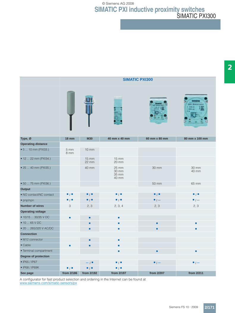
SIMATIC PXI inductive proximity switchesSIMATIC PXI300
2/171Siemens FS 10 · 2009
2
A configurator for fast product selection and ordering in the Internet can be found atwww.siemens.com/simatic-sensors/px
SIMATIC PXI300
Type, Ø 18 mm M30 40 mm x 40 mm 60 mm x 80 mm 80 mm x 100 mm
Operating distance
• 5 ... 10 mm (PXI33.) 5 mm8 mm
10 mm
• 12 ... 22 mm (PXI34.) 15 mm22 mm
15 mm20 mm
• 25 ... 40 mm (PXI35.) 40 mm 25 mm30 mm35 mm40 mm
30 mm 30 mm40 mm
• 50 ... 75 mm (PXI36.) 50 mm 65 mm
Output
• NO contact/NC contact / / / / /
• pnp/npn / / / / − / −Number of wires 3 2, 3 2, 3, 4 2, 3 2, 3
Operating voltage
• 10/15 ... 30/35 V DC
• 10 ... 65 V DC
• 20 ... 265/320 V AC/DC
Connection
• M12 connector
• Cable
• Terminal compartment
Degree of protection
• IP65 / IP67 − / / / − / −• IP68 / IP69K / / / See page from 2/186 from 2/192 from 2/197 from 2/207 from 2/211
© Siemens AG 2008
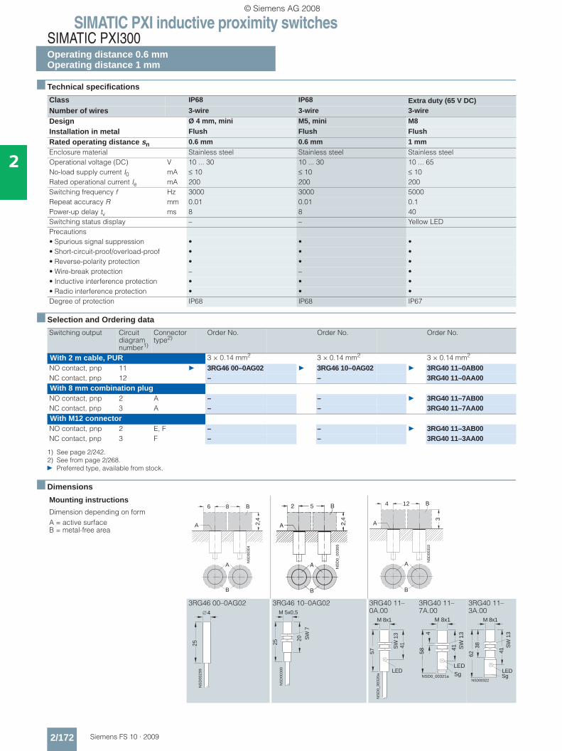
SIMATIC PXI inductive proximity switchesSIMATIC PXI300Operating distance 0.6 mmOperating distance 1 mm
2/172 Siemens FS 10 · 2009
2
■ Technical specifications
■ Selection and Ordering data
■ Dimensions
Class IP68 IP68 Extra duty (65 V DC)Number of wires 3-wire 3-wire 3-wire
Design Ø 4 mm, mini M5, mini M8
Installation in metal Flush Flush Flush
Rated operating distance sn 0.6 mm 0.6 mm 1 mmEnclosure material Stainless steel Stainless steel Stainless steelOperational voltage (DC) V 10 ... 30 10 ... 30 10 ... 65No-load supply current I0 mA ≤ 10 ≤ 10 ≤ 10Rated operational current Ie mA 200 200 200Switching frequency f Hz 3000 3000 5000Repeat accuracy R mm 0.01 0.01 0.1Power-up delay tv ms 8 8 40Switching status display – – Yellow LEDPrecautions• Spurious signal suppression • • •• Short-circuit-proof/overload-proof • • •• Reverse-polarity protection • • •• Wire-break protection – – •• Inductive interference protection • • •• Radio interference protection • • •Degree of protection IP68 IP68 IP67
Switching output Circuit diagram number1)
1) See page 2/242.
Connector type2)
2) See from page 2/268.} Preferred type, available from stock.
Order No. Order No. Order No.
With 2 m cable, PUR 3 × 0.14 mm2 3 × 0.14 mm2 3 × 0.14 mm2
NO contact, pnp 11 } 3RG46 00–0AG02 } 3RG46 10–0AG02 } 3RG40 11–0AB00NC contact, pnp 12 – – 3RG40 11–0AA00With 8 mm combination plugNO contact, pnp 2 A – – } 3RG40 11–7AB00NC contact, pnp 3 A – – 3RG40 11–7AA00With M12 connectorNO contact, pnp 2 E, F – – } 3RG40 11–3AB00NC contact, pnp 3 F – – 3RG40 11–3AA00
Mounting instructions
Dimension depending on formA = active surface B = metal-free area
3RG46 00–0AG02 3RG46 10–0AG02 3RG40 11–0A.00
3RG40 11–7A.00
3RG40 11–3A.00
A
B
NS
D00
304
8
2,4
A
B6
A
B
NS
D0_0
030
5
5
2,4
A
B2
A
B
NS
D00
319
4 12
3
A
B
NS
D00
299
25
4
25
SW
7
NS
D00
300
20
M 5x0,5
LED
57N
SD
0_00
320a
M 8x1
41SW
13
LED
M 8x1
SW
134
58
NSD0_00321a
41
SgLED
M 8x1
SW
13
NSD00322
38
41
62
Sg
© Siemens AG 2008
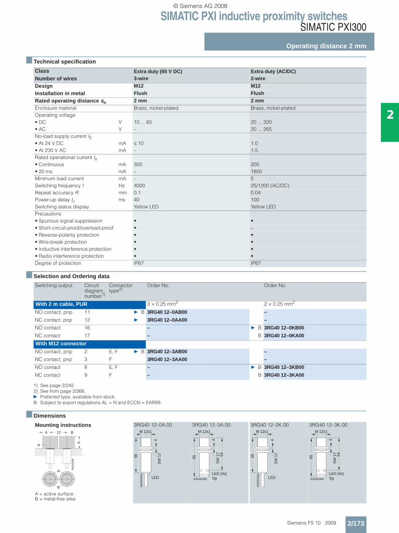
SIMATIC PXI inductive proximity switchesSIMATIC PXI300
Operating distance 2 mm
2/173Siemens FS 10 · 2009
2
■ Technical specification
■ Selection and Ordering data
■ Dimensions
Class Extra duty (65 V DC) Extra duty (AC/DC)Number of wires 3-wire 2-wire
Design M12 M12
Installation in metal Flush Flush
Rated operating distance sn 2 mm 2 mmEnclosure material Brass, nickel-plated Brass, nickel-platedOperating voltage• DC V 10 ... 65 20 ... 320• AC V – 20 ... 265No-load supply current I0• At 24 V DC mA ≤ 10 1.0• At 230 V AC mA – 1.5Rated operational current Ie• Continuous mA 300 200• 20 ms mA – 1800Minimum load current mA – 5Switching frequency f Hz 4000 25/1200 (AC/DC)Repeat accuracy R mm 0.1 0.04Power-up delay tv ms 40 100Switching status display Yellow LED Yellow LEDPrecautions• Spurious signal suppression • •• Short-circuit-proof/overload-proof • –• Reverse-polarity protection • •• Wire-break protection • •• Inductive interference protection • •• Radio interference protection • •Degree of protection IP67 IP67
Switching output Circuit diagram number1)
1) See page 2/242.
Connector type2)
2) See from page 2/268.} Preferred type, available from stock.B: Subject to export regulations AL = N and ECCN = EAR99.
Order No. Order No.
With 2 m cable, PUR 3 × 0.25 mm2 2 × 0.25 mm2
NO contact, pnp 11 } B 3RG40 12–0AB00 –
NC contact, pnp 12 } 3RG40 12–0AA00 –
NO contact 16 – } B 3RG40 12–0KB00
NC contact 17 – B 3RG40 12–0KA00
With M12 connectorNO contact, pnp 2 E, F } B 3RG40 12–3AB00 –
NC contact, pnp 3 F 3RG40 12–3AA00 –
NO contact 8 E, F – } B 3RG40 12–3KB00
NC contact 9 F – B 3RG40 12–3KA00
Mounting instructions
A = active surface B = metal-free area
3RG40 12–0A.00 3RG40 12–3A.00 3RG40 12–0K.00 3RG40 12–3K.00
A
B
NS
D00
368
6 12
6
A
B
LED
NS
D00
364
56
4
M 12x1
SW
17
NSD00365
65
M 12x1
54
LED (4x)
SW
17
4
Sg LED
NS
D00
364
56
4
M 12x1
SW
17
NSD00365
65
M 12x1
54
LED (4x)
SW
17
4
Sg
© Siemens AG 2008
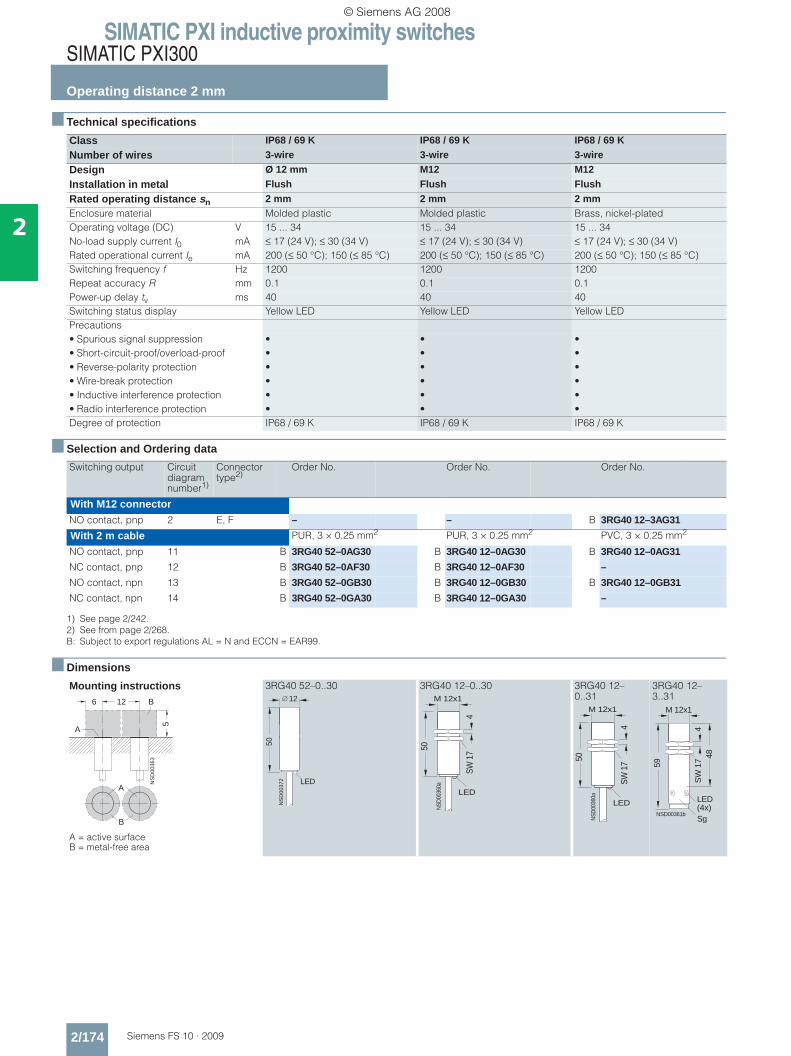
SIMATIC PXI inductive proximity switchesSIMATIC PXI300
Operating distance 2 mm
2/174 Siemens FS 10 · 2009
2
■ Technical specifications
■ Selection and Ordering data
■ Dimensions
Class IP68 / 69 K IP68 / 69 K IP68 / 69 K
Number of wires 3-wire 3-wire 3-wire
Design Ø 12 mm M12 M12
Installation in metal Flush Flush Flush
Rated operating distance sn 2 mm 2 mm 2 mmEnclosure material Molded plastic Molded plastic Brass, nickel-platedOperating voltage (DC) V 15 ... 34 15 ... 34 15 ... 34No-load supply current I0 mA ≤ 17 (24 V); ≤ 30 (34 V) ≤ 17 (24 V); ≤ 30 (34 V) ≤ 17 (24 V); ≤ 30 (34 V)Rated operational current Ie mA 200 (≤ 50 °C); 150 (≤ 85 °C) 200 (≤ 50 °C); 150 (≤ 85 °C) 200 (≤ 50 °C); 150 (≤ 85 °C)Switching frequency f Hz 1200 1200 1200Repeat accuracy R mm 0.1 0.1 0.1Power-up delay tv ms 40 40 40Switching status display Yellow LED Yellow LED Yellow LEDPrecautions• Spurious signal suppression • • •• Short-circuit-proof/overload-proof • • •• Reverse-polarity protection • • •• Wire-break protection • • •• Inductive interference protection • • •• Radio interference protection • • •Degree of protection IP68 / 69 K IP68 / 69 K IP68 / 69 K
Switching output Circuit diagram number1)
1) See page 2/242.
Connector type2)
2) See from page 2/268.B: Subject to export regulations AL = N and ECCN = EAR99.
Order No. Order No. Order No.
With M12 connectorNO contact, pnp 2 E, F – – B 3RG40 12–3AG31
With 2 m cable PUR, 3 × 0.25 mm2 PUR, 3 × 0.25 mm2 PVC, 3 × 0.25 mm2
NO contact, pnp 11 B 3RG40 52–0AG30 B 3RG40 12–0AG30 B 3RG40 12–0AG31
NC contact, pnp 12 B 3RG40 52–0AF30 B 3RG40 12–0AF30 –
NO contact, npn 13 B 3RG40 52–0GB30 B 3RG40 12–0GB30 B 3RG40 12–0GB31
NC contact, npn 14 B 3RG40 52–0GA30 B 3RG40 12–0GA30 –
Mounting instructions
A = active surface B = metal-free area
3RG40 52–0..30 3RG40 12–0..30 3RG40 12–0..31
3RG40 12–3..31
A
B
NS
D00
363
6 12
5
A
B
LED
NS
D00
372
50
12
LED
NSD
0036
0a
50
4
M 12x1
SW 1
7
LED
NSD
0036
0a
50
4
M 12x1
SW 1
7
NSD00361b
59
M 12x148
SW
17
4
Sg
LED(4x)
© Siemens AG 2008
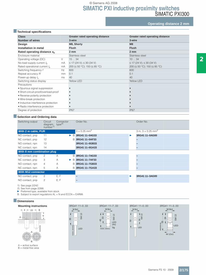
SIMATIC PXI inductive proximity switchesSIMATIC PXI300
Operating distance 2 mm
2/175Siemens FS 10 · 2009
2
■ Technical specifications
■ Selection and Ordering data
■ Dimensions
Class Greater rated operating distance Greater rated operating distance
Number of wires 3-wire 3-wire
Design M8, Shorty M8
Installation in metal Flush Flush
Rated operating distance sn 2 mm 2 mmEnclosure material Stainless steel Stainless steelOperating voltage (DC) V 15 ... 34 10 ... 34No-load supply current I0 mA ≤ 17 (24 V); ≤ 30 (34 V) ≤ 17 (24 V); ≤ 30 (34 V)Rated operational current Ie mA 200 (≤ 50 °C); 150 (≤ 85 °C) 200 (≤ 50 °C); 150 (≤ 85 °C)Switching frequency f Hz 600 600 Repeat accuracy R mm 0.1 0.1Power-up delay tv ms 40 40Switching status display Yellow LED Yellow LEDPrecautions• Spurious signal suppression • •• Short-circuit-proof/overload-proof • •• Reverse-polarity protection • •• Wire-break protection • •• Inductive interference protection • •• Radio interference protection • •Degree of protection IP67 IP67
Switching output Circuit diagram number1)
1) See page 2/242.
Connector type2)
2) See from page 2/268.} Preferred type, available from stock.B: Subject to export regulations AL = N and ECCN = EAR99.
Order No. Order No.
With 2 m cable, PUR 3 × 0.25 mm2 3 m, 3 × 0.25 mm2
NO contact, pnp 11 } B 3RG41 11–0AG33 } 3RG41 11–0AG00
NC contact, pnp 12 B 3RG41 11–0AF33 –
NO contact, npn 13 3RG41 11–0GB33 –
NC contact, npn 14 3RG41 11–0GA33 –
With 8 mm combination plugNO contact, pnp 2 A B 3RG41 11–7AG33 –
NC contact, pnp 3 A } B 3RG41 11–7AF33 –
NO contact, npn 4 A B 3RG41 11–7GB33 –
NC contact, npn 5 A B 3RG41 11–7GA33 –
With M12 connectorNO contact, pnp 2 E, F – } 3RG41 11–3AG00
NO contact, pnp 2 E, F –
Mounting instructions
A = active surface B = metal-free area
3RG41 11–0..33 3RG41 11–7..33 3RG41 11–0..00 3RG41 11–3..00
A
B
NS
D00
356
4 15
4
A
B
35
M 8x1
NS
D0
_0
03
40
a
LED
SW
13
33
M 8x1
LED(4x)
45 SW
13
SgNSD0_00341c
LED
50
M 8x1
34S
W 1
3
LED
M 8x1
SW
13
NS
D00
314b
3455
M 12x1
© Siemens AG 2008
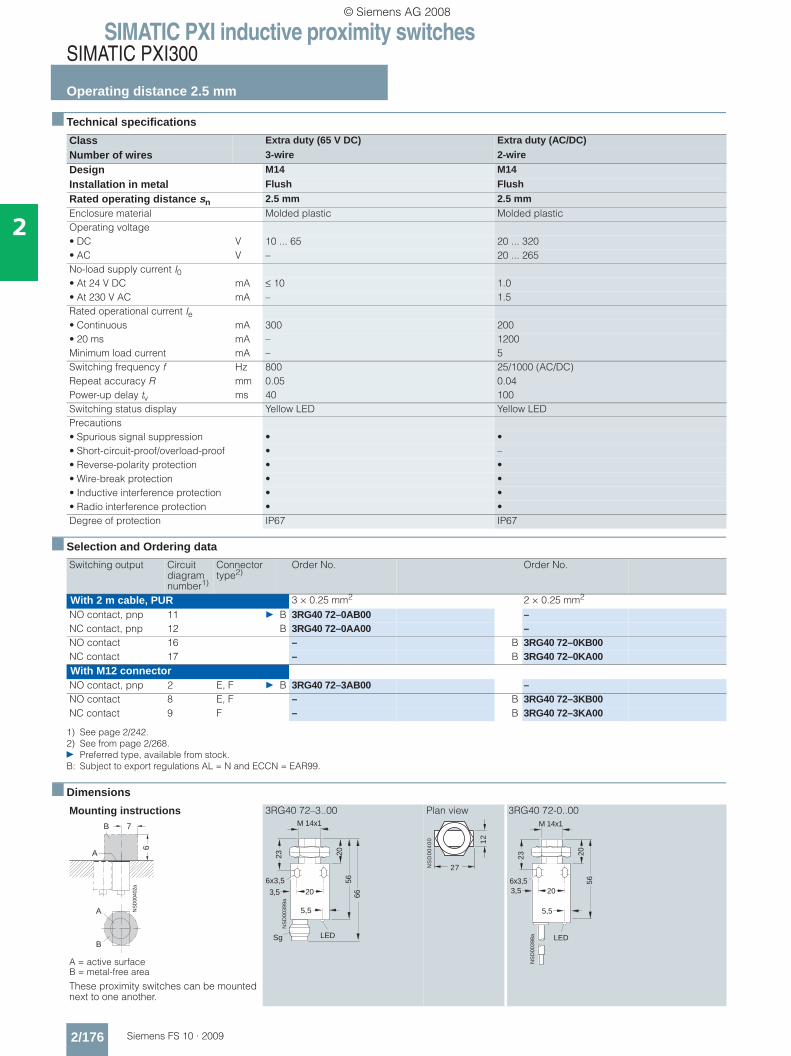
SIMATIC PXI inductive proximity switchesSIMATIC PXI300
Operating distance 2.5 mm
2/176 Siemens FS 10 · 2009
2
■ Technical specifications
■ Selection and Ordering data
■ Dimensions
Class Extra duty (65 V DC) Extra duty (AC/DC)
Number of wires 3-wire 2-wire
Design M14 M14
Installation in metal Flush Flush
Rated operating distance sn 2.5 mm 2.5 mmEnclosure material Molded plastic Molded plasticOperating voltage• DC V 10 ... 65 20 ... 320• AC V – 20 ... 265No-load supply current I0• At 24 V DC mA ≤ 10 1.0• At 230 V AC mA – 1.5Rated operational current Ie• Continuous mA 300 200• 20 ms mA – 1200Minimum load current mA – 5Switching frequency f Hz 800 25/1000 (AC/DC)Repeat accuracy R mm 0.05 0.04Power-up delay tv ms 40 100Switching status display Yellow LED Yellow LEDPrecautions• Spurious signal suppression • •• Short-circuit-proof/overload-proof • –• Reverse-polarity protection • •• Wire-break protection • •• Inductive interference protection • •• Radio interference protection • •Degree of protection IP67 IP67
Switching output Circuit diagram number1)
1) See page 2/242.
Connector type2)
2) See from page 2/268.} Preferred type, available from stock.B: Subject to export regulations AL = N and ECCN = EAR99.
Order No. Order No.
With 2 m cable, PUR 3 × 0.25 mm2 2 × 0.25 mm2
NO contact, pnp 11 } B 3RG40 72–0AB00 –NC contact, pnp 12 B 3RG40 72–0AA00 –NO contact 16 – B 3RG40 72–0KB00NC contact 17 – B 3RG40 72–0KA00With M12 connectorNO contact, pnp 2 E, F } B 3RG40 72–3AB00 –NO contact 8 E, F – B 3RG40 72–3KB00NC contact 9 F – B 3RG40 72–3KA00
Mounting instructions
A = active surface B = metal-free area
These proximity switches can be mounted next to one another.
3RG40 72–3..00 Plan view 3RG40 72-0..00
NS
D00
402a
7
6
A
B
A
B
NS
D00
399a
23
203,5
M 14x1
2056
66
Sg
6x3,5
LED
5,5
NS
D0
04
00 12
27
23
203,5
M 14x1
2056
NS
D00
398a
6x3,5
LED
5,5
© Siemens AG 2008

SIMATIC PXI inductive proximity switchesSIMATIC PXI300
Operating distance 2.5 mm
2/177Siemens FS 10 · 2009
2
■ Technical specifications
■ Selection and Ordering data
■ Dimensions
Class Increased operating distance (IP68) Increased operating distance (IP68)
Number of wires 3-wire 3-wire
Design Ø 6.5 mm M8
Installation in metal Flush Flush
Rated operating distance sn 2.5 mm 2.5 mmEnclosure material Stainless steel Stainless steelOperational voltage (DC) V 10 ... 30 10 ... 30No-load supply current I0 mA ≤ 10 ≤ 10Rated operational current Ie mA 200 200Switching frequency f Hz 1000 1000Repeat accuracy R mm 0.15 0.15Power-up delay tv ms 50 50Switching status display – –Precautions• Spurious signal suppression • •• Short-circuit-proof/overload-proof • •• Reverse-polarity protection • •• Wire-break protection – –• Inductive interference protection • •• Radio interference protection • •Degree of protection IP68 IP68
Switching output Circuit diagram number1)
1) See page 2/242.} Preferred type, available from stock.
Order No. Order No.
With 2 m cable, PUR 3 × 0.14 mm2 3 × 0.14 mm2
NO contact, pnp 11 } 3RG46 02–0AG02 } 3RG46 11–0AG02
Mounting instructionsA = active surface B = metal-free area
X ≥ 1.6 mm when mounted in steel,X ≥ 0.8 mm when mounted in other metal
3RG46 02 3RG46 11
3RG46 02–0AG02 3RG46 11–0AG02
A
B
NS
D01
191
6 16
9
A
B
NS
D00
395
8
9
A
B
X
A
B
16
6,5
45N
SD
0039
3
SW
13
45
M 8x1
NS
D00
392
© Siemens AG 2008
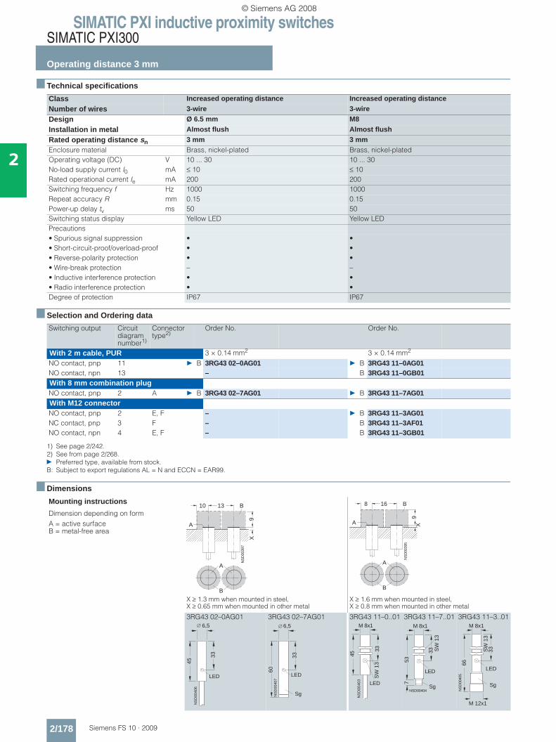
SIMATIC PXI inductive proximity switchesSIMATIC PXI300
Operating distance 3 mm
2/178 Siemens FS 10 · 2009
2
■ Technical specifications
■ Selection and Ordering data
■ Dimensions
Class Increased operating distance Increased operating distance
Number of wires 3-wire 3-wire
Design Ø 6.5 mm M8
Installation in metal Almost flush Almost flush
Rated operating distance sn 3 mm 3 mmEnclosure material Brass, nickel-plated Brass, nickel-platedOperating voltage (DC) V 10 ... 30 10 ... 30No-load supply current I0 mA ≤ 10 ≤ 10Rated operational current Ie mA 200 200Switching frequency f Hz 1000 1000Repeat accuracy R mm 0.15 0.15Power-up delay tv ms 50 50Switching status display Yellow LED Yellow LEDPrecautions• Spurious signal suppression • •• Short-circuit-proof/overload-proof • •• Reverse-polarity protection • •• Wire-break protection – –• Inductive interference protection • •• Radio interference protection • •Degree of protection IP67 IP67
Switching output Circuit diagram number1)
1) See page 2/242.
Connector type2)
2) See from page 2/268.} Preferred type, available from stock.B: Subject to export regulations AL = N and ECCN = EAR99.
Order No. Order No.
With 2 m cable, PUR 3 × 0.14 mm2 3 × 0.14 mm2
NO contact, pnp 11 } B 3RG43 02–0AG01 } B 3RG43 11–0AG01NO contact, npn 13 – B 3RG43 11–0GB01With 8 mm combination plugNO contact, pnp 2 A } B 3RG43 02–7AG01 } B 3RG43 11–7AG01With M12 connectorNO contact, pnp 2 E, F – } B 3RG43 11–3AG01NC contact, pnp 3 F – B 3RG43 11–3AF01NO contact, npn 4 E, F – B 3RG43 11–3GB01
Mounting instructions
Dimension depending on formA = active surface B = metal-free area
X ≥ 1.3 mm when mounted in steel,X ≥ 0.65 mm when mounted in other metal
X ≥ 1.6 mm when mounted in steel,X ≥ 0.8 mm when mounted in other metal
3RG43 02–0AG01 3RG43 02–7AG01 3RG43 11–0..01 3RG43 11–7..01 3RG43 11–3..01
NS
D00
397
13
9
A
B
X
A
B
10
NS
D00
395
8
9
A
B
X
A
B
16
45N
SD
0040
6
33
LED
6,5
NS
D00
407
60
33
LED
6,5
Sg
45
M 8x1
NS
D00
403
33S
W 1
3
LED
SW
13
753
NSD00404
M 8x1
33
LED
Sg
66
M 8x1
NS
D00
405
33
LED
M 12x1
SW
13
Sg
© Siemens AG 2008
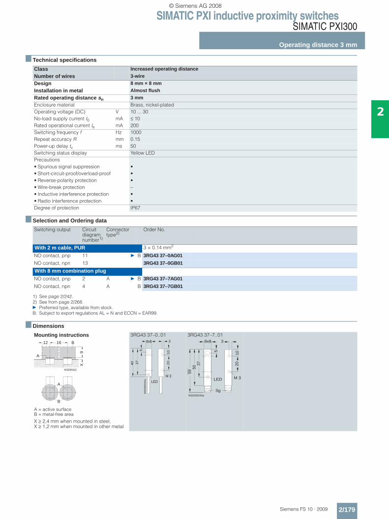
SIMATIC PXI inductive proximity switchesSIMATIC PXI300
Operating distance 3 mm
2/179Siemens FS 10 · 2009
2
■ Technical specifications
■ Selection and Ordering data
■ Dimensions
Class Increased operating distance
Number of wires 3-wire
Design 8 mm × 8 mm
Installation in metal Almost flush
Rated operating distance sn 3 mmEnclosure material Brass, nickel-platedOperating voltage (DC) V 10 ... 30No-load supply current I0 mA ≤ 10Rated operational current Ie mA 200Switching frequency f Hz 1000Repeat accuracy R mm 0.15Power-up delay tv ms 50Switching status display Yellow LEDPrecautions• Spurious signal suppression •• Short-circuit-proof/overload-proof •• Reverse-polarity protection •• Wire-break protection –• Inductive interference protection •• Radio interference protection •Degree of protection IP67
Switching output Circuit diagram number1)
1) See page 2/242.
Connector type2)
2) See from page 2/268.} Preferred type, available from stock.B: Subject to export regulations AL = N and ECCN = EAR99.
Order No.
With 2 m cable, PUR 3 × 0.14 mm2
NO contact, pnp 11 } B 3RG43 37–0AG01
NO contact, npn 13 3RG43 37–0GB01
With 8 mm combination plugNO contact, pnp 2 A } B 3RG43 37–7AG01
NO contact, npn 4 A B 3RG43 37–7GB01
Mounting instructions
A = active surface B = metal-free area
X ≥ 2,4 mm when mounted in steel,X ≥ 1,2 mm when mounted in other metal
3RG43 37–0..01 3RG43 37–7..01
NSD00412
12 16
9
A
B
X
A
B
NS
D0
03
33
a
37
8x8
5
3
10
20
M 3
LED
40
NSD00334a
5
1020
M 3
8x8 3
Sg
5059
37
LED
© Siemens AG 2008
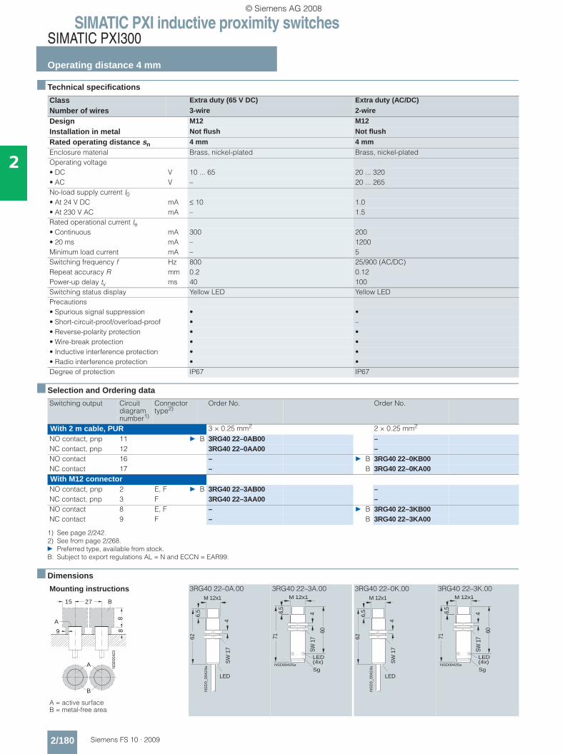
SIMATIC PXI inductive proximity switchesSIMATIC PXI300
Operating distance 4 mm
2/180 Siemens FS 10 · 2009
2
■ Technical specifications
■ Selection and Ordering data
■ Dimensions
Class Extra duty (65 V DC) Extra duty (AC/DC)
Number of wires 3-wire 2-wire
Design M12 M12
Installation in metal Not flush Not flush
Rated operating distance sn 4 mm 4 mmEnclosure material Brass, nickel-plated Brass, nickel-platedOperating voltage• DC V 10 ... 65 20 ... 320• AC V – 20 ... 265No-load supply current I0• At 24 V DC mA ≤ 10 1.0• At 230 V AC mA – 1.5Rated operational current Ie• Continuous mA 300 200• 20 ms mA – 1200Minimum load current mA – 5Switching frequency f Hz 800 25/900 (AC/DC)Repeat accuracy R mm 0.2 0.12Power-up delay tv ms 40 100Switching status display Yellow LED Yellow LEDPrecautions• Spurious signal suppression • •• Short-circuit-proof/overload-proof • –• Reverse-polarity protection • •• Wire-break protection • •• Inductive interference protection • •• Radio interference protection • •Degree of protection IP67 IP67
Switching output Circuit diagram number1)
1) See page 2/242.
Connector type2)
2) See from page 2/268.} Preferred type, available from stock.B: Subject to export regulations AL = N and ECCN = EAR99.
Order No. Order No.
With 2 m cable, PUR 3 × 0.25 mm2 2 × 0.25 mm2
NO contact, pnp 11 } B 3RG40 22–0AB00 –NC contact, pnp 12 3RG40 22–0AA00 –NO contact 16 – } B 3RG40 22–0KB00NC contact 17 – B 3RG40 22–0KA00With M12 connectorNO contact, pnp 2 E, F } B 3RG40 22–3AB00 –NC contact, pnp 3 F 3RG40 22–3AA00 –NO contact 8 E, F – } B 3RG40 22–3KB00NC contact 9 F – B 3RG40 22–3KA00
Mounting instructions
A = active surface B = metal-free area
3RG40 22–0A.00 3RG40 22–3A.00 3RG40 22–0K.00 3RG40 22–3K.00
NS
D00
423
15 27
889
A
B
A
B NS
D0_
0042
4a
4
M 12x1
6,5
62
SW
17
LED
NSD00425a
71
60
6,5
M 12x1
4SW
17
LED(4x)
Sg
NS
D0_
0042
4a
4
M 12x1
6,5
62
SW
17
LED
NSD00425a
71
60
6,5
M 12x1
4SW
17
LED(4x)
Sg
© Siemens AG 2008
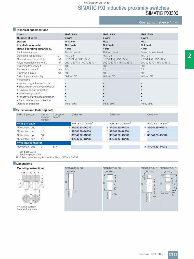
SIMATIC PXI inductive proximity switchesSIMATIC PXI300
Operating distance 4 mm
2/181Siemens FS 10 · 2009
2
■ Technical specifications
■ Selection and Ordering data
■ Dimensions
Class IP68 / 69 K IP68 / 69 K IP68 / 69 K
Number of wires 3-wire 3-wire 3-wire
Design Ø 12 mm M12 M12
Installation in metal Not flush Not flush Not flush
Rated operating distance sn 4 mm 4 mm 4 mmEnclosure material Molded plastic Molded plastic Brass, nickel-platedOperating voltage (DC) V 15 ... 34 15 ... 34 15 ... 34No-load supply current I0 mA ≤ 17 (24 V); ≤ 30 (34 V) ≤ 17 (24 V); ≤ 30 (34 V) ≤ 17 (24 V); ≤ 30 (34 V)Rated operational current Ie mA 200 (≤ 50 °C); 150 (≤ 85 °C) 200 (≤ 50 °C); 150 (≤ 85 °C) 200 (≤ 50 °C); 150 (≤ 85 °C)Switching frequency f Hz 800 800 800Repeat accuracy R mm 0.2 0.2 0.2Power-up delay tv ms 40 40 40Switching status display Yellow LED Yellow LED Yellow LEDPrecautions• Spurious signal suppression • • •• Short-circuit-proof/overload-proof • • •• Reverse-polarity protection • • •• Wire-break protection • • •• Inductive interference protection • • •• Radio interference protection • • •Degree of protection IP68 / 69 K IP68 / 69 K IP68 / 69 K
Switching output Circuit diagram number1)
1) See page 2/242.
Connector type2)
2) See from page 2/268.B: Subject to export regulations AL = N and ECCN = EAR99.
Order No. Order No. Order No.
With 2 m cable PUR, 3 × 0.25 mm2 PUR, 3 × 0.25 mm2 PVC, 3 × 0.25 mm2
NO contact, pnp 11 B 3RG40 62–0AG30 B 3RG40 22–0AG30 B 3RG40 22–0AG31
NC contact, pnp 12 B 3RG40 62–0AF30 B 3RG40 22–0AF30 –
NO contact, npn 13 B 3RG40 62–0GB30 B 3RG40 22–0GB30 B 3RG40 22–0GB31
NC contact, npn 14 B 3RG40 62–0GA30 B 3RG40 22–0GA30 –
With M12 connectorNO contact, pnp 2 E, F – – B 3RG40 22–3AG31
Mounting instructions
A = active surface B = metal-free area
3RG40 62–0..30 3RG40 22–0..30 3RG40 22–0..31 3RG40 22–3..31
NS
D00
423
15 27
889
A
B
A
B
LED
NS
D00
372
50
12
LED
NSD
0036
0a
50
4
M 12x1
SW 1
7
NS
D0_
0042
0a
4
6,5
56
SW
17
LED
M 12x1
NSD0_00421a
65
LED(4x)
54
M 12x1
6,5
4S
W 1
7
Sg
© Siemens AG 2008
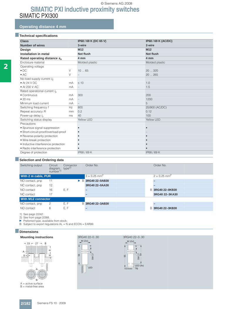
SIMATIC PXI inductive proximity switchesSIMATIC PXI300
Operating distance 4 mm
2/182 Siemens FS 10 · 2009
2
■ Technical specifications
■ Selection and Ordering data
■ Dimensions
Class IP68 / 69 K (DC 65 V) IP68 / 69 K (AC/DC)
Number of wires 3-wire 2-wire
Design M12 M12
Installation in metal Not flush Not flush
Rated operating distance sn 4 mm 4 mmEnclosure material Molded plastic Molded plasticOperating voltage• DC V 10 ... 65 20 ... 320• AC V – 20 ... 265No-load supply current I0• At 24 V DC mA ≤ 10 1.0• At 230 V AC mA – 1.5Rated operational current Ie• Continuous mA 300 200• 20 ms mA – 1200Minimum load current mA – 5Switching frequency f Hz 800 25/900 (AC/DC)Repeat accuracy R mm 0.2 0.12Power-up delay tv ms 40 100Switching status display Yellow LED Yellow LEDPrecautions• Spurious signal suppression • •• Short-circuit-proof/overload-proof • –• Reverse-polarity protection • •• Wire-break protection • •• Inductive interference protection • •• Radio interference protection • •Degree of protection IP68 / 69 K IP68 / 69 K
Switching output Circuit diagram number1)
1) See page 2/242.
Connector type2)
2) See from page 2/268.} Preferred type, available from stock.B: Subject to export regulations AL = N and ECCN = EAR99.
Order No. Order No.
With 2 m cable, PUR 3 × 0.25 mm2 2 × 0.25 mm2
NO contact, pnp 11 } B 3RG40 22–0AB30 –
NC contact, pnp 12 3RG40 22–0AA30 –
NO contact 16 E, F – B 3RG40 22–0KB30
NC contact 17 – 3RG40 22–3KA30
With M12 connectorNO contact, pnp 2 E, F B 3RG40 22–3AB30 –
NO contact 8 E, F – B 3RG40 22–3KB30
Mounting instructions
A = active surface B = metal-free area
3RG40 22–0..30 3RG40 22–3..30
NS
D00
423
15 27
889
A
B
A
B
LED
NS
D00
364
56
4
M 12x1
SW
17
NSD00365
65
M 12x1
54
LED (4x)
SW
17
4
Sg
© Siemens AG 2008
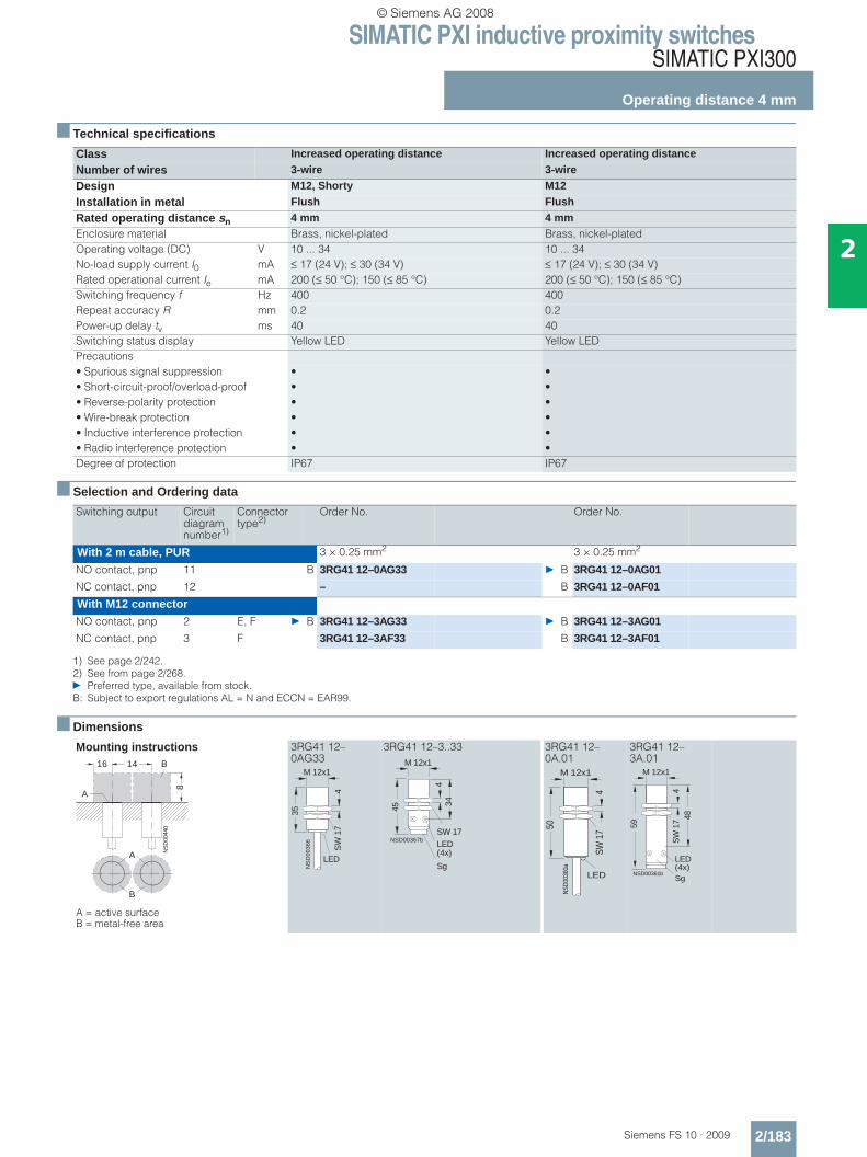
SIMATIC PXI inductive proximity switchesSIMATIC PXI300
Operating distance 4 mm
2/183Siemens FS 10 · 2009
2
■ Technical specifications
■ Selection and Ordering data
■ Dimensions
Class Increased operating distance Increased operating distance
Number of wires 3-wire 3-wire
Design M12, Shorty M12
Installation in metal Flush Flush
Rated operating distance sn 4 mm 4 mmEnclosure material Brass, nickel-plated Brass, nickel-platedOperating voltage (DC) V 10 ... 34 10 ... 34No-load supply current I0 mA ≤ 17 (24 V); ≤ 30 (34 V) ≤ 17 (24 V); ≤ 30 (34 V)Rated operational current Ie mA 200 (≤ 50 °C); 150 (≤ 85 °C) 200 (≤ 50 °C); 150 (≤ 85 °C)Switching frequency f Hz 400 400Repeat accuracy R mm 0.2 0.2Power-up delay tv ms 40 40Switching status display Yellow LED Yellow LEDPrecautions• Spurious signal suppression • •• Short-circuit-proof/overload-proof • •• Reverse-polarity protection • •• Wire-break protection • •• Inductive interference protection • •• Radio interference protection • •Degree of protection IP67 IP67
Switching output Circuit diagram number1)
1) See page 2/242.
Connector type2)
2) See from page 2/268.} Preferred type, available from stock.B: Subject to export regulations AL = N and ECCN = EAR99.
Order No. Order No.
With 2 m cable, PUR 3 × 0.25 mm2 3 × 0.25 mm2
NO contact, pnp 11 B 3RG41 12–0AG33 } B 3RG41 12–0AG01
NC contact, pnp 12 – B 3RG41 12–0AF01
With M12 connectorNO contact, pnp 2 E, F } B 3RG41 12–3AG33 } B 3RG41 12–3AG01
NC contact, pnp 3 F 3RG41 12–3AF33 B 3RG41 12–3AF01
Mounting instructions
A = active surface B = metal-free area
3RG41 12–0AG33
3RG41 12–3..33 3RG41 12–0A.01
3RG41 12–3A.01
A
B
NS
D00
440
16 14
8
A
B
NS
D00
366
35
M 12x1
SW
17
LED
4
NSD00367b
M 12x1
45
34
SW 17
4
Sg
LED(4x)
LED
NSD
0036
0a
50
4
M 12x1
SW 1
7
NSD00361b
59
M 12x1
48S
W 1
74
Sg
LED(4x)
© Siemens AG 2008
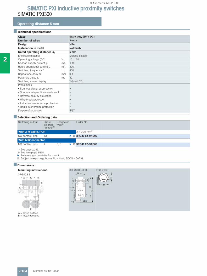
SIMATIC PXI inductive proximity switchesSIMATIC PXI300
Operating distance 5 mm
2/184 Siemens FS 10 · 2009
2
■ Technical specifications
■ Selection and Ordering data
■ Dimensions
Class Extra duty (65 V DC)
Number of wires 3-wire
Design M14
Installation in metal Not flush
Rated operating distance sn 5 mmEnclosure material Molded plasticOperating voltage (DC) V 10 ... 65No-load supply current I0 mA ≤ 10Rated operational current Ie mA 300Switching frequency f Hz 300Repeat accuracy R mm 0.1Power-up delay tv ms 40Switching status display Yellow LEDPrecautions• Spurious signal suppression •• Short-circuit-proof/overload-proof •• Reverse-polarity protection •• Wire-break protection •• Inductive interference protection •• Radio interference protection •Degree of protection IP67
Switching output Circuit diagram number1)
1) See page 2/242.
Connector type2)
2) See from page 2/268.} Preferred type, available from stock.B: Subject to export regulations AL = N and ECCN = EAR99.
Order No.
With 2 m cable, PUR 3 × 0.25 mm2
NO contact, pnp 13 } B 3RG40 82–0AB00
With M12 connectorNO contact, pnp 4 E, F } B 3RG40 82–3AB00
Mounting instructions
3RG40 82
A = active surface B = metal-free area
3RG40 82–3..00 Plan view:
NS
D00
475a
20 40
15
1212
A
B
A
B
NS
D00
399a
23
203,5
M 14x1
2056
66
Sg
6x3,5
LED
5,5
NS
D0
04
00 12
27
© Siemens AG 2008

SIMATIC PXI inductive proximity switchesSIMATIC PXI300
Operating distance 5 mm
2/185Siemens FS 10 · 2009
2
■ Technical specifications
■ Selection and Ordering data
■ Dimensions
Class Extra duty (65 V DC) Extra duty (AC/DC)
Number of wires 3-wire 2-wire
Design M18 M18
Installation in metal Flush Flush
Rated operating distance sn 5 mm 5 mmEnclosure material Brass, nickel-plated Brass, nickel-platedOperating voltage• DC V 10 ... 65 20 ... 320• AC V – 20 ... 265No-load supply current I0• At 24 V DC mA ≤ 10 1.0• At 230 V AC mA – 1.5Rated operational current Ie• Continuous mA 300 300• 20 ms mA – 1800Minimum load current mA – 5Switching frequency f Hz 800 (NO contact), 4000 (NC contact) 25/490 (AC/DC)Repeat accuracy R mm 0.15 0.15Power-up delay tv ms 40 100Switching status display Yellow LED Yellow LEDPrecautions• Spurious signal suppression • •• Short-circuit-proof/overload-proof • –• Reverse-polarity protection • •• Wire-break protection • •• Inductive interference protection • •• Radio interference protection • •Degree of protection IP67 IP67
Switching output Circuit diagram number1)
1) See page 2/242.
Connector type2)
2) See from page 2/268.} Preferred type, available from stock.B: Subject to export regulations AL = N and ECCN = EAR99.
Order No. Order No.
With 2 m cable, PUR 3 × 0.25 mm2 2 × 0.25 mm2
NO contact, pnp 11 } B 3RG40 13–0AB00 –
NC contact, pnp 12 } B 3RG40 13–0AA00 –
NO contact 16 – } 3RG40 13–0KB00
NC contact 17 – } B 3RG40 13–0KA00
With M12 connectorNO contact, pnp 2 E, F } B 3RG40 13–3AB00 –
NC contact, pnp 3 F B 3RG40 13–3AA00 –
NO contact 8 E, F – } B 3RG40 13–3KB00
NC contact 9 F – B 3RG40 13–3KA00
Mounting instructions
A = active surface B = metal-free area
3RG40 13–0..00 3RG40 13–0..01
3RG40 13–3..00 3RG40 13–3..01
A
B
NS
D00
451
11 30
10A
BM 18x1
NS
D00
445
54
LED
SW
24
4
LED(4x)
55
58,5
69
M 18x1
SW
24
4
M 12x1
NS
D00
446b
© Siemens AG 2008
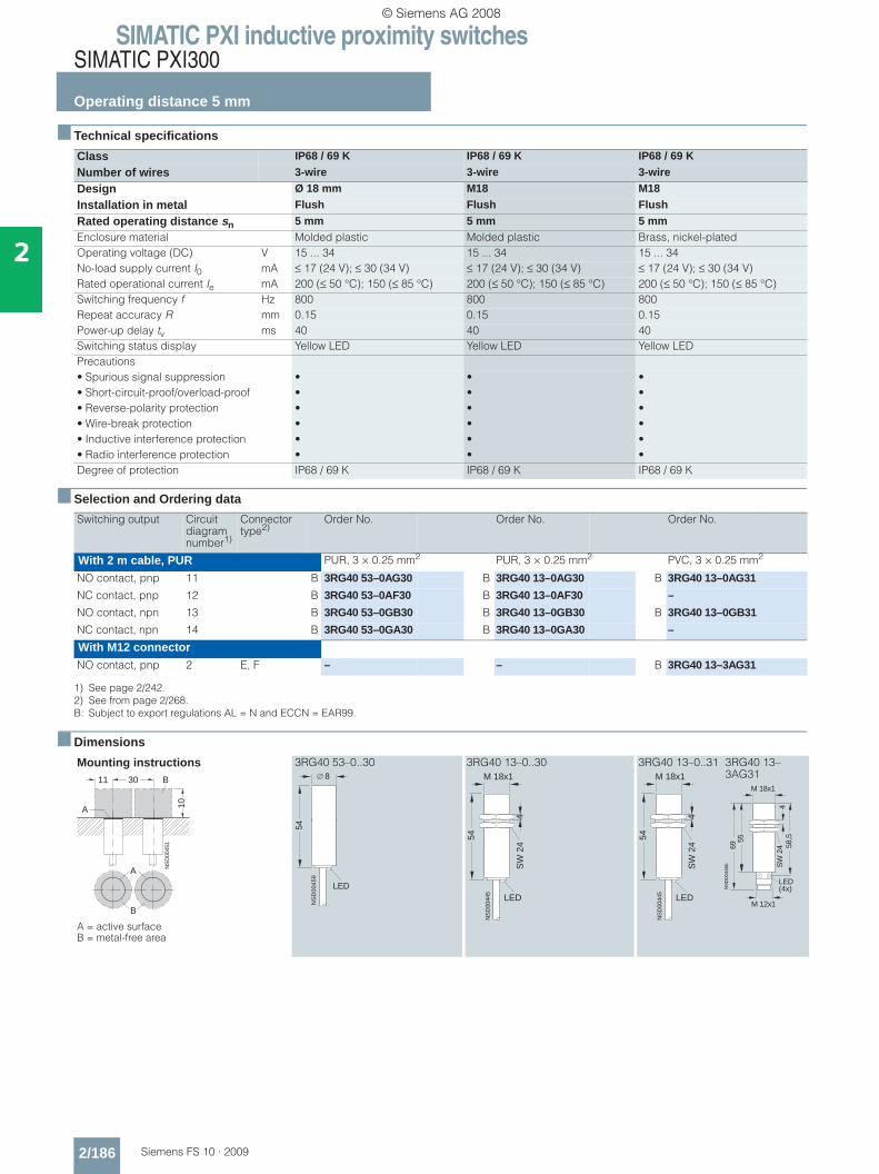
SIMATIC PXI inductive proximity switchesSIMATIC PXI300
Operating distance 5 mm
2/186 Siemens FS 10 · 2009
2
■ Technical specifications
■ Selection and Ordering data
■ Dimensions
Class IP68 / 69 K IP68 / 69 K IP68 / 69 K
Number of wires 3-wire 3-wire 3-wire
Design Ø 18 mm M18 M18
Installation in metal Flush Flush Flush
Rated operating distance sn 5 mm 5 mm 5 mmEnclosure material Molded plastic Molded plastic Brass, nickel-platedOperating voltage (DC) V 15 ... 34 15 ... 34 15 ... 34No-load supply current I0 mA ≤ 17 (24 V); ≤ 30 (34 V) ≤ 17 (24 V); ≤ 30 (34 V) ≤ 17 (24 V); ≤ 30 (34 V)Rated operational current Ie mA 200 (≤ 50 °C); 150 (≤ 85 °C) 200 (≤ 50 °C); 150 (≤ 85 °C) 200 (≤ 50 °C); 150 (≤ 85 °C)Switching frequency f Hz 800 800 800Repeat accuracy R mm 0.15 0.15 0.15Power-up delay tv ms 40 40 40Switching status display Yellow LED Yellow LED Yellow LEDPrecautions• Spurious signal suppression • • •• Short-circuit-proof/overload-proof • • •• Reverse-polarity protection • • •• Wire-break protection • • •• Inductive interference protection • • •• Radio interference protection • • •Degree of protection IP68 / 69 K IP68 / 69 K IP68 / 69 K
Switching output Circuit diagram number1)
1) See page 2/242.
Connector type2)
2) See from page 2/268.B: Subject to export regulations AL = N and ECCN = EAR99.
Order No. Order No. Order No.
With 2 m cable, PUR PUR, 3 × 0.25 mm2 PUR, 3 × 0.25 mm2 PVC, 3 × 0.25 mm2
NO contact, pnp 11 B 3RG40 53–0AG30 B 3RG40 13–0AG30 B 3RG40 13–0AG31
NC contact, pnp 12 B 3RG40 53–0AF30 B 3RG40 13–0AF30 –
NO contact, npn 13 B 3RG40 53–0GB30 B 3RG40 13–0GB30 B 3RG40 13–0GB31
NC contact, npn 14 B 3RG40 53–0GA30 B 3RG40 13–0GA30 –
With M12 connectorNO contact, pnp 2 E, F – – B 3RG40 13–3AG31
Mounting instructions
A = active surface B = metal-free area
3RG40 53–0..30 3RG40 13–0..30 3RG40 13–0..31 3RG40 13–3AG31
A
B
NS
D00
451
11 30
10A
B 8
NS
D00
459
54
LED
M 18x1
NS
D00
445
54
LED
SW
24
4
M 18x1
NS
D00
445
54
LED
SW
24
4
LED(4x)
55
58,5
69
M 18x1
SW
24
4
M 12x1
NS
D00
446b
© Siemens AG 2008
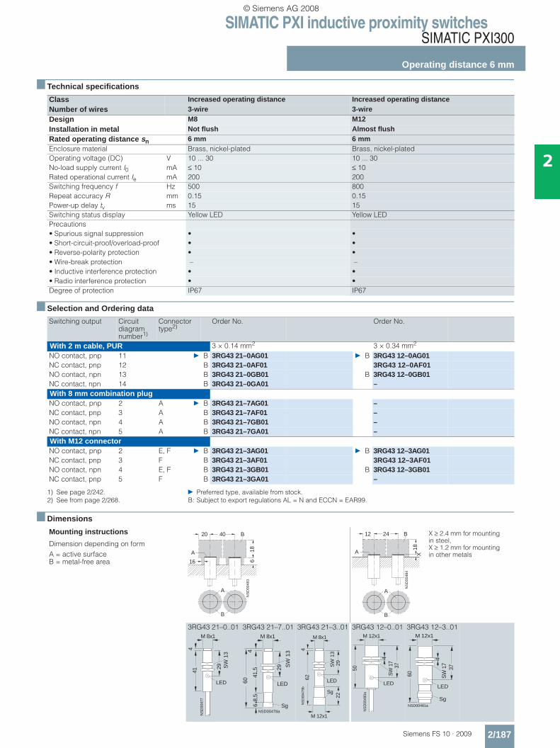
SIMATIC PXI inductive proximity switchesSIMATIC PXI300
Operating distance 6 mm
2/187Siemens FS 10 · 2009
2
■ Technical specifications
■ Selection and Ordering data
■ Dimensions
Class Increased operating distance Increased operating distance Number of wires 3-wire 3-wireDesign M8 M12Installation in metal Not flush Almost flushRated operating distance sn 6 mm 6 mmEnclosure material Brass, nickel-plated Brass, nickel-platedOperating voltage (DC) V 10 ... 30 10 ... 30No-load supply current I0 mA ≤ 10 ≤ 10Rated operational current Ie mA 200 200Switching frequency f Hz 500 800Repeat accuracy R mm 0.15 0.15Power-up delay tv ms 15 15Switching status display Yellow LED Yellow LEDPrecautions• Spurious signal suppression • •• Short-circuit-proof/overload-proof • •• Reverse-polarity protection • •• Wire-break protection – –• Inductive interference protection • •• Radio interference protection • •Degree of protection IP67 IP67
Switching output Circuit diagram number1)
1) See page 2/242. } Preferred type, available from stock.
Connector type2)
2) See from page 2/268. B: Subject to export regulations AL = N and ECCN = EAR99.
Order No. Order No.
With 2 m cable, PUR 3 × 0.14 mm2 3 × 0.34 mm2
NO contact, pnp 11 } B 3RG43 21–0AG01 } B 3RG43 12–0AG01NC contact, pnp 12 B 3RG43 21–0AF01 3RG43 12–0AF01NO contact, npn 13 B 3RG43 21–0GB01 B 3RG43 12–0GB01NC contact, npn 14 B 3RG43 21–0GA01 –With 8 mm combination plugNO contact, pnp 2 A } B 3RG43 21–7AG01 –NC contact, pnp 3 A B 3RG43 21–7AF01 –NO contact, npn 4 A B 3RG43 21–7GB01 –NC contact, npn 5 A B 3RG43 21–7GA01 –With M12 connectorNO contact, pnp 2 E, F } B 3RG43 21–3AG01 } B 3RG43 12–3AG01NC contact, pnp 3 F B 3RG43 21–3AF01 3RG43 12–3AF01NO contact, npn 4 E, F B 3RG43 21–3GB01 B 3RG43 12–3GB01NC contact, pnp 5 F B 3RG43 21–3GA01 –
Mounting instructions
Dimension depending on formA = active surface B = metal-free area
3RG43 21–0..01 3RG43 21–7..01 3RG43 21–3..01 3RG43 12–0..01 3RG43 12–3..01
A
B
NS
D00
483
20 40
18616
A
B
NS
D00
484
12 24
18
A
B
X
A
B
X ≥ 2.4 mm for mounting in steel,X ≥ 1.2 mm for mounting in other metals
SW
13
41N
SD
0047
7
4
M 8x1
29
LED
M 8x1
SW
134
NSD00478a
641
,5
LED
29
60
Sg
8,5
SW
13
62
M 8x1
NS
D00
479b
29
LED
22
M 12x1
4
Sg
50
M 12x1
NS
D00
480a
LED
37S
W 1
74
M 12x1
NSD00481a
60
Sg
LED
37S
W 1
74
© Siemens AG 2008
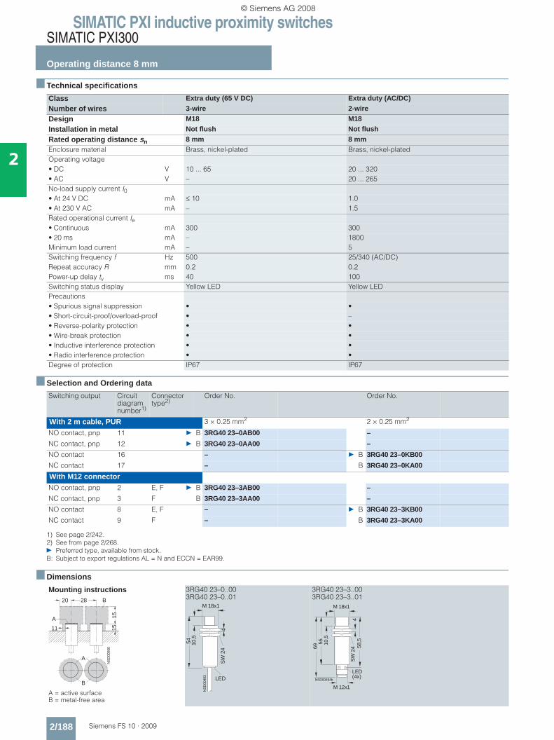
SIMATIC PXI inductive proximity switchesSIMATIC PXI300
Operating distance 8 mm
2/188 Siemens FS 10 · 2009
2
■ Technical specifications
■ Selection and Ordering data
■ Dimensions
Class Extra duty (65 V DC) Extra duty (AC/DC)
Number of wires 3-wire 2-wire
Design M18 M18
Installation in metal Not flush Not flush
Rated operating distance sn 8 mm 8 mmEnclosure material Brass, nickel-plated Brass, nickel-platedOperating voltage• DC V 10 ... 65 20 ... 320• AC V – 20 ... 265No-load supply current I0• At 24 V DC mA ≤ 10 1.0• At 230 V AC mA – 1.5Rated operational current Ie• Continuous mA 300 300• 20 ms mA – 1800Minimum load current mA – 5Switching frequency f Hz 500 25/340 (AC/DC)Repeat accuracy R mm 0.2 0.2Power-up delay tv ms 40 100Switching status display Yellow LED Yellow LEDPrecautions• Spurious signal suppression • •• Short-circuit-proof/overload-proof • –• Reverse-polarity protection • •• Wire-break protection • •• Inductive interference protection • •• Radio interference protection • •Degree of protection IP67 IP67
Switching output Circuit diagram number1)
1) See page 2/242.
Connector type2)
2) See from page 2/268.} Preferred type, available from stock.B: Subject to export regulations AL = N and ECCN = EAR99.
Order No. Order No.
With 2 m cable, PUR 3 × 0.25 mm2 2 × 0.25 mm2
NO contact, pnp 11 } B 3RG40 23–0AB00 –
NC contact, pnp 12 } B 3RG40 23–0AA00 –
NO contact 16 – } B 3RG40 23–0KB00
NC contact 17 – B 3RG40 23–0KA00
With M12 connectorNO contact, pnp 2 E, F } B 3RG40 23–3AB00 –
NC contact, pnp 3 F B 3RG40 23–3AA00 –
NO contact 8 E, F – } B 3RG40 23–3KB00
NC contact 9 F – B 3RG40 23–3KA00
Mounting instructions
A = active surface B = metal-free area
3RG40 23–0..00 3RG40 23–0..01
3RG40 23–3..00 3RG40 23–3..01
NS
D00
500
20 28
151511
A
B
A
B
NS
D00
493
LED
M 18x1
54 10,5
SW
24
4
LED(4x)
55
58,5
69
M 18x1
10,5
SW
24
4
M 12x1
NSD00494b
© Siemens AG 2008

SIMATIC PXI inductive proximity switchesSIMATIC PXI300
Operating distance 8 mm
2/189Siemens FS 10 · 2009
2
■ Technical specifications
■ Selection and Ordering data
■ Dimensions
Class IP68 / 69 K IP68 / 69 K IP68 / 69 K
Number of wires 3-wire 3-wire 3-wire
Design Ø 18 mm M18 M18
Installation in metal Not flush Not flush Not flush
Rated operating distance sn 8 mm 8 mm 8 mmEnclosure material Molded plastic Molded plastic Brass, nickel-platedOperating voltage (DC) V 15 ... 34 15 ... 34 15 ... 34No-load supply current I0 mA ≤ 17 (24 V); ≤ 30 (34 V) ≤ 17 (24 V); ≤ 30 (34 V) ≤ 17 (24 V); ≤ 30 (34 V)Rated operational current Ie mA 200 (≤ 50 °C); 150 (≤ 85 °C) 200 (≤ 50 °C); 150 (≤ 85 °C) 200 (≤ 50 °C); 150 (≤ 85 °C)Switching frequency f Hz 300 300 300Repeat accuracy R mm 0.2 0.2 0.2Power-up delay tv ms 40 40 40Switching status display Yellow LED Yellow LED Yellow LEDPrecautions• Spurious signal suppression • • •• Short-circuit-proof/overload-proof • • •• Reverse-polarity protection • • •• Wire-break protection • • •• Inductive interference protection • • •• Radio interference protection • • •Degree of protection IP68 / 69 K IP68 / 69 K IP68 / 69 K
Switching output Circuit diagram number1)
1) See page 2/242.
Connector type2)
2) See from page 2/268.B: Subject to export regulations AL = N and ECCN = EAR99.
Order No. Order No. Order No.
With 2 m cable PUR, 3 × 0.25 mm2 PUR, 3 × 0.25 mm2 PVC, 3 × 0.25 mm2
NO contact, pnp 11 B 3RG40 63–0AG30 B 3RG40 23–0AG30 B 3RG40 23–0AG31
NC contact, pnp 12 B 3RG40 63–0AF30 B 3RG40 23–0AF30 –
NO contact, npn 13 B 3RG40 63–0GB30 B 3RG40 23–0GB30 B 3RG40 23–0GB31
NC contact, npn 14 B 3RG40 63–0GA30 B 3RG40 23–0GA30 –
With M12 connectorNO contact, pnp 2 E, F – – B 3RG40 23–3AG31
Mounting instructions
A = active surface B = metal-free area
3RG40 63–0..30 3RG40 23–0..30 3RG40 23–0..31 3RG40 23–3..31
A
B
NS
D00
501
50
151511
A
B20 8
NS
D00
459
54
LED
M 18x1
NS
D00
445
54
LED
SW
24
4
NS
D00
493
LED
M 18x1
54 10,5
SW
24
4
LED(4x)
55
58,5
69
M 18x1
10,5
SW
24
4
M 12x1
NSD00494b
© Siemens AG 2008
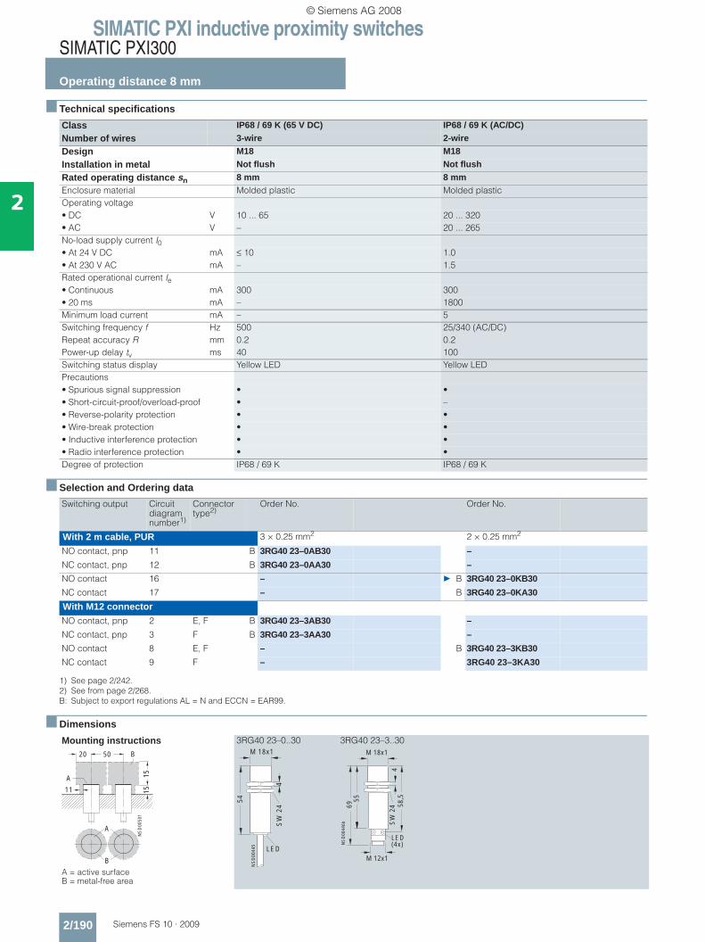
SIMATIC PXI inductive proximity switchesSIMATIC PXI300
Operating distance 8 mm
2/190 Siemens FS 10 · 2009
2
■ Technical specifications
■ Selection and Ordering data
■ Dimensions
Class IP68 / 69 K (65 V DC) IP68 / 69 K (AC/DC)
Number of wires 3-wire 2-wire
Design M18 M18
Installation in metal Not flush Not flush
Rated operating distance sn 8 mm 8 mmEnclosure material Molded plastic Molded plasticOperating voltage• DC V 10 ... 65 20 ... 320• AC V – 20 ... 265No-load supply current I0• At 24 V DC mA ≤ 10 1.0• At 230 V AC mA – 1.5Rated operational current Ie• Continuous mA 300 300• 20 ms mA – 1800Minimum load current mA – 5Switching frequency f Hz 500 25/340 (AC/DC)Repeat accuracy R mm 0.2 0.2Power-up delay tv ms 40 100Switching status display Yellow LED Yellow LEDPrecautions• Spurious signal suppression • •• Short-circuit-proof/overload-proof • –• Reverse-polarity protection • •• Wire-break protection • •• Inductive interference protection • •• Radio interference protection • •Degree of protection IP68 / 69 K IP68 / 69 K
Switching output Circuit diagram number1)
1) See page 2/242.
Connector type2)
2) See from page 2/268.B: Subject to export regulations AL = N and ECCN = EAR99.
Order No. Order No.
With 2 m cable, PUR 3 × 0.25 mm2 2 × 0.25 mm2
NO contact, pnp 11 B 3RG40 23–0AB30 –
NC contact, pnp 12 B 3RG40 23–0AA30 –
NO contact 16 – } B 3RG40 23–0KB30
NC contact 17 – B 3RG40 23–0KA30
With M12 connectorNO contact, pnp 2 E, F B 3RG40 23–3AB30 –
NC contact, pnp 3 F B 3RG40 23–3AA30 –
NO contact 8 E, F – B 3RG40 23–3KB30
NC contact 9 F – 3RG40 23–3KA30
Mounting instructions
A = active surface B = metal-free area
3RG40 23–0..30 3RG40 23–3..30
A
B
NS
D00
501
50
151511
A
B20 M 18x1
NS
D00
445
54
LED
SW
24
4
LED(4x)
55
58,5
69
M 18x1
SW
24
4
M 12x1
NS
D00
446b
© Siemens AG 2008

SIMATIC PXI inductive proximity switchesSIMATIC PXI300
Operating distance 8 mm
2/191Siemens FS 10 · 2009
2
■ Technical specifications
■ Selection and Ordering data
■ Dimensions
Class Increased operating distance Increased operating distance
Number of wires 3-wire 3-wire
Design M18, Shorty M18
Installation in metal Flush Flush
Rated operating distance sn 8 mm 8 mmEnclosure material Brass, nickel-plated Brass, nickel-platedOperating voltage (DC) V 10 ... 34 10 ... 34No-load supply current I0 mA ≤ 10 ≤ 10Rated operational current Ie mA 200 200Switching frequency f Hz 500 500Repeat accuracy R mm 0.2 0.2Power-up delay tv ms 3 3Switching status display Yellow LED Yellow LEDPrecautions• Spurious signal suppression • •• Short-circuit-proof/overload-proof • •• Reverse-polarity protection • •• Wire-break protection • •• Inductive interference protection • •• Radio interference protection • •Degree of protection IP67 IP67
Switching output Circuit diagram number1)
1) See page 2/242.
Connector type2)
2) See from page 2/268.} Preferred type, available from stock.B: Subject to export regulations AL = N and ECCN = EAR99.
Order No. Order No.
With 2 m cable, PUR 3 × 0.25 mm2
NO contact, pnp 11 B 3RG41 13–0AG33 –
With 3 m cable, PUR 3 × 0.25 mm2
NO contact, pnp 11 – B 3RG41 13–0AG01
With M12 connectorNO contact, pnp 2 E, F B 3RG41 13–3AG33 } B 3RG41 13–3AG01
Mounting instructions
A = active surface B = metal-free area
3RG41 13–0..33 3RG41 13–3..33 3RG41 13–0..01 3RG41 13–3..01
A
B
NS
D01
071
30
3
A
B
20
20 M 18x1
NS
D00
447
35
LED
SW
24
4
M 18x1
31
NSD0_00456b
34
45
SW
24
4
LED(4x)
M 12x1
M 18x1
50
NS
D01
067
LED
70 SW
24
4
LED
SgNS
D0_
0106
9a
M 18x1
50
70
52S
W 2
44
M 12x1
© Siemens AG 2008
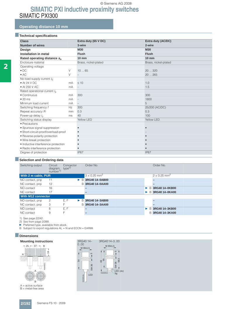
SIMATIC PXI inductive proximity switchesSIMATIC PXI300
Operating distance 10 mm
2/192 Siemens FS 10 · 2009
2
■ Technical specifications
■ Selection and Ordering data
■ Dimensions
Class Extra duty (65 V DC) Extra duty (AC/DC)
Number of wires 3-wire 2-wire
Design M30 M30
Installation in metal Flush Flush
Rated operating distance sn 10 mm 10 mmEnclosure material Brass, nickel-plated Brass, nickel-platedOperating voltage• DC V 10 ... 65 20 ... 320• AC V – 20 ... 265No-load supply current I0• At 24 V DC mA ≤ 10 1.0• At 230 V AC mA – 1.5Rated operational current Ie• Continuous mA 300 300• 20 ms mA – 1800Minimum load current mA – 5Switching frequency f Hz 300 25/200 (AC/DC)Repeat accuracy R mm 0.3 0.3Power-up delay tv ms 40 100Switching status display Yellow LED Yellow LED• Precautions• Spurious signal suppression • •• Short-circuit-proof/overload-proof • –• Reverse-polarity protection • •• Wire-break protection • •• Inductive interference protection • •• Radio interference protection • •Degree of protection IP67 IP67
Switching output Circuit diagram number1)
1) See page 2/242.
Connector type2)
2) See from page 2/268.} Preferred type, available from stock.B: Subject to export regulations AL = N and ECCN = EAR99.
Order No. Order No.
With 2 m cable, PUR 3 × 0.25 mm2 2 × 0.25 mm2
NO contact, pnp 11 } B 3RG40 14–0AB00 –NC contact, pnp 12 B 3RG40 14–0AA00 –NO contact 16 – } B 3RG40 14–0KB00NC contact 17 – } B 3RG40 14–0KA00With M12 connectorNO contact, pnp 2 E, F } B 3RG40 14–3AB00 –NC contact, pnp 3 F B 3RG40 14–3AA00 –NO contact 8 E, F – } B 3RG40 14–3KB00NC contact 9 F – B 3RG40 14–3KA00
Mounting instructions
A = active surface B = metal-free area
3RG40 14–0..00
3RG40 14–3..00
A
B
NS
D00
521
25 37
16
A
B
NS
D00
518a
M 30x1,5
LED
54
SW
36
5
NSD00519
M 30x1,5
5569
LED (4x)
58,5
SW
36
5
Sg
© Siemens AG 2008

SIMATIC PXI inductive proximity switchesSIMATIC PXI300
Operating distance 10 mm
2/193Siemens FS 10 · 2009
2
■ Technical specifications
■ Selection and Ordering data
■ Dimensions
Class IP68 / 69 K IP68 / 69 K
Number of wires 3-wire 3-wire
Design Ø 30 mm M30
Installation in metal Flush Flush
Rated operating distance sn 10 mm 10 mmEnclosure material Molded plastic Molded plasticOperating voltage (DC) V 15 ... 34 15 ... 34No-load supply current I0 mA ≤ 17 (24 V); ≤ 30 (34 V) ≤ 17 (24 V); ≤ 30 (34 V)Rated operational current Ie mA 200 (≤ 50 °C); 150 (≤ 85 °C) 200 (≤ 50 °C); 150 (≤ 85 °C)Switching frequency f Hz 300 300Repeat accuracy R mm 0.3 0.3Power-up delay tv ms 40 40Switching status display Yellow LED Yellow LEDPrecautions• Spurious signal suppression • •• Short-circuit-proof/overload-proof • •• Reverse-polarity protection • •• Wire-break protection • •• Inductive interference protection • •• Radio interference protection • •Degree of protection IP68 / 69 K IP68 / 69 K
Switching output Circuit diagram number1)
1) See page 2/242.B: Subject to export regulations AL = N and ECCN = EAR99.
Order No. Order No.
With 2 m cable PUR, 3 × 0.25 mm2 PUR, 3 × 0.25 mm2
NO contact, pnp 11 B 3RG40 54–0AG30 B 3RG40 14–0AG30
NC contact, pnp 12 B 3RG40 54–0AF30 B 3RG40 14–0AF30
NO contact, npn 13 B 3RG40 54–0GB30 B 3RG40 14–0GB30
NC contact, npn 14 B 3RG40 54–0GA30 B 3RG40 14–0GA30
Mounting instructions
A = active surface B = metal-free area
3RG40 54–0..30 3RG40 14–0..30
A
B
NS
D00
522
25 45
16A
B
NS
D0_
0052
5a
LED
54
30
NS
D00
518a
M 30x1,5
LED
54
SW
36
5
© Siemens AG 2008
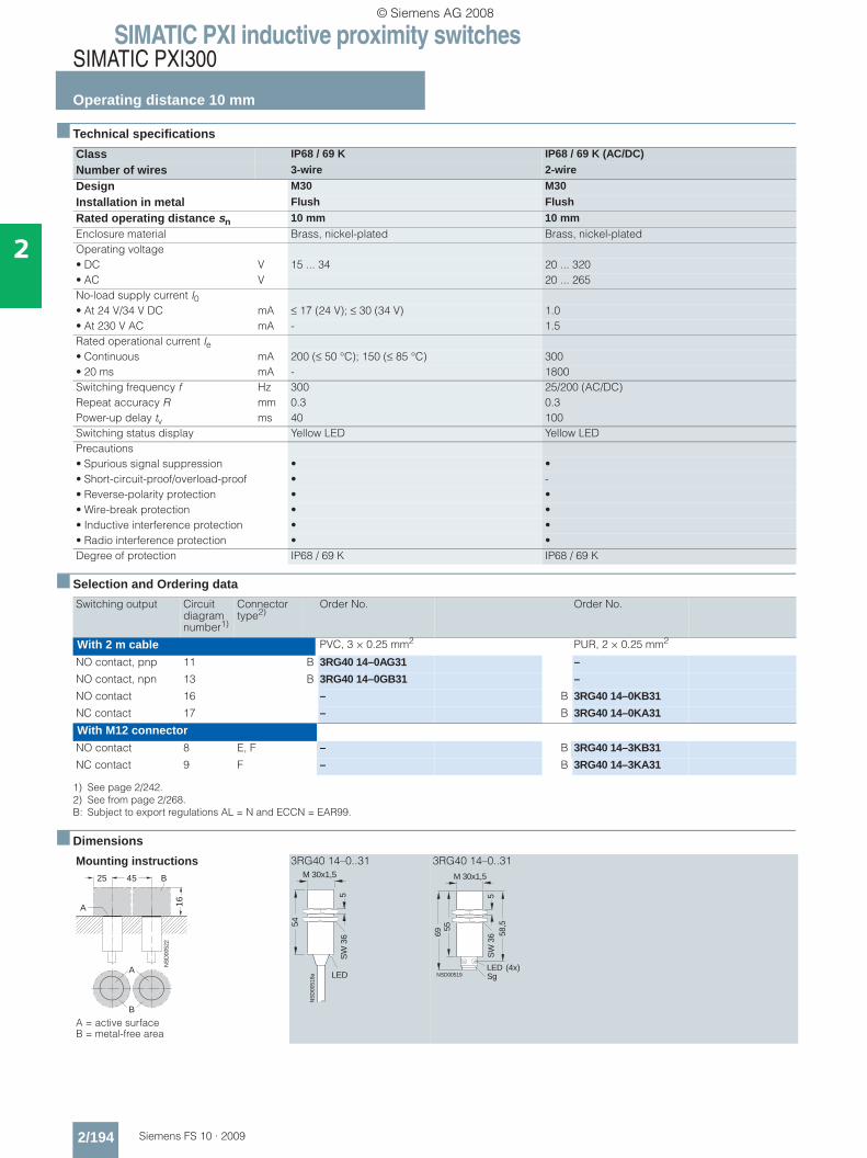
SIMATIC PXI inductive proximity switchesSIMATIC PXI300
Operating distance 10 mm
2/194 Siemens FS 10 · 2009
2
■ Technical specifications
■ Selection and Ordering data
■ Dimensions
Class IP68 / 69 K IP68 / 69 K (AC/DC)
Number of wires 3-wire 2-wire
Design M30 M30
Installation in metal Flush Flush
Rated operating distance sn 10 mm 10 mmEnclosure material Brass, nickel-plated Brass, nickel-platedOperating voltage• DC V 15 ... 34 20 ... 320• AC V 20 ... 265No-load supply current I0• At 24 V/34 V DC mA ≤ 17 (24 V); ≤ 30 (34 V) 1.0• At 230 V AC mA - 1.5Rated operational current Ie• Continuous mA 200 (≤ 50 °C); 150 (≤ 85 °C) 300 • 20 ms mA - 1800Switching frequency f Hz 300 25/200 (AC/DC) Repeat accuracy R mm 0.3 0.3Power-up delay tv ms 40 100Switching status display Yellow LED Yellow LEDPrecautions• Spurious signal suppression • •• Short-circuit-proof/overload-proof • -• Reverse-polarity protection • •• Wire-break protection • •• Inductive interference protection • •• Radio interference protection • •Degree of protection IP68 / 69 K IP68 / 69 K
Switching output Circuit diagram number1)
1) See page 2/242.
Connector type2)
2) See from page 2/268.B: Subject to export regulations AL = N and ECCN = EAR99.
Order No. Order No.
With 2 m cable PVC, 3 × 0.25 mm2 PUR, 2 × 0.25 mm2
NO contact, pnp 11 B 3RG40 14–0AG31 –
NO contact, npn 13 B 3RG40 14–0GB31 –
NO contact 16 – B 3RG40 14–0KB31
NC contact 17 – B 3RG40 14–0KA31
With M12 connectorNO contact 8 E, F – B 3RG40 14–3KB31
NC contact 9 F – B 3RG40 14–3KA31
Mounting instructions
A = active surface B = metal-free area
3RG40 14–0..31 3RG40 14–0..31
A
B
NS
D00
522
25 45
16A
B
NS
D00
518a
M 30x1,5
LED
54
SW
36
5
NSD00519
M 30x1,5
5569
LED (4x)
58,5
SW
36
5
Sg
© Siemens AG 2008
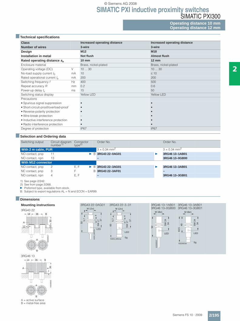
SIMATIC PXI inductive proximity switchesSIMATIC PXI300
Operating distance 10 mmOperating distance 12 mm
2/195Siemens FS 10 · 2009
2
■ Technical specifications
■ Selection and Ordering data
■ Dimensions
Class Increased operating distance Increased operating distance
Number of wires 3-wire 3-wire
Design M12 M18
Installation in metal Not flush Almost flush
Rated operating distance sn 10 mm 12 mmEnclosure material Brass, nickel-plated Brass, nickel-platedOperating voltage (DC) V 10 ... 30 10 ... 30No-load supply current I0 mA 10 ≤ 10Rated operational current Ie mA 200 200Switching frequency f Hz 400 500Repeat accuracy R mm 0.2 0.6Power-up delay tv ms 15 50Switching status display Yellow LED Yellow LEDPrecautions• Spurious signal suppression • •• Short-circuit-proof/overload-proof • •• Reverse-polarity protection • •• Wire-break protection – •• Inductive interference protection • •• Radio interference protection • •Degree of protection IP67 IP67
Switching output Circuit diagram number1)
1) See page 2/242.
Connector type2)
2) See from page 2/268.} Preferred type, available from stock.B: Subject to export regulations AL = N and ECCN = EAR99.
Order No. Order No.
With 2 m cable, PUR 3 × 0.34 mm2 3 × 0.34 mm2
NO contact, pnp 11 } B 3RG43 22–0AG01 } 3RG46 13–1AB01NO contact, npn 13 – 3RG46 13–0GB00With M12 connectorNO contact, pnp 2 E, F } B 3RG43 22–3AG01 } 3RG46 13–3AB01NC contact, pnp 3 F B 3RG43 22–3AF01 –NO contact, npn 4 E, F – 3RG46 13–3GB01
Mounting instructions
3RG43 22
3RG43 22–0AG01 3RG43 22–3..01 3RG46 13–1AB013RG46 13–0GB00
3RG46 13–3AB013RG46 13–3GB01
3RG46 13
A = active surface B = metal-free area
NS
D00
517
36
301012
A
B
A
B
18
NS
D0_
0051
3a
5,7
M 12x1
50
4S
W 1
7 37
LED
5,7
NSD0_00514a
60
Sg
M 12x1
4
37S
W 1
7
LED
50
34
M 18x1
LED
NS
D00
537
SW
24
40 34
M 18x1
LED
NSD00538Sg
SW
24
63,5
A
B
NS
D00
543
36
36A
B14
4
© Siemens AG 2008

SIMATIC PXI inductive proximity switchesSIMATIC PXI300
Operating distance 15 mm
2/196 Siemens FS 10 · 2009
2
■ Technical specifications
■ Selection and Ordering data
■ Dimensions
Class Extra duty (65 V DC) Extra duty (AC/DC)
Number of wires 3-wire 2-wire
Design M30 M30
Installation in metal Not flush Not flush
Rated operating distance sn 15 mm 15 mmEnclosure material Brass, nickel-plated Brass, nickel-platedOperating voltage• DC V 10 ... 65 20 ... 320• AC V – 20 ... 265No-load supply current I0• At 24 V DC mA ≤ 10 1.0• At 230 V AC mA – 1.5Rated operational current Ie• Continuous mA 300 300• 20 ms mA – 1800Minimum load current mA – 5Switching frequency f Hz 300 25/220 (AC/DC)Repeat accuracy R mm 0.4 0.4Power-up delay tv ms 40 100Switching status display Yellow LED Yellow LEDPrecautions• Spurious signal suppression • •• Short-circuit-proof/overload-proof • –• Reverse-polarity protection • •• Wire-break protection • •• Inductive interference protection • •• Radio interference protection • •Degree of protection IP67 IP67
Switching output Circuit diagram number1)
1) See page 2/242.
Connector type2)
2) See from page 2/268.} Preferred type, available from stock.B: Subject to export regulations AL = N and ECCN = EAR99.
Order No. Order No.
With 2 m cable, PUR 3 × 0.25 mm2 2 × 0.25 mm2
NO contact, pnp 11 B 3RG40 24–0AB00 –
NC contact, pnp 12 B 3RG40 24–0AA00 –
NO contact 16 – } B 3RG40 24–0KB00
NC contact 17 – } B 3RG40 24–0KA00
With M12 connectorNO contact, pnp 2 E, F } B 3RG40 24–3AB00 –
NC contact, pnp 3 F B 3RG40 24–3AA00 –
NO contact 8 E, F – } B 3RG40 24–3KB00
NC contact 9 F – B 3RG40 24–3KA00
Mounting instructions
A = active surface B = metal-free area
3RG40 24–0..00
3RG40 24–3..00
A
B
NS
D00
548
30 80
25
1515
A
B
54
M 30x1,5
16
NS
D0_
0054
4b
LED
SW
36
5
LED(4x)
55
M 30x1,5
16
NSD00545b
69 58,5
SW
36
5
M 12x1
© Siemens AG 2008

SIMATIC PXI inductive proximity switchesSIMATIC PXI300
Operating distance 15 mm
2/197Siemens FS 10 · 2009
2
■ Technical specifications
■ Selection and Ordering data
■ Dimensions
Class Extra duty (65 V DC) Extra duty (AC/DC)
Number of wires 3-wire 2-wire
Design Cubic 40 mm × 40 mm Cubic 40 mm × 40 mm
Installation in metal Flush Flush
Rated operating distance sn 15 mm 15 mmEnclosure material Molded plastic Molded plasticOperating voltage• DC V 10 ... 65 20 ... 320• AC V – 20 ... 265No-load supply current I0• At 24 V DC mA ≤ 20 1.0• At 230 V AC mA – 1.5Rated operational current Ie• Continuous mA 300 300• 20 ms mA – 1800Minimum load current mA – 5Switching frequency f Hz 100 25/150 (AC/DC)Repeat accuracy R mm 0.75 0.75Power-up delay tv ms 100 100LEDs• Switching status Yellow LED Yellow LED• Supply voltage Green LED –Precautions• Spurious signal suppression • •• Short-circuit-proof/overload-proof • –• Reverse-polarity protection • •• Wire-break protection • •• Inductive interference protection • •• Radio interference protection • •Degree of protection IP65 IP65
Switching output Circuit diagram number1)
1) See page 2/242.} Preferred type, available from stock.B: Subject to export regulations AL = N and ECCN = EAR99.
Order No. Order No.
With terminal box 0.5 ... 2.5 mm2 0.5 ... 2.5 mm2
NO contact or NC contact reposi-tionable, pnp
23 } B 3RG40 31–6AD00 –
NO contact or NC contact reposi-tionable
24 – } B 3RG40 31–6KD00
Mounting instructions
A = active surface B = metal-free area
3RG40 31–6AD00
The active surface can be adjusted in 5 directions.
3RG40 31–6KD00
The active surface can be adjusted in 5 directions.
NSD 01164
25 75 B
A 30
A
B
��
��
��
� �
� � � � � � �
� � �
��
� �
� � �
� �
�����������
� � �
� � � � �� �
� �
� �
45
60
12
0
30
40
40 40
NS
D0
_0
05
60
a
LED
14
5,3
7,3 × 5,3M 20×1,5
YE
© Siemens AG 2008
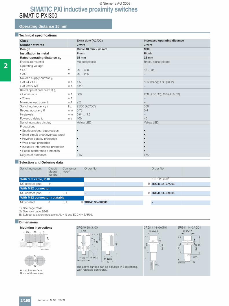
SIMATIC PXI inductive proximity switchesSIMATIC PXI300
Operating distance 15 mm
2/198 Siemens FS 10 · 2009
2
■ Technical specifications
■ Selection and Ordering data
■ Dimensions
Class Extra duty (AC/DC) Increased operating distance
Number of wires 2-wire 3-wire
Design Cubic 40 mm × 40 mm M30
Installation in metal Flush Flush
Rated operating distance sn 15 mm 15 mmEnclosure material Molded plastic Brass, nickel-platedOperating voltage• DC V 20 ... 320 15 ... 34• AC V 20 ... 265 –No-load supply current I0• At 24 V DC mA 1.5 ≤ 17 (24 V); ≤ 30 (34 V)• At 230 V AC mA ≤ 2.0 –Rated operational current Ie• Continuous mA 300 200 (≤ 50 °C); 150 (≤ 85 °C)• 20 ms mA –Minimum load current mA ≤ 2 –Switching frequency f Hz 25/50 (AC/DC) 300Repeat accuracy R mm 0.75 0.4Hysteresis mm 0.04 ... 3.3 –Power-up delay tv ms 100 40Switching status display Yellow LED Yellow LEDPrecautions• Spurious signal suppression • •• Short-circuit-proof/overload-proof – •• Reverse-polarity protection • •• Wire-break protection – •• Inductive interference protection • •• Radio interference protection • •Degree of protection IP67 IP67
Switching output Circuit diagram number1)
1) See page 2/242.
Connector type2)
2) See from page 2/268.B: Subject to export regulations AL = N and ECCN = EAR99.
Order No. Order No.
With 3 m cable, PUR 3 × 0.25 mm2
NO contact, pnp 11 – B 3RG41 14–0AG01
With M12 connectorNO contact, pnp 2 E, F – B 3RG41 14–3AG01
With M12 connector, rotatableNO contact 8 E, F B 3RG40 38–3KB00 –
Mounting instructions
A = active surface B = metal-free area
3RG40 38–3..00
The active surface can be adjusted in 5 directions. With rotatable connector..
3RG41 14–0AG01 3RG41 14–3AG01
NSD 01164
25 75 B
A 30
A
B
4030 5,3x7,3
46
55
40
NS
D 0
1163
LED
69
40
M 12x1
NS
D00
554
LED
M 30x1,5
7050
SW
36
5
LED
Sg
52
7050
NSD00555
M 30x1,5
SW
36
5
© Siemens AG 2008

SIMATIC PXI inductive proximity switchesSIMATIC PXI300
Operating distance 15 mm
2/199Siemens FS 10 · 2009
2
■ Technical specifications
■ Selection and Ordering data
■ Dimensions
Class IP68 / 69 K IP68 / 69 K IP68 / 69 K
Number of wires 3-wire 3-wire 3-wire
Design Ø 30 mm M30 M30
Installation in metal Not flush Not flush Not flush
Rated operating distance sn 15 mm 15 mm 15 mmEnclosure material Molded plastic Molded plastic Brass, nickel-platedOperating voltage (DC) V 15 ... 34 15 ... 34 15 ... 34No-load supply current I0 mA ≤ 17 (24 V); ≤ 30 (34 V) ≤ 17 (24 V); ≤ 30 (34 V) ≤ 17 (24 V); ≤ 30 (34 V)Rated operational current Ie mA 200 (≤ 50 °C); 150 (≤ 85 °C) 200 (≤ 50 °C); 150 (≤ 85 °C) 200 (≤ 50 °C); 150 (≤ 85 °C)Switching frequency f Hz 300 300 300Repeat accuracy R mm 0.4 0.4 0.4Power-up delay tv ms 40 40 40Switching status display Yellow LED Yellow LED Yellow LEDPrecautions• Spurious signal suppression • • •• Short-circuit-proof/overload-proof • • •• Reverse-polarity protection • • •• Wire-break protection • • •• Inductive interference protection • • •• Radio interference protection • • •Degree of protection IP68 / 69 K IP68 / 69 K IP68 / 69 K
Switching output Circuit diagram number1)
1) See page 2/242.
Connector type2)
2) See from page 2/268.B: Subject to export regulations AL = N and ECCN = EAR99.
Order No. Order No. Order No.
With 2 m cable PUR, 3 × 0.25 mm2 PUR, 3 × 0.25 mm2 PVC, 3 × 0.25 mm2
NO contact, pnp 11 B 3RG40 64–0AG30 B 3RG40 24–0AG30 B 3RG40 24–0AG31
NC contact, pnp 12 B 3RG40 64–0AF30 B 3RG40 24–0AF30 –
NO contact, npn 13 B 3RG40 64–0GB30 B 3RG40 24–0GB30 B 3RG40 24–0GB31
NC contact, npn 14 B 3RG40 64–0GA30 B 3RG40 24–0GA30 –
With M12 connectorNO contact, pnp 8 E, F – B 3RG40 24–3AG30 B 3RG40 24–3AG31
NC contact, pnp 9 F – B 3RG40 24–3AF30 –
Mounting instructions
A = active surface B = metal-free area
3RG40 64–0..30 3RG40 24–0..30 3RG40 24–3..30 3RG40 24–0..31 3RG40 24–3..31
A
B
NS
D00
548
30 80
25
1515
A
B
NS
D0_
0052
5a
LED
54
30
NS
D00
518a
M 30x1,5
LED
54
SW
36
5
NSD00519
M 30x1,5
5569
LED (4x)
58,5
SW
36
5
Sg
54
M 30x1,5
16
NS
D0_
0054
4b
LED
SW
36
5
LED(4x)
55
M 30x1,5
16
NSD00545b
69 58,5
SW
36
5
M 12x1
© Siemens AG 2008

SIMATIC PXI inductive proximity switchesSIMATIC PXI300
Operating distance 15 mm
2/200 Siemens FS 10 · 2009
2
■ Technical specifications
■ Selection and Ordering data
■ Dimensions
Class IP68 / 69 K (DC 65 V) IP68 / 69 K (AC/DC)
Number of wires 3-wire 2-wire
Design M30 M30
Installation in metal Not flush Not flush
Rated operating distance sn 15 mm 15 mmEnclosure material Molded plastic Molded plasticOperating voltage• DC V 10 ... 65 20 ... 320• AC V – 20 ... 265No-load supply current I0• At 24 V DC mA ≤ 10 1.0• At 230 V AC mA – 1.5Rated operational current Ie• Continuous mA 300 300• 20 ms mA – 1800Minimum load current mA – 5Switching frequency f Hz 300 25/220 (AC/DC)Repeat accuracy R mm 0.4 0.4Power-up delay tv ms 40 100Switching status display Yellow LED Yellow LEDPrecautions• Spurious signal suppression • •• Short-circuit-proof/overload-proof • –• Reverse-polarity protection • •• Wire-break protection • •• Inductive interference protection • •• Radio interference protection • •Degree of protection IP68 / 69 K IP68 / 69 K
Switching output Circuit diagram number1)
1) See page 2/242.
Connector type2)
2) See from page 2/268.} Preferred type, available from stock.B: Subject to export regulations AL = N and ECCN = EAR99.
Order No. Order No.
With 2 m cable, PUR 3 × 0.25 mm2 2 × 0.25 mm2
NO contact, pnp 11 B 3RG40 24–0AB30 –NC contact, pnp 12 B 3RG40 24–0AA30 –NO contact 16 – } B 3RG40 24–0KB30NC contact 17 – B 3RG40 24–0KA30With M12 connectorNO contact, pnp 2 E, F B 3RG40 24–3AB30 –NC contact, pnp 3 F B 3RG40 24–3AA30 –NO contact 8 E, F – B 3RG40 24–3KB30NC contact 9 F – B 3RG40 24–3KA30
Mounting instructions
A = active surface B = metal-free area
3RG40 24–0..30 3RG40 24–3..30
A
B
NS
D00
548
30 80
25
1515
A
B
NS
D00
518a
M 30x1,5
LED
54
SW
36
5
NSD00519
M 30x1,5
5569
LED (4x)
58,5
SW
36
5
Sg
© Siemens AG 2008
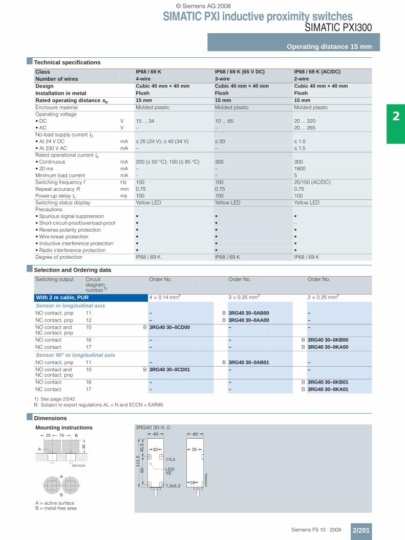
SIMATIC PXI inductive proximity switchesSIMATIC PXI300
Operating distance 15 mm
2/201Siemens FS 10 · 2009
2
■ Technical specifications
■ Selection and Ordering data
■ Dimensions
Class IP68 / 69 K IP68 / 69 K (65 V DC) IP68 / 69 K (AC/DC)Number of wires 4-wire 3-wire 2-wireDesign Cubic 40 mm × 40 mm Cubic 40 mm × 40 mm Cubic 40 mm × 40 mmInstallation in metal Flush Flush FlushRated operating distance sn 15 mm 15 mm 15 mmEnclosure material Molded plastic Molded plastic Molded plasticOperating voltage• DC V 15 ... 34 10 ... 65 20 ... 320• AC V – – 20 ... 265No-load supply current I0• At 24 V DC mA ≤ 25 (24 V); ≤ 40 (34 V) ≤ 20 ≤ 1.0• At 230 V AC mA – – ≤ 1.5Rated operational current Ie• Continuous mA 200 (≤ 50 °C); 150 (≤ 85 °C) 300 300• 20 ms mA – – 1800Minimum load current mA – – 5Switching frequency f Hz 100 100 25/150 (AC/DC)Repeat accuracy R mm 0.75 0.75 0.75Power-up delay tv ms 100 100 100Switching status display Yellow LED Yellow LED Yellow LEDPrecautions• Spurious signal suppression • • •• Short-circuit-proof/overload-proof • • –• Reverse-polarity protection • • •• Wire-break protection • • •• Inductive interference protection • • •• Radio interference protection • • •Degree of protection IP68 / 69 K IP68 / 69 K IP68 / 69 K
Switching output Circuit diagram number1)
1) See page 2/242.B: Subject to export regulations AL = N and ECCN = EAR99.
Order No. Order No. Order No.
With 2 m cable, PUR 4 × 0.14 mm2 3 × 0.25 mm2 2 × 0.25 mm2
Sensor in longitudinal axisNO contact, pnp 11 – B 3RG40 30–0AB00 –NC contact, pnp 12 – B 3RG40 30–0AA00 –NO contact and NC contact, pnp
10 B 3RG40 30–0CD00 – –
NO contact 16 – – B 3RG40 30–0KB00NC contact 17 – – B 3RG40 30–0KA00
Sensor 90° to longitudinal axisNO contact, pnp 11 – B 3RG40 30–0AB01 –NO contact and NC contact, pnp
10 B 3RG40 30–0CD01 – –
NO contact 16 – – B 3RG40 30–0KB01NC contact 17 – – B 3RG40 30–0KA01
Mounting instructions
A = active surface B = metal-free area
3RG40 30–0..0.
NSD 01164
25 75 B
A 30
A
B
40
30
11
1,5
LED
45
,56
0
7,3x5,328
NS
D00
561
40
35
5,3
YE
© Siemens AG 2008

SIMATIC PXI inductive proximity switchesSIMATIC PXI300
Operating distance 20 mm
2/202 Siemens FS 10 · 2009
2
■ Technical specifications
■ Selection and Ordering data
■ Dimensions
Class Extra duty (65 V DC) Extra duty (AC/DC)
Number of wires 3-wire 2-wire
Design Cubic 40 mm × 40 mm Cubic 40 mm × 40 mm
Installation in metal Not flush Not flush
Rated operating distance sn 20 mm 20 mmEnclosure material Molded plastic Molded plasticOperating voltage• DC V 10 ... 65 20 ... 320• AC V – 20 ... 265No-load supply current I0• At 24 V DC mA ≤ 20 1.0• At 230 V AC mA – 1.5Rated operational current Ie• Continuous mA 300 300• 20 ms mA – 1800Minimum load current mA – 5Switching frequency f Hz 75 25/100 (AC/DC)Repeat accuracy R mm 0.75 1.0Power-up delay tv ms 100 20LEDs• Switching status Yellow LED Yellow LED• Supply voltage Green LED –Precautions• Spurious signal suppression • •• Short-circuit-proof/overload-proof • –• Reverse-polarity protection • •• Wire-break protection • •• Inductive interference protection • •• Radio interference protection • •Degree of protection IP65 IP65
Switching output Circuit diagram number1)
1) See page 2/242.} Preferred type, available from stock.B: Subject to export regulations AL = N and ECCN = EAR99.
Order No. Order No.
With terminal box 0.5 ... 2.5 mm2 0.5 ... 2.5 mm2
NO contact or NC contact reposi-tionable, pnp
23 } B 3RG40 41–6AD00 –
NO contact or NC contact reposi-tionable
24 – } B 3RG40 41–6KD00
Mounting instructions
A = active surface; B = metal-free area
3RG40 41–6AD00
The active surface can be adjusted in 5 directions.
3RG40 41–6KD00
The active surface can be adjusted in 5 directions.
NS
D00
583
100
40
4050
A
B
A
B
70
��
��
��
� �
� � � � � � �
� � �
��
� �
� � �
� �
�����������
� � �
� � � � �� �
� �
� �
45
60
12
0
30
40
40 40
NS
D0
_0
05
60
a
LED
14
5,3
7,3 × 5,3M 20×1,5
YE
© Siemens AG 2008

SIMATIC PXI inductive proximity switchesSIMATIC PXI300
Operating distance 20 mm
2/203Siemens FS 10 · 2009
2
■ Technical specifications
■ Selection and Ordering data
■ Dimensions
Class Increased operating distance Increased operating distance Number of wires 3-wire 4-wireDesign M18 Cubic 40 mm × 40 mmInstallation in metal Not flush FlushRated operating distance sn 20 mm 20 mmEnclosure material Brass, nickel-plated Molded plasticOperational voltage (DC) V 10 ... 30 15 ... 34No-load supply current I0 mA ≤ 10 ≤ 30 (24 V); ≤ 50 (34 V)Rated operational current Ie mA 200 200 (≤ 50 °C); 150 (≤ 85 °C)Switching frequency f Hz 200 30Repeat accuracy R mm 1.0 1.5Power-up delay tv ms 100 100LEDs• Switching status Yellow LED Yellow LED• Supply voltage – Green LEDPrecautions• Spurious signal suppression • •• Short-circuit-proof/overload-proof • •• Reverse-polarity protection • •• Wire-break protection • •• Inductive interference protection • •• Radio interference protection • •Degree of protection IP67 IP65
Switching output Circuit diagram number1)
1) See page 2/242.
Connector type2)
2) See from page 2/268.} Preferred type, available from stock.B: Subject to export regulations AL = N and ECCN = EAR99.
Order No. Order No.
With 2 m cable, PUR 3 × 0.34 mm2
NO contact, pnp 11 } 3RG46 23–0AB02 –NO contact, npn 13 3RG46 23–0GB02 –With M12 connectorNO contact, pnp 2 E, F } 3RG46 23–3AB02 –NO contact, npn 4 E, F 3RG46 23–3GB02 –With terminal box 0.5 ... 2.5 mm2
NO contact and NC contact, pnp
18 – B 3RG41 34–6CD01
Mounting instructions
3RG46 23
3RG46 23–0..02 3RG46 23–3..02 3RG41 34–6CD01
The active surface can be adjusted in 5 directions. With screwed sensor.
3RG41 34 A = active surface B = metal-free area
A
B
NS
D00
574a
100
80A
B36
20
10
SW
24
34
M 18x1
LED
NS
D00
571
50
10
34
M 18x1
LED
63,5
NSD00572Sg
SW
24
40
45
60
11
8
30
5,3
40
40
LED
40
NS
D0
_0
05
70
a
LED
14
7,3×5,3
M 20×1,5
GN
YE
NSD01074
80
60
A
B40
A
B
© Siemens AG 2008
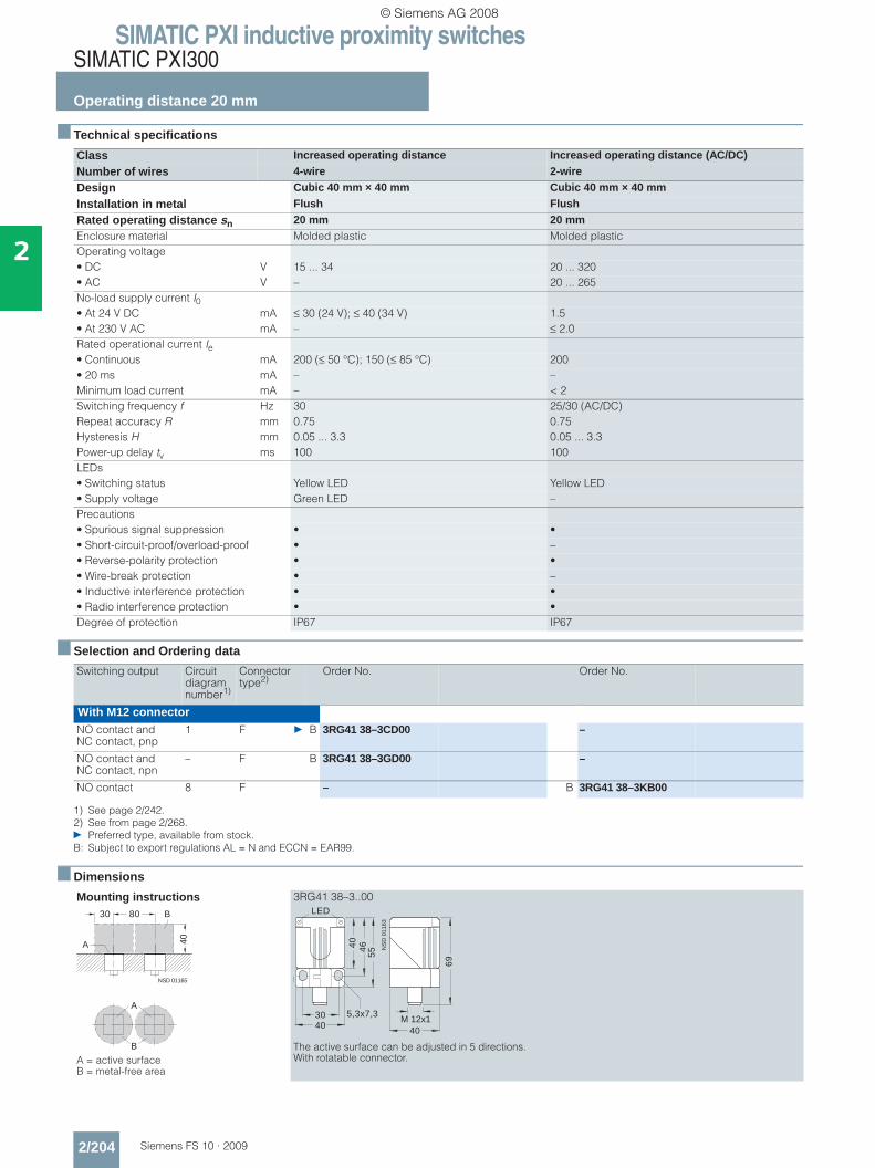
SIMATIC PXI inductive proximity switchesSIMATIC PXI300
Operating distance 20 mm
2/204 Siemens FS 10 · 2009
2
■ Technical specifications
■ Selection and Ordering data
■ Dimensions
Class Increased operating distance Increased operating distance (AC/DC)
Number of wires 4-wire 2-wire
Design Cubic 40 mm × 40 mm Cubic 40 mm × 40 mm
Installation in metal Flush Flush
Rated operating distance sn 20 mm 20 mmEnclosure material Molded plastic Molded plasticOperating voltage• DC V 15 ... 34 20 ... 320• AC V – 20 ... 265No-load supply current I0• At 24 V DC mA ≤ 30 (24 V); ≤ 40 (34 V) 1.5• At 230 V AC mA – ≤ 2.0Rated operational current Ie• Continuous mA 200 (≤ 50 °C); 150 (≤ 85 °C) 200• 20 ms mA – –Minimum load current mA – < 2Switching frequency f Hz 30 25/30 (AC/DC)Repeat accuracy R mm 0.75 0.75Hysteresis H mm 0.05 ... 3.3 0.05 ... 3.3Power-up delay tv ms 100 100LEDs• Switching status Yellow LED Yellow LED• Supply voltage Green LED –Precautions• Spurious signal suppression • •• Short-circuit-proof/overload-proof • –• Reverse-polarity protection • •• Wire-break protection • –• Inductive interference protection • •• Radio interference protection • •Degree of protection IP67 IP67
Switching output Circuit diagram number1)
1) See page 2/242.
Connector type2)
2) See from page 2/268.} Preferred type, available from stock.B: Subject to export regulations AL = N and ECCN = EAR99.
Order No. Order No.
With M12 connectorNO contact and NC contact, pnp
1 F } B 3RG41 38–3CD00 –
NO contact and NC contact, npn
– F B 3RG41 38–3GD00 –
NO contact 8 F – B 3RG41 38–3KB00
Mounting instructions
A = active surface B = metal-free area
3RG41 38–3..00
The active surface can be adjusted in 5 directions. With rotatable connector.
NSD 01165
30 80 B
A 40
A
B
4030 5,3x7,3
46
55
40
NS
D 0
1163
LED
69
40
M 12x1
© Siemens AG 2008

SIMATIC PXI inductive proximity switchesSIMATIC PXI300
Operating distance 22 mm
2/205Siemens FS 10 · 2009
2
■ Technical specifications
■ Selection and Ordering data
■ Dimensions
Class Increased operating distance
Number of wires 3-wire
Design M30
Installation in metal Almost flush
Rated operating distance sn 22 mmEnclosure material Brass, nickel-platedOperational voltage (DC) V 10 ... 30No-load supply current I0 mA ≤ 10Rated operational current Ie mA 200Switching frequency f Hz 100Repeat accuracy R mm 1.1Power-up delay tv ms 200LEDs• Switching status Yellow LED• Supply voltage –Precautions• Spurious signal suppression •• Short-circuit-proof/overload-proof •• Reverse-polarity protection •• Wire-break protection •• Inductive interference protection •• Radio interference protection •Degree of protection IP67
Switching output Circuit diagram number1)
1) See page 2/242.
Connector type2)
2) See from page 2/268.} Preferred type, available from stock.
Order No.
With 2 m cable, PUR 3 × 0.34 mm2
NO contact, pnp 11 } 3RG46 14–0AB00
NO contact, npn 13 3RG46 14–0GB00
With M12 connectorNO contact, pnp 2 E, F } 3RG46 14–3AB00
NO contact, npn 4 E, F 3RG46 14–3GB00
Mounting instructions
A = active surface B = metal-free area
3RG46 14–0..00 3RG46 14–3..00
A
B
NS
D00
593a
80
66A
B37
6
60
SW
36
45
M 30x1,5
LED
NS
D00
589
73,5
SW
36
45
M 30x1,5
LED
NSD00590Sg
50
© Siemens AG 2008

SIMATIC PXI inductive proximity switchesSIMATIC PXI300
Operating distance 25 mm
2/206 Siemens FS 10 · 2009
2
■ Technical specifications
■ Selection and Ordering data
■ Dimensions
Class Increased operating distance (65 V DC)
Number of wires 3-wire
Design Cubic 40 mm × 40 mm
Installation in metal Almost flush
Rated operating distance sn 25 mmEnclosure material Molded plasticOperating voltage (DC) V 10 ... 65No-load supply current I0 mA 20Rated operational current Ie mA 300Switching frequency f Hz 50Repeat accuracy R mm 1.5Power-up delay tv ms 100LEDs• Switching status Yellow LED• Supply voltage Green LEDPrecautions• Spurious signal suppression •• Short-circuit-proof/overload-proof •• Reverse-polarity protection •• Wire-break protection •• Inductive interference protection •• Radio interference protection •Degree of protection IP65
Switching output Circuit diagram number1)
1) See page 2/242.} Preferred type, available from stock.B: Subject to export regulations AL = N and ECCN = EAR99.
Order No.
With terminal box 0.5 ... 2.5 mm2
NO contact or NC contact reposi-tionable, pnp
23 } B 3RG41 31–6AD00
Mounting instructions
3RG41 31
A = active surface B = metal-free area
3RG41 31–6AD0.
The active surface can be adjusted in 5 directions.
NS
D00
595a
90 180
75
A
B
5
A
B
��
��
��
� �
� � � � � � �
� � �
��
� �
� � �
� �
�����������
� � �
� � � � �� �
� �
� �
© Siemens AG 2008
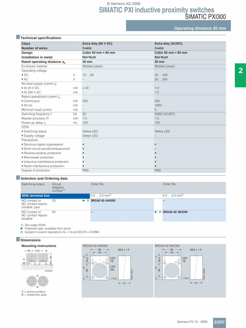
SIMATIC PXI inductive proximity switchesSIMATIC PXI300
Operating distance 30 mm
2/207Siemens FS 10 · 2009
2
■ Technical specifications
■ Selection and Ordering data
■ Dimensions
Class Extra duty (65 V DC) Extra duty (AC/DC)
Number of wires 3-wire 2-wire
Design Cubic 60 mm × 80 mm Cubic 60 mm × 80 mm
Installation in metal Not flush Not flush
Rated operating distance sn 30 mm 30 mmEnclosure material Molded plastic Molded plasticOperating voltage• DC V 10 ... 65 20 ... 320• AC V – 20 ... 265No-load supply current I0• At 24 V DC mA ≤ 40 1.0• At 230 V AC mA – 1.5Rated operational current Ie• Continuous mA 300 300• 20 ms mA – 1800Minimum load current mA – 5Switching frequency f Hz 50 25/60 (AC/DC)Repeat accuracy R mm 1.0 1.0Power-up delay tv ms 100 100LEDs• Switching status Yellow LED Yellow LED• Supply voltage Green LED –Precautions• Spurious signal suppression • •• Short-circuit-proof/overload-proof • –• Reverse-polarity protection • •• Wire-break protection • •• Inductive interference protection • •• Radio interference protection • •Degree of protection IP65 IP65
Switching output Circuit diagram number1)
1) See page 2/242.} Preferred type, available from stock.B: Subject to export regulations AL = N and ECCN = EAR99.
Order No. Order No.
With terminal box 0.5 ... 2.5 mm2 0.5 ... 2.5 mm2
NO contact or NC contact reposi-tionable, pnp
23 } B 3RG40 42–6AD00 –
NO contact or NC contact reposi-tionable
24 – } B 3RG40 42–6KD00
Mounting instructions
A = active surface B = metal-free area
3RG40 42–6AD00 3RG40 42–6KD00
NSD00608
90 210
90
4060
A
B
A
B
���
��
� � �
� � � � � �
����
������
��
� �
� �
� �
� � �
� �
� � �
� �
���
��
� � �
� � � � � �
����
������
��
� �
� �
� �
� � �
� �
© Siemens AG 2008

SIMATIC PXI inductive proximity switchesSIMATIC PXI300
Operating distance 30 mm
2/208 Siemens FS 10 · 2009
2
■ Technical specifications
■ Selection and Ordering data
■ Dimensions
Class Increased operating distance
Number of wires 4-wire
Design Cubic 40 mm × 40 mm
Installation in metal Not flush
Rated operating distance sn 30 mmEnclosure material Molded plasticOperating voltage V 15 ... 34No-load supply current I0 mA ≤ 30 (24 V); ≤ 50 (34 V)Rated operational current Ie mA 200 (≤ 50 °C); 150 (≤ 85 °C)Switching frequency f Hz 30Repeat accuracy R mm 1.5Power-up delay tv ms 100LEDs• Switching status Yellow LED• Supply voltage Green LEDPrecautions• Spurious signal suppression •• Short-circuit-proof/overload-proof •• Reverse-polarity protection •• Wire-break protection •• Inductive interference protection •• Radio interference protection •Degree of protection IP65
Switching output Circuit diagram number1)
1) See page 2/242.
Order No.
With terminal box 0.5 ... 2.5 mm2
NO contact and NC contact, pnp
18 3RG41 44–6CD01
Mounting instructions
A = active surface B = metal-free area
3RG41 44–6CD01
The active surface can be adjusted in 5 directions. With screwed sensor.
NSD00605
90 160
90
4060
A
B
A
B
45
60
11
8
30
5,3
40
40
LED
40
NS
D0_00570a
LED
14
7,3×5,3
M 20×1,5
GN
YE
© Siemens AG 2008
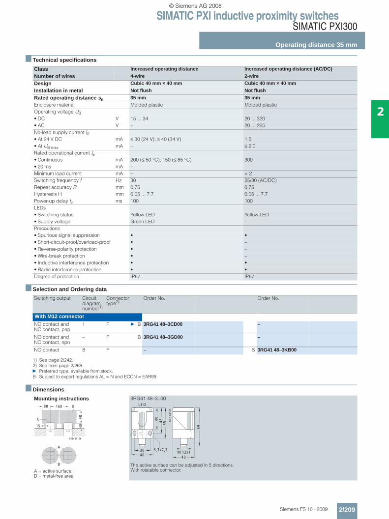
SIMATIC PXI inductive proximity switchesSIMATIC PXI300
Operating distance 35 mm
2/209Siemens FS 10 · 2009
2
■ Technical specifications
■ Selection and Ordering data
■ Dimensions
Class Increased operating distance Increased operating distance (AC/DC)
Number of wires 4-wire 2-wire
Design Cubic 40 mm × 40 mm Cubic 40 mm × 40 mm
Installation in metal Not flush Not flush
Rated operating distance sn 35 mm 35 mmEnclosure material Molded plastic Molded plasticOperating voltage UB• DC V 15 ... 34 20 ... 320• AC V – 20 ... 265No-load supply current I0• At 24 V DC mA ≤ 30 (24 V); ≤ 40 (34 V) 1.5• At UB max mA – ≤ 2.0Rated operational current Ie• Continuous mA 200 (≤ 50 °C); 150 (≤ 85 °C) 300• 20 ms mA –Minimum load current mA – < 2Switching frequency f Hz 30 25/30 (AC/DC)Repeat accuracy R mm 0.75 0.75Hysteresis H mm 0.05 ... 7.7 0.05 ... 7.7Power-up delay tv ms 100 100LEDs• Switching status Yellow LED Yellow LED• Supply voltage Green LED –Precautions• Spurious signal suppression • •• Short-circuit-proof/overload-proof • –• Reverse-polarity protection • –• Wire-break protection • –• Inductive interference protection • •• Radio interference protection • •Degree of protection IP67 IP67
Switching output Circuit diagram number1)
1) See page 2/242.
Connector type2)
2) See from page 2/268.} Preferred type, available from stock.B: Subject to export regulations AL = N and ECCN = EAR99.
Order No. Order No.
With M12 connectorNO contact and NC contact, pnp
1 F } B 3RG41 48–3CD00 –
NO contact and NC contact, npn
– F B 3RG41 48–3GD00 –
NO contact 8 F – B 3RG41 48–3KB00
Mounting instructions
A = active surface B = metal-free area
3RG41 48–3..00
The active surface can be adjusted in 5 directions. With rotatable connector.
NSD 01166
80 160
90
4015
A
B
A
B
4030 5,3x7,3
46
55
40
NS
D 0
1163
LED
69
40
M 12x1
© Siemens AG 2008

SIMATIC PXI inductive proximity switchesSIMATIC PXI300
Operating distance 40 mm
2/210 Siemens FS 10 · 2009
2
■ Technical specifications
■ Selection and Ordering data
■ Dimensions
Class Extra duty (65 V DC) Extra duty (AC/DC)
Number of wires 3-wire 2-wire
Design Cubic 80 mm × 100 mm Cubic 80 mm × 100 mm
Installation in metal Not flush Not flush
Rated operating distance sn 40 mm 40 mmEnclosure material Molded plastic Molded plasticOperating voltage UB• DC V 10 ... 65 20 ... 320• AC V – 20 ... 265No-load supply current I0• At 24 V DC mA ≤ 40 1.0• At 230 V AC mA – 1.5Rated operational current Ie• Continuous mA 300 300• 20 ms mA – 1800Minimum load current mA – 5Switching frequency Hz 10 25/60 (AC/DC)Repeat accuracy R mm 1.0 1.0Power-up delay tv ms 200 100LEDs• Switching status Yellow LED Yellow LED• Supply voltage Green LED –Precautions• Spurious signal suppression • •• Short-circuit-proof/overload-proof • –• Reverse-polarity protection • •• Wire-break protection • •• Inductive interference protection • •• Radio interference protection • •Degree of protection IP65 IP65
Switching output Circuit diagram number1)
1) See page 2/242.} Preferred type, available from stock.B: Subject to export regulations AL = N and ECCN = EAR99.
Order No. Order No.
With terminal box 0.5 ... 2.5 mm2 0.5 ... 2.5 mm2
NO contact or NC contact reposi-tionable, pnp
23 } B 3RG40 43–6AD00 –
NO contact or NC contact reposi-tionable
24 – } B 3RG40 43–6KD00
Mounting instructions
A = active surface B = metal-free area
3RG40 43–6AD00 3RG40 43–6KD00
NSD00613
80 160
90
4015
A
B
A
B
27,5
100
5,3
Pg 13,5
NS
D00
625LED
YE
LED GN
65
65
41,5
80,3
NS
D00
624
Pg 13,5
LED YE
41,5
5,3
6580,3
27,5
100
65
© Siemens AG 2008
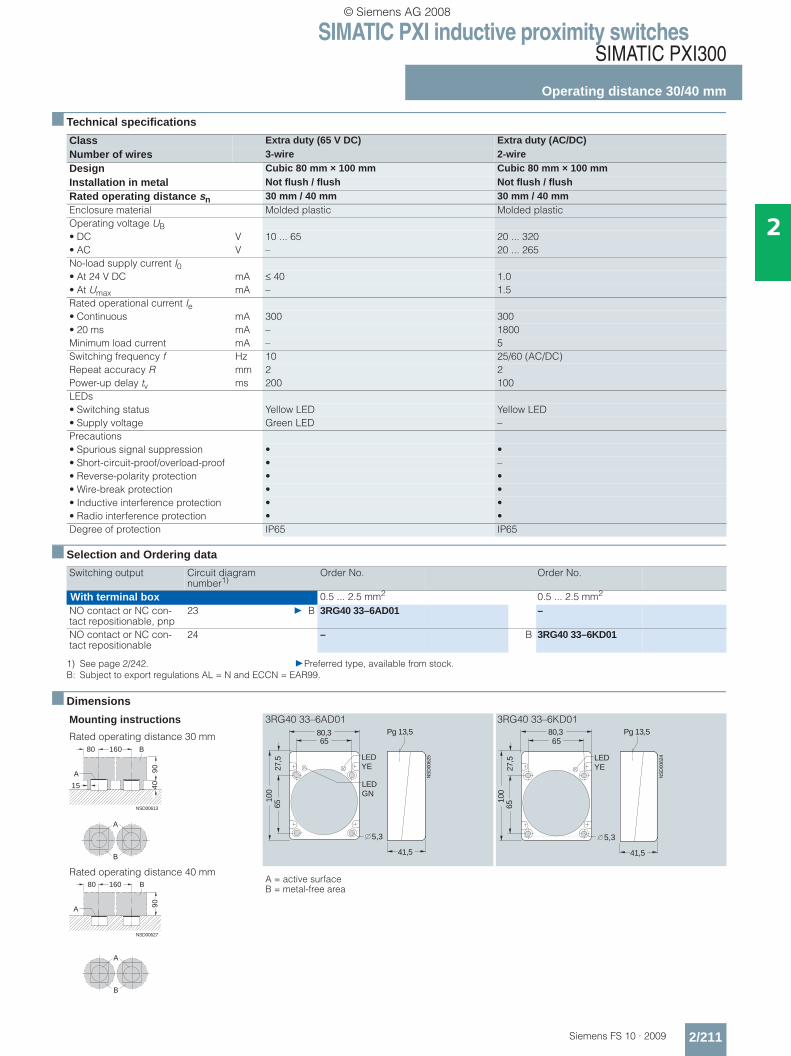
SIMATIC PXI inductive proximity switchesSIMATIC PXI300
Operating distance 30/40 mm
2/211Siemens FS 10 · 2009
2
■ Technical specifications
■ Selection and Ordering data
■ Dimensions
Class Extra duty (65 V DC) Extra duty (AC/DC)Number of wires 3-wire 2-wireDesign Cubic 80 mm × 100 mm Cubic 80 mm × 100 mmInstallation in metal Not flush / flush Not flush / flushRated operating distance sn 30 mm / 40 mm 30 mm / 40 mmEnclosure material Molded plastic Molded plasticOperating voltage UB• DC V 10 ... 65 20 ... 320• AC V – 20 ... 265No-load supply current I0• At 24 V DC mA ≤ 40 1.0• At Umax mA – 1.5Rated operational current Ie• Continuous mA 300 300• 20 ms mA – 1800Minimum load current mA – 5Switching frequency f Hz 10 25/60 (AC/DC)Repeat accuracy R mm 2 2Power-up delay tv ms 200 100LEDs• Switching status Yellow LED Yellow LED• Supply voltage Green LED –Precautions• Spurious signal suppression • •• Short-circuit-proof/overload-proof • –• Reverse-polarity protection • •• Wire-break protection • •• Inductive interference protection • •• Radio interference protection • •Degree of protection IP65 IP65
Switching output Circuit diagram number1)
1) See page 2/242. }Preferred type, available from stock.B: Subject to export regulations AL = N and ECCN = EAR99.
Order No. Order No.
With terminal box 0.5 ... 2.5 mm2 0.5 ... 2.5 mm2
NO contact or NC con-tact repositionable, pnp
23 } B 3RG40 33–6AD01 –
NO contact or NC con-tact repositionable
24 – B 3RG40 33–6KD01
Mounting instructions
Rated operating distance 30 mm
3RG40 33–6AD01 3RG40 33–6KD01
Rated operating distance 40 mmA = active surface B = metal-free area
NSD00613
80 160
90
4015
A
B
A
B
27,5
100
5,3
Pg 13,5
NS
D00
625LED
YE
LED GN
65
65
41,5
80,3
NS
D00
624
Pg 13,5
LED YE
41,5
5,3
6580,3
27,5
100
65
NSD00627
160
90A
B
A
B
80
© Siemens AG 2008

SIMATIC PXI inductive proximity switchesSIMATIC PXI300
Operating distance 40 mm
2/212 Siemens FS 10 · 2009
2
■ Technical specifications
■ Selection and Ordering data
■ Dimensions
Class Increased operating distance
Number of wires 3-wire
Design M30
Installation in metal Not flush
Rated operating distance sn 40 mmEnclosure material Brass, nickel-platedOperating voltage UB V 10 ... 30No-load supply current I0 mA ≤ 10Rated operational current Ie mA 200Switching frequency f Hz 100Repeat accuracy R mm 1.1Power-up delay tv ms 200LEDs• Switching status Yellow LED• Supply voltage –Precautions• Spurious signal suppression •• Short-circuit-proof/overload-proof •• Reverse-polarity protection •• Wire-break protection •• Inductive interference protection •• Radio interference protection •Degree of protection IP67 (not suitable for use under continuous wet conditions or outdoors)
Switching output Circuit diagram number1)
1) See page 2/242.
Connector type2)
2) See from page 2/268.} Preferred type, available from stock.
Order No.
With 2 m cable, PUR 3 × 0.34 mm2
NO contact, pnp 11 } 3RG46 24–0AB02
NO contact, npn 13 3RG46 24–0GB02
With M12 connectorNO contact, pnp 2 E, F } 3RG46 24–3AB02
NO contact, npn 4 E, F 3RG46 24–3GB02
Mounting instructions
A = active surface B = metal-free area
3RG46 24–0..02 3RG46 24–3..02
A
B
NS
D00
615a
150
120
A
B55
35
60
SW
36
44
M 30x1,5
LED
NSD00607a
10
SW
36
44
M 30x1,5
LED
10
NSD0_00609bSg
73,5
51,5
© Siemens AG 2008
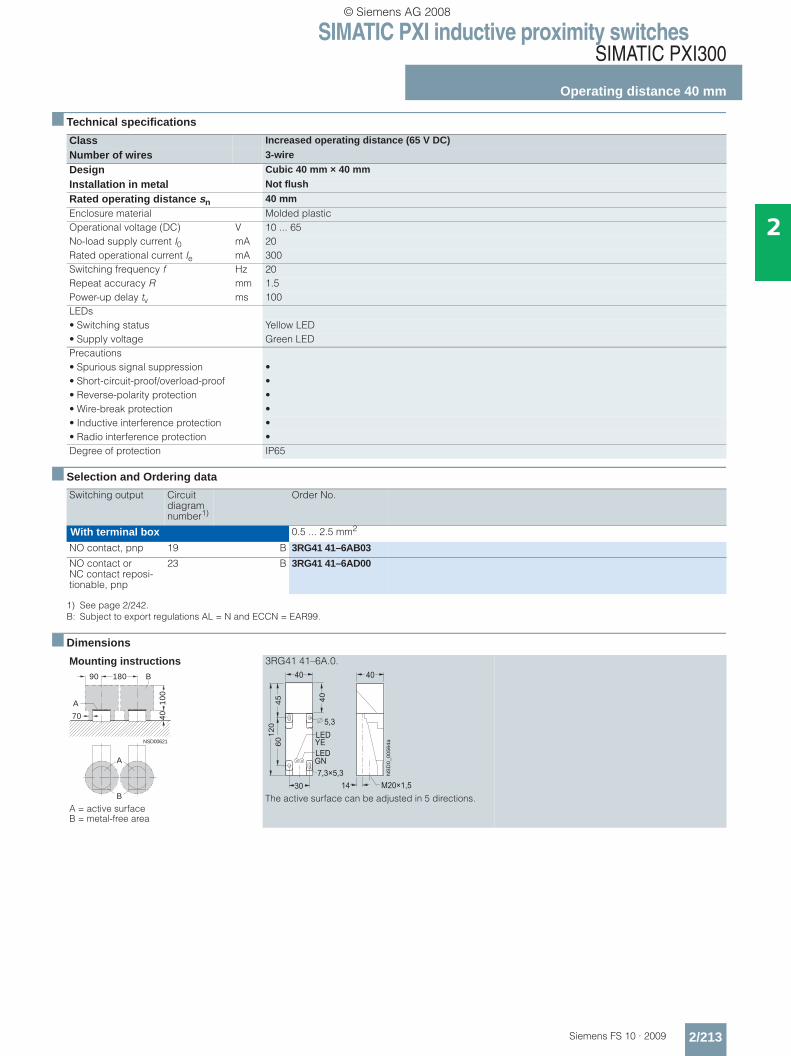
SIMATIC PXI inductive proximity switchesSIMATIC PXI300
Operating distance 40 mm
2/213Siemens FS 10 · 2009
2
■ Technical specifications
■ Selection and Ordering data
■ Dimensions
Class Increased operating distance (65 V DC)
Number of wires 3-wire
Design Cubic 40 mm × 40 mm
Installation in metal Not flush
Rated operating distance sn 40 mmEnclosure material Molded plasticOperational voltage (DC) V 10 ... 65No-load supply current I0 mA 20Rated operational current Ie mA 300Switching frequency f Hz 20Repeat accuracy R mm 1.5Power-up delay tv ms 100LEDs• Switching status Yellow LED• Supply voltage Green LEDPrecautions• Spurious signal suppression •• Short-circuit-proof/overload-proof •• Reverse-polarity protection •• Wire-break protection •• Inductive interference protection •• Radio interference protection •Degree of protection IP65
Switching output Circuit diagram number1)
1) See page 2/242.B: Subject to export regulations AL = N and ECCN = EAR99.
Order No.
With terminal box 0.5 ... 2.5 mm2
NO contact, pnp 19 B 3RG41 41–6AB03
NO contact or NC contact reposi-tionable, pnp
23 B 3RG41 41–6AD00
Mounting instructions
A = active surface B = metal-free area
3RG41 41–6A.0.
The active surface can be adjusted in 5 directions.
NSD00621
180
10
04
070
A
B
A
B
90
��
��
��
� �
� � � � � � �
� � �
��
� �
� � �
� �
�����������
� � �
� � � � �� �
� �
� �
© Siemens AG 2008

SIMATIC PXI inductive proximity switchesSIMATIC PXI300
Operating distance 25 mm or 40 mm
2/214 Siemens FS 10 · 2009
2
■ Technical specifications
■ Selection and Ordering data
■ Dimensions
Class Increased operating distance (65 V DC)
Number of wires 3-wire
Design Cubic 40 mm × 40 mm
Installation in metal Not flush
Rated operating distance sn 25 mm or 40 mm, selectableEnclosure material Molded plasticOperational voltage (DC) V 10 ... 65No-load supply current I0 mA 20Rated operational current Ie mA 300Switching frequency f Hz 20Repeat accuracy R mm 1.5Power-up delay tv ms 100LEDs• Switching status Yellow LED• Supply voltage Green LEDPrecautions• Spurious signal suppression •• Short-circuit-proof/overload-proof •• Reverse-polarity protection •• Wire-break protection •• Inductive interference protection •• Radio interference protection •Degree of protection IP67
Switching output Circuit diagram number1)
1) See page 2/242.
Connector type2)
2) See from page 2/268.B: Subject to export regulations AL = N and ECCN = EAR99.
Order No.
With M12 connectorNO contact, pnp 2 E, F B 3RG41 41–3AB02
Connector can be offset in steps of 30°NO contact, pnp 2 E, F B 3RG41 41–3AB01
Mounting instructions
Rated operating distance 25 mm
Rated operating distance 40 mm
A = active surface B = metal-free area
3RG41 41–3AB02
The active surface can be adjusted in 5 directions.
3RG41 41–3AB01
The active surface can be adjusted in 5 directions.
NSD00623
70 180
50
4050
A
B
A
B
NSD01169
180
10
04
070
A
B
A
B
40
13
1,5
NS
D00
617
40
30
40
12
0 5,3
45
60
7,3x5,3
40
16M 12x1Sg
LED
LED
GN
YE
40
30
40
12
0 5,3
13,3
45
60
14
9
7,3x5,3
16
NS
D00
618
M 12x1
40
Sg
LED
LED
GN
YE
© Siemens AG 2008
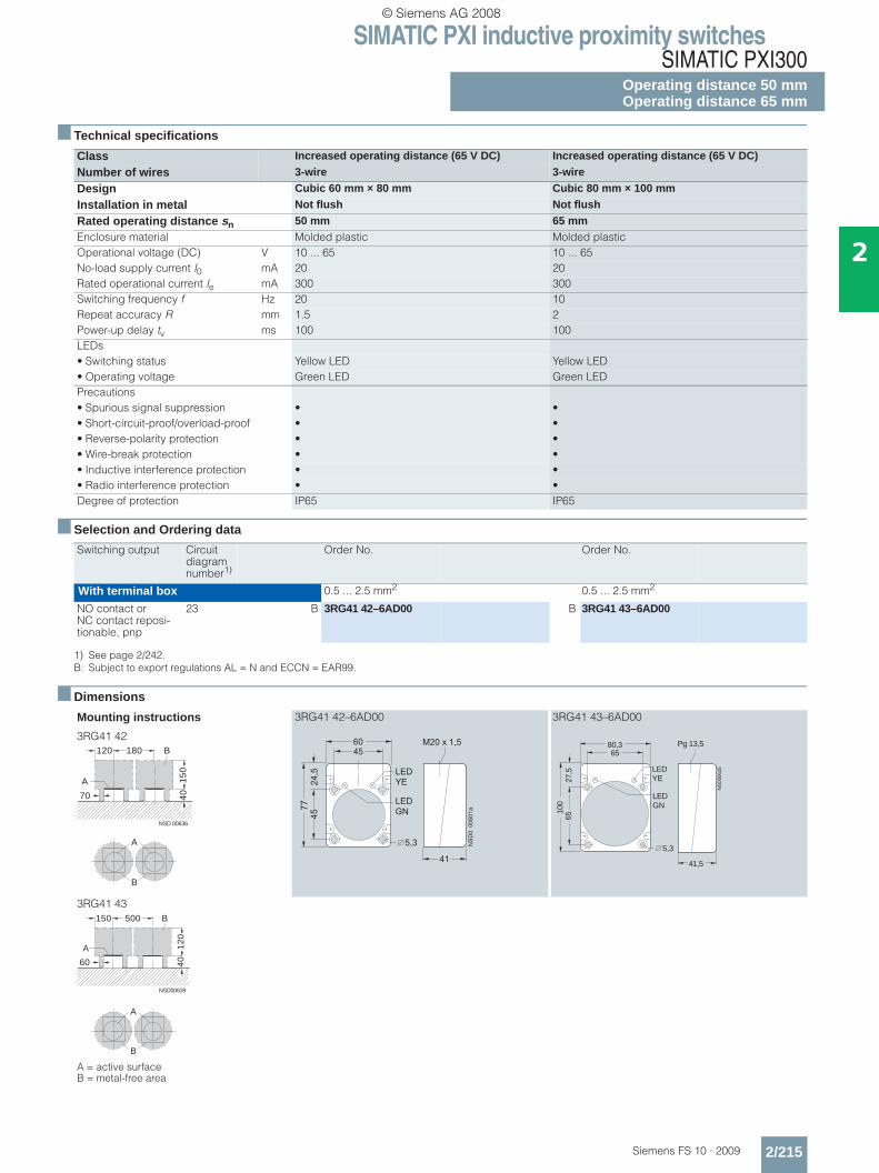
SIMATIC PXI inductive proximity switchesSIMATIC PXI300
Operating distance 50 mmOperating distance 65 mm
2/215Siemens FS 10 · 2009
2
■ Technical specifications
■ Selection and Ordering data
■ Dimensions
Class Increased operating distance (65 V DC) Increased operating distance (65 V DC)
Number of wires 3-wire 3-wire
Design Cubic 60 mm × 80 mm Cubic 80 mm × 100 mm
Installation in metal Not flush Not flush
Rated operating distance sn 50 mm 65 mmEnclosure material Molded plastic Molded plasticOperational voltage (DC) V 10 ... 65 10 ... 65No-load supply current I0 mA 20 20Rated operational current Ie mA 300 300Switching frequency f Hz 20 10Repeat accuracy R mm 1.5 2Power-up delay tv ms 100 100LEDs• Switching status Yellow LED Yellow LED• Operating voltage Green LED Green LEDPrecautions• Spurious signal suppression • •• Short-circuit-proof/overload-proof • •• Reverse-polarity protection • •• Wire-break protection • •• Inductive interference protection • •• Radio interference protection • •Degree of protection IP65 IP65
Switching output Circuit diagram number1)
1) See page 2/242.B: Subject to export regulations AL = N and ECCN = EAR99.
Order No. Order No.
With terminal box 0.5 ... 2.5 mm2 0.5 ... 2.5 mm2
NO contact or NC contact reposi-tionable, pnp
23 B 3RG41 42–6AD00 B 3RG41 43–6AD00
Mounting instructions
3RG41 42
3RG41 42–6AD00 3RG41 43–6AD00
3RG41 43
A = active surface B = metal-free area
NSD 00636
180
15
04
070
A
B120
A
B
���
��
� � �
� � � � � �
����
������
��
� �
� �
� �
� � �
� �
� � �
� �
27,5
100
5,3
Pg 13,5
NS
D00
625LED
YE
LED GN
65
65
41,5
80,3
NSD00639
500
12
04
060
A
B150
A
B
© Siemens AG 2008
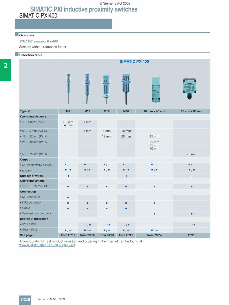
SIMATIC PXI inductive proximity switchesSIMATIC PXI400
2/216 Siemens FS 10 · 2009
2
■ Overview
SIMATIC sensors PXI400
Sensors without reduction factor
■ Selection table
A configurator for fast product selection and ordering in the Internet can be found at www.siemens.com/simatic-sensors/px
SIMATIC PXI400
Type, Ø M8 M12 M18 M30 40 mm x 40 mm 80 mm x 80 mm
Operating distance
• 1 ... 4 mm (PXI.2.) 1.5 mm4 mm
3 mm
• 5 ... 10 mm (PXI.3.) 8 mm 5 mm 10 mm
• 12 ... 22 mm (PXI.4.) 12 mm 20 mm 15 mm
• 25 ... 40 mm (PXI.5.) 25 mm35 mm40 mm
• 50 ... 75 mm (PXI.6.) 75 mm
Output
• NO contact/NC contact / − / − / − / − / − / −• pnp/npn / / / / / /
Number of wires 3 3 3 3 3 3
Operating voltage
• 10/15 ... 30/35 V DC
Connection
• M8 connector
• M12 connector
• Cable
• Terminal compartment
Degree of protection
• IP65 / IP67 − / − / − / − / • IP68 / IP69K / − / − / − / − / −See page from 2/217 from 2/218 from 2/220 from 2/222 from 2/224 2/228
© Siemens AG 2008
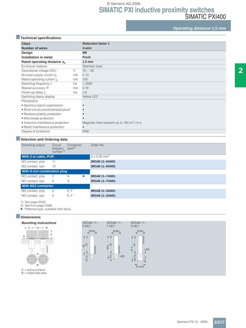
SIMATIC PXI inductive proximity switchesSIMATIC PXI400
Operating distance 1.5 mm
2/217Siemens FS 10 · 2009
2
■ Technical specifications
■ Selection and Ordering data
■ Dimensions
Class Reduction factor 1
Number of wires 3-wire
Design M8
Installation in metal Flush
Rated operating distance sn 1.5 mmEnclosure material Stainless steelOperational voltage (DC) V 10 ... 30No-load supply current I0 mA ≤ 13Rated operating current Ie mA 150Switching frequency f Hz < 2000Repeat accuracy R mm 0.16Power-up delay tv ms ≤ 8Switching status display Yellow LEDPrecautions• Spurious signal suppression •• Short-circuit-proof/overload-proof •• Reverse-polarity protection •• Wire-break protection •• Inductive interference protection Magnetic field resistant up to 160 mT r.m.s.• Radio interference protection •Degree of protection IP68
Switching output Circuit diagram number1)
1) See page 2/242.
Connector type2)
2) See from page 2/268.} Preferred type, available from stock.
Order No.
With 2 m cable, PUR 3 × 0.25 mm2
NO contact, pnp 11 3RG46 11–0AN01
NO contact, npn 13 3RG46 11–0GN01
With 8 mm combination plugNO contact, pnp 2 A } 3RG46 11–7AN01
NO contact, npn 4 A 3RG46 11–7GN01
With M12 connectorNO contact, pnp 2 E, F 3RG46 11–3AN01
NO contact, npn 4 E, F 3RG46 11–3GN01
Mounting instructions
A = active surface B = metal-free area
3RG46 11–0.N01
3RG46 11–7.N01
3RG46 11–3.N01
A
B
NS
D00
319
4 12
3
A
B
NS
D00
34842
1,6
40
M 8x1
NS
D00
349
49,6 40
LED9,2
M 8x1
NS
D00
350
57,4
M 8x1
40
LED
17
6,2
M 12x1
© Siemens AG 2008

SIMATIC PXI inductive proximity switchesSIMATIC PXI400
Operating distance 3 mm
2/218 Siemens FS 10 · 2009
2
■ Technical specifications
■ Selection and Ordering data
■ Dimensions
Class Reduction factor 1Number of wires 3-wireDesign M12Installation in metal FlushRated operating distance sn 3 mmEnclosure material Brass or stainless steelOperating voltage (DC) V 10 ... 30No-load supply current I0 mA ≤ 13Rated operating current Ie mA 200Switching frequency f Hz 3000Repeat accuracy R mm 0.04Power-up delay tv ms 8Switching status display Yellow LEDPrecautions• Spurious signal suppression •• Short-circuit-proof/overload-proof •• Reverse-polarity protection •• Wire-break protection •• Inductive interference protection Magnetic field resistant up to 160 mT r.m.s.• Radio interference protection •• Protective insulation •Degree of protection• Brass enclosure IP67• Stainless steel enclosure IP68
Switching output Circuit diagram number1)
1) See page 2/242. } Preferred type, available from stock.
Connector type2)
2) See from page 2/268.
Order No.
With 2 m cable, PUR 3 × 0.14 mm2
Brass, chrome-platedNO contact, pnp 11 } 3RG46 12–0AN01NO contact, npn 13 3RG46 12–0GN01
Stainless steelNO contact, pnp 11 3RG46 12–0AN61NO contact, npn 13 3RG46 12–0GN61With M12 connector
Brass, chrome-platedNO contact, pnp 2 E, F 3RG46 12–3AN01NO contact, npn 4 E, F 3RG46 12–3GN01
Brass, teflon-coatedNO contact, pnp 2 E, F 3RG46 12–3AN05NO contact, npn 4 E, F 3RG46 12–3GN05
Stainless steelNO contact, pnp 2 E, F } 3RG46 12–3AN61NO contact, npn 2 E, F 3RG46 12–3GN61
Mounting instructions
A = active surface B = metal-free area
3RG46 12–0.N.. 3RG46 12–3.N..
A
B
NS
D00
416
24
9
A
B
NS
D00
413
50,4
M 12x1
LED
SW
17
4
NSD00414
LEDSg
52
M 12x1
SW
17
4
© Siemens AG 2008

SIMATIC PXI inductive proximity switchesSIMATIC PXI400
Operating distance 4 mm
2/219Siemens FS 10 · 2009
2
■ Technical specifications
■ Selection and Ordering data
■ Dimensions
Class Reduction factor 1
Number of wires 3-wire
Design M8
Installation in metal Not flush
Rated operating distance sn 4 mmEnclosure material Stainless steelOperating voltage (DC) V 10 ... 30No-load supply current I0 mA ≤ 13Rated operating current Ie mA 150Switching frequency f Hz < 2000Repeat accuracy R mm 0.16Power-up delay tv ms ≤ 8Switching status display Yellow LEDPrecautions• Spurious signal suppression •• Short-circuit-proof/overload-proof •• Reverse-polarity protection •• Wire-break protection •• Inductive interference protection Magnetic field resistant up to 160 mT r.m.s.• Radio interference protection •Degree of protection IP68
Switching output Circuit diagram number1)
1) See page 2/242.
Connector type2)
2) See from page 2/268.} Preferred type, available from stock.
Order No.
With 2 m cable, PUR 3 × 0.25 mm2
NO contact, pnp 11 } 3RG46 21–0AN01
NO contact, npn 13 3RG46 21–0GN01
With 8 mm combination plugNO contact, pnp 2 A } 3RG46 21–7AN01
NO contact, npn 4 A 3RG46 21–7GN01
With M12 connectorNO contact, pnp 2 E, F } 3RG46 21–3AN01
NO contact, npn 4 E, F 3RG46 21–3GN01
Mounting instructions
A = active surface B = metal-free area
3RG46 21–0.N01
3RG46 21–7.N01
3RG46 21–3.N01
NS
D0_
0042
9
20 27
8816
A
B
A
B
NS
D00
41741
,6
M 8x1
1,6
355
NS
D00
418
49,2
M 8x1
35
LED9,2
5
NS
D00
419
5735
LED
17
6,2
M 12x1
5
© Siemens AG 2008
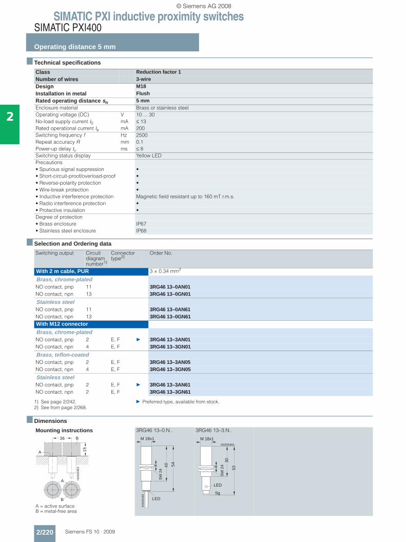
SIMATIC PXI inductive proximity switchesSIMATIC PXI400
Operating distance 5 mm
2/220 Siemens FS 10 · 2009
2
■ Technical specifications
■ Selection and Ordering data
■ Dimensions
Class Reduction factor 1Number of wires 3-wireDesign M18Installation in metal FlushRated operating distance sn 5 mmEnclosure material Brass or stainless steelOperating voltage (DC) V 10 ... 30No-load supply current I0 mA ≤ 13Rated operational current Ie mA 200Switching frequency f Hz 2500Repeat accuracy R mm 0.1Power-up delay tv ms ≤ 8Switching status display Yellow LEDPrecautions• Spurious signal suppression •• Short-circuit-proof/overload-proof •• Reverse-polarity protection •• Wire-break protection •• Inductive interference protection Magnetic field resistant up to 160 mT r.m.s.• Radio interference protection •• Protective insulation •Degree of protection• Brass enclosure IP67• Stainless steel enclosure IP68
Switching output Circuit diagram number1)
1) See page 2/242. } Preferred type, available from stock.
Connector type2)
2) See from page 2/268.
Order No.
With 2 m cable, PUR 3 × 0.34 mm2
Brass, chrome-platedNO contact, pnp 11 3RG46 13–0AN01NO contact, npn 13 3RG46 13–0GN01
Stainless steelNO contact, pnp 11 3RG46 13–0AN61NO contact, npn 13 3RG46 13–0GN61With M12 connector
Brass, chrome-platedNO contact, pnp 2 E, F } 3RG46 13–3AN01NO contact, npn 4 E, F 3RG46 13–3GN01
Brass, teflon-coatedNO contact, pnp 2 E, F 3RG46 13–3AN05NO contact, npn 4 E, F 3RG46 13–3GN05
Stainless steelNO contact, pnp 2 E, F } 3RG46 13–3AN61NO contact, npn 2 E, F 3RG46 13–3GN61
Mounting instructions
A = active surface B = metal-free area
3RG46 13–0.N.. 3RG46 13–3.N..
NS
D00
463
A
B
A
36 B
15
NS
D00
460
LED
54
40
M 18x1
SW
24
4
LED
Sg
NSD00461
53
30
M 18x1
SW
244
© Siemens AG 2008
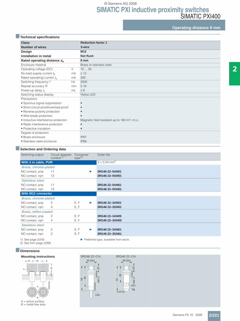
SIMATIC PXI inductive proximity switchesSIMATIC PXI400
Operating distance 8 mm
2/221Siemens FS 10 · 2009
2
■ Technical specifications
■ Selection and Ordering data
■ Dimensions
Class Reduction factor 1
Number of wires 3-wire
Design M12
Installation in metal Not flush
Rated operating distance sn 8 mmEnclosure material Brass or stainless steelOperating voltage (DC) V 10 ... 30No-load supply current I0 mA ≤ 12Rated operatingl current Ie mA 200Switching frequency f Hz 2000Repeat accuracy R mm 0.16Power-up delay tv ms ≤ 8Switching status display Yellow LEDPrecautions• Spurious signal suppression •• Short-circuit-proof/overload-proof •• Reverse-polarity protection •• Wire-break protection •• Inductive interference protection Magnetic field resistant up to 160 mT r.m.s.• Radio interference protection •• Protective insulation •Degree of protection• Brass enclosure IP67• Stainless steel enclosure IP68
Switching output Circuit diagram number1)
1) See page 2/242. } Preferred type, available from stock.
Connector type2)
2) See from page 2/268.
Order No.
With 2 m cable, PUR 3 × 0.34 mm2
Brass, chrome-platedNO contact, pnp 11 } 3RG46 22–0AN01NO contact, npn 13 3RG46 22–0GN01
Stainless steelNO contact, pnp 11 3RG46 22–0AN61NO contact, npn 13 3RG46 22–0GN61With M12 connector
Brass, chrome-platedNO contact, pnp 2 E, F } 3RG46 22–3AN01NO contact, npn 4 E, F 3RG46 22–3GN01
Brass, teflon-coatedNO contact, pnp 2 E, F 3RG46 22–3AN05NO contact, npn 4 E, F 3RG46 22–3GN05
Stainless steelNO contact, pnp 2 E, F } 3RG46 22–3AN61NO contact, npn 2 E, F 3RG46 22–3GN61
Mounting instructions
A = active surface B = metal-free area
3RG46 22–0.N.. 3RG46 22–3.N..
�������
� � �
�
��
�
�
�
�
NS
D00
489
54
M 12x1
40
10
LED
SW
17
4
Sg
M 12x1
10
5130
LED
NSD00490
SW
17
4
© Siemens AG 2008

SIMATIC PXI inductive proximity switchesSIMATIC PXI400
Operating distance 10 mm
2/222 Siemens FS 10 · 2009
2
■ Technical specifications
■ Selection and Ordering data
■ Dimensions
Class Reduction factor 1 Number of wires 3-wireDesign M30Installation in metal FlushRated operating distance sn 10 mmEnclosure material Brass or stainless steelOperating voltage (DC) V 10 ... 30No-load supply current I0 mA ≤ 13Rated operating current Ie mA 200Switching frequency f Hz 2000Repeat accuracy R mm 0.2Power-up delay tv ms ≤ 8Switching status display Yellow LEDPrecautions• Spurious signal suppression •• Short-circuit-proof/overload-proof •• Reverse-polarity protection •• Wire-break protection •• Inductive interference protection Magnetic field resistant up to 160 mT r.m.s.• Radio interference protection •• Protective insulation •Degree of protection• Brass enclosure IP67• Stainless steel enclosure IP68
Switching output Circuit diagram number1)
1) See page 2/242. } Preferred type, available from stock.
Connector type2)
2) See from page 2/268.
Order No.
With 2 m cable, PUR 3 × 0.34 mm2
Brass, chrome-platedNO contact, pnp 11 3RG46 14–0AN01NO contact, npn 13 3RG46 14–0GN01
Stainless steelNO contact, pnp 11 3RG46 14–0AN61NO contact, npn 13 3RG46 14–0GN61With M12 connector
Brass, chrome-platedNO contact, pnp 2 E, F } 3RG46 14–3AN01NO contact, npn 4 E, F 3RG46 14–3GN01
Brass, teflon-coatedNO contact, pnp 2 E, F 3RG46 14–3AN05NO contact, npn 4 E, F 3RG46 14–3GN05
Stainless steelNO contact, pnp 2 E, F 3RG46 14–3AN61NO contact, npn 2 E, F 3RG46 14–3GN61
Mounting instructions
A = active surface B = metal-free area
3RG46 14–0.N.. 3RG46 14–3.N..
NS
D0
05
32
60 B
30
A
A
B
NS
D00
529
LED
64
M 30x1,5
SW
36
5 50
NSD00530
Sg
LED
M 30x1,5
6350
SW
36
5
© Siemens AG 2008
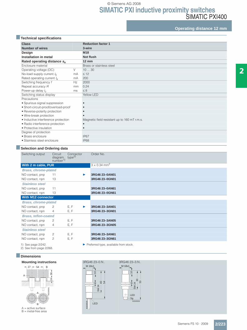
SIMATIC PXI inductive proximity switchesSIMATIC PXI400
Operating distance 12 mm
2/223Siemens FS 10 · 2009
2
■ Technical specifications
■ Selection and Ordering data
■ Dimensions
Class Reduction factor 1 Number of wires 3-wireDesign M18Installation in metal Not flushRated operating distance sn 12 mmEnclosure material Brass or stainless steelOperating voltage (DC) V 10 ... 30No-load supply current I0 mA ≤ 12Rated operating current Ie mA 200Switching frequency f Hz 2000Repeat accuracy R mm 0.24Power-up delay tv ms ≤ 8Switching status display Yellow LEDPrecautions• Spurious signal suppression •• Short-circuit-proof/overload-proof •• Reverse-polarity protection •• Wire-break protection •• Inductive interference protection Magnetic field resistant up to 160 mT r.m.s.• Radio interference protection •• Protective insulation •Degree of protection• Brass enclosure IP67• Stainless steel enclosure IP68
Switching output Circuit diagram number1)
1) See page 2/242. } Preferred type, available from stock.
Connector type2)
2) See from page 2/268.
Order No.
With 2 m cable, PUR 3 × 0.34 mm2
Brass, chrome-platedNO contact, pnp 11 } 3RG46 23–0AN01NO contact, npn 13 3RG46 23–0GN01
Stainless steelNO contact, pnp 11 3RG46 23–0AN61NO contact, npn 13 3RG46 23–0GN61With M12 connector
Brass, chrome-platedNO contact, pnp 2 E, F } 3RG46 23–3AN01NO contact, npn 4 E, F 3RG46 23–3GN01
Brass, teflon-coatedNO contact, pnp 2 E, F 3RG46 23–3AN05NO contact, npn 4 E, F 3RG46 23–3GN05
Stainless steelNO contact, pnp 2 E, F 3RG46 23–3AN61NO contact, npn 2 E, F 3RG46 23–3GN61
Mounting instructions
A = active surface B = metal-free area
3RG46 23–0.N.. 3RG46 23–3.N..
NS
D00
541
54
3624
A
B
A
B
27
NS
D00
535
LED
54
40
M 18x1
10S
W 2
44
LEDSg
5330
M 18x1
10
NSD00536
SW
244
© Siemens AG 2008

SIMATIC PXI inductive proximity switchesSIMATIC PXI400
Operating distance 15 mm
2/224 Siemens FS 10 · 2009
2
■ Technical specifications
■ Selection and Ordering data
■ Dimensions
Class Reduction factor 1 Number of wires 3-wireDesign Cubic 40 mm × 40 mmInstallation in metal FlushRated operating distance sn 15 mmEnclosure material Molded plasticOperating voltage (DC) V 10 ... 30No-load supply current I0 mA ≤ 15Rated operating current Ie mA 200Switching frequency f Hz 250Repeat accuracy R mm 0.3Power-up delay tv ms ≤ 8LEDs• Switching status Yellow LED• Supply voltage Green LEDPrecautions• Spurious signal suppression •• Short-circuit-proof/overload-proof •• Reverse-polarity protection •• Wire-break protection •• Inductive interference protection Magnetic field resistant up to 160 mT r.m.s.• Radio interference protection •• Protective insulation •Degree of protection IP68
Switching output Circuit diagram number1)
1) See page 2/242. } Preferred type, available from stock.
Connector type2)
2) See from page 2/268.
Order No. Order No.
With M12 connectorNO contact, pnp 2 E, F } 3RG46 38–3AN01 –NO contact, npn 4 E, F 3RG46 38–3GN01 –With terminal box 0.5 ... 2.5 mm2
NO contact, pnp 28 – 3RG46 34–6AN01NO contact, npn 29 – 3RG46 34–6GN01
Mounting instructions
3RG46 38
3RG46 38–3.N01 3RG46 34–6.N01
The active surface can be adjusted in 5 directions.
3RG46 34
A = active surface B = metal-free area
NSD 00569
40 80 B
A 45
A
B
4030
46 5265
LED
NS
D00
566
5,3x7,340
Sg
46
60
11
4
30
5,3
40
40 40
NS
D0_
0059
7a
M 20x1,514
7,3×5,3
LED
NSD 00569
20 80 B
A 45
A
B
© Siemens AG 2008

SIMATIC PXI inductive proximity switchesSIMATIC PXI400
Operating distance 20 mm
2/225Siemens FS 10 · 2009
2
■ Technical specifications
■ Selection and Ordering data
■ Dimensions
Class Reduction factor 1 Number of wires 3-wireDesign M30Installation in metal Not flushRated operating distance sn 20 mmEnclosure material Brass or stainless steelOperating voltage (DC) V 10 ... 30No-load supply current I0 mA ≤ 13Rated operating current Ie mA 200Switching frequency f Hz 1500Repeat accuracy R mm 0.4Power-up delay tv ms ≤ 8Switching status indication Yellow LEDPrecautions• Spurious signal suppression •• Short-circuit-proof/overload-proof •• Reverse-polarity protection •• Wire-break protection •• Inductive interference protection Magnetic field resistant up to 160 mT r.m.s.• Radio interference protection •• Protective insulation •Degree of protection• Brass enclosure IP67• Stainless steel enclosure IP68
Switching output Circuit diagram number1)
1) See page 2/242. } Preferred type, available from stock.
Connector type2)
2) See from page 2/268.
Order No.
With 2 m cable, PUR 3 × 0.34 mm2
Brass, chrome-platedNO contact, pnp 11 } 3RG46 24–0AN01NO contact, npn 13 3RG46 24–0GN01
Stainless steelNO contact, pnp 11 } 3RG46 24–0AN61NO contact, npn 13 3RG46 24–0GN61With M12 connector
Brass, chrome-platedNO contact, pnp 2 E, F } 3RG46 24–3AN01NO contact, npn 4 E, F 3RG46 24–3GN01
Brass, teflon-coatedNO contact, pnp 2 E, F 3RG46 24–3AN05NO contact, npn 4 E, F 3RG46 24–3GN05
Stainless steelNO contact, pnp 2 E, F 3RG46 24–3AN61NO contact, npn 2 E, F 3RG46 24–3GN61
Mounting instructions
A = active surface B = metal-free area
3RG46 24–0.N.. 3RG46 24–3.N..
NS
D00
578
90
60
40
A
B
A
B
45
NS
D00
575
LED
15
M 30x1,5
64S
W 3
65
LEDNSD00576
15
M 30x1,5
50
63
SW
365
Sg
© Siemens AG 2008
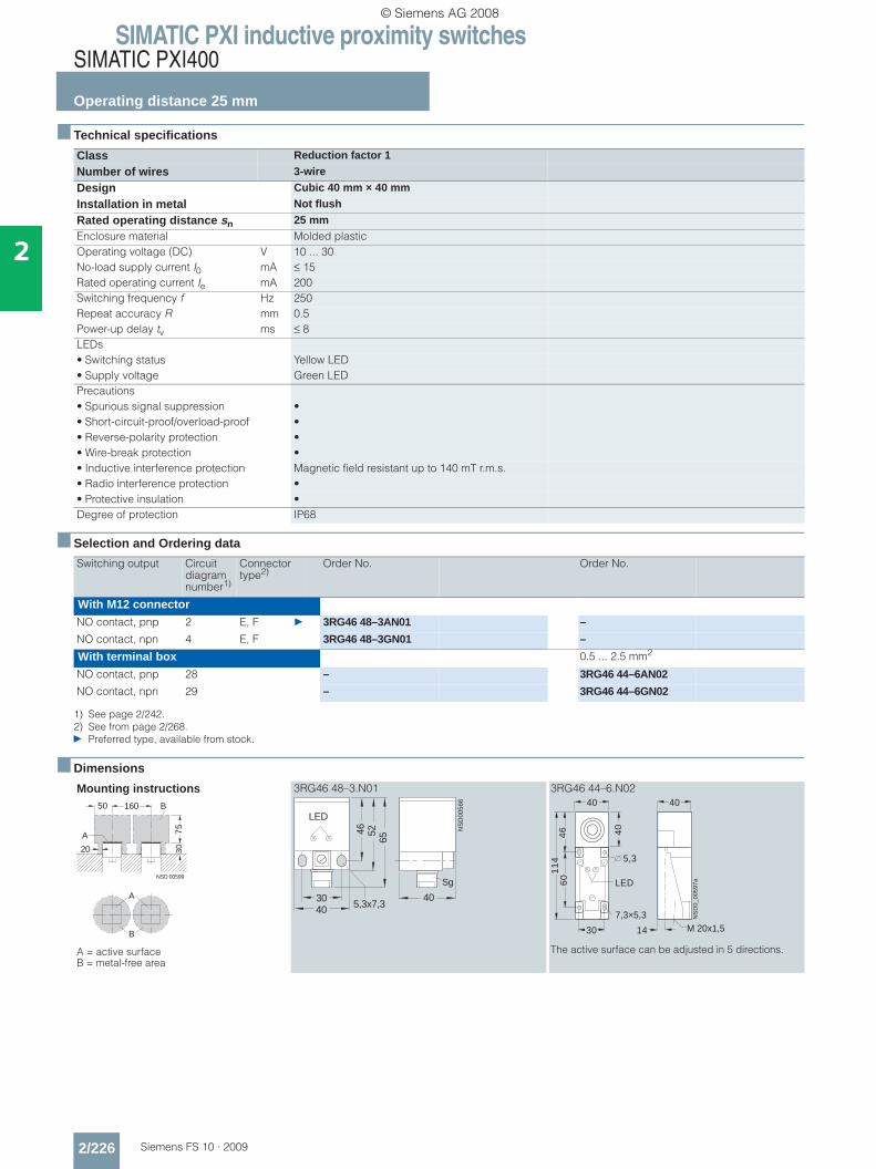
SIMATIC PXI inductive proximity switchesSIMATIC PXI400
Operating distance 25 mm
2/226 Siemens FS 10 · 2009
2
■ Technical specifications
■ Selection and Ordering data
■ Dimensions
Class Reduction factor 1
Number of wires 3-wire
Design Cubic 40 mm × 40 mm
Installation in metal Not flush
Rated operating distance sn 25 mmEnclosure material Molded plasticOperating voltage (DC) V 10 ... 30No-load supply current I0 mA ≤ 15Rated operating current Ie mA 200Switching frequency f Hz 250Repeat accuracy R mm 0.5Power-up delay tv ms ≤ 8LEDs• Switching status Yellow LED• Supply voltage Green LEDPrecautions• Spurious signal suppression •• Short-circuit-proof/overload-proof •• Reverse-polarity protection •• Wire-break protection •• Inductive interference protection Magnetic field resistant up to 140 mT r.m.s.• Radio interference protection •• Protective insulation •Degree of protection IP68
Switching output Circuit diagram number1)
1) See page 2/242.
Connector type2)
2) See from page 2/268.} Preferred type, available from stock.
Order No. Order No.
With M12 connectorNO contact, pnp 2 E, F } 3RG46 48–3AN01 –
NO contact, npn 4 E, F 3RG46 48–3GN01 –
With terminal box 0.5 ... 2.5 mm2
NO contact, pnp 28 – 3RG46 44–6AN02
NO contact, npn 29 – 3RG46 44–6GN02
Mounting instructions
A = active surface B = metal-free area
3RG46 48–3.N01 3RG46 44–6.N02
The active surface can be adjusted in 5 directions.
NSD 00599
50 160
75
3020
A
B
A
B
4030
46 5265
LED
NS
D00
566
5,3x7,340
Sg
46
60
11
4
30
5,3
40
40 40
NS
D0_
0059
7a
M 20x1,514
7,3×5,3
LED
© Siemens AG 2008
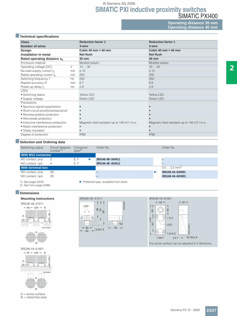
SIMATIC PXI inductive proximity switchesSIMATIC PXI400
Operating distance 35 mmOperating distance 40 mm
2/227Siemens FS 10 · 2009
2
■ Technical specifications
■ Selection and Ordering data
■ Dimensions
Class Reduction factor 1 Reduction factor 1 Number of wires 3-wire 3-wireDesign Cubic 40 mm × 40 mm Cubic 40 mm × 40 mmInstallation in metal Not flush Not flushRated operating distance sn 35 mm 40 mmEnclosure material Molded plastic Molded plasticOperating voltage (DC) V 10 ... 30 10 ... 30No-load supply current I0 mA ≤ 15 ≤ 15Rated operating current Ie mA 200 200Switching frequency f Hz 250 250Repeat accuracy R mm 0.7 0.8Power-up delay tv ms ≤ 8 ≤ 8LEDs• Switching status Yellow LED Yellow LED• Supply voltage Green LED Green LEDPrecautions• Spurious signal suppression • •• Short-circuit-proof/overload-proof • •• Reverse-polarity protection • •• Wire-break protection • •• Inductive interference protection Magnetic field resistant up to 140 mT r.m.s. Magnetic field resistant up to 140 mT r.m.s.• Radio interference protection • •• Totally insulated • •Degree of protection IP68 IP68
Switching output Circuit diagram number1)
1) See page 2/242. } Preferred type, available from stock.
Connector type2)
2) See from page 2/268.
Order No. Order No.
With M12 connectorNO contact, pnp 2 E, F } 3RG46 48–3AN11 –NO contact, npn 4 E, F 3RG46 48–3GN11 –With terminal box 0.5 ... 2.5 mm2
NO contact, pnp 28 – } 3RG46 44–6AN01NO contact, npn 29 – 3RG46 44–6GN01
Mounting instructions
3RG46 48–3.N11
3RG46 48–3.N11 3RG46 44–6.N01
The active surface can be adjusted in 5 directions.
3RG46 44–6.N01
A = active surface B = metal-free area
NSD 01065a
160
90
4015
A
B
A
B
80
4030
46 5265
LED
NS
D00
566
5,3x7,340
Sg
46
60
11
4
30
5,3
40
40 40
NS
D0_
0059
7a
M 20x1,514
7,3×5,3
LED
NSD00631
40 160
12
04020
A
B
A
B
© Siemens AG 2008

SIMATIC PXI inductive proximity switchesSIMATIC PXI400
Operating distance 75 mm
2/228 Siemens FS 10 · 2009
2
■ Technical specifications
■ Selection and Ordering data
■ Dimensions
Class Reduction factor 1
Number of wires 3-wire
Design Cubic 80 mm × 80 mm
Installation in metal Not flush
Rated operating distance sn 75 mmEnclosure material Molded plasticOperational voltage (DC) V 10 ... 30No-load supply current I0 mA ≤ 15Rated operational current Ie mA 200Switching frequency f Hz 250Repeat accuracy R mm 1.5Power-up delay tv ms ≤ 8Switching status display Yellow LEDPrecautions• Spurious signal suppression •• Short-circuit-proof/overload-proof •• Reverse-polarity protection •• Wire-break protection •• Inductive interference protection Magnetic field resistant up to 75 mT r.m.s.• Radio interference protection •• Totally insulated •Degree of protection IP67
Switching output Circuit diagram number1)
1) See page 2/242.} Preferred type, available from stock.
Order No.
With terminal box 0.5 ... 2.5 mm2
NO contact, pnp 28 } 3RG46 43–6AN01
NO contact, npn 29 3RG46 43–6GN01
Mounting instructions
A = active surface B = metal-free area
3RG46 43–6.N01
NSD00641
400
15
04080
A
B
A
B
120
80
5,5
65
65
27,540,5
Pg 13,5
NSD00637
© Siemens AG 2008

SIMATIC PXI inductive proximity switchesSIMATIC PXI600
2/229Siemens FS 10 · 2009
2
■ Overview
SIMATIC sensors PXI600
Sensors with special approvals:• ATEX proximity switches for hazardous areas, Zone 2• Devices with e1 type approval
■ Selection table
A configurator for fast product selection and ordering in the Internet can be found atwww.siemens.com/simatic-sensors/px
SIMATIC PXI600 ATEX SIMATIC PXI600 e1
Type, Ø M12 M18 M30 40 mm x 40 mm M12 M18 M30
Operating distance
• 1 ... 4 mm (PXI.2.) 2 mm4 mm
2 mm4 mm
• 5 ... 10 mm (PXI.3.) 5 mm8 mm 10 mm
5 mm8 mm 10 mm
• 12 ... 22 mm (PXI.4.) 15 mm 15 mm 15 mm
• 25 ... 40 mm (PXI.5.) 35 mm
Output
• NO contact/NC contact / / / / / / /
• pnp/npn / − / − / − / − / − / − / −Number of wires 4 4 4 4 3 3 3
Operating voltage
• 10/15 ... 30/35 V DC
• 10 ... 65 V DC
Connection
• M12 connector
• Cable
Degree of protection
• IP65/IP67 − / − / − / − / • IP68/IP69K / / / Approvals
• Hazardous area, Zone 2/22
• e1
See page 2/230 2/231 2/232 2/233 2/234 2/235 2/237
© Siemens AG 2008
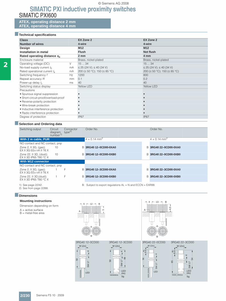
SIMATIC PXI inductive proximity switchesSIMATIC PXI600ATEX, operating distance 2 mmATEX, operating distance 4 mm
2/230 Siemens FS 10 · 2009
2
■ Technical specifications
■ Selection and Ordering data
■ Dimensions
Class EX Zone 2 EX Zone 2Number of wires 4-wire 4-wireDesign M12 M12Installation in metal Flush Not flushRated operating distance sn 2 mm 4 mmEnclosure material Brass, nickel-plated Brass, nickel-platedOperating voltage (DC) V 15 ... 34 15 ... 34No-load supply current I0 mA ≤ 25 (24 V); ≤ 40 (34 V) ≤ 25 (24 V); ≤ 40 (34 V)Rated operational current Ie mA 200 (≤ 50 °C); 150 (≤ 85 °C) 200 (≤ 50 °C); 150 (≤ 85 °C)Switching frequency f Hz 1200 800Repeat accuracy R mm 0.1 0.2Power-up delay tv ms 40 40Switching status display Yellow LED Yellow LEDPrecautions• Spurious signal suppression • •• Short-circuit-proof/overload-proof • •• Reverse-polarity protection • •• Wire-break protection • •• Inductive interference protection • •• Radio interference protection • •Degree of protection IP67 IP67
Switching output Circuit diagram number1)
1) See page 2/242. B: Subject to export regulations AL = N and ECCN = EAR99.
Connector type2)
2) See from page 2/268.
Order No. Order No.
With 2 m cable, PUR 4 × 0.14 mm2 4 × 0.14 mm2
NO contact and NC contact, pnpZone 2, II 3G, (gas); EX II 3G EEx nA II T6 X
10 B 3RG40 12–0CD00-0XA0 B 3RG40 22–0CD00-0XA0
Zone 22, II 3D, (dust); EX II 3D IP65 T80 °C X
10 B 3RG40 12–0CD00-0XB0 B 3RG40 22–0CD00-0XB0
With M12 connectorNO contact and NC contact, pnpZone 2, II 3G, (gas); EX II 3G EEx nA II T6 X
1 F B 3RG40 12–3CD00-0XA0 B 3RG40 22–3CD00-0XA0
Zone 22, II 3D,(dust); EX II 3D IP65 T80 °C X
1 F B 3RG40 12–3CD00-0XB0 B 3RG40 22–3CD00-0XB0
Mounting instructions
Dimension depending on formA = active surface B = metal-free area
3RG40 12–0CD00 3RG40 12–3CD00 3RG40 22–0CD00 3RG40 22–3CD00
A
B
NS
D00
363
6 12
5
A
B
A
B
NS
D00
332
4 13
4,5
A
B
LED
NS
D00
360a
50
4
M 12x1
SW
17
NSD00361b
59
M 12x1
48S
W 1
74
Sg
LED(4x)
NS
D0_
0042
0a
4
6,5
56
SW
17
LED
M 12x1
NSD0_00421a
65
LED(4x)
54
M 12x1
6,5
4S
W 1
7
Sg
© Siemens AG 2008
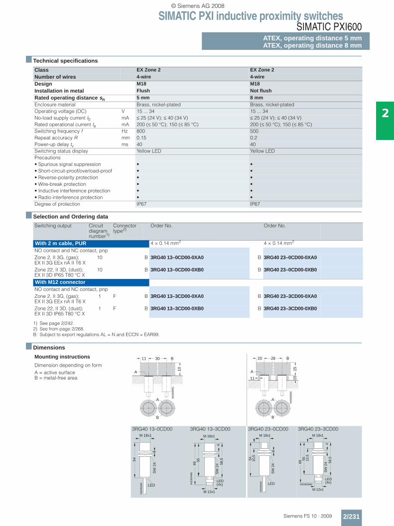
SIMATIC PXI inductive proximity switchesSIMATIC PXI600
ATEX, operating distance 5 mmATEX, operating distance 8 mm
2/231Siemens FS 10 · 2009
2
■ Technical specifications
■ Selection and Ordering data
■ Dimensions
Class EX Zone 2 EX Zone 2Number of wires 4-wire 4-wireDesign M18 M18Installation in metal Flush Not flushRated operating distance sn 5 mm 8 mmEnclosure material Brass, nickel-plated Brass, nickel-platedOperating voltage (DC) V 15 ... 34 15 ... 34No-load supply current I0 mA ≤ 25 (24 V); ≤ 40 (34 V) ≤ 25 (24 V); ≤ 40 (34 V)Rated operational current Ie mA 200 (≤ 50 °C); 150 (≤ 85 °C) 200 (≤ 50 °C); 150 (≤ 85 °C)Switching frequency f Hz 800 500Repeat accuracy R mm 0.15 0.2Power-up delay tv ms 40 40Switching status display Yellow LED Yellow LEDPrecautions• Spurious signal suppression • •• Short-circuit-proof/overload-proof • •• Reverse-polarity protection • •• Wire-break protection • •• Inductive interference protection • •• Radio interference protection • •Degree of protection IP67 IP67
Switching output Circuit diagram number1)
1) See page 2/242.
Connector type2)
2) See from page 2/268.B: Subject to export regulations AL = N and ECCN = EAR99.
Order No. Order No.
With 2 m cable, PUR 4 × 0.14 mm2 4 × 0.14 mm2
NO contact and NC contact, pnpZone 2, II 3G, (gas); EX II 3G EEx nA II T6 X
10 B 3RG40 13–0CD00-0XA0 B 3RG40 23–0CD00-0XA0
Zone 22, II 3D, (dust); EX II 3D IP65 T80 °C X
10 B 3RG40 13–0CD00-0XB0 B 3RG40 23–0CD00-0XB0
With M12 connectorNO contact and NC contact, pnpZone 2, II 3G, (gas); EX II 3G EEx nA II T6 X
1 F B 3RG40 13–3CD00-0XA0 B 3RG40 23–3CD00-0XA0
Zone 22, II 3D, (dust); EX II 3D IP65 T80 °C X
1 F B 3RG40 13–3CD00-0XB0 B 3RG40 23–3CD00-0XB0
Mounting instructions
Dimension depending on formA = active surface B = metal-free area
3RG40 13–0CD00 3RG40 13–3CD00 3RG40 23–0CD00 3RG40 23–3CD00
A
B
NS
D00
451
11 30
10A
B
NS
D00
500
20 28
151511
A
B
A
B
M 18x1
NS
D00
445
54
LED
SW
24
4
LED(4x)
55
58,5
69
M 18x1
SW
24
4
M 12x1
NS
D00
446b
NS
D00
493
LED
M 18x1
54 10,5
SW
24
4
LED(4x)
55
58,5
69
M 18x1
10,5
SW
24
4
M 12x1
NSD00494b
© Siemens AG 2008

SIMATIC PXI inductive proximity switchesSIMATIC PXI600ATEX, operating distance 10 mmATEX, operating distance 15 mm
2/232 Siemens FS 10 · 2009
2
■ Technical specifications
■ Selection and Ordering data
■ Dimensions
Class EX Zone 2 EX Zone 2Number of wires 4-wire 4-wireDesign M30 M30Installation in metal Flush Not flushRated operating distance sn 10 mm 15 mmEnclosure material Brass, nickel-plated Brass, nickel-platedOperating voltage (DC) V 15 ... 34 15 ... 34No-load supply current I0 mA ≤ 25 (24 V); ≤ 40 (34 V) ≤ 25 (24 V); ≤ 40 (34 V)Rated operational current Ie mA 200 (≤ 50 °C); 150 (≤ 85 °C) 200 (≤ 50 °C); 150 (≤ 85 °C)Switching frequency f Hz 300 300Repeat accuracy R mm 0.3 0.4Power-up delay tv ms 40 40Switching status display Yellow LED Yellow LEDPrecautions• Spurious signal suppression • •• Short-circuit-proof/overload-proof • •• Reverse-polarity protection • •• Wire-break protection • •• Inductive interference protection • •• Radio interference protection • •Degree of protection IP67 IP67
Switching output Circuit diagram number1)
1) See page 2/242.
Connector type2)
2) See from page 2/268.B Subject to export regulations AL = N and ECCN = EAR99
Order No. Order No.
With 2 m cable, PUR 4 × 0.14 mm2 4 × 0.14 mm2
NO contact and NC contact, pnpZone 2, II 3G, (gas); EX II 3G EEx nA II T6 X
10 B 3RG40 14–0CD00-0XA0 B 3RG40 24–0CD00-0XA0
Zone 22, II 3D, (dust); EX II 3D IP65 T80 °C X
10 B 3RG40 14–0CD00-0XB0 B 3RG40 24–0CD00-0XB0
With M12 connectorNO contact and NC contact, pnpZone 2, II 3G, (gas); EX II 3G EEx nA II T6 X
1 F B 3RG40 14–3CD00-0XA0 B 3RG40 24–3CD00-0XA0
Zone 22, II 3D, (dust); EX II 3D IP65 T80 °C X
1 F B 3RG40 14–3CD00-0XB0 B 3RG40 24–3CD00-0XB0
Mounting instructions
Dimension depending on formA = active surface B = metal-free area
3RG40 14–0CD00 3RG40 14–3CD00 3RG40 24–0CD00 3RG40 24–3CD00
A
B
NS
D00
521
25 37
16
A
B
A
B
NS
D00
548
30 80
25
1515
A
B
NS
D00
518a
M 30x1,5
LED
54
SW
36
5
NSD00519
M 30x1,5
5569
LED (4x)
58,5
SW
36
5
Sg
54
M 30x1,5
16
NS
D0_
0054
4b
LED
SW
36
5
LED(4x)
55
M 30x1,5
16
NSD00545b
69 58,5
SW
36
5
M 12x1
© Siemens AG 2008

SIMATIC PXI inductive proximity switchesSIMATIC PXI600
ATEX, operating distance 15 mmATEX, operating distance 35 mm
2/233Siemens FS 10 · 2009
2
■ Technical specifications
■ Selection and Ordering data
■ Dimensions
Class Ex Zone 2 Ex Zone 2
Number of wires 4-wire 4-wire
Design Cubic 40 mm x 40 mm Cubic 40 mm x 40 mm
Installation in metal Flush Not flush
Rated operating distance sn 15 mm 35 mmEnclosure material Molded plastic Molded plasticOperating voltage (DC) V 15 ... 34 15 ... 34No-load supply current I0 mA ≤ 30 (24 V); ≤ 40 (34 V) ≤ 230 (24 V); ≤ 40 (34 V)Rated operational current Ie mA 200 (≤ 50 °C); 150 (≤ 85 °C) 200 (≤ 50 °C); 150 (≤ 85 °C)Switching frequency f Hz 50 30Repeat accuracy R mm 0.75 0.75Hysteresis H mm - 0.05 ... 7.7Power-up delay tv ms 100 100Switching status display Yellow LED Yellow LEDSupply voltage Green LED Green LEDPrecautions• Spurious signal suppression • •• Short-circuit-proof/overload-proof • •• Reverse-polarity protection • •• Wire-break protection • •• Inductive interference protection • •• Radio interference protection • •Degree of protection IP67 IP67
Switching output Circuit diagram number1)
1) See page 2/242.
Connector type2)
2) See from page 2/268.B: Subject to export regulations AL = N and ECCN = EAR99.
Order No. Order No.
With M12 connectorNO contact and NC contact, pnp
Zone 2, II 3G, (gas); EX II 3G EEx nA II T6 X
1 F B 3RG40 38–3CD00-0XA0 B 3RG41 48–3CD00-0XA0
Zone 22, II 3D, (dust); EX II 3D IP65 T80 °C X
1 F B 3RG40 38–3CD00-0XB0 B 3RG41 48–3CD00-0XB0
Mounting instructions
Dimension depending on formA = active surface B = metal-free area
3RG40 38–3CD00 3RG41 48–3CD00
NSD 01164
25 75 B
A 30
A
B
NSD 01166
80 160
90
4015
A
B
A
B
4030 5,3x7,3
46
55
40
NS
D 0
1163
LED
69
40
M 12x14030 5,3x7,3
46
55
40
NS
D 0
1163
LED
69
40
M 12x1
© Siemens AG 2008
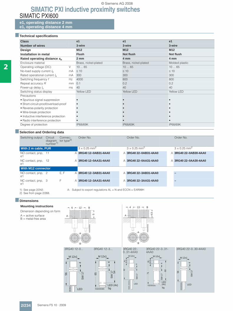
SIMATIC PXI inductive proximity switchesSIMATIC PXI600e1, operating distance 2 mme1, operating distance 4 mm
2/234 Siemens FS 10 · 2009
2
■ Technical specifications
■ Selection and Ordering data
■ Dimensions
Class e1 e1 e1
Number of wires 3-wire 3-wire 3-wire
Design M12 M12 M12
Installation in metal Flush Not flush Not flush
Rated operating distance sn 2 mm 4 mm 4 mmEnclosure material Brass, nickel-plated Brass, nickel-plated Molded plasticOperating voltage (DC) V 10 ... 65 10 ... 65 10 ... 65No-load supply current I0 mA ≤ 10 ≤ 10 ≤ 10Rated operational current Ie mA 300 300 300Switching frequency f Hz 4000 800 800Repeat accuracy R mm 0.1 0.2 0.2Power-up delay tv ms 40 40 40Switching status display Yellow LED Yellow LED Yellow LEDPrecautions• Spurious signal suppression • • •• Short-circuit-proof/overload-proof • • •• Reverse-polarity protection • • •• Wire-break protection • • •• Inductive interference protection • • •• Radio interference protection • • •Degree of protection IP68/69K IP68/69K IP68/69K
Switching output Circuit diagram number1)
1) See page 2/242. A: Subject to export regulations AL = N and ECCN = EAR99H
Connec-tor type2)
2) See from page 2/268.
Order No. Order No. Order No.
With 2 m cable, PUR 3 × 0.25 mm2 3 × 0.25 mm2 3 × 0.25 mm2
NO contact, pnp, e1
11 A 3RG40 12–0AB31-4AA0 A 3RG40 22–0AB31-4AA0 A 3RG40 22–0AB30-4AA0
NC contact, pnp, e1
12 A 3RG40 12–0AA31-4AA0 A 3RG40 22–0AA31-4AA0 A 3RG40 22–0AA30-4AA0
With M12 connectorNO contact, pnp, e1
2 E, F A 3RG40 12–3AB31-4AA0 A 3RG40 22–3AB31-4AA0 –
NC contact, pnp, e1
3 F A 3RG40 12–3AA31-4AA0 A 3RG40 22–3AA31-4AA0 –
Mounting instructions
Dimension depending on formA = active surface B = metal-free area
3RG40 12–0... 3RG40 12–3... 3RG40 22–0..31-4AA0
3RG40 22–3..31-4AA0
3RG40 22–0..30-4AA0
A
B
NS
D00
363
6 12
5
A
B
A
B
NS
D00
332
4 13
4,5
A
B
LED
D00
364
56
4
M 12x1
SW
17
NSD00365
65
M 12x1
54
LED (4x)
SW
17
4
Sg NS
D0_
0042
4a
4
M 12x1
6,5
62
SW
17
LEDNSD00425a
71
60
6,5
M 12x1
4S
W 1
7
LED(4x)
SgLED
NS
D00
364
56
4
M 12x1
SW
17
© Siemens AG 2008

SIMATIC PXI inductive proximity switchesSIMATIC PXI600
e1, operating distance 5 mm
2/235Siemens FS 10 · 2009
2
■ Technical specifications
■ Selection and Ordering data
■ Dimensions
Class e1 e1
Number of wires 3-wire 3-wire
Design M18 M18
Installation in metal Flush Flush
Rated operating distance sn 5 mm 5 mmEnclosure material Brass, nickel-plated Molded plasticOperating voltage (DC) V 10 ... 65 10 ... 65No-load supply current I0 mA ≤ 10 ≤ 10Rated operational current Ie mA 300 300Switching frequency f Hz 800 500Repeat accuracy R mm 0.15 0.15Power-up delay tv ms 40 40Switching status display Yellow LED Yellow LEDPrecautions• Spurious signal suppression • •• Short-circuit-proof/overload-proof • •• Reverse-polarity protection • •• Wire-break protection • •• Inductive interference protection • •• Radio interference protection • •Degree of protection IP68/69K IP68/69K
Switching output Circuit diagram number1)
1) See page 2/242.
Connector type2)
2) See from page 2/268.A: Subject to export regulations AL = N and ECCN = EAR99H.
Order No. Order No.
With 2 m cable, PUR 3 × 0.25 mm2 3 × 0.25 mm2
NO contact, pnp, e1 11 A 3RG40 13–0AB31-4AA0 A 3RG40 13–0AB30-4AA0
NC contact, pnp, e1 12 A 3RG40 13–0AA31-4AA0 –
With M12 connectorNO contact, pnp, e1 2 E, F A 3RG40 13–3AB31-4AA0 –
NC contact, pnp, e1 3 F A 3RG40 13–3AA31-4AA0 –
Mounting instructions
A = active surface B = metal-free area
3RG40 13–0... 3RG40 13–3...
A
B
NS
D00
451
11 30
10A
BM 18x1
NS
D00
445
54
LED
SW
24
4
LED(4x)
55
58,5
69
M 18x1
SW
24
4
M 12x1
NS
D00
446b
© Siemens AG 2008
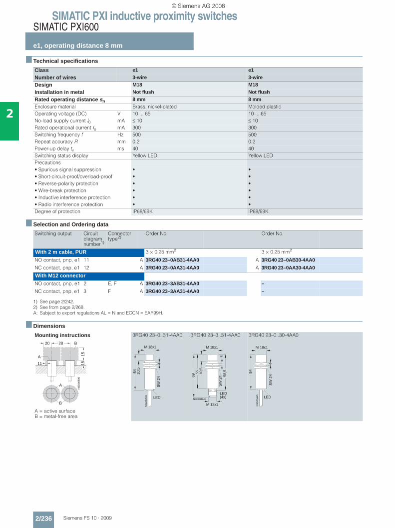
SIMATIC PXI inductive proximity switchesSIMATIC PXI600
e1, operating distance 8 mm
2/236 Siemens FS 10 · 2009
2
■ Technical specifications
■ Selection and Ordering data
■ Dimensions
Class e1 e1
Number of wires 3-wire 3-wire
Design M18 M18
Installation in metal Not flush Not flush
Rated operating distance sn 8 mm 8 mmEnclosure material Brass, nickel-plated Molded plasticOperating voltage (DC) V 10 ... 65 10 ... 65No-load supply current I0 mA ≤ 10 ≤ 10Rated operational current Ie mA 300 300Switching frequency f Hz 500 500Repeat accuracy R mm 0.2 0.2Power-up delay tv ms 40 40Switching status display Yellow LED Yellow LEDPrecautions• Spurious signal suppression • •• Short-circuit-proof/overload-proof • •• Reverse-polarity protection • •• Wire-break protection • •• Inductive interference protection • •• Radio interference protection • •Degree of protection IP68/69K IP68/69K
Switching output Circuit diagram number1)
1) See page 2/242.
Connector type2)
2) See from page 2/268.A: Subject to export regulations AL = N and ECCN = EAR99H.
Order No. Order No.
With 2 m cable, PUR 3 × 0.25 mm2 3 × 0.25 mm2
NO contact, pnp, e1 11 A 3RG40 23–0AB31-4AA0 A 3RG40 23–0AB30-4AA0
NC contact, pnp, e1 12 A 3RG40 23–0AA31-4AA0 A 3RG40 23–0AA30-4AA0
With M12 connectorNO contact, pnp, e1 2 E, F A 3RG40 23–3AB31-4AA0 –
NC contact, pnp, e1 3 F A 3RG40 23–3AA31-4AA0 –
Mounting instructions
A = active surface B = metal-free area
3RG40 23–0..31-4AA0 3RG40 23–3..31-4AA0 3RG40 23–0..30-4AA0
NS
D00
500
20 28
151511
A
B
A
B
NS
D00
493
LED
M 18x1
54 10,5
SW
24
4
LED(4x)
55
58,5
69
M 18x1
10,5
SW
24
4
M 12x1
NSD00494b
M 18x1
NS
D00
445
54
LED
SW
24
4
© Siemens AG 2008
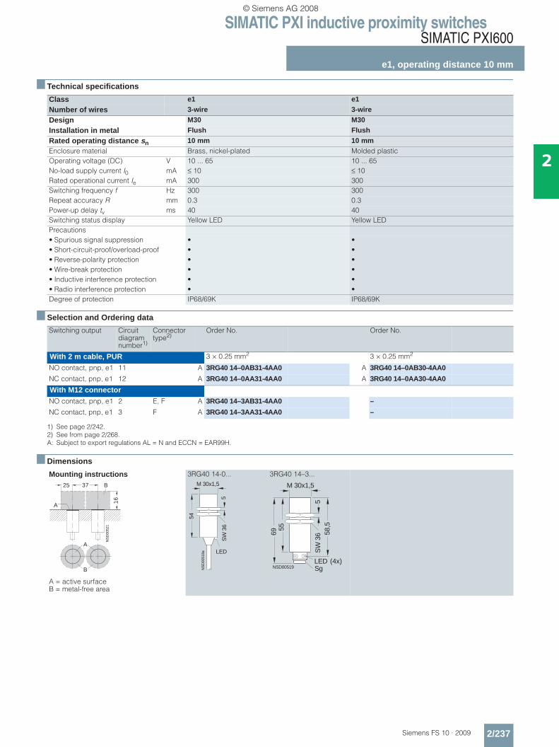
SIMATIC PXI inductive proximity switchesSIMATIC PXI600
e1, operating distance 10 mm
2/237Siemens FS 10 · 2009
2
■ Technical specifications
■ Selection and Ordering data
■ Dimensions
Class e1 e1
Number of wires 3-wire 3-wire
Design M30 M30
Installation in metal Flush Flush
Rated operating distance sn 10 mm 10 mmEnclosure material Brass, nickel-plated Molded plasticOperating voltage (DC) V 10 ... 65 10 ... 65No-load supply current I0 mA ≤ 10 ≤ 10Rated operational current Ie mA 300 300Switching frequency f Hz 300 300Repeat accuracy R mm 0.3 0.3Power-up delay tv ms 40 40Switching status display Yellow LED Yellow LEDPrecautions• Spurious signal suppression • •• Short-circuit-proof/overload-proof • •• Reverse-polarity protection • •• Wire-break protection • •• Inductive interference protection • •• Radio interference protection • •Degree of protection IP68/69K IP68/69K
Switching output Circuit diagram number1)
1) See page 2/242.
Connector type2)
2) See from page 2/268.A: Subject to export regulations AL = N and ECCN = EAR99H.
Order No. Order No.
With 2 m cable, PUR 3 × 0.25 mm2 3 × 0.25 mm2
NO contact, pnp, e1 11 A 3RG40 14–0AB31-4AA0 A 3RG40 14–0AB30-4AA0
NC contact, pnp, e1 12 A 3RG40 14–0AA31-4AA0 A 3RG40 14–0AA30-4AA0
With M12 connectorNO contact, pnp, e1 2 E, F A 3RG40 14–3AB31-4AA0 –
NC contact, pnp, e1 3 F A 3RG40 14–3AA31-4AA0 –
Mounting instructions
A = active surface B = metal-free area
3RG40 14-0... 3RG40 14–3...
A
B
NS
D00
521
25 37
16
A
B
NS
D00
518a
M 30x1,5
LED
54
SW
36
5
NSD00519
M 30x1,5
5569
LED (4x)
58,5
SW
36
5
Sg
© Siemens AG 2008

SIMATIC PXI inductive proximity switchesSIMATIC PXI600
e1, operating distance 15 mm
2/238 Siemens FS 10 · 2009
2
■ Technical specifications
■ Selection and Ordering data
■ Dimensions
Class e1 e1
Number of wires 3-wire 3-wire
Design M30 M30
Installation in metal Not flush Not flush
Rated operating distance sn 15 mm 15 mmEnclosure material Brass, nickel-plated Molded plasticOperating voltage (DC) V 10 ... 65 10 ... 65No-load supply current I0 mA ≤ 10 ≤ 10Rated operational current Ie mA 300 300Switching frequency f Hz 300 300Repeat accuracy R mm 0.4 0.4Power-up delay tv ms 40 40Switching status display Yellow LED Yellow LEDPrecautions• Spurious signal suppression • •• Short-circuit-proof/overload-proof • •• Reverse-polarity protection • •• Wire-break protection • •• Inductive interference protection • •• Radio interference protection • •Degree of protection IP68/69K IP68/69K
Switching output Circuit diagram number1)
1) See page 2/242.
Connector type2)
2) See from page 2/268.A: Subject to export regulations AL = N and ECCN = EAR99H.
Order No. Order No.
With 2 m cable, PUR 3 × 0.25 mm2 3 × 0.25 mm2
NO contact, pnp, e1 11 A 3RG40 24–0AB31-4AA0 A 3RG40 24–0AB30-4AA0
NC contact, pnp, e1 12 A 3RG40 24–0AA31-4AA0 A 3RG40 24–0AA30-4AA0
With M12 connectorNO contact, pnp, e1 2 E, F A 3RG40 24–3AB31-4AA0 –
NC contact, pnp, e1 3 F A 3RG40 24–3AA31-4AA0 –
Mounting instructions
A = active surface B = metal-free area
3RG40 24–0..31-4AA0 3RG40 24–3..31-4AA0 3RG40 24–0..30-4AA0
A
B
NS
D00
548
30 80
25
1515
A
B
54
M 30x1,5
16
NS
D0_
0054
4b
LED
SW
36
5
LED(4x)
55
M 30x1,5
16
NSD00545b
69 58,5
SW
36
5
M 12x1 NS
D00
518a
M 30x1,5
LED
54
SW
36
5
© Siemens AG 2008

SIMATIC PXI inductive proximity switchesSIMATIC PXI900
2/239Siemens FS 10 · 2009
2
■ Overview
SIMATIC sensors PXI900• Pressure-resistant sensors up to 500 bar• Sensors with analog output
■ Selection table
A configurator for fast product selection and ordering in the Internet can be found atwww.siemens.com/simatic-sensors/px
SIMATIC PXI900
Type, Ø M14Pressure resistant
M12Analog
Operating distance
• 1 ... 4 mm (PXI.2.) 3 mm
• 5 ... 10 mm (PXI.3.) 0 ... 6 mm
Output
• NO contact/NC contact /
• pnp/npn /
• Analog
Number of wires 3 4
Operating voltage
• 10/15 ... 30/35 V DC
Connection
• M12 connector
• Cable
Degree of protection
• IP65 / IP67 − / • IP68 / IP69K / −See page 2/240 2/241
© Siemens AG 2008
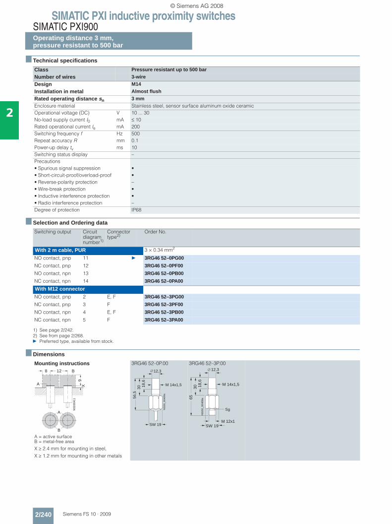
SIMATIC PXI inductive proximity switchesSIMATIC PXI900Operating distance 3 mm, pressure resistant to 500 bar
2/240 Siemens FS 10 · 2009
2
■ Technical specifications
■ Selection and Ordering data
■ Dimensions
Class Pressure resistant up to 500 bar
Number of wires 3-wire
Design M14
Installation in metal Almost flush
Rated operating distance sn 3 mmEnclosure material Stainless steel, sensor surface aluminum oxide ceramicOperational voltage (DC) V 10 ... 30No-load supply current I0 mA ≤ 10Rated operational current Ie mA 200Switching frequency f Hz 500Repeat accuracy R mm 0.1Power-up delay tv ms 10Switching status display –Precautions• Spurious signal suppression •• Short-circuit-proof/overload-proof •• Reverse-polarity protection –• Wire-break protection •• Inductive interference protection •• Radio interference protection –Degree of protection IP68
Switching output Circuit diagram number1)
1) See page 2/242.
Connector type2)
2) See from page 2/268.} Preferred type, available from stock.
Order No.
With 2 m cable, PUR 3 × 0.34 mm2
NO contact, pnp 11 } 3RG46 52–0PG00
NC contact, pnp 12 3RG46 52–0PF00
NO contact, npn 13 3RG46 52–0PB00
NC contact, npn 14 3RG46 52–0PA00
With M12 connectorNO contact, pnp 2 E, F 3RG46 52–3PG00
NC contact, pnp 3 F 3RG46 52–3PF00
NO contact, npn 4 E, F 3RG46 52–3PB00
NC contact, npn 5 F 3RG46 52–3PA00
Mounting instructions
A = active surface B = metal-free area
X ≥ 2.4 mm for mounting in steel,X ≥ 1.2 mm for mounting in other metals
3RG46 52–0P.00 3RG46 52–3P.00
NS
D00
411
8 12
9
A
B
X
A
B
M 14x1,518,6
3056
,5
NS
D0_
0040
9a
SW 19
12,3
M 14x1,518,6
3065
M 12x1SW 19
12,3
Sg
NS
D0_
0040
8a
© Siemens AG 2008

SIMATIC PXI inductive proximity switchesSIMATIC PXI900
Operating distance 0 … 6 mmwith analog output
2/241Siemens FS 10 · 2009
2
■ Technical specifications
■ Selection and Ordering data
■ Dimensions
Class Analog output
Number of wires 4-wire
Design M12
Installation in metal Almost flush
Rated operating distance sn 0 ... 6 mmEnclosure material Brass, nickel-platedOperational voltage (DC) V 10 ... 30No-load supply current I0 mA 10Switching frequency f Hz 1000Repeat accuracy R mm 0.3Power-up delay tv ms 50Output voltage (A1) at 25 °C• With s = 0 mm V 0 (–0 ... +0.2 V)• With s = 3 mm V +2.7 (±0.2 V)• With s = 6 mm V +5.0 (±0.2 V)Load current at voltage output max. 10 mAOutput current (A2) at 25 °C• With s = 0 mm mA 1.0 (±0.2 mA)• With s = 6 mm mA 5.0 (±0.2 mA)Max. resistive load at current output• With UB = 10 V kΩ 1• With UB = 30 V kΩ 5Switching status display –Precautions• Spurious signal suppression –• Short-circuit-proof/overload-proof •• Reverse-polarity protection •• Wire-break protection –• Inductive interference protection •• Radio interference protection –Degree of protection IP67
Analog output Circuit diagram number1)
1) See page 2/242.
Connector type2)
2) See from page 2/268.} Preferred type, available from stock.
Order No.
With 2 m cable, PUR 4 × 0.25 mm2
Voltage + current 30 } 3RG46 12–0NB00
With M12 connectorVoltage + current 30 F } 3RG46 12–3NB00
Mounting instructions
A = active surface B = metal-free area
3RG46 12–0NB00 3RG46 12–3NB00
A
B
NS
D00
488
16
9
A
6
2
50
M 12x1
NS
D00
485
SW
17
4
M 12x1
NSD00486a
60
SW
17
4
40
Sg
© Siemens AG 2008

SIMATIC PXI inductive proximity switchesSchematics
2/242 Siemens FS 10 · 2009
2
■ Schematics
Circuit diagram 1 Circuit diagram 11 Circuit diagram 21
Circuit diagram 2 Circuit diagram 12 Circuit diagram 22
Circuit diagram 3 Circuit diagram 13 Circuit diagram 23
Circuit diagram 4 Circuit diagram 14 Circuit diagram 24
Circuit diagram 5 Circuit diagram 15 Circuit diagram 25
Circuit diagram 6 Circuit diagram 16 Circuit diagram 26
Circuit diagram 7 Circuit diagram 17 Circuit diagram 27
Circuit diagram 8 Circuit diagram 18 Circuit diagram 28
Circuit diagram 9 Circuit diagram 19 Circuit diagram 29
Circuit diagram 10 Circuit diagram 20 Circuit diagram 30
Abbreviations for color identification of the connection cables according to IEC 60757:
BK = Black BN = BrownBU = Blue WH = White
1
243
L+
L
NSD00642
NO+NC
IL+
L
NSD00652a
NO
BN
BK
BU
I1
2/4
3
L+
LNO
NSD00662
I
1
4
3
L+
LNO
NSD00643
I
NCNSD00653
BN
BK
BU
L+
L
I1
4
L+
LNO
NSD00663
I
1
2
3
L+
LNC
NSD00644
I
NONSD00654
BN
BK
BU
L+
L
I1
2/4
3
L+
LNC NO
NSD00664
I
1
4
3
L+
LNO
NSD00645
I
NCNSD00655
BN
BK
BU
L+
L
I1/3
2/4
L1/L+
NC NONSD00665
(N/L )
N/L
(L1/L+)
I
1
2
3
L+
LNC
NSD00646
I
NONSD00656
BN
BU
L+
L
I3
42
1 L+
L
NO+NCNSD00666
I
1
4
L+
LNO
NSD00647
I
NONSD00657
BK
BK
L1/L+
N/L
(N/L )
(L1/L+)
I1/3
X
2/4
L+
L
NSD00667
NO
I
1
4
3
L+
L
NONSD00648
I
NCNSD00658
BK
BK
L1/L+
N/L
(N/L )
(L1/L+)
I1/3
X
2/4
L+
L
NSD00668
NC NO
I
3
4
L1/L+
NO
N/L
N/LL1/L+
I1
42
3
L+
LNO+NC
NSD00659
I1
4
3
L+
LNO
NSD01167
I
1
2NC
NSD00650
L1/L+N/L
L1/L+N/L
I1
2/4
3
L+
LNO
NSD00660
I1
4
3
L+
LNO
NSD01168
I
L
L+
NSD00651
NO+NC
WH
BN
BK
BU
I1
2/4
3
L+
LNC
NSD00661
I
R L2 R L1
NSD00669
+UBBN
BK
WH
BU
A1
A2
0 V
© Siemens AG 2008
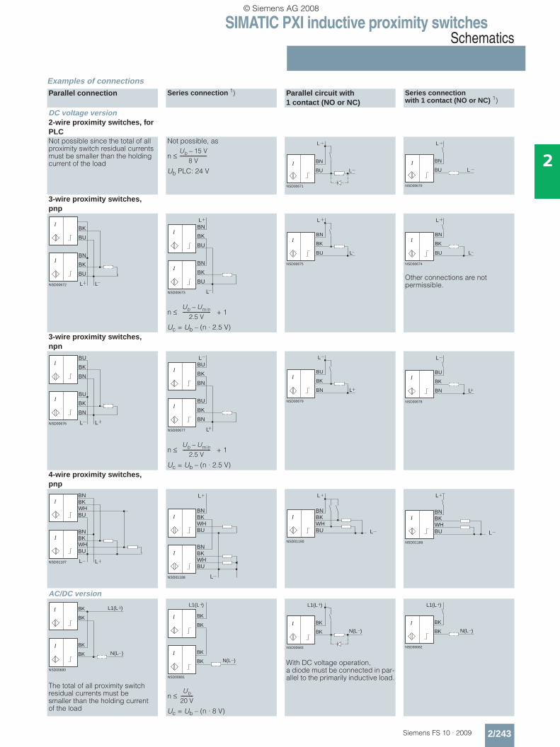
SIMATIC PXI inductive proximity switchesSchematics
2/243Siemens FS 10 · 2009
2
Examples of connectionsParallel connection Series connection 1) Parallel circuit with
1 contact (NO or NC)Series connection with 1 contact (NO or NC) 1)
DC voltage version2-wire proximity switches, for PLCNot possible since the total of all proximity switch residual currents must be smaller than the holding current of the load
Not possible, as
n ≤
Ub PLC: 24 V
3-wire proximity switches, pnp
n ≤ + 1
Uc = Ub – (n · 2.5 V)
Other connections are not permissible.
3-wire proximity switches, npn
n ≤ + 1
Uc = Ub – (n · 2.5 V)4-wire proximity switches, pnp
AC/DC version
The total of all proximity switch residual currents must be smaller than the holding current of the load
n ≤
Uc = Ub – (n · 8 V)
With DC voltage operation, a diode must be connected in par-allel to the primarily inductive load.
Ub 15 V–
8 V-------------------
NSD00671
BN
BU L
L
I
NSD00670
BN
BU L
L
I
NSD00672
BK
BU
L L
BN
BK
BU
I
I
NSD00673
BN
BK
BU
L
L
BN
BK
BU
I
I
Ub Umin–
2.5 V--------------------
NSD00675
L
BN
BK
BU
L
I
NSD00674
L
BN
BK
BU
L
I
NSD00676
BU
BK
BN
L L
BU
BK
BN
I
I
NSD00677
BU
BK
BN
L
L
BU
BK
BN
I
I
Ub Umin–
2.5 V--------------------
NSD00679
L
BU
BK
BN
L
I
NSD00678
L
BU
BK
BN
L
I
NSD01187 LL
BNBK
I
I
BU
BNBKWHBU
WH
NSD01188
BNBK
I
I
BU
BNBKWHBU
WH
L
L
IBNBKWHBU
NSD01190
L
L
IBNBKWHBU
NSD01189
L
L
NSD00680
BK
BK
BK
BK N(L )
L1(L )I
I
NSD00681
BK
BK
BK
BK N(L )
L1(L )
I
I
Ub
20 V---------
NSD00683
BK
BK
L1(L )
N(L )I
NSD00682
BK
BK N(L )
L1(L )
I
© Siemens AG 2008
SIMATIC PXI inductive proximity switchesSchematics
2/244 Siemens FS 10 · 2009
2
Ub= operating voltage Uc= minimum operating voltage of load n= number of proximity switches Umin = minimum permissible operating voltage1) )The power-up delay of the sensors must be considered when
determining the switching times.
Abbreviations for color identification of the connection cables according to IEC 60 757:BK = Black BN = Brown BU = Blue WH = White
© Siemens AG 2008

SIMATIC PXI inductive proximity switchesCharacteristic curves
2/245Siemens FS 10 · 2009
2
■ Characteristic curves
Response curves
The response curves are determined using standard targets according to EN 60947-5-2.Operating distance 0.6 mm (normal)3RG46 03, 3RG46 00, 3RG4610
Operating distance 0.8 mm (normal) 3RG 46 .0, 3RG 46 36
Operating distance 1 mm (normal)3RG40 11
Operating distance 1.5 mm (normal) 3RG40 ..–...33 (shorty)
Operating distance 1.5 mm (normal)3RG40 ..–...05, 3RG46 01, 3RG46 11, 3RG46 37
Operating distance 1.5 mm (PXI400) 3RG46 11
Operating distance 2 mm (normal)3RG40 12, 3RG40 52, 3RG40 7.
Operating distance 2 mm (extra duty) 3RG41 11
Operating distance 2.5 mm (normal)3RG40 21, 3RG40 60
Operating distance 2.5 mm (normal) 3RG40 72
Operating distance 2.5 mm (extra duty) 3RG46 02, 3RG46 11
Operating distance 3 mm (extra duty) 3RG46 11
Operating distance 3 mm (extra duty) 3RG46 02, 3RG46 37
Operating distance 3 mm (PXI400)3RG46 12
Operating distance 3 mm (pressure-resistant) 3RG46 52
Operating distance 4 mm (normal)3RG40 22, 3RG40 62
Operating distance 4 mm (extra duty) 3RG41 12
Operating distance 4 mm (PXI400)3RG46 21
ymm
mm mm
0,8
1 0 1
NS
D00
301
-x +x
0,6
0,2
1
0,51,5 1,50,5
0,4
ymm
mm mm
0,8
2 1 0 1
NS
D00
303
-x +x 2
0,6
0,4
0,2
1
y
mm mm2 1 0 1
NS
D00
318
-x +x 2
0,4
0,2
1,0
0,8
0,6
mmy
mm
mm mm
1,5
0,5
1
3 1 0 21
NS
D00
330
-x 2 +x3
mm
mm mm
1,5
0,5
1
3 1 0 21
NS
D00
331
-x 2 +x 3
y mm
mm mm
1,5
0,5
1
3 1 0 21
NS
D00
331
-x 2 +x 3
y ymm
-x +x
2
0,5
1
4 2 0 2 4
NS
D00
362
mm mm
ymm
-x +x
0,4
2
4 2 0 2 4
NS
D00
3550,8
1,2
1,6
mmmm
ymm
mm mm24 0 4
NS
D00
390
-x +x2
1
0,5
2,5
2
1,5
ymm
mm mm24 0 4
NS
D00
401
-x +x2
1
0,5
2,5
2
ymm
mm mm24 0 4
NS
D00
390
-x +x2
1
0,5
2,5
2
1,5
ymm
mm mm13 0 3
NS
D00
394
-x +x2
1
3
2
2 1 0 22-x +xmm mm
mmy
4 4
1
2
3
4
6 6
NS
D00
396
NS
D00
415
ymm
-x +x
3,53,0
1,51,00,5
4 2 420
2,02,5
mmmm
ymm
mm mm13 0 3
NS
D00
394
-x +x2
1
3
2
2 1
ymm
-xmm
1
2
4 2 0 42
NS
D00
422
4
+xmmmm
ymm
-xmm
1
2
4 2 0 42
NS
D00
422
4
+xmmmm
ymm
-xmm
1
2
4 2 0 42
NS
D0_
0042
6
4
+xmmmm
3
© Siemens AG 2008

SIMATIC PXI inductive proximity switchesCharacteristic curves
2/246 Siemens FS 10 · 2009
2
Operating distance 5 mm (normal)3RG40 13, 3RG40 53
Operating distance 5 mm (normal)3RG40 82
Operating distance 5 mm (PXI400)3RG46 13
Operating distance 6 mm (extra duty) 3RG46 21, 3RG46 12
Operating distance 0 ... 6 mm (analog) 3RG46 12
Operating distance 8 mm (normal)3RG40 23, 3RG40 63
Operating distance 8 mm (extra duty) 3RG41 13
Operating distance 8 mm (PXI400)3RG46 22
Operating distance 10 mm (normal)3RG40 14, 3RG40 54, 3RG46 25.
Operating distance 10 mm (extra duty) 3RG46 22
Operating distance 10 mm (PXI400) 3RG46 14
Operating distance 12 mm (extra duty) 3RG46 13
Operating distance 12 mm (PXI400)3RG46 23
Operating distance 15 mm (normal)3RG40 24, 3RG40 31, 3RG 40 64.
Operating distance 15 mm (normal)3RG40 30, 3RG40 34
Operating distance 15 mm (normal)3RG40 38
Operating distance 15 mm (extra duty) 3RG46 12
Operating distance 15 mm (PXI400) 3RG46 34, 3RG46 38
ymm
-x +x
54
3
2
1
8 4 0 4 8
NS
D00
450
mm mm
ymm
mm mm8 0 8
NS
D00
474
-x +x
1
5
4 4
2
4
3
NS
D0
04
62
ymm
-x +x
54
3
2
1
10 4 08 6 2 104 862mm mm
ymm
mm mm48 0 8
NS
D00
482
-x +x4
4
2
10
8
6
ymm
5
1
2
1 2 3 54
NS
D00
487
4
3
Smm
UA VI A mA
ymm
-x +x
10
2
4
8 4 0 84
NS
D00
499
8
6
mmmm
ymm
-x +x
10
2
4
8 4 0 84
NS
D00
499
8
6
mmmm
10
4
NS
D00
491
ymm
-x +x
8
6
2
4 2 420mmmm
mm
-x +x
10
8
6
4
2
10 5 1050
NS
D00
516
y
mmmm
mm
-x +x
10
8
6
4
2
10 5 1050
NS
D00
516
y
mmmm
NS
D00
531
10
4
ymm
-x +x
8
6
2
8 4 84012 12mmmm
ymm
-x +x
20
4
8
20 10 0 2010
NS
D00
542
16
12
mmmm
NS
D00
540
ymm
-x +x
12
4
6
2
10 4 08 6 2 104 862
8
10
mm mm
ymm
-x +x
NS
D05
47
mm mm0510 5 10
4
8
12
16
20
ymm
-x +x
20
16
8
4
NS
D00
562
16 8 1680mm mm
ymm
-x +x
NS
D01
170
mm mm0816 8 16
4
8
12
16
20
ymm
-x +x
NS
D05
47
mm mm0510 5 10
4
8
12
16
20
NS
D00
568
5
15
20
ymm
-x +x10 4 08 6 2 104 862
25
10
mmmm
© Siemens AG 2008

SIMATIC PXI inductive proximity switchesCharacteristic curves
2/247Siemens FS 10 · 2009
2
Operating distance 20 mm (normal)3RG40 41, 3RG46 26
Operating distance 20 mm (extra duty) 3RG46 23
Operating distance 20 mm (extra duty) 3RG 41 34, 3RG46 38
Operating distance 20 mm (extra duty) 3RG41 38
Operating distance 20 mm (PXI400)3RG46 12
Operating distance 22 mm (extra duty) 3RG46 14
Operating distance 25 mm (normal)3RG40 32
Operating distance 25 mm (extra duty) 3RG41 31, 3RG41 41
Operating distance 25 mm (PXI400)3RG46 44, 3RG46 48
Operating distance 30 mm (normal)3RG 40 33, 3RG40 42
Operating distance 30 mm (extra duty) 3RG41 44
Operating distance 35 mm (extra duty) 3RG41 48
Operating distance 35 mm (PXI400)3RG46 48
Operating distance 40 mm (normal)3RG 40 33, 3RG40 43
Operating distance 40 mm (extra duty) 3RG46 24
Operating distance 40 mm (extra duty) 3RG41 41
Operating distance 40 mm (PXI400)3RG46 44
Operating distance 50 mm (extra duty) 3RG41 42
Operating distance 65 mm (extra duty) 3RG41 43
Operating distance 75 mm (PXI400) 3RG46 43
y
mm mm816 0 16
NS
D00
581
-x +x8
8
4
20
12
mmy
mm
-x +x
25
5
40 20 0 4020
NS
D00
573
20
15
10
5 4 3 2 1 mmmm
y
mm mm816 0 16
NS
D00
581
-x +x8
8
4
20
12
mmy
mm mm1020
NS
D01
171
-x +x
mm
0 10 20
5
10
15
20
25
NS
D00
577
ymm
-x +x8 4 84012 12
5
10
15
20
mmmm
ymm
-x +x
30
6
40 20 0 4020
NS
D00
592
24
18
12
mmmm
ymm
-x +x
25
5
10
20 10 0 2010
NS
D00
594
15
20
mmmm
ymm
-x +x
25
5
10
20 10 0 2010
NS
D00
594
15
20
mmmm
25
NS
D00
598
ymm
-x +x20 10 2010030 30
20
10
5
15
30
mm mm
ymm
mm +x
30
6
12
30 15 0 3015
NS
D00
604
18
24
-xmm
ymm
mm +x
30
6
12
30 15 0 3015
NS
D00
604
18
24
-xmm
ymm
-x +x
50
10
20
40 20 0 4020
NS
D01
172
40
mm mm
30
ymm
-x +x
50
10
20
30
30 15 0 3015
NS
D00
612
40
mmmm
ymm
-x +x
50
10
20
30
30 15 0 3015
NS
D00
626
40
mm mm
ymm
-x +x
50
10
80 40 0 8040
NS
D00
614
40
30
20
mmmm
ymm
-x +x
50
10
20
40 20 0 4020
NS
D00
620
40
mm mm
ymm
-x +x
50
10
20
40 20 0 4020
40
NS
D00
630
mm mm
mm
mm mm2040 0 40
NS
D00
635a
-x +x20
20
10
50
50 30 10 10 30 50
40
30
0-x +xmm mm
mmy
20
40
8060
204060 20 40 60
NS
D0
06
38
NS
D00
640
ymm
-x +x
80
80 40 80400
100
60
40
20
mmmm
© Siemens AG 2008
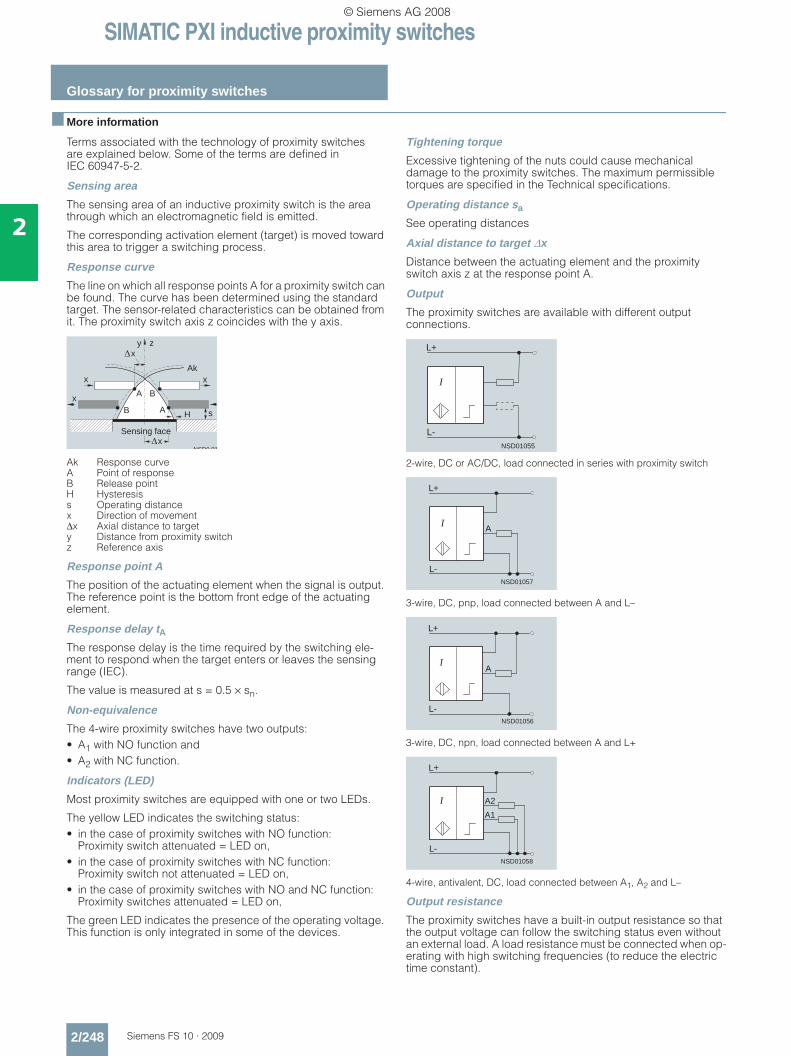
SIMATIC PXI inductive proximity switches
Glossary for proximity switches
2/248 Siemens FS 10 · 2009
2
■ More information
Terms associated with the technology of proximity switches are explained below. Some of the terms are defined in IEC 60947-5-2.
Sensing area
The sensing area of an inductive proximity switch is the area through which an electromagnetic field is emitted.
The corresponding activation element (target) is moved toward this area to trigger a switching process.
Response curve
The line on which all response points A for a proximity switch can be found. The curve has been determined using the standard target. The sensor-related characteristics can be obtained from it. The proximity switch axis z coincides with the y axis.
Ak Response curve A Point of response B Release point H Hysteresis s Operating distance x Direction of movement Δx Axial distance to target y Distance from proximity switch z Reference axis
Response point A
The position of the actuating element when the signal is output. The reference point is the bottom front edge of the actuating element.
Response delay tAThe response delay is the time required by the switching ele-ment to respond when the target enters or leaves the sensing range (IEC).
The value is measured at s = 0.5 × sn.
Non-equivalence
The 4-wire proximity switches have two outputs:• A1 with NO function and • A2 with NC function.
Indicators (LED)
Most proximity switches are equipped with one or two LEDs.
The yellow LED indicates the switching status:• in the case of proximity switches with NO function:
Proximity switch attenuated = LED on,• in the case of proximity switches with NC function:
Proximity switch not attenuated = LED on,• in the case of proximity switches with NO and NC function:
Proximity switches attenuated = LED on,
The green LED indicates the presence of the operating voltage. This function is only integrated in some of the devices.
Tightening torque
Excessive tightening of the nuts could cause mechanical damage to the proximity switches. The maximum permissible torques are specified in the Technical specifications.
Operating distance sa
See operating distances
Axial distance to target Δx
Distance between the actuating element and the proximity switch axis z at the response point A.
Output
The proximity switches are available with different output connections.
2-wire, DC or AC/DC, load connected in series with proximity switch
3-wire, DC, pnp, load connected between A and L–
3-wire, DC, npn, load connected between A and L+
4-wire, antivalent, DC, load connected between A1, A2 and L–
Output resistance
The proximity switches have a built-in output resistance so that the output voltage can follow the switching status even without an external load. A load resistance must be connected when op-erating with high switching frequencies (to reduce the electric time constant).
NSD0 01
y z
x
x
x
x
Ak
BA
B H s
x
x
A
Sensing face
NSD01055
L+
L-
I
NSD01057
L+
L-
AI
NSD01056
L+
L-
AI
NSD01058
L+
L-
A2
A1
I
© Siemens AG 2008
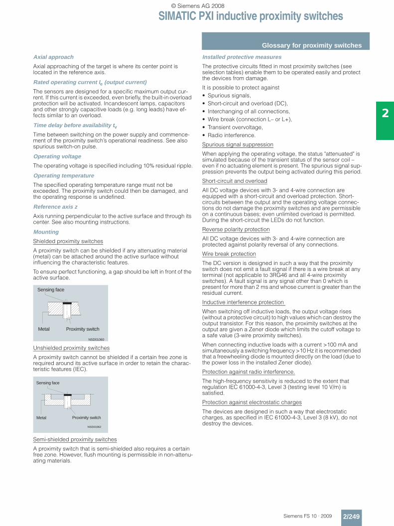
SIMATIC PXI inductive proximity switches
Glossary for proximity switches
2/249Siemens FS 10 · 2009
2
Axial approach
Axial approaching of the target is where its center point is located in the reference axis.
Rated operating current Ie (output current)
The sensors are designed for a specific maximum output cur-rent. If this current is exceeded, even briefly, the built-in overload protection will be activated. Incandescent lamps, capacitors and other strongly capacitive loads (e.g. long leads) have ef-fects similar to an overload.
Time delay before availability tvTime between switching on the power supply and commence-ment of the proximity switch’s operational readiness. See also spurious switch-on pulse.
Operating voltage
The operating voltage is specified including 10% residual ripple.
Operating temperature
The specified operating temperature range must not be exceeded. The proximity switch could then be damaged, and the operating response is undefined.
Reference axis z
Axis running perpendicular to the active surface and through its center. See also mounting instructions.
Mounting
Shielded proximity switches
A proximity switch can be shielded if any attenuating material (metal) can be attached around the active surface without influencing the characteristic features.
To ensure perfect functioning, a gap should be left in front of the active surface.
Unshielded proximity switches
A proximity switch cannot be shielded if a certain free zone is required around its active surface in order to retain the charac-teristic features (IEC).
Semi-shielded proximity switches
A proximity switch that is semi-shielded also requires a certain free zone. However, flush mounting is permissible in non-attenu-ating materials.
Installed protective measures
The protective circuits fitted in most proximity switches (see selection tables) enable them to be operated easily and protect the devices from damage.
It is possible to protect against• Spurious signals,• Short-circuit and overload (DC),• Interchanging of all connections,• Wire break (connection L– or L+),• Transient overvoltage,• Radio interference.
Spurious signal suppression
When applying the operating voltage, the status "attenuated" is simulated because of the transient status of the sensor coil – even if no actuating element is present. The spurious signal sup-pression prevents the output being activated during this period.
Short-circuit and overload
All DC voltage devices with 3- and 4-wire connection are equipped with a short-circuit and overload protection. Short-circuits between the output and the operating voltage connec-tions do not damage the proximity switches and are permissible on a continuous bases; even unlimited overload is permitted. During the short-circuit the LEDs do not function.
Reverse polarity protection
All DC voltage devices with 3- and 4-wire connection are protected against polarity reversal of any connections.
Wire break protection
The DC version is designed in such a way that the proximity switch does not emit a fault signal if there is a wire break at any terminal (not applicable to 3RG46 and all 4-wire proximity switches). A fault signal is any signal other than 0 which is present for more than 2 ms and whose current is greater than the residual current.
Inductive interference protection
When switching off inductive loads, the output voltage rises (without a protective circuit) to high values which can destroy the output transistor. For this reason, the proximity switches at the output are given a Zener diode which limits the cutoff voltage to a safe value (3-wire proximity switches).
When connecting inductive loads with a current >100 mA and simultaneously a switching frequency >10 Hz it is recommended that a freewheeling diode is mounted directly on the load (due to the power loss in the installed Zener diode).
Protection against radio interference.
The high-frequency sensitivity is reduced to the extent that regulation IEC 61000-4-3, Level 3 (testing level 10 V/m) is satisfied.
Protection against electrostatic charges
The devices are designed in such a way that electrostatic charges, as specified in IEC 61000-4-3, Level 3 (8 kV), do not destroy the devices.
NSD01060
Metal Proximity switch
Sensing face
NSD01062
Metal Proximity switch
Sensing face
© Siemens AG 2008
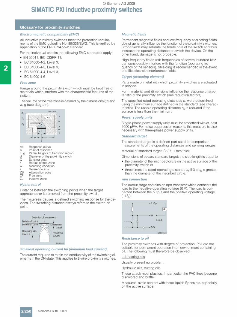
SIMATIC PXI inductive proximity switches
Glossary for proximity switches
2/250 Siemens FS 10 · 2009
2
Electromagnetic compatibility (EMC)
All inductive proximity switches meet the protection require-ments of the EMC guideline No. 89/336/EWG. This is verified by application of the EN 60 947-5-2 standard.
For the individual checks the following EMC standards apply:• EN 55011, IEC-CISPR 11,• IEC 61000-4-2, Level 3,• IEC 61000-4-3, Level 3,• IEC 61000-4-4, Level 3,• IEC 61000-4-6
Free zone
Range around the proximity switch which must be kept free of materials which interfere with the characteristic features of the switch.
The volume of the free zone is defined by the dimensions r, c and w, g (see diagram).
Ak Response curve A Point of response c, g Partial heights of transition region d Diameter of the proximity switch Q Sensing area r Radius of free zone w Mounting condition z Reference axis ZB Attenuation zone ZF Free zone ZJ Inactive zone
Hysteresis H
Distance between the switching points when the target approaches or is removed from the proximity switch.
The hysteresis causes a defined switching response for the de-vices. The switching distance always refers to the switch-on point.
Smallest operating current Im (minimum load current)
The current required to retain the conductivity of the switching el-ements in the ON state. This applies to 2-wire proximity switches.
Magnetic fields
Permanent magnetic fields and low-frequency alternating fields do not generally influence the function of the proximity switches. Strong fields may saturate the ferrite core of the switch and thus increase the operating distance or switch the device. On the other hand, damage is not probable.
High-frequency fields with frequencies of several hundred kHz can considerably interfere with the function (operating fre-quency of the sensors). Shielding is recommended in the event of difficulties with interference fields.
Target (actuating element)
Parts made of metal with which proximity switches are actuated in service.
Form, material and dimensions influence the response charac-teristic of the proximity switch (see reduction factors).
The specified rated operating distances sn were determined using the minimum surface defined in the standard (see charac-teristic). The usable operating distance su is reduced if the surface is less than the minimum.
Power supply units
Single-phase power supply units must be smoothed with at least 1000 µF/A. For noise suppression reasons, this measure is also necessary with three-phase power supply units.
Standard target
The standard target is a defined part used for comparison measurements of the operating distances and sensing ranges.
Material of standard target: St 37, 1 mm thick
Dimensions of square standard target: the side length is equal to• the diameter of the inscribed circle on the active surface of the
proximity switch or• three times the rated operating distance sn if 3 × sn is greater
than the diameter of the inscribed circle.
npn connection
The output stage contains an npn transistor which connects the load to the negative operating voltage (0 V). The load is con-nected between the output and the positive operating voltage (+UB).
Resistance to oil
The proximity switches with degree of protection IP67 are not suitable for permanent operation in an environment containing oil. The following must therefore be observed:
Lubricating oils
Usually present no problem.
Hydraulic oils, cutting oils
These attack most plastics. In particular, the PVC lines become discolored and brittle.
Measures: avoid contact with these liquids if possible, especially on the active surface.
w
dQ
Ak
A
ZF
ZJ
ZB
r
cg
z
NSD01061
NSD01053
Switch-off pointSwitch-on point
Operating dis-tance s
Responsecurves
Differential travel
Direction of movement
NSD01049
+U
A
B
0 V
R L
Load
© Siemens AG 2008
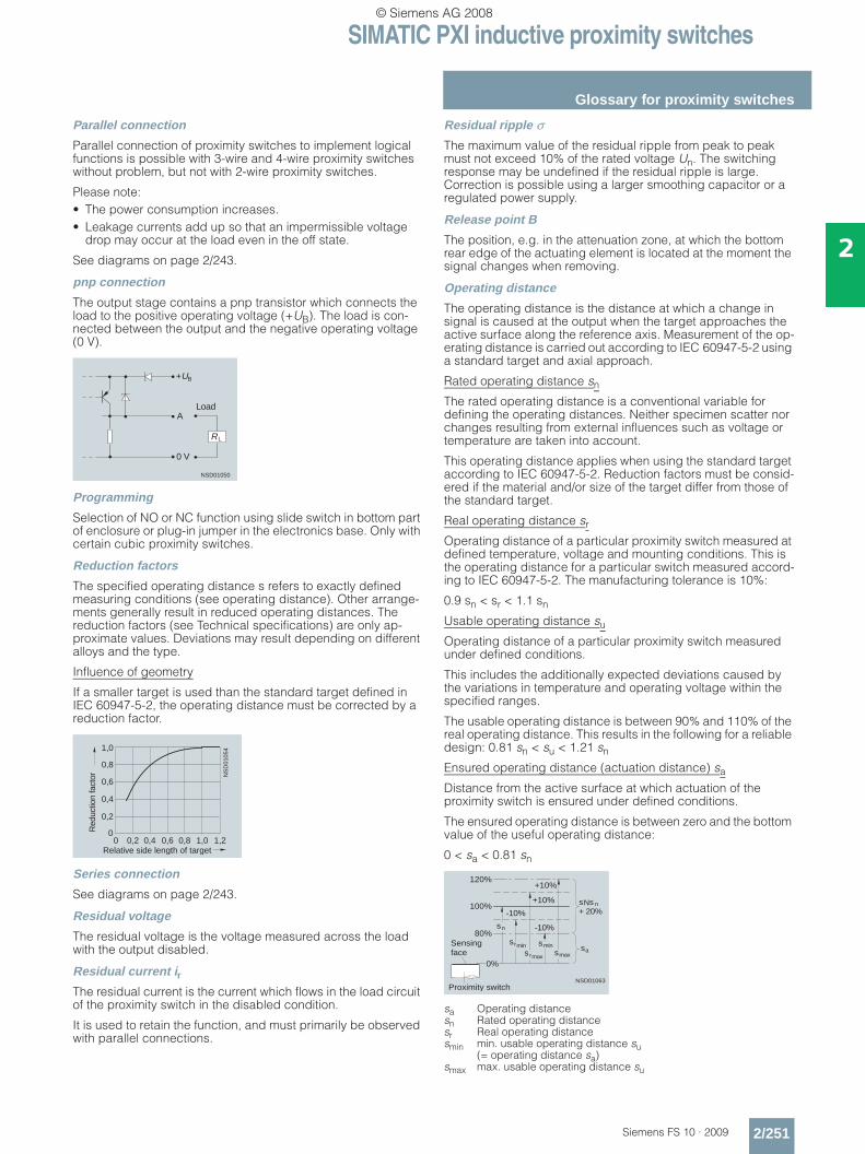
SIMATIC PXI inductive proximity switches
Glossary for proximity switches
2/251Siemens FS 10 · 2009
2
Parallel connection
Parallel connection of proximity switches to implement logical functions is possible with 3-wire and 4-wire proximity switches without problem, but not with 2-wire proximity switches.
Please note:• The power consumption increases.• Leakage currents add up so that an impermissible voltage
drop may occur at the load even in the off state.
See diagrams on page 2/243.
pnp connection
The output stage contains a pnp transistor which connects the load to the positive operating voltage (+UB). The load is con-nected between the output and the negative operating voltage (0 V).
Programming
Selection of NO or NC function using slide switch in bottom part of enclosure or plug-in jumper in the electronics base. Only with certain cubic proximity switches.
Reduction factors
The specified operating distance s refers to exactly defined measuring conditions (see operating distance). Other arrange-ments generally result in reduced operating distances. The reduction factors (see Technical specifications) are only ap-proximate values. Deviations may result depending on different alloys and the type.
Influence of geometry
If a smaller target is used than the standard target defined in IEC 60947-5-2, the operating distance must be corrected by a reduction factor.
Series connection
See diagrams on page 2/243.
Residual voltage
The residual voltage is the voltage measured across the load with the output disabled.
Residual current irThe residual current is the current which flows in the load circuit of the proximity switch in the disabled condition.
It is used to retain the function, and must primarily be observed with parallel connections.
Residual ripple σThe maximum value of the residual ripple from peak to peak must not exceed 10% of the rated voltage Un. The switching response may be undefined if the residual ripple is large. Correction is possible using a larger smoothing capacitor or a regulated power supply.
Release point B
The position, e.g. in the attenuation zone, at which the bottom rear edge of the actuating element is located at the moment the signal changes when removing.
Operating distance
The operating distance is the distance at which a change in signal is caused at the output when the target approaches the active surface along the reference axis. Measurement of the op-erating distance is carried out according to IEC 60947-5-2 using a standard target and axial approach.
Rated operating distance sn
The rated operating distance is a conventional variable for defining the operating distances. Neither specimen scatter nor changes resulting from external influences such as voltage or temperature are taken into account.
This operating distance applies when using the standard target according to IEC 60947-5-2. Reduction factors must be consid-ered if the material and/or size of the target differ from those of the standard target.
Real operating distance sr
Operating distance of a particular proximity switch measured at defined temperature, voltage and mounting conditions. This is the operating distance for a particular switch measured accord-ing to IEC 60947-5-2. The manufacturing tolerance is 10%:
0.9 sn < sr < 1.1 sn
Usable operating distance su
Operating distance of a particular proximity switch measured under defined conditions.
This includes the additionally expected deviations caused by the variations in temperature and operating voltage within the specified ranges.
The usable operating distance is between 90% and 110% of the real operating distance. This results in the following for a reliable design: 0.81 sn < su < 1.21 sn
Ensured operating distance (actuation distance) sa
Distance from the active surface at which actuation of the proximity switch is ensured under defined conditions.
The ensured operating distance is between zero and the bottom value of the useful operating distance:
0 < sa < 0.81 sn
sa Operating distance sn Rated operating distance sr Real operating distance smin min. usable operating distance su
(= operating distance sa) smax max. usable operating distance su
NSD01050
+U
R
A
0 V
L
B
Load
1,0
1,21,00,80,60,40,20
0,8
0,6
0,4
0,2
0
NS
D01
054
Relative side length of target
Red
uctio
n fa
ctor
NSD01063
120%
100%
80%
0%
sn
sr
-10%
+10%
minsrmax
smin
-10%
+10%
smax
s s + 20%
N n
saSensingface
Proximity switch
© Siemens AG 2008
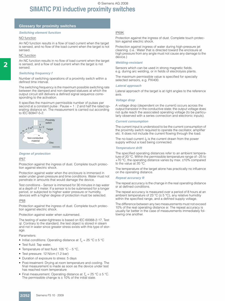
SIMATIC PXI inductive proximity switches
Glossary for proximity switches
2/252 Siemens FS 10 · 2009
2
Switching element function
NO function
An NO function results in a flow of load current when the target is sensed, and no flow of the load current when the target is not sensed.
NC function
An NC function results in no flow of load current when the target is sensed, and a flow of load current when the target is not sensed.
Switching frequency f
Number of switching operations of a proximity switch within a defined time interval.
The switching frequency is the maximum possible switching rate between the damped and non-damped statuses at which the output circuit still delivers a defined signal sequence corre-sponding to the activation.
It specifies the maximum permissible number of pulses per second at a constant pulse : Pause = 1 : 2 and half the rated op-erating distance sn. The measurement is carried out according to IEC 60947-5-2.
Degree of protection
IP67
Protection against the ingress of dust. Complete touch protec-tion against electric shock.
Protection against water when the enclosure is immersed in water under given pressure and time conditions. Water must not penetrate in amounts that would damage the device.
Test conditions – Sensor is immersed for 30 minutes in tap water at a depth of 1 meter. If a sensor is to be submersed for a longer period, or subjected to higher water pressure or humidity, devices with a higher degree of protection must be selected.
IP68
Protection against the ingress of dust. Complete touch protec-tion against electric shock.
Protection against water when submersed.
The testing of water-tightness is based on IEC 60068-2-17, Test ql. Contrary to the standard, the test object is stored in steam and not in water since greater stress exists with this type of stor-age.
Parameters:• Initial conditions: Operating distance at Tu = 25 °C ± 5 °C• Test fluid: Tap water, • Temperature of test fluid: 105 °C – 5 °C,• Test pressure: 12 N/cm (1.2 bar)• Duration of exposure to stress: 5 days• Post-treatment: Drying at room temperature and cooling. The
final measurement is made as soon as the device under test has reached room temperature
• Final measurement: Operating distance at Tu = 25 °C ± 5 °C. The permissible change is ± 10% of the initial state.
IP69K
Protection against the ingress of dust. Complete touch protec-tion against electric shock.
Protection against ingress of water during high-pressure jet cleaning. (i.e.: Water that is directed toward the enclosure at high pressure from any angle must not cause any damage to the device.)
Welding-resistant
Sensors which can be used in strong magnetic fields, e.g. during arc welding, or in fields of electrolysis plants.
The maximum permissible value is specified for specially selected sensors, e.g. PXI400.
Lateral approach
Lateral approach of the target is at right angles to the reference axis.
Voltage drop
A voltage drop (dependent on the current) occurs across the output transistor in the conductive state; the output voltage does not quite reach the associated operating voltage (to be particu-larly observed with a series connection and electronic inputs).
Current consumption
The current input is understood to be the current consumption of the proximity switch required to operate the oscillator, amplifier etc. It does not include the current flowing through the load.
The no-load current I0 is the current drawn from the power supply without a load being connected.
Temperature drift
The specified operating distances refer to an ambient tempera-ture of 20 °C. Within the permissible temperature range of –25 to +70 °C, the operating distance varies by max. ±10% compared to the value at 20 °C.
The temperature of the target alone has practically no influence on the operating distance.
Repeat accuracy R
The repeat accuracy is the change in the real operating distance sr at defined conditions.
The repeat accuracy is measured over a period of 8 hours at an ambient temperature of 23 °C (± 5 °C), any relative humidity within the specified range, and a defined supply voltage.
The difference between any two measurements must not exceed 10% of the real operating distance sr. The repeat accuracy is usually far better in the case of measurements immediately fol-lowing one another.
s / 2n
m2 m
NSD01052
Proximityswitch
Non-conductivematerial
Disc
Target
© Siemens AG 2008
SIMATIC PXI inductive proximity switches
2/253Siemens FS 10 · 2009
2
■ Notes
© Siemens AG 2008
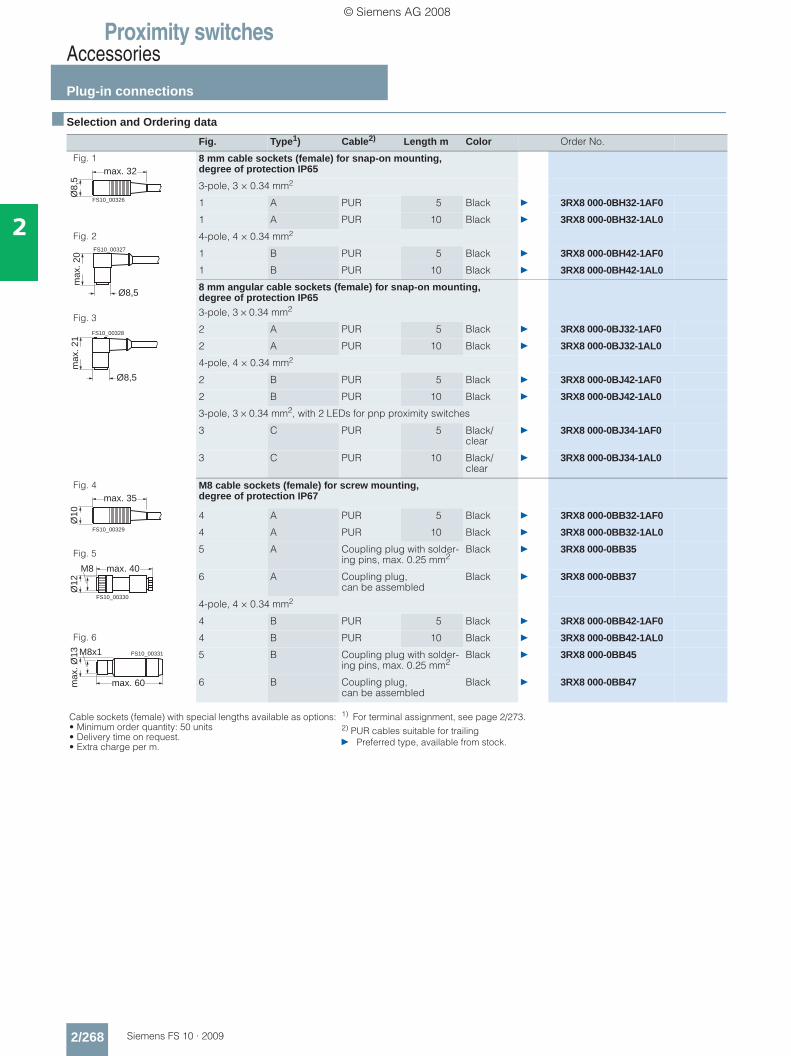
Proximity switchesAccessories
Plug-in connections
2/268 Siemens FS 10 · 2009
2
■ Selection and Ordering data
Fig. Type1) Cable2) Length m Color Order No.
Fig. 1 8 mm cable sockets (female) for snap-on mounting, degree of protection IP65
3-pole, 3 × 0.34 mm2
1 A PUR 5 Black } 3RX8 000-0BH32-1AF0
1 A PUR 10 Black } 3RX8 000-0BH32-1AL0
Fig. 2
Fig. 3
4-pole, 4 × 0.34 mm2
1 B PUR 5 Black } 3RX8 000-0BH42-1AF0
1 B PUR 10 Black } 3RX8 000-0BH42-1AL0
8 mm angular cable sockets (female) for snap-on mounting, degree of protection IP653-pole, 3 × 0.34 mm2
2 A PUR 5 Black } 3RX8 000-0BJ32-1AF0
2 A PUR 10 Black } 3RX8 000-0BJ32-1AL0
4-pole, 4 × 0.34 mm2
2 B PUR 5 Black } 3RX8 000-0BJ42-1AF0
2 B PUR 10 Black } 3RX8 000-0BJ42-1AL0
3-pole, 3 × 0.34 mm2, with 2 LEDs for pnp proximity switches
3 C PUR 5 Black/clear
} 3RX8 000-0BJ34-1AF0
3 C PUR 10 Black/clear
} 3RX8 000-0BJ34-1AL0
Fig. 4
Fig. 5
Fig. 6
M8 cable sockets (female) for screw mounting, degree of protection IP67
4 A PUR 5 Black } 3RX8 000-0BB32-1AF0
4 A PUR 10 Black } 3RX8 000-0BB32-1AL0
5 A Coupling plug with solder-ing pins, max. 0.25 mm2
Black } 3RX8 000-0BB35
6 A Coupling plug, can be assembled
Black } 3RX8 000-0BB37
4-pole, 4 × 0.34 mm2
4 B PUR 5 Black } 3RX8 000-0BB42-1AF0
4 B PUR 10 Black } 3RX8 000-0BB42-1AL0
5 B Coupling plug with solder-ing pins, max. 0.25 mm2
Black } 3RX8 000-0BB45
6 B Coupling plug, can be assembled
Black } 3RX8 000-0BB47
Cable sockets (female) with special lengths available as options:• Minimum order quantity: 50 units• Delivery time on request.• Extra charge per m.
1) For terminal assignment, see page 2/273.2) PUR cables suitable for trailing} Preferred type, available from stock.
max. 32
Ø8,
5
FS10_00326
max
. 20
Ø8,5
FS10_00327
max
. 21
Ø8,5
FS10_00328
max. 35
Ø10
FS10_00329
max. 40
Ø12
M8
FS10_00330
max. 60max
. Ø13 M8x1 FS10_00331
© Siemens AG 2008
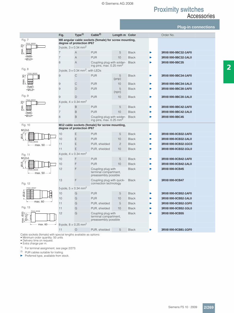
Proximity switchesAccessories
Plug-in connections
2/269Siemens FS 10 · 2009
2
Fig. Type1) Cable2) Length m Color Order No.
Fig. 7
Fig. 8
Fig. 9
M8 angular cable sockets (female) for screw mounting, degree of protection IP673-pole, 3 × 0.34 mm2
7 A PUR 5 Black } 3RX8 000-0BC32-1AF0
7 A PUR 10 Black } 3RX8 000-0BC32-1AL0
8 A Coupling plug with solder-ing pins, max. 0.25 mm2
Black } 3RX8 000-0BC35
3-pole, 3 × 0.34 mm2, with LEDs
9 C PUR 5(pnp)
Black } 3RX8 000-0BC34-1AF0
9 C PUR 10 Black } 3RX8 000-0BC34-1AL0
9 D PUR 5(npn)
Black } 3RX8 000-0BC30-1AF0
9 D PUR 10 Black } 3RX8 000-0BC30-1AL0
4-pole, 4 × 0.34 mm2
7 B PUR 5 Black } 3RX8 000-0BC42-1AF0
7 B PUR 10 Black } 3RX8 000-0BC42-1AL0
8 B Coupling plug with solder-ing pins, max. 0.25 mm2
Black } 3RX8 000-0BC45
Fig. 10
Fig. 11
Fig. 12
Fig. 13
M12 cable sockets (female) for screw mounting, degree of protection IP67
10 E PUR 5 Black } 3RX8 000-0CB32-1AF0
10 E PUR 10 Black } 3RX8 000-0CB32-1AL0
11 E PUR, shielded 2 Black } 3RX8 000-0CB32-1GC0
11 E PUR, shielded 10 Black } 3RX8 000-0CB32-1GL0
4-pole, 4 × 0.34 mm2
10 F PUR 5 Black } 3RX8 000-0CB42-1AF0
10 F PUR 10 Black } 3RX8 000-0CB42-1AL0
12 F Coupling plug with terminal compartment, preassembly possible
Black } 3RX8 000-0CB45
13 F Coupling plug with quick-connection technology
Black } 3RX8 000-0CB47
5-pole, 5 × 0.34 mm2
10 G PUR 5 Black } 3RX8 000-0CB52-1AF0
10 G PUR 10 Black } 3RX8 000-0CB52-1AL0
11 G PUR, shielded 5 Black } 3RX8 000-0CB52-1GF0
11 G PUR, shielded 10 Black } 3RX8 000-0CB52-1GL0
12 G Coupling plug with terminal compartment, preassembly possible
Black } 3RX8 000-0CB55
8-pole, 8 × 0.25 mm2
11 O PUR, shielded 5 Black } 3RX8 000-0CB81-1GF0
Cable sockets (female) with special lengths available as options:• Minimum order quantity: 50 units• Delivery time on request.• Extra charge per m.1) For terminal assignment, see page 2/273.2) PUR cables suitable for trailing.} Preferred type, available from stock.
max
. 20
Ø10M8
FS10_00332
max
. 30
Ø12M8
FS10_00333
max
. 20
Ø10M8
FS10_00334
M12x1
max. 50
Ø15
FS10_00335
M12x1
max. 50
Ø15
FS10_00336
max. 60
Ø18
FS10_00337
max. 60
M12
x1m
ax. Ø
20
FS10_00338
© Siemens AG 2008
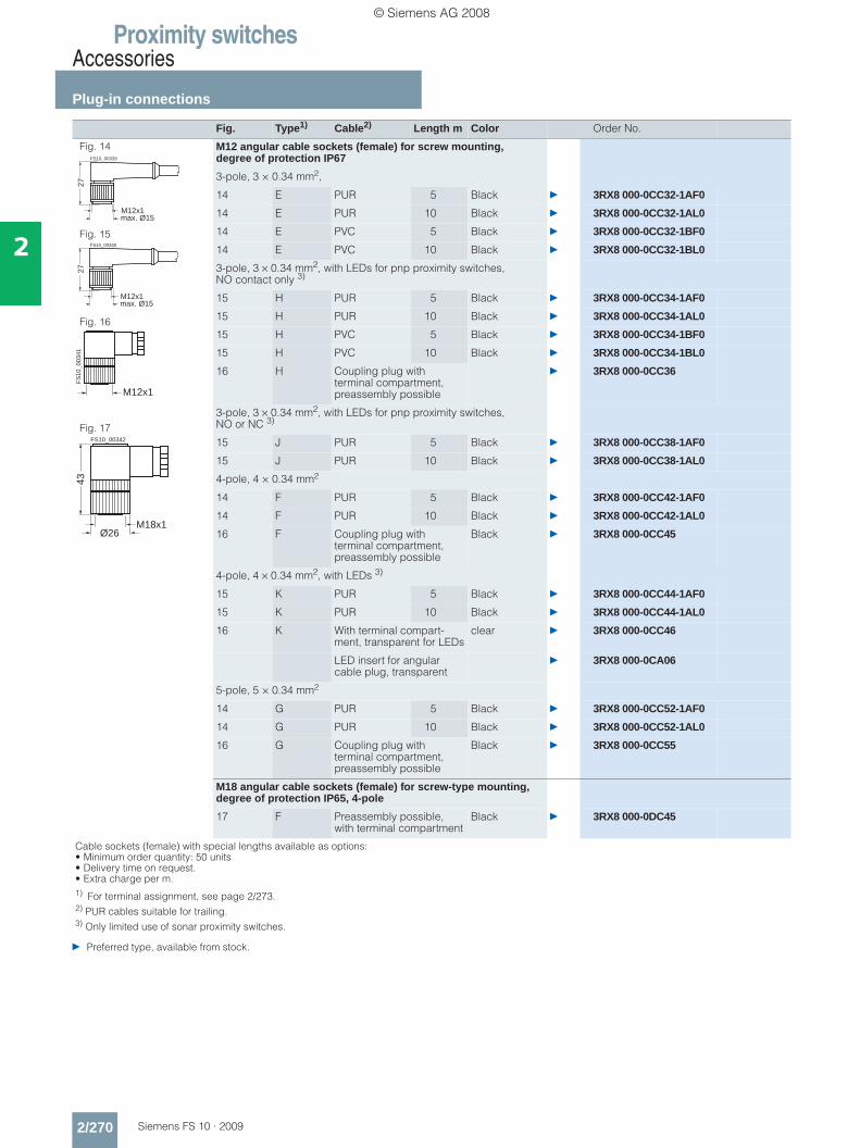
Proximity switchesAccessories
Plug-in connections
2/270 Siemens FS 10 · 2009
2
} Preferred type, available from stock.
Fig. 14
Fig. 15
Fig. 16
Fig. 17
M12 angular cable sockets (female) for screw mounting, degree of protection IP67
3-pole, 3 × 0.34 mm2,
14 E PUR 5 Black } 3RX8 000-0CC32-1AF0
14 E PUR 10 Black } 3RX8 000-0CC32-1AL0
14 E PVC 5 Black } 3RX8 000-0CC32-1BF0
14 E PVC 10 Black } 3RX8 000-0CC32-1BL0
3-pole, 3 × 0.34 mm2, with LEDs for pnp proximity switches, NO contact only 3)
15 H PUR 5 Black } 3RX8 000-0CC34-1AF0
15 H PUR 10 Black } 3RX8 000-0CC34-1AL0
15 H PVC 5 Black } 3RX8 000-0CC34-1BF0
15 H PVC 10 Black } 3RX8 000-0CC34-1BL0
16 H Coupling plug with terminal compartment, preassembly possible
} 3RX8 000-0CC36
3-pole, 3 × 0.34 mm2, with LEDs for pnp proximity switches, NO or NC 3)
15 J PUR 5 Black } 3RX8 000-0CC38-1AF0
15 J PUR 10 Black } 3RX8 000-0CC38-1AL0
4-pole, 4 × 0.34 mm2
14 F PUR 5 Black } 3RX8 000-0CC42-1AF0
14 F PUR 10 Black } 3RX8 000-0CC42-1AL0
16 F Coupling plug with terminal compartment, preassembly possible
Black } 3RX8 000-0CC45
4-pole, 4 × 0.34 mm2, with LEDs 3)
15 K PUR 5 Black } 3RX8 000-0CC44-1AF0
15 K PUR 10 Black } 3RX8 000-0CC44-1AL0
16 K With terminal compart-ment, transparent for LEDs
clear } 3RX8 000-0CC46
LED insert for angular cable plug, transparent
} 3RX8 000-0CA06
5-pole, 5 × 0.34 mm2
14 G PUR 5 Black } 3RX8 000-0CC52-1AF0
14 G PUR 10 Black } 3RX8 000-0CC52-1AL0
16 G Coupling plug with terminal compartment, preassembly possible
Black } 3RX8 000-0CC55
M18 angular cable sockets (female) for screw-type mounting, degree of protection IP65, 4-pole
17 F Preassembly possible, with terminal compartment
Black } 3RX8 000-0DC45
Cable sockets (female) with special lengths available as options:• Minimum order quantity: 50 units• Delivery time on request.• Extra charge per m.1) For terminal assignment, see page 2/273.2) PUR cables suitable for trailing.3) Only limited use of sonar proximity switches.
Fig. Type1) Cable2) Length m Color Order No.
M12x1
27
max. Ø15
FS10_00339
M12x1
27
max. Ø15
FS10_00340
M12x1
FS10
_003
41
M18x1
FS10_00342
Ø26
43
© Siemens AG 2008
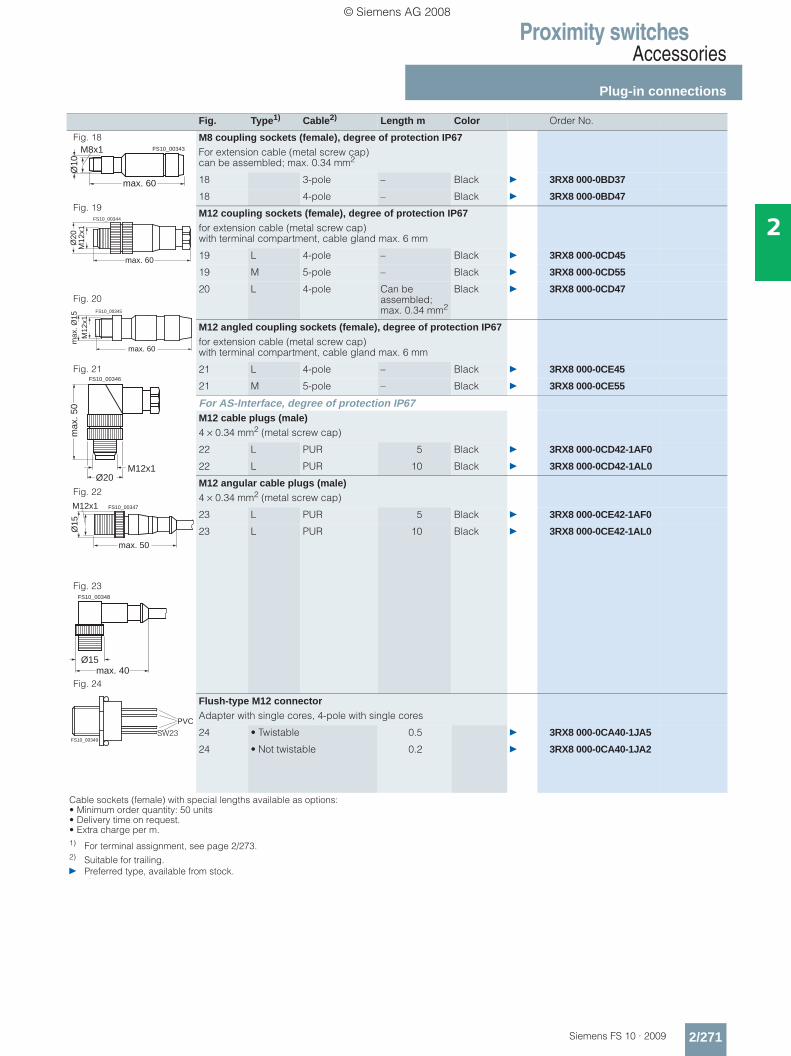
Proximity switchesAccessories
Plug-in connections
2/271Siemens FS 10 · 2009
2
Fig. Type1) Cable2) Length m Color Order No.
Fig. 18
Fig. 19
Fig. 20
Fig. 21
Fig. 22
Fig. 23
Fig. 24
M8 coupling sockets (female), degree of protection IP67For extension cable (metal screw cap) can be assembled; max. 0.34 mm2
18 3-pole – Black } 3RX8 000-0BD37
18 4-pole – Black } 3RX8 000-0BD47
M12 coupling sockets (female), degree of protection IP67for extension cable (metal screw cap) with terminal compartment, cable gland max. 6 mm
19 L 4-pole – Black } 3RX8 000-0CD45
19 M 5-pole – Black } 3RX8 000-0CD55
20 L 4-pole Can be assembled; max. 0.34 mm2
Black } 3RX8 000-0CD47
M12 angled coupling sockets (female), degree of protection IP67 for extension cable (metal screw cap) with terminal compartment, cable gland max. 6 mm
21 L 4-pole – Black } 3RX8 000-0CE45
21 M 5-pole – Black } 3RX8 000-0CE55
For AS-Interface, degree of protection IP67M12 cable plugs (male)4 × 0.34 mm2 (metal screw cap)
22 L PUR 5 Black } 3RX8 000-0CD42-1AF0
22 L PUR 10 Black } 3RX8 000-0CD42-1AL0
M12 angular cable plugs (male)4 × 0.34 mm2 (metal screw cap)
23 L PUR 5 Black } 3RX8 000-0CE42-1AF0
23 L PUR 10 Black } 3RX8 000-0CE42-1AL0
Flush-type M12 connectorAdapter with single cores, 4-pole with single cores
24 • Twistable 0.5 } 3RX8 000-0CA40-1JA5
24 • Not twistable 0.2 } 3RX8 000-0CA40-1JA2
Cable sockets (female) with special lengths available as options:• Minimum order quantity: 50 units• Delivery time on request.• Extra charge per m.1) For terminal assignment, see page 2/273.2) Suitable for trailing.} Preferred type, available from stock.
FS10_00343
max. 60
M8x1
Ø10
max. 60
M12
x1Ø
20
FS10_00344
max. 60
M12
x1m
ax. Ø
15
FS10_00345
max
. 50
M12x1Ø20
FS10_00346
max. 50
Ø15
M12x1 FS10_00347
max. 40Ø15
FS10_00348
PVC
FS10_00349SW23
© Siemens AG 2008
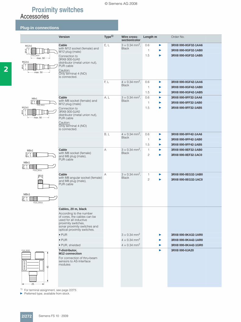
Proximity switchesAccessories
Plug-in connections
2/272 Siemens FS 10 · 2009
2
1
1) For terminal assignment, see page 2/273.} Preferred type, available from stock.
Version Type1) Wire cross-section/color
Length m Order No.
Cable with M12 socket (female) and M12 plug (male)Connection to 3RX8 000-0JA0 distributor (metal union nut),PUR cableCaution:Only terminal 4 (NO) is connected.
E, L 3 × 0.34 mm2, Black
0.6 } 3RX8 000-0GF32-1AA6
1 } 3RX8 000-0GF32-1AB0
1.5 } 3RX8 000-0GF32-1AB5
F, L 4 × 0.34 mm2, Black
0.6 } 3RX8 000-0GF42-1AA6
1 } 3RX8 000-0GF42-1AB0
1.5 } 3RX8 000-0GF42-1AB5
Cable with M8 socket (female) and M12 plug (male)Connection to 3RX8 000-0JA0 distributor (metal union nut),PUR cableCaution:Only terminal 4 (NO) is connected.
A, L 3 × 0.34 mm2, Black
0.6 } 3RX8 000-0FF32-1AA6
1 } 3RX8 000-0FF32-1AB0
1.5 } 3RX8 000-0FF32-1AB5
B, L 4 × 0.34 mm2, Black
0.6 } 3RX8 000-0FF42-1AA6
1 } 3RX8 000-0FF42-1AB0
1.5 } 3RX8 000-0FF42-1AB5
Cable with M8 socket (female) and M8 plug (male), PUR cable
A 3 × 0.34 mm2, Black
1 } 3RX8 000-0EF32-1AB0
2 } 3RX8 000-0EF32-1AC0
Cable with M8 angular socket (female) and M8 plug (male), PUR cable
A 3 × 0.34 mm2, Black
1 } 3RX8 000-0EG32-1AB0
2 } 3RX8 000-0EG32-1AC0
Cables, 20 m, blackAccording to the number of cores, the cables can be used for all inductive proximity switches, sonar proximity switches and optical proximity switches.
• PUR 3 × 0.34 mm2} 3RX8 000-0KA32-1AR0
• PUR 4 × 0.34 mm2} 3RX8 000-0KA42-1AR0
• PUR, shielded 4 × 0.34 mm2} 3RX8 000-0KA42-1GR0
T-distributor, M12 connectionFor connection of thru-beam sensors to AS-Interface modules
} 3RX8 000-0JA20
M12x1
max. 50
max. 50
Ø15
M12x1
Ø15
FS10_00324
M8x1
max. 50
Ø15
M12x1
Ø10
FS10_00323
M8x1
Ø10
M8x1
Ø10
FS10_00321
Ø10
Ø10
M8x1
FS10_00322
45
3RX8
000-
0JA2
0
FS10_00325
25
© Siemens AG 2008
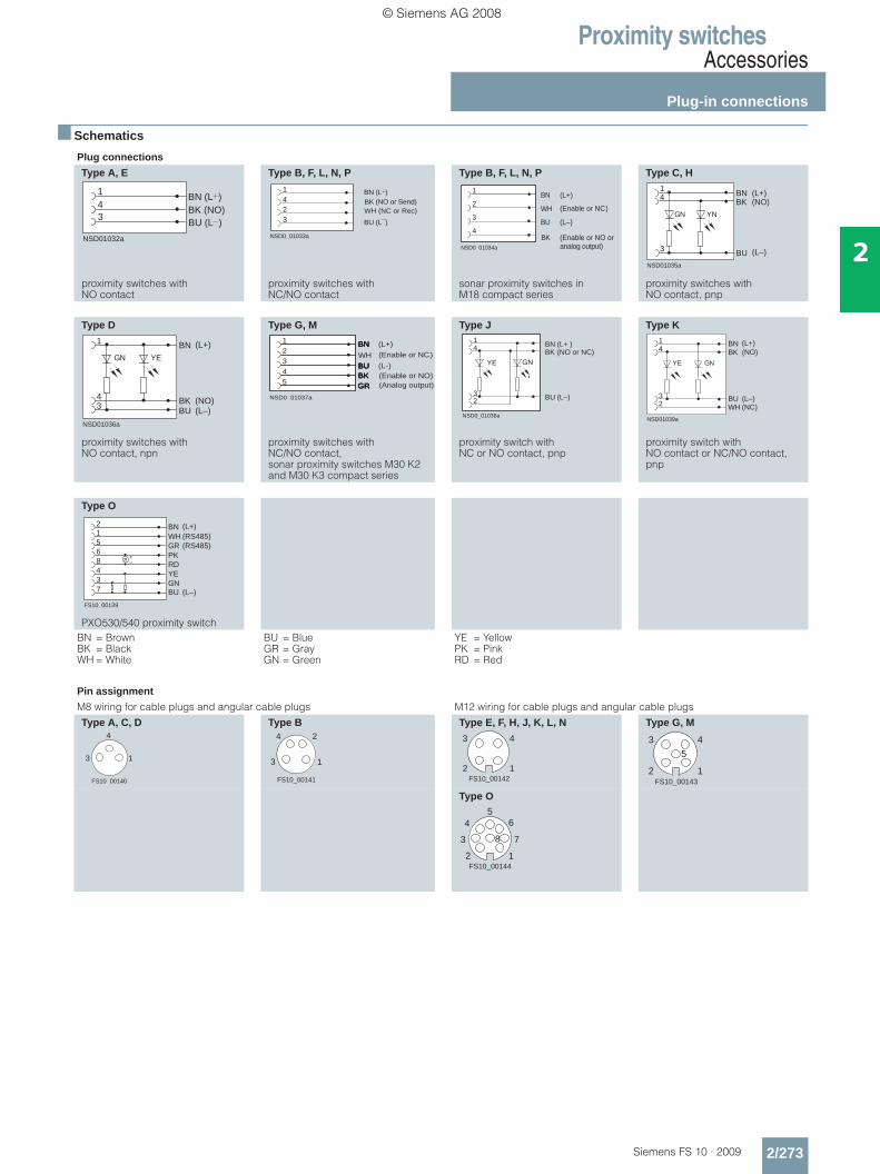
Proximity switchesAccessories
Plug-in connections
2/273Siemens FS 10 · 2009
2
■ Schematics
Plug connections
Type A, E
proximity switches with NO contact
Type B, F, L, N, P
proximity switches with NC/NO contact
Type B, F, L, N, P
sonar proximity switches in M18 compact series
Type C, H
proximity switches with NO contact, pnp
Type D
proximity switches with NO contact, npn
Type G, M
proximity switches with NC/NO contact, sonar proximity switches M30 K2 and M30 K3 compact series
Type J
proximity switch with NC or NO contact, pnp
Type K
proximity switch with NO contact or NC/NO contact, pnp
Type O
PXO530/540 proximity switchBN = BrownBK = BlackWH = White
BU = BlueGR = GrayGN = Green
YE = YellowPK = PinkRD = Red
Pin assignment
M8 wiring for cable plugs and angular cable plugs M12 wiring for cable plugs and angular cable plugs
Type A, C, D Type B Type E, F, H, J, K, L, N Type G, M
Type O
NSD01032a
1 BN (L )
BU (L )BK (NO)
34
NSD0_01033a
1
324
BN (L )
BU (L )
WH (NC or Rec)BK (NO or Send)
NSD0_01034a
1
4
3
2BN
WH
BU
BK
(L–)
(L+)
(Enable or NC)
(Enable or NO oranalog output)
NSD01035a
14
3
BNBK
BU
(L+)(NO)
(L–)
YNGN
NSD01036a
1
43
BN
BKBU
(L+)
(NO)(L–)
YEGN WH
GR
BN
BUBKGR
BN
BUBKGR
BN
BUBK
NSD0_01037a
12345 GR
BN
BUBK
(L+)
(L-)
(Enable or NC)
(Enable or NO)(Analog output)
14
32
BNBK
BU
NSD0_01038a
GNYE
(L+ )
(L–)
(NO or NC)
NSD01039a
4
32
BN
WHBU
(L+)
(NC)(L–)
YE GN
1
BK (NO)
FS10_00139
7 BU (L–)
BN (L+)2
3 GN
4 YE
8 RD
6 PK
5 GR (RS485)
1 WH (RS485)
+–
FS10_00140
1
4
3
FS10_00141
2
3
4
1
FS10_00142
3
2 1
4
FS10_00143
3
2 1
4
5
FS10_00144
8
4
2 1
6
73
5
© Siemens AG 2008
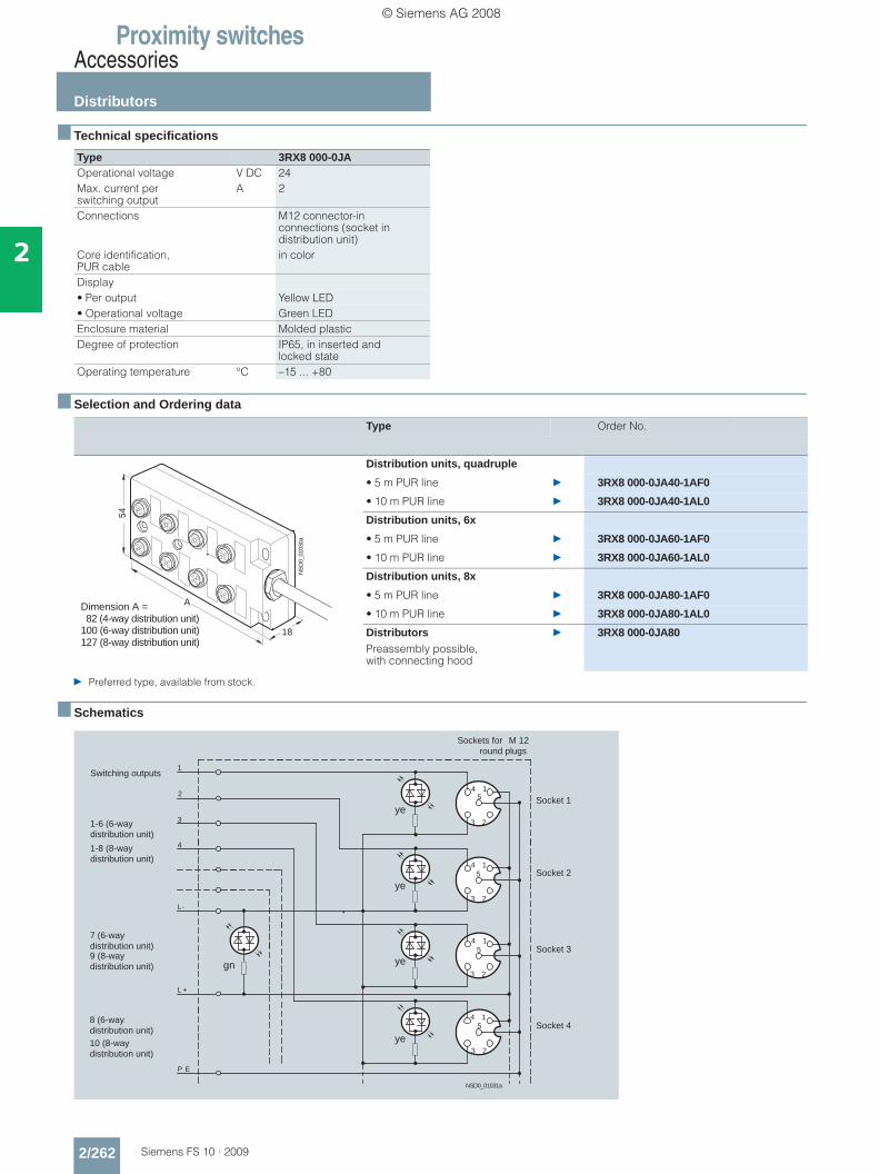
Proximity switchesAccessories
Distributors
2/262 Siemens FS 10 · 2009
2
■ Technical specifications
■ Selection and Ordering data
} Preferred type, available from stock.
■ Schematics
Type 3RX8 000-0JAOperational voltage V DC 24Max. current per switching output
A 2
Connections M12 connector-in connections (socket in distribution unit)
Core identification, PUR cable
in color
Display• Per output Yellow LED• Operational voltage Green LEDEnclosure material Molded plasticDegree of protection IP65, in inserted and
locked stateOperating temperature °C –15 ... +80
Type Order No.
Distribution units, quadruple
• 5 m PUR line } 3RX8 000-0JA40-1AF0
• 10 m PUR line } 3RX8 000-0JA40-1AL0
Distribution units, 6x
• 5 m PUR line } 3RX8 000-0JA60-1AF0
• 10 m PUR line } 3RX8 000-0JA60-1AL0
Distribution units, 8x
• 5 m PUR line } 3RX8 000-0JA80-1AF0
• 10 m PUR line } 3RX8 000-0JA80-1AL0
Distributors Preassembly possible, with connecting hood
} 3RX8 000-0JA80
A
54
18
NS
D0_
0103
0a
Dimension A = 82 (4-way distribution unit)100 (6-way distribution unit)127 (8-way distribution unit)
1
23
4
1
23
4
1
23
4
1
23
4
L-
L +
5
5
5
5
P E
1
2
3
4
NSD0_01031a
Switching outputs
1-6 (6-way distribution unit)
1-8 (8-way distribution unit)
7 (6-way distribution unit)9 (8-way distribution unit)
Socket 48 (6-way distribution unit)10 (8-way distribution unit)
Socket 3
Socket 2
Socket 1
Sockets for M 12round plugs
ye
ye
ye
ye
gn
© Siemens AG 2008
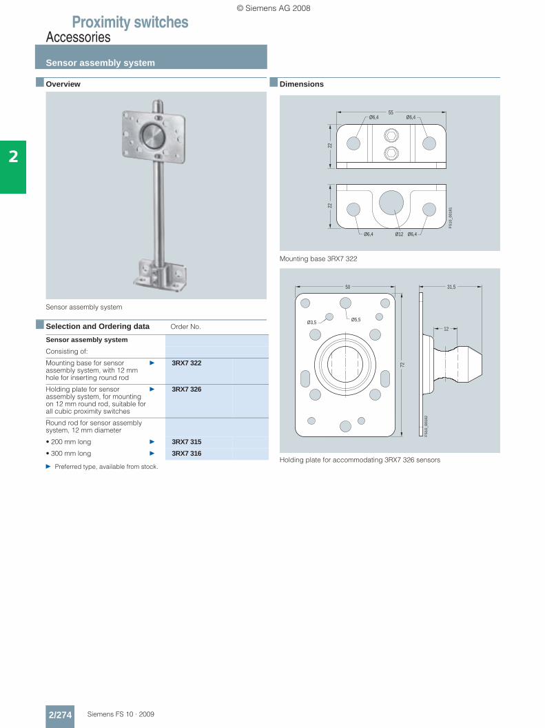
Proximity switchesAccessories
Sensor assembly system
2/274 Siemens FS 10 · 2009
2
■ Overview
Sensor assembly system
■ Selection and Ordering data Order No.
} Preferred type, available from stock.
■ Dimensions
Mounting base 3RX7 322
Holding plate for accommodating 3RX7 326 sensors
Sensor assembly system
Consisting of:
Mounting base for sensor assembly system, with 12 mm hole for inserting round rod
} 3RX7 322
Holding plate for sensor assembly system, for mounting on 12 mm round rod, suitable for all cubic proximity switches
} 3RX7 326
Round rod for sensor assembly system, 12 mm diameter
• 200 mm long } 3RX7 315
• 300 mm long } 3RX7 316FS
10_0
0181
2222
Ø6,4Ø6,455
Ø6,4Ø6,4 Ø12
50
72
Ø5,5Ø3,5
31,5
12
FS10
_001
82
© Siemens AG 2008
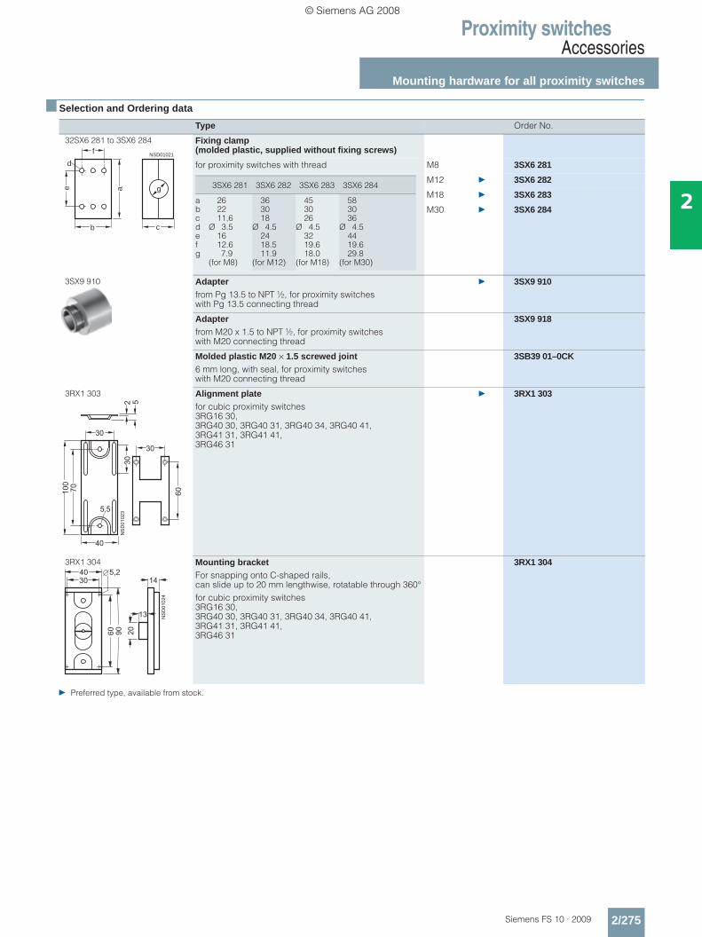
Proximity switchesAccessories
Mounting hardware for all proximity switches
2/275Siemens FS 10 · 2009
2
■ Selection and Ordering data
} Preferred type, available from stock.
Type Order No.
32SX6 281 to 3SX6 284 Fixing clamp (molded plastic, supplied without fixing screws)
for proximity switches with thread M8 3SX6 281
M12 } 3SX6 282
M18 } 3SX6 283
M30 } 3SX6 284
3SX9 910 Adapterfrom Pg 13.5 to NPT ½, for proximity switches with Pg 13.5 connecting thread
} 3SX9 910
Adapterfrom M20 x 1.5 to NPT ½, for proximity switches with M20 connecting thread
3SX9 918
Molded plastic M20 × 1.5 screwed joint6 mm long, with seal, for proximity switches with M20 connecting thread
3SB39 01–0CK
3RX1 303 Alignment platefor cubic proximity switches 3RG16 30, 3RG40 30, 3RG40 31, 3RG40 34, 3RG40 41, 3RG41 31, 3RG41 41, 3RG46 31
} 3RX1 303
3RX1 304 Mounting bracket For snapping onto C-shaped rails, can slide up to 20 mm lengthwise, rotatable through 360°for cubic proximity switches 3RG16 30, 3RG40 30, 3RG40 31, 3RG40 34, 3RG40 41, 3RG41 31, 3RG41 41, 3RG46 31
3RX1 304
b
a
NSD01021
e
f
c
d
g 3SX6 281 3SX6 282 3SX6 283 3SX6 284
abcdefg
262211,6
Ø 3.51612.67.9
(for M8)
363018
Ø 4.52418.511.9
(for M12)
453026
Ø 4.53219.618.0
(for M18)
583036
Ø 4.54419.629.8
(for M30)
���
��
���
��
��
��
���
�
�
�
��
� �
��
��
���
�
� ��
��
��
��
���
�
��
© Siemens AG 2008
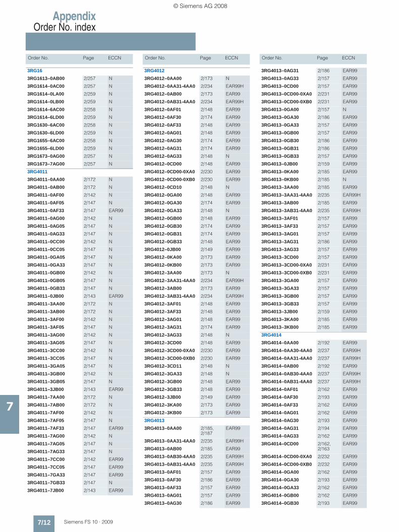
AppendixOrder No. index
7/12 Siemens FS 10 · 2009
Order No. Page ECCN Order No. Page ECCN Order No. Page ECCN
7
3RG16
3RG1613–0AB00 2/257 N
3RG1614–0AC00 2/257 N
3RG1614–0LA00 2/259 N
3RG1614–0LB00 2/259 N
3RG1614–6AC00 2/258 N
3RG1614–6LD00 2/259 N
3RG1630–6AC00 2/258 N
3RG1630–6LD00 2/259 N
3RG1655–6AC00 2/258 N
3RG1655–6LD00 2/259 N
3RG1673–0AG00 2/257 N
3RG1673–7AG00 2/257 N
3RG4011
3RG4011–0AA00 2/172 N
3RG4011–0AB00 2/172 N
3RG4011–0AF00 2/142 N
3RG4011–0AF05 2/147 N
3RG4011–0AF33 2/147 EAR99
3RG4011–0AG00 2/142 N
3RG4011–0AG05 2/147 N
3RG4011–0AG33 2/147 N
3RG4011–0CC00 2/142 N
3RG4011–0CC05 2/147 N
3RG4011–0GA05 2/147 N
3RG4011–0GA33 2/147 N
3RG4011–0GB00 2/142 N
3RG4011–0GB05 2/147 N
3RG4011–0GB33 2/147 N
3RG4011–0JB00 2/143 EAR99
3RG4011–3AA00 2/172 N
3RG4011–3AB00 2/172 N
3RG4011–3AF00 2/142 N
3RG4011–3AF05 2/147 N
3RG4011–3AG00 2/142 N
3RG4011–3AG05 2/147 N
3RG4011–3CC00 2/142 N
3RG4011–3CC05 2/147 N
3RG4011–3GA05 2/147 N
3RG4011–3GB00 2/142 N
3RG4011–3GB05 2/147 N
3RG4011–3JB00 2/143 EAR99
3RG4011–7AA00 2/172 N
3RG4011–7AB00 2/172 N
3RG4011–7AF00 2/142 N
3RG4011–7AF05 2/147 N
3RG4011–7AF33 2/147 EAR99
3RG4011–7AG00 2/142 N
3RG4011–7AG05 2/147 N
3RG4011–7AG33 2/147 N
3RG4011–7CC00 2/142 EAR99
3RG4011–7CC05 2/147 EAR99
3RG4011–7GA33 2/147 EAR99
3RG4011–7GB33 2/147 N
3RG4011–7JB00 2/143 EAR99
3RG4012
3RG4012–0AA00 2/173 N
3RG4012–0AA31-4AA0 2/234 EAR99H
3RG4012–0AB00 2/173 EAR99
3RG4012–0AB31-4AA0 2/234 EAR99H
3RG4012–0AF01 2/148 EAR99
3RG4012–0AF30 2/174 EAR99
3RG4012–0AF33 2/148 EAR99
3RG4012–0AG01 2/148 EAR99
3RG4012–0AG30 2/174 EAR99
3RG4012–0AG31 2/174 EAR99
3RG4012–0AG33 2/148 N
3RG4012–0CD00 2/148 EAR99
3RG4012–0CD00-0XA0 2/230 EAR99
3RG4012–0CD00-0XB0 2/230 EAR99
3RG4012–0CD10 2/148 N
3RG4012–0GA00 2/148 EAR99
3RG4012–0GA30 2/174 EAR99
3RG4012–0GA33 2/148 N
3RG4012–0GB00 2/148 EAR99
3RG4012–0GB30 2/174 EAR99
3RG4012–0GB31 2/174 EAR99
3RG4012–0GB33 2/148 EAR99
3RG4012–0JB00 2/149 EAR99
3RG4012–0KA00 2/173 EAR99
3RG4012–0KB00 2/173 EAR99
3RG4012–3AA00 2/173 N
3RG4012–3AA31-4AA0 2/234 EAR99H
3RG4012–3AB00 2/173 EAR99
3RG4012–3AB31-4AA0 2/234 EAR99H
3RG4012–3AF01 2/148 EAR99
3RG4012–3AF33 2/148 EAR99
3RG4012–3AG01 2/148 EAR99
3RG4012–3AG31 2/174 EAR99
3RG4012–3AG33 2/148 N
3RG4012–3CD00 2/148 EAR99
3RG4012–3CD00-0XA0 2/230 EAR99
3RG4012–3CD00-0XB0 2/230 EAR99
3RG4012–3CD11 2/148 N
3RG4012–3GA33 2/148 N
3RG4012–3GB00 2/148 EAR99
3RG4012–3GB33 2/148 EAR99
3RG4012–3JB00 2/149 EAR99
3RG4012–3KA00 2/173 EAR99
3RG4012–3KB00 2/173 EAR99
3RG4013
3RG4013–0AA00 2/185, 2/187
EAR99
3RG4013–0AA31-4AA0 2/235 EAR99H
3RG4013–0AB00 2/185 EAR99
3RG4013–0AB30-4AA0 2/235 EAR99H
3RG4013–0AB31-4AA0 2/235 EAR99H
3RG4013–0AF01 2/157 EAR99
3RG4013–0AF30 2/186 EAR99
3RG4013–0AF33 2/157 EAR99
3RG4013–0AG01 2/157 EAR99
3RG4013–0AG30 2/186 EAR99
3RG4013–0AG31 2/186 EAR99
3RG4013–0AG33 2/157 EAR99
3RG4013–0CD00 2/157 EAR99
3RG4013–0CD00-0XA0 2/231 EAR99
3RG4013–0CD00-0XB0 2/231 EAR99
3RG4013–0GA00 2/157 N
3RG4013–0GA30 2/186 EAR99
3RG4013–0GA33 2/157 EAR99
3RG4013–0GB00 2/157 EAR99
3RG4013–0GB30 2/186 EAR99
3RG4013–0GB31 2/186 EAR99
3RG4013–0GB33 2/157 EAR99
3RG4013–0JB00 2/159 EAR99
3RG4013–0KA00 2/185 EAR99
3RG4013–0KB00 2/185 N
3RG4013–3AA00 2/185 EAR99
3RG4013–3AA31-4AA0 2/235 EAR99H
3RG4013–3AB00 2/185 EAR99
3RG4013–3AB31-4AA0 2/235 EAR99H
3RG4013–3AF01 2/157 EAR99
3RG4013–3AF33 2/157 EAR99
3RG4013–3AG01 2/157 EAR99
3RG4013–3AG31 2/186 EAR99
3RG4013–3AG33 2/157 EAR99
3RG4013–3CD00 2/157 EAR99
3RG4013–3CD00-0XA0 2/231 EAR99
3RG4013–3CD00-0XB0 2/231 EAR99
3RG4013–3GA00 2/157 EAR99
3RG4013–3GA33 2/157 EAR99
3RG4013–3GB00 2/157 EAR99
3RG4013–3GB33 2/157 EAR99
3RG4013–3JB00 2/159 EAR99
3RG4013–3KA00 2/185 EAR99
3RG4013–3KB00 2/185 EAR99
3RG4014
3RG4014–0AA00 2/192 EAR99
3RG4014–0AA30-4AA0 2/237 EAR99H
3RG4014–0AA31-4AA0 2/237 EAR99H
3RG4014–0AB00 2/192 EAR99
3RG4014–0AB30-4AA0 2/237 EAR99H
3RG4014–0AB31-4AA0 2/237 EAR99H
3RG4014–0AF01 2/162 EAR99
3RG4014–0AF30 2/193 EAR99
3RG4014–0AF33 2/162 EAR99
3RG4014–0AG01 2/162 EAR99
3RG4014–0AG30 2/193 EAR99
3RG4014–0AG31 2/194 EAR99
3RG4014–0AG33 2/162 EAR99
3RG4014–0CD00 2/162, 2/163
EAR99
3RG4014–0CD00-0XA0 2/232 EAR99
3RG4014–0CD00-0XB0 2/232 EAR99
3RG4014–0GA00 2/162 EAR99
3RG4014–0GA30 2/193 EAR99
3RG4014–0GA33 2/162 EAR99
3RG4014–0GB00 2/162 EAR99
3RG4014–0GB30 2/193 EAR99
© Siemens AG 2008

AppendixOrder No. index
7/13Siemens FS 10 · 2009
Order No. Page ECCN Order No. Page ECCN Order No. Page ECCN
7
3RG4014–0GB31 2/194 EAR99
3RG4014–0GB33 2/162 EAR99
3RG4014–0JB00 2/163 EAR99
3RG4014–0KA00 2/192 EAR99
3RG4014–0KB00 2/192 EAR99
3RG4014–0KB31 2/194 EAR99
3RG4014–3AA00 2/192 EAR99
3RG4014–3AA31-4AA0 2/237 EAR99H
3RG4014–3AB00 2/192 EAR99
3RG4014–3AB31-4AA0 2/237 EAR99H
3RG4014–3AF01 2/162 EAR99
3RG4014–3AF33 2/162 EAR99
3RG4014–3AG01 2/162 EAR99
3RG4014–3AG33 2/162 EAR99
3RG4014–3CD00 2/162, 2/163
EAR99
3RG4014–3CD00-0XA0 2/232 EAR99
3RG4014–3CD00-0XB0 2/232 EAR99
3RG4014–3GA33 2/162 EAR99
3RG4014–3GB00 2/162 EAR99
3RG4014–3GB33 2/162 EAR99
3RG4014–3JB00 2/163 EAR99
3RG4014–3KA00 2/192 EAR99
3RG4014–3KA31 2/194 EAR99
3RG4014–3KB00 2/192 EAR99
3RG4014–3KB31 2/194 EAR99
3RG4021
3RG4021–0AF33 2/152 EAR99
3RG4021–0AG33 2/152 N
3RG4021–0GA33 2/152 N
3RG4021–0GB33 2/152 N
3RG4021–7AF33 2/152 EAR99
3RG4021–7AG33 2/152 N
3RG4021–7GA33 2/152 EAR99
3RG4021–7GB33 2/152 N
3RG4022
3RG4022–0AA00 2/180 N
3RG4022–0AA30 2/182 N
3RG4022–0AA30-4AA0 2/234 EAR99H
3RG4022–0AA31-4AA0 2/234 EAR99H
3RG4022–0AB00 2/180 EAR99
3RG4022–0AB30 2/182 EAR99
3RG4022–0AB30-4AA0 2/234 EAR99H
3RG4022–0AB31-4AA0 2/234 EAR99H
3RG4022–0AF01 2/155 EAR99
3RG4022–0AF30 2/181 EAR99
3RG4022–0AF33 2/155 EAR99
3RG4022–0AG01 2/155 EAR99
3RG4022–0AG30 2/181 EAR99
3RG4022–0AG31 2/181 EAR99
3RG4022–0AG33 2/155 N
3RG4022–0CD00 2/155 EAR99
3RG4022–0CD00-0XA0 2/230 EAR99
3RG4022–0CD00-0XB0 2/230 EAR99
3RG4022–0CD10 2/155 N
3RG4022–0GA00 2/155 EAR99
3RG4022–0GA30 2/181 EAR99
3RG4022–0GA33 2/155 N
3RG4022–0GB00 2/155 EAR99
3RG4022–0GB30 2/181 EAR99
3RG4022–0GB31 2/181 EAR99
3RG4022–0GB33 2/155 EAR99
3RG4022–0JB00 2/156 EAR99
3RG4022–0KA00 2/180 EAR99
3RG4022–0KB00 2/180 EAR99
3RG4022–0KB30 2/182 EAR99
3RG4022–3AA00 2/180 N
3RG4022–3AA31-4AA0 2/234 EAR99H
3RG4022–3AB00 2/180 EAR99
3RG4022–3AB30 2/182 EAR99
3RG4022–3AB31-4AA0 2/234 EAR99H
3RG4022–3AF01 2/155 EAR99
3RG4022–3AF33 2/155 EAR99
3RG4022–3AG01 2/155 EAR99
3RG4022–3AG31 2/181 EAR99
3RG4022–3AG33 2/155 N
3RG4022–3CD00 2/155 EAR99
3RG4022–3CD00-0XA0 2/230 EAR99
3RG4022–3CD00-0XB0 2/230 EAR99
3RG4022–3CD11 2/155 N
3RG4022–3GA00 2/155 EAR99
3RG4022–3GA33 2/155 N
3RG4022–3GB00 2/155 EAR99
3RG4022–3GB33 2/155 EAR99
3RG4022–3JB00 2/156 EAR99
3RG4022–3KA00 2/180 EAR99
3RG4022–3KB00 2/180 EAR99
3RG4022–3KB30 2/182 EAR99
3RG4023
3RG4023–0AA00 2/188 EAR99
3RG4023–0AA30 2/190 EAR99
3RG4023–0AA30-4AA0 2/236 EAR99H
3RG4023–0AA31-4AA0 2/236 EAR99H
3RG4023–0AB00 2/188 EAR99
3RG4023–0AB30 2/190 EAR99
3RG4023–0AB30-4AA0 2/236 EAR99H
3RG4023–0AB31-4AA0 2/236 EAR99H
3RG4023–0AF01 2/160 EAR99
3RG4023–0AF30 2/189 EAR99
3RG4023–0AF33 2/160 EAR99
3RG4023–0AG01 2/160 EAR99
3RG4023–0AG30 2/189 EAR99
3RG4023–0AG31 2/189 EAR99
3RG4023–0AG33 2/160 EAR99
3RG4023–0CD00 2/160 EAR99
3RG4023–0CD00-0XA0 2/231 EAR99
3RG4023–0CD00-0XB0 2/231 EAR99
3RG4023–0GA00 2/160 EAR99
3RG4023–0GA30 2/189 EAR99
3RG4023–0GA33 2/160 EAR99
3RG4023–0GB00 2/160 EAR99
3RG4023–0GB30 2/189 EAR99
3RG4023–0GB31 2/189 EAR99
3RG4023–0GB33 2/160 EAR99
3RG4023–0JB00 2/161 EAR99
3RG4023–0KA00 2/188 EAR99
3RG4023–0KA30 2/190 EAR99
3RG4023–0KB00 2/188 EAR99
3RG4023–0KB30 2/190 EAR99
3RG4023–3AA00 2/188 EAR99
3RG4023–3AA30 2/190 EAR99
3RG4023–3AA31-4AA0 2/236 EAR99H
3RG4023–3AB00 2/188 EAR99
3RG4023–3AB30 2/190 EAR99
3RG4023–3AB31-4AA0 2/236 EAR99H
3RG4023–3AF01 2/160 EAR99
3RG4023–3AF33 2/160 EAR99
3RG4023–3AG01 2/160 EAR99
3RG4023–3AG31 2/189 EAR99
3RG4023–3AG33 2/160 EAR99
3RG4023–3CD00 2/160 EAR99
3RG4023–3CD00-0XA0 2/231 EAR99
3RG4023–3CD00-0XB0 2/231 EAR99
3RG4023–3GA33 2/160 EAR99
3RG4023–3GB00 2/160 EAR99
3RG4023–3GB33 2/160 EAR99
3RG4023–3JB00 2/161 EAR99
3RG4023–3KA00 2/188 EAR99
3RG4023–3KB00 2/188 EAR99
3RG4023–3KB30 2/190 EAR99
3RG4024
3RG4024–0AA00 2/196 EAR99
3RG4024–0AA30 2/200 EAR99
3RG4024–0AA30-4AA0 2/238 EAR99H
3RG4024–0AA31-4AA0 2/238 EAR99H
3RG4024–0AB00 2/196 EAR99
3RG4024–0AB30 2/200 EAR99
3RG4024–0AB30-4AA0 2/238 EAR99H
3RG4024–0AB31-4AA0 2/238
3RG4024–0AF01 2/164 EAR99
3RG4024–0AF30 2/199 EAR99
3RG4024–0AF33 2/164 EAR99
3RG4024–0AG01 2/164 EAR99
3RG4024–0AG30 2/199 EAR99
3RG4024–0AG31 2/199 EAR99
3RG4024–0AG33 2/164 EAR99
3RG4024–0CD00 2/164 EAR99
3RG4024–0CD00-0XA0 2/232 EAR99
3RG4024–0CD00-0XB0 2/232 EAR99
3RG4024–0GA00 2/164 EAR99
3RG4024–0GA30 2/199 EAR99
3RG4024–0GA33 2/164 EAR99
3RG4024–0GB00 2/164 EAR99
3RG4024–0GB30 2/199 EAR99
3RG4024–0GB31 2/199 EAR99
3RG4024–0GB33 2/164 EAR99
3RG4024–0JB00 2/166 EAR99
3RG4024–0KA00 2/196 EAR99
3RG4024–0KA30 2/200 EAR99
© Siemens AG 2008
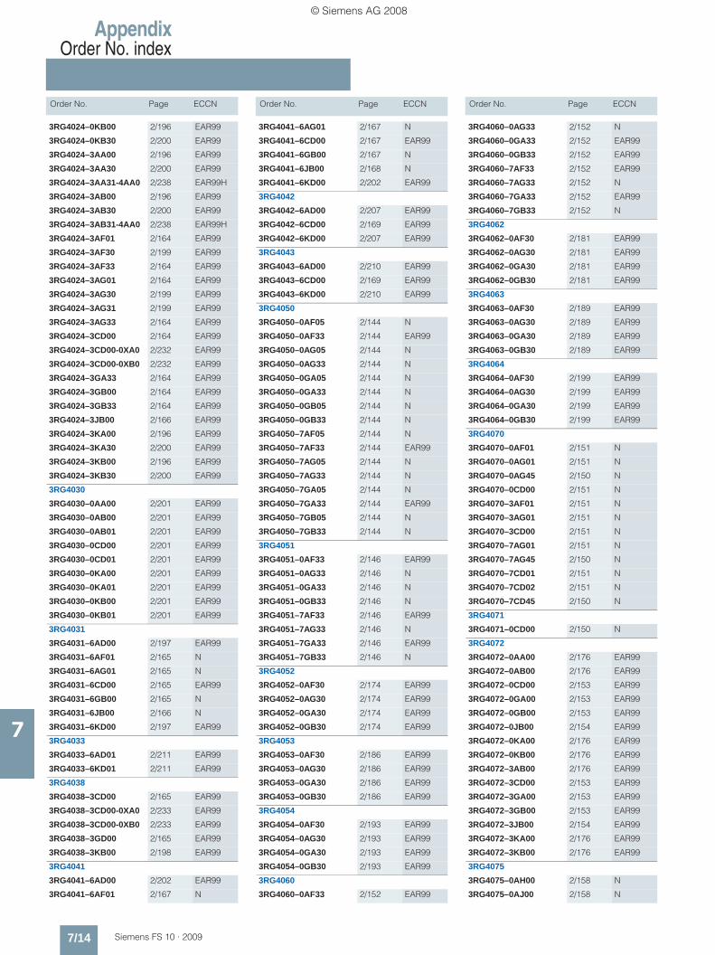
AppendixOrder No. index
7/14 Siemens FS 10 · 2009
Order No. Page ECCN Order No. Page ECCN Order No. Page ECCN
7
3RG4024–0KB00 2/196 EAR99
3RG4024–0KB30 2/200 EAR99
3RG4024–3AA00 2/196 EAR99
3RG4024–3AA30 2/200 EAR99
3RG4024–3AA31-4AA0 2/238 EAR99H
3RG4024–3AB00 2/196 EAR99
3RG4024–3AB30 2/200 EAR99
3RG4024–3AB31-4AA0 2/238 EAR99H
3RG4024–3AF01 2/164 EAR99
3RG4024–3AF30 2/199 EAR99
3RG4024–3AF33 2/164 EAR99
3RG4024–3AG01 2/164 EAR99
3RG4024–3AG30 2/199 EAR99
3RG4024–3AG31 2/199 EAR99
3RG4024–3AG33 2/164 EAR99
3RG4024–3CD00 2/164 EAR99
3RG4024–3CD00-0XA0 2/232 EAR99
3RG4024–3CD00-0XB0 2/232 EAR99
3RG4024–3GA33 2/164 EAR99
3RG4024–3GB00 2/164 EAR99
3RG4024–3GB33 2/164 EAR99
3RG4024–3JB00 2/166 EAR99
3RG4024–3KA00 2/196 EAR99
3RG4024–3KA30 2/200 EAR99
3RG4024–3KB00 2/196 EAR99
3RG4024–3KB30 2/200 EAR99
3RG4030
3RG4030–0AA00 2/201 EAR99
3RG4030–0AB00 2/201 EAR99
3RG4030–0AB01 2/201 EAR99
3RG4030–0CD00 2/201 EAR99
3RG4030–0CD01 2/201 EAR99
3RG4030–0KA00 2/201 EAR99
3RG4030–0KA01 2/201 EAR99
3RG4030–0KB00 2/201 EAR99
3RG4030–0KB01 2/201 EAR99
3RG4031
3RG4031–6AD00 2/197 EAR99
3RG4031–6AF01 2/165 N
3RG4031–6AG01 2/165 N
3RG4031–6CD00 2/165 EAR99
3RG4031–6GB00 2/165 N
3RG4031–6JB00 2/166 N
3RG4031–6KD00 2/197 EAR99
3RG4033
3RG4033–6AD01 2/211 EAR99
3RG4033–6KD01 2/211 EAR99
3RG4038
3RG4038–3CD00 2/165 EAR99
3RG4038–3CD00-0XA0 2/233 EAR99
3RG4038–3CD00-0XB0 2/233 EAR99
3RG4038–3GD00 2/165 EAR99
3RG4038–3KB00 2/198 EAR99
3RG4041
3RG4041–6AD00 2/202 EAR99
3RG4041–6AF01 2/167 N
3RG4041–6AG01 2/167 N
3RG4041–6CD00 2/167 EAR99
3RG4041–6GB00 2/167 N
3RG4041–6JB00 2/168 N
3RG4041–6KD00 2/202 EAR99
3RG4042
3RG4042–6AD00 2/207 EAR99
3RG4042–6CD00 2/169 EAR99
3RG4042–6KD00 2/207 EAR99
3RG4043
3RG4043–6AD00 2/210 EAR99
3RG4043–6CD00 2/169 EAR99
3RG4043–6KD00 2/210 EAR99
3RG4050
3RG4050–0AF05 2/144 N
3RG4050–0AF33 2/144 EAR99
3RG4050–0AG05 2/144 N
3RG4050–0AG33 2/144 N
3RG4050–0GA05 2/144 N
3RG4050–0GA33 2/144 N
3RG4050–0GB05 2/144 N
3RG4050–0GB33 2/144 N
3RG4050–7AF05 2/144 N
3RG4050–7AF33 2/144 EAR99
3RG4050–7AG05 2/144 N
3RG4050–7AG33 2/144 N
3RG4050–7GA05 2/144 N
3RG4050–7GA33 2/144 EAR99
3RG4050–7GB05 2/144 N
3RG4050–7GB33 2/144 N
3RG4051
3RG4051–0AF33 2/146 EAR99
3RG4051–0AG33 2/146 N
3RG4051–0GA33 2/146 N
3RG4051–0GB33 2/146 N
3RG4051–7AF33 2/146 EAR99
3RG4051–7AG33 2/146 N
3RG4051–7GA33 2/146 EAR99
3RG4051–7GB33 2/146 N
3RG4052
3RG4052–0AF30 2/174 EAR99
3RG4052–0AG30 2/174 EAR99
3RG4052–0GA30 2/174 EAR99
3RG4052–0GB30 2/174 EAR99
3RG4053
3RG4053–0AF30 2/186 EAR99
3RG4053–0AG30 2/186 EAR99
3RG4053–0GA30 2/186 EAR99
3RG4053–0GB30 2/186 EAR99
3RG4054
3RG4054–0AF30 2/193 EAR99
3RG4054–0AG30 2/193 EAR99
3RG4054–0GA30 2/193 EAR99
3RG4054–0GB30 2/193 EAR99
3RG4060
3RG4060–0AF33 2/152 EAR99
3RG4060–0AG33 2/152 N
3RG4060–0GA33 2/152 EAR99
3RG4060–0GB33 2/152 EAR99
3RG4060–7AF33 2/152 EAR99
3RG4060–7AG33 2/152 N
3RG4060–7GA33 2/152 EAR99
3RG4060–7GB33 2/152 N
3RG4062
3RG4062–0AF30 2/181 EAR99
3RG4062–0AG30 2/181 EAR99
3RG4062–0GA30 2/181 EAR99
3RG4062–0GB30 2/181 EAR99
3RG4063
3RG4063–0AF30 2/189 EAR99
3RG4063–0AG30 2/189 EAR99
3RG4063–0GA30 2/189 EAR99
3RG4063–0GB30 2/189 EAR99
3RG4064
3RG4064–0AF30 2/199 EAR99
3RG4064–0AG30 2/199 EAR99
3RG4064–0GA30 2/199 EAR99
3RG4064–0GB30 2/199 EAR99
3RG4070
3RG4070–0AF01 2/151 N
3RG4070–0AG01 2/151 N
3RG4070–0AG45 2/150 N
3RG4070–0CD00 2/151 N
3RG4070–3AF01 2/151 N
3RG4070–3AG01 2/151 N
3RG4070–3CD00 2/151 N
3RG4070–7AG01 2/151 N
3RG4070–7AG45 2/150 N
3RG4070–7CD01 2/151 N
3RG4070–7CD02 2/151 N
3RG4070–7CD45 2/150 N
3RG4071
3RG4071–0CD00 2/150 N
3RG4072
3RG4072–0AA00 2/176 EAR99
3RG4072–0AB00 2/176 EAR99
3RG4072–0CD00 2/153 EAR99
3RG4072–0GA00 2/153 EAR99
3RG4072–0GB00 2/153 EAR99
3RG4072–0JB00 2/154 EAR99
3RG4072–0KA00 2/176 EAR99
3RG4072–0KB00 2/176 EAR99
3RG4072–3AB00 2/176 EAR99
3RG4072–3CD00 2/153 EAR99
3RG4072–3GA00 2/153 EAR99
3RG4072–3GB00 2/153 EAR99
3RG4072–3JB00 2/154 EAR99
3RG4072–3KA00 2/176 EAR99
3RG4072–3KB00 2/176 EAR99
3RG4075
3RG4075–0AH00 2/158 N
3RG4075–0AJ00 2/158 N
© Siemens AG 2008

AppendixOrder No. index
7/15Siemens FS 10 · 2009
Order No. Page ECCN Order No. Page ECCN Order No. Page ECCN
7
3RG4075–0GJ00 2/158 N
3RG4080
3RG4080–0AG45 2/156 N
3RG4080–7AG45 2/156 N
3RG4082
3RG4082–0AB00 2/184 EAR99
3RG4082–0CD00 2/158 EAR99
3RG4082–3AB00 2/184 EAR99
3RG4082–3CD00 2/158 EAR99
3RG4111
3RG4111–0AF33 2/175 EAR99
3RG4111–0AG00 2/175 N
3RG4111–0AG33 2/175 EAR99
3RG4111–0GA33 2/175 N
3RG4111–0GB33 2/175 N
3RG4111–3AG00 2/175 N
3RG4111–7AF33 2/175 EAR99
3RG4111–7AG33 2/175 EAR99
3RG4111–7GA33 2/175 EAR99
3RG4111–7GB33 2/175 EAR99
3RG4112
3RG4112–0AF01 2/183 EAR99
3RG4112–0AG01 2/183 EAR99
3RG4112–0AG33 2/183 EAR99
3RG4112–3AF01 2/183 EAR99
3RG4112–3AF33 2/183 N
3RG4112–3AG01 2/183 EAR99
3RG4112–3AG33 2/183 EAR99
3RG4113
3RG4113–0AG01 2/191 EAR99
3RG4113–0AG33 2/191 EAR99
3RG4113–3AG01 2/191 EAR99
3RG4113–3AG33 2/191 EAR99
3RG4114
3RG4114–0AG01 2/198 EAR99
3RG4114–3AG01 2/198 EAR99
3RG4131
3RG4131–6AD00 2/206 EAR99
3RG4134
3RG4134–6CD01 2/203 EAR99
3RG4138
3RG4138–3CD00 2/204 EAR99
3RG4138–3GD00 2/204 EAR99
3RG4138–3KB00 2/204 EAR99
3RG4141
3RG4141–3AB01 2/214 EAR99
3RG4141–3AB02 2/214 EAR99
3RG4141–6AB03 2/213 EAR99
3RG4141–6AD00 2/213 EAR99
3RG4142
3RG4142–6AD00 2/215 EAR99
3RG4143
3RG4143–6AD00 2/215 EAR99
3RG4144
3RG4144–6CD01 2/208 N
3RG4148
3RG4148–3CD00 2/209 EAR99
3RG4148–3CD00-0XA0 2/233 EAR99
3RG4148–3CD00-0XB0 2/233 EAR99
3RG4148–3GD00 2/209 EAR99
3RG4148–3KB00 2/209 EAR99
3RG42
3RG4200–1AA00 2/141 N
3RG4200–1AB00 2/141 N
3RG4200–7AB00 2/141 N
3RG4201–1AB00 2/144 N
3RG4201–7AF00 2/144 N
3RG4201–7AG00 2/144 N
3RG4210–0AF00 2/141 N
3RG4210–0AG00 2/141 N
3RG4210–7AF00 2/141 N
3RG4210–7AG00 2/141 N
3RG4211–0AG31 2/146 N
3RG4211–7AF31 2/146 N
3RG4211–7AG31 2/146 N
3RG4236–0AG00 2/141 N
3RG4237–0AA00 2/146 N
3RG4237–0AB00 2/146 N
3RG4237–7AA00 2/146 N
3RG4237–7AB00 2/146 N
3RG43
3RG4302–0AG01 2/178 EAR99
3RG4302–7AG01 2/178 EAR99
3RG4311–0AG01 2/178 EAR99
3RG4311–0GB01 2/178 EAR99
3RG4311–3AF01 2/178 EAR99
3RG4311–3AG01 2/178 EAR99
3RG4311–3GB01 2/178 EAR99
3RG4311–7AG01 2/178 EAR99
3RG4312–0AG01 2/187 EAR99
3RG4312–0GB01 2/187 EAR99
3RG4312–3AG01 2/187 EAR99
3RG4312–3GB01 2/187, 2/190
EAR99
3RG4321–0AF01 2/187 EAR99
3RG4321–0AG01 2/187 EAR99
3RG4321–0GB01 2/187 EAR99
3RG4321–3AF01 2/187 EAR99
3RG4321–3AG01 2/187 EAR99
3RG4321–3GA01 2/187 EAR99
3RG4321–3GB01 2/187 EAR99
3RG4321–7AF01 2/187 EAR99
3RG4321–7AG01 2/187 EAR99
3RG4321–7GA01 2/187 EAR99
3RG4321–7GB01 2/187 EAR99
3RG4322–0AG01 2/195 EAR99
3RG4322–3AF01 2/195 EAR99
3RG4322–3AG01 2/195 EAR99
3RG4337–0AG01 2/179 EAR99
3RG4337–0GB01 2/179 N
3RG4337–7AG01 2/179 EAR99
3RG4337–7GB01 2/179 EAR99
3RG460
3RG4600–0AG02 2/172 N
3RG4601–7GB00 2/144 N
3RG4602–0AG02 2/177 N
3RG4603–2AB00 2/140 N
3RG461
3RG4610–0AG02 2/172 N
3RG4610–0GB00 2/141 N
3RG4610–7GB00 2/141 N
3RG4611–0AG02 2/177 N
3RG4611–0AN01 2/217 N
3RG4611–0GN01 2/217 N
3RG4611–3AN01 2/217 N
3RG4611–3GN01 2/217 N
3RG4611–7AN01 2/217 N
3RG4611–7GB31 2/146 N
3RG4611–7GN01 2/217 N
3RG4612–0AN01 2/218 N
3RG4612–0AN61 2/218 N
3RG4612–0GN01 2/218 N
3RG4612–0GN61 2/218 N
3RG4612–0NB00 2/241 N
3RG4612–3AN01 2/218 N
3RG4612–3AN05 2/218 N
3RG4612–3AN61 2/218 N
3RG4612–3GN01 2/218 N
3RG4612–3GN05 2/218 N
3RG4612–3GN61 2/218 N
3RG4612–3NB00 2/241 N
3RG4613–0AN01 2/220 N
3RG4613–0AN61 2/220 N
3RG4613–0GB00 2/195 N
3RG4613–0GN01 2/220 N
3RG4613–0GN61 2/220 N
3RG4613–1AB01 2/195 N
3RG4613–3AB01 2/195 N
3RG4613–3AN01 2/220 N
3RG4613–3AN05 2/220 N
3RG4613–3AN61 2/220 N
3RG4613–3GB01 2/195 N
3RG4613–3GN01 2/220 N
3RG4613–3GN05 2/220 N
3RG4613–3GN61 2/220 N
3RG4614–0AB00 2/205 N
3RG4614–0AN01 2/222 N
3RG4614–0AN61 2/222 N
3RG4614–0GB00 2/205 N
3RG4614–0GN01 2/222 N
3RG4614–0GN61 2/222 N
3RG4614–3AB00 2/205 N
3RG4614–3AN01 2/222 N
3RG4614–3AN05 2/222 N
3RG4614–3AN61 2/222 N
3RG4614–3GB00 2/205 N
3RG4614–3GN01 2/222 N
3RG4614–3GN05 2/222 N
3RG4614–3GN61 2/222 N
© Siemens AG 2008
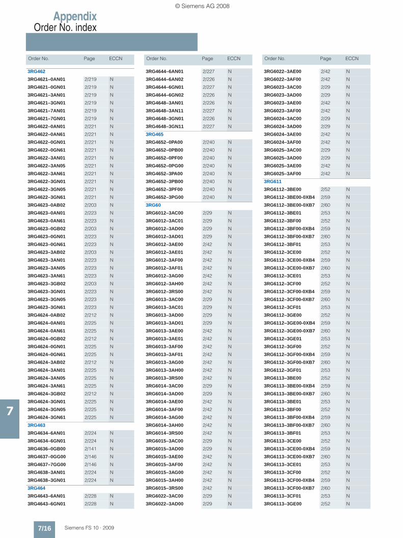
AppendixOrder No. index
7/16 Siemens FS 10 · 2009
Order No. Page ECCN Order No. Page ECCN Order No. Page ECCN
7
3RG462
3RG4621–0AN01 2/219 N
3RG4621–0GN01 2/219 N
3RG4621–3AN01 2/219 N
3RG4621–3GN01 2/219 N
3RG4621–7AN01 2/219 N
3RG4621–7GN01 2/219 N
3RG4622–0AN01 2/221 N
3RG4622–0AN61 2/221 N
3RG4622–0GN01 2/221 N
3RG4622–0GN61 2/221 N
3RG4622–3AN01 2/221 N
3RG4622–3AN05 2/221 N
3RG4622–3AN61 2/221 N
3RG4622–3GN01 2/221 N
3RG4622–3GN05 2/221 N
3RG4622–3GN61 2/221 N
3RG4623–0AB02 2/203 N
3RG4623–0AN01 2/223 N
3RG4623–0AN61 2/223 N
3RG4623–0GB02 2/203 N
3RG4623–0GN01 2/223 N
3RG4623–0GN61 2/223 N
3RG4623–3AB02 2/203 N
3RG4623–3AN01 2/223 N
3RG4623–3AN05 2/223 N
3RG4623–3AN61 2/223 N
3RG4623–3GB02 2/203 N
3RG4623–3GN01 2/223 N
3RG4623–3GN05 2/223 N
3RG4623–3GN61 2/223 N
3RG4624–0AB02 2/212 N
3RG4624–0AN01 2/225 N
3RG4624–0AN61 2/225 N
3RG4624–0GB02 2/212 N
3RG4624–0GN01 2/225 N
3RG4624–0GN61 2/225 N
3RG4624–3AB02 2/212 N
3RG4624–3AN01 2/225 N
3RG4624–3AN05 2/225 N
3RG4624–3AN61 2/225 N
3RG4624–3GB02 2/212 N
3RG4624–3GN01 2/225 N
3RG4624–3GN05 2/225 N
3RG4624–3GN61 2/225 N
3RG463
3RG4634–6AN01 2/224 N
3RG4634–6GN01 2/224 N
3RG4636–0GB00 2/141 N
3RG4637–0GG00 2/146 N
3RG4637–7GG00 2/146 N
3RG4638–3AN01 2/224 N
3RG4638–3GN01 2/224 N
3RG464
3RG4643–6AN01 2/228 N
3RG4643–6GN01 2/228 N
3RG4644–6AN01 2/227 N
3RG4644–6AN02 2/226 N
3RG4644–6GN01 2/227 N
3RG4644–6GN02 2/226 N
3RG4648–3AN01 2/226 N
3RG4648–3AN11 2/227 N
3RG4648–3GN01 2/226 N
3RG4648–3GN11 2/227 N
3RG465
3RG4652–0PA00 2/240 N
3RG4652–0PB00 2/240 N
3RG4652–0PF00 2/240 N
3RG4652–0PG00 2/240 N
3RG4652–3PA00 2/240 N
3RG4652–3PB00 2/240 N
3RG4652–3PF00 2/240 N
3RG4652–3PG00 2/240 N
3RG60
3RG6012–3AC00 2/29 N
3RG6012–3AC01 2/29 N
3RG6012–3AD00 2/29 N
3RG6012–3AD01 2/29 N
3RG6012–3AE00 2/42 N
3RG6012–3AE01 2/42 N
3RG6012–3AF00 2/42 N
3RG6012–3AF01 2/42 N
3RG6012–3AG00 2/42 N
3RG6012–3AH00 2/42 N
3RG6012–3RS00 2/42 N
3RG6013–3AC00 2/29 N
3RG6013–3AC01 2/29 N
3RG6013–3AD00 2/29 N
3RG6013–3AD01 2/29 N
3RG6013–3AE00 2/42 N
3RG6013–3AE01 2/42 N
3RG6013–3AF00 2/42 N
3RG6013–3AF01 2/42 N
3RG6013–3AG00 2/42 N
3RG6013–3AH00 2/42 N
3RG6013–3RS00 2/42 N
3RG6014–3AC00 2/29 N
3RG6014–3AD00 2/29 N
3RG6014–3AE00 2/42 N
3RG6014–3AF00 2/42 N
3RG6014–3AG00 2/42 N
3RG6014–3AH00 2/42 N
3RG6014–3RS00 2/42 N
3RG6015–3AC00 2/29 N
3RG6015–3AD00 2/29 N
3RG6015–3AE00 2/42 N
3RG6015–3AF00 2/42 N
3RG6015–3AG00 2/42 N
3RG6015–3AH00 2/42 N
3RG6015–3RS00 2/42 N
3RG6022–3AC00 2/29 N
3RG6022–3AD00 2/29 N
3RG6022–3AE00 2/42 N
3RG6022–3AF00 2/42 N
3RG6023–3AC00 2/29 N
3RG6023–3AD00 2/29 N
3RG6023–3AE00 2/42 N
3RG6023–3AF00 2/42 N
3RG6024–3AC00 2/29 N
3RG6024–3AD00 2/29 N
3RG6024–3AE00 2/42 N
3RG6024–3AF00 2/42 N
3RG6025–3AC00 2/29 N
3RG6025–3AD00 2/29 N
3RG6025–3AE00 2/42 N
3RG6025–3AF00 2/42 N
3RG611
3RG6112–3BE00 2/52 N
3RG6112–3BE00-0XB4 2/59 N
3RG6112–3BE00-0XB7 2/60 N
3RG6112–3BE01 2/53 N
3RG6112–3BF00 2/52 N
3RG6112–3BF00-0XB4 2/59 N
3RG6112–3BF00-0XB7 2/60 N
3RG6112–3BF01 2/53 N
3RG6112–3CE00 2/52 N
3RG6112–3CE00-0XB4 2/59 N
3RG6112–3CE00-0XB7 2/60 N
3RG6112–3CE01 2/53 N
3RG6112–3CF00 2/52 N
3RG6112–3CF00-0XB4 2/59 N
3RG6112–3CF00-0XB7 2/60 N
3RG6112–3CF01 2/53 N
3RG6112–3GE00 2/52 N
3RG6112–3GE00-0XB4 2/59 N
3RG6112–3GE00-0XB7 2/60 N
3RG6112–3GE01 2/53 N
3RG6112–3GF00 2/52 N
3RG6112–3GF00-0XB4 2/59 N
3RG6112–3GF00-0XB7 2/60 N
3RG6112–3GF01 2/53 N
3RG6113–3BE00 2/52 N
3RG6113–3BE00-0XB4 2/59 N
3RG6113–3BE00-0XB7 2/60 N
3RG6113–3BE01 2/53 N
3RG6113–3BF00 2/52 N
3RG6113–3BF00-0XB4 2/59 N
3RG6113–3BF00-0XB7 2/60 N
3RG6113–3BF01 2/53 N
3RG6113–3CE00 2/52 N
3RG6113–3CE00-0XB4 2/59 N
3RG6113–3CE00-0XB7 2/60 N
3RG6113–3CE01 2/53 N
3RG6113–3CF00 2/52 N
3RG6113–3CF00-0XB4 2/59 N
3RG6113–3CF00-0XB7 2/60 N
3RG6113–3CF01 2/53 N
3RG6113–3GE00 2/52 N
© Siemens AG 2008
Related Documents