v1, Feb 2020 | 1 | AFS Advanced Control Module integration guide Advanced Flight Systems makes their Advanced Control Module or ACM as a component of their aircraft panel wiring range. It provides power ports to drive: Landing lights Taxi lights (ACM-ECB version) Position (nav) lights Strobe lights. This guide shows you how to integrate a Flyleds lighting kit with the ACM. Refer to the ACM Installation Manual, specifically the ACM Power Diagram and Logic diagram, currently on page 19. Aircraft Rear connector Most of the fuselage wiring for your plane originates from the Aircraft Rear connector. Position and Strobe lights The ACM provides three 12 volt power pins for LED strobe lights on each wing and tail, as well as three 12 volt power pins for position/nav lights. The Flyleds controller board distributes power out to the three corners of the plane, so we only need to use one pin from the ACM to drive the Flyleds controller board. The average current draw for the strobes is under 5 amps. Here we nominate using Pin 11 for the strobe circuit and Pin 9 for the position lights. Use 20AWG wire. One of the other two ports associated with these may be used if your OCD would prefer using even numbered pins! Grounding The Flyleds controller board requires a single ground connection. Terminate a 20AWG wire locally at the controller board, at the ACM ground terminal, an ACM mounting screw, or some other convenient location. We have not had a single electrical noise complaint from hundreds of Flyleds installations so far! Refer to the Flyleds Installation guide for the rest of the wiring instructions out to the wings and tail.

Welcome message from author
This document is posted to help you gain knowledge. Please leave a comment to let me know what you think about it! Share it to your friends and learn new things together.
Transcript

v1, Feb 2020 | 1 |
AFS Advanced Control Module integration guide
Advanced Flight Systems makes their Advanced Control Module or ACM as a
component of their aircraft panel wiring range. It provides power ports to drive:
Landing lights
Taxi lights (ACM-ECB version)
Position (nav) lights
Strobe lights.
This guide shows you how to integrate a Flyleds lighting kit with the ACM.
Refer to the ACM Installation Manual, specifically the ACM Power Diagram and Logic diagram, currently on page 19.
Aircraft Rear connector Most of the fuselage wiring for your plane originates from the Aircraft Rear connector.
Position and Strobe lights The ACM provides three 12 volt power pins for LED strobe lights on each wing and tail, as well as three 12 volt power
pins for position/nav lights.
The Flyleds controller board distributes power out to the three corners of the plane, so we only need to use one pin
from the ACM to drive the Flyleds controller board. The average current draw for the strobes is under 5 amps.
Here we nominate using Pin 11 for the strobe circuit and Pin 9 for the position lights. Use 20AWG wire.
One of the other two ports associated with these may be used if your OCD would prefer using even numbered pins!
Grounding The Flyleds controller board requires a single ground connection. Terminate a 20AWG wire locally at the controller
board, at the ACM ground terminal, an ACM mounting screw, or some other convenient location.
We have not had a single electrical noise complaint from hundreds of Flyleds installations so far!
Refer to the Flyleds Installation guide for the rest of the wiring instructions out to the wings and tail.
| 2 |
www.Flyleds.com [email protected]
Landing lights The Flyleds The Works kit has landing light connections which can be set to wigwag (alternate flash) your landing
lights, however the ACM takes care of the wigwag function for you automatically based on airspeed. Therefore, we
recommend connecting your Flyleds landing light options directly to the ACM, bypassing the Flyleds controller board.
The ACM provides two 10 amp power outputs for the left and right landing lights, each
spread across two pins to account for the 5 amp current carrying capacity of the
individual pins. Use two short lengths of 20AWG wire and join them to the 14 to 18AWG wire run out to the wings.
The right landing light connects to Pins 7 and 20.
The left landing light connects to Pins 13 and 25.
All Flyleds lights should be grounded locally at the wing, rather than running a return wire all the way back to the
panel. Our lights do not make any electrical noise, and the additional loss incurred over the extra wire is not desired.
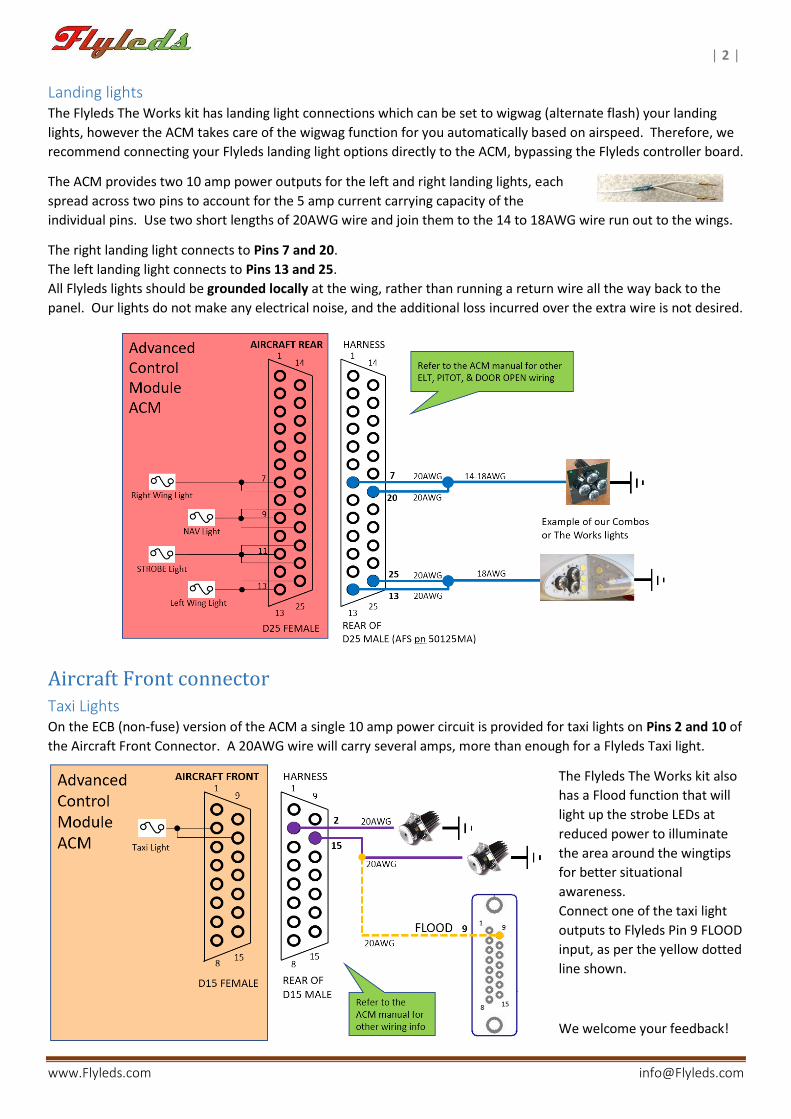
Aircraft Front connector Taxi Lights On the ECB (non-fuse) version of the ACM a single 10 amp power circuit is provided for taxi lights on Pins 2 and 10 of
the Aircraft Front Connector. A 20AWG wire will carry several amps, more than enough for a Flyleds Taxi light.
The Flyleds The Works kit also
has a Flood function that will
light up the strobe LEDs at
reduced power to illuminate
the area around the wingtips
for better situational
awareness.
Connect one of the taxi light
outputs to Flyleds Pin 9 FLOOD
input, as per the yellow dotted
line shown.
We welcome your feedback!
Related Documents