Chapter 4: Atomic Force Microscope (AFM)

Welcome message from author
This document is posted to help you gain knowledge. Please leave a comment to let me know what you think about it! Share it to your friends and learn new things together.
Transcript

Chapter 4: Atomic Force Microscope
(AFM)

Outline
• 4.1 Capabilities and Applications of AFM.
• 4.2 Basic working principles.
• 4.3 Instrumentation.
• 4.4 Example of AFM

What is AFM? • A microscope that uses a tiny probe mounted on a
cantilever to scan the surface of an object.
• As the probe traverses the surface, attractive and repulsive forces arising between it and the atoms on the surface induce forces on the probe that bend the cantilever.
• The amount of bending is measured and recorded, providing a map of the atoms on the surface.
• Atomic force microscopes can achieve magnification of a factor of 5 × 10⁶, with a resolution of 2 angstroms, sufficient to resolve individual carbon atoms.
• Also called scanning force microscope.

4.1 Capabilities and Applications of AFM
• Image the surface of all kinds of solid surfaces and provide the surface roughness /topography information.
1. Solid surface analysis of polymers, ceramics, metals , biomaterials etc.,
2. Nanostructure analysis, such as nanowires, graphene, quatum-dot, nanoparticles, nanodevices.
3. Atom image.
4. Surface potential (KPFM), Magnetic spins (MFM)
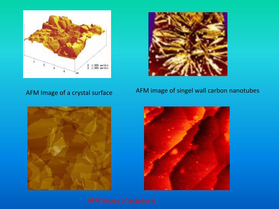
AFM Image of a crystal surface AFM image of singel wall carbon nanotubes
AFM image of graphene

AFM image of bacteria Nanodevices
Au lattice image Nanowires
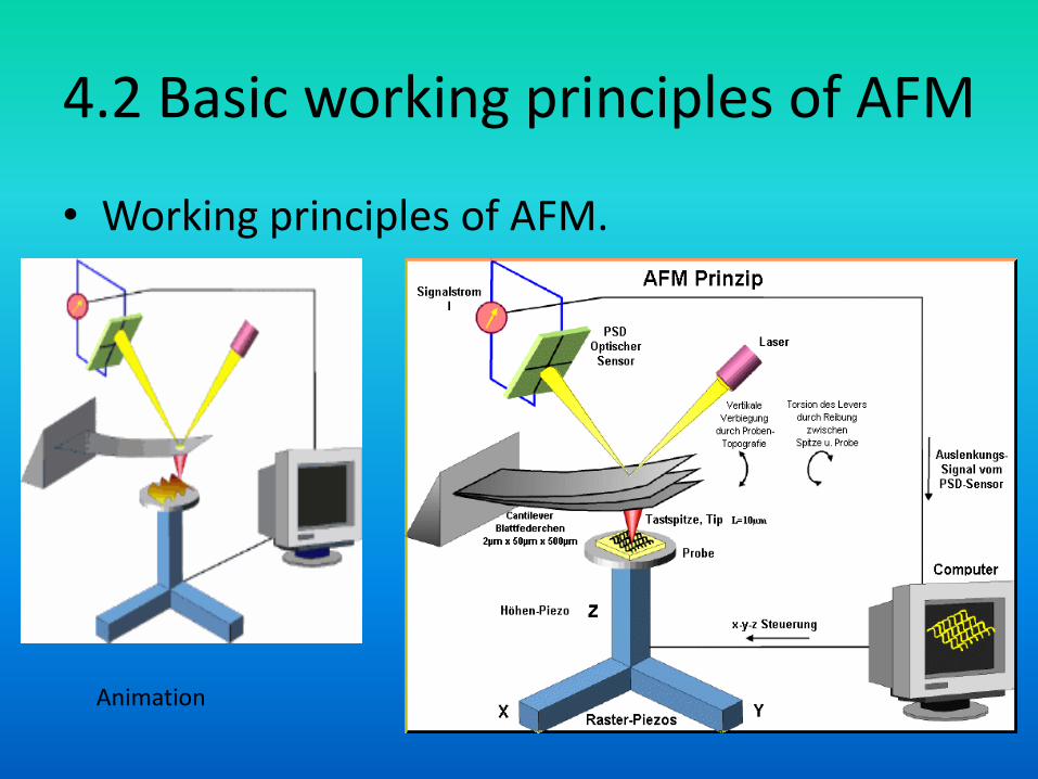
4.2 Basic working principles of AFM
• Working principles of AFM.
Animation
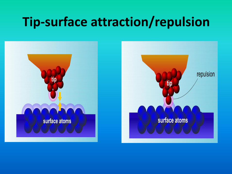
Tip-surface attraction/repulsion

Working principles of AFM
• The ultrafine tip is mounted on a tiny silicon cantilever.
• During the sample movement, driven by the X/Y scan-piezos, the cantilever deflects up and down caused by the normal interaction forces between tip and sample surface.
• This deflection is measured optically by means of a laser beam which is reflected at the backside of the cantilever.
• The position sensitive device (PSD) converts the laser spot to an electronic current signal and the computer generates an artificial image of the measured structure.

Three different working modes
• 1. Contact mode:
• 2. Tapping mode:
• 3. Non-contact mode:
• Working modes Animation:

Working modes of AFM
• 1. Contact mode: scans the sample while
monitoring the change in cantilever deflection.
Loop maintains a constant cantilever reflection
by vertically moving the scanner to get a
constant signal. The distance which the
scanner goes by moving vertically at each x,y
data point is stored by the computer to form
the topographic image of the sample surface.

Working modes of AFM
• 2. Tapping mode: oscillates the cantilever at its resonance frequency and lightly “taps” the tip on the surface during scanning.
• The electrostatic forces increase when tip gets close to the sample surface, therefore the amplitude of the oscillation decreases.
• The amplitude of cantilever oscillation is sensed and feedback loop maintains a constant oscillation amplitude by moving the scanner vertically at every x,y data point.

Working modes of AFM
• 3.Non-contact mode:
• The cantilever is oscillated at a frequency slightly above its resonant frequency where the amplitude of oscillation is typically a few nanometers (<10 nm). Decrease in resonant frequency caused by Van del Waals force combined with the feedback loop system maintains a constant oscillation amplitude or frequency by adjusting the average tip-to-sample distance to construct a topographic image of the sample surface.

Think about:
• Both AFM and SEM are surface image method, what are the advantages and disadvantages of each technique?

Advantages over SEM
1. It can produce 3-dimensional surface image.
2. Doesn’t need high vacuum system, can operate in atmosphere, even in solution.
3. Doesn’t need sample surface coating (for conduction), no charging effect.
4. No sample damage caused by high energy electron beams.
• Therefore, AFM is extremely useful in Bioscience or polymers!

Disadvantages compared with SEM
• 1. Low scan size, low scan speed.
• 2. Can not measure steep walls or extremely rough surface.
• 3. Artifact caused by the change of tips.

4.3 Instrumentation
• Basic components of AFM:
1. The AFM probe - a sharp tip mounted on a soft cantilever.
2. The optical lever that measures the cantilever deflections.
3. The feedback loop that allows for monitoring the interaction forces between the molecules on the tip with the ones on the cell surface.
4. The piezoelectric scanner that moves the tip relative to the sample in a 3D pattern.
5. The conversion system from raw data acquired by the instrument into an image or other useful display.

Cantilever stone

AFM tip / cantilever

4.4 Examples of AFM

Typical AFM images of
measurements for a
rough dimple before
testing and after 200
load–unload cycles ,
showing the flattened
asperities within the
encircled contact area.

Related Documents