1 1 An Assessment of the Continuum of the Systems Engineering Process Presented to the Systems Engineering Committee of the National Academy of Science March 2007 John Griffin AFIT’s Systems Engineering Case Studies 2 Outline The Generic SE Process – Concept to Initial Operational Capability (IOC) What we have now Joint Capability Integration and Development System (JCIDS) DoDD5000 / National Security Space Policy 03-01 What AFIT teaches What lessons do the case studies contain Observations

Welcome message from author
This document is posted to help you gain knowledge. Please leave a comment to let me know what you think about it! Share it to your friends and learn new things together.
Transcript

1
1
An Assessment of the Continuum ofthe Systems Engineering Process
Presented to the Systems EngineeringCommittee of the National Academy of Science
March 2007John Griffin
AFIT’s Systems EngineeringCase Studies
2
Outline
The Generic SE Process – Concept to Initial Operational Capability (IOC)
What we have now Joint Capability Integration and Development System (JCIDS)DoDD5000 / National Security Space Policy 03-01
What AFIT teaches
What lessons do the case studies contain
Observations

Report Documentation Page Form ApprovedOMB No. 0704-0188
Public reporting burden for the collection of information is estimated to average 1 hour per response, including the time for reviewing instructions, searching existing data sources, gathering andmaintaining the data needed, and completing and reviewing the collection of information. Send comments regarding this burden estimate or any other aspect of this collection of information,including suggestions for reducing this burden, to Washington Headquarters Services, Directorate for Information Operations and Reports, 1215 Jefferson Davis Highway, Suite 1204, ArlingtonVA 22202-4302. Respondents should be aware that notwithstanding any other provision of law, no person shall be subject to a penalty for failing to comply with a collection of information if itdoes not display a currently valid OMB control number.
1. REPORT DATE MAR 2007
2. REPORT TYPE N/A
3. DATES COVERED -
4. TITLE AND SUBTITLE An Assessment of the Continuum of the Systems Engineering Process
5a. CONTRACT NUMBER
5b. GRANT NUMBER
5c. PROGRAM ELEMENT NUMBER
6. AUTHOR(S) 5d. PROJECT NUMBER
5e. TASK NUMBER
5f. WORK UNIT NUMBER
7. PERFORMING ORGANIZATION NAME(S) AND ADDRESS(ES) Air Force Institute of Technology 2950 Hobson Way WPAFB, OH 45433-7765
8. PERFORMING ORGANIZATIONREPORT NUMBER
9. SPONSORING/MONITORING AGENCY NAME(S) AND ADDRESS(ES) 10. SPONSOR/MONITOR’S ACRONYM(S)
11. SPONSOR/MONITOR’S REPORT NUMBER(S)
12. DISTRIBUTION/AVAILABILITY STATEMENT Approved for public release, distribution unlimited
13. SUPPLEMENTARY NOTES The original document contains color images.
14. ABSTRACT
15. SUBJECT TERMS
16. SECURITY CLASSIFICATION OF: 17. LIMITATION OF ABSTRACT
SAR
18. NUMBEROF PAGES
22
19a. NAME OFRESPONSIBLE PERSON
a. REPORT unclassified
b. ABSTRACT unclassified
c. THIS PAGE unclassified
Standard Form 298 (Rev. 8-98) Prescribed by ANSI Std Z39-18

2
3
Concepts to IOC
Need to “Pull the thread” from Strategy to Concept to IOC
Joint Warfighting
Defense Strategy
Capabilities-> AttributesMeasures of Effectiveness
Gaps
Conceptual Solutions
Concept/ Systems
System DesignBuild
Integrate
Test / Verify/ Validate
System Requirements
Operation
Production
Disposal
4
Visual Model
Systems Engineers often visual the activities and task to “pull this thread” in a V-model.
Develop System Concept, Understand
User Requirements, andValidation Plan
Develop SystemPerformance Specification
and SystemValidation Plan
Expand PerformanceSpecifications into CI
“Design-to” Specificationsand CI Verification Plan
Evolve “Design-to”Specifications into
“Build-to” Documentationand Inspection Plan
Fabricate, Assemble andCode to “Build-to”
Documentation
Inspect“Build-to”
Documentation
Assemble CIs andPerform CI Verification
to CI “Design-to”Specifications
Integrate System and Perform SystemVerification to
Performance Specifications
Demonstrate andValidate System to
User Validation Plan
. . . . . .
Time
Inte
grat
ion
and
Qua
lific
atio
nDecom
position
and
Definition
Develop System Concept, Understand
User Requirements, andValidation Plan
Develop SystemPerformance Specification
and SystemValidation Plan
Expand PerformanceSpecifications into CI
“Design-to” Specificationsand CI Verification Plan
Evolve “Design-to”Specifications into
“Build-to” Documentationand Inspection Plan
Fabricate, Assemble andCode to “Build-to”
Documentation
Inspect“Build-to”
Documentation
Assemble CIs andPerform CI Verification
to CI “Design-to”Specifications
Integrate System and Perform SystemVerification to
Performance Specifications
Demonstrate andValidate System to
User Validation Plan
. . . . . .
Time
Inte
grat
ion
and
Qua
lific
atio
n
Inte
grat
ion
and
Qua
lific
atio
nDecom
position
and
DefinitionDecom
position
and
Definition
from: Forsberg, Mooz, Cotterman; “Visualizing Project Management”

3
5
Multiple SE Processes?
from: DAU Acquisition Guidebook, 2006
Regardless of DoD Policy, Instruction or Guide, these still must be done
6
Concepts to IOC
Joint Warfighting
Defense Strategy
Capabilities-> AttributesMeasures of Effectiveness
Gaps
Conceptual Solutions
Concept/ Systems
System DesignBuild
Integrate
Test / Verify/ Validate
System Requirements
Operation
Production
Disposal

4
7
Concepts to IOC
Joint Capability Integration
And Development System (JCIDS)
Analysis
FAA
FNA
FSA
CD
Organizational / ProgrammaticSeam
AOA
DoD Acquisition ManagementSystem
M/S B
PDR
CDR DT
OT
Later Increments
8
Concepts to IOC
Acquisition(DOD 5000/NSS 03-01)
JCIDS (CJCSI 3170)
IOCBAConcept
RefinementSystem Development
& DemonstrationProduction &Deployment
Systems Acquisition
Operations &Support
C
Sustainment
FRP DecisionReview
FOC
LRIP/IOT&EDesign
ReadinessReview
TechnologyDevelopment
(ProgramInitiation)
ConceptDecision
Pre-Systems Acquisition
IOCBAConcept
RefinementSystem Development
& DemonstrationProduction &Deployment
Systems Acquisition
Operations &Support
C
Sustainment
FRP DecisionReview
FOC
LRIP/IOT&EDesign
ReadinessReview
TechnologyDevelopment
(ProgramInitiation)
ConceptDecision
Pre-Systems Acquisition
Functional AreaJoint Functional Concepts
Integrated ArchitecturesFunctional Area Analysis
Functional Needs
Analysis
DOTLPF ChangesCJCSI 3180
Process
Materiel ChangesCJCSI 3170
process
Ideas for Materiel
Approaches
Analysis of Materiel Approaches
DOTMLPF
Alternative 1
Alternative 2ICD
Strategic PolicyGuidance
CDD
CPD
PostIndependent
Analysis
DOTLPF Change Recommendation
Functional Solution Analysis
Functional AreaJoint Functional Concepts
Integrated ArchitecturesFunctional Area Analysis
Functional Needs
Analysis
DOTLPF ChangesCJCSI 3180
Process
Materiel ChangesCJCSI 3170
process
Ideas for Materiel
Approaches
Analysis of Materiel Approaches
DOTMLPF
Alternative 1
Alternative 2ICD
Strategic PolicyGuidance
CDD
CPD
PostIndependent
Analysis
DOTLPF Change Recommendation
Functional Solution AnalysisFunctional Solution Analysis
CDDCDD
CPDCPD

5
9
JCIDS Triggers
Unified look at a Mission Analysis
Operational shortcomings
Joint examination of a New Operational Concept
Perceived Future Needs
Broad look at a Functional Area
JCIDS Analysis
White Paper on Conducting a Capabilities-Based Assessment (CBA) Under (JCIDS) JCS J-8, January 2006
What do we need to do
and how well?
Where are the (projected)
gaps?
Whatshould we
do about it?
Existingguidance
10
What AFIT teaches in Systems Engineering
FAA
FNA
FSA
CDAOA
M/S B
PDR
CDR DT
OT
Increments
Systems Architecture (DoDAF)- good architecting practices & context, evaluation
Systems Engineering Design- requirements specification, - trades/ allocation, modeling- verification/ test planning
Concept Definition and Systems Analysis- Analysis Guides, Optimization, Utility Theory, - Cost Estimation, Decision Making/ Modeling
- FAA, FNA, FSA
Decision Analysis
Systems Engineering Management- critical path analysis- EVM, case studies
Risk Analysis
Modeling and Simulation
Software Engineering
Reliability Analysis
Additional Emphasis NeededTo Bridge Seams

6
11
Systems Engineering Case Studies*
F-111
Hubble Space TelescopeTBMCS (Theater Battle
Management Core Systems)
C-5 Galaxy
B-2 Spirit
JASSM (FOUO)
Currently available case studies provide good and bad examples of pre-acquisition activity
- New cases underway
* Available at:www.afit.edu/cse/
12
Case Study Process
Highly DisciplinedDepth of StudyNumber of InterviewsAmount of Data sources and accessFirst and second reviews of draft case
Objectivity of authors and editorsWide review
ScopeConcentration
Effort 1-2MY/ 12-18 month
This is Hard!

7
13
C-5 Galaxy
Over 34 years of successful operational performance in support of the Nation’s cargo/transport needs
USAF inventory of 126 C-5 aircraft :74 C-5A, 50 C-5B, 2 C-5C
During Operation Desert Storm, C-5 fleet carried 46% of the total inter-theater cargo, flying only 29% of the cargo missions
In Operation Iraqi Freedom,
the C-5 fleet carried 48% of total
cargo flying only 23% of the cargo
missions
14
Mapping the C-5 to Today’s Process
FAA
Sustainment
C-5 Galaxy
FNA
FSA
CDAOA
PDR
CDR
• Solid early Trades studies• Mock-ups for roll-on, roll-off• Stable requirements• Size, Weight trades, Materials• Mission Analysis
• Requirement Management(Contract award & beyond)
- Prioritization of Rqmts
• Significant structuralconsequences (rewing)
M/S B
DT
OT

8
15
C-5 Learning Principles
LP #1. Systems requirements need to integrate the User (warfighter), planners, developers, and technologists into a well-balanced, well-understood set of requirements
LP #2. Total Package Procurement Concept (TPPC) was a fixed-price, incentive fee contract strategy for the design, development, andproduction of 58 aircraft. Invented to control cost growth, it was the underlying cause for the overrun
LP #3. A Weight Empty Guarantee was included in the specification and in the contract as a cost penalty for each delivered overweight aircraft. This measure dominated the traditionally balanced requirements resulting in a major shortfalls in wing and pylon fatigue life
LP #4, Independent Review Teams (IRTs) were to assemble nationalexperts to examine the program and provide the best advice and recommendations to the government in structures design, technology and service life
16
F-111 System Description
In 1950s, USAF needed a replacement for F-100, F-101, and F-105 fighter-bombers
Mach 2+, 60,000 foot altitude All-weather fighter, originally specified as capable of vertical andshort takeoff and landing (V/STOL)
Many firsts1st terrain-following radar, allowing it to fly at high speeds and low altitudes1st production aircraft with variable
swing wings 1st crew escape module

9
17
Mapping the F-111 to Today’s Process
PDR
CDR DT
OT
Sustainment
FSA
CDAOA
M/S B
• Incompatible and Infeasible (Joint) Requirements – “80% commonality” F-111
• Services understood and conveyedCapabilities and Gaps
• Navy bows outAF “stuck” with Navy design features
• Inflexible requirementsforced unsatisfactory design trades
• Weight growth beyond acceptable range
FNA
FAA
Air Force
Navy
18
F-111 Synopsis
LP #1: Ill-conceived, difficult-to-achieve joint requirements and attendant specifications made the F-111 system development extremely costly, risky and difficult to manage.
LP #2: Systems Engineering managers (both Gov’t and contractor) were not allowed to make the important tradeoffs that needed to be made in order to achieve an F-111 design that was balanced for performance, cost and mission effectiveness (including survivability) and the attendant risk and schedule impacts.
LP #3: The F-111 suffered from poor communications between the Service technical staffs, and from over-management by the Secretary of Defense and his staff, which restricted the System Program Office (SPO) Director from applying sound systems engineering principles.
LP #4: The F-111, like any complex weapon system development program which provides new war-fighting capability, had areas of risk that came to light during RDT&E even though there was perceived low risk in the design.
LP #5: Cancellation of the Navy F-111B in 1968, after the bi-service design was frozen, and production of the Air Force F-111A was well underway, had a lasting impact on the United States Air Force F-111 performance and cost.

10
19
Hubble System Description
Launched in 1990, scheduled operation through 2010 Permanent space-based observatory - planned regular servicing missions2.4-meter reflecting telescope deployed in low-Earth orbit (600 kilometers) by the Space Shuttle DiscoveryComplement of science instruments, spectrographs cameras and fine guidance sensors operating near-infrared into ultraviolet spectrums providing resolution of 0.1 arc-seconds
HST Successful System
Over 100,000 observations of more than 20,000 targets have been captured for retrieval
Tadpole Galaxy

11
21
Mapping Hubble to Today’s Process
FAA
Sustainment
FNA
FSA
CDAOA
• Solid early Trades studies• Size/Cost effectiveness of primary optics• Marriage to Shuttle as launch vehicle• On-orbit services/ logistics planning
PDR
CDR
Hubble Space Telescope
OT• No end-to-end full integratedtest planned, nor executed
• Poor Quality control• Optics grinding/polishing setup flawed
DT
• Created “Institute” to advocateRequirements for the world-wideScientific community
• Poor risk mitigationFollow-through
M/S B
22
Hubble Learning Principles
LP #1. Early and full participation by the customer/user throughout the program is essential to program success.
LP #2. The use of pre-program “Phased Studies” to broadly explore technical concepts and alternatives is essential and provides for a healthy variety of inputs from a variety of contractors and government (NASA) centers.
LP #3. Provision for a high degree of systems integration to assemble, test, deploy and operate the system is essential to success and must be identified as a fundamental program resource
LP #4. Life Cycle Support Planning and Execution must be integral to design. Programs structured with real life cycle performance as a design driver will be capable performing in-service better, and will be capable of dealing with unplanned, unforeseen events (even usage in unanticipated missions).
LP #5. For complex programs, the number of players (government and contractor) demands that the program be structured to cope with high risk factors in many management and technical areas simultaneously.

12
23
B-2 Spirit
Multi-role bomber combining survivability with ability to deliver massive firepower
Second generation stealth technologyUnique aerodynamic control schemeHigh altitude delivery of precision guided munitions
Combat proven33% of Serbian targets in opening weeks while operating from CONUS baseWide variety of strike missionsin Afghanistan, Iraq
24
Mapping the B-2 to Today’s Process
FAA
OT
Sustainment
FNA
FSA
CDAOA • Strong Integration of
requirements and design
B-2• Solid early trades studieswith combined SPO, user, contractor teams
PDR 1• System
Redesign
DTPDR 2
CDR
M/S B

13
25
B-2 Learning Principles
LP 1, Integration of the Requirements and Design Processes: Integration of the SPO requirement’s team with the contractors’ design, manufacturing and logistics Work Breakdown Structure (WBS) Task teams facilitated continual trade studies to assess the performance trade-offs against schedule, cost, and risk.LP 2, WBS Task Teams and Functional Hierarchy: The contract Work Breakdown Structure (WBS) stipulated the entire program content and tasking and the company organized the design/development effort into multiple teams according to the WBS. A vital distinction from many of today’s IPTs was retaining the WBS Task Team membership throughout the functional organizations’ various management levels. LP 3, Air Vehicle Reconfiguration: The identification of a major aeronautical control inadequacy just four months prior to the formal Configuration Freeze milestone necessitated a substantially revised design. While the program response to the crisis was rapid and effective, the magnitude of the impact on the downstream cost and schedule was not anticipated by the management team nor predicted by the systems engineering process.LP 4, Subsystem Maturity: The effect of the reconfiguration on the maturity of all the air vehicle subsystems was far greater than projected. It took longer than anticipated by the systems engineering process to recognize the growing problem of getting all the specifications updated. These iterations after PDR-2 resulted in the Vehicle Subsystems not achieving the Critical Design Review (CDR) milestone concurrently with the Structure, but rather five months later.LP 5, Risk Planning and Management: The program was structured so that all risks affecting the viability of the weapons system concept were identified at contract award and were structured as part of the program WBS work plans. Those initial risks were closed prior to PDR 2. The risk closure process continued throughout development and identified new risks and continuously identified new risk closure plans.
26
TBMCS System Description
Theater Battle Management Core System (TBMCS) is an integrated air command and control (C2) system
Performs secure, automated air battle planning and execution management for Air Force, multi-service, and allied commanders
Provides the means to plan, direct, and control all theater air ops and to coordinate with land, maritime, and special ops elements
Modular and scalable for air, land, or sea transport and the deployed configurations can be tailored to meet a particular contingency

14
27
TBMCS Successful System
Deployed worldwide as the mandated joint system that the JFACC uses to plan, manage, and execute the air battle
Demonstrated very rich functionality: it can produce a very complicated integrated air battle plan
During Operation Iraqi Freedom (OIF), the size of the Air Tasking Orders, which planned all sorties, well exceeded system performance parameters
TBMCS in the Air Operations Center, Al-Udeid, Qatar
28
Mapping TBMCS to Today’s Process
OT
CDAOA
M/S B
PDR
CDR DT
Spiral Increments
Sustainment
TBMCS
• Need emerged from Desert Storm
• In house development of CTAPSby user MAJCOM using O&M funds
• Broader TBMCS program initiated by C2 PEO - Recompeted under acq. reform
• Envisioned as integration, notdevelopment
• No user CONOPS• No ORD
OT
• First OT failed• Necessitates establishmentof baseline

15
29
TBMCS Synopsis
LP #1: The government did not produce a Concept of Operations, key operational performance parameters, or a system specification for the contractor
LP #2: The high-level system architecture and the government’s mandates for software reuse and use of commercial software (COTS) products were contradictory and problematic for the system development
LP #3: The system and subsystem design was severely hampered by the complexity of legacy applications and misunderstanding of the maturity and complexity of commercial and third party software
LP #4: Systems and interface integration was highly complex - integrating third party software was an arduous process and required extensive oversight.
LP #5: The lack of a firm requirements baseline made validation and verification very difficult. The scheduled-driven program often ran parallel tests without clear measures of success. Not being able to replicate the operational environment prior to acceptance test created severe problems.
30
JASSM System Description
Joint Air-to- Surface Standoff Missile (JASSM) is an autonomous, stealthy, long range conventional, air-to-ground, precision standoff missile used by the US Air Force and US Navy
Destroys high value, well defended fixed or relocateable targets, from ranges of over 200 nm
Employed as a fully autonomous "Fire and Forget" Weapon
IOC in 2003

16
31
Mapping JASSM to Today’s Process
Acq Reform Pilot-Only 2 performance req’tswith 1 at MOE level
-Contractor responsiblefor system trades
PDR
CDR DT
Reluctant Navy participationdue to SLAM-ER- Navy eventually bows out
Some stakeholders unhappy with resulting system trades-System Reliability-Un-implemented data link onbase JASSM
-JASSM production, JASSM-ER program on hold
Minimal DT program- M&S replaced robust flight test program- Insufficient data to address reliability concerns
Emerged from ashes of TSSAM- Requirements overload- TSSAM Cost tripled
JASSM
OT
AOA
M/S B
CD
32
JASSM Synopsis
LP #1: JASSM implemented many OSD and SAF/AQ acquisition reform initiatives with mixed results
Increased Value on Past Performance, Mandated No-Mil Specs/StandardsImplemented Requirements Control Working GroupApplied Performance Based Specification, Configuration Control to ContractorUsed Contractor-centric Test and Evaluation (T&E) PlanElevated Importance of System Affordability, Rolling Down-Select
LP #2: APPLICATION OF CAIV – Use of many COTS/NDI components and employment of non-traditional processes and suppliers. Objective req’ts traded off for lower cost.LP #3: GOVERNMENT TECHNICAL OVERSIGHT – Less than directed for traditional MDAP ACAT 1 programs, especially during transition to production and deployment phasesLP #4: INTERPRETATION OF TRADE SPACE - Contractor given responsibility for all system performance below range and Missile Mission Effectiveness (MME), an MOE level capability (55 missiles to destroy a 17 target set). The contractor chose to design JASSM with high values for major elements of MME, which allowed a design that had lower free flight reliability. LP #5: USE OF MODELING & SIMULATION – Resulted in a small developmental flight test effort. Insufficient flight tests were scheduled to adequately address emerging concerns with respect to missile reliability.

17
33
Conclusions from Case Study Assessment
Systems Engineering exists as a ContinuumFrom the beginning of the idea …… to the disposal of the equipment.There are no shortcuts
Different tools, people, skills are necessary throughout the modified “V”
Teach the skillsTrain and retain the people (ALL associated with implementing the SE process)
34
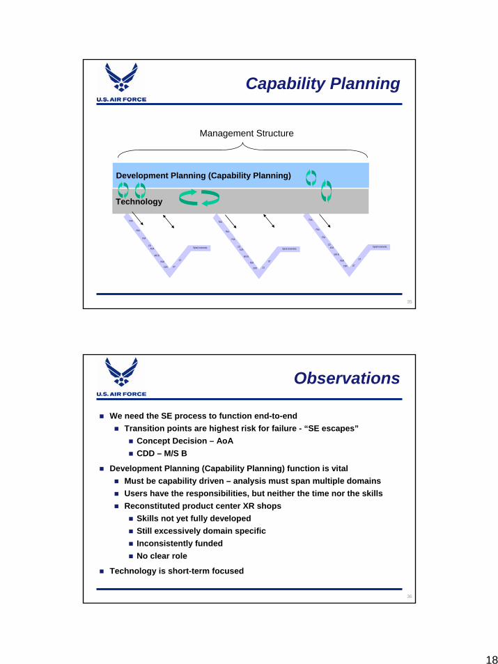
Our Management Structure
Development Planning (Capability Planning) Existed in the past
Reported to Product Center commandersFunded by PE 65808Mission focused
Mission narrowly defined in today’s viewNot adequate for Systems of Systems
18
35
Capability Planning
FAA
OT
Spiral Increments
FNA
FSA
CDAOA
M/S B
PDR
CDR DT
FAA
OT
Spiral Increments
FNA
FSA
CDAOA
M/S B
PDR
CDR DT
FAA
OT
Spiral Increments
FNA
FSA
CDAOA
M/S B
PDR
CDR DT
FAA
OT
Spiral Increments
FNA
FSA
CDAOA
M/S B
PDR
CDR DT
FAA
OT
Spiral Increments
FNA
FSA
CDAOA
M/S B
PDR
CDR DT
FAA
OT
Spiral Increments
FNA
FSA
CDAOA
M/S B
PDR
CDR DT
Technology
Development Planning (Capability Planning)
Management Structure
36
Observations
We need the SE process to function end-to-endTransition points are highest risk for failure - “SE escapes”
Concept Decision – AoACDD – M/S B
Development Planning (Capability Planning) function is vitalMust be capability driven – analysis must span multiple domainsUsers have the responsibilities, but neither the time nor the skillsReconstituted product center XR shops
Skills not yet fully developedStill excessively domain specificInconsistently fundedNo clear role
Technology is short-term focused

19
37
BACKUP
38
Case Studieshttp://www.afit.edu/cse

20
39
What we have now - Assessment
Usually good job of relating JCIDS effort to National Strategies, QDR, Joint Concepts, UJTL, Air Force Capabilities
But, Task Analysis, per JCIDS and good Systems Engineering practice, should define the standard to achieve
Measures of Effectiveness (MOE) by which to compare different solutions Strategy &
Overarching Concepts
Joint OperationsConcepts
Guidance
JointOperatingConcepts
JointFunctionalConcepts
OPLANSand
CONPLANS
OPLANSand
CONPLANS
DefensePlanningScenarios
DefensePlanningScenarios
IntegratedArchitectures
IntegratedArchitectures
Overlaywhat we have with what we need to do
• COCOM IPLs• Gap Analysis
• Risk Assessment
TaskAnalyses
TaskAnalyses
CapabilityAssessments
CapabilityAssessmentsAssessment
andAnalysis
Reconciliation& Recommendations
DecisionandAction
AcquisitionPPBEScience &
Technology Experimentation
NationalSecurityStrategy
JCIDS Recommendations
Capability NeedsDOTMLPF Changes
Our experience supporting AoAs has taught us that developing a good set of MOEs is usually a harrowing business.
-- Air Force Analyst’s Handbook
40
What we have now - Assessment
Without good Measures of Effectiveness, any Gaps in the Capability Assessment (Functional Needs Analysis) would be “hand waiving”
Results in not giving a sound and full understanding of gaps/ root causes
Solutions Analysis should
give fair assessment to entire
DOTMLPF* solution space
Strategy & Overarching
Concepts
Joint OperationsConcepts
Guidance
JointOperatingConcepts
JointFunctionalConcepts
OPLANSand
CONPLANS
OPLANSand
CONPLANS
DefensePlanningScenarios
DefensePlanningScenarios
IntegratedArchitectures
IntegratedArchitectures
Overlaywhat we have with what we need to do
• COCOM IPLs• Gap Analysis
• Risk Assessment
TaskAnalyses
TaskAnalyses
CapabilityAssessments
CapabilityAssessmentsAssessment
andAnalysis
Reconciliation& Recommendations
DecisionandAction
AcquisitionPPBEScience &
Technology Experimentation
NationalSecurityStrategy
JCIDS Recommendations
Capability NeedsDOTMLPF Changes
* Doctrine, Organization, Training, Materiel, Leadership, Personnel and Facilities

21
41
JCIDS Analysis
Adapted from CJCSI 3170.01C Joint Capabilities and Integration Development System, Figure A-1
Strategy & Overarching
Concepts
Joint OperationsConcepts
Guidance
JointOperatingConcepts
JointFunctionalConcepts
OPLANSand
CONPLANS
OPLANSand
CONPLANS
DefensePlanningScenarios
DefensePlanningScenarios
IntegratedArchitectures
IntegratedArchitectures
Overlaywhat we have with what we need to do
• COCOM IPLs• Gap Analysis
• Risk Assessment
TaskAnalyses
TaskAnalyses
CapabilityAssessments
CapabilityAssessmentsAssessment
andAnalysis
Reconciliation& Recommendations
DecisionandAction
AcquisitionPPBEScience &
Technology Experimentation
NationalSecurityStrategy
JCIDS Recommendations
Capability NeedsDOTMLPF Changes
FunctionalArea
AnalysisFunctional
Needs Analysis
FunctionalSolutions Analysis
42
DAU Acquisition Guide 2006

22
43
JCIDS Analysis
Functional Area Analysis (FAA)Identify operational tasks, conditions, and standards needed to accomplish military objectivesResult: Tasks to be reviewed in the FNA
Functional Needs Analysis (FNA)Assess ability of current and programmed capabilities to accomplish the tasksResult: List of capability gaps
Functional Solutions Analysis (FSA)Operational based assessment of doctrine, organization, training, materiel, leadership/education, personnel, and facilities (DOTMLPF) approaches to solving capability gapsResult: Potential integrated DOTMLPF approaches to capability gaps
Post Independent AnalysisIndependent analysis of approaches to determine best fitResult: Initial Capabilities Document
Related Documents


