AFGB1 Superpave ™ Gyratory Compactor Operation Manual Pine Test Equipment, Inc. 101 Industrial Drive Grove City, PA 16127 USA +1 (724) 458-6393 (phone) (724) 458-6418 (fax) www.pinetestequipment.com [email protected] LMAFGB1 Version 026 06-DEC-2019 © 2001-2019 Pine Test Equipment, Inc.

Welcome message from author
This document is posted to help you gain knowledge. Please leave a comment to let me know what you think about it! Share it to your friends and learn new things together.
Transcript

AFGB1
Superpave™ Gyratory Compactor
Operation Manual
Pine Test Equipment, Inc.
101 Industrial Drive
Grove City, PA 16127
USA
+1 (724) 458-6393 (phone)
(724) 458-6418 (fax)
www.pinetestequipment.com
LMAFGB1
Version 026
06-DEC-2019 © 2001-2019 Pine Test Equipment, Inc.

Pine Test Equipment, Inc.
LMAFGB1 (Rev 026) ii 06-DEC-2019
Intentionally Blank
Pine Test Equipment, Inc.
06-DEC-2019 iii LMAFGB1 (Rev 026)
Table of Contents
1. GENERAL INFORMATION ...................................................................................................................... 1
1.1 OVERVIEW ............................................................................................................................................ 1
1.2 COPYRIGHT ........................................................................................................................................... 1
1.3 TRADEMARKS ......................................................................................................................................... 1
1.4 PERSONAL SAFETY .................................................................................................................................. 2
1.5 AVOIDING DAMAGE ............................................................................................................................. 3
1.6 MATERIAL DISCLOSURE TABLE ................................................................................................................. 4
2. PRODUCT OVERVIEW ............................................................................................................................ 5
2.1 SPECIFICATIONS (SUBJECT TO CHANGE WITHOUT NOTICE) ......................................................................... 5
2.2 ACCESSORIES ........................................................................................................................................ 5
2.2.1 Calibration Accessories ........................................................................................................ 6
2.2.2 Specimen-Related Accessories .......................................................................................... 6
2.2.3 Lubricants ................................................................................................................................ 6
2.2.4 Data Handling ........................................................................................................................ 6
2.2.5 Miscellaneous Accessories .................................................................................................. 6
2.3 SETUP .................................................................................................................................................... 7
2.3.1 Unpacking the Gyratory Compactor ................................................................................ 7
2.3.2 Checking the Gyratory Head Cable ................................................................................. 8
2.3.3 Choosing the Right Location for the Compactor ........................................................... 8
2.3.4 Control Box Orientation ........................................................................................................ 9
2.3.5 Final Preparations ................................................................................................................ 10
3. OPERATION .......................................................................................................................................... 11
3.1 COMPACTOR CONTROLS .................................................................................................................... 11
3.1.1 Main Power Switch .............................................................................................................. 11
3.1.2 Emergency Stop Button ..................................................................................................... 11
3.1.3 Main Control Panel ............................................................................................................. 12
3.2 OPENING THE COMPACTION CHAMBER ............................................................................................... 16
3.3 FILLING THE MOLD WITH MIX ASPHALT ................................................................................................... 17
3.4 USING THE MOLD EXTRACTOR TONGS ................................................................................................... 18
3.5 PLACING THE MOLD INTO THE COMPACTION CHAMBER ........................................................................ 19
3.6 CLOSING THE COMPACTION CHAMBER ................................................................................................ 23
3.7 COMPACTING TO A SPECIFIC NUMBER OF GYRATIONS .......................................................................... 24

Pine Test Equipment, Inc.
LMAFGB1 (Rev 026) iv 06-DEC-2019
3.8 COMPACTING TO A SPECIFIC FINAL SPECIMEN HEIGHT .......................................................................... 25
3.9 EXTRUDING THE SPECIMEN FROM THE MOLD .......................................................................................... 27
3.10 IMPORTANT CAUTIONARY NOTES .......................................................................................................... 29
3.11 REMOVING THE MOLD FROM THE COMPACTION CHAMBER ................................................................... 31
3.12 PARKING THE RAM AND GYRATORY HEAD ............................................................................................ 32
3.13 SPECIMEN SQUARING ........................................................................................................................... 33
3.14 FILLING A MOLD IN THE COMPACTION CHAMBER .................................................................................. 35
3.15 TEST RESULTS ........................................................................................................................................ 36
3.15.1 Viewing Results on the Display ..................................................................................... 37
3.15.2 Printing Compaction Results ......................................................................................... 38
3.15.3 Saving Results to a USB Flash Memory Device .......................................................... 39
3.16 SETTING AUTOMATIC DATA OUTPUT MODES .......................................................................................... 40
3.17 SETTING THE DATE AND TIME ON THE SGC CONTROL PANEL .................................................................. 42
4. CALIBRATION ....................................................................................................................................... 43
4.1 RATE OF GYRATION .............................................................................................................................. 43
4.1.1 Rate of Gyration - Verification .......................................................................................... 43
4.1.2 Rate of Gyration - Adjustment .......................................................................................... 43
4.2 RAM PRESSURE..................................................................................................................................... 44
4.2.1 Ram Pressure Tuner .............................................................................................................. 44
4.2.2 Ram Pressure - Verification and Calibration .................................................................. 44
4.3 RAM POSITION (SPECIMEN HEIGHT) ...................................................................................................... 50
4.3.1 Ram Position - Verification and Calibration ................................................................... 50
4.4 ANGLE OF GYRATION .......................................................................................................................... 57
4.4.1 Angle of Gyration - Temperature Dependence ........................................................... 57
4.4.2 External Angle of Gyration - Measurement .................................................................... 59
4.4.3 Angle of Gyration – Adjustment ....................................................................................... 66
5. MAINTENANCE .................................................................................................................................... 70
5.1 LUBRICATION ....................................................................................................................................... 70
5.1.1 Mold Top Plate ..................................................................................................................... 70
5.1.2 Gyratory Head ..................................................................................................................... 71
5.1.3 Tapered Bearing .................................................................................................................. 72
5.1.4 Pressure Plate........................................................................................................................ 72
5.1.5 Spherical Seat ...................................................................................................................... 73

Pine Test Equipment, Inc.
06-DEC-2019 v LMAFGB1 (Rev 026)
5.1.6 Gyratory Head and Clamp Recesses ............................................................................. 75
5.1.7 Gyratory Head Lift Nut ........................................................................................................ 75
5.1.8 Timing Lift Screw ................................................................................................................... 76
5.2 PRESSURE PLATE SCREWS ...................................................................................................................... 77
5.3 CLAMP ADJUSTMENT ........................................................................................................................... 77
5.4 HYDRAULIC SYSTEM .............................................................................................................................. 79
5.5 MOLD RETAINING LATCHES .................................................................................................................. 81
5.6 CLEANING .......................................................................................................................................... 81
5.7 LOW BATTERY INDICATION .................................................................................................................... 82
5.8 CHANGING THE CPU BATTERY ............................................................................................................. 82
5.9 STORAGE ............................................................................................................................................ 85
5.10 PARTS LIST ........................................................................................................................................... 85
5.11 TROUBLESHOOTING .............................................................................................................................. 85
6. WARRANTY ........................................................................................................................................... 89
SAMPLE CALIBRATION LOG SHEETS

Pine Test Equipment, Inc.
LMAFGB1 (Rev 026) vi 06-DEC-2019
Intentionally Blank

Pine Test Equipment, Inc.
06-DEC-2019 vii LMAFGB1 (Rev 026)
Table of Figures
Figure 1-1: The two proper positions for the gyratory head. .................................................................... 3
Figure 2-1: Detaching compactor from the pallet. ................................................................................... 8
Figure 2-2: Rolling the compactor off the pallet. ....................................................................................... 8
Figure 2-3: Changing the orientation of the control box. .......................................................................10
Figure 3-1: Machine controls on the AFGB1 gyratory compactor........................................................11
Figure 3-2: The x2 Base Touchscreen AFGB1 main control panel. ........................................................12
Figure 3-3 - Main Menu Popup Screen ........................................................................................................13
Figure 3-4 - Typical Screen Showing Pop-up Keypad ...............................................................................14
Figure 3-5: Compaction chamber with gyratory head. .........................................................................14
Figure 3-6: Clamps on compaction chamber for securing gyratory head. .......................................15
Figure 3-7: Rotate gyratory head using specimen lift nut. ......................................................................16
Figure 3-8: Inserting bottom mold plate using magnet. ..........................................................................17
Figure 3-9: Using mold tongs to lift specimen mold. ................................................................................19
Figure 3-10: Mold pin locations. ...................................................................................................................20
Figure 3-11: Notches in pressure plate. .......................................................................................................20
Figure 3-12: Aligning the mold pins with the notches in the pressure plate. .......................................21
Figure 3-13: Use mold tongs to rotate mold clockwise. ..........................................................................22
Figure 3-14: Closing the compaction chamber. ......................................................................................23
Figure 3-15 - The SETUP Screen ......................................................................................................................24
Figure 3-16: Funnel cap attachment. .........................................................................................................27
Figure 3-17: Specimen extrusion with ram. ................................................................................................27
Figure 3-18: Specimen lift handle. ...............................................................................................................27
Figure 3-19: Improper actions leading to damage or injury. .................................................................30
Figure 3-20: Counterclockwise rotation moves mold pins away from notches. ................................31
Figure 3-21: Hydraulic extrusion of the mold. ............................................................................................32
Figure 3-22: Viewing results on the Test Results screen. ...........................................................................37
Figure 3-23 - Viewing More Results from the Displayed Test ....................................................................38
Figure 3-25 - The Setup Screen ......................................................................................................................40
Figure 3-24 - The Advanced Setup Screen .................................................................................................42
Figure 4-1: Adjusting the rate of gyration...................................................................................................43
Figure 4-2 - The Calibration Screen ..............................................................................................................45
Figure 4-3: Disconnect cable. ......................................................................................................................45
Pine Test Equipment, Inc.
LMAFGB1 (Rev 026) viii 06-DEC-2019
Figure 4-4: Reference cell. ........................................................................................................................... 47
Figure 4-5: Load cell cable. ......................................................................................................................... 47
Figure 4-6: Ram pressure tuner inside control box. .................................................................................. 48
Figure 4-7: Disconnect cable. ..................................................................................................................... 51
Figure 4-8: Height tube. .................................................................................................................................. 52
Figure 4-9: Adjusting vertical position of tapered bearing. ................................................................... 58
Figure 4-10: Inside the AFGB1 external angle measurement system. .................................................. 58
Figure 4-11: How the external angle measurement system works. ...................................................... 59
Figure 4-12: Disconnect cable. ................................................................................................................... 60
Figure 4-13: Height tube. ............................................................................................................................... 62
Figure 4-14: External angle sensor calibration setup. .............................................................................. 63
Figure 4-15: Inserting the spacer into the external angle sensor. ......................................................... 64
Figure 4-16: Adjustment nuts on the bearing support mounts. ............................................................. 67
Figure 5-1: Mold top plate lubrication. ...................................................................................................... 71
Figure 5-2: Gyratory head lubrication. ....................................................................................................... 71
Figure 5-3: Tapered bearing lubrication. ................................................................................................... 72
Figure 5-4: Pressure plate lubrication. ........................................................................................................ 73
Figure 5-5: Spherical seat lubrication. ........................................................................................................ 74
Figure 5-6: Clamp lubrication. ..................................................................................................................... 75
Figure 5-7: Lift nut lubrication. ...................................................................................................................... 75
Figure 5-8: Lift nut timing. .............................................................................................................................. 76
Figure 5-9: Adjusting tension on compaction chamber clamps. ......................................................... 78
Figure 5-10: Checking the hydraulic oil level. .......................................................................................... 80
Figure 5-11: Overview of the hydraulic system. ....................................................................................... 80
Figure 5-12: Cleaning the floor of the compaction chamber. ............................................................. 81
Figure 5-13: Low battery warning. ............................................................................................................... 82
Figure 5-14: Battery Location. ...................................................................................................................... 84
Figure 5-15: Battery Connector (bottom view of CPU Module). .......................................................... 84
Table of Tables
Table 1.1: Material disclosure. ....................................................................................................................... 4

Pine Test Equipment, Inc.
06-DEC-2019 1 LMAFGB1 (Rev 026)
1. General Information
1.1 Overview
This manual describes the proper use of the Pine AFGB1 SuperpaveTM Gyratory Compactor,
including routine operating procedures, periodic maintenance and calibration, and safety issues.
It is assumed that the reader of this manual is already familiar with hot mix asphalt design methods
and the SuperpaveTM mix design protocol.
1.2 Copyright
Pine Test Equipment, Inc. holds the copyright to this publication and grants permission to the owner
of a Pine AFGB1 Superpave Gyratory Compactor to duplicate this document for internal purposes
only.
1.3 Trademarks
SuperpaveTM is a trademark of the Strategic Highway Research Program now owned by the
Transportation Research Board (Washington, DC).
Microsoft Windows® and Excel® are registered trademarks of Microsoft Corporation (Redmond,
WA).
WD-40® is a registered trademark of the WD-40 Company (San Diego, CA).

Pine Test Equipment, Inc.
LMAFGB1 (Rev 026) 2 06-DEC-2019
1.4 Personal Safety
Heed the following personal safety warnings when working with an AFGB1 gyratory compactor.
Wear safety glasses.
Wear safety-toe shoes.
Wear garments that protect against heat and burns in the event that hot mix asphalt
is spilled. Long sleeve shirts and long pants are recommended.
Wear heat resistant gloves when working with hot mix asphalt, hot molds, and any
other hot material. Wear long gloves that protect the hand and forearm when
cleaning the inside surfaces of hot molds.
Wear gloves and grasp the mold firmly by the ridges machined around the outside of
the mold when moving a gyratory mold by hand.
Do not wear loose-fitting clothing items (i.e., jewelry, ties, etc.) which may be caught
in the moving parts of the gyratory compactor.
Do not place hands or any other body part inside the compaction chamber unless
the EMERGENCY STOP button has been activated.
Keep hands away from moving parts and pinch points at all times. Be especially
careful when extruding a specimen or the RAM to keep hands away from the area
immediately above the compaction chamber.
Remove anything other than a filled mold assembly from the compaction chamber
before initiating compaction.
Do not operate the compactor with any of the access panels removed.
Check the mold tongs for loose hardware and any sign of damage to the pegs at the
end of the tongs prior to use.
Use proper lifting techniques when lifting a mold to prevent a back injury.
Always use two hands when using the mold tongs to lift a mold. Maintain a constant
squeezing pressure on the mold tong handles while moving the mold.
Pine Test Equipment, Inc.
06-DEC-2019 3 LMAFGB1 (Rev 026)
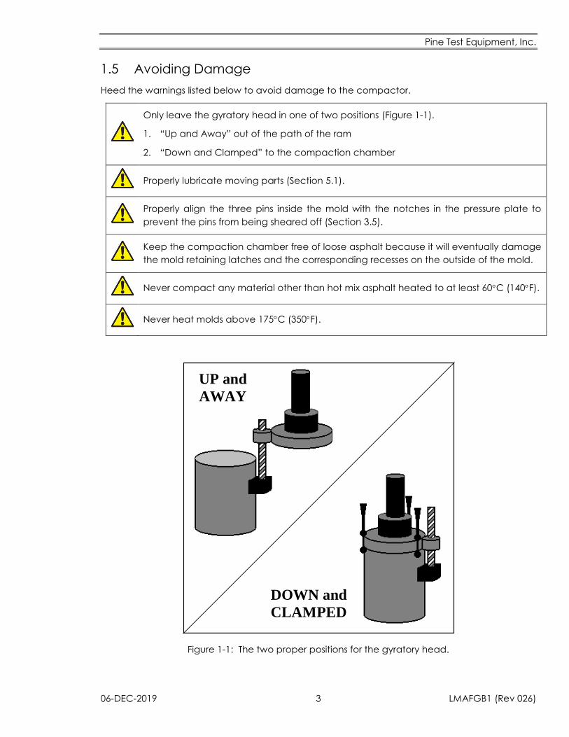
1.5 Avoiding Damage
Heed the warnings listed below to avoid damage to the compactor.
Only leave the gyratory head in one of two positions (Figure 1-1).
1. “Up and Away” out of the path of the ram
2. “Down and Clamped” to the compaction chamber
Properly lubricate moving parts (Section 5.1).
Properly align the three pins inside the mold with the notches in the pressure plate to
prevent the pins from being sheared off (Section 3.5).
Keep the compaction chamber free of loose asphalt because it will eventually damage
the mold retaining latches and the corresponding recesses on the outside of the mold.
Never compact any material other than hot mix asphalt heated to at least 60C (140F).
Never heat molds above 175C (350F).
DOWN and
CLAMPED
UP and
AWAY
Figure 1-1: The two proper positions for the gyratory head.
Pine Test Equipment, Inc.
LMAFGB1 (Rev 026) 4 06-DEC-2019
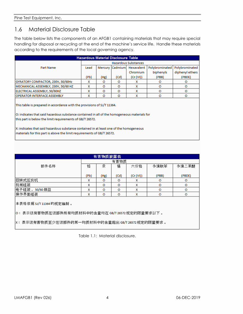
1.6 Material Disclosure Table
The table below lists the components of an AFGB1 containing materials that may require special
handling for disposal or recycling at the end of the machine’s service life. Handle these materials
according to the requirements of the local governing agency.
Table 1.1: Material disclosure.
Pine Test Equipment, Inc.
06-DEC-2019 5 LMAFGB1 (Rev 026)
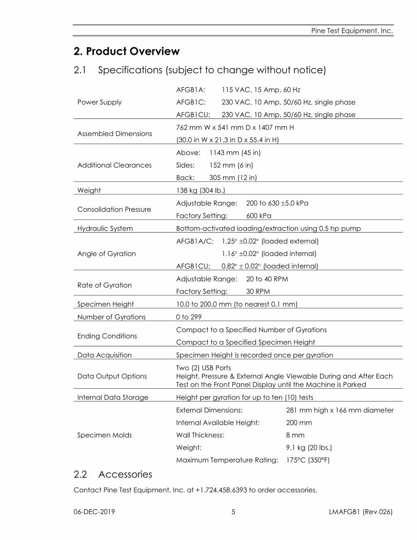
2. Product Overview
2.1 Specifications (subject to change without notice)
Power Supply
AFGB1A:
AFGB1C:
AFGB1CU:
115 VAC, 15 Amp, 60 Hz
230 VAC, 10 Amp, 50/60 Hz, single phase
230 VAC, 10 Amp, 50/60 Hz, single phase
Assembled Dimensions 762 mm W x 541 mm D x 1407 mm H
(30.0 in W x 21.3 in D x 55.4 in H)
Additional Clearances
Above:
Sides:
Back:
1143 mm (45 in)
152 mm (6 in)
305 mm (12 in)
Weight 138 kg (304 lb.)
Consolidation Pressure Adjustable Range:
Factory Setting:
200 to 630 5.0 kPa
600 kPa
Hydraulic System Bottom-activated loading/extraction using 0.5 hp pump
Angle of Gyration
AFGB1A/C:
AFGB1CU:
1.25 0.02 (loaded external)
1.16 0.02 (loaded internal)
0.82 0.02 (loaded internal)
Rate of Gyration Adjustable Range:
Factory Setting:
20 to 40 RPM
30 RPM
Specimen Height 10.0 to 200.0 mm (to nearest 0.1 mm)
Number of Gyrations 0 to 299
Ending Conditions Compact to a Specified Number of Gyrations
Compact to a Specified Specimen Height
Data Acquisition Specimen Height is recorded once per gyration
Data Output Options
Two (2) USB Ports
Height, Pressure & External Angle Viewable During and After Each
Test on the Front Panel Display until the Machine is Parked
Internal Data Storage Height per gyration for up to ten (10) tests
Specimen Molds
External Dimensions:
Internal Available Height:
Wall Thickness:
Weight:
Maximum Temperature Rating:
281 mm high x 166 mm diameter
200 mm
8 mm
9.1 kg (20 lbs.)
175°C (350°F)
2.2 Accessories
Contact Pine Test Equipment, Inc. at +1.724.458.6393 to order accessories.
Pine Test Equipment, Inc.
LMAFGB1 (Rev 026) 6 06-DEC-2019
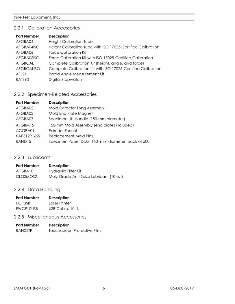
2.2.1 Calibration Accessories
Part Number Description
AFGBA04 Height Calibration Tube
AFGBA04ISO Height Calibration Tube with ISO 17025-Certified Calibration
AFGBA06 Force Calibration Kit
AFGBA06ISO Force Calibration Kit with ISO 17025-Certified Calibration
AFGBCAL Complete Calibration Kit (height, angle, and force)
AFGBCALISO Complete Calibration Kit with ISO 17025-Certified Calibration
AFLS1 Rapid Angle Measurement Kit
RATS90 Digital Stopwatch
2.2.2 Specimen-Related Accessories
Part Number Description
AFGBA02 Mold Extractor Tong Assembly
AFGBA03 Mold End Plate Magnet
AFGBA07 Specimen Lift Handle (150-mm diameter)
AFGBM15 150-mm Mold Assembly (end plates included)
ACGBA01 Extruder Funnel
KAP312R16SS Replacement Mold Pins
RAND15 Specimen Paper Disks, 1501mm diameter, pack of 500
2.2.3 Lubricants
Part Number Description
AFGBA10 Hydraulic Filter Kit
CLGSMOS2 Moly-Grade Anti-Seize Lubricant (10 oz.)
2.2.4 Data Handling
Part Number Description
RCPUSB Laser Printer
EWCP10USB USB Cable, 10 ft.
2.2.5 Miscellaneous Accessories
Part Number Description
RANX2TP Touchscreen Protective Film
Pine Test Equipment, Inc.
06-DEC-2019 7 LMAFGB1 (Rev 026)
2.3 Setup
Read and understand all of the unpacking and installation instructions in this section of the manual
before unpacking the compactor. Also, it is advised that the packing materials be saved in case
the AFGB1 needs to be shipped to a new location in the future.
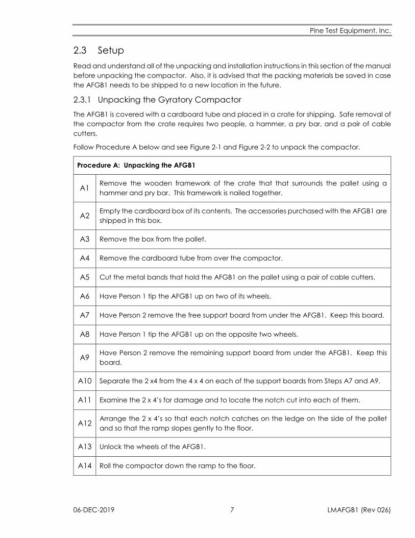
2.3.1 Unpacking the Gyratory Compactor
The AFGB1 is covered with a cardboard tube and placed in a crate for shipping. Safe removal of
the compactor from the crate requires two people, a hammer, a pry bar, and a pair of cable
cutters.
Follow Procedure A below and see Figure 2-1 and Figure 2-2 to unpack the compactor.
Procedure A: Unpacking the AFGB1
A1 Remove the wooden framework of the crate that that surrounds the pallet using a
hammer and pry bar. This framework is nailed together.
A2 Empty the cardboard box of its contents. The accessories purchased with the AFGB1 are
shipped in this box.
A3 Remove the box from the pallet.
A4 Remove the cardboard tube from over the compactor.
A5 Cut the metal bands that hold the AFGB1 on the pallet using a pair of cable cutters.
A6 Have Person 1 tip the AFGB1 up on two of its wheels.
A7 Have Person 2 remove the free support board from under the AFGB1. Keep this board.
A8 Have Person 1 tip the AFGB1 up on the opposite two wheels.
A9 Have Person 2 remove the remaining support board from under the AFGB1. Keep this
board.
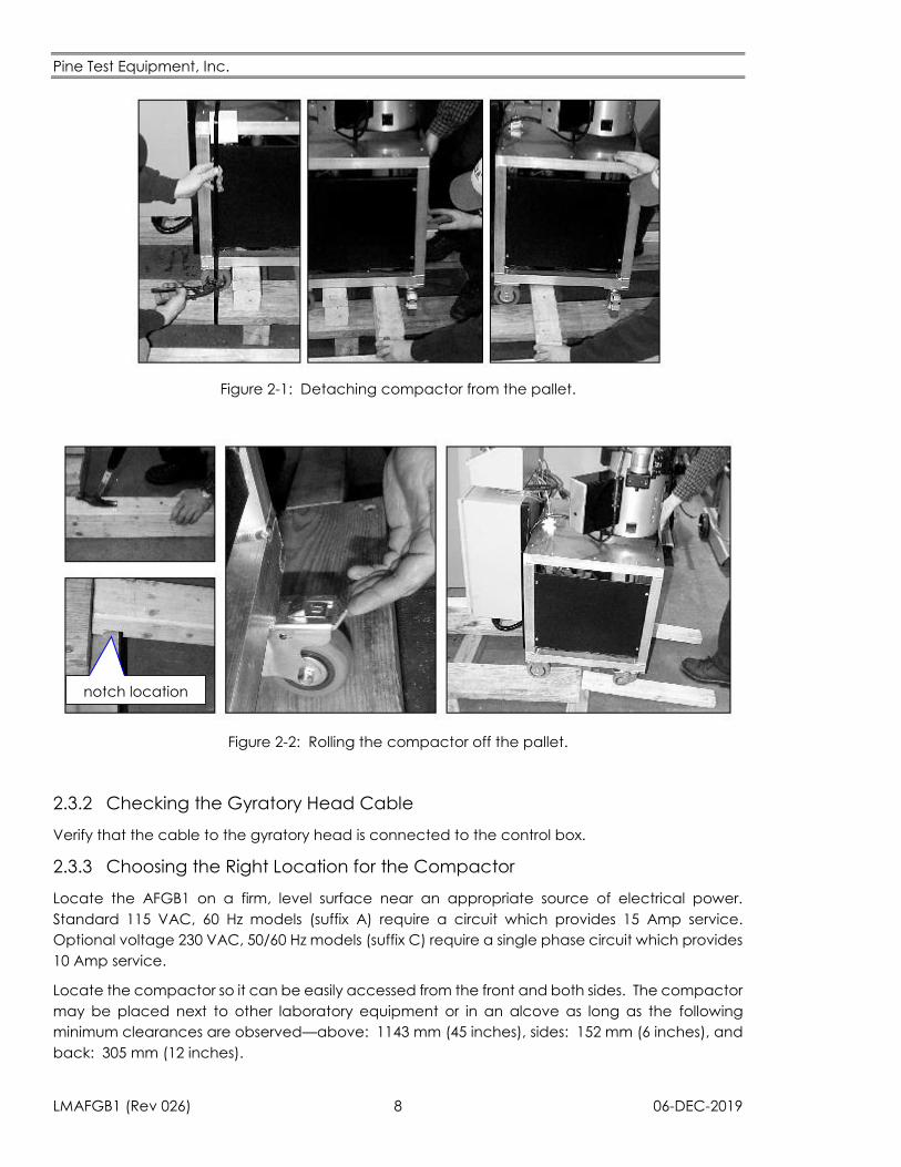
A10 Separate the 2 x4 from the 4 x 4 on each of the support boards from Steps A7 and A9.
A11 Examine the 2 x 4’s for damage and to locate the notch cut into each of them.
A12 Arrange the 2 x 4’s so that each notch catches on the ledge on the side of the pallet
and so that the ramp slopes gently to the floor.
A13 Unlock the wheels of the AFGB1.
A14 Roll the compactor down the ramp to the floor.
Pine Test Equipment, Inc.
LMAFGB1 (Rev 026) 8 06-DEC-2019
Figure 2-1: Detaching compactor from the pallet.
notch location
Figure 2-2: Rolling the compactor off the pallet.
2.3.2 Checking the Gyratory Head Cable
Verify that the cable to the gyratory head is connected to the control box.
2.3.3 Choosing the Right Location for the Compactor
Locate the AFGB1 on a firm, level surface near an appropriate source of electrical power.
Standard 115 VAC, 60 Hz models (suffix A) require a circuit which provides 15 Amp service.
Optional voltage 230 VAC, 50/60 Hz models (suffix C) require a single phase circuit which provides
10 Amp service.
Locate the compactor so it can be easily accessed from the front and both sides. The compactor
may be placed next to other laboratory equipment or in an alcove as long as the following
minimum clearances are observed—above: 1143 mm (45 inches), sides: 152 mm (6 inches), and
back: 305 mm (12 inches).
Pine Test Equipment, Inc.
06-DEC-2019 9 LMAFGB1 (Rev 026)
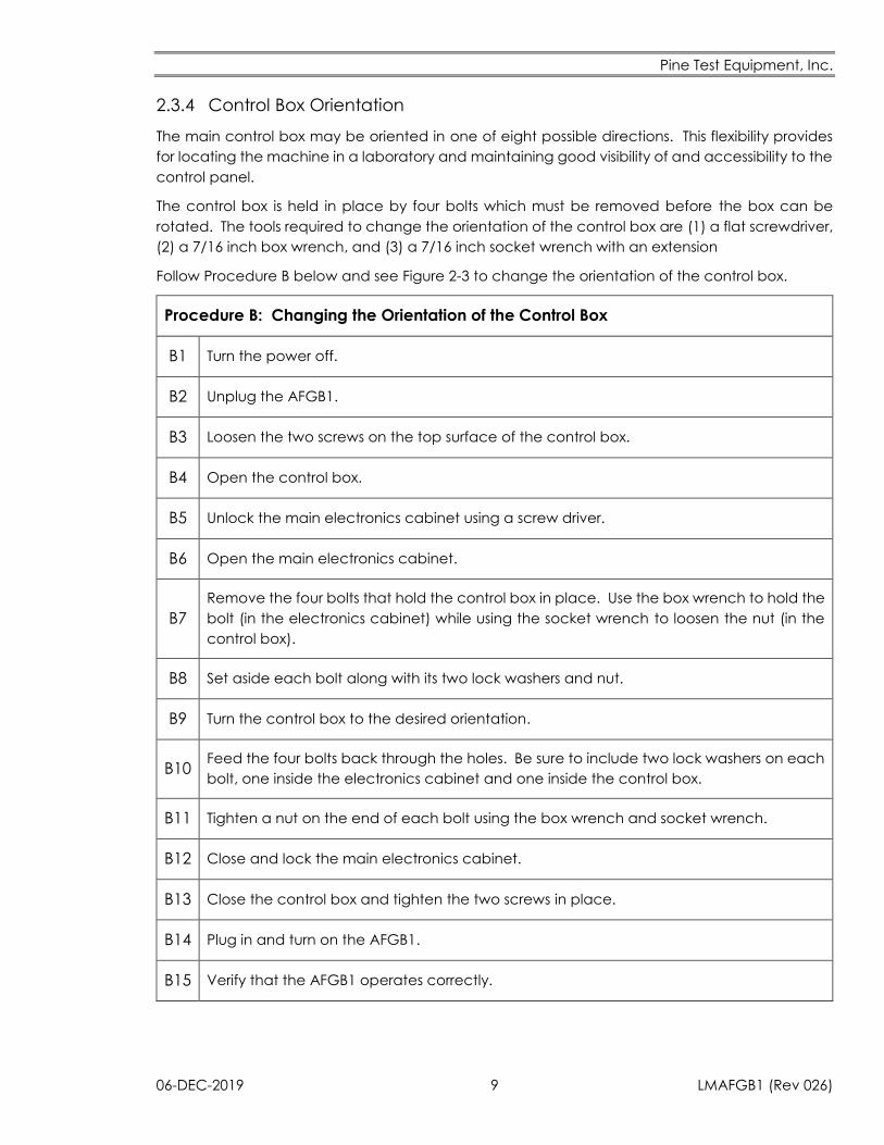
2.3.4 Control Box Orientation
The main control box may be oriented in one of eight possible directions. This flexibility provides
for locating the machine in a laboratory and maintaining good visibility of and accessibility to the
control panel.
The control box is held in place by four bolts which must be removed before the box can be
rotated. The tools required to change the orientation of the control box are (1) a flat screwdriver,
(2) a 7/16 inch box wrench, and (3) a 7/16 inch socket wrench with an extension
Follow Procedure B below and see Figure 2-3 to change the orientation of the control box.
Procedure B: Changing the Orientation of the Control Box
B1 Turn the power off.
B2 Unplug the AFGB1.
B3 Loosen the two screws on the top surface of the control box.
B4 Open the control box.
B5 Unlock the main electronics cabinet using a screw driver.
B6 Open the main electronics cabinet.
B7
Remove the four bolts that hold the control box in place. Use the box wrench to hold the
bolt (in the electronics cabinet) while using the socket wrench to loosen the nut (in the
control box).
B8 Set aside each bolt along with its two lock washers and nut.
B9 Turn the control box to the desired orientation.
B10 Feed the four bolts back through the holes. Be sure to include two lock washers on each
bolt, one inside the electronics cabinet and one inside the control box.
B11 Tighten a nut on the end of each bolt using the box wrench and socket wrench.
B12 Close and lock the main electronics cabinet.
B13 Close the control box and tighten the two screws in place.
B14 Plug in and turn on the AFGB1.
B15 Verify that the AFGB1 operates correctly.
Pine Test Equipment, Inc.
LMAFGB1 (Rev 026) 10 06-DEC-2019
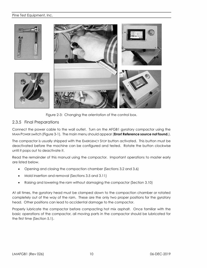
Figure 2-3: Changing the orientation of the control box.
2.3.5 Final Preparations
Connect the power cable to the wall outlet. Turn on the AFGB1 gyratory compactor using the
MAIN POWER switch (Figure 3-1). The main menu should appear (Error! Reference source not found.).
The compactor is usually shipped with the EMERGENCY STOP button activated. This button must be
deactivated before the machine can be configured and tested. Rotate the button clockwise
until it pops out to deactivate it.
Read the remainder of this manual using the compactor. Important operations to master early
are listed below.
Opening and closing the compaction chamber (Sections 3.2 and 3.6)
Mold insertion and removal (Sections 3.5 and 3.11)
Raising and lowering the ram without damaging the compactor (Section 3.10)
At all times, the gyratory head must be clamped down to the compaction chamber or rotated
completely out of the way of the ram. These are the only two proper positions for the gyratory
head. Other positions can lead to accidental damage to the compactor.
Properly lubricate the compactor before compacting hot mix asphalt. Once familiar with the
basic operations of the compactor, all moving parts in the compactor should be lubricated for
the first time (Section 5.1).
Pine Test Equipment, Inc.
06-DEC-2019 11 LMAFGB1 (Rev 026)
3. Operation
Read Section 1.4 Personal Safety Section 1.5 Avoiding Damage before using the AFGB1
gyratory compactor.
3.1 Compactor Controls
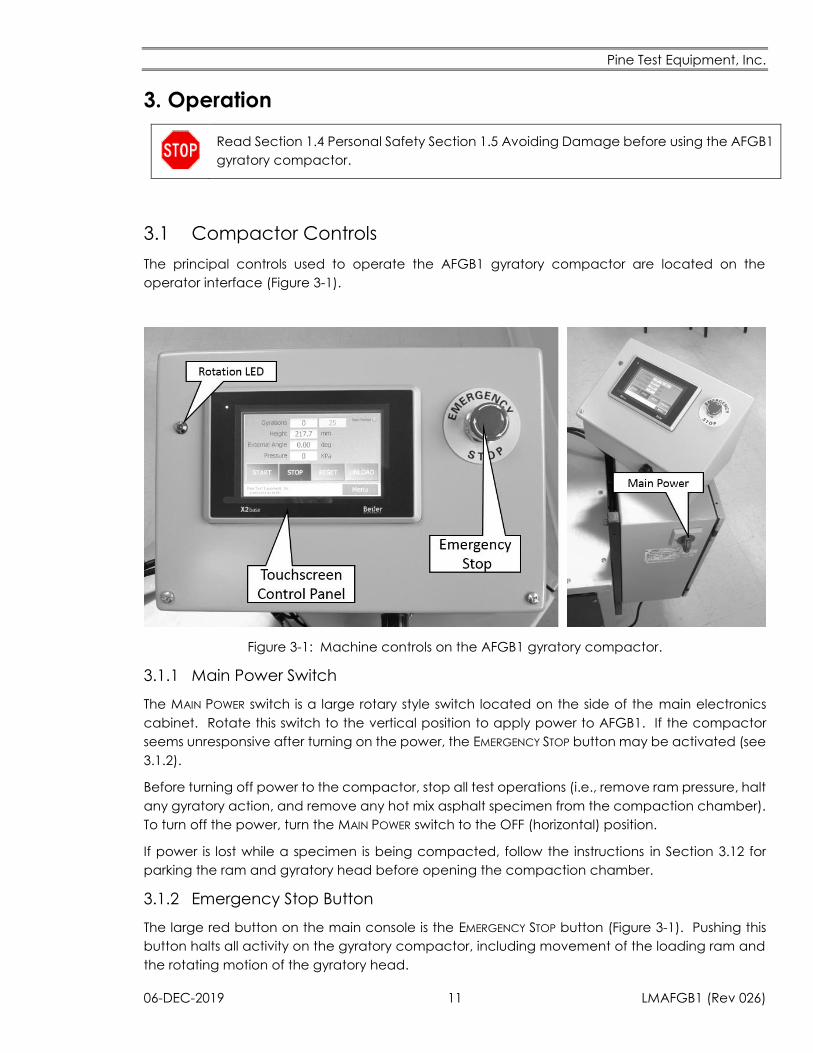
The principal controls used to operate the AFGB1 gyratory compactor are located on the
operator interface (Figure 3-1).
Figure 3-1: Machine controls on the AFGB1 gyratory compactor.
3.1.1 Main Power Switch
The MAIN POWER switch is a large rotary style switch located on the side of the main electronics
cabinet. Rotate this switch to the vertical position to apply power to AFGB1. If the compactor
seems unresponsive after turning on the power, the EMERGENCY STOP button may be activated (see
3.1.2).
Before turning off power to the compactor, stop all test operations (i.e., remove ram pressure, halt
any gyratory action, and remove any hot mix asphalt specimen from the compaction chamber).
To turn off the power, turn the MAIN POWER switch to the OFF (horizontal) position.
If power is lost while a specimen is being compacted, follow the instructions in Section 3.12 for
parking the ram and gyratory head before opening the compaction chamber.
3.1.2 Emergency Stop Button
The large red button on the main console is the EMERGENCY STOP button (Figure 3-1). Pushing this
button halts all activity on the gyratory compactor, including movement of the loading ram and
the rotating motion of the gyratory head.
Pine Test Equipment, Inc.
LMAFGB1 (Rev 026) 12 06-DEC-2019
When pushed, the EMERGENCY STOP button remains engaged until it is manually released by rotating
the button clockwise. As long as the EMERGENCY STOP button remains engaged, no motion of the
ram or gyratory head is permitted, even if the operator presses virtual buttons that would normally
initiate movement.
After the EMERGENCY STOP button is released by rotating it clockwise, the operator may initiate ram
or gyratory head movement using the appropriate button.
When shipped from the factory, the EMERGENCY STOP button on the AFGB1 is normally engaged
and must be manually released before the machine will run.
3.1.3 Main Control Panel
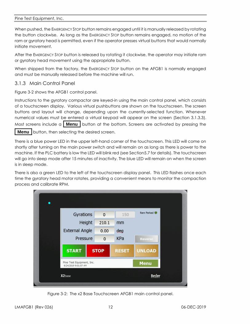
Figure 3-2 shows the AFGB1 control panel.
Instructions to the gyratory compactor are keyed-in using the main control panel, which consists
of a touchscreen display. Various virtual pushbuttons are shown on the touchscreen. The screen
buttons and layout will change, depending upon the currently-selected function. Whenever
numerical values must be entered a virtual keypad will appear on the screen (Section 3.1.3.3).
Most screens include a _Menu_ button at the bottom. Screens are activated by pressing the
_Menu_ button, then selecting the desired screen.
There is a blue power LED in the upper left-hand corner of the touchscreen. This LED will come on
shortly after turning on the main power switch and will remain on as long as there is power to the
machine. If the PLC battery is low the LED will blink red (see Section5.7 for details). The touchscreen
will go into sleep mode after 15 minutes of inactivity. The blue LED will remain on when the screen
is in sleep mode.
There is also a green LED to the left of the touchscreen display panel. This LED flashes once each
time the gyratory head motor rotates, providing a convenient means to monitor the compaction
process and calibrate RPM.
Figure 3-2: The x2 Base Touchscreen AFGB1 main control panel.
Pine Test Equipment, Inc.
06-DEC-2019 13 LMAFGB1 (Rev 026)
3.1.3.1 TOUCHSCREEN
The touchscreen is shipped with a protective plastic film overlay in place. The overlay should be
left in place to protect the screen. Care should be taken to keep asphalt from accumulating on
the screen. Basically, the screen is like a smart phone. It is rugged, but it will not hold up strong
cleaning solvents, excessive amounts of dirt, or rough handling. Additional screen protectors are
available for purchase from Pine.
The screen should be operated using only bare fingers, a stylus that is made explicitly for use with
touchscreens, or a clean pencil eraser. Do not poke the buttons on the screen with any metal
object. When numerical values must be entered a small virtual will keypad appear. If the buttons
on this keypad are too small to press easily with your fingers use a stylus or eraser as described
above.
Use only a damp (not wet) cloth with a small amount of mild detergent (if necessary) to keep the
screen clean.
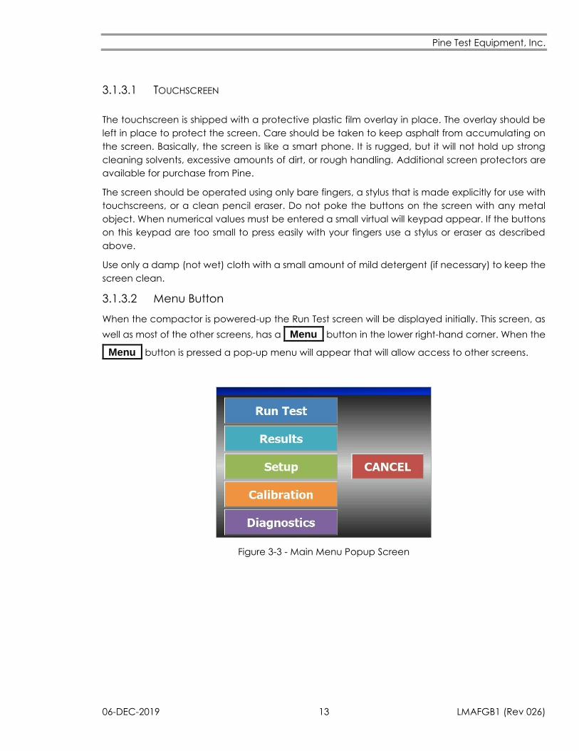
3.1.3.2 Menu Button
When the compactor is powered-up the Run Test screen will be displayed initially. This screen, as
well as most of the other screens, has a _Menu_ button in the lower right-hand corner. When the
_Menu_ button is pressed a pop-up menu will appear that will allow access to other screens.
Figure 3-3 - Main Menu Popup Screen
Pine Test Equipment, Inc.
LMAFGB1 (Rev 026) 14 06-DEC-2019
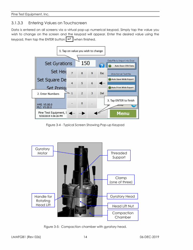
3.1.3.3 Entering Values on Touchscreen
Data is entered on all screens via a virtual pop-up numerical keypad. Simply tap the value you
wish to change on the screen and the keypad will appear. Enter the desired value using the
keypad, then tap the ENTER button _ _ when finished.
Figure 3-4 - Typical Screen Showing Pop-up Keypad
Compaction
Chamber
Head Lift Nut
Gyratory Head
Threaded
Support
Rod
Clamp
(one of three)
Handle for
Rotating
Head Lift
Nut
Gyratory
Motor
Figure 3-5: Compaction chamber with gyratory head.
Pine Test Equipment, Inc.
06-DEC-2019 15 LMAFGB1 (Rev 026)
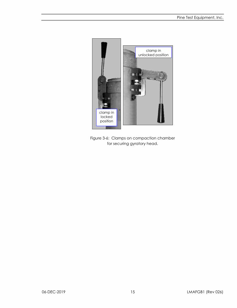
clamp in
unlocked position
clamp in
locked
position
Figure 3-6: Clamps on compaction chamber
for securing gyratory head.
Pine Test Equipment, Inc.
LMAFGB1 (Rev 026) 16 06-DEC-2019
3.2 Opening the Compaction Chamber
The main compaction chamber consists of a 9-inch diameter aluminum tube (Figure 3-5). The
gyratory head is mounted on a threaded vertical support rod attached to the back side of the
compaction chamber. The gyratory head can rotate freely around and travel freely up and down
the threaded support rod. A large head lift nut with a handle is located on the vertical support
rod just below the gyratory head. The gyratory head rides smoothly on top of the head lift nut.
(For instructions on how to lubricate the lift nut, see Section 5.1.7.)
Procedure C: Opening the Compaction Chamber
Only leave the gyratory head in one of two positions (Figure 1-1).
1. “Up and Away” out of the path of the ram
2. “Down and Clamped” to the compaction chamber
C1 Unlock the three clamps (Figure 3-6).
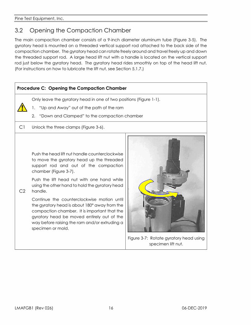
C2
Push the head lift nut handle counterclockwise
to move the gyratory head up the threaded
support rod and out of the compaction
chamber (Figure 3-7).
Push the lift head nut with one hand while
using the other hand to hold the gyratory head
handle.
Continue the counterclockwise motion until
the gyratory head is about 180° away from the
compaction chamber. It is important that the
gyratory head be moved entirely out of the
way before raising the ram and/or extruding a
specimen or mold.
Figure 3-7: Rotate gyratory head using
specimen lift nut.
Pine Test Equipment, Inc.
06-DEC-2019 17 LMAFGB1 (Rev 026)
3.3 Filling the Mold with Mix Asphalt
Procedure D provides instructions on how to correctly fill s mold with asphalt.
Procedure D: Filling the Mold with Asphalt
Molds, mold plates, and asphalt used during compaction are hot. Wear heavy gloves,
safety glasses, and other protective attire while working with these hot items.
The angle of gyration in an AFGB1 depends upon the temperature of the mold. Preheat
molds to the compaction temperature to assure a proper angle of gyration. Using
unheated or inadequately heated molds leads to a higher than expected angle of
gyration (see Section 0).
D1 Remove a preheated mold from the oven.
D2 Place the hot mold on a flat work surface.
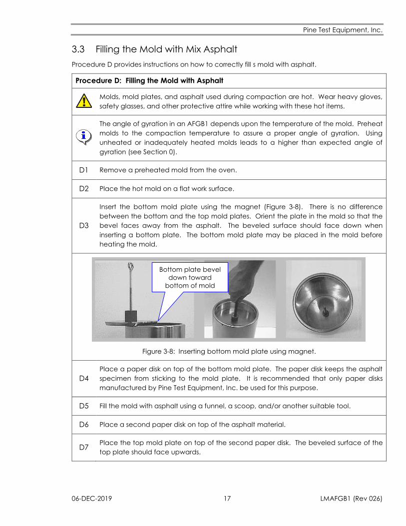
D3
Insert the bottom mold plate using the magnet (Figure 3-8). There is no difference
between the bottom and the top mold plates. Orient the plate in the mold so that the
bevel faces away from the asphalt. The beveled surface should face down when
inserting a bottom plate. The bottom mold plate may be placed in the mold before
heating the mold.
Bottom plate bevel
down toward
bottom of mold
Figure 3-8: Inserting bottom mold plate using magnet.
D4
Place a paper disk on top of the bottom mold plate. The paper disk keeps the asphalt
specimen from sticking to the mold plate. It is recommended that only paper disks
manufactured by Pine Test Equipment, Inc. be used for this purpose.
D5 Fill the mold with asphalt using a funnel, a scoop, and/or another suitable tool.
D6 Place a second paper disk on top of the asphalt material.
D7 Place the top mold plate on top of the second paper disk. The beveled surface of the
top plate should face upwards.
Pine Test Equipment, Inc.
LMAFGB1 (Rev 026) 18 06-DEC-2019
3.4 Using the Mold Extractor Tongs
Read and understand all of the following instructions regarding proper use of the
mold extractor tongs before using the tongs. Any uses of these mold extractor
tongs other than those outlined in this manual are not authorized.
The instruction “Warning Read Operator’s Manual” is found on the handle of the
mold extractor tong. The operator must read this manual and understand the
proper techniques and safety equipment required for safe use of the mold
extractor tongs.
The “Pinch Point” hazard identifier is found on the handle of the mold extractor
tong. This warns of the potential pinch point between the handles of the mold
extractor tongs. Avoid the pinch point while using the mold extractor tongs.
Check for loose hardware and signs of damage to the pegs at the end of the
tongs and/or the handles before using the mold extractor tongs.
Wear safety glasses, safety-toe shoes, heat resistant clothing and heavy gloves
while using the gyratory compactor and/or the mold extractor tongs.
Use proper lifting techniques to prevent a back injury when lifting a mold.
Always use two hands when using the mold tongs to lift the mold. Maintain a
constant squeezing pressure on the mold tong handles while moving the mold.
The mold may cause injury if dropped.
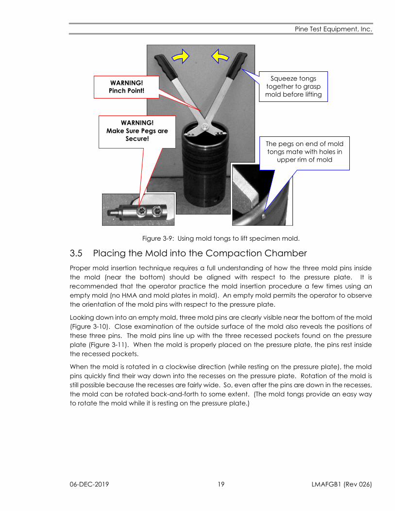
The easiest way to hold and carry a mold is to use a mold extractor tongs. The tongs are especially
useful for rotating and positioning the mold after it has been placed down into the compaction
chamber.
Two pegs at the ends of the tongs mate with two small holes on the inside (upper) rim of the mold
(Figure 3-9). Once inside the holes, the two pegs securely grip the mold as long as the two tong
handles are squeezed together.
Pine Test Equipment, Inc.
06-DEC-2019 19 LMAFGB1 (Rev 026)
The pegs on end of mold
tongs mate with holes in
upper rim of mold
Squeeze tongs
together to grasp
mold before lifting
WARNING! Pinch Point!
WARNING!
Make Sure Pegs are
Secure!
Figure 3-9: Using mold tongs to lift specimen mold.
3.5 Placing the Mold into the Compaction Chamber
Proper mold insertion technique requires a full understanding of how the three mold pins inside
the mold (near the bottom) should be aligned with respect to the pressure plate. It is
recommended that the operator practice the mold insertion procedure a few times using an
empty mold (no HMA and mold plates in mold). An empty mold permits the operator to observe
the orientation of the mold pins with respect to the pressure plate.
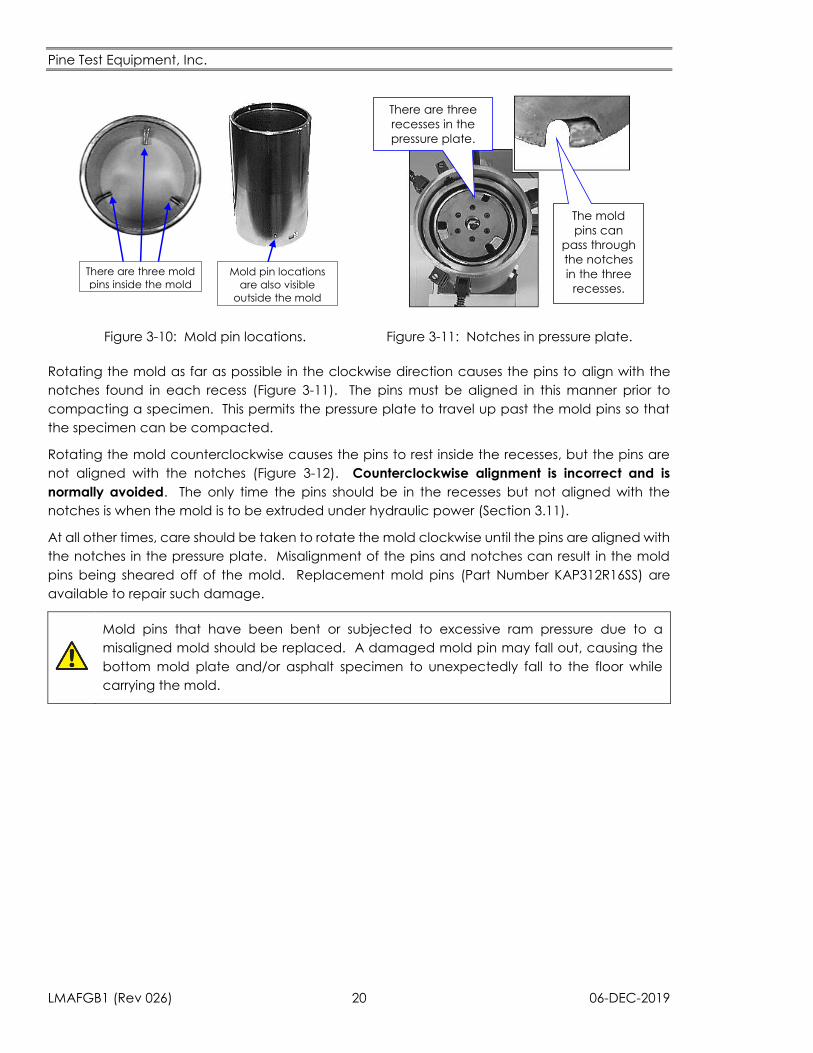
Looking down into an empty mold, three mold pins are clearly visible near the bottom of the mold
(Figure 3-10). Close examination of the outside surface of the mold also reveals the positions of
these three pins. The mold pins line up with the three recessed pockets found on the pressure
plate (Figure 3-11). When the mold is properly placed on the pressure plate, the pins rest inside
the recessed pockets.
When the mold is rotated in a clockwise direction (while resting on the pressure plate), the mold
pins quickly find their way down into the recesses on the pressure plate. Rotation of the mold is
still possible because the recesses are fairly wide. So, even after the pins are down in the recesses,
the mold can be rotated back-and-forth to some extent. (The mold tongs provide an easy way
to rotate the mold while it is resting on the pressure plate.)
Pine Test Equipment, Inc.
LMAFGB1 (Rev 026) 20 06-DEC-2019
There are three mold
pins inside the mold
Mold pin locations
are also visible
outside the mold
There are three
recesses in the
pressure plate.
The mold
pins can
pass through
the notches
in the three
recesses.
Figure 3-10: Mold pin locations. Figure 3-11: Notches in pressure plate.
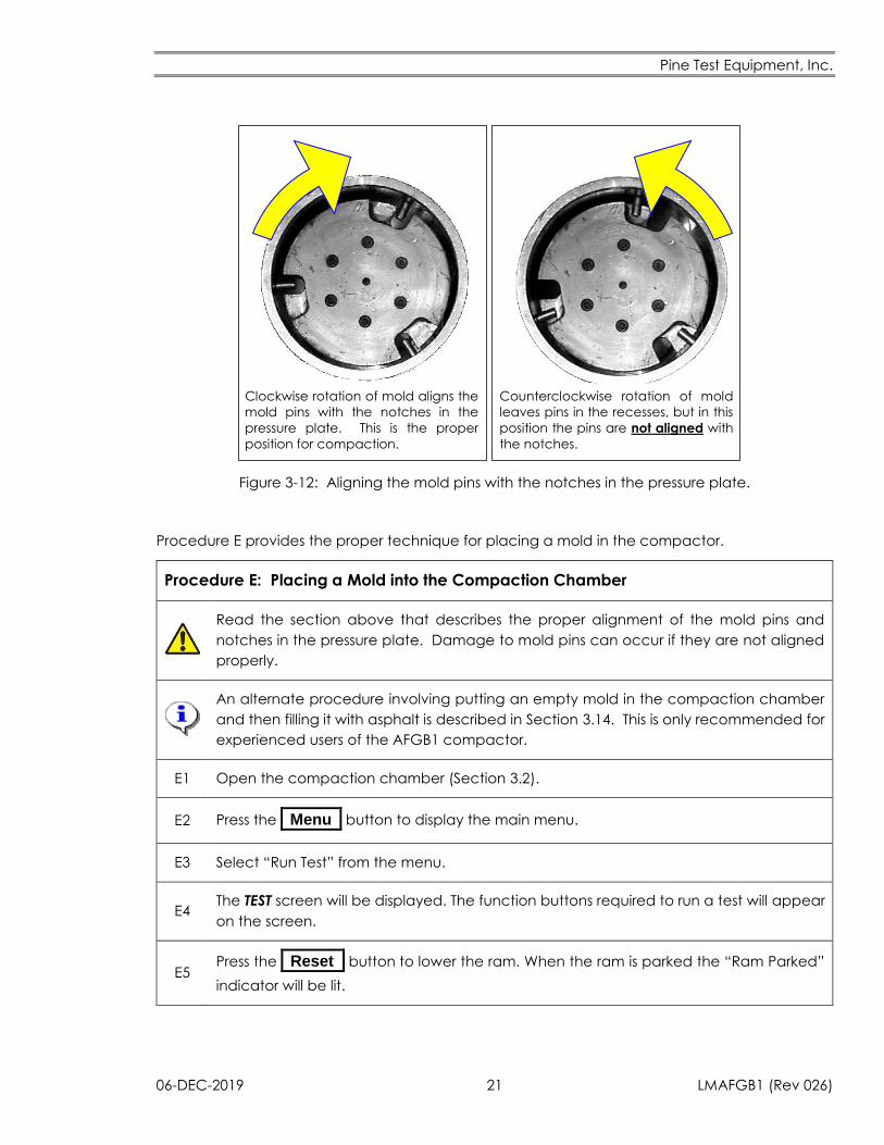
Rotating the mold as far as possible in the clockwise direction causes the pins to align with the
notches found in each recess (Figure 3-11). The pins must be aligned in this manner prior to
compacting a specimen. This permits the pressure plate to travel up past the mold pins so that
the specimen can be compacted.
Rotating the mold counterclockwise causes the pins to rest inside the recesses, but the pins are
not aligned with the notches (Figure 3-12). Counterclockwise alignment is incorrect and is
normally avoided. The only time the pins should be in the recesses but not aligned with the
notches is when the mold is to be extruded under hydraulic power (Section 3.11).
At all other times, care should be taken to rotate the mold clockwise until the pins are aligned with
the notches in the pressure plate. Misalignment of the pins and notches can result in the mold
pins being sheared off of the mold. Replacement mold pins (Part Number KAP312R16SS) are
available to repair such damage.
Mold pins that have been bent or subjected to excessive ram pressure due to a
misaligned mold should be replaced. A damaged mold pin may fall out, causing the
bottom mold plate and/or asphalt specimen to unexpectedly fall to the floor while
carrying the mold.
Pine Test Equipment, Inc.
06-DEC-2019 21 LMAFGB1 (Rev 026)
Clockwise rotation of mold aligns the
mold pins with the notches in the
pressure plate. This is the proper
position for compaction.
Counterclockwise rotation of mold
leaves pins in the recesses, but in this
position the pins are not aligned with
the notches.
Figure 3-12: Aligning the mold pins with the notches in the pressure plate.
Procedure E provides the proper technique for placing a mold in the compactor.
Procedure E: Placing a Mold into the Compaction Chamber
Read the section above that describes the proper alignment of the mold pins and
notches in the pressure plate. Damage to mold pins can occur if they are not aligned
properly.
An alternate procedure involving putting an empty mold in the compaction chamber
and then filling it with asphalt is described in Section 3.14. This is only recommended for
experienced users of the AFGB1 compactor.
E1 Open the compaction chamber (Section 3.2).
E2 Press the _Menu_ button to display the main menu.
E3 Select “Run Test” from the menu.
E4 The TEST screen will be displayed. The function buttons required to run a test will appear
on the screen.
E5 Press the _Reset_ button to lower the ram. When the ram is parked the “Ram Parked”
indicator will be lit.
Pine Test Equipment, Inc.
LMAFGB1 (Rev 026) 22 06-DEC-2019
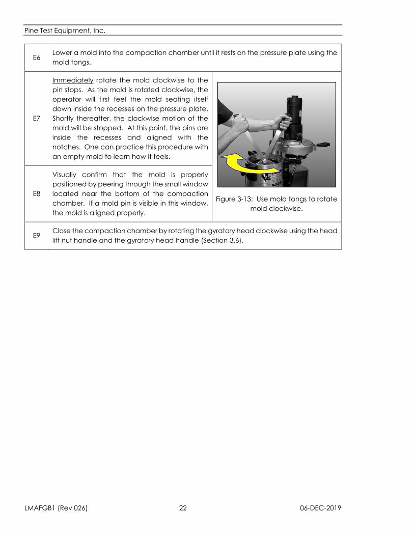
E6 Lower a mold into the compaction chamber until it rests on the pressure plate using the
mold tongs.
E7
Immediately rotate the mold clockwise to the
pin stops. As the mold is rotated clockwise, the
operator will first feel the mold seating itself
down inside the recesses on the pressure plate.
Shortly thereafter, the clockwise motion of the
mold will be stopped. At this point, the pins are
inside the recesses and aligned with the
notches. One can practice this procedure with
an empty mold to learn how it feels.
Figure 3-13: Use mold tongs to rotate
mold clockwise.
E8
Visually confirm that the mold is properly
positioned by peering through the small window
located near the bottom of the compaction
chamber. If a mold pin is visible in this window,
the mold is aligned properly.
E9 Close the compaction chamber by rotating the gyratory head clockwise using the head
lift nut handle and the gyratory head handle (Section 3.6).
Pine Test Equipment, Inc.
06-DEC-2019 23 LMAFGB1 (Rev 026)
3.6 Closing the Compaction Chamber
Procedure F explains how to correctly close the compaction chamber.
Procedure F: Closing the Compaction Chamber
Verify that the ram is fully retracted and the gyratory head is parked before closing the
compaction chamber (Section 3.12).
F1
Move the gyratory head into position over the compaction chamber by pushing the
head lift nut handle and the gyratory head handle clockwise. The head lift nut moves
down the threaded support rod as it turns clockwise. The handle on the gyratory head
may be used to keep the head aligned with the compaction chamber.
F2
Securely seat the gyratory head on top of the compaction chamber. If it does not seat
properly, first check to make sure the mold (inside the chamber) is not tilted too far off
center. If the head still doesn’t seat properly, the motor within gyratory head is likely not
in the “parked” position. Park the gyratory head (Section 3.12) before continuing.
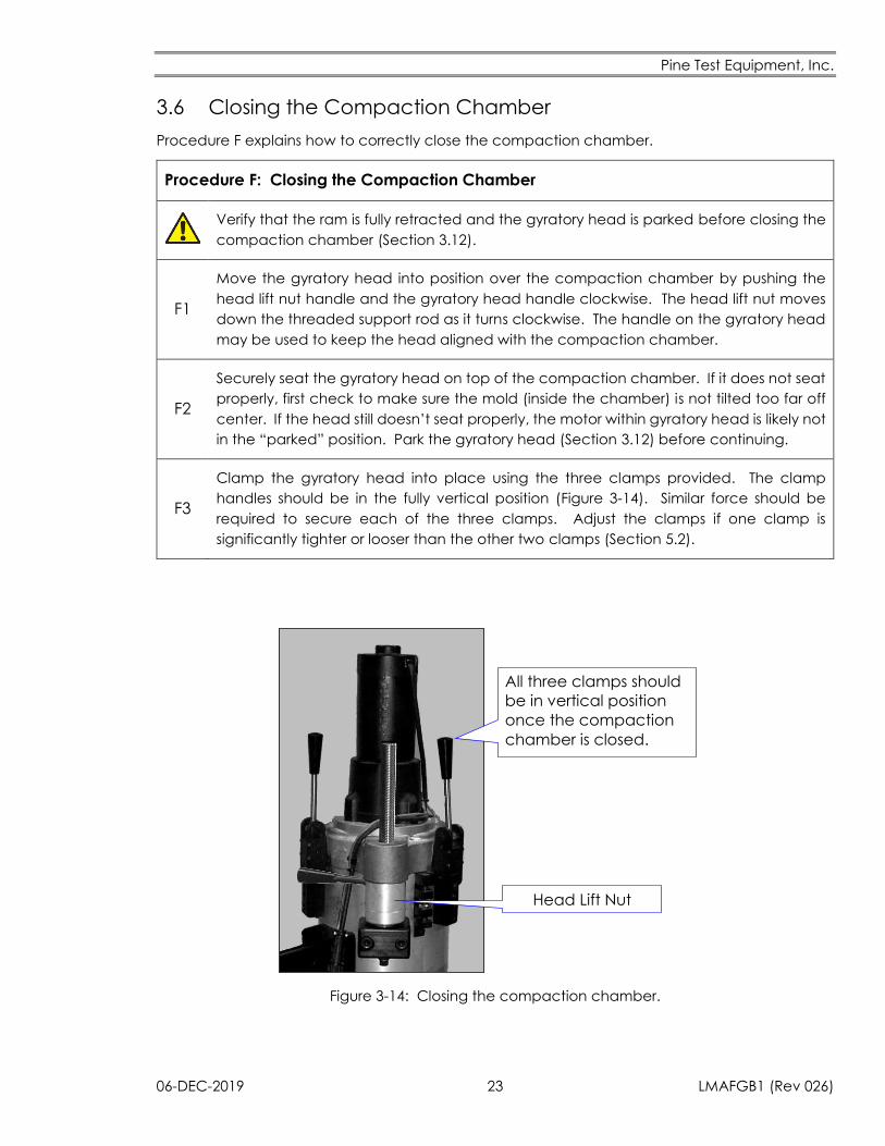
F3
Clamp the gyratory head into place using the three clamps provided. The clamp
handles should be in the fully vertical position (Figure 3-14). Similar force should be
required to secure each of the three clamps. Adjust the clamps if one clamp is
significantly tighter or looser than the other two clamps (Section 5.2).
All three clamps should
be in vertical position
once the compaction
chamber is closed.
Head Lift Nut
Figure 3-14: Closing the compaction chamber.
Pine Test Equipment, Inc.
LMAFGB1 (Rev 026) 24 06-DEC-2019
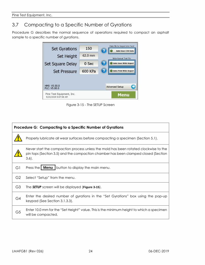
3.7 Compacting to a Specific Number of Gyrations
Procedure G describes the normal sequence of operations required to compact an asphalt
sample to a specific number of gyrations.
Figure 3-15 - The SETUP Screen
Procedure G: Compacting to a Specific Number of Gyrations
Properly lubricate all wear surfaces before compacting a specimen (Section 5.1).
Never start the compaction process unless the mold has been rotated clockwise to the
pin tops (Section 3.5) and the compaction chamber has been clamped closed (Section
3.6).
G1 Press the _Menu_ button to display the main menu.
G2 Select “Setup” from the menu.
G3 The SETUP screen will be displayed (Figure 3-15).
G4 Enter the desired number of gyrations in the “Set Gyrations” box using the pop-up
keypad (See Section 3.1.3.3).
G5 Enter 10.0 mm for the “Set Height” value. This is the minimum height to which a specimen
will be compacted.
Pine Test Equipment, Inc.
06-DEC-2019 25 LMAFGB1 (Rev 026)
G6 Enter 0 Sec for the “Set Square Delay” value.
G7 Enter 600 kPa for the “Set Pressure” value.
G8 Press the _Menu_ button.
G9 Select “Run Test” from the menu.
G10 The TEST screen shows the number of gyrations completed, the specimen height, the
external mold angle, the ram pressure, the time, and the date during compaction.
G11
Press the _Start_ button to begin the compaction process. The rotation LED will flash
one time as the gyratory motor unwinds the head from the park position followed by
one time for each completed gyration. At the end of the test, the light will flash twice
as the head removes the angle from the specimen. These reverse rotations are not
added to the number of gyrations.
G12 Watch the HEIGHT value on the display. It should immediately begin to decrease.
G13 If the HEIGHT value is decreasing, as it should be, skip to STEP G20.
G14
If the HEIGHT value is increasing, press the _Stop_ button immediately to stop the test.
The most likely problem is that the mold has not been rotated clockwise to the correct
position.
G15 Press the _Reset_ button to lower the ram.
G16 Open the compaction chamber (Section 3.2).
G17 Verify that the mold is rotated into the fully clockwise position (Section 3.5).
G18 Close the compaction chamber (Section 3.6).
G19 Press the _Start_ button to resume the test.
G20 Allow the test to complete, extrude the compacted specimen (Section 3.9).
3.8 Compacting to a Specific Final Specimen Height
When preparing an asphalt specimen at a target density, the mix is compacted to a specific final
height rather than to a specific number of gyrations. Knowledge of the proper final height is
normally obtained by first compacting a specimen a specific number of gyrations (Section 3.7).
Experience with this first specimen provides the information needed to choose a final specimen
height which corresponds to the desired target air voids (i.e., 7% air voids). Once the proper final
height is known, a second specimen is prepared for testing using Procedure H below.
Pine Test Equipment, Inc.
LMAFGB1 (Rev 026) 26 06-DEC-2019
Procedure H: Compacting to a Specific Final Height
Properly lubricate all wear surfaces before compacting a specimen (Section 5.1).
Never start compaction unless the mold has been rotated clockwise to the pin stops
(Section 3.5) and the compaction chamber has been clamped closed (Section 3.6).
Verify that the height measurement system is calibrated properly before compacting
to a specified height.
H1 Press the _Menu_ button to display the main menu.
H2 Select “Setup” from the menu.
H3 The SETUP screen will be displayed (Figure 3-15 - The SETUP ScreenFigure 3-15).
H4 Enter the desired specimen height in the “Set Height” box using the pop-up keypad
(See Section 3.1.3.3).
H5 Enter the desired number of gyrations in the “Set Gyrations” box. Enter a high number
of gyrations to ensure the desired height is reached first.
H6 Enter 600 kPa for the “Set Pressure” value.
H7 Press the _Menu_ button to display the main menu.
H8 Select “Run Test” from the menu.
H9 The TEST screen will be displayed.
H10 The TEST screen displays the number of gyrations completed, the specimen height, the
external mold angle, the ram pressure, the time, and the date during compaction.
H11
Press the _Start_ button to begin the compaction process. The rotation LED will flash
one time as the gyratory motor unwinds the head from the park position followed by
one time for each completed gyration. At the end of the test, the light will flash twice
as the head removes the angle from the specimen. These reverse rotations are not
added to the number of gyrations.
H12 Watch the HEIGHT value on the display. It should immediately begin to decrease.
H13 If the HEIGHT value is decreasing, as it should be, skip to STEP H20.
Pine Test Equipment, Inc.
06-DEC-2019 27 LMAFGB1 (Rev 026)
H14
If the HEIGHT value is increasing, press the _Stop_ button immediately to stop the test.
The most likely problem is that the mold has not been rotated clockwise to the correct
position.
H15 Press the _Reset_ button to lower the ram.
H16 Open the compaction chamber (Section 3.2).
H17 Verify that the mold is rotated into the fully clockwise position (Section 3.5).
H18 Close the compaction chamber (Section 3.6).
H19 Press the _Start_ button to resume the test.
H20 Extrude the specimen when compaction is complete (Section 3.9).
H21 Reset the HEIGHT value to 10.00 mm following Steps H1 through H6 before attempting
to compact a specimen to a specific number of gyrations.
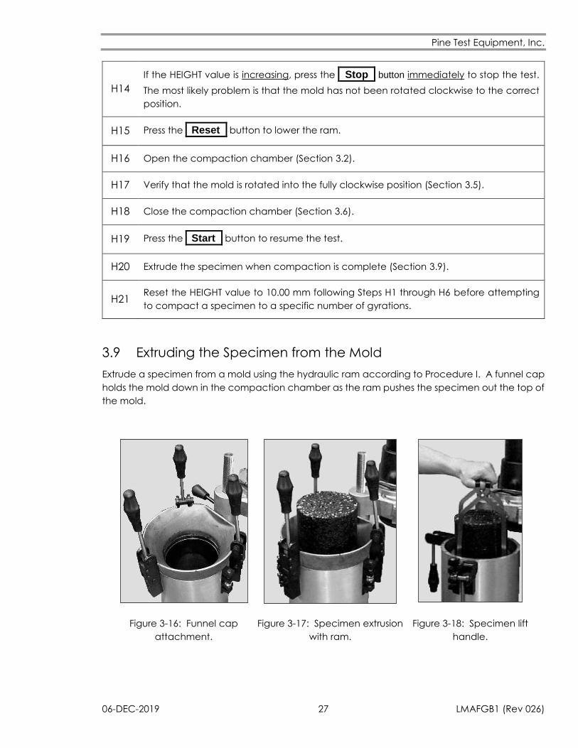
3.9 Extruding the Specimen from the Mold
Extrude a specimen from a mold using the hydraulic ram according to Procedure I. A funnel cap
holds the mold down in the compaction chamber as the ram pushes the specimen out the top of
the mold.
Figure 3-16: Funnel cap
attachment.
Figure 3-17: Specimen extrusion
with ram.
Figure 3-18: Specimen lift
handle.
Pine Test Equipment, Inc.
LMAFGB1 (Rev 026) 28 06-DEC-2019
Procedure I: Extruding a Specimen from the Mold
Keep fingers and hands away from the compaction chamber while extruding a
specimen. Moving parts and pinch points may cause injury.
I1 Open the compaction chamber (Section 3.2). If the chamber will not open easily, the
gyratory head probably needs to be parked (Section 3.12).
I2 Remove the top plate from the mold using the magnet.
I3
Verify that no portion of the gyratory head or handles are located over the compaction
chamber (Figure 1-1). The gyratory head and/or vertical support rod may be bent or
otherwise damaged if an obstruction is encountered.
I4 If the TEST screen is already displayed, skip to Step I8.
I5 Press the _Menu_ button to display the main menu.
I6 Select “Run Test” from the menu.
I7 The TEST screen will be displayed with the five buttons (START, STOP, RESET, UNLOAD, and
REVERSE) that control the ram.
I8
Secure the funnel cap to the compaction chamber using the three clamps (Figure 3-16).
This holds the mold down as the specimen is extruded up. Be careful not to rotate the
mold away from the fully clockwise position. The mold pins can be sheared off if the
pins become misaligned with the pressure plate notches.
I9 Press the _Unload_ button twice. The ram will push the specimen up out of the mold
after a brief delay (Figure 3-17).
I10 Press the _Reverse_ button to ensure that the gyratory head is parked properly.
I11 Remove the paper disk from the top of the specimen.
I12 Unclamp and remove the funnel cap.
Pine Test Equipment, Inc.
06-DEC-2019 29 LMAFGB1 (Rev 026)
I13
Move the specimen from the compactor to a nearby flat surface.
The specimen may be removed from the compactor by hand or by using the
specimen lift handle to grasp the bottom plate (Figure 3-18).
The bottom plate may stick to the specimen when lifting the specimen out of the
compactor by hand. It usually falls off the specimen in a few seconds, which may
damage the plate or injure a person’s foot.
I14 Remove the paper disks from the bottom of the specimen and allow it to cool.
I15 Press the _Reset_ button to lower the ram after the specimen has been removed.
I16 Remove the bottom plate from the mold using the magnet.
3.10 Important Cautionary Notes
Push the gyratory head and other items entirely out of the way before raising the ram.
Never close the compaction chamber without securing it with all three clamps.
Objects accidentally placed in the path of the ram (i.e., fingers, handles, the gyratory
head) may be damaged or broken by an extruding specimen and/or mold.
Pine Test Equipment, Inc.
LMAFGB1 (Rev 026) 30 06-DEC-2019
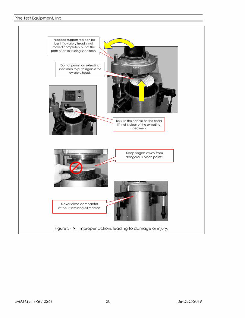
Threaded support rod can be
bent if gyratory head is not
moved completely out of the
path of an extruding specimen.
Do not permit an extruding
specimen to push against the
gyratory head.
Be sure the handle on the head
lift nut is clear of the extruding
specimen.
Keep fingers away from
dangerous pinch points.
Never close compactor
without securing all clamps.
Figure 3-19: Improper actions leading to damage or injury.
Pine Test Equipment, Inc.
06-DEC-2019 31 LMAFGB1 (Rev 026)
3.11 Removing the Mold from the Compaction Chamber
Procedure J describes the manual removal of a mold from the compaction chamber. Procedure
K provides the hydraulic procedure for removing a mold from the compaction chamber.
Procedure J: Manually Removing a Mold from the Compaction Chamber
J1 Press the _Menu_ button, then select “Run Test.” The TEST screen will be displayed.
J2 Fully retract the ram by pressing the _Reset_ button.
J3 Insert the mold extractor tong pins into the holes at the top of the mold.
J4 Grip the tongs as low as is comfortable on the handles to minimize the lift height.
J5 Lift the mold out of the compaction chamber and set it on a clean, flat surface.
Procedure K: Hydraulically Removing a Mold from the Compaction Chamber
K1 Press the _Menu_ button, then select “Run Test.” The TEST screen will be displayed.
K2 Fully retract the ram by pressing the _Reset_ button.
K3 Open the compaction chamber (Section 3.2) rotating the gyratory head completely out
of the way (Figure 1-1).
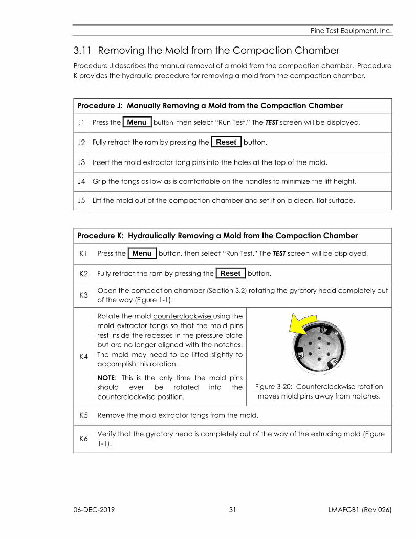
K4
Rotate the mold counterclockwise using the
mold extractor tongs so that the mold pins
rest inside the recesses in the pressure plate
but are no longer aligned with the notches.
The mold may need to be lifted slightly to
accomplish this rotation.
NOTE: This is the only time the mold pins
should ever be rotated into the
counterclockwise position.
Figure 3-20: Counterclockwise rotation
moves mold pins away from notches.
K5 Remove the mold extractor tongs from the mold.
K6 Verify that the gyratory head is completely out of the way of the extruding mold (Figure
1-1).
Pine Test Equipment, Inc.
LMAFGB1 (Rev 026) 32 06-DEC-2019
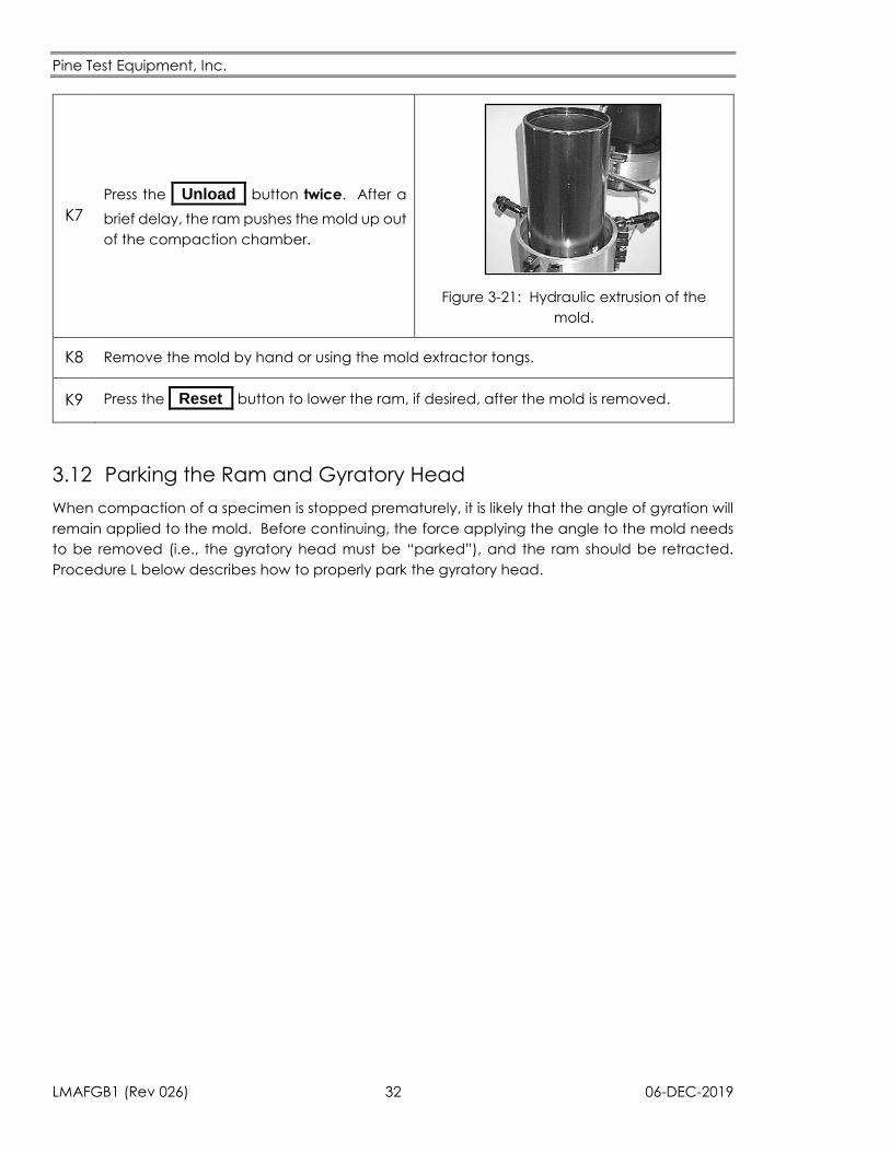
K7
Press the _Unload_ button twice. After a
brief delay, the ram pushes the mold up out
of the compaction chamber.
Figure 3-21: Hydraulic extrusion of the
mold.
K8 Remove the mold by hand or using the mold extractor tongs.
K9 Press the _Reset_ button to lower the ram, if desired, after the mold is removed.
3.12 Parking the Ram and Gyratory Head
When compaction of a specimen is stopped prematurely, it is likely that the angle of gyration will
remain applied to the mold. Before continuing, the force applying the angle to the mold needs
to be removed (i.e., the gyratory head must be “parked”), and the ram should be retracted.
Procedure L below describes how to properly park the gyratory head.
Pine Test Equipment, Inc.
06-DEC-2019 33 LMAFGB1 (Rev 026)
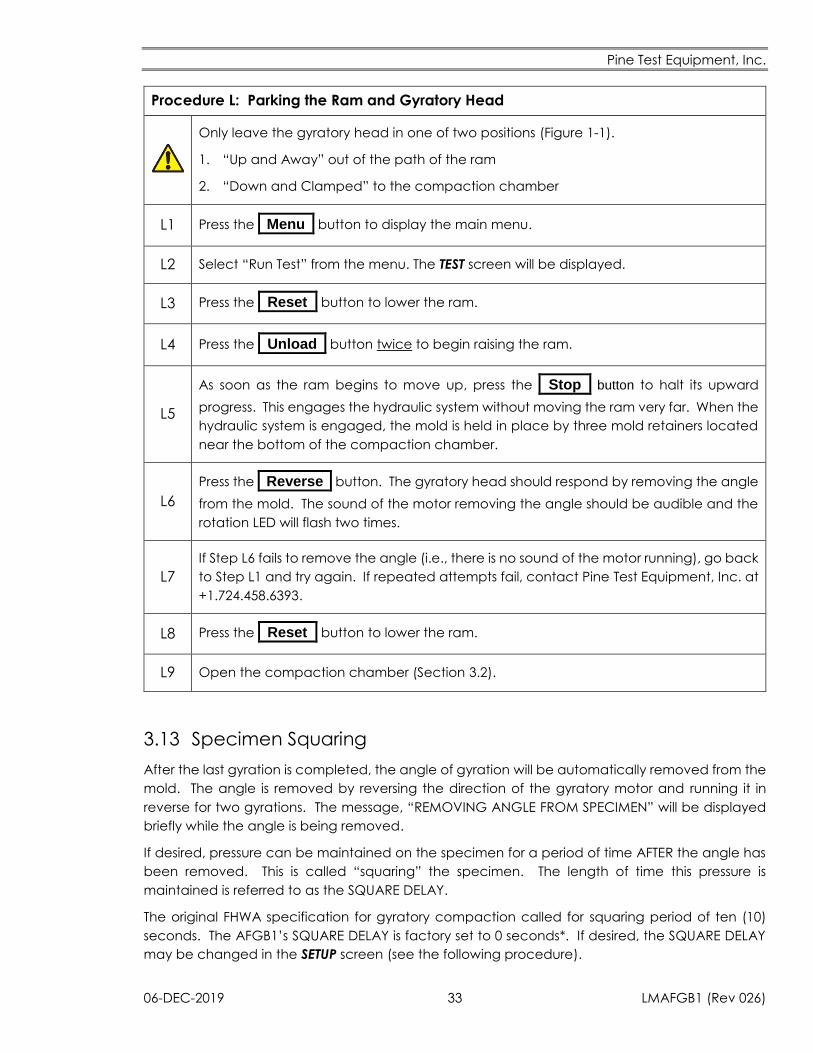
Procedure L: Parking the Ram and Gyratory Head
Only leave the gyratory head in one of two positions (Figure 1-1).
1. “Up and Away” out of the path of the ram
2. “Down and Clamped” to the compaction chamber
L1 Press the _Menu_ button to display the main menu.
L2 Select “Run Test” from the menu. The TEST screen will be displayed.
L3 Press the _Reset_ button to lower the ram.
L4 Press the _Unload_ button twice to begin raising the ram.
L5
As soon as the ram begins to move up, press the _Stop_ button to halt its upward
progress. This engages the hydraulic system without moving the ram very far. When the
hydraulic system is engaged, the mold is held in place by three mold retainers located
near the bottom of the compaction chamber.
L6
Press the _Reverse_ button. The gyratory head should respond by removing the angle
from the mold. The sound of the motor removing the angle should be audible and the
rotation LED will flash two times.
L7
If Step L6 fails to remove the angle (i.e., there is no sound of the motor running), go back
to Step L1 and try again. If repeated attempts fail, contact Pine Test Equipment, Inc. at
+1.724.458.6393.
L8 Press the _Reset_ button to lower the ram.
L9 Open the compaction chamber (Section 3.2).
3.13 Specimen Squaring
After the last gyration is completed, the angle of gyration will be automatically removed from the
mold. The angle is removed by reversing the direction of the gyratory motor and running it in
reverse for two gyrations. The message, “REMOVING ANGLE FROM SPECIMEN” will be displayed
briefly while the angle is being removed.
If desired, pressure can be maintained on the specimen for a period of time AFTER the angle has
been removed. This is called “squaring” the specimen. The length of time this pressure is
maintained is referred to as the SQUARE DELAY.
The original FHWA specification for gyratory compaction called for squaring period of ten (10)
seconds. The AFGB1’s SQUARE DELAY is factory set to 0 seconds*. If desired, the SQUARE DELAY
may be changed in the SETUP screen (see the following procedure).
Pine Test Equipment, Inc.
LMAFGB1 (Rev 026) 34 06-DEC-2019
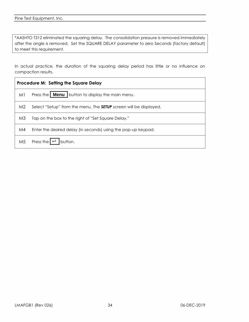
*AASHTO T312 eliminated the squaring delay. The consolidation pressure is removed immediately
after the angle is removed. Set the SQUARE DELAY parameter to zero Seconds (factory default)
to meet this requirement.
In actual practice, the duration of the squaring delay period has little or no influence on
compaction results.
Procedure M: Setting the Square Delay
M1 Press the _Menu_ button to display the main menu.
M2 Select “Setup” from the menu. The SETUP screen will be displayed.
M3 Tap on the box to the right of “Set Square Delay.”
M4 Enter the desired delay (in seconds) using the pop-up keypad.
M5 Press the _ _ button.
Pine Test Equipment, Inc.
06-DEC-2019 35 LMAFGB1 (Rev 026)
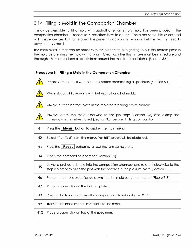
3.14 Filling a Mold in the Compaction Chamber
It may be desirable to fill a mold with asphalt after an empty mold has been placed in the
compaction chamber. Procedure N describes how to do this. There are some risks associated
with this procedure, but some operators prefer this approach because it eliminates the need to
carry a heavy mold.
The main mistake that can be made with this procedure is forgetting to put the bottom plate in
the mold before filling the mold with asphalt. Clean up after this mistake must be immediate and
thorough. Be sure to clean all debris from around the mold retainer latches (Section 5.5).
Procedure N: Filling a Mold in the Compaction Chamber
Properly lubricate all wear surfaces before compacting a specimen (Section 5.1).
Wear gloves while working with hot asphalt and hot molds.
Always put the bottom plate in the mold before filling it with asphalt.
Always rotate the mold clockwise to the pin stops (Section 3.5) and clamp the
compaction chamber closed (Section 3.6) before starting compaction.
N1 Press the _Menu_ button to display the main menu.
N2 Select “Run Test” from the menu. The TEST screen will be displayed.
N3 Press the _Reset_ button to retract the ram completely.
N4 Open the compaction chamber (Section 3.2),
N5 Lower a preheated mold into the compaction chamber and rotate it clockwise to the
stops to properly align the pins with the notches in the pressure plate (Section 3.5).
N6 Place the bottom plate flange down into the mold using the magnet (Figure 3-8).
N7 Place a paper disk on the bottom plate.
N8 Position the funnel cap over the compaction chamber (Figure 3-16).
N9 Transfer the loose asphalt material into the mold.
N10 Place a paper disk on top of the specimen.
Pine Test Equipment, Inc.
LMAFGB1 (Rev 026) 36 06-DEC-2019
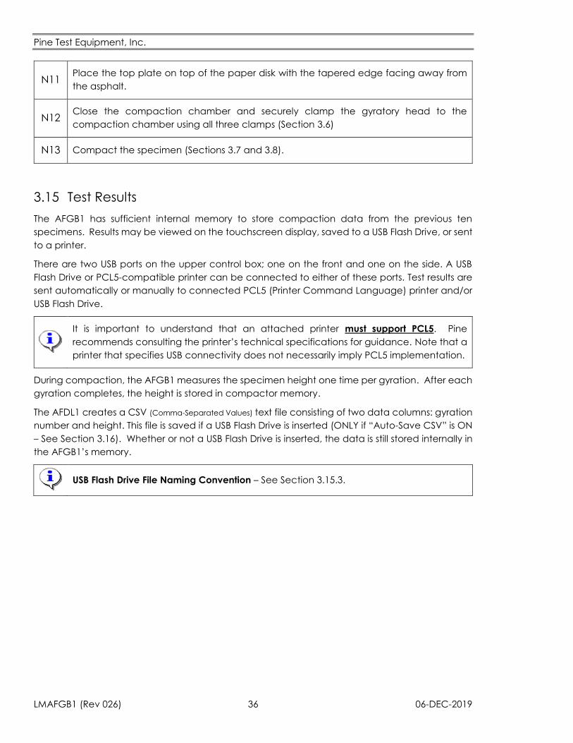
N11 Place the top plate on top of the paper disk with the tapered edge facing away from
the asphalt.
N12 Close the compaction chamber and securely clamp the gyratory head to the
compaction chamber using all three clamps (Section 3.6)
N13 Compact the specimen (Sections 3.7 and 3.8).
3.15 Test Results
The AFGB1 has sufficient internal memory to store compaction data from the previous ten
specimens. Results may be viewed on the touchscreen display, saved to a USB Flash Drive, or sent
to a printer.
There are two USB ports on the upper control box; one on the front and one on the side. A USB
Flash Drive or PCL5-compatible printer can be connected to either of these ports. Test results are
sent automatically or manually to connected PCL5 (Printer Command Language) printer and/or
USB Flash Drive.
It is important to understand that an attached printer must support PCL5. Pine
recommends consulting the printer’s technical specifications for guidance. Note that a
printer that specifies USB connectivity does not necessarily imply PCL5 implementation.
During compaction, the AFGB1 measures the specimen height one time per gyration. After each
gyration completes, the height is stored in compactor memory.
The AFDL1 creates a CSV (Comma-Separated Values) text file consisting of two data columns: gyration
number and height. This file is saved if a USB Flash Drive is inserted (ONLY if “Auto-Save CSV” is ON
– See Section 3.16). Whether or not a USB Flash Drive is inserted, the data is still stored internally in
the AFGB1’s memory.
USB Flash Drive File Naming Convention – See Section 3.15.3.
Pine Test Equipment, Inc.
06-DEC-2019 37 LMAFGB1 (Rev 026)
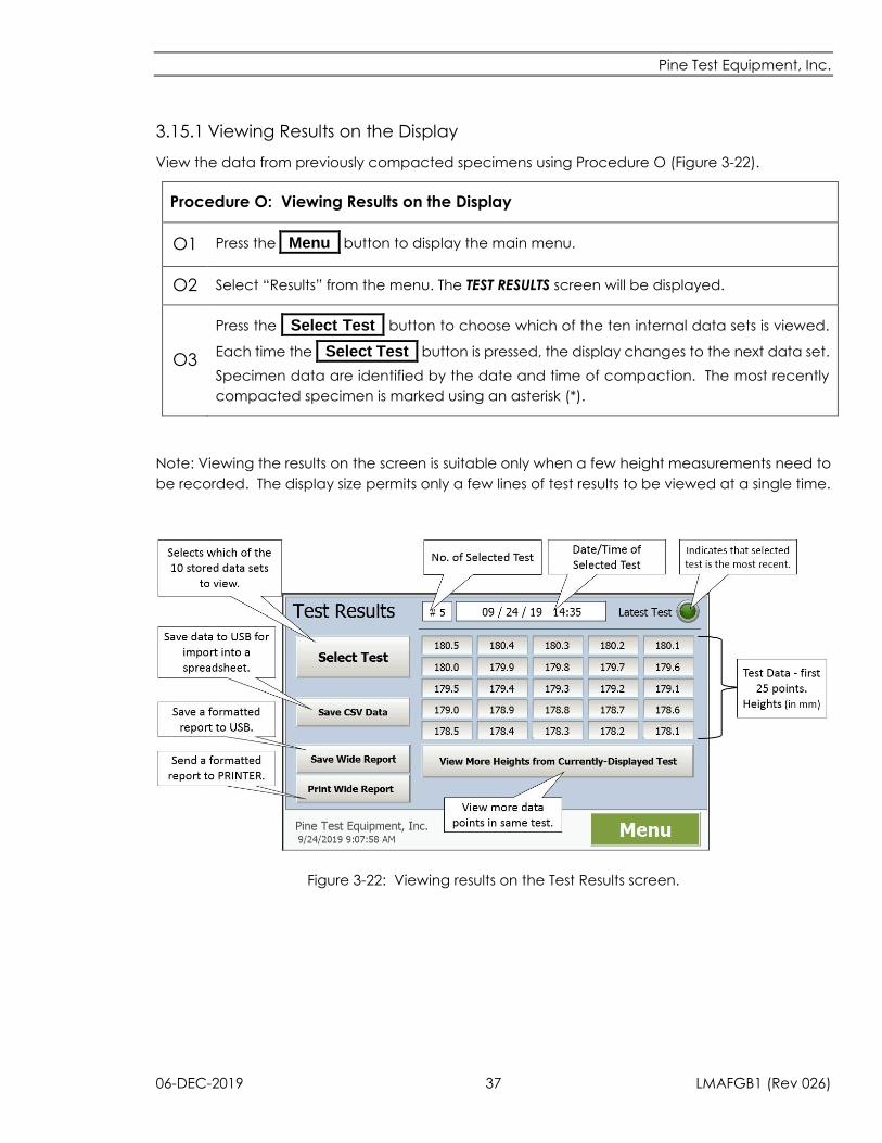
3.15.1 Viewing Results on the Display
View the data from previously compacted specimens using Procedure O (Figure 3-22).
Procedure O: Viewing Results on the Display
O1 Press the _Menu_ button to display the main menu.
O2 Select “Results” from the menu. The TEST RESULTS screen will be displayed.
O3
Press the _Select Test_ button to choose which of the ten internal data sets is viewed.
Each time the _Select Test_ button is pressed, the display changes to the next data set.
Specimen data are identified by the date and time of compaction. The most recently
compacted specimen is marked using an asterisk (*).
Note: Viewing the results on the screen is suitable only when a few height measurements need to
be recorded. The display size permits only a few lines of test results to be viewed at a single time.
Figure 3-22: Viewing results on the Test Results screen.
Pine Test Equipment, Inc.
LMAFGB1 (Rev 026) 38 06-DEC-2019
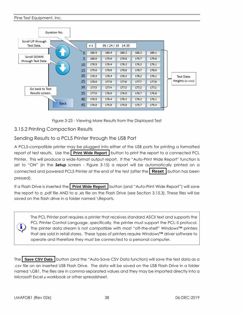
Figure 3-23 - Viewing More Results from the Displayed Test
3.15.2 Printing Compaction Results
Sending Results to a PCL5 Printer through the USB Port
A PCL5-compatible printer may be plugged into either of the USB ports for printing a formatted
report of test results. Use the _Print Wide Report_ button to print the report to a connected PCL
Printer. This will produce a wide-format output report. If the “Auto-Print Wide Report” function is
set to “ON” (in the Setup screen - Figure 3-15) a report will be automatically printed on a
connected and powered PCL5 Printer at the end of the test (after the _Reset_ button has been
pressed).
If a Flash Drive is inserted the _Print Wide Report_ button (and “Auto-Print Wide Report”) will save
the report to a .pdf file AND to a .xls file on the Flash Drive (see Section 3.15.3). These files will be
saved on the flash drive in a folder named \Reports.
The PCL Printer port requires a printer that receives standard ASCII text and supports the
PCL Printer Control Language, specifically, the printer must support the PCL-5 protocol.
The printer data stream is not compatible with most “off-the-shelf” Windows™ printers
that are sold in retail stores. These types of printers require Windows™ driver software to
operate and therefore they must be connected to a personal computer.
The _Save CSV Data_ button (and the “Auto-Save CSV Data function) will save the test data as a
.csv file on an inserted USB Flash Drive. The data will be saved on the USB Flash Drive in a folder
named \GB1. The files are in comma-separated values and they may be imported directly into a
Microsoft Excel ® workbook or other spreadsheet.
Pine Test Equipment, Inc.
06-DEC-2019 39 LMAFGB1 (Rev 026)
3.15.3 Saving Results to a USB Flash Memory Device
As described above, the AFGB1 automatically saves data to a USB Flash Drive if “Auto-Save CSV
Data” is ON. Data may also be saved to a USB Flash Drive after compaction is complete
(regardless of whether “Auto-Save CSV Data” is ON or OFF) by selecting the data as described in
Section 3.15.1 and using the _Save CSV Data_ button on the TEST RESULTS screen.
The “Save CSV Data” function will produce a two-column, comma-separated output file
containing ONLY the gyration number and the height. Data from this file can be readily loaded
into a spreadsheet for analysis. Files produced using the SAVE key will have a “.csv” filename
extension and they will be stored in a folder named \GB1 on the USB Flash Drive.
The “Save Wide Report” function will produce a wide-format output report which contains header
data. The report will be saved in a folder named \Reports on the USB Flash Drive. The report will
be saved in TWO formats: as a .pdf file that may be opened in any .pdf-reading program and as
a .xls format which may be opened in Microsoft Excel ®. The report may be printed from either of
these programs.
The data file will not be written to the USB Flash Drive until approximately 20 to 30 seconds AFTER
the gyratory compactor stops. DO NOT REMOVE the Flash Drive during this delay or the data file
will not be saved. The last ten compaction data sets are stored in the AFGB1 memory and may
be re-sent with the SAVE or PRINT functions.
Do not remove the USB Flash Drive for at least 30 seconds after the test completes.
The twenty to thirty second delay between the end of the test and writing the file to
the USB Flash Drive is due mainly to the display having to load a program to format
the data before sending it to the flash drive. CSV files do not take as long to save as
Reports since they require no formatting.
The first time a report is saved or printed it will take longer than subsequent times.
If a PCL printer is attached the first report may take up to one minute from the time
the test ends until the print-out is ejected from the printer. Subsequent reports should
be faster since the report template has already been loaded into memory.
USB Flash Drive File Naming Convention
The test data files saved on the USB Flash Drive will be named according to the date
and time when the test was performed.
Examples:
Report Files (stored in \Reports folder on the USB Flash Drive):
GB1_Report 9-6-2019 1.59.03 PM.pdf
GB1_Report 9-6-2019 1.59.03 PM.xls
CSV Files (stored in \GB1 folder on the USB Flash Drive):
GB1_190829_0940.csv
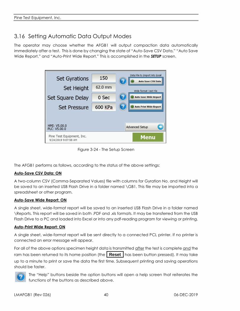
Pine Test Equipment, Inc.
LMAFGB1 (Rev 026) 40 06-DEC-2019
3.16 Setting Automatic Data Output Modes
The operator may choose whether the AFGB1 will output compaction data automatically
immediately after a test. This is done by changing the state of “Auto-Save CSV Data,” “Auto Save
Wide Report,” and “Auto-Print Wide Report.” This is accomplished in the SETUP screen.
Figure 3-24 - The Setup Screen
The AFGB1 performs as follows, according to the status of the above settings:
Auto-Save CSV Data: ON
A two-column CSV (Comma-Separated Values) file with columns for Gyration No. and Height will
be saved to an inserted USB Flash Drive in a folder named \GB1. This file may be imported into a
spreadsheet or other program.
Auto-Save Wide Report: ON
A single sheet, wide-format report will be saved to an inserted USB Flash Drive in a folder named
\Reports. This report will be saved in both .PDF and .xls formats. It may be transferred from the USB
Flash Drive to a PC and loaded into Excel or into any pdf-reading program for viewing or printing.
Auto-Print Wide Report: ON
A single sheet, wide-format report will be sent directly to a connected PCL printer. If no printer is
connected an error message will appear.
For all of the above options specimen height data is transmitted after the test is complete and the
ram has been returned to its home position (the _Reset_ has been button pressed). It may take
up to a minute to print or save the data the first time. Subsequent printing and saving operations
should be faster.
The “Help” buttons beside the option buttons will open a help screen that reiterates the
functions of the buttons as described above.

Pine Test Equipment, Inc.
06-DEC-2019 41 LMAFGB1 (Rev 026)
Even if both Auto-Save options and the Auto-Print option are set to “OFF”, the AFGB1 will still save
data from the last 10 tests to internal memory. This data can be manually saved or printed from
the TEST RESULTS screen at any time after the test is done. If more than 10 tests are run, the oldest
test data in memory will be overwritten first.
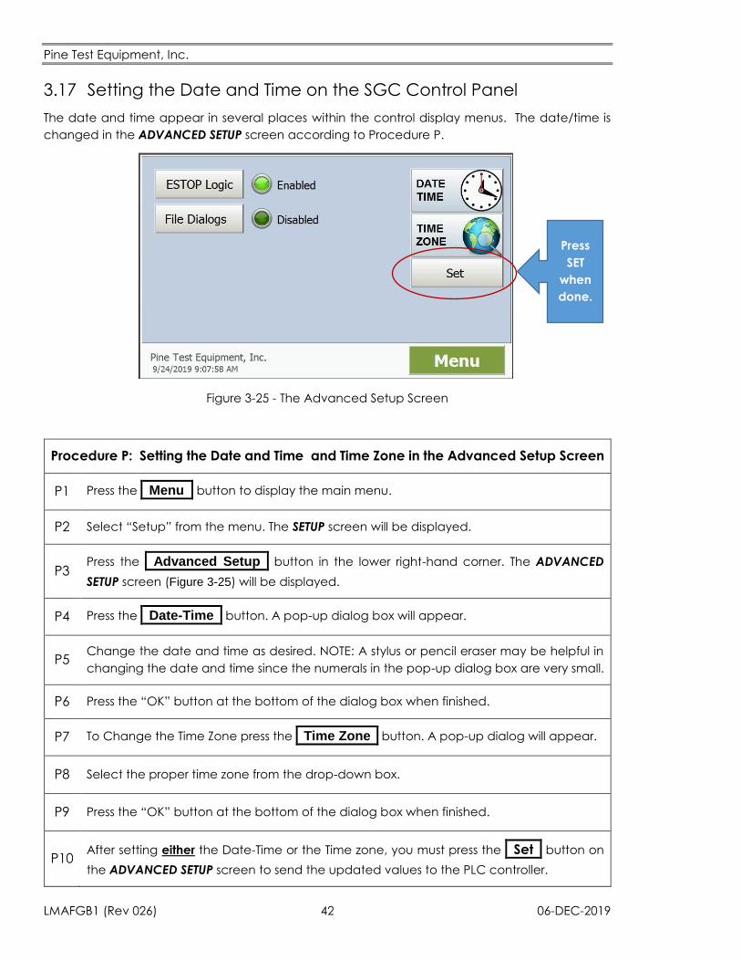
Pine Test Equipment, Inc.
LMAFGB1 (Rev 026) 42 06-DEC-2019
3.17 Setting the Date and Time on the SGC Control Panel
The date and time appear in several places within the control display menus. The date/time is
changed in the ADVANCED SETUP screen according to Procedure P.
Figure 3-25 - The Advanced Setup Screen
Procedure P: Setting the Date and Time and Time Zone in the Advanced Setup Screen
P1 Press the _Menu_ button to display the main menu.
P2 Select “Setup” from the menu. The SETUP screen will be displayed.
P3 Press the _Advanced Setup_ button in the lower right-hand corner. The ADVANCED
SETUP screen (Figure 3-25) will be displayed.
P4 Press the _Date-Time_ button. A pop-up dialog box will appear.
P5 Change the date and time as desired. NOTE: A stylus or pencil eraser may be helpful in
changing the date and time since the numerals in the pop-up dialog box are very small.
P6 Press the “OK” button at the bottom of the dialog box when finished.
P7 To Change the Time Zone press the _Time Zone_ button. A pop-up dialog will appear.
P8 Select the proper time zone from the drop-down box.
P9 Press the “OK” button at the bottom of the dialog box when finished.
P10 After setting either the Date-Time or the Time zone, you must press the _Set_ button on
the ADVANCED SETUP screen to send the updated values to the PLC controller.
Press
SET
when
done.
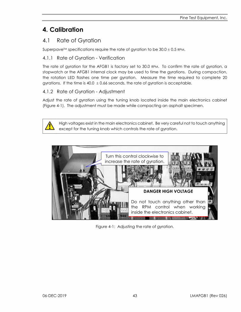
Pine Test Equipment, Inc.
06-DEC-2019 43 LMAFGB1 (Rev 026)
4. Calibration
4.1 Rate of Gyration
SuperpaveTM specifications require the rate of gyration to be 30.0 0.5 RPM.
4.1.1 Rate of Gyration - Verification
The rate of gyration for the AFGB1 is factory set to 30.0 RPM. To confirm the rate of gyration, a
stopwatch or the AFGB1 internal clock may be used to time the gyrations. During compaction,
the rotation LED flashes one time per gyration. Measure the time required to complete 20
gyrations. If the time is 40.0 0.66 seconds, the rate of gyration is acceptable.
4.1.2 Rate of Gyration - Adjustment
Adjust the rate of gyration using the tuning knob located inside the main electronics cabinet
(Figure 4-1). The adjustment must be made while compacting an asphalt specimen.
High voltages exist in the main electronics cabinet. Be very careful not to touch anything
except for the tuning knob which controls the rate of gyration.
Turn this control clockwise to
increase the rate of gyration.
DANGER HIGH VOLTAGE
Do not touch anything other than
the RPM control when working
inside the electronics cabinet.
Figure 4-1: Adjusting the rate of gyration.
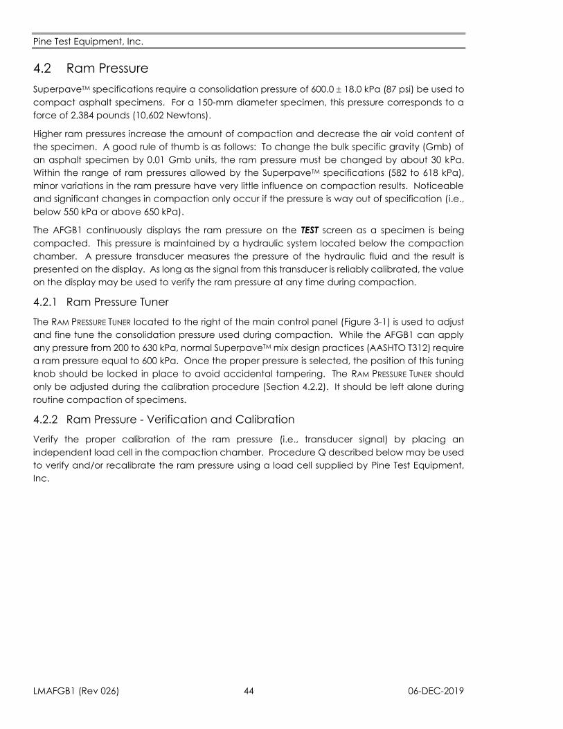
Pine Test Equipment, Inc.
LMAFGB1 (Rev 026) 44 06-DEC-2019
4.2 Ram Pressure
SuperpaveTM specifications require a consolidation pressure of 600.0 18.0 kPa (87 psi) be used to
compact asphalt specimens. For a 150-mm diameter specimen, this pressure corresponds to a
force of 2,384 pounds (10,602 Newtons).
Higher ram pressures increase the amount of compaction and decrease the air void content of
the specimen. A good rule of thumb is as follows: To change the bulk specific gravity (Gmb) of
an asphalt specimen by 0.01 Gmb units, the ram pressure must be changed by about 30 kPa.
Within the range of ram pressures allowed by the SuperpaveTM specifications (582 to 618 kPa),
minor variations in the ram pressure have very little influence on compaction results. Noticeable
and significant changes in compaction only occur if the pressure is way out of specification (i.e.,
below 550 kPa or above 650 kPa).
The AFGB1 continuously displays the ram pressure on the TEST screen as a specimen is being
compacted. This pressure is maintained by a hydraulic system located below the compaction
chamber. A pressure transducer measures the pressure of the hydraulic fluid and the result is
presented on the display. As long as the signal from this transducer is reliably calibrated, the value
on the display may be used to verify the ram pressure at any time during compaction.
4.2.1 Ram Pressure Tuner
The RAM PRESSURE TUNER located to the right of the main control panel (Figure 3-1) is used to adjust
and fine tune the consolidation pressure used during compaction. While the AFGB1 can apply
any pressure from 200 to 630 kPa, normal SuperpaveTM mix design practices (AASHTO T312) require
a ram pressure equal to 600 kPa. Once the proper pressure is selected, the position of this tuning
knob should be locked in place to avoid accidental tampering. The RAM PRESSURE TUNER should
only be adjusted during the calibration procedure (Section 4.2.2). It should be left alone during
routine compaction of specimens.
4.2.2 Ram Pressure - Verification and Calibration
Verify the proper calibration of the ram pressure (i.e., transducer signal) by placing an
independent load cell in the compaction chamber. Procedure Q described below may be used
to verify and/or recalibrate the ram pressure using a load cell supplied by Pine Test Equipment,
Inc.
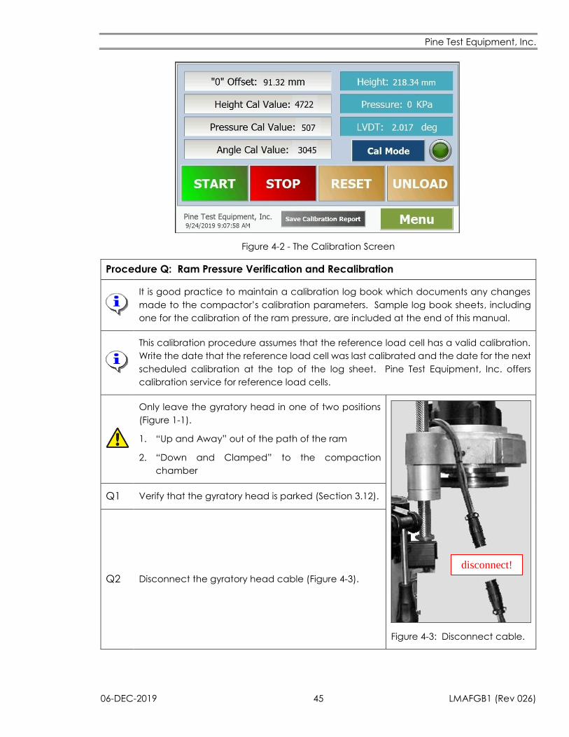
Pine Test Equipment, Inc.
06-DEC-2019 45 LMAFGB1 (Rev 026)
Figure 4-2 - The Calibration Screen
Procedure Q: Ram Pressure Verification and Recalibration
It is good practice to maintain a calibration log book which documents any changes
made to the compactor’s calibration parameters. Sample log book sheets, including
one for the calibration of the ram pressure, are included at the end of this manual.
This calibration procedure assumes that the reference load cell has a valid calibration.
Write the date that the reference load cell was last calibrated and the date for the next
scheduled calibration at the top of the log sheet. Pine Test Equipment, Inc. offers
calibration service for reference load cells.
Only leave the gyratory head in one of two positions
(Figure 1-1).
1. “Up and Away” out of the path of the ram
2. “Down and Clamped” to the compaction
chamber
disconnect!
Figure 4-3: Disconnect cable.
Q1 Verify that the gyratory head is parked (Section 3.12).
Q2 Disconnect the gyratory head cable (Figure 4-3).
Pine Test Equipment, Inc.
LMAFGB1 (Rev 026) 46 06-DEC-2019
Q3 Press the _Menu_ button to display the main menu.
Q4 Select “Setup” from the menu. The SETUP screen will be displayed.
Q5 Tap the box to the right of “Set Gyrations.”
Q6 Enter the desired number of gyrations using the pop-up keypad.
Q7 Tap the “Set Square Delay” box.
Q8 Enter the desired Square Delay (in seconds) using the pop-up keypad (Default = 0 Sec.
See Section 3.13).
Q9 Tap the “Set Pressure” box.
Q10 Set the ram pressure to 600 kPa using the pop-up keypad.
Q11 Press the _Menu_ button to display the main menu.
Q12 Select “Calibration” from the menu. The CALIBRATION screen (Figure 4-2) will be
displayed.
Q13
The only calibration parameter associated with the ram pressure measurement is the
pressure calibration value (PRESSURE CAL VALUE).
Ram pressure calibration involves adjusting the pressure calibration value. Typically, the
adjustment is very small in magnitude.
Q14 Record the PRESSURE CAL VALUE on the log sheet (column D). It is important to keep a
record of changes made to the pressure calibration value.
Q15 Open the compaction chamber (Section 3.2). Be sure the gyratory head is rotated clear
of the compaction chamber (Section 3.10).
Q16 Press the _Unload_ button twice to raise the ram.
Q17 After the ram is fully extended, press the _Stop_ button to halt the ram.
Q18 Activate the EMERGENCY STOP button. Injury may occur while cleaning compactor parts
if the EMERGENCY STOP is not activated.
Q19 Remove all grease and debris from the pressure plate, the gyratory head, and the mold
plates.
Q20 Place the bottom mold plate on the pressure plate.
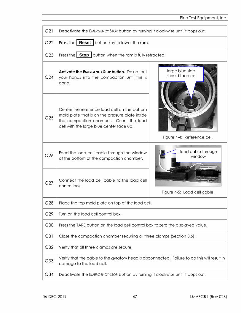
Pine Test Equipment, Inc.
06-DEC-2019 47 LMAFGB1 (Rev 026)
Q21 Deactivate the EMERGENCY STOP button by turning it clockwise until it pops out.
Q22 Press the _Reset_ button key to lower the ram.
Q23 Press the _Stop_ button when the ram is fully retracted.
Q24 Activate the EMERGENCY STOP button. Do not put
your hands into the compaction until this is
done.
large blue side
should face up
Figure 4-4: Reference cell.
Q25
Center the reference load cell on the bottom
mold plate that is on the pressure plate inside
the compaction chamber. Orient the load
cell with the large blue center face up.
Q26 Feed the load cell cable through the window
at the bottom of the compaction chamber.
feed cable through
window
Figure 4-5: Load cell cable.
Q27 Connect the load cell cable to the load cell
control box.
Q28 Place the top mold plate on top of the load cell.
Q29 Turn on the load cell control box.
Q30 Press the TARE button on the load cell control box to zero the displayed value.
Q31 Close the compaction chamber securing all three clamps (Section 3.6).
Q32 Verify that all three clamps are secure.
Q33 Verify that the cable to the gyratory head is disconnected. Failure to do this will result in
damage to the load cell.
Q34 Deactivate the EMERGENCY STOP button by turning it clockwise until it pops out.
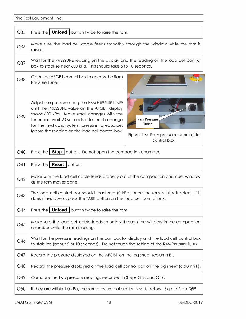
Pine Test Equipment, Inc.
LMAFGB1 (Rev 026) 48 06-DEC-2019
Q35 Press the _Unload_ button twice to raise the ram.
Q36 Make sure the load cell cable feeds smoothly through the window while the ram is
raising.
Q37 Wait for the PRESSURE reading on the display and the reading on the load cell control
box to stabilize near 600 kPa. This should take 5 to 10 seconds.
Q38 Open the AFGB1 control box to access the Ram
Pressure Tuner.
Figure 4-6: Ram pressure tuner inside
control box.
Q39
Adjust the pressure using the RAM PRESSURE TUNER
until the PRESSURE value on the AFGB1 display
shows 600 kPa. Make small changes with the
tuner and wait 20 seconds after each change
for the hydraulic system pressure to equalize.
Ignore the reading on the load cell control box.
Q40 Press the _Stop_ button. Do not open the compaction chamber.
Q41 Press the _Reset_ button.
Q42 Make sure the load cell cable feeds properly out of the compaction chamber window
as the ram moves done.
Q43 The load cell control box should read zero (0 kPa) once the ram is full retracted. If it
doesn’t read zero, press the TARE button on the load cell control box.
Q44 Press the _Unload_ button twice to raise the ram.
Q45 Make sure the load cell cable feeds smoothly through the window in the compaction
chamber while the ram is raising.
Q46 Wait for the pressure readings on the compactor display and the load cell control box
to stabilize (about 5 or 10 seconds). Do not touch the setting of the RAM PRESSURE TUNER.
Q47 Record the pressure displayed on the AFGB1 on the log sheet (column E).
Q48 Record the pressure displayed on the load cell control box on the log sheet (column F).
Q49 Compare the two pressure readings recorded in Steps Q48 and Q49.
Q50 If they are within 1.0 kPa, the ram pressure calibration is satisfactory. Skip to Step Q59.
Pine Test Equipment, Inc.
06-DEC-2019 49 LMAFGB1 (Rev 026)
Q51
If they are not within 1.0 kPa, compute the Correction Factor using the following
equation and record it in column G on the log sheet.
Correction Factor =Pressure Reading from the AFGB1
Pressure Reading from the Load Cell
Column G = Column E
Column F
Q52
Compute the new pressure Calibration Value using the following equation and record
it in column H on the log sheet.
New Pressure Calibration Value = Previous Pressure Calibation Value × Correction Factor
Column H = Column D × Column G
Q53 Press the _Cal Mode_ button to permit changes to the calibration data. The indicator
immediately to the right of the button will turn on.
Q54 Tap on the “Pressure Cal Value” box and enter the New Pressure Calibration Value
(column H) using the pop-up keypad.
Q55 Press the _ _ button.
Q56 Press the _Cal Mode_ button to lock in the new value. The light beside the key will turn
off.
Q57 Check the pressure value displayed on the AFGB1. It should change and be closer to
the value on the load cell control box.
Q58 Go back to Step Q40 to verify the new calibration value. Two or three passes through
the procedure may be required to achieve an acceptable calibration.
Q59 Now that the pressure calibration value has been adjusted and/or verified, the RAM
PRESSURE TUNER must be set so that the ram pressure is 600 kPa.
Q60
If necessary, use the RAM PRESSURE TUNER to adjust the pressure until the pressure on the
AFGB1 display is 600 kPa (Figure 4-6). Ignore the reading on the load cell control box
during this step. When adjusting the pressure using the RAM PRESSURE TUNER, make small
changes and wait 20 seconds after each change so that the hydraulic system has time
to equilibrate.
Q61 Lock the RAM PRESSURE TUNER in place. The position of the RAM PRESSURE TUNER should not
require further adjustment until the next time the ram pressure is calibrated.
Q62 Press the _Stop_ button. Leave the compaction chamber closed.
Q63 Press the _Reset_ button.
Pine Test Equipment, Inc.
LMAFGB1 (Rev 026) 50 06-DEC-2019
Q64 Make sure the load cell cable feeds properly out of the window in the compaction
chamber as the ram moves down.
Q65 Open the compaction chamber (Section 3.2).
Q66 Press the _Stop_ button to halt any ram movement.
Q67 Press the EMERGENCY STOP button. Do not put your hands into the compaction chamber
unless this button is activated.
Q68 Remove the top mold plate using the magnet.
Q69 Disconnect the load cell cable from the control box.
Q70 Remove the load cell from the compaction chamber.
Q71 Remove the bottom plate from the compaction chamber.
Q72 Reapply lubricant that was removed in Step Q19.
Q73 Reconnect the cable to the gyratory head.
Q74 Deactivate the EMERGENCY STOP button by rotating it clockwise until it pops out.
4.3 Ram Position (Specimen Height)
SuperpaveTM specifications require that the height of the specimen be measured once per
gyration to the nearest 0.1 millimeters. Loose mix placed in the mold usually has an initial height
near 140 millimeters. As the specimen is compacted, the height drops to less than 120 millimeters.
The specimen height reported by the AFGB1 compactor is based on a height transducer which
monitors the vertical position of the ram. As long as the signal from this encoder remains properly
calibrated, the height of the specimen recorded after each gyration and indicated on the display
screen is reliable.
4.3.1 Ram Position - Verification and Calibration
Proper calibration of the ram position can be verified by placing an object of known height in the
compaction chamber. Procedure R described below may be used to verify and/or recalibrate
the ram position signal using a height tube (Part Number AFGBA04) that can be purchased from
Pine Test Equipment, Inc.
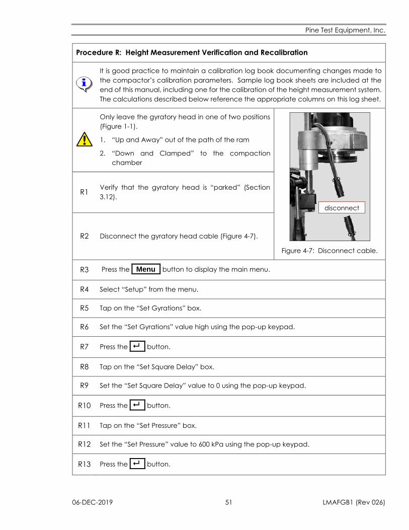
Pine Test Equipment, Inc.
06-DEC-2019 51 LMAFGB1 (Rev 026)
Procedure R: Height Measurement Verification and Recalibration
It is good practice to maintain a calibration log book documenting changes made to
the compactor’s calibration parameters. Sample log book sheets are included at the
end of this manual, including one for the calibration of the height measurement system.
The calculations described below reference the appropriate columns on this log sheet.
Only leave the gyratory head in one of two positions
(Figure 1-1).
1. “Up and Away” out of the path of the ram
2. “Down and Clamped” to the compaction
chamber
disconnect
Figure 4-7: Disconnect cable.
R1 Verify that the gyratory head is “parked” (Section
3.12).
R2 Disconnect the gyratory head cable (Figure 4-7).
R3 Press the _Menu_ button to display the main menu.
R4 Select “Setup” from the menu.
R5 Tap on the “Set Gyrations” box.
R6 Set the “Set Gyrations” value high using the pop-up keypad.
R7 Press the _ _ button.
R8 Tap on the “Set Square Delay” box.
R9 Set the “Set Square Delay” value to 0 using the pop-up keypad.
R10 Press the _ _ button.
R11 Tap on the “Set Pressure” box.
R12 Set the “Set Pressure” value to 600 kPa using the pop-up keypad.
R13 Press the _ _ button.
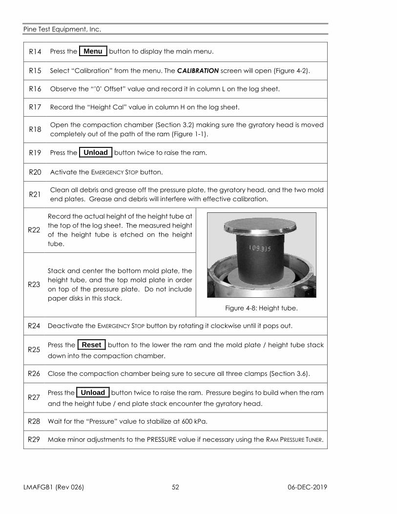
Pine Test Equipment, Inc.
LMAFGB1 (Rev 026) 52 06-DEC-2019
R14 Press the _Menu_ button to display the main menu.
R15 Select “Calibration” from the menu. The CALIBRATION screen will open (Figure 4-2).
R16 Observe the “’0’ Offset” value and record it in column L on the log sheet.
R17 Record the “Height Cal” value in column H on the log sheet.
R18 Open the compaction chamber (Section 3.2) making sure the gyratory head is moved
completely out of the path of the ram (Figure 1-1).
R19 Press the _Unload_ button twice to raise the ram.
R20 Activate the EMERGENCY STOP button.
R21 Clean all debris and grease off the pressure plate, the gyratory head, and the two mold
end plates. Grease and debris will interfere with effective calibration.
R22
Record the actual height of the height tube at
the top of the log sheet. The measured height
of the height tube is etched on the height
tube.
Figure 4-8: Height tube.
R23
Stack and center the bottom mold plate, the
height tube, and the top mold plate in order
on top of the pressure plate. Do not include
paper disks in this stack.
R24 Deactivate the EMERGENCY STOP button by rotating it clockwise until it pops out.
R25 Press the _Reset_ button to the lower the ram and the mold plate / height tube stack
down into the compaction chamber.
R26 Close the compaction chamber being sure to secure all three clamps (Section 3.6).
R27 Press the _Unload_ button twice to raise the ram. Pressure begins to build when the ram
and the height tube / end plate stack encounter the gyratory head.
R28 Wait for the “Pressure” value to stabilize at 600 kPa.
R29 Make minor adjustments to the PRESSURE value if necessary using the RAM PRESSURE TUNER.
Pine Test Equipment, Inc.
06-DEC-2019 53 LMAFGB1 (Rev 026)
R30 Record the HEIGHT value on the display in column D of the log sheet. This value is the
height signal. It may differ from the actual value of the height tube.
R31 Press the _Stop_ button.
R32 Open the compaction chamber (Section 3.2) making sure the gyratory head is moved
completely out of the path of the ram (Figure 1-1).
R33 Press the _Unload_ button twice to raise the height block and the end plates out of the
compaction chamber.
R34 Remove the height tube from between the two end plates.
R35 Center the two end plates on the ram.
R36 Press the _Reset_ button to lower the ram and the end plates down into the compaction
chamber.
R37 Close the compaction chamber being sure to secure all three clamps (Section 3.6).
R38 Press the _Unload_ button twice to raise the ram.
R39 Wait for the “Pressure” value to stabilize at 600 kPa. Do not make any adjustments to the
“Pressure” value using the RAM PRESSURE TUNER.
R40 Record the “Height” value on the display in column E of the log sheet. This value is the
height signal. It is normally close to zero.
R41 Press the _Stop_ button.
R42 Press the _Reset_ button. Do not open the compaction chamber.
R43
Calculate the Computed Height Tube Height.
Computed Height Tube Height
= Height Value with Height Tube − Height Value with End Plates Only
Column F = Column D − Column E
R44 Record the Computed Height Tube Height in column F of the log sheet.
R45 Calculate the difference between the Computed Height Tube Height (column F) and
the actual height block height recorded at the top of the log sheet.
R46 If the difference is less than 0.05 mm, the height calibration value does not need to be
changed. Skip to Step R57.
Pine Test Equipment, Inc.
LMAFGB1 (Rev 026) 54 06-DEC-2019
R47
If the difference is greater than 0.05 mm, calculate a Correction Factor.
Correction Factor =Computed Height Tube Height
Actual Height Tube Height
Column G =Column F
Actual Height Tube Height
R48 Record the Correction Factor in Column G of the log sheet.
R49
Calculate the New Calibration Value.
New Calibration Value = Previous Calibration Value × Correction Factor
Column J = Column H × Column G
R50 Record the New Calibration Value in column J of the log sheet.
R51 Press the _Cal Mode_ button to permit changes to be made to the calibration data.
The light immediately to the right of this button will turn on.
R52 Type on the “Height Cal Value” box.
R53 Enter the new “Height Cal Value” from column J of the log sheet using the pop-up
keypad.
R54 Press the _ _ button.
R55 Press the _Cal Mode_ button to lock in the new value. The light immediately to the right
of the button will turn off.
R56
Go back to Step R18 to verify that the new calibration value is acceptable. Typically,
two or three passes through this procedure are required to obtain a satisfactory setting
for the Height Calibration Value.
Pine Test Equipment, Inc.
06-DEC-2019 55 LMAFGB1 (Rev 026)
R57 Press the _Unload_ button twice to raise the ram.
R58 Wait for the PRESSURE to stabilize at 600 kPa. Do not make any adjustments with the RAM
PRESSURE TUNER.
R59 Record the HEIGHT reading on the log sheet in (column K). This is the residual height
signal. It may be positive or negative, but it should be close to zero.
R60 If the residual height signal is between –0.05 mm and +0.05 mm, skip to Step R70. The zero
offset parameter does not need adjusted.
R61
If the residual height signal is not between –0.05 mm and +0.05 mm, calculate the New
Zero Offset Value.
New Zero Offset Value = Previous Zero Offset Value − Residual Height Signal
Column M = Column L − Column K
R62 Record the new “’0’ Offset Value” in column M of the log sheet. Be sure to correctly
record whether the value is positive or negative.
R63 Press the _Cal Mode_ button to permit changes to the calibration data. The light
immediately to the right of the button will turn on.
R64 Tap the “’0’ Offset Value” box.
R65 Enter the new “’0’ Offset Value” (column M) using the pop-up keypad.
R66 Press the _ _ button.
R67 Press the _Cal Mode_ button. The new value will be locked in and the light beside the
button will turn off.
R68 Verify that the “Height Value” has changed to a value closer to zero.
R69 Go back to Step R57 to verify the new “’0’Offset value.” Usually only one pass through
this part of the procedure is required to find the proper zero offset value.
R70 Press the _Stop_ button.
R71 Press the _Reset_ button.
R72 Open the compaction chamber (Section 3.2) rotating the gyratory head completely out
of the way (Figure 1-1)
R73 Activate the EMERGENCY STOP button.

Pine Test Equipment, Inc.
LMAFGB1 (Rev 026) 56 06-DEC-2019
R74 Remove the mold plates from the compaction chamber.
R75 Reapply the lubricant that was removed in Step R21 (See Section 5.1).
R76 Reconnect the cable to the gyratory head.
R77 Deactivate the EMERGENCY STOP by rotating it clockwise until it pops out.
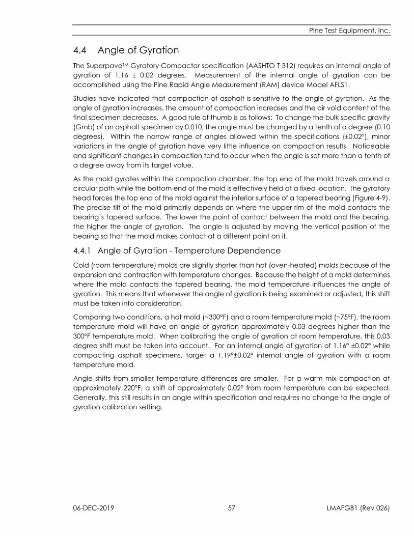
Pine Test Equipment, Inc.
06-DEC-2019 57 LMAFGB1 (Rev 026)
4.4 Angle of Gyration
The SuperpaveTM Gyratory Compactor specification (AASHTO T 312) requires an internal angle of
gyration of 1.16 0.02 degrees. Measurement of the internal angle of gyration can be
accomplished using the Pine Rapid Angle Measurement (RAM) device Model AFLS1.
Studies have indicated that compaction of asphalt is sensitive to the angle of gyration. As the
angle of gyration increases, the amount of compaction increases and the air void content of the
final specimen decreases. A good rule of thumb is as follows: To change the bulk specific gravity
(Gmb) of an asphalt specimen by 0.010, the angle must be changed by a tenth of a degree (0.10
degrees). Within the narrow range of angles allowed within the specifications (0.02), minor
variations in the angle of gyration have very little influence on compaction results. Noticeable
and significant changes in compaction tend to occur when the angle is set more than a tenth of
a degree away from its target value.
As the mold gyrates within the compaction chamber, the top end of the mold travels around a
circular path while the bottom end of the mold is effectively held at a fixed location. The gyratory
head forces the top end of the mold against the interior surface of a tapered bearing (Figure 4-9).
The precise tilt of the mold primarily depends on where the upper rim of the mold contacts the
bearing’s tapered surface. The lower the point of contact between the mold and the bearing,
the higher the angle of gyration. The angle is adjusted by moving the vertical position of the
bearing so that the mold makes contact at a different point on it.
4.4.1 Angle of Gyration - Temperature Dependence
Cold (room temperature) molds are slightly shorter than hot (oven-heated) molds because of the
expansion and contraction with temperature changes. Because the height of a mold determines
where the mold contacts the tapered bearing, the mold temperature influences the angle of
gyration. This means that whenever the angle of gyration is being examined or adjusted, this shift
must be taken into consideration.
Comparing two conditions, a hot mold (~300°F) and a room temperature mold (~75°F), the room
temperature mold will have an angle of gyration approximately 0.03 degrees higher than the
300°F temperature mold. When calibrating the angle of gyration at room temperature, this 0.03
degree shift must be taken into account. For an internal angle of gyration of 1.16° ±0.02° while
compacting asphalt specimens, target a 1.19°±0.02° internal angle of gyration with a room
temperature mold.
Angle shifts from smaller temperature differences are smaller. For a warm mix compaction at
approximately 220°F, a shift of approximately 0.02° from room temperature can be expected.
Generally, this still results in an angle within specification and requires no change to the angle of
gyration calibration setting.
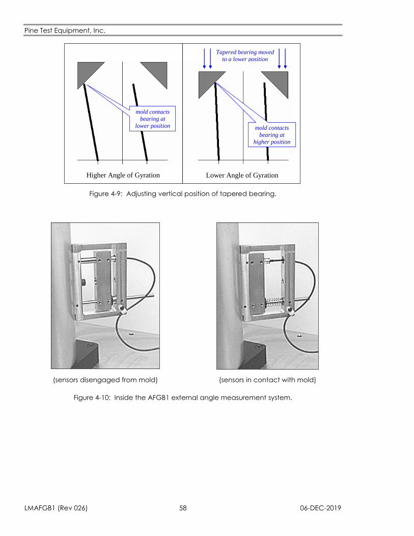
Pine Test Equipment, Inc.
LMAFGB1 (Rev 026) 58 06-DEC-2019
mold contacts
bearing at
lower position mold contacts
bearing at
higher position
Higher Angle of Gyration Lower Angle of Gyration
Tapered bearing moved
to a lower position
Figure 4-9: Adjusting vertical position of tapered bearing.
(sensors disengaged from mold)
(sensors in contact with mold)
Figure 4-10: Inside the AFGB1 external angle measurement system.
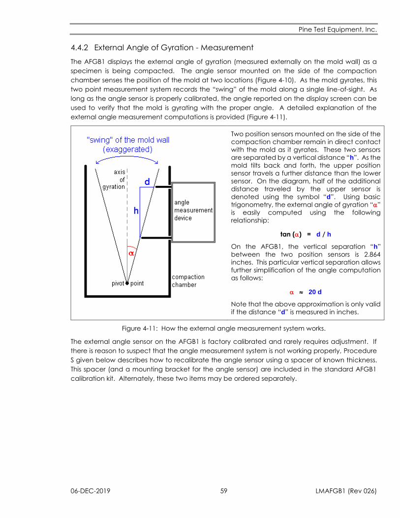
Pine Test Equipment, Inc.
06-DEC-2019 59 LMAFGB1 (Rev 026)
4.4.2 External Angle of Gyration - Measurement
The AFGB1 displays the external angle of gyration (measured externally on the mold wall) as a
specimen is being compacted. The angle sensor mounted on the side of the compaction
chamber senses the position of the mold at two locations (Figure 4-10). As the mold gyrates, this
two point measurement system records the “swing” of the mold along a single line-of-sight. As
long as the angle sensor is properly calibrated, the angle reported on the display screen can be
used to verify that the mold is gyrating with the proper angle. A detailed explanation of the
external angle measurement computations is provided (Figure 4-11).
Two position sensors mounted on the side of the
compaction chamber remain in direct contact
with the mold as it gyrates. These two sensors
are separated by a vertical distance “h”. As the
mold tilts back and forth, the upper position
sensor travels a further distance than the lower
sensor. On the diagram, half of the additional
distance traveled by the upper sensor is
denoted using the symbol “d”. Using basic
trigonometry, the external angle of gyration “”
is easily computed using the following
relationship:
tan () = d / h
On the AFGB1, the vertical separation “h”
between the two position sensors is 2.864
inches. This particular vertical separation allows
further simplification of the angle computation
as follows:
20 d
Note that the above approximation is only valid
if the distance “d” is measured in inches.
Figure 4-11: How the external angle measurement system works.
The external angle sensor on the AFGB1 is factory calibrated and rarely requires adjustment. If
there is reason to suspect that the angle measurement system is not working properly, Procedure
S given below describes how to recalibrate the angle sensor using a spacer of known thickness.
This spacer (and a mounting bracket for the angle sensor) are included in the standard AFGB1
calibration kit. Alternately, these two items may be ordered separately.
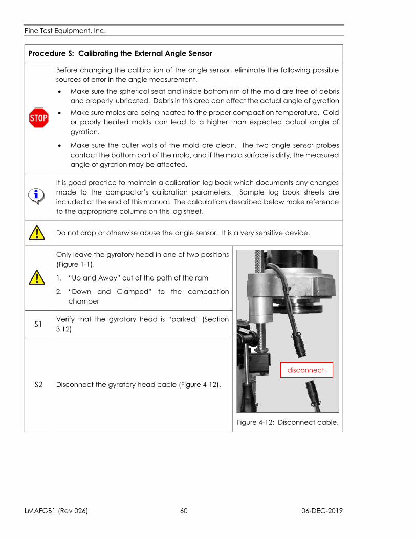
Pine Test Equipment, Inc.
LMAFGB1 (Rev 026) 60 06-DEC-2019
Procedure S: Calibrating the External Angle Sensor
Before changing the calibration of the angle sensor, eliminate the following possible
sources of error in the angle measurement.
Make sure the spherical seat and inside bottom rim of the mold are free of debris
and properly lubricated. Debris in this area can affect the actual angle of gyration
Make sure molds are being heated to the proper compaction temperature. Cold
or poorly heated molds can lead to a higher than expected actual angle of
gyration.
Make sure the outer walls of the mold are clean. The two angle sensor probes
contact the bottom part of the mold, and if the mold surface is dirty, the measured
angle of gyration may be affected.
It is good practice to maintain a calibration log book which documents any changes
made to the compactor’s calibration parameters. Sample log book sheets are
included at the end of this manual. The calculations described below make reference
to the appropriate columns on this log sheet.
Do not drop or otherwise abuse the angle sensor. It is a very sensitive device.
Only leave the gyratory head in one of two positions
(Figure 1-1).
1. “Up and Away” out of the path of the ram
2. “Down and Clamped” to the compaction
chamber
disconnect!
Figure 4-12: Disconnect cable.
S1 Verify that the gyratory head is “parked” (Section
3.12).
S2 Disconnect the gyratory head cable (Figure 4-12).

Pine Test Equipment, Inc.
06-DEC-2019 61 LMAFGB1 (Rev 026)
S3 Press the _Menu_ button to display the main menu.
S4 Select “Setup” from the menu.
S5 Tap the “Set Gyrations” box.
S6 Set the number of gyrations to a large value using the pop-up keypad.
S7 Press the _ _ button.
S8 Tap the “Set Height” box.
S9 Set the “Set Height” value to 50.0 mm using the pop-up keypad.
S10 Press the _ _ button.
S11 Tap the “Set Pressure” box.
S12 Set the “Set Pressure” value to 600 kPa using the pop-up keypad.
S13 Press the _ _ button.
S14 Tap the “Set Square Delay” box.
S15 Set the “Set Square Delay” value to 0 Seconds using the pop-up keypad.
S16 Press the _ _ button.
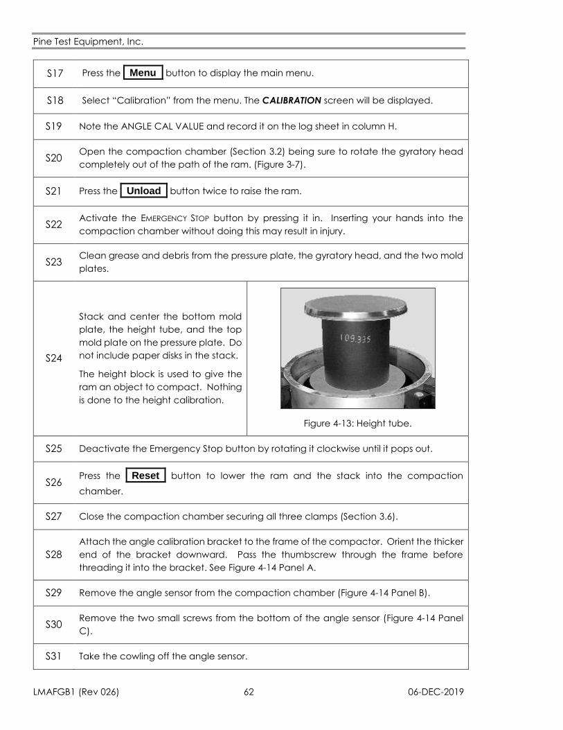
Pine Test Equipment, Inc.
LMAFGB1 (Rev 026) 62 06-DEC-2019
S17 Press the _Menu_ button to display the main menu.
S18 Select “Calibration” from the menu. The CALIBRATION screen will be displayed.
S19 Note the ANGLE CAL VALUE and record it on the log sheet in column H.
S20 Open the compaction chamber (Section 3.2) being sure to rotate the gyratory head
completely out of the path of the ram. (Figure 3-7).
S21 Press the _Unload_ button twice to raise the ram.
S22 Activate the EMERGENCY STOP button by pressing it in. Inserting your hands into the
compaction chamber without doing this may result in injury.
S23 Clean grease and debris from the pressure plate, the gyratory head, and the two mold
plates.
S24
Stack and center the bottom mold
plate, the height tube, and the top
mold plate on the pressure plate. Do
not include paper disks in the stack.
The height block is used to give the
ram an object to compact. Nothing
is done to the height calibration.
Figure 4-13: Height tube.
S25 Deactivate the Emergency Stop button by rotating it clockwise until it pops out.
S26 Press the _Reset_ button to lower the ram and the stack into the compaction
chamber.
S27 Close the compaction chamber securing all three clamps (Section 3.6).
S28
Attach the angle calibration bracket to the frame of the compactor. Orient the thicker
end of the bracket downward. Pass the thumbscrew through the frame before
threading it into the bracket. See Figure 4-14 Panel A.
S29 Remove the angle sensor from the compaction chamber (Figure 4-14 Panel B).
S30 Remove the two small screws from the bottom of the angle sensor (Figure 4-14 Panel
C).
S31 Take the cowling off the angle sensor.
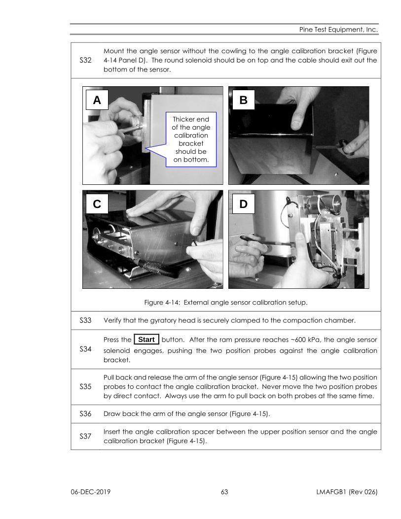
Pine Test Equipment, Inc.
06-DEC-2019 63 LMAFGB1 (Rev 026)
S32
Mount the angle sensor without the cowling to the angle calibration bracket (Figure
4-14 Panel D). The round solenoid should be on top and the cable should exit out the
bottom of the sensor.
A B
C D
Thicker end
of the angle
calibration
bracket
should be
on bottom.
Figure 4-14: External angle sensor calibration setup.
S33 Verify that the gyratory head is securely clamped to the compaction chamber.
S34
Press the _Start_ button. After the ram pressure reaches ~600 kPa, the angle sensor
solenoid engages, pushing the two position probes against the angle calibration
bracket.
S35
Pull back and release the arm of the angle sensor (Figure 4-15) allowing the two position
probes to contact the angle calibration bracket. Never move the two position probes
by direct contact. Always use the arm to pull back on both probes at the same time.
S36 Draw back the arm of the angle sensor (Figure 4-15).
S37 Insert the angle calibration spacer between the upper position sensor and the angle
calibration bracket (Figure 4-15).
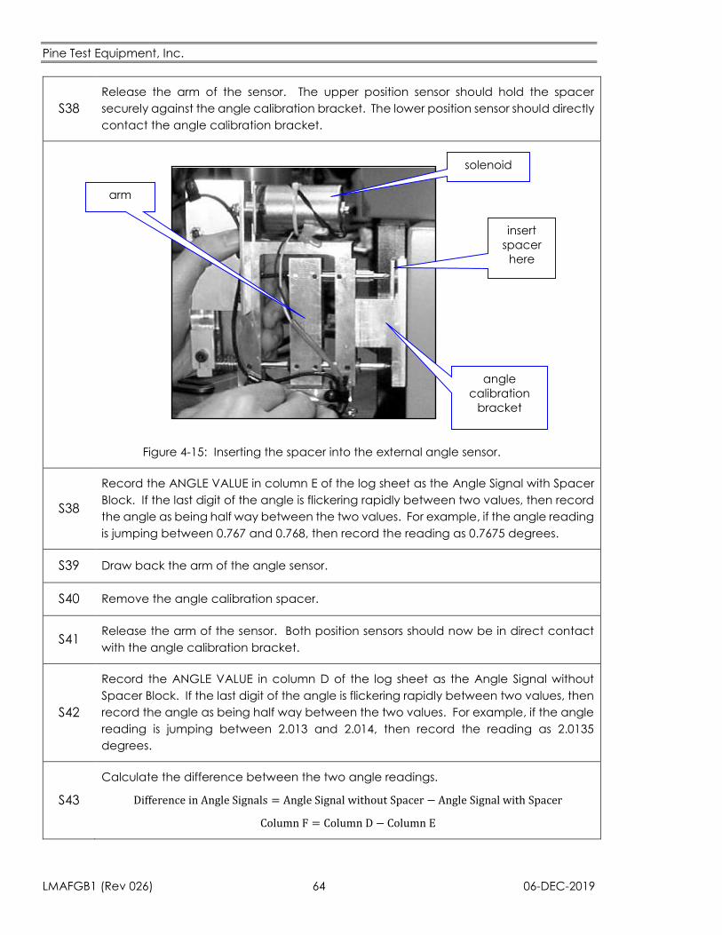
Pine Test Equipment, Inc.
LMAFGB1 (Rev 026) 64 06-DEC-2019
S38
Release the arm of the sensor. The upper position sensor should hold the spacer
securely against the angle calibration bracket. The lower position sensor should directly
contact the angle calibration bracket.
insert
spacer
here
solenoid
arm
angle
calibration
bracket
Figure 4-15: Inserting the spacer into the external angle sensor.
S38
Record the ANGLE VALUE in column E of the log sheet as the Angle Signal with Spacer
Block. If the last digit of the angle is flickering rapidly between two values, then record
the angle as being half way between the two values. For example, if the angle reading
is jumping between 0.767 and 0.768, then record the reading as 0.7675 degrees.
S39 Draw back the arm of the angle sensor.
S40 Remove the angle calibration spacer.
S41 Release the arm of the sensor. Both position sensors should now be in direct contact
with the angle calibration bracket.
S42
Record the ANGLE VALUE in column D of the log sheet as the Angle Signal without
Spacer Block. If the last digit of the angle is flickering rapidly between two values, then
record the angle as being half way between the two values. For example, if the angle
reading is jumping between 2.013 and 2.014, then record the reading as 2.0135
degrees.
S43
Calculate the difference between the two angle readings.
Difference in Angle Signals = Angle Signal without Spacer − Angle Signal with Spacer
Column F = Column D − Column E
Pine Test Equipment, Inc.
06-DEC-2019 65 LMAFGB1 (Rev 026)
S44 Record the Difference in Angle Signals in column F of the log sheet.
S45
If the difference in between the two angle signals is between 1.248 and 1.252, the angle
sensor is properly calibrated. The angle calibration value does not need to be
changed. Skip to Step S62
S46
If the difference in angle signals is outside the range from 1.248 to 1.252, calculate a
Correction Factor.
Correction Factor =Difference in Angle Signals
1.25°
Column G =Column F
1.25°
S47 Record the Correction Factor in column G of the log sheet.
S48
Calculate the New Angle Calibration Value.
New Angle Calibration Value = Previous Angle Calibration Value × Correction Factor
Column J = Column H × Column G
S49 Record the New Angle Calibration Value on the log sheet in column J.
S50 Press the _Cal Mode_ button to permit changes to the calibration data. The light
below the key will turn on.
S51 Tap the ANGLE CAL. VALUE box.
S52 Enter the New Angle Calibration Value using the pop-up keypad.
S53 Press the _ _ button.
S54
Press the _Cal Mode_ button. This locks in the New Angle Calibration Value and turns
off the light below the key. Also, the Angle Value reported at the bottom of the display
should change.
S55
Go back to Step S36 to verify that the New Angle Calibration Value is correct. It
usually takes two or three passes through the procedure to achieve the ideal setting
for the angle calibration value.
S56 Press the _Stop_ button.
S57 Press the _Reset_ button to retract the ram.
S58 Activate the Emergency Stop button by pressing it in.
Pine Test Equipment, Inc.
LMAFGB1 (Rev 026) 66 06-DEC-2019
S59 Open the compaction chamber (Section 3.2).
S60 Remove the mold plates and the height block from the compaction chamber.
S61 Reapply lubricant that was removed in Step S27 (Section 5.1).
S62 Reconnect the cable to the gyratory head.
S63 Remove the angle sensor from the angle calibration bracket
S64 Attach the cowling to the angle sensor using the two small screws.
S65 Attach the angle sensor to the compaction chamber.
S66 Remove the angle calibration bracket from the frame of the compactor.
S67 Deactivate the Emergency Stop button by rotating it clockwise until it pops out.
4.4.3 Angle of Gyration – Adjustment
Physically adjust the angle of gyration only as a last resort. Only consider physically
changing the angle after taking the following three steps.
1. Thoroughly clean the spherical seat, the inside bottom rim of the mold, and the
tapered bearing of all debris and grease.
2. Verify that the angle measurement system is calibrated properly and continues to
indicate an improper angle of gyration.
3. Measure the internal angle using and AFLS1 Rapid Angle Measurement Kit.
Sudden and unexpected changes in the angle of gyration reported by the external
angle measurement system are rarely caused by an actual physical change in the
angle of gyration. The problem usually lies with the angle measurement system
(binding) or interference from debris on the spherical and/or tapered bearings which
maintain the angle of gyration.
The angle of gyration is factory set to the customer’s specification (internal or external). If the
angle requires adjustment, change the vertical position of the tapered bearing inside the
compaction chamber following Procedure T. The angle of gyration increases if the bearing is
moved upwards. Conversely, lowering the bearing decreases the angle of gyration. Make fine
adjustment of the angle by making small changes in the bearing position using the adjustment
nuts located around the outside of the compaction chamber (Figure 4-16).
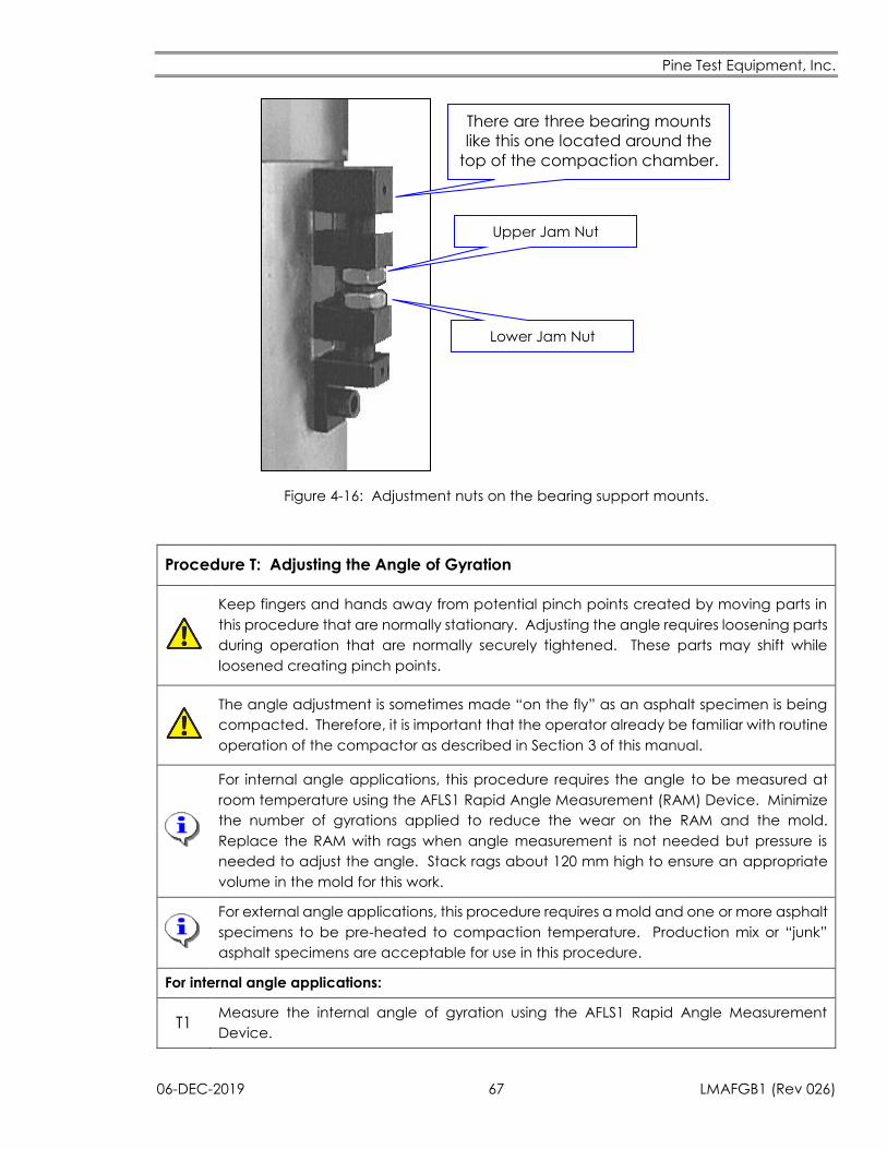
Pine Test Equipment, Inc.
06-DEC-2019 67 LMAFGB1 (Rev 026)
There are three bearing mounts
like this one located around the
top of the compaction chamber.
Upper Jam Nut
Lower Jam Nut
Figure 4-16: Adjustment nuts on the bearing support mounts.
Procedure T: Adjusting the Angle of Gyration
Keep fingers and hands away from potential pinch points created by moving parts in
this procedure that are normally stationary. Adjusting the angle requires loosening parts
during operation that are normally securely tightened. These parts may shift while
loosened creating pinch points.
The angle adjustment is sometimes made “on the fly” as an asphalt specimen is being
compacted. Therefore, it is important that the operator already be familiar with routine
operation of the compactor as described in Section 3 of this manual.
For internal angle applications, this procedure requires the angle to be measured at
room temperature using the AFLS1 Rapid Angle Measurement (RAM) Device. Minimize
the number of gyrations applied to reduce the wear on the RAM and the mold.
Replace the RAM with rags when angle measurement is not needed but pressure is
needed to adjust the angle. Stack rags about 120 mm high to ensure an appropriate
volume in the mold for this work.
For external angle applications, this procedure requires a mold and one or more asphalt
specimens to be pre-heated to compaction temperature. Production mix or “junk”
asphalt specimens are acceptable for use in this procedure.
For internal angle applications:
T1 Measure the internal angle of gyration using the AFLS1 Rapid Angle Measurement
Device.
Pine Test Equipment, Inc.
LMAFGB1 (Rev 026) 68 06-DEC-2019
T2 Record the external angle of gyration reported on the compactor display while the
internal angle is being measured.
T3
Determine the amount of adjustment needed to achieve the target internal angle.
The shift in the angle of gyration on the AFGB1 from room temperature (~75°F) to
compaction temperature (~300°F) is -0.03° (1.19° @ 75°F = 1.16° @ 300°F). This is the
adjustment that will be made to the external angle.
Under similar loading conditions, the internal angle tracks with the external angle.
Therefore any adjustment to the external angle should result in an equal shift in the
internal angle.
The internal angle must be confirmed with the AFLS1 RAM device after any
adjustment is made.
T4 Skip to Step T9 if the angle needs to be increased or Step T15 if the angle needs to be
decreased.
For external angle applications:
T5 Set the number of gyrations to a high value (~150) so that the duration of the
compaction process is long enough to complete the angle adjustment (Section 3.7).
T6 Begin compacting an asphalt specimen according to the procedures in Section 3.
T7 Extrude the specimen and continue the adjustment with a second specimen if the
adjustment is not complete after 150 gyrations.
T8 Go to Step T9 if the angle needs to be increased or skip to Step T15 if the angle needs
to be decreased.
Increasing the angle (Figure 4-16):
T9 Loosen the lower jam nuts on all three bearing mounts.
T10
Turn the upper jam nuts on the bearing mounts counterclockwise to raise the bearing,
which raises the angle. Make small changes by only turning a nut 1/6th of a revolution
at a time. One sixth of a revolution changes the angle about 0.01°.
T11 Keep the bearing level at all times by turning the nuts exactly the same amount on each
bearing mount.
T12 Continue raising the bearing until the angle displayed on the TEST screen reaches the
target value (i.e., 1.25°).
T13 Secure the upper jam nuts into position by tightening the lower jam nuts.
T14 Go to Step T20
Decreasing the angle (Figure 4-16):
T15 Loosen the upper jam nuts on all three bearing mounts.
Pine Test Equipment, Inc.
06-DEC-2019 69 LMAFGB1 (Rev 026)
T16
Turn the lower jam nuts clockwise to lower the bearing, which lowers the angle. Make
small changes by only turning a nut 1/6th of a revolution at a time. One sixth of a
revolution changes the angle about 0.01°.
T17 Keep the bearing level at all times by turning the nuts exactly the same amount on each
bearing mount.
T18 Keep lowering the bearing until the angle displayed on the TEST screen reaches the
target value (i.e., 1.25°).
T19 Secure the lower jam nuts into position by tightening the upper jam nuts.
Process completion:
T20
Continue the compaction process while monitoring the angle of gyration on the
compactor display.
The angle should remain stable.
Monitoring the external angle during compaction in internal angle applications
provides assurance that the angle has not shifted.
T21 Record when and why the angle was changed on a log sheet. A log sheet template is
provided at the end of this manual for your use.
Pine Test Equipment, Inc.
LMAFGB1 (Rev 026) 70 06-DEC-2019
5. Maintenance
The AFGB1 requires periodic maintenance to assure continued reliable performance. There are
not many moving parts, but there are several items that require attention from time to time.
5.1 Lubrication
There are several operational wear surfaces that require lubrication on a regular basis.
The spherical seat at the bottom of the compaction chamber below the ram.
The portion of the gyratory head that contacts the inner wall of the mold.
The tapered bearing used to adjust the angle of gyration.
The top surface of the pressure plate mounted on the ram.
The top surface of the top mold plate.
The three clamps on the gyratory head.
All of these surfaces should be lubricated using moly-grade anti-seize lubricant. This lubricant is
available from Pine Test Equipment, Inc. as part number CLGSMOS2. Call +1.724.458.6393.
Frequency of lubrication varies for each of the surfaces and depends upon how often the gyratory
compactor is used. The lubrication schedule for each surface is given below in terms of number
of specimens compacted and in terms of time periods. The time periods assume that six
specimens per day are prepared during a full week of asphalt production.
5.1.1 Mold Top Plate
Lubricate this surface each time a specimen is compacted.
Lubricate this surface just before compacting a specimen by applying a layer of molybdenum
disulfide grease around the outside 1.5 inches of the top mold plate (Figure 5-1). This is the only
portion of the top mold plate that comes into contact with the gyratory head. The inner 3.0-inch
diameter portion of the top plate does not contact any metal and should be kept free of grease
so that the mold top can be easily manipulated using the magnet.
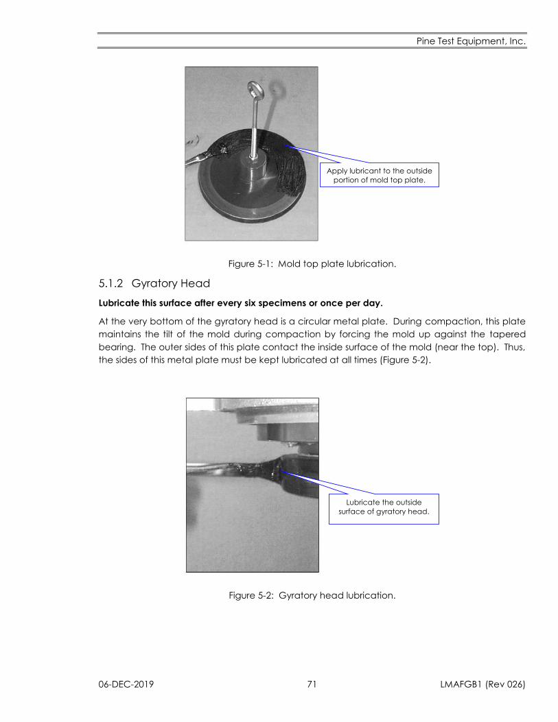
Pine Test Equipment, Inc.
06-DEC-2019 71 LMAFGB1 (Rev 026)
Apply lubricant to the outside
portion of mold top plate.
Figure 5-1: Mold top plate lubrication.
5.1.2 Gyratory Head
Lubricate this surface after every six specimens or once per day.
At the very bottom of the gyratory head is a circular metal plate. During compaction, this plate
maintains the tilt of the mold during compaction by forcing the mold up against the tapered
bearing. The outer sides of this plate contact the inside surface of the mold (near the top). Thus,
the sides of this metal plate must be kept lubricated at all times (Figure 5-2).
Lubricate the outside
surface of gyratory head.
Figure 5-2: Gyratory head lubrication.
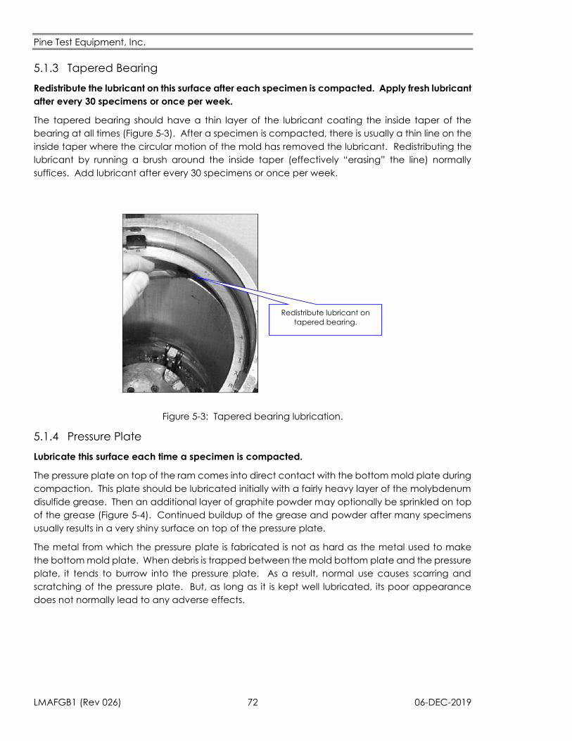
Pine Test Equipment, Inc.
LMAFGB1 (Rev 026) 72 06-DEC-2019
5.1.3 Tapered Bearing
Redistribute the lubricant on this surface after each specimen is compacted. Apply fresh lubricant
after every 30 specimens or once per week.
The tapered bearing should have a thin layer of the lubricant coating the inside taper of the
bearing at all times (Figure 5-3). After a specimen is compacted, there is usually a thin line on the
inside taper where the circular motion of the mold has removed the lubricant. Redistributing the
lubricant by running a brush around the inside taper (effectively “erasing” the line) normally
suffices. Add lubricant after every 30 specimens or once per week.
Redistribute lubricant on
tapered bearing.
Figure 5-3: Tapered bearing lubrication.
5.1.4 Pressure Plate
Lubricate this surface each time a specimen is compacted.
The pressure plate on top of the ram comes into direct contact with the bottom mold plate during
compaction. This plate should be lubricated initially with a fairly heavy layer of the molybdenum
disulfide grease. Then an additional layer of graphite powder may optionally be sprinkled on top
of the grease (Figure 5-4). Continued buildup of the grease and powder after many specimens
usually results in a very shiny surface on top of the pressure plate.
The metal from which the pressure plate is fabricated is not as hard as the metal used to make
the bottom mold plate. When debris is trapped between the mold bottom plate and the pressure
plate, it tends to burrow into the pressure plate. As a result, normal use causes scarring and
scratching of the pressure plate. But, as long as it is kept well lubricated, its poor appearance
does not normally lead to any adverse effects.
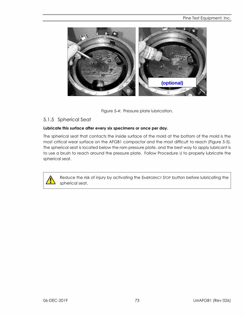
Pine Test Equipment, Inc.
06-DEC-2019 73 LMAFGB1 (Rev 026)
(optional)
Figure 5-4: Pressure plate lubrication.
5.1.5 Spherical Seat
Lubricate this surface after every six specimens or once per day.
The spherical seat that contacts the inside surface of the mold at the bottom of the mold is the
most critical wear surface on the AFGB1 compactor and the most difficult to reach (Figure 5-5).
The spherical seat is located below the ram pressure plate, and the best way to apply lubricant is
to use a brush to reach around the pressure plate. Follow Procedure U to properly lubricate the
spherical seat.
Reduce the risk of injury by activating the EMERGENCY STOP button before lubricating the
spherical seat.
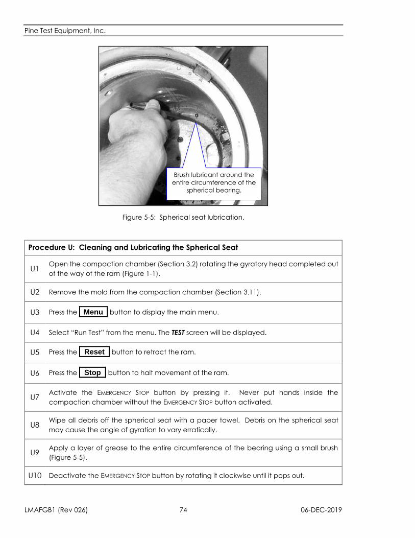
Pine Test Equipment, Inc.
LMAFGB1 (Rev 026) 74 06-DEC-2019
Brush lubricant around the
entire circumference of the
spherical bearing.
Figure 5-5: Spherical seat lubrication.
Procedure U: Cleaning and Lubricating the Spherical Seat
U1 Open the compaction chamber (Section 3.2) rotating the gyratory head completed out
of the way of the ram (Figure 1-1).
U2 Remove the mold from the compaction chamber (Section 3.11).
U3 Press the _Menu_ button to display the main menu.
U4 Select “Run Test” from the menu. The TEST screen will be displayed.
U5 Press the _Reset_ button to retract the ram.
U6 Press the _Stop_ button to halt movement of the ram.
U7 Activate the EMERGENCY STOP button by pressing it. Never put hands inside the
compaction chamber without the EMERGENCY STOP button activated.
U8 Wipe all debris off the spherical seat with a paper towel. Debris on the spherical seat
may cause the angle of gyration to vary erratically.
U9 Apply a layer of grease to the entire circumference of the bearing using a small brush
(Figure 5-5).
U10 Deactivate the EMERGENCY STOP button by rotating it clockwise until it pops out.
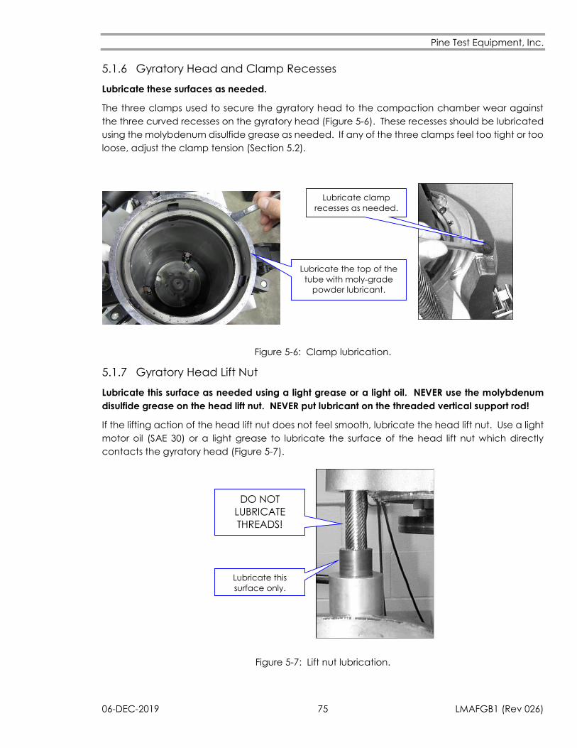
Pine Test Equipment, Inc.
06-DEC-2019 75 LMAFGB1 (Rev 026)
5.1.6 Gyratory Head and Clamp Recesses
Lubricate these surfaces as needed.
The three clamps used to secure the gyratory head to the compaction chamber wear against
the three curved recesses on the gyratory head (Figure 5-6). These recesses should be lubricated
using the molybdenum disulfide grease as needed. If any of the three clamps feel too tight or too
loose, adjust the clamp tension (Section 5.2).
Lubricate clamp
recesses as needed.
Lubricate the top of the
tube with moly-grade
powder lubricant.
Figure 5-6: Clamp lubrication.
5.1.7 Gyratory Head Lift Nut
Lubricate this surface as needed using a light grease or a light oil. NEVER use the molybdenum
disulfide grease on the head lift nut. NEVER put lubricant on the threaded vertical support rod!
If the lifting action of the head lift nut does not feel smooth, lubricate the head lift nut. Use a light
motor oil (SAE 30) or a light grease to lubricate the surface of the head lift nut which directly
contacts the gyratory head (Figure 5-7).
Lubricate this
surface only.
DO NOT
LUBRICATE
THREADS!
Figure 5-7: Lift nut lubrication.
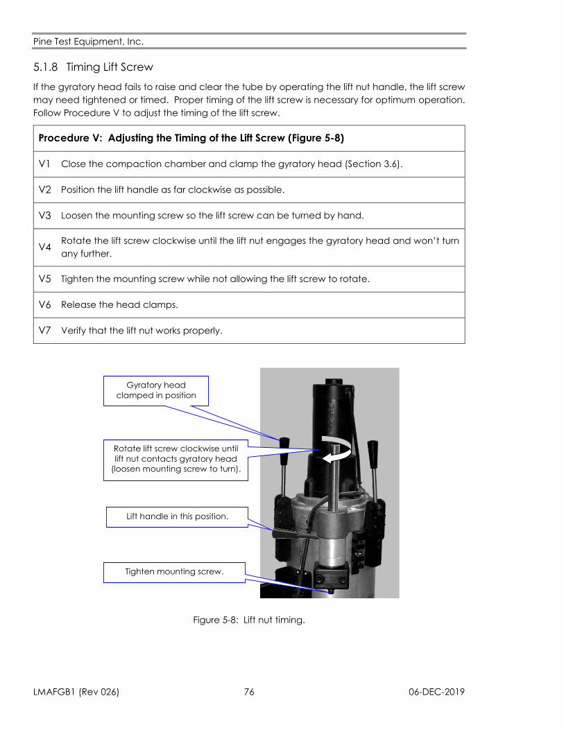
Pine Test Equipment, Inc.
LMAFGB1 (Rev 026) 76 06-DEC-2019
5.1.8 Timing Lift Screw
If the gyratory head fails to raise and clear the tube by operating the lift nut handle, the lift screw
may need tightened or timed. Proper timing of the lift screw is necessary for optimum operation.
Follow Procedure V to adjust the timing of the lift screw.
Procedure V: Adjusting the Timing of the Lift Screw (Figure 5-8)
V1 Close the compaction chamber and clamp the gyratory head (Section 3.6).
V2 Position the lift handle as far clockwise as possible.
V3 Loosen the mounting screw so the lift screw can be turned by hand.
V4 Rotate the lift screw clockwise until the lift nut engages the gyratory head and won’t turn
any further.
V5 Tighten the mounting screw while not allowing the lift screw to rotate.
V6 Release the head clamps.
V7 Verify that the lift nut works properly.
Lift handle in this position.
Gyratory head
clamped in position
Tighten mounting screw.
Rotate lift screw clockwise until
lift nut contacts gyratory head
(loosen mounting screw to turn).
Figure 5-8: Lift nut timing.
Pine Test Equipment, Inc.
06-DEC-2019 77 LMAFGB1 (Rev 026)
5.2 Pressure Plate Screws
The screws in the pressure plate (see Figure 5-4) may work loose. Check them weekly with a 3/16”
Allen wrench when lubricating the pressure plate to make sure they are tight.
5.3 Clamp Adjustment
The three clamps which secure the gyratory head to the compaction chamber should be
adjusted so that all three restrain movement of the gyratory head equally. If one clamp is not as
tight as the other two, the surface in contact with that clamp is subject to increased wear.
Clamping tension is easily adjusted using an Allen key and an adjustable wrench. In general,
when adjusting the tension on one clamp, it is a good idea to adjust all three clamps.
Clamps should be adjusted as tight as possible, but not so tight that the clamp is difficult to engage
and disengage. Procedure W describes how to correctly adjust the clamps.
Procedure W: Adjusting Clamp Tension (Figure 5-9)
W1 Verify that the ram is retracted to the bottom of the compaction chamber.
W2 Clamp the compaction chamber closed with all three clamps (Section 3.6).
W3 Loosen the cam set screw with an Allen key.
W4 Loosen the cam with an adjustable wrench. The clamp should disengage and swing
freely.
W5 Using one hand to hold the clamp at a 45° angle, hand-tighten the cam so that the
clamp no longer swings freely and stays in the 45° position without being held.
W6 Tighten the cam with an adjustable wrench so that the cam is “snug”.
W7 Retighten the cam set screw using an Allen key.
W8 Test the clamp. It should engage and disengage easily using the clamp lever.
W9 If the clamp is too tight, go back to Step W3. Be careful not to overtighten the clamp in
Step W6.
W10 Adjust the other two clamps using the procedure above so that all three clamps exert
the same force on the gyratory head.
W11 Retighten the small screws in the body of each clamp. Tighten these screws frequently.
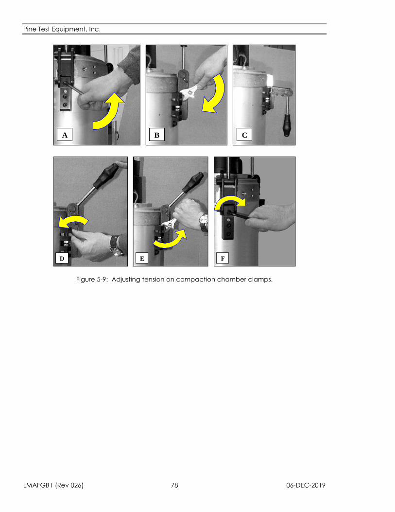
Pine Test Equipment, Inc.
LMAFGB1 (Rev 026) 78 06-DEC-2019
A B C
D E F
Figure 5-9: Adjusting tension on compaction chamber clamps.
Pine Test Equipment, Inc.
06-DEC-2019 79 LMAFGB1 (Rev 026)
5.4 Hydraulic System
Inspect the hydraulic oil level weekly or every 30 specimens.
The hydraulic system uses only filtered hydraulic oil. Inspect the oil level weekly to ensure that the
hydraulic system continues to function properly. Add oil to the system if it is found to be low. Use
only Mobil DTE 24 or ISO VG 32 type oil.
Whenever any new oil is added to the system or if the oil appears dirty after an extended period
of use, all of the oil in the system must be filtered using a special oil filter kit (Part Number
AFGBA10)offered by Pine Test Equipment, Inc. Never add oil to the system without performing the
proper filtering procedure using the oil filter kit. Oil taken straight from the manufacturer’s bottle is
too dirty for use in the AFGB1. The oil must be filtered under pressure using the oil filter kit.
Check the level of hydraulic oil using Procedure X below.
Procedure X: Checking the Hydraulic Oil Level (Figure 5-10 and Figure 5-11)
X1 Verify that the hydraulic oil is at room temperature, the ram is retracted, and the
compactor is powered off.
X2 Remove the front panel from the hydraulic cabinet.
X3 Thoroughly clean the top of the hydraulic reservoir area and the spill tube to avoid having
debris drop down into the reservoir.
X4 Unscrew and remove the spill tube assembly. Normally this can be done by hand, but use
a hand tool if required.
X5
Inspect the oil level inside the reservoir. There is a shiny return oil tube visible inside the
reservoir. The oil level (cold) should be just high enough to cover this tube. However, the
oil level (cold) must never be closer than one inch from the top of the reservoir. This leaves
enough room for the oil to expand when it heats up.
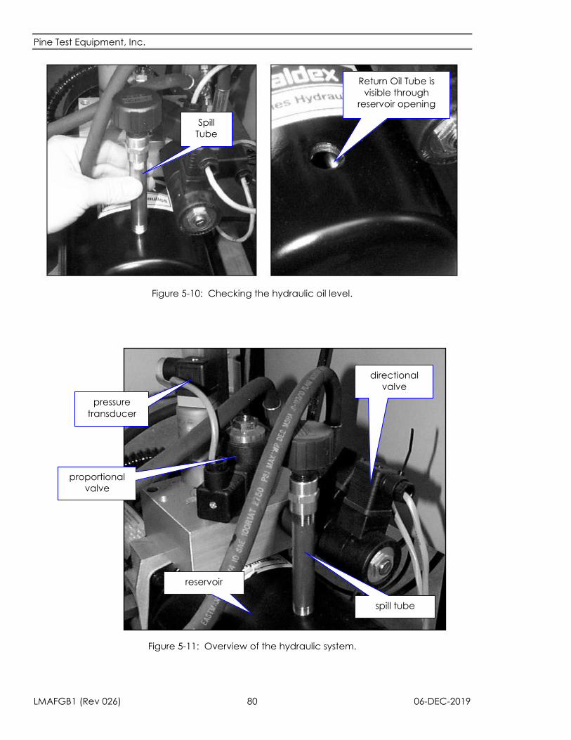
Pine Test Equipment, Inc.
LMAFGB1 (Rev 026) 80 06-DEC-2019
Spill
Tube
Return Oil Tube is
visible through
reservoir opening
Figure 5-10: Checking the hydraulic oil level.
reservoir
pressure
transducer
proportional
valve
directional
valve
spill tube
Figure 5-11: Overview of the hydraulic system.
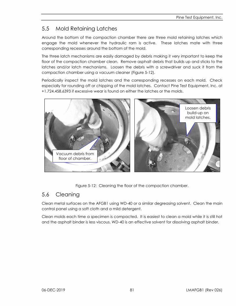
Pine Test Equipment, Inc.
06-DEC-2019 81 LMAFGB1 (Rev 026)
5.5 Mold Retaining Latches
Around the bottom of the compaction chamber there are three mold retaining latches which
engage the mold whenever the hydraulic ram is active. These latches mate with three
corresponding recesses around the bottom of the mold.
The three latch mechanisms are easily damaged by debris making it very important to keep the
floor of the compaction chamber clean. Remove asphalt debris that builds up and sticks to the
latches and/or latch mechanisms. Loosen the debris with a screwdriver and suck it from the
compaction chamber using a vacuum cleaner (Figure 5-12).
Periodically inspect the mold latches and the corresponding recesses on each mold. Check
especially for rounding off or chipping of the mold latches. Contact Pine Test Equipment, Inc. at
+1.724.458.6393 if excessive wear is found on either the latches or the molds.
Loosen debris
build-up on
mold latches.
Vacuum debris from
floor of chamber.
Figure 5-12: Cleaning the floor of the compaction chamber.
5.6 Cleaning
Clean metal surfaces on the AFGB1 using WD-40 or a similar degreasing solvent. Clean the main
control panel using a soft cloth and a mild detergent.
Clean molds each time a specimen is compacted. It is easiest to clean a mold while it is still hot
and the asphalt binder is less viscous. WD-40 is an effective solvent for dissolving asphalt binder.
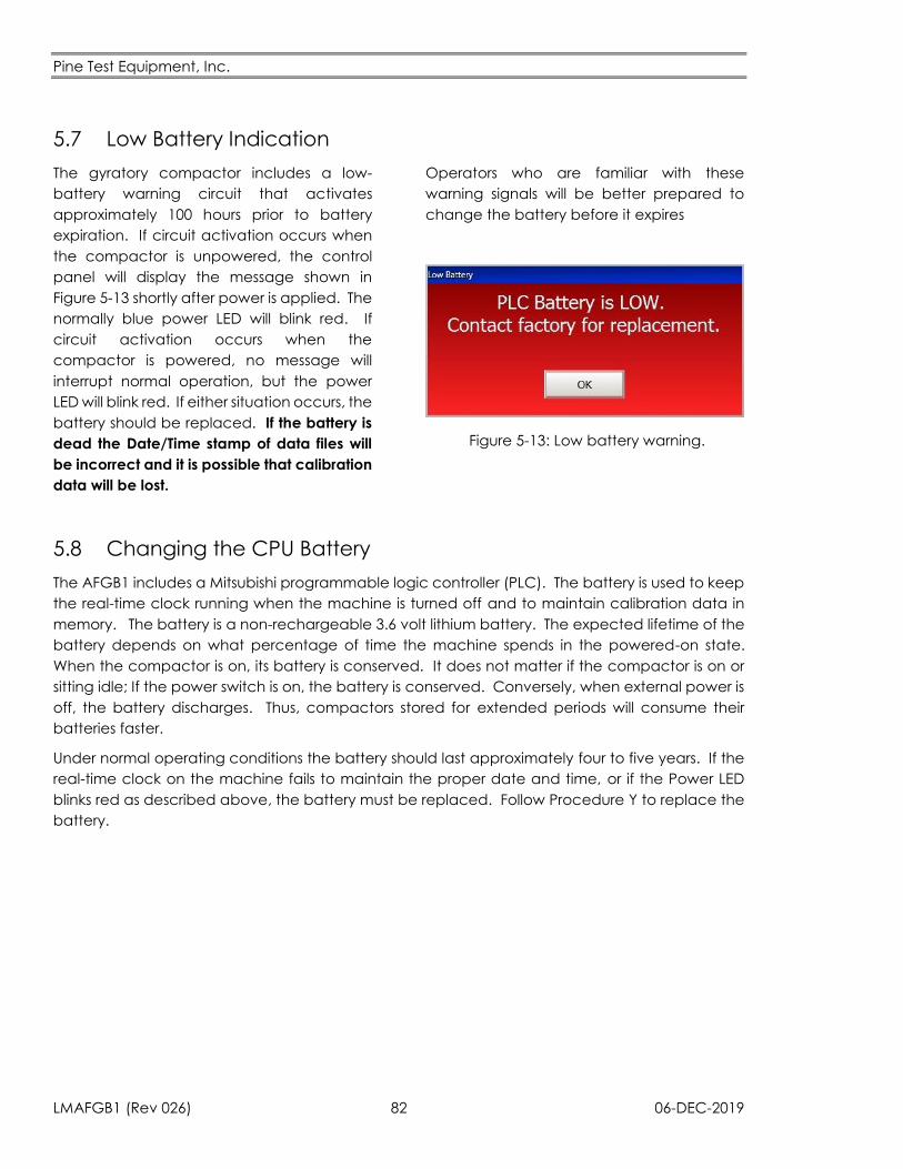
Pine Test Equipment, Inc.
LMAFGB1 (Rev 026) 82 06-DEC-2019
5.7 Low Battery Indication
The gyratory compactor includes a low-
battery warning circuit that activates
approximately 100 hours prior to battery
expiration. If circuit activation occurs when
the compactor is unpowered, the control
panel will display the message shown in
Figure 5-13 shortly after power is applied. The
normally blue power LED will blink red. If
circuit activation occurs when the
compactor is powered, no message will
interrupt normal operation, but the power
LED will blink red. If either situation occurs, the
battery should be replaced. If the battery is
dead the Date/Time stamp of data files will
be incorrect and it is possible that calibration
data will be lost.
Operators who are familiar with these
warning signals will be better prepared to
change the battery before it expires
Figure 5-13: Low battery warning.
5.8 Changing the CPU Battery
The AFGB1 includes a Mitsubishi programmable logic controller (PLC). The battery is used to keep
the real-time clock running when the machine is turned off and to maintain calibration data in
memory. The battery is a non-rechargeable 3.6 volt lithium battery. The expected lifetime of the
battery depends on what percentage of time the machine spends in the powered-on state.
When the compactor is on, its battery is conserved. It does not matter if the compactor is on or
sitting idle; If the power switch is on, the battery is conserved. Conversely, when external power is
off, the battery discharges. Thus, compactors stored for extended periods will consume their
batteries faster.
Under normal operating conditions the battery should last approximately four to five years. If the
real-time clock on the machine fails to maintain the proper date and time, or if the Power LED
blinks red as described above, the battery must be replaced. Follow Procedure Y to replace the
battery.
Pine Test Equipment, Inc.
06-DEC-2019 83 LMAFGB1 (Rev 026)
Procedure Y: Replacing the Battery (Figure 5-14 and Figure 5-15)
Y1 Confirm that the CPU is functional by verifying that the compactor operates.
Y2 Leave the AC power ON for at least 10 minutes before performing this procedure.
Y3
Turn the AC power off. A capacitor integral to the CPU provides DC power to the
memory allowing 10 to 15 minutes to change the battery, which should only take a few
minutes.
Y4 Open the electronics cabinet.
Y5 Locate the CPU in the upper left corner (Figure 5-14)
Y6 Open the battery holder located on the bottom of the CPU Module (Figure 5-14).
Y7 Remove the old battery from the battery holder and disconnect the wiring connector
(Figure 5-15).
Y8 Connect the lead connector of the new battery to that of the CPU module, then insert
the battery into the battery holder.
Y9 Attach the connectors to the connector stopper of the holder as shown in Figure 5-15.
Y10 Close the electronics cabinet.
Y11 Turn the AC power on
Y12 Verify the operation of the compactor.
Y13 Record a reminder note for when the next battery change will be due in the log.
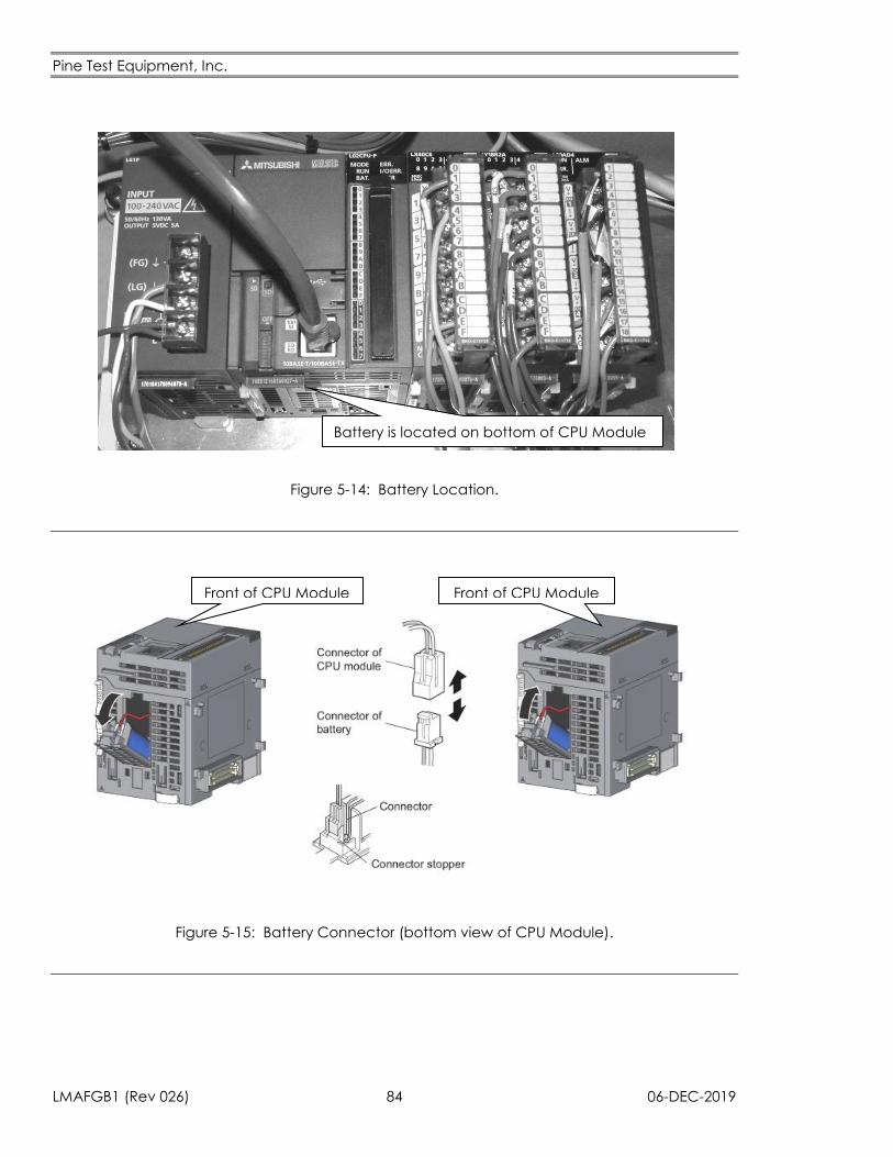
Pine Test Equipment, Inc.
LMAFGB1 (Rev 026) 84 06-DEC-2019
Figure 5-14: Battery Location.
Figure 5-15: Battery Connector (bottom view of CPU Module).
Battery is located on bottom of CPU Module
Front of CPU Module Front of CPU Module
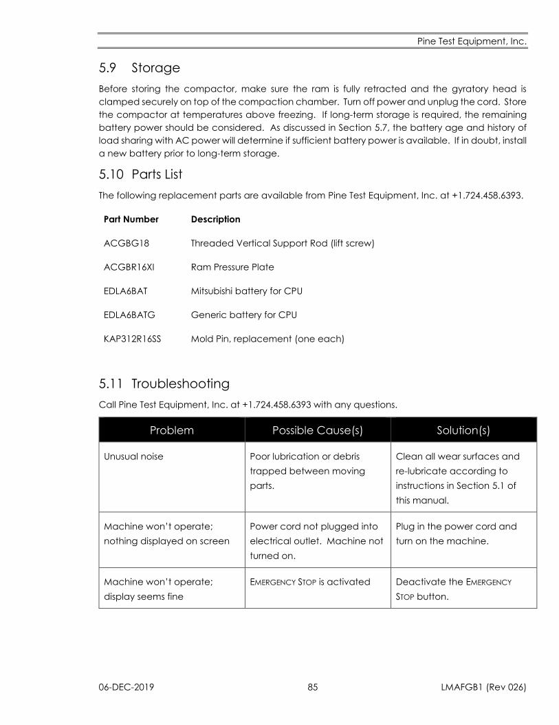
Pine Test Equipment, Inc.
06-DEC-2019 85 LMAFGB1 (Rev 026)
5.9 Storage
Before storing the compactor, make sure the ram is fully retracted and the gyratory head is
clamped securely on top of the compaction chamber. Turn off power and unplug the cord. Store
the compactor at temperatures above freezing. If long-term storage is required, the remaining
battery power should be considered. As discussed in Section 5.7, the battery age and history of
load sharing with AC power will determine if sufficient battery power is available. If in doubt, install
a new battery prior to long-term storage.
5.10 Parts List
The following replacement parts are available from Pine Test Equipment, Inc. at +1.724.458.6393.
Part Number Description
ACGBG18 Threaded Vertical Support Rod (lift screw)
ACGBR16XI Ram Pressure Plate
EDLA6BAT Mitsubishi battery for CPU
EDLA6BATG Generic battery for CPU
KAP312R16SS Mold Pin, replacement (one each)
5.11 Troubleshooting
Call Pine Test Equipment, Inc. at +1.724.458.6393 with any questions.
Problem Possible Cause(s) Solution(s)
Unusual noise Poor lubrication or debris
trapped between moving
parts.
Clean all wear surfaces and
re-lubricate according to
instructions in Section 5.1 of
this manual.
Machine won’t operate;
nothing displayed on screen
Power cord not plugged into
electrical outlet. Machine not
turned on.
Plug in the power cord and
turn on the machine.
Machine won’t operate;
display seems fine
EMERGENCY STOP is activated Deactivate the EMERGENCY
STOP button.
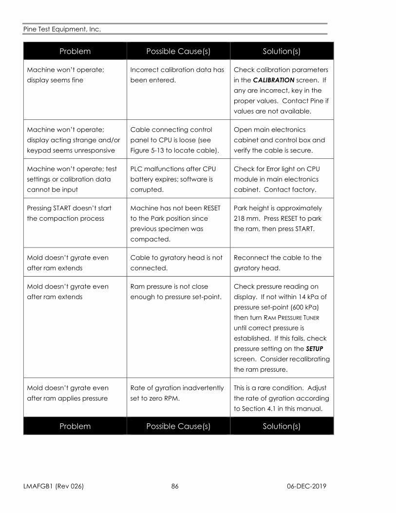
Pine Test Equipment, Inc.
LMAFGB1 (Rev 026) 86 06-DEC-2019
Problem Possible Cause(s) Solution(s)
Machine won’t operate;
display seems fine
Incorrect calibration data has
been entered.
Check calibration parameters
in the CALIBRATION screen. If
any are incorrect, key in the
proper values. Contact Pine if
values are not available.
Machine won’t operate;
display acting strange and/or
keypad seems unresponsive
Cable connecting control
panel to CPU is loose (see
Figure 5-13 to locate cable).
Open main electronics
cabinet and control box and
verify the cable is secure.
Machine won’t operate; test
settings or calibration data
cannot be input
PLC malfunctions after CPU
battery expires; software is
corrupted.
Check for Error light on CPU
module in main electronics
cabinet. Contact factory.
Pressing START doesn’t start
the compaction process
Machine has not been RESET
to the Park position since
previous specimen was
compacted.
Park height is approximately
218 mm. Press RESET to park
the ram, then press START.
Mold doesn’t gyrate even
after ram extends
Cable to gyratory head is not
connected.
Reconnect the cable to the
gyratory head.
Mold doesn’t gyrate even
after ram extends
Ram pressure is not close
enough to pressure set-point.
Check pressure reading on
display. If not within 14 kPa of
pressure set-point (600 kPa)
then turn RAM PRESSURE TUNER
until correct pressure is
established. If this fails, check
pressure setting on the SETUP
screen. Consider recalibrating
the ram pressure.
Mold doesn’t gyrate even
after ram applies pressure
Rate of gyration inadvertently
set to zero RPM.
This is a rare condition. Adjust
the rate of gyration according
to Section 4.1 in this manual.
Problem Possible Cause(s) Solution(s)
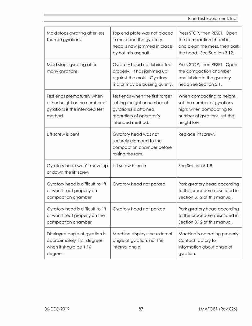
Pine Test Equipment, Inc.
06-DEC-2019 87 LMAFGB1 (Rev 026)
Mold stops gyrating after less
than 40 gyrations
Top end plate was not placed
in mold and the gyratory
head is now jammed in place
by hot mix asphalt.
Press STOP, then RESET. Open
the compaction chamber
and clean the mess, then park
the head. See Section 3.12.
Mold stops gyrating after
many gyrations.
Gyratory head not lubricated
properly. It has jammed up
against the mold. Gyratory
motor may be buzzing quietly.
Press STOP, then RESET. Open
the compaction chamber
and lubricate the gyratory
head See Section 5.1.
Test ends prematurely when
either height or the number of
gyrations is the intended test
method
Test ends when the first target
setting (height or number of
gyrations) is attained,
regardless of operator’s
intended method.
When compacting to height,
set the number of gyrations
high; when compacting to
number of gyrations, set the
height low.
Lift screw is bent Gyratory head was not
securely clamped to the
compaction chamber before
raising the ram.
Replace lift screw.
Gyratory head won’t move up
or down the lift screw
Lift screw is loose See Section 5.1.8
Gyratory head is difficult to lift
or won’t seat properly on
compaction chamber
Gyratory head not parked Park gyratory head according
to the procedure described in
Section 3.12 of this manual.
Gyratory head is difficult to lift
or won’t seat properly on the
compaction chamber
Gyratory head not parked Park gyratory head according
to the procedure described in
Section 3.12 of this manual.
Displayed angle of gyration is
approximately 1.21 degrees
when it should be 1.16
degrees
Machine displays the external
angle of gyration, not the
internal angle.
Machine is operating properly.
Contact factory for
information about angle of
gyration.
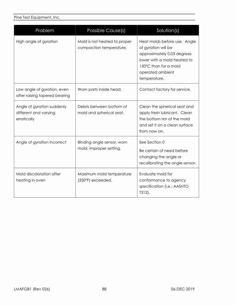
Pine Test Equipment, Inc.
LMAFGB1 (Rev 026) 88 06-DEC-2019
Problem Possible Cause(s) Solution(s)
High angle of gyration Mold is not heated to proper
compaction temperature.
Heat molds before use. Angle
of gyration will be
approximately 0.03 degrees
lower with a mold heated to
150°C than for a mold
operated ambient
temperature.
Low angle of gyration, even
after raising tapered bearing
Worn parts inside head. Contact factory for service.
Angle of gyration suddenly
different and varying
erratically
Debris between bottom of
mold and spherical seat.
Clean the spherical seat and
apply fresh lubricant. Clean
the bottom rim of the mold
and set it on a clean surface
from now on.
Angle of gyration incorrect Binding angle sensor, worn
mold, improper setting.
See Section 0
Be certain of need before
changing the angle or
recalibrating the angle sensor.
Mold discoloration after
heating in oven
Maximum mold temperature
(350°F) exceeded.
Evaluate mold for
conformance to agency
specification (i.e.: AASHTO
T312).
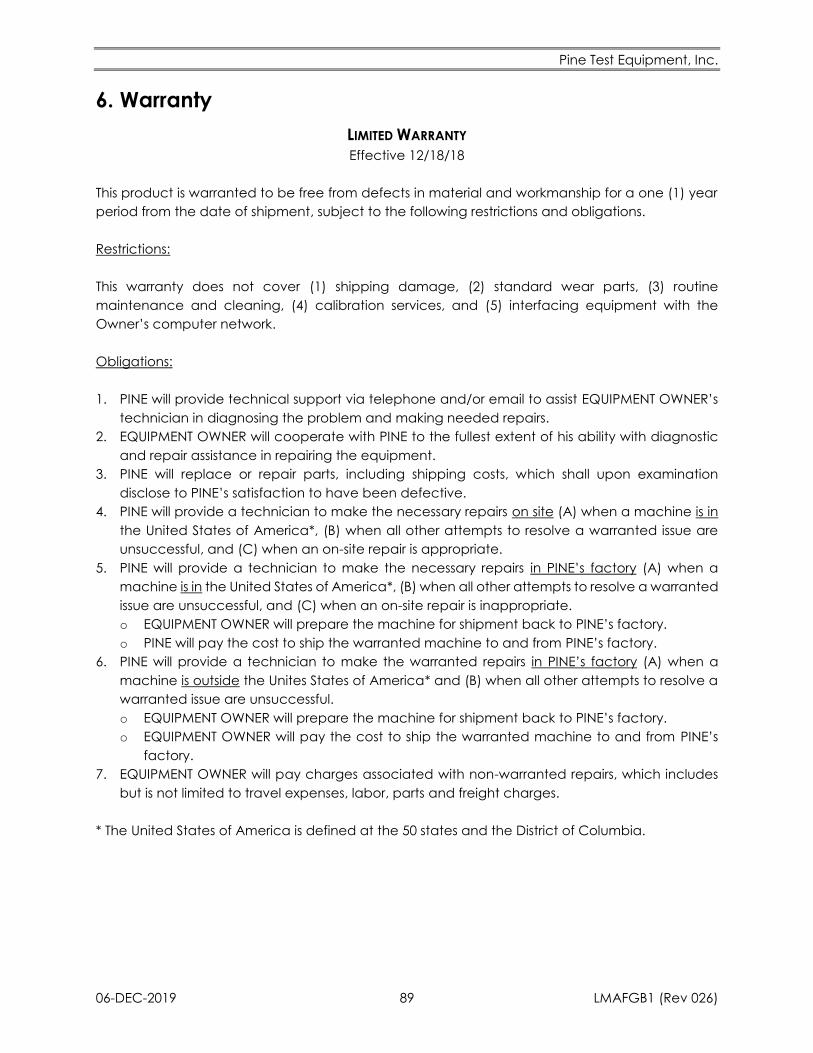
Pine Test Equipment, Inc.
06-DEC-2019 89 LMAFGB1 (Rev 026)
6. Warranty
LIMITED WARRANTY
Effective 12/18/18
This product is warranted to be free from defects in material and workmanship for a one (1) year
period from the date of shipment, subject to the following restrictions and obligations.
Restrictions:
This warranty does not cover (1) shipping damage, (2) standard wear parts, (3) routine
maintenance and cleaning, (4) calibration services, and (5) interfacing equipment with the
Owner’s computer network.
Obligations:
1. PINE will provide technical support via telephone and/or email to assist EQUIPMENT OWNER’s
technician in diagnosing the problem and making needed repairs.
2. EQUIPMENT OWNER will cooperate with PINE to the fullest extent of his ability with diagnostic
and repair assistance in repairing the equipment.
3. PINE will replace or repair parts, including shipping costs, which shall upon examination
disclose to PINE’s satisfaction to have been defective.
4. PINE will provide a technician to make the necessary repairs on site (A) when a machine is in
the United States of America*, (B) when all other attempts to resolve a warranted issue are
unsuccessful, and (C) when an on-site repair is appropriate.
5. PINE will provide a technician to make the necessary repairs in PINE’s factory (A) when a
machine is in the United States of America*, (B) when all other attempts to resolve a warranted
issue are unsuccessful, and (C) when an on-site repair is inappropriate.
o EQUIPMENT OWNER will prepare the machine for shipment back to PINE’s factory.
o PINE will pay the cost to ship the warranted machine to and from PINE’s factory.
6. PINE will provide a technician to make the warranted repairs in PINE’s factory (A) when a
machine is outside the Unites States of America* and (B) when all other attempts to resolve a
warranted issue are unsuccessful.
o EQUIPMENT OWNER will prepare the machine for shipment back to PINE’s factory.
o EQUIPMENT OWNER will pay the cost to ship the warranted machine to and from PINE’s
factory.
7. EQUIPMENT OWNER will pay charges associated with non-warranted repairs, which includes
but is not limited to travel expenses, labor, parts and freight charges.
* The United States of America is defined at the 50 states and the District of Columbia.

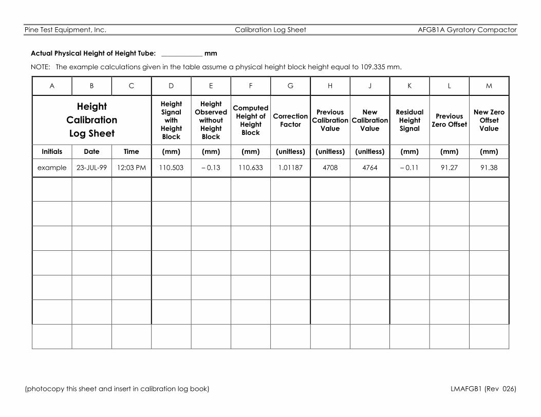
Pine Test Equipment, Inc. Calibration Log Sheet AFGB1A Gyratory Compactor
(photocopy this sheet and insert in calibration log book) LMAFGB1 (Rev 026)
Actual Physical Height of Height Tube: ____________ mm
NOTE: The example calculations given in the table assume a physical height block height equal to 109.335 mm.
A B C D E F G H J K L M
Height
Calibration
Log Sheet
Height
Signal
with
Height
Block
Height
Observed
without
Height
Block
Computed
Height of
Height
Block
Correction
Factor
Previous
Calibration
Value
New
Calibration
Value
Residual
Height
Signal
Previous
Zero Offset
New Zero
Offset
Value
Initials Date Time (mm) (mm) (mm) (unitless) (unitless) (unitless) (mm) (mm) (mm)
example 23-JUL-99 12:03 PM 110.503 – 0.13 110.633 1.01187 4708 4764 – 0.11 91.27 91.38
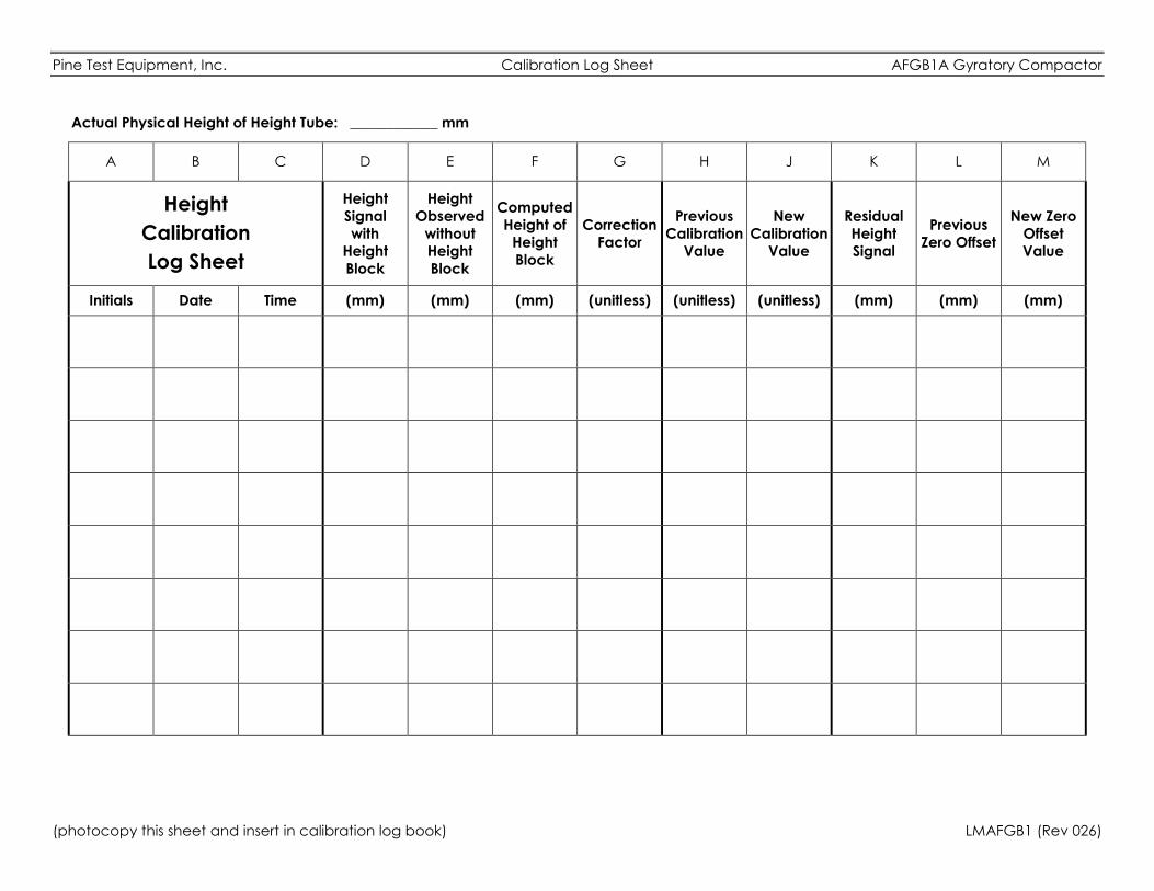
Pine Test Equipment, Inc. Calibration Log Sheet AFGB1A Gyratory Compactor
(photocopy this sheet and insert in calibration log book) LMAFGB1 (Rev 026)
Actual Physical Height of Height Tube: ____________ mm
A B C D E F G H J K L M
Height
Calibration
Log Sheet
Height
Signal
with
Height
Block
Height
Observed
without
Height
Block
Computed
Height of
Height
Block
Correction
Factor
Previous
Calibration
Value
New
Calibration
Value
Residual
Height
Signal
Previous
Zero Offset
New Zero
Offset
Value
Initials Date Time (mm) (mm) (mm) (unitless) (unitless) (unitless) (mm) (mm) (mm)
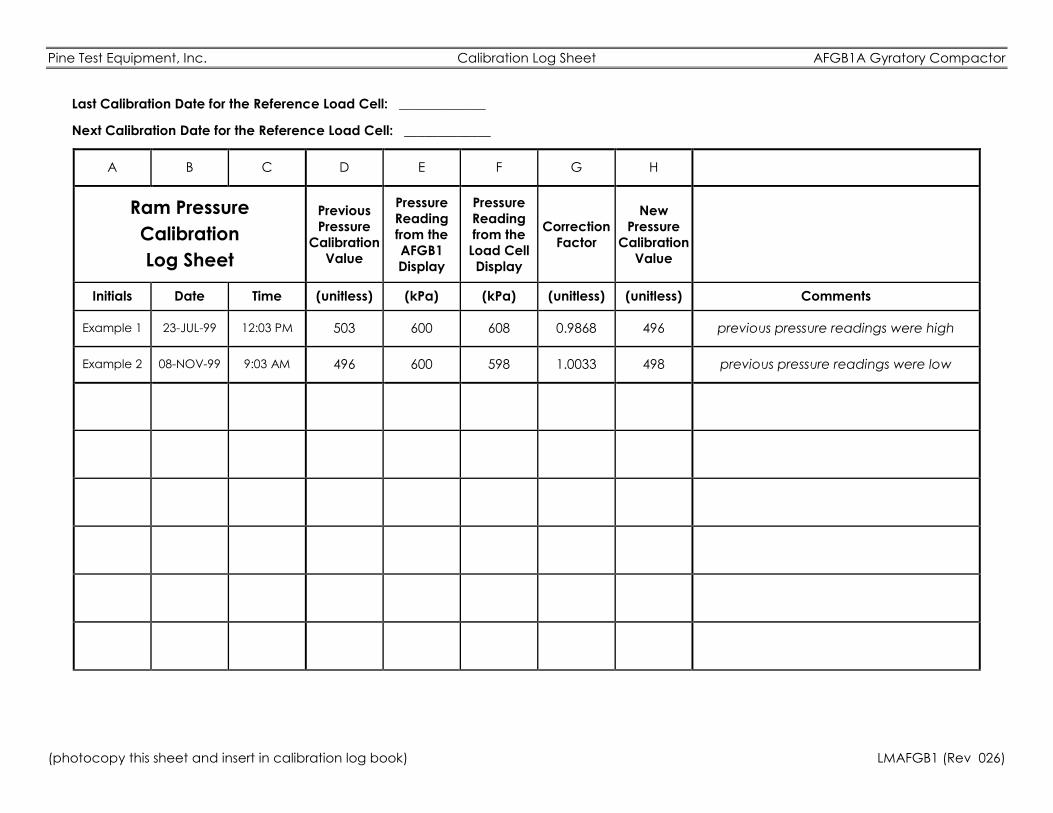
Pine Test Equipment, Inc. Calibration Log Sheet AFGB1A Gyratory Compactor
(photocopy this sheet and insert in calibration log book) LMAFGB1 (Rev 026)
Last Calibration Date for the Reference Load Cell: _____________
Next Calibration Date for the Reference Load Cell: _____________
A B C D E F G H
Ram Pressure
Calibration
Log Sheet
Previous
Pressure
Calibration
Value
Pressure
Reading
from the
AFGB1
Display
Pressure
Reading
from the
Load Cell
Display
Correction
Factor
New
Pressure
Calibration
Value
Initials Date Time (unitless) (kPa) (kPa) (unitless) (unitless) Comments
Example 1 23-JUL-99 12:03 PM 503 600 608 0.9868 496 previous pressure readings were high
Example 2 08-NOV-99 9:03 AM 496 600 598 1.0033 498 previous pressure readings were low
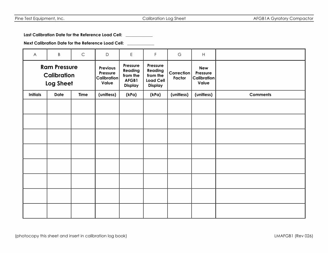
Pine Test Equipment, Inc. Calibration Log Sheet AFGB1A Gyratory Compactor
(photocopy this sheet and insert in calibration log book) LMAFGB1 (Rev 026)
Last Calibration Date for the Reference Load Cell: _____________
Next Calibration Date for the Reference Load Cell: _____________
A B C D E F G H
Ram Pressure
Calibration
Log Sheet
Previous
Pressure
Calibration
Value
Pressure
Reading
from the
AFGB1
Display
Pressure
Reading
from the
Load Cell
Display
Correction
Factor
New
Pressure
Calibration
Value
Initials Date Time (unitless) (kPa) (kPa) (unitless) (unitless) Comments
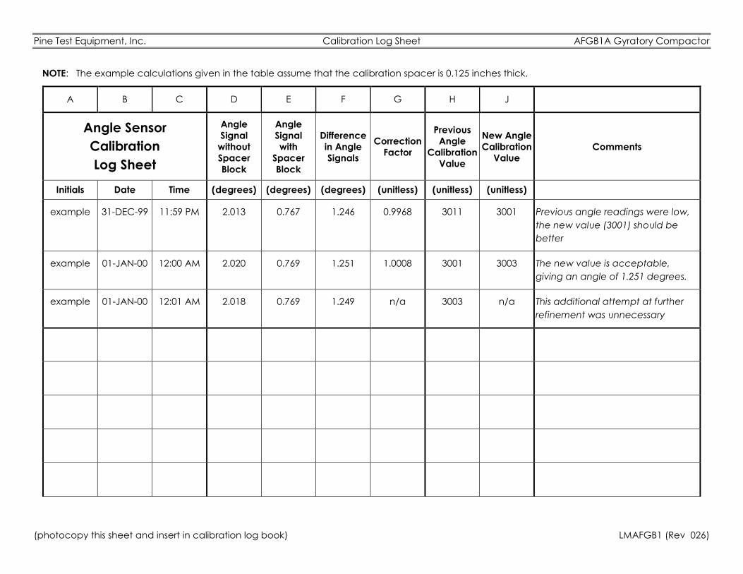
Pine Test Equipment, Inc. Calibration Log Sheet AFGB1A Gyratory Compactor
(photocopy this sheet and insert in calibration log book) LMAFGB1 (Rev 026)
NOTE: The example calculations given in the table assume that the calibration spacer is 0.125 inches thick.
A B C D E F G H J
Angle Sensor
Calibration
Log Sheet
Angle
Signal
without
Spacer
Block
Angle
Signal
with
Spacer
Block
Difference
in Angle
Signals
Correction
Factor
Previous
Angle
Calibration
Value
New Angle
Calibration
Value
Comments
Initials Date Time (degrees) (degrees) (degrees) (unitless) (unitless) (unitless)
example 31-DEC-99 11:59 PM 2.013 0.767 1.246 0.9968 3011 3001 Previous angle readings were low,
the new value (3001) should be
better
example 01-JAN-00 12:00 AM 2.020 0.769 1.251 1.0008 3001 3003 The new value is acceptable,
giving an angle of 1.251 degrees.
example 01-JAN-00 12:01 AM 2.018 0.769 1.249 n/a 3003 n/a This additional attempt at further
refinement was unnecessary
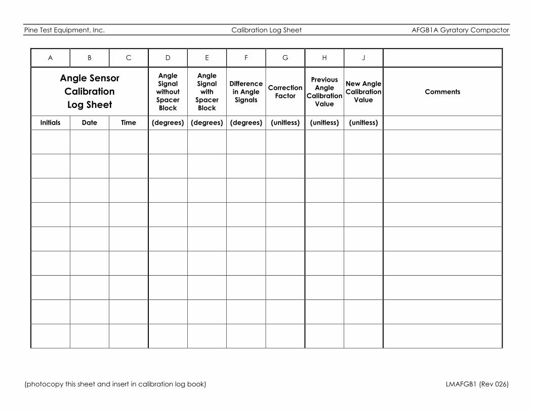
Pine Test Equipment, Inc. Calibration Log Sheet AFGB1A Gyratory Compactor
(photocopy this sheet and insert in calibration log book) LMAFGB1 (Rev 026)
A B C D E F G H J
Angle Sensor
Calibration
Log Sheet
Angle
Signal
without
Spacer
Block
Angle
Signal
with
Spacer
Block
Difference
in Angle
Signals
Correction
Factor
Previous
Angle
Calibration
Value
New Angle
Calibration
Value
Comments
Initials Date Time (degrees) (degrees) (degrees) (unitless) (unitless) (unitless)
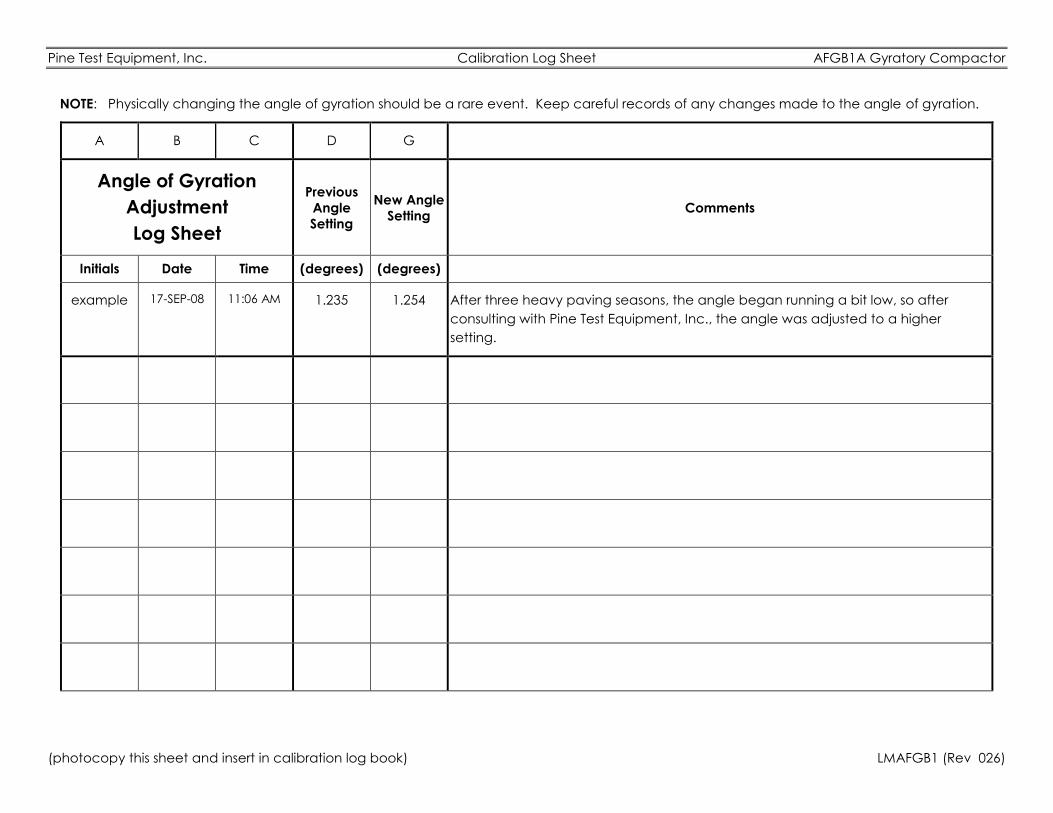
Pine Test Equipment, Inc. Calibration Log Sheet AFGB1A Gyratory Compactor
(photocopy this sheet and insert in calibration log book) LMAFGB1 (Rev 026)
NOTE: Physically changing the angle of gyration should be a rare event. Keep careful records of any changes made to the angle of gyration.
A B C D G
Angle of Gyration
Adjustment
Log Sheet
Previous
Angle
Setting
New Angle
Setting Comments
Initials Date Time (degrees) (degrees)
example 17-SEP-08 11:06 AM 1.235 1.254 After three heavy paving seasons, the angle began running a bit low, so after
consulting with Pine Test Equipment, Inc., the angle was adjusted to a higher
setting.
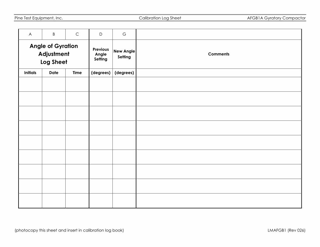
Pine Test Equipment, Inc. Calibration Log Sheet AFGB1A Gyratory Compactor
(photocopy this sheet and insert in calibration log book) LMAFGB1 (Rev 026)
A B C D G
Angle of Gyration
Adjustment
Log Sheet
Previous
Angle
Setting
New Angle
Setting Comments
Initials Date Time (degrees) (degrees)

Related Documents