University of Kentucky University of Kentucky UKnowledge UKnowledge Theses and Dissertations--Electrical and Computer Engineering Electrical and Computer Engineering 2018 AFFECT-PRESERVING VISUAL PRIVACY PROTECTION AFFECT-PRESERVING VISUAL PRIVACY PROTECTION Wanxin Xu University of Kentucky, [email protected] Author ORCID Identifier: https://orcid.org/0000-0001-7399-5027 Digital Object Identifier: https://doi.org/10.13023/etd.2018.303 Right click to open a feedback form in a new tab to let us know how this document benefits you. Right click to open a feedback form in a new tab to let us know how this document benefits you. Recommended Citation Recommended Citation Xu, Wanxin, "AFFECT-PRESERVING VISUAL PRIVACY PROTECTION" (2018). Theses and Dissertations-- Electrical and Computer Engineering. 122. https://uknowledge.uky.edu/ece_etds/122 This Doctoral Dissertation is brought to you for free and open access by the Electrical and Computer Engineering at UKnowledge. It has been accepted for inclusion in Theses and Dissertations--Electrical and Computer Engineering by an authorized administrator of UKnowledge. For more information, please contact [email protected].

Welcome message from author
This document is posted to help you gain knowledge. Please leave a comment to let me know what you think about it! Share it to your friends and learn new things together.
Transcript

University of Kentucky University of Kentucky
UKnowledge UKnowledge
Theses and Dissertations--Electrical and Computer Engineering Electrical and Computer Engineering
2018
AFFECT-PRESERVING VISUAL PRIVACY PROTECTION AFFECT-PRESERVING VISUAL PRIVACY PROTECTION
Wanxin Xu University of Kentucky, [email protected] Author ORCID Identifier:
https://orcid.org/0000-0001-7399-5027 Digital Object Identifier: https://doi.org/10.13023/etd.2018.303
Right click to open a feedback form in a new tab to let us know how this document benefits you. Right click to open a feedback form in a new tab to let us know how this document benefits you.
Recommended Citation Recommended Citation Xu, Wanxin, "AFFECT-PRESERVING VISUAL PRIVACY PROTECTION" (2018). Theses and Dissertations--Electrical and Computer Engineering. 122. https://uknowledge.uky.edu/ece_etds/122
This Doctoral Dissertation is brought to you for free and open access by the Electrical and Computer Engineering at UKnowledge. It has been accepted for inclusion in Theses and Dissertations--Electrical and Computer Engineering by an authorized administrator of UKnowledge. For more information, please contact [email protected].

STUDENT AGREEMENT: STUDENT AGREEMENT:
I represent that my thesis or dissertation and abstract are my original work. Proper attribution
has been given to all outside sources. I understand that I am solely responsible for obtaining
any needed copyright permissions. I have obtained needed written permission statement(s)
from the owner(s) of each third-party copyrighted matter to be included in my work, allowing
electronic distribution (if such use is not permitted by the fair use doctrine) which will be
submitted to UKnowledge as Additional File.
I hereby grant to The University of Kentucky and its agents the irrevocable, non-exclusive, and
royalty-free license to archive and make accessible my work in whole or in part in all forms of
media, now or hereafter known. I agree that the document mentioned above may be made
available immediately for worldwide access unless an embargo applies.
I retain all other ownership rights to the copyright of my work. I also retain the right to use in
future works (such as articles or books) all or part of my work. I understand that I am free to
register the copyright to my work.
REVIEW, APPROVAL AND ACCEPTANCE REVIEW, APPROVAL AND ACCEPTANCE
The document mentioned above has been reviewed and accepted by the student’s advisor, on
behalf of the advisory committee, and by the Director of Graduate Studies (DGS), on behalf of
the program; we verify that this is the final, approved version of the student’s thesis including all
changes required by the advisory committee. The undersigned agree to abide by the statements
above.
Wanxin Xu, Student
Dr. Sen-Ching Samson Cheung, Major Professor
Dr. Aaron Cramer, Director of Graduate Studies

AFFECT-PRESERVING VISUAL PRIVACY PROTECTION
DISSERTATION
A dissertation submitted in partial fulfillment of the requirements for the degree of Doctor of Philosophy in the
College of Engineering at the University of Kentucky
By Wanxin Xu
Lexington, Kentucky
Director: Dr. Sen-Ching Samson Cheung, Professor of Electrical and Computer Engineering
Lexington, Kentucky
2018
Copyright © Wanxin Xu 2018

AFFECT-PRESERVING VISUAL PRIVACY PROTECTION
The prevalence of wireless networks and the convenience of mobile cameras enable many new video applications other than security and entertainment. From behavioral diagnosis to wellness monitoring, cameras are increasing used for observations in various educational and medical settings. Videos collected for such applications are considered protected health information under privacy laws in many countries. Visual privacy protection techniques, such as blurring or object removal, can be used to mitigate privacy concern, but they also obliterate important visual cues of affect and social behaviors that are crucial for the target applications. In this dissertation, we propose to balance the privacy protection and the utility of the data by preserving the privacy-insensitive information, such as pose and expression, which is useful in many applications involving visual understanding.
The Intellectual Merits of the dissertation include a novel framework for visual privacy protection by manipulating facial image and body shape of individuals, which: (1) is able to conceal the identity of individuals; (2) provide a way to preserve the utility of the data, such as expression and pose information; (3) balance the utility of the data and capacity of the privacy protection.
The Broader Impacts of the dissertation focus on the significance of privacy protection on visual data, and the inadequacy of current privacy enhancing technologies in preserving affect and behavioral attributes of the visual content, which are highly useful for behavior observation in educational and medical settings. This work in this dissertation represents one of the first attempts in achieving both goals simultaneously.
KEYWORDS: Pose Estimation, Human Body Reshaping, 3D Face Reconstruction, Facial Expression Transfer, Visual Privacy Protection
ABSTRACT OF DISSERTATION
Wanxin Xu
July 16, 2018

AFFECT-PRESERVING VISUAL PRIVACY PROTECTION
Director of Graduate Studies:
Dr. Sen-Ching Samson Cheung
Dr. Aaron Cramer
July 16, 2018
By
Wanxin Xu
Director of Dissertation:
Date:

To my family

iii
ACKNOWLEDGEMENT
Looking back to the challenging but rewarding journey towards to pursue my PhD
degree, I have received generous help and support from many people.
First of all, I would like to extend my sincerest gratitude to my academic advisor,
Dr. Sen-ching Samson Cheung. It is my great pleasure to be supported and instructed by
a mentor like him, who has masterful grasp of his field and is constantly considerable
from his students’ point of view to inspire them towards success. I sincerely appreciate
the numerous recourses and facilities I have been provided from Dr. Cheung, without
which I would not be able to accomplish the work of my dissertation. He is quite
energetic and cheerful, has long-lasting enthusiasm in his career. I have learned a lot from
his unique characteristics and they will continue to inspire me through all the challenges
that I will face in my future endeavors
I also would like to thank Dr. Alberto Corso, Dr. Daniel Lau, Dr. Ruigang Yang
and Dr. Yuming Zhang for their time serving as my committee member. I really
appreciate their constructive feedback and comments on my dissertation, which give me
the opportunity to revisit it and make it a better one.
I truly appreciate the help and support from all my colleagues and friends at UK.
Because of them the years of challenging scientific exploration has turned to quite
enjoyable memories, which I will remember for the rest of my life.
Finally but most importantly, I would like to thank all members in my family
from the bottom of my heart, in particular my parents, my grandparents, my sister and my

iv
husband. My deepest appreciation goes to them. Without their unconditional love and
constant support, I cannot accomplish this today and would not be able to stick to the
completion of my PhD study.

v
TABLE OF CONTENTS
ACKNOWLEDGEMENT ................................................................................................. iii
TABLE OF CONTENTS .................................................................................................... v
LIST OF TABLES ........................................................................................................... viii
LIST OF FIGURES ........................................................................................................... ix
Chapter 1 Introduction ..................................................................................................... 1
1.1 Background ......................................................................................................... 1
1.2 Motivation ........................................................................................................... 2
1.3 Contributions....................................................................................................... 3
1.4 Outline of the dissertation ................................................................................... 5
Chapter 2 Related Work .................................................................................................. 7
2.1 De-identification of Visual Identifiable Information .......................................... 7
2.2 Facial Expression Capture and Reconstruction ................................................ 10
2.3 Human Pose Estimation .................................................................................... 16
2.4 Human Shape Reconstruction ........................................................................... 21
2.5 Body Reshaping ................................................................................................ 27
Chapter 3 Preliminary Works: General Pipeline for The Application of Face and Human Shape Manipulation ............................................................................................. 31
3.1 Geometric Data Collection and Processing ...................................................... 31
3.2 Surface Reconstruction from Point Cloud ........................................................ 35
3.3 Motion Capture for Face and Body Shapes ...................................................... 38
Chapter 4 Facial Image Manipulation with RGB Images ............................................. 41
4.1 Facial Image Manipulation with Recolor and Component Blending ............... 41
4.1.1 Overview of our system ................................................................................ 41
4.1.2 Skin recoloring and facial component blending ........................................... 42
4.1.3 Experimental results...................................................................................... 44
4.2 Fully Automatic Photorealistic Facial Expression and Eye Gaze Correction with a Single Image ...................................................................................................... 46

vi
4.2.1 Overview of the system ................................................................................ 48
4.2.2 Coarse and fine face reconstruction .............................................................. 48
4.2.2.1 Coarse model fitting .............................................................................. 49
4.2.2.2 Geometry refinement ............................................................................ 50
4.2.3 Facial expression transfer and eye gaze correction ....................................... 52
4.2.4 Experimental results...................................................................................... 53
Chapter 5 Human Body Reshaping with Single and Two Depth sensors ..................... 57
5.1 Skeleton-driven Approach for Human Body Reshaping with Single Depth Sensor 57
5.1.1 Data preparation and mesh generation .......................................................... 59
5.1.2 2D shape manipulation ................................................................................. 60
5.1.3 Experimental results...................................................................................... 61
5.2 Human Pose Estimation with Two RGB-D Sensors ........................................ 62
5.2.1 System overview ........................................................................................... 63
5.2.2 Data acquisition and preprocessing .............................................................. 64
5.2.3 Non-rigid point set registration ..................................................................... 65
5.2.4 Skeleton estimation using bone-based approach .......................................... 68
5.2.5 Experimental results...................................................................................... 69
Chapter 6 Model-based Approach for Human Body Reshaping with Sensor Network 73
6.1 Overview of the System .................................................................................... 73
6.2 Data Collection and Pre-processing .................................................................. 75
6.3 Pose and Shape Estimation with Multiple Depth Sensors ................................ 77
6.3.1 SCAPE model ............................................................................................... 77
6.3.2 GMM-based pose and shape fitting .............................................................. 78
6.3.2.1 GMM-based point set registration ........................................................ 79
6.3.2.2 Human pose and shape optimization .................................................... 81
6.3.3 Detailed motion reconstruction ..................................................................... 84
6.3.4 Bone-based approach for skeleton estimation .............................................. 85
6.4 Human Body Reshaping ................................................................................... 86
6.5 Experimental Results ........................................................................................ 87
6.5.1 Evaluation of poses ....................................................................................... 87
6.5.2 Evaluation of shapes ..................................................................................... 90
6.5.3 Evaluation of human body reshaping ........................................................... 93
6.6 Application on Visual Privacy Protection......................................................... 93

vii
6.6.1 Evaluation of human body reshaping with depth sensor network for visual privacy protection ..................................................................................................... 94
Chapter 7 Conclusions and Future Work .................................................................... 100
Bibliography ................................................................................................................... 102
Vita………. ..................................................................................................................... 119

viii
LIST OF TABLES
Table 6.1 Average step length with different reshaping parameters (mm) ....................... 98

ix
LIST OF FIGURES
Figure 2.1 Early method for face de-identification: (a) Original image; (b) Blurring; (c) Pixelization. ............................................................................................................ 8
Figure 2.2 Examples of Animoji with iPhone X............................................................... 10 Figure 2.3 Double counting error [137]. (a) Estimated pose; (b) Max marginal. ............. 16 Figure 2.4 Illustration of SCAPE model, 𝜃𝜃 - parameter for pose, 𝛽𝛽 - parameter for shape.
............................................................................................................................... 22
Figure 3.1 Examples of Kinect Sensor v1 (a) and Kinect Sensor v2 (b). ......................... 32 Figure 3.2 Example of imperfect depth data captured by Kinect sensor with noises and
black holes [155]. .................................................................................................. 33 Figure 3.3 Calibration result using the method from [155], (a) uncalibrated scene; (b)
calibrated scene. .................................................................................................... 34 Figure 3.4 Comparison of three methods for point clouds simplification using CGAL [36]:
(a) Original input; (b) Random simplification result; (c) Grid simplification result; (d) WLOP simplification result. ........................................................................... 36
Figure 3.5 Duality of Delaunay triangulation [37] (a) Delaunay triangulation with all the circumcircles and their centers (red); (b) Voronoi diagram (red) overlaid to Delaunay triangulation. ......................................................................................... 38
Figure 3.6 Template and embedded skeleton for human body and the hand [116]. (a) Human body with skeleton; (b) Hand with skeleton. ........................................... 39
Figure 4.1 Face image editing procedure .......................................................................... 42 Figure 4.2 Skin Color Transfer with input source image in (a), target image in (b) and the
skin-recolored source image in (c). ....................................................................... 42 Figure 4.3 Generation of the ROIs. (a) Landmark detection. (b) Landmark refinement by
linear interpolation. (c) Initial ROIs. (Mouth (blue), eyebrows (yellow), eyes and nose (green)). (d) Final generated ROIs by erosion and dilation. ......................... 43
Figure 4.4 Poisson blending result. (a) Source image. (b) Mask obtained from the ROIs generation. (c) Blended image. ............................................................................. 44
Figure 4.5 Fame image editing result. (a) Source image. (b) Skin recolored result. (c) Facial component blending result. ........................................................................ 45
Figure 4.6 The Overview of our proposed face expression transfer pipeline ................... 47 Figure 4.7 Coarse face reconstruction: (a) labeled 3D face landmarks; (b) 2D landmarks
detected on the input image; (c) reconstructed model projected to the input image............................................................................................................................... 49
Figure 4.8 Geometry refinement: (a) coarse shape; (b) shape after refinement; (c) reconstructed fine shape with texture; (d) Facial expression transfer with coarse (left) and refined (right) ........................................................................................ 51
Figure 4.9 Eye gaze transfer: (a) original pairs of image with detected eye mask; (b) direct transfer without refinement; (c) final synthesized image ........................... 52
Figure 4.10 3D reconstruction evaluation: (a) Input RGB image; (b) Ground truth; (c) reconstructed model by our method; (d) error map between our model and ground truth; (e) error map between model obtained by method of [210] and ground truth................................................................................................................................ 53

x
Figure 4.11 Face reconstruction on unconstrained image: Input RGB image; reconstruction with our method; reconstruction with method from [210]; reconstruction using our method with texture. ..................................................... 55
Figure 4.12 Result of our proposed system: (First row) source input and target input images; (Second row) manipulated image after expression transfer from source to target without eye gaze correction; (Third row) final output image with gaze correction. ............................................................................................................. 56
Figure 5.1 Human body reshaping with single depth sensor ............................................ 58 Figure 5.2 (a) Original mask. (b) Refined mask and contour. (c) Generated mesh. ......... 59 Figure 5.3 (a) Selected original image frame from two environments. (b) Reshaped image
frame (taller and thinner). ..................................................................................... 62 Figure 5.4 The Overview of our proposed pose estimation pipeline ................................ 63 Figure 5.5 Point cloud alignment from two depth sensors: (a) before alignment; (b) after
alignment............................................................................................................... 64 Figure 5.6 Visual comparison of our proposed method using the dataset in [70] with its
ground truth data. Blue line (Our method estimation) and Black dot (Ground truth). ..................................................................................................................... 69
Figure 5.7 Comparison of average joint position error for six sequences from the evaluation dataset: Kinect [156] (Dark blue), Baak.et al [13] (Light blue), Helten et al [70] (Yellow) and Ours (Red). ...................................................................... 70
Figure 5.8 Pose estimation visualization results: (a) Color image from depth sensor (front); (b) pose estimation from KinectSDK (front); (c) pose estimation from KinectSDK (back); (d) pose estimation from our proposed system. .................... 71
Figure 5.9 Poisson reconstruction with and without holes filling: (a) without holes filling before Poisson reconstruction; (b) with holes filling using our proposed way before Poisson reconstruction. .............................................................................. 72
Figure 6.1 Overview of our proposed system. .................................................................. 74 Figure 6.2 Point cloud alignment from four depth sensors: (a) before alignment, (b) after
alignment. (c) alignment with texture and camera position (1,2,3,4) ................... 75 Figure 6.3 Point cloud outlier removal and simplification: (a) Original aligned point
cloud; (b) after outlier removal using Gaussian filter; (c) after denoising using WLOP ................................................................................................................... 76
Figure 6.4 SCAPE Model with 16 parts of different poses and shapes ............................ 78 Figure 6.5 View direction transformation (a) Morphable model with view direction (b)
Original observed data with view direction (c) After transformation (Red: Y-axis; Blue: Z-axis; Green: X-axis) ................................................................................. 81
Figure 6.6 Detail reconstruction (a) Initial registration result. (b) Reconstruction with details. (c) Detailed model with texture. ............................................................... 86
Figure 6.7 Human body reshaping (a) Original; Reshaping to different shape parameters (b) shorter; (c) thinner; and (d) fatter. ................................................................... 86
Figure 6.8 Visual comparison of our proposed method using the dataset in [70] with its ground truth data. Black line (Our method) and Red dot (Ground truth). ............ 87
Figure 6.9 Comparison of average joint position error for six sequences from the evaluation dataset: Blue - [156], Orange - [70], Yellow - [192] and Purple - Ours method................................................................................................................... 88

xi
Figure 6.10 Pose estimation visualization result: (a) Color image from depth sensor (Kinect2); (b) (c) (d) (e)pose estimation from KinectSDK; (f) pose estimation from proposed system; (g) Reconstructed model with texture. ............................ 89
Figure 6.11 Error map for body shape fitting. (a) Original scan. (b) The estimated model overlaid with the ground truth, and (c) the difference between the estimated model and the ground truth, the unit is in millimeter. ..................................................... 90
Figure 6.12 Visual results of our shape fitting. Input model (gray) are overlaid on our result (red). ............................................................................................................ 91
Figure 6.13 Detail visualization of shape fitting. .............................................................. 91 Figure 6.14 Body reshaping visualization result (a) Original reconstructed model (b), (c)
and (d) Reshaped result with our method with different parameters of morphable model..................................................................................................................... 92
Figure 6.15 Our system reshapes the human body using multiple RGB-D sensors. (Left) Original reconstructed human model; (Right) 4 different views of the reshaped human body with shorter legs and longer body. ................................................... 93
Figure 6.16 Average score of questionnaire results on the naturalness of our reshaping method................................................................................................................... 95
Figure 6.17 Axis of rotation and relative angle of knees. ................................................ 96 Figure 6.18 Joint Angle in one gait cycle. (a) Sequence1. (b) Sequence2. ...................... 97 Figure 6.19 Foot Joint position in one gait cycle. (a) Sequence1. (b) Sequence2. ........... 99

1
Chapter 1 Introduction
Recent advances in digital image technologies have made it easier to capture and share
data online. The captured images or videos enable a variety of applications such as video
surveillance, intelligent monitoring system, etc. On the other hand, such forms of data
gathering raise concerns on protecting sensitive information, such as identify of a child,
that participant may want to keep hidden. As a result, an increasing amount of attention
has been gathered to prevent the violation of privacy of individuals from both academia
and industry.
1.1 Background
Privacy enhancing technologies for video data is a relatively new topic of research
with the explicit goal of visually protecting the identity of selected individuals. From the
early work at IBM on simple obfuscation [153] to the latest work on privacy in visual
sensor networks [191], visual information management [115], and location/activity
protection in surveillance [149], many aspects of enterprise surveillance have been
investigated. Despite the significant research effort, there are few systems that are
actually deployed in practice. Besides the questionable robustness of these research
prototypes, the market needs from large corporations and public facilities do not seem to
be significant enough to warrant large-scale deployment.
On the other hand, the prevalence of wireless network and the ease of capturing
and viewing videos enable many new applications other than security and surveillance.
Many of these applications have strong privacy need as required by law. The most
notable examples are the use of video for behavior observations for educational and

2
medical purposes. Behavioral observation is an important tool for early diagnosis of
many neurodevelopmental disorders in children. Behaviors like repetitive movements,
staring spells, and tantrums can be early signs of serious conditions including autism
spectrum disorder, epilepsy and Attention Deficit Hyperactivity Disorder (AD/HD). Such
intermittent behaviors either are not exhibited or are difficult to capture during brief
clinical visits. The gold standard in behavioral science is accurate recording of
problematic behaviors based on observation over a period of time in naturalistic
environments such as home or school. Such an approach is difficult to achieve in
practical terms because setting up recording devices in naturalistic environments faces
stringent privacy protection requirements as covered by HIPAA [174], FERPA [175],
COPPA [176], and other related regulations. It is in this context that visual privacy
protection is the most relevant and pressing to address.
1.2 Motivation
Visual privacy protection techniques, such as blurring, object removal or
pixelation, have been applied to some of these studies to obfuscate everything in the
video besides the subject of observation [64][66][65]. Besides these simple blurring or
removal techniques, more advanced techniques have been proposed. Since people often
identify a person by observing his/her face, large majority of the existing work focus on
face de-identification. Newton et al. [125] proposed a privacy enhancing algorithm called
k-Same, taking advantage of the concept of k-anonymity to face image databases. The
algorithm determines similarity between faces based on a distance metric and creates new
faces by averaging image components. More recently, Mosaddegh et al. [119] relied on a
set of face donors from which it can borrow various face components (eyes, chin, etc.).

3
However, it is not enough to protect visual privacy only by modifying the face area. Even
when the person's face is obscured, other elements could exist in the image, which can be
used to perform person identification, for instance, using inference channels and previous
knowledge [149]. Visual cues such as clothes, height and gait can be also used to identify
the person. Others deal with the de-identification of the whole human body instead of just
face. Tansuriyavong et al. [164] proposed to use a silhouette for privacy protection of a
person. They remove information about textures while maintaining the shape of the
person to complicate the identification. In [3], Agrawal et al. proposed person de-
identification method in videos by using different blurring function. Flores and Belongie
proposed to protect the privacy of a person in the image by removal [53]. Unfortunately,
all these privacy-enhancing techniques obfuscates affect behaviors and detailed social
interaction such as eye gaze between the subject and other individuals in the scene. Often,
these behaviors are the key behavioral episodes that are of high diagnostic values.
Finding a proper trade-off between the privacy and the utility of data remains a
challenging problem. The research presented in this dissertation aims to preserve the
utility like expression and pose of a person while protecting his/her privacy by making
use of advanced computer vision technologies.
1.3 Contributions
The research work presented in this dissertation address the problem of protecting
visual privacy while preserving most of the observable affect cues of an individual that
are of high value either for security or medical purposes. I hypothesize that affect-
preserving privacy protection can be achieved by digitally manipulating the identifiable
attributes of an individual (body shape and facial features) while preserving the behaviors

4
(pose and expression). Capitalizing on the advances in visual data capturing and
computer graphics, I argue that such an approach would be able to produce more
naturalistic results compared to transferring behaviors to an animated avatar. Major
contributions in this dissertation are listed as follows:
1. I propose a novel body reshaping scheme that, unlike typical 3D morphable
approaches, does not require any user interaction in fitting the model to the
original image. The proposed scheme uses a Kinect sensor to automatically
capture and back-project 3D skeleton to the image in driving the mesh
deformation process for reshaping.
2. I propose a novel human pose and shape estimation system that is more robust
than existing systems in capturing complex body movements and require no
manual initialization. The robust performance of the proposed system is due to
the use of data captured from multiple depth sensors that are fused via a non-
rigid fitting scheme. The subsequent estimation of pose and shape from the
fused data is based on the celebrated SCAPE parametric model [10].
3. I propose a novel facial privacy protection scheme that, unlike existing
approaches, protects privacy while preserving facial affect. The proposed
scheme protects privacy by recoloring skin tones and replacing key facial
features with those from other people, while preserving affect by blending
these components to match the original expression.
4. To address the inadequacy of existing facial privacy protection in handling
head pose variations and privacy leakage through the shape of the skull, I
propose a new privacy protection scheme that transfers facial expression and

5
eye gaze from one person to another. The proposed scheme solves these
problems by first using a coarse-to-fine scheme in reconstructing a detailed
3D face surface model from a single image in the wild, and then applying
mesh deformation in transferring facial expression and eye gaze between the
source and target models.
5. I propose a novel evaluation scheme to measure the effectiveness of body
reshaping schemes in protecting privacy while preserving the utility of the
videos. To the best of our knowledge, no evaluation schemes have been
previously developed for this purpose. The utility is measured based on the
subjective opinions on the naturalness of the reshaped videos. The privacy is
measured based on whether the identity of the individual can be recognized
after reshaping based on soft biometric techniques such as gait information.
1.4 Outline of the dissertation
The rest of this dissertation is organized as follows. Chapter 2 reviews the
necessary background and previous works on de-identification for privacy protection,
pose and shape estimation using depth information, and face reconstruction from RGB
image. A brief introduction about the general pipeline for human body and face
manipulation is presented in Chapter 3. In Chapter 4, the proposed method to hide the
identity while preserving the utility information of individual by face recolor and facial
component blending is first discussed. We then move to model-based approach for facial
expression synthesis and eye gaze correction. In Chapter 5, I introduce the skeleton-
driven an approach for human body reshaping in RGB images with single depth sensor.
In addition, a scheme for pose estimation to improve the performance of human body

6
reshaping with single depth sensor is discussed. In Chapter 6, a model-based approach to
reshape the body shape with multiple depth sensors and an application using human body
reshaping for visual privacy protection is presented. The conclusion and future work are
finally presented in Chapter 7.
Copyright © Wanxin Xu 2018

7
Chapter 2 Related Work
2.1 De-identification of Visual Identifiable Information
Images, videos or other forms of data always contain rich information about the
individuals in them – from facial features, body shapes, clothing styles to unique ways of
walking and interactions with others. Such kind of information makes it easier to infer the
identity of that person. However, most applications including those used in health and
education research and general safety surveillance like people counting and crowd
control, the knowledge of the identities of individuals are not necessary or required.
Therefore, a need to use de-identification to remove all personal information of
individual from an image or video draws much attention in recent years. Different from
recognition, which makes use of all possible features to recognize the identity of a person
or the label of an object, de-identification defined as an opposite process to conceal the
identity of the person from been recognized. Instead of removing all information of the
target person in image or video, the ideal goal for de-identification is to hide the identity
of the person without obscuring his/her action and expression. In this section, we give a
brief review on the most important work related to the pipeline for our visual privacy
protection. More comprehensive reviews on previous literature can be found in [53][127].
Most of previous works proposed for de-identification of person in image or
video focus on face de-identification, the primary biometric feature. Early approaches for
face de-identification use simple transformation like blurring (see Figure 2.1(b)) or
pixelization (see Figure 2.1(c)). While these methods are capable to protect the privacy of

8
person in the image, some forms of data utility, such as facial expression, fails to be
preserved due to heavy obfuscations of facial features. Most recent approaches attempt to
preserve such features in a more systematic manner. Newton et al. proposed the k-same
algorithm for face de-identification [125]. In their algorithm, they computed the average
of k most similar faces from a dataset and replace each face image with the obtained
average face. Some extensions to the k-same algorithm named k-same select [60] and
model-based k-same [61] were proposed by Gross et al. aiming to improve data utility of
the output. A large image gallery is required by the k-same select algorithm since there
must be an image for each individual in every utility subset. In addition, the utility
classifier need to be retrained if a new subset is added making this algorithm less flexible.
Bitouk et al. in [20] introduced a system for privacy protection by replacing the face with
another similar unrelated face selected from the database. Their algorithm blends the two
faces by replacing the eyes, nose and mouth area and further adjust the color and
illumination of the face in order to generate visually realistic result. Inspired by k-same
algorithm, Jourabloo et al. in [90] proposed an approach to hide the identity of person
while preserving a large set of facial attributes, such as gender, age, race, etc. by fusing
faces with similar attributes. It can achieve impressive result on grayscale image with
(a) (b) (c)
Figure 2.1 Early method for face de-identification: (a) Original image; (b) Blurring; (c) Pixelization.

9
attribute annotations, but the expression of the person fails to be preserved, which is not
suitable for the applications like action recognition or behavior observation. In [104], the
author presented a face de-identification method that enables the preservation of
important face clues which is useful for behavior or emotions analysis. Their approach
preserves the most important non-verbal facial features such as eyes, gaze, lips and lips
corners by applying variational adaptive filtering. However, the approach on the basis of
filtering fails to generate photo-realistic result.
Even though face plays the dominant role, other body features such as silhouette
and gait are also important clues contained in image or video that have been shown useful
for biometric identification. There are several works proposed to replace the object of
interest in image or video by their abstracted version to achieve the goal for privacy
protection. Williams et al. made use of silhouette representation for privacy protection in
a fall detection and object finder system [190]. In addition to silhouette representation,
Fan et al. proposed to use a generic 3D avatar to replace the person in video to protect the
privacy of content in the video [45]. Their system provides a number of ways to obscure
the person at different level, in addition to replace people within the video with 3D avatar
or virtual objects, blurring the video also available. An interesting approach for body de-
identification was presented in [126] - they proposed to replace a person with another one
selected from a dataset gallery. However, the movement of the new person is different
from the original one, which not proper for the applications like behavior observation or
video monitoring. Ruchaud and Dugelay [148] proposed an approach to make the identity
of people not be recognizable while preserving enough information such as body shape
and motion that are required for the surveillance. They replace the body shape by

10
Figure 2.2 Examples of Animoji with iPhone X.
applying polygonal approximation on it with the help of a predefined model. It should be
noted that the privacy of an individual can be protected or concealed by these schemes.
Unfortunately, most of these methods suffer from artifacts, fail to emphasize the data
utility and to preserve the naturalness of output image and video, which are key to
subsequent vision processing. In this dissertation, we aim to preserve the facial
expression and body pose of a person through reshaping while protecting his/her privacy.
2.2 Facial Expression Capture and Reconstruction
Human face plays a key role in human visual perception because it conveys a
wide variety of information about an individual such as identity, emotion and intention.
Reconstruction of a 3D model of a person’s face from RGB images is important with
various applications in face recognition, animation, video editing and more. For example,
the latest iPhone X released by Apple using Face ID technology to unlock the phone,
mimic and turn the expression of a person into an animated emoji, as is shown in Figure
2.2. Due to the variability in pose and environmental condition, this problem is
fundamental but challenging in computer vision and computer graphics. Because it is

11
easy for human to recognize the inaccuracies in face appearance, tremendous efforts have
been made to model the face with high quality.
The last few years have seen great progress on 3D face reconstruction from RGB
images. Various methods have been proposed to solve the problem of facial model
reconstruction and can be roughly categorized into three groups: shape from shading
based approach (SFS), structure from motion based approach (SFM) and statistical
model-based approach.
Shape from shading It is an approach to recover the shape information from a
single image with use of information on shading variations. Many approaches are
proposed to estimate the shape of a person’s face which is optimized to match the input
image and can be considered as an extension of shape from shading method. SFS-based
methods can recover the fine geometric details that may not be available from low-
dimensional models with the knowledge of lighting conditions and surface reflectance
properties. The original shape from shading algorithm was proposed by Horn [73] and
has been further investigated by others. Atick et al. in [12] used a statistical shape
shading algorithm to reconstruct the 3D shape of a human face from a single image. Their
work assumes the facial albedo to be constant and a linear constraint on the shape is
imposed. The drawback of this algorithm is its time for computation and complexity.
Dovgard and Basri [44] presented a SFS-based approach by combining the statistical
constraints from [207] and the geometric constraint of facial symmetry into a single
framework. Their framework is simple and has low cost in computation, however, the
main drawback of this approach is that it is more compatible to frontal faces and the
performance of the algorithm will be limited if the given human face is not symmetric.

12
Kemelmacher and Basri [94] introduced an approach to reconstruct the face model from a
single image using just a reference model. They assume Lambertain reflectance and use
spherical harmonics to represent the reflectance, which allows for and can handle
unknown lighting coming from multiple unknown light sources.
Structure from motion One major constraint of SFS-based methods is that the
lighting should be known as a prior or require a relatively simple model to approximate
the illumination. Therefore, it is hard to apply it directly to the image in the wild if the
configuration of the light sources is unknown or complicated. To overcome the limitation
of SFS-based methods, the structure from motion based approach making use of multiple
images is proposed to reconstruct the model of a human face. Fidaleo and Medioni [49]
estimated the 3d shape of a person’s face from the corresponding 2d facial feature points
of multiple facial images. With use of this method, a dense and accurate person-specific
3d face model can be obtained. However, it often requires many consistent face images
from different views, and self-occlusion or non-rigid variations which may lead to the
correspondence error in 2d images can easily cause the SFM-based methods to fail. Lee
et al. [103] proposed a SFM-based method for 3d face reconstruction which is robust to
self-occlusion. They first build a coarse 3d face model using facial landmarks detected on
multiple images. After that a dense 3d mean face model is warped to fit the coarse 3d
face by thin-plate spline fitting. Ichim et al. [80] introduced an approach to build dynamic
3d avatar from a collection of facial images captured by mobile devices, which can be
used to create avatar with low cost and hardware requirement. Their approach deforms
the template model with a constraint of noisy point cloud built from SFM. Compared to
SFS-based approaches, SFM-based methods are more robust to illumination. However, it

13
is challenging for SFM-based approaches to reconstruct a dense 3d face model because
reliable feature point correspondences among facial images captured in the wild is hard to
establish. Another limitation is that the SFM-based approaches cannot handle the non-
rigid transformation of a person’s face caused by variations in facial expression, which
serves as an important component in 3d face modeling.
Statistical Face Model Different from SFS-based and SFM-based methods,
statistical face model based approaches achieve face reconstruction on an image using a
training dataset to learn a deformable model and then infer the 3d model of face in the
given image by fitting a set of feature points between the 2d image and the obtained 3d
deformable model. The popular approach for this type of facial reconstruction
methodology is based on 3D morphable model (3DMM), an example-based approach
proposed by Blanz and Vetter [21]. It uses the principal component analysis to learn the
principal variations of face shape and appearance from the example faces, and then fitting
these properties to a specific face in an image as a linear combination of principal
components. This was extended by Vlasic et al. [180] who study and synthesize the
variations on the facial shape along several axes, such as identity and expression by using
a multilinear model. A variety of methods have been proposed in the last few years to
reconstruct the face model from images or video. Most of them make use of 3D
morphable model or a multilinear face model for face reconstruction [177][86][210]. Zhu
et al. in [211] proposed a discriminative approach for 3d face model fitting by using local
facial features and learn a cascade of regressor to estimate and update the parameters of
3d morphable model iteratively, achieving promising results. Some efforts in the field for
face reconstruction have also focused on trying to build face model from other type of

14
source data. For example, building face model from large unstructured photo collections
has been proven to be very successful [95][146][147]. Roth et al. [146] took a collection
of unconstrained facial images with various poses and expressions as input and finally
generated a person-specific face model of the individual. Their method first detects 2d
landmarks on all input images and a 3d template mesh is warped and projected to 2d to
match the 2d landmarks to get an initial model. A photometric stereo approach is further
applied to improve the reconstruction. They extended their work in [146] by using a 3d
morphable model instead of a simple template mesh to improve the fitting performance
on image with arbitrary face shape and pose in [147]. These techniques, however, are not
suitable for face reconstruction of individuals with only limited samples.
Other recent works have shown promising results for by integrating the 3d
morphable model with deep neural networks for reconstructing the model of faces in
images [24][43][166][172][173]. Richardson et al. [143] proposed a method to regress
the parameters of 3d morphable model for face images with use of convolutional neural
network. While their network can recover the facial shape from real image successfully,
external algorithms are required for pose alignment and detail refinement. To recover the
detailed information on face image, Richardson et al. [144] introduced an end-to-end
network-based approach to improve the coarse face model generated by 3d morphable
model with the help of a fine-scale network. A limitation of their method is that it may
not performs well for face image with large geometric variations beyond the given
subspace. To overcome this problem, Sela et al. [152] proposed a fully convolutional
network to predict correspondence and depth by learning the unconstrained geometry
directly in the image domain. They merge the model-based and data-driven geometries to

15
improve the quality for face reconstruction with details. In this dissertation, we extend the
work in [210] to develop a coarse-to-fine scheme to reconstruct a 3D face model from 2D
images. Different from [210], we capture the person-specific features like winkles using
shading information from the image. This is essential to making the result photorealistic.
With the success of face reconstruction from images, several algorithms have
been proposed for facial expression synthesis. In [107], Li and others proposed a method
for facial expression retargeting in video, but the scheme relies on a pre-captured dataset.
Song and others presented an analogy-based approach that uses the vertex tent coordinate
transfer to perform geometric warping [159]. A Face2Face framework proposed by Thies
et al. [177] allows for expression transfer between a captured RGB video of one actor and
another arbitrary target face video in real time. They use a blendshape model to estimate
the person’s identity, expression, appearance and lighting. Further work on expression
mapping and image-based mouth re-rendering enables the generation of photo-realistic
target video sequence. Suwajanakorn et al. [162] introduced a framework to synthesize
the lip movement by learning the mapping between audio and lip motion. Their work
requires a large amount of person specific training data and does not take gaze direction
into consideration. Thies et al. [167] presented an approach for real-time gaze-aware
facial reenactment in virtual reality using a RGB-D camera to capture a person wearing a
head-mounted display (HMD), and track the eye gaze with use of two internal infra-red
(IR) cameras. A recent work proposed by Wen et al. in [187] achieve the tracking for 3D
shape and motion of eyelids in real time from a single view RGB-D input. The
reconstructed face is integrated with the tracked eye region making the result more

16
realistic. They represent eyelid variation with two linear models and detect semantic
edges using a DNN, and further reconstruct the eyelid in real-time by a projective edge
fitting method. Our work, however, differs from the previous approaches as it does not
require any pre-captured dataset or neural images of the source and the target. We extend
the work proposed in [160] to manipulate the expression of target input image using mesh
deformation. Besides expression, we also transfer the eye gaze of the source actor to the
target actor by using geometry warping approach.
2.3 Human Pose Estimation
Existing approaches for pose estimation mainly fall into two classes: marker-
based and markerless. Most of the commercial motion capture (Mocap) systems use
marker-based techniques because of their robust and accurate performance. However, the
(a) (b)
Figure 2.3 Double counting error [137]. (a) Estimated pose; (b) Max marginal.

17
significant hardware cost, as well as the need of a highly controlled environment and a
special suit with markers significantly limit the use of Mocap in many of the
aforementioned applications. Fueled by advances in commodity video cameras, marker-
less Mocap systems are becoming more prevalent in recent years. Early markerless
systems are based on carefully-calibrated color camera networks [15][55]. Recent
advances using marker-less Mocap systems for human motion capture can be found in a
number of excellent survey articles [118][136][157]. However, these approaches often
require complex setup, careful control of illumination and background for foreground
extraction. The quality of the scan is often poor, making these types of markerless
systems impractical for casual usages like home entertainment. The related work I am
going to discuss here will focus on 2d pose and 3d pose estimation in color and depth
image. Based on this division, I first introduce the method of 2d pose estimation, and then
3d pose estimation will be presented in detail.
2D Pose Estimation. Many existing works estimate the pose of a person from a
single, monocular image or video depending on image features that are chosen to
represent the salient parts of the image with respect to the pose of a person. In the last
few decades, many features are proposed for pose estimation. The early approach for
pose estimation proposed by Hogg [71] makes use of edge information. Agarwal and
Triggs [2] proposed to separate the person from background in image using image
silhouettes. The author in [138][47] used color features to model the un-occluded skin or
clothing for pose estimation. Color and texture provide more information compared with
geometric features such as edge and silhouette, but the appearance model need to be
updated during tracking to account for the change of illumination. To achieve good

18
performance for pose estimation, the features like edge, silhouette, color and etc. are
combined together. Yang and Ramanan used oriented gradient descriptor for pose estimation
with low computation cost, which can be combined with other descriptors [198].
In addition to image features, some researchers estimate the pose of person by modeling
the articulated relationships between rigid human body parts with use of part-based models. In
particular, tree-structured pictorial structure models are popular and widely used for human pose
estimation. For instance, Johnson and Everingham [87] used a cascade of body parts detectors to
obtain discriminative template. Other approach extended part-based model to a more flexible
spatial body model implemented based on poselet features [134]. Despite impressive result, one
of the limitation for tree structure is double counting, it occurs because of the symmetric
appearance of body parts (left and right arm), more than one part is assigned to the same region of
the image with high confidence, an example is shown in Figure 2.3 [137]. To overcome this, a
lot of efforts have been focused on constructing more representative models and adding
additional constraints [182][48][85][169][38]. Ferrari et al. [48] included repulsive edges to
kinematic model to overcome double counting problem in upper-body pose estimation in video.
Recently, the development and surge of interest of deep convolutional neural networks
(CNN) for vision task enables the state-of-art performance on pose estimation by employing
convolutional architectures [8][27][171][133][185]. Among these approaches, DeepPose [171] is
the first attempt using CNN to estimate the pose of a person. It regressed the joint coordinates of
body parts with a cascade of ConvNet. Chen and Yuille [34] combined a part-based model with
ConvNets to improve CNN performance. They used a mixture model to represent the spatial
relationships between pairs of joint and learning the probabilities for the presence of joints and
their spatial relationships within image patches by DCNNs, to improve the overall performance.
Most recent approach for single person pose estimation is proposed by Newell et al. in [124].
They proposed a novel CNN architecture that replies on skip connections for feature learning and

19
a “stacked hourglass” network on the basis of repeated pooling and upsampling for the task of
human pose estimation. Thereafter many methods are proposed based on stacked hourglass
architecture. For example, Chu et al. [35] extended the work in [124] with a multi-context
attention mechanism and the author in [197] adopted hourglass as their basic structure and replace
the residual units with a Pyramid Residual Module.
Single person pose estimation in image or video has been studied extensively, parsing the
pose of multiple person in the scene is much more challenging due to occlusions and interactions
between people. The approaches for multi-person pose estimation can be categorized into two
groups: top-down and bottom-up. Top-down approaches [82][130][46][59] employ a person
detection and then perform single-person pose estimation for each detection. The performance of
these kind of method highly depend on the reliability of person detector and the runtime of these
approaches rely on the number of people. Bottom-up approaches [31][81][99][123][129] predict
the body joints of all person in the scene and further partition them to corresponding person
instances. These methods rely on context information and more robust to occlusion and complex
poses. Cao et al. [28] proposed part affinity fields to encode location and orientation of limbs, and
then used a greedy algorithm to parse the joints for all people in the image.
3D Pose Estimation. Estimate the 3D pose of a person from an image or video has been
of significant interest, it can be used in many applications such as gaming, human motion capture
and analysis, and human-computer interaction. Different methods have been proposed depending
on the input type and the number of capture devices [9][25]. Belagiannis et al. [16] estimated the
3d human pose of all person from images captured by synchronized cameras. Similar to the work
in [16] that integrates 2D pose detections in each view, Joo et al. proposed the first system to infer
the pose of more than five people engaged in social interactions with use of hundreds of VGA
cameras, HD cameras and Kinects sensors [88]. The application of these methods might be
limited due to the requirement of multi-camera system in a controlled environment. Instead of
estimating the 3d human pose with multiple images as input, some recent works are proposed rely

20
on deep-net frameworks for 3d human pose estimation from single image. The work of [108]
extended the structured-SVM model to deep neural networks for 3d human pose estimation from
monocular image by learning a similarity score between feature embedding of the image and the
pose. Zhou et al. [209] estimated the pose from monocular video using temporal and spatial
information with Expectation-Maximization algorithm.
With the recent advances in low cost and compact depth sensors such as
Microsoft Kinect cameras, several approaches have been proposed using depth sensors to
estimate human pose without any markers. The approach for human pose estimation with
one or more depth camera system can be classified into three categories: generative
approaches based on local or global optimization, discriminative approaches based on
learning from exemplars or exemplar pose retrieval and hybrid approaches [69].
Generative approaches: The earlier approach for real time depth-based motion
tracking from single view was presented in [22]. Ganapathi et al. [57] proposed a method
to track the pose of human by extending the traditional ICP with free space constraints.
Ye and Yang [201] performed a GMM-based optimization over a rigged mesh model for
human body tracking. A drawback of generative approaches is that its accuracy is limited
by the fidelity of the model used. Some of these generative models, however, fail to
preserve important surface details like the folds and winkles of the clothes and thereby
cannot produce high quality rendering. Different from the existing work, our proposed
pipeline can generate a human model with details of hairstyle and cloth wrinkles rather
than a rough shape.
Discriminative approaches: To address the limitation of generative models,
Shoton et al. in [156] trained a regression forest classifier to cluster the input single depth
image into parts using a large training dataset of realistic human body shapes, and

21
estimated the joint locations using mean shift. Similarly, based on regression forests,
Taylor et al. in [165] proposed an approach to predict dense correspondences between
image pixels and the vertices of an articulated mesh model directly. Since the effort used
to train classifiers can be quite significant for many learning-based methods, our
proposed methods have the advantage that it does not require significant effort in
acquiring training data to build customized classifiers.
Hybrid approaches: Combining the advantages from both generative and
discriminative approaches, the first hybrid approach for human motion capture was
presented in [56]. Baak et al. [13] and Ye et al. [200] both proposed a data-driven
approach for pose estimation, which used a discriminative approach to initialize the pose
estimation based on a set of pre-captured motion exemplars and refine the estimation via
a generative process. Contrary to these approaches, our goal is to estimate the pose and
shape of the actor with multiple stationary depth sensors and allow the actor to move
freely in the capturing space.
2.4 Human Shape Reconstruction
There is a vast amount of applications with human shape reconstruction, such as
computer games, animation, virtual reality and etc. It has been extensive studied both
theoretically and algorithmically by researchers in computer vision and computer
graphics. Over the last few decades, a number of approaches for modeling of human
shape has been developed with depth images [205][121], 3D scanners [10][188] and
multi-view images [55][75][110]. According to the number of camera used, existing
approaches can be classified as single and multi-view.

22
Single-view reconstruction: Some works rely on a good detection of silhouettes in
image. Sigal et al. [158] used silhouette to compute the shape features and then estimate
the shape of the person by a mixture of experts model. In addition to silhouette, Guan et
al. [62] proposed to use edge and shading information to improve the performance of
shape estimation with self-occlusion. Zhou et al. [208] introduced a body-aware image
warping approach to recover the 3D body shape. In their approach, it is required for user
to manually label the body parts and joints before the fitting, in order to estimate the body
shape dependent parameters. Bogo et al. [23] presented the first method to
simultaneously extract the 3D pose and body shape from a single image fully
automatically, without any user interaction, and without requiring a background image
for background extraction. The author in [194] proposed an approach to reconstruct the
Figure 2.4 Illustration of SCAPE model, 𝜃𝜃 - parameter for pose, 𝛽𝛽 - parameter for shape.

23
human body shape from monocular video using a pre-captured shape template. Recently,
several methods are proposed to capture both shape and pose of a parametric human body
model with depth cameras, such as Microsoft Kinect sensor. Weiss et al. [186] proposed
to estimate the shape of human body by fitting the parameters of a SCAPE model (see
Figure 2.4) to the depth data with a single depth sensor. Zhang et al. in [205] used a
single depth sensor to capture and register several scans of a user at multiple poses from
different views and used these data to build a personalized parametric model. Newcombe
et al. in [121] extended their previous work on Kinect-Fusion to capturing dynamic 3D
shapes including partial views of moving people. BodyFusion [202] reconstructed the
dynamic motion of a person from a single depth camera in real-time with use of skeleton
prior. The author in [203] further extended the work in [202] to be able to handle the
challenging scenario like fast motion and infer the inner body shape apart from clothing.
A recent system for real-time generation of 3D human model using ICP-based alignment
was proposed in [5]. However, this kind of approach may fail to track human pose from
noisy depth data due to its sensitive to initial poses and prone to local minima.
Multi-view reconstruction: Marker-less performance capture from multi-view
have been well studied. Aguiar et al. [4] achieved human performance capture by
volumetric deformation from multi-view video. Their approach requires the user to
specify the key vertices used to refine the surface for each pair of subsequent time
instants. Liu et al. [112] introduced a combined image segmentation and tracking
framework for capturing the motion of two characters from multi-view videos. They
extended the work to handle motion capture for more than two persons and gave a
comprehensive overview and thorough evaluation of the system in [110]. Rhodin et al.

24
[141] proposed a volumetric shape model and estimated the shape parameters by fitting a
parametric shape model to image edges and silhouette. However, their approach only
reconstructs a coarse shape model without cloth-level details, for instance, wrinkle or
folds. Robertini et al. [145] proposed a model-based performance capture algorithm to
capture the shape of human body with detailed in less controlled and outdoor
environments from multi-cameras. In [89], Joo et al. proposed an interesting approach to
capture the body movement with use of a unified deformation model in a multi-view
camera system. Their approach can capture the total body motion including facial
expressions, body motion, and hand gestures. Using multiple depth cameras for the
reconstruction of human body have received significant interests in recent literatures.
Helten et al. in [68] proposed a method for estimating a personalized human body model
with two depth sensors, and then they used the estimated model to track the user’s pose in
real time from a stream of depth images. Tong et al. presented a full body scanning
system by letting the user standing still on a turntable with multiple Kinect sensors [178].
Ye et al. [199] presented an algorithm to capture the performance of multi-person with
three handheld Kinects. Their proposed method removes the constrains that the cameras
have to be static and in controlled settings. Similar to the camera setting in [199], Wang
et al. [183] proposed a method to reconstruct the complete textured models of moving
subjects using a new pairwise registration algorithm to register partial scans with little
overlap without the knowledge of initial correspondences from three or four handheld
sensors. Fusion4D [42] used multiple depth cameras to capture human subject with
challenging motions in real-time and demonstrated pretty impressive results on dynamic
scenes modeling. A system named FlyCap was proposed in [195], this system aimed to

25
capture the human motion using multiple autonomous flying cameras equipped with
RGB-D sensors which was solved by a non-rigid surface registration approach for
tracking of moving object.
Understanding and manipulating the range of human body shape variation has
applications ranging from body beautification to computer animation. Recently, many
statistical methods have been proposed to model human body shape variations due to
different identities, postures, and motions.
Statistical shape models are commonly used as a prior when the goal is to predict
the body shape in motion. Early works in [6][154] used principle component analysis
(PCA) to characterize a space of human body shapes without considering the shape
changes with the pose. More recently, other approaches were introduced to model non-
rigid deformations caused by posture changes based on triangle transformations
[10][7][63]. These works resulted in a morphable human model that can be used to
produce body models of different people with different poses. A simplified SCAPE
model called S-SCAPE was proposed by Pishchulin et al. in [135] to model the variations
caused by different identity and postures as linear factors. This kind of model can be used
to represent the shape of human body and to generate the corresponding mesh models for
posture and shape fitting purposes. The limitation of global model is that a large available
dataset is required to train the parameters for shape and posture variations. To solve this
problem, Zuffi and Black [212] proposed a part-based statistical model, in which the
body is represented by a graphical model and can be deformed to represent the variation
of different postures and shapes, while ensuring the joint connected parts to be close.
Compared to SCAPE model, this part-based model is more efficient and flexible.

26
Recent advances in deep neural networks provide an alternative approach to
capture the human body shape from the data. Dibra et al. [40] presented an accurate and
fully automatic method to estimate the body shape of a person from silhouettes or shaded
images by using convolutional neural networks. A limitation of this method is that it
assumes a frontal view input and cannot handle poses with a significant difference from
the neutral pose or contain self-occlusions. In [163], the author proposed a novel encoder-
decoder architecture to estimate the pose and shape of a person. The proposed framework
makes it possible to indirectly learn the body shape and pose parameters from real images
and corresponding silhouette without knowing the ground truth on corresponding 3D
pose and shape parameters. Kanazawa et al. [91] proposed an end-to-end framework to
reconstruct the human body. The proposed architecture can infer the 3d pose and shape of
a person from image in-the-wild with complex background. Different from previous
approaches to estimate the human shape with arbitrary posture using a parametric model,
Varol et al. [179] proposed the BodyNet, a fully automatic end-to-end framework on the
basis of neural network to predict the human body shape from a single image in natural
scene, which contains four subnetworks and use a volumetric representation for body
shape estimation. The network is fully differentiable and provide segmentation on body
part.
Many applications, like reshaping human bodies in still images [208], reshaping
in video [84], and estimating body shape under clothes [196], all make use of such types
of morphable human models. In this dissertation, we use the SCAPE model from [11] and
a GMM based fitting approach for human body reshaping. Different from our previous
work in [193] that can only change the shape of the body along the direction of the

27
skeleton in 2D space, the current work uses a parametric model for mesh deformation
transfer in 3D space. Unlike our previous work in [192] that focused only on pose, the
proposed approach can simultaneously estimate both the human pose and shape for body
reshaping.
2.5 Body Reshaping
Realistic human performance capture is an active research area in computer vision
and computer graphics. It enables many applications from character animation in films
and computer games, to behavior analysis and monitoring in medical rehabilitation. In
recent years, great progress has been made in the field of human performance capture.
Many existing works specifically designed for pose tracking without the estimation of
human body shape or pre-obtain the shape of an actor and track it over time. Our goal, in
this dissertation, is to reshape the body shape of an actor by simultaneously estimating
his/her pose and shape.
Many existing commercial image-editing tools can only provide basic
functionality, and it may takes the user hours of manual work to change the appearance of
the body in an image. To provide an easy way to do such manipulation, [208] proposed a
semi-automatically approach to modify the shape of the person in image. They fit the 3d
model to image and allow the synthesis of image by deforming the model following a
body-aware image warping approach to transfer the effect of reshaping from the model to
image. However, a good 3d skeleton and segmentation of body is required from the user.
A system for quickly and easily manipulating the body shape of a human actor in video
footage is demonstrated in [84]. They change and modify the shape of the actor by
transforming the deformation of a body model fitted to the shape and pose of the actor.

28
The manipulated result on human body reshaping in video footage is obtained by
performing an imaged-based warping. Different from manipulating the shape of human
body in image or video, more recent work [51] develop a system to generate and reshape
avatar with a 3D body scan as input. However, user annotation or a good initialization
between the input and the morphable model is required by the aforementioned works,
which may limit the wide usage of the approach. Chen et al. [32] presented a system that
is able to produce realistic and plausible result for editing the clothed 3D body by using a
3D body-aware warping scheme. It is achieved by fitting a revised SCAPE model to the
actor and control the shape of the actor by a few semantically meaningful parameters.
Different from theirs with a good initial value for pose and shape parameter during fitting,
we combine the GMM with SCAPE to get correspondence between the model and the
actor and thus can handle more complex pose that are different from the neural pose.
Despite the great success of previous work, there still remains lots of
difficulties to produce global consistent and natural looking manipulation result. In this
dissertation, we explore a novel system to reshape the human body using noisy depth data
from multiple stationary depth sensors. Accurate and reliable estimation of pose and
shape plays a key role in our system, which is a challenging task because of the
complexity of human motion and complicated occlusions from self and environment.
Using a well-calibrated network of RGB-D sensors, our approach can accurately estimate
the non-frontal poses and poses with significant self-occlusions. Different from previous
approaches that require manual annotations or segmentations, we devise a fully
automated approach for surface representation of an actor move freely in the capturing
space with the help of a Gaussian mixture model (GMM) based framework. By taking all

29
data points into consideration, it enables the fitting without a prior knowledge of
correspondence between the model and the observed data practical and more robust to
noisy and outliers. Once the model is fitted to the observed data, a bone-based approach
is applied to find the location of skeletal bones.
Another advantage of our system is that it provides an easy and quick way to
make the observed actor getting taller, shorter, fatter or thinner by applying deformation
transfer across consistent captured frames. The physical attributes like height, weight or
leg length of the observed actor can be manipulated by changing the parameters of the
morphable model. Such reshaping enables new form of visual privacy protection that can
obfuscate soft biometrics of a person, like gait, height or weight, while maintaining the
cognitive behavioral patterns useful for many health-related observation tasks. A model-
based cloth try-on system with privacy protection using mobile Augmented Reality is
presented in [151]. They use secret sharing and secure computation technique to help the
selection of a 3d model of user to ensure the privacy protection. Different from theirs, our
approach provides a new way to build the 3d model of user and hide the identity by the
idea of avatar animation. Liu et al. [111] proposed to use linear blend skinning to achieve
the mesh deformation for image-based rendering. They can only change the pose of
person but the shape of person is still preserved, which cannot be used to preserve the
data utility and protect the privacy for the application of behavior observation. Contrary
to previous work for privacy protection by blurring the body or replace it with an avatar
[128], reshaping on real image can generate a more realistic image that preserve useful
information like the posture while hide the identity of the person which is crucial for
psychological and behavior analysis. Experimental results demonstrate the effectiveness

30
of our system to automatically estimate the pose and shape of human as well as the
reshaping of the estimated human body.
Copyright © Wanxin Xu 2018

31
Chapter 3 Preliminary Works: General Pipeline for The Application of Face and
Human Shape Manipulation
In this chapter, a high-level overview of the main components and steps for the
application of face and human shape manipulation is introduced and discussed. Even
though the pipeline of these methods highly depend on their applications and goals,
therefore, may varying significantly, a number of components tend to be common: the
input geometric data capture and preprocessing, surface reconstruction, and rendering.
The followings provide a detailed description for each of the most common components
used to achieve the goal of face and human shape manipulation.
3.1 Geometric Data Collection and Processing
Many applications benefit from or even require geometric information acquired
from the scenes in real world, such as virtual reality, human computer interaction, and
health care. Digital cameras are commonly used to obtain the 3D information of an object
captured from the physical environment through image-based 3D reconstruction
techniques, structure from motions, for example. In recent years, the availability of low-
cost and contact-free RGB-D cameras offer new possibilities for the capturing of more
complexed structures. This kind of sensors acquire range images in real-time, i.e. with 30
frames per second or more. Among them, the Time-of-Flight (ToF) and Structure-Light
sensor have experienced a remarkable success in developer and research communities.
Such range imaging-based devices make use of optical properties and use their own light
source for the active illumination of a scene. As is shown in Figure 3.1 (a), the
technology of Kinect v1 released in 2010 was based on the structured light approach. It

32
consists of two cameras, one RGB and one IR, and one laser-based IR projector [116].
The depth information for each pixel is calculated by triangulating the known pattern
through the projection of structured light emitted by the projector. Different from Kinect
v1 sensor, Kinect v2 sensor (see Figure 3.1 (b)) employs a time-of-flight (ToF) camera
for depth sensing. These technologies offer a cheap and easy access to measure the
distance to the nearest objects through every single pixel of the acquired depth maps.
Because of their geometric imaging capabilities, a lot of works have been explored using
RGB-D cameras in the last decade. Simultaneous Localization and Mapping (SLAM),
human pose recognition, face tracking, hand articulations and others have been explored
using RGB-D cameras by researchers from industry and academia
[167][187][201][156][202].
Depending on the type of RGB-D sensors, several pre-processing operations may
be required, such as noise removal, camera calibration and alignment. Take Kinect sensor
as an example and two sample depth images are shown in Figure 3.2. Darker grayscale
represents smaller depth measurements. Both images suffers excessive noises like
inaccurate depth pixel, values or holes, which could influence the performance and may
result in inaccurate estimation for pose detection, image localization or 3D reconstruction.
(a) (b)
Figure 3.1 Examples of Kinect Sensor v1 (a) and Kinect Sensor v2 (b).

33
The removal of noise is a challenging task because it is not easy to distinguish noise from
the true surface. An optimal noise removal algorithm is often expected to remove the
undesired outliers, while preserving the detailed geometrical information. Traditional
denoising approaches are effective in removing sporadic noise and filling in small
missing values. For example, Fleishman et al. [52] extended the concept of bilateral
filtering, first proposed for image smoothing [170], to remove the noises while preserve
the edge information. A modification of bilateral filtering named divisive normalized
bilateral filtering was proposed by Fu et al. [54] to achieve temporal and spatial filtering.
Holes on depth data can be caused by self-occlusion or specular reflection of the
underlying surface and in turn affect the performance of applications such as surface
reconstruction, action recognition, object segmentation etc. Some of the holes on depth
data are small and isolated, and others are large and connected. Small to medium size
holes can be filled by applying an interpolation technique such as linear interpolation, bi-
linear interpolation or polynomial interpolation.
Figure 3.2 Example of imperfect depth data captured by Kinect sensor with noises and black holes [155].
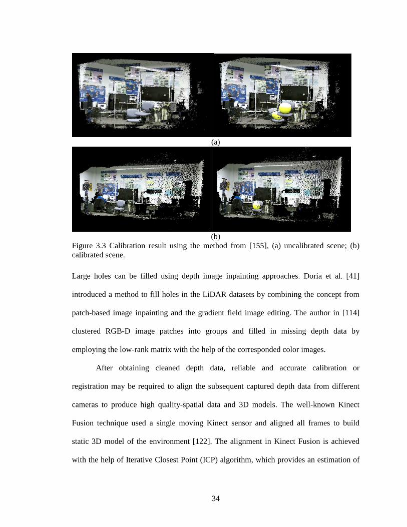
34
Large holes can be filled using depth image inpainting approaches. Doria et al. [41]
introduced a method to fill holes in the LiDAR datasets by combining the concept from
patch-based image inpainting and the gradient field image editing. The author in [114]
clustered RGB-D image patches into groups and filled in missing depth data by
employing the low-rank matrix with the help of the corresponded color images.
After obtaining cleaned depth data, reliable and accurate calibration or
registration may be required to align the subsequent captured depth data from different
cameras to produce high quality-spatial data and 3D models. The well-known Kinect
Fusion technique used a single moving Kinect sensor and aligned all frames to build
static 3D model of the environment [122]. The alignment in Kinect Fusion is achieved
with the help of Iterative Closest Point (ICP) algorithm, which provides an estimation of
(a)
(b)
Figure 3.3 Calibration result using the method from [155], (a) uncalibrated scene; (b) calibrated scene.

35
the extrinsic parameters of the sensor. In the case of using multiple Kinect sensors for
dynamic 3D scene reconstruction, estimating camera extrinsic parameters often require a
calibration object of known geometry. Traditional calibration methods with checkerboard
or laser pointers do not work well for depth camera as the specific color or texture pattern
are not observable for depth sensors. In addition, because of the wide baseline, the
overlapping views between adjacent sensors are small and using ICP algorithm to
estimate the extrinsic parameters of sensor cannot product a robust estimate. A possible
way is to use a separate calibration object to establish correspondences for registration
parameters estimation. One such example is to use a spherical calibration object [155].
Such a calibration technique can be used for scene reconstruction with multiple wide-
baseline RGB-D cameras without much user interaction, an example of multiple sensor
registration is shown in Figure 3.3. ICP algorithm can be further used to refine the result
of registration by optimizing the extrinsic parameters.
3.2 Surface Reconstruction from Point Cloud
Point Clouds are the measured scene points in 3D space, and they can be
calculated from the depth data obtained in the previous stage. A typical way to convert
the depth map produced by the RGB-D sensor to point cloud is to apply the perspective
projection with the information of calibration about the sensor. It can be achieved by
using the mapping function between the depth data and the camera space provided by the
Kinect SDK, a software development kit, to convert the depth data to point cloud [98].

36
The direct use of these point clouds is not suitable for most applications because of the
massive amount of redundant data they contain. Many works have been conducted to
simplify the dense point clouds by removing the redundant points while keeping the
feature points to represent the 3D geometry of the scene or object [77][67][78][113].
These works can be roughly divided into two categories: mesh-based and point cloud-
based. Mesh-based approaches construct triangular mesh from the point cloud in the first
step and then removing the redundant triangles. Because of the large amount of the data
to be processed, the time for computation is high. In contrast, the point-based methods for
simplification rely on the point information to simplify the point cloud without
reconstruction of mesh model and have lower computational complexity than mesh-based
methods. As such, they are more widely used and supported by open-source
computational geometry library such as Computational Geometry Algorithms
Library (CGAL) [36]. There are a number of different point-based simplification methods.
Figure 3.4 shows the comparison result of three methods for point cloud simplification.
The first one is to let the user specify the desired size of the point cloud and remove the
points from the input point set randomly, see Figure 3.4 (a). The grid-based approach
(a) (b) (c) (d) Figure 3.4 Comparison of three methods for point clouds simplification using CGAL [36]: (a) Original input; (b) Random simplification result; (c) Grid simplification result; (d) WLOP simplification result.

37
shown in Figure 3.4 (b) clusters all points into grid cells and replace all points inside a
cell with an arbitrarily chosen representative point. The speed for this algorithm is slower
compared to the first approach. The Weighted Locally Optimal Projection (WLOP)
algorithm proposed by Huang et al. in [77] simplifies the point cloud and also regularizes
the resampled points to be evenly distributed adhere to the original shape, as is shown in
Figure 3.4 (c), upon which is more useful and proper for further mesh reconstruction.
With the point clouds in hand, the process of converting such a discrete point set
into a continuous surface representation is defined as surface reconstruction. The
reconstructed surface mesh is good representation for the topology and geometric shapes.
During the last few decades, many algorithms for surface reconstruction have been
proposed depending on the output requirements, the properties of input point cloud data,
the preference of user, etc. Depending on how the mesh is constructed, these algorithms
can be roughly divided into three groups: implicit surface-based approaches, region
growing approaches, and Delaunay-based approaches [97]. Implicit surface-based
methods use weighted sum of basis functions such as the radial basis function to fit the
point cloud data. Region growing approach starts with a seed triangle and then
continually grows or expands from this seed triangle until all the points have been
considered. Different from the implicit surface-based approach, the region growing
approach takes all the points from the point cloud as the vertices of the reconstructed
triangle mesh. The details of the original object, therefore, will be preserved and tend to
produce more accurate reconstructed surface mesh. The Delaunay-based approach aims
to turn a set of points to a set of triangles for the desired triangle mesh surface
reconstruction. As is shown in Figure 3.5, in Delaunay triangulation, it is defined that no

38
points other than the three points that define the aforementioned triangle can be contained
by each circumcircle. The dual of Delaunay triangulation is called Voronoi diagram and
is generated by connecting the centers of the circumcircles as displayed in Figure 3.5 (a).
Both are important geometric data structures in computational geometry, which provide a
possible way to approximate the neighbor points in the point cloud data.
3.3 Motion Capture for Face and Body Shapes
Motion capture is the process to record the motion information of objects or
people. Due to the emergence of new types of sensors such as Kinect and the
improvement of computational performance, motion capture has found increasing usage
in many fields, like character animation for games and entertainment, motion analysis for
medical, sports and virtual reality.
(a) (b)
Figure 3.5 Duality of Delaunay triangulation [37] (a) Delaunay triangulation with all the circumcircles and their centers (red); (b) Voronoi diagram (red) overlaid to Delaunay triangulation.

39
In general, motion capture techniques can be classified into two categories: marker-based
systems require the attachment of different kinds of sensors or markers on the subject
being captured; markerless systems, on the other hand, capture motion based on statistical
inferences on captured images [22][110][112][195]. For consumer markets and other
domains like health care where it is desirable to have the least amount of restriction,
markerless systems provide a much more promising solution for motion capture. In this
work, we concentrate on markerless motion capture using single or multiple depth
sensors.
A surface mesh template with embedded skeleton is a widely used data structure
to model the tracked subject in markerless motion capture system [135][196][212]. This
kind of mesh template can be a generic model, SCAPE, for example, or a laser-scanned
mesh model with detailed surface geometry. The skeleton model can be represented by a
tree structure, as is shown in Figure 3.6. The red dots in this figure represent the joints.
The movement of each joint is controlled by different rigid body motion as indicated by
(a) (b)
Figure 3.6 Template and embedded skeleton for human body and the hand [116]. (a) Human body with skeleton; (b) Hand with skeleton.

40
the black arrows. A rigid motion of a joint can be represented in several ways, like Euler
angles, quaternions, twist, etc. The motion of a subject can be obtained by optimizing the
energy function which contains the data term and the regularization term.
Compared to body motion capture, facial motion capture is more challenging
because of the requirement for higher resolution in detection and tracking of subtle
expressions movement. The captured and processed facial movements can then be used
for facial animation in games or avatars. In recent years, blendshape has been used
successfully to create 3D dynamic models for the application of facial animation and
retargeting [106]. Such model contains a neutral face and a set of face with different
expressions, ranging from stereotypical (like happy and sad) to extremely subtle (like
narrow eyes). A new facial model can be created by combining different blendshapes
with different weights.
Copyright © Wanxin Xu 2018

41
Chapter 4 Facial Image Manipulation with RGB Images
In this chapter, two different ways to manipulate the expression of human face in
RGB images are presented. I first discuss image a retouching technique to manipulate the
face image while preserving the expression [193]. Then, a system to transfer expression
from one person to another is introduced.
4.1 Facial Image Manipulation with Recolor and Component Blending
Face image editing typically involves a set of image editing tools, such as
recoloring, image composition, tone adjustment and etc. Many of them have already been
widely studied and applied in face image editing. Bitouk et al. in [20] proposed a face
swapping system based on a large collection of face images. Another face swapping
method under large pose variation was proposed by Lin et al. [109]. Our work combines
recoloring and composition of facial component to produce a new face image while
preserving the general configuration of different facial features so as to preserve the
expression.
4.1.1 Overview of our system
The procedure of face image editing in our system is illustrated in Figure 4.1.
Given an input source image and a selected target image that best fits the facial
expression of the source image from the dataset, we first segment the skin part from the
rest of the image. Then, we use the color transfer method proposed by Reinhard et al [139]
to recolor the source image. To change the face component of the source image, like eyes,
nose or mouth, we first detect the facial component to be changed and then blend it with

42
Figure 4.1 Face image editing procedure
the corresponded parts from the target image using Poisson blending method [132].
Details of our implementation and the results are presented in the following section.
4.1.2 Skin recoloring and facial component blending
Given an input source image, we first search for the best fitted image from the
dataset that has a similar expression and head pose with the source image. Then we
segment the skin region from the rest of the image for source and target image. In this
step, we first manually select a patch to identify the proper skin color and then apply the
skin color detection algorithm. Our system uses a combination of HSV and YCrCb color-
(a) (b) (c)
Figure 4.2 Skin Color Transfer with input source image in (a), target image in (b) and the skin-recolored source image in (c).

43
spaces to model the skin color. Then, we use a simple thresholding scheme to classify the
skin pixels. To transfer the skin color of the target image to that of the source image, we
take advantage of the color transfer algorithm described in [139]. At the first step,
segmented source and target images are converted from RGB space to lαβ space. Then,
we compute the mean , ,s s sl α β and variance ˆ ˆˆ, ,s s sl α β of the source and target images for
each color channel. The final mapped distributions of the data points in lαβ space are
obtained by Equation (4.1), (4.2) and (4.3):
ˆ
( ) ˆt
mapped s s ts
ll l l ll
= − + (4.1)
ˆ
( )ˆ
tmapped s s t
s
αα α α αα
= − + (4.2)
ˆ
( ) ˆt
mapped s s ts
ββ β β ββ
= − + (4.3)
The last step for the color transfer procedure is to convert the result back to RGB space.
Figure 4.2 shows the result for color transfer.
(a) (b) (c) (d)
Figure 4.3 Generation of the ROIs. (a) Landmark detection. (b) Landmark refinement by linear interpolation. (c) Initial ROIs. (Mouth (blue), eyebrows (yellow), eyes and nose (green)). (d) Final generated ROIs by erosion and dilation.

44
The next part of face image editing in our system is to replace the specified facial
component of the source image with the target image. We first use the facial feature
detection algorithm proposed in [11] to detect the eyes, nose or mouth in source and
target image. Inspired by the work in [119], we then segment the face image into
different regions of interest (ROI) by linear interpolation, image erosion and dilation on
the basis of the detected feature point. The process to generate the ROIs is completely
automated, as illustrated in Figure 4.3. After cropping the corresponded ROIs from
source and target images, we apply the Poisson blending method [132] to blend the
cropped part from the target image with the source image seamlessly. The result of image
blending is shown in Figure 4.4.
4.1.3 Experimental results
The objective of the experiment in this part is to show that the resulting image
have the same general expression as the original one. In addition, the identity of the
person should not be revealed from the resulting image. To demonstrate the performance
of our method, we use FEI Face Database [79], which contains 2800 images of 200
different subjects, and Caltech Faces dataset [184] which contains 450 images of 27
(a) (b) (c)
Figure 4.4 Poisson blending result. (a) Source image. (b) Mask obtained from the ROIs generation. (c) Blended image.

45
different subjects. The choice of these datasets is led by the ease to find similar
expressions from different individuals. Figure 4.5 shows results obtained from our face
image editing method. We can see the result looks natural and the expression of the
person is preserved while some of the key facial biometric features including eyes, nose,
and mouths are replaced. One limitation of our method is that the source and target image
should have similar head pose and the change of head pose need to be small in order to
(a) (b) (c)
Figure 4.5 Fame image editing result. (a) Source image. (b) Skin recolored result. (c) Facial component blending result.

46
produce realistic rendering. One possible way to fix this problem is to align the face
image using 3D face model as discussed in the next section.
4.2 Fully Automatic Photorealistic Facial Expression and Eye Gaze Correction
with a Single Image
Nonverbal information like facial expression and eye gaze plays a crucial role in
social interaction. Generating a photorealistic facial expression from a single image while
preserving the identity of the actor has many applications in film making, gaming and
telepresence. In recent years, several approaches have been proposed to animate the
expression of a real actor on a virtual avatar in real time [150][29]. Instead of transferring
the expression to a virtual avatar, Thies et al. presented an algorithm to transfer the
captured expressions from the source video to another real actor [177]. While these
approaches have demonstrated impressive results on facial animation to real actor or
avatar, synthesizing a wide range of facial expressions accurately and realistically on
arbitrary real actors remains a challenging problem due to significant difference between
source and target actors, self-occlusion, uncontrolled illuminations, etc.
Recent advancements in low cost and compact depth sensors make it easier to
acquire depth information for facial performance editing. In [168], Thies et al. proposed a
method for face reenactment based on RGB-D data. Hsieh et al. in [74] developed a
system to capture and retargeting facial expressions using a commercialized depth sensor.
However, compared to 2D RGB cameras, depth devices are still not widely available and
the resolution of the captured images is low. Cao and others proposed a regression-based
algorithm on webcam, with robustness and accuracy comparable to RGB-D based
methods [29]. Similarly, the expression transfer method proposed in [177] can achieve

47
real-time transfer of facial expressions captured from a source actor to a target actor with
different identity. The main drawback of the previous systems for facial performance
capture is that they lack the capability to get information of eye gaze. Often ignored in
most facial expression transfer systems, eye gaze has been shown to significantly
contribute to our perception of social attention [100], and is of significant value in
medical evaluations of conditions like autism spectrum disorder. In [181], Wang et al.
presented the first approach to capture the eye gaze, head pose and expression
simultaneously using a single RGB camera.
In this section, we propose a facial reenactment system that takes a source and a
target image with arbitrary facial expressions, and generates a new image of the target
actor with both facial expression and eye gaze similar to those of the source actor while
preserving all the background information. To achieve photorealistic transfer, we propose
a novel coarse-to-fine scheme for reconstructing the 3D geometry of the face based on
details from a single image. The facial expression information is then transferred in a
fully automatic manner from source image to target image using mesh deformation.
Figure 4.6 The Overview of our proposed face expression transfer pipeline
Parametric model
Source
Target
Input Face reconstruction
Expression & eye gaze
transfer
Image Compositing
Expression transfer onlyExpression transfer with
eye gaze transfer
Output

48
4.2.1 Overview of the system
To manipulate the facial expression and eye gaze according to the source image
with minimal artifacts, I propose a system consisting of three main parts: 3D face
reconstruction, expression and eye gaze transfer, as well as image compositing (see
Figure 4.6).
3D face reconstruction: We start the whole pipeline by building the 3D models for
a single source and target images respectively. At the same time, we capture the person-
specific features like winkles using shading information from the image. This is essential
to making the result photorealistic.
Expression and eye gaze transfer: The second part in our system is to transfer the
expression and eye gaze from the source to the target. We manipulate the expression of
target input image using mesh deformation with a reference to the source input image. In
addition to expression, the eye gaze of the source actor is also transferred to the target
actor by using geometry warping approach.
Image compositing: The last component in our system blends the re-rendered
target image with its original background by using modified Poisson image editing [1],
where they take the pixels on source and target boundary into consideration, in addition,
alpha blending is added to the editing process.
4.2.2 Coarse and fine face reconstruction
In this section, we first discuss the use of a parametric face model for face
representation. Then, we introduce an approach to capture wrinkles and high frequency
details on image to generate a mesh with fine details.

49
4.2.2.1 Coarse model fitting
(a) (b) (c)
Figure 4.7 Coarse face reconstruction: (a) labeled 3D face landmarks; (b) 2D landmarks detected on the input image; (c) reconstructed model projected to the input image
We encode the face shapes by making use of a parametric face model created
based on publicly available 3D facial expression datasets. We control the expression and
shape of the 3D face on a lower-dimensional subspace with principle component analysis
(PCA):
exp expid idS S E Eα α= + + (4.4)
where S is the desired 3D shape, S denote the shape of the average face among the
scans, idE is the principle axis extracted from a collection of 3D face meshes with a
neutral expression. expE is the principle axis trained on the offset between expression
mesh and neutral mesh of each individual contained in the scans. idα and expα are the
representations of shape and expression weight for modeling. Basel Face Model [131]
and FaceWarehouse [30] are used for constructing idE and expE respectively.

50
Following the scheme of [210], we fit the parametric model to the source input
image and target input image. With the assumption of weak perspective projection:
2
1 0 00 1 0dS f RS T
= +
(4.5)
where 2dS represents the 2D positions of vertices in S projecting from the world
coordinate to image plane, f is scalar factor, R and T are rotation and translation
matrices respectively. After we find the 2D landmark alignment result _ 2land dS [140], all
unknowns in Equation (4.4) and Equation (4.5) can be solved by minimizing the
projection error of labeled 3D landmarks on the parametric model 2dS and _ 2land dS :
exp
2
_ 2 2, , , ,min
idland d df R T
E S Sα α
= − (4.6)
An example of our coarse face reconstruction is shown in Figure 4.7. It shows the
labeled 3D landmarks on parametric model, the 2D alignment on image, and the rendered
coarse model overlay to the image respectively.
4.2.2.2 Geometry refinement
A good estimate of the overall shape of an individual in the image can be obtained
by fitting the parametric model from the previous stage but person-specific facial features
like wrinkles are not adequately captured. To refine the geometric details in this stage, we
deform the obtained mesh to fit its shading with the input image. Inspired by the work in
[161], we assume Lambertian reflectance and approximate the image intensities with the

51
(a) (b) (c) (d)
Figure 4.8 Geometry refinement: (a) coarse shape; (b) shape after refinement; (c) reconstructed fine shape with texture; (d) Facial expression transfer with coarse (left) and refined (right)
surface normal using the first-order spherical harmonics. The objective function for
shading based geometry refinement is as follows:
2
1 2( ( )) ( ( ))Tv reg LP
vE I P v l h z v E Eβ β= − + +∑ (4.7)
where ( ( ))I P v is the image intensity of vertex v projected to the image plane with the
projection matrix P , l is a vector of 4 1× representing the spherical harmonics
coefficients, and ( )z v is the z -coordinate of vertex v . 1β and 2β are weights for the
regularization term regE that constrains the final mesh to be close to the original shape,
and the Laplacian smoothing term LPE . vh is 4D spherical harmonics approximation to
surface reflectance defined as ( ) ( )(1, )( ) ( )
r cv
r c
w w w whw w w w
− × −=
− × −, where ( , , )x y zw v v v= and rw ,
cw are neighboring vertices of w along horizontal and vertical direction on the surface.
Equation (4.7) can be solved by updating and fixing l and v iteratively with linear least
squares optimization. Figure 4.8 shows the result of geometry refinement. Figure 4.8 (a)
shows the coarse shape obtained from the previous stage, Figure 4.8 (b) shows the shape
with geometric refinement, Figure 4.8 (c) shows the refined shape with texture

52
information and Figure 4.8 (d) shows the effectiveness of geometry refinement for facial
expression transfer.
4.2.3 Facial expression transfer and eye gaze correction
After obtaining the 3D models for both the source and the target images, we apply
the mesh deformation to transfer the expression from the source to target. Our approach
is similar to that of [160]. However, instead of finding correspondences based on the user
selected markers, we register the models with coarse shape parameters to the refined
shape obtained by geometry refinement. In this way, the correspondences can be easily
treated as all of the triangles in the mesh. Thus, the efficiency for facial expression
transfer can be improved significantly without finding correspondence points. The
difference around the mouth of the source and target actors are reduced by piecewise
affine warping in the image domain.
(a) (b) (c)
Figure 4.9 Eye gaze transfer: (a) original pairs of image with detected eye mask; (b) direct transfer without refinement; (c) final synthesized image

53
In addition to expression transfer, we take the eye gaze difference into
consideration to make the final re-rendered image more realistic. As is shown in Figure
4.9, we first extract the eye mask from source and target image by morphological
operations. The gaze is estimated by sphere fitting, colored with the green circle and red
point in Figure 4.9 (a). Then, we use the correspondence points extracted from source and
target images around the eye area to compute the transformation matrix to warp the eye
mask. The relative location for eye gaze is calculated using the center of eye gaze and the
eye corner. The synthesized eye gaze is finally estimated by the aspect ratio from the
relative location. The final manipulated image is generated by blending the eye and the
mouth area with the re-rendered image together. More results are shown in the
experimental section.
4.2.4 Experimental results
We evaluate the performance of our system on face reconstruction from single
image using both qualitative analysis and quantitative evaluation.
(a) (b) (c) (d) (e)
Figure 4.10 3D reconstruction evaluation: (a) Input RGB image; (b) Ground truth; (c) reconstructed model by our method; (d) error map between our model and ground truth; (e) error map between model obtained by method of [210] and ground truth.

54
We first present the experimental result for face reconstruction. We evaluate the
accuracy of our system for face reconstruction on a public available dataset provided by
MPI Informatik [18]. The dataset contains three sequences captured indoor with 200k
vertices and one sequence captured outdoor with 50k vertices. The scanned models from
this dataset serve as the ground truth. To measure the difference between the ground truth
and our reconstructed model, we first align them by ICP algorithm [76] and search the
nearest point from the ground truth model along the normal direction of each vertex in
our reconstructed model. The Euclidean distance is then calculated for each pair of the
points. One example from the dataset is shown in Figure 4.10. The mean error distance
between our reconstructed model and the ground truth is 2.48mm, comparing with the
method from [210] which is 2.71mm. We also compare our method for face
reconstruction with the method from [210] on more unconstrained images of different
illumination and poses. Figure 4.11 presents the result of comparison, from left to right,
showing the reconstructed model and the model with texture.
To evaluate the performance of our method for facial expression and eye gaze
transfer, we choose images with different expression or head pose from the LFW dataset
[100]. The result of our method for transferring the expression and eye gaze between two
different identities with single image is shown in Figure 4.12. The leftmost row in each of
the three pairs is the input of source and target image, the transfer result of expression is
shown in middle column, the final result with eye gaze transfer is displayed in the
rightmost column. It can be seen that our system is able to generate realistic result for
various facial expression transfer with eye gaze correction.

55
Figure 4.11 Face reconstruction on unconstrained image: Input RGB image; reconstruction with our method; reconstruction with method from [210]; reconstruction using our method with texture.

56
Figure 4.12 Result of our proposed system: (First row) source input and target input images; (Second row) manipulated image after expression transfer from source to target without eye gaze correction; (Third row) final output image with gaze correction.
Copyright © Wanxin Xu 2018

57
Chapter 5 Human Body Reshaping with Single and Two Depth sensors
Automatic reshaping of human bodies is a computer vision and graphics
technique with many applications. It manipulates various shape attributes of the visual
appearance of a person without any manual editing. Keeping coherent reshaping results
across many video frames is more challenging and the recent advance in RGB-depth
sensors have significantly advanced key processing steps including pose and skeleton
estimation. In order to develop a system that can be used in the consumer market, it is
important to minimize the number of sensors required and the initialization setup. In the
first part of this chapter, I introduce a single RGB-D sensor based for human body pose
and shape reshaping system. This system features a novel pipeline for pose estimation
that can be used to improve the performance of human body reshaping with single depth
sensor. The limitation of a single sensor is that the estimation of pose from the 3D data
our reshaping system based on is not robust due to significant occlusions. In the second
part of this chapter, we extend our system to utilize two RGB-D sensors and introduce a
new pipeline for pose estimation.
5.1 Skeleton-driven Approach for Human Body Reshaping with Single Depth
Sensor
Reshaping of human body in image or video is an active area of research in
computer graphics [208][84]. Most existing works rely on the use of 3D Morphable
Model to edit the human shape. In our first system, we achieve this by manipulating the
3D skeleton data provided by a single Kinect V2 Sensor. We then apply the linear blend
skinning procedure with bounded biharmonic weights as described in [83] to perform a

58
smooth 2D mesh deformations. Figure 5.1 gives an overview of our human body
reshaping procedure, which consists of three stages. The first stage of body reshaping is
data preparation. We use Microsoft Kinect Sensor to acquire 3D skeleton data, back
projected 2D skeleton data and human shape mask simultaneously. These data are
computed using the Kinect V2 SDK by Microsoft. Next, we manipulate the 3D skeleton
data by scaling each body part along its direction to get new 3D skeleton data and back
project it to 2D image using coordinator mapper provided by Kinect V2 Sensor. The
shape deformation is achieved using linear blend skinning [83] by moving the 2D
skeleton data obtained in first stage to the corresponded projected 2D joints position
obtained in the second stage. Finally, we render the new image using 2D image rendering
tool. Details of our implementations and the results are presented in the following section.
Figure 5.1 Human body reshaping with single depth sensor

59
5.1.1 Data preparation and mesh generation
The process starts by capturing the color image frame of the whole environment
which will be used for further rendering. The Kinect SDK also provides the associated
body mask data, 3D skeleton data and back projected 2D skeleton data. The segmentation
of the human body from the color image frame can be achieved by overlaying the body
mask data on the color image. Due to the poor contrast and bad lighting of the image, we
use morphological operations to refine the segmentation. The contour of the human shape
is then obtained from the mask data. Note, the obtained contour must be a closed polygon.
We use the triangulation algorithm in [22] to generate the triangulated mesh inside the
contour. The entire procedure is demonstrated in Figure 5.2.
Figure 5.2 (a) Original mask. (b) Refined mask and contour. (c) Generated mesh.

60
5.1.2 2D shape manipulation
The 3D Skeleton data contains the 3D positions for 25 human joints. We use 19 of
them for body shape editing, excluding the unrelated hand thumb, hand tip, and foot for
our applications. Suppose each joint position in the skeleton space is represented as
( , , )X Y Z . The skeleton space coordinates are expressed in meters. The back projected
2D skeleton data on the color image is represented as ( , )x y in pixel. To change the shape
of the human body in each frame sequence and preserving their consistence, we propose
a method that are able to scale the correlated bone length without changing the human
pose. Using 1 1 1( , , ; , , ; , , )
Ti i in i in i inP X X Y Y Z Z= to represents the 3D joint position
set in thi frame and 1,2, ,19n = . We first calculate the length of the bone for each joint
pair in 3D space. Then, we divide the reshaping process of the 3D skeleton into five parts:
left arm, right arm, left leg, right leg and body. The target length of each part is based on
the skeleton of an average man/woman in the U.S. The scaling is computed in the 3D
space, mapping the original iP to the target iP′ in each frame in the video sequence. After
3D skeleton reshaping, we use the built-in function of Kinect SDK to map the new 3D
skeleton data iP′ to the color image to obtain the new 2D skeleton data. The 2D mesh
deformation is finally achieved using linear blend skinning [83] by moving the 2D
skeleton data on the mesh to the corresponded new projected joint position. To obtain the
final result, we render the new mesh by patching the color of the original appearance of
the human to the deformed mesh. In the last step, we embed the reshaped colored human
body image to the background image obtained in the first stage.

61
5.1.3 Experimental results
To evaluate the performance of our proposed human body reshaping method, we conduct
the experiment in two different environments. The spatial resolution of the image
captured by the Kinect is 1920 1080× . The practical ranging limit of Kinect is 0.4 to 4m.
The first column and second column in Figure 5.3 demonstrate a sample of the original
video frames and the corresponding reshaped video frame. The result shows that our
method can reshape the human shape under different and complex environment. The
limitations in segmentation and 3D skeleton tracking from the Kinect might influence our
reshaping results. In the future, we plan to combine advanced segmentation and tracking
under occlusion approach with those from the Kinect to improve the performance of our
approach and make it more robust.

62
(a) (b)
Figure 5.3 (a) Selected original image frame from two environments. (b) Reshaped image frame (taller and thinner).
5.2 Human Pose Estimation with Two RGB-D Sensors
Even though recent approaches have shown that 3D positions of body joints can
be estimated from a single depth sensor, the depth data often suffer from sensing noise

63
and self-occlusion. Before going to our model-based approach for human body reshaping,
I first introduce a system to estimate the pose of human subject using two RGB-D sensors
to improve the performance of the skeleton-based approach for human body reshaping as
described in Section 5.1.
5.2.1 System overview
The two sensors simultaneously capture the front and back of the body’s
movement. Using a wide-baseline RGB-D camera calibration algorithm, the two 3D
scans are first geometrically aligned, and then registered to a generic human template
using a Gaussian-mixture-model based point set registration procedure with local
structure constraints. The new pose of person is finally estimated by a rigid bone-based
pose transformation. Experimental results demonstrate the effectiveness of our system in
estimating the body pose over other state-of-the-arts techniques.
The overall pipeline of our proposed framework is illustrated in Figure 5.4. It
consists of three main components: data acquisition & preprocessing, non-rigid
Figure 5.4 The Overview of our proposed pose estimation pipeline

64
registration, and skeleton estimation. We first discuss the acquisition and preprocessing
of the data used in our framework in Section 5.2.2, followed by the method to register the
template to the target model in Section 5.2.3. In Section 5.2.4, we introduce how we
estimate the pose from the template and registered input scans. The experimental result is
finally discussed in Section 5.2.5.
5.2.2 Data acquisition and preprocessing
In our framework, two Kinects are mounted in opposite direction facing toward
the front and back of the subject being captured. The subject can move freely within the
intersecting view frusta of the two Kinects during the capture. The input data is a set of
color and depth images. Each pair of input images are aligned and transformed into a
point cloud representation. As shown in Figure 5.4, we first detect and segment the
person from the scene using background subtraction and morphological operations. Since
(a) (b)
Figure 5.5 Point cloud alignment from two depth sensors: (a) before alignment; (b) after alignment.

65
the 3D positions of point cloud is obtained with respect to the local coordinate system of
each depth sensor, we first provide a coarse alignment of the point clouds from those two
depth sensors using the extrinsic camera parameters. Different from traditional
calibration methods using a checkerboard [206], we use a wide-baseline RGB-D camera
network calibration method proposed in [155]. This approach makes use of a spherical
object with distinct color as a calibration object and identifies the correspondences across
different views based on the estimated locations of the center of the sphere. The
calibration procedure produces the relative camera pose between the two cameras, which
we use to provide a rough alignment of the two point clouds. Figure 5.5 shows the
alignment of the two point-clouds.
After the initial alignment process, the combined point clouds are roughly aligned
but there are still noise and outliers that could affect the pose estimation. To remove these
noises, we follow a two-stage process. By assuming the distribution of the distances of
each point to its closest K neighbors follows a Gaussian distribution, we first remove
those points whose mean distance between all its neighbors significantly deviate from the
global mean distance. Even though this stage can remove most outliers, the surface of the
point cloud is still noisy and unevenly distributed. Surface reconstruction directly on
these low-quality data would be highly unreliable. As such, we apply Weighted Locally
Optimal Projector (WLOP) to further denoise these data points and resample them evenly
across the surface [77].
5.2.3 Non-rigid point set registration
In the next stage of our proposed pipeline, similar to [201], we create a 3D
template model that consists of the surface vertices, the surface mesh connectivity, the

66
skeleton and the skinning weight, by having the person posed a T-shaped posture in the
overlapped region of the two frusta. We use the approach from Baran et al. [17] to
automatically get the kinematic skeleton with 18n = joints and the skinning weight,
which describes the association of each vertex to each bone. The generation of this
template model is done offline and only once over the entire pipeline.
For registration, the first frame of the sequence is registered with the template
while the rest of the frames are registered with the neighboring frames. Since the view
direction of the input scan might be different from that of the template, we first transform
the input scan according to the estimated view direction of the template. Applying
principle component analysis to the point cloud, the 3D orientations for the template and
the input scan are obtained. We then transform the input scan into the same view
direction with the template. Afterwards, we use the Coherent Point Drift (CPD) algorithm
proposed in [120] to register the input scan with the template. However, as the input scan
can be quite incomplete, direct application of CPD for registration can be problematic as
it fails to take spatial relationship between the neighboring points into consideration.
In our framework, inspired by the work in [58], we preserve the local structure of
the template through Laplacian coordinate. Similar to [120], we assume the template data,
{ }| 1, 2, ,
DnY y R n N= ∈ = represents the centroids of GMM. The goal is to derive an
optimal GMM parameters to fit the input scan { }| 1, 2, ,
DmX x R m M= ∈ = to the
GMM centroids by minimizing the objective function defined below:
2 2( , ) ( , ) lc lc g gE W Q W E Eσ σ λ λ≡ + + (5.1)

67
Following the same approach as [201][120][58], we use the Expectation
Maximization (EM) algorithm [19] to solve the objective function in Equation (5.1)
iteratively. Using a weighted uniform distribution account for outliers, with the
assumption that the variance 2σ for all Gaussians is same, the first term in Equation (5.1)
is defined as:
2 22
,( , ) ( , ) log
2 2mn P
m nm n
P N DQ W x y Wσ σσ
≡ −Ψ +∑ (5.2)
2
2
2 2 2
21
( , )exp( )
2( | )( , ) (2 )exp( )
2 (1 )
m n
old oldmn m D
Nm n
n old
x y W
P p n xx y W uN
u M
σ
πσσ=
−Ψ−
≡ =−Ψ
− +−∑
(5.3)
where Ψ can be considered as a function of Y with parameters W ; u is the weight of
uniform distribution; , 1 1
M N
m n m n= =
≡∑ ∑∑ ; ,
( | )oldP m
m nN p n x=∑ and oldp denotes the posterior
probabilities of GMM. Two more terms, lcE and gE , in Equation (5.1) are used for
regularization:
2
1( ) ( ( , ))
N
lc n nn
E L y L y W=
≡ − Ψ∑ (5.4)
2gE W≡ (5.5)
where L is Laplacian matrix with cotangent weights. The lcE term is used to preserve
the local shape structure of the template. The gE term ensures the continuous motion. lcλ
and gλ are trade-off parameters specified by user.

68
5.2.4 Skeleton estimation using bone-based approach
Once the input scan is registered to the template, the correspondence between
them is obtained. Inspired by the work in [101][102], we treat the template as a rest pose,
which is used to estimate the pose of the input scan. According to the skeleton and
weights provided by the template, we can obtain 17B = parts for the rest pose, the
vertices in the same cluster have the same rigid motion. The clustering in our framework
is achieved by assigning the vertices to the bone with the largest weights.
Since the vertices in the registered input scan { }| 1, ,iv i Nχ = = has
correspondences to the vertices in the rest pose { }| 1, ,iu i Nϕ = = , the estimation of the
new pose becomes the problem of finding a set of rigid bone transformations
{ }, | 1, 2, ,j jR T j B= to associate the vertices in the input scan to the vertices in the rest
pose through minimization the following objective function:
2
, 1min
j j
N
j j i j i diffR T iS R u T v Eλ
=
+ − +∑ (5.6)
2
( , )diff j j jk j k k jk k
j k EdgeE S R C T S R C T
∈
≡ + − −∑ (5.7)
where 1, 2, ,j B= ; jS is the scaling factor for each bone transformation, which helps
to fit the bone length of the input scan; ( , )j k Edge∈ means bone j and bone k share the
same joint jkC ; λ has the value of 1 in our framework. diffE ensures that the difference
of new positions of joints connecting two bones will be small after transformation.
Similar to [101][102], we find the solution to the Weighted Absolute Orientation problem

69
[72] to solve Equation (5.6). The new pose of the input scan can be obtained by applying
transformation to the rest pose.
In our framework, the last step in this stage is to build the detailed human pose
model. The original incomplete input scan contains the detailed information, like clothes
winkles, hair style etc., and the registered input scan can be used to fill the gap of the
missing data. As such, we fuse them together and then apply Poisson surface
reconstruction [93] to obtain a detailed human pose model.
5.2.5 Experimental results
In this section, we experimentally demonstrate the effectiveness of our framework
from two perspectives: qualitative analysis and quantitative evaluation. Our system was
first tested on a publicly available dataset provided by MPI Informatik [70]. This dataset
contains six sequences (D1-D6) of motion with varying difficulties performed by one
actor including kicking, rotation, and circular walking. The ground truth of joint position
of the actor is also provided in this dataset obtained by a marker-based Mocap system.
Figure 5.6 Visual comparison of our proposed method using the dataset in [70] with its ground truth data. Blue line (Our method estimation) and Black dot (Ground truth).

70
We can qualitatively and quantitatively evaluate our system by comparing the joint
position error against the ground truth data.
Even though this dataset is captured by one depth sensor, our proposed system
can be used. We first applied Hidden Point Removal (HPR) method in [92] to detect the
visible part of the template and then estimated the pose by our proposed pipeline. We
followed the same strategy as described in [70] to estimate the average joint error. Figure
5.6 shows the pose estimation of our system on this dataset. As shown in Figure 5.6, our
system can produce good estimation even with heavy occlusion and missing data. The
average joint position error of our method versus other state-of-art approaches on this
dataset are shown in Figure 5.7. The results clearly show that our system achieves higher
or comparable performance [70][156][13].
Figure 5.7 Comparison of average joint position error for six sequences from the evaluation dataset: Kinect [156] (Dark blue), Baak.et al [13] (Light blue), Helten et al [70] (Yellow) and Ours (Red).

71
In addition, we compare the accuracy of pose estimation on our pipeline by
comparing it with Kinect SDK [96]. We captured three sequences of three actors with
different weight and height, performing a variety of complexity movements like crossing
arm, rotation, running, etc. The first column of Figure 5.8 shows the captured color
images from the depth sensor in front; the second and third column show the pose
estimation by Kinect SDK for the depth sensors in front and behind respectively; the last
column shows the pose estimation by our proposed pipeline. It can be observed that the
Kinect SDK based method produce poorer pose estimation than our proposed system
under significant occlusion. Some joint positions deviate from the supposed position if
the body parts are occluded.
(a) (b) (c) (d)
Figure 5.8 Pose estimation visualization results: (a) Color image from depth sensor (front); (b) pose estimation from KinectSDK (front); (c) pose estimation from KinectSDK (back); (d) pose estimation from our proposed system.

72
In our last experiment, we visually show the comparison of the detailed model
generated with and without holes filling before the Poisson reconstruction. The data here
is the same as that from Figure 5.8. The comparison is shown in Figure 5.9. We can see
the reconstructed model with holes filling before Poisson reconstruction looks more
natural. The first column shows the reconstruction result without holes filling, some of
the body part (e.g. leg) is miss-connected or disconnected (e.g. hand).
(a) (b)
Figure 5.9 Poisson reconstruction with and without holes filling: (a) without holes filling before Poisson reconstruction; (b) with holes filling using our proposed way before Poisson reconstruction.
Copyright © Wanxin Xu 2018

73
Chapter 6 Model-based Approach for Human Body Reshaping with Sensor
Network
In this chapter, a novel pipeline to reshape the human body using noisy depth data
from multiple RGB-D sensors (sensor network) is presented. Compared with a single
view reshaping system introduced in Chapter 5, multiple RGB-D sensors provide more
constraints and better coverage, leading to more consistent results. However, there exist
several challenges in estimating the pose and shape of human simultaneously in RGB-D
data due to self-occlusion and motion complexity. To cope with the time-varying
articulated human shape, we propose a new approach that combines a Gaussian Mixture
Model (GMM) based fitting approach as introduced in Section 5.2.3 with a morphable
model learned from range scans. Without any user input, this approach can automatically
account for the variations in pose and shape. It also enables different types of reshaping
by manipulating body attributes such as height, weight or other physical features.
Experimental results are provided to demonstrate the effectiveness of our system in
manipulation of human body shapes. In the last part of this chapter, we demonstrate the
feasibility in using our proposed system for visual privacy protection.
6.1 Overview of the System
The schematic of our proposed framework is shown in Figure 6.1. It consists of
three main components: data acquisition & preprocessing, pose & shape estimation, and
human body reshaping. Inputs are aligned color and depth data captured from multiple
RGB-D cameras. Based on offline calibration parameters, we first perform denoising on

74
the depth data and align them onto the same coordinate system based on the system
described in [155].
To estimate the pose and shape of the actor, we use a morphable model along with
the GMM based framework to fit the observed data. We optimize the model to the
observed data in two stages. The first stage (Section 6.3.2) estimates the posture and
coarse body shape of the observed actor, by combining a modified approach from [10]
with the GMM based point set registration [120]. While this initial step produces accurate
pose and coarse shape, it fails to reconstruct the non-rigid deformations caused by
clothing of the actor. In the second stage (Section 6.3.3), the details of the surface shape
are estimated by finding the difference along the normal directions between the
reconstructed shape in the first stage and the original refined point cloud.
After finding the correspondence between the observed data and the morphable
model, we can now reshape the observed actor by modifying the semantic body attributes
of the morphable model and applying the deformation transfer to the fitted model fully
automatically (Section 6.4).
Foreground Segmentation(Section 4.1)
Wide-baseline camera network calibration(offline)
Pose and Shape Estimation
(Section 4.3;4.4;4.5)
Human Body Reshaping (Section 5)
SCAPE Model
Aligned Data Aligned Data
Noisy Removal & Alignment
Figure 6.1 Overview of our proposed system.

75
(a) (b) (c)
Figure 6.2 Point cloud alignment from four depth sensors: (a) before alignment, (b) after alignment. (c) alignment with texture and camera position (1,2,3,4)
6.2 Data Collection and Pre-processing
In our experimental setup, we used four Kinect cameras mounted in four
directions perpendicular to each other for data capture. This configuration helps to
minimize any interference between adjacent Kinect cameras. The actor can move freely
within the four intersecting view frusta during the capture. The input data is a set of color
and depth images. Each pair of input images are aligned and transformed into a point
cloud representation [26].
As shown in Figure 6.1, we first detect and segment the person from the scene
using background subtraction and morphological operations. Since each depth sensor
produces point clouds in its own local coordinate system, we need to estimate the
extrinsic camera parameters before aligning the local point cloud data into a global
coordinate system. Different from traditional calibration methods using checkerboard
[206], we estimate the extrinsic parameters using a wide-baseline RGB-D camera
network calibration method from [155]. This approach uses of a spherical object with
distinctive color as a calibration object, and identifies the correspondences across

76
(a) (b) (c)
Figure 6.3 Point cloud outlier removal and simplification: (a) Original aligned point cloud; (b) after outlier removal using Gaussian filter; (c) after denoising using WLOP
different views based on the estimated trajectory of the sphere’s center. The calibration
procedure produces the relative rigid transformation between the two cameras, which we
use to provide a rough alignment of the point clouds. Figure 6.2 shows a sample of point
clouds from different views in their local coordinates in Figure 6.2(a), in the global
coordinates in Figure 6.2(b), and with textures and cameras’ position in Figure 6.2(c).
After the process of initial alignment process, we follow the same two-stage
process to remove the noises and outliers as described in Section 5.2.2. By assuming the
distribution of the distance of each point in the aligned input scan to its neighbors is
Gaussian with a mean and a standard deviation, we first search for the nearest neighbors
at each 3D point and remove the point whose mean distance between all its neighbors is
greater than or smaller than the threshold defined by the global mean and standard
deviation. Even though this stage can remove most outliers, the surface of the point cloud
is still noisy and non-uniformly distributed. In this case, the assumption of a normal

77
distribution for further surface reconstruction would be unreliable. To solve this problem,
we apply Weighted Locally Optimal Projector (WLOP) [77] to generate a set of denoised,
simplified and evenly distributed point, as is shown in Figure 6.3.
6.3 Pose and Shape Estimation with Multiple Depth Sensors
6.3.1 SCAPE model
Unlike our previous work [192], we use the SCAPE model, instead of a non-
parametric model, as prior for the goal of reshape human body caused by different
identities and postures. This section briefly reviews the SCAPE model introduced in [10].
The SCAPE model uses separate parameters to control the deformation of the
pose and the body shape, and then fuses them together under a single transformation.
Denote the generic template model of shape and pose as X and the target model as Z .
SCAPE computes a 3 3× transformation matrix fA that deforms each triangle 0fT
(defined by vertices , , 1, 2,3f kx k = ) in the template model to its corresponding target
triangle fT with vertices ( , , 1, 2,3f kz k = ):
0 0( ) ( ) ( )f f f f f f fT A T R D Q Tθ β θ≡ ≡ (6.1)
where the pose is governed by the rotation of triangle in part ( )fR θ and the pose-
dependent non-rigid deformation ( )fQ θ . The shape variations are controlled by a linear
function ( )fD β . During the training phase, the pose of different individuals is fixed at

78
0θ . SCAPE models the shape variation using a PCA model ( )fD Uβ β µ≡ + , where U and µ are both pre-trained PCA parameters, µ is the mean body shape.
Given both θ and β , vertex positions 1, , Nz z of the target mesh can be
determined by solving the linear least square problem as follows:
1
2
, ,{ , , } 1 2,3argmin ( ) ( ) ( )
N
F
m f f f f k f kz z f k
E R D Q x zθ β θ= =
≡ ∆ −∆∑ ∑
(6.2)
where F is the total number of faces, N is the total number of vertices, and
, , ,1 , , ,1,f k f k f f k f k fx x x z z z∆ = − ∆ = − are edges for each triangle. As shown in Figure 6.4,
we can synthesize realistic meshes for different people in a broad range of poses and
shapes.
6.3.2 GMM-based pose and shape fitting
The next step is to fit the trained SCAPE model to the observed data obtained in
Section 6.2. The goal of fitting is to optimize both θ and β such that the resulting
(a) (b) (c) (d)
Figure 6.4 SCAPE Model with 16 parts of different poses and shapes

79
morphable model has good approximation for the observed data. Previous approaches
based on morphable models such as [196][33] require initial guesses about the closest
point correspondence or sparse tracking markers. Instead, we use a GMM based approach
[204] that takes all the observed data points into consideration. Our approach is more
robust against outliers and occlusions, and is also more effective in fitting between two
complex non-rigid point data sets. In the followings, we first describe the GMM based
non-rigid registration approach in Section 6.3.2.1, unlike the previous approach presented
in Section 5.2.3 that focused only on pose, the proposed approach in this section can
simultaneously estimate both the human pose and shape for body reshaping, and then
provide the details in Section 6.3.2.2 on how we apply this approach in fitting the
observable data with the morphable model.
6.3.2.1 GMM-based point set registration
Inspired by the work proposed in [120], we assume that the observed data
{ | 1, 2, , }
DmY y R m M= ∈ = follows a N -component GMM distribution with
component means initialized at the vertices { | 1, 2, , }
DnX x R n N= ∈ = of the
deformed template with pose and shape parameter θ and β . Therefore, the probability of
each observed data point can be expressed as:
1
1 1( ) (1 ) ( | )N
m m nn
P y u P y x uN M=
= − +∑
(6.3)
2
2 /2 21( | ) exp( )
(2 ) 2m n
m D
y xP y x
πσ σ−
= − (6.4)

80
where D is the dimension of the observed data (e.g. 3D = ); u is the weight of the
uniform distribution that accounts for outliers and the variance 2σ for all Gaussians is
assumed to be the same for simplicity.
The registration of these two point sets X and Y can be considered as a
Maximum Likelihood problem, which is equivalent to minimize the following negative
log-likelihood:
1log ( )
M
mm
E P y=
≡ −∑ (6.5)
Using the same approach as in [120], we apply the Expectation Maximization (EM) [39]
algorithm to minimize the objective function in Equation (6.5) iteratively until it
converges. During the E-step, the posterior probabilities are calculated using the
parameter obtained from the previous iteration based on the Bayes rule as:
2
2
2 2 2
21
exp( )2( | )
(2 )exp( )2 (1 )
m n
old oldnm n m D
Nm n
n old
y x
P p x yy x uN
u M
σ
πσσ=
−−
≡ =−
− +−∑
(6.6)
During the M-step, we can find the new parameters by minimizing the objective
function in Equation
22 22
1 1( ( , ), ) log
2 2
M Npnm
m nm n
N DPQ X y xθ β σ σσ= =
≡ − +∑∑ (6.7)
where 1 1
M N
p nmm n
N P= =
=∑∑ .

81
6.3.2.2 Human pose and shape optimization
Before applying the GMM registration, we need to first transform the observed
data to the same view direction of the morphable model. Using principle component
analysis on the point cloud, the 3D orientations of the morphable model and the observed
data are obtained. We then construct a transformation to transform the observed data into
the same view direction with the morphable model, as shown in Figure 6.5.
After the alignment process, we apply the GMM-based non-rigid registration
approach to fit the morphable model X to the observed data Y . We solve this by jointly
optimizing the two objective functions from Equation (6.2) and Equation (6.7) to obtain
X , θ and β using the following objective function:
2( ( , ), )m dataE Q Xω θ β σ+ ∗ (6.8)
(a) (b) (c)
Figure 6.5 View direction transformation (a) Morphable model with view direction (b) Original observed data with view direction (c) After transformation (Red: Y-axis; Blue: Z-axis; Green: X-axis)

82
where mE from Equation (6.2) and 2( ( , ), )Q X θ β σ from Equation (6.7) are weighted by
dataω that controls the influence of observed data on the morphable model. To simplify the
optimization problem, we use a coordinate descent strategy and solve for each variable
iteratively. The followings describe the steps that are summarized in Algorithm 1.
Initialization. In the initial stage, the variance 2σ is obtained by taking the derivative of
the objective function defined in Equation (6.8) w.r.t. 2σ and set it equal to zero, yielding:
22
1 1
1 M N
nm m nm np
P y xN D
σ= =
= −∑∑ (6.9)
Iteration. There are three main steps in each iteration:
1) Fixing θ and β , update X .
We solve the vertices that gives the best correspondence between the morphable model
X and the observed data Y . It can be obtained by minimizing the objective function
defined in Equation (6.8).
2) Fixing β and X , update θ .
To estimate the pose change θ∆ , we use the twist change to rotation as an
approximation, that is, i.e. ˆ( )newR I Rθ≈ + ∆ , where 1 2 3( , , )θ θ θ θ∆ = ∆ ∆ ∆ , and
3 2
3 1
2 1
0ˆ 0
0
θ θθ θ θ
θ θ
−∆ ∆ ∆ = ∆ −∆ −∆ ∆
(6.10)
Then, the pose change can be solved by minimizing the following function to deform the
morphable model into the pose that best approximates the observed data.

83
2 2
, , 1 21 2,3 1, 2
ˆmin ( )F
b b f f f k f k R b bf k b b adj
I R D Q x yθ
θ ω θ θ∆
= = ∈
+ ∆ ∆ −∆ + −∑ ∑ ∑ (6.11)
where fD and fQ are defined in Equation (6.2); Rω is a trade-off parameter; and 1, 2b b
are indices of the adjacent bones. The second term in Equation (6.11) is used to prevent
large joint rotation.
3) Fixing θ and X , update β .
Algorithm 1. Human Pose and Shape Optimization
Input: Initial 2, ,θ β σ and observed data Y .
Output: The optimized ,θ β∗ ∗ . 0iter = ;
Repeat 0j = ; E-step:
Compute posterior nmP according to Equation (6.6);
M-step: Repeat Compute X by solving Equation (6.8); Compute and update θ by Equation (6.11); Compute and update β by Equation (6.12);
Adjust dataω by simulated annealing;
j + + ; Until (satisfy the stop criteria) iter + + ; Until (satisfy the stop criteria)
,θ θ β β∗ ∗= =

84
For shape update, we find the best shape parameters to fit the observed data by
minimizing the following function:
2
, ,1 2,3
min ( )F
b f f k f kf k
R U Q x yβ
β µ= =
+ ∆ −∆∑ ∑ (6.12)
Termination. The process fits the morphable model to the observed data iteratively. The
process stops if it reaches to a maximum number of iterations (e.g. max_ 10iter = ) or the
maximum movement of the vertices is small enough (experimentally set to 1mm).
6.3.3 Detailed motion reconstruction
After the registration in Section 6.3.2, we obtain a deformed mesh
{ | 1, 2, , }
DnX x R n N′ ′≡ ∈ = that is a good approximation of the observed data.
However, to preserve details like winkles and folds, they need to be transferred from the
observed data to the deformed mesh.
To recover the details of observed data, we use a procedure similar to that
proposed in [105]. For each vertex ix′ in the deformed mesh, we first find the nearest
neighbor ic from observed data along its normal direction in . Then, the detail
coefficients id is obtained by optimizing the objective function as follows:
22 2
1 ,( )
N
d i i i i l i s i ji i j
E x d n c d d dλ λ=
′= + − + + −∑ ∑ (6.13)
where i and j are neighboring vertices. The second term in the first summation in
Equation (6.13) is used to prevent large movement. The weighting factor lλ is

85
empirically set to 0.1 . The last term accounts for smoothness with the weighting factor
0.5sλ = . This is a least square problem and can thus be solved efficiently. Figure 6.6
shows how the details are preserved and the resulting reconstructions.
6.3.4 Bone-based approach for skeleton estimation
Once the observed data are registered to the morphable model, the
correspondences between them can be obtained. Similar to the process of skeleton
estimation introduced in Section 5.2.4, we treat the morhpable model as a rest pose and
use it to estimate the skeleton of the observed data. According to the skeleton and weights

86
from the morhpable model, we can obtain 16B = parts or clusters for the rest pose.
Vertices in the same cluster are assumed to have the same rigid motion. The clustering in
our framework is achieved by assigning the vertices to the bone with the largest weights.
The new skeleton of the observed data can finally be obtained by applying the resulting
transformation to the rest pose following the procedure as described in Section 5.2.4.
6.4 Human Body Reshaping
In Section 6.3.2, we describe the procedure to establish the correspondences
between the morphable model and the observed data. Such correspondences can then be
used to reshape the human body. In particular, we treat the morphable model as source
mesh, and the deformed mesh with details as target mesh, the deformation transfer is
applied to reshape the human body.
The goal of the deformation transfer is to transfer the change in shape from the
source to that of the target. In our system, the attributes, like the weight, height or leg
length of a human body can be modified by changing the shape parameter from β to β ∗
(a) (b) (c)
Figure 6.6 Detail reconstruction (a) Initial registration result. (b) Reconstruction with details. (c) Detailed model with texture.
(a) (b) (c) (d)
Figure 6.7 Human body reshaping (a) Original; Reshaping to different shape parameters (b) shorter; (c) thinner; and (d) fatter.

87
in the source mesh ( , )X θ β . Given a new β ∗ , we first obtain the deformed source mesh,
and then transfer the deformation to the target by affine transformation similar to the
procedure proposed in [160]. Figure 6.7 shows one example of reshaping the human body
with different shape parameters.
6.5 Experimental Results
In this section, I experimentally evaluate our framework from two perspectives.
First, we quantitatively measure the pose estimation and shape quality of our system
using several publicly available datasets. The motion in these datasets ranges from simple
movements to very challenging ones with heavy occlusion. Second, we demonstrate the
effectiveness of our human body reshaping system.
6.5.1 Evaluation of poses
The IDT dataset [70] contains six sequences (D1-D6) of varying motion
complexities, including kicking, rotation, and circular walking, performed by one actor.
Figure 6.8 Visual comparison of our proposed method using the dataset in [70] with its ground truth data. Black line (Our method) and Red dot (Ground truth).

88
The ground truths of joint positions obtained by a marker-based MOCAP system
are provided as part of this dataset. As such, we can qualitatively and quantitatively
evaluate our system by comparing the joint position error against the ground truth data
following the same strategy as in [70].
As shown in Figure 6.8, our system can produce good estimation even with heavy
occlusion and missing data. The average joint position error of our method versus other
state-of-art approaches on this dataset are shown in Figure 6.9. Among the three methods
we compared ([156];[70];[192]) in which the dataset using in this paper is provided by
their method, our proposed method gave the best results five out of the six sequences in
the dataset.
In addition, we compare the accuracy of our pose estimation with that from the
Kinect SDK V2 [96]. We captured three sequences of three different actors performing a
Figure 6.9 Comparison of average joint position error for six sequences from the evaluation dataset: Blue - [156], Orange - [70], Yellow - [192] and Purple - Ours method.

89
(a) (b) (c) (d) (e) (f) (g)
Figure 6.10 Pose estimation visualization result: (a) Color image from depth sensor (Kinect2); (b) (c) (d) (e)pose estimation from KinectSDK; (f) pose estimation from proposed system; (g) Reconstructed model with texture.

90
variety of complex movements like crossing arm and running. The first column of Figure
6.10 shows the captured aligned color images from one depth sensor. The second to fifth
columns show the pose estimations by Kinect SDK for each of the four depth sensors
respectively. The sixth and seventh columns show the pose estimation and the
reconstructed model with texture by our proposed pipeline. It can be observed that the
Kinect SDK based method produces poorer pose estimation than our proposed system
under significant occlusion. Some joint positions deviate from the supposed position if
the body parts are occluded.
6.5.2 Evaluation of shapes
We evaluate the accuracy of body shape fitting using the SCAPE dataset [10],
which contains 71 example poses with 12k vertices and 25k triangles, as well as the
dataset in [196], which has 6 subjects (3 female and 3 male) performing 3 different
motions (knees up, spin and walk) in 3 clothing styles (tight, layered and wide).
(a) (b) (c)
Figure 6.11 Error map for body shape fitting. (a) Original scan. (b) The estimated model overlaid with the ground truth, and (c) the difference between the estimated model and the ground truth, the unit is in millimeter.

91
These two datasets are publicly available with high quality realistic 3D scans. We
visually and quantitatively measure the accuracy of our shape estimation. For the SCAPE
dataset, we calculate the Euclidean Distances between all pairs of correspondence points
between the ground truth and estimated shape. Figure 6.11 shows the error map for the
examples selected from the dataset. It is clearly visible that the optimized shape model
closely resembles the targeted example pose even though the input scan with large
missing area. The mean error and the maximum error distance between our estimated
shape and the ground truth for this example are 7.6 mm and 34.3 mm respectively.
Figure 6.13 Detail visualization of shape fitting.
Figure 6.12 Visual results of our shape fitting. Input model (gray) are overlaid on our result (red).

92
To visually validate our system, we compare our reconstruction result against the
model from the dataset from [196]. The results are shown in Figure 6.12, which shows
the overlay of our result with the model from the dataset. Figure 6.13 shows the shape
reconstruction in detail. It can be noticed that our detail reconstruction algorithm can well
preserve the winkles and folds of subject’s clothing.
Figure 6.14 Body reshaping visualization result (a) Original reconstructed model (b), (c) and (d) Reshaped result with our method with different parameters of morphable model.

93
Figure 6.15 Our system reshapes the human body using multiple RGB-D sensors. (Left) Original reconstructed human model; (Right) 4 different views of the reshaped human body with shorter legs and longer body.
6.5.3 Evaluation of human body reshaping
In our last experiment, we evaluate the entire system from data capturing to
human body reshaping. We capture four sequences of four individuals with different
height and weight in the lab environment. By changing the parameters of the morphable
models, we can produce various body types as shown in Figure 6.14.
6.6 Application on Visual Privacy Protection
The prevalence of wireless networks and the convenience of mobile cameras
enable many new video applications other than security and entertainment. From
behavioral diagnosis to wellness monitoring, cameras are increasing used for
observations in various educational and medical settings. Videos collected for such
applications are considered protected health information under privacy laws in many
countries. At the same time, there is an increasing need to share such video data across a
wide spectrum of stakeholders including professionals, therapists and families facing

94
similar challenges. Visual privacy protection techniques, such as blurring or object
removal, can be used to mitigate privacy concern, but they also obliterate important
visual cues of affect and social behaviors that are crucial for the target applications. In
this section, an application using human body reshaping and facial image manipulation
for concealing the identity of individuals while preserving the underlying affect states is
discussed. The experiment results demonstrate the effectiveness of our method for visual
privacy protection.
6.6.1 Evaluation of human body reshaping with depth sensor network for visual
privacy protection
In this section, we evaluate the entire system from data capturing to human
reshaping described in Section 6.1 for visual privacy protection. Our hypothesis is that
the reshaped video will preserve the naturalness of human movements while obfuscating
important soft biometrics such as height and weight for privacy protection. We use the
same sequences captured in the lab environment as mentioned in Section 6.5.3. In order
to objectively prove our hypothesis, we have devised two tests in measuring the
naturalness and privacy preservation of the reshaping results.
In the first test, we have recruited 25 non-expert participants who were not
familiar with the four actors in the videos. Each of them was shown 4 video sequences.
Each sequence has 4 sub-sequences derived from the same data – the second one was
always the original while the other three were different reshaped versions. However, the
participants were not aware which was the original, and they were asked to rank the 4
sub-sequences ranging from 1 (least natural) to 4 (most natural). The participants were
free to watch all sequences repeatedly.

95
As the ranks are not independent samples, we utilize the Wilcoxon signed-rank
test [189] to analyze the result obtained from the questionnaire. In this two-sample
statistical test, we set one sample to be the original video (sub-video 2), and the other one
to be each of the reshaped videos. The null hypothesis is that the mean rank of the
reshaped videos is the same as that of the original video. Our test results are shown in
Figure 6.16, in which the y-axis in (a), (b), (c) and (d) represents the rank scores from the
(a) (b)
(c) (d)
Figure 6.16 Average score of questionnaire results on the naturalness of our reshaping method.

96
questionnaire. The p-value of the test for each sub-video paired with the original video is
marked on top of each box bar. None of the p-values are significant enough (p < 0.05
[50]) to reject the null hypothesis. As such, we conclude that the naturalness of our
proposed method for human body reshaping is comparable with the real captured video.
In the second test, we evaluate the capacity of our reshaping method for privacy
protection. We use gait analysis as an instance. In particular, the performer is required to
first stand as an ‘A’-pose and then walk normally towards the depth sensor for a few
steps. The motion data are captured and extracted by using our skeleton estimation
approach mentioned in Section 6.3.4. We use the foot step or stride length and rotation
angle of knees as the gait features for analysis, which has been investigated and proved to
be a key measurement for gait recognition in existing work [117].
Foot step: During a walking period, one foot serves as a pivot when the other foot
moves, it’s half of the stride length. In our experiment, we assume that the pivot foot not
move in the short time interval. We compute the foot step by averaging the Euclidean
Distance between the locations of left and right foot joint in several intervals.
Axis of Rotation
Longitudinal Axis
θ α
β
Knee angle(Relative)
Figure 6.17 Axis of rotation and relative angle of knees.

97
Rotation Angle of knees: With the help of the obtained joint position from our
system, we calculate the relative angle of left and right knee along the longitudinal axis,
as shown in Figure 6.17. The knee angle can be computed as θ α β= − . After reshaping,
if the foot step is changed to some extent while the relative rotation angle of knee is
preserved, which indicates that the soft biometric feature, gait for example, is protected.
We test the effectiveness of our proposed method for privacy protection by
capturing two sequences of people walking normally in the room. Figure 6.19 shows the
result of foot joint position in one gait cycle before and after reshaping, respectively with
different reshaping parameters. In Table 6.1, we show the average step length in several
Figure 6.18 Joint Angle in one gait cycle. (a) Sequence1. (b) Sequence2.

98
intervals for different reshaping parameters. Reference to the work proposed by
Middleton et al. in [117], we can conclude that the range for stride length used as gait
feature to recognize the identity of a person from others is from 640mm~840mm, that is,
320mm~420m for each foot step. In other words, we can assume that the identities of two
people are different if the difference of their step length is greater than 20mm. Figure
6.18 shows the result of joint angle of knee in one gait cycle before and after reshaping,
respectively.
From Figure 6.19 and Table 6.1, we can see that the foot joint position after
reshaping is quite different with that of the original one for two different actors, and the
step length changes between 30-80mm according to different reshaping parameters. The
significant difference in foot step length between the original and reshaped videos will be
able to protect the identity of an individual from a gait biometric identification system.
And from Figure 6.18 we can see that the joint angle after reshaping is almost similar
with that of the original one for two different actors. The results, therefore, demonstrate
the effectiveness of our proposed method for privacy protection.
Table 6.1 Average step length with different reshaping parameters (mm)
Category Test1 Test2 Test3
Sequence1 Original 361.76 361.76 361.76
After Reshaping 407.14 339.96 328.76
Sequence2 Original 354.49 354.49 354.49
After Reshaping 434.40 329.95 299.80

99
Copyright © Wanxin Xu 2018
(a)
(b)
Figure 6.19 Foot Joint position in one gait cycle. (a) Sequence1. (b) Sequence2.

100
Chapter 7 Conclusions and Future Work
In this dissertation, I have described several novel systems that can be used to conceal the
identity of the person in the captured video frame while preserving the person’s pose and
facial expression. It has been demonstrated that unlike existing visual privacy protection
methods that often lead to loss of significant social cues, my dissertation work provides a
way to protect privacy and maintain utility for behavior observation. The key ideas
behind the proposed visual privacy protection are reshaping of body shape and facial
image manipulation. To the best of knowledge, we are the first to propose the usage of
body shape reshaping as an effective solution for visual privacy protection while
preserving the underlying affect states.
In addition to the target goal of privacy protection, I have also made fundamental
contributions to computer vision. Our proposed pose estimation scheme is robust under
heavy occlusion using multiple depth sensors. With a wide-baseline RGB-D camera
calibration algorithm, the point set registration procedure with local structure constraints,
the rigid bone-based pose transformation and the holes filling scheme, the reconstruction
of detailed human model is greatly improved. Even for the case with a single depth
sensor, I have presented a new method to accurately estimate the complex movement
pose, though the detailed human shape model have been shown to be too difficult to
capture. With the help of morphable model, all aforementioned models have been used to
reshape a human body through deformation transfer.
I have also presented two approaches for facial image manipulation. The first
method combines recoloring and composition of facial component to produce a new face

101
image while preserving the general configuration of different facial features so as to
preserve the expression. The second method transfers both the facial expression and the
eye gaze from source input image to target input image by first reconstructing the 3D
face from single image in an illumination-invariant manner and then capturing person
specific details with a coarse-to-fine scheme. The final manipulated output images have
demonstrated the effectiveness of our system.
In the future, I plan to improve the speed of the system for pose estimation to
make it run in real-time and improve eye gaze rendering by taking reflection caused by
local illumination into consideration. In addition, more challenging tasks such as multiple
people interacting, detailed human model from one depth sensor, will be investigated.
Copyright © Wanxin Xu 2018

102
Bibliography
[1] M. Afifi and K. F. Hussain, MPB: A modified poisson blending technique. Springer Comput. Vis. Media, pages 331–341, 2015.
[2] A. Agarwal and B. Triggs. Recovering 3d human pose from monocular images. IEEE Trans. Pattern Anal. Mach. Intell., pages 44–58, 2006.
[3] P. Agrawal and P. J. Narayanan. Person de-identification in videos. IEEE Trans. Circuits Syst. Video Technol., 2011.
[4] E. de Aguiar, C. Stoll, C. Theobalt, N. Ahmed, H. P. Seidel, and S. Thrun. Performance capture from sparse multi-view video. ACM Trans. Graph., (Proc. of SIG-GRAPH), pages 1-10, 2008.
[5] D. S. Alexiadis, D. Zarpalas, and P. Daras. Real-time, full 3-d reconstruction of moving foreground objects from multiple consumer depth cameras. IEEE Trans. Multimedia, vol. 15, no. 2, pp. 339–358, 2013.
[6] B. Allen, B. Curless, and Z. Popovic. The space of human body shapes: Reconstruction and parameterization from range scans. ACM Trans. Graph., (Proc. of SIG-GRAPH), pages 587-594, 2003.
[7] B. Allen, B. Curless, Z. Popović, and A. Hertzmann. 2006. Learning a correlated model of identity and pose-dependent body shape variation for real-time synthesis. In: Proc. ACM SIGGRAPH/Eurographics Symp. on Comp. Anim., pages 147–156, 2006.
[8] M. Andriluka, L. Pishchulin, P. Gehler, and B. Schiele. 2d human pose estimation: New benchmark and state of the art analysis. In IEEE Conf. on Comput. Vision and Patt. Recog (CVPR), 2014.
[9] M. Andriluka, S. Roth, and B. Schiele. Monocular 3d pose estimation and tracking by detection. In IEEE Conf. on Comput. Vision and Patt. Recog (CVPR), 2010.
[10] D. Anguelov, P. Srinivasan, D. Koller, S. Thrun, J. Rodgers, and J. Davis. SCAPE: Shape completion and animation of people. In ACM Trans. Graph., (Proc. of SIG- GRAPH), pages 408–416, New York, NY, USA, 2005.
[11] A. Asthana, S. Zafeiriou, S. Cheng, and M. Pantic. Robust discriminative response map fitting with constrained local models. In IEEE Conf. on Comput. Vision and Patt. Recog (CVPR), 2013.

103
[12] J. J. Atick, P. A. Griffin, and N. A. Redlich. Statistical approach to shape from shading:Reconstruction of 3d face surfaces from single 2d images. Neural Computation, pages 1321–1340, 1996.
[13] A. Baak, M. Muller, G. Bharaj, H.-P. Seidel, and C. Theobalt. A data-driven approach for real-time full body pose reconstruction from a depth camera. In IEEE International Conference on Computer Vision (ICCV), pages 1092–1099, 2011.
[14] M.C. Bakkay, M. Arafa, and E. Zagrouba. Dense 3D SLAM in dynamic scenes using Kinect. In Proceedings of 7th Iberian Conference on Pattern Recognition and Image Analysis, Santiago de Compostela, Spain, 17–19 June 2015; pp. 121–129.
[15] A. Balan, L. Sigal, M. Black, J. Davis, and H. Haussecker. Detailed human shape and pose from images. In IEEE Conf. on Comput. Vision and Patt. Recog (CVPR), 2007.
[16] V. Belagiannis, S. Amin, M. Andriluka, B. Schiele, N. Navab, and S. Ilic. 3d pictorial structures for multiple human pose estimation. In IEEE Conf. on Comput. Vision and Patt. Recog (CVPR), 2014.
[17] I. Baran and J. Popovic. Automatic rigging and animation of 3d characters. ACM Trans. Graph., (Proc. of SIG-GRAPH), 2007.
[18] P. J. Besl and N. D. McKay. A method for registration of 3-d shapes. IEEE Trans. Pattern Anal. Mach. Intell., pages 239–256, 1992.
[19] C. M. Bishop. Neural Networks for Pattern Recognition, Oxford University Press, Inc., New York, NY, USA, 1995.
[20] D. Bitouk, N. Kumar, S. Dhillon, P. Belhumeur, and S. K. Nayar. Face swapping: Automatically replacing faces in photographs. In ACM Trans. Graph., (Proc. of SIG- GRAPH), pages 1–8, 2008.
[21] V. Blanz and T. Vetter. Face recognition based on fitting a 3D morphable model. IEEE Trans. Pattern Anal. Mach. Intell., pages 1063–1074, 2003.
[22] A. Bleiweiss, E. Kutliroff, and G. Eilat. Markerless motion capture using a single depth sensor. In ACM SIGGRAPH ASIA Sketches, 2009.
[23] F. Bogo, A. Kanazawa, C. Lassner, P. Gehler, J. Romero, and M. J. Black. Keep it smpl: Automatic estimation of 3d human pose and shape from a single image. In European Conf. on Comput. Vision (ECCV), pages 561–578, 2016.
[24] J. Booth, E. Antonakos, S. Ploumpis, G. Trigeorgis, Y. Panagakis, and S. Zafeiriou. 3D face morphable models “in-the-wild”. In IEEE Conf. on Comput. Vision and Patt. Recog (CVPR), 2017.

104
[25] M. Burenius, J. Sullivan, and S. Carlsson. 3d pictorial structures for multiple view articulated pose estimation. In IEEE Conf. on Comput. Vision and Patt. Recog (CVPR), 2013.
[26] N. Burrus, Nicolas Burrus Homepage: Kinect Calibration. http://nicolas.burrus.name/index.php/Research/KinectCalibration. Accessed February 5, 2017.
[27] Z. Cao, T. Simon, S.-E. Wei, and Y. Sheikh. Realtime multi-person 2d pose estimation using part affinity fields. arXiv:1611.08050v1, 2016
[28] Z. Cao, T. Simon, S. -E. Wei, and Y. Sheikh. Realtime multi-person 2d pose estimation using part affinity fields. In IEEE Conf. on Comput. Vision and Patt. Recog (CVPR), 2017.
[29] C. Cao, Y. Weng, S. Lin, and K. Zhou. 3D shape regression for real-time facial animation. ACM Trans. Graph., (Proc. of SIG-GRAPH), 2013.
[30] C. Cao, Y. Weng, S. Zhou, Y. Tong, and K. Zhou. Facewarehouse: A 3d facial expression database for visual computing. IEEE Trans. Vis. Comput. Graph., pages 413–425, 2014.
[31] Z. Cao, T. Simon, S.-E. Wei, and Y. Sheikh. Realtime multi-person 2d pose estimation using part affinity fields. In IEEE Conf. on Comput. Vision and Patt. Recog (CVPR), 2017.
[32] Y. Chen, Z. Cheng, and R. R. Martin. Parametric editing of clothed 3d avatars. Visual Comput, pages 1405-1414, 2016.
[33] Y. Chen, Z. Liu, and Z. Zhang. Tensor-based human body modeling. In IEEE Conf. on Comput. Vision and Patt. Recog (CVPR), pages 105-112, 2013.
[34] X. Chen and A. Yuille. Articulated pose estimation with image-dependent preference on pairwise relations. In Proc. NIPS, 2014.
[35] X. Chu, W. Yang, W. Ouyang, C. Ma, A. L. Yuille, and X. Wang. Multi-context attention for human pose estimation. arXiv preprint arXiv:1702.07432, 2017.
[36] https://www.cgal.org
[37] https://en.wikipedia.org/wiki/Delaunay_triangulation
[38] M. Dantone, J. Gall, C. Leistner, and L. van Gool. Body parts dependent joint regressors for human pose estimation in still images. IEEE Trans. Pattern Anal. Mach. Intell., 2014.
[39] A. Dempster, N. Laird, and D. Rubin. Maximum likelihood from incomplete data via the (EM) Algorithm. Journal of the Royal Statistical Society. Series B (Methodological), pages 1-38, 1977.

105
[40] E. Dibra, H. Jain, C. O ̈ztireli, R. Ziegler, and M. Gross, HS-Nets: Estimating human body shape from silhouettes with convolutional neural networks. In 3D Vision (3DV), 2016.
[41] D. Doria and R. J. Radke. Filling large holes in lidar data by inpainting depth gradients. In IEEE Conf. on Comput. Vision and Patt. Recog Workshops (CVPRW), pages 65–72, 2012.
[42] M. Dou, S. Khamis, Y. Degtyarev, P. Davidson, S. R. Fanello, A. Kowdle, S. O. Escolano, C. Rhemann, D. Kim, J. Taylor, et al. Fusion4d: real-time performance capture of challenging scenes. ACM Trans. Graph., (Proc. of SIG-GRAPH), 35(4):114, 2016.
[43] P. Dou, S. K. Shah, and I. A. Kakadiaris. End-to-end 3D face reconstruction with deep neural networks. In IEEE Conf. on Comput. Vision and Patt. Recog (CVPR), 2017.
[44] R. Dovgard and R. Basri. Statistical symmetric shape from shading for 3D structure recovery of faces. In European Conf. on Comput. Vision (ECCV), 2004.
[45] J. Fan, H. Luo, M.-S. Hacid, and E. Bertino. A novel approach for privacy-preserving video sharing. In: Proc. CIKM, pages 609–616, 2005.
[46] H.-S. Fang, S. Xie, Y.-W. Tai, and C. Lu. RMPE: Regional multi-person pose estimation. In IEEE International Conference on Computer Vision (ICCV),, 2017.
[47] V. Ferrari, M. Marin-Jimenez, and A. Zisserman, Progressive Search Space Reduction for Human Pose Estimation. In IEEE Conf. on Comput. Vision and Patt. Recog (CVPR), 2008.
[48] V. Ferrari, M. Marın-Jimenez, and A. Zisserman. 2d human pose estimation in tv shows. In Statistical and Geometrical Approaches to Visual Motion Analysis, pages 128–147, 2009.
[49] D. Fidaleo and G. Medioni. Model-assisted 3D face reconstruction from video. Lecture Notes in Computer Science, pages 124–138, 2007.
[50] R.A. Fisher, Statistical methods and scientific inference. Math. Gaz. 1956, 58, 297. Available online: http://psycnet.apa.org/record/1957-00078-000 (accessed on 9 January 2018).
[51] A. Feng, D. Casas, A. Shapiro. Avatar reshaping and automatic rigging using a deformable model. In: Proceedings of the 8th ACM SIGGRAPH Conference on Motion in Games, pages 57–64, 2015.
[52] S. Fleishman, I. Drori, and D. Cohen-Or. Bilateral Mesh Denoising. ACM Trans. Graph., (Proc. of SIG-GRAPH), vol. 22, no.3, New York, pages 950-953, July 2003.

106
[53] A. Flores and S. Belongie. Removing pedestrians from Google street view images. In: International Workshop on Mobile Vision, June 2010.
[54] J. J. Fu, D. Miao, W. R. Yu, S. Q. Wang, Y. Lu, and S. P. Li. Kinect-Like Depth Data Compression. IEEE Trans. Multimed, pages 1340–1352, 2013.
[55] J. Gall, C. Stoll, E. de Aguiar, C. Theobalt, B. Rosenhahn, and H.-P. Seidel. Motion capture using joint skeleton tracking and surface estimation. In IEEE Conf. on Comput. Vision and Patt. Recog (CVPR), pages1746–1753, 2009.
[56] V. Ganapathi, C. Plagemann, S. Thrun, and D. Koller. Real time motion capture using a single time-of-flight camera. In IEEE Conf. on Comput. Vision and Patt. Recog (CVPR), pages 755-762, 2010.
[57] V. Ganapathi, C. Plagemann, D. Koller, and S. Thrun. Real-time human pose tracking from range data. In European Conf. on Comput. Vision (ECCV), pages 738–751, 2012.
[58] S. Ge and G. Fan. Non-rigid articulated point set registration with Local Structure Preservation. In Proc. IEEE Conf. Comput. Vis. Pattern Recognit. Work. (CVPRW), pages 126-133, 2015.
[59] G. Gkioxari, B. Hariharan, R. Girshick, and J. Malik. Using k-poselets for detecting people and localizing their keypo-ints. In IEEE Conf. on Comput. Vision and Patt. Recog (CVPR), 2014.
[60] R. Gross, E. Airoldi, B. Malin, and L. Sweeney. Integrating utility into face de-identification. In Workshop on Privacy Enhancing Technologies (PET), pages 227– 242, June 2005.
[61] R. Gross, L. Sweeney, F. de la Torre, and S. Baker. Model-based face de-identification. In IEEE Workshop on Privacy Research in Vision, 2006.
[62] P. Guan, A. Weiss, A. O. Balan, and M. J. Black. Estimating human shape and pose from a single image. In IEEE International Conference on Computer Vision (ICCV), 2009.
[63] N. Hasler, C. Stoll, M. Sunkel, B. Rosenhahn, H.-P. Seidel. 2009. A statistical model of human pose and body shape. In Comput. Graph. Forum, volume 28, pages 337– 346, 2009.
[64] G.R. Hayes and G. D. Abowd. Tensions in designing capture technologies for an evidence-based care community. In: Proceedings of the SIGCHI Conference on Human Factors in Computing Systems, pages 937–946, 2006.
[65] G.R. Hayes, L. M. Gardere, G. D. Abowd, and K. N. Truong. Carelog: A selective archiving tool for behavior management in schools. In Proceedings of the SIGCHI Conference on Human Factors in Computing Systems, pages 685–694, 2008.

107
[66] G. R. Hayes and K. N. Truong. Selective archiving: A model for privacy sensitive capture and access technologies. In Protecting Privacy in Video Surveillance, pages 165–184, 2009.
[67] L. He and S. Schaefer. Mesh denoising via l0 minimization. ACM Trans. Graph., (Proc. of SIG-GRAPH), 1–8 2013.
[68] T. Helten, A. Baak, G. Bharaj, M. Muller, H.-P. Seidel, and C. Theobalt. Personalization and evaluation of a real-time depth-based full body tracker. In 3D Vision (3DV), pages 279–286, 2013.
[69] T. Helten, A. Baak, M. Muller, and C. Theobalt. Full-body human motion capture from monocular depth images. In Time-of-Flight and Depth Imaging. Sensors, Algorithms, and Applications, pages 188–206, 2013.
[70] T. Helten, M. Muller, H. Seidel, and C. Theobalt. Real-time body tracking with one depth camera and inertial sensors. In IEEE International Conference on Computer Vision (ICCV), 2013.
[71] D. Hogg. Model-based vision: A program to see a walking person. Image and Vision Computing, pages 5–20, 1983.
[72] B. K. P. Horn. Closed-form solution of absolute orientation using unit quaternions. Journal of the Optical Society of America, 1987.
[73] B. Horn. Obtaining shape from shading information. In P. Winston, editor, The Psychology of Computer Vision, 1975.
[74] P.-L. Hsieh, C. Ma, J. Yu, and H. Li. Unconstrained realtime facial performance capture. In IEEE Conf. on Comput. Vision and Patt. Recog (CVPR), 2015.
[75] C.H. Huang, E. Boyer, N. Navab, and S. Ilic. Human shape and pose tracking using keyframes. In IEEE Conf. on Comput. Vision and Patt. Recog (CVPR), pages 3446–3453, June 2014.
[76] G. B. Huang, M. Ramesh, T. Berg, and E. Learned-miller. Labeled faces in the wild: A database for studying face recognition in unconstrained environments. In European Conf. on Comput. Vision Workshop (ECCVW) on Faces in Real-life Images, 2008.
[77] H. Huang, D. Li, H. Zhang, U. Ascher, and D. Cohen-Or. Consolidation of unorganized point clouds for surface reconstruction. ACM Trans. Graph., (Proc. of SIG-GRAPH), pages 176:1–176:78, 2009.
[78] H. Huang, S. Wu, M. Gong, D. Cohen-Or, U. Ascher, and H. Zhang. Edge-aware point set resampling. ACM Trans. Graph., (Proc. of SIG-GRAPH), pages 1–12, 2013.

108
[79] http://fei.edu.br/~cet/facedatabase.html.
[80] A. Ichim, S. Bouaziz, and M. Pauly. Dynamic 3D avatar creation from hand-held video input. In ACM Trans. Graph., (Proc. of SIG- GRAPH), pages 1–14, 2015.
[81] E. Insafutdinov, L. Pishchulin, B. Andres, M. Andriluka, and B. Schiele. Deepercut: A deeper, stronger, and faster multi-person pose estimation model. In European Conf. on Comput. Vision (ECCV), 2016.
[82] U. Iqbal, A. Milan, and J. Gall. Posetrack: Joint multi-person pose estimation and tracking. In IEEE Conf. on Comput. Vision and Patt. Recog (CVPR), 2017.
[83] A. Jacobson, I. Baran, J. Popovi´c, and O. Sorkine. Bounded biharmonic weights for real-time deformation. ACM Trans. Graph., (Proc. of SIG-GRAPH), 2011.
[84] A. Jain, T. Thormählen, H.-P. Seidel, C. Theobalt. MovieReshape: Tracking and reshaping of humans in videos. ACM Trans. Graph., (Proc. of SIG-GRAPH), pages 148:1-148:10, 2010.
[85] H. Jiang and D. Martin. Global pose estimation using non-tree models. In IEEE Conf. on Comput. Vision and Patt. Recog (CVPR), 2008.
[86] L. Jiang, J. Zhang, B. Deng, H. Li, and L. Liu. 3d face reconstruction with geometry details from a single image. arXiv preprint arXiv: 1702.05619, 2017.
[87] S. Johnson and M. Everingham. Learning effective human pose estimation from inaccurate annotation. In IEEE Conf. on Comput. Vision and Patt. Recog (CVPR), 2011.
[88] H. Joo, T. Simon, X. Li, H. Liu, L. Tan, L. Gui, S. Banerjee, T. Godisart, B. Nabbe, I. Matthews, et al. Panoptic studio: A massively multiview system for social interaction capture. IEEE Trans. Pattern Anal. Mach. Intell., 2017.
[89] H. Joo, T. Simon, and Y. Sheikh. Total Capture: A3D deformation model for tracking faces, hands, and bodies. arXiv preprint arXiv:1801.01615, 2018.
[90] A. Jourabloo, X. Yin, and X. Liu. Attribute preserved face de-identification. In International Conference on Biometrics (ICB), pages 278– 285, 2015.
[91] A. Kanazawa, M. J. Black, D. W. Jacobs, and J. Malik. End-to-end recovery of human shape and pose. In IEEE Conf. on Comput. Vision and Patt. Recog (CVPR), 2018.
[92] S. Katz, A. Tal, and R. Basri. Direct visibility of point sets. ACM Trans. Graph., (Proc. of SIG-GRAPH), 2007.

109
[93] M. Kazhdan, M. Bolitho, and H. Hoppe. Poisson surface reconstruction. In Proc. of the Eurographics Symposium on Geometry Processing, 2006.
[94] I. Kemelmacher-Shlizerman and R. Basri. 3D face reconstruction from a single image using a single reference face shape. IEEE Trans. Pattern Anal. Mach. Intell., pages 394–405, 2011.
[95] I. Kemelmacher-Shlizerman and S. M. Seitz. Face reconstruction in the wild. In IEEE International Conference on Computer Vision (ICCV), 2011.
[96] Kinect For Windows SDK 2.0. http://www. microsoft.com/en-us/kinectforwindows/ develop/.
[97] C. -C. Kuo, and H. -T. Yau. A Delaunay-Based Region-Growing Approach to Surface Reconstruction from Unorganized Points. Computer-Aided Design, vol. 37, no. 8, pages 825-835, 2005.
[98] E. Lachat, H. Macher, T. Landes, and P. Grussenmeyer. Assessment and Calibration of a RGB-D Camera (Kinect v2 Sensor) Towards a Potential Use for Close-Range 3D Modeling. Remote Sensing, vol. 7, no. 10, pages 13070–13097, 2015.
[99] L. Ladicky, P. H. S. Torr, and A. Zisserman. Human pose estimation using a joint pixel-wise and part-wise formulation. 2013.
[100] S. R. H. Langton, R.J. Watt, and V. Bruce. Do the eyes have it? Cues to the direction of social attention. Trends in cognitive sciences, pages 50-59, 2000.
[101] B. H. Le and Z. Deng. Smooth skinning decomposition with rigid bones. ACM Trans. Graph., (Proc. of SIG-GRAPH), pages 199:1– 199:10, 2012.
[102] B. H. Le and Z. Deng. Robust and accurate skeletal rigging from mesh sequences. ACM Trans. Graph., (Proc. of SIG-GRAPH), pages 84:1–84:10, 2014.
[103] S. Lee, K. Park, and J. Kim. A SfM-based 3D face recon- struction method robust to self-occlusion by using a shape conversion matrix. Pattern Recognition, pages 1470 – 1486, 2011.
[104] G. Letournel, A. Bugeau, V. T. Ta, and J. P. Domenger. Face de-identification with expressions preservation. In: IEEE International Conference on Image Processing (ICIP), pages 4366-4370, 2015.
[105] H. Li, B. Adams, L.J. Guibas, M. Pauly. Robust Single-View Geometry and Motion Reconstruction. ACM Trans. Graph., (Proc. of SIG-GRAPH), volume 28, pages 1-10, 2009.
[106] H. Li, T. Weise, and M. Pauly. Example-based facial rigging. ACM Trans. Graph., (Proc. of SIG-GRAPH), vol. 29, no. 4, pages 1–6, Jul. 2010.

110
[107] K. Li, F. Xu, J. Wang, Q. Dai, and Y. Liu. A data-driven approach for facial expression synthesis in video. In IEEE Conf. on Comput. Vision and Patt. Recog (CVPR), pages 57–64, 2012.
[108] S. Li, W. Zhang and A. B. Chan. Maximum-Margin Structured Learning with Deep Networks for 3D Human Pose Estimation. In IEEE International Conference on Computer Vision (ICCV), 2015.
[109] Y. Lin, S. Wang, Q. Lin, and F. Tang. Face swapping under large pose variations: A 3D model based approach. In IEEE International Conference on Multimedia and Expo (ICME), pages 333–338, July 2012.
[110] Y. Liu, J. Gall, C. Stoll, Q. Dai, H.P. Seidel, and C. Theobalt. Markerless motion capture of multiple characters using multiview image segmentation. IEEE Trans. Pattern Anal. Mach. Intell., pages 2720–2735, 2013.
[111] Z. Liu, Z. Lin, X. Wei and S. –C. Chan. A new model-based method for multi-view human body tracking and its application to view transfer in image-based rendering. IEEE Trans. Multimedia, (Early access), 2017.
[112] Y. Liu, C. Stoll, J. Gall, H.-P. Seidel, and C. Theobalt. Markerless motion capture of interacting characters using multi-view image segmentation. In IEEE Conf. on Comput. Vision and Patt. Recog (CVPR), pages 1249–1256, 2011.
[113] X. Lu, X. Liu, Z. Deng, and W. Chen. An efficient approach for feature-preserving mesh denoising. Opt. Lasers Eng., 2017.
[114] S. Lu, X. Ren, and F. Liu. Depth enhancement via low-rank matrix completion. In IEEE Conf. on Comput. Vision and Patt. Recog (CVPR), June 2014.
[115] Y. Luo and S.-C.S. Cheung. Privacy information management for video surveillance. In: Proceedings of SPIE–The International Society for Optical Engineering, 2013.
[116] M. A. Magnor, O. Grau, O. Sorkine-Hornung, C. Theobalt. Digital Representations of the Real World: How to Capture Model and Render Visual Reality, A K Peters, 2015.
[117] L. Middleton, A. Buss, A. Bazin, and M. Nixon. A floor sensor system for gait recognition. In Proc. 4th IEEE Workshop Autom. Identification Adv. Technol., Buffalo, NY, USA, Oct. 2005, pp. 171–176.
[118] T. Moeslund, A. Hilton, and V. Krger. A survey of advances in vision-based human motion capture and analysis. Computer Vision and Image Understanding, pages 90-126, 2006.

111
[119] S. Mosaddegh, L. Simon, and F. Jurie. Photorealistic face de-identification by aggregating donors’ face components. Asian Conference on Computer Vision (ACCV), pages 1–16, 2014.
[120] A. Myronenko and X. Song. Point set registration: Coherent point drift. IEEE Trans. Pattern Anal. Mach. Intell., pages 2262-2275, 2010.
[121] R. A. Newcombe, D. Fox, and S. M. Seitz. DynamicFusion: Reconstruction and tracking of non-rigid scenes in real-time. In IEEE Conf. on Comput. Vision and Patt. Recog (CVPR), pages 343–352, June 2015.
[122] R. Newcombe, A. Davison, S. Izadi, P. Kohli, O. Hilliges, J. Shotton, D. Molyneaux, S. Hodges, D. Kim, and A. Fitzgibbon. KinectFusion: Real-time dense surface mapping and tracking. In Proc. IEEE Int. Symp. Mixed Augmented Reality, pages 127–136, 2011.
[123] A. Newell, Z. Huang, and J. Deng. Associative embedding: End-to-end learning for joint detection and grouping. In Proc. NIPS, 2017.
[124] A. Newell, K. Yang, and J. Deng. Stacked hourglass networks for human pose estimation. In European Conf. on Comput. Vision (ECCV), 2016.
[125] E. M. Newton, L. Sweeney, and B. Malin. Preserving privacy by de-identifying face images. IEEE Transactions on Knowledge and Data Engineering, pages 232–243, 2005.
[126] A. Nodari, M. Vanetti, and I. Gallo. Digital privacy: Replacing pedestrians from Google street view images. In International Conference on Pattern Recognition (ICPR), pages 2889—2893, 2012.
[127] J. R. Padilla-Lopez, A. A. Chaaraoui, and F. Florez-Revuelta. Visual privacy protection methods: A survey. Expert Syst. Appl., pages 4177–4195, 2015.
[128] J. R. Padilla-Lopez, A. A. Chaaraoui, F. Gu, and F. Flórez-Revuelta. Visual privacy by context: Proposal and evaluation of a level-based visualisation scheme. Sensors, pages 12959– 12982, 2015.
[129] G. Papandreou, T. Zhu, L. -C. Chen, S. Gidaris, J. Tompson, and K. Murphy. PersonLab: Person Pose Estimation and Instance Segmentation with a Bottom-Up, Part-Based, Geometric Embedding Model. Technical report, arxiv: 1803.08225, 2018.
[130] G. Papandreou, T. Zhu, N. Kanazawa, A. Toshev, J. Tompson, C. Bregler, and K. Murphy. Towards accurate multi-person pose estimation in the wild. In IEEE Conf. on Comput. Vision and Patt. Recog (CVPR), 2017.

112
[131] P. Paysan, R. Knothe, B. Amberg, S. Romdhani, and T. Vetter. A 3d face model for pose and illumination invariant face recognition. In Advanced Video and Signal Based Surveillance, pages 296–301, 2009.
[132] P. Perez, M. Gangnet, and A. Blake. Poisson image editing. ACM Trans. Graph., (Proc. of SIG-GRAPH), pages 313–318, 2003.
[133] T. Pfister, J. Charles, and A. Zisserman. Flowing convnets for human pose estimation in videos. In IEEE International Conference on Computer Vision (ICCV), 2015.
[134] L. Pishchulin, M. Andriluka, P. Gehler, and B. Schiele. Strong appearance and expressive spatial models for human pose estimation. In IEEE International Conference on Computer Vision (ICCV), 2013.
[135] L. Pishchulin, S. Wuhrer, T. Helten, C. Theobalt, and B. Schiele. Building statistical shape spaces for 3d human modeling. Pattern Recognition, pages 276–286, 2017.
[136] R. Poppe. Vision-based human motion analysis: An overview. Computer Vision and Image Understanding, pages 4-18, 2007.
[137] V. Ramakrishna, D. Munoz, M. Hebert, J. A. Bagnell, and Y. Sheikh. Pose machines: Articulated pose estimation via inference machines. In European Conf. on Comput. Vision (ECCV), 2014.
[138] D. Ramanan. Learning to parse images of articulated bodies. In Neural Information and Processing Systems, 2006.
[139] E. Reinhard, M. Adhikhmin, B. Gooch, and P. Shirley. Color transfer between images. IEEE Computer Graphics and Applications, pages 34–41, 2001.
[140] S. Ren, X. Cao, Y. Wei, and J. Sun. Face alignment at 3000 fps via regressing local binary features. In IEEE Conf. on Comput. Vision and Patt. Recog (CVPR), 2014.
[141] H. Rhodin, N. Robertini, D. Casas, C. Richardt, H. -P. Seidel, and C. Theobalt. General automatic human shape and motion capture using volumetric contour cues. In European Conf. on Comput. Vision (ECCV), 2016.
[142] S. Ribaric, A. Ariyaeeinia, and N. Pavesic. De-identification for privacy protection in multimedia content: A survey. Signal Processing: Image Communication, pages 131–151, 2016.
[143] E. Richardson, M. Sela, and R. Kimmel. 3d face reconstruction by learning from synthetic data. In Int. Conf. on 3D Vision, 2016.

113
[144] E. Richardson, M. Sela, R. Or-El, and R. Kimmel. Learning detailed face reconstruction from a single image. In IEEE Conf. on Comput. Vision and Patt. Recog (CVPR), pages 1259– 1268, 2017.
[145] N. Robertini, D. Casas, H. Rhodin, H.-P. Seidel, and C. Theobalt. Model-based outdoor performance capture. In 3D Vision (3DV), pages 166–175, 2016.
[146] J. Roth, Y. Tong, and X. Liu. Unconstrained 3D face reconstruction. In IEEE Conf. on Comput. Vision and Patt. Recog (CVPR), 2015.
[147] J. Roth, Y. Tong, and X. Liu. Adaptive 3D face reconstruction from unconstrained photo collections. In IEEE Conf. on Comput. Vision and Patt. Recog (CVPR), 2016.
[148] N. Ruchaud and J. L. Dugelay. De-genderization by body contours reshaping. In 2017 IEEE International Conference on Identity, Security and Behavior Analysis (ISBA), pages 1-6, 2017.
[149] M. Saini, P. Atrey, S. Mehrotra, and M. Kankanhalli. W3-privacy: Understanding what, when, and where inference channels in multi-camera surveillance video. Multimed. Tools Appl., pages 135–158, 2014.
[150] J. M. Saragih, S. Lucey, and J. F. Cohn. Real-time avatar animation from a single image. In Int. Conf. on Automatic Face and Gesture Recognition, pages 117–124, 2011.
[151] Y. A. Sekhavat. Privacy preserving cloth try-on using mobile augmented reality. IEEE Trans. Multimedia, pages 1041-1049, 2017.
[152] M. Sela, E. Richardson, and R. Kimmel. Unrestricted facial geometry reconstruction using image-to-image translation. In IEEE International Conference on Computer Vision (ICCV), 2017.
[153] A. Senior, S. Pankanti, A. Hampapur, L. Brown, Y.-L. Tian, and A. Ekin. Blinkering surveillance: Enable video privacy through computer vision. IBM, Research report, August 2003.
[154] H. Seo, F. Cordier, and N. Magnenat-Thalmann. Synthesizing Animatable Body Models with Parameterized Shape Modifications. In: Proc. ACM SIGGRAPH/Eurographics Symp. Computer Animation, pages 120-125, 2003.
[155] J. Shen, W. Xu, Y. Luo, P.-C. Su, and S.-C.S. Cheung. Extrinsic calibration for wide-baseline RGB-D camera network. In IEEE International Workshop on Multimedia Signal Processing (MMSP), 2014.
[156] J. Shotton, A. Fitzgibbon, M. Cook, T. Sharp, M. Finocchio, R. Moore, A. Kipman, and A. Blake. Real-time human pose recognition in parts from a single depth image. In IEEE Conf. on Comput. Vision and Patt. Recog (CVPR), 2011.

114
[157] L. Sigal, A. Balan, and M. Black. Humaneva: Synchronized video and motion capture data set and baseline algorithm for evaluation of articulated human motion. Int'l J. Computer Vision, pages 4-27, 2010.
[158] L. Sigal, A. Balan, M. J. Black. Combined discriminative and generative articulated pose and non-rigid shape estimation. In Advances in Neural Information Processing Systems (NIPS). pages 1337–1344, 2008.
[159] M. Song, Z. Dong, C. Theobalt, H. Wang, Z. Liu, and H.-P. Seidel. A generic framework for efficient 2d and 3d facial expression analogy. IEEE Trans. Multimedia, pages 1384–1395, 2007.
[160] R. W. Sumner and J. Popovic. Deformation transfer for triangle meshes. ACM Trans. Graph., (Proc. of SIG-GRAPH), pages 399–405, 2004.
[161] S. Suwajanakorn, I. Kemelmacher-Shlizerman, and S. M. Seitz. Total moving face reconstruction. In European Conf. on Comput. Vision (ECCV), pages 796–812, 2014.
[162] S. Suwajanakorn, S. M. Seitz, and I. Kemelmacher-Shlizerman. Synthesizing obama: Learning lip sync from audio. In ACM Trans. Graph., (Proc. of SIG-GRAPH), pages 1-13, 2017.
[163] V. Tan, I. Budvytis, R. Cipolla. Indirect deep structured learning for 3D human body shape and pose prediction. In: BMVC. (2017)
[164] S. Tansuriyavong and S.-I. Hanaki. Privacy protection by concealing persons in circumstantial video image. In Proceedings of the 2001 Workshop on Perceptive User Interfaces, 2001.
[165] J. Taylor, J. Shotton, T. Sharp, and A. Fitzgibbon. The vitruvian manifold: Inferring dense correspondences for one-shot human pose estimation. In IEEE Conf. on Comput. Vision and Patt. Recog (CVPR), 2012.
[166] A. Tewari, M. Zollhofer, H. Kim, P. Garrido, F. Bernard, P. Perez, and C. Theobalt. MoFA: Model-based deep convolutional face autoencoder for unsupervised monocular reconstruction. In IEEE International Conference on Computer Vision (ICCV), 2017.
[167] J. Thies, M. Zollhöfer, M. Stamminger, C. Theobalt, and M. Nießner. FaceVR: Real-Time Facial Reenactment and Eye Gaze Control in Virtual Reality. arXiv preprint arXiv:1610.03151, 2016.
[168] J. Thies, M. Zollhofer, M. Nießner, L. Valgaerts, M. Stamminger, and C. Theobalt. Real-time expression transfer for facial reenactment. ACM Trans. Graph., (Proc. of SIG- GRAPH), 2015.

115
[169] T.-P. Tian and S. Sclaroff. Fast globally optimal 2d human detection with loopy graph models. In IEEE Conf. on Comput. Vision and Patt. Recog (CVPR), pages 81–88, 2010.
[170] C. Tomasi and R. Manduchi. Bilateral filtering for gray and color images. In IEEE International Conference on Computer Vision (ICCV), pages 839–846, 1998.
[171] A. Toshev and C. Szegedy. Deeppose: Human pose estimation via deep neural networks. In IEEE Conf. on Comput. Vision and Patt. Recog (CVPR), 2014.
[172] A. Tran, T. Hassner, I. Masi, and G. Medioni. Regressing robust and discriminative 3D morphable models with a very deep neural network. In IEEE Conf. on Comput. Vision and Patt. Recog (CVPR), 2017.
[173] A. T. Tran, T. Hassner, I. Masi, E. Paz, Y. Nirkin, and G. Medioni. Extreme 3D face reconstruction: Looking past occlusions. arXiv preprint arXiv:1712.05083v2, 2018.
[174] The Health Insurance Portability and Accountability Act of 1996. United States Federal Law.
[175] The Family Educational Rights and Privacy Act of 1974. United States Federal Law.
[176] The Children’s Online Privacy Protection Act of 1998. United States Federal Law.
[177] J. Thies, M. Zollhofer, M. Stamminger, C. Theobalt, and M. Niener. Face2Face: Real-time face capture and reenactment of RGB videos. In IEEE Conf. on Comput. Vision and Patt. Recog (CVPR), 2016.
[178] J. Tong, J. Zhou, L. Liu, Z. Pan, and H. Yan. Scanning 3d full human bodies using kinects. IEEE Trans. on Visualization and Computer Graphics, 18(4):643–650, 2012.
[179] G. Varol, D. Ceylan, B. Russell, J. Yang, E. Yumer, I. Laptev, and C. Schmid. BodyNet: Volumetric inference of 3D human body shapes. arXiv preprint arXiv:1804.04875, 2018.
[180] D. Vlasic, M. Brand, H. Pfister, and J. Popovic. Face transfer with multilinear models. In ACM Trans. Graph., (Proc. of SIG- GRAPH), pages 426–433, 2005.
[181] C. Wang, F. Shi, S. Xia, and J. Chai. Realtime 3D eye gaze animation using a single RGB camera. ACM Trans. Graph., (Proc. of SIG-GRAPH), 2016.
[182] F. Wang and Y. Li. Beyond physical connections: Tree mod- els in human pose estimation. In IEEE Conf. on Comput. Vision and Patt. Recog (CVPR), 2013.

116
[183] R. Wang, L. Wei, E. Vouga, Q. Huang, D. Ceylan, G. Medioni, and H. Li, Capturing Dynamic Textured Surfaces of Moving Targets. 2016.
[184] M. Weber. Caltech face dataset, http://www.vision.caltech.edu/archive.html.
[185] S. -E. Wei, V. Ramakrishna, T. Kanade, and Y. Sheikh. Convolutional pose machines. In IEEE Conf. on Comput. Vision and Patt. Recog (CVPR), 2016.
[186] A. Weiss, D. Hirshberg, M.J. Black. Home 3D body scans from noisy image and range data. In IEEE International Conference on Computer Vision (ICCV), 2011.
[187] Q. Wen, F. Xu, M. Lu, and J.-H. Yong. Real-time 3d eyelids tracking from semantic edges. In ACM Trans. Graph., (Proc. of SIG-GRAPH), pages 1-11, 2017.
[188] N. Werghi. Segmentation and modeling of full human body shape from 3-D scan data: A survey. IEEE Trans. Syst. Man Cybern. Part C: Appl. Rev, pages 1122–1136, 2007.
[189] F. Wilcoxon, Individual Comparisons by Ranking Methods, Biometrics Bull., vol. 1, no.6, pp. 80–83, Dec. 1945.
[190] A. Williams, D. Xie, S. Ou, R. Grupen, A. Hanson, and E. Riseman. Distributed smart cameras for aging in place. In ACM SenSys workshop on distributed smart cameras, 2006.
[191] T. Winkler and B. Rinner. Security and privacy protection in visual sensor networks: A survey. ACM Computing Surveys, pages 1–42, July 2014.
[192] W. Xu, P.-C. Su, S.-C.S. Cheung. Human pose estimation using two RGB-D sensors. In: IEEE International Conference on Image Processing (ICIP), pages 1279-1283, 2016.
[193] W. Xu, S.-C.S. Cheung, and N. Soares. Affect-preserving privacy protection of video. In: IEEE International Conference on Image Processing (ICIP), pages 158-162, 2015.
[194] W. Xu, A. Chatterjee, M. Zollhoefer, H. Rhodin, D. Mehta, H.-P. Seidel, and C. Theobalt. Monoperfcap: Human performance capture from monocular video. ACM Trans. Graph., (Proc. of SIG-GRAPH), 2018.
[195] L. Xu, L. Fang, W. Cheng, K. Guo, G. Zhou, Q. Dai, and Y. Liu. Flycap: Markerless motion capture using multiple autonomous flying cameras. arXiv preprint arXiv:1610.09534, 2016.
[196] J. Yang, J. Franco, F. Hetroy-Wheeler, and S. Wuhrer. Estimation of human body shape in motion with wide clothing. In European Conf. on Comput. Vision (ECCV), pages 439-454, 2016.

117
[197] W. Yang, S. Li, W. Ouyang, H. Li, and X. Wang. Learning feature pyramids for human pose estimation. In IEEE International Conference on Computer Vision (ICCV), 2017.
[198] Y. Yang and D. Ramanan. Articulated human detection with flexible mixtures of parts. IEEE Trans. Pattern Anal. Mach. Intell., 35(12), 2013.
[199] G. Ye, Y. Liu, N. Hasler, X. Ji, Q. Dai, and C. Theobalt. Performance capture of interacting characters with handheld kinects. In European Conf. on Comput. Vision (ECCV), pages 828–841, 2012.
[200] M. Ye, X. Wang, R. Yang, L. Ren, and M. Pollefeys. Accurate 3d pose estimation from a single depth image. In IEEE International Conference on Computer Vision (ICCV), 2011.
[201] M. Ye and R. Yang. Real-time simultaneous pose and shape estimation for articulated objects using a single depth camera. In IEEE Conf. on Comput. Vision and Patt. Recog (CVPR), pages 2353–2360, 2014.
[202] T. Yu, K. Guo, F. Xu, Y. Dong, Z. Su, J. Zhao, J. Li, Q. Dai, and Y. Liu. Bodyfusion: Real-time capture of human motion and surface geometry using a single depth camera. In IEEE International Conference on Computer Vision (ICCV), 2017.
[203] T. Yu, Z. Zheng, K. Guo, J. Zhao, Q. Dai, H. Li, G. Pons-Moll, and Y. Liu. DoubleFusion: Real-time Capture of Human Performances with Inner Body Shapes from a Single Depth Sensor. In IEEE Conf. on Comput. Vision and Patt. Recog (CVPR), 2018.
[204] Q. Zhang. High quality human 3D body modeling, tracking and application. Theses and Dissertations--Computer Science. 39, 2015.
[205] Q. Zhang, B. Fu, M. Ye, and R. Yang. Quality Dynamic Human Body Modeling Using a Single Low-Cost Depth Camera. In IEEE Conf. on Comput. Vision and Patt. Recog (CVPR), pages 676–683, June 2014.
[206] Z. Zhang. A flexible new technique for camera calibration. IEEE Trans. Pattern Anal. Mach. Intell., pages 1330– 1334, 2000.
[207] W. Zhao and R. Chellappa. Illumination-Insensitive Face Recognition using Symmetric Shape-from-Shading. In IEEE Conf. on Comput. Vision and Patt. Recog (CVPR), pages 286–293, 2000.
[208] S. Zhou, H. Fu, L. Liu, D. Cohen-Or, and X. Han. Parametric reshaping of human bodies in images. ACM Trans. Graph., (Proc. of SIG- GRAPH), pages 1-10, 2010.

118
[209] X. Zhou, M. Zhu, G. Pavlakos, S. Leonardos, K. G. Derpanis, and K. Daniilidis. Monocap: Monocular human motion capture using a cnn coupled with a geometric prior. arXiv preprint arXiv:1701.02354, 2017.
[210] X. Zhu, Z. Lei, J. Yan, D. Yi, and S. Z. Li. High-fidelity pose and expression normalization for face recognition in the wild. In IEEE Conf. on Comput. Vision and Patt. Recog (CVPR), pages 787–796, 2015.
[211] X. Zhu, J. Yan, D. Yi, Z. Lei, and S. Z. Li. Discriminative 3D Morphable Model Fitting. Automatic Face and Gesture Recognition (FG), 2015.
[212] S. Zuffi and M. Black. The stitched puppet: A graphical model of 3D human shape and pose. In IEEE Conf. on Comput. Vision and Patt. Recog (CVPR), 2015.

119
Vita
EDUCATION
B.S. in Communications Engineering, University of Electronic Science and Technology of China, 2011
M.S. in Electrical Engineering, University of Kentucky, 2013
INTERNSHIP
Mobile Platform Lab, Samsung Research American, 2017 Computer Vision Lab, Rakuten, Inc., 2016
PUBLICATION
(1) P.-C. Su, J. Shen, W. Xu, S.-C. Cheung and Y. Luo, “A Fast and Robust Extrinsics Calibration for RGB-D Camera Network”, Sensors, 18, 235, 2018.
(2) Po-Chang Su, Wanxin Xu, Ju Shen, Sen-ching (Samson) Cheung, “Real-time rendering of physical scene on virtual curved mirror with RGB-D camera networks”. IEEE International Conference on Multimedia & Expo Workshop, 2017. (ICMEW 2017)
(3) Wanxin Xu, Po-chang Su, Sen-ching (Samson) Cheung, “Human Pose Estimation using Two Kinect Sensors”. IEEE International Conference on Image Processing, 2016. (ICIP 2016).
(4) Yuqi Zhang, Nkiruka Uzuegbunam, Wanxin Xu, Sen-ching (Samson) Cheung, “Robomirror: Simulating a Mirror with A Robotic Camera”. IEEE International Conference on Image Processing, 2016. (ICIP 2016).
(5) Wanxin Xu, Sen-ching(Samson) Cheung, Neelkamal Soares, “Affect-Preserving Privacy Protection of Video”. IEEE International Conference on Image Processing, 2015. (ICIP 2015).
(6) Shen, J., W. Xu, Y. Luo, P.-C. Su, and S.-C. Cheung, “Extrinsic Calibration for Wide-baseline RGB-D Camera Networks”. IEEE International Workshop on Multimedia Signal Processing, 2014. (MMSP 2014).
(7) W.X. Xu, M.K. Qiu, Z. Chen, H. Su, “Intelligent Vehicle detection and tracking for highway driving”, IEEE International Conference on Multimedia & Expo Workshop, 2012. (ICMEW 2012) (8) Wanxin Xu, Po-chang Su, Sen-ching Cheung, “Human Body Reshaping using Multiple RGB-D Sensors”, IEEE Transactions on Multimedia. (Submitted)
Related Documents