AFE-BREAKOUT-MVK MAVRK Module Technical Reference Manual Literature Number: SLAU380 October 2011

Welcome message from author
This document is posted to help you gain knowledge. Please leave a comment to let me know what you think about it! Share it to your friends and learn new things together.
Transcript
AFE-BREAKOUT-MVK MAVRK Module
Technical Reference Manual
Literature Number: SLAU380
October 2011

2 SLAU380–October 2011Submit Documentation Feedback
Copyright © 2011, Texas Instruments Incorporated
Contents
1 Purpose of this document .................................................................................................... 52 EVM Overview .................................................................................................................... 6
2.1 EVM Description ......................................................................................................... 6
2.2 Highlighted Products .................................................................................................... 7
2.3 EVM Wiki ................................................................................................................. 7
2.4 EVM Landing Page ..................................................................................................... 7
3 Hardware Description .......................................................................................................... 73.1 Power Requirements .................................................................................................... 7
3.2 Connector Signal Descriptions ........................................................................................ 7
3.3 Getting Started: Configuring the EVM ................................................................................ 7
3.4 EVM Jumpers, LEDs, and Test Points ............................................................................... 7
4 Software Description ........................................................................................................... 84.1 MAVRK Software Minimum Requirements .......................................................................... 8
4.2 How to get the MAVRK Software ..................................................................................... 8
4.3 Where do I find the MAVRK Qt Demo Application? ................................................................ 8
4.4 Where do I find the Demo and Test Code? .......................................................................... 8
5 Software Project ................................................................................................................. 95.1 Getting Started ........................................................................................................... 9
5.2 UART Demo .............................................................................................................. 9
5.3 SPI Demo ................................................................................................................. 9
5.4 I2C Demo ............................................................................................................... 10
5.5 Outputing and Inputing on the GPIO ................................................................................ 10
6 Board Files ....................................................................................................................... 106.1 Bill of Materials (BOM) ................................................................................................ 10
6.2 Layout (PDF) ........................................................................................................... 11
6.3 Schematics (PDF) ..................................................................................................... 11
6.4 Fabrication Drawings (PDF) .......................................................................................... 12
6.5 Request Gerber and Schematic files ................................................................................ 12
7 MAVRK Links .................................................................................................................... 127.1 I want more info on MAVRK .......................................................................................... 12
7.2 I have MAVRK Questions ............................................................................................. 12
7.3 I want more Technical Info on MAVRK Hardware ................................................................. 12
7.4 I want more Technical Info on MAVRK Software .................................................................. 13
7.5 I want to get a MAVRK board ........................................................................................ 13
8 Important Notices .............................................................................................................. 138.1 ESD Precautions ....................................................................................................... 13
8.2 Certifications ............................................................................................................ 14
8.3 Evaluation Board/Kit Important Notice .............................................................................. 14
8.4 FCC Warning ........................................................................................................... 14
8.5 EVM Warnings and Restrictions ..................................................................................... 14
3SLAU380–October 2011 Table of ContentsSubmit Documentation Feedback
Copyright © 2011, Texas Instruments Incorporated

4 Contents SLAU380–October 2011Submit Documentation Feedback
Copyright © 2011, Texas Instruments Incorporated
Technical Reference ManualSLAU380–October 2011
1 Purpose of this document
This document discusses the Modular and Versatile Reference Kit (MAVRK) AFE Breakout module. TheAFE-BREAKOUT-MVK provides quick visual inspection of the AFE bus signals via LEDs, as well as a wayto easily interface electrically to the AFE bus through headers.
5SLAU380–October 2011Submit Documentation Feedback
Copyright © 2011, Texas Instruments Incorporated
EVM Overview www.ti.com
2 EVM Overview
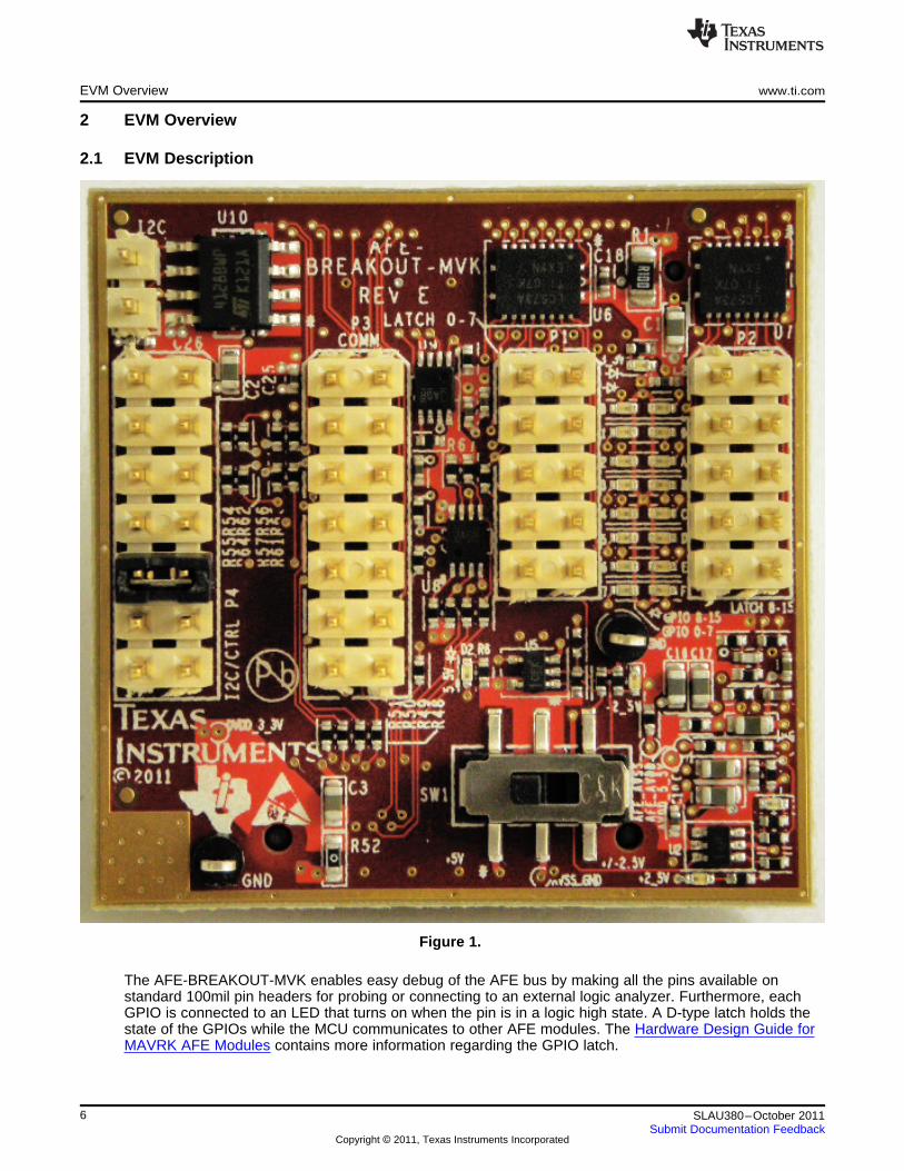
2.1 EVM Description
Figure 1.
The AFE-BREAKOUT-MVK enables easy debug of the AFE bus by making all the pins available onstandard 100mil pin headers for probing or connecting to an external logic analyzer. Furthermore, eachGPIO is connected to an LED that turns on when the pin is in a logic high state. A D-type latch holds thestate of the GPIOs while the MCU communicates to other AFE modules. The Hardware Design Guide forMAVRK AFE Modules contains more information regarding the GPIO latch.
6 SLAU380–October 2011Submit Documentation Feedback
Copyright © 2011, Texas Instruments Incorporated
www.ti.com Hardware Description
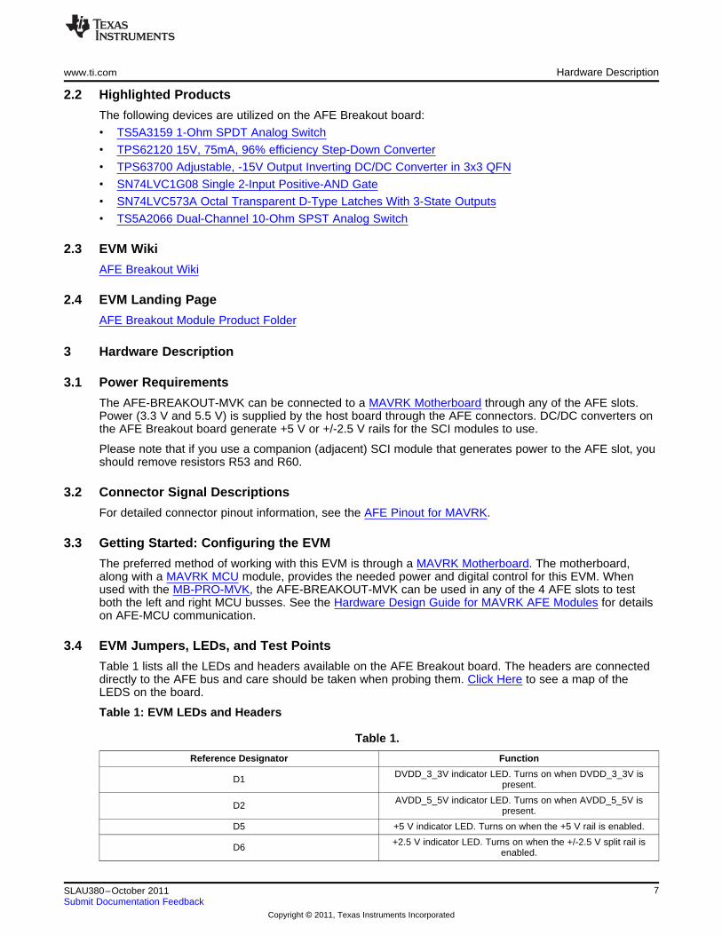
2.2 Highlighted Products
The following devices are utilized on the AFE Breakout board:
• TS5A3159 1-Ohm SPDT Analog Switch
• TPS62120 15V, 75mA, 96% efficiency Step-Down Converter
• TPS63700 Adjustable, -15V Output Inverting DC/DC Converter in 3x3 QFN
• SN74LVC1G08 Single 2-Input Positive-AND Gate
• SN74LVC573A Octal Transparent D-Type Latches With 3-State Outputs
• TS5A2066 Dual-Channel 10-Ohm SPST Analog Switch
2.3 EVM Wiki
AFE Breakout Wiki
2.4 EVM Landing Page
AFE Breakout Module Product Folder
3 Hardware Description
3.1 Power Requirements
The AFE-BREAKOUT-MVK can be connected to a MAVRK Motherboard through any of the AFE slots.Power (3.3 V and 5.5 V) is supplied by the host board through the AFE connectors. DC/DC converters onthe AFE Breakout board generate +5 V or +/-2.5 V rails for the SCI modules to use.
Please note that if you use a companion (adjacent) SCI module that generates power to the AFE slot, youshould remove resistors R53 and R60.
3.2 Connector Signal Descriptions
For detailed connector pinout information, see the AFE Pinout for MAVRK.
3.3 Getting Started: Configuring the EVM
The preferred method of working with this EVM is through a MAVRK Motherboard. The motherboard,along with a MAVRK MCU module, provides the needed power and digital control for this EVM. Whenused with the MB-PRO-MVK, the AFE-BREAKOUT-MVK can be used in any of the 4 AFE slots to testboth the left and right MCU busses. See the Hardware Design Guide for MAVRK AFE Modules for detailson AFE-MCU communication.
3.4 EVM Jumpers, LEDs, and Test Points
Table 1 lists all the LEDs and headers available on the AFE Breakout board. The headers are connecteddirectly to the AFE bus and care should be taken when probing them. Click Here to see a map of theLEDS on the board.
Table 1: EVM LEDs and Headers
Table 1.
Reference Designator Function
DVDD_3_3V indicator LED. Turns on when DVDD_3_3V isD1 present.
AVDD_5_5V indicator LED. Turns on when AVDD_5_5V isD2 present.
D5 +5 V indicator LED. Turns on when the +5 V rail is enabled.
+2.5 V indicator LED. Turns on when the +/-2.5 V split rail isD6 enabled.
7SLAU380–October 2011Submit Documentation Feedback
Copyright © 2011, Texas Instruments Incorporated
Software Description www.ti.com
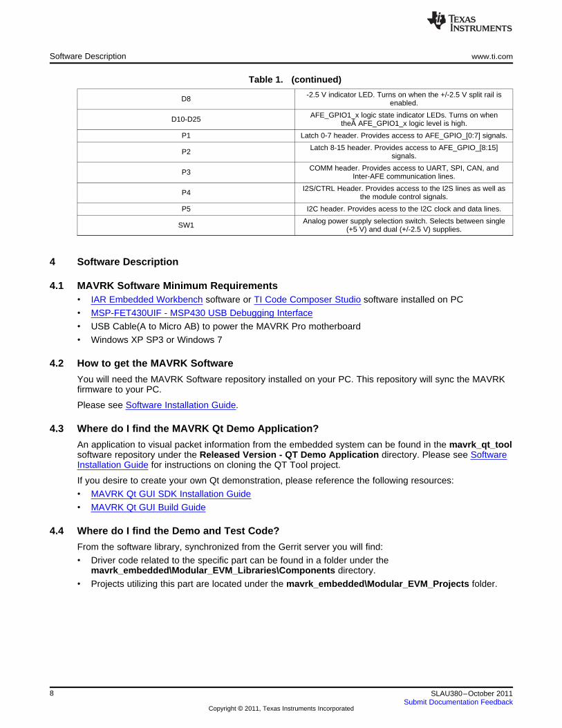
Table 1. (continued)
-2.5 V indicator LED. Turns on when the +/-2.5 V split rail isD8 enabled.
AFE_GPIO1_x logic state indicator LEDs. Turns on whenD10-D25 the AFE_GPIO1_x logic level is high.
P1 Latch 0-7 header. Provides access to AFE_GPIO_[0:7] signals.
Latch 8-15 header. Provides access to AFE_GPIO_[8:15]P2 signals.
COMM header. Provides access to UART, SPI, CAN, andP3 Inter-AFE communication lines.
I2S/CTRL Header. Provides access to the I2S lines as well asP4 the module control signals.
P5 I2C header. Provides acess to the I2C clock and data lines.
Analog power supply selection switch. Selects between singleSW1 (+5 V) and dual (+/-2.5 V) supplies.
4 Software Description
4.1 MAVRK Software Minimum Requirements• IAR Embedded Workbench software or TI Code Composer Studio software installed on PC
• MSP-FET430UIF - MSP430 USB Debugging Interface
• USB Cable(A to Micro AB) to power the MAVRK Pro motherboard
• Windows XP SP3 or Windows 7
4.2 How to get the MAVRK Software
You will need the MAVRK Software repository installed on your PC. This repository will sync the MAVRKfirmware to your PC.
Please see Software Installation Guide.
4.3 Where do I find the MAVRK Qt Demo Application?
An application to visual packet information from the embedded system can be found in the mavrk_qt_toolsoftware repository under the Released Version - QT Demo Application directory. Please see SoftwareInstallation Guide for instructions on cloning the QT Tool project.
If you desire to create your own Qt demonstration, please reference the following resources:
• MAVRK Qt GUI SDK Installation Guide
• MAVRK Qt GUI Build Guide
4.4 Where do I find the Demo and Test Code?
From the software library, synchronized from the Gerrit server you will find:
• Driver code related to the specific part can be found in a folder under themavrk_embedded\Modular_EVM_Libraries\Components directory.
• Projects utilizing this part are located under the mavrk_embedded\Modular_EVM_Projects folder.
8 SLAU380–October 2011Submit Documentation Feedback
Copyright © 2011, Texas Instruments Incorporated
www.ti.com Software Project
5 Software Project
5.1 Getting Started
A software project named AFE_Breakout_Demo exists in themavrk_embedded\Modular_EVM_Projects\Component_Demo_Projects\AFE_Breakout_Board_Demo_Project software repository directory. This project contains demo code for using the UART, SPI andI2C buses in the AFE breakout board. MAVRK Boards may be interconnected via the AFE breakoutboards using the above mentioned buses.
This demo expectst the AFE Breakout board to be in the AFE1 slot.
There actually three difference configuration in the one project (one for each bus). To select one of theconfigurations click on the drop down box in the "Workspace" window (on the left hand side of the screen)and select the bus that you would like to use. Only one configuration can be used at one time. There arethree choices:
• UART_Demo
• I2C_Demo
• SPI_Demo
After selecting one of the configurations compile (using "Make") the project and program the board.
5.2 UART Demo
Generally for board to board communications, there would be atleast two boards. In this case only one isused. The way that send and receive is verified in this project is by connecting the RX and TX lines on theAFE breakout board. What the loopback does is any signal that is transmitted will come back to thisdevice. So when there is a valid receive this proves that the device can transmit and receive successfully.The signals for the UART bus are located on the P3 header on the AFE breakout board. The TX signal islocated on header P3 on the 3rd pin. The RX signal is on the same header on the 5th pin. A standardjumper may be used to interconnect these two signals.
The UART is set by default in the mvk_Init_MAVRK_Standard_Settings function to a baud rate of 460Kand 8 bits data, no parity and one stop bit.
Before writing to the UART a handle has to be created and registered using this function call:UartDebugHandle = mvk_Register_UART_Tx (MAVRK_UART_P1P2, MAVRK_AFE1, 2, SET, CLEAR); // Priority2, Fast Print, Do not overwrite
This sets the UartDebugHandle to the device which is in AFE1 slot. This handle is later used tocommunicate with this device.
Then it continuually makes this function call which sends the message out.mvk_UART_Debug_PrintF_Flush (UartDebugHandle, "Hello from MCU UART", 19);
The demo continually sends a "Hello from UART". To verify that this transfer is sending and receivingcorrectly, a breakpoint may be placed in the user_Decode_UART_RX_Data(...) function. This function iscalled when there is an incoming UART character. The character that has arrived is given in the dataparameter. A watch may be placed on this variable and viewed to determine which character has justarrived.
For more information on utilizing the MAVRK UART APIs please refer to MAVRK UART Functions.
5.3 SPI Demo
The SPI demo continually sends a message through the SPI bus. As in the case with UART, a loopback isused on the MOSI (output) and MISO (input) pins to test the input portion of the SPI bus.
The signals for the SPI bus are located on the P3 header on the AFE breakout board. The SPI clock is onpin 9, the chip select in on pin 7, MOSI is on pin 11 and MISO in on pin 13.
To setup the SPI port this function call is used:mvk_Configure_SPI_Device_Working_Settings (MAVRK_AFE1, &AFE1_SPI_device_settings);
9SLAU380–October 2011Submit Documentation Feedback
Copyright © 2011, Texas Instruments Incorporated
Board Files www.ti.com
Which configures the SPI bus to the AFE1 module device settings.
The project continually sends "Hello from MCU SPI". This sending and receiving may be verified byplacing a breakpoint on the SPI call (mvk_Write_SPI_Payload (MAVRK_AFE1, "Hello from MCU SPI",read, 18, 0). After this line is executed the read variable will hold the results of the input (which should bethe message).
For more information on utilizing the MAVRK SPI APIs please refer to MAVRK SPI Functions.
5.4 I2C Demo
The I2C demo is different from the previous buses demo in that it does not use a loopback. It howeverwrites to an EEPROM chip that is located on the AFE breakout board. This EEPROM (16Kx8) is used tostore device information for the breakout board. This information is stored on the highest 256 bytes of thememory. This area should not be overwritten. Any other area is free to be used.
The project writes to the EEPROM chip an 8-bit value and reads that value back to make sure that it waswritten properly. The bus that is used to do this transfer is I2C.
The actual I2C write call happens deeper in the program but one example is this:mvk_Write_I2C (I2C_slave_address, device_slot, EEPROM24xx128_I2C_write_data,total_number_write_bytes);
The first parameter is the I2C slave address to write to, the second is the device slot to use for the write(in this case MAVRK_AFE1), then the write data, and the amount of data to write. An example of the I2Cread function may be found in the mvk_Read_EEPROM_24xx128 () function which may be found inEEPROM24xx128.c.
This demo also demonstrates how the LEDs may be used in the breakout board. Currently only 8 of theLEDs are controllable. They are on the left column.
For more information on utilizing the MAVRK I2C APIs please refer to MAVRK I2C Bus Functions.
5.5 Outputing and Inputing on the GPIO
It is only possible to output on the GPIO bus on the AFE breakout board as the bus is behind a register(Note: this is only the case on the AFE breakout board). Also although there are 16 lines on the bus, onlythe lower half are controllable.
There are two ways to configure this bus and use it. One way is to configure the whole port in oneinstruction or either break up the configuration to pin by pin.
To configure and set the whole bus in one instruction this function call is used:mvk_Write_AFE_GPIO (0xff, MAVRK_AFE1); // turns on the whole port on
To set the port pin by pin this function may be used:mvk_Write_AFE_GPIO_Pin (AFE_GPIO_PIN_7, CLEAR, MAVRK_AFE1); // writes to the top most pin to setit off only
This function call turns off the highest pin (7). The range of pins that may be used areAFE_GPIO_PIN_0...AFE_GPIO_PIN_7.
6 Board Files
6.1 Bill of Materials (BOM)
Download a PDF of the bill of materials.
AFE-BREAKOUT-MVK Bill of Materials
10 SLAU380–October 2011Submit Documentation Feedback
Copyright © 2011, Texas Instruments Incorporated
www.ti.com Board Files
Figure 2.
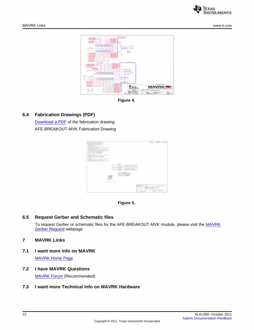
6.2 Layout (PDF)
Download a PDF of additional board layers.
AFE-BREAKOUT-MVK Board Top Silkscreen
Figure 3.
6.3 Schematics (PDF)
Download a PDF of the schematic.
AFE-BREAKOUT-MVK Schematics
11SLAU380–October 2011Submit Documentation Feedback
Copyright © 2011, Texas Instruments Incorporated
MAVRK Links www.ti.com
Figure 4.
6.4 Fabrication Drawings (PDF)
Download a PDF of the fabrication drawing.
AFE-BREAKOUT-MVK Fabrication Drawing
Figure 5.
6.5 Request Gerber and Schematic files
To request Gerber or schematic files for the AFE-BREAKOUT-MVK module, please visit the MAVRKGerber Request webpage.
7 MAVRK Links
7.1 I want more info on MAVRK
MAVRK Home Page
7.2 I have MAVRK Questions
MAVRK Forum (Recommended):
7.3 I want more Technical Info on MAVRK Hardware
12 SLAU380–October 2011Submit Documentation Feedback
Copyright © 2011, Texas Instruments Incorporated
www.ti.com Important Notices
Table 2.
• Hardware Design Guide for MAVRK• Hardware Design Guide for MAVRK PMU Gas Gauge Sub-ModulesMCU Modules• Hardware Design Guide for the• Hardware Design Guide for MAVRK• Hardware Design Guide for MAVRK uMAVRK Analog InterfacePMU High-Power DC/DCModules Sub-Modules • Hardware Design Guide for the
• Hardware Design Guide for MAVRK uMAVRK Power Interface• Hardware Design Guide for MAVRKPMU Charger Sub-Modules SCI Modules • Template - Hardware User's Guide• Hardware Design Guide for MAVRK • Hardware Design Guide for MAVRKPMU DC/DC Sub-Modules SCI Sub-Modules
7.4 I want more Technical Info on MAVRK Software
Table 3.
• Software - MAVRK Embedded• Demo Application - ADS1298 Demo • MAVRK Qt GUI SDK InstallationProject Abstraction Layerson MAVRK Guide
• Software - MAVRK I2C Bus• Demo Application - Sensors on • MAVRK Radio NetworkFunctionsuMAVRK • MAVRK Software Developers Guide
• Software - MAVRK SPI Bus• Demo Application - TCA8418 on • MAVRK Software Installation Guide FunctionsMAVRK • Running the TCA-8418 Demo (CCS) • Software - MAVRK UART Functions• Demo Application - UART • Running the TCA8418 Demo (IAR) • Software - Main Processing Loop inPassthrough on MAVRK• Software - API Documentation for Standard MAVRK Applications• Demo Application - UART Receiver
MAVRK Embedded Software • Software - My First MAVRKon MAVRKLibraries Application (Using Code Composer)• Demo Application - Wireless • Software - CC11xx, CC25xx, CC430 • Software - My First MAVRKKeyboard on MAVRK
Radio API Guide Application (Using IAR)• How to Convert a Project from IAR to • Software - CPU Power Down Logic • Software - Programming withCCSon Standard MAVRK Applications Elprotronic's FET-Pro430 Flash• IAR Broken Options Error • Software - Coding Conventions for Programmer
• IAR Project Open Error MAVRK Software • Software - Selecting the CCS• MAVRK - TortoiseGit Frequently • Software - Customizing a Demo Workspace Directory
Asked Questions Project • Software - Troubleshooting the• MAVRK Partners and Resources • Software - Doxygen Conventions for MAVRK COM Port Connection to QT• MAVRK Qt Demo Application User MAVRK Software • Software Design Guide for MAVRK
Guide • Software - MAVRK Adding the Radio Modules• MAVRK Qt GUI Build Guide Demo to Another Demo • Stellaris-ICDI Programming
7.5 I want to get a MAVRK board
MAVRK Home Page
8 Important Notices
8.1 ESD Precautions
The following guidelines should be followed in order to avoid ESD damage to the board components:
• Any person handling boards must be grounded either with a wrist strap or ESD protective footwear,used in conjunction with a conductive or static-dissipative floor or floor mat.
• The work surface where boards are placed for handing, processing, testing, etc., must be made ofstatic-dissipative material and be grounded to ESD ground.
• All insulator materials either must be removed from the work area or they must be neutralized with anionizer. Static-generating clothes should be covered with an ESD-protective smock.
• When boards are being stored, transferred between operations or workstations, or shipped, they mustbe maintained in a Faraday-shield container whose inside surface (touching the boards) is staticdissipative.
13SLAU380–October 2011Submit Documentation Feedback
Copyright © 2011, Texas Instruments Incorporated
Important Notices www.ti.com
8.2 Certifications
Eco-Info & Lead-Free Home
RoHS Compliant Solutions
Statement on Registration, Evaluation, Authorization of Chemicals (REACh)
FCC and EMC test report for the MAVRK STK-PRO430-MVK Starter Kit, featuring theAFE-BREAKOUT-MVK Module
8.3 Evaluation Board/Kit Important Notice
Texas Instruments (TI) provides the enclosed product(s) under the following conditions: This evaluationboard/kit is intended for use for ENGINEERING DEVELOPMENT, DEMONSTRATION, OR EVALUATIONPURPOSES ONLY and is not considered by TI to be a finished end-product fit for general consumer use.Persons handling the product(s) must have electronics training and observe good engineering practicestandards. As such, the goods being provided are not intended to be complete in terms of requireddesign-, marketing-, and/or manufacturing-related protective considerations, including product safety andenvironmental measures typically found in end products that incorporate such semiconductor componentsor circuit boards. This evaluation board/kit does not fall within the scope of the European Union directivesregarding electromagnetic compatibility, restricted substances (RoHS), recycling (WEEE), FCC, CE or UL,and therefore may not meet the technical requirements of these directives or other related directives.Should this evaluation board/kit not meet the specifications indicated in the Users Guide, the board/kitmay be returned within 30 days from the date of delivery for a full refund. THE FOREGOING WARRANTYIS THE EXCLUSIVE WARRANTY MADE BY SELLER TO BUYER AND IS IN LIEU OF ALL OTHERWARRANTIES, EXPRESSED, IMPLIED, OR STATUTORY, INCLUDING ANY WARRANTY OFMERCHANTABILITY OR FITNESS FOR ANY PARTICULAR PURPOSE. The user assumes allresponsibility and liability for proper and safe handling of the goods. Further, the user indemnifies TI fromall claims arising from the handling or use of the goods. Due to the open construction of the product, it isthe user's responsibility to take any and all appropriate precautions with regard to electrostatic discharge.EXCEPT TO THE EXTENT OF THE INDEMNITY SET FORTH ABOVE, NEITHER PARTY SHALL BELIABLE TO THE OTHER FOR ANY INDIRECT, SPECIAL, INCIDENTAL, OR CONSEQUENTIALDAMAGES. TI currently deals with a variety of customers for products, and therefore our arrangementwith the user is not exclusive. TI assumes no liability for applications assistance, customer product design,software performance, or infringement of patents or services described herein. Please read the UsersGuide and, specifically, the Warnings and Restrictions notice in the Users Guide prior to handling theproduct. This notice contains important safety information about temperatures and voltages. For additionalinformation on TI's environmental and/or safety programs, please contact the TI application engineer orvisit www.ti.com/esh. No license is granted under any patent right or other intellectual property right of TIcovering or relating to any machine, process, or combination in which such TI products or services mightbe or are used.
8.4 FCC Warning
This evaluation board/kit is intended for use for ENGINEERING DEVELOPMENT, DEMONSTRATION,OR EVALUATION PURPOSES ONLY and is not considered by TI to be a finished end-product fit forgeneral consumer use. It generates, uses, and can radiate radio frequency energy and has not beentested for compliance with the limits of computing devices pursuant to part 15 of FCC rules, which aredesigned to provide reasonable protection against radio frequency interference. Operation of thisequipment in other environments may cause interference with radio communications, in which case theuser at his own expense will be required to take whatever measures may be required to correct thisinterference.
8.5 EVM Warnings and Restrictions
It is important to operate this EVM within the input voltage range of –2.5V to +5V and the output voltagerange of 0V to 5V. Exceeding the specified input range may cause unexpected operation and/orirreversible damage to the EVM. If there are questions concerning the input range, please contact a TIfield representative prior to connecting the input power. Applying loads outside of the specified outputrange may result in unintended operation and/or possible permanent damage to the EVM. Please consultthe EVM User's Guide prior to connecting any load to the EVM output. If there is uncertainty as to the load
14 SLAU380–October 2011Submit Documentation Feedback
Copyright © 2011, Texas Instruments Incorporated
www.ti.com Important Notices
specification, please contact a TI field representative. During normal operation, some circuit componentsmay have case temperatures greater than +30°C. The EVM is designed to operate properly with certaincomponents above +30°C as long as the input and output ranges are maintained. These componentsinclude but are not limited to linear regulators, switching transistors, pass transistors, and current senseresistors. These types of devices can be identified using the EVM schematic located in the EVM User'sGuide. When placing measurement probes near these devices during operation, please be aware thatthese devices may be very warm to the touch.
Table 4.
For technical support on MAVRK please post your questions onThe MAVRK Toolbox Forum . Please post only comments about
the article AFE-BREAKOUT-MVK MAVRK Module here.
15SLAU380–October 2011Submit Documentation Feedback
Copyright © 2011, Texas Instruments Incorporated
IMPORTANT NOTICE
Texas Instruments Incorporated and its subsidiaries (TI) reserve the right to make corrections, modifications, enhancements, improvements,and other changes to its products and services at any time and to discontinue any product or service without notice. Customers shouldobtain the latest relevant information before placing orders and should verify that such information is current and complete. All products aresold subject to TI’s terms and conditions of sale supplied at the time of order acknowledgment.
TI warrants performance of its hardware products to the specifications applicable at the time of sale in accordance with TI’s standardwarranty. Testing and other quality control techniques are used to the extent TI deems necessary to support this warranty. Except wheremandated by government requirements, testing of all parameters of each product is not necessarily performed.
TI assumes no liability for applications assistance or customer product design. Customers are responsible for their products andapplications using TI components. To minimize the risks associated with customer products and applications, customers should provideadequate design and operating safeguards.
TI does not warrant or represent that any license, either express or implied, is granted under any TI patent right, copyright, mask work right,or other TI intellectual property right relating to any combination, machine, or process in which TI products or services are used. Informationpublished by TI regarding third-party products or services does not constitute a license from TI to use such products or services or awarranty or endorsement thereof. Use of such information may require a license from a third party under the patents or other intellectualproperty of the third party, or a license from TI under the patents or other intellectual property of TI.
Reproduction of TI information in TI data books or data sheets is permissible only if reproduction is without alteration and is accompaniedby all associated warranties, conditions, limitations, and notices. Reproduction of this information with alteration is an unfair and deceptivebusiness practice. TI is not responsible or liable for such altered documentation. Information of third parties may be subject to additionalrestrictions.
Resale of TI products or services with statements different from or beyond the parameters stated by TI for that product or service voids allexpress and any implied warranties for the associated TI product or service and is an unfair and deceptive business practice. TI is notresponsible or liable for any such statements.
TI products are not authorized for use in safety-critical applications (such as life support) where a failure of the TI product would reasonablybe expected to cause severe personal injury or death, unless officers of the parties have executed an agreement specifically governingsuch use. Buyers represent that they have all necessary expertise in the safety and regulatory ramifications of their applications, andacknowledge and agree that they are solely responsible for all legal, regulatory and safety-related requirements concerning their productsand any use of TI products in such safety-critical applications, notwithstanding any applications-related information or support that may beprovided by TI. Further, Buyers must fully indemnify TI and its representatives against any damages arising out of the use of TI products insuch safety-critical applications.
TI products are neither designed nor intended for use in military/aerospace applications or environments unless the TI products arespecifically designated by TI as military-grade or "enhanced plastic." Only products designated by TI as military-grade meet militaryspecifications. Buyers acknowledge and agree that any such use of TI products which TI has not designated as military-grade is solely atthe Buyer's risk, and that they are solely responsible for compliance with all legal and regulatory requirements in connection with such use.
TI products are neither designed nor intended for use in automotive applications or environments unless the specific TI products aredesignated by TI as compliant with ISO/TS 16949 requirements. Buyers acknowledge and agree that, if they use any non-designatedproducts in automotive applications, TI will not be responsible for any failure to meet such requirements.
Following are URLs where you can obtain information on other Texas Instruments products and application solutions:
Products Applications
Audio www.ti.com/audio Communications and Telecom www.ti.com/communications
Amplifiers amplifier.ti.com Computers and Peripherals www.ti.com/computers
Data Converters dataconverter.ti.com Consumer Electronics www.ti.com/consumer-apps
DLP® Products www.dlp.com Energy and Lighting www.ti.com/energy
DSP dsp.ti.com Industrial www.ti.com/industrial
Clocks and Timers www.ti.com/clocks Medical www.ti.com/medical
Interface interface.ti.com Security www.ti.com/security
Logic logic.ti.com Space, Avionics and Defense www.ti.com/space-avionics-defense
Power Mgmt power.ti.com Transportation and Automotive www.ti.com/automotive
Microcontrollers microcontroller.ti.com Video and Imaging www.ti.com/video
RFID www.ti-rfid.com
OMAP Mobile Processors www.ti.com/omap
Wireless Connectivity www.ti.com/wirelessconnectivity
TI E2E Community Home Page e2e.ti.com
Mailing Address: Texas Instruments, Post Office Box 655303, Dallas, Texas 75265Copyright © 2011, Texas Instruments Incorporated
Mouser Electronics
Authorized Distributor
Click to View Pricing, Inventory, Delivery & Lifecycle Information: Texas Instruments:
AFE-BREAKOUT-MVK
Related Documents