SECREDAS Product Security for Cross Domain Reliable Dependable Automated Systems DELIVERABLE REPORT “Single demonstrators working” Document Type Deliverable Document Number D9.2 Primary Author(s) David Aragón (FICO-ADAS) / Petr Fiedler (BUT) Document Date 30.6.2020 Document Version / Status v 1.2 Distribution Level Confidential Reference DoA May 2019 ----------------------------------------- Project Coordinator Patrick Pype, NXP Semiconductors, [email protected] Project Website www.secredas.eu (in progress) JU Grant Agreement Number 783119 SECREDAS has received funding from the Electronic Component Systems for European Leadership Joint Undertaking under grant agreement nr.783119. This Joint Undertaking receives support from the European Union’s Horizon 2020 research and innovation programme and Austria, Belgium, Czech Republic, Germany, Finland, Hungary, Italy, The Netherlands, Poland, Romania, Sweden and Tunis Ref. Ares(2020)4513190 - 31/08/2020

Welcome message from author
This document is posted to help you gain knowledge. Please leave a comment to let me know what you think about it! Share it to your friends and learn new things together.
Transcript
SECREDAS
Product Security for Cross Domain Reliable Dependable Automated Systems
DELIVERABLE REPORT “Single demonstrators working”
Document Type Deliverable
Document Number D9.2
Primary Author(s) David Aragón (FICO-ADAS) / Petr Fiedler (BUT)
Document Date 30.6.2020
Document Version / Status v 1.2
Distribution Level Confidential
Reference DoA May 2019 ----------------------------------------- Project Coordinator Patrick Pype, NXP Semiconductors, [email protected]
Project Website www.secredas.eu (in progress)
JU Grant Agreement Number 783119
SECREDAS has received funding from the Electronic Component Systems for European Leadership Joint Undertaking under grant agreement nr.783119. This Joint Undertaking receives support from the European Union’s Horizon 2020 research and innovation programme and Austria,
Belgium, Czech Republic, Germany, Finland, Hungary, Italy, The Netherlands, Poland, Romania, Sweden and Tunis
Ref. Ares(2020)4513190 - 31/08/2020
Page 2 of 91
CONTRIBUTORS
Name Organization Name Organization
Petr Fiedler BUT Stelios Karagiannis Beyond Vision
David Aragón FICO-ADAS Pedro Lousã PDMFC
Cyrille Falcou Thales DIS - GTO Marcin Borawski GUT
Luca Bongiovanni I&M Szabolcs Nyond ováczki Commsignia
Karel Kalivoda IMA Mohieddine El Soussi Imec-NL
Robin Smit TNO (IVS) Stefan Kraxberger secinto
Ian Oliver Nokia Bell Labs Arturo Medela TST
Marcus de Ree ITAV Domingos Barbosa ITAV
Rafael Garrido INDRA Michele Seeber UniMoRe
Ulrico Celentano UOULU Henna Mönttinen UOULU
Antony Bertin IDEMIA Jakub Arm, Pavel Smrž BUT
Thierry Ernst YoGoKo Ioannis Karydis CWA
Pavel Smrž BUT Sebastian Gerres MRTX
Adrian Loy MRTX
FORMAL REVIEWERS
Name Organization Date
Iuliana Dragomir TNO 16.07.2020
Roy Pennings NXP 27-07-2020; 24/8/2020
SECREDAS Steering Board N/A 27/08/2020
DOCUMENT HISTORY
Revision Date Author / Organization Description
0.1 13.1.2020 P.Fiedler/BUT, D. Aragón/FICO-ADAS
Initial version
0.1.1 22.4.2020 Ian Oliver/Nokia Updates: medical and rail demos
0.9 5.5.2020 Petr Fiedler Integration of latest contributions
20.5.2020 Rafael Garrido / INDRA Indra´s contribution
20.05.2020 Marcus de Ree / ITAV ITAV’s contribution
25.05.2020 Ulrico Celentano / UOULU UOULU’s contribution
1.0 10.07.2020 Petr Fiedler Document figure numbering, latest contributions integrated
1.1 16.07.2020 Iuliana Dragomir Added review comments
1.2 4.8.2020 Petr Fiedler Version integrating Roy’s comments with v 1.1
21-24.8.2020 Petr Fiedler Document finalization
Page 3 of 91
Executive summary
SECREDAS work package 9 (WP9) is in the process of developing and organizing Common Demonstrators to integrate,
validate and demonstrate outcomes of technical work packages (WP3-WP8) executed within the SECREDAS project.
The purpose of deliverable D9.2 is to show that systems are operational at the end of year 2. A secondary purpose of
this deliverable is to support consistent and aligned integration activities by describing the basic functionality of
demonstrator subsystems that are operational and available for integration activities. For these reasons, the system
descriptions are more verbose than would be required to fulfil only the primary purpose of the document.
Individual systems are designed according to findings from WP1 with respect to the Reference Architecture developed
within WP2. Individual systems implement Common Technological Elements (CTE) and Design Patterns (DP) that were
defined in WP3 (and as described in D9.1).
Deliverable D9.2 provides an overview of systems that are being completed to become future common demonstrators
(Demo I, Demo II and Demo III). The document provides a brief description of each system and they are documented
by 80 photographs/screenshots in total. Please note that each system in this deliverable is presented in a dedicated
chapter as an isolated component. This means that the order of the chapters does not follow the structure of the
common demonstrators. Additionally: due to the fact that this deliverable showcases standalone working
demonstrators and because other documents (mainly: WP9 and WP11 deliverables) may refer to a specific chapter in
this D9.2, the partner contributions were not grouped according to their relevance in each of the Use Cases. The initial
integration of individual systems presented in D9.2 into common demonstrators that provide solutions to the D1.7 Use
Cases will be demonstrated in D9.4: Demonstrators combined cooperating in to Use Cases.
Please note that as a result of new knowledge and ongoing technical development in WP4-WP8, some technologies
that are not described in this deliverable, may be added later to the WP9 Common Demonstrators if they
complement/enhance the intended Scenario solution. Their inclusion is dependent on specific
technical/operational/legal/permitting requirements and restrictions of the WP9 DEMO owners. Where such
technology cannot be included in WP9, it will be demonstrated inside the respective WP, but WP9 partners will be
informed about their status and (future) integration potential to the overall Threat/Scenario solution.
Page 4 of 91
Table of Contents
Executive summary ........................................................................................................................................................................................3
Table of Contents ...........................................................................................................................................................................................4
Acronyms ........................................................................................................................................................................................................6
1. NB-IoT SIM-card encryption (EXEL) ......................................................................................................................................................7
1.1. Single demonstrator ....................................................................................................................................................................7
2. Reliable and Secure wireless communication link (GUT) ....................................................................................................................9
2.1. Single demonstrator ....................................................................................................................................................................9
2.2. Realization ................................................................................................................................................................................. 10
2.3. Threat being addressed by the technology ............................................................................................................................. 12
2.4. Current stage of development and demonstrator results ...................................................................................................... 12
3. Driver Monitoring System (FICOSA) .................................................................................................................................................. 13
3.1. Single demonstrator ................................................................................................................................................................. 13
4. Driver’s Status Monitoring (UOULU) ................................................................................................................................................. 14
4.1. Single demonstrator ................................................................................................................................................................. 14
5. Identity Derivation for strong Authentication (Thales DIS) .............................................................................................................. 17
5.1. Single demonstrator ................................................................................................................................................................. 17
6. Anomaly detection on VCU (EVI-I&M-UniMoRe) ............................................................................................................................. 20
6.1. Single demonstrator ................................................................................................................................................................. 20
7. C-ITS Interconnection Module for video surveillance camera (CRF) ............................................................................................... 22
7.1. CRF demonstrator ..................................................................................................................................................................... 22
8. Identity manager service (IMA) ......................................................................................................................................................... 25
8.1. Single demonstrator ................................................................................................................................................................. 25
9. Access rights management server (IMA) .......................................................................................................................................... 26
9.1. Single demonstrator ................................................................................................................................................................. 26
10. IoT-based user identification (IMA) .............................................................................................................................................. 28
10.1. Single demonstrator ................................................................................................................................................................. 28
11. Sensor fusion for World Model (TNO) .......................................................................................................................................... 29
11.1. Single demonstrator ................................................................................................................................................................. 29
12. Car sharing mobile app (BUT) ....................................................................................................................................................... 32
12.1. Single demonstrator ................................................................................................................................................................. 32
13. Car Sharing Service Provider (BUT) ............................................................................................................................................... 33
13.1. Single demonstrator ................................................................................................................................................................. 33
14. Automotive Testbed Using Drones (Beyond Vision) .................................................................................................................... 35
14.1. Single demonstrator ................................................................................................................................................................. 36
Page 5 of 91
15. Identity Management and Smart Profiling (PDMFC) ................................................................................................................... 39
15.1. Single demonstrator ................................................................................................................................................................. 39
16. V2X Services (CMS) ........................................................................................................................................................................ 42
16.1. Single demonstrator ................................................................................................................................................................. 42
17. Encrypted V2X (CMS) .................................................................................................................................................................... 44
17.1. Single demonstrator ................................................................................................................................................................. 44
18. simple2secure (SECI) ..................................................................................................................................................................... 47
18.1. Single demonstrator ................................................................................................................................................................. 48
19. Secure Gateway (IDEMIA) ............................................................................................................................................................. 49
19.1. Single demonstrator ................................................................................................................................................................. 49
20. Secure Car Access (imec-NL) ......................................................................................................................................................... 51
20.1. Single demonstrator ................................................................................................................................................................. 51
21. Early warning (TST) ........................................................................................................................................................................ 53
21.1. Early warning single demonstrator .......................................................................................................................................... 54
22. Secure positioning (TST) ................................................................................................................................................................ 61
22.1. Secure positioning single demonstrator .................................................................................................................................. 61
23. Camera sensor anomaly detection (MRTX) .................................................................................................................................. 64
23.1. Single demonstrator ................................................................................................................................................................. 64
24. Secure and trustable C-ITS Platform (CMS).................................................................................................................................. 67
24.1. Single demonstrator ................................................................................................................................................................. 68
25. Anomaly Detection (UniMoRe) ..................................................................................................................................................... 70
25.1. Single demonstrator ................................................................................................................................................................. 70
26. Privacy-Preserving Authentication with Attribute-based Pseudonymity (ITAV) ........................................................................ 72
26.1. Single demonstrator ................................................................................................................................................................. 72
27. Anonymization Framework (PDMFC and CWA) .......................................................................................................................... 75
28. Drowsiness Detection (PDMFC and Beyond Vision) ................................................................................................................... 77
29. V2X Connection using LoRAWAN (Beyond Vision and PDMFC) ................................................................................................. 79
30. Adversary emulation, attack simulation and threat management (Beyond Vision and CWA) ............................................... 81
31. Secure cloud connectivity and V2X platform (YoGoKo) .............................................................................................................. 83
32. Additional demonstrations............................................................................................................................................................ 86
32.1. Trusted Data and Control Mechanisms (Nokia, WP7) ............................................................................................................ 86
32.2. Trusted Railway Simulation Environment (Nokia, WP8) ......................................................................................................... 87
33. Summary and conclusions............................................................................................................................................................. 88
Page 6 of 91
Acronyms
AD Anomaly Detection API Application Programming Interface ARMS Acces Rights Management Service AUTOSAR Automotive Open System Architecture CA Certification Authority CAM Cooperative Awareness Message CAN Controller Area Network CEN European Committee for Standardization C-ITS Cooperative Intelligent Transport Systems C-ITS-S Central ITS Station (ISO 21217) CO2 Carbon Dioxide CPM Collective Perception Message CSI Channel State Information CSSP Car Sharing Service Provider CTE Common Technology Element DDM Dynamic Directional Modulation DENM Decentralized Environmental Notification Message DMS Driver Monitoring System DP Design Pattern E/E Electric/Electronic ECG Electrocardiogram ECU Embedded Control Unit EDA Electrodermal Activity EEG Electroencephalogram ETSI European Telecommunications Standards Institute FGSM Fast Gradient Signed Method FoV Field of View GPS Global Positioning System GPU Graphic Processing Unit HMI Human Machine Interface HR Heart Rate HRV Heart Rate Variation HSM Hardware Security Module IDM Identity Management IdP Identity Provider IoT Internet-of-Things
IPv6 Internet Protocol Version 6 ISO International Organization for Standardization ITS Intelligent Transport Systems ITS-G5 Vehicular WiFi in 5.9 GHz frequency range ITS-S ITS station ITS-SCU ITS station communication unit (ISO 21217) ITS-SU ITS station unit (ISO 21217) KMS Key Management Servfice MAC Message Authentication Code MASA Modena Automotive Smart Area MIMO Multiple Input Multiple Output MLS Message level Security MRZ Machine Readable Zone NFC Near Field Communication OBU On-board unit OFDM Orthogonal Frequency-Division Multiplex OTA Over the Air PHY Physical Layer PIN Personal Identification Number PKI Public Key Infrastructure PPG Photoplethysmograph R-ITS-S Roadside ITS Station (ISO 21217 RSU Road-side unit SDR Software Defined Radio SE Secure Element SECANT SecOC CAN Network SecOC Secure Onboard Communication SPAT Signal Phase & Timing) SSH Secure Shell TLS Transport Layer Security TPM Trusted Privacy Module TxBF Transmit beamforming UC Use Case USB Universal Serial Bus V2X Localized communications VCA Video Content Analysis V-ITS-S Vehicle ITS Station (ISO 21217) WP Work Package
Page 7 of 91
1. NB-IoT SIM-card encryption (EXEL)
New innovations are moving towards IoT where devices are not equipped to fully implement conventional security
technologies like TLS. A key requirement to secure data communication for machine-type communication is therefore
end-to-end encryption. The challenge is to offer secure and well-encrypted data exchange over a heterogeneous
network incorporating also IoT devices.
This section provides insights into the implementation of the system described in D9.1, Sec. 7. The solution is based on
SIM-card encryption and offers secure end-to-end data protection in Narrowband IoT (NB-IoT) networks. This
component was developed as part of the work in WP7, where health data needs to be transmitted securely from a
driver monitoring system to an health cloud server and is within WP 9 it aims for Demo II, Scenario 2.2 and prevents
mainly Threat 2 („Attacking the car using V2X communication channels“), Threat 7(„Attacks that exploit security flaws“)
and Threat 8 („Attacks on privacy or data lost and leakage“).
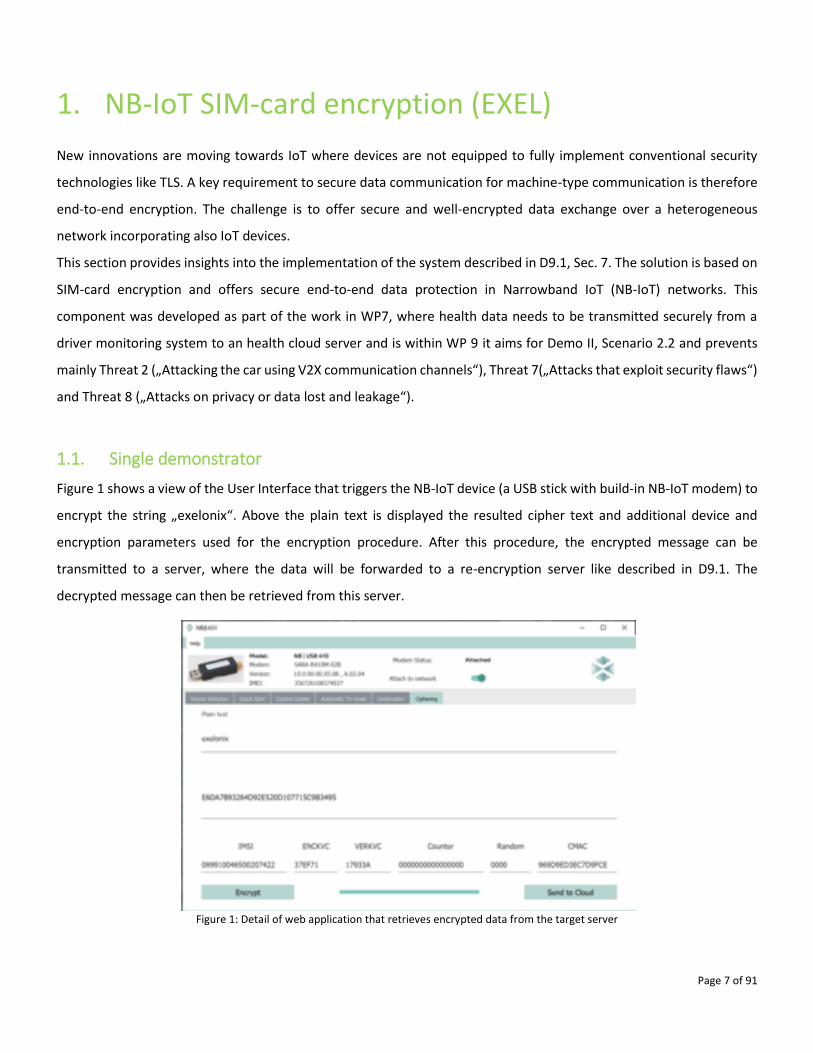
1.1. Single demonstrator
Figure 1 shows a view of the User Interface that triggers the NB-IoT device (a USB stick with build-in NB-IoT modem) to
encrypt the string „exelonix“. Above the plain text is displayed the resulted cipher text and additional device and
encryption parameters used for the encryption procedure. After this procedure, the encrypted message can be
transmitted to a server, where the data will be forwarded to a re-encryption server like described in D9.1. The
decrypted message can then be retrieved from this server.
Figure 1: Detail of web application that retrieves encrypted data from the target server
Page 8 of 91
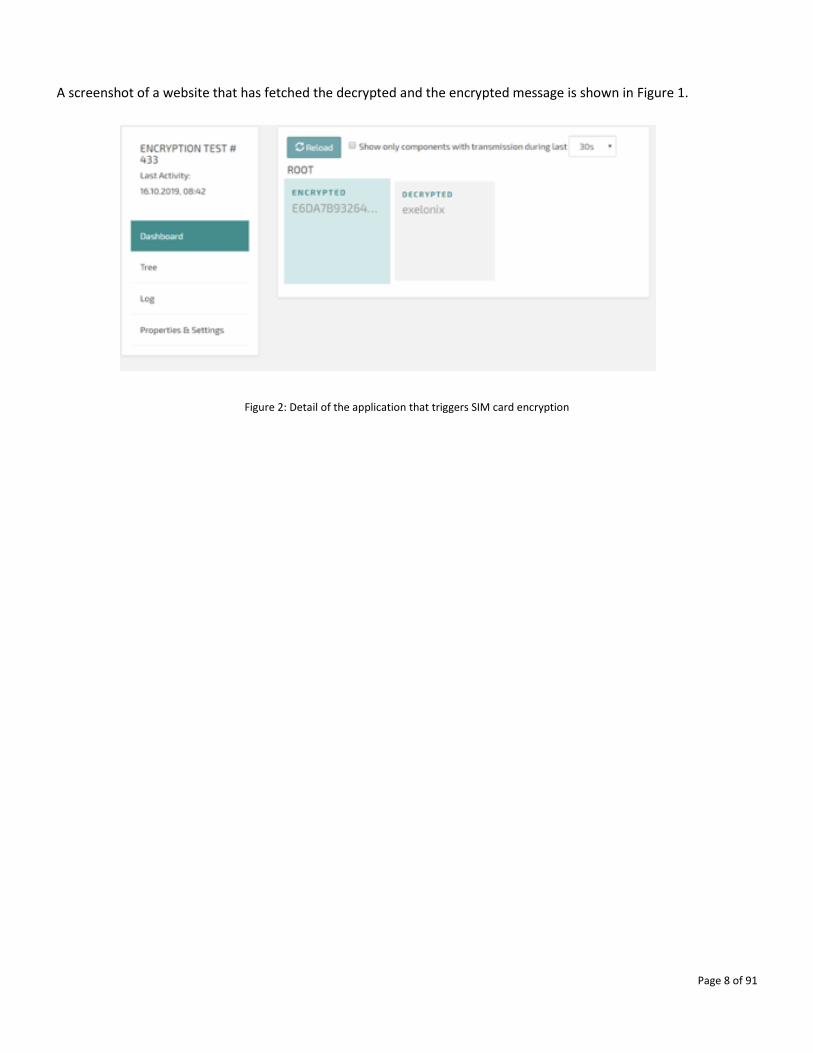
A screenshot of a website that has fetched the decrypted and the encrypted message is shown in Figure 1.
Figure 2: Detail of the application that triggers SIM card encryption
Page 9 of 91
2. Reliable and Secure wireless communication link (GUT)
This R&S Link system focuses on improving the reliability, confidentiality and security of wireless communication for
low power IoT devices that communicate using IEEE 802.15.1 (Bluetooth), IEEE 802.15.4 (ZigBee) or IEEE 802.11
(WLAN). The system exploits spatial capabilities of antenna arrays and reconfigurable antennas to provide secure
communication with a vehicle and/or interacting IoT devices. This system is relevant for Use Case 3, Scenario 3.1 - Keep
car secure for the whole vehicle product lifetime. Link to video demonstration of the technology:
https://nxp1.sharepoint.com/teams/ext282/Shared%20Documents/Forms/AllItems.aspx?RootFolder=%2fteams%2fe
xt282%2fShared%20Documents%2f05%2e%20Reporting%20%26%20Review%2fPMR2%2fDemonstrator%20recordin
gs&FolderCTID=0x012000E5173F29AC1FEE4C99EA9BCC0F876FC2
2.1. Single demonstrator
Reliable and Secure wireless communication link
In general, the traditional communication link in wireless system is assumed as being an insecure form of exchanging
information. This assumption is dictated by the broadcast nature of the radiation emitted by involved transceivers.
Even when using antenna arrays and traditional beam steering techniques, V2X systems need to consider side lobes of
antenna radiation pattern and effects of multipath propagation. This means that security and privacy of V2X
communication lies mostly in cryptography. However, cryptographic techniques do not prevent data leakage through
air medium, which can be recorded, and over longer periods of time cryptographic security can be bypassed. Proposed
system does not impair nor collide with cryptographic techniques or with other, because it involves modification at
physical layer only. These techniques can coexist.
GUT is developing a test system to simulate a spatially secured wireless communication link. The goal is to provide and
demonstrate a system that is able to spatially secure the wireless communication link against undesirable eavesdropper
attacks basing on the physical layer of the communication and without deploying any higher-layer cryptographic
solutions. The system, in order to be seen as an eligible solution by project partners, should be easily integrable into
existing wireless communication standards, e.g. IEEE 802.11 (WLAN, including WLAN-based V2x). To achieve this goal,
the IEEE 802.11 physical layer (PHY) stack has been implemented. Techniques of channel estimation were exploited to
obtain channel state information (CSI) that is required to perform transmit beamforming (TxBF). Channel state
information (CSI) is a term that refers to known communication channel properties. In other words, CSI describes how
signal propagates from the transmitter to the receiver and represents the combined effects the channel has on the
Page 10 of 91
signal. Transmit beamforming or transmit precoding (TxBF) is a technique that involves transformation of IQ samples
before their transmission. TxBF allows to compensate the effects a signal undergoes when it propagates through a
communication channel. Moreover, TxBF minimizes the power that is transmitted into undesirable directions while
maximizing it in the direction of a receiver. This feature of TxBF mitigates the potential eavesdropper effectiveness. For
the system to provide a spatially secured communication link CSI knowledge and TxBF techniques are cornerstones,
but such a system only mitigates the potential eavesdropping scenario. To fully secure the connection from an
eavesdropping attack, CSI knowledge will be utilized to radiate pseudorandom noise sequence into channels
orthogonal to the desirable information channel. In the literature, this approach is called dynamic directional
modulation (DDM).
Y2 demonstrator includes a simulator for TxBF technique, while the final Y3 demonstrator will feature a hardware
implementation of spatially secured communication link, backed by TxBF and DDM techniques.
2.2. Realization
The main purpose of the demonstration is to show the operation principle of a spatially secured communication link.
From that perspective, two actors can be distinguished: the base station, which performs the algorithms to secure the
link and a standard receiver.
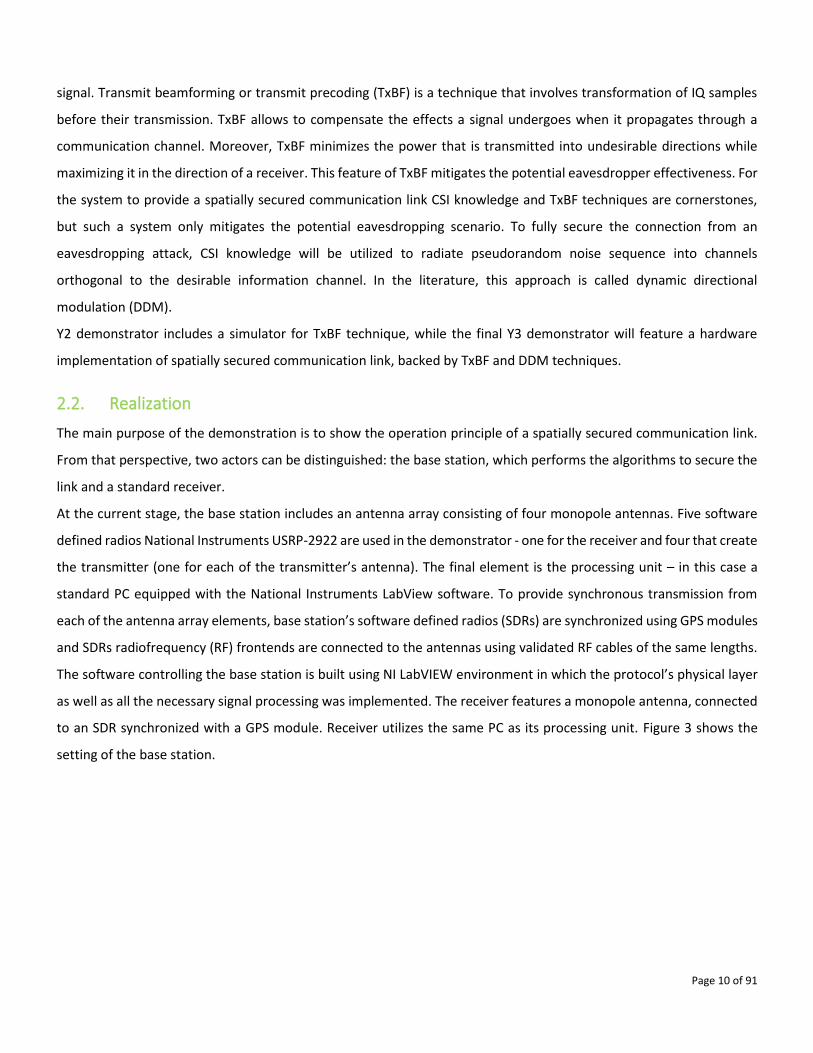
At the current stage, the base station includes an antenna array consisting of four monopole antennas. Five software
defined radios National Instruments USRP-2922 are used in the demonstrator - one for the receiver and four that create
the transmitter (one for each of the transmitter’s antenna). The final element is the processing unit – in this case a
standard PC equipped with the National Instruments LabView software. To provide synchronous transmission from
each of the antenna array elements, base station’s software defined radios (SDRs) are synchronized using GPS modules
and SDRs radiofrequency (RF) frontends are connected to the antennas using validated RF cables of the same lengths.
The software controlling the base station is built using NI LabVIEW environment in which the protocol’s physical layer
as well as all the necessary signal processing was implemented. The receiver features a monopole antenna, connected
to an SDR synchronized with a GPS module. Receiver utilizes the same PC as its processing unit. Figure 3 shows the
setting of the base station.
Page 11 of 91
Figure 3: Hardware used for the demonstrator
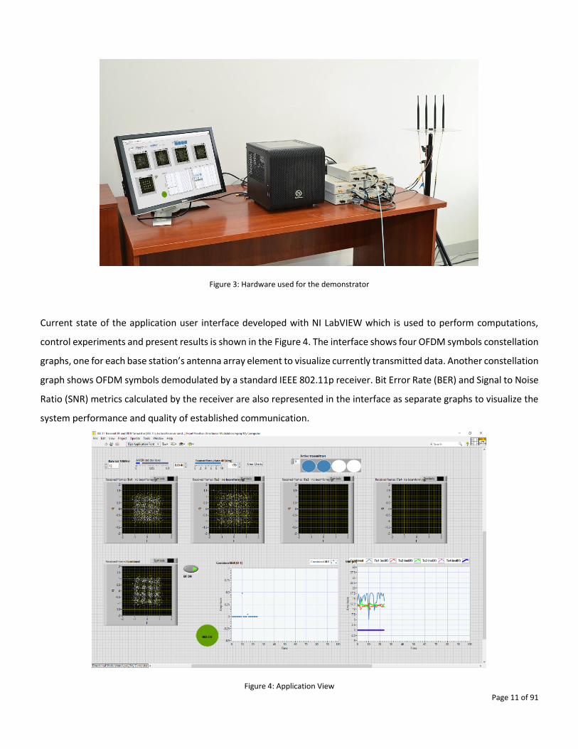
Current state of the application user interface developed with NI LabVIEW which is used to perform computations,
control experiments and present results is shown in the Figure 4. The interface shows four OFDM symbols constellation
graphs, one for each base station’s antenna array element to visualize currently transmitted data. Another constellation
graph shows OFDM symbols demodulated by a standard IEEE 802.11p receiver. Bit Error Rate (BER) and Signal to Noise
Ratio (SNR) metrics calculated by the receiver are also represented in the interface as separate graphs to visualize the
system performance and quality of established communication.
Figure 4: Application View
Page 12 of 91
2.3. Threat being addressed by the technology
• T8 – Attacks on privacy or data leakage in V2X communication.
• T2 – Attacking a car using V2X communication channels, e.g. stealing the credentials.
2.4. Current stage of development and demonstrator results
Currently GUT has developed a simulation system and began the hardware implementation of a real transmission using
software defined radios. Hardware implementation status already features IEEE 802.11p (V2X PHY) communication
with transmit beamforming (as described in subsection 4.1.1).
At present, the system is able to verify the quality of communication in different MIMO settings, using SNR and BER
metrics. It is possible to configure the system with different number of active antenna elements. Both in simulation
and in the hardware-enabled scenario, there is a possibility to activate or deactivate the TxBF and CSI estimation
algorithms to observe how they affect the communication quality. Simulation gives the possibility to control the phase
of the signal received from different antenna array elements (which simulates the physical change of the position of
the receiver) which allows to observe how TxBF is capable to compensate the separate channels effects for each of the
array elements when signals arrive out of phase.
The system controls the level of power radiated by the base station, regardless of the number of active elements in the
array.
Demonstrator already proves the usability of the spatial separation of the radio frequency signals to achieve a spatially
secured communication.
At the moment GUT has prepared a working platform to develop security algorithms based on spatial signal separation,
such as dynamic directional modulation. This platform enables GUT to conduct tests in controlled environments, such
as an anechoic chamber, as well as in the outdoor settings that are planned to be performed in Y3.
Page 13 of 91
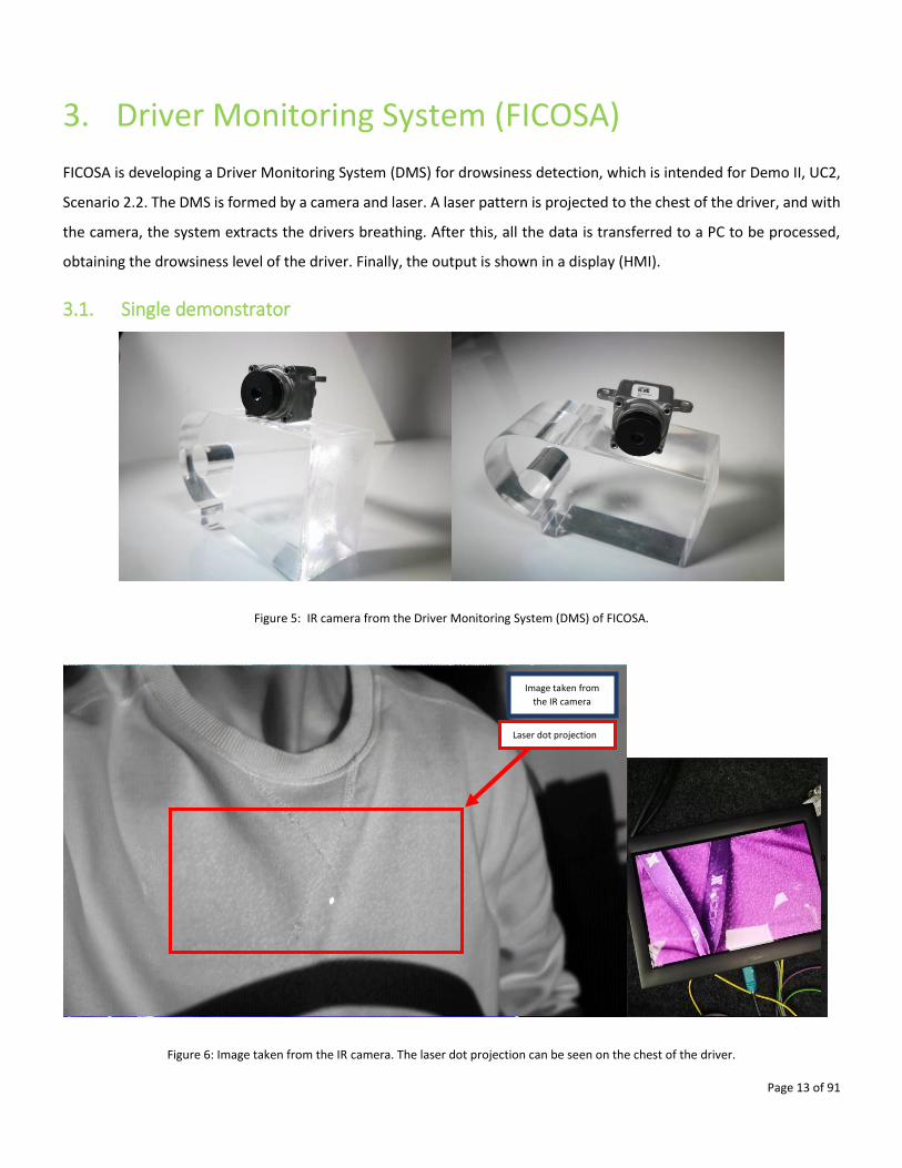
3. Driver Monitoring System (FICOSA)
FICOSA is developing a Driver Monitoring System (DMS) for drowsiness detection, which is intended for Demo II, UC2,
Scenario 2.2. The DMS is formed by a camera and laser. A laser pattern is projected to the chest of the driver, and with
the camera, the system extracts the drivers breathing. After this, all the data is transferred to a PC to be processed,
obtaining the drowsiness level of the driver. Finally, the output is shown in a display (HMI).
3.1. Single demonstrator
Figure 5: IR camera from the Driver Monitoring System (DMS) of FICOSA.
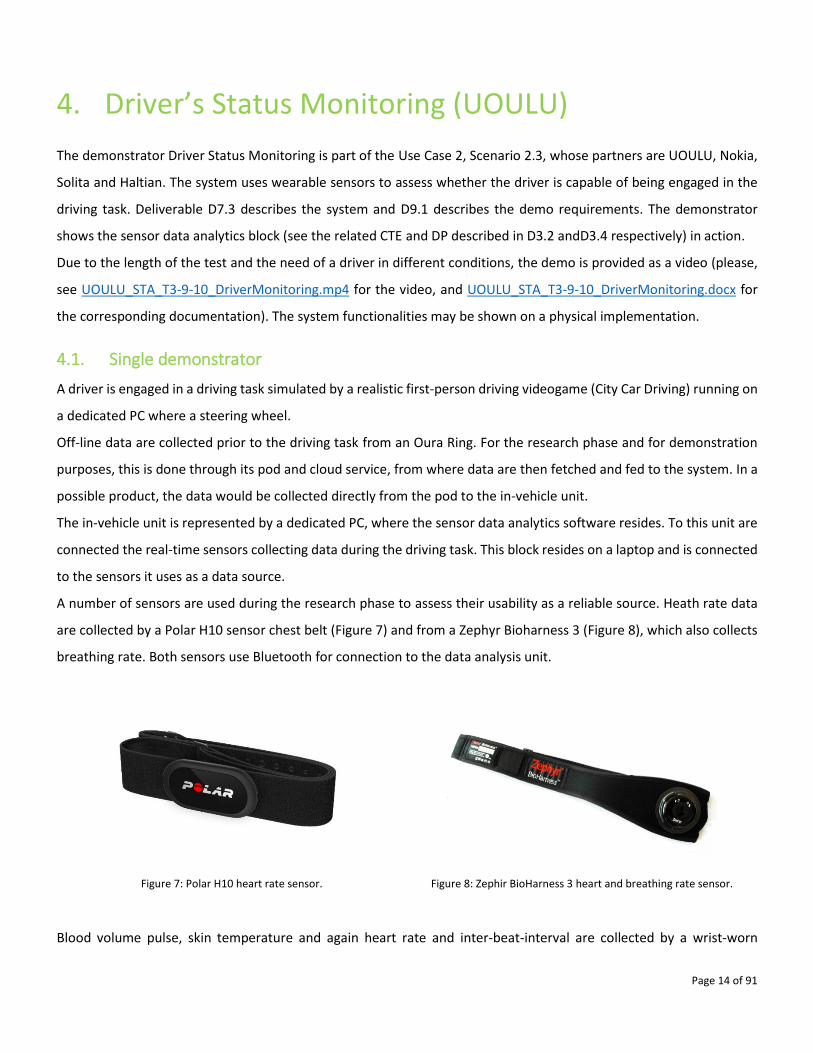
Figure 6: Image taken from the IR camera. The laser dot projection can be seen on the chest of the driver.
Image taken from
the IR camera
Laser dot projection
Page 14 of 91
4. Driver’s Status Monitoring (UOULU)
The demonstrator Driver Status Monitoring is part of the Use Case 2, Scenario 2.3, whose partners are UOULU, Nokia,
Solita and Haltian. The system uses wearable sensors to assess whether the driver is capable of being engaged in the
driving task. Deliverable D7.3 describes the system and D9.1 describes the demo requirements. The demonstrator
shows the sensor data analytics block (see the related CTE and DP described in D3.2 andD3.4 respectively) in action.
Due to the length of the test and the need of a driver in different conditions, the demo is provided as a video (please,
see UOULU_STA_T3-9-10_DriverMonitoring.mp4 for the video, and UOULU_STA_T3-9-10_DriverMonitoring.docx for
the corresponding documentation). The system functionalities may be shown on a physical implementation.
4.1. Single demonstrator
A driver is engaged in a driving task simulated by a realistic first-person driving videogame (City Car Driving) running on
a dedicated PC where a steering wheel.
Off-line data are collected prior to the driving task from an Oura Ring. For the research phase and for demonstration
purposes, this is done through its pod and cloud service, from where data are then fetched and fed to the system. In a
possible product, the data would be collected directly from the pod to the in-vehicle unit.
The in-vehicle unit is represented by a dedicated PC, where the sensor data analytics software resides. To this unit are
connected the real-time sensors collecting data during the driving task. This block resides on a laptop and is connected
to the sensors it uses as a data source.
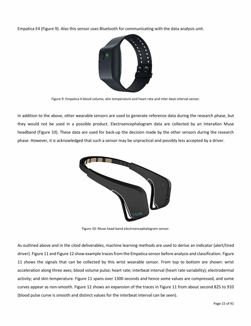
A number of sensors are used during the research phase to assess their usability as a reliable source. Heath rate data
are collected by a Polar H10 sensor chest belt (Figure 7) and from a Zephyr Bioharness 3 (Figure 8), which also collects
breathing rate. Both sensors use Bluetooth for connection to the data analysis unit.
Figure 7: Polar H10 heart rate sensor. Figure 8: Zephir BioHarness 3 heart and breathing rate sensor.
Blood volume pulse, skin temperature and again heart rate and inter-beat-interval are collected by a wrist-worn
Page 15 of 91
Empatica E4 (Figure 9). Also this sensor uses Bluetooth for communicating with the data analysis unit.
Figure 9: Empatica 4 blood volume, skin temperature and heart rate and inter-beat interval sensor.
In addition to the above, other wearable sensors are used to generate reference data during the research phase, but
they would not be used in a possible product. Electroencephalogram data are collected by an InteraXon Muse
headband (Figure 10). These data are used for back-up the decision made by the other sensors during the research
phase. However, it is acknowledged that such a sensor may be unpractical and possibly less accepted by a driver.
Figure 10: Muse head-band electroencephalogram sensor.
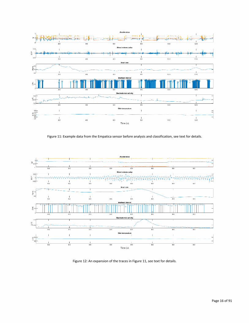
As outlined above and in the cited deliverables, machine learning methods are used to derive an indicator (alert/tired
driver). Figure 11 and Figure 12 show example traces from the Empatica sensor before analysis and classification. Figure
11 shows the signals that can be collected by this wrist wearable sensor. From top to bottom are shown: wrist
acceleration along three axes; blood volume pulse; heart rate; interbeat interval (heart rate variability); electrodermal
activity; and skin temperature. Figure 11 spans over 1300 seconds and hence some values are compressed, and some
curves appear as non-smooth. Figure 12 shows an expansion of the traces in Figure 11 from about second 825 to 910
(blood pulse curve is smooth and distinct values for the interbeat interval can be seen).
Page 16 of 91
Figure 11: Example data from the Empatica sensor before analysis and classification, see text for details.
Figure 12: An expansion of the traces in Figure 11, see text for details.
Page 17 of 91
5. Identity Derivation for strong Authentication (Thales DIS)
Identity Verification based on an official document is mandatory to access services such as opening a bank account.
This is becoming increasingly important as there are more and more eServices available in the cloud.
The system centralizes means of Identity Verification of any User that would like to access to any eServices (Car sharing
application in this context) in the cloud. After Identity Verification, the system generates a Derived Identity that will be
stored in User’s device (Mobile phone). Using this Derived Identity, the System is able to authenticate the User and
share User’s attributes such as “age > 18”, “Allowed Vehicle category to drive”. The attributes are protected by User’s
consent and for respect of privacy, only the System knows the real Identity of the User.
This system is dedicated to any Service Provider which would like to delegate Identity verification and strong User
Authentication to specialist for whom this is the core business. Within the Secredas project it is intended for UC4,
Scenario 4.1, where strong authentication is needed as part of Car Sharing demonstration.
5.1. Single demonstrator
Thales DIS has developed a single demonstrator that shows an authentication between a Service Provider and a User
using Derived Identity issued from an electronic document.
A video of the single demonstrator THALES_STA_T1_Identity_derivation.avi is available.
It is composed of:
- A mobile device (smartphone hardware) with a camera and NFC capacity
- A Mobile application
- A backend server (the IdP)
- A Service Provider for testing purpose
The process is split in 2 phases:
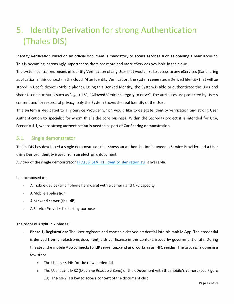
- Phase 1, Registration: The User registers and creates a derived credential into his mobile App. The credential
is derived from an electronic document, a driver license in this context, issued by government entity. During
this step, the mobile App connects to IdP server backend and works as an NFC reader. The process is done in a
few steps:
o The User sets PIN for the new credential.
o The User scans MRZ (Machine Readable Zone) of the eDocument with the mobile’s camera (see Figure
13). The MRZ is a key to access content of the document chip.
Page 18 of 91
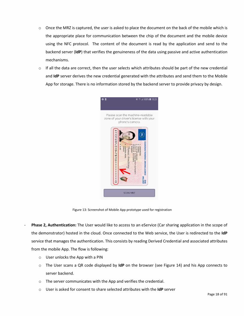
o Once the MRZ is captured, the user is asked to place the document on the back of the mobile which is
the appropriate place for communication between the chip of the document and the mobile device
using the NFC protocol. The content of the document is read by the application and send to the
backend server (IdP) that verifies the genuineness of the data using passive and active authentication
mechanisms.
o If all the data are correct, then the user selects which attributes should be part of the new credential
and IdP server derives the new credential generated with the attributes and send them to the Mobile
App for storage. There is no information stored by the backend server to provide privacy by design.
Figure 13: Screenshot of Mobile App prototype used for registration
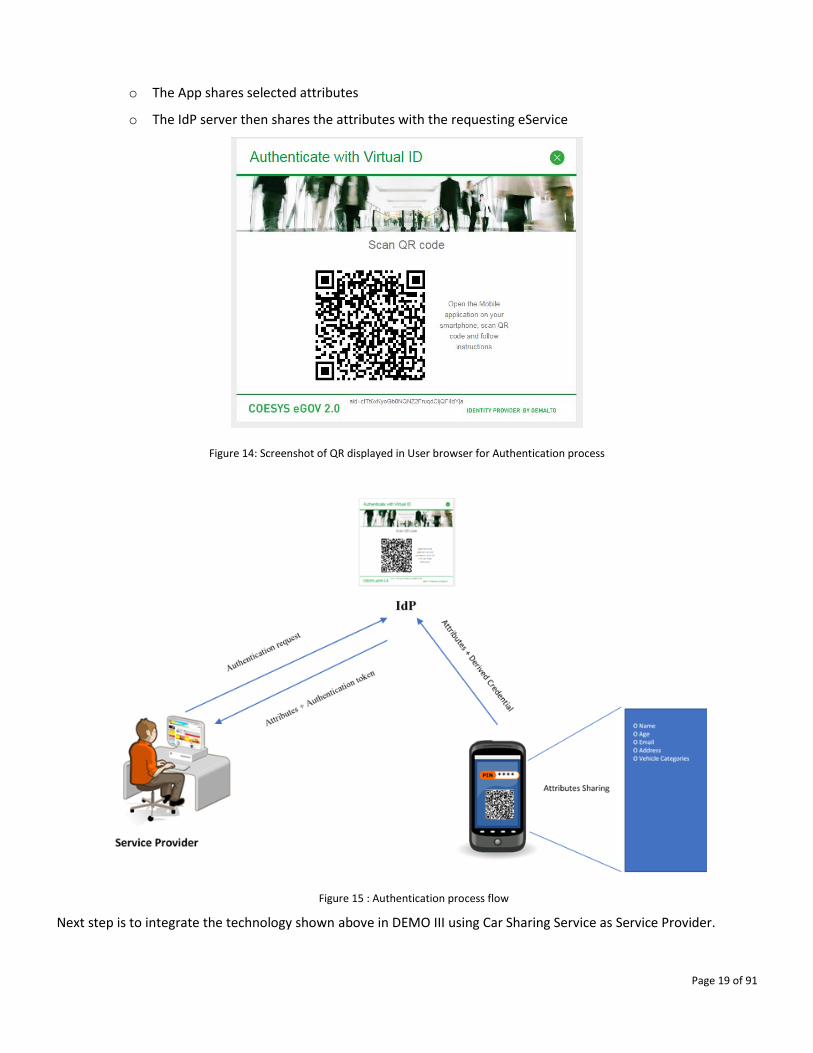
- Phase 2, Authentication: The User would like to access to an eService (Car sharing application in the scope of
the demonstrator) hosted in the cloud. Once connected to the Web service, the User is redirected to the IdP
service that manages the authentication. This consists by reading Derived Credential and associated attributes
from the mobile App. The flow is following:
o User unlocks the App with a PIN
o The User scans a QR code displayed by IdP on the browser (see Figure 14) and his App connects to
server backend.
o The server communicates with the App and verifies the credential.
o User is asked for consent to share selected attributes with the IdP server
Page 19 of 91
o The App shares selected attributes
o The IdP server then shares the attributes with the requesting eService
Figure 14: Screenshot of QR displayed in User browser for Authentication process
Figure 15 : Authentication process flow
Next step is to integrate the technology shown above in DEMO III using Car Sharing Service as Service Provider.
Page 20 of 91
6. Anomaly detection on VCU (EVI-I&M-UniMoRe)
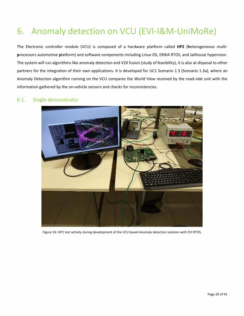
The Electronic controller module (VCU) is composed of a hardware platform called HP2 (heterogeneous multi-
processors automotive platform) and software components including Linux OS, ERIKA RTOS, and Jailhouse hypervisor.
The system will run algorithms like anomaly detection and V2X fusion (study of feasibility), it is also at disposal to other
partners for the integration of their own applications. It is developed for UC1 Scenario 1.3 (Scenario 1.3a), where an
Anomaly Detection algorithm running on the VCU compares the World View received by the road-side unit with the
information gathered by the on-vehicle sensors and checks for inconsistencies.
6.1. Single demonstrator
Figure 16: HP2 test activity during development of the VCU based Anomaly detection solution with EVI RTOS.
Page 21 of 91
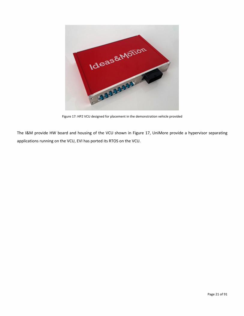
Figure 17: HP2 VCU designed for placement in the demonstration vehicle provided
The I&M provide HW board and housing of the VCU shown in Figure 17, UniMore provide a hypervisor separating
applications running on the VCU, EVI has ported its RTOS on the VCU.
Page 22 of 91
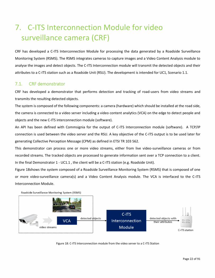
7. C-ITS Interconnection Module for video surveillance camera (CRF)
CRF has developed a C-ITS Interconnection Module for processing the data generated by a Roadside Surveillance
Monitoring System (RSMS). The RSMS integrates cameras to capture images and a Video Content Analysis module to
analyse the images and detect objects. The C-ITS Interconnection module will transmit the detected objects and their
attributes to a C-ITS station such as a Roadside Unit (RSU). The development is intended for UC1, Scenario 1.1.
7.1. CRF demonstrator
CRF has developed a demonstrator that performs detection and tracking of road-users from video streams and
transmits the resulting detected objects.
The system is composed of the following components: a camera (hardware) which should be installed at the road side,
the camera is connected to a video server including a video content analytics (VCA) on the edge to detect people and
objects and the new C-ITS interconnection module (software).
An API has been defined with Commsignia for the output of C-ITS Interconnection module (software). A TCP/IP
connection is used between the video server and the RSU. A key objective of the C-ITS output is to be used later for
generating Collective Perception Message (CPM) as defined in ETSI TR 103 562.
This demonstrator can process one or more video streams, either from live video-surveillance cameras or from
recorded streams. The tracked objects are processed to generate information sent over a TCP connection to a client.
In the final Demonstrator 1 - UC1.1 , the client will be a C-ITS station (e.g. Roadside Unit).
Figure 18shows the system composed of a Roadside Surveillance Monitoring System (RSMS) that is composed of one
or more video-surveillance camera(s) and a Video Content Analysis module. The VCA is interfaced to the C-ITS
Interconnection Module.
Figure 18: C-ITS Interconnection module from the video server to a C-ITS Station
Page 23 of 91
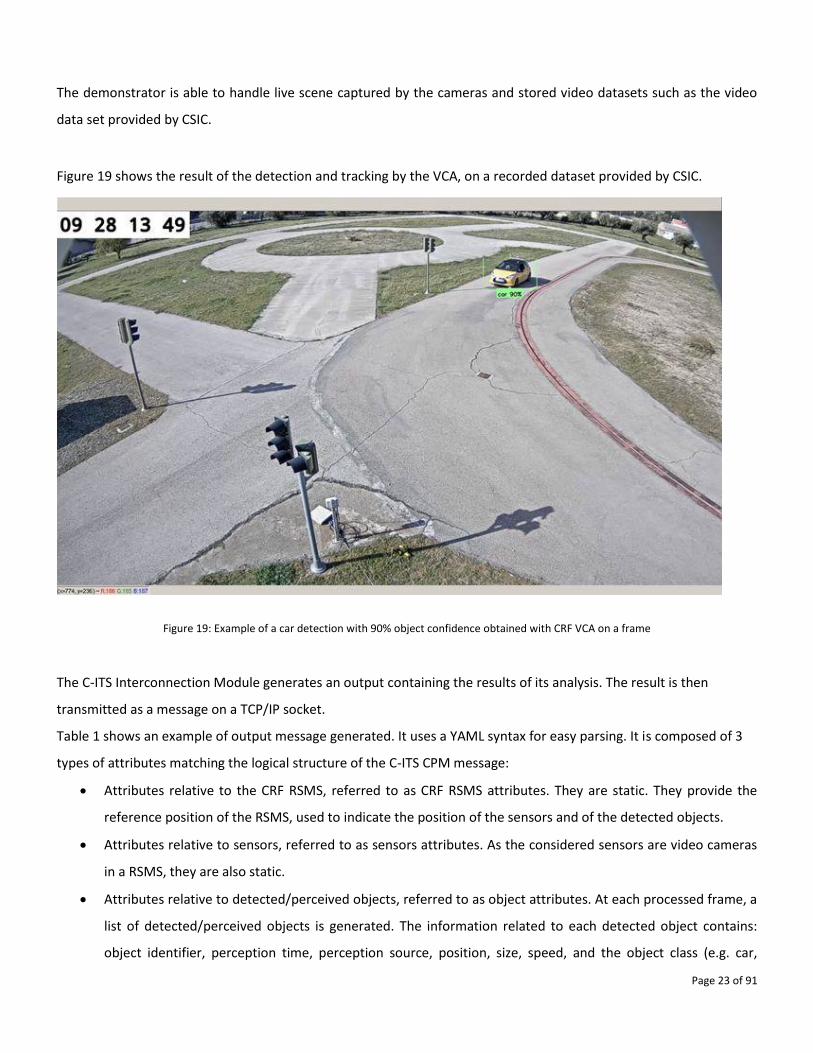
The demonstrator is able to handle live scene captured by the cameras and stored video datasets such as the video
data set provided by CSIC.
Figure 19 shows the result of the detection and tracking by the VCA, on a recorded dataset provided by CSIC.
Figure 19: Example of a car detection with 90% object confidence obtained with CRF VCA on a frame
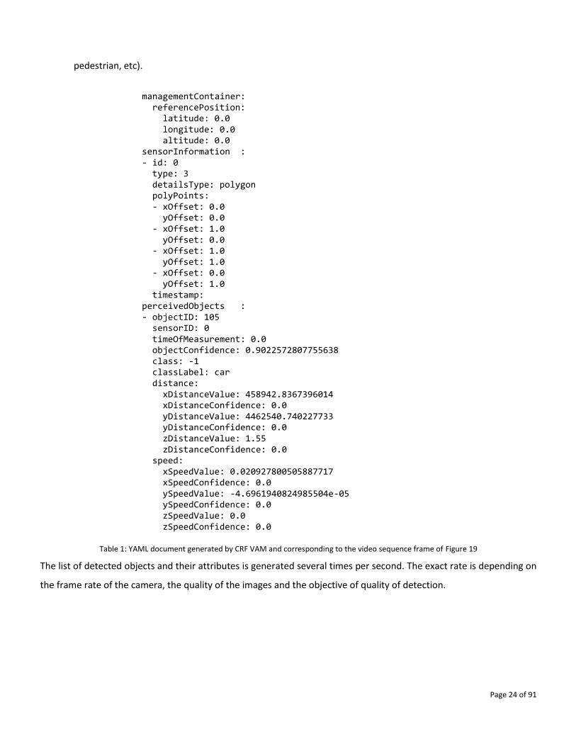
The C-ITS Interconnection Module generates an output containing the results of its analysis. The result is then
transmitted as a message on a TCP/IP socket.
Table 1 shows an example of output message generated. It uses a YAML syntax for easy parsing. It is composed of 3
types of attributes matching the logical structure of the C-ITS CPM message:
• Attributes relative to the CRF RSMS, referred to as CRF RSMS attributes. They are static. They provide the
reference position of the RSMS, used to indicate the position of the sensors and of the detected objects.
• Attributes relative to sensors, referred to as sensors attributes. As the considered sensors are video cameras
in a RSMS, they are also static.
• Attributes relative to detected/perceived objects, referred to as object attributes. At each processed frame, a
list of detected/perceived objects is generated. The information related to each detected object contains:
object identifier, perception time, perception source, position, size, speed, and the object class (e.g. car,
Page 24 of 91
pedestrian, etc).
managementContainer: referencePosition: latitude: 0.0 longitude: 0.0 altitude: 0.0 sensorInformation : - id: 0 type: 3 detailsType: polygon polyPoints: - xOffset: 0.0 yOffset: 0.0 - xOffset: 1.0 yOffset: 0.0 - xOffset: 1.0 yOffset: 1.0 - xOffset: 0.0 yOffset: 1.0 timestamp: perceivedObjects : - objectID: 105 sensorID: 0 timeOfMeasurement: 0.0 objectConfidence: 0.9022572807755638 class: -1 classLabel: car distance: xDistanceValue: 458942.8367396014 xDistanceConfidence: 0.0 yDistanceValue: 4462540.740227733 yDistanceConfidence: 0.0 zDistanceValue: 1.55 zDistanceConfidence: 0.0 speed: xSpeedValue: 0.020927800505887717 xSpeedConfidence: 0.0 ySpeedValue: -4.6961940824985504e-05 ySpeedConfidence: 0.0 zSpeedValue: 0.0 zSpeedConfidence: 0.0
Table 1: YAML document generated by CRF VAM and corresponding to the video sequence frame of Figure 19
The list of detected objects and their attributes is generated several times per second. The exact rate is depending on
the frame rate of the camera, the quality of the images and the objective of quality of detection.
Page 25 of 91
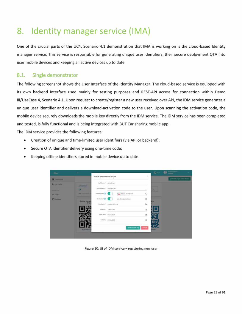
8. Identity manager service (IMA)
One of the crucial parts of the UC4, Scenario 4.1 demonstration that IMA is working on is the cloud-based Identity
manager service. This service is responsible for generating unique user identifiers, their secure deployment OTA into
user mobile devices and keeping all active devices up to date.
8.1. Single demonstrator
The following screenshot shows the User Interface of the Identity Manager. The cloud-based service is equipped with
its own backend interface used mainly for testing purposes and REST-API access for connection within Demo
III/UseCase 4, Scenario 4.1. Upon request to create/register a new user received over API, the IDM service generates a
unique user identifier and delivers a download-activation code to the user. Upon scanning the activation code, the
mobile device securely downloads the mobile key directly from the IDM service. The IDM service has been completed
and tested, is fully functional and is being integrated with BUT Car sharing mobile app.
The IDM service provides the following features:
• Creation of unique and time-limited user identifiers (via API or backend);
• Secure OTA identifier delivery using one-time code;
• Keeping offline identifiers stored in mobile device up to date.
Figure 20: UI of IDM service – registering new user

Page 26 of 91
9. Access rights management server (IMA)
In order to be able to provide a user with a time-limited virtual key for a specific car, the Car Access System must be
equipped with an Access rights management server (ARMS). This server is now being integrated with the Identity
Manager Service to enable complete management of user rights including issuing of the virtual identifiers. The ARMS
is a central server for the access control function responsible for linking individual users (i.e. mobile keys and contactless
cards) to cars and calendars. It will be an integral part of Demo III/UseCase 4, Scenario 4.1, where it will be operated
over REST-API from the Car Sharing Service Provider prepared by BUT.
9.1. Single demonstrator
The ARMS provides complete control over access rights of individual users of the Car Sharing System. It is a backend
server equipped with its own GUI and REST API for data management. Based on user or automated API input, the ARMS
generates a new access right, assigns it to a specific user and vehicle and adds a valid calendar. This access right is
pushed online to the vehicle in a form of a whitelist. This provides an enhanced security of the system, since lost or
stolen identifiers can be blocked from the system.
In the single demonstrator we have demonstrated preparation of a list of authorized users (and their identification
media such as mobile keys, contactless cards), the setup of access rights rules, generated a new mobile key over API
from IDM with limited validity for a Car Sharing system user, assigned it with access rights for a specific car and activated
access in the vehicle over-the-air. Currently we are working on API integration with Car Sharing Service Provider (CSSP)
prepared by BUT in order to process the above described automatically from the CSSP.
The Access rights management server provides the following features:
• Secure OTA connection with ID readers (fleet) and whitelist update.
• Access rights management, access events tracking.
• Definition of access rights rules.
• Remote in-vehicle HW configuration and FW update.
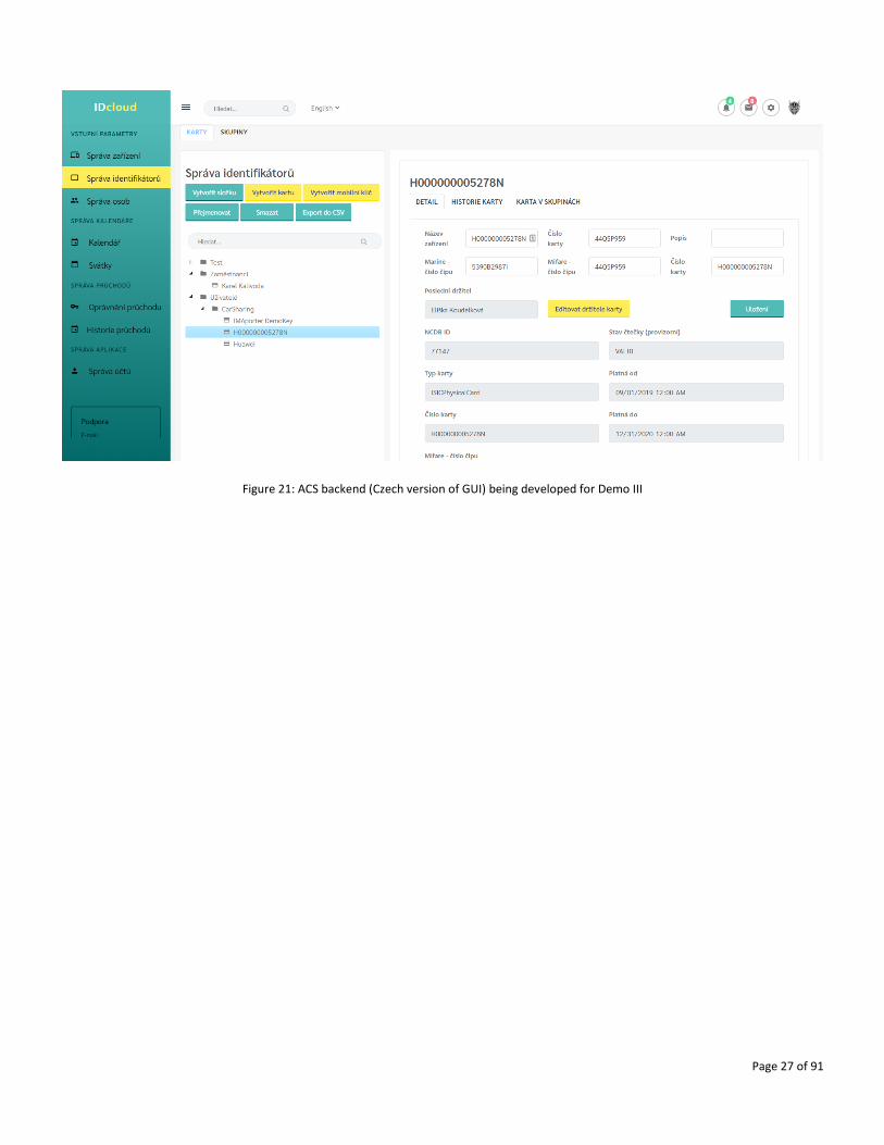
Graphic User Interface of the backend is shown in Figure 21, at present during the development a Czech version of GUI
is used, however for integration and demonstration within the Secredas Demo III an English version of the interface
will be available.
Page 27 of 91
Figure 21: ACS backend (Czech version of GUI) being developed for Demo III
Page 28 of 91
10. IoT-based user identification (IMA)
In order to enable users to enter a car-sharing vehicle using their mobile device, the vehicle must be equipped with HW
capable of IoT communication and access rights verification. The mobile device (phone) must be equipped with SW
enabling storage and secure transfer of user identification data to the vehicle. It is developed as part of Demo
III/UseCase 4, Scenario 4.1.
IMA has developed both components that are necessary for secure user identification:
• Communication app/library for a mobile device.
• Smart ID reader for vehicle.
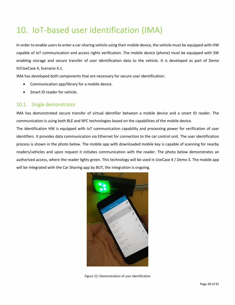
10.1. Single demonstrator
IMA has demonstrated secure transfer of virtual identifier between a mobile device and a smart ID reader. The
communication is using both BLE and NFC technologies based on the capabilities of the mobile device.
The identification HW is equipped with IoT communication capability and processing power for verification of user
identifiers. It provides data communication via Ethernet for connection to the car control unit. The user identification
process is shown in the photo below. The mobile app with downloaded mobile key is capable of scanning for nearby
readers/vehicles and upon request it initiates communication with the reader. The photo below demonstrates an
authorized access, where the reader lights green. This technology will be used in UseCase 4 / Demo 3. The mobile app
will be integrated with the Car Sharing app by BUT, the integration is ongoing.
Figure 22: Demonstration of user identification
Page 29 of 91
11. Sensor fusion for World Model (TNO)
TNO has developed a sensor fusion algorithm to provide a world view for the vehicle used in the demonstrator. This
sensor fusion algorithm is fed by the on-board sensors, consisting of a radar, camera, IMU and wheel encoders, as well
as objects observed by the CRF Roadside Surveillance Monitoring System (RSMS) described in Chapter 7. The output of
the algorithm will be the tracked objects consisting of kinematic information (position, speed, acceleration) with
uncertainties, and possibly dynamic/semantic information (size, object classification). The component is intended for
Demo I, UC1
11.1. Single demonstrator
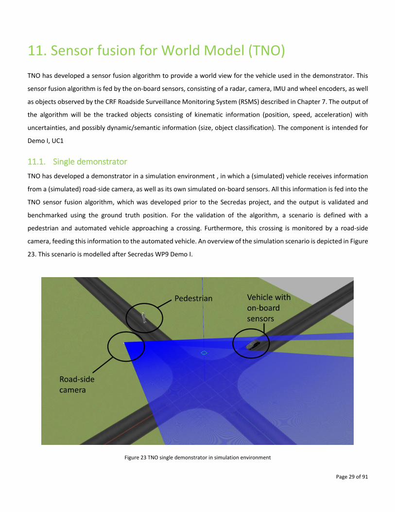
TNO has developed a demonstrator in a simulation environment , in which a (simulated) vehicle receives information
from a (simulated) road-side camera, as well as its own simulated on-board sensors. All this information is fed into the
TNO sensor fusion algorithm, which was developed prior to the Secredas project, and the output is validated and
benchmarked using the ground truth position. For the validation of the algorithm, a scenario is defined with a
pedestrian and automated vehicle approaching a crossing. Furthermore, this crossing is monitored by a road-side
camera, feeding this information to the automated vehicle. An overview of the simulation scenario is depicted in Figure
23. This scenario is modelled after Secredas WP9 Demo I.
Figure 23 TNO single demonstrator in simulation environment
Page 30 of 91
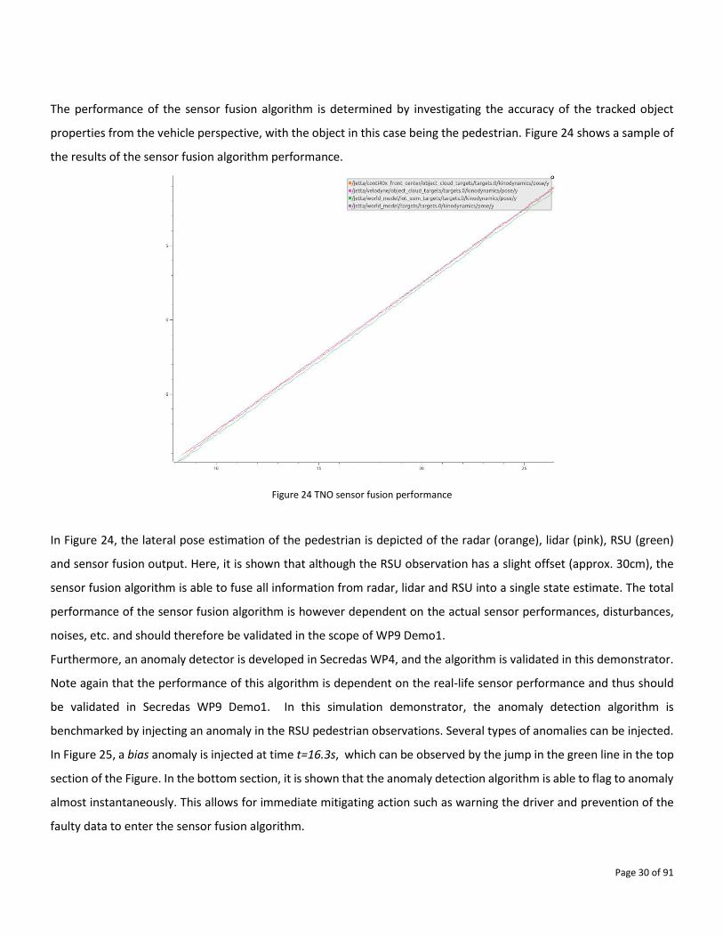
The performance of the sensor fusion algorithm is determined by investigating the accuracy of the tracked object
properties from the vehicle perspective, with the object in this case being the pedestrian. Figure 24 shows a sample of
the results of the sensor fusion algorithm performance.
Figure 24 TNO sensor fusion performance
In Figure 24, the lateral pose estimation of the pedestrian is depicted of the radar (orange), lidar (pink), RSU (green)
and sensor fusion output. Here, it is shown that although the RSU observation has a slight offset (approx. 30cm), the
sensor fusion algorithm is able to fuse all information from radar, lidar and RSU into a single state estimate. The total
performance of the sensor fusion algorithm is however dependent on the actual sensor performances, disturbances,
noises, etc. and should therefore be validated in the scope of WP9 Demo1.
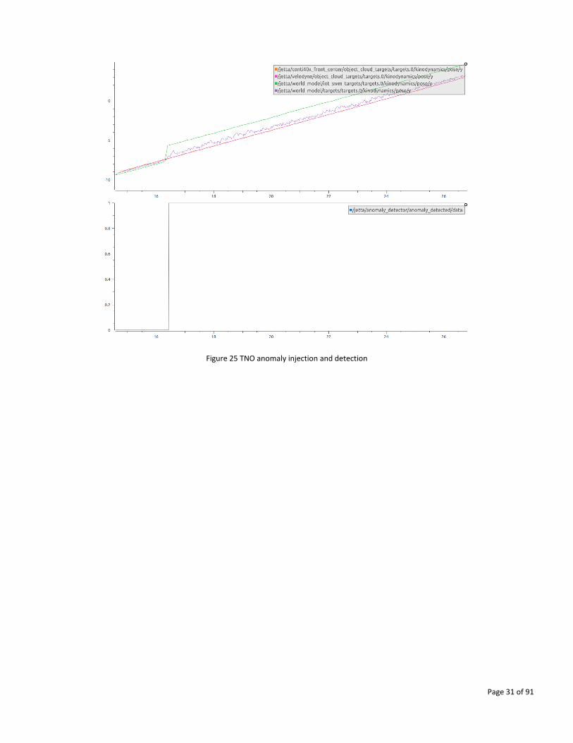
Furthermore, an anomaly detector is developed in Secredas WP4, and the algorithm is validated in this demonstrator.
Note again that the performance of this algorithm is dependent on the real-life sensor performance and thus should
be validated in Secredas WP9 Demo1. In this simulation demonstrator, the anomaly detection algorithm is
benchmarked by injecting an anomaly in the RSU pedestrian observations. Several types of anomalies can be injected.
In Figure 25, a bias anomaly is injected at time t=16.3s, which can be observed by the jump in the green line in the top
section of the Figure. In the bottom section, it is shown that the anomaly detection algorithm is able to flag to anomaly
almost instantaneously. This allows for immediate mitigating action such as warning the driver and prevention of the
faulty data to enter the sensor fusion algorithm.
Page 31 of 91
Figure 25 TNO anomaly injection and detection
Page 32 of 91
12. Car sharing mobile app (BUT)
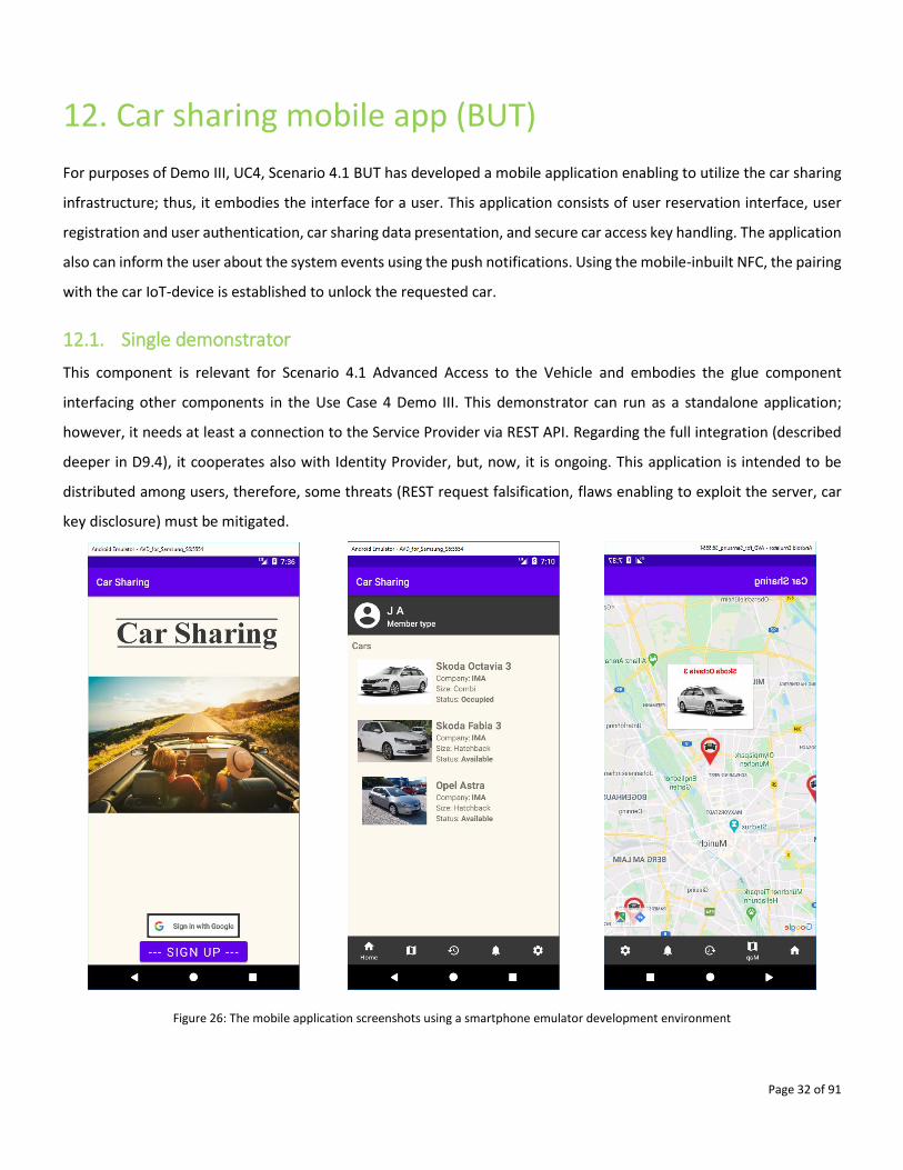
For purposes of Demo III, UC4, Scenario 4.1 BUT has developed a mobile application enabling to utilize the car sharing
infrastructure; thus, it embodies the interface for a user. This application consists of user reservation interface, user
registration and user authentication, car sharing data presentation, and secure car access key handling. The application
also can inform the user about the system events using the push notifications. Using the mobile-inbuilt NFC, the pairing
with the car IoT-device is established to unlock the requested car.
12.1. Single demonstrator
This component is relevant for Scenario 4.1 Advanced Access to the Vehicle and embodies the glue component
interfacing other components in the Use Case 4 Demo III. This demonstrator can run as a standalone application;
however, it needs at least a connection to the Service Provider via REST API. Regarding the full integration (described
deeper in D9.4), it cooperates also with Identity Provider, but, now, it is ongoing. This application is intended to be
distributed among users, therefore, some threats (REST request falsification, flaws enabling to exploit the server, car
key disclosure) must be mitigated.
Figure 26: The mobile application screenshots using a smartphone emulator development environment
Page 33 of 91
13. Car Sharing Service Provider (BUT)
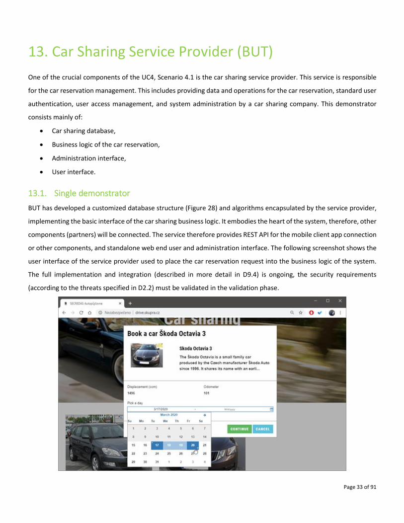
One of the crucial components of the UC4, Scenario 4.1 is the car sharing service provider. This service is responsible
for the car reservation management. This includes providing data and operations for the car reservation, standard user
authentication, user access management, and system administration by a car sharing company. This demonstrator
consists mainly of:
• Car sharing database,
• Business logic of the car reservation,
• Administration interface,
• User interface.
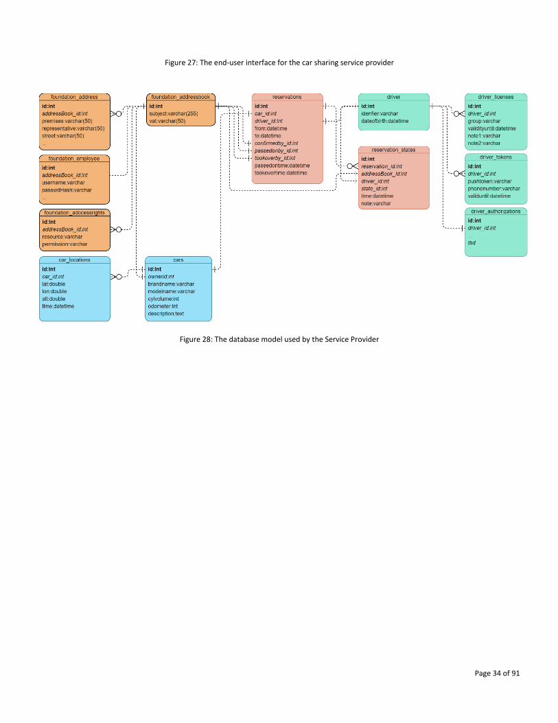
13.1. Single demonstrator
BUT has developed a customized database structure (Figure 28) and algorithms encapsulated by the service provider,
implementing the basic interface of the car sharing business logic. It embodies the heart of the system, therefore, other
components (partners) will be connected. The service therefore provides REST API for the mobile client app connection
or other components, and standalone web end user and administration interface. The following screenshot shows the
user interface of the service provider used to place the car reservation request into the business logic of the system.
The full implementation and integration (described in more detail in D9.4) is ongoing, the security requirements
(according to the threats specified in D2.2) must be validated in the validation phase.
Page 34 of 91
Figure 27: The end-user interface for the car sharing service provider
Figure 28: The database model used by the Service Provider
Page 35 of 91
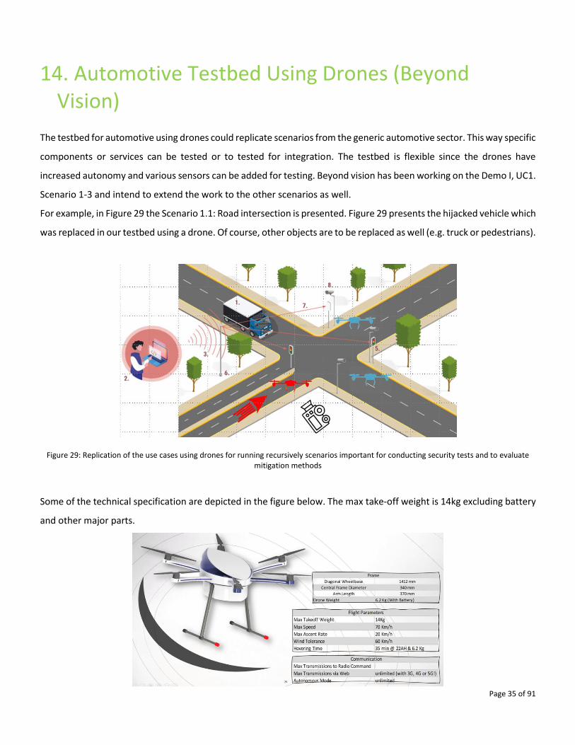
14. Automotive Testbed Using Drones (Beyond Vision)
The testbed for automotive using drones could replicate scenarios from the generic automotive sector. This way specific
components or services can be tested or to tested for integration. The testbed is flexible since the drones have
increased autonomy and various sensors can be added for testing. Beyond vision has been working on the Demo I, UC1.
Scenario 1-3 and intend to extend the work to the other scenarios as well.
For example, in Figure 29 the Scenario 1.1: Road intersection is presented. Figure 29 presents the hijacked vehicle which
was replaced in our testbed using a drone. Of course, other objects are to be replaced as well (e.g. truck or pedestrians).
Figure 29: Replication of the use cases using drones for running recursively scenarios important for conducting security tests and to evaluate mitigation methods
Some of the technical specification are depicted in the figure below. The max take-off weight is 14kg excluding battery
and other major parts.
Page 36 of 91
Figure 30: Specifications of the drones and capabilities
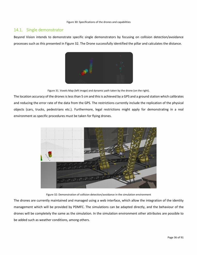
14.1. Single demonstrator
Beyond Vision intends to demonstrate specific single demonstrators by focusing on collision detection/avoidance
processes such as this presented in Figure 32. The Drone successfully identified the pillar and calculates the distance.
Figure 31. Voxels Map (left image) and dynamic path taken by the drone (on the right).
The location accuracy of the drones is less than 5 cm and this is achieved by a GPS and a ground station which calibrates
and reducing the error rate of the data from the GPS. The restrictions currently include the replication of the physical
objects (cars, trucks, pedestrians etc.). Furthermore, legal restrictions might apply for demonstrating in a real
environment as specific procedures must be taken for flying drones.
Figure 32: Demonstration of collision detection/avoidance in the simulation environment
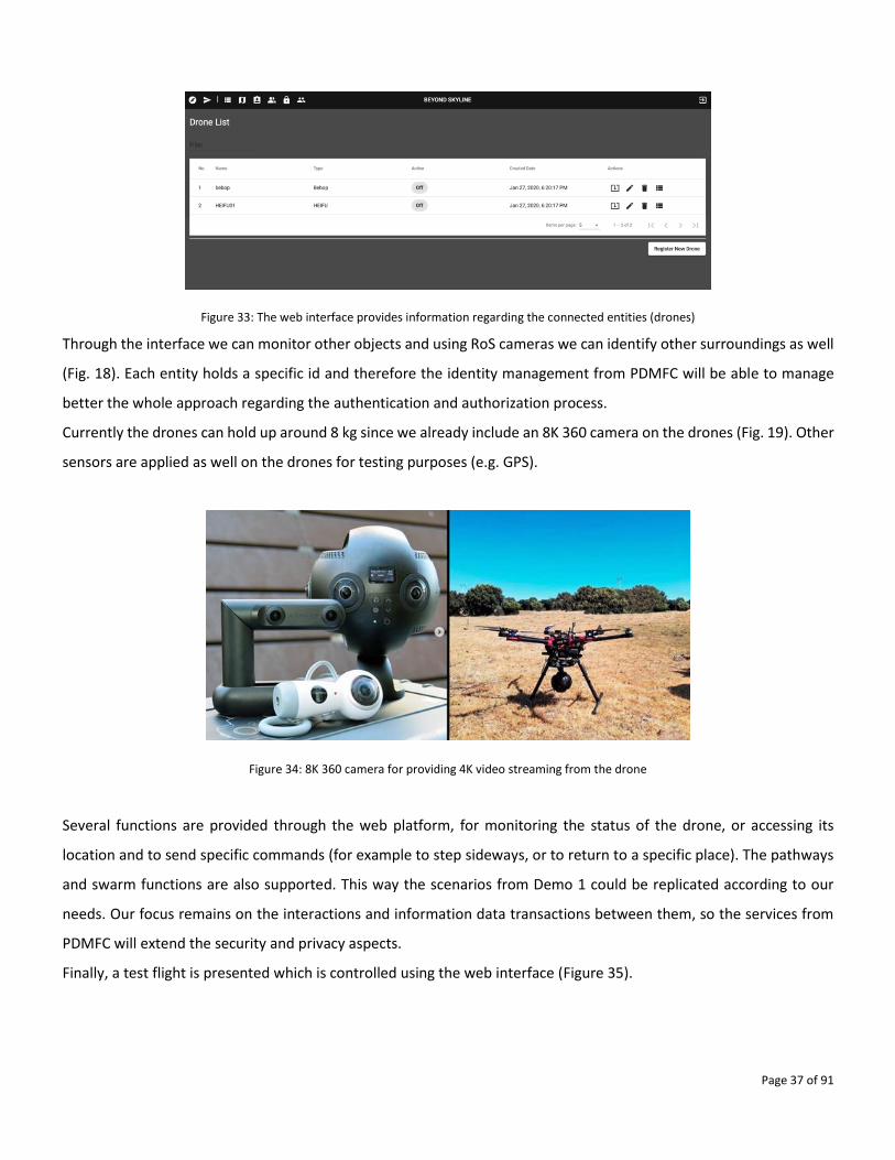
The drones are currently maintained and managed using a web interface, which allow the integration of the identity
management which will be provided by PDMFC. The simulations can be adapted directly, and the behaviour of the
drones will be completely the same as the simulation. In the simulation environment other attributes are possible to
be added such as weather conditions, among others.
Page 37 of 91
Figure 33: The web interface provides information regarding the connected entities (drones)
Through the interface we can monitor other objects and using RoS cameras we can identify other surroundings as well
(Fig. 18). Each entity holds a specific id and therefore the identity management from PDMFC will be able to manage
better the whole approach regarding the authentication and authorization process.
Currently the drones can hold up around 8 kg since we already include an 8K 360 camera on the drones (Fig. 19). Other
sensors are applied as well on the drones for testing purposes (e.g. GPS).
Figure 34: 8K 360 camera for providing 4K video streaming from the drone
Several functions are provided through the web platform, for monitoring the status of the drone, or accessing its
location and to send specific commands (for example to step sideways, or to return to a specific place). The pathways
and swarm functions are also supported. This way the scenarios from Demo 1 could be replicated according to our
needs. Our focus remains on the interactions and information data transactions between them, so the services from
PDMFC will extend the security and privacy aspects.
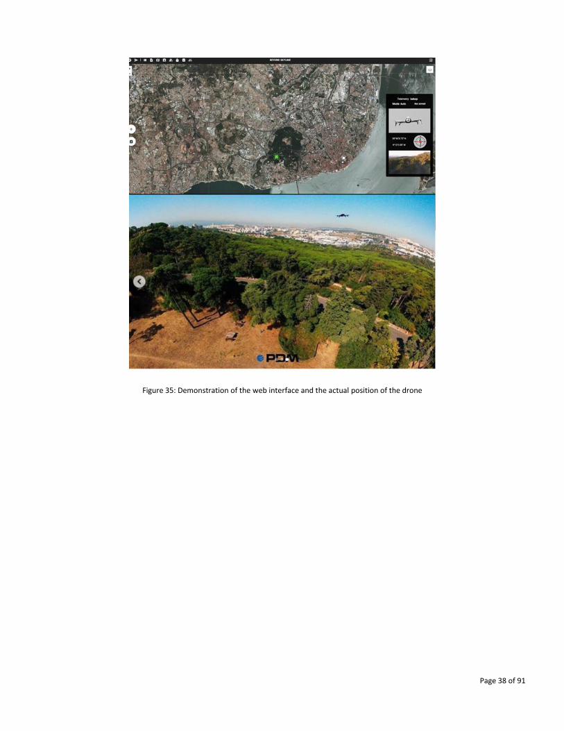
Finally, a test flight is presented which is controlled using the web interface (Figure 35).
Page 38 of 91
Figure 35: Demonstration of the web interface and the actual position of the drone
Page 39 of 91
15. Identity Management and Smart Profiling (PDMFC)
PDMFC provides software components and services such as the Identity Management and Smart profiling, Vulnerability
scanning and Security event management as well as the backend infrastructure for supporting software components
and integration plans. Towards this direction, PDMFC will provide the services for integration with the approaches from
Beyond Vision and the developed automotive testbed using drones. Furthermore, PDMFC advances and develop
technologies such as 5G and the usage of LoRaWAN. Privacy preservation methods will be tested on this approach as
well.
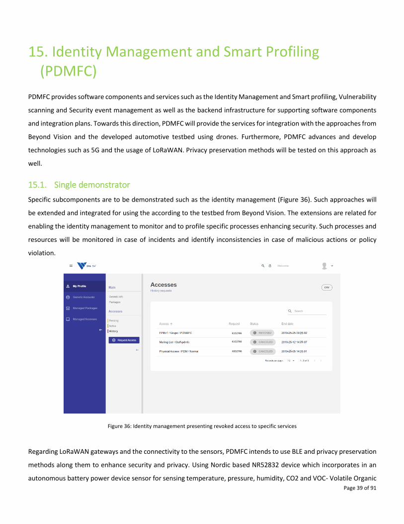
15.1. Single demonstrator
Specific subcomponents are to be demonstrated such as the identity management (Figure 36). Such approaches will
be extended and integrated for using the according to the testbed from Beyond Vision. The extensions are related for
enabling the identity management to monitor and to profile specific processes enhancing security. Such processes and
resources will be monitored in case of incidents and identify inconsistencies in case of malicious actions or policy
violation.
Figure 36: Identity management presenting revoked access to specific services
Regarding LoRaWAN gateways and the connectivity to the sensors, PDMFC intends to use BLE and privacy preservation
methods along them to enhance security and privacy. Using Nordic based NR52832 device which incorporates in an
autonomous battery power device sensor for sensing temperature, pressure, humidity, CO2 and VOC- Volatile Organic
Page 40 of 91
compounds have been tested in the past. A framework for maintaining the authentication of BLE devices is used (Figure
37). The identity management will be integrated with the privacy preserving authentication framework.
Figure 37: Privacy preserving authentication framework
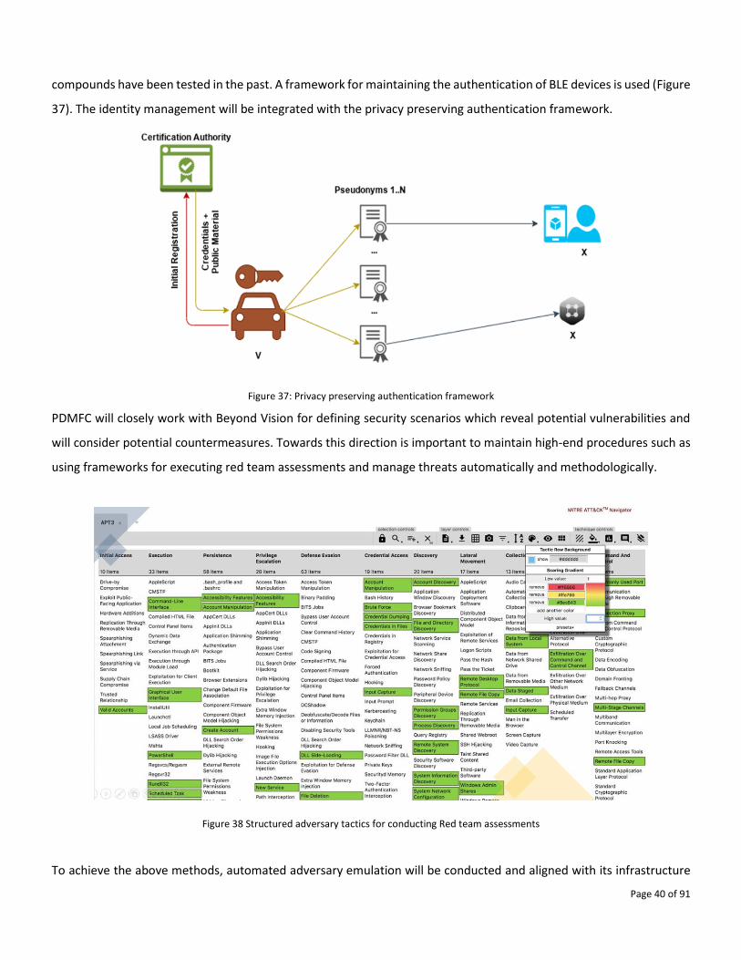
PDMFC will closely work with Beyond Vision for defining security scenarios which reveal potential vulnerabilities and
will consider potential countermeasures. Towards this direction is important to maintain high-end procedures such as
using frameworks for executing red team assessments and manage threats automatically and methodologically.
Figure 38 Structured adversary tactics for conducting Red team assessments
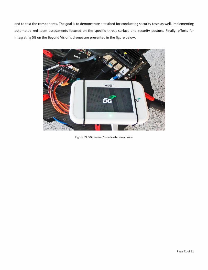
To achieve the above methods, automated adversary emulation will be conducted and aligned with its infrastructure
Page 41 of 91
and to test the components. The goal is to demonstrate a testbed for conducting security tests as well, implementing
automated red team assessments focused on the specific threat surface and security posture. Finally, efforts for
integrating 5G on the Beyond Vision’s drones are presented in the figure below.
Figure 39: 5G receiver/broadcaster on a drone

Page 42 of 91
16. V2X Services (CMS)
Commsignia has demonstrated several components during the year 1 consortium meeting in Glasgow (2019 June 12).
In collaboration with other partners we have demonstrated the following components (detailed in D9.1, and D5.2):
• V2X Communication devices and SW stack
• Filtering and Data Fusion
• V2X Applications
• CPM Service
Demo setup and components:
• Intersection safety by roadside infrastructure providing Collective Perception Service (ETSI TS 103 324) using
V2X
• Coupled dual-unit vehicle architecture using the V2X service
• Telematics unit
• Central gateway
• In-vehicle security by Anomaly detection
Demo partners: FICOSA, BME, COMMSIGNIA, supported by NXP and CANON
CMS contributes its components for Demo I (UC1) and Demo II (UC2).
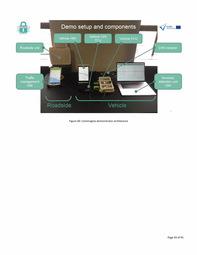
16.1. Single demonstrator
The demonstrator showed an anomaly detection use case: corrupted CAN traffic is detected by algorithm developed
by BME. The BME detection module informs the OBU V2X software stack (CMS) running on FICOSA hardware. As a
reaction the OBU stops sending CAM messages to prevent the broadcast of potentially malicious information. The
roadside unit (CMS) and the monitoring application (on the tablets) in this case are used to monitor the OBU actions:
in case there is no anomaly the CAMs are received by the roadside unit and the vehicle appears on the tablet screen.
On the other hand, when anomaly is detected the OBU stops sending CAMs thus the roadside unit will not receive
them, and the vehicle is not visible on the tablet screen.
The demonstrator was the first implementation of an in-vehicle anomaly detection and security threat reaction solution
which has been further developed in T6.1 by Commsignia, BME and TNO.
Page 43 of 91
Figure 40: Commsignia demonstrator architecture
Page 44 of 91
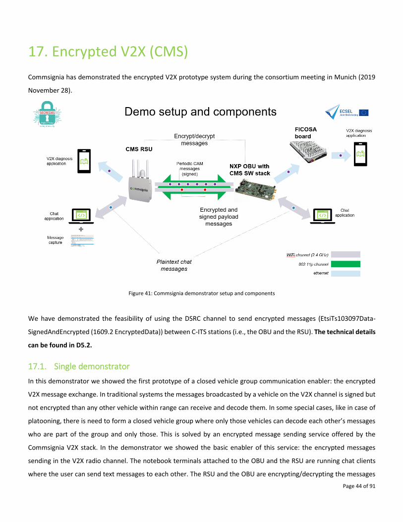
17. Encrypted V2X (CMS)
Commsignia has demonstrated the encrypted V2X prototype system during the consortium meeting in Munich (2019
November 28).
Figure 41: Commsignia demonstrator setup and components
We have demonstrated the feasibility of using the DSRC channel to send encrypted messages (EtsiTs103097Data-
SignedAndEncrypted (1609.2 EncryptedData)) between C-ITS stations (i.e., the OBU and the RSU). The technical details
can be found in D5.2.
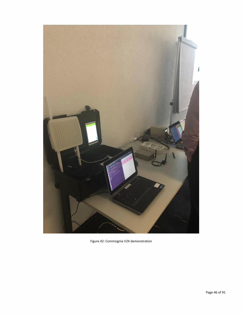
17.1. Single demonstrator
In this demonstrator we showed the first prototype of a closed vehicle group communication enabler: the encrypted
V2X message exchange. In traditional systems the messages broadcasted by a vehicle on the V2X channel is signed but
not encrypted than any other vehicle within range can receive and decode them. In some special cases, like in case of
platooning, there is need to form a closed vehicle group where only those vehicles can decode each other’s messages
who are part of the group and only those. This is solved by an encrypted message sending service offered by the
Commsignia V2X stack. In the demonstrator we showed the basic enabler of this service: the encrypted messages
sending in the V2X radio channel. The notebook terminals attached to the OBU and the RSU are running chat clients
where the user can send text messages to each other. The RSU and the OBU are encrypting/decrypting the messages
Page 45 of 91
and pass them to the radio channel or to the connected terminal, respectively.
The second iteration of this work is the integration of Prove & Run’s HSM module. The integration work has already
been started. The technical details can be found in D5.2.
In this task implements DP33 (Secondary Trusted OS). This will:
• Preventing a hacker from feeding fake information to a car to disrupt its operation (making it take wrong turns,
slowing down to avoid a none-existing accident, etc.)
• Protecting the privacy of the occupants of the car by preventing leaks regarding the identity of the car, its
direction, etc.
Therefore V2X communications must be signed or in some cases encrypted and using an HSM to do so is mandatory
for commercial V2X by automotive certification authorities. However, it may require the use of an additional hardware
platform, which is costly. Thanks to DP33, such costs can be avoided while maintaining a high level of security.
Commsignia’s V2X communication stack will run on a host board : NXP’s Roadlink platform, which is based on a i.MX
processor and includes a SE. Prove & Run will implement DP33 by porting its Secure OS (ProvenCore, brought as a
background asset) to the Roadlink platform, running in the Secure World of TrustZone. Commsignia’s V2X
communication stack will run in the Normal World of TrustZone. Prove & Run will provide a new HSM application
running on ProvenCore and accessible by the V2X communication stack through the HSM API. This HSM application will
rely on the key storage and cryptographic implementation features of the SE. Even if a hacker were to take control of
the software platform running the V2X stack, they would still not be able to access the data stored in the HSM, or even
to directly drive the SE, thanks to the security layer provided by ProvenCore and TrustZone.
Page 46 of 91
Figure 42: Commsignia V2X demonstration
Page 47 of 91
18. simple2secure (SECI)
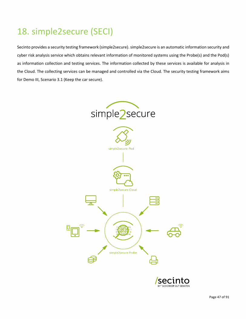
Secinto provides a security testing framework (simple2secure). simple2secure is an automatic information security and
cyber risk analysis service which obtains relevant information of monitored systems using the Probe(s) and the Pod(s)
as information collection and testing services. The information collected by these services is available for analysis in
the Cloud. The collecting services can be managed and controlled via the Cloud. The security testing framework aims
for Demo III, Scenario 3.1 (Keep the car secure).
Page 48 of 91
Figure 43: Overview of simple2secure security testing framework
18.1. Single demonstrator
From the Cloud it is possible to execute an arbitrary number of tests via the Pod(s) and group them together into test
sequences and perform actions upon execution using a configurable rule engine. These tests are executed on the Pods
and obtain information from an outsider perspective. Tests from an insider perspective can be performed using Probes,
which are installed on the monitored devices. The Pods and the Probes together can interact to provide a more concise
and detailed analysis of any monitored system.
Each Pod provides information about what tests it can execute and provide information on how to configure the tests.
It also provides information about the structure and content of the returned results. The exchange format for this
information is JSON. Depending on the capabilities of the Pod it is possible to obtain existing tests, configure and
execute them or also to specify and add new ones using the Cloud or also directly the Pod managed services.json.
Within in each Pod a simple service is always running which provides the required functionality for the interaction of
the Pod with the Cloud and vice versa. This service listens for incoming request from the Cloud and forwards responses
from the actual test applications to the Cloud. It also evaluates the incoming requests from the Cloud and performs the
actions required by it.
In this demonstrator we show different attacks on the Box Car (CEVT) instance as well as a real car together with AVL-
AT using the simple2secure testing framework. The simple2secure framework is available as open-source from
https://github.com/secinto/simple2secure and a playground is available on https://simple2secure.info:51003.
Page 49 of 91
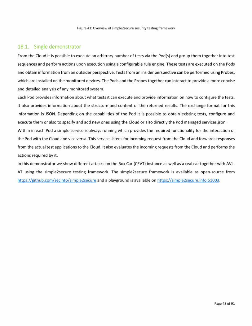
19. Secure Gateway (IDEMIA)
OEM’s and TierX need to be able to upgrade ECU software in a secure manner. This requires secure that ECU message
exchanges. IDEMIA’s In-Vehicle Secure Network concept is based on a TLS to ensure Authentication + Secure Channel
enforcement by ECUs. End-to-end Security is ensured by the MLS protocol in which the payload data are
encrypted/decrypted using:
• Secure Element from the Connected Object (seen as a small HSM and called PSSE: Pure SW SE).
• Key Management service (KMS) HSM server from the cloud.
Confidentiality, Authentication and Integrity are guaranteed by the IDEMIA backend server. Alternatively,
confidentiality can also be provided by OEM/TIER servers. The payload is ciphered & authenticated by AES. The Key
Management and Secure Channel comprises:
• KMS Remote Management.
• Message Level Security protocol (MLS) => AES GCM => dedicated for small ciphered & authenticated payload
=> no security overhead.
Figure 44: Overview of role of Secure Gateway for in Car Security.
19.1. Single demonstrator
We demonstrate through our Proof of Concept the secure upgrade of software for an OEM that want to operate on
one of its ECU in the vehicle. This standalone solution matches Secredas UC3, Scenario 3.1 (Keep the car secure). To
perform secure update it means confidentiality, authentication and integrity is assured. We have designed an HTML

Page 50 of 91
site dedicated to the upgrade transaction, a representation of a car, a KMS server (IDEMIA M-Trust), a Master ECU seen
here as a Secure Central Gateway and 2 slave ECUs. The slave ECUs control specific features or functions in the car,
here they are simply controlling LEDs (to visualize transfers of data). On HTML site we command a change of Led
configuration. The website creates a payload, send it to the M-Trust that enciphered it and add a MAC and then send
to the Master ECU that deciphers it, verifies the Mac and send it to the appropriate ECU.
Page 51 of 91
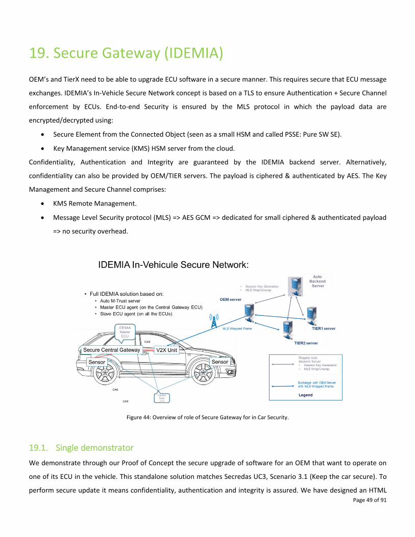
20. Secure Car Access (imec-NL)
Imec-NL is developing a secure car access system for Bluetooth Low Energy radios. This system allows the user to access
the car based on proximity, i.e. range, and provides security based on distance bounding protocol. The system
implements a novel secure and accurate distance bounding protocol that is based on phase-based distance
measurement capabilities providing high ranging accuracy and secure time-of-flight (distance bounding) providing
security.
This system is relevant for UC4, Scenario 4.1 Advanced Access to the Vehicle.
20.1. Single demonstrator
The secure and accurate distance bounding protocol provides a solution that improves the security of the system
against relay attacks and offers an accurate ranging using low power, low cost Bluetooth radios.
The protocol comprises three stages: authenticated key agreement, high accuracy ranging and distance bounding, and
authentication and authorization. In the first stage, the communicating entities securely agree on a symmetric session
key. In the second stage, secure ranging is obtained based on combination of timestamps, and amplitude and phase
measurements. In the last stage, one of the entities makes authentication decision based on the obtained results and
authorizes the other entity to access the requested resources if the authentication is successful.
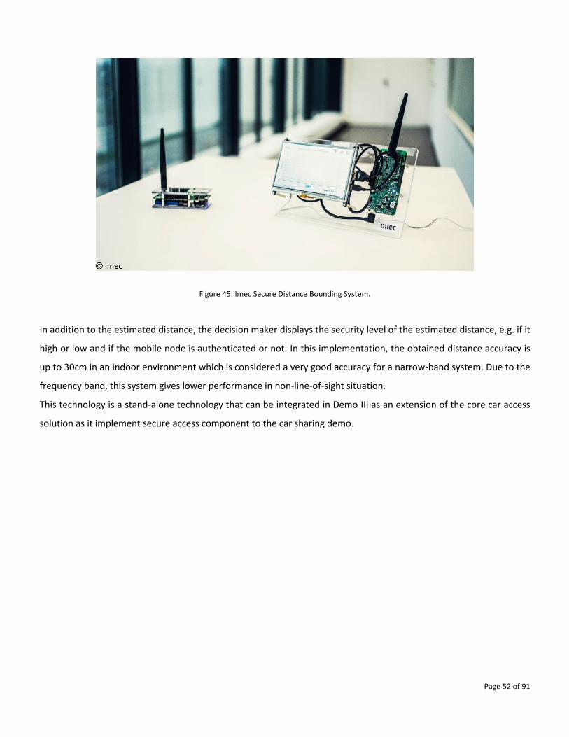
This protocol has been implemented on Bluetooth Low Energy radio platform as shown in Figure 45. In this figure, there
are two nodes, the left node is the mobile node that represents the keyfob or mobile phone and the right node with
screen is the decision maker node that represents the car. This technology allows the two nodes to securely estimate
the distance. The decision maker node is the one that estimates the distance with the mobile node and displays the
estimated distance.
Page 52 of 91
Figure 45: Imec Secure Distance Bounding System.
In addition to the estimated distance, the decision maker displays the security level of the estimated distance, e.g. if it
high or low and if the mobile node is authenticated or not. In this implementation, the obtained distance accuracy is
up to 30cm in an indoor environment which is considered a very good accuracy for a narrow-band system. Due to the
frequency band, this system gives lower performance in non-line-of-sight situation.
This technology is a stand-alone technology that can be integrated in Demo III as an extension of the core car access
solution as it implement secure access component to the car sharing demo.
Page 53 of 91
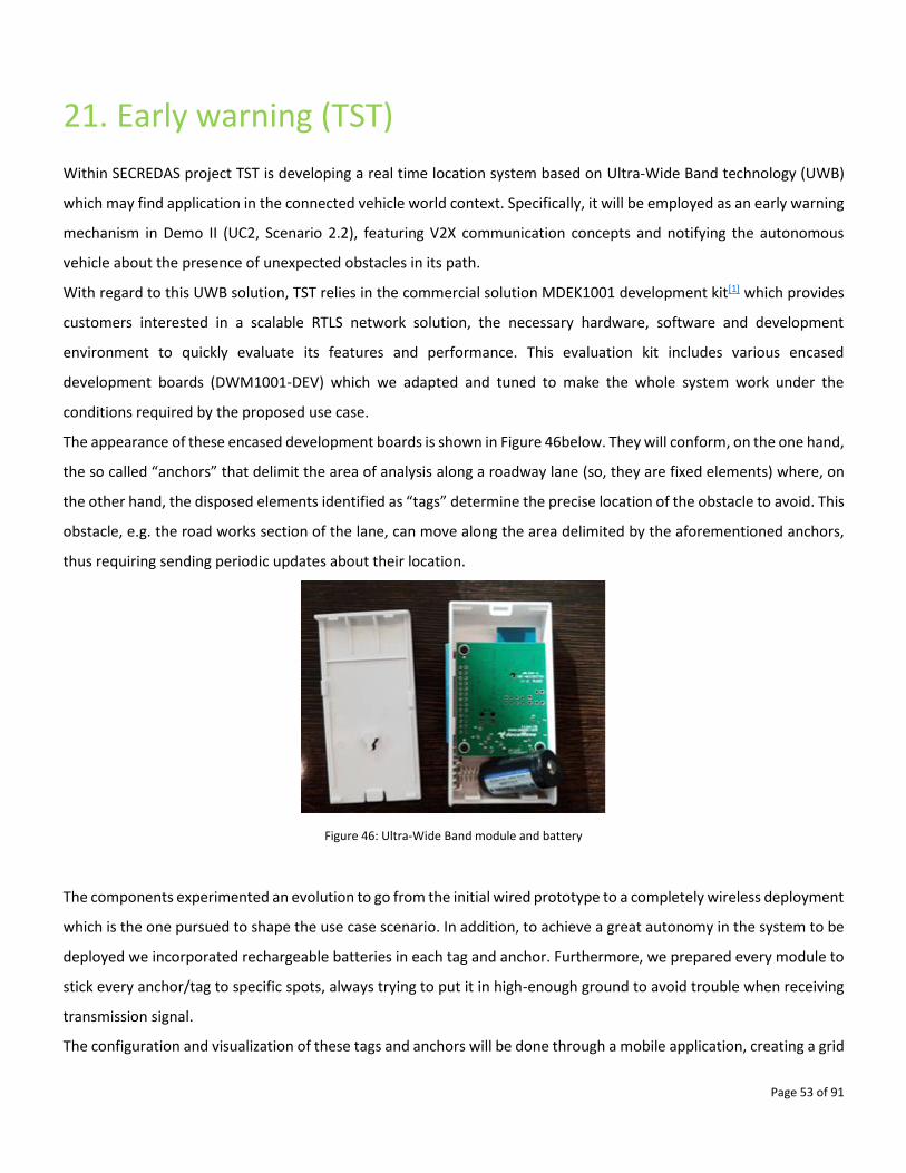
21. Early warning (TST)
Within SECREDAS project TST is developing a real time location system based on Ultra-Wide Band technology (UWB)
which may find application in the connected vehicle world context. Specifically, it will be employed as an early warning
mechanism in Demo II (UC2, Scenario 2.2), featuring V2X communication concepts and notifying the autonomous
vehicle about the presence of unexpected obstacles in its path.
With regard to this UWB solution, TST relies in the commercial solution MDEK1001 development kit[1] which provides
customers interested in a scalable RTLS network solution, the necessary hardware, software and development
environment to quickly evaluate its features and performance. This evaluation kit includes various encased
development boards (DWM1001-DEV) which we adapted and tuned to make the whole system work under the
conditions required by the proposed use case.
The appearance of these encased development boards is shown in Figure 46below. They will conform, on the one hand,
the so called “anchors” that delimit the area of analysis along a roadway lane (so, they are fixed elements) where, on
the other hand, the disposed elements identified as “tags” determine the precise location of the obstacle to avoid. This
obstacle, e.g. the road works section of the lane, can move along the area delimited by the aforementioned anchors,
thus requiring sending periodic updates about their location.
Figure 46: Ultra-Wide Band module and battery
The components experimented an evolution to go from the initial wired prototype to a completely wireless deployment
which is the one pursued to shape the use case scenario. In addition, to achieve a great autonomy in the system to be
deployed we incorporated rechargeable batteries in each tag and anchor. Furthermore, we prepared every module to
stick every anchor/tag to specific spots, always trying to put it in high-enough ground to avoid trouble when receiving
transmission signal.
The configuration and visualization of these tags and anchors will be done through a mobile application, creating a grid
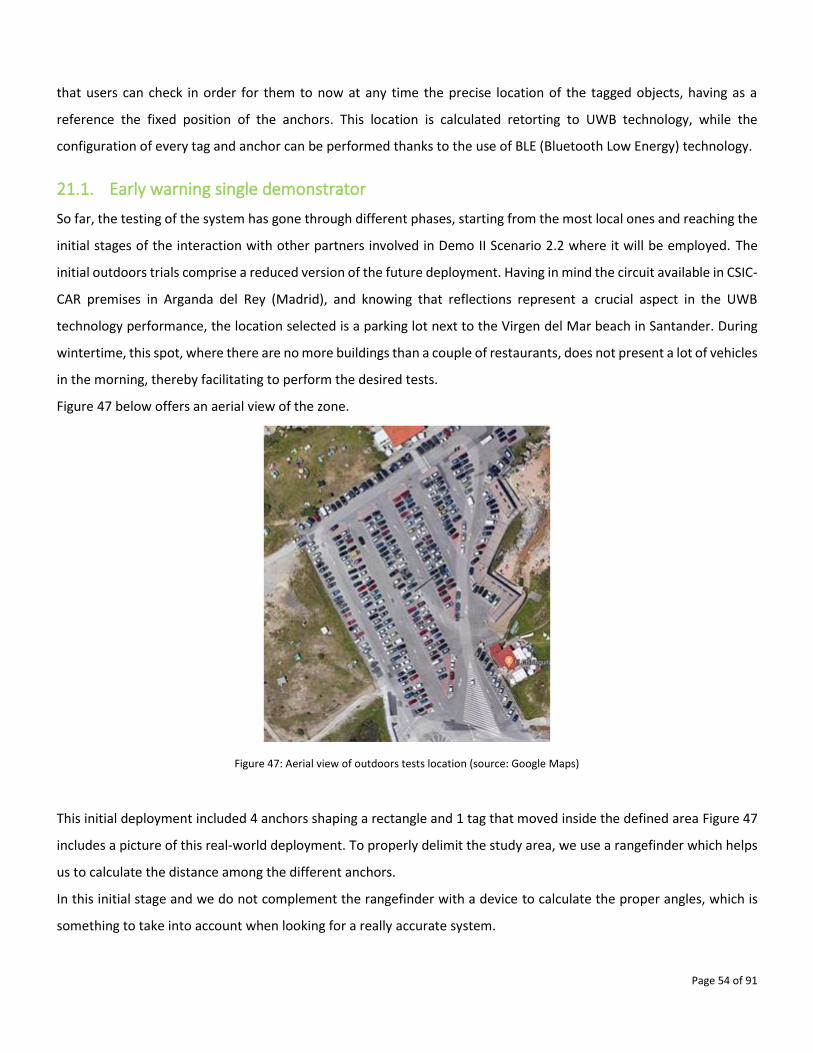
Page 54 of 91
that users can check in order for them to now at any time the precise location of the tagged objects, having as a
reference the fixed position of the anchors. This location is calculated retorting to UWB technology, while the
configuration of every tag and anchor can be performed thanks to the use of BLE (Bluetooth Low Energy) technology.
21.1. Early warning single demonstrator
So far, the testing of the system has gone through different phases, starting from the most local ones and reaching the
initial stages of the interaction with other partners involved in Demo II Scenario 2.2 where it will be employed. The
initial outdoors trials comprise a reduced version of the future deployment. Having in mind the circuit available in CSIC-
CAR premises in Arganda del Rey (Madrid), and knowing that reflections represent a crucial aspect in the UWB
technology performance, the location selected is a parking lot next to the Virgen del Mar beach in Santander. During
wintertime, this spot, where there are no more buildings than a couple of restaurants, does not present a lot of vehicles
in the morning, thereby facilitating to perform the desired tests.
Figure 47 below offers an aerial view of the zone.
Figure 47: Aerial view of outdoors tests location (source: Google Maps)
This initial deployment included 4 anchors shaping a rectangle and 1 tag that moved inside the defined area Figure 47
includes a picture of this real-world deployment. To properly delimit the study area, we use a rangefinder which helps
us to calculate the distance among the different anchors.
In this initial stage and we do not complement the rangefinder with a device to calculate the proper angles, which is
something to take into account when looking for a really accurate system.
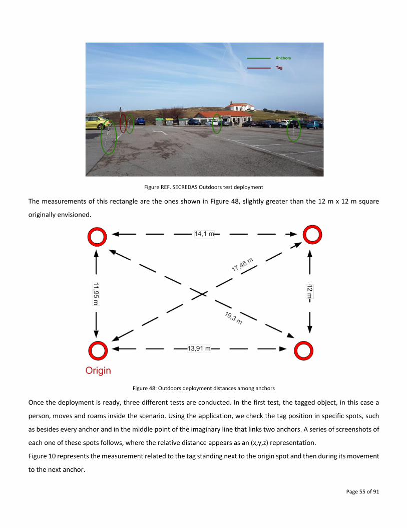
Page 55 of 91
Figure REF. SECREDAS Outdoors test deployment
The measurements of this rectangle are the ones shown in Figure 48, slightly greater than the 12 m x 12 m square
originally envisioned.
Figure 48: Outdoors deployment distances among anchors
Once the deployment is ready, three different tests are conducted. In the first test, the tagged object, in this case a
person, moves and roams inside the scenario. Using the application, we check the tag position in specific spots, such
as besides every anchor and in the middle point of the imaginary line that links two anchors. A series of screenshots of
each one of these spots follows, where the relative distance appears as an (x,y,z) representation.
Figure 10 represents the measurement related to the tag standing next to the origin spot and then during its movement
to the next anchor.
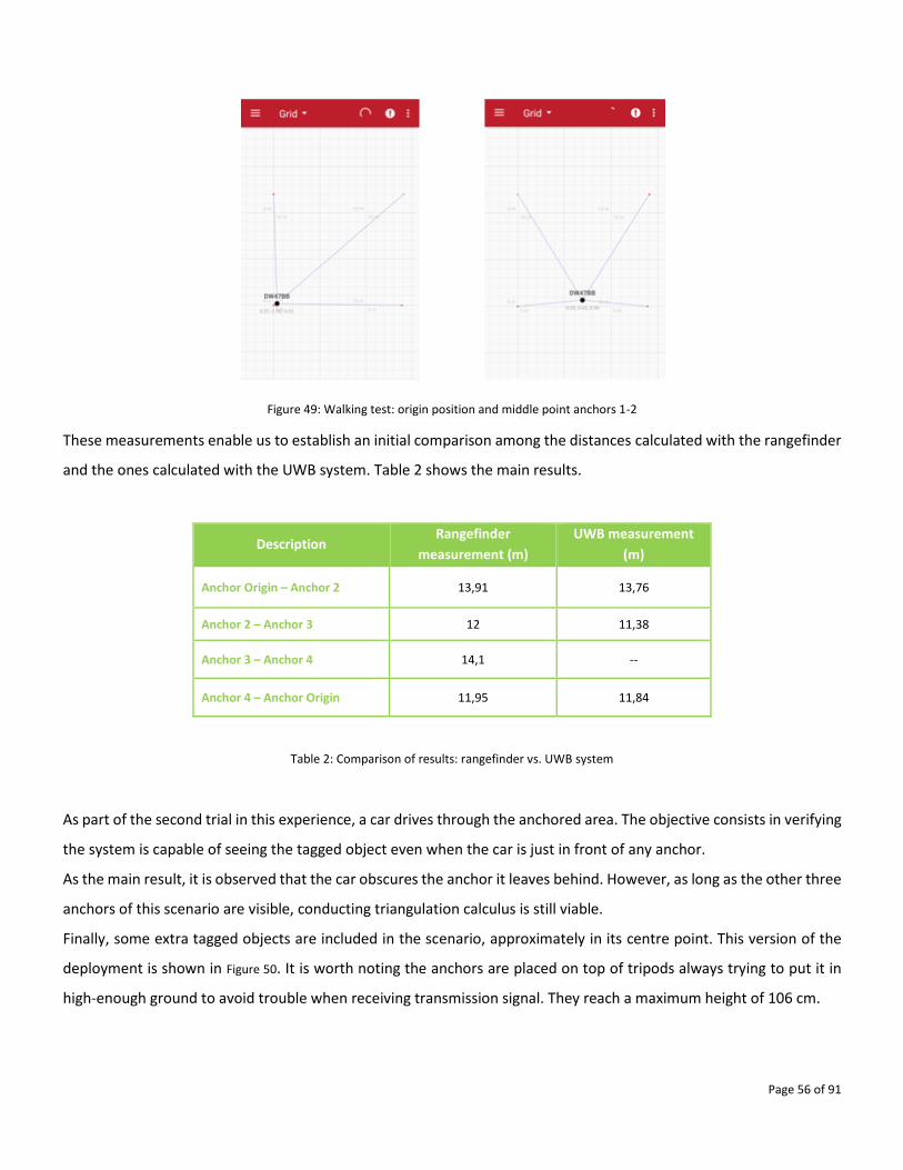
Page 56 of 91
Figure 49: Walking test: origin position and middle point anchors 1-2
These measurements enable us to establish an initial comparison among the distances calculated with the rangefinder
and the ones calculated with the UWB system. Table 2 shows the main results.
Description Rangefinder
measurement (m)
UWB measurement
(m)
Anchor Origin – Anchor 2 13,91 13,76
Anchor 2 – Anchor 3 12 11,38
Anchor 3 – Anchor 4 14,1 --
Anchor 4 – Anchor Origin 11,95 11,84
Table 2: Comparison of results: rangefinder vs. UWB system
As part of the second trial in this experience, a car drives through the anchored area. The objective consists in verifying
the system is capable of seeing the tagged object even when the car is just in front of any anchor.
As the main result, it is observed that the car obscures the anchor it leaves behind. However, as long as the other three
anchors of this scenario are visible, conducting triangulation calculus is still viable.
Finally, some extra tagged objects are included in the scenario, approximately in its centre point. This version of the
deployment is shown in Figure 50. It is worth noting the anchors are placed on top of tripods always trying to put it in
high-enough ground to avoid trouble when receiving transmission signal. They reach a maximum height of 106 cm.
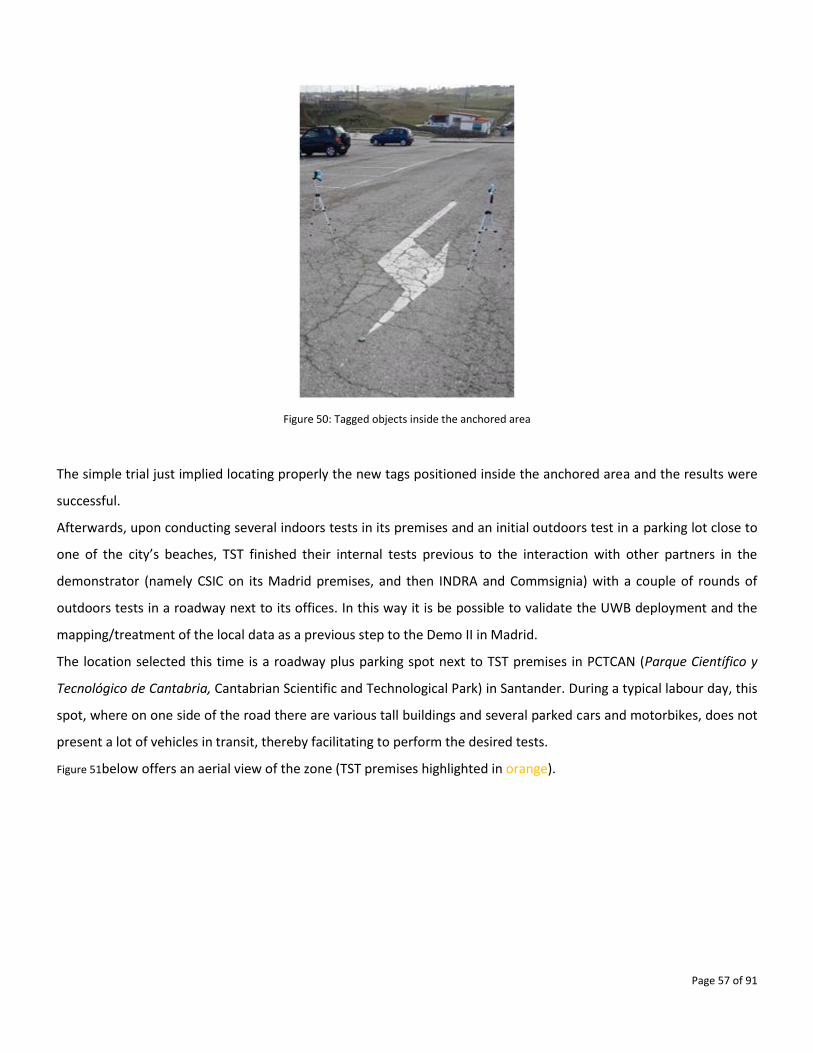
Page 57 of 91
Figure 50: Tagged objects inside the anchored area
The simple trial just implied locating properly the new tags positioned inside the anchored area and the results were
successful.
Afterwards, upon conducting several indoors tests in its premises and an initial outdoors test in a parking lot close to
one of the city’s beaches, TST finished their internal tests previous to the interaction with other partners in the
demonstrator (namely CSIC on its Madrid premises, and then INDRA and Commsignia) with a couple of rounds of
outdoors tests in a roadway next to its offices. In this way it is be possible to validate the UWB deployment and the
mapping/treatment of the local data as a previous step to the Demo II in Madrid.
The location selected this time is a roadway plus parking spot next to TST premises in PCTCAN (Parque Científico y
Tecnológico de Cantabria, Cantabrian Scientific and Technological Park) in Santander. During a typical labour day, this
spot, where on one side of the road there are various tall buildings and several parked cars and motorbikes, does not
present a lot of vehicles in transit, thereby facilitating to perform the desired tests.
Figure 51below offers an aerial view of the zone (TST premises highlighted in orange).
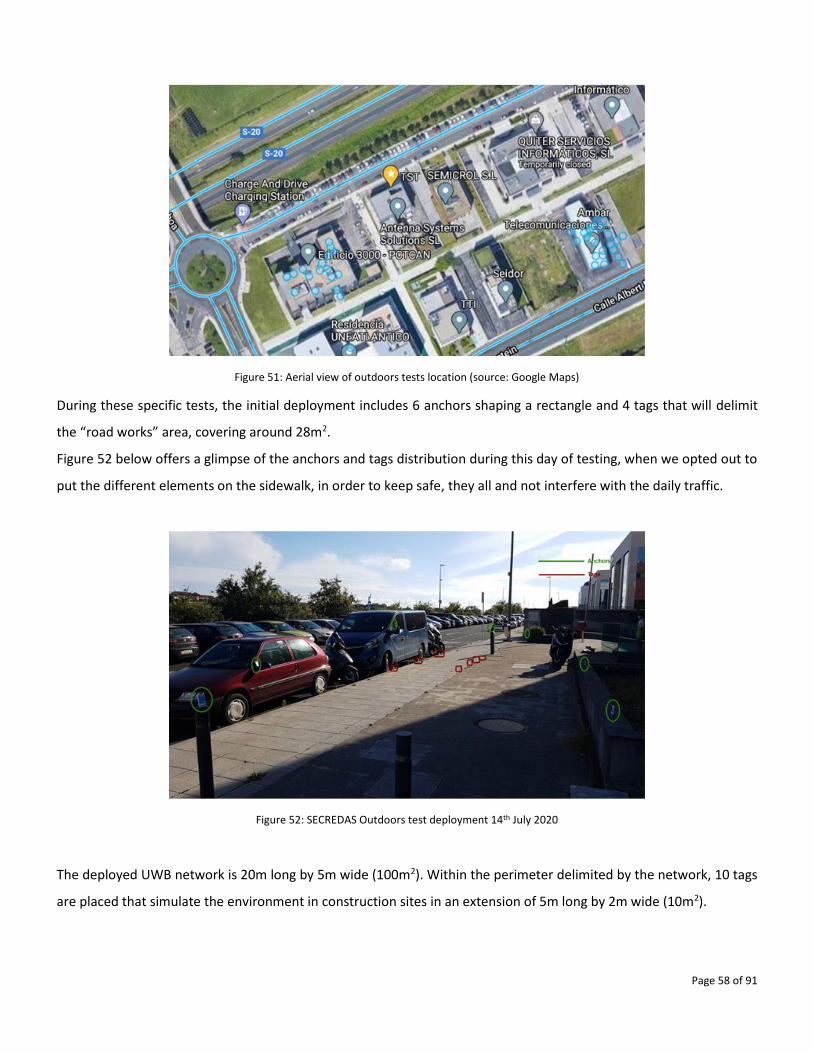
Page 58 of 91
Figure 51: Aerial view of outdoors tests location (source: Google Maps)
During these specific tests, the initial deployment includes 6 anchors shaping a rectangle and 4 tags that will delimit
the “road works” area, covering around 28m2.
Figure 52 below offers a glimpse of the anchors and tags distribution during this day of testing, when we opted out to
put the different elements on the sidewalk, in order to keep safe, they all and not interfere with the daily traffic.
Figure 52: SECREDAS Outdoors test deployment 14th July 2020
The deployed UWB network is 20m long by 5m wide (100m2). Within the perimeter delimited by the network, 10 tags
are placed that simulate the environment in construction sites in an extension of 5m long by 2m wide (10m2).
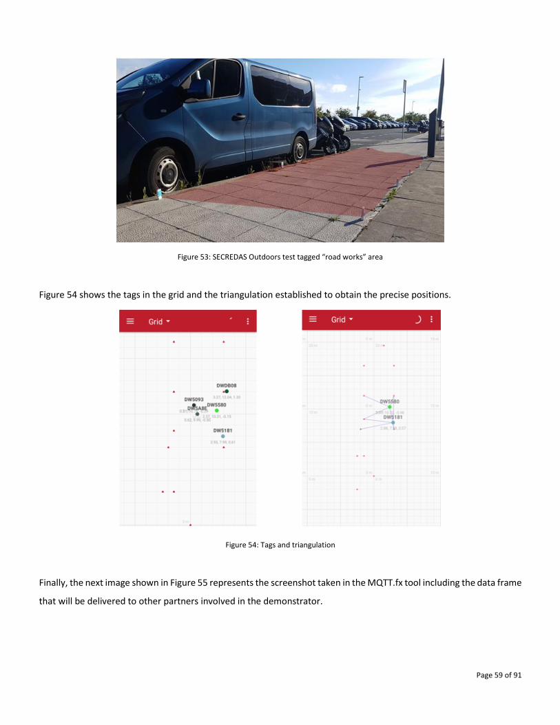
Page 59 of 91
Figure 53: SECREDAS Outdoors test tagged “road works” area
Figure 54 shows the tags in the grid and the triangulation established to obtain the precise positions.
Figure 54: Tags and triangulation
Finally, the next image shown in Figure 55 represents the screenshot taken in the MQTT.fx tool including the data frame
that will be delivered to other partners involved in the demonstrator.
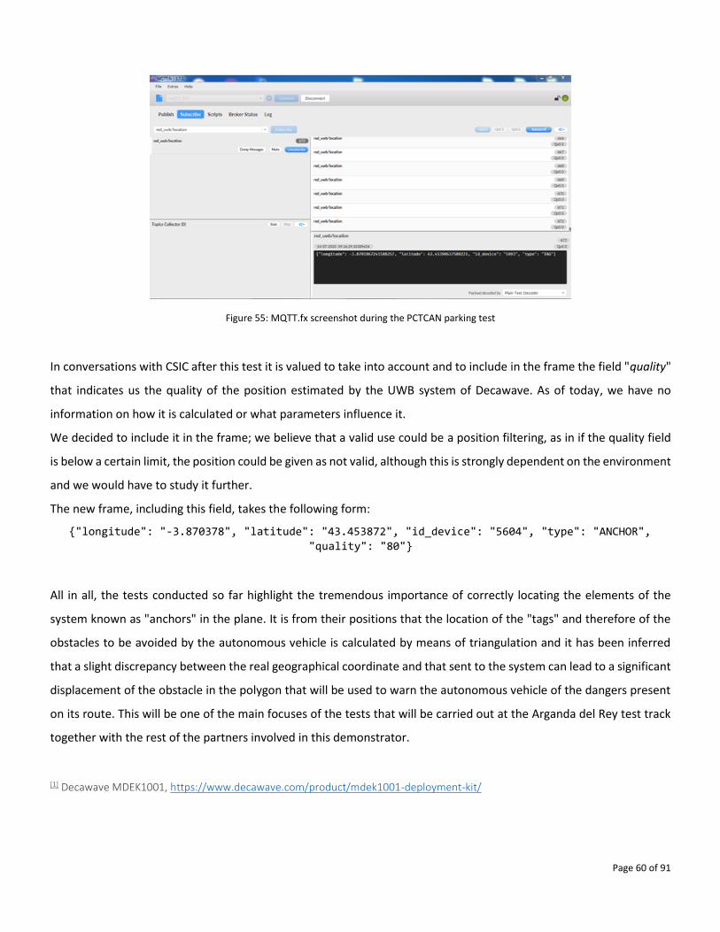
Page 60 of 91
Figure 55: MQTT.fx screenshot during the PCTCAN parking test
In conversations with CSIC after this test it is valued to take into account and to include in the frame the field "quality"
that indicates us the quality of the position estimated by the UWB system of Decawave. As of today, we have no
information on how it is calculated or what parameters influence it.
We decided to include it in the frame; we believe that a valid use could be a position filtering, as in if the quality field
is below a certain limit, the position could be given as not valid, although this is strongly dependent on the environment
and we would have to study it further.
The new frame, including this field, takes the following form:
{"longitude": "-3.870378", "latitude": "43.453872", "id_device": "5604", "type": "ANCHOR",
"quality": "80"}
All in all, the tests conducted so far highlight the tremendous importance of correctly locating the elements of the
system known as "anchors" in the plane. It is from their positions that the location of the "tags" and therefore of the
obstacles to be avoided by the autonomous vehicle is calculated by means of triangulation and it has been inferred
that a slight discrepancy between the real geographical coordinate and that sent to the system can lead to a significant
displacement of the obstacle in the polygon that will be used to warn the autonomous vehicle of the dangers present
on its route. This will be one of the main focuses of the tests that will be carried out at the Arganda del Rey test track
together with the rest of the partners involved in this demonstrator.
[1] Decawave MDEK1001, https://www.decawave.com/product/mdek1001-deployment-kit/
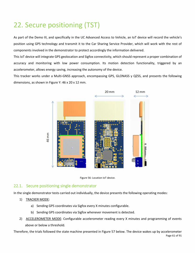
Page 61 of 91
22. Secure positioning (TST)
As part of the Demo III, and specifically in the UC Advanced Access to Vehicle, an IoT device will record the vehicle's
position using GPS technology and transmit it to the Car Sharing Service Provider, which will work with the rest of
components involved in the demonstrator to protect accordingly the information delivered.
This IoT device will integrate GPS geolocation and Sigfox connectivity, which should represent a proper combination of
accuracy and monitoring with low power consumption. Its motion detection functionality, triggered by an
accelerometer, allows energy saving, increasing the autonomy of the device.
This tracker works under a Multi-GNSS approach, encompassing GPS, GLONASS y QZSS, and presents the following
dimensions, as shown in Figure Y: 46 x 20 x 12 mm.
Figure 56: Location IoT device.
22.1. Secure positioning single demonstrator
In the single demonstrator tests carried out individually, the device presents the following operating modes:
1) TRACKER MODE:
a) Sending GPS coordinates via Sigfox every X minutes configurable.
b) Sending GPS coordinates via Sigfox whenever movement is detected.
2) ACCELEROMETER MODE: Configurable accelerometer reading every X minutes and programming of events
above or below a threshold.
Therefore, the trials followed the state machine presented in Figure 57 below. The device wakes up by accelerometer
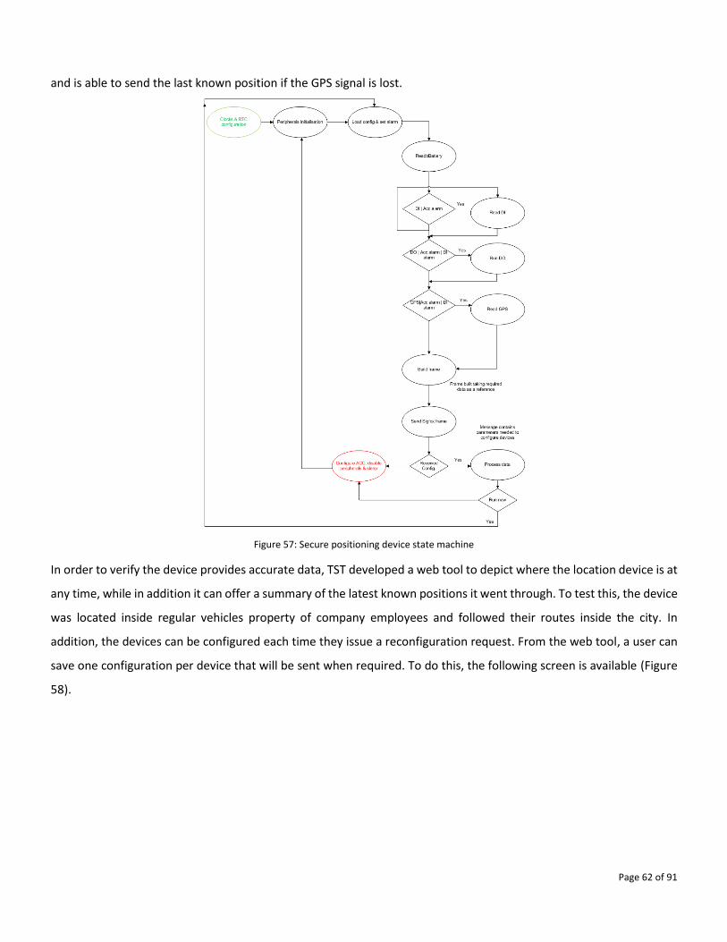
Page 62 of 91
and is able to send the last known position if the GPS signal is lost.
Figure 57: Secure positioning device state machine
In order to verify the device provides accurate data, TST developed a web tool to depict where the location device is at
any time, while in addition it can offer a summary of the latest known positions it went through. To test this, the device
was located inside regular vehicles property of company employees and followed their routes inside the city. In
addition, the devices can be configured each time they issue a reconfiguration request. From the web tool, a user can
save one configuration per device that will be sent when required. To do this, the following screen is available (Figure
58).
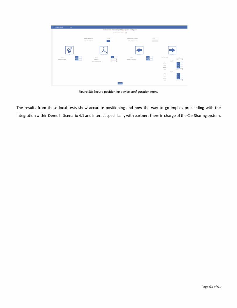
Page 63 of 91
Figure 58: Secure positioning device configuration menu
The results from these local tests show accurate positioning and now the way to go implies proceeding with the
integration within Demo III Scenario 4.1 and interact specifically with partners there in charge of the Car Sharing system.
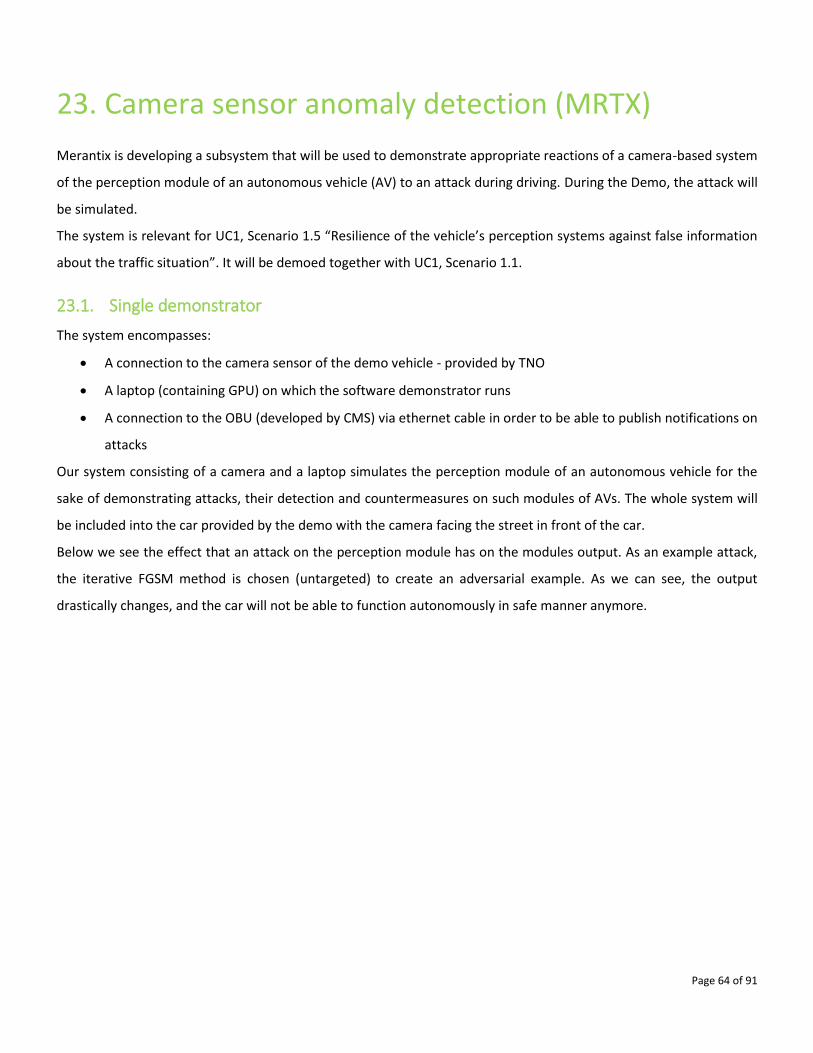
Page 64 of 91
23. Camera sensor anomaly detection (MRTX)
Merantix is developing a subsystem that will be used to demonstrate appropriate reactions of a camera-based system
of the perception module of an autonomous vehicle (AV) to an attack during driving. During the Demo, the attack will
be simulated.
The system is relevant for UC1, Scenario 1.5 “Resilience of the vehicle’s perception systems against false information
about the traffic situation”. It will be demoed together with UC1, Scenario 1.1.
23.1. Single demonstrator
The system encompasses:
• A connection to the camera sensor of the demo vehicle - provided by TNO
• A laptop (containing GPU) on which the software demonstrator runs
• A connection to the OBU (developed by CMS) via ethernet cable in order to be able to publish notifications on
attacks
Our system consisting of a camera and a laptop simulates the perception module of an autonomous vehicle for the
sake of demonstrating attacks, their detection and countermeasures on such modules of AVs. The whole system will
be included into the car provided by the demo with the camera facing the street in front of the car.
Below we see the effect that an attack on the perception module has on the modules output. As an example attack,
the iterative FGSM method is chosen (untargeted) to create an adversarial example. As we can see, the output
drastically changes, and the car will not be able to function autonomously in safe manner anymore.
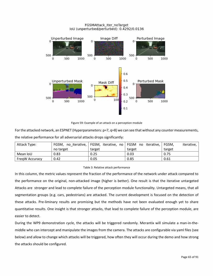
Page 65 of 91
Figure 59: Example of an attack on a perception module
For the attacked network, an ESPNET (Hyperparameters: p=7, q=8) we can see that without any counter measurements,
the relative performance for all adversarial attacks drops significantly:
Attack Type: FGSM, no_iterative, no target
FGSM, iterative, no target
FGSM no iterative, target
FGSM, iterative, target
Mean IoU 0.83 0.25 0.03 0.75
FreqW Accuracy 0.42 0.05 0.85 0.61
Table 3: Relative attack performance
In this column, the metric values represent the fraction of the performance of the network under attack compared to
the performance on the original, non-attacked image (higher is better). One result is that the iterative untargeted
Attacks are stronger and lead to complete failure of the perception module functionality. Untargeted means, that all
segmentation groups (e.g. cars, pedestrians) are attacked. The current development is focused on the detection of
these attacks. Pre-liminary results are promising but the methods have not been evaluated enough yet to share
quantitative results. One insight is that stronger attacks, that lead to complete failure of the perception module, are
easier to detect.
During the WP9 demonstration cycle, the attacks will be triggered randomly. Merantix will simulate a man-in-the-
middle who can intercept and manipulate the images from the camera. The attacks are configurable via yaml files (see
below) and allow to change which attacks will be triggered, how often they will occur during the demo and how strong
the attacks should be configured.
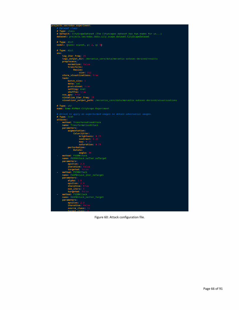
Page 66 of 91
Figure 60: Attack configuration file.
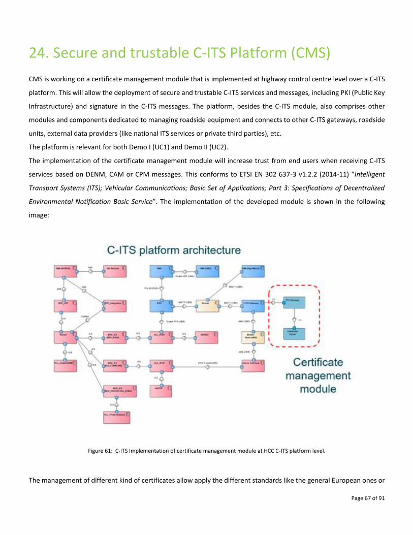
Page 67 of 91
24. Secure and trustable C-ITS Platform (CMS)
CMS is working on a certificate management module that is implemented at highway control centre level over a C-ITS
platform. This will allow the deployment of secure and trustable C-ITS services and messages, including PKI (Public Key
Infrastructure) and signature in the C-ITS messages. The platform, besides the C-ITS module, also comprises other
modules and components dedicated to managing roadside equipment and connects to other C-ITS gateways, roadside
units, external data providers (like national ITS services or private third parties), etc.
The platform is relevant for both Demo I (UC1) and Demo II (UC2).
The implementation of the certificate management module will increase trust from end users when receiving C-ITS
services based on DENM, CAM or CPM messages. This conforms to ETSI EN 302 637-3 v1.2.2 (2014-11) “Intelligent
Transport Systems (ITS); Vehicular Communications; Basic Set of Applications; Part 3: Specifications of Decentralized
Environmental Notification Basic Service”. The implementation of the developed module is shown in the following
image:
Figure 61: C-ITS Implementation of certificate management module at HCC C-ITS platform level.
The management of different kind of certificates allow apply the different standards like the general European ones or
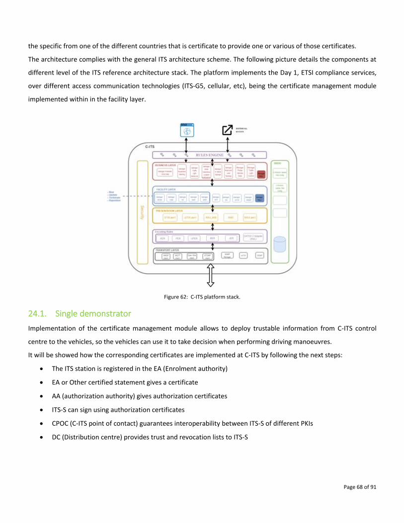
Page 68 of 91
the specific from one of the different countries that is certificate to provide one or various of those certificates.
The architecture complies with the general ITS architecture scheme. The following picture details the components at
different level of the ITS reference architecture stack. The platform implements the Day 1, ETSI compliance services,
over different access communication technologies (ITS-G5, cellular, etc), being the certificate management module
implemented within in the facility layer.
Figure 62: C-ITS platform stack.
24.1. Single demonstrator
Implementation of the certificate management module allows to deploy trustable information from C-ITS control
centre to the vehicles, so the vehicles can use it to take decision when performing driving manoeuvres.
It will be showed how the corresponding certificates are implemented at C-ITS by following the next steps:
• The ITS station is registered in the EA (Enrolment authority)
• EA or Other certified statement gives a certificate
• AA (authorization authority) gives authorization certificates
• ITS-S can sign using authorization certificates
• CPOC (C-ITS point of contact) guarantees interoperability between ITS-S of different PKIs
• DC (Distribution centre) provides trust and revocation lists to ITS-S
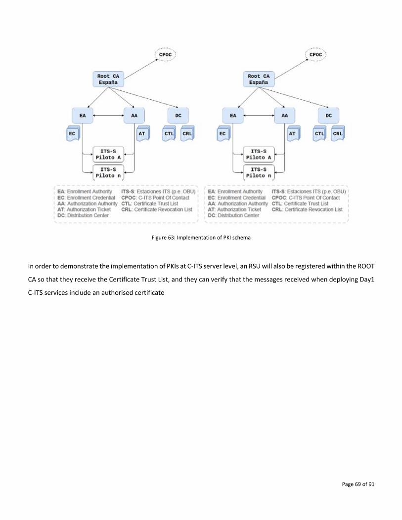
Page 69 of 91
Figure 63: Implementation of PKI schema
In order to demonstrate the implementation of PKIs at C-ITS server level, an RSU will also be registered within the ROOT
CA so that they receive the Certificate Trust List, and they can verify that the messages received when deploying Day1
C-ITS services include an authorised certificate
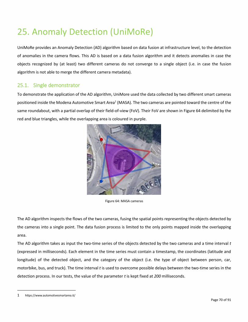
Page 70 of 91
25. Anomaly Detection (UniMoRe)
UniMoRe provides an Anomaly Detection (AD) algorithm based on data fusion at infrastructure level, to the detection
of anomalies in the camera flows. This AD is based on a data fusion algorithm and it detects anomalies in case the
objects recognized by (at least) two different cameras do not converge to a single object (i.e. in case the fusion
algorithm is not able to merge the different camera metadata).
25.1. Single demonstrator
To demonstrate the application of the AD algorithm, UniMore used the data collected by two different smart cameras
positioned inside the Modena Automotive Smart Area1 (MASA). The two cameras are pointed toward the centre of the
same roundabout, with a partial overlap of their field-of-view (FoV). Their FoV are shown in Figure 64 delimited by the
red and blue triangles, while the overlapping area is coloured in purple.
Figure 64: MASA cameras
The AD algorithm inspects the flows of the two cameras, fusing the spatial points representing the objects detected by
the cameras into a single point. The data fusion process is limited to the only points mapped inside the overlapping
area.
The AD algorithm takes as input the two-time series of the objects detected by the two cameras and a time interval t
(expressed in milliseconds). Each element in the time series must contain a timestamp, the coordinates (latitude and
longitude) of the detected object, and the category of the object (i.e. the type of object between person, car,
motorbike, bus, and truck). The time interval t is used to overcome possible delays between the two-time series in the
detection process. In our tests, the value of the parameter t is kept fixed at 200 milliseconds.
1 https://www.automotivesmartarea.it/
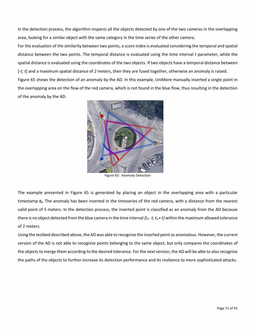
Page 71 of 91
In the detection process, the algorithm inspects all the objects detected by one of the two cameras in the overlapping
area, looking for a similar object with the same category in the time series of the other camera.
For the evaluation of the similarity between two points, a score index is evaluated considering the temporal and spatial
distance between the two points. The temporal distance is evaluated using the time interval t parameter, while the
spatial distance is evaluated using the coordinates of the two objects. If two objects have a temporal distance between
[-t; t] and a maximum spatial distance of 2 meters, then they are fused together, otherwise an anomaly is raised.
Figure 65 shows the detection of an anomaly by the AD. In this example, UniMore manually inserted a single point in
the overlapping area on the flow of the red camera, which is not found in the blue flow, thus resulting in the detection
of the anomaly by the AD.
Figure 65: Anomaly Detection
The example presented in Figure 65 is generated by placing an object in the overlapping area with a particular
timestamp ta. The anomaly has been inserted in the timeseries of the red camera, with a distance from the nearest
valid point of 5 meters. In the detection process, the inserted point is classified as an anomaly from the AD because
there is no object detected from the blue camera in the time interval [ta - t; ta + t] within the maximum allowed tolerance
of 2 meters.
Using the testbed described above, the AD was able to recognize the inserted point as anomalous. However, the current
version of the AD is not able to recognize points belonging to the same object, but only compares the coordinates of
the objects to merge them according to the desired tolerance. For the next version, the AD will be able to also recognize
the paths of the objects to further increase its detection performance and its resilience to more sophisticated attacks.
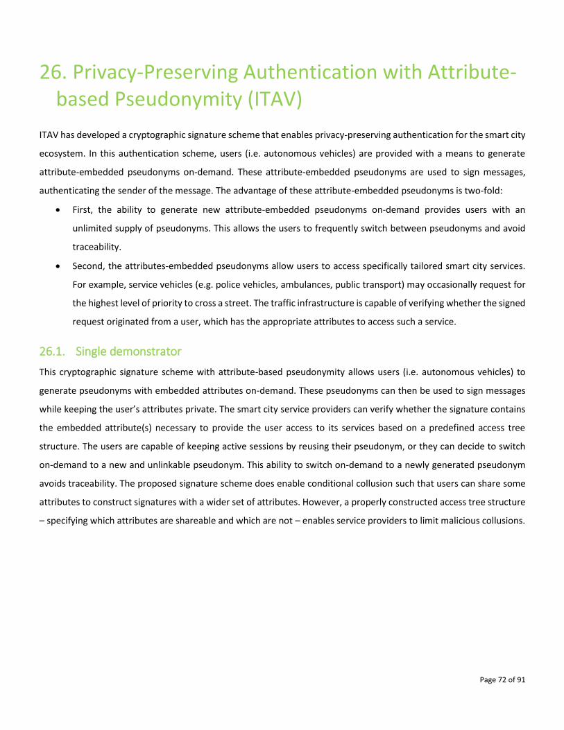
Page 72 of 91
26. Privacy-Preserving Authentication with Attribute-based Pseudonymity (ITAV)
ITAV has developed a cryptographic signature scheme that enables privacy-preserving authentication for the smart city
ecosystem. In this authentication scheme, users (i.e. autonomous vehicles) are provided with a means to generate
attribute-embedded pseudonyms on-demand. These attribute-embedded pseudonyms are used to sign messages,
authenticating the sender of the message. The advantage of these attribute-embedded pseudonyms is two-fold:
• First, the ability to generate new attribute-embedded pseudonyms on-demand provides users with an
unlimited supply of pseudonyms. This allows the users to frequently switch between pseudonyms and avoid
traceability.
• Second, the attributes-embedded pseudonyms allow users to access specifically tailored smart city services.
For example, service vehicles (e.g. police vehicles, ambulances, public transport) may occasionally request for
the highest level of priority to cross a street. The traffic infrastructure is capable of verifying whether the signed
request originated from a user, which has the appropriate attributes to access such a service.
26.1. Single demonstrator
This cryptographic signature scheme with attribute-based pseudonymity allows users (i.e. autonomous vehicles) to
generate pseudonyms with embedded attributes on-demand. These pseudonyms can then be used to sign messages
while keeping the user’s attributes private. The smart city service providers can verify whether the signature contains
the embedded attribute(s) necessary to provide the user access to its services based on a predefined access tree
structure. The users are capable of keeping active sessions by reusing their pseudonym, or they can decide to switch
on-demand to a new and unlinkable pseudonym. This ability to switch on-demand to a newly generated pseudonym
avoids traceability. The proposed signature scheme does enable conditional collusion such that users can share some
attributes to construct signatures with a wider set of attributes. However, a properly constructed access tree structure
– specifying which attributes are shareable and which are not – enables service providers to limit malicious collusions.
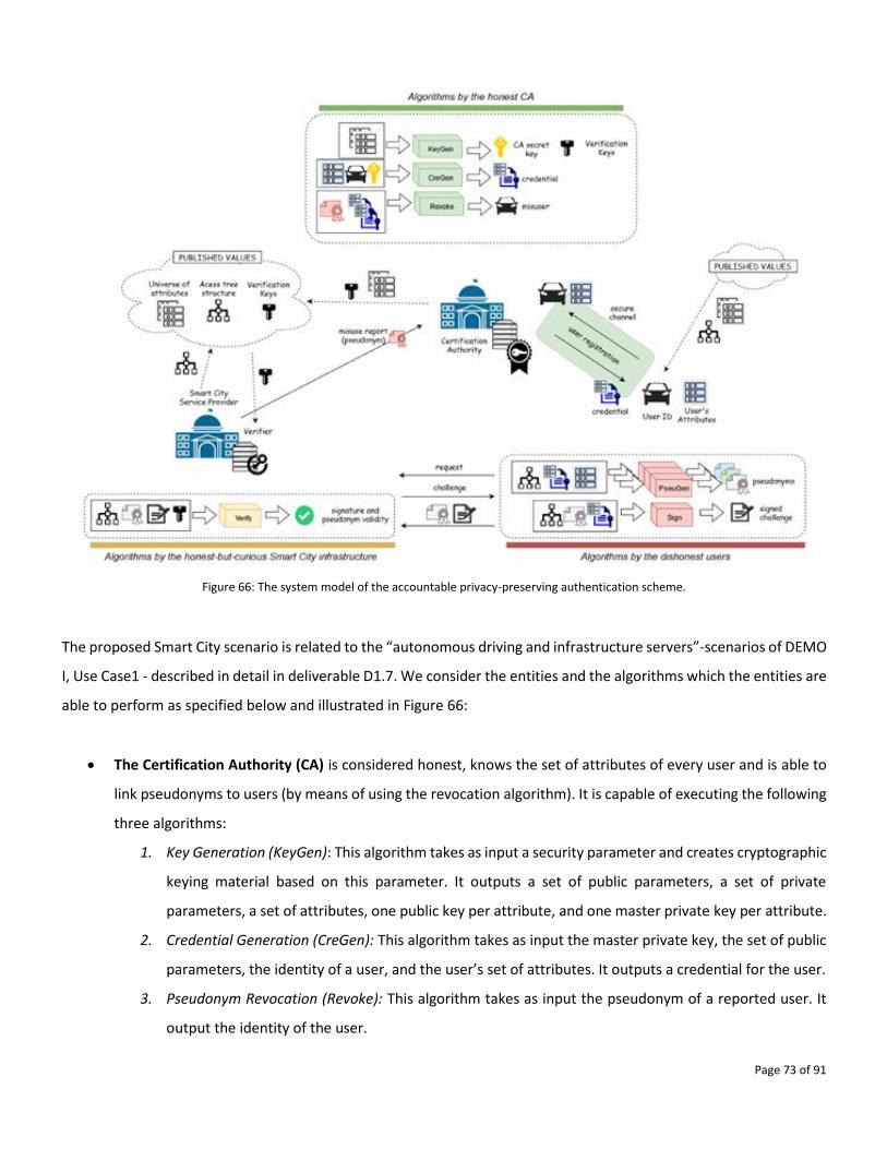
Page 73 of 91
Figure 66: The system model of the accountable privacy-preserving authentication scheme.
The proposed Smart City scenario is related to the “autonomous driving and infrastructure servers”-scenarios of DEMO
I, Use Case1 - described in detail in deliverable D1.7. We consider the entities and the algorithms which the entities are
able to perform as specified below and illustrated in Figure 66:
• The Certification Authority (CA) is considered honest, knows the set of attributes of every user and is able to
link pseudonyms to users (by means of using the revocation algorithm). It is capable of executing the following
three algorithms:
1. Key Generation (KeyGen): This algorithm takes as input a security parameter and creates cryptographic
keying material based on this parameter. It outputs a set of public parameters, a set of private
parameters, a set of attributes, one public key per attribute, and one master private key per attribute.
2. Credential Generation (CreGen): This algorithm takes as input the master private key, the set of public
parameters, the identity of a user, and the user’s set of attributes. It outputs a credential for the user.
3. Pseudonym Revocation (Revoke): This algorithm takes as input the pseudonym of a reported user. It
output the identity of the user.
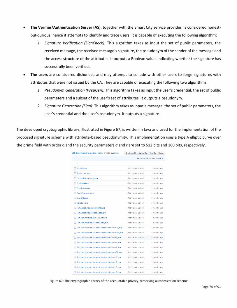
Page 74 of 91
• The Verifier/Authentication Server (AS), together with the Smart City service provider, is considered honest-
but-curious, hence it attempts to identify and trace users. It is capable of executing the following algorithm:
1. Signature Verification (SignCheck): This algorithm takes as input the set of public parameters, the
received message, the received message’s signature, the pseudonym of the sender of the message and
the access structure of the attributes. It outputs a Boolean value, indicating whether the signature has
successfully been verified.
• The users are considered dishonest, and may attempt to collude with other users to forge signatures with
attributes that were not issued by the CA. They are capable of executing the following two algorithms:
1. Pseudonym Generation (PseuGen): This algorithm takes as input the user’s credential, the set of public
parameters and a subset of the user’s set of attributes. It outputs a pseudonym.
2. Signature Generation (Sign): This algorithm takes as input a message, the set of public parameters, the
user’s credential and the user’s pseudonym. It outputs a signature.
The developed cryptographic library, illustrated in Figure 67, is written in Java and used for the implementation of the
proposed signature scheme with attribute-based pseudonymity. This implementation uses a type A elliptic curve over
the prime field with order q and the security parameters q and r are set to 512 bits and 160 bits, respectively.
Figure 67: The cryptographic library of the accountable privacy-preserving authentication scheme
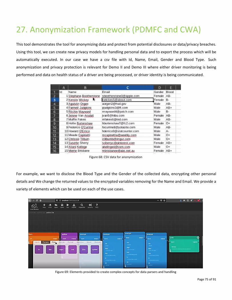
Page 75 of 91
27. Anonymization Framework (PDMFC and CWA)
This tool demonstrates the tool for anonymizing data and protect from potential disclosures or data/privacy breaches.
Using this tool, we can create new privacy models for handling personal data and to export the process which will be
automatically executed. In our case we have a csv file with Id, Name, Email, Gender and Blood Type. Such
anonymization and privacy protection is relevant for Demo II and Demo III where either driver monitoring is being
performed and data on health status of a driver are being processed, or driver identity is being communicated.
Figure 68: CSV data for anonymization
For example, we want to disclose the Blood Type and the Gender of the collected data, encrypting other personal
details and We change the returned values to the encrypted variables removing for the Name and Email. We provide a
variety of elements which can be used on each of the use cases.
Figure 69: Elements provided to create complex concepts for data parsers and handling
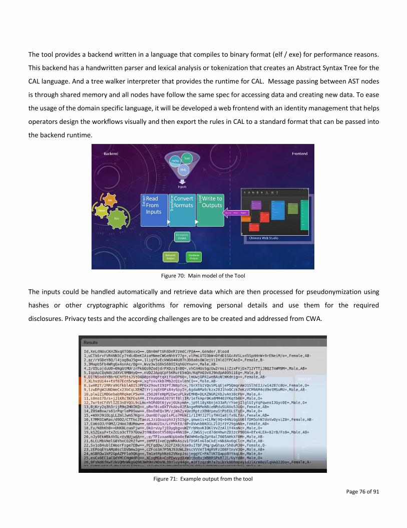
Page 76 of 91
The tool provides a backend written in a language that compiles to binary format (elf / exe) for performance reasons.
This backend has a handwritten parser and lexical analysis or tokenization that creates an Abstract Syntax Tree for the
CAL language. And a tree walker interpreter that provides the runtime for CAL. Message passing between AST nodes
is through shared memory and all nodes have follow the same spec for accessing data and creating new data. To ease
the usage of the domain specific language, it will be developed a web frontend with an identity management that helps
operators design the workflows visually and then export the rules in CAL to a standard format that can be passed into
the backend runtime.
Figure 70: Main model of the Tool
The inputs could be handled automatically and retrieve data which are then processed for pseudonymization using
hashes or other cryptographic algorithms for removing personal details and use them for the required
disclosures. Privacy tests and the according challenges are to be created and addressed from CWA.
Figure 71: Example output from the tool
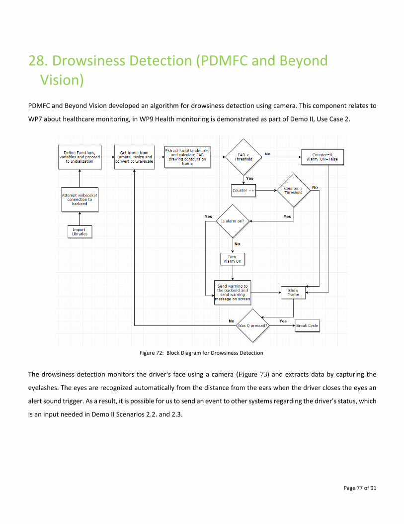
Page 77 of 91
28. Drowsiness Detection (PDMFC and Beyond Vision)
PDMFC and Beyond Vision developed an algorithm for drowsiness detection using camera. This component relates to
WP7 about healthcare monitoring, in WP9 Health monitoring is demonstrated as part of Demo II, Use Case 2.
Figure 72: Block Diagram for Drowsiness Detection
The drowsiness detection monitors the driver's face using a camera (Figure 73) and extracts data by capturing the
eyelashes. The eyes are recognized automatically from the distance from the ears when the driver closes the eyes an
alert sound trigger. As a result, it is possible for us to send an event to other systems regarding the driver's status, which
is an input needed in Demo II Scenarios 2.2. and 2.3.
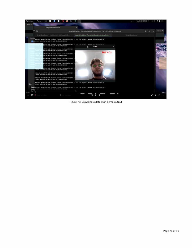
Page 78 of 91
Figure 73: Drowsiness detection demo output
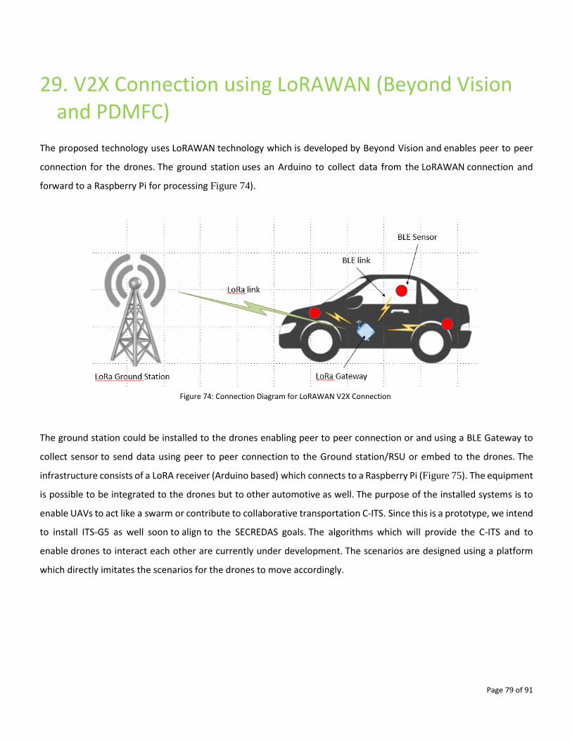
Page 79 of 91
29. V2X Connection using LoRAWAN (Beyond Vision and PDMFC)
The proposed technology uses LoRAWAN technology which is developed by Beyond Vision and enables peer to peer
connection for the drones. The ground station uses an Arduino to collect data from the LoRAWAN connection and
forward to a Raspberry Pi for processing Figure 74).
Figure 74: Connection Diagram for LoRAWAN V2X Connection
The ground station could be installed to the drones enabling peer to peer connection or and using a BLE Gateway to
collect sensor to send data using peer to peer connection to the Ground station/RSU or embed to the drones. The
infrastructure consists of a LoRA receiver (Arduino based) which connects to a Raspberry Pi (Figure 75). The equipment
is possible to be integrated to the drones but to other automotive as well. The purpose of the installed systems is to
enable UAVs to act like a swarm or contribute to collaborative transportation C-ITS. Since this is a prototype, we intend
to install ITS-G5 as well soon to align to the SECREDAS goals. The algorithms which will provide the C-ITS and to
enable drones to interact each other are currently under development. The scenarios are designed using a platform
which directly imitates the scenarios for the drones to move accordingly.
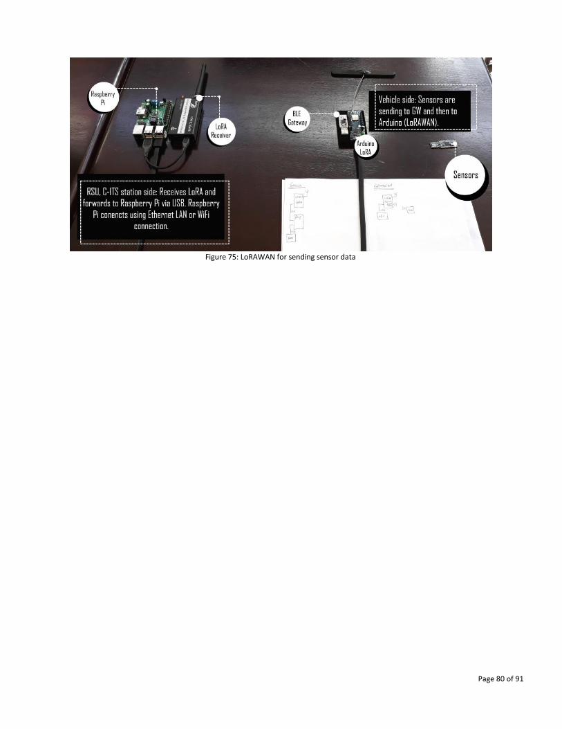
Page 80 of 91
Figure 75: LoRAWAN for sending sensor data
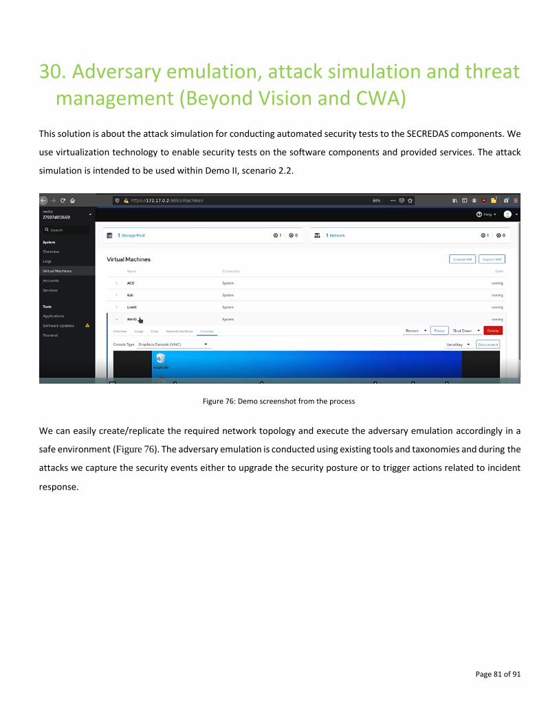
Page 81 of 91
30. Adversary emulation, attack simulation and threat management (Beyond Vision and CWA)
This solution is about the attack simulation for conducting automated security tests to the SECREDAS components. We
use virtualization technology to enable security tests on the software components and provided services. The attack
simulation is intended to be used within Demo II, scenario 2.2.
Figure 76: Demo screenshot from the process
We can easily create/replicate the required network topology and execute the adversary emulation accordingly in a
safe environment (Figure 76). The adversary emulation is conducted using existing tools and taxonomies and during the
attacks we capture the security events either to upgrade the security posture or to trigger actions related to incident
response.
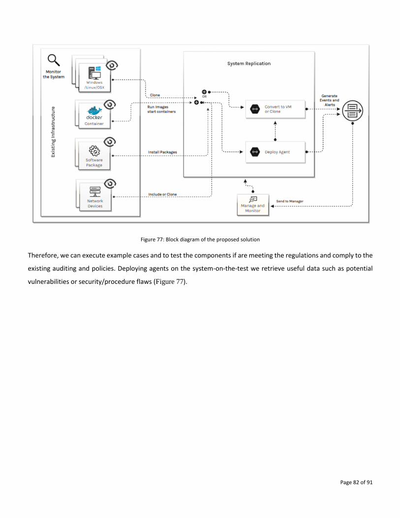
Page 82 of 91
Figure 77: Block diagram of the proposed solution
Therefore, we can execute example cases and to test the components if are meeting the regulations and comply to the
existing auditing and policies. Deploying agents on the system-on-the-test we retrieve useful data such as potential
vulnerabilities or security/procedure flaws (Figure 77).
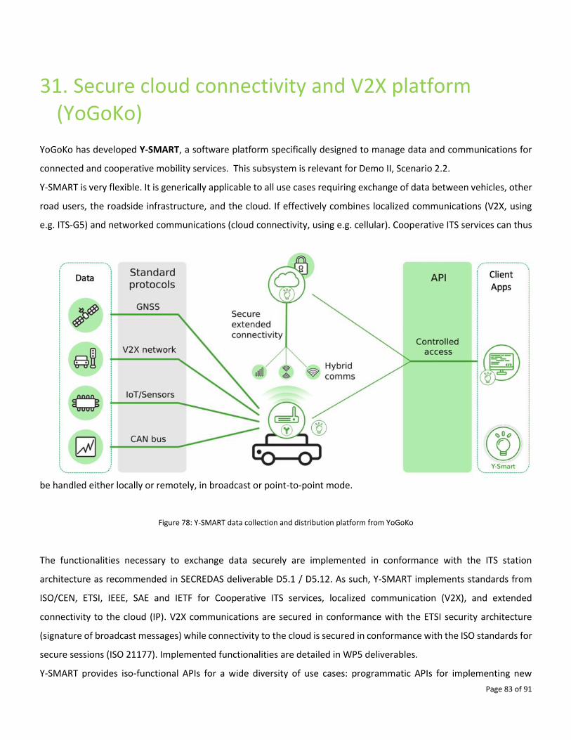
Page 83 of 91
31. Secure cloud connectivity and V2X platform (YoGoKo)
YoGoKo has developed Y-SMART, a software platform specifically designed to manage data and communications for
connected and cooperative mobility services. This subsystem is relevant for Demo II, Scenario 2.2.
Y-SMART is very flexible. It is generically applicable to all use cases requiring exchange of data between vehicles, other
road users, the roadside infrastructure, and the cloud. If effectively combines localized communications (V2X, using
e.g. ITS-G5) and networked communications (cloud connectivity, using e.g. cellular). Cooperative ITS services can thus
be handled either locally or remotely, in broadcast or point-to-point mode.
Figure 78: Y-SMART data collection and distribution platform from YoGoKo
The functionalities necessary to exchange data securely are implemented in conformance with the ITS station
architecture as recommended in SECREDAS deliverable D5.1 / D5.12. As such, Y-SMART implements standards from
ISO/CEN, ETSI, IEEE, SAE and IETF for Cooperative ITS services, localized communication (V2X), and extended
connectivity to the cloud (IP). V2X communications are secured in conformance with the ETSI security architecture
(signature of broadcast messages) while connectivity to the cloud is secured in conformance with the ISO standards for
secure sessions (ISO 21177). Implemented functionalities are detailed in WP5 deliverables.
Y-SMART provides iso-functional APIs for a wide diversity of use cases: programmatic APIs for implementing new
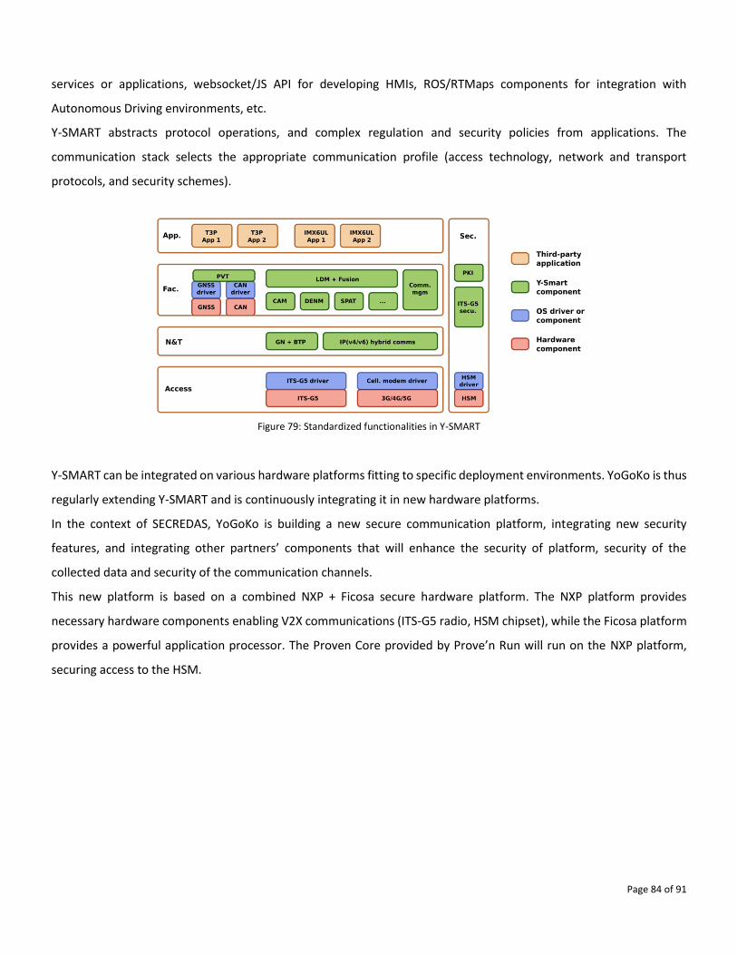
Page 84 of 91
services or applications, websocket/JS API for developing HMIs, ROS/RTMaps components for integration with
Autonomous Driving environments, etc.
Y-SMART abstracts protocol operations, and complex regulation and security policies from applications. The
communication stack selects the appropriate communication profile (access technology, network and transport
protocols, and security schemes).
Figure 79: Standardized functionalities in Y-SMART
Y-SMART can be integrated on various hardware platforms fitting to specific deployment environments. YoGoKo is thus
regularly extending Y-SMART and is continuously integrating it in new hardware platforms.
In the context of SECREDAS, YoGoKo is building a new secure communication platform, integrating new security
features, and integrating other partners’ components that will enhance the security of platform, security of the
collected data and security of the communication channels.
This new platform is based on a combined NXP + Ficosa secure hardware platform. The NXP platform provides
necessary hardware components enabling V2X communications (ITS-G5 radio, HSM chipset), while the Ficosa platform
provides a powerful application processor. The Proven Core provided by Prove’n Run will run on the NXP platform,
securing access to the HSM.
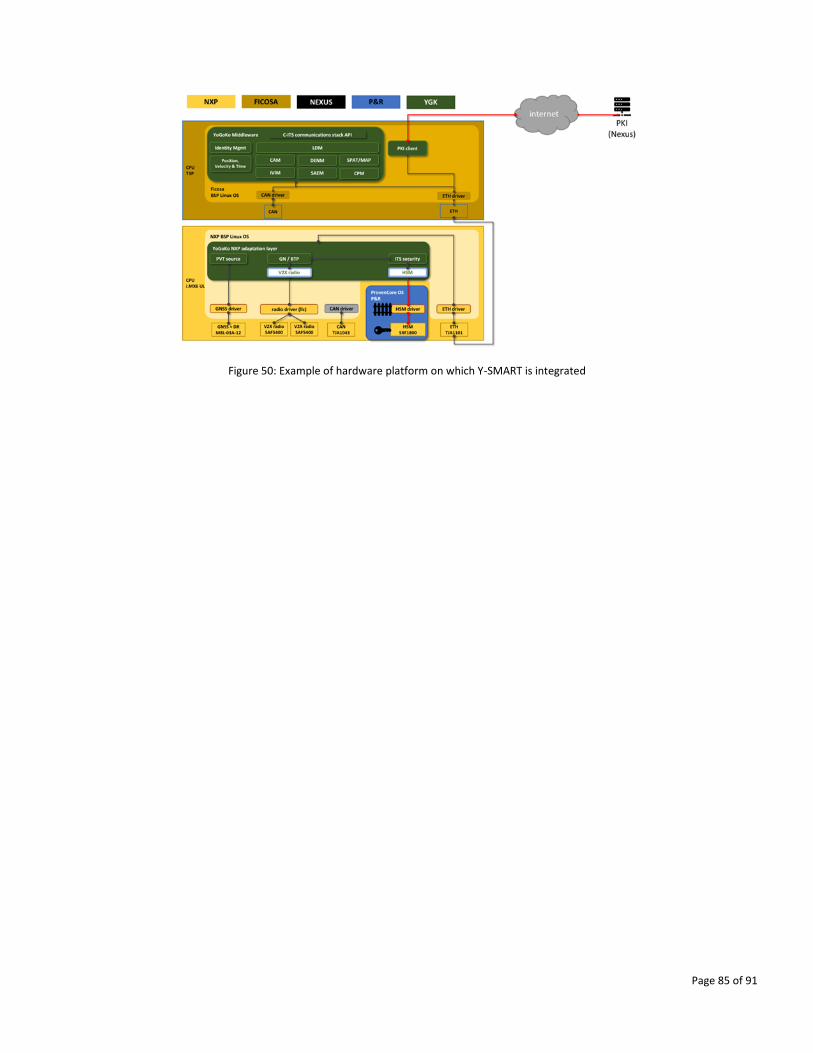
Page 85 of 91
Figure 50: Example of hardware platform on which Y-SMART is integrated
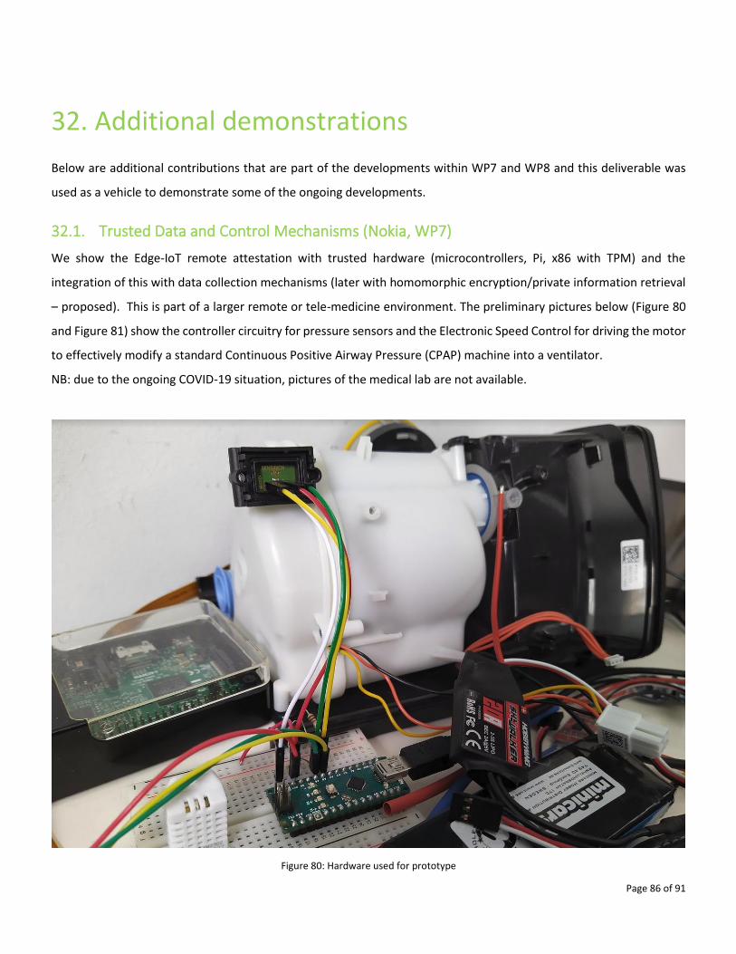
Page 86 of 91
32. Additional demonstrations
Below are additional contributions that are part of the developments within WP7 and WP8 and this deliverable was
used as a vehicle to demonstrate some of the ongoing developments.
32.1. Trusted Data and Control Mechanisms (Nokia, WP7)
We show the Edge-IoT remote attestation with trusted hardware (microcontrollers, Pi, x86 with TPM) and the
integration of this with data collection mechanisms (later with homomorphic encryption/private information retrieval
– proposed). This is part of a larger remote or tele-medicine environment. The preliminary pictures below (Figure 80
and Figure 81) show the controller circuitry for pressure sensors and the Electronic Speed Control for driving the motor
to effectively modify a standard Continuous Positive Airway Pressure (CPAP) machine into a ventilator.
NB: due to the ongoing COVID-19 situation, pictures of the medical lab are not available.
Figure 80: Hardware used for prototype
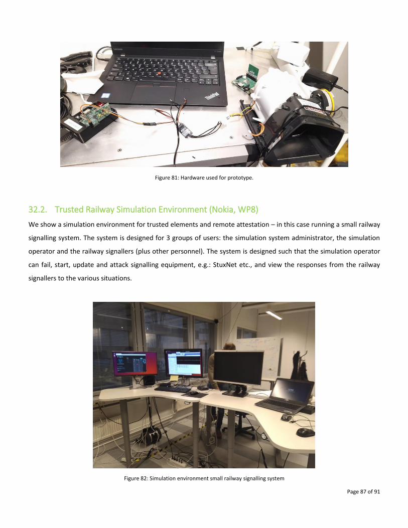
Page 87 of 91
Figure 81: Hardware used for prototype.
32.2. Trusted Railway Simulation Environment (Nokia, WP8)
We show a simulation environment for trusted elements and remote attestation – in this case running a small railway
signalling system. The system is designed for 3 groups of users: the simulation system administrator, the simulation
operator and the railway signallers (plus other personnel). The system is designed such that the simulation operator
can fail, start, update and attack signalling equipment, e.g.: StuxNet etc., and view the responses from the railway
signallers to the various situations.
Figure 82: Simulation environment small railway signalling system
Page 88 of 91
33. Summary and conclusions
Within the WP9 the following three common demonstrators are being developed in a form of Use Cases and their
individual Scenarios:
Demo I - Use Case1, Scenario 1.1, 1.2, 1.3, 1.4 and 1.5,
Demo II - Use Case2, Scenarios 2.1, 2.2 and 2.3, and
Demo III -Use Case 3 and Use Case 4, Scenarios 3.1 and 4.1.
Standalone systems that are presented in this document have been successfully demonstrated as functional
components, which are available for integration to form the above mentioned three demonstrators. For each
demonstrated standalone system a brief description, photographs/screenshots or diagrams were provided to show
that the documented system was demonstrated as operational and that basic functionality needed for integration is
available.
Altogether this document describes 31 subsystems intended for integration within the WP9 common demonstrators
and (Chapters 1 to 31), moreover two additional subsystems relevant for WP7 and WP8 are documented as well
(Chapter 32). The actual demonstration was documented using 82 figures.
The next step within the WP9 will be the integration of these standalone systems to provide the integrated
demonstrators (initial integration will be demonstrated in D9.4). Integration efforts will be documented and
demonstrated in subsequent deliverables (D9.3 will document sensor fusion in Demo I and Demo II, D9.5 will document
fusion of subsystems to form Demo I and Demo II scenarios and D9.6 will document requirements and specifications
for integration of Demo III scenarios).
Page 89 of 91
32. Figures
Figure 1: Detail of web application that retrieves encrypted data from the target server................................................ 7
Figure 2: Detail of the application that triggers SIM card encryption ................................................................................ 8
Figure 3: Hardware used for the demonstrator ............................................................................................................... 11
Figure 4: Application View ................................................................................................................................................ 11
Figure 5: IR camera from the Driver Monitoring System (DMS) of FICOSA. .................................................................... 13
Figure 6: Image taken from the IR camera. The laser dot projection can be seen on the chest of the driver. ............... 13
Figure 7: Polar H10 heart rate sensor. .............................................................................................................................. 14
Figure 8: Zephir BioHarness 3 heart and breathing rate sensor. ..................................................................................... 14
Figure 9: Empatica 4 blood volume, skin temperature and heart rate and inter-beat interval sensor. .......................... 15
Figure 10: Muse head-band electroencephalogram sensor. ............................................................................................ 15
Figure 11: Example data from the Empatica sensor before analysis and classification, see text for details. .................. 16
Figure 12: An expansion of the traces in Figure 11, see text for details. ......................................................................... 16
Figure 13: Screenshot of Mobile App prototype used for registration ............................................................................ 18
Figure 14: Screenshot of QR displayed in User browser for Authentication process ...................................................... 19
Figure 15 : Authentication process flow ........................................................................................................................... 19
Figure 16: HP2 test activity during development of the VCU based Anomaly detection solution with EVI RTOS. .......... 20
Figure 17: HP2 VCU designed for placement in the demonstration vehicle provided ..................................................... 21
Figure 18: C-ITS Interconnection module from the video server to a C-ITS Station ........................................................ 22
Figure 19: Example of a car detection with 90% object confidence obtained with CRF VCA on a frame ........................ 23
Figure 20: UI of IDM service – registering new user ........................................................................................................ 25
Figure 21: ACS backend (Czech version of GUI) being developed for Demo III ................................................................ 27
Figure 22: Demonstration of user identification .............................................................................................................. 28
Figure 23 TNO single demonstrator in simulation environment ...................................................................................... 29
Figure 24 TNO sensor fusion performance ....................................................................................................................... 30
Figure 25 TNO anomaly injection and detection .............................................................................................................. 31
Figure 26: The mobile application screenshots using an emulator .................................................................................. 32
Figure 27: The end-user interface for the car sharing service provider ........................................................................... 34
Figure 28: The database model used by the Service Provider ......................................................................................... 34
Figure 29: Replication of the use cases using drones for running recursively scenarios important for conducting security
tests and to evaluate mitigation methods ....................................................................................................................... 35
Figure 30: Specifications of the drones and capabilities .................................................................................................. 36
Figure 31. Voxels Map (left image) and dynamic path taken by the drone (on the right). .............................................. 36
Figure 32: Demonstration of collision detection/avoidance in the simulation environment .......................................... 36
Figure 33: The web interface provides information regarding the connected entities (drones) ..................................... 37
Figure 34: 8K 360 camera for providing 4K video streaming from the drone .................................................................. 37
Figure 35: Demonstration of the web interface and the actual position of the drone .................................................... 38
Figure 36: Identity management presenting revoked access to specific services ........................................................... 39
Figure 37: Privacy preserving authentication framework ................................................................................................ 40
Figure 38 Structured adversary tactics for conducting Red team assessments ............................................................... 40
Figure 39: 5G receiver/broadcaster on a drone ............................................................................................................... 41
Figure 40: Comsignia demonstrator architecture ............................................................................................................ 43
Figure 41: Comsignia demonstrator setup and components ........................................................................................... 44
Page 90 of 91
Figure 42: Comsignia V2X demonstration ........................................................................................................................ 46
Figure 43: Overview of simple2secure security testing framework ................................................................................. 48
Figure 44: Overview of role of Secure Gateway for in Car Security. ................................................................................ 49
Figure 45: Imec Secure Distance Bounding System. ......................................................................................................... 52
Figure 46: Ultra Wide Band module and battery ............................................................................................................. 53
Figure 47: Aerial view of outdoors tests location (source: Google Maps) ....................................................................... 54
Figure 48: Outdoors deployment distances among anchors ........................................................................................... 55
Figure 49: Walking test: origin position and middle point anchors 1-2 ........................................................................... 56
Figure 50: Tagged objects inside the anchored area ........................................................................................................ 57
Figure 51: Aerial view of outdoors tests location (source: Google Maps) ....................................................................... 58
Figure 52: SECREDAS Outdoors test deployment 14th July 2020 ...................................................................................... 58
Figure 53: SECREDAS Outdoors test tagged “road works” area ....................................................................................... 59
Figure 54: Tags and triangulation ..................................................................................................................................... 59
Figure 55: MQTT.fx screenshot during the PCTCAN parking test ..................................................................................... 60
Figure 56: Location IoT device. ......................................................................................................................................... 61
Figure 57: Secure positioning device state machine ........................................................................................................ 62
Figure 58: Secure positioning device configuration menu ............................................................................................... 63
Figure 59: Example of an attack on a perception module................................................................................................ 65
Figure 60: Attack configuration file. ................................................................................................................................. 66
Figure 61: C-ITS Implementation of certificate management module at HCC C-ITS platform level. .............................. 67
Figure 62: C-ITS platform stack. ....................................................................................................................................... 68
Figure 63: Implementation of PKI schema ....................................................................................................................... 69
Figure 64: MASA cameras ................................................................................................................................................. 70
Figure 65: Anomaly Detection ......................................................................................................................................... 71
Figure 66: The system model of the accountable privacy-preserving authentication scheme. ...................................... 73
Figure 67: The cryptographic library of the accountable privacy-preserving authentication scheme ............................ 74
Figure 68: CSV data for anonymization ............................................................................................................................ 75
Figure 69: Elements provided to create complex concepts for data parsers and handling ............................................. 75
Figure 70: Main model of the Tool .................................................................................................................................. 76
Figure 71: Example output from the tool ........................................................................................................................ 76
Figure 72: Block Diagram for Drowsiness Detection ....................................................................................................... 77
Figure 73: Drowsiness detection demo output ................................................................................................................ 78
Figure 74: Connection Diagram for LoRAWAN V2X Connection ...................................................................................... 79
Figure 74: LoRAWAN for sending sensor data.................................................................................................................. 80
Figure 76: Demo screenshot from the process ................................................................................................................ 81
Figure 77: Block diagram of the proposed solution ......................................................................................................... 82
Figure 78: Y-SMART data collection and distribution platform from YoGoKo ................................................................. 83
Figure 79: Standardized functionalities in Y-SMART ........................................................................................................ 84
Figure 80: Hardware used for prototype .......................................................................................................................... 86
Figure 81: Hardware used for prototype. ......................................................................................................................... 87
Figure 82: Simulation environment small railway signaling system ................................................................................. 87

Page 91 of 91
www.secredas.eu [email protected] Social media @secredas_eu
SECREDAS has received funding from the Electronic Component Systems for European Leadership Joint Undertaking under grant agreement nr.
Related Documents