OFFIC4AL--frEN61-T4VE 2320-D-128-201 Ministry Of Defence Army Equipment Support Publication Truck Utility Light (TUL) HS, Truck Utility Medium (TUM) HS and (TUM) Battlefield Ambulance HS, All Variants Operating Information 2320-D-128-201 6th Edition May 2017 Superseding 5th Edition January 2009 Sponsored for use in the United Kingdom Ministry of Defence and Armed Forces by Defence Equipment & Support Operational Support Vehicles Programme (OSVP) U05V9 This information is released by the UK Government for Defence purposes only. This information must be afforded the' same degree of protection as that afforded to information of an equivalent classification originated by the recipient Government or as required by the recipient Governments National Security regulations. This information may be disclosed only within the Defence Department of the recipient Government, except as otherwise authorised by the Ministry of Defence (Army). This information may be subject to privately owned rights. Publication Authority: Operational Support Vehicles Programme (OSVP) Mail Point #1309 Spruce 3c DE&S, Abbey Wood Bristol, B534 8JH Service users should send their comments through the channel prescribed for the purpose by the publication sponsor. OFFIGIAL-GE-N61-TIVE 2017-05-31 Page (i)

Welcome message from author
This document is posted to help you gain knowledge. Please leave a comment to let me know what you think about it! Share it to your friends and learn new things together.
Transcript

OFFIC4AL--frEN61-T4VE 2320-D-128-201
Ministry Of Defence
Army Equipment Support Publication
Truck Utility Light (TUL) HS, Truck Utility Medium (TUM) HS and (TUM) Battlefield Ambulance HS, All Variants
Operating Information 2320-D-128-201
6th Edition May 2017 Superseding 5th Edition January 2009
Sponsored for use in the United Kingdom Ministry of Defence and Armed Forces by Defence Equipment & Support Operational Support Vehicles Programme (OSVP)
U05V9 This information is released by the UK Government for Defence purposes only. This information must be
afforded the' same degree of protection as that afforded to information of an equivalent classification
originated by the recipient Government or as required by the recipient Governments National Security
regulations. This information may be disclosed only within the Defence Department of the recipient
Government, except as otherwise authorised by the Ministry of Defence (Army). This information may be
subject to privately owned rights.
Publication Authority:
Operational Support Vehicles Programme (OSVP) Mail Point #1309 Spruce 3c DE&S, Abbey Wood Bristol, B534 8JH
Service users should send their comments through the channel prescribed for the purpose by the
publication sponsor.
OFFIGIAL-GE-N61-TIVE 2017-05-31 Page (i)

2320-D-128-201 OFFIGIAL-SENSITWE ARMY EQUIPMENT SUPPORT PUBLICATION
T-1-116-9<4644M-ENT-1.8-4-H-E--PR4P-ER-T-Y-OF--1-I-ER-BRI-T-414NIG-MA-JES-T-Y18-694E-IRNMENT- aerel-4s issucd for the information of such persons only 03 aced to know its contents in the COUf3C of their effieial-aaties:-Afty-ftepsen-fiatifFtg-t494-deearaeiit-al4ettle-19and-'14-09-te-a-Br-iael9-ferees-ufrit-of-te-a-peliee statieii-far4te-safe-Feterfi-te-tae-Miftiatey- ef-Befenee7-(13i9e#-Sy)-,-Maki-Bailaiftg7Waitelie14-6eaften7-8.‘64-1-A 2HB, with particulars of how and where found. THE UNAUTHORISED RETENTION OR DESTRUCTION -OF THIS DOCUMENT IS AN OFFENCE UNDER THE OFFICIAL SECRETS ACTS OF 1-9-1-1-1-98.97-eMien-released-te-taereens-aatelde-Gever-swie#-sePolee-7-049--eleetie9eia-t-ie-lastteel-ee-a personal basis. The recipient to whom it i3 entrusted in confidence, within the provisions of the Official Secrets Acts 1911 1989, i3 personally responsible for its safe custody and for seeing that its contents fitf-e- diseieseei-eftly-te7auther-ised- ftefseFei
© CROWN COPYRIGHT RESERVED
Page (ii) OFfIGIAL--SEN-64-TIVE May 17

ARMY EQUIPMENT SUPPORT PUBLICATION
OFFICIAL SENSITIVE
AMENDMENT RECORD
Amdt No.
Incorporated By (Signature)
Date
1 Incorporated May 18
2 Incorporated Nov 18
3 Incorporated Apr 19
4 Incorporated Aug 19
5
6
7
8
9
10
11
12
13
14
15
16
17
18
19
20
21
22
23
24
25
26
27
28
29
30
31
2320-D-128-201 6m Edition
Amdt No.
Incorporated By (Signature)
Date
32 ..
33
34
35
36
37
38
39
40
41
42
43
44
45
46
47
48
49
50
51
52
53
54
55
56
57
58
59
60
61
62
May 17 OFFICIA6-SENSITIVE Page (iii)/(iv)

ARMY EQUIPMENT SUPPORT PUBLICATION
GFFIGIAL-GENSITIVE
CONTENTS
2320-D-128-201
PRELIMINARY MATERIAL Page
Front cover (title page) (i)
AMENDMENT RECORD (iii)/(iv)
CONTENTS (this list) (v)
PREFACE (vi)
Introduction (vi)
Related and Associated Publications (vii)
Related Publications (vii)
Associated Publications (viii)
WARNINGS AND CAUTIONS (ix)
Hazardous Substances (ix)
Warnings (ix)
Cautions (xii)
ABBREVIATIONS AND SYMBOLS (xvii)
Abbreviations (xvii)
Symbols (xix)
COMMENT(S) ON AESP Final leaf
OPERATING INFORMATION
Chapters
1 General Description 2 Controls and Instruments 3 Operating Instructions 4 User Maintenance 5 User Spares 6 Denial of Equipment
May 17 OFFIGIAL-GENSITIVE Page (v)
2320-D-128-201
INTRODUCTION
OFFICIALFENGIT4VE ARMY EQUIPMENT SUPPORT PUBLICATION
Sponsor:
Project Number:
File Ref:
Publication Authority:
PREFACE
Operational Support Vehicles Programme (OSVP)
DES-LE-OSP-OSVP-CVS
1 Any comments by service users on this publication should be forwarded through the channels prescribed in Army Equipment Support Publication (AESP) 0100-P-011-013. An AESP Form 10 is provided at the end of this publication; it should be photocopied and used for forwarding comments on this AESP. This procedure is only to be used for the purpose of commenting on the content of an individual AESP and must not be used as follows:
1.1 In place of the Equipment Failure Reporting (EFR) procedure outlined in the Land Equipment Unit Maintenance Standards (LEUMS) Edition 4.
1.2 For subjects which are the concern of the GEMS Defence Ideas Scheme. For advice on the GEMS procedure contact your GEMS Local Awards Group (LAG) through your Equipment Support (ES) Chain of Command. Details of the GEMS LAG locations and Points Of Contact (POC) can be obtained through the GEMS website or through:
GEMS Scheme Manager Level 6, Zone I MOD Main Building Whitehall London
2 AESPs are issued under United Kingdom (UK) Ministry Of Defence (MOD) authority and where AESPs specify action is to be taken, the AESP will of itself be sufficient authority for such action and also for the demanding of the necessary stores, subject to the provisions of Para 3 below.
3 The subject matter of this publication may be affected by Defence Instructions and Notices (DIN), Standard Operating Procedures (SOP) or by local regulations. When any such instruction, Order or Regulation contracts any portion of this publication it is to be taken as the overriding authority.
Page (vi) OFFIGIAL—SEN-F4T4VE May 17

ARMY EQUIPMENT OFFIGIAL—SENGITIVE SUPPORT PUBLICATION
RELATED AND ASSOCIATED PUBLICATIONS
Related Publications
9 The AESP Octad for the subject equipment consists of the publications shown below. All references
are prefixed with the first eight digits of this publication.
2320-D-128-201
Category/Sub-category
Information Level
1 User/
Operator
2 Unit
Maintenance
3 Field
Maintenance
4 Base
Maintenance
1
0 Purpose and Planning Information 101 101 101 101
1 Equipment Support Policy Directives 111 111 111 111
2 Cancellation Instructions * *
2
0 Operating Information 201 201 201 201
1 Aide-Memoire 211 211 * *
_ 2 Training Aids * *
3 Technical Description 302 * * *
4 1 Installation Instructions 411 411 411 411
2 Preparation for Special Environments 421 421 421 421
5
1 Failure Diagnosis * 512 512 512
2 Maintenance Instructions * 522 523 524
3 Inspection Standards * 532 533 533
4 Calibration Procedures * 524 524
6 Maintenance Schedules 601 601 601 601
7
1 Illustrated Parts Catalogues * 711 711 711
2 Commercial Parts Lists * 721 721 721
3Complete Equipment Schedule, Production
* *
4 Complete Equipment Schedule, Service Edition (Simple Equipment)
741 741 741 741
5 Complete Equipment Schedule, Service Edition (Complex Equipment)
*
8
1 Modification Instructions 811 811 811 811
2 General Instructions, Special Technical Instructions and Servicing Instructions
821 - 821 821 821
3Service Engineered Modification Instructions (RAF only)
* * *
* Category/sub-category not published
May 17 OFFICIAL—SENSITIVE Page (vii)

2320-D-128-201
Associated Publications
OFFICIAL&EN&ITIVE ARMY EQUIPMENT SUPPORT PUBLICATION
4 The following associated publications should be read in conjunction with this category:
Reference Title
A9399005
AESP 0200-A-062-013
TUL/TUM Safety Case
Management and Control of Equipment Support Units, Casting Procedures for all Equipment
AESP 0200-A-307-013 All Arms Equipment Recovery Manual
AESP 2320-D-128-Octad Truck Utility Light (TUL) HS, Truck Utility Medium (TUM) HS and (TUM) Ambulance HS, All Variants
AP 100B-01 Royal Air Force Engineering Policy and Regulations
AP 830 MOD (Air Force Department and RAF) Supply Regulations
AP 3260 Book 1 Mechanical Transport Maintenance Regulations for the Royal Air Force - Maintenance Repair Policy
AP 3260 Book 3 Mechanical Transport Maintenance Regulations for the Royal Air Force - General Orders and Modifications
DCI JS 105/00 Joint Air Transport Evaluation Unit (JATEU) — Functions and Tasking Procedures
DLF Defence Logistics Framework - Supply
JSP 375 Vol 2 MOD Health and Safety
JSP 800 Defence Movements and Transport Regulations
LEUMS Land Equipment User Maintenance Standard
Page (viii) OFFICIALSE*61TIVE May 17

ARMY EQUIPMENT SUPPORT PUBLICATION
HAZARDOUS SUBSTANCES
OFFIGIAL-604-61-TIVE 2320-D-128-201
WARNINGS AND CAUTIONS
5 Before using any hazardous substance or material, the user must be conversant with the safety
precautions and first aid instructions:
5.1 On the label of the container it was supplied in.
5.2 On the material Safety Data Sheet.
5.3 In local Safety Orders and Regulations.
WARNINGS
6 The following WARNINGS are used in this document:
1
2
(3) ALWAYS RECTIFY THE CAUSE OF A FAILURE BEFORE RESETTING THE CIRCUIT
BREAKER. SEEK QUALIFIED ASSISTANCE IF NECESSARY.
(4) BEFORE CONNECTION ENSURE ANY AUXILIARY EQUIPMENT TO BE SUPPLIED
WITH EXPORTED POWER IS OF THE CORRECT VOLTAGE.
(5) BEFORE CONNECTION ENSURE ANY EXTERNAL POWER SUPPLY TO BE
CONNECTED IS OF THE CORRECT VOLTAGE.
(6) BRAKING. THE HANDBRAKE ACTS ON THE TRANSMISSION NOT ON THE REAR
WHEELS AND MAY NOT HOLD THE VEHICLE WHEN JACKING UNLESS THE FOLLOWING
PROCEDURE IS USED. IF ONE FRONT WHEEL AND ONE REAR WHEEL ARE RAISED NO
VEHICLE HOLDING OR BRAKING EFFECT IS POSSIBLE. WHEELS SHOULD BE CHOCKED AT
ALL TIMES.
(7) CHOCKING. THE HANDBRAKE ACTS ON THE TRANSMISSION, NOT THE REAR
WHEELS AND MAY NOT HOLD THE VEHICLE WHEN JACKING UNLESS THE FOLLOWING
PROCEDURE IS USED. IF ONE FRONT WHEEL AND ONE REAR WHEEL ARE RAISED NO
VEHICLE HOLDING OR BRAKING EFFECT IS POSSIBLE. WHEELS SHOULD BE CHOCKED
UNDER ALL CIRCUMSTANCES.
(8) CIRCUIT BREAKERS. CB.3 MUST BE SWITCHED OFF WHEN 12 V SUPPLY SOCKETS
ARE NOT IN USE.
(9) CLEANLINESS. AVOID EXCESSIVE CONTACT AND WASH THOROUGHLY AFTER
CONTACT.
(continued)
May 17 OFFIGIAL-&EN-81T-IVE Page (ix)

2320-D-128-201
WARNINGS (continued)
GFRGAL—SCik&MVE ARMY EQUIPMENT SUPPORT PUBLICATION
(10) COMPRESSED AIR. DO NOT DIRECT AIR STREAM AT PERSONNEL AS THIS CAN CAUSE PERSONAL INJURY.
(11) DANGER TO PERSONNEL. IF THE WEAPON HAS BEEN FIRED CARE SHOULD BE TAKEN AS PARTS OF THE WEAPON MAY BE EXTREMELY HOT AND COULD CAUSE INJURY TO PERSONNEL OR DAMAGE TO EQUIPMENT.
(12) DANGER TO PERSONNEL. THE SWING ARM SHOULD BE STOWED IN THE NORMAL LOCKED POSITION DURING TRANSIT. FAILURE TO LOCK THE SWING ARM DURING TRANSIT COULD RESULT IN INJURY TO THE OPERATOR AND/OR OTHER PERSONNEL CAUSE BY THE MECHANISM SWINGING FREELY AND WITHOUT CONTROL.
(13) DO NOT OPERATE THE SYSTEM IF THE RECIRCULATION GRILLE IS BLOCKED.
(14) DO NOT OPERATE THE SYSTEM WITH ALL OF THE VENTS CLOSED.
(15) DO NOT USE THE HAND THROTTLE WHILST DRIVING THE VEHICLE.
(16) DO NOT USE THE SEAT IN RAISED POSITION WHEN THE VEHICLE IS MOVING.
(17) DO NOT USE TYRES WITH EXCESSIVELY WORN TREADS. TYRE WEAR SHOULD BE CHECKED AT EVERY MAINTENANCE INSPECTION.
(18) DO NOT VIEW THE FRONT LAMPS DIRECTLY WITH OPTICAL INSTRUMENTS. IT MAY CAUSE EYE DAMAGE. NIGHT VISION DEVICES MAY BE DAMAGED.
(19) DUE CONSIDERATION SHOULD BE GIVEN TO THE HIGHLY FLAMMABLE NATURE OF GASOLINE AND ITS VAPOUR. CARELESSNESS IN ITS USE MAY RESULT IN PAINFUL BURNS.
(20) EXPANSION CAP. DO NOT REMOVE THE EXPANSION CAP WHEN THE ENGINE IS HOT BECAUSE THE COOLING SYSTEM IS PRESSURISED AND PERSONAL SCALDING COULD RESULT.
(21) FAILURE TO ROTATE THE PINTLE INTO THE "LOCKED" POSITION (INTO THE LOWER SPRING CLIP) MAY RESULT IN THE PINTLE VIBRATING LOOSE DURING USE!
(22) FALLING OBJECTS. ALWAYS SUPPORT THE SAND CHANNELS ON THE BRACKETS WHILST RELEASING OR FASTENING THE RATCHETS.
(23) FALLING OBJECTS. THE SPARE WHEEL MUST ALWAYS BE SUPPORTED IN POSITION ON THE WHEEL CARRIER UNTIL THE CLAMP AND BOLTS ARE FITTED.
(24) FALLING OBJECTS. THE SPARE WHEEL MUST ALWAYS BE SUPPORTED IN POSITION ON THE WHEEL CARRIER UNTIL THE WHEEL NUTS ARE FITTED.
(25) FILLER CAP. DO NOT REMOVE THE EXPANSION TANK FILLER CAP WHEN THE ENGINE IS HOT, BECAUSE THE COOLING SYSTEM IS PRESSURISED AND PERSONAL SCALDING COULD RESULT.
(26) FINGER TRAP. THE CPWM ROTATES ABOUT THE SWINGING ARM AND THE SWINGING ARM ROTATES ABOUT THE MOUNTING POST. INJURY WILL RESULT IF FINGERS OR HANDS ARE ALLOWED TO BE TRAPPED BETWEEN THE MOVING PARTS.
i276111.1111=MIIIMIIIII=1111 11.1E.111
(continued)
Page (x) OFFICIALK4164TIVE May 17

ARMY EQUIPMENT OFFIGIAL--6.ENSITIVE 2320-D-128-201
SUPPORT PUBLICATION
WARNINGS (continued)
(28) FUSES. THESE FUSES PROTECT THE MAIN HARNESS, IF ANY OF THESE FUSES
FAIL REPORT IT IMMEDIATELY. TO CONTINUE WOULD RESULT IN SERIOUS DAMAGE.
(29)
(30) HEALTH. PROLONGED AND REPEATED CONTACT WITH USED ENGINE OILS MAY
CAUSE SERIOUS SKIN DISORDERS, INCLUDING DERMATITIS AND CANCER.
(31) HEAVY OBJECTS. THE REMOVABLE WINDSCREEN IS HEAVY. USE AN ASSISTANT
WHEN REMOVING OR REFITTING THE SCREEN.
(32) HOLDING THE WHEEL. DO NOT HOLD THE STEERING WHEEL WITH THE FINGERS
AND THUMBS INSIDE THE WHEEL. A SUDDEN VIOLENT KICK OF THE WHEEL COULD DAMAGE OR EVEN BREAK THE FINGERS. GRIP THE WHEEL ON THE OUTSIDE OF THE RIM
WHEN TRAVELLING ACROSS COUNTRY (FIG 20).
(33) IF FOR ANY REASON THE ENGINE IS SWITCHED OFF WHILE THE VEHICLE IS IN MOTION. DO NOT UNDER ANY CIRCUMSTANCES RETURN THE KEY TO THE "STEERING LOCKED" POSITION "0" UNTIL THE VEHICLE IS STATIONARY. TO PREVENT THE STEERING
COLUMN LOCK ENGAGING IT IS MOST IMPORTANT THAT BEFORE THE VEHICLE IS MOVED IN ANYWAY, FOR EXAMPLE TOWING, THE KEY MUST BE INSERTED IN THE LOCK AND TURNED TO POSITION "I". IF, DUE TO AN ACCIDENT OR ELECTRICAL FAULT IT IS NOT CONSIDERED SAFE TO TURN THE KEY, THE BATTERIES MUST FIRST BE DISCONNECTED.
(34) IF THE WARNING BUZZER SOUNDS AT THIS STAGE THE BATTERIES HAVE BEEN
CONNECTED INCORRECTLY. CHECK BATTERY CONFIGURATION (PARA 11) AND RECTIFY.
(35) INCORRECT USE. THE INCORRECT USE OF THE ROTATING TOWING HOOK COULD RESULT IN DAMAGE TO EQUIPMENT OR SERIOUS PERSONAL INJURY. ENSURE THE ROTATING TOWING HOOK IS USED IN THE CORRECT MANNER.
(36) INJURY TO PERSONNEL. LEAVING THE SLEWING HANDLES IN THE HORIZONTAL POSITION MAY RESULT IN INJURY TO AN OPERATOR SEATED OR WORKING WITHIN THE RING.
(37) INJURY TO PERSONNEL. THE SLEWING RING CAM LOCK LEVER SHOULD BE LEFT IN THE ENGAGED POSITION (HORIZONTAL) WHEN LEFT UNATTENDED. IF LEFT IN THE DISENGAGED POSITION (VERTICAL) IT MAY RESULT IN INJURY TO AN OPERATOR WORKING IN THE REAR OF THE VEHICLE.
(38) INJURY. TAKE CARE NOT TO TRAP FINGERS WHEN CLOSING BONNET WHEN
SECURING RADIATOR BLIND.
(39) LIFTING. THE SPARE WHEEL IS HEAVY TO LIFT, TAKE CARE WHEN LIFTING IT ON AND OFF. THIS WILL REQUIRE TWO MEN UNLESS THE SPARE WHEEL LIFTING HARNESS IS USED.
(40) LIQUIDS. MANY LIQUIDS AND SUBSTANCES USED IN MOTOR VEHICLES ARE POISONOUS; THEY MUST NOT BE CONSUMED UNDER ANY CIRCUMSTANCES AND MUST BE KEPT AWAY FROM OPEN WOUNDS. THESE SUBSTANCES INCLUDE BRAKE FLUID, FUEL, WINDSCREEN WASHER ADDITIVES, LUBRICANTS, BATTERY CONTENTS, VARIOUS ADHESIVES, COOLING SYSTEM CORROSION INHIBITOR AND POWER ASSISTED STEERING
FLUID.
(continued)
May 17 OFFICIALSEN&ITIVE Page (xi)
2320-D-128-201
WARNINGS (continued)
OFFIGIAL-SEI4GITIVE ARMY EQUIPMENT SUPPORT PUBLICATION
(41) MAIN HARNESS FUSE BOX. THIS CONTAINS FUSES THAT PROTECT THE VEHICLE MAIN HARNESSES. SHOULD ANY OF THESE FUSES FAIL THE VEHICLE MUST BE TAKEN TO THE WORKSHOP AND THE FAULT RECTIFIED IMMEDIATELY.
(42) MAINTENANCE. NEGLECT OF THE JACK MAY LEAD TO DIFFICULTY IN A ROAD SIDE EMERGENCY. EXAMINE THE JACK OCCASIONALLY. CLEAN THE THREAD TO PREVENT THE FORMATION OF RUST.
43
(44) PERSONNEL INJURY HAZARD. THE PROCEDURE OF INVERTING THE WEAPON THROUGH THE SLEWING RING MUST BE CARRIED OUT BY TWO PERSONS. FAILUR TO DO SO MAY RESULT IN INJURY TO PERSONNEL AND/OR DAMAGE TO EQUIPMENT.
(45) PROCEDURE. IT IS IMPORTANT THAT THE JACKING PROCEDURE DESCRIBED IN THIS HANDBOOK IS FOLLOWED. WHEELS SHOULD BE CHOCKED UNDER ALL CIRCUMSTANCES.
(46) PROCEDURE. TO ENSURE SAFETY WHEN USING THE JACK THE FOLLOWING PROCEDURE SHOULD BE FOLLOWED:
(1) DIFF LOCK. ALWAYS ENGAGE DIFFERENTIAL LOCK BEFORE JACKING.
(2) SAFETY. NO PERSON SHOULD REMAIN IN A VEHICLE BEING JACKED.
(3) BRAKING. APPLY THE HANDBRAKE AND ENGAGE FIRST GEAR IN THE MAIN GEARBOX.
(4) GEARS. ENGAGE LOW GEAR IN THE TRANSFER BOX.
(47) SAFETY. WHEN JACKING THE VEHICLE ENSURE THE JACK IS USED ON LEVEL AND FIRM GROUND ONLY.
(48) SEATS AND SAFETY HARNESS. ALL CREW/PASSENGERS MUST OCCUPY THE DESIGNATED SEATS AND WEAR THE SAFETY HARNESS PROVIDED, EVEN FOR THE SHORTEST JOURNEY.
(49) SHARP EDGES. HANDLE THE SAND CHANNELS WITH CARE.
(50) STABILITY. IT IS UNSAFE TO WORK UNDER THE VEHICLE USING ONLY THE JACK TO SUPPORT IT. ALWAYS USE STANDS OR OTHER SUITABLE SUPPORTS TO PROVIDE ADEQUATE SAFETY.
51
(52) THE BED SHOULD NOT BE USED WHEN THE VEHICLE IS MOVING.
(53) THE CPM MUST NOT BE USED WHEN ON THE MOVE.
Page (xii)
(continued)
OFFIGIAL-SC-*SITIVE May 17

ARMY EQUIPMENT GFFIGIAL—SEN&ITIVE 2320-D-128-201
SUPPORT PUBLICATION
WARNINGS (continued)
(54) THE PLATFORM EXTENSION (3) IS NOT SELF SUPPORTING AND MUST BE HELD
WHEN LIFTING /LOWERING.
(55) THE RADIO OPERATOR'S SEAT IN THE BACK OF A TUL/TUM(HS) FFR VEHICLE IS
NOT PERMITTED TO BE USED AS A SEAT FOR THE TRANSPORTATION OF PERSONNEL,
UNLESS IN AN EMERGENCY SITUATION, WHERE A LOCAL UNIT COMMANDER CAN MAKE
THE DECISION TO PLACE SOMEONE IN THE BACK.
(56) THE RWMIK COMMANDER MUST BE TRAINED IN ACCORDANCE WITH THE RWMIK
CRITICAL SAFETY ASPECTS AS DIRECTED IN RWMIK - REVISED CONCEPTS OF USE, REF
088/24/00 DATED 25 AUG 05.
(57) THE RWMIK MUST NOT BE USED TO CARRY ANY PERSONNEL OTHER THAN THE
THREE (3) DETAILED WITHIN THIS PUBLICATION.
58
(59) THE UNDERBONNET FUSE BOX CONTAINS FUSES THAT PROTECT THE VEHICLE
MAIN HARNESSES. SHOULD ANY OF THESE FUSES FAIL THE VEHICLE MUST BE TAKEN TO
THE WORKSHOP AND THE FAULT RECTIFIED IMMEDIATELY.
(60) THIS TEST MUST BE CARRIED OUT UNDER SAFE ROAD CONDITIONS, I.E. LEVEL
DRY ROAD WITH NO FOLLOWING OR ONCOMING TRAFFIC.
(61) TO ALLOW THE BUZZER TO WARN OF INCORRECT CONNECTION IT IS IMPORTANT
THAT THE RADIO BATTERIES HAVE BEEN ISOLATED FROM THE AUXILIARY TERMINAL
BOX - REFER TO PARA 10.
62
(63) TOWING. WHEN THE TOWING HOOK IS IN USE, THE JAW MUST ALWAYS BE
LOCKED TO PREVENT THE RING OF THE TOWING BAR OR CHAIN FROM JUMPING WHEN
TRAVERSING ROUGH TERRAIN OR ENCOUNTERING SUDDEN DIPS IN THE ROAD.
(64) TRAILER. IF THE VEHICLE IS COUPLED TO A TRAILER, DISCONNECT THE TRAILER
FROM THE VEHICLE BEFORE COMMENCING JACKING. THIS IS TO PREVENT THE TRAILER
PULLING THE VEHICLE OFF THE JACK AND CAUSING PERSONAL INJURY.
(65) TYRES. DO NOT MIX CROSS-PLY AND RADIAL-PLY TYRES ON THIS VEHICLE.
(66) USAGE. CB.3 MUST BE SWITCHED OFF WHEN 12 V SUPPLY SOCKETS ARE NOT IN
USE.
(67) VEHICLE PROTECTION. THE MAIN HARNESS FUSEBOX CONTAINS FUSES WHICH
PROTECT THE VEHICLE MAIN HARNESSES. SHOULD ANY OF THESE FUSES FAIL THE
VEHICLE SHOULD BE TAKEN TO THE WORKSHOP AND THE FAULT RECTIFIED
IMMEDIATELY.
(continued)
May 17 OFFICIAL SENSITIVE Page (xiii)

2320-D-128-201
WARNINGS (continued)
OFFIGIAL-SENSITIVE ARMY EQUIPMENT SUPPORT PUBLICATION
(68) WHEEL. THE SPARE WHEEL IS HEAVY TO LIFT, TAKE CARE WHEN LIFTING IT ON AND OFF. THIS WILL REQUIRE TWO MEN.
69
(70) WITH THE EXCEPTION OF THE COMMANDER'S IK, ROOF RACKS ARE PROHIBITED FROM BEING FITTED TO TULITUM (HS) VEHICLES.
(71) SAFETY HAZARD. RISK OF FIRE. THE USER SHOULD ENSURE THERE ARE NO NAKED FLAMES PRESENT DURING THE PURGING OF THE OXYGEN SYSTEM.
CAUTIONS
7 The following CAUTIONS are used in this document:
(1) 24 VOLT. All the bulbs incorporated in the vehicle are of the heavy duty 24 Volt type and should be changed immediately they have failed. Failure to do so will result in operating in an unreliable condition e.g. warning lights not indicating failure especially with the brakes, vehicle charging and 24 volt charging circuits.
(2) ADJUSTMENT SCREWS. Care must be taken not to disturb the headlight beam adjustment screws
(3) All the bulbs incorporated in the vehicle are of the 24 Volt type and should be changed immediately they have failed. Failure to do so will result in operating in an unreliable condition e.g. warning lights not indicating failure especially with the brakes, vehicle charging and 24 volt charging circuits.
(4) BATTERY CHARGER. Do not use a high-speed battery charger as a starting aid. When using a charger to charge the battery, it must be disconnected from the rest of the vehicle's electrical system.
(5) BATTERY TYPE. If a new battery is fitted to the vehicle, it should be the same type as the original battery. Alternatives may vary in size and terminal positions and this could lead to a possible fire hazard if the terminals or leads come in contact with the battery clamp assembly. When fitting a new battery ensure that the terminals and leads are well clear of the battery clamp assembly.
(6) BATTERY. Do not let the engine run with the battery is disconnected.
(7) BRAKING. Do not rely on the handbrake to hold the vehicle once the transmission brake has been subjected to mud and water; leave the vehicle parked in gear.
(8) BREATHER PIPES. Blocked breather pipes may cause damage to the axles, so ensure that regular servicing is carried out. When the vehicle has undergone rugged and difficult conditions more frequent servicing may be required.
(9) CARE. When topping-up a reservoir, care must be taken to ensure that fluid does not come in contact with any paintwork on the vehicle.
(10) CHANGING GEAR. Changes from 'H' (high) to 'L' (Low) should only be attempted when the vehicle is stationary.
(11) COOLANT. Never run the engine without coolant, not even for a very brief period, otherwise the injectors may be seriously damaged. This is due to the very high rate of heat transfer in the region of the injector nozzles.
(continued)
Page (xiv) OFFICIAL SENSITIVE Aug 19 (Amdt 4)

ARMY EQUIPMENT SUPPORT PUBLICATION
CAUTIONS (continued)
OFFICIAL-SENS4PVE 2320-D-128-201
(12) CORROSION. As a precaution against corrosion, the cooling system should be drained and flushed out as specified.
(13) DO NOT over fill the tank, if a full tank of fuel is required, stop filling immediately the fuel pump trips out, do not carry on and fill to the top of filler neck.
(14) Engagement of the lock with one or more wheels slipping will cause damage to the transmission.
(15) EQUIPMENT DAMAGE. If the .50 HMG is the weapon in use, remove the barrel and place in the spare barrel stowage bracket, prior to inverting the mount. Failure to do so could result in fouling, and/or equipment damage.
(16) EQUIPMENT DAMAGE. The ratchet handle must be folded back against the FIM to prevent the ratchet from coming into contact with the rear ROPS frame, when the weapon mount is being inverted, otherwise damage to the ratchet may result, rendering the FIM unserviceable.
(17) ETHER. The use of ether in any form must not be used to start the engine, as the very high cylinder pressures that are developed under these conditions can lead to serious and expensive mechanical failure.
(18) EXPANSION CAP. Failure to tighten the expansion cap may result in coolant loss with possible damage to the engine through overheating.
(19) FIXING BOLTS. When the front propeller shaft is to be removed check whether the four rear end fixing bolts in the gearbox flange are entered from the gearbox side. In this event they cannot readily be withdrawn. However, since the flange will revolve as soon as the vehicle is towed the four loose bolts must be tightly secured with nuts or suitably wired to prevent damage to the gearbox end casing.
(20) FIXING BOLTS. Where the rear propeller shaft is to be removed ensure that the four fixing bolts are replaced to secure the handbrake drum.
(21) HEATER OPERATION. Before switching on the Eberspacher heater ensure the outside fresh air grille is OPEN.
(22) HEATER STARTING. To prevent the heater from "locking out" do not try to start the heater more than four times (refer to Cat 512, Chap 18-2).
(23) MAINTENANCE. Before use check that the towing pintle is clean, well lubricated and in good condition.
(24) OIL LEVEL. The oil level must never be above the "FULL" mark as engine damage may be caused.
(25) POLARITY. When installing, ensure that the batteries are connected in the correct polarity.
(26) SEALANT. Ensure that the rubber boot is clean and free of old grease to ensure a secure seal when replaced.
(27) SPARE WHEEL. Ensure the spare wheel is removed from its stowed position prior to jacking the vehicle.
(continued)
Aug 19 (Amdt 4) OFF4GIAL-SENSITIVE Page (xv)

2320-D-128-201
CAUTIONS (continued)
OFFICIAL SENSITIVE ARMY EQUIPMENT SUPPORT PUBLICATION
(28) The Driver must be qualified in accordance with the DRLC GS driver pack and the RWMIK Specific instructions taken from Ref 1 of Annex B to RWMIK - Revised Concepts of Use, Ref 088/24/00 dated 25 Aug 05.
(29) The Gunner must be qualified on the weapons he is using and be trained in accordance with the RWMIK critical safety aspects as directed in Annexes A, B and C to RWMIK - Revised Concepts of Use, Ref 088/24/00 dated 25 Aug 05.
(30) The long arm mirror assembly should always be fitted to the side of the vehicle that has the spare wheel mounted.
(31) The mirrors should also be changed around if necessary. The long arm mirror assembly should always be fitted to the side of the vehicle that has the spare wheel mounted.
(32) The roof rack cover can only be used when there is a load on the roof rack.
(33) The Spare wheel should always be mounted on the side of the vehicle nearest the roadside kerb.
(34) The tyres should not be run in a partially deflated condition, (such as "emergency soft pressure" on soft sand) as internal tyre damage may result.
(35) The vehicle must be stationary when moving the transfer gears from high "H" to low L".
(36) This should only be attempted when the vehicle is stationary.
(37) To carry out the foregoing use suitable lifting gear or sufficient personnel to accomplish the task without risk of injury.
38
(39) Use of power output socket without the vehicle engine running could result in a discharged battery.
(40) Use of the power output socket without the vehicle engine running could result in a discharged battery.
(41) WELDING. The battery must be disconnected before carrying out any electrical welding on the vehicle.
(42) WHEELBRACE. When using the wheel brace from the vehicle tool kit apply hand pressure only. Do not use foot pressure or extension tubes as this could overstress the wheel studs.
(43) WHEELS. When changing the wheels of the vehicle, ensure that all the precautions as previously stated are carried out
(44) When loading the roof rack the maximum weight allowed is 70kg only.
Page (xvi) OFFICIAL SENSITIVE Aug 19 (Arndt 4)

ARMY EQUIPMENT SUPPORT PUBLICATION
ABBREVIATIONS
OFFICAL—SENSITIVE 2320-D-128-201
ABBREVIATIONS AND SYMBOLS
8 The following abbreviations are used in this category:
Abbreviation Definition
A/Amp Ampere
AC Alternating Current
AESP Army Equipment Support Publication
AGL Automatic Grenade Launcher
Amdt Amendment
C Celsius/Centigrade
Cat Category
Chap Chapter
Comm's Communication
CPM Crew Protection Mount
CPWM Crew Protection Weapons Mount
DE&S
DIN
ECU
EFR
Defence Equipment and Support
Defence Instructions and Notices
Electronic Control Unit
Equipment Failure Reporting
FFR Fit For Radio
Fig Figure
FIM Folding Interface Mount
GPMG
GS
General Purpose Machine Gun
General Service
HMG Heavy Machine Gun
HS High Specification
IK Installation Kit
in. Inches
IVSS Inter Vehicle Starting Socket
kg Kilogram
km Kilometres
km/h Kilometres per Hour
(continued)
May 17 GFFIGIAL-SENSITIVE Page (xvii)

2320-D-128-201 OFFIGIAL-SENSITIVE ARMY EQUIPMENT SUPPORT PUBLICATION
ABBREVIATIONS (continued)
Abbreviation Definition
LAG Local Awards Group lb Pound LEUMS Land Equipment Unit Maintenance Standards LH Left Hand LHD Left Hand Drive
m Metre min Minimum mm Millimetre MOD Ministry of Defence mph Miles per Hour
NATO North Atlantic Treaty Organisation Nm Newton-metre No. Number
OSVP Organisational Support Vehicle Programme
Para Paragraph PTO Power Take Off
RAF Royal Air Force RCD Residual Current Device RFI Radio Frequency Interface RH Right Hand RHD Right Hand Drive
SOP Standard Operating Procedures
TUL Truck Utility Light TUM Truck Utility Medium
V Volt VHF Very High Frequency VIN Vehicle Identification Number WMIK Weapons Mounted Installation Kit
Page (xviii) OFFIGIAL-SENSITIVE May 17
ARMY EQUIPMENT Gr-FIGIAL—SENSIT-IVE 2320-D-128-201
SUPPORT PUBLICATION
SYMBOLS
9 The following symbols are used in this category:
Symbol Nomenclature
+ve positive
-ve Negative
Degree (Angle/Temperature)
May 17 OFFIGIAL—BENSITIVE Page (xix)
2320-D-128-201 OFFIGIAL4E-N61-TIVE ARMY EQUIPMENT SUPPORT PUBLICATION
PAGE LEFT INTENTIONALLY BLANK
Page (u) OFFIGIAL-6ENBITIVE May 17

ARMY EQUIPMENT SUPPORT PUBLICATION
Para
1 Introduction 2 General
OFFICIAL SENCITIVE
CHAPTER 1
GENERAL DESCRIPTION
CONTENTS
2320-D-128-201
Fig Page
1 Truck Utility Light (TUL) 2
2 Truck Utility Medium (TUM) 2
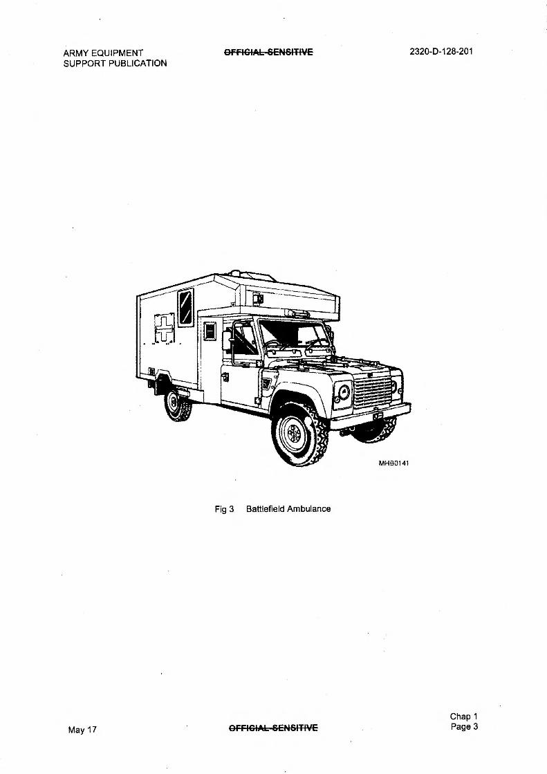
3 Battlefield Ambulance 3
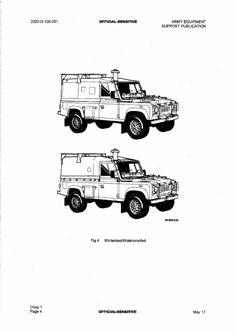
4 Winterised/Waterproofed 4
5 Commander IK 5
6 Weapons Mount Installation Kit (WMIK) 5
INTRODUCTION
1 This Chapter gives a General Description of the Truck Utility Light (TUL) HS, Truck Utility
Medium (TUM) HS and (TUM) Ambulance HS variants listed in the following sub-chapters:
1.1 Chapter 1-1 Basic Vehicle.
1.2 Chapter 1-2 Fitted For Radio (FFR).
1.3 Chapter 1-3 Battlefield Ambulance.
1.4 Chapter 1-4 Winterised/Waterproofed.
1.5 Chapter 1-5 Air-drop.
1.6 Chapter 1-6 Helicopter Support Vehicle.
1.7 Chapter 1-7 Commanders IK.
1.8 Chapter 1-8 Weapons Mount Installation Kit (RWMIK).
1.9 Chapter 1-9 Tropical Battlefield Ambulance.
1.10 Chapter 1-10 Winterised/Waterproofed Battlefield Ambulance.
1.11 Chapter 1-11 Waterproofed Weapons Mount Installation Kit (VVMIK).
Chap 1
May 17 OFF4GIAL—SENSIT-PiE Page 1

2320-D-128-201
General
OFFIGIA6-6ENV-T4VE ARMY EQUIPMENT SUPPORT PUBLICATION
2 The information given in this chapter is applicable to both Left Hand Drive (LHD) and Right Hand Drive (RHD) vehicles.
Fig 1 Truck Utility Light (TUL)
Fig 2 Truck Utility Medium (TUM)
Chap 1 Page 2 OffiGIA6-SENSITIVE May 17
ARMY EQUIPMENT SUPPORT PUBLICATION
OFFIGIAL—SENSITPiE 2320-D-128-201
Fig 3 Battlefield Ambulance
May 17 GFRGIAL—SEN6FTWE Chap 1 Page 3
2320-D-128-201 GFRGIAL-SENSITIVE ARMY EQUIPMENT SUPPORT PUBLICATION
Fig 4 Winterised/Waterproofed
MHB0438
Chap 1 Page 4 GFFIC4AL-GENSITIVE May 17

ARMY EQUIPMENT SUPPORT PUBLICATION
OFFICIAL&ENSITIVE 2320-0-128-201
Fig 5 Commander IK
Fig 6 Weapons Mount Installation Kit (WMIK)
111-1130753
1.1
Chap 1
May 17 @FRC IAL-SEN&ITIVE Page 5

2320-D-128-201 OFFICIALBENSITIVE ARMY EQUIPMENT SUPPORT PUBLICATION
PAGE LEFT INTENTIONALLY BLANK
Chap 1 Page 6 OfFIGFAE-BENBITIVE May 17
ARMY EQUIPMENT SUPPORT PUBLICATION
Para
GFFIGIAL-SENSI-TIVE 2320-0-128-201
CHAPTER 1-1
BASIC VEHICLE
CONTENTS
1 Introduction 2 The vehicle 3 Technical data 4 Labels 5 Nomenclature label 6 Vehicle weight plate 7 Rotating blades warning label 8 Brake fluid warning label 9 Radiator filler plug warning label
10 Anti-freeze label 11 Engine oil label 12 Differential lock warning label 13 Vehicle identification number plate (VIN) 15 24 volt warning labels 16 Jerry can labels 17 Fuel label 18 Spare wheel lifting harness label 19 Running-in period (WARNINGS) 21 The engine 23 Engine compartment (WARNINGS) 24 Truck Utility Light (TUL) external layout 26 Truck Utility Medium (TUM) external layout 28 Chassis 29 Front bumper 30 Front towing pintle 31 Recovery/tie down shackles 32 Suspension 33 Brakes 34 Brake actuation 35 Brake failure warning system 36 Axles 37 Front axle 38 Half shafts 39 Hub drive arrangement 40 Hub driving arrangement 41 Steering swivels 42 Axle breathers 43 Rear Axle 44 Body 45 Scuttle 46 Windscreen 47 Bonnet 48 Spare wheel stowage 50 Cab doors 51 Door locks 52 Door windows 53 Radiator mounting and grille 54 Front wings 55 Bodyside and rear quarters
(continued)
Chap 1-1 May 17 OFFIGIAL--SENSITIVE Page 1

2320-D-128-201
Para
56 Jerry can stowage 57 Bulkhead 58 Small arms clip 59 Floor 60 Electrical system 61 Alternator 62 Fuses 63 Batteries 64 Lights 65 Fuel system 66 Fuel lift pump 67 Fuel sedimenter 68 Fuel filter 69 Engine cooling system 70 Expansion tank 71 Radiator 72
AFFIGIAL—SENSIT4VE ARMY EQUIPMENT SUPPORT PUBLICATION
CONTENTS (continued)
Table Page
1 Technical Data (TUL) 3 2 Technical data (TUM) 3
Fig Page
1 Nomenclature label 4 2 Vehicle weight plate 4 3 Under bonnet labels 5 4 Antifreeze label (windscreen) 5 5 Differential lock warning label 6 6 Vehicle identification number (VIN) plate 7 7 VIN plate layout 7 8 24 Volt label (rear) 8 9 24 Volt label (in cab) 8
10 Jerry can labels 9 11 Spare wheel lifting harness label 9 12 Engine compartment 11 13 Truck Utility Light — External layout 12 14 Truck Utility Light (TUL) under chassis 13 15 Truck Utility Medium (TUM) — External layout 14 16 Truck Utility Medium (TUM) under chassis 15 17 Spare wheel lifting harness 18
Chap 1-1 Page 2 OFFIGIAL—SENSIT-WE May 17

ARMY EQUIPMENT OffIGIAL-6C-4461-T-WE 2320-D-128-201 SUPPORT PUBLICATION
INTRODUCTION
1 This chapter provides a General Description for all items common to the Truck Utility Light (TUL) HS and Truck Utility Medium (TUM) HS vehicles.
The vehicle
2 The vehicle is of the four wheeled type, permanently driving through all four wheels and is available in Right Hand Drive (RHD) or Left Hand Drive (LHD). It is capable of leaving made up road surfaces and travelling on to unmade ground and is capable of towing, when laden, the appropriate trailers without disproportionate loss of performance.
TECHNICAL DATA
3 The technical data for the TUL and TUM vehicles are detailed in Table 1 and Table 2 as follows:
TABLE 1 TECHNICAL DATA (TUL)
Serial (1)
Title (2)
Data (3)
1 Length 3835 mm
2 Width 1910 mm
3 Height (unladen) 2150 mm
4 Track (front and rear) 1521 mm
5
6
TABLE 2 TECHNICAL DATA (TUM)
Serial (1)
Title (2)
Data (3)
1 Length 4550 mm
2 Width 1910 mm
3 Height (unladen) 2200 mm
4 Track (front and rear) 1521 mm
5
6
Chap 1-1
May 17 GFFIGIAL—BENSITIVE Page 3
2320-D-128-201
LABELS
OfFEGIAL—SENSITIVE ARMY EQUIPMENT SUPPORT PUBLICATION
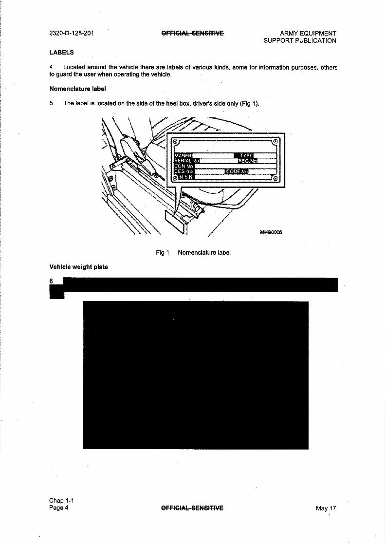
4 Located around the vehicle there are labels of various kinds, some for information purposes, others to guard the user when operating the vehicle.
Nomenclature label
5 The label is located on the side of the heel box, driver's side only (Fig 1).
Vehicle weight plate
Chap 1-1 Page 4
WIN ER ,SI-EH.AL No. CON No CIS N7)
YPE.HEG.No
Fig 1 Nomenclature label
OFFIGIAL—SENSITIVE May 17

ARMY EQUIPMENT GFFIGIAL--SENSITIVE 2320-D-128-201 SUPPORT PUBLICATION
Rotating blades warning label
7 The label is located under the bonnet, on top of the radiator cowling (Fig 3).
Brake fluid warning label
8 The label is located under the bonnet (Fig 3), moulded into the brake fluid reservoir.
Radiator filler plug warning label
9 The label is located on the top of the radiator adjacent to the plug (Fig 3).
Anti-freeze label
10 There are two labels, one of which is under the bonnet (Fig 3) affixed to the top of the radiator. and the other can be found, attached to the windscreen (Fig 4)
Engine oil label
11 The engine oil label (Fig 3) is located on top of the radiator and advised that only OX90 grade of oil is put into the engine.
USE ONLY 071,40 ENGINE OIL
Fig 3 Under bonnet labels
Fig 4 Antifreeze label (windscreen)
May 17 OFFIGIAL-GENSIT-IVE Chap 1-1
Page 5
2320-13-128-201
Differential lock warning label
OFFIGIAL-GENSITIVE ARMY EQUIPMENT SUPPORT PUBLICATION
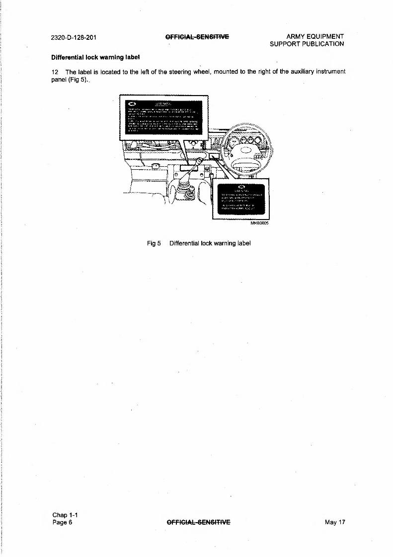
12 The label is located to the left of the steering wheel, mounted to the right of the auxiliary instrument panel (Fig 5)
Vaiktr , it.
t, Alt
'At %Mel. t,
.0.410.1 , r1 WO,
AtH BOOM
Fig 5 Differential lock warning label
Chap 1-1 Page 6 AFFIGIAL—SENSITIVE May 17

ARMY EQUIPMENT SUPPORT PUBLICATION
OFFICIAL-SEN-&MVE 2320-D-128-201
Vehicle identification number plate (VIN)
13
14
1 Type approval 4 Maximum vehicle and trailer weight.
2 VIN (min. seventeen digits) 5 Maximum road weight - front axle
3 Maximum permitted laden weight 6 Maximum road weight - rear axle
Fig 7 VIN plate layout
Chap 1-1 May 17 GFFIGIAL-SEN-64-T-IVE Page 7

2320-D-128: 201
24 volt warning labels
OFFIGIAL-SENSITIVE ARMY EQUIPMENT SUPPORT PUBLICATION
15 There are 24 Volt (V) labels are located on the vehicle, one located on the rear cross member adjacent to the 12 pin North Atlantic Treaty Organisation (NATO) socket (Fig 8)
Fig 8 24 Volt label (rear)
15.1 Another 24 V label is located in the cab, adjacent to the Inter Vehicle Starting Socket (IVSS) (Fig 9) and inform the user that the vehicle system is 24 volts only.
Fig 9 24 Volt label (in cab)
Chap 1-1 Page 8 OFFIGIAL-SENSITIVE May 17

ARMY EQUIPMENT OFFICIAL—SENSITIVE 2320-D-128-201 SUPPORT PUBLICATION
Jerry can labels
16 The labels are located on the inside of the respective compartment doors (Fig 10).
STOWAGE AREA FOR
FUEL JERRYCANS
ONLY
STOWAGE AREA FOR
WATER JEARYCANS
ONLY
Fig 10 Jerry can labels
Fuel label
17 The label is located below the filler cap.
Spare wheel lifting harness label
18 The spare wheel lifting harness label (Fig 11) is located on the harness and is visible when the spare wheel is in its stowed position.
WARIVNG UVi
SP.ARE 9, Ea.N.1, 44 akEE,Ex"T el., ACE E.. E E.'
4.1e0Mat,M., sksA,Tai MEE
,EAEFEA, • -owe, MAU; ...41119* CE.Y.YfA7:4.
'MR El+.1414EY-xt .?1,1 4.14.8.. , 4.1 'OA FESI
Fig 11 Spare wheel lifting harness label
37
Chap 1-1 May 17 OFFICIAL—SENSITIVE Page 9

2320-D-128-201 OFFICIALSENGITIVE ARMY EQUIPMENT SUPPORT PUBLICATION
RUNNING-IN PERIOD
WARNINGS
(1) TYRES. DO NOT MIX CROSS-PLY AND RADIAL-PLY TYRES ON THIS VEHICLE.
(2) FILLER CAP. DO NOT REMOVE THE EXPANSION TANK FILLER CAP WHEN THE ENGINE IS HOT, BECAUSE THE COOLING SYSTEM IS PRESSURISED AND PERSONAL SCALDING COULD RESULT.
(3) LIQUIDS. MANY LIQUIDS AND SUBSTANCES USED IN MOTOR VEHICLES ARE POISONOUS; THEY MUST NOT BE CONSUMED UNDER ANY CIRCUMSTANCES AND MUST BE KEPT AWAY FROM OPEN WOUNDS. THESE SUBSTANCES INCLUDE BRAKE FLUID, FUEL, WINDSCREEN WASHER ADDITIVES, LUBRICANTS, BATTERY CONTENTS, VARIOUS ADHESIVES, COOLING SYSTEM CORROSION INHIBITOR AND POWER ASSISTED STEERING FLUID.
(4) SEATS AND SAFETY HARNESS. ALL CREW/PASSENGERS MUST OCCUPY THE DESIGNATED SEATS AND WEAR THE SAFETY HARNESS PROVIDED, EVEN FOR THE SHORTEST JOURNEY.
19 Progressive running-in of the vehicle is important and has a direct bearing on reliability and smooth running throughout its life. The most important point is not to hold the vehicle on a large throttle opening for any sustained periods.
20 The maximum speed should be limited to 65 to 80 km/h (40 to 50 mph) on a light throttle and this may be progressively increased over the first 2,500 km (1550 miles).
Chap 1-1 Page 10 OFFIGIAL—GENSITIVE May 17

ARMY EQUIPMENT SUPPORT PUBLICATION
THE ENGINE
OFFICIAL—SENSITIVE 2320-D-128-201
21 The engine is a four cylinder, four stroke, compression ignition type with direct injection,
turbocharged and intercooled with overhead valves and liquid cooling. The power is transmitted through a
single dry plate clutch to a five forward and one reverse speed main gearbox and a two speed transfer
gearbox with an integral central differential to both front and rear axles.
22 The vehicle has the combination of a transfer gearbox and main gearbox which provides the driver
with 12 gear ratios, ten forward and two reverse.
Engine compartment
WARNINGS
(1) FILLER CAP. DO NOT REMOVE THE EXPANSION TANK FILLER CAP WHEN THE
ENGINE IS HOT, BECAUSE THE COOLING SYSTEM IS PRESSURISED AND PERSONAL
SCALDING COULD RESULT.
(2) LIQUIDS. MANY LIQUIDS AND SUBSTANCES USED IN MOTOR VEHICLES ARE
POISONOUS; THEY MUST NOT BE CONSUMED UNDER ANY CIRCUMSTANCES AND MUST
BE KEPT AWAY FROM OPEN WOUNDS. THESE SUBSTANCES INCLUDE BRAKE FLUID, FUEL, WINDSCREEN WASHER ADDITIVES, LUBRICANTS, BATTERY CONTENTS, VARIOUS ADHESIVES, COOLING SYSTEM CORROSION INHIBITOR AND POWER ASSISTED STEERING FLUID.
23 The layout of the main components within the Engine compartment are identified in Fig 12.
10
la 17 16 15 14 13 MHEAV13
1 Fuel filter 10 Heater matrix
2 Expansion Tank 11 Windscreen washer reservoir
3 Brake fluid reservoir 12 Power steering reservoir
4 Clutch fluid reservoir 13 24 V ducted alternator
5 Air cleaner 14 Water pump
6 Crankcase breather 15 Radiator filler cap
7 Engine oil filler cap 16 Dipstick
8 Breather pipes 17 Radiator
9 Auxiliary fuses 18 Fuel lift pump
Fig 12 Engine compartment
Chap 1-1
May 17 OFFICIAL SENSITIVE Page 11
2320-D-128-201 OFFICIAL—SEN-SIT4VE ARMY EQUIPMENT SUPPORT PUBLICATION
Truck Utility Light (TUL) external layout
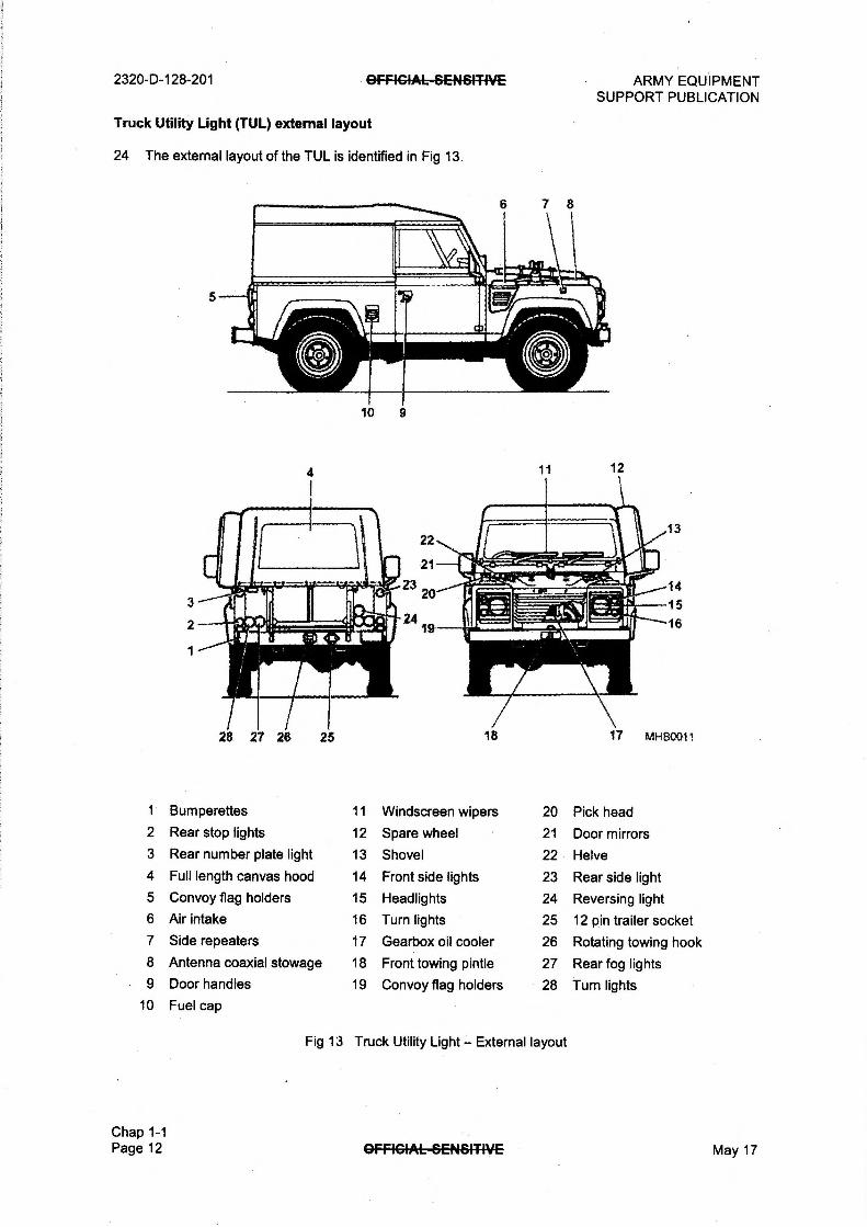
24 The external layout of the TUL is identified in Fig 13.
28 27 26 25
10 9
1 12
1 Bumperettes 11 Windscreen wipers 20 Pick head 2 Rear stop lights 12 Spare wheel 21 Door mirrors 3 Rear number plate light 13 Shovel 22 Helve
4 Full length canvas hood 14 Front side lights 23 Rear side light 5 Convoy flag holders 15 Headlights 24 Reversing light 6 Air intake 16 Turn lights 25 12 pin trailer socket 7 Side repeaters 17 Gearbox oil cooler 26 Rotating towing hook 8 Antenna coaxial stowage 18 Front towing pintle 27 Rear fog lights 9 Door handles 19 Convoy flag holders 28 Turn lights
10 Fuel cap
Chap 1-1 Page 12
Fig 13 Truck Utility Light — External layout
OFFICIAL&EN6MVE May 17

ARMY EQUIPMENT SUPPORT PUBLICATION
GFFIGIAL-SEN&ITIVE
25 The layout of the TUL under chassis is identified in Fig 14.
27
26 25
24
Ald'-7ioti,
I' „14,_Arg I{ 23
,„ • , 22
21
20
19 18
17-16
15-
14
11 i tr
10
—11
2320-D-128-201
13 12 MI-180015
1 Front towing pintle 11 Rear bumperettes c/w anti- 20 Rear propeller shaft
2 Front tie down shackles jack knife points 21 Transfer gearbox
3 Steering protection plate 12 Towing hook 22 Front propeller shaft
4 Front axle breather 13 Trailer socket 23 Engine oil filter
5 Engine sump 14 Convoy light 24 Track rod protection plate
6 Exhaust pipe and catalyst 15 Rear brakes 25 Front brake and swivel pin
7 Main gearbox 16 Rear differential axle housing
8 Transmission brake drum 17 Fuel sedimenter 26 Front differential axle
9 Rear axle breather 18 Fuel filler pipe 27 Steering box
10 Rear tie down shackles 19 Fuel tank 28 Front bumper
May 17
Fig 14 Truck Utility Light (TUL) under chassis
OFFICIALSENSITIVE Chap 1-1 Page 13

2320-D-128-201 OFFEGIAL-SEN61-T4VE
Truck Utility Medium (TUM) external layout
26 ' The external layout of the TUM is identified in Fig 15.
12
ARMY EQUIPMENT SUPPORT PUBLICATION
13
1 Bumperettes 11 Fuel cap 20 Pick head
2 Rear stop lights 12 Windscreen wipers 21 Door mirrors
3 Rear number plate light 13 Spare wheel 22 Helve 4 Full length canvas hood 14 Shovel 23 Rear side light 5 Convoy flag holders 15 Front side lights 24 Reversing light
6 Air intake 16 Headlights 25 12 pin trailer socket 7 Side repeaters 17 Turn lights 26 Rotating towing hook 8 Antenna coaxial stowage 18 Gearbox oil cooler 27 Rear fog lights
9 Door handles 19 Front towing pintle 28 Turn lights 10 Jerry can stowage
Chap 1-1 Page 14
Fig 15 Truck Utility Medium (TUM) — External layout
OFFIGIAL-SENSITIVE May 17

ARMY EQUIPMENT SUPPORT PUBLICATION
OFFIGIAL—GENfriTIVE
27 The layout of the TUM under chassis is identified in Fig 16.
29
28 27
26 25
24
23 —
22
21
20
19
16
17
16
15
14
13~
-2
10
2320-D-128-201
12 11 MHB0014
1 Front towing pintle 11 Towing hook 21 Transfer gearbox
2 Front tie down shackles 12 Trailer socket 22 Main gearbox
3 Steering protection plate 13 Fuel tank 23 Front propeller shaft
4 Front axle breather 14 Fuel filler pipe 24 Anti-roll bars
5 Engine sump 15 Convoy light 25 Track rod protection plate
6 Engine oil filter 16 Rear brakes 26 Front brake and swivel pin
7 Exhaust pipe and catalyst 17 Rear differential axle housing
8 Rear axle breather 18 Rear propeller shaft 27 Front differential axle
9 Rear tie down shackles 19 Fuel sedimenter 28 Steering box
10 Rear bumperettes c/w anti-
jack knife points
20 Transmission brake drum 29 Front bumper
May 17
Fig 16 Truck Utility Medium (TUM) under chassis
OFFIGIAL-SENSITIVE Chap 1-1 Page 15

2320-D-128-201
CHASSIS
OFFIGI.A.B-SENSF-TIVE ARMY EQUIPMENT SUPPORT PUBLICATION
28 The chassis (Fig 14/Fig 16) is constructed from two welded box section side members with five cross members on the TUL and seven cross members on the TUM vehicles and a detachable gearbox cross member.
Front bumper
29 Attached to the front of the chassis is a full width bumper (Fig 13/Fig 15) complete with convoy flag holder facilities at each end.
Front towing pintle
30 The front towing pintle (Fig 13/Fig 15) is built into the centre of the bumper and accepts a 75 mm tow eye.
Recovery/tie down shackles
31 Four recovery/tie down shackles are fitted to the chassis side members - two at the front and two at the rear for aircraft tie-down, lifting and recovery functions. In addition and attached to the front and rear bumpers are four lifting rings, the rear being incorporated in the bumperettes.
SUSPENSION
32 The suspension is provided by four helical coil springs, one at each wheel station with double acting hydraulic dampers and rubber buffers.
BRAKES
33 The brake circuit is divided to provide braking on all four wheels using ventilated disc brakes on the front and solid disc brakes on the rear wheels, with a servo-assisted hydraulic braking system. A mechanically operated transmission parking brake is provided, utilising the drum brake system, mounted on the rear of the transfer gearbox output shaft.
Brake actuation
34 Brake actuation is by a pendant pedal acting through a vacuum assisted servo unit on a tandem hydraulic master cylinder. A direct drive engine pump supplies vacuum. Rear feed (TUL only) passes through a pressure-reducing valve.
Brake failure warning system
35 A warning light on the binnacle in the cab indicates hydraulic failure.
AXLES
36 The axles on the TUL and TUM (Fig 14/Fig 16) vehicles are of the rigid construction type with a spiral bevel type differential at the front and rear.
Front axle
37 The front axle is made up of a two-piece pressed steel casing with offset banjo and spherical housings for universal joints in half shafts.
Half shafts
38 The half shafts are fully floating incorporating a single constant velocity joint.
Chap 1-1 Page 16 OFFICIALSENSITVE May 17

ARMY EQUIPMENT OFFIGIAL—GENSITIVE 2320-D-128-201 . SUPPORT PUBLICATION
Hub drive arrangement
39 The hub drive arrangements are driving flanges splined to the half shafts with taper roller hub bearings.
Hub driving arrangement
40 The hub driving arrangement is via a hub-driving member splined to the half shafts with taper roller hub bearings.
Steering swivels
41 These are taper roller bearings with asbestos resin upper bearings.
Axle breathers
42 The axle breathers (Fig 14/Fig 16) are flexible pipes starting from the axle tubes ending in the engine compartment. There are two breathers, one from each axle.
Rear Axle
43 The rear axle has two variants, one for TUL and one for TUM and are as follows:
43.1 Rear axle (TUL) (Fig 14) is made up of a two-piece pressed steel casing and 6mm (0.25 in) differential bowl.
43.2 Rear axle (TUM) (Fig 16) is made up of a rigid two piece pressed steel casing with a single heavy gauge steel stiffener on the underside and 6mm (0.25 in) differential bowl.
BODY
44 The body is constructed from pressed and folded aluminium alloy panels, spot welded or riveted. The scuttle, door frames and other minor items are made from steel.
Scuttle
45 The scuttle divides the engine bay from the driving/passenger compartment. It is constructed from mild steel with impact surfaces designed for collapsibility and are padded. The ventilators are pivoted adjustable flaps ducted to face level outlets and are fitted with gauze fly screens.
Windscreen
46 The windscreen is made up of a one-piece laminated glass.
Bonnet
47 The bonnet is constructed from aluminium alloy sheet with steel stiffeners. It is fitted with a central retaining device, a safety catch and an external release mechanism.
Chap 1-1 May 17 GFFIGIAL—GENSITIVE Page 17

2320-D-128-201
Spare wheel stowage
OFRGIAL—FrENSITIVE ARMY EQUIPMENT SUPPORT PUBLICATION
48 Spare wheel stowage is located in two possible areas:
48.1 On the opposite side to the driver, and is secured to a mounting bracket, which is bolted to the roll cage.
48.2 On the rear door of the vehicle.
49 The spare wheel is fitted with a lifting harness (Fig 17) to aid in removal and replacement of the spare wheel.
WARNING to i*Clitt-,1
$PARE NO:C•CI, St40...Mfoi V.**01$111:, ,M1-4. rtt
OVAartilt4 7iPt MIF Fri
0%44* Paw+,fft 0.144`Ell tewilfen.
af4&*1.0 ,tANDIACKYA CAV M, 0014414 4, I FY-Vi NO. a..ERAT0401.40/PtCT,ONIt
Fig 17 Spare wheel lifting harness
Cab doors
50 The cab doors are constructed from aluminium alloy panels with a one piece steel frame and fittings hung on two hinges. The upper door assembly is removable at waist level.
Door locks
51 The doors are fitted with direct action anti-burst door locks complete with a private lock set and adjustable striker plates.
Door windows
52 The door windows are made up of two-piece sliding section, of toughened glass, and are lockable in the closed position.
Radiator mounting and grille
53 The radiator is rubber mounted to the chassis/body and is protected by a black plastic moulded grille.
Front wings
54 The front wings are made from aluminium alloy sheet with flat tops and steel curved inner wheel valances. Tops are reinforced to permit the fitting of communication antennas.
Bodyside and rear quarters
55 The body side and rear quarters are constructed from aluminium alloy with steel cappings.
Chap 1-1 Page 18 OFFIGIAL—SENSITIVE May 17

ARMY EQUIPMENT OFFICIAL—SEN&ITWE 2320-D-128-201
SUPPORT PUBLICATION
Jerry can stowage
56 On TUM vehicles only, jerry can stowage has been built into the bodysides. The stowage is of alloy and steel construction with lockable aluminium alloy doors. The doors have a provision for padlocks.
Bulkhead
57 The bulkhead separates the driver/passenger compartment from the load compartment of the
vehicle. It is constructed from aluminium alloy with steel cappings and is permanently secured into
position.
Small arms clip
58 Mounted within the cab area are two sets of small arms clips. The clips are positioned for easy
access.
Floor
59 The floor is constructed from aluminium alloy sheet panelled, braced underframed and rigidly attached to the chassis frame. Riveted to the floor are two full-length galvanised steel wear strips.
ELECTRICAL SYSTEM
60 The electrical system is charged by the vehicle alternator to 24 volts rectified AC negative earth with voltage compensation and ducted breathing to control water ingress. The charging control and rectifier are integral with the alternator. The system feeds all the vehicles' electrical requirements.
Alternator
61 The alternator is a 24 volt charging system with a 50 Ampere nominal output.
Fuses
62 There are two fuse boxes, a master fuse box, which is located in the engine compartment, and a subsidiary fuse box located in the fascia. There are 3 fuses in the master box and 17 in the subsidiary box which protect the vehicle circuits.
Batteries
63 The vehicle batteries are of the low maintenance type with special airportable filler caps wired in
series to supply 24 volts.
Lights
64 The vehicle lights are of the commercial type and are controlled by the main lighting switch which
governs whether the vehicle is in normal lighting or blackout.
Chap 1-1
May 17 GFFIGIA6-BENSITIVE Page 19

2320-D-128-201 OFFIG-FAL—SENSITIVE ARMY EQUIPMENT SUPPORT PUBLICATION
FUEL SYSTEM
65 The fuel system consists of t)ie fuel tank feeding through a sedimenter to a fuel lift' pump and fuel filter located in the engine compartment, then to the engine.
Fuel lift pump
66 The engine mounted mechanical fuel lift pump is a self-priming unit and does not need any attention. The pump draws fuel up to the engine from the tank.
Fuel sedimenter
67 The fuel sedimenter is to allow excess water to be collected and, at periodic intervals, drained away to atmosphere.
Fuel filter
68 The fuel filter (Fig 12 (1)) is a full-flow unit and contains a renewable canister. The filter cleans the fuel and collects any foreign bodies found in the fuel.
ENGINE COOLING SYSTEM
69 The cooling system is located inside the engine compartment and comprises the expansion tank connected to the radiator by way of the engine.
Expansion tank
70 The expansion tank (Fig 12 (2)) is located on the right hand side wing valance and allows the coolant to expand when it gets hot. This prevents the system from being over pressurised.
Radiator
71 The radiator (Fig 12 (17)) is vaned so that air can pass through, allowing the heated fluid that has circulated through the engine to cool down.
Chap 1-1 Page 20 OFFIGIA6-&ENSIT4VE May 17

ARMY EQUIPMENT SUPPORT PUBLICATION
•
Para
OFFICIALSENGITPiE
CHAPTER 1-2
FITTED FOR RADIO
CONTENTS
2320-0-128-201
1 Introduction 2 Electrical system 3 Alternator (FFR) 5 Radio equipment 6 Radio table and battery stowage box 7 Radio equipment rack 8 VHF antenna leads, mountings and storage 9 Antenna mast mountings
10 Battery isolation switch and import/export system
Fig Page
1 Engine compartment (FFR) 2 2 FFR rear 3 3 FFR rear power layout 4
INTRODUCTION
1 This sub-chapter describes all the items applicable to the Fitted For Radio (FFR) Truck Utility Light (TUL) and Truck Utility Medium (TUM) vehicles which have not been covered in sub-chapter 1 - 1.
Chap 1-2 May 17 GFFIGIAL-SENSFHVE Page 1

2320-D-128-201
ELECTRICAL SYSTEM
OFFIGIAL-SE+161-TIVE ARMY EQUIPMENT SUPPORT PUBLICATION
2 A 24 Volt (V) 50 Ampere (A) alternator charges the auxiliary electrical system. The system feeds the vehicles' radio equipment via an in-line fuse to a terminal/shunt box mounted on the rear of the bulkhead.
3 FFR vehicles have an additional charging system to supply radio equipment. The two systems operate independently of each other but can assist one another when required. A control box is required to enable the load sharing facility to take place.
Alternator (FFR)
4 The alternator charging system provides a 24 V, 50 A nominal output.
1 Fuel filter 10 Heater matrix
2 Expansion tank 11 Windscreen washer reservoir
3 Brake fluid reservoir 12 Power steering reservoir
4 Clutch fluid reservoir 13 50 Amp alternator
5 Air cleaner 14 Water pump
6 Crankcase breather 15 Radiator filler cap
7 Engine oil filler cap 16 Dipstick
8 Breather pipes 17 Radiator
9 Auxiliary fuse box 18 50 Amp alternator (FFR)
Chap 1-2 Page 2
Fig 1 Engine compartment (FFR)
OFFIGIAL—SE14SITWE May 17
ARMY EQUIPMENT OFFICIALErENSFT4VE 2320-D-128-201
SUPPORT PUBLICATION
RADIO EQUIPMENT
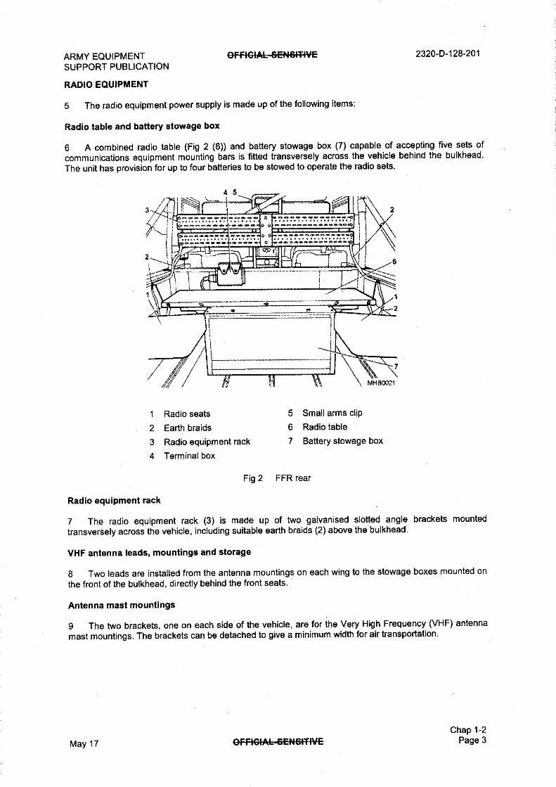
5 The radio equipment power supply is made up of the following items:
Radio table and battery stowage box
6 A combined radio table (Fig 2 (6)) and battery stowage box (7) capable of accepting five sets of
communications equipment mounting bars is fitted transversely across the vehicle behind the bulkhead.
The unit has provision for up to four batteries to be stowed to operate the radio sets.
4 5
1 Radio seats 5 Small arms clip
2 Earth braids 6 Radio table
3 Radio equipment rack 7 Battery stowage box
4 Terminal box
Fig 2 FFR rear
Radio equipment rack
7 The radio equipment rack (3) is made up of two galvanised slotted angle brackets mounted
transversely across the vehicle, including suitable earth braids (2) above the bulkhead.
VHF antenna leads, mountings and storage
8 Two leads are installed from the antenna mountings on each wing to the stowage boxes mounted on
the front of the bulkhead, directly behind the front seats.
Antenna mast mountings
9 The two brackets, one on each side of the vehicle, are for the Very High Frequency (VHF) antenna
mast mountings. The brackets can be detached to give a minimum width for air transportation.
Chap 1-2
May 17 OFfiGIA6-6C-ftS4T4V-E Page 3
2320-D-128-201 OFFIGIAL—SENSITIVE ARMY EQUIPMENT SUPPORT PUBLICATION
Battery isolation switch and import/export system
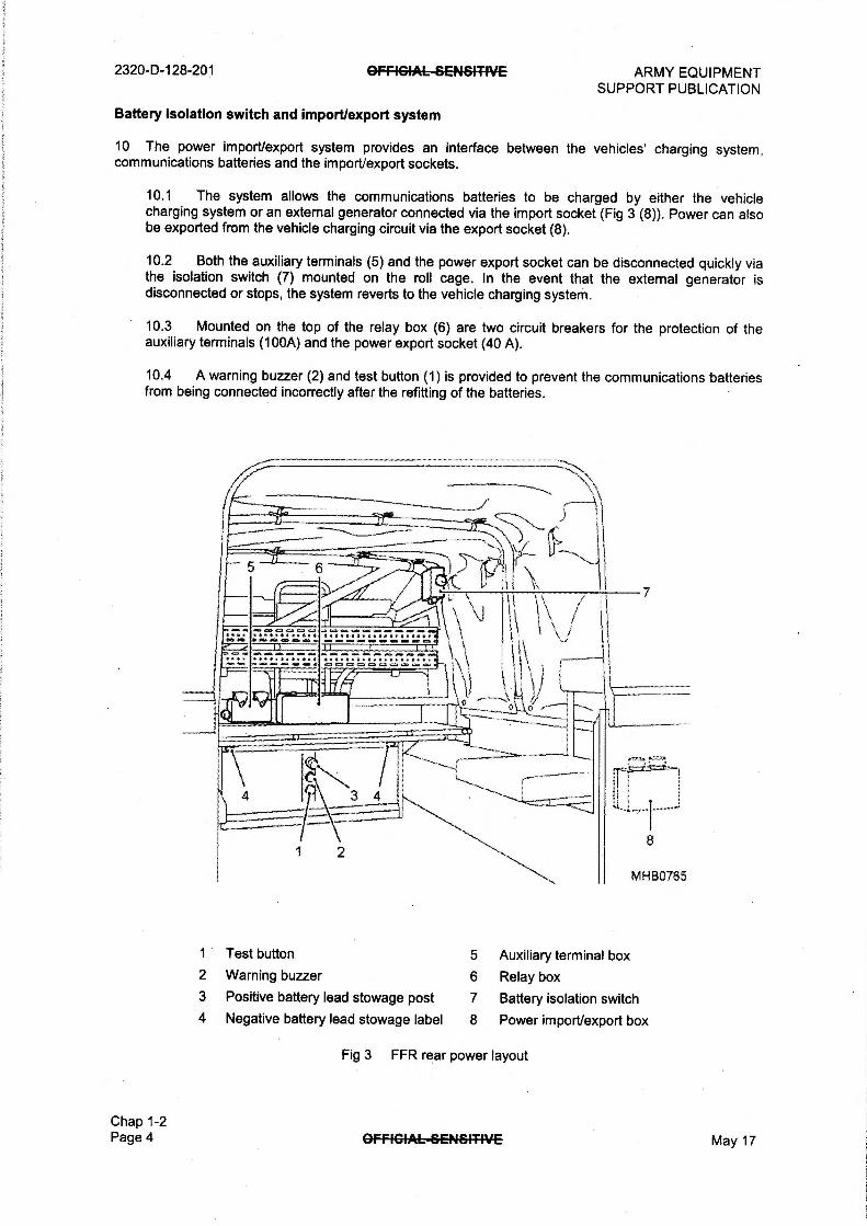
10 The power import/export system provides an interface between the vehicles' charging system, communications batteries and the import/export sockets.
10.1 The system allows the communications batteries to be charged by either the vehicle charging system or an external generator connected via the import socket (Fig 3 (8)). Power can also be exported from the vehicle charging circuit via the export socket (8).
10.2 Both the auxiliary terminals (5) and the power export socket can be disconnected quickly via the isolation switch (7) mounted on the roll cage. In the event that the external generator is disconnected or stops, the system reverts to the vehicle charging system.
10.3 Mounted on the top of the relay box (6) are two circuit breakers for the protection of the auxiliary terminals (100A) and the power export socket (40 A).
10.4 A warning buzzer (2) and test button (1) is provided to prevent the communications batteries from being connected incorrectly after the refitting of the batteries.
1 Test button 5 Auxiliary terminal box 2 Warning buzzer 6 Relay box 3 Positive battery lead stowage post 7 Battery isolation switch 4 Negative battery lead stowage label 8 Power import/export box
Chap 1-2 Page 4
Fig 3 FFR rear power layout
OFFIGIAL-8E-NBMVE May 17

ARMY EQUIPMENT SUPPORT PUBLICATION
Para
OFFICIAL SENSITIVE
CHAPTER 1-3
BATTLEFIELD AMBULANCE
CONTENTS
1 Introduction 2 Primary role 3 Secondary role 4 Technical data 5 Labels 6 No smoking or naked lights label 7 Oxygen label 8 Upper stretcher mechanism labels 9 Upper stretcher lock mechanism warning label
10 Stowing strut warning label 11 Emergency exit warning label 12 Rear step caution label 13 Heater start-up warning and caution labels 15 Seat lock identification label 16 External layout 17 Chassis
Body 18 Cab 19 Red crosses 20 Bonnet 21 Spare wheel stowage 22 Jerry can stowage 23 Bulkhead 24 Ambulance compartment 26 Doors 28 Stretcher support frames 29 Lower frame 31 Upper frame 34 Seats 35 Stretchers 36 Blankets 37 Attendants' seat 38 Infusion bottle tracks 39 Resuscitator sockets 40 Oxygen bottle stowage 41 Oxygen sockets (WARNING) 42 Small arms stowage 43 Rear step 44 Heater
In the cab 45 Controls 46 Stowage in the cab 47 Rifles 48 2 Kg fire extinguisher 49 Convoy flag pole 50 Breakdown equipment 51 Personnel equipment 52 Electrical system
2320-D-128-201
(continued)
Chap 1-3
Aug 19 (Amdt 4) OFFICIAL SENSITIVE Page 1

2320-D-128-201
Para
OFFICIAL SENSITIVE ARMY EQUIPMENT SUPPORT PUBLICATION
CONTENTS (continued)
53 Circuit breakers 54 Run engine device 57 Rotating beacons 58 Ambulance compartment lights 59 Distribution/control box 60 Heater control switch 61 Lighting control switch
Table Page
1 Technical data 3
Fig Page
1 No smoking or naked flames label 4 2 Oxygen no grease label 4 3 Upper stretcher mechanism warning label 5 4 Upper stretcher mechanism caution label 5 5 Upper stretcher lock mechanism warning label 6 6 Emergency exit label 7 7 Rear step caution label 7 8 Heater start-up warning and caution labels 8 9 Seat lock identification label 9
10 Battlefield Ambulance external layout 11 11 Battlefield Ambulance under chassis layout 12 12 Ambulance compartment layout 15 13 Vehicle dash layout 18
Chap 1-3 Page 2 OFFIGIAL—SENSITIVE May 17

ARMY EQUIPMENT OFFICIALSE14&IT4VE 2320-D-128-201
SUPPORT PUBLICATION
INTRODUCTION
1 This sub-chapter describes all the items applicable to the Battlefield Ambulance and identifies
equipment locations.
PRIMARY ROLE
2 In its primary role the vehicle allows the transportation of four persons on stretchers. The stretchers
are strapped to upper and lower stretcher support frames in the ambulance compartment at the rear of the
vehicle. Provision is made in the ambulance compartment for the stowage of oxygen, resuscitators and
other designated items of medical equipment. A single seat is also provided in the ambulance
compartment for use by a medical attendant.
SECONDARY ROLE
3 When required, the upper stretcher support frames can be stowed against the walls of the
ambulance compartment. This then allows six seats to be available for use by personnel/patients.
TECHNICAL DATA
4 The technical data for the vehicle is listed in as follows:
TABLE 1 TECHNICAL DATA
Serial (1)
Title (2)
Data (3)
1 Length 5194 mm
2 Width 2160 mm
3 Height (unladen) 2760 mm
4 Track (front and rear) 1521 mm
5 Gross Vehicle Weight
6 Fuel Capacity
Chap 1-3
May 17 OffiG4AL--SENSITIVE Page 3
2320-D-128-201
LABELS
GFRCIAL—SENSITIVE ARMY EQUIPMENT SUPPORT PUBLICATION
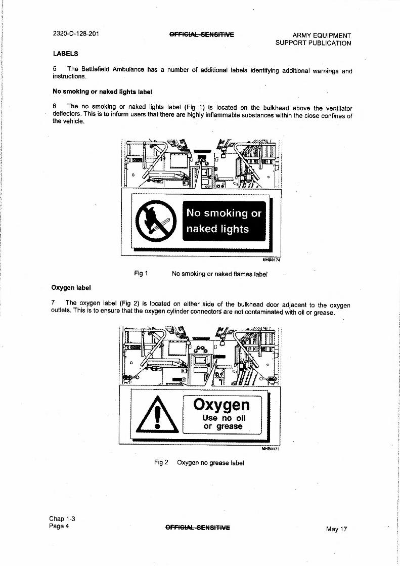
5 The Battlefield Ambulance has a number of additional labels identifying additional warnings and instructions.
No smoking or naked lights label
6 The no smoking or naked lights label (Fig 1) is located on the bulkhead above the ventilator deflectors. This is to inform users that there are highly inflammable substances within the close confines of the vehicle.
MI480174
Fig 1 No smoking or naked flames label
Oxygen label
7 The oxygen label (Fig 2) is located on either side of the bulkhead door adjacent to the oxygen outlets. This is to ensure that the oxygen cylinder connectors are not contaminated with oil or grease.
MHB01/3
Fig 2 Oxygen no grease label
Chap 1-3 Page 4 OFFIGIAL--SENiSIT4VE May 17

ARMY EQUIPMENT OFFIGIAL-SENSITIVE 2320-D-128-201 SUPPORT PUBLICATION
Upper stretcher mechanism labels
8 There are two upper stretcher mechanism labels - one is a warning and the other a caution as follows:
8.1 Warning label (Fig 3) is fitted to prevent personal injury when deploying the upper stretcher mechanism.
8.2 Caution label (Fig 4) is fitted to prevent fouling of mechanism when raising\lowering the stretcher mechanism.
WARNING KEEP HANDS CLEAR
FROM GRAS RAILS
DURING DEPLOYMENT
OF INTERNAL UPPER
STRETCHER MECHANISM
MHS0167
Fig 3 Upper stretcher mechanism warning label
CAUTION ENSURE SHOOTBOLT
IS FULLY RETRACTED
PRIOR TO LOWERING
& RAISING OF UPPER
STRETCHER MECHANISM
MH80168
Fig 4 Upper stretcher mechanism caution label
Chap 1-3 May 17 OFFIGIAL-SENSITIVE Page 5

2320-D-128-201 OffIGIAL-SC-N61-T4VE ARMY EQUIPMENT SUPPORT PUBLICATION
Upper stretcher lock mechanism warning label
9 The upper stretcher lock mechanism warning label (Fig 5) ensures that equipment is released correctly and safely during use.
LOCK UNLOCK
FOR TO
TRANSIT LOWER
STRUT MUST BE STOWED PRIOR TO LOWERING SIRE 1CHER MECHANISM
Fig 5 Upper stretcher lock mechanism warning label
Stowing strut warning label
10 The stowing strut warning label is to prevent the strut from being damaged when lowering the upper stretcher mechanism (Fig 5).
Chap 1-3 Page 6 AFFIGIAL-SENSITIVE May 17

ARMY EQUIPMENT OffiGIAL--&ENSITIVE 2320-D-128-201 SUPPORT PUBLICATION
Emergency exit warning label
11 The emergency exit label (Fig 6) is fitted to inform passengers of the correct operation in the need of emergency evacuation.
PULL SPLIT RING TO DISENGAGE FILLER STRIP COMPLETELY. PUSH GLASS OUTWARDS
TO RELEASE FROM SEALING RUBBER
Fig 6 Emergency exit label
Rear step caution label
MHB0170
12 The rear step caution label (Fig 7) is located on the front of the stretcher base to prevent personal injury when lowering step.
May 17
Caution Care wrier) re4easing
or lowerIN step
Fig 7 Rear step caution label
OFfIGIAL--&ENSITIVE Chap 1-3
Page 7

2320-D-128-201 GFFIGIAL—SENSIT4VE ARMY EQUIPMENT SUPPORT PUBLICATION
Heater start-up warning and caution labels
13 The heater start-up label (Fig 8) is to prevent the heater from being locked out after four attempts (refer to Chap 2-3).
14 There are two heater start-up warning and caution labels situated on the control panel, which gives information about starting and closing down of the heater.
Caution leo
If heater does not start after 4 attempts refer to handbook
/1 3ib, """"
Caution Before switching on Eberspacher heater ensure outside fresh air grille is OPEN. For antic conditions refer to handbook.
WARNING SWITCH OFF HEATER AND WAIT
FOR FAN TO STOP BEFORE ISOLATING BATTERIES.
er
Fig 8 Heater start-up warning and caution labels
PalB0397
Chap 1-3 Page 8 OFFIGIAL-8C-NSITIVE May 17
ARMY EQUIPMENT OffiGIAL--6ENSITIVE 2320-D-128-201 SUPPORT PUBLICATION
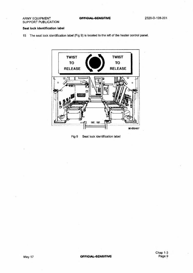
Seat lock identification label
15 The seat lock identification label (Fig 9) is located to the left of the heater control panel.
TWIST
TO
RELEASE
TWIST
TO
RELEASE
Fig 9 Seat lock identification label
Chap 1-3 May 17 OffiGIAL-GENGITIVE Page 9

2320-D-128-201 OFFIGIAL-SENSITIVE
Key to Fig 10
ARMY EQUIPMENT SUPPORT PUBLICATION
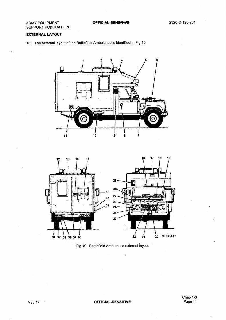
1 Ventilator 13 Spare wheel 26 Head light
2 Side window - rear 14 Rear door handle 27 Pick head
compartment 15 Red cross 28 Helve
3 Blue flashing beacon 16 Step (roof access) 29 Siren
4 Roof ventilation unit 17 Grab handle 30 Rear view mirror
5 Side repeater 18 Windscreen wipers 31 Convoy flag holder - rear
6 Spare wheel secondary 19 Shovel 32 Reflector
stowage 20 Gearbox oil cooler 33 Reversing light
7 Air intake 21 Front towing pintle 34 Rear number plate light
8 Door handle 22 Bonnet release catch 35 Fog light
9 Heater air intake grille 23 Convoy flag holder - front 36 Rear turn light
10 Jerry can stowage 24 Front turn light 37 Stop light
11 Fuel filler cap 25 Side light 38 Tail light
12 Rear window
Chap 1-3 Page 10 OfFIGIAL—SENSITIVE May 17
ARMY EQUIPMENT GFFIGIAL-SENSIT4VE SUPPORT PUBLICATION
EXTERNAL LAYOUT
16 The externa► layout of the Battlefield Ambulance is identified in Fig 10.
27
26 26
24
23
38 37 36 36 34 33
2320-D-128-201
16 17 18 19
22 21
Fig 10 Battlefield Ambulance external layout
26 Mt-480142
Chap 1-3 May 17 OFFIGIAL—SENSITIVE Page 11

2320-D-128-201
CHASSIS
OFFICIALSENSITIVE ARMY EQUIPMENT SUPPORT PUBLICATION .
17 The chassis (Fig 11) is made up of two welded box section side members with closed channel section cross members, with a detachable tubular cross-member.
10
IA :litiCfa A , _ L L.
A A _ • ." 111. ii ii "NA i i 1 ? sie1 Y" it -, ,, _.. i tt,:ilio., II 71irdwulotilirmitirropiliimmtes tt . . mom 1 . I i
---1: ----4 t---t4 1 al ih,1111.__til it14i 1L.
inIIIIIIIIIIIIIIIIIIIIIIIIII, IIIIP
12
13
—14
15
16
17
18
19
21
22
23
24 25
26 27
28 MHB0143
1 Front towing pintle 11 Rear lashing/towing eyes 21 Main gearbox
2 Front tie-down shackles 12 Fuel tank 22 Front propeller shaft
3 Steering protection plate 13 Fuel filler pipe 23 Anti-roll bar
4 Front axle breather 14 Convoy light 24 Steering protection bracket
5 Engine sump 15 Rear brakes 25 Front brake and swivel
6 Engine oil filter 16 Rear differential pin housing
7 Exhaust pipe 17 Rear propeller shaft 26 Front differential
8 Rear axle breather 18 Fuel sedimenter 27 Steering box
9 Anti-roll bar 19 Transmission brake drum 28 Front bumper
10 Rear tie-down shackles 20 Transfer gearbox
Fig 11 Battlefield Ambulance under chassis layout
Chap 1-3 Page 12 May 17

ARMY EQUIPMENT SUPPORT PUBLICATION
GFFICIAL-BENBITIVE 2320-D-128-201
BODY
Cab
18 The cab is constructed from pressed and folded aluminium alloy panels, spot welded or riveted. The scuttle, door frames and other minor items are made from steel.
Red crosses
19 To identify the vehicle as a Battlefield Ambulance, red crosses (Fig 10 (15)) are painted on the sides, rear and top of the vehicle.
19.1 Half of each Red Cross is painted onto a hinged panel which has two positions. In one position the Red Cross is exposed. In the other, the hinged panel is folded over and the Red Cross is obscured. The panel is held in either of the two positions by retaining catches.
Bonnet
20 The bonnet is constructed from aluminium alloy sheet with steel stiffeners and is fitted with a central bonnet release catch (22), including a safety catch. The bonnet has a walk-on facility and also provides a secondary stowage for the spare wheel.
Spare wheel stowage
21 The spare wheel (13) primary stowage is located on the ambulance compartment roof behind the ventilation unit. The wheel is secured to a roof mounted bracket by two bolts and an annular ring. A secondary stowage for the spare wheel is located on the bonnet.
Jerry can stowage
22 Two jerry can stowage compartments (10) are provided, one on either side of the vehicle, attached to the underside of the body forward of the rear wheels. Each stowage comprises a locker with a hinged retaining bar. Jerry cans slide into the lockers and are held in position by the retaining bars which are secured with a latch. The left hand stowage holds a 20 litre water jerry can while the right hand stowage holds a 20 litre fuel jerry can.
Chap 1-3
May 17 OFFIGIAL—GE44-6MVE Page 13

2320-D-128-201
BULKHEAD
GFfIGIAL-SEN&ITIVE ARMY EQUIPMENT SUPPORT PUBLICATION
23 The bulkhead separates the driver/passenger compartment from the ambulance compartment. It is constructed from a three element, aluminium-foam-aluminium panel and incorporates a central walk-through door, which connects the two compartments. A microswitch attached to the doorframe controls operation of ambulance compartment lighting when using the blackout facility.
AMBULANCE COMPARTMENT
24 The ambulance compartment (Fig 12) is mounted on the chassis and comprises of a box structure, which extends over the cab. The structure is formed from extruded aluminium sections, the roof, sides and floor panels, which are riveted together. Each side panel is fitted with a fixed window, which can be jettisoned to allow emergency egress.
25 Internally the compartment provides:
25.1 Stretcher support frames (41 and 48)
25.2 Seats (secondary role)
25.3 Stretchers
25.4 Blankets
25.5 Attendants' seat (36)
25.6 Infusion bottle 'holder tracks
25.7 Resuscitator sockets
25.8 Stowage compartments (29, 33 and 39)
25.9 Oxygen bottle stowage (34 and 37)
25.10 Small arms stowage (15)
25.11 Rear step (32)
25.12 Heater (25)
25.13 Lighting (Para 58)
25.14 Distribution/control box (20) (Para 59)
Doors
26 The compartment is closed at the front by a walk through door fitted in the bulkhead and at the rear by hinged double doors.
27 Normal access to the ambulance compartment is at the rear through the hinged double doors. The double doors open outwards and swing round though 270° to the sides of the vehicle. The Right Hand (RH) door is fitted with an internal and external handle, which can be locked with a key. The Left Hand (LH) door is fitted with an internal handle only. A microswitch is attached to the roof and controls the operation of ambulance compartment lighting when the blackout facility is in use (Para 58).
Chap 1-3 Page 14 OFFIGIAL—GENSITIVE May 17

ARMY EQUIPMENT SUPPORT PUBLICATION
OFFIGIAL-SENSITIVE 2320-D-128-201
19
421
il I i 2223
II24
25 I 26 I 27
40 39 38 37 36 35 34 33 32 31 30 29 28 MHS0148
1 Pivoting gate - LH 19 Head rest 38 Oxygen socket
2 Flood light socket 20 Distribution/control box 39 Stowage compartment
3 Moonlight 21 Pivoting gate shoot bolt - RH 40 Pivoting gate gas strut - LH
4 Flood light 22 Directional ventilators 41 Lower stretcher support
5 Stowage compartment 23 Back supports frame - LH
6 Upper stretcher catch 24 Stretcher stowage 42 Lower stretcher frame - LH
7 Luggage net 25 Heater compartment 43 Inertia reels
8 Ventilator deflectors 26 Lower stretcher frame - RH 44 Stowage nets
9 Walk through door 27 Seat pads 45 Pivoting gate shoot
10 Infusion bottle tracks 28 Pivoting gate gas strut - RH bolt - LH
11 Grab handles 29 Stowage compartment 46 Attendants headrest
12 Fluorescent light 30 Lower stretcher catch - RH 47 12 V & 24 V resuscitator
13 Vent grille 31 Drop down step catch sockets
14 Upper stretcher 32 Drop down step 48 Upper stretcher support
frame - RH 33 Stowage compartment frame
15 Small arms clip 34 Oxygen cylinder 49 Side window blind
16 Pivoting gate - RH 35 Upper stretcher catch 50 Pivoting gate pull down strap
17 Oxygen socket 36 Attendants seat 51 Upper support frame catch
18 Side window blind 37 Oxygen cylinder 52 Buffer
May 17
Fig 12 Ambulance compartment layout
OFFIGIAL—SENSITIVE Chap 1-3 Page 15

2320-D-128-201 OFFIGIAL—SEN-SITIVE ARMY EQUIPMENT SUPPORT PUBLICATION
Stretcher support frames
28 There are four stretcher support frames, two lower (26 and 42) and two upper (14).
Lower frame
29 Each lower frame is constructed from welded, aluminium extrusions and comprises a fixed inner frame and a sliding outer frame.
30 The fixed frame is bolted to the floor and incorporates runners at the sides. The sliding outer frame is located on top of the fixed inner frame and moves on rollers located within the runners; a catch locks the outer frame in position. A grab handle is provided on the sliding outer frame to enable the frame to be pulled rearwards.
Upper frame
31 The upper frames are also constructed from welded, aluminium extrusions and comprise of fixed and sliding frames.
32 The frames are supported; on a transverse mounting at the bulkhead and at the rear, on a pivoting frame and gate assembly. A gas strut is attached to the pivoting frame, via a link at one end and bolted to the vehicle at the other, providing a smooth, controlled operation when the frames are being used.
33 The frames are locked in the used position by a retaining catch on the bulkhead. When not in use the stretchers can be stowed in the upright position against the side of the body. When the pivoting gate catch is released the assembly can be pulled outwards and downwards to permit stretcher loading/unloading. When the frames are stowed away the seats can be used.
Seats
34 Seat pads are provided at six positions and can be used when the upper stretcher frames are stowed. An inertia reel lap strap is attached to the wall adjacent to the seat. Back support is provided by a flexible material which is attached to the underside of the upper stretcher support frames. When not in use the back supports are stowed under the seat pads.
Stretchers
35 In its primary role the stretchers are located on each of the lower and upper support frames. Each stretcher is retained by the same spring-pin which is used for preventing the frames from sliding apart. When the seats are in use, two stretchers are folded and stowed on either side, behind the back supports, on two sets of support brackets, one on either side.
Blankets
36 Blankets are stowed underneath and in front of the left hand side lower stretcher frame.
Attendants' seat
37 An attendants' seat (36) is located against the bulkhead. The seat lifts up providing access to storage space underneath it. The space is used for the storage of equipment and kit. A two-point lap belt for use by the attendant is fitted to the bulkhead.
Infusion bottle tracks
38 Two infusion bottle tracks are fixed to the roof; each comprising of a rail incorporating three sliding holders to which infusion bottles are attached.
Chap 1-3 Page 16 OFFICIAL6Cf461TVE May 17

ARMY EQUIPMENT SUPPORT PUBLICATION
Resuscitator sockets
OFFICIAL SENSITIVE 2320-D-128-201
39 There are four resuscitator socket outlets, two 12 V and two 24 V, in the ambulance compartment; one of each type are located on the auxiliary panel to the left of the walk through door bulkhead and also in the distribution/control box.
Oxygen bottle stowage
40 Oxygen bottle stowage (34 and 37) is located on the floor of the compartment under the stretcher frames. The stowage comprises of two support brackets and straps, which hold and retain a single oxygen cylinder.
Oxygen sockets
41 Oxygen sockets (17 and 38) are located on the bulkhead one on either side of the walk through door. The left hand socket is located at the lower level and the right hand socket at the upper level adjacent to the stretchers. Prior to first daily use of the oxygen sockets the oxygen system must be purged as follows:
WARNING
SAFETY HAZARD. RISK OF FIRE. THE USER SHOULD ENSURE THERE ARE NO NAKED FLAMES PRESENT DURING THE PURGING OF THE OXYGEN SYSTEM.
41.1 Open the rear doors of the vehicle to allow for ventilation of the purged gasses.
41.2 The user must purge the system using 100% flow oxygen for a period of 10 seconds.
Small arms stowage
42 Provision is made for the stowage of SA80 rifles (15) on the left-hand side in front of the bulkhead.
Rear step
43 An aluminium, folding step (32) is mounted at the rear of the vehicle just inside the doorway. When in use the step hinges down to rest against the rear of the vehicle. When not in use the step is folded up to a stowed position; it is held in this position by a spring-loaded pin.
Heater
44 Ambulance compartment heating is provided by an Eberspacher D5L air heater (25) located in a compartment, with a screwed down cover, adjacent to the attendants' seat. The heater is a fuel burning unit and is controlled from a rotary switch located on the Distribution/Control box on the bulkhead.
Chap 1-3 Aug 19 (Amdt 4) OFFICAL—SENSITIVE Page 17

2320-D-128-201 OFFICIAL-SENSITIVE
IN THE CAB
Controls
45 The driver controls and dash layout are shown in Fig 13.
26 25 24 23 22 21 20
ARMY EQUIPMENT SUPPORT PUBLICATION
1 Map reading light 10 Coolant temperature 19 Accelerator pedal
2 Ventilator control indicator •20 Brake pedal
3 Main lighting switch 11 Interior light switch 21 Starter switch
4 Inspection light sockets 12 Warning lights panel 22 Clutch pedal
5 Blue flashing beacon switch 13 Temperature control lever 23 Heater fan control
6 Two-tone horn switch 14 Distribution control 24 Hand brake
7 Headlight dip, direction
indicators, horn and flasher
15 Windscreen wash/wipe
switch
25 Transfer gear/differential
lock lever
switch 16 Hazard warning switch 26 Main gear change lever
8 Speedometer 17 Rear fog guard light switch 27 Fuse box
9 Fuel indicator 18 Levelling switch 28 Footwell air vent
Chap 1-3 Page 18
Fig 13 Vehicle dash layout
OFFIGIAL—SENSITIVE May 17

ARMY EQUIPMENT 9FF4G446-6ENSIT-WE 2320-D-128-201 SUPPORT PUBLICATION
Stowage in the cab
46 In the cab provision is made for the stowage of the following items of equipment:
Rifles
47 One rifle, held in clips on the front panel at the back of the left hand seat.
2 Kq fire extinguisher
48 A 2 kg fire extinguisher is stowed and retained by a strap in a bracket located between driver's and passenger's seats.
Convoy flag pole
49 Convoy flag pole is stowed in clips behind the seats.
Breakdown equipment
50 The following items of breakdown equipment are also carried:
50.1 Chocks.
50.2 Jack.
50.3 Jack handle.
50.4 Towrope.
50.5 Inter Vehicle Starting Socket (IVSS) lead.
Personnel equipment
51 A personal equipment stowage area is located at the right hand side of the cab above head height. Equipment is prevented from falling out of this stowage area by means of a canvas cover clipped onto the roof.
ELECTRICAL SYSTEM
52 The electrical system is charged by the vehicle alternator to 24 V rectified Alternating Current (AC) negative earth with voltage compensation and ducted breathing to control water ingress. The charging control and rectifier are integral with the alternator. The system feeds all the vehicle's electrical requirements.
Circuit breakers
53 There are five circuit breakers contained in the Distribution/Control box in the ambulance compartment. These breakers protect the ambulance compartment circuits as follows:
53.1 CB1 — Heater.
53.2 CB2 — Blowers.
53.3 CB3 — 12 V socket.
53.4 CB4 — Lights.
53.5 CB5 — 24 V sockets.
Chap 1-3 May 17 OFFIGAL—SENSIT-IVE Page 19

2320-D-128-201
Run engine device
OFFICIALSEP461T11 ARMY EQUIPMENT SUPPORT PUBLICATION
54 A run engine device is mounted on a double relay bracket attached to the dash behind the fascia.
55 The run engine device senses low battery voltage and automatically operates the buzzer and 24 V warning light to advise of the necessity to run the engine. This occurs when the battery voltage drops below 24.4 V, due to extended use with the engine not running. The warning light illuminates and the buzzer sounds intermittently.
56 After the engine has been run, and battery voltage rises above 26 V, the light extinguishes and the buzzer stops. Time for engine run is variable depending on current draw in the Battlefield Ambulance.
Rotating beacons
57 There are two rotating beacons mounted on the roof of the vehicle controlled from a rocker switch on the fascia.
Ambulance compartment lights
58 Lighting is provided in the ambulance compartment as follows:
58.1 Four twin tube fluorescent roof lights units, two on either side of the compartment. Supplied from the rotary lighting switch on the Distribution/Control box.
58.2 . Roof-mounted blackout moonlight, on the left side between the fluorescent lights. Supplied from the rotary lighting switch on the Distribution/Control box.
58.3 An inspection light socket is mounted on the control panel and is powered by a rocker switch adjacent to it.
58.4 A floodlight, mounted on a swivel-bracket on the roof above the doorway at the rear of the compartment. The floodlight electrical plug connects to a roof-mounted socket supplied through the Distribution/Control box. A 10 metre extension lead for the floodlight is stowed underneath the lower stretcher frame - RH.
Distribution/control box
59 The distribution/control box unit is mounted to the right side of the bulkhead adjacent to the attendant's locker. The unit comprises of a welded box assembly with a front panel. The front panel provides mountings for a casualty bag socket, a resuscitator socket, heater control switch, lighting control switch, inspection light switch and inspection light socket.
Heater control switch
60 The heater control switch is an illuminated rotary switch with graduations marked from 0 to 4 set within coloured fields. The graduations and fields indicate the mode of operation - refer to Chapter 2 - 3 for full instructions.
Lighting control switch
61 The Ambulance compartment lighting is controlled by this 4 - position rotary switch. The switch is marked OFF/BLUE/BLACK-OUT/WHITE and supplies the roof-mounted fluorescent lights and the roof - mounted, blackout moonlight.
Chap 1-3 Page 20 GFFIGFAL--6C-146ifiVE May 17

ARMY EQUIPMENT SUPPORT PUBLICATION
Para
OFFIGIAL—SENSITIVE
CHAPTER 1-4
WNITERISEDIWATERPROOFED
CONTENTS
2320-0-128-201
1 Introduction 2 Labels 3 Damage limitation warning label 4 External layout 5 In cab controls and dash layout
Engine compartment layout 6 Winterised/Waterproofed engine compartment (GS) 7 Winterised/Waterproofed engine compartment (FFR) 8 Rear bulkhead
10 Rear of the vehicle
Fig Page
1 Damage limitation warning label 2 2 Truck Utility Medium (TUM) Winterised/Waterproofed external layout 3 3 In cab controls and dash layout 4 4 Winterised/Waterproofed engine compartment (GS) 5 5 Winterised/Waterproofed engine compartment (FFR) 6 6 Rear bulkhead 7 7 Rear of the vehicle 8
Chap 1-4 May 17 Off-IGIAL—SENSITIVE Page 1
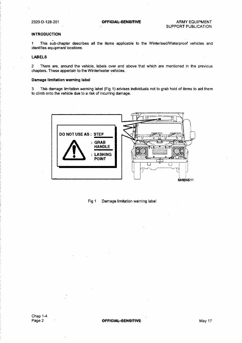
2320-D-128-201 OFFICIALSENSITIVE ARMY EQUIPMENT SUPPORT PUBLICATION
INTRODUCTION
1 This sub-chapter describes all the items applicable to the Winterised/Waterproof vehicles and identifies equipment locations.
LABELS
2 There are, around the vehicle, labels over and above that which are mentioned in the previous chapters. These appertain to the Winter/water vehicles.
Damage limitation warning label
3 This damage limitation warning label (Fig 1) advises individuals not to grab hold of items to aid them to climb onto the vehicle due to a risk of incurring damage.
: GRAB HANDLE
:LAS
POINT
Fig 1 Damage limitation warning label
MHB0511
Chap 1-4 Page 2 GFRGIAL—SENSI-TIVE May 17

ARMY EQUIPMENT OFFIGIAL-ErENfriT-PiE SUPPORT PUBLICATION
EXTERNAL LAYOUT
4 The external layout of the Truck Utility Medium (TUM) Winterised/Waterproofed is detailed in Fig 2.
15 20 21 22 23 24
2320-D-128-201
MHB0444
1 Antenna mounting 14 Door handle lock 27 Pick axe head
2 Side repeater 15 Driving mirror 28 Radiator snow blind
3 Raised air intake 16 Number plate light 29 Towing pintle
4 Snow blind 17 Rear door lock 30 Headlight
5 Air cleaner 18 Rear wiper 31 Rear stop light
6 Drain tap 19 Rear wash 32 Reversing light
7 Spare wheel 20 Pick axe handle 33 Rear side light
8 Antenna cable grommet 21 Front screen wiper 34 Rear indicator lights
9 Roof bar (Ski rack) 22 Front screen wash 35 Rear fog guard lights
10 Aerial mounting 23 Escape hatch 36 12 pin socket
11 GRP hardtop 24 Shovel 37 Towing hook
12 Rear bumperettes 25 Front side lights 38 Convoy flag holder
13 Jerry can stowage 26 Indicator light
Fig 2 Truck Utility Medium (TUM) Winterised/Waterproofed external layout
May 17 OFFIGIAL-GENSMVE Chap 1-4
Page 3

2320-D-128-201 OFFIGIAL—GENr&ITIVE
IN CAB CONTROLS AND DASH LAYOUT
5 The in cab controls and dash layout are detailed in Fig 3.
32
ARMY EQUIPMENT SUPPORT PUBLICATION
16 17 18 19 20 21 22 23
31 30 29 28 2/ 26 25 24
MHB0445
1 Map reading light 12 Hazard warning switch 23 Temp and distribution switch
2 Fuse box cover 13 Ignition switch 24 Accelerator pedal
3 Centre console 14 Inspection sockets 25 Brake pedal
4 Warning light panel 15 Rear wash/wipe switch 26 Clutch pedal
5 Main lighting switch 16 Air vent 27 Handbrake
6 Heater switch (Webasto) 17 Heater blower switch 28 Hand throttle
7 Map reading light switch 18 Horn/dip/indicator switch 29 Main gearbox lever
8 Headlamp levelling 19 Speedometer 30 Transfer/diff lock gearbox
9 Rear heated screen switch 20 Fuel gauge 31 Main fuse box 10 Front heated screen switch 21 Temperature switch 32 Heater footwell vents 11 Rear fog guard switch 22 Wash/wipe switch
Chap 1-4 Page 4
Fig 3 In cab controls and dash layout
OFRGIAL—SENSITIVE May 17

ARMY EQUIPMENT OFFIGIAL—SENSI-TPIE 2320-D-128-201 SUPPORT PUBLICATION
ENGINE COMPARTMENT LAYOUT
WinterisedlWaterproofed engine compartment (GS)
6 The engine compartment of the Winterised/Waterproofed General Service (GS) variant is detailed in Fig 4.
17 16 15 14 13 12 11
MHB0446
1 Engine coolant reservoir 7 Engine oil dipstick 13 Alternator
2 Brake fluid reservoir 8 Alternator breather 14 Radiator filler
3 Clutch fluid reservoir 9 Webasto heater ECU 15 Engine oil filler
4 Air cleaner 10 Webasto water heater 16 Radiator
5 Cyclone (crank breather) 11 Power steering reservoir 17 Fuel filter
6 RFI filter 12 Windscreen wash reservoir 18
May 17
Fig 4 Winterised/Waterproofed engine compartment (GS)
OFFIGIAL-SENSITIVE Chap 1-4
Page 5

2320-D-128-201 OFFIGIAL-FrENfrITIVE ARMY EQUIPMENT SUPPORT PUBLICATION
Winterised/Waterproofed engine compartment (FFR)
7 The engine compartment of the Winterised/Waterproofed Fitted For Radio (FFR) variant is detailed in Fig 5. The main difference from the GS variant id the addition of the alternator — upper (17).
2 5 6 7 8 9 10
17 16 15 14 13 12 11
MHB0509
1 Engine coolant reservoir 7 Engine oil dipstick 13 Alternator
2 Brake fluid reservoir 8 Alternator breather 14 Radiator filler
3 Clutch fluid reservoir 9 Webasto heater ECU 15 Engine oil filler
4 Air cleaner 10 Webasto water heater 16 Radiator
5 Cyclone (crank breather) 11 Power steering reservoir 17 Alternator - upper
6 RFI filter 12 Windscreen wash reservoir 18 Fuel filter
Chap 1-4 Page 6
Fig 5 Winterised/Waterproofed engine compartment (FFR)
GFFIG4AL-GC-14-61-T-W-E May 17
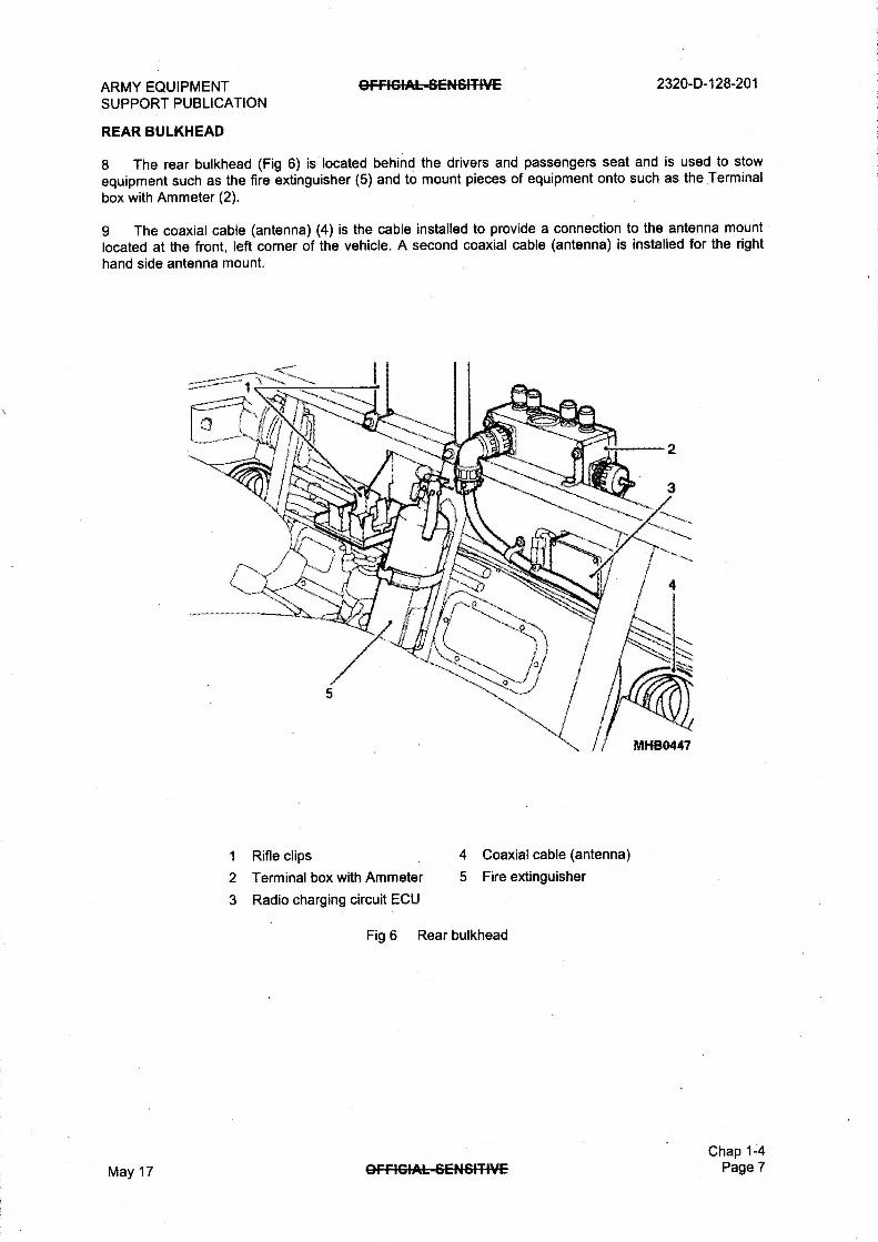
ARMY EQUIPMENT SUPPORT PUBLICATION
REAR BULKHEAD
GFREFIAL-GENSITIVE 2320-D-128-201
8 The rear bulkhead (Fig 6) is located behind the drivers and passengers seat and is used to stow equipment such as the fire extinguisher (5) and to mount pieces of equipment onto such as the Terminal
box with Ammeter (2).
9 The coaxial cable (antenna) (4) is the cable installed to provide a connection to the antenna mount located at the front, left corner of the vehicle. A second coaxial cable (antenna) is installed for the right hand side antenna mount.
1 Rifle clips
2 Terminal box with Ammeter
3 Radio charging circuit ECU
4 Coaxial cable (antenna)
5 Fire extinguisher
Fig 6 Rear bulkhead
Chap 1-4
May 17 OFFIGIAL—ErENSMVE Page 7

2320-D-128-201
REAR OF THE VEHICLE
OFFIGIAL-GENSI-TIVE ARMY EQUIPMENT SUPPORT PUBLICATION
10 The layout in the rear of the vehicle (Fig 7) is similar in appearance to the standard FFR variant with the addition of the heater radiators (7) and The radio bad (2).
1 Earth straps 5 Terminal box
2 Radio bag 6 Battery trays
3 Equipment racking 7 Heater radiators
4 Radio table 8 Radio operators seat
Fig 7 Rear of the vehicle
Chap 1-4 Page 8 OFFIGIA6-SENSIT-IVE May 17
ARMY EQUIPMENT SUPPORT PUBLICATION
Para
1 Introduction 2 General
INTRODUCTION
OFfiGIAL-BENSITIVE
CHAPTER 1-5
AIR DROPABLE
CONTENTS
2320-D-128-201
1 This sub-chapter describes all the items applicable to Truck Utility Light (TUL) HS Air drop vehicles, which are not covered in the previous chapters.
General
2 All information appertaining to the air dropable vehicles can be found in sub-chapter 1-1 Basic vehicle and sub-chapter 1-2 Fitted for Radio (FFR).
Chap 1-5
May 17 OFfIGIAk-GENSITIVE Page 1
2320-D-128-201 GFRGIAL-BENBITIVE ARMY EQUIPMENT SUPPORT PUBLICATION
PAGE LEFT INTENTIONALLY BLANK
Chap 1-5 Page 2 OFFIGIAL-SENSITPIE May 17
ARMY EQUIPMENT SUPPORT PUBLICATION
Para
1 Introduction 2 General
INTRODUCTION
OFFIGIAL—SENSIT-IVE
CHAPTER 1-6
HELICOPTER SUPPORT VEHICLE
CONTENTS
2320-D-128-201
1 This sub-chapter describes all the items applicable to the Truck Utility Medium (TUM) HS Helicopter Support Vehicle which are not covered in the previous chapters.
General
2 All information appertaining to the Helicopter support platform vehicles can be found in sub-chapter 1-1 Basic vehicle and sub-chapter 1-2 Fitted For Radio (FFR).
Chap 1-6 May 17 OFFICIALSENSITIVE Page 1

2320-D-128-201 OFFIGIA6-SENGITIVE ARMY EQUIPMENT SUPPORT PUBLICATION
PAGE LEFT INTENTIONALLY BLANK
Chap 1-6 Page 2 OFFICIALSENSITIVE May 17

ARMY EQUIPMENT SUPPORT PUBLICATION
Para
GFFIGIAL-SENSITIVE
CHAPTER 1-7
COMMANDERS 1K
CONTENTS
Introduction Labels
Earth warning label Voltage labels
Truck Utility Medium (TUM) (Commanders IK) external layout Roof rack (WARNING) Internal rear of the Commanders IK Rear bulkhead
2320-D-128-201
Fig Page
1 Earth warning label 2 2 Voltage labels 2 3 Commanders IK external layout 3 4 Internal rear of the Commanders IK 4 5 Rear bulkhead 5
Chap 1-7 May 17 OFFIGIAL--GENSITIVE Page 1

2320-D-128-201
INTRODUCTION
OFFIErfAL—SENBIT-IVE ARMY EQUIPMENT SUPPORT PUBLICATION
1 This sub-chapter describes all the items applicable to the Truck Utility Medium (TUM) HS Commanders IK vehicles, which are not covered in the previous chapters.
LABELS
2 There are, around the vehicle, labels over and above that which are mentioned in the previous chapters. These appertain to the Commanders IK vehicles.
Earth warning label
3 The earth warning label (Fig 1) advises individuals against connecting to an outside power supply without first earthing the vehicle.
Voltage labels
4 The voltage labels (Fig 2) inform the operator of the different power supplies of each bank of sockets. This prevents equipment being plugged into the wrong supply.
WARNING VEHICLE MUST BE EARTHED PRIOR TO CONNECTING TO 240V POWER
SOURCE. REFER TO AESP
ftSTRUCTION CAT 2
MH80779
Fig 1 Earth warning label
Fig 2 Voltage labels
Chap 1-7 Page 2 OFFIGIAL—SENGITIVE May 17

ARMY EQUIPMENT OFFIGIAL—SENSITIVE SUPPORT PUBLICATION
TRUCK UTILITY MEDIUM (TUM) (COMMANDERS IK) EXTERNAL LAYOUT
5 The external layout of the Commanders IK variant is detailed in Fig 3.
2320-D-128-201
1 Antenna coaxial stowage 11 Wing mirror 21 Front towing pintle
2 Side indicator light 12 Rear number plate light 22 Headlights
3 Spare wheel 13 Rear door handle 23 Rear stop light
4 Aerial outlet 14 Input/output sock 24 Reverse light
5 Roof rack 15 Mounting ladder 25 Rear side light
6 Antenna mounting base 16 Windscreen wiper 26 12 pin trailer socket
7 Hard top 17 Windscreen washer 27 Rotating towing hook
8 Bum perettes 18 Escape hatch 28 Turn light
9 Jerry can holder 19 Front side lights 29 Rear fog light
10 Door handle 20 Turn lights 30 Convoy flag holder
May 17
Fig 3 Commanders IK external layout
OFFIGFAL—SENSIT-IVE Chap 1-7
Page 3

2320-D-128-201 OFFICIAL SENSITIVE ARMY EQUIPMENT SUPPORT PUBLICATION
ROOF RACK
WARNING
WITH THE EXCEPTION OF THE COMMANDERS IK, ROOF RACKS ARE PROHIBITED FROM BEING FITTED TO TULITUM (HS) VEHICLES.
6 The Commander IK variant is fitted with a roof rack (Fig 3 (5)). This is the only TUL/TUM variant permitted to have a roof rack fitted.
INTERNAL REAR OF THE COMMANDERS IK
7 The internal rear of the Commanders IK variant is fitted with equipment detailed in Fig 4.
7
8
9
MHB0756
1 Retaining strap buckles 5 Auxiliary sockets 9 Battery box
2 Interior lights 6 Transformer/charger 10 Folding seats
3 Folding mapboard/bed 7 Terminal box 11 Circuit breakers
4 Cigar lighter 8 Stowage nets 12 Input socket
Fig 4 Internal rear of the Commanders IK
Chap 1-7 Page 4 GFFIGIAL-GENSITIVE May 17

ARMY EQUIPMENT SUPPORT PUBLICATION
REAR BULKHEAD
OFFIGIAL—SENBITIVE 2320-D-128-201
8 The rear bulkhead (Fig 5) is located behind the drivers and passengers seat and is used to stow equipment such as the fire extinguisher (7) and to mount items of equipment onto such as the fast fuse unit (3).
9 The coaxial cables (antenna) (4) are the cables installed to provide a connection from communication equipment to the antenna mount located at the front, left corner of the vehicle. A second coaxial cable (antenna) is installed for the right hand side antenna mount. When not in use they are stowed in the position shown.
1 Wheel chock 6 Jack handles
2 Tool kit 7 Fire extinguisher
3 Fast fuse 8 Vehicle jack
4 Radio charging circuit ECU 9 Wheel nut wrench
5 Coaxial cable (Antenna)
Fig 5 Rear bulkhead
May 17 OFFIGIAL—SENSITIVE Chap 1-7
Page 5

2320-D-128-201 8FfIGIAL-SC-NBITIVE ARMY EQUIPMENT SUPPORT PUBLICATION
PAGE LEFT INTENTIONALLY BLANK
Chap 1-7 Page 6 OFF/G4AL—SENBI'TIVE May 17

ARMY EQUIPMENT SUPPORT PUBLICATION
Para
OFFICIALSENSITPIE
CHAPTER 1-8
WEAPONS MOUNT INSTALLATION KIT (RWMIK)
CONTENTS
2320-D-128-201
1 2 5 6 7 8
Introduction RWMIK overview
Crew Protection Mount (CPM) (WARNING) Folding Interface Mount (FIM) Crew responsibilities (WARNINGS/CAUTIONS) Labels
9 Seat warnin label . 10 11 Cam net 12 13 Vehicle wei ht late 14 15 16 Armour
Fig Page
1 Truck Utility Medium RWMIK 2 2 Seat warnin label 4 3 5 4 5 5 Vehicle wei ht late 6 6 7
Chap 1-8 May 17 AFFIGIAL—SENSITIVE Page 1
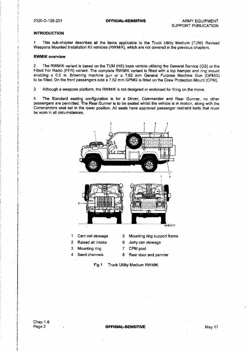
2320-D-128-201
INTRODUCTION
OFFICIALGE-NaTIVE ARMY EQUIPMENT SUPPORT PUBLICATION
1 This sub-chapter describes all the items applicable to the Truck Utility Medium (TUM) Revised Weapons Mounted Installation Kit vehicles (RWMIK), which are not covered in the previous chapters.
RWMIK overview
2 The RWMIK variant is based on the TUM (HS) base vehicle utilising the General Service (GS) or the Fitted For Radio (FFR) variant. The complete RWMIK variant is fitted with a top hamper and ring 'mount enabling a 0.5 in. Browning machine gun or a 7:62 mm General Purpose Machine Gun (GPMG) to be fitted. On the front passengers side a 7.62 mm GPMG is fitted on the Crew Protection Mount (CPM).
3 Although a weapons platform, the RWMIK is not designed or endorsed for firing on the move.
4 The Standard seating configuration is for a Driver, Commander and Rear Gunner, no other passengers are permitted. The Rear Gunner is to be seated whilst the vehicle is in motion, along with the Commanders seat set in the lower position. All seats have approved passenger restraint belts that must be worn in all circumstances.
1 Cam net stowage 5 Mounting ring support frame
2 Raised air intake 6 Jerry can stowage
3 Mounting ring 7 CPM post
4 Sand channels 8 Rear door and pannier
Fig 1 Truck Utility Medium RWMIK
Chap 1-8 Page 2 OFFICIALSENSITIVE May 17

ARMY EQUIPMENT OFFICIAL-SENSITIVE 2320-0-128-201 SUPPORT PUBLICATION
CREW PROTECTION MOUNT (CPM)
WARNING
THE CPM MUST NOT BE USED WHEN ON THE MOVE.
5 The Crew Protection Mount (CPM) is mounted on the front of the vehicle and allows the vehicle commander to operate a GPMG only while the vehicle is static.
FOLDING INTERFACE MOUNT (FIM)
6 The Folding Interface Mount (FIM) Manroy Soft Mount is mounted on top of the roll-bar assembly in the rear of the vehicle. It enables a 6400 mil traverse to engage ground targets from static positions. This mount can be used to operate the following weapons:
6.1 GPMG. The GPMG is mounted on key vehicles to provide an immediate self defence capability.
6.2 0.50 HMG. RWMIK will allow for the operation of the enhanced Heav Machine Gun HMG e ui ed with the Manroy Soft mount, Quick Change Barrel (QCB),
CREW RESPONSIBILITIES
WARNING
THE RWMIK MUST NOT BE USED TO CARRY ANY PERSONNEL OTHER THAN THE THREE (3) DETAILED WITHIN THIS PUBLICATION.
7 Due to the stowage and safety constraints associated with RWMIK, the vehicle Crew is strictly limited to three (3) personnel and will consist of the following:
WARNING
THE RWMIK COMMANDER MUST BE TRAINED IN ACCORDANCE WITH THE RWMIK CRITICAL SAFETY ASPECTS AS DIRECTED IN RWMIK - REVISED CONCEPTS OF USE, REF 088/24/00 DATED 25 AUG 05.
7.1 The vehicle/crew commander has overall responsibility for the RWMIK vehicle and its weapons systems. The commander carries out the following duties:
7.1.1 Navigation.
7.1.2 Performs surveillance
7.1.3 Assists in target acquisition.
7.1.4 Passes and receives information on the radio.
7.1.5 Assesses and anticipates the battle, passing orders to the remainder of the crew.
7.1.6 Once the RWMIK vehicle occupies a fire position, the vehicle commander is responsible for protecting the vehicle by operating the front mounted GPMG.
Chap 1-8 May 17 GFRGIAL-SENSITIVE Page 3

2320-D-128-201 OFFIGIAL—GENSIT-IVE ARMY EQUIPMENT SUPPORT PUBLICATION
CAUTION
The Driver must be qualified in accordance with the DRLC GS driver pack and the RWMIK Specific instructions taken from Ref 1 of Annex B to RWMIK - Revised Concepts of Use, Ref 088/24/00 dated 25 Aug 05.
7.2 The driver is responsible for operating the vehicle and for manoeuvring it safely in accordance with direction received from the vehicles commander.
CAUTION
The Gunner must be qualified on the weapons he is using and be trained in accordance with the RWMIK critical safety aspects as directed in Annexes A, B and C to RWMIK - Revised Concepts of Use, Ref 088/24/00 dated 25 Aug 05.
7.3 The Gunner is responsible for operating the rear mounted weapon. The gunner is also responsible for:
7.3.1 Surveillance.
7.3.2 Target acquisition.
7.3.3 Operating and maintaining the weapon.
7.3.4 Engaging targets.
LABELS
8 There is on the dash of the vehicle a label that is over and above those labels that are mentioned in the previous chapters.
Seat warning label
9 The seat warning label (Fig 2) advises individuals not to have the seat in the raised position when the vehicle is moving.
Chap 1-8 Page 4
WARNING DO NOT USE SEAT IN RAISED
POSITION WHEN VEHICLE IS MOVING
Fig 2 Seat warning label
OFFICIALSENSITIVE
R1C201.7
May 17

ARMY EQUIPMENT SUPPORT PUBLICATION
10 The
•
May 17
OFFICIALSENSITIVE 2320-D-128-201
OFFIGIAL—frENSITIVE Chap 1-8
Page 5

2320-D-128-201
VEHICLE WEIGHT PLATE
13
14
GFFICiAL—SENGIT-WE ARMY EQUIPMENT SUPPORT PUBLICATION
Chap 1-8 Page 6 OFFIG4AL-69464T4VE May 17

ARMY EQUIPMENT SUPPORT PUBLICATION
14.2
14.3
GFRGIAL-GENSITIVE 2320-b-128-201
111 1
Fig 6
15
ARMOUR
16
16.1
16.2
16.3
Chap 1-8 May 17 OffIGIAL-SENSITIVE Page 7

2320-D-128-201 OFfIG4AL-SC-NSITIVE ARMY EQUIPMENT SUPPORT PUBLICATION
PAGE LEFT INTENTIONALLY BLANK
Chap 1-8 Page 8 OFFIG4AL—GENSITIVE May 17

ARMY EQUIPMENT SUPPORT PUBLICATION
Para
1 Introduction 2 General 3 Air conditioning
INTRODUCTION
GFFIGIAL-GENSITIVE
CHAPTER 1-9
TROPICAL BATTLEFIELD AMBULANCE
CONTENTS
2320-D-128-201
1 This sub-chapter describes all the items applicable to Tropical Battlefield Ambulance which are not covered in the previous chapters.
General
2 All information appertaining to the Tropical Battlefield Ambulance vehicles can be found in sub-chapter 1-3.
AIR CONDITIONING
3 , The air conditioning system provides cold air to both the driver and ambulance compartments via adjustable vents located in the fresh air/recirculation unit above, the attendants seat and the evaporator unit in the drivers compartment.
4 The air conditioning is provided by a compressor, driven off the engine and a cooler/evaporator unit located in the drivers compartment. On/Off and fan switch controls for the distribution of the air conditioning are mounted on the distribution/control box in the ambulance compartment.
Chap 1-9 May 17 OfFIGIAL-BC-NSITIVE Page 1

2320-D-128-201 OFFICIALSENGITWE ARMY EQUIPMENT SUPPORT PUBLICATION
PAGE LEFT INTENTIONALLY BLANK
Chap 1-9 Page 2 GFFIGIAL-SENSITIME May 17

ARMY EQUIPMENT SUPPORT PUBLICATION
Para
1 Introduction 2 General 3 Wading
OFFICIAL-SENSITIVE 2320-D-128-201
CHAPTER 1-10
WINTERISED/WATERPROOFED BATTLEFIELD AMBULANCE
CONTENTS
Fig Page
1 Wading label 1
INTRODUCTION
1 This sub-chapter describes all the items applicable to Winterised/Waterproofed Battlefield Ambulance, which are not covered in the previous chapters.
General
2 All information appertaining to the Winterised/Waterproofed Battlefield Ambulance vehicles can be found in sub-chapter 1-4.
WADING
3 The label (Fig 1) is located on the dash in front of the steering wheel and informs the driver of the maximum depth the vehicle can safely ford.
May 17
MAX FORDING DEPTH OA METRE AT MAXIMUM SPEED 13KPH
Fig 1 Wading label
OFFIGIAL-6C-NfrITIVE
IVIIIB0783
Chap 1-10 Page 1

2320-0-128-201 OFFICIAL6E1481TIVE ARMY EQUIPMENT SUPPORT PUBLICATION
PAGE LEFT INTENTIONALLY BLANK
Chap 1-10 Page 2 OFFIGIAL—GENfrl-T-PiE May 17

ARMY EQUIPMENT OFFIGIAL-SENSITIVE SUPPORT PUBLICATION
CHAPTER 1-11
WATERPROOFED WEAPONS MOUNT INSTALLATION KIT (WMIK)
CONTENTS
Para
1 Introduction
INTRODUCTION
2320-D-128-201
1 This sub-chapter describes all the items applicable to the Waterproofed Truck Utility Medium (TUM) Weapons Mounted Installation Kit vehicles (WMIK), which are not covered in the previous chapters.
MHB1059
1 Raised air intake extension tube 5 Sand Channels
2 Raised air intake 6 Front windscreen
3 GPS Mounting 7 Radio rack and mounting
4 GPMG/HMG Barrel clamps
Fig 1 Truck Utility Medium WMIK
Chap 1-11
May 17 OFF4GIAL-SENSITIVE Page 1

2320-D-128-201
Chap 1-11 Page 2
OFFICIALErENfITWE ARMY EQUIPMENT SUPPORT PUBLICATION
PAGE LEFT INTENTIONALLY BLANK
GFAGIAL--SENSMYE May 17

ARMY EQUIPMENT SUPPORT PUBLICATION
Para
1 Introduction 2 General
INTRODUCTION
OFFIGIAL-SE-NSITIVE
CHAPTER 2
CONTROLS AND INSTRUMENTS
CONTENTS
2320-D-128-201
1 This Chapter describes the Controls and Instruments applicable to the Truck Utility Light (TUL) HS, Truck Utility Medium (TUM) HS and (TUM) Battlefield Ambulance HS variants listed in the following sub-chapters:
1.1 Chapter 2-1 Basic vehicle.
1.2 Chapter 2-2 Fitted For Radio (FFR).
1.3 Chapter 2-3 Battlefield Ambulance.
1.4 Chapter 2-4 Winterised/Waterproofed.
1.5 Chapter 2-5 Air drop.
1.6 Chapter 2-6 Helicopter Support Vehicle.
1.7 Chapter 2-7 Commanders IK.
1.8 Chapter 2-8 Weapons Mounted Installation Kit.
1.9 Chapter 2-9 Tropical Battlefield Ambulance.
1.10 Chapter 2-10 Winterised/Waterproofed Battlefield Ambulance.
1.11 Chapter 2-11 Waterproofed Weapons Mounted Installation Kit.
General
2 The information given in this Chapter is applicable to both left hand drive and right hand drive vehicles.
Chap 2 May 17 GFRGIAL—SENE4T-IVE Page 1
2320-D-128-201 OFFIGIAL—GENSITIVE ARMY EQUIPMENT SUPPORT PUBLICATION
PAGE LEFT INTENTIONALLY BLANK
Chap 2 Page 2 GFFIGIAL-GENSITIVE May 17
ARMY EQUIPMENT SUPPORT PUBLICATION
Para
OFF4GIAL-8EN&MVE
CHAPTER 2-1
BASIC VEHICLE
CONTENTS
1 Introduction 2 The vehicle side doors 3 To open and close the doors from the outside 4 Open and close the driver's door from the inside 5 Open and close the passengers door from the inside 6 Tailgate 7 Release the tailgate 8 Vehicle fascia 9 Driver/passenger seats
10 Adjusting the seats 13 Safety belt 14 Operating the safety belt 15 Testing the safety belt (WARNING) 16 Care of the belts 17 Safety belt cleaning 18 Instrument panel 19 Coolant temperature indicator 20 Fuel level indicator 21 Speedometer 22 Warning lights panel 23 Hazard warning switch 24 Operating the switch 25 Rear fog guard lights switch 26 Steering wheel console 27 The windscreen wash/wipe switch 29 Headlight dipper, turn lights, horn and headlight flasher switch 31 Steering lock and starter switch (WARNING) 32 Steering wheel 33 Dash ventilators 34 Main light switches 35 Six way main lighting switch 36 Seven way main lighting switch 37 Inspection sockets 38 Headlamp levelling 39 Map reading light 40 Fresh air/heating controls 41 The heater controls 42 Pedals 43 Foot brake pedal 44 Bonnet release 45 Inter vehicle starting socket 46 Operation of the socket 47 Vehicle battery isolator switch 48 Fire extinguisher bracket 49 Operation of the extinguisher bracket 50 Transmission handbrake 52 Transfer gear/differential lock lever (CAUTIONS) 53 Fully rearwards right 54 Fully rearwards left
2320-D-128-201
(continued)
Chap 2-1 May 17 OFFIGIAL—SE-NSITIVE Page 1

2320-D-128-201
Para
55 Centre left 56 Centre right 57 Fully forward right. 58 Fully forward left. 59 Main gear change lever 61 Fuse boxes (WARNING) 62 Main fuse box 63 Under-bonnet fuse box 65 Stowage compartments 67 Bench seats 70 Bench safety belt stowage 71 Windows 72 Vehicle tool kit 74
Off4GIAL—frENSITWE ARMY EQUIPMENT SUPPORT PUBLICATION
CONTENTS (continued)
Fig Page
1 External door lock 3 2 Internal door lock 4 3 Tailgate locking mechanism 4 4 Seat adjustment 5 5 Seat belt operation 6 6 Coolant temperature indicator 7 7 Fuel level indicator 7 8 Speedometer and trip setting 8 9 Warning lights panel 10
10 Hazard warning switch 11 11 Rear fog guard light switch 11 12 Windscreen wash/wipe switch 12 13 Headlight dipper, turn lights, horn and headlight flasher switch 13 14 Steering lock and starter switch 14 15 Dash ventilators 15 16 Six way main lighting switch 16 17 Seven way main lighting switch 16 18 Inspection sockets 17 19 Headlamp levelling switch 17 20 Map reading light 18 21 Fresh air/heating controls 19 22 Pedal layout 20 23 Bonnet release lever 21 24 Bonnet safety catch 21 25 Inter vehicle starting socket 22 26 Vehicle battery isolator switch 23 27 Fire extinguisher bracket 23 28 Transmission handbrake lever 24 29 Transfer gear/differential lock lever 25 30 Main gear change lever 25 31 Main fuse box location 26 32 Under-bonnet fuse box location 26 33 Removing the seat base cover 27 34 Bench seats 28 35 Bench safety belt stowage 28 36 Operating the windows 29 37 Vehicle tool kit 30 38 31
Chap 2-1 Page 2 OffIGIAL—SENSITIVE May 17

ARMY EQUIPMENT GFFIGIAL-SE4181-TIVE 2320-D-128-201 SUPPORT PUBLICATION
INTRODUCTION
1 This sub-chapter describes the Controls and Instruments applicable to the Truck Utility Light (TUL) HS and Truck Utility Medium (TUM) HS vehicles.
THE VEHICLE SIDE DOORS
2 There are two side doors fitted to the vehicle. The following operations apply to the vehicle side doors and are similar in many of the operations.
To open and close the doors from the outside
3 To unlock, open, and lock the doors from the outside proceed as follows:
3.1 To unlock the doors Insert the key into the lock (Fig 1 (1)) and turn it towards the rear of the vehicle (a quarter turn), return the key to the vertical position and remove.
3.2 To open the door, lift the handle (2).
3.3 To lock the door, turn the key towards the front of the vehicle (a quarter turn), return key to the vertical position and remove.
1 Lock 2 Handle
Fig 1 External door lock
Open and close the driver's door from the inside
NOTE
This affects only the driver's door.
4 To unlock the door proceed as follows:
4.1 Move the knob (Fig 2 (2)) on the lock case downwards.
4.2 Open the door using the inside handle (1).
4.3 To lock the door, close the door and move the knob on the lock case upwards.
Chap 2-1 May 17 OffiGIAL—SENSIT-IVE Page 3

2320-D-128-201 OFFIGIAL-GB4SITIVE ARMY EQUIPMENT SUPPORT PUBLICATION
1 Lock 2 Handle
Fig 2 Internal door lock
Open and close the passengers door from the inside
NOTE
This affects only the passenger's doors.
5 To unlock the door from the inside proceed as follows:
5.1 Move the knob (2) on the lock case downwards.
5.2 Open door using inside handle (1).
5.3 To lock the door move knob on lock case upwards before or after closing door.
TAILGATE
6 The tailgate (Fig 3) is either side or bottom hinged. The tailgate is secured by two latches in both cases. Restraining straps prevent excess travel for bottom hinged tailgates and a retaining door holder limits the travel for side hinged conversions.
Release the tailgate
7 To release the tailgate move the catches in an upward direction until they are able to fall into the horizontal position.
7.1 For bottom hinged tailgates pull the tailgate outwards until the retaining straps prevent any further travel. To close the tailgate, lift the tailgate and push it fully against the latching and secure.
7.2 For side hinged conversions rotate outwards until the retaining door holder prevents further travel. To close rotate tailgate inwards push against the latching and secure.
Chap 2-1 Page 4
Fig 3 Tailgate locking mechanism
GFRGIAL-SENfrITIVE May 17

ARMY EQUIPMENT GFFIGIAL—SENSITIVE 2320-D-128-201 SUPPORT PUBLICATION
VEHICLE FASCIA
8 The vehicle fascia displays the instruments and controls required by the operator when driving the vehicles.
DRIVER/PASSENGER SEATS
9 The front seats (Fig 4) have an adjustable setting for ease of driving and comfort.
Adjusting the seats
10 For Fore and aft adjustment lift the bar at the front of the seat and slide the seat to the required position. Release the bar and ensure that the seat guide catches have located the seat.
11 For Back angle rest adjustment ease the body from backrest and lift the locking handle.
11.1 Apply body pressure to move the back rest to the required position.
11.2 While remaining in the required position, press the handle down to lock in position.
NOTE
The backrest return is spring assisted.
12 Head restraints are fitted to the adjustable backrests of both the driver and front passenger seats. Each head restraint should be properly adjusted to provide maximum effectiveness in the event of a collision.
Fig 4 Seat adjustment
SAFETY BELT
13 The safety belt must be fitted to the anchorage points provided. Always use the safety belt provided, even for the shortest journeys. Alterations and additions must not be made to safety belts fitted to the vehicles.
Chap 2-1 May 17 OFFIGIAL—SENSITIVE Page 5
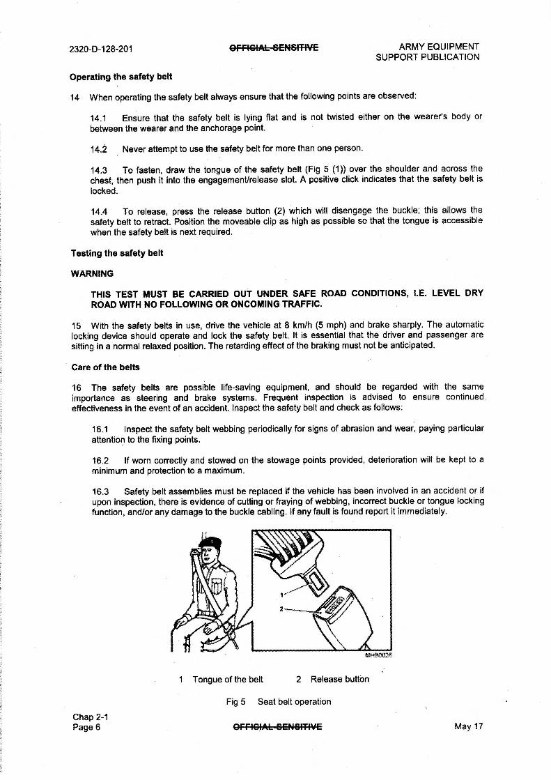
2320-0-128-201 OFFIGIAL—SENSITIVE ARMY EQUIPMENT SUPPORT PUBLICATION
Operating the safety belt
14 When operating the safety belt always ensure that the following points are observed:
14.1 Ensure that the safety belt is lying flat and is not twisted either on the wearer's body or between the wearer and the anchorage point.
14.2 Never attempt to use the safety belt for more than one person.
14.3 To fasten, draw the tongue of the safety belt (Fig 5 (1)) over the shoulder and across the chest, then push it into the engagement/release slot. A positive click indicates that the safety belt is locked.
14.4 To release, press the release button (2) which will disengage the buckle; this allows the safety belt to retract. Position the moveable clip as high as possible so that the tongue is accessible when the safety belt is next required.
Testing the safety belt
WARNING
THIS TEST MUST BE CARRIED OUT UNDER SAFE ROAD CONDITIONS, I.E. LEVEL DRY ROAD WITH NO FOLLOWING OR ONCOMING TRAFFIC.
15 With the safety belts in use, drive the vehicle at 8 km/h (5 mph) and brake sharply. The automatic locking device should operate and lock the safety belt. It is essential that the driver and passenger are sitting in a normal relaxed position. The retarding effect of the braking must not be anticipated.
Care of the belts
16 The safety belts are possible life-saving equipment, and should be regarded with the same importance as steering and brake systems. Frequent inspection is advised to ensure continued effectiveness in the event of an accident. Inspect the safety belt and check as follows:
16.1 Inspect the safety belt webbing periodically for signs of abrasion and wear, paying particular attention to the fixing points.
16.2 If worn correctly and stowed on the stowage points provided, deterioration will be kept to a minimum and protection to a maximum.
16.3 Safety belt assemblies must be replaced if the vehicle has been involved in an accident or if upon inspection, there is evidence of cutting or fraying of webbing, incorrect buckle or tongue locking function, and/or any damage to the buckle cabling. If any fault is found report it immediately.
Chap 2-1 Page 6
1 Tongue of the belt 2 Release button
Fig 5 Seat belt operation
OFF4GIAL—SENSIT-I-VE May 17

ARMY EQUIPMENT OFFIGIAL—GENSITIVE 2320-D-128-201 SUPPORT PUBLICATION
Safety belt cleaning
17 When cleaning a safety belt, do not attempt the following:
17.1 Do not bleach the belt webbing or re-dye it. If the belts become soiled, sponge with warm water using a non-detergent soap and allow them to dry naturally.
17.2 Do not use caustic soap, chemical cleaners or detergents for cleaning;
17.3 Do not dry with artificial heat or by direct exposure to the sun.
INSTRUMENT PANEL
18 The instrument panel is situated in front of the steering wheel console and consists of the following instruments:
Coolant temperature indicator
19 The coolant temperature gauge (Fig 6) indicates the running temperature of the engine. Under normal running conditions the temperature indicator needle should register in the black band. If the needle moves to the red band during normal running, the vehicle should be stopped and the cause investigated. The design of the indicator ensures that the needle does not fluctuate, but there is a time lag of a few seconds before registering after the engine has been started, or electrical services are switched on.
Fig 6 Coolant temperature indicator
Fuel level indicator
20 The fuel level indicator (Fig 7) shows the approximate contents of the tank. The design of the indicator ensures that the needle does not fluctuate, but there is a time lag of a few seconds before registering after the engine has been started, or after the electrical services have been switched on.
Fig 7 Fuel level indicator
May 17 GFFIGIAL-SENSITIVE Chap 2-1
Page 7

2320-D-128-201 OFfiGIAL-SENSITIVE ARMY EQUIPMENT SUPPORT PUBLICATION
Speedometer
21 The speedometer (Fig 8) indicates the speed of the vehicle in kilometres per hour with a miles per
hour subscale. The speedometer incorporates a total distance indicator and a trip distance indicator with a
trip reset button (1).
21.1 The speedometer trip setting allows the indicator to be reset to zero by pushing the small black knob on the front of the speedometer.
1 Trip reset button
Fig 8 Speedometer and trip setting
Chap 2-1 Page 8 GFRGIAL-SE+464-TIVE May 17
Related Documents