3 M - C.P. No. 1385 PROCUREMENT EXECUTIVE, MINISTRY OF DEFENCE AERONAUTICAL RESEARCH COUNCIL CURRENT PAPERS The Performance of a 6.5 Pressure Ratio Centrifugal Compressor having a Radially-Vaned Impeller M. G. Jones IVational Gas Turbine Establishment, Farnborough, Hants. LONDON: HER MAJESTY’S STATIONERY OFFICE 1977 f2.50 net

Welcome message from author
This document is posted to help you gain knowledge. Please leave a comment to let me know what you think about it! Share it to your friends and learn new things together.
Transcript

3 M - C.P. No. 1385
PROCUREMENT EXECUTIVE, MINISTRY OF DEFENCE
AERONAUTICAL RESEARCH COUNCIL
CURRENT PAPERS
The Performance of a 6.5 Pressure Ratio
Centrifugal Compressor having a
Radially-Vaned Impeller
M. G. Jones
IVational Gas Turbine Establishment, Farnborough, Hants.
LONDON: HER MAJESTY’S STATIONERY OFFICE
1977
f2.50 net

C.P. No. 1385* September 1976
THE PERFORMANCE OF A 6.5 PRESSURE RATIO CENTRIFUGAL COMPRESSOR RAVING A RADIALLY-VANED IMPELLER
- by - M-G. Jones
SUMMARY
The aerodynamic design and experimental performance of a centrifugal
compressor designed for a pressure ratio of 6.5 and a specific speed of 68
are described, The compressor consisted of a radially-vaned impeller and
a transonic, vaned radial diffuser. At design speed a peak overall total-
to-total isentropic efficiency of 0.746 was achieved at the maximum pressure
ratio of 5.9, rising to 0.79 at a pressure ratio of 3.5 at 80 per cent speed.
A theoretical analysis of the impeller channel flow suggests that high vane-
to-vane aerodynamic loading was partly responsible for the shortfall in
performance. The impeller was also tested with a vaneless diffuser and a
detailed analysis is made of static pressure measurements on the impeller
shroud and vaneless and vaned diffuser walls. Several recommendations are
made regarding the design and testing of centrifugal compressors.
*Replaces NGTE R 342 - ARC.37 043.

-2-
CONTENTS
Report 342
1.0 Introduction
2.0 Compressor design
2.1 Impeller 2.2 Diffuser
3.0 Compressor experimental test facility
3.1 Test rig 3.2 Instrumentation
3.2.1 Aerodynamic instrumentation 3.2.2 Mechanical instrumentation
4.0 Overall performance
4.1 Builds I and II - Design impeller with vaneless diffuser
Page
3 4
4 6
6 6 7
7 8
9
4.2 Build III - Design impeller with vaneless diffuser 4.3 Build IV - Design compressor stage 4.4 Build V - Modified impeller with vaneless diffuser 4.5 Build VI - Modified compressor stage _ _ .
9
10 10 10 11
collector 4.7 Choice of impeller exit station
5.0 Detailed static pressure measurements
5.1 Impeller shroud 5.2 Vaneless diffuser 5.3 Vaned diffuser
6.0 Conclusions
Appendix A Definitions of performance parameters
Appendix B Derivation of Mach numbers
References
Table I Main design parameters
Table II Summary of builds
Table III Build III derived parameters
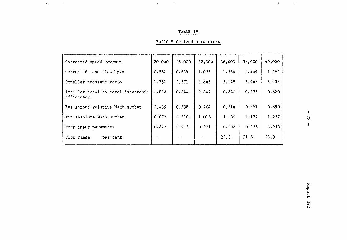
Table IV Build V derived parameters
Table V Build VI derived parameters
Table VI Build VII derived parameters
Table VII Comparison of test and predicted efficiencies
Illustrations
4.6 Build VII - Modified compressor stage with redesigned 12 13
14
14 15 17
18
20 21 24
25 26 27 28 29
30 31
Figures l-23

-3- Report 342 1.0 Introduction
The requirement in the past decade or so for small gas turbine
engines for advanced helicopter propulsion and for other aeronautical applications such as auxiliary power units has renewed interest in the centrifugal compressor which gave way to the axial machine for larger aircraft powerplants during the 'fifties. The centrifugal's advantages of simplicity, ruggedness, stability of operation and possible greater efficiency at high pressure ratios in small sizes are now widely recognised. A programme of centrifugal compressor research was therefore initiated at the National Gas Turbine Establishment (NGTE) in 1971.
It can be shown by means of simple cycle calculations with a turbine entry temperature consistent with uncooled blades, an important factor in reducing cost and complexity in small engines, and assuming best current component efficiencies, that minimum specific fuel consumption is obtained
at an overall cycle pressure ratio of at least 8. At the present time, the
highest overall compression efficiency for such pressure ratios would be obtained not from a single centrifugal compressor stage but from a combination of a centrifugal stage preceded by one or more axial stages, in which case the greater the proportion of the compression done by the axial stages the higher the optimum overall pressure ratio. A common arrangement, being a
convenient compromise between complexity and efficiency, is to use a single axial stage ahead of a centrifugal, in which case the cycle calculations give
an optimum overall pressure ratio of about 9. Assuming a pressure ratio from the axial stage of around 1.4, that for the centrifugal becomes about 6.5.
The other major parameter defining the duty of a centrifugal compressor is specific speed which is a function of impeller rotational speed, mass flow and work input. At least two slightly different formulae for specific speed exist and the one which will be used in this Report is due to Balje/l. Various attempts have been made to correlate centrifugal compressor efficiency with specific speed and to define an optimumvaluefor the latter. However,
examination of a number of engine designs shows that, for a given pressure ratio, the specific speed of the centrifugal compressor is limited by turbine blade stressing considerations to a value below any such aerodynamic optimum. This limiting specific speed is lower for a centrifugal compressor
forming part of an axial-centrifugal compressor combination than for one which provides the whole compression of the cycle.
-4- Report 342
This Report describes the aerodynamic design and experimental perform-
ance evaluation of a centrifugal compressor having an overall pressure ratio
of 6.5 and a specific speed of 68, these values rendering the design
relevant to an axial-centrifugal compressor system. Referred to as compressor
C139A, the design used a single-sided aluminium alloy impeller with radially-
stacked vanes and a transonic vaned radial diffuser.
2.0 Compressor design
The design duty for the compressor was as follows:
Overall pressure ratio 6.5
Overall isentropic efficiency 0.8
Mass flow 1.814 kg/s
Rotational speed 40,000 rev/min
Specific speed 68
A list of all the main design parameters is given in Table I and the layout
of the compressor is shown diagrammatically in Figure 1.
2.1 Impeller
Initially, a one-dimensional flow analysis was used to provide the
overall dimensions of the impeller such as tip diameter. Based on this data
an empirical geometrical specification was laid down for the complete impeller.
The hub and shroud wall contours were made up of circular arcs and the
necessary twist and form were given to the vanes by specifying a camber line
at the inlet shroud radius and prescribing that the vanes were stacked
radially. The form of the camber line was relatively simple in that it was
straight for the leadingedgeregion of the vane, followed by a circular arc
and finally became straight and parallel to the axis of rotation approximately
halfway through the impeller flow path. The circumferential thickness of the
vanes was specified by simple straight line contours in the meridional plane.
Intervanes, having the same camber line and thickness as the main vanes, were
also included in the radial portion of the impeller.
Having formulated a complete and detailed geometrical specification
for the impeller, it was decided to take the design a stage further and 2
assess the internal aerodynamics using the Matrix Throughflow technique in
which the flow in a meridional stream surface is analysed. For this design
exercise the shape of the mean stream surface was taken to be that of the vane
camber surface. This implies no allowance for slip or deviation at the
impeller tip but it was considered that this assumption would not detract
from the value of using the throughflow analysis as an aid in selecting an
impeller design. To allow for the flow blockage due to the presence of the

-5- Report 342
vanes, the thickness of the stream surface was taken to be proportional to
the ratio of vane thickness to vane pitch. The most difficult problem in
applying throughflow analysis is the modelling of the flow losses and
allowance for blockage created by the annulus wall boundary layers. For
the present task a simple approach was adopted of taking account of viscous
effects by assuming a constant local polytropic efficiency throughout the
flow field with no allowance for boundary layer blockage.
The throughflow analysis provides the distribution of relative
velocity along the hub and shroud. These velocities represent some mean of
the relative velocities on the vane suction and pressure surfaces and so
provide a measure of the rate of diffusion and boundary layer growth along
the vane surfaces for assessing the impeller design. To provide a means for
judging the design of blade profiles for axial turbomachines, Smith3 examined
a simple flow model in which the free stream velocity decreased linearly with
distance along the profile boundary. By applying two-dimensional boundary
layer theory Smith concluded that, to avoid flow separation, the velocity
ratio should not exceed 1.5. Dallenbach4 came to a similar conclusion in a
centrifugal compressor study. Whilst it was appreciated that the flow within
a centrifugal compressor is highly three-dimensional, it was decided, in the
absence of more relevant information, to assess the velocity distributions
for the current impeller design using the simple flow model of Dallenbach and
Smith.
The result of applying throughflow analysis to the initial empirical
specification for the impeller was to show that the geometry was unacceptable
in that the relative velocity ratio for the shroud of 3.5 was far in excess
of the limiting value of about 1.5. Following this analysis four modifications
to the impeller geometry were made before reaching the final design specifi-
cation. The value of the throughflow analysis can be seen in Figure 2 which
compares the hub and shroud wall velocities for the initial and final
impeller geometries. The final design is considered to be superior on two
accounts. Firstly, the adverse velocity gradient for the shroud is much
reduced and, secondly, there is a smaller difference between the hub and
shroud velocities in the region of the impeller outlet. These two factors
should provide improved flow conditions within the impeller and at entry to
the diffuser.
The final geometrical specification for the impeller is given in
Figures 3 and 4 and Table I. The method of defining the geometry is very
similar to that described above for the initial design except that the final

-6- Report 342
shroud wall contour is defined by a "supercircle" or Lam'e oval. The vane
camber surface is defined in Figure 4 in terms of a camber line for which the
radial stacking criterion has allowed the circumferentiai co-ordinate to be
non-dimensionalised according to radius.
2.2 Diffuser
A vaned radial diffuser having a straight channel centre-line was
designed on the principle of a short vaneless space between the impeller tip
and diffuser vane leading edge with a transonic approach Mach number, The
radius at the vane leading edge was therefore chosen as 5 per cent greater
than impeller tip radius and the radius at the vane trailing edge was
selected as being representative of the limiting value which would be imposed
in an actual engine application by considerations of frontal area and weight.
Parallel front and rear walls separated by an axial distance equal to the
tip width of the impeller were employed. The diffusion was achieved by
giving the side walls of each channel a "trumpet" shape with an included
angle of only lo at the throat increasing towards the channel outlet. Based
on an estimate of the flow conditions at diffuser approach, zero incidence
was specified with the suction surface of the vanes.
Taking account of the required throat area and of the desirability of
a throat channel aspect ratio in the region of unity, the number of vanes
and the channel outlet included angle were selected to give suitable values
of channel length/throat width and area ratio. These were chosen by
reference to the appropriate diffuser performance map presented by
Runstadler', the chosen operating point being determined by considerations
of maximum static pressure recovery coefficient consistent with remaining
within the assumed region of "no appreciable stall" defined in Figure 3 of
that reference.
The initial diffuser design was designated Al. A single channel is
shown in Figure 5 and the main design parameters are given in Table I.
3.0 Compressor experimental test facility
3.1 Test rig
A schematic layout of the test rig is given in Figure 6. The
compressor was driven by an air turbine through a 2/l step-up gearbox. The
impeller was "overhung", being bolted to the drive shaft by means of a flange
on the back face. The drive shaft ran in two preloaded, squeeze-filmed,
angular-contact ball bearings and also carried a balance piston to remove
most of the aerodynamic axial thrust load. Air entered the compressor from
atmosphere and passed axially through a flow-measuring venturi nozzle into a

-7- Report 342
plenum chamber from which the convergent inlet duct led into the impeller
eye. After leaving the compressor, the flow entered a scroll-type collector
having a single tangential outlet connected, by a short divergent duct, to a
throttle valve. Downstream of the valve, the flow was further diffused and
turned by a 90' cascade elbow into a flow-straightening section followed by
an orifice plate flowmeter. After further expansion and another turn through
9o", the flow joined the turbine exhaust stream.
3.2 Instrumentation
The compressor and test rig were fitted with comprehensive instrument-
ation to permit a detailed evaluation of the aerodynamic performance of the
impeller and diffuser. In addition, instrumentation for monitoring the
mechanical integrity of the compressor was incorporated.
3.2.1 Aerodynamic instrumentation
Before describing the aerodynamic instrumentation it is necessary to
explain that, in addition to the measurement of the overall stage performance
of the impeller and vaned diffuser, the performance of the impeller.alone was
investigated by running it in conjunction with a vaneless diffuser.
Static pressure tappings were situated in the plenum chamber, in the
impeller inlet and shroud casing, on the front and rear walls of the vaneless
and vaned diffusers and in the outlet duct. Figure 7 shows the locations of
tappings in the inlet and shroud casing. Within the limitations imposed by
space and other instrumentation, the main objective was to have fairly
complete sets of tappings in two circumferential positions (radial planes B
and D). Figure 8 shows the location of tappings in the vaneless diffuser
where, basically, eight radial planes with tappings at various radii repeated
on both walls were used. Figure 9 shows the arrangement of tappings in a
vaned diffuser. Two, approximately diametrically opposite, channels were
selected to have a complete set of centre-line tappings and eight others to
have tappings at channel throat and exit only. Since the front wall of the
vaned diffuser was the same as that of the vaneless diffuser, only those
tappings occurring in the vaneless space were used on that wall. All
pressures were measured on mercury or water manometers.
Air temperature was measured using stagnation, half-shield type chromel-
constantan thermocouples at entry to the compressor (in the plenum chamber),
at diffuser exit and in the collector outlet duct. At each of these three
stations four thermocouples were used.
-8- Report 342
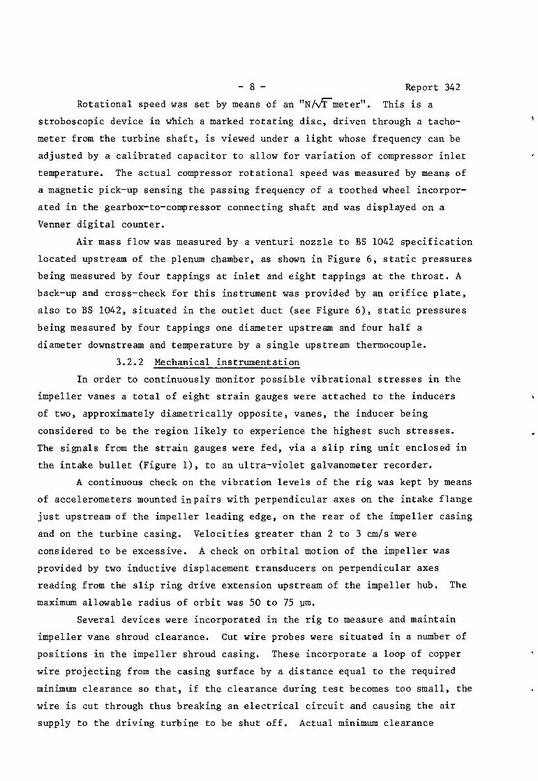
Rotational speed was set by means of an "N/fimeter". This is a
stroboscopic device in which a marked rotating disc, driven through a tacho-
meter from the turbine shaft, is viewed under a light whose frequency can be
adjusted by a calibrated capacitor to allow for variation of compressor inlet
temperature. The actual compressor rotational speed was measured by means of
a magnetic pick-up sensing the passing frequency of a toothed wheel incorpor-
ated in the gearbox-to-compressor connecting shaft and was displayed on a
Venner digital counter.
Air mass flow was measured by a venturi nozzle to BS 1042 specification
located upstream of the plenum chamber, as shown in Figure 6, static pressures
being measured by four tappings at inlet and eight tappings at the throat. A
back-up and cross-check for this instrument was provided by an orifice plate,
also to BS 1042, situated in the outlet duct (see Figure 6), static pressures
being measured by four tappings one diameter upstream and four half a
diameter downstream and temperature by a single upstream thermocouple.
3.2.2 Mechanical instrumentation
In order to continuously monitor possible vibrational stresses in the
impeller vanes a total of eight strain gauges were attached to the inducers
of two, approximately diametrically opposite, vanes, the inducer being
considered to be the region likely to experience the highest such stresses.
The signals from the strain gauges were fed, via a slip ring unit enclosed in
the intake bullet (Figure l), to an ultra-violet galvanometer recorder.
A continuous check on the vibration levels of the rig was kept by means
of accelerometers mounted inpairs with perpendicular axes on the intake flange
just upstream of the impeller leading edge, on the rear of the impeller casing
and on the turbine casing. Velocities greater than 2 to 3 cm/s were
considered to be excessive. A check on orbital motion of the impeller was
provided by two inductive displacement transducers on perpendicular axes
reading from the slip ring drive extension upstream of the impeller hub. The
maximum allowable radius of orbit was 50 to 75 urn.
Several devices were incorporated in the rig to measure and maintain
impeller vane shroud clearance. Cut wire probes were situated in a number of
positions in the impeller shroud casing. These incorporate a loop of copper
wire projecting from the casing surface by a distance equal to the required
minimum clearance so that, if the clearance during test becomes too small, the
wire is cut through thus breaking an electrical circuit and causing the air
supply to the driving turbine to be shut off. Actual minimum clearance

-9- Report 342
occurring during each test was recorded by soft metal plugs projecting from
the casing which were removed after running and the amount by which the
impeller vane tips had cut them back measured. At each test speed, readings
of the vane clearance were taken whilst running using two Fenlow probes at
the same radial position on the casing (about 6 per cent less than impeller
tip radius) but separated circumferentially by 90'. These enable the
clearance of a moving rotor to be determined by measuring the amount by
which a moving probe has to be driven towards the rotor before reaching the
known clearance at which a capacitor connected to the probe discharges.
4.0 Overall performance
Seven builds of the compressor were tested, as summarised in Table II.
For most builds, tests were conducted at a range of speeds up to the design
speed of 40,000 rev/min. The performance parameters quoted in the following
sections have, where appropriate, been corrected to the standard inlet
conditions of 101.32 kN/m2 pressure and 288.15 K temperature. Definitions
of the parameters are given in Appendix A.
4.1 Builds I and II - Design impeller with vaneless diffuser
These builds of the design impeller with a vaneless diffuser were
devoted to mechanical and instrumentation checks, notably adjustment of the
impeller shroud clearance to prevent contact between the vane tips and shroud
casing at the higher speeds.
It is desirable for the clearance at design speed to be as small as is
practicable to reduce losses due to flow recirculation. Some allowance has
to be made, however, for possible temporary reduction in clearance at the
surge condition due to the extra loads imposed on the compressor components
and a minimum design point running clearance of about 400 urn was considered
appropriate for the present compressor. Accordingly, for the first build,
the shroud casing inner contour was designed to give a static clearance on
assembly of approximately 400 urn along the whole length of the impeller
shroud. Upon running the impeller (Build I) it was found that the clearance
near the impeller tip was reducing with increasing rotational speed due,
probably, to "dishing" of the impeller under centrifugal loading. For
Build II the static clearance in this region was therefore increased by 150 pm
by shimming the whole of the diffuser, collector, shroud casing and intake
assembly axially upstream relative to the impeller drive shaft casing. This
static clearance still proved, however, to be insufficient to allow the
design speed to be reached whilst retaining the required running clearance and
it was not until Build III, described below, that this situation was achieved.

- 10 - Report 342
4.2 Build III - Design impeller with vaneless diffuser
This build of the compressor was the first associated with performance
measurement and was concerned with an evaluation of the flow characteristics
of the impeller only. For this purpose the compressor build consisted of the
design impeller with the vaneless diffuser. Based on the outcome of Builds I
and II, the impeller shroud static clearance was increased by a further 100 pm
axially resulting in the required running clearance at design speed of
approximately 400 urn near the impeller tip.
Figure 10 shows the impeller performance characteristic based on static
pressure measurements taken at a radius of 133.35 mm in the vaneless diffuser
rather than at the actual impeller tip radius of 124.46 mm. The reasons for
this choice of station will be given in a later Section, The temperature used
to calculate the impeller efficiency was that at diffuser exit. Table III
gives the values of a number of parameters derived from the test measurements
at the nearest test point to the maximum pressure ratio for each speed.
It can be seen that the maximum flow at the design speed was about
7 per cent below the design flow of 1.814 kg/s. This was thought to be due
to choking in the inducer throat, It should be noted, however, that, at the
lower speeds, where the flow characteristic does not become vertical, the
maximum flow is determined by choking of the throttle valve. Flow range is
therefore not given in Table III for these speeds. This also applies to the
results of a later vaneless diffuser build.
4.3 Build IV - Design compressor stage
Whilst the vaneless diffuser build described above showed the flow
capacity of the design impeller to be below the design target, it was
considered desirable to evaluate the stage performance of the compressor
consisting of the design impeller and the Al vaned diffuser. It was found
that the maximum flow at design speed was further reduced by approximately
6 per cent indicating choking in the diffuser.
4.4 Build V - Modified impeller with vaneless diffuser
At this point in the experimental programme it was clear from the
performance characteristics of the impeller alone, Build III, and of the
complete stage, Build IV, that it was necessary to modify the design
compressor stage in order to pass the design mass flow. Considering the
impeller first, the leading edges of the vanes were cut back axially by
5.08 mm in order to increase the throat area, as indicated in Figure 11, and
hence the choking mass flow. The impeller, thus modified, was then tested
with the vaneless diffuser as used in Build III.

- 11 - &port 3;
The full lines in Figure 12 show the resulting impeller performance
characteristic for the same station of 133.35 mm radius used in deriving the
characteristic for the design impeller Build III, Figure 10, and Table IV
gives the values of other salient parameters. The success of the modification
to the impeller can be seen from Figure 12 which shows that the maximum mass
flow at design speed was significantly increased and exceeded the design
target.
4.5 Build VI - Modified compressor stage
Having achieved an acceptable maximum mass flow for the modified
impeller the next step in the programme was to modify the vaned diffuser in
order that the complete stage should pass the design mass flow. This in fact
necessitated the design of an entirely new vaned diffuser, designated A2,
having increased throat area compared to Al. The design philosophy for this
diffuser was identical to that described in Section 2.2 for the original
design but, owing to the requirement to use the same collector, the overall
diameter of the A2 diffuser had to remain the same as for Al, resulting in
reduced channel length/throat width and area ratio and, hence, a slightly
lower pressure recovery as predicted by Reference 5.
Figure 13 shows the overall performance characteristic for the
compressor stage, consisting of the modified impeller and A2 diffuser, based
on diffuser exit total pressure calculated from measured static pressure and
channel exit geometrical area. Table V gives the values of other parameters.
The characteristic showed that the maximum flow at design speed was about
4 per cent less than for the vaneless diffuser build (Figure 12), implying
that, although the A2 diffuser was passing about 12 per cent more flow than
Al, the increase in diffuser throat area had not been quite sufficient. The
most notable feature of the characteristic, however, was the considerably
reduced flow range at each speed compared to the vaneless diffuser build,
although some reduction in range was to be expected due to the change to a
vaned diffuser. Efforts to understand this led to an analysis of the static
pressure measurements at exit from the vaned diffuser which revealed a
circumferential variation amounting to over twice the average dynamic head,
as shown in Figure 14. Individual diffuser channels would, therefore, pass
widely differing mass flows and it was presumed that those passing the
lower flows were causing premature surge thus restricting the compressor
flow range. It was concluded that the scroll-type collector was causing the
non-uniformity of static pressure at diffuser exit, either by its close
proximity to the diffuser vanes or because its cross-sectional area was not

- 12 - Report 342
correctly matched to the inlet flow conditions at all circumferential
positions. It may be seen from Figure 14 that the sudden rise in static
pressure occurred in the region of the collector scroll tongue position,
suggesting that incorrect matching was the more likely cause.
4.6 Build VII - Modified compressor stage with redesigned collector
The final build of the compressor incorporated the modified impeller
and A2 vaned diffuser with the flow discharging into a redesigned scroll-type
collector intended to eliminate the non-uniformity of flow at diffuser exit
experienced in Build VI. The new collector featured two major changes from
the original design. Firstly, the radial distance between the diffuser vane
trailing edges and the scroll entry was increased from approximately 12 mm
to 59 mm. Secondly, the scroll cross-sectional area was more than doubled
everywhere so that, whilst tangential velocity within it was still designed
to remain constant circumferentially, no attempt was made to preserve the
inlet dynamic head by area matching. The design scroll exit Mach number was
approximately 0.1. Although the inefficiency caused by such rapid dumping
of dynamic head would be undesirable in an actual engine application, it was
unimportant in the case of this research compressor whose overall performance
was measured upstream of the collector.
The compressor build incorporated additional instrumentation in the
form of eighteen Kiel total pressure probes positioned just downstream of
the diffuser vane trailing edges in six circumferentially equispaced axial
rakes of three each. The object was to give more reliable total pressure
measurements, for the purposes of obtaining the overall performance character-
istic, than those derived for previous builds from static pressure measurements
and the characteristic based on the Kiel probe readings is shown in Figure 15.
In fact, for this build, it was found that the characteristic derived from
static pressures was in very close agreement with that presented, thus
vindicating the use of this method in earlier builds. Total-to-static
efficiencies are also shown on the characteristic as these are often used
in published work by other organisations since they represent the most
pessimistic assumption regarding diffusion subsequent to the vaned diffuser,
that all the dynamic head is lost, whereas the total-to-total efficiency
assumes complete pressure recovery. Study of a number of actual engine
applications of centrifugal compressors shows that, in practice, between 75
and 90 per cent of the dynamic head is recovered. Comparing Figures 13 and
15, a considerable increase in flow range is evident as a result of the

- 13 - Report 342
redesigned collector giving a uniform static pressure at diffuser exit as
shown in Figure 14.
The maximum overall pressure ratio and total-to-total isentropic
efficiency at design speed fell considerably short of the design values of
6.5 and 0.8 respectively. The work input parameter was very close to its
design value, however, so that the shortfall in pressure ratio corresponded
to that in efficiency. In retrospect, the design efficiency may be
considered to have been unrealistically high in view of the non-optimisation
of specific speed referred to in the Introduction. It can be estimated from
the correlation of Reference 6 that this might result in an efficiency drop
of 2 to 3 points. By the time that the testing of the compressor had been
completed, the throughflow analysis method had been further developed, enabl-
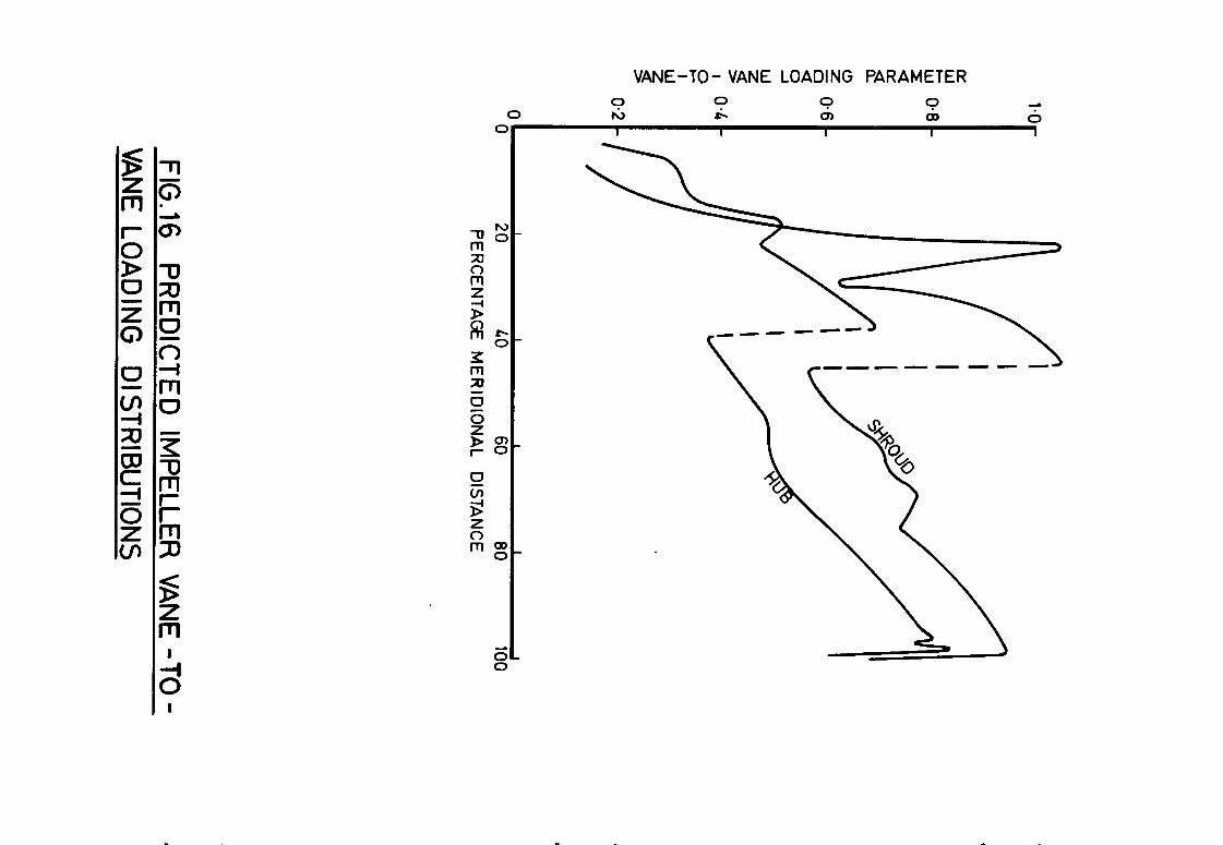
ing an estimation of vane-to-vane aerodynamic loading in the impeller to be
made. The result is shown in Figure 16, the loading parameter being defined
as:
where Ap is the static pressure difference from vane to vane across an
impeller passage,
Y is the ratio of specific heats,
p is the mean stream surface static pressure, and
M is the mean stream surface relative Mach number.
The sudden drop in loading at about 40 per cent meridional distance on each
surface is due to the start of the intervanes. Reference 7 suggests the
limiting value of loading parameter for avoidance of suction surface boundary
layer separation to be about 0.7 and this was clearly exceeded at the shroud.
It seems likely that this high loading was largely responsible for the remain-
ing 2 to 3 points difference in efficiency between the design value of 0.8 and
the measured 0.746.
4.7 Choice of impeller exit station
It is widely accepted that the unmixed flow at the exit from a
centrifugal impeller is complex and that a total pressure leading to a
meaningful impeller efficiency cannot be derived from the static pressures
indicated by conventional tappings located at the tip of the impeller. Of
more potential use is a static pressure measurement sufficiently far downstream
that the flow can be considered to have mixed out. The problem then, however,
in deriving the total pressure from such a static pressure measurement, is in
what assumptions to make concerning, firstly, blockage due to wall boundary

- 14 - Report 342
layers and, secondly, flow direction. In analysing the results of the
impeller tests described in this Report the very simple assumptions of zero
blockage and free vortex flow from the impeller tip to the required station
were made. The characteristics for the modified impeller (Build V) derived
on this basis at 133.35 mm radius and that based on static pressure measure-
ments at the actual impeller tip radius of 124.46 mm are shown in Figure 12
and Table VII compares the efficiencies at a common flow at design speed.
Also given in the table is the overall or compressor stage efficiency, for
the same conditions of flow and speed, for the final Build VII. The selected
test point was also simulated using a loss-modelling compressor performance
prediction program in which it is assumed that mixing-out occurs, in effect,
instantaneously at the impeller tip. The difference between the efficiency
after mixing and that at vaned diffuser exit predicted by the program is
also given in Table VII. Comparison of the test and predicted figures shows
a much greater difference between the impeller tip and overall efficiencies
for the test results (0.100 compared to 0.055). In fact, the predicted
difference is much more closely equated by the test efficiency difference of
0.051, from 133.35 mm radius to diffuser exit. It is reasonable to take the
overall efficiency as a common datum since the test total pressures at the
diffuser exit station are thought to be reliable, the same values having been
obtained by two independent methods (see Section 4.6). On this basis it
would appear that the test impeller efficiency at 133.35 mm radius is close
to the predicted impeller "mixed-out" efficiency. Whilst avoiding the
placing of too much reliance on the prediction program, there does, therefore,
appear to be justification for presenting the impeller characteristics on the
basis of measurements at 133.35 mm radius.
5.0 Detailed static pressure measurements
5.1 Impeller shroud
At the design speed of 40,000 rev/min measurements were made of the
static pressure distribution on the impeller shroud at two mass flows. The
results are shown for the modified impeller tested with the vaneless
diffuser (Build V) and with the A2 vaned diffuser and redesigned collector
(Build VII) in Figures 17 and 18 respectively. It will be seen that the
results for the vaned diffuser build exhibit greater scatter near the impeller
tip than is the case with the vaneless diffuser. This is in accordance with
the analysis by Dean et al8 of the experimental results of Welliver and
Acurio' which showed similar scatter, attributed to the extension of the
vaned diffuser pressure field upstream into the impeller channels.

- 15 - Report 342
Shown superimposed on the experimental results are theoretical
predictions from the Marsh throughflow program2 using local values of poly-
tropic efficiency in the impeller estimated from the experimental results.
Agreement is generally quite good, especially for the vaned diffuser
Build VII, but the theory tends to underestimate the static pressure near
the tip. The comparison in this region may be confused by several factors.
Firstly, the assumed value of polytropic efficiency may be locally incorrect.
Secondly, the existence of a region of separated flow near the impeller tip,
as has been demonstrated experimentally by a number of workers (listed in
Reference lo), would probably result in a time-averaged pressure somewhat
different from the prediction which is for a mean stream surface based on
full channel flow. Thirdly, it is shown in Reference 11 that the indicated
reading of a conventional static pressure tapping can be significantly
different from the true time-average of a fluctuating pressure.
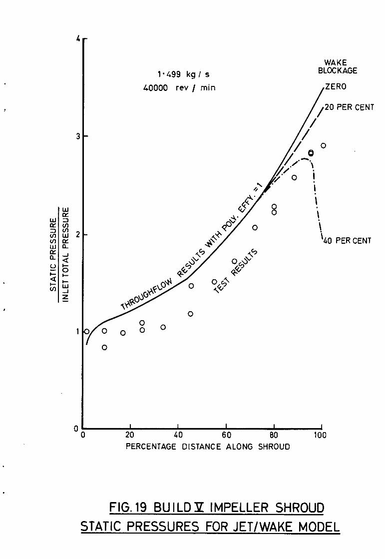
The flow model hypothesised by Dean8 consists of an isentropic
throughflow jet, initially filling the impeller passage and then separating
from the blade suction surface, leaving a stationary wake. The overall
impeller loss is realised when the jet and wake mix downstream of the impeller
tip. In an attempt to check the validity of this model, several throughflow
calculations were made for the vaneless diffuser Build V with a local
polytropic efficiency of unity within the impeller and with the wake region
simulated by additional vane thickness starting at about 75 per cent
meridional distance. Figure 19 shows the results of this analysis. Whilst
it is difficult to draw any real conclusions regarding the separated region,
since the extent of the wake is unknown, the analysis does show that, in the
assumed pre-separation zone, the assumption of isentropic flow is
inappropriate.
5.2 Vaneless diffuser
For Build V, consisting of the modified impeller and vaneless diffuser,
detailed measurements were made of the static pressure on the vaneless
diffuser walls at two points on the design speed characteristic, the pressure
tappings being disposed at various combinations of radial and circumferential
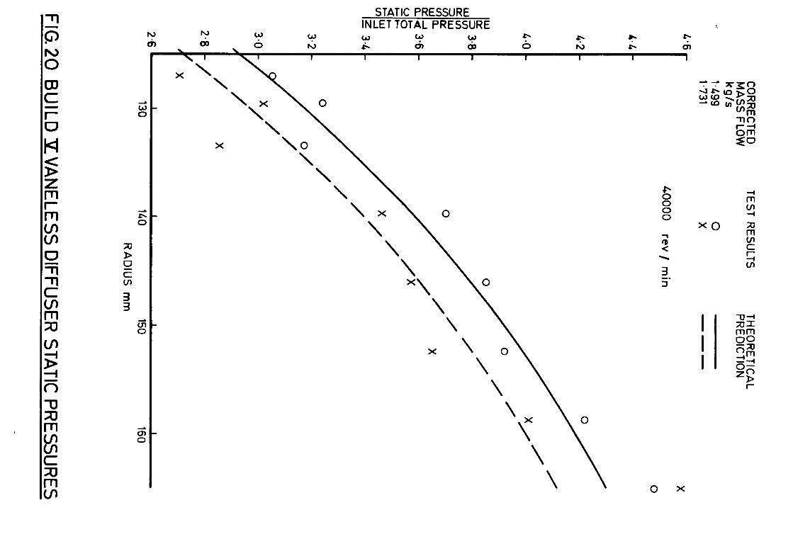
position as shown in Figure 8. The radial distribution of static pressure
obtained is shown in Figure 20, where each test result value is simply the
mean of the several readings, on both walls, for that radius. Also shown are
the theoretical results of the performance prediction program referred to in
Section 4.7 starting from impeller tip conditions derived from the measured

- 16 - Report 342
static pressure at the impeller tip radius of 124.46 mm, Although Section 4.7
would suggest that the conditions at 133.35 mm radius would be more appropr-
iate, the way in which the prediction program calculates losses necessitates
starting at the actual impeller tip. Whilst there is broad agreement between
test results and theory, the former exhibit considerable scatter amongst
themselves and this prompted a closer examination of the individual readings.
Figure 21 shows these plotted against circumferential position for the two
radial locations at which there were more than two tappings on either wall.
It may be seen that the pressures on the two walls are in close agreement,
enabling a mean circumferential distribution to be justifiably plotted. There
is, however, a marked circumferential variation of pressure which follows a
very similar pattern for both mass flows and for both radii except that the
trough at about 270' is less pronounced at the larger radius. This vaneless
diffuser build used the original design of collector which, when employed in
the vaned diffuser Build VI, caused the variation of static pressure at
diffuser exit described in Section 4.5 and shown in Figure 14. Although the
shape of the pressure distribution in Figure 21 is somewhat different to that
for Build VI in Figure 14, it is felt that the cause of the distortion was
probably the same. For comparison, the position of the collector tongue is
at about 13' on the axis of Figure 21. A very similar stationary distortion
phenomenon in a vaneless diffuser was observed by Eckardt 12 and attributed to
the collector. As in the present case, the distortion tended to decrease
with increasing radius in the diffuser although the reason for this is not
clear.
Because of this circumferential pressure variation, it is clearly
meaningless to take a simple average of the readings from all tappings at a
given radius, irrespective of their circumferential positions. An area-
weighted mean pressure is probably more significant and this can be calculated
for the two radii shown in Figure 21 but not directly for other radii where
there are, at most, only two circumferential stations. However, for every
radial station above 133.35 mm, readings are available for a common angle, as
specified in Figure 21, of 135'. Furthermore, because of the similarity in
shape of the circumferential distributions, the ratio of area-weighted mean
pressure to that at 135' does not change very much between the 133.35 mm and
152.40 mm radial stations. It has therefore been assumed that this ratio
varies linearly with radius and, since it is known at two radii, can be
calculated for all others. Hence the area-weighted mean static pressure at
- 17 - Report 342
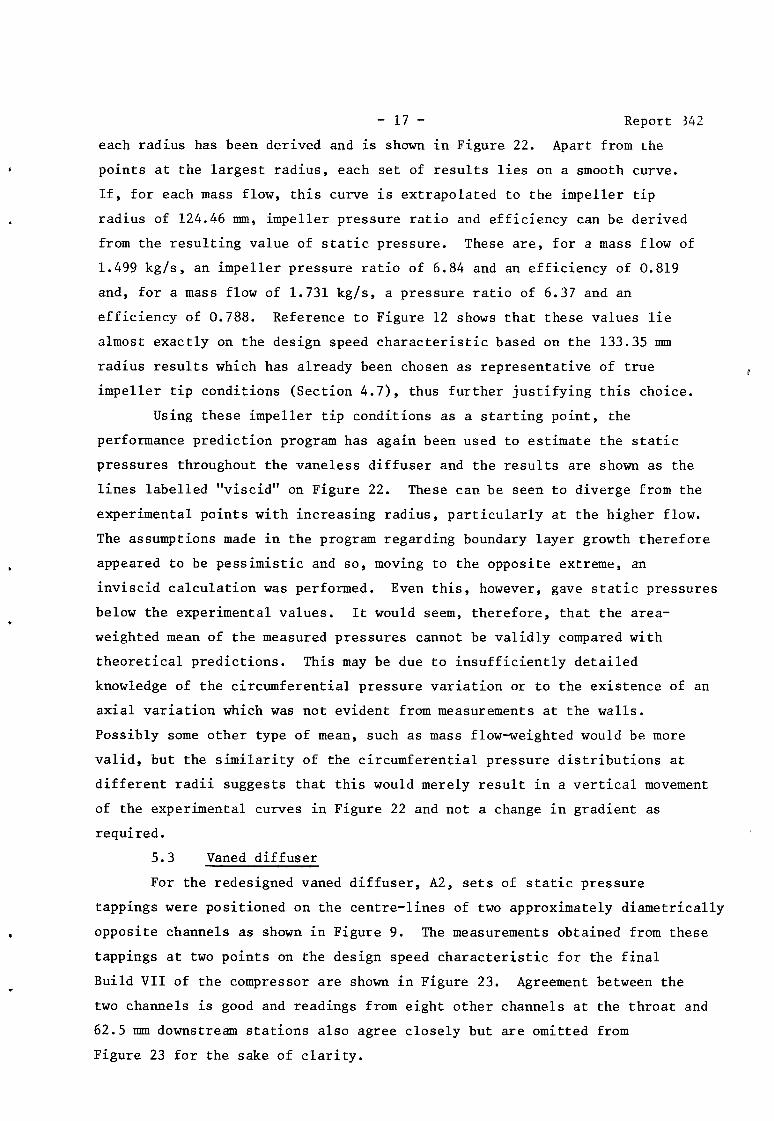
each radius has been derived and is shown in Figure 22. Apart from the
points at the largest radius, each set of results lies on a smooth curve.
If, for each mass flow, this curve is extrapolated to the impeller tip
radius of 124.46 mm, impeller pressure ratio and efficiency can be derived
from the resulting value of static pressure. These are, for a mass flow of
1.499 kg/s, an impeller pressure ratio of 6.84 and an efficiency of 0.819
and, for a mass flow of 1.731 kg/s, a pressure ratio of 6.37 and an
efficiency of 0.788. Reference to Figure 12 shows that these values lie
almost exactly on the design speed characteristic based on the 133.35 mm
radius results which has already been chosen as representative of true
impeller tip conditions (Section 4.7), thus further justifying this choice.
Using these impeller tip conditions as a starting point, the
performance prediction program has again been used to estimate the static
pressures throughout the vaneless diffuser and the results are shown as the
lines labelled "viscid" on Figure 22. These can be seen to diverge from the
experimental points with increasing radius , particularly at the higher flow.
The assumptions made in the program regarding boundary layer growth therefore
appeared to be pessimistic and so, moving to the opposite extreme, an
inviscid calculation was performed. Even this, however, gave static pressures
below the experimental values. It would seem, therefore, that the area-
weighted mean of the measured pressures cannot be validly compared with
theoretical predictions. This may be due to insufficiently detailed
knowledge of the circumferential pressure variation or to the existence of an
axial variation which was not evident from measurements at the walls.
Possibly some other type of mean, such as mass flow-weighted would be more
valid, but the similarity of the circumferential pressure distributions at
different radii suggests that this would merely result in a vertical movement
of the experimental curves in Figure 22 and not a change in gradient as
required.
5.3 Vaned diffuser
For the redesigned vaned diffuser, A2, sets of static pressure
tappings were positioned on the centre-lines of two approximately diametrically
opposite channels as shown in Figure 9. The measurements obtained from these
tappings at two points on the design speed characteristic for the final
Build VII of the compressor are shown in Figure 23. Agreement between the
two channels is good and readings from eight other channels at the throat and
62.5 mm downstream stations also agree closely but are omitted from
Figure 23 for the sake of clarity.

- 18 - Repoi-r X2
The performance prediction program already used in the vaneless
diffuser analysis will cater for a vaned diffuser, using the data of
Reference 5 to estimate the pressure recovery coefficient. In order to
obtain starting conditions for the calculation at the impeller tip, it has
been assumed that the impeller characteristic based on 133.35 mm radius for
Build V (Figure 12) still applies in the presence of a vaned diffuser. The
resulting predictions for static pressure at the diffuser vane leading edge,
throat and trailing edge stations are shown in Figure 23. At the trailing
edge, the experimental and theoretical pressures agree well. Throat pressure
is also predicted fairly accurately for the higher mass flow case. At the
vane leading edge position, the flow is passing through a shock system in the
semi-vaneless space and rapid changes of pressure are occurring in two
dimensions. The rather greater scatter of experimental results and discrep-
ancy compared to predicted results in this region is therefore not unexpected.
6.0 Conclusions
The aerodynamic design and experimental evaluation of a centrifugal
compressor consisting of a radially-vaned impeller and a transonic, vaned
diffuser have been described. The test performance has highlighted short-
comings in the design process, in that the design performance was not achieved,
and in the experimental measurement techniques. Accordingly, a number of
recommendations can be made regarding the design and testing of centrifugal
compressors.
(i> The vane-to-vane aerodynamic loading, Ap/ypM2, should be kept
as uniform as possible through the impeller. As a guide to the level
of loading to be aimed for, the maximum value of about 0.7 suggested
by Reference 7 is considered to be useful. With the NGTE design method,
these requirements would be satisfied by a rigorous application of the
throughflow analysis2 for which the impeller geometrical specification
and data preparation are now computer-based, enabling much quicker
convergence on a suitable design.
(ii) When the flow from the diffuser discharges into a collector, this
must be of large enough cross-section to avoid non-uniformity of flow
at exit from the diffuser causing premature compressor surge.
(iii) Static pressures should be measured at many stations in the
impeller tip/vaneless space region to give a basis for developing an
improved understanding of the complex flow in this part of the
compressor.
- 19 - Report 342
(iv) Conventional static pressure tappings in regions where there is
likely to be a variation of pressure with time, such as the impeller
tip, should be replaced by special tappings giving a true time-
averaged reading, of which several types are suggested in Reference 11.
These may need to be complemented by dynamic pressure measuring
instrumentation at selected stations to indicate the actual form of
the time variation.
The design recommendations have been followed in the design of a second
compressor having the same duty as the one described in this Report but with
impeller vanes swept back at the tip with the aim of achieving significantly
better efficiency and flow range.

- 20 -
APPENDIX A
Report 342
Definitions of performance parameters
Corrected speed
= Measured speed x J
288.15 measured inlet temperature in K
Corrected mass flow
= Measured mass flow x 101.32 measured inlet total pressure in kN/mL
X measured inlet temperature in K
288.15
Impeller pressure ratio
= Total pressure (derived from measured static) at 133.35 mm radius in vaneless diffuser (see Section 4.7)
inlet total pressure
Overall pressure ratio
= Total pressure (derived from measured static or measured directly) at diffuser exit
inlet total pressure
Total-to-total isentropic efficiency
= Inlet temperature x ‘ outlet total pressure inlet total pressure -1
measured temperature rise
Total-to-static isentropic efficiency
= Inlet temperature x ( outlet static pressure inlet total pressure
measured temperature rise
Work input parameter =
Diffuser
=
Diffuser recovery
=
Work input to impeller based on temperature rise (impeller tip blade speed)L
total pressure ratio
Total pressure (derived from measured static or measured directly) at diffuser exit total pressure (derived from measured static) at impeller tip
static pressure coefficient
Diffuser exit static pressure - throat static pressure throat total pressure - throat static pressure
Flow range
= Choking flow - surge flow choking flow

- 21 - Report 342
APPENDIX B
Derivation of Mach numbers
The derivations of the relative Mach number at the eye shroud and
the absolute Mach numbers at impeller tip and diffuser exit for which values
are given in Tables III to VI are shown in this Appendix in the form of flow
charts. The symbols used will first be defined:
A flow area
D diameter
M Mach number
N rotational speed
P pressure
Q mass flow
T temperature
AT temperature rise
u vane circumferential velocity
V air velocity
P density
Subscripts
abs absolute
ax axial
r radial
rel relative
S static
t total
W whirl
The remaining subscripts should be self-explanatory.

- 22 - Report 342
Eye shroud relative Mach number
T t eye shr = T t plenum A plenum
P s plenum
I I I I
I plenum
.
'"1 ) , 't eye,shr = 't plenum
t s eye shr
M abs eye shr
I T s eye shr
v sonic III N I eye shr
veye shr abs eye shr 7
v * rel ey,e shr
M I rel eye shr

.
- 23 -
Impeller tip absolute Mach number
Report 342
('t:p 1 ul y 1 Tt prnum1 , Tt ;i' =iTt diff exit)
- -------- 1 1 I I I i
tip I
impeller 1
/\
I 'abs. tip
r I
P s tip &
’ Ps Irip ‘~ tip I 9
M ' abs tip
Diffuser exit absolute Mach number
T t diff exit A diff exit
P s diff exit
diff exit
I M abs diff exit

- 24 - Report 342
No.
2 H. Marsh
5 P. W. Runstadler
8
9
10
11
12 D. Eckardt Private communication from DFVLR
Author(s)
0. E. Balje'
D. J. L. Smith
F. Dallenbach
C. F, McDonald
D. P. Morris R. E. Kenny
R. C. Dean D. D. Wright P. W. Runstadler
A. D. Welliver J. Acurio
R. C. Dean
H. Weyer R. Schodl
REFERENCES
Title, etc.
A study on design criteria and matching of turbomachines. Part B - Compressor and pump performance and matching of turbo-components ASME Paper No. 60-WA-231, 1961
A digital computer program for the through- flow fluid mechanics in an arbitrary turbomachine using a matrix method. NGTE Report No. R282, 1966 and ARC R&M 3509, 1967
Turbulent boundary layer theory and its application to blade profile design. ARC CP868, 1966
The aerodynamic design and performance of centrifugal and mixed flow compressors. Society of Automotive Engineers, Technical Progress Series, Vol. 3, 1961
Pressure recovery performance of straight- channel, single-plane divergence diffusers at high Mach numbers. USAAVLABS Technical Report 69-56, 1969
Study of a lightweight integral regenerative gas turbine for high performance. USSAAVLABS Technical Report 70-39, 1970
High pressure ratio centrifugal compressors for small gas turbine engines. AGARD Conference Proceedings 31 Helicopter Propulsion Systems, June 1968
Fluid mechanics analysis of high-pressure- ratio centrifugal compressor data. USAAVLABS Technical Report 69-76, 1970
Element design and development of small centrifugal compressors. USAAVLABS Technical Report 67-30, 1967
The centrifugal compressor. Gas Turbine International March-April and May-June, 1973
Development and testing of techniques for oscillating pressure measurements especially suitable for experimental work in turbo- machinery. Trans ASME Journal of Basic Engineering, December 1971

- 25 - Report 342
TABLE I
Main design parameters
Mass flow
Overall pressure ratio
Overall isentropic efficiency
Impeller
Pressure ratio
Isentropic efficiency
Rotational speed
Specific speed
Number of full vanes
Number of intervanes
Eye hub diameter
Eye shroud diameter
Eye shroud relative Mach number
Eye hub vane angle
Eye shroud vane angle
Eye shroud incidence
Tip diameter
Tip width
Tip vane speed
Tip absolute Mach number
Work input parameter
Diffuser
Diameter at vane leading edge
Axial width
Approach Mach number
Number of vanes
Throat width
Channel length/throat width
Area ratio
Diameter at vane trailing edge
1.814 kg/s
6.5
0.8
7.76
0.9
40,000 rev/min
68
17
17
60.96 mm
134.62 mm
0.966
38.1'
60.0'
0.8'
248.92 mm
5.08 mm
521.4 m/s
1.316
0.942
Original design Redesigned Al A2 - -
261.37 mm
5.08 mm
1.18
41
7.01 mm 8.18 mm
9.00 7.63
2.10 1.83
354.00 mm

- 26 - Report 342
TABLE II
Summarv of builds
build No. Impeller Diffuser Collector Purpose
I Design with static Vaneless Design Mechanical and shroud clearance of instrumentation checks, 400 nm approximately mainly establishment of
required impeller shroud clearance
II Design with static Vaneless Design shroud clearance increased by 150 urn axially
III Design with static Vaneless Design Performance evaluation shroud clearance of design impeller further increased by 100 urn axially
IV As Build III Design Design Performance evaluation vaned, Al of design compressor
stage
V Modified; i.e. design Vaneless Design Performance evaluation with leading edge of of modified impeller vanes cut back axially by 5.08 mm
VI As Build V Redesigned Design Performance evaluation vaned, A2 of modified compressor
stage
VII As Build V A2 Redesigned Performance evaluation of modified compressor stage with redesigned collector

Corrected speed rev/min
Corrected mass flow kg/s
Impeller pressure ratio
Impeller total-to-total isentropic efficiency
Eye shroud relative Mach number*
Tip absolute Mach number*
Work input parameter
Flow range per cent
20,000 25,000 29,000 32,000 34,000 36,000 38,000 40,000
0.541 0.643 0.884 1.096 1.281 1.380 1.471 1.498
1.831 2.454 3.187 3.952 4.505 5.197 6.148 6.841
0.877 0.861 0.866 0.865 0.853 0.851 0.843 0.826
0.429 0.536 0.632 0.710 0.767
0.691 0.830 0.943 1.035 1.095
0.916 0.925 0.918 0.924 0.927
0.815 0.865 0.908
1.139 1.197 1.217
0.926 0.949 0.940
22.3 18.3 17.2
. .
TABLE III
Build III derived parameters
* Derivation given in Appendix B
Corrected speed rev/min
Corrected mass flow kg/s
Impeller pressure ratio
Impeller total-to-total i efficiency
Eye shroud relative Mach
Tip absolute Mach number
Work input parameter
Flow range per cent
‘1C sentrop
number
. .
TABLE IV
Build V derived parameters
20,000
0.582
1.762
0.858
--
25,000
0.659
2.371
0.844
32,000 36,000 38,000 40,000
1.033 1.364 1.449 1.499
3.845 5.148 5.943 6.905
0.847 0.840 0.835 0.820
0.435 0.538 0.704
0.672 0.816 1.018
0.873 0.903 0.921
0.814 0.861 0.890
1.136 1.177 1.227
0.932 0.936 0.953
24.8 21.8 20.9
. .

Report 342 - 29 -
TABLE V
Build VI derived parameters
Corrected speed rev/min 32,000 36,000 38,000 40,000
Corrected mass flow kg/s 1.124 1.422 1.597 1.755
Overall ratio pressure 3.290 4.259 4.961 5.2826:
Overall total-to-total isentropic 0.751 0.740 0.745 0.699 efficiency
Eye shroud relative Mach number 0.713 0.821 0.881 0.940
Tip absolute Mach number 1.013 1.146 1.242 1.308
Diffuser exit Mach number** 0.355 0.365 0.360 0.384
Work input parameter 0.905 0.927 0.934 0.942
Diffuser total ratio pressure 0.792 0.800 0.860 0.804
Diffuser static pressure recovery 0.500 0.487 0.516 0.447 coefficient+
Flow cent range per 11.9 6.3 4.1 3.2
* pressure ratio significantly below maximum ** derivation given in Appendix B
t assumes blockage of 0.1 at throat

. . . . . .
TABLE VI
Build VII derived parameters
Corrected speed rev/min
Corrected mass flow kg/s
Overall pressure ratio
Overall total-to-total isentropic efficiency
Overall total-to-static isentropic efficiency
Eye shroud relative Mach number
Tip absolute Mach number
Diffuser exit Mach number
Work input parameter
Diffuser total pressure ratio
Diffuser static pressure recovery coefficient+
Flow range per cent
36,000
1.327
4.580
0.776
0.733
20,000 25,000 32,000
0.552 0.678 1.036
1.724 2.273 3.511
0.799 0.790 0.785
0.696 0.728 0.739
0.432 0.539 0.705
0.684 0.824 1.008
0.289 0.282 0.302
0.903 0.913 0.918
0.921 0.898 0.824
0.475 0.570 0.609
22.2 19.0
t assumes blockage of 0.1 at throat
0.810
1.116
0.312
0.924
0.817
0.610
16.2
38,000 40,000
1.470 1.600
5.219 5.913
0.764 0.746
0.725 0.712
0.864 0.919
1.178 1.224
0.311 0.306
0.934 0.945
0.832 0.783
0.626 0.658
14.0 12.2

- 31 - Report 342
TABLE VII
Build
V Modified impeller
with vaneless diffuser
VII Modified impeller
with vaned
diffuser
Comparison of test and predicted efficiencies
Station
Impeller tip (124.46 mm radius)
Vaneless diffuser (133.35 mm radius)
Compressor overall (Vaned diffuser exit)
Isentropic (total-to-total)
efficiency at 40,000 rev/min
and 1.7 kg/s
0.843
0.794
0.743
Efficiency difference
Test Predicted
0.049
0.051
0.055
1
Bas 416021587483 k5 10177 TPQ3

. . .
SCALE : HALF FULL SIZE
COLLECTOR
VANED DIFFUSER
VANELESS SPACE
SUPPORT STRUTS
INTERVANE
BULLET HOUSING SLIP RING UNIT ----_-_
/
FIG.1 LAYOUT OF COMPRESSOR

- - - INITIAL ( EMPIRICAL ) GEOMETRY
FINAL ( DESIGN ) GEOMETRY
0 20 40 60 80 100 PERCENTAGE MERIDIONAL DISTANCE
FIG. 2 PREDICTED RELATIVE VELOCITY DISTRIBUTIONS

110
100
90
. 60
50
40
114.3mm RAD
2x7 I
IH SHROUD PROFILE DEFINED BY:-
RADIUS = 124.46-57-15 AXIAL DISTANCE 2e708263 ,,35;3,8
58.42 1 1 0 10 20 30 LO 50 60 70
AXIAL DISTANCE mm
FIG. 3 IMPELLER MERIDIONAL SHAPE AND VANE THICKNESS

CIRCUMFERENTIAL DISTANCE RADIUS
0 0 0 0 0 0 . . . 0 4 h) w e- b in
. .,

I

f? t w ow f-9
I .---/I r r+--- - I------ --
--I I I I I
I I I

. .
M 1
NOMENCLATURE OF RADIAL PLANES CONTAINING TAPP INGS
.-.-.-. .-
SCALE: FULL SIZE
FIG.7 LOCATION OF STATIC TAPPINGS IN IMPELLER INLET AND SHROUD CASING

/ -FRONT WALL ’
I \
WALL A -
ALL TAPPINGS ON BOTH WALLS EXCEPT WHERE INDICATED
LOOKING DOWNSTREAM
FIG. 8 LOCATION OF STATIC TAPPINGS IN I YANELESS DIFFUSER

ALL TAPPINGS ON REAR WALL EXCEPT WHERE INDICATED
LOOKING DOWNSTREAM
FIG 9 LOCATION OF STATIC TAPPINGS IN A2
VANED DIFFUSER

IMPELLER PRESSURE RATIO
T h) w a- ul Q, 4
I I I 1 0 9 0 0 m 4 ai, Lb
IMPELLER TOTAL -TO -TOTAL ISEN. EFFY.
. *

C‘,
0 /
\ ‘\’ \
\ \ \ \
DEVELOPMENT OF SHROUD SECTION APPROXIMATELY TO SCALE
5.08 mm
AXIAL Dt RECTION
FIG.11 CUT-RACK OF IMPELLER VANE LEADING EDGES

-e+ 133.35mm RADIUS 1 IN VANELESS DIFFUSER)
-*- 124.46 mm RADIUS (IMPELLER TIP 1
b 38 36
1 I I I I I I 1
0.4 0.6 0.8 1.0 1.2 1.4 1.6 1.8
CORRECTED MASS FLOW kg/s
e
FIG. 12 BUILD P IMPELLER CHARACTERISTIC

0.4 0.6 O-8 1.0 l-2 1 *L
CORRECTED MASS FLOW kg/s
l-6 l-8
.
FIG. 13 BUILD XI OVERALL CHARACTERISTIC

. .
BUILD Yn POSITION OF TONGUE iOOO0 rov/min OF COLLECTOR SCROLL l-758 kg/s
n 0 " I n Y "
l3U&I 40000 rov/rriin l-755 kg/s
I I I I I I
1 10 D~Fwsm EL+JNEL NUI~BER
30 41
FIG. 14 VARIATION OF STATIC PRESSURE AT DIFFUSER EXIT

+ TOTAL-TO-TOTAL EFFICIENCY - *- TOTAL-TO-STATIC EFFICIENCY
3ES.PT
6
DES. 1 @
, 20 I I I I I I
Q.6 0,8 1-o l-2 l-4 l-6 l-8
CORRECTED MASS FLOW kg/s
FIG. 15 BUILD XII OVERALL CHARACTERISTIC
VANE-TO- VANE LOADING PARAMETER 0 0 0 0
0 lu rc a, W z )’ I I 1 I 1

CORRECTED
kz FLow 1.499 1,731
TEST RESULTS
0 X
40000 ret’ / min
THROUGHFLOW C3kXtiT’sAT’ON
---
0 0
X 0 /
20 40 60 80 100
PERCENTAGE DISTANCE ALONG SHROUD
FIG.17 BUILD P IMPELLER SHROUD STATIC PRESSURES

CORRECTED MASS FLOW kg/s 1.600 1,758
TEST RESULTS
0
X
lGOOO0 rev / min
THROUGHFLOW CXs’sL”T’sAT IO N
-v-
0
PERCENTAGE DISTANCE ALONG SHROUD
FIG. 18 BUILDIZll IMPELLER SHROUD STATIC PRESSURES
1.499 kg/ s
40000 rev / min
WAKE BLOCKAGE
/ ZERO
I 20 40 60 80 100 PERCENTAGE DISTANCE ALONG SHROUD
PER CENT
PER CENT
FIG. 19 BUILD P IMPELLER SHROUD STATIC PRESSURES FOR JET/WAKE MODEL
X
P b E ; 0
3 a. 3
; - )
I - I
I 0 x
STATIC PRESSURE INLET TOTAL PRESSURE 1.
h) h) w &
w w w (t3 * ? ?- CI t5 6 . ttJ G ch Q, 0 lu & a,
\ ’ I I
X\ \
;- B

4.2
3.8
3.6
3.4
3.2
1.499 kg/s --- 11731 kg/s
0 FRONT WALL X REAR WALL
40000 rev / min
0 0
X 0 \ 6---v/ A 0
/ \ X
A / \
/ \ /’ \ \
/ / \ 0
/ L --- 3 / \
\ . \ \ l!/ P / \ / 0
A X X
100 200 300 ANGLE FROM HORIZONTAL IN DIRECTION OF ROTATION’
FIG. 21 BUILD P VANELESS DIFFUSER CIRCUMFERENTIAL STATIC PRESSURE DISTRIBUTIONS I

4.2
CORRECTED MASS FLOW kg/s 1.499 l-731
TEST RESULTS
h ”
-SC--
40080 rev / m in
THEORETICAL PREDICTIONS
0
X
RADIUS mm
FIG.22 BUILD P VANELESS DIFFUSER AREA-WEIGHTED MEAN STATIC PRESSURES
Produced In England by Her Majesty’s Stationery Office, Reprography Centre, Basfidon
I I I I
130 140 150 160
Bas 41602/587483 KS lo/77 TPQ3 -

t4G TRACED AVP/H&M 3/76 TURBO. MECH ‘117714
STATIC PRESSURE NLET TOTAL PRESSURE
3 P 4
- - - - em-.
#(
x
-NW m-w---
6
--. --
XX
-- --Jw
00

. s . . .
- - - - - ------------------e-------------e-------- ______---------------------------------------.
ARC CP No. 1385 September 1976 Jones, M.G.
THEPEEU?ORMANCEOFA 6.5 PRESSURRRATIOClWI'RIFUGAL COMPRESSOR RAVING A RADIALLY-VANE3 IMPELLER
The aerodynamic design and experimental performance of a centrifugal compressor designed for a pressure ratio of 6.5 and a specific speed of 68 are described. The compressor consisted of a radially-vaned impeller and a transonic, vaned radial diffuser. At design speed a peak overall total-to-total isentropic efficiency of 0.746 was achieved at the maximum pressure ratio of 5.9, rising to 0.79 at a pressure ratio of 3.5 at 80 per cent speed. A theoretical analysis of the
ARC CP No.1385 September 1976 Jones, M.G.
THE PERFORMANCE OF A 6.5 PRESSURE RATIO CENTRIFUGAL COMPRESSOR HAVING A RADIALLY-VANED IMPELIZR
The aerodynamic design and experimental performance of a centrifugal compressor designed for a pressure ratio of 6.5 and a specific speed of 68 are described. The compressor consisted of a radially-vaned impeller and a transonic, vaned radial diffuser. At design speed a peak overall total-to-total isentropic efficiency of 0.746 was achieved at the maximum pressure ratio of 509, rising to 0.79 at a pressure ratio of 3.5 at 80 per cent speed. A theoretical analysis of the
ARC CP No.1385 September 1976 Jones, M.G.
THE PERFORMANCE OF A 6.5 pREssurn RATIO CENTRIFUGAL COMPRESSOR RAVING A RADIALLY-VANE32 IMPFLLER
The aerodynamic design and experimental performance of a centrifugal compressor designed for a pressure ratio of 6.5 and a specific speed of 68 are described. The compressor consisted of a radially-vaned impeller and a transonic, vaned radial diffuser. At design speed a peak overall total-to-total isentropic efficiency of 0.746 was achieved at the maximum pressure ratio of 5.9, rising to 0.79 at a pressure ratio of 3.5 at 80 per cent speed. A theoretical analysis of the
-"_-.
ARC CP No.1385 September 1976 Jones, M.G.
THE PERFORMANCE OF A 6.5 pREssuRE RATIO CENTRIFUGAL COMPRESSOR HAVING A RADIALLY-VANED IMPELLER
The aerodynamic design and experimental performance of a centrifugal compressor designed for a pressure ratio of 6.5 and a specific speed of 68 are described. The compressor consisted of a radially-vaned impeller and a transonic, vaned radial diffuser. At design speed a peak overall total-to-total isentropic efficient.:; of 0.746 was achieved at the maximum pressure ratio of 5.9, rising to 0.79 at a pressure ratio of 3.5 at 80 per cent speed. A theoretical analysis of the
-- -
impel:Ler channel flow suggests that high vane-to-vane aerodynamic loading was partly responsible for the shortfall in performance. The impeller was also tested with a vaneless diffuser and a detailed analysis is made of static pressure measurements on the impeller shroud and vaneless and vaned diffuser walls. Several recommendations are made regarding the design and testlnq of centrifugal compressors.
impeller channel flow suggests that high vane-to-vane aerodynamic loading was partly responsible for the shortfall in performance. The impeller was also tested with a vaneless diffuser and a detailed analysis is made of static pressure measurements on the impeller shroud and vaneless and vaned diffuser walls. Several recommendations are made regarding the design and testing of centrifugal compressors.
Impeller channel flow suggests that high vane-to-vane . aerodynamzc loading was partly responsible for the shortfall in performance. The impeller was also tested with a vaneless diffuser and a detailed analysis is made of static pressure measurements on the impeller shroud and vaneless and vaned diffuser walls. Several recommendations are made regarding the design and testing of centrifugal compressors.
impeller channel flow suggests that high vane-to-vane aerodynamic loading was partly responsible for the shortfall in performance. The impeller was also tested with a vaneless diffuser and a detailed analysis is made of static pressure measurements on the impeller shroud and vaneless and vaned diffuser walls. Several recommendations are made regarding the design and testing of centrifugal compressors,
1 I 1
- .___ - - _________________________I______--_---__-___-_---~-__--_---- - -_____----- - -~~~-~~----- - .
a\ ,I ., “3 ., .I

C.P. No. 1385
OCbown copyrighr 1977
HER MAJESTY’S STATIONERY OFFICE Government Bookshops
49 High Holborn, London WClV 6HB 13a Castle Street, Edinburgh EH2 3AR
4 1 T’he Hayes, Cardiff CFl 1 JW Brazennose Street, Manchester M60 8AS
Southey House, Wiie Street, Bristol BSl 2BQ 258 Broad Street, Birmingham Bl 2HE 80 Chichester Street, Belfast BT1 4JY
Government publications are also available through booksellers
C.P. No. 1385 ISBN 0 I1 471131 3
Related Documents