Commerce Spectrum Management Advisory Committee (CSMAC) Working Group 5 (WG 5) 1755-1850 MHz Airborne Operations Aeronautical Mobile Telemetry Sub-Working Group Report FINAL 1. Introduction: The Commerce Spectrum Management Advisory Committee (CSMAC) Working Group structure was created to explore ways to lower the repurposing costs and/or improve or facilitate commercial wireless industry access while protecting federal operations from adverse impact. Working Group 5 (WG-5) was specifically tasked with studying issues related to airborne operations in the 1755-1850 MHz band. Within WG-5, Sub-Working Group (SWG) Aeronautical Mobile Telemetry (AMT) was created to focus on issues related to Department of Defense (DOD) use of flight test telemetry operating in the band. Pursuant to the working group structure provided by the National Telecommunications and Information Administration (NTIA) the expected focus of work for WG-5 would be the 1) determination of protection requirements for federal operations, and 2) understanding of the impact to commercial wireless of federal government airborne operations. Based on this guidance, the SWG AMT met as required, typically on a bi-weekly basis, to develop a common understanding between federal government and industry regarding the operations and protection requirements for AMT and to agree on and execute an approach for analyzing the potential for interference both to and from AMT and commercial 4G Long Term Evolution (LTE) operations. This analysis will form a basis for a recommendation on the feasibility of spectrum sharing and on steps that should be taken, or areas for further analysis, to facilitate sharing if we determined that sharing appears feasible. Work was initiated based on information in the NTIA’s Fast Track Report. However, significant additional work was accomplished by Federal Government representatives to review the applicable government operations and ensure that the areas of operation and channel assignments are accurate. The SWG also used information developed in a Technical Committee created as part of WG-1 to provide accurate information on LTE parameters. Finally, SWG AMT was informed by the WG-5 Technical Committee, created as part of WG-5, to consider technical issues related to interference analysis. SWG AMT enjoyed broad participation from a range of federal government and industry representatives, and the work provides a solid foundation to evaluate sharing impacts and opportunities. Hereinafter, additions made by commercial wireless industry participants in the SWG AMT are in bold italics and additions made by Government participants in the SWG AMT are in bold. Their respective comments will be prefaced with either “Commercial wireless industry Note” or “Government Note”. [Commercial wireless industry Note: Work was limited to completion of worst case interference

Welcome message from author
This document is posted to help you gain knowledge. Please leave a comment to let me know what you think about it! Share it to your friends and learn new things together.
Transcript
Commerce Spectrum Management Advisory Committee (CSMAC) Working Group 5 (WG 5)
1755-1850 MHz Airborne Operations
Aeronautical Mobile Telemetry Sub-Working Group Report
FINAL
1. Introduction:
The Commerce Spectrum Management Advisory Committee (CSMAC) Working Group structure was created to explore ways to lower the repurposing costs and/or improve or facilitate commercial wireless industry access while protecting federal operations from adverse impact. Working Group 5 (WG-5) was specifically tasked with studying issues related to airborne operations in the 1755-1850 MHz band. Within WG-5, Sub-Working Group (SWG) Aeronautical Mobile Telemetry (AMT) was created to focus on issues related to Department of Defense (DOD) use of flight test telemetry operating in the band. Pursuant to the working group structure provided by the National Telecommunications and Information Administration (NTIA) the expected focus of work for WG-5 would be the 1) determination of protection requirements for federal operations, and 2) understanding of the impact to commercial wireless of federal government airborne operations.
Based on this guidance, the SWG AMT met as required, typically on a bi-weekly basis, to develop a common understanding between federal government and industry regarding the operations and protection requirements for AMT and to agree on and execute an approach for analyzing the potential for interference both to and from AMT and commercial 4G Long Term Evolution (LTE) operations. This analysis will form a basis for a recommendation on the feasibility of spectrum sharing and on steps that should be taken, or areas for further analysis, to facilitate sharing if we determined that sharing appears feasible.
Work was initiated based on information in the NTIA’s Fast Track Report. However, significant additional work was accomplished by Federal Government representatives to review the applicable government operations and ensure that the areas of operation and channel assignments are accurate. The SWG also used information developed in a Technical Committee created as part of WG-1 to provide accurate information on LTE parameters. Finally, SWG AMT was informed by the WG-5 Technical Committee, created as part of WG-5, to consider technical issues related to interference analysis. SWG AMT enjoyed broad participation from a range of federal government and industry representatives, and the work provides a solid foundation to evaluate sharing impacts and opportunities.
Hereinafter, additions made by commercial wireless industry participants in the SWG AMT are in bold italics and additions made by Government participants in the SWG AMT are in bold. Their respective comments will be prefaced with either “Commercial wireless industry Note” or “Government Note”.
[Commercial wireless industry Note: Work was limited to completion of worst case interference
2
analysis for three sample locations; however, there are a 15 major test ranges across US with several AMT antenna locations in and around the major test ranges. As described in this report, a number of proposals have been made and are under consideration to revise and refine the analysis to better understand when harmful interference would occur. Such refinement would allow for a more accurate assessment of sharing opportunities. In addition, because information on channel assignments or more detailed use of AMT was not provided to the SWG, no consideration of or discussion of methods to cooperatively facilitate sharing have occurred – either on a time basis, arrangement of channel use to meet the needs of both commercial wireless industry and government or other dynamic methods to facilitate sharing. Consideration of assignment information and related discussions would be highly relevant to meeting the goal of CSMAC to explore ways to lower the repurposing costs and/or improve or facilitate commercial wireless industry access while protecting federal operations from adverse impact. Such information and analysis could have informed consideration of a process to prioritize access to the 1755-1780 MHz portion of the band while ensuring that federal agencies are not adversely impacted. The worst case analysis completed by the group provides only minimal information towards sharing arrangements and is insufficient to fully assess opportunities without additional work.](Editor’s note: The preceding paragraph contributed by Industry.)
Government comments regarding highlighted Industry inputs within this reportNote:
1. The Government representatives to the AMT Sub-Group take exception to the preceding commercial wireless industry comments, and other similar commercial wireless industry comments in this Report. At the outset, the comments presume and prejudge the outcome of the ITS modeling and simulation effort when that work is not yet complete. More importantly, consideration of the ITS process, or its ultimate output, is beyond the scope of the tasking for the AMT Sub-Group. This Report was prepared according to that tasking and a set of standards that all parties agreed to prior to the start. Any changes to that scope would need to be reviewed and approved initially by the Technical Working Group and, ultimately, Working Group 5. This has not happened.
2. On the merits, commercial wireless industry agreed at the outset to the use of three representative Government Ranges, and the antennas at those Ranges for analysis. Those Ranges require M. 1459 protection. Now, having received the results of that analysis, it appears that commercial wireless industry seeks a much more time-consuming and labor-intensive effort focusing on hundreds of additional antennas in use at each of numerous Government Ranges, and whether each such Range also requires M. 1459 protection. Such an exercise is completely beyond the scope of the AMT Sub-Group’s effort and this Report.
3. The Government representatives further take exception to the notion that the analysis done to date is “worst case”-oriented. It is anything but. For example, with respect to interference from UE's to AMT ground stations, the simulations use a limited Monte Carlo technique, which is inherently biased towards a prediction of average, rather than worst-case, interference. With respect to interference to eNodeB’s from airborne AMT transmitters, the simulations do not model air vehicles at their maximum altitude of 100,000 feet, but examine two cases: 23,000 feet and 85,000 feet. There are other technical

3
problems with the commercial wireless industry paragraphs as well, but details as to these can be supplied later, if desired.
1.1 Executive Summary of Findings:
The SWG AMT initiated analysis on two specific work plans to identify the protection distances for: (1) LTE User Equipment (UE) to AMT Ground Station Receivers and (2) Aeronautical Mobile Telemetry (“AMT”) Transmitters to LTE eNodeB Base Stations. The Federal Government operates more than 300 identified antenna sites located within and around 15 test sites (aka “Ranges”). AMT receive sites were selected at three DoD Ranges to be analyzed for this study. The three Range sites are Eglin Air Force Base in Florida, Patuxent River, in Maryland and associated Atlantic Test Ranges, and the Pt. Mugu Test Range, on the coast of California. These sites were chosen to span the trade space of representative AMT ground stations and the wide variations of geographical and operational characteristics. Based on an analysis of these representative sites, models and simulations were developed with the results being applicable to similar DoD AMT sites throughout the US. A “randomized real” model, designed to represent a realistic deployment of UEs, was used for modeling the aggregate interference into individual AMT ground station antennas at the three chosen Ranges. Using this approach, in accordance with the details and parameters identified in the appendices, the computed protection distances extend beyond 75 km for the modeled UE to AMT interference environment for the three test ranges selected for the study. The corresponding protection distances for the eNodeB LTE Base Stations from AMT airborne transmitters, are greater than 560 km, depending slightly on the orientation of the base station antenna. It should be noted that variations in base station antenna heights above ground level had small effects on these predicted required separation distances.
Commercial wireless industry Note: In most situations bore sight-to-bore sight scenarios based on a high value of loading of the LTE network resulted in large protection distances.1 . A lower value of network loading may result in smaller protection distances [PLEASE ADVISE HOW TO TREAT CROSSED OUT TEXT]. Network loading was not considered in the simulations performed for this assessment. That is, for each simulation step, any active UE that represented a possible interference source was considered to be radiating during the entire simulation, resulting in 100% network loading. It is recognized that this represents an extreme worst-case assumption that may be reviewed if further analysis is pursued. Government Note: The Government does not agree that this represents “an extreme worse case assumption”. However, AMT ground stations use tracking antennas that point at all azimuth angles during the course of a single test flight or operation. Furthermore, the antenna can, and does, dwell at individual azimuth angles for long periods of time in an unpredictable fashion due to the requirements of a particular test and the constraints imposed by air traffic control and the weather.
1 It was also noted that network loading should be an important parameter to consider. LTE parameters provided by the WG-1 LTE Working Group assume high network loading. A typical loading on a network is approximately 50%, even during the “busy” hour.

4
Commercial wireless industry Note: However it should be noted that the flight path of the three test ranges under study was restricted over water, away from the densely populated metro areas. Government Note: However, this does not mean that a large deployment of UEs does not lie between the flight test area and the AMT ground station area. Government Note: With respect to the below reference to the established ITU protection criteria for AMT, the Government considers it to be a statement of fact, and not open to dispute. The results of the study for AMT protection are based on the ITU-R M. 1459 document that defines protection criteria for telemetry systems in the aeronautical mobile service with geostationary broadcasting-satellite and mobile-satellite services. This internationally recognized and approved document has also been used in the United States as the basis for sharing studies and coordination agreements for terrestrial systems. These include adjacent channel agreements for terrestrial IMT and the terrestrial components of Satellite Digital Audio Radio systems (SDARS); and for co-channel sharing with Medical Body Area Networks. In particular, these agreements have extended the methodology of Rec. M.1459 to the case of multiple, simultaneous terrestrial interferers. This methodology is used in the present report as the basis for the treatment of aggregation effects.2 The SWG AMT generally agreed to by the entire AMT Sub working group thatthat, based on the simulations completed and the assumptions that were used that, sharing between AMT and Commercial LTE systems is not feasible. The general consensus was reached that the size of the coordination zones would severely limit the deployment of LTE Systems in the top 100 markets. If there are significant changes to the assumptions that radically alter (shrink) the size of the coordination zone then this conclusion may change.
1.2 Summary of Observations/Recommendations for Presentation to CSMAC:
The SWG AMT has performed a full analysis using two work plans, the first to determine protection distances for aggregations of UEs to AMT ground stations, and the second for assessing the interference during flight to LTE base stations from airborne telemetry transmitters on flight test aircraft.
Protection levels for AMT ground stations are those defined in Recommendation ITU-R M.1459.3 Protection levels for LTE eNodeB base stations were developed by the technical working group formed within WG-1.
Operating characteristics for airborne AMT transmitter systems are those provided in Rec.
2 The methodology is an extension of equation 8 in the Recommendation, and is described in Appendix A-5 of this report. 3 See also, Appendices A-3 and A-7.
5
M.1459. Operating characteristics of LTE User Equipment are those developed by the technical WG-1 working group.
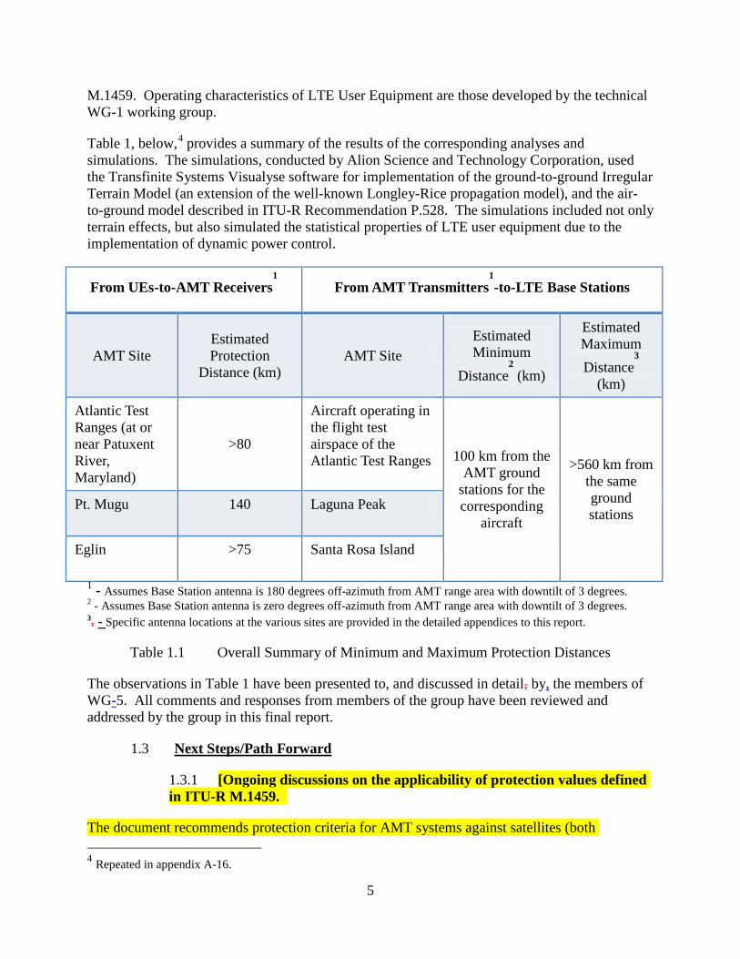
Table 1, below,4 provides a summary of the results of the corresponding analyses and simulations. The simulations, conducted by Alion Science and Technology Corporation, used the Transfinite Systems Visualyse software for implementation of the ground-to-ground Irregular Terrain Model (an extension of the well-known Longley-Rice propagation model), and the air-to-ground model described in ITU-R Recommendation P.528. The simulations included not only terrain effects, but also simulated the statistical properties of LTE user equipment due to the implementation of dynamic power control.
From UEs-to-AMT Receivers1 From AMT Transmitters
1-to-LTE Base Stations
AMT Site Estimated Protection
Distance (km) AMT Site
Estimated Minimum
Distance2 (km)
Estimated Maximum Distance
3
(km)
Atlantic Test Ranges (at or near Patuxent River, Maryland)
>80
Aircraft operating in the flight test airspace of the Atlantic Test Ranges 100 km from the
AMT ground stations for the corresponding
aircraft
>560 km from the same ground stations
Pt. Mugu 140 Laguna Peak
Eglin >75 Santa Rosa Island
1 - Assumes Base Station antenna is 180 degrees off-azimuth from AMT range area with downtilt of 3 degrees. 2 - Assumes Base Station antenna is zero degrees off-azimuth from AMT range area with downtilt of 3 degrees. 3. - Specific antenna locations at the various sites are provided in the detailed appendices to this report.
Table 1.1 Overall Summary of Minimum and Maximum Protection Distances
The observations in Table 1 have been presented to, and discussed in detail, by, the members of WG-5. All comments and responses from members of the group have been reviewed and addressed by the group in this final report.
1.3 Next Steps/Path Forward
1.3.1 [Ongoing discussions on the applicability of protection values defined in ITU-R M.1459.
The document recommends protection criteria for AMT systems against satellites (both 4 Repeated in appendix A-16.
6
geostationary and mobile) in which the operation of both the primary service (AMT) and the interferer (Satellite system) is air to ground. The recommended protection criteria are derived from the probability function that captures the portion of the time the satellite transmission is present in the minimum air space received by the AMT antenna. It is then shown that the pfd protection level is insensitive to such probabilistic considerations. Further understanding on how the same derivations can be applied to a large ensemble of IMT UE interferers, which are based on ground to ground propagation as opposed to air to ground propagation, are of academic interest. However, since the protection levels of M.1459 are specified for the aperture of the AMT ground station antenna, this issue is largely a question of propagation models.] [This section is in square brackets. Waiting for further information from ITS—PLEASE ADVISE HOW TO PROCEED.}]
Government Note: The Government considers this to be a statement of fact that does not require further review.
1.3.2 Post Report Items: Additional studies and related efforts may be required in order to address the outstanding issues noted in paragraph 1.4, below. However, at this time, the ability to conduct such studies will be affected by current fiscal constraints. The final decision to proceed will depend on the availability of funds within the Department of Defense budget and appropriations.
1.3.3 Lessons Learned: The creation of a small technical group within WG-5 to address the technical characteristics of the involved systems was helpful. It provided the forum for detailed technical discussions by all interested parties, without requiring the involvement, or time and expense commitment, of disinterested parties. The resulting technical information, in particular LTE characteristics, cumulative power distributions of ensembles of user equipment, and guidance for the randomized “lay-down” of base stations and user equipment, were critical to the ability to perform accurate simulations.
1.4 Promising Topics for Future Studies
The SWG AMT group determined there are promising opportunities for further study that might influence the results summarized in Table 1. Time and funds permitting, these could be studied. In particular, the WG-5 Sub Working Group identified the following topics that could be considered:
1. The impact of reducing the separation distances based on a C/ ((I+N) protection rather than I/N (or pfd) threshold. The I/N analysis is more appropriate as a coordination trigger, but that C/(I+N) would be more appropriate to better understand the potential for sharing. [However, M.1459 already uses a C/(I+N) methodology in its derivation of pfd protection levels, which is why the protection pfd levels in the Recommendation depend on the elevation angle above the horizon of the AMT ground station antenna.] [This section is in square brackets. Waiting for further information from ITS—PLEASE ADVISE HOW TO PROCEED.}]
Government Note: The Government considers this to be a statement of
fact that does not require further review.
7
2. Effects of off-tuning of the LTE base station to the AMT F0 –
Off tuning would avoid direct co-channel operation. Commercial wireless industry presented information on innovative spectrum sharing techniques that could exploit the dynamic nature of Government use of spectrum and the advanced features in the LTE standards. These mechanisms would enable commercial wireless industry licensees to dynamically relinquish use of spectrum with minimal impact to users in areas and during times that government users are operating. The economic acceptability of such sharing will depend on the amount of time and the areas impacted. Accordingly, study should include mechanisms to minimize the amount of time and area when a channel would need to be cleared for government operations.
3. Possible notches in wireless use of frequencies at selected
locations – Commercial wireless industry provided information on innovative spectrum sharing techniques that take advantage of advanced features in LTE technology to notch out a portion of an LTE channel at times and locations when government agencies are using the spectrum. This mechanism could be used to avoid co-channel operation with minimal impact on private sector users in cases where the government signals are narrow relative to an LTE channel. As with the previous item, the economic acceptability of such sharing will depend on the amount of time and the areas impacted and an effort would be needed to minimize the amount of time and area when a channel would need to be notched to accommodate government operations. This could include real-time monitoring to limit impact to times when government systems are operating rather than scheduled.
4. Consideration of different interference threshold based on
desired signal level desired rather than merely defining interference as a rise in the noise floor - Current WG-5 analysis uses long standing interference criteria established by the ITU. While there is no desire to modify this internationally accepted criterion, study of interference relative to a desired carrier taking into account actual system operations would be beneficial to understand how government and LTE systems would interact in a shared environment with close coordination between users and could significantly reduce any exclusion or protection zone required.
5. Possible effects of clutter and terrain – Consideration of the
possible increased path loss, and corresponding reduction in protection distances, by considering the effects of clutter that are not already included in the terrain modeling features of the models used herein. Expected effects of clutter and terrain - Cost231-Hata models (which include effects of clutter) were used by commercial wireless industry to determine LTE UE transmit power distribution, while the ITU-R P.528 model, which does not include effects of terrain or clutter, was used by WG-5 to model interference between AMT and commercial systems. This difference in the models used for different parts of the analysis can have an impact on the path losses and hence the protection distances. The COST 231 model extends some of the Hata work to the frequency range of interest here but also has limitations on antenna heights at both ends of a link and neither Hata nor COST 231 are appropriate for air/ground interactions for the altitudes of concern in this analysis. Greater study of the impact that clutter and terrain have on propagation, particularly in air-to-ground analysis could impact protection distances. A proposal for consideration to the technical working group would be to compare measured data to the
8
results of analysis.
6. . Consideration of AMT assignment information and the potential to prioritize access to markets prioritized by commercial wireless industry – Prioritizing AMT assignments in a way that minimizes impact to markets prioritized by commercial wireless industry has the potential to improve the economic viability of sharing while continuing to meet government requirements.
It should be noted that recommendations on a number of these issues have been made in the Technical Working Group and are under consideration.
2. Organization and Functioning of the Sub-Working Group
2.1 Organization and Participation of Sub-Working Group
2.1.1 The SWG AMT was created under the auspices of WG-5, taking overall direction from the WG-5 Co-chairs.
Co-chairs
Mr. Joe Giangrosso – Alion Science for DOD Mr. Tim Chalfant – Edwards AFB Mr. Joe Marx – AT&T Ms. Neeti Tandon – AT&T
Secretary
Mr. Ian McClymonds- Alion Science
FCC Liaisons
Mr. Mark Settle Mr. Michael Ha Mr. Chris Helzer Ms. Janet Young
NTIA Liaison
Ms. Renae Carter
Interference analyses were conducted by:
Mr. Robert Martin – Alion Science Mr. Dan Jablonski – John Hopkins Applied Physics Laboratory Mr. Rod Spence – NASA
Detailed information on the characteristics of aeronautical flight test systems, and on-site support of visits by WG-5 members to federal government flight test
9
facilities, was provided by:
Mr. Joe Giangrosso – Eglin AFB Mr. Kip Temple – Edwards AFB Mr. Scott Hoschar – PAX River Mr. Clint Robins – China Lake
AMT Report Writing Team Mr. Joe Giangrosso – DoD Mr. Dan Jablonski – DoD Mr. Bob Martin – DoD Mr. Ken Keane – DoD Mr. Scott Hoschar – DoD Mr. Mike Ryan – DoD Mr. Joe Marx – AT&T Ms. Neeti Tandon –- AT&T
2.2 Participation: The SWG enjoyed broad participation by federal government agencies, including their support contractors and industry representatives. A full list of the membership is attached, Reference Appendix A-1.
2.3 Work Plan
The work plan included the following efforts:
1) An overview of AMT operations and LTE system operation – Federal Government participants provided an overview of the AMT mission, operations, and technical requirements. Commercial wireless industry participants provided an overview of LTE technology and operation. Industry participants made visits to AMT sites at Eglin and Edwards Air Force Bases.
2) A review of Federal Government Assignments and Operations – Government participants updated the record of frequency assignments contained in the United States Government Master File (GMF). This effort resulted in the elimination of out-of-date records and unused frequency assignments. Updated records are not generally available to the public, but nevertheless helped clarify sharing and usage requirements.
3) Review of AMT Receiver Sites – Federal Government participants were unable to catalog the large number of the AMT receiver sites at each government Range. The complexity and size of carrying this effort to completion would be significant, and would require additional time and funds in order to conduct the appropriate research and necessary reviews. Since this also exceeds the scope of the CSMAC tasking, this work was not pursued.
4) Review of the impact of Federal Government spectrum needs toon the ability to share with LTE systems in the top 100 Broadband Wireless Markets – Commercial wireless industry representatives provided a list of the top 100 United States markets by population. These have the greatest demand for broadband services, and gaining access to spectrum for these markets is a priority for the commercial wireless industry. Federal Government participants compared channel assignments and operations to better understand the impact to these markets. This
10
analysis has not been released to the SWG, and remains under DOD review.
5) Interference Analyses – The SWG agreed to conduct interference analyses for three samplings of telemetry sites at flight test ranges that are considered to be representative of the larger trade-space of the considerable number of AMT operating locations in the United States. The locations chosen for simulation and modeling are the:5
• Naval Air Warfare Center Weapons Division-Sea Test Range, Naval Bases Ventura County, Point Mugu, CA;
• Naval Air Warfare Center Aircraft Division and Atlantic Test Ranges (ATR), at or near the Patuxent River Naval Air Station, Patuxent River, MD
• Eglin Test Range, Eglin AFB, FL.
The analyses at this sample of locations is meant to provide insight into the extent of any potential interference, and to provide a basis for further discussions of possible mitigation techniques or other approaches to sharing. Alion Science conducted the analyses using the Visualize software package. The analyses are based on LTE parameters and protection criteria developed in the technical committee formed under WG-1, and the AMT parameters and protection criteria provided by ITU-R Recommendation M.1459 supplemented, where appropriate, by range-specific information. The overall analysis approach was agreed to by a technical committee formed under the WG-5.
2.4 Activities and Meetings
Meetings, typically via web-supported teleconferencing, were held on a bi-weekly basis. Without exception, the meetings had broad Federal Government and industry participation. Although the majority of meetings were conducted via conference call, the SWG took advantage of opportunities for face-to-face meetings in conjunction with the in-person meetings of the larger WG-5 Group.
Between meetings, AMT representatives worked as a team to develop and review the work product presented to the industry representatives. Despite individuals being spread across the United States, the teamwork was effective and efficient, with quick turnaround or results, and a minimum of travel expenses.
2.5 Abstract of Sub-Working Group Report
The AMT Sub Working Group originally developed three goals for the detailed analyses. These included analyses to:
1. Assess distances required to protect AMT receivers from the emissions of the aggregation of LTE User Equipment; and,
5 Cf. Appendices A10 – 12.
11
2. Assess distances required to protect LTE eNodeB base station receivers from telemetry transmissions of AMT flight test aircraft.
The analyses were a cooperative effort between DOD and the commercial wireless providers, as detailed technical information for both AMT and LTE systems was essential for the performance of this effort.
As stated, the studies considered the Electromagnetic Compatibility (EMC) of the LTE User Equipment (UE) with respect to emissions into the AMT ground station receivers, and the EMC of the AMT airborne emitters into LTE Base Station receivers, at a small number of sites thought to be representative of the large trade space for the entire country.. A summary of the observations is noted in Table I, above, and described in detail in the next sections.
3. Details of the Technical Analyses
3.1 Overview
Simulation-based analyses were conducted to assess the interference from a full-scale deployment of LTE user equipment (i.e., handsets) to AMT ground stations, and to assess the interference from telemetry transmitters on board aircraft to LTE eNodeB base stations on the ground.
3.1.1 Assumptions and Approach
Co-channel operation, in which both AMT and LTE systems are simultaneously using the same frequencies, was assumed. The goal of the simulations was to determine the geographic separation required for the LTE and AMT systems to operate without causing harmful interference to each other.
The approach was straightforward. AMT and LTE operators exchanged detailed technical information about their operations.6 In particular, operators provided information about the signals generated by their systems, the nominal locations of their systems, relevant details of when and how the systems are operated, and the criteria for protection of their systems.
This information comprises two of the three sets of data that are required to perform an interference analysis using a link budget approach. These are the transmitted power and the acceptable values of received interference.
If this data is all that were needed, interference computations could be performed by hand using a calculator. However, the third set of data is the path loss between the interference transmitter and the victim receiver. The path loss is heavily influenced by terrain and atmospheric effects. In particular, an accurate interference analysis requires detailed consideration not just of hypothetical terrain, but of actual terrain.
The inclusion of terrain and atmospheric effects was accomplished by the use of two propagation
6 Cf. Appendices A-3 and A-4.
12
models. For the ground-to-ground interference from UEs to AMT ground stations, the LongelyLongley-Rice Irregular Terrain Model (ITM) was used in conjunction with the United State Geological Survey (USGS) 30 arc minute terrain data base. The air-to-ground interference from AMT equipped flight test aircraft to eNodeB base stations was modeled using the algorithms described in ITU-R Recommendation P.528.
To properly use these models requires sophisticated simulation software, which in this case is the commercially available Visualyse product. However, the models are implemented in other software products, such as EDX SignalPro and generic versions of the ITM model. The USGS terrain data base is available free of charge to all.
A feature that was not included in the analysis was the effect of “clutter” due to buildings, foliage, and other features of the environment that can affect the path loss, but which is not captured in the terrain data bases. This is an open and ongoing topic of discussion within WG-5, and will be addressed at the policy, rather than technical level. The rationale for its inclusion is that clutter might increase the path loss between the interference sources and the victim receivers, for both AMT and LTE, thus reducing the sizes of the “protection zones” computed using the Visualyse software.
This information, and the corresponding analysis approach, were reviewed by WG-5 members, and provided the mutually agreed basis for the simulations and analyses described below. With respect to AMT deployment, three of approximately 15 major AMT test ranges were included in the analyses, and at each of the three ranges 1 – 4 antenna sites were evaluated. For LTE deployment, a hypothetical “randomized” real data layout of base stations was created.
For the LTE systems, the presumption was then made that UE emissions would occur only when a UE was within sufficient range of an eNodeB base station that it could receive the station’s pilot tone. Because of the listen-before-talk operation of LTE user equipment, this approach links UE transmissions to base station locations. Since UE’s are mobile, this was considered to be a reasonable approach to defining and constraining the geographic locations of the handsets.
3.1.2 Protection Criteria and System Operational Details
Protection levels and operational information were provided, and agreed to by WG-5 members, for each system.7 For AMT, this consisted of reference to, ITU-R Recommendation M.1459, which is available for download from www.ITU.org. This document provides both operational characteristics and protection criteria for AMT systems. For LTE, a document developed by, and borrowed from, CSMAC Working Group 1 (WG-1) that contained the corresponding characteristics and protection criteria for LTE systems was used.
The AMT protection criterion consists of a single, power flux density level measured at the aperture of the victim AMT ground station antenna. This value is -180 dBW/m2 in 4 kHz, in accordance with M.1459. For LTE base stations, the protection criterion was the requirement that the received interference to noise ratio not exceed a threshold value, namely I/N = -6 dB, with N derived from the noise figure of the low noise amplifier at the eNodeB antenna aperture.
7 Cf. Appendices A-3 and A-4.
13
The telemetry signals from the transmitters on AMT flight test aircraft are specified in terms of the usual parameters: power, bandwidth, and antenna gain. The locations of the aircraft are geographically constrained by the ground footprint of the airspace within which flight test aircraft are authorized to operate for each of the test ranges included in the analyses.8
The signals from UE handsets are defined in a similar manner, with the locations and numbers of handsets constrained by the presumed locations of the eNodeB base stations as defined by the “randomized-real” deployment. A further consideration, however, is the use of dynamic power control, in which UEs transmit no more power than necessary in order to close the link with the base station. This feature prolongs the period between battery recharges, and reduces intercell interference within the ensemble of UE transmitters among a given collection of base station cells and sectors. It also has a significant impact on the analysis results, and thus warrants further discussion.
In particular, one would expect that a large ensemble of UEs could be accurately characterized by an average value of transmitted power. Indeed, the cumulative distribution functions or CDFs, provided by the LTE community are the simple bell-shaped curves that characterize many statistical processes, and with which most people are at least somewhat familiar. Two CDFs were used in the analyses, one for urban deployments, in which UE’s typically transmit at lower power levels, and one from rural deployments, in which higher power levels are typical.
However, the power levels associated with this distribution vary logarithmically, meaning that with respect to a median power level, a small number of UEs transmit, on average, at 1/10 of this power, and a small number transmit at ten times this power level. The effect of this logarithmic skewing of power levels is that pronounced deviations from the average power level are apparent in the simulation results provided below and in the appendices to this report.
3.1.3 Summary of the Analysis Parameters and Corresponding Technical Details9
As noted previously, three selected flight test ranges, representing a wide range of flight test operational areas and the associated geography, were included in the analyses:
1. Naval Air Warfare Center Weapons Division-Sea Test Range, Naval Bases Ventura County, Point Mugu, CA;
2. Naval Air Warfare Center Aircraft Division, Patuxent River Naval Air Station, MD;
3. Eglin Test Range, Eglin AFB, FL.
At each site, one to four separate antenna locations were evaluated. Locations and height above local terrain were specified; the antenna pattern used was the composite pattern from Recommendation ITU-R M.1459, which is presented in an appendix.
8 Cf. Appendices A-10 – 12. 9 See also, Appendices 6 – 9.
14
The UE locations were modeled using the “randomized real” geographical deployment with transmit power values modeled in accordance with the two cumulative distribution functions described above. For each base station, simultaneous operation of three handsets, one per antenna sector of the base station, per 1.67 MHz LTE channel was assumed. This means that for a 10 MHz wide AMT receive channel, 6 handsets per sector, with three sectors per eNodeB, was assumed.
For computing interference from UEs to AMT ground stations and from AMT equipped aircraft to eNodeB base stations, the Visualyse software was configured in accordance with the following settings and constraints:
1. UE power was set not to exceed 20 dBm
2. Propagation loss calculated using ITU-RP.528 for air to ground interactions
3. Clutter was not considered
4. Longley-Rice and terrain data used for ground/ground interactions
5. Additional AMT receiver system loss of approximately 2 dB for cable loss was added
6. Base station cable, insertion, and other receiver losses were assumed to be 2 dB
7. Only co-channel, “on-tuned” interference cases were considered
3.1.4 Simulation Methodology, UE’s to AMT ground stations
As described in Recommendation M.1459 and/or as practiced at flight test ranges, flight test aircraft can fly at any azimuth direction with respect to the AMT ground station, at distances of 250 statute miles and more, and at altitudes of up to 85,000 feet. AMT ground station antennas are tracking antennas with high values of directional gain. Interference is received not only in the main-lobe of the antenna but also in its side-lobes.
This necessitates running the Visualyse software implementation of the ITM model at each possible azimuth pointing angle of the AMT ground station antenna, and computing the aggregate interference into the AMT receiver through the main and side-lobes of the antenna. Then, after completing the additional steps described below, the azimuth pointing angle of the antenna was rotated by 0.5 degrees, and the simulation repeated 720 times.
For each of these 720 azimuth settings, 100 probability runs were conducted to determine values for the two cumulative distribution functions in order to establish a specific distribution of transmit power levels for the ensemble of UEs being simulated. Thus, in the graphs presented below, each of the 720 values of azimuth angles shows all 100 of the simulated values of CDF. The resulting graphs thus indicate a statistical distribution of UE power levels for each value of azimuth angle.
Finally, but of critical importance, a protection distance was assumed for each simulation run. Within this distance, as measured from the particular antenna being considered, all UEs were
15
considered turned off, and thus not generating interference.
3.1.5 Simulation Methodology, AMT Aircraft to eNodeB Base Stations
For modeling the interference from air-to-ground, the Visualyse software implemented tothe ITU-R P.528 propagation model. Then for each of several simulation runs, a single-aircraft was located at the perimeter of its authorized flight test area. Signal strength contours, corresponding to a received I/N ratio of -6 dB at the terminals of an eNodeB antenna, were then calculated.
Note that these contours depend on the presumed pointing direction of the antennas on the victim base station, as well as on a presumed antenna “downtilt” value of 3 degrees. These assumptions are made clear in the various graphs presented below.
3.1.6 Summary
The details provided herein outline the key features of the simulations. Additional details, highly technical but necessary for a full understanding of the simulation methodology, are included in an Appendix.
For example, aggregate interference to an AMT ground station antenna is converted from a power flux density (pfd) to an interference level at the antenna terminals, summed with interference arriving from other directions, and then converted back to an equivalent pfd that is referenced to the main-beam aperture of the AMT receive antenna.
This is necessary for consistency with the goal of Recommendation M.1459, which is to provide protection criteria that reflect the operational parameters that are unique to AMT systems. Attempts to model AMT systems as either satellite ground stations or commercial telephone systems fail to capture essential characteristics of flight test, namely that:
• there are extraordinarily high signal fades due to aircraft maneuvers and ground multipath effects
• during most flight operations, AMT antennas point at, and not above, the horizon
• during a single flight test, ground station antennas with different apertures and at multiple locations may be used
• rotary wing aircraft (helicopters and the V-22) can hover or move quickly, and fixed wing aircraft can fly at speeds from 100 knots to considerably faster than the speed of sound.
• aircraft operate in airspace subject to air traffic control and weather constraints
• vehicles other than aircraft, such as missiles, are heavy users of flight test telemetry
• given the nature of flight testing and test vehicles, and risk factors, many tests are not repeatable, or can only be repeated at substantial additional expense
16
4. Typical Simulation Results10
4.1 Overview
A detailed compendium of results is presented in an Appendix in the format of a PowerPoint presentation that was reviewed and discussed by WG-5. A subset of this data, with a discussion of its interpretation, is given here. The connection of these simulations results to the summary data in Table 1, above, is then explained.
4.2 Interference from UEs to AMT
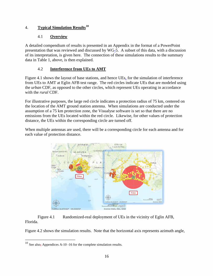
Figure 4.1 shows the layout of base stations, and hence UEs, for the simulation of interference from UEs to AMT at Eglin AFB test range. The red circles indicate UEs that are modeled using the urban CDF, as opposed to the other circles, which represent UEs operating in accordance with the rural CDF.
For illustrative purposes, the large red circle indicates a protection radius of 75 km, centered on the location of the AMT ground station antenna. When simulations are conducted under the assumption of a 75 km protection zone, the Visualyse software is set so that there are no emissions from the UEs located within the red circle. Likewise, for other values of protection distance, the UEs within the corresponding circle are turned off.
When multiple antennas are used, there will be a corresponding circle for each antenna and for each value of protection distance.
Figure 4.1 Randomized-real deployment of UEs in the vicinity of Eglin AFB, Florida.
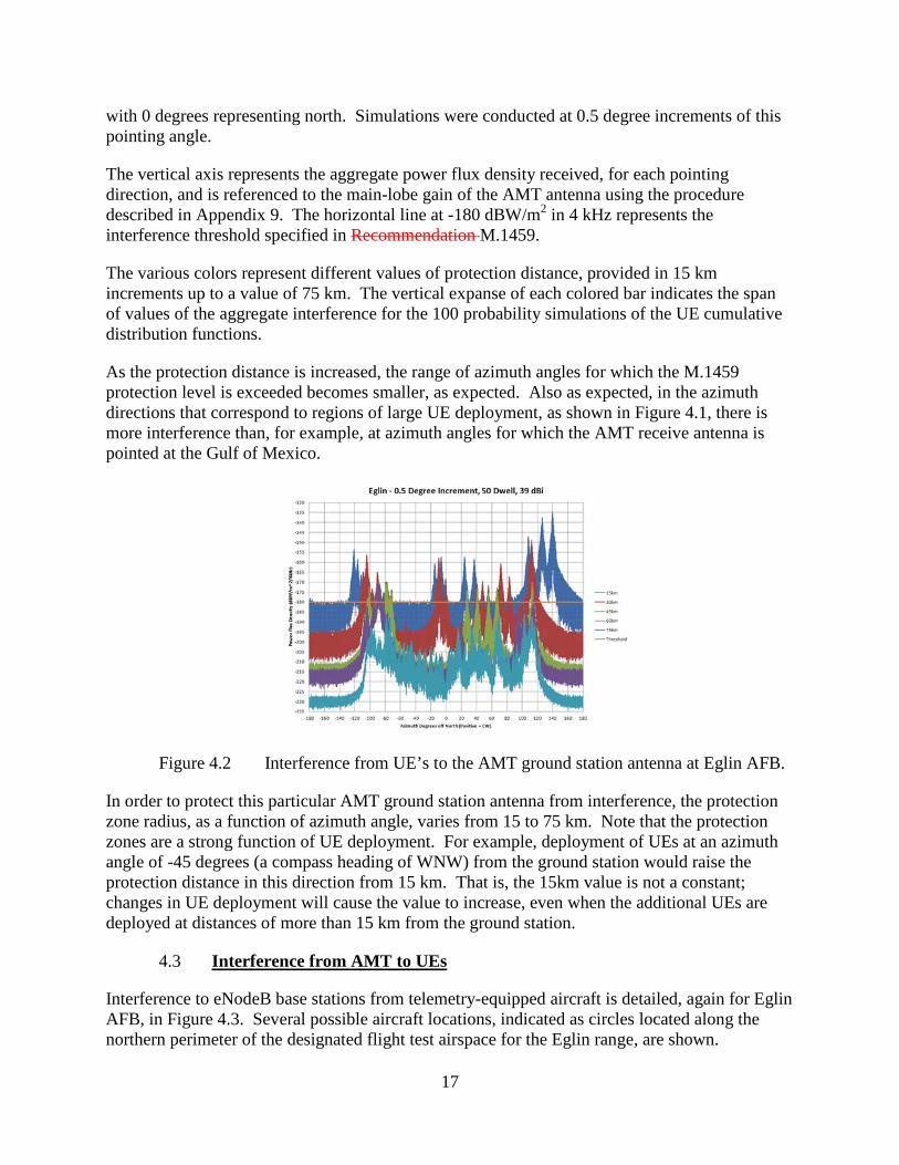
Figure 4.2 shows the simulation results. Note that the horizontal axis represents azimuth angle,
10 See also, Appendices A-10 -16 for the complete simulation results.
17
with 0 degrees representing north. Simulations were conducted at 0.5 degree increments of this pointing angle.
The vertical axis represents the aggregate power flux density received, for each pointing direction, and is referenced to the main-lobe gain of the AMT antenna using the procedure described in Appendix 9. The horizontal line at -180 dBW/m2 in 4 kHz represents the interference threshold specified in Recommendation M.1459.
The various colors represent different values of protection distance, provided in 15 km increments up to a value of 75 km. The vertical expanse of each colored bar indicates the span of values of the aggregate interference for the 100 probability simulations of the UE cumulative distribution functions.
As the protection distance is increased, the range of azimuth angles for which the M.1459 protection level is exceeded becomes smaller, as expected. Also as expected, in the azimuth directions that correspond to regions of large UE deployment, as shown in Figure 4.1, there is more interference than, for example, at azimuth angles for which the AMT receive antenna is pointed at the Gulf of Mexico.
Figure 4.2 Interference from UE’s to the AMT ground station antenna at Eglin AFB.
In order to protect this particular AMT ground station antenna from interference, the protection zone radius, as a function of azimuth angle, varies from 15 to 75 km. Note that the protection zones are a strong function of UE deployment. For example, deployment of UEs at an azimuth angle of -45 degrees (a compass heading of WNW) from the ground station would raise the protection distance in this direction from 15 km. That is, the 15km value is not a constant; changes in UE deployment will cause the value to increase, even when the additional UEs are deployed at distances of more than 15 km from the ground station.
4.3 Interference from AMT to UEs
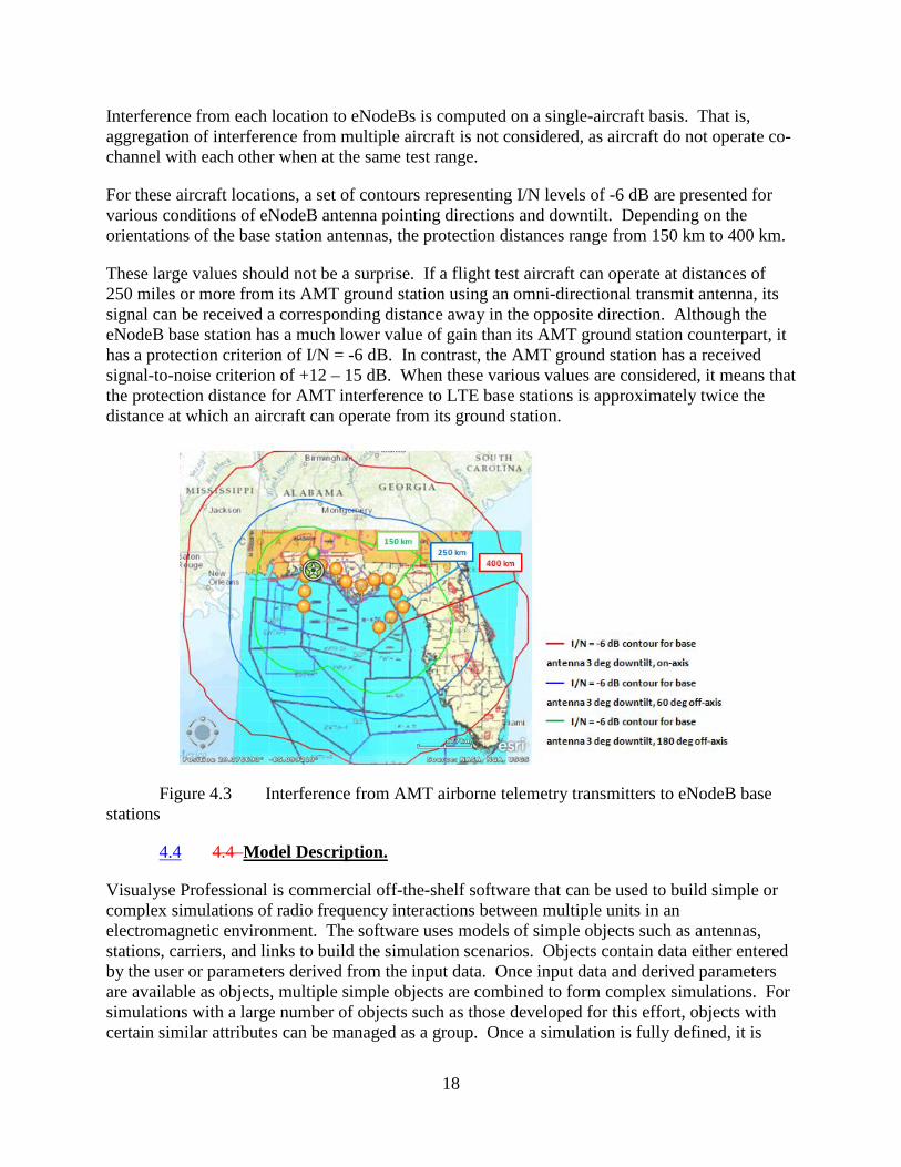
Interference to eNodeB base stations from telemetry-equipped aircraft is detailed, again for Eglin AFB, in Figure 4.3. Several possible aircraft locations, indicated as circles located along the northern perimeter of the designated flight test airspace for the Eglin range, are shown.
18
Interference from each location to eNodeBs is computed on a single-aircraft basis. That is, aggregation of interference from multiple aircraft is not considered, as aircraft do not operate co-channel with each other when at the same test range.
For these aircraft locations, a set of contours representing I/N levels of -6 dB are presented for various conditions of eNodeB antenna pointing directions and downtilt. Depending on the orientations of the base station antennas, the protection distances range from 150 km to 400 km.
These large values should not be a surprise. If a flight test aircraft can operate at distances of 250 miles or more from its AMT ground station using an omni-directional transmit antenna, its signal can be received a corresponding distance away in the opposite direction. Although the eNodeB base station has a much lower value of gain than its AMT ground station counterpart, it has a protection criterion of I/N = -6 dB. In contrast, the AMT ground station has a received signal-to-noise criterion of +12 – 15 dB. When these various values are considered, it means that the protection distance for AMT interference to LTE base stations is approximately twice the distance at which an aircraft can operate from its ground station.
Figure 4.3 Interference from AMT airborne telemetry transmitters to eNodeB base stations
4.4 4.4 Model Description.
Visualyse Professional is commercial off-the-shelf software that can be used to build simple or complex simulations of radio frequency interactions between multiple units in an electromagnetic environment. The software uses models of simple objects such as antennas, stations, carriers, and links to build the simulation scenarios. Objects contain data either entered by the user or parameters derived from the input data. Once input data and derived parameters are available as objects, multiple simple objects are combined to form complex simulations. For simulations with a large number of objects such as those developed for this effort, objects with certain similar attributes can be managed as a group. Once a simulation is fully defined, it is
19
executed by starting a series of simulation steps. The simulation steps are typically defined by time increments of a specific duration and the simulation will run for a designated number of steps. During the simulation, data can be both displayed and collected for post processing.
For the simulations associated with this effort a particular set of the basic inputs are of interest. First, several different types of antennas were modeled. Visualyse has over ninety different antenna patterns available as default choices as antenna objects. Most of these patterns are defined in ITU documents and are available, with several user-defined parameters such as frequency of operation, height, feeder loss, efficiency and other parameters. Users can also fully define an antenna by entering specific measured or calculated data points.
Antennas are associated with individual stations and in the Visualyse simulations several distinct station types were used. UEs, AMT-equipped aircraft, AMT Receive Site, and base stations were modeled as station types with associated antennas, locations, heights above terrain or sea level, and feeder losses. For each type, multiple individual stations were developed and deployed in an environment according to the parent simulation.
Stations are then grouped into links to allow for the RF calculations. Typically, UEs were grouped into transmit links, i.e., were treated only as transmitting sources. A traffic module was used to associate the urban and rural transmit EIRP values with individual UE stations in a transmit link and to vary these values for every simulation step for every transmitting station according to the appropriate urban or rural CDF. The ITU-R Recommendation P.528-3 propagation model for the air/ground/air interactions is assigned as a transmit link parameter. A version of the Longley-Rice propagation model was used to model ground-to-ground interactions. A transmit frequency, emission bandwidth, and baseline transmit power is also defined in a transmit link. Victim receivers are defined in receive links or receive link groups depending on the number of stations to be considered. In receive links, receiver frequency, bandwidth, and noise parameters are defined. In general, transmit and receive links are used to more completely define the various system and environmental parameters needed to complete an interference analysis.
A final step in Visualyse is to define the interference path. This step establishes the receive links to be addressed in a simulation and the transmit link, or links in most cases, to be used as the interference sources. Additional issues such as polarization loss may be established in this last step although that was not used in this effort. For all of the simulations performed in this effort, the values for various parameters of the simulations were recorded for all simulation steps. Recording of this data allowed for the development of I/N plots and the plotting of the number of interferers associated with each protection distance considered.
5. Summary and Observations
5.1 Overview
Within the context of spectrum sharing analyses, the protection distances that are required for sharing, asare summarized in Table 1.1 and described in detail in Appendices A-10 – 12 and A-16. It should further be noted that only three flight test ranges have been considered in the analysis presented here, and only a small subset of antenna locations have been analyzed.
20
There are many major flight test Ranges in the United States, and over 300 active AMT ground site locations. Furthermore, some of these locations are not located within the test Range boundaries; e.g., these are AMT ground stations capable of being moved to any other designated location to support the flight test mission off range. Although not mobile in the sense that they are not used while in motion like an LTE handset, these ground stations are nevertheless transportable. As they are receiving stations, they do not cause interference to others, and can in principle be located anywhere.
Other open topics of discussion include the question of whether I/N = -6 dB is an appropriate value for the protection criterion for an interference-limited system like LTE, whether P.528 and the ITM models are over or under-protective, whether a different terrain data base, such as the Shuttle Radar Topography Mission (SRTM) data should be used, etc.
Although time and budget do not permit investigation of these or other considerations as part of the preparation of this report, these topics may arise in the future.
5.2 Final Observations
There has been considerable discussion with regard to the metrics to be used for interference analyses. The LTE community favors a traditional I/N analyses, whereas the AMT community uses a pfd approach in recognition of the wide variability of resources are used and requirements that must be met during even a single flight test exercise.
However, as stated in Recommendation M.1459, the underlying interference metric for flight test is the impact of interference on the size of the usable airspace. Interference requires that aircraft fly closer to their ground stations in order to maintain a working data link, but even that is no guarantee that data drop outs will not occur necessitating re-flights. Given the speed at which aircraft fly, any reduction in usable airspace due to interference is simply not permissible.
The broadband wireless community is operating under precisely the same constraint. In order to not to interfere with AMT while using shared spectrum, it must restrict the coverage area over which LTE services can be provided. If the results of studies described herein are to be summarized in a single sentence, it is that sharing between these two disparate applications is problematic given the huge geographic areas required by both services.
5.3 Publicly releasable Federal systems general description and characteristics of operation to include:
5.3.1 AMT Site information for the sample AMT sites and operation characteristics (Appendices 610 – 12.)
5.4 LTE systems description, characteristics, and parameters
The LTE information was cross-referenced to work coming out of WG-1 spin off group that identified LTE characteristics and identify any deviations or additional LTE characteristics and parameters considered by Sub-Working Group. These are referenced in the following document: Baseline LTE Uplink Characteristics”, 12 November 2012 – Rev2, LTE Technical Characteristics group of CSMAC Working Groups (See Appendices 4, 6, and 7)
21
6.0 Full Participant Lists for Sub-Working Group Report Preparation Appendix A-1 is a full list of participants, subdivided by Federal Agency and Industry. 7.0 Web Location of Archival Documents/Exhibits A sharepoint or other web site will be designated in a cover memo to this document. The undersigned has jointly prepared and approves the content of the AMT analysis report and hereby submits this report to Working Group 5
_____________________________ _____________________________ Joe P. Giangrosso Date Joe Marx Date Alion Science and Technology for DoD AT&T AMT Co-Chair AMT Co-Chair
_____________________________ _____________________________ Tim Chalfant Date Neeti Tandon Date Edwards AFB AT&T AMT Co-Chair AMT Co-Chair
22
__
8.0 List of Appendices
A-1 List of participants
A-2 CSMAC WG-5 Objectives
A-3 Characteristics of Aeronautical Mobile Telemetry Systems
A-4 Characteristics of Long Term Evolution broadband wireless systems
A-5 Methodology for Interference Calculations and Simulations
A-6 Additional simulation details and summary of analysis assumptions
A-7 The composite antenna pattern from ITU-R Recommendation M.1459
A-8 The CDF functions for Urban and Rural UE’s
A-9 The conversion methodology used to convert the UE CDF value given in dBm for a 10 MHZ LTE channel to the Y axis of the graph represented as dbW/m2 in 4 kHz
A-10 Patuxent River/Atlantic Test Ranges Technical Parameters and Simulation Results A-11 Point Mugu Sea Range Technical Parameters and Simulation Results
A-12 Eglin AFB Technical Parameters and Simulation Results
A-13 Validation of Results
A-14 Observations – UE-to-AMT
A-15 Observations – AMT-to-Base Stations
A-16 Summary of Initial Distance Assessment
APPENDICES
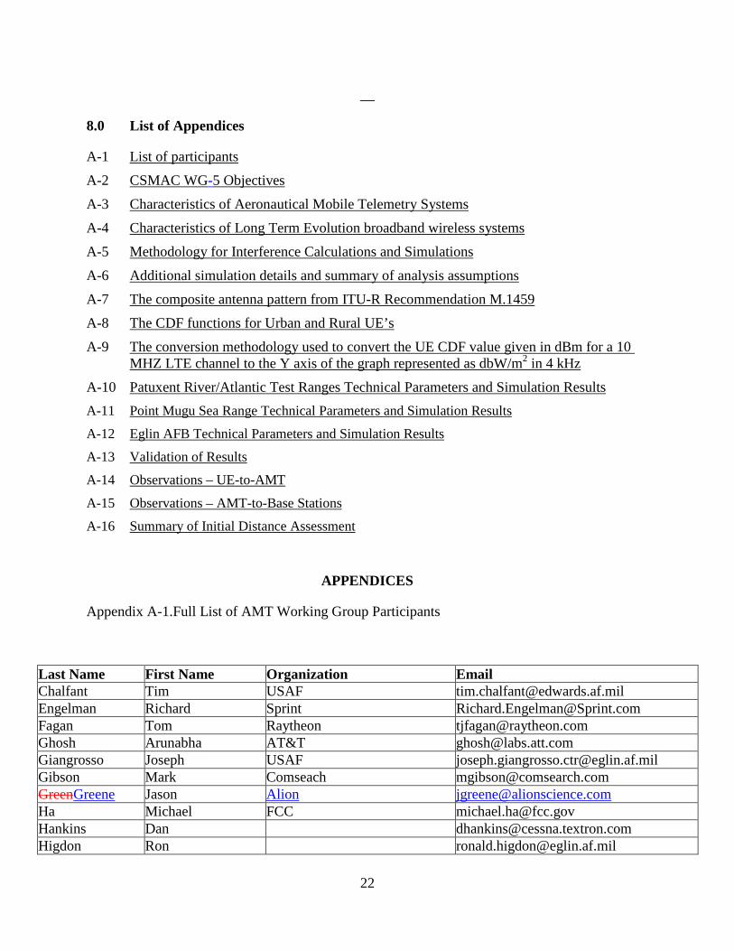
Appendix A-1.Full List of AMT Working Group Participants
Last Name First Name Organization Email Chalfant Tim USAF [email protected] Engelman Richard Sprint [email protected] Fagan Tom Raytheon [email protected] Ghosh Arunabha AT&T [email protected] Giangrosso Joseph USAF [email protected] Gibson Mark Comseach [email protected] GreenGreene Jason Alion [email protected] Ha Michael FCC [email protected] Hankins Dan [email protected] Higdon Ron [email protected]
23
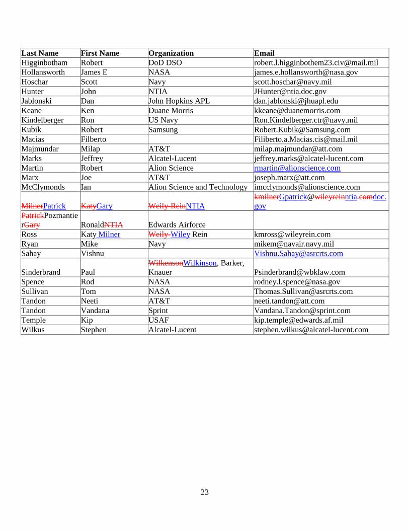
Last Name First Name Organization Email Higginbotham Robert DoD DSO [email protected] Hollansworth James E NASA [email protected] Hoschar Scott Navy [email protected] Hunter John NTIA [email protected] Jablonski Dan John Hopkins APL [email protected] Keane Ken Duane Morris [email protected] Kindelberger Ron US Navy [email protected] Kubik Robert Samsung [email protected] Macias Filberto [email protected] Majmundar Milap AT&T [email protected] Marks Jeffrey Alcatel-Lucent [email protected] Martin Robert Alion Science [email protected] Marx Joe AT&T [email protected] McClymonds Ian Alion Science and Technology [email protected]
MilnerPatrick KatyGary Weily-ReinNTIA [email protected]
PatrickPozmantierGary RonaldNTIA Edwards Airforce Ross Katy Milner Weily-Wiley Rein [email protected] Ryan Mike Navy [email protected] Sahay Vishnu [email protected]
Sinderbrand Paul WilkensonWilkinson, Barker, Knauer [email protected]
Spence Rod NASA [email protected] Sullivan Tom NASA [email protected] Tandon Neeti AT&T [email protected] Tandon Vandana Sprint [email protected] Temple Kip USAF [email protected] Wilkus Stephen Alcatel-Lucent [email protected]

Related Documents