Aeroelasticity in MSC.Nastran Hybrid Static Aeroelasticity new capabilities - CFD data management Presented By: Fausto Gill Di Vincenzo 04-06-2012

Welcome message from author
This document is posted to help you gain knowledge. Please leave a comment to let me know what you think about it! Share it to your friends and learn new things together.
Transcript

Aeroelasticity in MSC.Nastran
Hybrid Static Aeroelasticity new capabilities - CFD data management
Presented By: Fausto Gill Di Vincenzo04-06-2012
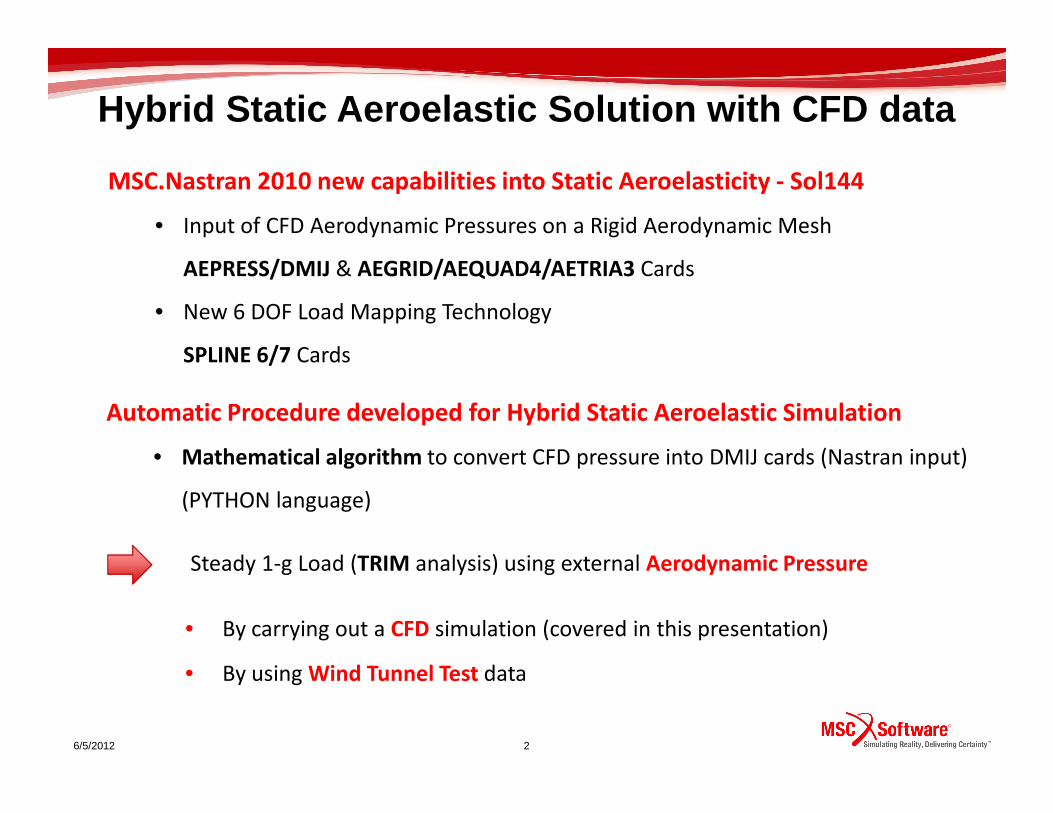
MSC.Nastran 2010 new capabilities into Static Aeroelasticity - Sol144
• Input of CFD Aerodynamic Pressures on a Rigid Aerodynamic Mesh
AEPRESS/DMIJ & AEGRID/AEQUAD4/AETRIA3 Cards
• New 6 DOF Load Mapping Technology
SPLINE 6/7 Cards
Automatic Procedure developed for Hybrid Static Aeroelastic Simulation
Hybrid Static Aeroelastic Solution with CFD data
6/5/2012 2
Steady 1-g Load (TRIM analysis) using external Aerodynamic Pressure
• By carrying out a CFD simulation (covered in this presentation)
• By using Wind Tunnel Test data
Automatic Procedure developed for Hybrid Static Aeroelastic Simulation
• Mathematical algorithm to convert CFD pressure into DMIJ cards (Nastran input)
(PYTHON language)
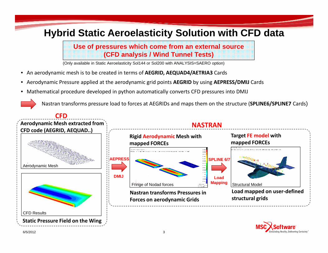
• An aerodynamic mesh is to be created in terms of AEGRID, AEQUAD4/AETRIA3 Cards
• Aerodynamic Pressure applied at the aerodynamic grid points AEGRID by using AEPRESS/DMIJ Cards
• Mathematical procedure developed in python automatically converts CFD pressures into DMIJ
Use of pressures which come from an external source (CFD analysis / Wind Tunnel Tests)
(Only available in Static Aeroelasticity Sol144 or Sol200 with ANALYSIS=SAERO option)
Nastran transforms pressure load to forces at AEGRIDs and maps them on the structure (SPLINE6/SPLINE7 Cards)
Aerodynamic Mesh extracted from
CFD code (AEGRID, AEQUAD..)
CFD
NASTRAN
Hybrid Static Aeroelasticity Solution with CFD data
6/5/2012 3
Static Pressure Field on the Wing
Target FE model with
mapped FORCEs Rigid Aerodynamic Mesh with
mapped FORCEs
Aerodynamic Mesh extracted from
CFD code (AEGRID, AEQUAD..)
SPLINE 6/7
Load Mapping
AEPRESS
DMIJ
CFD Results
Aerodynamic Mesh
Nastran transforms Pressures in
Forces on aerodynamic Grids
NASTRAN
Fringe of Nodad forces Structural Model
Load mapped on user-defined
structural grids

Application Test Case - UAV TRIM Analysis Sol144Yacovlev Yak112 – UAV Model
CAD Model - Ortho View
Flight condition parametres
• M=0.07 Sea Level• Straight and level case under 1g loading• Flight velocity 25 m/s � q=382 Pa
Free trim variables
• Angle of attack• Angle of Elevator
FE Model
Tuned NASTRAN model - Ortho View
Nastran
Hybrid Static Aeroelasticity Solution with CFD data
6/5/2012 4
Optimization by Sol 200
NastranStructural Model
• 1. Aerodynamic Pressures by Fluent mesh-based CFD code - Only left Wings (Tail & Elevator by UVLM)
• 2. Aerodynamic Pressures by Xflow meshless CFD code - Only left Wings (Tail & Elevator by UVLM)
• 3. Aerodynamic Pressures by UVLM code (ZONA Technology) - Wings, Tail & Elevator (beta testing)
Static Pressure field evaluated by CFD and UVLM cod es
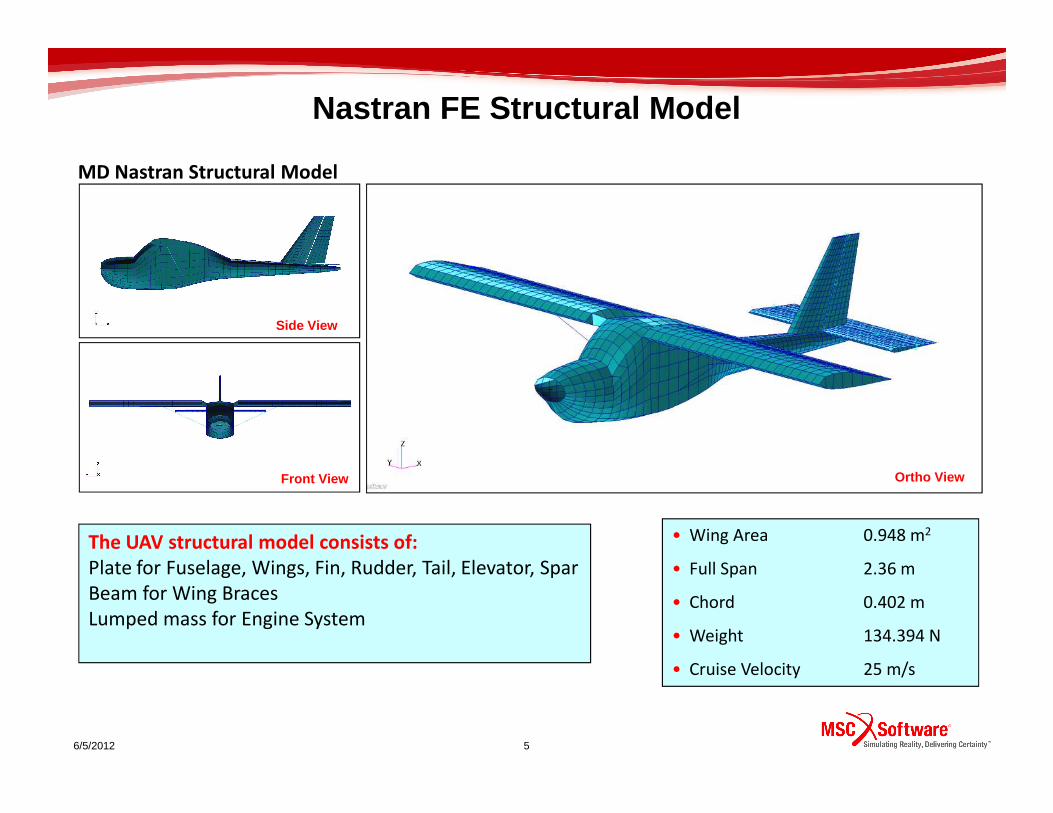
MD Nastran Structural Model
Side View
Nastran FE Structural Model
6/5/2012 5
The UAV structural model consists of:
Plate for Fuselage, Wings, Fin, Rudder, Tail, Elevator, Spar
Beam for Wing Braces
Lumped mass for Engine System
Front View Ortho View
• Wing Area 0.948 m2
• Full Span 2.36 m
• Chord 0.402 m
• Weight 134.394 N
• Cruise Velocity 25 m/s

Validation - Modal tuning through Sol 200
Modal tuning of the structural model via SOL 200
• An internal OPTIMIZATION TOOL of MD Nastran has been used to built a
numerical finite element model that accurately represents the structural
dynamic behavior of the experimantal model
• SOL 200 has been exploited to perform the modal optimization
• An error function based on the lowest four natural frequencies of the structure has
been defined as objective function
6/5/2012 6
been defined as objective function
• The error function to be minimized is defined as:
• The chosen design variables are the elastic parameters of the orthotropic material
• Density has been kept constant in order to obtain the actual mass of the UAV
• The MODAL TRACKING allows to follow each natural frequency in the
different optimization cycles.
• Modal Assurance Criterion is internally used to do it
( )24
1∑
=
−=i
exi
numi ffe

Structural Modal Tuning - Sol200IFASD-2009-166 “AEROELASTIC SYSTEM IDENTIFICATION OF A FLYING UAV IN OPERATIVE CONDITIONS”
Modal Assurance Criterion (MAC)Correlated Structural Modes - Frequencies
• Modal tuning of the structural model via SOL 200 - Modal tracking
• Mode shape comparison
Correlated mode shapes - Num
Correlated mode shapes – Exp
After the optimization process the sequence of the numerical natural
frequencies is exactly the same than that one of the experimental ones
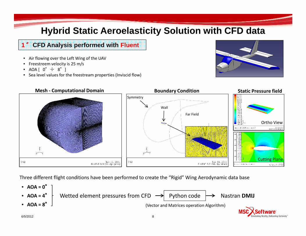
1°°°° CFD Analysis performed with Fluent
Boundary ConditionMesh - Computational Domain Static Pressure field
Far Field
Symmetry
Wall
• Air flowing over the Left Wing of the UAV
• Freestreem velocity is 25 m/s
• AOA [ 0°÷ 8°]
• Sea level values for the freestream properties (Inviscid flow)
Hybrid Static Aeroelasticity Solution with CFD data
6/5/2012 8
Cutting Plane
Ortho View
• AOA = 0°°°°
• AOA = 4°°°°
• AOA = 8°°°°
Three different flight conditions have been performed to create the “Rigid” Wing Aerodynamic data base
Wetted element pressures from CFD Python code Nastran DMIJ
(Vector and Matrices operation Algorithm)

Hybrid Static Aeroelasticity Solution with CFD data
From CFD code
Aerodynamic
Normal vectors on Nodes
Structural Model & CFD Model
Matrix/Vector
operation on Pressure
CFD Model
6/5/2012 9
AEGRID/AEQUAD4
Aerodynamic load mapped on structure
to Nastran Structural Solver
SPLINE 6
Undeformed Aerodynamic Mesh
with CFD Aerodynamic load
OUTPUT
FLUENT
Aerodynamic
Matrix (DMIJ)
Nastran input
Getting all Cp
Component
operation on Pressure
FE

Fluent - Coefficient pressure field
From CFD pressure to DMIJ
Fluent - Wetted elements wall Fluent - Force report
FZ = 14.167403 NMIN =- 0.597
Wetted elements transformed into AEGRID/AEQUAD4 - Rigid Aerodynamic Mesh
Input of CFD Aerodynamic Pressure on Rigid Aerodynamic Mesh - Validation case (0 Degrees AOA)
6/5/2012 10
Nastran - Cp on AEGRID (DMIJ)Nastran - Rigid Aerodynamic Mesh
AEGRID/AEQUAD4 Z - COMPONENT
Nastran - Aero monitor point
FZ = 14.17238 N
MAX = 0.596
Wetted elements transformed into AEGRID/AEQUAD4 - Rigid Aerodynamic Mesh
Pressures on wetted elements transformed into AEGRID Cp - DMIJ
Aerodynamic monitor point to check the mapped load on rigid aerodynamic mesh – Aero database
Right Aerodynamic pressure distrubution got by Nastran
(Direct Matrix Input at js-Set of the Rigid Aero Mesh)
Automatic process developed in python (SimXpert Customization..)
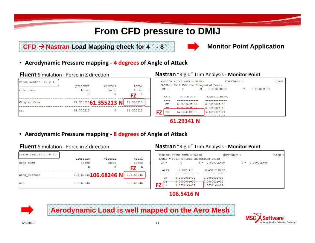
CFD ���� Nastran Load Mapping check for 4 °°°°- 8°°°°
Fluent Simulation - Force in Z direction Nastran “Rigid” Trim Analysis - Monitor Point
FZ
FZ
Monitor Point Application
• Aerodynamic Pressure mapping - 4 degrees of Angle of Attack
61.355213 N
61.29341 N
From CFD pressure to DMIJ
6/5/2012 11
Aerodynamic Load is well mapped on the Aero Mesh
Fluent Simulation - Force in Z direction Nastran “Rigid” Trim Analysis - Monitor Point
FZ
FZ
• Aerodynamic Pressure mapping - 8 degrees of Angle of Attack
106.68246 N
61.29341 N
106.5416 N

• Nastran support the ability to generate the rigid aerodynamic loads on one mesh while the aeroelastic
increment is generated from a second mesh. Separate Rigid and Flexible Aero Meshes needed.
Rigid Aerodynamic Mesh Flexible Aerodynamic Mesh
Hybrid Static Aeroelasticity Solution with CFD dataRIGID/Flexible Mesh Concepts
6/5/2012 12
Rigid Aerodynamic Loads Aeroelastic Increment
First run Subsequent run
Aerodynamics given by DLM
+
AEGRID/AEQUAD4 Aero Boxes – CAERO1 Cards
AOA 0°÷ 8°
Aerodynamics database given by Fluent Analysis
Hybrid Static Aeroelasticity Solution (Sol144) with CFD Pressure data
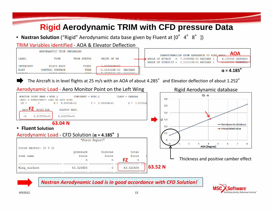
TRIM Variables identified - AOA & Elevator Deflection
Aerodynamic Load - Aero Monitor Point on the Left Wing
AOA
Rigid Aerodynamic TRIM with CFD pressure Data• Nastran Solution (“Rigid” Aerodynamic data base given by Fluent at [0°4°8°])
The Aircraft is in level flights at 25 m/s with an AOA of about 4.285°and Elevator deflection of about 1.252°
α ≈ 4.185°°°°
Rigid Aerodynamic database
6/5/2012 13
FZ
Nastran Aerodynamic Load is in good accordance with CFD Solution!
FZ
Aerodynamic Load - CFD Solution (α ≈ 4.185°°°°)
• Fluent Solution
Thickness and positive camber effect
63.04 N
63.52 N
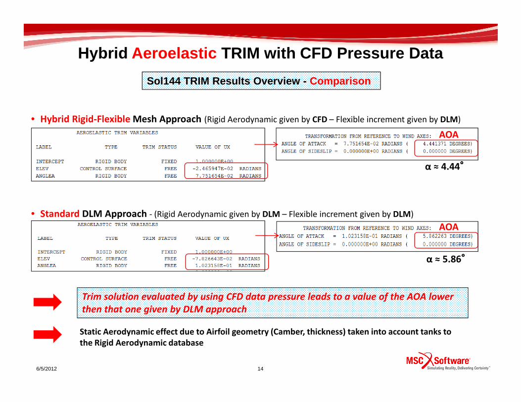
Sol144 TRIM Results Overview - Comparison
• Hybrid Rigid-Flexible Mesh Approach (Rigid Aerodynamic given by CFD – Flexible increment given by DLM)
AOA
α ≈ 4.44°°°°
Hybrid Aeroelastic TRIM with CFD Pressure Data
6/5/2012 14
• Standard DLM Approach - (Rigid Aerodynamic given by DLM – Flexible increment given by DLM)
Trim solution evaluated by using CFD data pressure leads to a value of the AOA lower
then that one given by DLM approach
AOA
α ≈ 5.86°°°°
Static Aerodynamic effect due to Airfoil geometry (Camber, thickness) taken into account tanks to
the Rigid Aerodynamic database
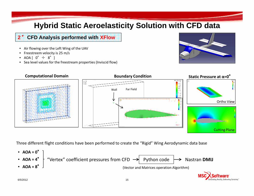
2°°°° CFD Analysis performed with XFlow
Boundary ConditionComputational Domain Static Pressure at α=0°°°°
Far FieldWall
• Air flowing over the Left Wing of the UAV
• Freestreem velocity is 25 m/s
• AOA [ 0°÷ 8°]
• Sea level values for the freestream properties (Inviscid flow)
Hybrid Static Aeroelasticity Solution with CFD data
6/5/2012 15
Cutting Plane
Ortho View
• AOA = 0°°°°
• AOA = 4°°°°
• AOA = 8°°°°
“Vertex” coefficient pressures from CFD Python code Nastran DMIJ
(Vector and Matrices operation Algorithm)
Three different flight conditions have been performed to create the “Rigid” Wing Aerodynamic data base
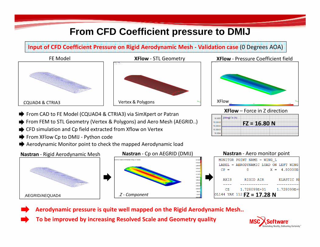
FE Model XFlow - STL Geometry XFlow - Pressure Coefficient field
CQUAD4 & CTRIA3 Vertex & Polygons
From FEM to STL Geometry (Vertex & Polygons) and Aero Mesh (AEGRID..)
XFlow
From CAD to FE Model (CQUAD4 & CTRIA3) via SimXpert or Patran
From CFD Coefficient pressure to DMIJInput of CFD Coefficient Pressure on Rigid Aerodynamic Mesh - Validation case (0 Degrees AOA)
XFlow – Force in Z direction
FZ = 16.80 NFrom FEM to STL Geometry (Vertex & Polygons) and Aero Mesh (AEGRID..)
From XFlow Cp to DMIJ - Python code
Aerodynamic pressure is quite well mapped on the Rigid Aerodynamic Mesh..
CFD simulation and Cp field extracted from Xflow on Vertex
Z - Component
Nastran - Aero monitor pointNastran - Cp on AEGRID (DMIJ)
To be improved by increasing Resolved Scale and Geometry quality
Nastran - Rigid Aerodynamic Mesh
FZ = 16.80 N
FZ = 17.28 N
Aerodynamic Monitor point to check the mapped Aerodynamic load
AEGRID/AEQUAD4
XFlow Simulation - Force in Z direction Nastran “Rigid” Trim Analysis - Monitor Point
FZ
FZ
60.67 N
62.12 N
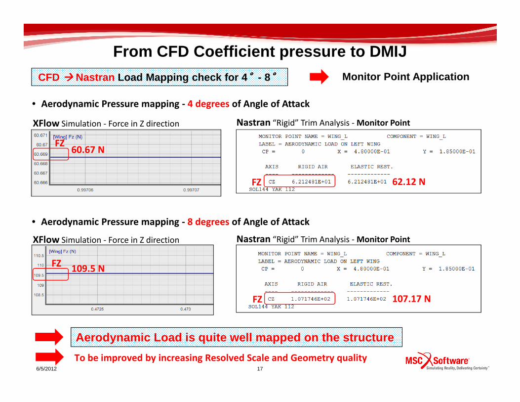
From CFD Coefficient pressure to DMIJ
CFD ���� Nastran Load Mapping check for 4 °°°°- 8°°°° Monitor Point Application
• Aerodynamic Pressure mapping - 4 degrees of Angle of Attack
6/5/2012 17
Aerodynamic Load is quite well mapped on the struct ure
XFlow Simulation - Force in Z direction Nastran “Rigid” Trim Analysis - Monitor Point
FZ
FZ
109.5 N
107.17 N
To be improved by increasing Resolved Scale and Geometry quality
• Aerodynamic Pressure mapping - 8 degrees of Angle of Attack
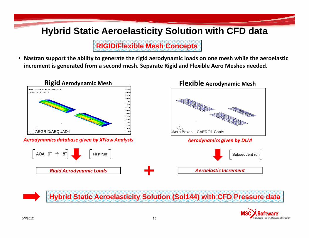
• Nastran support the ability to generate the rigid aerodynamic loads on one mesh while the aeroelastic
increment is generated from a second mesh. Separate Rigid and Flexible Aero Meshes needed.
RIGID/Flexible Mesh Concepts
Rigid Aerodynamic Mesh Flexible Aerodynamic Mesh
Hybrid Static Aeroelasticity Solution with CFD data
6/5/2012 18
Rigid Aerodynamic Loads Aeroelastic Increment
First run Subsequent run
Aerodynamics given by DLM
+
AEGRID/AEQUAD4 Aero Boxes – CAERO1 Cards
AOA 0°÷ 8°
Aerodynamics database given by XFlow Analysis
Hybrid Static Aeroelasticity Solution (Sol144) with CFD Pressure data

Sol144 TRIM Results Overview – Comparison
AOA
α ≈ 4.31°°°°
Hybrid Aeroelastic TRIM with CFD Pressure Data
• Hybrid Rigid-Flexible Mesh Approach (Rigid Aerodynamic given by CFD – Flexible increment given by DLM)
6/5/2012 19
• Standard DLM Approach - (Rigid Aerodynamic given by DLM – Flexible increment given by DLM)
Trim solution evaluated by using CFD data pressure leads to a value of the AOA lower
then that one given by DLM approach
AOA
α ≈ 5.86°°°°
Static Aerodynamic effect due to Airfoil geometry (Camber, thickness) taken into account tanks to
the Rigid Aerodynamic database

3°°°° Aerodynamics performed with UVLM
UVLM Aerodynamic Model Static Pressure distriutionat α=0°°°°
• Air flowing over the the entire model of the UAV
• Freestreem velocity is 25 m/s
• AOA [ 0°÷ 8°]
• Sea level values for the freestream properties (Inviscid flow)
Vortices shed
Free vortex wake
Hybrid Static Aeroelasticity Solution with CFD data
6/5/2012 20
Ortho View
Rigid Aerodynamic Mesh
Wetted Panels - Ortho View
• AOA = 0°°°°
• AOA = 4°°°°
• AOA = 8°°°°
Wetted Panels - Side View
Pressure Data export
Rigid Aerodynamic Mesh
Free wake formation
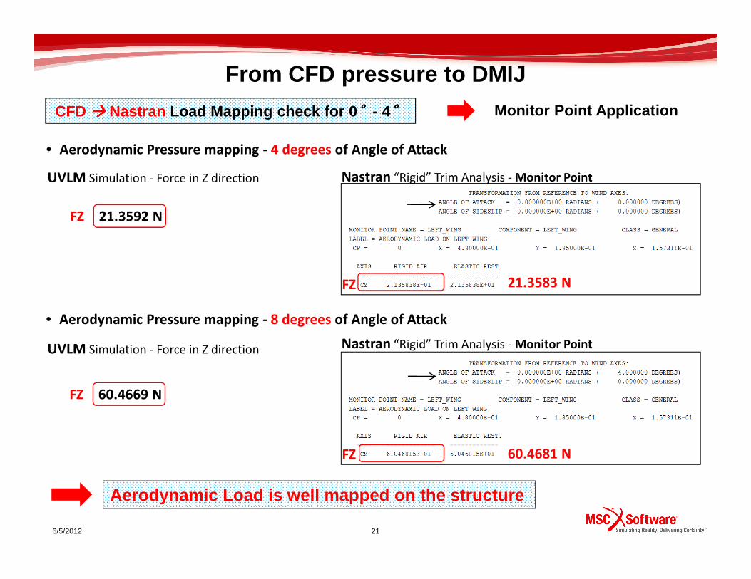
UVLM Simulation - Force in Z direction Nastran “Rigid” Trim Analysis - Monitor Point
FZ
FZ
21.3592 N
21.3583 N
CFD ���� Nastran Load Mapping check for 0 °°°°- 4°°°° Monitor Point Application
From CFD pressure to DMIJ
• Aerodynamic Pressure mapping - 4 degrees of Angle of Attack
6/5/2012 21
Aerodynamic Load is well mapped on the structure
UVLM Simulation - Force in Z direction Nastran “Rigid” Trim Analysis - Monitor Point
FZ
FZ
FZ 60.4669 N
21.3583 N
60.4681 N
• Aerodynamic Pressure mapping - 8 degrees of Angle of Attack

• Nastran support the ability to generate the rigid aerodynamic loads on one mesh while the aeroelastic
increment is generated from a second mesh. Separate Rigid and Flexible Aero Meshes needed.
Rigid Aerodynamic Mesh Flexible Aerodynamic Mesh
RIGID/Flexible Mesh Concepts
Hybrid Static Aeroelasticity Solution with CFD data
6/5/2012 22
Rigid Aerodynamic Loads Aeroelastic Increment
First run Subsequent run
Aerodynamics given by DLM
+
AEGRID/AEQUAD4 Aero Boxes – CAERO1 Cards
AOA 0°÷ 8°
Aerodynamics database given by UVLM Analysis
Hybrid Static Aeroelasticity Solution (Sol144) with CFD Pressure data

Sol144 TRIM Results Overview – Comparison
AOA
α ≈ 4.28°°°°
• Hybrid Rigid-Flexible Mesh Approach (Rigid Aerodynamic given by UVLM – Flexible increment given by DLM)
Hybrid Aeroelastic TRIM with UVLM Pressure Data
6/5/2012 23
• Standard DLM Approach - (Rigid Aerodynamic given by DLM – Flexible increment given by DLM)
Trim solution evaluated by using UVLM data pressure leads to a value of the AOA
lower then that one given by DLM approach
AOA
α ≈ 5.86°°°°
Static Aerodynamic effect due to Airfoil geometry (Camber, thickness) taken into account tanks to
the Rigid Aerodynamic database
Concluding Remarks
• It is now possible to use Aerodynamic Pressure data evaluated by a general CFD
or UVLM code in Static Aeroelasticity Analysis Sol 144
• The SPLINE6/7 load mapping technology transfers correctly the aerodynamic load
to the structure
• Monitor point is an important and essensial tool to check the Aero Load Mapping
• A new procedure able to use “external” aerodynamic pressure in Static
Aeroelasticity has been verified for:
6/5/2012 24
• a commercial CFD “mesh-based” code - Fluent
• a commercial CFD “meshless” code - Xflow MSC.Software
• an UVLM code “panel method” - Zona Technology
• A Mathematical algorithm to automatically convert pressures into DMIJ matrix
has been developed by using python programming language
• Possible future applications:
• Customize all the automatic procedure into SimXpert (python..)
• Load mapping of the entire Aircraft
Related Documents