Aerodynamics and Aeroelastics, WP 2 Flemming Rasmussen Aeroelastic Design Wind Energy Department Risø DTU

Aerodynamics and Aeroelastics, WP 2 Flemming Rasmussen Aeroelastic Design Wind Energy Department
Dec 31, 2015
Aerodynamics and Aeroelastics, WP 2 Flemming Rasmussen Aeroelastic Design Wind Energy Department Risø DTU. WP2 Aero-dynamics and Aero-elastics OBJECTIVES. Overall: To develop an aeroelastic design basis for large multi MW turbines. Specific:. - PowerPoint PPT Presentation
Welcome message from author
This document is posted to help you gain knowledge. Please leave a comment to let me know what you think about it! Share it to your friends and learn new things together.
Transcript

Aerodynamics and Aeroelastics, WP 2
Flemming Rasmussen
Aeroelastic Design
Wind Energy Department
Risø DTU

WP2 Aero-dynamics and Aero-elastics OBJECTIVES
1. Development of nonlinear structural dynamic models (modeling on the micromechanical scale is input from WP3).
2. Advanced aerodynamic models covering full 3D CFD rotor models, free wake models and improved BEM type models. (The wake description is a prerequisite for the wake modeling in WP8).
3. Models for aerodynamic control features and devices. (This represents the theoretical background for the smart rotor blades development in WP 1.B.3)
4. Models for analysis of aeroelastic stability and total damping including hydroelastic interaction
5. Development of models for computation of aerodynamic noise.
Overall: To develop an aeroelastic design basis for large multi MW turbines.
Specific:
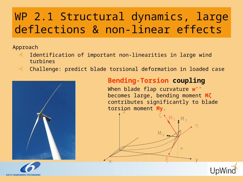
WP 2.1 Structural dynamics, large deflections & non-linear effects
ApproachIdentification of important non-linearities in large wind turbinesChallenge: predict blade torsional deformation in loaded case
z
yx
Mζ
w
Mz
My
ζ
η
ξ
Bending-Torsion couplingWhen blade flap curvature w’’ becomes large, bending moment Mζ contributes significantly to blade torsion moment My.

WP 2.1 Non-linear effects (analytical study)Additions to the baseline, 1st-order, model
Formulation of dynamic equations in the deformed state (same structural couplings as in baseline but 2nd-order kinematics and dynamics) (2nd order beam-0) Tension – torsion coupling terms (2nd order beam-1) Bending – torsion coupling terms (2nd order beam-2) Pre-twist – torsion coupling term (2nd order beam-3)
4.6
4.8
5.0
5.2
5.4
5.6
0.0 2.0 4.0 6.0 8.0 10.0 12.0 14.0 16.0 18.0 20.0
Flap
wis
e D
ispl
acem
ent a
t Tip
[m]
Time [s]
1st order Beam2nd order Beam-02nd order Beam-12nd order Beam-22nd order Beam-3
-1.0
-0.8
-0.6
-0.4
-0.2
0.0
0.2
0.4
0.6
0.8
1.0
0.0 2.0 4.0 6.0 8.0 10.0 12.0 14.0 16.0 18.0 20.0
Tors
iona
l Ang
le a
t Tip
[deg
]
Time [s]
1st order Beam2nd order Beam-02nd order Beam-12nd order Beam-22nd order Beam-3
Wind speed: 11m/s

WP 2.1 Non-linear effects
-2.5-2
-1.5-1
-0.50
0.51
260 280 300 320 340 360 380 400
tors
ion
(d
eg
)
time (s)
linear beam2nd order beam
-0.05
0
0.05
0.1
0.15
260 280 300 320 340 360 380 400
no
rma
lize
d f
lap
time (s)
linear beam2nd order beam
789
101112131415161718
260 280 300 320 340 360 380 400
win
d s
pe
ed
(m
/s)
time (s)
Linear vs. non linear beam model analysis, NTM at 11.4 m/s

WP2.2 Advanced aerodynamic models
Objectivesto identify the limitations in the engineering aerodynamic modeling in BEM type codes
Approachinter comparison of results of models of different complexity applied on MW rotors, RWT- 5MW
Simulation casesuniform inflow on RWT turbine (stiff model)strong wind shear in inflowunsteady inflow (turbulent)- not yet performed

Blade normal force distributionSimulations with various
codes at 8 m/s
uniform inflow
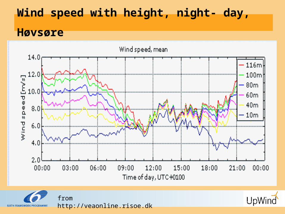
Wind speed with height, night- day,
Høvsøre
from http://veaonline.risoe.dk

Measured inflow angle on the NM80 at Tjæreborg during a period with strong shear and low turbulence
Inflow angle

Wake pattern, CFD with strong inflow shear

WP2.2 Blade normal force
8 m/s - strong inflow shear - exponent 0.55,
blade up blade down
0.55
( ) hubhub
zU z U
z

WP2.2 Blade normal force
8 m/s -- strong inflow shear - exponent 0.55
blade 90 deg. blade 270 deg.

WP 2.3 Advanced control features and aerodynamic devices
Approach:• Develope detailed models for analysis of a few promising flow control concepts (in close corporation with WP 1A5).• Deformable camberline.

Dynamic Stall model: Main input: CL
st(,)

Dynamic Stall: Harmonic Alpha and BetaBlue: Alpha and Beta in phaseBlack: No BetaRed: In counter-phase (180 shift)

WP 2.4: Aeroelastic stability and total damping including hydrodynamics
Approach:•Aerodynamic damping and aeroelastic stability of the RWT 5 MW turbine•Blade structural damping model•CFD-structure coupling
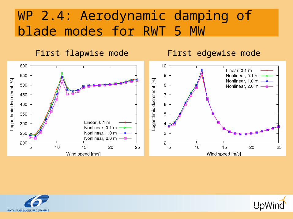
WP 2.4: Aerodynamic damping of blade modes for RWT 5 MW
First flapwise mode First edgewise mode

WP 2.5 Computation of aerodynamic noise– coupled CFD-CAA models
Approach:Improve computation of aerodynamic trailing edge noise.Input from CFD simulations of boundary layer parameters at trailing edge.Validation: Eksperimental data on both aerodynamics and aeroacustics

Test Cases : VTE Model Developed at LWT (SIROCCO Project)• goal: variation of boundary-layer parameters at trailing-
edge• requires strong contour change over major part of chord length• three variations: VTE_lin, VTE_kav (and VTE_vex)
Wind tunnel modelwith adjustable
shape

Results: VTE_kav, Cl=0.7, BL Parameters

Results: VTE_kav, Cl=0.7, Noise Spectra

WP2 Aerodynamics and Aeroelastics
SummaryBending-torsion coupling is importantInflow shear is non-trivialDynamic stall model for variable trailing edgeStability analysis including non-linear effects (and structural modal damping prediction)Noise prediction: Boundary layer predictions and measurements
Related Documents


