Title: AERODYNAMIC ANALYSIS OF ALOUETTE III ROTARY WINGS Authors: Mircea CORPODEAN Section: ENGINEERING Issue: 1(19)/2020 Received: 15 January 2020 Revised: 27 January 2020 Accepted: 9 March 2020 Available Online: 15 March 2020 Paper available online HERE DOI:

Welcome message from author
This document is posted to help you gain knowledge. Please leave a comment to let me know what you think about it! Share it to your friends and learn new things together.
Transcript
Title:
AERODYNAMIC ANALYSIS OF ALOUETTE III ROTARY WINGS
Authors:
Mircea CORPODEAN
Section: ENGINEERING
Issue: 1(19)/2020
Received: 15 January 2020
Revised: 27 January 2020
Accepted: 9 March 2020
Available Online: 15 March 2020
Paper available online HERE
DOI:
45
Engineering
AERODYNAMIC ANALYSIS OF ALOUETTE III ROTARY
WINGS
Mircea CORPODEAN1
ABSTRACT:
EVER SINCE THE FIRST MODELS APPEARED, THE HELICOPTER HAS REPRESENTED AND WILL BE A
SOLID SUBJECT OF STUDY, ALWAYS BEING A PLACE OF IMPROVEMENT IN ITS TECHNOLOGY WITH
THE EVOLUTION OF SCIENCE. IN THIS PAPER I WILL PRESENT SOME IDEAS REGARDING THE
AERODYNAMIC PERFORMANCES OF THE BEARING ROTORS, USING NUMERICAL SOFTWARE
SIMULATIONS BASED ON A SCALE MODEL OF THE SA 316B HELICOPTER.
KEY WORDS: ROTOR, XFLR5, QBLADE, HELICOPTER, ROTARY WINGS, ALOUETTE III
LIST OF ACRONIMS AND ABBREVIATIONS
Cl Lift coefficient Cp Power coefficient
Rot Rotational speed RPM Rotations per minute
Rho-ρ Density R Rotor radius
r Rotor hub radius V volume
TSR Tip Speed Ratio ISA Internat. Standard Atmosphere
E Glide Ratio AoA Angle of attack
1. INTRODUCTION
The Alouette III 2has its origins with an earlier helicopter design by French aircraft
manufacturer Sud-Est, the SE 3120 Alouette, which, while breaking several helicopter speed
and distance records in July 1953, was deemed to have been too complex to be realistic
commercial product. Having received financial backing from the French government, which
had taken an official interest in the venture, the earlier design was used as a starting point for
a new rotorcraft that would harness the newly developed turboshaft engine; only a few years
prior, Joseph Szydlowski, the founder of Turbomeca, had successfully managed to develop
the Artouste, a 260 hp (190 kW) single shaft turbine engine derived from his Orédon turbine
engine. This engine was combined with the revised design to quickly produce a new
helicopter, initially known as the SE 3130 Alouette II.
1 Student, “ Henri Coandă” Air Force Academy, Brașov 2 "The French Navy Is Finally Retiring These Antique Helicopters After 55 Years of Service."
46
During April 1956, the first production Alouette II was completed, becoming the first
production turbine-powered helicopter in the world. The innovative light helicopter, soon
broke several world records and became a commercial success.As a result of the huge
demand for the Alouette II, manufacturer Aérospatiale took a great interest in the
development of derivatives, as well as the more general ambition of embarking on further
advancement in the field of rotorcraft.
In accordance with these goals, the company decided to commit itself to a new
development programme with the aim of developing a more powerful helicopter that would
be capable of accommodating up to 7 seats or a pair of stretchers. The design team was
managed by French aerospace engineer René Mouille.The design produced, which was
initially designated as the SE 3160, featured several improvements over the Alouette II;
efforts were made to provide for a higher level of external visibility for the pilot as well as for
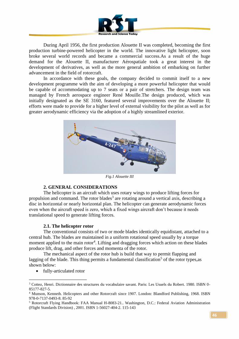
greater aerodynamic efficiency via the adoption of a highly streamlined exterior.
Fig.1 Alouette III
2. GENERAL CONSIDERATIONS
The helicopter is an aircraft which uses rotary wings to produce lifting forces for
propulsion and command. The rotor blades3 are rotating around a vertical axis, describing a
disc in horizontal or nearly horizontal plan. The helicopter can generate aerodynamic forces
even when the aircraft speed is zero, which a fixed wings aircraft don’t because it needs
translational speed to generate lifting forces.
2.1. The helicopter rotor
The conventional consists of two or mode blades identically equidistant, attached to a
central hub. The blades are maintained in a uniform rotational speed usually by a torque
moment applied to the main rotor4. Lifting and dragging forces which action on these blades
produce lift, drag, and other forces and momenta of the rotor.
The mechanical aspect of the rotor hub is build that way to permit flapping and
lagging of the blade. This thing permits a fundamental classification5 of the rotor types,as
shown below:
• fully-articulated rotor
3 Cottez, Henri. Dictionnaire des structures du vocabulaire savant. Paris: Les Usuels du Robert. 1980. ISBN 0-
85177-827-5. 4 Munson, Kenneth. Helicopters and other Rotorcraft since 1907. London: Blandford Publishing, 1968. ISBN
978-0-7137-0493-8. 85-92 5 Rotorcraft Flying Handbook: FAA Manual H-8083-21.. Washington, D.C.: Federal Aviation Administration
(Flight Standards Division) , 2001. ISBN 1-56027-404-2. 115-143
47
• semi-rigid rotor
• rigid rotor
2.2. The configuration with a single main rotor
This is the most common configuration nowadays, generalized in the past 30 years but
without remaining the single one. It consists, basically, of an aerodynamic fuselage, a main
rotor and a tail rotor. The last one is a tiny auxiliary rotor, vertically placed, used to conteract
the momentum produced by the main rotor and to command the steering. It is placed on the
top of the helicopter tail and it has the thrust orientated in the same way as the main rotor
blades are rotating.
3. SOFTWARE ANALISYS
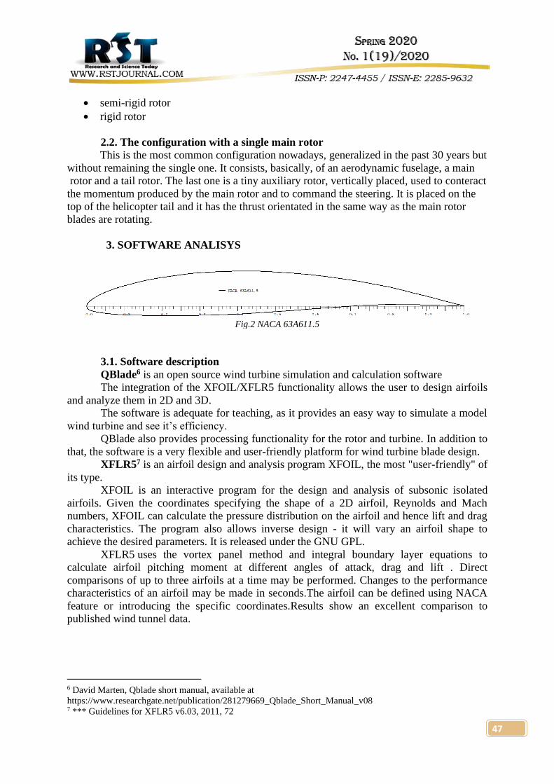
Fig.2 NACA 63A611.5
3.1. Software description
QBlade6 is an open source wind turbine simulation and calculation software
The integration of the XFOIL/XFLR5 functionality allows the user to design airfoils
and analyze them in 2D and 3D.
The software is adequate for teaching, as it provides an easy way to simulate a model
wind turbine and see it’s efficiency.
QBlade also provides processing functionality for the rotor and turbine. In addition to
that, the software is a very flexible and user-friendly platform for wind turbine blade design.
XFLR57 is an airfoil design and analysis program XFOIL, the most "user-friendly" of
its type.
XFOIL is an interactive program for the design and analysis of subsonic isolated
airfoils. Given the coordinates specifying the shape of a 2D airfoil, Reynolds and Mach
numbers, XFOIL can calculate the pressure distribution on the airfoil and hence lift and drag
characteristics. The program also allows inverse design - it will vary an airfoil shape to
achieve the desired parameters. It is released under the GNU GPL.
XFLR5 uses the vortex panel method and integral boundary layer equations to
calculate airfoil pitching moment at different angles of attack, drag and lift . Direct
comparisons of up to three airfoils at a time may be performed. Changes to the performance
characteristics of an airfoil may be made in seconds.The airfoil can be defined using NACA
feature or introducing the specific coordinates.Results show an excellent comparison to
published wind tunnel data.
6 David Marten, Qblade short manual, available at
https://www.researchgate.net/publication/281279669_Qblade_Short_Manual_v08 7 *** Guidelines for XFLR5 v6.03, 2011, 72
48
3.2. NACA 63A611.5 airfoil analysis
Simulation parameters:
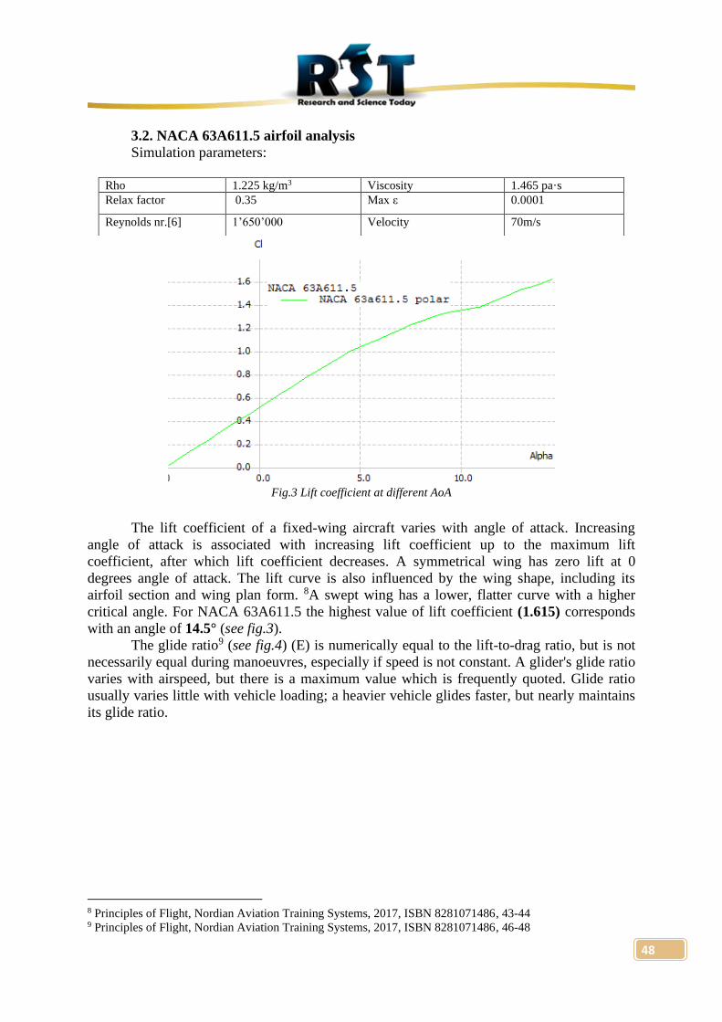
Fig.3 Lift coefficient at different AoA
The lift coefficient of a fixed-wing aircraft varies with angle of attack. Increasing
angle of attack is associated with increasing lift coefficient up to the maximum lift
coefficient, after which lift coefficient decreases. A symmetrical wing has zero lift at 0
degrees angle of attack. The lift curve is also influenced by the wing shape, including its
airfoil section and wing plan form. 8A swept wing has a lower, flatter curve with a higher
critical angle. For NACA 63A611.5 the highest value of lift coefficient (1.615) corresponds
with an angle of 14.5° (see fig.3).
The glide ratio9 (see fig.4) (E) is numerically equal to the lift-to-drag ratio, but is not
necessarily equal during manoeuvres, especially if speed is not constant. A glider's glide ratio
varies with airspeed, but there is a maximum value which is frequently quoted. Glide ratio
usually varies little with vehicle loading; a heavier vehicle glides faster, but nearly maintains
its glide ratio.
8 Principles of Flight, Nordian Aviation Training Systems, 2017, ISBN 8281071486, 43-44 9 Principles of Flight, Nordian Aviation Training Systems, 2017, ISBN 8281071486, 46-48
Rho 1.225 kg/m3 Viscosity 1.465 pa·s
Relax factor 0.35 Max ε 0.0001
Reynolds nr.[6] 1’650’000 Velocity 70m/s
49
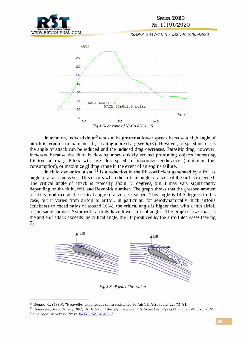
Fig.4 Glide ratio of NACA 63A611.5
In aviation, induced drag10 tends to be greater at lower speeds because a high angle of
attack is required to maintain lift, creating more drag (see fig.4). However, as speed increases
the angle of attack can be reduced and the induced drag decreases. Parasitic drag, however,
increases because the fluid is flowing more quickly around protruding objects increasing
friction or drag. Pilots will use this speed to maximize endurance (minimum fuel
consumption), or maximize gliding range in the event of an engine failure.
In fluid dynamics, a stall11 is a reduction in the lift coefficient generated by a foil as
angle of attack increases. This occurs when the critical angle of attack of the foil is exceeded.
The critical angle of attack is typically about 15 degrees, but it may vary significantly
depending on the fluid, foil, and Reynolds number. The graph shows that the greatest amount
of lift is produced as the critical angle of attack is reached. This angle is 14.5 degrees in this
case, but it varies from airfoil to airfoil. In particular, for aerodynamically thick airfoils
(thickness to chord ratios of around 10%), the critical angle is higher than with a thin airfoil
of the same camber. Symmetric airfoils have lower critical angles. The graph shows that, as
the angle of attack exceeds the critical angle, the lift produced by the airfoil decreases (see fig
5).
Fig.5 Stall point illustration
10 Renard, C. (1889). "Nouvelles experiences sur la resistance de l'air". L'Aéronaute. 22: 73–81. 11 Anderson, John David (1997). A History of Aerodynamics and its Impact on Flying Machines. New York, NY:
Cambridge University Press. ISBN 0-521-45435-2.
50
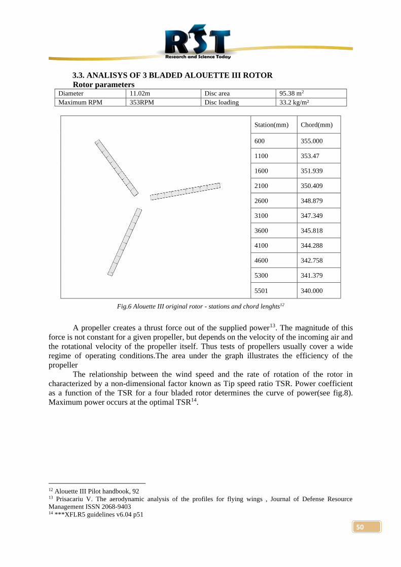
3.3. ANALISYS OF 3 BLADED ALOUETTE III ROTOR
Rotor parameters Diameter 11.02m Disc area 95.38 m2
Maximum RPM 353RPM Disc loading 33.2 kg/m²
Station(mm) Chord(mm)
600 355.000
1100 353.47
1600 351.939
2100 350.409
2600 348.879
3100 347.349
3600 345.818
4100 344.288
4600 342.758
5300 341.379
5501 340.000
Fig.6 Alouette III original rotor - stations and chord lenghts12
A propeller creates a thrust force out of the supplied power13. The magnitude of this
force is not constant for a given propeller, but depends on the velocity of the incoming air and
the rotational velocity of the propeller itself. Thus tests of propellers usually cover a wide
regime of operating conditions.The area under the graph illustrates the efficiency of the
propeller
The relationship between the wind speed and the rate of rotation of the rotor in
characterized by a non-dimensional factor known as Tip speed ratio TSR. Power coefficient
as a function of the TSR for a four bladed rotor determines the curve of power(see fig.8).
Maximum power occurs at the optimal TSR14.
12 Alouette III Pilot handbook, 92 13 Prisacariu V. The aerodynamic analysis of the profiles for flying wings , Journal of Defense Resource
Management ISSN 2068-9403 14 ***XFLR5 guidelines v6.04 p51
51
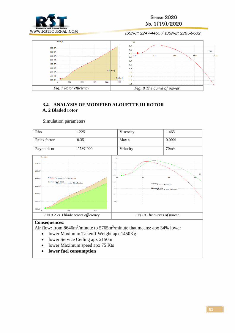
Fig. 7 Rotor efficiency Fig. 8 The curve of power
3.4. ANALYSIS OF MODIFIED ALOUETTE III ROTOR
A. 2 Bladed rotor
Simulation parameters
Rho 1.225 Viscosity 1.465
Relax factor 0.35 Max ε 0.0001
Reynolds nr. 1’289’000 Velocity 70m/s
Fig.9 2 vs 3 blade rotors efficiency Fig.10 The curves of power
Consequences:
Air flow: from 8646m3/minute to 5765m3/minute that means: apx 34% lower
• lower Maximum Takeoff Weight apx 1450Kg
• lower Service Ceiling apx 2150m
• lower Maximum speed apx 75 Kts
• lower fuel consumption

52
B.4 Bladed rotor
Simulation parameters
CONCLUSION
The effect of the number of the blades; more blades mean higher lift and efficiency,
but for this to happen there must be considered a powerful powerplant and/or a higher fuel
consumption
The effect of the number of the blades; less blades mean less lift and efficiency, but
for this to happen there must be considered a weaker powerplant and/or a lower fuel
consumption
The airfoil must prefferably have a high critic point to delay the separation of the limit
layer.
Author contributions regarding the theme
• Determine blade number influence of the Alouette III main rotor
• Determine NACA 63A611.5 airfoil aerodynamic performances
• Execute a 1:1 model of the rotor using NACA 63A611.5 airfoil and real dimensions
Rho 1.225 Viscosity 1.465
Relax factor 0.35 Max ε 0.0001
Reynolds nr. 1’289’000 Velocity 70m/s
Fig.11 3 vs 4 blade rotor efficiency Fig.12 The curves of power
Consequences:
Air flow: from 8646m3/minute to 11528m3/minute that means: apx33% higher
• higher Maximum Takeoff Weight apx 2900Kg
• higher Maximum Speed apx 150Kts
• higher Service Ceiling apx 4200m
• higher fuel consumption
53
REFERENCES
1. Vasile, Prisacariu; Elefterie Oliver, Ciuică; Aeronave de şcoală şi antrenament ISBN 978-606-8356-
35-8,
2. Vasile, Prisacariu; The aerodynamic analysis of the profiles for flying wings Journal of Defense
Resources Management 4 (1), 211
3. Anderson, John David; (1997). A History of Aerodynamics and its Impact on Flying Machines. New
York, NY: Cambridge University Press. ISBN 0-521-45435-2.
4. Prouty, Raymond W.; (2001). Helicopter Performance, Stability, and Control. Krieger Publishing
Company Press. ISBN 1-57524-209-5. OCLC 212379050.
5. Pope, Stephen B. (2000). Turbulent Flows. Cambridge University Press. ISBN 0-521-59886-9. OCLC
174790280.
6. XFLR5 Guidelines http://www.xflr5.tech/docs/XFLR5_and_Stability_analysis.pdf
7. Qblade- Wind turbine design and simulation application
https://sourceforge.net/projects/qblade/files/Guidelines/
8. Helicopter performance
https://www.faa.gov/regulations_policies/handbooks_manuals/aviation/helicopter_flying_handbook/m
edia/hfh_ch07.pdf
9. Airfoiltools Database https://www.airfoiltools.com/airfoils
10. *** Comparison of Aerodynamics Characteristics of NACA 0015
11. Technical Manual SA316B, Department of the Army 1996 ISBN 008-1035-08-5
12. John D. Anderson Jr. 2007 , Fundamentals of Aerodynamics, Fourth edition ISBN 007-1254-08-0
13. Vasile, Prisacariu; Alexandru, Chirilă; Aerodynamic analysis of helicopter fenestron vertical tail,
AFASES 2019 ISSN-L 2247-3173,p. 173-183, DOI: 10.19062/2247-3173.2019.21.24
Related Documents