AEROACOUSTIC ANALYSIS OF A HELICOPTER CONFIGURATION WITH DUCTED TAIL ROTOR Jae Hun You * , Nicolas Thouault * , Christian Breitsamter * and Nikolas A. Adams * * Institute of Aerodynamics and Fluid Mechanics, Technische Universität München Boltzmannstraße 15, D-85748 Garching, Germany [email protected] Keywords: aeroacoustics, helicopter, ducted tail rotor, unsteady RANS, FW-H analogy Abstract In the framework of the Bavarian research project FORLärm, numerical aeroacoustic investigations on a light weight transport helicopter with ducted tail rotor are carried out. To understand the noise generation mechanisms, a hybrid approach is applied for a forward flight condition. The flow field is calculated by an Unsteady Reynolds Averaged Navier-Stokes (URANS) method us- ing Shear Stress Transport (SST) turbulence model. The helicopter Fenestron R configura- tion without main rotor has been modeled based on a structured mesh. A sliding mesh ap- proach is employed to model the fan rotation. Based on instantaneous flow data provided by the URANS simulations, the computation of the acoustic far-field is performed by means of the Ffowcs Williams-Hawkings (FW-H) surface in- tegral method. A complex flow topology is pre- dicted by the URANS simulation. Flow sep- aration occurs on the aft part of the fuselage thereby creating vortical structures convected downstream to the ducted tail rotor. A separation bubble caused by boundary layer separation at the fan inlet lip geometry is also observed. Based on results of the FW-H caculations, tonal noise components are identified. The sideband fre- quencies related to the blade passing frequency (BPF) obtained by the FW-H calculation match well with the analytical solution based on the phase modulation technique. 1 Introduction Ducted tail rotor, also known as Fenestron R , is an innovative tail rotor concept of the conven- tional helicopter configuration (single main ro- tor and tail rotor configuration) to provide the necessary anti-torque thrust. Besides the sig- nificant improvement of operational safety near the ground and advancement of performance effi- ciency, the Fenestron R gives substantial acoustic benefits in contrast to the open tail rotor [1, 2]. For instance, the Fenestron R duct acts as an acoustic shield and the lower tip speed of the ro- tor blade also leads to decrease of acoustic power emission. Additionally, the rotor blades are un- equally circumferentially distributed to spread the acoustic tonal energy over several frequencies thus reducing the noise annoyance at the blade passing frequency. For the reason outlined above, the Fenestron R has been recently successfully implemented on a variety of helicopters (e.g. EC 120, EC 135 and SA 365). Numerous investigations related to aerodynamics [3, 4, 5] and aeroacoustics [6, 7] of the ducted tail rotor have been already conducted. However, ac- curate and detailed understanding of both aero- dynamic and aeroacoustic phenomena, in par- ticular, in forward flight condition still remain challenging considering the complex configura- tion and its flow field. Therefore, computa- tional methods could help to unterstand the flow physics of the helicopter with ducted tail rotor and provide insights on the noise sources with 1

Welcome message from author
This document is posted to help you gain knowledge. Please leave a comment to let me know what you think about it! Share it to your friends and learn new things together.
Transcript
AEROACOUSTIC ANALYSIS OF A HELICOPTERCONFIGURATION WITH DUCTED TAIL ROTOR
Jae Hun You∗ , Nicolas Thouault∗ , Christian Breitsamter∗ and Nikolas A. Adams∗∗Institute of Aerodynamics and Fluid Mechanics, Technische Universität München
Boltzmannstraße 15, D-85748 Garching, [email protected]
Keywords: aeroacoustics, helicopter, ducted tail rotor, unsteady RANS, FW-H analogy
Abstract
In the framework of the Bavarian research projectFORLärm, numerical aeroacoustic investigationson a light weight transport helicopter with ductedtail rotor are carried out. To understand thenoise generation mechanisms, a hybrid approachis applied for a forward flight condition. Theflow field is calculated by an Unsteady ReynoldsAveraged Navier-Stokes (URANS) method us-ing Shear Stress Transport (SST) turbulencemodel. The helicopter Fenestron R© configura-tion without main rotor has been modeled basedon a structured mesh. A sliding mesh ap-proach is employed to model the fan rotation.Based on instantaneous flow data provided bythe URANS simulations, the computation of theacoustic far-field is performed by means of theFfowcs Williams-Hawkings (FW-H) surface in-tegral method. A complex flow topology is pre-dicted by the URANS simulation. Flow sep-aration occurs on the aft part of the fuselagethereby creating vortical structures convecteddownstream to the ducted tail rotor. A separationbubble caused by boundary layer separation atthe fan inlet lip geometry is also observed. Basedon results of the FW-H caculations, tonal noisecomponents are identified. The sideband fre-quencies related to the blade passing frequency(BPF) obtained by the FW-H calculation matchwell with the analytical solution based on thephase modulation technique.
1 Introduction
Ducted tail rotor, also known as Fenestron R©, isan innovative tail rotor concept of the conven-tional helicopter configuration (single main ro-tor and tail rotor configuration) to provide thenecessary anti-torque thrust. Besides the sig-nificant improvement of operational safety nearthe ground and advancement of performance effi-ciency, the Fenestron R© gives substantial acousticbenefits in contrast to the open tail rotor [1, 2].For instance, the Fenestron R© duct acts as anacoustic shield and the lower tip speed of the ro-tor blade also leads to decrease of acoustic poweremission. Additionally, the rotor blades are un-equally circumferentially distributed to spreadthe acoustic tonal energy over several frequenciesthus reducing the noise annoyance at the bladepassing frequency. For the reason outlined above,the Fenestron R© has been recently successfullyimplemented on a variety of helicopters (e.g. EC120, EC 135 and SA 365).Numerous investigations related to aerodynamics[3, 4, 5] and aeroacoustics [6, 7] of the ducted tailrotor have been already conducted. However, ac-curate and detailed understanding of both aero-dynamic and aeroacoustic phenomena, in par-ticular, in forward flight condition still remainchallenging considering the complex configura-tion and its flow field. Therefore, computa-tional methods could help to unterstand the flowphysics of the helicopter with ducted tail rotorand provide insights on the noise sources with
1
J. H. YOU, N. THOUAULT, C. BREITSAMTER & N. A. ADAMS
a view to improve the Fenestron R© acoustic de-sign. The aim of the present study is to doc-ument the flow physics linked to sound gener-ation in the Fenestron R© by means of a hybridapproach combining Unsteady Reynolds Aver-aged Navier-Stokes (URANS) Simulations andthe Ffowcs Williams-Hawkings (FW-H) analogy.
Phase Modulation Technique. The idea ofthe phase modulation technique applied to theFenestron R© is to avoid acoustic repetition usingcircumferentially uneven spacing of rotor blades,thus the acoustic energy at the blade passing fre-quency is spread out over several frequencies.The even spacing of the Fenestron R© blades hasbeen redistributed by using the sinusoidal modu-lation described by [8]:
θ′i = θi +∆θsin(mθi), (1)
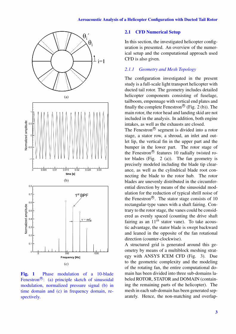
where θi is the primary position of the ith blade,θ′i is the rearranged position of ith blade after themodulation, ∆θ is the modulation amplitude andm is the number of the repeated modulation inone revolution of the fan. The rearranged bladespacing of a 10-blade Fenestron R© with m = 2 ispresented in Fig. 1 (a).By using the classical sinusoidal phase modula-tion equation, the pressure amplitude generatingfrom a rotating fan with modulated spacing canbe then predicted by [8]:
p(t) = A0sin(2πF0t +∆φsin2πνt), (2)
with A0 being the pressure amplitude by theblade passing frequency, F0 the blade passingfrequency (BPF) resulting from multiplication ofthe number of blades I and rotational frequencyof the fan fR, ν = m fR the modulation frequencyand ∆φ = I∆θ the phase-modulation amplitude.For a more realistic prediction of the pressureamplitude of a fan with small number of blades(I < 20), Ewald et al. [8] rearranged this formu-lation by introducing Fourier analysis and sinu-soidal approximation of the pressure waveformproduced by the fan:
p(t) = p(t)+∞
∑n=1
Bnsin(nωt)+∞
∑n=1
Cncos(nωt)
(3)
where ω = 2π fR,
Bn =1
2π
I
∑i=1
sin[(Di−n)θ−Diθi]
Di−n
− sin[(Di +n)θ−Diθi]
Di +n
θi+1
θi
(4)
and
Cn = − 12π
I
∑i=1
cos[(Di +n)θ−Diθi]
Di +n
− cos[(Di−n)θ−Diθi]
Di−n
θi+1
θi
(5)
with
Di =2π
(θi+1−θi)(6)
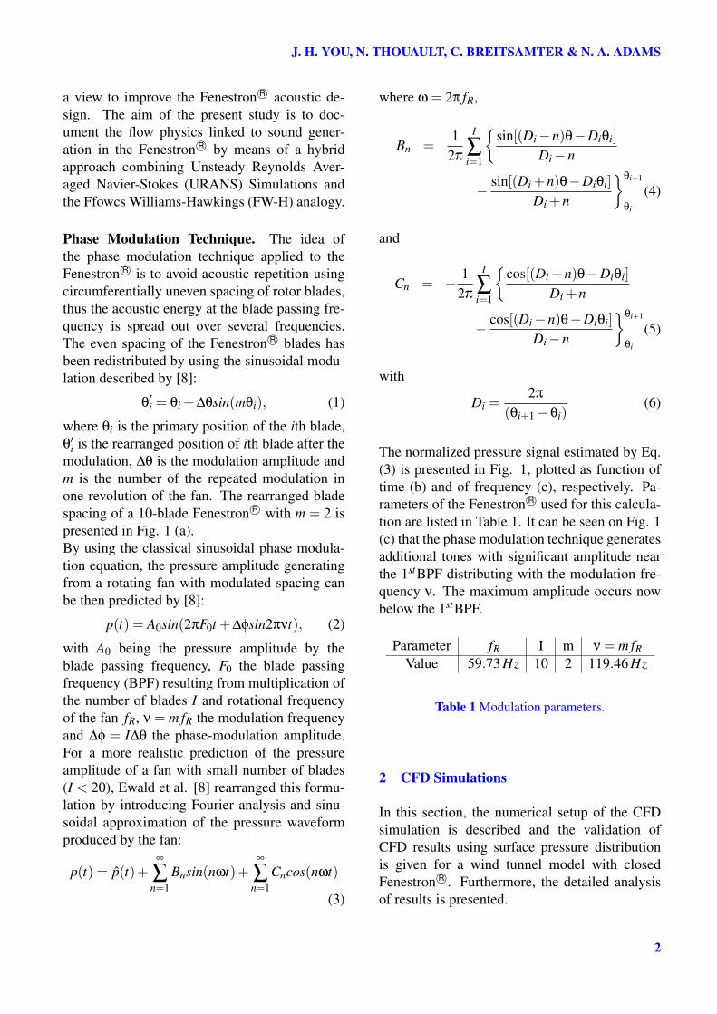
The normalized pressure signal estimated by Eq.(3) is presented in Fig. 1, plotted as function oftime (b) and of frequency (c), respectively. Pa-rameters of the Fenestron R© used for this calcula-tion are listed in Table 1. It can be seen on Fig. 1(c) that the phase modulation technique generatesadditional tones with significant amplitude nearthe 1stBPF distributing with the modulation fre-quency ν. The maximum amplitude occurs nowbelow the 1stBPF.
Parameter fR I m ν = m fRValue 59.73 Hz 10 2 119.46 Hz
Table 1 Modulation parameters.
2 CFD Simulations
In this section, the numerical setup of the CFDsimulation is described and the validation ofCFD results using surface pressure distributionis given for a wind tunnel model with closedFenestron R©. Furthermore, the detailed analysisof results is presented.
2
Aeroacoustic Analysis of a Helicopter Configuration with Ducted Tail Rotor
(a)
(b)
(c)
Fig. 1 Phase modulation of a 10-bladeFenestron R©: (a) principle sketch of sinusoidalmodulation, normalized pressure signal (b) intime domain and (c) in frequency domain, re-spectively.
2.1 CFD Numerical Setup
In this section, the investigated helicopter config-uration is presented. An overview of the numer-ical setup and the computational approach usedCFD is also given.
2.1.1 Geometry and Mesh Topology
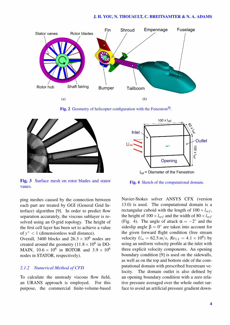
The configuration investigated in the presentstudy is a full-scale light transport helicopter withducted tail rotor. The geometry includes detailedhelicopter components consisting of fuselage,tailboom, empennage with vertical end plates andfinally the complete Fenestron R© (Fig. 2 (b)). Themain rotor, the rotor head and landing skid are notincluded in the analysis. In addition, both engineintakes, as well as the exhausts are closed.The Fenestron R© segment is divided into a rotorstage, a stator row, a shroud, an inlet and out-let lip, the vertical fin in the upper part and thebumper in the lower part. The rotor stage ofthe Fenestron R© features 10 radially twisted ro-tor blades (Fig. 2 (a)). The fan geometry isprecisely modeled including the blade tip clear-ance, as well as the cylindrical blade root con-necting the blade to the rotor hub. The rotorblades are unevenly distributed in the circumfer-ential direction by means of the sinusoidal mod-ulation for the reduction of typical shrill noise ofthe Fenestron R©. The stator stage consists of 10rectangular-type vanes with a shaft fairing. Con-trary to the rotor stage, the vanes could be consid-ered as evenly spaced (counting the drive shaftfairing as an 11th stator vane). To take acous-tic advantage, the stator blade is swept backwardand leaned in the opposite of the fan rotationaldirection (counter-clockwise).A structured grid is generated around this ge-ometry by means of a multiblock meshing strat-egy with ANSYS ICEM CFD (Fig. 3). Dueto the geometric complexity and the modelingof the rotating fan, the entire computational do-main has been divided into three sub-domains la-beled ROTOR, STATOR and DOMAIN (contain-ing the remaining parts of the helicopter). Themesh in each sub-domain has been generated sep-arately. Hence, the non-matching and overlap-
3
J. H. YOU, N. THOUAULT, C. BREITSAMTER & N. A. ADAMS
(a) (b)
Fig. 2 Geometry of helicopter configuration with the Fenestron R©.
Fig. 3 Surface mesh on rotor blades and statorvanes.
ping meshes caused by the connection betweeneach part are treated by GGI (General Grid In-terface) algorithm [9]. In order to predict flowseparation accurately, the viscous sublayer is re-solved using an O-grid topology. The height ofthe first cell layer has been set to achieve a valueof y+ < 1 (dimensionless wall distance).Overall, 3400 blocks and 26.3× 10⁶ nodes arecreated around the geometry (11.8× 10⁶ in DO-MAIN, 10.6 × 10⁶ in ROTOR and 3.9 × 10⁶
nodes in STATOR, respectively).
2.1.2 Numerical Method of CFD
To calculate the unsteady viscous flow field,an URANS approach is employed. For thispurpose, the commercial finite-volume-based
Fig. 4 Sketch of the computational domain.
Navier-Stokes solver ANSYS CFX (version13.0) is used. The computational domain is arectangular cuboid with the length of 100× lre f ,the height of 100× lre f and the width of 80× lre f(Fig. 4). The angle of attack α = −2 and thesideslip angle β = 0 are taken into account forthe given forward flight condition (free streamvelocity U∞ = 62.5 m/s, Re1:1 = 4.1× 10⁶) byusing an uniform velocity profile at the inlet withthree explicit velocity components. An openingboundary condition [9] is used on the sidewalls,as well as on the top and bottom side of the com-putational domain with prescribed freestream ve-locity. The domain outlet is also defined byan opening boundary condition with a zero rela-tive pressure averaged over the whole outlet sur-face to avoid an artificial pressure gradient down-
4
Aeroacoustic Analysis of a Helicopter Configuration with Ducted Tail Rotor
stream. For the spatial discretization, the highresolution scheme [9] is used. This method al-lows a dynamical adjustment of 1st order and 2nd
order upwind scheme controlled by the blend-ing factor (0 ≤ β ≤ 1) to make a compromisebetween the accuracy and the robustness. Forthe unsteady calculation, an implicit second or-der backward Euler scheme is used for the tempo-ral discretization. The k−ω Shear Stress Trans-port (SST) model by Menter [10] is adopted forthe turbulence modeling. All the computationsare performed fully turbulent. Since the bladetip Mach number given by the rotating speed isM > 0.5, the total energy model is employed totake into account of the compressibility effectsin this region. The fan rotation is modeled bymeans of the sliding mesh technique, so that theROTOR domain is connected to the stationarydomain (DOMAIN and STATOR) by sliding in-terfaces (Fig. 5). A steady simulation usingthe Frozen Rotor approach has been conducted.The steady state result is used as initial solu-tion for the unsteady simulation with Transient-Rotor-Stator method, which initializes an actualrotation of the fan grid. A constant time step(∆tCFD = 47 µs) corresponding to 1 of fan ro-tation is taken for the unsteady calculations (360time steps for a fan revolution).All simulations have been conducted on the highperformance computers (HLRB II / SuperMuc)of the Leibniz-Supercomputing center (LRZ) inMunich. A number of 40 to 120 processors perrun has been used to compute 15 fan revolu-tions. The convergence of the fan parameters is
Fig. 5 Schematic representation of the slidingmesh approach.
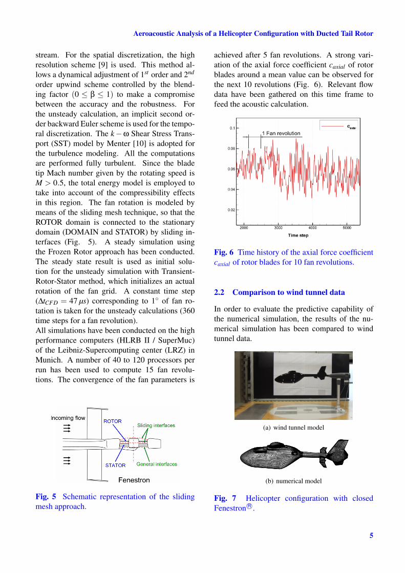
achieved after 5 fan revolutions. A strong vari-ation of the axial force coefficient caxial of rotorblades around a mean value can be observed forthe next 10 revolutions (Fig. 6). Relevant flowdata have been gathered on this time frame tofeed the acoustic calculation.
Fig. 6 Time history of the axial force coefficientcaxial of rotor blades for 10 fan revolutions.
2.2 Comparison to wind tunnel data
In order to evaluate the predictive capability ofthe numerical simulation, the results of the nu-merical simulation has been compared to windtunnel data.
(a) wind tunnel model
(b) numerical model
Fig. 7 Helicopter configuration with closedFenestron R©.
5

J. H. YOU, N. THOUAULT, C. BREITSAMTER & N. A. ADAMS
(a) lower side
(b) upper side
(c) horizontal plane
Fig. 8 Comparison of time averaged pressure co-efficient distribution for U∞ = 40 m/s, α = −2
and β = 0.
Fig. 9 Separation bubble at the aft body of thefuselage visualized by time-averaged streamlineson the symmetry plane (y/lre f = 0).
For this purpose, a numerical simulationof a scale down helicopter model (model size1:7.333) with closed Fenestron R© is considered(Fig. 7 (b)). The experimental work has beenconducted in the Göttingen-type wind tunnel Aat the Institute of Aerodynamics and Fluid Me-chanics of the Technische Universität München.This low speed wind tunnel has an open test sec-tion with dimensions of 1.8 m× 2.4 m× 4.8 m(height, width and length, respectively). Thefree stream at the nozzle exit exhibits a homo-geneous turbulence intensity of less than 0.4%.Both the numerical simulation with the closedFenestron R© and the wind tunnel experimentswere performed for a free stream velocity ofU∞ = 40m/s(Re1/7 = 3.6×10⁵) with an angle ofattack of α =−2 and a sideslip angle of β = 0.In the wind tunnel campaign, surface pressuremeasurements have been conducted. Further de-tails on the pressure measurement techniques canbe found in [11].In Fig. 8, the time-averaged pressure coefficientdistribution on the lower side (a), as well as on theupper side (b) in the symmetry plane (y/lre f = 0)of the fuselage is presented. A good agreementhas been found both on the lower and the up-per side. On the lower symmetry line (Fig. 8(a)), a slightly higher pressure is predicted at amonitor point located on the lower backside ofthe fuselage. In this region, a recirculation zone(separation bubble) is predicted by the simula-tion as indicated in Fig. 9. The numerical sim-
6
Aeroacoustic Analysis of a Helicopter Configuration with Ducted Tail Rotor
(a) (b)
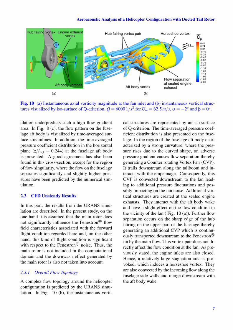
Fig. 10 (a) Instantaneous axial vorticity magnitude at the fan inlet and (b) instantaneous vortical struc-tures visualized by iso-surface of Q-criterion, Q = 6000 1/s2 for U∞ = 62.5 m/s, α =−2 and β = 0.
ulation underpredicts such a high flow gradientarea. In Fig. 8 (c), the flow pattern on the fuse-lage aft body is visualized by time-averaged sur-face streamlines. In addition, the time-averagedpressure coefficient distribution in the horizontalplane (z/lre f = 0.244) at the fuselage aft bodyis presented. A good agreement has also beenfound in this cross-section, except for the regionof flow singularity, where the flow on the fuselageseparates significantly and slightly higher pres-sures have been predicted by the numerical sim-ulation.
2.3 CFD Unsteady Results
In this part, the results from the URANS simu-lation are described. In the present study, on theone hand it is assumed that the main rotor doesnot significantly influence the Fenestron R© flowfield characteristics associated with the forwardflight condition regarded here and, on the otherhand, this kind of flight condition is significantwith respect to the Fenestron R© noise. Thus, themain rotor is not included in the computationaldomain and the downwash effect generated bythe main rotor is also not taken into account.
2.3.1 Overall Flow Topology
A complex flow topology around the helicopterconfiguration is predicted by the URANS simu-lation. In Fig. 10 (b), the instantaneous vorti-
cal structures are represented by an iso-surfaceof Q-criterion. The time-averaged pressure coef-ficient distribution is also presented on the fuse-lage. In the region of the fuselage aft body char-acterized by a strong curvature, where the pres-sure rises due to the curved shape, an adversepressure gradient causes flow separation therebygenerating a Counter rotating Vortex Pair (CVP).It trails downstream along the tailboom and in-teracts with the empennage. Consequently, thisCVP is convected downstream to the fan lead-ing to additional pressure fluctuations and pos-sibly impacting on the fan noise. Additional vor-tical structures are created at the sealed engineexhausts. They interact with the aft body wakeand have a slight effect on the flow condition inthe vicinity of the fan ( Fig. 10 (a)). Further flowseparation occurs on the sharp edge of the hubfairing on the upper part of the fuselage therebygenerating an additional CVP which is continu-ously transported downstream to the Fenestron R©
fin by the main flow. This vortex pair does not di-rectly affect the flow condition at the fan. As pre-viously stated, the engine inlets are also closed.Hence, a relatively large stagnation area is pro-voked, which induces a horseshoe vortex. Theyare also convected by the incoming flow along thefuselage side walls and merge downstream withthe aft body wake.
7

J. H. YOU, N. THOUAULT, C. BREITSAMTER & N. A. ADAMS
Fig. 11 Time-averaged total pressure distributionat the fan inlet.
2.3.2 Inlet Distortion
Besides vortical structures arising from the fuse-lage, flow separation occurs at the inlet geome-try and leads to a highly non-uniform inflow atthe rotor. In Fig. 11, the distribution of time-averaged total pressure ratio is shown at the in-terface between the ROTOR and the DOMAIN.Note that the rotational direction of the fan iscounter-clockwise. The separation bubble causedby boundary layer separation on the inlet lip ra-dius is revealed by a low level of the total pres-sure ratio (indicated by A in Fig. 11). In addi-tion, a recirculation area is generated behind theadvancing side of the rotor hub (indicated by Bin Fig. 11). Highly distorted and unsteady bladeloading is expected, when the blade is passingthrough these high turbulent flow regions. Thisinteraction can produce adverse effects on boththe fan efficiency and the noise generation.A detailed investigation of the inlet distortionhas been performed based on the power spectraldensity (PSD) of the pressure fluctuations. Anarray of monitor points located above the rotorand close to the shroud are considered (Fig. 12(a)). These monitor points are distributed withan equivalent azimuth angle of 12. Static pres-sure values are collected at these points duringthe 10 fan revolutions for each numerical timestep. Fig. 12 (b) shows the result of the PSD anal-ysis as a 2D waterfall plot. Dominant frequen-
(a)
(b)
Fig. 12 Power spectral density (PSD) analysis ofthe inlet distorsion.
cies related to the blade passing frequency (BPF)and its sidebands ( fSB =BPF±ν) are observed.It can be seen that the interaction between therotating blades and the separation bubble orig-inating from the inlet lip causes an increase ofthe pressure fluctuation at the BPF and its side-band frequencies. This statement is confirmed bycomparing the dominant peaks at the azimuth an-gle of θ = 150, where the inflow is relativelyundistorted, to monitor points in the distorted in-flow region (0 to 120 and 260 to 360). Theincrease of PSD magnitude for 180 to 260 iscaused by the interaction of the rotor with sepa-rated flow from the hub.
8
Aeroacoustic Analysis of a Helicopter Configuration with Ducted Tail Rotor
(a)
(b)
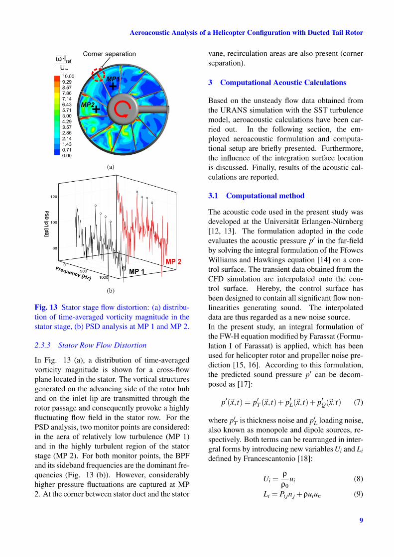
Fig. 13 Stator stage flow distortion: (a) distribu-tion of time-averaged vorticity magnitude in thestator stage, (b) PSD analysis at MP 1 and MP 2.
2.3.3 Stator Row Flow Distortion
In Fig. 13 (a), a distribution of time-averagedvorticity magnitude is shown for a cross-flowplane located in the stator. The vortical structuresgenerated on the advancing side of the rotor huband on the inlet lip are transmitted through therotor passage and consequently provoke a highlyfluctuating flow field in the stator row. For thePSD analysis, two monitor points are considered:in the aera of relatively low turbulence (MP 1)and in the highly turbulent region of the statorstage (MP 2). For both monitor points, the BPFand its sideband frequencies are the dominant fre-quencies (Fig. 13 (b)). However, considerablyhigher pressure fluctuations are captured at MP2. At the corner between stator duct and the stator
vane, recirculation areas are also present (cornerseparation).
3 Computational Acoustic Calculations
Based on the unsteady flow data obtained fromthe URANS simulation with the SST turbulencemodel, aeroacoustic calculations have been car-ried out. In the following section, the em-ployed aeroacoustic formulation and computa-tional setup are briefly presented. Furthermore,the influence of the integration surface locationis discussed. Finally, results of the acoustic cal-culations are reported.
3.1 Computational method
The acoustic code used in the present study wasdeveloped at the Universität Erlangen-Nürnberg[12, 13]. The formulation adopted in the codeevaluates the acoustic pressure p′ in the far-fieldby solving the integral formulation of the FfowcsWilliams and Hawkings equation [14] on a con-trol surface. The transient data obtained from theCFD simulation are interpolated onto the con-trol surface. Hereby, the control surface hasbeen designed to contain all significant flow non-linearities generating sound. The interpolateddata are thus regarded as a new noise source.In the present study, an integral formulation ofthe FW-H equation modified by Farassat (Formu-lation I of Farassat) is applied, which has beenused for helicopter rotor and propeller noise pre-diction [15, 16]. According to this formulation,the predicted sound pressure p′ can be decom-posed as [17]:
p′(~x, t) = p′T (~x, t)+ p′L(~x, t)+ p′Q(~x, t) (7)
where p′T is thickness noise and p′L loading noise,also known as monopole and dipole sources, re-spectively. Both terms can be rearranged in inter-gral forms by introducing new variables Ui and Lidefined by Francescantonio [18]:
Ui =ρ
ρ0ui (8)
Li = Pi jn j +ρuiun (9)
9
J. H. YOU, N. THOUAULT, C. BREITSAMTER & N. A. ADAMS
with ui the local flow velocity, ni normal vectorpointing away from the control surface, Pi j thecompressible stress tensor and ri the position vec-tor from the surface source to the observer po-sition. The integral forms of p′T and p′L for aporous, stationary surface can then be written as:
4πp′T (~x, t) =∂
∂t
∫s
[ρ0Un
R
]adv
dS (10)
4πp′L(~x, t) =
1c0
∂
∂t
∫s
[Lr
R
]adv
dS+∫
s
[Lr
R
]adv
dS
(11)with ρ0 the density, c0 the speed of sound andR the distance between the control surface andthe oberver position. Hereby, the subscript n andr refers to the normal component and the radialcomponent of the vector, respectively. The othersubscript adv denotes that the integration is con-ducted using the advanced time approach pre-sented by Casalino [19] and defined as:
τadv = t +Rc0
(12)
where t is the emission time at which the FW-Hcaculation is performed on the control surface.The term p′Q in Eq. (7) is the quadrupole noise.Here, the strength of the quadrupole source isgenerally very small. Thus, the quadrupole termin Eq. (7) is neglected in the present study.
3.1.1 Setup of Acoustic Simulation
The transient quantities including static pressurep(~x, t), density ρ(~x, t) and all three componentsof the velocity vector ~U(~x, t) have been storedevery three numerical time steps (∆tCAA = 3×∆tCFD) over the last 10 fan revolutions corre-sponding to a physical time of 16.92 ms. Overall,1200 samples are taken from the URANS sim-ulation. The frequency resolution of the soundspectrum corresponds to approximately 6 Hz.In order to perform the FW-H surface integralcalculation, the obtained instantaneous flow datahave been interpolated on a control surface forall acoustic time steps by using in-house writtenCFD macros. For the integral surface method
(a)
(b)
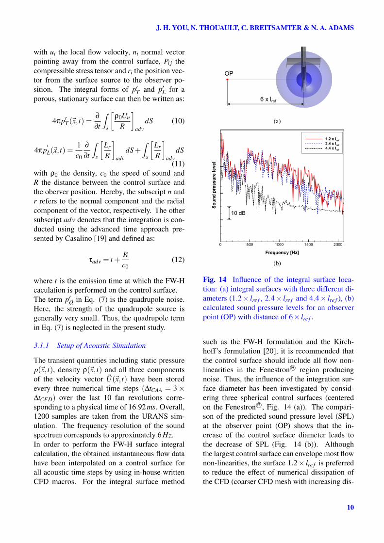
Fig. 14 Influence of the integral surface loca-tion: (a) integral surfaces with three different di-ameters (1.2× lre f , 2.4× lre f and 4.4× lre f ), (b)calculated sound pressure levels for an observerpoint (OP) with distance of 6× lre f .
such as the FW-H formulation and the Kirch-hoff’s formulation [20], it is recommended thatthe control surface should include all flow non-linearities in the Fenestron R© region producingnoise. Thus, the influence of the integration sur-face diameter has been investigated by consid-ering three spherical control surfaces (centeredon the Fenestron R©, Fig. 14 (a)). The compari-son of the predicted sound pressure level (SPL)at the observer point (OP) shows that the in-crease of the control surface diameter leads tothe decrease of SPL (Fig. 14 (b)). Althoughthe largest control surface can envelope most flownon-linearities, the surface 1.2× lre f is preferredto reduce the effect of numerical dissipation ofthe CFD (coarser CFD mesh with increasing dis-
10
Aeroacoustic Analysis of a Helicopter Configuration with Ducted Tail Rotor
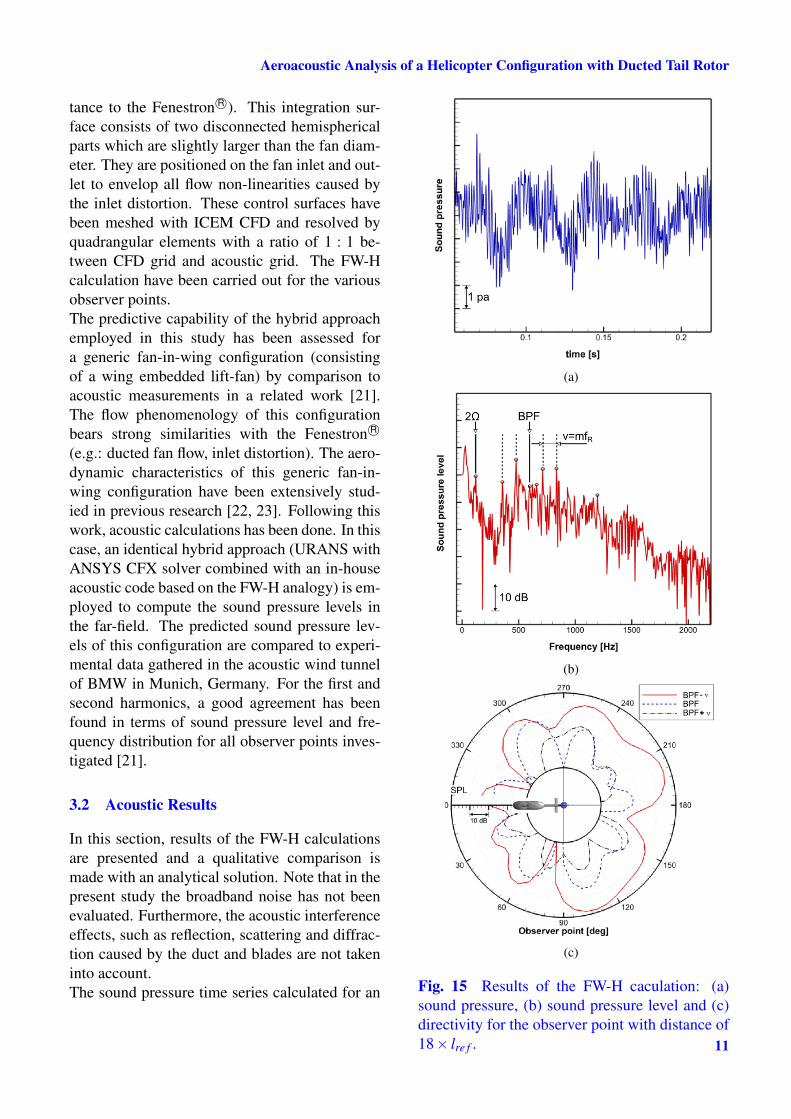
tance to the Fenestron R©). This integration sur-face consists of two disconnected hemisphericalparts which are slightly larger than the fan diam-eter. They are positioned on the fan inlet and out-let to envelop all flow non-linearities caused bythe inlet distortion. These control surfaces havebeen meshed with ICEM CFD and resolved byquadrangular elements with a ratio of 1 : 1 be-tween CFD grid and acoustic grid. The FW-Hcalculation have been carried out for the variousobserver points.The predictive capability of the hybrid approachemployed in this study has been assessed fora generic fan-in-wing configuration (consistingof a wing embedded lift-fan) by comparison toacoustic measurements in a related work [21].The flow phenomenology of this configurationbears strong similarities with the Fenestron R©
(e.g.: ducted fan flow, inlet distortion). The aero-dynamic characteristics of this generic fan-in-wing configuration have been extensively stud-ied in previous research [22, 23]. Following thiswork, acoustic calculations has been done. In thiscase, an identical hybrid approach (URANS withANSYS CFX solver combined with an in-houseacoustic code based on the FW-H analogy) is em-ployed to compute the sound pressure levels inthe far-field. The predicted sound pressure lev-els of this configuration are compared to experi-mental data gathered in the acoustic wind tunnelof BMW in Munich, Germany. For the first andsecond harmonics, a good agreement has beenfound in terms of sound pressure level and fre-quency distribution for all observer points inves-tigated [21].
3.2 Acoustic Results
In this section, results of the FW-H calculationsare presented and a qualitative comparison ismade with an analytical solution. Note that in thepresent study the broadband noise has not beenevaluated. Furthermore, the acoustic interferenceeffects, such as reflection, scattering and diffrac-tion caused by the duct and blades are not takeninto account.The sound pressure time series calculated for an
(a)
(b)
(c)
Fig. 15 Results of the FW-H caculation: (a)sound pressure, (b) sound pressure level and (c)directivity for the observer point with distance of18× lre f . 11
J. H. YOU, N. THOUAULT, C. BREITSAMTER & N. A. ADAMS
observer point located at the fan outlet side on thefan rotational axis with a distance of 18× lre f isshown in Fig. 15 (a). The corresponding soundpressure level spectrum is presented in Fig. 15(b). As expected, the energy of the BPF tone(dominant for an evenly spaced rotor), speads outto the neighbor frequency bands (sideband fre-quencies). A good agreement with the analyticalsolution of the Fenestron R© blades phase modu-lation is found for the frequencies of the relatedspectral peaks (BPF and sidebands, see Sec. 1.1).The asymmetrical tone magnitude of the side-bands to the BPF tone is also well predicted bythe simulation. Thus, the low frequency sideband( fSB = 1stBPF-ν) results in the maximum of thesound pressure level. Since the rotor is designed180 symmetrically in the circumferential direc-tion, the peak at the frequency of 2×Ω also ap-pears as dominant.In Fig. 15 (c), directivities of the calcu-lated sound pressure level are plotted for threedominant frequencies (1stBPF, 1stBPF-ν and1stBPF+ν , respectively). It can be seen that thepredicted tonal noise is more intense downstreamthan upstream. Considerably high sound pres-sure level at the fan inlet side at the azimuth anglerange between 275 to 280 might be caused bythe inlet distortion.
4 Conclusion and Outlook
Aeroacoustic investigations were conducted on ahelicopter fuselage-tail configuration with ductedtail rotor by means of a hybrid approach. Un-steady flow data were obtained from URANSsimulation results and served as input to a FfowcsWilliams and Hawkings analogy. The detailedFenestron R© geometry was modeled and the fanrotation was simulated using a sliding mesh ap-proach. The predictive capability of the CFDapproach has been assessed by comparison toexperimental data of a wind tunnel model withclosed Fenestron R©. A detailed analysis of theflow around the Fenestron R© has been conducted.In cruise, the fan operates under severe condi-tions. Flow separations on the inlet lip causesa significant distortion giving rise to the noise
level. Results of the acoustic simulation show agood agreement in terms of sideband frequencyprediction. The sound directivity in cruise hasbeen reported.Further work will be performed to correlatethe noise sources with the far-field sound pres-sure levels applying SAS (Scale Adaptive Sim-ulation). The effect of the cross-flow on theFenestron R© noise emission will be assessed bycomparison with a helicopter simulation in hover.
Acknowledgments
This work has been supported by the BayerischeForschungsstiftung (BFS) within the frameworkof the FORLärm project. The support of theseinvestigations by the Eurocopter DeutschlandGmbH is gratefully acknowledged. The authorswould like to thank ANSYS CFX for providingthe flow simulation software. The authors alsowish to thank C. Scheit and Dr. S. Becker fromthe Lehrstuhl für Prozessmaschinen und Anla-gentechnik, Universität Erlangen-Nürnberg, Ger-many for providing their FW-H code.
References
[1] Vuillet, A. and Morelli, F., New Aerodynamic De-sign of the Fenestron for Improved Performance,20th European Rotorcraft Forum, Garmisch-Partenkirchen, Germany, Sept. 22-25, 1986.
[2] Niesl, G. and Arnaud, G., Low Noise Designof The EC 135 Helicopter, American HelicopterSociety, 52nd Annual Forum, Washington, D.C.,United States, June 4-6, pp. 32-44, 1996.
[3] Alpman, E., Long, L. N. and Kothmann, B. D.,Toward a Better Understanding of the Ducted Ro-tor Antitorque and Directional Control in For-ward Flight, American Helicopter Society, 59th
Annual Forum, Phoenix, AZ, May 2003.[4] Mouterde, E., Sudre, L., Dequin, A. M.,
D’Alascio A. and Haldenwang, P., AerodynamicComputation of Isolated Fenestron in Hover Con-ditions, 33rd European Rotorcraft Forum, Kazan,Russia, Sept. 11-13, 2007.
[5] D’Alascio, A., Le Chuiton F., Mouterde, E., Su-dre, L., Kirstein, S. and Kau, H.-P., Aerody-namic study of the EC135 Fenestron in Hovering
12

Aeroacoustic Analysis of a Helicopter Configuration with Ducted Tail Rotor
Flight Conditions by Means of CFD, AmericanHelicopter Society 64th Annual Forum, Montréal,Canada, Apr. 29 - Mai 1, 2008.
[6] Roger, M. and Fournier, F., An Analysis of In-Fan Tail Rotor Noise, 20th European RotorcraftForum, Garmisch-Partenkirchen, Germany, Sept.22-25, 1986.
[7] Weisgerber, M. and Neuwerth, G., Influence of aHelicopter Tail Rotor Shroud on the InteractionNoise due to the Main Rotor Vortices, 29th Eu-ropean Rotorcraft Forum, Friedrichshafen, Ger-many, Sept. 16-18, 2003.
[8] Ewald, D., Pavlovic, A., and Bollinger, J. G.,Noise Reduction by Applying Modulation Prin-ciples, Journal of Acoustical Society of America,Vol. 49, Issue 5A, pp. 1381-1385, 1971.
[9] ANSYS, Inc., CFX-Solver Theory Guide Release13.0, Nov. 2010.
[10] Menter, F. R., Two-Equation Eddy-ViscosityTurbulence Models for Engineering ApplicationsAIAA Journal, Vol. 32, No. 8, pp. 1598-1605,1994.
[11] Vogel, F., Breitsamter, C. and Adams, N.A., Aerodynamic Investigations on a HelicopterFuselage, 29th AIAA Applied AerodynamicsConference, Honolulu, Hawaii, Jun. 27-30, 2011.
[12] Scheit, C. L., Implementation of FfowcsWilliams and Hawkings (FW-H) Method forAeroacoustic Prediction, Master Thesis, Univer-sität Erlangen, 2008.
[13] Scheit, C. L., Karic, B. and Becker, S., Effectof Blade Wrap Angle on Efficiency and Noise ofSmall Radial Fan Impellers - A Computationaland Experimental Study, Journal of Sound andVibration, Vol. 331, No. 5, pp. 996-1010, 2012.
[14] Ffwocs Williams, H., Sound Generation by Tur-bulence and Surfaces in Arbitrarary Motion,Philosophical Transactions of the Royal Societyof London, Ser. A, A264, pp. 321-342, 1969.
[15] Farassat, F., Linear Acoustic Formulas for Cal-culation of Rotating Blade Noise, AIAA Journal,Vol. 19, No. 9, pp. 1122-1130, 1981.
[16] Farassat, F., Derivation of Formulations 1 and1A of Farassat, NASA Technical Memorandum,NASA/TM-2007-214853, 2007.
[17] Lyrintzis, A. S., Surface Integral Methodsin Computational Aeroacoustics - From (CFD)Near-Field to the (Acoustic) Far-Field, Interna-
tional Journal of Aeroacoustics, Vol. 2, No. 2, pp.95-128, 2003.
[18] Di Francescantonio, P., A New Boundary Inte-gral Formulation for The Prediction of Sound Ra-diation, Journal of Sound and Vibration, Vol. 22,No. 4, pp. 491-509, 1997.
[19] Casalino, D., An Advanced Time Approach forAcoustic Analogy Predictions, Journal of Soundand Vibration, Vol. 261, No. 4, pp. 583-612,2003.
[20] Kirchhoff, G. R., Zur Theorie der Lichtstrahlen,Annalen der Physik und Chemie, Vol. 254, Issue4, pp. 663-695, 1883 .
[21] Tirakala, J., Thouault, N., Breitsamter, C., andAdams, N. A., Aeroacoustic Investigations of aGeneric Fan-in-Wing Configuration, Internoise,Osaka, Japan, Sept. 4-11, 2011.
[22] Thouault, N., Breitsamter, C., and Adams, N.A., Numerical Investigation of Inlet Distortionon a Wing-Embedded Lift Fan, AIAA Journal ofPropulsion and Power, Vol. 27, No. 1, pp. 16-28,2011.
[23] Thouault, N., Aerodynamic Investigation onGeneric Fan-in-Wing Configurations. PhD The-sis, Technische Universität München, Germany,2010.
Copyright Statement
The authors confirm that they, and/or their company ororganization, hold copyright on all of the original ma-terial included in this paper. The authors also confirmthat they have obtained permission, from the copy-right holder of any third party material included in thispaper, to publish it as part of their paper. The authorsconfirm that they give permission, or have obtainedpermission from the copyright holder of this paper, forthe publication and distribution of this paper as part ofthe ICAS2012 proceedings or as individual off-printsfrom the proceedings.
13
Related Documents


![Job Name: Location: Date: Purchaser: Engineer: …...SEZ-KD09,12,15,18NA (For data on specific indoor units [all ducted, all non-ducted, and both ducted and non-ducted] combinations,](https://static.cupdf.com/doc/110x72/5f3ef44adb4c0539d030f3d9/job-name-location-date-purchaser-engineer-sez-kd09121518na-for-data.jpg)
