AVA 1 Aero Engine Systems and Instruments

Aero engine systems and instruments AVA 1
Jul 13, 2015
Welcome message from author
This document is posted to help you gain knowledge. Please leave a comment to let me know what you think about it! Share it to your friends and learn new things together.
Transcript
AVA 1 Aero Engine
Systems and
Instruments

In this lesson we will briefly look at the various engine systems found in light aircraft
• Ignition• Carburation• Fuel• Oil• Vacuum• Cooling• Electrical

Ignition System
In a spark ignition engine the ignition system provides a spark that ignites the
fuel/air mixture in the cylinders and is made up of magnetos, spark plugs,
high-tension leads, and the ignition switch.
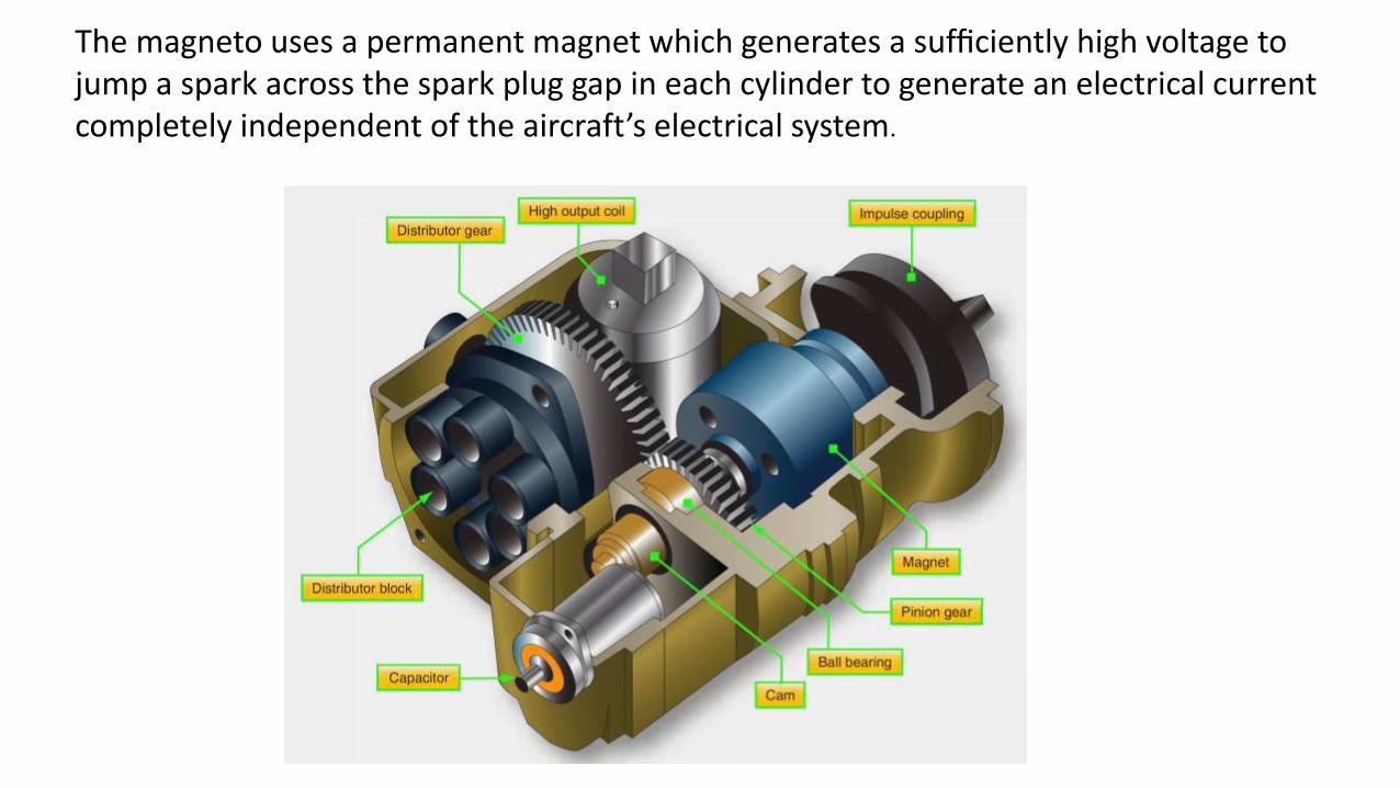
The magneto uses a permanent magnet which generates a sufficiently high voltage to jump a spark across the spark plug gap in each cylinder to generate an electrical current completely independent of the aircraft’s electrical system.

The system begins to fire when the starter is engaged and the crankshaft begins to turn. It continues to operate whenever the crankshaft is rotating.
Australian certificated aircraft incorporate a dual ignition system with two individual magnetos, separate sets of wires, and spark plugs as a fail safe mechanism.

Each magneto operates independently to fire one of the two spark plugs in each cylinder. The firing of two spark plugs also improves combustion of the fuel/air mixture and results in a slightly higher power output. If one of the magnetos fails, the other is unaffected. The engine will continue to operate normally, although a slight decrease in engine power can be expected. The same is true if one of the two spark plugs in a cylinder fails.

Following engine shutdown, turn the ignition switch to the OFF position. Even with the battery and master switches OFF, the engine can fire and turn over if the ignition switch is left ON and the propeller is moved because the magneto requires no outside source of electrical power. Be aware of the potential for serious injury in this situation.
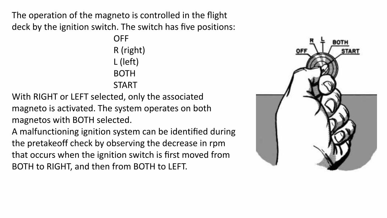
The operation of the magneto is controlled in the flight deck by the ignition switch. The switch has five positions:
OFFR (right)L (left)BOTHSTART
With RIGHT or LEFT selected, only the associated magneto is activated. The system operates on both magnetos with BOTH selected.A malfunctioning ignition system can be identified during the pretakeoff check by observing the decrease in rpm that occurs when the ignition switch is first moved from BOTH to RIGHT, and then from BOTH to LEFT.

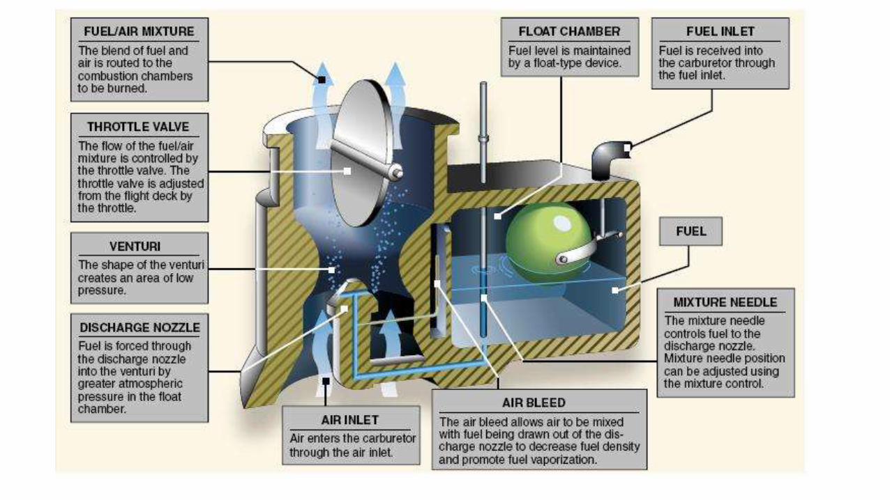
Carburettor Systems
Carburettors are classified as either float type or pressure type. The float type of carburettor, complete with idling, accelerating, mixture control, idle cut off, and power enrichment systems is probably the most common of all carburettor types.

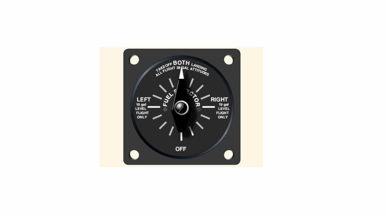
Fuel Systems
The fuel system is designed to provide
an uninterrupted flow of clean fuel from
the fuel tanks to the engine. The fuel
must be available to the engine under all
conditions of engine power, altitude,
attitude, and during all approved flight
manoeuvres. Two common
classifications apply to fuel systems in
small aircraft: gravity-feed and fuel-pump
systems.

Fuel GradesAviation gasoline (AVGAS) is identified by an octane or performance number
(grade), which designates the antiknock value or knock resistance of the fuel
mixture in the engine cylinder.
The current method identifies AVGAS for aircraft with reciprocating engines by
the octane and performance number, along with the abbreviation AVGAS.
These aircraft use AVGAS 80, 100, and 100LL. “LL” indicates it has a low lead
content.
Fuel for aircraft with turbine engines is classified as JET A, JET A-1, and JET B.
Jet fuel is basically kerosene and has a distinctive kerosene smell. Since use of
the correct fuel is critical, dyes are added to help identify the type and grade of
fuel.

Fuel Injection Systems
In a fuel injection system, the fuel is injected directly into the cylinders, or just ahead of the intake valve. The air intake for the fuel injection system is similar to that used in a carburettor system, with an alternate air source located within the engine cowling. This source is used if the external air source is obstructed. The alternate air source is usually operated automatically, with a backup manual system that can be used if the automatic feature malfunctions.

Superchargers and Turbosuperchargers
To increase an engine’s horsepower, manufacturers have developed forced induction systems called supercharger and turbosupercharger systems. They both compress the intake air to increase its density. The key difference lies in the power supply. A supercharger relies on an engine-driven air pump or compressor

turbocharger gets its power from the exhaust stream that runs through a turbine spinning the compressor. Aircraft with these systems have a manifold pressure gauge, which displays MAP within the engine’s intake manifold.

On a standard day at sea level with the engine shut down, the manifold pressure gauge will indicate the ambient absolute air pressure of 29.92 "Hg. Because atmospheric pressure decreases approximately 1 "Hg per 1,000 feet of altitude increase, the manifold pressure gauge will indicate approximately 24.92 "Hg at an airport that is 5,000 feet above sea level with standard day conditions.
Robinson helicopter instrument panel

As a normally aspirated aircraft climbs, it eventually reaches an altitude where the MAP is insufficient for a normal climb. That altitude limit is the aircraft’s service ceiling, and it is directly affected by the engine’s ability to produce power. If the induction air entering the engine is pressurized, or boosted, by either a supercharger or a turbosupercharger, the aircraft’s service ceiling can be increased. With these systems, an aircraft can fly at higher altitudes with the advantage of higher true airspeeds and the increased ability to circumnavigate adverse weather.
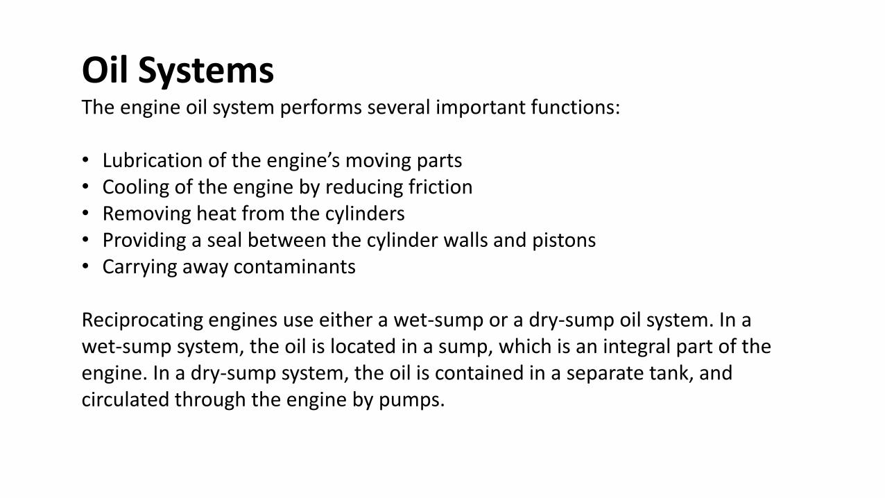
Oil SystemsThe engine oil system performs several important functions:
• Lubrication of the engine’s moving parts• Cooling of the engine by reducing friction• Removing heat from the cylinders• Providing a seal between the cylinder walls and pistons• Carrying away contaminants
Reciprocating engines use either a wet-sump or a dry-sump oil system. In a wet-sump system, the oil is located in a sump, which is an integral part of the engine. In a dry-sump system, the oil is contained in a separate tank, and circulated through the engine by pumps.


The oil filler cap and dipstick (for measuring the oil quantity) are usually
accessible through a panel in the engine cowling. If the quantity does not
meet the manufacturer’s recommended operating levels, oil should be
added. The AFM/POH or placards near the access panel provide
information about the correct oil type and weight, as well as the minimum
and maximum oil quantity.

Vacuum
In some aircraft, all the gyros are vacuum, pressure, or electrically operated. In other aircraft, vacuum or pressure systems provide the power for the heading and attitude indicators, while the electrical system provides the power for the turn coordinator. Most aircraft have at least two sources of power to ensure at least one source of bank information is available if one power source fails. The vacuum or pressure system spins the gyro by drawing a stream of air against the rotor vanes to spin the rotor at high speed, much like the operation of a waterwheel or turbine. The amount of vacuum or pressure required for instrument operation varies, but is usually between 4.5 "Hg and 5.5 "Hg.One source of vacuum for the gyros is a vane-type engine-driven pump that is mounted on the accessory case of the engine. Pump capacity varies in different airplanes, depending on the number of gyros.
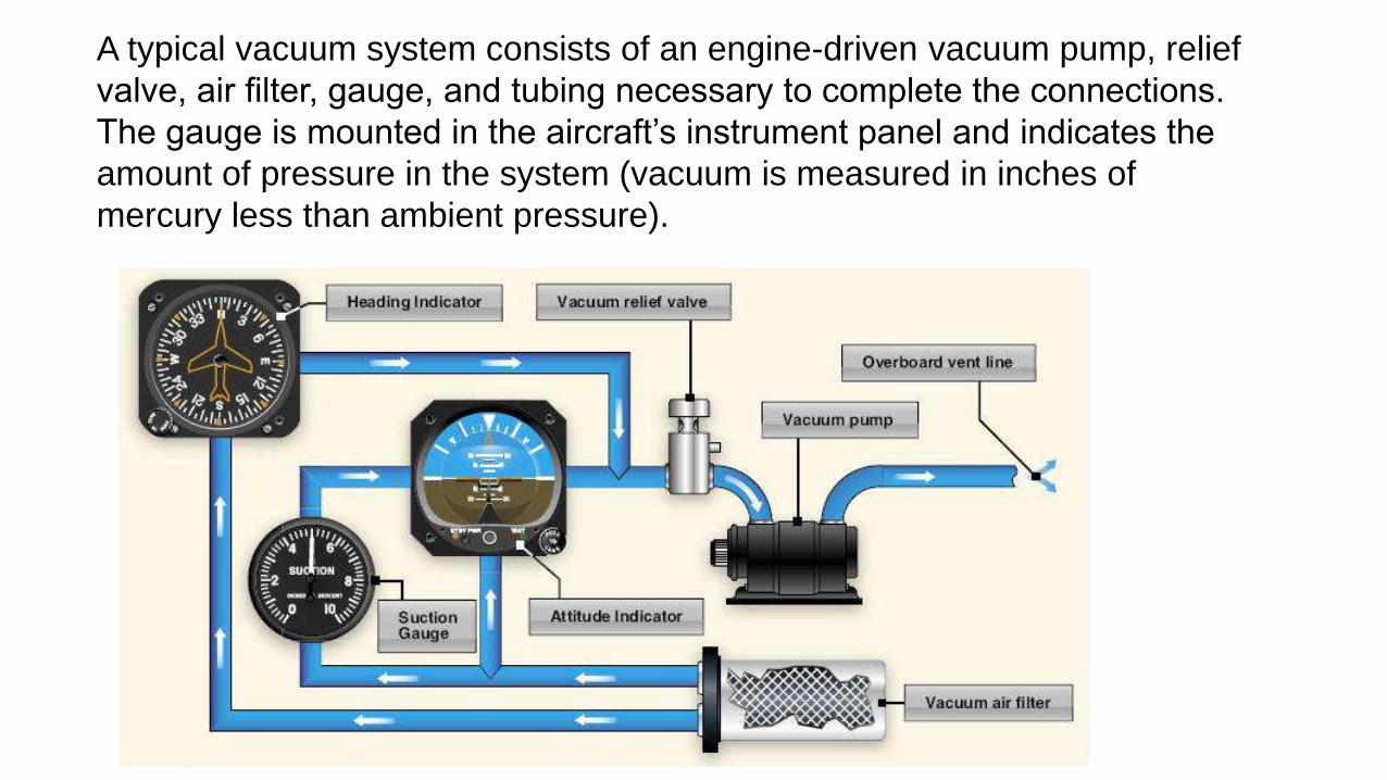
A typical vacuum system consists of an engine-driven vacuum pump, relief
valve, air filter, gauge, and tubing necessary to complete the connections.
The gauge is mounted in the aircraft’s instrument panel and indicates the
amount of pressure in the system (vacuum is measured in inches of
mercury less than ambient pressure).
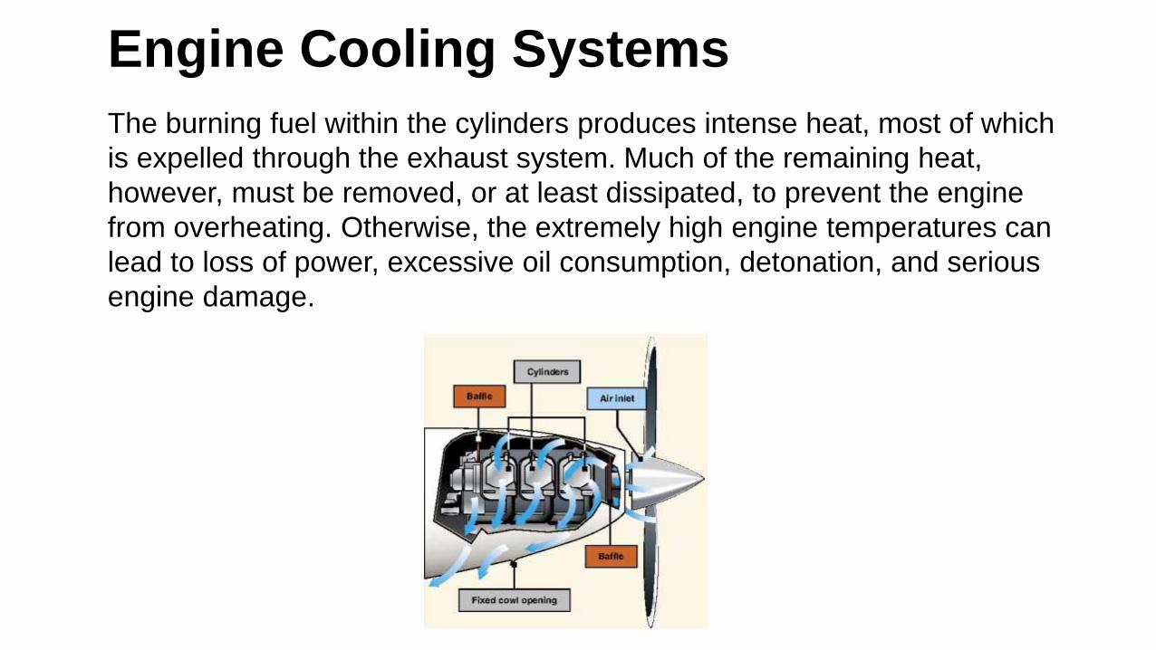
Engine Cooling Systems
The burning fuel within the cylinders produces intense heat, most of which
is expelled through the exhaust system. Much of the remaining heat,
however, must be removed, or at least dissipated, to prevent the engine
from overheating. Otherwise, the extremely high engine temperatures can
lead to loss of power, excessive oil consumption, detonation, and serious
engine damage.

Electrical System
Most aircraft are equipped with either a 14- or a 28-volt direct current electrical system. A basic aircraft electrical system consists of the following components:Alternator/generatorBatteryMaster/battery switchAlternator/generator switchBus bar, fuses, and circuit breakersVoltage regulatorAmmeter/loadmeterAssociated electrical wiring
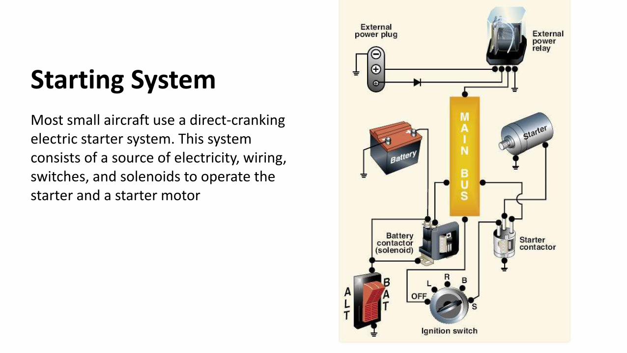
Starting System
Most small aircraft use a direct-cranking electric starter system. This system consists of a source of electricity, wiring, switches, and solenoids to operate the starter and a starter motor
Related Documents