Edited by Aerial Robotics for Inspection and Maintenance Alejandro Suarez, Jonathan Cacace and Matko Orsag Printed Edition of the Special Issue Published in Applied Sciences www.mdpi.com/journal/applsci

Welcome message from author
This document is posted to help you gain knowledge. Please leave a comment to let me know what you think about it! Share it to your friends and learn new things together.
Transcript

Edited by
Aerial Robotics for Inspection and Maintenance
Alejandro Suarez, Jonathan Cacace and Matko Orsag
Printed Edition of the Special Issue Published in Applied Sciences
www.mdpi.com/journal/applsci

Aerial Robotics for Inspection andMaintenance


Aerial Robotics for Inspection andMaintenance
Editors
Alejandro Suarez
Jonathan Cacace
Matko Orsag
MDPI • Basel • Beijing • Wuhan • Barcelona • Belgrade • Manchester • Tokyo • Cluj • Tianjin

Editors
Alejandro Suarez
University of Seville
Spain
Jonathan Cacace
University of Naples Federico
II
Italy
Matko Orsag
University of Zagreb
Croatia
Editorial Office
MDPI
St. Alban-Anlage 66
4052 Basel, Switzerland
This is a reprint of articles from the Special Issue published online in the open access journal
Applied Sciences (ISSN 2076-3417) (available at: https://www.mdpi.com/journal/applsci/special
issues/Aerial Robotics for Inspection and Maintenance).
For citation purposes, cite each article independently as indicated on the article page online and as
indicated below:
LastName, A.A.; LastName, B.B.; LastName, C.C. Article Title. Journal Name Year, Volume Number,
Page Range.
ISBN 978-3-0365-4637-7 (Hbk)
ISBN 978-3-0365-4638-4 (PDF)
Cover image courtesy of IEEE Access
© 2022 by the authors. Articles in this book are Open Access and distributed under the Creative
Commons Attribution (CC BY) license, which allows users to download, copy and build upon
published articles, as long as the author and publisher are properly credited, which ensuresmaximum
dissemination and a wider impact of our publications.
The book as a whole is distributed byMDPI under the terms and conditions of the Creative Commons
license CC BY-NC-ND.

Contents
About the Editors . . . . . . . . . . . . . . . . . . . . . . . . . . . . . . . . . . . . . . . . . . . . . . vii
Alejandro Suarez, Jonathan Cacace and Matko Orsag
Aerial Robotics for Inspection and Maintenance: Special Issue EditorialReprinted from: Appl. Sci. 2022, 12, 3583, doi:10.3390/app12073583 . . . . . . . . . . . . . . . . . 1
Alejandro Suarez, Pedro J. Sanchez-Cuevas, Guillermo Heredia and Anibal Ollero
Aerial Physical Interaction in Grabbing Conditions with Lightweight and Compliant Dual ArmsReprinted from: Appl. Sci. 2020, 10, 8927, doi:10.3390/app10248927 . . . . . . . . . . . . . . . . . 5
Alejandro Suarez, Manuel Perez, Guillermo Heredia and Anibal Ollero
Cartesian Aerial Manipulator with Compliant ArmReprinted from: Appl. Sci. 2021, 11, 1001, doi:10.3390/app11031001 . . . . . . . . . . . . . . . . . 23
Ryo Miyazaki, Hannibal Paul and Kazuhiro Shimonomura
Development of Add-On Planar Translational Driving Systemfor Aerial Manipulation withMultirotor PlatformReprinted from: Appl. Sci. 2021, 11, 1462, doi:10.3390/app11041462 . . . . . . . . . . . . . . . . . 43
Dean Martinovic, Stjepan Bogdan and Zdenko Kovacic
Mathematical Considerations for Unmanned Aerial Vehicle Navigation in the Magnetic Field ofTwo Parallel Transmission LinesReprinted from: Appl. Sci. 2021, 11, 3323, doi:10.3390/app11083323 . . . . . . . . . . . . . . . . . 57
Jonathan Cacace, Santos M. Orozco-Soto, Alejandro Suarez, Alvaro Caballero, Matko Orsag,
Stjepan Bogdan, Goran Vasiljevic, Emad Ebeid, Jose Alberto Acosta Rodriguez and Anibal
Ollero
Safe Local Aerial Manipulation for the Installation of Devices on Power Lines: AERIAL-COREFirst Year Results and DesignsReprinted from: Appl. Sci. 2021, 11, 6220, doi:10.3390/app11136220 . . . . . . . . . . . . . . . . . 79
Angel Rodriguez-Castano, Saeed Rafee Nekoo, Honorio Romero, Rafael Salmoral, Jose
Angel Acosta and Anibal Ollero
Installation of Clip-Type Bird Flight Diverters on High-Voltage Power Lines with AerialManipulation Robot: Prototype and Testbed ExperimentationReprinted from: Appl. Sci. 2021, 11, 7427, doi:10.3390/app11167427 . . . . . . . . . . . . . . . . . 97
Antun Ivanovic, Lovro Markovic, Marko Car, Ivan Duvnjak and Matko Orsag
Towards Autonomous Bridge Inspection: Sensor Mounting Using Aerial ManipulatorsReprinted from: Appl. Sci. 2021, 11, 8279, doi:10.3390/app11188279 . . . . . . . . . . . . . . . . . 113
Rafael Caballero, Jesus Parra, Miguel Angel Trujillo, Francisco J. Perez-Grau, Antidio
Viguria and Anıbal Ollero
Aerial Robotic Solution for Detailed Inspection of ViaductsReprinted from: Appl. Sci. 2021, 11, 8404, doi:10.3390/app11188404 . . . . . . . . . . . . . . . . . 135
Sabrina Carroll, Joud Satme, Shadhan Alkharusi, Nikolaos Vitzilaios, Austin Downey and
Dimitris C. Rizos
Drone-Based Vibration Monitoring and Assessment of StructuresReprinted from: Appl. Sci. 2021, 11, 8560, doi:10.3390/app11188560 . . . . . . . . . . . . . . . . . 155
v

Mostafa Mohammadi, Davide Bicego, Antonio Franchi, Davide Barcelli, and Domenico
Prattichizzo
Aerial Tele-Manipulation with Passive Tool via Parallel Position/Force ControlReprinted from: Appl. Sci. 2021, 11, 8955, doi:10.3390/app11198955 . . . . . . . . . . . . . . . . . 171
Manuel Garcia, Ivan Maza, Anibal Ollero, Daniel Gutierrez, Idoia Aguirre and Antidio
Viguria
Release of Sterile Mosquitoes with Drones in Urban and Rural Environments under theEuropean Drone RegulationReprinted from: Appl. Sci. 2022, 12, 1250, doi:10.3390/app12031250 . . . . . . . . . . . . . . . . . 193
vi

About the Editors
Alejandro Suarez
Alejandro Suarez (Dr.) received his degree in telecommunication engineering and M.Sc. degree
in automation and robotics from the University of Seville, Spain, in 2012 and 2014, respectively,
and his Ph.D. degree in robotics in 2019. Since 2012, he has been with the Robotics, Vision and
Control Group at the University of Seville, working on several European projects, including
FP7 EC-SAFEMOBIL, H2020 AEROARMS, and H2020 HYFLIERS. For three months he stayed
at the Robotics and Mechatronics Institute, DLR, Oberpfaffenhofen. He is currently working on
the AERIAL-CORE H2020 Project, the ERC Advanced GRIFFIN Project, and other projects with
companies involving robotic manipulation. He is the author of 35 articles in international conferences
and journals related to aerial robotics. His research interests include aerial robotic manipulation,
humanoid robots, and the development of anthropomorphic, compliant, and lightweight robotic
arms (LiCAS).
Jonathan Cacace
Jonathan Cacace (Dr.) was born in Naples, Italy, on December 13, 1987. He received his master’s
degree (magna cum laude) in computer science from the University of Naples Federico II in 2012
and his Ph.D. degree in robotics in 2016 from the same institution. Currently, he is working as an
Assistant Professor at the PRISMA Lab (Projects of Robotics for Industry and Services, Mechatronics
and Automation Laboratory) at the University of Naples Federico II, where he is involved in several
research projects in the fields of human–robot interaction in Industry 4.0, the autonomous control of
UAVs for inspection and maintenance, and robotic manipulation. He serves as an Associate Editor
for the IEEE ICRA conference and IEEE’s Robotics and Autonomous Letters.
Matko Orsag
Matko Orsag (Dr.) is an Associate Professor at the University of Zagreb Faculty of Electrical
Engineering and Computing. He is and has been involved in various projects in the fields of robotics,
control, and automation. In 2011/2012 he worked as a visiting researcher at Drexel University,
Philadelphia, USA as a recipient of the Fulbright exchange grant. He has coauthored over 60 scientific
and professional journal and conference papers, a book chapter, and a monography in aerial robotics.
He has helped organized multiple international conferences, serves as an editor of several journals,
and is currently serving as the National Coordinator of European Robotics Week as well as the IEEE
RAS Croatian Section Chair. In 2019 he received a Croatian Academy of Engineering young scientist
award, “Vera Johanides”.
vii


Citation: Suarez, A.; Cacace, J.; Orsag,
M. Aerial Robotics for Inspection and
Maintenance: Special Issue Editorial.
Appl. Sci. 2022, 12, 3583. https://
doi.org/10.3390/app12073583
Received: 28 March 2022
Accepted: 30 March 2022
Published: 1 April 2022
Publisher’s Note: MDPI stays neutral
with regard to jurisdictional claims in
published maps and institutional affil-
iations.
Copyright: © 2022 by the authors.
Licensee MDPI, Basel, Switzerland.
This article is an open access article
distributed under the terms and
conditions of the Creative Commons
Attribution (CC BY) license (https://
creativecommons.org/licenses/by/
4.0/).
applied sciences
Editorial
Aerial Robotics for Inspection and Maintenance: SpecialIssue Editorial
Alejandro Suarez 1,*, Jonathan Cacace 2 and Matko Orsag 3
1 GRVC Robotics Laboratory, University of Seville, Camino de los Descubrimientos s/n, 41092 Seville, Spain2 Department of Electrical Engineering and Information Technology, University of Naples Federico II,
Via Claudio 21, 80125 Naples, Italy; [email protected] Faculty of Electrical Engineering and Computing, University of Zagreb, Unska 3, 10000 Zagreb, Croatia;
[email protected]* Correspondence: [email protected]
1. Introduction
The significant advances in last decade in the research and technology of multi-rotordesign, modeling and control, supported by the increasing variety of commercially availableplatforms, components and manufacturers, have facilitated a rise in the novel applicationsof aerial robots, capable of not only perceiving, but also interacting with the environment,allowing the realization of diverse operations and tasks in areas and workspaces that aredifficult to access by human operators or ground vehicles. Although the use of dronesin surveillance and monitoring, or in aerial filming (both professional and personal) isquite extended nowadays due to the affordable cost of commercial platforms, the use ofaerial robots for the inspection and maintenance of infrastructures is currently the subjectof research and development, particularly when involving physical interaction duringflight. The integration of sensors and robotic manipulators in these platforms, capableof easily and quickly reaching high-altitude workspaces and maintaining their positionwhile hovering, allows us to obtain measurements of interest from cracks in bridges orcorrosion in viaducts, and conduct diverse operations such as the installation of bird flightdiverters on power lines. Aerial robots can also be used for the maintenance of healthyenvironmental conditions in urban or rural areas.
Despite the significant maturity level reached with these platforms, new research andtechnological challenges arise from applications demanding the benefits of aerial robots,particularly in outdoor environments, where regulation aspects must be considered. Thecurrent paradigm is to develop methods and technologies driven by specific applicationsand operational conditions imposed by the sensors or devices involved in the inspectionand maintenance tasks, also considering general goals such as reducing costs, improvingperformance time, safety, and precision, or reducing energy consumption. Therefore,considerable effort is still being devoted to the mechatronic development and integrationof new robotic manipulators, mechanisms, and sensor devices required to accomplish theintended task in flight, extending the capabilities of conventional multi-rotors in terms ofautonomy and force interaction.
This Special Issue presents several research works focused on the use of aerial robotsto conduct inspection and maintenance operations on infrastructures such as power lines,bridges, viaducts, or walls involving physical interactions.
2. Contribution and Advances
This Special Issue collects eleven papers from different research groups from Spain,Croatia, Italy, Japan, the USA, the Netherlands and Denmark, focused on the design,development and experimental validation methods and technologies of aerial robotics forinspection and maintenance. The main contributions and innovation of these works aresummarized below.
Appl. Sci. 2022, 12, 3583. https://doi.org/10.3390/app12073583 https://www.mdpi.com/journal/applsci1

Appl. Sci. 2022, 12, 3583
The lightweight and compliant dual-arm aerial manipulation robot presented in [1]employs one of the arms to estimate the position of the multirotor platform relative to thegrabbing point, while the other arm is intended to conduct the manipulation operation inflight. This is motivated by the necessity to improve the positioning accuracy outdoorsduring the installation of devices on power lines, allowing the estimation and control ofthe interaction forces exerted by the arm, relying on the mechanical flexibility of the jointswith deflection feedback. Reference [2] introduces the Cartesian aerial manipulator, a newmorphology of aerial robot that exploits the benefits of a two degrees of freedom (DoF)Cartesian base (XY-axes) in terms of low weight/inertia and positioning accuracy, witha single DoF compliant joint, exploiting the deflection feedback from the flexible jointand a linear elastic link for contact force control and collision detection and reaction. Thekinematic configuration of the manipulator is also applied in pick-and-store operations.
In order to increase the capability of conventional multi-rotors to generate forces alongthe horizontal plane, required in many contact-based inspection operations, the authorsin [3] describe an add-on mechanism for multi-rotors, consisting of three ducted fansarranged in a Y-shaped structure that can be easily integrated in different types of multi-rotors, in such a way that the horizontal thrust allows the decoupling of the translationalcontrol from the attitude control. The developed prototype demonstrates how a relativelysimple concept design can extend the functionalities and control capabilities of aerial robots.
The inspection and maintenance of power lines is the scope of the work in [4–6], in thecontext of the AERIAL-CORE H2020 project. The high altitude, high voltage, and difficultaccess of this essential infrastructure, comprising thousands of kilometers in any country,makes the realization of operations such as the installation of bird diverters (imposed byregulation to protect bird species from collision or electrocution) particularly risky forhuman operators, who have to climb the towers, using elevated lift platforms or evenmanned helicopters to reach the cables. This motivates the use of multi-rotor-based aerialrobots and the development of new capabilities specifically for this application. In thiscontext, reference [4] details the mathematical formulation for estimating the positionand orientation of a multi-rotor platform from the magnetic field generated by the powerline, measured by three magnetometers. Analytical expressions for the position of theaerial robot relative to the power line are derived, along with an exhaustive analysis of thedifferent solutions and possible arrangements of the sensors.
Several designs and preliminary results in control, planning, and manipulation for theinstallation of devices on power lines, such as bird flight diverters and electrical spacers,are presented in [5], covering also the design of cognitive human–machine interfaces andthe use of aerial manipulators for fast and safe tool delivery to human operators workingon the power lines. The paper provides an overview of the different solutions explored aspart of the AERIAL-CORE project in terms of safe local aerial manipulation. A particulartechnological solution for the installation of approved bird flight diverters is detailed in [6].The main challenge here is to exert very high forces to install the device on the cable, usingfor this purpose a linear actuator with a customized clamp mechanism that holds the deviceand supports the reaction forces, so the aerial platform is isolated during the realization ofthe operation on flight.
The inspection of bridges [7], viaducts [8], and other civil infrastructures [9] usingaerial robots requires the integration of specific sensors and devices, as well as the im-plementation of perception and navigation methods to conduct the operations in flightwith a sufficient level of autonomy and positioning accuracy. The authors in [7] proposethe deployment of a team of cooperative aerial robots to install inspection devices onbridges by spraying a resin onto the surface and applying a pushing force to keep thedevice attached. The paper presents the design of the control framework, covering theattitude/position and impedance controllers, the path planning, and the detection andestimation of the marked point. Two different aerial robotic solutions are presented in [8]for the visual and contact inspection of viaducts, where GNSS (Global Navigation SatelliteSystem) positioning is not possible, requiring the integration of 3D LiDAR (Light Detection
2

Appl. Sci. 2022, 12, 3583
and Ranging) combined with robotic stations to generate accurate maps of the environment.The presented work illustrates the development and integration efforts to increase the TRL(Technology Readiness Level) of aerial robots applied in real inspection scenarios.
Specific methods based on vibration monitoring for the assessment of civil infras-tructure using aerial robots equipped with deployable sensor units are described in [9].Different sensor technologies for Structural Health Monitoring (SHM) are identified, pre-senting the design of a sensor unit based on an accelerometer with a docking mechanismthat can be attached to metallic structures using the aerial platform. Damages on monitoredstructures are detected as changes in their Dynamic Signature Response (DSR), relying onthe B-Spline Impulsive Response Function (BIRF) for representing the time-variable systemdynamics. The paper illustrates, in laboratory conditions, the deployment of the inspectionsensor in a metallic structure subject to vibrations using the aerial robot, including the dataacquisition, analysis and interpretation of results.
Traditional contact-based inspection methods are carried out by human operators,typically consisting of placing the sensor device in the point of interest. In this sense,the operator is responsible for determining the desired inspection point according to theobservations of the environment and specific knowledge of the assessment. Therefore, insome cases it is not convenient or feasible to implement a fully autonomous inspectionoperation with an aerial robotic system, but it is convenient to allow the human operator tointeract with the environment through the aerial robot. This is the scope of the researchwork presented in [10], in which a multi-rotor equipped with a passive and compliantend effector is teleoperated to exert contact forces using a haptic device that provides theuser with feedback to improve his/her situation awareness. The paper is focused on thedesign of the bilateral teleoperation scheme and stability analysis to maintain contact forcesin flight.
Although the inspection and maintenance of industrial and civil infrastructures is oneof the most immediate application areas of aerial robots, reference [11] extends the scope byproposing the application of drones for releasing sterilized insects, in order to prevent theincrease in insect populations that could become vectors of disease transmission in urbanand rural environments. Given the capabilities of Unmanned Aircraft System (UAVs),either fixed wing or rotary wing, to cover large areas following accurately desired paths inan autonomous way, the paper considers the current regulation challenges in Europe andrisk assessment when flying over populated environments, particularly when the droneoperates beyond the visual line of sight (BVLOS).
3. Conclusions
The execution of inspection and maintenance operations in illustrative scenarios suchas power lines, bridges, viaducts and other civil infrastructures, consisting typically of theappropriate collocation of a sensor or device in the point of interest, presents considerablerisk when conducted at high altitude by human operators, and becomes a technologicalchallenge when it is intended to be performed by an aerial robot operating outdoors. Over-coming the gap between research in indoor laboratories and practical application in realisticoutdoor conditions also introduces significant difficulties, particularly in terms of position-ing accuracy and reliability, requiring the integration of additional systems that reducethe effective payload. New mechatronic designs, estimation and measurement methods,control frameworks and technological solutions emerge from demanding applications thathave been shown increasing interest in terms of the application of aerial robots to reducethe time, cost and risk compared with traditional procedures.
Since most of the inspection and maintenance devices currently employed in therealization of these operations are intended to be used by human operators, aerial roboticsresearchers and engineers face the problem of integrating or adapting these devices to aerialplatforms, where the limited payload and flight time capacity are still the main constraints.It is foreseeable, however, that manufacturers will develop new inspection solutionsadapted for aerial robots given the benefits and potential uses evidenced by multi-rotors.
3

Appl. Sci. 2022, 12, 3583
Author Contributions: Conceptualization, A.S., J.C. and M.O.; investigation, A.S., J.C. and M.O.;writing—original draft preparation, A.S.; writing—review and editing, A.S., J.C. and M.O.; visualiza-tion, J.C. and M.O.; supervision, J.C. and M.O.; All authors have read and agreed to the publishedversion of the manuscript.
Funding: This research was partially funded by the European Commission grant number 871479through the AERIAL-CORE H2020 project (AERIAL COgnitive integrated multi-task Robotic systemwith Extended operation range and safety).
Acknowledgments: We want to thank Anibal Ollero from the University of Seville, coordinator ofthe AERIAL-CORE project, for his contribution in the dissemination of this Special Issue.
Conflicts of Interest: The authors declare no conflict of interest.
References
1. Suarez, A.; Sanchez-Cuevas, P.J.; Heredia, G.; Ollero, A. Aerial Physical Interaction in Grabbing Conditions with Lightweight andCompliant Dual Arms. Appl. Sci. 2020, 10, 8927. [CrossRef]
2. Suarez, A.; Perez, M.; Heredia, G.; Ollero, A. Cartesian Aerial Manipulator with Compliant Arm. Appl. Sci. 2021, 11, 1001.[CrossRef]
3. Miyazaki, R.; Paul, H.; Shimonomura, K. Development of Add-On Planar Translational Driving System for Aerial Manipulationwith Multirotor Platform. Appl. Sci. 2021, 11, 1462. [CrossRef]
4. Martinovic, D.; Bogdan, S.; Kovacic, Z. Mathematical Considerations for Unmanned Aerial Vehicle Navigation in the MagneticField of Two Parallel Transmission Lines. Appl. Sci. 2021, 11, 3323. [CrossRef]
5. Cacace, J.; Orozco-Soto, S.M.; Suarez, A.; Caballero, A.; Orsag, M.; Bogdan, S.; Vasiljevic, G.; Ebeid, E.; Rodriguez, J.A.A.; Ollero,A. Safe Local Aerial Manipulation for the Installation of Devices on Power Lines: AERIAL-CORE First Year Results and Designs.Appl. Sci. 2021, 11, 6220. [CrossRef]
6. Rodriguez-Castaño, A.; Nekoo, S.R.; Romero, H.; Salmoral, R.; Acosta, J.Á.; Ollero, A. Installation of Clip-Type Bird FlightDiverters on High-Voltage Power Lines with Aerial Manipulation Robot: Prototype and Testbed Experimentation. Appl. Sci. 2021,11, 7427. [CrossRef]
7. Ivanovic, A.; Markovic, L.; Car, M.; Duvnjak, I.; Orsag, M. Towards Autonomous Bridge Inspection: Sensor Mounting UsingAerial Manipulators. Appl. Sci. 2021, 11, 8279. [CrossRef]
8. Caballero, R.; Parra, J.; Trujillo, M.Á.; Pérez-Grau, F.J.; Viguria, A.; Ollero, A. Aerial Robotic Solution for Detailed Inspection ofViaducts. Appl. Sci. 2021, 11, 8404. [CrossRef]
9. Carroll, S.; Satme, J.; Alkharusi, S.; Vitzilaios, N.; Downey, A.; Rizos, D. Drone-Based Vibration Monitoring and Assessment ofStructures. Appl. Sci. 2021, 11, 8560. [CrossRef]
10. Mohammadi, M.; Bicego, D.; Franchi, A.; Barcelli, D.; Prattichizzo, D. Aerial Tele-Manipulation with Passive Tool via ParallelPosition/Force Control. Appl. Sci. 2021, 11, 8955. [CrossRef]
11. Garcia, M.; Maza, I.; Ollero, A.; Gutierrez, D.; Aguirre, I.; Viguria, A. Release of Sterile Mosquitoes with Drones in Urban andRural Environments under the European Drone Regulation. Appl. Sci. 2022, 12, 1250. [CrossRef]
4

applied sciences
Article
Aerial Physical Interaction in Grabbing Conditionswith Lightweight and Compliant Dual Arms
Alejandro Suarez *, Pedro J. Sanchez-Cuevas, Guillermo Heredia and Anibal Ollero
GRVC Robotics Labs, University of Seville, 41092 Seville, Spain; [email protected] (P.J.S.-C.);[email protected] (G.H.); [email protected] (A.O.)* Correspondence: [email protected]
Received: 4 November 2020; Accepted: 12 December 2020; Published: 14 December 2020
Abstract: This paper considers the problem of performing bimanual aerial manipulation tasks ingrabbing conditions, with one of the arms grabbed to a fixed point (grabbing arm) while the otherconducts the task (operation arm). The goal was to evaluate the positioning accuracy of the aerialplatform and the end effector when the grabbing arm is used as position sensor, as well as to analyzethe behavior of the robot during the aerial physical interaction on flight. The paper proposed acontrol scheme that exploits the information provided by the joint sensors of the grabbing arm forestimating the relative position of the aerial platform w.r.t. (with respect to) the grabbing point.A deflection-based Cartesian impedance control was designed for the compliant arm, allowing thegeneration of forces that help the aerial platform to maintain the reference position when it is disturbeddue to external forces. The proposed methods were validated in an indoor testbed with a lightweightand compliant dual arm aerial manipulation robot.
Keywords: aerial manipulation; dual arm; compliance
1. Introduction
The reliability in the realization of an aerial manipulation task on flight strongly depends on thepositioning accuracy of the aerial robot, which mainly depends on the accuracy of the position sensors,the performance of the multirotor controller, and the effect of endogenous/exogenous forces raisedduring the execution of the operation. On the one hand, it is desirable that the accuracy in the positionestimation of the aerial vehicle is below the 10% of the reach of the manipulator [1], being capable ofcompensating the undesired deviations while the multirotor hovers within the workspace. Differentpositioning systems have been employed in the literature. Motion capture systems such as Vicon orOpti-Track have been extensively used in indoor testbeds [2–6] due to their high accuracy (<1 cm) andhigh update rates (100–200 Hz), as well as because no additional devices have to be integrated in theaerial platform, but only the passive markers. Similarly, the laser tracking systems used in [7] onlyrequire the addition of a reflective marker or a prism to the multirotor, although this solution imposesthat the marker is not occluded by any obstacle in the line of the laser. Several on-board perceptionsystems have been developed for multirotor platforms, including optical flow [8], stereo vision [9],live 3D dense reconstruction [10], or laser scanners [11]. However, these solutions reduce the payloadcapacity of the aerial platform, as additional devices such as cameras and on-board computers have tobe added and complicate the system integration. Not only that, but each of these technologies presentscertain limitations relative to the operation range, accuracy, reliability, or the update rate. The dockingsystem described in [12] is an alternative solution that exploits the proximity of the aerial platformto the workspace during the manipulation phase, using an articulated link for obtaining the relativeposition from the encoders of the joints.
An aerial manipulation robot operating on flight will be affected by three types of perturbations:the reaction wrenches induced over the multirotor platform due to the motion of the arms [13,14],
Appl. Sci. 2020, 10, 8927; doi:10.3390/app10248927 www.mdpi.com/journal/applsci
5

Appl. Sci. 2020, 10, 8927
the contact forces associated to the physical interactions on flight [4,6,15–17], as well as the aerodynamiceffects [7]. As consequence, the realization of certain manipulation tasks requiring the correct positioningof the end effector, such as object grasping [2,5], valve turning [3], or inspection by contact [7,15,18],may be compromised or become unfeasible. In order to overcome these problems, several methodsand strategies have been proposed, such as the estimation and control of the external wrenchesacting over the aerial platform [19,20], the development of multilayer control architectures [13], or thedesign of lightweight and compliant robotic arms [21,22]. In this sense, it is desirable to improve theaccommodation of the aerial platform to the position deviations when it is operating in contact withthe environment, exploiting for this purpose the mechanical compliance of the arms [22].
The main contribution of this paper is the design, modelling, and validation of a lightweight andcompliant dual arm system that allows for the estimation and control of the position of an aerial roboticmanipulator relative to a fixed grabbing point, using one of the arms for grabbing and as position sensor(grabbing arm), while the other is intended to conduct the operation while flying (operation arm).Figure 1 illustrates the application of the dual arm aerial manipulator for the installation of clip-typebird diverters on a power line [23]. Two methods are proposed and evaluated. Firstly, a zero-torquecontroller was implemented in the grabbing arm, and thus the reaction wrenches induced over themultirotor were relatively low, using the position estimation obtained from the joint servos to controlthe deviations in the position of the platform with respect to the reference pose. Secondly, a forcecontroller based on Cartesian deflection was developed to achieve the desired impedance behaviorduring the aerial physical interaction, using the grabbing arm to exert a force that helps the multirotorcontroller to reach the reference pose relative to the grabbing point. Experimental results carried out intest-bench and indoor flight tests (Figure 1) demonstrated the performance of both approaches.
Figure 1. Dual arm aerial manipulation robot grabbed a linear structure with the right (grabbing) arm.
The innovative aspects of this paper with respect to our previous published works [17,21,22] canbe summarized in the following points:
1. The development and testing of a new functionality for the dual arm aerial manipulator: estimatingthe position of the robot relative to the grabbing point with one of the arms while the other isintended to conduct the operation on flight.
2. The evaluation of the positioning accuracy in the estimation provided by the grabbing armcompared to the ground truth given by an Opti-Track system.
3. The combination of passive (mechanical) and active (control) compliance methods in the grabbingarm to facilitate the accommodation of the aerial robot to sustained grabbing forces.
4. The experimental evaluation and qualitative analysis of the effects of the grabbing arm and theinjected disturbances over the stability of the multirotor controller.
6

Appl. Sci. 2020, 10, 8927
The rest of the paper is organized as follows. The prototype employed in the experiments is firstlydescribed in Section 2. Section 3 covers the kinematics and position estimation, with the mentionedcontrol methods described in Section 4. The experimental results are presented in Section 5, and theconclusions are summarized in Section 6.
2. System Description
2.1. Compliant Dual Arm
The manipulator used for validating the methods described in Section 4 is a lightweight andcompliant dual arm system developed at the GRVC Robotics Labs. A picture of the arms can be seenin Figure 2, indicating in Table 1 its main features. Each arm provides three degrees of freedom forend effector positioning in the following kinematic configuration [22]: shoulder yaw at the base (q1),shoulder pitch (q2), and elbow pitch (q3). The arms are built with the Herkulex DRS-0201 smart servos,and a customized frame structure manufactured in carbon fiber and aluminum, providing full servoprotection at the shoulder yaw joint with a pair of polymer bearings, and partial servo protection inthe other two joints [21]. In order to estimate and control the torques and forces, the grabbing arm(right arm) integrates 14-bit resolution magnetic encoders that are interfaced through a STM32F303microcontroller board, sending the deflection measurement to the main computer at 200 Hz with 1 mslatency. Each of the arms and the sensors are connected to the Raspberry Pi 3B+ through USB-to-USARTinterfaces, where control program of the arms is executed. The manipulator is fed with a 2S, 650 mAhLiPo battery, providing an operation time of around 20 min.
Figure 2. Compliant dual arm used in the experiments.
Table 1. Main features of the lightweight and compliant dual arm.
Total Weight 1.0 (kg)
Maximum lift load(1 s playtime)
At elbow: 0.3 (kg)At shoulder: 0.12 (kg)
Joint stiffness 5 (Nm/rad)—all joints
Maximum joint speed 300 (◦/s)
7

Appl. Sci. 2020, 10, 8927
The tip of the forearm link includes an aluminum flange to facilitate the integration of the endeffector in the manipulator. For safety reasons, the grabbing operation is conducted with a magneticgripper (around 5 N force), using the linear metallic structure shown in Figure 1 for grabbing.
2.2. Aerial Manipulation Robot
The dual arm system is integrated in an S550 platform, a hexarotor similar to a DJI F550. This isequipped with six DJI 2312E brushless motors with 9 × 4.5 inch propellers. Figure 3 shows a pictureof the aerial robot, identifying its components, including the Pixhawk 2.1 autopilot, the RaspberryPi 3B+ computer board, and the 4S 4400 mAh LiPo battery (0.5 kg) used as counterweight of thearms. The setup is similar to the one described in [14], constraining the motion of the arms toprevent the collision with the landing gear. The hardware and software architecture of the systemis represented in Figure 4. The control program of the arms, developed in C/C++, as well as thedifferent software modules that control the aerial platform, based on ROS and the UAV AbstractionLayer [24], are executed in the Raspberry Pi and interfaced by the Ground Control Station (GCS)through the wireless link. Four USB-to-USART devices are connected to the computer board: (1) thePixhawk autopilot, (2) the left arm, (3) the right arm, and (4) the microcontroller board that reads thesensors. The position and orientation of the multirotor are obtained from an Opti Track system, used asground truth.
Figure 3. Dual arm aerial manipulation robot.
Figure 4. Hardware architecture of the aerial manipulation robot.
8

Appl. Sci. 2020, 10, 8927
3. Modelling
3.1. Kinematics
As usual, three reference frames are defined for the aerial manipulation system, as illustratedin Figure 5: the Earth fixed frame {E} (inertial), the multirotor body frame {B}, and the manipulatorframe {i}, with i = {1, 2} for the left/right arms. In the following, ArB denotes the position of a certainpoint B w.r.t. (with respect to) reference frame {A}. In this way, ErB = [x, y, z]T and EηB = [φ, θ, ψ]T
represent the multirotor position and orientation relative to {E}, and irTCP,i is the position of the toolcenter point (TCP) of the i-th manipulator expressed in its own frame. The origin of {i} is located at theintersection of the shoulder joints, with the x-axis pointing forwards, the y-axis parallel to the baselineof the two arms, and the z-axis pointing upwards.
Figure 5. Kinematic model of the dual arm aerial manipulator.
The three reference frames are related through the corresponding transformation matrices:
ETB =
[ ERB(φ, θ, ψ) ErB
01×3 1
]; BTi =
[I3×3
Bri01×3 1
]; ETi =
ETB·BTi (1)
where ERB is the multirotor rotation matrix; Bri = [Dx, ±D/2, Dz]T is the origin of {i} relative to {B},
with Dx and Dz being the displacement of the arms with respect to {B} in the x- and z-axes, respectively;and D is the separation distance between the arms in the y-axis.
The arms implement the 3-DOF (degrees of freedom) configuration considered in our previouswork [14,22], with three joints for TCP positioning: shoulder yaw (base), shoulder pitch, and elbowpitch. The wrist joints are not considered due to the convenience to simplify the mechanical constructionand reduce the weight of the arms. The rotation angle of the j-th joint of the i-th arm is denoted as qi
j,
whereas θij is the corresponding servo shaft position. The difference between these two variables is the
deflection angle, Δθij = θi
j − qij, measured by the encoders [17,21]. The forward and inverse kinematic
models are computed as follows (superscript i is omitted for clarity reasons):
irTCP,i = FK(qi)=
⎡⎢⎢⎢⎢⎢⎢⎢⎢⎣r(q2, q3)· cos(q1)
r(q2, q3)· sin(q1)
L1 cos(q2) + L2 cos(q2 + q3)
⎤⎥⎥⎥⎥⎥⎥⎥⎥⎦ (2)
9

Appl. Sci. 2020, 10, 8927
qi = IK(irTCP,i
)=
⎡⎢⎢⎢⎢⎢⎢⎢⎢⎢⎢⎢⎢⎢⎢⎣
atan2(y, x)
cos−1(
x2+y2+z2−L21−L2
2
2L1√
x2+y2
)
cos−1(
x2+y2+z2−L21−L2
22L1L2
)
⎤⎥⎥⎥⎥⎥⎥⎥⎥⎥⎥⎥⎥⎥⎥⎦(3)
where L1 and L2 are the upper arm/forearm link lengths, and r(q2, q3) is given by
r(q2, q3) = L1 sin(q2) + L2 sin(q2 + q3) (4)
3.2. Relative Position Estimation
If the end effector of the grabbing arm is firmly attached to a fixed point, then it is possible toestimate the position of the multirotor relative to this grabbing point just applying the homogeneoustransformation from {2} to {B}, taking into account that the position of the TCP referred to {2} is directlyobtained from the forward kinematic model given by Equation (2). The accuracy in the positionestimation can be obtained multiplying the joint position error (including the deflection error) by theJacobian of the arm. The wrist joints are not essential for this purpose, as the multirotor orientation canbe obtained from the inertial measurement unit (IMU) of the aerial platform. However, a certain levelof accommodation is required at the wrist so the robotic arm can follow the position and orientationdeviations of the aerial platform while it is grabbed.
Two similar mechanisms have been proposed in previous works for estimating the pose ofan aerial manipulator relative to a contact point. Reference [12] presents a docking tool consistingof an articulated arm with passive joints that is deployed over a pipe with a stiff-joint dual arm,whereas reference [25] relies on a passive spherical wrist joint and an IMU integrated at the end effectorof a 3-DOF arm. In this paper, we combine the passive/active compliance methods for estimating themultirotor position while controlling the interaction force.
3.3. Dynamics
The dynamic model of the compliant joint dual arm aerial manipulation robot is derived from theLagrangian and the generalized equations of the forces and torques:
L = K −V (5)
ddt
⎧⎪⎪⎨⎪⎪⎩∂L
∂.ξ
⎫⎪⎪⎬⎪⎪⎭−{∂L∂ξ
}= Γ + Γext (6)
where L is the Lagrangian; K and V are the kinetic and potential energies, respectively; ξ is the vectorof generalized coordinates; and Γ and Γext respectively represent the generated and external wrenchesacting on the aerial robot. The vector of generalized coordinates includes the multirotor position andorientation, as well as the servo shaft and output link angular position vectors, θi =
[θi
1 θi2 θi
3
]and qi =
[qi
1 qi2 qi
3
], respectively, and thus ξ is defined as follows.
ξ =[
ErBEηB θ1 q1 θ2 q2
]T ∈ �18 (7)
Analogously, the vector of generalized forces comprises the forces and torques acting over themultirotor and the joints of the manipulator.
Γ =[
FB τB τ1m τ1 τ2
m τ2]T ∈ �18 (8)
The vector of external forces Γext models the disturbance wrenches exerted on the multirotorbase [18–20], the contact forces at the end effector [4,6,17], as well as the aerodynamic forces raisedwhen the thrust of the rotors is affected by close surfaces in the environment [7,26].
10

Appl. Sci. 2020, 10, 8927
The kinetic energy of the aerial manipulator can be expressed as the sum of the kinetic energy ofthe aerial platform and the kinetic energy of the robotic arms:
K = KUAV + Karms (9)
Each of these components comprises two terms corresponding to the translation and rotation ofthe masses with respect to the inertial frame {E}:
KUAV =12
mUAV‖E .rB‖2 + 1
2EωT
BIUAVEωB (10)
Karms =2∑
i=1
4∑j=1
(12
mij‖E
.r j
i‖2+
12
Eωi,Tj Ii
jEωi
j
)(11)
where mUAV and IUAV are the mass and inertia tensor of the aerial platform, respectively, whereas mij
and Iij are mass and inertia of the j-th joint of the i-th arm, respectively. The potential energy of the
aerial manipulator also includes two terms, the gravity and elastic potential of the compliant joints:
V = g
⎛⎜⎜⎜⎜⎜⎜⎝mUAVzUAV +2∑
i=1
4∑j=1
mijz
ij
⎞⎟⎟⎟⎟⎟⎟⎠+2∑
i=1
4∑j=1
kij
(θi
j − qij
)2(12)
Here, g is the gravity constant, and kij is the corresponding joint stiffness. After some work, it is
possible to express the dynamic model in the usual compact matrix form [14]:
M..ξ+ C
(ξ,
.ξ)+ G(ξ) + K(ξ) + D
( .ξ)= Γ + Γext (13)
where M ∈ �18×18 is the generalized inertia matrix; C and G ∈ �18 represent the centrifugal, Coriolis,and gravity terms; and K and D ∈ �18 correspond to the stiffness and damping terms of the compliantmanipulator, respectively [17]. The dynamic coupling between the arms and the aerial platform isassociated with the cross terms in the generalized inertia matrix, which can be decomposed in threegroups of submatrices identified in [14]: multirotor translation (decoupled from rotation), multirotorrotation with coupling terms, and dual arm manipulator with coupling terms. Since the grabbing armwill be held to a fixed point, the corresponding inertia, Coriolis, and gravity terms will be negligiblecompared to the operation arm. Moreover, if the sensitivity of the zero-torque controller describedin next section is good enough, then the magnitude of the wrenches associated to the stiffness anddamping terms will be relatively low, and with it, the influence over the multirotor controller.
As stated in the introduction and illustrated in Figure 1, the operation arm is intended to performthe manipulation operation (the installation of a bird flight diverter) while the grabbing arm providesthe position estimation. This can be assimilated to a close kinematic chain [27,28] with floating base [29],in which the pushing/pulling force exerted by the operation arm will cause a reaction torque on theaerial platform that should be cancelled by the multirotor controller with the help of the grabbing armin order to prevent undesired position deviations. This motivates the implementation of an activeimpedance control scheme with the grabbing arm, as explained below.
4. Control
4.1. Definition of the Control Task
As stated in the introduction, a dual arm system allows the realization of aerial manipulationtasks in grabbing conditions, using one arm for grabbing and for estimating the position of the aerialplatform relative to the grabbing point (Section 3.2), whereas the other takes care of conducting thetask, for example, the installation of a sensor device [21]. Since the grabbing arm is actuated and
11

Appl. Sci. 2020, 10, 8927
mechanically compliant, it is possible to estimate and control the forces and torques acting over themanipulator from the deflection of the joints [17,21]. The idea is that the arm helps the multirotor toreach the desired position when it is disturbed by an external force, exerting a pushing/pulling force inthe opposite direction of the position error, as Figure 6 illustrates.
Figure 6. Model considered in grabbing conditions. Nominal operation pose (left), and displacementdue to external force (right). The grabbing arm compensates the disturbance exerting a reaction force.
Therefore, the grabbing arm can be used in two ways:
• As relative position sensor, with zero torque control, so the reaction wrenches induced over themultirotor are relatively small.
• As an active impedance link, exerting a controlled force over the aerial platform to compensateexternal forces and guide the multirotor towards the reference position.
In the first case, the joints of the grabbing arm implement a PI (proportional-integral) controller tomaintain a zero deflection (torque) reference, acting over the servo position as follows:
θ2j,re f = θ2
j +
(Kp
(θ2
j − q2j
)+ Ki
∫ (θ2
j − q2j
)dt)
(14)
Here, θ2j is the position of the j-th servo of the right arm, whereas the term on the right side is
the incremental position correction. The proportional and integral gains, Kp and Ki, can be tunedexperimentally, taking into account the nominal values of the deflection (≈5 degrees). Now, we imposethat the nominal operation position of the aerial robot relative to the grabbing point is the L-shapedconfiguration of the arm, since this is far enough from the joint limits and the kinematic singularities(although any other could be considered):
2rre fTCP2 =
⎡⎢⎢⎢⎢⎢⎢⎢⎢⎣L2
0−L1
⎤⎥⎥⎥⎥⎥⎥⎥⎥⎦ = FK(q2
re f
)= FK
⎛⎜⎜⎜⎜⎜⎜⎜⎜⎝⎡⎢⎢⎢⎢⎢⎢⎢⎢⎣
00−π/2
⎤⎥⎥⎥⎥⎥⎥⎥⎥⎦⎞⎟⎟⎟⎟⎟⎟⎟⎟⎠ (15)
The position deviation of the aerial platform is then defined as the displacement of the TCP of thegrabbing arm w.r.t. the reference position. That is,
ε =[εX εY εZ
]T= FK
(q2
re f
)− FK
(q2
)(16)
Note that the maximum deviation is limited by the reach of the arm, ‖ε‖ < L1 + L2 −√
L21 + L2
2.If the influence of the grabbing arm over the attitude controller is relatively low due to the zero-torque
12

Appl. Sci. 2020, 10, 8927
controller, this measurement can then be taken as input by the position controller of the multirotorplatform, as represented in upper part of Figure 7, replacing the GPS (Global Positioning System) usedfor navigating to achieve better accuracy during the manipulation phase.
DUAL ARM SYSTEM
AERIAL PLATFORM
Force Controller IK∆
FK
FK
+Grabbing
Arm
−∆ +
−
MultirotorAttitude Controller
Position Controller
+FK
− +Figure 7. Control scheme of the aerial manipulator with grabbing arm (i = 2).
4.2. Impedance Control in Grabbing Conditions
Assuming that the aerial platform is close to the hover state during the grabbing maneuver(φ � θ � 0), it is desired that the position deviation of the aerial platform is assimilated to an impedancebehavior characterized as follows:
Md..ε+ Dd
.ε+Kdε = Fext (17)
where Md, Dd, and Kd are the desired inertia, damping, and stiffness, respectively, and Fext is theexternal force exerted over the multi-rotor. This force can be estimated from the Cartesian deflection ofthe grabbing arm, as it will be seen in next subsection, and taken as input by the attitude controller ofthe aerial platform so it can be partially compensated with the wrenches generated by the rotors.
The grabbing arm will react to the external force exerting a pushing/pulling force at the endeffector in the direction of the position deviation, relying on the Cartesian force controller described inthe next subsection. The impedance control is then achieved, generating a force reference that cancelsthe dynamic behavior described by Equation (17). Figure 7 represents the case of desired stiffness,Fi
e,TCP = Kdε.
4.3. Force Control Based on Cartesian Deflection
The force control of the compliant arm is formulated in the Cartesian space and based on theCartesian deflection, defined as the position deviation of the TCP of the compliant arm w.r.t. the samepoint in an equivalent stiff joint arm. That is,
ΔlTCPi = FK(θi
)− FK
(qi)
(18)
This definition is useful for expressing the force at the end effector directly in the task space:
iFTCPi = KiCΔlTCPi + Di
C
.ΔlTCPi (19)
13

Appl. Sci. 2020, 10, 8927
where KiC and Di
C are the Cartesian stiffness and damping matrices, respectively, whose values can beobtained from the physical joint stiffness and damping through the Jacobian:
KiC =
(JT
)−1Ki
p J−1 (20)
where Kip = diag
{ki
j
}is the physical joint stiffness matrix [17]. The Cartesian damping can be obtained
analogously. The force controller, represented in Figure 7 relies on the inverse kinematics, giving asoutput an incremental position correction term for the TCP:
irre fTCPi =
irTCPi + ΔriTCP = FK
(qi)+
(KF
PFie,TCP + KF
I
∫Fi
e,TCPdt)
(21)
Here, ΔriTCP is the position increment that should be applied in the grabbing arm to
achieve the desired force reference; Fie,TCP = Fi
re f − FiTCP is the force control error at the TCP;
whereas KFP = diag
{KF
Px, KFPy, KF
Pz
}and KF
I = diag{KF
Ix, KFIy, KF
Iz
}are the proportional and integral
gain matrices, respectively, whose value is tuned experimentally knowing the nominal values of theforces (around 1 [N]) and the Cartesian deflection (around 0.02 [m]).
5. Experimental Results
5.1. Position Estimation with Zero Deflection/Torque Control
The goal of this experiment was to evaluate the accuracy of the position estimation provided bythe grabbing arm when this was used as position sensor, enabling the zero-torque controller to reducethe reaction wrenches induced over the aerial platform on flight (see Section 4.1). The experiment,shown in the video provided as Supplementary Material, consisted of four phases:
(1) The multirotor takes off.(2) The arms adopt the nominal operation pose given by Equation (15).(3) The aerial robot approaches the contact point using the Opti Track system for navigating.(4) Once the arm grabs the support structure, the zero-torque controller and the estimator are enabled
while the multirotor is controlled in position with the Opti Track system.
Figures 8–10 represent the signals of interest during the grabbing maneuver, that is, the multirotorposition (arm estimation and ground truth) relative to the nominal pose, the multirotor orientation,the estimation error, and the joint position and torque in the grabbing arm. In order to appreciate theability of accommodation of the arm and the accuracy in the estimation, we intentionally deviated theaerial platform in the x- and z-axes, with small deviations in the y-axis. Note that in the experiments theend-effector is supposed to be firmly attached to the grabbing point in such a way that the displacementof the multirotor platform will force the displacement of the grabbing arm. However, the magneticgripper may slip around the contact area, introducing errors in the position estimation. It was alsoassumed that the multirotor heading (yaw angle) was almost constant, with the YB-axis parallel tothe linear structure. Otherwise, additional degrees of freedom should be integrated in the wrist jointto estimate the relative orientation, although this is out of the scope of this work. The influence ofthese two effects over the positioning accuracy can be observed in Figure 9, where the estimationerror increased as the multirotor orientation in the yaw angle changed with respect to its initial value,causing mainly errors in the y-axis estimation.
14

Appl. Sci. 2020, 10, 8927
Figure 8. Multirotor displacement in the grabbing maneuver with zero torque control. Nominal pose(black), displacement measured by OptiTrack (magenta), and arm estimation (blue).
Figure 9. Position estimation error, using Opti-Track as ground truth. x-, y-, and z-axes error (up) anderror norm (middle). The three shaded areas correspond to situations in which the platform is rotatedin yaw and the error increased since the magnetic gripper was not firmly attached to the point.
Figure 10. Evolution of the servo position and torque estimation during the grabbing maneuver.
15

Appl. Sci. 2020, 10, 8927
5.2. Impedance Control in Test-Bench
Before its evaluation on flight, the impedance controller of the grabbing arm was firstly validatedin test-bench in order to evidence more clearly the variation in the desired stiffness, as definedin Equation (17). During the experiment, the arm adopted the L-shaped configuration (Figure 6and Equation (15)), manually exerting an external force at the end effector that was estimated andcompensated from the Cartesian deflection, as expressed by Equations (19) and (21). The desiredstiffness was set to Kd = 50 Nm for the experiment illustrated in Figure 11, and to Kd = 100 Nm for theexperiment represented in Figure 12. As it can be seen, the position deviation of the end effector waslower in the second case, as expected, and the instantaneous stiffness (Kx = Fx/εx) was similar to thedesired value. Note that the stiffness is affected by the singularity associated to the deflection whenthis tends to zero.
Figure 11. Force reference and estimation (up), position deviation (middle), and instantaneous stiffness(down) in the x- and z-axes for a desired stiffness Kd = 50 [Nm].
Figure 12. Force reference estimation (up), position deviation (middle), and instantaneous stiffness(down) in the x- and z-axes for a desired stiffness Kd = 100 [Nm].
16

Appl. Sci. 2020, 10, 8927
5.3. Grabbing Interaction on Flight with Impedance Control
The goal of this experiment was to analyze the behavior of the aerial manipulation robot on flightwhen the grabbing arm was actively controlling the impedance in the x- and z-axes, considering adesired Cartesian stiffness Kd,X = Kd,Z = 50 [N/m]. The performance of the controller was evaluatedby injecting a disturbance on the multirotor position that emulates the effect of an external force, such asa wind gust. The zero-torque controller of the first joint (shoulder yaw) was disabled, relying only onthe passive compliance to support the lateral displacements (y-axis) and heading variations (yaw angle)of the multirotor. The flight test consists of eight phases:
1. The aerial manipulator takes offwith the arms resting in landing configuration.2. The grabbing arm adopts the nominal pose (L-shaped) while the operation arm is retracted.3. The impedance controller is enabled, imposing a zero reference for the first joint (θ2
1 = 0).
4. The aerial manipulator approaches to the linear structure until the magnetic gripper grabs it.5. The aerial manipulator hovers while the impedance controller of the grabbing arm is active.6. A position disturbance is injected through the radio controller to observe the response of the
aerial manipulator and the reaction of the grabbing arm.7. The torque control of the servos is disabled to release the grabbing arm.8. The arms adopt the landing pose, and the platform goes back and lands.
Figures 13 and 14 show the evolution of the system in the time intervals corresponding to phase 5and phase 6, respectively. On the one hand, Figure 13 covers the time interval from t = 25 to t = 35 s,in which the multirotor was hovering at fixed position while the grabbing arm exerted a small force inthe x-axis, around 0.5 N, due to the slight displacement of the platform with respect to the nominalpose. On the other hand, Figure 14 covers the interval from t = 48 to t = 70 s. At t = 49.6 [s],we intentionally applied a 10 cm displacement in the x-axis position of the multirotor, emulating awind gust. The grabbing arm reacted, exerting a pushing force with a peak of 2.2 [N] that counteractedthe disturbance, recovering the nominal operation pose in 2 s. The instantaneous stiffness varied w.r.t.the desired value (50 N/m) due to the singularity in the displacement (Kd,x = Fx/εx). Note also that,since the grabbing arm was not aligned with the XBZB plane of the base but it was displaced a distanceD/2 (see Section 3.1), then the force exerted during the interaction would cause a reaction torque in theyaw angle of the multirotor, and with it, a position deviation in the y-axis, as can be seen in Figure 14.The effect was accentuated as the pilot disturbed the multirotor controller between t = 52 and t = 60 s.Although the passive deflection of the shoulder yaw joint provided a certain level of accommodation,the motion constraint associated with the grabbing condition had a more significant effect on the y-axisand yaw angle, in accordance with the results shown in Figure 9.
17

Appl. Sci. 2020, 10, 8927
Figure 13. Evolution of the grabbing arm while the multirotor hovers with no disturbance during thegrabbing maneuver (phase 5) with impedance control in the x- and z-axes (Kx = Kz = 50 N/m).
Figure 14. Evolution of the grabbing arm and the multirotor, disturbed at t = 49.6 seconds, during thegrabbing maneuver (phase 6) with impedance control in the x- and z-axes (Kx = Kz = 50 N/m).
18

Appl. Sci. 2020, 10, 8927
6. Conclusions
The paper presented two approaches for the estimation and control of the physical interactions ofa compliant dual arm aerial manipulation robot operating in grabbing conditions, in which one of thearms was used as position sensor relative to a grabbing point, implementing a zero-torque controller sothe wrenches induced over the multirotor base were relatively low. The mechanical joint complianceof the arm was also exploited for the development of active compliance methods, achieving desiredimpedance behaviors that improved the response of the aerial manipulator when it was affected byexternal disturbances while interacting physically with the environment. The experimental resultspresented here validated the concepts, allowed us to evaluate the accuracy of the position estimation,and evidenced the convenience of combining the passive/active compliance on the three Cartesian axes.
Although the aerial manipulation robot will require a navigation system to reach the workspace,the positioning accuracy required to perform the manipulation task (which should be around 10%of the reach of the arm) cannot be achieved with typical sensors employed in outdoor environments,such as GPS, LIDAR (light detecting and ranging), or vision systems. In this sense, the estimationmethods described in this work result from special interest to avoid the integration of additionalpositioning systems, taking into account the limited payload capacity of the aerial platform, being alsoan effective and reliable solution. In terms of future work, we propose the application of this system forthe installation of bird flight diverters on power lines, or for inspection and maintenance of railways,chemical plants, and other linear infrastructure.
Supplementary Materials: The following are available online at http://www.mdpi.com/2076-3417/10/24/8927/s1.Video S1: Aerial_Physical_Interaction.mp4.
Author Contributions: Conceptualization, A.O. and A.S.; software, A.S. and P.J.S.-C.; validation, A.S. andP.J.S.-C.; data curation, A.S.; writing—original draft preparation, A.S.; writing—review and editing, G.H. and A.S.;supervision, G.H.; project administration, A.O.; funding acquisition, A.O. All authors have read and agreed to thepublished version of the manuscript.
Funding: This work was funded by the AERIAL-CORE project (H2020-2019-871479) funded by the EuropeanCommission; the European Research Council Advanced Grant GRIFFIN project (Action 788247); and theARM-EXTEND (DPI2017-89790-R) and ARTIC (RTI2018-102224-B-I00) projects funded by the Spanish Ministeriode Economia, Industria, y Competitividad.
Conflicts of Interest: The authors declare no conflict of interest.
References
1. Suarez, A.; Vega, V.M.; Fernandez, M.; Heredia, G.; Ollero, A. Benchmarks for Aerial Manipulation.IEEE Robot. Autom. Lett. 2020, 5, 2650–2657. [CrossRef]
2. Kim, S.; Choi, S.; Kim, H.J. Aerial manipulation using a quadrotor with a two DOF robotic arm. In Proceedingsof the IEEE/RSJ International Conference on Intelligent Robots and Systems, Tokyo, Japan, 3–7 November2013; pp. 4990–4995.
3. Orsag, M.; Korpela, C.; Bogdan, S.; Oh, P. Dexterous aerial robots—Mobile manipulation using unmannedaerial systems. IEEE Trans. Robot. 2017, 33, 1453–1466. [CrossRef]
4. Cataldi, E.; Muscio, G.; Trujillo, M.A.; Rodriguez, Y.; Pierri, F.; Antonelli, G.; Caccavale, F.; Viguria, A.;Chiaverini, S.; Ollero, A. Impedance control of an aerial-manipulator: Preliminary results. In Proceedingsof the 2016 IEEE/RSJ International Conference on Intelligent Robots and Systems (IROS), Daejeon, Korea,9–14 October 2016; pp. 3848–3853.
5. Santamaria-Navarro, A.; Grosch, P.; Lippiello, V.; Solà, J.; Andrade-Cetto, J. Uncalibrated visual servo forunmanned aerial manipulation. Trans. Mechatron. 2017, 22, 1610–1621. [CrossRef]
6. Tognon, M.; Chavez, H.A.T.; Gasparin, E.; Sable, Q.; Bicego, D.; Mallet, A.; Lany, M.; Santi, G.; Revaz, B.;Cortess, J.; et al. A truly-redundant aerial manipulator system with application to push-and-slide inspectionin industrial plants. IEEE Robot. Autom. Lett. 2019, 4, 1846–1851. [CrossRef]
7. Jimenez-Cano, A.E.; Sanchez-Cuevas, P.J.; Grau, P.; Ollero, A.; Heredia, G. Contact-based bridge inspectionmultirotors: Design, modeling, and control considering the ceiling effect. IEEE Robot. Autom. Lett. 2019, 4,3561–3568. [CrossRef]
19

Appl. Sci. 2020, 10, 8927
8. Rhudy, M.B.; Chao, H.; Gu, Y. Wide-field optical flow aided inertial navigation for unmanned aerial vehicles.In Proceedings of the IEEE/RSJ Int. Conference on Intelligent Robots and Systems, Chicago, IL, USA, 14–18September 2014; pp. 674–679.
9. Schmid, K.; Tomic, T.; Ruess, F.; Hirschmüller, H.; Suppa, M. Stereo vision based indoor/outdoor navigationfor flying robots. In Proceedings of the 2013 IEEE/RSJ International Conference on Intelligent Robots andSystems, Tokyo, Japan, 3–7 November 2013; pp. 3955–3962.
10. Faessler, M.; Fontana, F.; Forster, C.; Mueggler, E.; Pizzoli, M.; Scaramuzza, D. Autonomous, vision-basedflight and live dense 3D mapping with a quadrotor micro aerial vehicle. J. Field Robot. 2016, 33, 431–450.[CrossRef]
11. Huh, S.; Shim, D.H.; Kim, J. Integrated navigation system using camera and gimbaled laser scanner forindoor and outdoor autonomous flight of UAVs. In Proceedings of the IEEE/ International Conference onIntelligent Robots and Systems, Tokyo, Japan, 3–7 November 2013; pp. 3158–3163.
12. Ramon Soria, P.; Arrue, B.C.; Ollero, A. A 3D-printable docking system for aerial robots: Controlling aerialrobotic manipulators in outdoor industrial applications. IEEE Robot. Autom. Mag. 2019, 26, 44–53. [CrossRef]
13. Ruggiero, F.; Trujillo, M.A.; Cano, R.; Ascorbe, H.; Viguria, A.; Perez, C.; Lippiello, V.; Ollero, A.; Siciliano, B.A multilayer control for multirotor UAVs equipped with a servo robot arm. In Proceedings of the IEEE Int.Conference on Robotics and Automation (ICRA), Seattle, WA, USA, 26–30 May 2015; pp. 4014–4020.
14. Suarez, A.; Jimenez-Cano, A.E.; Vega, V.M.; Heredia, G.; Rodriguez-Castaño, A.; Ollero, A. Design of alightweight dual arm system for aerial manipulation. Mechatronics 2018, 50, 30–44. [CrossRef]
15. Fumagalli, M.; Naldi, R.; Macchelli, A.; Forte, F.; Keemink, A.Q.L.; Stramigioli, S.; Carloni, R.; Marconi, L.Developing an aerial manipulator prototype: Physical interaction with the environment. IEEE Robot.Autom. Mag. 2014, 21, 41–50. [CrossRef]
16. Hamaza, S.; Georgilas, I.; Fernandez, M.; Sanchez, P.; Richardson, T.; Heredia, G.; Ollero, A. Sensor installationand retrieval operations using an unmanned aerial manipulator. IEEE Robot. Autom. Lett. 2019, 4, 2793–2800.[CrossRef]
17. Suarez, A.; Heredia, G.; Ollero, A. Physical-virtual impedance control in ultralightweight and compliantdual-arm aerial manipulators. IEEE Robot. Autom. Lett. 2018, 3, 2553–2560. [CrossRef]
18. Bodie, K.; Brunner, M.; Pantic, M.; Walser, S.; Pfändler, P.; Angst, U.; Siegwart, R.; Nieto, J. An omnidirectionalaerial manipulation platform for contact-based inspection. In Proceedings of Robotics: Science and Systems.arXiv 2019, arXiv:1905.03502.
19. Ruggiero, F.; Cacace, J.; Sadeghian, H.; Lippiello, V. Impedance control of VToL UAVs with a momentum-basedexternal generalized forces estimator. In Proceedings of the IEEE International Conference on Robotics andAutomation (ICRA), Hong Kong, China, 31 May–7 June 2014; pp. 2093–2099.
20. Tomic, T.; Haddadin, S. A unified framework for external wrench estimation, interaction control and collisionreflexes for flying robots. In Proceedings of the IEEE/RSJ International Conference on Intelligent Robots andSystems, Chicago, IL, USA, 14–18 September 2014; pp. 4197–4204.
21. Suarez, A.; Real, F.; Vega, V.M.; Heredia, G.; Rodriguez-Castaño, A.; Ollero, A. Compliant bimanual aerialmanipulation: Standard and long reach configurations. IEEE Access 2020, 8, 88844–88865. [CrossRef]
22. Suarez, A.; Heredia, G.; Ollero, A. Lightweight compliant arm with compliant finger for aerial manipulationand inspection. In Proceedings of the IEEE/RSJ International Conference on Intelligent Robots and Systems(IROS), Daejeon, Korea, 9–14 October 2016; pp. 4449–4454.
23. AERIAL-CORE Project Home Page. Available online: https://aerial-core.eu/ (accessed on 12 October 2020).24. Real, F.; Torres-González, A.; Ramon-Soria, P.; Capitan, J.; Ollero, A. UAL: An abstraction layer for unmanned
aerial vehicles. In Proceedings of the 2nd International Symposium on Aerial Robotics, Philadelphia, PA,USA, 11–12 June 2018.
25. Perez-Jimenez, M.; Montes-Grova, M.A.; Ramon-Soria, P.; Arrue, B.C.; Ollero, A. POSITRON: Lightweightactive positioning compliant joints robotic arm in power lines inspection. In Proceedings of the 2020International Conference on Unmanned Aircraft Systems (ICUAS), Athens, Greece, 1–4 September 2020;pp. 729–736.
26. Sanchez-Cuevas, P.J.; Heredia, G.; Ollero, A. Characterization of the aerodynamic ground effect and itsinfluence in multirotor control. Int. J. Aerosp. Eng. 2017, 2017, 1823056. [CrossRef]
27. Liu, T.; Lei, Y.; Han, L.; Xu, W.; Zou, H. Coordinated resolved motion control of dual-arm manipulators withclosed chain. Int. J. Adv. Robot. Syst. 2016, 13, 80. [CrossRef]
20

Appl. Sci. 2020, 10, 8927
28. Lee, J.; Chang, P.H.; Jamisola, R.S. Relative impedance control of dual-arm robots performing asymmetricbimanual tasks. Trans. Ind. Electron. 2014, 61, 3786–3796. [CrossRef]
29. Stolfi, A.; Gasbarri, P.; Sabatini, M. A combined impedance-PD approach for controlling a dual-arm spacemanipulator in the capture of a non-cooperative target. Acta Astronaut. 2017, 139, 243–253. [CrossRef]
Publisher’s Note: MDPI stays neutral with regard to jurisdictional claims in published maps and institutionalaffiliations.
© 2020 by the authors. Licensee MDPI, Basel, Switzerland. This article is an open accessarticle distributed under the terms and conditions of the Creative Commons Attribution(CC BY) license (http://creativecommons.org/licenses/by/4.0/).
21


applied sciences
Article
Cartesian Aerial Manipulator with Compliant Arm
Alejandro Suarez *, Manuel Perez, Guillermo Heredia and Anibal Ollero
Citation: Suarez, A.; Perez, M.;
Heredia, G.; Ollero, A. Cartesian
Aerial Manipulator with Compliant
Arm. Appl. Sci. 2021, 11, 1001.
https://doi.org/10.3390/app11031001
Received: 28 December 2020
Accepted: 18 January 2021
Published: 22 January 2021
Publisher’s Note: MDPI stays neutral
with regard to jurisdictional claims in
published maps and institutional affil-
iations.
Copyright: © 2021 by the authors.
Licensee MDPI, Basel, Switzerland.
This article is an open access article
distributed under the terms and
conditions of the Creative Commons
Attribution (CC BY) license (https://
creativecommons.org/licenses/by/
4.0/).
GRVC Robotics Labs, University of Seville, 41092 Sevilla, Spain; [email protected] (M.P.);[email protected] (G.H.); [email protected] (A.O.)* Correspondence: [email protected]
Abstract: This paper presents an aerial manipulation robot consisting of a hexa-rotor equipped witha 2-DOF (degree of freedom) Cartesian base (XY–axes) that supports a 1-DOF compliant joint armthat integrates a gripper and an elastic linear force sensor. The proposed kinematic configurationimproves the positioning accuracy of the end effector with respect to robotic arms with revolutejoints, where each coordinate of the Cartesian position depends on all the joint angles. The Cartesianbase reduces the inertia of the manipulator and the energy consumption since it does not need to liftits own weight. Consequently, the required torque is lower and, thus, the weight of the actuators.The linear and angular deflection sensors of the arm allow the estimation, monitoring and control ofthe interaction wrenches exerted in two axes (XZ) at the end effector. The kinematic and dynamicmodels are derived and compared with respect to a revolute-joint arm, proposing a force-positioncontrol scheme for the aerial robot. A battery counterweight mechanism is also incorporated in theX–axis linear guide to partially compensate for the motion of the manipulator. Experimental resultsindoors and outdoors show the performance of the robot, including object grasping and retrieval,contact force control, and force monitoring in grabbing situations.
Keywords: aerial manipulation; Cartesian manipulator; compliance; hexa-rotor
1. Introduction
1.1. Aerial Manipulation
Aerial manipulation robots (drones equipped with robotic arms) are extending the po-tential applications of multirotor platforms, allowing the realization of tasks involving themanipulation of objects and tools in flight, as well as interaction with the environment witha certain level of dexterity and control capability. The development of this technology ismotivated by interest in reducing the time, cost and risk for human workers associated withthe realization of certain tasks in high altitude or difficult access workspaces such as powerlines [1,2], chemical plants [3], oil and gas refineries [4], and other infrastructures [5,6].Recent works in this field have demonstrated the possibility to conduct operations such asobject grasping [7–9], valve turning [10], sensor installation and retrieval [2,11], contact-based inspection [3,12,13], insulation of cracks and leaks [14], or the realization of othertasks with grippers and other tools [15,16]. Several prototypes and morphologies of ma-nipulators have been specifically developed for their integration in multi-rotors, includingmulti-joint arms [17,18], dual arm systems [7,10], linear actuators [11], delta manipula-tors [14], compliant joint arms [2,19,20], long reach aerial manipulators [2,21], or three-armmanipulators used for object grasping and as reconfigurable landing gear [22].
Compliance, either mechanical [7,19–23] or at control level [11,24–26], is a highlydesirable feature for an aerial manipulation robot operating in contact with the environ-ment since the stability of the aerial platform may be compromised due to the interactionwrenches exerted on flight [24,25,27]. The design and development of compliant manip-ulators aim to increase safety by exploiting the energy storage capacity and passivityproperties of springs [7,19,26] and elastomers [23] while protecting the aerial robot against
Appl. Sci. 2021, 11, 1001. https://doi.org/10.3390/app11031001 https://www.mdpi.com/journal/applsci23

Appl. Sci. 2021, 11, 1001
impacts and overloads [23]. Unlike most industrial manipulators that use expensive force-torque sensors in the joints or in the end effector, the servo actuators (Herkulex, Dynamixel)typically employed for building lightweight robotic arms for aerial manipulation do notprovide a direct measurement of the torque; or this is based on the current, so its accuracy islow due to the friction of the gearbox. This has motivated the development of methods forestimating and controlling the forces and torques from the measurement of the deflectionin the elastic element, either at joint level [7,19] or in the Cartesian space [26]. Despite theevident benefits of mechanical compliance during the physical interactions of the aerialrobot while flying, the main drawback of these mechanisms is the reduction in positionaccuracy due to the deflection of the joints [19] or links [2], a consequence of the secondorder dynamics associated with the mass-spring-damper system [26]. As a result, therealization of tasks requiring accurate positioning tends to become more difficult.
1.2. Positioning Accuracy
Positioning accuracy is one of the most relevant and challenging requirements for anaerial manipulator operating on flight since it determines the reliability and success rate inthe realization of tasks like grasping [7] or the installation of devices on power lines [1,26],especially outdoors where Vicon or OptiTrack systems are not available, whereas sensorslike 3D laser scanners [28] and vision-based systems [29] are more suited. This feature isdirectly related to the performance of the multirotor position controller [30,31], affected bythe endogenous and exogenous wrenches exerted through the manipulator [25,27]. On theone hand, tilted-rotor hexa-rotors, also known as fully actuated aerial platforms [32,33],allow the translation of the platform as well as the application of wrenches [34,35] withoutchanging the orientation, which contributes to increasing the accuracy in the realization ofmanipulation tasks compared to coplanar multi-rotors. On the other hand, the error propa-gation at the end effector is closely related with the kinematic configuration and the physicalconstruction of the manipulator. This is, in most cases, a multi-link arm [7,8,17,18,24] withrevolute joints. However, this configuration present two main drawbacks: (1) the jointlimits (especially in the elbow joint) constraint or reduce the effective reach and workspaceof the arm, (2) a significant amount of torque and energy is needed to lift the weight ofthe manipulator itself (forearm-upper arm configuration), requiring high torque actuatorsthat tend to increase the weight. Alternatively, other works propose the use of simplemanipulators [3,5,11,14,15] in order to reduce the weight, at expenses of reducing the reachand dexterity.
1.3. Contribution of This Work
The main contribution of this paper is the design, development and experimentalvalidation of a new morphology of aerial manipulation robot consisting of a hexa-rotorplatform integrating a 2-DOF (degree of freedom) Cartesian base (XY–axes) that carries a1-DOF compliant joint arm equipped with a gripper and a deflection-based force-torquesensor. Figure 1 shows a picture of the prototype. The proposed morphology is intended toimprove the positioning accuracy of the end effector while reducing the inertia, torque andweight of the actuators, since the Cartesian base supports most of the weight of the roboticmanipulator (0.85 kg weight, 1 m reach, and 10 cm/s speed). The elastic deflection sensorsintegrated in the compliant joint and in the fore-arm link are used to estimate and monitorthe force (XZ–axes) and torque (pitch) exerted by the manipulator over the aerial platform.This allows the realization of a number of tasks such as sensor installation with contactforce control, force monitoring in grabbing situations, or object grasping and retrieval. Thekinematic and dynamic models of the aerial manipulator are derived, while analyzing inmore detail the error propagation at the end effector from the Jacobian, comparing theproposed morphology with respect to that of a revolute-joint arm in terms of positioningaccuracy, reach, and workspace. This paper also proposes a force-position control schemefor the aerial robot that takes into account the wrench estimation provided by the arm.
24

Appl. Sci. 2021, 11, 1001
Experimental results conducted in test-bench as well as indoor/outdoor flight tests validatethe functionalities and capabilities of the developed Cartesian aerial robot.
Figure 1. Cartesian manipulator (left) integrated in S550 hexarotor platform (right).
The rest of the paper is organized as follows. Section 2 presents the motivation forand describes the prototype of a Cartesian aerial manipulator with compliant joint arm.Section 3 presents the kinematic and dynamic models of the aerial robot, analyzing andcomparing the features of the Cartesian manipulator with respect to a revolute-joint arm.Section 4 covers the control of the aerial robot, the experimental results are shown inSection 5, and the conclusions in Section 6.
2. System Description
2.1. Motivation
The Cartesian manipulator aims to avoid three inconveniences of the human-likerobotic arms developed in our previous work [7,19]. First of all, several manipulationtasks like grasping or peg-in-hole are defined in the Cartesian space rather than in the jointspace, so it is more convenient that the mapping between both spaces is straightforwardin order to improve the positioning accuracy. According to the forward kinematic model,the XYZ position of the end effector depends simultaneously on the rotation angle of thethree [19] or four [7] joints of the manipulator (shoulder and elbow). Therefore, the jointposition errors, as well as errors associated with the manufacturing and assembly of thearm (clearance, misalignment), will be propagated to the three Cartesian coordinates of theend effector. Additionally, the mechanical deflection of the joints in a compliant arm [7]may cause deviations of several centimeters in the position of the end effector with respectto an equivalent stiff-joint arm. In a Cartesian manipulator, instead, the position of theend effector on each axis is controlled with its own actuator independently from the otherjoints, so the position errors are decoupled and the trajectory control in the task spaceis simplified.
Secondly, the effective reach of a human-like manipulator (~50 cm reach) is in practicerelatively small, around 30 cm, taking into account that the nominal operation positionof the arm is typically an L-shaped configuration (forearm lifted 90◦) and due to the limitin the rotation angle of the elbow joint. Note that humans extend the reach of the handswith the torso and legs, whereas in an aerial manipulator the motion of the arms is usuallyconstrained by the landing gear and the perimeter of the propellers. In this sense, theCartesian base avoids dead-zones in its workspace due to joint limits, allowing access topoints close to the multirotor base, which can be useful, for example, in object retrieval and
25

Appl. Sci. 2021, 11, 1001
storage. Finally, a two link manipulator in the upper arm-forearm morphology typicallyrequires a significant amount of torque and energy to lift its own weight, whereas in thedeveloped prototype the Cartesian manipulator only has to compensate for the inertia andfriction of the carriage, reducing in this way the required torque of the actuators, and thus,their weight. Not only that, but the linear guide also isolates the actuators from impactsand loads, avoiding the design of bearing-based protection mechanisms, as in [7].
The Cartesian manipulator shown in Figure 1 implements a Prismatic-Prismatic-Revolute (PPR) configuration, introducing a revolute joint attached at the Cartesian base,since the landing gear and central body of the hexa-rotor platform do not allow theplacement of a linear actuator in the vertical axis, and because this configuration extendsthe reach of the end effector in the X–axis (forward direction). No additional degrees offreedom are considered for end effector positioning due to the convenience of reducing theweight, complexity and size of the manipulator, and because the capabilities of the robot canbe extended with the additional degrees of freedom provided by the aerial platform [13,32].
2.2. Mechanical Design
The Cartesian aerial manipulator shown in Figure 1 consists of two systems. Theaerial platform is built from a Banggood S550 hexa-rotor (similar to the DJI F550) thatintegrates the DJI 2312E brushless motors with 9 × 4.5 inch propellers, and DJI 430 LITEelectronic speed controllers (ESC). The onboard controller comprises a Pixhawk autopilotand a Raspberry Pi model 3B+ that implements the software architecture described in thenext subsection. The Cartesian manipulator is divided into the five parts identified inFigure 2: X–axis linear guide (base), Y–axis linear guide, servo actuator, compliant arm andbattery counterweight mechanism. The mechanical specifications of the manipulator areindicated in Table 1, representing in Table 2 the mass and inertia parameters obtained fromthe 3D model.
Figure 2. Components of the Cartesian manipulator, indicating the center of mass of each structure (XYZ axes).
26

Appl. Sci. 2021, 11, 1001
Table 1. Specifications of the Cartesian manipulator and the compliant joint arm.
Cartesian Manipulator Compliant Joint Arm
Actuator features Stall torque: 0.3 NmMass: 10 g, 120 RPM Actuator features Stall torque: 1.17 Nm
Stiffness: 1.4 Nm/rad
Linear range X–axis: 500 mm Rotation range ±120◦
Y–axis: 250 mm Joint deflection 30◦
Max. speed 100 mm/s Link length 250 mm
Total mass 0.85 kg (including battery–2S LiPo, 1500 mAh)
Table 2. Mass and inertia parameters of the hexa-rotor platform and the different structures of theCartesian manipulator relative to the center of mass. The cross inertial terms (Ixy, Ixz, Iyz) are omittedsince their value is negligible.
Structure Mass [kg] Ixx [kg·m2] Iyy [kg·m2] Izz [kg·m2]
Hexa-rotor 1.27 1.9 × 10⁻² 1.8 × 10⁻² 3.0 × 10⁻²
X–axis 0.2 7.9 × 10⁻⁵ 6.8 × 10⁻³ 6.8 × 10⁻³
Y–axis 0.14 1.0 × 10⁻³ 2.1 × 10⁻⁵ 1.0 × 10⁻³
Servo 0.08 3.4 × 10⁻⁵ 3.0 × 10⁻⁵ 1.0 × 10⁻⁵
Link 0.09 6.0 × 10⁻⁴ 6.0 × 10⁻⁴ 1.1 × 10⁻⁵
The 2-DOF Cartesian base is built from the igus® NS-01-17-600 (X–axis) and NS-01-17-300 (Y–axis) linear guides, using three NW-02-17 carriages to support the mobileparts. Two 22 mm Ø timing pulleys are placed at the tip of both linear guides to transmitthe motion of the Pololu micro metal gear motors (10 g weight, 250:1 reduction ratio,2.7 kg·cm stall torque) to the timing belts, measuring the rotation angle with a MurataSV01A potentiometer and with the magnetic encoder of the micro-motors. The lineardisplacement of the Cartesian base relative to an initial position is obtained from the rotationangle and the number of turns given by the encoder (6 pulses per revolution at the micromotor shaft, 1500 pulses per turn at the output shaft of the gearbox). Figure 3 illustratesthe timing pulley-belt actuator in the X and Y linear guides. The battery counterweight issupported by a C-shaped aluminum frame that can slide along the X–axis linear guide andmove in synchronization with the Y–axis structure, but in the opposite direction when it isattached to the X–axis timing belt (see Section 5.2).
The integration of the Cartesian manipulator in the hexa-rotor platform and the batterycounter-weight mechanism are shown in Figure 4. The X–axis linear guide is supported bythe carbon fiber tubes attached to the multirotor base through the two U-shaped aluminumframes identified in Figure 2. As can be seen in the front view of Figure 4, the legs of thelanding gear should be separated to avoid collision of the Y–axis linear guide. However, thisadditional separation is not needed if the battery counter-weight mechanism is enabled. Asdepicted in Figure 4, this mechanism consists of a C–shaped aluminum frame that supportsthe 2S LiPo battery and is actuated by the X–axis timing pulley, but in the opposite directionto the Y–axis linear guide. Since both structures share the same linear guide, the effectiverange is reduced by half. The counterweight mechanism can be set to a fixed position bysimply removing the zip tie that connects the timing belt with the linear carriage.
27

Appl. Sci. 2021, 11, 1001
Figure 3. Pololu micro metal gear motors employed in the XY axes’ timing pulley-belt transmission.
Figure 4. Side (left) and front (right) views of the Cartesian aerial manipulator, indicating the components.
The compliant arm depicted in Figure 5 employs a Herkulex DRS-0101 servo and aspring-lever transmission mechanism (1.4 Nm/rad stiffness) that allows the estimationand control of the torque from the deflection measurement [19], integrating an AS5048magnetic encoder to obtain the deflection angle at 500 Hz with 0.2◦ accuracy. The esti-mator described in Section 4.2 employs this signal for collision detection and controls thetorque/force/impedance [26] exerted at the end effector. The link of the arm consists of aNS–01–17–200 linear guide and a NW–02–17 carriage that supports the displacement of theend effector (±30 mm range), using a pair of extension springs (3.2 N/mm stiffness) and alinear potentiometer to estimate the pushing/pulling forces in the XZ–axes in grabbingconditions, as will be explained in Section 4.2.
28

Appl. Sci. 2021, 11, 1001
Figure 5. Magnetic gripper supported by the compliant linear joint (left). Compliant joint actuator (right).
The end effector of the arm can be reconfigured according to the intended task and typeof object to be manipulated. This can be a simple hook to retrieve a device with handles, amagnetic gripper for catching ferromagnetic objects as hand tools, or a servo-gripper forgrabbing objects of different shapes.
As indicated in the previous subsection, one of the main benefits of the Cartesianmorphology with respect to the human-like dual arm systems developed in our previouswork [7,26] is that the manipulator wastes lesser energy in lifting its own weight or reachingany point in its workspace, as the displacement of the end effector along the XY–axes issupported by the linear guide system. Note that in a forearm-upper arm configuration, theshoulder actuators must lift a 50 cm length frame structure, including the servo actuatorsplaced in the links. Thus, the proposed solution is more energy efficient in this sense.
Finally, it is necessary to remark that the purpose of the Cartesian manipulator andthe compliant arm is to provide a certain level of dexterity (3–DOFs) and sense capability(Fx, Fz, τθ) to the aerial platform, sufficient to implement a number of functionalities andtasks without unnecessarily increasing the weight with additional sensors or actuators.
2.3. Hardware Architecture
The components and architecture of the Cartesian aerial manipulator are representedin Figure 6. The aerial platform consists of the S550 hexa-rotor integrating the NAVIOautopilot and a Raspberry Pi 3B+ board running the PX4 firmware [36] as well as thecontrol program of the manipulator, developed in C/C++. This program is built aroundthe Task Manager class [2], which implements the different functionalities used in theexperiments: go to rest position, go to operation position, teleoperation, force control andmonitoring, and Cartesian base calibration. The manipulator is interfaced through a USB–to–USART (Universal Synchronous-Asynchronous Receiver Transmitter) device connectingthe Raspberry Pi board with the STM32F303K8 Nucleo microcontroller that takes care ofthe low level control of the XY–axes’ micro motors and reads the measurements from thethree sensors:
• The two potentiometers used to estimate the displacement of the linear base.• The magnetic encoder attached to the servo that measures the joint deflection.• The linear potentiometer in the link used to estimate the pushing/pulling force.
The microcontroller generates as output the PWM (Pulse Width Modulation) signalstaken as input by the DRV 8833 dual H-bridge that controls the micro motors (Section 4.1),providing another PWM signal to control a gripper servo. The Herkulex servo of thecompliant joint is controlled in position through a dedicated USART interface [7,26]. Thecontrol references generated by the Task Manager and the feedback measurements collectedby the microcontroller are sent at 100 Hz through the USART as data packets codified asC-type data structures.
29

Appl. Sci. 2021, 11, 1001
Figure 6. Components and architecture of the Cartesian aerial manipulator with ground control station (GCS).
The Cartesian aerial manipulator is operated from the Ground Control Station (GCS)through a wireless link, typically a Wi–Fi network, that supports the SSH (Secure Shell)session used to launch and manage remotely the aerial manipulator control programs. Thecommands introduced by the operator to select the particular task to be executed or totele-operate the manipulator using a joystick are sent as C–type data packets through UDP(User Datagram Protocol) sockets.
3. Modelling
3.1. Kinematic Model
In the definition of an aerial manipulation task, three reference frames can be identified:the Earth fixed frame {E} (inertial), the multirotor base frame {B}, and the manipulatorbase frame {0}. The position and orientation of the multirotor, ErB = [x, y, z]T and EηB =
[φ, θ, ψ]T , are referred to the Earth fixed frame, whereas the position of the tool center point(TCP) of the manipulator, 0rTCP = [xTCP, yTCP, zTCP ]T , is expressed in {0} for convenience,considering that the onboard perception system usually gives the reference positions in thelocal axes. Figure 7 depicts the reference frames, position vectors and the joint variables inthe Cartesian aerial manipulator. Here d1 and d2 denote the displacement of the Cartesianbase along the X0Y0 axes, respectively, q3 is the rotation angle of the joint in the pitch angle,whereas D1, D2 and L are the corresponding link lengths.
Figure 7. Kinematic model of the Cartesian aerial manipulator.
30

Appl. Sci. 2021, 11, 1001
The position of the tool center point referred to {0} can be computed easily from thejoint variables applying the forward kinematic model FK : �3 → �3 :
0rTCP =
⎡⎣ xTCP
yTCPzTCP
⎤⎦ = FK
⎛⎝⎡⎣ d1
d2q3
⎤⎦⎞⎠ =
⎡⎣ d1 + L· sin(q3)
d2−L· cos(q3)
⎤⎦ (1)
Note that xTCP depends on two joint variables (d1 and q3), although q3 is determinedby zTCP. The inverse kinematic model, IK : �3 → �3 , provides two analytical solutionsfor q3 if |xTCP| < D1/2, and only one solution if |xTCP| ≥ D1/2. The double solutionis determined by the sign of q3, and indicates the pointing direction of the link, eitherforwards or backwards:⎡
⎣ d1d2q3
⎤⎦ = IK
⎛⎝⎡⎣ xTCP
yTCPzTCP
⎤⎦⎞⎠ =
⎡⎣ xTCP ∓ L· sin(α)
yTCP±α
⎤⎦ (2)
where angle α is defined in the following way:
α =∣∣∣cos−1
( zTCPL
)∣∣∣ (3)
3.2. Positioning Accuracy and Workspace
It is interesting to compare the workspace, joint limits and position errors of theproposed Cartesian manipulator with compliant joint arm with respect to other kinematicconfigurations, like the 3–DOF robotic arm described in [19], where the TCP position isgiven by:
0r∗TCP =
⎡⎣ r(q2, q3)· cos(q1)
r(q2, q3)· sin(q1)L1 cos(q2) + L2 cos(q2 + q3)
⎤⎦ (4)
Here L1 and L2 are the upper arm and forearm link lengths, respectively, and:
r(q2, q3) = L1 sin(q2) + L2 sin(q2 + q3) (5)
As stated in the introduction and in Section 2.1, the Cartesian base reduces the prop-agation of positioning errors in the TCP due to angular deviations (joint deflection) ormanufacturing errors (misalignments, clearance). This can be quantitatively evaluatedthrough the Jacobian matrix:
εTCP = J(q)·εq (6)
where εTCP is the position deviation of the TCP in the XYZ axes due to a variation inthe vector of joint variables εq, which depends on the Jacobian of the arm particularizedto the nominal pose, J(q). Although it is omitted for space reasons, the Jacobian of themanipulator described by Equation (4) introduces coupled terms in the XYZ axes, i.e., eachof the Cartesian coordinates depends on the three joint variables simultaneously, whereasin the kinematic configuration considered in this paper, the Jacobian matrix is significantlysimplified, resulting in the following expression.
As can be seen, the positioning accuracy in the X–axis depends on the accuracy of theX–axis actuator and on the compliant joint, whereas the accuracy on the YZ axes dep
εTCP =
⎡⎣ εY
εYεZ
⎤⎦ =
⎡⎣ 1 0 L· cos(q3)
0 1 00 0 L· sin(q3)
⎤⎦·⎡⎣ εd1
εd2εq3
⎤⎦ =
⎡⎣ εd1 + L· cos(q3)·εq3
εd2L· sin(q3)·εq3
⎤⎦ (7)
ends on the accuracy of the d2 and q3 coordinates.The volume of operation of the Cartesian manipulator is a parallelepiped of length
D1 = 0.5 [m], depth D2 = 0.2 [m], and height L = 0.2 [m], with two additional circular
31

Appl. Sci. 2021, 11, 1001
sections generated by the revolution of the compliant joint with maximum rotation. qmax3 is
around 120◦:V = D1D2L + D2L2qmax
3 = 0.037[m3
](8)
whereas the volume of operation of a 3–DOF robotic arm corresponding to a hollow semi-sphere with upper arm link length L1 = 0.2 [m] and forearm link length L2 = 0.2 [m] isgiven by:
V∗ = 43
π[(L1 + L2)
3 − R3min
]= 0.234
[m3
](9)
This is represented graphically in Figure 8, and compared with respect to the workspaceof the 3–DOF manipulator described in [19]. The hollow area is determined by the max-imum rotation angle of the elbow joint, qmax
3 , defining a minimum radius Rmin from theorigin of the manipulator frame to the end effector. Although the difference is signifi-cant, the dexterity and performance of configurations with revolute joints are typicallyreduced when integrated in multirotor platforms due to the motion constraints associ-ated with the landing gear and the effect of the kinematic singularities when the armtends to be stretched. The effective workspace of the Cartesian prototype described herecan be extended by exploiting the rotation of the multirotor in the yaw angle, equal toV = 0.13
[m3] for a full rotation. The combination of this morphology with tilted or fully
actuated platforms like [32–34] is especially convenient in applications related to objectretrieval and storage in order to extend the workspace of the aerial robot while providing ahigh positioning accuracy.
Figure 8. Volume of operation in the Cartesian manipulator (up) and in a 3-degrees of freedom(3-DOF) revolute joint arm (down).
3.3. Dynamic Model
The equations of the dynamic model of the Cartesian aerial manipulator with compli-ant arm can be derived following the Euler-Lagrange formulation based on the Lagrangianand the generalized equation of the forces and torques:
ddt
{∂L
∂.ξ
}− ∂L
∂ξ= Γ + Γext ; L = K − V (10)
32

Appl. Sci. 2021, 11, 1001
Here L is the Lagrangian, which is the difference between the kinetic and potentialenergies, K and V, respectively, ξ is the vector of generalized coordinates, whereas Γ andΓext are the vectors of endogenous and exogenous (external) generalized forces, defined asfollows.
ξ =[ ErT
BEηT
B d1 d2 q3 θ3 Δl4]T ∈ �11 (11)
Γ =[
FTB τT
B F1 F2 τ3 τm,3 F4]T ∈ �11 (12)
where ErB = [x, y, z]T and EηB = [φ, θ, ψ]T represent the position and orientation of theaerial platform in the Earth fixed frame, d1, d2, and q3 are the joint variables defined earlier,and Δl4 is the linear elongation of the end effector. The forces and torques acting overthe hexa-rotor are denoted by FB and τB, whereas F1 and F2 are the force exerted by theCartesian manipulator in the X and Y axes, respectively, τ3 is the torque applied over thecompliant joint, and F4 is the force exerted or supported in the direction of the arm link.
The kinetic energy is the sum of two terms corresponding to the aerial platform,considered as a rigid solid, and the masses of the manipulator:
K =12
mAP ‖ E .rB ‖2 +
12
EωTBIAP
EωB +12
4
∑i=1
(mi ‖ E .
ri ‖2 +EωTi Ii
Eω i
)(13)
where mAP and IAP are the mass and inertia tensor of the aerial platform (includingthe X–axis support structure), mi and Ii are the mass and inertia of the i-th link of themanipulator (Y–axis linear structure, servo structure, arm link and forearm, as indicated inFigure 2 and Table 2), E .
rB and EωB are the translational and rotational speed of the aerialplatform, whereas E .
ri and Eω i are the speed of the i-th link of the manipulator.The potential energy includes the gravity potential and elastic potential of the compli-
ant joints:
V = geTZ
{mAP
ErB + ∑4i=1 mi
Eri
}+
12
k3(θ3 − q3)2 +
12
KSΔl2 (14)
Here g is the gravity constant, eTZ = [0, 0, 1] is the Z–axis unit vector, k3 is the torsional
stiffness of the compliant joint, and KS is the stiffness of the extension springs that supportthe end effector, as shown in Figure 5. Applying the Lagrangian in Equation (10) over thekinetic and potential energies given by Equations (13) and (14), the usual compact matrixform is derived, given by:
M(ξ)..ξ + C
(ξ,
.ξ)+ G(ξ) + K(ξ) = Γ + Γext (15)
where M ∈ �11×11 is the generalized inertia matrix, C ∈ �11 represents the centrifugal andCoriolis terms, G ∈ �11 corresponds to the gravity wrenches, and K ∈ �11 are the elasticpotential terms. It is worth noting that, since the analytical expression of the kinematics ofthe Cartesian manipulator is simpler compared to a revolute joint arm due to the reductionin sine/cosine terms and the decoupling of the Cartesian coordinates, the complexity ofthe dynamic model is reduced, and consequently so is the computational time, facilitatingreal-time implementation.
4. Estimation and Control
4.1. Cartesian Base Control
The Cartesian manipulator described in Section 2.2 is built with DC micro-motorscontrolled at low level through a PWM signal (1 kHz frequency) generated by the microcon-troller board. The motion of the linear guide system depicted in Figure 3 can be modelledas follows:
mi..di + fi
.di = ri·pwmi; i = {1, 2} (16)
33

Appl. Sci. 2021, 11, 1001
where mi is the displaced mass, fi is the friction coefficient of the linear carriage, pwmi ∈ [−1, 1]represents the mean current injected to the motor relative to the stall current, whereas ri is aconstant that depends on the motor current-torque constant and the radius of the timing pulley.
Two control modes are implemented on the microcontroller. On the one hand, theopen-loop velocity control consists of directly applying the PWM reference provided bythe higher level controller. According to Equation (16), if the acceleration term is neglected,then the linear velocity can be regulated directly through the PWM signal. On the otherhand, a PI position controller executed at 100 Hz is used for moving the Cartesian base atdesired absolute positions:
pwmre fi =
{sign
(edi
)·PWMmaxi i f
∣∣edi
∣∣ ≥ ethdi
kPi ·edi+ kIi ·
∫edi
dt i f∣∣edi
∣∣ < ethdi
}(17)
Here edi= di,re f − di is the position error of the i-th Cartesian coordinate, PWMmax
i ∈[0, 1] is the maximum PWM of the micro motor (PWMmax
i < 0.8 to prevent damaging themotor winding when it is stalled), whereas kPi and kIi are the proportional and integralgains. To avoid the discontinuity of the control signal, it is imposed that kPi ·eth
di= PWMmax
i .
The integral term is reset when∣∣edi
∣∣ ≥ ethdi
to prevent the saturation of the controller due tothe wind-up effect.
4.2. Force-Torque Estimation with Compliant Arm
The linear and angular deflection sensors integrated in the compliant arm allowthe estimation of the force and torque exerted on the manipulator in the correspondingdirections, as represented in Figure 7. On the one hand, the spring-lever transmissionmechanism introduced in the servo joint allows the estimation and control of the torquefrom the deflection measurement [7,19]. If k3 and d3 denote the joint stiffness and damping,the torque delivered by the motor can be estimated as follows:
τm,3 = k3Δθ3 + d3.
Δθ3 (18)
This torque is spent to compensate three terms: gravity, output link inertia, and thetorque due to external forces:
τm,3 = J3..q3 + m3gl3 sin(q3) + Fext sin(β)L (19)
Here m3 and J3 are the mass and inertia of the output link, l3 is the distance from therotation axis to the center of mass, and Fext is the external force acting over the tool centerpoint at distance L with an angle β. The transmitted torque can be controlled through theservo position reference [19]:
θre f3 = θ3 +
(kP3 τe,3 + kI3
∫τe,3dt
)(20)
where θ3 is the current servo position, τe,3 = τre f3 − τm,3 is the torque error, and kP3 and
kI3 are the gains in PI control. This controller will be applied in the experiment shownin Section 5.4. On the other hand, the force acting along the direction of the arm link isestimated from the elongation of the extension springs (see Figure 5), measured with alinear potentiometer:
F4 = K4Δl4 (21)
where K4 is the spring stiffness and Δl4 is the elongation. The experiment described inSection 5.3 (force monitoring in grabbing situations) exploits this estimation to detectover-loads and release the gripper in order to prevent crashes. The torque exerted by thecompliant joint and the force along the link are supported by the thrust generated by the
34

Appl. Sci. 2021, 11, 1001
multirotor. These wrenches are depicted in Figure 7. However, note that the arm does notprovide an estimation of the Y–axis wrenches.
4.3. Cartesian Aerial Manipulator Control Scheme
The control scheme of the Cartesian aerial manipulator is shown in Figure 9. The TaskManager [2,7] is the high-level functional block that implements the functionalities of therobot, generating the appropriate control references for the manipulator and the aerial plat-form, relying on the low level controllers of the Cartesian manipulator (Sections 4.1 and 4.2)and the autopilot. Some of the tasks are:
• For the multirotor: take-off, land, follow trajectory, go to workspace, approach refer-ence position, interaction force control [25,27,33–35,37].
• For the manipulator: move manipulator to rest/operation position, object grasping [7,8]and store, sensor installation/retrieval [2,11], teleoperation.
Figure 9. Functional blocks of the Cartesian aerial manipulator controller.
Since the aerial robot is intended to operate in contact with objects and the environ-ment, it is necessary to estimate and monitor the interaction wrenches exerted by themanipulator to ensure the stability of the aerial platform, exploiting for this purpose thelinear and angular deflection sensors of the compliant arm (see Figure 5). The OverloadDetector, evaluated in Section 5.3, will report the Task Manager in case the arm is not able toretrieve a grabbed object, whereas the Wrench Estimator [25,27] can be used by the AttitudeController to compensate for the external forces (see Section 5.4). In this way the attitudecontrol is partially coupled with the manipulator control. The stability of the interactioncontrol in the Cartesian configuration has been analyzed in terms of Lyapunov in [25,37].
5. Experimental Results
5.1. Cartesian Base Control
As stated in the introduction, the Cartesian base that supports the compliant arm en-hances the positioning accuracy of the end effector compared to a revolute joint manipulator,in such a way that the mapping defined by the forward kinematics given by Equation (1) isalmost straightforward. In order to evaluate this feature and the low level position controlof the Cartesian base described in Section 4.1, a calibration test is conducted, executinga stair sequence from d1 = −100 to d1 = 100 (mm)and from d2 = −50 to d2 = 50 (mm),with increments of Δd1 = 25 and Δd2 = 10 (mm), respectively. Figure 10 represents theevolution of the two variables along with the position control error. The Murata SV01potentiometers used to measure the rotation angle and the number of turns of the micromotors provide an effective rotational angle of 333◦. Note that a pair of potentiometersis required to overcome the dead zone. The 12-bit resolution ADC limits the accuracy to0.08◦, which corresponds to a linear displacement of 0.014 mm for a 21 mm Ø timing pulley.
35

Appl. Sci. 2021, 11, 1001
However, in practice, the accuracy is limited by the backlash of the gearbox of the micromotors (around 2◦) and the clearance in the timing belt.
Figure 10. Cartesian base calibration: reference and measured displacement (left), and control error (right) in X0Y0.
5.2. Compensation of Mass Displacement
The positioning accuracy of the end effector is also affected by the dynamic couplingbetween the aerial platform and the manipulator, as the movement of the Cartesian basecauses a variation of the center of mass and a reaction torque over the multirotor. TheX–axis linear guide in Figure 4 incorporates a counterweight mechanism that moves themanipulator battery synchronized with the Y–axis guide, so the mass distribution is moresymmetric, but at expenses of reducing the range of d1 by half. The goal of this experimentis to evaluate the effectiveness of this mechanism in a flight test, showing the evolution ofthe position and velocity of the multirotor when the Y–axis structure and the compliantarm move in the forward direction while the multirotor is controlled in stabilize mode. Theposition controller is disabled in order to observe more clearly the desired effect, using alaser tracker to measure the multirotor position. Figure 11 ilustrates the execution of theexperiment, representing the signals of interest in Figure 12.
The manipulator is initially at rest position, d1 = 0, d2 = 0, q3 = 0. Between t = 0 andt = 1 [s], the Cartesian base is displaced to d1 = 95 [mm], and between t = 4 and t = 5 [s]q3 is rotated from 0 to 90◦. Note that the rotation of the joint cannot be compensated withthe counter-weight mass. As can be seen on the lower part of Figure 12, the perturbationin the position and velocity of the multirotor along the X–axis (blue line) is more evidentwhen the counterweight mechanism is disabled.
5.3. Monitoring Linear Deflection in Grabbing Conditions
The link of the compliant arm is equipped with an elastic force sensor consistingof a pair of extension springs and a linear potentiometer that measures the deflectionalong the link (Figure 5). This mechanism is used in this experiment to detect and reactagainst overloads in grabbing situations, for example when the arm tries to retrieve anobject that is too heavy to be grasped or it is anchored to a fixed point. This situation isdepicted in Figure 13. In order to avoid the destabilization of the attitude controller dueto the interaction forces, the linear deflection is monitored in such a way that the gripperis released if the deflection exceeds a threshold of 10 (mm), corresponding to a force ofaround 3 (N). The compliant joint is controlled imposing a zero torque reference, accordingto the controller given by Equation (20), so the reaction torque in the pitch angle of themultirotor is relatively low. Figure 13 shows the monitoring-release capability on flight,
36

Appl. Sci. 2021, 11, 1001
representing the position of the Cartesian base, along with the linear deflection, the jointtorque and the orientation of the multirotor. Once the support structure is grabbed at t = 3[s], the X–axis guide moves backwards trying to retrieve the object. At t = 3.6 [s], thelinear deflection threshold is exceeded, so the Cartesian base reacts by moving the gripperforwards while the compliant joint is rotated to release the bar. The process is repeated att = 10 [s]. The hexa-rotor was controlled in stabilize mode.
Figure 11. Phases involved in the battery counterweight experiment: no battery (left), batterycounterweight (right).
5.4. Contact Force Control
This experiment is intended to evaluate the performance of the contact force controllerdescribed in Section 4.2 and the effect over the attitude controller of the hexa-rotor platform.A sequence of images taken from the video is depicted in Figure 14. The Cartesian baseand the compliant joint arm are initially at rest position (d1 = 0, d2 = 0, q3 = 0). Oncethe hexa-rotor is close to the contact point, the Cartesian base moves the output link inthe forward direction until the collision with the obstacle is detected at t = 3.36 [s]. Thedeflection detection threshold is set to Δθth
3 = 2◦. Then, the PI force controller is activated,generating the force stair reference represented in Figure 15. As it can be seen, the pushingforce is compensated by the attitude controller increasing the reference in the pitch angle,so the thrust of the multirotor is projected in the X–axis. The experiment was repeatedagain in order to validate the results, represented in Figure 16. The ability to accommodatethe compliant joint arm is more evident here, considering the deviation in the positionof the multirotor. The contact force control is useful in tasks like sensor installation andretrieval, inspection by contact, or for moving objects in the environment.
37

Appl. Sci. 2021, 11, 1001
Figure 12. Multirotor position deviation when the manipulator moves in the forward direction (d1, q3).
Figure 13. Variables of interest (left) and sequence of images (right) in the force monitoring experiment.
38

Appl. Sci. 2021, 11, 1001
Figure 14. Sequence of images from the contact force control experiment.
Figure 15. Contact force control experiment. Force reference and estimation (up, left), servo positionand PI correction terms (up, right), multirotor position, velocity, orientation and angular rate (down).
Figure 16. Contact force control experiment. Second test.
39

Appl. Sci. 2021, 11, 1001
6. Conclusions
This paper described an aerial manipulator consisting of a multirotor equipped with a2–DOF Cartesian base (XY–axes) and a compliant arm with angular and linear deflectionsensors that allow the estimation, monitoring and control of the interaction wrenchesexerted on flight, improving safety in grabbing conditions. This new morphology presentsseveral benefits with respect to revolute joint manipulators in terms of positioning accuracy,energy consumption, and effective workspace, thanks to mechanical construction with twotransversal linear guide systems that support the translation of the compliant arm. Theforward kinematic model shows that the map between the joint space and the Cartesianspace, in which the intended task is usually defined, is almost straightforward, so theCartesian coordinates (XYZ) can be controlled with the corresponding actuators, reducingin this way the kinematic coupling between the joints and, with it, the propagation of errorsat the end effector. The lack of dead-zones around the base of the manipulator extends theeffective workspace, particularly useful for object retrieval and store operations. In thissense, the experiments presented in the paper showed how the linear deflection sensorcan be used to detect overloads when the arm tries to grab an object too heavy to be lifted,moving the Cartesian base to release it and preventing the stability of the aerial platformfrom being compromised. The experiments also show the possibility of exerting sustainedcontact forces with the compliant joint arm, and the effect of the battery counterweightover positioning accuracy (at the expense of reducing the motion range in the X–axis byhalf). Although the mechanism is able to compensate partially for the reaction wrenchescaused by the displacement of the Y–axis structure in the pitch angle, its effectiveness isreduced when the compliant arm is rotated, so this may not be practical in some casestaking into account the limitation it imposes on the range of motion of the X–axis structure.
Author Contributions: Conceptualization, A.S.; validation, A.S and M.P.; writing—original draftpreparation, A.S.; writing—review and editing, A.S. and G.H.; supervision, G.H. and A.O.; projectadministration, A.O.; funding acquisition, A.O. All authors have read and agreed to the publishedversion of the manuscript.
Funding: This work was funded by the AERIAL-CORE (H2020-2019-871479) and HYFLIERS (H2020-ICT-25-2017-779411) projects funded by the European Commission; and the ARTIC (RTI2018-102224-B-I00) projects funded by the Spanish Ministerio de Economia, Industria, y Competitividad.
Informed Consent Statement: Not applicable.
Acknowledgments: Authors want to thank Antonio Enrique Jimenez-Cano for his support in therealization of the experiments.
Conflicts of Interest: The authors declare no conflict of interest.
References
1. The AERIAL-CORE Project. Available online: https://aerial-core.eu/ (accessed on 28 December 2020).2. Suarez, A.; Real, F.; Vega, V.M.; Heredia, G.; Rodriguez-Castano, A.; Ollero, A. Compliant Bimanual Aerial Manipulation:
Standard and Long Reach Configurations. IEEE Access 2020, 8, 88844–88865. [CrossRef]3. Trujillo, M.A.; Dios, J.R.M.-D.; Martín, C.; Viguria, A.; Ollero, A. Novel Aerial Manipulator for Accurate and Robust Industrial
NDT Contact Inspection: A New Tool for the Oil and Gas Inspection Industry. Sensors 2019, 19, 1305. [CrossRef] [PubMed]4. Ollero, A.; Cortés, J.; Santamaria-Navarro, Àngel; Trujillo, M.A.; Balachandran, R.; Andrade-Cetto, J.; Rodriguez, A.; Heredia, G.;
Franchi, A.; Antonelli, G.; et al. The AEROARMS Project: Aerial Robots with Advanced Manipulation Capabilities for Inspectionand Maintenance. IEEE Robot. Autom. Mag. 2018, 25, 12–23. [CrossRef]
5. Ikeda, T.; Yasui, S.; Fujihara, M.; Ohara, K.; Ashizawa, S.; Ichikawa, A.; Okino, A.; Oomichi, T.; Fukuda, T. Wall contact byocto-rotor UAV with one DoF manipulator for bridge inspection. In Proceedings of the 2017 IEEE/RSJ International Conferenceon Intelligent Robots and Systems (IROS), Vancouver, BC, Canada, 24–28 September 2017; pp. 5122–5127.
6. Fumagalli, M.; Naldi, R.; Macchelli, A.; Forte, F.; Keemink, A.Q.L.; Stramigioli, S.; Carloni, R.; Marconi, L. Developing an AerialManipulator Prototype: Physical Interaction with the Environment. IEEE Robot. Autom. Mag. 2014, 21, 41–50. [CrossRef]
7. Suarez, A.; Heredia, G.; Ollero, A. Design of an Anthropomorphic, Compliant, and Lightweight Dual Arm for Aerial Manipulation.IEEE Access 2018, 6, 29173–29189. [CrossRef]
40

Appl. Sci. 2021, 11, 1001
8. Seo, H.; Kim, S.; Kim, H.J. Aerial grasping of cylindrical object using visual servoing based on stochastic model predic-tive control. In Proceedings of the 2017 IEEE International Conference on Robotics and Automation (ICRA), Singapore,29 May–3 June 2017; pp. 6362–6368.
9. Chen, H.; Quan, F.; Fang, L.; Zhang, S. Aerial Grasping with a Lightweight Manipulator Based on Multi-Objective Optimizationand Visual Compensation. Sensors 2019, 19, 4253. [CrossRef] [PubMed]
10. Orsag, M.; Korpela, C.; Bogdan, S.; Oh, P. Valve turning using a dual-arm aerial manipulator. In Proceedings of the 2014International Conference on Un-manned Aircraft Systems (ICUAS), Orlando, FL, USA, 27–30 May 2014; pp. 836–841.
11. Hamaza, S.; Georgilas, I.; Fernandez, M.; Sanchez-Cuevas, P.J.; Richardson, T.; Heredia, G.; Ollero, A. Sensor Installation andRetrieval Operations Using an Unmanned Aerial Manipulator. IEEE Robot. Autom. Lett. 2019, 4, 2793–2800. [CrossRef]
12. Wopereis, H.W.; Hoekstra, J.J.; Post, T.H.; Folkertsma, G.A.; Stramigioli, S.; Fumagalli, M. Application of substantial and sustainedforce to vertical surfaces using a quadrotor. In Proceedings of the 2017 IEEE International Conference on Robotics and Automation(ICRA), Singapore, 29 May–3 June 2017; pp. 2704–2709.
13. Tognon, M.; Chavez, H.A.T.; Gasparin, E.; Sable, Q.; Bicego, D.; Mallet, A.; Lany, M.; Santi, G.; Revaz, B.; Cortés, J.; et al. ATruly-Redundant Aerial Manipulator System with Application to Push-and-Slide Inspection in Industrial Plants. IEEE Robot.Autom. Lett. 2019, 4, 1846–1851. [CrossRef]
14. Chermprayong, P.; Zhang, K.; Xiao, F.; Kovac, M. An Integrated Delta Manipulator for Aerial Repair: A New Aerial RoboticSystem. IEEE Robot. Autom. Mag. 2019, 26, 54–66. [CrossRef]
15. Shimahara, S.; Leewiwatwong, S.; Ladig, R.; Shimonomura, K. Aerial torsional manipulation employing multi-rotor flying robot.In Proceedings of the 2016 IEEE/RSJ International Conference on Intelligent Robots and Systems (IROS), Daejeon, Korea, 9–14October 2016; pp. 1595–1600.
16. Nguyen, H.N.; Park, S.; Lee, D. Aerial tool operation system using quadrotors as rotating thrust generators. In Proceedings of theIEEE International Conference on Intelligent Robots and Systems, Hamburg, Germany, 28 September–2 October 2015.
17. Bellicoso, C.D.; Buonocore, L.R.; Lippiello, V.; Siciliano, B. Design, modeling and control of a 5-DoF light-weight robot arm foraerial manipulation. In Proceedings of the 2015 23rd Mediterranean Conference on Control and Automation (MED), Torremolinos,Spain, 16–19 June 2015; pp. 853–858.
18. Cano, R.; Pérez, C.; Pruano, F.; Ollero, A.; Heredia, G. Mechanical design of a 6-DOF aerial manipulator for assembling structuresusing UAVs. In Proceedings of the 2nd RED-UAS 2013 Workshop on Research, Education and Development of Unmanned AerialSystems, Compiegne, France, 20–22 November 2013.
19. Suarez, A.; Heredia, G.; Ollero, A. Lightweight compliant arm with compliant finger for aerial manipulation and inspection.In Proceedings of the 2016 IEEE/RSJ International Conference on Intelligent Robots and Systems (IROS), Daejeon, Korea, 9–14October 2016; pp. 4449–4454.
20. Yuksel, B.; Mahboubi, S.; Secchi, C.; Bulthoff, H.H.; Franchi, A. Design, identification and experimental testing of a light-weightflexible-joint arm for aerial physical interaction. In Proceedings of the 2015 IEEE International Conference on Robotics andAutomation (ICRA), Seattle, WA, USA, 26–30 May 2015; pp. 870–876.
21. Miyazaki, R.; Paul, H.; Kominami, T.; Shimonomura, K. Wire-Suspended Device Control Based on Wireless Communication withMultirotor for Long Reach-Aerial Manipulation. IEEE Access 2020, 8, 172096–172104. [CrossRef]
22. Paul, H.; Miyazaki, R.; Ladig, R.; Shimonomura, K. Landing of a Multirotor Aerial Vehicle on an Uneven Surface Using MultipleOn-board Manipulators. In Proceedings of the 2019 IEEE/RSJ International Conference on Intelligent Robots and Systems (IROS),Venetian Macao, Macau, China, 4–8 November 2019; pp. 1926–1933.
23. Bartelds, T.; Capra, A.; Hamaza, S.; Stramigioli, S.; Fumagalli, M. Compliant Aerial Manipulators: Toward a New Generation ofAerial Robotic Workers. IEEE Robot. Autom. Lett. 2016, 1, 477–483. [CrossRef]
24. Cataldi, E.; Muscio, G.; Trujillo, M.A.; Rodriguez, Y.; Pierri, F.; Antonelli, G.; Caccavale, F.; Viguria, A.; Chiaverini, S.; Ollero, A.Impedance Control of an aerial-manipulator: Preliminary results. In Proceedings of the 2016 IEEE/RSJ International Conferenceon Intelligent Robots and Systems (IROS), Daejeon, Korea, 9–14 October 2016; pp. 3848–3853.
25. Ruggiero, F.; Cacace, J.; Sadeghian, H.; Lippiello, V. Impedance control of VToL UAVs with a momentum-based externalgeneralized forces estimator. In Proceedings of the 2014 IEEE International Conference on Robotics and Automation (ICRA),Hong Kong, China, 31 May–5 June 2014; pp. 2093–2099.
26. Suarez, A.; Sanchez-Cuevas, P.J.; Heredia, G.; Ollero, A. Aerial Physical Interaction in Grabbing Conditions with Lightweight andCompliant Dual Arms. Appl. Sci. 2020, 10, 8927. [CrossRef]
27. Tomic, T.; Haddadin, S. A unified framework for external wrench estimation, interaction control and collision reflexes for flyingrobots. In Proceedings of the 2014 IEEE/RSJ International Conference on Intelligent Robots and Systems, Chicago, IL, USA, 14–18September 2014; pp. 4197–4204.
28. Garcia-Cruz, X.; Sergiyenko, O.; Tyrsa, V.; López, M.R.; Hernández-Balbuena, D.; Rodriguez-Quiñonez, J.; Basaca-Preciado, L.;Mercorelli, P.; Quiñonez, J.C.R. Optimization of 3D laser scanning speed by use of combined variable step. Opt. Lasers Eng. 2014,54, 141–151. [CrossRef]
29. Lindner, L.; Sergiyenko, O.; Rivas-Lopez, M.; Ivanov, M.; Quiñonez, J.C.R.; Hernandez-Balbuena, D.; Fuentes, W.F.; Tyrsa, V.;Muerrieta-Rico, F.N.; Mercorelli, P. Machine vision system errors for unmanned aerial vehicle navigation. In Proceedings of the2017 IEEE 26th International Symposium on Industrial Electronics (ISIE), Edinburgh, Scotland, 19–21 June 2017; pp. 1615–1620.
41

Appl. Sci. 2021, 11, 1001
30. Ruggiero, F.; Trujillo, M.A.; Cano, R.; Ascorbe, H.; Viguria, A.; Perez, C.; Lippiello, V.; Ollero, A.; Siciliano, B. A multilayer controlfor multirotor UAVs equipped with a servo robot arm. In Proceedings of the 2015 IEEE International Conference on Robotics andAutomation (ICRA), Seattle, WA, USA, 26–30 May 2015; pp. 4014–4020.
31. Lippiello, V.; Cacace, J.; Santamaria-Navarro, A.; Andrade-Cetto, J.; Trujillo, M.A.; Esteves, Y.R.; Viguria, A. Hybrid VisualServoing With Hierarchical Task Composition for Aerial Manipulation. IEEE Robot. Autom. Lett. 2016, 1, 259–266. [CrossRef]
32. Rajappa, S.; Ryll, M.; Bulthoff, H.H.; Franchi, A. Modeling, control and design optimization for a fully-actuated hexa-rotor aerialvehicle with tilted propellers. In Proceedings of the 2015 IEEE International Conference on Robotics and Automation (ICRA),Seattle, WA, USA, 26–30 May 2015; pp. 4006–4013.
33. Ryll, M.; Bicego, D.; Franchi, A. Modeling and control of FAST-Hex: A fully-actuated by synchronized-tilting hexa-rotor. InProceedings of the 2016 IEEE/RSJ International Conference on Intelligent Robots and Systems (IROS), Daejeon, Korea, 9–14October 2016; pp. 1689–1694.
34. Ryll, M.; Muscio, G.; Pierri, F.; Cataldi, E.; Antonelli, G.; Caccavale, F.; Bicego, D.; Franchi, A. 6D interaction control with aerialrobots: The flying end-effector paradigm. Int. J. Robot. Res. 2019, 38, 1045–1062. [CrossRef]
35. Bodie, K.; Brunner, M.; Pantic, M.; Walser, S.; Pfandler, P.; Angst, U.; Siegwart, R.; Nieto, J. An omni-directional aerial manipulationplatform for contact-based inspection. In Proceedings of the Robotics: Science and Systems, Breisgau, Germany, 22–26 June 2019.
36. Meier, L.; Honegger, D.; Pollefeys, M. PX4: A node-based multithreaded open source robotics framework for deeply embeddedplatforms. In Proceedings of the 2015 IEEE International Conference on Robotics and Automation (ICRA), Seattle, WA, USA,26–30 May 2015; pp. 6235–6240.
37. Lippiello, V.; Ruggiero, F. Cartesian Impedance Control of a UAV with a Robotic Arm. In Proceedings of the IFAC ProceedingsVolumes, Dubrovnik, Croatia, 5–7 September 2012; Volume 45, pp. 704–709.
42
applied sciences
Article
Development of Add-On Planar Translational Driving Systemfor Aerial Manipulation with Multirotor Platform
Ryo Miyazaki *, Hannibal Paul and Kazuhiro Shimonomura *
Citation: Miyazaki, R.; Paul, H.;
Shimonomura, K. Development of
Add-On Planar Translational Driving
System for Aerial Manipulation with
Multirotor Platform. Appl. Sci. 2021,
11, 1462. http://doi.org/10.3390/
app11041462
Academic Editor: Alejandro Suarez
Received: 29 December 2020
Accepted: 2 February 2021
Published: 5 February 2021
Publisher’s Note: MDPI stays neu-
tral with regard to jurisdictional clai-
ms in published maps and institutio-
nal affiliations.
Copyright: © 2021 by the authors. Li-
censee MDPI, Basel, Switzerland.
This article is an open access article
distributed under the terms and con-
ditions of the Creative Commons At-
tribution (CC BY) license (https://
creativecommons.org/licenses/by/
4.0/).
Department of Robotics, Ritsumeikan University, Kusatsu, Shiga 5258577, Japan; [email protected]* Correspondence: [email protected] (R.M.); [email protected] (K.S.)
Abstract: We propose an add-on planar translational driving system (ATD) which can be equipped ona multirotor platform for aerial manipulation. The device is lightweight and consists of three ductedfans controlled via an on-board CPU. It uses a simple control method and enables a multirotor toperform positioning and generate force in two dimensions while keeping the airframe horizontal. Bytranslating the multirotor without changing attitude, it can more smoothly and easily perform manytypes of aerial manipulation tasks with higher positioning accuracy. In this paper, we mainly showthe design, modeling, and control of the ATD. Several preliminary experiments were performedto verify the positioning accuracy and effectiveness of the system. In addition, we successfullyperformed the push and pull task using a rigid arm.
Keywords: aerial manipulation; multirotor UAV; translational driving system
1. Introduction
The multirotor type unmanned aerial vehicle (UAV), which is simply called a drone,has increased in popularity in the consumer industry and industrial applications in the last10 years. Because of their flight stability, easier operation, and autonomy, they are not onlyuseful for hobbyist applications, but also for industrial applications such as civil engineer-ing surveys, security, agriculture, infrastructure inspections, logistics, remote sensing [1],and many other fields. In addition, in high-altitude tasks which can pose danger to humanworkers, such as maintenance of bridges, tunnel roofs, windmill blades, dam walls, andhigh-voltage electric lines, assistance by multirotor UAVs can be a promising application.The technique of physical interaction with the environment by using a manipulator at-tached to the aerial robot is called “aerial manipulation”, and many studies are focused onit [2–4]. In previously reported studies, a robotic gripper or arm is equipped on the bottomof the multirotor to perform the manipulation task downward from the body frame [5],on its side for contact inspection [6], or on its top for perching on a high altitude place [7,8],torsional task [9], and contact inspection of the roof [10]. Although several aerial manip-ulation tasks are successfully performed in these studies, it is still challenging to realizeboth the positioning and manipulation task with high accuracy. Traditional multirotors areable to take-off and land vertically on the ground and can move vertically while keepingthe attitude of the body horizontal. However, it requires tilting the airframe for translatingand generating contact force in horizontal direction. This motion affects the multirotor toperform the task not so smoothly. In addition, to stop the multirotor in horizontal directionafter it moves, it requires break-like motion by quickly tilting the airframe in oppositedirection. These movements make it difficult for the multirotor to move finely to accuratelyposition itself and often prevents performing smooth manipulation tasks. Therefore, torealize aerial manipulation task in higher accuracy, it is desirable that the translation andattitude control of the multirotor be separated.
To perform the position and attitude control of multirotor independently, which isimpossible with a typical multirotor, several studies on novel platform development arereported in [11–17]. An omnidirectional aerial vehicle with unidirectional thrusters fixed
Appl. Sci. 2021, 11, 1462. https://doi.org/10.3390/app11041462 https://www.mdpi.com/journal/applsci43

Appl. Sci. 2021, 11, 1462
to its airframe is proposed in [11,12]. The control algorithm was designed by [11] andthe aerial robot was developed to perform the translation and attitude control on SE(3)separately [12]. Another approach for realizing positing and attitude independently is bytilting the rotors of a multirotor [13,14]. In [13], a quad tilt rotor UAV is developed andsuccessfully showed hovering of the quad rotor with a 90 deg pitch angle. In [14], thedesign and optimal control of a novel omnidirectional vehicle that can exert a wrench in anyorientation while maintaining efficient flight configurations is presented. In [15,17], a novelmulti-linked type of multirotor is developed and performed a manipulation task [16]. In allof these studies, new aerial robot hardware structures and control techniques are neededto put them to practical use.
Figure 1. Add-on planar translational driving system (ATD) with the multirotor: (a) the overviewof ATD with multirotor; and (b–d) the case of assuming some aerial manipulation task in narrowregion, roof, and wall surfaces.
On the other hand, many flight controllers that can fly typical multirotors with highstability are already in the market and are widely being used. The availability of theseplatforms, which are used in today’s major applications such as aerial photography andtransportation, is convenient and leads to greater reach. Therefore, we focus on utilizinga typical type of multirotor. To realize position and attitude control independently withtypical type of multirotor, we propose an add-on planar translational driving system(hereafter, ATD), which consists of three ducted fans arranged to generate thrust in thehorizontal direction, as shown in Figure 1a. Three ducted fans generate thrust in anydirection on the horizontal plane, allowing the multi-rotor aircraft to move while keepingits attitude horizontal. As a result, fine position control becomes easy, and the positioningability is improved.
44

Appl. Sci. 2021, 11, 1462
In this study, we mainly designed ATD and its control laws. Then, several preliminaryexperiments were performed to verify the accuracy of positioning and effectiveness ofthe system in aerial manipulation. The concept description of the ATD is provided inSection 2. Section 3 presents the kinematics, control laws, and system of ATD. Section 4presents the force measurement of ATD to verify how much force currently works on themultirotor. Section 5 discusses comparison between the ATD control with the multirotorcontrol. Section 6 evaluates the experiments of position control and translational movementin different directions. Moreover, we show push and pull operations performed using arigid arm for verifying the possibility of aerial manipulations. Section 7 concludes thispaper and discusses about future work.
2. Concept of ATD
In order for a normal multirotor UAV to move horizontally, it is necessary to appropri-ately change the balance of the propellers rotation speed and tilt the aircraft. As a result,a propulsive force in the horizontal direction can be obtained. To move in the horizontaldirection while keeping the attitude of the aircraft horizontal, it is sufficient to add a driv-ing force that generates thrust in the horizontal direction. Furthermore, to move in anydirection of the horizontal plane, it is necessary to be able to generate a thrust vector inany direction. For this, at least three drive sources are required. The main features of theproposed ATD are based on the concept as follows.
(1) The ATD allows the multi-rotor aircraft to move horizontally while keeping its attitudehorizontal. This leads to easier and fine position control, and the positioning accuracycan be improved.
(2) When applying a force to an object sideways in aerial work, the attitude of the aircraftis horizontal, so the force can be applied continuously and stably. Moreover, theaddition of ATD increases the force that can be generated compared to the case of anormal multirotor aircraft alone.
(3) The vertical thrust is generated by the multirotor aircraft, and the horizontal thrust isgenerated by ATD. Since these can be controlled independently, the structure makes iteasy to generate horizontal force at any given height of the multi-rotor aircraft.
(4) While moving horizontally using ATD, the driving force of the multi-rotor aircraft canbe devoted to keeping the altitude and attitude of the aircraft constant. Therefore, itmay become robust due to disturbances such as wind.
(5) The proposed ATD is add-on type and can be retrofitted to a multirotor, which meansit can work with any of typical multirotors, from hobby to industrial ones.
The system can be useful for various applications; for example, in some contact ornon-contact inspection tasks, by keeping attitude of multirotor horizontal, the task canbe done more easily and smoothly while staying nearer the target surfaces in a narrowspace (Figure 1b), roof (Figure 1c), or walls (Figure 1d). Moreover, it also can be useful forincreasing accuracy of some tasks which requires multirotor generating force in horizontaldirection without changing its attitude, such as high pressure cleaning or painting tasks.
To construct ATD, to be equipped on a typical multirotor UAV, we use ducted fanas the main actuator unit, which is lightweight, compact, and able to generate relativelyhigh thrust. The generated thrust from ATD acts on the multirotor to allow it to translateand generate the force in horizontal direction. At least three forces applied in a plane arerequired for positioning a body in that plane. Three or more ducted fans are required togenerate thrust in any direction on the horizontal plane. In this research, we designed andmanufactured ATD using three ducted fans, which is the minimum configuration.
3. Design and Implementation of the ATD
3.1. Mechanical Structure
To construct ATD, to be equipped on a typical multirotor UAV, we use ducted fanas the main actuator unit, which is lightweight, compact, and able to generate relativelyhigh thrust. The generated thrust from ATD acts on the multirotor to allow it to translate
45

Appl. Sci. 2021, 11, 1462
and generate the force in horizontal direction. At least three forces applied in a plane arerequired for positioning a body in that plane. The structure of ATD is shown in Figure 2a.Three ducted fans are placed every 120 degrees and set as Y-configurations, so that awell-balanced force can be generated by the combination of any of two thrusts of ductedfans. To avoid exhaust from the ducted fan from being affected by the downwash ofthe multirotor’s propellers, the ducted fans are mounted outside the propeller radiusof the multirotor. ATD comprises three ducted fans, power module, PCA9685-I2C toPWM interface, ESC, and a CPU board (LattePanda Alpha 864). The ducted fan is 50 mmin diameter and can generate 0.95 kg of maximum thrust. The CPU board is used forprocessing feedback control. The distance L from ducted fan can be set depending on thesize of multirotor platform. The specifications of the device are summarized in Table 1.
To control ATD, for any feasible control force F, the output thrust of three ducted fansshould be calculated. According to the arrangement of ducted fans, the model of ATD isshown in Figure 2b. The coordination is defined as the same as the multirotor body frame.F1, F2, and F3 show the output thrusts of the ducted fans. The blocked region in Figure 2b isthe feasible control force volume which is mixed by thrust of three ducted fans. The regioncan be separated into S1, S2, and S3 and given as follows.
S1 := {F ∈ �2 | −kFx ≤ Fy, kFx − Fmax ≥ Fy, −kFx − Fmax ≥ Fy, kFx ≤ Fy} (1)
S2 := {F ∈ �2 | kFx ≥ Fy, − k2
Fmax ≤ Fx ≤ 0, kFx + Fmax ≤ Fy} (2)
S3 := {F ∈ �2 | −kFx ≥ Fy, 0 ≤ Fx ≤ k2
Fmax, −kFx + Fmax ≤ Fy} (3)
Figure 2. (a) Overview of ATD and its defined parameters; and (b) the model of ATD. The blockedregion shows feasible control force volume and parameters corresponding to (a). The coordination isdefined as the same as the body frame of multirotor.
Table 1. Specifications of ATD.
Gross weight 0.69 kg without batterySize 0.7 m (W) × 0.6 m (D) × 0.12 m (H)Number of ducted fan 3Ducted fan size/motor φ50 mm/4300 KVMax thrust 950 g for each ducted fanL 0.4 m
L is adjustable depending on multirotor size.
46

Appl. Sci. 2021, 11, 1462
In Equations (1)–(3), ±k represents the slope of F1 and F2 based on the coordination,and the value is ±
√3
3 . Fmax shows the maximum output thrust of ducted fan. Thus, for anyfeasible force F, output thrust of ducted fans [F1 F2 F3]
T can be given by as follows.
A =
⎧⎪⎪⎪⎪⎪⎪⎪⎪⎪⎪⎪⎪⎪⎪⎪⎪⎪⎨⎪⎪⎪⎪⎪⎪⎪⎪⎪⎪⎪⎪⎪⎪⎪⎪⎪⎩
⎡⎣ k 1
k −10 0
⎤⎦ (F ∈ S1)
⎡⎣ 2k 0
0 0−k 1
⎤⎦ (F ∈ S1)
⎡⎣ 0 0
2k 0k 1
⎤⎦ (F ∈ S3)
,
⎡⎣ F1
F2F3
⎤⎦ = A
[FxFy
](4)
The input thrust of ducted fan ui with its output thrust Fi is ui ∝ Fi, and we define theequation as follows.
Fi = ζui + C (0 ≤ ui ≤ 100, i = 1, 2, 3) (5)
In Equation (5), ζ and C are constants, and these parameters are estimated in Section 3.
3.2. Components of the System
The proposed system (shown in Figure 1a) consists of a multirotor UAV with ATD.The multirotor platform is constructed using DJI F550 frame (the diameters of the bodyand propellers are 550 and 238 mm, respectively) and DJI N3 flight controller. High levelcontrol for the multirotor navigation is achieved by the communication link between theflight controller and the on-board CPU. The pictures of ATD with multirotor system isshown Figure 3. The coordination is defined as the same as in Figure 2. RealSense T265 isused for estimating velocity of the UAV.
Through the communication between flight controller of the multirotor and the on-board CPU, we constructed the system, as shown in Figure 4, based on ROS(Robot Operat-ing System). In the figure, the processes inside the CPU board block shows ROS nodes whatwe mainly developed and data flow shows the topics being published and subscribed ineach nodes. Constructing the system using ROS improves the reusability of the system, andadditional devices can be easily integrated into the system. To verify positioning accuracyof ATD with multirotor, a motion capture system is used for estimating the position. In thesystem, the state estimator summarizes converted sensor feedback and transmits necessaryvalues to UAV and ATD controller. The I2C interface receives control input of three ductedfans and converts it to desired PWM signal using Python library of PCA9685. The UAVcontroller includes roll and pitch angle, yaw angle rate, throttle (vertical velocity/thrust),and enable/disable brake-like motion as control inputs. The brake-like motion of themultirotor will effect the flight, if it is enabled with the ATD control. Thus, we designedthree different control modes, namely position control mode, manual ATD control mode,and manual UAV control mode, by making a switch based on CH5 position on the remotecontroller (RC) (shown in Figures 3 (side view) and 4). These control modes are describedas follows.
• Position control mode allows the multirotor to translate automatically by keepingbody frame horizontal. In the UAV controller, control inputs of roll and pitch angleare set to 0, yaw angle rate is controlled automatically, throttle is controlled manu-ally, and break-like motion is disabled. In the ATD controller, the ducted fans arecontrolled automatically.
47

Appl. Sci. 2021, 11, 1462
• Manual ATD control mode allows the operator to control the multirotor manually andtranslate it with fixed attitude of the airframe. In the UAV controller, the control inputsare set the same as in position control mode. The ATD controller is designed based onCH1∼2 input values on the RC for operating the multirotor translating in horizontal,and a brake-like motion is designed for stopping the multirotor immediately afterthe operation.
• Manual UAV control mode allows the operator to control the multirotor manuallywhich is same as typical operation. The UAV’s roll and pitch angle, yaw rate, and throt-tle are set based on RC input of CH1∼4 and brake-like motion is enabled. The ductedfans in the ATD controller are disabled.
Figure 3. Pictures of ATD with multirotor system.
Figure 4. Block diagram of the ATD with multirotor system.
Through our designed system with three different control modes, the system allowsthe operator to easily switch desired control mode depending on the task. In the positioncontrol mode, the horizontal position and heading direction of multirotor are controlledautomatically, and the operator only needs to adjust its height. It makes some inspectiontasks much easier than when controlling the multirotor normally, such as the cases shownin Figure 1d. It can be realized by adding sensors such as LIDAR or RGB-D camera to oursystem for localization. On the other hand, it can be useful for performing some aerialmanipulation tasks by switching to manual ATD control mode from UAV control mode.It allows an aerial manipulator to reach smoothly to the manipulated target.
48

Appl. Sci. 2021, 11, 1462
3.3. Control
To design the controller of the multirotor and ATD corresponding to the three controlmodes described above, we defined control inputs of the multirotor as uroll/upitch (rolland pitch angle), uyaw (yaw angle rate), uthrottle (vertical velocity), and ubrake (1 and 0 forenable/disable brake-like motion) and for ATD as ux/uy(thrust inputs in x(roll)/y(pitch)axis), and u1–u3 (thrust inputs of three ducted fans). The RC input of CH1∼CH5 valuesare set to uch1 ∼ uch5 (uchi ∈ {1,−1}, i = 1, . . . , 5).
In the case of position control mode, the control inputs of multirotor and ATD can begiven by
uroll = 0, upitch = 0, uyaw = Kpyaweyaw + Kdyaweyaw, uthrottle = Kthuch4, ubrake = 0
u = [ux; uy], u = Kpepos + Kdepos, (uch5 = 1) (6)
In Equation (6), for the UAV controller, Kpyaw and Kdyaw are control gain of PD con-troller in yaw axis and eyaw is the yaw angle error between target direction and its headingdirection. Kth is the parameter for adjusting vertical velocity of the multirotor. In the ATDcontroller, Kp, Kp and Kd are the control gain of PD controller for position control by ATD,and epos is the position error in x and y axis.
In the case of manual ATD control mode, the control inputs can be given as follows:
uroll = 0, upitch = 0, uyaw = Kpyaweyaw + Kdyaweyaw, uthrottle = Kthuch4, ubrake = 0
eyaw = θtaryaw − θyaw, θtaryaw = θyaw(0) + Kvyaw
∫ t
0uch3dt
uch1,2 = [uch1; uch2], v = [vx; vy], u =
{K f maxuch1,2(uch1, uch2 = 0)−Kvv(uch1, uch2 = 0)
(uch5 = 0) (7)
In Equation (7), in the UAV controller, θtaryaw, θyaw, and θyaw(0) are target yawangle, current yaw angle, and initial yaw angle of the airframe. Kvyaw is the parameter foradjusting yaw angle rate. Through calculation, yaw angle of multirotor can be controlledmanually. In the ATD controller, v is the estimated velocity of multirotor. K f max is thecontrol gain for the RC input values. Kv is the control gain for the damping control thatallows multirotor to stop immediately after operating the ATD.
In the case of manual UAV control mode, the control inputs are given by
uroll = Kθmaxuch1, upitch = Kθmaxuch2, uyaw = Kpyaweyaw + Kdyaweyaw,
uthrottle = Kthuch4, ubrake = 1 ; u = [0; 0] (uch5 = −1) (8)
In Equation (8), in the UAV controller, Kθmax is the control gain for the RC input values,and it corresponds to the maximum feasible control input of roll and pitch angles. eyaw iscalculated the same as in Equation (7). In the ATD controller, the control input in x and yaxis are given as 0 to disable the ATD control.
Through Equations (6)–(8), calculated control inputs for the multirotor are convertedto desired PWM signal in the flight controller and sent to ESCs to control the propellers. Inthe ATD controller, control inputs of u = [ux; uy] are converted to thrust inputs of ductedfans [u1 u2 u3]
T according to Equations (4) and (5), converted to the desired PWM signal,and sent to ESCs to control the ducted fans.To generate the PWM signal, an I2C to PWMinterface (PCA9685 board) board is used with its Python library in the CPU. A range ofinput values were chosen for control by experimentally checking the change in the fan’sspeed from minimum to maximum for the given inputs. According to that, the minimumand maximum values were set as 150 and 535, respectively (e.g., the values 1000–2000 inPython control program are mapped to generate pulses in the range 1–2 ms at the outputof PCA9685) at the frequency of 70 Hz. The process is shown in Figure 4.
49

Appl. Sci. 2021, 11, 1462
4. Force Measurement of ATD
To verify the force generated by ATD on multirotor while it is flying, and to obtain therelation between thrust input with output force of ducted fans, we measured the force ofATD. The experimental setup is shown in Figure 5. To avoid the thrust of propellers fromaffecting the measurement results, we put the ATD with multirotor on the ground and fixedit to a force gauge using a wire. To reduce the friction between multirotor and ground, wefixed three ball-bearings (in this case, coefficient of friction is 0.05) under ATD and adjustedthe thrust of the multirotor to slightly less than its total weight (3 kg including battery).Therefore, the friction between multirotor and ground can be ignored. In the experiment,we set the heading direction of the multirotor as the same as the wire by controlling yawangle of the multirotor. The thrust input of ducted fan was set from 90% and reduced by5% until 10%. The output force data were recorded for a duration of 5 s for each input.
Figure 5. Experimental set up for force measurement.
The experimental result of the measurement is shown in Figure 6. The graph showsaverage value of the measured force for the thrust inputs and the dotted line shows itslinear approximation, which is given by y = 0.0826x + 0.1274. In the graph, the small graphshows the recorded data of force during a 5-s interval, when the thrust input was at 60%.Accordingly, we verified if the output thrust is stable for the input thrust. The parametersζ and C in Equation (5) can be decided based on this experiment.
Figure 6. Experimental result on output force of the ATD for different input thrust. The linearapproximation is y = 0.0826x + 0.1274.
5. Comparison of the Performance between ATD with Multirotor Control
To compare the performance of the ATD control and multirotor control, comparativeexperiments were performed. Both experiments were done with manual control. In thecase of ATD control, if the input thrust in y axis (see Figure 3) is 50%, the output force canbe estimated as 4.9 N (according to Figure 6). To generate the same force in y axis in thecase of multirotor control, the pitch angle should be controlled to about 10 degrees. Thus,the experiment was done by translating the multirotor at the same force with a differentcontrol mode (ATD control mode and UAV control mode). To fix the control input todesired values, we reset the end points of the sticks in the RC transmitter. By limitingthe maximum input value from the transmitter, the value can be fixed since we are fullybringing down the stick. The multirotor can perform brake-like motion after releasing thestick of RC transmitter in both control modes.
50

Appl. Sci. 2021, 11, 1462
The experimental results are shown in Figure 7. The figure shows velocity in y axisand pitch angle change of the multirotor in different control modes. In the case of UAVcontrol, the velocity was increased more quickly than in the case of ATD control, but, sincewe released the stick, the brake-like motion was performed autonomously by controllingits pitch angle in the opposite direction, and it was observed to be much larger thanwhen translating the multirotor. Continuous images of the motion are shown in Figure 8a.In addition, it took 1.2 s to completely stop the body frame in horizontal direction. In thecase of the ATD control, although velocity was increased more slowly than in the case ofUAV control, it was increased more smoothly. It took 0.5 s to completely stop the bodyframe in horizontal direction from when the multirotor started to perform brake-like motion.Continuous images of the motion are shown in Figure 8b. During the flight, the attitude ofmultirotor remained stable. Through the experiments, we verified that the ATD control wassuccessfully able to translate the multirotor by keeping the attitude horizontal includingbrake-like motion, and it can be helpful for the multirotor to move finely to accurate positionand perform smooth aerial manipulation tasks.
Figure 7. Experimental results of the ATD control and multirotor control. The result was recordedfrom the start of multirotor translating until it stopped: (top) the velocity change of the multirotor iny axis; and (bottom) the pitch angle change.
Figure 8. Continuous images of the brake-like motion in different control mode: (a) the multirotorcontrol mode; and (b) ATD control mode. Both (a,b) follow from left to right, and they correspond toSeconds 7–9 in Figure 7. The video of the experiment is available from the supplementary materials.
51

Appl. Sci. 2021, 11, 1462
6. Experiments
To assess efficiency of the ATD with multirotor system, several preliminary experi-ments were performed with motion capture system, and the experiment of push and pulloperation was performed outdoors.
6.1. Position Control
The target position and initial position of multirotor was set to [0, 0] and [−1,−1] on xand y axes. In the experiment, we switched to position control mode after the multirotortook off from the ground. The experimental result is shown in Figure 9. In the figure,the top graph shows position of the multirotor in x and y axis and the bottom graph showsroll and pitch angle of multirotor during the flight. The average position error was 0.0358 mon x-axis and 0.0188 m on y-axis, and it was in the region ±0.05 m. During the flight, theattitude of multirotor (Figure 9, bottom) was in the region ± 2 degree, therefore the bodyframe can be considered to be kept horizontal.
Figure 9. Experimental result of position control.
Moreover, to verify how fine of position control of the ATD with multirotor system ispossible, another experiment was performed. According to experiment result of positioncontrol (Figure 9), it is possible to perform the positioning every 0.2 m. Thus, we set theinitial position of the multirotor to [0, 0] and increased target position by 0.2 m in every 5-sinterval. The experimental result is shown in Figure 10. In the figure, the top graph showsposition of the multirotor in x and y axes and the bottom graph shows roll and pitch angleof multirotor during the flight. The target position was increased from the time Second5 in the figure. The average position error was 0.037 m on x-axis and 0.0194 m on y-axis,and it was within the region of ±0.05 m for each target position. During the flight, attitudeof the multirotor was also kept stable which was in the region ±2 degree. Through theexperiment, we verified that it is possible to perform positioning at 0.2 m, and this is theminimum possible distance.
52

Appl. Sci. 2021, 11, 1462
Figure 10. Experimental result of positioning by 0.2 m.
6.2. Experiment of Translational Movement in Different Directions
The experiment was performed for verifying how much the direction shifts whilethe ATD is translating the multirotor. The experimental setup is shown in Figure 11 (left).The target position was set 0.5 m away from the initial position at 30-degree intervals.The experimental result is shown in Figure 11 (right). The multirotor was observed to betranslated almost straightly when the target position was on x and y axes. For the othertarget positions, it shifted about five degrees from the desired direction. It is caused bydesign error of ATD and control error from ESC of the ducted fans, but the direction errorwas absorbed since it was able to reach target position.
Figure 11. Experimental set up (left); and result (right) of translational movement in any direction.
6.3. Experiment of Push and Pull Operation
To verify if it possible to perform the aerial manipulation tasks with our system, wedemonstrated a push and pull task. To perform the task, we equipped a rigid arm (theweight and length were 0.1 kg and 0.4 m, respectively) to the multirotor airframe. and a3D printed disk-like object was fixed to the tip of the arm. The manipulated target wasa nail-like object, and it was inserted to the vertical plate tightly. In the experiment, weused the manual ATD control mode to operate the multirotor. The external wind velocityduring the experiment was 2–3 m/s. Continuous images of push and pull task are shownin Figure 12. Although wind disturbed the flight sometimes, both push and pull weresuccessfully performed smoothly.
53

Appl. Sci. 2021, 11, 1462
Figure 12. Continuous images of push (a) and pull (b) tasks. The images follow from left to rightand the red region shows the target object. The video of the experiment is available from thesupplementary materials.
During the flight, attitude of multirotor was kept horizontal (roll and pitch angleswere in the region of ±2 degree), as shown in Figure 13. In addition, we also tried thetask by the UAV control mode, but it was challenging to operate the multirotor finely andimpossible to push/pull the target object with such a rigid arm. Through the experiment,we verified that it was possible to perform the manipulation tasks, and it was much easierto perform the task than by controlling multirotor normally.
Figure 13. Experimental result of push (a) and pull (b) tasks. The graph shows roll and pitch anglesof multirotor during the operation, and it corresponds to Figure 12.
7. Conclusions
In this study, we proposed and developed an add-on planar translational drivingsystem (ATD) which is equipable to a typical type of multirotor for aerial manipulation. Thedevice allows multirotor translating motion by keeping the attitude horizontal. This motionallows a multirotor to perform manipulation tasks easily, such as contact or non-contactinspections. To allow the operator to easily control the ATD with multirotor, three differentcontrol modes were designed, and the operator can switch among the control modesfrom RC transmitter. To verify the generated force from the ATD actually works onmultirotor, we measured its force and verified relations between input thrust with outputforce. According to the measurement result, comparison of the performance between theATD with multirotor control was performed, especially to observe the difference of brake-
54

Appl. Sci. 2021, 11, 1462
like motions. To verify positioning accuracy, i.e., to verify if it actually keeps the attitude ofthe multirotor stable while translating, how finely the position control can be performed,and if the translational movement can be performed in any direction, several preliminaryexperiments were performed. Finally, to verify the possibility of aerial manipulation byemploying our system, a push and pull task was performed outdoors in an environmentwith wind velocity of 2–3 m/s. During the experiments, the ATD was observed to workas expected.
In future work, we are going to improve the design and control law of our system toallow for higher accuracy positioning and performing the task with much robustness. Wealso plan to develop several applications such as inspection of high-rise buildings and highpressure cleaning tasks by employing our system. Furthermore, implementing autonomouslocalization for our system will allow the multirotor to perform aerial manipulation at ahigher precision.
Supplementary Materials: The following are available online at https://www.mdpi.com/2076-3417/11/4/1462/s1, Video S1: Supporting Video.mp4.
Author Contributions: R.M. developed the proposed device, controllers and system; designed andperformed experiments; analyzed the data, and wrote the manuscript. H.P. advised on the designconcepts, designed and performed experiments, and wrote the manuscript. K.S. provided generalideas about the work, advised on the design of experiments, and wrote the manuscript. All authorshave read and agreed to the published version of the manuscript.
Funding: This research received no external funding.
Institutional Review Board Statement: Not applicable.
Informed Consent Statement: Not applicable.
Conflicts of Interest: The authors declare no conflict of interest.
References
1. Lippitt, C.D.; Zhang, S. The impact of small unmanned airborne platforms on passive optical remote sensing: A conceptualperspective. Int. J. Remote Sens. 2018, 39, 4852–4868. [CrossRef]
2. Ruggiero, F.; Lippiello, V.; Ollero, A. Aerial Manipulation: A Literature Review. IEEE Robot. Autom. Lett. 2018, 3, 1957–1964.[CrossRef]
3. Ding, X.; Guo, P.; Xu, K.; Yu, Y. A review of aerial manipulation of small-scale rotorcraft unmanned robotic systems.Chin. J. Aeronaut. 2019, 32, 200–214. [CrossRef]
4. Mendoza-Mendoza, J.; Gonzalez-Villela, V.J.; Aguilar-Ibanez, C.; Suarez-Castanon, M.; Fonseca-Ruiz, L. Snake Aerial Manipula-tors: A Review. IEEE Access 2020, 8, 28222–28241. [CrossRef]
5. Suarez, A.; Real, F.; Vega, V.M.; Heredia, G.; Rodriguez-Castaño, A.; Ollero, A. Compliant Bimanual Aerial Manipulation:Standard and Long Reach Configurations. IEEE Access 2020, 8, 88844–88865. [CrossRef]
6. Fumagalli, M.; Naldi, R.; Macchelli, A.; Carloni, R.; Stramigioli, S.; Marconi, L. Modeling and Control of a Flying Robotfor Contact Inspection. In Proceedings of the IEEE/RSJ International Conference on Intelligent Robots and Systems (IROS),Vilamoura, Portugal, 7–12 October 2012; pp. 3532–3537.
7. Thomas, J.; Loianno, G.; Daniilidis, K.; Kumar, V. Visual Servoing of Quadrotors for Perching by Hanging From CylindricalObjects. IEEE Robot. Autom. Lett. 2016, 1, 57–64. [CrossRef]
8. Paul, H.; Ono, K.; Ladig, R.; Shimonomura, K. A Multirotor Platform Employing a Three-Axis Vertical Articulated RoboticArm for Aerial Manipulation Tasks. In Proceedings of the 2018 IEEE/ASME International Conference on Advanced IntelligentMechatronics (AIM 2018), Auckland, New Zealand, 9–12 July 2018; pp. 478–485.
9. Shimahara, S.; Suphachart, L.; Ladig, R.; Shimonomura, K. Aerial torsional manipulation employing multirotor flying robot.In Proceedings of the IEEE/RSJ International Conference on Intelligent Robots and Systems (IROS), Daejeon, Korea, 9–14 October2016; pp. 1596–1600.
10. Ikeda, T.; Yasui, S.; Minamiyama, S.; Ohara, K.; Ashizawa, S.; Ichikawa, A.; Okino, A.; Oomichi, T.; Fukuda, T. Stable impact andcontact force control by UAV for inspection of floor slab of bridge. Adv. Robot. 2018, 32, 1061–1076. [CrossRef]
11. Tognon, M.; Franchi, A. Omnidirectional Aerial Vehicles With Unidirectional Thrusters: Theory, Optimal Design, and Control.IEEE Robot. Autom. Lett. 2018, 3, 2277–2282. [CrossRef]
12. Park, S.; Lee, J.; Ahn, J.; Kim, M.; Her, J.; Yang, G.; Lee, D. ODAR: Aerial Manipulation Platform Enabling OmnidirectionalWrench Generation. IEEE/ASME Trans. Mechatron. 2018, 23, 1907–1918. [CrossRef]
55

Appl. Sci. 2021, 11, 1462
13. Oosedo, A.; Abiko, S.; Narasaki, S.; Kuno, A.; Konno, A.; Uchiyama, M. Large attitude change flight of a quad tilt rotor unmannedaerial vehicle. Adv. Robot. 2016, 30, 326–337. [CrossRef]
14. Allenspach, M.; Bodie, K.; Brunner, M.; Rinsoz, L.; Taylor, Z.; Kamel, M.; Siegwart, R.; Nieto, J. Design and optimal control of atiltrotor micro-aerial vehicle for efficient omnidirectional flight. Int. J. Robot. Res. (IJRR) 2020, 39, 1305–1325. [CrossRef]
15. Zhao, M.; Anzai, T.; Shi, F.; Chen, X.; Okada, K.; Inaba, M. Design, Modeling, and Control of an Aerial Robot DRAGON: ADual-Rotor-Embedded Multilink Robot With the Ability of Multi-Degree-of-Freedom Aerial Transformation. IEEE Robot. Autom.Lett. 2018, 3, 1176–1183. [CrossRef]
16. Zhao, M.; Shi, F.; Anzai, T.; Okada, K.; Inaba, M. Online Motion Planning for Deforming Maneuvering and Manipulation byMultilinked Aerial Robot Based on Differential Kinematics. IEEE Robot. Autom. Lett. 2020, 5, 1602–1609. [CrossRef]
17. Park, S.; Lee, Y.; Heo, J.; Lee, D. Pose and Posture Estimation of Aerial Skeleton Systems for Outdoor Flying. In Proceedings of theInternational Conference on Robotics and Automation (ICRA), Montreal, QC, Canada, 20–24 May 2019; pp. 704–710.
56

applied sciences
Article
Mathematical Considerations for Unmanned Aerial VehicleNavigation in the Magnetic Field of Two ParallelTransmission Lines
Dean Martinovic, Stjepan Bogdan * and Zdenko Kovacic
Citation: Martinovic, D.; Bogdan, S.;
Kovacic, Z. Mathematical
Considerations for Unmanned Aerial
Vehicle Navigation in the Magnetic
Field of Two Parallel Transmission
Lines. Appl. Sci. 2021, 11, 3323.
https://doi.org/10.3390/app11083323
Academic Editor: Alejandro Suarez
Received: 9 March 2021
Accepted: 2 April 2021
Published: 7 April 2021
Publisher’s Note: MDPI stays neutral
with regard to jurisdictional claims in
published maps and institutional affil-
iations.
Copyright: © 2021 by the authors.
Licensee MDPI, Basel, Switzerland.
This article is an open access article
distributed under the terms and
conditions of the Creative Commons
Attribution (CC BY) license (https://
creativecommons.org/licenses/by/
4.0/).
Faculty of Electrical Engineering and Computing, University of Zagreb, 10000 Zagreb, Croatia;[email protected] (D.M.); [email protected] (Z.K.)* Correspondence: [email protected]
Abstract: This publication deals with the navigation of unmanned aerial vehicles (UAVs) movingin the magnetic field of two long, straight, parallel conductors, which is of high interest for severalnew technical applications. How the position and orientation of the UAV can be calculated using aminimal number of only three three-axis magnetometers are discussed. It is shown that the angles canbe determined without the knowledge of the conductor currents and the magnetic field equations, butonly by combining the sensor measurements with the rotation matrix and exploiting a characteristicproperty of the magnetic field. Furthermore, different strategies were investigated to determine therespective sensor positions. An analytical solution was derived from the nonlinear magnetic fieldequations, which promises a low computational time. It is shown that for a given sensor, severalsolutions exist, from which the correct one has to be selected. Therefore, a specific detection methodis introduced. Once the solution is known, the UAV location can be determined. Finally, the overallalgorithm was tested by simulations far from and near the conductors with superimposed typicalmagnetic noise.
Keywords: magnetic field navigation; parallel conductors; transmission lines; unmanned aerialvehicles; aerial manipulation
1. Introduction
Magnetic field-based navigation is an old discipline that had its beginnings in the 20thCentury [1]. Magnetic fields have several advantages over other physical quantities. Forexample, unlike electromagnetic waves, they are not subject to multipath effects or fadingbecause they do not reflect off surfaces. This allows for much higher accuracy. In addition,they are not attenuated when passing through magnetically neutral materials, makingmagnetic field-based navigation ideal for use between obstacles, at night, or in difficultweather conditions such as snow or fog. A large number of publications exist dealing withtechniques for object navigation and localization. Depending on the application, they alluse one or more distributed magnetic field sources that emit an alternating magnetic signal.This is usually sampled and measured by several sensors, which may be from differenttechnologies. By combining these measurement data with the mathematical model of thesource used, the position and orientation of the observed object are then determined. Thiscan be divided into four different types of sources.
The first type is a simple rectangular or circular coil that typically has a large numberof turns. It represents the basic element for the construction of more complex coil typesand is often referred to as a dipole, since above a minimum distance from the winding,its magnetic field distribution can be described by the equations of a magnetic dipole.In various research projects [2–6], such as MILPS (magnetic indoor local positioning system),multiple coils mounted on walls are used to locate cell phones and robots in buildingsor patients in hospitals. Other use cases include the navigation of medical instruments
Appl. Sci. 2021, 11, 3323. https://doi.org/10.3390/app11083323 https://www.mdpi.com/journal/applsci57

Appl. Sci. 2021, 11, 3323
inside the human body [7] or the localization of an implantable transponder for intensity-modulated radiation therapy [8]. In addition, several projects have investigated how thesecoils can be used to locate trapped persons as quickly as possible [9–12]. These could beburied miners or avalanche victims, who can be found by the emitted signal from a smallcoil worn close to the body. Another interesting topic is the detection of buried landminesin old war zones, also known as humanitarian demining [13,14]. This involves the use ofhand-held coils such as metal detectors. Finally, a new application has emerged with theadvent of the electric vehicle age.
In the context of inductive charging, the receiver coil mounted on the underbody ofthe car must be positioned relatively precisely above the transmitter coil in the parkinglot, as shown in Figure 1. Since this is very difficult for the driver to achieve, the MPPS(magnetic pulse positioning system) was developed in [15]. Here, the transmitting coil inthe ground emits a low-frequency pulsed magnetic signal that allows precise localizationby the vehicle in the sub-centimeter range.
Figure 1. Navigation using a one-axis coil [15].
The next two coil types consist of two or three base coils wound orthogonally to eachother. An example of a three-axis magnetic field source is shown in Figure 2.
Figure 2. Principle of a three-axis coil.
For two-axis sources, the coils carry phase quadrature currents that produce a rotat-ing magnetic dipole [1,16,17]. Together with phase detection algorithms and amplitudeevaluation, the object position and also the orientation can be determined. For three-axissources, all source axes are successively excited with currents of the same frequency andphase. In this way, each axis generates an equivalent dipole of arbitrary orientation [18–20].The three sensor responses are linearly independent and provide sufficient information todetermine both the sensor position and its orientation.
The last type of source to be mentioned is a long wire with an alternating signal.In [21–23], its magnetic field was used to allow an underwater vehicle to locate and track aburied underwater cable.
Until now, however, no attention has been paid to magnetic sources consisting of twolong parallel conductors. They enable many new useful engineering applications, especiallywhen it comes to the realization of unmanned aerial vehicles (UAVs). For example, UAVscould autonomously perform inventory in warehouses. For this purpose, parallel guidescan be attached to the floor or ceiling for navigation between shelves. In addition, UAVscould provide an inspection of rail systems efficiently when a current flows through them.
58

Appl. Sci. 2021, 11, 3323
Another interesting topic is the autonomous performance of inspection and assemblywork around power line systems. This is exactly what was investigated in the Aerial-Core(https://aerial-core.eu/, accessed on 06.04.2021) project. One of the goals of the projectwas to develop a technology that will enable a UAV to perform (Figure 3) the placement ofdistance separators between power lines.
Figure 3. Distance separator for transmission lines.
This is usually performed by workers who are exposed to very high electric andmagnetic fields. Moreover, such a task requires a highly skilled helicopter pilot to keepthe helicopter close to the power lines while a worker performs the installation. Therefore,the main objective of this work is to derive the equations for determining the position andorientation of a UAV moving through the magnetic field of two parallel conductors, thusenabling precise navigation of a UAV in close proximity to the power lines. We assumedthat a UAV is equipped with visual and other sensors that are used both for navigatingfarther away from the lines and for approaching the lines.
2. Orientation and Localization Equations
2.1. System Overview
Figure 4 shows two parallel lines, which together form one phase of a three-phasepower transmission system and a UAV flying in close proximity. The transmission lineslie in the xy-plane of the global coordinate frame {G} positioned exactly between thelines. For the purpose of sensing the magnetic field of the transmission lines, there aremagnetometers mounted on the UAV, which are marked with yellow points.
zG
xG
yG
yu
zu
xu
pD
pi
UAV
transmission lines
Figure 4. System overview. Global frame and UAV frame.
The transmission lines of a single phase carry sinusoidal currents of fixed frequencyand phase, which can be used to our advantage. They generate an alternating magneticfield, which allows static and low-frequency magnetic interference fields such as the Earth’sfield to be canceled out. This is realized by a differential measurement of the amplitudeof the magnetic signal. The calculation can be implemented in the time domain and is
59

Appl. Sci. 2021, 11, 3323
very efficient [24]. In addition, the system can be treated as a static field problem withconstant currents. For simplicity, they are chosen as I in the following. The magneticfield thus generated can be calculated using the law of Biot–Savart for thin conductors.In general, transmission lines are not thin. However, as the distance from the lines increases,the magnetic flux density distribution approaches that of thin conductors relatively quickly:
�B(�r) = − μ0
4πI∫ ∞
−∞
(�r −�r ′)× d�s ′
|�r −�r ′|3 . (1)
The integration is executed only along the cables according to the arrangement inFigure 4, i.e., d�s ′ = (d�x ′, 0, 0)T . Thus, from the cross-product in Equation (1), it immedi-ately follows that:
Bx = 0, ∀(x, y, z)T , (2)
which means that there is no field component in the direction parallel to the cables. Solvingthe integral for one cable and using the superposition principle, the remaining field compo-nents By and Bz can be determined. The total magnetic field equation with the transmissionlines at ±y0 is then:
�B(y, z) = C
⎛⎜⎜⎝
0−z
z2+(y+y0)2 +−z
z2+(y−y0)2
y+y0z2+(y+y0)2 +
y−y0z2+(y−y0)2
⎞⎟⎟⎠, with C =
Iμ0
2π, (3)
where C is a prefactor depending on the transmission line current.Figure 5 shows the signal amplitude |�B(y, z)| around the transmission lines for
I = 700 A and y0 = 0.25 m. Figure 6 shows the locations of equal amplitude in theyz-plane expressed by isolines. The magnetic field contributions of the other two phasesare neglected because the cables are typically at least 2 m apart.
Figure 5. Signal power around the transmission lines.
60

Appl. Sci. 2021, 11, 3323
Magnetometer
|y0|=0.25m
xG yG
zG
Figure 6. Isolines of the magnetic field describing equal power.
The magnetic field-based navigation of a UAV requires that the UAV can sense themagnetic field in all spatial directions. It uses this information to determine its relativeposition and orientation with respect to the fixed position and orientation of the globalcoordinate frame {G}. The flight capabilities allow the UAV to achieve an arbitraryorientation by rotating the UAV’s body about the z- (blue), y- (green), and x-axes (red) ofthe local drone frame Lu for the respective yaw, pitch, and roll angles α, β, and γ. The originposition of the local frame Lu in {G}, denoted by �pD, also represents the position of theUAV to be determined. The sensors have predefined positions �pi0 in Lu, where the index irefers to a particular sensor. Moreover, each magnetometer has its own local coordinateframe Li. Then, their respective positions �pi = (xi, yi, zi)
T in {G} can be expressed usingthe rotation matrix RLu
G (α, β, γ) = Rx(γ) Ry(β) Rz(α):
�pi = RLuG (α, β, γ)�pi0 + �pD, (4)
Rz(α) =
⎛⎝ cα sα 0−sα cα 0
0 0 1
⎞⎠, Ry(β) =
⎛⎝cβ 0 −sβ
0 1 0sβ 0 cβ
⎞⎠, Rx(γ) =
⎛⎝1 0 0
0 cγ sγ
0 −sγ cγ
⎞⎠.
where sx and cx are abbreviations for sin x and cos x needed in the following. FromEquation (3), it can be seen that the position of the UAV along the cables (x-direction)cannot be determined because the magnetic field does not provide sufficient information.Thus, only the projections of the magnetometers and the UAV frame origin in the yz-planecan be computed. The representation of the magnetic field �vi measured by the i-th sensorat position �pi expressed in {G} then becomes:
�B(�pi) = RLuG (α, β, γ) RLi
Lu�vi, (5)
where RLiLu
is the user-defined orientation of Li in the UAV body frame Lu and RLuG is the
orientation of Lu in the global frame {G}. If Li is aligned with {G}, then it is RLuG RLi
Lu= I,
where I is the identity matrix. In this case, the sensor measures exactly the magnetic fieldgiven by Equation (3), i.e., �B(�pi) = �vi. The system of three equations in (5) establishes arelationship between the sensor measurement, sensor position, and UAV orientation. Itis nonlinear and has five unknowns (yi, zi, α, β, γ)T , which are determined in the follow-ing sections.
2.2. Orientation Determination
In this section, the UAV angles α, β, and γ are derived. As will be shown below,the calculation is possible without knowledge of the field equation and the transmission
61

Appl. Sci. 2021, 11, 3323
line current. Three magnetometers were considered. For the following analysis, theircorresponding equations were set up in matrix notation, where 03×3 is a 3 × 3 zero matrix:
⎛⎝�B(�p1)�B(�p2)�B(�p3)
⎞⎠ =
⎛⎜⎝
RLuG RL1
Lu03×3 03×3
03×3 RLuG RL2
Lu03×3
03×3 03×3 RLuG RL3
Lu
⎞⎟⎠⎛⎝�v1�v2�v3
⎞⎠. (6)
It is obvious that this system of equations is solvable since the rank of the matrix isnine, which is equal to the number of unknowns. In general, in addition to the three angles,each row provides two unknowns yi and zi. Now, the UAV’s yaw and pitch angles can becalculated directly from the two sensor measurements �vl and �vn and the zero field property(2). With this and the Cartesian unit vector�ex, it follows from Equation (6) that:
0 = (RLuG RLi
Lu�vi) ·�ex, i = l, n. (7)
Obviously, this equation does not depend on the sensor positions or the choice of theirlocal frames. Thus, they can be located anywhere on the UAV and have any local frame.However, to avoid additional transformations or computational effort, the sensor framesare aligned with the UAV body frame. Then, the equation system (7) becomes:
0 = cβ cα vlx +cβ sα vly −sβ vlz0 = cβ cα vnx +cβ sα vny −sβ vnz
(8)
After division by cβ and subsequent subtraction, tan β can be eliminated. Solving theremaining equation for α leads to:
α = atan
(vlzvnx − vlxvnz
vlyvnz − vlzvny
)= atan
((�vl ×�vn) ·�ey
(�vl ×�vn) ·�ex
)(9)
and further with A = tan α to:
β = atan(
vnx + vny A
vnz√
A2 + 1
)= atan
( vlx + vly A
vlz√
A2 + 1
). (10)
The roll angle γ can also be computed by exploiting the zero field property (2).However, the rotation matrix RLu
G does not in general contain γ in its x-row. Thus, adifferent sensor k must have a different local frame Lk in order for the zero to appear in they- or z-row containing all three angles. This can be achieved by, for example, placing thesensor so that it is rotated relative to the UAV body frame Lu by an angle δ about the y-axis,i.e., it is:
RLkLu
= Ry(δ). (11)
Then, from Equation (5), it follows that after applying the coordinate transformationA = RLu
G RTy (δ)RG
Lu, the vector �B(�pk) is expressed in Lu:
�B(�pk) = A �B(�pk) = RLuG RT
y (δ)RGLu
RLuG Ry(δ)�vk,
for δ = π2 ⇒
⎛⎝Bx(�pk)
By(�pk)0
⎞⎠ = RLu
G �vk.(12)
From Equation (12), it follows that the rotation of �B(�pk) for a given angle δ = π2
around the y-axis of Lu has forced the z-component of the resulting vector �B(�pk) to zero:
Bz(�pk) = 0 = (RLuG �vk) ·�ez, (13)
62

Appl. Sci. 2021, 11, 3323
where�ez is the Cartesian unit vector. Then, in a first step, Equation (13) can be written as:
0 = (sγsα + cγcαsβ)vkx + (cγsβsα − cαsγ)vky + cγcβvkz.
Next, the division by cγ forms the tangent function tγ, which can be isolated andfinally solved for γ:
0 = (tγsα + cαsβ)vkx + (sβsα − cαtγ)vky + cβvkz
⇒ γ = atan( vkysβsα+vkxsβcα+vkzcβ
vkycα−vkxsα
).
(14)
The sensor can be placed anywhere on the UAV. However, the result only appliesto the local frame definition in (11). Theoretically, arbitrary local frame definitions canbe chosen, but in this case, there is no zero in any coordinate, and the whole systemof Equation (12) must be solved since the sensor position �pk is unknown. However,the equations are complicated, and it is questionable whether an analytical solution exists.The presented formulas are valid if the UAV angles are within the definition range D,respectively α, β, γ ∈ D = [−π
2 , π2 ]. The limits of the equations presented are discussed
in Section 3.
2.3. Position Determination
In the previous section, it was shown that the UAV orientation and position computa-tion can be decoupled into two independent problems. In doing so, it was shown how theUAV orientation can be computed using the zero field property and without knowledgeof the transmission line currents or the magnetic field equation. This section now dealswith the computation of the respective sensor positions �pi, which are needed to finallydetermine the UAV position �pD via Equation (4).
With the decoupling presented, the complexity of the equation system (6) can begreatly reduced, since by knowing the angles, the right side can be computed and becomesa simple real-numbered vector. With RLu
G RLiLu�vi = �Vi, the system becomes:
⎛⎝�B(�p1)�B(�p2)�B(�p3)
⎞⎠ =
⎛⎝�V1�V2�V3
⎞⎠. (15)
Obviously, the computation of the respective sensor positions is also decoupled. Thus,to obtain �pD, it is sufficient to solve one of these rows in (15). Then, for a sensor i, thecorresponding row is:
�B(�pi) =
(By(yi, zi)Bz(yi, zi)
)=
(ViyViz
)= �Vi, (16)
which represents a system of two equations. The components By and Bz describe themagnetic field in two dimensions in {G} and were obtained by calculating the Biot–Savartintegral (1). This means, on the one hand, that the two equations in (16) are linearlyindependent and theoretically allow the determination of the unknowns yi and zi. On theother hand, the equations are nonlinear, and the question arises whether it is possible tosolve (16) analytically and, if so, how. In this context, there are several approaches, all ofwhich were investigated in the context of this work. Since the following considerations areequally valid for all sensors, the subscript i is omitted for simplicity.
The first row in (16) can be solved for one coordinate y or z, which is then inserted intothe second row to compute the other coordinate; and the same in reverse. However, solvingBy = Vy for z or Bz = Vz for y in the general form leads to extremely large solutions z(y, Vy)and y(z, Vz), which contain root terms with eighth-order polynomials as arguments. The
63

Appl. Sci. 2021, 11, 3323
other two cases, i.e., solving By = Vy for y or Bz = Vz for z, lead to smaller solutions. Forexample, from the latter, the four solutions for z follow:
z(y, Vz) = ±√±D(y2, y) + a(y2, y),
with D = 1Vz
√4V2
z y2y20 − 4CVzyy2
0 + C2y2,
a = −y20 − y2 + Cy
Vz.
(17)
The result y(z, Vy) has the same structure, but is not used, as the easiest final equationcan be found by inserting (17) into B2
y(y, z) = V2y . With D from (17), it becomes:
Vz(Cy ± D)2(−Vzy20 − Vzy2 + Cy ± D)
y2(−2Vzy20 + Cy ± D)2
= V2y . (18)
The equation can in principle be solved for y. However, no suitable substitution couldbe found, so that the root terms disappear, and at the same time, a polynomial of a smallerorder than five is obtained. For example, after the substitution with E = Cy ± D, unwantedy2 expressions still remain in the equation. The square roots can also be eliminated by subse-quent isolation and squaring. However, this leads to a high-order polynomial. In summary,it is difficult to impossible to derive an analytical solution only from the equation system(16). In this context, the idea is to consider the signal power as an additional equation. Aswill be shown in the next steps, its combination with (16) leads to a compact analyticalsolution, which is derived below: At a given position, the signal power can be calculatedby taking the dot product of the corresponding sensor response �V with itself. This must beequal to the dot product of �B(y, z) with itself, leading to the following equation:
�V · �V = |�V|2 = �B(y, z) · �B(y, z) ⇒ |�V|2 = 4C2(z2+y2)
z4+y4+(2y20+2y2)z2+y4
0−2y2y20. (19)
The most simple equation is found by solving the formula for z2 and inserting it intoBz(y, z) = Vz. For this, the two solutions for z2 are obtained with P = |�V|:
z2(y, P) = ±2
√y2y2
0 −C2y2
0P2 +
C4
P4 − y20 − y2 +
2C2
P2 . (20)
Next, with the positive solution of (20), the equation Bz(y, z2(y, P)) = Vz can be writ-ten as:
−P4yy20+DP2y+C2P2y
−CP2y20+2CD+2C3 = Vz, with D =
√(P4y2 − C2P2)y2
0 + C4.
Further, D is isolated and squared, which leads to:
D2 =((P4y − CP2Vz)y2
0 − C2P2y + 2C3Vz)2
(P2y − 2CVz)2 .
This eliminates the square root of D. After re-substituting and transforming theequation, the position calculation is reduced to a root-finding problem of a fourth-orderpolynomial,
∑4n=0 anyn = 0, a4 = P8y2
0, a3 = −4CP6Vzy20,
a2 = −P8y40 + C2P6y2
0 + 4C2P4V2z y2
0,
a1 = 2CP6Vzy40 − 2C3P4Vzy2
0, a0 = −C2P4V2z y4
0.
(21)
The general analytic root expressions of such a polynomial are extremely large. There-fore, it is important to make Equation (3) as simple as possible by placing the globalcoordinate frame exactly halfway between the transmission lines. In addition, the lines
64

Appl. Sci. 2021, 11, 3323
should be placed in the xy-plane parallel to the x-axis. Then, with the coefficients an givenin (21), the four large expressions for y are greatly reduced and become:
y = ±√
P4y20+2C2Vz
√V2
z −P2+2C2V2z −C2P2
2P2 ±√
P4y20−2C2Vz
√V2
z −P2+2C2V2z −C2P2
2P2 + CVzP2
= S2P2 +
CVzP2
(22)
where S represents the two square root addends. The same result is obtained for thenegative solution of Equation (20). Now, in the next step, four different cases can be distin-guished, all of which lead to a certain class of solutions.
(I) Vy, Vz = 0:
Theorem 1. Two of the y-solutions in (22) can immediately be excluded, because they are complex.
Proof. Vz ≤ |�V| = P, ∀�V ∈ R3 ⇒ √V2
z − P2 ∈ C. With this, the above square root ad-dends represented by S can be written as:
S = ±√a + j b ±√
a − j b,
a = P4y20 + (2V2
z − P2)C2, b = 2C2Vz√
P2 − V2z .
(23)
Next, the parameters r and ϕ are introduced as:
r =√
a2 + b2, ϕ = tan−1(
ba
)+ π. (24)
Now, if the addends have a different sign S, this results in:
S = ±√a + j b ∓√
a − j b = ±√r ej ϕ
2 ∓√r e−j ϕ
2
= ±2j√
r 12j (e
j ϕ2 − e−j ϕ
2 ) = ±2j√
r sin ϕ2 ,
whereby the e-expressions are obtained using Euler’s formula.
Applying this procedure for the case of the same sign, the real-numbered and morecompact expressions for y can be derived. Therefore, in a first step, S is determined:
S = ±√a + j b ±√
a − j b = ±√r ej ϕ
2 ±√r e−j ϕ
2
= ±2√
r 12 (e
j ϕ2 + e−j ϕ
2 ) = ±2√
r cos ϕ2 .
The square root addends in Equation (22) represented by S now can be replaced bythis result, leading to:
y1,2 = S2P2 +
CVzP2 = 1
P2
(±√r cos ϕ
2 + CVz), (25)
with r and ϕ according to (24).
Theorem 2. There exist two solutions |y1| = |y2|. One each is in y < 0 and y > 0, respectively.
Proof. The hypothesis is true if the absolute value of the square root addends in Equation (22)is always greater than C|Vz|P−2.
|±(√
a+jb+√
a−jb )|2P2 > C|Vz |
P2 ⇒ |(√a + jb +√
a − jb )|2 > (2C|Vz|)2
⇒ ql =√
a + jb√
a − jb > 2C2V2z − a = qr.
65

Appl. Sci. 2021, 11, 3323
Further, with a, b from (23), it follows for the left and right side:
ql = P8y40 + (4C2P4V2
z − 2C2P6)y20 + C4P4,
qr = P8y40 − 2C2P6y2
0 + C4P4,
⇒ ql − qr = 4C2P4V2z y2
0 > 0.
(II) Vy = 0 ⇒ P = |Vz|: In this case, the excluded complex solutions must also beconsidered, since they become real. Both give the same result y3. The two real solutionsy1,2 can again be obtained from (25) or from the general Equation (22).
y1,2 = 1V2
z(±
√V4
z y20 + C2V2
z + CVz), y3 = CVz
(26)
|y1| = |y2| = |y3|. One of the solutions lies in the opposite half plane.
(III) Vz = 0 ⇒ P = |Vy|: The solutions are obtained analogous to Case (II).|y1| = |y2|.
y1,2 = ±√
V4y y2
0−C2V2y
V2y
, y3 = 0 (27)
(IV) Vy = Vz = 0: If this case occurs, the sensor lies exactly in the origin of theglobal frame.
Once the corresponding y is determined, in a final step, z can be calculated fromEquation (20):
z = ±√±2
√(y2 − C2
P2 )y20 +
C4
P4 − y20 − y2 +
2C2
P2 , (28)
offering four possible z-solutions, all of which can be real-numbered. There are also situa-tions where, for a given y, a subset of the z-solutions in (28) can become complex. Therefore,their use must be treated with caution, especially when the formulas are implemented on amicrocontroller of a real UAV. A safer way is to check the arguments of the square roots.The argument of the outer square root can be written as:
Ao = ±g + h, h = −y20 − y2 +
2C2
P2 , (29)
where g is the inner square root expression. For all solutions y1,2,3 obtained, g ≥ 0 holds,since they were obtained using the z2-expression (20). Thus, the argument of the innersquare root does not need to be checked. In contrast, Ao can become negative in generaland should be checked to satisfy that the condition Ao > 0 is fulfilled before applying thesquare root.
2.4. Selecting the Right Solution
Equation (28) yields four z-solutions for each y-solution of Cases (I)–(IV). Thus, de-pending on the case, there are up to twelve possible positions in the yz-plane for a givensensor. For navigation, it is necessary to know which of these points is the correct one.Finding it is the task of this subsection.
Now, in the first approach, the number of possible positions can be narrowed down byexcluding Cases (II)–(IV). The reason for this is that they can only occur in very few locationsand for a very short time during navigation, which extremely reduces their probabilityof occurrence. For example, the solutions of Case (II) all lie on the z-axis. In Case (III),one solution lies on the y-axis and the other two lie on a circle with a diameter equal tothe distance between the transmission lines, i.e., 2y0. This can be shown by computing
66

Appl. Sci. 2021, 11, 3323
the radius√
y21,2 + |z2(y1,2)|, where y1,2 comes from Equation (27) and z2 comes from (20).
The case with the lowest probability of occurrence is Case (IV), where the sensor is locateddirectly at the origin. The locations of Cases (II)–(IV) are summarized in Figure 7 andshown as black and red lines. Since they are not relevant for navigation and only increasethe implementation effort, they can be ignored. Thus, since only Case (I) is considered,eight possible positions for a single sensor remain, from which the correct one must still beselected.
In the next steps, it will be seen that six can be excluded. To do this, some constraintsmust be met. As explained in Section 2.1, the sinusoidal transmission line current canbe considered as an equivalent constant current I, i.e., it never changes its direction.Furthermore, the UAV orientation must not exceed the definition range D from Section 2.2with α, β, γ ∈ D = [−π
2 , π2 ]. This would otherwise lead to ambiguities due to the symmetry
of the magnetic field. The details concerning ambiguities are the subject of Section 3. Now,the idea is to investigate which of the eight remaining positions lead to a match with thesensor measurement �V, i.e., which positions satisfy Equation (16).
Theorem 3. Given a sensor k that measures �Vk = (Vky, Vkz)T and has two y-solutions according
to (25) in Case (I), for each of the two values, there are four associated z-solutions according toEquation (28). However, for each y, there is only one z-solution that leads to a match with �Vk,i.e., there are only two possible locations in the yz-plane where the sensor can lie.
Proof. Let yk be one of the two y-solutions. Then, it generates the four z-solutions, whichin simplified notation are zn = ±√±g + h, g, h = 0. zn has two outer and two inner signs.Further, the Bz-component in Equation (3) has a z2-addend in the nominator as the onlyz-dependency, so it can be written as Bz(yk, z2). Now, if for zl = ±√
g + h, it follows that:
Bz(yk, z2l ) = Bz(yk, g + h) = Vkz,
then with g + h = −g + h:
Vkz = Bz(yk, g + h) = Bz(yk,−g + h),
because Bz(yk, z2) is strictly monotonous. This means, that only one of the inner signs ofzn leads to a match with Vkz. This fact is independent of the outer sign. Once the innersign is known, similarly, the By-component in Equation (3) can be analyzed. Therefore, letz2
m = g + h lead to a match with Vkz. Now, if By(yk, zm) = Vky, then By(yk,−zm) is:
C( −(−zm)
z2m + (yk + y0)2 +
−(−zm)
z2m + (yk − y0)2
)= −Vky. (30)
As shown in the last step, only one of the outer signs of zn can be the correct one, leadingto a match with Vky.
In summary, there are only two possible locations for a single sensor, so thatEquation (16) is satisfied. With the constraints defined above, another fact follows from theproof. It is needed for the consideration of the ambiguities in Section 3.
Corollary 1. The sign of Vy of the sensor response �V with respect to the global frame {G} dependsonly on the half plane z > 0 or z < 0 in which the sensor is located.
Consequently, both solutions are always in the same half plane. By Theorem 2, onelies in y < 0 and the other in y > 0. An example is given in Figure 7, which shows thesolutions as bold dots.
67

Appl. Sci. 2021, 11, 3323
Figure 7. Two remaining positions of a sensor.
Since both points must be in areas with the same direction of the magnetic field linesto satisfy Equation (16), one is outside the circle and one is inside. Of the two remainingsensor positions that match �V, one must still be excluded. By considering only a singlesensor, it is impossible to determine the correct one. However, in the following, multiplesensors are considered instead, which provide much more information through which awhole set of correct sensor positions can be selected.
The idea is as follows. On the one hand, the user-defined positions �pi0 of N sensorsform an original polygon in the yz-plane of the UAV frame Lu. It has a fixed geometricstructure Su like a fingerprint. On the other hand, the two positions �pi1,2 computed for eachsensor can now be combined into 2N polygons in the global frame {G}. Finally, the onethat matches the structure Su is selected. Therefore, before comparison, each polygonmust be transformed back to Lu using Equation (4). However, this is not possible sincethe UAV position �pD must already be known for this. One way around this problem isto choose a different reference point. For example, all polygons are shifted so that theirupper left corner appears in the origin of {G} before comparison. What is important hereis that the original polygon is first transformed to {G}. Its new geometric structure SGcan be computed using the known UAV orientation and �pi0 via Equation (4) with �pD =�0.Then, its upper left corner is moved to the origin. The other polygons obtained from thesensor measurements are already representations with respect to {G}, so their upper leftcorner only needs to be shifted to the origin. The shift is allowed since it does not affect thepolygon geometry. Finally, the comparison can be done using the least- squares estimation.Here, the deviation of the corresponding polygon nodes is squared and added up. Thepolygon with the smallest sum best fits SG and is selected. From each of its nodes, the UAVposition �pD can then finally be computed using Equation (4). It is recommended to placethe sensors in the yz-plane of Lu so that they span an area as large as possible. This allowsfor better polygon detection, since during the aerial manipulation, the roll and pitch angleof the UAV will typically have a rather small misalignment with respect to the globalframe {G}. The polygon detection method proposed here was successfully tested. Theimplementation details and test results are presented in Section 4.
3. Ambiguities
3.1. Ambiguities Due to Field Symmetry
An ambiguity exists if all of the UAV’s sensors show the same output in at least twodifferent locations. Under the condition of equivalent static transmission line current,several cases can be identified, which are shown in Figure 8.
68

Appl. Sci. 2021, 11, 3323
zi
yi xi
zi
yixi
a)
zi
yi
xib)
Figure 8. Ambiguities due to field symmetry.
In the lower left, the real position of the local frame Li of the i-th sensor is shown. TheUAV can now change its flight direction and additionally be above the transmission line inCase (a). The sensor output would be the same. In Case (b), the whole UAV is rotated byangle π around the x-axis. Here, since the magnetic field is mapped to itself, the sensorwill again measure the same. In this case, the UAV is flying on its back.
3.2. Ambiguities Due to Signal Symmetry
As introduced in Section 2.1, transmission lines carry an alternating current. In ad-dition to improved filtering capabilities, this also introduces a number of ambiguitiesin navigation, as shown below. The magnitude and sign of the three field componentsmeasured by a three-axis magnetometer can be determined in the time domain from thesamples. For this purpose, a method was proposed in [24], which is beyond the scopeof the present paper. It is taken as given for the following considerations. For example,a sensor with the sample values depicted in Figure 9 would yield the measured value�v = (1 mT,−200μT,−500μT)T .
Figure 9. Sample values of a magnetometer.
However, a half period later, the signals in Figure 9 appear shifted, and the signs of theindividual field components change; i.e., the sensor now measures −�v. Since technically,only signal amplitudes are used, it is as if the equivalent static current I changes its directionevery half period. A direct consequence of this fact follows from Corollary 1. Under thedefined constraints in Section 2.4, it allows detecting whether the UAV is flying under orabove the transmission lines, since the sign of the measured y-components Viy in the globalframe depends only on which half plane z > 0 or z < 0 the sensors are located. However,since the direction of I changes cyclically, this is no longer possible without additionaldetection methods, since Viy also changes sign. Such a detection could be realized, forexample, by comparing the signal energy of several sensors. This could exploit the factthat the closer the sensor is to the cables, the higher the energy is. However, this is beyondthe scope of this paper. The fact that it is impossible to uniquely determine the sensor
69

Appl. Sci. 2021, 11, 3323
position can even be seen directly from Equation (25). It contains the prefactor C, which, asshown in (17), depends on the current; thus, it can be C > 0 or C < 0, leading to differentsolutions. Furthermore, the whole approach proposed in Theorem 3 to narrow down thesolutions no longer works.
3.3. Resolving the Ambiguities
If no additional electronic means are to be used, the ambiguities can be resolved assuggested in [15], where an electric vehicle approaches the inductive charging coil of aparking lot. In the case of using only two magnetometers, it never knows whether thecoil is in front or behind it. The vehicle therefore assumes that the coil is always in frontof it or that the driver is always moving ahead of the parking space. In the same way,concrete constraints for the navigation of a UAV must be defined and passed to it as apriori knowledge. These are:
1. The equivalent static current I always flows away from the UAV towards that end ofthe transmission line to which the UAV is looking; i.e., I > 0 ⇒ C > 0.
2. During the navigation, the UAV always remains under the transmission lines, i.e., inz < 0.
3. The UAV angles never exceed the definition range D, so that α, β, γ ∈ D = [−π2 , π
2 ].This means that the UAV never makes large turns and never flies on its back.
Furthermore, a selection criterion for the measured values must be established. This isbecause, as mentioned earlier, the sign of the measurement �vi of the sensor i changes witheach half period. It must now be decided which is the correct one. The selection criterioncan be derived from the above constraints. With C > 0 and z < 0 from Conditions (1) and(2), it follows from the right-hand rule that the magnetic field always has a positive y-component, i.e., By(y, z) > 0. This can also be shown directly with Equation (3). Moreover,according to Theorem 3, this circumstance never changes as long as the UAV remains inthe half plane z < 0 and as long as Constraint (3) is not broken. Using Equation (5) and theCartesian unit vector�ey leads to the necessary selection criterion:
(R�vi) ·�ey > 0. (31)
If �vi does not satisfy (31), −�vi does, and vice versa. Only one sign can be a match.Direct comparison of the signs of �viy and By(yi, zi) is not allowed, since from By(yi, zi) > 0,�viy > 0 does not necessarily follow. The last point to be clarified is the orientation of theUAV. Since the rotation matrix in (31) is used, it must be ensured that the angles can becomputed independently of the direction of I.
Theorem 4. Given two sensors i and k with equally aligned local frames and fixed locations�pi = �pk, as long as their measurement values �vi and �vk are obtained from the same signal period,the yaw angle α and pitch angle β are independent of the direction of the static current I.
Proof. Referenced to the same time interval containing a whole signal period, the sensorsmeasure�vi,�vk =�0. Half a signal period later, when both measurements are calculated fromthe same new time interval and the sensors have not moved, the sign of the measurementsis reversed. Then, the cross-product in Equation (9) for the yaw angle becomes −�vi ×−�vk.Now, by applying the rule (r�a)×�b =�a × (r�b) = r(�a ×�b), it follows that:
−�vi ×−�vk = (−1)2(�vi ×�vk) = �vi ×�vk.
Since the direction of the static current obviously has no effect on the cross-product,the result for the yaw angle also remains unchanged. Flipping the signs of the fieldcomponents in Equation (10) for the pitch angle leads to:
−vkx − vky A
−vkz√
A2 + 1=
vkx + vky A
vkz√
A2 + 1, A = tan α.
70

Appl. Sci. 2021, 11, 3323
The direction of the static current obviously also has no influence on the pitch angle.
Equation (14) for the roll angle γ uses the measurement from only one sensor as theinput. Thus, it is also independent of the sign of I. In summary, the sign of I does not affectthe orientation as long as the measurements are referenced to the same time interval of thecorresponding signal.
4. Simulation Results
In this section, the presented equations for determining the UAV position and orienta-tion are tested in the context of a software-in-the-loop (SIL) simulation.
4.1. SIL Design and Test Procedure
The SIL simulation was implemented in MATLAB and cyclically ran through a spec-ified flight trajectory created with the Gazebo tool. Each waypoint of the trajectory isrepresented by a vector (yD, zD, α, β, γ)T , which describes the position and orientation ofthe local UAV frame Lu with respect to the global frame {G}. From this, the SIL computesthe positions of the virtual sensors i and the corresponding magnetic measurements �viwith respect to the local sensor frame Li in each run. For this purpose, Equations (4) and (5)were used, where the rotation matrix was used according to the convention in Gazebo,i.e., RLU
G = RTx (γ)RT
y (β)RTz (α). This corresponds to the transposed version of the definition
used in this paper, i.e., RLUG = (RLu
G )T . In order for the angles α, β, and γ obtained in the testrun to be compared later with the Gazebo angles α, β, and γ, they must first be convertedat the end of each run. This is done automatically by the SIL. To calculate the measuredvalues �vi, the SIL assumes that there is a transmission line system with the arrangementdescribed in Section 2.1; i.e., the cables are in the xy-plane at −y0 and y0. The SIL thenpasses the computed �vi as the input values to the test procedure, which verifies the entiremethod described in this publication. The test procedure uses the constraints defined inSection 3.3 for navigation as a priori knowledge. It is called cyclically from the SIL until allwaypoints on the flight trajectory have been passed and is divided into the following steps:
1. Select the correct sign for the measurement values �vi according to the selection cri-terion (31) (the SIL skips this step because it always calculates with the equivalentstatic current).
2. Calculate the UAV angles using Equations (9), (10) and (14) for all possible sensorcombinations and calculate the average. The results are α, β, and γ.
3. Filter out the outliers by applying the moving median filter to the last 10 calculatedvalues of each angle.
4. Calculate the measurement values �Vi referred to the global frame {G} via�Vi = RLu
G (α, β, γ) RLiLu�vi from Equation (6). Calculate the signal powers Pi = |�Vi|.
5. Calculate the y-coordinates yi1 and yi2 using Equation (25).6. Select the correct signs in Equation (28) using the Theorem 3 in order to reduce the
amount of possible z-solutions and calculate the z-coordinates zi1 and zi2.7. Calculate the nodes �pi,e of the original polygon referred to {G}. They are calculated
from the user-defined sensor positions �pi0 in Lu and the orientation of the UAV in{G}, i.e., �pi,e = RLu
G (α, β, γ)�pi0. Shift the resulting polygon so that its upper left cornerappears in the origin of {G}.
8. Calculate from the determined sensor positions �pi1,2 all possible polygons and shiftthem so that their upper left corner appears in the origin of {G}. The nodes of thek-th polygon are represented by �pi,k.
9. Compare all polygons with the original one. Therefore, first calculate the sum Uk ofthe least-squared errors of the corresponding polygon nodes with:
Uk =N
∑i=1
(�pi,e − �pi,k)T(�pi,e − �pi,k), (32)
71

Appl. Sci. 2021, 11, 3323
where N is the number of nodes, respectively sensors. Choose the polygons of thetwo smallest sums. Finally, choose one out of these two whose perimeter most closelymatches that of the original polygon.
10. Calculate the UAV position from the found polygon for each node using Equation (4),i.e.,
�pD,i = �pi,k − RLuG (α, β, γ)�pi0.
Take the average of all �pD,i as the UAV position �pD.11. Filter out the outliers by applying the moving median filter to the last 10 calculated
positions.12. Convert the angles to Gazebo angles.
If the entire trajectory has been run through by the SIL, the specified and actualposition are output graphically. The same goes for the angles. The software offers severalconfiguration parameters. These are:
1. Strength of the current I2. Position of the transmission lines ±y03. Number of sensors4. Sensor positions in Lu5. The SIL can simulate white noise that is superimposed on the magnetic measurements
�vi. For this, the standard deviation σ can be set.6. The flight trajectory can be shifted in the yz-plane in order to test the algorithms, both
close to and further away from the transmission lines.
4.2. Test Parameters
The test cases and the associated results are presented below. If not otherwise stated,the following configuration is used:
• Transmission lines: y0 = 0.25 m, I = 700 A• Two sensors aligned with Lu. Their positions in Lu are:
�p1 = (0.05m, 0.2m,−0.05)T , �p2 = (0.05m,−0.2m,−0.05)T .
• Two sensors rotated by 90◦. Their positions in Lu are:
�p3 = (0.05m, 0.2m,−0.25)T , �p4 = (0.05m,−0.2m,−0.25)T .
In the previous publication [25], it was shown that the electric motor of a small 1:5scale electric toy car can produce stray magnetic fields of several μT; especially when thevehicle accelerates. The reason for this is that inadequate magnetic shielding measuresare often taken in technical installations. The supply lines of electronic components withhigh power requirements can therefore emit strong magnetic interference fields. Since theUAV was also equipped with several electric motors, the test cases were performed withdifferent standard deviations σ of the white noise. A value of 1μT was assumed for thecase of good shielding and 8μT for poorly shielded electric motors. These were realisticvalues based on the measurements in [25] and took into account that the UAV may havemultiple electric motors.
4.3. Test Results
Figure 10 shows the localization results using the derived equations and the proposedpolygon detection method.
72

Appl. Sci. 2021, 11, 3323
Figure 10. Localization quality, good shielding: σ = 1μT.
The flight started at the arrow in the indicated direction, with the UAV flying onelap under the transmission lines. As was to be expected, good shielding allowed moreprecise navigation. The quality of localization was obviously very high with a magneticnoise standard deviation of σ = 1μT. The mean deviation from the specified flight path was21 mm, with a maximum error of 54 mm. The standard deviation of the roll angle errorwas 0.4◦, and its mean was very close to zero, around 0.025◦. Only the roll angle is shownhere, as it had the largest values since the UAV moved almost exclusively in the yz-planein the simulation.
Figure 11 shows the localization results for the case where poorly shielded electricaldrives in the UAV produce magnetic noise with a standard deviation of σ = 8μT.
Figure 11. Localization quality, poor shielding: σ = 8μT.
Despite the high magnetic interference, the navigation worked very well near thetransmission lines due to the high signal-to-noise ratio (SNR). The deviations increasedwith greater distance from the transmission lines. Figure 12 shows the deviation from thespecified flight path and the specified roll angle for each waypoint.
73

Appl. Sci. 2021, 11, 3323
Figure 12. Path and roll angle errors, poor shielding: σ = 8μT.
The mean deviation from the specified flight path was 41 mm, where the maximumerror was 221 mm. The mean deviation from the specified roll angle was −0.22◦, wherethe maximum error was 12.3◦. The standard deviation of the roll angle error was 2.96◦.
Figure 13 shows the localization results for the same noise standard deviation ofσ = 8μT when only three sensors were used, i.e., Sensor 4 at �p4 was excluded.
Figure 13. Localization quality, three sensors, σ = 8μT.
The mean deviation from the specified flight path was 91 mm. In areas far from thetransmission lines, as in this case, very strong outliers could occur occasionally, so that themaximum error was now about 2260 mm. The outliers occurred very frequently comparedto the case with four sensors, as demonstrated by repeated experiments. These were notdue to an incorrect calculation of the UAV position, but to an incorrect detection of thepolygons. These were extremely distorted by the strong magnetic interference and couldtherefore hardly be distinguished from each other. This was to be expected, because themore sensors were used, the higher the noise immunity was. In practice, the UAV wouldcarry out aerial manipulations in the vicinity of the transmission lines and would thereforebe in an area with a high SNR. Therefore, it may also be possible to use only three sensors,as shown in Figure 14. The UAV started its flight near the transmission lines and then flewbetween the lines. Only when it then moved away did strong outliers occur. Repeated testsalways led to the same result.
74

Appl. Sci. 2021, 11, 3323
Figure 14. Localization quality close to the transmission lines and far away, three sensors, σ = 8μT.
In the tests, a current of 700 A was assumed. It should be mentioned that the qualityof the localization depended on the current strength in the transmission lines. This in turndepended on the per capita energy consumption of the residents, which may vary from cityto city. Thus, for completeness, Figure 15 shows additionally the same case as Figure 10with a low transmission line current of 100 A.
Figure 15. Localization quality in the case of low transmission line current of 100 A, four sensors,σ = 1μT.
5. Discussion
As mentioned in Section 3.2, in a real transmission line system, it is difficult to detectwhether the UAV is located below or above the cables without additional detection mecha-nisms. This is only possible in Figure 14 because the SIL calculated with a static equivalentcurrent and was only used in the context of the tests.
In this paper, transmission lines were modeled as perfectly straight cables, whichmay not be the case in real-world circumstances. Transmission lines, for example, hangdownward, thus forming more of a curved line. Even though the radius of this curve isvery large, the influence on navigation accuracy should be investigated in a further work.In UAV indoor navigation applications, this problem does not occur because the cables areshorter and can be routed to fit the straight line model.
Furthermore, the magnetic field contributions of the other two phases of the three-phase system were neglected, since they are typically at least 2 m away from the phaseunder consideration. This should also be investigated in more detail in a further study inthe context of transmission line navigation.
Finally, the magnetometers should be as far away as possible from ferromagneticmaterials that may be in the UAV; otherwise, they may affect the sensor readings.
6. Conclusions
In this work, it was demonstrated that UAV navigation is possible in the magneticfield of two long parallel conductors. In this context, equations were derived to be able tocalculate the UAV orientation analytically. It was shown that only three magnetometersare needed for this purpose and that neither the current, nor the magnetic field equations
75

Appl. Sci. 2021, 11, 3323
need to be known. Furthermore, it was shown that combining the magnetic field equationwith the magnetic energy equation leads to analytical solutions for the calculation of thesensor position. This results in 16 possible positions for a single sensor, from which thecorrect one must be determined. For this purpose, theorems were derived, which can beused to exclude 14 of the 16. The last two remaining positions are not distinguishable.However, it was shown that considering multiple sensors allows a whole set of correctpositions to be selected. Here, the positions were combined into a number of polygons inthe yz-plane, from which the one most similar to the original polygon was selected. Thiscan be determined from the known orientation and the user-defined sensor positions inthe local UAV frame. This ultimately led to a unique determination of the correct sensorpositions and hence the UAV position. All equations, as well as the polygon selectionmethod were successfully verified for different noise.
Author Contributions: Investigation, D.M.; methodology, D.M.; software, D.M.; validation, D.M.;writing—original draft preparation, D.M.; writing—review and editing, Z.K., S.B.; visualization,D.M.; supervision, S.B., Z.K.; project administration, S.B. All authors read and agreed to the publishedversion of the manuscript.
Funding: The project AERIAL COgnitive integrated multi-task Robotic system with Extendedoperation range and safety (Aerial-Core) received funding by the European Union’s Horizon 2020research and innovation program under grant agreement No. 871479.
Institutional Review Board Statement: Not applicable.
Informed Consent Statement: Not applicable.
Data Availability Statement: Not applicable.
Acknowledgments: I would like to thank my colleague Filip Zoric who generated the test flight datain Gazebo and thus supported the tests.
Conflicts of Interest: The authors declare no conflict of interest.
Abbreviations
The following abbreviations are used in this manuscript:
SNR signal-to-noise ratioUAV unmanned aerial vehicle
References
1. Kalmus, H.P. A New Guiding and Tracking System. Ire Trans. Aerosp. Navig. Electron. 1962, ANE-9, 7–10. [CrossRef]2. Prigge, E.A.; How, J.P. Signal architecture for a distributed magnetic local positioning system. IEEE Sensors J. 2004, 4, 864–873.
[CrossRef]3. Blankenbach, J.; Norrdine, A. Position estimation using artificial generated magnetic fields. In Proceedings of the IPIN
International Conference on Indoor Positioning and Indoor Navigation, Zurich, Switzerland, 15–17 September 2010; pp. 1–5.4. Blankenbach, J.; Norrdine, A.; Hellmers, H. A robust and precise 3D indoor positioning system for harsh environments. In
Proceedings of the 2012 International Conference on Indoor Positioning and Indoor Navigation (IPIN), Sydney, Australia, 13–15November 2012; pp. 1–8. [CrossRef]
5. Hellmers, H.; Eichhorn, A.; Norrdine, A.; Blankenbach, J. Indoor localisation for wheeled platforms based on IMU and artificiallygenerated magnetic field. In Proceedings of the 2014 Ubiquitous Positioning Indoor Navigation and Location Based Service(UPINLBS), Corpus Christi, TX, USA, 20–21 November 2014; pp. 255–264. [CrossRef]
6. Pasku, V.; Angelis, A.D.; Dionigi, M.; Angelis, G.D.; Moschitta, A.; Carbone, P. A Positioning System Based on Low-FrequencyMagnetic Fields. IEEE Trans. Ind. Electron. 2016, 63, 2457–2468. [CrossRef]
7. Plotkin, A.; Paperno, E. 3-D magnetic tracking of a single subminiature coil with a large 2-D array of uniaxial transmitters. IEEETrans. Magn. 2003, 39, 3295–3297. [CrossRef]
8. Loke, W.; Choi, T.; Maleki, T.; Papiez, L.; Ziaie, B.; Jung, B. Magnetic Tracking System for Radiation Therapy. IEEE Trans. Biomed.Circuits Syst. 2010, 4, 223–231. [CrossRef] [PubMed]
9. Olsen, R.G.; Farstad, A.J. Electromagnetic Direction Finding Experiments for Location of Trapped Miners. IEEE Trans. Geosci.Electron. 1973, 11, 178–185. [CrossRef]
10. Wait, J. Electromagnetic Induction Technique for Locating a Buried Source. IEEE Trans. Geosci. Electron. 1971, 9, 95–98. [CrossRef]
76
Appl. Sci. 2021, 11, 3323
11. Caffey, T.W.H.; Romero, L. Locating a Buried Magnetic Dipole. IEEE Trans. Geosci. Remote. Sens. 1982, GE-20, 188–192. [CrossRef]12. Pinies, P.; Tardos, J.D. Fast localization of avalanche victims using sum of Gaussians. In Proceedings of the 2006 IEEE International
Conference on Robotics and Automation (ICRA), Orlando, FL, USA, 15–19 May 2006; pp. 3989–3994. [CrossRef]13. Vasic, D.; Ambruš, D.; Bilas, V. Analytical modelling of soil effects on electromagnetic induction sensor for humanitarian
demining. J. Phys. Conf. Ser. 2013, 450, 012052. [CrossRef]14. Ambruš, D.; Vasic, D.; Bilas, V. Innovating on top of I&M fundamentals for safer humanitarian demining. IEEE Instrum. Meas.
Mag. 2020, 23, 35–41. [CrossRef]15. Martinovic, D. Precise Vehicle Alignment by Eliminating the Distortion of the Pulsed Magnetic Flux Density Distribution of a
Charging Coil. Doctoral Thesis, University of Stuttgart, Stuttgart, Germany, 2017.16. Paperno, E.; Sasada, I.; Leonovich, E. A new method for magnetic position and orientation tracking. IEEE Trans. Magn. 2001,
37, 1938–1940. [CrossRef]17. Song, S.; Hu, C.; Li, B.; Li, X.; Meng, M.Q. An Electromagnetic Localization and Orientation Method Based on Rotating Magnetic
Dipole. IEEE Trans. Magn. 2013, 49, 1274–1277. [CrossRef]18. Raab, F.H.; Blood, E.B.; Steiner, T.O.; Jones, H.R. Magnetic Position and Orientation Tracking System. IEEE Trans. Aerosp. Electron.
Syst. 1979, AES-15, 709–718. [CrossRef]19. Raab, F.H. Quasi-Static Magnetic-Field Technique for Determining Position And Orientation. IEEE Trans. Geosci. Remote. Sens.
1981, GE-19, 235–243. [CrossRef]20. Jinglan, T.; Shuang, S.; Xiaojing, W.; Tingfang, Y.; Chao, H.; Meng, M.Q. An improved method and algorithm for electromagnetic
localization. In Proceedings of the 2011 IEEE International Conference on Information and Automation, Shenzhen, China, 6–8June 2011; pp. 406–411. [CrossRef]
21. Ito, Y.; Kato, N.; Kojima, J.; Takagi, S.; Asakawa, K.; Shirasaki, Y. Cable tracking for autonomous underwater vehicle. InProceedings of the IEEE Symposium on Autonomous Underwater Vehicle Technology (AUV’94), Cambridge, MA, USA, 19–20July 1994; pp. 218–224. [CrossRef]
22. Xiang, X.; Yu, C.; Niu, Z.; Zhang, Q. Subsea Cable Tracking by Autonomous Underwater Vehicle with Magnetic Sensing Guidance.Sensors 2016, 16. [CrossRef] [PubMed]
23. Yu, C.; Xiang, X.; Lapierre, L.; Zhang, Q. Robust Magnetic Tracking of Subsea Cable by AUV in the Presence of Sensor Noise andOcean Currents. IEEE J. Ocean. Eng. 2018, 43, 311–322. [CrossRef]
24. Martinovic, D.; Binz, C.; Reuss, H.C. Magnetic Field based Localization of the Charging Coil using Trilateration. In Autoreg2015—VDI-Berichte 2233; VDI Verlag GmbH: Düsseldorf, Germany, 2015; pp. 129–140.
25. Hisung, M.; Martinovic, D.; Reuss, H.C. Feasibility study on the basis of a prototype for automated vehicle positioning ininductive charging process. In Proceedings of the 19. Internationales Stuttgarter Symposium; Springer Fachmedien: Wiesbaden,Germany, 2019; pp. 667–678. [CrossRef]
77


applied sciences
Article
Safe Local Aerial Manipulation for the Installation of Deviceson Power Lines: AERIAL-CORE First Year Results and Designs
Jonathan Cacace 1,2,*, Santos M. Orozco-Soto 2, Alejandro Suarez 3, Alvaro Caballero 3, Matko Orsag 4,
Stjepan Bogdan 4, Goran Vasiljevic 4, Emad Ebeid 5, Jose Alberto Acosta Rodriguez 6 and Anibal Ollero 3
Citation: Cacace, J.; Orozco-Soto,
S.M.; Suarez, A.; Caballero, A.; Orsag,
M.; Bogdan, S.; Vasiljevic, G.; Ebeid,
E.; Rodriguez, J.A.A.; Ollero, A. Safe
Local Aerial Manipulation for the
Installation of Devices on Power
Lines: AERIAL-CORE First Year
Results and Designs. Appl. Sci. 2021,
11, 6220. https://doi.org/10.3390/
app11136220
Academic Editor: Oscar Reinoso
García
Received: 8 June 2021
Accepted: 2 July 2021
Published: 5 July 2021
Publisher’s Note: MDPI stays neutral
with regard to jurisdictional claims in
published maps and institutional affil-
iations.
Copyright: © 2021 by the authors.
Licensee MDPI, Basel, Switzerland.
This article is an open access article
distributed under the terms and
conditions of the Creative Commons
Attribution (CC BY) license (https://
creativecommons.org/licenses/by/
4.0/).
1 Department of Electrical Engineering and Information Technology, University of Naples Federico II,Via Claudio 21, 80125 Naples, Italy
2 CREATE Consortium, Via Claudio 21, 80125 Naples, Italy; [email protected] GRVC Robotics Labs, University of Seville, 41092 Sevilla, Spain; [email protected] (A.S.);
[email protected] (A.C.); [email protected] (A.O.)4 Department of Control and Computer Engineering, University of Zagreb, 10000 Zagreb, Croatia;
[email protected] (M.O.); [email protected] (S.B.); [email protected] (G.V.)5 SDU UAS Center, University of Southern Denmark, 5230 Odense, Denmark; [email protected] E-distribución, 41007 Sevilla, Spain; [email protected]* Correspondence: [email protected]
Abstract: The power grid is an essential infrastructure in any country, comprising thousands ofkilometers of power lines that require periodic inspection and maintenance, carried out nowadays byhuman operators in risky conditions. To increase safety and reduce time and cost with respect toconventional solutions involving manned helicopters and heavy vehicles, the AERIAL-CORE projectproposes the development of aerial robots capable of performing aerial manipulation operationsto assist human operators in power lines inspection and maintenance, allowing the installationof devices, such as bird flight diverters or electrical spacers, and the fast delivery and retrieval oftools. This manuscript describes the goals and functionalities to be developed for safe local aerialmanipulation, presenting the preliminary designs and experimental results obtained in the first yearof the project.
Keywords: aerial manipulation; inspection and maintenance; power lines
1. Introduction
The power grid is one of the most extended and critical infrastructures in any country,comprising thousands of kilometers of power lines that require periodic inspection andmaintenance (I&M) to ensure continuous service, despite the diverse factors that may affectcorrect operation. Adverse climatic conditions (i.e., rain, wind, snow), vegetation growth,and the impact on the bird species in the environment are some typical problems facedby companies responsible for its management and maintenance, involving a significanteconomic investment due to the vast extension of this infrastructure. Not only that, butthe high altitude (15–50 m) and high voltage (15–500 kV) of the power lines make them ahighly risky workspace for human operators, who must follow strict safety protocols [1]and use special clothes [2], which reduce the effective operation time and the feeling ofcomfort in the realization of manipulation tasks. The installation of devices, such as birdflight diverters or electrical spacers, such as those shown in Figure 1, is an illustrativeexample of an operation that requires the transportation and deployment of the workeron power lines. As indicated in [1], different methods and tools can be considered forpositioning the personnel on the points of interest, including non-conductive ropes, buckettrucks, or manned helicopters.
The development of aerial manipulation robots in the last decade [3–5] has beenmotivated by the ability of these platforms to easily and quickly reach high altitude workspaces and conduct diverse operations involving physical interaction with the environment,
Appl. Sci. 2021, 11, 6220. https://doi.org/10.3390/app11136220 https://www.mdpi.com/journal/applsci79

Appl. Sci. 2021, 11, 6220
demonstrating their application in contact-based inspection in chemical plants [6] andbridges [7], the installation of sensor devices [8,9], valve turning [10] and other torsionaloperations [11]. In this sense, the use of aerial manipulation robots are particularly usefulto install devices, such as the ones shown in Figure 1, avoiding risk for human operatorswhile reducing the time required to reach the points of interest. However, some newchallenges arise. First, the electrical interaction between the high voltage power line andthe aerial robot, considered a floating conductor [12], should be investigated to avoidpossible malfunctions due to electrostatic discharge [13] or magnetic noise. Second, the riskof collision of the aerial robot with the transmission line conductors, especially outdoors,where the wind gusts may be significant, makes convenient the use of long-reach [8] orcable-suspended [14,15] configurations to increase the separation distance between themanipulator and the aerial platform. Third, the manipulator should provide a sufficientlevel of dexterity and force to install the mentioned devices, taking into account that theseare intended for human operators.
Figure 1. Three devices typically installed on the power lines.
This paper proposes the application of aerial manipulation robots for the installationof bird flight diverters and electrical spacers on power lines, presenting the preliminarydesigns and results derived from the first year of the AERIAL-CORE (AERIAL COgnitiveintegrated multi-task Robotic system with Extended operation range and safety) H2020project [16]. The paper describes the technological solutions under development, includingprototypes of arms and end effectors, methods for safe and accurate aerial manipulation,and augmented human–machine interfaces. The paper analyzes first the requirements andfunctionalities of the system from an illustrative scenario, identifying later the effects ofthe high voltage/current of the power line on the aerial robot. The paper aims to providea wider perspective of the problem and the possible solutions, considering the differentapproaches followed by the authors.
The rest of the paper is organized as follows. Section 2 introduces the current proce-dures in the inspection and maintenance of power lines with a focus on the installationof devices based on the requirements and functionalities. Section 3 analyzes the electro-magnetic effects of the power lines on the aerial manipulation robot. Section 4 presents thepreliminary designs of arms and end effectors for the installation of the devices, whereasSection 5 is devoted to the methods for safe aerial manipulation. Section 6 describes thehuman–aerial robot interaction, comprising augmented cognitive human–machine inter-faces intended to facilitate the aerial manipulation operation, and the use of long-reachaerial manipulators for fast and safe tool delivery to the operators. Finally, the conclusionand future works are summarized.
80

Appl. Sci. 2021, 11, 6220
2. Procedures in the Inspection and Maintenance of Power Lines
In this section, an overview of the inspection and maintenance procedures is providedalong with a set of system functionalities to be implemented by the aerial manipulation robots.
2.1. Power Lines Inspection
The inspection and maintenance of power line assets are of great importance to ensurethat the infrastructure can deliver electricity to millions of inhabitants, while maximizingthe operational life of the lines before replacement is required. The task of power lineinspection is undertaken through various approaches [17]. The most common approachis to use a helicopter to transport a photographer within proximity of the line, takinghigh-resolution photos for further analysis. Unmanned Aerial Vehicles (UAVs) are alsoused by technicians to inspect faults and areas of importance. In both cases, pilots andtechnicians require special training and permissions to complete the inspection. Eventhough UAVs are faster, more accurate, and cost-effective, the working range for UAVsis limited to the pilot’s visual line of sight. To overcome this limitation, onboard sensorsand navigation algorithms are embedded into the UAVs to enable the system autonomy toinspect cables, beyond visual line of sight (BVLOS) [18,19].
2.2. Installation of Devices on Power Lines
The aerial manipulators developed in the AERIAL-CORE project (see Section 4) areintended to conduct the installation of the three devices illustrated in Figure 1: the clip-typebird diverter, the helical bird diverter, and the electrical spacer. Although the particulardevices employed in each country or region may vary according to the local regulation oravailable manufacturers, the mechanisms employed to attach these to the power lines aresimilar between the different models. Nowadays, the installation operation is carried outby human workers employing elevating work platforms or manned helicopters to reachthe points of interest. Some solutions with rolling robots [20,21] and multirotors [22] havebeen already demonstrated. To identify the most suitable solution according to the featuresof each device, Table 1 summarizes the associated operations and requirements for thecorresponding manipulator. The clip-type bird diverter is installed, exerting a relativelyhigh pushing force (around 200 N) over the device once the line is introduced in the slotup to the circular hole that crosses the plastic body of the device. The helical bird diverterrequires dexterous bimanual manipulation capabilities, given the geometry of the deviceand the complex installation procedure [23]. In this case, a human-like and human-sizedual-arm system results in a particularly suitable solution since it allows to replicate in anintuitive way the movements of the operators. As occurs with the clip-type bird diverter,the installation of the electrical spacer requires the design of a specific manipulator thatholds the main body of the device along with the two clamps and the screws, which shouldbe also screwed automatically with a screwdriver mechanism. The manipulator is attachedto the multirotor platform, exploiting the yaw control to achieve an adequate orientationwhen it is introduced between the two cables.
Table 1. Procedure for the installation of the different devices.
Device Operation Manipulator Main Requirement
Clip-Type Insertion/pushing Linear actuator High force (>100 N)
Helical Grasping and rolling Dual arm Dexterity, human-size
Electrical spacer Screwing Screwdriver Support screw/nut
2.3. Requirements and Functionalities
In order to perform the installation of devices on the power line using aerial roboticmanipulators, the following main system requirements have been identified:
81

Appl. Sci. 2021, 11, 6220
1. Installation of clip-type bird diverters, helical bird diverters, and electrical spacers.These are the target devices on which the solution design is focused.
2. Landing and takeoff from the power line. This allows an increment in the accuracy ofthe manipulation since the robot can operate with its base fixed on the cables.
3. Locomotion along power lines using the cables. In this way, the installation of severaldevices along a segment of the power line can be simplified, avoiding continuouslandings and take-offs and improving energy efficiency.
4. Compatibility with the live-line operation. Cut-offs of the energy transmission duringI&M tasks on power lines entail high costs due to the supply losses and should beplanned to mitigate their effects. For this reason, these cut-offs should be avoided.
5. Autonomous installation of devices. The installation of devices, such as clip-typebird diverters, can become repetitive and relatively easy. Consequently, it should beautomated to speed up the process and to reduce the operator workload.
6. Teleoperation capabilities for manipulation. In contrast to the previous requirement,the helical bird diverters require complex interaction with the power line that can bedifficult to automate. In this case, teleoperation methods can be applied to achievebetter performance by introducing the human in the loop.
7. Cognitive safe aerial manipulation. During the approaching phase to the power lineand when operating around it, potential obstacles, such as trees, electric towers, orcables can be present and the associated collision and entrapment risks should bedetected and mitigated.
According to the previous requirements, the developed solution should incorporatethe functionalities listed below:
1. Task-oriented end effectors. The use of end effectors specially designed for themanipulation of a specific device leads to a more effective operation.
2. Dual-arm manipulation capabilities. Devices such as helical bird diverters are rela-tively large and difficult to manipulate due to their elasticity, so a dual-arm system ismore adequate to perform their installation.
3. Manipulation with force interaction. The installation of devices involves the applica-tion of high forces to attach them in a reliable way to the power line. Since this canbe critical, particularly if the robot is flying, the aerial manipulator and its controlstrategy need to be designed carefully.
4. Aerial manipulation with extended locomotion. The aerial manipulator can integratea rolling base that allows movement along the power line once the robot has landedon it. In this way, flight segments can be substituted by rolling segments on the line,whose energy consumption is lower.
5. High-voltage-tolerant design. The electric and electromagnetic fields associated withthe high voltage and current of the power line can disturb the robot electronics.Consequently, the robot design needs to deal with this difficulty.
6. Planning system for the installation of devices on power lines. The efficient instal-lation of many devices in terms of time and energy requires the use of missionplans computed according to the particular characteristics of both the robot andthe environment.
7. Autonomous navigation and manipulation. In order to autonomously install deviceson power lines, the aerial manipulator needs to detect the power line, estimate itsrelative position, and apply the proper hybrid position/force control techniques.
8. Augmented cognitive human–machine interface. The aerial manipulator will incor-porate a module that allows an operator to easily operate it from a ground controlstation in order to perform and supervise the installation of complex devices.
9. Obstacle detection and avoidance. Thanks to perception sensors installed onboardthe aerial manipulator, the different obstacles in the operation area will be identified,and the robot trajectory will be locally modified to avoid them.
82

Appl. Sci. 2021, 11, 6220
3. Effects of Power Lines on Aerial Manipulators
Power transmission lines generate magnetic and electric fields in their environment.The magnetic field strength depends on the current flowing through the conductor, whilethe electric field strength depends on the voltage. Both fields can affect the aerial manipula-tor operating near the power line.
3.1. Effects of the Magnetic Field
Power line can be seen as a thin straight long conductor, which generates the magneticfield proportional to the current flowing through it:
B =μ0 I2πr
(1)
where I is the current flowing through the conductor, B is the magnetic field strength, r isthe distance from the conductor and μ0 is the permeability of vacuum.
The magnetic field isomagnetic lines of a single conductor are circular (Figure 2),centered on the conductor, and their direction is determined by a right-hand rule. Withtwo or more conductors, the magnetic field becomes more complex.
Figure 2. Magnetic field around the long straight conductor.
The typical current flowing through the power line conductor is an alternating currentwith a frequency of 50 or 60 Hz and with the strength of several hundred amperes. Itgenerates a strong alternating magnetic field with the same frequency as the current. Insuch a setup, at a distance of less than 1 m from the power line, the magnetic field strengthis stronger than the earth’s magnetic field, rendering the information from the drone’son-board compass useless.
On the other hand, since the idea is to perform operations on the power line, themagnetic field generated by the current flowing through the conductors can be used forprecise localization with respect to the power line. We explored this approach in [24],where the position of the drone with respect to the two-wire power line was calculated,using measurements from magnetometers mounted on the drone. Here, we present ananalytical solution derived from the nonlinear magnetic field equations that promises lowcomputational time. To determine the orientation of the drone with respect to the powerlines, only three magnetometers are needed, and neither the current nor the magneticfield equations need to be known. It was shown that an analytical solution for calculatingthe drone position can be determined by combining the magnetic field equation with themagnetic energy equation.
3.2. Electrostatic Discharge
Preliminary flight tests were conducted in the context of the AERIAL-CORE project [25] inorder to identify possible malfunctions of an aerial manipulation robot interacting with alive power line, taking into account that the installation procedures described in Section 2.2involve the potential risk of crash and entrapment due to the proximity with the cables.The experiments revealed that the multirotor platform can be severely affected by theelectrostatic discharge (ESD) due to the high voltage difference between the power line andthe robot, whose charge increases as it approaches to the power line due to the capacitivecoupling [12]. The ESD event is triggered when the electric field between the two bodies
83

Appl. Sci. 2021, 11, 6220
(the power line and the aerial robot) exceeds the breakdown strength of the air, causinga charge transfer between them that equalizes the electric potential. This ESD currentis introduced through the robotic manipulator and propagated through the wires andconductors of the different on-board electronic components, reaching the autopilot andelectronic speed controllers (ESC). Although these components were not damaged in therealization of the tests, the ESD caused the crash of the platform, due to the perturbationintroduced in the PWM (pulse width modulation) signal taken as input by the ESC of thepropellers. This fault is particularly critical in platforms that integrate ESCs with activebrakes, which is a common feature in many commercial multirotors, causing a suddenstop of the rotors when the PWM signal presents irregular pulses. In order to overcomethis problem, two solutions were investigated in [25]: shielding the aerial manipulator toprevent the entry of the ESD, and insulating electrically the manipulator from the aerialplatform to prevent its propagation.
4. Arms and End Effectors for Aerial Manipulation
4.1. Aerial Manipulation Platforms
According to the requirements and functionalities identified in Section 2.3, four dif-ferent aerial robotic manipulators are developed to perform the installation of the devicesshown in Figure 1. These are the Main Local-Manipulation Platform (MLMP), the De-ployable Manipulator with Carriage (DM-C), the Linear-Actuator Platform (LAP), and theDual-Arm Platform (DAP). Figure 3 depicts these platforms.
Figure 3. Aerial manipulation platforms: Main Local-Manipulation Platform (MLMP), Deployable Manipulator withCarriage (DM-C), Linear-Actuator Platform (LAP), and Dual-Arm Platform (DAP).
The MLMP platform is a multi-purpose aerial manipulator conceptually designedfor the efficient installation of devices after landing on the power line and moving alongit, using a rolling system inspired by [26]. This approach combines the benefits fromrolling [20] and aerial solutions [22] into a compact system. To reach the stability requiredto operate on the cables, the mass is distributed in such a way that the center of mass islocated below the cables. This aerial manipulator is endowed with a robotic arm withinterchangeable end effectors that can be used for the teleoperated installation of clip-typebird diverters and electrical spacers. Nevertheless, opposite to other specialized solutions,such as [22], its multi-purpose design makes the MLMP platform suitable for other I&Mtasks on power lines.
The DM-C platform was conceived as an alternative to the MLMP. The main idea isto keep similar capabilities while allowing the decoupling of the aerial platform to themanipulator and the rolling system. Thus, the rolling manipulator can be deployed onthe power line for the installation of devices. Simultaneously, the aerial platform can beused to provide devices from a supply point and to assist the rolling manipulator in aerialtransitions between different segments of the power line. With this novel approach, therobot complexity increases but the installation of many devices can be addressed faster andwith more efficient use of the whole system.
The LAP platform is devoted to the fast and autonomous installation of clip-typebird diverters on flight. In contrast to the few state-of-the-art solutions available for theinstallation of bird diverters while flying, the LAP platform allows the application of high
84

Appl. Sci. 2021, 11, 6220
forces during installation, without the need to use a heavy aerial vehicle. Hence, theinstallation mechanism consists of a high force (up to 90 kg) linear actuator that exerts apushing force directly on the device, which is held by a clamp mechanism that transmits thereaction forces to the power line, isolating in this way the aerial platform. This manipulatoris attached to an aerial platform on its bottom part through a passive spherical joint thatavoids the propagation of wrench disturbances from the mechanism to the aerial platformduring the realization of the operation on flight.
The DAP platform is intended to install helical bird diverters for the first time on flight,using aerial robots. Due to the complexity in the manipulation of these large and flexible de-vices, this robot makes use of a teleoperated dual arm in the long-reach configuration [8,27],replicating the dexterous manipulation capabilities of human operators. Similarly to theLAP platform, the long-reach manipulator is attached to the aerial platform through apassive revolute joint that reduces the disturbance transmission. Moreover, the long-reachfeature offers two main advantages. Firstly, it increases the safety distance between themanipulation area and the robot propellers, which reduces collision risks. Secondly, it actsas an electrical insulator for the aerial platform because the link is made of PVC. Thus,after placing the main system electronics on the aerial platform, high-voltage physicalinteraction with the power line is possible.
4.2. Design of End Effectors for Holding/Grabbing and Manipulation
The devices shown in Figure 1 are commercially available and intended for installationon the power lines by human workers. To overcome this, new types of end effectors needto be designed to enable the autonomous installation of these devices. Typically, in thisscenario, there are two main functions of end effectors: holding/carrying the devices to beinstalled, and fixing them to the power line. The installation procedure depends on eachparticular device, as mentioned in Section 2.2. This can be done by applying sufficient force(clip-type), twisting the device around the power line (helical), or tightening the screw onthe device (electrical spacer). After the device is fixed to the power line, the end effectormust be released and detached from the installed device.
The two main functions of end effectors can be achieved by two individual endeffectors, e.g., one end effector holds and carries the device to be installed, and the otherend effector takes care of fixing it to the power line. This approach requires two differentmanipulators: one for each end effector, and a certain coordination between them. Thisincreases the weight of the whole system and requires more precise manipulation. Theadvantage of this approach is that the individual end effectors are mechanically simplerand can be used for different purposes, e.g., one gripper type can be used to hold a clip-typebird diverter as well as a helical-type bird diverter.
The other approach integrates both functions on the same end effector, designedspecifically for the device in question. These types of end effectors are more complex andare suited only for operation with one device type. The advantage of this approach is thatonly one end effector is needed to install (remove) the device to (from) the power line,using only one manipulator, which results in the need for less manipulation precision.The example of such an end effector for the installation of electrical spacers is shown inFigure 4, whereas Figure 5 shows the installation of the clip-type bird diverter.
Figure 4. End effector for electrical spacers installation.
85

Appl. Sci. 2021, 11, 6220
Figure 5. Installation of clip-type bird diverter with linear actuator and clamp mechanism.
4.3. Dual Arm Manipulation
As motivated in Section 2.2, the installation of the helical bird diverter will be con-ducted by a human-like dual arm system, considering the long-reach configuration [8]for the integration in the aerial platform to improve safety during the realization of theoperation on flight. The manipulator employed in the preliminary tests shown in Figure 6is the LiCAS A1 [28], a lightweight and compliant anthropomorphic dual-arm system, builtwith smart servos and a very low weight frame structure that protects the actuators againstaxial–radial loads and tilting moments and integrates a compact spring-lever transmissionmechanism in all the joints to provide mechanical compliance [29]. The arms provide 4DOF (degrees of freedom) for end effector positioning—three at the shoulder and one atthe elbow—with the kinematic configuration described in [29] and depicted in Figure 6.The manipulator consists of a shoulder structure that supports the left/right arms in theusual upper arm/forearm link configuration. The main mechanical features of the armsare summarized in Table 2.
Figure 6. Kinematic model of the LiCAS A1 representing the joint angles and link lengths (left) andmanipulation of helical bird diverter with LiCAS A1 anthropomorphic dual arm (right).
Table 2. Main mechanical features of the LiCAS A1 dual-arm manipulator.
Weight (kg) 2.2 Payload (at elbow) (kg) 0.7
Forearm/Upper armlinks length (mm)
250250
Separation betweenarms (mm) 360
Max joint speed (deg/s) 300 Joint stiffness (Nm/rad) 5–20
The compliant mechanism integrated in the joints is a particular implementation ofthe series elastic actuators presented in [30,31], allowing the estimation and control ofthe torques and forces from the deflection of the manipulator, defined as the position
86

Appl. Sci. 2021, 11, 6220
deviation referred at the joints or at the end effector with respect to an equivalent stiff-jointmanipulator [8,29,32]. Regardless of the sensor employed to measure the deflection, eithera magnetic encoder (joint deflection) or a camera head (Cartesian deflection), the controlproblem can be formulated in the joint or Cartesian space, relying on the forward andinverse kinematic models of the manipulator. It is necessary to remark that most servoactuators do not provide torque feedback or control. At most, they can be controlleddirectly in PWM mode, although the friction of the gearbox, with reduction ratios in theorder of 1:200, reduces significantly the accuracy in the estimation of the transmitted torque.The performance of a torque/force controller based on joint deflection measurement wasevaluated on flight in [32], using a 3-DOF compliant dual arm, proposing the use of oneof the arms (grabbing arm) for estimating the position of the aerial manipulator relativeto a fixed point, a power line in this case, while the other arm performs the operation,exploiting the passive/active compliance of the manipulator.
5. Safe and Accurate Aerial Manipulation
5.1. Hybrid Position/Force Control of Aerial Manipulators
The force interaction of aerial manipulators can be accomplished, using a hybridposition/force controller; the motion part is helpful while approaching the force applica-tion point, and thereafter the force control is activated for the interaction task. ConsiderCartesian-space dynamics of an aerial manipulator given by the following:
H(X)X + B(X, X) + Fe = F (2)
where X ∈ R6 is the Cartesian-space position coordinates vector, H(X) ∈ R6×6 is the inertialforces matrix, b(X, X) ∈ R6 is a bias vector containing centripetal, Coriolis and gravityeffects, Fe ∈ R6 is the external forces vector due to interaction with the environment andF ∈ R6 is the control wrench vector. The control target is to regulate the interaction forcebetween the aerial manipulator and the environment. The following hybrid position/forcecontroller is proposed [33]:
F = B(X, X) + Fe + K f S(Fd − Fe) + (I − S)Kp(Xd − X) + Kd(X
d − X) (3)
where Xd, Xd ∈ R6, are the desired position and velocity vectors, Fd ∈ R6 is the desiredwrench, K f , Kp and Kd are diagonal 6 × 6 constant positive definite matrices, I is the6 × 6 identity and S ∈ R6×6 is a ones and zeros matrix that is useful to switch betweenposition and force control depending on the task. The selected approach is the base ofmany other controllers found in the literature, which can also be enhanced, according tothe requirements of the tasks performed by the aerial manipulators.
Case Study: Hybrid Position/Force Control of a 2-Link Aerial Manipulator
In this example, the control of a planar aerial manipulator is presented. The experimentconsists of applying the wrench Fd = (20 N, 0 N, 0 N, 0 Nm, 0 Nm, 0 Nm) at the point Xd =(0.2 m, 0 m, 1.7 m, 0◦, 0◦, 0◦), with respect to the world reference frame, and considering theinitial position of the end effector at X(0) = (0 m, 0 m, 1.5 m, 0◦, 0◦, 0◦). The controller usedis (3), with a switching condition of ||Xd − X|| < 0.02 m. In Figure 7, the controlled positionof the end effector at (rd, zd) ⊂ Xd is presented, where rd = ||(xd, yd)||. Additionally, theforces applied by the end effector along the horizontal plane and vertical axis are alsoshown. Notice that the force errors and the z position error are 0; the r−plane error is notzero, due to the control switch, at the pointed time, when the corresponding condition wasreached. The Figure 8 shows the trajectory of the aerial manipulator applying the force atthe corresponding point.
87

Appl. Sci. 2021, 11, 6220
Figure 7. Error signals for the controlled end effector of the planar aerial manipulator. The dashedvertical line points out the time when the position controller is switched to force controller.
Figure 8. Cartesian-space trajectory of the planar aerial manipulator to the target force application point.
5.2. Control Methods for Aerial Manipulation
Different methods exist to control aerial manipulators. Some of them consider de-centralized approaches, developing control strategies to actuate the floating base and themanipulation tool as two separate systems [34,35]. Differently, aerial manipulators canalso be considered as highly-coupled nonlinear systems. In this context, the dynamicmodel parameters are usually unknown or difficult to identify; in addition, wind gusts, themotion of the aerial manipulator, and its interaction with the environment produce externaldisturbances for the aerial floating base. Here, the control problem consists of stabilizingthe UAV at a desired pose while the manipulator completes a task, minimizing the effectsof external disturbances and the inaccurate representation of its dynamics [36,37]. In thefollowing, some control methods to accomplish aerial manipulation tasks are discussed.
5.2.1. Dynamics and Actuation Properties of Multirotor UAVs
Control strategies for aerial manipulators strictly depend on their controllable space.In this work, we mainly focus on rotary-wings UAVs. The generalized dynamics of theseplatforms can be expressed as follows: [38]:
[mI3×3 03×3
03×3 J
][p
ω
]= −
[mge3
ω × Jω
]+
[WRB 03×3
03×3 I3×3
]u (4)
88

Appl. Sci. 2021, 11, 6220
where m is the mass of the UAV, J ∈ R3×3 is the inertia tensor of the airframe, p ∈ R3 isthe position of the UAV with respect to the world frame, ω ∈ R3 is the angular velocity ofthe UAV, WRB ∈ SO(3) is the orientation of the airframe with respect to the world frame,03×3 is the zeros matrix of the corresponding dimensions, I3×3 is the identity matrix of thecorresponding dimensions, g is the gravity acceleration, ei is the canonical basis vector ofi = 1, 2, 3 and u ∈ R6 is the control vector in the generalized coordinates. For UAVs withpassively or actively tilting rotors, the control vector is statically mapped from the rotorsthrust, using the following:
u = F(α, ς, L, σ) fr (5)
where fr ∈ R2j is the vector containing the vectorized thrusts supplied by the j rotors [39],and F(α, ς, L, σ) ∈ R6×2j is the allocation matrix that depends on the following:
• The vector containing the tilting angles of the j rotors about their respective x-axisα =
[α1, α2, ..., αj
].
• The offset angle depending on the xB axis of the UAV (for example “X” or “+” quadro-tor configurations) ς.
• The length of the arms of the UAV L.• The relation between the rotor torque constant kτ and the rotor force constant k f
σ = kτ/k f .
For fully actuated UAVs, i.e., those that are capable of moving in 6D with itsnumber of actuators, there exists the allocation pseudoinverse F(α, ς, L, σ)† such thatfr = F(α, ς, L, σ)†u : R6 → R2j. Therefore, the velocity of each rotor can be computed asfollows [40]:
ωri =
√√√√√fri + frj+i
k f, i = 1, 2, ..., j (6)
The tilting angles to exert the desired thrust are given by the following [40]:
αi = atan2( f j+i, | fi|), i = 1, 2, ..., j (7)
For the case when the rotors of the UAV are not able to tilt, i.e., α = 0∀t, the UAVbecomes underactuated since the thrust of the rotors can be only exerted, in a first stage, tocontrol the orientation and the z axis of the airframe; hence, a cascade control is required tolead the UAV to a desired Cartesian position.
5.2.2. On Robust UAV Stabilization
In order to deal with both internal and external disturbances of aerial manipulators,appropriate control techniques must be implemented. First, consider the generalizedmultirotor UAV dynamics (4) in state-space representation, as follows:
ddt
[x
x
]=
[x
−M−1b + M−1Ru +D(t)
](8)
where x =[pT φ θ ψ
], M =
[mI3×3 03×3
03×3 J
], R =
[WRB 03×3
03×3 I3×3
], b ∈ R6 : b =[
mge3ω × Jω
]and D(t) ∈ R6 is the external disturbances vector function, usually unknown
but bounded and Lipschitz continuous, or at least with a removable discontinuity. In thiscontext, there are some approaches that use higher order dynamics and the isolation ofnonlinearities and disturbances [41]. To illustrate how robust control works on a UAVsystem, consider it as a 6-dimensional motion unit mass such as the following [42]:
ddt
[x
x
]=
[x
u +F (x, x, t)
], (9)
89

Appl. Sci. 2021, 11, 6220
where 0 < |F (x, x, t)| ≤ Fmax is a bounded disturbance term, including both the UAVdynamics and external disturbances. The target is to lead the UAV (9) to a displacedequilibrium xd. Below are presented some techniques to achieve such a target.
5.2.3. Active Disturbance Rejection Control
The main idea of this strategy is to estimate online F (x, x, t) in some accurate manner [43];thereafter, it is used as part of the feedback control action. The total disturbance can beestimated with a high-order observer such as the following:
⎡⎣ ˙x1
˙x2˙x3
⎤⎦ =
⎡⎢⎢⎢⎢⎢⎢⎣
x2 + εΦ1
(x1 − x1
ε2
)
x3 + Φ2
(x1 − x1
ε2
)+ u
1ε
Φ3
(x1 − x1
ε2
)
⎤⎥⎥⎥⎥⎥⎥⎦
, (10)
where x1 = x is the measured pose of the UAV, xi ∈ R6 i = 1, 2, are the estimated states ofthe UAV, x3 ∈ R6 is an estimated augmented state vector that contain the estimated lumpeddisturbance x3 � F (x, x, t), Φi : R6 → R6 are functions that guarantee |x1 − x1| → 0 ast → ∞ and ε is a positive scalar that the smaller it is, the faster (10) converges.
Thus, the feedback control that yields (9) despite disturbances and uncertainty affect-ing the UAV is the following:
u = R−1M(u0 − x3), (11)
where M is an approximation of M. Note that, if the mass or the inertia tensor of the UAVare not accurately known, an approximation of such values are suitable to be proposed. Ifthey are completely unknown, a unit value is also a good alternative; the estimation of thetotal disturbance is even capable of compensating them.
5.2.4. Variable Structure Control
The target is to lead the UAV (9) to a displaced equilibrium xd. Therefore, the followingchanges of variables are proposed [42]:
z = xd − x (12)
z = xd − x (13)
σ = Cz + z (14)
where σ ∈ R6 is called the sliding surface and C ∈ R6×6 is a constant diagonal matrix.Now the control target is to reach the origin (0,0). In this context, the following candidateLyapunov function V(σ) = 1
2 σTσ is proposed; its derivative is given by the following [42]:
V(σ) = σT σ = σT(
Cz + xd − u −F (x, x, t))
(15)
Using the following controller with acceleration feedforward,
u = Cz + xd − Kssign(σ) (16)
V can be rewritten as follows:
V(σ) ≤ |σ|(Fmax − Ks) (17)
where it can be appreciated that (z, z) → (0, 0) as long as Ks > Fmax. The proposedcontroller (16) forces the motion of (z, z) to reach the surface and to remain on it despite thedisturbance F (x, x, t), by means of finite-amplitude high-frequency switching along (14)called chattering, which is important to avoid in systems such as DC motors or aircrafts [42]because it might be dangerous for the actuators. Different approaches have been proposed
90

Appl. Sci. 2021, 11, 6220
for chattering attenuation [42,44], which are suitable to be implemented for UAVs, specifi-cally higher order SMC, since they conserve robustness and do not necessarily require thederivative of z. In this context, the u0 must be properly regulated (9).
5.2.5. Case Study: Full-Pose Regulation of Passively Tilted Hexarotor
In this example, a passively tilted hexarotor is controlled using a SMC. The proposedcontroller is as follows:
u = Kp(z) + Kd(z) + Kssign(σ) (18)
where Kp, Kd and Ks are diagonal matrices with positive constants. The target position isxd = (1 m, 1 m, 2 m, 0◦, 0◦, 10◦). In Figure 9 the position errors are presented. Notice thatall error signals converge to 0; therefore, the full pose of the UAV is regulated.
Figure 9. Error signals for the controlled states of the passively tilted hexarotor.
5.3. Planning Methods for Aerial Manipulation
Devices such as bird diverters have to be installed every 5–10 m. Since the length ofeach segment of a power line is typically above 150 m, this implies the installation of alarge number of devices. Moreover, taking into account the limited payload capacity of theaerial platform, it is expected that the aerial robot has to move frequently to a supply pointwhere the devices are stored. Consequently, it is proposed the application of planningmethods that generate the most efficient trajectories in terms of energy consumption forthe aerial manipulator in order to maximize the number of installed devices. To the best ofthe authors’ knowledge, this paper proposes for the first time the use of planning methodsfor the efficient installation of devices on power lines.
Power lines are linear structures that admit a graph-based representation, where thenodes model the electric towers and the edges model the segments of the power line.These power lines are usually located in open environments with sparse obstacles, suchas trees or buildings, but where weather factors, especially wind, play an important rolewhen operating with aerial robots. Taking into account the features above, the planningproblem is suitable to be addressed as a vehicle routing problem in which the obstaclesare neglected. Later, during the robot operation, these obstacles can be avoided using acollision-avoidance system working at a local level.
Focusing on the formulation of the vehicle routing problem for the aerial manipulationplatforms described in Section 4.1, the general approach proposed in this paper is based oncovering all the segments of the power line while minimizing the energy consumption. Forthis, simplified but realistic models of energy consumption are required to define edge costs.These models should consider the hybrid locomotion capabilities of some of the presentedaerial manipulators. Therefore, the graph representation of the power line is composed
91

Appl. Sci. 2021, 11, 6220
of two kinds of edges. Firstly, rolling edges are associated with the power line. Secondly,flying edges are associated with either aerial transitions between segments/points ofthe power line or connections of the power line with the supply point. Moreover, theconsideration of effects, such as the wind, transforms the graph into a directed one since itsedges have asymmetric costs. Finally, constraints such as the maximum robot payload orthe battery capacity allow closing the definition of the problem.
Figure 10 shows some preliminary planning results for the installation of clip-type birddiverters on the represented power line, using both MLMP and the DM-C platforms. Theproblem was solved using linear programming after imposing the following requirements:(a) all the power lines should be covered rolling once, (b) minimizing the total energyconsumption, (c) taking into account the maximum robot payload (10 devices for theMLMP and no limits for the DM-C because the aerial platform provides the devices), and(d) visiting the supply point to load the devices when it is needed. The number of divertersto be installed in each segment of the power line is indicated inside the circles in the figure.For these results, no wind was considered and the cost of rolling per unit of distance wasfixed to be lower than the cost of flying. As can be seen in the figure, the proposed planningmethod computes efficient routes that are compatible with the imposed constraints.
-100 -50 0 50 100 150 200x [m]
-100
-50
0
50
y [m
]
Supply pointElectric towersPower gridFlying segmentsRolling segments
2
1 (SP)
4 5
6
310
87
5
-100 -50 0 50 100 150 200x [m]
-100
-50
0
50
y [m
]
2
1 (SP)
4 5
6
310
87
5
Supply pointElectric towersPower gridFlying segmentsRolling segments
MLMP DM-C
Figure 10. Preliminary planning results for the installation of clip-type bird diverters, using the MLMP platform (left) andthe DM-C platform (right).
6. Human–Aerial Robot Interaction
6.1. Augmented Cognitive Human–Machine Interfaces
The remote control of the aerial manipulator is carried out by the newly developedhuman–machine interface (HMI). The idea of the new augmented HMI is to create a methodby which an operator can control the drone, not through the classic control that uses onlyhands and fingers, but through the full range of human body movement as well as voicecommands. On the other hand, it is planned to provide the user with enhanced feedbackthat includes not only visual, but also acoustic and haptic information about the state ofthe vehicle. In addition to functionality, special attention is paid to the ergonomics of thenewly developed HMI, which is personalized for each operator [45].
The user gives commands by the movement of the body (see Figure 11), which aredetected based on measurements from IMUs (Inertial Measurement Units) placed at specificpoints on the body. This approach is the extension of the FlyJacket system presented in [46].Another type of command output is based on the smart gloves worn by the user, whichhave the ability to measure the pose of the hand and the flexion of each finger. Finally, thevoice recognition system is used for issuing direct commands to the drone.
The main feedback to the operator is visual information displayed on the smartglasses, allowing the user to see telemetry and camera information from the drone as wellas the drone itself through the transparent lenses. Another feedback channel is based onthe acoustic information, which can be used to inform the operator about hazards, the
92

Appl. Sci. 2021, 11, 6220
distance to the obstacle or to the ground, but also to follow a previously defined path ortrajectory [47]. Tactile feedback is provided by the vibration motors placed at certain pointson the operator’s body. A particular motor may start vibrating when the drone is in contactwith the manipulated object, but it may also vibrate depending on whether the drone isperforming a left–right or up–down movement [48].
Figure 11. Augmented human–machine interface.
6.2. Aerial Co-Worker for Fast Tool Delivery
One application in which the use of aerial manipulators can be particularly usefulfor the operators working on the power lines is the delivery of tools, such as screwdriversand pliers, or devices, such as clip-type bird diverters. This is motivated by taking intoaccount the time and effort required to climb to the power lines, and the possibility to loseaccidentally part of the equipment during operations. As occurs with other human–robotcollaborative tasks [49,50], the close interaction of the aerial robot with the human operatormust be safe, especially taking into account the risk due to the high altitude and the diffi-culty in standing upright in this kind of workspace. Since the proximity of the propellers tothe worker will result in an uncomfortable feeling and a sense of danger [51], it is preferablethat the handover operation [8,52] is carried out in such a way that the manipulator isseparated from the aerial platform. Thus, the proposed solution consists of employing anaerial manipulator in long-reach [8,27] or cable-suspended configurations [14,15], using acable (around 1.5 m in length) to attach the manipulator to the multirotor base. Figure 12illustrates the use of a dual-arm aerial manipulator in a long-reach configuration for thedelivery of tools (a screwdriver and some pliers) to a human operator working on a line.
Four reference frames are considered in the definition of the operation: the Earth fixedframe {E} (inertial), the multirotor body frame {E}, the manipulator frame {0}, and theoperators head/helmet frame {H}. These are illustrated in Figure 12. In the navigationphase, the aerial robot takes off from the supply point and navigates to the proximity ofthe power line employing GNSS (Global Navigation Satellite System) sensors, such asGPS, to estimate the position relative to the Earth fixed frame. In the approaching phase,the aerial robot is positioned relative to the operators helmet, using, for example, visualmarkers on it for its detection and localization [53]. Two constraints should be imposed inthe realization of the handover operation: (1) keep a minimum separation distance betweenthe multirotor base and the operator’s helmet for safety, and (2) keep the end effector of the
93

Appl. Sci. 2021, 11, 6220
manipulator within the reach of the operator’s hand to ensure a comfortable interactionwith the aerial robot.
Figure 12. Reference frames in the aerial delivery application (left). Aerial tool delivery to a humanoperator with a dual-arm aerial manipulator in a long-reach configuration (right).
7. Conclusions
This paper presented the first-year results of the AERIAL-CORE project, focusing onaerial manipulation operations. The AERIAL-CORE project is framed in the Horizon 2020European research and innovation program and aims to develop new aerial robots able toautonomously perform or assist human operators in the inspection and maintenance ofpower grid lines. The goal of this work is to introduce the aerial manipulation problem inthe context of power line maintenance, describing the general procedure for the installationof bird flight diverters and electrical spacers to outline the requirements in the design of theaerial manipulators. First prototypes of aerial manipulation platforms and end effectorssatisfying such requirements were presented along with low-level control techniques andplanning methods proposed to achieve safe operation on flight and energy efficiency, takinginto account the vast extension of this kind of infrastructure. The paper also covered theinteraction of the aerial manipulator with the human operators through the design ofappropriate human–machine interfaces, as well as the application of aerial co-workersin aerial tool delivery tasks. Future directions of this work involve the integration ofmanipulation, control, perception, planning and navigation functionalities in the proposedplatforms, and their experimental validation in a real power-line scenario.
Author Contributions: Conceptualization, investigation and original draft presentation, J.C., S.M.O.-S.,A.S., A.C., M.O., S.B., G.V., E.E., J.A.A.R., supervision J.C., A.S., and A.O., funding acquisition A.O.Writing–review & editing, J.C. All authors have read and agreed to thepublished version of the manuscript.
Funding: The research leading to these results has been supported by the AERIAL-CORE project(Horizon 2020 Grant Agreement No. 871479) and by the 2018 FPI Program of the Spanish Ministeriode Ciencia, Innovación y Universidades.
Conflicts of Interest: The authors declare no conflict of interest.
References
1. IEEE Guide for Maintenance Methods on Energized Power-Lines. 2009. Available online: https://ieeexplore.ieee.org/abstract/document/29044 (accessed on 2 July 2021). [CrossRef]
2. Hotte, P.; Gela, G.; Mitchell, J.; Lyons, P. Electrical performance of conductive suits. IEEE Trans. Power Deliv. 1997, 12, 1193–1201.[CrossRef]
3. Ruggiero, F.; Lippiello, V.; Ollero, A. Aerial manipulation: A literature review. IEEE Robot. Autom. Lett. 2018, 3, 1957–1964.[CrossRef]
4. Orsag, M.; Korpela, C.; Oh, P.; Bogdan, S.; Ollero, A. Aerial Manipulation; Springer: Berlin/Heidelberg, Germany, 2018.5. Meng, X.; He, Y.; Han, J. Survey on aerial manipulator: System, modeling, and control. Robotica 2020, 38, 1288–1317. [CrossRef]
94

Appl. Sci. 2021, 11, 6220
6. Trujillo, M.Á.; Martínez-de Dios, J.R.; Martín, C.; Viguria, A.; Ollero, A. Novel aerial manipulator for accurate and robustindustrial ndt contact inspection: A new tool for the oil and gas inspection industry. Sensors 2019, 19, 1305. [CrossRef] [PubMed]
7. Ikeda, T.; Yasui, S.; Fujihara, M.; Ohara, K.; Ashizawa, S.; Ichikawa, A.; Okino, A.; Oomichi, T.; Fukuda, T. Wall contact byocto-rotor UAV with one DoF manipulator for bridge inspection. In Proceedings of the 2017 IEEE/RSJ International Conferenceon Intelligent Robots and Systems (IROS), Vancouver, BC, Canada, 24–28 September 2017; pp. 5122–5127.
8. Suarez, A.; Real, F.; Vega, V.M.; Heredia, G.; Rodriguez-Castaño, A.; Ollero, A. Compliant bimanual aerial manipulation: Standardand long reach configurations. IEEE Access 2020, 8, 88844–88865. [CrossRef]
9. Hamaza, S.; Georgilas, I.; Fernandez, M.; Sanchez, P.; Richardson, T.; Heredia, G.; Ollero, A. Sensor installation and retrievaloperations using an unmanned aerial manipulator. IEEE Robot. Autom. Lett. 2019, 4, 2793–2800. [CrossRef]
10. Orsag, M.; Korpela, C.; Bogdan, S.; Oh, P. Valve turning using a dual-arm aerial manipulator. In Proceedings of the 2014International Conference on Unmanned Aircraft Systems (ICUAS), Orlando, FL, USA, 27–30 May 2014; pp. 836–841.
11. Shimahara, S.; Leewiwatwong, S.; Ladig, R.; Shimonomura, K. Aerial torsional manipulation employing multi-rotor flying robot.In Proceedings of the 2016 IEEE/RSJ International Conference on Intelligent Robots and Systems (IROS), Daejeon, Korea, 9–14October 2016; pp. 1595–1600.
12. Greason, W.D. Generalized model of electrostatic discharge (ESD) for bodies in approach: analyses of multiple discharges andspeed of approach. J. Electrost. 2002, 54, 23–37. [CrossRef]
13. Wan, S.; Bian, X.; Chen, L.; Yu, D.; Wang, L.; Guan, Z. Electrostatic discharge effect on safe distance determination for 500 kV acpower line’s helicopter inspection. J. Electrost. 2013, 71, 778–780. [CrossRef]
14. Sarkisov, Y.S.; Kim, M.J.; Bicego, D.; Tsetserukou, D.; Ott, C.; Franchi, A.; Kondak, K. Development of sam: Cable-suspendedaerial manipulator. In Proceedings of the 2019 International Conference on Robotics and Automation (ICRA), Montreal, QC,Canada, 20–24 May 2019; pp. 5323–5329.
15. Miyazaki, R.; Paul, H.; Kominami, T.; Shimonomura, K. Wire-Suspended Device Control Based on Wireless Communication withMultirotor for Long Reach-Aerial Manipulation. IEEE Access 2020, 8, 172096–172104. [CrossRef]
16. AERIAL-CORE Project Home Page. Available online: https://aerial-core.eu/ (accessed on 9 May 2021).17. Yang, L.; Fan, J.; Liu, Y.; Li, E.; Peng, J.; Liang, Z. A Review on State-of-the-Art Power Line Inspection Techniques. IEEE Trans.
Instrum. Meas. 2020, 69, 9350–9365. [CrossRef]18. Schofield, O.B.; Lorenzen, K.H.; Ebeid, E. Cloud to Cable: A Drone Framework for Autonomous Power line Inspection. In Pro-
ceedings of the 2020 23rd Euromicro Conference on Digital System Design (DSD), Kranj, Slovenia, 26–28 August 2020; pp. 503–509.[CrossRef]
19. Iversen, N.; Schofield, O.B.; Ebeid, E. LOCATOR—Lightweight and Low-Cost Autonomous Drone System for Overhead CableDetection and Soft Grasping. In Proceedings of the 2020 IEEE International Symposium on Safety, Security, and Rescue Robotics(SSRR), Abu Dhabi, United Arab Emirates, 4–6 November 2020; pp. 205–212. [CrossRef]
20. LineRanger: A Revolution in Transmission Line Robotics. Available online: https://www.youtube.com/watch?v=OItActG9S6U"(accessed on 25 April 2021).
21. FulcrumAir’s Heavy Lift UAV and Line Fly installing Bird Flight Diverters on a 144kV Power Line. Available online: https://www.youtube.com/watch?v=FxpnxHnVGPw (accessed on 25 April 2021).
22. UAV Installation Services—Bird Diverters. Available online: https://www.youtube.com/watch?v=PfkRt2W7NAk" (accessed on25 April 2021).
23. Swan-Fight Diverters. Available online: https://www.preformed.com/za/energy/distribution/wildlife-protection/swan-flight-diverter (accessed on 25 April 2021).
24. Martinovic, D.; Bogdan, S.; Kovacic, Z. Mathematical Considerations for Unmanned Aerial Vehicle Navigation in the MagneticField of Two Parallel Transmission Lines. Appl. Sci. 2021, 11, 3323. [CrossRef]
25. Suarez, A.; Salmoral, R.; Zarco-Periñan, P.J.; Ollero, A. Experimental Evaluation of Aerial Manipulation Robot in Contact with15 kV Power Line: Shielded and Long Reach Configurations. IEEE Access 2021. [CrossRef]
26. Suarez, A.; Caballero, A.; Garofano, A.; Sanchez-Cuevas, P.J.; Heredia, G.; Ollero, A. Aerial Manipulator With Rolling Base forInspection of Pipe Arrays. IEEE Access 2020, 8, 162516–162532. [CrossRef]
27. Caballero, A.; Suarez, A.; Real, F.; Vega, V.M.; Bejar, M.; Rodriguez-Castaño, A.; Ollero, A. First Experimental Results onMotion Planning for Transportation in Aerial Long-Reach Manipulators with Two Arms. In Proceedings of the 2018 IEEE/RSJInternational Conference on Intelligent Robots and Systems (IROS), Madrid, Spain, 1–5 October 2018; pp. 8471–8477. [CrossRef]
28. LiCAS Robotic Arms Home Page. Available online: https://licas-robotic-arms.com/ (accessed on 25 April 2021).29. Suarez, A.; Heredia, G.; Ollero, A. Design of an anthropomorphic, compliant, and lightweight dual arm for aerial manipulation.
IEEE Access 2018, 6, 29173–29189. [CrossRef]30. Pratt, G.A.; Williamson, M.M. Series elastic actuators. In Proceedings of the 1995 IEEE/RSJ International Conference on
Intelligent Robots and Systems, Human Robot Interaction and Cooperative Robots, Pittsburgh, PA, USA, 5–9 August 1995;Volume 1, pp. 399–406.
31. Oh, S.; Kong, K. High-precision robust force control of a series elastic actuator. IEEE/ASME Trans. Mechatron. 2016, 22, 71–80.[CrossRef]
32. Suarez, A.; Sanchez-Cuevas, P.J.; Heredia, G.; Ollero, A. Aerial Physical Interaction in Grabbing Conditions with Lightweight andCompliant Dual Arms. Appl. Sci. 2020, 10, 8927. [CrossRef]
95

Appl. Sci. 2021, 11, 6220
33. Raibert, M.H.; Craig, J.J. Hybrid position/force control of manipulators. ASME J. Dyn. Syst. Meas. Control 1981, 103, 126–133.[CrossRef]
34. Lippiello, V.; Cacace, J.; Santamaria-Navarro, A.; Andrade-Cetto, J.; Trujillo, M.A.; Esteves, Y.R.R.; Viguria, A. Hybrid VisualServoing With Hierarchical Task Composition for Aerial Manipulation. IEEE Robot. Autom. Lett. 2016, 1, 259–266. [CrossRef]
35. Buonocore, L.R.; Cacace, J.; Lippiello, V. Hybrid visual servoing for aerial grasping with hierarchical task-priority control. InProceedings of the 2015 23rd Mediterranean Conference on Control and Automation (MED), Torremolinos, Spain, 16–19 June2015; pp. 617–623. [CrossRef]
36. Ruggiero, F.; Cacace, J.; Sadeghian, H.; Lippiello, V. Impedance control of VToL UAVs with a momentum-based externalgeneralized forces estimator. In Proceedings of the 2014 IEEE International Conference on Robotics and Automation (ICRA),Hong Kong, China, 31 May–5 June 2014; pp. 2093–2099. [CrossRef]
37. Ruggiero, F.; Cacace, J.; Sadeghian, H.; Lippiello, V. Passivity-based control of VToL UAVs with a momentum-based estimator ofexternal wrench and unmodeled dynamics. Robot. Auton. Syst. 2015, 72, 139–151. [CrossRef]
38. Michieletto, G.; Ryll, M.; Franchi, A. Fundamental actuation properties of multirotors: Force—Moment decoupling and fail—Saferobustness. IEEE Trans. Robot. 2018, 34, 702–715. [CrossRef]
39. Invernizzi, D.; Lovera, M. Geometric tracking control of a quadcopter tiltrotor UAV. IFAC-PapersOnLine 2017, 50, 11565–11570.[CrossRef]
40. Invernizzi, D.; Giurato, M.; Gattazzo, P.; Lovera, M. Full pose tracking for a tilt-arm quadrotor UAV. In Proceedings of the 2018IEEE Conference on Control Technology and Applications (CCTA), Copenhagen, Denmark, 21–24 August 2018; pp. 159–164.
41. Dullerud, G.E.; Paganini, F. A Course in Robust Control Theory: A Convex Approach; Springer: Berlin/Heidelberg, Germany, 2013;Volume 36.
42. Shtessel, Y.; Edwards, C.; Fridman, L.; Levant, A. Sliding Mode Control and Observation; Springer: Berlin/Heidelberg, Germany,2014; Volume 10.
43. Sira-Ramírez, H.; Luviano-Juárez, A.; Ramírez-Neria, M.; Zurita-Bustamante, E.W. Active Disturbance Rejection Control of DynamicSystems: A Flatness Based Approach; Butterworth-Heinemann : Oxford, UK, 2018.
44. Shtessel, Y.B.; Moreno, J.A.; Plestan, F.; Fridman, L.M.; Poznyak, A.S. Super-twisting adaptive sliding mode control: A Lyapunovdesign. In Proceedings of the 49th IEEE Conference on Decision and control (CDC), Atlanta, GA, USA, 15–17 December2010; pp. 5109–5113.
45. Macchini, M.; Schiano, F.; Floreano, D. Personalized Telerobotics by Fast Machine Learning of Body-Machine Interfaces. IEEERobot. Autom. Lett. 2020, 5, 179–186. [CrossRef]
46. Rognon, C.; Mintchev, S.; Dellagnola, F.; Cherpillod, A.; Atienza, D.; Floreano, D. FlyJacket: An Upper Body Soft Exoskeleton forImmersive Drone Control. IEEE Robot. Autom. Lett. 2018, 3, 2362–2369. [CrossRef]
47. Vasilijevic, A.; Jambrosic, K.; Vukic, Z. Teleoperated path following and trajectory tracking of unmanned vehicles using spatialauditory guidance system. Appl. Acoust. 2018, 129, 72–85. [CrossRef]
48. Orsag, M.; Haus, T.; Tolic, D.; Ivanovic, A.; Car, M.; Palunko, I.; Bogdan, S. Human-in-the-loop control of multi-agent aerial sys-tems. In Proceedings of the 2016 European Control Conference, ECC 2016, Aalborg, Denmark, 29 June–1 July 2016; pp. 2139–2145.[CrossRef]
49. Bauer, A.; Wollherr, D.; Buss, M. Human–robot collaboration: A survey. Int. J. Hum. Robot. 2008, 5, 47–66. [CrossRef]50. Edsinger, A.; Kemp, C.C. Human-robot interaction for cooperative manipulation: Handing objects to one another. In Proceedings
of the RO-MAN 2007—The 16th IEEE International Symposium on Robot and Human Interactive Communication, Jeju Island,Korea, 26–29 August 2007; pp. 1167–1172.
51. Pounds, P.E.; Deer, W. The safety rotor—An electromechanical rotor safety system for drones. IEEE Robot. Autom. Lett. 2018,3, 2561–2568. [CrossRef]
52. Eguíluz, A.G.; Rañó, I.; Coleman, S.A.; McGinnity, T.M. Reliable robotic handovers through tactile sensing. Auton. Robot. 2019,43, 1623–1637.
53. Sani, M.F.; Karimian, G. Automatic navigation and landing of an indoor AR. drone quadrotor using ArUco marker and inertialsensors. In Proceedings of the 2017 International Conference on Computer and Drone Applications (IConDA), Kuching, Malaysia,9–11 November 2017; pp. 102–107.
96

applied sciences
Article
Installation of Clip-Type Bird Flight Diverters on High-VoltagePower Lines with Aerial Manipulation Robot: Prototype andTestbed Experimentation
Angel Rodriguez-Castaño, Saeed Rafee Nekoo *, Honorio Romero, Rafael Salmoral, José Ángel Acosta
and Anibal Ollero
Citation: Rodriguez-Castaño, A.;
Nekoo, S.R.; Romero, H.; Salmoral, R.;
Acosta, J.Á.; Ollero, A. Installation of
Clip-Type Bird Flight Diverters on
High-Voltage Power Lines with
Aerial Manipulation Robot: Prototype
and Testbed Experimentation. Appl.
Sci. 2021, 11, 7427. https://doi.
org/10.3390/app11167427
Academic Editor: Alessandro Di
Nuovo
Received: 2 July 2021
Accepted: 11 August 2021
Published: 12 August 2021
Publisher’s Note: MDPI stays neutral
with regard to jurisdictional claims in
published maps and institutional affil-
iations.
Copyright: © 2021 by the authors.
Licensee MDPI, Basel, Switzerland.
This article is an open access article
distributed under the terms and
conditions of the Creative Commons
Attribution (CC BY) license (https://
creativecommons.org/licenses/by/
4.0/).
GRVC Robotics Laboratory, Departamento de Ingeniería de Sistemas y Automática, Escuela Técnica Superior deIngeniería, Universidad de Sevilla, 41004 Seville, Spain; [email protected] (A.R.-C.); [email protected] (H.R.);[email protected] (R.S.); [email protected] (J.Á.A.); [email protected] (A.O.)* Correspondence: [email protected]
Abstract: This work presents the application of an aerial manipulation robot for the semi-autonomousinstallation of clip-type bird flight diverters on overhead power line cables. A custom-made prototypeis designed, developed, and experimentally validated. The proposed solution aims to reduce thecost and risk of current procedures carried out by human operators deployed on suspended carts,lifts, or manned helicopters. The system consists of an unmanned aerial vehicle (UAV) equippedwith a custom-made tool. This tool allows the high force required for the diverter installation to begenerated; however, it is isolated from the aerial robot through a passive joint. Thus, the aerial robotstability is not compromised during the installation. This paper thoroughly describes the designedprototype and the control system for semi-autonomous operation. Flight experiments conductedin an illustrative scenario validate the performance of the system; the tests were carried out in anindoor testbed using a power line cable mock-up.
Keywords: arial manipulation; inspection and maintenance; multirotor systems; high-voltage powerlines; clip-type bird flight diverters
1. Introduction
Overhead high-voltage power lines are built to transmit electricity between the source(dams, wind-turbine power stations, photovoltaic panel power generators, fossil fuelpower stations, etc.) and regional/local distribution stations. The medium-voltage powerline transmits electricity with less than 33 kV, and high-voltage lines are in the range of110–750 kV [1]. The usual voltage of the high-voltage power lines is 220 or 380 kV, isolatedfar from the ground on pylons in two branches of cables in triangle arrangements [2]. Thelength of the power lines is so extensive, for example, in Spain that it was reported to be44,372 km in 2019 [3]. This makes the inspection and maintenance (IM) topic so crucialin terms of economy, technology, time, personnel, and monitoring. The conventionalmethods for IM of power lines could be listed as human operators, vision inspection byhelicopters, deployment of tools by elevators, etc. This current work proposes automaticand unmanned IM by unmanned aerial vehicles (UAVs) to reduce the cost and increasethe safety of the task, defined through the framework of the current project “AERIALCOgnitive integrated multi-task Robotic system with Extended operation range and safety(AERIAL-CORE)” [4].
The use of UAVs is becoming more frequent in IM-based projects, such as the visualinspection of local distribution power networks [5], photovoltaic fields [6], vision-basedpositioning of an aerial platform on transmission lines [7], cracks in wind turbines [8], andstructural health monitoring [9]. Kim and Ham studied wind-induced damage analysis by avision inspection system based on received information by UAVs [5]. The leaning/damage
Appl. Sci. 2021, 11, 7427. https://doi.org/10.3390/app11167427 https://www.mdpi.com/journal/applsci97

Appl. Sci. 2021, 11, 7427
of the utility poles generated power loss in local distribution networks. The use of UAVsand vision inspection reduced the cost of the operation and avoided different observationsby human operators. Bizzarri et al. presented the application of UAVs in the inspectionof photovoltaic panels [6]. One field of solar energy production possesses a huge numberof photovoltaic panels; automation of an IM system presents a systematic method forregular checks. It was concluded that the automation for less than 50 MW plants was notcost-effective. Menéndez et al. researched a positioning system using vision on top ofthe overhead power transmission lines by UAVs [7]. Reddy et al. investigated the cracksand damage inspection in wind turbine blades using artificial intelligence-based imageanalytics [8]. UAVs and the idea of deep learning were used to train a neural network modelfor the classification of the cracks and faults in the blades. Accuracy was found to be 94.94%for binary fault classification and 91% for multiple class fault classification. Myeong et al.presented structural health monitoring using a wall-climbing drone prototype [9]. Thementioned research works were engaged with vision inspection and monitoring withoutintervention [5–9].
Physical intervention IM by UAVs could be regarded as a further complicated stepin unmanned aerial vehicles used in this field. Physical interaction with the environmentgenerates force reactions to the UAV and causes deviation of the system from a stablehover. Some of the applications of UAVs in IM with interaction with the environmentare ultrasonic contact inspection [10], pipe inspection in refineries [11], aerial manipulatorsystem [12], bridge inspection [13], tank thickness measurement [14], and the UAV witha parallel manipulator [15]. Kocer et al. presented contact-based autonomous inspectionusing UAVs equipped with ultrasonic sensors [10]. A soft compensation mechanism wasdesigned to handle the oscillations in hovering while the UAV was inspecting the target.Ultrasonic inspection needed continuous contact in certain force ranges; to provide thiscondition compactly and feasibly, an optimization algorithm was used, so-called nonlinearmoving horizon estimation. Ollero et al. employed UAVs with different configurationsfor contact inspection of pipes and infrastructures in refineries [11]. Customized add-onsand dual-arm compliant manipulators were used to provide the possibility of contact; theconfiguration of the UAVs was also different, with a simple hexarotor design and a tiltedrotor structure to impose six-degree-of-freedom control. Suarez et al. studied a lightweightcompliant arm with a compliant finger for aerial manipulation and inspection [12]. Jointcompliance was proposed in the manipulator design to facilitate force interaction withthe environment. Sanchez-Cuevas et al. used a tilted hexacopter design for UAV and anultrasonic sensor placed on an add-on for bridge inspection [13]. Danko et al. employed aparallel manipulator for holding the sensor in UAV contact inspection [15].
UAVs are also very helpful in IM overhead transmission lines since the pylons are hardto reach and the length of transmission lines is so significant. The IM topic in this field is alsodiverse, but the majority of cases are devoted to visual inspection and monitoring. Larrauriet al. presented a UAV-based automatic system for inspection of overhead transmissionpower lines [16]. The objective was to collect consecutive images together with telemetrydata sent from the autopilot to identify areas of vegetation, trees, and buildings close totransmission lines. The usage of an automatic mechanism or robot for the installation ofdevices (mounted on the cables with a rolling mechanism) was also reported, though thedeployment was done by a helicopter or manually since the payload of the UAVs was notsufficient [17]. He et al. investigated the visual inspection of power lines using a multirotorUAV and image processing [18]. The range of the image capturing was calculated, andthe efficiency of the automatic inspection was calculated to be 58–62% concerning manualconventional inspections. Teng et al. used a mini-UAV and LiDAR sensor for inspectionand survey of the terrain under pylons [19]. Zhang et al. presented the automatic extractionof high-voltage power transmission objects from UAV LiDAR point clouds [20]. Visualinspection is common for power lines, though the maintenance part requires touching thecables; there has been some effort to grasp the cable [21]. This could be critical since evencoming near the cables exposes the UAV to a high magnitude magnetic field and noise [22].
98

Appl. Sci. 2021, 11, 7427
Working near the cables and pylons also has advantages, such as the wireless charging ofbatteries [23,24]. It was shown that direct contact with power lines caused a malfunction inthe electronic speed controller and resulted in the UAV falling [25]. It was recommendedto insulate the add-ons of the UAV to avoid electrical interference; here, in this work, weuse the same approach and insulate the linear actuator with non-conductive material.
Among all the IM tasks carried out by energy distribution companies, in this work,we focus on bird flight diverters. These devices are the most widespread measure toreduce bird collisions with these infrastructures and therefore mitigate their impact onwildlife. Thus, most of the available studies reporting on these diverters are devoted toeither confirming their effectiveness in the reduction of avian mortality at power lines, asin [26,27], or even in night collisions as in [28], or analyzing the impact of malfunctioning,as power line companies do not replace them often due to high cost, as in [29].
Importantly, unlike in vision inspection works, bird flight diverters need interactionwith cables for their installation. Thus, the short circuit problem, shielding, isolation of theUAV, etc., must be considered. This research presents a prototype design and developmentof the system along with experimentation in an indoor testbed. This is the first andnecessary step before a validation test on real power lines and pylons due to safety reasons.
Problem statement: Bird flight diverters, commonly known in the industry as birdflappers, bird diverters, power line markers, or simply diverters, are devices developed toincrease overhead power line visibility for birds and reduce their risk of collision. Theyare also often installed on overhead cables near airfields to reduce the possibility of anaircraft or drone collision, and some of them use marking lights or strobe lights to improvevisibility at night.
In this paper, a kind of clip-type diverter commonly used by Endesa® (the mainSpanish electricity company) has been employed (see Figure 1). These diverters have twocomponents: a supporting clip and two attached flaps. In this case, the clip is made of a50 × 50 × 60 mm red plastic part with a 12 mm hole in the middle and a guiding slot a littlebit smaller than the diameter of the cables considered (about 10 mm). Two 300× 55× 3 mmblack rubber flaps are attached to each side of the clip. This kind of diverter is very robustand durable due to the lack of moving parts. It is installed by pushing the clip onto thepower line cable until it is plugged in, as shown in Figure 1b. Several tests have beenperformed to obtain the required pushing force for the installation: 440 N (45 kg). Once itis installed, the diverter can rotate around the cable due to winds or bird strikes.
(a) (b)
Figure 1. (a) Clip-type bird flight diverter developed by Wigeva currently installed on a power linecable; (b) detailed view of the diverter’s clip part (red) with the cable inserted.
Most common procedures to install bird flight diverters on power lines require humanintervention, using lifts, helicopters, suspended carts, or climbing the pylons. Theseoperations are quite risky, particularly when the forces are high, or the required workingtime is long. Moreover, diverters are typically installed at 5 to 10 m intervals along thepower line cable to be effective, so any time reduction of this operation would significantlycontribute to decreasing the costs and risks.
99

Appl. Sci. 2021, 11, 7427
The main goal of this work is the automation of the installation process of clip-typediverters. For this purpose, a prototype based on an unmanned aerial platform with acustom-made tool has been developed; it allows a user to install the diverters on the cablewithout human intervention. The tool has to generate enough force to push the diverteron the cable without endangering the aerial platform stability. The system is designed toisolate the high force needed to install the diverter (440 N) from the aerial robot, and so theUAV flying conditions are minimally perturbed. The required force is generated inside thetool, and a net-zero external force is exerted on the UAV.
The main contributions of this work are:
− Design and manufacturing of a novel prototype for the installation of a kind ofclip-type bird flight diverter;
− Development of a semi-autonomous method for bird diverter installation on overheadpower line cables using an unmanned aerial robot;
− Experimental validation of the prototype in an indoor testbed, closing the control loopwith a vision-based Opti-Track system;
− Experimental validation and performance evaluation of the complete installation task.
The paper is organized as follows. Section 2 presents the prototype designed anddeveloped. Section 2.1 describes the aerial platform and Section 2.2 the installation tool forclip-type bird diverters. Test results are reported in Section 3. Finally, the discussion andconclusions are presented in Section 4.
2. Aerial Robot Design and Development
This section describes the design and development of an aerial robot that can installbird clip-type diverters on high voltage power lines. The aerial robot is based on a custom-made multi-copter with a diverter installation tool attached using a pivot joint as shownin Figure 2. The multi-copter flies above the power line and approaches it slowly untilthe tool touches the cable. Then, it automatically installs the clip-type diverter while themulti-copter is hovering. Once the bird diverter is placed, the aerial platform flies out to thehome location. The pivot joint provides some flexibility; it allows some lateral movementof the multi-copter while hovering above the power line during the attachment procedure.The next subsections describe the aerial platform, the diverter installation tool, and theprocedure in detail.
(a) (b)
Figure 2. (a) The aerial platform of the diverter installation process and (b) the attachment of the clip installation toolthrough a pivot joint.
100

Appl. Sci. 2021, 11, 7427
2.1. Aerial Platform
The aerial platform is a custom-made quadrotor (see Figure 2) that weighs 6.5 kgincluding batteries and avionics. It can carry up to a 3.5 kg payload which is enough forthe diverter installation tool (1.7 kg) and one clip-type diverter (0.3 kg). There is a sparepayload (1.5 kg) to add more sensors or carry heavier diverters if needed. The distancebetween its motors is 975 mm, and the height of the quadrotor is 500 mm. The hardwarespecification is as follows:
− Propellers: four ultra-carbon fiber 21-inch radius propellers are used to generateenough thrust and load capacity in a plus “+” shape configuration.
− Motors: brushless direct-current (BLDC) motors, 6010, with Kv = 130 (rpm/V), havebeen used, where Kv is the motor velocity constant. They provide 5.1 kg maximumpulling force per rotor, with a maximum of 770 W power. It has a cooling air circulationsystem, convenient for long-term operation. The weight of each motor is 270 g. Thesuggested battery is 12 S 45 V. Thus, the no-load speed by 12 V batteries is 1560 rpm.
− Drivers: a 1240 S electronic speed controller is used as the driver of the BLDC motors.It is waterproof and has silica thermal pads and heat sinks for maximum heat transferand dissipation. It works with a maximum of 52.2 V and up to 25 A continuouscurrent and 40 A peak.
− Main processor: an Intel NUC-i7, with 16 GB RAM, plays the role of the main pro-cessor of the UAV. It has USB 3.0, Ethernet, HDMI, Mini PCI Express ports, and lowconsumption that allows it to work with a 65 W power supply.
− − Autopilot: the UAV uses PIXHAWK Cube 2.1 autopilot. It has a 32-bit STM32F427Cortex-M4F core with FPU, 168 MHz/252 MIPS, 256 KB RAM, 2 MB Flash (fullyaccessible), 32-bit STM32F103 failsafe co-processor, and 14 PWM/Servo outputs(8 with failsafe and manual override, 6 auxiliaries, high-power compatible).
2.2. Diverter Installation Tool
The tool has been designed to meet the following requirements:
• It should exert at least a 685 N (70 kg) force on the bird diverter: 440 N (45 kg) force toinsert the clip plus 245 N (25 kg) force as a safety margin.
• The force exerted on the UAV during the installation should be minimal.• It should be operated easily.
The next subsections describe the mechanical components and how they are mounted,the control electronics, and the insertion procedure.
2.2.1. Tool Design and Mechanical Components
The tool developed has three main components as shown in Figure 3: the electriclinear actuator, the clamps, and the pulling cables.
The electric linear actuator is a Firgelli FA-PO-240-12-4. This actuator provides a 200 lb(90 kg) dynamic force with a 4-inch (10 cm) stroke and a 7.5 mm/s speed. It is equippedwith a built-in 10 KΩ potentiometer to provide position feedback, and it is operated using a12VDC input. The actuator housing is fixed to an aluminum disc that supports the clampsas shown in Figures 3 and 4. The rod end of the linear actuator holds the pusher. This is asquare-shaped metallic part with two 6 mm pins that support the diverter and two ends ofthe pulling cables (see Figure 4).
Two plastic clamps are attached to the aluminum disc as shown in Figure 4. Eachclamp is made of two jaws, a pivot joint, an innerspring between the jaws (K2 in Figure 4),and an outer spring (K1 in Figures 3 and 4). The outer spring stiffness (K1) is higher thanthe innerspring stiffness (K2) by design, and their equilibrium length keeps the clampopen. Moreover, a cable guide (red part in Figure 3) allows for centering the power linecable in the tool and supporting the diverter’s flaps to avoid obstructions during theinsertion process.
101

Appl. Sci. 2021, 11, 7427
(a) (b)
Figure 3. (a) Design of the diverter installation tool and (b) the current prototype developed.
Figure 4. Detailed view of the attachment of the clamps to the linear actuator.
One pulling cable is needed to close or open each clamp moving the jaws. One endof the cable is attached to the rod end of the linear actuator, then the cable goes throughthe clamp innerspring K2 (see Figure 4), and the other end is attached to the outer springK1 (see Figures 3 and 4). When the linear actuator stretches out, the cable is pulled so theclamp closes (compressing both springs). When the linear actuator retracts, the springsrecover their equilibrium length, so the clamp opens.
102

Appl. Sci. 2021, 11, 7427
2.2.2. Control Electronics
The control electronics are based on an Arduino Nano board as shown in Figure 5.The control board receives commands from the operator through a radio-control (RC)receiver. Then, the Arduino board regulates the linear actuator stroke with the feedbackof the embedded potentiometer. The actuator is commanded through an H-bridge driver,and the whole system is powered using a 12 S LiPo battery, with 7000 mAh at 44.4 V. Thedetails of the voltages and the connections are illustrated in Figure 6.
Linear
Potentiometer
RC receiver
3S battery
H bridge driver
Arduino
NANO
Linear
N
dge drecei H
uino
R
Figure 5. Block diagram of the control electronics.
Figure 6. The details of the electronics and voltages of the units.
2.2.3. Insertion Procedure
The bird diverter has to be pre-charged in the installation tool before the process starts.For this purpose, the red clip part has to be inserted into the 6 mm pins of the pusherdescribed in Section 2.2.1. Then, the aerial robot is ready to fly towards the power line cableand to approach the installation tool to the cable as shown in Figure 7a. The cable guides(in red) help to center the cable in the tool while the robot is descending (see Figure 7b).The clamps are still open at that moment. When the power line cable is centered in thetool, the insertion process is triggered. The linear actuator stretches out closing the clamps
103

Appl. Sci. 2021, 11, 7427
and pushing the clip on the cable as shown in Figure 7c. The force exerted by the linearactuator on the cable is canceled by the clamp’s force, and therefore no force is appliedto the aerial robot. In addition, the pivot joint between the installation tool and the aerialrobot helps to avoid perturbations that could unbalance the UAV flight. Then the linearactuator retracts, disengaging the clip part (see Figure 7d) and opening the clamps. Finally,the aerial robot can move up and fly back to charge another diverter.
(a) (b)
(c) (d)
Figure 7. (a) Automatic installation process. The aerial robot carries the installation tool with a pre-charged diverter andapproaches the power line cable. (b) The cable is centered in the tool while the aerial robot descends. (c) When the cable isin place, the linear actuator closes the clamps and pushes the diverter on the cable. (d) Finally, the linear actuator retracts,detaching the diverter and opening the clamps before flying out.
3. Experimental Results
The system has been validated in an indoor testbed using a mock-up as shownin Figure 8. The mock-up is a 2 m long cable suspended at 1 m above the ground.Four positions are defined, namely WP#, and prerecorded using an Opti-Track motioncapture system:
− WP1 is defined at a 6.5 m distance from the insertion point on the cable and a2.5 m height.
− WP2 is defined above the insertion point at a 2 m height (1 m above the cable).− WP3 is defined above the insertion point at a 1.3 m height (30 cm above the cable).− WP4 is defined as the insertion point on the cable.
104

Appl. Sci. 2021, 11, 7427
(a) (c)
(b) (d)
Figure 8. (a) Experimental setup for validation. The aerial robot takes off to WP1. (b) Then, it stabilizes on WP2, 1 mabove the cable. (c) The robot slowly descends to WP3, 30 cm above the insertion point, and (d) it finally reaches WP4, theinsertion point.
The Opti-Track is an ultra-precise camera tracking system for providing visual feed-back to the controller. The current testbed dimension is 20 × 15 × 7 m with high accuracy(1 mm) including 28 cameras. The high data rate translation and orientation feedback areread by the drone’s controller and facilitate the semi-autonomous operation.
The multi-copter autopilot controls the position using the feedback provided by the Opti-Track system. The experiments, shown in the video provided as Supplementary Material,consisted of the following phases:
1. The pilot sends a “Goto WP1” command to the aerial robot, and it takes off to WP1.2. After reaching WP1, the pilot sends a “Goto WP2” command, so the robot moves
toward the cable, and the pilot waits until it is stabilized in that position.3. Then, the pilot sends consecutive “Goto WP3” and “Goto WP4” commands, and the
aerial robot slowly descends to the insertion point (WP4). In this position, the cable iscentered in the tool and inside the clamps.
4. After WP4 has been reached, the pilot triggers the installation command, and thediverter installation tool starts its operation, automatically closing the clamps andinserting the clip on the cable.
5. When the pilot visually confirms that the bird diverter has been deployed, he/shesends a fly-up command to the aerial robot, which is finally landed.
The trajectory performed during one of the trials is shown in Figures 9–14. TheCartesian coordinates are shown in Figures 9–11, and the orientation variables are plottedin Figures 12–14. The 3D trajectory of the system is also presented in Figure 15. Theoscillations in the y-axis seem bigger than the other x and z axes; however, they are in
105

Appl. Sci. 2021, 11, 7427
the same order. Since the motion in the y-axis is almost zero, the oscillation seems biggerthan the other two. The UAV takes off and goes to WP1 from t = 0 s to t = 14 s. Then, itnavigates to WP2, which is reached at t = 27 s. As shown in Figure 14, during this timeslot, the yaw is changed to align the UAV with the cable. The pilot sends the “Goto WP3”command at t = 27 s and the “Goto WP4” command at t = 33 s. The insertion operation isthen triggered at t = 37 s. After installing the bird diverter, the UAV flies away at t = 40 s.
t(s)
Z (m
)
actual
setpoint
Figure 9. Z-axis motion during one of the trials.
t(s)
X (m
)
actual
setpoint
Figure 10. X-axis motion during one of the trials.
The yaw control would need more fine-tuning (Figure 14); however, it was intendedto demonstrate that the system works even with misalignment between the tool and thepower line. This has been experimentally evaluated; theoretically, the tool design (clampsand cable guide size) and the pivot joint should allow a maximum 8 cm lateral error (if it isperfectly aligned) or a maximum 20 degree misalignment (if the lateral error is zero). TheUAV does not try to follow a continuous trajectory, though it tries to reach the predefinedwaypoints. The UAV reaches each waypoint with an error lower than 4 cm (see Figure 15).
106

Appl. Sci. 2021, 11, 7427
t(s)
Y (m
)
actual
setpoint
Figure 11. Y-axis motion during one of the trials.
t(s)
roll
angl
e (r
ad)
actual
setpoint
Figure 12. The roll angle of the UAV in clip installation.
t(s)
pitc
h an
gle
(rad
)
actual
setpoint
Figure 13. The pitch angle of the UAV in clip installation.
107

Appl. Sci. 2021, 11, 7427
t(s)
yaw
ang
le (r
ad)
actual
setpoint
Figure 14. Yaw angle of the UAV during one of the trials.
Figure 15. The 3D trajectory of the autonomous clip installation.
The operation performed during step 4 is illustrated in detail in Figure 16. First, theguide leads the cable inside the clamps (Figure 16a). The insertion operation is triggeredwhen the cable is placed in the middle of the clamps and touching the clip (Figure 16b).The linear actuator stretches out, moving the clamps (Figure 16c) until they are fully closedaround the cable (Figure 16d). Then, the actuator continues pushing the bird diverteruntil the cable is clipped (Figure 16e). Then, the actuator retracts, opening the clamps(Figure 16f); then, the clamp moves back (Figure 16g), and the aerial robot flies up, leavingthe bird diverter deployed (Figure 16h).
108

Appl. Sci. 2021, 11, 7427
(a) (b)
(c) (d)
(e) (f)
(g) (h)
Figure 16. A series of images to show the sequence of the process; (a) approaching, (b) positioning the device, (c) pushingdown the diverter, (d) fixing the diverter, (e) clamping, (f) opening, (g) retreating of the linear actuator, (h) fly back to station.
The effect of the force exerted during the installation on the hovering conditionof the UAV is then analyzed. As can be seen in Figure 9, there is only a minor effecton the Z-axis error due to the vertical force during the installation, but the horizontalerror (Figures 10 and 11) and orientation angles (pitch, roll, and yaw, Figures 12–14) aremainly unaffected.
Three consecutive trials have been performed to validate the repeatability and robust-ness and to obtain some timing data. The following three-time intervals are measured:
• Descending toward cable: the time it takes to navigate from WP2 to WP4 and until thepilot triggers the installation procedure. This time can vary because the pilot triggersthe operation when he/she considers the UAV is stabilized enough in WP4.
• Clamping: the time the diverter installation tool takes to insert the bird diverter intothe cable.
109

Appl. Sci. 2021, 11, 7427
• Retreat: the time the linear actuator needs to retreat and open the clamps again, plusthe time required to fly back to WP3. This time can also vary because the flybackcommand is manually triggered by the pilot.
The time details of the experiments are summarized in Table 1. The average time ofthe operation is 32.6 s (excluding the time required for take-off and navigation from WP1 toWP2). Descending onto the cable takes an average time of 9 s due to the constrained verticalspeed and smoothness required. The clamping and retreating stages are automatic andtake identical time (10 s), but, as explained before, the decision to fly back is made by thepilot, so “Retreat” values are different in Table 1. It should be noted that the “DescendingToward Cable” phase could take quite a different time in a real operation due to the longflight to cable position.
Table 1. The timing of the clip installation process.
Test Number 1 2 3 Average
Descending toward cable 11 s 7 s 9 s 9 s
Clamping 10 s 10 s 10 s 10 s
Retreat 16 s 10 s 15 s 13.6 s
Total time 37 s 27 s 34 s 32.6 s
The flight time was estimated and recorded 20 min of autonomy, measured approxi-mately. Accounting less than 2 min for each diverter (30–40 s for installation plus fly backand new diverter uploading), a single battery would install 10 diverters. For real outdoorinstallation, adding a new device for holding several clips is necessary, which changes thecurrent timing on the indoor tests. The flight to the pylon and back to the station wouldalso be different.
4. Conclusions
This paper describes a prototype that allows for the semi-automated installation ofa kind of clip-type bird diverter on power line cables. The current process is usuallyperformed using helicopters, suspended carts, or elevators, this being costly and risky forthe personnel involved. Using an autonomous aerial robot would help to reduce risks andincrease efficiency. For this purpose, a custom-made novel diverter installation tool has beendesigned and developed. The novel system presented here is based on a linear actuator andtwo clamps attached to the aerial robot, and it allows the user to isolate the force exertedon the cable from the aerial platform. To the best of the authors’ knowledge, it is the firstsemi-autonomous system with a customized design to conduct clip installations on powerlines. A set of experiments have been performed on an indoor mock-up scenario, and thesystem shows a successful performance with acceptable repeatability. The diverters can beinstalled in less than 40 s, including some delay due to human intervention, and the aerialplatform is completely stable during the operation.
Future steps: Future work will include fully autonomous installation using visualservoing to close the control loop and testing in a real de-energized power line cable. Inreality, looking up when the UAV is flying near cables is difficult; it is too far away (toohigh) to see details with the naked eye, it is too fast to see and control with binoculars, thesky is bright and the UAV is dark, and it is very difficult/painful to work with the UAV.The GPS feedback is also not precise enough to provide sufficient accuracy for autonomousinstallation. As a result, the platform for the real experiment will be different in termsof feedback generation and tracking. It should be noted that the customized add-onsand the insulation, the flight controller, and the quadcopter will keep their design andmechanical structure. For these reasons, the use of onboard cameras and visual servoing isan obligation. Moreover, a new tool for multiple diverter installation is a work in progress.This would allow deploying several diverters without landing to recharge each time, thus
110

Appl. Sci. 2021, 11, 7427
increasing efficiency. The final objective is to perform the entire process automaticallyand efficiently.
The Opti-Track system is unique to indoor experiments. For the real flight andinstallation, the use of a ground station is necessary where it can localize the UAV forproviding feedback. Onboard visual servoing is also proposed for future experimentationfor recognition of the cable and giving the pilot/controller visual feedback.
Any wind gust results in bad performance. It is ideal to work in good conditions,though the study could be expanded in the future for adding active disturbance rejectionsystems or robust controllers.
Supplementary Materials: The following are available online at https://www.mdpi.com/article/10.3390/app11167427/s1, Video S1: The multi-copter autopilot controls the position using thefeedback provided by the Opti-Track system.
Author Contributions: Conceptualization, A.R.-C., S.R.N., H.R., R.S. and J.Á.A.; methodology, A.R.-C., S.R.N., H.R., R.S. and J.Á.A.; validation, H.R. and R.S.; formal analysis, A.R.-C. and S.R.N.;investigation, A.R.-C., S.R.N., H.R., R.S. and J.Á.A.; resources, A.R.-C. and A.O.; writing—originaldraft preparation, S.R.N.; writing—review and editing, A.R.-C., S.R.N. and J.Á.A.; visualization,A.R.-C., S.R.N., H.R., R.S. and J.Á.A.; supervision, A.R.-C. and A.O.; project administration, A.R.-C.and A.O.; funding acquisition, A.R.-C. and A.O. All authors have read and agreed to the publishedversion of the manuscript.
Funding: This work was supported by the European Commission H2020 Programme under theAERIAL COgnitive integrated multi-task Robotic system with Extended operation range and safety(AERIAL-CORE) project, contract number 871479.
Institutional Review Board Statement: Not applicable.
Informed Consent Statement: Not applicable.
Conflicts of Interest: There is no conflict of interest reported by the authors.
References
1. European-Commission. Guidance on Energy Transmission Infrastructure and EU Nature Legislation; European-Commission: Brussels,Belgium, 2018.
2. Sardaro, R.; Bozzo, F.; Fucilli, V. High-voltage overhead transmission lines and farmland value: Evidences from the real estatemarket in Apulia, southern Italy. Energy Policy 2018, 119, 449–457. [CrossRef]
3. Red Eléctrica de España. Available online: https://www.ree.es/es/conocenos/principales-indicadores/red-de-transporte-circuito (accessed on 15 December 2020).
4. Permanent-URL(a). Available online: https://aerial-core.eu/ (accessed on 15 December 2020).5. Kim, J.; Ham, Y. Vision-based analysis of utility poles using drones and digital twin modeling in the context of power distribution
infrastructure systems. In Proceedings of the Construction Research Congress 2020, Tempe, Arizona, 8–10 March 2020; ComputerApplications; pp. 954–963.
6. Bizzarri, F.; Nitti, S.; Malgaroli, G. The use of drones in the maintenance of photovoltaic fields. E3S Web Conf. 2019, 119, 21.[CrossRef]
7. Menéndez, O.; Pérez, M.; Auat Cheein, F. Visual-based positioning of aerial maintenance platforms on overhead transmissionlines. Appl. Sci. 2019, 9, 165. [CrossRef]
8. Reddy, A.; Indragandhi, V.; Ravi, L.; Subramaniyaswamy, V. Detection of Cracks and damage in wind turbine blades usingartificial intelligence-based image analytics. Measurement 2019, 147, 106823. [CrossRef]
9. Myeong, W.C.; Jung, K.Y.; Jung, S.W.; Jung, Y.H.; Myung, H. Drone-type wall-climbing robot platform for structural healthmonitoring. In Proceedings of the 6th International Conference on Advances in Experimental Structural Engineering/11thInternational Workshop on Advanced Smart Materials and Smart Structures Technology, Champaign, IL, USA, 1–2 August 2015.
10. Kocer, B.B.; Tjahjowidodo, T.; Pratama, M.; Seet, G.G.L. Inspection-while-flying: An autonomous contact-based nondestructivetest using UAV-tools. Autom. Constr. 2019, 106, 102895. [CrossRef]
11. Ollero, A.; Heredia, G.; Franchi, A.; Antonelli, G.; Kondak, K.; Sanfeliu, A.; Viguria, A.; Martinez-de Dios, J.R.; Pierri, F.; Cortés, J.The aeroarms project: Aerial robots with advanced manipulation capabilities for inspection and maintenance. IEEE Robot. Autom.Mag. 2018, 25, 12–23. [CrossRef]
12. Suarez, A.; Heredia, G.; Ollero, A. Lightweight compliant arm with compliant finger for aerial manipulation and inspection.In Proceedings of the 2016 IEEE/RSJ International Conference on Intelligent Robots and Systems (IROS), Daejeon, Korea, 9–14October 2016; pp. 4449–4454.
111

Appl. Sci. 2021, 11, 7427
13. Sanchez-Cuevas, P.J.; Gonzalez-Morgado, A.; Cortes, N.; Gayango, D.B.; Jimenez-Cano, A.E.; Ollero, A.; Heredia, G. Fully-actuated aerial manipulator for infrastructure contact inspection: Design, modeling, localization, and control. Sensors 2020,20, 4708. [CrossRef]
14. Trujillo, M.Á.; Martínez-de Dios, J.R.; Martín, C.; Viguria, A.; Ollero, A. Novel aerial manipulator for accurate and robustindustrial NDT contact inspection: A new tool for the oil and gas inspection industry. Sensors 2019, 19, 1305. [CrossRef] [PubMed]
15. Danko, T.W.; Chaney, K.P.; Oh, P.Y. A parallel manipulator for mobile manipulating UAVs. In Proceedings of the 2015 IEEEInternational Conference on Technologies for Practical Robot Applications (TePRA), Woburn, MA, USA, 11–12 May 2015; pp. 1–6.
16. Larrauri, J.I.; Sorrosal, G.; González, M. Automatic system for overhead power line inspection using an Unmanned AerialVehicle—RELIFO project. In Proceedings of the 2013 International Conference on Unmanned Aircraft Systems (ICUAS), Atlanta,GA, USA, 28–31 May 2013; pp. 244–252.
17. Pagnano, A.; Höpf, M.; Teti, R. A roadmap for automated power line inspection. Maintenance and repair. Procedia Cirp 2013,12, 234–239. [CrossRef]
18. He, T.; Zeng, Y.; Hu, Z. Research of multi-rotor UAVs detailed autonomous inspection technology of transmission lines based onroute planning. IEEE Access 2019, 7, 114955–114965. [CrossRef]
19. Teng, G.E.; Zhou, M.; Li, C.R.; Wu, H.H.; Li, W.; Meng, F.R.; Zhou, C.C.; Ma, L. Mini-UAV LiDAR for power line inspection. Int.Arch. Photogramm. Remote Sens. Spat. Inf. Sci. 2017, XLII-2/W7, 297–300. [CrossRef]
20. Zhang, R.; Yang, B.; Xiao, W.; Liang, F.; Liu, Y.; Wang, Z. Automatic extraction of high-voltage power transmission objects fromUAV lidar point clouds. Remote Sens. 2019, 11, 2600. [CrossRef]
21. Schofield, O.B.; Lorenzen, K.H.; Ebeid, E. Cloud to cable: A drone framework for autonomous power line inspection. InProceedings of the 2020 23rd Euromicro Conference on Digital System Design (DSD), Kranj, Slovenia, 26–28 August 2020;pp. 503–509.
22. da Silva, M.F.; Honorio, L.M.; Marcato, A.L.M.; Vidal, V.F.; Santos, M.F. Unmanned aerial vehicle for transmission line inspectionusing an extended Kalman filter with colored electromagnetic interference. ISA Trans. 2020, 100, 322–333. [CrossRef] [PubMed]
23. Lu, M.; Bagheri, M.; James, A.P.; Phung, T. Wireless charging techniques for UAVs: A review, reconceptualization, and extension.IEEE Access 2018, 6, 29865–29884. [CrossRef]
24. Simic, M.; Bil, C.; Vojisavljevic, V. Investigation in wireless power transmission for UAV charging. Procedia Comput. Sci. 2015, 60,1846–1855. [CrossRef]
25. Suarez, A.; Salmoral, R.; Zarco-Periñan, P.J.; Ollero, A. Experimental evaluation of aerial manipulation robot in contact with 15 kVpower line: Shielded and long reach configurations. IEEE Access 2021, 9, 94573–94585. [CrossRef]
26. Barrientos, R.; Ponce, C.; Palacín, C.; Martín, C.A.; Martín, B.; Alonso, J.C. Wire marking results in a small but significant reductionin avian mortality at power lines: A BACI designed study. PLoS ONE 2012, 7, e32569. [CrossRef] [PubMed]
27. Ferrer, M.; Morandini, V.; Baumbusch, R.; Muriel, R.; De Lucas, M.; Calabuig, C. Efficacy of different types of “bird flight diverter”in reducing bird mortality due to collision with transmission power lines. Glob. Ecol. Conserv. 2020, 23, e01130. [CrossRef]
28. Dwyer, J.F.; Pandey, A.K.; McHale, L.A.; Harness, R.E. Near-ultraviolet light reduced Sandhill Crane collisions with a power lineby 98%. Condor 2019, 121, duz008. [CrossRef]
29. Dashnyam, B.; Purevsuren, T.; Amarsaikhan, S.; Bataa, D.; Buuveibaatar, B.; Dutson, G. Malfunction rates of bird flight diverterson powerlines in the Mongolian Gobi. Mong. J. Biol. Sci. 2016, 14, 13–20. [CrossRef]
112

applied sciences
Article
Towards Autonomous Bridge Inspection: Sensor MountingUsing Aerial Manipulators
Antun Ivanovic 1,*, Lovro Markovic 1, Marko Car 1, Ivan Duvnjak 2 and Matko Orsag 1
Citation: Ivanovic, A.; Markovic, L.;
Car, M.; Duvnjak, I.; Orsag, M.
Towards Autonomous Bridge
Inspection: Sensor Mounting Using
Aerial Manipulators. Appl. Sci. 2021,
11, 8279. https://doi.org/
10.3390/app11188279
Academic Editor: Alessandro
Gasparetto
Received: 23 July 2021
Accepted: 1 September 2021
Published: 7 September 2021
Publisher’s Note: MDPI stays neutral
with regard to jurisdictional claims in
published maps and institutional affil-
iations.
Copyright: © 2021 by the authors.
Licensee MDPI, Basel, Switzerland.
This article is an open access article
distributed under the terms and
conditions of the Creative Commons
Attribution (CC BY) license (https://
creativecommons.org/licenses/by/
4.0/).
1 Faculty of Electrical Engineering and Computing, University of Zagreb, Unska 3, 10000 Zagreb, Croatia;[email protected] (L.M.); [email protected] (M.C.); [email protected] (M.O.)
2 Faculty of Civil Engineering, University of Zagreb, Fra Andrije Kacica-Miosica 26, 10000 Zagreb, Croatia;[email protected]
* Correspondence: [email protected]
Featured Application: The main idea of this paper was to deploy a team of unmanned aerial vehi-
cles (UAVs) to attach a sensor to a bridge using a two-component adhesive in order to perform an
inspection. Constant pressure must be applied for several minutes to form a bond between two
adhesives. Therefore, one UAV sprays the colored component of an adhesive while the aerial ma-
nipulator transports the sensor, detects the contact point and attaches the sensor to it. A trajectory
planning algorithm was developed around the dynamic model of the UAV and the manipulator
attached to it, ensuring that the end-effector is parallel to the wall normal. Finally, the aerial ma-
nipulator achieves and maintains contact with a predefined force through an adaptive impedance
control approach.
Abstract: Periodic bridge inspections are required every several years to determine the state ofa bridge. Most commonly, the inspection is performed using specialized trucks allowing humaninspectors to review the conditions underneath the bridge, which requires a road closure. The aim ofthis paper was to use aerial manipulators to mount sensors on the bridge to collect the necessarydata, thus eliminating the need for the road closure. To do so, a two-step approach is proposed: anunmanned aerial vehicle (UAV) equipped with a pressurized canister sprays the first glue componentonto the target area; afterward, the aerial manipulator detects the precise location of the sprayed area,and mounts the required sensor coated with the second glue component. The visual detection isbased on an Red Green Blue - Depth (RGB-D) sensor and provides the target position and orientation.A trajectory is then planned based on the detected contact point, and it is executed through theadaptive impedance control capable of achieving and maintaining a desired force reference. Suchan approach allows for the two glue components to form a solid bond. The described pipelineis validated in a simulation environment while the visual detection is tested in an experimentalenvironment.
Keywords: aerial robotics; inspection and maintenance; aerial manipulation; multirotor control
1. Introduction
The world of unmanned aerial vehicles (UAVs) has been rapidly growing in recentyears. As their design and control are perfected, these aerial vehicles have become moreand more available. Nowadays, off-the-shelf ready-to-fly UAVs can be found and boughtin shops, which makes them available to virtually anybody. This, in turn, has sparked agreat deal of public interest in UAVs since their potential can be found in applications suchas agriculture, various inspections (bridges, buildings, wind turbines), geodetic terrainmapping, the film industry, and even for hobby enthusiasts to fly and record videos from afirst-person perspective. The vast majority of commercially available UAVs are equippedwith a camera, while more specialized vehicles for terrain mapping or crop spraying offera more diverse sensor suite.
Appl. Sci. 2021, 11, 8279. https://doi.org/10.3390/app11188279 https://www.mdpi.com/journal/applsci113

Appl. Sci. 2021, 11, 8279
All of the aforementioned systems primarily observe and gather data about theenvironment, while having little to no ability to interact with and change the environment.One way to augment these vehicles for physical interaction is to attach a lightweightmanipulator to their body, which is the main interest of the aerial manipulation field.Although such vehicles are more complex for both modeling and control, their benefit liesin performing versatile tasks that require interaction with the environment.
In general, there are three types of bridge inspections: periodic, special and damageinspections. Periodic bridge inspections differ from country to country according tonational standards, and are usually performed at least once every two to three years.Special inspections are typically used to monitor the condition of deficient elements atspecific locations based on predefined requirements. Damage inspections are usuallyperformed after events that have occurred due to environmental impacts or human actions.The aim of a bridge inspection is to evaluate and assess structural safety and reliability.Current techniques are based on traditional visual inspection with a combination of non-destructive methods (NDTs). Traditional visual inspection is performed by experienced(trained) engineers and using specialized trucks equipped with the cranes and basket, thatallow inspectors to review the conditions underneath the bridge. During the inspection,the engineers are equipped with various NDT [1] tools to detect construction faults anddefects such as corrosion, cracks, voids, weakening connections, and concrete delamination.Some of these NDTs require mounting small sensors to collect data, such as accelerometers,strain gauges, tilt meters and various transducers for acoustic or pressure measurements.Afterwards, the bridge is excited with vibrations, sound waves, tapping, etc., and mountedsensors record responses to these specific excitations. Furthermore, there are usuallyrequirements for performing measurements during the bridge inspection, such as theshort- and long-term monitoring of vibrations, strains, displacements, etc. Mainly, theseinspections offer valuable information about the current bridge conditions, but thereare a number of disadvantages. The use of trucks during inspections requires total ortemporary road closures, which at the same time require safety measures to keep trafficflowing as freely as possible. In addition, inspectors often encounter challenges in reachingall portions or elements in narrow areas, such as tight spaces between girders, beamsand vaults. The aforementioned significantly increases the time and overall cost of theinspection. An aerial robot, with the potential to reach these challenging locations onthe bridge, could significantly reduce the time and cost of these inspections and improveworker safety. Moreover, we note that the aforementioned sensors are relatively lightweight,which makes them suitable for transportation and mounting with an aerial robot.
1.1. Concept
We envision a team of robots working together to attach sensors to bridges and similargrade separation infrastructure. In theory, such a task could be accomplished with a singleaerial robot, at the cost of a complex mechanical design. The proposed team shown inFigure 1 consists of two drones. One drone applies the adhesive material, and the otherattaches sensors. We envision a two-stage process using two-component adhesives whichform a solid bond from two separate reactive components: the “resin” and the “hardener”.The first UAV applies the resin by spraying it onto the surface, while the second oneattaches the sensor with the hardener already applied before the flight.
It is important to follow the prescribed ratio of the resin and the hardener to achievethe desired physical properties of the adhesive. Only when mixed together do the twocomponents form the adhesive. The reaction typically begins immediately after the twocomponents are mixed and the bond strength depends both on maintaining the contactand the viscosity of the mixed adhesive during the process. Manufacturers can control thecure rate to achieve various working times (worklife) until final bond strength is achieved,ranging from minutes to weeks. Resin bases are usually more viscous than their respectivehardener and are generally applied by brush, roller, applicator or spray. In this work,we propose attaching a canister of pressurized resin to the UAV, and spray it through a
114

Appl. Sci. 2021, 11, 8279
nozzle onto the infrastructure surface. In this scenario, the spray needs to be softer and lessturbulent to reduce the amount of material lost due to bouncing and it must be coloredfor the detection in the second stage. Spraying with drones is not a novel concept [2,3],so without loss of generality, we will omit the details of this design and instead focus ondetecting, navigating to, and sustaining contact with the sprayed surface.
In typical applications, the assemblies are usually kept in contact until the sufficientstrength of the bond is achieved. When fully cured, two-component adhesives are typicallytough and rigid with good temperature and chemical resistance. We rely on the roboticarm attached to the second aerial vehicle to apply a controlled contact force between thesensor and the surface. Maintaining this fixed assembly contact through the impedancecontrol system enables us to achieve a successful curing process and create a permanentbond between the sensor and the infrastructure. After the first UAV sprays the resin ontothe surface, the second aerial robot finds the sprayed part and applies the contact with thesensor’s surface. Before takeoff, the surface of the sensor is brushed with a hardener. Oncecontact is made, it is maintained for the prescribed curing time, after which the aerial robotdisembarks and leaves the sensor attached to the surface.
Figure 1. Two aerial robots working together to attach sensors to different parts of a bridge andsimilar grade separation infrastructure. The one on the left is used to spray the resin onto the surface,while the aerial robot on the right maintains contact to the surface with the sensor attached to itsend-effector.
1.2. Contributions
This paper focuses on developing a method for mounting sensors on a bridge wallusing an aerial manipulator. The first contribution is augmenting the model-based motionplanning with the adaptive impedance controller. The motion planning method accountsfor the underactuated nature of the multirotor UAV and corrects the end-effector configu-ration for an appropriate approach. This method also relies on the dexterity analysis whichkeeps the manipulator configuration within its optimal region, ensuring that the manipula-tor is never fully extended or contracted while mounting a sensor. The second contributionis the visual blob detection which locates and tracks the appropriate sensor mounting point.The blob detection has been experimentally verified in an indoor environment, yieldingthe reliable and robust tracking of the mount location, as well as the blob plane orientation.Finally, the third contribution is the simulation analysis of the system’s performance, con-ducted on a straight and inclined wall approach. The simulation concentrates on testingthe motion planning together with the impedance controller, performing a repeatabilityanalysis and ensuring that the desired contact force is achieved.
115

Appl. Sci. 2021, 11, 8279
2. Related Work
In the world of aerial inspections, a number of UAV-based solutions are being pro-posed by researchers. In [4], a technical survey for bridge inspections is given. Researchersin [5] present the project AERIAL COgnitive Integrated Multi-task Robotic System withExtended Operation Range and Safety (AERIAL-CORE) which focuses on power linesinspection, maintenance and installing bird diverters and line spacers. Most of theseapproaches are based in conjunction with new technologies to ensure faster and cheaper in-spections. Nowadays, UAVs use high-resolution cameras for visual inspections and employpoint cloud methods based on digital photogrammetry [6], Light Detection And Rang-ing (LiDAR)-based methods [7], digital image correlation [8], etc. There are also reportsfor visual compensation during aerial grasping [9], aerial grasping in strong winds [10],and the development of a fully actuated aerial manipulator for performing inspectionsunderneath a bridge [11]. According to the experimental testing of contact-based bridgeinspections, there is a need to develop a solution for mounting application sensors (such asaccelerometers, strain gauges and tilt meters) on a bridge using a UAV. It is expected that asophisticated system with the possibility of automatic sensor mounting will increase thefrequency of measurements without interrupting traffic, ensure the safety of inspectors aswell as reduce inspection time and overall costs.
As mentioned earlier, the second UAV needs to be aware of the position of the sprayedadhesive which is applied in a blob-like pattern. For this purpose, an Red Green Blue -Depth (RGB-D) camera is used due to its favorable dimensions and weight. It providesimage and depth information about the environment which proves useful for object local-ization and UAV navigation. Such cameras were commonly found on UAVs and unmannedground vehicles (UGVs) present at the recent MBZIRC 2020 competition. In [12,13], RGB-Dinformation is used for color-based brick detection and localization for the wall-buildingchallenge using UAVs and UGVs, respectively, while in [14] the authors use a Convolu-tional Neural Network (CNN)-based UAV detection and tracking method for the intruderUAV interception challenge. Furthermore, visual sensors proved useful in [15], where theauthors performed a contact-based inspection of a flat surface with an aerial manipulator.The surface position and orientation was obtained by applying random sample consensus(RANSAC) on the RGB-D information. A thorough survey of 2D object detection methodsfrom UAVs was given in [16]. In this paper, the authors present a modular frameworkfor object detection in which a simple contour-based blob detector is implemented. Thegoal is to use RGB-D information to enable an autonomous inspection workflow. The blobposition is obtained by segmenting the depth data at the points where the object is detectedin the image, while RANSAC [17] is used to determine its orientation.
After the successful detection of a blob-like pattern, it is necessary to attach theinspection sensor. The first phase of the sensor attachment is achieving contact, and thesecond is maintaining that contact to allow for the two adhesive components to forma bond. Generally, the contact can be achieved with or without force measurements.In [18], contact with the wall is performed and maintained. Researchers in [19] performedwall contact and aerial writing experiments. The work presented in [20] modeled andexploited the effects of the ceiling effect to perform an inspection underneath a bridge. Thecommon denominator in the former approaches is maintaining the contact without anyforce feedback. Although mounting a force sensor on a UAV increases both mechanicaland control complexity, an immediate benefit is the ability to maintain precise contactforce regardless of the environment. In [21], the researchers used a force/torque sensor toachieve compliant control while pulling a rope and a semi-flexible bar. A fully actuatedUAV with a manipulator has been employed in [22] to compare force feedback control withand without the force/torque sensor. Researchers in [23] used a single degree of freedommanipulator with a force sensor mounted at the end-effector to press an emergency switch.
Relying on the blob-like pattern detection and the impedance control, a trajectoryfor achieving contact is required to steer the aerial manipulator towards the contact point.While mounting the sensor, it is essential that the approach and contact are perpendicular
116
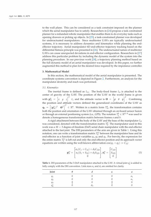
Appl. Sci. 2021, 11, 8279
to the wall plane. This can be considered as a task constraint imposed on the plannerwhich the aerial manipulator has to satisfy. Researchers in [24] propose a task constrainedplanner for a redundant robotic manipulator that enables them to do everyday tasks such asopening drawers or picking up objects. In [25], a task-constrained planner was developedfor underactuated manipulators. Since multirotor UAVs are typically underactuatedsystems, it is necessary to address dynamics and kinematics while planning the end-effector trajectory. Aerial manipulator 6D end-effector trajectory tracking based on thedifferential flatness principle was presented in [26]. The underactuated nature of multirotorUAVs can cause unexpected deviations in end-effector configuration. Researchers in [27]address this particular problem by including the dynamic model of the system into theplanning procedure. In our previous work [28], a trajectory planning method based onthe full dynamic model of an aerial manipulator was developed. In this paper, we furtheraugmented this method to plan for the desired force required by the impedance controller.
3. Mathematical Model
In this section, the mathematical model of the aerial manipulator is presented. Thecoordinate systems convention is depicted in Figure 2. Furthermore, an analysis for themanipulator dexterity and reach was performed.
3.1. Kinematics
The inertial frame is defined as LW. The body-fixed frame LB is attached to thecenter of gravity of the UAV. The position of the UAV in the world frame is given
with pBW =
[x y z
]T ∈, and the attitude vector is Θ =[φ θ ψ
]T. Combining
the position and attitude vectors defined the generalized coordinates of the UAV as
qB =[(pB
W)T ΘT]T ∈ R6. Written in a matrix form TB
W, the transformation containsboth the position and orientation of the UAV obtained through an on-board sensor fusionor through an external positioning system (i.e., GPS). The notation Tb
a ∈ R4×4 was used todenote a homogeneous transformation matrix between frames a and b.
A rigid attachment between the body of the UAV and the base of the manipulator L0was considered, denoted with the transformation matrix T0
B . The manipulator used in thiswork was a M = 3 degree-of-freedom (DoF) serial chain manipulator with the end-effectorattached to the last joint. The DH parameters of the arm are given in Table 1. Using thisnotation, one can write a transformation matrix Tee
0 between the manipulator base and itsend-effector as a function of joint variables q1, q2 and q3. For brevity, the expression forthe entire matrix Tee
0 is left out and only the end-effector position and its approach vectorequations are written using the well-known abbreviation cos(q1 + q2) := C12:
pee0 =
⎡⎢⎣a1(C1 + C12) + d3C123
a1(S1 + S12) + d3S123
0
⎤⎥⎦, zee
0 =
⎡⎢⎣C123
S123
0
⎤⎥⎦ (1)
Table 1. DH parameters of the 3-DoF manipulator attached to the UAV. A virtual joint q∗4 is added tofully comply with the DH convention. Link sizes a1 and d3 are omitted for clarity.
Joint θ d α a
q1 0 0 0 a1q2 0 0 0 a1q3
π2 0 π
2 0q∗4 0 d3 0 0
117

Appl. Sci. 2021, 11, 8279
L
L
LLL 0
1
2ee
B
LW
zxy
z
x
zx
zxzxz
x
Figure 2. Coordinate systems of the world, UAV and the 3-DoF manipulator.
Putting it all together, the full kinematic chain of the aerial manipulator can be con-structed as
TeeW = TB
W · T0B · Tee
0 , (2)
combining the fixed transformation T0B with TB
W and Tee0 depend on UAV and manipu-
lator motion. Since there is obvious coupling between the motion of the body and themanipulator arm, a β ∈ [0, 1] parameter is introduced to distribute the end-effector motioncommands either to the UAV global position control or manipulator joint position control.To this end, the following distribution relationship is used:
ΔPUAV = β · ΔP
ΔParm = (1 − β) · ΔP, (3)
where ΔP is used to denote the desired aerial manipulator displacement expressed as thefollowing combination body and arm motion:
ΔP = ΔPUAV + ΔParm
= β · ΔP + (1 − β) · ΔP. (4)
The manipulator displacement is denoted by ΔParm and the UAV displacement byΔPUAV, where both ΔParm and ΔPUAV are expressed in the coordinate system L0. Withβ = 1, the UAV motion is used to control the position of the end-effector. When β = 0,the situation is reversed and the manipulator motion is used to move the end-effector.For every other β, the end-effector motion is obtained in part by the UAV body and themanipulator arm motion.
There are obvious advantages in combining the motion of the UAV and the manip-ulator arm. The UAV can move in 3D space beyond the reach of the arm; however, themotion of the UAV is not as precise and dynamically decoupled. The kinematics of thearm enable the end-effector to obtain the desired approach angle zee
0 = [cos(δ), sin(δ), 0]T ,which under the hovering assumption, becomes equal to the global approach vector zee
Wpointing towards the contact point on the infrastructure. The straightforward mathematicalmanipulation of Equation (1) allows for writing the constraint equation:
q3 = δ − q1 − q2, (5)
which ensures that the manipulator points in the right direction, where δ is the desiredmanipulator inclination in the body x–z plane.
118

Appl. Sci. 2021, 11, 8279
To find the optimal manipulator pose during contact, the dexterity D and the reach R
of the pose were taken into account, while considering that the joints are as far as possiblefrom their physical limits L. Since the motion of the arm is constrained with its approachaxis condition, a reduced form of a Jacobian matrix was used J =
[δpee
0δq1
, δpee0
δq2
]to derive the
pose dexterity index D =∣∣JT · J
∣∣ and determine how far the current pose is from the nullspace of the manipulator [29]. The reach of the pose R = (pee
0 )T · pee
0 was also taken intoaccount, since the goal was to keep the end-effector and the contact point as far away fromthe UAV body. Finally, the following equation is defined:
L =(q2
1 − Q1max2)(q2
2 − Q2max2)
Q1max2Q2max
2 , (6)
to measure how far away the given configuration is (i.e., q1, q2) from the joint limitsQ1max, Q2max. Normalizing D,R and L enables combining the three conditions into a
single manifold M = D ·R · L and find the optimal configuration q∗M =
[q∗1 q∗2 q∗3
]Tfor
the desired approach angle δ. The described method is depicted in Figure 3 for the specificcase of the approach angle δ = 0◦, but can be extended to any value of the approach anglethrough Equation (5).
As a side note, the manipulator attachment on the top of the UAV body was chosento be able to reach surfaces underneath the bridge. Although this shifts the center ofgravity upwards, the stability of the system is not compromised since the manipulator isconstructed of lightweight materials.
Figure 3. The visual decomposition of dexterity D, reach R, limit L and the overall combined surface.This analysis is performed for δ = 0◦: (a) the dexterity D surface shows the measure of how far themanipulator is from the null space. Values around zero are closer to the null space; (b) the reachR surface shows how far the end-effector can move in a certain configuration. This value tendstowards zero as the arm approaches a folded configuration; (c) the limit L depicts how far a certainconfiguration is from the physical limits of the manipulator joints; and (d) the combined manifold M
of the formerly described surfaces. Higher values offer better trade-off between dexterity, reach andlimit, defining the optimal manipulator configuration q∗
M.
3.2. Dynamics
The most complicated task of the aerial manipulator is attaching the sensor to a walland maintaining the required force reference while the two-component adhesive hardens.
119

Appl. Sci. 2021, 11, 8279
To successfully perform such a task, the coupled UAV-manipulator system dynamics haveto be addressed for the precise end-effector configuration planning.
Considering the UAV dynamics only, the derivative of the generalized coordinates
can be defined as qB =[(pB
W)T (ωBW)T
]T ∈ R6. Here, the (pBW)T is the linear velocity of
the body of the UAV in the world frame and the (ωBW)T represents the angular velocity
of the UAV in the world frame. The UAV’s propulsion system consists of np propellersrigidly attached to the body. Each propeller produces force and torque along the zB axis.The vector of the propeller rotational velocities is simply defined as
ΩUAV =[Ω1 . . . Ωnp
]T ∈ Rnp . (7)
Force and torque produced by each propeller are non-linear functions depending onthe rotational velocity ΩUAV. Rather than using the rotational velocities as control inputs,they can be mapped to a more convenient space. Namely, the mapped control input spacecan be written as
uUAV = K · diag(ΩUAV) · ΩUAV, (8)
where K ∈ R4×np is the mapping matrix and uUAV =
[u1 u2 u3 u4
]T, where u4
represents the net thrust and u1, u2 and u3 are moments around the body frame axes.As stated earlier, the manipulator consists of three rotational DoFs. Therefore, the joint
positions of the manipulator are defined as qM =[q1 q2 q3
]T. The rotational velocity of
each joint is a time derivative of joint positions qM = dqM/dt. The torque of each joint is
considered the control input of the manipulator uM =[τ1 τ2 τ3
]T.
The resulting generalized coordinates of the aerial manipulator can be written as
q =[qUAV qM
]T ∈ R9, and the velocities can be obtained in the same manner as
q =[qUAV qM
]T ∈ R9. The resulting control inputs of the system can be expressed as
u =[uUAV uM
]T ∈ R7. Finally, the full system dynamics can be written as
M(q)q + c(q, q) + g(q) = u, (9)
where M(q) ∈ R9×7 is the inertia matrix, c(q, q) ∈ R7 is the vector of centrifugal andCoriolis forces, g(q) ∈ R7 is the gravitational term.
4. Control System
The overall control of the aerial manipulator consists of several nested control loops.The complete controller overview, with motion planning and blob detection blocks, isdepicted in Figure 4.
4.1. Aerial Manipulator Control
At the inner most level, the UAV is controlled through cascade attitude and ratecontrollers. The input to these controllers is the desired orientation and based on the state,the output is the vector of the rotors’ angular velocities. The second level of control, whichuses the inner attitude control loop, consists of two additional cascades, the position andthe velocity control. These controllers receive a referent position and velocity feed-forwardvalue to generate the desired vehicle orientation and thrust. The manipulator joints arecontrolled through standard Proportional, Integral, Derivative (PID) controllers; however,in a real-world setting, servo motors with integrated control are typically used.
As mentioned earlier, it is important to track the desired force after contact with a wallis achieved. To accomplish this, an adaptive impedance controller is employed to generatean appropriate setpoint for the position controller. This controller receives a trajectory
120

Appl. Sci. 2021, 11, 8279
supplied by the mission planner, which steers the aerial manipulator towards the sensormounting target on the bridge.
Attitude andrate control
Position andvelocity control
Adaptiveimpedance
control
Motionplanning
Blob detectionand estimation
Manipulatorcontrol
Aerial manipulator control
Figure 4. The overall functional schematic of the system. The aerial manipulator control subsystemis necessary for the controlling position and attitude of the UAV, and manipulator joints. On topof this controller, the adaptive impedance control is employed in order to track the desired force.Motion planning generates an appropriate trajectory based on the target point supplied by the blobdetection algorithm.
4.2. Adaptive Impedance Control
The objective of the adaptive impedance controller is to ensure a stable physicalinteraction between the aerial manipulator and the environment [30]. As mentioned earlier,the standard UAV control scheme is based on position and attitude controllers. Wheninteracting with the environment, the desired contact force must be considered. Theposition controlled system can be extended to follow the desired force by introducing animpedance filter. The design of such a filter is explained here for a single DoF.
The behavior of the system is defined by the target impedance as
e(t) = m(xc(t)− xr(t)) + b(xc(t)− xr(t)) + k(xc(t)− xr(t)), (10)
where m, b and k are constants, xr(t) is the referent position, provided to the impedancefilter as an input, and xc(t) is the output of the impedance filter representing the positioncommand. The filter is designed as a linear second-order system with a dynamic rela-tionship between the position and the contact force tracking error e(t) so that it mimics amass-spring–damper system. The contact force tracking error is defined as follows:
e(t) = fr(t)− f (t), (11)
where fr(t) is the other filter input defining the referent force, and f (t) is the measured (ex-erted) contact force. If the environment is modeled as a first-order elastic system (equivalentspring system) with unknown stiffness ke, the measured force can be approximated as
f (t) = ke(x(t)− xe(t)), (12)
where x(t) is the position of the manipulator and xe(t) is the position of the environmentin an unexcited state. By substituting Equation (12) in Equation (11), the position of theaerial manipulator can be expressed as follows:
x(t) =fr(t)− e(t)
ke+ xe(t). (13)
121

Appl. Sci. 2021, 11, 8279
Assuming that the commanded position value can be achieved by the aerial manipula-tor, i.e., x = xc, the substitution of Equation (13) in Equation (10), the system in the steadystate can be described as follows:
e(t) =k · ke
k + ke
(fr(t)ke
+ xe(t)− xr(t))
. (14)
For a contact force error of zero in the steady state, the following must hold:
xr(t) =fr(t)ke
+ xe(t). (15)
In other words, the position setpoint has to be designed in such a way that it compen-sates for the displacement of the environment due to the exerted contact force. To ensurethis, a value of the unknown environment stiffness ke is needed. Furthermore, ke plays afundamental role in the stability of the impedance filter Equation (10), which ultimatelyaffects the stability of the aerial manipulator while in contact with the environment. A sta-ble contact between the aerial manipulator and the environment can be ensured using theHurwitz stability criterion, by designing the system with b/m > 0 and (k + ke)/m > 0.However, since ke is unknown, an adaptation law for the position setpoint that guaranteesthe contact stability while compensating for this hidden, unknown parameter is proposed.
The adaptation law is derived starting from Equation (15). An adaptive parameterκ(t) is introduced so that:
xr(t) = κ(t) fr(t) + xe(t). (16)
It can be shown using the Lyapunov stability analysis that the following adaptationdynamics equation for κ(t) will yield a stable system response:
kκ(t) + bκ(t) + m...κ (t) = −γσ(t) + γdσ(t). (17)
We refer the interested reader to the proof which can be found in the Appendix A.
5. Motion Planning
As discussed in Section 1.1, the main concept of this paper was to use a team of twoUAVs, each applying one component of the adhesive. To apply the “resin” component,the UAV has to plan a collision-free trajectory and position itself in front of the targetarea to start spraying. This is fundamentally different from mounting a sensor coatedwith “hardener”. In the latter case, apart from planning a collision-free trajectory, themanipulator-endowed UAV has to apply pressure for a certain amount of time for the twocomponents to mix.
From the perspective of motion planning, the planner needs to be augmented toinclude a manipulator with three degrees of freedom, contact force and the weighingparameter β. To successfully maintain the pressure, the planner relies on the impedancecontroller described in Section 4.2. Furthermore, one of the requirements when mountingthe sensor on the wall is for the sensor to be perpendicular to the wall. Therefore, it isnecessary to take the underactuated nature of the multirotor UAVs into account duringthe motion planning. Namely, the errors in the planned end-effector configuration weremainly induced due to the roll and pitch angles while executing the planned motion. In ourprevious work [28], we developed a model-based motion planner for aerial manipulatorsthat is capable of correcting the aforementioned end-effector deviations. In this paper, theidea from [28] was extended to consider the impedance control when obtaining the fullstate of the aerial manipulator.
122

Appl. Sci. 2021, 11, 8279
5.1. Waypoint Configuration
When dealing with an aerial manipulator, exerting some contact force inevitably yieldsa high dimensional waypoint configuration. We define a single waypoint as a set of UAVand joint poses, together with the force reference and motion distribution factor β:
w =[qT
B qTM fT
r β]T ∈ R
13, (18)
where qB ∈ R6 and qM ∈ R3 are generalized coordinates of the UAV and the manipulator
defined in Section 3.1. The force reference vector fr =[
fx fy fz
]T ∈ R3 and weighingscalar parameter β are required by the impedance controller. Furthermore, the impedancecontroller assumes a step change of these values. Ideally, the change should occur at themoment of contact since no force can be exerted without contact. Therefore, these valuesare only changed at the final waypoint.
Apart from the desired force and the parameter β, the final waypoint must contain theUAV position and orientation, as well as the manipulator joint configuration. Specifyingthese values relies on the blob detection algorithm presented in Section 6. Namely, thealgorithm outputs the position and orientation of the detected blob in the world frame.Following the manipulator dexterity and reach analysis described in Section 3.1, the optimalmanipulator configuration q∗
M is obtained based on the provided plane normal. The optimalmanipulator configuration is then used as the desired configuration for the final waypoint.This way, during operation, the manipulator never reaches a fully extended or contractedpose, which allows the impedance controller to command both the arm and the UAV toachieve and maintain the desired force.
5.2. Trajectory Planning
There are three phases in the trajectory planning procedure. First, an initial trajectoryis planned based on the provided waypoints. Second, the initial trajectory is sent to asimulated model in order to obtain the full state of the aerial manipulator during thetrajectory execution. Third, the end-effector configuration is corrected based on the fullstate of the vehicle, and the final trajectory is sent to the target aerial manipulator.
Initial Trajectory
To execute a smooth motion towards the desired waypoint, we use a suitable time-optimal path planning by reachability analysis (TOPP-RA) trajectory planner [31]. TheTOPP-RA algorithm searches for the time-optimal trajectory and is based on a “bang-bang”principle on the generalized torque of each DoF. The planner is capable of receiving theinput waypoints of an arbitrary dimension and output a smooth trajectory. Each DoF hasto be provided with dynamical constraints in terms of velocity and acceleration, which arerespected during the trajectory generation process.
As mentioned, the input to the TOPP-RA trajectory is the path of a set of n ≥ 2 waypoints:
P ={
wi | wi ∈ R13, i ∈ (0, 1, . . . , n)
}. (19)
Based on the dynamical constraints, the output of the TOPP-RA planner is asampled trajectory:
Ts ={
t(kTs) | t(kTs) ∈ R3×13, k ∈ (0, . . . , nt)
}, (20)
where t =[(w)T (w)T (w)T
]T ∈ R3×13 is a single sampled trajectory point consistingof position, velocity and acceleration; Ts is the sampling time; and nt is the number ofpoints in the sampled trajectory. Note that each trajectory point contains both roll andpitch angles. Although these angles can be planned through the TOPP-RA algorithm,
123

Appl. Sci. 2021, 11, 8279
they are omitted at this point because of the underactuated nature of the multirotor UAV.Nevertheless, they are used later in the paper when the model corrections are applied.
The impedance controller expects a step change in the force and weighing parameterβ referent values. To satisfy this requirement, large constraints for velocity and accelerationare imposed for these DoFs. However, because other DoFs have constraints below theirphysical limit, the overall force and β trajectory has a slower, dynamically smooth profile.These profiles also have overshoots and undershoots which are not acceptable becausethey are not within the hard constraints required for β. To tackle this problem, a simplepiecewise constant velocity interpolation was applied to the force and β. This way, alarge velocity constraint produces a step change which is a suitable input to the impedancecontroller. A visual example of the difference between the TOPP-RA and piecewise constantvelocity interpolation is depicted in Figure 5.
Figure 5. Visual comparison between TOPP-RA and the piecewise constant velocity interpolation.Waypoints for both trajectories are kept the same, and around t = 2.5 s, the middle waypoint(yellowcross) is reached. Although the dynamical constraints are the same, TOPP-RA takes other degrees offreedom into account and produces a trajectory with overshoot which is not suitable for parameter β.
5.3. Model-Based Corrections
The initial trajectory from Equation (20) is planned without any consideration aboutthe underactuated nature of the multirotor UAV. To obtain the unknowns, namely rolland pitch angles, the initial trajectory can be executed in a simulation environment. Thechosen simulation environment is, in our case, Gazebo, because it is realistic and supportsthe robotics operating system (ROS), which is the backbone of our implementation. Thesimulated aerial manipulator is based on the mathematical model described in Section 3.The standard cascade PID controllers are employed for low-level attitude and high-levelposition control. The impedance controller is built on top of the position controller and pro-vides a position reference based on the input trajectory. More details about the simulationenvironment are provided in Section 7.
The first step is executing the initial trajectory in the aforementioned simulationenvironment. While executing, the roll and pitch angles are recorded as they are needed forobtaining the full state of the UAV. Rearranging Equation (2) and plugging the unknownroll and pitch angles in the full state of the UAV, the transform of the end-effector in themanipulator base frame can be obtained:
TeeL0
= (TL0B )−1 · (TB
W)−1 · TeeW . (21)
Usingthe inverse kinematics of the manipulator, joint values qM for the desired end-effector configuration are obtained. This way, the null space of the aerial manipulator isused for the end-effector correction. Note that due to the configuration of the manipulator,an exact solution of the inverse kinematics will not always exist. In such a case, anapproximate closest solution is used instead.
The final trajectory is constructed by replacing the initial qM with the corrected values.This trajectory is afterwards sent to the target aerial manipulator.
The careful reader should note that the developed three DoF manipulator operates onthe x and z position in the body frame, as well as the pitch angle. This allows the impedancecontroller to maintain the orientation perpendicular to the wall, while compensating for the
124

Appl. Sci. 2021, 11, 8279
UAV body motion in the x and z axes. However, the system will experience disturbancesand control errors which will act on the roll and pitch angle, and the lateral movementalong the body y axis. We can address these issues either with mechanical dampers orby adding additional degrees of freedom to the manipulator, which will be explored infuture work.
6. Blob Detection
This section presents the methods we propose to detect the hardener blob positionand orientation. A modular object detection framework, as shown in Figure 6, is designedto ensure a reliable blob pose detection. Since the detection is to be done on board theUAVs, RGB-D cameras are selected. Therefore, the inputs to the framework are imagesand organized point clouds obtained from the visual sensor. The remainder of this sectionintroduces the individual components of the framework and adds implementation detailswhere necessary.
Figure 6. The pipeline for the modular object detection framework. Inputs to the system are anarbitrary number of sensor messages (image, depth, point cloud, etc.) along with sensor–worldframe transformations. Output is the detected blob pose in the world frame. The synchronizer anddetector are modular components, while the linear Kalman filter, world transformation and posetracker stay invariant.
The sensor message synchronizer is responsible for the time-based synchronization ofthe given sensor message streams. In the case of blob detection, a module that synchronizesimages and organized pointclouds from an RGB-D camera is derived. This is necessarysince the algorithm detects the blob in both 2D image space and 3D point clouds, whichare not necessarily sampled simultaneously. The underlying implementation uses ROSlibraries to synchronize messages with an approximate time policy.
An object detector attempts to find a set of object poses using synchronized sensordata. The module used in this paper detects blob poses and is implemented in the followingway. First, all the blob positions and radii are found in the image frame using the standardblob detection functionality found in the OpenCV libraries. Second, the depth informationcorresponding to the detected blobs is isolated from the organized point cloud. Finally,blob positions are calculated as centroids of the corresponding depth positions, while theorientation is obtained through the random sample consensus (RANSAC) algorithm fromthe Point Cloud Library (PCL).
The remaining framework components are independent from synchronizer and detec-tor modules. The pose tracker is used to track the obtained object’s poses through multipleframes based on the closest Euclidean distance criterion. This component solves the issueof multiple objects being visible, as it always outputs the pose of the currently trackedobject. Moreover, it increases the robustness of the system since it remembers the objectposes for a certain number of frames, which allows some leniency with the detector.
The goal of the world transformation component is to transform the tracked posefrom the sensor to the world frame using the estimated odometry from an external source
125
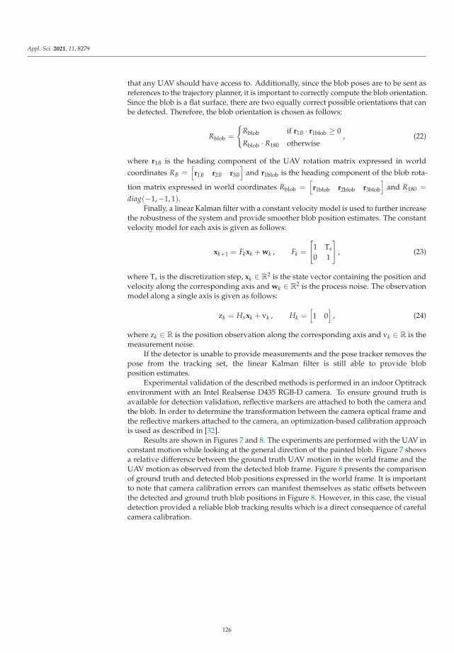
Appl. Sci. 2021, 11, 8279
that any UAV should have access to. Additionally, since the blob poses are to be sent asreferences to the trajectory planner, it is important to correctly compute the blob orientation.Since the blob is a flat surface, there are two equally correct possible orientations that canbe detected. Therefore, the blob orientation is chosen as follows:
Rblob =
{Rblob if r1B · r1blob ≥ 0
Rblob · R180 otherwise, (22)
where r1B is the heading component of the UAV rotation matrix expressed in worldcoordinates RB =
[r1B r2B r3B
]and r1blob is the heading component of the blob rota-
tion matrix expressed in world coordinates Rblob =[r1blob r2blob r3blob
]and R180 =
diag(−1,−1, 1).Finally, a linear Kalman filter with a constant velocity model is used to further increase
the robustness of the system and provide smoother blob position estimates. The constantvelocity model for each axis is given as follows:
xk+1 = Fkxk + wk , Fk =
[1 Ts
0 1
], (23)
where Ts is the discretization step, xk ∈ R2 is the state vector containing the position andvelocity along the corresponding axis and wk ∈ R2 is the process noise. The observationmodel along a single axis is given as follows:
zk = Hxxk + vk , Hk =[1 0
], (24)
where zk ∈ R is the position observation along the corresponding axis and vk ∈ R is themeasurement noise.
If the detector is unable to provide measurements and the pose tracker removes thepose from the tracking set, the linear Kalman filter is still able to provide blobposition estimates.
Experimental validation of the described methods is performed in an indoor Optitrackenvironment with an Intel Realsense D435 RGB-D camera. To ensure ground truth isavailable for detection validation, reflective markers are attached to both the camera andthe blob. In order to determine the transformation between the camera optical frame andthe reflective markers attached to the camera, an optimization-based calibration approachis used as described in [32].
Results are shown in Figures 7 and 8. The experiments are performed with the UAV inconstant motion while looking at the general direction of the painted blob. Figure 7 showsa relative difference between the ground truth UAV motion in the world frame and theUAV motion as observed from the detected blob frame. Figure 8 presents the comparisonof ground truth and detected blob positions expressed in the world frame. It is importantto note that camera calibration errors can manifest themselves as static offsets betweenthe detected and ground truth blob positions in Figure 8. However, in this case, the visualdetection provided a reliable blob tracking results which is a direct consequence of carefulcamera calibration.
126

Appl. Sci. 2021, 11, 8279
Figure 7. This figure shows the comparison of normalized motion of the UAV body frame as observedfrom the Optitrack world frame and as observed from the detected blob frame labeled pW
B [k]− pWB [0]
and pblobB [k]− pblob
B [0], respectively.
Figure 8. This figure shows the comparison of the ground truth blob position and the blob positionestimate expressed in the Optitrack world frame. The root mean squared error across all three axes is4.6 cm.
127

Appl. Sci. 2021, 11, 8279
7. Simulation
The environment used for simulating the UAV and manipulator dynamics, as wellas the contact with the environment, is the widely accepted Gazebo simulator. It is real-istic and highly modular, with a large community and a support for the robot operatingsystem (ROS), which is also the primary implementation environment for impedancecontrol, motion planning and blob detection. Through ROS, Gazebo has a large varietyof developed plugins realistically simulating various sensors and actuators. All simu-lations were conducted with Linux Ubuntu 18.04 operating system and ROS Melodicmiddleware installed.
The UAV is modeled as a single rigid body with np propellers mounted at the endof each arm. As propulsion units, these propellers generate thrust along the z axis of theUAV body. To simulate the propeller dynamics, the rotors_simulator package is used. Itcontains a plugin that models thrust based on the user-provided propeller parameters [33].Furthermore, to obtain the UAV attitude and position, IMU and odometry plugins aremounted on the vehicle. The manipulator was mounted on the body of the UAV andconsists of three joints connected with links. A rod type tool is mounted as the end-effector,with a force-torque sensor required by the impedance controller. Furthermore, a monocularcamera with an infrared projector is also mounted for the blob detection.
7.1. End-Effector Motion Distribution Analysis
Given some end-effector configuration, the inverse kinematics is responsible forfinding the UAV position and yaw angle, as well as the manipulator joint values thatsatisfy the desired configuration. The parameter β from Equation (3) defines a ratio of howmuch the manipulator joints and UAV position and orientation contribute to achieving thedesired end-effector configuration, as described in Section 3.1. Recalling the values, β = 1only moves the UAV in the direction of the desired end-effector configuration; and β = 0uses the inverse kinematics of the manipulator to achieve the desired configuration.
To determine the influence of β on the overall system, an analysis was conducted withdifferent β values. The desired end-effector configuration was chosen to be in contact witha plane perpendicular to the bridge wall which required the force reference along the xaxis. The waypoints for the trajectory planner were kept the same across all trials, and onlyβ was changed. The results of this analysis are depicted in Figure 9. As can be observed,all trials produced very similar results with oscillating force upon contact and eventuallyreaching the desired reference, providing us with no obvious conclusion regarding how toselect the optimal β. However, following the dexterity analysis from Section 3.1, and onlyrelying on the manipulator motion might drive the system close to its limits due to theUAV body movement. On the other hand, the motion of the UAV induces disturbances inthe end-effector pose control. The manipulator is therefore responsible for compensatingerrors introduced by the motion of the UAV body. Taking all of the aforementioned intoaccount, the value is chosen as β = 0.5 so that both the manipulator and the UAV aresimultaneously used to maintain a steady contact force.
Figure 9. Force response comparison for different values of the parameter β. The analysis wasconducted on a plane perpendicular to the ground where the force reference along the x axisis required.
128

Appl. Sci. 2021, 11, 8279
7.2. Bridge Sensor Mounting
Since the concept of this paper was to mount inspection sensors on a bridge, thesimulation trials were tailored in the same direction. After spraying the first component, itis necessary to achieve and maintain a stable contact while the second adhesive componenton the sensor dries. Since the manipulator is attached above the propellers, the workspaceof the manipulator is limited to contact above the UAV or on the plane perpendicular tothe ground.
Naturally, the first set of simulation trials were conducted by holding the desired forceon a plane perpendicular to the ground. In this case, the contact force only acts along the xaxis and the response is depicted in Figure 10. The time delay between the planned andexecuted contact is present due to the impedance filter which slows down the dynamics ofthe referent trajectory. After the initial contact, there are some oscillations and an overshootwhich diminish over time and the desired force reference is achieved.
Figure 10. Force response in case of a contact plane perpendicular to the ground, δ = 0◦.
The second set of simulation trials included an inclined contact plane. This requiresthe UAV approach from below the plane and achieving contact perpendicular to the plane.Since the plane is inclined for δ = 68◦, the planned force referent values have componentsin both the x and z axes, as shown in Figure 11. Similarly to the previous example, the forceresponse has some oscillations around the instance of contact, but it eventually settles andreaches the desired force reference.
Figure 11. Force response in the case of the contact plane inclined for δ = 68◦.
The simulation tests for δ = 0◦ and δ = 68◦ were performed n = 10 times for eachcase, as depicted in Figure 12. The left portion of the figure is a dot product between thenormal of the blob rt and the end-effector orientation vector ree. If the value of the dotproduct rt · ree = 1, the two vectors are parallel which results in a successful approach. For
129

Appl. Sci. 2021, 11, 8279
both angles, the dot product is very close to 1 and the orientation error is negligible. Onthe right, the distance between the center of the target and contact point is shown. Theerror distance is in both cases less than 0.1 m, which ensures the relatively high precision ofsensor mounting, well within margins for the bridge inspection. The accompanying videoof simulation tests can be found on our YouTube channel [34].
Figure 12. (Left): box and whiskers plot of the dot product between the blob plane normal vector rt
and the end-effector orientation vector ree; and (Right): box and whiskers plot of the distance fromthe target point after contact.
8. Conclusions
This paper presents a step towards autonomous bridge inspection by investigatingthe possibility of mounting various inspection sensors using an aerial manipulator. Cur-rently, inspectors use specialized trucks with cranes and baskets in order to access the areaunderneath the bridge. This inevitably leads to road closure which poses an inconveniencefor both inspectors and traffic. To alleviate this problem, the aforementioned aerial manip-ulators can be used to access difficult-to-reach areas of the bridge. As mounting sensorsrequire forming a bond between the wall and sensor, we envision using a two-componentadhesive with a short cure time. Since the aerial manipulator has to achieve and maintaincontact with the sensor mount point, short cure times are desirable because of te limitedflight time of these platforms. Nevertheless, current flight times of outdoor multirotorsreach up to 30 min, which ensures enough time for the two adhesive components to formthe bond.
Although preliminary, the results of this paper seem promising. The visual detectionwas extensively tested and reliably tracks the blob position. The adaptive impedancecontroller is capable of maintaining the required force. Even though there are someoscillations and settling times in the force response, in practical use, it does not makemuch difference since the curing time of the adhesive is at least several minutes. Thetrajectory planner was augmented to plan in the force space which allows for settingthe force reference step change before the contact. The simulation results show the highrepeatability of the overall system which gives us the confidence to perform experimentsin a real-world environment.
Our first step in future work was to perform experiments in a controlled laboratoryenvironment. The outdoor environment poses a different set of challenges including thelower accuracy positioning system and unpredictable disturbances, i.e., wind gusts. Sincethese factors will inevitably reflect on the overall end-effector accuracy, we are lookinginto augmenting the manipulator to be able to compensate for lateral movements, as wellas roll and yaw angles. To further increase the system’s accuracy, the developed visual
130

Appl. Sci. 2021, 11, 8279
tracker will be used to improve feedback around the tracked blob on the bridge wall inreal-world experiments.
Author Contributions: All authors contributed equally to this work. Conceptualization, M.O. andI.D.; methodology, A.I., L.M. and M.C.; software, A.I., L.M. and M.C.; investigation, A.I.; writing—original draft preparation, A.I.; writing—review and editing, L.M., I.D. and M.O.; supervision, I.D.and M.O.; project administration, I.D. and M.O.; funding acquisition I.D. and M.O. All authors haveread and agreed to the published version of the manuscript.
Funding: This work was supported by the European Commission Horizon 2020 Programme throughthe project under G.A. number 820434, named Energy-Aware BIM Cloud Platform in a Cost-EffectiveBuilding Renovation Context—ENCORE. Furthermore, this research was part of the scientific projectAutonomous System for Assessment and Prediction of Infrastructure Integrity (ASAP), financed bythe European Union through the European Regional Development Fund—The Competitiveness andCohesion Operational Programme (KK.01.1.1.04.0041).
Institutional Review Board Statement: Not applicable.
Informed Consent Statement: Not applicable.
Data Availability Statement: Not applicable.
Conflicts of Interest: The authors declare no conflict of interest.
Appendix A
Here, we show detailed proof that the adaptation law (17) is stable. Assuming thatTHE referent force fr(t) is constant, fr(t) = Fr, the time derivatives of Equation (16) are:
xr(t) = κ(t)Fr + xe(t),
xr(t) = κ(t)Fr + xe(t),(A1)
while the derivatives of Equation (13) yield:
x(t) = −e(t)ke
+ xe(t),
x(t) = −e(t)ke
+ xe(t).(A2)
By susbstituting Equations (A1) and (A2) into Equation (10), the dynamics of thecontact force error can be obtained as
me(t) + be(t) + (k + ke)e(t) = g(t), (A3)
where:g(t) = Fr[k(1 − keκ(t))− ke(bκ(t) + mκ(t))], (A4)
and x = xc. The adaptation law thus determines the dynamics of the adaptation parameterκ(t) and defines the dynamics of the contact force error. Formally, the adaptation lawshould enforce g(t) −→ g∗ such that e(t) −→ 0 and κ(t) −→ 1/ke.
For the Lyapunov candidate:
V(t) =12
[p1e(t)2 + p2 e2(t)
]+
12γ
[g(t)− g∗]2, (A5)
with p1, p2 and γ as positive parameters, the condition V(t) ≤ 0 yields:
2γ
g(t)g(t) + 2g(t)[p1e(t) + p2 e(t)]− 2γ
g(t)g∗ ≤ 0. (A6)
131

Appl. Sci. 2021, 11, 8279
After reordering, we obtain:
g(t)[g(t)− g∗] ≤ −γσ(t)g(t), (A7)
where σ(t) = [p1e(t) + p2 e(t)]. By choosing:
g(t) = −γσ(t) + γdσ(t), (A8)
where γd is a positive constant, Lyapunov condition Equation (A7) becomes:
g(t) ≤ g∗, (A9)
i.e., for the adaptation law to be stable, g(t) should be bounded. Since xr, xr and xrare bounded, so are e, e and e. Therefore, g(t) is also bounded, i.e., the condition inEquation (A9) is satisfied. The adaptation law is finally obtained by taking the derivativeof Equation (A3), and substituting g(t) with Equation (A8), yields the (17). Parameters γand γd dictate the adaptation dynamics. Based on the measured contact force, the erroradaptation law Equation (17) estimates the adaptation parameter κ (reciprocal value ofthe environment stiffness), which is then used in Equation (16) for calculating the referentposition xr.
References
1. Kashif Ur Rehman, S.; Ibrahim, Z.; Memon, S.A.; Jameel, M. Nondestructive test methods for concrete bridges: A review. Constr.Build. Mater. 2016, 107, 58–86. [CrossRef]
2. Hunt, G.; Mitzalis, F.; Alhinai, T.; Hooper, P.A.; Kovac, M. 3D printing with flying robots. In Proceedings of the 2014 IEEEInternational Conference on Robotics and Automation (ICRA), Hong Kong, China, 31 May–7 June 2014; pp. 4493–4499. [CrossRef]
3. Vempati, A.S.; Kamel, M.; Stilinovic, N.; Zhang, Q.; Reusser, D.; Sa, I.; Nieto, J.; Siegwart, R.; Beardsley, P. PaintCopter: AnAutonomous UAV for Spray Painting on Three-Dimensional Surfaces. IEEE Robot. Autom. Lett. 2018, 3, 2862–2869. [CrossRef]
4. Jeong, E.; Seo, J.; Wacker, J. Literature Review and Technical Survey on Bridge Inspection Using Unmanned Aerial Vehicles.J. Perform. Constr. Facil. 2020, 34, 04020113. [CrossRef]
5. Cacace, J.; Orozco-Soto, S.M.; Suarez, A.; Caballero, A.; Orsag, M.; Bogdan, S.; Vasiljevic, G.; Ebeid, E.; Rodriguez, J.A.A.; Ollero, A.Safe Local Aerial Manipulation for the Installation of Devices on Power Lines: AERIAL-CORE First Year Results and Designs.Appl. Sci. 2021, 11, 6220. [CrossRef]
6. Zollini, S.; Alicandro, M.; Dominici, D.; Quaresima, R.; Giallonardo, M. UAV Photogrammetry for Concrete Bridge InspectionUsing Object-Based Image Analysis (OBIA). Remote Sens. 2020, 12, 3180. [CrossRef]
7. Bolourian, N.; Hammad, A. LiDAR-equipped UAV path planning considering potential locations of defects for bridge inspection.Autom. Constr. 2020, 117, 103250. [CrossRef]
8. Reagan, D.; Sabato, A.; Niezrecki, C. Unmanned aerial vehicle acquisition of three-dimensional digital image correlationmeasurements for structural health monitoring of bridges. In Proceedings of the Nondestructive Characterization and Monitoring ofAdvanced Materials, Aerospace, and Civil Infrastructure, Portland, OR, USA, 25–29 March 2017; Wu, H.F., Gyekenyesi, A.L., Shull, P.J.,Yu, T.Y., Eds.; International Society for Optics and Photonics, SPIE: Bellingham, DC, USA, 2017; Volume 10169, pp. 68–77.[CrossRef]
9. Chen, H.; Quan, F.; Fang, L.; Zhang, S. Aerial Grasping with a Lightweight Manipulator Based on Multi-Objective Optimizationand Visual Compensation. Sensors 2019, 19, 4253. [CrossRef] [PubMed]
10. Zhang, G.; He, Y.; Dai, B.; Gu, F.; Yang, L.; Han, J.; Liu, G. Aerial Grasping of an Object in the Strong Wind: Robust Control of anAerial Manipulator. Appl. Sci. 2019, 9, 2230. [CrossRef]
11. Sanchez-Cuevas, P.J.; Gonzalez-Morgado, A.; Cortes, N.; Gayango, D.B.; Jimenez-Cano, A.E.; Ollero, A.; Heredia, G. Fully-Actuated Aerial Manipulator for Infrastructure Contact Inspection: Design, Modeling, Localization, and Control. Sensors 2020,20, 4708. [CrossRef] [PubMed]
12. Baca, T.; Penicka, R.; Stepan, P.; Petrlik, M.; Spurny, V.; Hert, D.; Saska, M. Autonomous Cooperative Wall Building by a Team ofUnmanned Aerial Vehicles in the MBZIRC 2020 Competition. arXiv 2020, arXiv:2012.05946.
13. Vatavuk, I.; Polic, M.; Hrabar, I.; Petric, F.; Orsag, M.; Bogdan, S. Autonomous, Mobile Manipulation in a Wall-building Scenario:Team LARICS at MBZIRC 2020. J. Field Robot. 2021, submitted for publication.
14. Barišic, A.; Petric, F.; Bogdan, S. Brain over Brawn—Using a Stereo Camera to Detect, Track and Intercept a Faster UAV byReconstructing Its Trajectory. arXiv 2021, arXiv:2107.00962.
15. Markovic, L.; Car, M.; Orsag, M.; Bogdan, S. Adaptive stiffness estimation impedance control for achieving sustained contactin aerial manipulation. In Proceedings of the 2021 IEEE International Conference on Robotics and Automation, Xi’an, China,30 May–5 June 2021.
132

Appl. Sci. 2021, 11, 8279
16. Cazzato, D.; Cimarelli, C.; Sanchez-Lopez, J.L.; Voos, H.; Leo, M. A Survey of Computer Vision Methods for 2D Object Detectionfrom Unmanned Aerial Vehicles. J. Imaging 2020, 6, 78. [CrossRef]
17. Fischler, M.A.; Bolles, R.C. Random Sample Consensus: A Paradigm for Model Fitting with Applications to Image Analysis andAutomated Cartography. Commun. ACM 1981, 24, 381–395. [CrossRef]
18. Fumagalli, M.; Naldi, R.; Macchelli, A.; Carloni, R.; Stramigioli, S.; Marconi, L. Modeling and control of a flying robot for contactinspection. In Proceedings of the 2012 IEEE/RSJ International Conference on Intelligent Robots and Systems, Algarve, Portugal,7–12 October 2012; pp. 3532–3537. [CrossRef]
19. Alexis, K.; Darivianakis, G.; Burri, M.; Siegwart, R. Aerial Robotic Contact-based Inspection: Planning and Control. Auton. Robot.2016, 40, 631–655. [CrossRef]
20. Jimenez-Cano, A.E.; Sanchez-Cuevas, P.J.; Grau, P.; Ollero, A.; Heredia, G. Contact-Based Bridge Inspection Multirotors: Design,Modeling, and Control Considering the Ceiling Effect. IEEE Robot. Autom. Lett. 2019, 4, 3561–3568. [CrossRef]
21. Cataldi, E.; Muscio, G.; Trujillo, M.A.; Rodriguez, Y.; Pierri, F.; Antonelli, G.; Caccavale, F.; Viguria, A.; Chiaverini, S.; Ollero, A.Impedance Control of an aerial-manipulator: Preliminary results. In Proceedings of the 2016 IEEE/RSJ International Conferenceon Intelligent Robots and Systems (IROS), Daejeon, Korea, 9–14 October 2016; pp. 3848–3853. [CrossRef]
22. Nava, G.; Sablé, Q.; Tognon, M.; Pucci, D.; Franchi, A. Direct Force Feedback Control and Online Multi-Task Optimization forAerial Manipulators. IEEE Robot. Autom. Lett. 2020, 5, 331–338. [CrossRef]
23. Meng, X.; He, Y.; Li, Q.; Gu, F.; Yang, L.; Yan, T.; Han, J. Contact Force Control of an Aerial Manipulator in Pressing an EmergencySwitch Process. In Proceedings of the 2018 IEEE/RSJ International Conference on Intelligent Robots and Systems (IROS), Madrid,Spain, 1–5 October 2018; pp. 2107–2113. [CrossRef]
24. Stilman, M. Global Manipulation Planning in Robot Joint Space With Task Constraints. IEEE Trans. Robot. 2010, 26, 576–584.[CrossRef]
25. Cefalo, M.; Oriolo, G. Task-constrained motion planning for underactuated robots. In Proceedings of the 2015 IEEE InternationalConference on Robotics and Automation (ICRA), Seattle, WA, USA, 26–30 May 2015; pp. 2965–2970. [CrossRef]
26. Yu, Y.; Lippiello, V. 6D Pose Task Trajectory Tracking for a Class of 3D Aerial Manipulator From Differential Flatness. IEEE Access2019, 7, 52257–52265. [CrossRef]
27. Tognon, M.; Cataldi, E.; Chavez, H.A.T.; Antonelli, G.; Cortés, J.; Franchi, A. Control-Aware Motion Planning for Task-ConstrainedAerial Manipulation. IEEE Robot. Autom. Lett. 2018, 3, 2478–2484. [CrossRef]
28. Ivanovic, A.; Car, M.; Orsag, M.; Bogdan, S. Exploiting Null Space in Aerial Manipulation through Model-In-The-Loop MotionPlanning. In Proceedings of the 2020 International Conference on Unmanned Aircraft Systems (ICUAS), Athens, Greece, 1–4September 2020; pp. 686–693. [CrossRef]
29. Zargarbashi, S.; Khan, W.; Angeles, J. The Jacobian condition number as a dexterity index in 6R machining robots. Robot.Comput.-Integr. Manuf. 2012, 28, 694–699. [CrossRef]
30. Car, M.; Ivanovic, A.; Orsag, M.; Bogdan, S. Position-based adaptive impedance control for a UAV. In Proceedings of the 2018International Conference on Unmanned Aircraft Systems (ICUAS), Dallas, TX, USA 12–15 June 2018; pp. 957–963. [CrossRef]
31. Pham, H.; Pham, Q. A New Approach to Time-Optimal Path Parameterization Based on Reachability Analysis. IEEE Trans. Robot.2018, 34, 645–659. [CrossRef]
32. Maric, B.; Polic, M.; Tabak, T.; Orsag, M. Unsupervised optimization approach to in situ calibration of collaborative human–robotinteraction tools. In Proceedings of the 2020 IEEE International Conference on Multisensor Fusion and Integration for IntelligentSystems (MFI), Karlsruhe, Germany, 14–16 September 2020; pp. 255–262. [CrossRef]
33. Furrer, F.; Burri, M.; Achtelik, M.; Siegwart, R. Robot Operating System (ROS): The Complete Reference (Volume 1). In Studies inComputational Intelligence; Chapter RotorS—A Modular Gazebo MAV Simulator Framework; Springer International Publishing:Cham, Switzerland, 2016; pp. 595–625. [CrossRef]
34. LARICS. Aerial Manipulation Approach for Autonomous Bridge Inspection. Available online: https://youtu.be/bBaxPMZEV04(accessed on 23 July 2021).
133


applied sciences
Article
Aerial Robotic Solution for Detailed Inspection of Viaducts
Rafael Caballero 1,*, Jesús Parra 1, Miguel Ángel Trujillo 1,*, Francisco J. Pérez-Grau 1, Antidio Viguria 1
and Aníbal Ollero 2
Citation: Caballero, R.; Parra, J.;
Trujillo, M.Á.; Pérez-Grau, F.J.;
Viguria, A.; Ollero, A. Aerial Robotic
Solution for Detailed Inspection of
Viaducts. Appl. Sci. 2021, 11, 8404.
https://doi.org/10.3390/app
11188404
Academic Editor: Yosoon Choi
Received: 6 August 2021
Accepted: 7 September 2021
Published: 10 September 2021
Publisher’s Note: MDPI stays neutral
with regard to jurisdictional claims in
published maps and institutional affil-
iations.
Copyright: © 2021 by the authors.
Licensee MDPI, Basel, Switzerland.
This article is an open access article
distributed under the terms and
conditions of the Creative Commons
Attribution (CC BY) license (https://
creativecommons.org/licenses/by/
4.0/).
1 Advanced Center for Aerospace Technologies (FADA-CATEC), 41309 Sevilla, Spain;[email protected] (J.P.); [email protected] (F.J.P.-G.); [email protected] (A.V.)
2 GRVC Robotics Labs, University of Seville, 41092 Sevilla, Spain; [email protected]* Correspondence: [email protected] (R.C.); [email protected] (M.Á.T.)
Abstract: The inspection of public infrastructure, such as viaducts and bridges, is crucial for theirproper maintenance given the heavy use of many of them. Current inspection techniques are verycostly and manual, requiring highly qualified personnel and involving many risks. This articlepresents a novel solution for the detailed inspection of viaducts using aerial robotic platforms. Thesystem provides a highly automated visual inspection platform that does not rely on GPS andcould even fly underneath the infrastructure. Unlike commercially available solutions, our systemautomatically references the inspection to a global coordinate system usable throughout the lifespanof the infrastructure. In addition, the system includes another aerial platform with a robotic arm tomake contact inspections of detected defects, thus providing information that cannot be obtainedonly with images. Both aerial robotic platforms feature flexibility in the choice of camera or contactmeasurement sensors as the situation requires. The system was validated by performing inspectionflights on real viaducts.
Keywords: inspection; maintenance; UAV; aerial robotics; aerial robotic manipulation; viaduct;LIDAR; photogrammetry; contact
1. Introduction
The inspection of viaducts and bridges is a very time-consuming and resource-intensive activity. It requires heavy involvement from highly qualified and specificallytrained personnel. Additionally, these inspections pose health and safety risks that aremainly derived from working at height and the difficulty of the operation. Current inspec-tion methodologies involve the use of climbing operators, who, by means of ropes, hangfrom the structure and perform the measurements required by the inspectors to evaluateits current state (see Figure 1a). These works present many potential accident risks due tothe difficulty and technical level required to access certain complicated areas at heights,the possible physical fatigue of the workers, human errors in the safety of the operation, oreven problems with the use of specific measuring tools.
An alternative method is the use of heavy machinery, like cherry pickers, truck-mounted lifts, and cranes (see Figure 1b). This machinery requires new specialized person-nel to operate it and perform inspections and does not eliminate the problem of havingto expose people to work at heights. The surfaces to be inspected are usually located ata high altitude, and under it, several types of obstacles could be found, such as traffic ofvehicles or trains, water flows, or rough terrain. This means that the use of machinery hasto be done from the top surface of the structure, interrupting its service and increasing theoperational costs of the inspection.
Currently, the highly qualified staff required for inspections is normally composedof civil engineers working for engineering firms specialized in structures. Every littledeformation, crack, or defect can be the cause of a potentially bigger critical problem, sothey must be identified as soon as possible. An example that requires high accuracy is
Appl. Sci. 2021, 11, 8404. https://doi.org/10.3390/app11188404 https://www.mdpi.com/journal/applsci135

Appl. Sci. 2021, 11, 8404
the measurement of cracks width with an error smaller than 0.1 mm. Moreover, crackdepth can only be measured using contact sensors. However, visual inspection is themost extended way of assessing the preliminary status of the viaduct before deciding ifspecialized equipment is needed. This means that, in order to find the smallest defects,the inspector must be very close to them. Furthermore, human subjectivity or the lack ofexperience could lead to an undervaluation of the severity of a defect.
(a) (b)
(c)Figure 1. Examples of current inspection methodologies. (a) Current method for the viaduct inspec-tion with rope access, from Ayres Associates, Inc. [1]. (b) Current method for the viaduct inspectionusing specialized machinery, from Forsgren Associates, Inc. [2]. (c) Proposed new methodologyusing the flight platform AERO-CAM in Álora, Málaga (Spain) performing an inspection under aviaduct deck.
This whole process presents many inefficiencies that can be minimized using aerialrobotic technologies combined with computer vision algorithms (e.g., artificial intelligence)and other computerized technologies supporting the post-processing of the acquired data.This article proposes an aerial robotic solution for gathering all the needed data to analyzethe status of a viaduct. Our proposed solution drastically improves the safety of theinspections, as it does not involve the work at height of any human being or the useof heavy machinery. It reduces inspection times and costs by reducing the number ofspecialized people required to perform the inspection and avoiding the need to interruptthe use of the structure. On the other hand, it improves the quality of the data obtained,since it is the inspectors themselves who indicate the points to be inspected by the aerialrobotic platforms, which can always be quickly sent back to obtain more information ifnecessary. In addition, the system is flexible to use the different sensors needed: eithercameras or sensors that require physical contact with the structure.
136

Appl. Sci. 2021, 11, 8404
1.1. Aerial Robots for Inspection
The use of autonomous unmanned aerial vehicles (UAVs) to capture images and theirsubsequent use in infrastructure analysis is currently on the rise. After an exhaustivesearch of the projects developed in the research world, relevant applications have beenfound that make use of autonomous UAVs for image capture in the inspection of railwaytracks [3], where autonomous flights are carried out to follow the tracks, capturing imagesfor subsequent analysis. Other applications, like mining inspection obtained 3D maps [4],make it possible to evaluate the earthworks carried out; wind turbines inspection forevaluation of deformations or damage [5]; inspection of civil infrastructures capturingimages and their subsequent analysis through the use of neural networks to identifypossible cracks or landslides [6]. Finally, in [7], bridge inspection is studied in a similar wayas proposed in this article, where images are captured autonomously using a UAV platformand then analyzed using photogrammetry software. The main limitation raised is that theyuse Global Navigation Satellite System (GNSS) positioning to automate flights, while inthe system proposed in this article, the aircraft that captures images does not navigate withGNSS but with onboard sensors such as LIDAR. The physical characteristics of the viaductscause the GNSS signal to be partially or totally degraded when flying near or under them.These degradation problems with global positioning signals are discussed in [8], wherethe most critical ones affecting this article are signal masking and multipath. Therefore,the degradation of this signal leads to localization problems in the UAV in which it candrift its flight or even make sudden changes in its positioning, seriously compromising thesafety and integrity of the operation. In addition, GNSS poses problems of repeatability ofinspection operations, since the number and position of available satellites varies over time.
There are currently some commercial systems for infrastructure inspection such as theone offered by Skydio [9], which makes use of several onboard cameras to navigate andperform the inspection autonomously. Unlike Skydio’s system, our system is able to refer-ence the inspection to a global coordinate system that can be used from the construction ofthe viaduct until the end of its life. This feature makes our methodology better suited to thecurrent workflow of inspectors, who already use total stations to check the displacementsof structures against global references defined during construction. Additionally, thanks tothe global coordinate system, the solution offers the possibility for more than one aircraftto navigate and perform an inspection while maintaining the same references. By usinga generic gimbal, our system is much more flexible than Skydio’s system in the choiceand configuration of the required camera sensor, as it is not limited to the built-in camera.In addition, our system uses an aerial robot that performs inspection by making physicalcontact with the structure. This provides information that cannot be acquired by picturesexclusively, such as precise measurements of crack depth and width, material hardness,concrete humidity, etc.
In relation to this inspection by contact with an aerial robot, there are different linesof research with a number of projects that focus on maintaining stability during physicalcontact [10,11]. In [12] the predecessor aerial manipulator of the one used in this work ispresented, which was patented [13] and awarded with the EU Radar Innovation Award2017 [14]. In [15], an aerial vehicle that operates overhead using a rigid arm, and that iseven capable of keeping in contact with the surface [16], is presented. In [17] an aerialvehicle that operates at the bottom as well as at the front, is presented. Aerial manipulatorscapable of operating in either direction are presented in [18]. Stable contact operationshave been achieved using a pusher trirotor in [19] or, a quadrotor in [20,21]. In [22] a longrigid tool exerting force against a surface is applied.
1.2. Aerial Robots Localization
Different sensors can be used to achieve effective positioning of aerial robots. Totalstations can be used to localize an UAV in motion with respect to a reference system,as in [23]. This presents several problems, such as the high cost of this tool, as well asthe dependence on flying continuously in line of sight with it or having an uninterrupted
137

Appl. Sci. 2021, 11, 8404
wireless communication system with the aerial robot. In addition, total stations onlyprovide position information, not orientation.
On the other hand, the localization problem can also be solved through monocularor stereo visual cameras, as in [24,25]. The problem with visual cameras is that theyare totally dependent on external light conditions. This is especially problematic whennavigating near infrastructure because of the shadows and light changes it can cause. Otherlocalization systems use a LIDAR as the main sensor [26]. These sensors do not depend onexternal light conditions, as they use lasers to measure distances. While their applicationin autonomous driving is on the rise, their use in aerial robots is still limited because theyrequire more available payload and a more powerful onboard computer than cameras.In [27], a comparison of several algorithms applied to aerial robots is made.
1.3. Article Introduction
This article proposes a novel solution for the detailed inspection of viaducts usingaerial robotics. This solution is an alternative to current inspection methodologies, im-proving safety, costs, time, and data quality. Given the amount of details involved in thissolution, this article first provides a general overview and then focuses on the technicaland experimental aspects of the visual inspection.
The rest of the article is organized as follows. Section 2 describes the proposed viaductinspection system and the two aircraft involved. Section 3 presents a localization solutionthat provides one of the aircraft with autonomous capabilities to perform a visual inspectionof a viaduct. Section 4 outlines the localization and inspection experiments and presentsthe results used to assess the performance of the proposed solution. Finally, the conclusionsand future work are summarized in Section 5.
2. System Description
The proposed viaduct inspection system offers a comprehensive solution to check andto evaluate the condition of these infrastructures through its integrated tools. A workflowhas been created that meets the needs to speed up, reduce the cost, and increase thesafety of these inspections. All the tasks are carried out with aerial robotic platformswhose characteristics are chosen according to the task to be performed. These tasks can begeneral and/or detailed photographs or make physical contact with the structure to takemeasurements with sensors as required.
The workflow is shown in Figure 2 and is as follows. Given a viaduct of interest onwhich an inspection should be performed, the proposed workflow begins with the creationof a mission. During this phase, it is required to acquire a 3D map of the structure inwhich the inspector can select the areas and points of interest. This 3D map is not onlyuseful for the creation and subsequent visualization of the mission, but it is also requiredfor the global localization of the aircraft. It is obtained with the help of a robotic totalstation that establishes an arbitrary coordinate system and performs scans to obtain the3D points around it. It is important to capture these data from different points of view toobtain a complete point cloud of the viaduct. To facilitate the subsequent use of this map,the reference system should be aligned with the ENU axes (x = East, y = North, z = Top).If possible, it is desirable to obtain an approximate GNSS coordinate of the origin of thepoint cloud to locate it globally. Otherwise, this can be done manually. The use of the totalstation is then limited to one time only. Once the map has been created, it can be reused inall subsequent inspections, provided that the viaduct has not suffered significant changes.
With the points and areas of interest selected on the 3D map created, this informationis sent to the aerial platform, which translates it to its local coordinate system and createsthe route of waypoints and actions necessary to carry out the inspection autonomouslycapturing overlapping pictures. This mission is then a first general visual inspection of thestructure to locate any possible defect. This check is performed by taking general picturesof the structure with high resolution in an automated way using the visual inspectionplatform described in Section 2.1.
138

Appl. Sci. 2021, 11, 8404
Figure 2. General viaduct inspection workflow.
After the first general pictures are taken, they are analyzed to check the conditionof the viaduct, paying special attention to those areas where a defect is suspected. Thisanalysis can be performed manually by an inspector or automatically by applying anautomatic image defect detection algorithm, like [28,29]. After the analysis, a decisionshould be made to determine if more detailed information on the defects found or suspectareas are required. If so, more detailed visual or contact information may be obtained usingthe visual or contact inspection platforms, respectively. In case more visual information isrequired, the mission previously created by the inspector can be reused but using anothercamera configuration that better collects the required information. For example, a differentlens can be used for the camera with a longer focal length to obtain better details of thespecific area. However, if the previous mission does not meet the requirements of thenew visual inspection, the inspector can create a new one with the 3D map and select thepreviously found defects.
When the missions are finished and the visual information obtained is sufficient, ourproposed solution also considers the use of a specific platform for contact inspections. Thisplatform is described in Section 2.2 and has a robotic arm with an end effector on whicha sensor can be installed. In case of finding defects in the visual inspection that require adeep analysis with specific sensors that require physical contact with the structure, thisplatform is sent to those defects and captures data. When the contact inspection data isanalyzed, a decision is made as to whether further visual or contact information is requiredor whether the inspection is terminated.
In short, the proposed workflow is an iterative process in which one can always returnto a suspect area to obtain more detailed information. All the inspections are carried outby aerial robots specifically designed for each purpose. The viaduct inspection systemcomprises two platforms that work sequentially as described previously. The followingsections describe these UAVs, showing their configuration and capabilities.
139

Appl. Sci. 2021, 11, 8404
2.1. Visual Inspection
The visual inspection UAV (see Figure 3) is known as AERO-CAM. This aircraft isspecialized in taking very high quality images of a structure. This UAV is equipped with astabilized camera which takes the images of desired areas.
Figure 3. AERO-CAM robot for visual inspection UAV.
The AERO-CAM platform is built from a DJI Matrice 600 Pro on which the neces-sary components to operate have been installed. Since the DJI is a commercial platform,the system is easily replicable. The standard configuration of the UAV has been preserved,with both the autopilot and the rotors and blades being those recommended by DJI. The au-topilot includes a GPS/GNSS receiver, a 9-axis IMU, a magnetometer, and a barometricaltimeter. In addition, it carries a Lightware Laser Altimeter for precision landing. Regard-ing the camera system, the UAV is equipped with a Gremsy T3V2 gimbal [30] mountedin the slot available above the platform and carrying a Sony Alpha 7 camera [31]. Thismounting location allows the gimbal-camera set to have a better available field of viewand can even take pictures pointing completely upwards, as opposed to mounting it on thebottom of the UAV like most commercial camera drone systems. This is especially usefulwhen performing inspections under a viaduct as the UAV will be able to take picturesof the bottom part of the deck. Depending on the space available for the flight and theamount of detail to be obtained in each image, the camera can be equipped with differentlenses. This camera is managed by a Raspberry Pi Model 3B+ that implements a softwaredeveloped using using Sony’s Camera Remote SDK [32].
To provide the platform with autonomous capabilities, the UAV mounts an OusterOS0-128 LIDAR sensor [33] under the avionics with a custom anti-vibration structure. Allpreviously mentioned sensors are connected together with the autopilot to the onboardcomputer, which is an Intel NUCi7. Finally, an Ubiquiti Rocket M5 is used for groundcommunications and to connect the Rapsberry Pi and Intel NUC via Wi-Fi.
Both onboard computers run Ubuntu 18.04 and ROS Melodic and have their clockssynchronized for greater accuracy in capturing images with metadata. The software of theplatform is programmed as nodes that communicate with each other. Figure 4 shows thescheme of processes that operate in the system.
With all this equipment, the AERO-CAM is able to perform completely autonomousvisual inspections even in GNSS-denied environments. It is capable of taking off andlanding on its own, as well as carrying out the mission created from the 3D map of theviaduct. These missions are composed of many waypoints that have an image associatedwith them. Each time the UAV reaches a waypoint, it moves the gimbal and captures thecorresponding image autonomously.
140

Appl. Sci. 2021, 11, 8404
Figure 4. AERO-CAM general software architecture.
2.2. Contact Inspection
The aerial contact inspection robot is named AeroX [12] (see Figure 5). It is a special-ized aircraft capable of contacting static surfaces. This UAV is composed of two differentplatforms: the aerial platform and the Robotic Mobile Contact Platform (RMCP), whichwill be in charge of the Ultrasonic Testing (UT) inspection for measuring the cracks’ depth.The RMCP is attached at the end of the contact device of the aerial platform.
Figure 5. AeroX robot for contact inspection.
141

Appl. Sci. 2021, 11, 8404
AeroX is a novel aerial robotic manipulator that performs physical contact inspectionwith unprecedented capabilities. It is composed of a robotic vehicle, a six degree-of-freedom(DoF) robotic arm, and a robotic end-effector equipped with wheels and inspection sensors.AeroX has a semi-autonomous operation, which provides interesting advantages in contactinspection. In the free-flight mode, the pilot guides the robot until performing contactwith its end-effector on the surface to be inspected. During contact, AeroX is in its fully-autonomous GNSS-free contact-flight mode, in which the robot keeps its relative positionwith respect to the surface contact point using only its internal sensors. During autonomousflight, the inspector—with uninterrupted contact—can move the end-effector on the surfaceto accurately select the points to be inspected with sensors that require to be in contact withor very close to the surface.
The AeroX controller is able to efficiently compensate perturbations thanks to itsdesign, which transmits the surface contact forces and perturbations to the robot center ofmass and allows small movements of the aerial part of the robot in every DoF to absorbother perturbations such as wind. AeroX adopts a 4 coaxial rotor configuration and asimple and efficient design which provides high stability, maneuverability, and robustnessto rotor failure. It can perform contact inspection on surfaces at any orientation, includingvertical, inclined, horizontal top or horizontal bottom, and its operation can be easilyintegrated into current maintenance operations in many industries.
Although AeroX is part of the proposed solution for viaduct inspection, the technicaland experimental development of this article focuses on the AERO-CAM localizationalgorithms. For more information about AeroX, please refer to [12].
3. Localization Solution
The proposed solution for the visual inspection of the viaduct requires the creation ofa previous 3D map using a total station. This map will be a point cloud that identifies thereference coordinate origin for the entire inspection system. To create this map, operatorsshould ensure that the ENU coordinate system is followed. This map can be reused infuture inspections of the viaduct.
The UAV system has its own localization and navigation algorithm that provides thetransform {TLD} whose origin is the take-off point {L}. Since this location may vary, the com-plete system requires a second localization system that establishes the 3D transformation,{TGL}, between the initial UAV pose and the global reference system, {G}, expressed in ENUcoordinates at the origin of the map created by the total station. These transforms can bevisualized in Figure 6.
Figure 6. Full transformation system.
142

Appl. Sci. 2021, 11, 8404
Therefore, the AERO-CAM platform has two parallel localization processes to performthe automatic inspection of the viaducts. The following subsections explain the details ofboth processes.
3.1. Global Localization System
The function of the global localization system is to find the transform, {TGL}, whichestablishes the connection between the global reference system of the viaduct 3D map andthe UAV localization system as expressed in Equation (1). Finding this transform is crucial,as it will allow the aerial robot to safely navigate to those areas of interest selected by theinspector without maintaining the same take-off position between flights. This processeliminates total station dependency after the initial 3D map has been created/acquired.In addition, since the viaduct can be found in an inaccessible area, the take-off positionmay not be replicated between flights. This can occur even on inspections on different dayswhere changing terrain or weather conditions make it impossible to replicate the take-offposition accurately.
TGL = TGD ∗ T−1LD (1)
TGD = TGL ∗ TLD (2)
This global localization system is designed to calculate the transform at the start ofeach mission, just before the aerial robot takes off. Therefore, the transform, {TGL}, is fixedand will only vary during the flight if another transform with better accuracy has beenobtained. During flight, this system continues to calculate the transform between theUAV’s current position and the base map, {TGD}, as expressed in Equation (2), so that if theaccuracy of the transform improves, it gets updated. This last case can be also visualized inFigure 6. This in-flight update is only applied with the confirmation of the inspector on theground, who personally checks whether the mean square error calculated by the globalpositioning algorithm is better.
The global localization can be executed on a ground computer asynchronously, sincethis calculation need not be instantaneous. In this case, the onboard computer sends thedata to the ground computer, which performs the calculations and sends the results backto the aerial robot. This update has no direct impact on the relative localization of theUAV, as this is not affected by the change of {TGL}. This update has no direct impact on theongoing flight of the UAV, as its relative localization and control are not affected. However,the mission waypoints, which are referenced to {G}, are updated in the onboard computer.Therefore, the UAV changes its target points to more accurate ones.
To find the correspondence between the 3D map generated by the total station andthe data from the onboard sensors, we apply an algorithm that makes use of the geometriccharacteristics of the point clouds. Firstly, the point clouds are preprocessed to filter outthe sparse data noise by applying a filter that removes outliers if the number of neighborsin a given radius (e.g., 0.1 m) is smaller than a given number, typically 15. Secondly,the algorithm performs a distributed downsampling by applying a voxel grid filter andtries to remove the ground points. The process of eliminating the ground points is carriedout by creating a parametrizable grid of squares that is filled with the z-value of thelowest point within each square. For each square, all points with z-values between theminimum and a given threshold (1.5 m) are removed. Then, the algorithm calculatesthe FPFH (Fast Point Feature Histogram) descriptors [34] of the remaining distributedpoints. These features encode the geometric properties of the k-nearest neighbors of agiven point using the average curvature of the multidimensional histogram around thatpoint. Among its advantages, these features are invariant in position and a certain levelof noise. After this feature extraction process, the Random Sample Consensus (RANSAC)algorithm is applied to find a first approximation between both inputs. The result is thencorrected according to the problem-specific assumptions outlined below and refined via theIterative Closest Point (ICP) algorithm. These correction and refinement steps are appliedtwice to further adjust the result. They are only refined twice as doing it more has not
143

Appl. Sci. 2021, 11, 8404
shown a substantial improvement of the result but an increase of computational load andcomputational time. Depending on whether the initial guess is reliable and if, at the instantof processing, the UAV is close to the structure, the RANSAC stage can be exchanged forthe ICP algorithm directly to obtain better results. To identify these refinement stages,they are named ICP1, ICP2, and ICP3, with ICP1 being the one that can be exchangedfor RANSAC, as explained before. Figure 7 shows a block diagram of the main steps ofthe algorithm.
PreprocessingFeatures
Extraction + RANSAC
TransformCorrection ICP
Total Station Map
Lidar Map
Figure 7. Global localization algorithm.
To improve this process, some assumptions are made that simplify the problem andwork in all possible scenarios:
• The total station 3D map is filtered manually so that it only contains information aboutthe viaduct. This prevents unwanted objects from appearing.
• The total station map’s origin and the UAV’s take-off point are aligned with thehorizon, so they both have 0 degrees in pitch and roll.
• The absolute yaw orientation of the UAV is known thanks to an onboard magnetome-ter. Therefore, the approximate rotation matrix between the LIDAR and the totalstation map is known beforehand.
• The GNSS position of the total station map’s origin is known approximately. If thedrone has GNSS coverage at the take-off point, an initial guess for its position can alsobe obtained.
The introduction of the above assumptions mainly corrects the orientation beforestarting the alignment process, thus reducing the problem to almost pure translation.In addition, even minimal GNSS coverage at the take-off point provides an initial guessthat makes the problem converge more accurately and faster. In case no GNSS coverage isavailable, the approximate coordinate of the take-off point with respect to the total station3D map can be entered manually.
In addition to the above assumptions, in case of significant changes between realityand the reference map obtained with the total station due to catastrophes or severe struc-tural failures, the discordant areas of the reference map should be removed. Alternatively,a map of the new state of the structure can be created with the same reference origin as theprevious one.
3.2. Relative Localization System
The purpose of the relative localization system is to find the transform {TLD}, whichdescribes the motion of the aerial robot from its take-off point. This take-off point will belocated near the viaduct, on a flat surface parallel to the horizon so that the UAV can take offsafely. This localization is performed using only current readings from the onboard sensorsand does not require any prior data. It is desirable that this localization is as accurateas possible and minimizes drift over time, as much as possible, to avoid a significantdivergence between the UAV’s perceived and actual poses.
The relative localization system makes use of the LIDAR and a 9-axis IMU to calculatethe UAV’s pose at each instant. The algorithm operates at high frequency in real time,updating the pose at the same frequency as the IMU, which in the case of AERO-CAM is400 Hz. The LIDAR is set to an operating frequency of 10 Hz. This algorithm is executedentirely onboard the aerial robot in the equipped Intel NUC. Despite running in real time,this algorithm has the highest processing load among the programs executed. It is of vitalimportance to the system, as it provides localization feedback to the UAV control algorithm,so that it can ensure a stable flight while navigating autonomously to the desired target
144

Appl. Sci. 2021, 11, 8404
points. The localization algorithm is based on LIO-SAM [35] and its general architecture isadapted to AERO-CAM as shown in Figure 8.
This architecture establishes a tightly coupled fusion between the LIDAR and the IMU,building a factor graph in which the measurements made by the sensors are integratedto build and optimize the map, as shown in Figure 9. The factor graph is optimizedusing smoothing and mapping a Bayes tree with iSAM2 [36]. The IMU pre-integrationis based on [37]. Since the double integration of IMU measurements leads to large drift,the architecture proposes its short-term integration instead, correcting its bias thanks to thelocalization at lower frequency in the built map using the information of the LIDAR pointcloud. In order to process everything in real time, the algorithm discards LIDAR readingsif they are not sufficiently displaced (typically 1 m and 0.2 radians) with respect to theprevious reading (known as LIDAR keyframes). In this way, a lot of redundant informationthat would otherwise increase the computational load is discarded. Between LIDARkeyframes, the IMU readings are integrated, converging in a node of the graph thatwould be the state of the location at that given instant. Unlike the original algorithm,the adaptation for AERO-CAM does not introduce GPS/GNSS factors since the signalquality is totally impaired during the inspection flight due to the structure itself. Anotherdifference with the original algorithm is that the loop closure option is disabled to avoidpossible jumps in the odometry. The main reason is that this odometry is used to close thecontrol loop so as to avoid as many peaks and spikes as possible, as it is safety critical tosmooth the flight near the viaduct during the inspection. However, this particularizationof the algorithm can lead to larger drifts in the calculated odometry. To overcome thisproblem, inspection flights are assumed to have a controlled duration with a planned routeclose to the viaduct, thus providing a rich point cloud which will help to minimize drift.
Odometry
400 Hz
10 Hz
400 Hz
IMUPreintegration
PointcloudProjection
FeaturesExtraction
Map Building & Optimization
Figure 8. LIO-SAM adapted architecture.
145

Appl. Sci. 2021, 11, 8404
| | | | | | | | | | |…| Drone State
Lidar Keyframes
IMU Factor
Lidar Frames
IMU Meassurements
Lidar Factor
| | | | | | | | | | |…|
Figure 9. LIO-SAM adapted factor graph.
As already mentioned, the result of all this processing is the relative localization of theaerial robot with a high frequency (400 Hz) that serves the control algorithm to proceedwith the AERO-CAM. This publication does not intend to go into the details of the originalLIO-SAM implementation. For more details, please refer to [35].
4. Experimental Results
The experimentation phase of this article was carried out with the AERO-CAM plat-form, performing the various experiments described next. Real flights around and undertwo viaducts were performed to evaluate the localization solution. On the one hand, thereis the railway viaduct Arroyo del Espinazo in Álora, Málaga (Spain). This viaduct wasinaugurated in 2006 and is currently in use. It has a length of 1.2 km with a maximum pillarheight of 93 m and a width of 14 m. The pillars are equidistantly distributed and have ahollow square cross-section. On the other hand, there is the road viaduct Puente de las Navasin Algodonales, Cádiz (Spain). This viaduct was built in the 1980s and is still active withthe A-384 road passing over it; therefore, it withstands daily traffic. It is approximately350 m long and consists of cylindrical pillars supporting in pairs three longitudinal beamson which the deck rests. Both viaducts are in a good state of conservation, presenting smallaesthetic defects in the concrete during the inspections without danger. The utility of theexperimental inspections is focused on predictive maintenance, being able to return in thefuture to carry out the same inspection and compare the evolution. The flights in Álorawere pilot assisted in order to perform realistic routes while those in Algodonales werefully autonomous. A preliminary map of the viaducts was created using a Leica NovaMS50 total station.
The trajectory followed in these experiments consists of a take-off close to the viaductand a flight inspection of different areas that may include changes in altitude. Figure 10shows some of these trajectories. In order to obtain the ground truth of the trajectoryfollowed by the platform, a prism was installed on it and, using the Leica total station,the position with respect to the origin of the viaduct map was tracked. Note that the totalstation only provides position data, as it cannot estimate orientation. This position data isprovided at 20 Hz.
146

Appl. Sci. 2021, 11, 8404
(a)
(b)
(c)
(d)Figure 10. Examples of trajectories followed from take-off to landing. The maneuvers were performed under a deck of theAlgodonales and Álora viaducts. The graphs on the left illustrate X-Y, center X-Z and right X-Y-Z. (a) Alora sequence 5,(b) Alora sequence 7, (c) Algodonales sequence 3, (d) Algodonales sequence 4.
147

Appl. Sci. 2021, 11, 8404
4.1. Global Localization
The experiments to test the global localization algorithm consisted of extractingLIDAR readings from the aerial platform for different time instants and inputting themfor computation. These instants include moments before take-off and during flight andlanding. To illustrate this process, Figure 11 shows two alignment examples at take-off.
On the one hand, the initial alignment of the total station 3D map and the LIDAR datareadouts are shown, taking into account the assumptions introduced in Section 3.1. On theother hand, both point clouds aligned with the algorithm results are shown.
During the experimentation, the execution of the global localization algorithms wascarried out on a laptop with a 4-core Intel Core i7-8564U CPU and 8 GB of RAM. The exe-cution and convergence time of the algorithm varied between 12 and 25 s for each resultingtransform. This duration is not a problem since the first iteration is performed beforetake-off. The rest of them can be performed during the flight and update the transform atconvenience, as explained in Section 3.1.
The performance evaluation of the global localization algorithm is carried out bystudying the mean error between matches after each ICP step. All tested cases convergeto a valid solution. Tables 1 and 2 show the metrics obtained for Algodonales and Álora,respectively. As explained in Section 3, the ICP1 step is not always executed, so it is denotedin the tables as “*” when there is no data. The so called “Proportional Correspondence”metrics (Prop. Corr.) shows the number of correspondences in that ICP stage dividedby the size of the LIDAR point cloud at that instant in time. The MSE metrics representsthe mean square error of the correspondences after applying the transform obtained atthat stage.
(a) (b)Figure 11. Global localization examples at take-off. Red points are the LIDAR reading. (a) Algo-donales, (b) Álora.
Table 1. Algodonales global localization metrics.
SeqICP1 ICP2 ICP3
Prop. Corr. MSE Prop. Corr. MSE Prop. Corr. MSE
take-off_0 * * 0.38 0.1551 0.34 0.0252
middle_0 * * 0.45 0.3004 0.33 0.0354
ending_0 * * 0.58 0.2141 0.56 0.0230
Table 2. Álora global localization metrics.
SeqICP1 ICP2 ICP3
Prop. Corr. MSE Prop. Corr. MSE Prop. Corr. MSE
take-off_0 0.98 0.0615 0.98 0.0328 0.96 0.0051
take-off_1 0.97 0.0060 0.97 0.0060 0.97 0.0044
beginning_0 * * 0.83 0.0370 0.86 0.0082
middle_0 * * 0.73 0.0312 0.73 0.0087
ending_0 * * 0.65 0.0283 0.65 0.0107
148

Appl. Sci. 2021, 11, 8404
Additionally, during these instants, the position given by the total station—whichhas the same reference system as the 3D map—was obtained. This position serves as aground truth to check the output of the global localization algorithm, since the output ofthis algorithm should correspond with the reading of the total station. Again, since the totalstation does not provide orientation, only the transitional part is considered. Tables 3 and 4show the obtained results.
Table 3. Comparative table between the ground truth obtained by the total station and the output ofthe global location algorithm for the Algodonales viaduct.
SeqGround Truth [m] Algorithm Estimation [m] Distance [m]
x y z x y z Δx Δy Δz Total
take-off_0 −9.30 −27.64 0.51 −9.20 −27.59 0.34 −0.10 −0.05 0.17 0.20
middle_0 −0.29 −27.75 2.29 −0.38 −27.63 2.12 0.09 −0.12 0.17 0.23
ending_0 14.73 −31.02 2.39 14.70 −31.18 2.27 0.03 0.16 0.12 0.20
Table 4. Comparative table between the ground truth obtained by the total station and the output ofthe global location algorithm for the Álora viaduct.
SeqGround Truth [m] Algorithm Estimation [m] Distance [m]
x y z x y z Δx Δy Δz Total
take-off_0 −13.99 −5.20 2.92 −14.10 −5.35 2.37 0.11 0.15 0.55 0.58
take-off_1 −10.24 −7.39 4.97 −10.59 −7.37 4.43 0.35 −0.02 0.54 0.64
beginning_0 −5.19 −7.75 5.13 −5.46 −7.87 4.72 0.27 0.12 0.41 0.51
middle_0 4.62 −9.74 5.59 4.60 −9.78 5.10 0.02 0.04 0.49 0.49
ending_0 23.45 −20.41 5.24 23.37 −20.35 4.76 0.08 −0.06 0.48 0.49
The results are considered valid since the algorithm is able to converge correctly inthe proposed realistic cases. The advantage of the global localization system is that, if runbefore take-off, the operator can visually validate the obtained result and proceed with theinspection if there is no problem. Tables 3 and 4 show how the final 3D error is between0.2 and 0.64 m for the tested cases, the z-axis (vertical) being the most affected. The resultsare considered good since the uncertainty of the point clouds and of the algorithm itselfmust be taken into account. While the total station error is in the order of millimeters(always proportional to the distance), the LIDAR points have an error of ±1.5–5 cm (botherrors according to the manufacturers), which may influence the result.
4.2. Relative Localization
In the experiments to test the relative localization, the position data estimated by thealgorithm were compared with the ground truth from the total station. It should be takeninto account that the latter can only provide positions without orientation, so only thetranslation part is compared. The comparison between the two sets was made with a timeassociation of the positions and a scale-free alignment was performed with the Umeyamaalgorithm [38]. The EVO framework [39] was used to facilitate this task. The metricsused are the APE (Absolute Position Error), to evaluate the global consistency, and the RPE(Relative Position Error), to evaluate the local one. For the RPE, an increment of 0.5 mwas selected for the calculations. For both metrics, data such as maximum peak, mean,standard deviation, and RMSE (Root Mean Square Error) were obtained. Tables 5 and 6 showthe results.
149
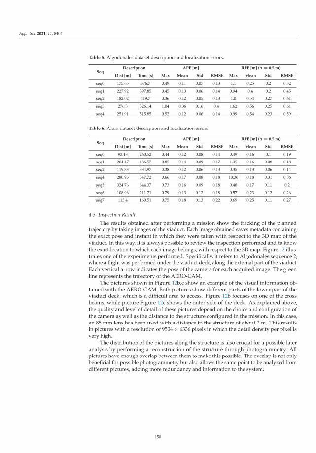
Appl. Sci. 2021, 11, 8404
Table 5. Algodonales dataset description and localization errors.
SeqDescription APE [m] RPE [m] (Δ = 0.5 m)
Dist [m] Time [s] Max Mean Std RMSE Max Mean Std RMSE
seq0 175.65 376.7 0.49 0.11 0.07 0.13 1.1 0.25 0.2 0.32
seq1 227.92 397.85 0.45 0.13 0.06 0.14 0.94 0.4 0.2 0.45
seq2 182.02 419.7 0.36 0.12 0.05 0.13 1.0 0.54 0.27 0.61
seq3 276.3 526.14 1.04 0.36 0.16 0.4 1.62 0.56 0.25 0.61
seq4 251.91 515.85 0.52 0.12 0.06 0.14 0.99 0.54 0.23 0.59
Table 6. Álora dataset description and localization errors.
SeqDescription APE [m] RPE [m] (Δ = 0.5 m)
Dist [m] Time [s] Max Mean Std RMSE Max Mean Std RMSE
seq0 93.18 260.52 0.44 0.12 0.08 0.14 0.49 0.16 0.1 0.19
seq1 204.47 486.57 0.85 0.14 0.09 0.17 1.35 0.16 0.08 0.18
seq2 119.83 334.97 0.38 0.12 0.06 0.13 0.35 0.13 0.06 0.14
seq4 280.93 547.72 0.66 0.17 0.08 0.18 10.36 0.18 0.31 0.36
seq5 324.76 644.37 0.73 0.16 0.09 0.18 0.48 0.17 0.11 0.2
seq6 108.96 211.71 0.79 0.13 0.12 0.18 0.57 0.23 0.12 0.26
seq7 113.4 160.51 0.75 0.18 0.13 0.22 0.69 0.25 0.11 0.27
4.3. Inspection Result
The results obtained after performing a mission show the tracking of the plannedtrajectory by taking images of the viaduct. Each image obtained saves metadata containingthe exact pose and instant in which they were taken with respect to the 3D map of theviaduct. In this way, it is always possible to review the inspection performed and to knowthe exact location to which each image belongs, with respect to the 3D map. Figure 12 illus-trates one of the experiments performed. Specifically, it refers to Algodonales sequence 2,where a flight was performed under the viaduct deck, along the external part of the viaduct.Each vertical arrow indicates the pose of the camera for each acquired image. The greenline represents the trajectory of the AERO-CAM.
The pictures shown in Figure 12b,c show an example of the visual information ob-tained with the AERO-CAM. Both pictures show different parts of the lower part of theviaduct deck, which is a difficult area to access. Figure 12b focuses on one of the crossbeams, while picture Figure 12c shows the outer side of the deck. As explained above,the quality and level of detail of these pictures depend on the choice and configuration ofthe camera as well as the distance to the structure configured in the mission. In this case,an 85 mm lens has been used with a distance to the structure of about 2 m. This resultsin pictures with a resolution of 9504 × 6336 pixels in which the detail density per pixel isvery high.
The distribution of the pictures along the structure is also crucial for a possible lateranalysis by performing a reconstruction of the structure through photogrammetry. Allpictures have enough overlap between them to make this possible. The overlap is not onlybeneficial for possible photogrammetry but also allows the same point to be analyzed fromdifferent pictures, adding more redundancy and information to the system.
150

Appl. Sci. 2021, 11, 8404
(a)
(b) (c)Figure 12. Algodonales sequence 2 inspection result. (a) shows the 3D model with the followedroute (green) and the location of the acquired pictures (blue planes). (b,c) show two examples of theacquired pictures.
5. Conclusions
This work demonstrates that it is possible to perform an inspection of a viaduct withaerial robots as an alternative to current methodologies, saving time and cost and improvingthe safety and quality of data obtained. The design and development of the AERO-CAMand AeroX inspection platforms was quite successful, since together they cover the sensorneeds of a viaduct: either looking for possible defects or analyzing existing ones.
In addition, the provision of autonomous capabilities to the platforms, especially to theAERO-CAM, greatly facilitates the work and provides more flexibility than conventionalmethods. These capabilities also reduce the number of specialized people needed to operatethese platforms, thus improving their safety and speed of use.
Thanks to the choice of a LIDAR-type sensor for the autonomous capabilities of theAERO-CAM, the platform is fully versatile to operate in variable lighting situations, eitherdue to weather conditions or to possible shadows and lighting changes that may be causedby the viaducts themselves. In addition, the system does not rely on a total station forthe flight of the robotic platforms. Likewise, the camera installed in its gimbal can beconfigured to adapt to the different level of detail required or even be replaced by anotherone without having to redesign the platform.
As future developments, although the localization presented in this article providesgood and sufficient results in terms of accuracy and calculation speed, the AERO-CAMdoes not consider taking off autonomously from areas where its LIDAR cannot see thestructure, as the global localization would fail. This means that, until the system is able tolocate itself, the pilot has to fly the UAV to the viaduct. Therefore, other strategies can bedeveloped to complement the localization system to overcome these edge cases.
On the other hand, another line of work is the inclusion of a detect and avoid systemto provide the AERO-CAM with more advanced intelligent capabilities when executingmissions. Currently, the system relies on the fact that the mission designed by the inspector
151

Appl. Sci. 2021, 11, 8404
is free of obstacles and the waypoints keep a safe distance from the viaduct, but it couldmake use of the LIDAR readings to detect potential hazards on the route and re-plan it inreal time.
Author Contributions: Conceptualization, R.C., M.Á.T., F.J.P.-G., A.V. and A.O.; Investigation, R.C.,J.P., M.Á.T. and F.J.P.-G.; Methodology, R.C.; Software, R.C. and J.P.; Validation, R.C. and J.P.; Projectadministration, M.Á.T., F.J.P.-G., A.V. and A.O.; writing—original draft preparation, R.C.; writing—review and editing, R.C., J.P., M.Á.T., F.J.P.-G., A.V. and A.O. All authors have read and agreed to thepublished version of the manuscript.
Funding: This work was funded by the RESIST (H2020-2019-769066) and PILOTING (H2020-2020-871542) projects funded by the European Commission.
Institutional Review Board Statement: Not applicable.
Informed Consent Statement: Not applicable.
Data Availability Statement: The data presented in this study are available on request from thecorresponding author. The data are not publicly available yet due to ongoing private work.
Acknowledgments: Authors would like to thank David Tejero for his support in the developmentof the global localization algorithm, Jorge Mariscal for his review of this article and the interestingdiscussions, and the GRVC from the University of Seville for collaborating with their total station. Inaddition, the authors would like to thank Ferrovial for allowing and providing access to infrastructurefor the experimentation phase.
Conflicts of Interest: The authors declare no conflict of interest.
Abbreviations
The following abbreviations are used in this manuscript:
APE Absolute Pose ErrorDoF Degree of FreedomENU East North UpFPFH Fast Point Feature HistogramGNSS Global Navigation Satellite SystemGPS Global Positioning SystemICP Iterative Closest PointIMU Inertial Measurement UnitLIDAR Light Detection and RangingMDPI Multidisciplinary Digital Publishing InstituteMSE Mean Squared ErrorRANSAC Random Sample ConsensusRMCP Robotic Mobile Contact PlatformRMSE Root Mean Square ErrorRPE Relative Pose ErrorUAV Unmanned Aerial VehicleUT Ultrasonic Testing
References
1. Ayres Associates, Inc. Bridge Inspection with Rope Access. Available online: https://www.ayresassociates.com/project/eagle-canyon-bridge-inspection (accessed on 26 August 2021).
2. Forsgren Associates, Inc. Viaduct Inspection with a Crane. Available online: https://www.forsgren.com/bridge-management-services-inspections (accessed on 14 July 2021).
3. Saini, A.; Singh, D. DroneRTEF: Development of a novel adaptive framework for railroad track extraction in drone images.Pattern Anal. Appl. 2021, 1–20. [CrossRef]
4. Erenoglu, O. UAV for 3D Morphological Mapping Applications: A Case Study of Koru Mining Site, Canakkale, NW Turkey. Teh.Vjesn. 2021, 28, 1044–1050. [CrossRef]
5. Khadka, A.; Afshar, A.; Zadeh, M. Strain monitoring of wind turbines using a semi-autonomous drone. Wind. Eng. 2021, 1–12.[CrossRef]
152

Appl. Sci. 2021, 11, 8404
6. Chen, K.; Reichard, G.; Xu, X.; Akanmu, A. Automated crack segmentation in close-range building façade inspection imagesusing deep learning techniques. J. Build. Eng. 2021, 43, 102913. [CrossRef]
7. Popescu, C.; Mirzazade, A.; Ohlsson, U.; Sas, G. Bridge Inspections Using Unmanned Aerial Vehicles—A Case Study in Sweden; LuleåTekniska Universitet: Luleå, Sweden, 2021.
8. MacGougan, G.; Lachapelle, G.; Nayak, R.; Wang, A. Overview of GNSS signal degradation phenomena. In Proceedings of theInternational Symposium Kinematic Systems and Geodesy, Geomatics and Navigation, Banff, AB, Canada, 5–8 June 2001.
9. Skydio Inc. Available online: https://www.skydio.com/inspection (accessed on 29 July 2021).10. Jimenez-Cano, A.E.; Braga, J.; Heredia, G.; Ollero, A. Aerial manipulator for structure inspection by contact from the underside.
IEEE Int. Conf. Intell. Robot. Syst. 2015, 2015, 1879–1884. [CrossRef]11. Suarez, A.; Heredia, G.; Ollero, A. Lightweight compliant arm with compliant finger for aerial manipulation and inspection.
IEEE Int. Conf. Intell. Robot. Syst. 2016, 2016, 4449–4454. [CrossRef]12. Trujillo, M.; Martínez-De Dios, J.; Martín, C.; Viguria, A.; Ollero, A. Novel aerial manipulator for accurate and robust industrial
NDT contact inspection: A new tool for the oil and gas inspection industry. Sensors 2019, 19, 1305. [CrossRef] [PubMed]13. Trujillo, M.A.; Viguria, A.; Marquez, J.C.; Petrus, A.L.; Jimenez, A.; Garcia, J.J.; Ollero, A. Aeronave con Dispositivo de Contacto.
EU Patent ES2614994A1, 2 March 2018.14. EU Innovation Radar Prize. Available online: https://www.innoradar.eu/innoradarprize (accessed on 28 July 2021).15. Kocer, B.B.; Tjahjowidodo, T.; Pratama, M.; Seet, G.G.L. Inspection-while-flying: An autonomous contact-based nondestructive
test using UAV-tools. Autom. Constr. 2019, 106, 102895. [CrossRef]16. Sanchez-Cuevas, P.J.; Ramon-Soria, P.; Arrue, B.; Ollero, A.; Heredia, G. Robotic system for inspection by contact of bridge beams
using UAVs. Sensors 2019, 19, 305. [CrossRef]17. Kamel, M.; Alexis, K.; Siegwart, R. Design and modeling of dexterous aerial manipulator. IEEE Int. Conf. Intell. Robot. Syst. 2016,
2016, 4870–4876. [CrossRef]18. Park, S.; Her, J.; Kim, J.; Lee, D. Design, modeling and control of omni-directional aerial robot. IEEE Int. Conf. Intell. Robot. Syst.
2016, 2016, 1570–1575. [CrossRef]19. Papachristos, C.; Alexis, K.; Tzes, A. Efficient force exertion for aerial robotic manipulation: Exploiting the thrust-vectoring
authority of a tri-tiltrotor UAV. In Proceedings of the IEEE International Conference on Robotics and Automation, Hong Kong,China, 31 May–7 June 2014; pp. 4500–4505. [CrossRef]
20. Darivianakis, G.; Alexis, K.; Burri, M.; Siegwart, R. Hybrid predictive control for aerial robotic physical interaction towardsinspection operations. In Proceedings of the IEEE International Conference on Robotics and Automation, Hong Kong, China,31 May–7 June 2014; pp. 53–58. [CrossRef]
21. González-deSantos, L.M.; Martínez-Sánchez, J.; González-Jorge, H.; Navarro-Medina, F.; Arias, P. UAV payload with collisionmitigation for contact inspection. Autom. Constr. 2020, 115, 103200. [CrossRef]
22. Gioioso, G.; Ryll, M.; Prattichizzo, D.; Bulthoff, H.H.; Franchi, A. Turning a near-hovering controlled quadrotor into a 3D forceeffector. In Proceedings of the IEEE International Conference on Robotics and Automation, Hong Kong, China, 31 May–7 June2014; pp. 6278–6284. [CrossRef]
23. Delgado, J.P.; Soria, P.R.; Arrue, B.C.; Ollero, A. Bridge Mapping for Inspection Using an UAV Assisted by a Total Station. Adv.Intell. Syst. Comput. 2017, 694, 309–319. [CrossRef]
24. Qin, T.; Li, P.; Shen, S. VINS-Mono: A Robust and Versatile Monocular Visual-Inertial State Estimator. IEEE Trans. Robot. 2018,34, 1004–1020. [CrossRef]
25. Campos, C.; Elvira, R.; Rodríguez, J.J.; Montiel, J.M.; Tardós, J.D. ORB-SLAM3: An Accurate Open-Source Library for Visual,Visual—Inertial, and Multimap SLAM. IEEE Trans. Robot. 2021. [CrossRef]
26. Zhang, J.; Singh, S. LOAM: Lidar Odometry and Mapping in Real-time. In Proceedings of the Robotics: Science and Systems,Berkeley, CA, USA, 12–16 July 2014.
27. Milijas, R.; Markovic, L.; Ivanovic, A.; Petric, F.; Bogdan, S. A Comparison of LiDAR-based SLAM Systems for Control ofUnmanned Aerial Vehicles. In Proceedings of the 2021 International Conference on Unmanned Aircraft Systems (ICUAS), Athens,Greece, 15–18 June 2021; pp. 1148–1154. [CrossRef]
28. Mundt, M.; Majumder, S.; Murali, S.; Panetsos, P.; Ramesh, V. Meta-learning Convolutional Neural Architectures for Multi-targetConcrete Defect Classification with the COncrete DEfect BRidge IMage Dataset. Proc. IEEE Comput. Soc. Conf. Comput. Vis.Pattern Recognit. 2019, 2019, 11188–11197.
29. Chow, J.K.; Su, Z.; Wu, J.; Tan, P.S.; Mao, X.; Wang, Y.H. Anomaly detection of defects on concrete structures with the convolutionalautoencoder. Adv. Eng. Inform. 2020, 45, 101105. [CrossRef]
30. Gremsy T3-Gremsy. Available online: https://gremsy.com/products/gremsy-t3v3 (accessed on 15 June 2021).31. Sony Alpha 7. Available online: https://www.sony.es/electronics/camaras-lentes-intercambiables/ilce-7-body-kit (accessed on
16 July 2021).32. Sony-Camera Remote SDK. Available online: https://support.d-imaging.sony.co.jp/app/sdk/en/index.html (accessed on
15 June 2021).33. Ouster OS0-128. Available online: https://ouster.com/products/os0-lidar-sensor/ (accessed on 15 June 2021).34. Rusu, R.B.; Blodow, N.; Beetz, M. Fast Point Feature Histograms (FPFH) for 3D Registration; Institute of Electrical and Electronics
Engineers (IEEE): Piscataway, NJ, USA, 2009; pp. 3212–3217. [CrossRef]
153

Appl. Sci. 2021, 11, 8404
35. Shan, T.; Englot, B.; Meyers, D.; Wang, W.; Ratti, C.; Rus, D. LIO-SAM: Tightly-coupled lidar inertial odometry via smoothing andmapping. In Proceedings of the IEEE International Conference on Intelligent Robots and Systems, Las Vegas, NA, USA, 25–29October 2020; pp. 5135–5142. [CrossRef]
36. Kaess, M.; Johannsson, H.; Roberts, R.; Ila, V.; Leonard, J.J.; Dellaert, F. ISAM2: Incremental smoothing and mapping using theBayes tree. Int. J. Robot. Res. 2012, 31, 216–235. [CrossRef]
37. Forster, C.; Carlone, L.; Dellaert, F.; Scaramuzza, D. On-Manifold Preintegration for Real-Time Visual-Inertial Odometry. IEEETrans. Robot. 2015, 33, 1–21. [CrossRef]
38. Umeyama, S. Least-Squares Estimation of Transformation Parameters between Two Point Patterns. IEEE Trans. Pattern Anal.Mach. Intell. 1991, 13, 376–380. [CrossRef]
39. Grupp, M. Evo: Python Package for the Evaluation of Odometry and SLAM. 2017. Available online: https://github.com/MichaelGrupp/evo (accessed on 14 July 2021).
154

applied sciences
Article
Drone-Based Vibration Monitoring and Assessmentof Structures
Sabrina Carroll 1, Joud Satme 2, Shadhan Alkharusi 3, Nikolaos Vitzilaios 1,*, Austin Downey 1,3
and Dimitris Rizos 3
Citation: Carroll, S.; Satme, J.;
Alkharusi, S.; Vitzilaios, N.; Downey,
A.; Rizos, D. Drone-Based Vibration
Monitoring and Assessment of
Structures. Appl. Sci. 2021, 11, 8560.
https://doi.org/10.3390/app11188560
Academic Editors: Alejandro Suarez,
Jonathan Cacace and Matko Orsag
Received: 11 August 2021
Accepted: 10 September 2021
Published: 15 September 2021
Publisher’s Note: MDPI stays neutral
with regard to jurisdictional claims in
published maps and institutional affil-
iations.
Copyright: © 2021 by the authors.
Licensee MDPI, Basel, Switzerland.
This article is an open access article
distributed under the terms and
conditions of the Creative Commons
Attribution (CC BY) license (https://
creativecommons.org/licenses/by/
4.0/).
1 Department of Mechanical Engineering, University of South Carolina, Columbia, SC 29208, USA;[email protected] (S.C.); [email protected] (A.D.)
2 Department of Electrical Engineering, University of South Carolina, Columbia, SC 29208, USA;[email protected]
3 Department of Civil and Environmental Engineering, University of South Carolina,Columbia, SC 29208, USA; [email protected] (S.A.); [email protected] (D.R.)
* Correspondence: [email protected]
Abstract: This paper presents a novel method of procuring and processing data for the assessment ofcivil structures via vibration monitoring. This includes the development of a custom sensor packagedesigned to minimize the size/weight while being fully self-sufficient (i.e., not relying on externalpower). The developed package is delivered to the structure utilizing a customized UnmannedAircraft System (UAS), otherwise known as a drone. The sensor package features an electropermanentmagnet for securing it to the civil structure while a second magnet is used to secure the package tothe drone during flight. The novel B-Spline Impulse Response Function (BIRF) technique was utilizedto extract the Dynamic Signature Response (DSR) from the data collected by the sensor package.Experimental results are presented to validate this method and show the feasibility of deploying thesensor package on structures and collecting data valuable for Structural Health Monitoring (SHM)data processing. The advantages and limitations of the proposed techniques are discussed, andrecommendations for further developments are made.
Keywords: Structural Health Monitoring; Unmanned Aircraft System; drone; damage detection;electropermanent magnet; B-spline impulse response function; Dynamic Signature Response
1. Introduction
This work presents an innovative process by which the health status of difficult-to-access structures (e.g., bridges) can be determined, utilizing a wireless sensor package fordata acquisition, deployed by an Unmanned Aircraft System (UAS) (commonly knownas a drone), which provides data for Dynamic Signature Response (DSR) techniques fordamage detection. This sensor technology is a compact and low-cost sensor package withan onboard power supply that allows wireless acceleration data collection, eliminatingthe need for wired connection to the power grid. The sensor package is equipped withan electropermanent magnet that facilitates the rapid installation to various points on theunderside of a metal structure or any structure outfitted with metal plates. The sensorpackage is deployed and retrieved using a drone designed to operate under structuresand deliver the packages safely to regions that may not otherwise be readily accessible(such as the underside of bridges that cross rivers or busy highways). The data collectedby the sensor package is then analyzed with damage detection algorithms that processthe vibration data and extract the DSR, which depends only on the structural condition.Based on the correlation between data collected at a prior, known, and healthy, state andthe current state, Level 1 damage detection (the presence of damage in the structure) canbe determined [1].
This paper is organized as follows: Section 2 provides the relevant background on struc-tural health assessment using drones and vibration-based sensing algorithms. In Section 3,
Appl. Sci. 2021, 11, 8560. https://doi.org/10.3390/app11188560 https://www.mdpi.com/journal/applsci155

Appl. Sci. 2021, 11, 8560
we present the development of the novel sensor package, the UAS for sensor deployment,and the data processing algorithm for the structural vibration data collected. The experi-mental validation of the proposed system along with experimental results are presented anddiscussed in Section 4. Finally, in Section 5, we conclude the paper and discuss future work.
2. Background
2.1. Accelerometer-Based Sensing
Accelerometers have countless uses, from flipping the screen orientation on smart-phones to keeping planes on their trajectory in flight. Accelerometers also play a crucialrole in Structural Health Monitoring (SHM). Researchers have created many methodsof determining the condition of a structure using the vibration signature [2]. However,hardware implementations of such methods are limited due to multiple factors includingsize, cost, and power requirements. The high-sensitivity, low-noise electronics required tomake such measurements are relatively large, expensive, and require experienced person-nel to operate [2]. Attempts to make more compact systems and increase the resolutionand sensitivity are included in the references of this work [3,4]. However, these compactsystems can be labor-intensive and dangerous to deploy in remote areas. Such areas alsomake it impossible to connect these systems to the power grid, creating a need for wirelessand power-independent sensor packages.
Accelerometers are electromechanical devices that detect the change in acceleration in agiven direction. Piezoelectric (PE) and Integrated Electronics Piezoelectric (IEPE) accelerom-eters use internal crystals and the piezoelectric effect to generate a charge related to theacceleration introduced to the system. There are also piezoresistive accelerometers that varytheir resistance in relation to an input acceleration. The third common type of accelerometersare the Capacitive Microelectromechanical Systems (MEMSs). These accelerometers havea suspended microstructure, embedded in the Integrated Circuit (IC), with a small massthat is free to vibrate and measure the change of capacitance of the microstructure due toacceleration [5]. DC coupling of capacitive MEMS accelerometers allows for the detectionof low-frequency signals, which is critical when measuring the vibration signature of largestructures, which typically resonate at frequencies below 1 Hz. Furthermore, MEMSs arecapable of detecting steady-state acceleration [6,7] in addition to allowing the integrationand double integration of their outputs to determine velocity and displacement, which is im-portant for quantifying the stresses and loads on structures. Figure 1 compares performanceversus qualitative cost estimates for the three main types of accelerometers. For this work,a MEMS accelerometer was chosen for its reliability, affordability, and ease-of-use.
Figure 1. Comparison of performance versus cost for the three main types of accelerometers.
156

Appl. Sci. 2021, 11, 8560
2.2. Unmanned Aircraft Systems in SHM
One of the major challenges in SHM is accessing remote areas or difficult-to-accesssegments of structures. UAS (drones) are increasingly used as a solution to this problem.Thus far, much of the research considering drones in SHM applications has focused on theuse of onboard cameras for image acquisition [8,9]. The assessment is then performed by aqualified engineer through visual inspection of the images with or without the use of imageprocessing software. Another approach is to use a drone to hold a reflector prism againstthe bridge for total station measurements instead of holding the prism manually [10].In this case, the prism is affixed directly to the UAS in a configuration described as a helpinghand [11]. Moreover, Unmanned Aerial Manipulators (UAMs) are a new type of drone thatachieve higher precision by utilizing a gripper or multifingered end effector to provideadditional degrees of freedom over helping hands [11].
Jimenez-Cano et al. [10] presented an application of drones for SHM in which adynamic model and controller were developed to achieve contact between the manipulatorarm and the underside of a structure. They proposed to use an ultrasound sensor, attachedto the end effector, to assess the depth of cracks in the structure. During the experiments,the proposed aerial manipulator was able to maintain continuous contact with the structure,which is necessary for the assessment; however, the experiments were performed withoutthe actual ultrasound sensor. In another study by Bodie et al. [12], a contact-based UASmeasured the electrical potential difference between materials in a sample of concrete as amethod of nondestructive testing.
In addition to these contact-based methods, there is ongoing research into the de-ployment and retrieval of sensors by drones. For SHM applications, these sensors can beany of the variety of options considered in the previous subsection. For example in [13],a drone was developed with a hooked gripper able to attach a dummy package with apreprepared adhesive to a target by using the arm to apply pressure to the package againstthe desired surface. The package was then removed using a loop attached to the package,with which the hook can engage, and then, reverse thrust was used to remove it fromthe surface. Closer to this work, drones were attached directly to civil structures usingelectropermanent magnets for the collection of vibration data from civil structures [14].In this case, an electropermanent magnet was utilized to maintain contact between thedrone and the underside of the structure until the onboard systems have completed thedata collection. However, the sensor package was integrated with the UAS and not treatedas a separate system for deployment.
2.3. Vibration-Based SHM
SHM refers to activities used to diagnose structures over time. Structural damagecan be detected by investigating the dynamic properties of the structure. The change inthe modal parameters (e.g., frequencies, mode shapes, and modal damping) indicatesthe change of the physical properties of the structure (e.g., mass, damping, stiffness) [15].Methods for SHM can be divided into local and global methods; local methods are usedin locations where damage is expected, while global methods are used to detect damagethrough monitoring changes in the structure’s dynamic fingerprint [16]. Vibration-baseddamage detection methods are classified into four levels based on what the method is ableto do [17]:
• Level 1: indicates that damage is present;• Level 2: identifies the location of the damage;• Level 3: quantifies the severity of the damage;• Level 4: finds the remaining lifetime of the structure.
Research developments in early damage detection focus on model-based and data-based methods. Model-based methods assume that a detailed numerical model of thestructure is available, and the model parameters are updated based on measurementsobtained from the physical structure [15,18]. Data-driven methods use in situ monitoringto identify changes in the structure’s response characteristics and correlate those changes
157

Appl. Sci. 2021, 11, 8560
to the location (Level 2) and severity (Level 3) of damage [18–20]. Contactless techniquesare also being developed to capture the pure dynamic response of the structure withoutadded masses or stiffening due to the attached sensors [21].
In this work, a data-driven method is investigated to detect Level 1 damage usingtime-domain responses. The B-Spline Response Function (BIRF) technique [22–25] wasimplemented to extract the DSR of the structure from experimental vibration measurements.The DSR is a unique characteristic of the structure and will remain the same if the geometry,materials, and boundary conditions of the structure are not altered. The DSR is independentof the actual loads that caused the vibration. Therefore, the DSR represents the currentstate and condition of a structure. Comparing the DSR before and after damage can beused for damage detection.
3. System Development
The goal of this work was to develop a system that can identify structural damageusing vibration data collected by wireless sensor packages deployed with drones. Thissection presents the three main elements of this system: sensor package, drone, and methodfor damage identification.
3.1. Sensor Package
The sensor package consisted of three components: (i) electronics for data gathering,storage, and wireless control, (ii) a docking mechanism based on an electropermanentmagnet, and (iii) the power supply (battery). These components are presented in Figures 2and 3, while Table 1 summarizes the main features of the sensor package. A compact3D-printed frame was built to house these components, forming the standalone sensorpackage shown in Figure 4 (black box).
Table 1. Summary of the sensor package features.
Sample Size Rate of Data Collection Resolution Sensitivity Steady-State Power Package Weight
74,000 Samples 28 kHz 16-bit 5400 LSB/g 0.296 W 380 g
The sensor package features the ARM Cortex-M7 processor onboard the Teensy 4.0high-performance microcontroller. The system utilizes the 600 MHz clock speed of theTeensy 4.0 and the Serial Communication Interface (SPI) to communicate between themodules and achieve a data collection rate up to 28 kHz. The sensor package also includesthree control options (Figure 2): a PWM port used for wireless control, a digital 5 V as ahard-wired trigger, and manual controls for testing and calibration purposes.
Figure 2. Block diagram of the sensor package circuit schematic.
158

Appl. Sci. 2021, 11, 8560
Figure 3. Constituent components of the sensor package.
Power is supplied using a DC-DC buck converter (MP1584EN manufactured byMonolithic Power Systems) and a lithium polymer battery (Lumenier 7.4V 1000 mAh),as shown in Figure 3. This battery currently runs the sensor package for about 11 h on asingle charge. The deployment period can be prolonged by utilizing standby mode whereunused modules are turned off to conserve energy. In cold weather though, testing hasshown that batteries tend to discharge relatively faster, in turn requiring a more restrictivepower conservation schedule, limiting the number of tests conducted per deployment.
The docking mechanism consists of an electropermanent magnet (NicaDrone EPM V3R5C) able to mount the sensor package onto metal surfaces (Electropermanent Magnet #1in Figure 4). The package collects acceleration data using a MEMS accelerometer (MurataSCA3300-d01) mounted to the metal frame of the electropermanent magnet to ensurecontact with the structure being examined. The system can collect up to 74,000 samples asone continuous dataset, before having to transfer the data onto the onboard nonvolatilememory (SD card), a process that takes approximately 3.288 s.
Figure 4. The docking and retrieval system of the sensor package featuring two electropermanentmagnets: #1 on the top of the package, used to mount it to the underside of structures; and #2 on thedrone docking platform, used to secure, transfer, deliver, and retrieve the package.
3.2. UAS Platform
The standalone sensor package does not require connection to the power grid, so itcan be deployed to any structure. Traditional (human operator) deployment and retrievalthough may be challenging in remote locations. For example, in remote bridges, a lift from
159

Appl. Sci. 2021, 11, 8560
the ground is required to reach the underside (which may be impractical if the bridgecrosses a body of water or a busy highway) or a crane on the topside of the bridge, which canposition the operator underneath the structure. Both methods are risky and require costlyequipment and roads to be shut down to make the underside of the structure accessible.A drone platform has been developed to overcome these limitations and securely deployand retrieve sensor packages in difficult-to-access areas.
The drone platform was based on the DJI F550, a hexacopter with six standard 2312Emotors, shown in Figure 5 [26]. Pixhawk 4 was used as the flight controller, and the systemwas operated via the ArduPilot Mission Planner. Onboard sensors included an IMU,accelerometers, gyroscope, magnetometer, and barometer to provide data for a variety ofparameters including drone orientation and altitude. There was also an external GPS usedfor global positioning when the signal was available. The FrSky X8R radio was used as theonboard receiver to communicate with the FrSky 2.4 GHz Taranis X9D radio controller formanual flight commands. The sensor package, as previously described, was attached to theUAS via a second electropermanent magnet (#2 in Figure 4), which was controlled usingone of the RC servo ports available on the power management board of the Pixhawk 4.
Figure 5. Overview of the custom Unmanned Aircraft System (UAS or drone) developed for sensordeployment and retrieval.
The system was designed to work as follows: On the ArduPilot Mission Planner, twochannels from the FrSky Taranis were set to send high, low, and neutral commands tothe two magnets. During the high command, the magnet begins the charging sequence,which can only be completed once it is in contact with a ferromagnetic surface. Once themagnet is mounted on the metallic surface, this command can be shifted to neutral as theelectropermanent magnet will remain magnetized until the low command is sent. Whenthe low command is sent, it will disengage the magnet.
During operations, the sensor package is delivered onboard the drone (Magnet #2engaged) to the desired point on the structure where Magnet #1 arms and connects thesensor package and drone to the structure. Once the package is secured in place, Magnet #2disengages, and the drone detaches and flies away. The sensor package then periodicallycollects and stores acceleration data for DSR processing. When this operation is complete,the drone conducts a retrieval sequence by reversing the docking procedure. A summaryof the status of both magnets in each phase of operations is given in Table 2.
160

Appl. Sci. 2021, 11, 8560
Table 2. Operation status for Electropermanent Magnets #1 and #2 for each sensor package and UAS position.
Electropermanent Magnet #1 Electropermanent Magnet #2 Sensor Package UAS
Unmagnetized Magnetized Attached to UAS At deliveryMagnetized Unmagnetized Attached to structure Package deployed
To assist with the retrieval of the sensor package, the UAS was outfitted with a 3Dprinted alignment tool (docking platform in Figure 4). The alignment tool features angledwalls, which help to center the sensor package over the electropermanent magnet andprevent the sensor package from coming into contact with the propellers.
3.3. Method of Damage Identification
The Dynamic Signature Response (DSR) of a system is a characteristic response ofthe system and was first introduced by Rizos et al. [23] as the B-Spline Impulse ResponseFunction (BIRF) for soil–structure interaction analysis. The BIRF is a time-varying functionthat is defined between any two points in a mechanical system. It represents the timehistory of the response of one of the two points due to a unit amplitude B-spline excitationapplied to the other point [23,24,27,28]. The B-spline functions are piecewise smoothpolynomials of order k and belong to a family of base functions used in data interpolationand approximation. They are defined with respect to a time knot sequence tn, n = 1, 2, . . .,by the recursive formula,
Bkn(t) =
{1, if tn < t < tn+1
0, elsewherek = 1, (1)
Bkn(t) =
(t − tn
tn+k−1 − tn
)Bk−1
n (t) +(
tn+k − ttn+k − tn+1
)Bk−1
n+1(t), k > 1. (2)
The Bkn-spline polynomials are of degree k − 1 and have k − 2 continuous derivatives.
While the BIRFs are computed efficiently in numerical models of physical systems [23,28,29],it is almost impossible to measure the BIRFs directly in physical systems due to the difficultyof accurately reproducing the B-spline loading on the physical system. The BIRF between twopoints of a mechanical system, however, can be extracted from vibration tests that acquirethe time history record of a response, R, and excitation, f, at the two points. For example,the fourth-order-based BIRF is computed in a discrete form at a time step N as:
BIRFN =
(RN −
N−2
∑n=1
BIRFn fN−n+2 + BIRFN−1( f3 − f1)
)/( f2 + 2 f1), (3)
where subscripts indicate the time step at which the corresponding functions are evaluated.Details of the method along with verification and validation studies were presented inAlkharousi et al. [30,31].
Structural assessment procedures through dynamic testing focus on identifying changesin the dynamic properties of the system through modal analysis and/or model updatingtechniques. In Equation (3), the BIRFs are independent of any external excitations and areconsidered the DSRs that capture the current state of the dynamic system. Any changesin the current state of the structure are captured as changes in its DSRs. Therefore, if theresponse time history, R, and the corresponding excitation, f, are known through vibrationtest measurements conducted before and after a damage-inducing event, the difference inthe corresponding DSR is an indication of damage [30,31].
The computation of the BIRF shown in Equation (3) represents in essence a discretedeconvolution of the response signal, and the BIRF can be perceived as an equivalent timedomain transfer function of the system that captures all frequencies in the range defined bythe sampling time interval. It is noted and had been demonstrated that the analysis of onlya short duration segment of the recorded response is adequate for change detection through
161

Appl. Sci. 2021, 11, 8560
the DSR algorithm, compared to mainstream methods that require, in most cases, the entireresponse record from multiple sensors. However, the noise inherent to the time historyresponse records may have to be removed through filtering before the DSR is extracted.Nevertheless, the computing demand of the proposed method is very low, minimizing thepostprocessing times, leading potentially to damage detection in real time, and facilitatingthe integration to the damage detection algorithms in the overall proposed system.
4. Experimental Validation and Results
In order to validate the developed system (drone, sensor package, damage detectionalgorithm), we created a laboratory experimental testbed and designed experiments to col-lect and analyze data. The goal was to show the feasibility of the drone-based deploymentand retrieval of our sensor package, as well as the extraction of damage information fromthe collected vibration data.
4.1. Test Apparatus
A test apparatus was constructed in the lab to replicate a bridge with a metallic surface,as shown in Figure 6. The structure was 6.5 ft tall and 6.5 ft wide (2 m × 2 m) with a 2 ftby 4 ft (60 cm × 120 cm) steel plate mounted in the center to serve as a docking platform.Figure 7 shows a schematic of this plate. An electromagnetic shaker (Ling Dynamic SystemsV408) was permanently mounted on top of the plate and used to excite the structure duringour experiments. The test apparatus was placed inside a drone cage where the OptiTrackMotion Capture system was used for rigid body tracking. This system can provide accuratepose data (position and orientation) for our drone flights.
Figure 6. Overview of the test apparatus with key components annotated.
162

Appl. Sci. 2021, 11, 8560
Figure 7. Schematic of the steel plate structure used in the experiments featuring the sensor packageplacement and the relative location of the supporting bolts used to simulate damage.
4.2. Drone-Based Deployment Validation
In this experiment, we aimed to validate the use of the drone for the sensor packagedeployment. The experiment was designed as follows: The drone approaches the structureand conducts the docking sequence described in Section 3.2, then mounts the sensorpackage to the structure. After sufficient time for data collection has passed, the UASapproaches the structure again and reverses the docking sequence to retrieve the package.When the package has been retrieved, the entire system lands, and the test is complete.During this experiment, the electromagnetic shaker was set to excite the structure at 11.3 Hzwhile we collected acceleration data from the sensor package and displacement data fromthe OptiTrack Motion Capture system. Due to the underside of the structure being outsideof the OptiTrack field of view, only the UAS position and orientation were tracked usingthe OptiTrack system.
The results are presented in Figure 8. The first 25 s of the test were used to coordinatethe data collection and ensure that the electropermanent magnets were properly set beforetakeoff. Adjustments were performed to properly align the UAS with the structure beforemaking contact at 38 s, at which point, the UAS maintained contact until the 48 s mark(area II) to ensure the engagement of the electropermanent magnet on the sensor packageand the disengaging of the electropermanent magnet on the UAS. Once the magnets wereset, the UAS left the sensor package on the structure from the 38 s mark until the 75 s mark(area III). During this time, the UAS hovered near the structure to allow the sensor packageto perform data collection without interference from the hanging mass of the UAS.
After allowing sufficient time for data collection, the UAS began the retrieval processby making contact with the package at 75 s. Contact was again maintained for 10 s toconfirm the change in the electropermanent magnet state (area IV). For retrieval, the magneton the UAS was engaged to maintain hold of the sensor package during landing prior tothe magnet on the sensor package disengaging, allowing the system to begin its descent.This descent was performed immediately after securing the sensor package, and the dronelanded at 94 s, completing the flight test.
The acceleration of the sensor package presented in Figure 8 substantiated thesemovements showing intense vibration when the package was onboard the UAS andsignificantly smaller acceleration while in contact with a structure, indicating successfuldeployment. Experimental results showed the feasibility of the method, which can now befurther developed [26].
163

Appl. Sci. 2021, 11, 8560
Figure 8. UAS deployment of the sensor package showing (a) acceleration of the sensor package,(b) displacement of the UAS, and (c) photos of the sensor deployment and retrieval experiment.
4.3. Sensor Package Validation
This experiment aimed at validating the accuracy of acceleration data collected bythe sensor package. For this purpose, the sensor package was manually mounted alongwith a PCB accelerometer onto the steel plate, which was excited by the electromagneticshaker (as shown in Figure 6). Using a data acquisition module, the excitation signalwas swept from 1–20 Hz over a test period of 50 s. Due to the limited sample size of thesensor package (74,000 samples), a sampling frequency of 1480 Hz was used as a resultof the limited buffer size onboard the sensor package. The validation was conductedutilizing a frequency response function of the sensor package data over the reference PCBaccelerometer, shown in Figure 9. The results indicated an exponentially increasing error asthe frequency approached zero. At lower frequencies (<5 Hz), the acceleration signal wasbelow the sensitivity of the sensor package (5400 LSB/g), resulting in the large error shown.This could be mitigated in future designs by utilizing a higher accuracy accelerometer anddecreasing the damping caused by the sensor package frame.
164

Appl. Sci. 2021, 11, 8560
Figure 9. Frequency response function of the sensor package for 1–20 Hz excitation.
4.4. Damage Detection Validation
This experiment was designed to validate the ability of the sensor package to collectmeaningful data for SHM applications. Since the system was developed to detect Level1 damage, the sensor package needed to collect data before and after the structure hadsustained damage. To simulate damage, three bolts supporting the steel plate were removed,as shown in Figure 7. This experiment also utilized the electromagnetic shaker to generateharmonic excitation forces. Additionally, a load cell (Ling Dynamic Systems V408) wasplaced between the shaker and the plate to record the force transmitted to the structureto provide ground truth measurements. The sensor package was then manually mounteddirectly underneath the electromagnetic shaker and load cell, in the position a0 shown inFigure 7. The shaker was first actuated at 7 Hz for 4 s and then stopped to allow the structureto vibrate freely. This was repeated at 14 Hz for both the undamaged and damaged structure.
The collected data underwent preprocessing in which the data from each experimentwere smoothed through a 50-point rolling average and resampled to a total of 200 pointsto be considered as the response, RN , in Equation (3). The associated forcing function, fN ,in Equation (3) can be either the load cell record or the voltage signal that drives the linearactuator [31]. In this paper, the load cell record was utilized. Equation (3) can now beimplemented on each record to extract the DSR of the structure. It has been shown thatdamage can be detected by processing even a short segment of the record [31], providedthat the time step of the acquisition is adequate to capture the maximum desired frequencyaffecting the response.
Figure 10 shows a 400-step segment of the DSR of the undamaged structure. EachDSR was extracted from the acceleration time history sampled in each of the three testswith the 14 Hz excitation force. As expected, the three DSR signals were almost identicaland showed a high correlation (R2 = 0.989). This indicated that the state of the structurehad not changed between acquisitions, and therefore, no damage was present. Figure 11compares the DSR of the damaged and undamaged structure to the 14 Hz excitation force.These two BIRFs showed no correlation, indicating a change in the structural condition;thus, the presence of damage is detected.
In Figures 10 and 11, the damage detection algorithm operated on a 0.8 s window ofthe free vibration structural response with an acquisition step of 2 × 10⁻³ s. This allowedfor approximately 10 sampling points within a response cycle, and thus, this was theminimum acquisition step required to capture frequencies up to approximately 300 Hz. It isnoted that the structural response record was resampled to 1/4th of the original samplingfrequency. It is also noted that an even shorter segment of the structural response couldpotentially be used in the damage detection algorithm.
165

Appl. Sci. 2021, 11, 8560
Figure 10. The Dynamic Signature Response (DSR) extracted from 400 steps of the free vibrationphase of the response of the undamaged structure excited by a 14 Hz harmonic force.
Figure 11. The DSR extracted from 400 steps of the free vibration phase of the response of theundamaged and damaged structure excited by a 14 Hz harmonic force.
Table 3 summarizes the R2 correlation coefficients of the BIRFs extracted from alltests for the two excitation frequencies on the undamaged and damaged structure. It wasobserved that all BIRFs correlated well (R2 > 0.8) when extracted from responses of eitherthe undamaged or damaged structure, for both frequencies. However, the correlation wascompletely lost (R2 ≈ 0) when the BIRFs of the undamaged and damaged structures werecompared, regardless of the excitation.
166

Appl. Sci. 2021, 11, 8560
Table 3. Correlation coefficients between BIRFs of the undamaged and damaged structure for the 7 Hz and 14 Hzexcitation frequencies.
Before Damage After Damage
7 Hz 14 Hz 7 Hz 14 Hz
Test 1 2 3 1 2 3 1 2 3 1 2 3
Befo
reD
amag
e
7H
z 1 1.000 0.883 0.890 0.900 0.888 0.895 0.092 0.080 0.086 0.084 0.087 0.0792 1.000 0.891 0.909 0.898 0.905 0.098 0.086 0.090 0.083 0.087 0.0863 1.000 0.865 0.864 0.865 0.086 0.078 0.079 0.083 0.096 0.078
14H
z 1 1.000 0.989 0.991 0.097 0.095 0.094 0.087 0.091 0.0872 1.000 0.990 0.095 0.096 0.093 0.088 0.088 0.0853 1.000 0.099 0.098 0.096 0.092 0.088 0.081
Aft
erD
amag
e
7H
z 1 1.000 0.879 0.892 0.813 0.798 0.8152 1.000 0.906 0.812 0.809 0.8393 1.000 0.805 0.787 0.813
14H
z 1 1.000 0.921 0.9272 1.000 0.9103 1.000
5. Conclusions
This paper presented an initial prototype and the associated methodologies for asensor package that can be deployed via a drone onto civil structures for structural healthmonitoring. Alongside this demonstration, Level 1 damage detection (the presence ofdamage in the structure) was performed using a novel BIRF technique to extract the DSRfrom data collected by reference accelerometers. Through manual flights, the feasibility ofdelivering and retrieving a sensor package from the underside of a structure was proven.Similarly, experimental validation showed that the BIRF method is an effective method fordetermining damage based on data collected from any sensor package.
In future work, the landing mechanism of the UAS system will be fully automated,instead of relying on manual flight controls. The sensitivity of the sensor package will beimproved, and wireless communication and data transfer will be added. The use of elastomerswill be considered in an effort to reduce the effect of drone vibrations on the measurements.As for the damage detection algorithm, future work will focus on expanding the methodologyto include damage quantification and damage localization, which relate to Level 2 and 3damage detection, respectively.
Author Contributions: The authors confirm the contributions to the paper as follows: study concep-tion and design: N.V., A.D. and D.R.; data collection: S.C., J.S. and S.A.; analysis and interpretation ofresults: S.C., J.S., S.A., N.V., A.D. and D.R.; draft manuscript preparation: S.C., J.S., S.A., N.V., A.D.and D.R. All authors have read and agreed to the published version of the manuscript.
Funding: This work was partially supported by the University of South Carolina (UofSC) Office ofUndergraduate Research (Magellan Awards 80003124 and 80003491), the UofSC College of Engineer-ing and Computing startup fund and the Advanced Railway Technology Group at UofSC.
Institutional Review Board Statement: Not applicable.
Informed Consent Statement: Not applicable.
Conflicts of Interest: The authors declare no conflict of interest.
References
1. Doebling, S.; Farrar, C.; Prime, M.; Shevitz, D. Damage Identification and Health Monitoring of Structural and Mechanical Systemsfrom Changes in Their Vibration Characteristics: A Literature Review; Technical Report; Los Alamos National Laboratory (LANL):Los Alamos, NM, USA, 1996; doi:10.2172/249299. [CrossRef]
2. Ho, D.D.; Nguyen, K.D.; Yoon, H.S.; Kim, J.T. Multiscale Acceleration-Dynamic Strain-Impedance Sensor System for StructuralHealth Monitoring. Int. J. Distrib. Sens. Netw. 2012, 8, 709208. [CrossRef]
167

Appl. Sci. 2021, 11, 8560
3. Illinois Structural Health Monitoring Project. SHM-H Board High-Sensitivity Accelerometer Sensor Board Datasheet and User’sGuide. June 2009. Available online: https://shm.cs.illinois.edu/ (accessed on 1 August 2021).
4. Smart Structure Systems Lab, University of Arizona. Structural Health Monitoring (SHM) Board Series for Imote2 Smart Sensor Platform.Technical Report. 2020. Available online: https://smartstructure.weebly.com/smart-sensor.html (accessed on 1 August 2021).
5. Mohammed, Z.; Elfadel, I.; Rasras, M. Monolithic Multi Degree of Freedom (MDoF) Capacitive MEMS Accelerometers. Microma-chines 2018, 9, 602. [CrossRef] [PubMed]
6. Lent, B. Simple Steps to Selecting the Right Accelerometer. 2018. Available online: https://www.fierceelectronics.com/components/simple-steps-to-selecting-right-accelerometer-0 (accessed on 5 May 2020).
7. Yoder, N.; Adams, D. Commonly used sensors for civil infrastructures and their associated algorithms. In Woodhead PublishingSeries in Electronic and Optical Materials, Sensor Technologies for Civil Infrastructures; Woodhead Publishing: Cambridge, UK, 2014;pp. 57–85. [CrossRef]
8. Sankarasrinivasan, S.; Balasubramanian, E.; Karthik, K.; Chandrasekar, U.; Gupta, R. Health Monitoring of Civil Structures withIntegrated UAV and Image Processing System. Procedia Comput. Sci. 2015, 54, 508–515. [CrossRef]
9. Sony, S.; Laventure, S.; Sadhu, A. A literature review of next-generation smart sensing technology in structural health monitoring.Struct. Control Health Monit. 2019, 26, e2321. [CrossRef]
10. Jimenez-Cano, A.; Braga, J.; Heredia, G.; Ollero, A. Aerial manipulator for structure inspection by contact from the underside. InProceedings of the 2015 IEEE/RSJ International Conference on Intelligent Robots and Systems (IROS), Hamburg, Germany, 28September–2 October 2015; pp. 1879–1884. [CrossRef]
11. Ruggiero, F.; Lippiello, V.; Ollero, A. Aerial Manipulation: A Literature Review. IEEE Robot. Autom. Lett. 2018, 3, 1957–1964.[CrossRef]
12. Bodie, K.; Brunner, M.; Pantic, M.; Walser, S.; Pfndler, P.; Angst, U.; Siegwart, R.; Nieto, J. An Omnidirectional Aerial ManipulationPlatform for Contact-Based Inspection. arXiv 2019, arXiv:1905.03502.
13. Hamaza, S.; Georgilas, I.; Fernandez, M.; Sanchez, P.; Richardson, T.; Heredia, G.; Ollero, A. Sensor Installation and RetrievalOperations Using an Unmanned Aerial Manipulator. IEEE Robot. Autom. Lett. 2019, 4, 2793–2800. [CrossRef]
14. Takeuchi, K.; Masuda, A.; Akahori, S.; Higashi, Y.; Miura, N. A close inspection and vibration sensing aerial robot for steelstructures with an EPM-based landing device. In Proceedings of the Nondestructive Characterization and Monitoring ofAdvanced Materials, Aerospace, and Civil Infrastructure 2017, Portland, OR, USA, 26–29 March 2017; Volume 10169, p. 101692U.[CrossRef]
15. Sabamehr, A.; Lim, C.; Bagchi, A. System identification and model updating of highway bridges using ambient vibration tests. J.Civ. Struct. Health Monit. 2018, 8, 755–771. [CrossRef]
16. Fritzen, C.P.; Kraemer, P. Self-diagnosis of smart structures based on dynamical properties. Mech. Syst. Signal Process. 2009,23, 1830–1845. [CrossRef]
17. Liu, J.; Chen, S.; Bergés, M.; Bielak, J.; Garrett, J.H.; Kovacevic, J.; Noh, H.Y. Diagnosis algorithms for indirect structural healthmonitoring of a bridge model via dimensionality reduction. Mech. Syst. Signal Process. 2020, 136, 106454. [CrossRef]
18. Abdo, M. Structural Health Monitoring, History, Applications and Future. A Review Book; Open Science: New York, NY, USA, 2014.19. Farrar, C.R.; Doebling, S. An Overview Of Modal Based Damage Identification Methods, Engineering Analysis Group. In
Proceedings of the Structural Damage Assessment Using Advanced Signal Processing Procedures (DAMAS), Sheffield, UK,30 June–2 July 1997.
20. Doebling, S.W.; Farrar, C.R.; Prime, M.B. A Summary Review of Vibration-Based Damage Identification Methods. Shock Vib. Dig.1998, 30, 91–105. [CrossRef]
21. Civera, M.; Zanotti Fragonara, L.; Surace, C. An experimental study of the feasibility of phase-based video magnification fordamage detection and localisation in operational deflection shapes. Strain 2020, 56, e12336. [CrossRef]
22. Rizos, D.C.; Karabalis, D.L. A time domain BEM for 3-D elastodynamic analysis using the B-spline fundamental solutions.Comput. Mech. 1998, 22, 108–115. [CrossRef]
23. Rizos, D.C.; Loya, K.G. Dynamic and Seismic Analysis of Foundations based on Free Field B-Spline Characteristic ResponseHistories. J. Eng. Mech. 2002, 128, 438–448. [CrossRef]
24. Stehmeyer, E.H.; Rizos, D.C. B-Spline impulse response functions (BIRF) for transient SSI analysis of rigid foundations. Soil Dyn.Earthq. Eng. 2006, 26, 421–434. [CrossRef]
25. Leon, E.; Rizos, D.C.; Caicedo, J.M. A procedure to develop scalable models for the transient response of sleepers in conventionaland high-speed railway lines and implementation to the vertical vibration mode. Soil Dyn. Earthq. Eng. 2011, 31, 502–511.[CrossRef]
26. Carroll, S.; Kalaitzakis, M.; Vitzilaios, N. UAS Sensor Deployment and Retrieval to the Underside of Structures. In Proceedingsof the 2021 International Conference on Unmanned Aircraft Systems (ICUAS), Athens, Greece, 15–18 June 2021; pp. 895–900.[CrossRef]
27. Rizos, D.C. Advanced Time Domain Boundary Element Method for General 3-D Elastodynamic Problems. Ph.D. Thesis, Civiland Environmental Engineering, University of South Carolina, Columbia, SC, USA, 1993.
28. Mulliken, J.; Rizos, D.C. A coupled computational method for multi-solver, multi-domain transient problems in elastodynamics.Soil Dyn. Earthq. Eng. 2012, 34, 78–88. [CrossRef]
29. Karabalis, D.L.; Rizos, D. Dynamic analysis of 3-D foundations. Bound. Elem. Tech. Geomech. 1993, 6, 177–208.
168

Appl. Sci. 2021, 11, 8560
30. Alkharousi, S. Identification of Structural Signature Responses from Response Time Histories Using B-Spline Impulse ResponseTechniques. Master’s Thesis, Department of Civil & Environmental Engineering, University of South Carolina, Columbia, SC,USA, 2021.
31. Alkharousi, S.; Rizos, D.C. Identification of Structural Signature Responses from Response Time Histories Using B Spline ImpulseResponse Techniques. Struct. Health Monit. 2022, in preparation.
169


applied sciences
Article
Aerial Tele-Manipulation with Passive Tool via ParallelPosition/Force Control†
Mostafa Mohammadi 1,2, Davide Bicego 3,*, Antonio Franchi 3,4, Davide Barcelli 1 and Domenico Prattichizzo 1,2
Citation: Mohammadi, M.; Bicego,
D.; Franchi, A.; Barcelli, D.;
Prattichizzo, D. Aerial
Tele-Manipulation with Passive Tool
via Parallel Position/Force Control.
Appl. Sci. 2021, 11, 8955. https://
doi.org/10.3390/app11198955
Academic Editor: Seong-Ik Han
Received: 6 August 2021
Accepted: 18 September 2021
Published: 26 September 2021
Publisher’s Note: MDPI stays neutral
with regard to jurisdictional claims in
published maps and institutional affil-
iations.
Copyright: © 2021 by the authors.
Licensee MDPI, Basel, Switzerland.
This article is an open access article
distributed under the terms and
conditions of the Creative Commons
Attribution (CC BY) license (https://
creativecommons.org/licenses/by/
4.0/).
1 Department of Information Engineering and Mathematics, University of Siena, 53100 Siena, Italy;[email protected] or [email protected] (M.M.); [email protected] (D.B.);[email protected] (D.P.)
2 Department of Advanced Robotics, Italian Institute of Technology, 16163 Genoa, Italy3 Robotics and Mechatronics Group, University of Twente, 7522 NH Enschede, The Netherlands;
[email protected] or [email protected] LAAS-CNRS, Université de Toulouse, CNRS, 31400 Toulouse, France* Correspondence: [email protected]; Tel.: +31-534-892-626† This research was partially supported by the European Union’s Horizon 2020 research and innovation
program grant agreement ID: 871479 AERIAL-CORE.
Abstract: This paper addresses the problem of unilateral contact interaction by an under-actuatedquadrotor UAV equipped with a passive tool in a bilateral teleoperation scheme. To solve thechallenging control problem of force regulation in contact interaction while maintaining flightstability and keeping the contact, we use a parallel position/force control method, commensurate tothe system dynamics and constraints in which using the compliant structure of the end-effector therotational degrees of freedom are also utilized to attain a broader range of feasible forces. In a bilateralteleoperation framework, the proposed control method regulates the aerial manipulator positionin free flight and the applied force in contact interaction. On the master side, the human operatoris provided with force haptic feedback to enhance his/her situational awareness. The validity ofthe theory and efficacy of the solution are shown by experimental results. This control architecture,integrated with a suitable perception/localization pipeline, could be used to perform outdoor aerialteleoperation tasks in hazardous and/or remote sites of interest.
Keywords: aerial robotics; aerial manipulation; force control; bilateral teleoperation; haptics; quadrotor
1. Introduction
Aerial robotics has become increasingly popular in research, industry, and for com-mercial applications. Beyond the traditional visual inspection functionality that made themwidely used and appreciated, aerial robots have recently received profound interest forapplications which require to seek, establish, and maintain some sort of physical interactionwith the environment in order to fulfill a certain task. Relevant examples are epitomizedby maintenance operations in the energy sector, for example, oil, gas, refinery, and powerplants, in particular, to perform non-destructive tests that require keeping some sensors intouch with objects not easily accessible by a human, due to their installation altitude, andalso in hazardous environments [1,2]. Apart from their growing use in industrial and civilsites, these systems are starting to also be employed for the in-contact documentation ofhistorical buildings [3]. Other applications of aerial interaction involve the transportationof cable-suspended payloads [4] and packages for search and rescue missions [5].
Aerial manipulation is the deliberately controlled physical interaction of an aerialmanipulator with objects in its environment. For an extensive overview of the works onthis topic, the interested reader is referred to [6,7]. By aerial manipulator we mean a smallsize Vertical Take-Off and Landing (VTOL) Unmanned Aerial Vehicle (UAV) equipped witha manipulation tool. This manipulation tool is either an active robotic arm manipulator ora passive tool.
Appl. Sci. 2021, 11, 8955. https://doi.org/10.3390/app11198955 https://www.mdpi.com/journal/applsci171

Appl. Sci. 2021, 11, 8955
When dexterous manipulation by an aerial manipulator is not required, for example,when the robot is intended to apply desired force vectors to an object in order to push,inspect, or probe its surface, or when the normal grippers are not effective, for example, foran object with a wide flat surface, the use of a lightweight passive tool is preferable to aheavier active arm manipulator, as the smaller payload imposed to the aerial robot resultsin a more energy-efficient system and longer operational flight time. Moreover, simplicityand low weight of a passive tool allow the usage of a broader range of UAVs.
Despite significant achievements in the fully autonomous control of drones, limitedproblem-solving capabilities, inadequacy in unexpected environmental conditions, le-gal restrictions, and imperfect position control [8] often require the presence of humanoperator(s) in aerial manipulation tasks. In bilateral teleoperation schemes, the humancapabilities are enhanced by providing them with tangible interaction information of theremote side in the form of force and motion feedbacks (haptic feedback), besides thetraditional visual feedback.
In this paper, we propose an aerial manipulation solution using passive tools with acompliant end-effector. Applying a desired force profile in a uni-lateral contact, and at thesame time maintaining the flight stability, that is, position and orientation control, and keep-ing the contact stable, that is, to avoid losing contact and sliding over the contact surface,represents a challenging control problem, especially when it is performed with an under-actuated aerial manipulator in a bilateral teleoperation loop. Fully-actuated aerial manipu-lators have been demonstrated to be more effective for this kind of application [8–11] butconsume more energy due to internal forces. That is why the use of under-actuated UAVsis investigated in this work. Our aerial manipulator is a quadrotor UAV equipped with alightweight passive tool rigidly attached to the top of it (Figures 1 and 2). The end-effectorhas a mechanical damper on its surface to smooth free flight to contact transition, and apassive compliant spherical joint to keep the contact while changing the orientation. Thiscompliant mechanism, along with appropriate control policy conforming with the systemconstraints, allows involving all the robot’s degrees of freedom to generate the desiredforce vector. The desired motion and force of the aerial manipulator are attained using aparallel position/force control scheme within a bilateral teleoperation control framework.
The proposed control scheme regulates the aerial manipulator pose in free flight andthe applied force in contact conditions. A human operator using a haptic device (witha limited workspace) commands the aerial manipulator pose (with virtually unlimitedworkspace) in free flight. When the aerial manipulator’s end-effector comes in contactwith the environment, the haptic device movement is interpreted as desired force. Positioncontrol in free flight and force control in contact are achieved by utilizing a cascadedparallel position/force controller. The reference pose is composed by the operator’s posecommand (free flight pose command) and the output of a force controller in an outerloop. To avoid losing the contact, the desired force is always kept in a feasible range thatsatisfies the friction and compliance constraints. On the master side, the human operatoris provided with force feedback proportional to the robot’s velocity in free flight and theapplied force in contact.
The aerial tele-manipulation system presented in this paper may contribute to address-ing and solving a broad class of relevant use-case applications where a UAV is remotelyoperated in hardly accessible and life-threatening sites, for example, at high altitudes, by ahuman safely located in a protected place, thus relieving him/her from potentially danger-ous tasks. A conceptual example is depicted in Figure 1. Apart from the aforementionedapplications of remote sensor placement, contact holding and remote button pushing,another idea that could be envisioned is to employ such a system to push boxes located ona shelf onto a conveyor belt, in an industrial warehouse scenario. Thanks to the enhancedsituational awareness guaranteed by the haptic feedback, the operator could easily regulatethe force applied to the load. Furthermore, the designed control law would ensure that thecontact is maintained throughout the manipulation. As should be appreciated, many otherrelevant applications involving the aforementioned conditions can be easily conceived.
172

Appl. Sci. 2021, 11, 8955
Figure 1. A conceptual example of aerial tele-manipulation with a passive tool: an aerial robotequipped with a lightweight passive tool tasked to press an emergency shut down push button.
Figure 2. The passive lightweight tool with compliant end-effector used to convert a normal VTOLUAV to an aerial manipulator.
The rest of the paper is organized as follows. The next subsection reviews the relatedworks and the contribution of the paper. Section 2 explains the platform and its dynamicmodel in the teleoperation system. Section 3 presents the proposed control approach, thestability analysis of which is presented in Section 4. Experimental results are presented inSection 5, while concluding remarks and hints about intended future works are outlined inSection 6.
Related Works and Contribution
There has been a growing interest in aerial robots with physical interaction in the pastfew years, and many research projects such as [12] have focused on this context. In thefollowing, we try to concisely provide a general overview of the state of the art of thisbroad topic, focusing then on the works more closely related to the one presented in thispaper. Aerial physical interaction with the environment can be macro-categorized as:
(i) using active manipulators; and(ii) using passive tools;
and naturally, different mechanical solutions demand different controllers.To mention some examples belonging to the first group, in [13] the authors designed
and installed a small parallel manipulator on one side of a VTOL, while the use of one andtwo serial manipulators to grasp objects was proposed in [14] and in [15], respectively. Inthese works, the authors implemented and validated different instances of hybrid forcecontrol. A visual servoing approach to control a quadrotor equipped with a serial manipu-lator is suggested by [16], while a passivity-based adaptive controller, which can be appliedto both position and velocity control to guide a quadrotor aerial manipulator, is utilizedby [17]. Furthermore, the behavioral control of an aerial manipulator is presented in [18].In the multi-robot scenario, a team of quadrotors, equipped with serial manipulators,
173

Appl. Sci. 2021, 11, 8955
controlled by a visual servoing technique, is demonstrated in [19]. Differently from theseworks, we tackle the scenario of aerial tele-manipulation with haptic feedback of an objectof interest via parallel/force control, using a passive tool.
In the second group, which encompasses the research presented in this paper, differentworks have focused on solutions to applications requiring less dexterous manipulationcapabilities, but with the benefits of being more cost-effective, versatile, and lightweight,thus allowing for longer operational flight time. In [20], a quadrotor UAV equipped witha rigid tool, controlled based on a mapping between the desired vehicle attitude and thecommanded force, is used to establish contacts with the environment. The control strategytherein is designed as a variation of near-hovering control, and does not take into accountthe friction cone constraints that allow maintenance of the contact between the robot tool-tip and the environment, while instead our strategy does. The authors of [21] proposeinstead an interesting combination of both mechanical design and control strategy tohandle collisions and interaction in a more compliant way, without focusing on direct forcecontrol. A hybrid position/force control framework for a quadrotor is presented in [22],which allows the exertion of forces with the quadrotor airframe, without any tool, on theenvironment. A similar control approach is also adopted in [23] for the very relevant taskof tool operation with quadrotors. Planning and control for an aerial robot in contact withits environment, based again on a hybrid position/force switching controller, is presentedin [24], where obstacle avoidance is also performed. The control schemes of [22–24] arebased on the decoupling of axes of the applied force and motion; that is, force is applied inthe motion constrained axes while on the other axes the motion is controlled. Differentlyfrom [22–24] and other similar approaches, in this work, we do consider friction constraintsin a compliant uni-lateral contact to avoid slipping of the tool in the non-constrained axesof motion and to maintain the contact, which allows us to generate 3D force vectors. Forthis reason, we use a parallel (and not hybrid) position/force control approach, which alsodeploys rotational degrees of freedom to attain a broader feasible range of forces. It is worthnoting that the traditional parallel position/force controller applied to generic six-DoFgrounded manipulators is not directly applicable to our system, as it is an under-actuatedfloating robot. All the wrench components of the contact interaction are transmitted to therobot CoM and affect its orientation, by which the position is controlled, which makes theproblem more challenging, especially in the transition from free flight to contact interactionand vice versa.
Furthermore, in all the aforementioned papers, the use of haptic feedback is not envi-sioned. Haptic teleoperation of UAVs is mainly used for obstacle avoidance in free flight,aiming to improve the situational awareness of the human operator using haptic feedback,such as the generic hierarchical passive teleoperation control architecture presented in [25].We use haptic feedback not only to improve the performance of position tracking in freeflight, but also to reflect the applied force, in order to let the user feel the force in the contactinteraction, which eventually leads to a more accurate tele-manipulation. The stabilityanalysis and experimental results validate the proposed bilateral teleoperation scheme foraerial manipulation using passive tools.
To the best of our knowledge, the problem of teleoperating VTOL UAVs with hapticfeedback to establish contact and apply forces on objects of interest while ensuring thecompliance with friction constraints and avoiding slipping has not yet been deeply investi-gated by the community researching aerial physical interaction. We introduced the aerialhaptic tele-manipulation idea in [26]. The present paper completes, improves, and extendsthis concept in the following ways:
(1) the force control in [26] is based on a mapping that calculates the appropriate robot’sdesired orientation to generate the desired force; in this work, we use a more efficientsensor-based closed-loop force control;
(2) the force controller considers the limited friction of the end-effector and objectsurfaces, and utilizes the independently controlled yaw motion, which allows a
174

Appl. Sci. 2021, 11, 8955
wider range of feasible force commands by using the passive compliant sphericaljoint mechanism of the end-effector, enforcing the contact maintenance;
(3) the stability analysis of the system is presented;(4) this work presents experimental results of tracking 3D force vectors applied to both
stationary and moving objects.
2. Dynamic Model
The bilateral teleoperation system consists of: a human operator, a haptic device(master), an aerial manipulator (slave), and the remote environment (cf. Section 3). Thissection presents the dynamic model of the aerial manipulator (a quadrotor UAV equippedwith a passive lightweight tool) in contact with the environment. The tool is rigidlyconnected to the top of the quadrotor, and a lightweight rigid link ensures enough roombetween the propellers and the end-effector to allow safe contact with the environment.A compliant spherical joint connects the lightweight rigid link to the end-effector, and anelastic shock absorber damper along with the compliant joint help to establish smoothercontacts (Figure 2). In the following we assume that the spherical joint rotation is small, sothe springs remain in their linear region, the weight of the tool is negligible, and the toollink is rigid.
Let us define the world frame W : {OW , xw, yw, zw}, the body frame B : {OB , xb, yb, zb}for the robot, and the contact frame C : {OC , o, t, n} placed at the contact point (Figure 3).The position of OB in W is indicated with p = [x y z]� ∈ R3, R ∈ SO(3) is the rotationmatrix representing the orientation of B in W . We consider the RPY parameterization of R,that is, η := [φ θ ψ]� ∈ R3, where φ, θ, ψ are the roll, pitch and yaw angles, respectively,and are bounded as −π
2 < φ < π2 , −π
2 < θ < π2 , and −π < ψ ≤ π. The end-effector
position expressed in W is pe = p + Rd, where d is the end-effector position vector in B.The angular velocity of B, denoted by ω ∈ R3, is related to the derivative of Euler angles ηby ω = E(η)η where E(η) ∈ R3×3 is defined according to R. The robot dynamics can beexpressed in terms of robot pose x = [p� η�]� ∈ R6, in W , as follows.
Ms(x)x + Cs(x, x)x + g(x) = w + we, (1)
where Ms = diag{mI3×3, M}, with M = E� JE, is the inertia matrix in which m ∈ R+,J ∈ R3×3 are the robot mass and moment of inertia matrix, Cs = diag{03×3, C}, withC = E�(JE + S(Eη)JE) includes the Coriolis/centripetal dynamics in which S(a) is theskew-symmetric matrix of a generic vector a; g = [mgz�w , 03]
� is the gravity vector with gbeing the gravity acceleration constant. w = [(uzRzb)
�, u�η ]
� is the robot control wrenchin which the magnitude of the total thrust acting along the zb direction is denoted withuz ∈ R+, and uη ∈ R3 is the rotational control moment. we = [ f�t (S(d) ft + τr)�]�is the external wrench applied to the system. The wrench applied to the end-effectoris modeled as spring wrench ( ft, τr), expressed in W as ft = −Rw
c Ktδpc and τr =−Rw
c Krδηc, where Rwc is the rotation matrix representing the orientation of C w.r.t. W ,
and Kt = diag{kto, ktt, ktn}, Kr = diag{kro, krt, krn} are the diagonal stiffness matrices,δpc = [δo δt δn]� is the compression of the linear spring, and δηc = [δηo δηt δηn]� is thecompression of the angular spring, expressed in C, respectively.
We consider the soft finger model for the contact in which all three components of forceand the normal component of the torque are transmitted in the contact independently [27].Considering this model and the force torque balance for the end-effector, the wrenchtransmitted by the end-effector, that is, applied force f = [ fo ft fn]� and torque τ =[0 0 τn]�, in C, can be obtained as:
{f = − f c
t − 1‖d‖2 S(dc)τc
r = Ktδpc + 1‖d‖2 S(dc)Krδηc
τn = krnδηn.(2)
175
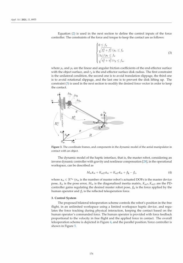
Appl. Sci. 2021, 11, 8955
Equation (2) is used in the next section to define the control inputs of the forcecontroller. The constraints of the force and torque to keep the contact are as follows:⎧⎪⎪⎪⎪⎪⎨
⎪⎪⎪⎪⎪⎩
0 ≤ fn√f 2o + f 2
t /μs ≤ fn
|τn|/μt ≤ fn√τ2
o + τ2t /rd ≤ fn,
(3)
where μs and μt are the linear and angular friction coefficients of the end-effector surfacewith the object surface, and rd is the end-effector surface disk radius. The first constraintis the unilateral condition, the second one is to avoid translation slippage, the third oneis to avoid rotational slippage, and the last one is to prevent the disk lifting up. Theconstraint (3) is used in the next section to modify the desired force vector in order to keepthe contact.
Figure 3. The coordinate frames, and components in the dynamic model of the aerial manipulator incontact with an object.
The dynamic model of the haptic interface, that is, the master robot, considering aninverse dynamic controller with gravity and nonlinear compensation [28], in the operationalworkspace, can be described as
Mm xm + KmD xm = KmP xm + fh − fc, (4)
where xm ∈ Rnm (nm is the number of master robot’s actuated DOFs is the master devicepose, xm is the pose error, Mm is the diagonalized inertia matrix, KmP, KmD are the PD-controller gains regulating the desired master robot pose, fh is the force applied by thehuman operator and fc is the reflected teleoperation force.
3. Control System
The proposed bilateral teleoperation scheme controls the robot’s position in the freeflight, in an unlimited workspace using a limited workspace haptic device, and regu-lates the force tracking during physical interaction, keeping the contact based on thehuman operator’s commanded force. The human operator is provided with force feedbackproportional to the velocity in free flight and the applied force in contact. The overallteleoperation scheme is depicted in Figure 4, and the parallel position/force controller isshown in Figure 5.
176

Appl. Sci. 2021, 11, 8955
Figure 4. The bilateral teleoperation scheme with a parallel position/force controller in the slave sideto control an aerial manipulator.
-
Figure 5. Parallel position/force controller for an aerial manipulator, in the remote side of theteleoperation scheme.
3.1. Position Control
The position control of the mechanically under-actuated quadrotor is implementedusing a two layer cascade controller. The orientation is controlled using PID in the innerloop, and the outer loop provides the inner loop with reference roll and pitch (φd, θd)to control the robot planar motion using a gravity-compensated-PD. The yaw motion iscontrolled independently.
⎧⎪⎪⎪⎪⎪⎪⎪⎪⎪⎨⎪⎪⎪⎪⎪⎪⎪⎪⎪⎩
uz =m
cos(φ) cos(θ) (g − kpzz − kdzz)
ux = −kpxx − kdxxuy = −kpyy − kdyy[
sin(φd)
sin(θd)
]= m
uz
[sin(ψ) − cos(ψ)cos(ψ)cos(φ)
sin(ψ)cos(φ)
][uy
ux
]
uη = −KD η − KPη− KI∫ t
0 η(s)ds,
(5)
where p − pd = [x y z]� is the position error with pd ∈ R3 being the desired position,kpx, kdx, kpy, kdy, kpz, kdz,∈ R+ are proportional and derivative gains, η = η − ηd is the
177

Appl. Sci. 2021, 11, 8955
orientation error with ηd = [φd, θd, ψd]� being the desired orientation, and KP, KD, KI are
the proportional, derivative, and integral diagonal gain matrices to regulate the attitude.
3.2. Force Control
The force is regulated by providing the internal position control loop with an appropriatereference. The robot’s desired position pd and desired yaw ψd are four commanded states ofthe system, noting that the system is mechanically under-actuated. As depicted in Figure 5,the outer force regulating the feedback loop generates additional terms (p f , ψ f ), dependingon the force error, that are added to the previously commanded pose (pp, ψp) in the freeflight. As we aimed at contact interaction with the environment using the end-effector, wecommand the end-effector pose; therefore, we convert the end-effector pose to the COM poseby including the term −Rd in the desired pose. Thus, pd and ψd are expressed as:{
pd = pp + p f − Rdψd = ψp + ψ f .
(6)
In the sequel, we see how pp, ψp, p f , and ψ f are generated from the user command,given by xm, based on the aerial manipulator contact condition.
When the robot is in free flight condition, the master robot position (xm) is interpretedas a position command; while when the end-effector comes in contact xm is interpreted asthe desired force. In order to distinguish the two conditions, let us introduce the contactfunction u( f , fd) as:
u(tk) =
⎧⎪⎨⎪⎩
1 if fn(tk) > 0 & fn(tk−1) > ε
0 if fn(tk) = 0 & fd,n(tk) < −ε
u(tk−1) otherwise.
(7)
This hysteresis-like function is intended to prevent the chattering phenomenon inthe attachment and detachment phases. In Equation (7), fn(tk) is the normal componentof the measured contact force at tk instance and fn(tk−1) is the previous sample of thesame measurement; fd,n(tk) is the normal component of the commanded force, u(tk−1)is the previous output of the function (u(0) = 0), and ε ∈ R+ is a small positive value.In the contact condition, if the commanded normal component of the force is negative( fd,n(tk) < −ε) and the normal component of the applied force is zero, the detachmenttakes place. During free flight u(t) = 0 and the component of the desired position that isintended to control the aerial manipulator position in free flight is generated by integratingthe master position as:
pp = pd(t0) +∫ t
t0
(1 − u(t))K fpxm dt, (8)
where K fp is a 3 × 3 matrix that rotates and scales the master robot motion appropriately.
The aerial manipulator heading ψp in free flight is directly commanded by the user, throughmapping one of the master robot motions, similar to pp.
When the end-effector establishes a contact u(t) = 1, and thus (1 − u(t)) = 0, in thiscase the integral stores the end-effector position at the contact moment, and the motion ofthe master robot during the contact interaction is used to command the desired force. Theforce commanded by the human operator, f ∗d ∈ R3, expressed in C, is generated as:
f ∗d = u(t)K ff xm, (9)
where K ff is a 3 × 3 matrix that rotates and scales the master robot motion appropriately.
To prevent the desired force violating the contact constraint (3), the commanded forceis modified as follows:
178
Appl. Sci. 2021, 11, 8955
fd =
⎧⎨⎩
f ∗d if 1μs
√( f ∗o )2 + ( f ∗t )2 + 1√
r2d+μ2
t
|τ| ≤ f ∗n
σ( f ∗d ) otherwise,(10)
where f ∗d = [ f ∗o , f ∗t , f ∗n ]�, and σ( f ∗d ) is a function projecting the desired commanded forcef ∗d to the surface of the contact constraints (3) as follows:
σ( f ∗d ) = cos(α) f ∗d + sin(α)(S(a) f ∗d ) + (1 − cos(α))(a� f ∗d )a +1√
r2d + μ2
t
|τ|n, (11)
where a = (S( f ∗d )n)/||(S( f ∗d )n)|| is the unit axis of rotation, α = β − γ is the requiredangle to rotate f ∗d around a to project it on the surface of the friction cone, β is the anglebetween f ∗d and n, and γ = tan−1(μs) is the translational friction cone angle. This functionminimally increases the normal component (by adding (r2
d + μ2t )
−0.5|τ|n) to avoid torsionalslippage and lifting up the end-effector disk, and applies the minimum rotation to itsdirection to keep it within the feasible force range.
The next step to generate p f and ψ f is to feed the force error f = f − fd = [ fo ft fn]�to a PI-controller as:
u f = −KP f f − KI f
∫ t
0f dt, (12)
where KP f , KI f ∈ R3×3 are proportional and integral diagonal gain matrices, respectively.The PI-output u f = [uo ut un]�—after appropriate transformations—generates p f and ψ f .
At the contact moment, in which the springs are in rest position, we define thecontact frame C which is its orientation w.r.t. B represented by rotation matrix Rb
c . Letd = [dx, 0, dz]�; we can always define C with a constant Rb
c such that dc = [do, 0, dn]�.Expanding (2) we get:
⎧⎪⎪⎨⎪⎪⎩
fo(δo, δηt) = ktoδo − dnkrt‖d‖2 δηt
ft(δt, δηo, δηn) =dnkro‖d‖2 δηo + kttδt − dokrn
‖d‖2 δηn
fn(δn, δηt) = ktnδn + dokrt‖d‖2 δηt.
(13)
Therefore, fn and fo can be regulated by commanding the motion along n and t,respectively. To control ft, we choose δηo, and the reason is: due to the under-actuationof the quadrotor, changing δt requires changing the roll and pitch angles of the aerialmanipulator and this results in applying an undesirable moment around the normal axis ofthe contact frame. The usage of rotation to generate the desired force also leads to a widerrange of feasible forces, as it not only relies on the limited linear friction of the end-effectorand object surfaces. δηo can be considered as changing the yaw angle ψ (see Figure 3).Therefore, p f and ψ f can be obtained as follows:
{p f = R�Rb
c [u0 0 un]�
ψ f = ut.(14)
3.3. Master Control and Haptic Feedback
The input of the master robot (haptic device), as expressed by (4), receives two ele-ments from the teleoperation scheme: the human force fh and the haptic feedback forcefc, which is itself constituted by two parts fPD, and fp f . The term fPD is a negative pro-portional derivative term, based on master position xm, that is intended to bring back thedevice to its zero position gently when the device is not moved by the operator, so that thequadrotor will not move or apply force when the haptic device handle is released. On the
179

Appl. Sci. 2021, 11, 8955
other hand, fp f is the haptic feedback given to the user depending on the velocity in freeflight or force error in contact. The haptic feedack fc is synthesized as:
fc = fPD + fp f = (KPhxm + KDh xm) + (Kbf f + (1 − u)Kb
p p), (15)
where Kbf , Kb
p, KPh, KDh ∈ R3×3 are positive diagonal gains.
4. Stability Analysis
We first show the stability of the rotational dynamics in contact, then the stabilityof the force controller, and finally the stability of the teleoperation scheme. In order tofacilitate the tractability, let C and W coincide, Rw
c = I3, and at the contact instance Rbc = I
(see Figure 3).
4.1. Rotational Stability
The angular dynamics M(η)η+ C(η, η)η+ Krη+ τf = uη , where τf = −S(d) ft hasthe following properties:
• M is symmetric positive definite and bounded as μM ≤ ‖M‖ ≤ γM; where μM, γM areits minimum and maximum eigenvalues. Moreover, M is strictly diagonally dominant(SDD), that is Mii > Σi =j|Mij|;
• M − 2C is skew-symmetric, or M = C + C�;• ‖C(η, η)‖ ≤ δc‖η‖, where δc ≤ 2σmax(J);• the rotational stiffness matrix is bounded as μk ≤ ‖Kr‖ ≤ γk.
Theorem 1. Applying the rotational part of the control law (5) to the aerial manipulator describedby (1), its rotational dynamic is locally asymptotically stable such that η, η → 0 and
∫ t0 η(s)ds →
−K−1I (Krη+ τf ) as t → ∞.
Proof. Let ζ = [Δη�η�η�]�, where Δη =∫ t
0 η(s)ds + K−1I (Krη + τf ), and consider the
following scalar function:
V(ζ) =12
ζ�Pζ , (16)
where the symmetric matrix P is defined as follows:
P =
⎡⎣ KI K12 εM
K12 K22 εMεM εM M
⎤⎦ , (17)
with ε = kεμMγM
and 0 < kε < 0.5, K12 = KI + εKD − Kr, and K22 = KP + εKD − K12K−1I Kr.
Let Ks = ks I for s = {P, I, D} with ks > 0; in a range satisfying inequities,
0 < kD < μKε − γM, ε < μK
γMkp > kI +
γKkI(εkD − μK) + εγM.
(18)
P becomes SDD with positive diagonal elements, and is therefore positive definite.Thus, V(ζ) is a positive definite function and hence a Lyapunov function candidate, whichis radially unbounded and satisfies the Rayleigh–Ritz inequality [29] as:
μP‖ζ‖2 ≤ V(ζ) ≤ γP‖ζ‖2 , (19)
where μP and γP are the minimum and maximum eigenvalues of P. The time derivative ofthe Lyapunov candidate (16) is:
V = −ζ�Qζ + ζ�B[τ�f η�d ]
� , (20)
180

Appl. Sci. 2021, 11, 8955
with
B =
⎡⎣ I −K12
K12 −K22εK−1
I M −εM
⎤⎦ (21)
Q =
⎡⎣ εKI
12 ((ε − 1)KI + εKP) − 1
2 εC�12 ((ε − 1)KI + εKP) εKP − (KI + εKD − Kr) − 1
2 ε(C� + M)
− 12 εC� − 1
2 ε(C� + M) KD − εM(I + K−1I Kr),
⎤⎦ (22)
In the following we shall show that:
V(ζ) ≤ −ζ�1 Q1ζ1 + ζ�B[τ�f η�d ]
� , (23)
where ζ1 = [‖Δη‖ ‖η‖ ‖η‖]� and
Q1 =
⎡⎢⎣ εkI
12 ((ε − 1)kI + εkP)
12 εδC‖η‖
12 ((ε − 1)kI + εkP) ε(kP − kD) + μK − kI
12 ε(γM + δC‖η‖)
12 εδC‖η‖ 1
2 ε(γM + δC‖η‖) kD − εγM(1 + γKkI)
⎤⎥⎦. (24)
To obtain (23), we choose kP, kI , kD such that:
ε(2μK + γM) < kI < μK( 1
ε − ε)kI < kP < 2μK + γMεγM( 3
2 + γKkI) < kD < μK(1 − ε)
. (25)
Consequently, ε must be chosen such that
ε < min
{μK − kI
μK − kP2 + γM
2
,23
μK(2μK + γM)− γKγMγM(2μK + γM)
,μM
2γM,
μKγM
}. (26)
Then, it is also assumed that the spherical joint mechanical stiffness is chosen properlyin accordance with the system moment of inertia such that μK > γM
2 (1 + γMμK
), which canbe simplified as σmin(Kr) > γM, which simply means that the higher the inertia, the stifferthe spring that must be chosen. Let μv = min{kI − εkP, εkP + 2(μK − εkD)− (ε + 1)kI −εγM, kD − 3
2 εγM − εγMγKkI
}, for trajectories bounded by:
‖η‖ ≤ 1δC
μv. (27)
Q1 will be SDD with positive diagonal elements, and therefore positive definite. Thus,we can conclude:
V(t, ζ) ≤ −μ‖ζ‖2 + κ‖ζ‖ , (28)
where μ = σmin(Q1) and κ = δB1δ f + δB2δv with δB1 = max{1, kI + εkD −μK, kP + εγM/kI},δB2 = max{kI + εkD − μK, kP + εkD − μK(kI + εkD − μK)/kI , εγM},and ‖ηd‖ ≤ δv is the upper bound on the norm of ηd. ‖τf ‖ ≤ δ f is the upper boundon the norm of the τf , which is a reasonable assumption considering that the rotationaldynamics is faster than translational [30]. Let W be the positive root of V = W2, as in [31],considering (19) we can state W ≤ − μ
2γPW + κ
2√
μP, which means:
W(t) ≤ W(0)e−μ
2γPt − κ
2√
μP
∫ t
0e−
μ2γP
(t−s)ds ≤ W(0)e−μ
2γPt+
κγP√μPμ
. (29)
181

Appl. Sci. 2021, 11, 8955
Considering (19), we can ensure that (27) is satisfied if W(0)+ κγP√μPμ ≤ 1
δCμv. Therefore,
choosing sufficiently large kP, and sufficiently small kI and kD such that (18) and (25) aresatisfied, the solution of the error system converges to zero asymptotically.
4.2. Force Control Stability
The stability of the force dynamic in the closed-loop force controlled system is in-vestigated in a decentralized manner, that is, each component of the force is analyzedindependently by considering the effect of other state variables as disturbances.
4.2.1. Force Along n-Axis
The forces along n-axis is controlled by translational pose command along n, from (13)we have
fn = ktnn + kjηt , (30)
where kj =dokrt‖d‖2 . If we substitute the pose controller in (30), assuming the gravity term
compensated by feedback linearizing term, the dynamics will be:
mnn + ktnn = −kpn − kdn , (31)
where mn = m is derived from (1). Substituting n and its derivatives, in the left hand sideof (31), with fn from (30), and control terms, in the right hand side, with (12) we obtain:
m f fn + b f fn + k f fn = −k1
∫ t
0fn − k2 fn + hn(ηt, ηt, ηt) , (32)
where m f = mnk−1tn , b f = kdk−1
tn , k f = (1 + kpk−1tn ), hn = (mnk−1
tn kjηt + kdk−1tn kjηt + (1 +
kp)k−1tn kjηj), and k1 = kpkI f , k2 = kpkP f .One can express (32) in the frequency domain by introducing the controller transfer
function C(s) = k2 +k1s and plant transfer function G(s) = 1/(m f s2 + b f s + k f ), where
(s = σ + jω). The system output f (s) is then obtained as:
f (s) =G(s)C(s)
1 + G(s)C(s)fd(s) +
11 + G(s)C(s)
h(s) . (33)
For the stability of the system, the characteristic polynomial of the system, that is,s(m f s2 + b f s+ k f ) + (k2s+ k1), must have all roots with a real negative part and, to achievethis, according to the Routh–Hurwitz stability criterion it is required that:
kP f +1
kP+
1ktn
>mkD
kI f . (34)
Choosing sufficiently high PD gains and an appropriately low I-gain for slowly-varying force commands, that is, s → 0, we obtain G(s)C(s)
1+G(s)C(s) → 1, 11+G(s)C(s) → 0, thus
f → fd.
4.2.2. Force Along o-Axis
The forces along o-axis are controlled by the translational pose command along o andthe stability analysis is the same as the force along the n − axis.
4.2.3. Force Along t-Axis
The forces along the t-axis are controlled by the rotational pose command around o,that is, ηo = ψ considering the frame convention. From (14) one can write:
ft = koψ + [ktt krn][t ηn]� , (35)
182

Appl. Sci. 2021, 11, 8955
where ko =dnkro‖d‖2 and krn = dokr,n
‖d‖2 . If we substitute the orientation controller in the dynamicmodel, considering the results of Theorem 1, we obtain:
m33ψ + (c33 + kD)ψ = −kpψ − (c31φ + c32θ) , (36)
where mij, cij are extracted from M and C. It is worth noting that m33 and c33 are constantwith respect to ψ and its derivatives. Substituting ψ and from (35) in (36) we get:
m33
koft +
kD + c33
koft +
kPko
ft = −k1
∫ t
0ft − k2 ft + ht , (37)
with
ht = −(c31φ + c32θ) + (m33ktko
t + kt(kD+c33)ko
t + ktkPko
t)+
+(m33knko
ηn +kn(kD+c33)
koηn +
knkPko
ηn) .(38)
Following the same procedure of force along the n-axis, the Routh–Hurwitz criterionenforces the controller coefficients to be chosen as:
kP f +1ko
>m33
kD + c33kI f , (39)
which is fulfilled by setting appropriately high proportional and derivative gains andsufficiently low integral gain, and for slowly-varying force commands ft → fd.
Choosing coefficients according to (34) and (39) makes the system over damped, thatis, without overshoot, which is that f is not getting higher than fd. Thus, if fd is the outputof (10), contact maintenance is ensured.
4.3. Stability of Teleoperator in Contact Interaction
During the contact interaction, from (4) we can define the dynamics of the masterrobot and its controller in the frequency domain as: Gr(s) = Mms2 + KmDs, Cm(s) = KmP.The haptic feedback in the master side (PD term) could also be expressed as: Ch(s) =KhP + KhDs. We have shown that the force interaction dynamics and force controller in theremote side could be expressed as: Gs(s) = diag(Mf s2 + Bf s+K f )
−1, Cm(s) = K2 +K11s .
We define the transfer function of the master robot and its controller as: Gm(s) = CmGr(I +CmGr)−1. The internal stability of the system requires that the roots of the denominatorof Gm all have real negative parts, for which KmP, KmD > 0 suffice. The overall transferfunction of the master side, with force input and position output, is defined as:
G1(s) = Gm(I + GmCh)−1 . (40)
The characteristic polynomial of G1 is (MmKmPKhD)s3 + (MmKmP(1 + KhP)+ KmPKmDKhD)s2 + (KmDKmPKhP + KmPKmD)s + 1. For internal stability, the controllercoefficients must conform with the following constraint:
kmDkmPkhP + kmPkmD > σmax(Mm)khPσmin(Mm)(1+khP)+kmDkhD
. (41)
The transfer function of the slave side, with force input and force output, is obtainedas: G2(s) = GsCs(I + GsCs)−1. Its internal stability constraints are expressed by (34) and(39). The teleoperator output f (see Figure 6), can be obtained as:
f (s) = G2K ff G1(I + G2K f
f G1Kbf )
−1 fh(s)
+(I + GsCs)−1h(s). (42)
183

Appl. Sci. 2021, 11, 8955
The constraint (34), (39) and (41) gives all the poles of G1 and G2 a negative real part;therefore, G1 and G2 are strictly positive real and thus passive systems, and the negativefeedback interconnection of a passive system is a passive system [32]; thus, (42), that is, theteleoperator in the contact interaction, is stable.
Figure 6. Block diagram of teleoperation system using the aerial manipulator in free flight (left) andin contact interaction (right).
4.4. Stability of Teleoperator in Free Flight
During the free flight, assuming fast rotational dynamics compared to translationaldynamics, and gravity compensation, we may express the slave robot and its controlleras Gs(s) = Ms2 + KDs and Cs(s) = Kp, the input to Gs is the integrated value of scaledxm, and the force feedback to the master side is the robot velocity. Therefore, G2 can beexpressed as (Figure 6):
G2 = (1s
I)(GsCs(I + GsCs)−1)(Is) = GsCs(I + GsCs)
−1, (43)
which is internally stable by choosing pose controller gains kP, kD > 0. The master sideof the teleoperator is the same as in the contact interaction; therefore, G1 does not change.Considering velocity p as the output of the system, it can be obtained as:
sp(s) = G2K fpG1(I + G2K f
pG1Kbp)
−1 fh. (44)
sp(s), that is, velocity in frequency domain, is the system output constituted by thenegative feedback interconnection of passive systems G1 and G2. Therefore, the teleoperatorin free flight is passive and stable.
5. Experimental Results
In order to evaluate the proposed aerial tele-manipulation solution, and to assessthe functionalities of the proposed controller in the bilateral teleoperation scheme, twoexperiments with fixed and movable objects were performed. In the first experiment, ahuman operator drives the aerial manipulator to establish a contact with a stationary targetand applies force to it, receiving force feedback. In the second experiment, the humanoperator drives the quadrotor to establish a contact with a wheeled cart and pushes it togenerate motion, while receiving force feedback.
We encourage the interested reader to watch the video of the experiments in themultimedia attachment to this paper, cf. Supplementary Materials, to better appreciate thepresented validation.
5.1. Experimental Setup
Our aerial manipulator was equipped with a lightweight tool (Figure 2) with a totalweight of 0.05 kg. It was rigidly connected to the top of a quadrotor UAV with 1.0 kg
184

Appl. Sci. 2021, 11, 8955
weight. The quadrotor platform used for the experiments was a Mikrokopter© x4 platform(HiSystems GmbH). The distance vector from the quadrotor COM to the end-effectorsurface was d = [0 m, 0.5 m and 0.2 m]. The link lengths were d1 = 0.51 m, and d2 = 0.02 mlong. A compliant spherical joint, that connects the lightweight rigid link to the end-effector,and an elastic shock absorber damper on the end-effector helped to establish smoothcontacts. The end-effector surface was covered by a high friction material to expand thefeasible force vector range.
The robot positioning was performed by a Vicon tracking system (Vicon CaptureSystems, London, UK). The quadrotor thrust and rotational controller was implementedon its onboard microcontroller (Atmel AVR 8-bit, ATmega-1284, running at 20 MHz), basedon the inertial sensors of the robot, the rest of the control law was implemented on anexternal PC (Core i7, 16GB RAM, running Ubuntu 14), communicating with the robotusing a pair of Zig-Bee transceiver chips. An Omega.3 haptic device (Force Dimension,Nyon, Switzerland) was used as the master device. We used the force/torque ATI sensor(ATI Industrial Automation, Apex, NC, USA) embedded inside the object to measure theapplied force by the aerial manipulator. The software was implemented in the ROS, and allcontrol loops ran at a frequency of 100 Hz.
5.2. Results5.2.1. Stationary Object Experiment
Initially the quadrotor was located at the origin of the global coordinate, while the object,which was a 0.15 m × 0.15 m plate, was located at [1.0 m, 0.0 m and −0.85 m] with downwardpointing zw. The human operator drove the quadrotor towards the object, and once the robotreached the object, the driver commanded a variable continuous force vector, by means of thehaptics device. Finally, the human operator commanded the robot to leave the object, andbrought it back to free flight. Figure 7-top shows the snapshots of different moments of theexperiment, while Figures 8-left, 9-left, and 10-left show the results of the experiment.
t=20 s t=24 s t=30 s t=97 s t=100 s(a) (b) (c) (e)(d)
t=7 s t=17 s t=19 s t=20 s t=21 s( a) (b) (c) (d) (e)' ' ' ' '
Figure 7. Snapshots of stationary object (top) and movable object (bottom) experiments. The experiments aimed to dockand apply a commanded time-varying force to the objects. (a,a’) In free flight, (b,b’) establishing a contact with the object,(c,c’) applying force vectors, (d,d’) releasing the contact, and (e,e’) in free flight again.
Figure 8a shows the position tracking during the experiment, while the position erroris explicitly reported in Figure 9-left, for the reader’s convenience. As can be seen, beforethe contact event, and after the quadrotor leaves the object, the position error is low, thatis, bounded below 7 cm, while during the contact there is significant position error, thatis, ≈35 cm, specifically in x-direction which corresponds to the normal component offorce. It is worth underlining the fact that, during the interaction, the position error doesnot provide relevant information for evaluating the controller’s performance, as duringthat phase the platform is force-controlled, and the position error represents a necessarycondition to guarantee the force tracking. As a matter of fact, a higher position errorduring the contact with stationary object means a higher thrust and a higher pitch angle isdemanded, which results in larger applied forces.
Figure 8b shows the contact maintenance function output, which keeps the desiredforce vector inside the friction cone. It can bee seen that, when the commanded force
185

Appl. Sci. 2021, 11, 8955
violates the friction constraints of (10), the normal component of the desired commandedforce is increased while the other two tangential components are decreased, and the desirednorms of the input ( f ∗d ) and output ( fd) are equal.
Figure 8c shows the force tracking control result during the experiment. As is evident,the force tracking performance is very good (average absolute error of 0.11 N, whichrepresents less than 10% relative error, and a maximum absolute error of 0.51 N). Thecontact transition is shown in a separate window inside Figure 8c, which introduces avery smooth contact transition with only a small single bouncing event. Note that in thetransition phase of the robot force control with a rigid environment, having a small amountof bouncing and inadvertent losses of contact are common, even for grounded robotic armmanipulators with non-zero reaching velocity [33].
The haptic feedback components are shown in Figure 10-left. The master position (theposition of the haptic device’s handle with respect to the center of its workspace) is shownin creating the spring-damper force fPD that brings back the master device’s handle to thecenter of its workspace (Figure 10a). The position tracking error of the aerial manipulatorin the free flight condition along with the force applied to the object in contact create thesecond constitutive component of the haptic feedback fp f , which is shown in Figure 10b.The haptic feedback in the contact condition is equal to the measured force from the forcesensor with the opposite direction.
'
'
'
Figure 8. Stationary object experiment (left): docking and applying a force commanded by the human operator to astationary object: (a) position tracking, (b) contact maintenance, that is, keeping of the desired force within the friction cone,and (c) force tracking. Movable object experiment (right): docking and applying force to a movable object in order to pushit 1 m away: (a’) position tracking, (b’) contact maintenance, that is, keeping of the desired force within the friction cone,and (c’) force tracking.
186

Appl. Sci. 2021, 11, 8955
Figure 9. Position error in the stationary object experiment (left) and movable object experiment (right): as can be seen, theerror is bigger during the interaction phase, in both cases, as a consequence of the force tracking. Furthermore, the error ishigher in the movable object experiment, in particular during the undocking phase.
'
'
Figure 10. Stationary (left) and movable (right) object experiments: (a,a’) spring–damper force brings back the masterdevice’s handle to the center of its workspace, (b,b’) the haptic feedback fp f that renders the applied force to the object incontact and position error in free flight.
5.2.2. Movable Object Experiment
In the second experiment, the robot was initially located at the global frame origin. Themovable object, which was a cart with plate of 0.15 m × 0.15 m attached to it, was located at[0.5 m, 0.0 m and −0.90 m], with downward pointing zw. The human operator was drivingthe quadrotor towards the cart, and once the robot reached the cart, the driver pushed ituntil it passed 1.0 m, and eventually the driver commanded the robot to leave the object,and brought the robot back to free flight. Figure 7-bottom shows the snapshots of thisexperiment, while Figures 8-right, 9-right, and 10-right depict the results of the experiment.
Figure 8a’ shows the position tracking during the experiment. The difference betweenthe new situation (a movable object) compared to the previous experiment (a stationary ob-ject) can be seen through this plot, where after establishing the contact, while the quadrotoris applying the force to the object (cart), its position is not changing until the moment (inthis experiment at 14.5 s) the applied force overcomes the static friction of the cart wheelswith the ground. Then, the cart (and the aerial manipulator too) experiences an acceleratedmotion. The position error is explicitly reported in Figure 9-right), for the reader’s conve-nience. As in the previous scenario, before the interaction the error is relatively close to zero,
187

Appl. Sci. 2021, 11, 8955
that is, bounded below 7 cm, while during the contact there is significant position error,that is, ≈50 cm, specifically in x-direction which corresponds to the normal component offorce. As already mentioned, this is in accordance with the fact that, in this phase, the robotis tracking the desired force provided by the user, and not the desired position. Duringthe undocking phase, namely when the human operator sees the accelerating cart passingthe goal line and pushes back the handle of the haptic device in order to bring the robotback, a peak of ≈75 cm is reached due to a small false contact detection, after which theposition error converges back to its typical free-flight values. The large error value in thedetachment phase can be improved by limiting the integral term of the PI-force controller,and increasing the proportional gain of PI-controller, or also using a more agile controller inthe inner position loop. It is worth noting that, in this experiment, the goal was to evaluatethe efficiency of the proposed controller in applying force to objects in order to move themin a way the human operator wants, rather than performing precise force tracking.
In relation to this last point, another meaningful note is that the two experimentshere discussed were explicitly designed and performed with the main goal of validatingthe presented aerial robotic solution in indoor laboratory conditions, which imply the useof a motion capture system for state estimation, a cabled connection between the robotand the ground workstation, and the absence of non-negligible external disturbances.Under these conditions, we basically experienced a rate of success of 100%. A more fairand comprehensive validation and testing of the this system in outdoor, mocap-denied,and realistic scenarios in the presence of external disturbances and using only onboardcomputation, which is not in the scope of this paper, will be the subject of future work.
Figure 8b’ shows the contact maintenance function input and output forces. Since themain purpose is to push the cart, the major component of the commanded force is alongthe normal direction; therefore, most of the time the feasible commanded force is the sameas the desired commanded force by the human operator and, as is evident from Figure 8c’,the contact is kept during the force interaction.
The force tracking control results, shown in Figure 8c’, represent a more difficult taskcompared to the previous task (force tracking control in contact with a stationary object).As can be seen, while the cart is stationary, that is, when the force applied by the quadrotorend-effector is compensated for by the friction of the cart wheels with the surface, the forcetracking has a similar performance to the previous experiment. On the other hand, once thecart starts to move the error increases. However, considering the particular application ofthis experiment, which aims at pushing a cart forward, as far as the contact is kept and theoperator is able to accomplish the task, the experiment is considered successful, althoughthe average of the absolute force error norm is 0.5 N, that is a 20% relative error.
The haptic feedback components are shown in Figure 10-right. fPD is depicted inFigure 10a’, and the haptic feedback component related to the slave side, fp f , is shownin Figure 10b’. As is evident, the magnitude of the latter is generally bigger than themagnitude of the former, allowing the human operator to be aware of the aerial manipulatorcondition in the master side (this is also true for the experiment with the stationary object).Haptic feedback in this experiment is even more important for the human operator to notlose the contact, as fp f allows the human operator to feel the applied force during thecontact interaction. When the perceived force is small, it means that the contact is weak,and the human operator can command a higher force to ensure the contact maintenance.
5.3. Discussion
The experimental results validated the capability and efficacy of the aerial manipulatorwith a passive tool in free flight pose tracking and in contact force tracking while keepingthe contact and maintaining the flight stability. After performing several experimentsto investigate the properties of the system and the controller, the following results frominterpreting observations were obtained. In the free flight phase, the autonomous control ofpose is not very precise, and there are position/velocity errors that prevent the autonomouscontroller from doing very fine tasks, even in the case of knowing the environment perfectly.
188

Appl. Sci. 2021, 11, 8955
This happens due to the existence of aerodynamics disturbances and unmodeled dynamicsthat are not incorporated in the controller design. However, a human teleoperated aerialsystem is capable of doing such tasks, thanks to superior human learning and sensorymotor capabilities. A similar observation has been made in [8].
The contact establishing phase (docking) involves bouncing; this is a natural behaviorbecause the reaction force of the contact is directly applied to the robot CoM that is afloating (hovering) object, and this results in jumping back; unlike grounded manipulatorsthis force is not transmitted to the ground. To mitigate this effect, velocity slowing-downpolicy and physical shock absorber on the end-effector surface is used, that results in asmooth transition and reduces the bouncing effect significantly. Moreover, deploying fPDin the haptic feedback prevents the operator from loosely grasping the master robot, whichcould increase the effect. Note that in establishing a contact with non-zero reaching velocity,having a small amount of bouncing is commonly acceptable, even for grounded roboticarm manipulators [33].
Contact maintenance function, in conjunction with appropriate gain tunings (to avoidovershoots as mentioned in the stability analysis section) plays an important role; withoutrespecting these constraints the end-effector could slide on the surface. Therefore, usingthis function is necessary if the task involves keeping the contact, unlike the hybrid position-force controllers such as in [2,24,34] in which it is desirable to slide over the surface.
The force error constituted by a non-zero-mean part (DC) and a high frequency signal(AC). The DC part is the effect of the not-force-controlled axes of motion (due to the under-actuation and uni-lateral contact), and the AC part is because of the propeller rotational(aero)dynamics. The DC part can be decreased by choosing appropriately large gains,while increasing these gains increases the AC part. Therefore, care is to be taken in tuningthe controller to achieve an acceptable trade-off depending on the task.
The detachment phase also showed some bouncing effects, which is due to the time ittakes to deplete the integral term, and imprecise free flight position control in the vicinityof the object. This effect is mitigated by deploying the switch function (7), and by boundingthe integral term and choosing a small coefficient for it while choosing appropriately bigproportional and derivative terms. A similar phenomenon is also observed in the case ofgrounded manipulators controlled by the parallel position/force control method in [35]and referred to as the sticky-effect.
The proposed controller can also be utilized in redundant omni-directional or partiallyomni-directional aerial manipulators, such as [1,8], by keeping their position controllersand providing it with a reference based on the presented force controller that considerscontact maintenance and deploying orientation to generate the desired force.
6. Conclusions and Future Works
The topic of aerial physical interaction using a typical under-actuated VTOL UAVequipped with a passive tool was considered in this paper. We use a simple passive lightweight tool, instrumented with a compliant end-effector, rigidly attached to the top ofan aerial robot. We propose a control method in a bilateral teleoperation scheme to let ahuman operator drive the aerial manipulator in a remote environment, controlling theposition of the robot in free flight and regulating the force applied to the object in contactinteraction while maintaining the flight stability and keeping the contact. For this purpose,a parallel position/force controller is utilized, which also uses the rotational dynamicaxes, that is, yaw motion, to generate the desired force that allows maintenance of thecontact with a wider range of forces. On the one hand, theoretical proof of the stability ofcontrolled system is derived and presented. On the other, experiments on driving the aerialrobot toward the desired point, docking, and applying the desired forces to stationaryand movable objects represented the feasibility and efficacy of the proposed solution. Thehuman operator is provided with force haptic feedback proportional to the velocity in freeflight and the applied force in contact, allowing for an improved situational awareness.
189

Appl. Sci. 2021, 11, 8955
Future work will involve vision based outdoor implementation of the proposedapproach, and investigating bandwidth and delay effects in haptic teleoperation based onpassivity theories such as [36]. Performing more complex tasks cooperatively with a teamof aerial manipulators will also be considered.
Supplementary Materials: The following are available at https://www.mdpi.com/article/10.3390/app11198955/s1, Video S1: The video of the experiments in the multimedia.
Author Contributions: Conceptualization, M.M., A.F., D.B. (Davide Barceli) and D.P.; Fundingacquisition, A.F. and D.P.; Investigation, A.F. and D.P.; Methodology, M.M., A.F., D.B. (Davide Barceli)and D.P.; Project administration, A.F. and D.P.; Software, M.M. and D.B. (Davide Barceli); Supervision,A.F. and D.P.; Visualization, D.B. (Davide Bicego); Writing—original draft, M.M., D.B. (DavideBicego), A.F., D.B. (Davide Barceli) and D.P.; Writing—review & editing, M.M., D.B. (Davide Bicego),A.F. and D.P. All authors have read and agreed to the published version of the manuscript.
Funding: This research was partially supported by the European Union’s Horizon 2020 research andinnovation program grant agreement ID: 871479 AERIAL-CORE.
Institutional Review Board Statement: Not applicable.
Informed Consent Statement: Not applicable.
Data Availability Statement: Not applicable.
Conflicts of Interest: The authors declare no conflict of interest.
References
1. Tognon, M.; Chavez, H.A.T.; Gasparin, E.; Sablé, Q.; Bicego, D.; Mallet, A.; Lany, M.; Santi, G.; Revaz, B.; Cortés, J.; et al. A TrulyRedundant Aerial Manipulator System with Application to Push-and-Slide Inspection in Industrial Plants. IEEE Robot. Autom.Lett. 2019, 4, 1846–1851. [CrossRef]
2. Trujillo, M.Á.; Martínez-de Dios, J.R.; Martín, C.; Viguria, A.; Ollero, A. Novel Aerial Manipulator for Accurate and RobustIndustrial NDT Contact Inspection: A New Tool for the Oil and Gas Inspection Industry. Sensors 2019, 19, 1305. [CrossRef]
3. Smrcka, D.; Baca, T.; Nascimento, T.; Saska, M. Admittance Force-Based UAV-Wall Stabilization and Press Exertion forDocumentation and Inspection of Historical Buildings. In Proceedings of the 2021 International Conference on UnmannedAircraft Systems (ICUAS), Athens, Greece, 15–18 June 2021; IEEE: Piscataway, NJ, USA, 2021; pp. 552–559.
4. Li, G.; Ge, R.; Loianno, G. Cooperative Transportation of Cable Suspended Payloads With MAVs Using Monocular Vision andInertial Sensing. IEEE Robot. Autom. Lett. 2021, 6, 5316–5323.
5. Bernard, M.; Kondak, K.; Maza, I.; Ollero, A. Autonomous transportation and deployment with aerial robots for search andrescue missions. J. Field Robot. 2011, 28, 914–931. [CrossRef]
6. Ruggiero, F.; Lippiello, V.; Ollero, A. Aerial Manipulation: A Literature Review. IEEE Robot. Autom. Lett. 2018, 3, 1957–1964.[CrossRef]
7. Ollero, A.; Tognon, M.; Suarez, A.; Lee, D.J.; Franchi, A. Past, Present, and Future of Aerial Robotic Manipulators. IEEE Trans.Robot. 2021, 1–20. [CrossRef]
8. Park, S.; Lee, J.; Ahn, J.; Kim, M.; Her, J.; Yang, G.H.; Lee, D. ODAR: Aerial Manipulation Platform Enabling OmnidirectionalWrench Generation. IEEE/ASME Trans. Mechatron. 2018, 23, 1907–1918. [CrossRef]
9. Ryll, M.; Muscio, G.; Pierri, F.; Cataldi, E.; Antonelli, G.; Caccavale, F.; Bicego, D.; Franchi, A. 6D Interaction Control with AerialRobots: The Flying End-Effector Paradigm. Int. J. Robot. Res. 2019, 38, 1045–1062. [CrossRef]
10. Staub, N.; Bicego, D.; Sablé, Q.; Arellano-Quintana, V.; Mishra, S.; Franchi, A. Towards a Flying Assistant Paradigm: The OTHex.In Proceedings of the 2018 IEEE International Conference on Robotics and Automation, Brisbane, QLD, Australia, 21–25 May2018; pp. 6997–7002.
11. Rashad, R.; Bicego, D.; Jiao, R.; Sanchez-Escalonilla, S.; Stramigioli, S. Towards Vision-Based Impedance Control for theContact Inspection of Unknown Generically-Shaped Surfaces with a Fully-Actuated UAV. In Proceedings of the 2020 IEEE/RSJInternational Conference on Intelligent Robots and Systems (IROS), Las Vegas, NV, USA, 24 October–24 January 2021; IEEE:Piscataway, NJ, USA, 2020; pp. 1605–1612.
12. Aerial-Core. EU Coll. Proj. H2020-ICT-2019-2. Available online: https://aerial-core.eu/ (accessed on 1 September 2021).13. Scholten, J.L.; Fumagalli, M.; Stramigioli, S.; Carloni, R. Interaction control of an UAV endowed with a manipulator. In
Proceedings of the Robotics and Automation (ICRA), 2013 IEEE International Conference on Karlsruhe, Karlsruhe, Germany,6–10 May 2013; IEEE: Piscataway, NJ, USA, 2013; pp. 4910–4915.
14. Fanni, M.; Khalifa, A. A new 6-DOF quadrotor manipulation system: Design, kinematics, dynamics, and control. IEEE/ASMETrans. Mechatron. 2017, 22, 1315–1326. [CrossRef]
190

Appl. Sci. 2021, 11, 8955
15. Orsag, M.; Korpela, C.M.; Bogdan, S.; Oh, P.Y. Hybrid adaptive control for aerial manipulation. J. Intell. Robot. Syst. 2014,73, 693–707. [CrossRef]
16. Mebarki, R.; Lippiello, V.; Siciliano, B. Image-based control for dynamically cross-coupled aerial manipulation. In Proceedings ofthe 2014 IEEE/RSJ International Conference on Intelligent Robots and Systems, Chicago, IL, USA, 14–18 September 2014; IEEE:Piscataway, NJ, USA, 2014; pp. 4827–4833.
17. Kim, S.; Seo, H.; Choi, S.; Kim, H.J. Vision-guided aerial manipulation using a multirotor with a robotic arm. IEEE/ASME Trans.Mechatron. 2016, 21, 1912–1923. [CrossRef]
18. Baizid, K.; Giglio, G.; Pierri, F.; Trujillo, M.A.; Antonelli, G.; Caccavale, F.; Viguria, A.; Chiaverini, S.; Ollero, A. Behavioral controlof unmanned aerial vehicle manipulator systems. Auton. Robot. 2017, 41, 1203–1220. [CrossRef]
19. Mebarki, R.; Lippiello, V.; Siciliano, B. Toward image-based visual servoing for cooperative aerial manipulation. In Proceedings ofthe 2015 IEEE International Conference on Robotics and Automation (ICRA), Seattle, WA, USA, 26–30 May 2015; IEEE: Piscataway,NJ, USA, 2015; pp. 6074–6080.
20. Gioioso, G.; Ryll, M.; Prattichizzo, D.; Bülthoff, H.H.; Franchi, A. Turning a near-hovering controlled quadrotor into a 3D forceeffector. In Proceedings of the 2014 IEEE International Conference on Robotics and Automation (ICRA), Hong Kong, China, 31May–7 June 2014; IEEE: Piscataway, NJ, USA, 2014; pp. 6278–6284.
21. Bartelds, T.; Capra, A.; Hamaza, S.; Stramigioli, S.; Fumagalli, M. Compliant Aerial Manipulators: Toward a New Generation ofAerial Robotic Workers. IEEE Robot. Autom. Lett. 2016, 1, 477–483. [CrossRef]
22. Bellens, S.; De Schutter, J.; Bruyninckx, H. A hybrid pose/wrench control framework for quadrotor helicopters. In Proceedingsof the Robotics and Automation (ICRA), 2012 IEEE International Conference on, Saint Paul, MN, USA, 14–18 May 2012; IEEE:Piscataway, NJ, USA, 2012; pp. 2269–2274.
23. Nguyen, H.N.; Lee, D. Hybrid force/motion control and internal dynamics of quadrotors for tool operation. In Proceedingsof the 2013 IEEE/RSJ International Conference on Intelligent Robots and Systems, Tokyo, Japan, 3–7 November 2013; IEEE:Piscataway, NJ, USA, 2013; pp. 3458–3464.
24. Alexis, K.; Darivianakis, G.; Burri, M.; Siegwart, R. Aerial robotic contact-based inspection: Planning and control. Auton. Robot.2016, 40, 631–655. [CrossRef]
25. Mersha, A.Y.; Stramigioli, S.; Carloni, R. On bilateral teleoperation of aerial robots. IEEE Trans. Robot. 2014, 30, 258–274.[CrossRef]
26. Gioioso, G.; Mohammadi, M.; Franchi, A.; Prattichizzo, D. A force-based bilateral teleoperation framework for aerial robots incontact with the environment. In Proceedings of the 2015 IEEE International Conference on Robotics and Automation (ICRA),Seattle, WA, USA, 26–30 May 2015; IEEE: Piscataway, NJ, USA, 2015; pp. 318–324.
27. Prattichizzo, D.; Trinkle, J.C. Grasping, Springer Handbook of Robotics; Springer: Berlin/Heidelberg, Germany, 2008; pp. 671–700.28. Siciliano, B.; Sciavicco, L.; Villani, L.; Oriolo, G. Robotics: Modelling, Planning and Control; Springer Science & Business Media:
Berlin/Heidelberg, Germany, 2010.29. Marquez, H.J. Nonlinear Control Systems: Analysis and Design; Wiley-Interscience: Hoboken, NJ, USA, 2003.30. Antonelli, G.; Cataldi, E.; Arrichiello, F.; Giordano, P.R.; Chiaverini, S.; Franchi, A. Adaptive trajectory tracking for quadrotor
MAVs in presence of parameter uncertainties and external disturbances. IEEE Trans. Control. Syst. Technol. 2018, 26, 248–254.[CrossRef]
31. Wen, J.T.; Murphy, S.H. PID Control for Robot Manipulators; Rensselaer Polytechnic Institute: Troy, NY, USA, 1990.32. Lawrence, D.A. Stability and transparency in bilateral teleoperation. IEEE Trans. Robot. Autom. 1993, 9, 624–637. [CrossRef]33. Tarn, T.J.; Wu, Y.; Xi, N.; Isidori, A. Force regulation and contact transition control. IEEE Control Syst. 1996, 16, 32–40.34. Yüksel, B.; Secchi, C.; Bülthoff, H.H.; Franchi, A. Aerial physical interaction via IDA-PBC. Int. J. Robot. Res. 2019, 38, 403–421.
[CrossRef]35. Hashtrudi-Zaad, K.; Salcudean, S.E. Bilateral parallel force/position teleoperation control. J. Robot. Syst. 2002, 19, 155–167.
[CrossRef]36. Lee, D.; Spong, M.W. Passive bilateral teleoperation with constant time delay. IEEE Trans. Robot. 2006, 22, 269–281. [CrossRef]
191


Citation: Garcia, M.; Maza, I.; Ollero,
A.; Gutierrez, D.; Aguirre, I.; Viguria,
A. Release of Sterile Mosquitoes with
Drones in Urban and Rural
Environments under the European
Drone Regulation. Appl. Sci. 2022, 12,
1250. https://doi.org/10.3390/app
12031250
Academic Editor: Augusto Ferrante
Received: 6 December 2021
Accepted: 14 January 2022
Published: 25 January 2022
Publisher’s Note: MDPI stays neutral
with regard to jurisdictional claims in
published maps and institutional affil-
iations.
Copyright: © 2022 by the authors.
Licensee MDPI, Basel, Switzerland.
This article is an open access article
distributed under the terms and
conditions of the Creative Commons
Attribution (CC BY) license (https://
creativecommons.org/licenses/by/
4.0/).
applied sciences
Article
Release of Sterile Mosquitoes with Drones in Urban and RuralEnvironments under the European Drone Regulation
Manuel Garcia 1, Ivan Maza 1,*, Anibal Ollero 1, Daniel Gutierrez 2, Idoia Aguirre 3 and Antidio Viguria 4
1 GRVC Robotics Laboratory, University of Seville, Avda. de los Descubrimientos, s/n, 41092 Seville, Spain;[email protected] (M.G.); [email protected] (A.O.)
2 Instituto Tecnológico de Galicia, c/Cantón Grande 9, Planta 3, 15003 La Coruña, Spain; [email protected] Centro Tecnológico de Automoción y Mecatrónica, c/Cantón Grande 9, Planta 3, Plaza Cein 4,
31110 Noain, Spain; [email protected] Advanced Center for Aerospace Technologies, c/Wilbur y Orville Wright 19, La Rinconada,
41300 Seville, Spain; [email protected]* Correspondence: [email protected]
Featured Application: Drones can be a very useful tool to help mosquito control tasks in areas
where these insects are an important vector of disease transmission. Storing sterile mosquitoes
in drones and releasing them in targeted areas where previous suppression of wild populations
has been performed can be a major advance in this methodology. This is part of the sterile insect
techniques (SIT) which have been demonstrated to be an environmentally friendly solution for
the control of insect pests. However, the use of drones in the areas where these operations are
foreseen is limited by the fact that we have a regulation that advances at a slower pace than
technology. Of particular interest is the case of the suppression of mosquito populations in urban
areas below the transmission threshold, where drones and their operating conditions must meet
demanding safety requirements. This article presents the current regulatory situation in Europe
that affects drone operations and its applicability to the case of the release of sterile mosquitoes
to control the population of these insects in two different scenarios: urban and rural areas.
Abstract: In recent years, several countries have developed the use of sterile insect techniques (SIT)to fight against mosquitoes that transmit diseases. From a technical and economic point of view,the use of drones in the aerial release of sterile mosquitoes leads to important improvements inaerial coverage and savings in operational costs due to the requirement of fewer release sites andfield staff. However, these operations are under the European drone regulation, one of the mostadvanced in the world. The main contribution and novelty of this paper with respect to previouswork is the analysis of the SIT application with drones under the European risk-based regulation intwo scenarios: urban and rural areas. The specific operations risk assessment (SORA) methodologyhas been applied to assess the risk of drone operations in these scenarios. The paper presents theoperational requirements for aerial release of mosquitoes with drones along with the regulatoryconsiderations that must be applied. Finally, an overview of the conditions in operation that couldrelax risks and mitigation measures is also discussed.
Keywords: mosquitoes’ control; drones; drone regulation; unmanned aircraft systems (UAS); U-space;SORA methodology; sterile insect technique (SIT)
1. Introduction
Mosquitoes are considered one of the deadliest reservoirs of vector borne disease inthe world. According to the World Health Organisation (WHO), several million of deathsand hundreds of millions of cases occur each year from mosquito-borne diseases. Mosquitocontrol is essential to reduce the transmission of diseases such as malaria, dengue fever,
Appl. Sci. 2022, 12, 1250. https://doi.org/10.3390/app12031250 https://www.mdpi.com/journal/applsci193

Appl. Sci. 2022, 12, 1250
and Zika. In [1] the main, mosquito-borne diseases are shown with a summary of statisticsand places where mosquito pest control is essential.
Different techniques have been used in recent years to control mosquitoes that transmithuman disease. Most mosquito control techniques require the use of insecticides withhigh costs associated in terms of personnel and time. Furthermore, the presence of thesetoxic products has a large impact not only on human health but also on the environment.Concerns about resistance to pyrethroids in recent years [2] have led researchers to explorealternative solutions, such as the sterile insect technique (SIT) for mosquito control. Therelease of sterile insects to contain and suppress [3] mosquito populations was proposed byDahmana and Mediannikov (2020) [4]. This technology has been used for a long time, forexample, in 1980 in a program in El Salvador [5], but the required logistics have limited itsapplicability in practice.
The use of drones is seen as a promising tool for the release of sterile insect populationsinto targeted environments. Furthermore, these releases are carried out repeatedly overa certain period. The ease of use of drones and their ability to access any environment fromthe air make them a viable system in this mosquito control technique. Drones may providea means of releasing sterile mosquitoes over large areas due to the ability of drones to travellong distances in short periods of time. A standard DJI Phantom 4 type light drone can flyfor 25 min, being able to travel up to 25 km. Furthermore, one of the main advantages ofusing drones is that they can reach inaccessible areas where humans cannot.
There are some interesting works on this aspect. In [6] a fully automated system forreleasing adult mosquitoes with a DJI M600 drone in a region of Brazil was reported. Thesystem enabled a homogeneous dispersal of sterile male Aedes aegypti while maintainingtheir quality, leading to a homogeneous sterile-to-wild male ratio due to their aggregationat the same sites. This article concluded that the use of drones for the release of sterilemosquitoes leads to important improvements in aerial coverage and savings in operationalcosts due to the requirement of fewer release sites and field staff. One of the first works inthis direction, dating back to 2017, can be found in [7] when the WeRobotics organizationmodified a DJI Matrice 600 drone to integrate a sterile mosquito release mechanism.
The effect of storage conditions on the survival of male Aedes aegypti mosquitoesduring transport was studied in [8]. During transport from the rearing facility to therelease site and during actual release in the field, damage to male mosquitoes should beminimized to preserve their reproductive competitiveness. The short flight range of maleAedes aegypti requires elaborate release strategies, such as release via drones. The authorsconducted shipping in a ‘real-life’ setting to determine a good storage temperature and acompaction rate for the survival of the mosquitoes. In [9], optimized chilling conditionsfor handling male adults of Aedes albopictus prior to release were analyzed. The authorsclaimed that further studies are required to develop drone release systems specific forchilled mosquitoes to improve release efficiency, as well as to compare the populationsuppression efficiency between release of postchilled and nonchilled males in the field.In any case, the weight of the payload for the UAS was not high and some low-costsolutions [10,11] could be applied.
The sterile insect technique is also used to control the codling moth pests and theauthors of [12] evaluated the use of small uncrewed aircraft systems (UAS) for the releaseof sterile codling moths. Sterile codling moths released from higher altitudes were morewidely distributed and drifted more in strong winds, compared to those released fromlower altitudes. Most of the released insects were recaptured in a 50 m wide swath underthe release route. Recapture rates for aerially released insects were 40–70% higher comparedto those released from the ground. The authors claimed that drones provide a promisingalternative to ground release and conventional aircraft for the release of sterile codlingmoths. For the same pest, in [13] the authors compared the recapture rate of sterile mothsfollowing their release by four methods, and the efficiency of each system. The methodswere the following: a fixed-wing unmanned plane flying ~40–45 m high at 70 km/h, anunmanned hexacopter travelling 20 m high at 25 km/h, and manually from the ground via
194

Appl. Sci. 2022, 12, 1250
bicycles or motor vehicles. The highest recapture rate followed delivery by hexacopter, thenbicycle, vehicle, and plane, whereas the methods in ascending order of time per hectare fordelivery were the following: plane and vehicle, hexacopter, then bicycle.
From an analysis of the state of the art, drone technology is mature enough from atechnical point of view to perform the SIT application. However, the use of drones forthe release of sterile insects is affected by the new regulation that has been approved atthe European level [14] and came into force in January 2021. Then, the main contributionand novelty of this paper with respect to previous work is the risk analysis needed toput this application in practice with drones in rural and urban areas under the Europeandrone regulation.
The European Aviation Safety Agency (EASA) is responsible for implementing, main-taining and monitoring compliance with newly established rules. Historically, each Eu-ropean Union (EU) member state maintained its own drone regulation at national level.Recently, a new EU regulation was approved that affects all member states equally. Thisnew regulation was developed in the spirit of harmonizing rules and promoting the growthof the drone sector. The European regulation applies to any drone regardless of its mass anduse. Drone operations are classified according to risk and are broken down into three opera-tional categories. Table 1 shows this categorization.
Table 1. Categorization of drone operations in the new European regulation.
Category Risk
Open Low-risk operationSpecific Medium-risk operation
Certified High-risk operation, similar to manned aviation operations
In addition to this, EASA has published the acceptable means of compliance (AMC)and guidance material (GM) [15], which complement the regulation and explains in detailthe different categories set out above. The document entitled Specific Operations RiskAssessment (SORA) details the methodology for assessing the risk of drone operations. Inthis regard, several papers about risk analysis and SORA can be found in the literature.Reference [16] analyzes the application of SORA for a multi-UAS airframe inspection (AFI)operation, which involves the deployment of multiple UAS with autonomous featureswithin an airport. In [17], the authors present the most important risks related to conductingoperations with the use of UAS by first responders (FRs), while reference [18] presentsthe application of the SORA methodology for media production with a small UAS team.In addition, [19] describes the application of SORA to the flight of large remotely pilotedaircraft systems (RPAS) in Australian airspace highlighting its distinguishing factors.
The paper is structured as follows. First, the current European drone regulation will beexplained in detail in Section 2. Materials and methods are described in Section 3, where theSORA methodology will be shown as a basis to assess the risk of drone operation and helpcategorize the operation. Then, the concept of U-Space will be introduced in Section 4 sinceit is the framework that will help integrate drone operations into the airspace. Section 5explains the results of the application of the SORA methodology to some typical mosquito-related operations. Finally, Section 6 closes the paper with a discussion of the analysis.
2. Current European Drone Regulation
As mentioned above, the European Commission adopted a new set of provisionsfor the use of drones within the Single European Sky strategy, which is an initiative ofthe European Commission aiming to reform the current air traffic management system inmost of Europe. The aim is not only to guarantee standards on the safety, efficiency, andenvironmental impact of the air traffic, but also to integrate drones safely into airspace.
EU legislation has been radically amended in recent years. In July 2018, Europeanlawmakers passed the new Regulation (EU) 2018/1139 on common rules in the field ofcivil aviation, which included a new mandate for the EU EASA on drones and urban air
195

Appl. Sci. 2022, 12, 1250
mobility [14]. This regulation adopts a new comprehensive legal strategy for the dronesector and repeals Reg. (EC) 2008/216 [20], which only concerned drones with a take-offweight of more than 150 kg, while drones with a maximum take-off weight of less than150 kg were within the jurisdiction of the member states.
Since neither the EU Parliament nor the EU Council had any objections, both theImplementing and Delegated Acts (Commission Delegated Regulation (EU) 2019/945 [21]and Commission Implementing Regulation (EU) 2019/947 [22]) were published in June2019 and entered into force on 1 July 2019. Drone operators were required to registereither in the member state of their residence or where the drone operator registered theirmain place of business by July 2020. These regulations were gradually enforced over thecourse of a one-year transition period from their date of publication. This transition periodprovided Member States and drone operators with time to prepare before full regulatoryenforcement in 2022.
The new EU regulatory framework covers all types of existing and future droneoperations, enabling operators—once authorized in their state of registration—to freelycirculate between Member States. The purpose of introducing these new regulations isto ensure the safety of drone operations, as well as to protect the privacy of EU citizens,with respect to personal data protection and the environment while allowing free access toairspace. The new regulations establish technical and operational requirements, provisionsfor drone operations, and personnel (minimum requirements and operator training), includ-ing both pilots and organizations. The EU regulatory framework defines drone capabilities,types of operation and labels these into three broad risk-based categories (open, specific,and certified) following the distinction suggested by EASA in the Opinion 01/2018 [23].These three categories of operations are based on the levels of risk involved per drone flight,and each adopts a varied regulatory approach, with drone flight operational limitationsdecreasing with the requirement for greater authorization from a member state’s nationalaviation authority.
Regulation 2019/947 presents a comprehensive system of unified legal regulationsthat classifies drone operations into the above-mentioned three categories based on differ-ent criteria:
• Open (Article 4 of Regulation 2019/947). Operations in this category shall not besubject to any prior operational authorization, nor to an operational declaration by thedrone operator before the operation if the following conditions are met. The dronebelongs to one of the classes set out in the Delegated Regulation (EU) 2019/945 or isprivately built or meets the conditions defined in Article 20 of Regulation 2019/947.The unmanned aircraft has a maximum take-off mass of less than 25 kg, and theremote pilot keeps the unmanned aircraft in visual line of sight (VLOS) conditions atall times except when flying in follow-me mode or when using an unmanned aircraftobserver. During open operations, the remote pilot ensures that the unmanned aircraftis maintained within 120 m from the closest point on the surface of the Earth (exceptwhen it overflies an obstacle upon request to its owner) and at a safe distance frompeople (never flying over crowds). The unmanned aircraft cannot carry dangerousgoods and does not drop any material. Open operations are further divided intothree subcategories: A1 (fly over people), A2 (fly close to people) and A3 (fly farfrom people).
• Specific (Article 5 of Regulation 2019/947). Operations fall into this category as longas the concept of operation exceeds the limitations defined in the open category. Thedrone operator shall apply to obtain an operational authorization from the competentauthority in the member state where it is registered, submitting a risk assessmentincluding adequate mitigating measures. This risk assessment approach allows han-dling new technologies and operations such as beyond visual line of sight (BVLOS),fully autonomous drones, urban areas, etc. However, if the operation complies withone of the standard scenarios (STS) defined by EASA, the drone operator shall not be
196

Appl. Sci. 2022, 12, 1250
required to obtain the above-mentioned operational authorization, and a declaration(responsible) by the drone operator will be sufficient. EASA has defined two STS:
◦ STS01: VLOS operation in a controlled ground area in an urban environment;◦ STS02: BVLOS operation in a controlled ground area in a sparsely populated
environment.
Apart from that, an operational authorization or a declaration shall not be required fordrone operators holding a light UAS operator certificate (LUC) with appropriate privileges,which is valid in all EU member states without additional demonstrations.
• Certified (Article 6 of Regulation 2019/947). An operation is classified as being in thecertified category when, according to the risk assessment, the operation cannot takeplace without a certificate for the operator, a certificate for the airworthiness of thedrone, and a license for the remote pilot (unless fully autonomous). In any case, thefollowing operations are within the certified category: operations over assemblies ofpeople with an aircraft of characteristic dimensions of 3 m or more, transportation ofpeople, and transportation of dangerous goods if, in case of accident, they pose a highrisk for third parties.
In October 2019, EASA published its guidance material (GM) and a description of themeans of complying with the regulation (acceptable means of compliance (AMC)). TheAMC shed light on how to carry out the SORA, which is required for operation, dependingon the ‘specific’ category under scrutiny. Along the same lines, EASA has publishedsome predefined risk assessments as AMC to Article 11, to cover most common droneoperations. The intent is to simplify the burden for drone operators, paving the way for thefull implementation of the new legal framework.
Finally, there are some points to be remarked: there is no distinction between profes-sional and leisure activities with drones or between experimental flights and aerial works.
3. Materials and Methods: The SORA Risk Analysis Methodology
In the current regulatory framework for drones or UAS in Europe, a risk-based ap-proach is used to assess the safety of drone operations. The SORA methodology has beendeveloped by the Joint Authorities for Rulemaking of Unmanned Systems (JARUS) andfocuses primarily on the specific category.
The SORA is a multistage process of risk assessment aiming at risk analysis of certainunmanned aircraft operations, as well as defining necessary mitigations and levels ofrobustness. The application of this methodology is an acceptable means of evaluating therisks associated with the operation of a drone within the specific category and to determinethe acceptability of the proposed operation. In this section, a general description of theSORA methodology is presented.
3.1. Introduction to SORA
JARUS pursues a consensus from various national aviation authorities and stake-holders on a common procedure to identify and qualitatively assess safety risks for droneoperations. In particular, JARUS developed SORA [24] in 2019.
Any risk assessment methodology uses a schema based on the ISO 31000 standard,providing a reference framework and guiding the general risk management process (seeFigure 1).
197

Appl. Sci. 2022, 12, 1250
Figure 1. General aspects of risk management from ISO 31000. The risk management process involvesthe systematic application of policies, procedures and practices to the activities of communicatingand consulting, establishing the context and assessing, treating, monitoring, reviewing, recordingand reporting risk.
SORA is a method based on a holistic risk model that provides a generic framework toidentify possible hazards and threats, as well as relevant harm and threat barriers applicableto drone operation. The aim is to establish a sufficient level of confidence that a specificoperation can be carried out safely. To achieve this, SORA requires first the applicant tocollect and provide the relevant technical, operational, and system information needed toassess the risk associated with the intended operation of the drone.
Some key aspects related to the applicability of the methodology are the following.
• It aims to assess the safety risks involved in the operation of drones of any class, size,and type of operation and particularly suited, but not limited to ‘specific’ operationsfor which a risk and hazard assessment is required.
• The safety risks associated with collisions between drones and manned aircraft arewithin the scope of the methodology.
• Security aspects are excluded when not limited to those confined by the airworthinessof the systems (e.g., aspects relevant to the protection from unlawful electromag-netic interference).
• Privacy aspects are excluded from the applicability of this methodology.
3.2. The SORA Process
The SORA methodology provides a logical process for analyzing the proposed conceptof operations (ConOps) and establishing an adequate level of confidence that the operationcan be conducted with an acceptable level of risk. There are ten steps that support theSORA methodology, as shown in Figure 2. The process begins with the ConOps description,which provides the relevant technical, operational, and system information needed toassess the risk associated with the intended operation of the drone, both ground risk andair risk.
198

Appl. Sci. 2022, 12, 1250
Figure 2. The SORA process adapted from [24] shows the ten steps that support the SORA methodology.
The ground risk class (GRC) is the intrinsic ground risk of the drone related to the riskof a person being struck by the drone (in the case of loss of drone control with a reasonableassumption of safety). To compute it, the applicant needs to identify the maximum dronecharacteristic dimension (e.g., wingspan for fixed wing, blade diameter for rotorcraft,maximum dimension for multicopters, etc.) and the knowledge of the intended operationalscenario (VLOS or BVLOS; population density of the overflown areas). Intrinsic risks canbe controlled and reduced by mitigations. The mitigations used to modify the intrinsicGRC have a direct effect on the safety objectives associated with a particular operation and,therefore, are important to ensure its robustness. The final determination of the GRC isbased on the availability of these mitigations for operation.
The air risk class (ARC), understood as the intrinsic risk of mid-air collision, determinesthe air risk category. Identification of the ARC must take into account the impact on otherair traffic and air traffic management (the altitude of the operation; controlled versusuncontrolled airspace; aerodrome versus non-aerodrome environment; airspace over urbanversus rural environment). The ARC may be lowered by applying strategic and tacticalmitigation means (detect and avoid systems or alternate means) resulting in the residualARC. Strategic conflict strategies will deal with the planning at a global level of the routethat the drone must follow to execute the mission, while tactical conflict strategies willdeal with reactive local maneuvers that are executed during the flight to fulfill certainfunctionalities, such as avoiding possible encounters with other aircraft.
After determining the final GRC and residual ARC, it is now possible to derive thespecific assurance and integrity levels (SAIL) associated with the proposed ConOps. The
199

Appl. Sci. 2022, 12, 1250
SAIL represents the level of confidence that the operation will remain under control. On theother hand, the SAIL is also used to evaluate the defenses within the operation in the formof operational safety objectives (OSO) and to determine the associated level of robustness.These OSOs appear in the SORA as a list of objectives that have historically been used toensure safe drone operations regarding technical issues, external systems supporting theoperation, the effects of human errors, and the effects of adverse operating conditions.
In this paper we address two different scenarios that are highly representative ofmosquitoes-related operations. First, it is considered the case of an urban environmenttargeted for a SIT mosquito program. Usually, large cities and their surroundings are im-mersed within the airspace associated with airports. Therefore, the operation is consideredto be carried out in controlled airspace. The following conditions for the urban scenarioconstitute the ConOps for this case:
• VLOS: The operation takes place within the visual line of sight of the pilot;• Moderately populated environment;• Inside of controlled airspace;• VLL: very low level operation, flights below 150 m of altitude.
The other case is in rural environments, without people around, which are alignedwith population control in areas where this type of insect reproduces: lakes, humid areas,areas with dense vegetation, etc. In this case, the operational conditions that are consideredas inputs for the ConOps are the following:
• BVLOS: the operation takes place beyond the visual line of sight of the pilot, withoutobservers who can help the pilot;
• Sparsely populated environment;• Out of controlled airspace;• VLL: very low level operation, flights below 150 m of altitude.
4. Integration into Airspace (U-Space)
As indicated in [25], the expected number of drone operations in the European marketis expected to reach 10 billion euros per year by 2035 and more than 15 billion euros per yearby 2050. This volume of operations will pose safety, security and airspace integration issuesin European airspace, especially at low flight levels (which are currently defined as altitudesbelow 150 m) with drones belonging mostly to open and specific categories.
Many organizations are iteratively maturing their approach to address this volume ofdrone operations, as outlined in various concepts developed by bodies such as the SingleEuropean Sky Airspace Research (SESAR) Joint Undertaking (JU) through the CORUSproject [26], the Federal Aviation Administration (FAA) [27], and global standardizationbodies such as the Global UTM Association (GUTMA) [28].
In Europe, safe drone traffic management and its safe operation within the existingair traffic environment in a harmonized manner across the European airspace are ensuredby U-space (outside Europe, this concept is commonly referred to as unmanned trafficmanagement or UTM). In [29], SESAR JU defined U-space in a blueprint as a set of servicesbased on high levels of digitization, as well as automation of functions and proceduresdesigned to guarantee access to airspace for a large number of drones in a safe and efficientway, with an initial focus on operations at very low levels (VLL), with a maximum heightabove ground level of 150 m. Then, U-space is a technological framework designed tofacilitate any type of operation, in all classes of airspace and in any environment, eventhe most congested, while providing an appropriate interface for manned aviation and airtraffic control.
The ConOps (concept of operations) for U-space was developed in the CORUS projectand published on 30 September 2019 [26]. CORUS was focused on drones belonging toopen or specific categories that operate in VLL, which are split into three types accordingto the services provided (see Figure 3):
• X: No conflict resolution service is offered;
200

Appl. Sci. 2022, 12, 1250
• Y: Only preflight conflict resolution is offered;• Z: Preflight conflict resolution and in-flight separation are offered.
Figure 3. Classification of airspace adapted from the CORUS project [26]. The VLL airspace is dividedinto X, Y, Z volumes: X (low risk), Y (higher risk—access only with approved operation plan andspecific technical requirements per volume) and Z (highest risk—access only with approved operationplan being Zu under U-space and Za the ATC controlled airspace).
Type Y airspace will be available from U2 and will facilitate VLOS, EVLOS (extendedvisual line of sight) and BVLOS flight. The risk mitigations provided by U-space mean thatthe Y airspace is more amenable to other flight modes than X.
Type Z airspace may be subdivided into Zu and Za, controlled by UTM and air trafficmanagement (ATM), respectively. Za is simply a normal controlled airspace and is thereforeimmediately available. Zu airspace will be available from U3.
Because U-space provides more risk mitigations for Z type, it is more amenable toother flight modes, and allows higher density operations than Y airspace. Z allows VLOSand EVLOS and facilitates BVLOS and automatic drone flight.
Finally, EASA issued Opinion No 01/2020 [30] on 13 March 2020, which proposed adraft of the high-level regulatory framework for U space, closely linked to the two existingdrone regulations [21,22]. The opinion proposed a first set of what were consideredby EASA as the minimum necessary rules, which are to be complemented later withfurther provisions enabling a more mature state of airspace integration. The objectiveof the opinion was to create and harmonize the necessary conditions for manned andunmanned aircraft to operate safely in the U-space airspace focusing on strategic andpretactical traffic management techniques in order to mitigate the risk of collisions byrequiring adapted services and sharing essential traffic information. In this sense, theopinion acknowledged that ensuring that U-space participants are cooperative is requireduntil further development of detect and avoid (DAA) systems to ensure safe operations, inparticular for BVLOS operations.
The airspace in which aircrafts fly can be classified as controlled airspace in whichair traffic control (ATC) services such as clearance and traffic information. However, inuncontrolled airspace, there are no such services for manned aircraft. With the integrationof U-Space in the future, when the member states designate a volume of airspace as U-spaceairspace, there will be a restriction: both for drone operators, to use U-space services tofly in that airspace; and for manned aircraft operators, to make available their position atregular intervals.
201

Appl. Sci. 2022, 12, 1250
Based on the evaluation conducted by EASA of existing U-space services and theirmaturity, the following U-space services are considered necessary and mandatory to ensuresafe and efficient operations in each U-space airspace implementation: network identi-fication, geoawareness, traffic information, and drone flight authorization. In addition,member states may decide that additional U-space services are needed to support safe andefficient drone operations in specific volumes of U-space airspace implementation. Theycan decide to mandate them based on their risk assessment.
5. Results: Application of the European Drone Regulation to Mosquito Release Operations
This section will show the results of the application of the SORA methodology tothe scenarios previously presented in Section 3.2: urban and rural scenarios. One of themain parameters for the application of the SORA analysis is the size of the drone. Inboth scenarios, a very small size drone is considered, with a characteristic dimensionsmaller than 1m or typical kinetic energy expected less than 700 J. In this category, droneswith up to approximately 2 kg of weight can be included, which can have enough payloadcapacity and high endurance to perform mosquito release operations from the air accordingto the state of the art in Section 1. The release of mosquitoes from the drone does notrequire heavy systems to be integrated on the aircraft, nor do mosquitoes weigh too much,thus very small size drones are suitable. In the following, it should be noticed that for thecharacteristics of the drone and other parameters we consider ranges instead of particularvalues. The goal is to make the analysis broader and more useful to the drone community.
The SORA methodology is performed for each scenario, and the following subsectionsshow the main results. In addition to that, a final overview of the conditions in theoperation that could relax risks and mitigation measures is presented. Instead of showingthe detailed steps of the SORA methodology, an added value of this paper is to summarizethe main points. To this end, a division of the SORA into three fundamental parts isconsidered: evaluation of the GRC, evaluation of the ARC and the TMPR (tactical mitigationperformance requirements), and final evaluation of the SAIL and identification of the OSOs.
5.1. Urban Scenario
Once the ConOps was defined in Section 3.2, it is possible to start with the applicationof the SORA methodology to analyze the level of risk of the operation, as well as to identifythe mitigating measures to reach an acceptable risk in order to carry out the operation safely.
For the GRC evaluation, the drone is considered to fly over a controlled ground area.This means the ground area where the drone is operated and within which the operatorcan ensure that only the involved persons are present. In this way, taking into accountthe size considered for the drone, the resulting GRC is one. This is the lowest value ofthe GRC in the final evaluation table, so it is considered acceptable in this case. Whencontrolling the ground area is not feasible, the GRC increases a lot since the case wouldturn to VLOS in a populated environment, resulting in a GRC of four. In this case, somemitigation measures should be applied to reduce this GRC, such as the integration of aparachute and the creation of ground risk buffers, which should both be approved by theauthority through analysis and results.
Regarding the risk assessment in air, considering the type of VLL operation and incontrolled airspace, an ARC-c is obtained. It is possible to apply both strategic and tacticalmitigations to try to reduce that ARC level. First, strategic mitigations can be applied due tooperational restrictions that may imply the geographical limitation of the volume in whichthe operation takes place or the temporal limitation to establish specific terms in whichthe operation is executed. It is also possible to establish strategic mitigation measures byestablishing common structures and rules for all aircraft that will share such airspace. Thelast possibility is to apply tactical mitigations, which correspond to the measures that areapplied once the aircraft is in flight, to reduce the risk of an encounter with another aircraft.This includes measures such as situational awareness through VLOS or alternative detectand avoid (DAA) systems.
202

Appl. Sci. 2022, 12, 1250
According to [15], if the applicant considers that the assigned initial ARC is correct,which makes sense in this scenario, then that initial ARC becomes the final one, resulting inan ARC-c. This has implications at the level of the TMPR. In this scenario, the fact that theoperation is VLOS is considered as an acceptable tactical mitigation for all levels of ARC.Despite this, the operator is advised to consider additional means to increase situationalawareness of the air traffic operating in the vicinity. Additionally, the operator is requiredto have a conflict resolution scheme in which the applicant explains the methods used fordetection and defines the criteria and decision-making in the case of possible encounters.
Once the GRC and ARC have been defined, it is possible to determine the SAILassociated with the operation. Taking into account the previous consideration, the resultobtained is SAIL IV. This implies that the robustness levels required for the different OSOsare between medium (M) and high (H), meaning that the requirements that must be met inrelation to the technical aspects of the drone and operation, operational procedures, pilotcompetencies, design, dependence on external systems such as GPS, human error, andoperational conditions are moderately demanding and, in some cases, very demanding.This high level of SAIL is mainly because most cities have airports in their proximity andtherefore are immersed in controlled airspace, which implies a high ARC and, therefore,a high SAIL. This also occurs for all levels of GRC less than or equal to 2, that is, for aircraftless than 25 kg, as can be seen in the SAIL allocation table shown in Table 2. Section 5.3 willshow other alternatives for this kind of operation that offer more relaxed conditions.
Table 2. The SAIL determination table adapted from [24] is used to obtain the SAIL assigned to aparticular ConOps.
Residual ARC
Final GRC a b c d
≤2 I II IV VI3 II II IV VI4 III III IV VI5 IV IV IV VI6 V V V VI7 VI VI VI VI
>7 Category C operation
This result comes from the formal application of the SORA to the ConOps described,with the result as analyzed being a fairly high SAIL for the reasons that have been discussed.However, it is possible to consider one of the STS published by EASA for this scenario,under which, as explained in Section 2, the regime is declarative by the operator and itis not necessary to have an operational authorization, which would greatly facilitate theoperation in the regulatory aspect. The STS-01 scenario is the one that best fits the ConOpsdescribed, with the following characteristics: VLOS operation at a maximum height of120 m, at a ground speed of less than 5 m/s, over controlled ground areas that can be ina populated environment, using drones with maximum weight up to 25 kg. Hence, theoperator must declare that the conditions of its operation comply with the characteristicsof STS-01.
The difference from the previous formal application of SORA is that in STS-01 the ARClevel considered is ARC-b, which finally results in a much lower final SAIL (SAIL II). Inorder to consider this ARC-b, the airspace in which operations are intended to be conductedmust have a low probability of the drone encountering manned aircraft or other airspaceusers. Even in urban areas with controlled airspace, as it is the analyzed airspace, this couldbe achieved by means of limiting the altitude of the operation (for example, fly alwaysbelow the highest surrounding buildings) or following coordination procedures with ATCof the nearby airport/aerodrome. However, other restrictions imposed by the STS-01definition are required, such as the control of the ground area from uninvolved people.
203

Appl. Sci. 2022, 12, 1250
For this STS-01 it has been proposed that drones operating under this scenario shouldcarry a C5 class mark. The main requirements that apply to class C5 drones are as follows.
• Be an aircraft other than a fixed-wing aircraft, with less than 25 kg of weight, which isthe case considered in our analysis;
• Be equipped with a geo-awareness function;• Provide to the remote pilot clear information about height of the drone above surface
or take-off point;• Limit the groundspeed to not more than 5 m/s;• Limit the maximum height above take-off point or surface to 120 m;• Provide means to the remote pilot to terminate the flight of the drone;• Provide means to the remote pilot to monitor the quality of the command and control
link, providing alerts in case of degradation or loss of communications.
Thus, by complying with the conditions described for STS-01, which fit very wellwith the ConOps described above, the operator could use this scenario and work undera declarative regime, which greatly speeds up all the bureaucracy associated with theoperation in all aspects.
5.2. Rural Scenario
According to the ConOps presented in Section 3.2, for the assessment of the GRC, thedrone is considered to fly over a sparsely populated area. This means that the flight isnot executed over a populated environment and there is no need to control the presenceof uninvolved persons in the area of operation of the drone. In this way, and taking intoaccount the size considered for the drone, the resulting GRC is three. As in the previouscase, it is possible to apply mitigating measures to reduce this GRC, such as integratinga parachute into the drone, but considering the SAIL determination table, there is not muchdifference between GRC 2 and 3 in terms of final SAIL, for levels of ARC-b or higher, so itis considered a nonessential mitigating measure.
As for the evaluation of the ARC in this scenario, considering the type of VLL operationand in noncontrolled airspace, an ARC-b is obtained. As in the previous case, tactical andstrategic mitigation measures can be applied to try to reduce the level of ARC obtained.In this case, it is noted that lowering ARC-b to ARC-a is a complicated process, since theARC-a level corresponds to an atypical or segregated airspace where the probability ofencountering another aircraft is practically zero. Therefore, even if measures are appliedto mitigate the risk of encounter in the air, the level of ARC-b is considered adequate forthis scenario.
In this case, the evaluation of the TMPR is important because it is a BVLOS flight.Because the resulting ARC is ARC-b, the robustness level assignment for TMPR is low, as itis considered an airspace where the probability of encountering another aircraft is low butnot negligible. Operations with a low TMPR level are supported by technology designedto help the pilot detect other traffic. This is where detect and avoid (DAA) systems comein, which can be based on ground systems, such as U-Space, or air systems such as thetransponder called automatic dependent surveillance—broadcast (ADS-B) or the trafficawareness and collision avoidance system from FLARM (https://flarm.com/ (accessedon 1 December 2021)) for general aviation, light aircrafts, and drones. This ARC imposeslow performance requirements for the DAA system; hence, in this case, the DAA systemis required to detect approximately 50% of all possible aircrafts present in the operationalvolume in which an encounter could occur.
Having already obtained the final levels of GRC and ARC, it is possible to proceed withthe determination of the SAIL. In this case, the resulting level is SAIL II, so it is an operationwith lower risk levels than the case previously considered of the urban environment. Thismeans that the robustness levels required for the different OSOs are low (L), and evenmany of them are optional (O). Certain objectives with a medium level of robustness (M)are appreciated corresponding mainly to operational procedures. As can be checked in
204

Appl. Sci. 2022, 12, 1250
Table 2, for ARC-b, the SAIL level is II for GRC 3 and GRC 2, so drones with weight lessthan 25 kg can be considered with the same level of risk in this scenario.
5.3. Alternatives to Relax Risk Levels
Certain operational conditions can help relax risk levels and have less demandingmitigating measures. The environment in which the release of sterile mosquitoes is the mostimportant is the urban scenario. At the same time, this scenario is the most complex due tothe conditions that exist in this case: normally they are immersed in the airspaces affectedby the nearby airports, they are populated environments with the presence of people onthe ground, and there is more possibility of traffic from other aircraft (emergency, medicaland police helicopters, etc.). However, it is important to note here that there is a currentdiscussion between the different stakeholders on how to redefine and redistribute airspace.Currently, controlled airspace in urban areas covers most of the urban volume from groundto high altitude due to the proximity of their airports, so any drone that wants to fly inVLL would be in controlled airspace. That is why the drone and airspace community isstudying relaxing the airspace distribution and starting from different heights dependingon the distance to the airport, establishing a kind of cone to categorize the airspace.
According to the European drone regulation [14], drone operations can be included inthe open category if they are considered low risk operations. The main characteristics ofthis kind of operation are that the drone should have a CE mark, weigh less than 25 kg andbe operated in VLOS or assisted by an observer, and that the maximum height is 120 m.Today, the ASD-STAN organization has established a D05/WG08 working group called theUAS unmanned aircraft system, in which standardization activities are being developedfor the definition of means of compliance to obtain the CE mark. Furthermore, there is onemajor restriction regarding the impossibility of carrying dangerous goods or dropping anymaterial. This last aspect is crucial when it comes to discerning with the aviation authoritythe possibility of including this type of mosquito release operation in the open category.This must be further discussed with the aviation authority to reach an agreement.
By analyzing the different operational alternatives of the open category for mosquitorelease operations, options that include flights in urban environments will be highlighted.Within the subcategories into which the open category is divided, those particularities thataffect the urban environment are as follow.
• Subcategory A1: The drone can fly in urban areas but not over an assembly of peopleand is trying to reduce overflying uninvolved persons. If uninvolved persons areoverflown, the remote pilot must reduce as much as possible the time during whichthe drone overflies those persons. Apart from that, maximum take off weight (MTOW)of drones in this subcategory can be up to 900 g.
• Subcategory A2: The drone can fly in urban areas, but a safety distance of at least 30 mmust be maintained with respect to the uninvolved people in the operation. In thiscase, the drone can weigh up to 4 kg.
The STS-01 standard scenario analyzed above in Section 5.1 is considered to be anextension of the A2 subcategory of the open category because of the similarities in theconditions and requirements that are posed. However, operations in an urban environmentcan fall under these two subcategories within the open category as long as they complywith the airspace restrictions imposed by the national civil aviation authority. This is thepoint that differentiates these subcategories from the STS-01 approach raised in Section 5.1,since most authorities reject the possibility of flying the open category in controlled airspace,in which most cities with nearby airports are immersed. Therefore, there is a current trendof redefinition of airspace in cities, which would allow the dimensions of these controlledspaces to be relaxed by not reaching the ground when there is a certain distance from theairport. This would allow flying in the open category in an urban environment underthe criteria previously defined in most cities, as long as there is a certain distance fromthe aerodromes.
205

Appl. Sci. 2022, 12, 1250
6. Discussion
This article presented the current legal framework in the EU for the use of drones asan innovative tool for the release of sterile mosquitoes within a SIT operational programagainst human disease transmitting mosquitoes in two different environments: urban andrural. Targeting urban environments for sterile mosquito release is a promising scenariodue to the density of human populations. Additionally, drones are characterized by theirease of use and versatility of operation, and can significantly help release these mosquitoesin hard-to-reach areas and distribute them evenly over a given zone.
We analyzed the current European drone regulation and its impact on possiblemosquito release operations. This regulation is based on the risk of the operation, and not inthe weight of the drone, so it opens the possibility, for example, to fly drones in urban areasin the open category as explained in Section 5.3, which has been really complex until now.In addition, the SORA methodology proposed by the JARUS organization and accepted bythe EASA authority within its auxiliary material to the regulations was described. SORAis a tool for analyzing the risks of drone operations, evaluating their level of safety, andidentifying possible mitigating measures to achieve the desired level of safety. In addition,the concept of U-Space is introduced as a set of services that will help to manage droneair traffic.
Finally, the European regulation establishes common standards for all member statesthat will help harmonize and encourage the drone market. This new regulatory frameworkwill affect all drone operations, including the release of sterile mosquitoes. As analyzed inthis article, there are different alternatives for this operation that, depending on the risk ofthe operation, will fundamentally determine its classification in an open or specific category.Among the key criteria that determine this risk are drone weight, airspace classification(controlled or uncontrolled), operational scenario (presence of people or not), VLOS orBVLOS flight, flight height, etc.
Author Contributions: Individual contributions to this article are: “Section 1. Introduction”, “Section 5.Application of the new European Drone regulation to mosquitoes-related operations” and “Section 6.Conclusions” by M.G.; “Section 2. New European Drone Regulation” by I.M., “Section 3. SORA RiskAnalysis Methodology” by I.A., “Section 4. Integration into Airspace (U-Space)” by D.G., and A.O.and A.V. have contributed intensively by supporting and reviewing the article. In addition, M.G. hasmade the final compilation of the contents and I.M. has reviewed the document to give it coherence.All authors have read and agreed to the published version of the manuscript.
Funding: This work has been partially funded by the Spanish public organism CDTI through theiMOV3D R&D project (CER-20191007).
Institutional Review Board Statement: Not applicable.
Informed Consent Statement: Not applicable.
Acknowledgments: The authors especially thank Antonio Jiménez for his support in the definitionof the scenarios which are of interest for this application.
Conflicts of Interest: The authors declare no conflict of interest, and the funders had no role inthe design of the study; in the collection, analyses, or interpretation of data; in the writing of themanuscript, or in the decision to publish the results.
References
1. Tolle, M.A. Mosquito-borne Diseases. Curr. Probl. Pediatr. Adolesc. Health Care 2009, 39, 97–140. [CrossRef] [PubMed]2. Ranson, H.; N’Guessan, R.; Lines, J.; Moiroux, N.; Nkuni, Z.; Corbel, V. Pyrethroid resistance in African anopheline mosquitoes:
What are the implications for malaria control? Trends Parasitol. 2011, 27, 91–98. [CrossRef] [PubMed]3. Hendrichs, J.; Vreysen, M.J.B.; Enkerlin, W.R.; Cayol, J.P. Strategic Options in Using Sterile Insects for Area-Wide Integrated Pest
Management. In Sterile Insect Technique; Springer: Berlin/Heidelberg, Germany, 2005; pp. 563–600.4. Dahmana, H.; Mediannikov, O. Mosquito-Borne Diseases Emergence/Resurgence and How to Effectively Control It Biologically.
Pathogens 2020, 9, 310. [CrossRef] [PubMed]5. Lowe, R.E.; Bailey, D.L.; Dame, D.A.; Savage, K.E.; Kaiser, P.E. Efficiency of Techniques for the Mass Release of Sterile Male
Anopheles albimanus Wiedemann in El Salvador. Am. J. Trop. Med. Hyg. 1980, 29, 695–703. [CrossRef] [PubMed]
206

Appl. Sci. 2022, 12, 1250
6. Bouyer, J.; Culbert, N.J.; Dicko, A.H.; Pacheco, M.G.; Virginio, J.; Pedrosa, M.C.; Garziera, L.; Pinto, A.T.M.; Klaptocz, A.; Germann,J.; et al. Field performance of sterile male mosquitoes released from an uncrewed aerial vehicle. Sci. Robot. 2020, 5, eaba6251.[CrossRef] [PubMed]
7. Ackerman, E. Drones make a special delivery-Mosquitoes [News]. IEEE Spectr. 2017, 54, 9–11. [CrossRef]8. Chung, H.-N.; Rodriguez, S.D.; Gonzales, K.K.; Vulcan, J.; Cordova, J.J.; Mitra, S.; Adams, C.G.; Moses-Gonzales, N.; Tam, N.;
Cluck, J.W.; et al. Toward Implementation of Mosquito Sterile Insect Technique: The Effect of Storage Conditions on Survival ofMale Aedes aegypti Mosquitoes (Diptera: Culicidae) during Transport. J. Insect Sci. 2018, 18, 2. [CrossRef] [PubMed]
9. Zhang, D.; Xi, Z.; Li, Y.; Wang, X.; Yamada, H.; Qiu, J.; Liang, Y.; Zhang, M.; Wu, Y.; Zheng, X. Toward implementation ofcombined incompatible and sterile insect techniques for mosquito control: Optimized chilling conditions for handling Aedesalbopictus male adults prior to release. PLoS Negl. Trop. Dis. 2020, 14, e0008561. [CrossRef] [PubMed]
10. Deaconu, A.M.; Udroiu, R.; Nanau, C.-S. Algorithms for Delivery of Data by Drones in an Isolated Area Divided into Squares.Sensors 2021, 21, 5472. [CrossRef] [PubMed]
11. Udroiu, R.; Deaconu, A.M.; Nanau, C.-S. Data Delivery in a Disaster or Quarantined Area Divided into Triangles UsingDTN-Based Algorithms for Unmanned Aerial Vehicles. Sensors 2021, 21, 3572. [CrossRef] [PubMed]
12. Esch, E.D.; Horner, R.M.; Krompetz, D.C.; Moses-Gonzales, N.; Tesche, M.R.; Suckling, D.M. Operational parameters for theaerial release of sterile codling moths using an uncrewed aircraft system. Insects 2021, 12, 159. [CrossRef] [PubMed]
13. Lo, P.L.; Rogers, D.J.; Walker, J.T.S.; Abbott, B.H.; Vandervoet, T.F.; Kokeny, A.; Horner, R.M.; Suckling, D.M. Comparing Deliveriesof Sterile Codling Moth (Lepidoptera: Tortricidae) by Two Types of Unmanned Aerial Systems and from the Ground. J. Econ.Entomol. 2021, 114, 1917–1926. [CrossRef] [PubMed]
14. OJEU. Regulation (EU) 2018/1139 of the European Parliament and of the Council of 4 July 2018 on common rules in the field ofcivil aviation and establishing a European Union Aviation Safety Agency, and amending Regulations (EC) No 2111/2005, (EC)No 1008/2008. Off. J. Eur. Union L 2018, 212, 1–122.
15. EASA. Acceptable Means of Compliance (AMC) and Guidance Material (GM) to Part-UAS. UAS Operations in the “Open” and“Specific” Categories. 2019. Available online: https://www.easa.europa.eu/sites/default/files/dfu/AMC%20%26%20GM%20to%20Part-UAS%20%E2%80%94%20Issue%201.pdf (accessed on 1 December 2021).
16. Martinez, C.; Sanchez-Cuevas, P.J.; Gerasimou, S.; Bera, A.; Olivares-Mendez, M.A. SORA Methodology for Multi-UAS AirframeInspections in an Airport. Drones 2021, 5, 141. [CrossRef]
17. Janik, P.; Zawistowski, M.; Fellner, R.; Zawistowski, G. Unmanned Aircraft Systems Risk Assessment Based on SORA for FirstResponders and Disaster Management. Appl. Sci. 2021, 11, 5364. [CrossRef]
18. Capitán, C.; Capitán, J.; Castaño, Á.R.; Ollero, A. Risk Assessment based on SORA Methodology for a UAS Media ProductionApplication. In Proceedings of the 2019 International Conference on Unmanned Aircraft Systems (ICUAS), Atlanta, GA, USA,11–14 June 2019; pp. 451–459.
19. Miles, T.; Suarez, B.; Kunzi, F.; Jackson, R. SORA Application to Large RPAS Flight Plans. In Proceedings of the 2019 IEEE/AIAA38th Digital Avionics Systems Conference (DASC), San Diego, CA, USA, 8–12 September 2019.
20. OJEU. Regulation (EC) No 216/2008 of the European Parliament and of the Council of 20 February 2008 on common rules inthe field of civil aviation and establishing a European Aviation Safety Agency, and repealing Council Directive 91/670/EEC,Regulation (EC) No. Off. J. Eur. Union L 2008, 79, 1–49.
21. OJEU. Commission Delegated Regulation (EU) 2019/945 of 12 March 2019 on unmanned aircraft systems and on third-countryoperators of unmanned aircraft systems. Off. J. Eur. Union L 2019, 152, 1–40.
22. OJEU. Commission Implementing Regulation (EU) 2019/947 of 24 May 2019 on the rules and procedures for the operation ofunmanned aircraft. Off. J. Eur. Union L 2019, 152, 45–71.
23. Agency EASA. Opinion No 01/2018: Introduction of a Regulatory Framework for the Operation of Unmanned Aircraft Systemsin the ‘Open’ and ‘Specific’ Categories. 2018. Available online: https://www.easa.europa.eu/sites/default/files/dfu/Opinion%20No%2001-2018.pdf (accessed on 1 December 2021).
24. JARUS. JARUS Guidelines on Specific Operations Risk Assessment (SORA). 2019. Available online: http://jarus-rpas.org/sites/jarus-rpas.org/files/jar_doc_06_jarus_sora_v2.0.pdf (accessed on 1 December 2021).
25. SESAR JU. European Drones Outlook Study Unlocking the Value for Europe. 2016. Available online: https://www.sesarju.eu/sites/default/files/documents/reports/European_Drones_Outlook_Study_2016.pdf (accessed on 1 December 2021).
26. SESAR JU. U-Space Concept of Operations. 2019. Available online: https://www.sesarju.eu/sites/default/files/documents/u-space/CORUS%20ConOps%20vol2.pdf (accessed on 1 December 2021).
27. FAA. Unmanned Aircraft System (UAS) Traffic Management (UTM) Concept of Operations. 2020. Available online: https://www.faa.gov/uas/research_development/traffic_management/media/UTM_ConOps_v2.pdf (accessed on 1 December 2021).
28. GUTMA. UAS Traffic Management Architecture. 2017. Available online: https://www.gutma.org/docs/Global_UTM_Architecture_V1.pdf (accessed on 1 December 2021).
29. SESAR JU. U-Space Blueprint. 2017. Available online: https://www.sesarju.eu/sites/default/files/documents/reports/U-space%20Blueprint%20brochure%20final.PDF (accessed on 1 December 2021).
30. EASA. Opinion 01/2020: High-Level Regulatory Framework for the U-Space. 2020. Available online: https://www.easa.europa.eu/sites/default/files/dfu/Opinion%20No%2001-2020.pdf (accessed on 1 December 2021).
207


MDPISt. Alban-Anlage 66
4052 BaselSwitzerland
Tel. +41 61 683 77 34Fax +41 61 302 89 18
www.mdpi.com
Applied Sciences Editorial OfficeE-mail: [email protected]
www.mdpi.com/journal/applsci


ISBN 978-3-0365-4638-4
MDPI
St. Alban-Anlage 66
4052 Basel
Switzerland
Tel: +41 61 683 77 34
www.mdpi.com
Related Documents


