AERIAL

Welcome message from author
This document is posted to help you gain knowledge. Please leave a comment to let me know what you think about it! Share it to your friends and learn new things together.
Transcript

AERIAL
Olex has been designing and manufacturing cables
in Australia for over half a century, delivering
superior performance in design, quality engineering
excellence, distribution and customer service.
And now as part of the world’s largest cable
manufacturer, Nexans, Olex are able access the
worldwide resources of the company, including R&D
and testing facilities, new products and technical
knowledge and experience.
Contents
Introduction 1
Bare Overhead Conductors 2
Type AAC 4
Type AAAC/1120 5
Hard Drawn Copper 6
Type ACSR/GZ 7
Type ACSR/AC 8
Type SC/GZ & SC/AC 9
Low Voltage Aerial Bundled Cables 10
LV XLPE Insulated 2/3/4 Core Aluminium 12
LV XLPE Insulated 2/3/4 Core Copper 13
PVC Insulated Single 2/3/4 Core Copper 14
Covered Conductors 16
Type CCT 17
High Voltage Aerial Bundled Cables 18
HV XLPE Non Metallic Screened ABC 21
HV XLPE Non Metallic Screened ABC HDPE 22
HV XLPE Metallic Screened ABC 6.35/11kV 23
HV XLPE Metallic Screened ABC 12.7/22kV 24
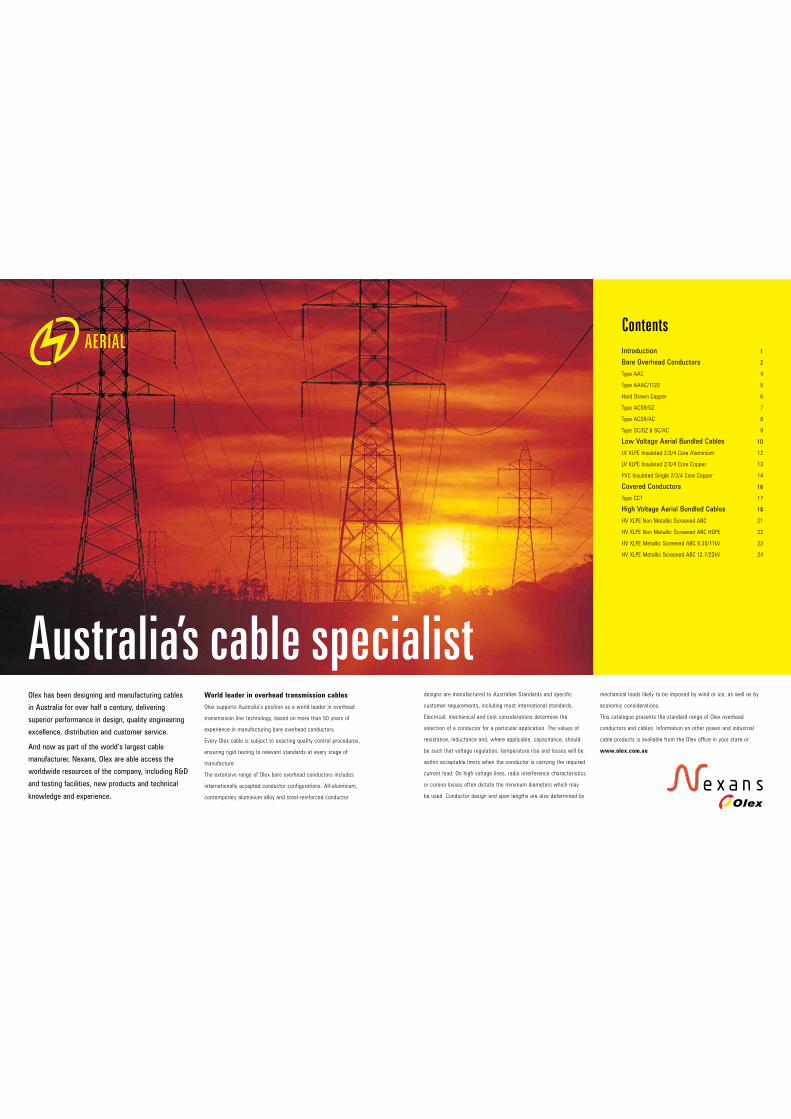
Australia’s cable specialistWorld leader in overhead transmission cables
Olex supports Australia’s position as a world leader in overhead
transmission line technology, based on more than 50 years of
experience in manufacturing bare overhead conductors.
Every Olex cable is subject to exacting quality control procedures,
ensuring rigid testing to relevant standards at every stage of
manufacture.
The extensive range of Olex bare overhead conductors includes
internationally accepted conductor configurations. All-aluminium,
contemporary aluminium alloy and steel-reinforced conductor
designs are manufactured to Australian Standards and specific
customer requirements, including most international standards.
Electrical, mechanical and cost considerations determine the
selection of a conductor for a particular application. The values of
resistance, inductance and, where applicable, capacitance, should
be such that voltage regulation, temperature rise and losses will be
within acceptable limits when the conductor is carrying the required
current load. On high voltage lines, radio interference characteristics
or corona losses often dictate the minimum diameters which may
be used. Conductor design and span lengths are also determined by
AERIAL
mechanical loads likely to be imposed by wind or ice, as well as by
economic considerations.
This catalogue presents the standard range of Olex overhead
conductors and cables. Information on other power and industrial
cable products is available from the Olex office in your state or
www.olex.com.au

wires provides additional protection against corrosion. Conductors
incorporating aluminium-clad steel are more corrosion-resistant than
those incorporating galvanised steel. Aluminium alloy 1120 conductors
are becoming more popular as replacements for steel-reinforced
conductors in areas of high corrosion risk.
The exposed surface of aluminium wires can be specially treated to
provide a dull, non-specular finish when conductors are required to
blend into the environment. Aluminium alloy 1120 conductors may be
identified by means of a blue thread incorporated within the conductor.
Packing
Conductor lengths are determined from a consideration of such factors
as physical drum dimensions, drum weights, span length and handling
equipment.
Olex offers a number of materials meeting
the requirements of both Australian and
International Standards.
Aluminium 1350 High purity electrical conductor (EC) grade
aluminium (alloy 1350) has a conductivity of 61% IACS and UTS
of 160–185MPa.
Aluminium alloy 1120 Olex alloy 1120 has a conductivity of 59% IACS
and UTS of 240–250MPa and 40–50% higher strength than a similar
conductor of EC grade material. This alloy can be considered a ‘high
tech’ version of EC grade aluminium and offers significant advantages
over older type alloys, such as alloy 6201. Steel-reinforced aluminium
alloy 1120 conductors have a high strength to weight ratio, resulting in
small sags on long span lengths. Fittings for alloy 1120 conductors are
similar to those used for EC grade aluminium conductors.
Please note that Olex no longer offers alloy 6201 conductors, as they
have little, if any, practical advantage over alloy 1120. Compared with
alloy 1120, alloy 6201 conductors have poor electrical performance,
are less resistant to corrosion, more susceptible to fatigue failure,
more expensive and require the use of special fittings.
Copper Hard drawn copper wire produced from high conductivity alloy
110A has a conductivity of 97% IACS and UTS of 405–460MPa.
Galvanised steel Galvanised steel wire made from fully-killed steel
with a carbon content of 0.6% has a UTS of 1.31–1.39GPa. It is
galvanised by either a hot dip or electrolytic process to give a zinc
coating mass of 200–260g/m2.
Aluminium-clad steel Aluminium-clad steel has an aluminium
cladding with a radial thickness not less than 5% of the overall
wire diameter. It has a conductivity of 20.3% IACS and UTS of
1.27–1.34GPa. Conductors incorporating aluminium-clad steel for
reinforcement have lower electrical resistance and provide better
protection against corrosion than those using galvanised steel.
Construction
The wires in all bare conductors are stranded concentrically with
successive layers having an opposite direction of lay, the outermost
layer being right-handed. When required, a larger central wire
(king-wire) is included in a conductor. The diameter of this wire is
based on conductor design considerations and is usually 5% greater
than the surrounding wires. The incorporation of a king wire is often
an advantage for ACSR type conductors, as it ensures that the
surrounding layer of wires fits firmly on the central wire.
ACSR conductors may be subjected to corrosive conditions such
as high pollution found in industrial areas or salt spray in coastal
areas. The application of a high melting point grease over the steel
Bare Overhead Conductors
Properties of MaterialsUnit Aluminium Aluminium Copper Galvanised Aluminium-clad alloy 1120 steel steel
Density at 20°C
kg/m3 2700 2700 8890 7800 6590
Conductivity at 20°C
% IACS 61 59 97 10.1 20.3
Resistivity at 20°C
µ!.m 0.0283 0.0293 0.01777 0.17 0.085
Constant-mass temperature coefficient of resistance
per ºC 0.00403 0.00390 0.00381 0.0044 0.0036
Ultimate tensile stress
MPa 160–185 230–250 405–460 1310–1390 1270–1340
Modulus of elasticity
GPa 68 68 124 193 162
Coefficient of linear expansion
per ºC 23.0x10⁻⁶ 23.0x10⁻⁶ 17x10–6 11.5x10⁻⁶ 12.9x10⁻⁶
Further technical information is available if required. Topics include:
Thermal characteristics 1 air movement
1 continuous current 1 emissivity and solar
carrying capacity absorption coefficients
1 ambient temperature 1 solar radiation
Electrical characteristics
1 AC resistance 1 inductive reactance
Physical and mechanical characteristics
1 sag and tension 1 thermal elongation
1 everyday tension 1 creep
1 stress-strain characteristics
HIGH VOLTAGE2 3
Note Current ratings are based on the following conditions:
1 Conductor temperature rise above ambient of 40°C
1 Ambient air temp. of 35°C for summer noon or 10°C for winter night
1 Direct solar radiation intensity of 1000W/m2 for summer noon or zero for winter night
1 Diffuse solar radiation intensity of 100W/m2 for summer noon or zero for winter night
1 Ground reflectance of 0.2
1 Emissivity of 0.5 for rural weathered conductor or 0.85 for industrial weathered
conductor
1 Solar absorption coefficient of 0.5 for rural weathered conductor or 0.85 for industrial
weathered conductor
Cross sections not to scale
Electrical Performance Data
Cond. DC AC Inductive Continuous current carrying capacity, A code resist. resist. reactance Rural weathered Industrial weathered name at 20°C at 50Hz to 0.3m Winter night Summer noon Winter night Summer noon 75°C at 50Hz Still 1m/s 2m/s Still 1m/s 2m/s Still 1m/s 2m/s Still 1m/s 2m/s !/km !/km !/km air wind wind air wind wind air wind wind air wind wind
Chlorine 0.864 1.05 0.295 121 207 241 94 187 221 130 212 246 87 183 219
Chromium 0.713 0.866 0.289 137 234 272 106 210 249 148 240 277 98 206 246
Fluorine 0.599 0.728 0.284 154 261 303 118 234 277 166 268 309 108 229 273
Helium 0.383 0.465 0.270 208 345 401 155 307 364 225 356 410 141 300 358
Hydrogen 0.266 0.323 0.259 265 434 504 194 383 455 288 448 517 74 373 447
Iodine 0.239 0.291 0.255 285 464 539 207 409 486 310 480 553 185 398 477
Krypton 0.189 0.230 0.244 338 540 627 240 473 562 368 560 644 213 459 551
Lutetium 0.163 0.198 0.240 375 593 688 265 517 615 409 615 707 234 502 603
Neon 0.142 0.173 0.235 413 647 750 290 562 669 451 672 771 256 545 655
Nitrogen 0.114 0.139 0.227 482 743 861 336 642 765 528 774 887 295 621 748
Nobelium 0.0973 0.119 0.222 539 821 961 373 706 842 590 856 990 326 682 822
Oxygen 0.0884 0.108 0.220 575 871 1025 397 747 891 630 908 1057 346 721 870
Phosphorus 0.0731 0.0897 0.213 658 982 1172 451 837 1013 722 1026 1209 391 807 988
Selenium 0.0592 0.0730 0.206 762 1120 1357 518 949 1172 838 1173 1401 446 912 1142
Silicon 0.0511 0.0634 0.201 843 1227 1501 569 1034 1295 928 1287 1550 488 992 1262
Sulfur 0.0444 0.0554 0.197 927 1336 1650 623 1122 1423 1021 1403 1705 532 1074 1386
Physical and Mechanical Performance Data
Conductor Stranding Nominal Cross- Approximate Breaking Modulus Coefficient Product code codename and wire overall sectional mass load of elasticity of linear diameter diameter area expansion no/mm mm mm2 kg/km kN GPa x10–6/°C
Chlorine 7/2.50 7.50 34.4 94.3 8.18 65 23.0 Chlorine
Chromium 7/2.75 8.25 41.6 113 9.91 65 23.0 Chromium
Fluorine 7/3.00 9.00 49.5 135 11.8 65 23.0 Fluorine
Helium 7/3.75 11.3 77.3 211 17.6 65 23.0 Helium
Hydrogen 7/4.50 13.5 111 304 24.3 65 23.0 Hydrogen
Iodine 7/4.75 14.3 124 339 27.1 65 23.0 Iodine
Krypton 19/3.25 16.3 158 433 37.4 65 23.0 Krypton
Lutetium 19/3.50 17.5 183 503 41.7 65 23.0 Lutetium
Neon 19/3.75 18.8 210 576 47.8 65 23.0 Neon
Nitrogen 37/3.00 21.0 262 721 62.2 64 23.0 Nitrogen
Nobelium 37/3.25 22.8 307 845 72.8 64 23.0 Nobelium
Oxygen 19/4.75 23.8 337 924 73.6 65 23.0 Oxygen
Phosphorus 37/3.75 26.3 409 1120 93.1 64 23.0 Phosphorus
Selenium 61/3.25 29.3 506 1400 114 64 23.0 Selenium
Silicon 61/3.50 31.5 587 1620 127 64 23.0 Silicon
Sulfur 61/3.75 33.8 673 1860 145 64 23.0 Sulfur
HIGH VOLTAGE4
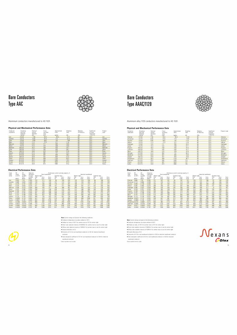
Bare Conductors
Type AAC
Aluminium conductors manufactured to AS 1531.
5
Bare Conductors
Type AAAC/1120
Aluminium alloy 1120 conductors manufactured to AS 1531.
Note Current ratings are based on the following conditions:
1 Conductor temperature rise above ambient of 40°C
1 Ambient air temp. of 35°C for summer noon or 10°C for winter night
1 Direct solar radiation intensity of 1000W/m2 for summer noon or zero for winter night
1 Diffuse solar radiation intensity of 100W/m2 for summer noon or zero for winter night
1 Ground reflectance of 0.2
1 Emissivity of 0.5 for rural weathered conductor or 0.85 for industrial weathered conductor
1 Solar absorption coefficient of 0.5 for rural weathered conductor or 0.85 for industrial
weathered conductor
Cross sections not to scale
Electrical Performance Data
Cond. DC AC Inductive Continuous current carrying capacity, A code resist. resist. reactance Rural weathered Industrial weathered name at 20°C at 50Hz to 0.3m Winter night Summer noon Winter night Summer noon 75°C at 50Hz Still 1m/s 2m/s Still 1m/s 2m/s Still 1m/s 2m/s Still 1m/s 2m/s !/km !/km !/km air wind wind air wind wind air wind wind air wind wind
Leo 0.833 1.02 0.295 123 211 245 95 190 225 132 216 250 88 186 222
Leonids 0.689 0.842 0.289 140 237 276 107 213 253 150 243 282 99 209 249
Libra 0.579 0.707 0.284 157 265 308 119 237 281 169 272 314 110 232 277
Mars 0.370 0.452 0.270 211 350 408 157 311 369 228 361 417 143 304 364
Mercury 0.258 0.315 0.259 269 440 511 196 388 461 292 454 524 176 378 453
Moon 0.232 0.284 0.255 289 470 546 209 413 492 314 486 560 188 403 483
Neptune 0.183 0.224 0.244 343 548 636 243 479 570 373 568 653 216 465 559
Orion 0.157 0.192 0.240 381 603 699 269 525 625 416 626 719 238 510 612
Pluto 0.137 0.168 0.235 420 657 762 295 570 679 458 683 784 260 553 665
Saturn 0.110 0.135 0.227 490 755 875 341 651 776 536 786 901 299 630 759
Sirius 0.0940 0.116 0.222 547 834 975 379 716 854 599 869 1006 331 692 834
Taurus 0.0857 0.105 0.220 583 883 1039 402 756 902 639 921 1071 350 730 880
Triton 0.0706 0.0872 0.213 668 997 1190 457 849 1028 733 1042 1228 396 818 1002
Uranus 0.0572 0.0710 0.206 773 1137 1377 525 962 1188 850 1191 1422 452 925 1158
Ursula 0.0493 0.0616 0.201 856 1246 1524 578 1049 1314 942 1307 1574 495 1006 1280
Venus 0.0429 0.0539 0.197 941 1356 1674 631 1137 1442 1036 1424 1730 539 1089 1405
Physical and Mechanical Performance Data
Conductor Stranding Nominal Cross- Approximate Breaking Modulus Coefficient Product codename and wire overall sectional mass load of elasticity of linear code diameter diameter area expansion no/mm mm mm2 kg/km kN GPa x10–6/°C
Leo 7/2.50 7.50 34.4 94.3 5.71 65 23.0 Leo
Leonids 7/2.75 8.25 41.6 113 6.72 65 23.0 Leonids
Libra 7/3.00 9.00 49.5 135 7.98 65 23.0 Libra
Mars 7/3.75 11.3 77.3 211 11.8 65 23.0 Mars
Mercury 7/4.50 13.5 111 304 16.9 65 23.0 Mercury
Moon 7/4.75 14.3 124 339 18.9 65 23.0 Moon
Neptune 19/3.25 16.3 158 433 24.7 65 23.0 Neptune
Orion 19/3.50 17.5 183 503 28.7 65 23.0 Orion
Pluto 19/3.75 18.8 210 576 31.9 65 23.0 Pluto
Saturn 37/3.00 21.0 262 721 42.2 64 23.0 Saturn
Sirius 37/3.25 22.8 307 845 48.2 64 23.0 Sirius
Taurus 19/4.75 23.8 337 924 51.3 65 23.0 Taurus
Triton 37/3.75 26.3 409 1120 62.2 64 23.0 Triton
Uranus 61/3.25 29.3 506 1400 75.2 64 23.0 Uranus
Ursula 61/3.50 31.5 587 1620 87.3 64 23.0 Ursula
Venus 61/3.75 33.8 673 1860 97.2 64 23.0 Venus
Physical and Mechanical Performance Data
Conductor Stranding and wire Nominal Cross- Approximate Breaking Modulus Coefficient Product codename diameter no/mm overall sectional mass load of elasticity of linear code diameter area expansion Aluminium Steel mm mm2 kg/km kN GPa x10–6/°C
Almond 6/2.50 1/2.50 7.5 34.4 119 10.5 83 19.3 Almond
Apricot 6/2.75 1/2.75 8.3 41.6 144 12.6 83 19.3 Apricot
Apple 6/3.00 1/3.00 9.0 49.5 171 14.9 83 19.3 Apple
Banana 6/3.75 1/3.75 11.3 77.3 268 22.7 83 19.3 Banana
Cherry 6/4.75 7/1.60 14.3 120 402 33.4 80 19.9 Cherry
Grape 30/2.50 7/2.50 17.5 182 677 63.5 88 18.4 Grape
Lemon 30/3.00 7/3.00 21.0 262 973 90.4 88 18.4 Lemon
Lychee 30/3.25 7/3.25 22.8 307 1140 105 88 18.4 Lychee
Lime 30/3.50 7/3.50 24.5 356 1320 122 88 18.4 Lime
Mango 54/3.00 7/3.00 27.0 431 1440 119 78 19.9 Mango
Orange 54/3.25 7/3.25 29.3 506 1690 137 78 19.9 Orange
Olive 54/3.50 7/3.50 31.5 587 1960 159 78 19.9 Olive
Pawpaw 54/3.75 19/2.25 33.8 672 2240 178 77 20.0 Pawpaw
Quince 3/1.75 4/1.75 5.3 16.8 95 12.7 136 13.9 Quince
Raisin 3/2.50 4/2.50 7.5 34.4 195 24.4 136 13.9 Raisin
Sultana 4/3.00 3/3.00 9.0 49.5 243 28.3 119 15.2 Sultana
Walnut 4/3.75 3/3.75 11.3 77.3 380 43.9 119 15.2 Walnut
Electrical Performance Data
Cond. DC AC Inductive Continuous current carrying capacity, A code resist. resist. reactance Rural weathered Industrial weathered name at 20°C at 50Hz to 0.3m Winter night Summer noon Winter night Summer noon 75°C at 50Hz Still 1m/s 2m/s Still 1m/s 2m/s Still 1m/s 2m/s Still 1m/s 2m/s !/km !/km !/km air wind wind air wind wind air wind wind air wind wind
Almond 0.975 1.31 0.296 108 186 216 84 167 198 116 190 220 79 164 196
Apricot 0.805 1.08 0.290 123 209 244 95 188 223 131 215 248 89 184 220
Apple 0.677 0.910 0.285 138 233 272 107 209 248 148 240 277 98 205 244
Banana 0.433 0.582 0.271 187 309 359 141 274 326 201 318 367 129 268 321
Cherry 0.271 0.367 0.256 259 416 483 191 364 434 280 430 495 171 354 426
Grape 0.196 0.263 0.240 330 513 598 238 449 531 361 532 614 211 436 520
Lemon 0.136 0.167 0.228 441 680 787 307 586 698 482 707 811 269 567 682
Lychee 0.116 0.142 0.223 493 752 879 341 645 769 540 783 906 298 623 751
Lime 0.100 0.123 0.219 548 826 976 377 706 843 601 862 1007 328 681 823
Mango 0.0758 0.0955 0.212 648 960 1147 443 816 991 711 1003 1183 383 786 966
Orange 0.0646 0.0816 0.207 724 1061 1282 492 898 1106 796 1110 1323 424 863 1078
Olive 0.0557 0.0705 0.202 804 1165 1421 543 981 1225 884 1220 1466 466 941 1194
Pawpaw 0.0485 0.0615 0.198 885 1270 1563 595 1065 1347 974 1333 1614 508 1020 1312
Quince 3.25 4.37 0.346 53 93 108 42 85 100 56 95 110 40 83 99
Raisin 1.59 2.14 0.324 85 145 169 66 131 155 91 149 172 61 129 153
Sultana 0.897 1.21 0.302 120 203 236 91 181 215 129 208 241 84 178 212
Walnut 0.573 0.770 0.288 161 269 312 121 238 283 175 277 319 111 233 279
Physical and Mechanical Performance Data
Stranding Nominal Cross- Approximate Breaking Modulus Coefficient Product and wire overall sectional mass load of elasticity of linear code diameter area expansion no/mm mm mm2 kg/km kN GPa x10–6/°C
7/1.00 3.00 5.50 49.3 2.32 120 17.0 ACUT35AA001
7/1.25 3.75 8.59 76.9 3.59 120 17.0 ACUT36AA001
7/1.75 5.25 16.8 151 6.89 120 17.0 ACUT37AA001
7/2.00 6.00 22.0 197 8.89 120 17.0 ACUT38AA001
7/2.75 8.25 41.6 375 16.2 120 17.0 ACUT39AA001
19/1.75 8.75 45.7 413 18.3 118 17.0 ACUT40AA001
19/2.00 10.0 59.7 538 23.6 118 17.0 ACUT41AA001
7/3.50 10.5 67.4 607 25.4 120 17.0 ACUT42AA001
7/3.75 11.3 77.3 696 28.8 120 17.0 ACUT63AA001
37/1.75 12.3 89.0 806 35.6 117 17.0 ACUT43AA001
19/2.75 13.8 113 1020 43.1 118 17.0 ACUT44AA001
19/3.00 15.0 134 1210 50.8 118 17.0 ACUT45AA001
37/2.50 17.5 182 1640 70.3 117 17.0 ACUT46AA001
37/2.75 19.3 220 1990 83.9 117 17.0 ACUT47AA001
37/3.00 21.0 262 2370 98.9 117 17.0 ACUT48AA001
61/2.75 24.8 362 3290 138 117 17.0 ACUT49AA001
Electrical Performance Data
Stranding DC AC Inductive Continuous current carrying capacity, A and wire resist. resist. reactance Rural weathered Industrial weathered at 20°C at 50Hz to 0.3m Winter night Summer noon Winter night Summer noon 75°C at 50Hz Still 1m/s 2m/s Still 1m/s 2m/s Still 1m/s 2m/s Still 1m/s 2m/s no/mm !/km !/km !/km air wind wind air wind wind air wind wind air wind wind
7/1.00 3.25 3.93 0.353 47 85 99 39 79 93 49 86 101 37 78 92
7/1.25 2.09 2.53 0.339 62 112 131 51 103 122 66 114 133 48 102 121
7/1.75 1.06 1.28 0.318 97 171 200 78 156 185 104 175 203 73 154 183
7/2.00 0.815 0.986 0.310 116 202 235 92 183 217 124 206 239 86 180 215
7/2.75 0.433 0.524 0.289 176 300 350 136 270 320 190 308 356 126 265 316
19/1.75 0.395 0.478 0.283 188 319 371 144 286 340 203 327 379 133 281 335
19/2.00 0.303 0.367 0.275 225 377 438 170 337 400 242 388 448 156 330 394
7/3.50 0.268 0.324 0.274 243 406 472 183 362 430 262 418 482 167 354 423
7/3.75 0.233 0.282 0.270 267 443 515 199 394 468 288 456 526 181 385 460
37/1.75 0.203 0.246 0.261 294 485 564 217 430 511 318 500 577 197 420 502
19/2.75 0.160 0.194 0.255 344 563 653 251 496 590 374 581 670 226 484 579
19/3.00 0.134 0.163 0.249 388 629 730 280 552 657 423 650 748 250 538 645
37/2.50 0.0996 0.121 0.239 479 758 879 339 661 787 523 786 903 300 642 771
37/2.75 0.0823 0.100 0.233 547 854 989 384 742 883 598 887 1018 339 719 864
37/3.00 0.0691 0.0846 0.227 618 952 1102 431 823 981 676 991 1136 378 796 959
61/2.75 0.0500 0.0618 0.217 772 1162 1376 533 996 1193 847 1213 1419 463 961 1164
6
Bare Conductors
Hard Drawn Copper
Hard drawn copper conductors manufactured to AS 1746.
Note Current ratings are based on the following conditions:
1 Conductor temperature rise above ambient of 40°C
1 Ambient air temp. of 35°C for summer noon or 10°C for winter night
1 Direct solar radiation intensity of 1000W/m2 for summer noon or zero for winter night
1 Diffuse solar radiation intensity of 100W/m2 for summer noon or zero for winter night
1 Ground reflectance of 0.2
1 Emissivity of 0.5 for rural weathered conductor or 0.85 for industrial weathered conductor
1 Solar absorption coefficient of 0.5 for rural weathered conductor or 0.85 for industrial
weathered conductor
Cross sections not to scale
7
Bare Conductors
Type ACSR/GZ
Aluminium conductors, galvanised steel reinforced manufactured to AS 3607.
Note Current ratings are based on the following conditions:
1 Conductor temperature rise above ambient of 40°C
1 Ambient air temp. of 35°C for summer noon or 10°C for winter night
1 Direct solar radiation intensity of 1000W/m2 for summer noon or zero for winter night
1 Diffuse solar radiation intensity of 100W/m2 for summer noon or zero for winter night
1 Ground reflectance of 0.2
1 Emissivity of 0.5 for rural weathered conductor or 0.85 for industrial weathered conductor
1 Solar absorption coefficient of 0.5 for rural weathered conductor or 0.85 for industrial
weathered conductor
Cross sections not to scale
HIGH VOLTAGE

SC/GZ
Stranding Nominal Cross- Approx. Breaking Modulus Coeff. DC Continuous current carrying capacity, A Product and wire overall sectional mass load of of linear resistance code diameter diameter area elasticity expan. at at Winter night Summer noon 20°C 75°C Still 1m/s 2m/s Still 1m/s 2m/s no/mm mm mm2 kg/km kN GPa x 10–6/°C !/km !/km air wind wind air wind wind
3/2.00 4.3 9.43 74 11.7 189 11.5 20 25 21 37 43 17 34 40 GALSTEEL 3/2.00
3/2.75 5.9 17.8 140 22.2 189 11.5 11 14 31 54 63 25 49 58 GALSTEEL 3/2.75
7/2.00 6.0 22.0 173 26.0 187 11.5 8.7 11 35 61 71 28 55 66 GALSTEEL 7/2.00
7/2.75 8.3 41.6 328 49.0 187 11.5 4.6 5.7 54 91 106 41 82 97 GALSTEEL 7/2.75
7/3.25 9.8 58.1 458 68.7 187 11.5 3.3 4.1 67 113 131 51 100 119 GALSTEEL 7/3.25
7/3.75 11.3 77.3 609 91.3 187 11.5 2.5 3.1 81 134 156 60 119 141 GALSTEEL 7/3.75
19/2.00 10.0 59.7 473 70.5 184 11.5 3.2 4.0 69 115 134 52 102 121 GALSTEEL 19/2.00
19/2.75 13.8 113 894 133 184 11.5 1.7 2.1 105 171 199 76 150 179 GALSTEEL 19/2.7
19/3.25 16.3 158 1250 186 184 11.5 1.2 1.5 133 213 247 94 186 221 GALSTEEL 19/3.25
SC/AC
Stranding Nominal Cross- Approx. Breaking Modulus Coeff. DC Continuous current carrying capacity, A Product code and wire overall sectional mass load of of linear resistance diameter diameter area elasticity expan. at at Winter night Summer noon 20°C 75°C Still 1m/s 2m/s Still 1m/s 2m/s no/mm mm mm2 kg/km kN GPa x 10–6/°C !/km !/km air wind wind air wind wind
3/2.75 5.9 17.82 118 22.7 159 12.9 4.80 5.75 48 83 97 38 76 90 ALCLAD3/2.75
3/3.00 6.5 21.21 141 27.0 159 12.9 4.02 4.82 54 93 108 42 84 100 ALCLAD3/3.00
3/3.25 7.0 24.89 165 31.6 159 12.9 3.42 4.10 60 103 120 47 93 110 ALCLAD3/3.25
3/3.75 8.1 33.12 220 39.3 159 12.9 2.58 3.09 72 123 143 56 111 131 ALCLAD3/3.75
7/2.75 8.3 41.58 277 50.1 157 12.9 2.06 2.47 81 138 161 63 124 148 ALCLAD7/2.75
7/3.00 9.0 49.48 330 59.7 157 12.9 1.73 2.07 91 154 179 70 138 164 ALCLAD7/3.00
7/3.25 9.8 58.07 387 69.9 157 12.9 1.47 1.76 102 170 198 77 153 181 ALCLAD7/3.25
7/3.75 11.3 77.28 515 86.9 157 12.9 1.11 1.33 123 204 237 92 181 215 ALCLAD7/3.75
7/4.25 12.8 99.33 662 105 157 12.9 0.864 1.04 145 238 277 107 211 251 ALCLAD7/4.25
19/2.75 13.8 112.9 755 136 155 12.9 0.764 0.915 158 259 300 116 228 272 ALCLAD19/2.75
19/3.00 15.0 134.3 899 162 155 12.9 0.642 0.769 178 288 335 129 54 302 ALCLAD19/3.00
19/3.25 16.3 157.6 1060 189 155 12.9 0.545 0.653 200 320 371 142 280 334 ALCLAD19/3.25
19/3.75 18.8 209.8 1410 236 155 12.9 0.411 0.492 244 382 443 172 333 397 ALCLAD19/3.75
19/4.25 21.3 269.6 1800 286 155 12.9 0.320 0.383 291 448 519 203 387 462 ALCLAD19/4.25
9
Galvanised steel conductors manufactured to AS 1222.1
and aluminium-clad steel conductors manufactured to AS 1222.2
Bare Conductors
Type SC/GZ & SC/AC
Note The electrical performance characteristics shown above do not take magnetic effects
into consideration and are therefore only approximate. Current ratings are based on the
following conditions:
1 Conductor temperature rise above ambient of 40°C
1 Ambient air temp. of 35°C for summer noon or 10°C for winter night
1 Direct solar radiation intensity of 1000W/m2 for summer noon or zero for winter night
1 Diffuse solar radiation intensity of 100W/m2 for summer noon or zero for winter night
1 Ground reflectance of 0.2
1 Emissivity and solar absorption coefficient of the conductor surface, 0.5
Cross sections not to scale
Electrical Performance Data
Cond. DC AC Inductive Continuous current carrying capacity, A code resist. resist. reactance Rural weathered Industrial weathered name at 20°C at 50Hz to 0.3m Winter night Summer noon Winter night Summer noon 75°C at 50Hz Still 1m/s 2m/s Still 1m/s 2m/s Still 1m/s 2m/s Still 1m/s 2m/s !/km !/km !/km air wind wind air wind wind air wind wind air wind wind
Angling 0.923 1.24 0.296 111 191 222 87 172 204 119 195 226 81 169 201
Aquatics 0.763 1.03 0.290 126 215 250 98 193 229 136 221 255 91 189 226
Archery 0.641 0.861 0.285 141 240 279 109 215 255 152 246 285 100 210 251
Baseball 0.410 0.551 0.271 192 318 369 145 282 335 207 327 378 133 276 329
Bowls 0.259 0.352 0.256 265 425 494 195 372 444 286 440 506 175 362 436
Cricket 0.182 0.245 0.240 342 532 620 246 465 554 374 555 637 219 452 540
Darts 0.126 0.155 0.228 458 706 817 319 609 725 501 735 842 280 589 709
Dice 0.108 0.133 0.223 511 779 911 354 668 797 560 812 939 309 646 779
Diving 0.0928 0.114 0.219 569 857 1013 391 732 875 624 895 1045 340 707 854
Golf 0.0726 0.0915 0.212 662 980 1172 452 834 1012 726 1024 1208 392 803 987
Gymnastics 0.0619 0.0782 0.207 740 1084 1309 503 917 1130 813 1134 1351 433 882 1101
Hurdles 0.0533 0.0675 0.202 821 1190 1452 555 1003 1252 903 1247 1499 476 962 1220
Lacrosse 0.0465 0.0590 0.198 904 1297 1596 607 1088 1375 995 1361 1648 519 1042 1339
Skating 2.75 3.70 0.346 57 101 118 46 92 109 61 103 120 43 91 108
Soccer 1.34 1.80 0.324 92 158 184 72 143 169 99 162 188 67 140 167
Swimming 0.807 1.08 0.302 127 214 249 96 191 227 136 219 254 89 187 224
Tennis 0.517 0.695 0.288 170 283 329 127 251 298 184 291 336 116 245 293
Physical and Mechanical Performance Data
Conductor Stranding and Nominal Cross- Approximate Breaking Modulus Coefficient Product codename wire diameter overall sectional mass load of elasticity of linear code no/mm diameter area expansion Aluminium Steel mm mm2 kg/km kN GPa x10–6/°C
Angling 6/2.50 1/2.50 7.5 34.4 113 10.6 79 20.1 Angling
Aquatics 6/2.75 1/2.75 8.3 41.6 137 12.7 79 20.1 Aquatics
Archery 6/3.00 1/3.00 9.0 49.5 163 15.1 79 20.1 Archery
Baseball 6/3.75 1/3.75 11.3 77.3 254 22.3 79 20.1 Baseball
Bowls 6/4.75 7/1.60 14.3 120 385 32.7 76 20.6 Bowls
Cricket 30/2.50 7/2.50 17.5 182 636 64.4 82 19.4 Cricket
Darts 30/3.00 7/3.00 21.0 262 913 91.6 82 19.4 Darts
Dice 30/3.25 7/3.25 22.8 307 1070 106 82 19.4 Dice
Diving 30/3.50 7/3.50 24.5 356 1240 122 82 19.4 Diving
Golf 54/3.00 7/3.00 27.0 431 1380 120 75 20.6 Golf
Gymnastics 54/3.25 7/3.25 29.3 506 1620 139 75 20.6 Gymnastics
Hurdles 54/3.50 7/3.50 31.5 587 1880 159 75 20.6 Hurdles
Lacrosse 54/3.75 19/2.25 33.8 672 2150 180 74 20.7 Lacrosse
Skating 3/1.75 4/1.75 5.3 16.8 83 12.3 119 15.3 Skating
Soccer 3/2.50 4/2.50 7.5 34.4 171 24.9 119 15.3 Soccer
Swimming 4/3.00 3/3.00 9.0 49.5 218 28.9 106 16.5 Swimming
Tennis 4/3.75 3/3.75 11.3 77.3 340 42.6 106 16.5 Tennis
8
Bare Conductors
Type ACSR/AC
Aluminium conductors, aluminium-clad steel reinforced manufactured to AS 3607.
Note Current ratings are based on the following conditions:
1 Conductor temperature rise above ambient of 40°C
1 Ambient air temp. of 35°C for summer noon or 10°C for winter night
1 Direct solar radiation intensity of 1000W/m2 for summer noon or zero for winter night
1 Diffuse solar radiation intensity of 100W/m2 for summer noon or zero for winter night
1 Ground reflectance of 0.2
1 Emissivity of 0.5 for rural weathered conductor or 0.85 for industrial weathered conductor
1 Solar absorption coefficient of 0.5 for rural weathered conductor or 0.85 for industrial
weathered conductor
Cross sections not to scale
HIGH VOLTAGE

1110HIGH VOLTAGE
Low Voltage Aerial Bundled CablesAS/NZS 3560 specifies the require ments of Aerial
Bundled Cables with XLPE insulation for use up to
0.6/1kV. It is a result of considerable deliberation
among supply authorities and manufac turers
seeking to improve on the overseas standard,
and features unique tests to verify superior field
service performance.
Conductor
All four conductors are manufactured from high conductivity high
purity aluminium alloy 1350 and are stranded circular compacted.
Based on extensive development testing and production research,
the surface of the conductor is specially treated to improve adhesion
of the insulation to the conductor. This is important because the
installed cable tension is completely provided by this ‘adhesion’
or ’friction‘ between the conductor and the insulation.
Insulation
The insulation consists of X-90UV, a cross-linked polyethylene with
a minimum of 2% carbon black to provide adequate protection from
ultra violet radiation. This material is far superior to PVC, in its ability
to withstand higher operating temperatures, is more robust during
installation, and has much better (higher) insulation resistance values.
For improved characteristics in fire or overload situations, X-FP-90
insulation is available. For this application, Olex uses a highly filled
XLPE with greater levels of carbon black and other fillers.
Both insulation types are tested at 80°C with a special adhesion test
that simulates the conditions prevailing under tension at strain clamps
to ensure no failure of insulation adhesion occurs in the field. X-FP-90
insulated cables are additionally tested at the higher temperature of
120°C, and are also subjected to a heat radiation test that simulates
conditions prevalent in bush fires. The X-90UV material used by Olex
passes the criteria test at 105°C which provides our customer with
a further safety margin over the Standard.
Proper carbon black dispersion is even more important than carbon
black content and Olex has developed special processing procedures
to ensure adequate protection from UV radiation. Both X-90UV and
X-FP-90 compounds are tested for carbon black content and dispersion.
The cores
Each phase core is marked with numerals 1, 2 or 3 and with one rib,
two ribs or three ribs to denote the three phases. The neutral core
carries equally spaced ribs right round the circumference. These
ribs facilitate identification of the phases and the neutral even when
numerals cannot be properly seen due to bad light. Alternative
identification means, using coloured extruded stripes, are also available.
To expedite ascertaining the approximate length of cable left on the
drum, sequential six-digit numerals are marked on one active core at
one metre intervals. Drum lengths start at any number with the lowest
number near the end at the drum barrel.
The cores are laid up in a bundle with a left hand lay. Rating of LV-ABC
is based on a conductor operating temperature of 80°C.
LV ABC at suspension clamp and at strain point
In the fully supported LV ABC system tension is
shared equally by all four conductors. This has
distinct advantages, one obvious benefit being higher
working and operating tensions.

Performance Data
Nominal DC AC Inductive Voltage Continuous current rating, A Fault Minimum Min. Rec. tension Modulus Coeff. conductor resist. resist. reactance drop current bending radius breaking Highest Max of of linear area at 20°C at 50Hz at 50Hz at 50Hz rating (installed) mm load of everyday working elasticity expansion 80°C 80°C Still 1m/s 2m/s kA for cable tension tension mm2 !/km !/km !/km mV/A.m air wind wind 1s Core Cable kN kN kN GPa x10–6/°C
2 Core
16 1.91 2.37 0.094 4.75 49 78 91 1.4 30 90 4.4 0.79 1.23 59 23.0
25 1.20 1.49 0.089 2.99 64 105 120 2.2 35 100 7.0 1.26 1.96 59 23.0
35 0.868 1.08 0.086 2.16 78 125 145 3.1 60 120 9.8 1.76 2.74 59 23.0
50 0.641 0.796 0.086 1.60 94 150 180 4.1 65 130 14.0 2.52 3.92 59 23.0
95 0.320 0.398 0.080 0.812 140 230 275 8.3 90 270 26.6 4.79 7.45 56 23.0
3 Core
25 1.20 1.49 0.089 2.99 59 97 115 2.2 35 110 10.5 1.89 2.94 59 23.0
35 0.868 1.08 0.086 2.16 72 120 135 3.1 60 120 14.7 2.65 4.12 59 23.0
50 0.641 0.796 0.086 1.60 88 140 165 4.1 65 140 21.0 3.78 5.88 59 23.0
4 Core
16 1.91 2.37 0.10 4.11 44 74 86 1.4 30 110 8.8 1.58 2.46 59 23.0
25 1.20 1.49 0.097 2.59 59 97 115 2.2 35 120 14.0 2.52 3.92 59 23.0
35 0.868 1.08 0.094 1.87 72 120 135 3.1 60 140 19.6 3.53 5.49 59 23.0
50 0.641 0.796 0.093 1.39 88 140 165 4.1 65 160 28.0 5.04 7.84 59 23.0
70 0.443 0.551 0.088 0.966 110 175 205 6.0 75 280 39.2 7.06 11.0 56 23.0
95 0.320 0.398 0.087 0.706 135 215 255 8.3 90 320 53.2 9.58 14.9 56 23.0
120 0.253 0.315 0.085 0.566 155 250 300 10.5 100 350 67.2 12.1 18.8 56 23.0
150 0.206 0.257 0.084 0.468 180 280 345 12.9 110 390 84.0 15.1 23.5 56 23.0
Performance Data
Nominal DC AC Inductive Voltage Continuous current rating, A Fault Minimum Min. Rec. tension Modulus Coeff. conductor resist. resist. reactance drop current bending radius breaking Highest Max of of linear area at 20°C at 50Hz at 50Hz at 50Hz rating (installed) mm load of everyday working elasticity expansion 80°C 80°C Still 1m/s 2m/s kA for cable tension tension mm2 !/km !/km !/km mV/A.m air wind wind 1s Core Cable kN kN kN GPa x10–6/°C
2 Core
6 3.17 3.18 0.11 7.79 36 56 66 0.8 25 70 4.6 0.84 1.30 112 17.0
10 1.88 1.89 0.098 4.62 48 77 90 1.4 25 80 7.8 1.41 2.20 112 17.0
16 1.18 1.19 0.092 2.91 64 100 120 2.2 30 95 11.8 2.13 3.32 112 17.0
3 Core
6 3.17 3.89 0.11 7.79 32 54 62 0.8 25 75 7.0 1.25 1.95 112 17.0
10 1.88 2.31 0.098 4.62 44 73 84 1.4 25 90 11.8 2.12 3.29 112 17.0
16 1.18 1.45 0.092 2.91 58 96 110 2.2 30 100 17.8 3.20 4.97 112 17.0
4 Core
6 3.17 3.89 0.11 6.75 32 54 62 0.8 25 85 9.3 1.67 2.60 112 17.0
10 1.88 2.31 0.11 4.00 44 73 84 1.4 25 100 15.7 2.82 4.39 112 17.0
16 1.18 1.45 0.10 2.52 58 96 110 2.2 30 110 23.7 4.26 6.63 112 17.0
Physical Data
Nominal Number and Nominal Average Nominal Nominal Approximate Product code conductor nominal conductor insulation diameter diameter mass area diameter diameter thickness over over laid-up of wires insulation cores mm2 no/mm mm mm mm mm kg/km
2 Core
6 7/1.04 3.1 1.3 5.8 11.7 150 XDAT11AA002
10 7/1.35 4.1 1.3 6.8 13.5 230 XDAT13AA002
16 7/1.70 5.1 1.3 7.8 15.6 350 XDAT15AA002
3 Core
6 7/1.04 3.1 1.3 5.8 12.6 220 XDAT11AA003
10 7/1.35 4.1 1.3 6.8 14.6 340 XDAT13AA003
16 7/1.70 5.1 1.3 7.8 16.9 520 XDAT15AA003
4 Core
6 7/1.04 3.1 1.3 5.8 14.1 290 XDAT11AA004
10 7/1.35 4.1 1.3 6.8 16.3 460 XDAT13AA004
16 7/1.70 5.1 1.3 7.8 18.9 690 XDAT15AA004
Physical Data
Nominal Nominal conductor Average insulation Nominal diameter Nominal diameter Approximate Product code conductor area diameter thickness over insulation over laid-up cores mass mm2 mm mm mm mm kg/km
2 Core
16 4.7 1.3 7.4 14.8 130 XDAB15AA002
25 5.9 1.3 8.6 17.2 190 XDAB17AA002
35 6.9 1.3 9.6 19.3 250 XDAB18AA002
50 8.1 1.5 11.2 22.3 340 XDAB19AA002
95 11.4 1.7 14.9 29.8 640 XDAB22AA002
3 Core
25 5.9 1.3 8.6 18.5 290 XDAB17AA003
35 6.9 1.3 9.6 20.8 370 XDAB18AA003
50 8.1 1.5 11.2 24.1 510 XDAB19AA003
4 Core
16 4.7 1.3 7.4 17.8 270 XDAB15AA004
25 5.9 1.3 8.6 20.8 390 XDAB17AA004
35 6.9 1.3 9.6 23.2 500 XDAB18AA004
50 8.1 1.5 11.2 27.0 670 XDAB19AA004
70 9.7 1.5 12.8 30.8 930 XDAB20AA004
95 11.4 1.7 14.9 36.0 1280 XDAB22AA004
120 12.8 1.7 16.3 39.3 1570 XDAB23AA004
150 14.2 1.7 17.7 42.8 1890 XDAB24AA004
HIGH VOLTAGE12
LV XLPE Insulated Aerial Bundled
Cables 2/3/4 Core Aluminium
0.6/1kV XLPE (X-90) insulated, aerial bundled cables (service and mains cables) to AS/NZS 3560.1.
Hard drawn aluminium conductors.
Note Voltage drops are single-phase for 2 & 3 core cables and three-phase for 4 core
cables. Continuous current ratings are based on an ambient temperature of 40°C, maximum
conductor temperature of 80°C and solar radiation intensity of 1000W/m2. Ratings for
2 & 3 core cables are based on all cores fully loaded. Ratings for 4 core cables are based
on a lightly loaded neutral. Fault current ratings are based on initial and final conductor
temperatures of 80°C and 210°C respectively.
An improved performance grade of XLPE (X-FP-90) designed to provide improved circuit
integrity when subjected to the heat radiation effects of a bush fire or overload conditions
is available as an option.
13
LV XLPE Insulated Aerial Bundled
Cables 2/3/4 Core Copper
0.6/1kV XLPE (X-90) insulated aerial bundled cables (service cables) to AS/NZS 3560.2.
Hard drawn copper conductors.
Note Voltage drops are single-phase for 2 & 3 core cables and three-phase for 4 core
cables. Continuous current ratings are based on an ambient temperature of 40°C, maximum
conductor temperature of 80°C and solar radiation intensity of 1000W/m2. Ratings for
2 & 3 core cables are based on all cores fully loaded. Ratings for 4 core cables are based
on a lightly loaded neutral. Fault current ratings are based on initial and final conductor
temperatures of 80°C and 220°C respectively.

Performance Data
Nominal DC AC Inductive Voltage Continuous current rating, A Fault Minimum bending Minimum Recomm. tension Modulus Coeff. conductor resist. resist. reactance drop current radius (installed) breaking Highest Max. of of linear area at 20°C at 50Hz at 50Hz at 50Hz rating mm load of everyday working elasticity expansion 75°C 75°C Still 1 m/s 2 m/s kA for cable tension tension mm2 !/km !/km !/km mV/A.m air wind wind 1s Core Cable kN kN kN GPa x10–6/°C
2 Core
6 3.17 3.83 0.098 7.67 30 50 59 0.6 20 65 4.6 0.84 1.30 112 17.0
10 1.88 2.27 0.092 4.55 40 68 80 1.0 25 75 7.8 1.41 2.20 112 17.0
16 1.18 1.43 0.087 2.86 52 90 105 1.7 30 85 11.8 2.13 3.32 112 17.0
25 0.749 0.906 0.083 1.82 68 120 140 2.8 35 110 20.8 3.74 5.82 110 17.0
3 Core
6 3.17 3.83 0.098 7.67 26 48 56 0.6 20 70 7.0 1.25 1.95 112 17.0
10 1.88 2.27 0.092 4.55 36 65 76 1.0 25 80 11.8 2.12 3.29 112 17.0
16 1.18 1.43 0.087 2.86 47 85 100 1.7 30 95 17.8 3.20 4.97 112 17.0
25 0.749 0.906 0.083 1.82 63 115 135 2.8 35 120 31.2 5.62 8.74 110 17.0
4 Core
6 3.17 3.83 0.11 6.64 26 48 56 0.6 20 75 9.3 1.67 2.60 112 17.0
10 1.88 2.27 0.10 3.94 36 65 76 1.0 25 90 15.7 2.82 4.39 112 17.0
16 1.18 1.43 0.095 2.48 47 85 100 1.7 30 100 23.7 4.26 6.63 112 17.0
25 0.749 0.906 0.090 1.58 63 115 135 2.8 35 140 41.6 7.49 11.6 110 17.0
Physical Data
Nominal Number and Nominal Average Nominal Nominal Approximate Product conductor nominal conductor insulation diameter diameter mass code area diameter diameter thickness over insulation over laid-up of wires cores mm2 no/mm mm mm mm mm kg/km
2 Core
6 7/1.04 3.1 1.0 5.3 10.5 160 DAFT11AA002
10 7/1.35 4.1 1.0 6.2 12.4 240 DAFT13AA002
16 7/1.70 5.1 1.0 7.2 14.5 370 DAFT15AA002
25 19/1.35 6.8 1.2 9.3 18.6 610 DAFT17AA002
3 Core
6 7/1.04 3.1 1.0 5.3 11.3 240 FAFT11AA003
10 7/1.35 4.1 1.0 6.2 13.3 360 FAFT13AA003
16 7/1.70 5.1 1.0 7.2 15.6 550 FAFT15AA003
25 19/1.35 6.8 1.2 9.3 20.1 910 FAFT17AA003
4 Core
6 7/1.04 3.1 1.0 5.3 12.7 310 HAFT11AA004
10 7/1.35 4.1 1.0 6.2 14.9 480 HAFT13AA004
16 7/1.70 5.1 1.0 7.2 17.5 730 HAFT15AA004
25 19/1.35 6.8 1.2 9.3 22.5 1210 HAFT17AA004
Performance Data
Nominal DC AC Inductive Voltage Continuous current rating, A Fault Minimum Min. Rec. tension Modulus Coeff. conductor resist. resist. reactance drop current bending breaking Highest Max of of linear area at 20°C at 50Hz at 50Hz at 50Hz rating radius load of everyday working elasticity expansion 75°C 75°C Still 1m/s 2m/s kA for (installed) cable tension tension mm2 !/km !/km !/km mV/A.m air wind wind 1s mm kN kN kN GPa x10–6/°C
Single Core
6 3.17 3.83 0.38 6.67 35 70 79 0.6 20 2.3 0.42 0.65 112 17.0
10 1.88 2.27 0.37 3.99 48 96 110 1.0 25 3.9 0.71 1.10 112 17.0
16 1.18 1.43 0.35 2.55 65 125 145 1.7 30 5.9 1.07 1.66 112 17.0
25 0.749 0.906 0.33 1.67 88 165 190 2.8 35 10.4 1.87 2.91 110 17.0
35 0.540 0.653 0.32 1.26 105 205 230 3.6 60 12.7 2.29 3.56 110 17.0
50 0.399 0.483 0.31 0.998 130 240 275 4.9 70 17.3 3.11 4.84 110 17.0
70 0.276 0.334 0.30 0.781 165 305 345 7.1 80 25.0 4.50 7.00 110 17.0
2 Core
6 3.17 3.83 0.10 7.67 30 50 59 0.6 30 4.6 0.84 1.30 112 17.0
10 1.88 2.27 0.096 4.55 40 68 80 1.0 35 7.8 1.41 2.20 112 17.0
16 1.18 1.43 0.091 2.86 52 90 105 1.7 45 11.8 2.13 3.32 112 17.0
25 0.749 0.906 0.085 1.82 68 120 140 2.8 55 20.8 3.74 5.82 110 17.0
3 Core
6 3.17 3.83 0.12 7.67 30 50 59 0.6 30 7.0 1.25 1.95 112 17.0
10 1.88 2.27 0.11 4.55 40 68 80 1.0 35 11.8 2.12 3.29 112 17.0
16 1.18 1.43 0.11 2.86 52 90 105 1.7 45 17.8 3.20 4.97 112 17.0
Physical Data
Nominal Number and Nominal Average Nominal Approximate Product conductor nominal conductor insulation diameter mass code area diameter diameter thickness over insulation of wires mm2 no/mm mm mm mm kg/km
Single Core
6 7/1.04 3.1 1.0 5.3 80 BAAT11AA001
10 7/1.35 4.1 1.0 6.2 120 BAAT13AA001
16 7/1.70 5.1 1.0 7.2 180 BAAT15AA001
25 19/1.35 6.8 1.2 9.3 300 BAAT17AA001
35 19/1.53 7.7 1.2 10.2 370 BAAT18AA001
50 19/1.78 8.9 1.4 11.9 510 BAAT19AA001
70 19/2.14 10.7 1.4 13.7 710 BAAT20AA001
2 Core
6 7/1.04 3.1 1.0 5.3 x 11.1 150 DAAT11AA002
10 7/1.35 4.1 1.0 6.2 x 13.0 240 DAAT13AA002
16 7/1.70 5.1 1.0 7.2 x 15.1 360 DAAT15AA002
25 19/1.35 6.8 1.2 9.3 x 19.2 600 DAAT17AA002
3 Core
6 7/1.04 3.1 1.0 5.3 x 17.0 230 FAAT11AA003
10 7/1.35 4.1 1.0 6.2 x 19.8 360 FAAT13AA003
16 7/1.70 5.1 1.0 7.2 x 22.9 540 FAAT15AA003
HIGH VOLTAGE14
PVC Insulated Aerial Cables
Single/2/3 Core Copper
0.6/1kV PVC insulated aerial cables to AS/NZS 5000.1.
Hard drawn copper conductors.
Note Reactance and voltage drop are based on three cables laid in flat formation spaced
0.46m apart. The values can also be applied to single-phase circuits or 3-phase circuits
with cables in trefoil formation. For single-phase circuits the voltage drop values should be
multiplied by 1.155. Continuous current ratings are based on an ambient temperature of
40°C, maximum conductor temperature of 75°C and solar radiation intensity of 1000 W/m2.
Fault current ratings are based on initial and final conductor temperatures of 75°C and
150°C respectively.
PVC Insulated Twisted Aerial
Cables 2/3/4 Core Copper
0.6/1kV PVC insulated twisted aerial cables to AS/NZS 5000.1.
Hard drawn copper conductors.
Note Voltage drops are single-phase for 2 & 3 core cables and three-phase for 4 core
cables. Continuous current ratings are based on an ambient temperature of 40°C, maximum
conductor temperature of 75°C and solar radiation intensity of 1000 W/m2. Ratings for
2 and 3 core cables are based on all cores fully loaded. Ratings for 4 core cables are based
on a lightly loaded neutral. Fault current ratings are based on initial and final conductor
temperatures of 75°C and 150°C respectively.
15

Performance Data
Nominal DC AC Inductive Three-phase Continuous current rating, A Earth fault Minimum Min. Rec. tension Modulus Coeff. conductor resist. resist. reactance voltage drop current bending breaking Highest Max of of linear area at 20°C at 50Hz at 50Hz at 50Hz rating radius load of everyday working elasticity expansion 80°C 80°C Still 1m/s 2m/s for 1s (installed) cable tension tension mm2 !/km !/km !/km mV/A.m air wind wind kA mm kN kN kN GPa x10–6/°C
6.35/11kV
40 0.713 0.880 0.331 1.63 115 190 215 3.7 240 9.9 1.49 4.96 65 23.0
80 0.383 0.473 0.311 0.981 170 280 310 6.8 280 17.6 2.64 8.80 65 23.0
120 0.239 0.295 0.295 0.723 230 370 420 11.0 330 27.1 4.07 13.6 65 23.0
180 0.163 0.202 0.279 0.597 295 470 530 16.1 380 41.7 6.26 20.9 65 23.0
240 0.124 0.154 0.271 0.539 350 550 630 21.2 420 52.3 7.85 26.2 65 23.0
12.7/22kV
80 0.383 0.473 0.311 0.981 170 265 295 6.8 350 17.6 2.64 8.80 65 23.0
120 0.239 0.295 0.295 0.723 230 355 395 11.0 390 27.1 4.07 13.6 65 23.0
180 0.163 0.202 0.279 0.597 295 450 500 16.1 440 41.7 6.26 20.9 65 23.0
19/33kV
80 0.383 0.473 0.311 0.981 175 255 280 6.8 420 17.6 2.64 8.80 65 23.0
120 0.239 0.295 0.295 0.723 230 340 375 11.0 470 27.1 4.07 13.6 65 23.0
180 0.163 0.202 0.279 0.597 295 430 475 16.1 510 41.7 6.26 20.9 65 23.0
Physical Data
Nominal Nominal and Nominal Average Nominal Approximate Product conductor nominal conductor insulation diameter mass code area diameter diameter thickness over insulation of wires mm2 no/mm mm mm mm kg/km
6.35/11kV
40 7/2.75 8.4 3.4 15.8 260 UJAJ12AA001
80 7/3.75 11.4 3.4 18.8 400 UJAJ87AA001
120 7/4.75 14.5 3.4 21.9 580 UJAJ90AA001
180 19/3.50 17.7 3.4 25.0 790 UJAJ73AA001
240 19/4.01 20.2 3.4 27.7 1000 UJAJ83AA001
12.7/22kV
80 7/3.75 11.4 5.5 23.0 530 ULAJ87AA001
120 7/4.75 14.5 5.5 26.1 720 ULAJ90AA001
180 19/3.50 17.7 5.5 29.2 960 ULAJ73AA001
19/33kV
80 7/3.75 11.4 8.0 28.0 710 UNAJ87AA001
120 7/4.75 14.5 8.0 31.1 930 UNAJ90AA001
180 19/3.50 17.7 8.0 34.2 1190 UNAJ73AA001
17
Covered Conductors Type CCT
6.35/11, 12.7/22 & 19/33kV
XLPE covered aerial cables to AS/NZS 3675. Waterblocked aluminium alloy 1120 conductors.
Also available with XLPE/HDPE covering.
Note Reactance and voltage drop are based on three cables laid in flat formation spaced
0.46m apart. The values can also be applied to three-phase circuits with cables in trefoil
formation. Continuous current ratings are based on an ambient temperature of 40°C,
maximum conductor temperature of 80°C and solar radiation intensity of 1000W/m2. Fault
current ratings are based on initial and final conductor temperatures of 80°C and 210°C
respectively.
Covered Conductors
Covered conductors are conductors covered with insulation material
but without conductor or insulation screens. They must be used in
a similar manner to open wire 11 to 33kV bare overhead systems
with exceptions described in the Australian Standard for Covered
Conductors, AS/NZS 3675. Two main types of Covered Conductors
are available: CC and CCT. Olex technical staff can provide detailed
recommendations on the most suitable installation conditions and
fittings for both systems.
Covered Conductors
CC covered conductors have a covering with a minimum average
thickness of 2.0mm for use on all working voltages up to and
including 19/33kV. CC can withstand intermittent contact with
conductive material between phases or to ground, e.g. trees and
branches, but should not remain in permanent contact.
Conductors Conductors are available in aluminium alloy 1120 which
was developed by Olex with technology obtained originally under
license from Sweden in 1978. Alloy 1120 has excellent mass-tension-
conductance properties and in Australia and Sweden has taken the
place of other types of aluminium alloys.
Water blocking Olex pioneered the development of water blocking
for covered conductors in Australia. Extensive research in material
processing and techniques has enabled the manufacturing of
covered conductors that are water blocked with a special material
meeting all the test requirements of AS/NZS 3675.
Covering The conductors are covered with a track resistant UV
stabilised XLPE. CC are marked on the external surface with “CC,”
“Olex,” year of manufacture, and conductor material. They are also
marked with sequential six-digit numbers at 1-metre intervals, with
the lowest number at the inner end of the drum.
Operating temperatures
(a) Normal operation 80°C
(b) Emergency operation 100°C
(c) Short circuit operation 210°C (5s max);
(250°C for aluminium clad steel)
Full Thickness Covering (CCT)
CCT covered conductors have a specified thickness of covering for
each of the nominated working voltages. While still required to
operate under similar principles to a bare wire or CC system, they
have electrical and mechanical characteristics which permit them to
remain in contact with tree limbs for an extended period dependent
on abrasive characteristics of the tree, frequency and strength
of prevailing winds and operating temperature. CCT show better
performance in polluted environments. They are suitable for use in
‘spacer cable’ systems and in the Insulated Unscreened Conductor
(IUC) systems.
Conductors Conductors are available in aluminium alloy 1120.
Water blocking The conductors are water blocked with a special
material meeting the test requirements of AS/NZS 3675.
Covering The conductors are covered with a track resistant UV
stabilised XLPE or with an inner layer of non-UV stabilised XLPE,
and an outer layer of UV stabilised High Density Polyethylene
(HDPE). In the latter case, the average thickness of HDPE is not
more than 40% of the specified minimum average thickness, and not
less than 1.0mm. CCT are marked on the external surface with “CCT,”
“Olex,” year of manufacture, and conductor material. They are also
marked with sequential six-digit numbers at 1-metre intervals, with
the lowest number at the inner end of the drum.
HIGH VOLTAGE16

HV ABC in suspension and strain clampsHigh Voltage Aerial Bundled CablesTwo types of HV ABC are available:
Metallic Screened (MS HV ABC) and
Non Metallic Screened (NMS HV ABC).
Metallic Screened High Voltage Aerial Bundled Cable conforming to
AS/NZS 3599.1 incorporates a metallic screen of copper wires and
a galvanised steel messenger. Non-Metallic Screened High Voltage
Aerial Bundled Cable conforming to AS/NZS 3599.2 is provided only
with a semi-conductive screen and the fault currents are carried by
the high conductivity Aluminium Alloy (1120) catenary. NMS HV-ABC
is smaller, lighter and less expensive than MS HV ABC.
Metallic Screened HV ABC
Conductors Phase conductors are stranded circular compacted
aluminium alloy 1350 to H68 condition. The standard catenary is
manufactured from galvanised stranded high tensile steel. For corrosive
environments catenaries of aluminium clad steel are available.
Conductor Screen, Insulation and Insulation Screen
Semiconductive conductor screen, XLPE insulation and semiconductive
insulation screen are triple extruded. The insulation screen is hand
strippable without preheating and complies with strippability and
adhesion tests given in AS/NZS 3599.1. Figures and words “1 ONE,”
“2 TWO” and “3 THREE” are printed on the insulation screen to
identify the three phase cores. Alternative identification means are
available on request.
A water swellable textile tape is applied over the insulation screen to
prevent longitudinal ingress of moisture in the event of damage to the
outer sheath.
Metallic Screen The metallic screen comprises a layer of helically
applied copper wires. For short circuit protection, two types of
screens, a light and a heavy duty, are available. A separator tape to
prevent the penetration of sheath material between the screen wires
is applied over the metallic screen. On this design of cable it should
be noted that the screens of individual cores are not in direct contact
with each other and therefore the fault current level is limited.
Sheath High density polyethylene (HDPE) is used as the standard
outer sheath of each phase core. In addition to the identification on
the cores, the sheaths of each phase cable are marked with phase
numbers matching those of the cores. Furthermore, identification of
the bundled cable comprises embossing of the words “Olex,” the year
of manufacture, and the voltage on the sheath or the use of printed tapes
inserted throughout the length under the sheath of a phase cable.
19HIGH VOLTAGE18
In HV ABC the three phase cores are supported from
a bare ‘messenger’ or ‘catenary’ to prevent straining
the insulation of the high voltage phase cores.
Performance Data
Nominal DC AC Inductive Three-phase Conductor Continuous current rating, A Earth fault Minimum bending Projected conductor resistance resistance reactance voltage to screen current rating radius (installed) diameter area at 20°C at 50Hz at 50Hz drop at capacitance for 1s mm for wind 90°C 50Hz 90°C Still 1m/s 2m/s conductor loading mm2 !/km !/km !/km mV/A.m µF/km air wind wind kA Core Cable mm
6.35/11kV
35 0.868 1.11 0.153 1.94 0.202 110 155 185 3.3 260 480 41.3
50 0.641 0.822 0.145 1.45 0.224 130 185 225 4.7 270 510 43.5
70 0.443 0.568 0.134 1.01 0.254 160 235 285 6.6 300 540 46.7
95 0.320 0.411 0.127 0.745 0.286 195 285 345 9.0 320 570 50.2
120 0.253 0.325 0.127 0.604 0.312 225 335 410 11.4 340 630 54.6
150 0.206 0.265 0.122 0.506 0.338 255 380 465 14.2 360 660 57.4
185 0.164 0.211 0.118 0.419 0.366 295 435 530 17.5 390 690 60.4
12.7/22kV
35 0.868 1.11 0.161 1.94 0.144 110 155 185 3.3 320 570 49.9
50 0.641 0.822 0.153 1.45 0.158 130 185 220 4.7 340 590 52.2
70 0.443 0.568 0.142 1.01 0.177 160 230 275 6.6 360 630 55.4
95 0.320 0.411 0.134 0.749 0.197 195 285 340 9.0 390 660 58.8
120 0.253 0.325 0.134 0.609 0.214 225 330 395 11.4 410 720 63.2
150 0.206 0.265 0.129 0.511 0.230 255 375 450 14.2 430 750 66.4
185 0.164 0.211 0.125 0.424 0.247 290 430 520 17.5 460 780 69.4
AAAC/1120 Support Conductors
Stranding & Nominal overall Cross-sectional DC resistance Minimum Recommended tension Modulus of Coeff. of linear nom. wire dia. diameter area at 20°C breaking load Highest everyday Max. working elasticity expansion no/mm mm mm2 !/km kN kN kN GPa x10–6/°C
7/4.75 14.3 124.0 0.239 27.1 4.1 13.6 59 23.0
19/3.50 17.5 182.8 0.163 41.7 6.3 20.9 56 23.0
Physical Data
Nominal Nominal Average Nominal Average Nominal AAAC/1120 Nominal Approximate Product conductor conductor insulation diameter insulation diameter support conductor overall mass code area diameter thickness over screen over core Size Diameter diameter insulation thickness mm2 mm mm mm mm mm no/mm mm mm kg/km
6.35/11kV
35 6.9 3.4 14.9 1.0 17.1 7/4.75 14.3 48.4 1170 UJCA18AA003
50 8.1 3.4 16.0 1.0 18.2 7/4.75 14.3 50.7 1320 UJCA19AA003
70 9.6 3.4 17.6 1.0 19.8 7/4.75 14.3 53.9 1560 UJCA20AA003
95 11.4 3.4 19.3 1.0 21.5 7/4.75 14.3 57.3 1860 UJCA22AA003
120 12.8 3.4 20.7 1.0 22.9 19/3.50 17.5 63.3 2280 UJCA23AA003
150 14.2 3.4 22.1 1.0 24.3 19/3.50 17.5 66.2 2570 UJCA24AA003
185 15.7 3.4 23.6 1.0 25.8 19/3.50 17.5 69.2 2890 UJCA25AA003
12.7/22kV
35 6.9 5.5 19.2 1.0 21.4 7/4.75 14.3 57.1 1540 ULCA18AA003
50 8.1 5.5 20.3 1.0 22.5 7/4.75 14.3 59.3 1710 ULCA19AA003
70 9.6 5.5 21.9 1.0 24.1 7/4.75 14.3 62.5 1990 ULCA20AA003
95 11.4 5.5 23.6 1.0 25.8 7/4.75 14.3 66.0 2310 ULCA22AA003
120 12.8 5.5 25.0 1.0 27.2 19/3.50 17.5 72.0 2760 ULCA23AA003
150 14.2 5.5 26.4 1.1 28.8 19/3.50 17.5 75.2 3100 ULCA24AA003
185 15.7 5.5 27.9 1.1 30.3 19/3.50 17.5 78.2 3460 ULCA25AA003
21
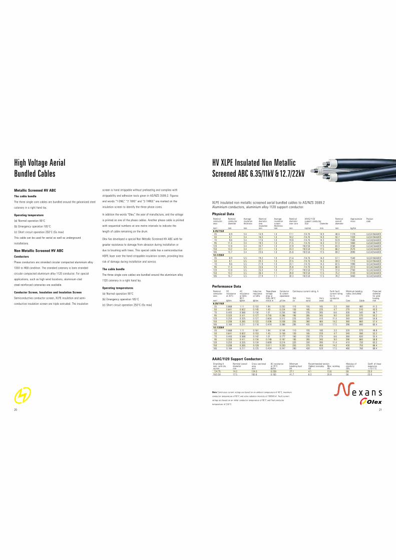
HV XLPE Insulated Non Metallic
Screened ABC 6.35/11kV & 12.7/22kV
XLPE insulated non metallic screened aerial bundled cables to AS/NZS 3599.2
Aluminium conductors, aluminium alloy 1120 support conductor.
Note Continuous current ratings are based on an ambient temperature of 40°C, maximum
conductor temperature of 90°C and solar radiation intensity of 1000W/m2. Fault current
ratings are based on an initial conductor temperature of 90°C and final conductor
temperature of 250°C.
HIGH VOLTAGE20
High Voltage Aerial
Bundled Cables
Metallic Screened HV ABC
The cable bundle
The three single core cables are bundled around the galvanised steel
catenary in a right hand lay.
Operating temperature
(a) Normal operation 90°C
(b) Emergency operation 105°C
(c) Short circuit operation 250°C (5s max)
This cable can be used for aerial as well as underground
installations.
Non Metallic Screened HV ABC
Conductors
Phase conductors are stranded circular compacted aluminium alloy
1350 to H68 condition. The standard catenary is bare stranded
circular compacted aluminium alloy 1120 conductor. For special
applications, such as high wind locations, aluminium-clad
steel-reinforced catenaries are available.
Conductor Screen, Insulation and Insulation Screen
Semiconductive conductor screen, XLPE insulation and semi-
conductive insulation screen are triple extruded. The insulation
screen is hand strippable without preheating and complies with
strippability and adhesion tests given in AS/NZS 3599.2. Figures
and words “1 ONE,” “2 TWO” and “3 THREE” are marked on the
insulation screen to identify the three phase cores.
In addition the words “Olex,” the year of manufacture, and the voltage
is printed on one of the phase cables. Another phase cable is printed
with sequential numbers at one metre intervals to indicate the
length of cable remaining on the drum.
Olex has developed a special Non Metallic Screened HV ABC with far
greater resistance to damage from abrasion during installation or
due to brushing with trees. This special cable has a semiconductive
HDPE layer over the hand-strippable insulation screen, providing less
risk of damage during installation and service.
The cable bundle
The three single core cables are bundled around the aluminium alloy
1120 catenary in a right hand lay.
Operating temperatures
(a) Normal operation 90°C
(b) Emergency operation 105°C
(c) Short circuit operation 250°C (5s max)

Galvanised Steel Catenaries
Stranding & Nominal overall Cross-sectional DC resistance Minimum Recommended tension Modulus of Coeff. of linear nom. wire dia. diameter area at 20°C breaking load Highest everyday Max. working elasticity expansion no/mm mm mm2 !/km kN kN kN GPa x10–6/°C
7/2.00 6.0 22.0 8.7 26.0 6.5 13.0 170 11.5
19/2.00 10.0 59.7 3.2 70.5 17.6 35.3 166 11.5
Performance Data
Nominal DC AC Inductive Three-phase Conductor Continuous current rating, A Earth fault Minimum bending Projected conductor resistance resistance reactance voltage to screen current rating radius (installed) diameter area at 20°C at 50Hz at 50Hz drop at capacitance for 1s mm for wind 90°C 50Hz 90°C Still 1m/s 2m/s conductor mm2 !/km !/km !/km mV/A.m µF/km air wind wind kA Core Cable mm
Light duty screen
35 0.868 1.11 0.149 1.94 0.202 99 140 165 2.0 350 530 50.1
35 0.868 1.11 0.157 1.94 0.202 100 145 165 2.0 350 570 52.1
50 0.641 0.822 0.149 1.45 0.224 120 170 200 2.0 370 590 54.3
70 0.443 0.568 0.138 1.01 0.254 150 215 250 2.0 390 630 57.5
95 0.320 0.411 0.130 0.747 0.286 180 260 305 2.0 420 660 61.0
120 0.253 0.325 0.125 0.603 0.312 205 300 355 2.0 440 690 63.8
150 0.206 0.265 0.121 0.505 0.338 235 340 400 2.0 460 720 67.0
185 0.164 0.211 0.117 0.418 0.366 265 390 460 2.0 490 750 70.0
Heavy duty screen
35 0.868 1.11 0.149 1.94 0.202 99 140 165 3.4 350 530 50.1
35 0.868 1.11 0.157 1.94 0.202 100 145 165 3.4 350 570 52.1
50 0.641 0.822 0.151 1.45 0.224 120 175 200 4.9 390 610 56.3
70 0.443 0.568 0.140 1.01 0.254 150 215 255 6.8 410 650 59.5
95 0.320 0.411 0.132 0.748 0.286 180 260 310 8.1 430 680 63.0
120 0.253 0.325 0.127 0.604 0.312 205 300 355 8.1 460 710 65.8
150 0.206 0.265 0.123 0.506 0.338 230 340 400 8.1 480 740 69.0
185 0.164 0.211 0.119 0.419 0.366 265 390 460 8.1 500 770 72.0
Physical Data
Nominal Nominal Average Nominal Average Copper Nominal Average Nominal Galvanised Nominal Approx. Product conductor conductor insulation diameter insulation wire diameter sheath diameter steel overall mass code area diameter thickness over screen screen over thickness over catenary diameter insulation thickness stranding screen sheath stranding mm2 mm mm mm mm no/mm mm mm mm no/mm mm kg/km
Light duty screen
35 6.9 3.4 14.9 0.8 24/0.85 19.2 1.8 23.5 7/2.00 53.1 1760 UJLA18DZ003
35 6.9 3.4 14.9 0.8 24/0.85 19.2 1.8 23.5 19/2.00 57.1 2060 UJLA18AA003
50 8.1 3.4 16.0 0.8 24/0.85 20.4 1.8 24.7 19/2.00 59.3 2230 UJLA19AA003
70 9.6 3.4 17.6 0.8 24/0.85 22.0 1.8 26.3 19/2.00 62.5 2500 UJLA20AA003
95 11.4 3.4 19.3 0.8 24/0.85 23.7 1.8 28.0 19/2.00 66.0 2820 UJLA22AA003
120 12.8 3.4 20.7 0.8 24/0.85 25.1 1.8 29.4 19/2.00 68.8 3100 UJLA23AA003
150 14.2 3.4 22.1 0.8 24/0.85 26.5 1.9 31.0 19/2.00 72.0 3440 UJLA24AA003
185 15.7 3.4 23.6 0.8 24/0.85 28.0 1.9 32.5 19/2.00 75.0 3800 UJLA25AA003
Heavy duty screen
35 6.9 3.4 14.9 0.8 40/0.85 19.2 1.8 23.5 7/2.00 53.1 2020 UJHA18DZ003
35 6.9 3.4 14.9 0.8 40/0.85 19.2 1.8 23.5 19/2.00 57.1 2310 UJHA18AA003
50 8.1 3.4 16.0 0.8 23/1.35 21.4 1.8 25.7 19/2.00 61.3 2790 UJHA19AA003
70 9.6 3.4 17.6 0.8 32/1.35 23.0 1.8 27.3 19/2.00 64.5 3420 UJHA20AA003
95 11.4 3.4 19.3 0.8 38/1.35 24.7 1.8 29.0 19/2.00 68.0 3980 UJHA22AA003
120 12.8 3.4 20.7 0.8 38/1.35 26.1 1.8 30.4 19/2.00 70.8 4270 UJHA23AA003
150 14.2 3.4 22.1 0.8 38/1.35 27.5 1.9 32.0 19/2.00 74.0 4600 UJHA24AA003
185 15.7 3.4 23.6 0.8 38/1.35 29.0 1.9 33.5 19/2.00 77.0 4960 UJHA25AA003
AAAC/1120 Support Conductors
Stranding & Nominal overall Cross-sectional DC resistance Minimum Recommended tension Modulus of Coeff. of linear nom. wire dia. diameter area at 20°C breaking load Highest everyday Max. working elasticity expansion no/mm mm mm2 !/km kN kN kN GPa x10–6/°C
7/4.75 14.3 124.0 0.239 27.1 4.1 13.6 59 23.0
19/3.50 17.5 182.8 0.163 41.7 6.3 20.9 56 23.0
Performance Data
Nominal DC AC Inductive Three-phase Conductor Continuous current rating, A Earth fault Minimum bending Projected conductor resistance resistance reactance voltage to screen current rating radius (installed) diameter area at 20°C at 50Hz at 50Hz drop at capacitance for 1s mm for wind 90°C 50Hz 90°C Still 1m/s 2m/s conductor loading mm2 !/km !/km !/km mV/A.m µF/km air wind wind kA Core Cable mm
6.35/11kV
35 0.868 1.11 0.156 1.94 0.202 110 155 185 3.3 280 520 44.8
50 0.641 0.822 0.149 1.45 0.224 130 185 225 4.7 300 540 47.1
70 0.443 0.568 0.137 1.01 0.254 160 235 280 6.6 320 570 50.3
95 0.320 0.411 0.130 0.746 0.286 195 285 345 9.0 350 610 53.7
120 0.253 0.325 0.130 0.606 0.312 225 335 400 11.4 370 670 58.1
150 0.206 0.265 0.125 0.508 0.338 255 380 460 14.2 390 700 60.9
185 0.164 0.211 0.121 0.421 0.366 290 435 530 17.5 410 730 63.9
12.7/22kV
35 0.868 1.11 0.164 1.94 0.144 110 155 180 3.3 350 610 53.4
50 0.641 0.822 0.156 1.45 0.158 130 185 220 4.7 360 630 55.7
70 0.443 0.568 0.144 1.02 0.177 160 230 275 6.6 390 660 58.9
95 0.320 0.411 0.137 0.750 0.197 195 280 335 9.0 410 690 62.3
120 0.253 0.325 0.136 0.610 0.214 225 330 390 11.4 430 750 66.7
150 0.206 0.265 0.131 0.512 0.230 255 375 445 14.2 460 780 69.6
185 0.164 0.211 0.127 0.426 0.247 290 430 510 17.5 480 810 72.6
Physical Data
Nominal Nominal Average Nominal Average Nominal AAAC/1120 Nominal Approximate Product conductor conductor insulation diameter insulation diameter support conductor overall mass code area diameter thickness over screen over core Size Diameter diameter insulation thickness mm2 mm mm mm mm mm no/mm mm mm kg/km
6.35/11kV
35 6.9 3.4 14.9 1.8 18.8 7/4.75 14.3 52.0 1320 UJDA18AA003
50 8.1 3.4 16.0 1.8 20.0 7/4.75 14.3 54.2 1490 UJDA19AA003
70 9.6 3.4 17.6 1.8 21.6 7/4.75 14.3 57.4 1740 UJDA20AA003
95 11.4 3.4 19.3 1.8 23.3 7/4.75 14.3 60.9 2050 UJDA22AA003
120 12.8 3.4 20.7 1.8 24.7 19/3.50 17.5 66.9 2480 UJDA23AA003
150 14.2 3.4 22.1 1.8 26.1 19/3.50 17.5 69.7 2780 UJDA24AA003
185 15.7 3.4 23.6 1.8 27.6 19/3.50 17.5 72.7 3120 UJDA25AA003
12.7/22kV
35 6.9 5.5 19.2 1.8 23.1 7/4.75 14.3 60.6 1730 ULDA18AA003
50 8.1 5.5 20.3 1.8 24.3 7/4.75 14.3 62.9 1910 ULDA19AA003
70 9.6 5.5 21.9 1.8 25.9 7/4.75 14.3 66.1 2200 ULDA20AA003
95 11.4 5.5 23.6 1.8 27.6 7/4.75 14.3 69.5 2530 ULDA22AA003
120 12.8 5.5 25.0 1.8 29.0 19/3.50 17.5 75.5 3000 ULDA23AA003
150 14.2 5.5 26.4 1.8 30.4 19/3.50 17.5 78.3 3320 ULDA24AA003
185 15.7 5.5 27.9 1.8 31.9 19/3.50 17.5 81.3 3690 ULDA25AA003
Note Continuous current ratings are based on an ambient temperature of 40°C, maximum
conductor temperature of 90°C and solar radiation intensity of 1000W/m2. Fault current
ratings are based on an initial conductor temperature of 90°C and final conductor
temperature of 250°C.
Note Continuous current ratings are based on an ambient temperature of 40°C, maximum
conductor temperature of 90°C and solar radiation intensity of 1000W/m2 with screens
solidly bonded at both ends. Fault current ratings are based on an initial screen temperature
of 85°C and final screen temperature of 250°C.
23
HV XLPE Insulated Metallic
Screened ABC 6.35/11kV
XLPE insulated copper wire screened HDPE sheathed aerial bundled cables to AS/NZS 3599.1
Aluminium conductors, galvanised steel catenary.
HV XLPE Insulated Non Metallic Screened
ABC HDPE 6.35/11kV & 12.7/22kV
XLPE insulated non metallic screened aerial bundled cables with HDPE covering to AS/NZS 3599.2
Aluminium conductors, aluminium alloy 1120 support conductor.
HIGH VOLTAGE22

Galvanised Steel Catenaries
Stranding & Nominal overall Cross-sectional DC resistance Minimum Recommended tension Modulus of Coeff. of linear nom. wire dia. diameter area at 20°C breaking load Highest everyday Max. working elasticity expansion no/mm mm mm2 !/km kN kN kN GPa x10–6/°C
7/2.00 6.0 22.0 8.7 26.0 6.5 13.0 170 11.5
19/2.00 10.0 59.7 3.2 70.5 17.6 35.3 166 11.5
Physical Data
Nominal Nominal Average Nominal Average Copper Nominal Average Nominal Galvanised steel Nominal Approx. Product conductor conductor insulation diameter insulation wire diameter sheath diameter catenary stranding overall mass code area diameter thickness over screen screen over thickness over diameter insulation thickness stranding screen sheath Size Diameter mm2 mm mm mm mm no/mm mm mm mm no/mm mm mm kg/km
Light duty screen
35 6.9 5.5 19.2 0.8 24/0.85 23.5 1.8 27.8 7/2.00 6.0 61.7 2210 ULLA18DZ003
35 6.9 5.5 19.2 0.8 24/0.85 23.5 1.8 27.8 19/2.00 10.0 65.7 2500 ULLA18AA003
50 8.1 5.5 20.3 0.8 24/0.85 24.7 1.8 29.0 19/2.00 10.0 68.0 2690 ULLA19AA003
70 9.6 5.5 21.9 0.8 24/0.85 26.3 1.9 30.8 19/2.00 10.0 71.6 3020 ULLA20AA003
95 11.4 5.5 23.6 0.8 24/0.85 28.0 1.9 32.5 19/2.00 10.0 75.0 3370 ULLA22AA003
120 12.8 5.5 25.0 0.8 24/0.85 29.4 2.0 34.1 19/2.00 10.0 78.2 3720 ULLA23AA003
150 14.2 5.5 26.4 0.8 24/0.85 30.8 2.0 35.5 19/2.00 10.0 81.0 4060 ULLA24AA003
185 15.7 5.5 27.9 0.8 24/0.85 32.3 2.1 37.2 19/2.00 10.0 84.4 4470 ULLA25AA003
Heavy duty screen
35 6.9 5.5 19.2 0.8 40/0.85 23.5 1.8 27.8 7/2.00 6.0 61.7 2460 ULHA18DZ003
35 6.9 5.5 19.2 0.8 40/0.85 23.5 1.8 27.8 19/2.00 10.0 65.7 2760 ULHA18AA003
50 8.1 5.5 20.3 0.8 23/1.35 25.7 1.8 30.0 19/2.00 10.0 70.0 3250 ULHA19AA003
70 9.6 5.5 21.9 0.8 32/1.35 27.3 1.9 31.8 19/2.00 10.0 73.6 3940 ULHA20AA003
95 11.4 5.5 23.6 0.8 38/1.35 29.0 1.9 33.5 19/2.00 10.0 77.0 4530 ULHA22AA003
120 12.8 5.5 25.0 0.8 38/1.35 30.4 2.0 35.1 19/2.00 10.0 80.2 4880 ULHA23AA003
150 14.2 5.5 26.4 0.8 38/1.35 31.8 2.0 36.5 19/2.00 10.0 83.0 5220 ULHA24AA003
185 15.7 5.5 27.9 0.8 38/1.35 33.3 2.1 38.2 19/2.00 10.0 86.4 5640 ULHA25AA003
Performance Data
Nominal DC AC Inductive Three-phase Conductor Continuous current rating, A Earth fault Minimum bending Projected conductor resistance resistance reactance voltage to screen current rating radius (installed) diameter area at 20°C at 50Hz at 50Hz drop at capacitance for 1s mm for wind 90°C 50Hz 90°C Still 1m/s 2m/s Conductor loading mm2 !/km !/km !/km mV/A.m µF/km air wind wind kA Core Cable mm
Light duty screen
35 0.868 1.11 0.158 1.94 0.144 100 140 165 2.0 420 620 58.7
35 0.868 1.11 0.165 1.94 0.144 105 145 165 2.0 420 660 60.7
50 0.641 0.822 0.157 1.45 0.158 125 170 200 2.0 430 680 63.0
70 0.443 0.568 0.145 1.02 0.177 150 215 250 2.0 460 720 66.6
95 0.320 0.411 0.138 0.751 0.197 180 260 305 2.0 490 750 70.0
120 0.253 0.325 0.133 0.608 0.214 205 300 350 2.0 510 780 73.2
150 0.206 0.265 0.128 0.510 0.230 235 340 395 2.0 530 810 76.0
185 0.164 0.211 0.124 0.424 0.247 265 390 455 2.0 560 840 79.4
Heavy duty screen
35 0.868 1.11 0.158 1.94 0.144 100 140 165 3.4 420 620 58.7
35 0.868 1.11 0.165 1.94 0.144 105 145 165 3.4 420 660 60.7
50 0.641 0.822 0.159 1.45 0.158 125 175 200 4.9 450 700 65.0
70 0.443 0.568 0.147 1.02 0.177 155 215 250 6.8 480 740 68.6
95 0.320 0.411 0.139 0.752 0.197 180 260 305 8.1 500 770 72.0
120 0.253 0.325 0.134 0.609 0.214 205 300 350 8.1 530 800 75.2
150 0.206 0.265 0.129 0.511 0.230 230 340 395 8.1 550 830 78.0
185 0.164 0.211 0.125 0.425 0.247 265 390 450 8.1 570 860 81.4
Note Continuous current ratings are based on an ambient temperature of 40°C, maximum
conductor temperature of 90°C and solar radiation intensity of 1000W/m2 with screens solidly
bonded at both ends. Fault current ratings are based on an initial screen temperature of 85°C
and final screen temperature of 250°C.
HV XLPE Insulated Metallic
Screened ABC 12.7/22kV
XLPE insulated copper wire screened HDPE sheathed aerial bundled cables to AS/NZS 3599.1
Aluminium conductors, galvanised steel catenary.
HIGH VOLTAGE24
At Olex, the future always looks incredibly bright. That’s because we
spend most of our time there. Over the decades, Olex has consistently
led the cable market in technological innovation. For more than 60 years
Olex has stood for the highest quality and the most innovative
technology, from design, through manufacture to installation and service.
The following range of standards approved cables is proudly designed
and produced in Australia by Olex: Versolex® and Flexolex™ Flexible
Power Cables, Instrolex™ Instrumentation Cables, Ship Wiring
Cables, Envirolex™ PVC Free Cables, Mining Cables, Varolex®
EMC Cables, Aerial Cables, High Voltage Power Cables, Pyrolex™
Ceramifiable® Fire-Rated Cables, Low Voltage Building Wires,
Airport Lighting Cables and Lead Covered Power Cables.
For the latest product information see
www.olex.com.au
The future is our favourite place
Olex reserves the right to change or vary the construction of any of their products without notice.
Every care has been taken in the printing of this publication but Olex accepts no liability of any
kind resulting from the information provided herein.
Olex Australia Pty Limited A.B.N. 61 087 542 863 Printed in Australia 10/2010 Disegno OLC10419

Australia Head Office 207 Sunshine Road Tottenham
Victoria 3012 Australia Phone 613 9281 4444
Cable Sales Phone 1300 CABLES
New Zealand Paraite Road Bell Block
New Plymouth New Zealand Phone 646 755 9800
www.olex.co.nz
South East Asia 401 Macpherson Road
#02-07 Hotel Windsor Singapore 368125
Phone 65 688 70200
China Room 5410 Building 4, Xiyuan Hotel
Beijing China 100044 Phone 86 10 6835 1019
For more information see
www.olex.com.au
LOW VOLTAGE INDUSTRIAL HIGH VOLTAGE FIRE RATED DATA/COMMS MINING
Related Documents