138-2: 2015 CEB SPECIFICATION AERIAL BUNDLE CONDUCTOR ACCESSORIES (33kV) CEYLON ELECTRICITY BOARD SRI LANKA Telephone: +94 11 232 8051 Fax: +94 11 232 5387

Welcome message from author
This document is posted to help you gain knowledge. Please leave a comment to let me know what you think about it! Share it to your friends and learn new things together.
Transcript
138-2: 2015
CEBSPECIFICATION
AERIAL BUNDLE CONDUCTORACCESSORIES (33kV)
CEYLON ELECTRICITY BOARDSRI LANKA
Telephone: +94 11 232 8051 Fax: +94 11 232 5387
CEB SPECIFICATION 138-2: 2015
CONTENTS
Page
1.0 Scope 3
2.0 System Parameters 3
3.0 Service Conditions ° 3
4.0 Applicable Standards 3
5.0 Basic Features and Technical Requirements 4
6.0 Quality Assurance 7
7.0 Additional Requirements 8
8.0 Inspection and Testing 8
9.0 Information to be furnished with the Offer 10
10.0 Annex 11
Annex A-1: Drawing: Triangular Suspension Bracket 12
Annex A-2: Drawing: Suspension Clamp 13
Annex A-3: Drawing: Tension Bracket 14
Annex A-4: Drawing: 33kV ABC T-Off 15
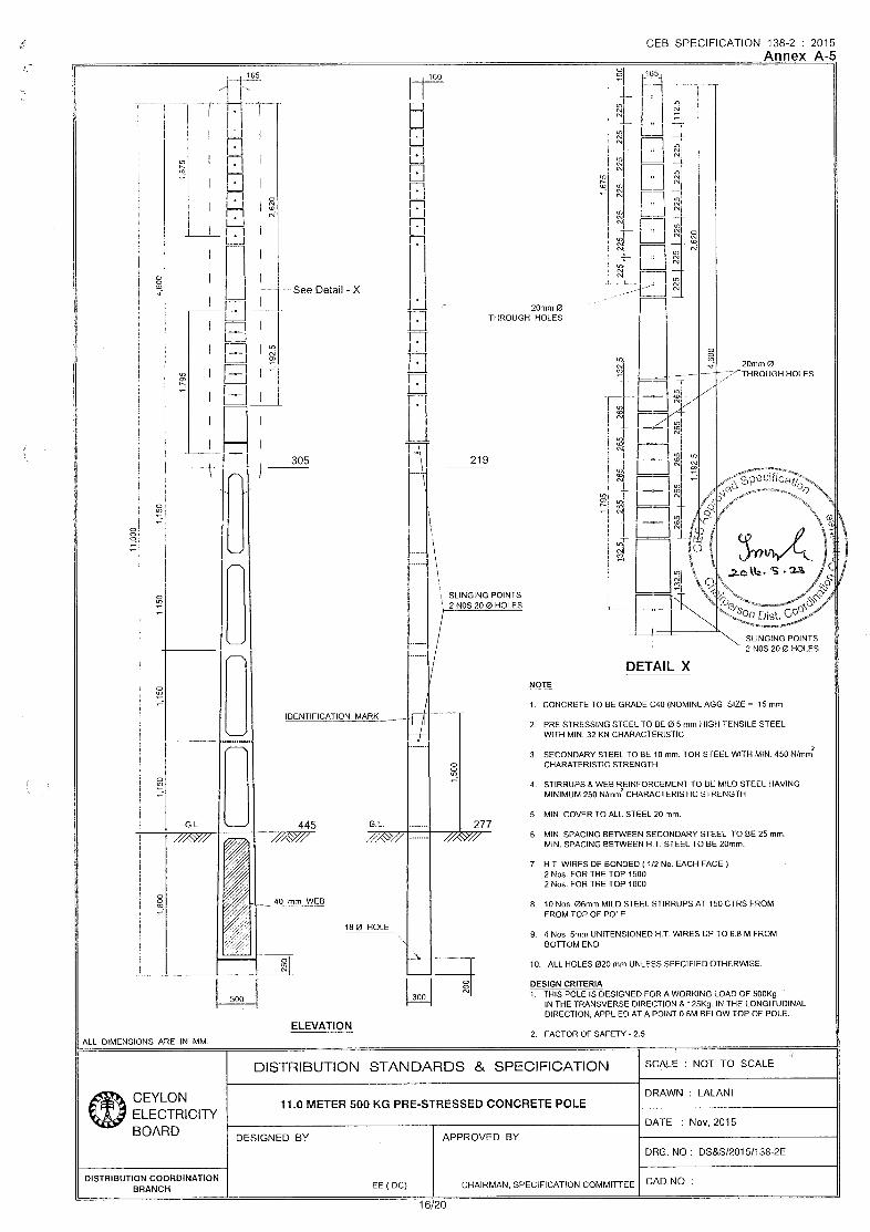
Annex A-5: Drawing: Details of the 11m/500kg Pole 16
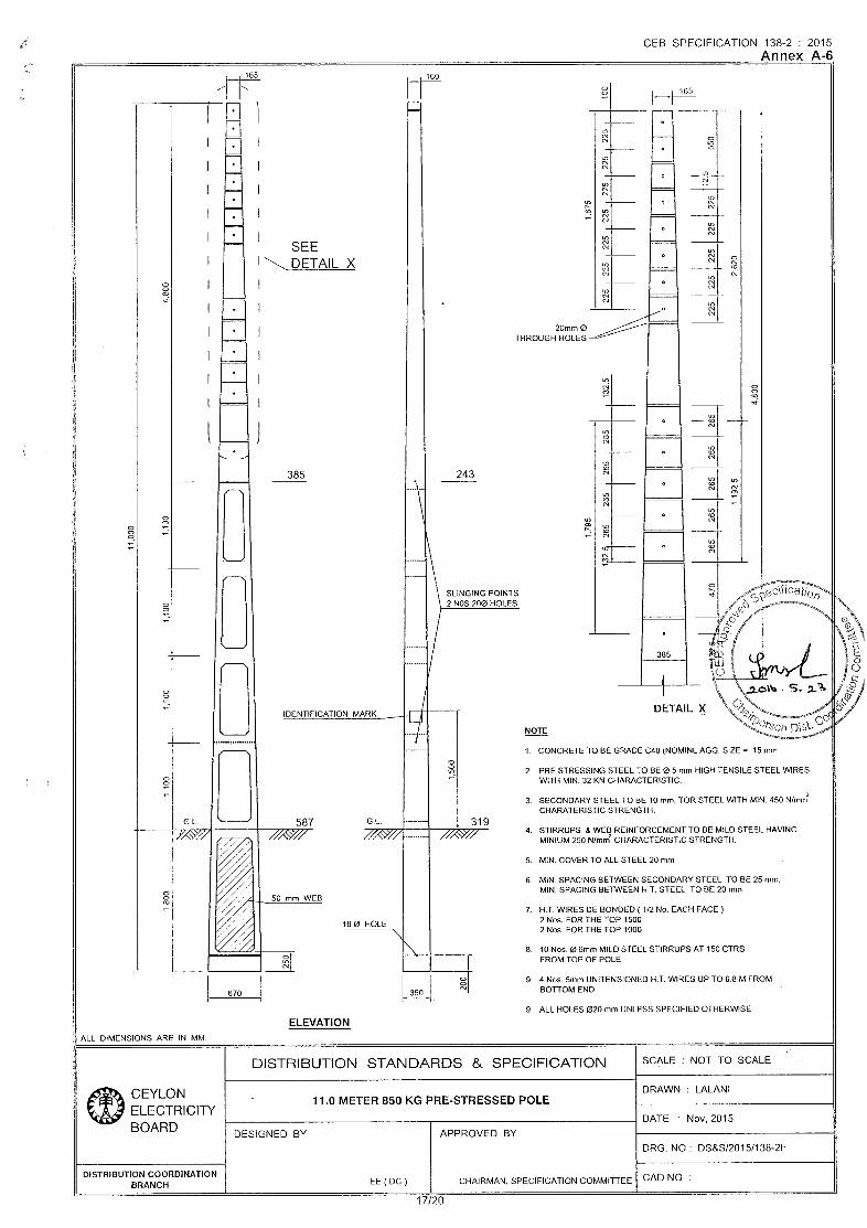
Annex A-6: Drawing: Details of the 11m/850kg Pole 17
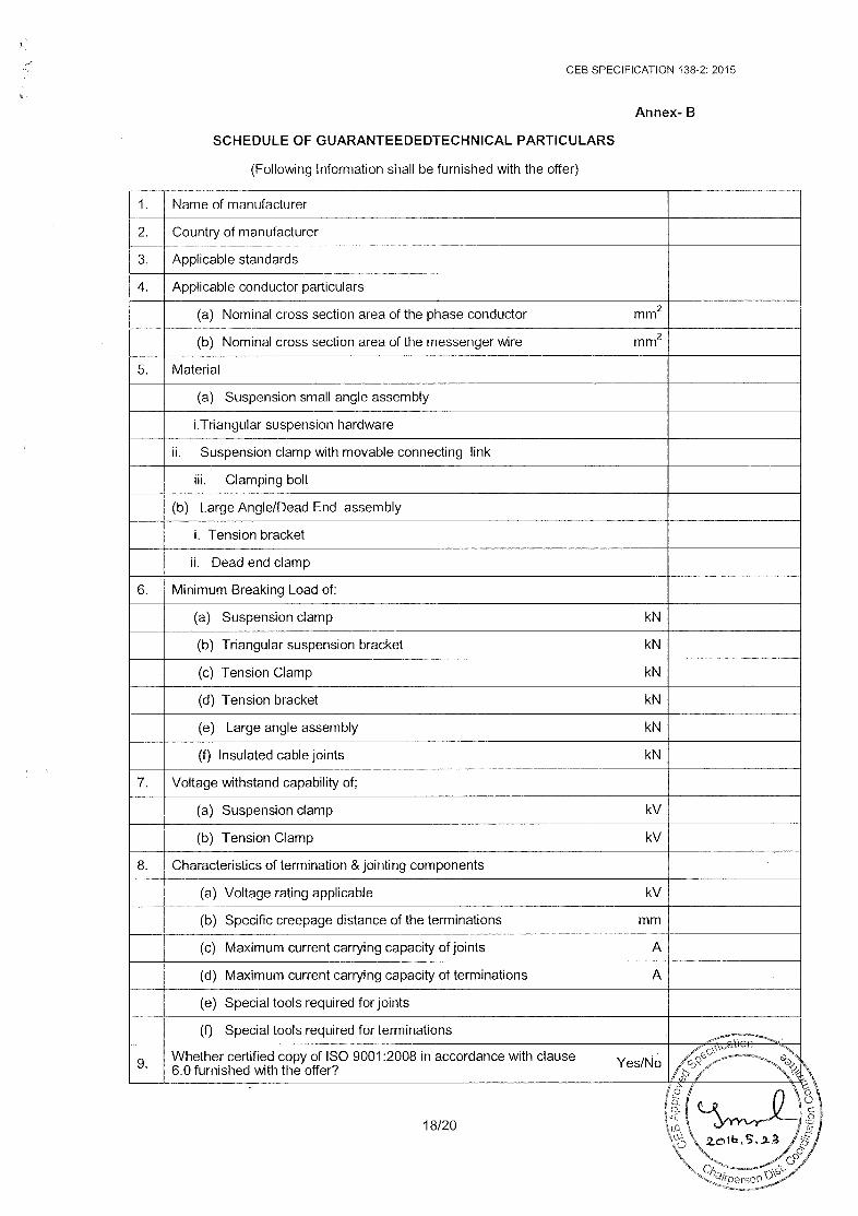
Annex B: Schedule of Guaranteed Technical Particulars 18
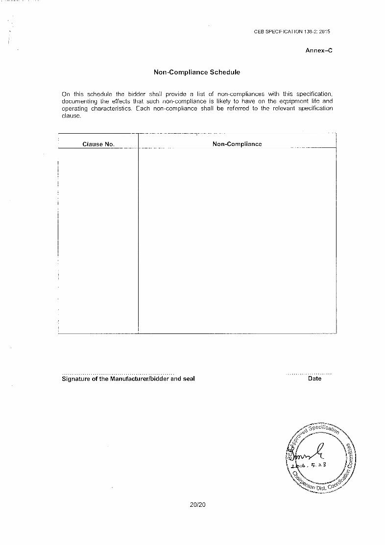
Annex C: Non-Compliance schedule
2/20
CEB SPECIFICATION 138-2: 2015
SPECIFICATION FOR AERIAL BUNDLE CONDUCTOR ACCESSORIES (33kV)
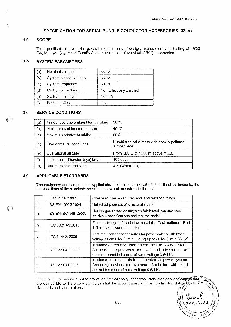
1.0 SCOPE
This specification covers the general requirements of design, manufacture and testing of 19/33(36) kV, Up/U (Um) Aerial Bundle Conductor (here in after called “ABC”) accessories.
2.0 SYSTEM PARAMETERS
(a)|Nominal voltage 33 kV
(b)|System highest voltage 36 kV
(c)|System frequency 50 Hz
(d)|Method of earthing Non Effectively Earthed(e)|System fault level 13.1 kA
(f) Fault duration 1s
3.0 SERVICE CONDITIONS
(a)|Annual average ambient temperature|30 °C
(b)|Maximum ambient temperature 40°C(c)|Maximum relative humidity 90%
(d)|Environmental conditions Humid tropical climate with heavily pollutedatmosphere
(e)|Operational altitude From M.S.L. to 1900 m above M.S.L.
(f)|lsokeraunic (Thunder days) level 100 days(g)|Maximum solar radiation 4.5 kWhim*/day
4.0 APPLICABLE STANDARDS
The equipment and components supplied shall be in accordance with, but shall not be limited to, thelatest editions of the standards specified below and amendments thereof.
i. IEC 61284:1997 Overhead lines -Requirements and tests for fittingsil. BS EN 10025:2004 Hot rolled products of structural steels
Hot dip galvanized coatings on fabricated iron and steelMN. BS EN ISO 1461:2009
articles — specifications and test methods
Electric strength of insulating materials - Test methods - Partiv. IEC 60243-1:2013 .1: Tests at power frequencies
Test methods for accessories for power cables with ratedvoltages from 6 kV (Um = 7,2 kV) up to 30 kV (Um = 36 kV)
Insulated cables and their accessories for power systems-Vi. NFC 33 040:2013 Suspension equipments for overhead distribution withbundle assembled cores,of rated voltage 0,6/1 Kv
Insulated cables and their accessories for power systems -
vii. NFC 33 041:2013 Anchoring devices for overhead distribution with bundleassembled cores of rated voltage 0,6/1 Kv
Vv. IEC 61442: 2005
Offers of items manufactured to any other internationally recognized standards or specification¢at Sp
are compatible to the above standards shail be accompanied with an English translatiga, OLstandards and specifications. {0
3/20
CEB SPECIFICATION 138-2: 2015
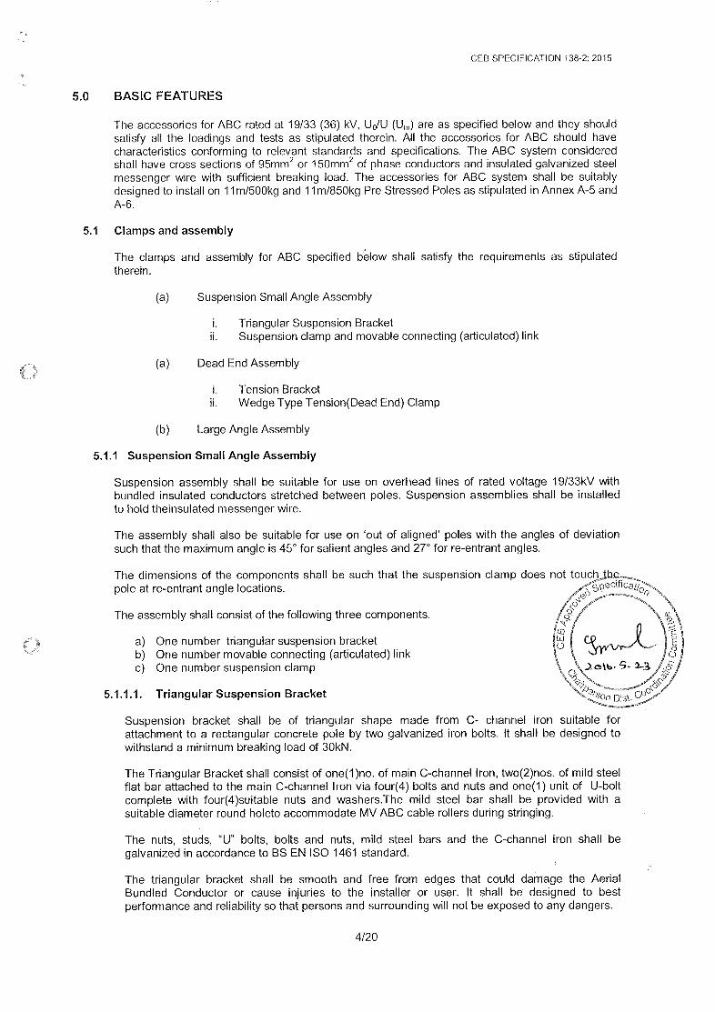
5.0 BASIC FEATURES
The accessories for ABC rated at 19/33 (36) kV, U»/U (U,,) are as specified below and they shouldsatisfy all the loadings and tests as stipulated therein. All the accessories for ABC should havecharacteristics conforming to relevant standards and specifications. The ABC system consideredshall have cross sections of 85mm? or 150mm’ of phase conductors and insulated galvanized steelmessenger wire with sufficient breaking load. The accessories for ABC system shail be suitablydesignedto install on 14m/500kg and 11m/850kg Pre Stressed Poles as stipulated in Annex A-5 andA-6.
5.1. Clamps and assembly
The clamps and assembly for ABC specified below shall satisfy the requirements as stipulatedtherein.
(a) Suspension Small Angle Assembly
i. Triangular Suspension Bracketii. Suspension clamp and movable connecting (articulated) link
(a) Dead End Assembly
i. Tension Bracketii. Wedge Type Tension(Dead End) Clamp
(b) Large Angle Assembly
5.1.1 Suspension Small Angle Assembly
Suspension assembly shall be suitable for use on overhead lines of rated voltage 19/33kV withbundled insulated conductors stretched between poles. Suspension assemblies shail be installedto hold theinsulated messengerwire.
The assembly shail also be suitable for use on ‘out of aligned’ poles with the angles of deviationsuch that the maximum angle is 45° for salient angles and 27° for re-entrant angles.
The dimensions of the components shall be such that the suspension clamp does not touchthepole at re-entrant angle locations. eclflog pn.OOomeme onThe assembly shall consist of the following three components. &s/SSofLy
Oa) One number triangular suspension bracketb) One number movable connecting (articulated) linkc) One number suspension clamp
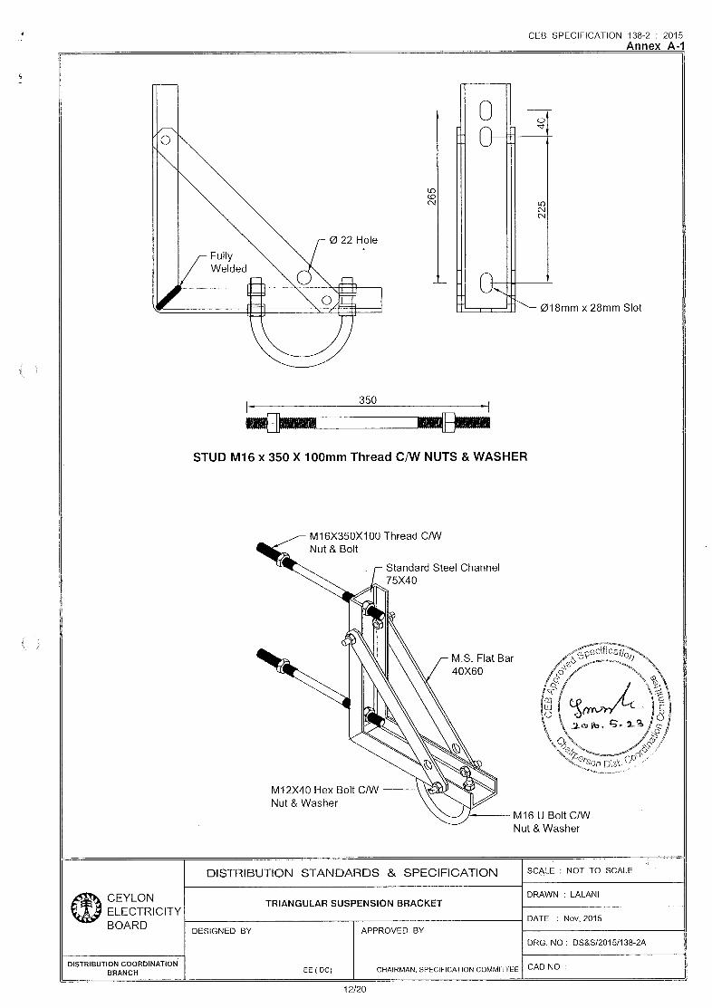
5.1.1.1. Triangular Suspension Bracket
Suspension bracket shall be of triangular shape made from C- channel iron suitable forattachment to a rectangular concrete pole by two galvanized iron bolts. It shall be designed towithstand a minimum breaking load of 30kN.
The Triangular Bracket shall consist of one(1)no. of main C-channel Iron, two(2)nos. of mild steelflat bar attached to the main C-channel Iron via four(4) bolts and nuts and one(1) unit of U-boltcomplete with four(4)suitable nuts and washers.The mild steel bar shall be provided with asuitable diameter round holeto accommodate MV ABC cable rollers during stringing.
The nuts, studs, “U” bolts, bolts and nuts, mild steel bars and the C-channel iron shall begalvanized in accordance to BS EN ISO 1461 standard.
The triangular bracket shall be smooth and free from edges that could damage the AerialBundled Conductor or cause injuries to the installer or user. It shall be designed to bestperformance and reliability so that persons and surrounding will not be exposed to any dangers.
4/20
CEB SPECIFICATION 138-2: 2015
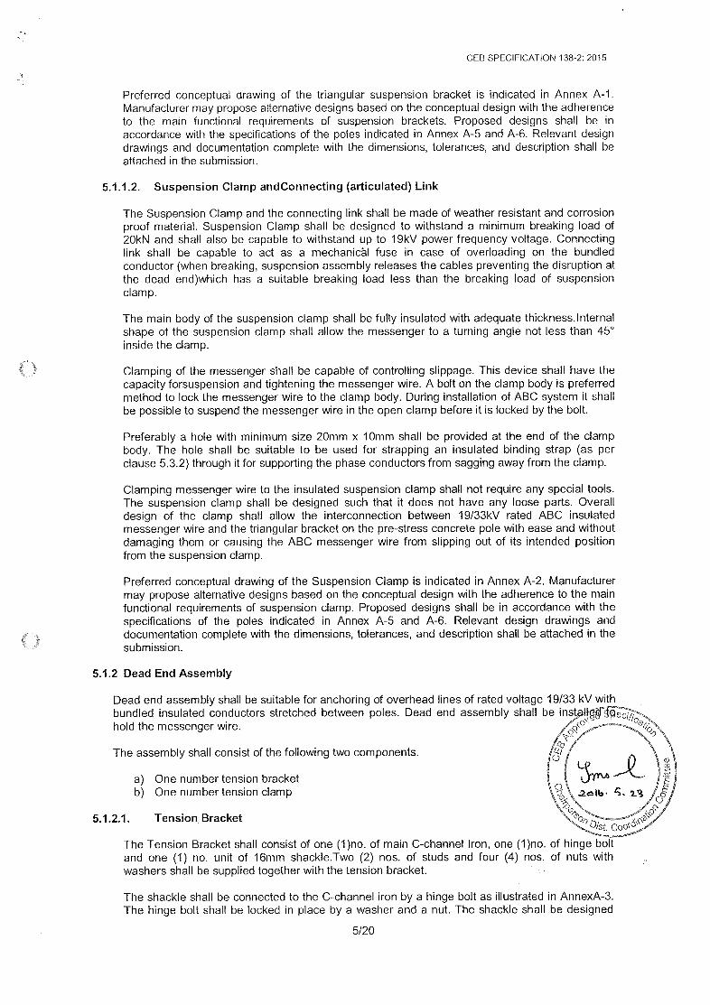
Preferred conceptual drawing of the triangular suspension bracket is indicated in Annex A-1.Manufacturer may propose alternative designs based on the conceptual design with the adherenceto the main functional requirements of suspension brackets. Proposed designs shal! be inaccordance with the specifications of the poles indicated in Annex A-5 and A-6. Relevant designdrawings and documentation complete with the dimensions, tolerances, and description shall beattached in the submission.
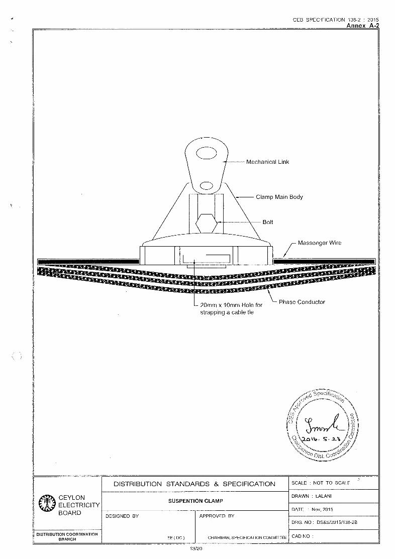
5.1.1.2. Suspension Clamp andConnecting (articulated) Link
The Suspension Clamp and the connecting link shall be made of weather resistant and corrosionproof material. Suspension Clamp shall be designed to withstand a minimum breaking load of20KN and shall also be capable to withstand up to 19kV power frequency voltage. Connectinglink shall be capable to act as a mechanical fuse in case of overloading on the bundledconductor (when breaking, suspension assembly releases the cables preventing the disruption atthe dead end)which has a suitable breaking load less than the breaking load of suspensionclamp.
The main body of the suspension clamp shall be fully insulated with adequate thickness. internalshape of the suspension clamp shal! allow the messenger to a turning angle not less than 45°inside the clamp.
Clamping of the messenger shall be capable of controlling slippage. This device shall have thecapacity forsuspension and tightening the messengerwire. A bolt on the clamp bodyis preferredmethod to lock the messenger wire to the clamp body. During installation of ABC system it shallbe possible to suspend the messengerwire in the open clamp beforeit is locked by the bolt.
Preferably a hole with minimum size 20mm x 10mm shall be provided at the end of the clampbody. The hole shall be suitable to be used for strapping an insulated binding strap (as perclause 5.3.2) throughit for supporting the phase conductors from sagging away from the clamp.
Clamping messengerwire to the insulated suspension clamp shall not require any special tools.The suspension clamp shail be designed such that it does not have any loose parts. Overalldesign of the clamp shall allow the interconnection between 19/33kV rated ABC insulatedmessengerwire and the triangular bracket on the pre-stress concrete pole with ease and withoutdamaging them or causing the ABC messenger wire from slipping out of its intended positionfrom the suspension clamp.
Preferred conceptual drawing of the Suspension Clampis indicated in Annex A-2. Manufacturermay propose alternative designs based on the conceptual design with the adherence to the mainfunctional requirements of suspension clamp. Proposed designs shall be in accordance with thespecifications of the poles indicated in Annex A-5 and A-6. Relevant design drawings anddocumentation complete with the dimensions, tolerances, and description shall be attached in thesubmission.
5.1.2 Dead End Assembly
Dead end assembly shall be suitable for anchoring of overhead lines of rated voltage 19/33 KV withhold the messengerwire.
The assembly shall consist of the following two components.
a) One number tension bracketb) One number tension clamp
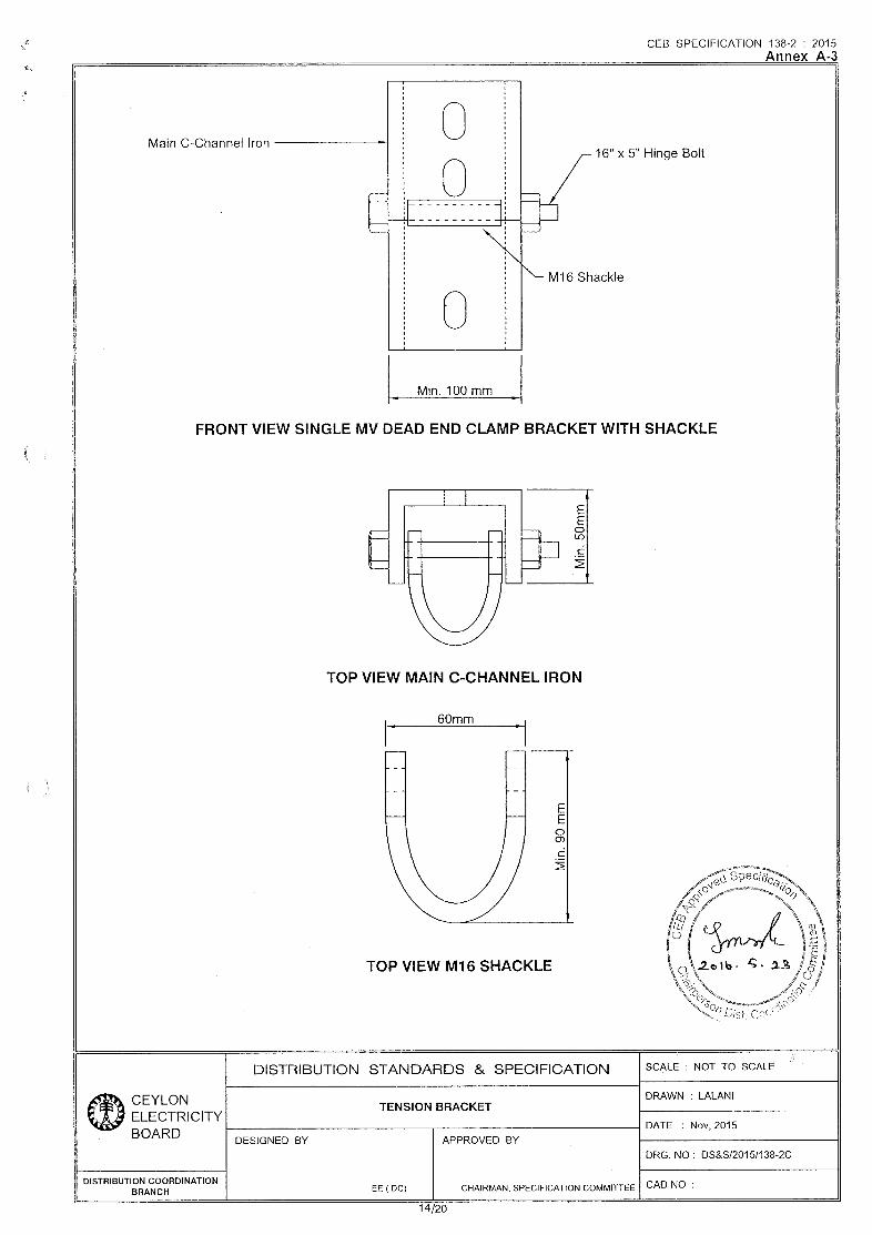
5.1.2.1. Tension Bracket
The Tension Bracket shall consist of one (1)no. of main C-channel Iron, one (1)no. of hinge boltand one (1) no. unit of 16mm shackle.Two (2) nos. of studs and four (4) nos. of nuts withwashers shall be supplied together with the tension bracket. Mo
The shackle shall be connected to the C-channel iron by a hinge bolt as illustrated in AnnexA-3.The hinge bolt shall be locked in place by a washer and a nut. The shackle shall be designed
5/20

CEB SPECIFICATION 138-2: 2015
such that it shall be possible to remove the shackle from the C-channel iron by removing thehinge bolt.
The C-channel iron shall be provided with two through holes for mounting it to concretepoles. The nuts, studs, bolts and the C-channel iron shall be galvanized in accordance to BS ENISO 1461.
The tension bracket shall be designed to withstand a minimum breaking load of 31KN. It shall besmooth and free from edges that could damage the Aerial Bundled Conductor or cause injuriesto the installer or user. It shall be designed to best performance and reliability so that personsand surrounding will not be exposed to any dangers.
Preferred conceptual drawing of the tension bracket is indicated in Annex A-3. Manufacturer maypropose alternative designs based on the conceptual design with the adherence to the mainfunctional requirements of tension bracket. Proposed designs shall be in accordance with thespecifications of the poles indicated in Annex A-5 and A-6. Relevant design drawings anddocumentation complete with the dimensions, tolerances, and description shall be attached in thesubmission.
5.1.2.2. Tension (Dead End) Clamp
Tension clamps shall be suitably designed to anchor the bundled conductor on the messengerwire. The Tension Clamp shall be designed to withstand a minimum breaking load of 31kKN andshall be capable of withstanding 19kV power frequencyvoltage.
Housing of the tension clamp shall be made out of weather resisting material. All components shallbe unloosable. In all cases, it shall be possible to install the cable clamp without using any specialtool.
To ease thetorsional movement involved in the ABC system, the clamp shall be supplied withasuitablestainless steel attachment to the above tension bracket. The Clamp shall be exclusivelymade of weather resistant insulating material and shall be designed to withstand the relevantbreaking load of themessengerwire without slipping.
Ail the components shall be made of corrosion resistant materials. Manufacturer may proposealternative design based on the requirements stipulated here. Proposed designs shall adhere tothe main functional requirement of the dead end clamp and specifications of the poles indicated inAnnex A-5 and A-6.
5.1.3 Large Angle Assembly
Each assembly shall include:
(a) One numberTension Bracket with Two Shackles.(b) Two numbers Tension Clamps.
Description of sub components of the large angle assembly are the same as for thedead endassembly described in Clause 5.1.2. above, but two TensionClamps and one tension bracket withtwo Shackles shall be supplied instead of one Tension Clampas in the DeadEnd Assembly.
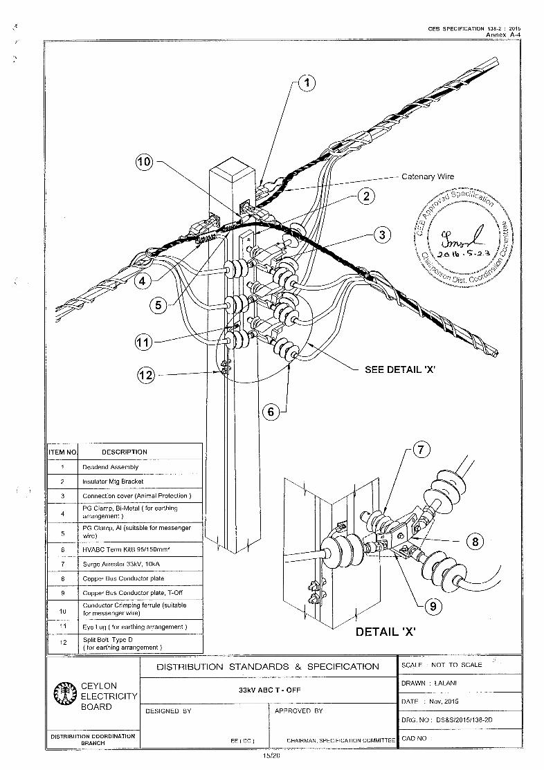
5.2 T-offsand Straight Through Joints
T-offs and straight through joints in ABC system are used to interconnect three or two ABC lines.Following components shall contain in a 19/33(36) KVABC T-off joint.
(a) Dead end assemblies for each cable end(b) Insulator Mounting Bracket(c) Connection Cover(d) PG Clamp, Bi-Metal, (For earthing arrangement)(e) PG Clamp,Al, (suitable for messengerwire)(f) HV ABC Termination Kit 95mm?/150mm?(g) Surge Arrester 33kV, 10kA(h) Copper Bus Conductor Plate
6/20
5.3
CEB SPECIFICATION 138-2: 2015
(i) Copper Bus Conductor Plate, T-Off(j) Conductor Crimping Ferrule (Suitable for messenger wire)(k) Eye Lugs (For earthing arrangement)(i) Split Bolt -type D (For earthing arrangement)
Preferred conceptual drawing is indicated in Annex A-4 in the specification for the T-offs.Manufacturer may propose alternative designs based on the conceptual design with the adherenceto the main functional requirements of T-offs. Proposed designs shall be in accordance with thespecifications of the poles indicated in Annex A-5 and A-6. Relevant design drawings anddocumentation complete with the dimensions, tolerances, and description with details aboutnecessary tools required for T-off joint, shall be attached in the submission.
Straight through joints shall be analogous to T-offs, with relevant components indicated above,having ability to connect two ABC lines.Termination Kits and Other Accessories
5.3.1. Termination Kits.
The termination kits shall be designed and manufactured to IEC 61442 and shall be of heatshrinkable material suitable for use in terminating ABC having aluminum stranded conductors.
The termination shall be complete with all components and materials necessary for terminatingcables of specified size. The components and materials for each category of termination shallinclude the following items.
) Internal insulation tubing) Stress control tubing) Anti-track tubing) Moisture sealant) Compression/mechanical lugs for appropriate size of the cable
Sufficient duty earth strip) Constant tension clips) Insulation boots for indoor termination and shields to increase creepage for outdoortermination. Boots are either angle or straight depending on the use.
(i) Cable break out to separate the cores.
abcdef ~~
(
(
(
(
(
(
(g(h
The termination kits shall be designed and manufactured to ensure that all components andmaterials shall be weather resistant. The components and materials shall be manufactured toensure high moisture sealing capacity, proper stress control and resistance to tracking when inservice.Relevant design drawings and documentation complete with the dimensions, tolerances, anddescription with details about necessary tools required for termination kit, shall be attached in thesubmission
5.3.2 Insulating Binding Strap
6.0
The binding strap shall be used for binding the cable atdifferent locations with the tension clamp andsuspension clamp.
The strap shall be made of polyamide whichis suitable to strap ABC systems up to 150mm? phaseconductors with sufficient strength to hold all cable cores tight. The binding strap shall be designed tocomply with the dimensions of relevant accessories mentioned in clause 5.1.
There shall be tilted grooves on one side of the strap and the top of the strap shall have a lockingand releasing facility.
QUALITY ASSURANCE
The manufacturer shall possess [SO 9001:2008 Quality Assurance Certification valid throughout thedelivery period of this bid, for both manufacture of accessories of ABC (33kV) and the plant wherethe ABC (33kV) accessories are being manufactured. The Bidder shall furnish a copy of theds§certificate certified as true copy of the original by the manufacturer, along with the offer. :
7120

7.0
7.1
7.2
8.0
8.1
CEB SPECIFICATION 138-2: 2015
ADDITIONAL REQUIREMENTS
Manufacturing Experience
The manufacturer shall have minimum of5years experience in manufacturing and supply ofaccessories of ABC (33kV). Manufacturer shall furnish documentary evidence with the offer to provehis manufacturing experience.
Packaging and Delivery
The Accessories for Aerial Bundled Conductors shall be packed as indicated below. Nameof Itemand the quantity shall be clearly marked on each packing.
Relevant to items in Clause 5.1
(a) The complete Suspension Small Angle Assembly shall be delivered ina single pack in asuitable bag.
(b) The complete Dead End Assembly shall be delivered in a single pack in a suitable bag.
(c) The complete Large Angle Assembly shall be delivered in a singlepack in a suitablebag.
Relevant to items in Clause 5.2
Each accessory shall be packed in a strong suitable container to protect from mechanical damage.Individual parts shall be packed in strong sealed plastic bags to protect them from ingress of dirt andmoisture. The container shall have:
(a) Installation instructions indicating the tools required for each stage all in English Language.
(b) All necessary components and consumables required to complete the installation as per theClause 5.2.
(c) Packing shall be such as to permit easy identification of the components without theirremoval of packaging.
Relevant to items in Clause 5.3
Each accessory shall be packed in a strong cardboard container to protect from mechanicaldamage. Individual parts shall be packed in strong sealed plastic bags to protect them from ingressof dirt and moisture. The cardboard container shall have:
(a) Installation instructions indicating the tools required for each stageall in English Language.
(b) All necessary components and consumables required to complete the installation as per theClause 5.3.
(c) Packing shall be such as to permit easy identification of the components without theirremoval of packaging.
INSPECTION AND TESTING
Type Tests
The equipment/items shall be subjected to the following Type Tests, in accordance with the relevantstandards specified in clause 4.0.
Type Tests Relevant to items in Clause 5.1
(a) Mechanical Testi. Tensile tests on bracketsil. Tensile tests on sub-assemblies
8/20
CEB SPECIFICATION 138-2: 2015
iii. Slippage test on the clamp of the suspension assemblies
(b) Voltage tests on sub-assembly suspension clamp & connecting link(c) Ageing Test(d) Corrosion test(e) Hot dip galvanizing test according to BS EN [SO 1461 for tension and suspension brackets.
Type Tests Relevant to items in Clause 5.2
a) Voltage and water tightness testb) Temperature rise and over current testsc) Climatic ageing testd) Installation tests at Low temperaturee) Mechanical testf) Corrosion testg) Electrical ageing test
(
(
(
(
(
(
(
Type Tests Relevant to items in Clause 5.3.1
a) AC voltage testb) DC voltage testc) Voltage and water tightness testd) Impulse Voltage teste)f
Partial discharge test) Heating cycle voltage testsg) Impact test at ambient temperatureh) Screen resistance measurementi) Screen leakage current measurements
Test Certificatesbased on the type tests conforming to the relevant standard shall be supplied alongwith the offer for evaluation purpose.
Test certificates referred to shall be from an accredited independent testing laboratoryacceptable to the purchaser. Proof of accreditation by a national/ international authority shall beforwarded with the offer. Test reports shall be complete including all the pages as issued by thetesting authority. Parts of test reports shall not be acceptable.
8.2 Routine Tests
While manufacturing each batch of equipment/item shall be subjected to the RoutineTests conforming to the standards specified in clause 4.0.
/ 8.3 Inspection
The Successful bidder shall make necessary arrangements for pre-shipment inspection by anInspector sent by the CEB andto carry out in his presence necessary Sample / Acceptance tests onequipment and material offered. Routine test reports shall also be made for the observation of theinspector. CEB may waiveoff the inspection with the condition of carrying out the acceptance testsby an independent testing authority acceptable to CEB. In suchasituation a notice of waive off will
be issued in advanceto the supplier.
8.4 Acceptance / Sample Tests
The following Acceptance /Sample Test shall be witnessed by the engineer appointed by the CEBand shall conform to the relevant standards specified in clause 4.0.
Relevant to items in Clause 5.1
(a) Mechanical Tests ml(b) Voltage tests on sub-assembly suspension clamp &connecting link somtion™
(c) Galvanizing Test according to BS EN ISO 1461 for tension and suspension bracke Se -ofSweAQP,
9/20
9.0
CEB SPECIFICATION 138-2: 2015
Relevant to items in Clause 5.2
(a)(b)(c)
Voltage and water tightness testTemperature rise and over current testsMechanical tests
Relevant to items in Clause 5.3.1
(a(b(c(d(e
8.3 Sample
) Voltage and water tightness test) Impulse Voltage test} Impact test at ambient temperature) Screen resistance measurement) Screen leakage current measurements
Study
One sample of all types of accessories offered shall accompany the bid to facilitate analysis andevaluation
INFORMATIONTO BE SUPPLIED WITH THE OFFER
The selected Bidder shall supply all relevant drawings, technical literature, handbooks etc. in
English,
Routineshall be
a.
in order to facilitate proper installation.
Test Certificates conforming to the Clause 8.2 shall be furnished with theequipment.The Bid
accompanied with the following also;
English version of catalogues describing the equipment and indicating thetype/madelnumber.
Technical literature in English describing the constructional and operationalfeatures of theequipment.
The standard to which the goods have been manufactured.
Recommended current carrying capacity of the cable joints and terminations.
Dimensional drawings of the conductor accessories.
Other relevant details, design drawings, recommended tools to be used with respect toclauses 5.1.1, 5.1.2, 5.1.3, 5.2 and 5.3.
Packing details.
Completed schedule of particulars as per Annexure B.
Type test certificates for the following items conforming to Clause 8.1
i. Suspension, Large Angle and Dead End Assembly,ii. T -Off Assemblyiii. Cable Termination kits.
The Bidder shall furnish information to ascertain that manufacturer has over 5 yearsof manufacturingaccesso ries for ABC.
Failure to furnish the above details, data as per Clause 8.0 and samples as perClause 8.3 willresult in the offer being rejected.
10/20
10.0
CEB SPECIFICATION 138-2: 2015
ANNEX
Annex A-1: Drawing: Triangular Suspension Bracket
Annex A-2: Drawing: Suspension Clamp
Annex A-3: Drawing: Tension Bracket
Annex A-4: Drawing: 33kV ABC T-Off
Annex A-5: Drawing: Details of the 14m/500kg Pole
Annex A-6: Drawing: Details of the 11m/850kg Pole
AnnexB- Schedule of Guaranteed Technical Particulars - To be filled by the manufacturer.
Annex C- Non-Compliance schedule — To be filled by the manufacturer/bidder
\ \2aib 5.23 fO]2 JS fAOS, A. af
. “Son Dist.
11/20
CEB SPECIFICATION 138-2 : 2015Annex A-1
__ 0 +zUN i
Gn st
mn wr cnXS Li Ltd
woON wo
NN
© 22 Hole
Fully°
Welded Uy L
a Hl OsHH 0 I I\é fl PLT)S- 18mm x 28mm Slot
350
STUD M16 x 350 X 100mm Thread C/W NUTS & WASHER
M12X40 Hex Bolt C/VNut & Washer
M16X350X100 Thread C/WNut & Bolt
Standard Steel Channel
M16 U Bolt C/WNut & Washer
CEYLONELECTRICITYBOARD
DISTRIBUTION STANDARDS & SPECIFICATION SCALE : NOT TO SCALE
TRIANGULAR SUSPENSION BRACKETDRAWN : LALANI
DISTRIBUTION COORDINATIONBRANCH
DESIGNED BY
EE (DC)
APPROVED BY
CHAIRMAN, SPECIFICATION COMMITTEE
DATE : Nov, 2015
DRG. NO: DS&S/2015/138-2A
CAD NO :
12/20
Bolt
CEB SPECIFICATION 138-2 : 2015
Mechanical Link
Clamp Main Body
/ MassengerWire
Annex A-2
L 20mm x 10mm Hole forstrapping a cabletie
Phase Conductor
CEYLONELECTRICITYBOARD
DISTRIBUTION STANDARDS & SPECIFICATION SCALE : NOT TO SCALE
SUSPENTION CLAMPDRAWN : LALANI
DATE : Nov, 2015
DISTRIBUTION COORDINATIONBRANCH
DESIGNED BY APPROVED BY
FE(DC)
DRG. NO: DS&S/2015/138-2B
CHAIRMAN, SPECIFICATION COMMITTEE|CAD NO :
13/20
CEB SPECIFICATION 138-2 : 2015Annex A-3
Main C-Channel tron —-—---_} 16" x 5" Hinge Bolt
IN M16 Shackle
Min. 100 mm
FRONT VIEW SINGLE MV DEAD END CLAMP BRACKET WITH SHACKLE
/Min.
50mm
TOP VIEW MAIN C-CHANNEL IRON
|
60mm
Min.
90
mm
TOP VIEW M16 SHACKLE
DISTRIBUTION STANDARDS & SPECIFICATION SCALE : NOT TO SCALE
CEYLON DRAWN : LALAN!TE BRACKETeR ELECTRICITY
NSION BR
———: Nov,BOARD DESIGNED BY APPROVED BY
DRG. NO: DS&S/2015/138-2C
DISTRIBUTION COORDINATIONBRANCH EE (DC) CHAIRMAN, SPECIFICATION COMMITTEE|CAD NO :
14/20
CEB SPECIFICATION 138-2 : 2015Annex A-4
ITEM NO. DESCRIPTION
1 Deadend Assembly
2 Insulator Mtg Bracket
3 Connection cover (Animal Protection )
PG Clamp, Bi-Metal ( for earthing4 arrangement)
PG Clamp,Al (suitable for messenger5 wire)
6 HVABC Term KitB 95/150mm7?
7 Surge Arrester 33kV, 10kA
8 Copper Bus Conductor plate
9 Copper Bus Conductor plate, T-Off
Conductor Crimping ferrule (suitable10 for messenger wire)
4 Eye Lug( for earthing arrangement )42 Split Bolt Type D
( for earthing arrangement )
SEE DETAIL ‘xX’
DETAIL 'X’
ZEESKEameawe
@DISTRIBUTION STANDARDS & SPECIFICATION SCALE : NOT TO SCALE
CEYLONELECTRICITY
33kV ABC T - OFFDRAWN : LALANI
BOARD DESIGNED BY
DISTRIBUTION COORDINATIONBRANCH EE(DC)
APPROVED BY
CHAIRMAN, SPECIFICATION COMMITTEE
DATE : Nov, 2015
DRG. NO: DS&S/2015/138-2D
CAD NO :
15/20
f CEB SPECIFICATION 138-2 : 2015Annex A-5
100 165td[112.5
+|1,675
t225,
225
225
225
4,675
2.620
i| Cr2,620
| [225|225|225|225|225|225|
225
225
5
225
4,600
~— See Detail - X - _—2
20mm @
THROUGH HOLES|;20mm @
[> THROUGH HOLES
1,192.5
(132.5
1,795
5 \\4,600
LL
265 |T 265
265 |]305 219
>| 285 |I4,150
1,795265
41,000
132,55
A =| SLINGING POINTS
2. NOS 20 @ HOLES i4,150 a SLINGING POINTS‘ 2 NOS 20 @ HOLES
DETAIL X
NOTE4,150
1. CONCRETE TO BE GRADE C40 (NOMINL AGG. SIZE = 15mmIDENTIFICATION MARK __LTJ 2. PRE STRESSING STEEL TO BE @ 5 mm HIGH TENSILE STEEL
Ne —$ WITH MIN. 32 KN CHARACTERISTIC
3. SECONDARY STEEL TO BE 10 mm. TOR STEEL WITH MIN. 450 Nimm’
CHARATERISTIC STRENGTH4,500
. STIRRUPS & WEB REINFORCEMENT TO BE MILO STEEL HAVINGMINIMUM 250 Nimm CHARACTERISTIC STRENGTH
1.150eS
i 5. MIN. COVER TO ALL STEEL 20 mm.: GL a, 445 GL. . 277
ZY DRT on 6. MIN. SPACING BETWEEN SECONDARY STEEL TO BE 25 mm.MIN. SPACING BETWEEN H.T. STEEL TO BE 20mm.
7. H.T. WIRES DE BONDED ( 1/2 No. EACH FACE }
2 Nos. FOR THE TOP 15002 Nos. FOR THE TOP 1000
4,800 —._40_mm WEB 8. 10 Nos. @6mm MILO STEEL STIRRUPS AT 150 CTRS FROMFROM TOP OF POLE
18@ HOLEae 9. 4 Nos. 5mm UNITENSIONEDH.T. WIRES UP TO 6.8 M FROMN BOTTOM END
40. ALL HOLES @20 mm UNLESS SPECIFIED OTHERWISE.250
DESIGN CRITERIA1. THIS POLE IS DESIGNED FOR A WORKING LOAD OF 500Kg
IN THE TRANSVERSE DIRECTION & 125Kg. IN THE LONGITUDINALDIRECTION, APPLIED AT A POINT 0.6M BELOW TOP OF POLE.
200
500|300|ELEVATION 2. FACTOR OF SAFETY - 2.5ALL DIMENSIONS ARE IN MM.
DISTRIBUTION STANDARDS & SPECIFICATION SCALE : NOT TO SCALE
CEYLON DRAWN : LALANI11.0 METER 500 KG PRE-STRESSED CONCRETE POLE
ELECTRICITYDATE : Nov, 2015
BOARD DESIGNED BY APPROVED BY
DRG. NO: DS&S/2015/138-2E
ealoNtraiaaanaaliacal EE (DC) CHAIRMAN, SPECIFICATION COMMITTEE|CAD NO :
16/20
CEB SPECIFICATION 138-2 : 2015Annex A-6
te rr 4100
Jp188| ao
iDwo| °
12.5
225|1,675
. 225i1 SEE| I“. DETAIL X
| |
° .
| . | 20mm @
bce THROUGH HOLES
2,620
225
,225|
225
|225
;225
;225
,225)
4,800
225
132.5
4,800
385 2431,192.5
1,100
44,000
1,795
182.5
265
|265
|265
,265
fesrcoemSLINGING POINTS “5 eciiiCatig in2. NOS 20@ HOLES fds?) orn,
470
1,100
4,100OQee Sysecanecony 4. CONCRETE TO BE GRADE C40 (NOMINL AGG. SIZE = 15mm
4,500 2. PRE STRESSING STEEL TO BE @ 5 mm HIGH TENSILE STEEL WIRESWITH MIN. 32 KN CHARACTERISTIC.
4,100
3. SECONDARY STEEL TO BE 10 mm. TOR STEEL WITH MIN. 450 NimCHARATERISTIC STRENGTH.
587 om ——— 3194. STI P: WEB REINFORCEMENT TO BE MILD STEEL HAVING. IRRUPS & NT TO LeSL ST “A
MINIUM 250 N/mm’ CHARACTERISTIC STRENGTH.
5. MIN. COVER TO ALL STEEL 20 mm
6. MIN. SPACING BETWEEN SECONDARY STEEL TO BE 25 mm.MIN. SPACING BETWEEN H.T. STEEL TO BE 20 mm.
}{50mm
WEB1,800
7. H.T. WIRES DE BONDED ( 1/2 No. EACH FACE )
48@ HOLE 2 Nos. FOR THE TOP 1500— 2 Nos. FOR THE TOP 1000
8. 10 Nos. @ 6mm MILD STEEL STIRRUPS AT 150 CTRSFROM TOP OF POLE250
9. 4 Nos. 5mm UNITENSIONEDH.T. WIRES UP TO 6.8 M FROM
670 360 BOTTOM END200
9. ALL HOLES @20 mm UNLESS SPECIFIED OTHERWISE.
ELEVATIONALL DIMENSIONS ARE IN MM.
DISTRIBUTION STANDARDS & SPECIFICATION SCALE : NOT TO SCALE
CEYLON DRAWN : LALANI. 11.0 METER 850 KG PRE-STRESSED POLE
ELECTRICITYBOARD
DATE : Nov, 2015DESIGNED BY APPROVED BY
DRG. NO: DS&S8/2015/138-2F
DISTRIBUTION COORDINATION CAD NO :
BRANCH EE (DC) CHAIRMAN, SPECIFICATION COMMITTEE :
17/20
234;
ae?
“on
Cora
CEB SPECIFICATION 138-2: 2015
Annex- B
SCHEDULE OF GUARANTEEDEDTECHNICAL PARTICULARS
(Following Information shall be furnished with the offer)
1.|Name of manufacturer
2.|Country of manufacturer
3.|Applicable standards
4.|Applicable conductor particulars
(a) Nominal cross section area of the phase conductor mm?
(b) Nominal cross section area of the messenger wire mm?
5.|Material
(a) Suspension small angle assemblyi.Triangular suspension hardware
ii, Suspension clamp with movable connecting link
ii. Clamping bolt
(b) Large Angle/Dead End assembly
i. Tension bracket
ii Dead end clamp
6.|Minimum Breaking Load of:
(a) Suspension clamp kN
(b) Triangular suspension bracket kN
(c) Tension Clamp kN
(d) Tension bracket kN
(e) Large angle assembly kN
(f) Insulated cable joints KN
7.|Voltage withstand capability of,
(a) Suspension clamp kV
(b) Tension Clamp kV
8.|Characteristics of termination & jointing components
(a) Voltage rating applicable kV
(b) Specific creepage distance of the terminations mm
(c) Maximum current carrying capacity of joints A
(d) Maximum current carrying capacity of terminations A
(e) Special tools required for joints(f) Special tools required for terminations Pee
9. ethercertifiedcopyoF190 9001:2008 in accordance with clause Yes/No fiSs %ofay18/20 dea,

CEB SPECIFICATION 138-2: 2015
Whether the entire Type Test certificates in accordance with clause10. 8.4 furnished with the offer? Yes/No
11.|Whether the information as per clause 9.0 supplied with the offer? Yes/No
Signature of the Manufacturerandseal _ Date”
I/We certify that the above data are true and correct
Signature of the Bidderandseal Date
19/20
CEB SPECIFICATION 138-2: 2015
Annex—C
Non-Compliance Schedule
On this schedule the bidder shall provide a list of non-compliances with this specification,documenting the effects that such non-compliance is likely to have on the equipment life andoperating characteristics. Each non-compliance shall be referred to the relevant specificationclause.
Clause No. Non-Compliance
Signature of the Manufacturer/bidder and seal Date
20/20
Related Documents