AER-56-13 The Design and Performance of an Axial-Flow Fan LIONEL S. MARKS1 and JOHN R. WESKE,2 CAMBRIDGE, MASS. This paper deals with the design and performance of an axial-flow fan for comparatively high pressures. The design is based largely on extensive investigations of the air flow through a fan of well-known design which yielded cer - tain constants. The procedure in design is sketched very briefly—it involves the use of both airfoil theory and circulation theory. Full details are given of the completed fan. The performance of this fan is shown in a series of graphs and is compared with that of the fan used for the preliminary investigations. The influence of the number and location of guide vanes was investigated. Diffuser action is also discussed. The noise emission was measured and was found to be considerably lower than that from the original fan. A relation between noise and fan perform- ance is pointed out. T HIS PAPER deals with the design and performance of an axial-flow fan for comparatively high pressures. It was hoped that some improvement in efficiency over values previously recorded might be obtained by giving careful con- sideration to the aerodynamic principles involved, including both airfoil theory and circulation theory. To analyze fully the operation of an axial-flow fan, it is neces- sary to have knowledge of the pressure, direction, and velocity of the air in every part of the fan while in operation. To obtain these data a fan was built, following closely a design which has given good performance, and an extensive investigation was made of the air flow through this fan. The details of this in- vestigation and its results would require too much space to be 1 Professor of Mechanical Engineering, Harvard University, Cam- bridge, Mass. Mem. A.S.M.E. Professor Marks was born in Bir- mingham, England. He received the degree of B.Sc. from the Uni- versity of London in 1892 and M.M.E. from Cornell University in 1894. He was with the Ames Iron Works, Oswego, N. Y., in 1894 and then went to Harvard University as instructor in mechanical engineer- ing. In 1900 he was made assistant professor and in 1909 was ad- vanced to his present position. Professor Marks is author of “Steam Tables and Diagrams,” “Gas and Oil Engines,” “Mechanical Engi- neers’ Handbook,” “The Airplane Engine,” and has contributed numerous articles to the technical press. 2 Bethlehem Shipbuilding Corporation, Quincy, Mass. Mr. Weske entered the Hanover Institute of Technology in 1920 and in 1923 was graduated with the degree of Diplom Ingenieur in mechanical engineering. From 1924 until 1930 he was engaged in mechanical engineering and design work with several industrial concerns. These included Deutsche Schiffs und Maschinenbau A. G., Bremen, Ger- many; several firms in Detroit and San Francisco; and the turbine- engineering department, General Electric Company, Schenectady, N. Y. Since 1930 Mr. Weske has been intermittently with the Bethlehem Shipbuilding Corp., Quincy, Mass. From 1931 to 1934 he has been engaged in graduate studies and research at the Harvard Engineering School, receiving in 1932 the degree of M.S. and in 1934 that of S.D. Contributed by the Aeronautics Division for presentation at the Annual Meeting, New York, N. Y., December 3 to 7, 1934, of T he A merican S ociety of M echanical E ngineers . Discussion of this paper should be addressed to the Secretary, A.S.M.E., 29 West 39th Street, New York, N. Y., and will be ac- cepted until January 10, 1935, for publication in a later issue of Transactions. N ote : Statements and opinions advanced in papers are to be understood as individual expressions of their authors, and not those of the Society. included in this paper and it is expected that they will be pub- lished elsewhere. Certain constants obtained from this preliminary investiga- tion have been used in the new design and the fan developed on the basis of these researches has high efficiency. In addition, consideration was given throughout the design to the question of minimizing noise, and tests appear to show that in this respect also the fan performance shows improvement over previous designs. D esign A consideration of the two-dimensional flow around a blade element in a fluid of infinite extent, with corrections for mutual blade interference and for finite blade length, leads to certain basic conclusions which after having been verified by test were applied to the design. The velocity diagram, Fig. 1, shows the conditions of flow at inlet and discharge in the usual manner and with the standard symbols for velocities and their components. It is drawn for an airfoil operating with a constant axial-velocity component. It is apparent from Fig. 1 that an increase in the angle of attack, a, accompanies a diminution of the axial velocity and an increase F ig . 1 V elocity D iagram for I deal F an in the discharge circumferential velocity. At the same time, it increases the lift and drag until the stalling angle is reached. The decrease in relative velocity of the air with respect to the blade corresponds to a static pressure difference across the wheel. The endeavor to obtain constant axial velocity leads, in the first approximation, to constant pitch or a pitch angle inversely proportional to the radius. The fan can be designed so that the same amount of work is done on each particle of air, at the flow conditions corresponding to the point of maximum efficiency. To accomplish this, varia- tion in the angle of attack was utilized, but this procedure can- not be effective through a large range of maximum to minimum radius of blade. Consequently a large hub diameter is necessary. Increase in hub size will increase the necessary diameter of the fan for a desired capacity. A compromise had to be reached and, for the present design, the hub diameter was made one-half the fan diameter. Choice was made of an airfoil profile with a straight front, for which the center of pressure difference across the blade is well toward the leading edge. With this profile, eddy formation at the trailing edge is reduced—a condition favorable to the minimizing of noise. A study of the lift and drag characteristics of such airfoils 807

Welcome message from author
This document is posted to help you gain knowledge. Please leave a comment to let me know what you think about it! Share it to your friends and learn new things together.
Transcript

AER-56-13
T he D esign and P erfo rm ance of an A xial-F low F an
LIONEL S. MARKS1 a n d JOHN R. W ESKE,2 CAM BRIDGE, MASS.
T h is p ap er d ea ls w ith th e d e s ig n a n d p e r fo r m a n c e o f a n a x ia l-flo w fa n fo r c o m p a r a t iv e ly h ig h p r e ssu r e s . T h e d e s ig n i s b a sed la rg e ly o n e x te n s iv e in v e s t ig a t io n s o f t h e a ir flow th r o u g h a fa n o f w e ll-k n o w n d e s ig n w h ic h y ie ld e d c e r ta in c o n s ta n ts . T h e p ro ce d u r e in d e s ig n is s k e tc h e d very briefly— it in v o lv e s th e u se o f b o th a ir fo il th e o r y a n d c ir c u la t io n th e o r y . F u l l d e ta i ls a re g iv e n o f th e c o m p le te d fa n . T h e p er fo rm a n c e o f t h is fa n is s h o w n in a ser ie s o f gra p h s a n d is co m p a r ed w ith t h a t o f t h e fa n u se d fo r th e p r e lim in a r y in v e s t ig a t io n s . T h e in f lu e n c e o f t h e n u m b e r a n d lo c a t io n o f g u id e v a n es w a s in v e s t ig a te d . D iffu se r a c t io n is a lso d is c u ss e d . T h e n o is e e m is s io n w a s m e a su r e d a n d w as fo u n d t o be c o n s id e r a b ly lo w er t h a n t h a t fr o m th e o r ig in a l fa n . A r e la t io n b e tw e e n n o ise a n d fa n p e r fo r m a n c e is p o in te d o u t .
THIS PAPER deals with the design and performance of an axial-flow fan for comparatively high pressures. I t was hoped that some improvement in efficiency over values previously recorded might be obtained by giving careful con
sideration to the aerodynamic principles involved, including both airfoil theory and circulation theory.
To analyze fully the operation of an axial-flow fan, it is necessary to have knowledge of the pressure, direction, and velocity of the air in every part of the fan while in operation. To obtain these data a fan was built, following closely a design which has given good performance, and an extensive investigation was made of the air flow through this fan. The details of this investigation and its results would require too much space to be
1 P ro fesso r of M ech an ica l E n g in ee rin g , H a rv a rd U n iv e rs ity , C a m bridge, M ass. M em . A .S .M .E . P ro fe sso r M a rk s w as b o rn in B irm in g h am , E n g lan d . H e rece iv ed th e deg ree of B .S c. from th e U n iv e rs ity of L o n d o n in 1892 a n d M .M .E . fro m C o rn e ll U n iv e rs i ty in 1894. H e w as w ith th e A m es I ro n W orks, O sw ego, N . Y ., in 1894 a n d th e n w en t to H a rv a rd U n iv e rs ity a s in s t ru c to r in m ech an ica l en g in eering. In 1900 h e w as m ad e a s s is ta n t p ro fesso r a n d in 1909 w as a d van ced to h is p re se n t p o sitio n . P ro fe sso r M a rk s is a u th o r o f “ S team T ab les an d D ia g ram s,” “ G a s a n d Oil E n g in e s ,” “ M e c h an ica l E n g in ee rs’ H a n d b o o k ,” “ T h e A irp lan e E n g in e ,” a n d h a s c o n tr ib u te d n u m ero u s a rtic le s to th e te c h n ica l p ress.
2 B e th leh em S h ip b u ild in g C o rp o ra tio n , Q u in cy , M ass . M r. W eske e n te red th e H a n o v e r I n s t i tu te of T ech n o lo g y in 1920 a n d in 1923 w as g ra d u a te d w ith th e degree of D ip lo m In g e n ie u r in m ech an ica l eng ineering . F ro m 1924 u n t i l 1930 he w as e n g ag ed in m ech an ica l eng ineering an d design w o rk w ith sev era l in d u s tr ia l concerns. T h ese in c lu d ed D e u tsc h e Schiffs u n d M a sc h in en b a u A. G ., B rem en , G e rm an y ; several firm s in D e tro it a n d S a n F ra n c isco ; a n d th e tu rb in e - en g ineering d e p a r tm e n t, G e n e ra l E le c tr ic C o m p an y , S c h e n ec tad y , N . Y . S ince 1930 M r. W eske h a s been in te r m it te n t ly w ith th e B e th leh em S h ip b u ild in g C o rp ., Q u in cy , M ass . F ro m 1931 to 1934 he h a s been engaged in g ra d u a te s tu d ie s a n d re se a rc h a t th e H a rv a rd E n g in ee rin g School, rece iv in g in 1932 th e deg ree o f M .S . a n d in 1934 t h a t of S .D .
C o n tr ib u te d b y th e A e ro n au tic s D iv is io n fo r p re s e n ta tio n a t th e A n n u a l M ee tin g , N ew Y o rk , N . Y ., D ecem b er 3 to 7 , 1 9 3 4 , of T h e A m e r ic a n S o c i e t y o f M e c h a n i c a l E n g i n e e r s .
D iscussion of th is p a p e r sh o u ld b e ad d re ssed to th e S e c re ta ry , A .S .M .E ., 29 W es t 3 9 th S tre e t, N ew Y o rk , N . Y ., a n d w ill b e acc ep ted u n til J a n u a ry 10, 1935, fo r p u b lic a tio n in a l a te r issu e of T ran sac tio n s .
N o t e : S ta te m e n ts a n d o p in io n s a d v a n c e d in p a p e rs a re to be u n d e rs to o d a s in d iv id u a l exp ressions of th e ir a u th o rs , a n d n o t th o se of th e S ociety .
included in this paper and it is expected tha t they will be published elsewhere.
Certain constants obtained from this preliminary investigation have been used in the new design and the fan developed on the basis of these researches has high efficiency. In addition, consideration was given throughout the design to the question of minimizing noise, and tests appear to show tha t in this respect also the fan performance shows improvement over previous designs.
D e s ig n
A consideration of the two-dimensional flow around a blade element in a fluid of infinite extent, with corrections for mutual blade interference and for finite blade length, leads to certain basic conclusions which after having been verified by test were applied to the design.
The velocity diagram, Fig. 1, shows the conditions of flow at inlet and discharge in the usual manner and with the standard symbols for velocities and their components. I t is drawn for an airfoil operating with a constant axial-velocity component. I t is apparent from Fig. 1 tha t an increase in the angle of attack, a, accompanies a diminution of the axial velocity and an increase
F i g . 1 V e l o c i t y D i a g r a m f o r I d e a l F a n
in the discharge circumferential velocity. At the same time, it increases the lift and drag until the stalling angle is reached. The decrease in relative velocity of the air with respect to the blade corresponds to a static pressure difference across the wheel.
The endeavor to obtain constant axial velocity leads, in the first approximation, to constant pitch or a pitch angle inversely proportional to the radius.
The fan can be designed so tha t the same amount of work is done on each particle of air, at the flow conditions corresponding to the point of maximum efficiency. To accomplish this, variation in the angle of attack was utilized, but this procedure cannot be effective through a large range of maximum to minimum radius of blade. Consequently a large hub diameter is necessary. Increase in hub size will increase the necessary diameter of the fan for a desired capacity. A compromise had to be reached and, for the present design, the hub diameter was made one-half the fan diameter.
Choice was made of an airfoil profile with a straight front, for which the center of pressure difference across the blade is well toward the leading edge. With this profile, eddy formation a t the trailing edge is reduced—a condition favorable to the minimizing of noise.
A study of the lift and drag characteristics of such airfoils807

808 TRANSACTIONS OF TH E AM ERICAN SOCIETY OF MECHANICAL ENGINEERS
shows tha t thin profiles have their best lift-drag ratio a t small angles of attack, while thicker profiles produce an optimum ratio a t larger angles of attack and have also a large stalling angle. The lift produced by these sections can be increased by increasing the angle of attack above the value giving the best lift-drag ratio. This increase in the angle of attack above the optimum was varied from a negative quantity at the periphery to a maximum at the hub and resulted in an increase of pitch along the radius from tip to hub. Some decrease in the angle of attack is necessary as a result of mutual blade interference. The angle of attack was selected so as to give constant pressure on each blade element.
F i g . 2 S t r e a m l i n e s a n d V e l o c i t y D i s t r i b u t i o n A r o u n d N o s e o f H u b
the blade a t an angle to the radius and of the leading edge of the guide vanes in the opposite direction had also for its purpose the reduction of noise.
The guide vanes were designed on the basis of measurements of the air stream a t discharge, and the varying direction and velocity of the air stream approaching the guide vanes was considered when selecting a suitable profile. While the angle of incidence was selected for best results at maximum efficiency, the thick profiles were intended to obtain good flow under other operating conditions. The change of section of the guide vane with radius is shown in Fig. 3.
Diffuser action was obtained in a cylindrical casing by the tapering of the hub. Diffusers for moderate deceleration are
The theory of the individual blade element does not take into account the mutual interference of neighboring blades, or induction phenomena near the tip and the hub, or the effect of rotational flow in the interval between two blades. The last is a rotation of the air relative to the blades and in a direction opposite to the direction of rotation of the fan and is due to the fact tha t the air enters without rotational motion.
A more precise estimate of the pressure difference was obtained through application of the circulation theory. According to this theory, the circulation a t the discharge side is equal to the sum of the circulations around the individual blades, provided tha t the circulation a t the suction side is zero. Through Joukow- sky’s theory, relating the circulation to the lift of an airfoil, the connection between airfoil theory and circulation theory is established. To investigate this relation, measurements were made of the rotational velocity a t discharge from the fan, in the preliminary investigations. The results of these investigations were summarized in the computation of a mean-value coefficient, which is the ratio of the arithmetic average of measured circumferential velocities and the circumferential velocity of the ideal fan. This coefficient has the value of 0.5 to 0.6 for a fan in which the chord of the blade section is approximately equal to the normal pitch a t tha t section. This factor is not greatly altered for deviations from this ratio of chord to normal pitch.
The principles of streamlining were observed throughout the design of the fan and adjoining air passages. The nose of the hub is shown in Fig. 2, which also gives the calculated flow lines for the case in which the air approaches the hub in an axial direction. I t will be seen tha t this shape has the advantage of giving somewhat greater axial velocities in the vicinity of the hub.
The number of guide vanes was chosen so as to avoid simultaneous encounters of the trailing edge of the wheel and the leading edge of a guide. This should tend to keep down the intensity of sound emission. The tilting of the trailing edge of
F i g . 3 C y l i n d r i c a l S e c t i o n s o f G u i d e V a n e s
F i g . 5 A r r a n g e m e n t o f T h r e e - B l a d e d P r o p e l l e r i n C a s i n g

AERONAUTICAL EN G IN EERIN G AER-56-13 809
fairly efficient—up to 85 per cent. For area ratios in excess of 1.22 with a conical diffuser and with laminar flow, back flow sets in and the efficiency drops. W ith a cylindrical casing and a tapering hub the inequality of decrease in velocity is counteracted and a good efficiency is possible.
T e s t in g A e r a n g e m e n t s
The details of the fan design are given in the pattern drawing, Fig. 4; its arrangement in the casing, with its stationary streamline continuation, is shown in Fig. 5. The well-rounded entry to the casing is omitted from Fig. 5 but is indicated in Fig. 6, which shows the test set-up. The stationary streamline continuation of the fan hub was centered in the casing by a spider of five radial blades and it contained the ball bearings which support the shaft a t the fan end. The guide vanes are located between the fan and the radial blades.
As shown in the set-up for performance tests, Fig. 6, the fan discharges directly into the atmosphere. The air enters through a calibrated nozzle and the resistance is controlled by screens and slats located 22 ft past the nozzle. The resistances are succeeded by a 12Va-ft length of square duct of about 50-in. side. The air enters the fan casing through a well-rounded bell mouth. The fan is driven by a long shaft which permitted the use of diffusers of any desired length and located the dynamometer at such distance as to offer no disturbance to the air flow. I t had the disadvantage, however, of limiting the permissible speed of operation to about 3000 rpm.
The volume of air passing through the fan was measured by an impact tube arranged on the center line of the nozzle, one-half of its diameter distant from its outlet.
The total pressure is the difference between the impact pressures at the inlet to the bell mouth and a t discharge from the fan casing or diffuser. The velocity pressure at the bell mouth is too small to be measurable at any operating condition and consequently a static-pressure measurement was substituted a t the location indicated. As the velocity over the discharge area is variable, the discharge impact pressure was calculated from the static pressure (which is atmospheric) and the mean-velocity pressure computed from the air flow. This gives a smaller value than the actual pressure.
Tests were made at 1800, 2400, 2700, and 3000 rpm and a stroboscopic device, consisting of a neon lamp and a disk with radial markings, rotating with the shaft, served to adjust the speed to within one rpm of the desired speed.
The power input shown in the performance curves is the net input, i.e., the difference between the measured and the frictional horsepower. The latter was determined by tests in which a plain cylindrical hub was substituted for the fan.
The test set-up differs in many ways from tha t of the Standard Test Code for Propeller Fans of the American Society of Heating and Ventilating Engineers. After the completion of the tests at Harvard University the fan was tested in another laboratory, following the methods of the Standard Test Code. The pres
F i g . 7 P e r f o r m a n c e C h a r a c t e r i s t i c s o f T h r e e - B l a d e d P r o p e l l e b F a n
(Tests with ten guide vanes and diffuser; clearance, d = 1 in.)sures, volumes and efficiencies as determined by the Standard Test Code are greater than those recorded here.
T e s t R e s u l t s
The curves of Fig. 7 give the results of tests in which the fan was provided with 10 guide vanes and discharged through a conical diffuser, which increased in diameter from 20 in. to 38 in. in a length of 80 in. All the remaining tests described in this paper are with a cylindrical casing and no conical diffuser.
The curves of static pressure, efficiency, and horsepower input are typical of propeller fans. The static pressure rises steadily with decreasing flow to a “no-flow” value which is 70 per cent of the spouting pressure corresponding to tip velocity, or equal to the velocity head of a particle rotating with the fan wheel 8 in. distant from the axis. At about 40 per cent of the flow giving best efficiency, there is a disturbance, noticeable by a bend in the curves and by a considerable increase in noise. Measurements of flow within the fan show tha t this is caused by secondary currents due to centrifugal effects.
Peak efficiencies vary with the velocity as indicated by the measurements a t different speeds, but a t 2700 and 3000 rpm the maximum total efficiency has a constant value of about 80 per cent.
L o n <h t u d /m a l s e c t / oa/
F i g . 6 A r r a n g e m e n t o f A x i a l - F l o w P r o p e l l e r F a n f o r P e r f o r m a n c e T e s t sV ie w "A '
8 1 0 TRANSACTIONS OF TH E AM ERICAN SOCIETY OF MECHANICAL ENGINEERS
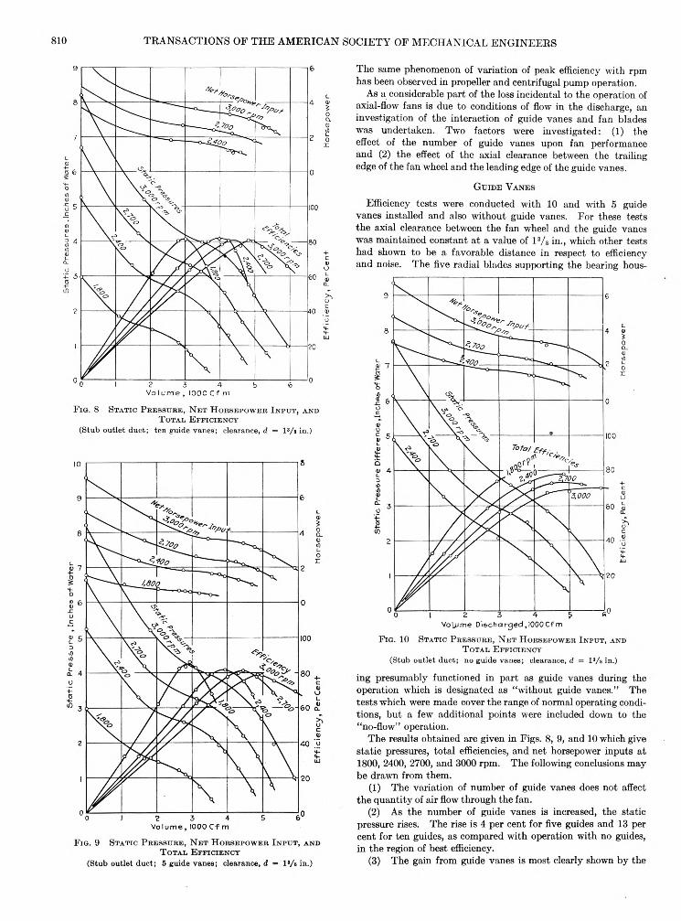
F i g . 8 S t a t i c P r e s s u r e , N e t H o r s e p o w e r I n p u t , a n d T o t a l E f f i c i e n c y
(Stub outle t duct; ten guide vanes; clearance, d — l 3/s in.)
F i g . 9 S t a t i c P r e s s u r e , N e t H o r s e p o w e r I n p u t , a n d T o t a l E f f i c i e n c y
(Stub outle t duc t; 5 guide vanes; clearance, d = l 3/s in.)
The same phenomenon of variation of peak efficiency with rpm has been observed in propeller and centrifugal pump operation.
As a considerable part of the loss incidental to the operation of axial-flow fans is due to conditions of flow in the discharge, an investigation of the interaction of guide vanes and fan blades was undertaken. Two factors were investigated: (1) the effect of the number of guide vanes upon fan performance and (2) the effect of the axial clearance between the trailing edge of the fan wheel and the leading edge of the guide vanes.
G u id e V a n e s
Efficiency tests were conducted with 10 and with 5 guide vanes installed and also without guide vanes. For these tests the axial clearance between the fan wheel and the guide vanes was maintained constant a t a value of l 3/s in., which other tests had shown to be a favorable distance in respect to efficiency and noise. The five radial blades supporting the bearing hous-
F ig . 10 S t a t i c P r e s s u r e , N e t H o r s e p o w e r I n p u t , a n d T o t a l E f f i c i e n c y
(Stub outlet duct; no guide vanes; clearance, d = l 3/s in.)ing presumably functioned in part as guide vanes during the operation which is designated as “without guide vanes.” The tests which were made cover the range of normal operating conditions, but a few additional points were included down to the “no-flow” operation.
The results obtained are given in Figs. 8, 9, and 10 which give static pressures, total efficiencies, and net horsepower inputs at 1800, 2400, 2700, and 3000 rpm. The following conclusions may be drawn from them.
(1) The variation of number of guide vanes does not affect the quantity of air flow through the fan.
(2) As the number of guide vanes is increased, the static pressure rises. The rise is 4 per cent for five guides and 13 per cent for ten guides, as compared with operation with no guides, in the region of best efficiency.
(3) The gain from guide vanes is most clearly shown by the
AERONAUTICAL EN G IN EERIN G AER-56-13 811
curves jf total efficiency. For no guides the total efficiency has a maximum of 70 per cent a t 3000 rpm but diminishes slowly with change of volume flowing. W ith five guides the peak efficiency is brought up to 79 per cent at 3000 rpm but the efficiency curve is steeper. At large flows, the efficiency obtained with five guides is slightly less than with no guides, as the guides are not designed for this condition. For all other operating conditions the use of five guides yields higher efficiency than with no guides. With ten guide vanes the maximum efficiency increases to 81 per cent but the efficiency curve becomes steeper still and a further moderate decrease of efficiency is indicated at largest flows.
These tests seem to indicate tha t the optimum number of guide vanes for a fan of this type is between five and ten.
E f f e c t o f C l e a r a n c e B e t w e e n F a n a n d G u i d e s
Variation of the axial distance, d, between propeller and guides has a considerable influence upon the noisiness of the fan. In-
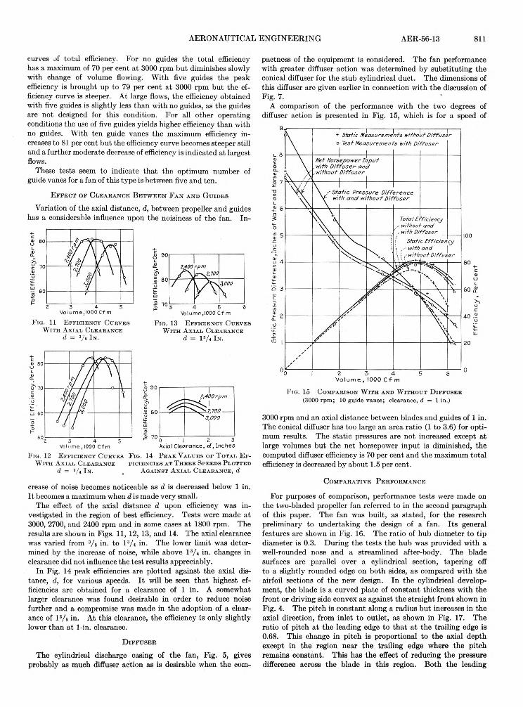
pactness of the equipment is considered. The fan performance with greater diffuser action was determined by substituting the conical diffuser for the stub cylindrical duct. The dimensions of this diffuser are given earlier in connection with the discussion of Fig. 7.
A comparison of the performance with the two degrees of diffuser action is presented in Fig. 15, which is for a speed of
F i g . 1 3 E f f i c i e n c y C u r v e s W i t h A x i a l C l e a r a n c e
d — I 3/* I n .
F i g . 11 E f f i c i e n c y C u r v e s W i t h A x i a l C l e a r a n c e
d = 3/ 8 I n .
F i g . 12 E f f i c i e n c y C u r v e s W i t h A x i a l C l e a r a n c e
d = 3/ t I n .
F i g . 14 P e a k V a l u e s o f T o t a l E f f i c i e n c i e s a t T h r e e S p e e d s P l o t t e d
A g a i n s t A x i a l C l e a r a n c e , d
crease of noise becomes noticeable as d is decreased below 1 in. It becomes a maximum when d is made very small.
The effect of the axial distance d upon efficiency was investigated in the region of best efficiency. Tests were made a t 3000, 2700, and 2400 rpm and in some cases a t 1800 rpm. The results are shown in Figs. 11, 12, 13, and 14. The axial clearance was varied from 3/ s in. to l 3/ 4 in. The lower limit was determined by the increase of noise, while above l 3/ 4 in. changes in clearance did not influence the test results appreciably.
In Fig. 14 peak efficiencies are plotted against the axial distance, d, for various speeds. I t will be seen tha t highest efficiencies are obtained for a clearance of 1 in. A somewhat larger clearance was found desirable in order to reduce noise further and a compromise was made in the adoption of a clearance of 13/ a in. At this clearance, the efficiency is only slightly lower than at 1-in. clearance.
D i f f u s e r
The cylindrical discharge casing of the fan, Fig. 5, gives probably as much diffuser action as is desirable when the com
F i g . 1 5 C o m p a r i s o n W i t h a n d W i t h o u t D i f f u s e r (3000 rpm ; 10 guide v anes; clearance, d = 1 in.)
3000 rpm and an axial distance between blades and guides of 1 in. The conical diffuser has too large an area ratio (1 to 3.6) for optimum results. The static pressures are not increased except at large volumes but the net horsepower input is diminished, the computed diffuser efficiency is 70 per cent and the maximum total efficiency is decreased by about 1.5 per cent.
C o m p a r a t iv e P e r f o r m a n c e
For purposes of comparison, performance tests were made on the two-bladed propeller fan referred to in the second paragraph of this paper. The fan was built, as stated, for the research preliminary to undertaking the design of a fan. Its general features are shown in Fig. 16. The ratio of hub diameter to tip diameter is 0.3. During the tests the hub was provided with a well-rounded nose and a streamlined after-body. The blade surfaces are parallel over a cylindrical section, tapering off to a slightly rounded edge on both sides, as compared with the airfoil sections of the new design. In the cylindrical development, the blade is a curved plate of constant thickness with the front or driving side convex as against the straight front shown in Fig. 4. The pitch is constant along a radius but increases in the axial direction, from inlet to outlet, as shown in Fig. 17. The ratio of pitch at the leading edge to tha t at the trailing edge is 0.68. This change in pitch is proportional to the axial depth except in the region near the trailing edge where the pitch remains constant. This has the effect of reducing the pressure difference across the blade in this region. Both the leading

812 TRANSACTIONS OF TH E AM ERICAN SOCIETY OF MECHANICAL ENGINEERS
edge and the trailing edge are radial lines in an axial plane. In the new design the pitch is variable along a radius and is constant in the axial direction.
Ten guide vanes of constant curvature along the radius and with an angle of incidence of 28 deg were installed for the performance tests.
The test results with this fan are given in Fig. 18 and a comparison of the two fans is made in Table 1. The tabulation is
Two- Three-bladed bladedfan fan20 19.36 106 3 .56 5 .53000 3000262 252.56500 465054.2 51.6
TA BLE 1 C O M PA R ISO N OF A TW O -BLAD ED AXIAL-FLOW FA N W IT H T H E N EW T H R E E -B L A D E D AX IAL-FLO W FAN
T ip diam , in ........................................................................H ub diam, in ......................................................................Axial depth , tip , in ...........................................................Axial depth , hub, in .........................................................R p m ....... .............................................................................T ip velocity, f t per sec...................................................Air volume a t maximum efficiency, cfm ...................M ean axial velocity a t fan discharge plane, fp s . . . . S ta tic pressure a t m aximum sta tic efficiency, in. ofw a te r . ..............................................................................N et horsepower in p u t.....................................................M aximum static efficiency, per cen t...........................M aximum to ta l efficiency, per cen t............................Volume coefficient,_ / axial velocity a t discharge plane\
\ tip velocity /Pressure coefficient,_____ static pressure \velocity head a t tip sp eed /C haracteristic speed based on 1 in. of w a ter...........
2 .403.5868 .569.5
0.207
0.1571580
0.205
0.2161150
U s e d f o r C o m p a r i s o n W i t h N e w T h r e e - B l a d e d F a n
°W ith stub-discharge duct; all other figures with conical diffuser.
N o is e
High-speed axial-flow fans are noisy in operation as compared with centrifugal fans. The problem of noise reduction was kept in mind throughout the design as indicated at several places in this paper. The completed fan was tested for noise and similar tests were made on the two-bladed fan and on* a centrifugal fan. In the noise tests of the axial-flow fans, the stub cylindrical discharge duct was used and the microphone was placed 2 ft from the end of the duct, near the edge of the air
F i g . 1 7 V a r i a t i o n o f P i t c h W i t h A x i a l t D e p t h i n T w o - B l a d e d A x i a l - F l o w F a n
F ig . 18
for 3000 rpm which is considerably below the optimum operating speed. The new design has a diameter slightly smaller than the two-bladed fan and consequently has a lower tip speed. The smaller discharge volume of the new design results from the larger hub diameter, the lower tip speed, the thicker blades, and the decrease in pitch of the blades. The tests were made with the conical diffuser previously described.
I t will be noted th a t the pressure coefficient of the new fan is 37.5 per cent greater than th a t of the two-bladed fan. This is in accordance with the original purpose of designing a fan for comparatively high pressures.
P e r f o r m a n c e C h a r a c t e r i s t i c s o f T w o - B l a d e d 2 0 - I n . P r o p e l l e r F a n (3000 rpm ; 10 guide vanes and diffuser.)
flow, and was oriented a t 45 deg to the axial direction. In the case of the centrifugal fan, the microphone was placed 2 ft away from the edge of the well-rounded inlet to the fan and was oriented a t 45 deg. to the fan axis.
The results of these tests are presented in Figs. 19, 20, and 21. For the axial-flow fans, observations were made a t two speeds, 2400 and 3000 rpm, with one additional observation a t 1800 rpm
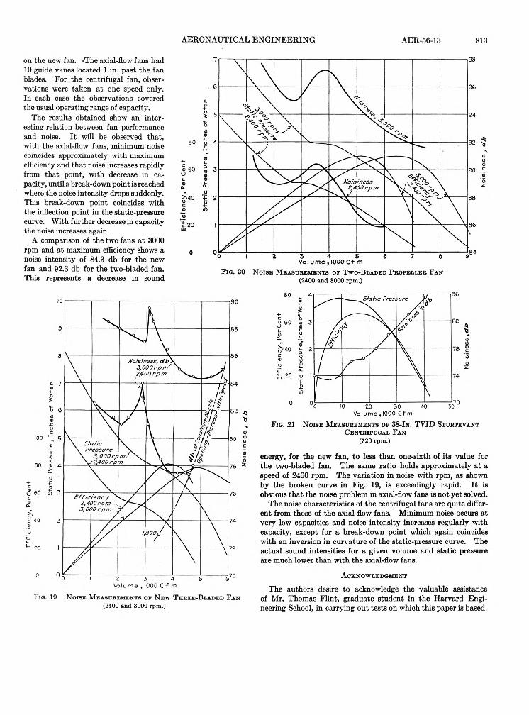
AERONAUTICAL EN G IN EER IN G AER-56-13 813on the new fan. »The axial-flow fans had 10 guide vanes located 1 in. past the fan blades. For the centrifugal fan, observations were taken a t one speed only. In each case the observations covered the usual operating range of capacity.
The results obtained show an interesting relation between fan performance and noise. I t will be observed that, with the axial-flow fans, minimum noise coincides approximately with maximum efficiency and that noise increases rapidly from that point, with decrease in capacity, until a break-down point is reached where the noise intensity drops suddenly. This break-down point coincides with the inflection point in the static-pressure curve. With further decrease in capacity the noise increases again.
A comparison of the two fans a t 3000 rpm and at maximum efficiency shows a noise intensity of 84.3 db for the new fan and 92.3 db for the two-bladed fan. This represents a decrease in sound F ig . 20 N o is e M e a s u r e m e n t s o f T w o -B l a d e d P r o p e l l e r F a n
(2400 and 3000 rpm .)
F i g . 21
F ig . 19 N o is e M e a s u r e m e n t s o f N e w T h r e e -B l a d e d F a n (2400 and 3000 rpm.)
N o ise M e a s u r e m e n ts o f 38-In. TVID S t u r t e v a n t C e n t b i f u g a l F a n
(720 rpm .)energy, for the new fan, to less than one-sixth of its value for the two-bladed fan. The same ratio holds approximately a t a speed of 2400 rpm. The variation in noise with rpm, as shown by the broken curve in Fig. 19, is exceedingly rapid. I t is obvious tha t the noise problem in axial-flow fans is not yet solved.
The noise characteristics of the centrifugal fans are quite different from those of the axial-flow fans. Minimum noise occurs at very low capacities and noise intensity increases regularly with capacity, except for a break-down point which again coincides with an inversion in curvature of the static-pressure curve. The actual sound intensities for a given volume and static pressure are much lower than with the axial-flow fans.
A c k n o w l e d g m e n t
The authors desire to acknowledge the valuable assistance of Mr. Thomas Flint, graduate student in the Harvard Engineering School, in carrying out tests on which this paper is based.
Related Documents