ÄKTA pure User Manual cytiva.com

Welcome message from author
This document is posted to help you gain knowledge. Please leave a comment to let me know what you think about it! Share it to your friends and learn new things together.
Transcript
Table of Contents
1 Introduction ........................................................................................................ 61.1 Important user information ....................................................................................................................... 71.2 ÄKTA pure overview ..................................................................................................................................... 91.3 ÄKTA pure user documentation .............................................................................................................. 11
2 The ÄKTA pure instrument ................................................................................ 132.1 Overview illustrations .................................................................................................................................. 142.2 Liquid flow path ............................................................................................................................................... 272.3 Instrument control panel ............................................................................................................................ 292.4 Instrument modules .................................................................................................................................... 35
2.4.1 System pumps .............................................................................................................................................. 362.4.2 Mixer .................................................................................................................................................................. 402.4.3 Valves, overview ............................................................................................................................................ 422.4.4 Inlet valves ....................................................................................................................................................... 432.4.5 Mixer valve ...................................................................................................................................................... 512.4.6 Injection valve ................................................................................................................................................ 542.4.7 Loop valve ........................................................................................................................................................ 592.4.8 Column valves ................................................................................................................................................ 622.4.9 Versatile valve ................................................................................................................................................ 672.4.10 pH valve ............................................................................................................................................................ 682.4.11 Outlet valves .................................................................................................................................................. 732.4.12 Pressure monitors ........................................................................................................................................ 762.4.13 UV monitors .................................................................................................................................................... 792.4.14 Conductivity monitor .................................................................................................................................. 832.4.15 Flow restrictor ................................................................................................................................................ 85
2.5 Installation of internal modules ............................................................................................................... 872.6 Accessories ...................................................................................................................................................... 91
3 ÄKTA pure external modules ............................................................................ 1003.1 External air sensors ....................................................................................................................................... 1013.2 Fraction collector F9-C .............................................................................................................................. 103
3.2.1 Function ............................................................................................................................................................ 1043.2.2 Fraction collector F9-C illustrations .................................................................................................... 1063.2.3 Cassettes, Cassette tray and racks ...................................................................................................... 1103.2.4 Connect tubing to the ÄKTA pure instrument .................................................................................. 116
3.3 Fraction collector F9-R .............................................................................................................................. 1173.4 Sample pump S9 and S9H ........................................................................................................................... 1213.5 I/O-box E9 ......................................................................................................................................................... 126
3.5.1 Overview of the I/O-box ............................................................................................................................. 1273.5.2 Analog connector and signals ................................................................................................................. 1293.5.3 Digital connector and signals .................................................................................................................. 1313.5.4 Connect external equipment to the I/O-box ..................................................................................... 133
3.6 Connection of external modules .............................................................................................................. 136
4 System configuration ......................................................................................... 1394.1 Configuration overview ............................................................................................................................... 1404.2 Configure modules ........................................................................................................................................ 146
4.2.1 Configuration of inlet valves .................................................................................................................... 147
Table of Contents
2 ÄKTA pure User Manual 29119969 AD
4.2.2 Configuration of Mixer valves .................................................................................................................. 1494.2.3 Configuration of Loop valves ................................................................................................................... 1504.2.4 Configuration of column valves .............................................................................................................. 1514.2.5 Configuration of Versatile valves ........................................................................................................... 1534.2.6 Configuration of pH valves ........................................................................................................................ 1544.2.7 Configuration of outlet valves ................................................................................................................. 1554.2.8 Configuration of UV monitors .................................................................................................................. 1564.2.9 Configuration of Conductivity monitor ................................................................................................ 1574.2.10 Configuration of external air sensors ................................................................................................... 1584.2.11 Configuration of fraction collectors ...................................................................................................... 1594.2.12 Configuration of I/O-box ............................................................................................................................ 162
4.3 General system settings ............................................................................................................................. 163
5 Operation ............................................................................................................ 1665.1 Before you prepare the system ................................................................................................................ 1675.2 Prepare the flow path ................................................................................................................................... 1685.3 Start UNICORN and connect to system ................................................................................................ 1755.4 Prime inlets and purge pump heads ....................................................................................................... 179
5.4.1 System pumps ............................................................................................................................................... 1805.4.2 Sample pump ................................................................................................................................................. 187
5.5 Connect a column .......................................................................................................................................... 1935.6 Pressure alarms .............................................................................................................................................. 1985.7 Sample application ........................................................................................................................................ 201
5.7.1 Sample application using direct injection onto the column ....................................................... 2035.7.2 Sample application using a Superloop™ ............................................................................................. 2055.7.3 Sample application using a sample loop ............................................................................................ 213
5.8 Fractionation ................................................................................................................................................... 2175.8.1 Prepare Fraction collector F9-C ........................................................................................................... 2185.8.2 Prepare Fraction collector F9-R ............................................................................................................. 2255.8.3 Fractionation overview .............................................................................................................................. 233
5.9 Create a method and perform a run ....................................................................................................... 2385.9.1 Create a method ........................................................................................................................................... 2395.9.2 Prepare and perform a run ....................................................................................................................... 2455.9.3 Monitor a run .................................................................................................................................................. 2475.9.4 After run procedures ................................................................................................................................... 249
6 Performance tests .............................................................................................. 2526.1 General performance test actions .......................................................................................................... 2536.2 Air sensor A and Inlet valve A tests .......................................................................................................... 2566.3 Air sensor B and Inlet valve B tests .......................................................................................................... 2586.4 Air sensor S and Sample inlet valve tests .............................................................................................. 2606.5 Column valve C tests .................................................................................................................................... 2626.6 Fraction collector F9-C test ....................................................................................................................... 2646.7 Fraction Collector F9-R Test ...................................................................................................................... 2676.8 Sample pump tests ....................................................................................................................................... 2696.9 System Test UV U9-L (fixed) ....................................................................................................................... 2716.10 System Test UV U9-M (variable) ............................................................................................................... 275
7 Maintenance ....................................................................................................... 2797.1 Maintenance Manager ................................................................................................................................ 2807.2 Maintenance program ................................................................................................................................. 2857.3 Weekly maintenance .................................................................................................................................... 288
Table of Contents
ÄKTA pure User Manual 29119969 AD 3
7.3.1 Change pump rinsing solution ................................................................................................................ 2897.3.2 Replace the inline filter ............................................................................................................................... 2947.3.3 Clean the Fraction collector F9-C sensors ......................................................................................... 295
7.4 Monthly maintenance .................................................................................................................................. 2977.5 Semiannual maintenance .......................................................................................................................... 300
7.5.1 Clean the UV flow cell ................................................................................................................................. 3017.5.2 Replace the pH electrode .......................................................................................................................... 304
7.6 Maintenance when required ..................................................................................................................... 3057.6.1 Clean the instrument externally ............................................................................................................ 3067.6.2 Perform System CIP .................................................................................................................................... 3077.6.3 Perform Column CIP .................................................................................................................................... 3157.6.4 Clean Fraction collector F9-C .................................................................................................................. 3197.6.5 Clean Fraction collector F9-R .................................................................................................................. 3217.6.6 Storage of the pH electrode ..................................................................................................................... 3227.6.7 Clean the pH electrode .............................................................................................................................. 3247.6.8 Clean the pump head check valves ...................................................................................................... 3277.6.9 Wipe off excess oil from the pump head ............................................................................................. 3307.6.10 Clean the Conductivity flow cell ............................................................................................................. 331
7.7 Calibration procedures ................................................................................................................................ 3337.7.1 Calibrate the pH monitor ........................................................................................................................... 3347.7.2 Calibrate the pressure monitors ............................................................................................................ 3367.7.3 Calibrate the Conductivity monitor ...................................................................................................... 3397.7.4 Calibrate the UV monitors ....................................................................................................................... 344
7.8 Replacement procedures ........................................................................................................................... 3487.8.1 Replace tubing and connectors ............................................................................................................. 3497.8.2 Replace internal tubing in Fraction collector F9-C ......................................................................... 3517.8.3 Replace the Mixer ......................................................................................................................................... 3557.8.4 Replace the O-ring inside the Mixer ..................................................................................................... 3567.8.5 Replace the UV monitor U9-M flow cell ............................................................................................... 3587.8.6 Replace the UV monitor U9-L flow cell ................................................................................................ 3617.8.7 Replace Flow restrictor .............................................................................................................................. 3637.8.8 Replace the inlet filters ............................................................................................................................... 3647.8.9 Replace the pump head check valves .................................................................................................. 3657.8.10 Replace pump piston seals of Pump P9 or P9H ............................................................................... 3687.8.11 Replace pump piston seals of Pump P9-S .......................................................................................... 3777.8.12 Replace pump pistons ................................................................................................................................ 3857.8.13 Replace pump rinsing system tubing .................................................................................................. 386
8 Troubleshooting ................................................................................................. 3898.1 Introduction to troubleshooting .............................................................................................................. 3908.2 Troubleshooting: General Checklist ....................................................................................................... 3928.3 Troubleshooting: Monitors ......................................................................................................................... 3948.4 Troubleshooting: Valves .............................................................................................................................. 4098.5 Troubleshooting: Fraction collector ....................................................................................................... 4118.6 Troubleshooting: Pumps ............................................................................................................................. 4238.7 Troubleshooting: Other components .................................................................................................... 4308.8 Troubleshooting: Instrument communication ................................................................................... 4388.9 Troubleshooting: Method development ............................................................................................... 4408.10 Error codes ....................................................................................................................................................... 441
9 Reference information ....................................................................................... 4479.1 System specifications .................................................................................................................................. 448
Table of Contents
4 ÄKTA pure User Manual 29119969 AD
9.2 Module specifications ................................................................................................................................. 4509.3 Tubing and connectors ................................................................................................................................ 4589.4 Recommended tubing kits for prepacked columns ......................................................................... 4669.5 Chemical resistance guide ......................................................................................................................... 469
9.5.1 General information about biocompatibility and chemical resistance ................................. 4709.5.2 Chemical resistance specifications ...................................................................................................... 471
9.6 Wetted materials ........................................................................................................................................... 4759.7 Predefined methods and phases ............................................................................................................. 477
9.7.1 Predefined purification methods ........................................................................................................... 4789.7.2 Predefined maintenance methods ....................................................................................................... 4849.7.3 Predefined phases ....................................................................................................................................... 486
9.8 System settings .............................................................................................................................................. 4899.8.1 System settings ‑ UV ................................................................................................................................... 4919.8.2 System settings ‑ Conductivity ............................................................................................................... 4929.8.3 System settings ‑ pH ................................................................................................................................... 4939.8.4 System settings ‑ Pressure alarms ....................................................................................................... 4949.8.5 System settings ‑ Air sensor .................................................................................................................... 4969.8.6 System settings ‑ I/O-box .......................................................................................................................... 4989.8.7 System settings ‑ Fraction collection ................................................................................................... 4999.8.8 System settings ‑ Tubing and Delay volumes ................................................................................... 5019.8.9 System settings ‑ Wash settings ........................................................................................................... 5039.8.10 System settings ‑ Watch parameters .................................................................................................. 5059.8.11 System settings ‑ Advanced .................................................................................................................... 5069.8.12 System settings ‑ Data collection .......................................................................................................... 507
9.9 Manual instructions ...................................................................................................................................... 5089.9.1 Manual instructions ‑ Pumps .................................................................................................................. 5109.9.2 Manual instructions ‑ Flow path ............................................................................................................. 5149.9.3 Manual instructions ‑ Monitors ............................................................................................................... 5169.9.4 Manual instructions ‑ Fraction collection ........................................................................................... 5189.9.5 Manual instructions ‑ I/O-box ................................................................................................................. 5229.9.6 Manual instructions ‑ Alarms .................................................................................................................. 5239.9.7 Manual instructions ‑ Wash settings ................................................................................................... 5269.9.8 Manual instructions ‑ Watch parameters .......................................................................................... 5279.9.9 Manual instructions ‑ Advanced ............................................................................................................ 5289.9.10 Manual instructions ‑ Other ..................................................................................................................... 531
9.10 Available Run data ......................................................................................................................................... 5329.11 Available Curves ............................................................................................................................................. 5369.12 Injection volumes and peak broadening ............................................................................................... 5399.13 Delay volumes ................................................................................................................................................. 5409.14 Component volumes .................................................................................................................................... 5469.15 Pressure control ............................................................................................................................................. 5499.16 Node IDs ............................................................................................................................................................ 551
10 Ordering information ......................................................................................... 554
Index ........................................................................................................................... 562
Table of Contents
ÄKTA pure User Manual 29119969 AD 5
1 Introduction
Purpose of the User ManualThe User Manual provides you with instructions and information to run the ÄKTA™pure system. It also includes relevant guidance for practical handling and maintenanceof instrument components.
In this chapter
Section See page
1.1 Important user information 7
1.2 ÄKTA pure overview 9
1.3 ÄKTA pure user documentation 11
1 Introduction
6 ÄKTA pure User Manual 29119969 AD
1.1 Important user information
Read this before operating ÄKTApure
All users must read the entire ÄKTA pure Operating Instructions before instal-ling, operating, or maintaining the instrument. Always keep the ÄKTA pureOperating Instructions at hand when operating ÄKTA pure.
Do not operate ÄKTA pure in any other way than described in the user documentation.If you do, you may be exposed to hazards that can lead to personal injury and you maycause damage to the equipment.
Intended useÄKTA pure is intended for purification of bio-molecules, in particular proteins, forresearch purposes by trained laboratory staff members in research laboratories.
ÄKTA pure shall not be used in any clinical procedures, or for diagnostic purposes.
PrerequisitesIn order to operate the system according to the intended purpose, it is important that:
• you have a general understanding of how the computer and the Microsoft®
Windows® operating system work.
• you understand the concepts of liquid chromatography.
• you have read and understood the Safety instructions chapter in ÄKTA pureOperating Instructions .
• a user account has been created according to UNICORN™ Administration andTechnical Manual.
Safety NoticesThis user documentation contains safety notices (WARNING, CAUTION, and NOTICE)concerning the safe use of the product. See definitions below.
WARNING
WARNING indicates a hazardous situation which, if not avoided,could result in death or serious injury. It is important not to proceeduntil all stated conditions are met and clearly understood.
1 Introduction1.1 Important user information
ÄKTA pure User Manual 29119969 AD 7
CAUTION
CAUTION indicates a hazardous situation which, if not avoided,could result in minor or moderate injury. It is important not toproceed until all stated conditions are met and clearly understood.
NOTICE
NOTICE indicates instructions that must be followed to avoiddamage to the product or other equipment.
Notes and tipsNote: A Note is used to indicate information that is important for trouble-free and
optimal use of the product.
Tip: A tip contains useful information that can improve or optimize your proce-dures.
1 Introduction1.1 Important user information
8 ÄKTA pure User Manual 29119969 AD
1.2 ÄKTA pure overview
IntroductionÄKTA pure is intended for purification of bio-molecules, in particular proteins, forresearch purposes by trained laboratory staff members in research laboratories.
This section gives an overview of the ÄKTA pure instrument and the UNICORN soft-ware. For detailed information about UNICORN, see the UNICORN manuals listed in UNICORN user documentation, on page 11. For detailed information about the instru-ment, see Chapter 2 The ÄKTA pure instrument, on page 13.
Main featuresThe main features of ÄKTA pure are listed below.
• ÄKTA pure is a flexible system that allows the user to configure both hardware andsoftware to meet many purification needs.
• The instrument can be easily extended with additional valves, detectors and frac-tion collectors.
• There are a large number of different hardware modules to choose from. The usercan adjust, for example, the number of columns, inlets, outlets and detectors andchoose between different ways to apply and collect samples.
• Purification and maintenance methods are easily created using predefinedmethods and method phases. A method phase refers to a specific step/part in themethod, such as column wash or elution. Method phases are described in PhaseProperties and are displayed graphically in a method outline. This makes methodsand phases easy to understand and edit.
• ÄKTA pure is controlled by the UNICORN software: a complete package for control,supervision and evaluation of chromatography instruments and purification runs.
• UNICORN has different software licence options, such as Design of Experiments(DoE) and Column logbook, to further add user support.
1 Introduction1.2 ÄKTA pure overview
ÄKTA pure User Manual 29119969 AD 9
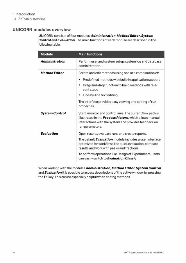
UNICORN modules overviewUNICORN consists of four modules: Administration, Method Editor, SystemControl and Evaluation. The main functions of each module are described in thefollowing table.
Module Main functions
Administration Perform user and system setup, system log and databaseadministration.
Method Editor Create and edit methods using one or a combination of:
• Predefined methods with built-in application support
• Drag-and-drop function to build methods with rele-vant steps
• Line-by-line text editing
The interface provides easy viewing and editing of runproperties.
System Control Start, monitor and control runs. The current flow path isillustrated in the Process Picture, which allows manualinteractions with the system and provides feedback onrun parameters.
Evaluation Open results, evaluate runs and create reports.
The default Evaluation module includes a user interfaceoptimized for workflows like quick evaluation, compareresults and work with peaks and fractions.
To perform operations like Design of Experiments, userscan easily switch to Evaluation Classic.
When working with the modules Administration, Method Editor, System Controland Evaluation it is possible to access descriptions of the active window by pressingthe F1 key. This can be especially helpful when editing methods
1 Introduction1.2 ÄKTA pure overview
10 ÄKTA pure User Manual 29119969 AD
1.3 ÄKTA pure user documentation
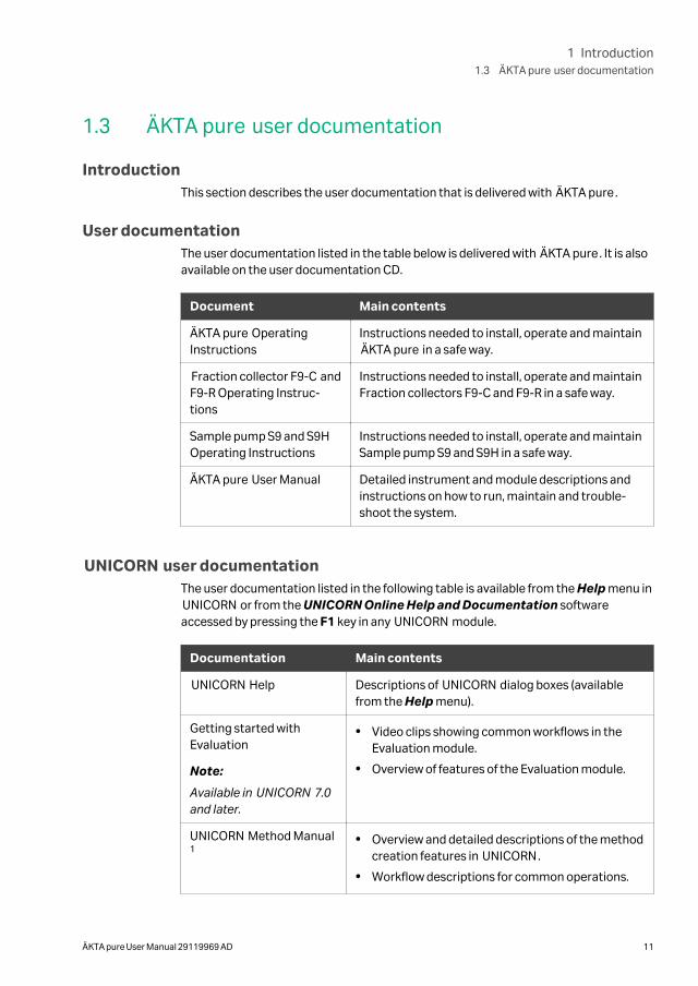
IntroductionThis section describes the user documentation that is delivered with ÄKTA pure.
User documentationThe user documentation listed in the table below is delivered with ÄKTA pure. It is alsoavailable on the user documentation CD.
Document Main contents
ÄKTA pure OperatingInstructions
Instructions needed to install, operate and maintainÄKTA pure in a safe way.
Fraction collector F9-C andF9-R Operating Instruc-tions
Instructions needed to install, operate and maintainFraction collectors F9-C and F9-R in a safe way.
Sample pump S9 and S9HOperating Instructions
Instructions needed to install, operate and maintainSample pump S9 and S9H in a safe way.
ÄKTA pure User Manual Detailed instrument and module descriptions andinstructions on how to run, maintain and trouble-shoot the system.
UNICORN user documentationThe user documentation listed in the following table is available from the Help menu inUNICORN or from the UNICORN Online Help and Documentation softwareaccessed by pressing the F1 key in any UNICORN module.
Documentation Main contents
UNICORN Help Descriptions of UNICORN dialog boxes (availablefrom the Help menu).
Getting started withEvaluation
Note:
Available in UNICORN 7.0and later.
• Video clips showing common workflows in theEvaluation module.
• Overview of features of the Evaluation module.
UNICORN Method Manual1
• Overview and detailed descriptions of the methodcreation features in UNICORN.
• Workflow descriptions for common operations.
1 Introduction1.3 ÄKTA pure user documentation
ÄKTA pure User Manual 29119969 AD 11
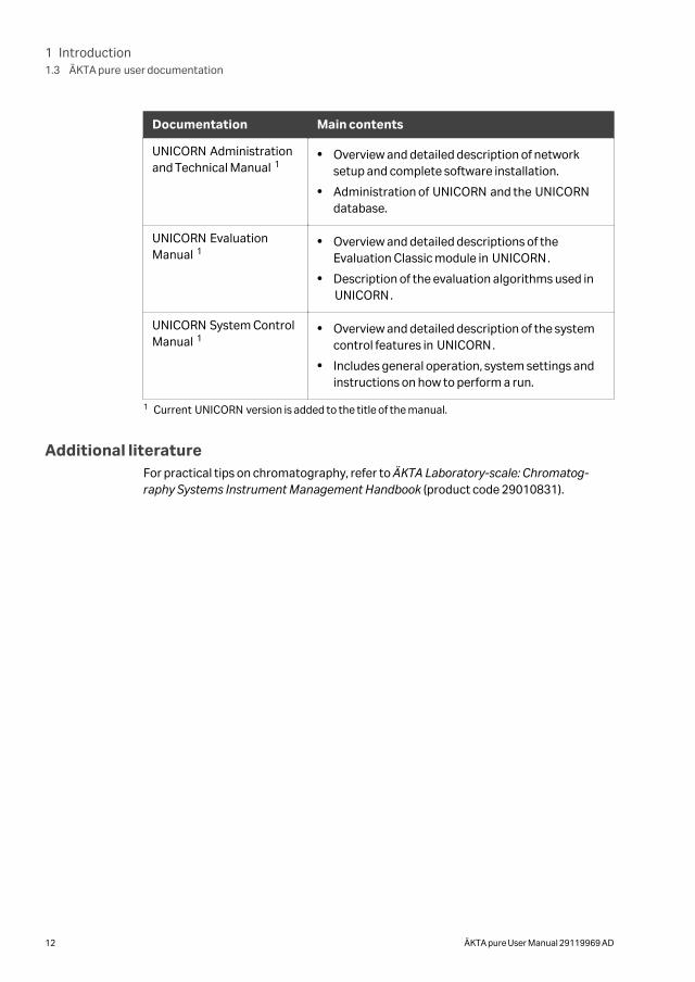
Documentation Main contents
UNICORN Administrationand Technical Manual 1
• Overview and detailed description of networksetup and complete software installation.
• Administration of UNICORN and the UNICORNdatabase.
UNICORN EvaluationManual 1
• Overview and detailed descriptions of theEvaluation Classic module in UNICORN.
• Description of the evaluation algorithms used inUNICORN.
UNICORN System ControlManual 1
• Overview and detailed description of the systemcontrol features in UNICORN.
• Includes general operation, system settings andinstructions on how to perform a run.
1 Current UNICORN version is added to the title of the manual.
Additional literatureFor practical tips on chromatography, refer to ÄKTA Laboratory-scale: Chromatog-raphy Systems Instrument Management Handbook (product code 29010831).
1 Introduction1.3 ÄKTA pure user documentation
12 ÄKTA pure User Manual 29119969 AD
2 The ÄKTA pure instrument
About this chapterThis chapter provides an overview of the ÄKTA pure instrument. It also describes theinternal instrument components and how these are installed in the instrument.
In this chapter
Section See page
2.1 Overview illustrations 14
2.2 Liquid flow path 27
2.3 Instrument control panel 29
2.4 Instrument modules 35
2.5 Installation of internal modules 87
2.6 Accessories 91
2 The ÄKTA pure instrument
ÄKTA pure User Manual 29119969 AD 13
2.1 Overview illustrations
IntroductionThis section provides an overview of the system and its available modules.
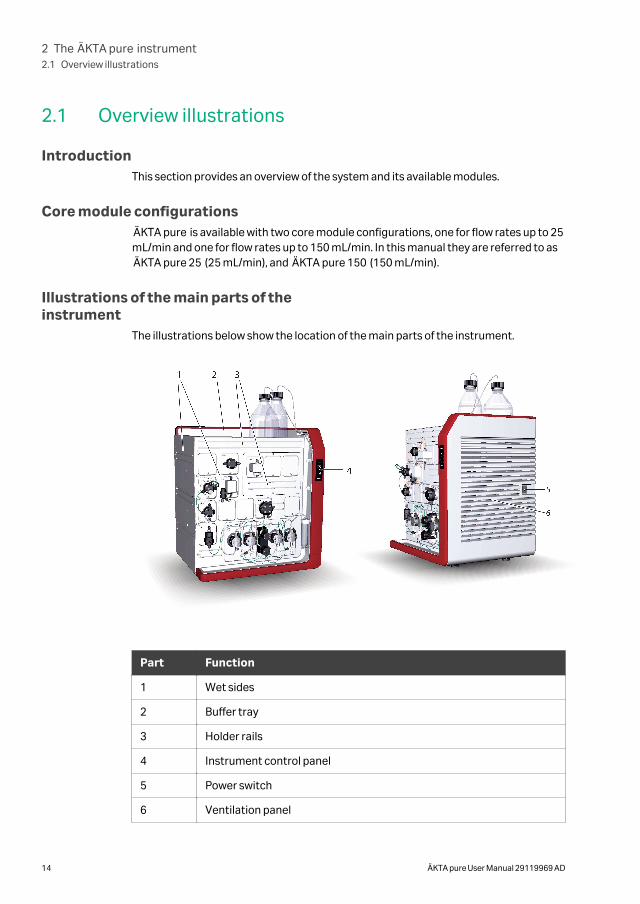
Core module configurationsÄKTA pure is available with two core module configurations, one for flow rates up to 25mL/min and one for flow rates up to 150 mL/min. In this manual they are referred to asÄKTA pure 25 (25 mL/min), and ÄKTA pure 150 (150 mL/min).
Illustrations of the main parts of theinstrument
The illustrations below show the location of the main parts of the instrument.
Part Function
1 Wet sides
2 Buffer tray
3 Holder rails
4 Instrument control panel
5 Power switch
6 Ventilation panel
2 The ÄKTA pure instrument2.1 Overview illustrations
14 ÄKTA pure User Manual 29119969 AD
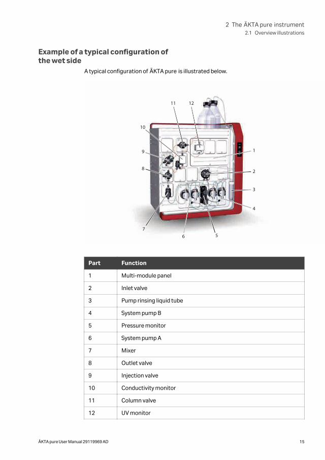
Example of a typical configuration ofthe wet side
A typical configuration of ÄKTA pure is illustrated below.
567
8
9
10
11 12
2
3
4
1
Part Function
1 Multi-module panel
2 Inlet valve
3 Pump rinsing liquid tube
4 System pump B
5 Pressure monitor
6 System pump A
7 Mixer
8 Outlet valve
9 Injection valve
10 Conductivity monitor
11 Column valve
12 UV monitor
2 The ÄKTA pure instrument2.1 Overview illustrations
ÄKTA pure User Manual 29119969 AD 15
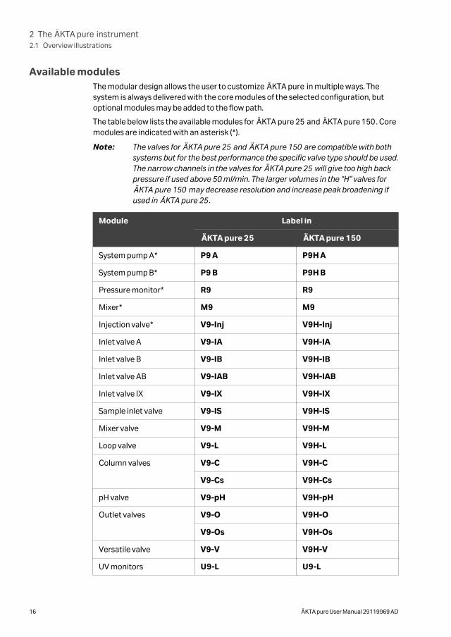
Available modulesThe modular design allows the user to customize ÄKTA pure in multiple ways. Thesystem is always delivered with the core modules of the selected configuration, butoptional modules may be added to the flow path.
The table below lists the available modules for ÄKTA pure 25 and ÄKTA pure 150. Coremodules are indicated with an asterisk (*).
Note: The valves for ÄKTA pure 25 and ÄKTA pure 150 are compatible with bothsystems but for the best performance the specific valve type should be used.The narrow channels in the valves for ÄKTA pure 25 will give too high backpressure if used above 50 ml/min. The larger volumes in the “H” valves forÄKTA pure 150 may decrease resolution and increase peak broadening ifused in ÄKTA pure 25.
Module Label in
ÄKTA pure 25 ÄKTA pure 150
System pump A* P9 A P9H A
System pump B* P9 B P9H B
Pressure monitor* R9 R9
Mixer* M9 M9
Injection valve* V9-Inj V9H-Inj
Inlet valve A V9-IA V9H-IA
Inlet valve B V9-IB V9H-IB
Inlet valve AB V9-IAB V9H-IAB
Inlet valve IX V9-IX V9H-IX
Sample inlet valve V9-IS V9H-IS
Mixer valve V9-M V9H-M
Loop valve V9-L V9H-L
Column valves V9-C V9H-C
V9-Cs V9H-Cs
pH valve V9-pH V9H-pH
Outlet valves V9-O V9H-O
V9-Os V9H-Os
Versatile valve V9-V V9H-V
UV monitors U9-L U9-L
2 The ÄKTA pure instrument2.1 Overview illustrations
16 ÄKTA pure User Manual 29119969 AD
Module Label in
ÄKTA pure 25 ÄKTA pure 150
U9-M U9-M
Conductivity monitor C9 C9
External air sensor L9-1.5 L9-1.5
L9-1.2 L9-1.2
Fraction collectors F9-C F9-C
F9-R F9-R
I/O-box E9 E9
Sample pump S9 S9H
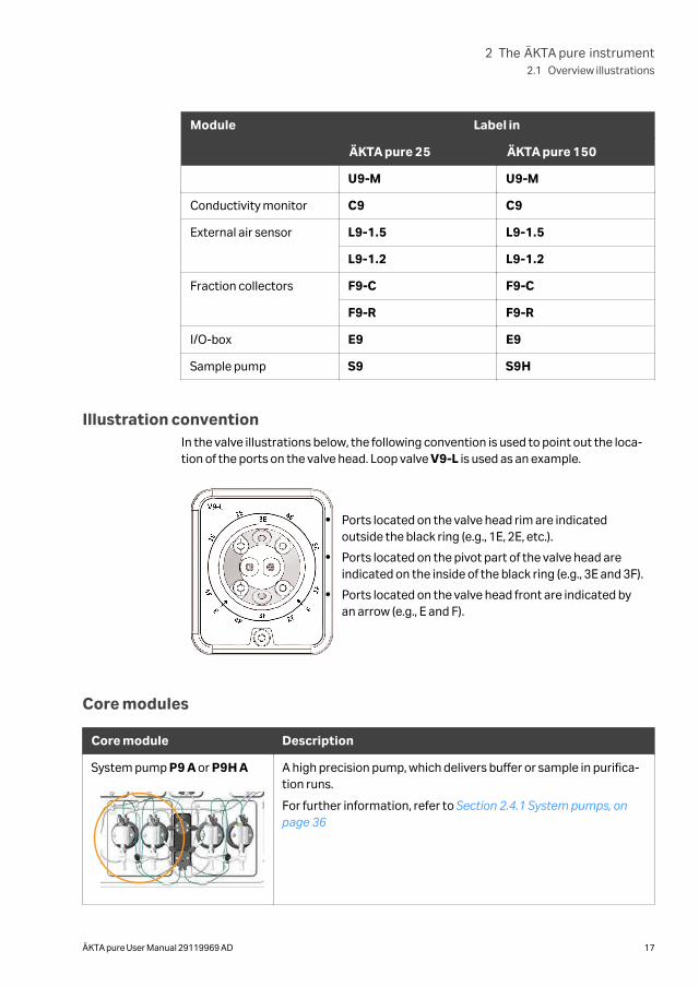
Illustration conventionIn the valve illustrations below, the following convention is used to point out the loca-tion of the ports on the valve head. Loop valve V9-L is used as an example.
• Ports located on the valve head rim are indicatedoutside the black ring (e.g., 1E, 2E, etc.).
• Ports located on the pivot part of the valve head areindicated on the inside of the black ring (e.g., 3E and 3F).
• Ports located on the valve head front are indicated byan arrow (e.g., E and F).
Core modules
Core module Description
System pump P9 A or P9H A A high precision pump, which delivers buffer or sample in purifica-tion runs.
For further information, refer to Section 2.4.1 System pumps, onpage 36
2 The ÄKTA pure instrument2.1 Overview illustrations
ÄKTA pure User Manual 29119969 AD 17
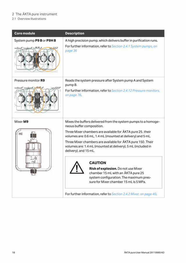
Core module Description
System pump P9 B or P9H B A high precision pump, which delivers buffer in purification runs.
For further information, refer to Section 2.4.1 System pumps, onpage 36
Pressure monitor R9 Reads the system pressure after System pump A and Systempump B.
For further information, refer to Section 2.4.12 Pressure monitors,on page 76.
Mixer M9 Mixes the buffers delivered from the system pumps to a homoge-neous buffer composition.
Three Mixer chambers are available for ÄKTA pure 25, theirvolumes are: 0.6 mL, 1.4 mL (mounted at delivery) and 5 mL.
Three Mixer chambers are available for ÄKTA pure 150. Theirvolumes are: 1.4 mL (mounted at delivery), 5 mL (included indelivery), and 15 mL.
CAUTION
Risk of explosion. Do not use Mixerchamber 15 mL with an ÄKTA pure 25system configuration. The maximum pres-sure for Mixer chamber 15 mL is 5 MPa.
For further information, refer to Section 2.4.2 Mixer, on page 40.
2 The ÄKTA pure instrument2.1 Overview illustrations
18 ÄKTA pure User Manual 29119969 AD
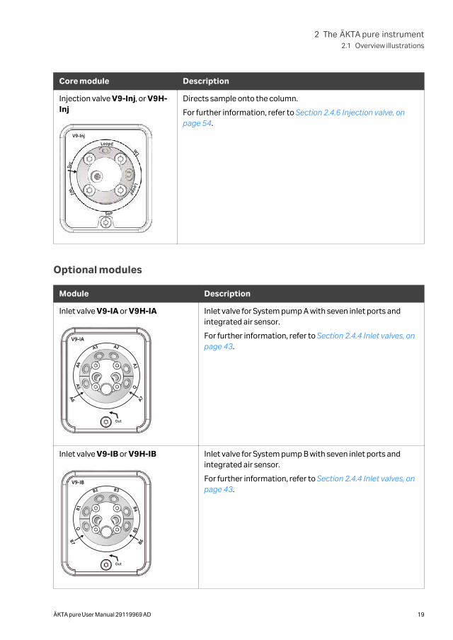
Core module Description
Injection valve V9-Inj, or V9H-Inj
LoopE
LoopF
Syr
W1
PaS
2W
V9-Inj
Directs sample onto the column.
For further information, refer to Section 2.4.6 Injection valve, onpage 54.
Optional modules
Module Description
Inlet valve V9-IA or V9H-IA
V9-IA
Q
A1
A2A3
A4
A7A6A5
Out
Inlet valve for System pump A with seven inlet ports andintegrated air sensor.
For further information, refer to Section 2.4.4 Inlet valves, onpage 43.
Inlet valve V9-IB or V9H-IB
V9-IB
B5
B4
B3B2
B1
B6
B7Q
Out
Inlet valve for System pump B with seven inlet ports andintegrated air sensor.
For further information, refer to Section 2.4.4 Inlet valves, onpage 43.
2 The ÄKTA pure instrument2.1 Overview illustrations
ÄKTA pure User Manual 29119969 AD 19
Module Description
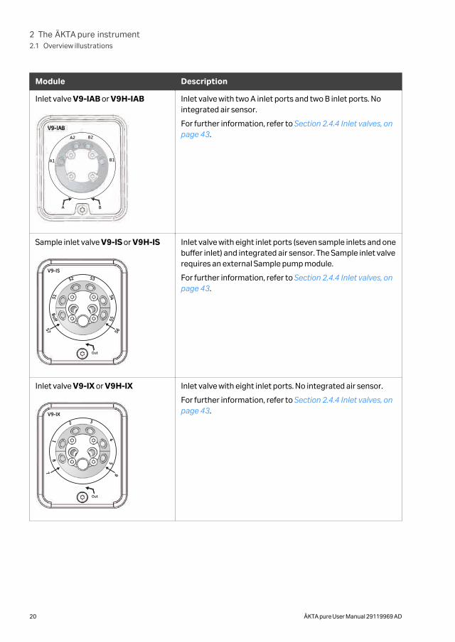
Inlet valve V9-IAB or V9H-IAB
A B
A1
A2
B1
B2
Inlet valve with two A inlet ports and two B inlet ports. Nointegrated air sensor.
For further information, refer to Section 2.4.4 Inlet valves, onpage 43.
Sample inlet valve V9-IS or V9H-IS
V9-IS
S5
S4
S3S2
S1
S6
S7Buff
Out
Inlet valve with eight inlet ports (seven sample inlets and onebuffer inlet) and integrated air sensor. The Sample inlet valverequires an external Sample pump module.
For further information, refer to Section 2.4.4 Inlet valves, onpage 43.
Inlet valve V9-IX or V9H-IX
V9-IX
5
4
32
1
6
78
Out
Inlet valve with eight inlet ports. No integrated air sensor.
For further information, refer to Section 2.4.4 Inlet valves, onpage 43.
2 The ÄKTA pure instrument2.1 Overview illustrations
20 ÄKTA pure User Manual 29119969 AD
Module Description
Mixer valve V9-M or V9H-M
V9-M Re-Inj
Out In
Mixer
Directs the flow to the Injection valve, bypassing the Mixer,or to the Injection valve via the Mixer.
For further information, refer to Section 2.4.5 Mixer valve, onpage 51.
Loop valve V9-L or V9H-L Enables the use of up to five loops connected to the instru-ment.
For further information, refer to Section 2.4.7 Loop valve, onpage 59.
Column valve V9-C or V9H-C
and V9-C2 or V9H-C2
V9-C or V9H-C can connect up to five columns to the instru-ment. Up to ten columns can be connected by installing theoptional column valves V9-C2 or V9H-C2 .
The column valves direct the flow to one column at a timeand feature two integrated pressure sensors.
The valves allow the user to choose flow direction throughthe column, or to bypass the column.
For further information, refer to Section 2.4.8 Column valves,on page 62.
2 The ÄKTA pure instrument2.1 Overview illustrations
ÄKTA pure User Manual 29119969 AD 21
Module Description
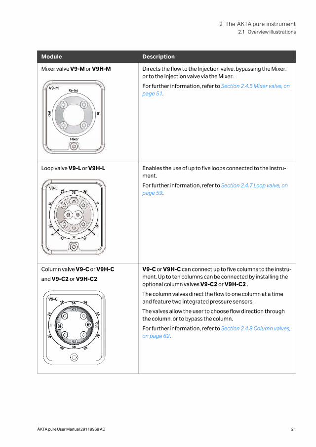
Column valve V9-Cs or V9H-Cs
V9-CsA
OutIn
B
Connects a single column to the instrument.
Allows the user to chose flow direction through the column,or to bypass the column.
For further information, refer to Section 2.4.8 Column valves,on page 62.
pH valve V9-pH or V9H-pH Enables the pH electrode to be included in the flow path orbypassed during a run. The pH electrode may be calibratedwhen installed in the pH valve.
For further information, refer to Section 2.4.10 pH valve, onpage 68.
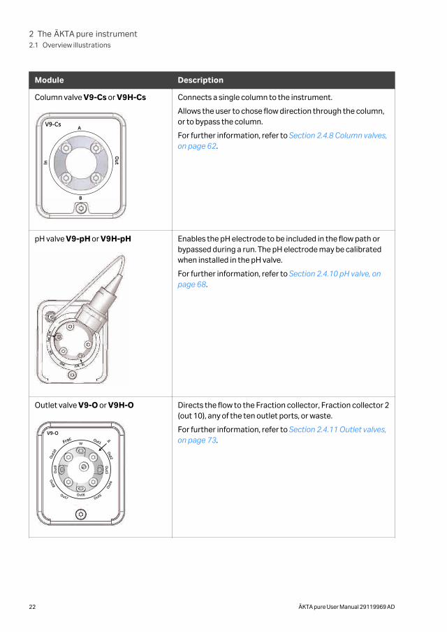
Outlet valve V9-O or V9H-O
V9-O
Out2
Out1Frac
Out1
0
In
Out4
W
Out6
Out3O
ut9
Out5Out7
Out8
Directs the flow to the Fraction collector, Fraction collector 2(out 10), any of the ten outlet ports, or waste.
For further information, refer to Section 2.4.11 Outlet valves,on page 73.
2 The ÄKTA pure instrument2.1 Overview illustrations
22 ÄKTA pure User Manual 29119969 AD
Module Description
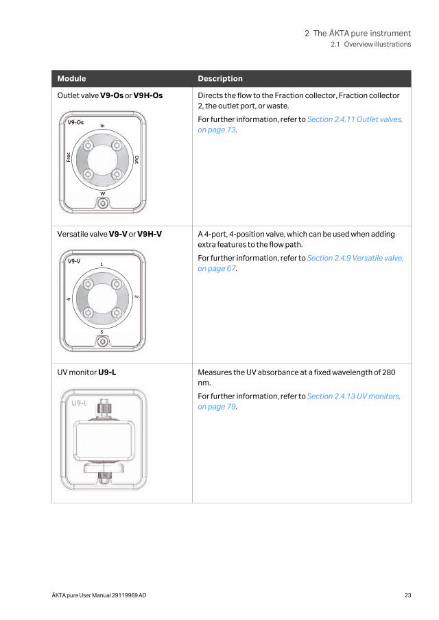
Outlet valve V9-Os or V9H-Os
V9-Os In
Frac O
ut
W
Directs the flow to the Fraction collector, Fraction collector2, the outlet port, or waste.
For further information, refer to Section 2.4.11 Outlet valves,on page 73.
Versatile valve V9-V or V9H-V
V9-V 1
4
2
3
A 4-port, 4-position valve, which can be used when addingextra features to the flow path.
For further information, refer to Section 2.4.9 Versatile valve,on page 67.
UV monitor U9-L Measures the UV absorbance at a fixed wavelength of 280nm.
For further information, refer to Section 2.4.13 UV monitors,on page 79.
2 The ÄKTA pure instrument2.1 Overview illustrations
ÄKTA pure User Manual 29119969 AD 23
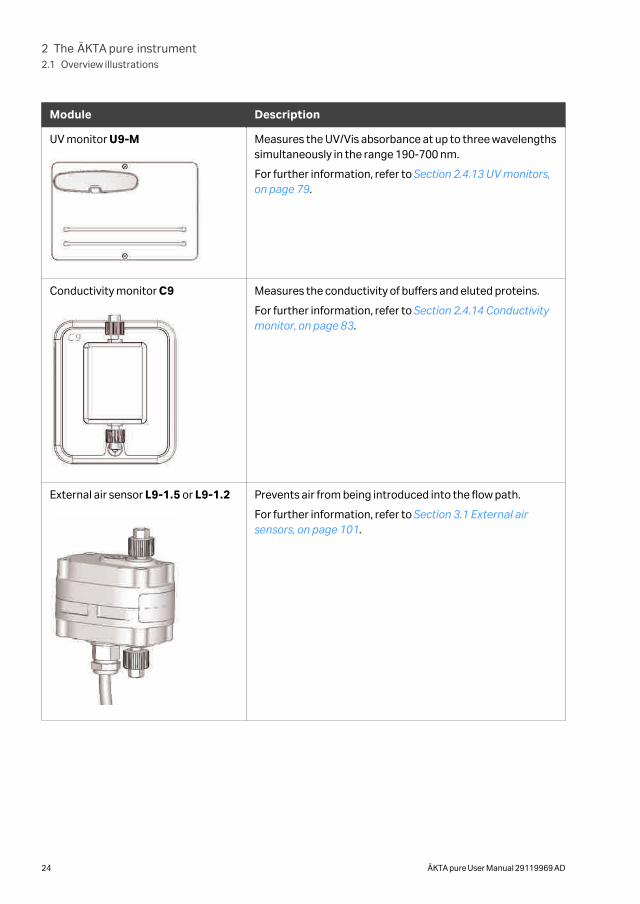
Module Description
UV monitor U9-M Measures the UV/Vis absorbance at up to three wavelengthssimultaneously in the range 190-700 nm.
For further information, refer to Section 2.4.13 UV monitors,on page 79.
Conductivity monitor C9 Measures the conductivity of buffers and eluted proteins.
For further information, refer to Section 2.4.14 Conductivitymonitor, on page 83.
External air sensor L9-1.5 or L9-1.2 Prevents air from being introduced into the flow path.
For further information, refer to Section 3.1 External airsensors, on page 101.
2 The ÄKTA pure instrument2.1 Overview illustrations
24 ÄKTA pure User Manual 29119969 AD
Module Description
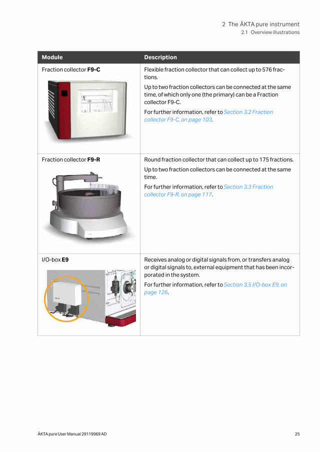
Fraction collector F9-C Flexible fraction collector that can collect up to 576 frac-tions.
Up to two fraction collectors can be connected at the sametime, of which only one (the primary) can be a Fractioncollector F9-C.
For further information, refer to Section 3.2 Fractioncollector F9-C, on page 103.
Fraction collector F9-R Round fraction collector that can collect up to 175 fractions.
Up to two fraction collectors can be connected at the sametime.
For further information, refer to Section 3.3 Fractioncollector F9-R, on page 117.
I/O-box E9 Receives analog or digital signals from, or transfers analogor digital signals to, external equipment that has been incor-porated in the system.
For further information, refer to Section 3.5 I/O-box E9, onpage 126.
2 The ÄKTA pure instrument2.1 Overview illustrations
ÄKTA pure User Manual 29119969 AD 25
Module Description
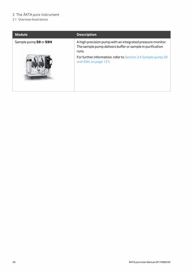
Sample pump S9 or S9H A high precision pump with an integrated pressure monitor.The sample pump delivers buffer or sample in purificationruns.
For further information, refer to Section 3.4 Sample pump S9and S9H, on page 121.
2 The ÄKTA pure instrument2.1 Overview illustrations
26 ÄKTA pure User Manual 29119969 AD
2.2 Liquid flow path
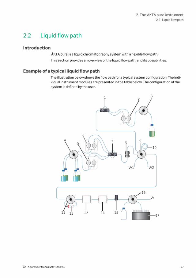
IntroductionÄKTA pure is a liquid chromatography system with a flexible flow path.
This section provides an overview of the liquid flow path, and its possibilities.
Example of a typical liquid flow pathThe illustration below shows the flow path for a typical system configuration. The indi-vidual instrument modules are presented in the table below. The configuration of thesystem is defined by the user.
45
6
7 8 9
10
11 12 13 14 15
16
17
W1 W2
W
321
2 The ÄKTA pure instrument2.2 Liquid flow path
ÄKTA pure User Manual 29119969 AD 27
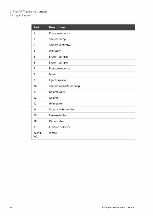
Part Description
1 Pressure monitor
2 Sample pump
3 Sample inlet valve
4 Inlet valve
5 System pump B
6 System pump A
7 Pressure monitor
8 Mixer
9 Injection valve
10 Sample loop or Superloop
11 Column valve
12 Column
13 UV monitor
14 Conductivity monitor
15 Flow restrictor
16 Outlet valve
17 Fraction collector
W, W1,W2
Waste
2 The ÄKTA pure instrument2.2 Liquid flow path
28 ÄKTA pure User Manual 29119969 AD
2.3 Instrument control panel
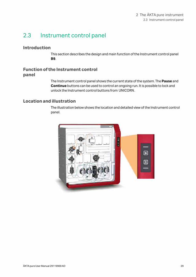
IntroductionThis section describes the design and main function of the Instrument control panelB9.
Function of the Instrument controlpanel
The Instrument control panel shows the current state of the system. The Pause andContinue buttons can be used to control an ongoing run. It is possible to lock andunlock the Instrument control buttons from UNICORN.
Location and illustrationThe illustration below shows the location and detailed view of the Instrument controlpanel.
2 The ÄKTA pure instrument2.3 Instrument control panel
ÄKTA pure User Manual 29119969 AD 29
1
2
3
4
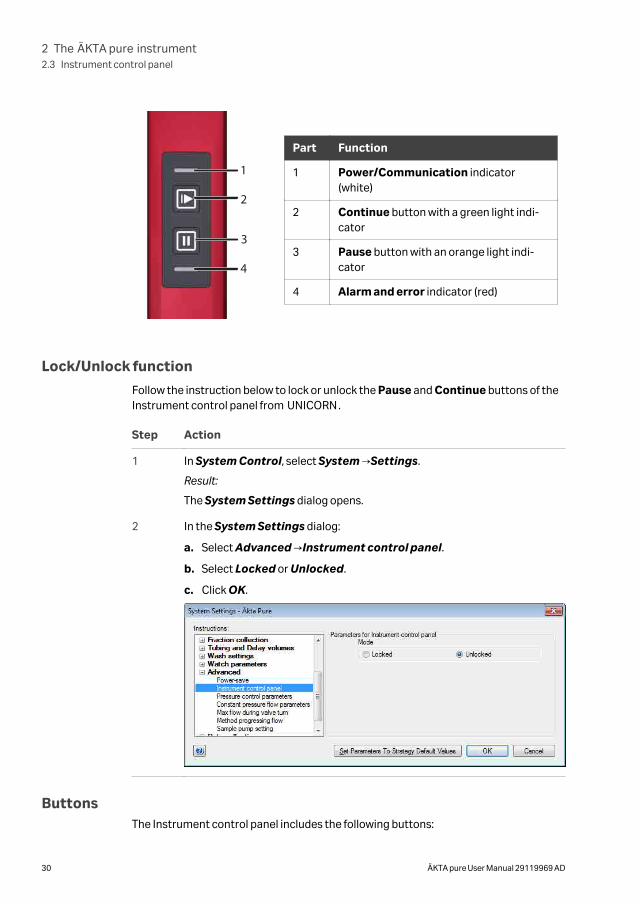
Part Function
1 Power/Communication indicator(white)
2 Continue button with a green light indi-cator
3 Pause button with an orange light indi-cator
4 Alarm and error indicator (red)
Lock/Unlock function
Follow the instruction below to lock or unlock the Pause and Continue buttons of theInstrument control panel from UNICORN.
Step Action
1 In System Control, select System →Settings.
Result:
The System Settings dialog opens.
2 In the System Settings dialog:
a. Select Advanced →Instrument control panel.
b. Select Locked or Unlocked.
c. Click OK.
ButtonsThe Instrument control panel includes the following buttons:
2 The ÄKTA pure instrument2.3 Instrument control panel
30 ÄKTA pure User Manual 29119969 AD
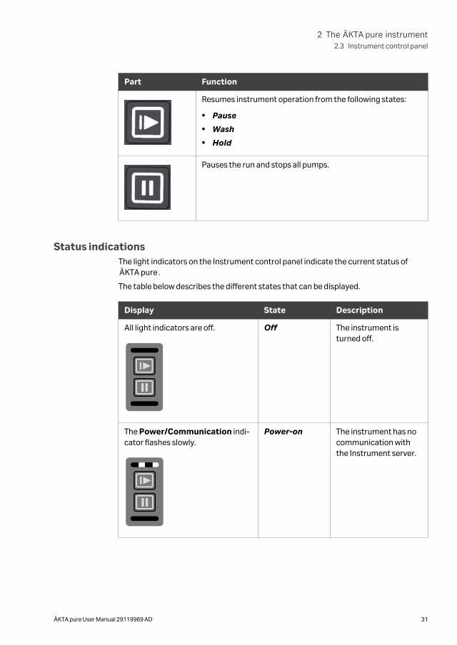
Part Function
Resumes instrument operation from the following states:
• Pause
• Wash
• Hold
Pauses the run and stops all pumps.
Status indicationsThe light indicators on the Instrument control panel indicate the current status ofÄKTA pure.
The table below describes the different states that can be displayed.
Display State Description
All light indicators are off.
Off
Off The instrument isturned off.
The Power/Communication indi-cator flashes slowly.
Power-on
Power-on The instrument has nocommunication withthe Instrument server.
2 The ÄKTA pure instrument2.3 Instrument control panel
ÄKTA pure User Manual 29119969 AD 31
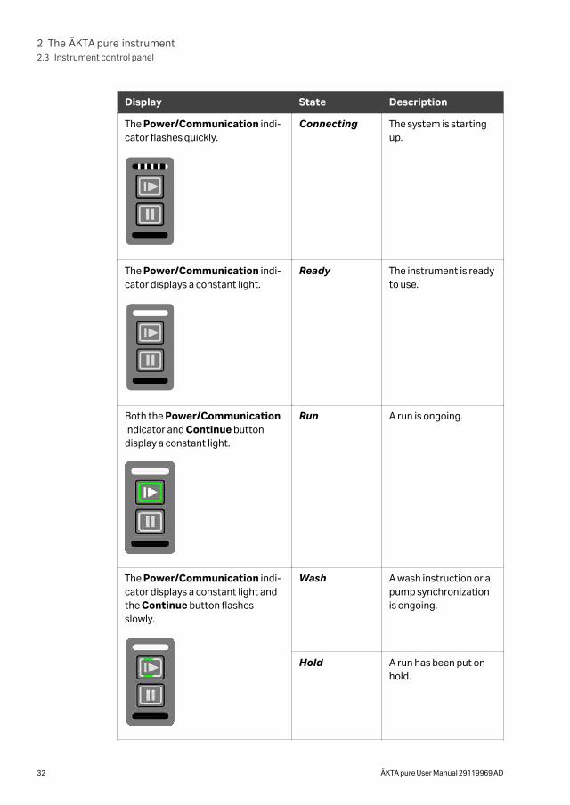
Display State Description
The Power/Communication indi-cator flashes quickly.
Connecting
Connecting The system is startingup.
The Power/Communication indi-cator displays a constant light.
Ready
Ready The instrument is readyto use.
Both the Power/Communicationindicator and Continue buttondisplay a constant light.
Run A run is ongoing.
The Power/Communication indi-cator displays a constant light andthe Continue button flashesslowly.
Wash A wash instruction or apump synchronizationis ongoing.
Hold A run has been put onhold.
2 The ÄKTA pure instrument2.3 Instrument control panel
32 ÄKTA pure User Manual 29119969 AD
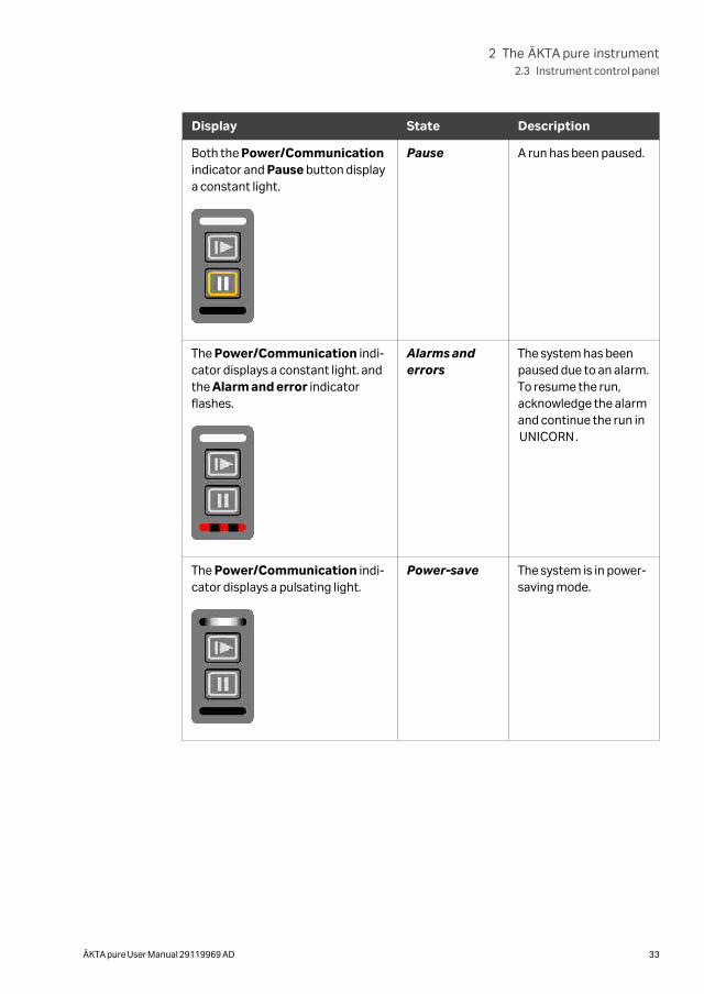
Display State Description
Both the Power/Communicationindicator and Pause button displaya constant light.
Pause A run has been paused.
The Power/Communication indi-cator displays a constant light. andthe Alarm and error indicatorflashes.
Alarms anderrors
The system has beenpaused due to an alarm.To resume the run,acknowledge the alarmand continue the run inUNICORN.
The Power/Communication indi-cator displays a pulsating light.
Power-save The system is in power-saving mode.
2 The ÄKTA pure instrument2.3 Instrument control panel
ÄKTA pure User Manual 29119969 AD 33
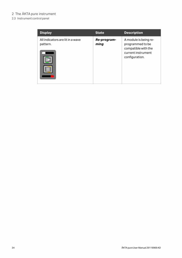
Display State Description
All indicators are lit in a wavepattern.
Re-program-ming
A module is being re-programmed to becompatible with thecurrent instrumentconfiguration.
2 The ÄKTA pure instrument2.3 Instrument control panel
34 ÄKTA pure User Manual 29119969 AD
2.4 Instrument modules
IntroductionThis section describes the design and main functions of the instrument modules.
In this section
Section See page
2.4.1 System pumps 36
2.4.2 Mixer 40
2.4.3 Valves, overview 42
2.4.4 Inlet valves 43
2.4.5 Mixer valve 51
2.4.6 Injection valve 54
2.4.7 Loop valve 59
2.4.8 Column valves 62
2.4.9 Versatile valve 67
2.4.10 pH valve 68
2.4.11 Outlet valves 73
2.4.12 Pressure monitors 76
2.4.13 UV monitors 79
2.4.14 Conductivity monitor 83
2.4.15 Flow restrictor 85
2 The ÄKTA pure instrument2.4 Instrument modules
ÄKTA pure User Manual 29119969 AD 35
2.4.1 System pumps
IntroductionThis section describes the design and main functions of the system pumps, and alsothe pump piston rinsing systems. The system can also be equipped with an external,optional sample pump, see Section 3.4 Sample pump S9 and S9H, on page 121.
Function of the system pumpsThe ÄKTA pure instrument is fitted with two high precision system pumps, Systempump A and System pump B. The system pumps can be used individually, or in combi-nation to generate isocratic or gradient elution in purification methods.
Each pump module consists of two pump heads that work alternately to give a contin-uous, low pulsation, liquid delivery. To ensure delivery of correct liquid volume, thepumps must be free from air. Each pump head is equipped with a purge valve that isused for this purpose. See Section 5.4 Prime inlets and purge pump heads, on page 179.
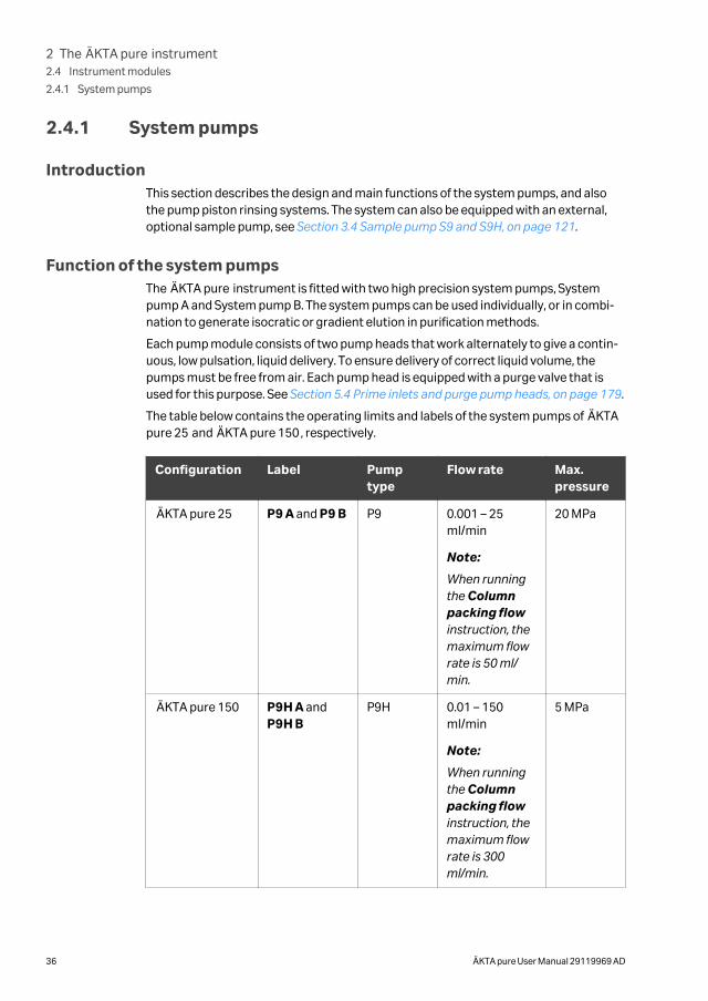
The table below contains the operating limits and labels of the system pumps of ÄKTApure 25 and ÄKTA pure 150, respectively.
Configuration Label Pumptype
Flow rate Max.pressure
ÄKTA pure 25 P9 A and P9 B P9 0.001 – 25ml/min
Note:
When runningthe Columnpacking flowinstruction, themaximum flowrate is 50 ml/min.
20 MPa
ÄKTA pure 150 P9H A andP9H B
P9H 0.01 – 150ml/min
Note:
When runningthe Columnpacking flowinstruction, themaximum flowrate is 300ml/min.
5 MPa
2 The ÄKTA pure instrument2.4 Instrument modules
2.4.1 System pumps
36 ÄKTA pure User Manual 29119969 AD
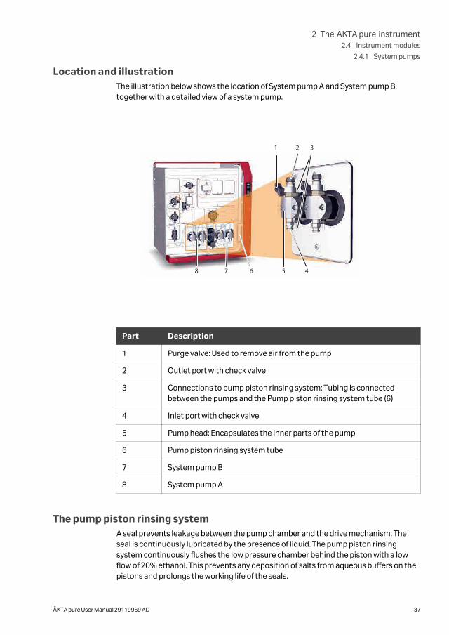
Location and illustrationThe illustration below shows the location of System pump A and System pump B,together with a detailed view of a system pump.
1 2 3
45678
Part Description
1 Purge valve: Used to remove air from the pump
2 Outlet port with check valve
3 Connections to pump piston rinsing system: Tubing is connectedbetween the pumps and the Pump piston rinsing system tube (6)
4 Inlet port with check valve
5 Pump head: Encapsulates the inner parts of the pump
6 Pump piston rinsing system tube
7 System pump B
8 System pump A
The pump piston rinsing systemA seal prevents leakage between the pump chamber and the drive mechanism. Theseal is continuously lubricated by the presence of liquid. The pump piston rinsingsystem continuously flushes the low pressure chamber behind the piston with a lowflow of 20% ethanol. This prevents any deposition of salts from aqueous buffers on thepistons and prolongs the working life of the seals.
2 The ÄKTA pure instrument2.4 Instrument modules
2.4.1 System pumps
ÄKTA pure User Manual 29119969 AD 37
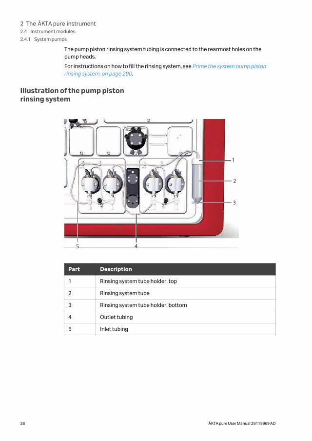
The pump piston rinsing system tubing is connected to the rearmost holes on thepump heads.
For instructions on how to fill the rinsing system, see Prime the system pump pistonrinsing system, on page 290.
Illustration of the pump pistonrinsing system
1
2
3
45
Part Description
1 Rinsing system tube holder, top
2 Rinsing system tube
3 Rinsing system tube holder, bottom
4 Outlet tubing
5 Inlet tubing
2 The ÄKTA pure instrument2.4 Instrument modules
2.4.1 System pumps
38 ÄKTA pure User Manual 29119969 AD
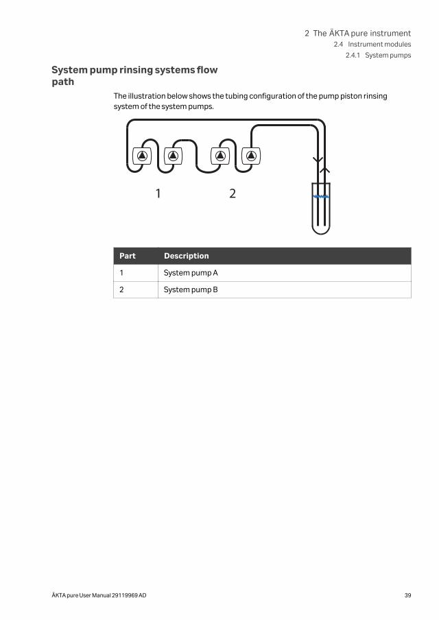
System pump rinsing systems flowpath
The illustration below shows the tubing configuration of the pump piston rinsingsystem of the system pumps.
1 2
Part Description
1 System pump A
2 System pump B
2 The ÄKTA pure instrument2.4 Instrument modules
2.4.1 System pumps
ÄKTA pure User Manual 29119969 AD 39
2.4.2 Mixer
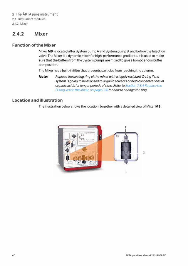
Function of the MixerMixer M9 is located after System pump A and System pump B, and before the Injectionvalve. The Mixer is a dynamic mixer for high-performance gradients. It is used to makesure that the buffers from the System pumps are mixed to give a homogenous buffercomposition.
The Mixer has a built-in filter that prevents particles from reaching the column.
Note: Replace the sealing ring of the mixer with a highly resistant O-ring if thesystem is going to be exposed to organic solvents or high concentrations oforganic acids for longer periods of time. Refer to Section 7.8.4 Replace theO-ring inside the Mixer, on page 356 for how to change the ring.
Location and illustrationThe illustration below shows the location, together with a detailed view of Mixer M9.
1
2
3
2 The ÄKTA pure instrument2.4 Instrument modules
2.4.2 Mixer
40 ÄKTA pure User Manual 29119969 AD
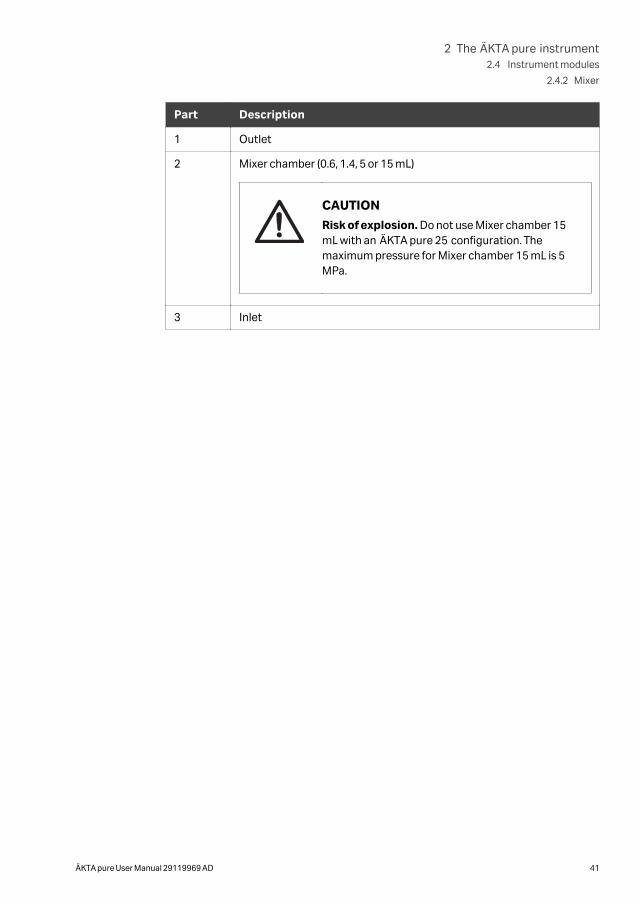
Part Description
1 Outlet
2 Mixer chamber (0.6, 1.4, 5 or 15 mL)
CAUTION
Risk of explosion. Do not use Mixer chamber 15mL with an ÄKTA pure 25 configuration. Themaximum pressure for Mixer chamber 15 mL is 5MPa.
3 Inlet
2 The ÄKTA pure instrument2.4 Instrument modules
2.4.2 Mixer
ÄKTA pure User Manual 29119969 AD 41
2.4.3 Valves, overview
General design and function of rotaryvalves
The valves of the ÄKTA pure instrument allow flexibility in the liquid flow path.
All valves used in the ÄKTA pure instrument are rotary valves. The motorized rotaryvalve consists of a Valve connection block with a number of defined bores with chan-nels to the inlet and outlet ports of the valve. The Rotary disc, mounted on the motor,has a number of defined channels. The pattern of channels of the Rotary disc togetherwith the pattern and location of the ports of the Valve connection block, define the flowpath and function of each type of valve. When the Rotary disc turns, the flow path in thevalve changes.
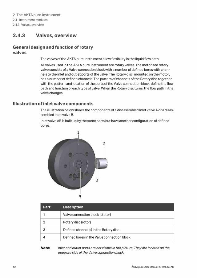
Illustration of inlet valve componentsThe illustration below shows the components of a disassembled Inlet valve A or a disas-sembled Inlet valve B.
Inlet valve AB is built up by the same parts but have another configuration of definedbores.
Part Description
1 Valve connection block (stator)
2 Rotary disc (rotor)
3 Defined channel(s) in the Rotary disc
4 Defined bores in the Valve connection block
Note: Inlet and outlet ports are not visible in the picture. They are located on theopposite side of the Valve connection block.
2 The ÄKTA pure instrument2.4 Instrument modules
2.4.3 Valves, overview
42 ÄKTA pure User Manual 29119969 AD
2.4.4 Inlet valves
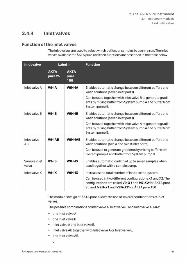
Function of the inlet valvesThe inlet valves are used to select which buffers or samples to use in a run. The inletvalves available for ÄKTA pure and their functions are described in the table below.
Inlet valve Label in Function
ÄKTApure 25
ÄKTApure150
Inlet valve A V9-IA V9H-IA Enables automatic change between different buffers andwash solutions (seven inlet ports) .
Can be used together with Inlet valve B to generate gradi-ents by mixing buffer from System pump A and buffer fromSystem pump B.
Inlet valve B V9-IB V9H-IB Enables automatic change between different buffers andwash solutions (seven inlet ports).
Can be used together with Inlet valve A to generate gradi-ents by mixing buffer from System pump A and buffer fromSystem pump B.
Inlet valveAB
V9-IAB V9H-IAB Enables automatic change between different buffers andwash solutions (two A and two B inlet ports).
Can be used to generate gradients by mixing buffer fromSystem pump A and buffer from System pump B.
Sample inletvalve
V9-IS V9H-IS Enables automatic loading of up to seven samples whenused together with a sample pump.
Inlet valve X V9-IX V9H-IX Increases the total number of inlets to the system.
Can be used in two different configurations X1 and X2. Theconfigurations are called V9-X1 and V9-X2 for ÄKTA pure25 and, V9H-X1 and V9H-X2 for ÄKTA pure 150.
The modular design of ÄKTA pure allows the use of several combinations of inletvalves.
The possible combinations of Inlet valve A, Inlet valve B and Inlet valve AB are:
• one Inlet valve A
• one Inlet valve B
• Inlet valve A and Inlet valve B,
• Inlet valve AB together with Inlet valve A or Inlet valve B,
• one Inlet valve AB,
or
2 The ÄKTA pure instrument2.4 Instrument modules
2.4.4 Inlet valves
ÄKTA pure User Manual 29119969 AD 43
• no installed inlet valves.
The sample inlet valve can be used together with any of the combinations listed above.
The air sensors integrated in Inlet valve A, Inlet valve B, and Sample inlet valve detectthe presence of air and prevent the air from entering the pump.
Inlet valve AB and Inlet valve IX lack built-in air sensors, but can be used together withexternal air sensors.
Location of inlet valvesThe locations of the inlet valves are described in the following table:
Inlet valve Location
Inlet valve A Before System pump A
Inlet valve B Before System pump B
Inlet valve AB Before both System pump A and System pump B
Sample inlet valve Before the sample pump
Inlet valve IX For example, before another inlet valve
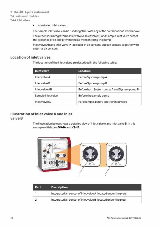
Illustration of Inlet valve A and Inletvalve B
The illustration below shows a detailed view of Inlet valve A and Inlet valve B, in thisexample with labels V9-IA and V9-IB.
1 2
Part Description
1 Integrated air sensor of Inlet valve A (located under the plug)
2 Integrated air sensor of Inlet valve B (located under the plug)
2 The ÄKTA pure instrument2.4 Instrument modules
2.4.4 Inlet valves
44 ÄKTA pure User Manual 29119969 AD
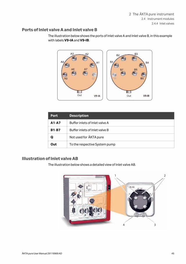
Ports of Inlet valve A and Inlet valve BThe illustration below shows the ports of Inlet valve A and Inlet valve B, in this examplewith labels V9-IA and V9-IB.
Out Out
Port Description
A1-A7 Buffer inlets of Inlet valve A
B1-B7 Buffer inlets of Inlet valve B
Q Not used for ÄKTA pure
Out To the respective System pump
Illustration of Inlet valve ABThe illustration below shows a detailed view of Inlet valve AB.
1 2
34
2 The ÄKTA pure instrument2.4 Instrument modules
2.4.4 Inlet valves
ÄKTA pure User Manual 29119969 AD 45
Part Description
1 A inlet ports
2 B inlet ports
3 Outlet port to System pump B
4 Outlet port to System pump A
Note: Inlet valve AB does not have any integrated air sensor.
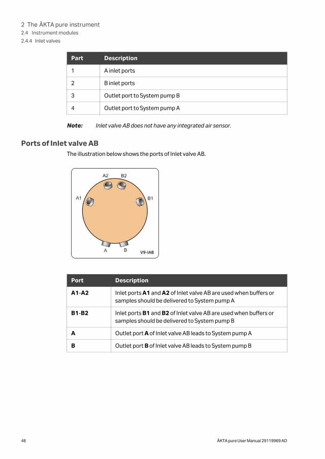
Ports of Inlet valve ABThe illustration below shows the ports of Inlet valve AB.
Port Description
A1-A2 Inlet ports A1 and A2 of Inlet valve AB are used when buffers orsamples should be delivered to System pump A
B1-B2 Inlet ports B1 and B2 of Inlet valve AB are used when buffers orsamples should be delivered to System pump B
A Outlet port A of Inlet valve AB leads to System pump A
B Outlet port B of Inlet valve AB leads to System pump B
2 The ÄKTA pure instrument2.4 Instrument modules
2.4.4 Inlet valves
46 ÄKTA pure User Manual 29119969 AD
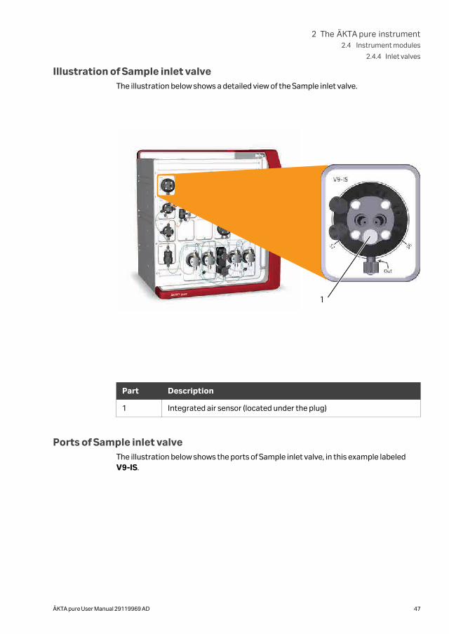
Illustration of Sample inlet valveThe illustration below shows a detailed view of the Sample inlet valve.
1
Part Description
1 Integrated air sensor (located under the plug)
Ports of Sample inlet valveThe illustration below shows the ports of Sample inlet valve, in this example labeledV9-IS.
2 The ÄKTA pure instrument2.4 Instrument modules
2.4.4 Inlet valves
ÄKTA pure User Manual 29119969 AD 47
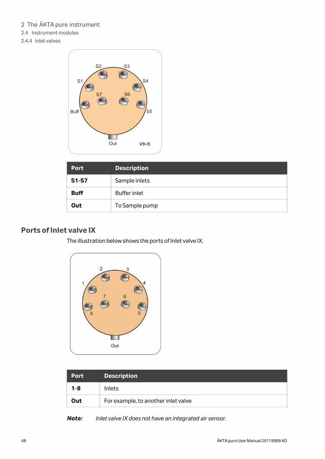
Port Description
S1-S7 Sample inlets
Buff Buffer inlet
Out To Sample pump
Ports of Inlet valve IXThe illustration below shows the ports of Inlet valve IX.
Port Description
1-8 Inlets
Out For example, to another inlet valve
Note: Inlet valve IX does not have an integrated air sensor.
2 The ÄKTA pure instrument2.4 Instrument modules
2.4.4 Inlet valves
48 ÄKTA pure User Manual 29119969 AD
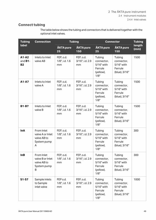
Connect tubingThe table below shows the tubing and connectors that is delivered together with theoptional inlet valves.
Tubinglabel
Connection Tubing Connector Tubinglength(mm)ÄKTA pure
25ÄKTA pure150
ÄKTA pure25
ÄKTA pure150
A1-A2and B1-B2
Inlets to Inletvalve AB
FEP, o.d.1/8", i.d. 1.6mm
FEP, o.d.3/16", i.d. 2.9mm
Tubingconnector,5/16" withFerrule(yellow),1/8"
Tubingconnector,5/16" withFerrule(blue), 3/16"
1500
A1-A7 Inlets to Inletvalve A
FEP, o.d.1/8", i.d. 1.6mm
FEP, o.d.3/16", i.d. 2.9mm
Tubingconnector,5/16" withFerrule(yellow),1/8"
Tubingconnector,5/16" withFerrule(blue), 3/16"
1500
B1-B7 Inlets to Inletvalve B
FEP, o.d.1/8", i.d. 1.6mm
FEP, o.d.3/16", i.d. 2.9mm
Tubingconnector,5/16" withFerrule(yellow),1/8"
Tubingconnector,5/16" withFerrule(blue), 3/16"
1500
InA From Inletvalve A or Inletvalve AB toSystem pumpA
FEP, o.d.1/8", i.d. 1.6mm
FEP, o.d.3/16", i.d. 2.9mm
Tubingconnector,5/16" withFerrule(yellow),1/8"
Tubingconnector,5/16" withFerrule(blue), 3/16"
300
InB From Inletvalve B or Inletvalve AB toSystem pumpB
FEP, o.d.1/8", i.d. 1.6mm
FEP, o.d.3/16", i.d. 2.9mm
Tubingconnector,5/16" withFerrule(yellow),1/8"
Tubingconnector,5/16" withFerrule(blue), 3/16"
300
S1-S7 Sample inletsto Sampleinlet valve
FEP o.d.1/8", i.d. 1.6mm
FEP, o.d.3/16", i.d. 2.9mm
Tubingconnector,5/16" withFerrule(yellow),1/8"
Tubingconnector,5/16" withFerrule(blue), 3/16"
1000
2 The ÄKTA pure instrument2.4 Instrument modules
2.4.4 Inlet valves
ÄKTA pure User Manual 29119969 AD 49
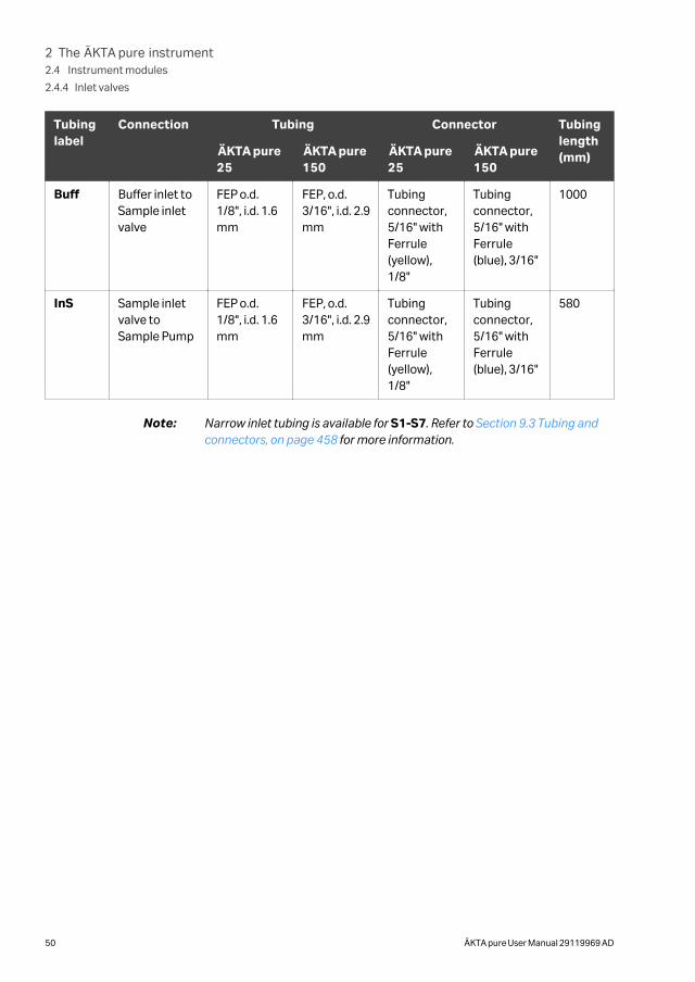
Tubinglabel
Connection Tubing Connector Tubinglength(mm)ÄKTA pure
25ÄKTA pure150
ÄKTA pure25
ÄKTA pure150
Buff Buffer inlet toSample inletvalve
FEP o.d.1/8", i.d. 1.6mm
FEP, o.d.3/16", i.d. 2.9mm
Tubingconnector,5/16" withFerrule(yellow),1/8"
Tubingconnector,5/16" withFerrule(blue), 3/16"
1000
InS Sample inletvalve toSample Pump
FEP o.d.1/8", i.d. 1.6mm
FEP, o.d.3/16", i.d. 2.9mm
Tubingconnector,5/16" withFerrule(yellow),1/8"
Tubingconnector,5/16" withFerrule(blue), 3/16"
580
Note: Narrow inlet tubing is available for S1-S7. Refer to Section 9.3 Tubing andconnectors, on page 458 for more information.
2 The ÄKTA pure instrument2.4 Instrument modules
2.4.4 Inlet valves
50 ÄKTA pure User Manual 29119969 AD
2.4.5 Mixer valve
Function of Mixer valveMixer valve (V9-M or V9H-M) allows the user to bypass the mixer. It is intended to beused when the System pump is used for sample application or when a sample is re-injected.
Note: Mixer valve (V9-M or V9H-M) cannot be used together with Sample pumpS9 or Sample pump S9H.
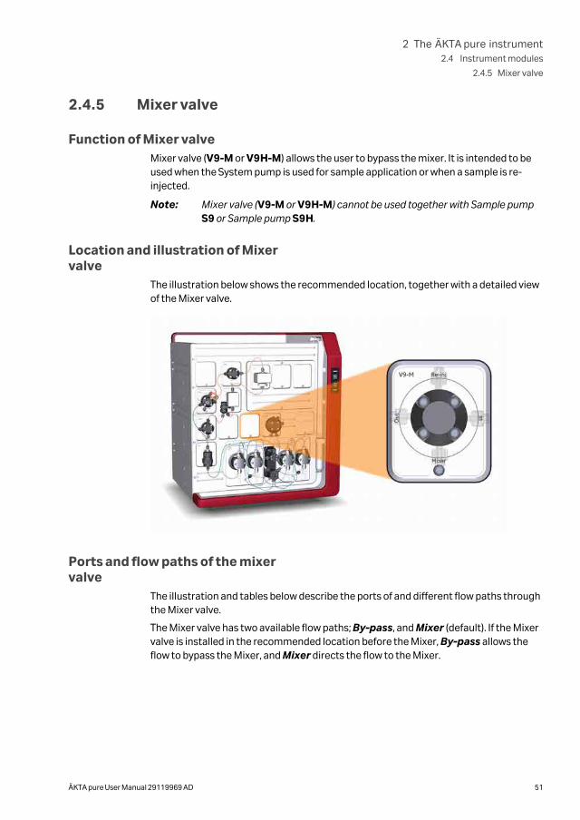
Location and illustration of Mixervalve
The illustration below shows the recommended location, together with a detailed viewof the Mixer valve.
Ports and flow paths of the mixervalve
The illustration and tables below describe the ports of and different flow paths throughthe Mixer valve.
The Mixer valve has two available flow paths; By-pass, and Mixer (default). If the Mixervalve is installed in the recommended location before the Mixer, By-pass allows theflow to bypass the Mixer, and Mixer directs the flow to the Mixer.
2 The ÄKTA pure instrument2.4 Instrument modules
2.4.5 Mixer valve
ÄKTA pure User Manual 29119969 AD 51
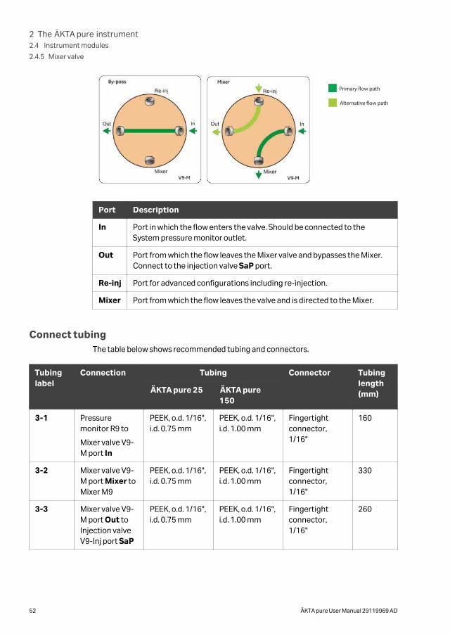
Primary �ow path
Alternative �ow path
Port Description
In Port in which the flow enters the valve. Should be connected to theSystem pressure monitor outlet.
Out Port from which the flow leaves the Mixer valve and bypasses the Mixer.Connect to the injection valve SaP port.
Re-inj Port for advanced configurations including re-injection.
Mixer Port from which the flow leaves the valve and is directed to the Mixer.
Connect tubingThe table below shows recommended tubing and connectors.
Tubinglabel
Connection Tubing Connector Tubinglength(mm)ÄKTA pure 25 ÄKTA pure
150
3-1 Pressuremonitor R9 to
Mixer valve V9-M port In
PEEK, o.d. 1/16",i.d. 0.75 mm
PEEK, o.d. 1/16",i.d. 1.00 mm
Fingertightconnector,1/16"
160
3-2 Mixer valve V9-M port Mixer toMixer M9
PEEK, o.d. 1/16",i.d. 0.75 mm
PEEK, o.d. 1/16",i.d. 1.00 mm
Fingertightconnector,1/16"
330
3-3 Mixer valve V9-M port Out toInjection valveV9-Inj port SaP
PEEK, o.d. 1/16",i.d. 0.75 mm
PEEK, o.d. 1/16",i.d. 1.00 mm
Fingertightconnector,1/16"
260
2 The ÄKTA pure instrument2.4 Instrument modules
2.4.5 Mixer valve
52 ÄKTA pure User Manual 29119969 AD
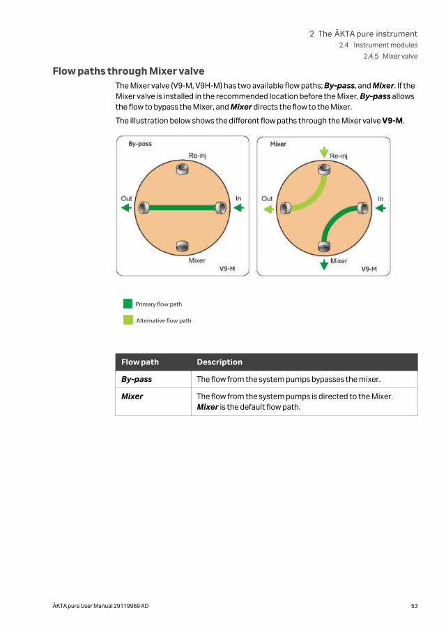
Flow paths through Mixer valveThe Mixer valve (V9-M, V9H-M) has two available flow paths; By-pass, and Mixer. If theMixer valve is installed in the recommended location before the Mixer, By-pass allowsthe flow to bypass the Mixer, and Mixer directs the flow to the Mixer.
The illustration below shows the different flow paths through the Mixer valve V9-M.
Primary �ow path
Alternative �ow path
Flow path Description
By-pass The flow from the system pumps bypasses the mixer.
Mixer The flow from the system pumps is directed to the Mixer.Mixer is the default flow path.
2 The ÄKTA pure instrument2.4 Instrument modules
2.4.5 Mixer valve
ÄKTA pure User Manual 29119969 AD 53
2.4.6 Injection valve
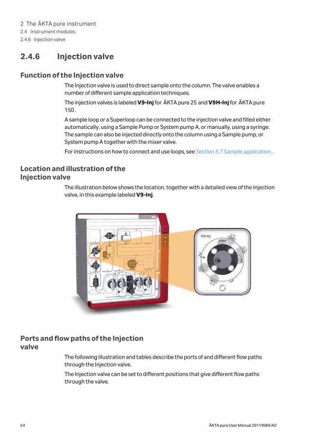
Function of the Injection valveThe Injection valve is used to direct sample onto the column. The valve enables anumber of different sample application techniques.
The injection valves is labeled V9-Inj for ÄKTA pure 25 and V9H-Inj for ÄKTA pure150.
A sample loop or a Superloop can be connected to the injection valve and filled eitherautomatically, using a Sample Pump or System pump A, or manually, using a syringe.The sample can also be injected directly onto the column using a Sample pump, orSystem pump A together with the mixer valve.
For instructions on how to connect and use loops, see Section 5.7 Sample application, .
Location and illustration of theInjection valve
The illustration below shows the location, together with a detailed view of the Injectionvalve, in this example labeled V9-Inj.
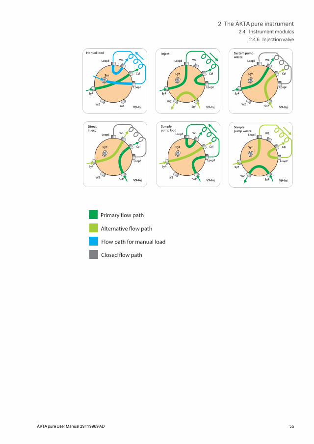
Ports and flow paths of the Injectionvalve
The following illustration and tables describe the ports of and different flow pathsthrough the Injection valve.
The Injection valve can be set to different positions that give different flow pathsthrough the valve.
2 The ÄKTA pure instrument2.4 Instrument modules
2.4.6 Injection valve
54 ÄKTA pure User Manual 29119969 AD
Primary �ow path
Alternative �ow path
Flow path for manual load
Closed �ow path
2 The ÄKTA pure instrument2.4 Instrument modules
2.4.6 Injection valve
ÄKTA pure User Manual 29119969 AD 55
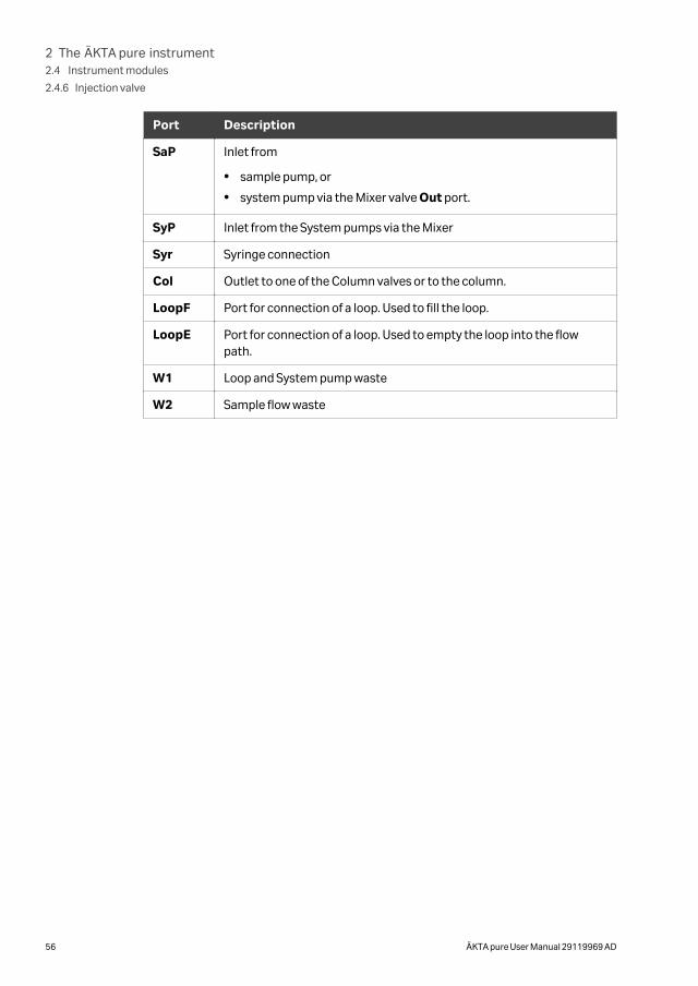
Port Description
SaP Inlet from
• sample pump, or
• system pump via the Mixer valve Out port.
SyP Inlet from the System pumps via the Mixer
Syr Syringe connection
Col Outlet to one of the Column valves or to the column.
LoopF Port for connection of a loop. Used to fill the loop.
LoopE Port for connection of a loop. Used to empty the loop into the flowpath.
W1 Loop and System pump waste
W2 Sample flow waste
2 The ÄKTA pure instrument2.4 Instrument modules
2.4.6 Injection valve
56 ÄKTA pure User Manual 29119969 AD
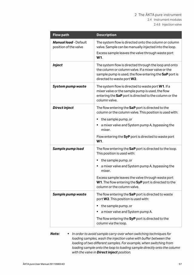
Flow path Description
Manual load - Defaultposition of the valve
The system flow is directed onto the column or columnvalve. Sample can be manually injected into the loop.
Excess sample leaves the valve through waste portW1.
Inject The system flow is directed through the loop and ontothe column or column valve. If a mixer valve or thesample pump is used, the flow entering the SaP port isdirected to waste port W2.
System pump waste The system flow is directed to waste port W1. If amixer valve or the sample pump is used, the flowentering the SaP port is directed to the column or thecolumn valve.
Direct inject The flow entering the SaP port is directed to thecolumn or the column valve. This position is used with:
• the sample pump, or
• a mixer valve and System pump A, bypassing themixer.
Flow entering the SyP port is directed to waste portW1.
Sample pump load The flow entering the SaP port is directed to the loop.This position is used with:
• the sample pump, or
• a mixer valve and System pump A, bypassing themixer.
Excess sample leaves the valve through waste portW1. The flow entering the SyP port is directed to thecolumn or the column valve.
Sample pump waste The flow entering the SaP port is directed to wasteport W2. This position is used with:
• the sample pump, or
• a mixer valve and System pump A.
The flow entering the SyP port is directed to thecolumn via the loop.
Note: • In order to avoid sample carry-over when switching techniques forloading samples, wash the injection valve with buffer between theloading of two different samples. For example, when switching fromloading sample onto the loop to loading sample directly onto the columnwith the valve in Direct inject position.
2 The ÄKTA pure instrument2.4 Instrument modules
2.4.6 Injection valve
ÄKTA pure User Manual 29119969 AD 57
• Make sure that the SaP port is plugged with a stop plug if neither thesample pump nor the mixer is used.
2 The ÄKTA pure instrument2.4 Instrument modules
2.4.6 Injection valve
58 ÄKTA pure User Manual 29119969 AD
2.4.7 Loop valve
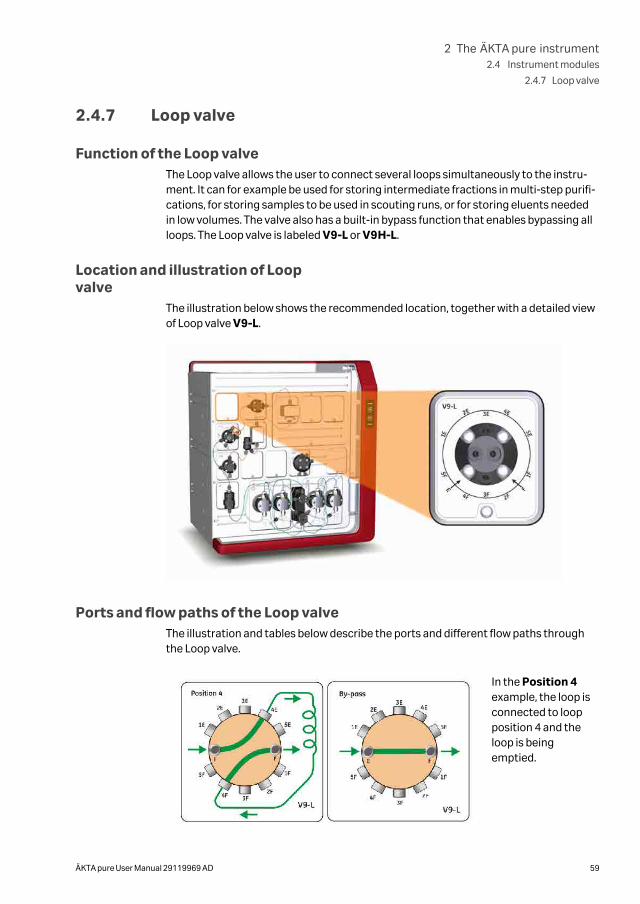
Function of the Loop valveThe Loop valve allows the user to connect several loops simultaneously to the instru-ment. It can for example be used for storing intermediate fractions in multi-step purifi-cations, for storing samples to be used in scouting runs, or for storing eluents neededin low volumes. The valve also has a built-in bypass function that enables bypassing allloops. The Loop valve is labeled V9-L or V9H-L.
Location and illustration of Loopvalve
The illustration below shows the recommended location, together with a detailed viewof Loop valve V9-L.
Ports and flow paths of the Loop valveThe illustration and tables below describe the ports and different flow paths throughthe Loop valve.
In the Position 4example, the loop isconnected to loopposition 4 and theloop is beingemptied.
2 The ÄKTA pure instrument2.4 Instrument modules
2.4.7 Loop valve
ÄKTA pure User Manual 29119969 AD 59
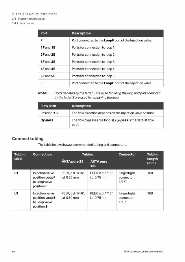
Port Description
F Port connected to the LoopF port of the Injection valve.
1F and 1E Ports for connection to loop 1.
2F and 2E Ports for connection to loop 2.
3F and 3E Ports for connection to loop 3.
4F and 4E Ports for connection to loop 4.
5F and 5E Ports for connection to loop 5.
E Port connected to the LoopE port of the Injection valve.
Note: Ports denoted by the letter F are used for filling the loop and ports denotedby the letter E are used for emptying the loop.
Flow path Description
Position 1-5 The flow direction depends on the Injection valve position.
By-pass The flow bypasses the loop(s). By-pass is the default flowpath.
Connect tubingThe table below shows recommended tubing and connectors.
Tubinglabel
Connection Tubing Connector Tubinglength(mm)ÄKTA pure 25 ÄKTA pure
150
L1 Injection valveposition LoopFto Loop valveposition F
PEEK, o.d. 1/16",i.d. 0.50 mm
PEEK, o.d. 1/16",i.d. 0.75 mm
Fingertightconnector,1/16"
160
L2 Injection valveposition LoopEto Loop valveposition E
PEEK, o.d. 1/16",i.d. 0.50 mm
PEEK, o.d. 1/16",i.d. 0.75 mm
Fingertightconnector,1/16"
160
2 The ÄKTA pure instrument2.4 Instrument modules
2.4.7 Loop valve
60 ÄKTA pure User Manual 29119969 AD
Connect a Loop valve
The Loop valve is connected to the Injection valve instead of a loop, as described below.
Step Action
1 Connect port E on the Loop valve to port LoopE on the Injection valve.
2 Connect port F on the Loop valve to port LoopF on the Injection valve.
3 Connect one or many loops to the Loop valve. See Section 5.7 Sample appli-cation, on page 201.
Note:
Always use the the first positions of the valve for the connected loops (e.g., ifthree loops will be used, use port 1F-3F and the corresponding ports 1E-3E)to avoid cross-contamination.
Note: It is possible to place the Loop valve in other positions in the flow path thanthe one described above. However, the volume used for washes will then beincorrect, just as the system configuration shown in the process picture.
2 The ÄKTA pure instrument2.4 Instrument modules
2.4.7 Loop valve
ÄKTA pure User Manual 29119969 AD 61
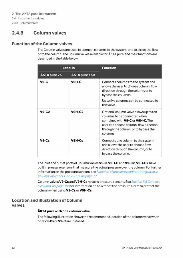
2.4.8 Column valves
Function of the Column valvesThe Column valves are used to connect columns to the system, and to direct the flowonto the column. The Column valves available for ÄKTA pure and their functions aredescribed in the table below.
Label in Function
ÄKTA pure 25 ÄKTA pure 150
V9-C V9H-C Connects columns to the system andallows the user to choose column, flowdirection through the column, or tobypass the columns.
Up to five columns can be connected tothe valve.
V9-C2 V9H-C2 Optional column valve allows up to tencolumns to be connected whencombined with V9-C or V9H-C. Theuser can choose column, flow directionthrough the column, or to bypass thecolumns.
V9-Cs V9H-Cs Connects one column to the systemand allows the user to choose flowdirection through the column, or tobypass the column.
The inlet and outlet ports of Column valves V9-C, V9H-C and V9-C2, V9H-C2 havebuilt in pressure sensors that measure the actual pressure over the column. For furtherinformation on the pressure sensors, see Function of pressure monitors integrated inColumn valves V9-C or V9H-C, on page 77.
Column valves V9-Cs and V9H-Cs have no pressure sensors. See Section 5.5 Connecta column, on page 193 for information on how to set the pressure alarm to protect thecolumn when using V9-Cs or V9H-Cs.
Location and illustration of Columnvalves
ÄKTA pure with one column valve
The following illustration shows the recommended location of the column valve whenonly V9-Cs or V9-C are installed.
2 The ÄKTA pure instrument2.4 Instrument modules
2.4.8 Column valves
62 ÄKTA pure User Manual 29119969 AD
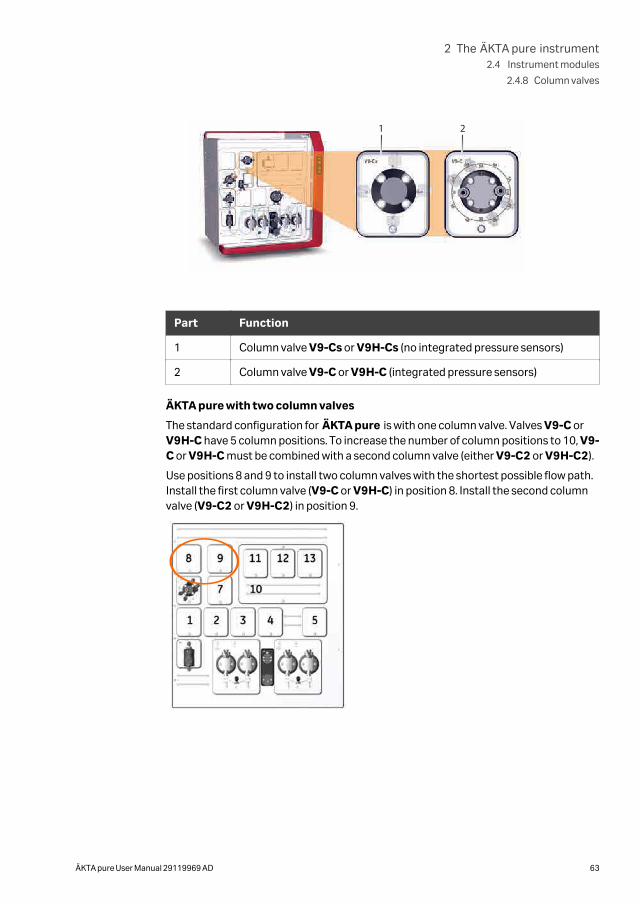
1 2
Part Function
1 Column valve V9-Cs or V9H-Cs (no integrated pressure sensors)
2 Column valve V9-C or V9H-C (integrated pressure sensors)
ÄKTA pure with two column valves
The standard configuration for ÄKTA pure is with one column valve. Valves V9-C orV9H-C have 5 column positions. To increase the number of column positions to 10, V9-C or V9H-C must be combined with a second column valve (either V9-C2 or V9H-C2).
Use positions 8 and 9 to install two column valves with the shortest possible flow path.Install the first column valve (V9-C or V9H-C) in position 8. Install the second columnvalve (V9-C2 or V9H-C2) in position 9.
2 The ÄKTA pure instrument2.4 Instrument modules
2.4.8 Column valves
ÄKTA pure User Manual 29119969 AD 63
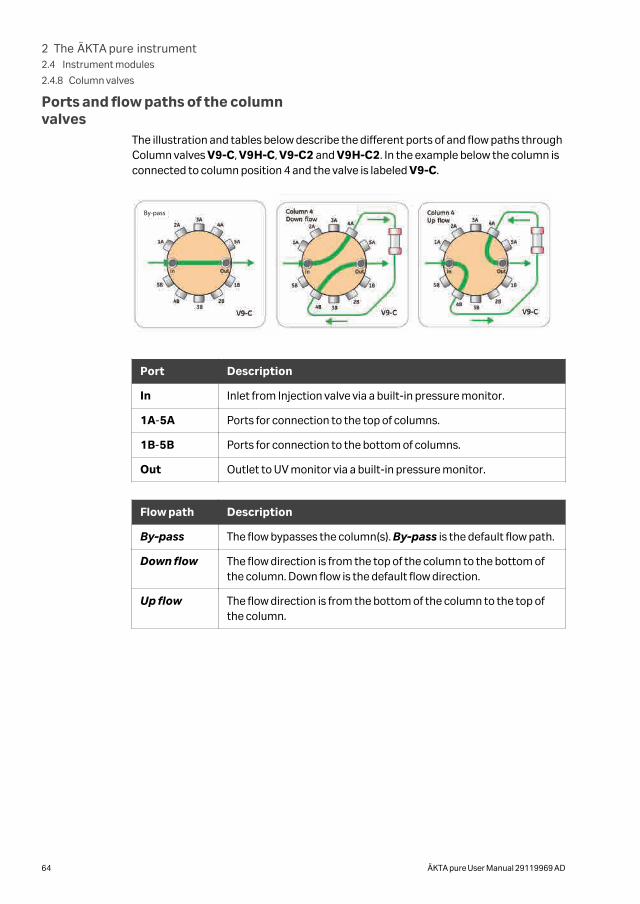
Ports and flow paths of the columnvalves
The illustration and tables below describe the different ports of and flow paths throughColumn valves V9-C, V9H-C, V9-C2 and V9H-C2. In the example below the column isconnected to column position 4 and the valve is labeled V9-C.
By-pass
Port Description
In Inlet from Injection valve via a built-in pressure monitor.
1A-5A Ports for connection to the top of columns.
1B-5B Ports for connection to the bottom of columns.
Out Outlet to UV monitor via a built-in pressure monitor.
Flow path Description
By-pass The flow bypasses the column(s). By-pass is the default flow path.
Down flow The flow direction is from the top of the column to the bottom ofthe column. Down flow is the default flow direction.
Up flow The flow direction is from the bottom of the column to the top ofthe column.
2 The ÄKTA pure instrument2.4 Instrument modules
2.4.8 Column valves
64 ÄKTA pure User Manual 29119969 AD
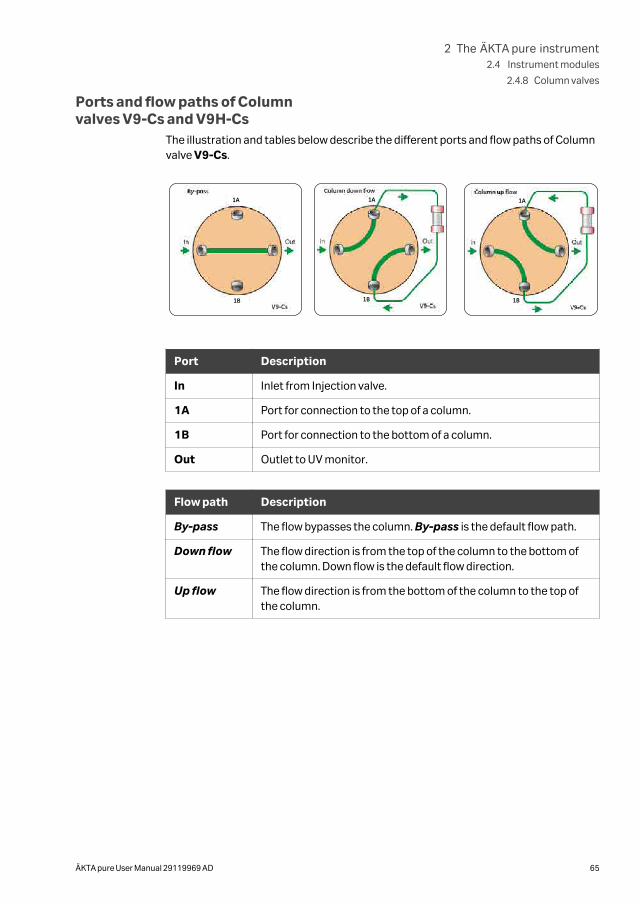
Ports and flow paths of Columnvalves V9-Cs and V9H-Cs
The illustration and tables below describe the different ports and flow paths of Columnvalve V9-Cs.
1A
1B
1A
1B
1A
1B
Port Description
In Inlet from Injection valve.
1A Port for connection to the top of a column.
1B Port for connection to the bottom of a column.
Out Outlet to UV monitor.
Flow path Description
By-pass The flow bypasses the column. By-pass is the default flow path.
Down flow The flow direction is from the top of the column to the bottom ofthe column. Down flow is the default flow direction.
Up flow The flow direction is from the bottom of the column to the top ofthe column.
2 The ÄKTA pure instrument2.4 Instrument modules
2.4.8 Column valves
ÄKTA pure User Manual 29119969 AD 65
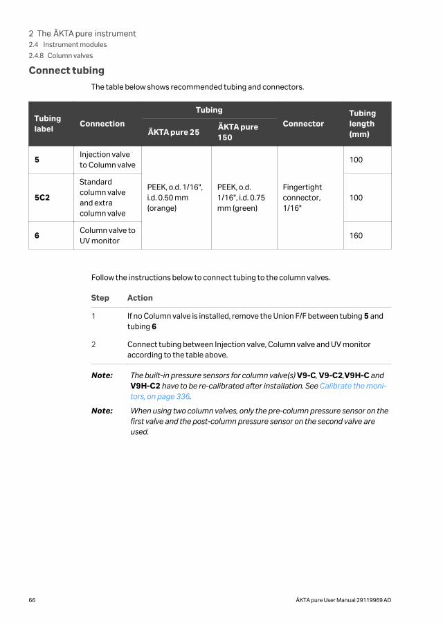
Connect tubing
The table below shows recommended tubing and connectors.
Tubinglabel
Connection
Tubing
ConnectorTubinglength(mm)ÄKTA pure 25
ÄKTA pure150
5Injection valveto Column valve
PEEK, o.d. 1/16",i.d. 0.50 mm(orange)
PEEK, o.d.1/16", i.d. 0.75mm (green)
Fingertightconnector,1/16"
100
5C2
Standardcolumn valveand extracolumn valve
100
6Column valve toUV monitor
160
Follow the instructions below to connect tubing to the column valves.
Step Action
1 If no Column valve is installed, remove the Union F/F between tubing 5 andtubing 6
2 Connect tubing between Injection valve, Column valve and UV monitoraccording to the table above.
Note: The built-in pressure sensors for column valve(s) V9-C, V9-C2,V9H-C andV9H-C2 have to be re-calibrated after installation. See Calibrate the moni-tors, on page 336.
Note: When using two column valves, only the pre-column pressure sensor on thefirst valve and the post-column pressure sensor on the second valve areused.
2 The ÄKTA pure instrument2.4 Instrument modules
2.4.8 Column valves
66 ÄKTA pure User Manual 29119969 AD
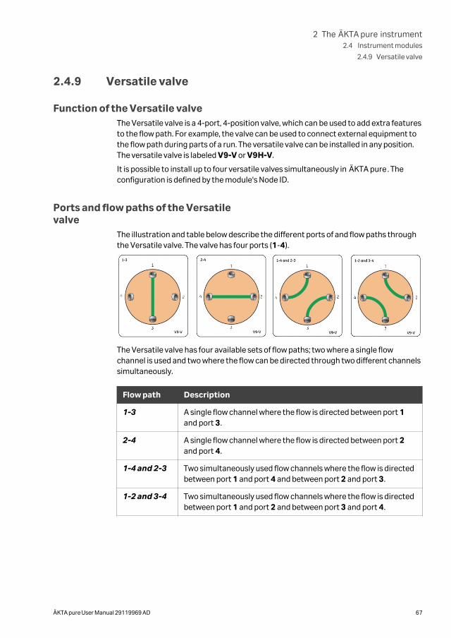
2.4.9 Versatile valve
Function of the Versatile valveThe Versatile valve is a 4-port, 4-position valve, which can be used to add extra featuresto the flow path. For example, the valve can be used to connect external equipment tothe flow path during parts of a run. The versatile valve can be installed in any position.The versatile valve is labeled V9-V or V9H-V.
It is possible to install up to four versatile valves simultaneously in ÄKTA pure. Theconfiguration is defined by the module's Node ID.
Ports and flow paths of the Versatilevalve
The illustration and table below describe the different ports of and flow paths throughthe Versatile valve. The valve has four ports (1-4).
The Versatile valve has four available sets of flow paths; two where a single flowchannel is used and two where the flow can be directed through two different channelssimultaneously.
Flow path Description
1-3 A single flow channel where the flow is directed between port 1and port 3.
2-4 A single flow channel where the flow is directed between port 2and port 4.
1-4 and 2-3 Two simultaneously used flow channels where the flow is directedbetween port 1 and port 4 and between port 2 and port 3.
1-2 and 3-4 Two simultaneously used flow channels where the flow is directedbetween port 1 and port 2 and between port 3 and port 4.
2 The ÄKTA pure instrument2.4 Instrument modules
2.4.9 Versatile valve
ÄKTA pure User Manual 29119969 AD 67
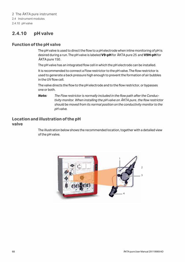
2.4.10 pH valve
Function of the pH valveThe pH valve is used to direct the flow to a pH electrode when inline monitoring of pH isdesired during a run. The pH valve is labeled V9-pH for ÄKTA pure 25 and V9H-pH forÄKTA pure 150.
The pH valve has an integrated flow cell in which the pH electrode can be installed.
It is recommended to connect a Flow restrictor to the pH valve. The flow restrictor isused to generate a back pressure high enough to prevent the formation of air bubblesin the UV flow cell.
The valve directs the flow to the pH electrode and to the flow restrictor, or bypassesone or both.
Note: The Flow restrictor is normally included in the flow path after the Conduc-tivity monitor. When installing the pH valve on ÄKTA pure, the flow restrictorshould be moved from its normal position on the conductivity monitor to thepH valve.
Location and illustration of the pHvalve
The illustration below shows the recommended location, together with a detailed viewof the pH valve.
1
2
3
4
2 The ÄKTA pure instrument2.4 Instrument modules
2.4.10 pH valve
68 ÄKTA pure User Manual 29119969 AD
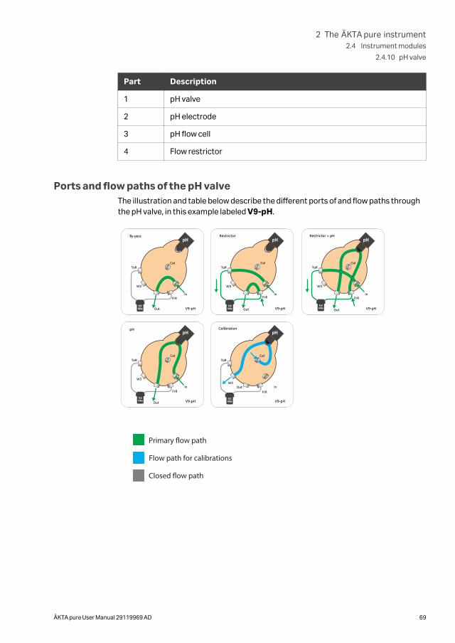
Part Description
1 pH valve
2 pH electrode
3 pH flow cell
4 Flow restrictor
Ports and flow paths of the pH valveThe illustration and table below describe the different ports of and flow paths throughthe pH valve, in this example labeled V9-pH.
By-pass
Primary �ow path
Flow path for calibrations
Closed �ow path
2 The ÄKTA pure instrument2.4 Instrument modules
2.4.10 pH valve
ÄKTA pure User Manual 29119969 AD 69
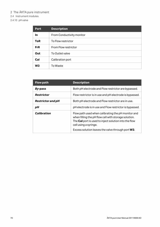
Port Description
In From Conductivity monitor
ToR To Flow restrictor
FrR From Flow restrictor
Out To Outlet valve
Cal Calibration port
W3 To Waste
Flow path Description
By-pass Both pH electrode and Flow restrictor are bypassed.
Restrictor Flow restrictor is in use and pH electrode is bypassed.
Restrictor and pH Both pH electrode and Flow restrictor are in use.
pH pH electrode is in use and Flow restrictor is bypassed.
Calibration Flow path used when calibrating the pH monitor andwhen filling the pH flow cell with storage solution.The Cal port is used to inject solution into the flowcell using a syringe.
Excess solution leaves the valve through port W3.
2 The ÄKTA pure instrument2.4 Instrument modules
2.4.10 pH valve
70 ÄKTA pure User Manual 29119969 AD
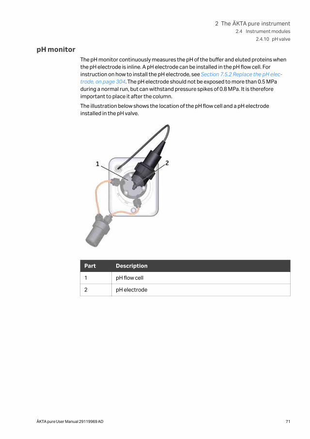
pH monitorThe pH monitor continuously measures the pH of the buffer and eluted proteins whenthe pH electrode is inline. A pH electrode can be installed in the pH flow cell. Forinstruction on how to install the pH electrode, see Section 7.5.2 Replace the pH elec-trode, on page 304. The pH electrode should not be exposed to more than 0.5 MPaduring a normal run, but can withstand pressure spikes of 0.8 MPa. It is thereforeimportant to place it after the column.
The illustration below shows the location of the pH flow cell and a pH electrodeinstalled in the pH valve.
Part Description
1 pH flow cell
2 pH electrode
2 The ÄKTA pure instrument2.4 Instrument modules
2.4.10 pH valve
ÄKTA pure User Manual 29119969 AD 71
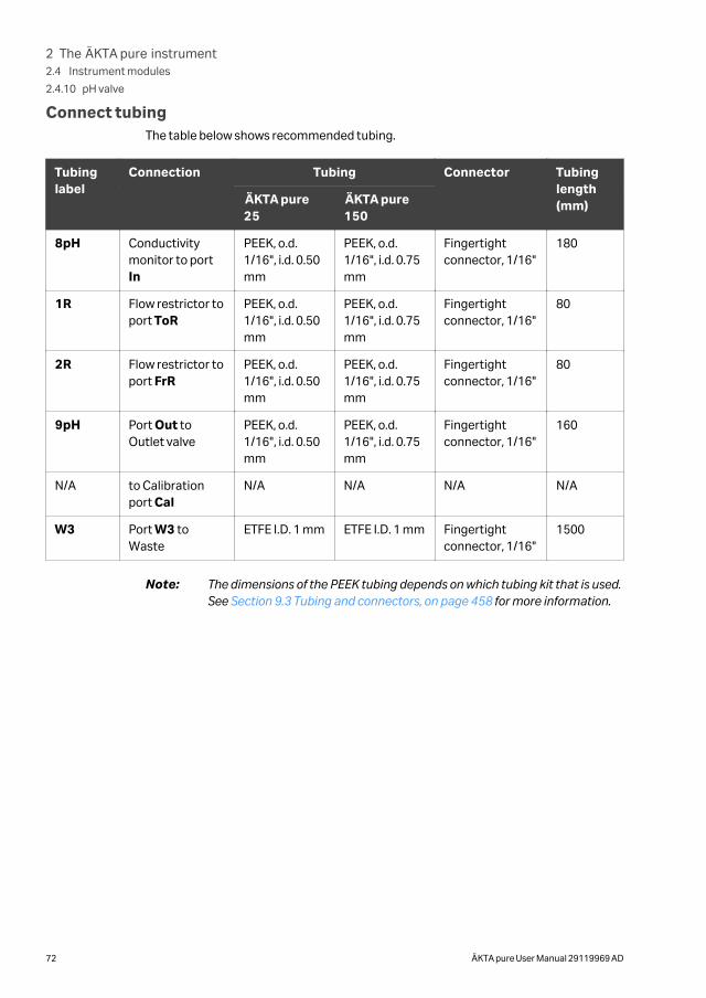
Connect tubingThe table below shows recommended tubing.
Tubinglabel
Connection Tubing Connector Tubinglength(mm)ÄKTA pure
25ÄKTA pure150
8pH Conductivitymonitor to portIn
PEEK, o.d.1/16", i.d. 0.50mm
PEEK, o.d.1/16", i.d. 0.75mm
Fingertightconnector, 1/16"
180
1R Flow restrictor toport ToR
PEEK, o.d.1/16", i.d. 0.50mm
PEEK, o.d.1/16", i.d. 0.75mm
Fingertightconnector, 1/16"
80
2R Flow restrictor toport FrR
PEEK, o.d.1/16", i.d. 0.50mm
PEEK, o.d.1/16", i.d. 0.75mm
Fingertightconnector, 1/16"
80
9pH Port Out toOutlet valve
PEEK, o.d.1/16", i.d. 0.50mm
PEEK, o.d.1/16", i.d. 0.75mm
Fingertightconnector, 1/16"
160
N/A to Calibrationport Cal
N/A N/A N/A N/A
W3 Port W3 toWaste
ETFE I.D. 1 mm ETFE I.D. 1 mm Fingertightconnector, 1/16"
1500
Note: The dimensions of the PEEK tubing depends on which tubing kit that is used.See Section 9.3 Tubing and connectors, on page 458 for more information.
2 The ÄKTA pure instrument2.4 Instrument modules
2.4.10 pH valve
72 ÄKTA pure User Manual 29119969 AD
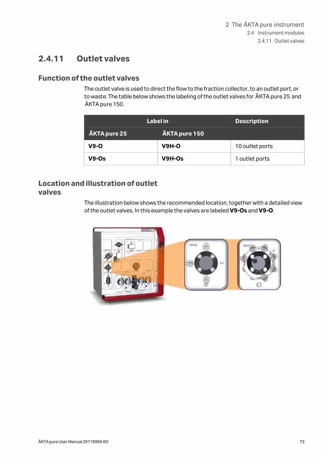
2.4.11 Outlet valves
Function of the outlet valvesThe outlet valve is used to direct the flow to the fraction collector, to an outlet port, orto waste. The table below shows the labeling of the outlet valves for ÄKTA pure 25 andÄKTA pure 150.
Label in Description
ÄKTA pure 25 ÄKTA pure 150
V9-O V9H-O 10 outlet ports
V9-Os V9H-Os 1 outlet ports
Location and illustration of outletvalves
The illustration below shows the recommended location, together with a detailed viewof the outlet valves. In this example the valves are labeled V9-Os and V9-O.
2 The ÄKTA pure instrument2.4 Instrument modules
2.4.11 Outlet valves
ÄKTA pure User Manual 29119969 AD 73
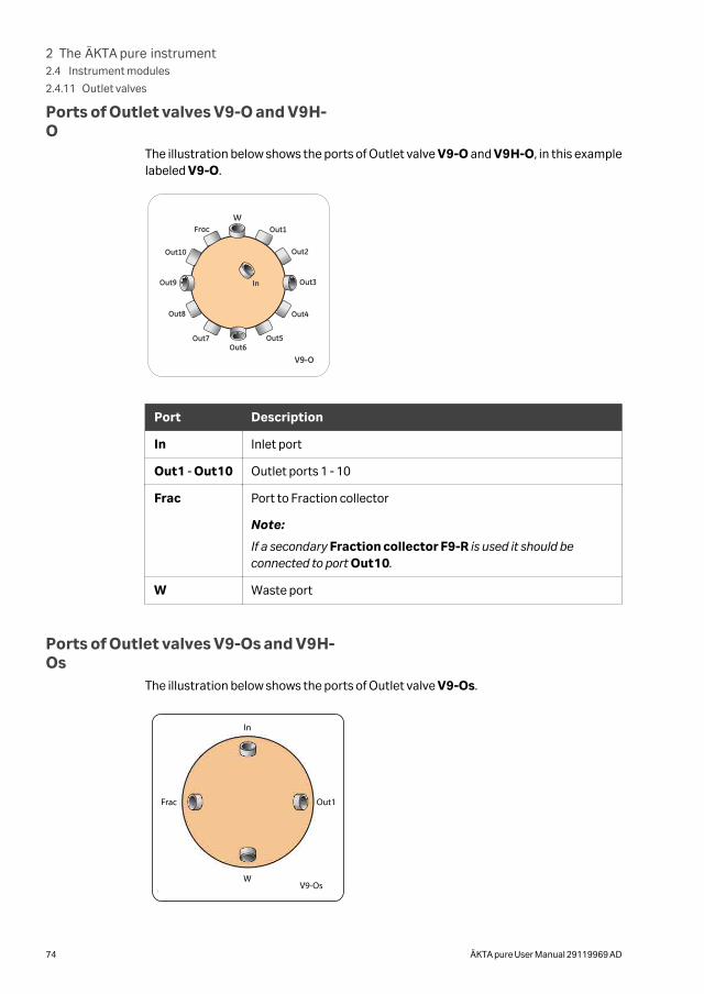
Ports of Outlet valves V9-O and V9H-O
The illustration below shows the ports of Outlet valve V9-O and V9H-O, in this examplelabeled V9-O.
Port Description
In Inlet port
Out1 - Out10 Outlet ports 1 - 10
Frac Port to Fraction collector
Note:
If a secondary Fraction collector F9-R is used it should beconnected to port Out10.
W Waste port
Ports of Outlet valves V9-Os and V9H-Os
The illustration below shows the ports of Outlet valve V9-Os.
In
Out1Frac
WV9-Os
2 The ÄKTA pure instrument2.4 Instrument modules
2.4.11 Outlet valves
74 ÄKTA pure User Manual 29119969 AD
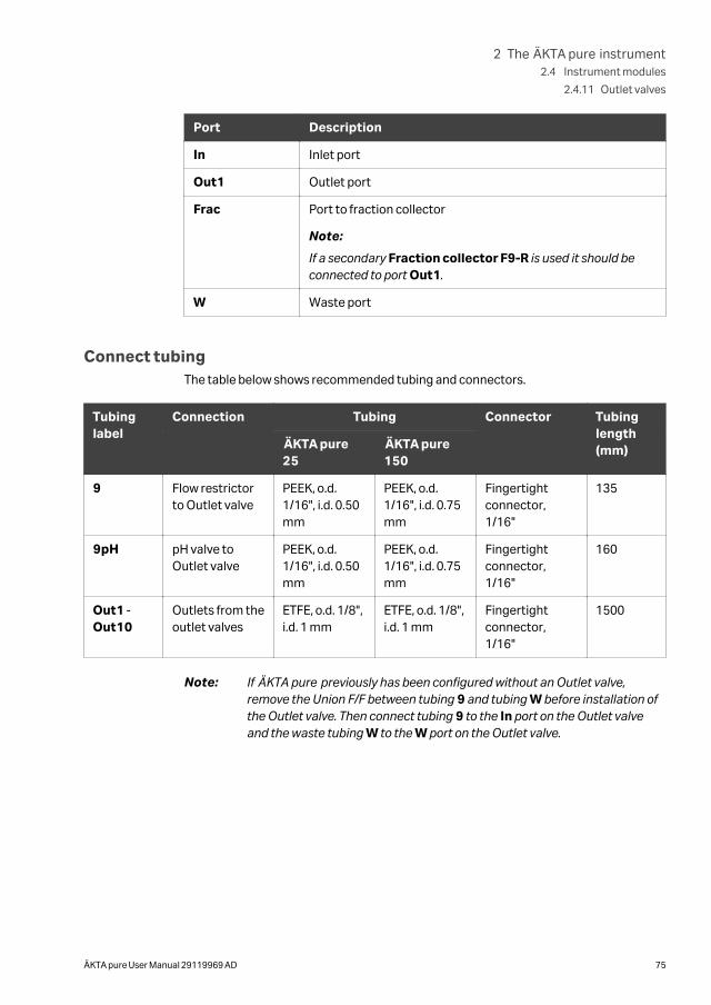
Port Description
In Inlet port
Out1 Outlet port
Frac Port to fraction collector
Note:
If a secondary Fraction collector F9-R is used it should beconnected to port Out1.
W Waste port
Connect tubingThe table below shows recommended tubing and connectors.
Tubinglabel
Connection Tubing Connector Tubinglength(mm)ÄKTA pure
25ÄKTA pure150
9 Flow restrictorto Outlet valve
PEEK, o.d.1/16", i.d. 0.50mm
PEEK, o.d.1/16", i.d. 0.75mm
Fingertightconnector,1/16"
135
9pH pH valve toOutlet valve
PEEK, o.d.1/16", i.d. 0.50mm
PEEK, o.d.1/16", i.d. 0.75mm
Fingertightconnector,1/16"
160
Out1 -Out10
Outlets from theoutlet valves
ETFE, o.d. 1/8",i.d. 1 mm
ETFE, o.d. 1/8",i.d. 1 mm
Fingertightconnector,1/16"
1500
Note: If ÄKTA pure previously has been configured without an Outlet valve,remove the Union F/F between tubing 9 and tubing W before installation ofthe Outlet valve. Then connect tubing 9 to the In port on the Outlet valveand the waste tubing W to the W port on the Outlet valve.
2 The ÄKTA pure instrument2.4 Instrument modules
2.4.11 Outlet valves
ÄKTA pure User Manual 29119969 AD 75
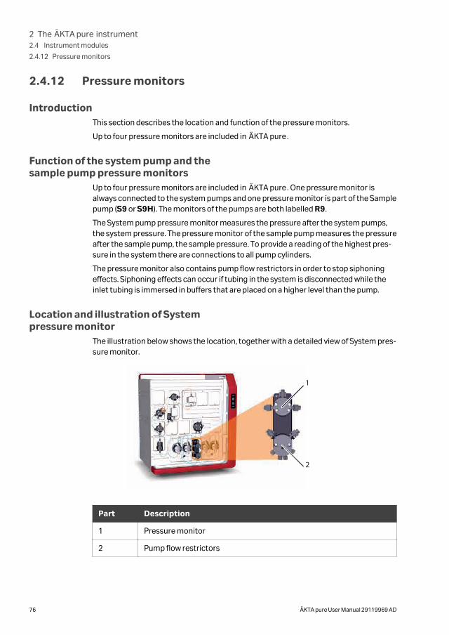
2.4.12 Pressure monitors
IntroductionThis section describes the location and function of the pressure monitors.
Up to four pressure monitors are included in ÄKTA pure.
Function of the system pump and thesample pump pressure monitors
Up to four pressure monitors are included in ÄKTA pure. One pressure monitor isalways connected to the system pumps and one pressure monitor is part of the Samplepump (S9 or S9H). The monitors of the pumps are both labelled R9.
The System pump pressure monitor measures the pressure after the system pumps,the system pressure. The pressure monitor of the sample pump measures the pressureafter the sample pump, the sample pressure. To provide a reading of the highest pres-sure in the system there are connections to all pump cylinders.
The pressure monitor also contains pump flow restrictors in order to stop siphoningeffects. Siphoning effects can occur if tubing in the system is disconnected while theinlet tubing is immersed in buffers that are placed on a higher level than the pump.
Location and illustration of Systempressure monitor
The illustration below shows the location, together with a detailed view of System pres-sure monitor.
1
2
Part Description
1 Pressure monitor
2 Pump flow restrictors
2 The ÄKTA pure instrument2.4 Instrument modules
2.4.12 Pressure monitors
76 ÄKTA pure User Manual 29119969 AD
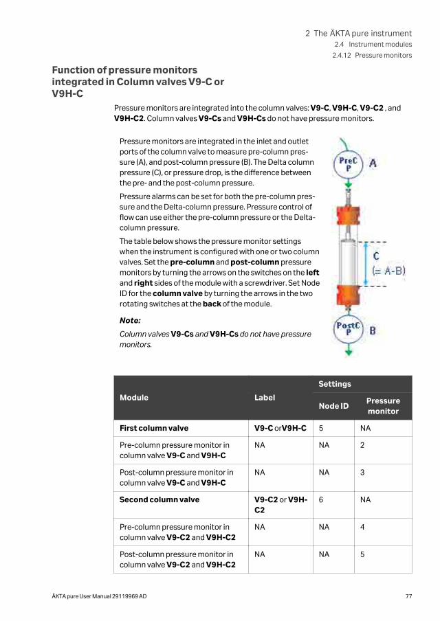
Function of pressure monitorsintegrated in Column valves V9-C orV9H-C
Pressure monitors are integrated into the column valves: V9-C, V9H-C, V9-C2 , andV9H-C2. Column valves V9-Cs and V9H-Cs do not have pressure monitors.
Pressure monitors are integrated in the inlet and outletports of the column valve to measure pre-column pres-sure (A), and post-column pressure (B). The Delta columnpressure (C), or pressure drop, is the difference betweenthe pre- and the post-column pressure.
Pressure alarms can be set for both the pre-column pres-sure and the Delta-column pressure. Pressure control offlow can use either the pre-column pressure or the Delta-column pressure.
The table below shows the pressure monitor settingswhen the instrument is configured with one or two columnvalves. Set the pre-column and post-column pressuremonitors by turning the arrows on the switches on the leftand right sides of the module with a screwdriver. Set NodeID for the column valve by turning the arrows in the tworotating switches at the back of the module.
Note:
Column valves V9-Cs and V9H-Cs do not have pressuremonitors.
Module Label
Settings
Node IDPressuremonitor
First column valve V9-C orV9H-C 5 NA
Pre-column pressure monitor incolumn valve V9-C and V9H-C
NA NA 2
Post-column pressure monitor incolumn valve V9-C and V9H-C
NA NA 3
Second column valve V9-C2 or V9H-C2
6 NA
Pre-column pressure monitor incolumn valve V9-C2 and V9H-C2
NA NA 4
Post-column pressure monitor incolumn valve V9-C2 and V9H-C2
NA NA 5
2 The ÄKTA pure instrument2.4 Instrument modules
2.4.12 Pressure monitors
ÄKTA pure User Manual 29119969 AD 77
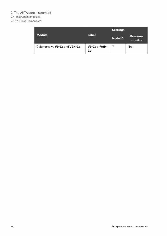
Module Label
Settings
Node IDPressuremonitor
Column valve V9-Cs and V9H-Cs V9-Cs or V9H-Cs
7 NA
2 The ÄKTA pure instrument2.4 Instrument modules
2.4.12 Pressure monitors
78 ÄKTA pure User Manual 29119969 AD
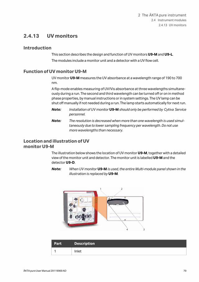
2.4.13 UV monitors
IntroductionThis section describes the design and function of UV monitors U9-M and U9-L.
The modules include a monitor unit and a detector with a UV flow cell.
Function of UV monitor U9-MUV monitor U9-M measures the UV absorbance at a wavelength range of 190 to 700nm.
A flip-mode enables measuring of UV/Vis absorbance at three wavelengths simultane-ously during a run. The second and third wavelength can be turned off or on in methodphase properties, by manual instructions or in system settings. The UV lamp can beshut off manually if not needed during a run. The lamp starts automatically for next run.
Note: Installation of UV monitor U9-M should only be performed by Cytiva Servicepersonnel.
Note: The resolution is decreased when more than one wavelength is used simul-taneously due to lower sampling frequency per wavelength. Do not usemore wavelengths than necessary.
Location and illustration of UVmonitor U9-M
The illustration below shows the location of UV monitor U9-M, together with a detailedview of the monitor unit and detector. The monitor unit is labelled U9-M and thedetector U9-D.
Note: When UV monitor U9-M is used, the entire Multi-module panel shown in theillustration is replaced by U9-M.
1 2
34
Part Description
1 Inlet
2 The ÄKTA pure instrument2.4 Instrument modules
2.4.13 UV monitors
ÄKTA pure User Manual 29119969 AD 79
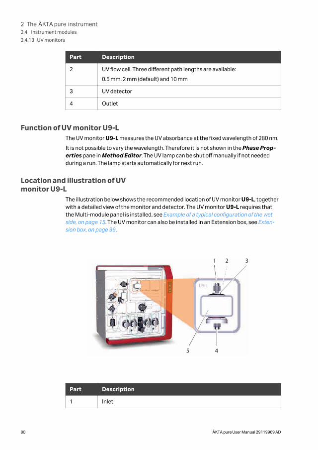
Part Description
2 UV flow cell. Three different path lengths are available:
0.5 mm, 2 mm (default) and 10 mm
3 UV detector
4 Outlet
Function of UV monitor U9-LThe UV monitor U9-L measures the UV absorbance at the fixed wavelength of 280 nm.
It is not possible to vary the wavelength. Therefore it is not shown in the Phase Prop-erties pane in Method Editor. The UV lamp can be shut off manually if not neededduring a run. The lamp starts automatically for next run.
Location and illustration of UVmonitor U9-L
The illustration below shows the recommended location of UV monitor U9-L, togetherwith a detailed view of the monitor and detector. The UV monitor U9-L requires thatthe Multi-module panel is installed, see Example of a typical configuration of the wetside, on page 15. The UV monitor can also be installed in an Extension box, see Exten-sion box, on page 99.
1 2 3
45
Part Description
1 Inlet
2 The ÄKTA pure instrument2.4 Instrument modules
2.4.13 UV monitors
80 ÄKTA pure User Manual 29119969 AD
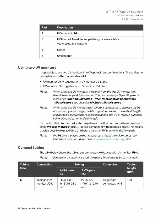
Part Description
2 UV monitor U9-L
3 UV flow cell. Two different path lengths are available:
2 mm (default) and 5 mm
4 Outlet
5 UV detector
Using two UV monitorsIt is possible to use two UV monitors in ÄKTA pure, in two combinations. The configura-tion is defined by the module's Node ID.
• UV monitor U9-M together with UV monitor U9-L, 2nd
• UV monitor U9-L together with UV monitor U9-L, 2nd
Note: When using two UV monitors, the signal from the first UV monitor is bydefault used for peak fractionation. This can be changed by editing the textinstruction Fraction Collection →Peak fractionation parameters→Signal source and choosing UV 2nd as Signal source.
Note: When using two UV monitors with different cell lengths to increase the UVabsorption dynamic range, the U9-L signal comes from the real cell lengthand has to be calibrated for exact calculations. The U9-M signal is automati-cally calibrated to nominal cell length.
UV monitor U9-L, 2nd can be located anywhere in the flow path and is therefore shownin the Process Picture in UNICORN as a component without a fixed place. This meansthat it is possible to place U9-L, 2nd before the other UV monitor in the flow path.
Note: If U9-L 2nd is placed on the high pressure side of the column, pressurelimits have to be considered. See UV monitor options, on page 454
Connect tubingThe table below shows the tubing and connectors to be used with UV monitor U9-L.
Note: If a second UV monitor is used, the tubing for this has to be cut manually.
Tubinglabel
Connection Tubing Connector Tubinglength(mm)ÄKTA pure
25ÄKTA pure150
6 Tubing to UVmonitor U9-L
PEEK, o.d.1/16", i.d. 0.50mm
PEEK, o.d.1/16", i.d. 0.75mm
Fingertightconnector, 1/16"
160
2 The ÄKTA pure instrument2.4 Instrument modules
2.4.13 UV monitors
ÄKTA pure User Manual 29119969 AD 81
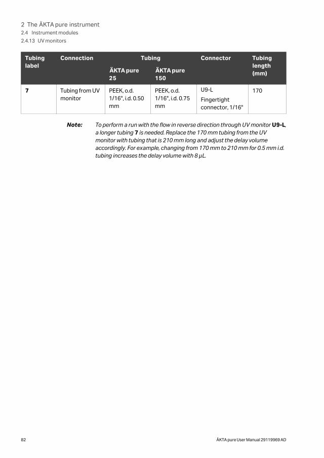
Tubinglabel
Connection Tubing Connector Tubinglength(mm)ÄKTA pure
25ÄKTA pure150
7 Tubing from UVmonitor
PEEK, o.d.1/16", i.d. 0.50mm
PEEK, o.d.1/16", i.d. 0.75mm
U9-L
Fingertightconnector, 1/16"
170
Note: To perform a run with the flow in reverse direction through UV monitor U9-L,a longer tubing 7 is needed. Replace the 170 mm tubing from the UVmonitor with tubing that is 210 mm long and adjust the delay volumeaccordingly. For example, changing from 170 mm to 210 mm for 0.5 mm i.d.tubing increases the delay volume with 8 µL.
2 The ÄKTA pure instrument2.4 Instrument modules
2.4.13 UV monitors
82 ÄKTA pure User Manual 29119969 AD
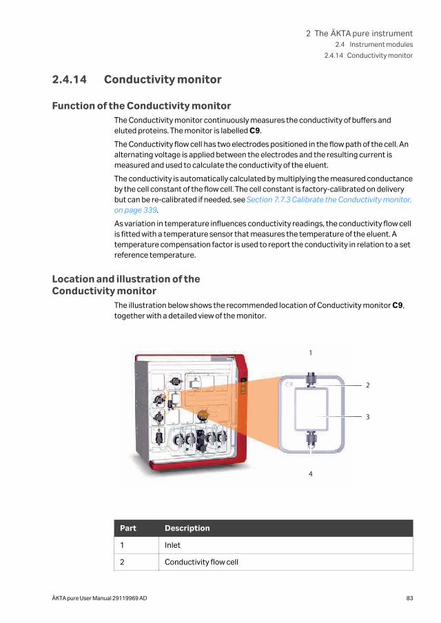
2.4.14 Conductivity monitor
Function of the Conductivity monitorThe Conductivity monitor continuously measures the conductivity of buffers andeluted proteins. The monitor is labelled C9.
The Conductivity flow cell has two electrodes positioned in the flow path of the cell. Analternating voltage is applied between the electrodes and the resulting current ismeasured and used to calculate the conductivity of the eluent.
The conductivity is automatically calculated by multiplying the measured conductanceby the cell constant of the flow cell. The cell constant is factory-calibrated on deliverybut can be re-calibrated if needed, see Section 7.7.3 Calibrate the Conductivity monitor,on page 339.
As variation in temperature influences conductivity readings, the conductivity flow cellis fitted with a temperature sensor that measures the temperature of the eluent. Atemperature compensation factor is used to report the conductivity in relation to a setreference temperature.
Location and illustration of theConductivity monitor
The illustration below shows the recommended location of Conductivity monitor C9,together with a detailed view of the monitor.
1
2
3
4
Part Description
1 Inlet
2 Conductivity flow cell
2 The ÄKTA pure instrument2.4 Instrument modules
2.4.14 Conductivity monitor
ÄKTA pure User Manual 29119969 AD 83
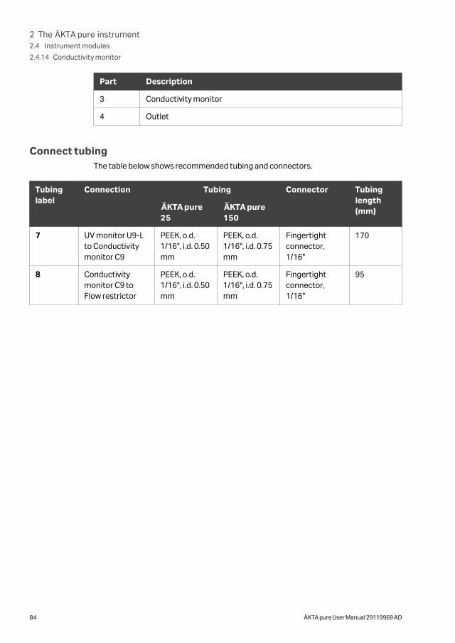
Part Description
3 Conductivity monitor
4 Outlet
Connect tubingThe table below shows recommended tubing and connectors.
Tubinglabel
Connection Tubing Connector Tubinglength(mm)ÄKTA pure
25ÄKTA pure150
7 UV monitor U9-Lto Conductivitymonitor C9
PEEK, o.d.1/16", i.d. 0.50mm
PEEK, o.d.1/16", i.d. 0.75mm
Fingertightconnector,1/16"
170
8 Conductivitymonitor C9 toFlow restrictor
PEEK, o.d.1/16", i.d. 0.50mm
PEEK, o.d.1/16", i.d. 0.75mm
Fingertightconnector,1/16"
95
2 The ÄKTA pure instrument2.4 Instrument modules
2.4.14 Conductivity monitor
84 ÄKTA pure User Manual 29119969 AD
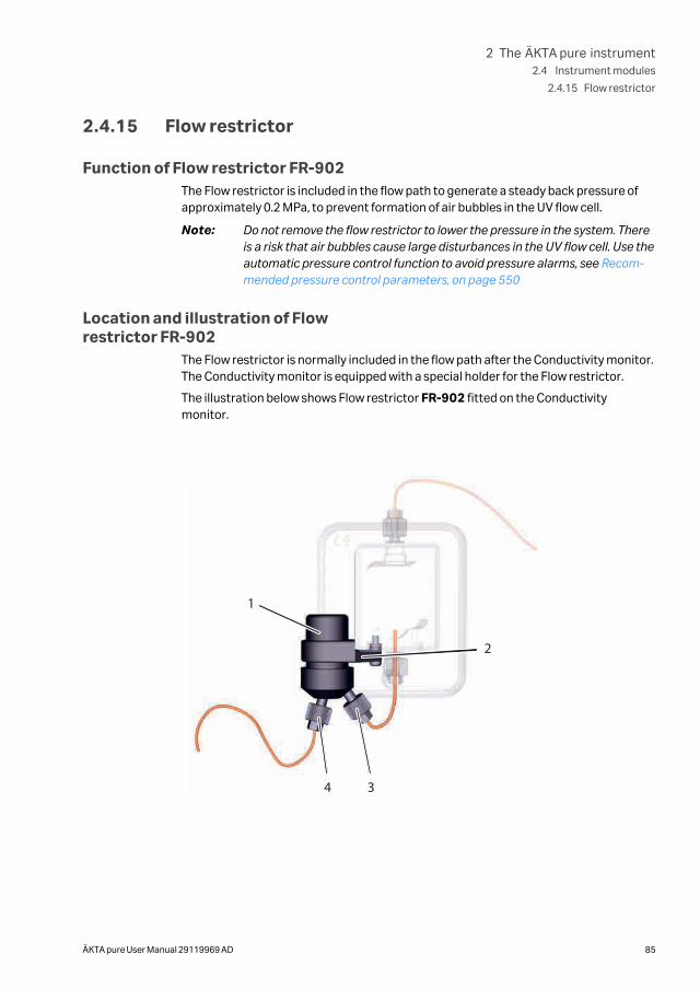
2.4.15 Flow restrictor
Function of Flow restrictor FR-902The Flow restrictor is included in the flow path to generate a steady back pressure ofapproximately 0.2 MPa, to prevent formation of air bubbles in the UV flow cell.
Note: Do not remove the flow restrictor to lower the pressure in the system. Thereis a risk that air bubbles cause large disturbances in the UV flow cell. Use theautomatic pressure control function to avoid pressure alarms, see Recom-mended pressure control parameters, on page 550
Location and illustration of Flowrestrictor FR-902
The Flow restrictor is normally included in the flow path after the Conductivity monitor.The Conductivity monitor is equipped with a special holder for the Flow restrictor.
The illustration below shows Flow restrictor FR-902 fitted on the Conductivitymonitor.
1
4 3
2
2 The ÄKTA pure instrument2.4 Instrument modules
2.4.15 Flow restrictor
ÄKTA pure User Manual 29119969 AD 85
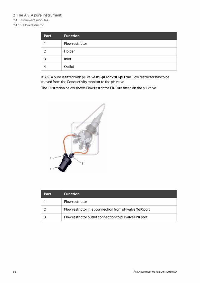
Part Function
1 Flow restrictor
2 Holder
3 Inlet
4 Outlet
If ÄKTA pure is fitted with pH valve V9-pH or V9H-pH the Flow restrictor has to bemoved from the Conductivity monitor to the pH valve.
The illustration below shows Flow restrictor FR-902 fitted on the pH valve.
1
2
3
Part Function
1 Flow restrictor
2 Flow restrictor inlet connection from pH valve ToR port
3 Flow restrictor outlet connection to pH valve FrR port
2 The ÄKTA pure instrument2.4 Instrument modules
2.4.15 Flow restrictor
86 ÄKTA pure User Manual 29119969 AD
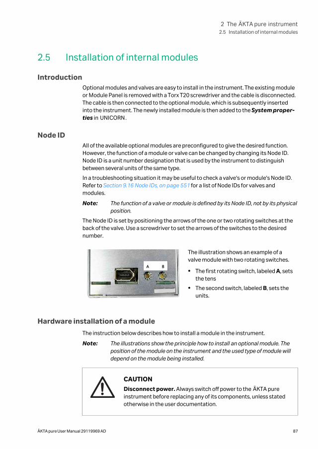
2.5 Installation of internal modules
IntroductionOptional modules and valves are easy to install in the instrument. The existing moduleor Module Panel is removed with a Torx T20 screwdriver and the cable is disconnected.The cable is then connected to the optional module, which is subsequently insertedinto the instrument. The newly installed module is then added to the System proper-ties in UNICORN.
Node IDAll of the available optional modules are preconfigured to give the desired function.However, the function of a module or valve can be changed by changing its Node ID.Node ID is a unit number designation that is used by the instrument to distinguishbetween several units of the same type.
In a troubleshooting situation it may be useful to check a valve's or module's Node ID.Refer to Section 9.16 Node IDs, on page 551 for a list of Node IDs for valves andmodules.
Note: The function of a valve or module is defined by its Node ID, not by its physicalposition.
The Node ID is set by positioning the arrows of the one or two rotating switches at theback of the valve. Use a screwdriver to set the arrows of the switches to the desirednumber.
A B
The illustration shows an example of avalve module with two rotating switches.
• The first rotating switch, labeled A, setsthe tens
• The second switch, labeled B, sets theunits.
Hardware installation of a module
The instruction below describes how to install a module in the instrument.
Note: The illustrations show the principle how to install an optional module. Theposition of the module on the instrument and the used type of module willdepend on the module being installed.
CAUTION
Disconnect power. Always switch off power to the ÄKTA pureinstrument before replacing any of its components, unless statedotherwise in the user documentation.
2 The ÄKTA pure instrument2.5 Installation of internal modules
ÄKTA pure User Manual 29119969 AD 87
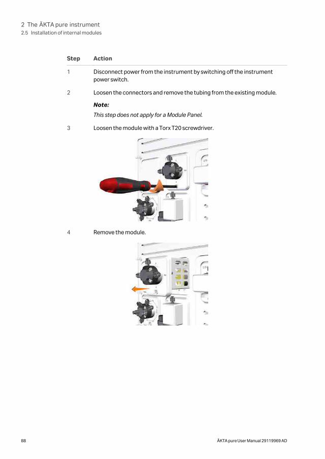
Step Action
1 Disconnect power from the instrument by switching off the instrumentpower switch.
2 Loosen the connectors and remove the tubing from the existing module.
Note:
This step does not apply for a Module Panel.
3 Loosen the module with a Torx T20 screwdriver.
4 Remove the module.
2 The ÄKTA pure instrument2.5 Installation of internal modules
88 ÄKTA pure User Manual 29119969 AD
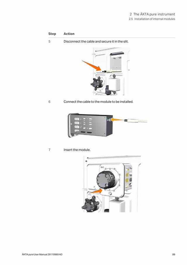
Step Action
5 Disconnect the cable and secure it in the slit.
6 Connect the cable to the module to be installed.
7 Insert the module.
2 The ÄKTA pure instrument2.5 Installation of internal modules
ÄKTA pure User Manual 29119969 AD 89
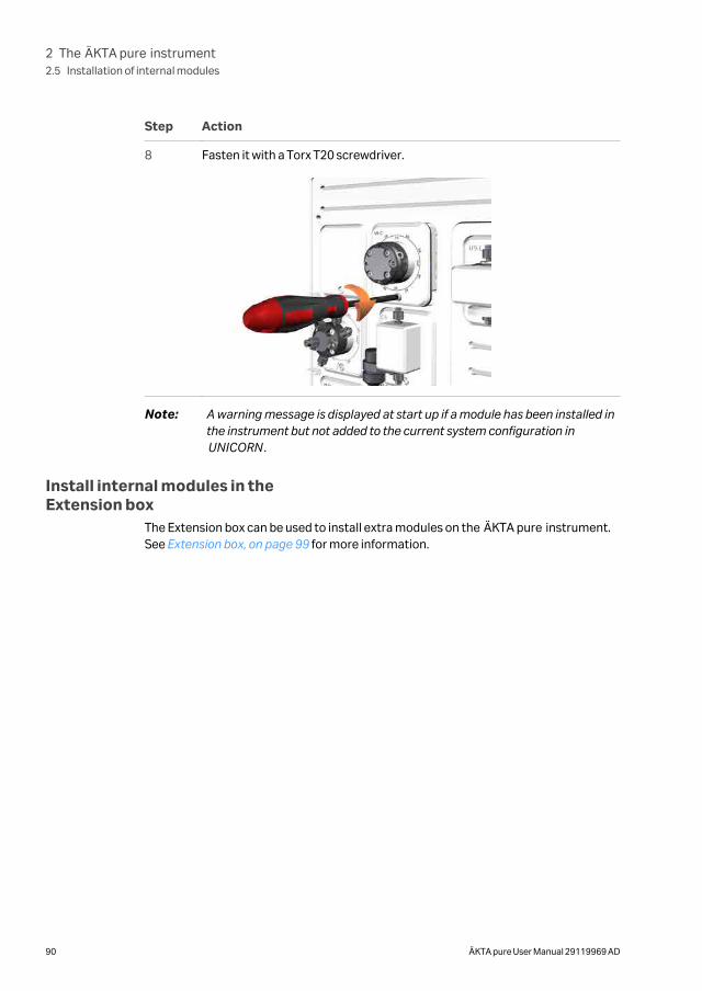
Step Action
8 Fasten it with a Torx T20 screwdriver.
Note: A warning message is displayed at start up if a module has been installed inthe instrument but not added to the current system configuration inUNICORN.
Install internal modules in theExtension box
The Extension box can be used to install extra modules on the ÄKTA pure instrument.See Extension box, on page 99 for more information.
2 The ÄKTA pure instrument2.5 Installation of internal modules
90 ÄKTA pure User Manual 29119969 AD
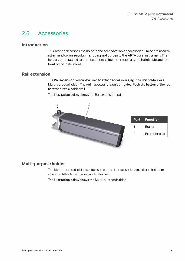
2.6 Accessories
IntroductionThis section describes the holders and other available accessories. These are used toattach and organize columns, tubing and bottles to the ÄKTA pure instrument. Theholders are attached to the instrument using the holder rails on the left side and thefront of the instrument.
Rail extensionThe Rail extension rod can be used to attach accessories, eg., column holders or aMulti-purpose holder. The rod has extra rails on both sides. Push the button of the rodto attach it to a holder rail.
The illustration below shows the Rail extension rod.
1 2
Part Function
1 Button
2 Extension rod
Multi-purpose holderThe Multi-purpose holder can be used to attach accessories, eg., a Loop holder or acassette. Attach the holder to a holder rail.
The illustration below shows the Multi-purpose holder.
2 The ÄKTA pure instrument2.6 Accessories
ÄKTA pure User Manual 29119969 AD 91
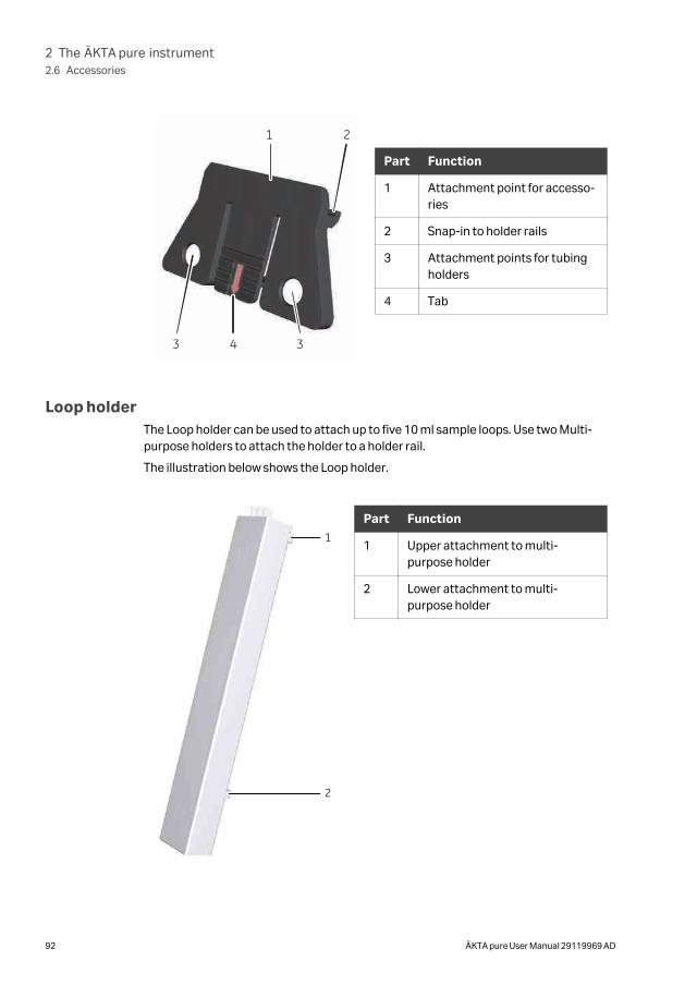
1 2
3 4 3
Part Function
1 Attachment point for accesso-ries
2 Snap-in to holder rails
3 Attachment points for tubingholders
4 Tab
Loop holderThe Loop holder can be used to attach up to five 10 ml sample loops. Use two Multi-purpose holders to attach the holder to a holder rail.
The illustration below shows the Loop holder.
1
2
Part Function
1 Upper attachment to multi-purpose holder
2 Lower attachment to multi-purpose holder
2 The ÄKTA pure instrument2.6 Accessories
92 ÄKTA pure User Manual 29119969 AD
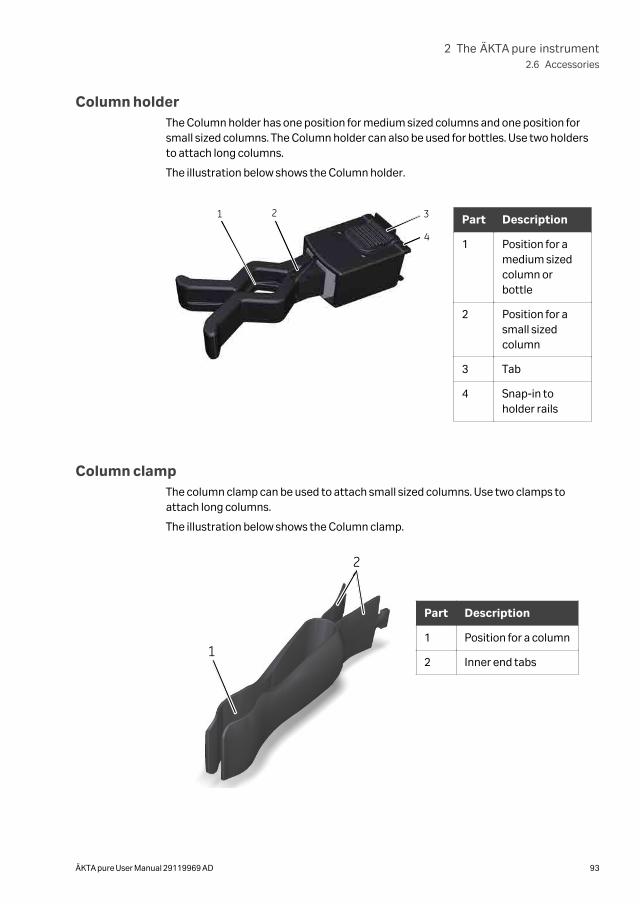
Column holderThe Column holder has one position for medium sized columns and one position forsmall sized columns. The Column holder can also be used for bottles. Use two holdersto attach long columns.
The illustration below shows the Column holder.
1 2 3
4
Part Description
1 Position for amedium sizedcolumn orbottle
2 Position for asmall sizedcolumn
3 Tab
4 Snap-in toholder rails
Column clampThe column clamp can be used to attach small sized columns. Use two clamps toattach long columns.
The illustration below shows the Column clamp.
1
2
Part Description
1 Position for a column
2 Inner end tabs
2 The ÄKTA pure instrument2.6 Accessories
ÄKTA pure User Manual 29119969 AD 93
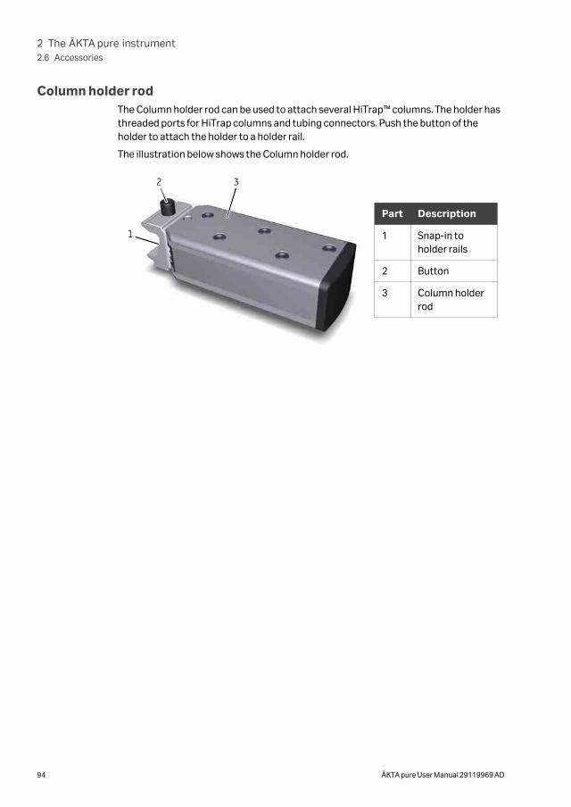
Column holder rodThe Column holder rod can be used to attach several HiTrap™ columns. The holder hasthreaded ports for HiTrap columns and tubing connectors. Push the button of theholder to attach the holder to a holder rail.
The illustration below shows the Column holder rod.
1
2 3
Part Description
1 Snap-in toholder rails
2 Button
3 Column holderrod
2 The ÄKTA pure instrument2.6 Accessories
94 ÄKTA pure User Manual 29119969 AD
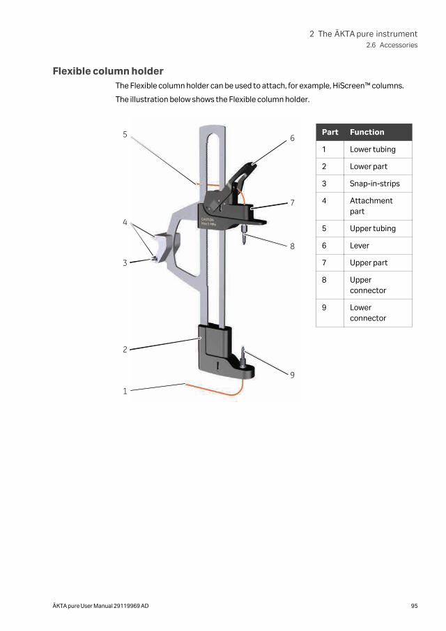
Flexible column holderThe Flexible column holder can be used to attach, for example, HiScreen™ columns.
The illustration below shows the Flexible column holder.
2
3
4
5
7
6
9
1
8
Part Function
1 Lower tubing
2 Lower part
3 Snap-in-strips
4 Attachmentpart
5 Upper tubing
6 Lever
7 Upper part
8 Upperconnector
9 Lowerconnector
2 The ÄKTA pure instrument2.6 Accessories
ÄKTA pure User Manual 29119969 AD 95
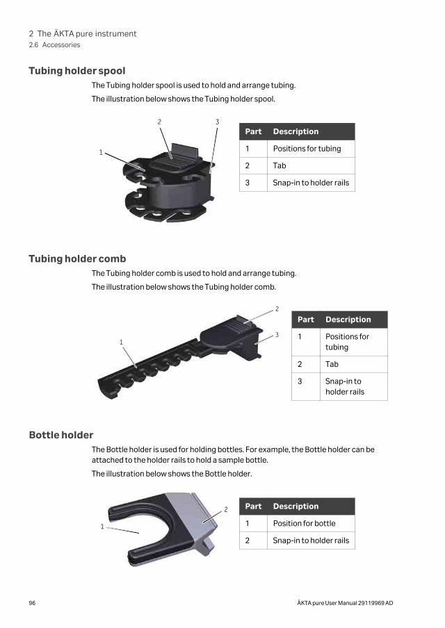
Tubing holder spoolThe Tubing holder spool is used to hold and arrange tubing.
The illustration below shows the Tubing holder spool.
1
2 3Part Description
1 Positions for tubing
2 Tab
3 Snap-in to holder rails
Tubing holder combThe Tubing holder comb is used to hold and arrange tubing.
The illustration below shows the Tubing holder comb.
1
2
3
Part Description
1 Positions fortubing
2 Tab
3 Snap-in toholder rails
Bottle holderThe Bottle holder is used for holding bottles. For example, the Bottle holder can beattached to the holder rails to hold a sample bottle.
The illustration below shows the Bottle holder.
1
2 Part Description
1 Position for bottle
2 Snap-in to holder rails
2 The ÄKTA pure instrument2.6 Accessories
96 ÄKTA pure User Manual 29119969 AD
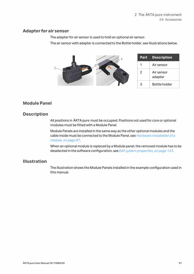
Adapter for air sensorThe adapter for air sensor is used to hold an optional air sensor.
The air sensor with adapter is connected to the Bottle holder, see illustrations below.
12
3 Part Description
1 Air sensor
2 Air sensoradapter
3 Bottle holder
Module Panel
DescriptionAll positions in ÄKTA pure must be occupied. Positions not used for core or optionalmodules must be fitted with a Module Panel.
Module Panels are installed in the same way as the other optional modules and thecable inside must be connected to the Module Panel, see Hardware installation of amodule, on page 87.
When an optional module is replaced by a Module panel, the removed module has to bedeselected in the software configuration, see Edit system properties, on page 143.
IllustrationThe illustration shows the Module Panels installed in the example configuration used inthis manual.
2 The ÄKTA pure instrument2.6 Accessories
ÄKTA pure User Manual 29119969 AD 97
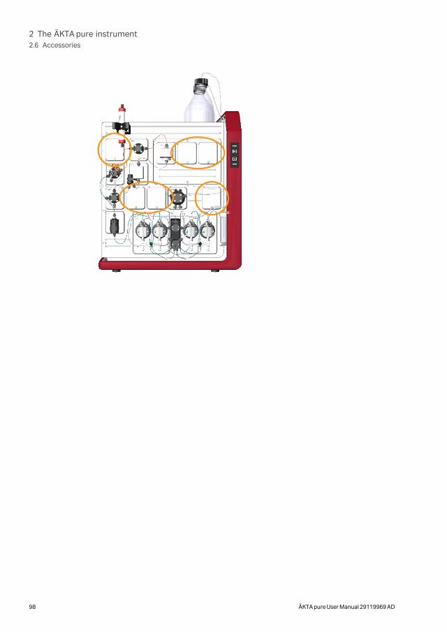
2 The ÄKTA pure instrument2.6 Accessories
98 ÄKTA pure User Manual 29119969 AD
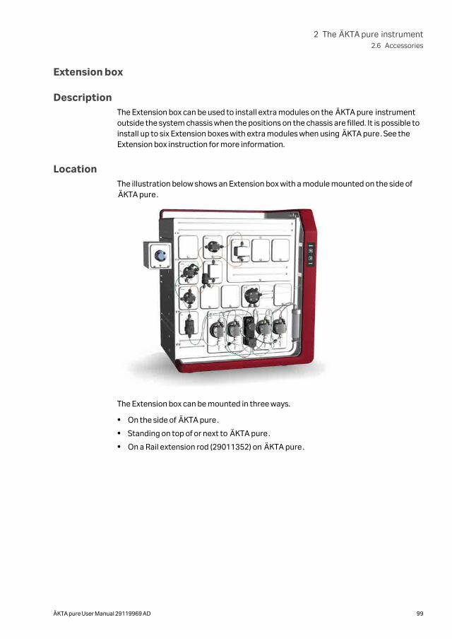
Extension box
DescriptionThe Extension box can be used to install extra modules on the ÄKTA pure instrumentoutside the system chassis when the positions on the chassis are filled. It is possible toinstall up to six Extension boxes with extra modules when using ÄKTA pure. See theExtension box instruction for more information.
LocationThe illustration below shows an Extension box with a module mounted on the side ofÄKTA pure.
The Extension box can be mounted in three ways.
• On the side of ÄKTA pure.
• Standing on top of or next to ÄKTA pure.
• On a Rail extension rod (29011352) on ÄKTA pure.
2 The ÄKTA pure instrument2.6 Accessories
ÄKTA pure User Manual 29119969 AD 99
3 ÄKTA pure external modules
About this chapterThis chapter provides an overview of the external modules that can be connected tothe ÄKTA pure instrument. A brief description of how to connect external modules isalso provided.
In this chapter
Section See page
3.1 External air sensors 101
3.2 Fraction collector F9-C 103
3.3 Fraction collector F9-R 117
3.4 Sample pump S9 and S9H 121
3.5 I/O-box E9 126
3.6 Connection of external modules 136
3 ÄKTA pure external modules
100 ÄKTA pure User Manual 29119969 AD
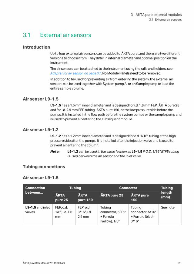
3.1 External air sensors
IntroductionUp to four external air sensors can be added to ÄKTA pure, and there are two differentversions to choose from. They differ in internal diameter and optimal position on theinstrument.
The air sensors can be attached to the instrument using the rails and holders, see Adapter for air sensor, on page 97. No Module Panels need to be removed.
In addition to be used for preventing air from entering the system, the external airsensors can be used together with System pump A, or an Sample pump to load theentire sample volume.
Air sensor L9-1.5L9-1.5 has a 1.5 mm inner diameter and is designed for i.d. 1.6 mm FEP, ÄKTA pure 25,and for i.d. 2.9 mm FEP tubing, ÄKTA pure 150, at the low pressure side before thepumps. It is installed in the flow path before the system pumps or the sample pump andis used to prevent air entering the subsequent module.
Air sensor L9-1.2L9-1.2 has a 1.2 mm inner diameter and is designed for o.d. 1/16" tubing at the highpressure side after the pumps. It is installed after the injection valve and is used toprevent air entering the column.
Note: L9-1.2 can be used in the same fashion as L9-1.5 if O.D. 1/16" ETFE tubingis used between the air sensor and the inlet valve.
Tubing connections
Air sensor L9-1.5
Connectionbetween...
Tubing Connector Tubinglength(mm)ÄKTA
pure 25ÄKTApure 150
ÄKTA pure 25 ÄKTA pure150
L9-1.5 and inletvalves
FEP, o.d.1/8", i.d. 1.6mm
FEP, o.d.3/16", i.d.2.9 mm
Tubingconnector, 5/16"+ Ferrule(yellow), 1/8"
Tubingconnector, 5/16"+ Ferrule (blue),3/16"
See note
3 ÄKTA pure external modules3.1 External air sensors
ÄKTA pure User Manual 29119969 AD 101
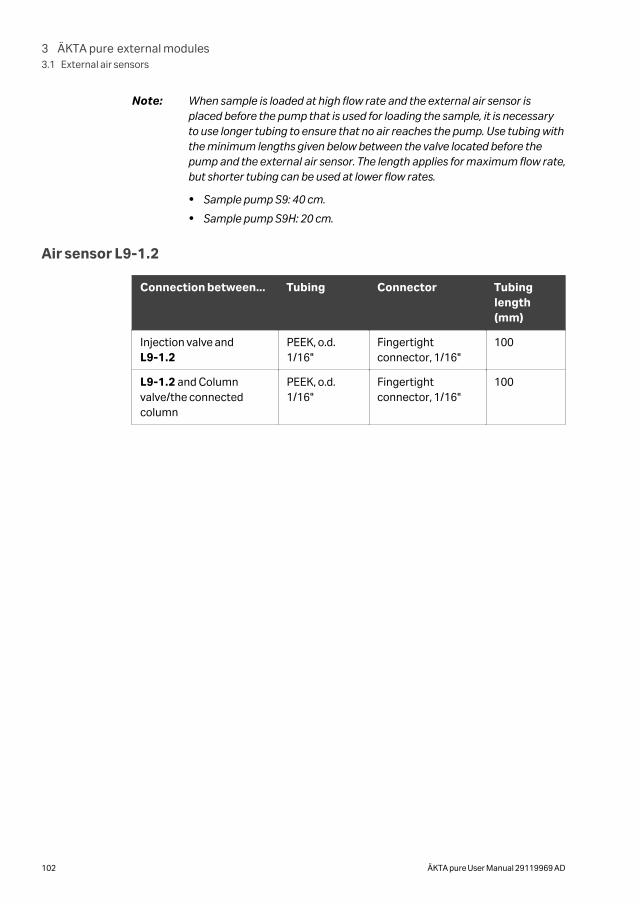
Note: When sample is loaded at high flow rate and the external air sensor isplaced before the pump that is used for loading the sample, it is necessaryto use longer tubing to ensure that no air reaches the pump. Use tubing withthe minimum lengths given below between the valve located before thepump and the external air sensor. The length applies for maximum flow rate,but shorter tubing can be used at lower flow rates.
• Sample pump S9: 40 cm.
• Sample pump S9H: 20 cm.
Air sensor L9-1.2
Connection between... Tubing Connector Tubinglength(mm)
Injection valve andL9-1.2
PEEK, o.d.1/16"
Fingertightconnector, 1/16"
100
L9-1.2 and Columnvalve/the connectedcolumn
PEEK, o.d.1/16"
Fingertightconnector, 1/16"
100
3 ÄKTA pure external modules3.1 External air sensors
102 ÄKTA pure User Manual 29119969 AD
3.2 Fraction collector F9-C
About this sectionThis section shows an overview of Fraction collector F9-C.
Technical details are found in the ÄKTA pure User manual.
In this section
Section See page
3.2.1 Function 104
3.2.2 Fraction collector F9-C illustrations 106
3.2.3 Cassettes, Cassette tray and racks 110
3.2.4 Connect tubing to the ÄKTA pure instrument 116
3 ÄKTA pure external modules3.2 Fraction collector F9-C
ÄKTA pure User Manual 29119969 AD 103
3.2.1 Function
IntroductionFraction collector F9-C can collect fractions in deep well plates, tubes of different sizesor bottles. Up to six cassettes for deep well plates and tubes can be used. The cassettescan be used in any combination and are placed on the Cassette tray. A rack for 50 mLtubes and a rack for 250 mL bottles are also available.
Scanner functions detect which types of trays, racks, cassettes and deep well platesthat are used in each run.
The Cassette tray or one of the racks is placed inside the fraction collector. A heightexclusion bar ensures that the bottles, tubes and deep well plates are correctly posi-tioned and cannot damage the Dispenser head. The Tray catch and positioning discson the floor of the fraction collector guide the Cassette tray or the rack into the correctposition.
Scanning of CassettesWhen the door of the fraction collector is closed automatic scanning is performed.There are two types of scanning procedures:
• Full scan: Scanning of Cassette type codes to determine which types of Cassettesare used, and scanning of rows and columns in deep well plates to identify whichtypes of plates are used (24, 48, or 96 wells). Full scan is performed only when thesystem is in state Ready.
• Quick scan: Scanning of Cassette type codes to determine which type of Cassettesare used. Quick scan is performed during the run to ensure that correct Cassettesare placed in the Fraction collector.
Fractionation modes to avoid spillageThree fractionation modes are available, all of which avoid spillage between wells ortubes during fractionation:
• Accumulator: The accumulator is used to collect liquid during movement betweenwells, tubes or bottles. The liquid is then dispensed in the next well or tube. Fractio-nation with accumulator can be used at all flow rates.
• DropSync: When using DropSync the sensors in the Dispenser head detect whena drop is released from the nozzle. The Dispenser head moves to the next well ortube just after a drop is released. Fractionation with DropSync can be used at flowrates up to 2 mL/min. If the cassettes are placed near the waste funnel the Drop-Sync mode can be used at higher flow rates. Volatile solutions and solutions withlow surface tension may require a lower flow.
• Automatic: The fraction collector uses the Drop Sync mode for flow rates up to 2mL/min and automatically switches to Accumulator mode for higher flow rates.
3 ÄKTA pure external modules3.2 Fraction collector F9-C
3.2.1 Function
104 ÄKTA pure User Manual 29119969 AD
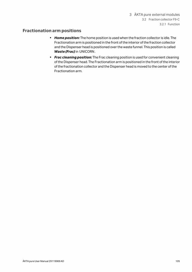
Fractionation arm positions
• Home position: The home position is used when the fraction collector is idle. TheFractionation arm is positioned in the front of the interior of the fraction collectorand the Dispenser head is positioned over the waste funnel. This position is calledWaste (Frac) in UNICORN.
• Frac cleaning position: The Frac cleaning position is used for convenient cleaningof the Dispenser head. The Fractionation arm is positioned in the front of the interiorof the fractionation collector and the Dispenser head is moved to the center of theFractionation arm.
3 ÄKTA pure external modules3.2 Fraction collector F9-C
3.2.1 Function
ÄKTA pure User Manual 29119969 AD 105
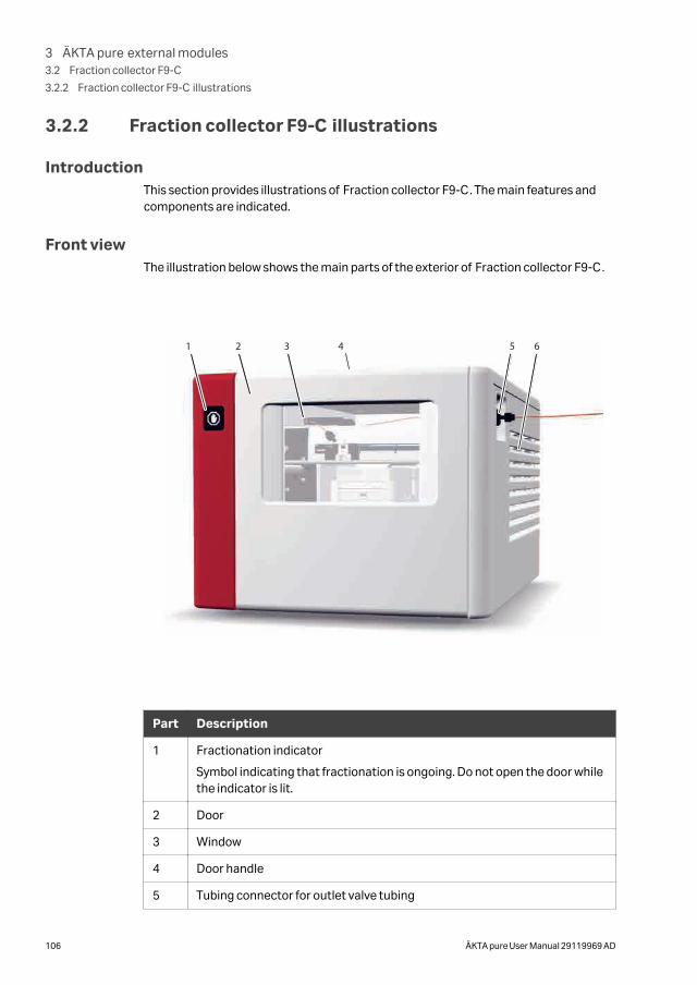
3.2.2 Fraction collector F9-C illustrations
IntroductionThis section provides illustrations of Fraction collector F9-C. The main features andcomponents are indicated.
Front viewThe illustration below shows the main parts of the exterior of Fraction collector F9-C.
1 2 3 5 64
Part Description
1 Fractionation indicator
Symbol indicating that fractionation is ongoing. Do not open the door whilethe indicator is lit.
2 Door
3 Window
4 Door handle
5 Tubing connector for outlet valve tubing
3 ÄKTA pure external modules3.2 Fraction collector F9-C
3.2.2 Fraction collector F9-C illustrations
106 ÄKTA pure User Manual 29119969 AD
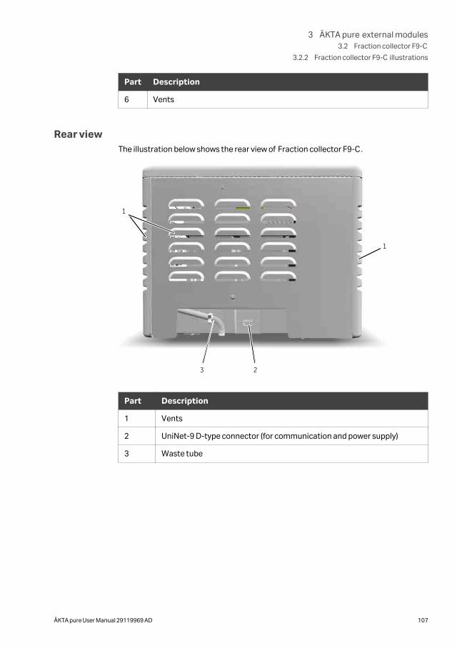
Part Description
6 Vents
Rear viewThe illustration below shows the rear view of Fraction collector F9-C.
1
1
23
Part Description
1 Vents
2 UniNet-9 D-type connector (for communication and power supply)
3 Waste tube
3 ÄKTA pure external modules3.2 Fraction collector F9-C
3.2.2 Fraction collector F9-C illustrations
ÄKTA pure User Manual 29119969 AD 107
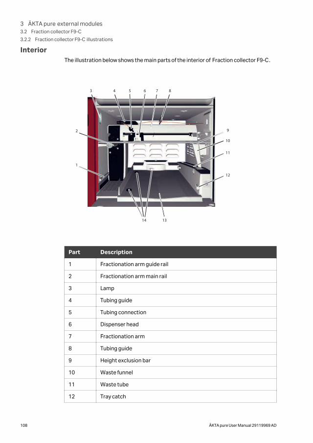
InteriorThe illustration below shows the main parts of the interior of Fraction collector F9-C.
1
2
3 4 5 6 7 8
9
10
11
12
1314
Part Description
1 Fractionation arm guide rail
2 Fractionation arm main rail
3 Lamp
4 Tubing guide
5 Tubing connection
6 Dispenser head
7 Fractionation arm
8 Tubing guide
9 Height exclusion bar
10 Waste funnel
11 Waste tube
12 Tray catch
3 ÄKTA pure external modules3.2 Fraction collector F9-C
3.2.2 Fraction collector F9-C illustrations
108 ÄKTA pure User Manual 29119969 AD
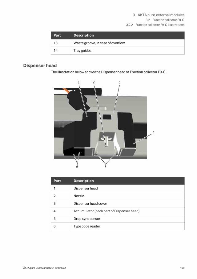
Part Description
13 Waste groove, in case of overflow
14 Tray guides
Dispenser headThe illustration below shows the Dispenser head of Fraction collector F9-C.
1 2 3
4
56
Part Description
1 Dispenser head
2 Nozzle
3 Dispenser head cover
4 Accumulator (back part of Dispenser head)
5 Drop sync sensor
6 Type code reader
3 ÄKTA pure external modules3.2 Fraction collector F9-C
3.2.2 Fraction collector F9-C illustrations
ÄKTA pure User Manual 29119969 AD 109
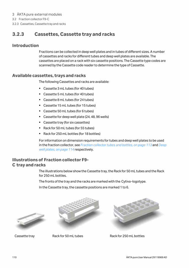
3.2.3 Cassettes, Cassette tray and racks
IntroductionFractions can be collected in deep well plates and in tubes of different sizes. A numberof cassettes and racks for different tubes and deep well plates are available. Thecassettes are placed on a rack with six cassette positions. The Cassette type codes arescanned by the Cassette code reader to determine the type of Cassette.
Available cassettes, trays and racksThe following Cassettes and racks are available:
• Cassette 3 mL tubes (for 40 tubes)
• Cassette 5 mL tubes (for 40 tubes)
• Cassette 8 mL tubes (for 24 tubes)
• Cassette 15 mL tubes (for 15 tubes)
• Cassette 50 mL tubes (for 6 tubes)
• Cassette for deep well plate (24, 48, 96 wells)
• Cassette tray (for six cassettes)
• Rack for 50 mL tubes (for 55 tubes)
• Rack for 250 mL bottles (for 18 bottles)
For information on dimension requirements for tubes and deep well plates to be usedin the fraction collector, see Fraction collector tubes and bottles, on page 113 and Deepwell plates, on page 114 respectively.
Illustrations of Fraction collector F9-C tray and racks
The illustrations below show the Cassette tray, the Rack for 50 mL tubes and the Rackfor 250 mL bottles.
The fronts of the tray and the racks are marked with the Cytiva-logotype.
In the Cassette tray, the cassette positions are marked 1 to 6.
Cassette tray Rack for 50 mL tubes Rack for 250 mL bottles
3 ÄKTA pure external modules3.2 Fraction collector F9-C
3.2.3 Cassettes, Cassette tray and racks
110 ÄKTA pure User Manual 29119969 AD
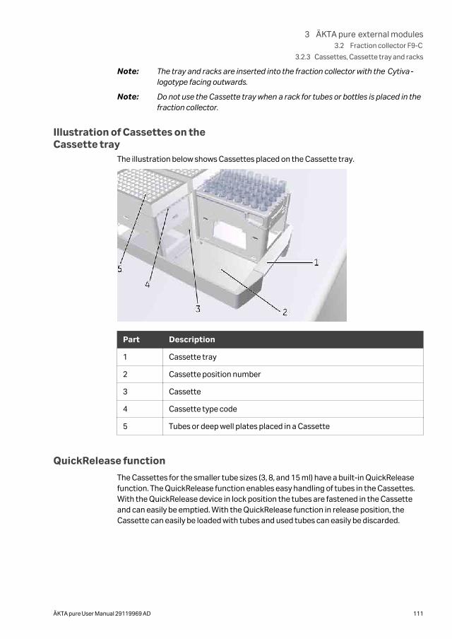
Note: The tray and racks are inserted into the fraction collector with the Cytiva-logotype facing outwards.
Note: Do not use the Cassette tray when a rack for tubes or bottles is placed in thefraction collector.
Illustration of Cassettes on theCassette tray
The illustration below shows Cassettes placed on the Cassette tray.
Part Description
1 Cassette tray
2 Cassette position number
3 Cassette
4 Cassette type code
5 Tubes or deep well plates placed in a Cassette
QuickRelease function
The Cassettes for the smaller tube sizes (3, 8, and 15 ml) have a built-in QuickReleasefunction. The QuickRelease function enables easy handling of tubes in the Cassettes.With the QuickRelease device in lock position the tubes are fastened in the Cassetteand can easily be emptied. With the QuickRelease function in release position, theCassette can easily be loaded with tubes and used tubes can easily be discarded.
3 ÄKTA pure external modules3.2 Fraction collector F9-C
3.2.3 Cassettes, Cassette tray and racks
ÄKTA pure User Manual 29119969 AD 111
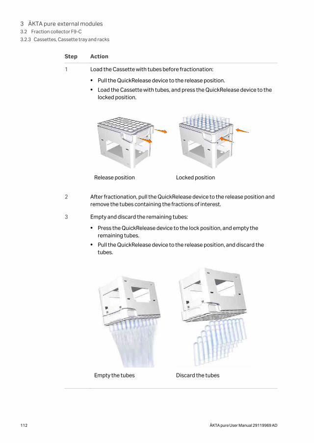
Step Action
1 Load the Cassette with tubes before fractionation:
• Pull the QuickRelease device to the release position.
• Load the Cassette with tubes, and press the QuickRelease device to thelocked position.
Release position Locked position
2 After fractionation, pull the QuickRelease device to the release position andremove the tubes containing the fractions of interest.
3 Empty and discard the remaining tubes:
• Press the QuickRelease device to the lock position, and empty theremaining tubes.
• Pull the QuickRelease device to the release position, and discard thetubes.
Empty the tubes Discard the tubes
3 ÄKTA pure external modules3.2 Fraction collector F9-C
3.2.3 Cassettes, Cassette tray and racks
112 ÄKTA pure User Manual 29119969 AD
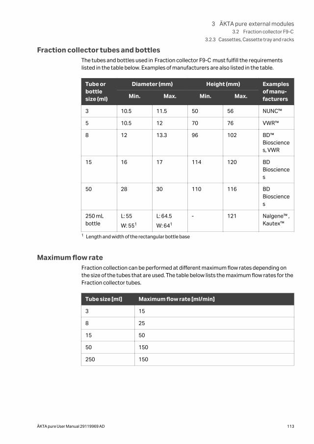
Fraction collector tubes and bottlesThe tubes and bottles used in Fraction collector F9-C must fulfill the requirementslisted in the table below. Examples of manufacturers are also listed in the table.
Tube orbottlesize (ml)
Diameter (mm) Height (mm) Examplesof manu-facturersMin. Max. Min. Max.
3 10.5 11.5 50 56 NUNC™
5 10.5 12 70 76 VWR™
8 12 13.3 96 102 BD™Biosciences, VWR
15 16 17 114 120 BDBiosciences
50 28 30 110 116 BDBiosciences
250 mLbottle
L: 55
W: 551
L: 64.5
W: 641
- 121 Nalgene™ ,Kautex™
1 Length and width of the rectangular bottle base
Maximum flow rateFraction collection can be performed at different maximum flow rates depending onthe size of the tubes that are used. The table below lists the maximum flow rates for theFraction collector tubes.
Tube size [ml] Maximum flow rate [ml/min]
3 15
8 25
15 50
50 150
250 150
3 ÄKTA pure external modules3.2 Fraction collector F9-C
3.2.3 Cassettes, Cassette tray and racks
ÄKTA pure User Manual 29119969 AD 113
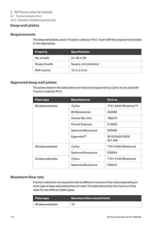
Deep well plates
RequirementsThe deep well plates used in Fraction collector F9-C must fulfill the requirements listedin the table below.
Property Specification
No. of wells 24, 48, or 96
Shape of wells Square, not cylindrical
Well volume 10, 5, or 2 mL
Approved deep well platesThe plates listed in the table below are tested and approved by Cytiva to be used withFraction collector F9-C.
Plate type Manufacturer Part no.
96 deep well plate Cytiva 7701-5200 (Whatman™)
BD Biosciences 353966
Greiner Bio-One 780270
Porvair Sciences 219009
Seahorse Bioscience S30009
Eppendorf™ 951033405/ 0030501.306
48 deep well plate Cytiva 7701-5500 (Whatman)
Seahorse Bioscience S30004
24 deep well plate Cytiva 7701-5102 (Whatman)
Seahorse Bioscience S30024
Maximum flow rateFraction collection can be performed at different maximum flow rates depending onwhat type of deep well plates that are used. The table below lists the maximum flowrates for the different plate types.
Plate type Maximum flow rate (ml/min)
96 deep well plate 10
3 ÄKTA pure external modules3.2 Fraction collector F9-C
3.2.3 Cassettes, Cassette tray and racks
114 ÄKTA pure User Manual 29119969 AD
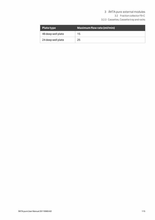
Plate type Maximum flow rate (ml/min)
48 deep well plate 15
24 deep well plate 25
3 ÄKTA pure external modules3.2 Fraction collector F9-C
3.2.3 Cassettes, Cassette tray and racks
ÄKTA pure User Manual 29119969 AD 115
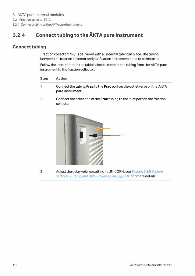
3.2.4 Connect tubing to the ÄKTA pure instrument
Connect tubing
Fraction collector F9-C is delivered with all internal tubing in place. The tubingbetween the fraction collector and purification instrument need to be installed.
Follow the instructions in the table below to connect the tubing from the ÄKTA pureinstrument to the fraction collector.
Step Action
1 Connect the tubing Frac to the Frac port on the outlet valve on the ÄKTApure instrument.
2 Connect the other end of the Frac tubing to the inlet port on the fractioncollector.
3 Adjust the delay volume setting in UNICORN, see Section 9.8.8 Systemsettings ‑ Tubing and Delay volumes, on page 501 for more details.
3 ÄKTA pure external modules3.2 Fraction collector F9-C
3.2.4 Connect tubing to the ÄKTA pure instrument
116 ÄKTA pure User Manual 29119969 AD
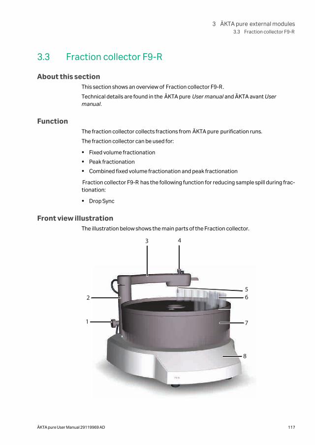
3.3 Fraction collector F9-R
About this sectionThis section shows an overview of Fraction collector F9-R.
Technical details are found in the ÄKTA pure User manual and ÄKTA avant Usermanual.
FunctionThe fraction collector collects fractions from ÄKTA pure purification runs.
The fraction collector can be used for:
• Fixed volume fractionation
• Peak fractionation
• Combined fixed volume fractionation and peak fractionation
Fraction collector F9-R has the following function for reducing sample spill during frac-tionation:
• Drop Sync
Front view illustrationThe illustration below shows the main parts of the Fraction collector.
1
3 4
5
7
6
8
2
3 ÄKTA pure external modules3.3 Fraction collector F9-R
ÄKTA pure User Manual 29119969 AD 117
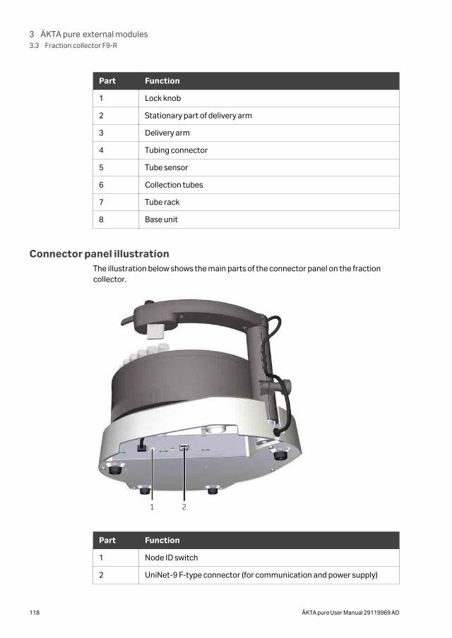
Part Function
1 Lock knob
2 Stationary part of delivery arm
3 Delivery arm
4 Tubing connector
5 Tube sensor
6 Collection tubes
7 Tube rack
8 Base unit
Connector panel illustrationThe illustration below shows the main parts of the connector panel on the fractioncollector.
1 22
Part Function
1 Node ID switch
2 UniNet-9 F-type connector (for communication and power supply)
3 ÄKTA pure external modules3.3 Fraction collector F9-R
118 ÄKTA pure User Manual 29119969 AD
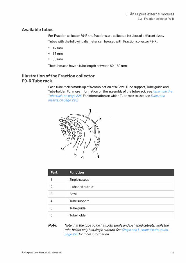
Available tubesFor Fraction collector F9-R the fractions are collected in tubes of different sizes.
Tubes with the following diameter can be used with Fraction collector F9-R:
• 12 mm
• 18 mm
• 30 mm
The tubes can have a tube length between 50-180 mm.
Illustration of the Fraction collectorF9-R Tube rack
Each tube rack is made up of a combination of a Bowl, Tube support, Tube guide andTube holder. For more information on the assembly of the tube rack, see Assemble theTube rack, on page 225. For information on which Tube rack to use, see Tube rackinserts, on page 226.
1
2
3456
Part Function
1 Single cutout
2 L-shaped cutout
3 Bowl
4 Tube support
5 Tube guide
6 Tube holder
Note: Note that the tube guide has both single and L-shaped cutouts, while thetube holder only has single cutouts. See Single and L-shaped cutouts, onpage 226 for more information.
3 ÄKTA pure external modules3.3 Fraction collector F9-R
ÄKTA pure User Manual 29119969 AD 119
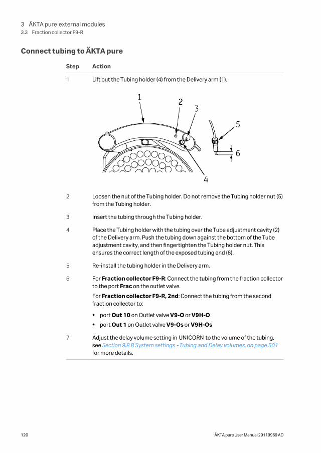
Connect tubing to ÄKTA pure
Step Action
1 Lift out the Tubing holder (4) from the Delivery arm (1).
3
4
5
6
2 Loosen the nut of the Tubing holder. Do not remove the Tubing holder nut (5)from the Tubing holder.
3 Insert the tubing through the Tubing holder.
4 Place the Tubing holder with the tubing over the Tube adjustment cavity (2)of the Delivery arm. Push the tubing down against the bottom of the Tubeadjustment cavity, and then fingertighten the Tubing holder nut. Thisensures the correct length of the exposed tubing end (6).
5 Re-install the tubing holder in the Delivery arm.
6 For Fraction collector F9-R: Connect the tubing from the fraction collectorto the port Frac on the outlet valve.
For Fraction collector F9-R, 2nd: Connect the tubing from the secondfraction collector to:
• port Out 10 on Outlet valve V9-O or V9H-O
• port Out 1 on Outlet valve V9-Os or V9H-Os
7 Adjust the delay volume setting in UNICORN to the volume of the tubing,see Section 9.8.8 System settings ‑ Tubing and Delay volumes, on page 501for more details.
3 ÄKTA pure external modules3.3 Fraction collector F9-R
120 ÄKTA pure User Manual 29119969 AD
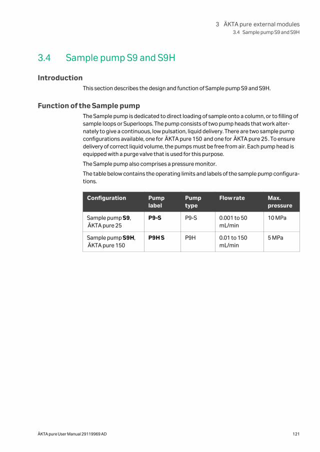
3.4 Sample pump S9 and S9H
IntroductionThis section describes the design and function of Sample pump S9 and S9H.
Function of the Sample pumpThe Sample pump is dedicated to direct loading of sample onto a column, or to filling ofsample loops or Superloops. The pump consists of two pump heads that work alter-nately to give a continuous, low pulsation, liquid delivery. There are two sample pumpconfigurations available, one for ÄKTA pure 150 and one for ÄKTA pure 25. To ensuredelivery of correct liquid volume, the pumps must be free from air. Each pump head isequipped with a purge valve that is used for this purpose.
The Sample pump also comprises a pressure monitor.
The table below contains the operating limits and labels of the sample pump configura-tions.
Configuration Pumplabel
Pumptype
Flow rate Max.pressure
Sample pump S9,ÄKTA pure 25
P9-S P9-S 0.001 to 50mL/min
10 MPa
Sample pump S9H,ÄKTA pure 150
P9H S P9H 0.01 to 150mL/min
5 MPa
3 ÄKTA pure external modules3.4 Sample pump S9 and S9H
ÄKTA pure User Manual 29119969 AD 121
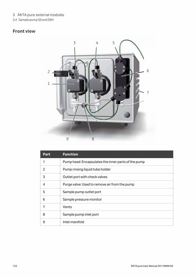
Front view
1
2
3 4 5
6
7
89
Part Function
1 Pump head: Encapsulates the inner parts of the pump
2 Pump rinsing liquid tube holder
3 Outlet port with check valves
4 Purge valve: Used to remove air from the pump
5 Sample pump outlet port
6 Sample pressure monitor
7 Vents
8 Sample pump inlet port
9 Inlet manifold
3 ÄKTA pure external modules3.4 Sample pump S9 and S9H
122 ÄKTA pure User Manual 29119969 AD
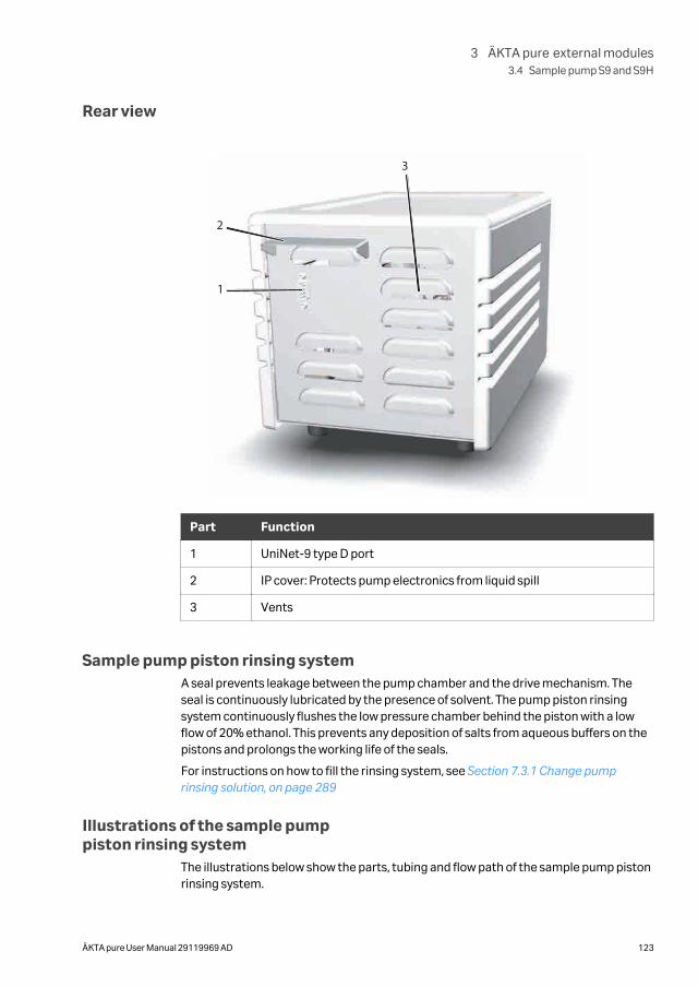
Rear view
2
1
3
Part Function
1 UniNet-9 type D port
2 IP cover: Protects pump electronics from liquid spill
3 Vents
Sample pump piston rinsing systemA seal prevents leakage between the pump chamber and the drive mechanism. Theseal is continuously lubricated by the presence of solvent. The pump piston rinsingsystem continuously flushes the low pressure chamber behind the piston with a lowflow of 20% ethanol. This prevents any deposition of salts from aqueous buffers on thepistons and prolongs the working life of the seals.
For instructions on how to fill the rinsing system, see Section 7.3.1 Change pumprinsing solution, on page 289
Illustrations of the sample pumppiston rinsing system
The illustrations below show the parts, tubing and flow path of the sample pump pistonrinsing system.
3 ÄKTA pure external modules3.4 Sample pump S9 and S9H
ÄKTA pure User Manual 29119969 AD 123
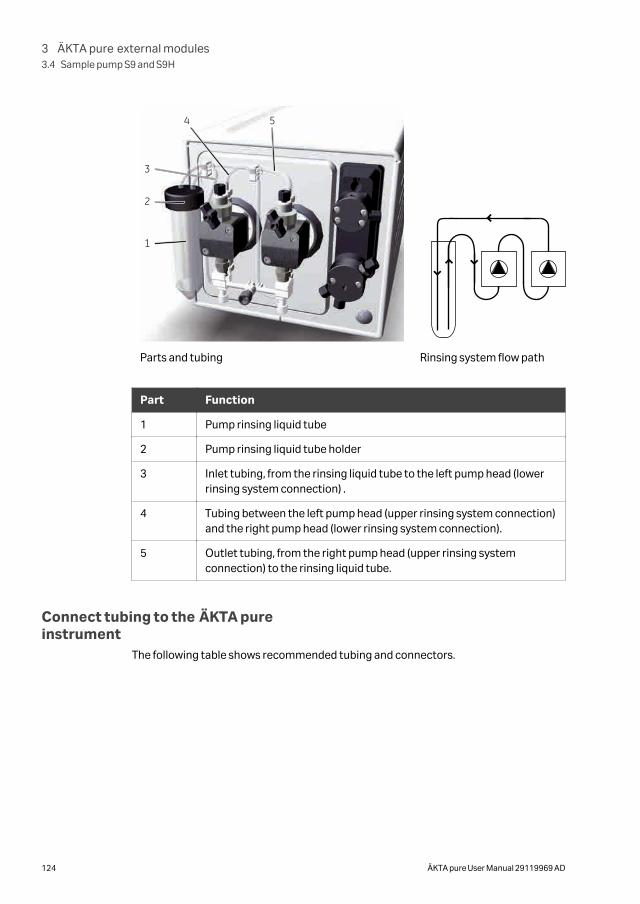
1
2
3
4 5
Parts and tubing Rinsing system flow path
Part Function
1 Pump rinsing liquid tube
2 Pump rinsing liquid tube holder
3 Inlet tubing, from the rinsing liquid tube to the left pump head (lowerrinsing system connection) .
4 Tubing between the left pump head (upper rinsing system connection)and the right pump head (lower rinsing system connection).
5 Outlet tubing, from the right pump head (upper rinsing systemconnection) to the rinsing liquid tube.
Connect tubing to the ÄKTA pureinstrument
The following table shows recommended tubing and connectors.
3 ÄKTA pure external modules3.4 Sample pump S9 and S9H
124 ÄKTA pure User Manual 29119969 AD
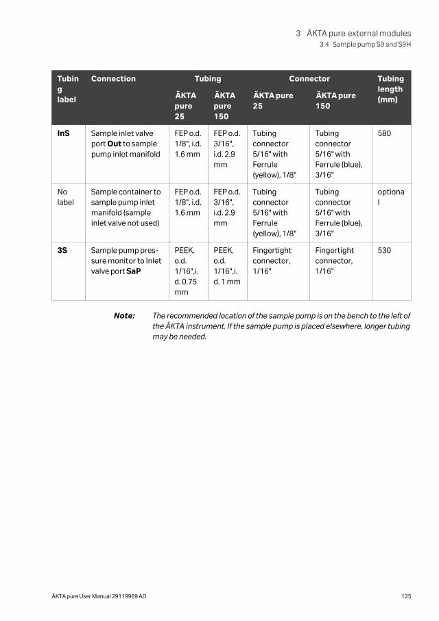
Tubinglabel
Connection Tubing Connector Tubinglength(mm)ÄKTA
pure25
ÄKTApure150
ÄKTA pure25
ÄKTA pure150
InS Sample inlet valveport Out to samplepump inlet manifold
FEP o.d.1/8", i.d.1.6 mm
FEP o.d.3/16",i.d. 2.9mm
Tubingconnector5/16" withFerrule(yellow), 1/8"
Tubingconnector5/16" withFerrule (blue),3/16"
580
Nolabel
Sample container tosample pump inletmanifold (sampleinlet valve not used)
FEP o.d.1/8", i.d.1.6 mm
FEP o.d.3/16",i.d. 2.9mm
Tubingconnector5/16" withFerrule(yellow), 1/8"
Tubingconnector5/16" withFerrule (blue),3/16"
optional
3S Sample pump pres-sure monitor to Inletvalve port SaP
PEEK,o.d.1/16",i.d. 0.75mm
PEEK,o.d.1/16",i.d. 1 mm
Fingertightconnector,1/16"
Fingertightconnector,1/16"
530
Note: The recommended location of the sample pump is on the bench to the left ofthe ÄKTA instrument. If the sample pump is placed elsewhere, longer tubingmay be needed.
3 ÄKTA pure external modules3.4 Sample pump S9 and S9H
ÄKTA pure User Manual 29119969 AD 125
3.5 I/O-box E9
About this sectionThis section describes the design and the function of the I/O-box E9
In this section
Section See page
3.5.1 Overview of the I/O-box 127
3.5.2 Analog connector and signals 129
3.5.3 Digital connector and signals 131
3.5.4 Connect external equipment to the I/O-box 133
3 ÄKTA pure external modules3.5 I/O-box E9
126 ÄKTA pure User Manual 29119969 AD
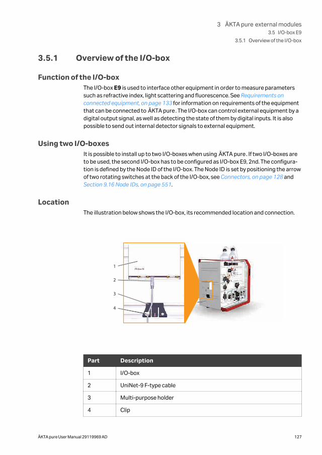
3.5.1 Overview of the I/O-box
Function of the I/O-boxThe I/O-box E9 is used to interface other equipment in order to measure parameterssuch as refractive index, light scattering and fluorescence. See Requirements onconnected equipment, on page 133 for information on requirements of the equipmentthat can be connected to ÄKTA pure. The I/O-box can control external equipment by adigital output signal, as well as detecting the state of them by digital inputs. It is alsopossible to send out internal detector signals to external equipment.
Using two I/O-boxesIt is possible to install up to two I/O-boxes when using ÄKTA pure. If two I/O-boxes areto be used, the second I/O-box has to be configured as I/O-box E9, 2nd. The configura-tion is defined by the Node ID of the I/O-box. The Node ID is set by positioning the arrowof two rotating switches at the back of the I/O-box, see Connectors, on page 128 and Section 9.16 Node IDs, on page 551.
LocationThe illustration below shows the I/O-box, its recommended location and connection.
1
2
3
4
Part Description
1 I/O-box
2 UniNet-9 F-type cable
3 Multi-purpose holder
4 Clip
3 ÄKTA pure external modules3.5 I/O-box E9
3.5.1 Overview of the I/O-box
ÄKTA pure User Manual 29119969 AD 127
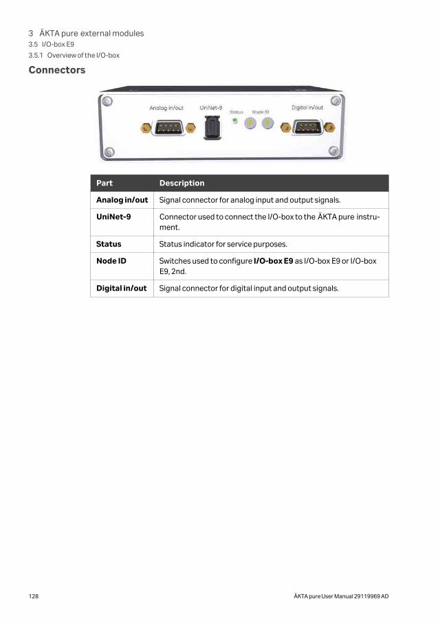
Connectors
Part Description
Analog in/out Signal connector for analog input and output signals.
UniNet-9 Connector used to connect the I/O-box to the ÄKTA pure instru-ment.
Status Status indicator for service purposes.
Node ID Switches used to configure I/O-box E9 as I/O-box E9 or I/O-boxE9, 2nd.
Digital in/out Signal connector for digital input and output signals.
3 ÄKTA pure external modules3.5 I/O-box E9
3.5.1 Overview of the I/O-box
128 ÄKTA pure User Manual 29119969 AD
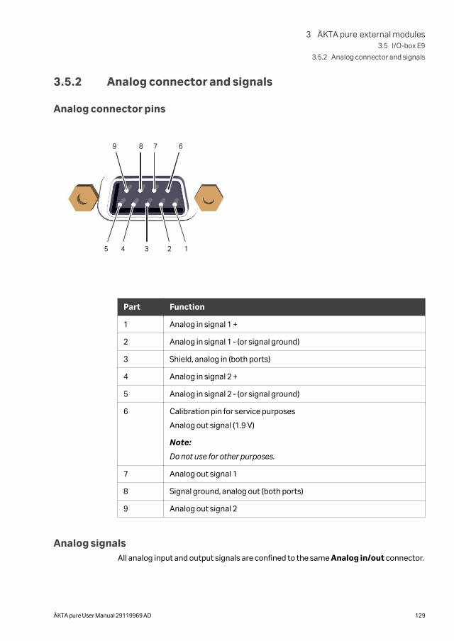
3.5.2 Analog connector and signals
Analog connector pins
12345
6789
Part Function
1 Analog in signal 1 +
2 Analog in signal 1 - (or signal ground)
3 Shield, analog in (both ports)
4 Analog in signal 2 +
5 Analog in signal 2 - (or signal ground)
6 Calibration pin for service purposes
Analog out signal (1.9 V)
Note:
Do not use for other purposes.
7 Analog out signal 1
8 Signal ground, analog out (both ports)
9 Analog out signal 2
Analog signalsAll analog input and output signals are confined to the same Analog in/out connector.
3 ÄKTA pure external modules3.5 I/O-box E9
3.5.2 Analog connector and signals
ÄKTA pure User Manual 29119969 AD 129
Analog input signalsThere are two analog input channels from which analog input signals can be used forpeak detection, or data collection in UNICORN. It is possible to auto-zero the inputsignals, which means that the current value will be displayed as 0 V in UNICORN. Thiscan be done individually for the two analog input channels. The auto-zero value is savedbetween runs and power-offs. The auto-zero value can be reset.
Parameter Description
Input signal range -2000 to 2000 mV
Analog output signalsThere are two analog output channels from which analog output signals and systemparameters, that is, UV, cond, conc B, temperature and pH, are transferred to theexternal connected equipment, for example, light scattering detectors or plotters.
Parameter Description
Outputsignal range
-1000 to 1000 mV
Defaultoutput
The user defines the default output level for the selected signal.
Full scaleoutput
The user sets the desired output signal value of, e.g., mAU, % or mS,which will corresponds to the full scale output voltage 1000 mV.
Negative fullscale output
The corresponding negative full scale output value is set automati-cally. For example, if the full scale output is set to 2000 mAU, a UVvalue of 500 mAU will give an output voltage of 250 mV, and -100mAU will give -50 mV output voltage. A signal value of 0 mAU, 0% or0 mS will always give an output voltage of 0 mV.
Fix point Zero is always a fix point. A desired output signal of, i.e., 0 mAU, 0%or 0 mS corresponds to an output voltage of 0 mV. At power-on, anoutput signal of 0 mV is transferred to the connected equipment,until the output signal range values are set.
Note: No warning will be displayed in UNICORN if the analog output signalexceeds the set full scale output value or is less than the set negative fullscale output value.
3 ÄKTA pure external modules3.5 I/O-box E9
3.5.2 Analog connector and signals
130 ÄKTA pure User Manual 29119969 AD
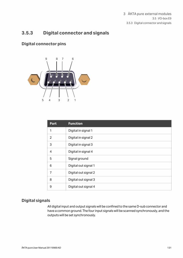
3.5.3 Digital connector and signals
Digital connector pins
12345
6789
Part Function
1 Digital in signal 1
2 Digital in signal 2
3 Digital in signal 3
4 Digital in signal 4
5 Signal ground
6 Digital out signal 1
7 Digital out signal 2
8 Digital out signal 3
9 Digital out signal 4
Digital signalsAll digital input and output signals will be confined to the same D-sub connector andhave a common ground. The four input signals will be scanned synchronously, and theoutputs will be set synchronously.
3 ÄKTA pure external modules3.5 I/O-box E9
3.5.3 Digital connector and signals
ÄKTA pure User Manual 29119969 AD 131
Digital input signalsThe digital in-signal can be used to monitor external equipment by registering, forexample, error signals or event marks. An event mark can be used as a trigger forwatches. The measured digital signals can be shown as a curve in UNICORN. The unitwill handle both open/closed circuit and TTL-type voltage signals. An open circuit isinterpreted as logical 1 and a closed circuit as logical 0.
Note: A closed circuit is always closed against signal ground.
Input connection UNICORN interpretation
Open circuit Logical 1
Applied voltage 3.5 to 5.0 V
Closed circuit Logical 0
Applied voltage 0 to 0.8 V
Digital output signalsThe digital output signal can be used to control external equipment that can receivedigital signals, such as pumps or fraction collectors. The digital output signals define anopen or closed circuit, where a logical 1 will result in an open circuit and a logical 0 willgive a closed circuit. The default level, 1 or 0, is set by the user. The level can be changedby instructions either manually, in System Settings or by a method. It is possible tosend pulses from the current level, with a pulse length of 0.1 s to 10 s.
Note: A closed circuit is always closed against signal ground.
3 ÄKTA pure external modules3.5 I/O-box E9
3.5.3 Digital connector and signals
132 ÄKTA pure User Manual 29119969 AD
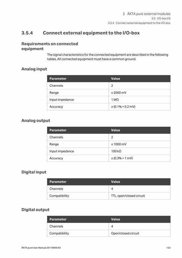
3.5.4 Connect external equipment to the I/O-box
Requirements on connectedequipment
The signal characteristics for the connected equipment are described in the followingtables. All connected equipment must have a common ground.
Analog input
Parameter Value
Channels 2
Range ± 2000 mV
Input impedance 1 MΩ
Accuracy ± (0.1% + 0.2 mV)
Analog output
Parameter Value
Channels 2
Range ± 1000 mV
Input impedance 100 kΩ
Accuracy ± (0.3% + 1 mV)
Digital input
Parameter Value
Channels 4
Compatibility TTL, open/closed circuit
Digital output
Parameter Value
Channels 4
Compatibility Open/closed circuit
3 ÄKTA pure external modules3.5 I/O-box E9
3.5.4 Connect external equipment to the I/O-box
ÄKTA pure User Manual 29119969 AD 133
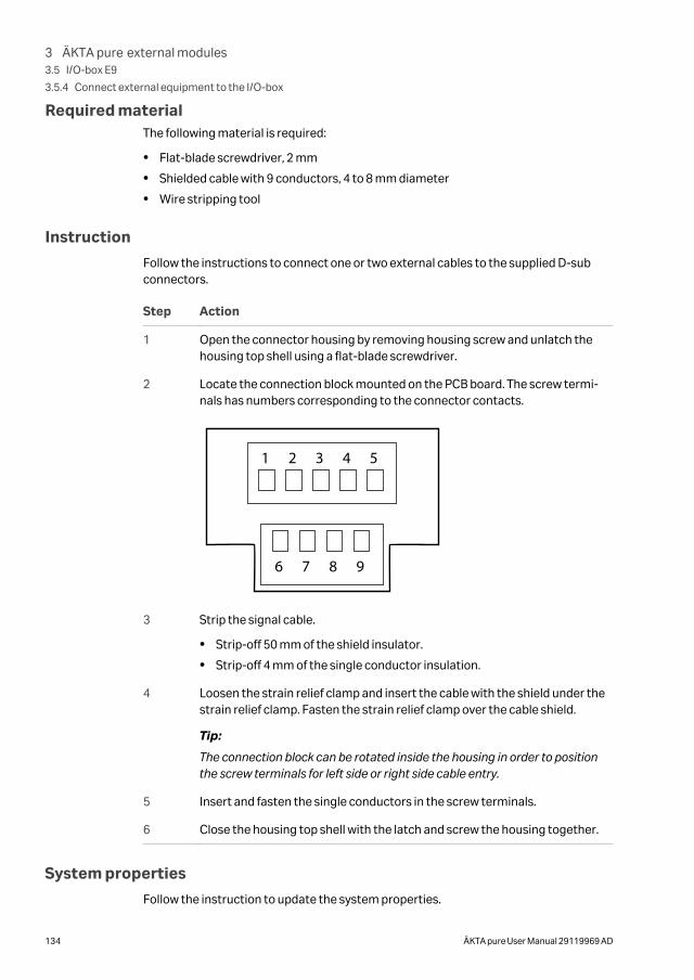
Required materialThe following material is required:
• Flat-blade screwdriver, 2 mm
• Shielded cable with 9 conductors, 4 to 8 mm diameter
• Wire stripping tool
Instruction
Follow the instructions to connect one or two external cables to the supplied D-subconnectors.
Step Action
1 Open the connector housing by removing housing screw and unlatch thehousing top shell using a flat-blade screwdriver.
2 Locate the connection block mounted on the PCB board. The screw termi-nals has numbers corresponding to the connector contacts.
54321
9876
3 Strip the signal cable.
• Strip-off 50 mm of the shield insulator.
• Strip-off 4 mm of the single conductor insulation.
4 Loosen the strain relief clamp and insert the cable with the shield under thestrain relief clamp. Fasten the strain relief clamp over the cable shield.
Tip:
The connection block can be rotated inside the housing in order to positionthe screw terminals for left side or right side cable entry.
5 Insert and fasten the single conductors in the screw terminals.
6 Close the housing top shell with the latch and screw the housing together.
System properties
Follow the instruction to update the system properties.
3 ÄKTA pure external modules3.5 I/O-box E9
3.5.4 Connect external equipment to the I/O-box
134 ÄKTA pure User Manual 29119969 AD
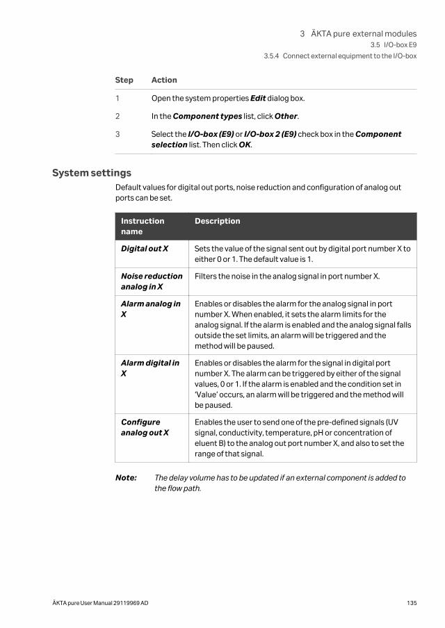
Step Action
1 Open the system properties Edit dialog box.
2 In the Component types list, click Other.
3 Select the I/O-box (E9) or I/O-box 2 (E9) check box in the Componentselection list. Then click OK.
System settingsDefault values for digital out ports, noise reduction and configuration of analog outports can be set.
Instructionname
Description
Digital out X Sets the value of the signal sent out by digital port number X toeither 0 or 1. The default value is 1.
Noise reductionanalog in X
Filters the noise in the analog signal in port number X.
Alarm analog inX
Enables or disables the alarm for the analog signal in portnumber X. When enabled, it sets the alarm limits for theanalog signal. If the alarm is enabled and the analog signal fallsoutside the set limits, an alarm will be triggered and themethod will be paused.
Alarm digital inX
Enables or disables the alarm for the signal in digital portnumber X. The alarm can be triggered by either of the signalvalues, 0 or 1. If the alarm is enabled and the condition set in‘Value’ occurs, an alarm will be triggered and the method willbe paused.
Configureanalog out X
Enables the user to send one of the pre-defined signals (UVsignal, conductivity, temperature, pH or concentration ofeluent B) to the analog out port number X, and also to set therange of that signal.
Note: The delay volume has to be updated if an external component is added tothe flow path.
3 ÄKTA pure external modules3.5 I/O-box E9
3.5.4 Connect external equipment to the I/O-box
ÄKTA pure User Manual 29119969 AD 135
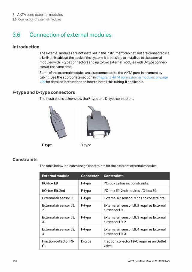
3.6 Connection of external modules
IntroductionThe external modules are not installed in the instrument cabinet, but are connected viaa UniNet-9 cable at the back of the system. it is possible to install up to six externalmodules with F-type connectors and up to two external modules with D-type connec-tors at the same time.
Some of the external modules are also connected to the ÄKTA pure instrument bytubing. See the appropriate section in Chapter 3 ÄKTA pure external modules, on page100 for detailed instructions on how to install this tubing, if applicable.
F-type and D-type connectorsThe illustrations below show the F-type and D-type connectors.
F-type D-type
ConstraintsThe table below indicates usage constraints for the different external modules.
External module Connector Constraints
I/O-box E9 F-type I/O-box E9 has no constraints.
I/O-box E9, 2nd F-type I/O-box E9, 2nd requires I/O-box E9.
External air sensor L9 F-type External air sensor L9 has no constraints.
External air sensor L9,2
F-type External air sensor L9, 2 requires Externalair sensor L9.
External air sensor L9,3
F-type External air sensor L9, 3 requires Externalair sensor L9, 2.
External air sensor L9,4
F-type External air sensor L9, 4 requires Externalair sensor L9, 3.
Fraction collector F9-C
D-type Fraction collector F9-C requires an Outletvalve.
3 ÄKTA pure external modules3.6 Connection of external modules
136 ÄKTA pure User Manual 29119969 AD
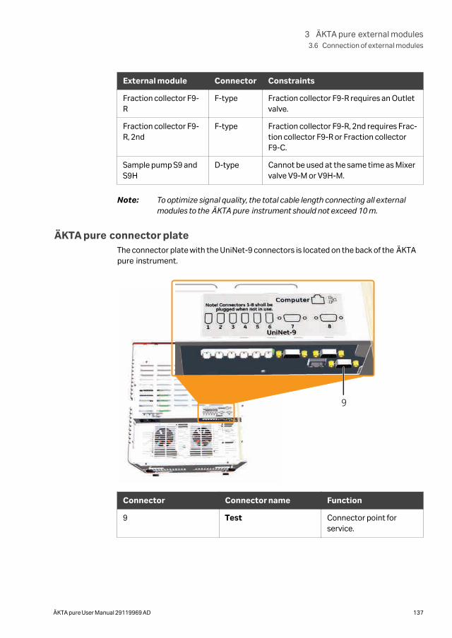
External module Connector Constraints
Fraction collector F9-R
F-type Fraction collector F9-R requires an Outletvalve.
Fraction collector F9-R, 2nd
F-type Fraction collector F9-R, 2nd requires Frac-tion collector F9-R or Fraction collectorF9-C.
Sample pump S9 andS9H
D-type Cannot be used at the same time as Mixervalve V9-M or V9H-M.
Note: To optimize signal quality, the total cable length connecting all externalmodules to the ÄKTA pure instrument should not exceed 10 m.
ÄKTA pure connector plateThe connector plate with the UniNet-9 connectors is located on the back of the ÄKTApure instrument.
9
Connector Connector name Function
9 Test Connector point forservice.
3 ÄKTA pure external modules3.6 Connection of external modules
ÄKTA pure User Manual 29119969 AD 137

NOTICE
Do not connect any module to the connector Test on the ÄKTApure instrument.
Note: Plug all unused UniNet-9 ports (ports 1 to 8) on the ÄKTA pure instrumentwith jumpers.
Note: The connector Test should be protected by a plastic lid. Do not plug theconnector with a jumper.
3 ÄKTA pure external modules3.6 Connection of external modules
138 ÄKTA pure User Manual 29119969 AD
4 System configuration
About this chapterThis chapter describes hardware configuration of the ÄKTA pure instrument and howto install optional modules and add them in UNICORN.
In this chapter
Section See page
4.1 Configuration overview 140
4.2 Configure modules 146
4.3 General system settings 163
4 System configuration
ÄKTA pure User Manual 29119969 AD 139
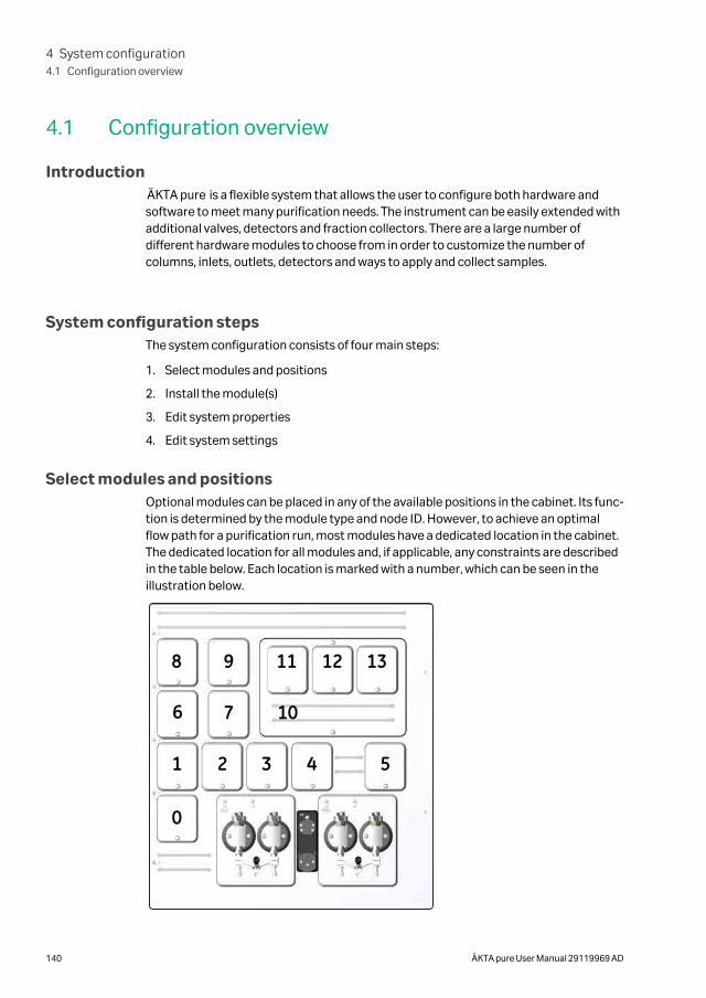
4.1 Configuration overview
IntroductionÄKTA pure is a flexible system that allows the user to configure both hardware andsoftware to meet many purification needs. The instrument can be easily extended withadditional valves, detectors and fraction collectors. There are a large number ofdifferent hardware modules to choose from in order to customize the number ofcolumns, inlets, outlets, detectors and ways to apply and collect samples.
System configuration stepsThe system configuration consists of four main steps:
1. Select modules and positions
2. Install the module(s)
3. Edit system properties
4. Edit system settings
Select modules and positionsOptional modules can be placed in any of the available positions in the cabinet. Its func-tion is determined by the module type and node ID. However, to achieve an optimalflow path for a purification run, most modules have a dedicated location in the cabinet.The dedicated location for all modules and, if applicable, any constraints are describedin the table below. Each location is marked with a number, which can be seen in theillustration below.
8 9
7
1 2 3 4 5
10
11 12 13
6
0
4 System configuration4.1 Configuration overview
140 ÄKTA pure User Manual 29119969 AD
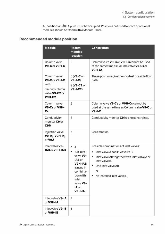
All positions in ÄKTA pure must be occupied. Positions not used for core or optionalmodules should be fitted with a Module Panel.
Recommended module position
Module Recom-mendedlocation
Constraints
Column valveV9-C or V9H-C
9 Column valve V9-C or V9H-C cannot be usedat the same time as Column valve V9-Cs orV9H-Cs.
Column valveV9-C or V9H-Cwith
Second columnvalve V9-C2 orV9H-C2
8 (V9-C orV9H-C)
9 (V9-C2 orV9H-C2)
These positions give the shortest possible flowpath.
Column valveV9-Cs or V9H-Cs
9 Column valve V9-Cs or V9H-Cs cannot beused at the same time as Column valve V9-C orV9H-C.
Conductivitymonitor C9 orC9M
7 Conductivity monitor C9 has no constraints.
Injection valveV9-Inj, V9H-Injor V9J
6 Core module.
Inlet valve V9-IAB or V9H-IAB
• 4
• 5, if Inletvalve V9-IAB orV9H-IABis used incombina-tion withInletvalve V9-IA orV9H-IA.
Possible combinations of inlet valves:
• Inlet valve A and Inlet valve B.
• Inlet valve AB together with Inlet valve A orInlet valve B.
• One Inlet valve AB.
or
• No installed inlet valves.
Inlet valve V9-IAor V9H-IA
4
Inlet valve V9-IBor V9H-IB
5
4 System configuration4.1 Configuration overview
ÄKTA pure User Manual 29119969 AD 141
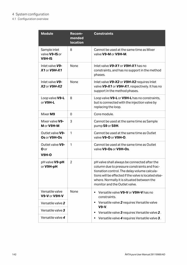
Module Recom-mendedlocation
Constraints
Sample inletvalve V9-IS orV9H-IS
8 Cannot be used at the same time as Mixervalve V9-M or V9H-M.
Inlet valve V9-X1 or V9H-X1
None Inlet valve V9-X1 or V9H-X1 has noconstraints, and has no support in the methodphases.
Inlet valve V9-X2 or V9H-X2
None Inlet valve V9-X2 or V9H-X2 requires Inletvalve V9-X1 or V9H-X1, respectively. It has nosupport in the method phases.
Loop valve V9-Lor V9H-L
8 Loop valve V9-L or V9H-L has no constraints,but is connected with the injection valve byreplacing the loop.
Mixer M9 0 Core module.
Mixer valve V9-M or V9H-M
3 Cannot be used at the same time as Samplepump S9 or S9H.
Outlet valve V9-Os or V9H-Os
1 Cannot be used at the same time as Outletvalve V9-O or V9H-O.
Outlet valve V9-O or
V9H-O
1 Cannot be used at the same time as Outletvalve V9-Os or V9H-Os.
pH valve V9-pHor V9H-pH
2 pH valve shall always be connected after thecolumn due to pressure constraints and frac-tionation control. The delay volume calcula-tions will be effected if the valve is located else-where. Normally it is situated between themonitor and the Outlet valve.
Versatile valveV9-V or V9H-V
None • Versatile valve V9-V or V9H-V has noconstraints.
• Versatile valve 2 requires Versatile valveV9-V.
• Versatile valve 3 requires Versatile valve 2 .
• Versatile valve 4 requires Versatile valve 3 .
Versatile valve 2
Versatile valve 3
Versatile valve 4
4 System configuration4.1 Configuration overview
142 ÄKTA pure User Manual 29119969 AD
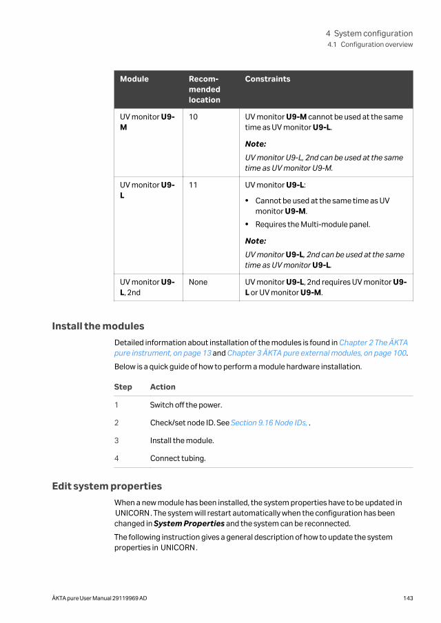
Module Recom-mendedlocation
Constraints
UV monitor U9-M
10 UV monitor U9-M cannot be used at the sametime as UV monitor U9-L.
Note:
UV monitor U9-L, 2nd can be used at the sametime as UV monitor U9-M.
UV monitor U9-L
11 UV monitor U9-L:
• Cannot be used at the same time as UVmonitor U9-M.
• Requires the Multi-module panel.
Note:
UV monitor U9-L, 2nd can be used at the sametime as UV monitor U9-L.
UV monitor U9-L, 2nd
None UV monitor U9-L, 2nd requires UV monitor U9-L or UV monitor U9-M.
Install the modules
Detailed information about installation of the modules is found in Chapter 2 The ÄKTApure instrument, on page 13 and Chapter 3 ÄKTA pure external modules, on page 100.
Below is a quick guide of how to perform a module hardware installation.
Step Action
1 Switch off the power.
2 Check/set node ID. See Section 9.16 Node IDs, .
3 Install the module.
4 Connect tubing.
Edit system properties
When a new module has been installed, the system properties have to be updated inUNICORN. The system will restart automatically when the configuration has beenchanged in System Properties and the system can be reconnected.
The following instruction gives a general description of how to update the systemproperties in UNICORN.
4 System configuration4.1 Configuration overview
ÄKTA pure User Manual 29119969 AD 143
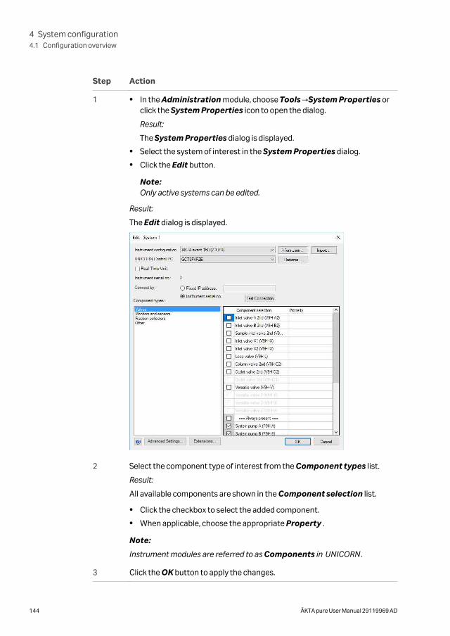
Step Action
1 • In the Administration module, choose Tools →System Properties orclick the System Properties icon to open the dialog.
Result:
The System Properties dialog is displayed.
• Select the system of interest in the System Properties dialog.
• Click the Edit button.
Note:Only active systems can be edited.
Result:
The Edit dialog is displayed.
2 Select the component type of interest from the Component types list.
Result:
All available components are shown in the Component selection list.
• Click the checkbox to select the added component.
• When applicable, choose the appropriate Property .
Note:
Instrument modules are referred to as Components in UNICORN.
3 Click the OK button to apply the changes.
4 System configuration4.1 Configuration overview
144 ÄKTA pure User Manual 29119969 AD
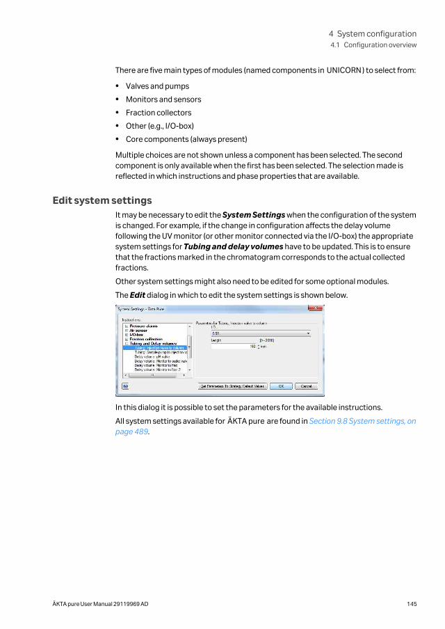
There are five main types of modules (named components in UNICORN) to select from:
• Valves and pumps
• Monitors and sensors
• Fraction collectors
• Other (e.g., I/O-box)
• Core components (always present)
Multiple choices are not shown unless a component has been selected. The secondcomponent is only available when the first has been selected. The selection made isreflected in which instructions and phase properties that are available.
Edit system settingsIt may be necessary to edit the System Settings when the configuration of the systemis changed. For example, if the change in configuration affects the delay volumefollowing the UV monitor (or other monitor connected via the I/O-box) the appropriatesystem settings for Tubing and delay volumes have to be updated. This is to ensurethat the fractions marked in the chromatogram corresponds to the actual collectedfractions.
Other system settings might also need to be edited for some optional modules.
The Edit dialog in which to edit the system settings is shown below.
In this dialog it is possible to set the parameters for the available instructions.
All system settings available for ÄKTA pure are found in Section 9.8 System settings, onpage 489.
4 System configuration4.1 Configuration overview
ÄKTA pure User Manual 29119969 AD 145
4.2 Configure modulesThis section describes the software configuration that must be set for the individualmodules that are to be used for a specific run.
A general description of how to update the system properties are found in Edit systemproperties, on page 143.
A general decription of how to edit system settings are found in Edit system settings, onpage 145.
In this section
Section See page
4.2.1 Configuration of inlet valves 147
4.2.2 Configuration of Mixer valves 149
4.2.3 Configuration of Loop valves 150
4.2.4 Configuration of column valves 151
4.2.5 Configuration of Versatile valves 153
4.2.6 Configuration of pH valves 154
4.2.7 Configuration of outlet valves 155
4.2.8 Configuration of UV monitors 156
4.2.9 Configuration of Conductivity monitor 157
4.2.10 Configuration of external air sensors 158
4.2.11 Configuration of fraction collectors 159
4.2.12 Configuration of I/O-box 162
4 System configuration4.2 Configure modules
146 ÄKTA pure User Manual 29119969 AD
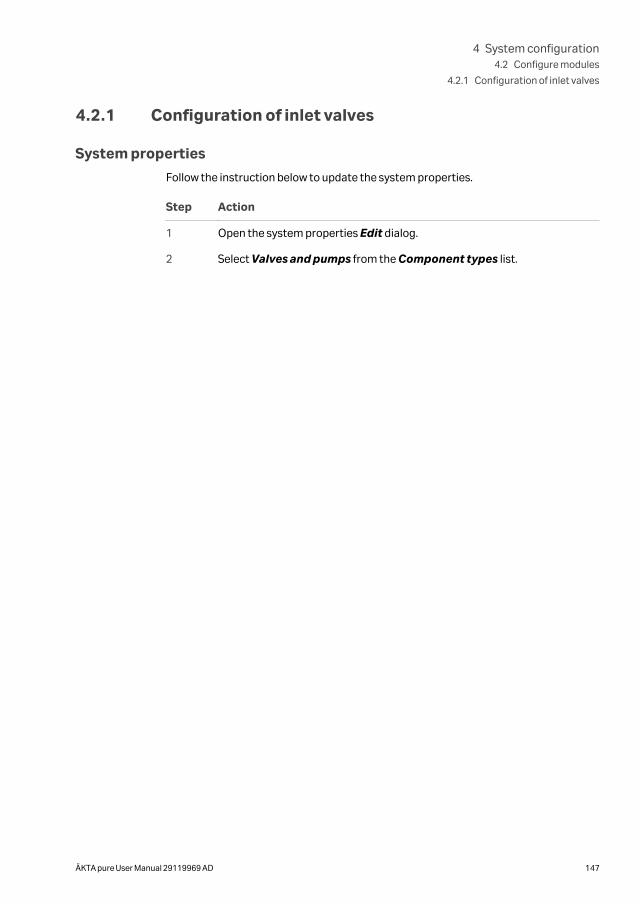
4.2.1 Configuration of inlet valves
System properties
Follow the instruction below to update the system properties.
Step Action
1 Open the system properties Edit dialog.
2 Select Valves and pumps from the Component types list.
4 System configuration4.2 Configure modules
4.2.1 Configuration of inlet valves
ÄKTA pure User Manual 29119969 AD 147
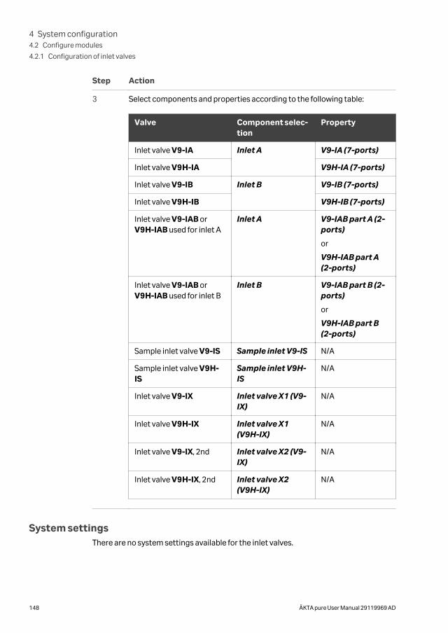
Step Action
3 Select components and properties according to the following table:
Valve Component selec-tion
Property
Inlet valve V9-IA Inlet A V9-IA (7-ports)
Inlet valve V9H-IA V9H-IA (7-ports)
Inlet valve V9-IB Inlet B V9-IB (7-ports)
Inlet valve V9H-IB V9H-IB (7-ports)
Inlet valve V9-IAB orV9H-IAB used for inlet A
Inlet A V9-IAB part A (2-ports)
or
V9H-IAB part A(2-ports)
Inlet valve V9-IAB orV9H-IAB used for inlet B
Inlet B V9-IAB part B (2-ports)
or
V9H-IAB part B(2-ports)
Sample inlet valve V9-IS Sample inlet V9-IS N/A
Sample inlet valve V9H-IS
Sample inlet V9H-IS
N/A
Inlet valve V9-IX Inlet valve X1 (V9-IX)
N/A
Inlet valve V9H-IX Inlet valve X1(V9H-IX)
N/A
Inlet valve V9-IX, 2nd Inlet valve X2 (V9-IX)
N/A
Inlet valve V9H-IX, 2nd Inlet valve X2(V9H-IX)
N/A
System settingsThere are no system settings available for the inlet valves.
4 System configuration4.2 Configure modules
4.2.1 Configuration of inlet valves
148 ÄKTA pure User Manual 29119969 AD
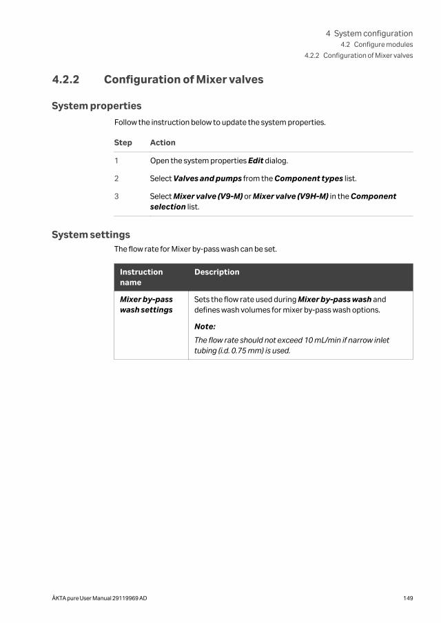
4.2.2 Configuration of Mixer valves
System properties
Follow the instruction below to update the system properties.
Step Action
1 Open the system properties Edit dialog.
2 Select Valves and pumps from the Component types list.
3 Select Mixer valve (V9-M) or Mixer valve (V9H-M) in the Componentselection list.
System settingsThe flow rate for Mixer by-pass wash can be set.
Instructionname
Description
Mixer by-passwash settings
Sets the flow rate used during Mixer by-pass wash anddefines wash volumes for mixer by-pass wash options.
Note:
The flow rate should not exceed 10 mL/min if narrow inlettubing (i.d. 0.75 mm) is used.
4 System configuration4.2 Configure modules
4.2.2 Configuration of Mixer valves
ÄKTA pure User Manual 29119969 AD 149
4.2.3 Configuration of Loop valves
System properties
Follow the instruction below to update the system properties.
Step Action
1 Open the system properties Edit dialog.
2 Select Valves and pumps from the Component types list.
3 Select Loop valve (V9-L) or Loop valve (V9H-L) in the Component selec-tion list.
System settingsThe flow rate for Loop wash can be set.
Instructionname
Description
Loop washsettings
Sets the flow rate used during Loop wash.
Note:
The flow rate should not exceed 10 mL/min if narrow inlettubing (i.d. 0.75 mm) is used.
4 System configuration4.2 Configure modules
4.2.3 Configuration of Loop valves
150 ÄKTA pure User Manual 29119969 AD
4.2.4 Configuration of column valves
System properties
Follow the instruction below to update the system properties.
Step Action
1 Open the system properties Edit dialog.
2 Select Valves and pumps from the Component types list.
3 Select components and properties according to the following table:
Valve Componentselection
Property
Column selection valveV9-C
Column valve V9-C (5-columns)
Column selection valveV9H-C
Column valve V9H-C (5-columns)
Second column selectionvalve V9-C2
Column valve V9-C2 (5-columns)
Second column selectionvalve V9H-C2
Column valve V9H-C2 (5-columns)
Column control valve V9-Cs
Column valve V9-Cs (1-column)
Column control valveV9H-Cs
Column valve V9H-Cs (1-column)
System settings
After selecting Column valve V9-Cs, V9H-Cs or no column valve, in UNICORN, thetube length has to be defined.
The instructions Tubing →Injection valve to column and Tubing →Sample pumpto injection valve are used in calculations of pre-column pressure when Column valveV9-C or V9H-C (5-columns) is NOT mounted onto the system. In such cases, there isno pre-column pressure sensor present. The estimated pre-column pressure is calcu-lated using the measured system pressure and the length of the tubing between thesystem pressure sensor and the Column.
The instructions are available only when the Column valve V9-C or V9H-C (5-columns)is not selected in the component list. The instruction Tubing →Sample pump toinjection valve is in addition only available if the sample pump is selected in the list.
4 System configuration4.2 Configure modules
4.2.4 Configuration of column valves
ÄKTA pure User Manual 29119969 AD 151
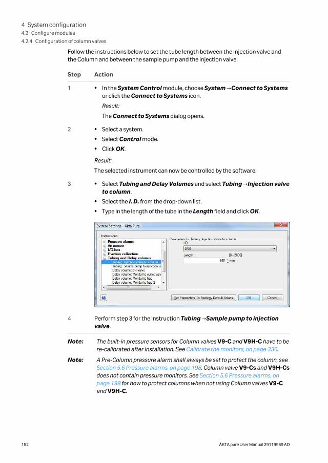
Follow the instructions below to set the tube length between the Injection valve andthe Column and between the sample pump and the injection valve.
Step Action
1 • In the System Control module, choose System →Connect to Systemsor click the Connect to Systems icon.
Result:
The Connect to Systems dialog opens.
2 • Select a system.
• Select Control mode.
• Click OK.
Result:
The selected instrument can now be controlled by the software.
3 • Select Tubing and Delay Volumes and select Tubing →Injection valveto column.
• Select the I. D. from the drop-down list.
• Type in the length of the tube in the Length field and click OK.
4 Perform step 3 for the instruction Tubing →Sample pump to injectionvalve.
Note: The built-in pressure sensors for Column valves V9-C and V9H-C have to bere-calibrated after installation. See Calibrate the monitors, on page 336.
Note: A Pre-Column pressure alarm shall always be set to protect the column, see Section 5.6 Pressure alarms, on page 198. Column valve V9-Cs and V9H-Csdoes not contain pressure monitors. See Section 5.6 Pressure alarms, onpage 198 for how to protect columns when not using Column valves V9-Cand V9H-C.
4 System configuration4.2 Configure modules
4.2.4 Configuration of column valves
152 ÄKTA pure User Manual 29119969 AD
4.2.5 Configuration of Versatile valves
System properties
Follow the instruction below to update the system properties.
Step Action
1 Open the system properties Edit dialog.
2 Select Valves and pumps from the Component types list.
3 Select Versatile valve (V9-V), Versatile valve 2 (V9-V), Versatile valve 3(V9-V) or Versatile valve 4 (V9-V) in the Component selection list.
System settingsIf the valve is placed in the flow path between the UV monitor and the outlet valve, thedelay volume must be set. See Check/Set delay volume, on page 163.
4 System configuration4.2 Configure modules
4.2.5 Configuration of Versatile valves
ÄKTA pure User Manual 29119969 AD 153
4.2.6 Configuration of pH valves
System properties
Follow the instruction below to update the system properties.
Step Action
1 Open the system properties Edit dialog.
2 Select Valves and pumps from the Component types list.
3 Select pH valve (V9-pH) or pH valve (V9H-pH) in the Component selec-tion list.
System settingsIf the valve is placed in the flow path between the UV monitor and the outlet valve, thedelay volume must be set. See Check/Set delay volume, on page 163.
Note: It is recommended not to alter the default values for restrictor and pH celldelay volumes when standard modules and standard tubing for flowrestrictor are used.
4 System configuration4.2 Configure modules
4.2.6 Configuration of pH valves
154 ÄKTA pure User Manual 29119969 AD
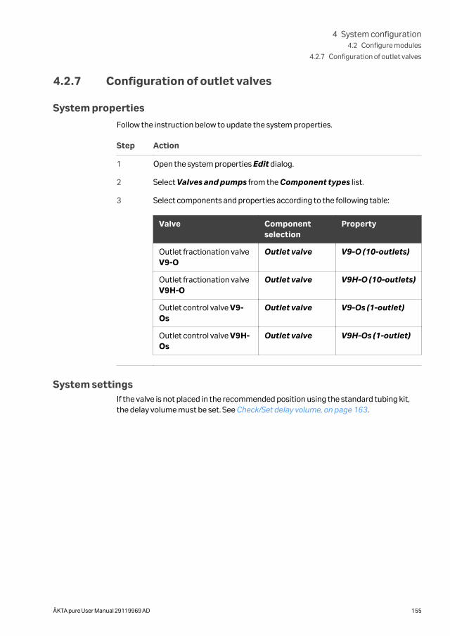
4.2.7 Configuration of outlet valves
System properties
Follow the instruction below to update the system properties.
Step Action
1 Open the system properties Edit dialog.
2 Select Valves and pumps from the Component types list.
3 Select components and properties according to the following table:
Valve Componentselection
Property
Outlet fractionation valveV9-O
Outlet valve V9-O (10-outlets)
Outlet fractionation valveV9H-O
Outlet valve V9H-O (10-outlets)
Outlet control valve V9-Os
Outlet valve V9-Os (1-outlet)
Outlet control valve V9H-Os
Outlet valve V9H-Os (1-outlet)
System settingsIf the valve is not placed in the recommended position using the standard tubing kit,the delay volume must be set. See Check/Set delay volume, on page 163.
4 System configuration4.2 Configure modules
4.2.7 Configuration of outlet valves
ÄKTA pure User Manual 29119969 AD 155
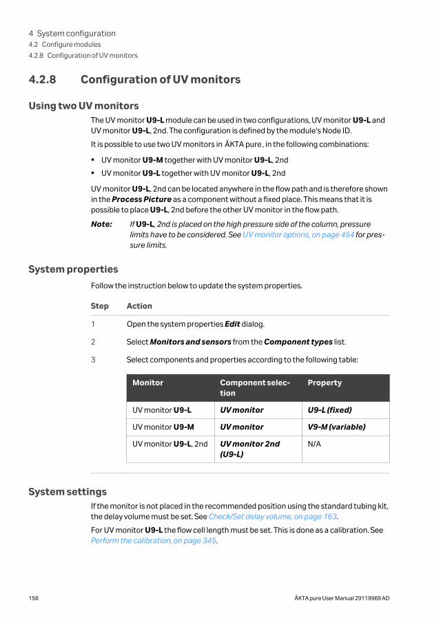
4.2.8 Configuration of UV monitors
Using two UV monitorsThe UV monitor U9-L module can be used in two configurations, UV monitor U9-L andUV monitor U9-L, 2nd. The configuration is defined by the module's Node ID.
It is possible to use two UV monitors in ÄKTA pure, in the following combinations:
• UV monitor U9-M together with UV monitor U9-L, 2nd
• UV monitor U9-L together with UV monitor U9-L, 2nd
UV monitor U9-L, 2nd can be located anywhere in the flow path and is therefore shownin the Process Picture as a component without a fixed place. This means that it ispossible to place U9-L, 2nd before the other UV monitor in the flow path.
Note: If U9-L, 2nd is placed on the high pressure side of the column, pressurelimits have to be considered. See UV monitor options, on page 454 for pres-sure limits.
System properties
Follow the instruction below to update the system properties.
Step Action
1 Open the system properties Edit dialog.
2 Select Monitors and sensors from the Component types list.
3 Select components and properties according to the following table:
Monitor Component selec-tion
Property
UV monitor U9-L UV monitor U9-L (fixed)
UV monitor U9-M UV monitor V9-M (variable)
UV monitor U9-L, 2nd UV monitor 2nd(U9-L)
N/A
System settingsIf the monitor is not placed in the recommended position using the standard tubing kit,the delay volume must be set. See Check/Set delay volume, on page 163.
For UV monitor U9-L the flow cell length must be set. This is done as a calibration. See Perform the calibration, on page 345.
4 System configuration4.2 Configure modules
4.2.8 Configuration of UV monitors
156 ÄKTA pure User Manual 29119969 AD
4.2.9 Configuration of Conductivity monitor
System properties
Follow the instruction below to update the system properties.
Step Action
1 Open the system properties Edit dialog.
2 Select Monitors and sensors from the Component types list.
3 Select Conductivity monitor (C9) in the Component selection list.
System settingsIf the monitor is placed in the flow path between the UV monitor and the outlet valve,the delay volume must be set. See Check/Set delay volume, on page 163.
4 System configuration4.2 Configure modules
4.2.9 Configuration of Conductivity monitor
ÄKTA pure User Manual 29119969 AD 157
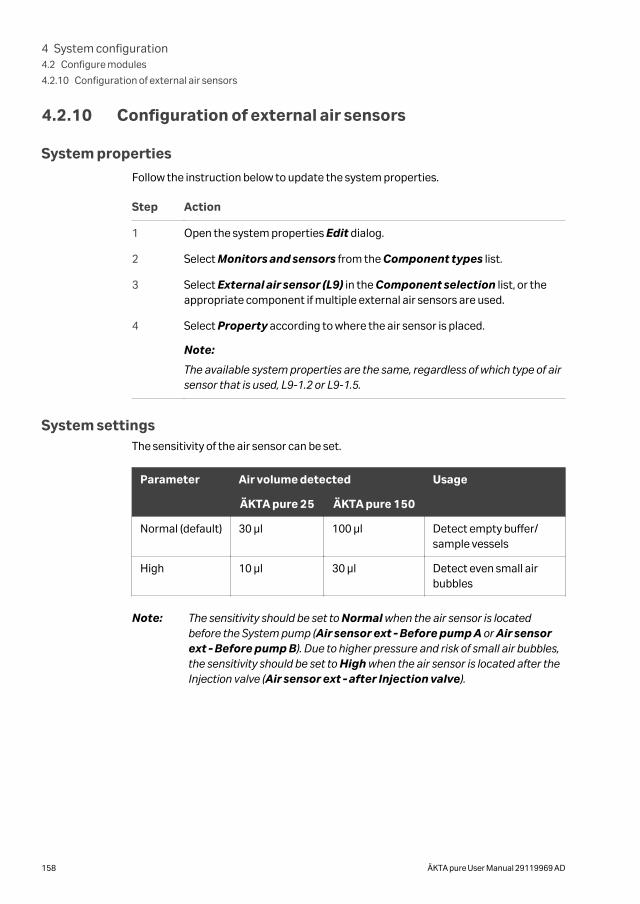
4.2.10 Configuration of external air sensors
System properties
Follow the instruction below to update the system properties.
Step Action
1 Open the system properties Edit dialog.
2 Select Monitors and sensors from the Component types list.
3 Select External air sensor (L9) in the Component selection list, or theappropriate component if multiple external air sensors are used.
4 Select Property according to where the air sensor is placed.
Note:
The available system properties are the same, regardless of which type of airsensor that is used, L9-1.2 or L9-1.5.
System settingsThe sensitivity of the air sensor can be set.
Parameter Air volume detected Usage
ÄKTA pure 25 ÄKTA pure 150
Normal (default) 30 μl 100 μl Detect empty buffer/sample vessels
High 10 μl 30 μl Detect even small airbubbles
Note: The sensitivity should be set to Normal when the air sensor is locatedbefore the System pump (Air sensor ext - Before pump A or Air sensorext - Before pump B). Due to higher pressure and risk of small air bubbles,the sensitivity should be set to High when the air sensor is located after theInjection valve (Air sensor ext - after Injection valve).
4 System configuration4.2 Configure modules
4.2.10 Configuration of external air sensors
158 ÄKTA pure User Manual 29119969 AD
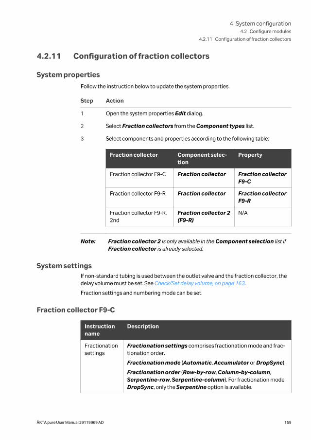
4.2.11 Configuration of fraction collectors
System properties
Follow the instruction below to update the system properties.
Step Action
1 Open the system properties Edit dialog.
2 Select Fraction collectors from the Component types list.
3 Select components and properties according to the following table:
Fraction collector Component selec-tion
Property
Fraction collector F9-C Fraction collector Fraction collectorF9-C
Fraction collector F9-R Fraction collector Fraction collectorF9-R
Fraction collector F9-R,2nd
Fraction collector 2(F9-R)
N/A
Note: Fraction collector 2 is only available in the Component selection list ifFraction collector is already selected.
System settingsIf non-standard tubing is used between the outlet valve and the fraction collector, thedelay volume must be set. See Check/Set delay volume, on page 163.
Fraction settings and numbering mode can be set.
Fraction collector F9-C
Instructionname
Description
Fractionationsettings
Fractionation settings comprises fractionation mode and frac-tionation order.
Fractionation mode (Automatic, Accumulator or DropSync).
Fractionation order (Row-by-row, Column-by-column,Serpentine-row, Serpentine-column). For fractionation modeDropSync, only the Serpentine option is available.
4 System configuration4.2 Configure modules
4.2.11 Configuration of fraction collectors
ÄKTA pure User Manual 29119969 AD 159
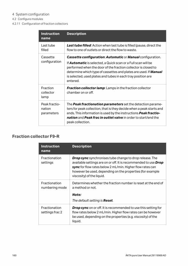
Instructionname
Description
Last tubefilled
Last tube filled: Action when last tube is filled (pause, direct theflow to one of outlets or direct the flow to waste.
Cassetteconfiguration
Cassette configuration: Automatic or Manual configuration.
If Automatic is selected, a Quick scan or a Full scan will beperformed when the door of the fraction collector is closed todetermine which type of cassettes and plates are used. If Manualis selected, used plates and tubes in each tray position areentered.
Fractioncollectorlamp
Fraction collector lamp: Lamps in the fraction collectorchamber on or off.
Peak fractio-nationparameters
The Peak fractionation parameters set the detection parame-ters for peak collection, that is they decide when a peak starts andends. This information is used by the instructions Peak fractio-nation and Peak frac in outlet valve in order to start/end thepeak collection.
Fraction collector F9-R
Instructionname
Description
Fractionationsettings
Drop sync synchronises tube change to drop release. Theavailable settings are on or off. It is recommended to use Dropsync for flow rates below 2 mL/min. Higher flow rates canhowever be used, depending on the properties (for exampleviscosity) of the liquid.
Fractionationnumbering mode
Determines whether the fraction number is reset at the end ofa method or not.
Note:
The default setting is Reset.
Fractionationsettings frac 2
Drop sync on or off. It is recommended to use this setting forflow rates below 2 mL/min. Higher flow rates can be howeverbe used, depending on the properties (e.g. viscosity) of theliquid.
4 System configuration4.2 Configure modules
4.2.11 Configuration of fraction collectors
160 ÄKTA pure User Manual 29119969 AD
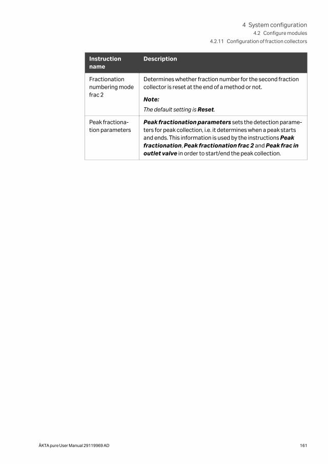
Instructionname
Description
Fractionationnumbering modefrac 2
Determines whether fraction number for the second fractioncollector is reset at the end of a method or not.
Note:
The default setting is Reset.
Peak fractiona-tion parameters
Peak fractionation parameters sets the detection parame-ters for peak collection, i.e. it determines when a peak startsand ends. This information is used by the instructions Peakfractionation, Peak fractionation frac 2 and Peak frac inoutlet valve in order to start/end the peak collection.
4 System configuration4.2 Configure modules
4.2.11 Configuration of fraction collectors
ÄKTA pure User Manual 29119969 AD 161
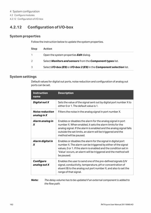
4.2.12 Configuration of I/O-box
System properties
Follow the instruction below to update the system properties.
Step Action
1 Open the system properties Edit dialog.
2 Select Monitors and sensors from the Component types list.
3 Select I/O-box (E9) or I/O-box 2 (E9) in the Component selection list.
System settingsDefault values for digital out ports, noise reduction and configuration of analog outports can be set.
Instructionname
Description
Digital out X Sets the value of the signal sent out by digital port number X toeither 0 or 1. The default value is 1.
Noise reductionanalog in X
Filters the noise in the analog signal in port number X.
Alarm analog inX
Enables or disables the alarm for the analog signal in portnumber X. When enabled, it sets the alarm limits for theanalog signal. If the alarm is enabled and the analog signal fallsoutside the set limits, an alarm will be triggered and themethod will be paused.
Alarm digital inX
Enables or disables the alarm for the signal in digital portnumber X. The alarm can be triggered by either of the signalvalues, 0 or 1. If the alarm is enabled and the condition set in‘Value’ occurs, an alarm will be triggered and the method willbe paused.
Configureanalog out X
Enables the user to send one of the pre-defined signals (UVsignal, conductivity, temperature, pH or concentration ofeluent B) to the analog out port number X, and also to set therange of that signal.
Note: The delay volume has to be updated if an external component is added tothe flow path.
4 System configuration4.2 Configure modules
4.2.12 Configuration of I/O-box
162 ÄKTA pure User Manual 29119969 AD
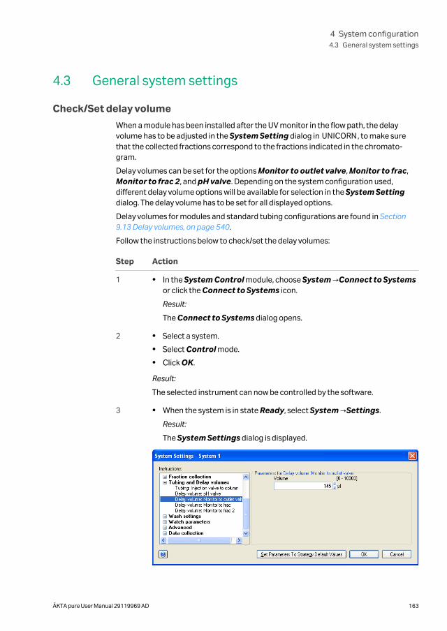
4.3 General system settings
Check/Set delay volume
When a module has been installed after the UV monitor in the flow path, the delayvolume has to be adjusted in the System Setting dialog in UNICORN, to make surethat the collected fractions correspond to the fractions indicated in the chromato-gram.
Delay volumes can be set for the options Monitor to outlet valve, Monitor to frac,Monitor to frac 2, and pH valve. Depending on the system configuration used,different delay volume options will be available for selection in the System Settingdialog. The delay volume has to be set for all displayed options.
Delay volumes for modules and standard tubing configurations are found in Section9.13 Delay volumes, on page 540.
Follow the instructions below to check/set the delay volumes:
Step Action
1 • In the System Control module, choose System →Connect to Systemsor click the Connect to Systems icon.
Result:
The Connect to Systems dialog opens.
2 • Select a system.
• Select Control mode.
• Click OK.
Result:
The selected instrument can now be controlled by the software.
3 • When the system is in state Ready, select System →Settings.
Result:
The System Settings dialog is displayed.
4 System configuration4.3 General system settings
ÄKTA pure User Manual 29119969 AD 163
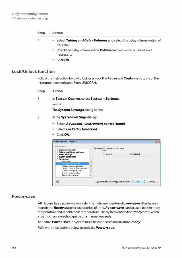
Step Action
4 • Select Tubing and Delay Volumes and select the delay volume option ofinterest.
• Check the delay volume in the Volume field and enter a new value ifnecessary.
• Click OK.
Lock/Unlock function
Follow the instruction below to lock or unlock the Pause and Continue buttons of theInstrument control panel from UNICORN.
Step Action
1 In System Control, select System →Settings.
Result:
The System Settings dialog opens.
2 In the System Settings dialog:
• Select Advanced →Instrument control panel.
• Select Locked or Unlocked.
• Click OK.
Power-save
ÄKTA pure has a power-save mode. The instrument enters Power-save after havingbeen in the Ready state for a set period of time. Power-save can be used both in roomtemperature and in cold room temperature. The system enters the Ready state whena method run, a method queue or a manual run ends.
To enable Power-save, a system must be connected and in state Ready.
Follow the instructions below to activate Power-save.
4 System configuration4.3 General system settings
164 ÄKTA pure User Manual 29119969 AD
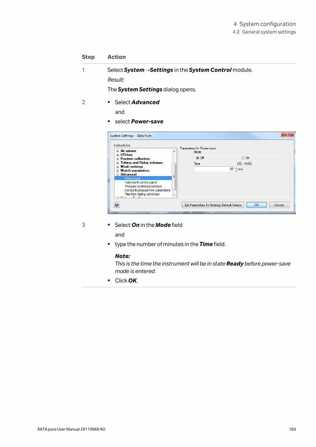
Step Action
1 Select System →Settings in the System Control module.
Result:
The System Settings dialog opens.
2 • Select Advanced
and
• select Power-save
3 • Select On in the Mode field
and
• type the number of minutes in the Time field.
Note:This is the time the instrument will be in state Ready before power-savemode is entered.
• Click OK.
4 System configuration4.3 General system settings
ÄKTA pure User Manual 29119969 AD 165
5 Operation
About this chapterThis chapter describes the steps involved when operating ÄKTA pure.
In this chapter
Section See page
5.1 Before you prepare the system 167
5.2 Prepare the flow path 168
5.3 Start UNICORN and connect to system 175
5.4 Prime inlets and purge pump heads 179
5.5 Connect a column 193
5.6 Pressure alarms 198
5.7 Sample application 201
5.8 Fractionation 217
5.9 Create a method and perform a run 238
5 Operation
166 ÄKTA pure User Manual 29119969 AD
5.1 Before you prepare the system
IntroductionIt is important to prepare the system in accordance with the settings in the method tobe run. Before preparing the system, check the settings in the Method Editor andmake sure that all accessories to be used are available.
ChecklistMake sure the system is prepared in accordance with the settings in the method to berun. Depending on configuration, remember to check:
• which valve ports to use for inlets and outlets
• which column type to use
• which column position to use
• which buffers and samples to prepare
• which sample application technique to use
• that the pH electrode is connected and calibrated
5 Operation5.1 Before you prepare the system
ÄKTA pure User Manual 29119969 AD 167
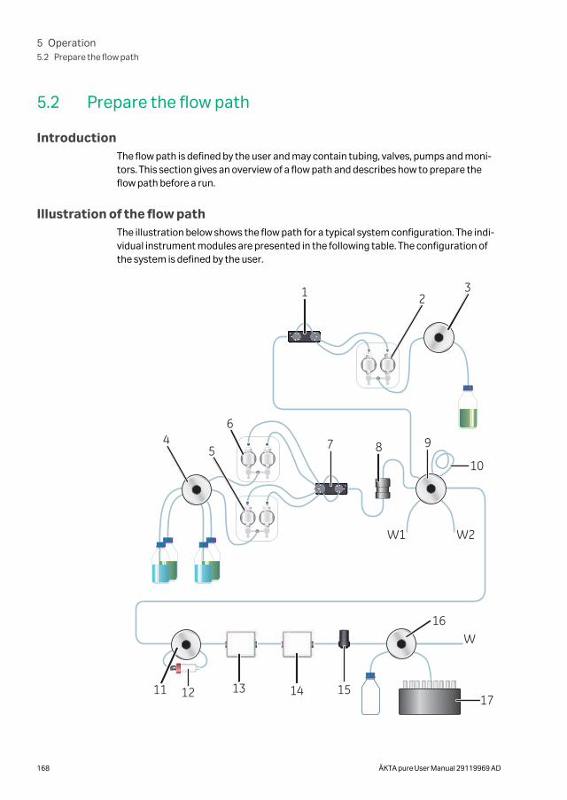
5.2 Prepare the flow path
IntroductionThe flow path is defined by the user and may contain tubing, valves, pumps and moni-tors. This section gives an overview of a flow path and describes how to prepare theflow path before a run.
Illustration of the flow pathThe illustration below shows the flow path for a typical system configuration. The indi-vidual instrument modules are presented in the following table. The configuration ofthe system is defined by the user.
45
6
7 8 9
10
11 12 13 14 15
16
17
W1 W2
W
321
5 Operation5.2 Prepare the flow path
168 ÄKTA pure User Manual 29119969 AD
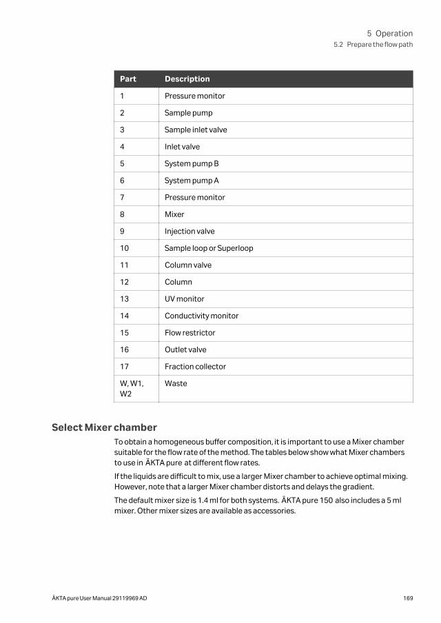
Part Description
1 Pressure monitor
2 Sample pump
3 Sample inlet valve
4 Inlet valve
5 System pump B
6 System pump A
7 Pressure monitor
8 Mixer
9 Injection valve
10 Sample loop or Superloop
11 Column valve
12 Column
13 UV monitor
14 Conductivity monitor
15 Flow restrictor
16 Outlet valve
17 Fraction collector
W, W1,W2
Waste
Select Mixer chamberTo obtain a homogeneous buffer composition, it is important to use a Mixer chambersuitable for the flow rate of the method. The tables below show what Mixer chambersto use in ÄKTA pure at different flow rates.
If the liquids are difficult to mix, use a larger Mixer chamber to achieve optimal mixing.However, note that a larger Mixer chamber distorts and delays the gradient.
The default mixer size is 1.4 ml for both systems. ÄKTA pure 150 also includes a 5 mlmixer. Other mixer sizes are available as accessories.
5 Operation5.2 Prepare the flow path
ÄKTA pure User Manual 29119969 AD 169
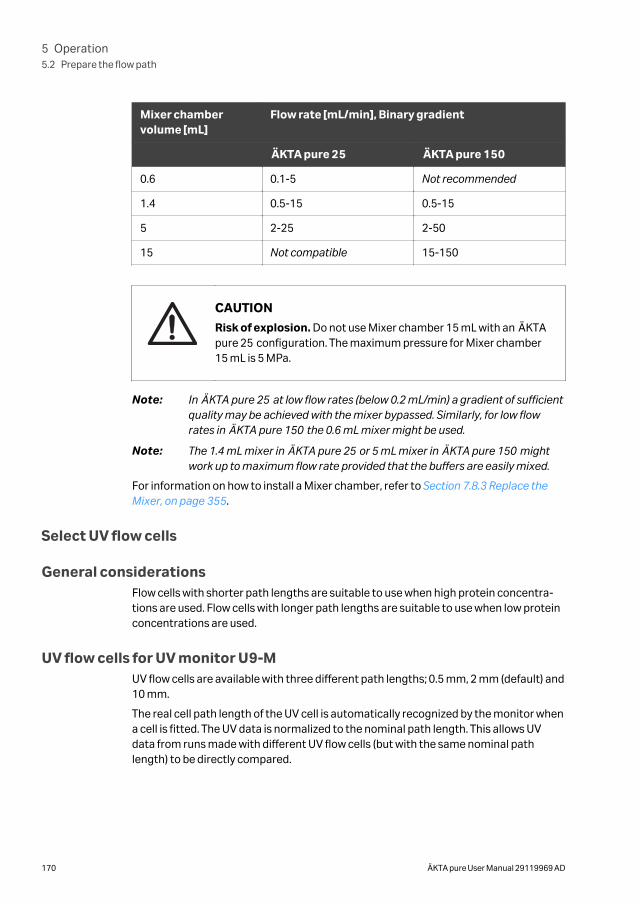
Mixer chambervolume [mL]
Flow rate [mL/min], Binary gradient
ÄKTA pure 25 ÄKTA pure 150
0.6 0.1-5 Not recommended
1.4 0.5-15 0.5-15
5 2-25 2-50
15 Not compatible 15-150
CAUTION
Risk of explosion. Do not use Mixer chamber 15 mL with an ÄKTApure 25 configuration. The maximum pressure for Mixer chamber15 mL is 5 MPa.
Note: In ÄKTA pure 25 at low flow rates (below 0.2 mL/min) a gradient of sufficientquality may be achieved with the mixer bypassed. Similarly, for low flowrates in ÄKTA pure 150 the 0.6 mL mixer might be used.
Note: The 1.4 mL mixer in ÄKTA pure 25 or 5 mL mixer in ÄKTA pure 150 mightwork up to maximum flow rate provided that the buffers are easily mixed.
For information on how to install a Mixer chamber, refer to Section 7.8.3 Replace theMixer, on page 355.
Select UV flow cells
General considerationsFlow cells with shorter path lengths are suitable to use when high protein concentra-tions are used. Flow cells with longer path lengths are suitable to use when low proteinconcentrations are used.
UV flow cells for UV monitor U9-MUV flow cells are available with three different path lengths; 0.5 mm, 2 mm (default) and10 mm.
The real cell path length of the UV cell is automatically recognized by the monitor whena cell is fitted. The UV data is normalized to the nominal path length. This allows UVdata from runs made with different UV flow cells (but with the same nominal pathlength) to be directly compared.
5 Operation5.2 Prepare the flow path
170 ÄKTA pure User Manual 29119969 AD
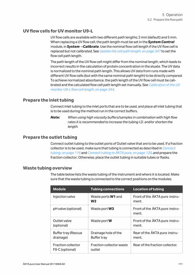
UV flow cells for UV monitor U9-LUV flow cells are available with two different path lengths; 2 mm (default) and 5 mm.When replacing a UV flow cell, the path length must be set in the System Controlmodule, in System →Calibrate. Use the nominal flow cell length if the UV flow cell isreplaced but not calibrated. See Update the cell path length, on page 347 to set theflow cell path length.
The path length of the UV flow cell might differ from the nominal length, which leads toincorrect results in the calculation of protein concentration in the eluate. The UV datais normalized to the nominal path length. This allows UV data from runs made withdifferent UV flow cells (but with the same nominal path length) to be directly compared.To achieve normalized absorbance, the path length of the UV flow cell must be cali-brated and the calculated flow cell path length set manually. See Calibration of the UVmonitor U9-L flow cell length, on page 344.
Prepare the inlet tubingConnect inlet tubing to the inlet ports that are to be used, and place all inlet tubing thatis to be used during the method run in the correct buffers.
Note: When using high viscosity buffers/samples in combination with high flowrates it is recommended to increase the tubing I.D. and/or shorten thelength.
Prepare the outlet tubingConnect outlet tubing to the outlet ports of Outlet valve that are to be used. If a fractioncollector is to be used, make sure that tubing is connected as described in Connecttubing, on page 116 and Connect tubing to ÄKTA pure, on page 120, and prepare thefraction collector. Otherwise, place the outlet tubing in suitable tubes or flasks.
Waste tubing overviewThe table below lists the waste tubing of the instrument and where it is located. Makesure that the waste tubing is connected to the correct positions on the modules.
Module Tubing connections Location of tubing
Injection valve Waste ports W1 andW2
Front of the ÄKTA pure instru-ment.
pH valve (optional) Waste port W3 Front of the ÄKTA pure instru-ment.
Outlet valve(optional)
Waste port W Front of the ÄKTA pure instru-ment.
Buffer tray (Rescuedrainage)
Drainage hole of theBuffer tray
Rear of the ÄKTA pure instru-ment.
Fraction collectorF9-C (optional)
Fraction collector wasteoutlet
Rear of the fraction collector.
5 Operation5.2 Prepare the flow path
ÄKTA pure User Manual 29119969 AD 171
Prepare waste tubing
Follow the instructions below to prepare the waste tubing.
CAUTION
Fasten the waste tubing. During operation at high pressure theÄKTA pure instrument may release bursts of liquid in the wastetubing. Securely fasten all waste tubing to the ÄKTA pure instru-ment and to the waste vessel.
CAUTION
Make sure that the waste vessel will hold all the produced volumeof the run. For ÄKTA pure, a suitable waste vessel should typicallyhave a volume of 2 to 10 liters.
NOTICE
The maximum level of the waste vessel must be lower than thebottom of the ÄKTA pure instrument.
Step Action
1 Insert the waste tubing from all installed modules, in this example Injectionvalve, Outlet valve (W, W1 and W2) and the fraction collector, in a vessel.
5 Operation5.2 Prepare the flow path
172 ÄKTA pure User Manual 29119969 AD
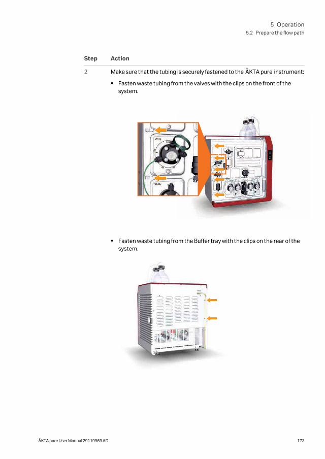
Step Action
2 Make sure that the tubing is securely fastened to the ÄKTA pure instrument:
• Fasten waste tubing from the valves with the clips on the front of thesystem.
• Fasten waste tubing from the Buffer tray with the clips on the rear of thesystem.
5 Operation5.2 Prepare the flow path
ÄKTA pure User Manual 29119969 AD 173
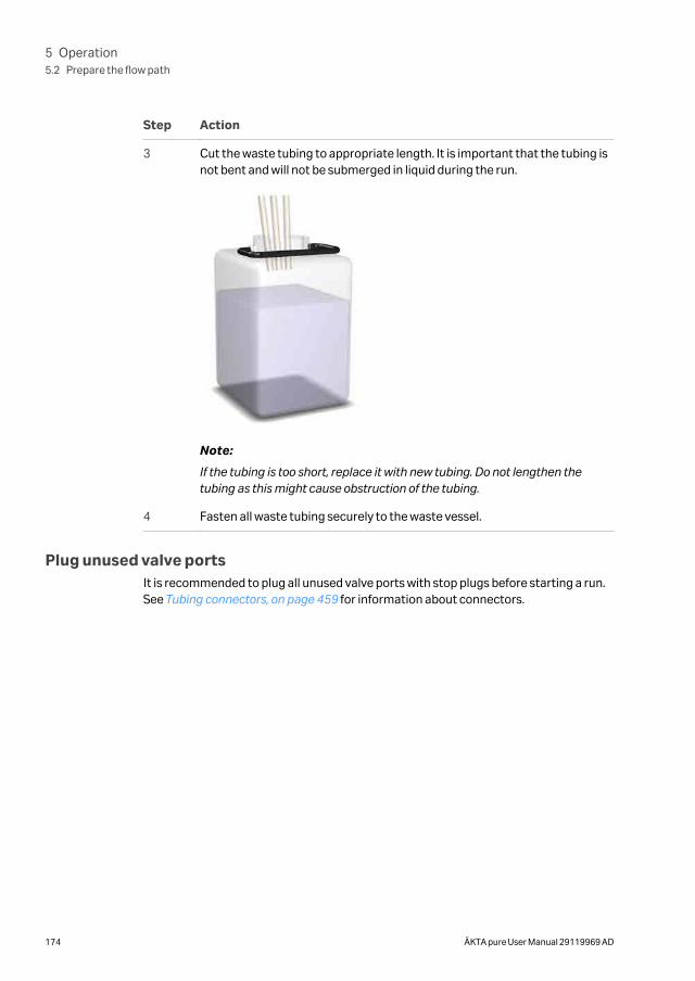
Step Action
3 Cut the waste tubing to appropriate length. It is important that the tubing isnot bent and will not be submerged in liquid during the run.
Note:
If the tubing is too short, replace it with new tubing. Do not lengthen thetubing as this might cause obstruction of the tubing.
4 Fasten all waste tubing securely to the waste vessel.
Plug unused valve portsIt is recommended to plug all unused valve ports with stop plugs before starting a run.See Tubing connectors, on page 459 for information about connectors.
5 Operation5.2 Prepare the flow path
174 ÄKTA pure User Manual 29119969 AD
5.3 Start UNICORN and connect to system
IntroductionThis section describes how to start and log on to UNICORN and how to connect theinstrument to UNICORN.
Start UNICORN and log on
Follow the instructions to start UNICORN and log on to the program. A valid e-licensemust be available for the workstation. See UNICORN Administration and TechnicalManual for more information about e-licenses.
Step Action
1 Double-click the UNICORN icon on the desktop.
Result:
The Log On dialog box opens.
Note:
If there is no connection to the database it is still possible to log on toUNICORN and control a running system. The Log On dialog box will give theoption to start System Control without a database. Click Start SystemControl to proceed to the next Log On dialog box.
5 Operation5.3 Start UNICORN and connect to system
ÄKTA pure User Manual 29119969 AD 175
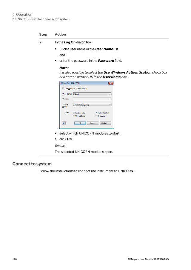
Step Action
2 In the Log On dialog box:
• Click a user name in the User Name list
and
• enter the password in the Password field.
Note:It is also possible to select the Use Windows Authentication check boxand enter a network ID in the User Name box.
• select which UNICORN modules to start.
• click OK.
Result:
The selected UNICORN modules open.
Connect to system
Follow the instructions to connect the instrument to UNICORN.
5 Operation5.3 Start UNICORN and connect to system
176 ÄKTA pure User Manual 29119969 AD
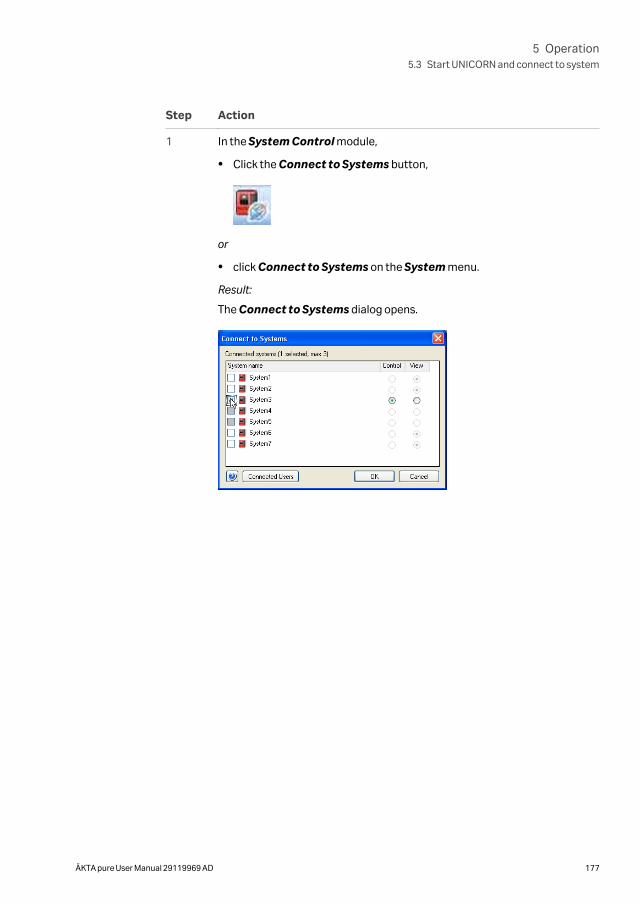
Step Action
1 In the System Control module,
• Click the Connect to Systems button,
or
• click Connect to Systems on the System menu.
Result:
The Connect to Systems dialog opens.
5 Operation5.3 Start UNICORN and connect to system
ÄKTA pure User Manual 29119969 AD 177
Step Action
2 In the Connect to systems dialog:
• Select the checkbox in front of the system name.
• To control the selected system, click Control.
• Click OK.
Result:
The instrument control panel displays a white, rapidly flashing light followedby a steady white light when the system is ready. The selected instrumentcan now be controlled by the software.
Note:
Instruments that are turned off or disconnected from the network appeardimmed and cannot be connected.
Tip:
To view the users currently connected to systems, either in control or viewmode, click the Connected Users button.
Tip:
Result UNICORN states Connection = Connected in control orConnection = Connected in view in the status bar in the lower part of theSystem Control window.
.
5 Operation5.3 Start UNICORN and connect to system
178 ÄKTA pure User Manual 29119969 AD
5.4 Prime inlets and purge pump heads
About this sectionBefore usage of a pump, it is important to:
• Prime the inlets (fill the buffer inlets with liquid).
• Purge the pump (remove air from the pump heads).
This section describes how to prime inlets and purge the pump heads of the systempumps and the sample pump (the sample pump is an optional module).
Note: Note that the procedures described in this section may have to be adapted ifyour system configuration differs from the one described in this manual.
In this section
Section See page
5.4.1 System pumps 180
5.4.2 Sample pump 187
5 Operation5.4 Prime inlets and purge pump heads
ÄKTA pure User Manual 29119969 AD 179
5.4.1 System pumps
IntroductionThis section describes how to prime inlets and purge the System pumps.
OverviewThe procedure consists of the following stages:
Stage Description
1 Prime all inlet tubing to be used during the run
2 Purge System pump B
3 Validate purge of System pump B
4 Purge System pump A
5 Validate purge of System pump A
6 End the run
Tip: The procedures for purging the pump heads and priming the inlets using theProcess Picture, are described below. It is also possible to perform theprocedures from the Manual instructions dialog.
Prime inlet tubing
Follow the instructions below to fill all A and B inlet tubing to be used in the run withappropriate buffer/solution.
Step Action
1 Make sure that all inlet tubing that is to be used during the method run isplaced in the correct buffer.
2 Open the System Control module.
5 Operation5.4 Prime inlets and purge pump heads
5.4.1 System pumps
180 ÄKTA pure User Manual 29119969 AD
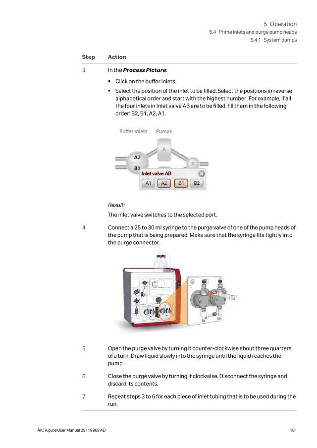
Step Action
3 In the Process Picture:
• Click on the buffer inlets.
• Select the position of the inlet to be filled. Select the positions in reversealphabetical order and start with the highest number. For example, if allthe four inlets in Inlet valve AB are to be filled, fill them in the followingorder: B2, B1, A2, A1.
Result:
The inlet valve switches to the selected port.
4 Connect a 25 to 30 ml syringe to the purge valve of one of the pump heads ofthe pump that is being prepared. Make sure that the syringe fits tightly intothe purge connector.
5 Open the purge valve by turning it counter-clockwise about three quartersof a turn. Draw liquid slowly into the syringe until the liquid reaches thepump.
6 Close the purge valve by turning it clockwise. Disconnect the syringe anddiscard its contents.
7 Repeat steps 3 to 6 for each piece of inlet tubing that is to be used during therun.
5 Operation5.4 Prime inlets and purge pump heads
5.4.1 System pumps
ÄKTA pure User Manual 29119969 AD 181
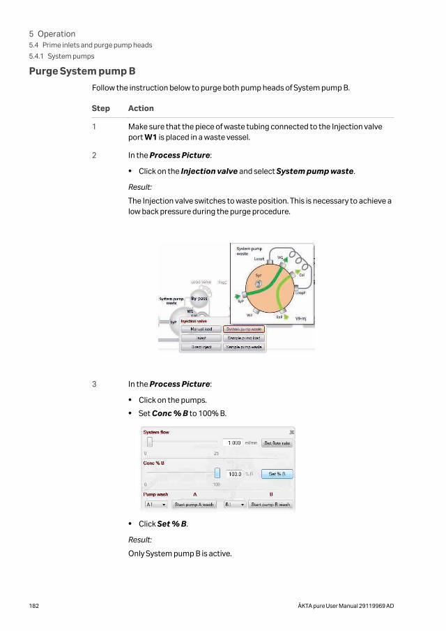
Purge System pump B
Follow the instruction below to purge both pump heads of System pump B.
Step Action
1 Make sure that the piece of waste tubing connected to the Injection valveport W1 is placed in a waste vessel.
2 In the Process Picture:
• Click on the Injection valve and select System pump waste.
Result:
The Injection valve switches to waste position. This is necessary to achieve alow back pressure during the purge procedure.
3 In the Process Picture:
• Click on the pumps.
• Set Conc % B to 100% B.
• Click Set % B.
Result:
Only System pump B is active.
5 Operation5.4 Prime inlets and purge pump heads
5.4.1 System pumps
182 ÄKTA pure User Manual 29119969 AD
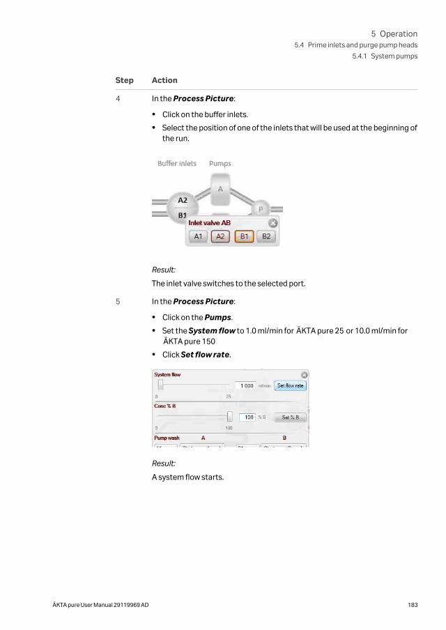
Step Action
4 In the Process Picture:
• Click on the buffer inlets.
• Select the position of one of the inlets that will be used at the beginning ofthe run.
Result:
The inlet valve switches to the selected port.
5 In the Process Picture:
• Click on the Pumps.
• Set the System flow to 1.0 ml/min for ÄKTA pure 25 or 10.0 ml/min forÄKTA pure 150
• Click Set flow rate.
Result:
A system flow starts.
5 Operation5.4 Prime inlets and purge pump heads
5.4.1 System pumps
ÄKTA pure User Manual 29119969 AD 183
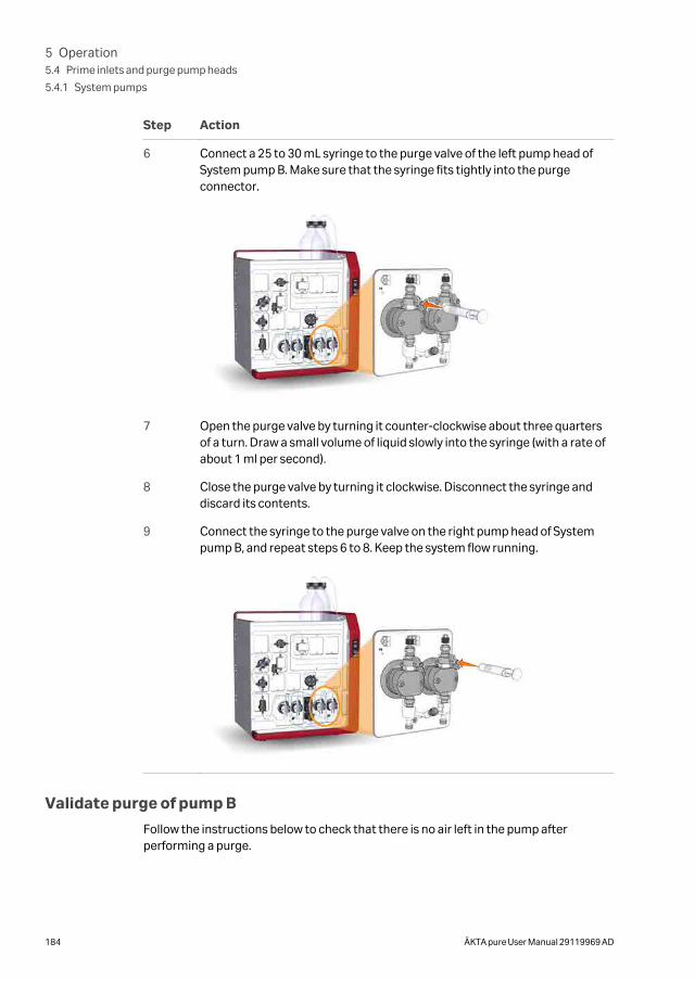
Step Action
6 Connect a 25 to 30 mL syringe to the purge valve of the left pump head ofSystem pump B. Make sure that the syringe fits tightly into the purgeconnector.
7 Open the purge valve by turning it counter-clockwise about three quartersof a turn. Draw a small volume of liquid slowly into the syringe (with a rate ofabout 1 ml per second).
8 Close the purge valve by turning it clockwise. Disconnect the syringe anddiscard its contents.
9 Connect the syringe to the purge valve on the right pump head of Systempump B, and repeat steps 6 to 8. Keep the system flow running.
Validate purge of pump B
Follow the instructions below to check that there is no air left in the pump afterperforming a purge.
5 Operation5.4 Prime inlets and purge pump heads
5.4.1 System pumps
184 ÄKTA pure User Manual 29119969 AD
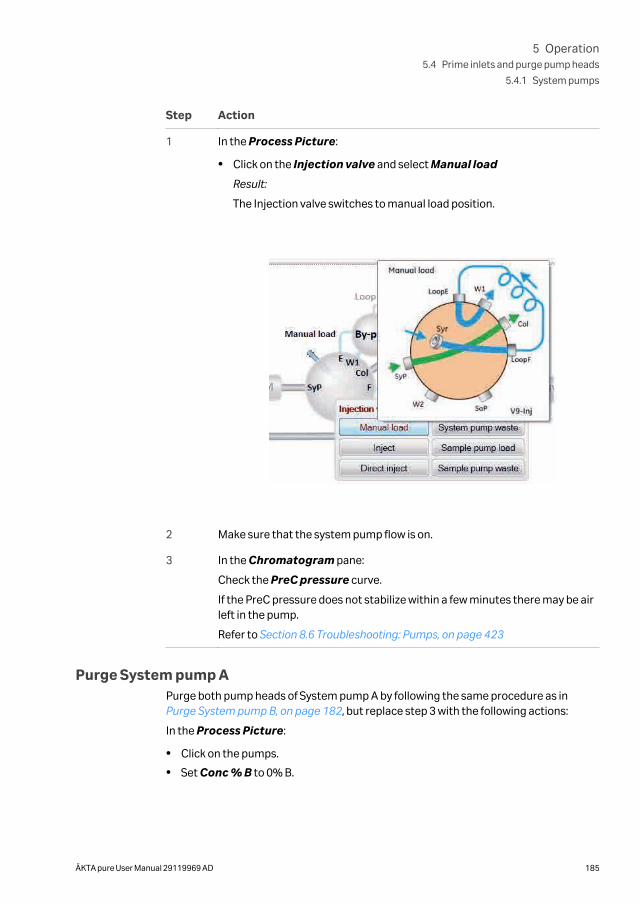
Step Action
1 In the Process Picture:
• Click on the Injection valve and select Manual load
Result:
The Injection valve switches to manual load position.
2 Make sure that the system pump flow is on.
3 In the Chromatogram pane:
Check the PreC pressure curve.
If the PreC pressure does not stabilize within a few minutes there may be airleft in the pump.
Refer to Section 8.6 Troubleshooting: Pumps, on page 423
Purge System pump APurge both pump heads of System pump A by following the same procedure as in Purge System pump B, on page 182, but replace step 3 with the following actions:
In the Process Picture:
• Click on the pumps.
• Set Conc % B to 0% B.
5 Operation5.4 Prime inlets and purge pump heads
5.4.1 System pumps
ÄKTA pure User Manual 29119969 AD 185
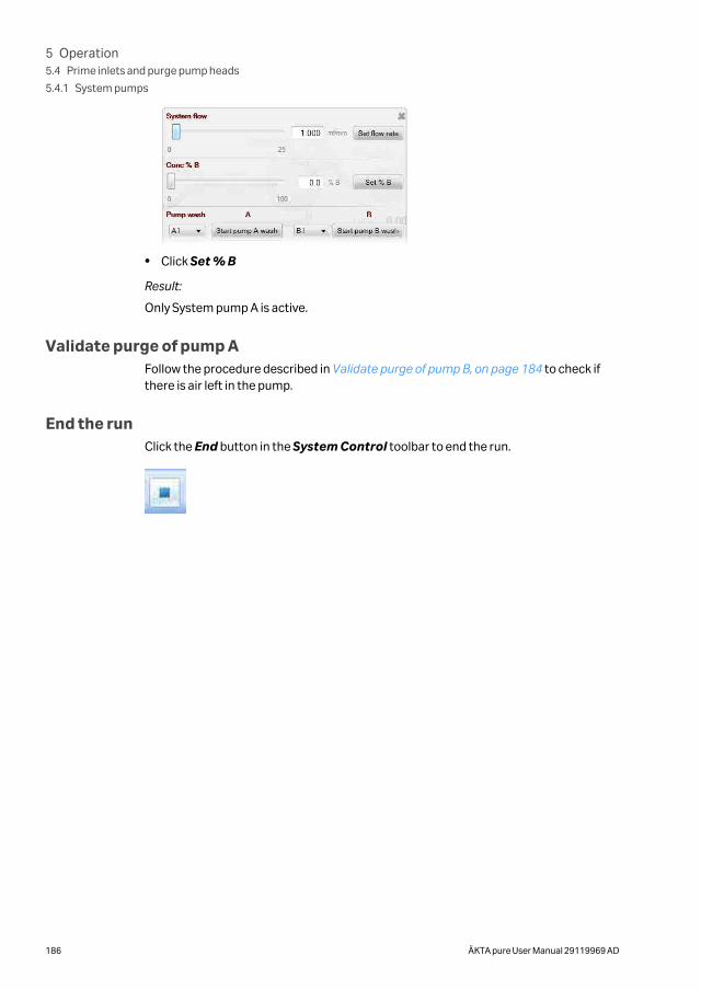
• Click Set % B
Result:
Only System pump A is active.
Validate purge of pump AFollow the procedure described in Validate purge of pump B, on page 184 to check ifthere is air left in the pump.
End the runClick the End button in the System Control toolbar to end the run.
5 Operation5.4 Prime inlets and purge pump heads
5.4.1 System pumps
186 ÄKTA pure User Manual 29119969 AD
5.4.2 Sample pump
IntroductionThis section describes how to prime inlets and purge Sample pumps S9 and S9H.
Overview
The procedure consists of the following steps:
Step Action
1 Prime all sample inlet tubing to be used during the run
2 Purge the Sample pump
3 Validate purge
4 End the run
Prime sample inlets
Follow the instructions below to fill all sample inlet tubing, to be used in the run, withappropriate buffer or solution. Skip steps three and four if no sample inlet valve is used.
Step Action
1 Make sure that all sample inlet tubing that is to be used during the methodrun is immersed in the correct buffers.
2 Make sure that the waste tubing connected to Injection valve port W2 isimmersed in a waste vessel.
3 Open the System Control module.
5 Operation5.4 Prime inlets and purge pump heads
5.4.2 Sample pump
ÄKTA pure User Manual 29119969 AD 187
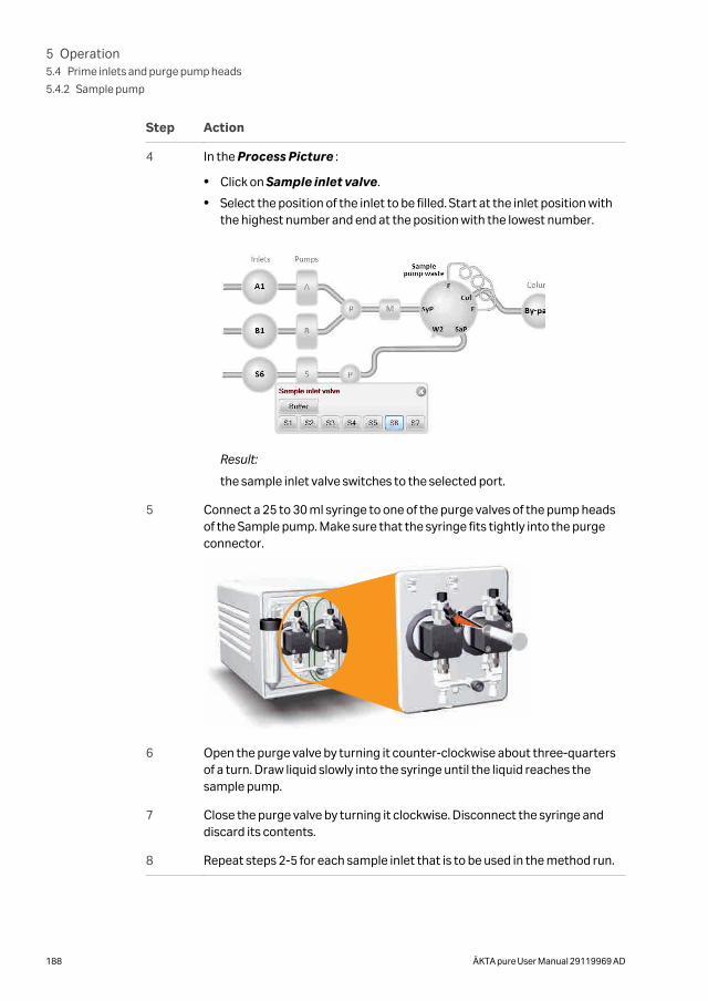
Step Action
4 In the Process Picture :
• Click on Sample inlet valve.
• Select the position of the inlet to be filled. Start at the inlet position withthe highest number and end at the position with the lowest number.
Result:
the sample inlet valve switches to the selected port.
5 Connect a 25 to 30 ml syringe to one of the purge valves of the pump headsof the Sample pump. Make sure that the syringe fits tightly into the purgeconnector.
6 Open the purge valve by turning it counter-clockwise about three-quartersof a turn. Draw liquid slowly into the syringe until the liquid reaches thesample pump.
7 Close the purge valve by turning it clockwise. Disconnect the syringe anddiscard its contents.
8 Repeat steps 2-5 for each sample inlet that is to be used in the method run.
5 Operation5.4 Prime inlets and purge pump heads
5.4.2 Sample pump
188 ÄKTA pure User Manual 29119969 AD
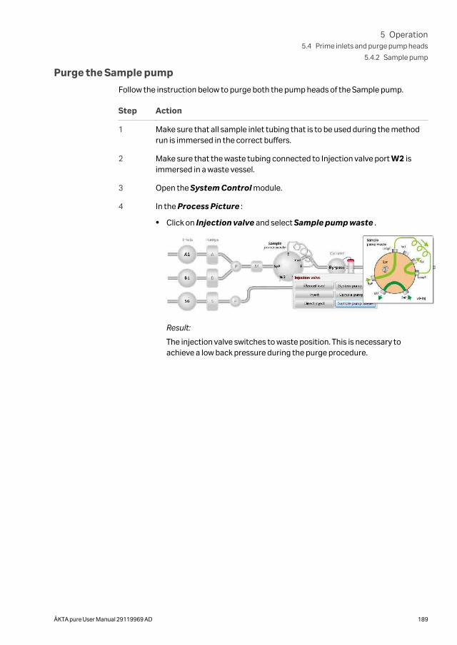
Purge the Sample pump
Follow the instruction below to purge both the pump heads of the Sample pump.
Step Action
1 Make sure that all sample inlet tubing that is to be used during the methodrun is immersed in the correct buffers.
2 Make sure that the waste tubing connected to Injection valve port W2 isimmersed in a waste vessel.
3 Open the System Control module.
4 In the Process Picture :
• Click on Injection valve and select Sample pump waste .
Result:
The injection valve switches to waste position. This is necessary toachieve a low back pressure during the purge procedure.
5 Operation5.4 Prime inlets and purge pump heads
5.4.2 Sample pump
ÄKTA pure User Manual 29119969 AD 189
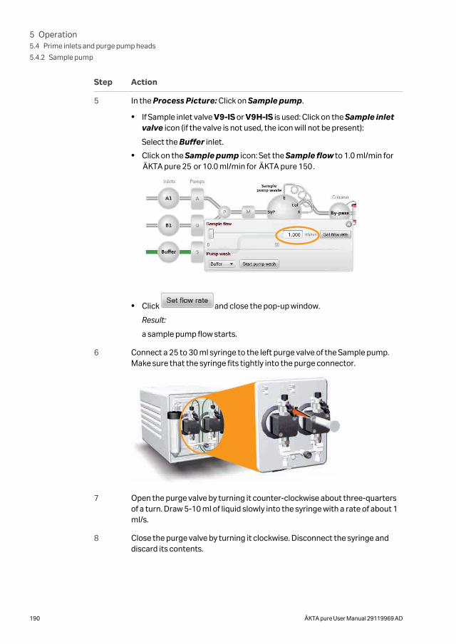
Step Action
5 In the Process Picture: Click on Sample pump.
• If Sample inlet valve V9-IS or V9H-IS is used: Click on the Sample inletvalve icon (if the valve is not used, the icon will not be present):
Select the Buffer inlet.
• Click on the Sample pump icon: Set the Sample flow to 1.0 ml/min forÄKTA pure 25 or 10.0 ml/min for ÄKTA pure 150.
• Click and close the pop-up window.
Result:
a sample pump flow starts.
6 Connect a 25 to 30 ml syringe to the left purge valve of the Sample pump.Make sure that the syringe fits tightly into the purge connector.
7 Open the purge valve by turning it counter-clockwise about three-quartersof a turn. Draw 5-10 ml of liquid slowly into the syringe with a rate of about 1ml/s.
8 Close the purge valve by turning it clockwise. Disconnect the syringe anddiscard its contents.
5 Operation5.4 Prime inlets and purge pump heads
5.4.2 Sample pump
190 ÄKTA pure User Manual 29119969 AD
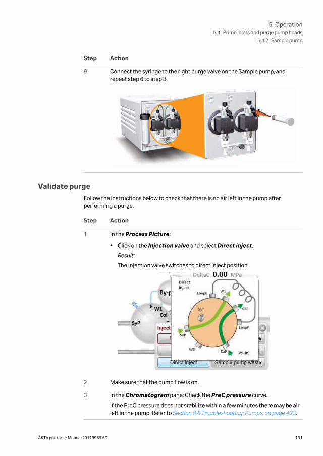
Step Action
9 Connect the syringe to the right purge valve on the Sample pump, andrepeat step 6 to step 8.
Validate purge
Follow the instructions below to check that there is no air left in the pump afterperforming a purge.
Step Action
1 In the Process Picture:
• Click on the Injection valve and select Direct inject.
Result:
The Injection valve switches to direct inject position.
2 Make sure that the pump flow is on.
3 In the Chromatogram pane: Check the PreC pressure curve.
If the PreC pressure does not stabilize within a few minutes there may be airleft in the pump. Refer to Section 8.6 Troubleshooting: Pumps, on page 423.
5 Operation5.4 Prime inlets and purge pump heads
5.4.2 Sample pump
ÄKTA pure User Manual 29119969 AD 191

End the runClick the End button in the System Control toolbar to end the run.
5 Operation5.4 Prime inlets and purge pump heads
5.4.2 Sample pump
192 ÄKTA pure User Manual 29119969 AD
5.5 Connect a column
IntroductionThis section describes how to connect a column to the instrument using a columnholder and without introducing air into the flow path. Several types of column holdersare available for ÄKTA pure.
WARNING
To avoid exposing the column to excessive pressure, make surethat the pressure limit is set to the specified maximum pressure ofthe column. Before connecting a column to the ÄKTA pure instru-ment, read the instructions for use of the column.
Methods automatically include a pressure alarm based on the specifications of thechosen column type. However, when running manual runs you have to set the pressurelimits yourself. Also, to protect the column media, special settings are needed. See Section 5.6 Pressure alarms, on page 198 for more information on pressure alarms.
Note: Do not overtighten when connecting columns. Overtightening mightrupture the connectors or squeeze the tubing and thereby result in highback pressure.
Note: If no column valve is used, remove the column from the system beforerunning a system wash. The pressure during a system wash may becometoo high for the column.
Attach a column holder and connect acolumn
Follow the instructions below to connect a column to the instrument. Always use acolumn holder. If a column valve is used, connect the column to the appropriate A andB ports on the valve. If no column valve is used, connect the column directly to the flowpath tubing. Use appropriate tubing and connectors. The instructions below show asystem configured with Column valve V9-Cs.
5 Operation5.5 Connect a column
ÄKTA pure User Manual 29119969 AD 193
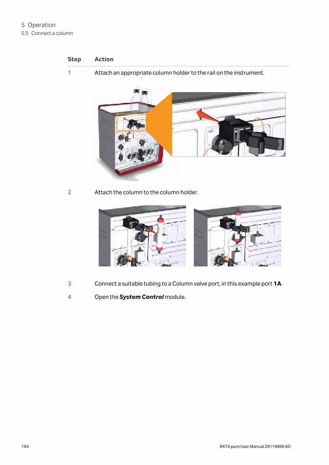
Step Action
1 Attach an appropriate column holder to the rail on the instrument.
2 Attach the column to the column holder.
3 Connect a suitable tubing to a Column valve port, in this example port 1A.
4 Open the System Control module.
5 Operation5.5 Connect a column
194 ÄKTA pure User Manual 29119969 AD
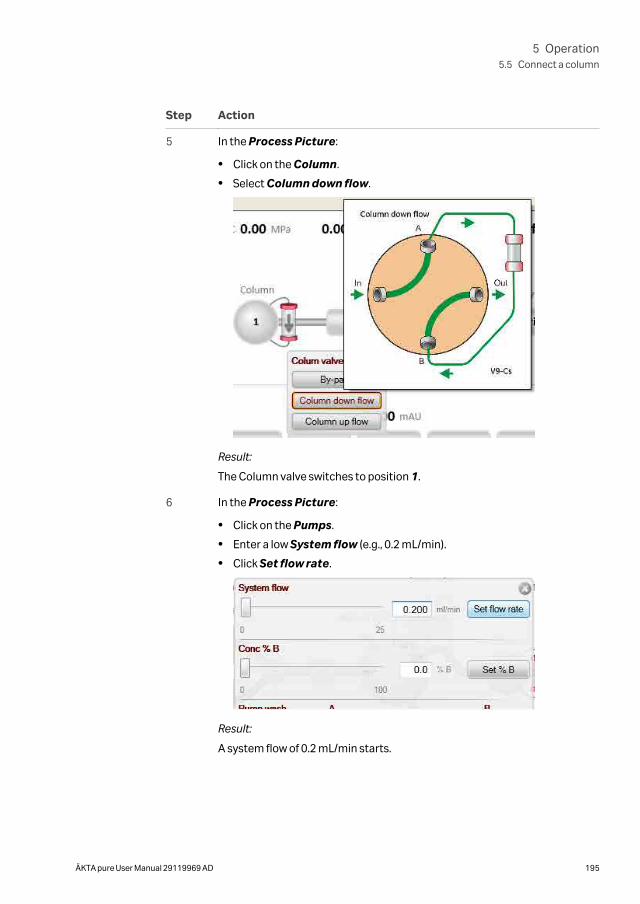
Step Action
5 In the Process Picture:
• Click on the Column.
• Select Column down flow.
Result:
The Column valve switches to position 1.
6 In the Process Picture:
• Click on the Pumps.
• Enter a low System flow (e.g., 0.2 mL/min).
• Click Set flow rate.
Result:
A system flow of 0.2 mL/min starts.
5 Operation5.5 Connect a column
ÄKTA pure User Manual 29119969 AD 195
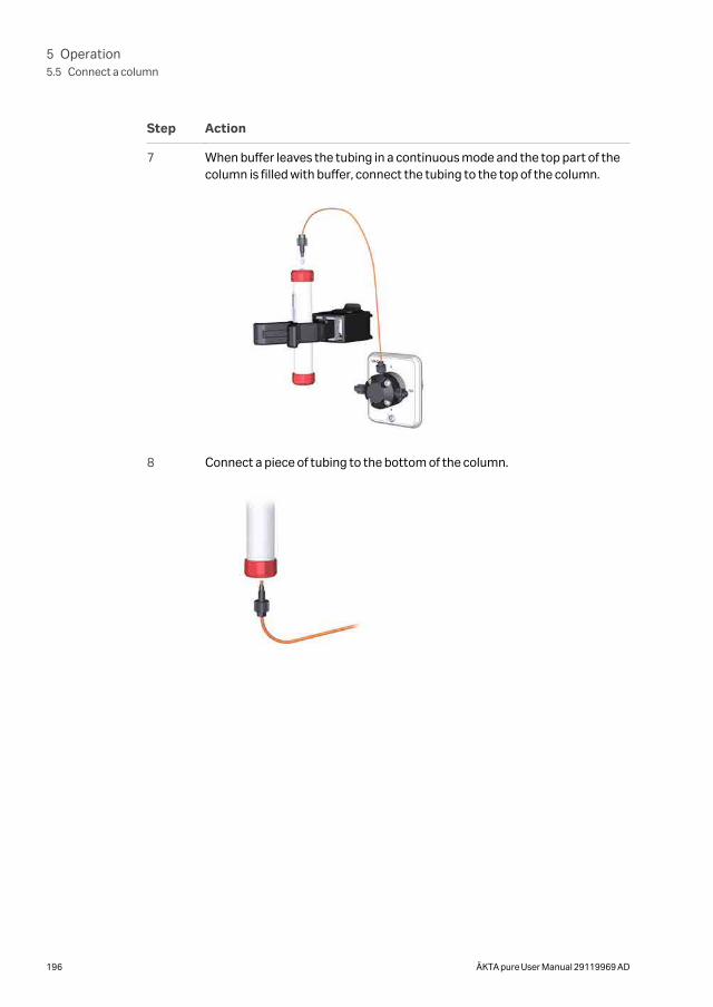
Step Action
7 When buffer leaves the tubing in a continuous mode and the top part of thecolumn is filled with buffer, connect the tubing to the top of the column.
8 Connect a piece of tubing to the bottom of the column.
5 Operation5.5 Connect a column
196 ÄKTA pure User Manual 29119969 AD
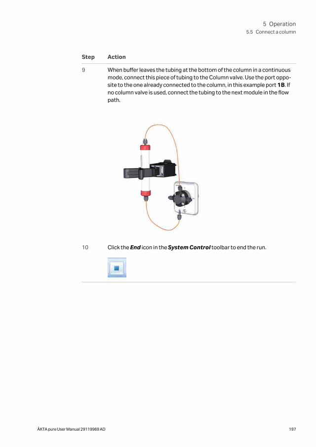
Step Action
9 When buffer leaves the tubing at the bottom of the column in a continuousmode, connect this piece of tubing to the Column valve. Use the port oppo-site to the one already connected to the column, in this example port 1B. Ifno column valve is used, connect the tubing to the next module in the flowpath.
10 Click the End icon in the System Control toolbar to end the run.
5 Operation5.5 Connect a column
ÄKTA pure User Manual 29119969 AD 197
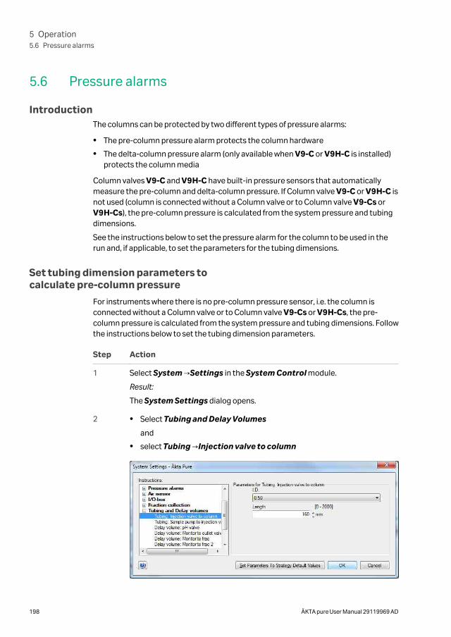
5.6 Pressure alarms
IntroductionThe columns can be protected by two different types of pressure alarms:
• The pre-column pressure alarm protects the column hardware
• The delta-column pressure alarm (only available when V9-C or V9H-C is installed)protects the column media
Column valves V9-C and V9H-C have built-in pressure sensors that automaticallymeasure the pre-column and delta-column pressure. If Column valve V9-C or V9H-C isnot used (column is connected without a Column valve or to Column valve V9-Cs orV9H-Cs), the pre-column pressure is calculated from the system pressure and tubingdimensions.
See the instructions below to set the pressure alarm for the column to be used in therun and, if applicable, to set the parameters for the tubing dimensions.
Set tubing dimension parameters tocalculate pre-column pressure
For instruments where there is no pre-column pressure sensor, i.e. the column isconnected without a Column valve or to Column valve V9-Cs or V9H-Cs, the pre-column pressure is calculated from the system pressure and tubing dimensions. Followthe instructions below to set the tubing dimension parameters.
Step Action
1 Select System →Settings in the System Control module.
Result:
The System Settings dialog opens.
2 • Select Tubing and Delay Volumes
and
• select Tubing →Injection valve to column
5 Operation5.6 Pressure alarms
198 ÄKTA pure User Manual 29119969 AD
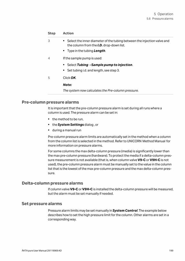
Step Action
3 • Select the inner diameter of the tubing between the injection valve andthe column from the I.D. drop-down list.
• Type in the tubing Length.
4 If the sample pump is used:
• Select Tubing →Sample pump to injection.
• Set tubing i.d. and length, see step 3.
5 Click OK.
Note:
The system now calculates the Pre-column pressure.
Pre-column pressure alarmsIt is important that the pre-column pressure alarm is set during all runs where acolumn is used. The pressure alarm can be set in:
• the method to be run,
• the System Settings dialog , or
• during a manual run
Pre-column pressure alarm limits are automatically set in the method when a columnfrom the column list is selected in the method. Refer to UNICORN Method Manual formore information on pressure alarms.
For some columns the max delta-column pressure (media) is significantly lower thanthe max pre-column pressure (hardware). To protect the media if a delta-column pres-sure measurement is not available (that is, when column valve V9-C or V9H-C is notused), the pre-column pressure alarm must be manually set to the value in the columnlist that is the lowest of the max pre-column pressure and the max delta-column pres-sure.
Delta-column pressure alarmsIf column valve V9-C or V9H-C is installed the delta-column pressure will be measured,but the alarm must be set manually if needed.
Set pressure alarms
Pressure alarm limits may be set manually in System Control. The example belowdescribes how to set the high pressure limit for the column. Other alarms are set in acorresponding way.
5 Operation5.6 Pressure alarms
ÄKTA pure User Manual 29119969 AD 199
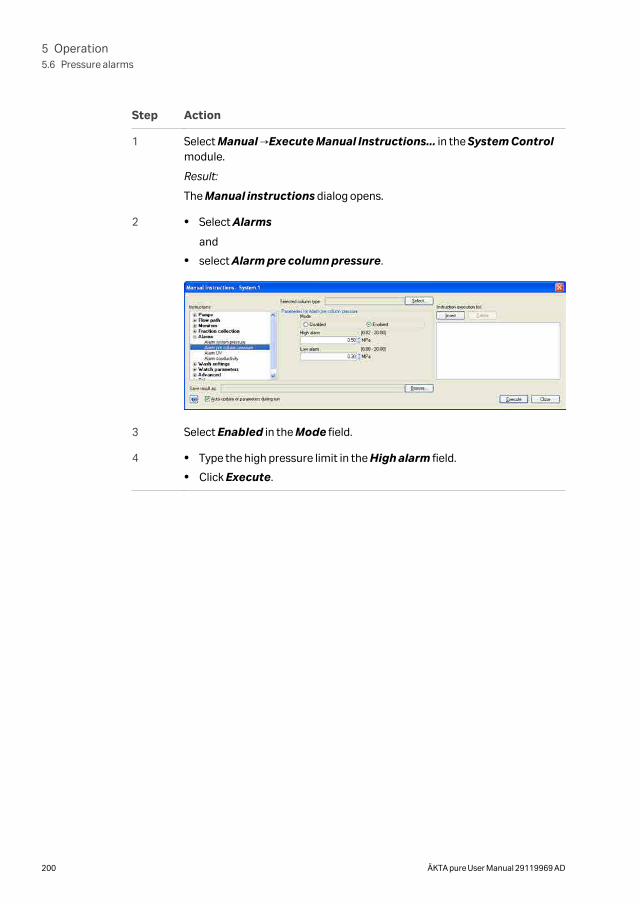
Step Action
1 Select Manual →Execute Manual Instructions... in the System Controlmodule.
Result:
The Manual instructions dialog opens.
2 • Select Alarms
and
• select Alarm pre column pressure.
3 Select Enabled in the Mode field.
4 • Type the high pressure limit in the High alarm field.
• Click Execute.
5 Operation5.6 Pressure alarms
200 ÄKTA pure User Manual 29119969 AD
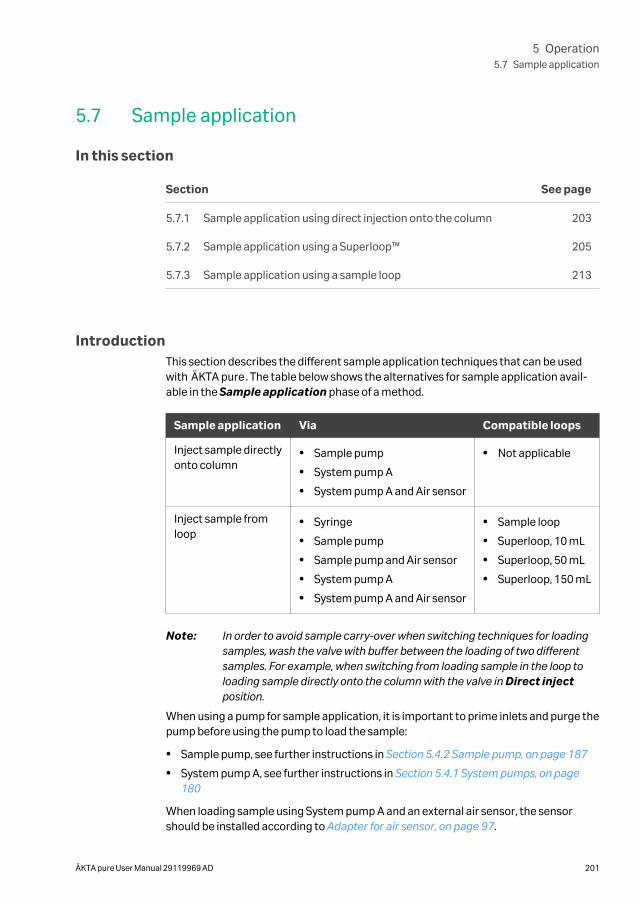
5.7 Sample application
In this section
Section See page
5.7.1 Sample application using direct injection onto the column 203
5.7.2 Sample application using a Superloop™ 205
5.7.3 Sample application using a sample loop 213
IntroductionThis section describes the different sample application techniques that can be usedwith ÄKTA pure. The table below shows the alternatives for sample application avail-able in the Sample application phase of a method.
Sample application Via Compatible loops
Inject sample directlyonto column
• Sample pump
• System pump A
• System pump A and Air sensor
• Not applicable
Inject sample fromloop
• Syringe
• Sample pump
• Sample pump and Air sensor
• System pump A
• System pump A and Air sensor
• Sample loop
• Superloop, 10 mL
• Superloop, 50 mL
• Superloop, 150 mL
Note: In order to avoid sample carry-over when switching techniques for loadingsamples, wash the valve with buffer between the loading of two differentsamples. For example, when switching from loading sample in the loop toloading sample directly onto the column with the valve in Direct injectposition.
When using a pump for sample application, it is important to prime inlets and purge thepump before using the pump to load the sample:
• Sample pump, see further instructions in Section 5.4.2 Sample pump, on page 187
• System pump A, see further instructions in Section 5.4.1 System pumps, on page180
When loading sample using System pump A and an external air sensor, the sensorshould be installed according to Adapter for air sensor, on page 97.
5 Operation5.7 Sample application
ÄKTA pure User Manual 29119969 AD 201
Note: When sample is loaded at high flow rate and the external air sensor isplaced before the pump that is used for loading the sample, it is necessaryto use longer tubing to ensure that no air reaches the pump. Use tubing withthe minimum lengths given below between the valve located before thepump and the external air sensor. The length applies for maximum flow rate,but shorter tubing can be used at lower flow rates.
• Sample pump S9: 40 cm.
• Sample pump S9H: 20 cm.
5 Operation5.7 Sample application
202 ÄKTA pure User Manual 29119969 AD
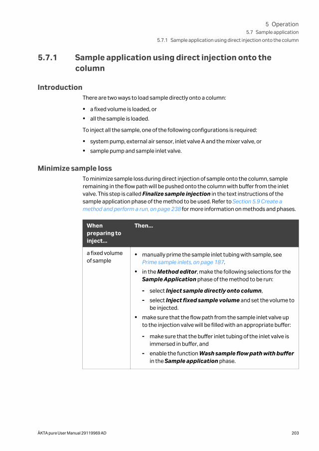
5.7.1 Sample application using direct injection onto thecolumn
IntroductionThere are two ways to load sample directly onto a column:
• a fixed volume is loaded, or
• all the sample is loaded.
To inject all the sample, one of the following configurations is required:
• system pump, external air sensor, inlet valve A and the mixer valve, or
• sample pump and sample inlet valve.
Minimize sample lossTo minimize sample loss during direct injection of sample onto the column, sampleremaining in the flow path will be pushed onto the column with buffer from the inletvalve. This step is called Finalize sample injection in the text instructions of thesample application phase of the method to be used. Refer to Section 5.9 Create amethod and perform a run, on page 238 for more information on methods and phases.
Whenpreparing toinject...
Then...
a fixed volumeof sample
• manually prime the sample inlet tubing with sample, see Prime sample inlets, on page 187.
• in the Method editor, make the following selections for theSample Application phase of the method to be run:
- select Inject sample directly onto column,
- select Inject fixed sample volume and set the volume tobe injected.
• make sure that the flow path from the sample inlet valve upto the injection valve will be filled with an appropriate buffer:
- make sure that the buffer inlet tubing of the inlet valve isimmersed in buffer, and
- enable the function Wash sample flow path with bufferin the Sample application phase.
5 Operation5.7 Sample application
5.7.1 Sample application using direct injection onto the column
ÄKTA pure User Manual 29119969 AD 203
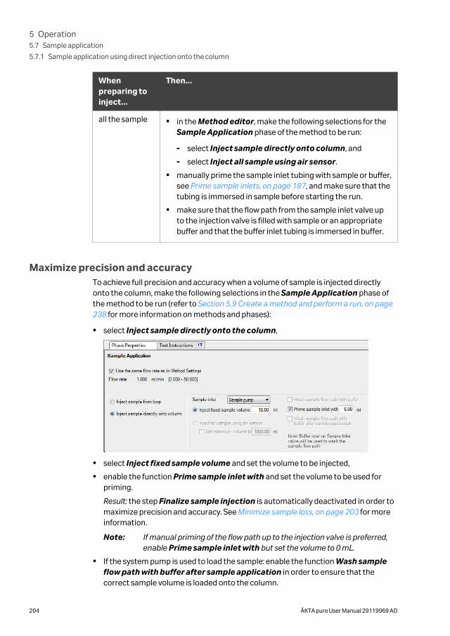
Whenpreparing toinject...
Then...
all the sample • in the Method editor, make the following selections for theSample Application phase of the method to be run:
- select Inject sample directly onto column, and
- select Inject all sample using air sensor.
• manually prime the sample inlet tubing with sample or buffer,see Prime sample inlets, on page 187, and make sure that thetubing is immersed in sample before starting the run.
• make sure that the flow path from the sample inlet valve upto the injection valve is filled with sample or an appropriatebuffer and that the buffer inlet tubing is immersed in buffer.
Maximize precision and accuracyTo achieve full precision and accuracy when a volume of sample is injected directlyonto the column, make the following selections in the Sample Application phase ofthe method to be run (refer to Section 5.9 Create a method and perform a run, on page238 for more information on methods and phases):
• select Inject sample directly onto the column,
• select Inject fixed sample volume and set the volume to be injected,
• enable the function Prime sample inlet with and set the volume to be used forpriming.
Result: the step Finalize sample injection is automatically deactivated in order tomaximize precision and accuracy. See Minimize sample loss, on page 203 for moreinformation.
Note: If manual priming of the flow path up to the injection valve is preferred,enable Prime sample inlet with but set the volume to 0 mL.
• If the system pump is used to load the sample: enable the function Wash sampleflow path with buffer after sample application in order to ensure that thecorrect sample volume is loaded onto the column.
5 Operation5.7 Sample application
5.7.1 Sample application using direct injection onto the column
204 ÄKTA pure User Manual 29119969 AD
5.7.2 Sample application using a Superloop™
IntroductionA Superloop allows injection of large sample volumes onto the column. A Superloopcan also be used for multiple injections, for example in a scouting experiment when thesame application conditions are required. Superloop models are available in 10 ml, 50ml and 150 ml sizes.
A superloop can be connected to either the Injection valve or the Loop valve. Whenusing the Loop valve, up to five loops can be connected simultaneously.
Note: After loading a Superloop, always plug the Syr port on the Injection valvewith a Stop plug. With a Superloop connected to the valve, an over-pressuremay be created during injection.
Prepare the SuperloopTo avoid injecting air into the system flow path, the Superloop should be prefilled withbuffer manually, before fitting the Superloop to the system.
Note: Read the instruction for the Superloop to be used.
Connect the Superloop
Follow the instruction below to connect the Superloop to the Injection valve or to theLoop valve.
Step Action
1 Attach the Superloop to the instrument using a Column holder.
2 Connect a piece of tubing from the top of the Superloop to:
• port LoopE on the Injection valve
or
• a E port, eg., 1E, on the Loop valve
5 Operation5.7 Sample application
5.7.2 Sample application using a Superloop™
ÄKTA pure User Manual 29119969 AD 205
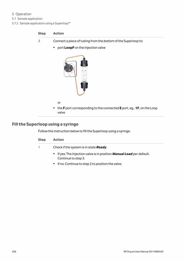
Step Action
3 Connect a piece of tubing from the bottom of the Superloop to:
• port LoopF on the Injection valve
or
• the F port corresponding to the connected E port, eg., 1F, on the Loopvalve
Fill the Superloop using a syringe
Follow the instruction below to fill the Superloop using a syringe.
Step Action
1 Check if the system is in state Ready.
• If yes: The Injection valve is in position Manual Load per default.Continue to step 3.
• If no: Continue to step 2 to position the valve.
5 Operation5.7 Sample application
5.7.2 Sample application using a Superloop™
206 ÄKTA pure User Manual 29119969 AD
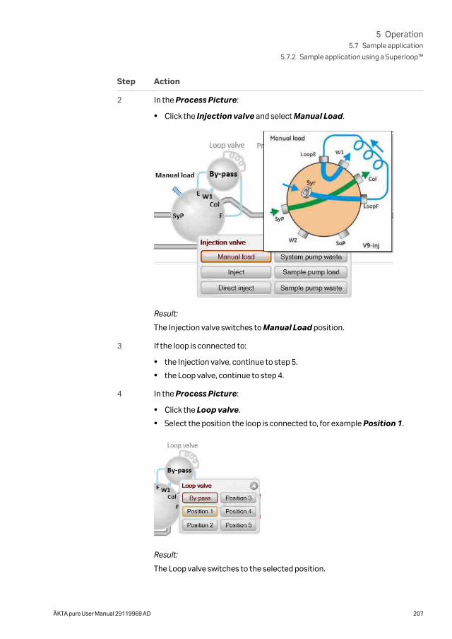
Step Action
2 In the Process Picture:
• Click the Injection valve and select Manual Load.
Result:
The Injection valve switches to Manual Load position.
3 If the loop is connected to:
• the Injection valve, continue to step 5.
• the Loop valve, continue to step 4.
4 In the Process Picture:
• Click the Loop valve.
• Select the position the loop is connected to, for example Position 1.
Result:
The Loop valve switches to the selected position.
5 Operation5.7 Sample application
5.7.2 Sample application using a Superloop™
ÄKTA pure User Manual 29119969 AD 207
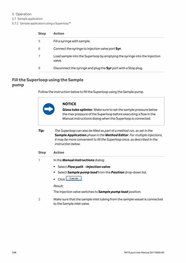
Step Action
5 Fill a syringe with sample.
6 Connect the syringe to Injection valve port Syr.
7 Load sample into the Superloop by emptying the syringe into the Injectionvalve.
8 Disconnect the syringe and plug the Syr port with a Stop plug.
Fill the Superloop using the Samplepump
Follow the instruction below to fill the Superloop using the Sample pump.
NOTICE
Glass tube splinter. Make sure to set the sample pressure belowthe max pressure of the Superloop before executing a flow in theManual instructions dialog when the Superloop is connected.
Tip: The Superloop can also be filled as part of a method run, as set in theSample Application phase in the Method Editor. For multiple injections,it may be more convenient to fill the Superloop once, as described in theinstruction below.
Step Action
1 In the Manual instructions dialog:
• Select Flow path →Injection valve.
• Select Sample pump load from the Position drop-down list.
• Click .
Result:
The Injection valve switches to Sample pump load position.
2 Make sure that the sample inlet tubing from the sample vessel is connectedto the Sample inlet valve.
5 Operation5.7 Sample application
5.7.2 Sample application using a Superloop™
208 ÄKTA pure User Manual 29119969 AD
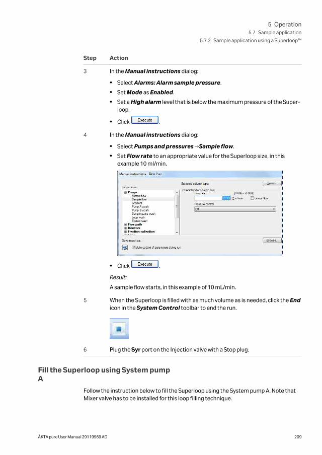
Step Action
3 In the Manual instructions dialog:
• Select Alarms: Alarm sample pressure.
• Set Mode as Enabled.
• Set a High alarm level that is below the maximum pressure of the Super-loop.
• Click .
4 In the Manual instructions dialog:
• Select Pumps and pressures →Sample flow.
• Set Flow rate to an appropriate value for the Superloop size, in thisexample 10 ml/min.
• Click .
Result:
A sample flow starts, in this example of 10 mL/min.
5 When the Superloop is filled with as much volume as is needed, click the Endicon in the System Control toolbar to end the run.
6 Plug the Syr port on the Injection valve with a Stop plug.
Fill the Superloop using System pumpA
Follow the instruction below to fill the Superloop using the System pump A. Note thatMixer valve has to be installed for this loop filling technique.
5 Operation5.7 Sample application
5.7.2 Sample application using a Superloop™
ÄKTA pure User Manual 29119969 AD 209
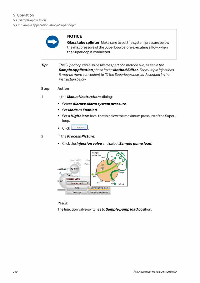
NOTICE
Glass tube splinter. Make sure to set the system pressure belowthe max pressure of the Superloop before executing a flow, whenthe Superloop is connected.
Tip: The Superloop can also be filled as part of a method run, as set in theSample Application phase in the Method Editor. For multiple injections,it may be more convenient to fill the Superloop once, as described in theinstruction below.
Step Action
1 In the Manual instructions dialog:
• Select Alarms: Alarm system pressure.
• Set Mode as Enabled.
• Set a High alarm level that is below the maximum pressure of the Super-loop.
• Click .
2 In the Process Picture:
• Click the Injection valve and select Sample pump load.
Result:
The Injection valve switches to Sample pump load position.
5 Operation5.7 Sample application
5.7.2 Sample application using a Superloop™
210 ÄKTA pure User Manual 29119969 AD
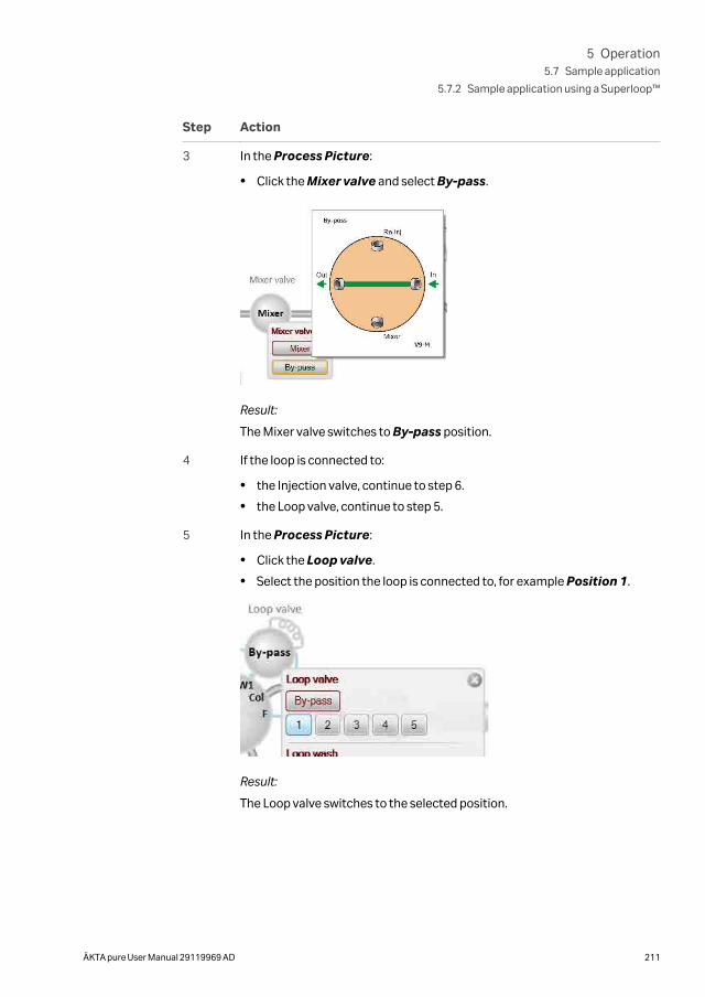
Step Action
3 In the Process Picture:
• Click the Mixer valve and select By-pass.
Result:
The Mixer valve switches to By-pass position.
4 If the loop is connected to:
• the Injection valve, continue to step 6.
• the Loop valve, continue to step 5.
5 In the Process Picture:
• Click the Loop valve.
• Select the position the loop is connected to, for example Position 1.
Result:
The Loop valve switches to the selected position.
5 Operation5.7 Sample application
5.7.2 Sample application using a Superloop™
ÄKTA pure User Manual 29119969 AD 211
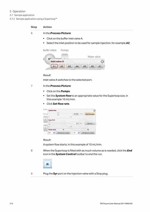
Step Action
6 In the Process Picture:
• Click on the buffer inlet valve A.
• Select the inlet position to be used for sample injection, for example A2.
Result:
Inlet valve A switches to the selected port.
7 In the Process Picture:
• Click on the Pumps.
• Set the System flow to an appropriate value for the Superloop size, inthis example 10 mL/min.
• Click Set flow rate.
Result:
A system flow starts, in this example of 10 mL/min.
8 When the Superloop is filled with as much volume as is needed, click the Endicon in the System Control toolbar to end the run.
9 Plug the Syr port on the Injection valve with a Stop plug.
5 Operation5.7 Sample application
5.7.2 Sample application using a Superloop™
212 ÄKTA pure User Manual 29119969 AD
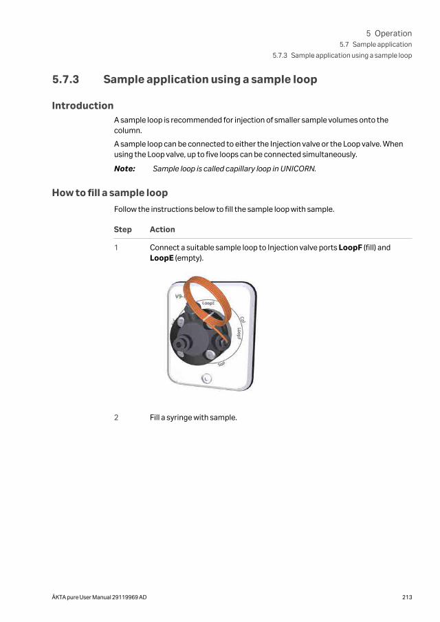
5.7.3 Sample application using a sample loop
IntroductionA sample loop is recommended for injection of smaller sample volumes onto thecolumn.
A sample loop can be connected to either the Injection valve or the Loop valve. Whenusing the Loop valve, up to five loops can be connected simultaneously.
Note: Sample loop is called capillary loop in UNICORN.
How to fill a sample loop
Follow the instructions below to fill the sample loop with sample.
Step Action
1 Connect a suitable sample loop to Injection valve ports LoopF (fill) andLoopE (empty).
2 Fill a syringe with sample.
5 Operation5.7 Sample application
5.7.3 Sample application using a sample loop
ÄKTA pure User Manual 29119969 AD 213
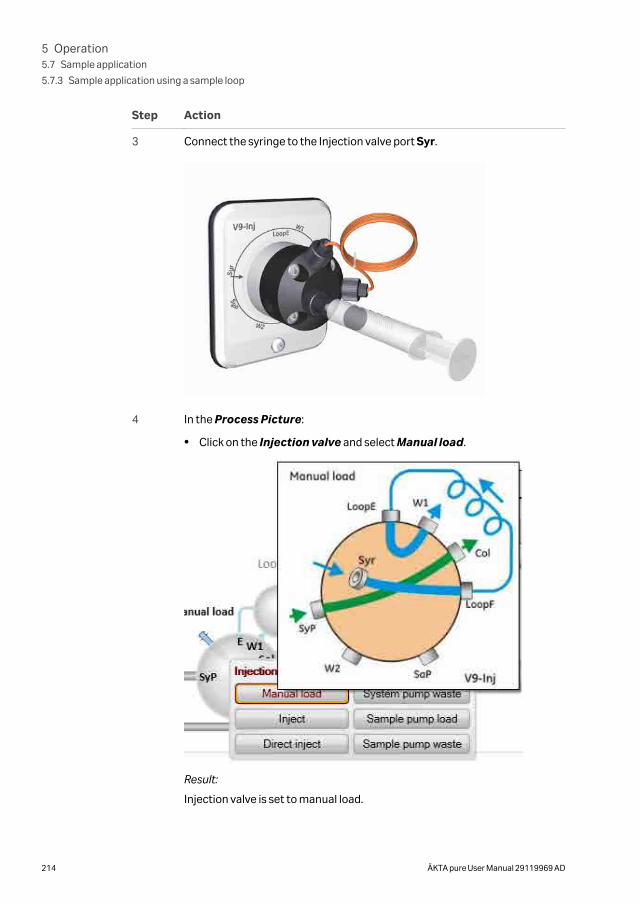
Step Action
3 Connect the syringe to the Injection valve port Syr.
4 In the Process Picture:
• Click on the Injection valve and select Manual load.
Result:
Injection valve is set to manual load.
5 Operation5.7 Sample application
5.7.3 Sample application using a sample loop
214 ÄKTA pure User Manual 29119969 AD
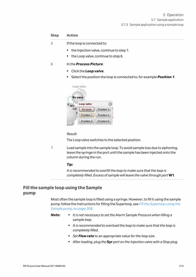
Step Action
5 If the loop is connected to:
• the Injection valve, continue to step 7.
• the Loop valve, continue to step 6.
6 In the Process Picture:
• Click the Loop valve.
• Select the position the loop is connected to, for example Position 1.
Result:
The Loop valve switches to the selected position.
7 Load sample into the sample loop. To avoid sample loss due to siphoning,leave the syringe in the port until the sample has been injected onto thecolumn during the run.
Tip:
It is recommended to overfill the loop to make sure that the loop iscompletely filled. Excess of sample will leave the valve through port W1.
Fill the sample loop using the Samplepump
Most often the sample loop is filled using a syringe. However, to fill it using the samplepump, follow the instructions for filling the Superloop, see Fill the Superloop using theSample pump, on page 208.
Note: • It is not necessary to set the Alarm Sample Pressure when filling asample loop.
• It is recommended to overload the loop to make sure that the loop iscompletely filled.
• Set Flow rate to an appropriate value for the loop size.
• After loading, plug the Syr port on the Injection valve with a Stop plug.
5 Operation5.7 Sample application
5.7.3 Sample application using a sample loop
ÄKTA pure User Manual 29119969 AD 215
Fill the sample loop using Systempump A
Most often the sample loop is filled using a syringe. However, to fill it using Systempump A, follow the instructions for filling the Superloop, see Fill the Superloop usingSystem pump A, on page 209.
Empty the loopGeneral considerations
During the method run, the sample is automatically injected onto the column. The loopis emptied and washed out using buffer from the system pumps. The total buffervolume to be used for emptying and washing the loop is set in the Method Editor.
Using a sample loop connected to Loop valve V9-L or V9H-L
For maximum reproducibility, use complete loop fill when loading the loop, that is,overfill the loop with a sample volume of up to 3-5 times the volume of the loop. Forminimum sample loss, use partial loop fill, that is, fill only up to 50% of the loop volume.Empty the loop with 3-5 times the volume of the loop.
Volume used to empty a loop connected to Loop valve V9-L or V9H-L
To minimize the risk for carry over and to make sure that the complete sample volumereaches the column, the loop should be emptied with an excess of buffer. The tubingbetween the Loop valve port E and the Injection valve port E holds a small volume. If theloop is emptied with a volume equal to, or less than the loop volume this needs to betaken into account. It is also important to use a low flow rate to ensure that the correctvolume is added to the column when injecting a small volume.
Note: Partially emptying the loops that are attached to Loop valve V9-L or V9H-Lcan increase the risk for carry over from one loop position to the next.
5 Operation5.7 Sample application
5.7.3 Sample application using a sample loop
216 ÄKTA pure User Manual 29119969 AD
5.8 Fractionation
IntroductionFraction collector F9-C and Fraction collector F9-R collect fractions from ÄKTApure purification runs. The fraction collectors are connected to ÄKTA pure andcontrolled by UNICORN. Control of the fraction collector can be achieved automati-cally in a method run, or manually.
In this section
Section See page
5.8.1 Prepare Fraction collector F9-C 218
5.8.2 Prepare Fraction collector F9-R 225
5.8.3 Fractionation overview 233
5 Operation5.8 Fractionation
ÄKTA pure User Manual 29119969 AD 217
5.8.1 Prepare Fraction collector F9-C
About this sectionThis section describes how to prepare and assemble Fraction collector F9-C before arun.
The fraction collector is connected to ÄKTA pure and controlled by UNICORN. Controlof the fraction collector can be achieved automatically in a method run, or manually.
CAUTIONFire Hazard. Do not fractionate flammable liquids using Frac-tion collector F9-C. When running RPC methods, or other proce-dures using organic solvents, collect fractions through the outletvalve or Fraction collector F9-R.
Note: The tray and racks can tilt slightly when not fully inserted into the fractioncollector and may harm the fractionation arm. The tilt is due to the heightdifference between the door and the floor of the fraction collector. Thetendency to tilt is affected by the placement and weight of the cassettes,tubes or bottles
Prepare the fraction collectorBefore starting to prepare Fraction collector F9-C, check the fractionation settings inthe method to be run. Perform the steps described below according to the settings inthe method.
• Insert the Cassette tray or a rack for tubes or bottles.
• Change the System Settings in UNICORN to set the fractionation mode and othersettings for fraction collection.
How to insert a tray or a rack is shown below.
For information on how to change the System Settings before a run, see UNICORNSystem Control Manual . The available System Settings are described in the ÄKTApure User manual.
Prepare and insert the Cassette tray
Follow the instructions below to add cassettes to the Cassette tray and insert the trayinto the fraction collector.
5 Operation5.8 Fractionation
5.8.1 Prepare Fraction collector F9-C
218 ÄKTA pure User Manual 29119969 AD
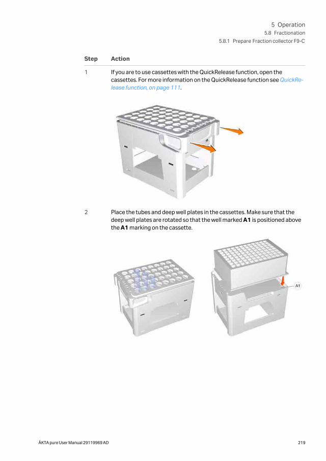
Step Action
1 If you are to use cassettes with the QuickRelease function, open thecassettes. For more information on the QuickRelease function see QuickRe-lease function, on page 111.
2 Place the tubes and deep well plates in the cassettes. Make sure that thedeep well plates are rotated so that the well marked A1 is positioned abovethe A1 marking on the cassette.
5 Operation5.8 Fractionation
5.8.1 Prepare Fraction collector F9-C
ÄKTA pure User Manual 29119969 AD 219
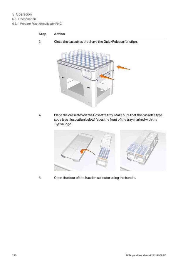
Step Action
3 Close the cassettes that have the QuickRelease function.
4 Place the cassettes on the Cassette tray. Make sure that the cassette typecode (see illustration below) faces the front of the tray marked with theCytiva logo.
5 Open the door of the fraction collector using the handle.
5 Operation5.8 Fractionation
5.8.1 Prepare Fraction collector F9-C
220 ÄKTA pure User Manual 29119969 AD
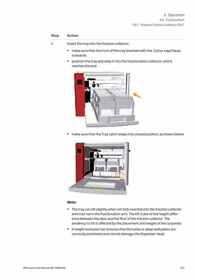
Step Action
6 Insert the tray into the fraction collector:
• make sure that the front of the tray (marked with the Cytiva logo) facesoutwards
• position the tray and slide it into the fractionation collector until itreaches the end
• make sure that the Tray catch snaps into closed position, as shown below.
Note:
• The tray can tilt slightly when not fully inserted into the fraction collectorand may harm the fractionation arm. The tilt is due to the height differ-ence between the door and the floor of the fraction collector. Thetendency to tilt is affected by the placement and weight of the cassettes.
• A height exclusion bar ensures that the tubes or deep well plates arecorrectly positioned and cannot damage the Dispenser head.
5 Operation5.8 Fractionation
5.8.1 Prepare Fraction collector F9-C
ÄKTA pure User Manual 29119969 AD 221
Step Action
7 Close the door. Make sure that it closes properly.
Result:
After the door has been closed, the fractionation arm scans the cassettetype code of each cassette to identify the cassette types. If deep well platesare used, the instrument also identifies the types of deep well plates.
Note:
If the tray is inserted with the front of the tray facing the wrong way it will notbe possible to close the door.
Prepare and insert a rack for tubes orbottles
Follow the instructions below to insert a rack for tubes or bottles into the fractioncollector.
Step Action
1 Place the tubes or bottles in the rack.
2 Open the door of the fraction collector using the handle.
5 Operation5.8 Fractionation
5.8.1 Prepare Fraction collector F9-C
222 ÄKTA pure User Manual 29119969 AD
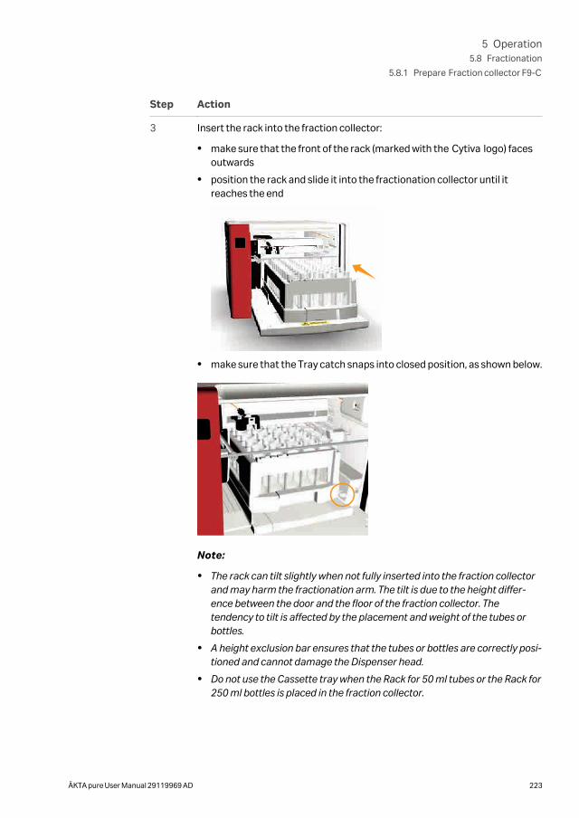
Step Action
3 Insert the rack into the fraction collector:
• make sure that the front of the rack (marked with the Cytiva logo) facesoutwards
• position the rack and slide it into the fractionation collector until itreaches the end
• make sure that the Tray catch snaps into closed position, as shown below.
Note:
• The rack can tilt slightly when not fully inserted into the fraction collectorand may harm the fractionation arm. The tilt is due to the height differ-ence between the door and the floor of the fraction collector. Thetendency to tilt is affected by the placement and weight of the tubes orbottles.
• A height exclusion bar ensures that the tubes or bottles are correctly posi-tioned and cannot damage the Dispenser head.
• Do not use the Cassette tray when the Rack for 50 ml tubes or the Rack for250 ml bottles is placed in the fraction collector.
5 Operation5.8 Fractionation
5.8.1 Prepare Fraction collector F9-C
ÄKTA pure User Manual 29119969 AD 223

Step Action
4 Close the door. Make sure that it closes properly.
Note:
If the rack is inserted with the front of the rack facing the wrong way it will notbe possible to close the door.
5 Operation5.8 Fractionation
5.8.1 Prepare Fraction collector F9-C
224 ÄKTA pure User Manual 29119969 AD
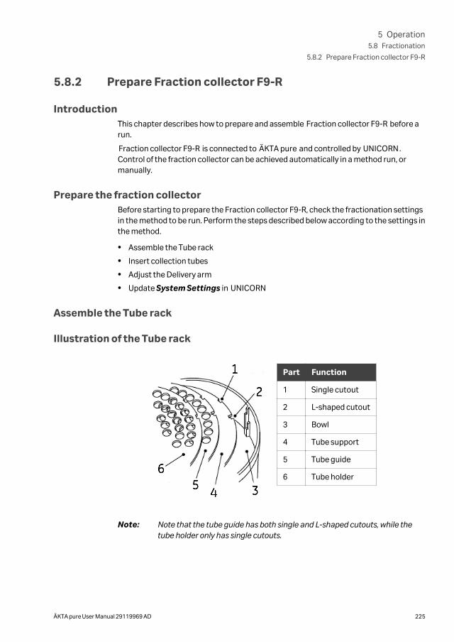
5.8.2 Prepare Fraction collector F9-R
IntroductionThis chapter describes how to prepare and assemble Fraction collector F9-R before arun.
Fraction collector F9-R is connected to ÄKTA pure and controlled by UNICORN.Control of the fraction collector can be achieved automatically in a method run, ormanually.
Prepare the fraction collectorBefore starting to prepare the Fraction collector F9-R, check the fractionation settingsin the method to be run. Perform the steps described below according to the settings inthe method.
• Assemble the Tube rack
• Insert collection tubes
• Adjust the Delivery arm
• Update System Settings in UNICORN
Assemble the Tube rack
Illustration of the Tube rack
1
2
3456
Part Function
1 Single cutout
2 L-shaped cutout
3 Bowl
4 Tube support
5 Tube guide
6 Tube holder
Note: Note that the tube guide has both single and L-shaped cutouts, while thetube holder only has single cutouts.
5 Operation5.8 Fractionation
5.8.2 Prepare Fraction collector F9-R
ÄKTA pure User Manual 29119969 AD 225
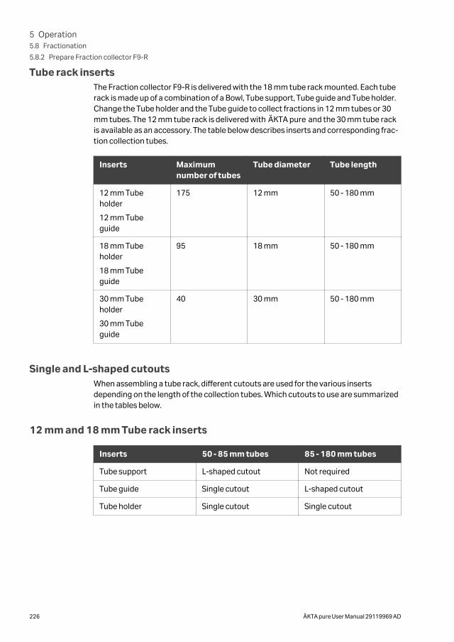
Tube rack insertsThe Fraction collector F9-R is delivered with the 18 mm tube rack mounted. Each tuberack is made up of a combination of a Bowl, Tube support, Tube guide and Tube holder.Change the Tube holder and the Tube guide to collect fractions in 12 mm tubes or 30mm tubes. The 12 mm tube rack is delivered with ÄKTA pure and the 30 mm tube rackis available as an accessory. The table below describes inserts and corresponding frac-tion collection tubes.
Inserts Maximumnumber of tubes
Tube diameter Tube length
12 mm Tubeholder
12 mm Tubeguide
175 12 mm 50 - 180 mm
18 mm Tubeholder
18 mm Tubeguide
95 18 mm 50 - 180 mm
30 mm Tubeholder
30 mm Tubeguide
40 30 mm 50 - 180 mm
Single and L-shaped cutoutsWhen assembling a tube rack, different cutouts are used for the various insertsdepending on the length of the collection tubes. Which cutouts to use are summarizedin the tables below.
12 mm and 18 mm Tube rack inserts
Inserts 50 - 85 mm tubes 85 - 180 mm tubes
Tube support L-shaped cutout Not required
Tube guide Single cutout L-shaped cutout
Tube holder Single cutout Single cutout
5 Operation5.8 Fractionation
5.8.2 Prepare Fraction collector F9-R
226 ÄKTA pure User Manual 29119969 AD
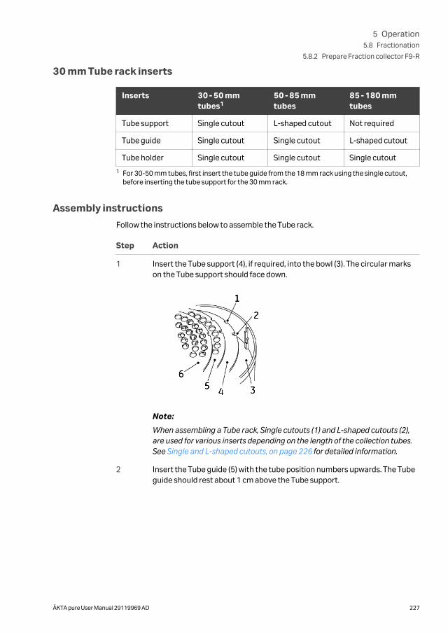
30 mm Tube rack inserts
Inserts 30 - 50 mmtubes1
50 - 85 mmtubes
85 - 180 mmtubes
Tube support Single cutout L-shaped cutout Not required
Tube guide Single cutout Single cutout L-shaped cutout
Tube holder Single cutout Single cutout Single cutout
1 For 30-50 mm tubes, first insert the tube guide from the 18 mm rack using the single cutout,before inserting the tube support for the 30 mm rack.
Assembly instructions
Follow the instructions below to assemble the Tube rack.
Step Action
1 Insert the Tube support (4), if required, into the bowl (3). The circular markson the Tube support should face down.
1
2
3456
Note:
When assembling a Tube rack, Single cutouts (1) and L-shaped cutouts (2),are used for various inserts depending on the length of the collection tubes.See Single and L-shaped cutouts, on page 226 for detailed information.
2 Insert the Tube guide (5) with the tube position numbers upwards. The Tubeguide should rest about 1 cm above the Tube support.
5 Operation5.8 Fractionation
5.8.2 Prepare Fraction collector F9-R
ÄKTA pure User Manual 29119969 AD 227
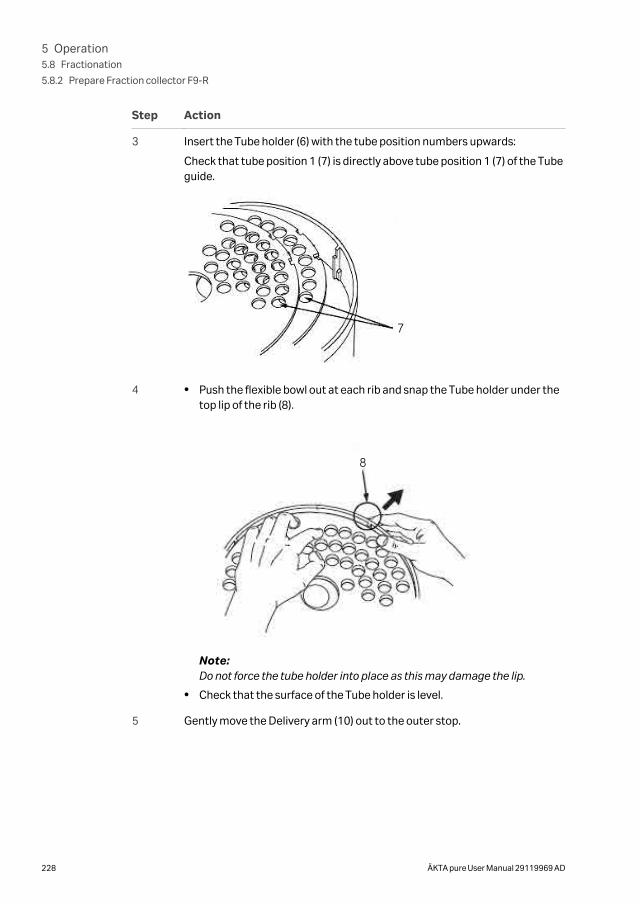
Step Action
3 Insert the Tube holder (6) with the tube position numbers upwards:
Check that tube position 1 (7) is directly above tube position 1 (7) of the Tubeguide.
7
4 • Push the flexible bowl out at each rib and snap the Tube holder under thetop lip of the rib (8).
8
Note:Do not force the tube holder into place as this may damage the lip.
• Check that the surface of the Tube holder is level.
5 Gently move the Delivery arm (10) out to the outer stop.
5 Operation5.8 Fractionation
5.8.2 Prepare Fraction collector F9-R
228 ÄKTA pure User Manual 29119969 AD
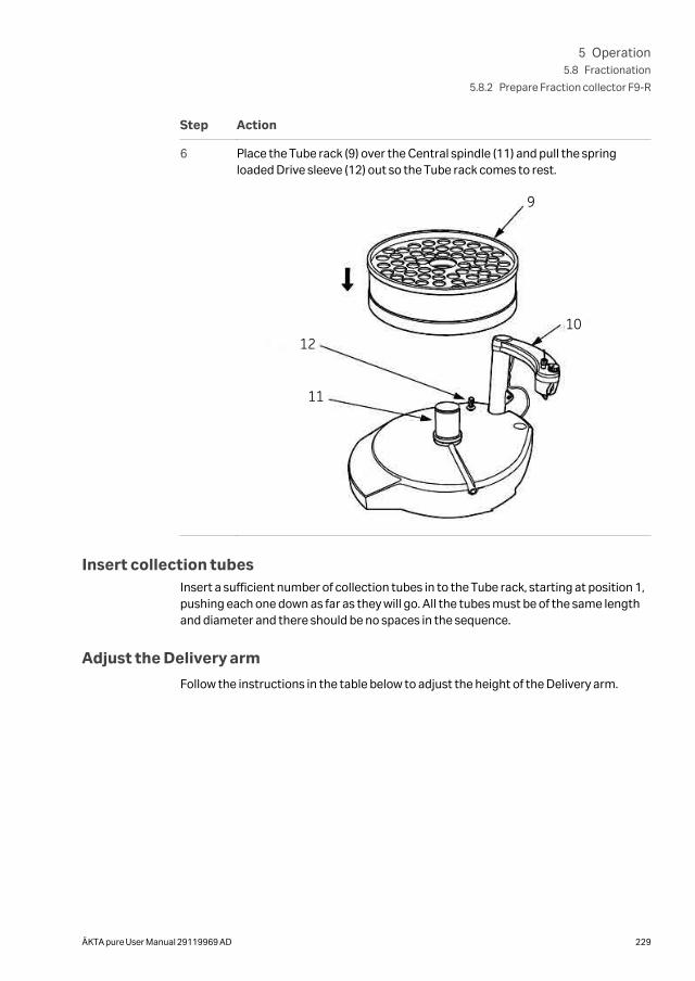
Step Action
6 Place the Tube rack (9) over the Central spindle (11) and pull the springloaded Drive sleeve (12) out so the Tube rack comes to rest.
9
1012
11
Insert collection tubesInsert a sufficient number of collection tubes in to the Tube rack, starting at position 1,pushing each one down as far as they will go. All the tubes must be of the same lengthand diameter and there should be no spaces in the sequence.
Adjust the Delivery arm
Follow the instructions in the table below to adjust the height of the Delivery arm.
5 Operation5.8 Fractionation
5.8.2 Prepare Fraction collector F9-R
ÄKTA pure User Manual 29119969 AD 229
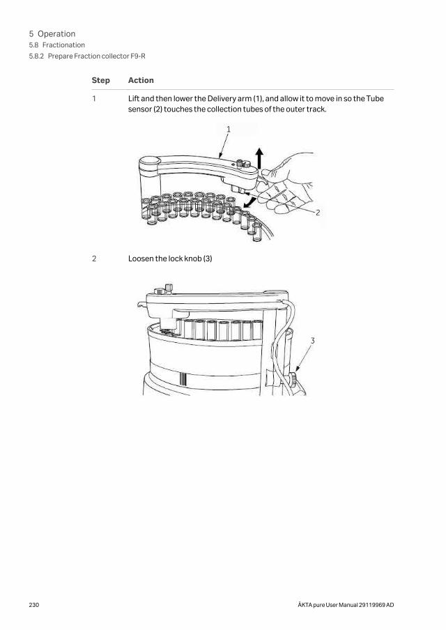
Step Action
1 Lift and then lower the Delivery arm (1), and allow it to move in so the Tubesensor (2) touches the collection tubes of the outer track.
1
2
2 Loosen the lock knob (3)
3
5 Operation5.8 Fractionation
5.8.2 Prepare Fraction collector F9-R
230 ÄKTA pure User Manual 29119969 AD
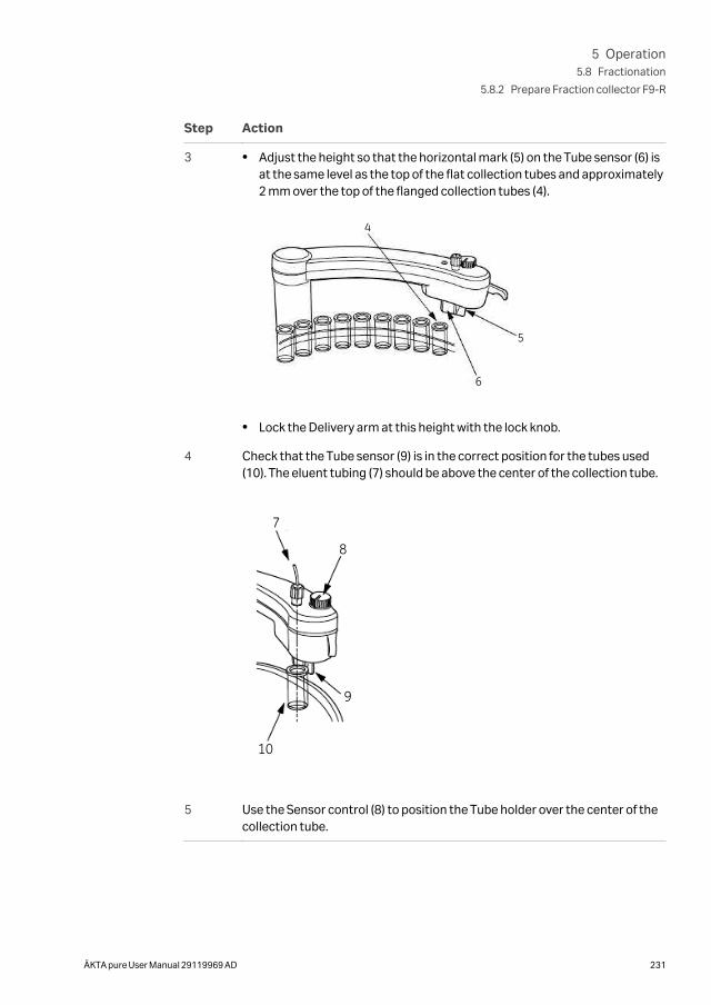
Step Action
3 • Adjust the height so that the horizontal mark (5) on the Tube sensor (6) isat the same level as the top of the flat collection tubes and approximately2 mm over the top of the flanged collection tubes (4).
4
5
6
• Lock the Delivery arm at this height with the lock knob.
4 Check that the Tube sensor (9) is in the correct position for the tubes used(10). The eluent tubing (7) should be above the center of the collection tube.
7
8
9
10
5 Use the Sensor control (8) to position the Tube holder over the center of thecollection tube.
5 Operation5.8 Fractionation
5.8.2 Prepare Fraction collector F9-R
ÄKTA pure User Manual 29119969 AD 231
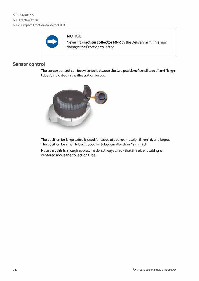
NOTICE
Never lift Fraction collector F9-R by the Delivery arm. This maydamage the Fraction collector.
Sensor controlThe sensor control can be switched between the two positions "small tubes" and "largetubes", indicated in the illustration below.
The position for large tubes is used for tubes of approximately 18 mm i.d. and larger.The position for small tubes is used for tubes smaller than 18 mm i.d.
Note that this is a rough approximation. Always check that the eluent tubing iscentered above the collection tube.
5 Operation5.8 Fractionation
5.8.2 Prepare Fraction collector F9-R
232 ÄKTA pure User Manual 29119969 AD
5.8.3 Fractionation overview
Fractionation typesThe table below lists the types of fractionation that the fraction collectors can be usedfor.
Type Description
Fixed volumefractionation
During fixed volume fractionation the fraction collector contin-uously switches tubes according to the set volume throughoutthe entire fractionation. This type of fractionation is also knownas straight fractionation.
Peak fractiona-tion
Peak fractionation can be used to further increase the purity ofthe collected protein peaks and minimize the number of tubesused. The monitor signal is used to determine when to switchthe tubes. See Section 9.8.10 System settings ‑ Watch parame-ters, on page 505 for information about different watch options.
Combined fixedvolume fractio-nation and peakfractionation
The two fractionation types listed above can be used in combi-nation. Combination of fixed volume and peak fractionationallows fractions collected by fixed volume fractionation andfractions collected by peak fractionation to be directed todifferent collection tubes.
To be able to analyze different parts of the peak, the fraction size during elution isusually set to a value smaller than the expected peak volume.
IllustrationThe illustration below shows examples of fractionation using fixed volume fractiona-tion and fractionation using peak fractionation.
5 Operation5.8 Fractionation
5.8.3 Fractionation overview
ÄKTA pure User Manual 29119969 AD 233
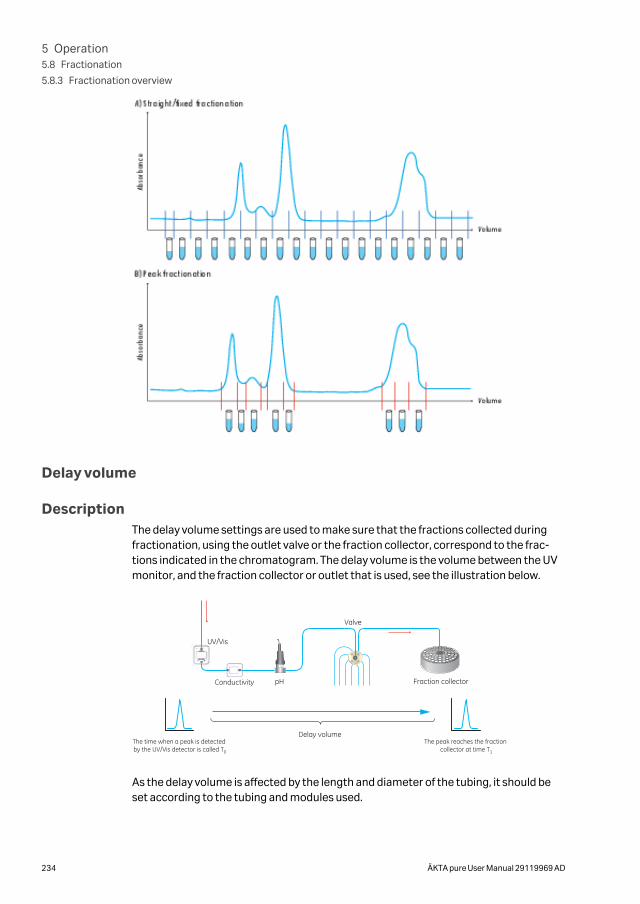
Delay volume
DescriptionThe delay volume settings are used to make sure that the fractions collected duringfractionation, using the outlet valve or the fraction collector, correspond to the frac-tions indicated in the chromatogram. The delay volume is the volume between the UVmonitor, and the fraction collector or outlet that is used, see the illustration below.
UV/Vis
pH
Valve
The time when a peak is detected by the UV/Vis detector is called T0
The peak reaches the fraction collector at time T1
Fraction collectorConductivity
Delay volume
As the delay volume is affected by the length and diameter of the tubing, it should beset according to the tubing and modules used.
5 Operation5.8 Fractionation
5.8.3 Fractionation overview
234 ÄKTA pure User Manual 29119969 AD
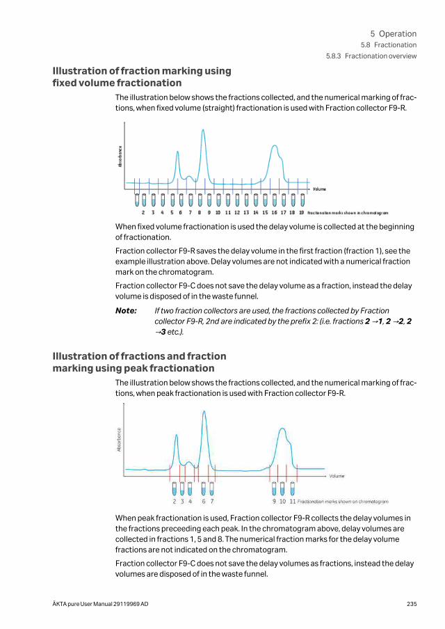
Illustration of fraction marking usingfixed volume fractionation
The illustration below shows the fractions collected, and the numerical marking of frac-tions, when fixed volume (straight) fractionation is used with Fraction collector F9-R.
When fixed volume fractionation is used the delay volume is collected at the beginningof fractionation.
Fraction collector F9-R saves the delay volume in the first fraction (fraction 1), see theexample illustration above. Delay volumes are not indicated with a numerical fractionmark on the chromatogram.
Fraction collector F9-C does not save the delay volume as a fraction, instead the delayvolume is disposed of in the waste funnel.
Note: If two fraction collectors are used, the fractions collected by Fractioncollector F9-R, 2nd are indicated by the prefix 2: (i.e. fractions 2 →1, 2 →2, 2→3 etc.).
Illustration of fractions and fractionmarking using peak fractionation
The illustration below shows the fractions collected, and the numerical marking of frac-tions, when peak fractionation is used with Fraction collector F9-R.
When peak fractionation is used, Fraction collector F9-R collects the delay volumes inthe fractions preceeding each peak. In the chromatogram above, delay volumes arecollected in fractions 1, 5 and 8. The numerical fraction marks for the delay volumefractions are not indicated on the chromatogram.
Fraction collector F9-C does not save the delay volumes as fractions, instead the delayvolumes are disposed of in the waste funnel.
5 Operation5.8 Fractionation
5.8.3 Fractionation overview
ÄKTA pure User Manual 29119969 AD 235
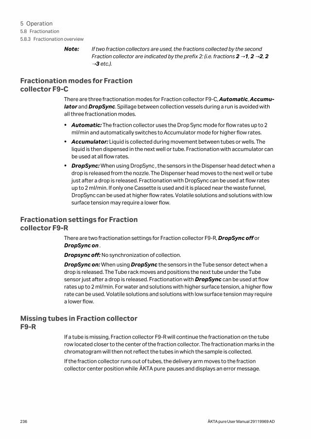
Note: If two fraction collectors are used, the fractions collected by the secondFraction collector are indicated by the prefix 2: (i.e. fractions 2 →1, 2 →2, 2→3 etc.).
Fractionation modes for Fractioncollector F9-C
There are three fractionation modes for Fraction collector F9-C, Automatic, Accumu-lator and DropSync. Spillage between collection vessels during a run is avoided withall three fractionation modes.
• Automatic: The fraction collector uses the Drop Sync mode for flow rates up to 2ml/min and automatically switches to Accumulator mode for higher flow rates.
• Accumulator: Liquid is collected during movement between tubes or wells. Theliquid is then dispensed in the next well or tube. Fractionation with accumulator canbe used at all flow rates.
• DropSync: When using DropSync , the sensors in the Dispenser head detect when adrop is released from the nozzle. The Dispenser head moves to the next well or tubejust after a drop is released. Fractionation with DropSync can be used at flow ratesup to 2 ml/min. If only one Cassette is used and it is placed near the waste funnel,DropSync can be used at higher flow rates. Volatile solutions and solutions with lowsurface tension may require a lower flow.
Fractionation settings for Fractioncollector F9-R
There are two fractionation settings for Fraction collector F9-R, DropSync off orDropSync on .
Dropsync off: No synchronization of collection.
DropSync on: When using DropSync the sensors in the Tube sensor detect when adrop is released. The Tube rack moves and positions the next tube under the Tubesensor just after a drop is released. Fractionation with DropSync can be used at flowrates up to 2 ml/min. For water and solutions with higher surface tension, a higher flowrate can be used. Volatile solutions and solutions with low surface tension may requirea lower flow.
Missing tubes in Fraction collectorF9-R
If a tube is missing, Fraction collector F9-R will continue the fractionation on the tuberow located closer to the center of the fraction collector. The fractionation marks in thechromatogram will then not reflect the tubes in which the sample is collected.
If the fraction collector runs out of tubes, the delivery arm moves to the fractioncollector center position while ÄKTA pure pauses and displays an error message.
5 Operation5.8 Fractionation
5.8.3 Fractionation overview
236 ÄKTA pure User Manual 29119969 AD
Missing tubes or plates in Fractioncollector F9-C
When automatic cassette configuration is selected in the system settings the fractioncollector automatically detects which types of cassettes and plates that are present.The fraction collector will however not detect if tubes or bottles are missing in thecassettes. Make sure that the cassettes to be used are occupied by appropriate typesand numbers of tubes or bottles before starting a run.
It is not possible to change the cassette configuration during a run. When the systemstate is set to Pause it is possible to take out cassettes or plates from the fractioncollector only if they are replaced by cassettes or plates of the same type and areplaced in the same positions.
The action of the system when the last tube in the fraction collector is filled is set in theinstruction Last tube filled in the system settings. The flow can be directed to wasteor to any of the outlets or the run can be paused. If the action is set to Pause, thesystem automatically pauses when the last tube is filled and prompts the user toreplace the filled tubes.
Peak broadeningThe width of peaks at the fraction collector is influenced by the properties of thecolumn and the dimensions of tubing connecting the components. Initial samplevolume affects the peak width in gel filtration (GF) chromatography. A sample zone isbroadened during passage through a GF column so that the sample is diluted and theresolution decreases with increasing sample volume. Sample volume does nothowever affect the resolution in adsorption chromatography techniques such asaffinity chromatography (AC), ion exchange chromatography (IEX), and hydrophobicinteraction chromatography (HIC). The effect of peak broadening in the system fromsample injection to peak detection (including dilution on the column) is apparent in thechromatogram from the UV monitor, but broadening from the UV monitor to fractioncollection is not visible in the chromatogram. This "hidden" effect can sometimes bedramatic, especially for high-resolution columns.
To minimize peak broadening, use narrow and short tubing connections as far aspossible. Remember that using narrow tubing will increase the back pressure in thesystem.
5 Operation5.8 Fractionation
5.8.3 Fractionation overview
ÄKTA pure User Manual 29119969 AD 237
5.9 Create a method and perform a run
IntroductionThis section provides an overview of how to create a method in UNICORN and how toperform manual and method runs on ÄKTA pure.
It also contains advice on things to be considered during a run.
In this section
Section See page
5.9.1 Create a method 239
5.9.2 Prepare and perform a run 245
5.9.3 Monitor a run 247
5.9.4 After run procedures 249
5 Operation5.9 Create a method and perform a run
238 ÄKTA pure User Manual 29119969 AD
5.9.1 Create a method
IntroductionThe predefined methods are built up using phases, where each phase corresponds to astep in a chromatography run with a number of properties associated with that phase.
See UNICORN Method Manual for more information about method structure, defini-tions and concepts of methods in UNICORN.
Predefined methodsThere are several predefined methods to choose from. All the predefined methods arelisted below.
The predefined methods available for each system are defined by the InstrumentConfiguration. Refer to Section 9.7 Predefined methods and phases, on page 477 formore information about each method.
Purification methods
• Affinity Chromatography (AC)
• Affinity Chromatography (AC) with Tag Removal
• Anion Exchange Chromatography (AIEX)
• Cation Exchange Chromatography (CIEX)
• Chromatofocusing (CF)
• Desalting
• Gel filtration (GF)
• Hydrophobic Interaction Chromatography (HIC)
• Manual Loop Fill
• NHS-coupling
• Reversed Phase Chromatography (RPC)
Maintenance methods
• Column CIP
• Column Performance Test
• Column Preparation
• System CIP
• System Preparation
Main steps when defining a newmethod
The main steps when defining a method are:
5 Operation5.9 Create a method and perform a run
5.9.1 Create a method
ÄKTA pure User Manual 29119969 AD 239
Step Action
1 Create/open a method
• Create a Predefined method (including a set of phases that may beedited)or
• Open an existing method that can be edited and saved with a new nameor overwritten.
2 Build/edit the Method Outline and/or edit the Phase Properties for theappropriate phases.
3 Save the method.
Create a new method
Follow the instructions below to create a new method.
5 Operation5.9 Create a method and perform a run
5.9.1 Create a method
240 ÄKTA pure User Manual 29119969 AD
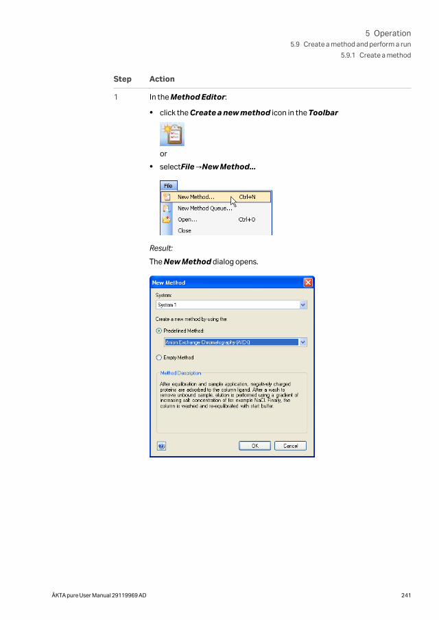
Step Action
1 In the Method Editor:
• click the Create a new method icon in the Toolbar
or
• selectFile →New Method...
Result:
The New Method dialog opens.
5 Operation5.9 Create a method and perform a run
5.9.1 Create a method
ÄKTA pure User Manual 29119969 AD 241
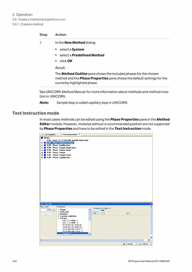
Step Action
2 In the New Method dialog:
• select a System
• select a Predefined Method
• click OK
Result:
The Method Outline pane shows the included phases for the chosenmethod and the Phase Properties pane shows the default settings for thecurrently highlighted phase.
See UNICORN Method Manual for more information about methods and method crea-tion in UNICORN.
Note: Sample loop is called capillary loop in UNICORN.
Text Instruction modeIn most cases methods can be edited using the Phase Properties pane in the MethodEditor module. However, modules without a recommended position are not supportedby Phase Properties and have to be edited in the Text Instruction mode.
5 Operation5.9 Create a method and perform a run
5.9.1 Create a method
242 ÄKTA pure User Manual 29119969 AD
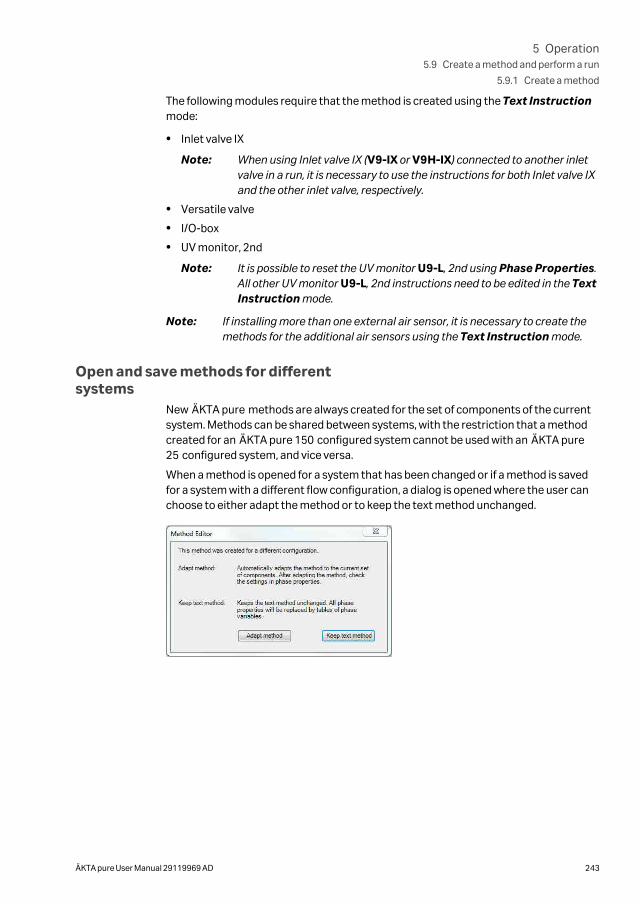
The following modules require that the method is created using the Text Instructionmode:
• Inlet valve IX
Note: When using Inlet valve IX (V9-IX or V9H-IX) connected to another inletvalve in a run, it is necessary to use the instructions for both Inlet valve IXand the other inlet valve, respectively.
• Versatile valve
• I/O-box
• UV monitor, 2nd
Note: It is possible to reset the UV monitor U9-L, 2nd using Phase Properties.All other UV monitor U9-L, 2nd instructions need to be edited in the TextInstruction mode.
Note: If installing more than one external air sensor, it is necessary to create themethods for the additional air sensors using the Text Instruction mode.
Open and save methods for differentsystems
New ÄKTA pure methods are always created for the set of components of the currentsystem. Methods can be shared between systems, with the restriction that a methodcreated for an ÄKTA pure 150 configured system cannot be used with an ÄKTA pure25 configured system, and vice versa.
When a method is opened for a system that has been changed or if a method is savedfor a system with a different flow configuration, a dialog is opened where the user canchoose to either adapt the method or to keep the text method unchanged.
5 Operation5.9 Create a method and perform a run
5.9.1 Create a method
ÄKTA pure User Manual 29119969 AD 243
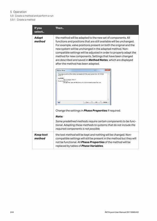
If youselect..
Then..
Adaptmethod
the method will be adapted to the new set of components. Allfunctions and positions that are still available will be unchanged.For example, valve positions present on both the original and thenew system will be unchanged in the adapted method. Non-compatible settings will be adjusted in order to properly adapt themethod for new components. Settings that have been changedare described and saved in Method Notes, which are displayedafter the method has been adapted.
Change the settings in Phase Properties if required.
Note:
Some predefined methods require certain components to be func-tional. Adapting these methods to systems that do not include therequired components is not possible.
Keep textmethod
the text method will be kept and nothing will be changed. Non-compatible settings will still be present in the method but they willnot be functional. All Phase Properties of the method will bereplaced by tables of Phase Variables.
5 Operation5.9 Create a method and perform a run
5.9.1 Create a method
244 ÄKTA pure User Manual 29119969 AD
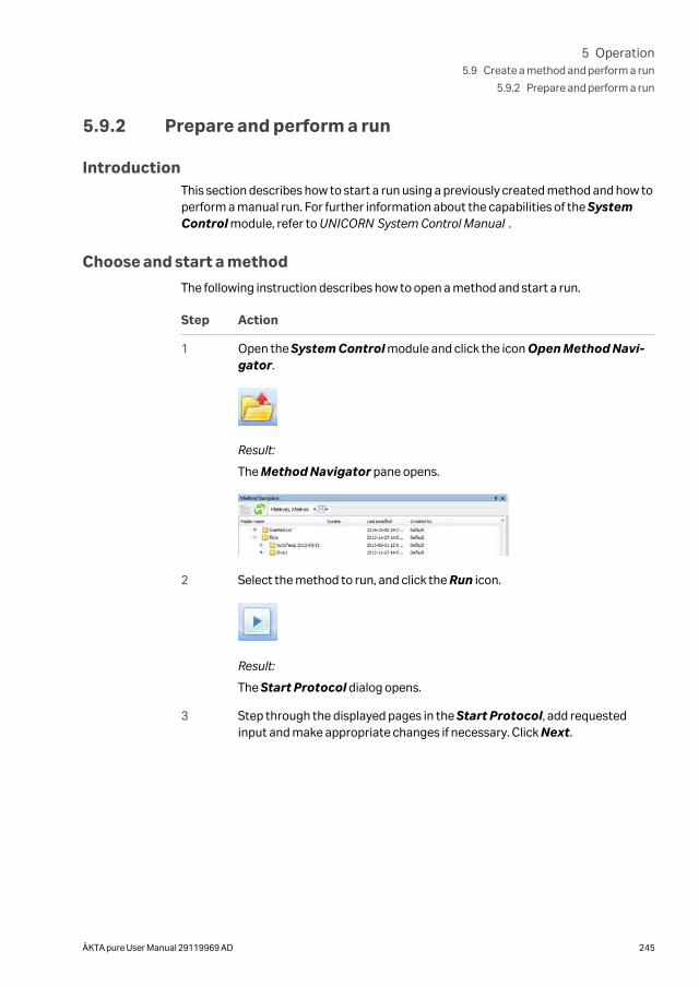
5.9.2 Prepare and perform a run
IntroductionThis section describes how to start a run using a previously created method and how toperform a manual run. For further information about the capabilities of the SystemControl module, refer to UNICORN System Control Manual .
Choose and start a method
The following instruction describes how to open a method and start a run.
Step Action
1 Open the System Control module and click the icon Open Method Navi-gator.
Result:
The Method Navigator pane opens.
2 Select the method to run, and click the Run icon.
Result:
The Start Protocol dialog opens.
3 Step through the displayed pages in the Start Protocol, add requestedinput and make appropriate changes if necessary. Click Next.
5 Operation5.9 Create a method and perform a run
5.9.2 Prepare and perform a run
ÄKTA pure User Manual 29119969 AD 245
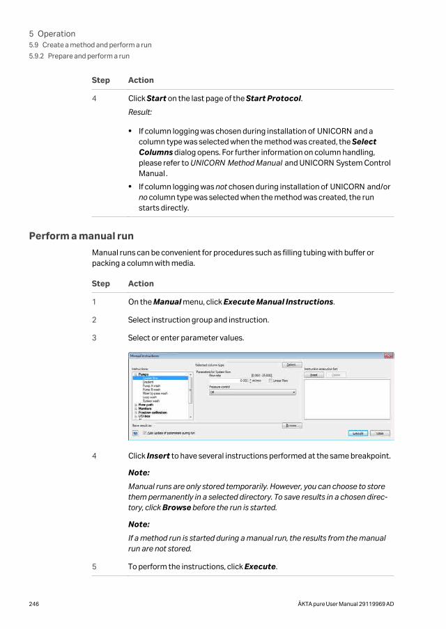
Step Action
4 Click Start on the last page of the Start Protocol.
Result:
• If column logging was chosen during installation of UNICORN and acolumn type was selected when the method was created, the SelectColumns dialog opens. For further information on column handling,please refer to UNICORN Method Manual and UNICORN System ControlManual .
• If column logging was not chosen during installation of UNICORN and/orno column type was selected when the method was created, the runstarts directly.
Perform a manual run
Manual runs can be convenient for procedures such as filling tubing with buffer orpacking a column with media.
Step Action
1 On the Manual menu, click Execute Manual Instructions.
2 Select instruction group and instruction.
3 Select or enter parameter values.
4 Click Insert to have several instructions performed at the same breakpoint.
Note:
Manual runs are only stored temporarily. However, you can choose to storethem permanently in a selected directory. To save results in a chosen direc-tory, click Browse before the run is started.
Note:
If a method run is started during a manual run, the results from the manualrun are not stored.
5 To perform the instructions, click Execute.
5 Operation5.9 Create a method and perform a run
5.9.2 Prepare and perform a run
246 ÄKTA pure User Manual 29119969 AD
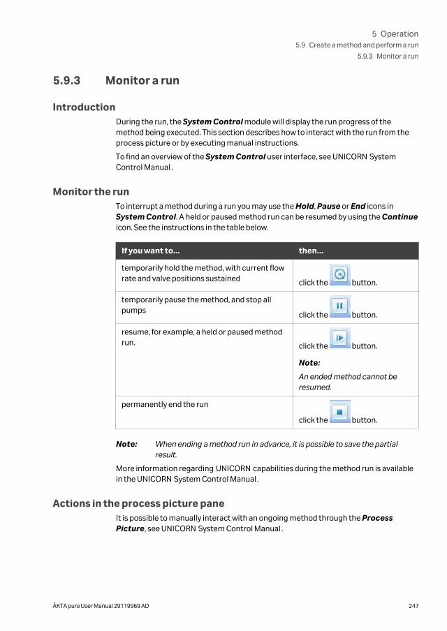
5.9.3 Monitor a run
IntroductionDuring the run, the System Control module will display the run progress of themethod being executed. This section describes how to interact with the run from theprocess picture or by executing manual instructions.
To find an overview of the System Control user interface, see UNICORN SystemControl Manual .
Monitor the runTo interrupt a method during a run you may use the Hold, Pause or End icons inSystem Control. A held or paused method run can be resumed by using the Continueicon. See the instructions in the table below.
If you want to... then...
temporarily hold the method, with current flowrate and valve positions sustained click the button.
temporarily pause the method, and stop allpumps click the button.
resume, for example, a held or paused methodrun. click the button.
Note:
An ended method cannot beresumed.
permanently end the run
click the button.
Note: When ending a method run in advance, it is possible to save the partialresult.
More information regarding UNICORN capabilities during the method run is availablein the UNICORN System Control Manual .
Actions in the process picture paneIt is possible to manually interact with an ongoing method through the ProcessPicture, see UNICORN System Control Manual .
5 Operation5.9 Create a method and perform a run
5.9.3 Monitor a run
ÄKTA pure User Manual 29119969 AD 247
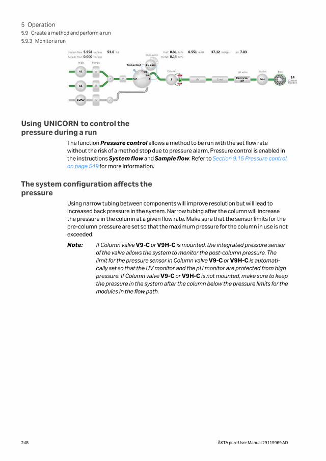
Using UNICORN to control thepressure during a run
The function Pressure control allows a method to be run with the set flow ratewithout the risk of a method stop due to pressure alarm. Pressure control is enabled inthe instructions System flow and Sample flow. Refer to Section 9.15 Pressure control,on page 549 for more information.
The system configuration affects thepressure
Using narrow tubing between components will improve resolution but will lead toincreased back pressure in the system. Narrow tubing after the column will increasethe pressure in the column at a given flow rate. Make sure that the sensor limits for thepre-column pressure are set so that the maximum pressure for the column in use is notexceeded.
Note: If Column valve V9-C or V9H-C is mounted, the integrated pressure sensorof the valve allows the system to monitor the post-column pressure. Thelimit for the pressure sensor in Column valve V9-C or V9H-C is automati-cally set so that the UV monitor and the pH monitor are protected from highpressure. If Column valve V9-C or V9H-C is not mounted, make sure to keepthe pressure in the system after the column below the pressure limits for themodules in the flow path.
5 Operation5.9 Create a method and perform a run
5.9.3 Monitor a run
248 ÄKTA pure User Manual 29119969 AD
5.9.4 After run procedures
IntroductionThis section describes how to clean the instrument and columns after a chromato-graphic run, and how to prepare the system for storage.
The instrument and the columns should be cleaned between the runs. This will prevent,for example, sample contamination, protein precipitation and column clogging. If theinstrument is not going to be used for a couple of days or longer, the instrument,columns and the pH flow cell should be filled with storage solution. For further informa-tion about cleaning and maintenance procedures, see Chapter 7 Maintenance, on page279.
Tip: To clean and fill the instrument and columns with storage solution, useSystem CIP and Column CIP either as separate, predefined methods or asphases included in a chromatographic method.
CAUTION
Hazardous chemicals and biological agents. Before mainte-nance, service and decommissioning, wash the ÄKTA pure instru-ment with a neutral solution to make sure that any hazardoussolvents and biological agents have been flushed out from thesystem.
System cleaningAfter a method run is completed, perform the following:
• Rinse the instrument with one or several cleaning solution(s) (e.g., NaOH, buffersolution or distilled water) using System CIP.
Note: If Column valve V9-C or V9H-C is mounted, the integrated pressuresensor of the valve allows the system to monitor the post-column pres-sure. The limit for the pressure sensor in Column valve V9-C or V9H-C isautomatically set so that the UV monitor and the pH monitor areprotected from high pressure. If Column valve V9-C or V9H-C is notmounted, make sure to keep the pressure in the system after the columnbelow the pressure limits for the modules in the flow path.
• If applicable, empty the fraction collector.
• Clean all spills on the instrument and on the bench using a moist tissue.
• Empty the waste vessel.
• Clean the manual injection port of the injection valve, see Section 7.6.2 PerformSystem CIP, on page 307 for detailed instructions.
• If applicable, clean the pH electrode manually and make sure to leave it in an appro-priate buffer. See Section 7.6.7 Clean the pH electrode, on page 324 for detailedinstructions.
5 Operation5.9 Create a method and perform a run
5.9.4 After run procedures
ÄKTA pure User Manual 29119969 AD 249
System storageIf the instrument is not going to be used for a couple of days or longer, also perform thefollowing:
• Fill the system and inlets with storage solution (e.g., 20% ethanol) using SystemCIP.
Note: If Column valve V9-C or V9H-C is mounted, the integrated pressuresensor of the valve allows the system to monitor the post-column pres-sure. The limit for the pressure sensor in Column valve V9-C or V9H-C isautomatically set so that the UV monitor and the pH monitor areprotected from high pressure. If Column valve V9-C or V9H-C is notmounted, make sure to keep the pressure in the system after the columnbelow the pressure limits for the modules in the flow path.
• If applicable, prepare the pH electrode for storage as described in Section 7.6.6Storage of the pH electrode, on page 322.
Column cleaningAfter a method run is completed, perform the following:
• Clean the column with one or several cleaning solution(s) using Column CIP.
Column storageIf the column is not going to be used for a couple of days or longer, also perform thefollowing:
• Fill the column with storage solution (e.g., 20% ethanol) using Column CIP.
pH electrode storage
If pH monitoring will not be used for a week or longer, perform one of the followingactions:
• Inject new storage solution into the pH flow cell. Refer to Section 7.6.6 Storage of thepH electrode, on page 322 for instructions.
• Replace the pH electrode with the dummy electrode that is installed in the pH valveon delivery.
In the following situations, in order to increase the lifetime of the pH electrode, use theBy-pass position and store the electrode in storage solution inside the pH flow cell:
• pH monitoring is not needed during the run.
• Organic solutions are used.
• Extremely acidic or extremely basic solutions are used.
For further information on how to prepare the pH electrode for storage, refer to Section7.6.6 Storage of the pH electrode, on page 322.
5 Operation5.9 Create a method and perform a run
5.9.4 After run procedures
250 ÄKTA pure User Manual 29119969 AD
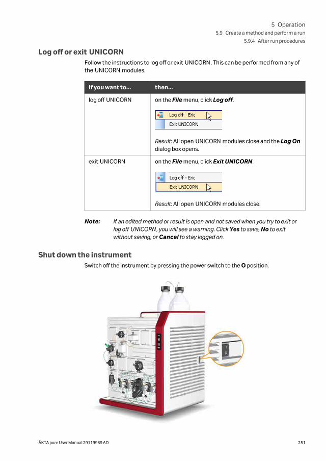
Log off or exit UNICORNFollow the instructions to log off or exit UNICORN. This can be performed from any ofthe UNICORN modules.
If you want to... then...
log off UNICORN on the File menu, click Log off.
Result: All open UNICORN modules close and the Log Ondialog box opens.
exit UNICORN on the File menu, click Exit UNICORN.
Result: All open UNICORN modules close.
Note: If an edited method or result is open and not saved when you try to exit orlog off UNICORN, you will see a warning. Click Yes to save, No to exitwithout saving, or Cancel to stay logged on.
Shut down the instrumentSwitch off the instrument by pressing the power switch to the O position.
5 Operation5.9 Create a method and perform a run
5.9.4 After run procedures
ÄKTA pure User Manual 29119969 AD 251
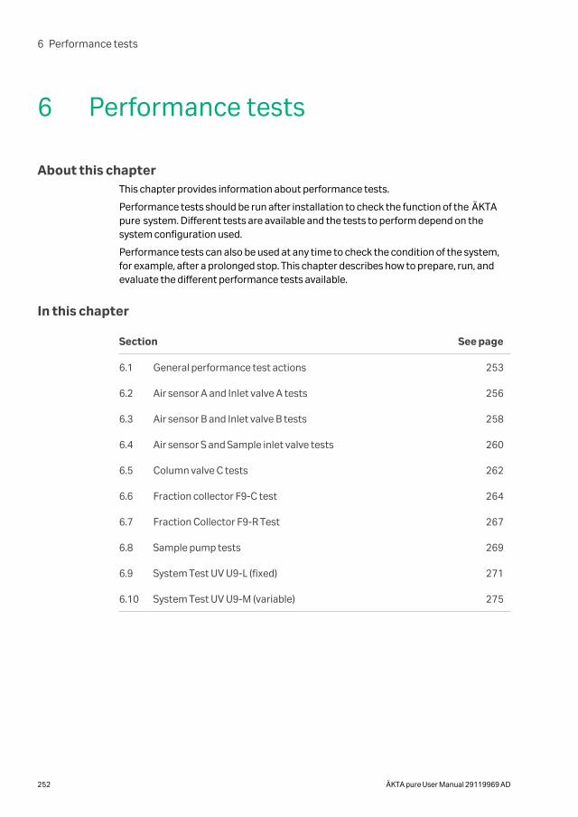
6 Performance tests
About this chapterThis chapter provides information about performance tests.
Performance tests should be run after installation to check the function of the ÄKTApure system. Different tests are available and the tests to perform depend on thesystem configuration used.
Performance tests can also be used at any time to check the condition of the system,for example, after a prolonged stop. This chapter describes how to prepare, run, andevaluate the different performance tests available.
In this chapter
Section See page
6.1 General performance test actions 253
6.2 Air sensor A and Inlet valve A tests 256
6.3 Air sensor B and Inlet valve B tests 258
6.4 Air sensor S and Sample inlet valve tests 260
6.5 Column valve C tests 262
6.6 Fraction collector F9-C test 264
6.7 Fraction Collector F9-R Test 267
6.8 Sample pump tests 269
6.9 System Test UV U9-L (fixed) 271
6.10 System Test UV U9-M (variable) 275
6 Performance tests
252 ÄKTA pure User Manual 29119969 AD
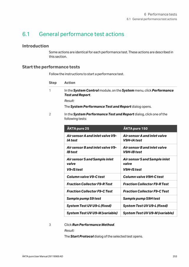
6.1 General performance test actions
IntroductionSome actions are identical for each performance test. These actions are described inthis section.
Start the performance tests
Follow the instructions to start a performance test.
Step Action
1 In the System Control module, on the System menu, click PerformanceTest and Report.
Result:
The System Performance Test and Report dialog opens.
2 In the System Performance Test and Report dialog, click one of thefollowing tests:
ÄKTA pure 25 ÄKTA pure 150
Air sensor A and inlet valve V9-IA test
Air sensor A and inlet valveV9H-IA test
Air sensor B and inlet valve V9-IB test
Air sensor B and inlet valveV9H-IB test
Air sensor S and Sample inletvalve
V9-IS test
Air sensor S and Sample inletvalve
V9H-IS test
Column valve V9-C test Column valve V9H-C test
Fraction Collector F9-R Test Fraction Collector F9-R Test
Fraction Collector F9-C Test Fraction Collector F9-C Test
Sample pump S9 test Sample pump S9H test
System Test UV U9-L (fixed) System Test UV U9-L (fixed)
System Test UV U9-M (variable) System Test UV U9-M (variable)
3 Click Run Performance Method.
Result:
The Start Protocol dialog of the selected test opens.
6 Performance tests6.1 General performance test actions
ÄKTA pure User Manual 29119969 AD 253
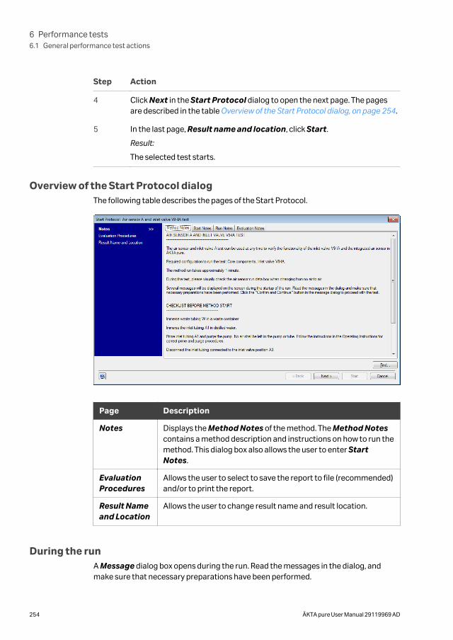
Step Action
4 Click Next in the Start Protocol dialog to open the next page. The pagesare described in the table Overview of the Start Protocol dialog, on page 254.
5 In the last page, Result name and location, click Start.
Result:
The selected test starts.
Overview of the Start Protocol dialogThe following table describes the pages of the Start Protocol.
Page Description
Notes Displays the Method Notes of the method. The Method Notescontains a method description and instructions on how to run themethod. This dialog box also allows the user to enter StartNotes.
EvaluationProcedures
Allows the user to select to save the report to file (recommended)and/or to print the report.
Result Nameand Location
Allows the user to change result name and result location.
During the runA Message dialog box opens during the run. Read the messages in the dialog, andmake sure that necessary preparations have been performed.
6 Performance tests6.1 General performance test actions
254 ÄKTA pure User Manual 29119969 AD
• Click Confirm and Continue in the Message dialog box to change system statefrom System Pause to Run and proceed with the test.
• Alternatively, click Confirm in the Message dialog box and click the Continuebutton on the Instrument display.
Automatic evaluationThe system automatically generates a report when the test is finished. The report canbe printed in two ways:
• It is recommended to select Save the report to file in the Evaluation Procedurespage of the Start Protocol dialog box when starting the test. The report is saved inthe folder Temp in your UNICORN installation folder. For exampleC:\Program Files\GE Healthcare\UNICORN\UNICORN 7.0\Temp .
• If the option Print report was selected in the Evaluation Procedures page of theStart Protocol dialog box when starting the test, the report is also automaticallyprinted on the system printer. Refer to UNICORN Administration and TechnicalManual for information on how to install a printer.
Print the report and check the status of the tests. For each of the tests the report states" The test passed " or " The test failed ".
Note: The fraction collector test is evaluated manually and no report is generated.
6 Performance tests6.1 General performance test actions
ÄKTA pure User Manual 29119969 AD 255
6.2 Air sensor A and Inlet valve A tests
Air sensor A and Inlet valve A testsThe following Air sensor A and Inlet valve A tests are available, for ÄKTA pure 25 andÄKTA pure 150, respectively:
• Air sensor A and inlet valve V9-IA test
• Air sensor A and inlet valve V9H-IA test
Method descriptionThe Air sensor A and inlet valve A tests switches inlet valve A, labeled V9-IA or V9H-IA,to an empty position and checks if the air sensor detects air.
The method run takes approximately 1 minute.
Required configurationA correctly installed Inlet valve A is required to run the test.
Required materialThe following materials are required:
• Syringe, 25-30 ml
• Distilled water
Prepare the test
Follow the instructions below to prepare the system before method start.
Step Action
1 Direct the outlet tubing marked W to a waste container.
2 Place inlet tubing A1 into distilled water.
3 Prime the A1 inlet and purge the pump. See Section 5.4.1 System pumps, onpage 180.
4 Disconnect the inlet tubing connected to the A3 inlet valve position. Duringthe test method air is introduced into the inlet valve through that inlet portto test the function of the air sensor.
Run and evaluate the testFollow the instructions described in Section 6.1 General performance test actions, onpage 253 to start, run and automatically evaluate the performance test.
6 Performance tests6.2 Air sensor A and Inlet valve A tests
256 ÄKTA pure User Manual 29119969 AD
Possible causes of a failed testThe tables below describe possible causes of a failed test. When possible sources oferror have been checked and corrected, repeat the test.
Faulty air sensor A test
Cause Action
Faulty air sensor For further information, see Section 8.4 Troubleshooting:Valves, on page 409.
Incorrect preparationof
tubing
Make sure that the tubing was correctly prepared, see Prepare the test, on page 256.
Faulty inlet valve A test
Cause Action
The valve did notswitch
For further information, see Section 8.4 Troubleshooting:Valves, on page 409.
6 Performance tests6.2 Air sensor A and Inlet valve A tests
ÄKTA pure User Manual 29119969 AD 257
6.3 Air sensor B and Inlet valve B tests
Air sensor B and Inlet valve B testsThe following Air sensor B and Inlet valve B tests are available, for ÄKTA pure 25 andÄKTA pure 150, respectively:
• Air sensor B and inlet valve V9-IB test
• Air sensor B and inlet valve V9H-IB test
Method descriptionThe Air sensor B and inlet valve B test switches the inlet valve B, labeled V9-IB or V9H-IB, to an empty position and checks if the air sensor detects air.
The method run takes approximately 1 minute.
Required configurationA correctly installed Inlet valve B is required to run the test.
Required materialThe following materials are required:
• Syringe, 25-30 ml
• Distilled water
Prepare the test
Follow the instructions below to prepare the system before method start.
Step Action
1 Direct the outlet tubing marked W to a waste container.
2 Place inlet tubing B1 into distilled water.
3 Prime the B1 inlet and purge the pump. See Section 5.4.1 System pumps, onpage 180.
4 Disconnect the inlet tubing connected to inlet valve position B3. During thetest method air is introduced into the inlet valve through that inlet port totest the function of the air sensor.
Run and evaluate the testFollow the instructions described in Section 6.1 General performance test actions, onpage 253 to start, run and automatically evaluate the performance test.
6 Performance tests6.3 Air sensor B and Inlet valve B tests
258 ÄKTA pure User Manual 29119969 AD
Possible causes of a failed testThe tables below describe possible causes of a failed test. When possible sources oferror have been checked and corrected, repeat the test.
Faulty air sensor B test
Cause Action
Faulty air sensor For further information, see Section 8.4 Troubleshooting:Valves, on page 409.
Incorrect prepara-tion of
tubing
Make sure that the tubing was correctly prepared, see Prepare the test, on page 258.
Faulty inlet valve B test
Cause Action
The valve did not switch For further information, see Section 8.4 Troubleshooting:Valves, on page 409.
6 Performance tests6.3 Air sensor B and Inlet valve B tests
ÄKTA pure User Manual 29119969 AD 259
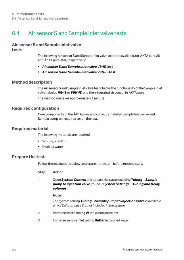
6.4 Air sensor S and Sample inlet valve tests
Air sensor S and Sample inlet valvetests
The following Air sensor S and Sample inlet valve tests are available, for ÄKTA pure 25and ÄKTA pure 150, respectively:
• Air sensor S and Sample inlet valve V9-IS test
• Air sensor S and Sample inlet valve V9H-IS test
Method descriptionThe Air sensor S and Sample inlet valve test checks the functionality of the Sample inletvalve, labeled V9-IS or V9H-IS, and the integrated air sensor in ÄKTA pure.
The method run takes approximately 1 minute.
Required configurationCore components of the ÄKTA pure and correctly installed Sample Inlet valve andSample pump are required to run the test.
Required materialThe following materials are required:
• Syringe, 25-30 ml
• Distilled water
Prepare the test
Follow the instructions below to prepare the system before method start.
Step Action
1 Open System Control and update the system setting Tubing →Samplepump to injection valve (found inSystem Settings →Tubing and Delayvolumes).
Note:
The system setting Tubing →Sample pump to injection valve is availableonly if Column valve C is not included in the system.
2 Immerse waste tubing W in a waste container
3 Immerse sample inlet tubing Buffer in distilled water.
6 Performance tests6.4 Air sensor S and Sample inlet valve tests
260 ÄKTA pure User Manual 29119969 AD
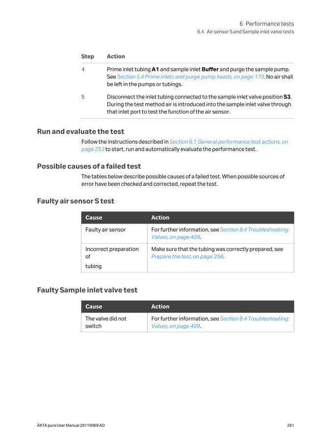
Step Action
4 Prime inlet tubing A1 and sample inlet Buffer and purge the sample pump.See Section 5.4 Prime inlets and purge pump heads, on page 179. No air shallbe left in the pumps or tubings.
5 Disconnect the inlet tubing connected to the sample inlet valve position S3.During the test method air is introduced into the sample inlet valve throughthat inlet port to test the function of the air sensor.
Run and evaluate the testFollow the instructions described in Section 6.1 General performance test actions, onpage 253 to start, run and automatically evaluate the performance test.
Possible causes of a failed testThe tables below describe possible causes of a failed test. When possible sources oferror have been checked and corrected, repeat the test.
Faulty air sensor S test
Cause Action
Faulty air sensor For further information, see Section 8.4 Troubleshooting:Valves, on page 409.
Incorrect preparationof
tubing
Make sure that the tubing was correctly prepared, see Prepare the test, on page 258.
Faulty Sample inlet valve test
Cause Action
The valve did notswitch
For further information, see Section 8.4 Troubleshooting:Valves, on page 409.
6 Performance tests6.4 Air sensor S and Sample inlet valve tests
ÄKTA pure User Manual 29119969 AD 261
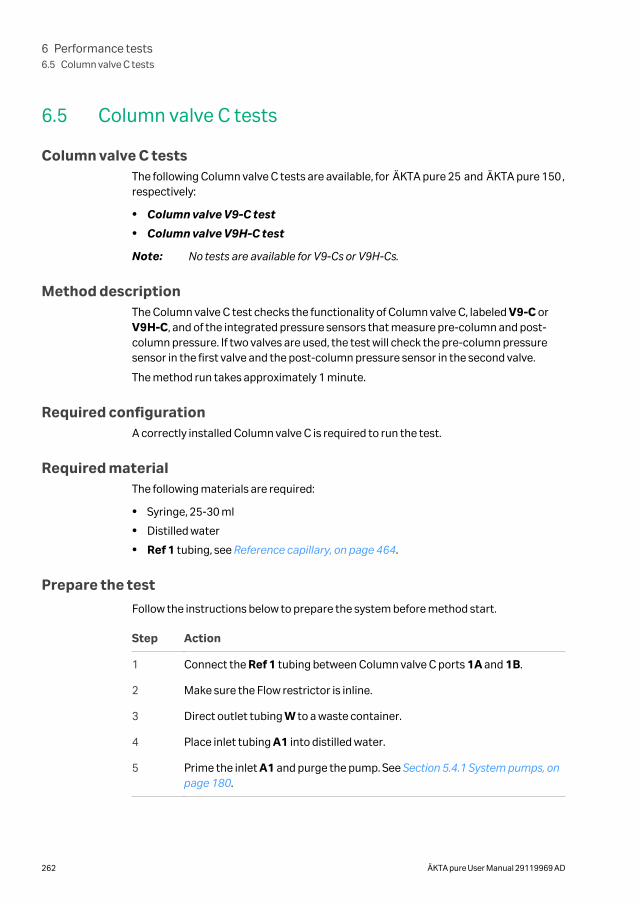
6.5 Column valve C tests
Column valve C testsThe following Column valve C tests are available, for ÄKTA pure 25 and ÄKTA pure 150,respectively:
• Column valve V9-C test
• Column valve V9H-C test
Note: No tests are available for V9-Cs or V9H-Cs.
Method descriptionThe Column valve C test checks the functionality of Column valve C, labeled V9-C orV9H-C, and of the integrated pressure sensors that measure pre-column and post-column pressure. If two valves are used, the test will check the pre-column pressuresensor in the first valve and the post-column pressure sensor in the second valve.
The method run takes approximately 1 minute.
Required configurationA correctly installed Column valve C is required to run the test.
Required materialThe following materials are required:
• Syringe, 25-30 ml
• Distilled water
• Ref 1 tubing, see Reference capillary, on page 464.
Prepare the test
Follow the instructions below to prepare the system before method start.
Step Action
1 Connect the Ref 1 tubing between Column valve C ports 1A and 1B.
2 Make sure the Flow restrictor is inline.
3 Direct outlet tubing W to a waste container.
4 Place inlet tubing A1 into distilled water.
5 Prime the inlet A1 and purge the pump. See Section 5.4.1 System pumps, onpage 180.
6 Performance tests6.5 Column valve C tests
262 ÄKTA pure User Manual 29119969 AD
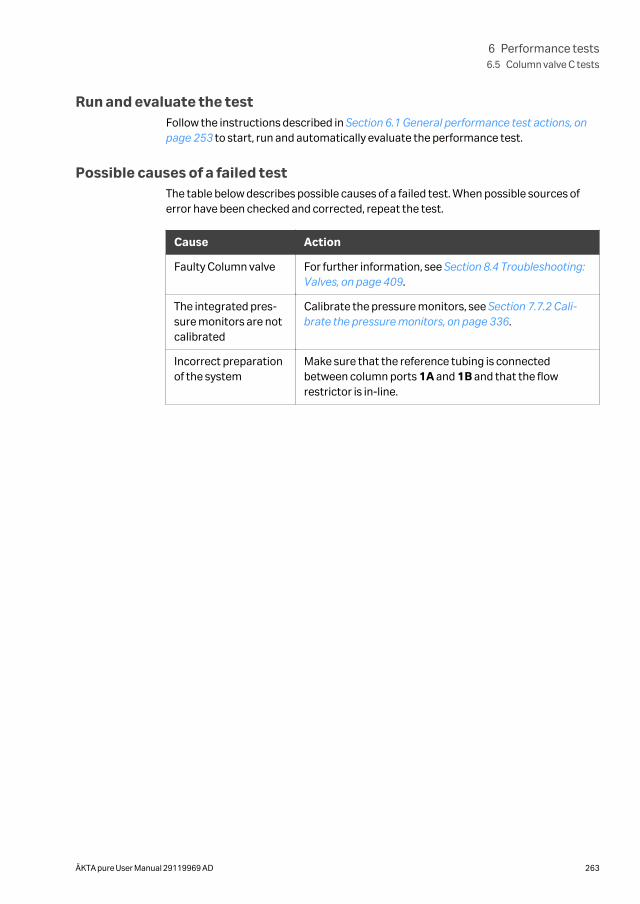
Run and evaluate the testFollow the instructions described in Section 6.1 General performance test actions, onpage 253 to start, run and automatically evaluate the performance test.
Possible causes of a failed testThe table below describes possible causes of a failed test. When possible sources oferror have been checked and corrected, repeat the test.
Cause Action
Faulty Column valve For further information, see Section 8.4 Troubleshooting:Valves, on page 409.
The integrated pres-sure monitors are notcalibrated
Calibrate the pressure monitors, see Section 7.7.2 Cali-brate the pressure monitors, on page 336.
Incorrect preparationof the system
Make sure that the reference tubing is connectedbetween column ports 1A and 1B and that the flowrestrictor is in-line.
6 Performance tests6.5 Column valve C tests
ÄKTA pure User Manual 29119969 AD 263
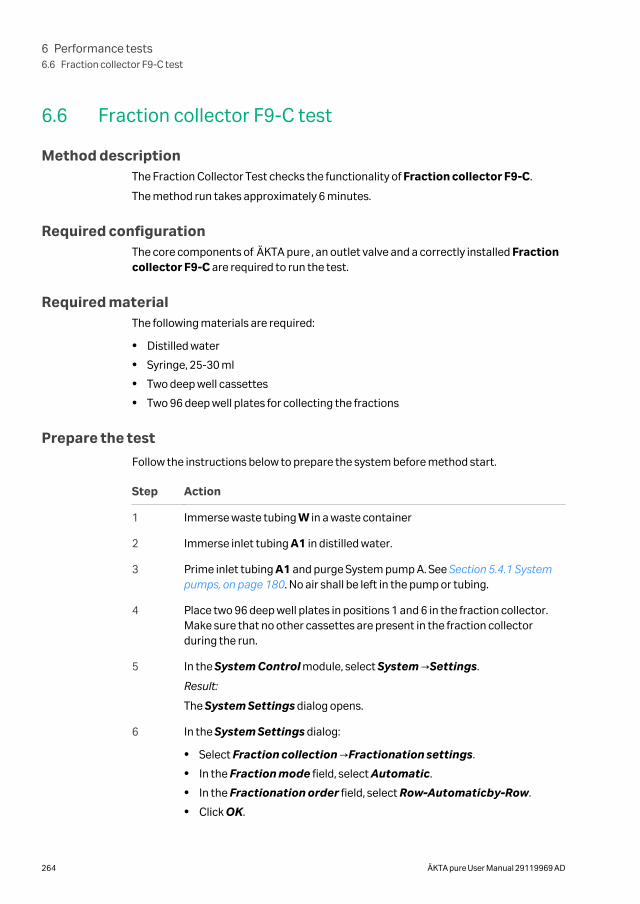
6.6 Fraction collector F9-C test
Method descriptionThe Fraction Collector Test checks the functionality of Fraction collector F9-C.
The method run takes approximately 6 minutes.
Required configurationThe core components of ÄKTA pure, an outlet valve and a correctly installed Fractioncollector F9-C are required to run the test.
Required materialThe following materials are required:
• Distilled water
• Syringe, 25-30 ml
• Two deep well cassettes
• Two 96 deep well plates for collecting the fractions
Prepare the test
Follow the instructions below to prepare the system before method start.
Step Action
1 Immerse waste tubing W in a waste container
2 Immerse inlet tubing A1 in distilled water.
3 Prime inlet tubing A1 and purge System pump A. See Section 5.4.1 Systempumps, on page 180. No air shall be left in the pump or tubing.
4 Place two 96 deep well plates in positions 1 and 6 in the fraction collector.Make sure that no other cassettes are present in the fraction collectorduring the run.
5 In the System Control module, select System →Settings.
Result:
The System Settings dialog opens.
6 In the System Settings dialog:
• Select Fraction collection →Fractionation settings.
• In the Fraction mode field, select Automatic.
• In the Fractionation order field, select Row-Automaticby-Row.
• Click OK.
6 Performance tests6.6 Fraction collector F9-C test
264 ÄKTA pure User Manual 29119969 AD
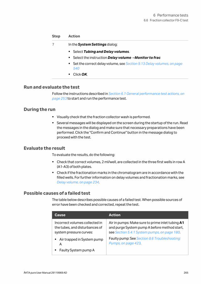
Step Action
7 In the System Settings dialog:
• Select Tubing and Delay volumes.
• Select the instruction Delay volume →Monitor to frac
• Set the correct delay volume, see Section 9.13 Delay volumes, on page540
• Click OK.
Run and evaluate the testFollow the instructions described in Section 6.1 General performance test actions, onpage 253 to start and run the performance test.
During the run
• Visually check that the fraction collector wash is performed.
• Several messages will be displayed on the screen during the startup of the run. Readthe messages in the dialog and make sure that necessary preparations have beenperformed. Click the "Confirm and Continue" button in the message dialog toproceed with the test.
Evaluate the resultTo evaluate the results, do the following:
• Check that correct volumes, 2 ml/well, are collected in the three first wells in row A(A1-A3) of both plates.
• Check if the fractionation marks in the chromatogram are in accordance with thefilled wells. For further information on delay volumes and fractionation marks, see Delay volume, on page 234.
Possible causes of a failed testThe table below describes possible causes of a failed test. When possible sources oferror have been checked and corrected, repeat the test.
Cause Action
Incorrect volumes collected inthe tubes, and disturbances ofsystem pressure curves:
• Air trapped in System pumpA
• Faulty System pump A
Air in pumps: Make sure to prime inlet tubing A1and purge System pump A before method start,see Section 5.4.1 System pumps, on page 180.
Faulty pump: See Section 8.6 Troubleshooting:Pumps, on page 423.
6 Performance tests6.6 Fraction collector F9-C test
ÄKTA pure User Manual 29119969 AD 265

Cause Action
Incorrect preparation of bufferand tubing
Make sure that the system was correctlyprepared, see Prepare the test, on page 264.
6 Performance tests6.6 Fraction collector F9-C test
266 ÄKTA pure User Manual 29119969 AD
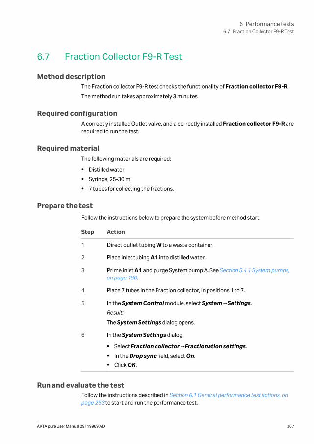
6.7 Fraction Collector F9-R Test
Method descriptionThe Fraction collector F9-R test checks the functionality of Fraction collector F9-R.
The method run takes approximately 3 minutes.
Required configurationA correctly installed Outlet valve, and a correctly installed Fraction collector F9-R arerequired to run the test.
Required materialThe following materials are required:
• Distilled water
• Syringe, 25-30 ml
• 7 tubes for collecting the fractions.
Prepare the test
Follow the instructions below to prepare the system before method start.
Step Action
1 Direct outlet tubing W to a waste container.
2 Place inlet tubing A1 into distilled water.
3 Prime inlet A1 and purge System pump A. See Section 5.4.1 System pumps,on page 180.
4 Place 7 tubes in the Fraction collector, in positions 1 to 7.
5 In the System Control module, select System →Settings.
Result:
The System Settings dialog opens.
6 In the System Settings dialog:
• Select Fraction collector →Fractionation settings.
• In the Drop sync field, select On.
• Click OK.
Run and evaluate the testFollow the instructions described in Section 6.1 General performance test actions, onpage 253 to start and run the performance test.
6 Performance tests6.7 Fraction Collector F9-R Test
ÄKTA pure User Manual 29119969 AD 267
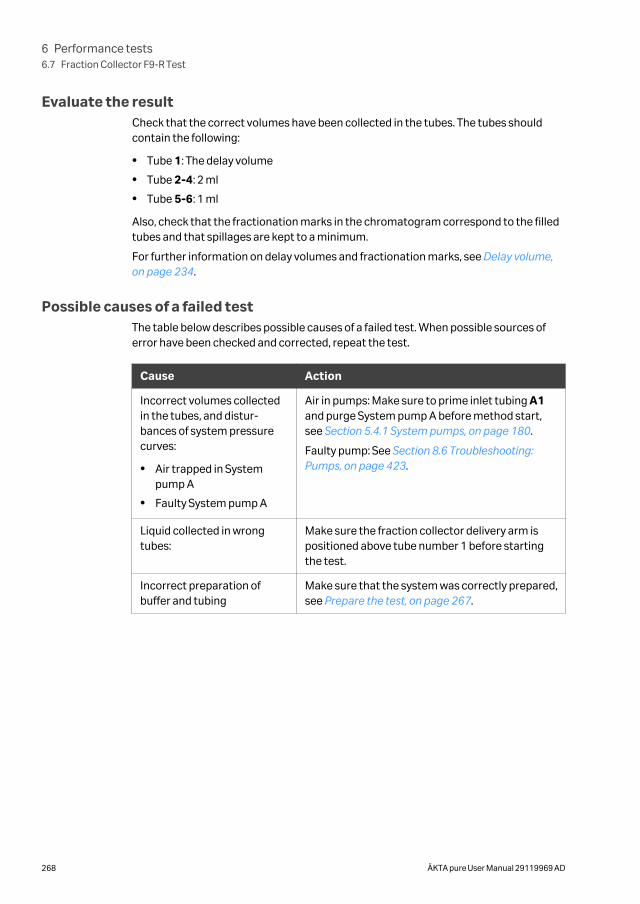
Evaluate the resultCheck that the correct volumes have been collected in the tubes. The tubes shouldcontain the following:
• Tube 1: The delay volume
• Tube 2-4: 2 ml
• Tube 5-6: 1 ml
Also, check that the fractionation marks in the chromatogram correspond to the filledtubes and that spillages are kept to a minimum.
For further information on delay volumes and fractionation marks, see Delay volume,on page 234.
Possible causes of a failed testThe table below describes possible causes of a failed test. When possible sources oferror have been checked and corrected, repeat the test.
Cause Action
Incorrect volumes collectedin the tubes, and distur-bances of system pressurecurves:
• Air trapped in Systempump A
• Faulty System pump A
Air in pumps: Make sure to prime inlet tubing A1and purge System pump A before method start,see Section 5.4.1 System pumps, on page 180.
Faulty pump: See Section 8.6 Troubleshooting:Pumps, on page 423.
Liquid collected in wrongtubes:
Make sure the fraction collector delivery arm ispositioned above tube number 1 before startingthe test.
Incorrect preparation ofbuffer and tubing
Make sure that the system was correctly prepared,see Prepare the test, on page 267.
6 Performance tests6.7 Fraction Collector F9-R Test
268 ÄKTA pure User Manual 29119969 AD
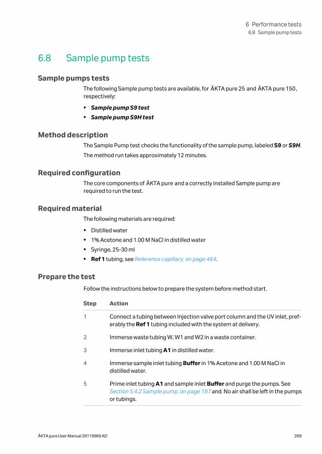
6.8 Sample pump tests
Sample pumps testsThe following Sample pump tests are available, for ÄKTA pure 25 and ÄKTA pure 150,respectively:
• Sample pump S9 test
• Sample pump S9H test
Method descriptionThe Sample Pump test checks the functionality of the sample pump, labeled S9 or S9H.
The method run takes approximately 12 minutes.
Required configurationThe core components of ÄKTA pure and a correctly installed Sample pump arerequired to run the test.
Required materialThe following materials are required:
• Distilled water
• 1% Acetone and 1.00 M NaCl in distilled water
• Syringe, 25-30 ml
• Ref 1 tubing, see Reference capillary, on page 464.
Prepare the test
Follow the instructions below to prepare the system before method start.
Step Action
1 Connect a tubing between Injection valve port column and the UV inlet, pref-erably the Ref 1 tubing included with the system at delivery.
2 Immerse waste tubing W, W1 and W2 in a waste container.
3 Immerse inlet tubing A1 in distilled water.
4 Immerse sample inlet tubing Buffer in 1% Acetone and 1.00 M NaCl indistilled water.
5 Prime inlet tubing A1 and sample inlet Buffer and purge the pumps. See Section 5.4.2 Sample pump, on page 187 and. No air shall be left in the pumpsor tubings.
6 Performance tests6.8 Sample pump tests
ÄKTA pure User Manual 29119969 AD 269
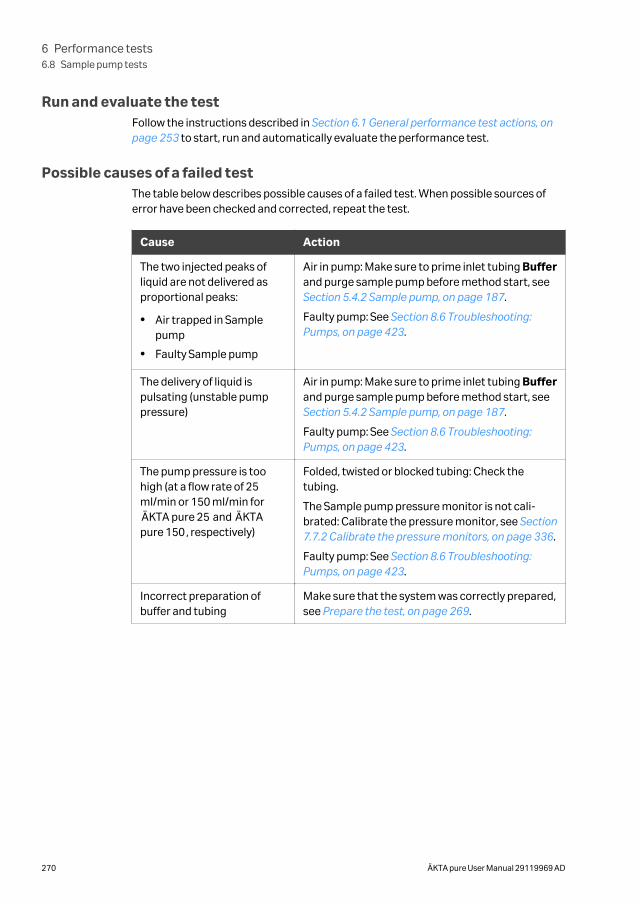
Run and evaluate the testFollow the instructions described in Section 6.1 General performance test actions, onpage 253 to start, run and automatically evaluate the performance test.
Possible causes of a failed testThe table below describes possible causes of a failed test. When possible sources oferror have been checked and corrected, repeat the test.
Cause Action
The two injected peaks ofliquid are not delivered asproportional peaks:
• Air trapped in Samplepump
• Faulty Sample pump
Air in pump: Make sure to prime inlet tubing Bufferand purge sample pump before method start, see Section 5.4.2 Sample pump, on page 187.
Faulty pump: See Section 8.6 Troubleshooting:Pumps, on page 423.
The delivery of liquid ispulsating (unstable pumppressure)
Air in pump: Make sure to prime inlet tubing Bufferand purge sample pump before method start, see Section 5.4.2 Sample pump, on page 187.
Faulty pump: See Section 8.6 Troubleshooting:Pumps, on page 423.
The pump pressure is toohigh (at a flow rate of 25ml/min or 150 ml/min forÄKTA pure 25 and ÄKTApure 150, respectively)
Folded, twisted or blocked tubing: Check thetubing.
The Sample pump pressure monitor is not cali-brated: Calibrate the pressure monitor, see Section7.7.2 Calibrate the pressure monitors, on page 336.
Faulty pump: See Section 8.6 Troubleshooting:Pumps, on page 423.
Incorrect preparation ofbuffer and tubing
Make sure that the system was correctly prepared,see Prepare the test, on page 269.
6 Performance tests6.8 Sample pump tests
270 ÄKTA pure User Manual 29119969 AD
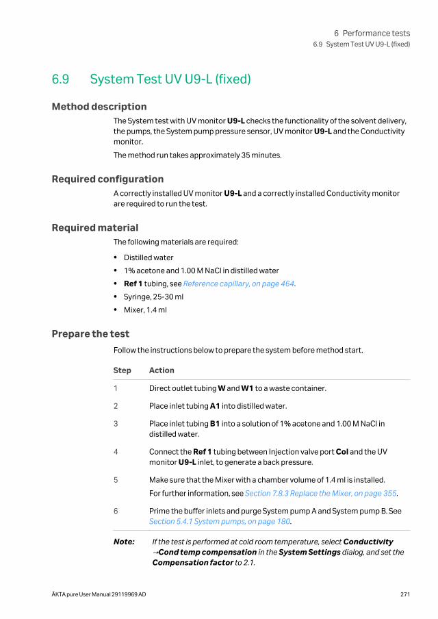
6.9 System Test UV U9-L (fixed)
Method descriptionThe System test with UV monitor U9-L checks the functionality of the solvent delivery,the pumps, the System pump pressure sensor, UV monitor U9-L and the Conductivitymonitor.
The method run takes approximately 35 minutes.
Required configurationA correctly installed UV monitor U9-L and a correctly installed Conductivity monitorare required to run the test.
Required materialThe following materials are required:
• Distilled water
• 1% acetone and 1.00 M NaCl in distilled water
• Ref 1 tubing, see Reference capillary, on page 464.
• Syringe, 25-30 ml
• Mixer, 1.4 ml
Prepare the test
Follow the instructions below to prepare the system before method start.
Step Action
1 Direct outlet tubing W and W1 to a waste container.
2 Place inlet tubing A1 into distilled water.
3 Place inlet tubing B1 into a solution of 1% acetone and 1.00 M NaCl indistilled water.
4 Connect the Ref 1 tubing between Injection valve port Col and the UVmonitor U9-L inlet, to generate a back pressure.
5 Make sure that the Mixer with a chamber volume of 1.4 ml is installed.
For further information, see Section 7.8.3 Replace the Mixer, on page 355.
6 Prime the buffer inlets and purge System pump A and System pump B. See Section 5.4.1 System pumps, on page 180.
Note: If the test is performed at cold room temperature, select Conductivity→Cond temp compensation in the System Settings dialog, and set theCompensation factor to 2.1.
6 Performance tests6.9 System Test UV U9-L (fixed)
ÄKTA pure User Manual 29119969 AD 271
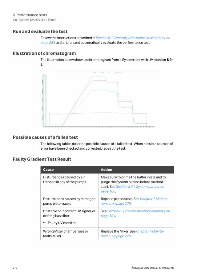
Run and evaluate the testFollow the instructions described in Section 6.1 General performance test actions, onpage 253 to start, run and automatically evaluate the performance test.
Illustration of chromatogramThe illustration below shows a chromatogram from a System test with UV monitor U9-L.
Possible causes of a failed testThe following tables describe possible causes of a failed test. When possible sources oferror have been checked and corrected, repeat the test.
Faulty Gradient Test Result
Cause Action
Disturbances caused by airtrapped in any of the pumps
Make sure to prime the buffer inlets and topurge the System pumps before methodstart. See Section 5.4.1 System pumps, onpage 180.
Disturbances caused by damagedpump piston seals
Replace piston seals. See Chapter 7 Mainte-nance, on page 279.
Unstable or incorrect UV signal, ordrifting base line:
• Faulty UV monitor
See Section 8.3 Troubleshooting: Monitors, onpage 394.
Wrong Mixer chamber size orfaulty Mixer
Replace the Mixer. See Chapter 7 Mainte-nance, on page 279.
6 Performance tests6.9 System Test UV U9-L (fixed)
272 ÄKTA pure User Manual 29119969 AD
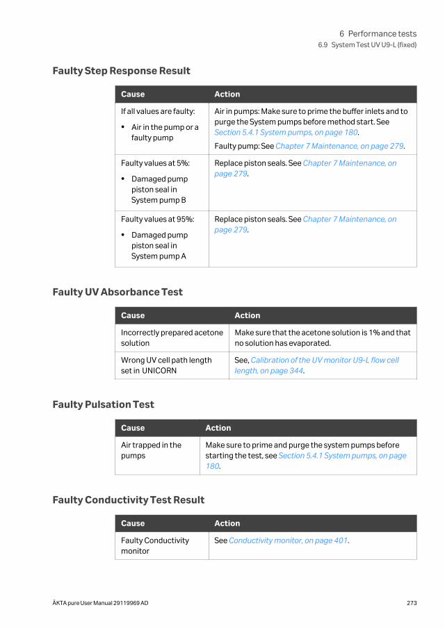
Faulty Step Response Result
Cause Action
If all values are faulty:
• Air in the pump or afaulty pump
Air in pumps: Make sure to prime the buffer inlets and topurge the System pumps before method start. See Section 5.4.1 System pumps, on page 180.
Faulty pump: See Chapter 7 Maintenance, on page 279.
Faulty values at 5%:
• Damaged pumppiston seal inSystem pump B
Replace piston seals. See Chapter 7 Maintenance, onpage 279.
Faulty values at 95%:
• Damaged pumppiston seal inSystem pump A
Replace piston seals. See Chapter 7 Maintenance, onpage 279.
Faulty UV Absorbance Test
Cause Action
Incorrectly prepared acetonesolution
Make sure that the acetone solution is 1% and thatno solution has evaporated.
Wrong UV cell path lengthset in UNICORN
See, Calibration of the UV monitor U9-L flow celllength, on page 344.
Faulty Pulsation Test
Cause Action
Air trapped in thepumps
Make sure to prime and purge the system pumps beforestarting the test, see Section 5.4.1 System pumps, on page180.
Faulty Conductivity Test Result
Cause Action
Faulty Conductivitymonitor
See Conductivity monitor, on page 401.
6 Performance tests6.9 System Test UV U9-L (fixed)
ÄKTA pure User Manual 29119969 AD 273
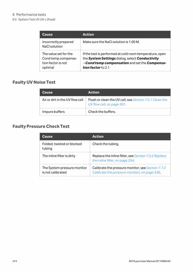
Cause Action
Incorrectly preparedNaCl solution
Make sure the NaCl solution is 1.00 M.
The value set for theCond temp compensa-tion factor is notoptimal
If the test is performed at cold room temperature, openthe System Settings dialog, select Conductivity→Cond temp compensation and set the Compensa-tion factor to 2.1
Faulty UV Noise Test
Cause Action
Air or dirt in the UV flow cell Flush or clean the UV cell, see Section 7.5.1 Clean theUV flow cell, on page 301.
Impure buffers Check the buffers.
Faulty Pressure Check Test
Cause Action
Folded, twisted or blockedtubing
Check the tubing.
The inline filter is dirty Replace the inline filter, see Section 7.3.2 Replacethe inline filter, on page 294.
The System pressure monitoris not calibrated
Calibrate the pressure monitor, see Section 7.7.2Calibrate the pressure monitors, on page 336.
6 Performance tests6.9 System Test UV U9-L (fixed)
274 ÄKTA pure User Manual 29119969 AD

6.10 System Test UV U9-M (variable)
Method descriptionThe System test with UV monitor U9-M checks the functionality of the solvent delivery,the pumps, the System pump pressure sensor, UV monitor U9-M and the Conductivitymonitor.
The method run takes approximately 35 minutes.
Required configurationA correctly installed UV monitor U9-M and a correctly installed Conductivity monitorare required to run the test.
Required materialThe following materials are required:
• Distilled water
• 1% acetone and 1.00 M NaCl in distilled water
• Ref 1 tubing, see Reference capillary, on page 464.
• Syringe, 25-30 ml
• Mixer, 1.4 ml
Prepare the test
Follow the instructions below to prepare the system before method start.
Step Action
1 Direct outlet tubing W and W1 to a waste container.
2 Place inlet tubing A1 into distilled water.
3 Place inlet tubing B1 into a solution of 1% acetone and 1.00 M NaCl indistilled water.
4 Connect the Ref 1 tubing between Injection valve port Col and the UVmonitor U9-M inlet, to generate a back pressure.
5 Make sure that the Mixer with a chamber volume of 1.4 ml is installed.
For further information, see Section 7.8.3 Replace the Mixer, on page 355.
6 Prime the buffer inlets and purge System pump A and System pump B. See Section 5.4.1 System pumps, on page 180.
Note: If the test is performed at cold room temperature, select Conductivity→Cond temp compensation in the System Settings dialog, and set theCompensation factor to 2.1.
6 Performance tests6.10 System Test UV U9-M (variable)
ÄKTA pure User Manual 29119969 AD 275
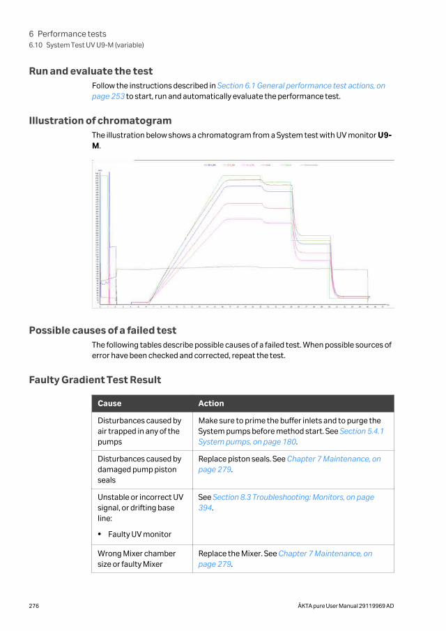
Run and evaluate the testFollow the instructions described in Section 6.1 General performance test actions, onpage 253 to start, run and automatically evaluate the performance test.
Illustration of chromatogramThe illustration below shows a chromatogram from a System test with UV monitor U9-M.
Possible causes of a failed testThe following tables describe possible causes of a failed test. When possible sources oferror have been checked and corrected, repeat the test.
Faulty Gradient Test Result
Cause Action
Disturbances caused byair trapped in any of thepumps
Make sure to prime the buffer inlets and to purge theSystem pumps before method start. See Section 5.4.1System pumps, on page 180.
Disturbances caused bydamaged pump pistonseals
Replace piston seals. See Chapter 7 Maintenance, onpage 279.
Unstable or incorrect UVsignal, or drifting baseline:
• Faulty UV monitor
See Section 8.3 Troubleshooting: Monitors, on page394.
Wrong Mixer chambersize or faulty Mixer
Replace the Mixer. See Chapter 7 Maintenance, onpage 279.
6 Performance tests6.10 System Test UV U9-M (variable)
276 ÄKTA pure User Manual 29119969 AD
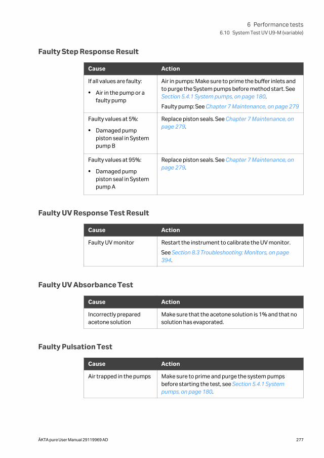
Faulty Step Response Result
Cause Action
If all values are faulty:
• Air in the pump or afaulty pump
Air in pumps: Make sure to prime the buffer inlets andto purge the System pumps before method start. See Section 5.4.1 System pumps, on page 180.
Faulty pump: See Chapter 7 Maintenance, on page 279
Faulty values at 5%:
• Damaged pumppiston seal in Systempump B
Replace piston seals. See Chapter 7 Maintenance, onpage 279.
Faulty values at 95%:
• Damaged pumppiston seal in Systempump A
Replace piston seals. See Chapter 7 Maintenance, onpage 279.
Faulty UV Response Test Result
Cause Action
Faulty UV monitor Restart the instrument to calibrate the UV monitor.
See Section 8.3 Troubleshooting: Monitors, on page394.
Faulty UV Absorbance Test
Cause Action
Incorrectly preparedacetone solution
Make sure that the acetone solution is 1% and that nosolution has evaporated.
Faulty Pulsation Test
Cause Action
Air trapped in the pumps Make sure to prime and purge the system pumpsbefore starting the test, see Section 5.4.1 Systempumps, on page 180.
6 Performance tests6.10 System Test UV U9-M (variable)
ÄKTA pure User Manual 29119969 AD 277
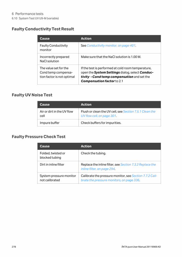
Faulty Conductivity Test Result
Cause Action
Faulty Conductivitymonitor
See Conductivity monitor, on page 401.
Incorrectly preparedNaCl solution
Make sure that the NaCl solution is 1.00 M.
The value set for theCond temp compensa-tion factor is not optimal
If the test is performed at cold room temperature,open the System Settings dialog, select Conduc-tivity →Cond temp compensation and set theCompensation factor to 2.1
Faulty UV Noise Test
Cause Action
Air or dirt in the UV flowcell
Flush or clean the UV cell, see Section 7.5.1 Clean theUV flow cell, on page 301.
Impure buffer Check buffers for impurities.
Faulty Pressure Check Test
Cause Action
Folded, twisted orblocked tubing
Check the tubing.
Dirt in inline filter Replace the inline filter, see Section 7.3.2 Replace theinline filter, on page 294.
System pressure monitornot calibrated
Calibrate the pressure monitor, see Section 7.7.2 Cali-brate the pressure monitors, on page 336.
6 Performance tests6.10 System Test UV U9-M (variable)
278 ÄKTA pure User Manual 29119969 AD
7 Maintenance
About this chapterThis chapter describes the maintenance program for ÄKTA pure and provides instruc-tions for maintenance and replacement of spare parts.
In this chapter
Section See page
7.1 Maintenance Manager 280
7.2 Maintenance program 285
7.3 Weekly maintenance 288
7.4 Monthly maintenance 297
7.5 Semiannual maintenance 300
7.6 Maintenance when required 305
7.7 Calibration procedures 333
7.8 Replacement procedures 348
7 Maintenance
ÄKTA pure User Manual 29119969 AD 279
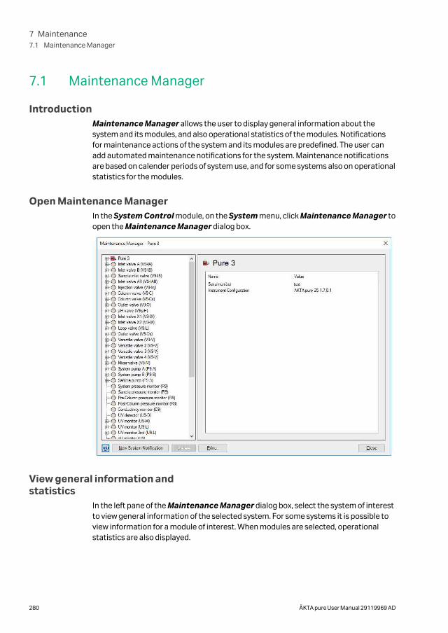
7.1 Maintenance Manager
IntroductionMaintenance Manager allows the user to display general information about thesystem and its modules, and also operational statistics of the modules. Notificationsfor maintenance actions of the system and its modules are predefined. The user canadd automated maintenance notifications for the system. Maintenance notificationsare based on calender periods of system use, and for some systems also on operationalstatistics for the modules.
Open Maintenance ManagerIn the System Control module, on the System menu, click Maintenance Manager toopen the Maintenance Manager dialog box.
View general information andstatistics
In the left pane of the Maintenance Manager dialog box, select the system of interestto view general information of the selected system. For some systems it is possible toview information for a module of interest. When modules are selected, operationalstatistics are also displayed.
7 Maintenance7.1 Maintenance Manager
280 ÄKTA pure User Manual 29119969 AD
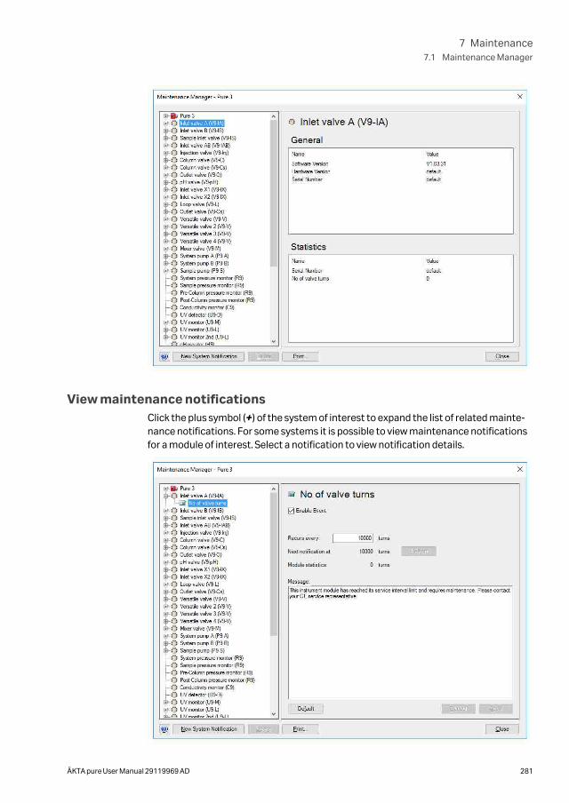
View maintenance notificationsClick the plus symbol (+) of the system of interest to expand the list of related mainte-nance notifications. For some systems it is possible to view maintenance notificationsfor a module of interest. Select a notification to view notification details.
7 Maintenance7.1 Maintenance Manager
ÄKTA pure User Manual 29119969 AD 281
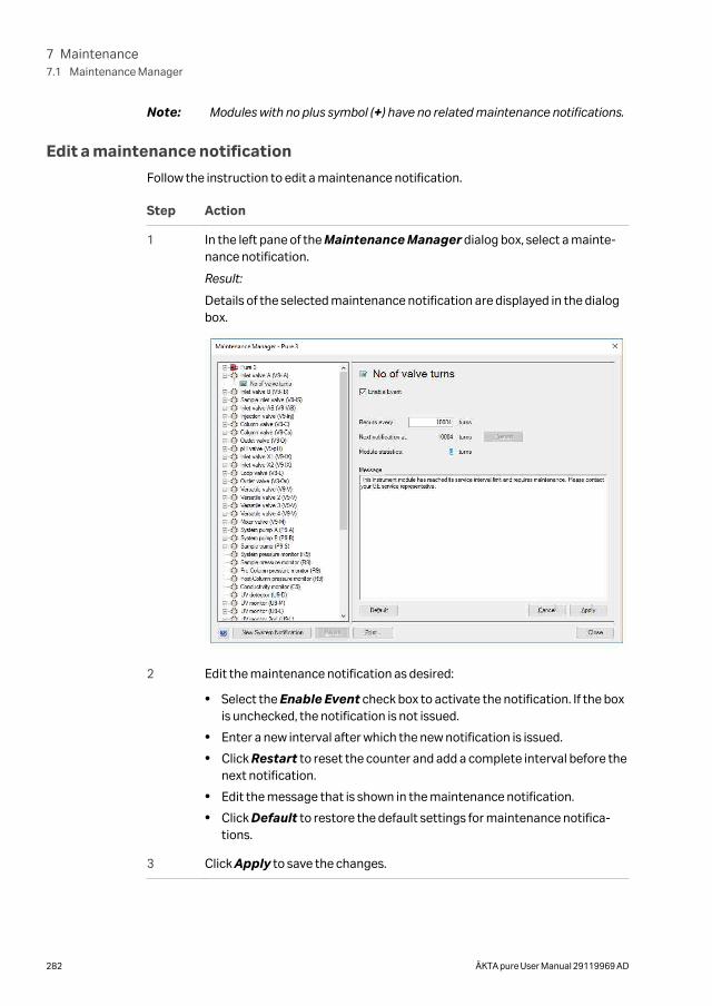
Note: Modules with no plus symbol (+) have no related maintenance notifications.
Edit a maintenance notification
Follow the instruction to edit a maintenance notification.
Step Action
1 In the left pane of the Maintenance Manager dialog box, select a mainte-nance notification.
Result:
Details of the selected maintenance notification are displayed in the dialogbox.
2 Edit the maintenance notification as desired:
• Select the Enable Event check box to activate the notification. If the boxis unchecked, the notification is not issued.
• Enter a new interval after which the new notification is issued.
• Click Restart to reset the counter and add a complete interval before thenext notification.
• Edit the message that is shown in the maintenance notification.
• Click Default to restore the default settings for maintenance notifica-tions.
3 Click Apply to save the changes.
7 Maintenance7.1 Maintenance Manager
282 ÄKTA pure User Manual 29119969 AD
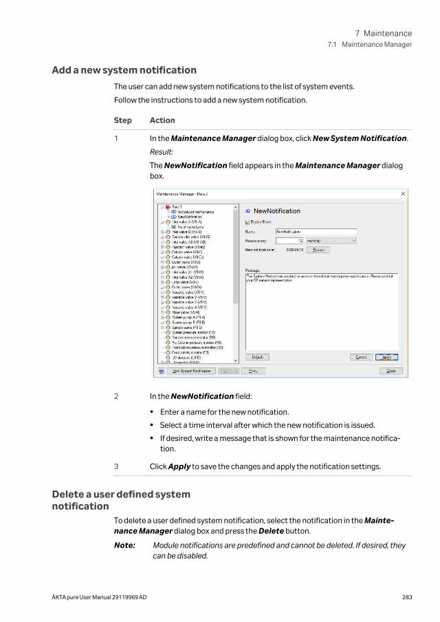
Add a new system notification
The user can add new system notifications to the list of system events.
Follow the instructions to add a new system notification.
Step Action
1 In the Maintenance Manager dialog box, click New System Notification.
Result:
The NewNotification field appears in the Maintenance Manager dialogbox.
2 In the NewNotification field:
• Enter a name for the new notification.
• Select a time interval after which the new notification is issued.
• If desired, write a message that is shown for the maintenance notifica-tion.
3 Click Apply to save the changes and apply the notification settings.
Delete a user defined systemnotification
To delete a user defined system notification, select the notification in the Mainte-nance Manager dialog box and press the Delete button.
Note: Module notifications are predefined and cannot be deleted. If desired, theycan be disabled.
7 Maintenance7.1 Maintenance Manager
ÄKTA pure User Manual 29119969 AD 283
Handle a maintenance notificationEach maintenance notification has a time interval after which the notification is issued.When this time interval has been reached, a Maintenance Notification dialog boxappears.
Note: The possibility to add maintenance notifications for modules is only avail-able for some systems, but all systems can add maintenance notificationsfor the complete system.
Follow the instruction to handle the notification.
Click... to...
Acknowl-edge
reset the counter for a new maintenance notification period.
Note:
Make sure that the maintenance action is performed as instructedafter the notification is acknowledged, otherwise the systemperformance can deteriorate.
Ignore close the dialog box without action.
Note:
The Maintenance Notification is displayed each time theSystem Control module is opened until the notification isacknowledged.
Note: The predefined maintenance notifcation periods use average values. Theactual service interval for a specific module can be shorter or longer.
7 Maintenance7.1 Maintenance Manager
284 ÄKTA pure User Manual 29119969 AD
7.2 Maintenance program
IntroductionThis section lists the periodic maintenance activities that should be performed by theuser of ÄKTA pure, as well as maintenance activities that should be performed whenrequired.
Maintenance is divided into:
• Daily maintenance
• Weekly maintenance
• Monthly maintenance
• Semiannual maintenance
• Maintenance when required
WARNING
Hazardous biological agents during run. When usinghazardous biological agents, perform a system cleaning to flushthe entire system tubing with bacteriostatic solution (e.g. NaOH)followed by a neutral buffer and finally distilled water, beforeservice and maintenance.
CAUTION
Hazardous chemicals during run. When using hazardous chemi-cals, run System CIP and Column CIP to flush the entire systemtubing with distilled water, before service and maintenance.
CAUTION
Always use appropriate personal protective equipment whendecommissioning the equipment.
Periodic maintenance programThe following periodic maintenance should be performed by the user of ÄKTA pure.
Interval Maintenance action See section
Daily Calibrate the pHmonitor
Section 7.7.1 Calibrate the pH monitor, onpage 334
7 Maintenance7.2 Maintenance program
ÄKTA pure User Manual 29119969 AD 285
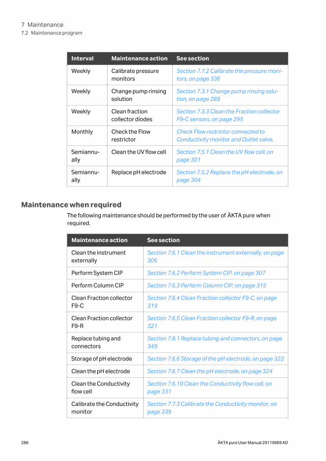
Interval Maintenance action See section
Weekly Calibrate pressuremonitors
Section 7.7.2 Calibrate the pressure moni-tors, on page 336
Weekly Change pump rinsingsolution
Section 7.3.1 Change pump rinsing solu-tion, on page 289
Weekly Clean fractioncollector diodes
Section 7.3.3 Clean the Fraction collectorF9-C sensors, on page 295
Monthly Check the Flowrestrictor
Check Flow restrictor connected toConductivity monitor and Outlet valve,
Semiannu-ally
Clean the UV flow cell Section 7.5.1 Clean the UV flow cell, onpage 301
Semiannu-ally
Replace pH electrode Section 7.5.2 Replace the pH electrode, onpage 304
Maintenance when requiredThe following maintenance should be performed by the user of ÄKTA pure whenrequired.
Maintenance action See section
Clean the instrumentexternally
Section 7.6.1 Clean the instrument externally, on page306
Perform System CIP Section 7.6.2 Perform System CIP, on page 307
Perform Column CIP Section 7.6.3 Perform Column CIP, on page 315
Clean Fraction collectorF9-C
Section 7.6.4 Clean Fraction collector F9-C, on page319
Clean Fraction collectorF9-R
Section 7.6.5 Clean Fraction collector F9-R, on page321
Replace tubing andconnectors
Section 7.8.1 Replace tubing and connectors, on page349
Storage of pH electrode Section 7.6.6 Storage of the pH electrode, on page 322
Clean the pH electrode Section 7.6.7 Clean the pH electrode, on page 324
Clean the Conductivityflow cell
Section 7.6.10 Clean the Conductivity flow cell, onpage 331
Calibrate the Conductivitymonitor
Section 7.7.3 Calibrate the Conductivity monitor, onpage 339
7 Maintenance7.2 Maintenance program
286 ÄKTA pure User Manual 29119969 AD
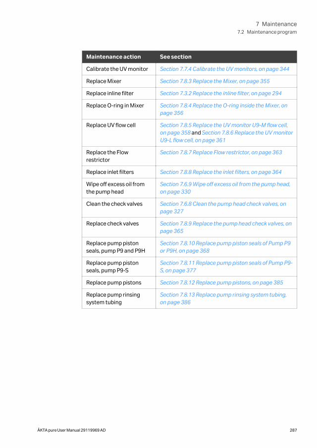
Maintenance action See section
Calibrate the UV monitor Section 7.7.4 Calibrate the UV monitors, on page 344
Replace Mixer Section 7.8.3 Replace the Mixer, on page 355
Replace inline filter Section 7.3.2 Replace the inline filter, on page 294
Replace O-ring in Mixer Section 7.8.4 Replace the O-ring inside the Mixer, onpage 356
Replace UV flow cell Section 7.8.5 Replace the UV monitor U9-M flow cell,on page 358 and Section 7.8.6 Replace the UV monitorU9-L flow cell, on page 361
Replace the Flowrestrictor
Section 7.8.7 Replace Flow restrictor, on page 363
Replace inlet filters Section 7.8.8 Replace the inlet filters, on page 364
Wipe off excess oil fromthe pump head
Section 7.6.9 Wipe off excess oil from the pump head,on page 330
Clean the check valves Section 7.6.8 Clean the pump head check valves, onpage 327
Replace check valves Section 7.8.9 Replace the pump head check valves, onpage 365
Replace pump pistonseals, pump P9 and P9H
Section 7.8.10 Replace pump piston seals of Pump P9or P9H, on page 368
Replace pump pistonseals, pump P9-S
Section 7.8.11 Replace pump piston seals of Pump P9-S, on page 377
Replace pump pistons Section 7.8.12 Replace pump pistons, on page 385
Replace pump rinsingsystem tubing
Section 7.8.13 Replace pump rinsing system tubing,on page 386
7 Maintenance7.2 Maintenance program
ÄKTA pure User Manual 29119969 AD 287
7.3 Weekly maintenance
IntroductionThis section provides instructions for weekly maintenance activities.
In this section
Section See page
7.3.1 Change pump rinsing solution 289
7.3.2 Replace the inline filter 294
7.3.3 Clean the Fraction collector F9-C sensors 295
7 Maintenance7.3 Weekly maintenance
288 ÄKTA pure User Manual 29119969 AD
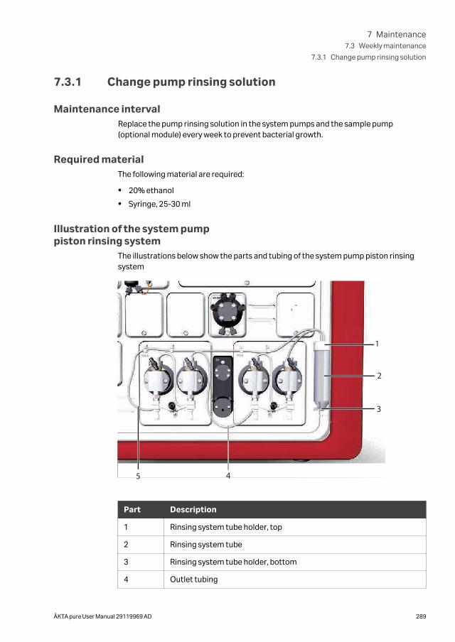
7.3.1 Change pump rinsing solution
Maintenance intervalReplace the pump rinsing solution in the system pumps and the sample pump(optional module) every week to prevent bacterial growth.
Required materialThe following material are required:
• 20% ethanol
• Syringe, 25-30 ml
Illustration of the system pumppiston rinsing system
The illustrations below show the parts and tubing of the system pump piston rinsingsystem
1
2
3
45
Part Description
1 Rinsing system tube holder, top
2 Rinsing system tube
3 Rinsing system tube holder, bottom
4 Outlet tubing
7 Maintenance7.3 Weekly maintenance
7.3.1 Change pump rinsing solution
ÄKTA pure User Manual 29119969 AD 289
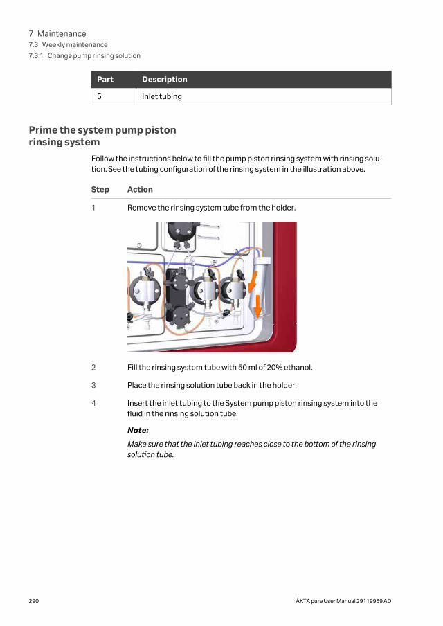
Part Description
5 Inlet tubing
Prime the system pump pistonrinsing system
Follow the instructions below to fill the pump piston rinsing system with rinsing solu-tion. See the tubing configuration of the rinsing system in the illustration above.
Step Action
1 Remove the rinsing system tube from the holder.
2 Fill the rinsing system tube with 50 ml of 20% ethanol.
3 Place the rinsing solution tube back in the holder.
4 Insert the inlet tubing to the System pump piston rinsing system into thefluid in the rinsing solution tube.
Note:
Make sure that the inlet tubing reaches close to the bottom of the rinsingsolution tube.
7 Maintenance7.3 Weekly maintenance
7.3.1 Change pump rinsing solution
290 ÄKTA pure User Manual 29119969 AD
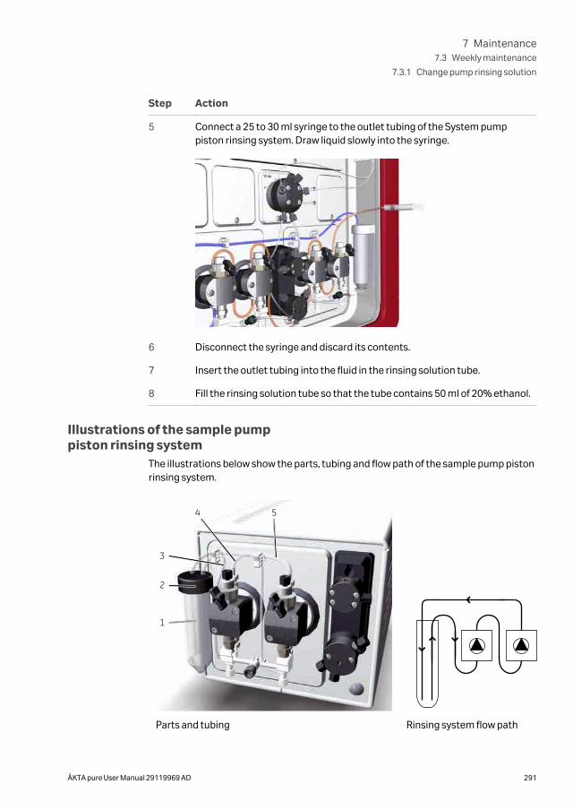
Step Action
5 Connect a 25 to 30 ml syringe to the outlet tubing of the System pumppiston rinsing system. Draw liquid slowly into the syringe.
6 Disconnect the syringe and discard its contents.
7 Insert the outlet tubing into the fluid in the rinsing solution tube.
8 Fill the rinsing solution tube so that the tube contains 50 ml of 20% ethanol.
Illustrations of the sample pumppiston rinsing system
The illustrations below show the parts, tubing and flow path of the sample pump pistonrinsing system.
1
2
3
4 5
Parts and tubing Rinsing system flow path
7 Maintenance7.3 Weekly maintenance
7.3.1 Change pump rinsing solution
ÄKTA pure User Manual 29119969 AD 291
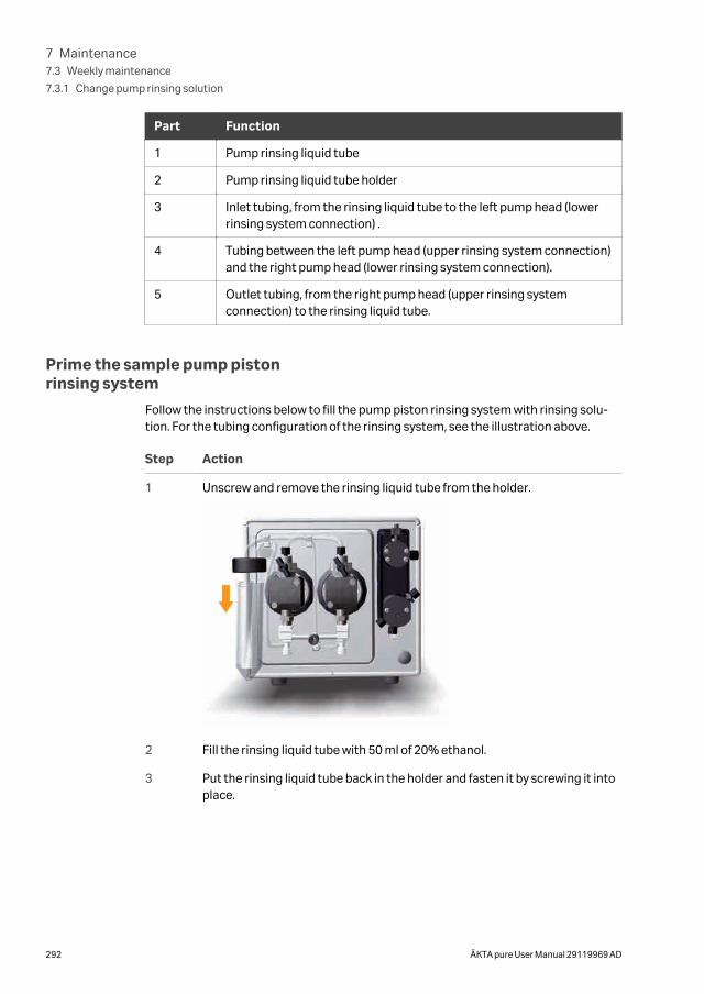
Part Function
1 Pump rinsing liquid tube
2 Pump rinsing liquid tube holder
3 Inlet tubing, from the rinsing liquid tube to the left pump head (lowerrinsing system connection) .
4 Tubing between the left pump head (upper rinsing system connection)and the right pump head (lower rinsing system connection).
5 Outlet tubing, from the right pump head (upper rinsing systemconnection) to the rinsing liquid tube.
Prime the sample pump pistonrinsing system
Follow the instructions below to fill the pump piston rinsing system with rinsing solu-tion. For the tubing configuration of the rinsing system, see the illustration above.
Step Action
1 Unscrew and remove the rinsing liquid tube from the holder.
2 Fill the rinsing liquid tube with 50 ml of 20% ethanol.
3 Put the rinsing liquid tube back in the holder and fasten it by screwing it intoplace.
7 Maintenance7.3 Weekly maintenance
7.3.1 Change pump rinsing solution
292 ÄKTA pure User Manual 29119969 AD
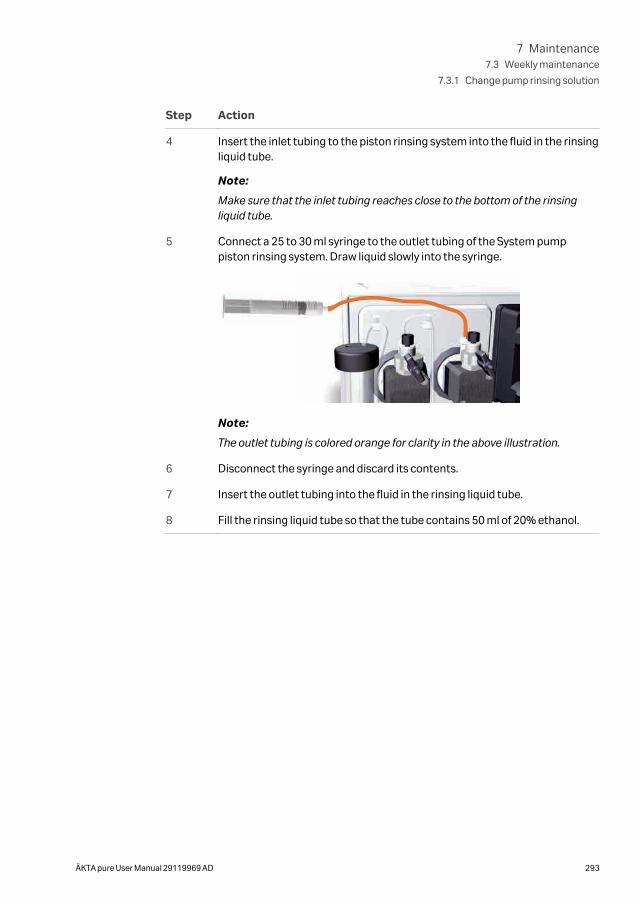
Step Action
4 Insert the inlet tubing to the piston rinsing system into the fluid in the rinsingliquid tube.
Note:
Make sure that the inlet tubing reaches close to the bottom of the rinsingliquid tube.
5 Connect a 25 to 30 ml syringe to the outlet tubing of the System pumppiston rinsing system. Draw liquid slowly into the syringe.
Note:
The outlet tubing is colored orange for clarity in the above illustration.
6 Disconnect the syringe and discard its contents.
7 Insert the outlet tubing into the fluid in the rinsing liquid tube.
8 Fill the rinsing liquid tube so that the tube contains 50 ml of 20% ethanol.
7 Maintenance7.3 Weekly maintenance
7.3.1 Change pump rinsing solution
ÄKTA pure User Manual 29119969 AD 293
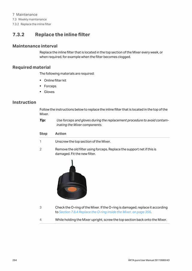
7.3.2 Replace the inline filter
Maintenance intervalReplace the inline filter that is located in the top section of the Mixer every week, orwhen required, for example when the filter becomes clogged.
Required materialThe following materials are required:
• Online filter kit
• Forceps
• Gloves
Instruction
Follow the instructions below to replace the inline filter that is located in the top of theMixer.
Tip: Use forceps and gloves during the replacement procedure to avoid contam-inating the Mixer components.
Step Action
1 Unscrew the top section of the Mixer.
2 Remove the old filter using forceps. Replace the support net if this isdamaged. Fit the new filter.
3 Check the O-ring of the Mixer. If the O-ring is damaged, replace it accordingto Section 7.8.4 Replace the O-ring inside the Mixer, on page 356.
4 While holding the Mixer upright, screw the top section back onto the Mixer.
7 Maintenance7.3 Weekly maintenance
7.3.2 Replace the inline filter
294 ÄKTA pure User Manual 29119969 AD
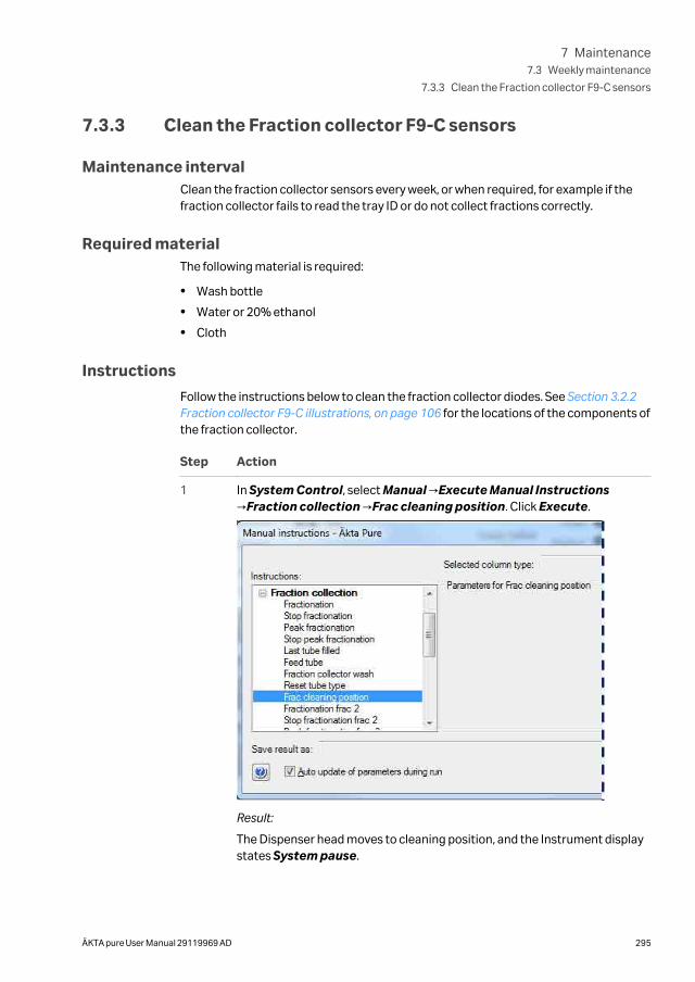
7.3.3 Clean the Fraction collector F9-C sensors
Maintenance intervalClean the fraction collector sensors every week, or when required, for example if thefraction collector fails to read the tray ID or do not collect fractions correctly.
Required materialThe following material is required:
• Wash bottle
• Water or 20% ethanol
• Cloth
Instructions
Follow the instructions below to clean the fraction collector diodes. See Section 3.2.2Fraction collector F9-C illustrations, on page 106 for the locations of the components ofthe fraction collector.
Step Action
1 In System Control, select Manual →Execute Manual Instructions→Fraction collection →Frac cleaning position. Click Execute.
Result:
The Dispenser head moves to cleaning position, and the Instrument displaystates System pause.
7 Maintenance7.3 Weekly maintenance
7.3.3 Clean the Fraction collector F9-C sensors
ÄKTA pure User Manual 29119969 AD 295
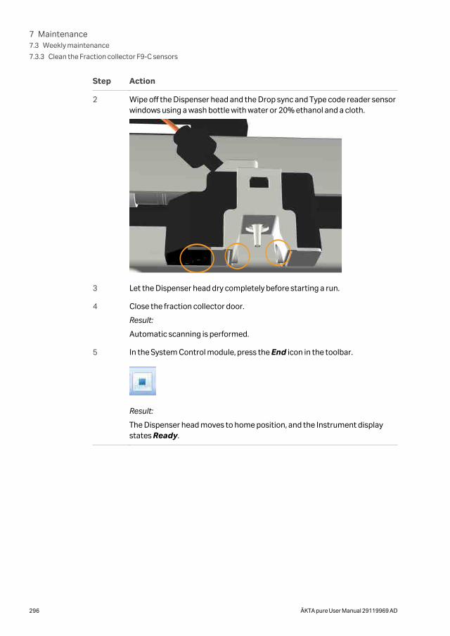
Step Action
2 Wipe off the Dispenser head and the Drop sync and Type code reader sensorwindows using a wash bottle with water or 20% ethanol and a cloth.
3 Let the Dispenser head dry completely before starting a run.
4 Close the fraction collector door.
Result:
Automatic scanning is performed.
5 In the System Control module, press the End icon in the toolbar.
Result:
The Dispenser head moves to home position, and the Instrument displaystates Ready.
7 Maintenance7.3 Weekly maintenance
7.3.3 Clean the Fraction collector F9-C sensors
296 ÄKTA pure User Manual 29119969 AD
7.4 Monthly maintenance
IntroductionThis section provides instructions for monthly maintenance actions.
Maintenance intervalCheck the back pressure for the Flow restrictor every month.
Location of the Flow restrictorThe recommended positions for Flow restrictor FR-902 are:
• Connected between the Conductivity monitor C9 and the Outlet valve.
or
• Connected to the ToR and FrR ports of the pH valve.
Check Flow restrictor connected toConductivity monitor and Outletvalve
Follow the instructions below to check the back pressure of Flow restrictor FR-902,when this is connected between the Conductivity monitor and the Outlet valve.
Step Action
1 Immerse the piece of inlet tubing marked A1 in distilled water, and insert thepiece of tubing from Outlet valve port W into a waste container.
2 In the System Control module, select Manual →Execute Manual Instruc-tions.
Result:
The Manual instructions dialog opens.
3 In the Manual instructions dialog:
• Select Flowpath →Injection valve, and select Manual Load. ClickInsert.
• Select Flowpath →Column valve, and select By-pass. Click Insert.
• Select Flowpath →Outlet valve, and select Out-Waste. Click Insert.
• Select Pumps →System flow and set the Flow rate to 2.5 ml/min. ClickInsert.
• Click Execute.
Result:
A system flow of 2.5 ml/min starts.
7 Maintenance7.4 Monthly maintenance
ÄKTA pure User Manual 29119969 AD 297

Step Action
4 Note the PreC pressure displayed in the Run Data pane.
Tip:
If PreC pressure is not displayed, click the Customize icon. In theCustomize dialog, under the Run Data Groups tab, select PreC pressure.
5 Click on the Pause icon to stop the flow.
6 Replace the Flow restrictor with a female/female union connector.
Tip:
The female/female union connector is included in the accessory kit.
7 Click the Continue icon to restart the flow.
8 Note the PreC pressure displayed in the Run Data pane.
9 Calculate the difference between the two pressure values.
10 Check that the pressure difference is within the range 0.2 ± 0.05 MPa.
If this is not the case, the Flow restrictor should be replaced, see Section7.8.7 Replace Flow restrictor, on page 363.
Check Flow restrictor connected topH valve
Follow the instructions below to check the back pressure of Flow restrictor FR-902.
Step Action
1 Immerse the piece of inlet tubing marked A1 in distilled water, and insert thepiece of tubing from Outlet valve port W into a waste container.
2 In the System Control module, select Manual →Execute Manual Instruc-tions.
Result:
The Manual instructions dialog opens.
7 Maintenance7.4 Monthly maintenance
298 ÄKTA pure User Manual 29119969 AD
Step Action
3 In the Manual instructions dialog:
• Select Flowpath →Injection valve, and then select Manual Load. ClickInsert.
• Select Flowpath →Column valve, and then select By-pass. Click Insert.
• Select Flowpath →pH valve, and set the pH electrode to Off-line andthe Restrictor to In-line. Click Insert.
• Select Flowpath →Outlet valve, and then select Out-Waste. ClickInsert.
• Select Pumps →System flow and set the Flow rate to 2.5 ml/min. ClickInsert.
• Click Execute.
Result:
A system flow of 2.5 ml/min starts.
4 Note the PreC pressure displayed in the Run Data pane.
Tip:
If PreC pressure is not displayed, click the Customize icon. In theCustomize dialog, under the Run Data Groups tab, select PreC pressure.
5 In the Manual instructions dialog:
• Select Flowpath →pH valve, and set the pH electrode to Off-line andthe Restrictor to Off-line.
• Click Execute.
6 Note the PreC pressure displayed in the Run Data pane.
7 Calculate the difference between the two pressure values noted in step 4and step 6.
8 Check that the pressure difference is within the range 0.2 ± 0.05 MPa.
If this is not the case, the Flow restrictor should be replaced, see Section7.8.7 Replace Flow restrictor, on page 363.
7 Maintenance7.4 Monthly maintenance
ÄKTA pure User Manual 29119969 AD 299

7.5 Semiannual maintenance
IntroductionThis section provides instructions for semiannual maintenance activities.
In this section
Section See page
7.5.1 Clean the UV flow cell 301
7.5.2 Replace the pH electrode 304
7 Maintenance7.5 Semiannual maintenance
300 ÄKTA pure User Manual 29119969 AD
7.5.1 Clean the UV flow cell
Maintenance intervalClean the UV flow cell every six months, or when required.
NOTICE
Keep UV flow cell clean. Do not allow solutions containingdissolved salts, proteins or other solid solutes to dry out in the flowcell. Do not allow particles to enter the flow cell, as damage to theflow cell may occur.
Required materialThe following materials are required:
• Luer connector
• Waste container
• Syringe, 25-30 ml
• 10% surfactant detergent solution (e.g., Decon™ 90, Deconex 11, or RBS 25)
• Distilled water
Instruction
Follow the instructions below to clean the UV flow cell for UV monitor U9-M or UVmonitor U9-L. The UV flow cell can be mounted or not mounted on the instrumentduring the cleaning procedure.
The illustrations in the instructions below show UV monitor U9-M. UV monitor U9-L iscleaned in a corresponding way.
7 Maintenance7.5 Semiannual maintenance
7.5.1 Clean the UV flow cell
ÄKTA pure User Manual 29119969 AD 301
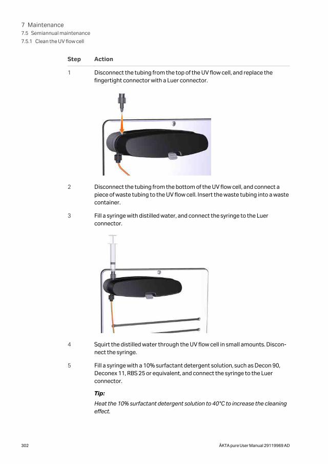
Step Action
1 Disconnect the tubing from the top of the UV flow cell, and replace thefingertight connector with a Luer connector.
2 Disconnect the tubing from the bottom of the UV flow cell, and connect apiece of waste tubing to the UV flow cell. Insert the waste tubing into a wastecontainer.
3 Fill a syringe with distilled water, and connect the syringe to the Luerconnector.
4 Squirt the distilled water through the UV flow cell in small amounts. Discon-nect the syringe.
5 Fill a syringe with a 10% surfactant detergent solution, such as Decon 90,Deconex 11, RBS 25 or equivalent, and connect the syringe to the Luerconnector.
Tip:
Heat the 10% surfactant detergent solution to 40°C to increase the cleaningeffect.
7 Maintenance7.5 Semiannual maintenance
7.5.1 Clean the UV flow cell
302 ÄKTA pure User Manual 29119969 AD
Step Action
6 Squirt the detergent solution through the UV flow cell about five times.
7 Leave the detergent solution in the flow cell for at least 20 minutes.
8 Inject the detergent solution remaining in the syringe into the flow cell.Disconnect the syringe.
9 Fill a syringe with distilled water. Connect the syringe to the Luer connector.
10 Inject the distilled water into the UV flow cell to rinse the flow cell. Discon-nect the syringe.
11 Disconnect the Luer connector from the top of the UV flow cell. Reconnectthe piece of tubing from the Column valve to the top of the UV flow cell.
12 Disconnect the waste tubing from the bottom of the UV flow cell. Reconnectthe piece of tubing from the Conductivity monitor to the bottom of the UVflow cell.
7 Maintenance7.5 Semiannual maintenance
7.5.1 Clean the UV flow cell
ÄKTA pure User Manual 29119969 AD 303
7.5.2 Replace the pH electrode
Maintenance intervalReplace the pH electrode every six months, or when required.
Required materialThe following materials are required:
• pH electrode
• Deionized water
• Standard buffer pH 4
Instruction
CAUTION
pH electrode. Handle the pH electrode with care. The glass tipmay break and cause injury.
Follow the instructions below to replace the pH electrode.
Step Action
1 Disconnect the pH electrode cable of the used pH electrode from theconnection on the front of the pH valve.
2 Unscrew the nut of the pH electrode by hand, and pull the used electrodeaway.
3 Unpack the new pH electrode. Remove the cover from the tip of the new pHelectrode. Make sure that the electrode is not broken or dry.
4 Prior to first use of the electrode, immerse the glass bulb in deionized waterfor 30 minutes and then in a standard buffer, pH 4, for 30 minutes.
5 Carefully insert the new pH electrode into the pH flow cell. Tighten the nut byhand to secure the electrode.
6 Connect the pH electrode cable of the new electrode to the connection onthe front of the pH valve.
7 Calibrate the new pH electrode, see Section 7.7.1 Calibrate the pH monitor,on page 334.
7 Maintenance7.5 Semiannual maintenance
7.5.2 Replace the pH electrode
304 ÄKTA pure User Manual 29119969 AD
7.6 Maintenance when required
IntroductionThis section gives instructions for maintenance activities to be performed whenrequired.
In this section
Section See page
7.6.1 Clean the instrument externally 306
7.6.2 Perform System CIP 307
7.6.3 Perform Column CIP 315
7.6.4 Clean Fraction collector F9-C 319
7.6.5 Clean Fraction collector F9-R 321
7.6.6 Storage of the pH electrode 322
7.6.7 Clean the pH electrode 324
7.6.8 Clean the pump head check valves 327
7.6.9 Wipe off excess oil from the pump head 330
7.6.10 Clean the Conductivity flow cell 331
7 Maintenance7.6 Maintenance when required
ÄKTA pure User Manual 29119969 AD 305
7.6.1 Clean the instrument externally
Maintenance intervalClean the the instrument externally when required. Do not allow spilled liquid to dry onthe instrument.
Required materialThe following materials are required:
• Cloth
• Mild cleaning agent or 20% ethanol
Instruction
Follow the instructions below to clean the instrument externally.
Step Action
1 Check that no run is in progress.
2 Switch off the instrument.
3 Wipe the surface with a damp cloth. Wipe off stains using a mild cleaningagent or 20% ethanol. Wipe off any excess.
4 Let the instrument dry completely before using it.
7 Maintenance7.6 Maintenance when required
7.6.1 Clean the instrument externally
306 ÄKTA pure User Manual 29119969 AD
7.6.2 Perform System CIP
Maintenance intervalPerform a System cleaning in place (System CIP) when required, for example betweenruns where different samples and buffers are used. This is important to prevent cross-contamination and bacterial growth in the instrument.
Required materialThe following materials are required:
• Appropriate cleaning solutions (e.g., NaOH, buffer solution or distilled water).
• Syringe, 25-30 ml
IntroductionThe System CIP method is used to fill the instrument and the selected inlets andoutlets with cleaning solution.
WARNING
Hazardous biological agents during run. When usinghazardous biological agents, perform a system cleaning to flushthe entire system tubing with bacteriostatic solution (e.g. NaOH)followed by a neutral buffer and finally distilled water, beforeservice and maintenance.
CAUTION
Hazardous substances. When using hazardous chemical andbiological agents, take all suitable protective measures, such aswearing protective glasses and gloves resistant to the substancesused. Follow local and/or national regulations for safe operation,maintenance and decommissioning of the equipment.
CAUTIONExplosion hazard if flammable liquid leaks during cleaning ofthe flow path. When cleaning the flow path of Fraction collectorF9-C with a flammable liquid like ethanol, carefully inspect the flowpath, including the waste tubing, to make sure there will be noleakage.
Tip: If hazardous chemicals are used for system or column cleaning, wash thesystem or columns with a neutral solution in the last phase or step.
7 Maintenance7.6 Maintenance when required
7.6.2 Perform System CIP
ÄKTA pure User Manual 29119969 AD 307
Create a System CIP method
Follow the instruction below to create a System CIP method.
Step Action
1 In the Method Editor module,
• click the New Method icon
or
• select File →New Method.
Result:
The New Method dialog opens.
7 Maintenance7.6 Maintenance when required
7.6.2 Perform System CIP
308 ÄKTA pure User Manual 29119969 AD
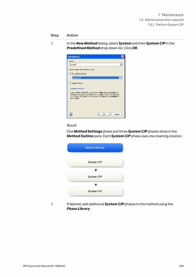
Step Action
2 In the New Method dialog, select System and then System CIP in thePredefined Method drop-down list. Click OK.
Result:
One Method Settings phase and three System CIP phases show in theMethod Outline pane. Each System CIP phase uses one cleaning solution.
3 If desired, add additional System CIP phases to the method using thePhase Library.
7 Maintenance7.6 Maintenance when required
7.6.2 Perform System CIP
ÄKTA pure User Manual 29119969 AD 309
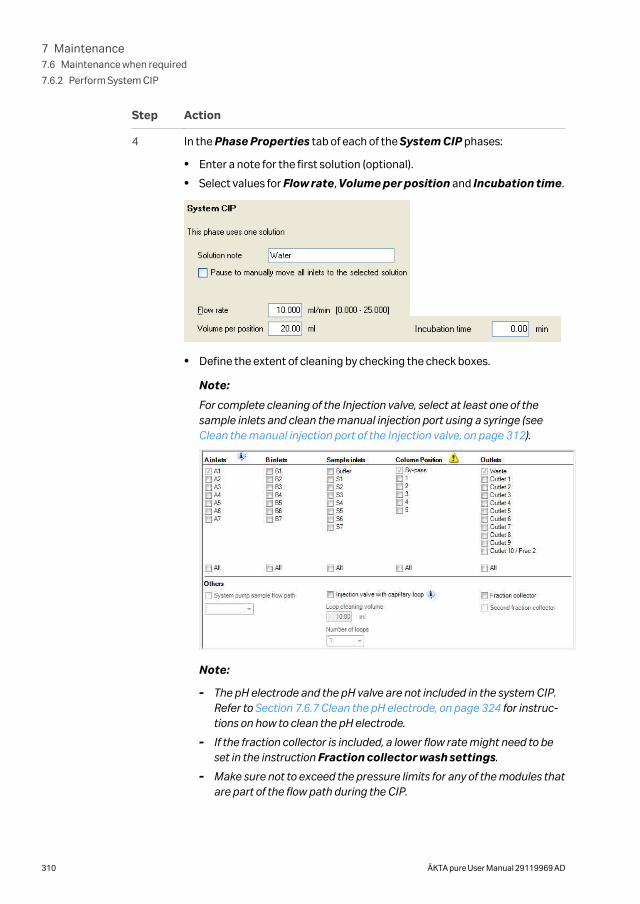
Step Action
4 In the Phase Properties tab of each of the System CIP phases:
• Enter a note for the first solution (optional).
• Select values for Flow rate, Volume per position and Incubation time.
• Define the extent of cleaning by checking the check boxes.
Note:
For complete cleaning of the Injection valve, select at least one of thesample inlets and clean the manual injection port using a syringe (see Clean the manual injection port of the Injection valve, on page 312).
Note:
- The pH electrode and the pH valve are not included in the system CIP.Refer to Section 7.6.7 Clean the pH electrode, on page 324 for instruc-tions on how to clean the pH electrode.
- If the fraction collector is included, a lower flow rate might need to beset in the instruction Fraction collector wash settings.
- Make sure not to exceed the pressure limits for any of the modules thatare part of the flow path during the CIP.
7 Maintenance7.6 Maintenance when required
7.6.2 Perform System CIP
310 ÄKTA pure User Manual 29119969 AD
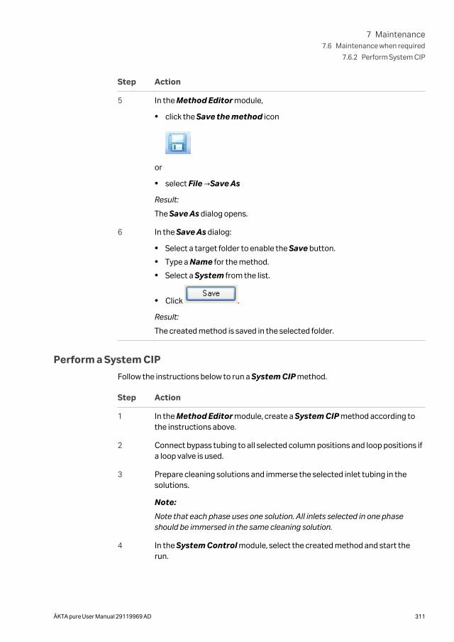
Step Action
5 In the Method Editor module,
• click the Save the method icon
or
• select File →Save As
Result:
The Save As dialog opens.
6 In the Save As dialog:
• Select a target folder to enable the Save button.
• Type a Name for the method.
• Select a System from the list.
• Click .
Result:
The created method is saved in the selected folder.
Perform a System CIP
Follow the instructions below to run a System CIP method.
Step Action
1 In the Method Editor module, create a System CIP method according tothe instructions above.
2 Connect bypass tubing to all selected column positions and loop positions ifa loop valve is used.
3 Prepare cleaning solutions and immerse the selected inlet tubing in thesolutions.
Note:
Note that each phase uses one solution. All inlets selected in one phaseshould be immersed in the same cleaning solution.
4 In the System Control module, select the created method and start therun.
7 Maintenance7.6 Maintenance when required
7.6.2 Perform System CIP
ÄKTA pure User Manual 29119969 AD 311
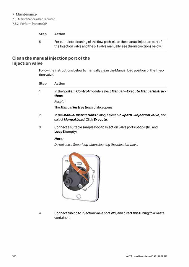
Step Action
5 For complete cleaning of the flow path, clean the manual injection port ofthe Injection valve and the pH valve manually, see the instructions below.
Clean the manual injection port of theInjection valve
Follow the instructions below to manually clean the Manual load position of the Injec-tion valve.
Step Action
1 In the System Control module, select Manual →Execute Manual Instruc-tions.
Result:
The Manual instructions dialog opens.
2 In the Manual instructions dialog, select Flowpath →Injection valve, andselect Manual Load. Click Execute.
3 Connect a suitable sample loop to Injection valve ports LoopF (fill) andLoopE (empty).
Note:
Do not use a Superloop when cleaning the Injection valve.
4 Connect tubing to Injection valve port W1, and direct this tubing to a wastecontainer.
7 Maintenance7.6 Maintenance when required
7.6.2 Perform System CIP
312 ÄKTA pure User Manual 29119969 AD
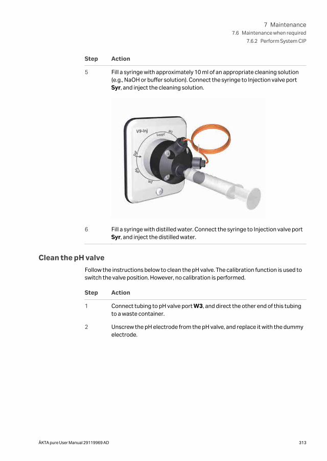
Step Action
5 Fill a syringe with approximately 10 ml of an appropriate cleaning solution(e.g., NaOH or buffer solution). Connect the syringe to Injection valve portSyr, and inject the cleaning solution.
6 Fill a syringe with distilled water. Connect the syringe to Injection valve portSyr, and inject the distilled water.
Clean the pH valve
Follow the instructions below to clean the pH valve. The calibration function is used toswitch the valve position. However, no calibration is performed.
Step Action
1 Connect tubing to pH valve port W3, and direct the other end of this tubingto a waste container.
2 Unscrew the pH electrode from the pH valve, and replace it with the dummyelectrode.
7 Maintenance7.6 Maintenance when required
7.6.2 Perform System CIP
ÄKTA pure User Manual 29119969 AD 313
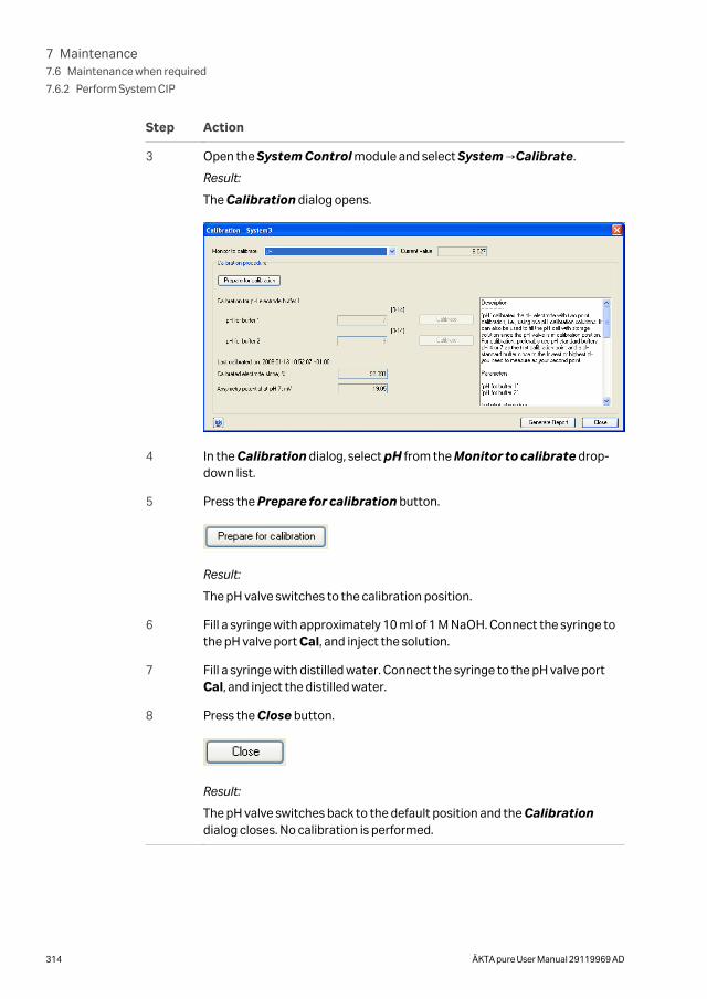
Step Action
3 Open the System Control module and select System →Calibrate.
Result:
The Calibration dialog opens.
4 In the Calibration dialog, select pH from the Monitor to calibrate drop-down list.
5 Press the Prepare for calibration button.
Result:
The pH valve switches to the calibration position.
6 Fill a syringe with approximately 10 ml of 1 M NaOH. Connect the syringe tothe pH valve port Cal, and inject the solution.
7 Fill a syringe with distilled water. Connect the syringe to the pH valve portCal, and inject the distilled water.
8 Press the Close button.
Result:
The pH valve switches back to the default position and the Calibrationdialog closes. No calibration is performed.
7 Maintenance7.6 Maintenance when required
7.6.2 Perform System CIP
314 ÄKTA pure User Manual 29119969 AD
7.6.3 Perform Column CIP
Maintenance intervalPerform a Column cleaning in place (Column CIP) when required, for example betweenruns where different samples are used.
Required materialThe following materials are required:
• Appropriate cleaning solutions. Please refer to the instructions for use of thecolumn.
IntroductionThe Column CIP method is used to clean the column after purification runs, to removenon-specifically bound proteins and to minimize the risk for carry-over betweendifferent purification runs.
WARNING
Hazardous biological agents during run. When usinghazardous biological agents, perform a system cleaning to flushthe entire system tubing with bacteriostatic solution (e.g. NaOH)followed by a neutral buffer and finally distilled water, beforeservice and maintenance.
CAUTION
Hazardous substances. When using hazardous chemical andbiological agents, take all suitable protective measures, such aswearing protective glasses and gloves resistant to the substancesused. Follow local and/or national regulations for safe operation,maintenance and decommissioning of the equipment.
Tip: If hazardous chemicals are used for system or column cleaning, wash thesystem or columns with a neutral solution in the last phase or step.
Create a Column CIP method
Follow the instruction below to create a Column CIP method.
7 Maintenance7.6 Maintenance when required
7.6.3 Perform Column CIP
ÄKTA pure User Manual 29119969 AD 315
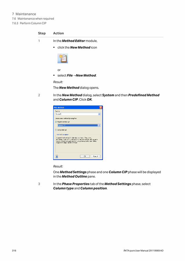
Step Action
1 In the Method Editor module,
• click the New Method icon
or
• select File →New Method.
Result:
The New Method dialog opens.
2 In the New Method dialog, select System and then Predefined Methodand Column CIP. Click OK.
Result:
One Method Settings phase and one Column CIP phase will be displayedin the Method Outline pane.
3 In the Phase Properties tab of the Method Settings phase, selectColumn type and Column position.
7 Maintenance7.6 Maintenance when required
7.6.3 Perform Column CIP
316 ÄKTA pure User Manual 29119969 AD
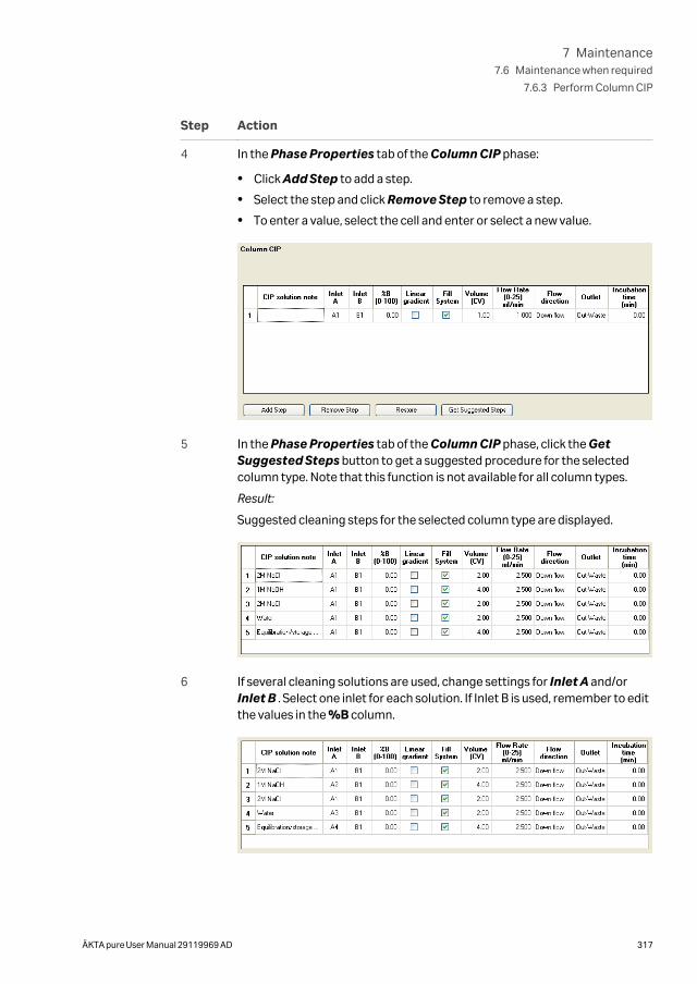
Step Action
4 In the Phase Properties tab of the Column CIP phase:
• Click Add Step to add a step.
• Select the step and click Remove Step to remove a step.
• To enter a value, select the cell and enter or select a new value.
5 In the Phase Properties tab of the Column CIP phase, click the GetSuggested Steps button to get a suggested procedure for the selectedcolumn type. Note that this function is not available for all column types.
Result:
Suggested cleaning steps for the selected column type are displayed.
6 If several cleaning solutions are used, change settings for Inlet A and/orInlet B . Select one inlet for each solution. If Inlet B is used, remember to editthe values in the %B column.
7 Maintenance7.6 Maintenance when required
7.6.3 Perform Column CIP
ÄKTA pure User Manual 29119969 AD 317
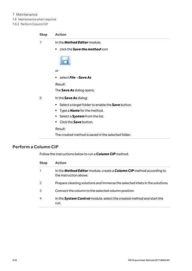
Step Action
7 In the Method Editor module,
• click the Save the method icon
or
• select File →Save As
Result:
The Save As dialog opens.
8 In the Save As dialog:
• Select a target folder to enable the Save button.
• Type a Name for the method.
• Select a System from the list.
• Click the Save button.
Result:
The created method is saved in the selected folder.
Perform a Column CIP
Follow the instructions below to run a Column CIP method.
Step Action
1 In the Method Editor module, create a Column CIP method according tothe instruction above.
2 Prepare cleaning solutions and immerse the selected inlets in the solutions.
3 Connect the column to the selected column position.
4 In the System Control module, select the created method and start therun.
7 Maintenance7.6 Maintenance when required
7.6.3 Perform Column CIP
318 ÄKTA pure User Manual 29119969 AD
7.6.4 Clean Fraction collector F9-C
Maintenance intervalClean the Fraction collector when required, for example if liquid has been spilled in theFraction collector chamber. The internal tubing of the fraction collector may need to bereplaced for maintenance or for process purposes. Information on how and when toreplace the internal tubing can be found in the ÄKTA pure User manual.
Required materialThe following materials are required:
• Wash bottle
• Water or 20% ethanol
• Cloth
Instruction
Follow the instruction below to clean the interior of the Fraction collector. The loca-tions of the components of the fraction collector are shown in Section 3.2.2 Fractioncollector F9-C illustrations, on page 106.
Step Action
1 Perform a fraction collector wash:
In System Control, select Manual →Execute Manual Instructions→Fraction collection →Fraction collector wash. Click Execute.
NOTICE
• If no column valve is used, make sure to replace anycolumns in the flow path with tubing before a fractioncollector wash is performed.
• Lower the flow for the fraction collector wash in theinstruction Fraction collector wash settings if thesystem back pressure is elevated during the wash.
• Make sure not to exceed the pressure limits for any ofthe modules that are part of the flow path.
2 In System Control, select Manual →Execute Manual Instructions→Fraction collection →Frac cleaning position . Click Execute.
Result:
The Dispenser head moves to cleaning position, and the Instrument displaystates System pause.
7 Maintenance7.6 Maintenance when required
7.6.4 Clean Fraction collector F9-C
ÄKTA pure User Manual 29119969 AD 319
Step Action
3 Open the door of the fraction collector and remove the rack
4 Wash the Cassette tray or rack and the Cassettes (if applicable), with waterand a mild cleaning agent.
5 Lift off the Waste funnel and wash it with water and a mild cleaning agent.
Refit the Waste funnel.
6 Wipe off the interior of the fraction collector using a damp cloth. Wipe offstains using a mild cleaning agent or 20% ethanol.
7 Wipe off the Dispenser head and its diode windows (the Drop sync sensorand the Type code reader) using a wash bottle with water or 20% ethanoland a cloth.
8 Let the fraction collector dry completely before starting a run.
9 Close the door of the fraction collector.
Result:
Automatic scanning is performed.
10 In the System Control module, press the End icon in the toolbar.
Result:
The Dispenser head moves to home position.
7 Maintenance7.6 Maintenance when required
7.6.4 Clean Fraction collector F9-C
320 ÄKTA pure User Manual 29119969 AD
7.6.5 Clean Fraction collector F9-R
Maintenance intervalClean the Fraction collector when required, for example in case of liquid spill.
Required materialThe following materials are required:
• Water or 20% ethanol
• Cloth
Clean the instrument
Follow the instructions below to clean the instrument externally.
Step Action
1 Check that no run is in progress.
2 Switch off the instrument.
3 Wipe the surface with a damp cloth. Wipe off stains using a mild cleaningagent or 20% ethanol. Wipe off any excess.
4 Let the Fraction collector F9-R dry completely before restart.
Clean DropSync sensorClean the drop sensor photocell located above the tube sensor (see Front view illustra-tion, on page 117) with a damp cloth.
7 Maintenance7.6 Maintenance when required
7.6.5 Clean Fraction collector F9-R
ÄKTA pure User Manual 29119969 AD 321
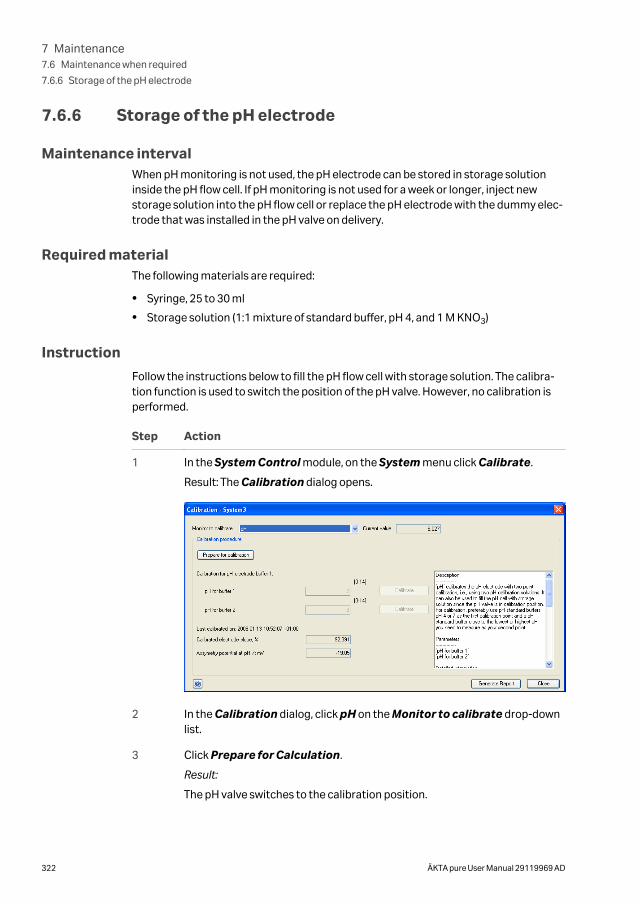
7.6.6 Storage of the pH electrode
Maintenance intervalWhen pH monitoring is not used, the pH electrode can be stored in storage solutioninside the pH flow cell. If pH monitoring is not used for a week or longer, inject newstorage solution into the pH flow cell or replace the pH electrode with the dummy elec-trode that was installed in the pH valve on delivery.
Required materialThe following materials are required:
• Syringe, 25 to 30 ml
• Storage solution (1:1 mixture of standard buffer, pH 4, and 1 M KNO3)
Instruction
Follow the instructions below to fill the pH flow cell with storage solution. The calibra-tion function is used to switch the position of the pH valve. However, no calibration isperformed.
Step Action
1 In the System Control module, on the System menu click Calibrate.
Result: The Calibration dialog opens.
2 In the Calibration dialog, click pH on the Monitor to calibrate drop-downlist.
3 Click Prepare for Calculation.
Result:
The pH valve switches to the calibration position.
7 Maintenance7.6 Maintenance when required
7.6.6 Storage of the pH electrode
322 ÄKTA pure User Manual 29119969 AD
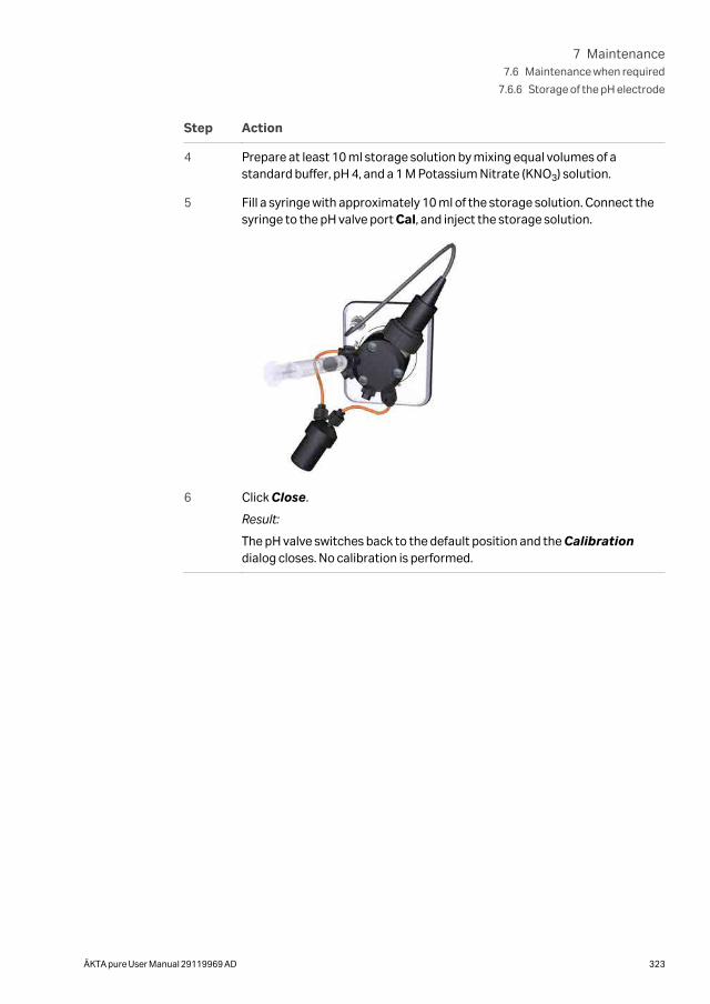
Step Action
4 Prepare at least 10 ml storage solution by mixing equal volumes of astandard buffer, pH 4, and a 1 M Potassium Nitrate (KNO3) solution.
5 Fill a syringe with approximately 10 ml of the storage solution. Connect thesyringe to the pH valve port Cal, and inject the storage solution.
6 Click Close.
Result:
The pH valve switches back to the default position and the Calibrationdialog closes. No calibration is performed.
7 Maintenance7.6 Maintenance when required
7.6.6 Storage of the pH electrode
ÄKTA pure User Manual 29119969 AD 323
7.6.7 Clean the pH electrode
Maintenance intervalClean the pH electrode when required. The pH electrode can be cleaned either when itis installed in the pH valve or when it has been removed. The pH electrode has a limitedlongevity and should be replaced every six months or when the response time is slow,see Section 7.5.2 Replace the pH electrode, on page 304. After cleaning has beenperformed, re-calibrate the pH monitor, see Section 7.7.1 Calibrate the pH monitor, onpage 334.
Required materialThe following materials are required:
• Syringe, 25-30 ml
• Distilled water
• 0.1 M HCl and 0.1 M NaOH
or
• Liquid detergent
or
• 1% pepsin solution in 0.1 M HCl
or
• 1 M KNO3
Cleaning agents
Clean the pH electrode using one of the following procedures:
Salt depositsDissolve the deposits by immersing the electrode for a five minute period in each of thefollowing solutions:
• 0.1 M HCl
• 0.1 M NaOH
• 0.1 M HCl
Rinse the electrode tip in distilled water between each solution.
Oil or grease filmsWash the electrode tip in liquid detergent and water. If the films are known to besoluble in a particular organic solvent, wash with this solvent. Rinse the electrode tip indistilled water.
7 Maintenance7.6 Maintenance when required
7.6.7 Clean the pH electrode
324 ÄKTA pure User Manual 29119969 AD
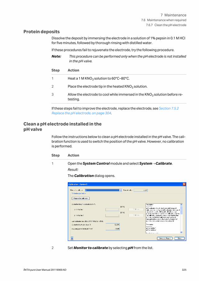
Protein depositsDissolve the deposit by immersing the electrode in a solution of 1% pepsin in 0.1 M HClfor five minutes, followed by thorough rinsing with distilled water.
If these procedures fail to rejuvenate the electrode, try the following procedure.
Note: This procedure can be performed only when the pH electrode is not installedin the pH valve.
Step Action
1 Heat a 1 M KNO3 solution to 60°C–80°C.
2 Place the electrode tip in the heated KNO3 solution.
3 Allow the electrode to cool while immersed in the KNO3 solution before re-testing.
If these steps fail to improve the electrode, replace the electrode, see Section 7.5.2Replace the pH electrode, on page 304.
Clean a pH electrode installed in thepH valve
Follow the instructions below to clean a pH electrode installed in the pH valve. The cali-bration function is used to switch the position of the pH valve. However, no calibrationis performed.
Step Action
1 Open the System Control module and select System →Calibrate.
Result:
The Calibration dialog opens.
2 Set Monitor to calibrate by selecting pH from the list.
7 Maintenance7.6 Maintenance when required
7.6.7 Clean the pH electrode
ÄKTA pure User Manual 29119969 AD 325
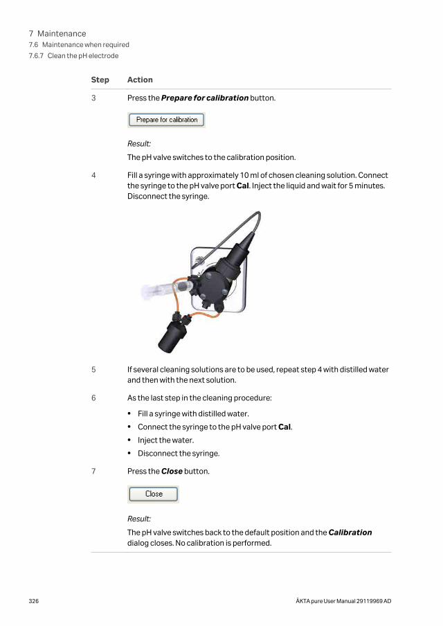
Step Action
3 Press the Prepare for calibration button.
Result:
The pH valve switches to the calibration position.
4 Fill a syringe with approximately 10 ml of chosen cleaning solution. Connectthe syringe to the pH valve port Cal. Inject the liquid and wait for 5 minutes.Disconnect the syringe.
5 If several cleaning solutions are to be used, repeat step 4 with distilled waterand then with the next solution.
6 As the last step in the cleaning procedure:
• Fill a syringe with distilled water.
• Connect the syringe to the pH valve port Cal.
• Inject the water.
• Disconnect the syringe.
7 Press the Close button.
Result:
The pH valve switches back to the default position and the Calibrationdialog closes. No calibration is performed.
7 Maintenance7.6 Maintenance when required
7.6.7 Clean the pH electrode
326 ÄKTA pure User Manual 29119969 AD
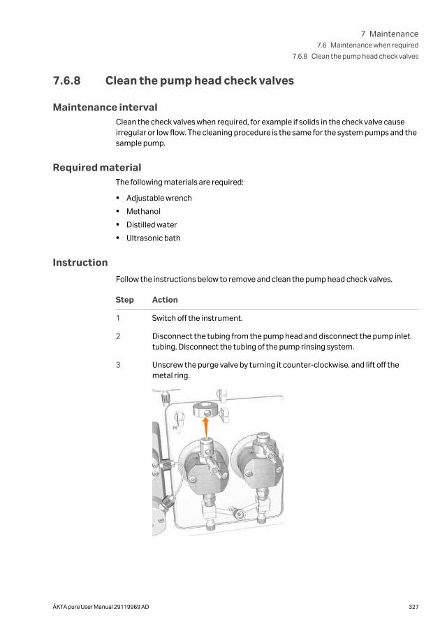
7.6.8 Clean the pump head check valves
Maintenance intervalClean the check valves when required, for example if solids in the check valve causeirregular or low flow. The cleaning procedure is the same for the system pumps and thesample pump.
Required materialThe following materials are required:
• Adjustable wrench
• Methanol
• Distilled water
• Ultrasonic bath
Instruction
Follow the instructions below to remove and clean the pump head check valves.
Step Action
1 Switch off the instrument.
2 Disconnect the tubing from the pump head and disconnect the pump inlettubing. Disconnect the tubing of the pump rinsing system.
3 Unscrew the purge valve by turning it counter-clockwise, and lift off themetal ring.
7 Maintenance7.6 Maintenance when required
7.6.8 Clean the pump head check valves
ÄKTA pure User Manual 29119969 AD 327
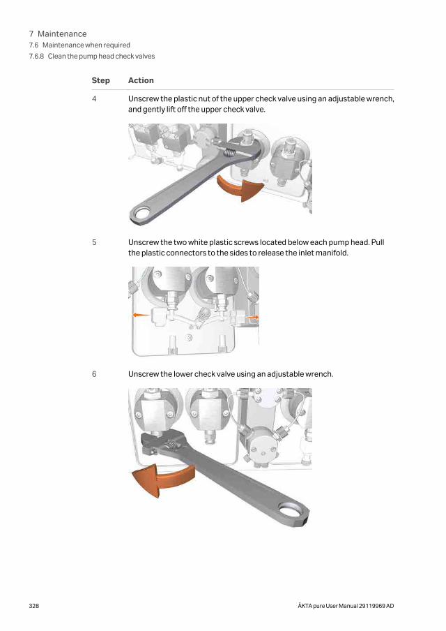
Step Action
4 Unscrew the plastic nut of the upper check valve using an adjustable wrench,and gently lift off the upper check valve.
5 Unscrew the two white plastic screws located below each pump head. Pullthe plastic connectors to the sides to release the inlet manifold.
6 Unscrew the lower check valve using an adjustable wrench.
7 Maintenance7.6 Maintenance when required
7.6.8 Clean the pump head check valves
328 ÄKTA pure User Manual 29119969 AD
Step Action
7CAUTION
Hazardous substances. When using hazardous chem-ical and biological agents, take all suitable protectivemeasures, such as wearing protective glasses andgloves resistant to the substances used. Follow localand/or national regulations for safe operation, mainte-nance and decommissioning of the equipment.
Immerse the valves completely in methanol and place them in an ultrasonicbath for a few minutes. Repeat the ultrasonic bath with deionized water.
8 Refit the check valves.
9 Tighten the nut until fully finger-tight and then use the adjustable wrench totighten a further 90 degrees.
10 Refit the inlet manifold and reconnect the tubing to the pump head.
7 Maintenance7.6 Maintenance when required
7.6.8 Clean the pump head check valves
ÄKTA pure User Manual 29119969 AD 329
7.6.9 Wipe off excess oil from the pump head
Maintenance intervalDuring the first months of use it is normal that excess oil leaks out of the drain holebelow the System pump. The function of the pump is not in any way affected by this.
Required materialThe following materials are required:
• Cloth
• Mild cleaning agent or 20% ethanol
Instruction
Follow the instructions below to clean the System pumps externally.
Step Action
1 Check that no run is in progress.
2 Switch off the instrument.
3 Wipe off the excess oil from the pump head with a damp cloth. Wipe offstains using a mild cleaning agent or 20% ethanol.
4 Let the pump dry completely before using the instrument.
7 Maintenance7.6 Maintenance when required
7.6.9 Wipe off excess oil from the pump head
330 ÄKTA pure User Manual 29119969 AD
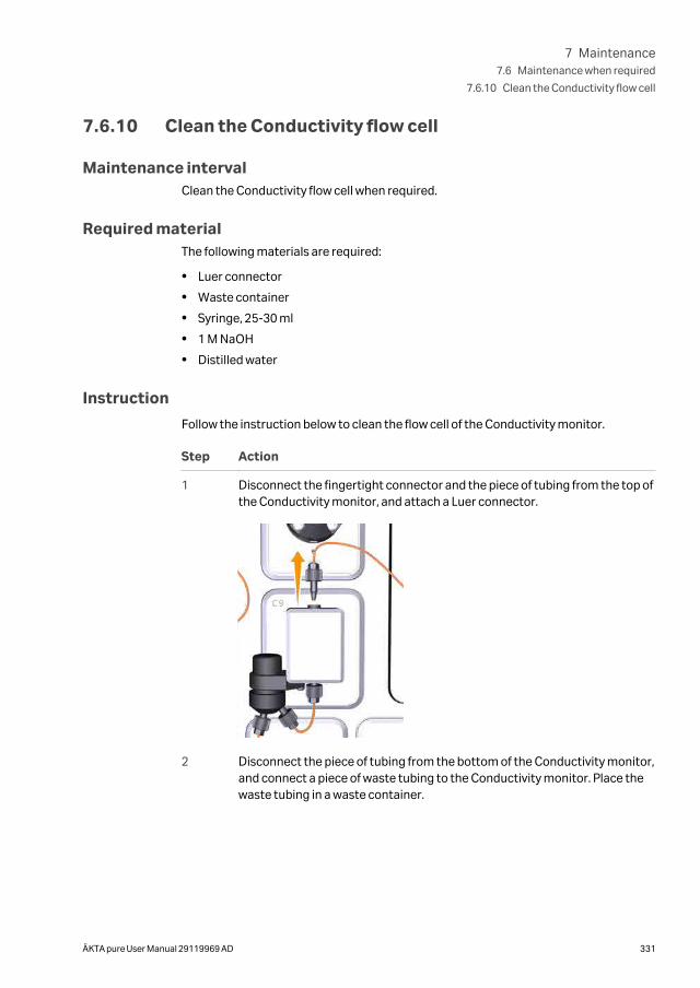
7.6.10 Clean the Conductivity flow cell
Maintenance intervalClean the Conductivity flow cell when required.
Required materialThe following materials are required:
• Luer connector
• Waste container
• Syringe, 25-30 ml
• 1 M NaOH
• Distilled water
Instruction
Follow the instruction below to clean the flow cell of the Conductivity monitor.
Step Action
1 Disconnect the fingertight connector and the piece of tubing from the top ofthe Conductivity monitor, and attach a Luer connector.
2 Disconnect the piece of tubing from the bottom of the Conductivity monitor,and connect a piece of waste tubing to the Conductivity monitor. Place thewaste tubing in a waste container.
7 Maintenance7.6 Maintenance when required
7.6.10 Clean the Conductivity flow cell
ÄKTA pure User Manual 29119969 AD 331
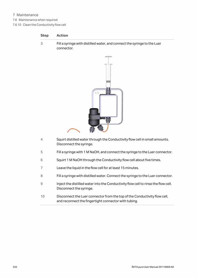
Step Action
3 Fill a syringe with distilled water, and connect the syringe to the Luerconnector.
4 Squirt distilled water through the Conductivity flow cell in small amounts.Disconnect the syringe.
5 Fill a syringe with 1 M NaOH, and connect the syringe to the Luer connector.
6 Squirt 1 M NaOH through the Conductivity flow cell about five times.
7 Leave the liquid in the flow cell for at least 15 minutes.
8 Fill a syringe with distilled water. Connect the syringe to the Luer connector.
9 Inject the distilled water into the Conductivity flow cell to rinse the flow cell.Disconnect the syringe.
10 Disconnect the Luer connector from the top of the Conductivity flow cell,and reconnect the fingertight connector with tubing.
7 Maintenance7.6 Maintenance when required
7.6.10 Clean the Conductivity flow cell
332 ÄKTA pure User Manual 29119969 AD
7.7 Calibration procedures
IntroductionThis section provides instructions for calibration procedures that can be performedusing the System Control module in UNICORN software.
In this section
Section See page
7.7.1 Calibrate the pH monitor 334
7.7.2 Calibrate the pressure monitors 336
7.7.3 Calibrate the Conductivity monitor 339
7.7.4 Calibrate the UV monitors 344
Menu command in UNICORNOpen the System Control module and select System →Calibrate to open the Cali-bration dialog.
7 Maintenance7.7 Calibration procedures
ÄKTA pure User Manual 29119969 AD 333
7.7.1 Calibrate the pH monitor
Maintenance intervalCalibrate the pH monitor once a day, when the pH electrode has been replaced, or if theambient temperature has changed by more than ± 5°C.
Required materialUse two pH calibration buffers with a difference of at least one pH unit. Preferably use apH standard buffer, pH 4 or pH 7, as the first calibration point, and a pH standard bufferclose to the lowest or highest pH you need to measure as your second point. Allow thebuffers to equilibrate to ambient temperature before use.
Instruction
CAUTION
pH electrode. Handle the pH electrode with care. The glass tipmay break and cause injury.
Follow the instructions below to calibrate the pH monitor.
Step Action
1 In the Calibration dialog, select pH from the Monitor to calibrate drop-down list.
2 Click the Prepare for calibration button.
Result:
The pH valve switches to the calibration position.
3 Enter the pH of the first pH standard buffer in the pH for buffer 1 field.
7 Maintenance7.7 Calibration procedures
7.7.1 Calibrate the pH monitor
334 ÄKTA pure User Manual 29119969 AD
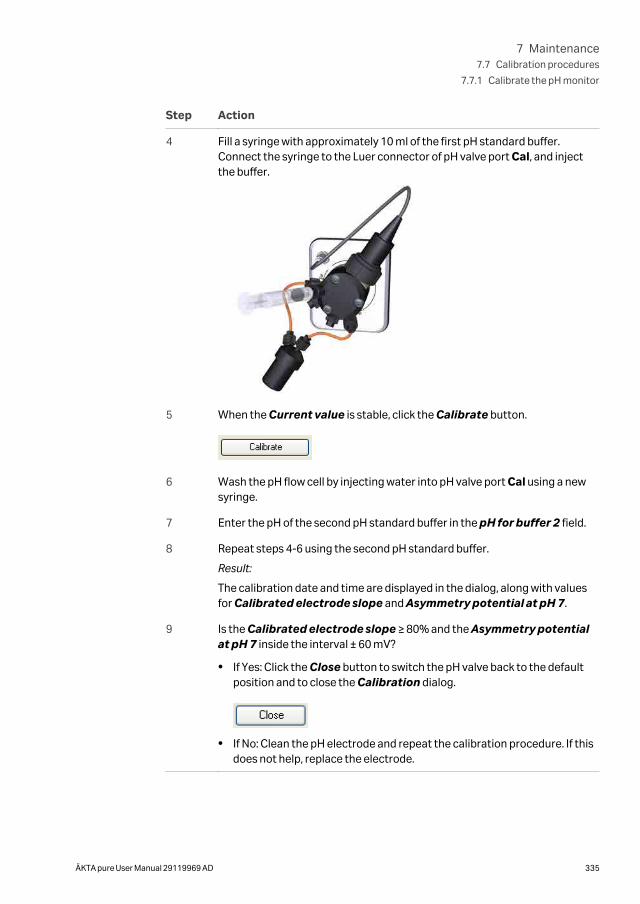
Step Action
4 Fill a syringe with approximately 10 ml of the first pH standard buffer.Connect the syringe to the Luer connector of pH valve port Cal, and injectthe buffer.
5 When the Current value is stable, click the Calibrate button.
6 Wash the pH flow cell by injecting water into pH valve port Cal using a newsyringe.
7 Enter the pH of the second pH standard buffer in the pH for buffer 2 field.
8 Repeat steps 4-6 using the second pH standard buffer.
Result:
The calibration date and time are displayed in the dialog, along with valuesfor Calibrated electrode slope and Asymmetry potential at pH 7.
9 Is the Calibrated electrode slope ≥ 80% and the Asymmetry potentialat pH 7 inside the interval ± 60 mV?
• If Yes: Click the Close button to switch the pH valve back to the defaultposition and to close the Calibration dialog.
• If No: Clean the pH electrode and repeat the calibration procedure. If thisdoes not help, replace the electrode.
7 Maintenance7.7 Calibration procedures
7.7.1 Calibrate the pH monitor
ÄKTA pure User Manual 29119969 AD 335
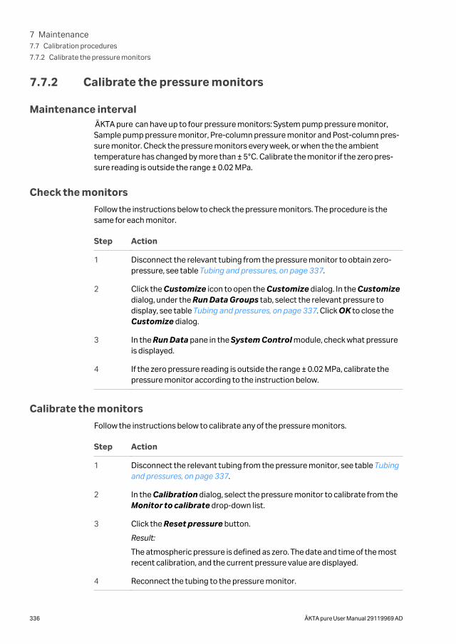
7.7.2 Calibrate the pressure monitors
Maintenance intervalÄKTA pure can have up to four pressure monitors: System pump pressure monitor,Sample pump pressure monitor, Pre-column pressure monitor and Post-column pres-sure monitor. Check the pressure monitors every week, or when the the ambienttemperature has changed by more than ± 5°C. Calibrate the monitor if the zero pres-sure reading is outside the range ± 0.02 MPa.
Check the monitors
Follow the instructions below to check the pressure monitors. The procedure is thesame for each monitor.
Step Action
1 Disconnect the relevant tubing from the pressure monitor to obtain zero-pressure, see table Tubing and pressures, on page 337.
2 Click the Customize icon to open the Customize dialog. In the Customizedialog, under the Run Data Groups tab, select the relevant pressure todisplay, see table Tubing and pressures, on page 337. Click OK to close theCustomize dialog.
3 In the Run Data pane in the System Control module, check what pressureis displayed.
4 If the zero pressure reading is outside the range ± 0.02 MPa, calibrate thepressure monitor according to the instruction below.
Calibrate the monitors
Follow the instructions below to calibrate any of the pressure monitors.
Step Action
1 Disconnect the relevant tubing from the pressure monitor, see table Tubingand pressures, on page 337.
2 In the Calibration dialog, select the pressure monitor to calibrate from theMonitor to calibrate drop-down list.
3 Click the Reset pressure button.
Result:
The atmospheric pressure is defined as zero. The date and time of the mostrecent calibration, and the current pressure value are displayed.
4 Reconnect the tubing to the pressure monitor.
7 Maintenance7.7 Calibration procedures
7.7.2 Calibrate the pressure monitors
336 ÄKTA pure User Manual 29119969 AD
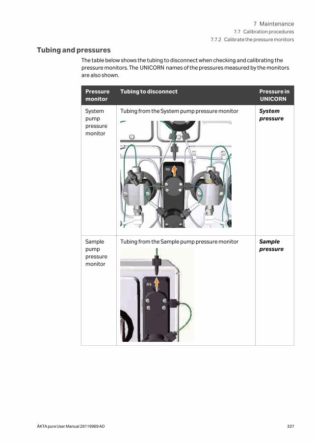
Tubing and pressuresThe table below shows the tubing to disconnect when checking and calibrating thepressure monitors. The UNICORN names of the pressures measured by the monitorsare also shown.
Pressuremonitor
Tubing to disconnect Pressure inUNICORN
Systempumppressuremonitor
Tubing from the System pump pressure monitor Systempressure
Samplepumppressuremonitor
Tubing from the Sample pump pressure monitor Samplepressure
7 Maintenance7.7 Calibration procedures
7.7.2 Calibrate the pressure monitors
ÄKTA pure User Manual 29119969 AD 337
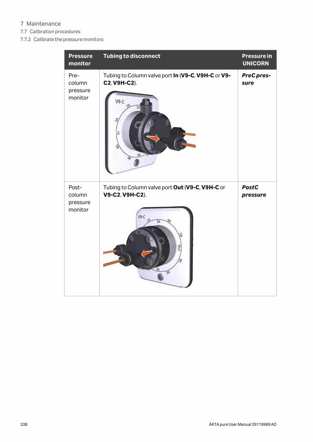
Pressuremonitor
Tubing to disconnect Pressure inUNICORN
Pre-columnpressuremonitor
Tubing to Column valve port In (V9-C, V9H-C or V9-C2, V9H-C2).
PreC pres-sure
Post-columnpressuremonitor
Tubing to Column valve port Out (V9-C, V9H-C orV9-C2, V9H-C2).
PostCpressure
7 Maintenance7.7 Calibration procedures
7.7.2 Calibrate the pressure monitors
338 ÄKTA pure User Manual 29119969 AD
7.7.3 Calibrate the Conductivity monitor
IntroductionTwo types of calibrations can be performed:
• Conductivity monitor - factory calibration: Restores the conductivity cellconstant to the factory default value.
• Conductivity monitor - user calibration: Calibrates the conductivity cellconstant.
Maintenance intervalRecommended maintenance intervals for the two types of calibrations:
• Conductivity monitor - factory calibration: Perform calibration to override anincorrect user calibration.
• Conductivity monitor - user calibration: The conductivity cell is factory cali-brated, and should not require recalibration under normal usage. Perform calibra-tion when the signal is unstable or you suspect that it is incorrect. It is also recom-mended to recalibrate the Conductivity monitor after cleaning.
Conductivity monitor - factorycalibration
Follow the instruction below to restore the conductivity cell constant to the factorydefault value.
Step Action
1 In the Calibration dialog, select Conductivity monitor - factory calibra-tion from the Monitor to calibrate drop-down list.
Result:
The time for the new calibration and the current value are displayed.
2 Click Restore.
Result:
The conductivity cell constant is restored to the factory default value. Theconductivity cell constant is written on the packaging of the Conductivitymonitor.
Conductivity monitor - usercalibration
Follow the instruction below to calibrate the Conductivity flow cell constant.
7 Maintenance7.7 Calibration procedures
7.7.3 Calibrate the Conductivity monitor
ÄKTA pure User Manual 29119969 AD 339
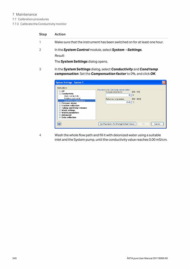
Step Action
1 Make sure that the instrument has been switched on for at least one hour.
2 In the System Control module, select System →Settings.
Result:
The System Settings dialog opens.
3 In the System Settings dialog, select Conductivity and Cond tempcompensation. Set the Compensation factor to 0%, and click OK.
4 Wash the whole flow path and fill it with deionized water using a suitableinlet and the System pump, until the conductivity value reaches 0.00 mS/cm.
7 Maintenance7.7 Calibration procedures
7.7.3 Calibrate the Conductivity monitor
340 ÄKTA pure User Manual 29119969 AD
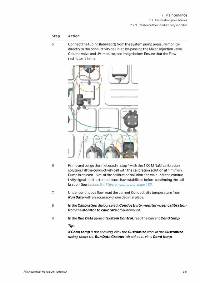
Step Action
5 Connect the tubing (labelled 3) from the system pump pressure monitordirectly to the conductivity cell inlet, by-passing the Mixer, Injection valve,Column valve and UV-monitor, see image below. Ensure that the Flowrestrictor is inline.
6 Prime and purge the inlet used in step 4 with the 1.00 M NaCl calibrationsolution. Fill the conductivity cell with the calibration solution at 1 ml/min.Pump in at least 15 ml of the calibration solution and wait until the conduc-tivity signal and the temperature have stabilized before continuing the cali-bration. See Section 5.4.1 System pumps, on page 180.
7 Under continuous flow, read the current Conductivity temperature fromRun Data with an accuracy of one decimal place.
8 In the Calibration dialog, select Conductivity monitor - user calibrationfrom the Monitor to calibrate drop-down list.
9 In the Run Data pane of System Control, read the current Cond temp.
Tip:
If Cond temp is not showing, click the Customize icon. In the Customizedialog, under the Run Data Groups tab, select to view Cond temp.
7 Maintenance7.7 Calibration procedures
7.7.3 Calibrate the Conductivity monitor
ÄKTA pure User Manual 29119969 AD 341
Step Action
10 In the Calibration dialog, enter the theoretical conductivity value at thecurrent conductivity temperature in the Enter theoretical conductivityvalue input field.
• If a certified conductivity standard solution is used, use the suppliedtheoretical conductivity value.
• If a manually prepared 1.00 M NaCl calibration solution is used, see thegraph for conductivity value at the current temperature Graph forconductivity value, on page 342.
11 In the Calibration dialog, click Calibrate.
Result:
The new conductivity cell constant is displayed in the Conductivity cell 1constant/cm box. The new constant should normally be 40 ± 10 cm-1. Thedate and time for the calibration are also displayed.
12 In the System Control toolbar, click the End icon to end the run.
13 In the System Settings dialog, select Conductivity: Cond tempcompensation and set the Compensation factor back to desired value,default 2.0%. Click OK.
Note:
When using NaCl, the optimal compensation factor is 2.1%.
Graph for conductivity valueThe graph below shows the conductivity value at the current temperature when 1.00 MNaCl calibration solution is used.
7 Maintenance7.7 Calibration procedures
7.7.3 Calibrate the Conductivity monitor
342 ÄKTA pure User Manual 29119969 AD
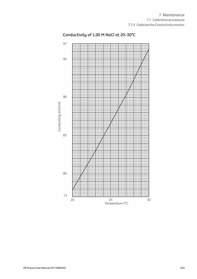
03520277
80
85
90
95
97
Temperature (°C)
Cond
uctiv
ity (m
S/cm
)
Conductivity of 1.00 M NaCl at 20–30°C
7 Maintenance7.7 Calibration procedures
7.7.3 Calibrate the Conductivity monitor
ÄKTA pure User Manual 29119969 AD 343
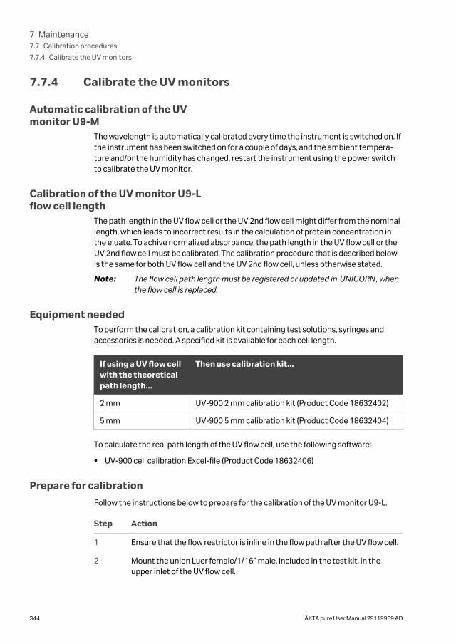
7.7.4 Calibrate the UV monitors
Automatic calibration of the UVmonitor U9-M
The wavelength is automatically calibrated every time the instrument is switched on. Ifthe instrument has been switched on for a couple of days, and the ambient tempera-ture and/or the humidity has changed, restart the instrument using the power switchto calibrate the UV monitor.
Calibration of the UV monitor U9-Lflow cell length
The path length in the UV flow cell or the UV 2nd flow cell might differ from the nominallength, which leads to incorrect results in the calculation of protein concentration inthe eluate. To achive normalized absorbance, the path length in the UV flow cell or theUV 2nd flow cell must be calibrated. The calibration procedure that is described belowis the same for both UV flow cell and the UV 2nd flow cell, unless otherwise stated.
Note: The flow cell path length must be registered or updated in UNICORN, whenthe flow cell is replaced.
Equipment neededTo perform the calibration, a calibration kit containing test solutions, syringes andaccessories is needed. A specified kit is available for each cell length.
If using a UV flow cellwith the theoreticalpath length...
Then use calibration kit...
2 mm UV-900 2 mm calibration kit (Product Code 18632402)
5 mm UV-900 5 mm calibration kit (Product Code 18632404)
To calculate the real path length of the UV flow cell, use the following software:
• UV-900 cell calibration Excel-file (Product Code 18632406)
Prepare for calibration
Follow the instructions below to prepare for the calibration of the UV monitor U9-L.
Step Action
1 Ensure that the flow restrictor is inline in the flow path after the UV flow cell.
2 Mount the union Luer female/1/16” male, included in the test kit, in theupper inlet of the UV flow cell.
7 Maintenance7.7 Calibration procedures
7.7.4 Calibrate the UV monitors
344 ÄKTA pure User Manual 29119969 AD
Step Action
3 Open the software UV-900 cell calibration Excel-file.
4 The solution bottles are labelled with the concentration value and the refer-ence absorbance value for each solution. Enter the concentrations of thesolutions in ascending order into the column UV Test kit Concentration(mg/l). Enter the corresponding absorbance values into the column UV Testkit Absorbance (AU/cm).
Perform the calibration
Follow the instructions below to calibrate UV monitor U9-L and UV monitor U9-L, 2nd.
Step Action
1 In the System Control module, select Manual →Execute Manual Instruc-tions.
In the Manual Instructions dialog:
• Select Pumps →System flow and set the Flow rate to 0.0 ml/min.
• Click Execute.
Result:
The absorbance can now be monitored.
2 Fill one of the supplied syringes with 1.5-2 ml of the first solution (0 mg/l).Ensure that there are no air bubbles in the syringe.
7 Maintenance7.7 Calibration procedures
7.7.4 Calibrate the UV monitors
ÄKTA pure User Manual 29119969 AD 345
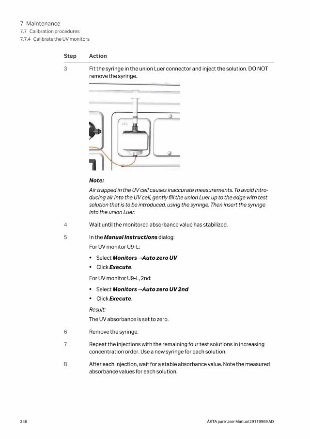
Step Action
3 Fit the syringe in the union Luer connector and inject the solution. DO NOTremove the syringe.
Note:
Air trapped in the UV cell causes inaccurate measurements. To avoid intro-ducing air into the UV cell, gently fill the union Luer up to the edge with testsolution that is to be introduced, using the syringe. Then insert the syringeinto the union Luer.
4 Wait until the monitored absorbance value has stabilized.
5 In the Manual Instructions dialog:
For UV monitor U9-L:
• Select Monitors →Auto zero UV
• Click Execute.
For UV monitor U9-L, 2nd:
• Select Monitors →Auto zero UV 2nd
• Click Execute.
Result:
The UV absorbance is set to zero.
6 Remove the syringe.
7 Repeat the injections with the remaining four test solutions in increasingconcentration order. Use a new syringe for each solution.
8 After each injection, wait for a stable absorbance value. Note the measuredabsorbance values for each solution.
7 Maintenance7.7 Calibration procedures
7.7.4 Calibrate the UV monitors
346 ÄKTA pure User Manual 29119969 AD
Step Action
9 Enter the measured absorbance values into the table in the column UV-900Absorbance (AU).
Note:
The values should be converted from mAU to AU.
10 When all absorbance values have been entered into the table, the real UVflow cell path length is shown at the bottom of the table.
Note:
The regression coefficient R2 should be larger than 0.999. If this is not thecase, one or more measured values are faulty.
Update the cell path length
Follow the instructions below to define the UV cell path length or the UV 2nd cellpath length. The flow cell path length should be updated when the flow cell has beenreplaced or calibrated.
Step Action
1 In the System Control module, select System →Calibration.
2 In the Calibration dialog, select
• UV cell path length
or
• UV 2nd cell path length
from the Monitor to calibrate drop-down list.
3 Enter the nominal flow cell path length in the Nominal length input fieldand click Set.
4 • If a calibration has been performed: enter the calculated flow cell pathlength, obtained in the calibration procedure, in the Real length inputfield and click Set.
• If no calibration has been performed: enter the nominal flow cell pathlength in the Real length input field and click Set.
Result:
The UV flow cell path length is updated.
7 Maintenance7.7 Calibration procedures
7.7.4 Calibrate the UV monitors
ÄKTA pure User Manual 29119969 AD 347
7.8 Replacement procedures
IntroductionThis section gives instructions for the replacement procedures to be performed by theuser of ÄKTA pure.
WARNING
Disconnect power. Always disconnect power from the instru-ment before replacing any component on the instrument, unlessstated otherwise in the user documentation.
In this section
Section See page
7.8.1 Replace tubing and connectors 349
7.8.2 Replace internal tubing in Fraction collector F9-C 351
7.8.3 Replace the Mixer 355
7.8.4 Replace the O-ring inside the Mixer 356
7.8.5 Replace the UV monitor U9-M flow cell 358
7.8.6 Replace the UV monitor U9-L flow cell 361
7.8.7 Replace Flow restrictor 363
7.8.8 Replace the inlet filters 364
7.8.9 Replace the pump head check valves 365
7.8.10 Replace pump piston seals of Pump P9 or P9H 368
7.8.11 Replace pump piston seals of Pump P9-S 377
7.8.12 Replace pump pistons 385
7.8.13 Replace pump rinsing system tubing 386
7 Maintenance7.8 Replacement procedures
348 ÄKTA pure User Manual 29119969 AD
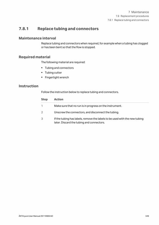
7.8.1 Replace tubing and connectors
Maintenance intervalReplace tubing and connectors when required, for example when a tubing has cloggedor has been bent so that the flow is stopped.
Required materialThe following material are required:
• Tubing and connectors
• Tubing cutter
• Fingertight wrench
Instruction
Follow the instruction below to replace tubing and connectors.
Step Action
1 Make sure that no run is in progress on the instrument.
2 Unscrew the connectors, and disconnect the tubing.
3 If the tubing has labels, remove the labels to be used with the new tubinglater. Discard the tubing and connectors.
7 Maintenance7.8 Replacement procedures
7.8.1 Replace tubing and connectors
ÄKTA pure User Manual 29119969 AD 349
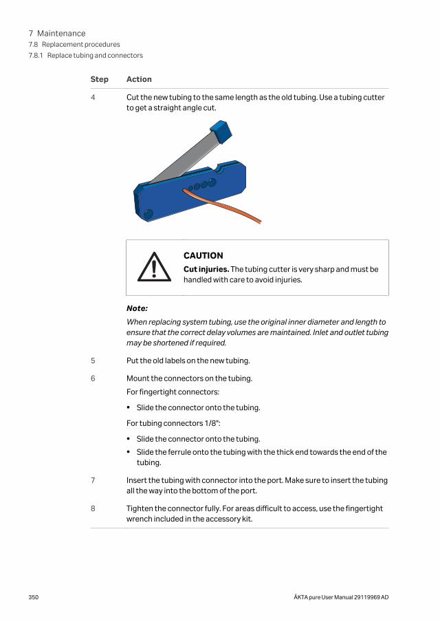
Step Action
4 Cut the new tubing to the same length as the old tubing. Use a tubing cutterto get a straight angle cut.
CAUTION
Cut injuries. The tubing cutter is very sharp and must behandled with care to avoid injuries.
Note:
When replacing system tubing, use the original inner diameter and length toensure that the correct delay volumes are maintained. Inlet and outlet tubingmay be shortened if required.
5 Put the old labels on the new tubing.
6 Mount the connectors on the tubing.
For fingertight connectors:
• Slide the connector onto the tubing.
For tubing connectors 1/8":
• Slide the connector onto the tubing.
• Slide the ferrule onto the tubing with the thick end towards the end of thetubing.
7 Insert the tubing with connector into the port. Make sure to insert the tubingall the way into the bottom of the port.
8 Tighten the connector fully. For areas difficult to access, use the fingertightwrench included in the accessory kit.
7 Maintenance7.8 Replacement procedures
7.8.1 Replace tubing and connectors
350 ÄKTA pure User Manual 29119969 AD
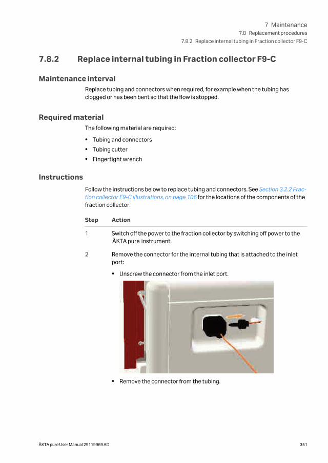
7.8.2 Replace internal tubing in Fraction collector F9-C
Maintenance intervalReplace tubing and connectors when required, for example when the tubing hasclogged or has been bent so that the flow is stopped.
Required materialThe following material are required:
• Tubing and connectors
• Tubing cutter
• Fingertight wrench
Instructions
Follow the instructions below to replace tubing and connectors. See Section 3.2.2 Frac-tion collector F9-C illustrations, on page 106 for the locations of the components of thefraction collector.
Step Action
1 Switch off the power to the fraction collector by switching off power to theÄKTA pure instrument.
2 Remove the connector for the internal tubing that is attached to the inletport:
• Unscrew the connector from the inlet port.
• Remove the connector from the tubing.
7 Maintenance7.8 Replacement procedures
7.8.2 Replace internal tubing in Fraction collector F9-C
ÄKTA pure User Manual 29119969 AD 351
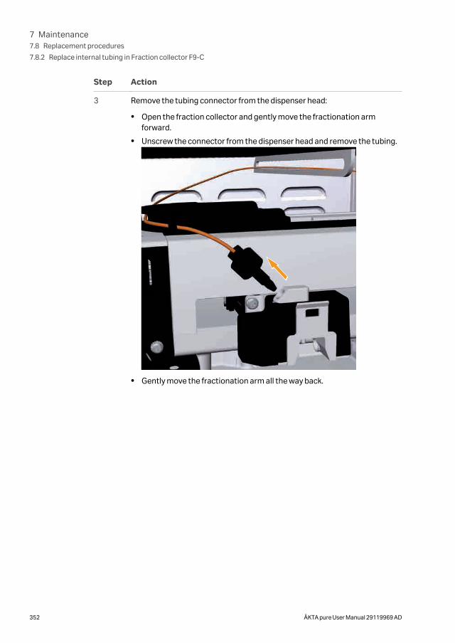
Step Action
3 Remove the tubing connector from the dispenser head:
• Open the fraction collector and gently move the fractionation armforward.
• Unscrew the connector from the dispenser head and remove the tubing.
• Gently move the fractionation arm all the way back.
7 Maintenance7.8 Replacement procedures
7.8.2 Replace internal tubing in Fraction collector F9-C
352 ÄKTA pure User Manual 29119969 AD
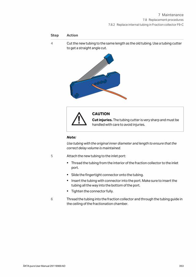
Step Action
4 Cut the new tubing to the same length as the old tubing. Use a tubing cutterto get a straight angle cut.
CAUTION
Cut injuries. The tubing cutter is very sharp and must behandled with care to avoid injuries.
Note:
Use tubing with the original inner diameter and length to ensure that thecorrect delay volume is maintained.
5 Attach the new tubing to the inlet port:
• Thread the tubing from the interior of the fraction collector to the inletport.
• Slide the fingertight connector onto the tubing.
• Insert the tubing with connector into the port. Make sure to insert thetubing all the way into the bottom of the port.
• Tighten the connector fully.
6 Thread the tubing into the fraction collector and through the tubing guide inthe ceiling of the fractionation chamber.
7 Maintenance7.8 Replacement procedures
7.8.2 Replace internal tubing in Fraction collector F9-C
ÄKTA pure User Manual 29119969 AD 353
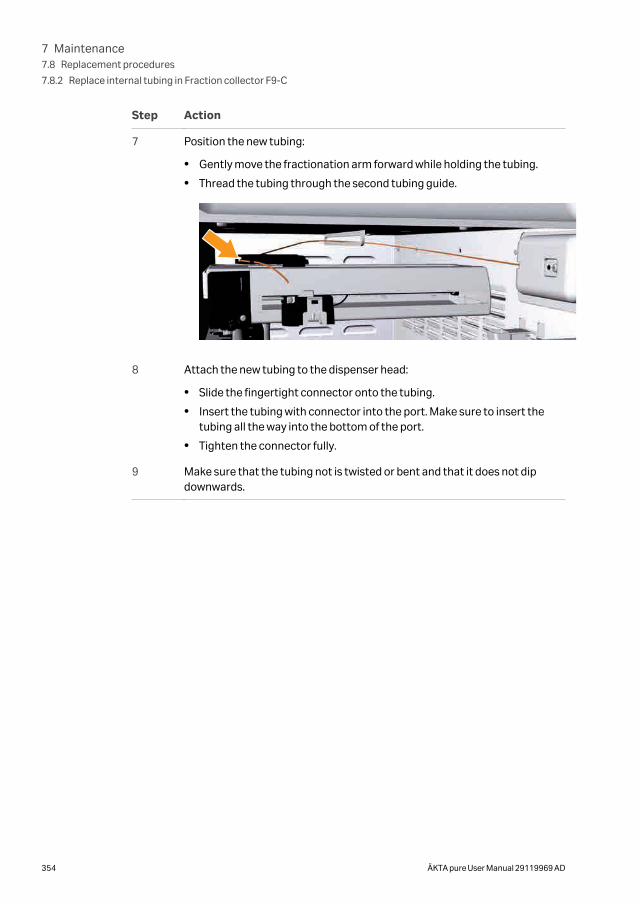
Step Action
7 Position the new tubing:
• Gently move the fractionation arm forward while holding the tubing.
• Thread the tubing through the second tubing guide.
8 Attach the new tubing to the dispenser head:
• Slide the fingertight connector onto the tubing.
• Insert the tubing with connector into the port. Make sure to insert thetubing all the way into the bottom of the port.
• Tighten the connector fully.
9 Make sure that the tubing not is twisted or bent and that it does not dipdownwards.
7 Maintenance7.8 Replacement procedures
7.8.2 Replace internal tubing in Fraction collector F9-C
354 ÄKTA pure User Manual 29119969 AD
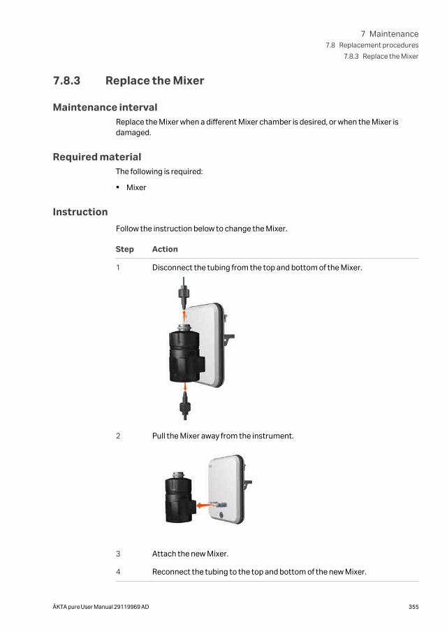
7.8.3 Replace the Mixer
Maintenance intervalReplace the Mixer when a different Mixer chamber is desired, or when the Mixer isdamaged.
Required materialThe following is required:
• Mixer
Instruction
Follow the instruction below to change the Mixer.
Step Action
1 Disconnect the tubing from the top and bottom of the Mixer.
2 Pull the Mixer away from the instrument.
3 Attach the new Mixer.
4 Reconnect the tubing to the top and bottom of the new Mixer.
7 Maintenance7.8 Replacement procedures
7.8.3 Replace the Mixer
ÄKTA pure User Manual 29119969 AD 355
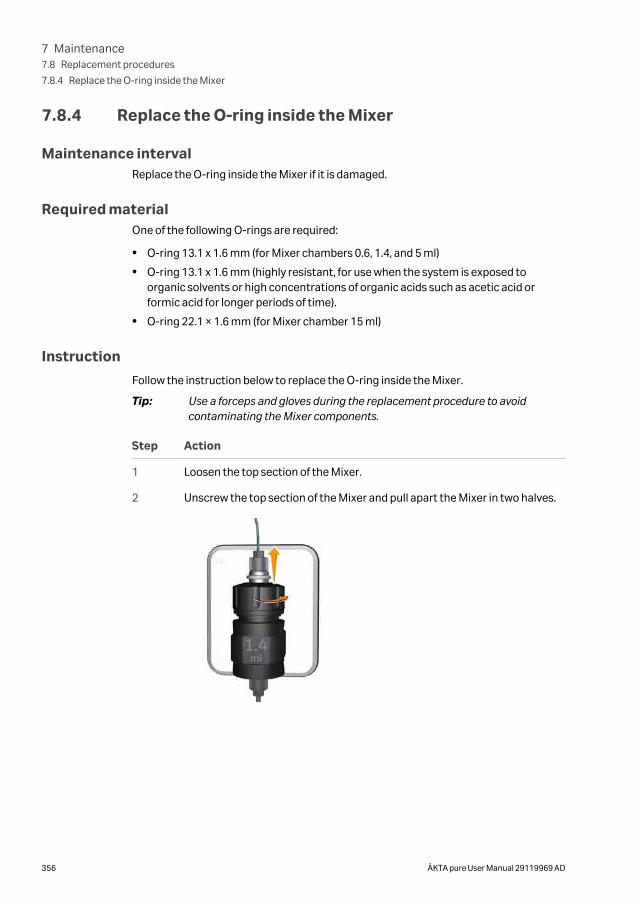
7.8.4 Replace the O-ring inside the Mixer
Maintenance intervalReplace the O-ring inside the Mixer if it is damaged.
Required materialOne of the following O-rings are required:
• O-ring 13.1 x 1.6 mm (for Mixer chambers 0.6, 1.4, and 5 ml)
• O-ring 13.1 x 1.6 mm (highly resistant, for use when the system is exposed toorganic solvents or high concentrations of organic acids such as acetic acid orformic acid for longer periods of time).
• O-ring 22.1 × 1.6 mm (for Mixer chamber 15 ml)
Instruction
Follow the instruction below to replace the O-ring inside the Mixer.
Tip: Use a forceps and gloves during the replacement procedure to avoidcontaminating the Mixer components.
Step Action
1 Loosen the top section of the Mixer.
2 Unscrew the top section of the Mixer and pull apart the Mixer in two halves.
7 Maintenance7.8 Replacement procedures
7.8.4 Replace the O-ring inside the Mixer
356 ÄKTA pure User Manual 29119969 AD
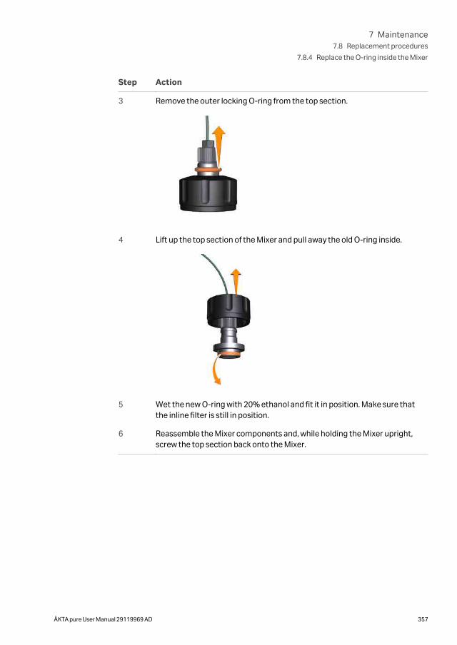
Step Action
3 Remove the outer locking O-ring from the top section.
4 Lift up the top section of the Mixer and pull away the old O-ring inside.
5 Wet the new O-ring with 20% ethanol and fit it in position. Make sure thatthe inline filter is still in position.
6 Reassemble the Mixer components and, while holding the Mixer upright,screw the top section back onto the Mixer.
7 Maintenance7.8 Replacement procedures
7.8.4 Replace the O-ring inside the Mixer
ÄKTA pure User Manual 29119969 AD 357
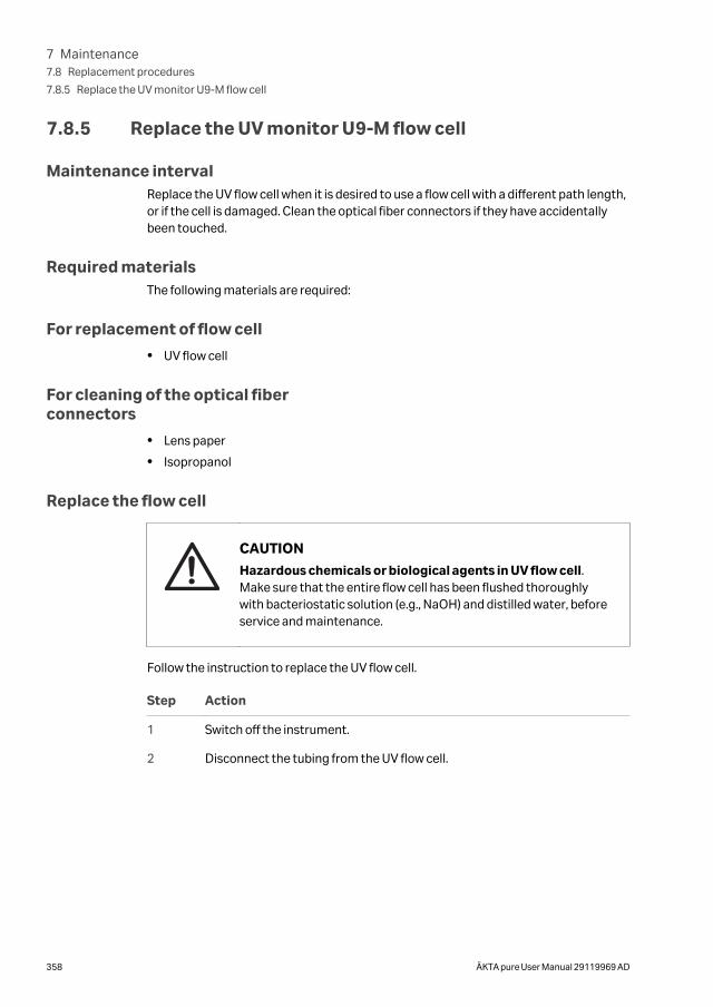
7.8.5 Replace the UV monitor U9-M flow cell
Maintenance intervalReplace the UV flow cell when it is desired to use a flow cell with a different path length,or if the cell is damaged. Clean the optical fiber connectors if they have accidentallybeen touched.
Required materialsThe following materials are required:
For replacement of flow cell
• UV flow cell
For cleaning of the optical fiberconnectors
• Lens paper
• Isopropanol
Replace the flow cell
CAUTION
Hazardous chemicals or biological agents in UV flow cell.Make sure that the entire flow cell has been flushed thoroughlywith bacteriostatic solution (e.g., NaOH) and distilled water, beforeservice and maintenance.
Follow the instruction to replace the UV flow cell.
Step Action
1 Switch off the instrument.
2 Disconnect the tubing from the UV flow cell.
7 Maintenance7.8 Replacement procedures
7.8.5 Replace the UV monitor U9-M flow cell
358 ÄKTA pure User Manual 29119969 AD
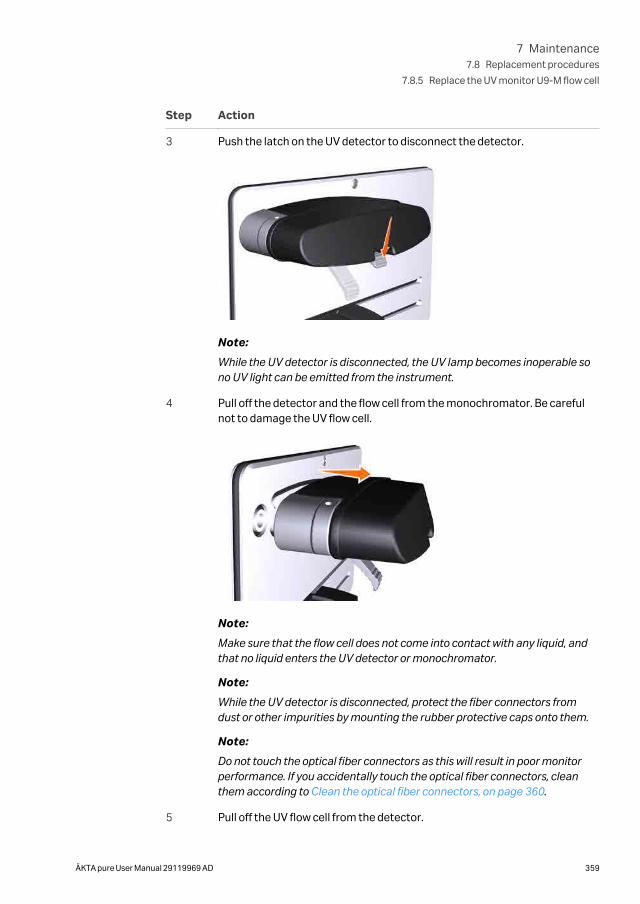
Step Action
3 Push the latch on the UV detector to disconnect the detector.
Note:
While the UV detector is disconnected, the UV lamp becomes inoperable sono UV light can be emitted from the instrument.
4 Pull off the detector and the flow cell from the monochromator. Be carefulnot to damage the UV flow cell.
Note:
Make sure that the flow cell does not come into contact with any liquid, andthat no liquid enters the UV detector or monochromator.
Note:
While the UV detector is disconnected, protect the fiber connectors fromdust or other impurities by mounting the rubber protective caps onto them.
Note:
Do not touch the optical fiber connectors as this will result in poor monitorperformance. If you accidentally touch the optical fiber connectors, cleanthem according to Clean the optical fiber connectors, on page 360.
5 Pull off the UV flow cell from the detector.
7 Maintenance7.8 Replacement procedures
7.8.5 Replace the UV monitor U9-M flow cell
ÄKTA pure User Manual 29119969 AD 359
Step Action
6 Pull off the black protective caps from the new UV flow cell, and connect thenew UV flow cell to the detector.
7 Connect the detector, with the new flow cell connected, to the monochro-mator. Pull the latch upwards to fasten the detector.
8 Connect the tubing to the new flow cell.
9 Switch on the instrument.
Result:
The flow cell path length is automatically recognized by the monitor when anew flow cell is connected.
Clean the optical fiber connectors
Follow the instruction to clean the optical fiber connectors.
WARNING
Hazardous substances. When using hazardous chemicals, takeall suitable protective measures, such as wearing protectiveclothing, glasses and gloves resistant to the substances used.Follow local and/or national regulations for safe operation andmaintenance of the product.
Step Action
1 Wipe the optical fiber connectors with isopropanol on lens paper.
2 Wipe the optical fiber connectors dry with lens paper.
7 Maintenance7.8 Replacement procedures
7.8.5 Replace the UV monitor U9-M flow cell
360 ÄKTA pure User Manual 29119969 AD
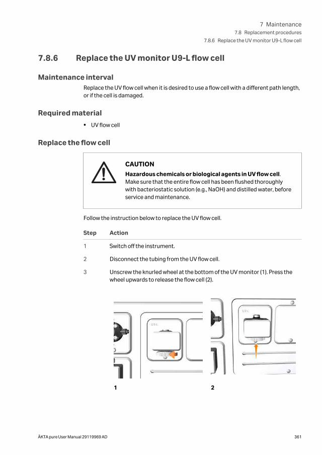
7.8.6 Replace the UV monitor U9-L flow cell
Maintenance intervalReplace the UV flow cell when it is desired to use a flow cell with a different path length,or if the cell is damaged.
Required material
• UV flow cell
Replace the flow cell
CAUTION
Hazardous chemicals or biological agents in UV flow cell.Make sure that the entire flow cell has been flushed thoroughlywith bacteriostatic solution (e.g., NaOH) and distilled water, beforeservice and maintenance.
Follow the instruction below to replace the UV flow cell.
Step Action
1 Switch off the instrument.
2 Disconnect the tubing from the UV flow cell.
3 Unscrew the knurled wheel at the bottom of the UV monitor (1). Press thewheel upwards to release the flow cell (2).
1 2
7 Maintenance7.8 Replacement procedures
7.8.6 Replace the UV monitor U9-L flow cell
ÄKTA pure User Manual 29119969 AD 361
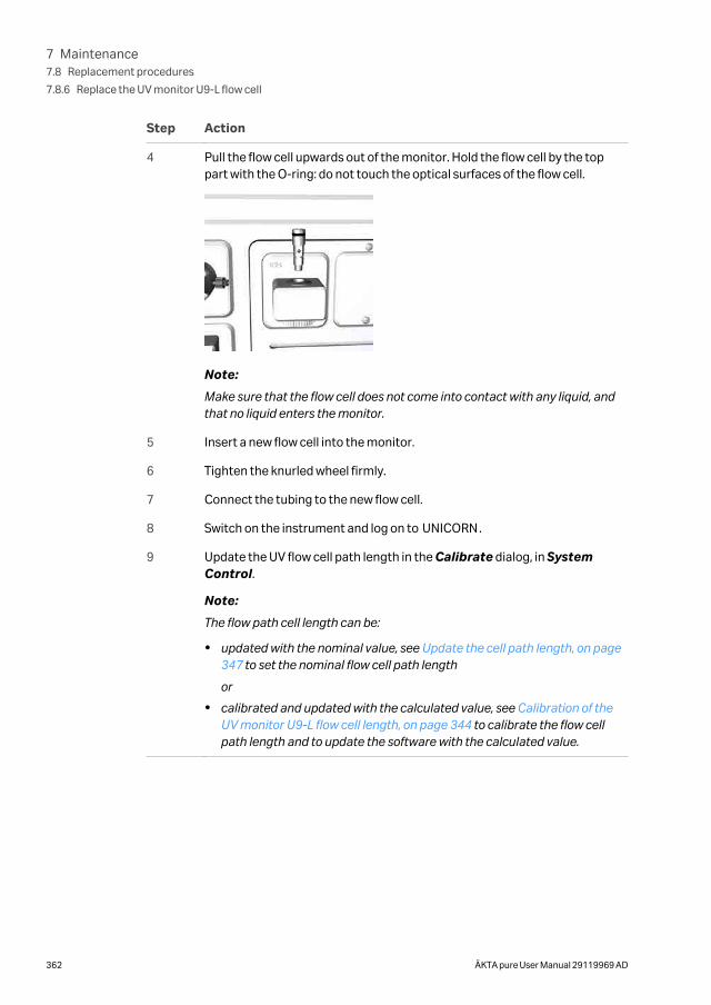
Step Action
4 Pull the flow cell upwards out of the monitor. Hold the flow cell by the toppart with the O-ring: do not touch the optical surfaces of the flow cell.
Note:
Make sure that the flow cell does not come into contact with any liquid, andthat no liquid enters the monitor.
5 Insert a new flow cell into the monitor.
6 Tighten the knurled wheel firmly.
7 Connect the tubing to the new flow cell.
8 Switch on the instrument and log on to UNICORN.
9 Update the UV flow cell path length in the Calibrate dialog, in SystemControl.
Note:
The flow path cell length can be:
• updated with the nominal value, see Update the cell path length, on page347 to set the nominal flow cell path length
or
• calibrated and updated with the calculated value, see Calibration of theUV monitor U9-L flow cell length, on page 344 to calibrate the flow cellpath length and to update the software with the calculated value.
7 Maintenance7.8 Replacement procedures
7.8.6 Replace the UV monitor U9-L flow cell
362 ÄKTA pure User Manual 29119969 AD
7.8.7 Replace Flow restrictor
Maintenance intervalReplace the Flow restrictor when required, for example when the back pressure of theFlow restrictor is outside the range 0.2 ± 0.05 MPa.
Required materialThe following material is required:
• Flow restrictor FR-902
Instruction
Follow the instruction to replace the Flow restrictor.
Step Action
1 Disconnect the tubing connected from the used Flow restrictor, and discardthe used Flow restrictor.
2 Connect the tubing to the new Flow restrictor. Make sure that the Flowrestrictor connector marked IN is connected to the pH valve port ToR (ToRestrictor), and that the Flow restrictor connector marked OUT isconnected to the pH valve port FrR (From Restrictor).
3 Check the back-pressure of the new Flow restrictor, see Section 7.4 Monthlymaintenance, on page 297
7 Maintenance7.8 Replacement procedures
7.8.7 Replace Flow restrictor
ÄKTA pure User Manual 29119969 AD 363
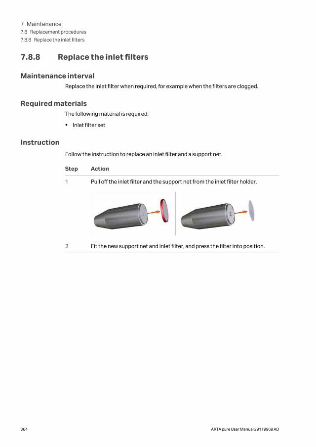
7.8.8 Replace the inlet filters
Maintenance intervalReplace the inlet filter when required, for example when the filters are clogged.
Required materialsThe following material is required:
• Inlet filter set
Instruction
Follow the instruction to replace an inlet filter and a support net.
Step Action
1 Pull off the inlet filter and the support net from the inlet filter holder.
2 Fit the new support net and inlet filter, and press the filter into position.
7 Maintenance7.8 Replacement procedures
7.8.8 Replace the inlet filters
364 ÄKTA pure User Manual 29119969 AD
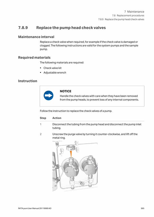
7.8.9 Replace the pump head check valves
Maintenance intervalReplace a check valve when required, for example if the check valve is damaged orclogged. The following instructions are valid for the system pumps and the samplepump.
Required materialsThe following materials are required:
• Check valve kit
• Adjustable wrench
Instruction
NOTICE
Handle the check valves with care when they have been removedfrom the pump heads, to prevent loss of any internal components.
Follow the instruction to replace the check valves of a pump.
Step Action
1 Disconnect the tubing from the pump head and disconnect the pump inlettubing.
2 Unscrew the purge valve by turning it counter-clockwise, and lift off themetal ring.
7 Maintenance7.8 Replacement procedures
7.8.9 Replace the pump head check valves
ÄKTA pure User Manual 29119969 AD 365
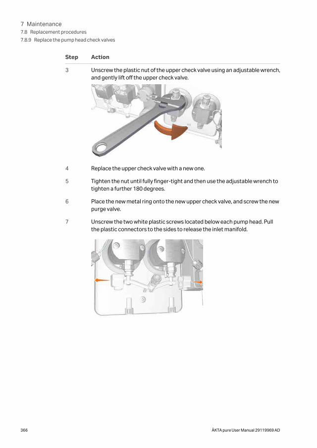
Step Action
3 Unscrew the plastic nut of the upper check valve using an adjustable wrench,and gently lift off the upper check valve.
4 Replace the upper check valve with a new one.
5 Tighten the nut until fully finger-tight and then use the adjustable wrench totighten a further 180 degrees.
6 Place the new metal ring onto the new upper check valve, and screw the newpurge valve.
7 Unscrew the two white plastic screws located below each pump head. Pullthe plastic connectors to the sides to release the inlet manifold.
7 Maintenance7.8 Replacement procedures
7.8.9 Replace the pump head check valves
366 ÄKTA pure User Manual 29119969 AD
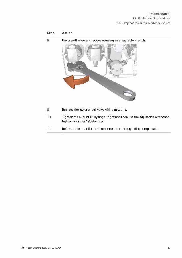
Step Action
8 Unscrew the lower check valve using an adjustable wrench.
9 Replace the lower check valve with a new one.
10 Tighten the nut until fully finger-tight and then use the adjustable wrench totighten a further 180 degrees.
11 Refit the inlet manifold and reconnect the tubing to the pump head.
7 Maintenance7.8 Replacement procedures
7.8.9 Replace the pump head check valves
ÄKTA pure User Manual 29119969 AD 367
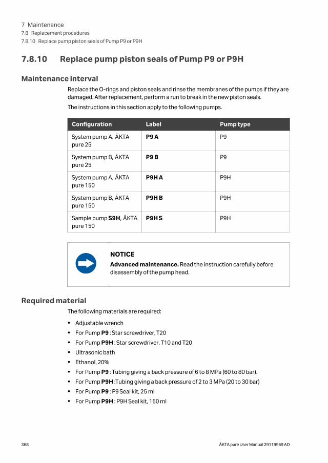
7.8.10 Replace pump piston seals of Pump P9 or P9H
Maintenance intervalReplace the O-rings and piston seals and rinse the membranes of the pumps if they aredamaged. After replacement, perform a run to break in the new piston seals.
The instructions in this section apply to the following pumps.
Configuration Label Pump type
System pump A, ÄKTApure 25
P9 A P9
System pump B, ÄKTApure 25
P9 B P9
System pump A, ÄKTApure 150
P9H A P9H
System pump B, ÄKTApure 150
P9H B P9H
Sample pump S9H, ÄKTApure 150
P9H S P9H
NOTICE
Advanced maintenance. Read the instruction carefully beforedisassembly of the pump head.
Required materialThe following materials are required:
• Adjustable wrench
• For Pump P9 : Star screwdriver, T20
• For Pump P9H : Star screwdriver, T10 and T20
• Ultrasonic bath
• Ethanol, 20%
• For Pump P9 : Tubing giving a back pressure of 6 to 8 MPa (60 to 80 bar).
• For Pump P9H :Tubing giving a back pressure of 2 to 3 MPa (20 to 30 bar)
• For Pump P9 : P9 Seal kit, 25 ml
• For Pump P9H : P9H Seal kit, 150 ml
7 Maintenance7.8 Replacement procedures
7.8.10 Replace pump piston seals of Pump P9 or P9H
368 ÄKTA pure User Manual 29119969 AD
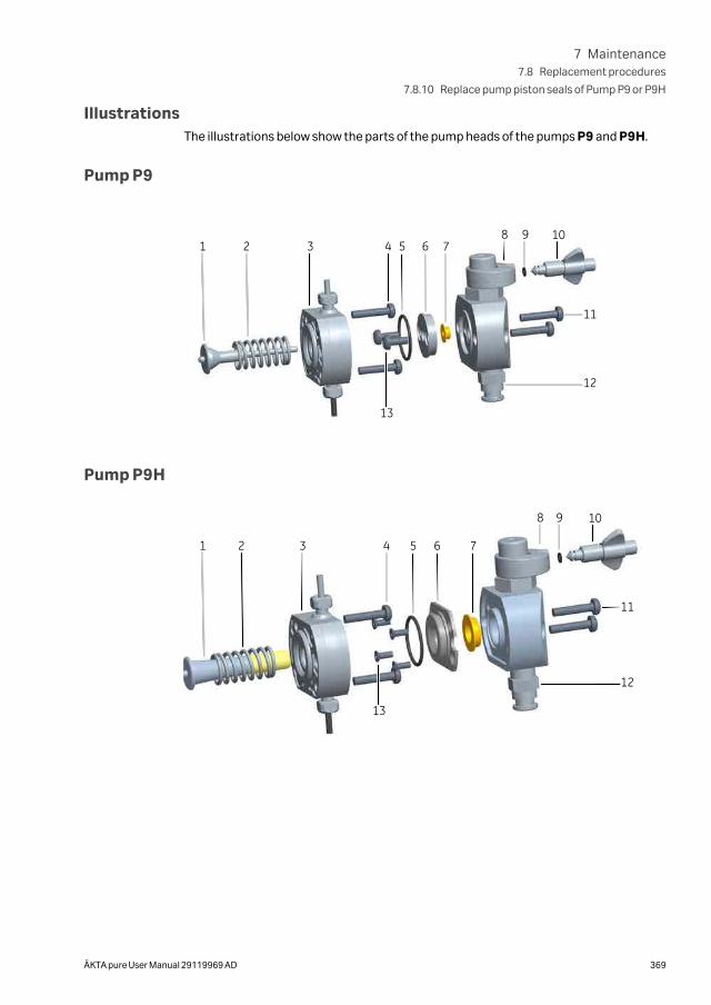
IllustrationsThe illustrations below show the parts of the pump heads of the pumps P9 and P9H.
Pump P9
1 2 3 4 5 6 7
12
98 10
11
13
Pump P9H
1 2 3 4 5 6 7
12
98 10
11
13
7 Maintenance7.8 Replacement procedures
7.8.10 Replace pump piston seals of Pump P9 or P9H
ÄKTA pure User Manual 29119969 AD 369
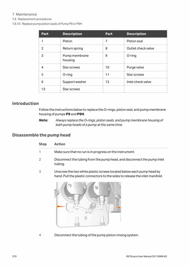
Part Description Part Description
1 Piston 7 Piston seal
2 Return spring 8 Outlet check valve
3 Pump membranehousing
9 O-ring
4 Star screws 10 Purge valve
5 O-ring 11 Star screws
6 Support washer 12 Inlet check valve
13 Star screws
IntroductionFollow the instructions below to replace the O-rings, piston seal, and pump membranehousing of pumps P9 and P9H.
Note: Always replace the O-rings, piston seals, and pump membrane housing ofboth pump heads of a pump at the same time.
Disassemble the pump head
Step Action
1 Make sure that no run is in progress on the instrument.
2 Disconnect the tubing from the pump head, and disconnect the pump inlettubing.
3 Unscrew the two white plastic screws located below each pump head byhand. Pull the plastic connectors to the sides to release the inlet manifold.
4 Disconnect the tubing of the pump piston rinsing system.
7 Maintenance7.8 Replacement procedures
7.8.10 Replace pump piston seals of Pump P9 or P9H
370 ÄKTA pure User Manual 29119969 AD
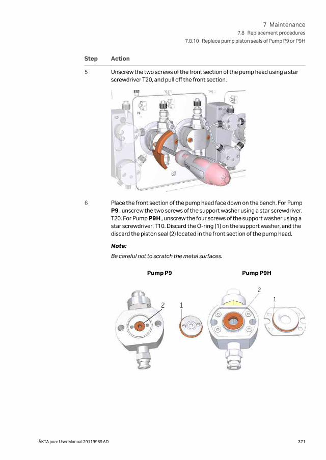
Step Action
5 Unscrew the two screws of the front section of the pump head using a starscrewdriver T20, and pull off the front section.
6 Place the front section of the pump head face down on the bench. For PumpP9 , unscrew the two screws of the support washer using a star screwdriver,T20. For Pump P9H , unscrew the four screws of the support washer using astar screwdriver, T10. Discard the O-ring (1) on the support washer, and thediscard the piston seal (2) located in the front section of the pump head.
Note:
Be careful not to scratch the metal surfaces.
Pump P9
2 1
Pump P9H
21
7 Maintenance7.8 Replacement procedures
7.8.10 Replace pump piston seals of Pump P9 or P9H
ÄKTA pure User Manual 29119969 AD 371
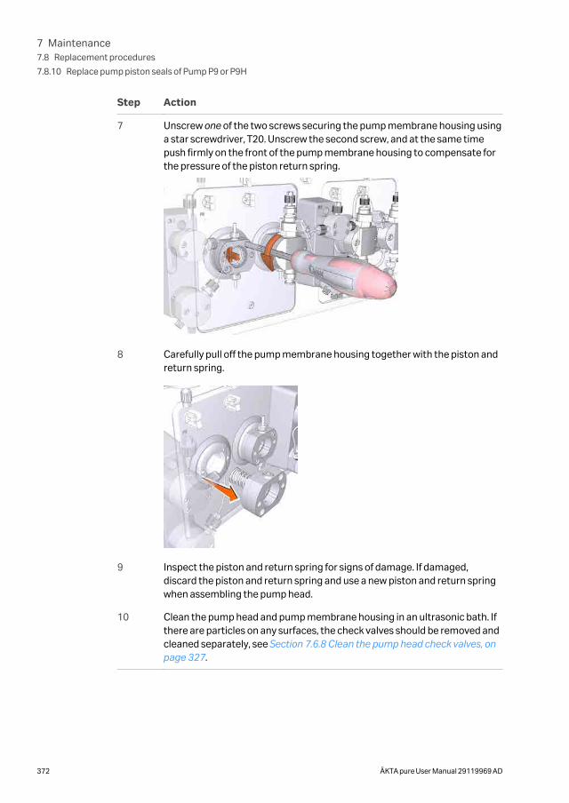
Step Action
7 Unscrew one of the two screws securing the pump membrane housing usinga star screwdriver, T20. Unscrew the second screw, and at the same timepush firmly on the front of the pump membrane housing to compensate forthe pressure of the piston return spring.
8 Carefully pull off the pump membrane housing together with the piston andreturn spring.
9 Inspect the piston and return spring for signs of damage. If damaged,discard the piston and return spring and use a new piston and return springwhen assembling the pump head.
10 Clean the pump head and pump membrane housing in an ultrasonic bath. Ifthere are particles on any surfaces, the check valves should be removed andcleaned separately, see Section 7.6.8 Clean the pump head check valves, onpage 327.
7 Maintenance7.8 Replacement procedures
7.8.10 Replace pump piston seals of Pump P9 or P9H
372 ÄKTA pure User Manual 29119969 AD
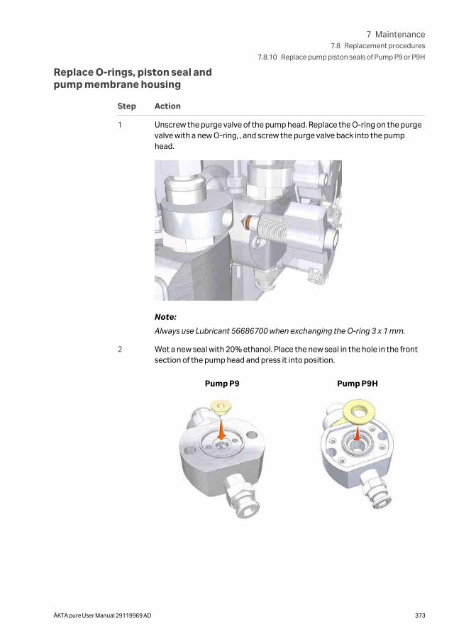
Replace O-rings, piston seal andpump membrane housing
Step Action
1 Unscrew the purge valve of the pump head. Replace the O-ring on the purgevalve with a new O-ring, , and screw the purge valve back into the pumphead.
Note:
Always use Lubricant 56686700 when exchanging the O-ring 3 x 1 mm.
2 Wet a new seal with 20% ethanol. Place the new seal in the hole in the frontsection of the pump head and press it into position.
Pump P9 Pump P9H
7 Maintenance7.8 Replacement procedures
7.8.10 Replace pump piston seals of Pump P9 or P9H
ÄKTA pure User Manual 29119969 AD 373
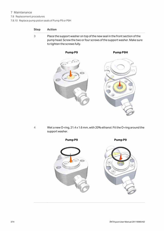
Step Action
3 Place the support washer on top of the new seal in the front section of thepump head. Screw the two or four screws of the support washer. Make sureto tighten the screws fully.
Pump P9 Pump P9H
4 Wet a new O-ring, 21.4 x 1.6 mm, with 20% ethanol. Fit the O-ring around thesupport washer.
Pump P9 Pump P9
7 Maintenance7.8 Replacement procedures
7.8.10 Replace pump piston seals of Pump P9 or P9H
374 ÄKTA pure User Manual 29119969 AD
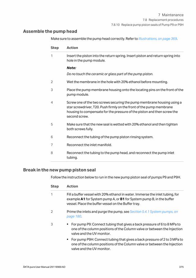
Assemble the pump head
Make sure to assemble the pump head correctly. Refer to Illustrations, on page 369.
Step Action
1 Insert the piston into the return spring. Insert piston and return spring intohole in the pump module.
Note:
Do no touch the ceramic or glass part of the pump piston.
2 Wet the membrane in the hole with 20% ethanol before mounting.
3 Place the pump membrane housing onto the locating pins on the front of thepump module.
4 Screw one of the two screws securing the pump membrane housing using astar screwdriver, T20. Push firmly on the front of the pump membranehousing to compensate for the pressure of the piston and then screw thesecond screw.
5 Make sure that the new seal is wetted with 20% ethanol and then tightenboth screws fully.
6 Reconnect the tubing of the pump piston rinsing system.
7 Reconnect the inlet manifold.
8 Reconnect the tubing to the pump head, and reconnect the pump inlettubing.
Break in the new pump piston seal
Follow the instruction below to run in the new pump piston seal of pumps P9 and P9H.
Step Action
1 Fill a buffer vessel with 20% ethanol in water. Immerse the inlet tubing, forexample A1 for System pump A, or B1 for System pump B, in the buffervessel. Place the buffer vessel on the Buffer tray.
2 Prime the inlets and purge the pump, see Section 5.4.1 System pumps, onpage 180.
3 • For pump P9: Connect tubing that gives a back pressure of 6 to 8 MPa toone of the column positions of the Column valve or between the Injectionvalve and the UV monitor.
• For pump P9H: Connect tubing that gives a back pressure of 2 to 3 MPa toone of the column positions of the Column valve or between the Injectionvalve and the UV monitor.
7 Maintenance7.8 Replacement procedures
7.8.10 Replace pump piston seals of Pump P9 or P9H
ÄKTA pure User Manual 29119969 AD 375
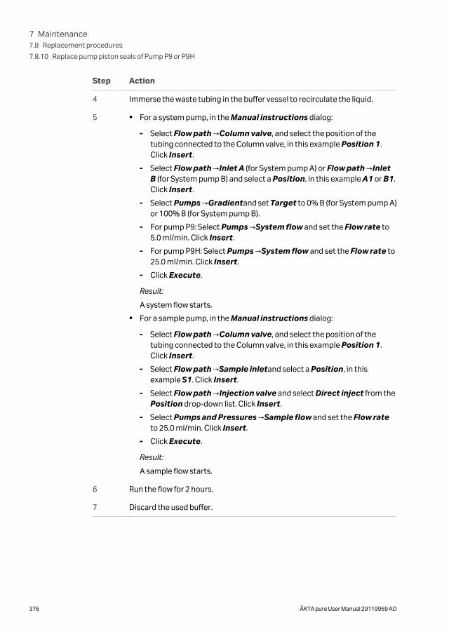
Step Action
4 Immerse the waste tubing in the buffer vessel to recirculate the liquid.
5 • For a system pump, in the Manual instructions dialog:
- Select Flow path →Column valve, and select the position of thetubing connected to the Column valve, in this example Position 1.Click Insert.
- Select Flow path →Inlet A (for System pump A) or Flow path →InletB (for System pump B) and select a Position, in this example A1 or B1.Click Insert.
- Select Pumps →Gradientand set Target to 0% B (for System pump A)or 100% B (for System pump B).
- For pump P9: Select Pumps →System flow and set the Flow rate to5.0 ml/min. Click Insert.
- For pump P9H: Select Pumps →System flow and set the Flow rate to25.0 ml/min. Click Insert.
- Click Execute.
Result:
A system flow starts.
• For a sample pump, in the Manual instructions dialog:
- Select Flow path →Column valve, and select the position of thetubing connected to the Column valve, in this example Position 1.Click Insert.
- Select Flow path →Sample inletand select a Position, in thisexample S1. Click Insert.
- Select Flow path →Injection valve and select Direct inject from thePosition drop-down list. Click Insert.
- Select Pumps and Pressures →Sample flow and set the Flow rateto 25.0 ml/min. Click Insert.
- Click Execute.
Result:
A sample flow starts.
6 Run the flow for 2 hours.
7 Discard the used buffer.
7 Maintenance7.8 Replacement procedures
7.8.10 Replace pump piston seals of Pump P9 or P9H
376 ÄKTA pure User Manual 29119969 AD
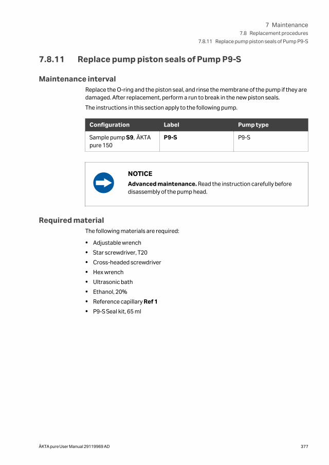
7.8.11 Replace pump piston seals of Pump P9-S
Maintenance intervalReplace the O-ring and the piston seal, and rinse the membrane of the pump if they aredamaged. After replacement, perform a run to break in the new piston seals.
The instructions in this section apply to the following pump.
Configuration Label Pump type
Sample pump S9, ÄKTApure 150
P9-S P9-S
NOTICE
Advanced maintenance. Read the instruction carefully beforedisassembly of the pump head.
Required materialThe following materials are required:
• Adjustable wrench
• Star screwdriver, T20
• Cross-headed screwdriver
• Hex wrench
• Ultrasonic bath
• Ethanol, 20%
• Reference capillary Ref 1
• P9-S Seal kit, 65 ml
7 Maintenance7.8 Replacement procedures
7.8.11 Replace pump piston seals of Pump P9-S
ÄKTA pure User Manual 29119969 AD 377
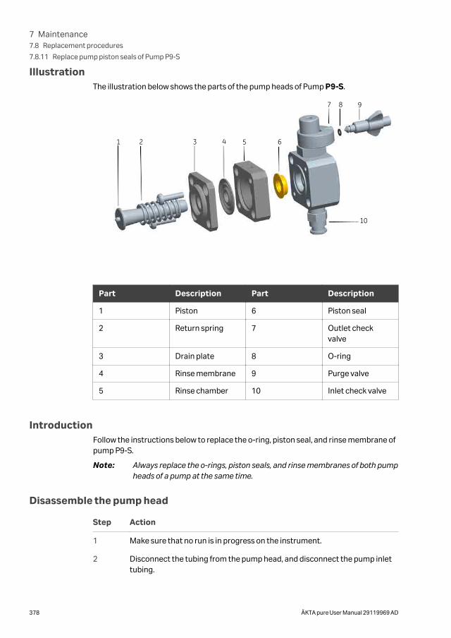
IllustrationThe illustration below shows the parts of the pump heads of Pump P9-S.
1 2 3 4 5
10
87 9
6
Part Description Part Description
1 Piston 6 Piston seal
2 Return spring 7 Outlet checkvalve
3 Drain plate 8 O-ring
4 Rinse membrane 9 Purge valve
5 Rinse chamber 10 Inlet check valve
IntroductionFollow the instructions below to replace the o-ring, piston seal, and rinse membrane ofpump P9-S.
Note: Always replace the o-rings, piston seals, and rinse membranes of both pumpheads of a pump at the same time.
Disassemble the pump head
Step Action
1 Make sure that no run is in progress on the instrument.
2 Disconnect the tubing from the pump head, and disconnect the pump inlettubing.
7 Maintenance7.8 Replacement procedures
7.8.11 Replace pump piston seals of Pump P9-S
378 ÄKTA pure User Manual 29119969 AD
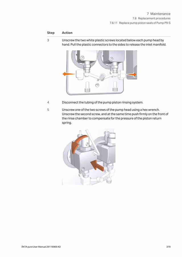
Step Action
3 Unscrew the two white plastic screws located below each pump head byhand. Pull the plastic connectors to the sides to release the inlet manifold.
4 Disconnect the tubing of the pump piston rinsing system.
5 Unscrew one of the two screws of the pump head using a hex wrench.Unscrew the second screw, and at the same time push firmly on the front ofthe rinse chamber to compensate for the pressure of the piston returnspring.
7 Maintenance7.8 Replacement procedures
7.8.11 Replace pump piston seals of Pump P9-S
ÄKTA pure User Manual 29119969 AD 379
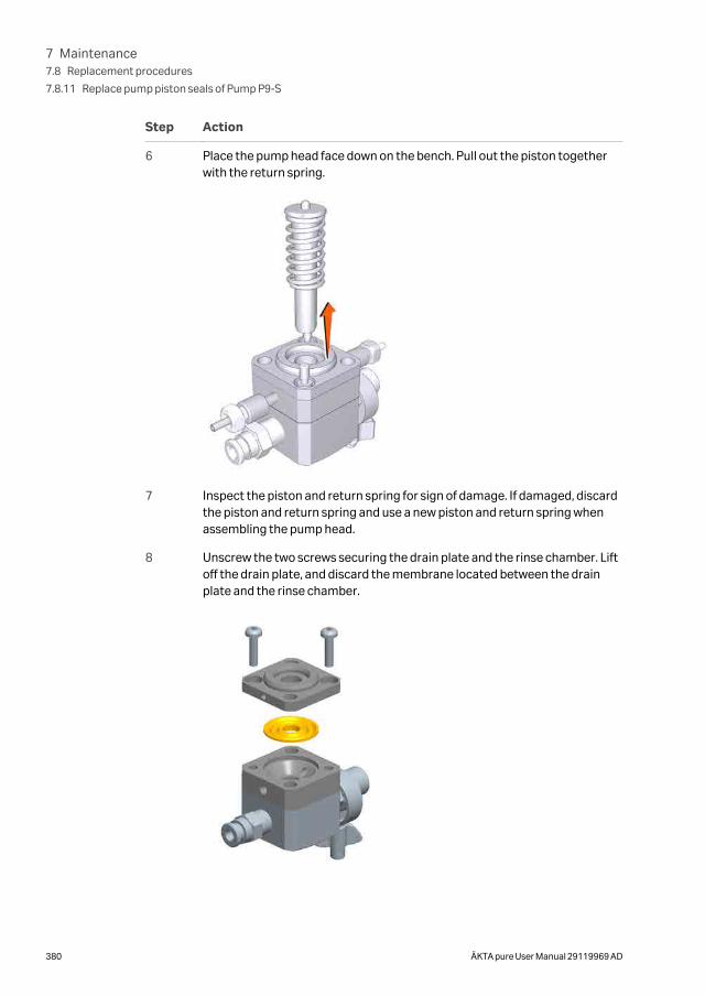
Step Action
6 Place the pump head face down on the bench. Pull out the piston togetherwith the return spring.
7 Inspect the piston and return spring for sign of damage. If damaged, discardthe piston and return spring and use a new piston and return spring whenassembling the pump head.
8 Unscrew the two screws securing the drain plate and the rinse chamber. Liftoff the drain plate, and discard the membrane located between the drainplate and the rinse chamber.
7 Maintenance7.8 Replacement procedures
7.8.11 Replace pump piston seals of Pump P9-S
380 ÄKTA pure User Manual 29119969 AD
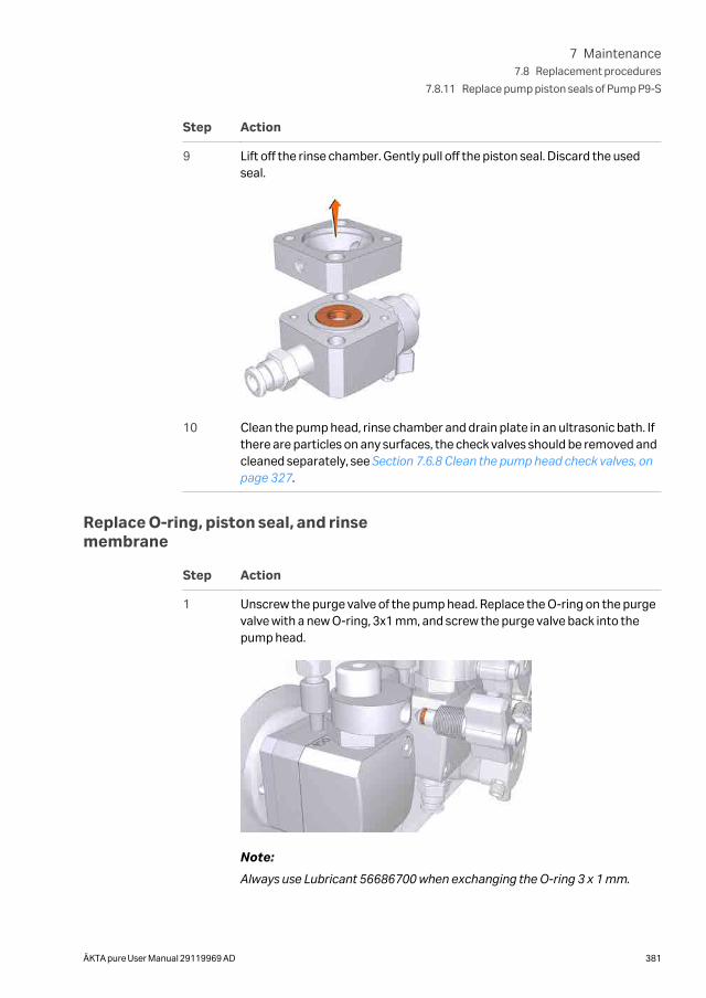
Step Action
9 Lift off the rinse chamber. Gently pull off the piston seal. Discard the usedseal.
10 Clean the pump head, rinse chamber and drain plate in an ultrasonic bath. Ifthere are particles on any surfaces, the check valves should be removed andcleaned separately, see Section 7.6.8 Clean the pump head check valves, onpage 327.
Replace O-ring, piston seal, and rinsemembrane
Step Action
1 Unscrew the purge valve of the pump head. Replace the O-ring on the purgevalve with a new O-ring, 3x1 mm, and screw the purge valve back into thepump head.
Note:
Always use Lubricant 56686700 when exchanging the O-ring 3 x 1 mm.
7 Maintenance7.8 Replacement procedures
7.8.11 Replace pump piston seals of Pump P9-S
ÄKTA pure User Manual 29119969 AD 381
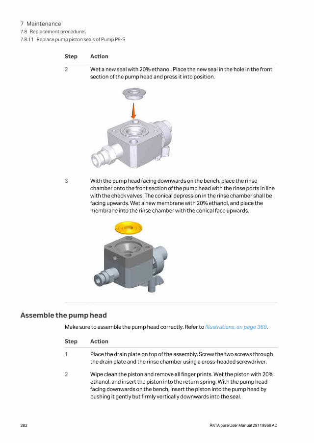
Step Action
2 Wet a new seal with 20% ethanol. Place the new seal in the hole in the frontsection of the pump head and press it into position.
3 With the pump head facing downwards on the bench, place the rinsechamber onto the front section of the pump head with the rinse ports in linewith the check valves. The conical depression in the rinse chamber shall befacing upwards. Wet a new membrane with 20% ethanol, and place themembrane into the rinse chamber with the conical face upwards.
Assemble the pump head
Make sure to assemble the pump head correctly. Refer to Illustrations, on page 369.
Step Action
1 Place the drain plate on top of the assembly. Screw the two screws throughthe drain plate and the rinse chamber using a cross-headed screwdriver.
2 Wipe clean the piston and remove all finger prints. Wet the piston with 20%ethanol, and insert the piston into the return spring. With the pump headfacing downwards on the bench, insert the piston into the pump head bypushing it gently but firmly vertically downwards into the seal.
7 Maintenance7.8 Replacement procedures
7.8.11 Replace pump piston seals of Pump P9-S
382 ÄKTA pure User Manual 29119969 AD
Step Action
3 Place the complete pump head over the locating pins on the front panel ofthe sample pump module. Turn the pump head so that the text UP on thedrain plate is facing upwards. Push firmly on the front of the pump head, andat the same time screw one of the screws to fasten the pump head onto thefront of the module using a hex wrench. Screw the second screw of the pumphead. Make sure to tighten both screws fully.
4 Reconnect the tubing of the pump piston rinsing system.
5 Reconnect the inlet manifold.
6 Reconnect the tubing to the pump head, and reconnect the pump inlettubing.
7 Break in the new pump piston seal, see instruction below.
Break in the new pump piston seal
Follow the instruction below to break in the new pump piston seal of pump P9-S.
Step Action
1 Fill a buffer vessel with 20% ethanol in water. Immerse a piece of sampleinlet tubing, for example S1, in the buffer vessel. Place the buffer vessel onthe Buffer tray.
2 Prime the inlets and purge the pump, see Section 5.4.2 Sample pump, onpage 187
3 Connect the reference capillary Ref 1 (or equivalent tubing that gives abackpressure of 2-3 MPa) to one of the column positions of the Column valve(e.g., ports 1A and 1B).
4 Immerse the waste tubing in the buffer vessel to recirculate the liquid.
7 Maintenance7.8 Replacement procedures
7.8.11 Replace pump piston seals of Pump P9-S
ÄKTA pure User Manual 29119969 AD 383
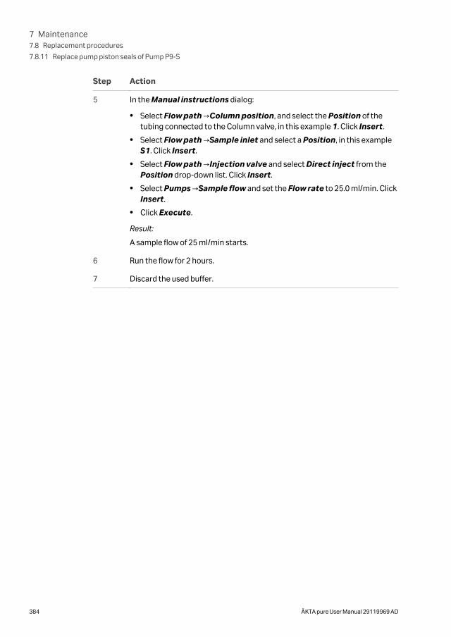
Step Action
5 In the Manual instructions dialog:
• Select Flow path →Column position, and select the Position of thetubing connected to the Column valve, in this example 1. Click Insert.
• Select Flow path →Sample inlet and select a Position, in this exampleS1. Click Insert.
• Select Flow path →Injection valve and select Direct inject from thePosition drop-down list. Click Insert.
• Select Pumps →Sample flow and set the Flow rate to 25.0 ml/min. ClickInsert.
• Click Execute.
Result:
A sample flow of 25 ml/min starts.
6 Run the flow for 2 hours.
7 Discard the used buffer.
7 Maintenance7.8 Replacement procedures
7.8.11 Replace pump piston seals of Pump P9-S
384 ÄKTA pure User Manual 29119969 AD
7.8.12 Replace pump pistons
Maintenance intervalReplace the pump pistons if they are damaged.
Required materialThe following materials are required:
• Adjustable wrench
• Star screwdriver, T20
• Piston kit
Replace pump pistons of Pump P9and P9H
If a damaged piston has been in operation, the piston seal will be destroyed and shouldalso be replaced. To replace the piston and the seal of a system pump, see Section7.8.10 Replace pump piston seals of Pump P9 or P9H, on page 368.
Replace pump pistons of Pump P9-SIf a damaged piston has been in operation, the piston seal will be destroyed and shouldalso be replaced. To replace the piston and the seal of Pump P9-S , see Section 7.8.11Replace pump piston seals of Pump P9-S, on page 377.
7 Maintenance7.8 Replacement procedures
7.8.12 Replace pump pistons
ÄKTA pure User Manual 29119969 AD 385
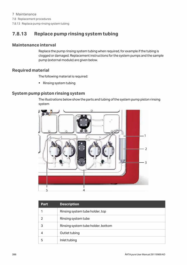
7.8.13 Replace pump rinsing system tubing
Maintenance intervalReplace the pump rinsing system tubing when required, for example if the tubing isclogged or damaged. Replacement instructions for the system pumps and the samplepump (external module) are given below.
Required materialThe following material is required:
• Rinsing system tubing
System pump piston rinsing systemThe illustrations below show the parts and tubing of the system pump piston rinsingsystem
1
2
3
45
Part Description
1 Rinsing system tube holder, top
2 Rinsing system tube
3 Rinsing system tube holder, bottom
4 Outlet tubing
5 Inlet tubing
7 Maintenance7.8 Replacement procedures
7.8.13 Replace pump rinsing system tubing
386 ÄKTA pure User Manual 29119969 AD
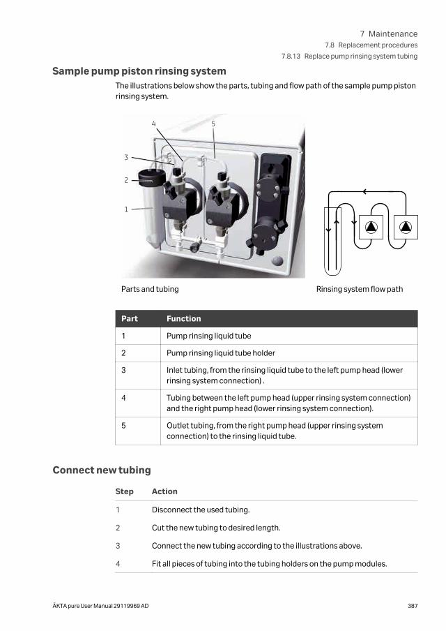
Sample pump piston rinsing systemThe illustrations below show the parts, tubing and flow path of the sample pump pistonrinsing system.
1
2
3
4 5
Parts and tubing Rinsing system flow path
Part Function
1 Pump rinsing liquid tube
2 Pump rinsing liquid tube holder
3 Inlet tubing, from the rinsing liquid tube to the left pump head (lowerrinsing system connection) .
4 Tubing between the left pump head (upper rinsing system connection)and the right pump head (lower rinsing system connection).
5 Outlet tubing, from the right pump head (upper rinsing systemconnection) to the rinsing liquid tube.
Connect new tubing
Step Action
1 Disconnect the used tubing.
2 Cut the new tubing to desired length.
3 Connect the new tubing according to the illustrations above.
4 Fit all pieces of tubing into the tubing holders on the pump modules.
7 Maintenance7.8 Replacement procedures
7.8.13 Replace pump rinsing system tubing
ÄKTA pure User Manual 29119969 AD 387

Prime the rinsing systemsBefore usage, prime the pump rinsing system tubing. Refer to Section 7.3.1 Changepump rinsing solution, on page 289 for detailed instructions.
7 Maintenance7.8 Replacement procedures
7.8.13 Replace pump rinsing system tubing
388 ÄKTA pure User Manual 29119969 AD
8 Troubleshooting
About this chapterThis chapter describes troubleshooting and corrective actions for ÄKTA pure.
In this chapter
Section See page
8.1 Introduction to troubleshooting 390
8.2 Troubleshooting: General Checklist 392
8.3 Troubleshooting: Monitors 394
8.4 Troubleshooting: Valves 409
8.5 Troubleshooting: Fraction collector 411
8.6 Troubleshooting: Pumps 423
8.7 Troubleshooting: Other components 430
8.8 Troubleshooting: Instrument communication 438
8.9 Troubleshooting: Method development 440
8.10 Error codes 441
8 Troubleshooting
ÄKTA pure User Manual 29119969 AD 389
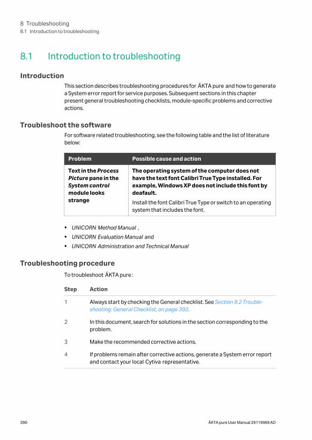
8.1 Introduction to troubleshooting
IntroductionThis section describes troubleshooting procedures for ÄKTA pure and how to generatea System error report for service purposes. Subsequent sections in this chapterpresent general troubleshooting checklists, module-specific problems and correctiveactions.
Troubleshoot the softwareFor software related troubleshooting, see the following table and the list of literaturebelow:
Problem Possible cause and action
Text in the ProcessPicture pane in theSystem controlmodule looksstrange
The operating system of the computer does nothave the text font Calibri True Type installed. Forexample, Windows XP does not include this font bydeafault.
Install the font Calibri True Type or switch to an operatingsystem that includes the font.
• UNICORN Method Manual ,
• UNICORN Evaluation Manual and
• UNICORN Administration and Technical Manual
Troubleshooting procedure
To troubleshoot ÄKTA pure:
Step Action
1 Always start by checking the General checklist. See Section 8.2 Trouble-shooting: General Checklist, on page 392.
2 In this document, search for solutions in the section corresponding to theproblem.
3 Make the recommended corrective actions.
4 If problems remain after corrective actions, generate a System error reportand contact your local Cytiva representative.
8 Troubleshooting8.1 Introduction to troubleshooting
390 ÄKTA pure User Manual 29119969 AD
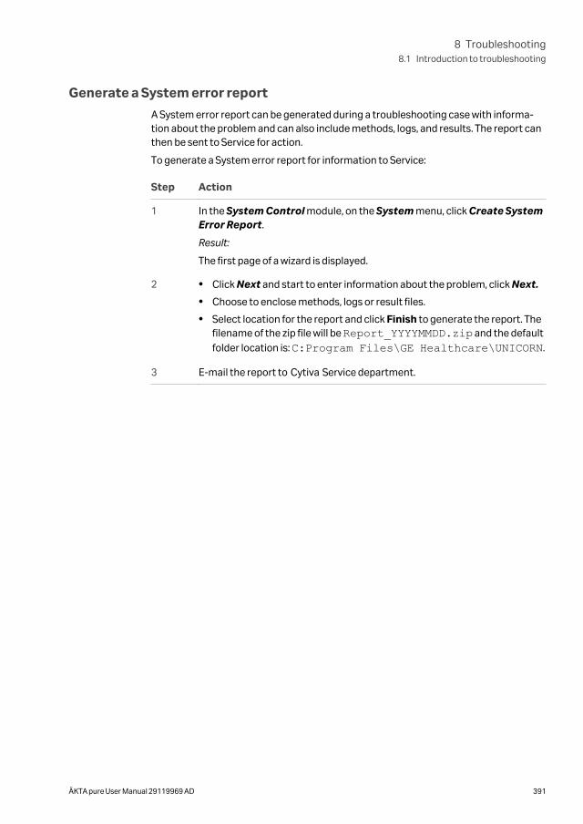
Generate a System error report
A System error report can be generated during a troubleshooting case with informa-tion about the problem and can also include methods, logs, and results. The report canthen be sent to Service for action.
To generate a System error report for information to Service:
Step Action
1 In the System Control module, on the System menu, click Create SystemError Report.
Result:
The first page of a wizard is displayed.
2 • Click Next and start to enter information about the problem, click Next.
• Choose to enclose methods, logs or result files.
• Select location for the report and click Finish to generate the report. Thefilename of the zip file will be Report_YYYYMMDD.zip and the defaultfolder location is: C:Program Files\GE Healthcare\UNICORN.
3 E-mail the report to Cytiva Service department.
8 Troubleshooting8.1 Introduction to troubleshooting
ÄKTA pure User Manual 29119969 AD 391
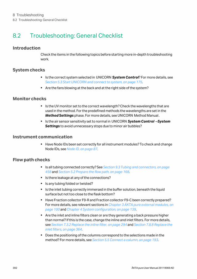
8.2 Troubleshooting: General Checklist
IntroductionCheck the items in the following topics before starting more in-depth troubleshootingwork.
System checks
• Is the correct system selected in UNICORN System Control? For more details, see Section 5.3 Start UNICORN and connect to system, on page 175.
• Are the fans blowing at the back and at the right side of the system?
Monitor checks
• Is the UV monitor set to the correct wavelength? Check the wavelengths that areused in the method. For the predefined methods the wavelengths are set in theMethod Settings phase. For more details, see UNICORN Method Manual .
• Is the air sensor sensitivity set to normal in UNICORN System Control →SystemSettings to avoid unnecessary stops due to minor air bubbles?
Instrument communication
• Have Node IDs been set correctly for all instrument modules? To check and changeNode IDs, see Node ID, on page 87.
Flow path checks
• Is all tubing connected correctly? See Section 9.3 Tubing and connectors, on page458 and Section 5.2 Prepare the flow path, on page 168.
• Is there leakage at any of the connections?
• Is any tubing folded or twisted?
• Is the inlet tubing correctly immersed in the buffer solution, beneath the liquidsurface but not too close to the flask bottom?
• Have Fraction collector F9-R and Fraction collector F9-C been correctly prepared?For more details, see relevant sections in Chapter 3 ÄKTA pure external modules, onpage 100 and Chapter 4 System configuration, on page 139.
• Are the inlet and inline filters clean or are they generating a back pressure higherthan normal? If this is the case, change the inline and inlet filters. For more details,see Section 7.3.2 Replace the inline filter, on page 294 and Section 7.8.8 Replace theinlet filters, on page 364.
• Does the positioning of the columns correspond to the selections made in themethod? For more details, see Section 5.5 Connect a column, on page 193.
8 Troubleshooting8.2 Troubleshooting: General Checklist
392 ÄKTA pure User Manual 29119969 AD
Purification checks
• Have all columns been cleaned and prepared according to the column recommen-dations?
• Have the samples been adjusted to binding buffer conditions?
• Have the samples been clarified by centrifugation and/or filtration prior to sampleloading?
• Are the correct buffers used for the chosen columns and proteins?
• Check buffers for precipitations. Adjust to room temperature.
• Are the chosen columns suitable for the chosen target proteins?
• Do the buffers have correct pH? The pH of some buffers changes with the tempera-ture.
• Are the UV-wavelengths used by the method appropriate with respect to usedbuffers and proteins? For more details see the method handbooks available fromCytiva.
8 Troubleshooting8.2 Troubleshooting: General Checklist
ÄKTA pure User Manual 29119969 AD 393
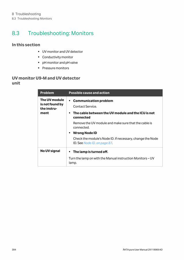
8.3 Troubleshooting: Monitors
In this section
• UV monitor and UV detector
• Conductivity monitor
• pH monitor and pH valve
• Pressure monitors
UV monitor U9-M and UV detectorunit
Problem Possible cause and action
The UV moduleis not found bythe instru-ment
• Communication problem
Contact Service.
• The cable between the UV module and the ICU is notconnected
Remove the UV module and make sure that the cable isconnected.
• Wrong Node ID
Check the module's Node ID. If necessary, change the NodeID. See Node ID, on page 87.
No UV signal • The lamp is turned off.
Turn the lamp on with the Manual instruction Monitors – UVlamp.
8 Troubleshooting8.3 Troubleshooting: Monitors
394 ÄKTA pure User Manual 29119969 AD
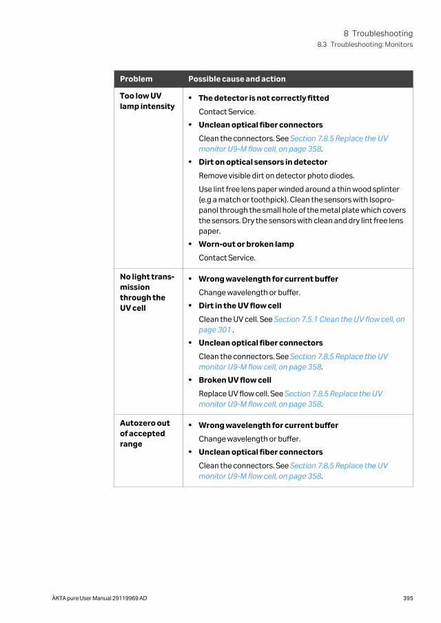
Problem Possible cause and action
Too low UVlamp intensity
• The detector is not correctly fitted
Contact Service.
• Unclean optical fiber connectors
Clean the connectors. See Section 7.8.5 Replace the UVmonitor U9-M flow cell, on page 358.
• Dirt on optical sensors in detector
Remove visible dirt on detector photo diodes.
Use lint free lens paper winded around a thin wood splinter(e.g a match or toothpick). Clean the sensors with Isopro-panol through the small hole of the metal plate which coversthe sensors. Dry the sensors with clean and dry lint free lenspaper.
• Worn-out or broken lamp
Contact Service.
No light trans-missionthrough theUV cell
• Wrong wavelength for current buffer
Change wavelength or buffer.
• Dirt in the UV flow cell
Clean the UV cell. See Section 7.5.1 Clean the UV flow cell, onpage 301 .
• Unclean optical fiber connectors
Clean the connectors. See Section 7.8.5 Replace the UVmonitor U9-M flow cell, on page 358.
• Broken UV flow cell
Replace UV flow cell. See Section 7.8.5 Replace the UVmonitor U9-M flow cell, on page 358.
Autozero outof acceptedrange
• Wrong wavelength for current buffer
Change wavelength or buffer.
• Unclean optical fiber connectors
Clean the connectors. See Section 7.8.5 Replace the UVmonitor U9-M flow cell, on page 358.
8 Troubleshooting8.3 Troubleshooting: Monitors
ÄKTA pure User Manual 29119969 AD 395
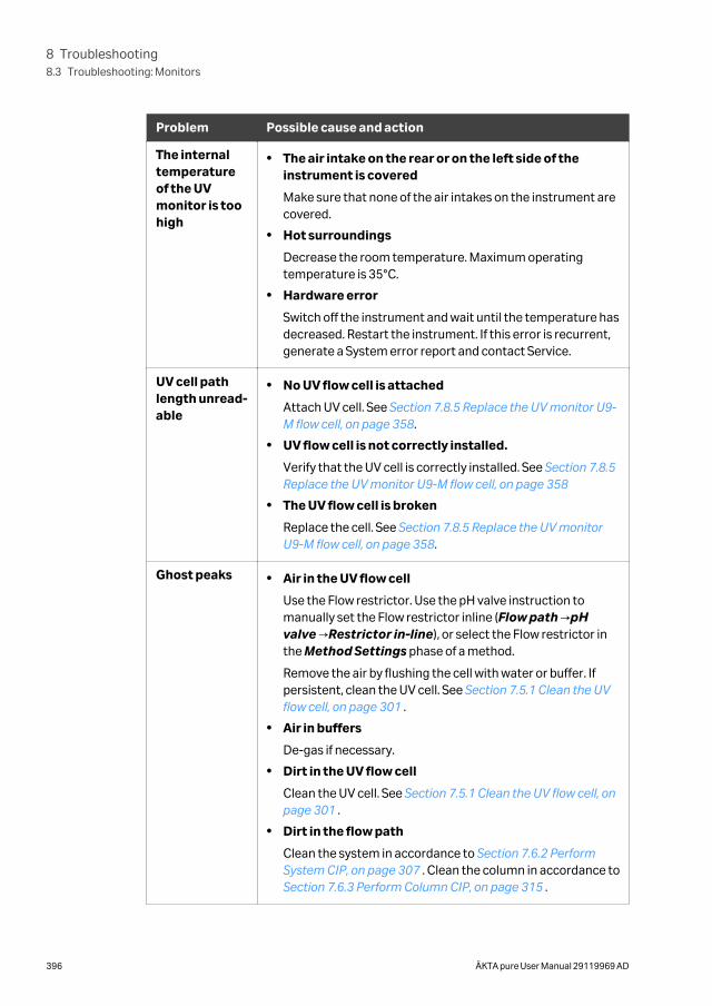
Problem Possible cause and action
The internaltemperatureof the UVmonitor is toohigh
• The air intake on the rear or on the left side of theinstrument is covered
Make sure that none of the air intakes on the instrument arecovered.
• Hot surroundings
Decrease the room temperature. Maximum operatingtemperature is 35°C.
• Hardware error
Switch off the instrument and wait until the temperature hasdecreased. Restart the instrument. If this error is recurrent,generate a System error report and contact Service.
UV cell pathlength unread-able
• No UV flow cell is attached
Attach UV cell. See Section 7.8.5 Replace the UV monitor U9-M flow cell, on page 358.
• UV flow cell is not correctly installed.
Verify that the UV cell is correctly installed. See Section 7.8.5Replace the UV monitor U9-M flow cell, on page 358
• The UV flow cell is broken
Replace the cell. See Section 7.8.5 Replace the UV monitorU9-M flow cell, on page 358.
Ghost peaks • Air in the UV flow cell
Use the Flow restrictor. Use the pH valve instruction tomanually set the Flow restrictor inline (Flow path →pHvalve →Restrictor in-line), or select the Flow restrictor inthe Method Settings phase of a method.
Remove the air by flushing the cell with water or buffer. Ifpersistent, clean the UV cell. See Section 7.5.1 Clean the UVflow cell, on page 301 .
• Air in buffers
De-gas if necessary.
• Dirt in the UV flow cell
Clean the UV cell. See Section 7.5.1 Clean the UV flow cell, onpage 301 .
• Dirt in the flow path
Clean the system in accordance to Section 7.6.2 PerformSystem CIP, on page 307 . Clean the column in accordance to Section 7.6.3 Perform Column CIP, on page 315 .
8 Troubleshooting8.3 Troubleshooting: Monitors
396 ÄKTA pure User Manual 29119969 AD
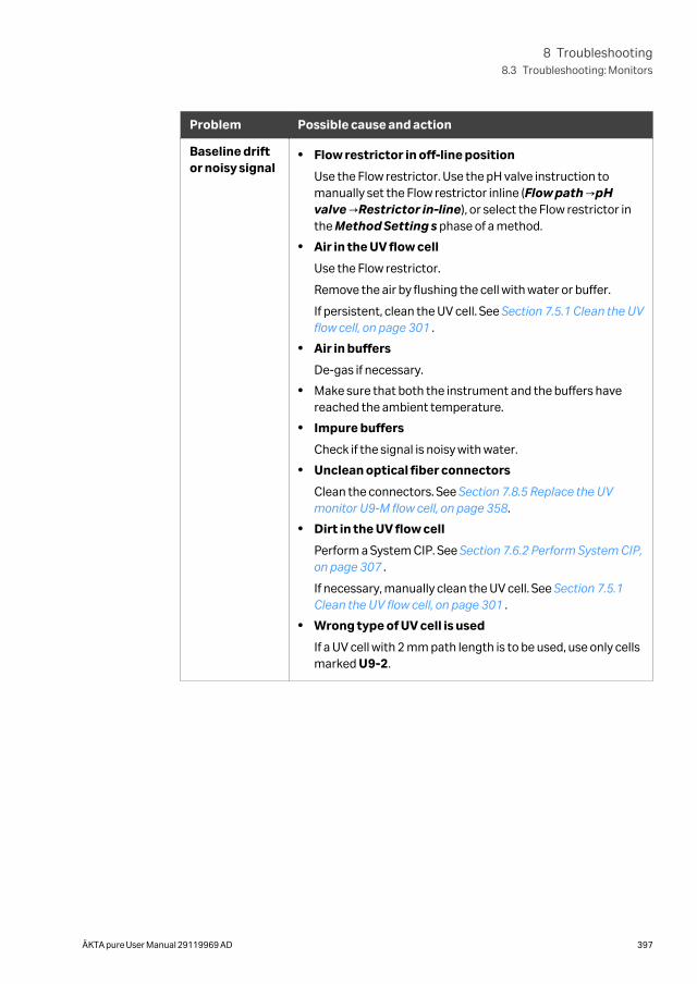
Problem Possible cause and action
Baseline driftor noisy signal
• Flow restrictor in off-line position
Use the Flow restrictor. Use the pH valve instruction tomanually set the Flow restrictor inline (Flow path →pHvalve →Restrictor in-line), or select the Flow restrictor inthe Method Setting s phase of a method.
• Air in the UV flow cell
Use the Flow restrictor.
Remove the air by flushing the cell with water or buffer.
If persistent, clean the UV cell. See Section 7.5.1 Clean the UVflow cell, on page 301 .
• Air in buffers
De-gas if necessary.
• Make sure that both the instrument and the buffers havereached the ambient temperature.
• Impure buffers
Check if the signal is noisy with water.
• Unclean optical fiber connectors
Clean the connectors. See Section 7.8.5 Replace the UVmonitor U9-M flow cell, on page 358.
• Dirt in the UV flow cell
Perform a System CIP. See Section 7.6.2 Perform System CIP,on page 307 .
If necessary, manually clean the UV cell. See Section 7.5.1Clean the UV flow cell, on page 301 .
• Wrong type of UV cell is used
If a UV cell with 2 mm path length is to be used, use only cellsmarked U9-2.
8 Troubleshooting8.3 Troubleshooting: Monitors
ÄKTA pure User Manual 29119969 AD 397
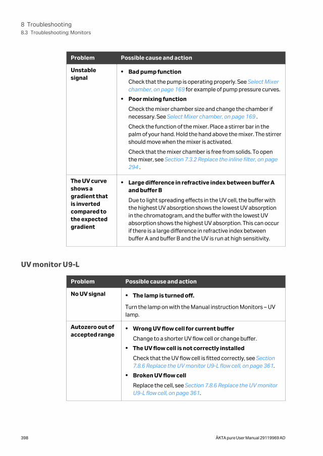
Problem Possible cause and action
Unstablesignal
• Bad pump function
Check that the pump is operating properly. See Select Mixerchamber, on page 169 for example of pump pressure curves.
• Poor mixing function
Check the mixer chamber size and change the chamber ifnecessary. See Select Mixer chamber, on page 169 .
Check the function of the mixer. Place a stirrer bar in thepalm of your hand. Hold the hand above the mixer. The stirrershould move when the mixer is activated.
Check that the mixer chamber is free from solids. To openthe mixer, see Section 7.3.2 Replace the inline filter, on page294 .
The UV curveshows agradient thatis invertedcompared tothe expectedgradient
• Large difference in refractive index between buffer Aand buffer B
Due to light spreading effects in the UV cell, the buffer withthe highest UV absorption shows the lowest UV absorptionin the chromatogram, and the buffer with the lowest UVabsorption shows the highest UV absorption. This can occurif there is a large difference in refractive index betweenbuffer A and buffer B and the UV is run at high sensitivity.
UV monitor U9-L
Problem Possible cause and action
No UV signal • The lamp is turned off.
Turn the lamp on with the Manual instruction Monitors – UVlamp.
Autozero out ofaccepted range
• Wrong UV flow cell for current buffer
Change to a shorter UV flow cell or change buffer.
• The UV flow cell is not correctly installed
Check that the UV flow cell is fitted correctly, see Section7.8.6 Replace the UV monitor U9-L flow cell, on page 361.
• Broken UV flow cell
Replace the cell, see Section 7.8.6 Replace the UV monitorU9-L flow cell, on page 361.
8 Troubleshooting8.3 Troubleshooting: Monitors
398 ÄKTA pure User Manual 29119969 AD
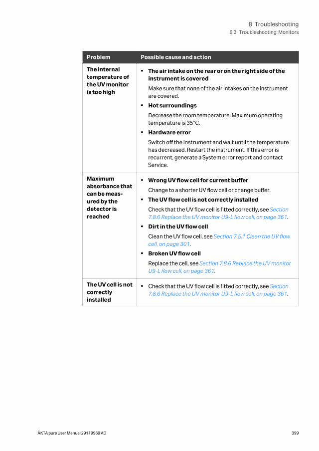
Problem Possible cause and action
The internaltemperature ofthe UV monitoris too high
• The air intake on the rear or on the right side of theinstrument is covered
Make sure that none of the air intakes on the instrumentare covered.
• Hot surroundings
Decrease the room temperature. Maximum operatingtemperature is 35°C.
• Hardware error
Switch off the instrument and wait until the temperaturehas decreased. Restart the instrument. If this error isrecurrent, generate a System error report and contactService.
Maximumabsorbance thatcan be meas-ured by thedetector isreached
• Wrong UV flow cell for current buffer
Change to a shorter UV flow cell or change buffer.
• The UV flow cell is not correctly installed
Check that the UV flow cell is fitted correctly, see Section7.8.6 Replace the UV monitor U9-L flow cell, on page 361.
• Dirt in the UV flow cell
Clean the UV flow cell, see Section 7.5.1 Clean the UV flowcell, on page 301.
• Broken UV flow cell
Replace the cell, see Section 7.8.6 Replace the UV monitorU9-L flow cell, on page 361.
The UV cell is notcorrectlyinstalled
• Check that the UV flow cell is fitted correctly, see Section7.8.6 Replace the UV monitor U9-L flow cell, on page 361.
8 Troubleshooting8.3 Troubleshooting: Monitors
ÄKTA pure User Manual 29119969 AD 399
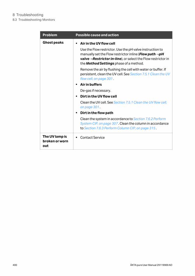
Problem Possible cause and action
Ghost peaks • Air in the UV flow cell
Use the Flow restrictor. Use the pH valve instruction tomanually set the Flow restrictor inline (Flow path →pHvalve →Restrictor in-line), or select the Flow restrictor inthe Method Settings phase of a method.
Remove the air by flushing the cell with water or buffer. Ifpersistent, clean the UV cell. See Section 7.5.1 Clean the UVflow cell, on page 301 .
• Air in buffers
De-gas if necessary.
• Dirt in the UV flow cell
Clean the UV cell. See Section 7.5.1 Clean the UV flow cell,on page 301 .
• Dirt in the flow path
Clean the system in accordance to Section 7.6.2 PerformSystem CIP, on page 307 . Clean the column in accordanceto Section 7.6.3 Perform Column CIP, on page 315 .
The UV lamp isbroken or wornout
• Contact Service
8 Troubleshooting8.3 Troubleshooting: Monitors
400 ÄKTA pure User Manual 29119969 AD
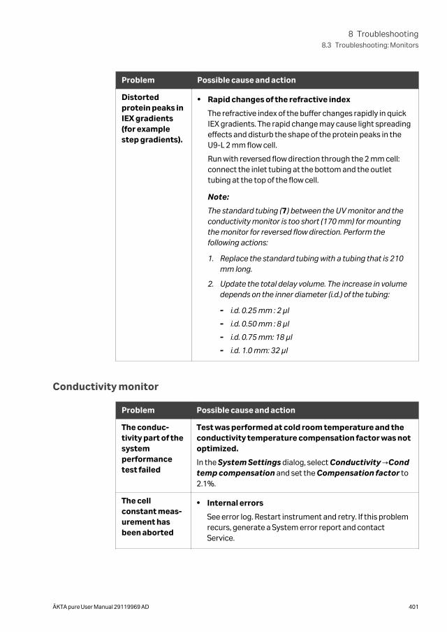
Problem Possible cause and action
Distortedprotein peaks inIEX gradients(for examplestep gradients).
• Rapid changes of the refractive index
The refractive index of the buffer changes rapidly in quickIEX gradients. The rapid change may cause light spreadingeffects and disturb the shape of the protein peaks in theU9-L 2 mm flow cell.
Run with reversed flow direction through the 2 mm cell:connect the inlet tubing at the bottom and the outlettubing at the top of the flow cell.
Note:
The standard tubing (7) between the UV monitor and theconductivity monitor is too short (170 mm) for mountingthe monitor for reversed flow direction. Perform thefollowing actions:
1. Replace the standard tubing with a tubing that is 210mm long.
2. Update the total delay volume. The increase in volumedepends on the inner diameter (i.d.) of the tubing:
- i.d. 0.25 mm : 2 µl
- i.d. 0.50 mm : 8 µl
- i.d. 0.75 mm: 18 µl
- i.d. 1.0 mm: 32 µl
Conductivity monitor
Problem Possible cause and action
The conduc-tivity part of thesystemperformancetest failed
Test was performed at cold room temperature and theconductivity temperature compensation factor was notoptimized.
In the System Settings dialog, select Conductivity →Condtemp compensation and set the Compensation factor to2.1%.
The cellconstant meas-urement hasbeen aborted
• Internal errors
See error log. Restart instrument and retry. If this problemrecurs, generate a System error report and contactService.
8 Troubleshooting8.3 Troubleshooting: Monitors
ÄKTA pure User Manual 29119969 AD 401
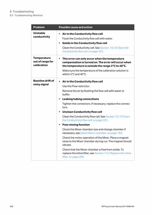
Problem Possible cause and action
Unstableconductivity
• Air in the Conductivity flow cell
Flush the Conductivity flow cell with water.
• Solids in the Conductivity flow cell
Clean the Conductivity cell. See Section 7.6.10 Clean theConductivity flow cell, on page 331.
Temperatureout of range forcalibration
• This error can only occur when the temperaturecompensation is turned on. The error will occur whenthe temperature is outside the range 2°C to 40°C.
Make sure the temperature of the calibration solution iswithin 2°C and 40°C.
Baseline drift ofnoisy signal
• Air in the Conductivity flow cell
Use the Flow restrictor.
Remove the air by flushing the flow cell with water orbuffer.
• Leaking tubing connections
Tighten the connectors. If necessary, replace the connec-tors.
• Unclean Conductivity flow cell
Clean the Conductivity flow cell. See Section 7.6.10 Cleanthe Conductivity flow cell, on page 331.
• Poor mixing function
Check the Mixer chamber size and change chamber ifnecessary, see Select Mixer chamber, on page 169.
Check the motor operation of the Mixer. Place a magnetclose to the Mixer chamber during run. The magnet shouldvibrate.
Check that the Mixer chamber is free from solids. Toreplace the inline filter, see Section 7.3.2 Replace the inlinefilter, on page 294.
8 Troubleshooting8.3 Troubleshooting: Monitors
402 ÄKTA pure User Manual 29119969 AD
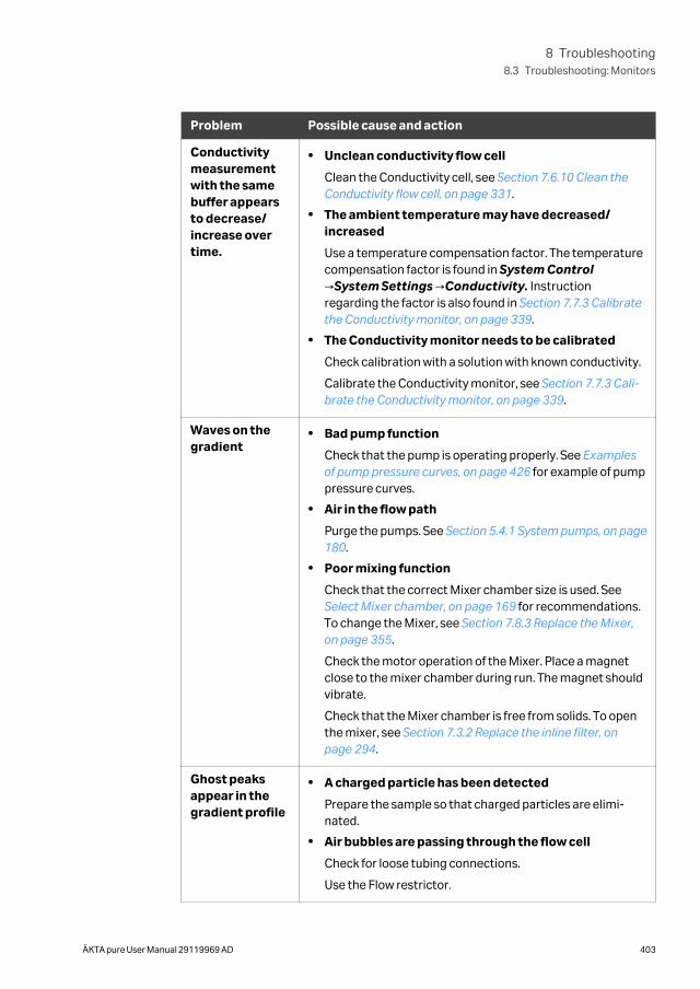
Problem Possible cause and action
Conductivitymeasurementwith the samebuffer appearsto decrease/increase overtime.
• Unclean conductivity flow cell
Clean the Conductivity cell, see Section 7.6.10 Clean theConductivity flow cell, on page 331.
• The ambient temperature may have decreased/increased
Use a temperature compensation factor. The temperaturecompensation factor is found in System Control→System Settings →Conductivity. Instructionregarding the factor is also found in Section 7.7.3 Calibratethe Conductivity monitor, on page 339.
• The Conductivity monitor needs to be calibrated
Check calibration with a solution with known conductivity.
Calibrate the Conductivity monitor, see Section 7.7.3 Cali-brate the Conductivity monitor, on page 339.
Waves on thegradient
• Bad pump function
Check that the pump is operating properly. See Examplesof pump pressure curves, on page 426 for example of pumppressure curves.
• Air in the flow path
Purge the pumps. See Section 5.4.1 System pumps, on page180.
• Poor mixing function
Check that the correct Mixer chamber size is used. See Select Mixer chamber, on page 169 for recommendations.To change the Mixer, see Section 7.8.3 Replace the Mixer,on page 355.
Check the motor operation of the Mixer. Place a magnetclose to the mixer chamber during run. The magnet shouldvibrate.
Check that the Mixer chamber is free from solids. To openthe mixer, see Section 7.3.2 Replace the inline filter, onpage 294.
Ghost peaksappear in thegradient profile
• A charged particle has been detected
Prepare the sample so that charged particles are elimi-nated.
• Air bubbles are passing through the flow cell
Check for loose tubing connections.
Use the Flow restrictor.
8 Troubleshooting8.3 Troubleshooting: Monitors
ÄKTA pure User Manual 29119969 AD 403
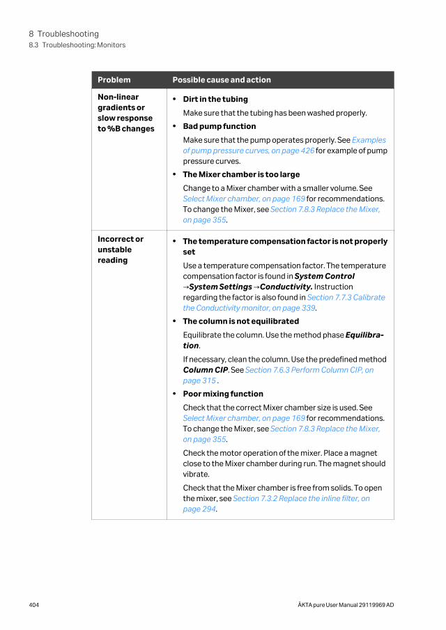
Problem Possible cause and action
Non-lineargradients orslow responseto %B changes
• Dirt in the tubing
Make sure that the tubing has been washed properly.
• Bad pump function
Make sure that the pump operates properly. See Examplesof pump pressure curves, on page 426 for example of pumppressure curves.
• The Mixer chamber is too large
Change to a Mixer chamber with a smaller volume. See Select Mixer chamber, on page 169 for recommendations.To change the Mixer, see Section 7.8.3 Replace the Mixer,on page 355.
Incorrect orunstablereading
• The temperature compensation factor is not properlyset
Use a temperature compensation factor. The temperaturecompensation factor is found in System Control→System Settings →Conductivity. Instructionregarding the factor is also found in Section 7.7.3 Calibratethe Conductivity monitor, on page 339.
• The column is not equilibrated
Equilibrate the column. Use the method phase Equilibra-tion.
If necessary, clean the column. Use the predefined methodColumn CIP. See Section 7.6.3 Perform Column CIP, onpage 315 .
• Poor mixing function
Check that the correct Mixer chamber size is used. See Select Mixer chamber, on page 169 for recommendations.To change the Mixer, see Section 7.8.3 Replace the Mixer,on page 355.
Check the motor operation of the mixer. Place a magnetclose to the Mixer chamber during run. The magnet shouldvibrate.
Check that the Mixer chamber is free from solids. To openthe mixer, see Section 7.3.2 Replace the inline filter, onpage 294.
8 Troubleshooting8.3 Troubleshooting: Monitors
404 ÄKTA pure User Manual 29119969 AD
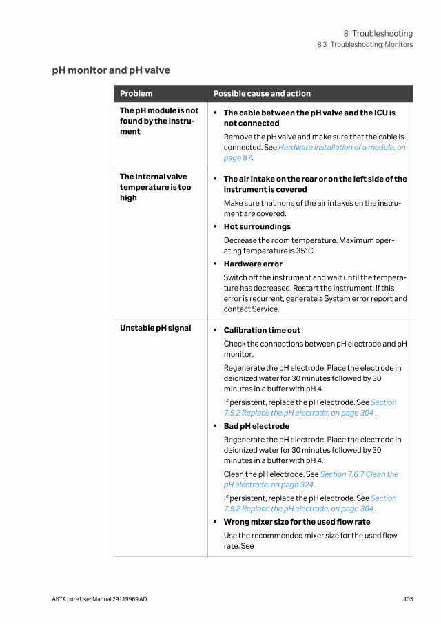
pH monitor and pH valve
Problem Possible cause and action
The pH module is notfound by the instru-ment
• The cable between the pH valve and the ICU isnot connected
Remove the pH valve and make sure that the cable isconnected. See Hardware installation of a module, onpage 87.
The internal valvetemperature is toohigh
• The air intake on the rear or on the left side of theinstrument is covered
Make sure that none of the air intakes on the instru-ment are covered.
• Hot surroundings
Decrease the room temperature. Maximum oper-ating temperature is 35°C.
• Hardware error
Switch off the instrument and wait until the tempera-ture has decreased. Restart the instrument. If thiserror is recurrent, generate a System error report andcontact Service.
Unstable pH signal • Calibration time out
Check the connections between pH electrode and pHmonitor.
Regenerate the pH electrode. Place the electrode indeionized water for 30 minutes followed by 30minutes in a buffer with pH 4.
If persistent, replace the pH electrode. See Section7.5.2 Replace the pH electrode, on page 304 .
• Bad pH electrode
Regenerate the pH electrode. Place the electrode indeionized water for 30 minutes followed by 30minutes in a buffer with pH 4.
Clean the pH electrode. See Section 7.6.7 Clean thepH electrode, on page 324 .
If persistent, replace the pH electrode. See Section7.5.2 Replace the pH electrode, on page 304 .
• Wrong mixer size for the used flow rate
Use the recommended mixer size for the used flowrate. See
8 Troubleshooting8.3 Troubleshooting: Monitors
ÄKTA pure User Manual 29119969 AD 405
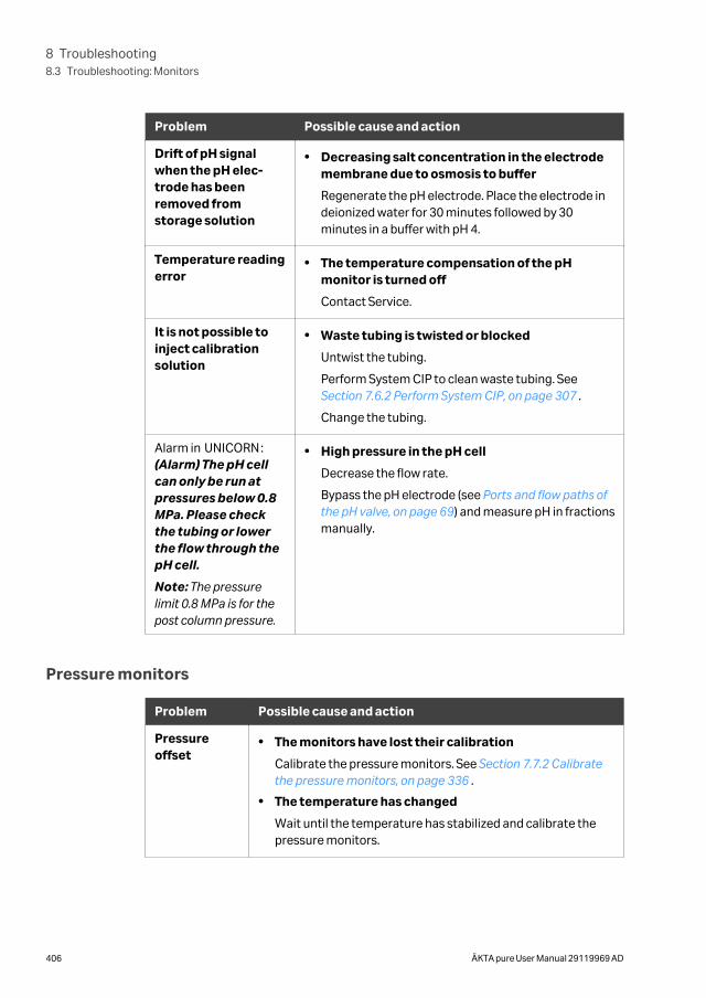
Problem Possible cause and action
Drift of pH signalwhen the pH elec-trode has beenremoved fromstorage solution
• Decreasing salt concentration in the electrodemembrane due to osmosis to buffer
Regenerate the pH electrode. Place the electrode indeionized water for 30 minutes followed by 30minutes in a buffer with pH 4.
Temperature readingerror
• The temperature compensation of the pHmonitor is turned off
Contact Service.
It is not possible toinject calibrationsolution
• Waste tubing is twisted or blocked
Untwist the tubing.
Perform System CIP to clean waste tubing. See Section 7.6.2 Perform System CIP, on page 307 .
Change the tubing.
Alarm in UNICORN:(Alarm) The pH cellcan only be run atpressures below 0.8MPa. Please checkthe tubing or lowerthe flow through thepH cell.
Note: The pressurelimit 0.8 MPa is for thepost column pressure.
• High pressure in the pH cell
Decrease the flow rate.
Bypass the pH electrode (see Ports and flow paths ofthe pH valve, on page 69) and measure pH in fractionsmanually.
Pressure monitors
Problem Possible cause and action
Pressureoffset
• The monitors have lost their calibration
Calibrate the pressure monitors. See Section 7.7.2 Calibratethe pressure monitors, on page 336 .
• The temperature has changed
Wait until the temperature has stabilized and calibrate thepressure monitors.
8 Troubleshooting8.3 Troubleshooting: Monitors
406 ÄKTA pure User Manual 29119969 AD
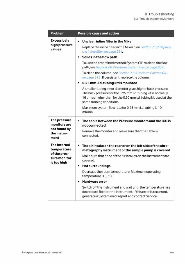
Problem Possible cause and action
Excessivelyhigh pressurevalues
• Unclean inline filter in the Mixer
Replace the inline filter in the Mixer. See Section 7.3.2 Replacethe inline filter, on page 294.
• Solids in the flow path
To use the predefined method System CIP to clean the flowpath, see Section 7.6.2 Perform System CIP, on page 307.
To clean the column, see Section 7.6.3 Perform Column CIP,on page 315 . If persistent, replace the column.
• 0.25 mm .i.d. tubing kit is mounted
A smaller tubing inner diameter gives higher back pressure.The back pressure for the 0.25 mm i.d. tubing kit is normally16 times higher than for the 0.50 mm i.d. tubing kit used at thesame running conditions.
Maximum system flow rate for 0.25 mm i.d. tubing is 10ml/min
The pressuremonitors arenot found bythe instru-ment
• The cable between the Pressure monitors and the ICU isnot connected.
Remove the monitor and make sure that the cable isconnected.
The internaltemperatureof the pres-sure monitoris too high
• The air intake on the rear or on the left side of the chro-matography instrument or the sample pump is covered
Make sure that none of the air intakes on the instrument arecovered.
• Hot surroundings
Decrease the room temperature. Maximum operatingtemperature is 35°C.
• Hardware error
Switch off the instrument and wait until the temperature hasdecreased. Restart the instrument. If this error is recurrent,generate a System error report and contact Service.
8 Troubleshooting8.3 Troubleshooting: Monitors
ÄKTA pure User Manual 29119969 AD 407
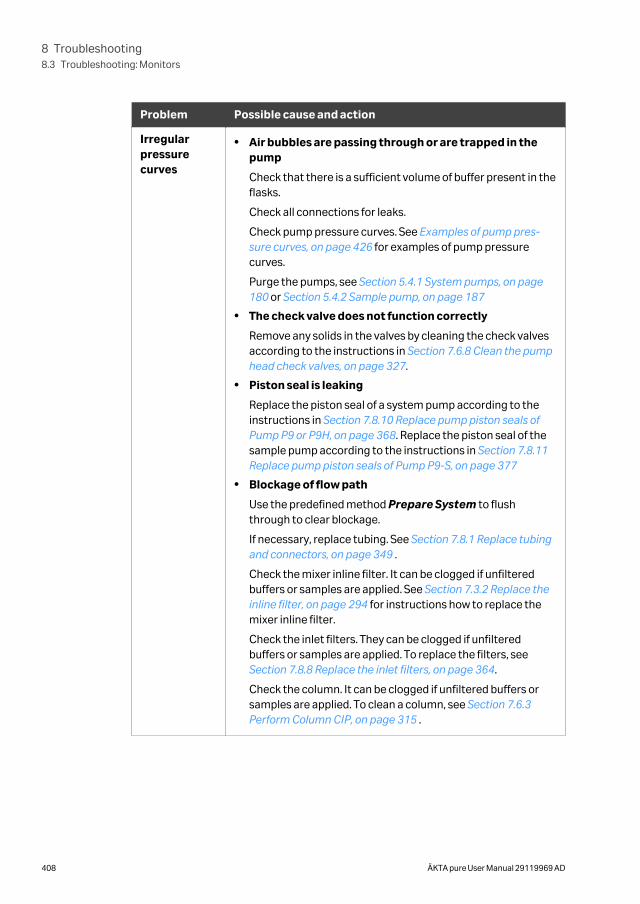
Problem Possible cause and action
Irregularpressurecurves
• Air bubbles are passing through or are trapped in thepump
Check that there is a sufficient volume of buffer present in theflasks.
Check all connections for leaks.
Check pump pressure curves. See Examples of pump pres-sure curves, on page 426 for examples of pump pressurecurves.
Purge the pumps, see Section 5.4.1 System pumps, on page180 or Section 5.4.2 Sample pump, on page 187
• The check valve does not function correctly
Remove any solids in the valves by cleaning the check valvesaccording to the instructions in Section 7.6.8 Clean the pumphead check valves, on page 327.
• Piston seal is leaking
Replace the piston seal of a system pump according to theinstructions in Section 7.8.10 Replace pump piston seals ofPump P9 or P9H, on page 368. Replace the piston seal of thesample pump according to the instructions in Section 7.8.11Replace pump piston seals of Pump P9-S, on page 377
• Blockage of flow path
Use the predefined method Prepare System to flushthrough to clear blockage.
If necessary, replace tubing. See Section 7.8.1 Replace tubingand connectors, on page 349 .
Check the mixer inline filter. It can be clogged if unfilteredbuffers or samples are applied. See Section 7.3.2 Replace theinline filter, on page 294 for instructions how to replace themixer inline filter.
Check the inlet filters. They can be clogged if unfilteredbuffers or samples are applied. To replace the filters, see Section 7.8.8 Replace the inlet filters, on page 364.
Check the column. It can be clogged if unfiltered buffers orsamples are applied. To clean a column, see Section 7.6.3Perform Column CIP, on page 315 .
8 Troubleshooting8.3 Troubleshooting: Monitors
408 ÄKTA pure User Manual 29119969 AD
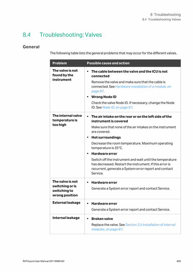
8.4 Troubleshooting: Valves
GeneralThe following table lists the general problems that may occur for the different valves.
Problem Possible cause and action
The valve is notfound by theinstrument
• The cable between the valve and the ICU is notconnected
Remove the valve and make sure that the cable isconnected. See Hardware installation of a module, onpage 87.
• Wrong Node ID
Check the valve Node ID. If necessary, change the NodeID. See Node ID, on page 87.
The internal valvetemperature istoo high
• The air intake on the rear or on the left side of theinstrument is covered
Make sure that none of the air intakes on the instrumentare covered.
• Hot surroundings
Decrease the room temperature. Maximum operatingtemperature is 35°C.
• Hardware error
Switch off the instrument and wait until the temperaturehas decreased. Restart the instrument. If this error isrecurrent, generate a System error report and contactService.
The valve is notswitching or isswitching towrong position
• Hardware error
Generate a System error report and contact Service.
External leakage • Hardware error
Generate a System error report and contact Service.
Internal leakage • Broken valve
Replace the valve. See Section 2.5 Installation of internalmodules, on page 87.
8 Troubleshooting8.4 Troubleshooting: Valves
ÄKTA pure User Manual 29119969 AD 409
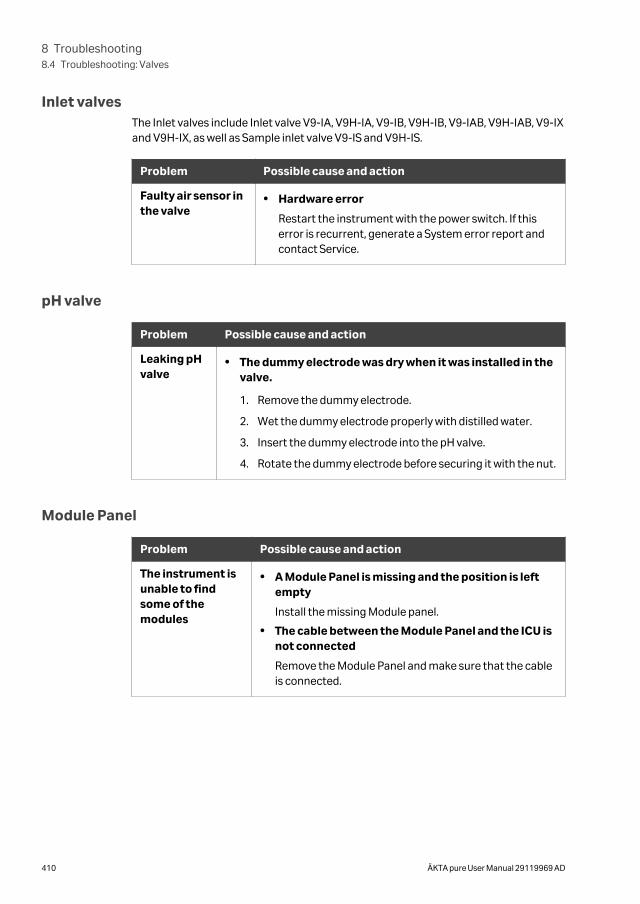
Inlet valvesThe Inlet valves include Inlet valve V9-IA, V9H-IA, V9-IB, V9H-IB, V9-IAB, V9H-IAB, V9-IXand V9H-IX, as well as Sample inlet valve V9-IS and V9H-IS.
Problem Possible cause and action
Faulty air sensor inthe valve
• Hardware error
Restart the instrument with the power switch. If thiserror is recurrent, generate a System error report andcontact Service.
pH valve
Problem Possible cause and action
Leaking pHvalve
• The dummy electrode was dry when it was installed in thevalve.
1. Remove the dummy electrode.
2. Wet the dummy electrode properly with distilled water.
3. Insert the dummy electrode into the pH valve.
4. Rotate the dummy electrode before securing it with the nut.
Module Panel
Problem Possible cause and action
The instrument isunable to findsome of themodules
• A Module Panel is missing and the position is leftempty
Install the missing Module panel.
• The cable between the Module Panel and the ICU isnot connected
Remove the Module Panel and make sure that the cableis connected.
8 Troubleshooting8.4 Troubleshooting: Valves
410 ÄKTA pure User Manual 29119969 AD
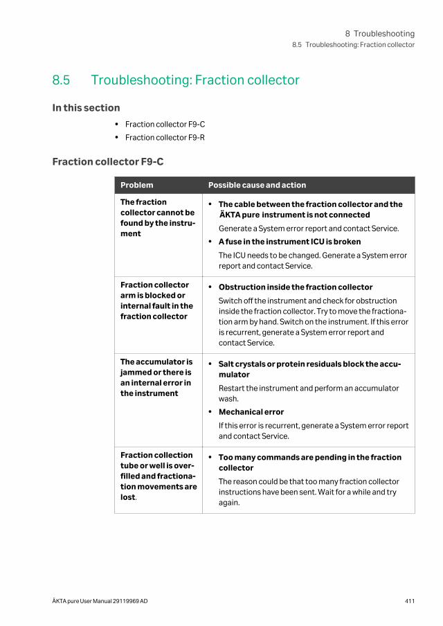
8.5 Troubleshooting: Fraction collector
In this section
• Fraction collector F9-C
• Fraction collector F9-R
Fraction collector F9-C
Problem Possible cause and action
The fractioncollector cannot befound by the instru-ment
• The cable between the fraction collector and theÄKTA pure instrument is not connected
Generate a System error report and contact Service.
• A fuse in the instrument ICU is broken
The ICU needs to be changed. Generate a System errorreport and contact Service.
Fraction collectorarm is blocked orinternal fault in thefraction collector
• Obstruction inside the fraction collector
Switch off the instrument and check for obstructioninside the fraction collector. Try to move the fractiona-tion arm by hand. Switch on the instrument. If this erroris recurrent, generate a System error report andcontact Service.
The accumulator isjammed or there isan internal error inthe instrument
• Salt crystals or protein residuals block the accu-mulator
Restart the instrument and perform an accumulatorwash.
• Mechanical error
If this error is recurrent, generate a System error reportand contact Service.
Fraction collectiontube or well is over-filled and fractiona-tion movements arelost.
• Too many commands are pending in the fractioncollector
The reason could be that too many fraction collectorinstructions have been sent. Wait for a while and tryagain.
8 Troubleshooting8.5 Troubleshooting: Fraction collector
ÄKTA pure User Manual 29119969 AD 411
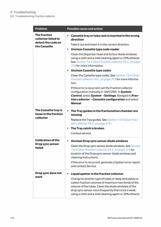
Problem Possible cause and action
The fractioncollector failed todetect the code onthe Cassette
• Cassette tray or tube rack is inserted in the wrongdirection
Take it out and insert it in the correct direction.
• Unclean Cassette type code reader
Clean the dispenser head and its four diode windowsusing a cloth and a mild cleaning agent or 20% ethanol.See Section 7.6.4 Clean Fraction collector F9-C, on page319 for more information.
• Unclean Cassette type codes
Clean the Cassette type codes. See Section 7.6.4 CleanFraction collector F9-C, on page 319 for more informa-tion.
If this error is recurrent, set the Fraction collectorconfiguration manually in UNICORN. In SystemControl, select System →Settings. Navigate toFrac-tion collector →Cassette configuration and selectManual.
The Cassette tray isloose in the fractioncollector
• The Tray guides in the fractionation chamber aremissing
Replace the Tray guides. See Section 7.6.4 Clean Frac-tion collector F9-C, on page 319 .
• The Tray catch is broken
Contact service.
Calibration of theDrop sync sensorfailed
• Unclean Drop sync sensor diode windows
Clean the Drop sync sensor diode windows. See Section7.6.4 Clean Fraction collector F9-C, on page 319 forlocation of the Drop sync sensor diode windows andcleaning instructions.
If this error is recurrent, generate a System error reportand contact Service.
Drop sync does notwork
• Liquid spatter in the fraction collector
Change to another type of tubes or deep well plates orcollect fraction volumes of maximum two thirds of thevolume of the tubes. Clean the diode windows of thedrop sync sensor more frequently than once a week,using a cloth and a mild cleaning agent or 20% ethanol.
8 Troubleshooting8.5 Troubleshooting: Fraction collector
412 ÄKTA pure User Manual 29119969 AD
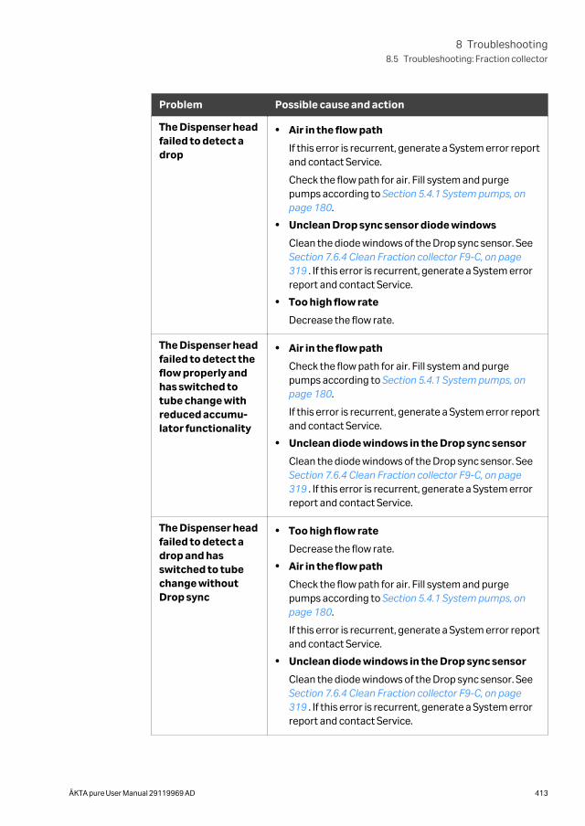
Problem Possible cause and action
The Dispenser headfailed to detect adrop
• Air in the flow path
If this error is recurrent, generate a System error reportand contact Service.
Check the flow path for air. Fill system and purgepumps according to Section 5.4.1 System pumps, onpage 180.
• Unclean Drop sync sensor diode windows
Clean the diode windows of the Drop sync sensor. See Section 7.6.4 Clean Fraction collector F9-C, on page319 . If this error is recurrent, generate a System errorreport and contact Service.
• Too high flow rate
Decrease the flow rate.
The Dispenser headfailed to detect theflow properly andhas switched totube change withreduced accumu-lator functionality
• Air in the flow path
Check the flow path for air. Fill system and purgepumps according to Section 5.4.1 System pumps, onpage 180.
If this error is recurrent, generate a System error reportand contact Service.
• Unclean diode windows in the Drop sync sensor
Clean the diode windows of the Drop sync sensor. See Section 7.6.4 Clean Fraction collector F9-C, on page319 . If this error is recurrent, generate a System errorreport and contact Service.
The Dispenser headfailed to detect adrop and hasswitched to tubechange withoutDrop sync
• Too high flow rate
Decrease the flow rate.
• Air in the flow path
Check the flow path for air. Fill system and purgepumps according to Section 5.4.1 System pumps, onpage 180.
If this error is recurrent, generate a System error reportand contact Service.
• Unclean diode windows in the Drop sync sensor
Clean the diode windows of the Drop sync sensor. See Section 7.6.4 Clean Fraction collector F9-C, on page319 . If this error is recurrent, generate a System errorreport and contact Service.
8 Troubleshooting8.5 Troubleshooting: Fraction collector
ÄKTA pure User Manual 29119969 AD 413
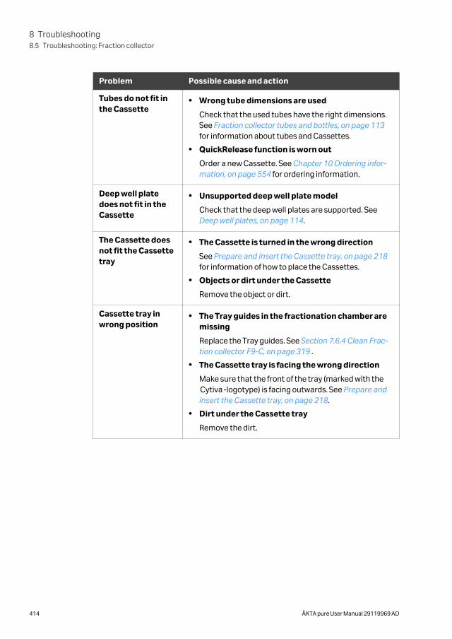
Problem Possible cause and action
Tubes do not fit inthe Cassette
• Wrong tube dimensions are used
Check that the used tubes have the right dimensions.See Fraction collector tubes and bottles, on page 113for information about tubes and Cassettes.
• QuickRelease function is worn out
Order a new Cassette. See Chapter 10 Ordering infor-mation, on page 554 for ordering information.
Deep well platedoes not fit in theCassette
• Unsupported deep well plate model
Check that the deep well plates are supported. See Deep well plates, on page 114.
The Cassette doesnot fit the Cassettetray
• The Cassette is turned in the wrong direction
See Prepare and insert the Cassette tray, on page 218for information of how to place the Cassettes.
• Objects or dirt under the Cassette
Remove the object or dirt.
Cassette tray inwrong position
• The Tray guides in the fractionation chamber aremissing
Replace the Tray guides. See Section 7.6.4 Clean Frac-tion collector F9-C, on page 319 .
• The Cassette tray is facing the wrong direction
Make sure that the front of the tray (marked with theCytiva-logotype) is facing outwards. See Prepare andinsert the Cassette tray, on page 218.
• Dirt under the Cassette tray
Remove the dirt.
8 Troubleshooting8.5 Troubleshooting: Fraction collector
414 ÄKTA pure User Manual 29119969 AD
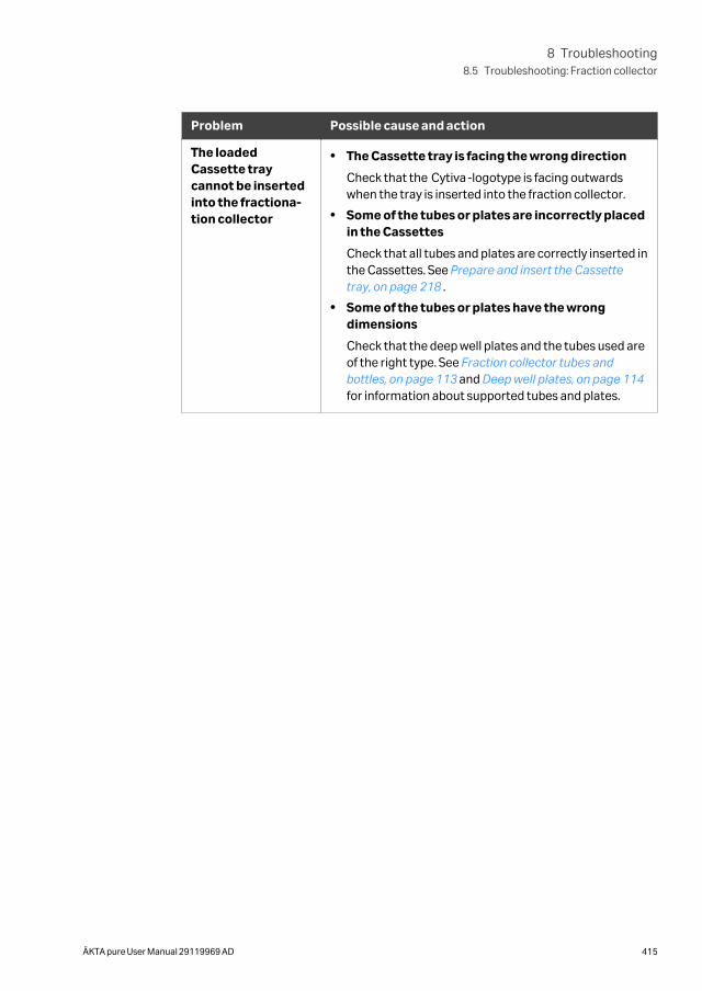
Problem Possible cause and action
The loadedCassette traycannot be insertedinto the fractiona-tion collector
• The Cassette tray is facing the wrong direction
Check that the Cytiva-logotype is facing outwardswhen the tray is inserted into the fraction collector.
• Some of the tubes or plates are incorrectly placedin the Cassettes
Check that all tubes and plates are correctly inserted inthe Cassettes. See Prepare and insert the Cassettetray, on page 218 .
• Some of the tubes or plates have the wrongdimensions
Check that the deep well plates and the tubes used areof the right type. See Fraction collector tubes andbottles, on page 113 and Deep well plates, on page 114for information about supported tubes and plates.
8 Troubleshooting8.5 Troubleshooting: Fraction collector
ÄKTA pure User Manual 29119969 AD 415
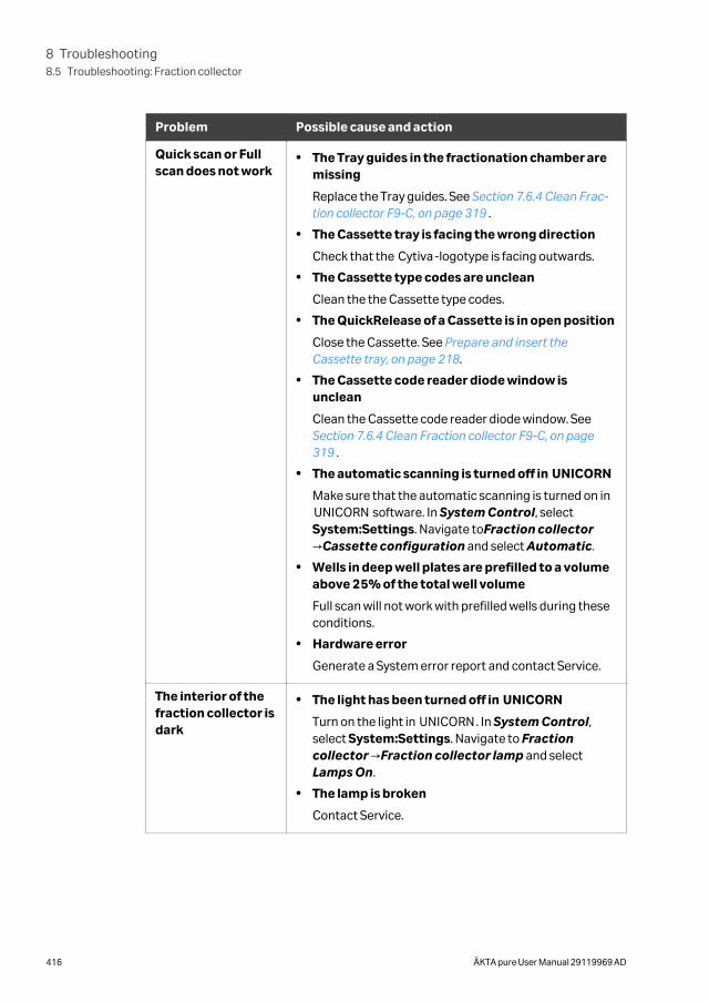
Problem Possible cause and action
Quick scan or Fullscan does not work
• The Tray guides in the fractionation chamber aremissing
Replace the Tray guides. See Section 7.6.4 Clean Frac-tion collector F9-C, on page 319 .
• The Cassette tray is facing the wrong direction
Check that the Cytiva-logotype is facing outwards.
• The Cassette type codes are unclean
Clean the the Cassette type codes.
• The QuickRelease of a Cassette is in open position
Close the Cassette. See Prepare and insert theCassette tray, on page 218.
• The Cassette code reader diode window isunclean
Clean the Cassette code reader diode window. See Section 7.6.4 Clean Fraction collector F9-C, on page319 .
• The automatic scanning is turned off in UNICORN
Make sure that the automatic scanning is turned on inUNICORN software. In System Control, selectSystem:Settings. Navigate toFraction collector→Cassette configuration and select Automatic.
• Wells in deep well plates are prefilled to a volumeabove 25% of the total well volume
Full scan will not work with prefilled wells during theseconditions.
• Hardware error
Generate a System error report and contact Service.
The interior of thefraction collector isdark
• The light has been turned off in UNICORN
Turn on the light in UNICORN. In System Control,select System:Settings. Navigate to Fractioncollector →Fraction collector lamp and selectLamps On.
• The lamp is broken
Contact Service.
8 Troubleshooting8.5 Troubleshooting: Fraction collector
416 ÄKTA pure User Manual 29119969 AD
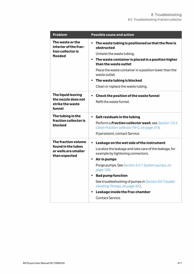
Problem Possible cause and action
The waste or theinterior of the frac-tion collector isflooded
• The waste tubing is positioned so that the flow isobstructed
Untwist the waste tubing.
• The waste container is placed in a position higherthan the waste outlet
Place the waste container in a position lower than thewaste outlet.
• The waste tubing is blocked.
Clean or replace the waste tubing.
The liquid leavingthe nozzle does notstrike the wastefunnel
• Check the position of the waste funnel
Refit the waste funnel.
The tubing in thefraction collector isblocked
• Salt residuals in the tubing
Perform a Fraction collector wash, see Section 7.6.4Clean Fraction collector F9-C, on page 319.
If persistent, contact Service.
The fraction volumefound in the tubesor wells are smallerthan expected
• Leakage on the wet side of the instrument
Localize the leakage and take care of the leakage, forexample by tightening connectors.
• Air in pumps
Purge pumps. See Section 5.4.1 System pumps, onpage 180.
• Bad pump function
See troubleshooting of pumps in Section 8.6 Trouble-shooting: Pumps, on page 423.
• Leakage inside the Frac chamber
Contact Service.
8 Troubleshooting8.5 Troubleshooting: Fraction collector
ÄKTA pure User Manual 29119969 AD 417
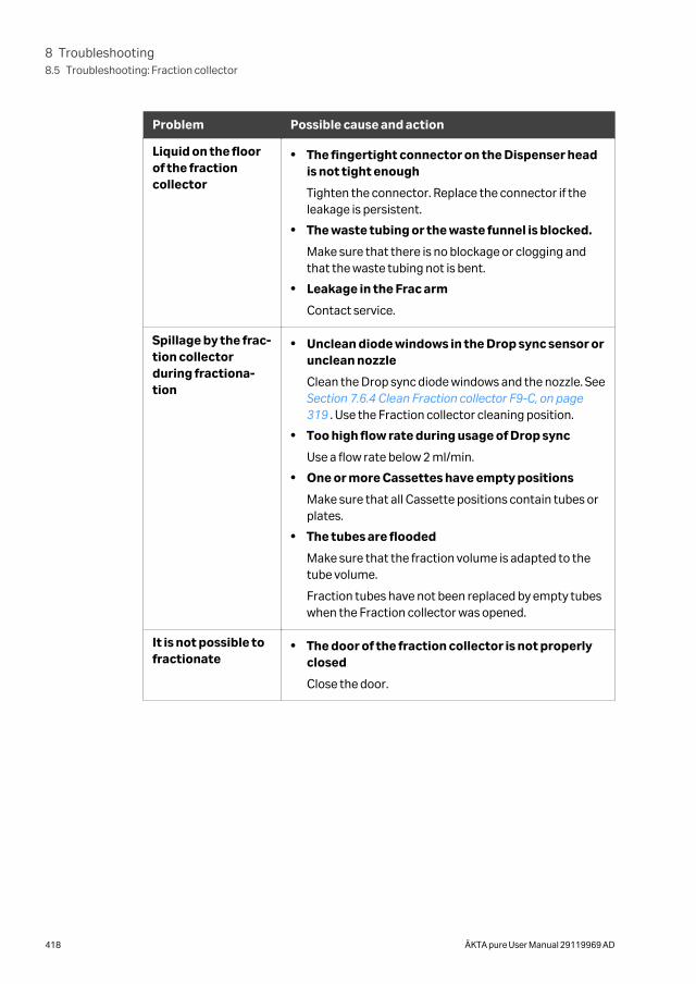
Problem Possible cause and action
Liquid on the floorof the fractioncollector
• The fingertight connector on the Dispenser headis not tight enough
Tighten the connector. Replace the connector if theleakage is persistent.
• The waste tubing or the waste funnel is blocked.
Make sure that there is no blockage or clogging andthat the waste tubing not is bent.
• Leakage in the Frac arm
Contact service.
Spillage by the frac-tion collectorduring fractiona-tion
• Unclean diode windows in the Drop sync sensor orunclean nozzle
Clean the Drop sync diode windows and the nozzle. See Section 7.6.4 Clean Fraction collector F9-C, on page319 . Use the Fraction collector cleaning position.
• Too high flow rate during usage of Drop sync
Use a flow rate below 2 ml/min.
• One or more Cassettes have empty positions
Make sure that all Cassette positions contain tubes orplates.
• The tubes are flooded
Make sure that the fraction volume is adapted to thetube volume.
Fraction tubes have not been replaced by empty tubeswhen the Fraction collector was opened.
It is not possible tofractionate
• The door of the fraction collector is not properlyclosed
Close the door.
8 Troubleshooting8.5 Troubleshooting: Fraction collector
418 ÄKTA pure User Manual 29119969 AD
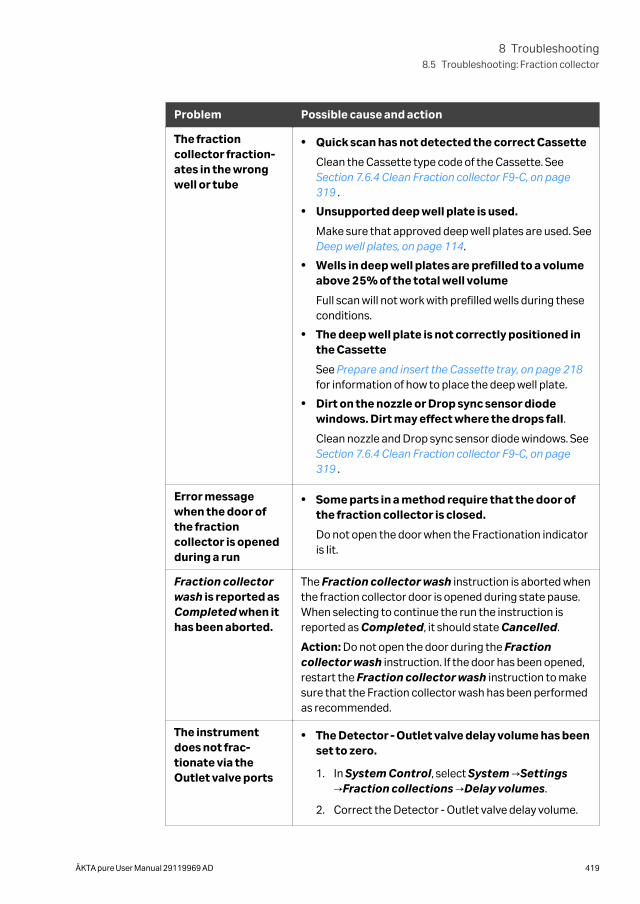
Problem Possible cause and action
The fractioncollector fraction-ates in the wrongwell or tube
• Quick scan has not detected the correct Cassette
Clean the Cassette type code of the Cassette. See Section 7.6.4 Clean Fraction collector F9-C, on page319 .
• Unsupported deep well plate is used.
Make sure that approved deep well plates are used. See Deep well plates, on page 114.
• Wells in deep well plates are prefilled to a volumeabove 25% of the total well volume
Full scan will not work with prefilled wells during theseconditions.
• The deep well plate is not correctly positioned inthe Cassette
See Prepare and insert the Cassette tray, on page 218for information of how to place the deep well plate.
• Dirt on the nozzle or Drop sync sensor diodewindows. Dirt may effect where the drops fall.
Clean nozzle and Drop sync sensor diode windows. See Section 7.6.4 Clean Fraction collector F9-C, on page319 .
Error messagewhen the door ofthe fractioncollector is openedduring a run
• Some parts in a method require that the door ofthe fraction collector is closed.
Do not open the door when the Fractionation indicatoris lit.
Fraction collectorwash is reported asCompleted when ithas been aborted.
The Fraction collector wash instruction is aborted whenthe fraction collector door is opened during state pause.When selecting to continue the run the instruction isreported as Completed, it should state Cancelled.
Action: Do not open the door during the Fractioncollector wash instruction. If the door has been opened,restart the Fraction collector wash instruction to makesure that the Fraction collector wash has been performedas recommended.
The instrumentdoes not frac-tionate via theOutlet valve ports
• The Detector - Outlet valve delay volume has beenset to zero.
1. In System Control, select System →Settings→Fraction collections →Delay volumes.
2. Correct the Detector - Outlet valve delay volume.
8 Troubleshooting8.5 Troubleshooting: Fraction collector
ÄKTA pure User Manual 29119969 AD 419
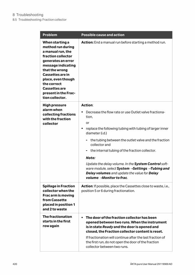
Problem Possible cause and action
When starting amethod run duringa manual run, thefraction collectorgenerates an errormessage indicatingthat the wrongCassettes are inplace, even thoughthe correctCassettes arepresent in the Frac-tion collector.
Action: End a manual run before starting a method run.
High pressurealarm whencollecting fractionswith the fractioncollector
Action:
• Decrease the flow rate or use Outlet valve fractiona-tion,
or
• replace the following tubing with tubing of larger innerdiameter (i.d.)
- the tubing between the outlet valve and the fractioncollector and
- the internal tubing of the fraction collector.
Note:
Update the delay volume. In the System Control soft-ware module, select System →Settings →Tubing andDelay volumes and update the value for Delayvolume →Monitor to frac.
Spillage in Fractioncollector when theFrac arm is movingfrom Cassetteplaced in position 1and 2 to waste
Action: If possible, place the Cassettes close to waste, i.e.,position 5 or 6 during fractionation.
The fractionationstarts in the firstrow again
• The door of the fraction collector has beenopened between two runs. When the instrumentis in state Ready and the door is opened andclosed, the Fraction collector content is reset.
If fractionation will continue after the last fraction ofthe first run, do not open the door of the fractioncollector between two runs.
8 Troubleshooting8.5 Troubleshooting: Fraction collector
420 ÄKTA pure User Manual 29119969 AD
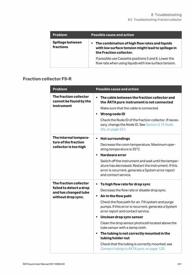
Problem Possible cause and action
Spillage betweenfractions
• The combination of high flow rates and liquidswith low surface tension might lead to spillage inthe Fraction collector.
If possible use Cassette positions 5 and 6. Lower theflow rate when using liquids with low surface tension.
Fraction collector F9-R
Problem Possible cause and action
The fraction collectorcannot be found by theinstrument
• The cable between the fraction collector andthe ÄKTA pure instrument is not connected
Make sure that the cable is connected.
• Wrong node ID
Check the Node ID of the fraction collector. If neces-sary, change the Node ID. See Section 9.16 NodeIDs, on page 551.
The internal tempera-ture of the fractioncollector is too high
• Hot surroundings
Decrease the room temperature. Maximum oper-ating temperature is 35°C.
• Hardware error
Switch off the instrument and wait until the temper-ature has decreased. Restart the instrument. If thiserror is recurrent, generate a System error reportand contact service.
The fraction collectorfailed to detect a dropand has changed tubewithout drop sync.
• To high flow rate for drop sync
Decrease the flow rate or disable drop sync.
• Air in the flow path
Check the flow path for air. Fill system and purgepumps. If this error is recurrent, generate a Systemerror report and contact service.
• Unclean drop sync sensor
Clean the drop sensor photocell located above thetube sensor with a damp cloth.
• The tubing is not correctly mounted in thetubing holder nut
Check that the tubing is correctly mounted, see Connect tubing to ÄKTA pure, on page 120.
8 Troubleshooting8.5 Troubleshooting: Fraction collector
ÄKTA pure User Manual 29119969 AD 421
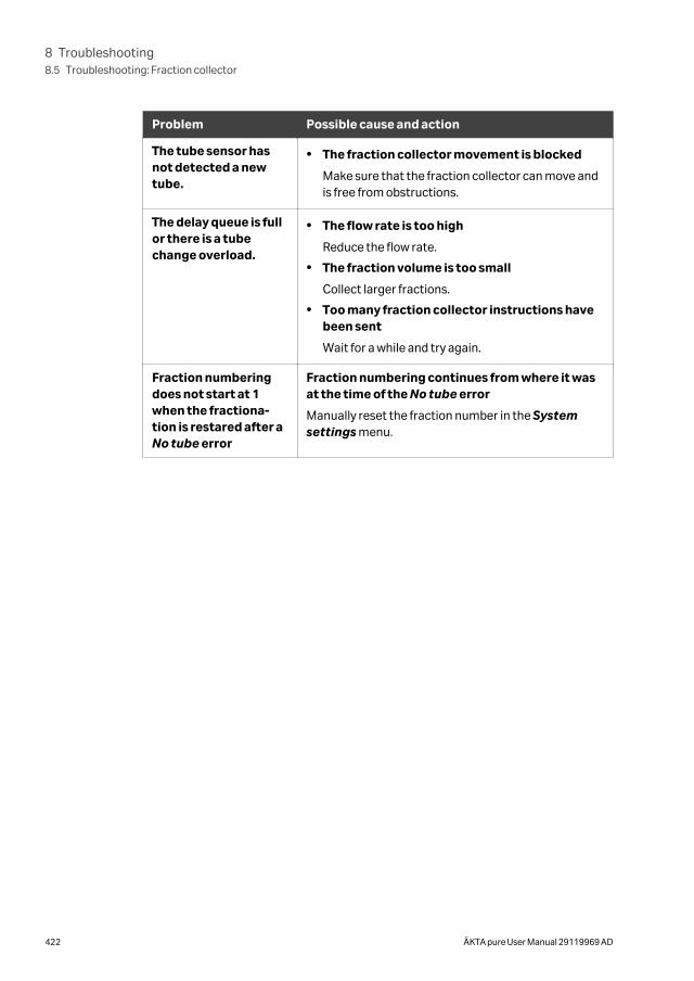
Problem Possible cause and action
The tube sensor hasnot detected a newtube.
• The fraction collector movement is blocked
Make sure that the fraction collector can move andis free from obstructions.
The delay queue is fullor there is a tubechange overload.
• The flow rate is too high
Reduce the flow rate.
• The fraction volume is too small
Collect larger fractions.
• Too many fraction collector instructions havebeen sent
Wait for a while and try again.
Fraction numberingdoes not start at 1when the fractiona-tion is restared after aNo tube error
Fraction numbering continues from where it wasat the time of the No tube error
Manually reset the fraction number in the Systemsettings menu.
8 Troubleshooting8.5 Troubleshooting: Fraction collector
422 ÄKTA pure User Manual 29119969 AD
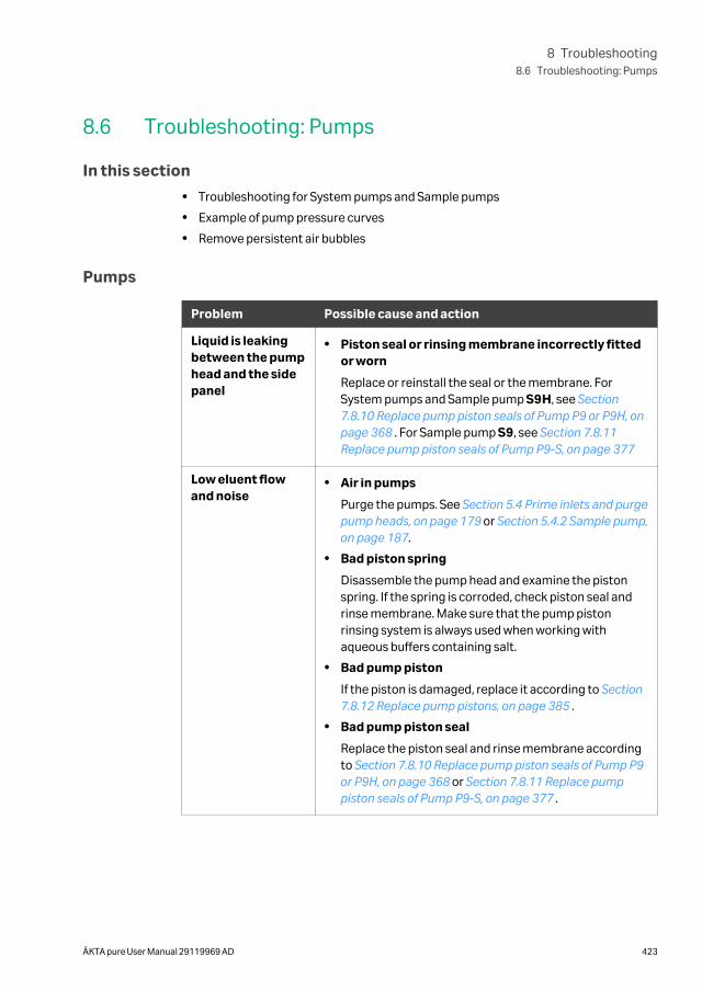
8.6 Troubleshooting: Pumps
In this section
• Troubleshooting for System pumps and Sample pumps
• Example of pump pressure curves
• Remove persistent air bubbles
Pumps
Problem Possible cause and action
Liquid is leakingbetween the pumphead and the sidepanel
• Piston seal or rinsing membrane incorrectly fittedor worn
Replace or reinstall the seal or the membrane. ForSystem pumps and Sample pump S9H, see Section7.8.10 Replace pump piston seals of Pump P9 or P9H, onpage 368 . For Sample pump S9, see Section 7.8.11Replace pump piston seals of Pump P9-S, on page 377
Low eluent flowand noise
• Air in pumps
Purge the pumps. See Section 5.4 Prime inlets and purgepump heads, on page 179 or Section 5.4.2 Sample pump,on page 187.
• Bad piston spring
Disassemble the pump head and examine the pistonspring. If the spring is corroded, check piston seal andrinse membrane. Make sure that the pump pistonrinsing system is always used when working withaqueous buffers containing salt.
• Bad pump piston
If the piston is damaged, replace it according to Section7.8.12 Replace pump pistons, on page 385 .
• Bad pump piston seal
Replace the piston seal and rinse membrane accordingto Section 7.8.10 Replace pump piston seals of Pump P9or P9H, on page 368 or Section 7.8.11 Replace pumppiston seals of Pump P9-S, on page 377 .
8 Troubleshooting8.6 Troubleshooting: Pumps
ÄKTA pure User Manual 29119969 AD 423
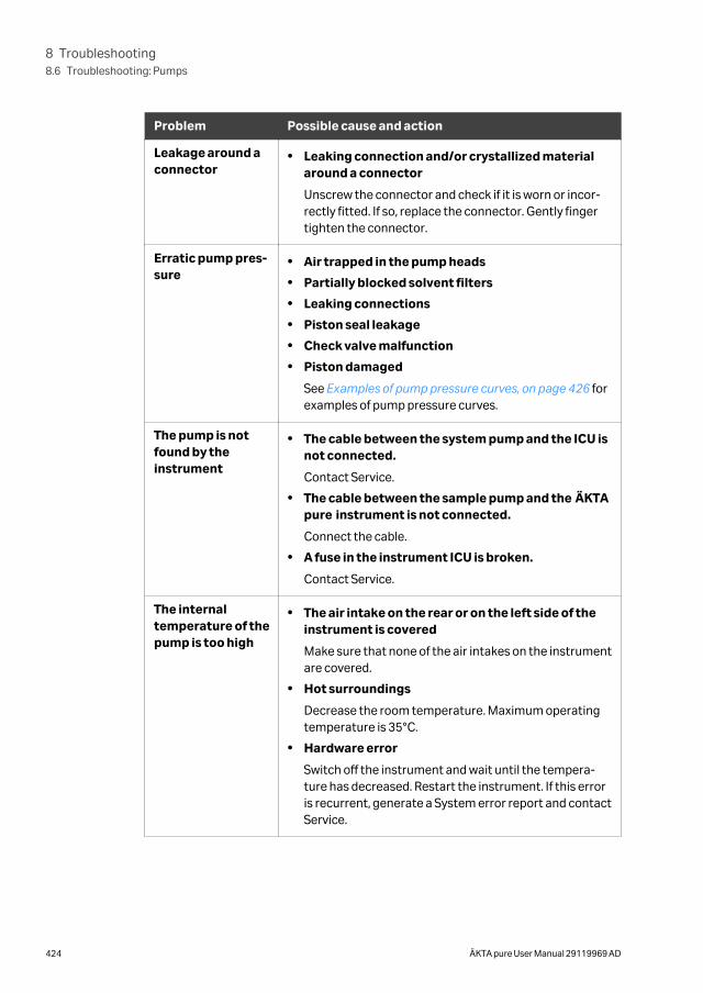
Problem Possible cause and action
Leakage around aconnector
• Leaking connection and/or crystallized materialaround a connector
Unscrew the connector and check if it is worn or incor-rectly fitted. If so, replace the connector. Gently fingertighten the connector.
Erratic pump pres-sure
• Air trapped in the pump heads
• Partially blocked solvent filters
• Leaking connections
• Piston seal leakage
• Check valve malfunction
• Piston damaged
See Examples of pump pressure curves, on page 426 forexamples of pump pressure curves.
The pump is notfound by theinstrument
• The cable between the system pump and the ICU isnot connected.
Contact Service.
• The cable between the sample pump and the ÄKTApure instrument is not connected.
Connect the cable.
• A fuse in the instrument ICU is broken.
Contact Service.
The internaltemperature of thepump is too high
• The air intake on the rear or on the left side of theinstrument is covered
Make sure that none of the air intakes on the instrumentare covered.
• Hot surroundings
Decrease the room temperature. Maximum operatingtemperature is 35°C.
• Hardware error
Switch off the instrument and wait until the tempera-ture has decreased. Restart the instrument. If this erroris recurrent, generate a System error report and contactService.
8 Troubleshooting8.6 Troubleshooting: Pumps
424 ÄKTA pure User Manual 29119969 AD
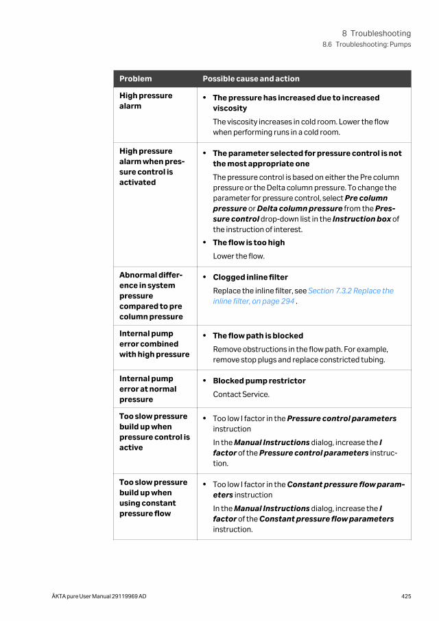
Problem Possible cause and action
High pressurealarm
• The pressure has increased due to increasedviscosity
The viscosity increases in cold room. Lower the flowwhen performing runs in a cold room.
High pressurealarm when pres-sure control isactivated
• The parameter selected for pressure control is notthe most appropriate one
The pressure control is based on either the Pre columnpressure or the Delta column pressure. To change theparameter for pressure control, select Pre columnpressure or Delta column pressure from the Pres-sure control drop-down list in the Instruction box ofthe instruction of interest.
• The flow is too high
Lower the flow.
Abnormal differ-ence in systempressurecompared to precolumn pressure
• Clogged inline filter
Replace the inline filter, see Section 7.3.2 Replace theinline filter, on page 294 .
Internal pumperror combinedwith high pressure
• The flow path is blocked
Remove obstructions in the flow path. For example,remove stop plugs and replace constricted tubing.
Internal pumperror at normalpressure
• Blocked pump restrictor
Contact Service.
Too slow pressurebuild up whenpressure control isactive
• Too low I factor in the Pressure control parametersinstruction
In the Manual Instructions dialog, increase the Ifactor of the Pressure control parameters instruc-tion.
Too slow pressurebuild up whenusing constantpressure flow
• Too low I factor in the Constant pressure flow param-eters instruction
In the Manual Instructions dialog, increase the Ifactor of the Constant pressure flow parametersinstruction.
8 Troubleshooting8.6 Troubleshooting: Pumps
ÄKTA pure User Manual 29119969 AD 425
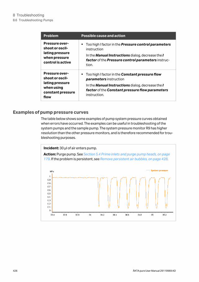
Problem Possible cause and action
Pressure over-shoot or oscil-lating pressurewhen pressurecontrol is active
• Too high I factor in the Pressure control parametersinstruction
In the Manual Instructions dialog, decrease the Ifactor of the Pressure control parameters instruc-tion.
Pressure over-shoot or oscil-lating pressurewhen usingconstant pressureflow
• Too high I factor in the Constant pressure flowparameters instruction
In the Manual Instructions dialog, decrease the Ifactor of the Constant pressure flow parametersinstruction.
Examples of pump pressure curvesThe table below shows some examples of pump system pressure curves obtainedwhen errors have occurred. The examples can be useful in troubleshooting of thesystem pumps and the sample pump. The system pressure monitor R9 has higherresolution than the other pressure monitors, and is therefore recommended for trou-bleshooting purposes.
Incident: 30 μl of air enters pump.
Action: Purge pump. See Section 5.4 Prime inlets and purge pump heads, on page179. If the problem is persistent, see Remove persistent air bubbles, on page 428.
8 Troubleshooting8.6 Troubleshooting: Pumps
426 ÄKTA pure User Manual 29119969 AD
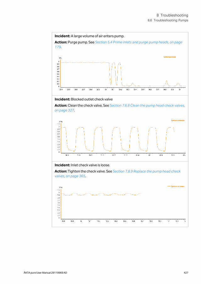
Incident: A large volume of air enters pump.
Action: Purge pump. See Section 5.4 Prime inlets and purge pump heads, on page179.
Incident: Blocked outlet check valve
Action: Clean the check valve, See Section 7.6.8 Clean the pump head check valves,on page 327.
Incident: Inlet check valve is loose.
Action: Tighten the check valve. See Section 7.8.9 Replace the pump head checkvalves, on page 365.
8 Troubleshooting8.6 Troubleshooting: Pumps
ÄKTA pure User Manual 29119969 AD 427
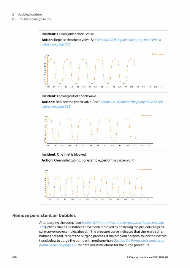
Incident: Leaking inlet check valve.
Action: Replace the check valve. See Section 7.8.9 Replace the pump head checkvalves, on page 365.
Incident: Leaking outlet check valve.
Actions: Replace the check valve. See Section 7.8.9 Replace the pump head checkvalves, on page 365.
Incident: One inlet is blocked,
Action: Clean inlet tubing. For example, perform a System CIP.
Remove persistent air bubbles
After purging the pump (see Section 5.4 Prime inlets and purge pump heads, on page179), check that all air bubbles have been removed by analyzing the pre-column pres-sure curve (see examples above). If the pressure curve indicates that there are still airbubbles present, repeat the purging process. If the problem persists, follow the instruc-tions below to purge the pump with methanol (see Section 5.4 Prime inlets and purgepump heads, on page 179 for detailed instructions for the purge procedure).
8 Troubleshooting8.6 Troubleshooting: Pumps
428 ÄKTA pure User Manual 29119969 AD
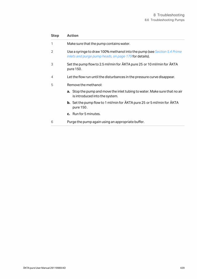
Step Action
1 Make sure that the pump contains water.
2 Use a syringe to draw 100% methanol into the pump (see Section 5.4 Primeinlets and purge pump heads, on page 179 for details).
3 Set the pump flow to 2.5 ml/min for ÄKTA pure 25 or 10 ml/min for ÄKTApure 150.
4 Let the flow run until the disturbances in the pressure curve disappear.
5 Remove the methanol:
a. Stop the pump and move the inlet tubing to water. Make sure that no airis introduced into the system.
b. Set the pump flow to 1 ml/min for ÄKTA pure 25 or 5 ml/min for ÄKTApure 150.
c. Run for 5 minutes.
6 Purge the pump again using an appropriate buffer.
8 Troubleshooting8.6 Troubleshooting: Pumps
ÄKTA pure User Manual 29119969 AD 429
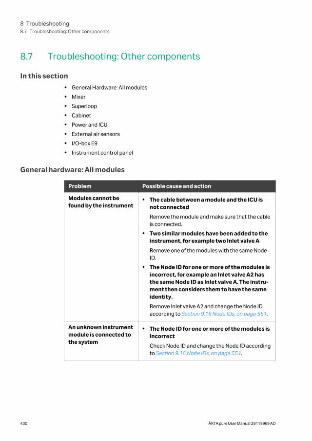
8.7 Troubleshooting: Other components
In this section
• General Hardware: All modules
• Mixer
• Superloop
• Cabinet
• Power and ICU
• External air sensors
• I/O-box E9
• Instrument control panel
General hardware: All modules
Problem Possible cause and action
Modules cannot befound by the instrument
• The cable between a module and the ICU isnot connected
Remove the module and make sure that the cableis connected.
• Two similar modules have been added to theinstrument, for example two Inlet valve A
Remove one of the modules with the same NodeID.
• The Node ID for one or more of the modules isincorrect, for example an Inlet valve A2 hasthe same Node ID as Inlet valve A. The instru-ment then considers them to have the sameidentity.
Remove Inlet valve A2 and change the Node IDaccording to Section 9.16 Node IDs, on page 551.
An unknown instrumentmodule is connected tothe system
• The Node ID for one or more of the modules isincorrect
Check Node ID and change the Node ID accordingto Section 9.16 Node IDs, on page 551.
8 Troubleshooting8.7 Troubleshooting: Other components
430 ÄKTA pure User Manual 29119969 AD
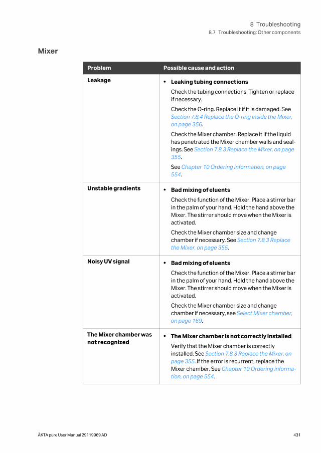
Mixer
Problem Possible cause and action
Leakage • Leaking tubing connections
Check the tubing connections. Tighten or replaceif necessary.
Check the O-ring. Replace it if it is damaged. See Section 7.8.4 Replace the O-ring inside the Mixer,on page 356.
Check the Mixer chamber. Replace it if the liquidhas penetrated the Mixer chamber walls and seal-ings. See Section 7.8.3 Replace the Mixer, on page355.
See Chapter 10 Ordering information, on page554.
Unstable gradients • Bad mixing of eluents
Check the function of the Mixer. Place a stirrer barin the palm of your hand. Hold the hand above theMixer. The stirrer should move when the Mixer isactivated.
Check the Mixer chamber size and changechamber if necessary. See Section 7.8.3 Replacethe Mixer, on page 355.
Noisy UV signal • Bad mixing of eluents
Check the function of the Mixer. Place a stirrer barin the palm of your hand. Hold the hand above theMixer. The stirrer should move when the Mixer isactivated.
Check the Mixer chamber size and changechamber if necessary, see Select Mixer chamber,on page 169.
The Mixer chamber wasnot recognized
• The Mixer chamber is not correctly installed
Verify that the Mixer chamber is correctlyinstalled. See Section 7.8.3 Replace the Mixer, onpage 355. If the error is recurrent, replace theMixer chamber. See Chapter 10 Ordering informa-tion, on page 554.
8 Troubleshooting8.7 Troubleshooting: Other components
ÄKTA pure User Manual 29119969 AD 431
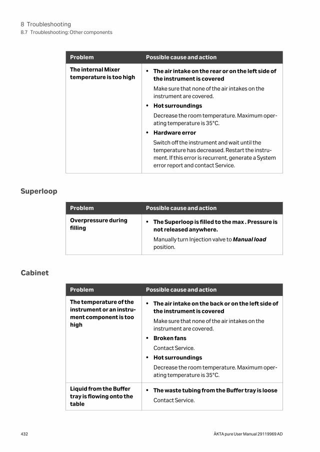
Problem Possible cause and action
The internal Mixertemperature is too high
• The air intake on the rear or on the left side ofthe instrument is covered
Make sure that none of the air intakes on theinstrument are covered.
• Hot surroundings
Decrease the room temperature. Maximum oper-ating temperature is 35°C.
• Hardware error
Switch off the instrument and wait until thetemperature has decreased. Restart the instru-ment. If this error is recurrent, generate a Systemerror report and contact Service.
Superloop
Problem Possible cause and action
Overpressure duringfilling
• The Superloop is filled to the max . Pressure isnot released anywhere.
Manually turn Injection valve to Manual loadposition.
Cabinet
Problem Possible cause and action
The temperature of theinstrument or an instru-ment component is toohigh
• The air intake on the back or on the left side ofthe instrument is covered
Make sure that none of the air intakes on theinstrument are covered.
• Broken fans
Contact Service.
• Hot surroundings
Decrease the room temperature. Maximum oper-ating temperature is 35°C.
Liquid from the Buffertray is flowing onto thetable
• The waste tubing from the Buffer tray is loose
Contact Service.
8 Troubleshooting8.7 Troubleshooting: Other components
432 ÄKTA pure User Manual 29119969 AD
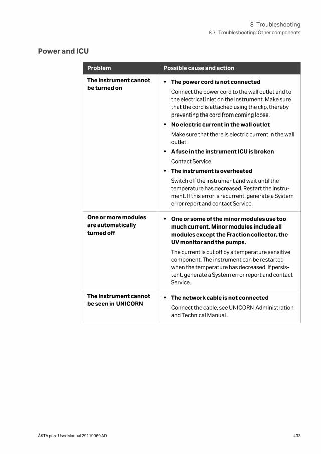
Power and ICU
Problem Possible cause and action
The instrument cannotbe turned on
• The power cord is not connected
Connect the power cord to the wall outlet and tothe electrical inlet on the instrument. Make surethat the cord is attached using the clip, therebypreventing the cord from coming loose.
• No electric current in the wall outlet
Make sure that there is electric current in the walloutlet.
• A fuse in the instrument ICU is broken
Contact Service.
• The instrument is overheated
Switch off the instrument and wait until thetemperature has decreased. Restart the instru-ment. If this error is recurrent, generate a Systemerror report and contact Service.
One or more modulesare automaticallyturned off
• One or some of the minor modules use toomuch current. Minor modules include allmodules except the Fraction collector, theUV monitor and the pumps.
The current is cut off by a temperature sensitivecomponent. The instrument can be restartedwhen the temperature has decreased. If persis-tent, generate a System error report and contactService.
The instrument cannotbe seen in UNICORN
• The network cable is not connected
Connect the cable, see UNICORN Administrationand Technical Manual .
8 Troubleshooting8.7 Troubleshooting: Other components
ÄKTA pure User Manual 29119969 AD 433
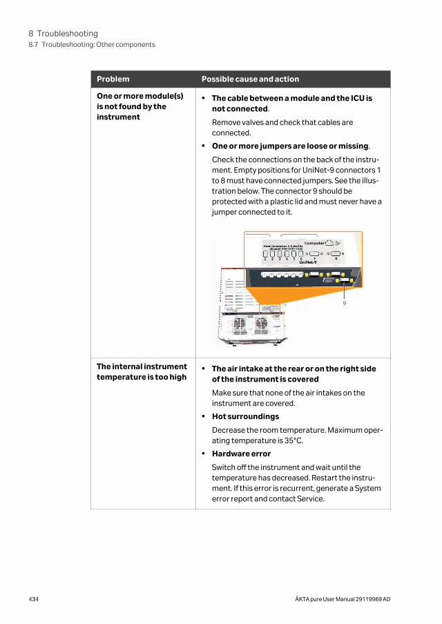
Problem Possible cause and action
One or more module(s)is not found by theinstrument
• The cable between a module and the ICU isnot connected.
Remove valves and check that cables areconnected.
• One or more jumpers are loose or missing.
Check the connections on the back of the instru-ment. Empty positions for UniNet-9 connectors 1to 8 must have connected jumpers. See the illus-tration below. The connector 9 should beprotected with a plastic lid and must never have ajumper connected to it.
9
The internal instrumenttemperature is too high
• The air intake at the rear or on the right sideof the instrument is covered
Make sure that none of the air intakes on theinstrument are covered.
• Hot surroundings
Decrease the room temperature. Maximum oper-ating temperature is 35°C.
• Hardware error
Switch off the instrument and wait until thetemperature has decreased. Restart the instru-ment. If this error is recurrent, generate a Systemerror report and contact Service.
8 Troubleshooting8.7 Troubleshooting: Other components
434 ÄKTA pure User Manual 29119969 AD
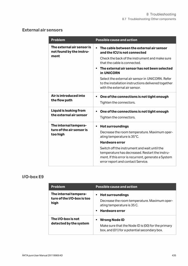
External air sensors
Problem Possible cause and action
The external air sensor isnot found by the instru-ment
• The cable between the external air sensorand the ICU is not connected
Check the back of the instrument and make surethat the cable is connected.
• The external air sensor has not been selectedin UNICORN
Select the external air sensor in UNICORN. Referto the installation instructions delivered togetherwith the external air sensor.
Air is introduced intothe flow path
• One of the connections is not tight enough
Tighten the connectors.
Liquid is leaking fromthe external air sensor
• One of the connections is not tight enough
Tighten the connectors.
The internal tempera-ture of the air sensor istoo high
• Hot surroundings
Decrease the room temperature. Maximum oper-ating temperature is 35°C.
Hardware error
Switch off the instrument and wait until thetemperature has decreased. Restart the instru-ment. If this error is recurrent, generate a Systemerror report and contact Service.
I/O-box E9
Problem Possible cause and action
The internal tempera-ture of the I/O-box is toohigh
• Hot surroundings
Decrease the room temperature. Maximum oper-ating temperature is 35 C.
• Hardware error
The I/O-box is notdetected by the system
• Wrong Node ID
Make sure that the Node ID is (00) for the primarybox, and (01) for a potential secondary box.
8 Troubleshooting8.7 Troubleshooting: Other components
ÄKTA pure User Manual 29119969 AD 435
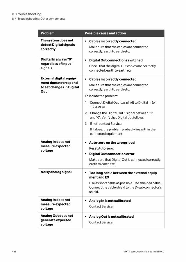
Problem Possible cause and action
The system does notdetect Digital signalscorrectly
• Cables incorrectly connected
Make sure that the cables are connectedcorrectly, earth to earth etc.
Digital In always ”0”,regardless of inputsignals
• Digital Out connections switched
Check that the digital Out cables are correctlyconnected, earth to earth etc.
External digital equip-ment does not respondto set changes in DigitalOut
• Cables incorrectly connected
Make sure that the cables are connectedcorrectly, earth to earth etc.
To isolate the problem:
1. Connect Digital Out (e.g. pin 6) to Digital In (pin1,2,3, or 4).
2. Change the Digital Out 1 signal between ”1”and ”0”. Verify that Digital out follows.
3. If not: contact Service.
If it does: the problem probably lies within theconnected equipment.
Analog In does notmeasure expectedvoltage
• Auto-zero on the wrong level
Reset Auto-zero.
• Digital Out connection error
Make sure that Digital Out is connected correctly,earth to earth etc.
Noisy analog signal • Too long cable between the external equip-ment and E9
Use as short cable as possible. Use shielded cable.Connect the cable shield to the D-sub connector’sshield.
Analog In does notmeasure expectedvoltage
• Analog In is not calibrated
Contact Service.
Analog Out does notgenerate expectedvoltage
• Analog Out is not calibrated
Contact Service.
8 Troubleshooting8.7 Troubleshooting: Other components
436 ÄKTA pure User Manual 29119969 AD
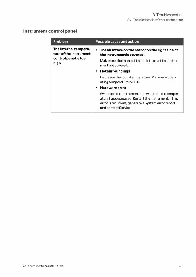
Instrument control panel
Problem Possible cause and action
The internal tempera-ture of the instrumentcontrol panel is toohigh
• The air intake on the rear or on the right side ofthe instrument is covered.
Make sure that none of the air intakes of the instru-ment are covered.
• Hot surroundings
Decrease the room temperature. Maximum oper-ating temperature is 35 C.
• Hardware error
Switch off the instrument and wait until the temper-ature has decreased. Restart the instrument. If thiserror is recurrent, generate a System error reportand contact Service.
8 Troubleshooting8.7 Troubleshooting: Other components
ÄKTA pure User Manual 29119969 AD 437
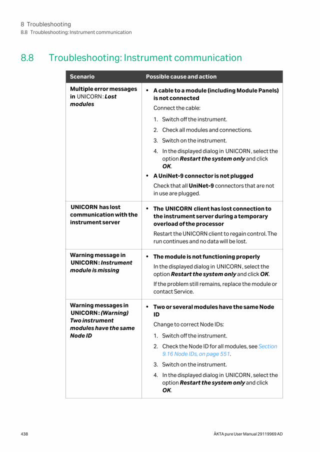
8.8 Troubleshooting: Instrument communication
Scenario Possible cause and action
Multiple error messagesin UNICORN: Lostmodules
• A cable to a module (including Module Panels)is not connected
Connect the cable:
1. Switch off the instrument.
2. Check all modules and connections.
3. Switch on the instrument.
4. In the displayed dialog in UNICORN, select theoption Restart the system only and clickOK.
• A UniNet-9 connector is not plugged
Check that all UniNet-9 connectors that are notin use are plugged.
UNICORN has lostcommunication with theinstrument server
• The UNICORN client has lost connection tothe instrument server during a temporaryoverload of the processor
Restart the UNICORN client to regain control. Therun continues and no data will be lost.
Warning message inUNICORN: Instrumentmodule is missing
• The module is not functioning properly
In the displayed dialog in UNICORN, select theoption Restart the system only and click OK.
If the problem still remains, replace the module orcontact Service.
Warning messages inUNICORN: (Warning)Two instrumentmodules have the sameNode ID
• Two or several modules have the same NodeID
Change to correct Node IDs:
1. Switch off the instrument.
2. Check the Node ID for all modules, see Section9.16 Node IDs, on page 551.
3. Switch on the instrument.
4. In the displayed dialog in UNICORN, select theoption Restart the system only and clickOK.
8 Troubleshooting8.8 Troubleshooting: Instrument communication
438 ÄKTA pure User Manual 29119969 AD
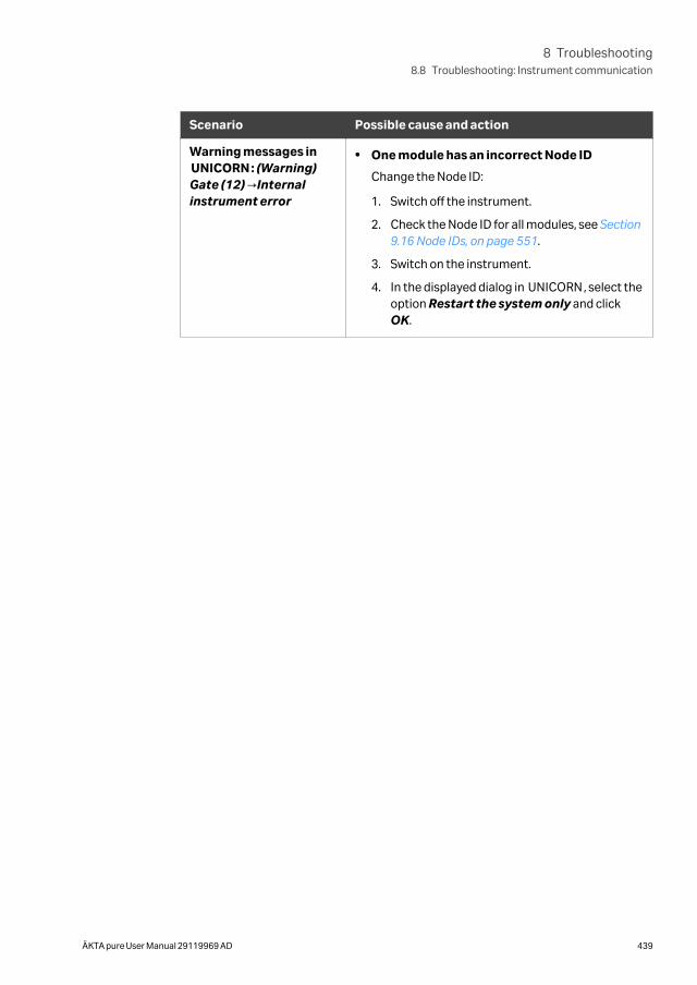
Scenario Possible cause and action
Warning messages inUNICORN: (Warning)Gate (12) →Internalinstrument error
• One module has an incorrect Node ID
Change the Node ID:
1. Switch off the instrument.
2. Check the Node ID for all modules, see Section9.16 Node IDs, on page 551.
3. Switch on the instrument.
4. In the displayed dialog in UNICORN, select theoption Restart the system only and clickOK.
8 Troubleshooting8.8 Troubleshooting: Instrument communication
ÄKTA pure User Manual 29119969 AD 439
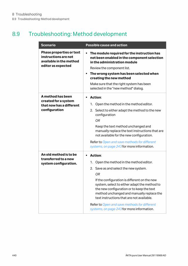
8.9 Troubleshooting: Method development
Scenario Possible cause and action
Phase properties or textinstructions are notavailable in the methodeditor as expected
• The module required for the instruction hasnot been enabled in the component selectionin the administration module
Review the component list.
• The wrong system has been selected whencreating the new method
Make sure that the right system has beenselected in the "new method" dialog.
A method has beencreated for a systemthat now has a differentconfiguration
• Action:
1. Open the method in the method editor.
2. Select to either adapt the method to the newconfiguration
OR
Keep the text method unchanged andmanually replace the text instructions that arenot available for the new configuration.
Refer to Open and save methods for differentsystems, on page 243 for more information.
An old method is to betransferred to a newsystem configuration.
• Action:
1. Open the method in the method editor.
2. Save as and select the new system.
OR
If the configuration is different on the newsystem, select to either adapt the method tothe new configuration or to keep the textmethod unchanged and manually replace thetext instructions that are not available.
Refer to Open and save methods for differentsystems, on page 243 for more information.
8 Troubleshooting8.9 Troubleshooting: Method development
440 ÄKTA pure User Manual 29119969 AD
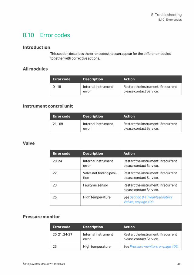
8.10 Error codes
IntroductionThis section describes the error codes that can appear for the different modules,together with corrective actions.
All modules
Error code Description Action
0 - 19 Internal instrumenterror
Restart the instrument. If recurrentplease contact Service.
Instrument control unit
Error code Description Action
21 - 69 Internal instrumenterror
Restart the instrument. If recurrentplease contact Service.
Valve
Error code Description Action
20, 24 Internal instrumenterror
Restart the instrument. If recurrentplease contact Service.
22 Valve not finding posi-tion
Restart the instrument. If recurrentplease contact Service.
23 Faulty air sensor Restart the instrument. If recurrentplease contact Service.
25 High temperature See Section 8.4 Troubleshooting:Valves, on page 409
Pressure monitor
Error code Description Action
20, 21, 24-27 Internal instrumenterror
Restart the instrument. If recurrentplease contact Service.
23 High temperature See Pressure monitors, on page 406.
8 Troubleshooting8.10 Error codes
ÄKTA pure User Manual 29119969 AD 441
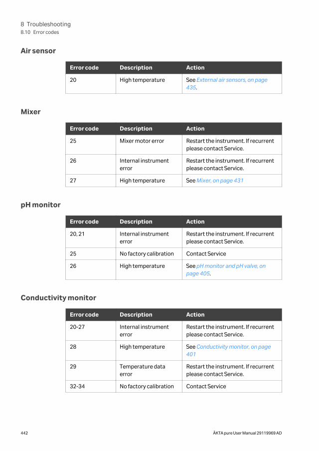
Air sensor
Error code Description Action
20 High temperature See External air sensors, on page435.
Mixer
Error code Description Action
25 Mixer motor error Restart the instrument. If recurrentplease contact Service.
26 Internal instrumenterror
Restart the instrument. If recurrentplease contact Service.
27 High temperature See Mixer, on page 431
pH monitor
Error code Description Action
20, 21 Internal instrumenterror
Restart the instrument. If recurrentplease contact Service.
25 No factory calibration Contact Service
26 High temperature See pH monitor and pH valve, onpage 405.
Conductivity monitor
Error code Description Action
20-27 Internal instrumenterror
Restart the instrument. If recurrentplease contact Service.
28 High temperature See Conductivity monitor, on page401
29 Temperature dataerror
Restart the instrument. If recurrentplease contact Service.
32-34 No factory calibration Contact Service
8 Troubleshooting8.10 Error codes
442 ÄKTA pure User Manual 29119969 AD

Pump
Error code Description Action
51-53 Internal pump error Check that there is no blockage ofthe pump outlet. Restart the instru-ment. If recurrent please contactService.
54 High temperature See Section 8.6 Troubleshooting:Pumps, on page 423
UV monitor U9-M
Error code Description Action
21, 25, 26, 31 Grating error Restart the instrument. If recurrentplease contact Service.
22, 23, 32 Block filter error Restart the instrument. If recurrentplease contact Service.
24 Internal instrumenterror
Restart the instrument. If recurrentplease contact Service.
27 Spectrum calibrationerror
Restart the instrument. If recurrentplease contact Service.
28, 29 Lamp error Restart the instrument. If recurrentplease contact Service.
30 High temperature See UV monitor U9-M and UVdetector unit, on page 394.
UV detector U9-D
Error code Description Action
24, 26, 28, 29,31, 33
Internal instrumenterror
Restart the instrument. If recurrentplease contact Service.
25 Too low light intensity Check that the detector and flow cellare fitted correctly. If warning reap-pears, contact Service.
27 Too high light intensity Check that the detector and flow cellare fitted correctly. If warning reap-pears, contact Service.
8 Troubleshooting8.10 Error codes
ÄKTA pure User Manual 29119969 AD 443
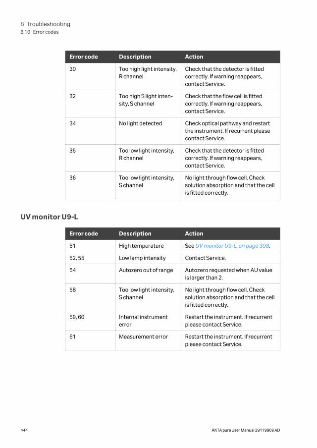
Error code Description Action
30 Too high light intensity,R channel
Check that the detector is fittedcorrectly. If warning reappears,contact Service.
32 Too high S light inten-sity, S channel
Check that the flow cell is fittedcorrectly. If warning reappears,contact Service.
34 No light detected Check optical pathway and restartthe instrument. If recurrent pleasecontact Service.
35 Too low light intensity,R channel
Check that the detector is fittedcorrectly. If warning reappears,contact Service.
36 Too low light intensity,S channel
No light through flow cell. Checksolution absorption and that the cellis fitted correctly.
UV monitor U9-L
Error code Description Action
51 High temperature See UV monitor U9-L, on page 398.
52, 55 Low lamp intensity Contact Service.
54 Autozero out of range Autozero requested when AU valueis larger than 2.
58 Too low light intensity,S channel
No light through flow cell. Checksolution absorption and that the cellis fitted correctly.
59, 60 Internal instrumenterror
Restart the instrument. If recurrentplease contact Service.
61 Measurement error Restart the instrument. If recurrentplease contact Service.
8 Troubleshooting8.10 Error codes
444 ÄKTA pure User Manual 29119969 AD
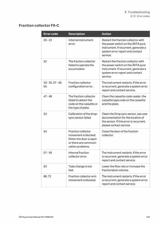
Fraction collector F9-C
Error code Description Action
20 - 22 Internal instrumenterror.
Restart the fraction collector withthe power switch on the ÄKTA pureinstrument. If recurrent, generate asystem error report and contactservice.
32 The fraction collectorfailed to operate theaccumulator.
Restart the fraction collector withthe power switch on the ÄKTA pureinstrument. If recurrent, generate asystem error report and contactservice.
33 - 35, 37 - 40,55
Fraction collectorconfiguration error.
The instrument restarts. If the erroris recurrent, generate a system errorreport and contact service.
47 - 48 The fraction collectorfailed to detect thecode on the cassette orthe type of plate.
Clean the cassette code reader, thecassette type code on the cassetteand the plate.
53 Calibration of the drop-sync sensor failed.
Clean the Drop sync sensor, see userdocumentation for the location ofthe sensor. If this error is recurrent,please contact service.
54 Fraction collectormovement is blocked.Either the door is openor there are communi-cation problems.
Close the door of the fractioncollector.
57 - 59 Internal fractioncollector error.
The instrument restarts. If the erroris recurrent, generate a system errorreport and contact service.
63 Tube change is toofast.
Lower the flow rate or increase thefractionation volume.
68, 72 Fraction collector armmovement is blocked.
The instrument restarts. If the erroris recurrent, generate a system errorreport and contact service.
8 Troubleshooting8.10 Error codes
ÄKTA pure User Manual 29119969 AD 445
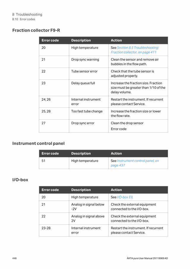
Fraction collector F9-R
Error code Description Action
20 High temperature See Section 8.5 Troubleshooting:Fraction collector, on page 411
21 Drop sync warning Clean the sensor and remove airbubbles in the flow path.
22 Tube sensor error Check that the tube sensor isadjusted properly.
23 Delay queue full Increase the fraction size. Fractionsize must be greater than 1/10 of thedelay volume.
24, 26 Internal instrumenterror
Restart the instrument. If recurrentplease contact Service.
25, 28 Too fast tube change Increase the fraction size or lowerthe flow rate.
27 Drop sync error Clean the drop sensor
Error code
Instrument control panel
Error code Description Action
51 High temperature See Instrument control panel, onpage 437
I/O-box
Error code Description Action
20 High temperature See I/O-box E9,
21 Analog in signal below-2V
Check the external equipmentconnected to the I/O-box.
22 Analog in signal above2V
Check the external equipmentconnected to the I/O-box.
23-28 Internal instrumenterror
Restart the instrument. If recurrentplease contact Service.
8 Troubleshooting8.10 Error codes
446 ÄKTA pure User Manual 29119969 AD
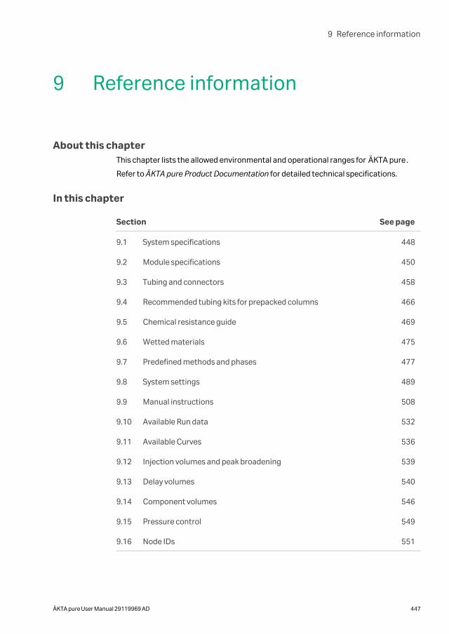
9 Reference information
About this chapterThis chapter lists the allowed environmental and operational ranges for ÄKTA pure.
Refer to ÄKTA pure Product Documentation for detailed technical specifications.
In this chapter
Section See page
9.1 System specifications 448
9.2 Module specifications 450
9.3 Tubing and connectors 458
9.4 Recommended tubing kits for prepacked columns 466
9.5 Chemical resistance guide 469
9.6 Wetted materials 475
9.7 Predefined methods and phases 477
9.8 System settings 489
9.9 Manual instructions 508
9.10 Available Run data 532
9.11 Available Curves 536
9.12 Injection volumes and peak broadening 539
9.13 Delay volumes 540
9.14 Component volumes 546
9.15 Pressure control 549
9.16 Node IDs 551
9 Reference information
ÄKTA pure User Manual 29119969 AD 447
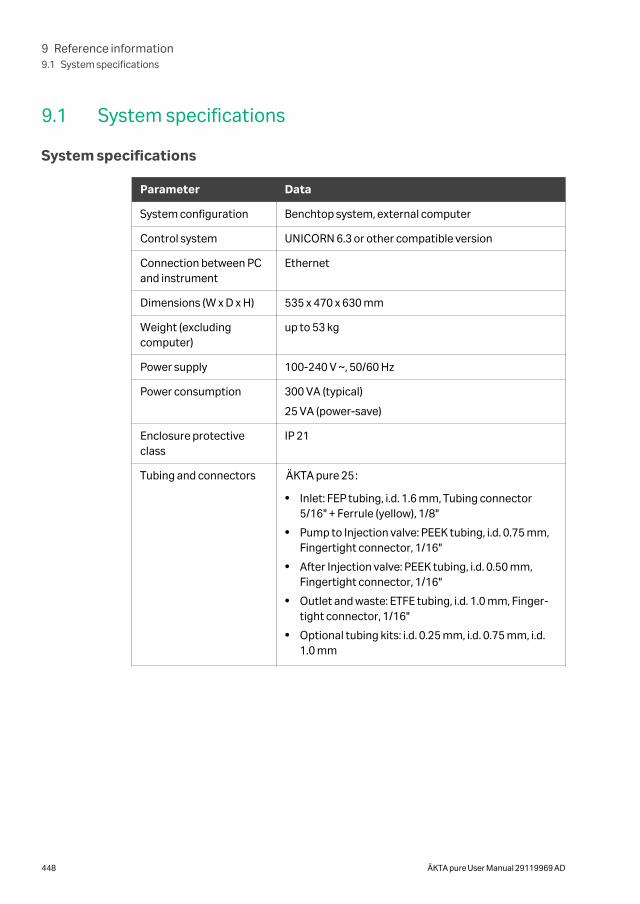
9.1 System specifications
System specifications
Parameter Data
System configuration Benchtop system, external computer
Control system UNICORN 6.3 or other compatible version
Connection between PCand instrument
Ethernet
Dimensions (W x D x H) 535 x 470 x 630 mm
Weight (excludingcomputer)
up to 53 kg
Power supply 100-240 V ~, 50/60 Hz
Power consumption 300 VA (typical)
25 VA (power-save)
Enclosure protectiveclass
IP 21
Tubing and connectors ÄKTA pure 25:
• Inlet: FEP tubing, i.d. 1.6 mm, Tubing connector5/16" + Ferrule (yellow), 1/8"
• Pump to Injection valve: PEEK tubing, i.d. 0.75 mm,Fingertight connector, 1/16"
• After Injection valve: PEEK tubing, i.d. 0.50 mm,Fingertight connector, 1/16"
• Outlet and waste: ETFE tubing, i.d. 1.0 mm, Finger-tight connector, 1/16"
• Optional tubing kits: i.d. 0.25 mm, i.d. 0.75 mm, i.d.1.0 mm
9 Reference information9.1 System specifications
448 ÄKTA pure User Manual 29119969 AD
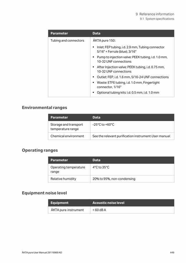
Parameter Data
Tubing and connectors ÄKTA pure 150:
• Inlet: FEP tubing, i.d. 2.9 mm, Tubing connector5/16" + Ferrule (blue), 3/16"
• Pump to injection valve: PEEK tubing, i.d. 1.0 mm,10-32 UNF connections
• After Injection valve: PEEK tubing, i.d. 0.75 mm,10-32 UNF connections
• Outlet: FEP, i.d. 1.6 mm, 5/16-24 UNF connections
• Waste: ETFE tubing, i.d. 1.0 mm, Fingertightconnector, 1/16"
• Optional tubing kits: i.d. 0.5 mm, i.d. 1.0 mm
Environmental ranges
Parameter Data
Storage and transporttemperature range
-25°C to +60°C
Chemical environment See the relevant purification instrument User manual.
Operating ranges
Parameter Data
Operating temperaturerange
4°C to 35°C
Relative humidity 20% to 95%, non-condensing
Equipment noise level
Equipment Acoustic noise level
ÄKTA pure instrument < 60 dB A
9 Reference information9.1 System specifications
ÄKTA pure User Manual 29119969 AD 449
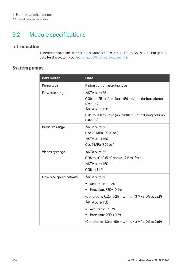
9.2 Module specifications
IntroductionThis section specifies the operating data of the components in ÄKTA pure. For generaldata for the system see System specifications, on page 448.
System pumps
Parameter Data
Pump type Piston pump, metering type
Flow rate range ÄKTA pure 25:
0.001 to 25 mL/min (up to 50 mL/min during columnpacking)
ÄKTA pure 150:
0.01 to 150 mL/min (up to 300 mL/min during columnpacking)
Pressure range ÄKTA pure 25:
0 to 20 MPa (2900 psi)
ÄKTA pure 150:
0 to 5 MPa (725 psi)
Viscosity range ÄKTA pure 25:
0.35 to 10 cP (5 cP above 12.5 mL/min)
ÄKTA pure 150:
0.35 to 5 cP
Flow rate specifications ÄKTA pure 25:
• Accuracy: ± 1.2%
• Precision: RSD < 0.5%
(Conditions: 0.25 to 25 mL/min, < 3 MPa, 0.8 to 2 cP)
ÄKTA pure 150:
• Accuracy: ± 1.5%
• Precision: RSD < 0.5%
(Conditions: 1.0 to 150 mL/min, < 3 MPa, 0.8 to 2 cP)
9 Reference information9.2 Module specifications
450 ÄKTA pure User Manual 29119969 AD
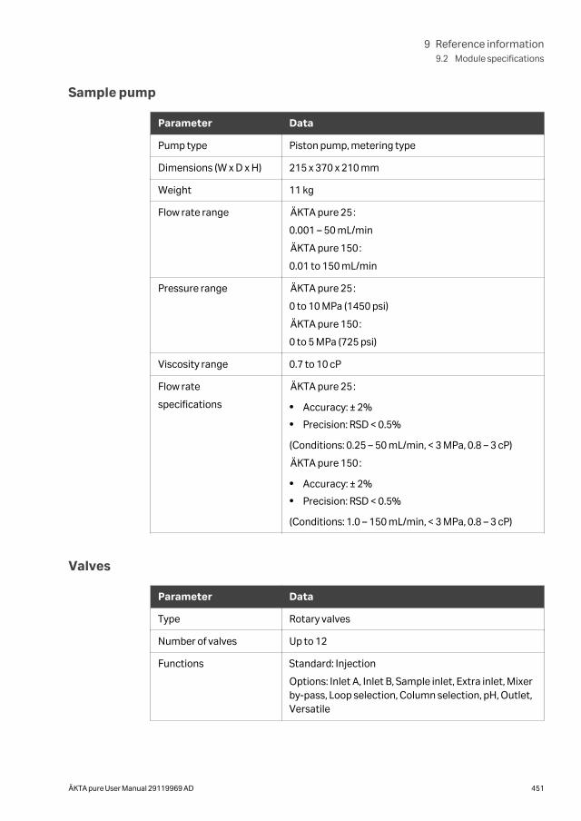
Sample pump
Parameter Data
Pump type Piston pump, metering type
Dimensions (W x D x H) 215 x 370 x 210 mm
Weight 11 kg
Flow rate range ÄKTA pure 25:
0.001 – 50 mL/min
ÄKTA pure 150:
0.01 to 150 mL/min
Pressure range ÄKTA pure 25:
0 to 10 MPa (1450 psi)
ÄKTA pure 150:
0 to 5 MPa (725 psi)
Viscosity range 0.7 to 10 cP
Flow rate
specifications
ÄKTA pure 25:
• Accuracy: ± 2%
• Precision: RSD < 0.5%
(Conditions: 0.25 – 50 mL/min, < 3 MPa, 0.8 – 3 cP)
ÄKTA pure 150:
• Accuracy: ± 2%
• Precision: RSD < 0.5%
(Conditions: 1.0 – 150 mL/min, < 3 MPa, 0.8 – 3 cP)
Valves
Parameter Data
Type Rotary valves
Number of valves Up to 12
Functions Standard: Injection
Options: Inlet A, Inlet B, Sample inlet, Extra inlet, Mixerby-pass, Loop selection, Column selection, pH, Outlet,Versatile
9 Reference information9.2 Module specifications
ÄKTA pure User Manual 29119969 AD 451
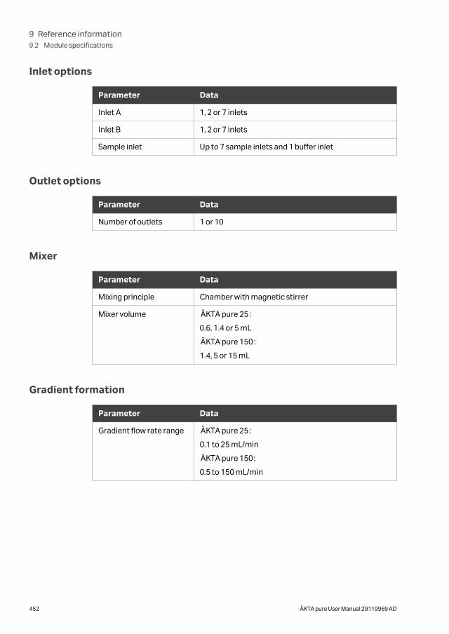
Inlet options
Parameter Data
Inlet A 1, 2 or 7 inlets
Inlet B 1, 2 or 7 inlets
Sample inlet Up to 7 sample inlets and 1 buffer inlet
Outlet options
Parameter Data
Number of outlets 1 or 10
Mixer
Parameter Data
Mixing principle Chamber with magnetic stirrer
Mixer volume ÄKTA pure 25:
0.6, 1.4 or 5 mL
ÄKTA pure 150:
1.4, 5 or 15 mL
Gradient formation
Parameter Data
Gradient flow rate range ÄKTA pure 25:
0.1 to 25 mL/min
ÄKTA pure 150:
0.5 to 150 mL/min
9 Reference information9.2 Module specifications
452 ÄKTA pure User Manual 29119969 AD
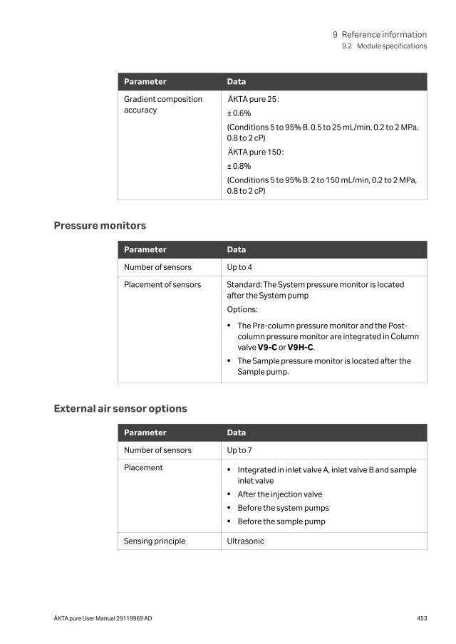
Parameter Data
Gradient compositionaccuracy
ÄKTA pure 25:
± 0.6%
(Conditions 5 to 95% B. 0.5 to 25 mL/min, 0.2 to 2 MPa,0.8 to 2 cP)
ÄKTA pure 150:
± 0.8%
(Conditions 5 to 95% B. 2 to 150 mL/min, 0.2 to 2 MPa,0.8 to 2 cP)
Pressure monitors
Parameter Data
Number of sensors Up to 4
Placement of sensors Standard: The System pressure monitor is locatedafter the System pump
Options:
• The Pre-column pressure monitor and the Post-column pressure monitor are integrated in Columnvalve V9-C or V9H-C.
• The Sample pressure monitor is located after theSample pump.
External air sensor options
Parameter Data
Number of sensors Up to 7
Placement • Integrated in inlet valve A, inlet valve B and sampleinlet valve
• After the injection valve
• Before the system pumps
• Before the sample pump
Sensing principle Ultrasonic
9 Reference information9.2 Module specifications
ÄKTA pure User Manual 29119969 AD 453
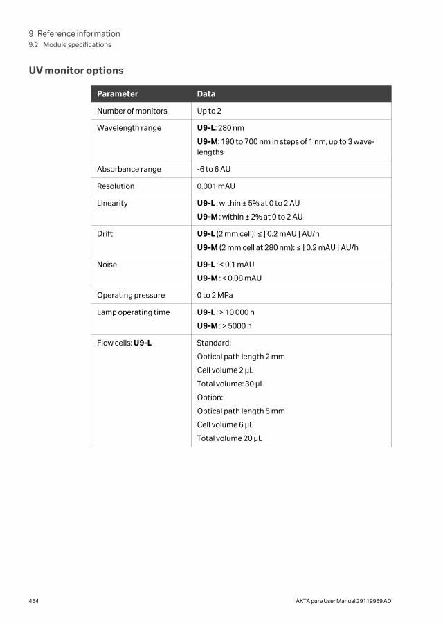
UV monitor options
Parameter Data
Number of monitors Up to 2
Wavelength range U9-L: 280 nm
U9-M: 190 to 700 nm in steps of 1 nm, up to 3 wave-lengths
Absorbance range -6 to 6 AU
Resolution 0.001 mAU
Linearity U9-L : within ± 5% at 0 to 2 AU
U9-M : within ± 2% at 0 to 2 AU
Drift U9-L (2 mm cell): ≤ | 0.2 mAU | AU/h
U9-M (2 mm cell at 280 nm): ≤ | 0.2 mAU | AU/h
Noise U9-L : < 0.1 mAU
U9-M : < 0.08 mAU
Operating pressure 0 to 2 MPa
Lamp operating time U9-L : > 10 000 h
U9-M : > 5000 h
Flow cells: U9-L Standard:
Optical path length 2 mm
Cell volume 2 µL
Total volume: 30 µL
Option:
Optical path length 5 mm
Cell volume 6 µL
Total volume 20 µL
9 Reference information9.2 Module specifications
454 ÄKTA pure User Manual 29119969 AD
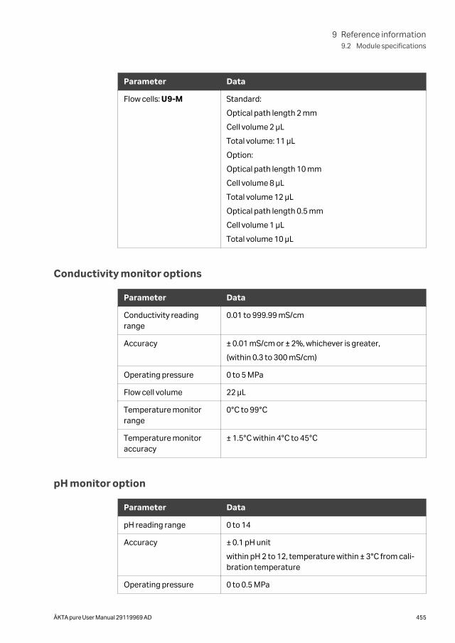
Parameter Data
Flow cells: U9-M Standard:
Optical path length 2 mm
Cell volume 2 µL
Total volume: 11 µL
Option:
Optical path length 10 mm
Cell volume 8 µL
Total volume 12 µL
Optical path length 0.5 mm
Cell volume 1 µL
Total volume 10 µL
Conductivity monitor options
Parameter Data
Conductivity readingrange
0.01 to 999.99 mS/cm
Accuracy ± 0.01 mS/cm or ± 2%, whichever is greater,
(within 0.3 to 300 mS/cm)
Operating pressure 0 to 5 MPa
Flow cell volume 22 μL
Temperature monitorrange
0°C to 99°C
Temperature monitoraccuracy
± 1.5°C within 4°C to 45°C
pH monitor option
Parameter Data
pH reading range 0 to 14
Accuracy ± 0.1 pH unit
within pH 2 to 12, temperature within ± 3°C from cali-bration temperature
Operating pressure 0 to 0.5 MPa
9 Reference information9.2 Module specifications
ÄKTA pure User Manual 29119969 AD 455
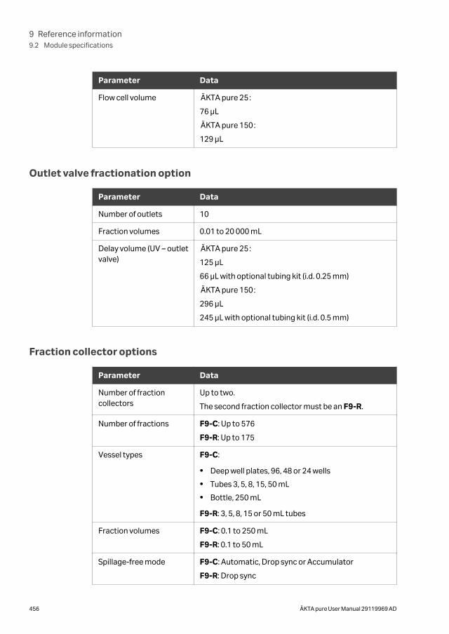
Parameter Data
Flow cell volume ÄKTA pure 25:
76 μL
ÄKTA pure 150:
129 μL
Outlet valve fractionation option
Parameter Data
Number of outlets 10
Fraction volumes 0.01 to 20 000 mL
Delay volume (UV – outletvalve)
ÄKTA pure 25:
125 µL
66 µL with optional tubing kit (i.d. 0.25 mm)
ÄKTA pure 150:
296 µL
245 µL with optional tubing kit (i.d. 0.5 mm)
Fraction collector options
Parameter Data
Number of fractioncollectors
Up to two.
The second fraction collector must be an F9-R.
Number of fractions F9-C: Up to 576
F9-R: Up to 175
Vessel types F9-C:
• Deep well plates, 96, 48 or 24 wells
• Tubes 3, 5, 8, 15, 50 mL
• Bottle, 250 mL
F9-R: 3, 5, 8, 15 or 50 mL tubes
Fraction volumes F9-C: 0.1 to 250 mL
F9-R: 0.1 to 50 mL
Spillage-free mode F9-C: Automatic, Drop sync or Accumulator
F9-R: Drop sync
9 Reference information9.2 Module specifications
456 ÄKTA pure User Manual 29119969 AD
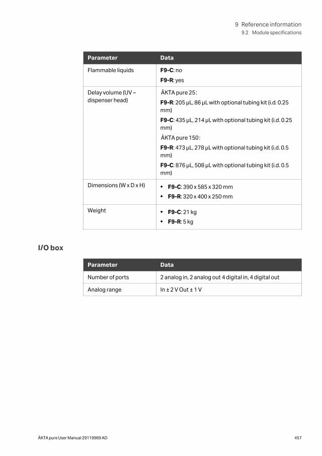
Parameter Data
Flammable liquids F9-C: no
F9-R: yes
Delay volume (UV –dispenser head)
ÄKTA pure 25:
F9-R: 205 µL, 86 µL with optional tubing kit (i.d. 0.25mm)
F9-C: 435 µL, 214 µL with optional tubing kit (i.d. 0.25mm)
ÄKTA pure 150:
F9-R: 473 µL, 278 µL with optional tubing kit (i.d. 0.5mm)
F9-C: 876 µL, 508 µL with optional tubing kit (i.d. 0.5mm)
Dimensions (W x D x H) • F9-C: 390 x 585 x 320 mm
• F9-R: 320 x 400 x 250 mm
Weight • F9-C: 21 kg
• F9-R: 5 kg
I/O box
Parameter Data
Number of ports 2 analog in, 2 analog out 4 digital in, 4 digital out
Analog range In ± 2 V Out ± 1 V
9 Reference information9.2 Module specifications
ÄKTA pure User Manual 29119969 AD 457
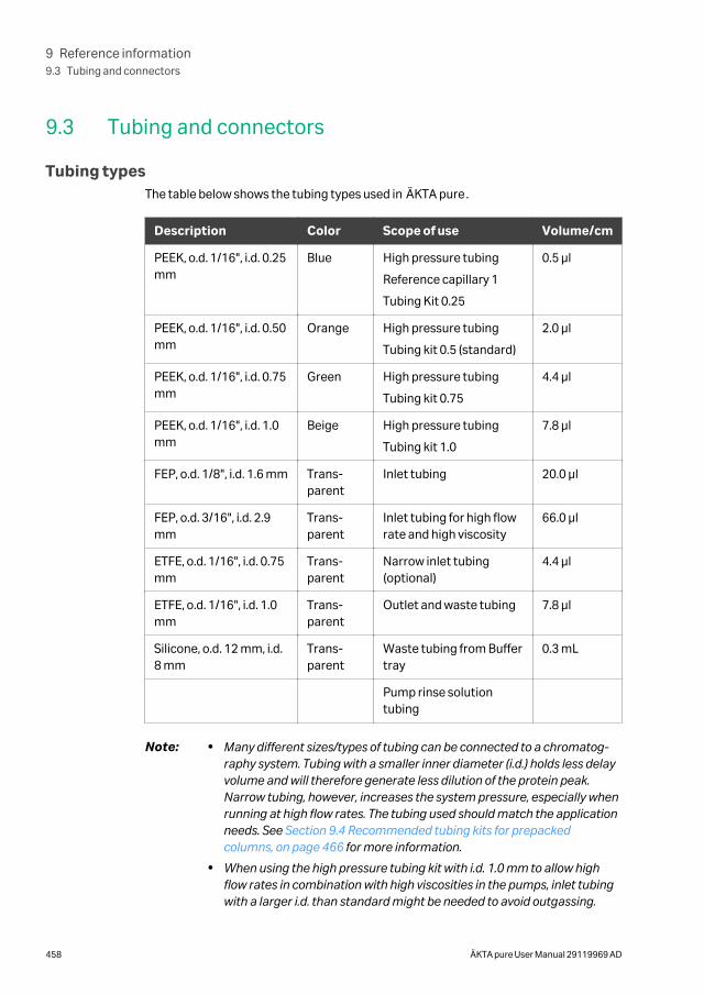
9.3 Tubing and connectors
Tubing typesThe table below shows the tubing types used in ÄKTA pure.
Description Color Scope of use Volume/cm
PEEK, o.d. 1/16", i.d. 0.25mm
Blue High pressure tubing
Reference capillary 1
Tubing Kit 0.25
0.5 μl
PEEK, o.d. 1/16", i.d. 0.50mm
Orange High pressure tubing
Tubing kit 0.5 (standard)
2.0 μl
PEEK, o.d. 1/16", i.d. 0.75mm
Green High pressure tubing
Tubing kit 0.75
4.4 μl
PEEK, o.d. 1/16", i.d. 1.0mm
Beige High pressure tubing
Tubing kit 1.0
7.8 μl
FEP, o.d. 1/8", i.d. 1.6 mm Trans-parent
Inlet tubing 20.0 μl
FEP, o.d. 3/16", i.d. 2.9mm
Trans-parent
Inlet tubing for high flowrate and high viscosity
66.0 μl
ETFE, o.d. 1/16", i.d. 0.75mm
Trans-parent
Narrow inlet tubing(optional)
4.4 μl
ETFE, o.d. 1/16", i.d. 1.0mm
Trans-parent
Outlet and waste tubing 7.8 μl
Silicone, o.d. 12 mm, i.d.8 mm
Trans-parent
Waste tubing from Buffertray
0.3 mL
Pump rinse solutiontubing
Note: • Many different sizes/types of tubing can be connected to a chromatog-raphy system. Tubing with a smaller inner diameter (i.d.) holds less delayvolume and will therefore generate less dilution of the protein peak.Narrow tubing, however, increases the system pressure, especially whenrunning at high flow rates. The tubing used should match the applicationneeds. See Section 9.4 Recommended tubing kits for prepackedcolumns, on page 466 for more information.
• When using the high pressure tubing kit with i.d. 1.0 mm to allow highflow rates in combination with high viscosities in the pumps, inlet tubingwith a larger i.d. than standard might be needed to avoid outgassing.
9 Reference information9.3 Tubing and connectors
458 ÄKTA pure User Manual 29119969 AD
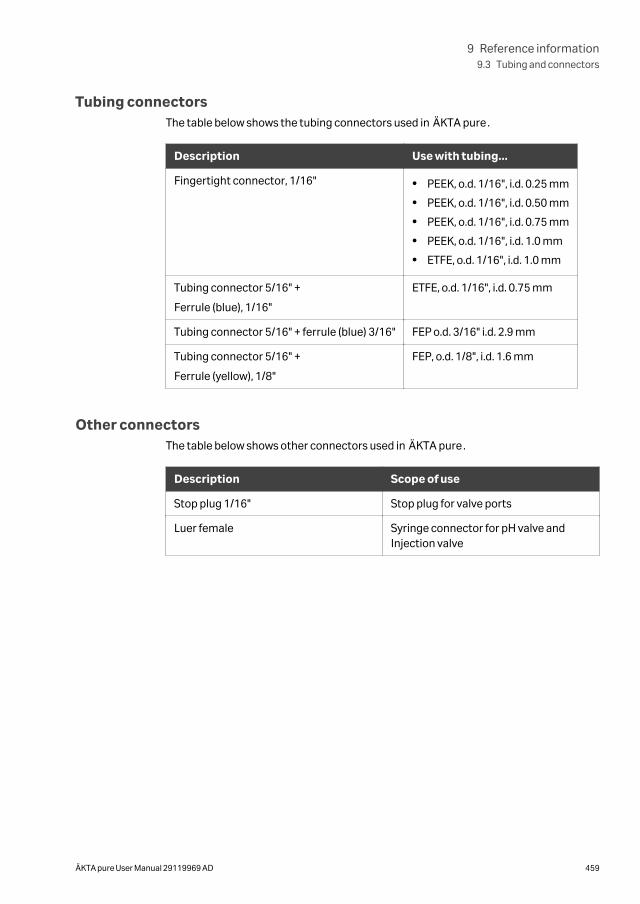
Tubing connectorsThe table below shows the tubing connectors used in ÄKTA pure.
Description Use with tubing...
Fingertight connector, 1/16" • PEEK, o.d. 1/16", i.d. 0.25 mm
• PEEK, o.d. 1/16", i.d. 0.50 mm
• PEEK, o.d. 1/16", i.d. 0.75 mm
• PEEK, o.d. 1/16", i.d. 1.0 mm
• ETFE, o.d. 1/16", i.d. 1.0 mm
Tubing connector 5/16" +
Ferrule (blue), 1/16"
ETFE, o.d. 1/16", i.d. 0.75 mm
Tubing connector 5/16" + ferrule (blue) 3/16" FEP o.d. 3/16" i.d. 2.9 mm
Tubing connector 5/16" +
Ferrule (yellow), 1/8"
FEP, o.d. 1/8", i.d. 1.6 mm
Other connectorsThe table below shows other connectors used in ÄKTA pure.
Description Scope of use
Stop plug 1/16" Stop plug for valve ports
Luer female Syringe connector for pH valve andInjection valve
9 Reference information9.3 Tubing and connectors
ÄKTA pure User Manual 29119969 AD 459
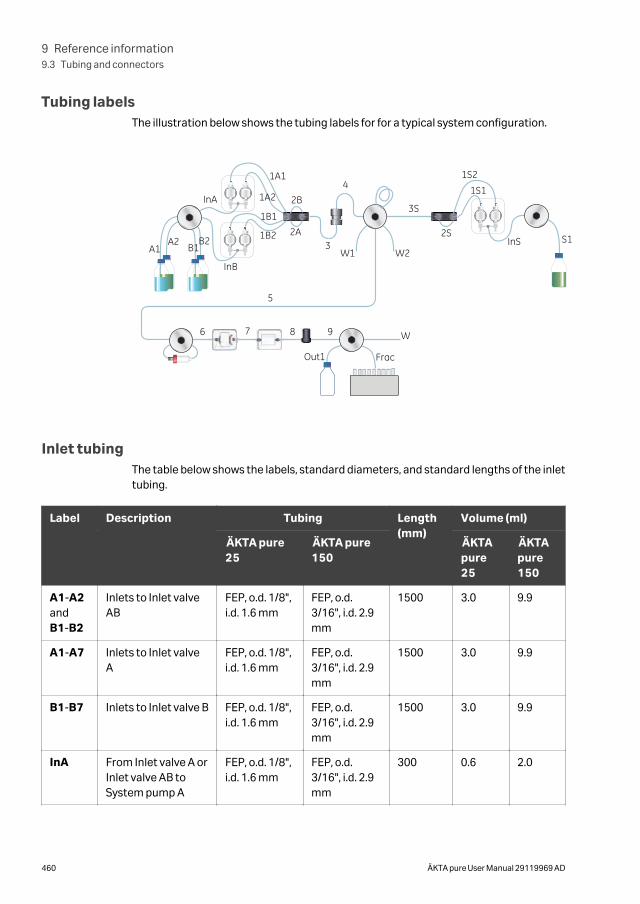
Tubing labelsThe illustration below shows the tubing labels for for a typical system configuration.
W1 W2
W
A1A2 B1
B2
InA
InS S1
1A1
1A2
1B1
1B2
2B
2A3
4
6 7 9
Out1 Frac
8
5
InB
1S11S2
2S
3S
Inlet tubingThe table below shows the labels, standard diameters, and standard lengths of the inlettubing.
Label Description Tubing Length(mm)
Volume (ml)
ÄKTA pure25
ÄKTA pure150
ÄKTApure25
ÄKTApure150
A1-A2andB1-B2
Inlets to Inlet valveAB
FEP, o.d. 1/8",i.d. 1.6 mm
FEP, o.d.3/16", i.d. 2.9mm
1500 3.0 9.9
A1-A7 Inlets to Inlet valveA
FEP, o.d. 1/8",i.d. 1.6 mm
FEP, o.d.3/16", i.d. 2.9mm
1500 3.0 9.9
B1-B7 Inlets to Inlet valve B FEP, o.d. 1/8",i.d. 1.6 mm
FEP, o.d.3/16", i.d. 2.9mm
1500 3.0 9.9
InA From Inlet valve A orInlet valve AB toSystem pump A
FEP, o.d. 1/8",i.d. 1.6 mm
FEP, o.d.3/16", i.d. 2.9mm
300 0.6 2.0
9 Reference information9.3 Tubing and connectors
460 ÄKTA pure User Manual 29119969 AD
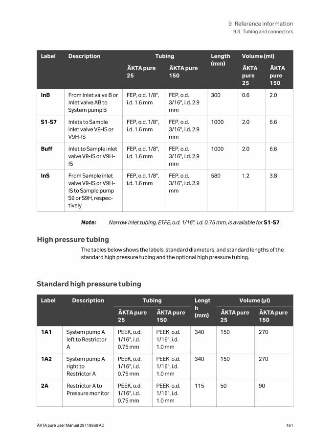
Label Description Tubing Length(mm)
Volume (ml)
ÄKTA pure25
ÄKTA pure150
ÄKTApure25
ÄKTApure150
InB From Inlet valve B orInlet valve AB toSystem pump B
FEP, o.d. 1/8",i.d. 1.6 mm
FEP, o.d.3/16", i.d. 2.9mm
300 0.6 2.0
S1-S7 Inlets to Sampleinlet valve V9-IS orV9H-IS
FEP, o.d. 1/8",i.d. 1.6 mm
FEP, o.d.3/16", i.d. 2.9mm
1000 2.0 6.6
Buff Inlet to Sample inletvalve V9-IS or V9H-IS
FEP, o.d. 1/8",i.d. 1.6 mm
FEP, o.d.3/16", i.d. 2.9mm
1000 2.0 6.6
InS From Sample inletvalve V9-IS or V9H-IS to Sample pumpS9 or S9H, respec-tively
FEP, o.d. 1/8",i.d. 1.6 mm
FEP, o.d.3/16", i.d. 2.9mm
580 1.2 3.8
Note: Narrow inlet tubing, ETFE, o.d. 1/16", i.d. 0.75 mm, is available for S1-S7.
High pressure tubingThe tables below shows the labels, standard diameters, and standard lengths of thestandard high pressure tubing and the optional high pressure tubing.
Standard high pressure tubing
Label Description Tubing Length(mm)
Volume (μl)
ÄKTA pure25
ÄKTA pure150
ÄKTA pure25
ÄKTA pure150
1A1 System pump Aleft to RestrictorA
PEEK, o.d.1/16", i.d.0.75 mm
PEEK, o.d.1/16", i.d.1.0 mm
340 150 270
1A2 System pump Aright toRestrictor A
PEEK, o.d.1/16", i.d.0.75 mm
PEEK, o.d.1/16", i.d.1.0 mm
340 150 270
2A Restrictor A toPressure monitor
PEEK, o.d.1/16", i.d.0.75 mm
PEEK, o.d.1/16", i.d.1.0 mm
115 50 90
9 Reference information9.3 Tubing and connectors
ÄKTA pure User Manual 29119969 AD 461
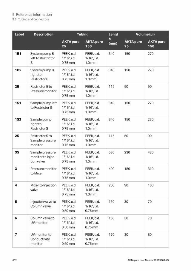
Label Description Tubing Length(mm)
Volume (μl)
ÄKTA pure25
ÄKTA pure150
ÄKTA pure25
ÄKTA pure150
1B1 System pump Bleft to RestrictorB
PEEK, o.d.1/16", i.d.0.75 mm
PEEK, o.d.1/16", i.d.1.0 mm
340 150 270
1B2 System pump Bright toRestrictor B
PEEK, o.d.1/16", i.d.0.75 mm
PEEK, o.d.1/16", i.d.1.0 mm
340 150 270
2B Restrictor B toPressure monitor
PEEK, o.d.1/16", i.d.0.75 mm
PEEK, o.d.1/16", i.d.1.0 mm
115 50 90
1S1 Sample pump leftto Restrictor S
PEEK, o.d.1/16", i.d.0.75 mm
PEEK, o.d.1/16", i.d.1.0 mm
340 150 270
1S2 Sample pumpright toRestrictor S
PEEK, o.d.1/16", i.d.0.75 mm
PEEK, o.d.1/16", i.d.1.0 mm
340 150 270
2S Restrictor S toSample pressuremonitor
PEEK, o.d.1/16", i.d.0.75 mm
PEEK, o.d.1/16", i.d.1.0 mm
115 50 90
3S Sample pressuremonitor to injec-tion valve.
PEEK, o.d.1/16", i.d.0.75 mm
PEEK, o.d.1/16", i.d.1.0 mm
530 230 420
3 Pressure monitorto Mixer
PEEK, o.d.1/16", i.d.0.75 mm
PEEK, o.d.1/16", i.d.1.0 mm
400 180 310
4 Mixer to Injectionvalve
PEEK, o.d.1/16", i.d.0.75 mm
PEEK, o.d.1/16", i.d.1.0 mm
200 90 160
5 Injection valve toColumn valve
PEEK, o.d.1/16", i.d.0.50 mm
PEEK, o.d.1/16", i.d.0.75 mm
160 30 70
6 Column valve toUV monitor
PEEK, o.d.1/16", i.d.0.50 mm
PEEK, o.d.1/16", i.d.0.75 mm
160 30 70
7 UV monitor toConductivitymonitor
PEEK, o.d.1/16", i.d.0.50 mm
PEEK, o.d.1/16", i.d.0.75 mm
170 30 80
9 Reference information9.3 Tubing and connectors
462 ÄKTA pure User Manual 29119969 AD
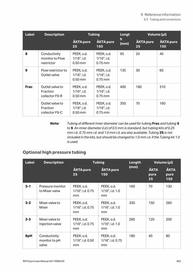
Label Description Tubing Length(mm)
Volume (μl)
ÄKTA pure25
ÄKTA pure150
ÄKTA pure25
ÄKTA pure150
8 Conductivitymonitor to Flowrestrictor
PEEK, o.d.1/16", i.d.0.50 mm
PEEK, o.d.1/16", i.d.0.75 mm
95 20 40
9 Flow restrictor toOutlet valve
PEEK, o.d.1/16", i.d.0.50 mm
PEEK, o.d.1/16", i.d.0.75 mm
135 30 60
Frac Outlet valve toFractioncollector F9-R
PEEK, o.d.1/16", i.d.0.50 mm
PEEK, o.d.1/16", i.d.0.75 mm
400 180 310
Outlet valve toFractioncollector F9-C
PEEK, o.d.1/16", i.d.0.50 mm
PEEK, o.d.1/16", i.d.0.75 mm
350 70 160
Note: Tubing of different inner diameter can be used for tubing Frac and tubing 5to 9. An inner diameter (i.d.) of 0.5 mm is standard, but tubing kits of 0.25mm i.d., 0.75 mm i.d. and 1.0 mm i.d. are also available. Tubing 3S is notincluded in the kits, but should be changed to 1.0 mm i.d. if the Tubing kit 1.0is used.
Optional high pressure tubing
Label Description Tubing Length(mm)
Volume (μl)
ÄKTA pure25
ÄKTA pure150
ÄKTApure25
ÄKTApure150
3-1 Pressure monitorto Mixer valve
PEEK, o.d.1/16", i.d. 0.75mm
PEEK, o.d.1/16", i.d. 1.0mm
160 70 130
3-2 Mixer valve toMixer
PEEK, o.d.1/16", i.d. 0.75mm
PEEK, o.d.1/16", i.d. 1.0mm
330 150 260
3-3 Mixer valve toInjection valve
PEEK, o.d.1/16", i.d. 0.75mm
PEEK, o.d.1/16", i.d. 1.0mm
260 120 200
8pH Conductivitymonitor to pHvalve
PEEK, o.d.1/16", i.d. 0.50mm
PEEK, o.d.1/16", i.d. 0.75mm
180 40 80
9 Reference information9.3 Tubing and connectors
ÄKTA pure User Manual 29119969 AD 463
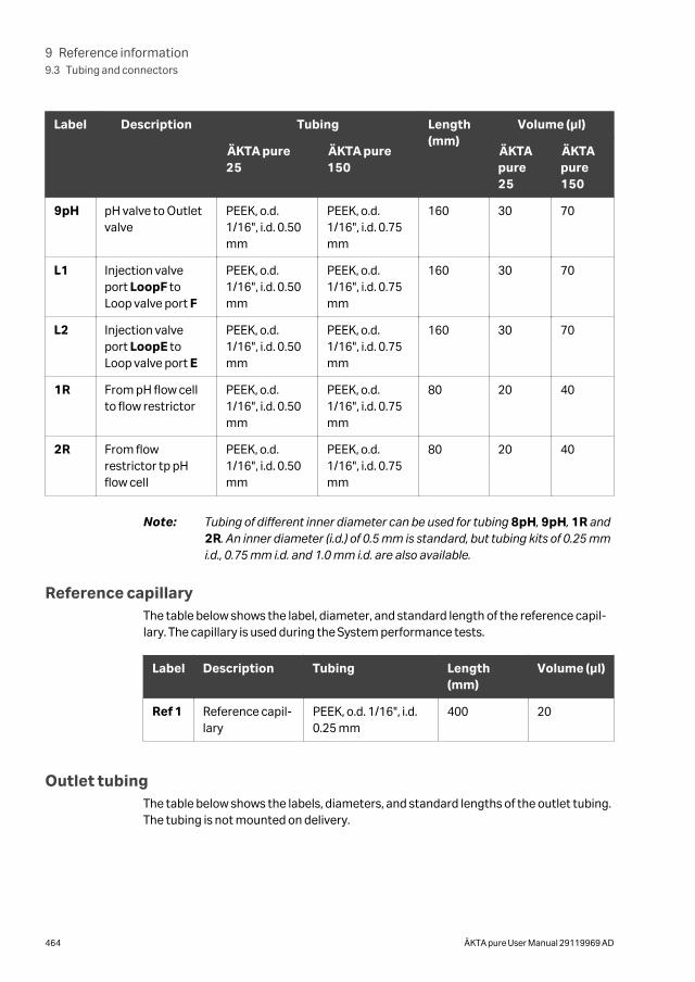
Label Description Tubing Length(mm)
Volume (μl)
ÄKTA pure25
ÄKTA pure150
ÄKTApure25
ÄKTApure150
9pH pH valve to Outletvalve
PEEK, o.d.1/16", i.d. 0.50mm
PEEK, o.d.1/16", i.d. 0.75mm
160 30 70
L1 Injection valveport LoopF toLoop valve port F
PEEK, o.d.1/16", i.d. 0.50mm
PEEK, o.d.1/16", i.d. 0.75mm
160 30 70
L2 Injection valveport LoopE toLoop valve port E
PEEK, o.d.1/16", i.d. 0.50mm
PEEK, o.d.1/16", i.d. 0.75mm
160 30 70
1R From pH flow cellto flow restrictor
PEEK, o.d.1/16", i.d. 0.50mm
PEEK, o.d.1/16", i.d. 0.75mm
80 20 40
2R From flowrestrictor tp pHflow cell
PEEK, o.d.1/16", i.d. 0.50mm
PEEK, o.d.1/16", i.d. 0.75mm
80 20 40
Note: Tubing of different inner diameter can be used for tubing 8pH, 9pH, 1R and2R. An inner diameter (i.d.) of 0.5 mm is standard, but tubing kits of 0.25 mmi.d., 0.75 mm i.d. and 1.0 mm i.d. are also available.
Reference capillaryThe table below shows the label, diameter, and standard length of the reference capil-lary. The capillary is used during the System performance tests.
Label Description Tubing Length(mm)
Volume (μl)
Ref 1 Reference capil-lary
PEEK, o.d. 1/16", i.d.0.25 mm
400 20
Outlet tubingThe table below shows the labels, diameters, and standard lengths of the outlet tubing.The tubing is not mounted on delivery.
9 Reference information9.3 Tubing and connectors
464 ÄKTA pure User Manual 29119969 AD
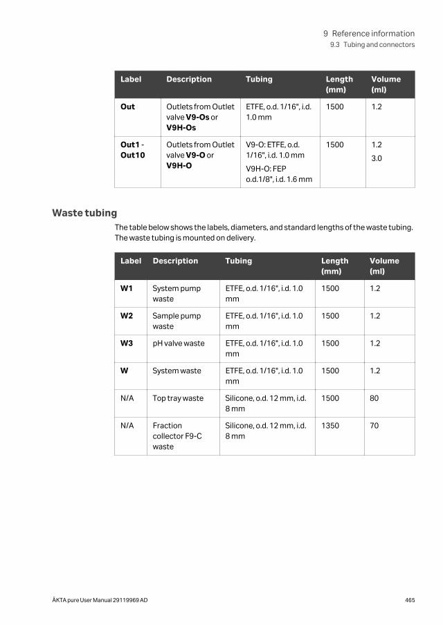
Label Description Tubing Length(mm)
Volume(ml)
Out Outlets from Outletvalve V9-Os orV9H-Os
ETFE, o.d. 1/16", i.d.1.0 mm
1500 1.2
Out1 -Out10
Outlets from Outletvalve V9-O orV9H-O
V9-O: ETFE, o.d.1/16", i.d. 1.0 mm
V9H-O: FEPo.d.1/8", i.d. 1.6 mm
1500 1.2
3.0
Waste tubingThe table below shows the labels, diameters, and standard lengths of the waste tubing.The waste tubing is mounted on delivery.
Label Description Tubing Length(mm)
Volume(ml)
W1 System pumpwaste
ETFE, o.d. 1/16", i.d. 1.0mm
1500 1.2
W2 Sample pumpwaste
ETFE, o.d. 1/16", i.d. 1.0mm
1500 1.2
W3 pH valve waste ETFE, o.d. 1/16", i.d. 1.0mm
1500 1.2
W System waste ETFE, o.d. 1/16", i.d. 1.0mm
1500 1.2
N/A Top tray waste Silicone, o.d. 12 mm, i.d.8 mm
1500 80
N/A Fractioncollector F9-Cwaste
Silicone, o.d. 12 mm, i.d.8 mm
1350 70
9 Reference information9.3 Tubing and connectors
ÄKTA pure User Manual 29119969 AD 465
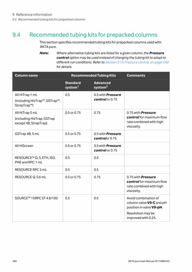
9.4 Recommended tubing kits for prepacked columnsThis section specifies recommended tubing kits for prepacked columns used withÄKTA pure.
Note: Where alternative tubing kits are listed for a given column, the Pressurecontrol option may be used instead of changing the tubing kit to adapt todifferent run conditions. Refer to Section 9.15 Pressure control, on page 549for details.
Column name Recommended Tubing Kits Comments
Standardsystem1
Advancedsystem2
All HiTrap 1 mL
(including HisTrap™, GSTrap™,StrepTrap™)
0.5 0.5 with Pressurecontrol or 0.75
All HiTrap 5 mL
(including HisTrap, GSTrapexcept 4B, StrepTrap)
0.5 or 0.75 0.75 0.75 with Pressurecontrol for maximum flowrate combined with highviscosity.
GSTrap 4B, 5 mL 0.5 or 0.75 0.5 with Pressurecontrolor 0.75
All HiScreen 0.5 or 0.75 0.5 with Pressurecontrol or 0.75
RESOURCE™ Q, S, ETH, ISO,PHE and RPC 1 mL
0.5 0.5
RESOURCE RPC 3 mL 0.5 0.5
RESOURCE Q, S 6 mL 0.5 or 0.75 0.75 0.75 with Pressurecontrol for maximum flowrate combined with highviscosity.
SOURCE™ 15RPC ST 4.6/100 0.5 0.5 Avoid combination ofcolumn valve V9-C and pHposition in valve V9-pH.
Resolution may beimproved with 0.25.
9 Reference information9.4 Recommended tubing kits for prepacked columns
466 ÄKTA pure User Manual 29119969 AD
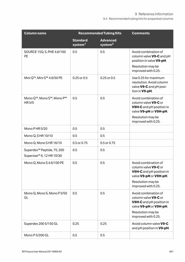
Column name Recommended Tubing Kits Comments
Standardsystem1
Advancedsystem2
SOURCE 15Q. S, PHE 4.6/100PE
0.5 0.5 Avoid combination ofcolumn valve V9-C and pHposition in valve V9-pH.
Resolution may beimproved with 0.25.
Mini Q™, Mini S™ 4.6/50 PE 0.25 or 0.5 0.25 or 0.5 Use 0.25 for maximumresolution. Avoid columnvalve V9-C and pH posi-tion in V9-pH.
Mono Q™, Mono S™, Mono P™HR 5/5
0.5 0.5 Avoid combination ofcolumn valve V9-C orV9H-C and pH position invalve V9-pH or V9H-pH.
Resolution may beimproved with 0.25.
Mono P HR 5/20 0.5 0.5
Mono Q, S HR 10/10 0.5 0.5
Mono Q, Mono S HR 16/10 0.5 or 0.75 0.5 or 0.75
Superdex™ Peptide, 75, 200
Superose™ 6, 12 HR 10/30
0.5 0.5
Mono Q, Mono S 4.6/100 PE 0.5 0.5 Avoid combination ofcolumn valve V9-C orV9H-C and pH position invalve V9-pH or V9H-pH.
Resolution may beimproved with 0.25.
Mono Q, Mono S, Mono P 5/50GL
0.5 0.5 Avoid combination ofcolumn valve V9-C orV9H-C and pH position invalve V9-pH or V9H-pH.
Resolution may beimproved with 0.25.
Superdex 200 5/150 GL 0.25 0.25 Avoid column valve V9-Cand pH position in V9-pH.
Mono P 5/200 GL 0.5 0.5
9 Reference information9.4 Recommended tubing kits for prepacked columns
ÄKTA pure User Manual 29119969 AD 467
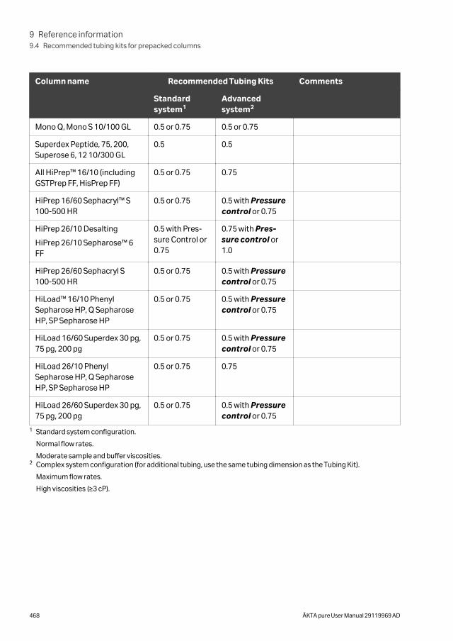
Column name Recommended Tubing Kits Comments
Standardsystem1
Advancedsystem2
Mono Q, Mono S 10/100 GL 0.5 or 0.75 0.5 or 0.75
Superdex Peptide, 75, 200,Superose 6, 12 10/300 GL
0.5 0.5
All HiPrep™ 16/10 (includingGSTPrep FF, HisPrep FF)
0.5 or 0.75 0.75
HiPrep 16/60 Sephacryl™ S100-500 HR
0.5 or 0.75 0.5 with Pressurecontrol or 0.75
HiPrep 26/10 Desalting
HiPrep 26/10 Sepharose™ 6FF
0.5 with Pres-sure Control or0.75
0.75 with Pres-sure control or1.0
HiPrep 26/60 Sephacryl S100-500 HR
0.5 or 0.75 0.5 with Pressurecontrol or 0.75
HiLoad™ 16/10 PhenylSepharose HP, Q SepharoseHP, SP Sepharose HP
0.5 or 0.75 0.5 with Pressurecontrol or 0.75
HiLoad 16/60 Superdex 30 pg,75 pg, 200 pg
0.5 or 0.75 0.5 with Pressurecontrol or 0.75
HiLoad 26/10 PhenylSepharose HP, Q SepharoseHP, SP Sepharose HP
0.5 or 0.75 0.75
HiLoad 26/60 Superdex 30 pg,75 pg, 200 pg
0.5 or 0.75 0.5 with Pressurecontrol or 0.75
1 Standard system configuration.
Normal flow rates.
Moderate sample and buffer viscosities.2 Complex system configuration (for additional tubing, use the same tubing dimension as the Tubing Kit).
Maximum flow rates.
High viscosities (≥3 cP).
9 Reference information9.4 Recommended tubing kits for prepacked columns
468 ÄKTA pure User Manual 29119969 AD
9.5 Chemical resistance guide
IntroductionThis section provides general information about biocompatibilty and detailed informa-tion about chemical resistance of the ÄKTA pure instrument.
In this section
Section See page
9.5.1 General information about biocompatibility and chemicalresistance
470
9.5.2 Chemical resistance specifications 471
9 Reference information9.5 Chemical resistance guide
ÄKTA pure User Manual 29119969 AD 469
9.5.1 General information about biocompatibility andchemical resistance
BiocompatibilityThe ÄKTA pure instrument is designed for maximum biocompatibility, with biochemi-cally inert flow paths constructed mainly from titanium, PEEK and highly resistant fluo-ropolymers and fluoroelastomers. Titanium is used as far as possible to minimizecontribution of potentially deactivating metal ions such as iron, nickel and chromium.There is no standard stainless steel in the flow path. Plastics and rubber materials areselected to avoid leakage of monomers, plasticizers or other additives.
Cleaning chemicalsStrong cleaning works well with 2 M sodium hydroxide, 70% acetic acid or the alcoholsmethanol, ethanol and isopropyl alcohol. Complete system cleaning using 1 M hydro-chloric acid should be avoided in order to not damage the pressure sensors. If you arecleaning separation media using 1 M hydrochloric acid, use loop injections of the acidand make sure that the column is not mounted on the Column Valve V9-C. The ColumnValve V9-C contains a pressure sensor which can be damaged by 1 M hydrochloricacid.
If sodium hypochlorite is used as sanitizing agent instead of 2 M sodium hydroxide, usea concentration up to 10%.
Organic solventsReversed phase chromatography of proteins works well with 100% acetonitrile andadditives trifluoroacetic acid (TFA) up to 0.2% or formic acid up to 5%.
Strong organic solvents like ethyl acetate, 100% acetone or chlorinated organicsolvents should be avoided. These might cause swelling of plastic material and reducethe pressure tolerance of PEEK tubing. For this reason, flash chromatography andstraight (“normal”) phase chromatography is generally not recommended on thesystem
Assumptions madeThe ratings are based on the following assumptions:
• Synergy effects of chemical mixtures have not been taken into account.
• Room temperature and limited overpressure is assumed.
Note: Chemical influences are time and pressure dependent. Unless otherwisestated, all concentrations are 100%.
9 Reference information9.5 Chemical resistance guide
9.5.1 General information about biocompatibility and chemical resistance
470 ÄKTA pure User Manual 29119969 AD
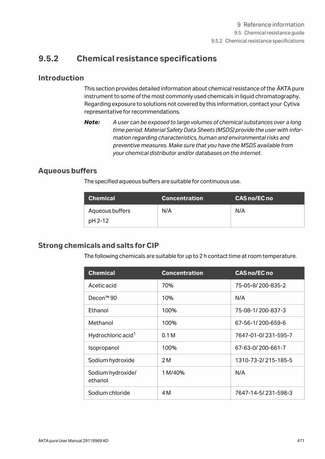
9.5.2 Chemical resistance specifications
IntroductionThis section provides detailed information about chemical resistance of the ÄKTA pureinstrument to some of the most commonly used chemicals in liquid chromatography.Regarding exposure to solutions not covered by this information, contact your Cytivarepresentative for recommendations.
Note: A user can be exposed to large volumes of chemical substances over a longtime period. Material Safety Data Sheets (MSDS) provide the user with infor-mation regarding characteristics, human and environmental risks andpreventive measures. Make sure that you have the MSDS available fromyour chemical distributor and/or databases on the internet.
Aqueous buffersThe specified aqueous buffers are suitable for continuous use.
Chemical Concentration CAS no/EC no
Aqueous buffers
pH 2-12
N/A N/A
Strong chemicals and salts for CIPThe following chemicals are suitable for up to 2 h contact time at room temperature.
Chemical Concentration CAS no/EC no
Acetic acid 70% 75-05-8/ 200-835-2
Decon™ 90 10% N/A
Ethanol 100% 75-08-1/ 200-837-3
Methanol 100% 67-56-1/ 200-659-6
Hydrochloric acid1 0.1 M 7647-01-0/ 231-595-7
Isopropanol 100% 67-63-0/ 200-661-7
Sodium hydroxide 2 M 1310-73-2/ 215-185-5
Sodium hydroxide/ethanol
1 M/40% N/A
Sodium chloride 4 M 7647-14-5/ 231-598-3
9 Reference information9.5 Chemical resistance guide
9.5.2 Chemical resistance specifications
ÄKTA pure User Manual 29119969 AD 471
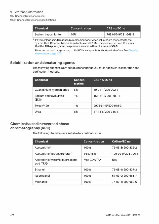
Chemical Concentration CAS no/EC no
Sodium hypochlorite 10% 7681-52-9/231-668-3
1 If hydrochloric acid, HCl, is used as a cleaning agent when columns are connected to thesystem, the HCl concentration should not exceed 0.1 M in the pressure sensors. Rememberthat the ÄKTA pure system has pressure sensors in the column valve V9-C.
For other parts of the system up to 1 M HCl is acceptable for short periods of use. See Cleaningchemicals, on page 470
Solubilization and denaturing agentsThe following chemicals are suitable for continuous use, as additives in separation andpurification methods.
Chemical Concen-tration
CAS no/EC no
Guanidinium hydrochloride 6 M 50-01-1/ 200-002-3
Sodium dodecyl sulfate(SDS)
1% 151-21-3/ 205-788-1
Tween™ 20 1% 9005-64-5/ 500-018-3
Urea 8 M 57-13-6/ 200-315-5
Chemicals used in reversed phasechromatography (RPC)
The following chemicals are suitable for continuous use.
Chemical Concentration CAS no/EC no
Acetonitrile1 100% 75-05-8/ 200-835-2
Acetonitrile/Tetrahydrofuran1 85%/15% 109-99-9/ 203-726-8
Acetonitrile/water/Trifluoroaceticacid (TFA)2
Max 0.2% TFA N/A
Ethanol 100% 75-08-1/ 200-837-3
Isopropanol 100% 67-63-0/ 200-661-7
Methanol 100% 74-93-1/ 200-659-6
9 Reference information9.5 Chemical resistance guide
9.5.2 Chemical resistance specifications
472 ÄKTA pure User Manual 29119969 AD
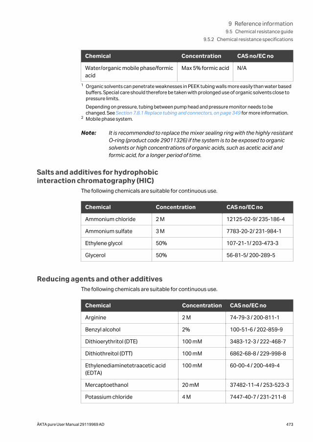
Chemical Concentration CAS no/EC no
Water/organic mobile phase/formicacid
Max 5% formic acid N/A
1 Organic solvents can penetrate weaknesses in PEEK tubing walls more easily than water basedbuffers. Special care should therefore be taken with prolonged use of organic solvents close topressure limits.
Depending on pressure, tubing between pump head and pressure monitor needs to bechanged. See Section 7.8.1 Replace tubing and connectors, on page 349 for more information.
2 Mobile phase system.
Note: It is recommended to replace the mixer sealing ring with the highly resistantO-ring (product code 29011326) if the system is to be exposed to organicsolvents or high concentrations of organic acids, such as acetic acid andformic acid, for a longer period of time.
Salts and additives for hydrophobicinteraction chromatography (HIC)
The following chemicals are suitable for continuous use.
Chemical Concentration CAS no/EC no
Ammonium chloride 2 M 12125-02-9/ 235-186-4
Ammonium sulfate 3 M 7783-20-2/ 231-984-1
Ethylene glycol 50% 107-21-1/ 203-473-3
Glycerol 50% 56-81-5/ 200-289-5
Reducing agents and other additivesThe following chemicals are suitable for continuous use.
Chemical Concentration CAS no/EC no
Arginine 2 M 74-79-3 / 200-811-1
Benzyl alcohol 2% 100-51-6 / 202-859-9
Dithioerythritol (DTE) 100 mM 3483-12-3 / 222-468-7
Dithiothreitol (DTT) 100 mM 6862-68-8 / 229-998-8
Ethylenediaminetetraacetic acid(EDTA)
100 mM 60-00-4 / 200-449-4
Mercaptoethanol 20 mM 37482-11-4 / 253-523-3
Potassium chloride 4 M 7447-40-7 / 231-211-8
9 Reference information9.5 Chemical resistance guide
9.5.2 Chemical resistance specifications
ÄKTA pure User Manual 29119969 AD 473
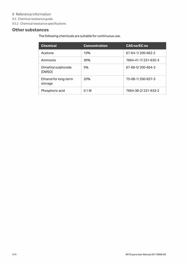
Other substancesThe following chemicals are suitable for continuous use.
Chemical Concentration CAS no/EC no
Acetone 10% 67-64-1/ 200-662-2
Ammonia 30% 7664-41-7/ 231-635-3
Dimethyl sulphoxide(DMSO)
5% 67-68-5/ 200-664-3
Ethanol for long-termstorage
20% 75-08-1/ 200-837-3
Phosphoric acid 0.1 M 7664-38-2/ 231-633-2
9 Reference information9.5 Chemical resistance guide
9.5.2 Chemical resistance specifications
474 ÄKTA pure User Manual 29119969 AD
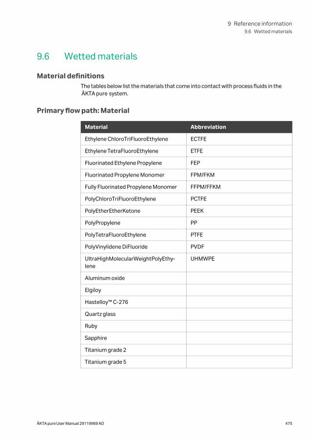
9.6 Wetted materials
Material definitionsThe tables below list the materials that come into contact with process fluids in theÄKTA pure system.
Primary flow path: Material
Material Abbreviation
Ethylene ChloroTriFluoroEthylene ECTFE
Ethylene TetraFluoroEthylene ETFE
Fluorinated Ethylene Propylene FEP
Fluorinated Propylene Monomer FPM/FKM
Fully Fluorinated Propylene Monomer FFPM/FFKM
PolyChloroTriFluoroEthylene PCTFE
PolyEtherEtherKetone PEEK
PolyPropylene PP
PolyTetraFluoroEthylene PTFE
PolyVinylidene DiFluoride PVDF
UltraHighMolecularWeightPolyEthy-lene
UHMWPE
Aluminum oxide
Elgiloy
Hastelloy™ C-276
Quartz glass
Ruby
Sapphire
Titanium grade 2
Titanium grade 5
9 Reference information9.6 Wetted materials
ÄKTA pure User Manual 29119969 AD 475
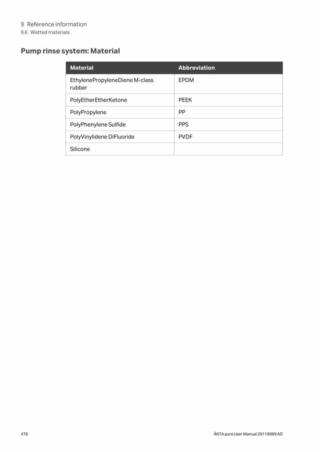
Pump rinse system: Material
Material Abbreviation
EthylenePropyleneDiene M-classrubber
EPDM
PolyEtherEtherKetone PEEK
PolyPropylene PP
PolyPhenylene Sulfide PPS
PolyVinylidene DiFluoride PVDF
Silicone
9 Reference information9.6 Wetted materials
476 ÄKTA pure User Manual 29119969 AD
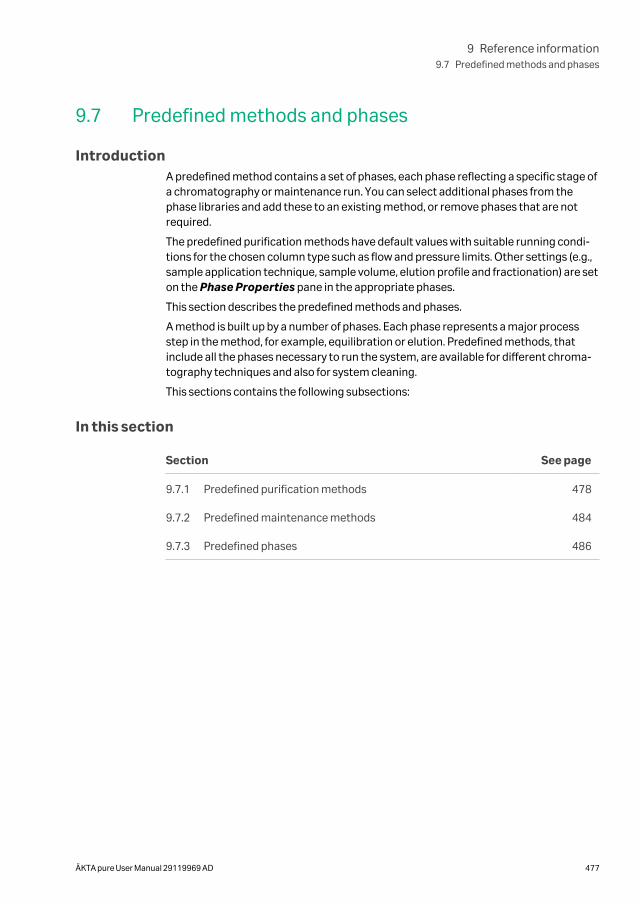
9.7 Predefined methods and phases
IntroductionA predefined method contains a set of phases, each phase reflecting a specific stage ofa chromatography or maintenance run. You can select additional phases from thephase libraries and add these to an existing method, or remove phases that are notrequired.
The predefined purification methods have default values with suitable running condi-tions for the chosen column type such as flow and pressure limits. Other settings (e.g.,sample application technique, sample volume, elution profile and fractionation) are seton the Phase Properties pane in the appropriate phases.
This section describes the predefined methods and phases.
A method is built up by a number of phases. Each phase represents a major processstep in the method, for example, equilibration or elution. Predefined methods, thatinclude all the phases necessary to run the system, are available for different chroma-tography techniques and also for system cleaning.
This sections contains the following subsections:
In this section
Section See page
9.7.1 Predefined purification methods 478
9.7.2 Predefined maintenance methods 484
9.7.3 Predefined phases 486
9 Reference information9.7 Predefined methods and phases
ÄKTA pure User Manual 29119969 AD 477
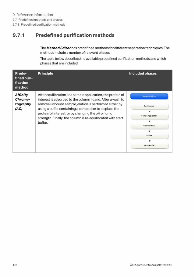
9.7.1 Predefined purification methods
The Method Editor has predefined methods for different separation techniques. Themethods include a number of relevant phases.
The table below describes the available predefined purification methods and whichphases that are included.
Prede-fined puri-ficationmethod
Principle Included phases
AffinityChroma-tography(AC)
After equilibration and sample application, the protein ofinterest is adsorbed to the column ligand. After a wash toremove unbound sample, elution is performed either byusing a buffer containing a competitor to displace theprotein of interest, or by changing the pH or ionicstrength. Finally, the column is re-equilibrated with startbuffer.
9 Reference information9.7 Predefined methods and phases
9.7.1 Predefined purification methods
478 ÄKTA pure User Manual 29119969 AD
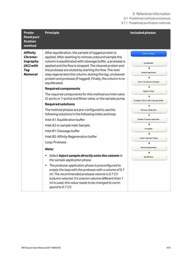
Prede-fined puri-ficationmethod
Principle Included phases
AffinityChroma-tography(AC) withTagRemoval
After equilibration, the sample of tagged protein isapplied. After washing to remove unbound sample thecolumn is equilibrated with cleavage buffer, a protease isapplied and the flow is stopped. The cleaved protein andthe protease are eluted by starting the flow. The nextstep regenerates the column, eluting the tag, uncleavedprotein and protease (if tagged). Finally, the column is re-equilibrated.
Required components
The required components for this method are Inlet valve(2-ports or 7-ports) and Mixer valve, or the sample pump.
Required solutions
The method phases are pre-configured to use thefollowing solutions in the following inlets and loop:
Inlet A1: Equilibration buffer
Inlet A2 or sample inlet: Sample
Inlet B1: Cleavage buffer
Inlet B2: Affinity Regeneration buffer
Loop: Protease
Note:
• Select Inject sample directly onto the column inthe sample application phase.
• The protease application phase is preconfigured toempty the loop with the protease with a volume of 0.7ml. The recommended protease volume is 0.7 CV(column volume). If a column volume different than 1ml is used, this value needs to be changed to corre-spond to 0.7 CV.
9 Reference information9.7 Predefined methods and phases
9.7.1 Predefined purification methods
ÄKTA pure User Manual 29119969 AD 479
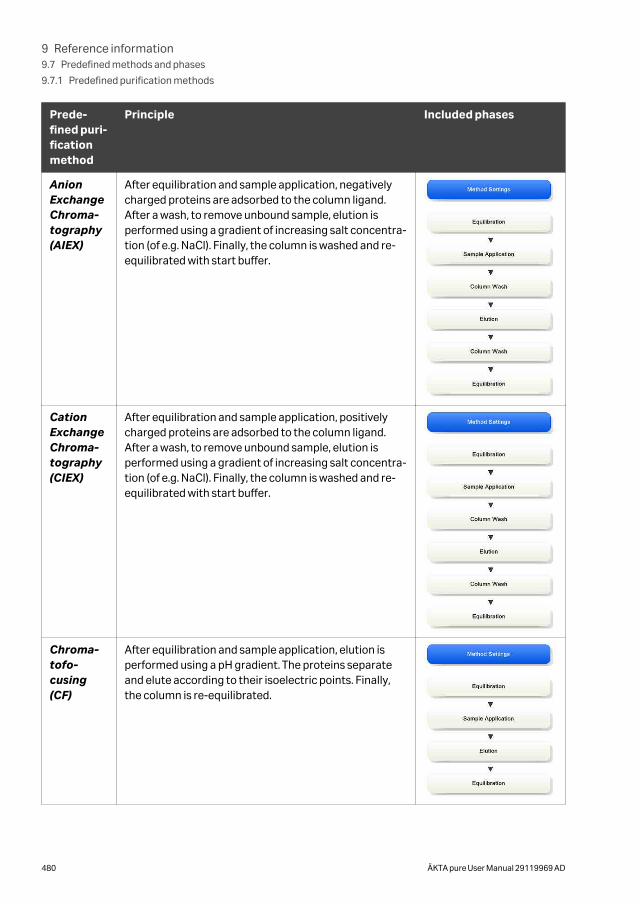
Prede-fined puri-ficationmethod
Principle Included phases
AnionExchangeChroma-tography(AIEX)
After equilibration and sample application, negativelycharged proteins are adsorbed to the column ligand.After a wash, to remove unbound sample, elution isperformed using a gradient of increasing salt concentra-tion (of e.g. NaCl). Finally, the column is washed and re-equilibrated with start buffer.
CationExchangeChroma-tography(CIEX)
After equilibration and sample application, positivelycharged proteins are adsorbed to the column ligand.After a wash, to remove unbound sample, elution isperformed using a gradient of increasing salt concentra-tion (of e.g. NaCl). Finally, the column is washed and re-equilibrated with start buffer.
Chroma-tofo-cusing(CF)
After equilibration and sample application, elution isperformed using a pH gradient. The proteins separateand elute according to their isoelectric points. Finally,the column is re-equilibrated.
9 Reference information9.7 Predefined methods and phases
9.7.1 Predefined purification methods
480 ÄKTA pure User Manual 29119969 AD
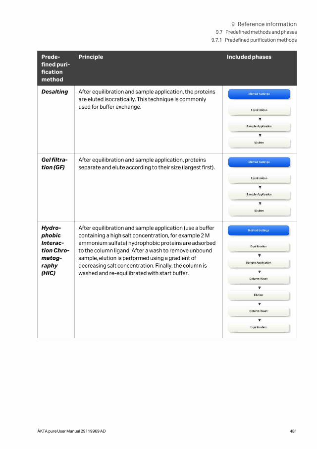
Prede-fined puri-ficationmethod
Principle Included phases
Desalting After equilibration and sample application, the proteinsare eluted isocratically. This technique is commonlyused for buffer exchange.
Gel filtra-tion (GF)
After equilibration and sample application, proteinsseparate and elute according to their size (largest first).
Hydro-phobicInterac-tion Chro-matog-raphy(HIC)
After equilibration and sample application (use a buffercontaining a high salt concentration, for example 2 Mammonium sulfate) hydrophobic proteins are adsorbedto the column ligand. After a wash to remove unboundsample, elution is performed using a gradient ofdecreasing salt concentration. Finally, the column iswashed and re-equilibrated with start buffer.
9 Reference information9.7 Predefined methods and phases
9.7.1 Predefined purification methods
ÄKTA pure User Manual 29119969 AD 481
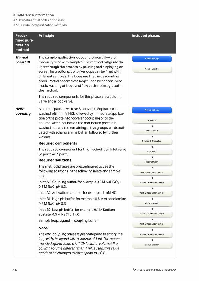
Prede-fined puri-ficationmethod
Principle Included phases
ManualLoop Fill
The sample application loops of the loop valve aremanually filled with samples. The method will guide theuser through the process by pausing and displaying on-screen instructions. Up to five loops can be filled withdifferent samples. The loops are filled in descendingorder. Partial or complete loop fill can be chosen. Auto-matic washing of loops and flow path are integrated inthe method.
The required components for this phase are a columnvalve and a loop valve.
NHS-coupling
A column packed with NHS-activated Sepharose iswashed with 1 mM HCl, followed by immediate applica-tion of the protein for covalent coupling onto thecolumn. After incubation the non-bound protein iswashed out and the remaining active groups are deacti-vated with ethanolamine buffer, followed by furtherwashes.
Required components
The required component for this method is an Inlet valve(2-ports or 7-ports).
Required solutions
The method phases are preconfigured to use thefollowing solutions in the following inlets and sampleloop:
Inlet A1: Coupling buffer, for example 0.2 M NaHCO3 +0.5 M NaCl pH 8.3.
Inlet A2: Activation solution, for example 1 mM HCl
Inlet B1: High pH buffer, for example 0.5 M ethanolamine,0.5 M NaCl pH 8.3
Inlet B2: Low pH buffer, for example 0.1 M Sodiumacetate, 0.5 M NaCl pH 4.0
Sample loop: Ligand in coupling buffer
Note:
The NHS coupling phase is preconfigured to empty theloop with the ligand with a volume of 1 ml. The recom-mended ligand volume is 1 CV (column volume). If acolumn volume different than 1 ml is used, this valueneeds to be changed to correspond to 1 CV.
9 Reference information9.7 Predefined methods and phases
9.7.1 Predefined purification methods
482 ÄKTA pure User Manual 29119969 AD
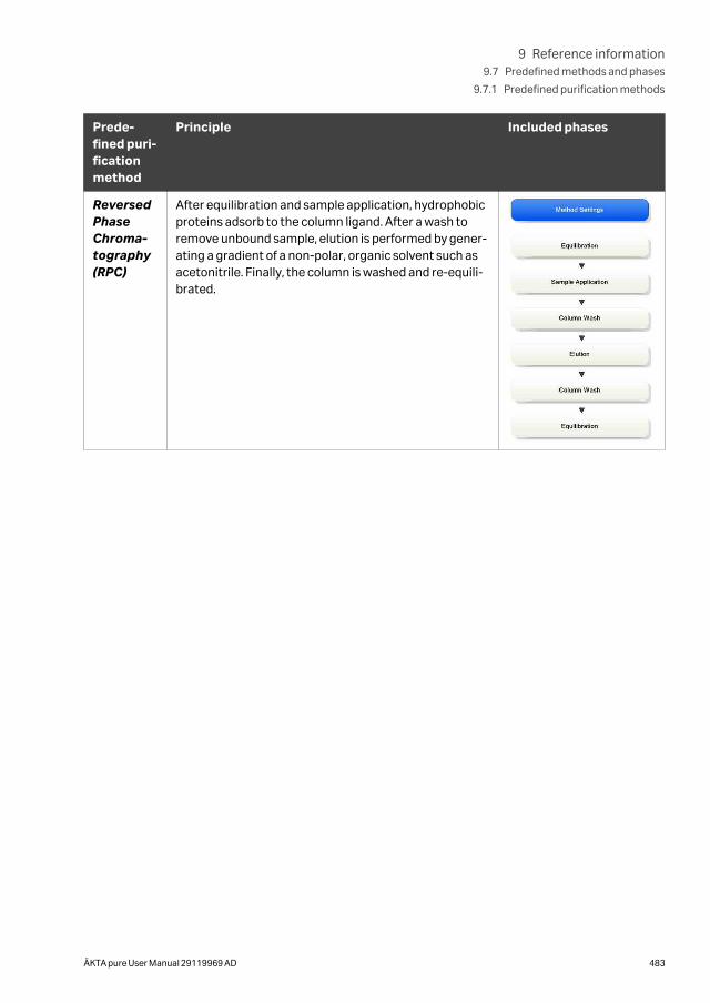
Prede-fined puri-ficationmethod
Principle Included phases
ReversedPhaseChroma-tography(RPC)
After equilibration and sample application, hydrophobicproteins adsorb to the column ligand. After a wash toremove unbound sample, elution is performed by gener-ating a gradient of a non-polar, organic solvent such asacetonitrile. Finally, the column is washed and re-equili-brated.
9 Reference information9.7 Predefined methods and phases
9.7.1 Predefined purification methods
ÄKTA pure User Manual 29119969 AD 483
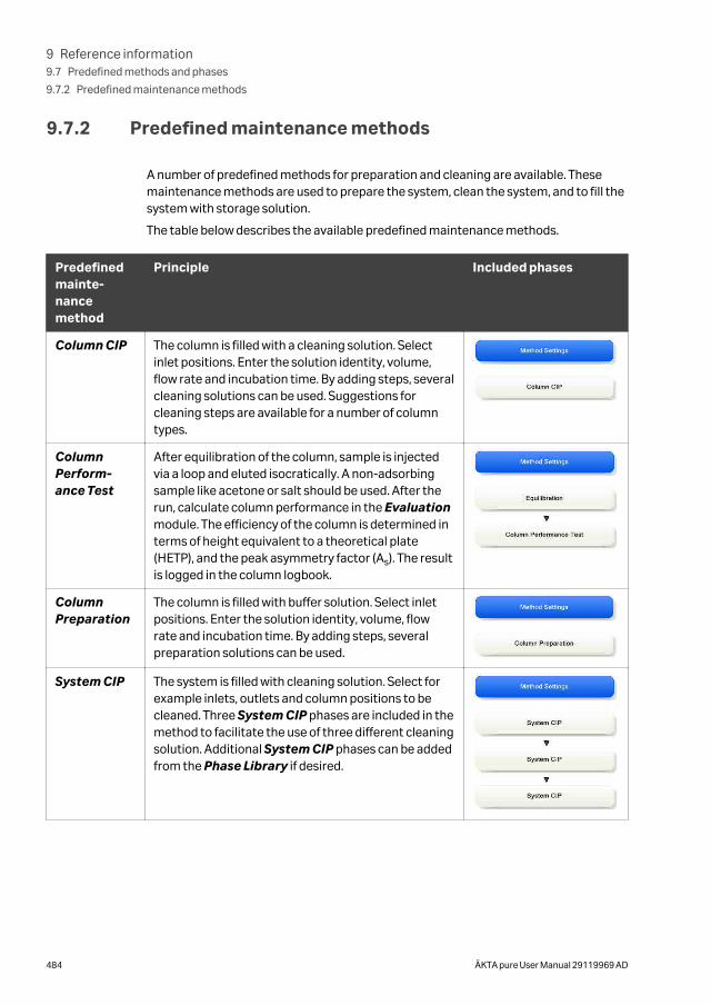
9.7.2 Predefined maintenance methods
A number of predefined methods for preparation and cleaning are available. Thesemaintenance methods are used to prepare the system, clean the system, and to fill thesystem with storage solution.
The table below describes the available predefined maintenance methods.
Predefinedmainte-nancemethod
Principle Included phases
Column CIP The column is filled with a cleaning solution. Selectinlet positions. Enter the solution identity, volume,flow rate and incubation time. By adding steps, severalcleaning solutions can be used. Suggestions forcleaning steps are available for a number of columntypes.
ColumnPerform-ance Test
After equilibration of the column, sample is injectedvia a loop and eluted isocratically. A non-adsorbingsample like acetone or salt should be used. After therun, calculate column performance in the Evaluationmodule. The efficiency of the column is determined interms of height equivalent to a theoretical plate(HETP), and the peak asymmetry factor (As). The resultis logged in the column logbook.
ColumnPreparation
The column is filled with buffer solution. Select inletpositions. Enter the solution identity, volume, flowrate and incubation time. By adding steps, severalpreparation solutions can be used.
System CIP The system is filled with cleaning solution. Select forexample inlets, outlets and column positions to becleaned. Three System CIP phases are included in themethod to facilitate the use of three different cleaningsolution. Additional System CIP phases can be addedfrom the Phase Library if desired.
9 Reference information9.7 Predefined methods and phases
9.7.2 Predefined maintenance methods
484 ÄKTA pure User Manual 29119969 AD
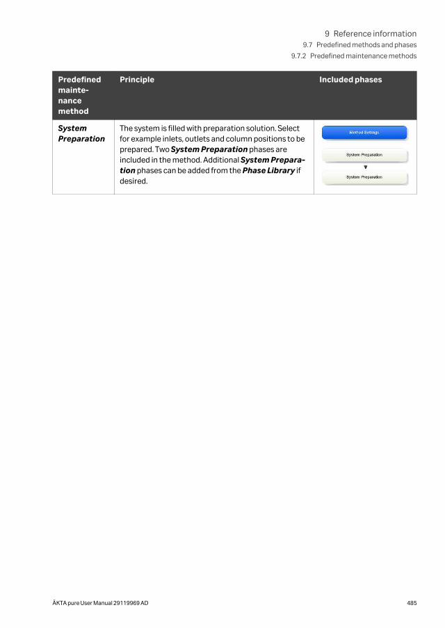
Predefinedmainte-nancemethod
Principle Included phases
SystemPreparation
The system is filled with preparation solution. Selectfor example inlets, outlets and column positions to beprepared. Two System Preparation phases areincluded in the method. Additional System Prepara-tion phases can be added from the Phase Library ifdesired.
9 Reference information9.7 Predefined methods and phases
9.7.2 Predefined maintenance methods
ÄKTA pure User Manual 29119969 AD 485

9.7.3 Predefined phases
The following table describes the predefined phases.
9 Reference information9.7 Predefined methods and phases
9.7.3 Predefined phases
486 ÄKTA pure User Manual 29119969 AD
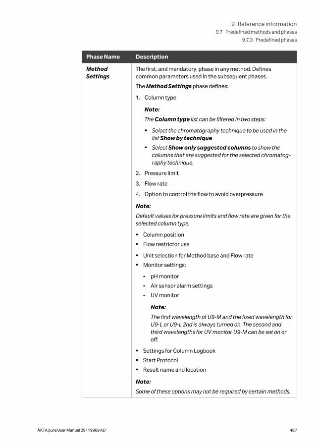
Phase Name Description
MethodSettings
The first, and mandatory, phase in any method. Definescommon parameters used in the subsequent phases.
The Method Settings phase defines:
1. Column type
Note:
The Column type list can be filtered in two steps:
• Select the chromatography technique to be used in thelist Show by technique
• Select Show only suggested columns to show thecolumns that are suggested for the selected chromatog-raphy technique.
2. Pressure limit
3. Flow rate
4. Option to control the flow to avoid overpressure
Note:
Default values for pressure limits and flow rate are given for theselected column type.
• Column position
• Flow restrictor use
• Unit selection for Method base and Flow rate
• Monitor settings:
- pH monitor
- Air sensor alarm settings
- UV monitor
Note:
The first wavelength of U9-M and the fixed wavelength forU9-L or U9-L 2nd is always turned on. The second andthird wavelengths for UV monitor U9-M can be set on oroff.
• Settings for Column Logbook
• Start Protocol
• Result name and location
Note:
Some of these options may not be required by certain methods.
9 Reference information9.7 Predefined methods and phases
9.7.3 Predefined phases
ÄKTA pure User Manual 29119969 AD 487
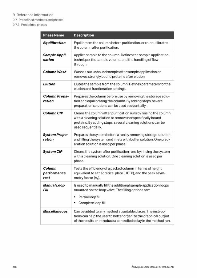
Phase Name Description
Equilibration Equilibrates the column before purification, or re-equilibratesthe column after purification.
Sample Appli-cation
Applies sample to the column. Defines the sample applicationtechnique, the sample volume, and the handling of flow-through.
Column Wash Washes out unbound sample after sample application orremoves strongly bound proteins after elution.
Elution Elutes the sample from the column. Defines parameters for theelution and fractionation settings.
Column Prepa-ration
Prepares the column before use by removing the storage solu-tion and equilibrating the column. By adding steps, severalpreparation solutions can be used sequentially.
Column CIP Cleans the column after purification runs by rinsing the columnwith a cleaning solution to remove nonspecifically boundproteins. By adding steps, several cleaning solutions can beused sequentially.
System Prepa-ration
Prepares the system before a run by removing storage solutionand filling the system and inlets with buffer solution. One prep-aration solution is used per phase.
System CIP Cleans the system after purification runs by rinsing the systemwith a cleaning solution. One cleaning solution is used perphase.
Columnperformancetest
Tests the efficiency of a packed column in terms of heightequivalent to a theoretical plate (HETP), and the peak asym-metry factor (As).
Manual LoopFill
Is used to manually fill the additional sample application loopsmounted on the loop valve. The filling options are:
• Partial loop fill
• Complete loop fill
Miscellaneous Can be added to any method at suitable places. The instruc-tions can help the user to better organize the graphical outputof the results or introduce a controlled delay in the method run.
9 Reference information9.7 Predefined methods and phases
9.7.3 Predefined phases
488 ÄKTA pure User Manual 29119969 AD
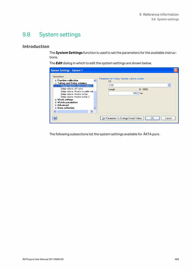
9.8 System settings
IntroductionThe System Settings function is used to set the parameters for the available instruc-tions.
The Edit dialog in which to edit the system settings are shown below.
The following subsections list the system settings available for ÄKTA pure.
9 Reference information9.8 System settings
ÄKTA pure User Manual 29119969 AD 489
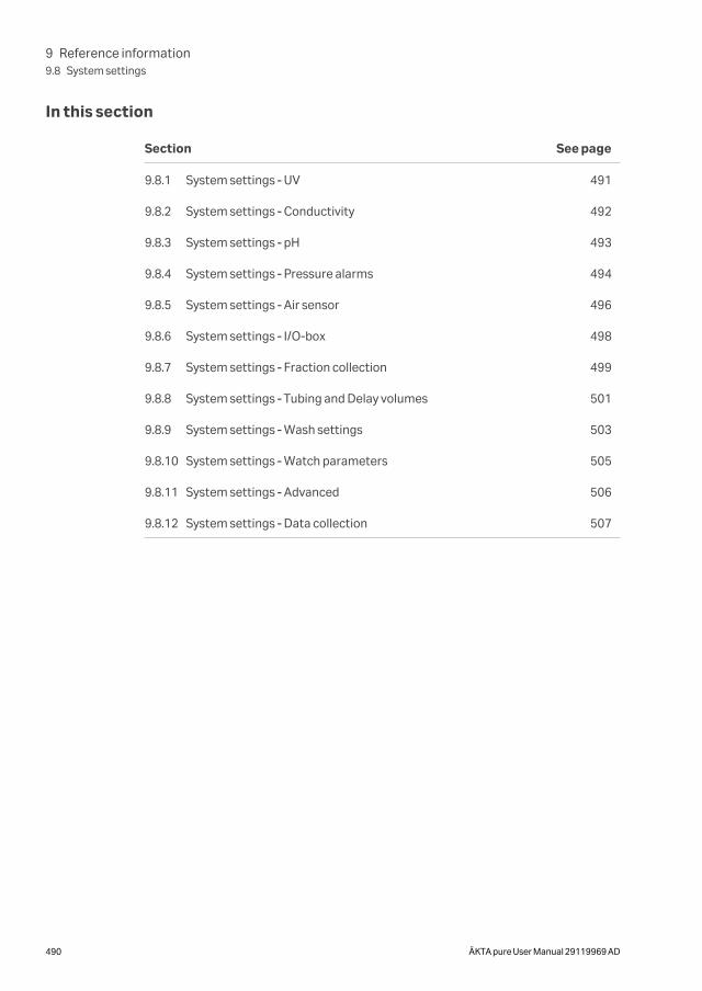
In this section
Section See page
9.8.1 System settings ‑ UV 491
9.8.2 System settings ‑ Conductivity 492
9.8.3 System settings ‑ pH 493
9.8.4 System settings ‑ Pressure alarms 494
9.8.5 System settings ‑ Air sensor 496
9.8.6 System settings ‑ I/O-box 498
9.8.7 System settings ‑ Fraction collection 499
9.8.8 System settings ‑ Tubing and Delay volumes 501
9.8.9 System settings ‑ Wash settings 503
9.8.10 System settings ‑ Watch parameters 505
9.8.11 System settings ‑ Advanced 506
9.8.12 System settings ‑ Data collection 507
9 Reference information9.8 System settings
490 ÄKTA pure User Manual 29119969 AD
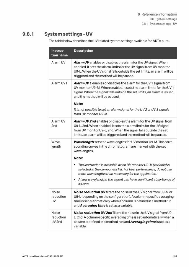
9.8.1 System settings ‑ UVThe table below describes the UV related system settings available for ÄKTA pure.
Instruc-tion name
Description
Alarm UV Alarm UV enables or disables the alarm for the UV signal. Whenenabled, it sets the alarm limits for the UV signal from UV monitorU9-L. When the UV signal falls outside the set limits, an alarm will betriggered and the method will be paused.
Alarm UV1 Alarm UV 1 enables or disables the alarm for the UV 1 signal fromUV monitor U9-M. When enabled, it sets the alarm limits for the UV 1signal. When the signal falls outside the set limits, an alarm is issuedand the method will be paused.
Note:
It is not possible to set an alarm signal for the UV 2 or UV 3 signalsfrom UV monitor U9-M.
Alarm UV2nd
Alarm UV 2nd enables or disables the alarm for the UV signal fromU9-L, 2nd. When enabled, it sets the alarm limits for the UV signalfrom UV monitor U9-L, 2nd. When the signal falls outside the setlimits, an alarm will be triggered and the method will be paused.
Wave-length
Wavelength sets the wavelengths for UV monitor U9-M. The corre-sponding curves in the chromatogram are marked with the setwavelengths.
Note:
• The instruction is available when UV monitor U9-M (variable) isselected in the component list. For best performance, do not usemore wavelengths than necessary for the application.
• At low wavelengths, the eluent can have significant absorbance ofits own.
NoisereductionUV
Noise reduction UV filters the noise in the UV signal from U9-M orU9-L (depending on the configuration). A column-specific averagingtime is set automatically when a column is defined in a method runand Averaging time is set as a variable.
NoisereductionUV 2nd
Noise reduction UV 2nd filters the noise in the UV signal from U9-L, 2nd. A column-specific averaging time is set automatically when acolumn is defined in a method run and Averaging time is set as avariable.
9 Reference information9.8 System settings
9.8.1 System settings ‑ UV
ÄKTA pure User Manual 29119969 AD 491
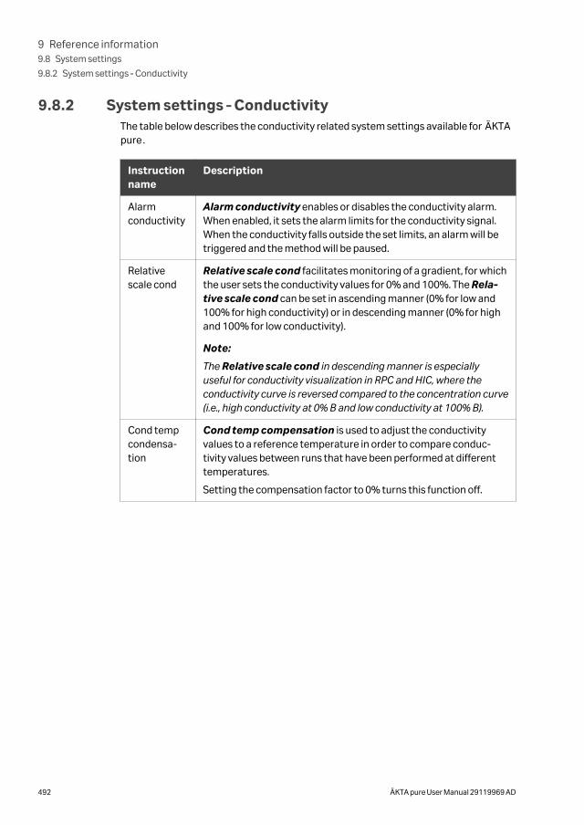
9.8.2 System settings ‑ ConductivityThe table below describes the conductivity related system settings available for ÄKTApure.
Instructionname
Description
Alarmconductivity
Alarm conductivity enables or disables the conductivity alarm.When enabled, it sets the alarm limits for the conductivity signal.When the conductivity falls outside the set limits, an alarm will betriggered and the method will be paused.
Relativescale cond
Relative scale cond facilitates monitoring of a gradient, for whichthe user sets the conductivity values for 0% and 100%. The Rela-tive scale cond can be set in ascending manner (0% for low and100% for high conductivity) or in descending manner (0% for highand 100% for low conductivity).
Note:
The Relative scale cond in descending manner is especiallyuseful for conductivity visualization in RPC and HIC, where theconductivity curve is reversed compared to the concentration curve(i.e., high conductivity at 0% B and low conductivity at 100% B).
Cond tempcondensa-tion
Cond temp compensation is used to adjust the conductivityvalues to a reference temperature in order to compare conduc-tivity values between runs that have been performed at differenttemperatures.
Setting the compensation factor to 0% turns this function off.
9 Reference information9.8 System settings
9.8.2 System settings ‑ Conductivity
492 ÄKTA pure User Manual 29119969 AD
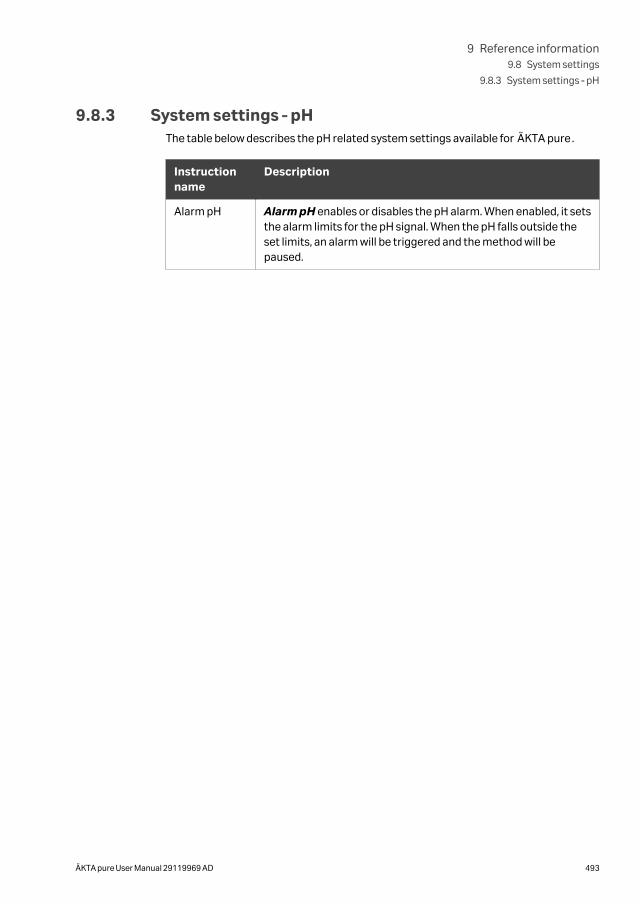
9.8.3 System settings ‑ pHThe table below describes the pH related system settings available for ÄKTA pure.
Instructionname
Description
Alarm pH Alarm pH enables or disables the pH alarm. When enabled, it setsthe alarm limits for the pH signal. When the pH falls outside theset limits, an alarm will be triggered and the method will bepaused.
9 Reference information9.8 System settings
9.8.3 System settings ‑ pH
ÄKTA pure User Manual 29119969 AD 493
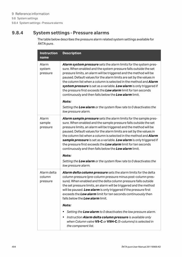
9.8.4 System settings ‑ Pressure alarmsThe table below describes the pressure alarm related system settings available forÄKTA pure.
Instructionname
Description
Alarmsystempressure
Alarm system pressure sets the alarm limits for the system pres-sure. When enabled and the system pressure falls outside the setpressure limits, an alarm will be triggered and the method will bepaused. Default values for the alarm limits are set by the values inthe column list when a column is selected in the method and Alarmsystem pressure is set as a variable. Low alarm is only triggered ifthe pressure first exceeds the Low alarm limit for ten secondscontinuously and then falls below the Low alarm limit.
Note:
Setting the Low alarm or the system flow rate to 0 deactivates thelow pressure alarm.
Alarmsamplepressure
Alarm sample pressure sets the alarm limits for the sample pres-sure. When enabled and the sample pressure falls outside the setpressure limits, an alarm will be triggered and the method will bepaused. Default values for the alarm limits are set by the values inthe column list when a column is selected in the method and Alarmsample pressure is set as a variable. Low alarm is only triggered ifthe pressure first exceeds the Low alarm limit for ten secondscontinuously and then falls below the Low alarm limit.
Note:
Setting the Low alarm or the system flow rate to 0 deactivates thelow pressure alarm.
Alarm deltacolumnpressure
Alarm delta column pressure sets the alarm limits for the deltacolumn pressure (pre-column pressure minus post-column pres-sure). When enabled and the delta column pressure falls outsidethe set pressure limits, an alarm will be triggered and the methodwill be paused. Low alarm is only triggered if the pressure firstexceeds the Low alarm limit for ten seconds continuously thenfalls below the Low alarm limit.
Note:
• Setting the Low alarm to 0 deactivates the low pressure alarm.
• Instruction Alarm delta column pressure is available onlywhen Column valve V9-C or V9H-C (5-columns) is selected inthe component list.
9 Reference information9.8 System settings
9.8.4 System settings ‑ Pressure alarms
494 ÄKTA pure User Manual 29119969 AD
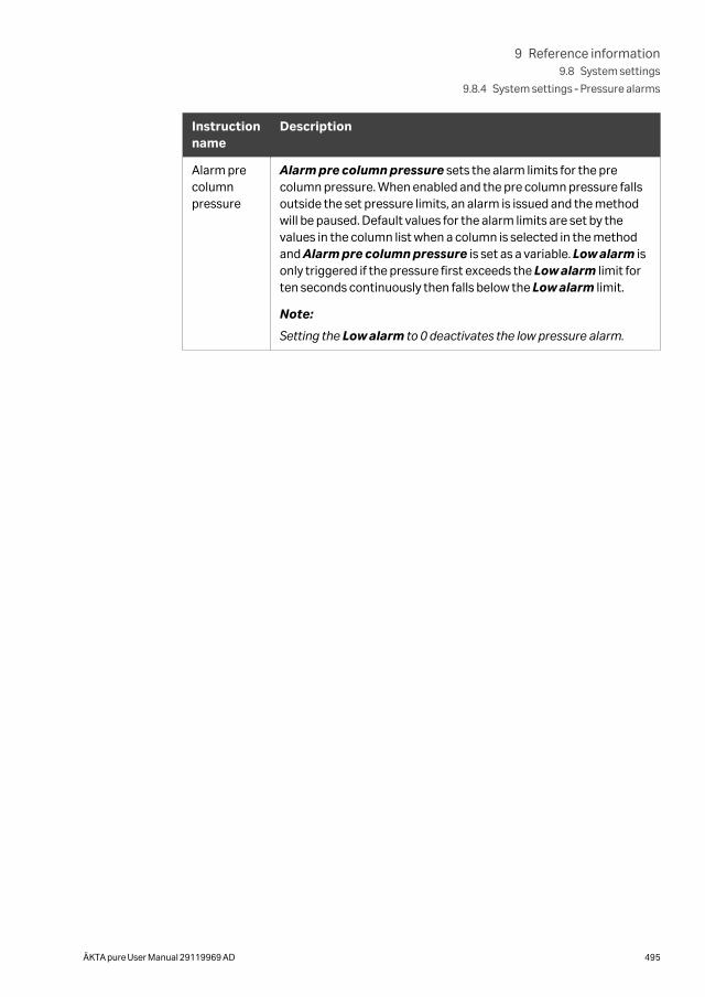
Instructionname
Description
Alarm precolumnpressure
Alarm pre column pressure sets the alarm limits for the precolumn pressure. When enabled and the pre column pressure fallsoutside the set pressure limits, an alarm is issued and the methodwill be paused. Default values for the alarm limits are set by thevalues in the column list when a column is selected in the methodand Alarm pre column pressure is set as a variable. Low alarm isonly triggered if the pressure first exceeds the Low alarm limit forten seconds continuously then falls below the Low alarm limit.
Note:
Setting the Low alarm to 0 deactivates the low pressure alarm.
9 Reference information9.8 System settings
9.8.4 System settings ‑ Pressure alarms
ÄKTA pure User Manual 29119969 AD 495
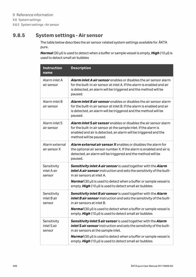
9.8.5 System settings ‑ Air sensorThe table below describes the air sensor related system settings available for ÄKTApure.
Normal (30 µl) is used to detect when a buffer or sample vessel is empty. High (10 µl) isused to detect small air bubbles
Instructionname
Description
Alarm inlet Aair sensor
Alarm inlet A air sensor enables or disables the air sensor alarmfor the built-in air sensor at inlet A. If the alarm is enabled and airis detected, an alarm will be triggered and the method will bepaused.
Alarm inlet Bair sensor
Alarm inlet B air sensor enables or disables the air sensor alarmfor the built-in air sensor at inlet B. If the alarm is enabled and airis detected, an alarm will be triggered and the method will bepaused.
Alarm inlet Sair sensor
Alarm inlet S air sensor enables or disables the air sensor alarmfor the built-in air sensor at the sample inlet. If the alarm isenabled and air is detected, an alarm will be triggered and themethod will be paused.
Alarm externalair sensor X
Alarm external air sensor X enables or disables the alarm forthe optional air sensor number X. If the alarm is enabled and air isdetected, an alarm will be triggered and the method will bepaused.
Sensitivityinlet A airsensor
Sensitivity inlet A air sensor is used together with the Alarminlet A air sensor instruction and sets the sensitivity of the built-in air sensors at inlet A.
Normal (30 µl) is used to detect when a buffer or sample vessel isempty. High (10 µl) is used to detect small air bubbles
Sensitivityinlet B airsensor
Sensitivity inlet B air sensor is used together with the Alarminlet B air sensor instruction and sets the sensitivity of the built-in air sensors at inlet B.
Normal (30 µl) is used to detect when a buffer or sample vessel isempty. High (10 µl) is used to detect small air bubbles
Sensitivityinlet S airsensor
Sensitivity inlet S air sensor is used together with the Alarminlet S air sensor instruction and sets the sensitivity of the built-in air sensors at the sample inlet.
Normal (30 µl) is used to detect when a buffer or sample vessel isempty. High (10 µl) is used to detect small air bubbles
9 Reference information9.8 System settings
9.8.5 System settings ‑ Air sensor
496 ÄKTA pure User Manual 29119969 AD
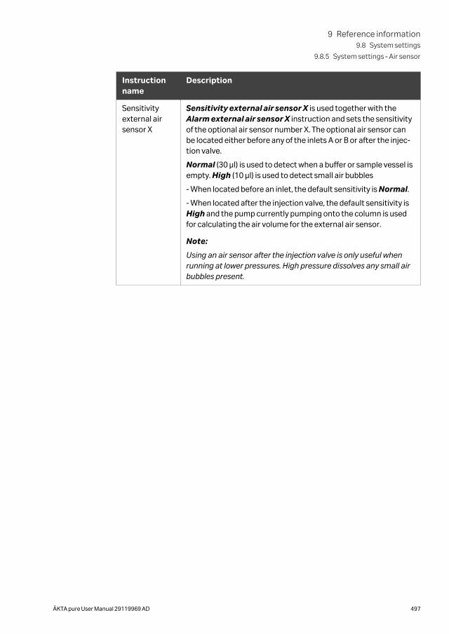
Instructionname
Description
Sensitivityexternal airsensor X
Sensitivity external air sensor X is used together with theAlarm external air sensor X instruction and sets the sensitivityof the optional air sensor number X. The optional air sensor canbe located either before any of the inlets A or B or after the injec-tion valve.
Normal (30 µl) is used to detect when a buffer or sample vessel isempty. High (10 µl) is used to detect small air bubbles
- When located before an inlet, the default sensitivity is Normal.
- When located after the injection valve, the default sensitivity isHigh and the pump currently pumping onto the column is usedfor calculating the air volume for the external air sensor.
Note:
Using an air sensor after the injection valve is only useful whenrunning at lower pressures. High pressure dissolves any small airbubbles present.
9 Reference information9.8 System settings
9.8.5 System settings ‑ Air sensor
ÄKTA pure User Manual 29119969 AD 497
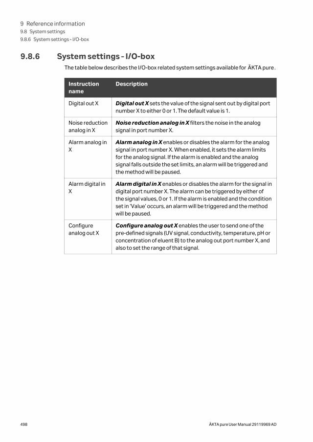
9.8.6 System settings ‑ I/O-boxThe table below describes the I/O-box related system settings available for ÄKTA pure.
Instructionname
Description
Digital out X Digital out X sets the value of the signal sent out by digital portnumber X to either 0 or 1. The default value is 1.
Noise reductionanalog in X
Noise reduction analog in X filters the noise in the analogsignal in port number X.
Alarm analog inX
Alarm analog in X enables or disables the alarm for the analogsignal in port number X. When enabled, it sets the alarm limitsfor the analog signal. If the alarm is enabled and the analogsignal falls outside the set limits, an alarm will be triggered andthe method will be paused.
Alarm digital inX
Alarm digital in X enables or disables the alarm for the signal indigital port number X. The alarm can be triggered by either ofthe signal values, 0 or 1. If the alarm is enabled and the conditionset in ‘Value’ occurs, an alarm will be triggered and the methodwill be paused.
Configureanalog out X
Configure analog out X enables the user to send one of thepre-defined signals (UV signal, conductivity, temperature, pH orconcentration of eluent B) to the analog out port number X, andalso to set the range of that signal.
9 Reference information9.8 System settings
9.8.6 System settings ‑ I/O-box
498 ÄKTA pure User Manual 29119969 AD
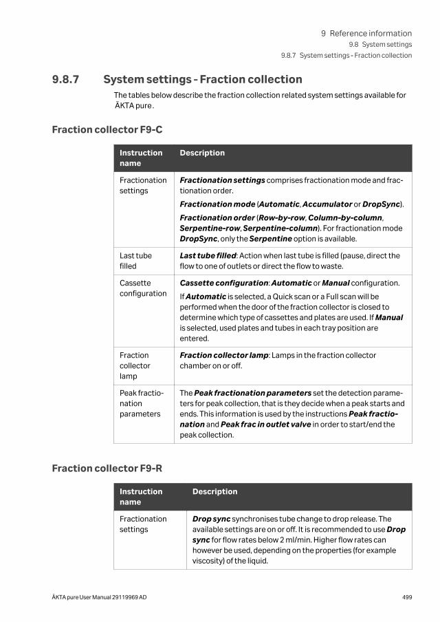
9.8.7 System settings ‑ Fraction collectionThe tables below describe the fraction collection related system settings available forÄKTA pure.
Fraction collector F9-C
Instructionname
Description
Fractionationsettings
Fractionation settings comprises fractionation mode and frac-tionation order.
Fractionation mode (Automatic, Accumulator or DropSync).
Fractionation order (Row-by-row, Column-by-column,Serpentine-row, Serpentine-column). For fractionation modeDropSync, only the Serpentine option is available.
Last tubefilled
Last tube filled: Action when last tube is filled (pause, direct theflow to one of outlets or direct the flow to waste.
Cassetteconfiguration
Cassette configuration: Automatic or Manual configuration.
If Automatic is selected, a Quick scan or a Full scan will beperformed when the door of the fraction collector is closed todetermine which type of cassettes and plates are used. If Manualis selected, used plates and tubes in each tray position areentered.
Fractioncollectorlamp
Fraction collector lamp: Lamps in the fraction collectorchamber on or off.
Peak fractio-nationparameters
The Peak fractionation parameters set the detection parame-ters for peak collection, that is they decide when a peak starts andends. This information is used by the instructions Peak fractio-nation and Peak frac in outlet valve in order to start/end thepeak collection.
Fraction collector F9-R
Instructionname
Description
Fractionationsettings
Drop sync synchronises tube change to drop release. Theavailable settings are on or off. It is recommended to use Dropsync for flow rates below 2 ml/min. Higher flow rates canhowever be used, depending on the properties (for exampleviscosity) of the liquid.
9 Reference information9.8 System settings
9.8.7 System settings ‑ Fraction collection
ÄKTA pure User Manual 29119969 AD 499
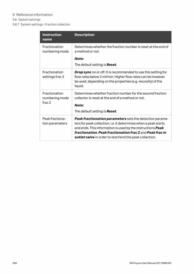
Instructionname
Description
Fractionationnumbering mode
Determines whether the fraction number is reset at the end ofa method or not.
Note:
The default setting is Reset.
Fractionationsettings frac 2
Drop sync on or off. It is recommended to use this setting forflow rates below 2 ml/min. Higher flow rates can be howeverbe used, depending on the properties (e.g. viscosity) of theliquid.
Fractionationnumbering modefrac 2
Determines whether fraction number for the second fractioncollector is reset at the end of a method or not.
Note:
The default setting is Reset.
Peak fractiona-tion parameters
Peak fractionation parameters sets the detection parame-ters for peak collection, i.e. it determines when a peak startsand ends. This information is used by the instructions Peakfractionation, Peak fractionation frac 2 and Peak frac inoutlet valve in order to start/end the peak collection.
9 Reference information9.8 System settings
9.8.7 System settings ‑ Fraction collection
500 ÄKTA pure User Manual 29119969 AD
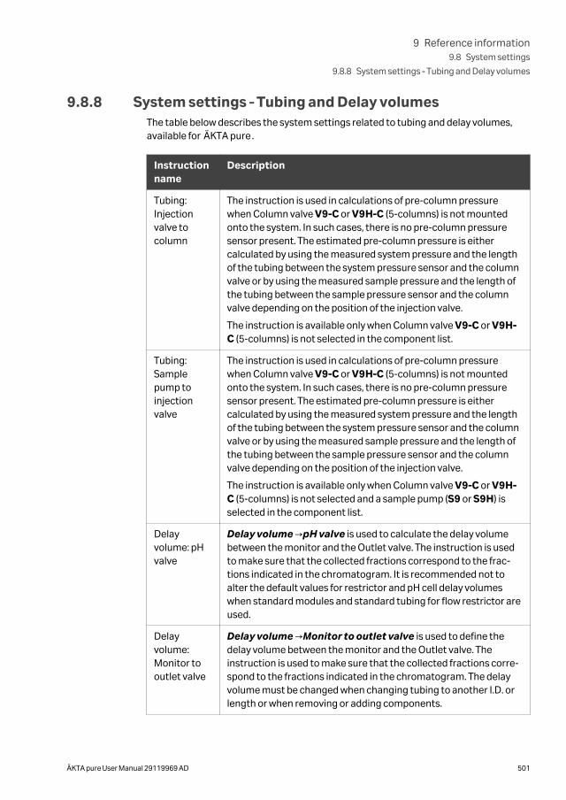
9.8.8 System settings ‑ Tubing and Delay volumesThe table below describes the system settings related to tubing and delay volumes,available for ÄKTA pure.
Instructionname
Description
Tubing:Injectionvalve tocolumn
The instruction is used in calculations of pre-column pressurewhen Column valve V9-C or V9H-C (5-columns) is not mountedonto the system. In such cases, there is no pre-column pressuresensor present. The estimated pre-column pressure is eithercalculated by using the measured system pressure and the lengthof the tubing between the system pressure sensor and the columnvalve or by using the measured sample pressure and the length ofthe tubing between the sample pressure sensor and the columnvalve depending on the position of the injection valve.
The instruction is available only when Column valve V9-C or V9H-C (5-columns) is not selected in the component list.
Tubing:Samplepump toinjectionvalve
The instruction is used in calculations of pre-column pressurewhen Column valve V9-C or V9H-C (5-columns) is not mountedonto the system. In such cases, there is no pre-column pressuresensor present. The estimated pre-column pressure is eithercalculated by using the measured system pressure and the lengthof the tubing between the system pressure sensor and the columnvalve or by using the measured sample pressure and the length ofthe tubing between the sample pressure sensor and the columnvalve depending on the position of the injection valve.
The instruction is available only when Column valve V9-C or V9H-C (5-columns) is not selected and a sample pump (S9 or S9H) isselected in the component list.
Delayvolume: pHvalve
Delay volume →pH valve is used to calculate the delay volumebetween the monitor and the Outlet valve. The instruction is usedto make sure that the collected fractions correspond to the frac-tions indicated in the chromatogram. It is recommended not toalter the default values for restrictor and pH cell delay volumeswhen standard modules and standard tubing for flow restrictor areused.
Delayvolume:Monitor tooutlet valve
Delay volume →Monitor to outlet valve is used to define thedelay volume between the monitor and the Outlet valve. Theinstruction is used to make sure that the collected fractions corre-spond to the fractions indicated in the chromatogram. The delayvolume must be changed when changing tubing to another I.D. orlength or when removing or adding components.
9 Reference information9.8 System settings
9.8.8 System settings ‑ Tubing and Delay volumes
ÄKTA pure User Manual 29119969 AD 501
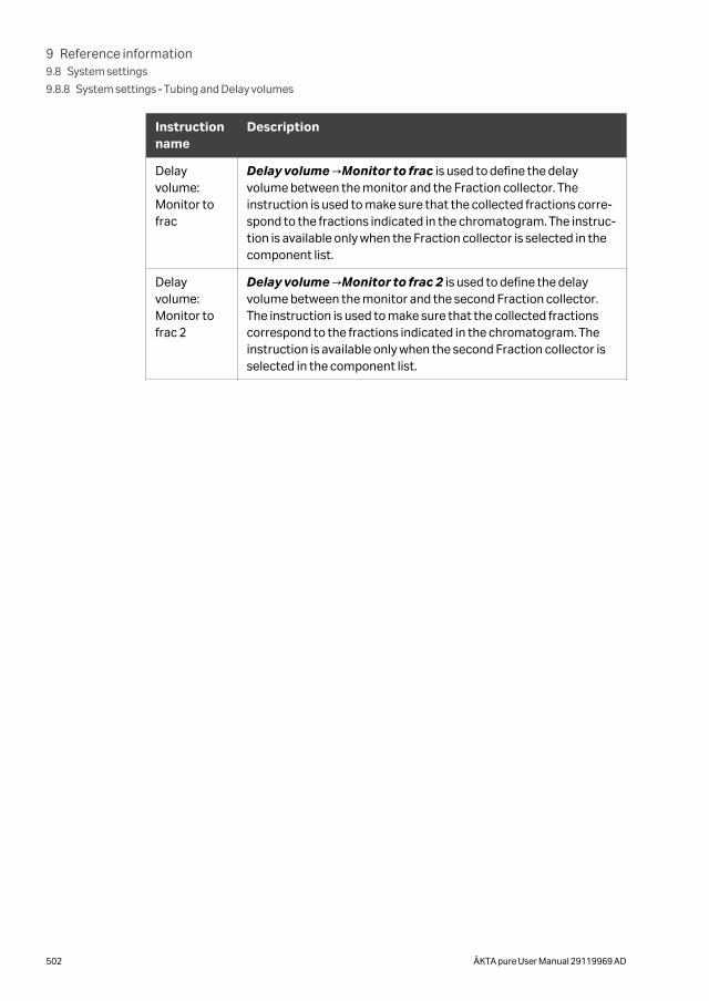
Instructionname
Description
Delayvolume:Monitor tofrac
Delay volume →Monitor to frac is used to define the delayvolume between the monitor and the Fraction collector. Theinstruction is used to make sure that the collected fractions corre-spond to the fractions indicated in the chromatogram. The instruc-tion is available only when the Fraction collector is selected in thecomponent list.
Delayvolume:Monitor tofrac 2
Delay volume →Monitor to frac 2 is used to define the delayvolume between the monitor and the second Fraction collector.The instruction is used to make sure that the collected fractionscorrespond to the fractions indicated in the chromatogram. Theinstruction is available only when the second Fraction collector isselected in the component list.
9 Reference information9.8 System settings
9.8.8 System settings ‑ Tubing and Delay volumes
502 ÄKTA pure User Manual 29119969 AD
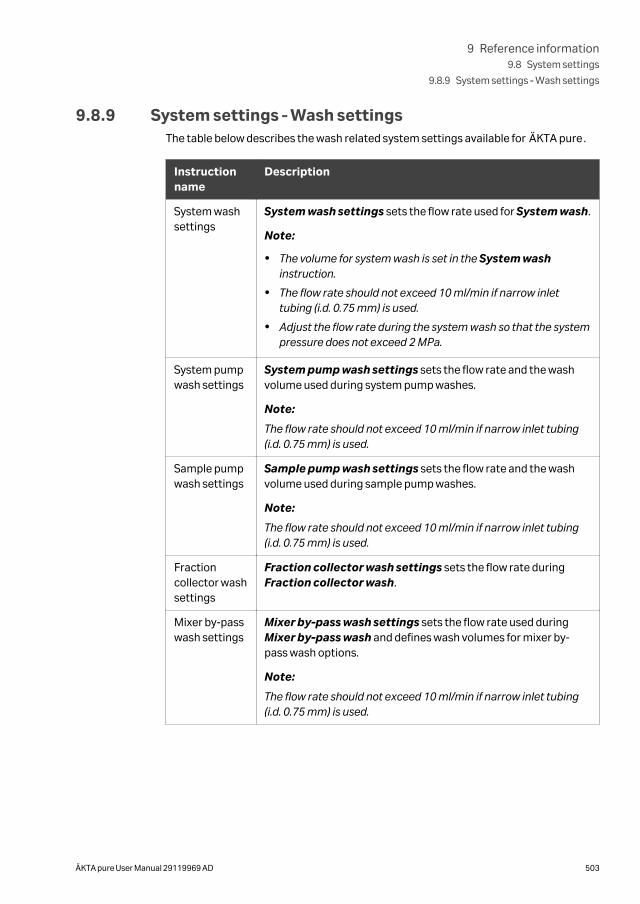
9.8.9 System settings ‑ Wash settingsThe table below describes the wash related system settings available for ÄKTA pure.
Instructionname
Description
System washsettings
System wash settings sets the flow rate used for System wash.
Note:
• The volume for system wash is set in the System washinstruction.
• The flow rate should not exceed 10 ml/min if narrow inlettubing (i.d. 0.75 mm) is used.
• Adjust the flow rate during the system wash so that the systempressure does not exceed 2 MPa.
System pumpwash settings
System pump wash settings sets the flow rate and the washvolume used during system pump washes.
Note:
The flow rate should not exceed 10 ml/min if narrow inlet tubing(i.d. 0.75 mm) is used.
Sample pumpwash settings
Sample pump wash settings sets the flow rate and the washvolume used during sample pump washes.
Note:
The flow rate should not exceed 10 ml/min if narrow inlet tubing(i.d. 0.75 mm) is used.
Fractioncollector washsettings
Fraction collector wash settings sets the flow rate duringFraction collector wash.
Mixer by-passwash settings
Mixer by-pass wash settings sets the flow rate used duringMixer by-pass wash and defines wash volumes for mixer by-pass wash options.
Note:
The flow rate should not exceed 10 ml/min if narrow inlet tubing(i.d. 0.75 mm) is used.
9 Reference information9.8 System settings
9.8.9 System settings ‑ Wash settings
ÄKTA pure User Manual 29119969 AD 503
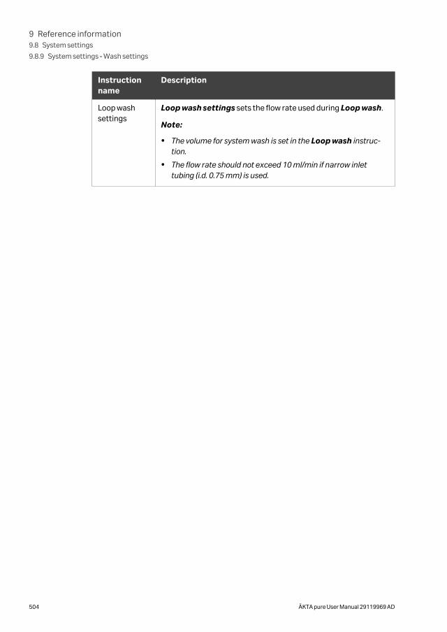
Instructionname
Description
Loop washsettings
Loop wash settings sets the flow rate used during Loop wash.
Note:
• The volume for system wash is set in the Loop wash instruc-tion.
• The flow rate should not exceed 10 ml/min if narrow inlettubing (i.d. 0.75 mm) is used.
9 Reference information9.8 System settings
9.8.9 System settings ‑ Wash settings
504 ÄKTA pure User Manual 29119969 AD
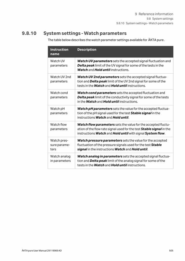
9.8.10 System settings ‑ Watch parametersThe table below describes the watch parameter settings available for ÄKTA pure.
Instructionname
Description
Watch UVparameters
Watch UV parameters sets the accepted signal fluctuation andDelta peak limit of the UV signal for some of the tests in theWatch and Hold until instructions.
Watch UV 2ndparameters
Watch UV 2nd parameters sets the accepted signal fluctua-tion and Delta peak limit of the UV 2nd signal for some of thetests in the Watch and Hold until instructions.
Watch condparameters
Watch cond parameters sets the accepted fluctuation andDelta peak limit of the conductivity signal for some of the testsin the Watch and Hold until instructions.
Watch pHparameters
Watch pH parameters sets the value for the accepted fluctua-tion of the pH signal used for the test Stable signal in theinstructions Watch and Hold until.
Watch flowparameters
Watch flow parameters sets the value for the accepted fluctu-ation of the flow rate signal used for the test Stable signal in theinstructions Watch and Hold until with signal System flow.
Watch pres-sure parame-ters
Watch pressure parameters sets the value for the acceptedfluctuation of the pressure signals used for the test Stablesignal in the instructions Watch and Hold until.
Watch analogin parameters
Watch analog in parameters sets the accepted signal fluctua-tion and Delta peak limit of the analog signal for some of thetests in the Watch and Hold until instructions.
9 Reference information9.8 System settings
9.8.10 System settings ‑ Watch parameters
ÄKTA pure User Manual 29119969 AD 505
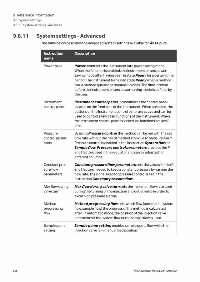
9.8.11 System settings ‑ AdvancedThe table below describes the advanced system settings available for ÄKTA pure.
Instructionname
Description
Power-save Power-save sets the instrument into power saving mode.When the function is enabled, the instrument enters power-saving mode after having been in state Ready for a certain timeperiod. The instrument turns into state Ready when a methodrun, a method queue or a manual run ends. The time intervalbefore the instrument enters power-saving mode is defined bythe user.
Instrumentcontrol panel
Instrument control panel locks/unlocks the control panellocated on the front side of the instrument. When unlocked, thebuttons on the Instrument control panel are active and can beused to control a few basic functions of the instrument. Whenthe Instrument control panel is locked, no functions are avail-able.
Pressurecontrol param-eters
By using Pressure control the method can be run with the setflow rate without the risk of method stop due to pressure alarm.Pressure control is enabled in the instruction System flow orSample flow. Pressure control parameters provides the Pand I factors used in the regulator and can be adjusted fordifferent columns.
Constant pres-sure flowparameters
Constant pressure flow parameters sets the values for the Pand I factors needed to keep a constant pressure by varying theflow rate. The signal used for pressure control is set in theinstruction Constant pressure flow.
Max flow duringvalve turn
Max flow during valve turn sets the maximum flow rate usedduring the turning of the injection and outlet valve in order toavoid high pressure alarms.
Methodprogressingflow
Method progressing flow sets which flow (automatic, systemflow, sample flow) the progress of the method is calculatedafter. In automatic mode, the position of the injection valvedetermines if the system flow or the sample flow is used.
Sample pumpsetting
Sample pump setting enables sample pump flow while theinjection valve is in manual load position.
9 Reference information9.8 System settings
9.8.11 System settings ‑ Advanced
506 ÄKTA pure User Manual 29119969 AD
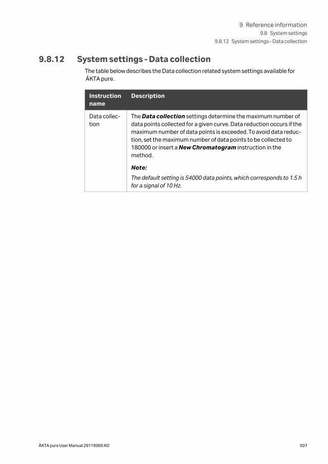
9.8.12 System settings ‑ Data collectionThe table below describes the Data collection related system settings available forÄKTA pure.
Instructionname
Description
Data collec-tion
The Data collection settings determine the maximum number ofdata points collected for a given curve. Data reduction occurs if themaximum number of data points is exceeded. To avoid data reduc-tion, set the maximum number of data points to be collected to180000 or insert a New Chromatogram instruction in themethod.
Note:
The default setting is 54000 data points, which corresponds to 1.5 hfor a signal of 10 Hz.
9 Reference information9.8 System settings
9.8.12 System settings ‑ Data collection
ÄKTA pure User Manual 29119969 AD 507
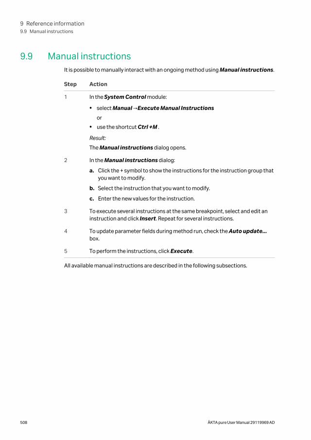
9.9 Manual instructionsIt is possible to manually interact with an ongoing method using Manual instructions.
Step Action
1 In the System Control module:
• select Manual →Execute Manual Instructions
or
• use the shortcut Ctrl +M .
Result:
The Manual instructions dialog opens.
2 In the Manual instructions dialog:
a. Click the + symbol to show the instructions for the instruction group thatyou want to modify.
b. Select the instruction that you want to modify.
c. Enter the new values for the instruction.
3 To execute several instructions at the same breakpoint, select and edit aninstruction and click Insert. Repeat for several instructions.
4 To update parameter fields during method run, check the Auto update...box.
5 To perform the instructions, click Execute.
All available manual instructions are described in the following subsections.
9 Reference information9.9 Manual instructions
508 ÄKTA pure User Manual 29119969 AD
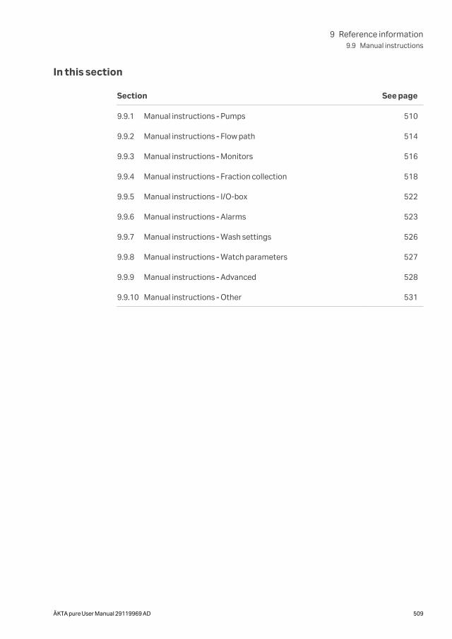
In this section
Section See page
9.9.1 Manual instructions ‑ Pumps 510
9.9.2 Manual instructions ‑ Flow path 514
9.9.3 Manual instructions ‑ Monitors 516
9.9.4 Manual instructions ‑ Fraction collection 518
9.9.5 Manual instructions ‑ I/O-box 522
9.9.6 Manual instructions ‑ Alarms 523
9.9.7 Manual instructions ‑ Wash settings 526
9.9.8 Manual instructions ‑ Watch parameters 527
9.9.9 Manual instructions ‑ Advanced 528
9.9.10 Manual instructions ‑ Other 531
9 Reference information9.9 Manual instructions
ÄKTA pure User Manual 29119969 AD 509
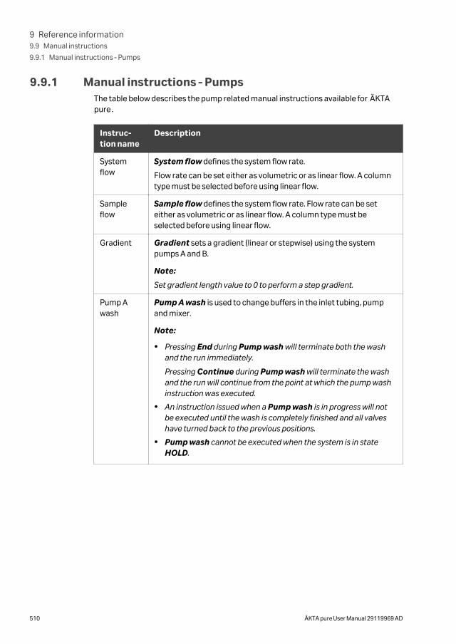
9.9.1 Manual instructions ‑ PumpsThe table below describes the pump related manual instructions available for ÄKTApure.
Instruc-tion name
Description
Systemflow
System flow defines the system flow rate.
Flow rate can be set either as volumetric or as linear flow. A columntype must be selected before using linear flow.
Sampleflow
Sample flow defines the system flow rate. Flow rate can be seteither as volumetric or as linear flow. A column type must beselected before using linear flow.
Gradient Gradient sets a gradient (linear or stepwise) using the systempumps A and B.
Note:
Set gradient length value to 0 to perform a step gradient.
Pump Awash
Pump A wash is used to change buffers in the inlet tubing, pumpand mixer.
Note:
• Pressing End during Pump wash will terminate both the washand the run immediately.
Pressing Continue during Pump wash will terminate the washand the run will continue from the point at which the pump washinstruction was executed.
• An instruction issued when a Pump wash is in progress will notbe executed until the wash is completely finished and all valveshave turned back to the previous positions.
• Pump wash cannot be executed when the system is in stateHOLD.
9 Reference information9.9 Manual instructions
9.9.1 Manual instructions ‑ Pumps
510 ÄKTA pure User Manual 29119969 AD
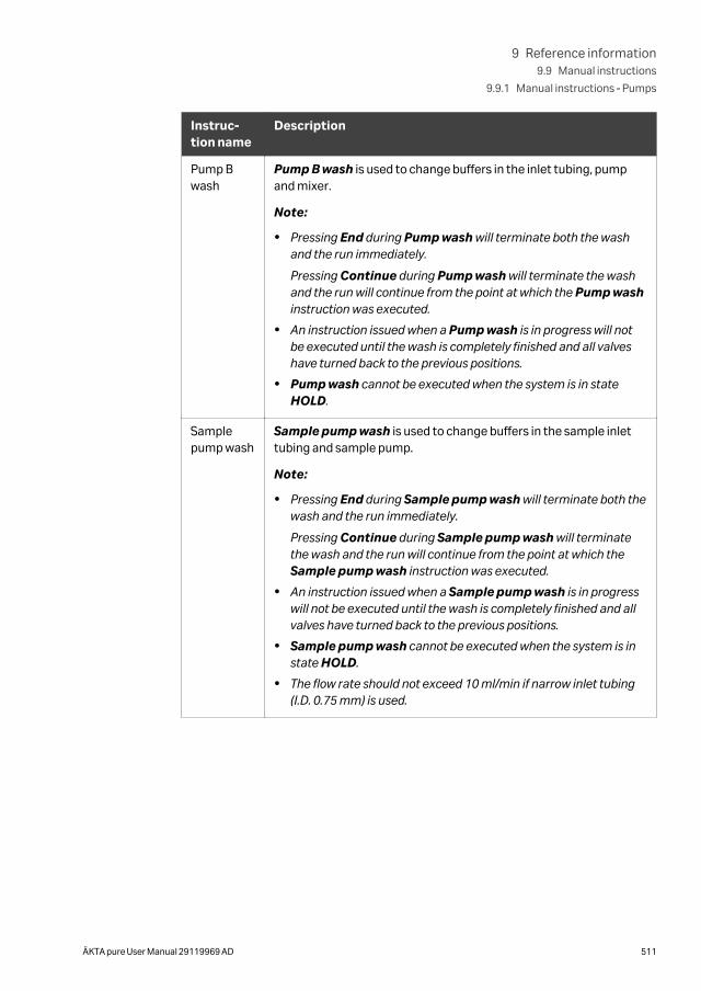
Instruc-tion name
Description
Pump Bwash
Pump B wash is used to change buffers in the inlet tubing, pumpand mixer.
Note:
• Pressing End during Pump wash will terminate both the washand the run immediately.
Pressing Continue during Pump wash will terminate the washand the run will continue from the point at which the Pump washinstruction was executed.
• An instruction issued when a Pump wash is in progress will notbe executed until the wash is completely finished and all valveshave turned back to the previous positions.
• Pump wash cannot be executed when the system is in stateHOLD.
Samplepump wash
Sample pump wash is used to change buffers in the sample inlettubing and sample pump.
Note:
• Pressing End during Sample pump wash will terminate both thewash and the run immediately.
Pressing Continue during Sample pump wash will terminatethe wash and the run will continue from the point at which theSample pump wash instruction was executed.
• An instruction issued when a Sample pump wash is in progresswill not be executed until the wash is completely finished and allvalves have turned back to the previous positions.
• Sample pump wash cannot be executed when the system is instate HOLD.
• The flow rate should not exceed 10 ml/min if narrow inlet tubing(I.D. 0.75 mm) is used.
9 Reference information9.9 Manual instructions
9.9.1 Manual instructions ‑ Pumps
ÄKTA pure User Manual 29119969 AD 511
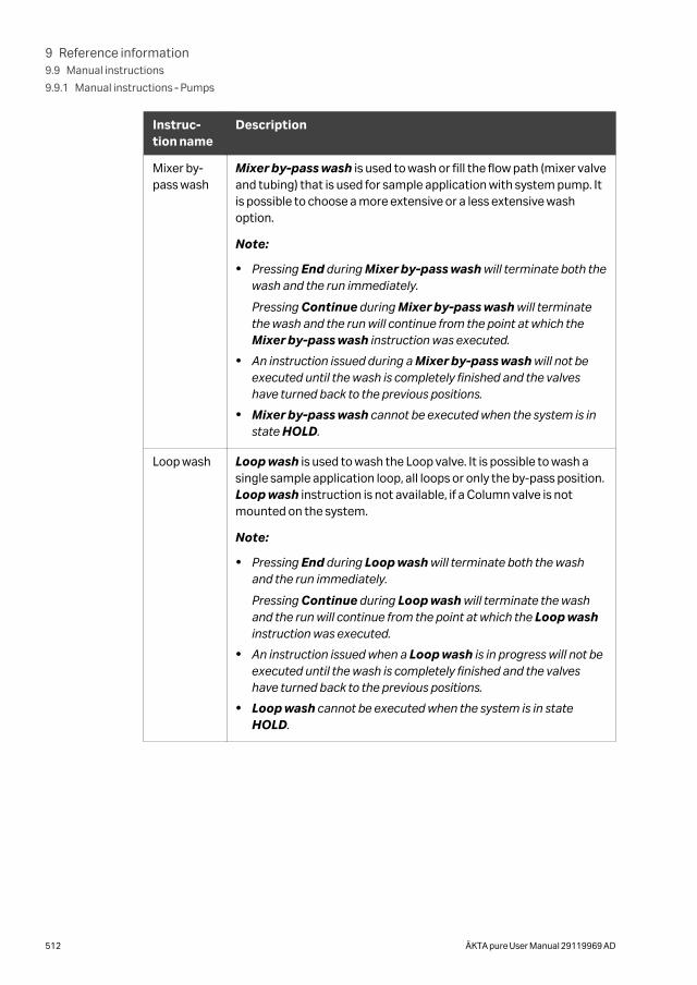
Instruc-tion name
Description
Mixer by-pass wash
Mixer by-pass wash is used to wash or fill the flow path (mixer valveand tubing) that is used for sample application with system pump. Itis possible to choose a more extensive or a less extensive washoption.
Note:
• Pressing End during Mixer by-pass wash will terminate both thewash and the run immediately.
Pressing Continue during Mixer by-pass wash will terminatethe wash and the run will continue from the point at which theMixer by-pass wash instruction was executed.
• An instruction issued during a Mixer by-pass wash will not beexecuted until the wash is completely finished and the valveshave turned back to the previous positions.
• Mixer by-pass wash cannot be executed when the system is instate HOLD.
Loop wash Loop wash is used to wash the Loop valve. It is possible to wash asingle sample application loop, all loops or only the by-pass position.Loop wash instruction is not available, if a Column valve is notmounted on the system.
Note:
• Pressing End during Loop wash will terminate both the washand the run immediately.
Pressing Continue during Loop wash will terminate the washand the run will continue from the point at which the Loop washinstruction was executed.
• An instruction issued when a Loop wash is in progress will not beexecuted until the wash is completely finished and the valveshave turned back to the previous positions.
• Loop wash cannot be executed when the system is in stateHOLD.
9 Reference information9.9 Manual instructions
9.9.1 Manual instructions ‑ Pumps
512 ÄKTA pure User Manual 29119969 AD
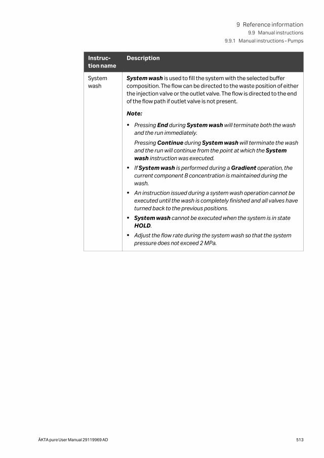
Instruc-tion name
Description
Systemwash
System wash is used to fill the system with the selected buffercomposition. The flow can be directed to the waste position of eitherthe injection valve or the outlet valve. The flow is directed to the endof the flow path if outlet valve is not present.
Note:
• Pressing End during System wash will terminate both the washand the run immediately.
Pressing Continue during System wash will terminate the washand the run will continue from the point at which the Systemwash instruction was executed.
• If System wash is performed during a Gradient operation, thecurrent component B concentration is maintained during thewash.
• An instruction issued during a system wash operation cannot beexecuted until the wash is completely finished and all valves haveturned back to the previous positions.
• System wash cannot be executed when the system is in stateHOLD.
• Adjust the flow rate during the system wash so that the systempressure does not exceed 2 MPa.
9 Reference information9.9 Manual instructions
9.9.1 Manual instructions ‑ Pumps
ÄKTA pure User Manual 29119969 AD 513
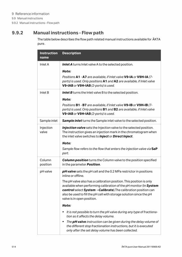
9.9.2 Manual instructions ‑ Flow pathThe table below describes the flow path related manual instructions available for ÄKTApure.
Instructionname
Description
Inlet A Inlet A turns Inlet valve A to the selected position.
Note:
Positions A1 - A7 are available, if Inlet valve V9-IA or V9H-IA (7-ports) is used. Only positions A1 and A2 are available, if Inlet valveV9-IAB or V9H-IAB (2-ports) is used.
Inlet B Inlet B turns the Inlet valve B to the selected position.
Note:
Positions B1 - B7 are available, if Inlet valve V9-IB or V9H-IB (7-ports) is used. Only positions B1 and B2 are available, if Inlet valveV9-IAB or V9H-IAB (2-ports) is used.
Sample inlet Sample inlet turns the Sample inlet valve to the selected position.
Injectionvalve
Injection valve sets the Injection valve to the selected position.The instruction gives an injection mark in the chromatogram whenthe inlet valve switches to Inject or Direct Inject.
Note:
Sample flow refers to the flow that enters the injection valve via SaPport.
Columnposition
Column position turns the Column valve to the position specifiedin the parameter Position.
pH valve pH valve sets the pH cell and the 0.2 MPa restrictor in positionsinline or offline.
The pH valve also has a calibration position. This position is onlyavailable when performing calibration of the pH monitor (In Systemcontrol select System →Calibrate).The calibration position canalso be used to fill the pH cell with storage solution since the pHvalve is in open position.
Note:
• It is not possible to turn the pH valve during any type of fractiona-tion as it affects the delay volume.
• The pH valve instruction can be given during the delay volume ofthe different stop fractionation instructions, but it is executedonly after the set delay volume has been collected.
9 Reference information9.9 Manual instructions
9.9.2 Manual instructions ‑ Flow path
514 ÄKTA pure User Manual 29119969 AD
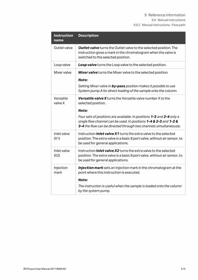
Instructionname
Description
Outlet valve Outlet valve turns the Outlet valve to the selected position. Theinstruction gives a mark in the chromatogram when the valve isswitched to the selected position.
Loop valve Loop valve turns the Loop valve to the selected position.
Mixer valve Mixer valve turns the Mixer valve to the selected position.
Note:
Setting Mixer valve in by-pass position makes it possible to useSystem pump A for direct loading of the sample onto the column.
Versatilevalve X
Versatile valve X turns the Versatile valve number X to theselected position.
Note:
Four sets of positions are available. In positions 1-3 and 2-4 only asingle flow channel can be used. In positions 1-4 & 2-3 and 1-2 &3-4 the flow can be directed through two channels simultaneously.
Inlet valve(X1)
Instruction Inlet valve X1 turns the extra valve to the selectedposition. The extra valve is a basic 8 port valve, without air sensor, tobe used for general applications.
Inlet valve(X2)
Instruction Inlet valve X2 turns the extra valve to the selectedposition. The extra valve is a basic 8 port valve, without air sensor, tobe used for general applications.
Injectionmark
Injection mark sets an injection mark in the chromatogram at thepoint where this instruction is executed.
Note:
The instruction is useful when the sample is loaded onto the columnby the system pump.
9 Reference information9.9 Manual instructions
9.9.2 Manual instructions ‑ Flow path
ÄKTA pure User Manual 29119969 AD 515
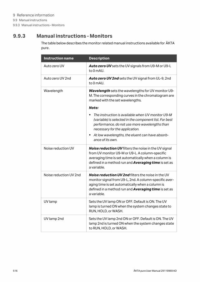
9.9.3 Manual instructions ‑ MonitorsThe table below describes the monitor related manual instructions available for ÄKTApure.
Instruction name Description
Auto zero UV Auto zero UV sets the UV signals from U9-M or U9-Lto 0 mAU.
Auto zero UV 2nd Auto zero UV 2nd sets the UV signal from UL-9, 2ndto 0 mAU.
Wavelength Wavelength sets the wavelengths for UV monitor U9-M. The corresponding curves in the chromatogram aremarked with the set wavelengths.
Note:
• The instruction is available when UV monitor U9-M(variable) is selected in the component list. For bestperformance, do not use more wavelengths thannecessary for the application.
• At low wavelengths, the eluent can have absorb-ance of its own.
Noise reduction UV Noise reduction UV filters the noise in the UV signalfrom UV monitor U9-M or U9-L. A column-specificaveraging time is set automatically when a column isdefined in a method run and Averaging time is set asa variable.
Noise reduction UV 2nd Noise reduction UV 2nd filters the noise in the UVmonitor signal from U9-L, 2nd. A column-specific aver-aging time is set automatically when a column isdefined in a method run and Averaging time is set asa variable.
UV lamp Sets the UV lamp ON or OFF. Default is ON. The UVlamp is turned ON when the system changes state toRUN, HOLD, or WASH.
UV lamp 2nd Sets the UV lamp 2nd ON or OFF. Default is ON. The UVlamp 2nd is turned ON when the system changes stateto RUN, HOLD, or WASH.
9 Reference information9.9 Manual instructions
9.9.3 Manual instructions ‑ Monitors
516 ÄKTA pure User Manual 29119969 AD
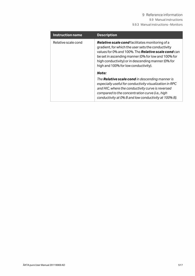
Instruction name Description
Relative scale cond Relative scale cond facilitates monitoring of agradient, for which the user sets the conductivityvalues for 0% and 100%. The Relative scale cond canbe set in ascending manner (0% for low and 100% forhigh conductivity) or in descending manner (0% forhigh and 100% for low conductivity).
Note:
The Relative scale cond in descending manner isespecially useful for conductivity visualization in RPCand HIC, where the conductivity curve is reversedcompared to the concentration curve (i.e., highconductivity at 0% B and low conductivity at 100% B).
9 Reference information9.9 Manual instructions
9.9.3 Manual instructions ‑ Monitors
ÄKTA pure User Manual 29119969 AD 517
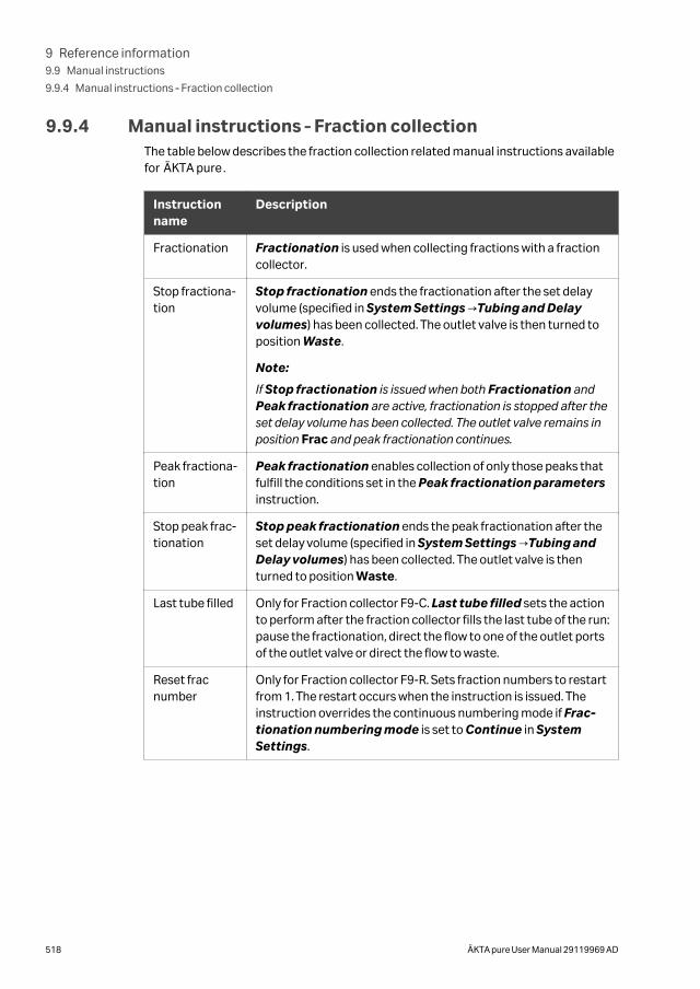
9.9.4 Manual instructions ‑ Fraction collectionThe table below describes the fraction collection related manual instructions availablefor ÄKTA pure.
Instructionname
Description
Fractionation Fractionation is used when collecting fractions with a fractioncollector.
Stop fractiona-tion
Stop fractionation ends the fractionation after the set delayvolume (specified in System Settings →Tubing and Delayvolumes) has been collected. The outlet valve is then turned toposition Waste.
Note:
If Stop fractionation is issued when both Fractionation andPeak fractionation are active, fractionation is stopped after theset delay volume has been collected. The outlet valve remains inposition Frac and peak fractionation continues.
Peak fractiona-tion
Peak fractionation enables collection of only those peaks thatfulfill the conditions set in the Peak fractionation parametersinstruction.
Stop peak frac-tionation
Stop peak fractionation ends the peak fractionation after theset delay volume (specified in System Settings →Tubing andDelay volumes) has been collected. The outlet valve is thenturned to position Waste.
Last tube filled Only for Fraction collector F9-C. Last tube filled sets the actionto perform after the fraction collector fills the last tube of the run:pause the fractionation, direct the flow to one of the outlet portsof the outlet valve or direct the flow to waste.
Reset fracnumber
Only for Fraction collector F9-R. Sets fraction numbers to restartfrom 1. The restart occurs when the instruction is issued. Theinstruction overrides the continuous numbering mode if Frac-tionation numbering mode is set to Continue in SystemSettings.
9 Reference information9.9 Manual instructions
9.9.4 Manual instructions ‑ Fraction collection
518 ÄKTA pure User Manual 29119969 AD
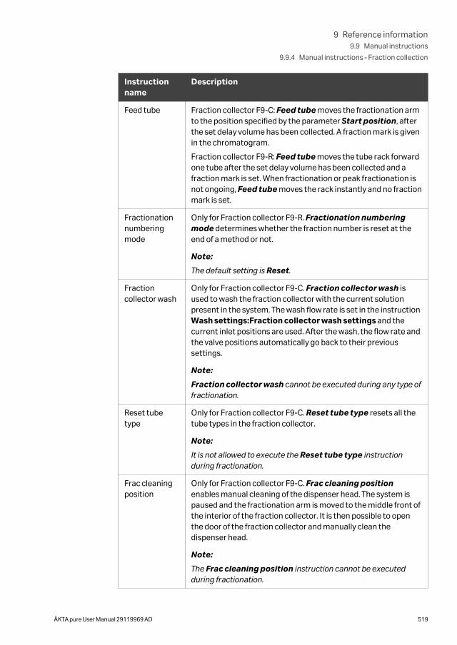
Instructionname
Description
Feed tube Fraction collector F9-C: Feed tube moves the fractionation armto the position specified by the parameter Start position, afterthe set delay volume has been collected. A fraction mark is givenin the chromatogram.
Fraction collector F9-R: Feed tube moves the tube rack forwardone tube after the set delay volume has been collected and afraction mark is set. When fractionation or peak fractionation isnot ongoing, Feed tube moves the rack instantly and no fractionmark is set.
Fractionationnumberingmode
Only for Fraction collector F9-R. Fractionation numberingmode determines whether the fraction number is reset at theend of a method or not.
Note:
The default setting is Reset.
Fractioncollector wash
Only for Fraction collector F9-C. Fraction collector wash isused to wash the fraction collector with the current solutionpresent in the system. The wash flow rate is set in the instructionWash settings:Fraction collector wash settings and thecurrent inlet positions are used. After the wash, the flow rate andthe valve positions automatically go back to their previoussettings.
Note:
Fraction collector wash cannot be executed during any type offractionation.
Reset tubetype
Only for Fraction collector F9-C. Reset tube type resets all thetube types in the fraction collector.
Note:
It is not allowed to execute the Reset tube type instructionduring fractionation.
Frac cleaningposition
Only for Fraction collector F9-C. Frac cleaning positionenables manual cleaning of the dispenser head. The system ispaused and the fractionation arm is moved to the middle front ofthe interior of the fraction collector. It is then possible to openthe door of the fraction collector and manually clean thedispenser head.
Note:
The Frac cleaning position instruction cannot be executedduring fractionation.
9 Reference information9.9 Manual instructions
9.9.4 Manual instructions ‑ Fraction collection
ÄKTA pure User Manual 29119969 AD 519
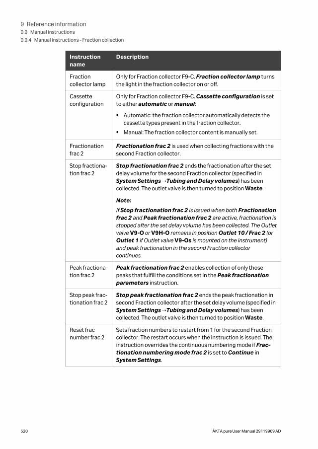
Instructionname
Description
Fractioncollector lamp
Only for Fraction collector F9-C. Fraction collector lamp turnsthe light in the fraction collector on or off.
Cassetteconfiguration
Only for Fraction collector F9-C. Cassette configuration is setto either automatic or manual:
• Automatic: the fraction collector automatically detects thecassette types present in the fraction collector.
• Manual: The fraction collector content is manually set.
Fractionationfrac 2
Fractionation frac 2 is used when collecting fractions with thesecond Fraction collector.
Stop fractiona-tion frac 2
Stop fractionation frac 2 ends the fractionation after the setdelay volume for the second Fraction collector (specified inSystem Settings →Tubing and Delay volumes) has beencollected. The outlet valve is then turned to position Waste.
Note:
If Stop fractionation frac 2 is issued when both Fractionationfrac 2 and Peak fractionation frac 2 are active, fractionation isstopped after the set delay volume has been collected. The Outletvalve V9-O or V9H-O remains in position Outlet 10 / Frac 2 (orOutlet 1 if Outlet valve V9-Os is mounted on the instrument)and peak fractionation in the second Fraction collectorcontinues.
Peak fractiona-tion frac 2
Peak fractionation frac 2 enables collection of only thosepeaks that fulfill the conditions set in the Peak fractionationparameters instruction.
Stop peak frac-tionation frac 2
Stop peak fractionation frac 2 ends the peak fractionation insecond Fraction collector after the set delay volume (specified inSystem Settings →Tubing and Delay volumes) has beencollected. The outlet valve is then turned to position Waste.
Reset fracnumber frac 2
Sets fraction numbers to restart from 1 for the second Fractioncollector. The restart occurs when the instruction is issued. Theinstruction overrides the continuous numbering mode if Frac-tionation numbering mode frac 2 is set to Continue inSystem Settings.
9 Reference information9.9 Manual instructions
9.9.4 Manual instructions ‑ Fraction collection
520 ÄKTA pure User Manual 29119969 AD
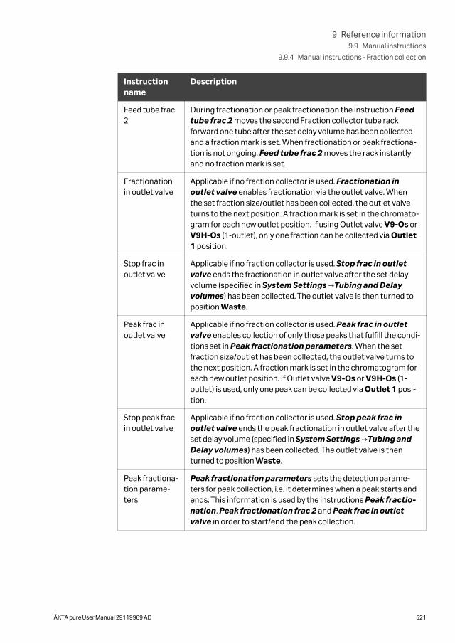
Instructionname
Description
Feed tube frac2
During fractionation or peak fractionation the instruction Feedtube frac 2 moves the second Fraction collector tube rackforward one tube after the set delay volume has been collectedand a fraction mark is set. When fractionation or peak fractiona-tion is not ongoing, Feed tube frac 2 moves the rack instantlyand no fraction mark is set.
Fractionationin outlet valve
Applicable if no fraction collector is used. Fractionation inoutlet valve enables fractionation via the outlet valve. Whenthe set fraction size/outlet has been collected, the outlet valveturns to the next position. A fraction mark is set in the chromato-gram for each new outlet position. If using Outlet valve V9-Os orV9H-Os (1-outlet), only one fraction can be collected via Outlet1 position.
Stop frac inoutlet valve
Applicable if no fraction collector is used. Stop frac in outletvalve ends the fractionation in outlet valve after the set delayvolume (specified in System Settings →Tubing and Delayvolumes) has been collected. The outlet valve is then turned toposition Waste.
Peak frac inoutlet valve
Applicable if no fraction collector is used. Peak frac in outletvalve enables collection of only those peaks that fulfill the condi-tions set in Peak fractionation parameters. When the setfraction size/outlet has been collected, the outlet valve turns tothe next position. A fraction mark is set in the chromatogram foreach new outlet position. If Outlet valve V9-Os or V9H-Os (1-outlet) is used, only one peak can be collected via Outlet 1 posi-tion.
Stop peak fracin outlet valve
Applicable if no fraction collector is used. Stop peak frac inoutlet valve ends the peak fractionation in outlet valve after theset delay volume (specified in System Settings →Tubing andDelay volumes) has been collected. The outlet valve is thenturned to position Waste.
Peak fractiona-tion parame-ters
Peak fractionation parameters sets the detection parame-ters for peak collection, i.e. it determines when a peak starts andends. This information is used by the instructions Peak fractio-nation, Peak fractionation frac 2 and Peak frac in outletvalve in order to start/end the peak collection.
9 Reference information9.9 Manual instructions
9.9.4 Manual instructions ‑ Fraction collection
ÄKTA pure User Manual 29119969 AD 521
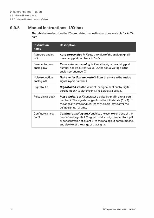
9.9.5 Manual instructions ‑ I/O-boxThe table below describes the I/O-box related manual instructions available for ÄKTApure.
Instructionname
Description
Auto zero analogin X
Auto zero analog in X sets the value of the analog signal inthe analog port number X to 0 mV.
Reset auto zeroanalog in X
Reset auto zero analog in X sets the signal in analog portnumber X to its current value, i.e. the actual voltage in theanalog port number X.
Noise reductionanalog in X
Noise reduction analog in X filters the noise in the analogsignal in port number X.
Digital out X Digital out X sets the value of the signal sent out by digitalport number X to either 0 or 1. The default value is 1.
Pulse digital out X Pulse digital out X generates a pulsed signal in digital portnumber X. The signal changes from the initial state (0 or 1) tothe opposite state and returns to the initial state after thedefined length of time.
Configure analogout X
Configure analog out X enables the user to send one of thepre-defined signals (UV signal, conductivity, temperature, pHor concentration of eluent B) to the analog out port number X,and also to set the range of that signal.
9 Reference information9.9 Manual instructions
9.9.5 Manual instructions ‑ I/O-box
522 ÄKTA pure User Manual 29119969 AD
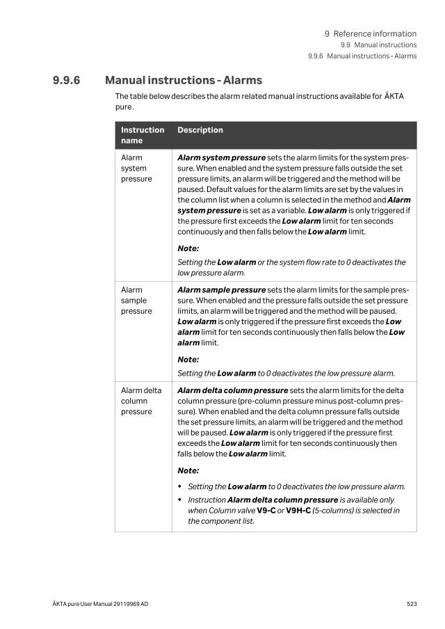
9.9.6 Manual instructions ‑ AlarmsThe table below describes the alarm related manual instructions available for ÄKTApure.
Instructionname
Description
Alarmsystempressure
Alarm system pressure sets the alarm limits for the system pres-sure. When enabled and the system pressure falls outside the setpressure limits, an alarm will be triggered and the method will bepaused. Default values for the alarm limits are set by the values inthe column list when a column is selected in the method and Alarmsystem pressure is set as a variable. Low alarm is only triggered ifthe pressure first exceeds the Low alarm limit for ten secondscontinuously and then falls below the Low alarm limit.
Note:
Setting the Low alarm or the system flow rate to 0 deactivates thelow pressure alarm.
Alarmsamplepressure
Alarm sample pressure sets the alarm limits for the sample pres-sure. When enabled and the pressure falls outside the set pressurelimits, an alarm will be triggered and the method will be paused.Low alarm is only triggered if the pressure first exceeds the Lowalarm limit for ten seconds continuously then falls below the Lowalarm limit.
Note:
Setting the Low alarm to 0 deactivates the low pressure alarm.
Alarm deltacolumnpressure
Alarm delta column pressure sets the alarm limits for the deltacolumn pressure (pre-column pressure minus post-column pres-sure). When enabled and the delta column pressure falls outsidethe set pressure limits, an alarm will be triggered and the methodwill be paused. Low alarm is only triggered if the pressure firstexceeds the Low alarm limit for ten seconds continuously thenfalls below the Low alarm limit.
Note:
• Setting the Low alarm to 0 deactivates the low pressure alarm.
• Instruction Alarm delta column pressure is available onlywhen Column valve V9-C or V9H-C (5-columns) is selected inthe component list.
9 Reference information9.9 Manual instructions
9.9.6 Manual instructions ‑ Alarms
ÄKTA pure User Manual 29119969 AD 523
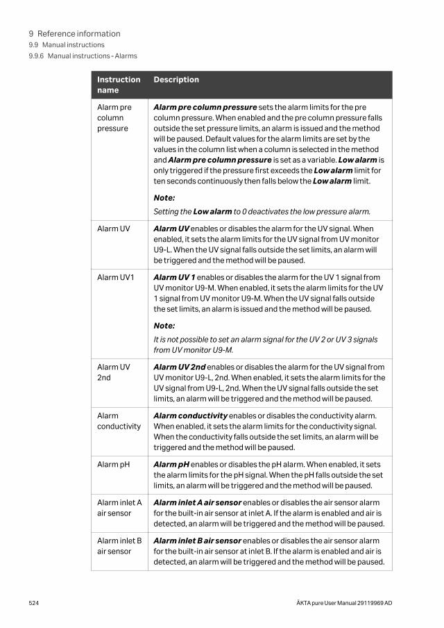
Instructionname
Description
Alarm precolumnpressure
Alarm pre column pressure sets the alarm limits for the precolumn pressure. When enabled and the pre column pressure fallsoutside the set pressure limits, an alarm is issued and the methodwill be paused. Default values for the alarm limits are set by thevalues in the column list when a column is selected in the methodand Alarm pre column pressure is set as a variable. Low alarm isonly triggered if the pressure first exceeds the Low alarm limit forten seconds continuously then falls below the Low alarm limit.
Note:
Setting the Low alarm to 0 deactivates the low pressure alarm.
Alarm UV Alarm UV enables or disables the alarm for the UV signal. Whenenabled, it sets the alarm limits for the UV signal from UV monitorU9-L. When the UV signal falls outside the set limits, an alarm willbe triggered and the method will be paused.
Alarm UV1 Alarm UV 1 enables or disables the alarm for the UV 1 signal fromUV monitor U9-M. When enabled, it sets the alarm limits for the UV1 signal from UV monitor U9-M. When the UV signal falls outsidethe set limits, an alarm is issued and the method will be paused.
Note:
It is not possible to set an alarm signal for the UV 2 or UV 3 signalsfrom UV monitor U9-M.
Alarm UV2nd
Alarm UV 2nd enables or disables the alarm for the UV signal fromUV monitor U9-L, 2nd. When enabled, it sets the alarm limits for theUV signal from U9-L, 2nd. When the UV signal falls outside the setlimits, an alarm will be triggered and the method will be paused.
Alarmconductivity
Alarm conductivity enables or disables the conductivity alarm.When enabled, it sets the alarm limits for the conductivity signal.When the conductivity falls outside the set limits, an alarm will betriggered and the method will be paused.
Alarm pH Alarm pH enables or disables the pH alarm. When enabled, it setsthe alarm limits for the pH signal. When the pH falls outside the setlimits, an alarm will be triggered and the method will be paused.
Alarm inlet Aair sensor
Alarm inlet A air sensor enables or disables the air sensor alarmfor the built-in air sensor at inlet A. If the alarm is enabled and air isdetected, an alarm will be triggered and the method will be paused.
Alarm inlet Bair sensor
Alarm inlet B air sensor enables or disables the air sensor alarmfor the built-in air sensor at inlet B. If the alarm is enabled and air isdetected, an alarm will be triggered and the method will be paused.
9 Reference information9.9 Manual instructions
9.9.6 Manual instructions ‑ Alarms
524 ÄKTA pure User Manual 29119969 AD
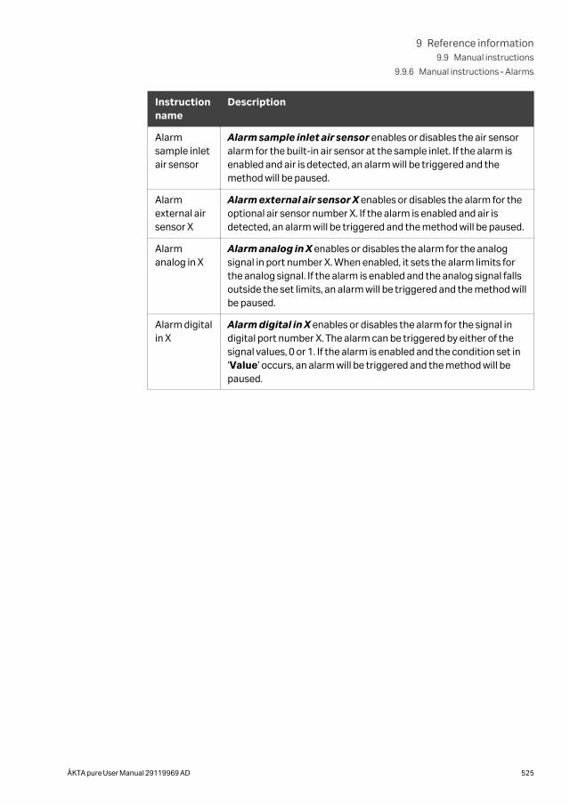
Instructionname
Description
Alarmsample inletair sensor
Alarm sample inlet air sensor enables or disables the air sensoralarm for the built-in air sensor at the sample inlet. If the alarm isenabled and air is detected, an alarm will be triggered and themethod will be paused.
Alarmexternal airsensor X
Alarm external air sensor X enables or disables the alarm for theoptional air sensor number X. If the alarm is enabled and air isdetected, an alarm will be triggered and the method will be paused.
Alarmanalog in X
Alarm analog in X enables or disables the alarm for the analogsignal in port number X. When enabled, it sets the alarm limits forthe analog signal. If the alarm is enabled and the analog signal fallsoutside the set limits, an alarm will be triggered and the method willbe paused.
Alarm digitalin X
Alarm digital in X enables or disables the alarm for the signal indigital port number X. The alarm can be triggered by either of thesignal values, 0 or 1. If the alarm is enabled and the condition set in‘Value’ occurs, an alarm will be triggered and the method will bepaused.
9 Reference information9.9 Manual instructions
9.9.6 Manual instructions ‑ Alarms
ÄKTA pure User Manual 29119969 AD 525
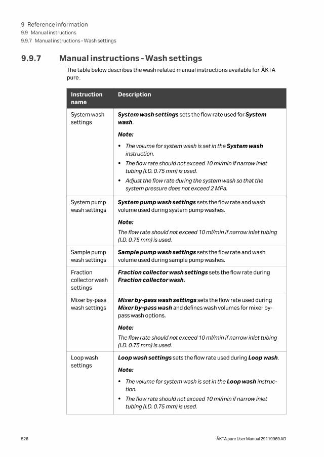
9.9.7 Manual instructions ‑ Wash settingsThe table below describes the wash related manual instructions available for ÄKTApure.
Instructionname
Description
System washsettings
System wash settings sets the flow rate used for Systemwash.
Note:
• The volume for system wash is set in the System washinstruction.
• The flow rate should not exceed 10 ml/min if narrow inlettubing (I.D. 0.75 mm) is used.
• Adjust the flow rate during the system wash so that thesystem pressure does not exceed 2 MPa.
System pumpwash settings
System pump wash settings sets the flow rate and washvolume used during system pump washes.
Note:
The flow rate should not exceed 10 ml/min if narrow inlet tubing(I.D. 0.75 mm) is used.
Sample pumpwash settings
Sample pump wash settings sets the flow rate and washvolume used during sample pump washes.
Fractioncollector washsettings
Fraction collector wash settings sets the flow rate duringFraction collector wash.
Mixer by-passwash settings
Mixer by-pass wash settings sets the flow rate used duringMixer by-pass wash and defines wash volumes for mixer by-pass wash options.
Note:
The flow rate should not exceed 10 ml/min if narrow inlet tubing(I.D. 0.75 mm) is used.
Loop washsettings
Loop wash settings sets the flow rate used during Loop wash.
Note:
• The volume for system wash is set in the Loop wash instruc-tion.
• The flow rate should not exceed 10 ml/min if narrow inlettubing (I.D. 0.75 mm) is used.
9 Reference information9.9 Manual instructions
9.9.7 Manual instructions ‑ Wash settings
526 ÄKTA pure User Manual 29119969 AD
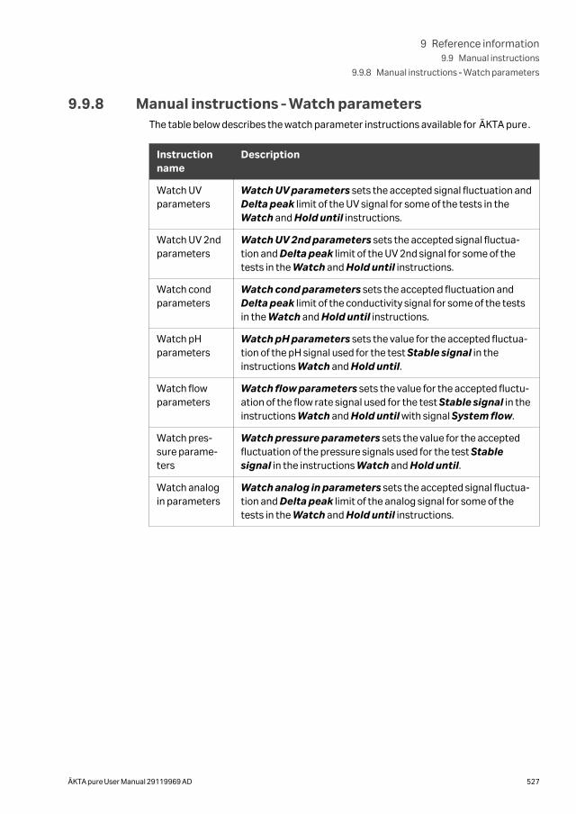
9.9.8 Manual instructions ‑ Watch parametersThe table below describes the watch parameter instructions available for ÄKTA pure.
Instructionname
Description
Watch UVparameters
Watch UV parameters sets the accepted signal fluctuation andDelta peak limit of the UV signal for some of the tests in theWatch and Hold until instructions.
Watch UV 2ndparameters
Watch UV 2nd parameters sets the accepted signal fluctua-tion and Delta peak limit of the UV 2nd signal for some of thetests in the Watch and Hold until instructions.
Watch condparameters
Watch cond parameters sets the accepted fluctuation andDelta peak limit of the conductivity signal for some of the testsin the Watch and Hold until instructions.
Watch pHparameters
Watch pH parameters sets the value for the accepted fluctua-tion of the pH signal used for the test Stable signal in theinstructions Watch and Hold until.
Watch flowparameters
Watch flow parameters sets the value for the accepted fluctu-ation of the flow rate signal used for the test Stable signal in theinstructions Watch and Hold until with signal System flow.
Watch pres-sure parame-ters
Watch pressure parameters sets the value for the acceptedfluctuation of the pressure signals used for the test Stablesignal in the instructions Watch and Hold until.
Watch analogin parameters
Watch analog in parameters sets the accepted signal fluctua-tion and Delta peak limit of the analog signal for some of thetests in the Watch and Hold until instructions.
9 Reference information9.9 Manual instructions
9.9.8 Manual instructions ‑ Watch parameters
ÄKTA pure User Manual 29119969 AD 527
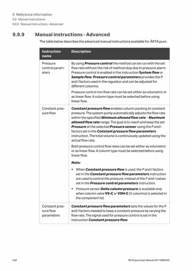
9.9.9 Manual instructions ‑ AdvancedThe table below describes the advanced manual instructions available for ÄKTA pure.
Instructionname
Description
Pressurecontrol param-eters
By using Pressure control the method can be run with the setflow rate without the risk of method stop due to pressure alarm.Pressure control is enabled in the instruction System flow orSample flow. Pressure control parameters provides the Pand I factors used in the regulator and can be adjusted fordifferent columns.
Pressure control min flow rate can be set either as volumetric oras linear flow. A column type must be selected before usinglinear flow.
Constant pres-sure flow
Constant pressure flow enables column packing at constantpressure. The system pump automatically adjusts the flow ratewithin the specified Minimum allowed flow rate – Maximumallowed flow rate range. The goal is to reach and keep the setPressure at the selected Pressure sensor using the P and Ifactors set in the Constant pressure flow parametersinstruction. The total volume is continuously updated using theactual flow rate.
Both pressure control flow rates can be set either as volumetricor as linear flow. A column type must be selected before usinglinear flow.
Note:
• When Constant pressure flow is used, the P and I factorsset in the Constant pressure flow parameters instructionare used to control the pressure, instead of the P and I valuesset in the Pressure control parameters instruction.
• Pressure sensor Delta column pressure is available onlywhen column valve V9-C or V9H-C (5-columns) is selected inthe component list.
Constant pres-sure flowparameters
Constant pressure flow parameters sets the values for the Pand I factors needed to keep a constant pressure by varying theflow rate. The signal used for pressure control is set in theinstruction Constant pressure flow.
9 Reference information9.9 Manual instructions
9.9.9 Manual instructions ‑ Advanced
528 ÄKTA pure User Manual 29119969 AD
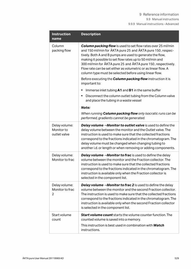
Instructionname
Description
Columnpacking flow
Column packing flow is used to set flow rates over 25 ml/minand 150 ml/min for ÄKTA pure 25 and ÄKTA pure 150, respec-tively. Both A and B pumps are used to generate the flow,making it possible to set flow rates up to 50 ml/min and300 ml/min for ÄKTA pure 25 and ÄKTA pure 150, respectively.Flow rate can be set either as volumetric or as linear flow. Acolumn type must be selected before using linear flow.
Before executing the Column packing flow instruction it isimportant to:
• Immerse inlet tubing A1 and B1 in the same buffer
• Disconnect the column outlet tubing from the Column valveand place the tubing in a waste vessel
Note:
When running Column packing flow only isocratic runs can beperformed, gradients cannot be generated.
Delay volume:Monitor tooutlet valve
Delay volume →Monitor to outlet valve is used to define thedelay volume between the monitor and the Outlet valve. Theinstruction is used to make sure that the collected fractionscorrespond to the fractions indicated in the chromatogram. Thedelay volume must be changed when changing tubing toanother i.d. or length or when removing or adding components.
Delay volume:Monitor to frac
Delay volume →Monitor to frac is used to define the delayvolume between the monitor and the Fraction collector. Theinstruction is used to make sure that the collected fractionscorrespond to the fractions indicated in the chromatogram. Theinstruction is available only when the Fraction collector isselected in the component list.
Delay volume:Monitor to frac2
Delay volume →Monitor to frac 2 is used to define the delayvolume between the monitor and the second Fraction collector.The instruction is used to make sure that the collected fractionscorrespond to the fractions indicated in the chromatogram. Theinstruction is available only when the second Fraction collectoris selected in the component list.
Start volumecount
Start volume count starts the volume counter function. Thecounted volume is saved into a memory.
This instruction is best used in combination with Watchinstructions.
9 Reference information9.9 Manual instructions
9.9.9 Manual instructions ‑ Advanced
ÄKTA pure User Manual 29119969 AD 529
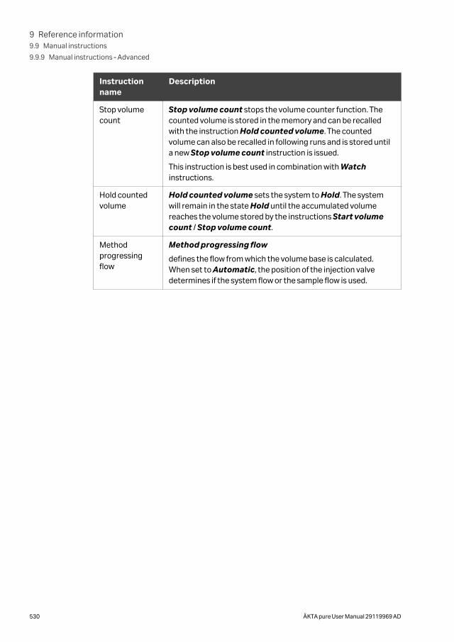
Instructionname
Description
Stop volumecount
Stop volume count stops the volume counter function. Thecounted volume is stored in the memory and can be recalledwith the instruction Hold counted volume. The countedvolume can also be recalled in following runs and is stored untila new Stop volume count instruction is issued.
This instruction is best used in combination with Watchinstructions.
Hold countedvolume
Hold counted volume sets the system to Hold. The systemwill remain in the state Hold until the accumulated volumereaches the volume stored by the instructions Start volumecount / Stop volume count.
Methodprogressingflow
Method progressing flow
defines the flow from which the volume base is calculated.When set to Automatic, the position of the injection valvedetermines if the system flow or the sample flow is used.
9 Reference information9.9 Manual instructions
9.9.9 Manual instructions ‑ Advanced
530 ÄKTA pure User Manual 29119969 AD
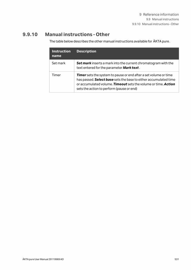
9.9.10 Manual instructions ‑ OtherThe table below describes the other manual instructions available for ÄKTA pure.
Instructionname
Description
Set mark Set mark inserts a mark into the current chromatogram with thetext entered for the parameter Mark text .
Timer Timer sets the system to pause or end after a set volume or timehas passed. Select base sets the base to either accumulated timeor accumulated volume. Timeout sets the volume or time. Actionsets the action to perform (pause or end)
9 Reference information9.9 Manual instructions
9.9.10 Manual instructions ‑ Other
ÄKTA pure User Manual 29119969 AD 531
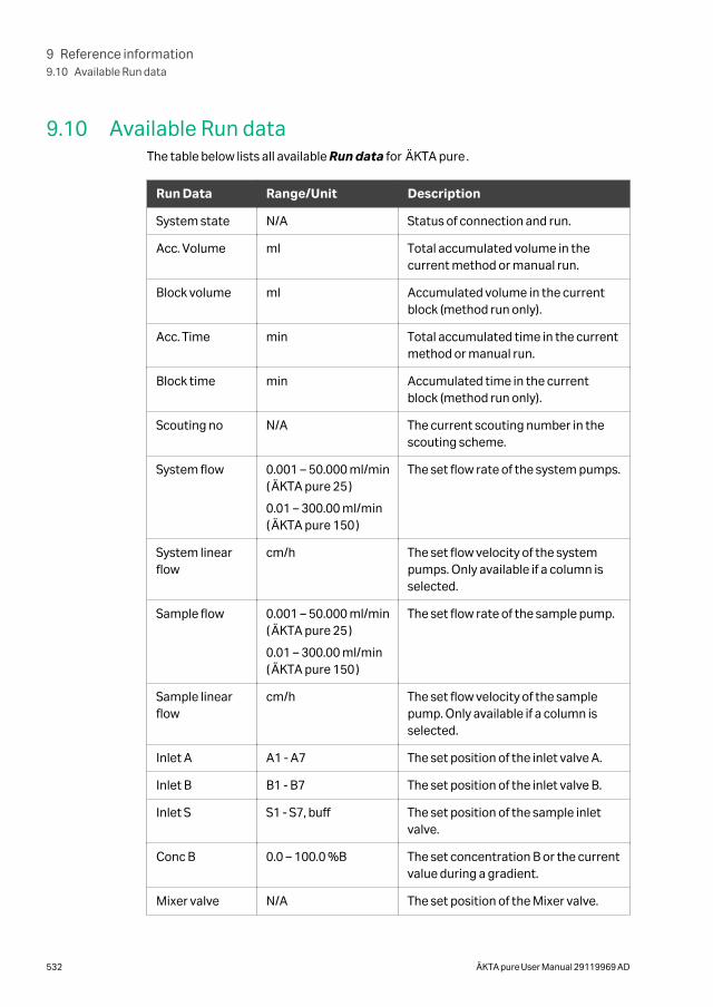
9.10 Available Run dataThe table below lists all available Run data for ÄKTA pure.
Run Data Range/Unit Description
System state N/A Status of connection and run.
Acc. Volume ml Total accumulated volume in thecurrent method or manual run.
Block volume ml Accumulated volume in the currentblock (method run only).
Acc. Time min Total accumulated time in the currentmethod or manual run.
Block time min Accumulated time in the currentblock (method run only).
Scouting no N/A The current scouting number in thescouting scheme.
System flow 0.001 – 50.000 ml/min(ÄKTA pure 25)
0.01 – 300.00 ml/min(ÄKTA pure 150)
The set flow rate of the system pumps.
System linearflow
cm/h The set flow velocity of the systempumps. Only available if a column isselected.
Sample flow 0.001 – 50.000 ml/min(ÄKTA pure 25)
0.01 – 300.00 ml/min(ÄKTA pure 150)
The set flow rate of the sample pump.
Sample linearflow
cm/h The set flow velocity of the samplepump. Only available if a column isselected.
Inlet A A1 - A7 The set position of the inlet valve A.
Inlet B B1 - B7 The set position of the inlet valve B.
Inlet S S1 - S7, buff The set position of the sample inletvalve.
Conc B 0.0 – 100.0 %B The set concentration B or the currentvalue during a gradient.
Mixer valve N/A The set position of the Mixer valve.
9 Reference information9.10 Available Run data
532 ÄKTA pure User Manual 29119969 AD
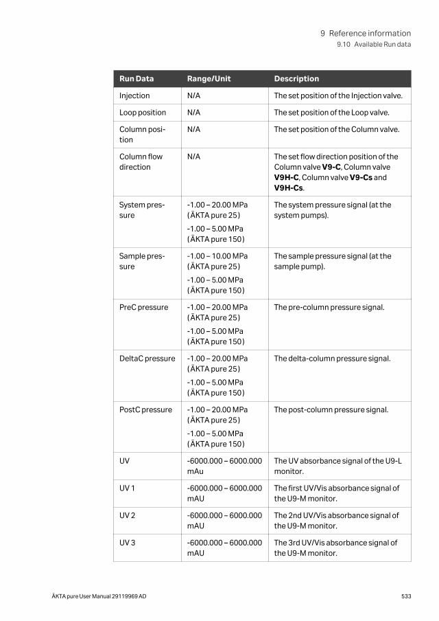
Run Data Range/Unit Description
Injection N/A The set position of the Injection valve.
Loop position N/A The set position of the Loop valve.
Column posi-tion
N/A The set position of the Column valve.
Column flowdirection
N/A The set flow direction position of theColumn valve V9-C, Column valveV9H-C, Column valve V9-Cs andV9H-Cs.
System pres-sure
-1.00 – 20.00 MPa(ÄKTA pure 25)
-1.00 – 5.00 MPa(ÄKTA pure 150)
The system pressure signal (at thesystem pumps).
Sample pres-sure
-1.00 – 10.00 MPa(ÄKTA pure 25)
-1.00 – 5.00 MPa(ÄKTA pure 150)
The sample pressure signal (at thesample pump).
PreC pressure -1.00 – 20.00 MPa(ÄKTA pure 25)
-1.00 – 5.00 MPa(ÄKTA pure 150)
The pre-column pressure signal.
DeltaC pressure -1.00 – 20.00 MPa(ÄKTA pure 25)
-1.00 – 5.00 MPa(ÄKTA pure 150)
The delta-column pressure signal.
PostC pressure -1.00 – 20.00 MPa(ÄKTA pure 25)
-1.00 – 5.00 MPa(ÄKTA pure 150)
The post-column pressure signal.
UV -6000.000 – 6000.000mAu
The UV absorbance signal of the U9-Lmonitor.
UV 1 -6000.000 – 6000.000mAU
The first UV/Vis absorbance signal ofthe U9-M monitor.
UV 2 -6000.000 – 6000.000mAU
The 2nd UV/Vis absorbance signal ofthe U9-M monitor.
UV 3 -6000.000 – 6000.000mAU
The 3rd UV/Vis absorbance signal ofthe U9-M monitor.
9 Reference information9.10 Available Run data
ÄKTA pure User Manual 29119969 AD 533
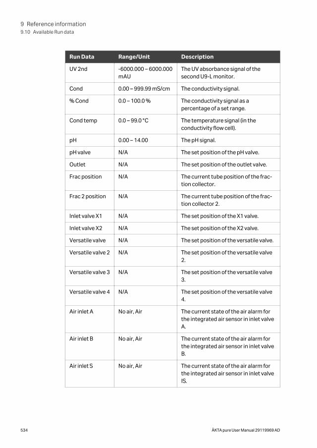
Run Data Range/Unit Description
UV 2nd -6000.000 – 6000.000mAU
The UV absorbance signal of thesecond U9-L monitor.
Cond 0.00 – 999.99 mS/cm The conductivity signal.
% Cond 0.0 – 100.0 % The conductivity signal as apercentage of a set range.
Cond temp 0.0 – 99.0 °C The temperature signal (in theconductivity flow cell).
pH 0.00 – 14.00 The pH signal.
pH valve N/A The set position of the pH valve.
Outlet N/A The set position of the outlet valve.
Frac position N/A The current tube position of the frac-tion collector.
Frac 2 position N/A The current tube position of the frac-tion collector 2.
Inlet valve X1 N/A The set position of the X1 valve.
Inlet valve X2 N/A The set position of the X2 valve.
Versatile valve N/A The set position of the versatile valve.
Versatile valve 2 N/A The set position of the versatile valve2.
Versatile valve 3 N/A The set position of the versatile valve3.
Versatile valve 4 N/A The set position of the versatile valve4.
Air inlet A No air, Air The current state of the air alarm forthe integrated air sensor in inlet valveA.
Air inlet B No air, Air The current state of the air alarm forthe integrated air sensor in inlet valveB.
Air inlet S No air, Air The current state of the air alarm forthe integrated air sensor in inlet valveIS.
9 Reference information9.10 Available Run data
534 ÄKTA pure User Manual 29119969 AD
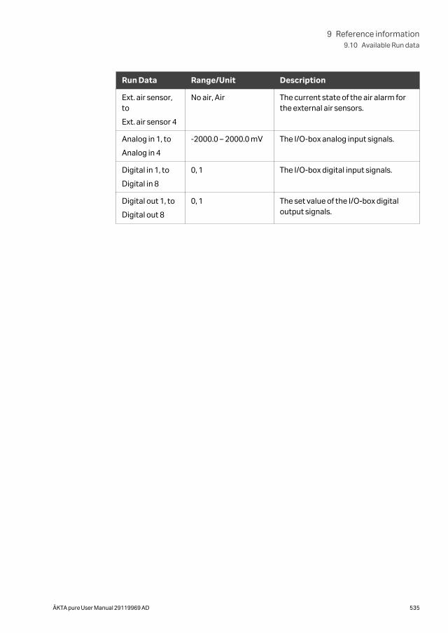
Run Data Range/Unit Description
Ext. air sensor,to
Ext. air sensor 4
No air, Air The current state of the air alarm forthe external air sensors.
Analog in 1, to
Analog in 4
-2000.0 – 2000.0 mV The I/O-box analog input signals.
Digital in 1, to
Digital in 8
0, 1 The I/O-box digital input signals.
Digital out 1, to
Digital out 8
0, 1 The set value of the I/O-box digitaloutput signals.
9 Reference information9.10 Available Run data
ÄKTA pure User Manual 29119969 AD 535
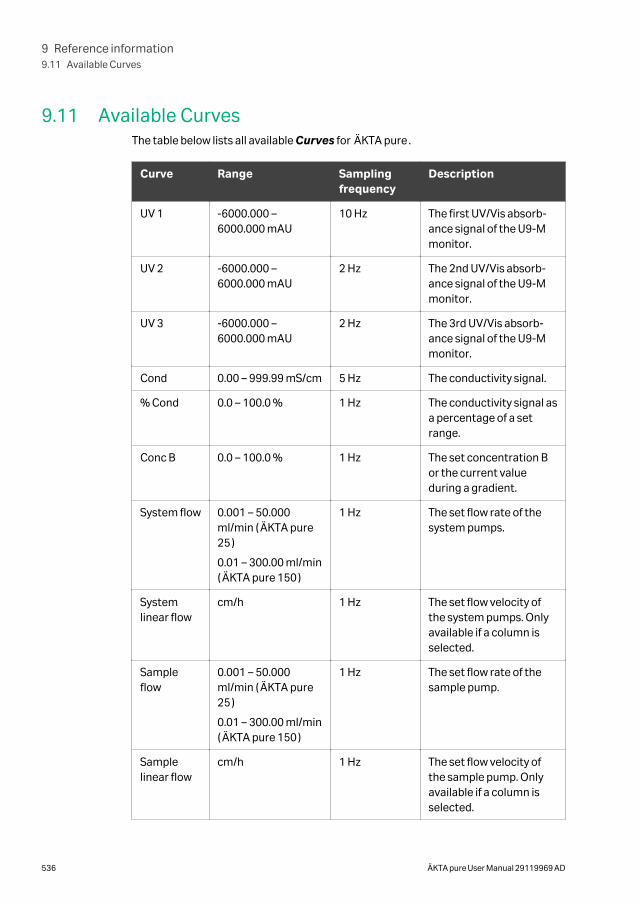
9.11 Available CurvesThe table below lists all available Curves for ÄKTA pure.
Curve Range Samplingfrequency
Description
UV 1 -6000.000 –6000.000 mAU
10 Hz The first UV/Vis absorb-ance signal of the U9-Mmonitor.
UV 2 -6000.000 –6000.000 mAU
2 Hz The 2nd UV/Vis absorb-ance signal of the U9-Mmonitor.
UV 3 -6000.000 –6000.000 mAU
2 Hz The 3rd UV/Vis absorb-ance signal of the U9-Mmonitor.
Cond 0.00 – 999.99 mS/cm 5 Hz The conductivity signal.
% Cond 0.0 – 100.0 % 1 Hz The conductivity signal asa percentage of a setrange.
Conc B 0.0 – 100.0 % 1 Hz The set concentration Bor the current valueduring a gradient.
System flow 0.001 – 50.000ml/min (ÄKTA pure25)
0.01 – 300.00 ml/min(ÄKTA pure 150)
1 Hz The set flow rate of thesystem pumps.
Systemlinear flow
cm/h 1 Hz The set flow velocity ofthe system pumps. Onlyavailable if a column isselected.
Sampleflow
0.001 – 50.000ml/min (ÄKTA pure25)
0.01 – 300.00 ml/min(ÄKTA pure 150)
1 Hz The set flow rate of thesample pump.
Samplelinear flow
cm/h 1 Hz The set flow velocity ofthe sample pump. Onlyavailable if a column isselected.
9 Reference information9.11 Available Curves
536 ÄKTA pure User Manual 29119969 AD
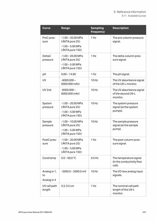
Curve Range Samplingfrequency
Description
PreC pres-sure
-1.00 – 20.00 MPa(ÄKTA pure 25)
-1.00 – 5.00 MPa(ÄKTA pure 150)
1 Hz The pre-column pressuresignal.
DeltaCpressure
-1.00 – 20.00 MPa(ÄKTA pure 25)
-1.00 – 5.00 MPa(ÄKTA pure 150)
1 Hz The delta-column pres-sure signal.
pH 0.00 – 14.00 1 Hz The pH signal.
UV -6000.000 –6000.000 mAU
10 Hz The UV absorbance signalof the U9-L monitor.
UV 2nd -6000.000 –6000.000 mAU
10 Hz The UV absorbance signalof the second U9-Lmonitor.
Systempressure
-1.00 – 20.00 MPa(ÄKTA pure 25)
-1.00 – 5.00 MPa(ÄKTA pure 150)
10 Hz The system pressuresignal (at the systempumps).
Samplepressure
-1.00 – 10.00 MPa(ÄKTA pure 25)
-1.00 – 5.00 MPa(ÄKTA pure 150)
10 Hz The sample pressuresignal (at the samplepump).
PostC pres-sure
-1.00 – 20.00 MPa(ÄKTA pure 25)
-1.00 – 5.00 MPa(ÄKTA pure 150)
1 Hz The post-column pres-sure signal.
Cond temp 0.0 – 99.0 °C 0.5 Hz The temperature signal(in the conductivity flowcell).
Analog in 1,to
Analog in 4
-2000.0 – 2000.0 mV 10 Hz The I/O-box analog inputsignals.
UV cell pathlength
0.2, 0.5 cm 1 Hz The nominal cell pathlength of the U9-Lmonitor.
9 Reference information9.11 Available Curves
ÄKTA pure User Manual 29119969 AD 537
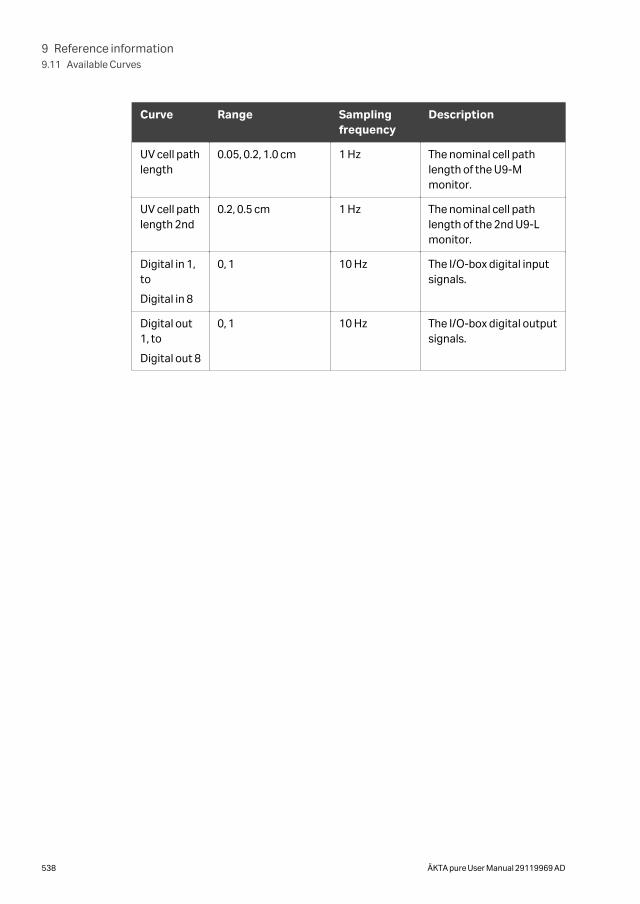
Curve Range Samplingfrequency
Description
UV cell pathlength
0.05, 0.2, 1.0 cm 1 Hz The nominal cell pathlength of the U9-Mmonitor.
UV cell pathlength 2nd
0.2, 0.5 cm 1 Hz The nominal cell pathlength of the 2nd U9-Lmonitor.
Digital in 1,to
Digital in 8
0, 1 10 Hz The I/O-box digital inputsignals.
Digital out1, to
Digital out 8
0, 1 10 Hz The I/O-box digital outputsignals.
9 Reference information9.11 Available Curves
538 ÄKTA pure User Manual 29119969 AD
9.12 Injection volumes and peak broadeningThe width of peaks at the fraction collector is influenced by the following:
• the properties of the column,
• the dimensions of the tubing,
• the dimensions of the modules in the flow path, and
• fluid dynamics.
Initial sample volume affects the peak width in gel filtration (GF) chromatography andother isocratic techniques. A sample zone is broadened during passage through a GFcolumn so that the sample is diluted and the resolution decreases with increasingsample volume. Sample volume does not however affect the resolution in adsorptionchromatography techniques such as affinity chromatography (AC), ion exchange chro-matography (IEX), and hydrophobic interaction chromatography (HIC) if the retentionfactor k is high.
The effect of peak broadening in the system from sample injection to peak detection(including dilution on the column) is apparent in the chromatogram from the UVmonitor, but broadening from the UV monitor to fraction collection is not visible in thechromatogram. This "hidden" effect is more pronounced for smaller peak volumes.
Narrow and short tubing reduces peak broadening. However, narrow tubing alsoincreases the back pressure. See for recommendations on tubing dimensions forprepacked columns.
9 Reference information9.12 Injection volumes and peak broadening
ÄKTA pure User Manual 29119969 AD 539
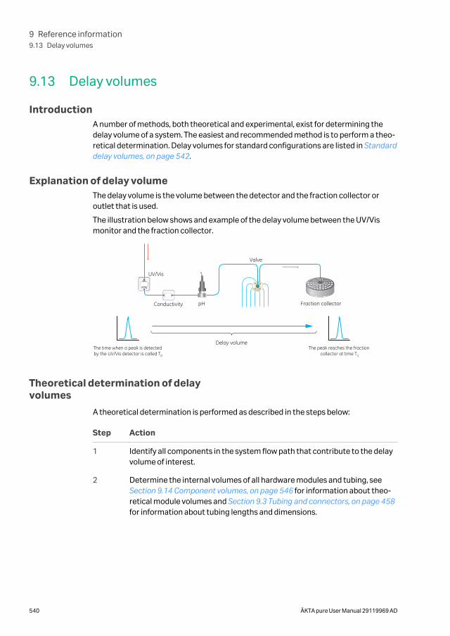
9.13 Delay volumes
IntroductionA number of methods, both theoretical and experimental, exist for determining thedelay volume of a system. The easiest and recommended method is to perform a theo-retical determination. Delay volumes for standard configurations are listed in Standarddelay volumes, on page 542.
Explanation of delay volumeThe delay volume is the volume between the detector and the fraction collector oroutlet that is used.
The illustration below shows and example of the delay volume between the UV/Vismonitor and the fraction collector.
UV/Vis
pH
Valve
The time when a peak is detected by the UV/Vis detector is called T0
The peak reaches the fraction collector at time T1
Fraction collectorConductivity
Delay volume
Theoretical determination of delayvolumes
A theoretical determination is performed as described in the steps below:
Step Action
1 Identify all components in the system flow path that contribute to the delayvolume of interest.
2 Determine the internal volumes of all hardware modules and tubing, see Section 9.14 Component volumes, on page 546 for information about theo-retical module volumes and Section 9.3 Tubing and connectors, on page 458for information about tubing lengths and dimensions.
9 Reference information9.13 Delay volumes
540 ÄKTA pure User Manual 29119969 AD
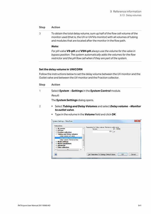
Step Action
3 To obtain the total delay volume, sum up half of the flow cell volume of themonitor used (that is, the UV or UV/Vis monitor) with all volumes of tubingand modules that are located after the monitor in the flow path.
Note:
For pH-valve V9-pH and V9H-pH always use the volume for the valve inbypass position. The system automatically adds the volumes for the flowrestrictor and the pH flow cell when if they are part of the system.
Set the delay volume in UNICORN
Follow the instructions below to set the delay volume between the UV monitor and theOutlet valve and between the UV monitor and the Fraction collector.
Step Action
1 Select System →Settings in the System Control module.
Result:
The System Settings dialog opens.
2 • Select Tubing and Delay Volumes and select Delay volume →Monitorto outlet valve.
• Type in the volume in the Volume field and click OK.
9 Reference information9.13 Delay volumes
ÄKTA pure User Manual 29119969 AD 541
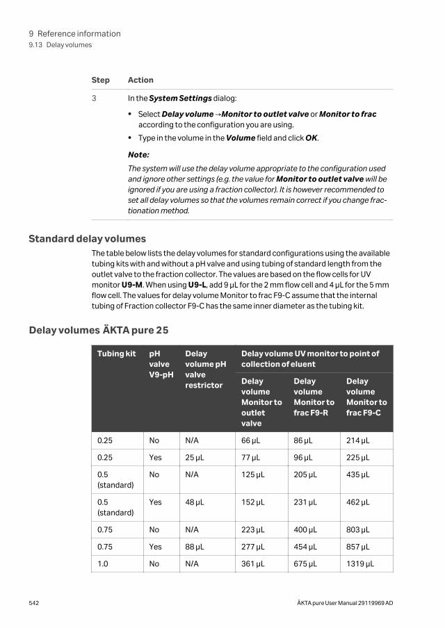
Step Action
3 In the System Settings dialog:
• Select Delay volume →Monitor to outlet valve or Monitor to fracaccording to the configuration you are using.
• Type in the volume in the Volume field and click OK.
Note:
The system will use the delay volume appropriate to the configuration usedand ignore other settings (e.g. the value for Monitor to outlet valve will beignored if you are using a fraction collector). It is however recommended toset all delay volumes so that the volumes remain correct if you change frac-tionation method.
Standard delay volumesThe table below lists the delay volumes for standard configurations using the availabletubing kits with and without a pH valve and using tubing of standard length from theoutlet valve to the fraction collector. The values are based on the flow cells for UVmonitor U9-M. When using U9-L, add 9 µL for the 2 mm flow cell and 4 µL for the 5 mmflow cell. The values for delay volume Monitor to frac F9-C assume that the internaltubing of Fraction collector F9-C has the same inner diameter as the tubing kit.
Delay volumes ÄKTA pure 25
Tubing kit pHvalveV9-pH
Delayvolume pHvalverestrictor
Delay volume UV monitor to point ofcollection of eluent
DelayvolumeMonitor tooutletvalve
DelayvolumeMonitor tofrac F9-R
DelayvolumeMonitor tofrac F9-C
0.25 No N/A 66 µL 86 µL 214 µL
0.25 Yes 25 µL 77 µL 96 µL 225 µL
0.5(standard)
No N/A 125 µL 205 µL 435 µL
0.5(standard)
Yes 48 µL 152 µL 231 µL 462 µL
0.75 No N/A 223 µL 400 µL 803 µL
0.75 Yes 88 µL 277 µL 454 µL 857 µL
1.0 No N/A 361 µL 675 µL 1319 µL
9 Reference information9.13 Delay volumes
542 ÄKTA pure User Manual 29119969 AD
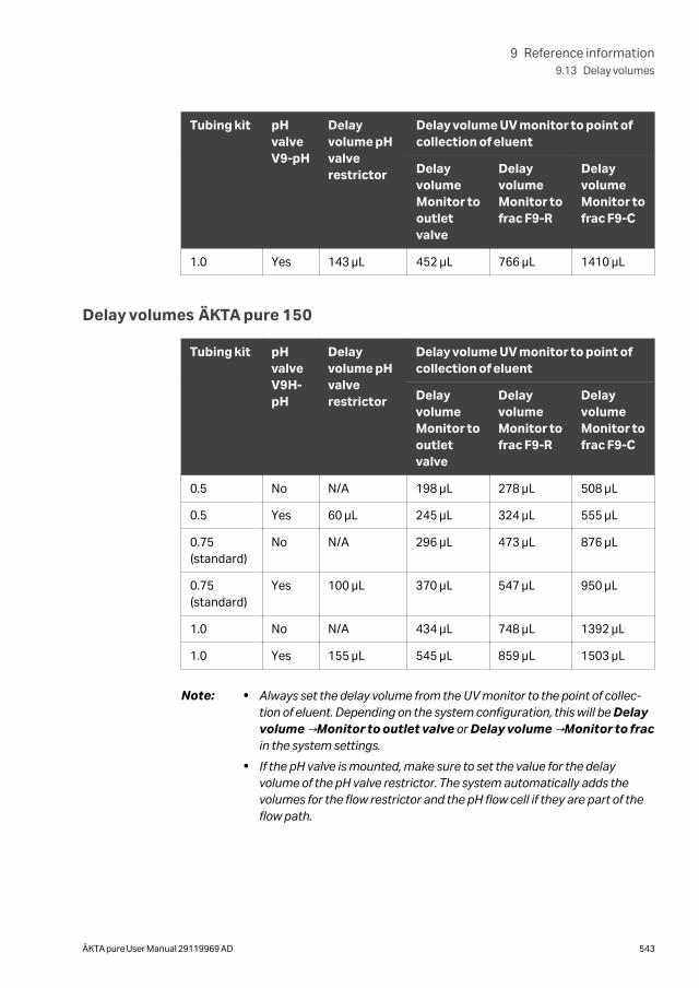
Tubing kit pHvalveV9-pH
Delayvolume pHvalverestrictor
Delay volume UV monitor to point ofcollection of eluent
DelayvolumeMonitor tooutletvalve
DelayvolumeMonitor tofrac F9-R
DelayvolumeMonitor tofrac F9-C
1.0 Yes 143 µL 452 µL 766 µL 1410 µL
Delay volumes ÄKTA pure 150
Tubing kit pHvalveV9H-pH
Delayvolume pHvalverestrictor
Delay volume UV monitor to point ofcollection of eluent
DelayvolumeMonitor tooutletvalve
DelayvolumeMonitor tofrac F9-R
DelayvolumeMonitor tofrac F9-C
0.5 No N/A 198 µL 278 µL 508 µL
0.5 Yes 60 µL 245 µL 324 µL 555 µL
0.75(standard)
No N/A 296 µL 473 µL 876 µL
0.75(standard)
Yes 100 µL 370 µL 547 µL 950 µL
1.0 No N/A 434 µL 748 µL 1392 µL
1.0 Yes 155 µL 545 µL 859 µL 1503 µL
Note: • Always set the delay volume from the UV monitor to the point of collec-tion of eluent. Depending on the system configuration, this will be Delayvolume →Monitor to outlet valve or Delay volume →Monitor to fracin the system settings.
• If the pH valve is mounted, make sure to set the value for the delayvolume of the pH valve restrictor. The system automatically adds thevolumes for the flow restrictor and the pH flow cell if they are part of theflow path.
9 Reference information9.13 Delay volumes
ÄKTA pure User Manual 29119969 AD 543
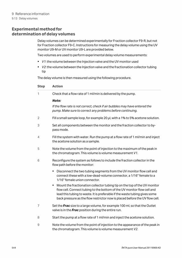
Experimental method fordetermination of delay volumes
Delay volumes can be determined experimentally for Fraction collector F9-R, but notfor Fraction collector F9-C. Instructions for measuring the delay volume using the UVmonitor U9-M or UV monitor U9-L are provided below.
Two volumes are used to perform experimental delay volume measurements:
• V1: the volume between the Injection valve and the UV monitor used
• V2: the volume between the Injection valve and the fractionation collector tubingtip
The delay volume is then measured using the following procedure.
Step Action
1 Check that a flow rate of 1 ml/min is delivered by the pump.
Note:
If the flow rate is not correct, check if air bubbles may have entered thepump. Make sure to correct any problems before continuing.
2 Fill a small sample loop, for example 20 μl, with a 1% to 5% acetone solution.
3 Set all components between the monitor and the fraction collector to by-pass mode.
4 Fill the system with water. Run the pump at a flow rate of 1 ml/min and injectthe acetone solution as a sample.
5 Note the volume from the point of injection to the maximum of the peak inthe chromatogram. This volume is volume measurement V1.
6 Reconfigure the system as follows to include the fraction collector in theflow path before the monitor:
• Disconnect the two tubing segments from the UV monitor flow cell andconnect these with a low-dead-volume connector, a 1/16'' female to a1/16'' female union connector.
• Mount the fractionation collector tubing tip on the top of the UV monitorflow cell. Connect tubing to the bottom of the UV monitor flow cell andlead this tubing to waste. It is preferable if the waste tubing gives someback pressure as the flow restrictor now is placed before the UV flow cell.
7 Set the Frac size to a large volume, for example 100 ml, so that the Outletvalve is in the Frac position during the entire run.
8 Start the pump at a flow rate of 1 ml/min and inject the acetone solution.
9 Note the volume from the point of injection to the appearance of the peak inthe chromatogram. This volume is volume measurement V2.
9 Reference information9.13 Delay volumes
544 ÄKTA pure User Manual 29119969 AD
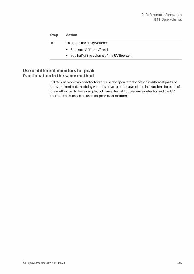
Step Action
10 To obtain the delay volume:
• Subtract V1 from V2 and
• add half of the volume of the UV flow cell.
Use of different monitors for peakfractionation in the same method
If different monitors or detectors are used for peak fractionation in different parts ofthe same method, the delay volumes have to be set as method instructions for each ofthe method parts. For example, both an external fluorescence detector and the UVmonitor module can be used for peak fractionation.
9 Reference information9.13 Delay volumes
ÄKTA pure User Manual 29119969 AD 545
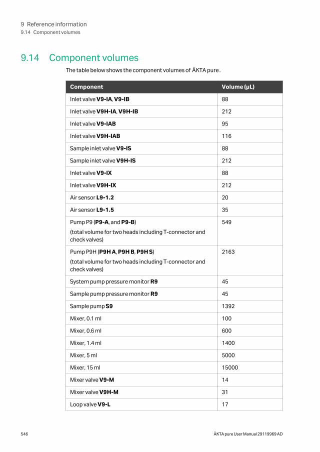
9.14 Component volumesThe table below shows the component volumes of ÄKTA pure.
Component Volume (μL)
Inlet valve V9-IA, V9-IB 88
Inlet valve V9H-IA, V9H-IB 212
Inlet valve V9-IAB 95
Inlet valve V9H-IAB 116
Sample inlet valve V9-IS 88
Sample inlet valve V9H-IS 212
Inlet valve V9-IX 88
Inlet valve V9H-IX 212
Air sensor L9-1.2 20
Air sensor L9-1.5 35
Pump P9 (P9-A, and P9-B)
(total volume for two heads including T-connector andcheck valves)
549
Pump P9H (P9H A, P9H B, P9H S)
(total volume for two heads including T-connector andcheck valves)
2163
System pump pressure monitor R9 45
Sample pump pressure monitor R9 45
Sample pump S9 1392
Mixer, 0.1 ml 100
Mixer, 0.6 ml 600
Mixer, 1.4 ml 1400
Mixer, 5 ml 5000
Mixer, 15 ml 15000
Mixer valve V9-M 14
Mixer valve V9H-M 31
Loop valve V9-L 17
9 Reference information9.14 Component volumes
546 ÄKTA pure User Manual 29119969 AD
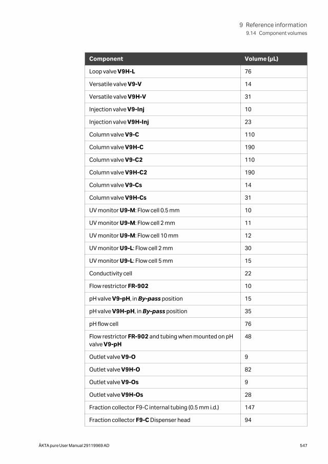
Component Volume (μL)
Loop valve V9H-L 76
Versatile valve V9-V 14
Versatile valve V9H-V 31
Injection valve V9-Inj 10
Injection valve V9H-Inj 23
Column valve V9-C 110
Column valve V9H-C 190
Column valve V9-C2 110
Column valve V9H-C2 190
Column valve V9-Cs 14
Column valve V9H-Cs 31
UV monitor U9-M: Flow cell 0.5 mm 10
UV monitor U9-M: Flow cell 2 mm 11
UV monitor U9-M: Flow cell 10 mm 12
UV monitor U9-L: Flow cell 2 mm 30
UV monitor U9-L: Flow cell 5 mm 15
Conductivity cell 22
Flow restrictor FR-902 10
pH valve V9-pH, in By-pass position 15
pH valve V9H-pH, in By-pass position 35
pH flow cell 76
Flow restrictor FR-902 and tubing when mounted on pHvalve V9-pH
48
Outlet valve V9-O 9
Outlet valve V9H-O 82
Outlet valve V9-Os 9
Outlet valve V9H-Os 28
Fraction collector F9-C internal tubing (0.5 mm i.d.) 147
Fraction collector F9-C Dispenser head 94
9 Reference information9.14 Component volumes
ÄKTA pure User Manual 29119969 AD 547

Note: The given values for the component volumes of the valves are averagevalues. Depending on the chosen flow path the actual component volumemay differ somewhat.
9 Reference information9.14 Component volumes
548 ÄKTA pure User Manual 29119969 AD
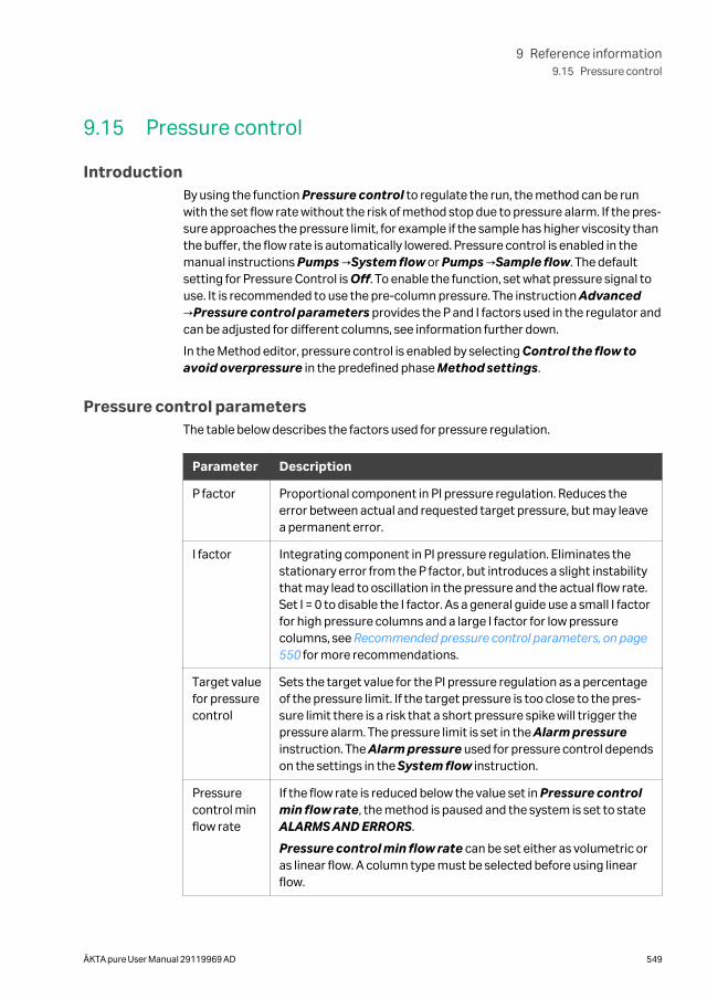
9.15 Pressure control
IntroductionBy using the function Pressure control to regulate the run, the method can be runwith the set flow rate without the risk of method stop due to pressure alarm. If the pres-sure approaches the pressure limit, for example if the sample has higher viscosity thanthe buffer, the flow rate is automatically lowered. Pressure control is enabled in themanual instructions Pumps →System flow or Pumps →Sample flow. The defaultsetting for Pressure Control is Off. To enable the function, set what pressure signal touse. It is recommended to use the pre-column pressure. The instruction Advanced→Pressure control parameters provides the P and I factors used in the regulator andcan be adjusted for different columns, see information further down.
In the Method editor, pressure control is enabled by selecting Control the flow toavoid overpressure in the predefined phase Method settings.
Pressure control parametersThe table below describes the factors used for pressure regulation.
Parameter Description
P factor Proportional component in PI pressure regulation. Reduces theerror between actual and requested target pressure, but may leavea permanent error.
I factor Integrating component in PI pressure regulation. Eliminates thestationary error from the P factor, but introduces a slight instabilitythat may lead to oscillation in the pressure and the actual flow rate.Set I = 0 to disable the I factor. As a general guide use a small I factorfor high pressure columns and a large I factor for low pressurecolumns, see Recommended pressure control parameters, on page550 for more recommendations.
Target valuefor pressurecontrol
Sets the target value for the PI pressure regulation as a percentageof the pressure limit. If the target pressure is too close to the pres-sure limit there is a risk that a short pressure spike will trigger thepressure alarm. The pressure limit is set in the Alarm pressureinstruction. The Alarm pressure used for pressure control dependson the settings in the System flow instruction.
Pressurecontrol minflow rate
If the flow rate is reduced below the value set in Pressure controlmin flow rate, the method is paused and the system is set to stateALARMS AND ERRORS.
Pressure control min flow rate can be set either as volumetric oras linear flow. A column type must be selected before using linearflow.
9 Reference information9.15 Pressure control
ÄKTA pure User Manual 29119969 AD 549
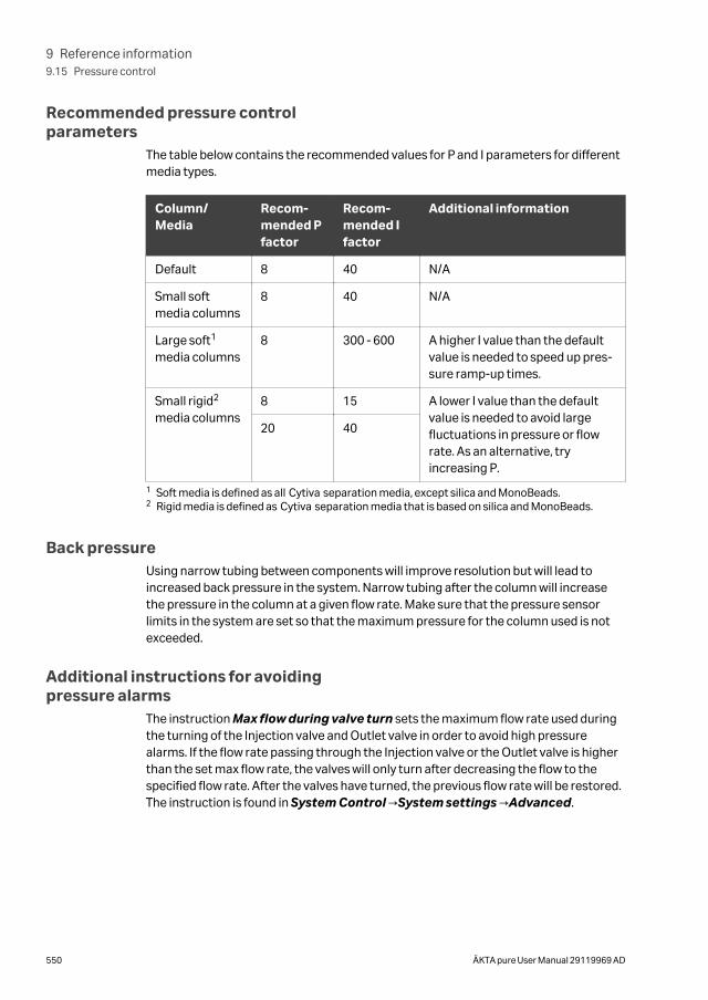
Recommended pressure controlparameters
The table below contains the recommended values for P and I parameters for differentmedia types.
Column/Media
Recom-mended Pfactor
Recom-mended Ifactor
Additional information
Default 8 40 N/A
Small softmedia columns
8 40 N/A
Large soft1
media columns8 300 - 600 A higher I value than the default
value is needed to speed up pres-sure ramp-up times.
Small rigid2
media columns8 15 A lower I value than the default
value is needed to avoid largefluctuations in pressure or flowrate. As an alternative, tryincreasing P.
20 40
1 Soft media is defined as all Cytiva separation media, except silica and MonoBeads.2 Rigid media is defined as Cytiva separation media that is based on silica and MonoBeads.
Back pressureUsing narrow tubing between components will improve resolution but will lead toincreased back pressure in the system. Narrow tubing after the column will increasethe pressure in the column at a given flow rate. Make sure that the pressure sensorlimits in the system are set so that the maximum pressure for the column used is notexceeded.
Additional instructions for avoidingpressure alarms
The instruction Max flow during valve turn sets the maximum flow rate used duringthe turning of the Injection valve and Outlet valve in order to avoid high pressurealarms. If the flow rate passing through the Injection valve or the Outlet valve is higherthan the set max flow rate, the valves will only turn after decreasing the flow to thespecified flow rate. After the valves have turned, the previous flow rate will be restored.The instruction is found in System Control →System settings →Advanced.
9 Reference information9.15 Pressure control
550 ÄKTA pure User Manual 29119969 AD
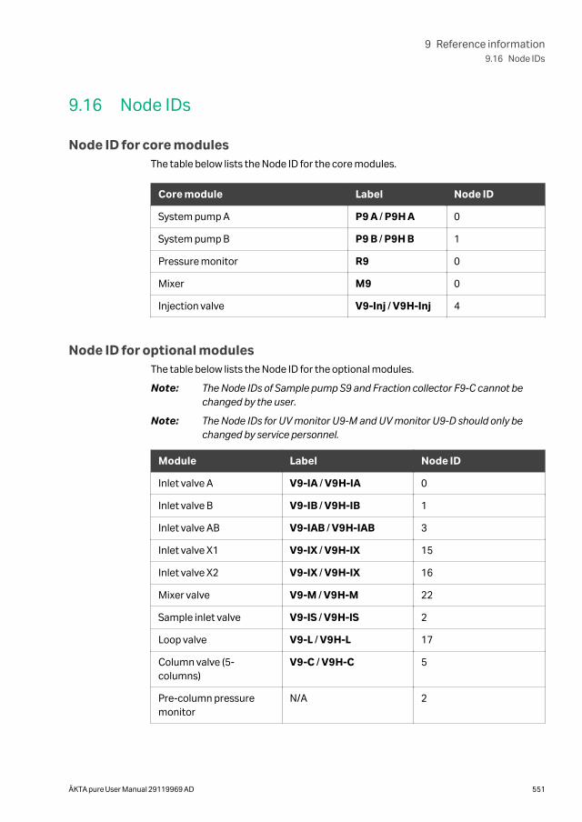
9.16 Node IDs
Node ID for core modulesThe table below lists the Node ID for the core modules.
Core module Label Node ID
System pump A P9 A / P9H A 0
System pump B P9 B / P9H B 1
Pressure monitor R9 0
Mixer M9 0
Injection valve V9-Inj / V9H-Inj 4
Node ID for optional modulesThe table below lists the Node ID for the optional modules.
Note: The Node IDs of Sample pump S9 and Fraction collector F9-C cannot bechanged by the user.
Note: The Node IDs for UV monitor U9-M and UV monitor U9-D should only bechanged by service personnel.
Module Label Node ID
Inlet valve A V9-IA / V9H-IA 0
Inlet valve B V9-IB / V9H-IB 1
Inlet valve AB V9-IAB / V9H-IAB 3
Inlet valve X1 V9-IX / V9H-IX 15
Inlet valve X2 V9-IX / V9H-IX 16
Mixer valve V9-M / V9H-M 22
Sample inlet valve V9-IS / V9H-IS 2
Loop valve V9-L / V9H-L 17
Column valve (5-columns)
V9-C / V9H-C 5
Pre-column pressuremonitor
N/A 2
9 Reference information9.16 Node IDs
ÄKTA pure User Manual 29119969 AD 551
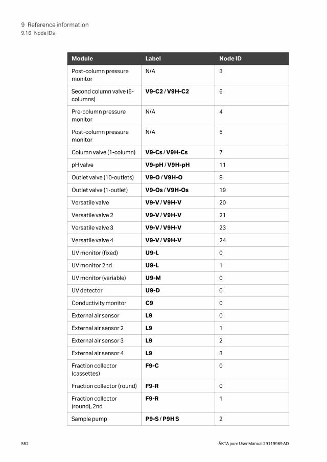
Module Label Node ID
Post-column pressuremonitor
N/A 3
Second column valve (5-columns)
V9-C2 / V9H-C2 6
Pre-column pressuremonitor
N/A 4
Post-column pressuremonitor
N/A 5
Column valve (1-column) V9-Cs / V9H-Cs 7
pH valve V9-pH / V9H-pH 11
Outlet valve (10-outlets) V9-O / V9H-O 8
Outlet valve (1-outlet) V9-Os / V9H-Os 19
Versatile valve V9-V / V9H-V 20
Versatile valve 2 V9-V / V9H-V 21
Versatile valve 3 V9-V / V9H-V 23
Versatile valve 4 V9-V / V9H-V 24
UV monitor (fixed) U9-L 0
UV monitor 2nd U9-L 1
UV monitor (variable) U9-M 0
UV detector U9-D 0
Conductivity monitor C9 0
External air sensor L9 0
External air sensor 2 L9 1
External air sensor 3 L9 2
External air sensor 4 L9 3
Fraction collector(cassettes)
F9-C 0
Fraction collector (round) F9-R 0
Fraction collector(round), 2nd
F9-R 1
Sample pump P9-S / P9H S 2
9 Reference information9.16 Node IDs
552 ÄKTA pure User Manual 29119969 AD
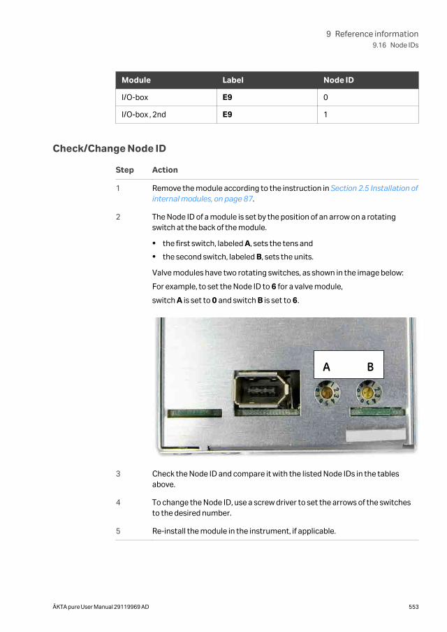
Module Label Node ID
I/O-box E9 0
I/O-box , 2nd E9 1
Check/Change Node ID
Step Action
1 Remove the module according to the instruction in Section 2.5 Installation ofinternal modules, on page 87.
2 The Node ID of a module is set by the position of an arrow on a rotatingswitch at the back of the module.
• the first switch, labeled A, sets the tens and
• the second switch, labeled B, sets the units.
Valve modules have two rotating switches, as shown in the image below:
For example, to set the Node ID to 6 for a valve module,
switch A is set to 0 and switch B is set to 6.
A B
3 Check the Node ID and compare it with the listed Node IDs in the tablesabove.
4 To change the Node ID, use a screw driver to set the arrows of the switchesto the desired number.
5 Re-install the module in the instrument, if applicable.
9 Reference information9.16 Node IDs
ÄKTA pure User Manual 29119969 AD 553
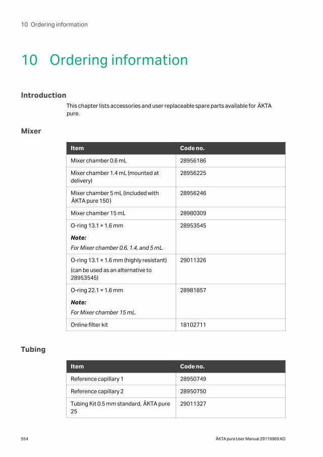
10 Ordering information
IntroductionThis chapter lists accessories and user replaceable spare parts available for ÄKTApure.
Mixer
Item Code no.
Mixer chamber 0.6 mL 28956186
Mixer chamber 1.4 mL (mounted atdelivery)
28956225
Mixer chamber 5 mL (included withÄKTA pure 150)
28956246
Mixer chamber 15 mL 28980309
O-ring 13.1 × 1.6 mm
Note:
For Mixer chamber 0.6, 1.4, and 5 mL.
28953545
O-ring 13.1 × 1.6 mm (highly resistant)
(can be used as an alternative to28953545)
29011326
O-ring 22.1 × 1.6 mm
Note:
For Mixer chamber 15 mL.
28981857
Online filter kit 18102711
Tubing
Item Code no.
Reference capillary 1 28950749
Reference capillary 2 28950750
Tubing Kit 0.5 mm standard, ÄKTA pure25
29011327
10 Ordering information
554 ÄKTA pure User Manual 29119969 AD

Item Code no.
Tubing Kit 0.5 mm, ÄKTA pure 150 29051669
Tubing Kit 0.25 mm, ÄKTA pure 25 29011328
Tubing Kit 0.75 mm, ÄKTA pure 25 29011329
Tubing Kit 0.75 mm standard, ÄKTApure 150
29048242
Tubing Kit 1.0 mm 29032426
Tubing kit 10×1.0 m, ETFE ID 1.0 mm OD1/16
28980995
Tubing kit for sample inlet valve V9-IS(7-ports)
29035331
Tubing kit for sample inlet valve V9H-IS(7-ports)
29051166
Sample tubing kit for 7 inlets, i.d. 0.75mm
28957217
Inlet tubing kit 2+2 29011330
V9-pH tubing kit 29011331
V9H-pH tubing kit standard 29051674
Tubing kit for inlet valve V9-IA (7 ports) 29011332
Tubing kit for inlet valve V9H-IA (7ports)
29051197
Tubing kit for inlet valve V9-IB (7 ports) 29011333
Tubing kit for inlet valve V9H-IB (7 ports) 29051189
Outlet tubing kit, ÄKTA pure 25 29011334
Outlet tubing kit, ÄKTA pure 150 29048611
Rinse system tubing 29011348
Union 1/16 male/male, i.d. 0.5 mm (5-pack)
28954326
Tubing cutter 18111246
Inlet filter holder kit 11000407
Inlet filter set 11000414
10 Ordering information
ÄKTA pure User Manual 29119969 AD 555
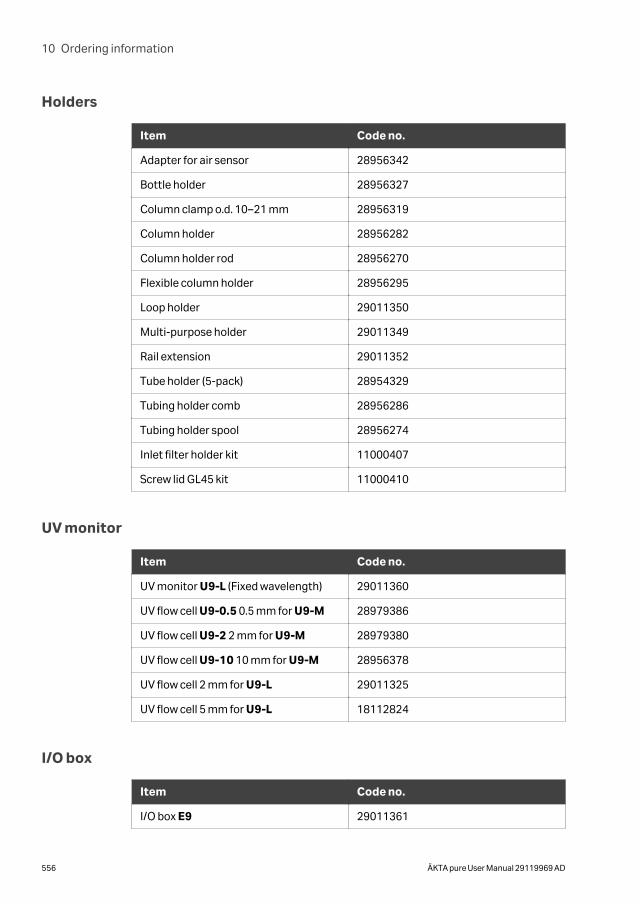
Holders
Item Code no.
Adapter for air sensor 28956342
Bottle holder 28956327
Column clamp o.d. 10–21 mm 28956319
Column holder 28956282
Column holder rod 28956270
Flexible column holder 28956295
Loop holder 29011350
Multi-purpose holder 29011349
Rail extension 29011352
Tube holder (5-pack) 28954329
Tubing holder comb 28956286
Tubing holder spool 28956274
Inlet filter holder kit 11000407
Screw lid GL45 kit 11000410
UV monitor
Item Code no.
UV monitor U9-L (Fixed wavelength) 29011360
UV flow cell U9-0.5 0.5 mm for U9-M 28979386
UV flow cell U9-2 2 mm for U9-M 28979380
UV flow cell U9-10 10 mm for U9-M 28956378
UV flow cell 2 mm for U9-L 29011325
UV flow cell 5 mm for U9-L 18112824
I/O box
Item Code no.
I/O box E9 29011361
10 Ordering information
556 ÄKTA pure User Manual 29119969 AD
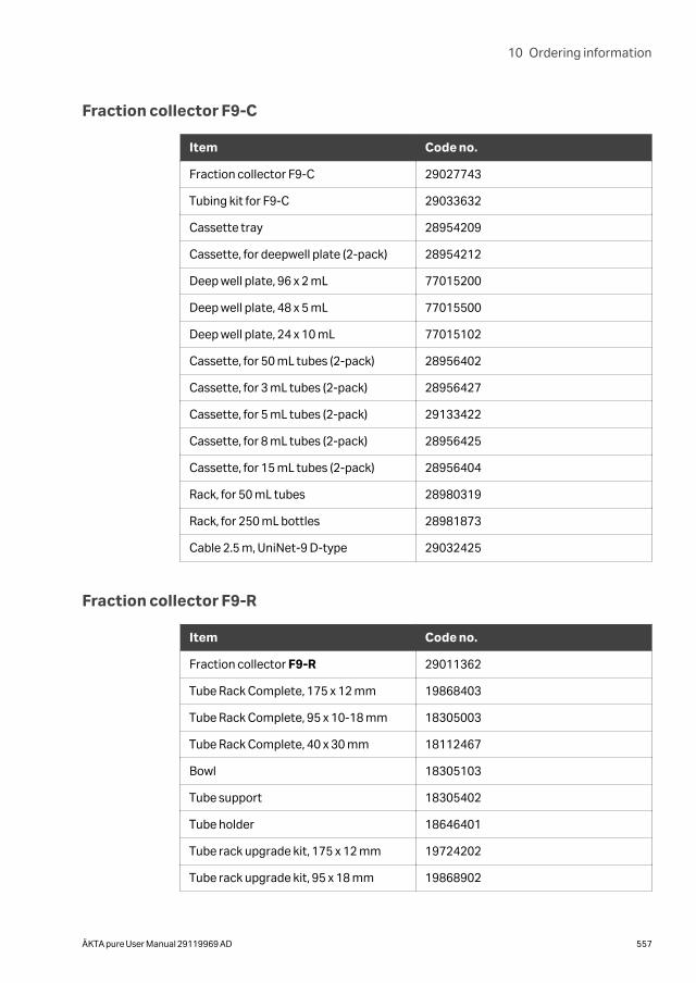
Fraction collector F9-C
Item Code no.
Fraction collector F9-C 29027743
Tubing kit for F9-C 29033632
Cassette tray 28954209
Cassette, for deepwell plate (2-pack) 28954212
Deep well plate, 96 x 2 mL 77015200
Deep well plate, 48 x 5 mL 77015500
Deep well plate, 24 x 10 mL 77015102
Cassette, for 50 mL tubes (2-pack) 28956402
Cassette, for 3 mL tubes (2-pack) 28956427
Cassette, for 5 mL tubes (2-pack) 29133422
Cassette, for 8 mL tubes (2-pack) 28956425
Cassette, for 15 mL tubes (2-pack) 28956404
Rack, for 50 mL tubes 28980319
Rack, for 250 mL bottles 28981873
Cable 2.5 m, UniNet-9 D-type 29032425
Fraction collector F9-R
Item Code no.
Fraction collector F9-R 29011362
Tube Rack Complete, 175 x 12 mm 19868403
Tube Rack Complete, 95 x 10-18 mm 18305003
Tube Rack Complete, 40 x 30 mm 18112467
Bowl 18305103
Tube support 18305402
Tube holder 18646401
Tube rack upgrade kit, 175 x 12 mm 19724202
Tube rack upgrade kit, 95 x 18 mm 19868902
10 Ordering information
ÄKTA pure User Manual 29119969 AD 557
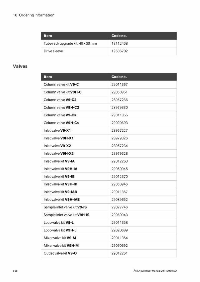
Item Code no.
Tube rack upgrade kit, 40 x 30 mm 18112468
Drive sleeve 19606702
Valves
Item Code no.
Column valve kit V9-C 29011367
Column valve kit V9H-C 29050951
Column valve V9-C2 28957236
Column valve V9H-C2 28979330
Column valve V9-Cs 29011355
Column valve V9H-Cs 29090693
Inlet valve V9-X1 28957227
Inlet valve V9H-X1 28979326
Inlet valve V9-X2 28957234
Inlet valve V9H-X2 28979328
Inlet valve kit V9-IA 29012263
Inlet valve kit V9H-IA 29050945
Inlet valve kit V9-IB 29012370
Inlet valve kit V9H-IB 29050946
Inlet valve kit V9-IAB 29011357
Inlet valve kit V9H-IAB 29089652
Sample inlet valve kit V9-IS 29027746
Sample inlet valve kit V9H-IS 29050943
Loop valve kit V9-L 29011358
Loop valve kit V9H-L 29090689
Mixer valve kit V9-M 29011354
Mixer valve kit V9H-M 29090692
Outlet valve kit V9-O 29012261
10 Ordering information
558 ÄKTA pure User Manual 29119969 AD
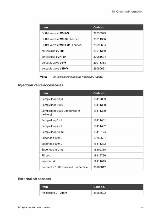
Item Code no.
Outlet valve kit V9H-O 29050949
Outlet valve kit V9-Os (1 outlet) 29011356
Outlet valve kit V9H-Os (1 outlet) 29090694
pH valve kit V9-pH 29011359
pH valve kit V9H-pH 29051684
Versatile valve V9-V 29011353
Versatile valve V9H-V 29090691
Note: All valve kits include the necessary tubing.
Injection valve accessories
Item Code no.
Sample loop 10 µL 18112039
Sample loop 100 µL 18111398
Sample loop 500 µL (mounted atdelivery)
18111399
Sample loop 1 mL 18111401
Sample loop 2 mL 18111402
Sample loop 10 mL 18116124
Superloop 10 mL 19758501
Superloop 50 mL 18111382
Superloop 150 mL 18102385
Fill port 18112766
Injection kit 18111089
Connector 1/16" male and Luer female 28985812
External air sensors
Item Code no.
Air sensor L9-1.2 mm 28956502
10 Ordering information
ÄKTA pure User Manual 29119969 AD 559
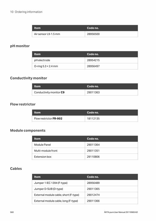
Item Code no.
Air sensor L9-1.5 mm 28956500
pH monitor
Item Code no.
pH electrode 28954215
O-ring 5.3 × 2.4 mm 28956497
Conductivity monitor
Item Code no.
Conductivity monitor C9 29011363
Flow restrictor
Item Code no.
Flow restrictor FR-902 18112135
Module components
Item Code no.
Module Panel 29011364
Multi-module front 29011351
Extension box 29110806
Cables
Item Code no.
Jumper 1 IEC 1394 (F-type) 28956489
Jumper D-SUB (D-type) 29011365
External module cable, short (F-type) 29012474
External module cable, long (F-type) 29011366
10 Ordering information
560 ÄKTA pure User Manual 29119969 AD
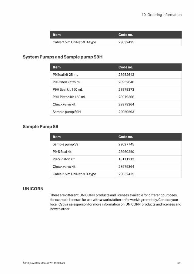
Item Code no.
Cable 2.5 m UniNet-9 D-type 29032425
System Pumps and Sample pump S9H
Item Code no.
P9 Seal kit 25 mL 28952642
P9 Piston kit 25 mL 28952640
P9H Seal kit 150 mL 28979373
P9H Piston kit 150 mL 28979368
Check valve kit 28979364
Sample pump S9H 29050593
Sample Pump S9
Item Code no.
Sample pump S9 29027745
P9-S Seal kit 28960250
P9-S Piston kit 18111213
Check valve kit 28979364
Cable 2.5 m UniNet-9 D-type 29032425
UNICORNThere are different UNICORN products and licenses available for different purposes,for example licenses for use with a workstation or for working remotely. Contact yourlocal Cytiva salesperson for more information on UNICORN products and licenses andhow to order.
10 Ordering information
ÄKTA pure User Manual 29119969 AD 561
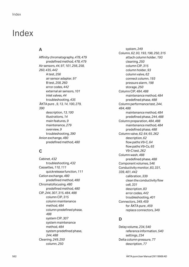
Index
A
Affinity chromatography, 478, 479predefined method, 478, 479
Air sensors, 44, 97, 101, 256, 258,260, 435, 442
A test, 256air sensor adapter, 97B test, 258, 260error codes, 442external air sensors, 101inlet valves, 44troubleshooting, 435
ÄKTA pure , 9, 13, 14, 100, 279,390
description, 13, 100illustrations, 14main features, 9maintenance, 279overview, 9troubleshooting, 390
Anion exchange, 480predefined method, 480
C
Cabinet, 432troubleshooting, 432
Cassettes, 110, 111quickrelease function, 111
Cation exchange, 480predefined method, 480
Chromatofocusing, 480predefined method, 480
CIP, 244, 307, 315, 484, 488column CIP, 315column maintenancemethod, 484column predefined phase,488system CIP, 307system maintenancemethod, 484system predefined phase,244, 488
Cleaning, 249, 250column, 250
system, 249Column, 62, 93, 193, 198, 250, 315
attach column holder, 193cleaning, 250column CIP, 315column holder, 93column valve, 62connect column, 193pressure alarm, 198storage, 250
Column CIP, 484, 488maintenance method, 484predefined phase, 488
Column performance test, 244,484, 488
maintenance method, 484predefined phase, 244, 488
Column preparation, 484, 488maintenance method, 484predefined phase, 488
Column valve, 62, 64, 65, 262description, 62flow paths V9-C, 64flow paths V9-Cs, 65V9-C test, 262
Column wash, 488predefined phase, 488
Component volumes, 546Conductivity monitor, 83, 331,339, 401, 442
calibration, 339clean the conductivity flowcell, 331description, 83error codes, 442troubleshooting, 401
Connectors, 349, 459for ÄKTA pure, 459replace connectors, 349
D
Delay volume, 234, 540reference information, 540settings, 234
Delta column pressure, 77description, 77
Index
562 ÄKTA pure User Manual 29119969 AD
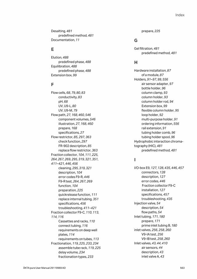
Desalting, 481predefined method, 481
Documentation, 11
E
Elution, 488predefined phase, 488
Equilibration, 488predefined phase, 488
Extension box, 99
F
Flow cells, 68, 79, 80, 83conductivity, 83pH, 68UV, U9-L, 80UV, U9-M, 79
Flow path, 27, 168, 460, 546component volumes, 546illustration, 27, 168, 460prepare, 168specifications, 27
Flow restrictor, 85, 297, 363check function, 297FR-902 description, 85replace flow restrictor, 363
Fraction collector, 104, 111, 225,264, 267, 269, 295, 319, 321, 351,411–421, 446, 456
cleaning, 295, 319, 321description, 104error codes F9-R, 446F9-R test, 264, 267, 269function, 104preparation, 225quickrelease function, 111replace internal tubing, 351specifications, 456troubleshooting, 411–421
Fraction collector F9-C, 110, 113,114, 116
Cassettes and racks, 110connect tubing, 116requirements on deep wellplates, 114requirements on tubes, 113
Fractionation, 119, 225, 233, 234assemble tube rack, 119, 225delay volume, 234fractionation types, 233
prepare, 225
G
Gel filtration, 481predefined method, 481
H
Hardware installation, 87of a module, 87
Holders, 91–97, 99, 556air sensor adapter, 97bottle holder, 96column clamp, 93column holder, 93column holder rod, 94Extension box, 99flexible column holder, 95loop holder, 92multi-purpose holder, 91ordering information, 556rail extension, 91tubing holder comb, 96tubing holder spool, 96
Hydrophobic interaction chroma-tography (HIC), 481
predefined method, 481
I
I/O-box E9, 127, 128, 435, 446, 457connectors, 128description, 127error codes, 446Fraction collector F9-Cinstallation, 127specifications, 457troubleshooting, 435
Injection valve, 54description, 54flow paths, 54
Inlet tubing, 171, 180prepare, 171prime inlet tubing B, 180
inlet valves, 256, 258, 260V9-IA test, 256V9-IB test, 258, 260
Inlet valves, 43, 44, 410air sensors, 44description, 43inlet valve A, 43
Index
ÄKTA pure User Manual 29119969 AD 563
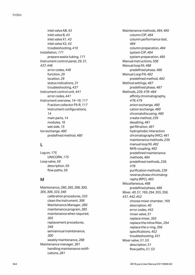
inlet valve AB, 43inlet valve B, 43inlet valve X1, 43inlet valve X2, 43troubleshooting, 410
Installation, 171prepare waste tubing, 171
Instrument control panel, 29, 31,437, 446
error codes, 446function, 29location, 29status indications, 31troubleshooting, 437
Instrument control unit, 441error codes, 441
Instrument overview, 14–16, 117Fraction collector F9-R, 117Instrument configurations,14main parts, 14modules, 16wet side, 15
Ion exchange, 480predefined method, 480
L
Log on, 175UNICORN, 175
Loop valve, 59description, 59flow paths, 59
M
Maintenance, 280, 285, 288, 300,305, 306, 333, 348
calibration procedures, 333clean the instrument, 306Maintenance Manager, 280maintenance program, 285maintenance when required,305replacement procedures,348semiannual maintenance,300weekly maintenance, 288
Maintenance manager, 281handling maintenance notifi-cations, 281
Maintenance methods, 484, 485column CIP, 484column performance test,484column preparation, 484system CIP, 484system preparation, 485
Manual instructions, 508Manual loop fill, 488
predefined phase, 488Manual Loop Fill, 482
predefined method, 482Method settings, 487
predefined phase, 487Methods, 239, 478–484
affinity chromatography,478, 479anion exchange, 480cation exchange, 480chromatofocusing, 480create method, 239desalting, 481gel filtration, 481hydrophobic interactionchromatography (HIC), 481maintenance methods, 239manual loop fill, 482NHS-coupling, 482predefined maintenancemethods, 484predefined methods, 239,478purification methods, 239reverse phase chromatog-raphy (RPC), 483
Miscellaneous, 488predefined phase, 488
Mixer, 40, 51, 169, 294, 355, 356,431, 442, 452
choose mixer chamber, 169description, 40error codes, 442mixer valve, 51replace mixer, 355replace the inline filter, 294replace the o-ring, 356specifications, 452troubleshooting, 431
Mixer valve, 51, 53description, 51flow paths, 51, 53
Index
564 ÄKTA pure User Manual 29119969 AD
Module panel, 97, 410description, 97troubleshooting, 410
Module Panel Assembly, 141Modules, 36, 40, 43, 51, 54, 59, 62,67, 68, 73, 76, 79, 83, 85, 121, 140
column valve, 62conductivity monitor, 83flow restrictor, 85injection valve, 54inlet valves, 43loop valve, 59mixer, 40mixer valve, 51outlet valve, 73pH valve, 68pressure monitor, 76pumps, 36, 121recommended positions, 140UV monitor, 79versatile valve, 67
Monitors, 71, 76, 79, 83, 101, 394,454, 455
conductivity, 83external air sensors, 101pH, 71pressure monitor, 76specifications, 454, 455troubleshooting, 394UV, 79
N
NHS-coupling, 482predefined method, 482
Node ID, 87, 551, 553change Node ID, 553check Node ID, 553description, 87list, 551
O
Optional configurations, 87install optional modules, 87
Ordering information, 554–561cables, 560, 561conductivity monitor, 560dummy module, 560external air sensors, 559, 560flow restrictor, 560fraction collector, 557, 558
holders, 556I/O-box E9, 556mixer, 554pH monitor, 560pump, 561tubing, 554, 555UV monitor, 556, 557, 559valves, 558, 559
Outlet tubing, 171prepare, 171
Outlet valve, 73, 74description, 73V9-O ports, 74V9-Os ports, 74
P
Performance tests, 253, 256, 258,260, 262, 264, 267, 269, 271, 275
air sensor A and inlet valveV9-IA, 256air sensor B and inlet valveV9-IB, 258, 260column valve V9-C, 262fraction collector F9-R, 264,267, 269overview, 253UV U9-L system, 271UV U9-M system, 275
pH monitor, 71, 250, 304, 322, 324,334, 442
calibration, 334clean the pH electrode, 324description, 71error codes, 442replace the pH electrode, 304storage of the pH electrode,250, 322
pH valve, 68, 69, 410description, 68flow paths, 69troubleshooting, 410
Phases, 244, 486–488column CIP, 488column performance test,244, 488column preparation, 488column wash, 488elution, 488equilibration, 488manual loop fill, 488method settings, 487
Index
ÄKTA pure User Manual 29119969 AD 565
miscellaneous, 488predefined phases, 486sample application, 488system CIP, 244, 488system preparation, 488
Power save, 164Prepare the system, 168–172, 175,193, 201, 225
connect column, 193flow path, 168fraction collector, 225inlet tubing, 171mixer, 169outlet tubing, 171sample application, 201Start UNICORN, 175UV monitor U9-L, 171UV monitor U9-M, 170waste tubing, 172
Pressure alarm, 198set, 198
Pressure control, 248system configuration, 248
Pressure monitor, 441error codes, 441
Pressure monitors, 76, 336, 406calibration, 336check the pressure monitors,336description, 76troubleshooting, 406
Prime inlet tubing B, 180Process picture, 247
actions in the processpicture, 247
Pump piston rinsing system, 39,123, 289–292, 386, 387
flow path, 39illustration, 123, 289, 291,386, 387prime, 290, 292
Pumps, 36, 121, 180, 187, 289, 327,365, 368, 377, 385, 386, 423, 443,450
change pump rinsing solu-tion, 289clean check valves, 327description, 36description, sample pump,121error codes, 443purge sample pump, 187
purge system pumps, 180replace check valves, 365replace pump piston seals ofpump P9, 368replace pump piston seals ofPump P9-S, 377replace pump pistons, 385replace pump rinsing systemtubing, 386specifications, 450troubleshooting, 423
Q
QuickRelease function, 111
R
reference information, 539injection volumes and peakbroadening, 539
Reference information, 447, 448,450, 469, 540, 549, 550
back pressure, 550chemical resistance guide,469delay volumes, 540module specifications, 450pressure regulation, 549system specifications, 448
Reverse phase chromatography(RPC), 483
predefined method, 483Run, 245–247, 249, 532, 536
after run procedures, 249available curves, 536available run data, 532choose method, 245monitor run, 247perform manual run, 246perform run, 245prepare run, 245
S
Safety notices, 7definitions, 7
Sample application, 54, 201, 205,213, 488
flow paths, 54injection valve, 54predefined phase, 488
Index
566 ÄKTA pure User Manual 29119969 AD
sample loading, 201sample loop, 213superloop, 205
Sample loop, 213sample loading, 213
Sample pump, 121description, 121
Software overview, 10software modules, 10
Storage, 250column, 250pH electrode, 250system, 250
Superloop, 205, 432sample loading, 205troubleshooting, 432
System CIP, 244, 484, 488maintenance method, 484predefined phase, 244, 488
System cleaning, 249System configuration, 87, 140,143, 145, 248
control pressure, 248installation of modules, 87modules and positions, 140overview, 140system properties, 143system settings, 145
System Control module, 508manual instructions, 508
System preparation, 167, 485, 488before preparation, 167maintenance method, 485predefined phase, 488
System pumps, 36operating ranges, 36
System storage, 250System test, 271, 275
UV U9-L, 271UV U9-M, 275
T
Technical specifications, 450module specifications, 450
Trays, 110Troubleshooting, 394, 411–421,423, 430, 438, 441
error codes, 441fraction collector, 411Fraction collector, 411–421
instrument communication,438monitors, 394other components, 430pumps, 423
Tube rack, 119, 225assembly, 119, 225
Tubing, 349, 351, 458for ÄKTA pure, 458replace tubing, 349, 351
U
UNICORN, 175, 176connect to system, 176Log on, 175Start, 175
User information, 7UV detector U9-D, 443
error codes, 443UV monitor, 79, 156, 170, 171, 301,344, 358, 361
calibration, 170, 171, 344clean UV flow cell, 301description, 79installing two monitors, 156replace UV flow cell, 358, 361
UV monitor U9-L, 80, 171, 271, 444description, 80, 171error codes, 444system test, 271
UV monitor U9-M, 79, 170, 275,443
description, 79, 170error codes, 443system test, 275
V
Valves, 42, 43, 51, 54, 59, 62, 63, 67,68, 73, 441, 451
column valve, 62error codes, 441extra Column valve, 63extra inlet valves, 43injection valve, 54inlet valves, 43loop valve, 59mixer valve, 51outlet valve, 73overview, 42pH valve, 68
Index
ÄKTA pure User Manual 29119969 AD 567

specifications, 451versatile valve, 67
Versatile valve, 67description, 67flow paths, 67
W
Waste tubing, 171, 172prepare, 172
Index
568 ÄKTA pure User Manual 29119969 AD

Page intentionally left blank
cytiva.com/akta
Cytiva and the Drop logo are trademarks of Global Life Sciences IP Holdco LLC or an affiliate.
ÄKTA, AxiChrom, GSTrap, HiLoad, HiPrep, HiScreen, HiTrap, HisTrap, Mini Q, Mini S, Mono P, Mono Q, Mono S, RESOURCE, Sephacryl,Sepharose, SOURCE, StrepTrap, Superdex, Superloop, Superose, UNICORN and Whatman are trademarks of Global Life SciencesSolutions USA LLC or an affiliate doing business as Cytiva.
Decon is a trademark of Decon Laboratories Ltd.
Eppendorf is a trademark of Eppendorf AG.
GE is a trademark of General Electric Company.
Hastelloy is a trademark of Haynes International Inc.
Kautex is a trademark of Kautex Textron GmbH & Co. KG.
Microsoft and Windows are registered trademarks of Microsoft Corporation.
Nalgene is a trademark of Thermo Fisher Scientific.
NUNC is a trademark of Thermo Fisher Scientific.
Tween is a trademark of Croda Group of Companies.
VWR is a trademark of VWR International, Inc.
All other third-party trademarks are the property of their respective owners.
© 2020 Cytiva
Any use of UNICORN is subject to Cytiva Standard Software End-User License Agreement for Life Sciences Software Products. A copyof this Standard Software End-User License Agreement is available on request.
All goods and services are sold subject to the terms and conditions of sale of the supplying company operating within the Cytivabusiness. A copy of those terms and conditions is available on request. Contact your local Cytiva representative for the most currentinformation.
For local office contact information, visit cytiva.com/contact
29119969 AD V:7 11/2020
Related Documents