Istituto Nazionale di Fisica Nucleare Sezione di Pisa Largo Bruno Pontecorvo, 56127 Pisa – Italy. http://www.pi.infn.it VIRGO Collaboration Advanced Virgo - Suspension Control System Document Number: VIR-NOT-PIS-4900-151 Issue: 1.0 Date: 24/11/2008 Author: Alberto Gennai

Welcome message from author
This document is posted to help you gain knowledge. Please leave a comment to let me know what you think about it! Share it to your friends and learn new things together.
Transcript

Istituto Nazionale di Fisica Nucleare
Sezione di Pisa
Largo Bruno Pontecorvo, 56127 Pisa – Italy. http://www.pi.infn.it
VIRGO Collaboration
Advanced Virgo - Suspension Control System
Document Number: VIR-NOT-PIS-4900-151
Issue: 1.0
Date: 24/11/2008
Author: Alberto Gennai

Advanced Virgo - Suspension
Control System
Doc Nr: VIR-NOT-PIS-4900-151 Issue: 1.0 Date: 24/11/2008 Page 2 of 38
Change Record
Issue Date Affected Paragraphs Reason/Remarks Author
1.0 24/11/2008 All First issue A. Gennai
Table Of Contents
1. INTRODUCTION................................................................................................................. 4
1.1 PURPOSE.......................................................................................................................... 4 1.2 SCOPE.............................................................................................................................. 4 1.3 ACRONYMS...................................................................................................................... 4 1.4 REFERENCES.................................................................................................................... 5
2. OVERVIEW .......................................................................................................................... 6
2.1 SUPERATTENUATOR.......................................................................................................... 6 2.1.1 Advanced Virgo ....................................................................................................... 7 2.1.2 Present Performances vs Specifications ................................................................... 7
2.2 SUSPENSION CONTROL SYSTEM ........................................................................................ 8 2.2.1 Top Stage Control.................................................................................................... 8 2.2.2 Payload Control....................................................................................................... 9 2.2.3 Motors Control ...................................................................................................... 11 2.2.4 Performances......................................................................................................... 11
3. SUSPENSION CONTROL HARDWARE......................................................................... 12
3.1 FRONT END ELECTRONICS.............................................................................................. 12 3.1.1 LVDT..................................................................................................................... 12 3.1.2 Accelerometers ...................................................................................................... 13 3.1.3 Coil Driver ............................................................................................................ 14 3.1.4 Motors Driving Electronics.................................................................................... 16 3.1.5 Piezoelectric Actuators Drivers.............................................................................. 16 3.1.6 Thermal Stabilization Control ................................................................................ 17
3.2 DATA CONVERSION, PROCESSING AND TRANSFER........................................................... 17 3.2.1 Noise Performances ............................................................................................... 19 3.2.2 Upgrades ............................................................................................................... 21 3.2.3 DSP ....................................................................................................................... 21 3.2.4 ADC & DAC .......................................................................................................... 23 3.2.5 Data Path Optimization ......................................................................................... 26
3.3 OTHER ACTIVITIES ......................................................................................................... 27 3.3.1 Angular Accelerometer Electronics........................................................................ 27 3.3.2 Conduction Cooling ............................................................................................... 27 3.3.3 DC Supplies Distribution ....................................................................................... 27
Advanced Virgo - Suspension
Control System
Doc Nr: VIR-NOT-PIS-4900-151 Issue: 1.0 Date: 24/11/2008 Page 3 of 38
4. SUPERATTENUATOR CONTROL SOFTWARE........................................................... 28
5. TASKS ................................................................................................................................. 30
5.1 FRONT END ELECTRONICS.............................................................................................. 30 5.1.1 Crates Replacement ............................................................................................... 30 5.1.2 Cabling.................................................................................................................. 30 5.1.3 LVDT Conditioning Boards.................................................................................... 30 5.1.4 Accelerometers Electronics.................................................................................... 31 5.1.5 Coil Drivers ........................................................................................................... 31 5.1.6 Piezo Drivers ......................................................................................................... 31 5.1.7 Motors Driving Control Board............................................................................... 31 5.1.8 Motors Driving Power Modules ............................................................................. 32 5.1.9 Temperature Stabilization Control ......................................................................... 32 5.1.10 Optical Levers (Roma-Napoli) ............................................................................... 32
5.2 DATA CONVERSION, PROCESSING AND TRANSFER........................................................... 32 5.2.1 Analog to Digital Converters ................................................................................. 32 5.2.2 Digital to Analog Converters ................................................................................. 32 5.2.3 DSP ....................................................................................................................... 33 5.2.4 Data Transfer Interface.......................................................................................... 33
5.3 SOFTWARE..................................................................................................................... 33 5.3.1 DSP Server ............................................................................................................ 33 5.3.2 Coordination Software........................................................................................... 33
5.4 SYSTEM ASSEMBLY & INTEGRATION............................................................................... 34 5.4.1 Installation............................................................................................................. 34 5.4.2 Cabling.................................................................................................................. 34
5.5 COMMISSIONING............................................................................................................. 34 5.6 MAINTENANCE ............................................................................................................... 34
6. COSTS ................................................................................................................................. 36
6.1 HARDWARE PRODUCTION............................................................................................... 36 6.2 MANPOWER.................................................................................................................... 37
6.2.1 External Firms....................................................................................................... 37 6.2.2 Profiles .................................................................................................................. 38 6.2.3 Virgo & EGO Labs Participation........................................................................... 38

Advanced Virgo - Suspension
Control System
Doc Nr: VIR-NOT-PIS-4900-151 Issue: 1.0 Date: 24/11/2008 Page 4 of 38
1. INTRODUCTION
1.1 Purpose Purpose of this document is to collect and summarize all information available concerning the
upgrade of the Suspension Control System for Advanced Virgo.
1.2 Scope This document describes upgrades required by the Suspension Control System during next few
years. As it will be clear after reading this document, all foreseen upgrades are not requested from
the performances point of view. In fact the system fulfils Advanced Virgo requirements as it is, with
only few minor points, still to be verified, and concerning items such as the use of fans to cool
down electronics (not disturbing suspensions of course, but injecting vibration noise on optical
benches) or if we can tolerate few days a year with worsen sensitivity.
In spite of its title, this document describes upgrades of the Suspension Control System
independently from Advanced Virgo. Since performances are already met, all changes can be
considered only as a natural replacement of obsolete devices (the Suspension Control Systems is
composed by about 500 devices). The system is in use now since more than 10 years and would not
guarantee Virgo operation beyond 2009 without described upgrades.
1.3 Acronyms This document contains several abbreviations and acronyms to refer concisely to an item after it has
been introduced. The following list is aimed to help the reader in recalling the extended meaning of
each short expression.
ADC Analog to Digital Converter
CCD Charge-Coupled Device
CEB Central Building
DAC Digital to Analog Converter
DSP Digital Signal Processor
FE Front End
LVDT Linear Variable Differential Transformer
NIM Nuclear Instrumentation Module
PMC PCI Mezzanine Card
SA Super Attenuator

Advanced Virgo - Suspension
Control System
Doc Nr: VIR-NOT-PIS-4900-151 Issue: 1.0 Date: 24/11/2008 Page 5 of 38
TBC To Be Confirmed
TBD To Be Defined
VBeX Virgo Bus eXpansion
VME VersaModule Eurocard
VSB VME Subsystem Bus
WS Workstation
XMC Switched Mezzanine Card
1.4 References This report refers to the following documents containing background or detailed information that
can be useful for the reader.
[RD1] Advanced Virgo Preliminary Design, 28 October 2008, VIR-089A-08
[RD2] Advanced Virgo Suspensions, R. Passaquieti
[RD3] Advanced Virgo Preliminary Design, 28 October 2008, VIR-089A-08
[RD4] A. Gennai, VIR-TRE-PIS-4900-151, “DAC Noise”, January 2008
[RD5] A. Gennai, VIR-072A-08 “DAC Noise Contribution to Virgo Sensitivity”, June 2008
[RD6] A. Gennai, D. Passuello, “Arithmetic Noise in DSP”, January 2007, Draft
[RD7] S. Braccini, Study of marionette correction forces.
[RD8] S. Braccini, SA Positioning Requirements
[RD9] M. Errante, Tesi di laurea
[RD10] G. Scandurra, Relazione finale borsa di studio
[RD11] A. Gennai, New DSP Software: Project Scope, VIR-TRE-PIS-4900-124, 3/5/2005

Advanced Virgo - Suspension
Control System
Doc Nr: VIR-NOT-PIS-4900-151 Issue: 1.0 Date: 24/11/2008 Page 6 of 38
2. OVERVIEW This section provides an overview of superatttenuators in the configuration used for Virgo and
Virgo+. Please refer to [RD2] for detailed description of changes foreseen for Advanced Virgo.
2.1 Superattenuator VIRGO Superattenuators (SA), often referred also with ‘Suspensions’ and seldom – referring to the
vacuum chamber containing superattenuator – as ‘Towers’, are complex mechanical structures used
to insulate optical elements from seismic noise. The structure, described by an 80 vibrational modes
model, is controlled by 18 coil-magnet pairs commanded with two distinct Digital Signal
Processors (DSP) operating at 10 kHz sampling
frequency. The suspension status is observed using 20
local sensors plus 3 global sensors available when the full
VIRGO interferometer is locked.
A total number of 9 Super-attenuators are currently
installed in the Virgo experiment providing seismic
isolation to mirrors and input and detection benches. Each
Super-attenuator operates in an Ultra High Vacuum
(UHV) chamber. 6 Superattenuator are installed in the
Virgo Central Building and the other three are located in
the North End, West End and Mode Cleaner building
respectively. Each Super-attenuator is identified by a two
letters code representing the role of optical element
suspended to it. Two classes of suspensions, short and
long, are used depending on actual chain length and
number of Standard Filters (in the Virgo and Virgo+
configuration),
Long Suspensions
NE – North End mirror suspension
WE – West End suspension
NI – North Input mirror suspension
WI – West Input mirror suspension

Advanced Virgo - Suspension
Control System
Doc Nr: VIR-NOT-PIS-4900-151 Issue: 1.0 Date: 24/11/2008 Page 7 of 38
BS – Beam Splitter mirror suspension
PR – Power Recycling mirror suspension
Short Suspensions
IB – Injection Bench suspension
MC – Mode Cleaner mirror suspension
OB – Output Bench suspension Several actuators are available to set suspension operating point and to control payloads position
within required accuracy. 18 coil-magnet pair actuators are distributed in 3 actuation point:
• Filter zero (top stage)
• Filter #7 – Marionette
• Recoil Mass – Mirror
In addition to the magnet-coil pair actuators, 18 stepping motors are distributed along the chain and
are used to set the correct operating point.
Several sensors distributed along the Super-attenuator:
• 5 accelerometers (on top stage)
• 14 position sensors (on top stage and distributed along the chain)
Payload coarse local position readout is achieved using a CCD camera while Marionette and
mirrors fine local position readout are achieved via optical levers. Feedback control system is
digital and implemented using DSP boards designed and manufactured by INFN Pisa.
2.1.1 Advanced Virgo The main modifications to the Superattenuator are described in details in [RD2] from control point
of view they can be summarized in the following main issues:
• Piezoelectric actuators below inverted pendulum legs (3)
• Position sensors detecting piezo actuators displacement
• Angular acceleration sensors located on superattenuator base ring
• Signal Recycling suspension
• Reaction masses (for marionette and mirror) position monitoring (TBC)
Actual installation of angular acceleration sensors depends on outcome of currently running R&D
activities.
2.1.2 Present Performances vs Specifications

Advanced Virgo - Suspension
Control System
Doc Nr: VIR-NOT-PIS-4900-151 Issue: 1.0 Date: 24/11/2008 Page 8 of 38
2.2 Suspension Control System The Suspension Control System takes care of setting and maintaining the correct operation point for
Superattenuators and for suspended optical elements. It is the heart of the Virgo interferometer.
Local controls implement digital feedback control loops using measurements provided by local
sensors and include two main multi-variable control loops: Top Stage Control and Payload Local
Control.
2.2.1 Top Stage Control The Top Stage Control (often referred as ‘Inertial Damping’) is the digital control loop in charge of
the reduction of suspended payload free motion. During normal operation of the Super-attenuator,
the Top Stage Control loop is always active.
Figure 1 Superattenuator Top Stage
Suspension Control System
Chain Control Payload Control
Top Stage Control Motors Control
Advanced Virgo - Suspension
Control System
Doc Nr: VIR-NOT-PIS-4900-151 Issue: 1.0 Date: 24/11/2008 Page 9 of 38
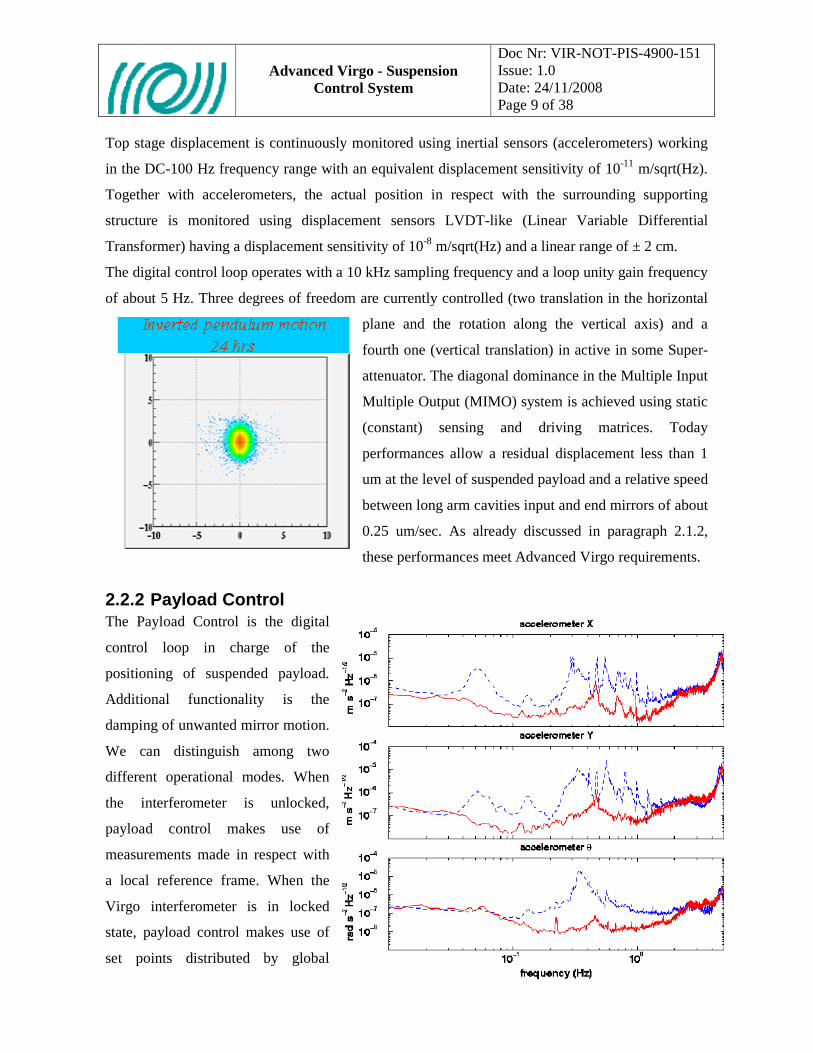
Top stage displacement is continuously monitored using inertial sensors (accelerometers) working
in the DC-100 Hz frequency range with an equivalent displacement sensitivity of 10-11 m/sqrt(Hz).
Together with accelerometers, the actual position in respect with the surrounding supporting
structure is monitored using displacement sensors LVDT-like (Linear Variable Differential
Transformer) having a displacement sensitivity of 10-8 m/sqrt(Hz) and a linear range of ± 2 cm.
The digital control loop operates with a 10 kHz sampling frequency and a loop unity gain frequency
of about 5 Hz. Three degrees of freedom are currently controlled (two translation in the horizontal
plane and the rotation along the vertical axis) and a
fourth one (vertical translation) in active in some Super-
attenuator. The diagonal dominance in the Multiple Input
Multiple Output (MIMO) system is achieved using static
(constant) sensing and driving matrices. Today
performances allow a residual displacement less than 1
um at the level of suspended payload and a relative speed
between long arm cavities input and end mirrors of about
0.25 um/sec. As already discussed in paragraph 2.1.2,
these performances meet Advanced Virgo requirements.
2.2.2 Payload Control The Payload Control is the digital
control loop in charge of the
positioning of suspended payload.
Additional functionality is the
damping of unwanted mirror motion.
We can distinguish among two
different operational modes. When
the interferometer is unlocked,
payload control makes use of
measurements made in respect with
a local reference frame. When the
Virgo interferometer is in locked
state, payload control makes use of
set points distributed by global

Advanced Virgo - Suspension
Control System
Doc Nr: VIR-NOT-PIS-4900-151 Issue: 1.0 Date: 24/11/2008 Page 10 of 38
control and alignment computer. Mirrors position is corrected along three degrees of freedom:
longitudinal displacement (along the Virgo laser beam direction – ‘Z’), rotation around the vertical
axis (‘ThetaY’) and rotation along the horizontal axis orthogonal to laser beam direction (‘ThetaX’).
Correction of longitudinal position is named in Virgo ‘Locking’ while correction of ThetaX and
ThetaY angles is
named ‘Automatic
Alignment’. The
low frequency part
(10s of mHz) of the
Z error signal is
forwarded to
Superattenuator
Top Stage Control
for correcting tidal
strain acting on top
stage where we can
achieve bigger
displacements. Local payload position is monitored using two Position Sensing Devices reading
Marionette and Mirror positions respectively plus a CCD camera reading the mirror coarse position
as shown in the following picture. Performances of payload control system meet Advanced Virgo
requirements allowing a residual angular displacement less than 1 urad using local sensors and less
than 1 nrad using angular displacement measurements outputs from Virgo ITF.

Advanced Virgo - Suspension
Control System
Doc Nr: VIR-NOT-PIS-4900-151 Issue: 1.0 Date: 24/11/2008 Page 11 of 38
CCD
CCD-MIRROR distance =1250 mmCCD focal L. = 25 mmApert ure = 18 mm
incidence 35o
(z) beam axisopt ical port s
dif f usive markers
halogenilluminat or
opt ical port s
XY
Err( θxθy)
Err( θxθy)
PSD device on t he focal plane
XY
PSD deviceon t he image plane
Err(z)
14 mW red laserdiode - SM fiber
XY
Err(θxθy)PSD deviceon t he focal plane
1.4 mW red laserdiode - SM f iber
incidence 30o
f =200 mm
f =200 mm
actuat or
actuat or
t o SA’s f ilt er 7 ( F7)
( F7)
Figure 2 Payload Local Control: position readout
2.2.3 Motors Control Along the Super-attenuator chain there are several stepping motors used to set the correct operating
state. This paragraph list main motors only to give a rough idea of their use.
Each accelerometer has a motor for cancelling dc output by moving accelerometers suspended
mass. Three motors acting on top stage are used for setting the Super-attenuator dc position. One
motor acts on the so called ‘Chiocciolone’ for setting the vertical length of the whole chain. One
motor (‘Fishing Rod’ motor) is installed in each of the Standard Filters (see picture at the beginning
of this chapter) for setting the anti-spring magnets bar position. Two motors allow rotation of Filter
Seven in respect with last Standard Filter and rotation of Marionette in respect with Filter Seven.
One motor is installed on Marionette moving a balancing mass and two motors are used to set Filter
#7 angles. Requirements for the positioning system are reported in [RD8]
2.2.4 Performances Overall system performances are excellent and completely fulfilling Virgo and Virgo+
requirements. Only in case of extremely bad weather condition (a few days per year) excess seismic
noise could potentially affect Advanced Virgo sensitivity at very low frequency (below 10 Hz)
([RD2][RD7]).

Advanced Virgo - Suspension
Control System
Doc Nr: VIR-NOT-PIS-4900-151 Issue: 1.0 Date: 24/11/2008 Page 12 of 38
3. SUSPENSION CONTROL HARDWARE This chapter starts from a description of the Virgo configuration for then moving to changes
implemented for Virgo+ and finally describing a proposed Advanced Virgo configuration.
Superattenuator control hardware can be split in three different main categories: Front End
Electronics and Data Conversion, Processing and Transfer Electronics and Supervisory Control
Workstations
3.1 Front End Electronics The main activity concerning front-end electronics is the upgrade of the conditioning electronics
used to manage the sensor and the actuators placed in the suspension stage, namely the
accelerometers, the LVDTs, the stepping motors, the local control sensors and the coil working at
different levels of the chain.
3.1.1 LVDT The LVDT sensors (Linear Variable Differential Transformer, inductive position sensor) actually
used to measure the position of the top stage of the suspended chain in the very low frequency band,
did not require any particular improvement. They are, in fact (and being dominated by seismic
noise), enough sensitive to be compliant with the Advanced Virgo requirements.
On the other hand the conditioning electronics of these sensors need to be upgraded for two main
reasons. The first one is the age of the electronic components used in the driver, that are now
Suspension Control Hardware
Front End Electronics Data Conversion, Processing and Transfer
Supervisory Control Workstations
Position Sensor LVDT
Acceleration Sensor
Coil Actuator Driver
Motor Driver
Analog to Digital Converter ADC
Digital to Analog Converter DAC
Digital Signal Processing DSP
Digital Optical Point-to-point Link DOL
Optical Lever Driving and Readout

Advanced Virgo - Suspension
Control System
Doc Nr: VIR-NOT-PIS-4900-151 Issue: 1.0 Date: 24/11/2008 Page 13 of 38
obsolete and difficult to maintain; of course and even if not strictly required, using more recent and
specific components will produce benefits also in terms of performances. The second reason
concerns the possibility to implement a digital output on the driver by using an onboard ADC to
immediately digitize the position signal, and sending it to the processing and control electronics
through a digital link. This solution has the clear advantage to greatly reduce interferences and
electrical pick-ups from the electromagnetic noise present in the environment.
Finally it is foreseen to use such new drivers also to manage the LVDT sensors used inside the
accelerometers of the top stage; this solution will avoid the development of hybrid electronic board
and will make more logical and easy to maintain the full suspension electronics.
Running Activities
INFN Pisa is being studying a new design for LVDT electronics since a few years. A candidate
ADC converter was selected and tested together with a DAC converter and a PLL circuitry capable
of letting the two converters operate at different rates synchronously with VIRGO timing signal.
Such studies were partially integrated in the R&D activity for the upgrade of Virgo control
electronics together with new DSP design. Characterization of the developed prototype board was
subject of a University Degree thesis by M. Errante, “Caratterizzazione e realizzazione di una
scheda di conversione D/A A/D per l’esperimento VIRGO “, Facolta’ di Ingegneria Univerita’ di
Pisa ([RD9]).
Digital data link was studied taking advantage from a fellowship (Dr. G. Scandurra) paid by
Fondazione Bonino-Pulejo. The final report was “Sviluppo di una scheda di I/O dotata di interfacce
PCI e IEEE1394b per il rivelatore Virgo” ([RD10])
3.1.2 Accelerometers The main upgrade foreseen for the driving electronics is the replacement of a digital feedback
instead of the analog one currently used in addition to the use of an external LVDT driver and the
introduction of a digital output for the acceleration signal, as already stated in the previous section,.
The upgrade of the accelerometers used to perform the inertial damping of the top stage involves
both the sensor and the internal driver (sensors are force-balance accelerometers). At sensor level
some adjustment in the design is needed to enhance the performances. In particular the balancing
and the stability of the suspended mass, have to be improved for enhancing noise performances,
especially in the low frequency range, that is the most interesting for the inertial damping
application.

Advanced Virgo - Suspension
Control System
Doc Nr: VIR-NOT-PIS-4900-151 Issue: 1.0 Date: 24/11/2008 Page 14 of 38
The implementation of such digital system would allow the design of more effective feedback for
the internal loop, resulting in a wider frequency band, in an improved robustness and in improved
noise performances.
Of course for this aim some suitable additional electronics has to be hosted on the driver, namely an
ADC to digitize the position signal coming from the LVDT, a DSP for the digital filtering, and a
DAC for the actuation on the internal coil.
Running Activities
In addition to the studies carried on for ADC and DAC converter mentioned in the previous section,
a few different options for the digital controller implementation were investigated by INFN Pisa.
Such controller could be implemented with either a devoted DSP processor or with one of the multi-
DSP boards developed by INFN Pisa handling several sensors at a time or with fast FPGA.
Concerning the actuation, a few initial studies were carried on to evaluate the possibility to replace
existing voice coil actuator (coil-magnet) with a coil-coil pair.
3.1.3 Coil Driver The Coil Driver were upgraded for Virgo+ and their current performances, in terms of noise,
linearity and frequency band are already compliant with the Advanced Virgo requirements [RD5].
The major upgrade is related to the introduction of a digital input, through a fast optical link
connected to an onboard DAC and to a selection of a new DAC converter (the one in use is
obsolete). The digital link is particularly important since the actuation signals of the coil are the
most critical for the ITF sensitivity, and a connection between the control and processing
electronics that is virtually unaffected by environmental interferences is strongly desirable.
New Coil Drivers ACDV-07-P2 are Eurocard 6U boards each one hosting two independent
channels.

Advanced Virgo - Suspension
Control System
Doc Nr: VIR-NOT-PIS-4900-151 Issue: 1.0 Date: 24/11/2008 Page 15 of 38
Figure 3 New coil driver evaluation board
Each channel has two inputs, DAC#1 and DAC#2, one main output COIL and three monitoring
outputs: Voltage Monitor (VMONI), High Power Mode Current Monitor (HPMONI) and Low
Noise Mode Current Monitor (LNMONI). One parallel digital input allows remote control of board
operating mode.
Detailed information about the Coil Driver theory of operation and main specifications can be found
in Virgo+ review documentation available at:
http://wwwcascina.virgo.infn.it/collmeetings/DMwebpages/Virgo+/2ndReviewDocuments/coildrive
rs.pdf
Coil Drivers are power amplifiers used to drive coil-magnet pair actuators steering VIRGO optical
elements. Those amplifiers need a wide dynamical range due to the big force impulse required to
acquire the lock of VIRGO optical cavities and stringent noise behavior during linear regime.
The new coil driver was designed using two distinct sections: one high power section for lock
acquisition and one low noise section for linear regime. The two sections are driven by two
independent digital to analog converter channels. The new coil driver can supply up to 2 A during
the lock acquisition phase with a few nA/Hz1/2 of noise during linear regime.
The ACDV-P2 version of the new coil driver hosts three distinct sections. The following picture
shows a functional block diagram for one Coil Driver channel. For each magnet-coil actuator pair,
two analog inputs are available. Due to the high dynamics of the current flowing into the coil, also
the monitoring section is split in two parts: Coarse (High Power) and Fine (Low Noise).

Advanced Virgo - Suspension
Control System
Doc Nr: VIR-NOT-PIS-4900-151 Issue: 1.0 Date: 24/11/2008 Page 16 of 38
High Power
Section
Low Noise Section #1
Low Noise Section #2
Analog IN #1
Analog IN #2
ControlSectionSerial Link
Low Noise Coil Current
Monitor
High PowerCoil Current
Monitor
Analog OUT #2
Analog OUT #1Coil
• Sections switch• Gain selection• De-enphasis filtering• Monitor configuration
High PowerSection
High PowerSection
Low Noise Section #1Low Noise Section #1
Low Noise Section #2Low Noise Section #2
Analog IN #1Analog IN #1
Analog IN #2Analog IN #2
ControlSectionControlSectionSerial LinkSerial Link
Low Noise Coil Current
Monitor
Low Noise Coil Current
Monitor
High PowerCoil Current
Monitor
High PowerCoil Current
Monitor
Analog OUT #2Analog OUT #2
Analog OUT #1Analog OUT #1CoilCoil
• Sections switch• Gain selection• De-enphasis filtering• Monitor configuration
Figure 4 New coil driver block diagram
For each actuator three distinct section are available (one High Power plus two Low Noise). The
High Power section is a transconductive amplifier able to supply up to 2 A into the coil while the
two Low Noise sections are voltage amplifiers with resistor in series with the coil.
Running Activities
R&D related to the development of an engineered version of coil driver prototypes is now closed.
What still remains to be studied is the use of high power – low noise modes with marionette
actuators. Tests will take place during next commissioning phase.
3.1.4 Motors Driving Electronics No changes are foreseen for the driving system of the stepper motors working on the suspension. A
minor change is related to the control logic that is currently obsolete. A standard commercial
solution seems the best choice since there are no special requirements on the performances of the
system.
Running Activities
Possible solutions are being investigated by EGO Electronics group in collaboration with INFN
Pisa.
3.1.5 Piezoelectric Actuators Drivers Advanced Virgo suspension configuration foresees the use of piezoelectric actuators placed under
the inverted pendulum legs. To drive such actuators we need high voltage amplifiers.
Running Activities
A prototype driver was designed few years ago to drive high voltage (up to 800V) piezos. Design
doesn’t allow driving negative polarization piezos (the most common ones). Recently a new design
was developed to drive piezo actuators up to +/- 150V. Investigation with Physik Instrumente (PI)
is in progress to have piezo being able to cover our travel range with such mid voltage. Using 150V

Advanced Virgo - Suspension
Control System
Doc Nr: VIR-NOT-PIS-4900-151 Issue: 1.0 Date: 24/11/2008 Page 17 of 38
instead of 800V would enormously simplify signals cabling, vacuum feed-through and of course
operation. A few boards were developed founded outside the Virgo project.
Figure 5 Dual Channel +/- 150V Piezo Driver Board
3.1.6 Thermal Stabilization Control Since several years a thermal stabilization system, required to control the temperature of the
suspension and therefore its length and filters operating points, is ready to be installed. For proper
operation of the suspension enclosure temperature variations shall not exceed +/- 0.2 oC. This
requirement was up to now fulfilled stabilizing the temperature of the whole central hall and
terminal building. Since such requirement could be easily met using heating belts wounded around
towers, we could relax specifications on air conditioning system allowing temperature variations
into the building up to 2 oC. It is also worth mentioning that very low frequency variation of the air
temperature do not affect at all suspension performances. We could therefore allow a continuous
change of mean temperature following seasons change.
3.2 Data Conversion, Processing and Transfer Each of the 9 Virgo Superattenuators has a dedicated Suspension Control Unit composed by one
VME crate hosting data conversion, processing and communication boards. A Suspension Control
Unit hosts two PowerPC-based CPU boards, running real time operating system LynxOS, used for
supervision and for CCD camera readout software. Hard real-time signal processing is performed
using two Digital Signal Processing (DSP) boards based on Motorola DSP96002 floating-point
DSP. Control Unit is completed by about 60 channels of analog I/O, 4 digital optical point-to-point
links, CCD camera and Timing system interface. Suspension Control Units are located in the Virgo

Advanced Virgo - Suspension
Control System
Doc Nr: VIR-NOT-PIS-4900-151 Issue: 1.0 Date: 24/11/2008 Page 18 of 38
Data Acquisition Room and in the two Terminal Building. A second crate hosting front-end analog
electronics is located close to each suspension tower.
DSPs implement the hard real-time part of the control system. The following table summarizes
measured load.
Figure 6 DSP Load
The distributed load adds up to about 300 MFLOPS, 300 Mbit/sec I/O rate with a latency lower
than 100 usec. The system was designed in the mid 90’s and it is operative 24 hours a day 365 days
per year since 1998.
Within a Suspension Control Unit, three are the communication standards used to access interface
devices: VME (VersaModule Eurocard), VSB (VME Subsystem bus) and VBeX (Virgo Bus
eXpansion). VMEbus is used for communication involving one of the two CPUs and average
throughput is in the order of 40 kBytes/sec. VSB bus is used for communication between DSP and
Digital Optical Link interfaces to receive data from Global Control and to send data to Data
Acquisition with 800 kBytes/sec total throughput. VBeX shares the physical layer with the VSB bus
but uses an asynchronous private protocol. This bus is used for communication between DSP and

Advanced Virgo - Suspension
Control System
Doc Nr: VIR-NOT-PIS-4900-151 Issue: 1.0 Date: 24/11/2008 Page 19 of 38
analog to digital (ADC) and digital to analog (DAC) conversion board (1 MByte/sec total
throughput).
DAC boards, designed together with ADC and DSP boards by INFN Pisa, are 8 channels, 20
nominal bits (17.5 effective bits) operating in Virgo at the sampling rate of 10 kSample/sec. Analog
anti-aliasing (reconstruction) filter is a 7th order Cauer filter with 3.7 kHz cut-off frequency.
Balanced outputs provide a 20 Volts peak-to-peak signal.
ADC boards are 8 differential channels, 16 nominal bits (14.5 effective bits) operating in Virgo at
the sampling rate of 10 kSample/sec. Analog anti-aliasing filters is the same used in DAC boards:
7th order Cauer filter with 3.7 kHz cut-off frequency. Dynamical range of differential inputs is 20
Volts peak-to-peak.
DSP boards, operate at the sustained rate of about 10 million floating point operation per second
(MFLOPS) for a total computational power in the range of 200 MFLOPS for controlling 9
Superattenuators. Computational power is used to implement control filters with about 100 poles
per DSP board within an interrupt service routine activated with a repetition period of 100
microseconds and triggered by Virgo timing distribution system. Within such period DSP reads
input from ADC boards and communication links, computes correction signal and sends results to
DAC boards and communication links.
Data transfer take place using two distinct mechanisms. Slow monitoring signals (1 second
sampling period) are transferred using Ethernet connection available at PowerPC level. Real time
signals (10 kHz sampling rate) are transferred using a point to point optical link connecting each
DSP to a Data Acquisition Frame Builder. The same mechanism is used by Global Control
computer to provide DSPs with proper set points.
3.2.1 Noise Performances Noise performances of data converters and signal processing were described and analyzed in
several notes (see [RD4][RD5][RD6]). Since one of the point most frequently misunderstood within
the collaboration was the actuation noise (dominated by digital to analog converter noise), it is
worth reporting also in this document the converter noise budget for the actuators located on the
lower stages of the suspension: marionette and reference mass. The following two plots show the
noise budget. The brown line is the expected Advanced Virgo sensitivity at low frequency. The
green line is the DAC noise contribution while the blue line can be considered as a safety margin
(10 at 10 Hz). Both plots were calculated assuming to drive only the minimum number of actuators
(noise decrease with the square root of the number of actuators, therefore noise contribution could
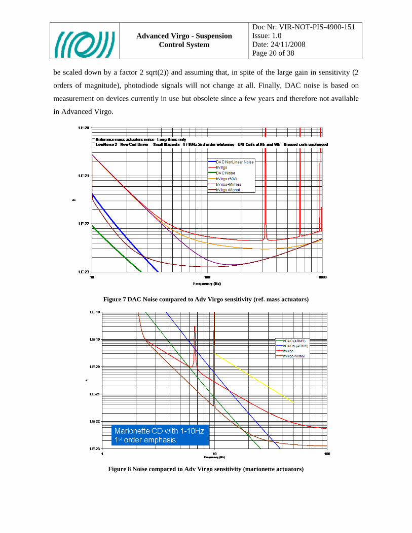
Advanced Virgo - Suspension
Control System
Doc Nr: VIR-NOT-PIS-4900-151 Issue: 1.0 Date: 24/11/2008 Page 20 of 38
be scaled down by a factor 2 sqrt(2)) and assuming that, in spite of the large gain in sensitivity (2
orders of magnitude), photodiode signals will not change at all. Finally, DAC noise is based on
measurement on devices currently in use but obsolete since a few years and therefore not available
in Advanced Virgo.
Figure 7 DAC Noise compared to Adv Virgo sensitivity (ref. mass actuators)
Figure 8 Noise compared to Adv Virgo sensitivity (marionette actuators)

Advanced Virgo - Suspension
Control System
Doc Nr: VIR-NOT-PIS-4900-151 Issue: 1.0 Date: 24/11/2008 Page 21 of 38
3.2.2 Upgrades The major upgrade in the architecture of the Processing and Control Electronics, namely the DSP,
the ADC, the DAC and the digital optical link, was already performed during the Virgo+ upgrade.
In particular the new processing board [see Virgo+ 2nd review document at
http://wwwcascina.virgo.infn.it/collmeetings/DMwebpages/Virgo+/2ndReviewDocuments/DSP.pdf
], with its 6 DSP, allows a very high computing power respect to the old Virgo single DSP board.
Moreover the new Photodiode Readout Scheme (section DAQ:PhReadOut) and the new Global
Control Architecture (section DAQ:GlobalControl), both based on more recent CPUs and faster
digital optical links, allow a better conditioning and an higher frequency band of the error signals.
Thanks to these changes it is possible to perform better control strategies and to design more
effective digital filters.
Some improvement is still required for the analog/digital converters, ADCs and DACs, in particular
about the effective number of bits, in order to reduce the quantization noise introduced during both
the sensing and the driving.
3.2.3 DSP The new DSP board named is being replacing the obsolete DSPV96 board developed by INFN Pisa
for VIRGO. The new device is a VME board hosting up to 6 Analog Devices DSPs.

Advanced Virgo - Suspension
Control System
Doc Nr: VIR-NOT-PIS-4900-151 Issue: 1.0 Date: 24/11/2008 Page 22 of 38
Figure 9 New DSP mezzanine plugged on VME carrier
The board is constituted by a VME carrier board hosting one mezzanine board hosting DSPs and
one additional mezzanine board for Timing and fast data links.
Figure 10 New DSP Mezzanine Board
Detailed information about the new DSP board and main specifications can be found in Virgo+
review documentation available at:
http://wwwcascina.virgo.infn.it/collmeetings/DMwebpages/Virgo+/2ndReviewDocuments/DSP.pdf

Advanced Virgo - Suspension
Control System
Doc Nr: VIR-NOT-PIS-4900-151 Issue: 1.0 Date: 24/11/2008 Page 23 of 38
No major change is foreseen on the processing board. Nevertheless a daughter-board has to be
developed to manage the digital signals exchanged with the suspension electronics equipped with
digital input or output. The architecture should be very similar to the one already implemented for
the global control signal in Virgo and in Virgo+, but in this case it refers also to local control
signals.
Running Activities
Digital data link was studied by INFN Pisa taking advange from a fellowship (Dr. G. Scandurra)
payed by Fonzaione Bonino-Pulejo. The final report was “Sviluppo di una scheda di I/O dotata di
interfacce PCI e IEEE1394b per il rivelatore Virgo” A preliminary design of the board is already
available.
3.2.4 ADC & DAC The ADC of the control electronics, in the Virgo and Virgo+ configuration, are located in the same
unit of the processing electronics and are used mainly to convert signals coming from the
suspension electronics, located close to the respective tower. In Advanced Virgo some of these
converters will be placed directly in the suspension electronics (section DAQ:SuspEle). Despite of
their location, an improvement of their performances, mainly in terms of quantization noise
reduction, should be achieved.
As for the case of ADC, also the DAC performances need to be improved. The DAC noise is even
more critical, since the current performances are still a limiting factor for the achievement of the
Advance Virgo sensitivity in the low frequency region, due to the direct coupling with the coils
actuating on the test masses. A specific R&D is dedicated to the selection of a suitable chip, with an
higher number of bits respect to now and higher sampling frequency to decrease the noise content.
Running Activities
A candidate ADC converter was selected and tested together with a DAC converter and a PLL
circuitry capable of letting the two converters operate at different rates synchronously with VIRGO
timing signal.

Advanced Virgo - Suspension
Control System
Doc Nr: VIR-NOT-PIS-4900-151 Issue: 1.0 Date: 24/11/2008 Page 24 of 38
Figure 11 New ADC/DAC board - simplfied diagram
Figure 12 New DAC/ADC evaluation board
Such studies were partially integrated in the R&D activity for the upgrade of Virgo control
electronics together with new DSP design. Characterization of the developed prototype board was
subject of a University Degree thesis by M. Errante, “Caratterizzazione e realizzazione di una
scheda di conversione D/A A/D per l’esperimento VIRGO “, Facolta’ di Ingegneria Univerita’ di
Pisa. Obtained results show an noise level about 2 time smaller than the DAC currently in use by
Virgo at frequencies larger than a few Hertz. The following table summarize main specifications for
the converter in use and for the tested one
AD1862 (in use now)
• 20 bit converter
DSD1792
• 24 bit converter

Advanced Virgo - Suspension
Control System
Doc Nr: VIR-NOT-PIS-4900-151 Issue: 1.0 Date: 24/11/2008 Page 25 of 38
• 120 dB SNR
• -88 dB THD
• Noise Spectra (20 Vpp output)
• 125 dB SNR
• -90 dB THD
• Noise Spectra (20 Vpp output)

Advanced Virgo - Suspension
Control System
Doc Nr: VIR-NOT-PIS-4900-151 Issue: 1.0 Date: 24/11/2008 Page 26 of 38
3.2.5 Data Path Optimization The following picture shows the Virgo / Virgo+ block diagram of the Suspension Control System
Figure 13 Virgo / Virgo+ Suspension Control System Layout
Architecture proposed for Adv. Virgo is much simplified. VME CPU (RIO) disappears together
with more than 1600 m of analog cabling per tower. In the Central Building (CEB) a single fiber
could be used to connect all DSPs with control workstation. Such simplification is major step in
system reliability and performances due to the huge gain for EMC.
Figure 14 Adv Virgo Layout

Advanced Virgo - Suspension
Control System
Doc Nr: VIR-NOT-PIS-4900-151 Issue: 1.0 Date: 24/11/2008 Page 27 of 38
3.3 Other Activities
3.3.1 Angular Accelerometer Electronics Up to today it looks reasonable being able to use the same electronics used for horizontal and
vertical accelerometers. All test in progress on the two angular accelerometer prototype available
were performed using standard Virgo electronics.
3.3.2 Conduction Cooling To reduce vibration in the central hall and terminal buildings, the possibility to remove fan from
front end racks is under investigation. Adoption of standard IEEE 1101.2 “Standard for Mechanical
Core Specifications for Conduction-Cooled Eurocards” looks to be mandatory to remove fan. Costs
for this operation are available but actual benefits are still to be clarified.
3.3.3 DC Supplies Distribution Removal of power supplies from the experimental area would produce several benefits:
• EMC improvements (mainly on mains 50Hz and harmonics) • Heat reduction • Power Supply fans vibrations
Some preliminary investigations are in progress but a cost benefit analysis is not yet available.

Advanced Virgo - Suspension
Control System
Doc Nr: VIR-NOT-PIS-4900-151 Issue: 1.0 Date: 24/11/2008 Page 28 of 38
4. SUPERATTENUATOR CONTROL SOFTWARE Since a couple of yeas a redesign of suspension control software is in progress with support from
EGO Software group. A quite large amount of documentation is available at
https://workarea.ego-gw.it/ego2/ego/itf/software/auth-only/projects/superattenuator-control-
software (EGO-Virgo Workarea, access require a workarea login and passwd). The following
pictures show architecture and layout of suspension control software for Adv.Virgo
VIRGO Common Software
User
DAQ
SCS<<System>>
Suspension
Figure 15 Top level context diagram
Figure 16 Software Architecture
Figure 17 Software Layout
Super-attenuator Control Software (SCS) shall allow maintenance, configuration and operation of
the whole set of Suspensions.

Advanced Virgo - Suspension
Control System
Doc Nr: VIR-NOT-PIS-4900-151 Issue: 1.0 Date: 24/11/2008 Page 29 of 38
• The main purposes of the first SCS version can be summarized as follows:
• Handle replacement of DSP currently in use conserving existing functionalities.
• Provide in-system test capabilities for hardware devices.
• Minimize changes on interfaces with external packages.
• Simplify operations
• Provide online help
• Improve portability towards environments different from the Virgo one.
• Improve software fault tolerance and maintainability

Advanced Virgo - Suspension
Control System
Doc Nr: VIR-NOT-PIS-4900-151 Issue: 1.0 Date: 24/11/2008 Page 30 of 38
5. TASKS This chapter summarizes the main tasks related to the upgrade of Suspension Control System for
Advanced Virgo. For each task a few lines recall main motivations and describe implementation.
Three attribute were added: Need (Desirable, Very Desirable, and Mandatory), Priority (Low,
Mean, and High) and Risk (Low, Mean, and High). A preliminary estimation of costs is available in
next section.
5.1 Front End Electronics
5.1.1 Crates Replacement Motivation : Standard in use (NIM) will be abandoned since is no longer available, adoption of
standard IEEE 1101.2 or equivalent (TBC). VME Crate will be abandoned since no longer
necessary for communication with other Virgo sub systems.
Implementation: NIM crates will be replaced with Eurocard ones. At present we have 2 NIM crate
+ 1 VME crate for a total of 3 crates to be replaced for each suspension.
Need: Crate replacement is Mandatory. Still TBD the need of conduction cooling
Priority : High
Risk: Low; Mean if conduction cooling is requested.
5.1.2 Cabling Motivation : Replacement of crates and electronics.
Implementation: Cabling will be simplified a lot, see related paragraph in this document.
Need: Very Desirable.
Priority : High
Risk: Low.
5.1.3 LVDT Conditioning Boards Motivation : components obsolete, digital output to improve EMC, adoption of standard IEEE
1101.2 or equivalent (TBC).
Implementation: Eurocard module hosting from 4 to 8 channels.
Note:Same board will be used for accelerometers internal LVDT.
Need: Mandatory.
Priority : High
Risk: Mean.

Advanced Virgo - Suspension
Control System
Doc Nr: VIR-NOT-PIS-4900-151 Issue: 1.0 Date: 24/11/2008 Page 31 of 38
5.1.4 Accelerometers Electronics Motivation : components obsolete, digital output to improve EMC, digital control to improve
performances, replacement of voice coil actuator with coil-coil pair (TBC1), adoption of standard
IEEE 1101.2 or equivalent (TBC)
Implementation. Eurocard module hosting from 4 to 8 channels.
Need: Mandatory.
Priority : High
Risk: Mean.
5.1.5 Coil Drivers New coil drivers were designed for Virgo+ and no changes are expected for Adv. Virgo.
Nevertheless adoption of standard IEEE 1101.2 or equivalent will imply a redesign of boards. In
addition production of coil driver for complete replacement is not part of Virgo+ upgrades that was
covering only the lower stage of superattenuators. Virgo+ coil drivers already foresee digital I/O.
Need: Desirable, Mandatory if conduction cooling is required
Priority : Low
Risk: Mean.
5.1.6 Piezo Drivers Need: Desirable
Priority : Low
Risk: Mean.
5.1.7 Motors Driving Control Board Motivation : no spare available and not reproducible, move out from VME standard.
Implementation: commercial solution or development of custom control boards (see related
paragraph in this document)
Need: Very Desirable
Priority : Low
Risk: Mean.
1 This possibility already mentioned in the paragraph describing accelerometers electronics would imply re-manufacturing of all accelerometers mechanics. Such mechanical change, whose workload is dominant in respect with electronics, is not detailed in this document.

Advanced Virgo - Suspension
Control System
Doc Nr: VIR-NOT-PIS-4900-151 Issue: 1.0 Date: 24/11/2008 Page 32 of 38
5.1.8 Motors Driving Power Modules Modules are still commercially available and we do not foresee a replacement. Crate backplane is
custom and shall be probably replaced.
Need: Very Desirable
Priority : Low
Risk: Mean.
5.1.9 Temperature Stabilization Control Motivation : provide digital I/O for linear power supplies.
Need: Desirable
Priority : Low
Risk: Low.
5.1.10 Optical Levers (Roma-Napoli) This task is reported only for completeness.
Motivation : Standardize (TBD), allow alignment remote control
Need: Very Desirable
Priority : Mean
Risk: High.
5.2 Data Conversion, Processing and Transfer
5.2.1 Analog to Digital Converters Motivation : Move out of VME standard and in particular move close to front end electronics,
improve noise and bandwidth performances.
Implementation: Mezzanine board, presumably standard PMC, hosting a TBD number of ADC
and DAC channels. Mezzanine board will be located directly on front modules.
Need: Very Desirable
Priority : Mean
Risk: High.
5.2.2 Digital to Analog Converters Motivation : chips obsolete, move out of VME standard and in particular move close to front end
electronics, improve performances.
Implementation: See previous paragraph

Advanced Virgo - Suspension
Control System
Doc Nr: VIR-NOT-PIS-4900-151 Issue: 1.0 Date: 24/11/2008 Page 33 of 38
Need: Mandatory
Priority : High
Risk: High.
5.2.3 DSP New DSP were designed for Virgo+. Few changes could anyway be required as for example move
from PMC to XMC standard (i.e. add one or two connectors). See DSP paragraph in this document
for further info.
Need: Desirable
Priority : Low
Risk: High.
5.2.4 Data Transfer Interface Motivation : see relate paragraph 3.2.5
Implementation: both converter and processing cards will share a fast real-time communication
interface based on IEEE1394 standards (and/or USB 3.0 and/or PCI Express all TBD). Such
interface, at the today level of the preliminary design, can be seen as a mezzanine board plugged (or
integrated) on both DSP and ADC/DAC carrier boards.
Need: Very Desirable
Priority : Mean
Risk: High.
5.3 Software
5.3.1 DSP Server Motivation : RIOs will no longer be used.
Implementation: see software chapter in this document.
Need: Very Desirable
Priority : Mean
Risk: Mean.
5.3.2 Coordination Software Motivation : Virgo software supervisor and cm no longer maintained.
Implementation: see software chapter in this document.
Need: Very Desirable

Advanced Virgo - Suspension
Control System
Doc Nr: VIR-NOT-PIS-4900-151 Issue: 1.0 Date: 24/11/2008 Page 34 of 38
Priority : Mean
Risk: Mean.
5.4 System Assembly & Integration
5.4.1 Installation (This task was left intentionally empty)
5.4.2 Cabling (This task was left intentionally empty)
5.5 Commissioning (This task was left intentionally empty)
5.6 Maintenance Maintenance has a not negligible cost that will affect budget beyond the installation. For the
Suspension Control System maintenance interventions are classified into three different levels:
Level Applies to Action Time Scale
1 Sudden Failure (failure = anything preventing continuing Virgo operation at usual sensitivity level)
Hours
2 Request for a change affecting the Suspension Control System but not its interfaces with other Virgo Sub-Systems
Days
3 Request for a change affecting the Suspensoin Control System and its interfaces with other Virgo sub-systems
Weeks
Table 1 Support Levels
Failure Use Case
Primary Actor : User
Standard Course
• User detects a sudden failure prevent continuing Virgo operation at usual sensitivity level.
• User creates a Problem Report sending an e-mail to [email protected] shortly describing
problem.
• User contacts Maintenance Staff, if out standard working time using OnCall service, thus
activating a Level 1 Support procedure.
• User will receive Problem Report status information and worklog via e-mail.
Advanced Virgo - Suspension
Control System
Doc Nr: VIR-NOT-PIS-4900-151 Issue: 1.0 Date: 24/11/2008 Page 35 of 38
• Control Room will be keep informed.
Level 1 Support Use Case
Primary Actor : Maintenance Staff (MS)
Standard Course
• Upon receiving notice of a failure, Maintenance Staff (MS) replies to Problem Report email
(or create Problem Report entry in case it doesn’t exist).
• MS makes a cross check to confirm failure.
• In case of confirmed failure, MS asks Control Room permission to proceed to problem
solving (requesting support if needed).
• MS reports any change in the hardware configuration into the Online Database of Electronic
Devices and in Virgo logbook.
• After problem fixing, MS reports actions updating the Problem Report entry and informing
Control Room
• Problem Report entry is closed.
Action Software Tool
Problem Report Software Problem Report ([email protected])
Change Request Software Problem Report ([email protected])
Hardware Change Online Database of Electronics Devices & Logbook
Software Change CVS Archive & Logbook
Table 2 Software Tools

Advanced Virgo - Suspension
Control System
Doc Nr: VIR-NOT-PIS-4900-151 Issue: 1.0 Date: 24/11/2008 Page 36 of 38
6. COSTS
6.1 Hardware Production NOTE: Costs do not include in vacuum cabling whose cost was added to the mechanics costs.
A preliminary estimation of costs foreseen for Advanced Virgo can be done on the basis of what
was spent for Virgo. Suspension Electronics, excluding maintenance costs, required about 740
kEuro. Present value, assuming a 2% year increase for 8 years, corresponds to about 940 kEuro.
Keeping in mind previous number we can try to make an evaluation of costs task by task.
Concerning electronic hardware development, assuming to have enough manpower available, we
can estimate the following costs based on what we paid for Virgo+ upgrades. Note that costs are
computed for 15 towers (10 Adv.Virgo suspensions + SAFE + Laboratory + Test Facility + Spare).
Ch/Susp Ch/Board Nr Nr. Towers Total Production Unit Cost Production Total Cost ( k€)FE Crates Replacement 3 15 45 3.5 157.5LVDT Conditioning Electronics 20 4 5 15 75 1.5 112.5Accelerometer Electronics 7 4 2 15 30 1.5 45Coil Drivers 10 2 3 15 45 2 90Motors Control 1 1 1 15 15 1 15Motors Power 1 1 1 15 15 1 15Piezo Drivers 3 2 1 15 15 2 30Thermal Stab. 3 4 1 15 15Data Converters 45 8 12 15 180 1.5 270DSP 2 1 1 15 15 2 30DSP Carrier 2 1 1 15 15 1 15Cabling
Total 780
Table 3 Hardware Costs Estimate (manpower NOT included – blank cell still TBD)
Which costs are included?
• Prototyping (when needed)
• PCB Manufacturing (external firm)
• Components Procurement
• Boards Assembly (external firm)
Which costs are NOT included?
• Manpower (excluding external firms that will take care of PCB manufacturing and boards
assembly)
• Laboratory Tools (firmware, JTAG, test, measurements – scopes, analyzers ..- , supply,
reworking station …)
• Conduction Cooling (if confirmed)
• DC supply (if confirmed)

Advanced Virgo - Suspension
Control System
Doc Nr: VIR-NOT-PIS-4900-151 Issue: 1.0 Date: 24/11/2008 Page 37 of 38
From previous table we can see that we are talking of something less than 500 electronic devices.
To set up such large amount of devices we should setup a properly equipped laboratory. Cost for
setting up the laboratory, excluding infrastructure cost, can be estimate in the range between 100
and 200 kEuro.
6.2 Manpower Following table units are month-man. Divide by 12 to get actual FTE number. Empty cells are to be
defined.
Des
ign
PCB
Desi
gn
Test
Firm
war
e
FE Crates Replacement 1LVDT Conditioning Electronics 4 3 1 2Accelerometer Electronics 4 3 2 2Coil Drivers 4 3 2 2Motors Control 3 2 1 3Motors Power 3 1Piezo Drivers 4 3 1 2Thermal Stab.Data Converters 4 3 2 4DSP 4 3 2 4DSP Carrier 3 3 1 3
Scientifical & Technical Supervision 36Technical Management 36Contracts & Procurement 12Software D&D 54InstallationCommissioningMaintenance
Total 230 (month-man) Table 4 Manpower
6.2.1 External Firms We can take advantage from the extensive use of external firms. In particular there two task whose
load in terms of manpower is very high but with little pay back: Components procurement and
Board assembly supervision. Both task could be assigned to one or two external firms that shall take
care of buying selected components from resellers, collect printed circuit boards and assembly
notes, verify correctness of assembly and store boards waiting for the installation.

Advanced Virgo - Suspension
Control System
Doc Nr: VIR-NOT-PIS-4900-151 Issue: 1.0 Date: 24/11/2008 Page 38 of 38
6.2.2 Profiles At present INFN Pisa is the only confirmed participant to the listed tasks. Available manpower adds
up to 2-3 FTE and additional position shall be open. In particular we need:
• System/Control Engineer. Overall coordination support
• Hardware Engineer. Design
• Software Engineer. Firmware
• Electronic Technician. Assembly and test.
6.2.3 Virgo & EGO Labs Participation Participation to tasks described in this document is of course open. Institution and laboratories
willing to participate are more than welcome. Responsibility assignment will follow high level
assignments for Advance Virgo.
It is worth mentioning that EGO already participates to some of the listed tasks. In particular EGO
is involved since a few years in the upgrade of software [RD11] and in some of the tasks related to
the Front End Electronics.
oOo
Related Documents