ADVERTISED WINDOW-BASED TCP FLOW CONTROL IN ROUTERS 0. Pop , I. Moldovan, Cs. Simon, J. Biro High Speed Networks Laboratory Department of Telecommunications and Telematics Budapest University of Technology and Economics H-1117, Pazmany P. s. 1/D. Budapest, Hungary Phone: +36 1 463 3110 Fax: +36 1 463 3107 {pop, moldovan, simon, biro}@ttt-atm.ttt.bme.hu A. Koike, H. Ishii Information Sharing Platform Laboratories Nippon Telegraph and Telephone Co., Japan 3-9-11, Midori-cho, Musashino-shi, Tokyo 180-8585, Japan Phone: +81 422 59 4445 Fax: +81 422 60 7372 {koike.arata, ishii.hiroshi}@lab.ntt.co.jp Abstract Nowadays, TCP is basically the only protocol that is used to provide a reliable data communication over the Internet. In recent research of TCP great effort has been put on enhancing the flow and congestion control mechanisms of this protocol. The most relevant of these mech- anisms are the RED-like intelligent queue management techniques that try to avoid the congestion keeping the average queue size low while allowing occasional bursts of packets in the queue. However, these tech- niques notify TCP connections about congestion by dropping packets, thus reducing their goodput. Another possible technique is ECN (Ex- plicit Congestion Notification) which may help avoiding the packet losses but it needs changes in the TCP implementations of the end systems. In this paper we propose a TCP flow control technique for routers, based on modifying the window size advertised by the receiver. Ac- cording to the congestion level at the routers we overwrite the corre- sponding bytes in the acknowledgement (Ack) packet headers. In this way we can match the amount of data sent by the TCP sources to the available buffer capacity, keeping the average queue length below the congestion level without buffer overflows, thus improving the goodput of the TCP connections. Moreover, this technique does not require any modification of the existing TCP protocol implementations, unlike the The original version of this chapter was revised: The copyright line was incorrect. This has been corrected. The Erratum to this chapter is available at DOI: © IFIP International Federation for Information Processing 2000 H. R. van As (ed.), Telecommunication Network Intelligence 10.1007/978-0-387-35522-1_37

Welcome message from author
This document is posted to help you gain knowledge. Please leave a comment to let me know what you think about it! Share it to your friends and learn new things together.
Transcript
ADVERTISED WINDOW-BASED TCP FLOW CONTROL IN ROUTERS
0. Pop , I. Moldovan, Cs. Simon, J. Biro High Speed Networks Laboratory
Department of Telecommunications and Telematics
Budapest University of Technology and Economics
H-1117, Pazmany P. s. 1/D. Budapest, Hungary
Phone: +36 1 463 3110 Fax: +36 1 463 3107
{pop, moldovan, simon, biro}@ttt-atm.ttt.bme.hu
A. Koike, H. Ishii Information Sharing Platform Laboratories
Nippon Telegraph and Telephone Co., Japan
3-9-11, Midori-cho, Musashino-shi, Tokyo 180-8585, Japan
Phone: +81 422 59 4445 Fax: +81 422 60 7372
{koike.arata, ishii.hiroshi}@lab.ntt.co.jp
Abstract Nowadays, TCP is basically the only protocol that is used to provide a reliable data communication over the Internet. In recent research of TCP great effort has been put on enhancing the flow and congestion control mechanisms of this protocol. The most relevant of these mech-anisms are the RED-like intelligent queue management techniques that try to avoid the congestion keeping the average queue size low while allowing occasional bursts of packets in the queue. However, these tech-niques notify TCP connections about congestion by dropping packets, thus reducing their goodput. Another possible technique is ECN (Ex-plicit Congestion Notification) which may help avoiding the packet losses but it needs changes in the TCP implementations of the end systems.
In this paper we propose a TCP flow control technique for routers, based on modifying the window size advertised by the receiver. Ac-cording to the congestion level at the routers we overwrite the corre-sponding bytes in the acknowledgement (Ack) packet headers. In this way we can match the amount of data sent by the TCP sources to the available buffer capacity, keeping the average queue length below the congestion level without buffer overflows, thus improving the goodput of the TCP connections. Moreover, this technique does not require any modification of the existing TCP protocol implementations, unlike the
The original version of this chapter was revised: The copyright line was incorrect. This has beencorrected. The Erratum to this chapter is available at DOI:
© IFIP International Federation for Information Processing 2000H. R. van As (ed.), Telecommunication Network Intelligence
10.1007/978-0-387-35522-1_37

198
ECN method. Per active-flow accounting of TCP connections is used in order to avoid 'window shrinking'. The performance evaluation of this technique is presented using measurements and simulation. The ef-fects of the maintenance of per-flow information in the routers are also analyzed.
Keywords: TCP, flow control, advertised window
1. INTRODUCTION
TCP is the most widely used protocol that ensures error-free data communications between end systems in the Internet. TCP assumes no reliability on underlying network and includes flow and congestion control mechanisms to transport data in an efficient manner and effi-ciently utilise the network resources. All control is done by end-to-end basis. This nature is based on the history of TCP that interconnects various kinds of computers in different network environments. As a re-sult, many people implement TCP lIP in almost all kind of operating systems (OSs) and therefore TCP runs on various kinds of networks. This enables application developers to use TCP lIP as a core protocol for their applications.
High-speed network age, however, reveals limitations of end-to-end TCP control. In what follows in section 2 we present the drawbacks of the TCP protocol and review the literature related to the methods used to improve its performance. The third section describes in detail our window based router algorithm. Our algorithm was thoroughly tested, using measurements and simulations. We have built a prototype IP net-work for measurements, using the most popular TCP implementations in the end-systems. The prototype implementation and the results of the measurements are presented in section four. To have a complete view about the behaviour of the algorithm, extensive simulations have been used, which are also described in section four. Finally we conclude our work. We attached two appendices as well, presenting the measurements regarding the processing overhead generated by the per-flow information handling in the routers, and the formal description of our algorithm.
2. BACKGROUND In order to adapt the sending rate of the source to the available band-
width TCP uses a sliding window based flow control [5, 18]. Remember that, with the sliding window protocol the window size is equal to the maximum number of unacknowledged data that a source may send. TCP defines a variable called congestion window computed by the source; the window size is the minimum of the congestion window and the window
Advertised Window-based TCP Flow Control in Routers 199
advertised by the destination. The evolution of the congestion window in a TCP source consists of two phases: slow-start phase and the con-gestion avoidance phase. The slow-start phase occurs during startup, as well as when a packet loss is detected by a timeout at the source. During the slow-start phase, the congestion window essentially doubles during each round-trip time (RTT), until a threshold window size known as slow-start threshold (ssthresh) is reached. At this point the host en-ters the congestion avoidance phase where TCP is probing for additional bandwidth by increasing the window more slowly, at the rate of one seg-ment per RTT. The packet losses can be detected either by expiration of a timer at the source or when three duplicate acks are received. In the latter case we speak about the Fast Retransmit mechanism that is further followed by the Fast Recovery mechanism. The Fast Recovery mechanism avoids slow-start in such cases by setting the congestion win-dow to approximately half of its current value and keeping the connection in the congestion avoidance phase.
The main drawback of this protocol is that, to detect network con-gestion, in most of the TCP implementations (except TCP Vegas), TCP sources rely mainly on packet losses, which triggers then a decrease of the sender's congestion window size. The TCP performance depends on a lot of factors such as the packet dropping strategy used by the router, the flow and congestion control mechanism of the TCP protocol or the nature of the network (high or low speed, large RTTs or not). Using Drop-Tail routers (packets are dropped when the buffer is full) losses occur in bursts causing timeouts, since the Fast Retransmit and Fast Recovery mechanism can be used only once in a given window. It is de-sirable especially in high-speed networks (backbones) to avoid timeouts, since they introduce burstiness and goodput degradation of the TCP connections.
More recently, random packet dropping strategies have been intro-duced (Random Early Detection, RED, and its variants) [2, 3, 4] which try to prevent congestion, rather than just reacting to it, by dropping packets before the buffers of the router are totally exhausted. These techniques try to spread the packet losses (avoiding bursty losses), there-fore the early-dropped packets usually are Fast Retransmitted and no timeout occurs. Moreover, RED tries to keep the average queue length as low as possible while maximising the throughput of TCP flows. It is undesirable to have large queues because this significantly increases the average delay in the network. However, the number of packet losses is even higher than in the case of Drop-Tail routers reducing the TCP goodput especially when the roundtrip time of the connection is large.
200
Other, more explicit methods are considered, as the Explicit Conges-tion Notification (ECN) [6] different Ack delaying approaches [10, 12, 15, 16], or different explicit window based methods [13, 19, 20]. The ECN uses the TOS field in the IP header to notify senders about congestion without packet dropping. The disadvantage of this method is that it needs modification to the existing TCP lIP protocol suite.
The Ack delaying algorithms try to control the flow of Ack packets according to the level of congestion at the routers. In [10, 12, 16] this technique is used especially for regulating TCP traffic over ATM net-works with the goal of minimizing the network-edge buffer requirements while maximizing TCP goodput. In [12] for every TCP connection there is a different ACK buffer that is drained according to the ABR explicit rate and a different indicator that memorise the state of the TCP sender, i.e. congestion avoidance or slow start. A more general method that can be used in common IP router and do not need to maintain per-flow in-formation is also presented in [15]. The performance of these Ack-delay algorithms is high in a small network, but its scalability is highly affected by the number of active flows and their window size. They can intro-duce high delays by increasing the RTT of the TCP connections, and also the reaction to the congestion is slower than in case of the proposed algorithm.
Explicit window based flow control methods modify the TCP sender window by receiving explicitly the congestion status from network. In [19] the presented technique, is used for adjusting the TCP rate over ATM, by changing the congestion window according to the ABR explicit rate. In [20] in order to avoid the layer violation and re-computation of the CRC the congestion status is transmitted in the IP header of the Ack packets (in case of IPv6) or in special ICMP messages in case of IPv4. As in the case of ECN both approaches need to modify the TCP protocol in the end system. Explicit Window Adaptation (EWA) method [13] is very similar with our algorithm. Both EWA and our proposed algorithm try to prevent the congestion by modifying the advertised window size of the receivers encoded in the acknowledgement packet. But EWA did not take into account the window-shrinking phenomena [5]. It can be avoided only by maintaining per-TCP flow information and suppose some constrains on the way of changing the advertised window size. As in the ECN case this router algorithm explicitly notifies the sender about the congestion, but it does not need any changes in the TCP end systems.
Advertised Window-based TCP Flow Control in Routers 201
3. ALGORITHM DESCRIPTION
3.1. NETWORK MODEL Before describing our proposed algorithm, first let us consider the fol-
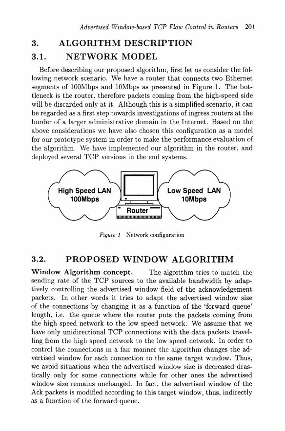
lowing network scenario. We have a router that connects two Ethernet segments of lOOMbps and lOMbps as presented in Figure 1. The bot-tleneck is the router, therefore packets coming from the high-speed side will be discarded only at it. Although this is a simplified scenario, it can be regarded as a first step towards investigations of ingress routers at the border of a larger administrative domain in the Internet. Based on the above considerations we have also chosen this configuration as a model for our prototype system in order to make the performance evaluation of the algorithm. We have implemented our algorithm in the router, and deployed several TCP versions in the end systems.
D Figure 1 Network configuration
3.2. PROPOSED WINDOW ALGORITHM Window Algorithm concept. The algorithm tries to match the sending rate of the TCP sources to the available bandwidth by adap-tively controlling the advertised window field of the acknowledgement packets. In other words it tries to adapt the advertised window size of the connections by changing it as a function of the 'forward queue' length, i.e. the queue where the router puts the packets coming from the high speed network to the low speed network. We assume that we have only unidirectional TCP connections with the data packets travel-ling from the high speed network to the low speed network. In order to control the connections in a fair manner the algorithm changes the ad-vertised window for each connection to the same target window. Thus, we avoid situations when the advertised window size is decreased dras-tically only for some connections while for other ones the advertised window size remains unchanged. In fact, the advertised window of the Ack packets is modified according to this target window, thus, indirectly as a function of the forward queue.
202
D. Oat ackets
Sender
Figure 2 Algorithm concept
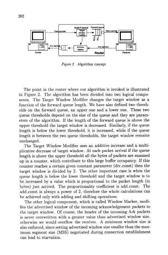
The point in the router where our algorithm is invoked is illustrated in Figure 2. The algorithm has been divided into two logical compo-nents. The Target Window Modifier changes the target window as a function of the forward queue length. We have also defined two thresh-olds on the forward queue, an upper one and a lower one. These two queue thresholds depend on the size of the queue and they are param-eters of the algorithm. If the length of the forward queue is above the upper threshold the target window is decreased. Similarly, if the queue length is below the lower threshold, it is increased, while if the queue length is between the two queue thresholds, the target window remains unchanged.
The Target Window Modifier uses an additive increase and a multi-plicative decrease of target window. At each packet arrival if the queue length is above the upper threshold all the bytes of packets are summed up in a counter, which contribute to this large buffer occupancy. If this counter reaches a certain given constant parameter (div _const) then the target window is divided by 2. The other important case is when the queue length is below the lower threshold and the target window is to be increased by a value which is proportional to the packet length (in bytes) just arrived. The proportionality coefficient is add_const. The add_const is always a power of 2, therefore the whole calculations can be achieved only with adding and shifting operations.
The other logical component, which is called Window Marker, modi-fies the advertised window of the incoming acknowledgement packets to the target window. Of course, the header of the incoming Ack packets is never overwritten with a greater value than advertised window size, otherwise we would overflow the receiver. A minimum window size is also enforced, since setting advertised window size smaller than the max-imum segment size (MSS) negotiated during connection establishment can lead to starvation.
Advertised Window-based TCP Flow Control in Routers 203
Before presenting the way of decreasing and increasing the advertised window size, we describe the window shrinking phenomena and its con-straints imposed on our algorithm.
Window Shrinking. Window shrinking occurs when the right edge of the window moves to the left, i.e. the window size is reduced by a number higher than the currently acknowledged data. The Host Requirements RFC 1122 strongly discourages this, but also says TCP must be able to cope with a peer that does this. However, making mea-surements we have found that some TCP implementations are not able to do that. For a better understanding of window-shrinking phenomena and its influence we are going to present an example.
'" r-- N •• N •• N+. i
N •• N •• ... N.,
i N+' : N.' N.7
N •• i
N •• i , No. N •• i
N., , No' N+S
N.' N.' N.' N"
N+:l N+' N., N.3 N.3
N.2 "'2 N.2 N.2 N.2
No! N., N.I N.! N.!
N N N N N
sender
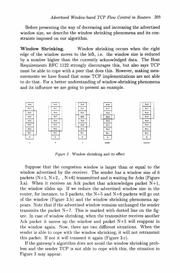
Figure 3 Window shrinking and its effect
Suppose that the congestion window is larger than or equal to the window advertised by the receiver. The sender has a window size of 6 packets (N+1, N+2,. ,N+6) transmitted and is waiting for Acks (Figure 3.a). When it receives an Ack packet that acknowledges packet N+1, the window slides up. If we reduce the advertised window size in the router, for instance, to 3 packets, the N+5 and N+6 packets will go out of the window (Figure 3. b) and the window shrinking phenomena ap-pears. Note that if the advertised window remains unchanged the sender transmits the packet N+7. This is marked with dotted line on the fig-ure. In case of window shrinking, when the transmitter receives another Ack packet it moves up the window and packet N+5 will reappear in the window again. Now, there are two different situations. When the sender is able to cope with the window shrinking, it will not retransmit this packet. If not it will transmit it again (Figure 3.c).
If the gateway's algorithm does not avoid the window shrinking prob-lem and the sender TCP is not able to cope with this, the situation in Figure 3 may appear.
204
Now let us assume that the sender has the window size further reduced to 1 packet. Packets N+5 and N+6 were transmitted but because we shrunk the window packet N +5 is retransmitted. When the receiver gets the packet N +5, it will transmit an Ack packet, which acknowledge the packet N +6. But because packet N +6 is outside the window, the sender will drop this Ack and will transmit again the packet N +5. This leads to an infinite loop.
We have experienced this symptom with the TCP implementation of the Linux 2.0. In this case the window shrinking leads to periodic retransmission of the last acknowledged packet.
A voiding Window Shrinking. The window shrinking is avoided by decreasing the advertised window at once only by the size of the last acknowledged segment. It means that we have to keep the last acknowledged sequence number for every connection, and we reduce the advertised window size only by the difference between the actual Ack sequence number and the last Ack sequence number. For example in Figure 3.b we could decrease the window size only by one packet.
In this way we can get the desired window size without window shrink-ing by gradually decreasing the window as we receive the Ack's. Thus, when the Window Marker receive an Ack packet the target window is always compared to the advertised window of the previous transmitted Ack packet belonging to the same connection. In our case the per-flow maintenance of the advertised window of the previous transmitted Ack packet for every connection is also a subpart of the Window Marker module, but it may also be implemented as a different component.
Finally, we note that the advertised window size is only an upper bound to the congestion window size of the sender. Thus, when the congestion window on the sender side is smaller then the advertised window on the receiver side, e.g. in the slow start phase, the decreasing of the advertised window may be without effect, until the congestion window will be larger than the advertised window. We emphasize that the fastest way to reduce the sending rate of a TCP source would be to directly decrease its congestion window size. However this parameter is controlled by the TCP end system, its value is not advertised to the other TCP hosts. hence it can not be directly changed in the routers.
4. PERFORMANCE EVALUATION In order to make the performance evaluations of this algorithm two
possible approaches have been followed: simulation and benchmarking (measurements). Both of them have advantages and disadvantages. The simulation approach is straightforward since several simulation tools for
Advertised Window-based TCP Flow Control in Routers 205
protocol evaluation are available. However, it may eliminate important elements of TCP specifications and implementations. The performance of the TCP is affected not only by its protocol specification and internal algorithms, but also by its implementation, memory management mech-anism in its underlying operating system and system architecture. On the other hand, the benchmarking method has also limitations because it is not practical to build and use a complex network scenario only for testing purposes.
4.1. MEASUREMENTS In the test network configuration we have used different operating sys-
tems at the receiver and sender side. We have tested the algorithm with TCP versions implemented in the following operating systems: Linux 2.0, 2.2, NetBSD 1.3, SunOS Release 5.6, FreeBSD 3.0, Microsoft Win-dows 95 jNT. All of these operating systems have different TCP imple-mentations. At the router we have used Linux operating system because its source code which was to be modified is freely accessible.
Measurement with Drop-Tail Router. For comparison pur-poses, the measurements for performance evaluation were also performed for cases when there is no control algorithm in the router. All measure-ments presented in this paper are based on sender and receiver hosts with Linux 2.0. However, we observed the same characteristics for all other OSs.
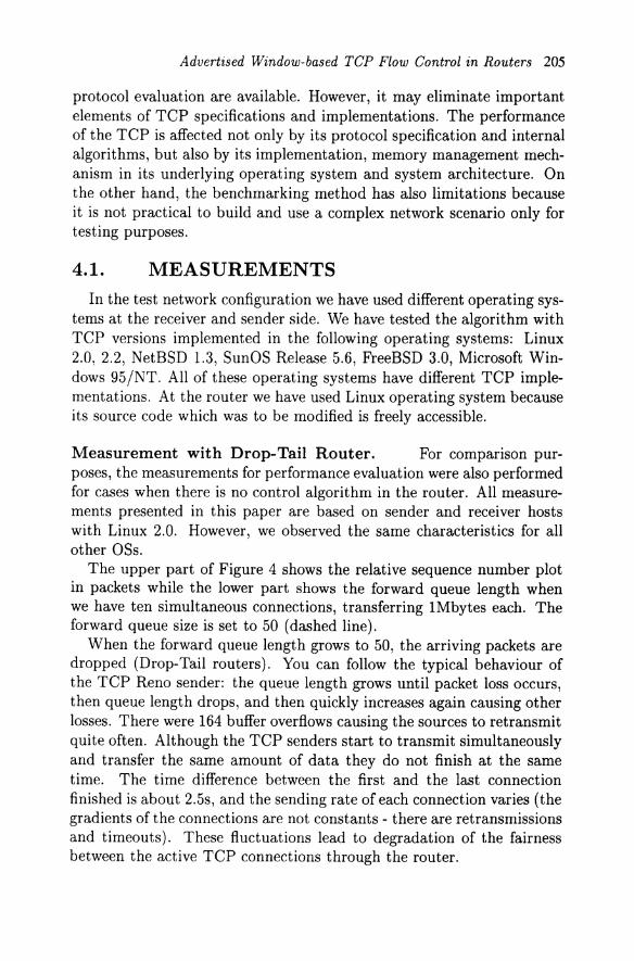
The upper part of Figure 4 shows the relative sequence number plot in packets while the lower part shows the forward queue length when we have ten simultaneous connections, transferring 1Mbytes each. The forward queue size is set to 50 (dashed line).
When the forward queue length grows to 50, the arriving packets are dropped (Drop-Tail routers). You can follow the typical behaviour of the TCP Reno sender: the queue length grows until packet loss occurs, then queue length drops, and then quickly increases again causing other losses. There were 164 buffer overflows causing the sources to retransmit quite often. Although the TCP senders start to transmit simultaneously and transfer the same amount of data they do not finish at the same time. The time difference between the first and the last connection finished is about 2.5s, and the sending rate of each connection varies (the gradients of the connections are not constants - there are retransmissions and timeouts). These fluctuations lead to degradation of the fairness between the active TCP connections through the router.
206
Treee: 3162
1000
i" 800 i!
E
! 400
I
6000 8000 10000 12000 lim. (ms)
o 2000 4000 6000 8000 10000 12000 hme(ms)
Figure 4 Ten connections with Drop-Tail
Trice: U13
14000
I
14000
14000 11m. 1m,)
time (ms)
Fzgure 5 Ten connections with algorithm
Advertised Window-based TCP Flow Control in Routers 207
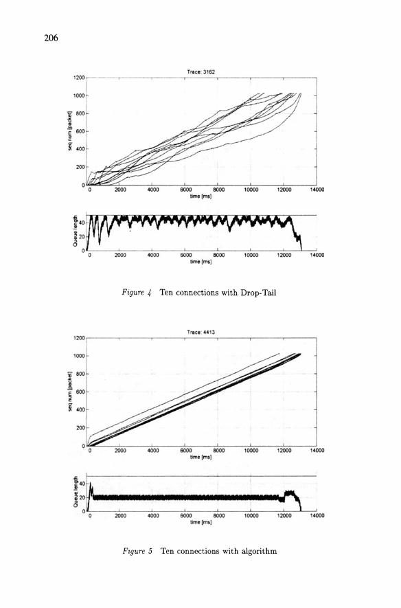
Measurement with algorithm. We have tested the algorithm, with several operating systems and with different traffic generators and the results were very good in all cases. Goodput was slightly increased because packet losses were eliminated, and the fairness was also im-proved. For fairness calculation we have used Jain's measure [8].
We can see on Figure 5 the same measurement scenario as for the Figure 4, but with the proposed algorithm in the router. The forward queue size was also set to 50 packets (dashed line), the upper threshold was set to 35 packets, the lower threshold to 15 packets (dash-dotted lines), the "add_const" parameter to 15 packets and the "div_const" to 64 (the packet size is not considered).
After the slow start period of the connections, after about 200ms the forward queue length is kept below the upper threshold at an almost constant level, eliminating completely the packet losses. The connection, which started first, gets more share of initial throughput, but after the slow-start period all the curves of connections are parallel, which means that the bandwidth is shared equally as the sources transmit at the same rate.
By observing the results in Figure 4 and 5, we find that the through-put differences are small. This is because we measured in small RTT environment and even if we observe packet loss for Figure 4 (with no control algorithm), the TCP sender can perceive the packet loss imme-diately. Therefore although the fairness among connections for figure 4 is worse, the throughput degradation is small.
4.2. SIMULATION
One lack of our prototype network [Figure 1] is that the round trip times (RTT's) of the TCP connections were small having the same val-ues.
TCP connections with large roundtrip time may much dramatically influence (decrease) the overall throughput when packets have been lost, that is to say, throughput of a TCP connection is inversely proportional with its round-trip time value. Moreover, in the measurements presented above we have found that the goodput of the TCP connections is not affected greatly by packet losses which reason is also the small RTT values.
In order to see how our algorithm increases the goodputs of connec-tions with large roundtrip times we have made simulation investigations using the ns network simulator [17].
Network and traffic scenario. We consider simulation of the net-work from Figure 6. The link between the two routers is heavily loaded
208
with background traffic only in one direction from Router1 to Router2. In order to model the background traffic we use FTP connections with large advertised window sizes and small roundtrip times In the simula-tor FTP sources always have a packet to send as soon as the congestion window allows them to do so. A sink at the receiver side immediately sends an Ack packet when it receives a data packet. The FTP sources rely on Reno version of the TCP protocol, i.e. the TCP sender side includes the slow start, congestion avoidance, Fast Recovery and Fast Retransmission mechanism, which are the same as the TCP mechanisms we used in the measurements.
Each FTP sender and FTP receiver is connected to Router1 and Router2, respectively through 10Mbps links. The TCP connections, which the FTP are using, have a maximum window of 64 packets while the delay between the FTP senders and Router1, and FTP receivers and Router2, respectively is chosen from the uniform distribution on [lms, 3ms]. Moreover, they transfer 3 Mbytes data each starting uniform ran-domly between 0 and 120s.
Connection from node FTPSource generates the traffic under test (TUT). The window size for this connection is also 64 packets but the roundtrip time is around 322ms as the delay between the FTPReceiver and Router2 is 150ms. It starts when the link is already congested (at about 60s, to affect also its slow start mechanism) and transmits until the simulation ends (180ms). The packet length of both the background traffic and TUT is 1000 bytes. The queue size in routers was set to 100kBytes. Due to the random characteristic of the starting times of the connections and links delay, we have run each simulation 10 times.
Background traffic Background traffic
10 Mbps Routerl r-------I Router2
IOms
Figure 6 Network scenario for simulation
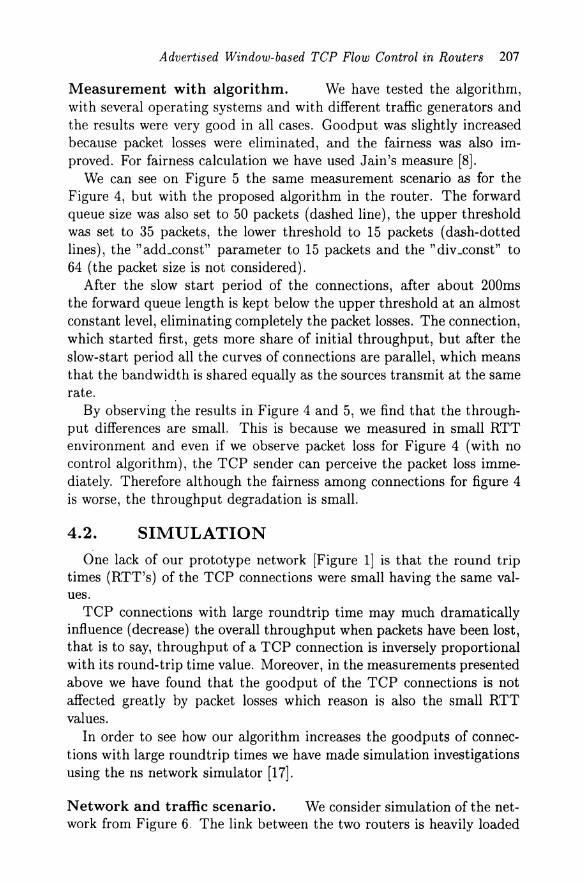
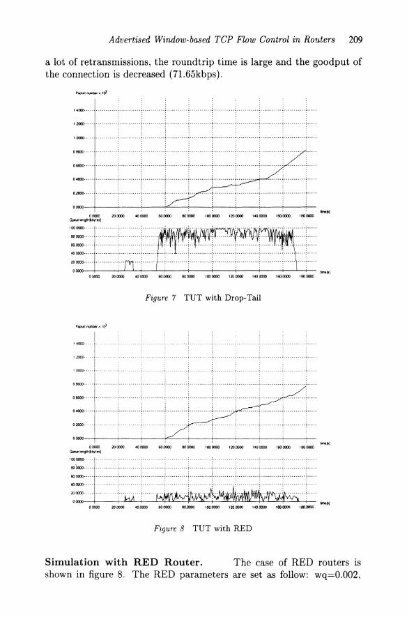
Simulation with Drop-Tail Router. Figure 7 shows the packet number growing of the tested connection and the queue length variation of Router1 using Drop-Tail. We can see that the queue is heavily con-gested between 50s and 180s and there are a lot of packet losses (3421). Therefore the packet number growing of the TUT is not linear, there are
Advertised Window-based TCP Flow Control in Routers 209
a lot of retransmissions, the roundtrip time is large and the goodput of the connection is decreased (71.65kbps).
14000--·-- ... ---.----.- •.•.•.•..••
, , , . --.. .; .. -_ ...... -1-······ --- i'" -_. --_. -.. _.-12000-···· •... - ...•....... •....•... ... - ... .. -- ..• - ..
., . 10000-·--- .. ----.---- •........• _." ..... -..... --_. -_. --.. --. . --. - -. -.. -.. --- ----.. -.. -. : ...... --.
08Q)J··-·- .--.- • -----·-T- ........ (-_ ....... (, ... __ ... : ......... _-: .......... ': ... , 06000···· -_ ...••.•• -- _. - _. _. - _. •• _ .. --_ .. -i' _ ...... -.. i· .. ··· --_. -i _ ... _ .. _ .. -... -... -_ .. i-····· -... - . -....... --_ ..
, , : , : ,
041XWJ---·- ·······1"··········1····· 0=· .. ·· .......... i·· ........ ; .......... j ..... j... . ... .. j ..... " ... j' .. " ' .. "j." .. o()(O)
00000 2000XI 4OCOXI 6O.CXKKI 8CJOCDJ l0000J0 120roKI 140.0000 ISO.1Xm 18CJroKI -'.....,._1
00000 2000XI 400000 60.0000 8CJ00Xl l00OO'Xl 120.0000 14000XI 160.0000 1800000
Figure 7 TUT with Drop-Tail
'4000· -.--
'2000·· .--
10000---
08000·- .-.
06000
04000··_··
t_la) 00000 200000 400000 60.0000 BOOCOO l0000Xl 120.0000 1400000 1600000 18000J0
CMU8lenQthpcbytn)
. ......... ; ........... ; ........... .......... ........... .... .
ao'roJo.· .. , . . , . .
. ..... ........... ........... ........... ........... ........... .... .
60 0000··· . .... . .... : ..••...•... : ••..••.. ··i·········· 'i'" ..... "':' .......... i' .......... i" ......... i······· .... :"'" 1000000 .'j''' .......... . .. Drol····· ... ·····'· .. ... ' ..... .. _ .. .. .. _···
00000 200000 4O.000J 600000 8O.1XOO loo.0c00 1200000 14O.00IXI UIO.oooo IBO.OOOO
Figure 8 TUT with RED
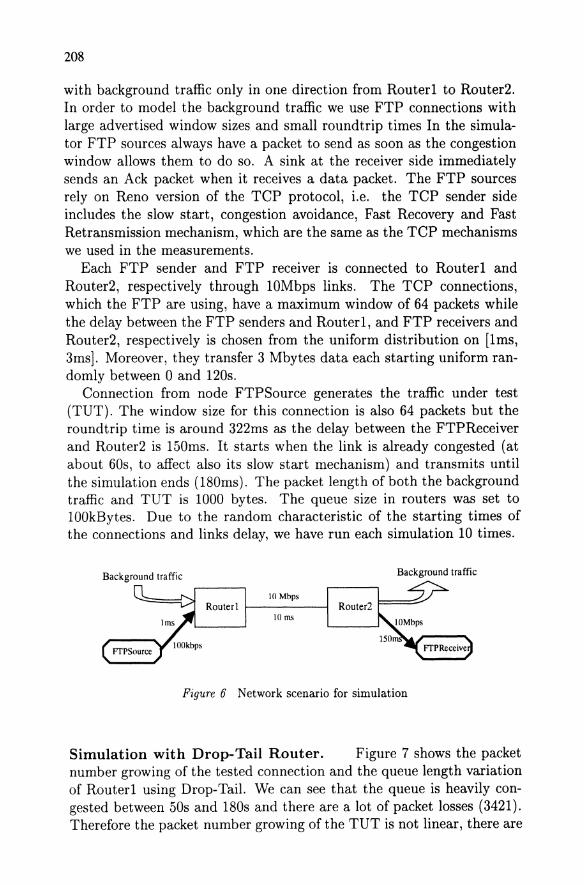
Simulation with RED Router. The case of RED routers is shown in figure 8. The RED parameters are set as follow: wq=O.002,
210
lower threshold 5 packets, upper threshold 15 packets, and maxp=I/50. In this case the queue length is kept low, the congestion is avoided but the number of losses is much higher than in the case of Drop-Tail (10588). These losses cause performance degradation only for the tested connection and not for the background traffic. This is evident since the background traffic has low latency connections and the RED algorithm spreads the losses, which induce Fast Retransmissions and Fast Recovery as we have mentioned in the introduction. Moreover, the TUT has a high-latency connection when the performance is affected much more by the number of losses and not only by their burstiness. The goodput of the tested connection was 70.217kbps.
00000 200000 400000 6000Cl0 800000 1000000 1200000 140.1))((1 160.0000 1800000
[1 tme,,}
000)1) '" 0000 40 OOCIO 60 0000 80 0000 1 00 0000 120 0000 140.0000 1 SO.OOOO
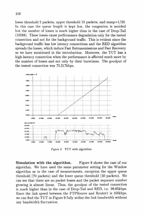
Figure g TUT with algorithm
Simulation with the algorithm. Figure 9 shows the case of our algorithm. We have used the same parameter setting for the Window algorithm as in the case of measurements, exception the upper queue threshold (70 packets) and the lower queue threshold (30 packets). We can see that there are no packet losses and the packet sequence number growing is almost linear. Thus, the goodput of the tested connection is much higher than in the case of Drop-Tail and RED, i.e. 99.65kbps. Since the link speed between the FTPSource and Routerl is 100kbps, we can find the TUT in Figure 9 fully utilize the link bandwidth without any bandwidth fluctuation.
Advertised Window-based TCP Flow Control in Routers 21 I
120
100 Ui' Q. 80 .c
.... ::l 60 Q.
" 0 0 40 DI
-Drop-Tai
20 -*-Algorithn
0 0 50 100 150 200 250
Delay between Router2 and FTPRecelver [ms]
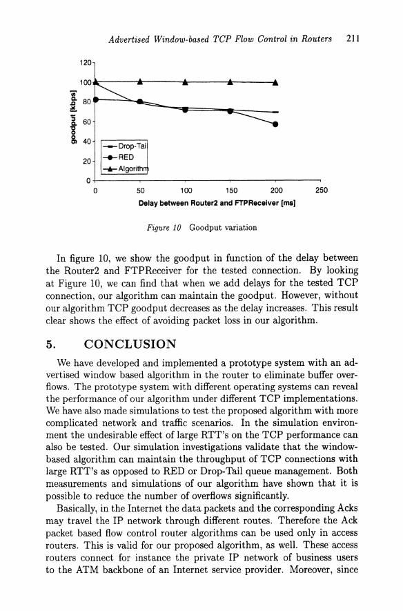
Figure 10 Goodput variation
In figure 10, we show the goodput in function of the delay between the Router2 and FTPReceiver for the tested connection. By looking at Figure 10, we can find that when we add delays for the tested TCP connection, our algorithm can maintain the goodput. However, without our algorithm TCP goodput decreases as the delay increases. This result clear shows the effect of avoiding packet loss in our algorithm.
5. CONCLUSION
We have developed and implemented a prototype system with an ad-vertised window based algorithm in the router to eliminate buffer over-flows. The prototype system with different operating systems can reveal the performance of our algorithm under different TCP implementations. We have also made simulations to test the proposed algorithm with more complicated network and traffic scenarios. In the simulation environ-ment the undesirable effect of large RTT's on the TCP performance can also be tested. Our simulation investigations validate that the window-based algorithm can maintain the throughput of TCP connections with large RTT's as opposed to RED or Drop-Tail queue management. Both measurements and simulations of our algorithm have shown that it is possible to reduce the number of overflows significantly.
Basically, in the Internet the data packets and the corresponding Acks may travel the IP network through different routes. Therefore the Ack packet based flow control router algorithms can be used only in access routers. This is valid for our proposed algorithm, as well. These access routers connect for instance the private IP network of business users to the ATM backbone of an Internet service provider. Moreover, since
212
this algorithm needs to maintain per-flow information its applicability is restricted to such routers, where the per-flow data processing is within acceptable bounds.
Acknowledgments This work has been done in the framework of a joint project between Depart-
ment of Telecommunications and Telematics, Technical University of Budapest and NTT, Japan. The continuous, encouraging and very useful support of our Japanese colleagues is highly appreciated.
References
[1] S. Floyd, K Fall, " Router Mechanisms to Support End-to End Con-gestion Control", http://www-nrg.ee.lbLgov /floyd/papers.html
[2] S. Floyd, V. Jacobson, "Random Early Routers for Congestion Avoidance", http://www-nrg.ee.lbLgov /floyd/papers.html
[3] D. Lin, R. Morris, "Dynamics of Random early Detection", SIG-COMM'97
[4] W. Feng D.D. Kandlur, D. Saha, KG. Shin, "Techniques for Elim-inating Packet Loss in Congested TCP /IP Networks", Technical Report CSE-TR-349-97, University of Michigan, Dept. of Electrical Engineering and Computer Science, Nov. 1997
[5] R. Stevens, TCP lIP Illustrated, VoL 1: The Protocols, Addison Wesley, 1994
[6] KK Ramakrishnan, S. Floyd, "A Proposal to add Explicit Con-gestion Notification (ECN) to IP", RFC 2481, January 1999.
[7] J. Nagle, " Congestion Control in IP /TCP Internetworks" , RFC896, January 1994
[8] R. Jain, "The Art of Computer Systems Performance Analysis", John Wiley and Sons, Inc., New York, 1991
[9] The Linux Documentation Project (LDP), http://sunsite.unc.edu/pub/Linux/docs/LDP /
[10] A. Koike, "TCP flow control with ACR information", ATM Forum/97-0758R1
[11] Y. Murayama, S. Yamaguchi, "DBS: a powerful tool for TCP perfor-mance evaluations", Proc. of Performance and Control of Network Systems, SPIE Volume 3231, pp. 570-581, November 1997
[12] P. Narvez, K-y' Siu, "Acknowledgement bucket scheme for regulat-ing TCP flow over ATM", Computer Networks and ISDN systems 30, pp. 1775-1791, 1998

Advertised Window-based TCP Flow Control in Routers 213
[13J L. Kalampoukas, A. Varma, K. K. Ramakrishnan, Explicit Win-dow Adaptation: A Method to Enhance TCP Performance", IEEE INFOCOM'98
[14J K. Fendick, M. A. Rodriguez, A. ACM SIGCOMM '92, Baltimore, MD, pp.136-148, August 1992. Weiss, "Analysis of a rate based control strategy with delayed feedback", Proc.
[15J I. Moldovan, G. Bajk6, O. Pop, J. Bir, A. Koike, "TCP Flow Con-trol in Routers", ICCC'99, Tokyo, Japan
[16J I. Moldovan, G. Bajk6, O. Pop, J. Bir, A. Koike, "Rate controll algorithm for TCP over ABR", IFIP'99, Antwerp, Belgium
[17J http://www-mash.cs.berkeley.edu/ns/
[18J http://www.cis.ohio-state.edu/htbin/rfc/rfc1122.html
[19J Jae-il Jung, Inhwan Lee, "TCP window control scheme using ER value in TCP over ABR services", Electronics Letters, vol. 35 No.7, April 1999
[20J M. Gerla, R. Lo Cigno, S. Mascolo, W. Weng, "Generalized Win-dow Advertising for TCP Congestion Control", Technical Report No. 990012, University of California Los Angeles, Computer Sci-ence Department, 1999
Appendix A
Processing overhead
Our algorithm uses per-flow statistics and we expect that the pro-cessing costs are proportionally higher as the number of active flows increase. Since the performance characteristics are crucial in this con-text, we considered the cost estimation an important issue. We have identified two components of the costs, the RAM space occupied by the flow-table and the CPU time used to look up this table. We considered that in the current implementation the storage capacity is not a bottle-neck. Even if we store all the information needed for one connection, i.e. TCP /IP port and address field (12 bytes), advertised window size (2 bytes) and Ack sequence number (4 bytes), with the current RAM prices we can handle more than one million flows. The other component, the time consumed for table lookup could severely damage the performance of our algorithm. Further on we will refer to the CPU load caused by the flow-handling routines as processing overhead or as overhead. Some measurement-based estimation of this overhead will be provided.
214
First we have measured the processing time of a packet when we have used our algorithm in the router, then based on these measurements, we compute the processing overhead introduced by our algorithm.
As we tried to measure the packet processing time we had to eliminate two problems. Due to the internal architecture of the NICs (Network Interface Card) and the load on the physical link the delays and losses on a NIC cannot be controlled. As a consequence during the overhead measurements the NICs or its drivers should not process the packets. The other issue was to force the packets to enter our algorithm. The algorithm is implemented in the IP Forwarding module of the IP layer. This module is not used if the packets are sent from or received by an upper layer. If we originate a flow from an upper layer and the destination is the same machine, the packets will be handled in the IP layer by the so-called 'loopback interface'. This is a virtual interface, which operates before the IP Forwarding module.
According to these requirements we have chosen a point in the Op-erating System, where the IP flow already left the input NIC, but did not reach yet the IP layer. It is the input pool of the Operating System, where the data is collected from every peripheral of the system before being distributed to the internal modules. This pool is called in the Linux terminology the 'backlog queue' and we will refer to it the same way. As the time needed for the IP layer to process a packet (us) is much smaller than the time resolution of the operating system (ms) we have measured the processing time for a large number of packets, then averaging them we got the packet processing time.
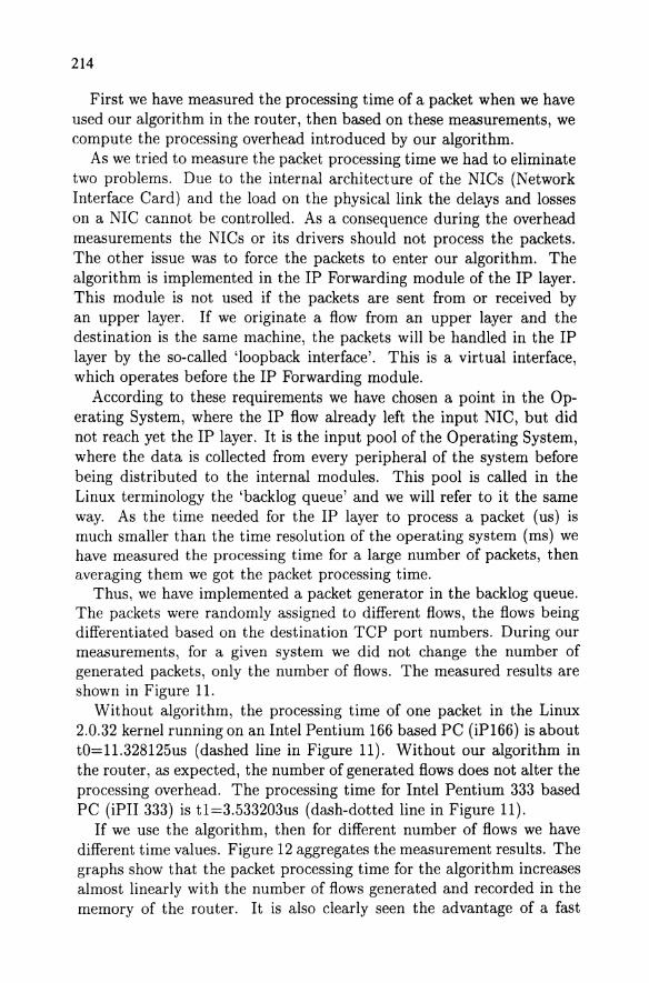
Thus, we have implemented a packet generator in the backlog queue. The packets were randomly assigned to different flows, the flows being differentiated based on the destination TCP port numbers. During our measurements, for a given system we did not change the number of generated packets, only the number of flows. The measured results are shown in Figure 11.
Without algorithm, the processing time of one packet in the Linux 2.0.32 kernel running on an Intel Pentium 166 based PC (iP166) is about to=11.328125us (dashed line in Figure 11). Without our algorithm in the router, as expected, the number of generated flows does not alter the processing overhead. The processing time for Intel Pentium 333 based PC (iPII 333) is t1=3.533203us (dash-dotted line in Figure 11).
If we use the algorithm, then for different number of flows we have different time values. Figure 12 aggregates the measurement results. The graphs show that the packet processing time for the algorithm increases almost linearly with the number of flows generated and recorded in the memory of the router. It is also clearly seen the advantage of a fast

250
200
Advertised Window-based TCP Flow Control in Routers 215
_iP166
_iPII333
-_ IP 166 NoAlg.
I 150 '---------::;;0...----'
.:. 1\1 E j:: 100
50
o 500 1000 1500 2000 2500 3000 3500 4000 4500 5000
Nr. of active flows
Figure 11 Packet proccessing time with and without the algorithm
processor. The delay introduced by the algorithm in the faster PC is less than one fourth than in the case of the iP166 PC. It means that the performance can be significantly improved if we use newer, thus more powerful processors. Also we have to mention that the table lookup procedure used is the simplest linear one. Better performance can also be achieved using an optimized search algorithm.
Having these measurements done, we calculate the overhead intro-duced by our algorithm in the router, due to the incapacity of the IP forwarding function to handle the packets as fast as they come from the NICs. If we consider NIC that has always a packet to the IP layer, the processing overhead depends on the link speed of NIC and packets size. If the packets are smaller, there are more packets on the same bandwidth, thus the router have to handle them faster. In other words the packet size is an important parameter in evaluating the processing overhead introduced by the algorithm.
In the followings we investigate two cases. In the first we have con-sidered the packet size equals to the typical MTU in the Internet, 1500 bytes, while in the second we have considered the worst-case approach, where the packet size is set to a hypothetical average, 500 bytes. The link capacity was set to 100 Megabits/second (we conducted our mea-surements on a Fast Ethernet link). Table 1 and 2 show the process-ing overhead in [iP133 processor and iP333, respectively. For a given packet size we get the maximum number of generated packets per second: pO=100*10242/(1500*8) = 8738 packets/sec for the packets containing 1500 bytes and pl=26214 packets/sec for the 500 bytes long packets. Moreover, for a given number of flows in the lookup table, we also know from the measurements the maximum number of packets that can be

216
transferred in a second if the algorithm is active. While the algorithm can handle more packets then allowed by the link capacity, the pro-cessing overhead of the router is considered Othe ratio of the maximum transferable packet rate and pO (or pI).
Nr of flows I Processing overhead[%] with MTU=
10 500 1000 2500 5000
1500 bytes o o 12 43 71
Table 1 iP 166
Nr of flows I Processing overhead[%] with MTU=
10 500 1000 2500 5000
1500 bytes o o o o 3
Table 2 iP II 333
500 bytes o 38 70 81 90
500 bytes o o o 39 68
As a conclusion, the processing overhead is found to be acceptable for an Intel Pentium133 PC up to almost 900 flows if the packet has the MTU size, and 300 if the packet size is 500 byte. In the case of Intel Pentiumll 333 the same value are 4900 flows and 1500 flows, respectively.
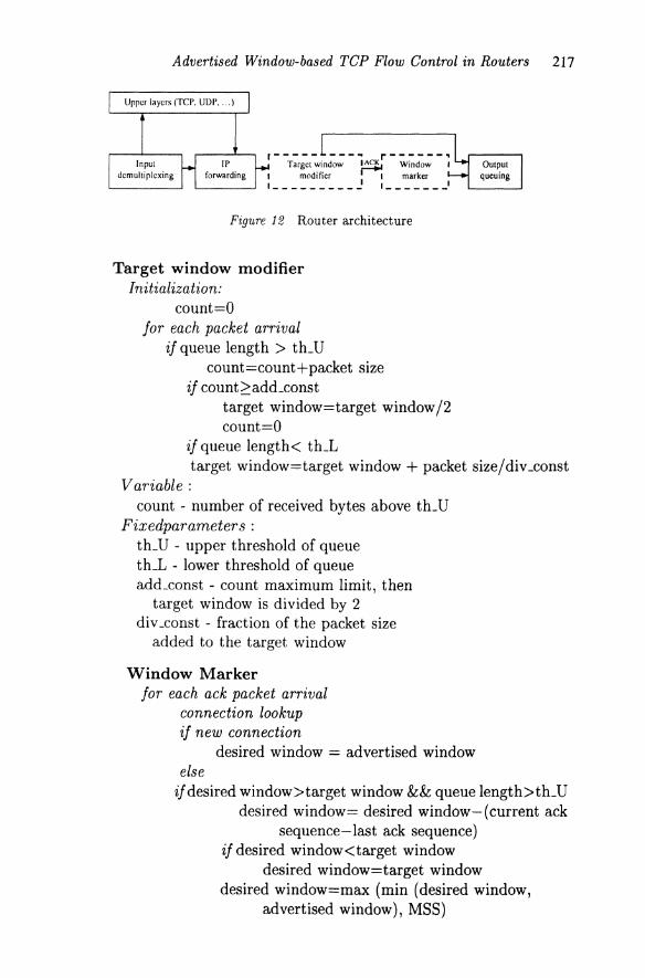
Appendix B Figure 12 shows how the data packets are processed in a router. IP
forwarding includes the selection of the output interface, the selection of the next hop, encapsulation, etc. Once all this is done, packets are queued on the respective output interface. The point where our algo-rithm is invoked is illustrated in figure 12 with dotted line. Note that each of the output queues of a router should have associated a Target window modifier and a Window marker.
Advertised Window-based TCP Flow Control in Routers 217
,----- r------· Target window Window ,
1 modifier ',marker 1 ______ ----' , _______ ,
Figure 12 Router architecture
Target window modifier Initialization:
count=O for each packet arrival
if queue length > th_U count=count+packet size
if target window=target window /2 count=O
if queue length < th_L target window=target window + packet size/div_const
Variable: count - number of received bytes above th_U
Fixedparameter s : th_U - upper threshold of queue th.L - lower threshold of queue add_const - count maximum limit, then
target window is divided by 2 div _const - fraction of the packet size
added to the target window
Window Marker for each ack packet arrival
connection lookup if new connection
desired window = advertised window else
ifdesired window> target window && queue length>th_U desired window= desired window-(current ack
sequence-last ack sequence) if desired window<target window
desired window=target window desired window=max (min (desired window,
advertised window), MSS)
218
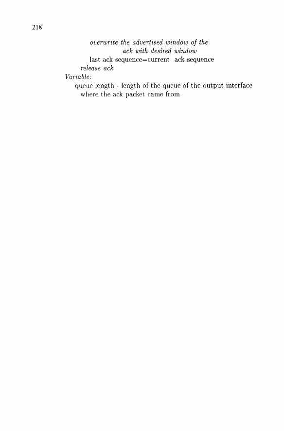
overwrite the advertised window of the ack with desired window
last ack sequence=current ack sequence release ack
Variable: queue length - length of the queue of the output interface
where the ack packet came from
Related Documents