i Notices SCOPE OF THIS MANUAL This document describes the installation and maintenance procedures for the N-Series Automatic Circuit Recloser with ADVC Controller Range. LIMITATIONS This document is copyright and is provided solely for the use of the purchaser. It is not to be copied in any way, nor its contents divulged to any third party, nor to be used as the basis of a tender or specification without the express written permission of the manufacturer. DISCLAIMER The advisory procedures and information contained within this Manual have been compiled as a guide to the safe and effective operation of products supplied by Nu-Lec Industries Pty Ltd. It has been prepared in conjunction with references from sub-assembly suppliers and the collective experience of the manufacturer. In-service conditions for use of the products may vary between customers and end-users. Consequently, this Manual is offered as a guide only. It should be used in conjunction with the customers own safety procedures, maintenance program, engineering judgement and training qualifications. No responsibility, either direct or consequential, for injury or equipment failure can be accepted by Nu-Lec Industries Pty Ltd resulting from the use of this Manual. COPYRIGHT © 2008 by Nu-Lec Industries Pty Ltd. All rights reserved. No part of the contents of this document may be reproduced or transmitted in any form or by any means without the written permission of the manufacturer. REVISION RECORD Level Date Comment R00 26 September, 2005 First Release R01 23 January, 2006 Progressive updates R02 22 November, 2006 ADVC Version 42 R03 2 September, 2008 ADVC Version 44

ADVC2-1161 ADVC N Series Installation Manual R03 PRESS
Dec 27, 2015
Welcome message from author
This document is posted to help you gain knowledge. Please leave a comment to let me know what you think about it! Share it to your friends and learn new things together.
Transcript
i
Notices
Scope of thiS Manual
This document describes the installation and maintenance procedures for the N-Series Automatic Circuit Recloser with ADVC Controller Range.
liMitationS
This document is copyright and is provided solely for the use of the purchaser. It is not to be copied in any way, nor its contents divulged to any third party, nor to be used as the basis of a tender or specification without the express written permission of the manufacturer.
DiSclaiMer
The advisory procedures and information contained within this Manual have been compiled as a guide to the safe and effective operation of products supplied by Nu-Lec Industries Pty Ltd.
It has been prepared in conjunction with references from sub-assembly suppliers and the collective experience of the manufacturer.
In-service conditions for use of the products may vary between customers and end-users. Consequently, this Manual is offered as a guide only. It should be used in conjunction with the customers own safety procedures, maintenance program, engineering judgement and training qualifications.
No responsibility, either direct or consequential, for injury or equipment failure can be accepted by Nu-Lec Industries Pty Ltd resulting from the use of this Manual.
copyright
© 2008 by Nu-Lec Industries Pty Ltd.
All rights reserved. No part of the contents of this document may be reproduced or transmitted in any form or by any means without the written permission of the manufacturer.
reviSion recorD
Level Date CommentR00 26 September, 2005 First ReleaseR01 23 January, 2006 Progressive updatesR02 22 November, 2006 ADVC Version 42 R03 2 September, 2008 ADVC Version 44

ii
N-Series Recloser with ADVC Controller
ii
CoNteNtsNotices � � � � � � � � � � � � � � � � � � � � � � � � � � � � � � � � � � � � � � � � � � � � � � � � � � � � � � � � � � � � � � � � � � � � � � � � � � � � � � � � � � � � � � � � � � � � � � � � � � � � � � � � � � � � � � � � � � � � � � � � � � � � � � � � i
Scope of thiS Manual � � � � � � � � � � � � � � � � � � � � � � � � � � � � � � � � � � � � � � � � � � � � � � � � � � � � � � � � � � � � � � � � � � � � � � � � � � � � � � � � � � � � � � � � � � � � � � � � � � � � � � � � � � � � � iliMitationS � � � � � � � � � � � � � � � � � � � � � � � � � � � � � � � � � � � � � � � � � � � � � � � � � � � � � � � � � � � � � � � � � � � � � � � � � � � � � � � � � � � � � � � � � � � � � � � � � � � � � � � � � � � � � � � � � � � � � � � � � � � � iDiSclaiMer � � � � � � � � � � � � � � � � � � � � � � � � � � � � � � � � � � � � � � � � � � � � � � � � � � � � � � � � � � � � � � � � � � � � � � � � � � � � � � � � � � � � � � � � � � � � � � � � � � � � � � � � � � � � � � � � � � � � � � � � � � � � icopyright � � � � � � � � � � � � � � � � � � � � � � � � � � � � � � � � � � � � � � � � � � � � � � � � � � � � � � � � � � � � � � � � � � � � � � � � � � � � � � � � � � � � � � � � � � � � � � � � � � � � � � � � � � � � � � � � � � � � � � � � � � � � ireviSion recorD � � � � � � � � � � � � � � � � � � � � � � � � � � � � � � � � � � � � � � � � � � � � � � � � � � � � � � � � � � � � � � � � � � � � � � � � � � � � � � � � � � � � � � � � � � � � � � � � � � � � � � � � � � � � � � � � � � � i
Contents � � � � � � � � � � � � � � � � � � � � � � � � � � � � � � � � � � � � � � � � � � � � � � � � � � � � � � � � � � � � � � � � � � � � � � � � � � � � � � � � � � � � � � � � � � � � � � � � � � � � � � � � � � � � � � � � � � � � � � � � � � � � � � ii
1 scope of this Manual � � � � � � � � � � � � � � � � � � � � � � � � � � � � � � � � � � � � � � � � � � � � � � � � � � � � � � � � � � � � � � � � � � � � � � � � � � � � � � � � � � � � � � � � � � � � � � � � � � � 1-1general � � � � � � � � � � � � � � � � � � � � � � � � � � � � � � � � � � � � � � � � � � � � � � � � � � � � � � � � � � � � � � � � � � � � � � � � � � � � � � � � � � � � � � � � � � � � � � � � � � � � � � � � � � � � � � � � � � � � � � � � � � 1-1equipMent verSionS covereD by thiS Manual � � � � � � � � � � � � � � � � � � � � � � � � � � � � � � � � � � � � � � � � � � � � � � � � � � � � � � � � � � � � � � � � � � � � � � � � � � � 1-1SyMbolS � � � � � � � � � � � � � � � � � � � � � � � � � � � � � � � � � � � � � � � � � � � � � � � � � � � � � � � � � � � � � � � � � � � � � � � � � � � � � � � � � � � � � � � � � � � � � � � � � � � � � � � � � � � � � � � � � � � � � � � � � � � 1-1Software iDentification � � � � � � � � � � � � � � � � � � � � � � � � � � � � � � � � � � � � � � � � � � � � � � � � � � � � � � � � � � � � � � � � � � � � � � � � � � � � � � � � � � � � � � � � � � � � � � � � � � � � � � 1-2abbreviationS � � � � � � � � � � � � � � � � � � � � � � � � � � � � � � � � � � � � � � � � � � � � � � � � � � � � � � � � � � � � � � � � � � � � � � � � � � � � � � � � � � � � � � � � � � � � � � � � � � � � � � � � � � � � � � � � � � � � 1-2
2 Introduction � � � � � � � � � � � � � � � � � � � � � � � � � � � � � � � � � � � � � � � � � � � � � � � � � � � � � � � � � � � � � � � � � � � � � � � � � � � � � � � � � � � � � � � � � � � � � � � � � � � � � � � � � � � � � � � � � � 2-1terMinology � � � � � � � � � � � � � � � � � � � � � � � � � � � � � � � � � � � � � � � � � � � � � � � � � � � � � � � � � � � � � � � � � � � � � � � � � � � � � � � � � � � � � � � � � � � � � � � � � � � � � � � � � � � � � � � � � � � � � 2-3
3 Installation � � � � � � � � � � � � � � � � � � � � � � � � � � � � � � � � � � � � � � � � � � � � � � � � � � � � � � � � � � � � � � � � � � � � � � � � � � � � � � � � � � � � � � � � � � � � � � � � � � � � � � � � � � � � � � � � � � � � 3-1contentS of crate � � � � � � � � � � � � � � � � � � � � � � � � � � � � � � � � � � � � � � � � � � � � � � � � � � � � � � � � � � � � � � � � � � � � � � � � � � � � � � � � � � � � � � � � � � � � � � � � � � � � � � � � � � � � 3-1unpacking proceDure � � � � � � � � � � � � � � � � � � � � � � � � � � � � � � � � � � � � � � � � � � � � � � � � � � � � � � � � � � � � � � � � � � � � � � � � � � � � � � � � � � � � � � � � � � � � � � � � � � � � � � � � 3-1control cable connection � � � � � � � � � � � � � � � � � � � � � � � � � � � � � � � � � � � � � � � � � � � � � � � � � � � � � � � � � � � � � � � � � � � � � � � � � � � � � � � � � � � � � � � � � � � � � � � � � 3-2teSting & configuring � � � � � � � � � � � � � � � � � � � � � � � � � � � � � � � � � � � � � � � � � � � � � � � � � � � � � � � � � � � � � � � � � � � � � � � � � � � � � � � � � � � � � � � � � � � � � � � � � � � � � � � 3-2tranSport to Site � � � � � � � � � � � � � � � � � � � � � � � � � � � � � � � � � � � � � � � � � � � � � � � � � � � � � � � � � � � � � � � � � � � � � � � � � � � � � � � � � � � � � � � � � � � � � � � � � � � � � � � � � � � � � 3-3Site inStallation � � � � � � � � � � � � � � � � � � � � � � � � � � � � � � � � � � � � � � � � � � � � � � � � � � � � � � � � � � � � � � � � � � � � � � � � � � � � � � � � � � � � � � � � � � � � � � � � � � � � � � � � � � � � � � � � 3-3
Tools Required . . . . . . . . . . . . . . . . . . . . . . . . . . . . . . . . . . . . . . . . . . . . . . . . . . . . . . . . . . . . . . . . . . . . . . . . . . . . . . . . . . . . . . . . . . . . . . . . . . . . . . . . . . . . . . 3-3Parts Required (Not supplied by the manufacturer) . . . . . . . . . . . . . . . . . . . . . . . . . . . . . . . . . . . . . . . . . . . . . . . . . . . . . . . . . . . . . . 3-3Site Procedure . . . . . . . . . . . . . . . . . . . . . . . . . . . . . . . . . . . . . . . . . . . . . . . . . . . . . . . . . . . . . . . . . . . . . . . . . . . . . . . . . . . . . . . . . . . . . . . . . . . . . . . . . . . . . . 3-4Cable Tail Connections . . . . . . . . . . . . . . . . . . . . . . . . . . . . . . . . . . . . . . . . . . . . . . . . . . . . . . . . . . . . . . . . . . . . . . . . . . . . . . . . . . . . . . . . . . . . . . . . . . . 3-6Surge Arrester Mounting and Terminating . . . . . . . . . . . . . . . . . . . . . . . . . . . . . . . . . . . . . . . . . . . . . . . . . . . . . . . . . . . . . . . . . . . . . . . . . . . 3-7Earthing (Grounding) . . . . . . . . . . . . . . . . . . . . . . . . . . . . . . . . . . . . . . . . . . . . . . . . . . . . . . . . . . . . . . . . . . . . . . . . . . . . . . . . . . . . . . . . . . . . . . . . . . 3-8LV Auxiliary Power from Mains . . . . . . . . . . . . . . . . . . . . . . . . . . . . . . . . . . . . . . . . . . . . . . . . . . . . . . . . . . . . . . . . . . . . . . . . . . . . . . . . . . . . . . . . . 3-8LV Auxiliary Power from Dedicated Utility Transformer . . . . . . . . . . . . . . . . . . . . . . . . . . . . . . . . . . . . . . . . . . . . . . . . . . . . . . . . . . 3-8Auxiliary Power from Integrated Transformer . . . . . . . . . . . . . . . . . . . . . . . . . . . . . . . . . . . . . . . . . . . . . . . . . . . . . . . . . . . . . . . . . . . . . . . 3-8
4 Communications and Accessories Installation � � � � � � � � � � � � � � � � � � � � � � � � � � � � � � � � � � � � � � � � � � � � � � � � � � � � � � � � 4-1raDio antenna � � � � � � � � � � � � � � � � � � � � � � � � � � � � � � � � � � � � � � � � � � � � � � � � � � � � � � � � � � � � � � � � � � � � � � � � � � � � � � � � � � � � � � � � � � � � � � � � � � � � � � � � � � � � � � � � � � 4-1
Protection of Radio Equipment . . . . . . . . . . . . . . . . . . . . . . . . . . . . . . . . . . . . . . . . . . . . . . . . . . . . . . . . . . . . . . . . . . . . . . . . . . . . . . . . . . . . . . . . . 4-1the cuStoMer coMpartMent � � � � � � � � � � � � � � � � � � � � � � � � � � � � � � � � � � � � � � � � � � � � � � � � � � � � � � � � � � � � � � � � � � � � � � � � � � � � � � � � � � � � � � � � � � � � � � � � 4-2
Connecting to the Terminal Block . . . . . . . . . . . . . . . . . . . . . . . . . . . . . . . . . . . . . . . . . . . . . . . . . . . . . . . . . . . . . . . . . . . . . . . . . . . . . . . . . . . . . . 4-2Radio/Modem Power . . . . . . . . . . . . . . . . . . . . . . . . . . . . . . . . . . . . . . . . . . . . . . . . . . . . . . . . . . . . . . . . . . . . . . . . . . . . . . . . . . . . . . . . . . . . . . . . . . . . . . 4-3
ioeX2 inStallation � � � � � � � � � � � � � � � � � � � � � � � � � � � � � � � � � � � � � � � � � � � � � � � � � � � � � � � � � � � � � � � � � � � � � � � � � � � � � � � � � � � � � � � � � � � � � � � � � � � � � � � � � � � � 4-4coMMunication portS � � � � � � � � � � � � � � � � � � � � � � � � � � � � � � � � � � � � � � � � � � � � � � � � � � � � � � � � � � � � � � � � � � � � � � � � � � � � � � � � � � � � � � � � � � � � � � � � � � � � � � � � � 4-5
RS232 . . . . . . . . . . . . . . . . . . . . . . . . . . . . . . . . . . . . . . . . . . . . . . . . . . . . . . . . . . . . . . . . . . . . . . . . . . . . . . . . . . . . . . . . . . . . . . . . . . . . . . . . . . . . . . . . . . . . . . . . . 4-5RS485 . . . . . . . . . . . . . . . . . . . . . . . . . . . . . . . . . . . . . . . . . . . . . . . . . . . . . . . . . . . . . . . . . . . . . . . . . . . . . . . . . . . . . . . . . . . . . . . . . . . . . . . . . . . . . . . . . . . . . . . . . 4-6V23 FSK . . . . . . . . . . . . . . . . . . . . . . . . . . . . . . . . . . . . . . . . . . . . . . . . . . . . . . . . . . . . . . . . . . . . . . . . . . . . . . . . . . . . . . . . . . . . . . . . . . . . . . . . . . . . . . . . . . . . . . 4-6Ethernet . . . . . . . . . . . . . . . . . . . . . . . . . . . . . . . . . . . . . . . . . . . . . . . . . . . . . . . . . . . . . . . . . . . . . . . . . . . . . . . . . . . . . . . . . . . . . . . . . . . . . . . . . . . . . . . . . . . . . . . 4-7Windows Switchgear Operating System (WSOS) . . . . . . . . . . . . . . . . . . . . . . . . . . . . . . . . . . . . . . . . . . . . . . . . . . . . . . . . . . . . . . . . . 4-7SCADA Protocols . . . . . . . . . . . . . . . . . . . . . . . . . . . . . . . . . . . . . . . . . . . . . . . . . . . . . . . . . . . . . . . . . . . . . . . . . . . . . . . . . . . . . . . . . . . . . . . . . . . . . . . . . . . 4-7
Contents
iii
5 testing Your Installation � � � � � � � � � � � � � � � � � � � � � � � � � � � � � � � � � � � � � � � � � � � � � � � � � � � � � � � � � � � � � � � � � � � � � � � � � � � � � � � � � � � � � � � � � � � � � 5-1powering up the aDvc � � � � � � � � � � � � � � � � � � � � � � � � � � � � � � � � � � � � � � � � � � � � � � � � � � � � � � � � � � � � � � � � � � � � � � � � � � � � � � � � � � � � � � � � � � � � � � � � � � � � � 5-1battery � � � � � � � � � � � � � � � � � � � � � � � � � � � � � � � � � � � � � � � � � � � � � � � � � � � � � � � � � � � � � � � � � � � � � � � � � � � � � � � � � � � � � � � � � � � � � � � � � � � � � � � � � � � � � � � � � � � � � � � � � � � � 5-2connection between the aDvc anD the acr � � � � � � � � � � � � � � � � � � � � � � � � � � � � � � � � � � � � � � � � � � � � � � � � � � � � � � � � � � � � � � � � � � � � � � � � 5-2auXiliary Supply � � � � � � � � � � � � � � � � � � � � � � � � � � � � � � � � � � � � � � � � � � � � � � � � � � � � � � � � � � � � � � � � � � � � � � � � � � � � � � � � � � � � � � � � � � � � � � � � � � � � � � � � � � � � � � � � 5-3work tag � � � � � � � � � � � � � � � � � � � � � � � � � � � � � � � � � � � � � � � � � � � � � � � � � � � � � � � � � � � � � � � � � � � � � � � � � � � � � � � � � � � � � � � � � � � � � � � � � � � � � � � � � � � � � � � � � � � � � � � � 5-3terMinal DeSignation anD phaSe rotation � � � � � � � � � � � � � � � � � � � � � � � � � � � � � � � � � � � � � � � � � � � � � � � � � � � � � � � � � � � � � � � � � � � � � � � � � � � � � 5-4power flow Direction Setting � � � � � � � � � � � � � � � � � � � � � � � � � � � � � � � � � � � � � � � � � � � � � � � � � � � � � � � � � � � � � � � � � � � � � � � � � � � � � � � � � � � � � � � � � � � � 5-5tripping anD cloSing � � � � � � � � � � � � � � � � � � � � � � � � � � � � � � � � � � � � � � � � � � � � � � � � � � � � � � � � � � � � � � � � � � � � � � � � � � � � � � � � � � � � � � � � � � � � � � � � � � � � � � � � � � 5-6enable/DiSable SwitcheS � � � � � � � � � � � � � � � � � � � � � � � � � � � � � � � � � � � � � � � � � � � � � � � � � � � � � � � � � � � � � � � � � � � � � � � � � � � � � � � � � � � � � � � � � � � � � � � � � � � � 5-6Mechanical trip � � � � � � � � � � � � � � � � � � � � � � � � � � � � � � � � � � � � � � � � � � � � � � � � � � � � � � � � � � � � � � � � � � � � � � � � � � � � � � � � � � � � � � � � � � � � � � � � � � � � � � � � � � � � � � � � 5-6SeconDary injection teSting � � � � � � � � � � � � � � � � � � � � � � � � � � � � � � � � � � � � � � � � � � � � � � � � � � � � � � � � � � � � � � � � � � � � � � � � � � � � � � � � � � � � � � � � � � � � � � � 5-6priMary injection teSting � � � � � � � � � � � � � � � � � � � � � � � � � � � � � � � � � � � � � � � � � � � � � � � � � � � � � � � � � � � � � � � � � � � � � � � � � � � � � � � � � � � � � � � � � � � � � � � � � � � 5-6power flow Direction teSting � � � � � � � � � � � � � � � � � � � � � � � � � � � � � � � � � � � � � � � � � � � � � � � � � � � � � � � � � � � � � � � � � � � � � � � � � � � � � � � � � � � � � � � � � � � � 5-7on loaD checkS � � � � � � � � � � � � � � � � � � � � � � � � � � � � � � � � � � � � � � � � � � � � � � � � � � � � � � � � � � � � � � � � � � � � � � � � � � � � � � � � � � � � � � � � � � � � � � � � � � � � � � � � � � � � � � � � 5-8
6 Control electronics operation � � � � � � � � � � � � � � � � � � � � � � � � � � � � � � � � � � � � � � � � � � � � � � � � � � � � � � � � � � � � � � � � � � � � � � � � � � � � � � � � � � � � 6-1Sealing & conDenSation � � � � � � � � � � � � � � � � � � � � � � � � � � � � � � � � � � � � � � � � � � � � � � � � � � � � � � � � � � � � � � � � � � � � � � � � � � � � � � � � � � � � � � � � � � � � � � � � � � � � � 6-1auXiliary power Source � � � � � � � � � � � � � � � � � � � � � � � � � � � � � � � � � � � � � � � � � � � � � � � � � � � � � � � � � � � � � � � � � � � � � � � � � � � � � � � � � � � � � � � � � � � � � � � � � � � � � 6-1controller � � � � � � � � � � � � � � � � � � � � � � � � � � � � � � � � � � � � � � � � � � � � � � � � � � � � � � � � � � � � � � � � � � � � � � � � � � � � � � � � � � � � � � � � � � � � � � � � � � � � � � � � � � � � � � � � � � � � � � 6-1
PSU Module . . . . . . . . . . . . . . . . . . . . . . . . . . . . . . . . . . . . . . . . . . . . . . . . . . . . . . . . . . . . . . . . . . . . . . . . . . . . . . . . . . . . . . . . . . . . . . . . . . . . . . . . . . . . . . . . . 6-1CAPE Module . . . . . . . . . . . . . . . . . . . . . . . . . . . . . . . . . . . . . . . . . . . . . . . . . . . . . . . . . . . . . . . . . . . . . . . . . . . . . . . . . . . . . . . . . . . . . . . . . . . . . . . . . . . . . . . 6-1
cuStoMer coMpartMent � � � � � � � � � � � � � � � � � � � � � � � � � � � � � � � � � � � � � � � � � � � � � � � � � � � � � � � � � � � � � � � � � � � � � � � � � � � � � � � � � � � � � � � � � � � � � � � � � � � � � � 6-2PROTECTION AND COMMUNICATION SUBMODULE (PCOM) . . . . . . . . . . . . . . . . . . . . . . . . . . . . . . . . . . . . . . . . . . . . . 6-2POWER SUPPLY AND SWITCHGEAR MODULE (PSSM) . . . . . . . . . . . . . . . . . . . . . . . . . . . . . . . . . . . . . . . . . . . . . . . . . . . . . 6-2
operator interface/Door aSSeMbly � � � � � � � � � � � � � � � � � � � � � � � � � � � � � � � � � � � � � � � � � � � � � � � � � � � � � � � � � � � � � � � � � � � � � � � � � � � � � � � � � � � � � 6-2WSOS5 Interface . . . . . . . . . . . . . . . . . . . . . . . . . . . . . . . . . . . . . . . . . . . . . . . . . . . . . . . . . . . . . . . . . . . . . . . . . . . . . . . . . . . . . . . . . . . . . . . . . . . . . . . . . . 6-2
cuStoMer coMpartMent(S) � � � � � � � � � � � � � � � � � � � � � � � � � � � � � � � � � � � � � � � � � � � � � � � � � � � � � � � � � � � � � � � � � � � � � � � � � � � � � � � � � � � � � � � � � � � � � � � � � � 6-3
7 operator Interface � � � � � � � � � � � � � � � � � � � � � � � � � � � � � � � � � � � � � � � � � � � � � � � � � � � � � � � � � � � � � � � � � � � � � � � � � � � � � � � � � � � � � � � � � � � � � � � � � � � � � � � � 7-1 setVUE panel � � � � � � � � � � � � � � � � � � � � � � � � � � � � � � � � � � � � � � � � � � � � � � � � � � � � � � � � � � � � � � � � � � � � � � � � � � � � � � � � � � � � � � � � � � � � � � � � � � � � � � � � � � � � � � 7-2DiSplay groupS � � � � � � � � � � � � � � � � � � � � � � � � � � � � � � � � � � � � � � � � � � � � � � � � � � � � � � � � � � � � � � � � � � � � � � � � � � � � � � � � � � � � � � � � � � � � � � � � � � � � � � � � � � � � � 7-3Navigating the Menu Structure . . . . . . . . . . . . . . . . . . . . . . . . . . . . . . . . . . . . . . . . . . . . . . . . . . . . . . . . . . . . . . . . . . . . . . . . . . . . . . . . . . . . . . . . . 7-3
DiSplay Screen layout � � � � � � � � � � � � � � � � � � � � � � � � � � � � � � � � � � � � � � � � � � � � � � � � � � � � � � � � � � � � � � � � � � � � � � � � � � � � � � � � � � � � � � � � � � � � � � � � � � � � � � 7-3changing SettingS � � � � � � � � � � � � � � � � � � � � � � � � � � � � � � � � � � � � � � � � � � � � � � � � � � � � � � � � � � � � � � � � � � � � � � � � � � � � � � � � � � � � � � � � � � � � � � � � � � � � � � � � � � � � � 7-4
Operator Settings . . . . . . . . . . . . . . . . . . . . . . . . . . . . . . . . . . . . . . . . . . . . . . . . . . . . . . . . . . . . . . . . . . . . . . . . . . . . . . . . . . . . . . . . . . . . . . . . . . . . . . . . . . 7-4Password Protected Settings . . . . . . . . . . . . . . . . . . . . . . . . . . . . . . . . . . . . . . . . . . . . . . . . . . . . . . . . . . . . . . . . . . . . . . . . . . . . . . . . . . . . . . . . . . 7-4Protection Settings . . . . . . . . . . . . . . . . . . . . . . . . . . . . . . . . . . . . . . . . . . . . . . . . . . . . . . . . . . . . . . . . . . . . . . . . . . . . . . . . . . . . . . . . . . . . . . . . . . . . . . . . 7-5
quick keyS � � � � � � � � � � � � � � � � � � � � � � � � � � � � � � � � � � � � � � � � � � � � � � � � � � � � � � � � � � � � � � � � � � � � � � � � � � � � � � � � � � � � � � � � � � � � � � � � � � � � � � � � � � � � � � � � � � � � � � � 7-5 flexVUE panel � � � � � � � � � � � � � � � � � � � � � � � � � � � � � � � � � � � � � � � � � � � � � � � � � � � � � � � � � � � � � � � � � � � � � � � � � � � � � � � � � � � � � � � � � � � � � � � � � � � � � � � � � � � � � 7-6Default configuration � � � � � � � � � � � � � � � � � � � � � � � � � � � � � � � � � � � � � � � � � � � � � � � � � � � � � � � � � � � � � � � � � � � � � � � � � � � � � � � � � � � � � � � � � � � � � � � � � � � 7-8Status Lamps . . . . . . . . . . . . . . . . . . . . . . . . . . . . . . . . . . . . . . . . . . . . . . . . . . . . . . . . . . . . . . . . . . . . . . . . . . . . . . . . . . . . . . . . . . . . . . . . . . . . . . . . . . . . . . . . 7-8Quick Action Keys . . . . . . . . . . . . . . . . . . . . . . . . . . . . . . . . . . . . . . . . . . . . . . . . . . . . . . . . . . . . . . . . . . . . . . . . . . . . . . . . . . . . . . . . . . . . . . . . . . . . . . . . . . 7-9
DiSplay groupS � � � � � � � � � � � � � � � � � � � � � � � � � � � � � � � � � � � � � � � � � � � � � � � � � � � � � � � � � � � � � � � � � � � � � � � � � � � � � � � � � � � � � � � � � � � � � � � � � � � � � � � � � � � � � � � 7-11Navigating the Menu Structure . . . . . . . . . . . . . . . . . . . . . . . . . . . . . . . . . . . . . . . . . . . . . . . . . . . . . . . . . . . . . . . . . . . . . . . . . . . . . . . . . . . . . . . 7-11
DiSplay Screen layout � � � � � � � � � � � � � � � � � � � � � � � � � � � � � � � � � � � � � � � � � � � � � � � � � � � � � � � � � � � � � � � � � � � � � � � � � � � � � � � � � � � � � � � � � � � � � � � � � � � � 7-11changing SettingS � � � � � � � � � � � � � � � � � � � � � � � � � � � � � � � � � � � � � � � � � � � � � � � � � � � � � � � � � � � � � � � � � � � � � � � � � � � � � � � � � � � � � � � � � � � � � � � � � � � � � � � � � � � 7-11
Operator Settings. . . . . . . . . . . . . . . . . . . . . . . . . . . . . . . . . . . . . . . . . . . . . . . . . . . . . . . . . . . . . . . . . . . . . . . . . . . . . . . . . . . . . . . . . . . . . . . . . . . . . . . . . 7-11Password Protected Settings . . . . . . . . . . . . . . . . . . . . . . . . . . . . . . . . . . . . . . . . . . . . . . . . . . . . . . . . . . . . . . . . . . . . . . . . . . . . . . . . . . . . . . . . . 7-12
alertS Menu � � � � � � � � � � � � � � � � � � � � � � � � � � � � � � � � � � � � � � � � � � � � � � � � � � � � � � � � � � � � � � � � � � � � � � � � � � � � � � � � � � � � � � � � � � � � � � � � � � � � � � � � � � � � � � � � � � � 7-12Normal Alerts . . . . . . . . . . . . . . . . . . . . . . . . . . . . . . . . . . . . . . . . . . . . . . . . . . . . . . . . . . . . . . . . . . . . . . . . . . . . . . . . . . . . . . . . . . . . . . . . . . . . . . . . . . . . . . 7-12Critical Alerts: . . . . . . . . . . . . . . . . . . . . . . . . . . . . . . . . . . . . . . . . . . . . . . . . . . . . . . . . . . . . . . . . . . . . . . . . . . . . . . . . . . . . . . . . . . . . . . . . . . . . . . . . . . . . . . 7-12ACTIVATING Protection Settings . . . . . . . . . . . . . . . . . . . . . . . . . . . . . . . . . . . . . . . . . . . . . . . . . . . . . . . . . . . . . . . . . . . . . . . . . . . . . . . . . . . . 7-13Exiting the Protection Menu . . . . . . . . . . . . . . . . . . . . . . . . . . . . . . . . . . . . . . . . . . . . . . . . . . . . . . . . . . . . . . . . . . . . . . . . . . . . . . . . . . . . . . . . . . . 7-13Re-Entering the Protection Menu . . . . . . . . . . . . . . . . . . . . . . . . . . . . . . . . . . . . . . . . . . . . . . . . . . . . . . . . . . . . . . . . . . . . . . . . . . . . . . . . . . . . 7-13
Contents (cont)
iv
N-Series Recloser with ADVC Controller
8 event Log � � � � � � � � � � � � � � � � � � � � � � � � � � � � � � � � � � � � � � � � � � � � � � � � � � � � � � � � � � � � � � � � � � � � � � � � � � � � � � � � � � � � � � � � � � � � � � � � � � � � � � � � � � � � � � � � � � � � � � 8-1introDuction � � � � � � � � � � � � � � � � � � � � � � � � � � � � � � � � � � � � � � � � � � � � � � � � � � � � � � � � � � � � � � � � � � � � � � � � � � � � � � � � � � � � � � � � � � � � � � � � � � � � � � � � � � � � � � � � � � � � 8-1reaDing the event log � � � � � � � � � � � � � � � � � � � � � � � � � � � � � � � � � � � � � � � � � � � � � � � � � � � � � � � � � � � � � � � � � � � � � � � � � � � � � � � � � � � � � � � � � � � � � � � � � � � � � � � 8-1typical event log trip Sequence DiSplay � � � � � � � � � � � � � � � � � � � � � � � � � � � � � � � � � � � � � � � � � � � � � � � � � � � � � � � � � � � � � � � � � � � � � � � � � � � � 8-2
Display of Events . . . . . . . . . . . . . . . . . . . . . . . . . . . . . . . . . . . . . . . . . . . . . . . . . . . . . . . . . . . . . . . . . . . . . . . . . . . . . . . . . . . . . . . . . . . . . . . . . . . . . . . . . . . 8-3Setting Change Events . . . . . . . . . . . . . . . . . . . . . . . . . . . . . . . . . . . . . . . . . . . . . . . . . . . . . . . . . . . . . . . . . . . . . . . . . . . . . . . . . . . . . . . . . . . . . . . . . . . 8-3
9 Power system Measurements � � � � � � � � � � � � � � � � � � � � � � � � � � � � � � � � � � � � � � � � � � � � � � � � � � � � � � � � � � � � � � � � � � � � � � � � � � � � � � � � � � � � 9-1power SySteM frequency � � � � � � � � � � � � � � � � � � � � � � � � � � � � � � � � � � � � � � � � � � � � � � � � � � � � � � � � � � � � � � � � � � � � � � � � � � � � � � � � � � � � � � � � � � � � � � � � � � � 9-1real tiMe DiSplayS � � � � � � � � � � � � � � � � � � � � � � � � � � � � � � � � � � � � � � � � � � � � � � � � � � � � � � � � � � � � � � � � � � � � � � � � � � � � � � � � � � � � � � � � � � � � � � � � � � � � � � � � � � � � 9-2
System Measurements . . . . . . . . . . . . . . . . . . . . . . . . . . . . . . . . . . . . . . . . . . . . . . . . . . . . . . . . . . . . . . . . . . . . . . . . . . . . . . . . . . . . . . . . . . . . . . . . . . . 9-2Current . . . . . . . . . . . . . . . . . . . . . . . . . . . . . . . . . . . . . . . . . . . . . . . . . . . . . . . . . . . . . . . . . . . . . . . . . . . . . . . . . . . . . . . . . . . . . . . . . . . . . . . . . . . . . . . . . . . . . . . . 9-2Voltage . . . . . . . . . . . . . . . . . . . . . . . . . . . . . . . . . . . . . . . . . . . . . . . . . . . . . . . . . . . . . . . . . . . . . . . . . . . . . . . . . . . . . . . . . . . . . . . . . . . . . . . . . . . . . . . . . . . . . . . 9-2Sequence Voltage . . . . . . . . . . . . . . . . . . . . . . . . . . . . . . . . . . . . . . . . . . . . . . . . . . . . . . . . . . . . . . . . . . . . . . . . . . . . . . . . . . . . . . . . . . . . . . . . . . . . . . . . . . 9-3Power . . . . . . . . . . . . . . . . . . . . . . . . . . . . . . . . . . . . . . . . . . . . . . . . . . . . . . . . . . . . . . . . . . . . . . . . . . . . . . . . . . . . . . . . . . . . . . . . . . . . . . . . . . . . . . . . . . . . . . . . . . 9-3Maximum Demand Indicators . . . . . . . . . . . . . . . . . . . . . . . . . . . . . . . . . . . . . . . . . . . . . . . . . . . . . . . . . . . . . . . . . . . . . . . . . . . . . . . . . . . . . . . . . . . 9-3
10 Maintenance � � � � � � � � � � � � � � � � � � � � � � � � � � � � � � � � � � � � � � � � � � � � � � � � � � � � � � � � � � � � � � � � � � � � � � � � � � � � � � � � � � � � � � � � � � � � � � � � � � � � � � � � � � � � � � 10-1acr Maintenance � � � � � � � � � � � � � � � � � � � � � � � � � � � � � � � � � � � � � � � � � � � � � � � � � � � � � � � � � � � � � � � � � � � � � � � � � � � � � � � � � � � � � � � � � � � � � � � � � � � � � � � � � � � 10-1acr Sf6 recharging � � � � � � � � � � � � � � � � � � � � � � � � � � � � � � � � � � � � � � � � � � � � � � � � � � � � � � � � � � � � � � � � � � � � � � � � � � � � � � � � � � � � � � � � � � � � � � � � � � � � � � � 10-1
SafetyRemoval from Service � � � � � � � � � � � � � � � � � � � � � � � � � � � � � � � � � � � � � � � � � � � � � � � � � � � � � � � � � � � � � � � � � � � � � � � � � � � � � � � � � � � � � � � � � � � 10-1Sulphur Hexafluoride (SF6) Safety Data Sheet . . . . . . . . . . . . . . . . . . . . . . . . . . . . . . . . . . . . . . . . . . . . . . . . . . . . . . . . . . . . . . . . . . . 10-1Equipment Required . . . . . . . . . . . . . . . . . . . . . . . . . . . . . . . . . . . . . . . . . . . . . . . . . . . . . . . . . . . . . . . . . . . . . . . . . . . . . . . . . . . . . . . . . . . . . . . . . . . . . 10-1Procedure . . . . . . . . . . . . . . . . . . . . . . . . . . . . . . . . . . . . . . . . . . . . . . . . . . . . . . . . . . . . . . . . . . . . . . . . . . . . . . . . . . . . . . . . . . . . . . . . . . . . . . . . . . . . . . . . . . 10-2Preparation . . . . . . . . . . . . . . . . . . . . . . . . . . . . . . . . . . . . . . . . . . . . . . . . . . . . . . . . . . . . . . . . . . . . . . . . . . . . . . . . . . . . . . . . . . . . . . . . . . . . . . . . . . . . . . . . . 10-2Connecting the Gas Cylinder to the Gas Fill Valve. . . . . . . . . . . . . . . . . . . . . . . . . . . . . . . . . . . . . . . . . . . . . . . . . . . . . . . . . . . . . . 10-2Filling with Gas . . . . . . . . . . . . . . . . . . . . . . . . . . . . . . . . . . . . . . . . . . . . . . . . . . . . . . . . . . . . . . . . . . . . . . . . . . . . . . . . . . . . . . . . . . . . . . . . . . . . . . . . . . . . 10-2Confirming the Gas Pressure . . . . . . . . . . . . . . . . . . . . . . . . . . . . . . . . . . . . . . . . . . . . . . . . . . . . . . . . . . . . . . . . . . . . . . . . . . . . . . . . . . . . . . . . . 10-3Disconnecting the Gas Fill Adaptor . . . . . . . . . . . . . . . . . . . . . . . . . . . . . . . . . . . . . . . . . . . . . . . . . . . . . . . . . . . . . . . . . . . . . . . . . . . . . . . . . . 10-3
aDvc Maintenance � � � � � � � � � � � � � � � � � � � � � � � � � � � � � � � � � � � � � � � � � � � � � � � � � � � � � � � � � � � � � � � � � � � � � � � � � � � � � � � � � � � � � � � � � � � � � � � � � � � � � � � � � 10-4cleaning � � � � � � � � � � � � � � � � � � � � � � � � � � � � � � � � � � � � � � � � � � � � � � � � � � � � � � � � � � � � � � � � � � � � � � � � � � � � � � � � � � � � � � � � � � � � � � � � � � � � � � � � � � � � � � � � � � � � � � � � 10-4battery replaceMent � � � � � � � � � � � � � � � � � � � � � � � � � � � � � � � � � � � � � � � � � � � � � � � � � � � � � � � � � � � � � � � � � � � � � � � � � � � � � � � � � � � � � � � � � � � � � � � � � � � � � � � 10-4
Battery Heater Accessory . . . . . . . . . . . . . . . . . . . . . . . . . . . . . . . . . . . . . . . . . . . . . . . . . . . . . . . . . . . . . . . . . . . . . . . . . . . . . . . . . . . . . . . . . . . . . . 10-4Door Seal . . . . . . . . . . . . . . . . . . . . . . . . . . . . . . . . . . . . . . . . . . . . . . . . . . . . . . . . . . . . . . . . . . . . . . . . . . . . . . . . . . . . . . . . . . . . . . . . . . . . . . . . . . . . . . . . . . . 10-5
battery care � � � � � � � � � � � � � � � � � � � � � � � � � � � � � � � � � � � � � � � � � � � � � � � � � � � � � � � � � � � � � � � � � � � � � � � � � � � � � � � � � � � � � � � � � � � � � � � � � � � � � � � � � � � � � � � � � � 10-5abnorMal operating conDitionS � � � � � � � � � � � � � � � � � � � � � � � � � � � � � � � � � � � � � � � � � � � � � � � � � � � � � � � � � � � � � � � � � � � � � � � � � � � � � � � � � � � � � � � � 10-5
Low Power Mode . . . . . . . . . . . . . . . . . . . . . . . . . . . . . . . . . . . . . . . . . . . . . . . . . . . . . . . . . . . . . . . . . . . . . . . . . . . . . . . . . . . . . . . . . . . . . . . . . . . . . . . . . 10-5Excess Close Operations . . . . . . . . . . . . . . . . . . . . . . . . . . . . . . . . . . . . . . . . . . . . . . . . . . . . . . . . . . . . . . . . . . . . . . . . . . . . . . . . . . . . . . . . . . . . . . 10-5
fault finDing � � � � � � � � � � � � � � � � � � � � � � � � � � � � � � � � � � � � � � � � � � � � � � � � � � � � � � � � � � � � � � � � � � � � � � � � � � � � � � � � � � � � � � � � � � � � � � � � � � � � � � � � � � � � � � � � � � 10-6ADVC Controller Check . . . . . . . . . . . . . . . . . . . . . . . . . . . . . . . . . . . . . . . . . . . . . . . . . . . . . . . . . . . . . . . . . . . . . . . . . . . . . . . . . . . . . . . . . . . . . . . . . 10-6
replaceMent of electronic MoDuleS anD upgraDeS � � � � � � � � � � � � � � � � � � � � � � � � � � � � � � � � � � � � � � � � � � � � � � � � � � � � � � � � � � � � � � 10-6
11 Ratings and specifications � � � � � � � � � � � � � � � � � � � � � � � � � � � � � � � � � � � � � � � � � � � � � � � � � � � � � � � � � � � � � � � � � � � � � � � � � � � � � � � � � � � � � 11-1equipMent anD crating DiMenSionS � � � � � � � � � � � � � � � � � � � � � � � � � � � � � � � � � � � � � � � � � � � � � � � � � � � � � � � � � � � � � � � � � � � � � � � � � � � � � � � � � � � � � 11-1acr � � � � � � � � � � � � � � � � � � � � � � � � � � � � � � � � � � � � � � � � � � � � � � � � � � � � � � � � � � � � � � � � � � � � � � � � � � � � � � � � � � � � � � � � � � � � � � � � � � � � � � � � � � � � � � � � � � � � � � � � � � � � � � 11-1baSic tiMingS � � � � � � � � � � � � � � � � � � � � � � � � � � � � � � � � � � � � � � � � � � � � � � � � � � � � � � � � � � � � � � � � � � � � � � � � � � � � � � � � � � � � � � � � � � � � � � � � � � � � � � � � � � � � � � � � � � 11-2breaking Duty � � � � � � � � � � � � � � � � � � � � � � � � � � � � � � � � � � � � � � � � � � � � � � � � � � � � � � � � � � � � � � � � � � � � � � � � � � � � � � � � � � � � � � � � � � � � � � � � � � � � � � � � � � � � � � � � 11-2
Duty Cycle . . . . . . . . . . . . . . . . . . . . . . . . . . . . . . . . . . . . . . . . . . . . . . . . . . . . . . . . . . . . . . . . . . . . . . . . . . . . . . . . . . . . . . . . . . . . . . . . . . . . . . . . . . . . . . . . . . 11-3Bushing Boots . . . . . . . . . . . . . . . . . . . . . . . . . . . . . . . . . . . . . . . . . . . . . . . . . . . . . . . . . . . . . . . . . . . . . . . . . . . . . . . . . . . . . . . . . . . . . . . . . . . . . . . . . . . . . 11-3HV Cables . . . . . . . . . . . . . . . . . . . . . . . . . . . . . . . . . . . . . . . . . . . . . . . . . . . . . . . . . . . . . . . . . . . . . . . . . . . . . . . . . . . . . . . . . . . . . . . . . . . . . . . . . . . . . . . . . . 11-3Current Transformers. . . . . . . . . . . . . . . . . . . . . . . . . . . . . . . . . . . . . . . . . . . . . . . . . . . . . . . . . . . . . . . . . . . . . . . . . . . . . . . . . . . . . . . . . . . . . . . . . . . . 11-3Environmental . . . . . . . . . . . . . . . . . . . . . . . . . . . . . . . . . . . . . . . . . . . . . . . . . . . . . . . . . . . . . . . . . . . . . . . . . . . . . . . . . . . . . . . . . . . . . . . . . . . . . . . . . . . . . 11-3
aDvc � � � � � � � � � � � � � � � � � � � � � � � � � � � � � � � � � � � � � � � � � � � � � � � � � � � � � � � � � � � � � � � � � � � � � � � � � � � � � � � � � � � � � � � � � � � � � � � � � � � � � � � � � � � � � � � � � � � � � � � � � � � 11-4General Specifications . . . . . . . . . . . . . . . . . . . . . . . . . . . . . . . . . . . . . . . . . . . . . . . . . . . . . . . . . . . . . . . . . . . . . . . . . . . . . . . . . . . . . . . . . . . . . . . . . . 11-4
controller eMc type teStS � � � � � � � � � � � � � � � � � � � � � � � � � � � � � � � � � � � � � � � � � � � � � � � � � � � � � � � � � � � � � � � � � � � � � � � � � � � � � � � � � � � � � � � � � � � 11-6power SySteM MeaSureMentS � � � � � � � � � � � � � � � � � � � � � � � � � � � � � � � � � � � � � � � � � � � � � � � � � � � � � � � � � � � � � � � � � � � � � � � � � � � � � � � � � � � � � � � � � � � � 11-8Sf6 gaS preSSure MeaSureMent � � � � � � � � � � � � � � � � � � � � � � � � � � � � � � � � � � � � � � � � � � � � � � � � � � � � � � � � � � � � � � � � � � � � � � � � � � � � � � � � � � � � � � � 11-8
Contents (cont)
v
12 Accessories Installation � � � � � � � � � � � � � � � � � � � � � � � � � � � � � � � � � � � � � � � � � � � � � � � � � � � � � � � � � � � � � � � � � � � � � � � � � � � � � � � � � � � � � � � � � � 12-1input output eXpanDer MoDule (ioeX) � � � � � � � � � � � � � � � � � � � � � � � � � � � � � � � � � � � � � � � � � � � � � � � � � � � � � � � � � � � � � � � � � � � � � � � � � � � � � � 12-1
IOEX Compatibility . . . . . . . . . . . . . . . . . . . . . . . . . . . . . . . . . . . . . . . . . . . . . . . . . . . . . . . . . . . . . . . . . . . . . . . . . . . . . . . . . . . . . . . . . . . . . . . . . . . . . . . 12-1Parts supplied with the IOEX . . . . . . . . . . . . . . . . . . . . . . . . . . . . . . . . . . . . . . . . . . . . . . . . . . . . . . . . . . . . . . . . . . . . . . . . . . . . . . . . . . . . . . . . . . 12-2IOEX Specifications . . . . . . . . . . . . . . . . . . . . . . . . . . . . . . . . . . . . . . . . . . . . . . . . . . . . . . . . . . . . . . . . . . . . . . . . . . . . . . . . . . . . . . . . . . . . . . . . . . . . . 12-2
faSt trip input MoDule (ftiM) � � � � � � � � � � � � � � � � � � � � � � � � � � � � � � � � � � � � � � � � � � � � � � � � � � � � � � � � � � � � � � � � � � � � � � � � � � � � � � � � � � � � � � � � � 12-2FTIM Compatibility . . . . . . . . . . . . . . . . . . . . . . . . . . . . . . . . . . . . . . . . . . . . . . . . . . . . . . . . . . . . . . . . . . . . . . . . . . . . . . . . . . . . . . . . . . . . . . . . . . . . . . . 12-3Parts supplied with the FTIM . . . . . . . . . . . . . . . . . . . . . . . . . . . . . . . . . . . . . . . . . . . . . . . . . . . . . . . . . . . . . . . . . . . . . . . . . . . . . . . . . . . . . . . . . . 12-3FTIM Specifications . . . . . . . . . . . . . . . . . . . . . . . . . . . . . . . . . . . . . . . . . . . . . . . . . . . . . . . . . . . . . . . . . . . . . . . . . . . . . . . . . . . . . . . . . . . . . . . . . . . . . . 12-3
ioeX & ftiM inStallation � � � � � � � � � � � � � � � � � � � � � � � � � � � � � � � � � � � � � � � � � � � � � � � � � � � � � � � � � � � � � � � � � � � � � � � � � � � � � � � � � � � � � � � � � � � � � � � � 12-3ioeX electrical connectionS � � � � � � � � � � � � � � � � � � � � � � � � � � � � � � � � � � � � � � � � � � � � � � � � � � � � � � � � � � � � � � � � � � � � � � � � � � � � � � � � � � � � � � � � � � � 12-5
Connecting Inputs using the built-in isolated supply . . . . . . . . . . . . . . . . . . . . . . . . . . . . . . . . . . . . . . . . . . . . . . . . . . . . . . . . . . . . 12-5Connecting Inputs using an external source . . . . . . . . . . . . . . . . . . . . . . . . . . . . . . . . . . . . . . . . . . . . . . . . . . . . . . . . . . . . . . . . . . . . . . 12-5Voltage-free outputs . . . . . . . . . . . . . . . . . . . . . . . . . . . . . . . . . . . . . . . . . . . . . . . . . . . . . . . . . . . . . . . . . . . . . . . . . . . . . . . . . . . . . . . . . . . . . . . . . . . . 12-6
ftiM electrical connectionS � � � � � � � � � � � � � � � � � � � � � � � � � � � � � � � � � � � � � � � � � � � � � � � � � � � � � � � � � � � � � � � � � � � � � � � � � � � � � � � � � � � � � � � � � � � 12-6Using the built-in isolated supply . . . . . . . . . . . . . . . . . . . . . . . . . . . . . . . . . . . . . . . . . . . . . . . . . . . . . . . . . . . . . . . . . . . . . . . . . . . . . . . . . . . . . 12-6Using an external source . . . . . . . . . . . . . . . . . . . . . . . . . . . . . . . . . . . . . . . . . . . . . . . . . . . . . . . . . . . . . . . . . . . . . . . . . . . . . . . . . . . . . . . . . . . . . . . 12-7Shielded cable . . . . . . . . . . . . . . . . . . . . . . . . . . . . . . . . . . . . . . . . . . . . . . . . . . . . . . . . . . . . . . . . . . . . . . . . . . . . . . . . . . . . . . . . . . . . . . . . . . . . . . . . . . . . 12-8
cuStoMer cable inStallation � � � � � � � � � � � � � � � � � � � � � � � � � � � � � � � � � � � � � � � � � � � � � � � � � � � � � � � � � � � � � � � � � � � � � � � � � � � � � � � � � � � � � � � � � � � � � 12-8EMC gland specification . . . . . . . . . . . . . . . . . . . . . . . . . . . . . . . . . . . . . . . . . . . . . . . . . . . . . . . . . . . . . . . . . . . . . . . . . . . . . . . . . . . . . . . . . . . . . . . . 12-8
eMc glanD inStallation � � � � � � � � � � � � � � � � � � � � � � � � � � � � � � � � � � � � � � � � � � � � � � � � � � � � � � � � � � � � � � � � � � � � � � � � � � � � � � � � � � � � � � � � � � � � � � � � � � � 12-9Cable termination. . . . . . . . . . . . . . . . . . . . . . . . . . . . . . . . . . . . . . . . . . . . . . . . . . . . . . . . . . . . . . . . . . . . . . . . . . . . . . . . . . . . . . . . . . . . . . . . . . . . . . . 12-10
general purpoSe outlet (gpo) � � � � � � � � � � � � � � � � � � � � � � � � � � � � � � � � � � � � � � � � � � � � � � � � � � � � � � � � � � � � � � � � � � � � � � � � � � � � � � � � � � � � � 12-11Compatibility . . . . . . . . . . . . . . . . . . . . . . . . . . . . . . . . . . . . . . . . . . . . . . . . . . . . . . . . . . . . . . . . . . . . . . . . . . . . . . . . . . . . . . . . . . . . . . . . . . . . . . . . . . . . . 12-11GPO Cable installation . . . . . . . . . . . . . . . . . . . . . . . . . . . . . . . . . . . . . . . . . . . . . . . . . . . . . . . . . . . . . . . . . . . . . . . . . . . . . . . . . . . . . . . . . . . . . . . . 12-11GPO cable ratings . . . . . . . . . . . . . . . . . . . . . . . . . . . . . . . . . . . . . . . . . . . . . . . . . . . . . . . . . . . . . . . . . . . . . . . . . . . . . . . . . . . . . . . . . . . . . . . . . . . . . . 12-12
Appendix A Replaceable Parts & tools � � � � � � � � � � � � � � � � � � � � � � � � � � � � � � � � � � � � � � � � � � � � � � � � � � � � � � � � � � � � � � � � � � � � � � A-1
Appendix B Dimensions � � � � � � � � � � � � � � � � � � � � � � � � � � � � � � � � � � � � � � � � � � � � � � � � � � � � � � � � � � � � � � � � � � � � � � � � � � � � � � � � � � � � � � � � � � � � � � � B-1acr DiMenSionS � � � � � � � � � � � � � � � � � � � � � � � � � � � � � � � � � � � � � � � � � � � � � � � � � � � � � � � � � � � � � � � � � � � � � � � � � � � � � � � � � � � � � � � � � � � � � � � � � � � � � � � � � � � � � � � B-1ADVC COMPACT � � � � � � � � � � � � � � � � � � � � � � � � � � � � � � � � � � � � � � � � � � � � � � � � � � � � � � � � � � � � � � � � � � � � � � � � � � � � � � � � � � � � � � � � � � � � � � � � � � � � � � � � � � � � � � B-2ADVC ULTRA � � � � � � � � � � � � � � � � � � � � � � � � � � � � � � � � � � � � � � � � � � � � � � � � � � � � � � � � � � � � � � � � � � � � � � � � � � � � � � � � � � � � � � � � � � � � � � � � � � � � � � � � � � � � � � � � � � � B-2pole Mounting bracketS � � � � � � � � � � � � � � � � � � � � � � � � � � � � � � � � � � � � � � � � � � � � � � � � � � � � � � � � � � � � � � � � � � � � � � � � � � � � � � � � � � � � � � � � � � � � � � � � � � � B-3ioeX2 DiMenSionS � � � � � � � � � � � � � � � � � � � � � � � � � � � � � � � � � � � � � � � � � � � � � � � � � � � � � � � � � � � � � � � � � � � � � � � � � � � � � � � � � � � � � � � � � � � � � � � � � � � � � � � � � � � � B-4
Appendix C safety Data sheet - sulphur Hexafluoride (sF6) � � � � � � � � � � � � � � � � � � � � � � � � � � � � � � � � � � � C-1
Appendix D silicone Grease Hazard Data � � � � � � � � � � � � � � � � � � � � � � � � � � � � � � � � � � � � � � � � � � � � � � � � � � � � � � � � � � � � � � � � � � D-1
Notes � � � � � � � � � � � � � � � � � � � � � � � � � � � � � � � � � � � � � � � � � � � � � � � � � � � � � � � � � � � � � � � � � � � � � � � � � � � � � � � � � � � � � � � � � � � � � � � � � � � � � � � � � � � � � � � � � � � � � � � � � � � � � � � D-6
Contents (cont)

vi
N-Series Recloser with ADVC Controller

1-1
General This manual describes the installation and maintenance of the N-Series Automatic Circuit Recloser and the ADVC Controller.
Whilst every care has been taken in the preparation of this manual, no responsibility is taken for loss or damage incurred by the purchaser or user due to any error or omission in the document.
Inevitably, not all details of equipment are provided nor are instructions for every variation or contingency during installation, operation or maintenance.
For additional information on specific problems or requirements, please contact the manufacturer or your distributor.
equipment versions covered by this manual
This manual applies to the following equipment:
N-Series Automatic Circuit Recloser N15 N27 N38-12.5 N38-16Controller Cubicle ADVC Controller Range
The model number is shown on the equipment rating plate. If your equipment does not show one of these model numbers, this manual is not applicable. Please contact the manufacturer or your local distributor.
symbols
The following symbols are used throughout this manual (and others). The are designed to give a quick way of indicating information that is designed for specific areas of interest.
The bushing symbol indicates that the adjacent information applies only to the specified Switchgear. The grey box symbol indicates that the adjacent information does not apply to all products.
The note symbol indicates that the adjacent text contains information for your particular attention.
The warning symbol indicates that the adjacent text contains a warning.
The caution symbol indicates that the adjacent text details a situation in which care should be taken.
The following information only relates to the setVUE Operator Interface. See setVUE Panel (page 7-2) for more details. Note: Panel messages or Menu Navigation follows these icons in DOT MATRIX FONT
The following information only relates to the flexVUE Operator Interface. See flexVUE Panel (page 7-6) for more details. Note: Panel Messages or Menu Navigation follows these icons in DOT MATRIX FONT
1 scope of this Manual

1-2
N-Series Recloser with ADVC Controller
software identification
The software loaded into the ADVC Controller is identified by its version number which has the form:
AXX-XX�XX�
This precisely identifies the software loaded into the microprocessor on the controller.
In order to obtain effective technical support from the manufacturer or your distributor it is vital to record the software version and to quote this when making your inquiry. Without this information it is impossible for our customer service department to identify the software and provide correct support.
The software version is shown on the Operator Control Interface “Switchgear Wear/General Details” page, in the field “App.Ver”:
- - - - Switchgear Wear/General Details - - - - S U Contact 100.0% Cubicle S/N 1234 V Contact 100.0% AppVer A44-01.01 W Contact 100.0%
Switchgear Status can be found on the flexVUE at the following location:
OPERATOR MENU - Switchgear Status - Switchgear Info
See 7 Operator Interface (page 7-1) for instructions on how to use the Operator Interface.
abbreviationsACR Automatic Circuit Recloser ADVC Advanced Controller BDU Basic Display Unit CAPE Control and protection enclosure CT Current transformerCVT Capacitive Voltage TransducerHMI Human Machine InterfaceLCD Liquid Crystal DisplayLED Light Emitting Diodes (Lamps)MCB Miniature Circuit BreakerOCP Operator Control Panel (also known as Operator Interface)O.I. Operator InterfacePCOM Protection and communications modulePSU Power supply unitPSSM Power Supply & Switchgear ModulePTCC Pole top control cubicleQAK Quick Action Keys (flexVUE only)SCEM Switch cable entry moduleSWGM Switchgear moduleWSOS Windows Switchgear Operating System

2-1
2 Introduction
The N-Series remotely controlled and monitored automatic circuit recloser consists of an N-Series automatic circuit recloser (ACR) combined with an Advanced Controller (ADVC).
The N-Series ACR
consists of vacuum interrupters in a sealed, stainless steel tank �
the tank is filled with sulphur hexaflouride (SF6) gas �
a pressure transducer is used to monitor gas pressure in the tank �
surge arresters can be directly fitted to the ACR and should be fitted at �installation
voltages are measured on each of the 6 bushings �
current is measured on each phase �
the ACR itself retains information such as serial number, switchgear type, �operations and contact wear, independently of the ADVC
the ACR can be tripped from the ground by a hookstick and then be locked out �by opening the isolating switches located on the ADVC.
a clearly visible, external pointer shows whether the ACR is tripped or closed. �
The ACR field-fitting kit includes a polymeric bushing boot and predetermined length of 120 mm2,185 mm2, or 240 mm2 aluminium, insulated water-tight cable tail rated at 250A, 400A, 630A for each of the six bushings.
the ACR is connected to the Advanced Controller (ADVC) via a control cable �through the base of the ADVC
the ACR can be connected into an insulated or bare conductor system. �
The ADVC Controller reads and displays the information which is stored in the ACR and provides protection and communication properties for the ACR. The ADVC Controller
consists of: �an electronic switchgear controller that monitors the ACR, and provides �communication and protection functions. (CAPE),an operator interface mounted on the CAPE, �a power supply which also supplies power for customer equipment, �an accessories and customer equipment compartment, �
is powered by an auxiliary voltage supply of 110, 220, or 240 volts AC, �
is connected to the ACR via a detachable control cable. �
The customer compartment provides ample room for equipment. Standard communications cables can be used for connection to the communications ports on the ADVC and power is readily accessible from the programmable power terminal block. (Please refer to “4 Communications and Accessories Installation (page 4-1)”.)

2-2
N-Series Recloser with ADVC Controller
N-Series ACR ConstructionFigure 1.
ADVC Controller Components Figure 2.
CompaCt

2-3
Introduction (cont)
terMinology
The N-Series recloser bushings are identified as U1, V1, and W1 on one side, usually the source side, and U2, V2, and W2 on the other, usually the load side. (Source and load side are configurable) See Figure 3 : ACR Bushings (page 3)
ACR BushingsFigure 3.

2-4
N-Series Recloser with ADVC Controller
3-1
contents of crate
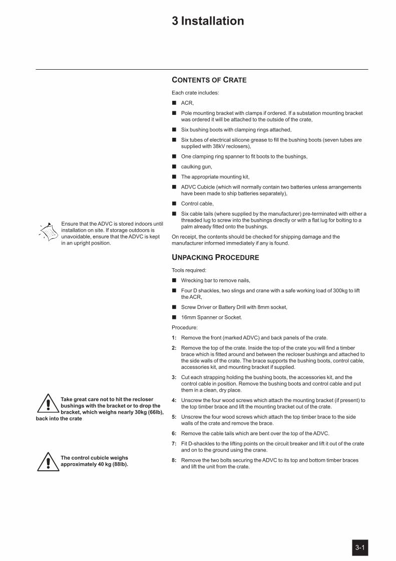
Each crate includes:
ACR, �
Pole mounting bracket with clamps if ordered. If a substation mounting bracket �was ordered it will be attached to the outside of the crate,
� Six bushing boots with clamping rings attached,
� Six tubes of electrical silicone grease to fill the bushing boots (seven tubes are supplied with 38kV reclosers),
� One clamping ring spanner to fit boots to the bushings,
� caulking gun,
� The appropriate mounting kit,
� ADVC Cubicle (which will normally contain two batteries unless arrangements have been made to ship batteries separately),
� Control cable,
� Six cable tails (where supplied by the manufacturer) pre-terminated with either a threaded lug to screw into the bushings directly or with a flat lug for bolting to a palm already fitted onto the bushings.
On receipt, the contents should be checked for shipping damage and the manufacturer informed immediately if any is found.
unpackinG procedure
Tools required:
� Wrecking bar to remove nails,
� Four D shackles, two slings and crane with a safe working load of 300kg to lift the ACR,
� Screw Driver or Battery Drill with 8mm socket,
� 16mm Spanner or Socket.
Procedure:
1: Remove the front (marked ADVC) and back panels of the crate.
2: Remove the top of the crate. Inside the top of the crate you will find a timber brace which is fitted around and between the recloser bushings and attached to the side walls of the crate. The brace supports the bushing boots, control cable, accessories kit, and mounting bracket if supplied.
3: Cut each strapping holding the bushing boots, the accessories kit, and the control cable in position. Remove the bushing boots and control cable and put them in a clean, dry place.
4: Unscrew the four wood screws which attach the mounting bracket (if present) to the top timber brace and lift the mounting bracket out of the crate.
5: Unscrew the four wood screws which attach the top timber brace to the side walls of the crate and remove the brace.
6: Remove the cable tails which are bent over the top of the ADVC.
7: Fit D-shackles to the lifting points on the circuit breaker and lift it out of the crate and on to the ground using the crane.
8: Remove the two bolts securing the ADVC to its top and bottom timber braces and lift the unit from the crate.
Ensure that the ADVC is stored indoors until installation on site. If storage outdoors is unavoidable, ensure that the ADVC is kept in an upright position.
take great care not to hit the recloser bushings with the bracket or to drop the bracket, which weighs nearly 30kg (66lb),
back into the crate
the control cubicle weighs approximately 40 kg (88lb)�
3 Installation
3-2
N-Series Recloser with ADVC Controller
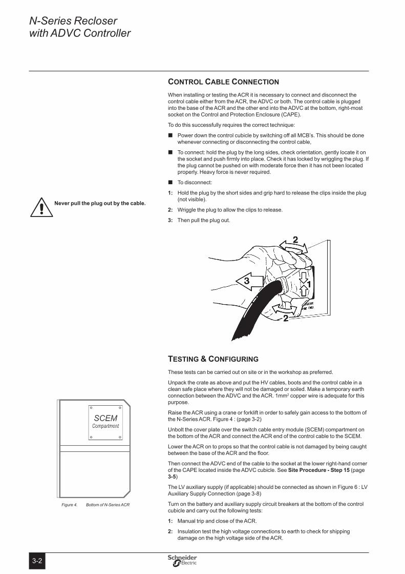
control cable connection
When installing or testing the ACR it is necessary to connect and disconnect the control cable either from the ACR, the ADVC or both. The control cable is plugged into the base of the ACR and the other end into the ADVC at the bottom, right-most socket on the Control and Protection Enclosure (CAPE).
To do this successfully requires the correct technique:
Power down the control cubicle by switching off all MCB’s. This should be done �whenever connecting or disconnecting the control cable,
To connect: hold the plug by the long sides, check orientation, gently locate it on �the socket and push firmly into place. Check it has locked by wriggling the plug. If the plug cannot be pushed on with moderate force then it has not been located properly. Heavy force is never required.
To disconnect: �
Hold the plug by the short sides and grip hard to release the clips inside the plug 1: (not visible).
Wriggle the plug to allow the clips to release. 2:
3: Then pull the plug out.
testinG & confiGurinG
These tests can be carried out on site or in the workshop as preferred.
Unpack the crate as above and put the HV cables, boots and the control cable in a clean safe place where they will not be damaged or soiled. Make a temporary earth connection between the ADVC and the ACR. 1mm2 copper wire is adequate for this purpose.
Raise the ACR using a crane or forklift in order to safely gain access to the bottom of the N-Series ACR. Figure 4 : (page 3-2)
Unbolt the cover plate over the switch cable entry module (SCEM) compartment on the bottom of the ACR and connect the ACR end of the control cable to the SCEM.
Lower the ACR on to props so that the control cable is not damaged by being caught between the base of the ACR and the floor.
Then connect the ADVC end of the cable to the socket at the lower right-hand corner of the CAPE located inside the ADVC cubicle. See site Procedure - step 15 (page 3-5)
The LV auxiliary supply (if applicable) should be connected as shown in Figure 6 : LV Auxiliary Supply Connection (page 3-8)
Turn on the battery and auxiliary supply circuit breakers at the bottom of the control cubicle and carry out the following tests:
Manual trip and close of the ACR.1:
Insulation test the high voltage connections to earth to check for shipping 2: damage on the high voltage side of the ACR.
Never pull the plug out by the cable�
Bottom of N-Series ACRFigure 4.
3-3
Installation (cont)
Configure the protection settings.3:
Perform primary current injection as required.4:
Perform secondary current injection (if required by your Authority) using a Test 5: and Training Set (TTS).
Fit and test a radio or modem if required.6:
7: Attend to the battery using the care instructions given in Battery Care (page 10-5).
It may be desirable at this time to fit the cable tails and surge arresters to the ACR. See Figure 5 : Cable Tail Installation (page 3-7).
transport to siteIf the unpacking and testing was carried out in the workshop then the ACR and ADVC must be transported safely to site. It is important the following steps are carried out:
Turn off all ADVC circuit breakers and disconnect all auxiliary power supplies. �Disconnect the control cable from both ACR and ADVC and replace the cover plate on the bottom of the ACR.
� Transport the ACR, ADVC and all parts in a safe and secure manner to site.
site installation
If you are replacing a pole-top control cubicle (PTCC) or an original ADVC Controller (Ver 43 or earlier) with an ADVC Controller (Ver 44 or above), the following should be considered:
The ADVC Controllers have different mounting points to the PTCC � 1.
The connection to the auxiliary supply enters the cubicle at a different point. �
The earth stud is in a different position. �
Accessory cables may need extending. �
Unlike the PTCC which required an auxiliary power supply rating of 50VA, the �ADVC Controller requires 100VA.
� If the auxiliary supply is provided by an external VT connected through the ACR, there are limitations to the supply ratings of equipment powered by the radio power supply. For an external VT, the maximum continuous current drawn from the radio supply should be limited to 0.5 amps.
The ADVC Controller (Ver 44 or above) door is held open by a door stay mechanism �which prevent door swinging or blowing shut. To disengage the door stay follow the directions on the operator sheet located on the inside of the door.
tools Required
� Torque wrench and metric socket set, normal engineers tools.
� 24mm Open ended drive to fit the torque wrench (commonly known as a "Claw Foot"). This is only required with 630A cable tails which screw directly into the bushings and are tightened by a 24mm lock-nut.
� Standard 300gm cartridge applicator, (Caulking Gun).
� Bushing boot clamping spanner, (supplied by the manufacturer).
� Tools to prepare pole as required.
� Crane or other lift for ACR and ADVC, four D shackles and slings. A 1m spreader bar is also useful, if the surge arresters are to be fitted onto the ACR tank, to keep the slings away from the surge arresters when lifting.
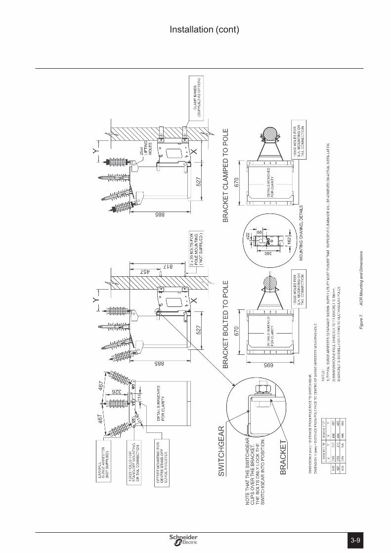
Parts Required (Not supplied by the manufacturer)Two 20mm galvanised or stainless steel bolts with washers and nuts etc. to bolt �the ACR mounting bracket to power pole. See Figure 7 : ACR Mounting and Dimensions (page 3-9). If the optional pole clamps have been purchased this is not required.
1 An accessory mounting bracket can be purchased to allow the use of the same mounting holes as were used with the manufacturer’s PTCC. (Part No. 99800125)
Connecting the batteries with reverse polarity will cause damage to the electronic systems�
An application note detailing workshop and field test procedures is available. Contact your agent or distributor.
3-4
N-Series Recloser with ADVC Controller
Mounting parts for the ADVC. Either 20mm steel strapping or 10mm galvanised �or stainless steel bolts, nuts, etc.
Fixing hardware for the control cable. This is a 27mm (1 1/16") diameter �sheathed conduit and can be fixed to the pole with ties, straps, P-clips or saddles.
Earth wire and lugs for the earthing scheme and parts for LV mains auxiliary �power connection. See Figure 6 : (page 3-8), Figure 8 : (page 3-10) and Figure 9 : (page 3-11).
20mm sealing cable entry glands to suit auxiliary supply mains cables, 16mm �sealing cable entry glands to suit antenna or communications cable as required.
Antenna, antenna feeder cable, and surge arrester as required if a radio is fitted �(unless supplied by the manufacturer).
Aluminium jointing paste (250A and 400A cable tails only). �
Heat shrink or insulating tape (800A cable tails only). �
site Procedure
To erect and test the ACR and ADVC, carry out the following steps. Mounting details are given in Figure 7 : (page 3-9).
Transport to site and carry out testing prior to erection as required.1:
Connect cable tails and surge arresters before raising the ACR. See 2: “Cable Tail Connections (page 3-6)” and “Surge Arrester Mounting and Terminating (page 3-7)”
Ensure that the pole is of sufficient strength to support the ACR. A structural 3: engineer may be needed to calculate the stresses involved.
Securely mount the ACR mounting bracket on the power pole.4:
Lift the ACR into position and lower it so that it sits on the mounting bracket. See 5: Figure 7 : (page 3-9).
Bolt the ACR to the mounting bracket with the four 12mm nuts and bolts 6: provided. Tighten to 50 Nm.
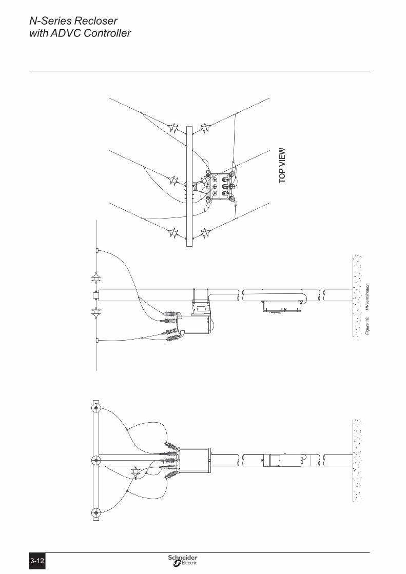
Complete the high voltage connections as shown in 7: Figure 10 : (page 3-12) or as appropriate for the site installation.
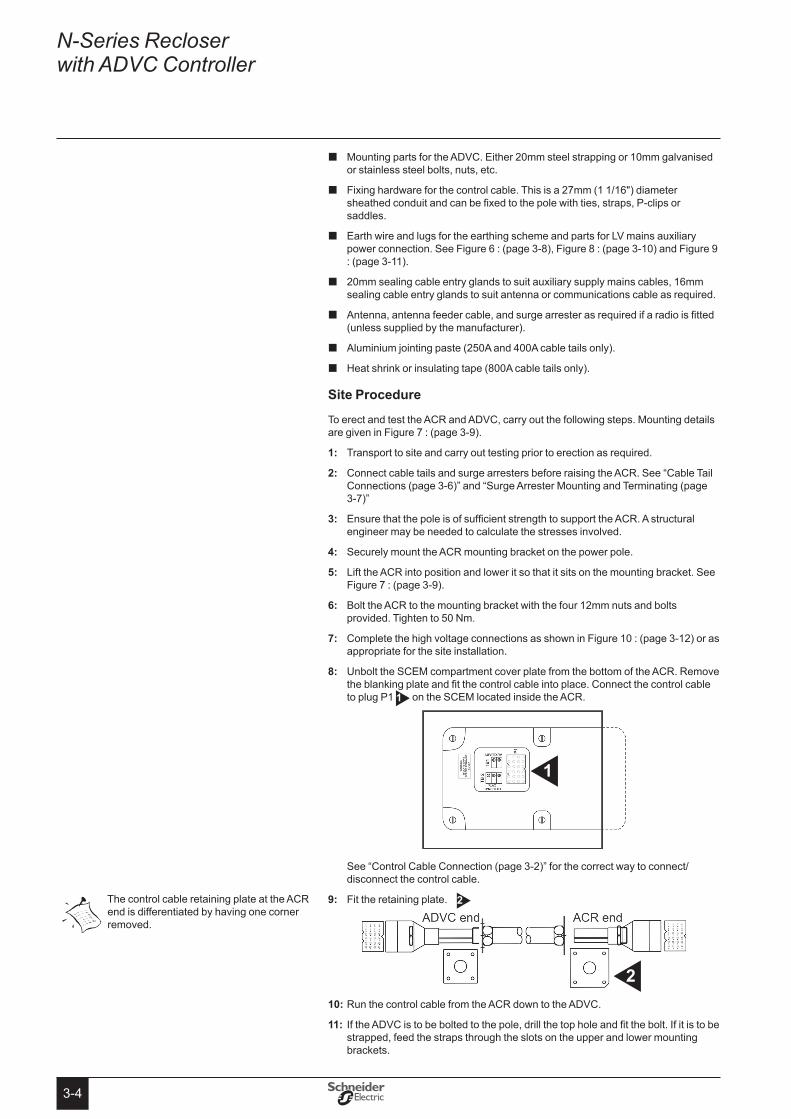
Unbolt the SCEM compartment cover plate from the bottom of the ACR. Remove 8: the blanking plate and fit the control cable into place. Connect the control cable to plug P1 1 on the SCEM located inside the ACR.
See “Control Cable Connection (page 3-2)” for the correct way to connect/disconnect the control cable.
9: Fit the retaining plate. 2
Run the control cable from the ACR down to the ADVC.10:
If the ADVC is to be bolted to the pole, drill the top hole and fit the bolt. If it is to be 11: strapped, feed the straps through the slots on the upper and lower mounting brackets.
1
The control cable retaining plate at the ACR end is differentiated by having one corner removed.
2

3-5
12: Lift the ADVC into position and bolt or strap it to the power pole.
Attach the control cable to the power pole maintaining maximum available 13: separation from the main earth bond (at 200mm for wood and concrete poles and 150mm for steel poles). Ensure that there is enough cable available at each end to permit connection to the equipment.
Run the earth connections as described in 14: “Earthing (Grounding) (page 3-8)”.
15: Connect the control cable from the ACR through the base of the ADVC 1
and then to the switchgear socket 2 on the CAPE.
For LV mains supply run auxiliary wiring as shown in 16: Figure 8 : (page 3-10). Make the connection inside the ADVC as shown in Figure 6 : (page 3-8).
For LV supply from a dedicated transformer supplied by the utility, connect as 17: shown in Figure 9 : (page 3-11).
For Integrated supply from an external transformer, connect as shown in 18: Figure 9 : (page 3-11). (See also “Auxiliary Power from Integrated Transformer (page 3-8)”)
Power down the ADVC by switching off all MCB’s. Note that this should be done 19: whenever connecting or disconnecting the control cable from the ADVC.
20: Fit the batteries if they are not already in place.
If communications equipment is to be installed go to 21: “4 Communications and Accessories Installation (page 4-1)”.
Otherwise go to 22: “5 Testing Your Installation (page 5-1)”.
When mounting the ADVC to a wooden pole, use a spirit level to ensure correct alignment, and minimise torque on the mounting brackets�
Note that the ADVC mounts have key holes as shown here, so that you can lift the ADVC on to the mounting bolt and slide it into position.
It is vital that the earthing scheme is carried out as described�
1
2
Fitting the batteries with reverse polarity will cause damage to the electronic systems�
Installation (cont)

3-6
N-Series Recloser with ADVC Controller
Cable tail Connections
HV cables are supplied in one of two forms:
Fitted with a lug to be bolted to a factory fitted palm on the end of the bushing �(250, 400, or 800 A).
Fitted with a threaded termination that is screwed into the bushing (630A). �
In both cases the procedure is to attach the cable to the bushing and then cover with the bushing boot as detailed in the following sections.
The bushing is supplied clean and protected with a plastic cap. Ensure this is �undisturbed and the bushing body and tin plated central conductor or palm are clean and undamaged. If the bushing has become soiled then clean with methylated spirits. Sand or brush the aluminium palm to remove oxide.
Grease the bushing and the conductor with the silicone grease provided (part �number 990000350).
Unpack the cable tail and bushing boots. Check that the cable termination and �the boot are clean and undamaged. If necessary, clean with methylated spirits.
� Push the boot down the cable to a distance approximately 1 metre from the termination (place a small amount of grease on the closed end of the boot to assist the boot to slide down the cable). Fill the bushing boot with the silicone grease provided, starting at the closed end and finishing approx 60mm from the open end of the boot.
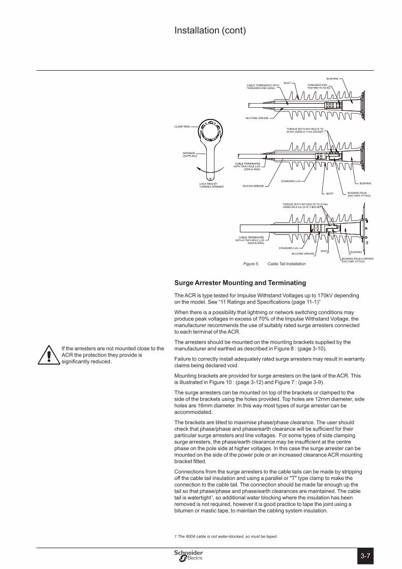
For 630 A cables terminated with a screw thread, ensure the thread, locknut and �bushing surfaces are clean and dry. Screw the tail into the bushing by turning the whole cable tail. Tighten to 50 Nm using a spanner across the brass locknut fitted. Take care to apply only twisting forces to the terminal (no shear force).
For 250, 400 and 630A cables terminated with a lug, smear with aluminium �jointing paste and bolt the lug to the bushing palm with the two M10 bolts provided and tighten to 44 Nm using a 17mm socket.
� For 800 A copper cables terminated with a lug, smear with aluminium jointing paste and bolt the lug to the bushing palm. Because of the weight of the cable it may be difficult to fit the bolts through the lug and the bushing palm while holding the cable. Therefore, using an M10 bolt from the packing crate, temporarily insert the M10 bolt through the rear of one of the holes in the palm. Fit the corresponding hole in the tail over the M10 bolt. Insert a cap head socket screw into the other hole from the lug side and partially tighten it. Remove the M10 bolt. Insert the second cap head socket screw through the lug and tighten both screws to 22 Nm using an 8 mm (5/16") hex key.
� Grease the surface of the bushing, slide the bushing boot down over the bushing while rotating the boot back and forth. Fix into place using the clamping ring and spanner provided. The bottom of the boot should be firmly seated on the top of the circuit breaker tank. During the clamping process silicone may bleed from the top of the boot where the cable tail comes out. This is quite normal and can be assisted by sliding a small screwdriver into the boot alongside the cable tail but be very careful not to damage the bushing. Silicone grease will also come out around the bottom of the bushing. This is quite normal. Wipe off excess silicone grease with a clean cloth.
The insulated cables supplied by the manufacturer are rated for use at the following voltages and ratings:
Up to 15kV 100mm minimum clearance phase to phase, or phase to earth
>15kV to 38kV 150mm minimum clearance phase to phase, or phase to earth
Hint - as you fill the boot with grease, keep sliding it down the cable as this pushes the grease up into the boot.
When making the 800 A cable tail line connection, suitable steps must be taken to prevent water ingress to the cable�
3-7
CABLE TERMINATED WITH TWO-HOLE LUG
(250A & 400A)
BOOT
SILICON GREASEBUSHING
BUSHING
TORQUE BOTH M10 BOLTS TO44 Nm USING A 17mm SOCKET
BOOT
SILICONE GREASE
BUSHING PALM(FACTORY FITTED)
STANDARD LUG
CABLE TERMINATED WITHTHREADED END (630A)
LOCK RING BYTURNING SPANNER
SPANNER(SUPPLIED)
CLAMP RING
THREADED ENDTIGHTEN TO 50 Nm
BOOT BUSHING
BUSHING PALM (COPPER)(FACTORY FITTED)
SILICONE GREASE
CABLE TERMINATED WITH A TWO-HOLE LUG
(630A & 800A)
TORQUE BOTH M10 BOLTS TO 22 NmUSING AN 8 mm (5/16”) HEX KEY
STANDARD LUG
surge Arrester Mounting and terminating
The ACR is type tested for Impulse Withstand Voltages up to 170kV depending on the model. See “11 Ratings and Specifications (page 11-1)”
When there is a possibility that lightning or network switching conditions may produce peak voltages in excess of 70% of the Impulse Withstand Voltage, the manufacturer recommends the use of suitably rated surge arresters connected to each terminal of the ACR.
The arresters should be mounted on the mounting brackets supplied by the manufacturer and earthed as described in Figure 8 : (page 3-10).
Failure to correctly install adequately rated surge arresters may result in warranty claims being declared void.
Mounting brackets are provided for surge arresters on the tank of the ACR. This is illustrated in Figure 10 : (page 3-12) and Figure 7 : (page 3-9).
The surge arresters can be mounted on top of the brackets or clamped to the side of the brackets using the holes provided. Top holes are 12mm diameter, side holes are 16mm diameter. In this way most types of surge arrester can be accommodated.
The brackets are tilted to maximise phase/phase clearance. The user should check that phase/phase and phase/earth clearance will be sufficient for their particular surge arresters and line voltages. For some types of side clamping surge arresters, the phase/earth clearance may be insufficient at the centre phase on the pole side at higher voltages. In this case the surge arrester can be mounted on the side of the power pole or an increased clearance ACR mounting bracket fitted.
Connections from the surge arresters to the cable tails can be made by stripping off the cable tail insulation and using a parallel or "T" type clamp to make the connection to the cable tail. The connection should be made far enough up the tail so that phase/phase and phase/earth clearances are maintained. The cable tail is watertight1, so additional water blocking where the insulation has been removed is not required, however it is good practice to tape the joint using a bitumen or mastic tape, to maintain the cabling system insulation.
1 The 800A cable is not water-blocked, so must be taped.
If the arresters are not mounted close to the ACR the protection they provide is significantly reduced.
Installation (cont)
Cable Tail InstallationFigure 5.
3-8
N-Series Recloser with ADVC Controller
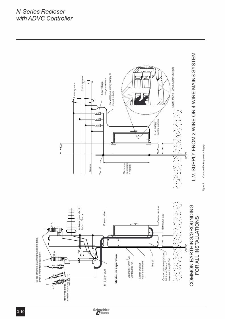
earthing (Grounding)
Figure 8 : (page 3-10) shows the earthing (grounding) common to all installations.
This arrangement earths the ACR frame and the surge arresters directly to earth through a main earth bond consisting of a copper conductor of 70 sq. mm. Any surges will flow down this path.
The control cubicle is connected to this main earth bond by a tee-off. The control cubicle electronics are internally protected from potential differences which may occur between the ACR frame and control cubicle frame whilst surge currents are flowing down the main earth bond. No other connections to earth from the control cubicle are allowed since surge currents will also flow in those paths. Follow this arrangement on both conducting and insulating power poles.
Keep the main earth bond physically separated from the control cable, as they run down the power pole, by the maximum spacing available and at least 150mm.
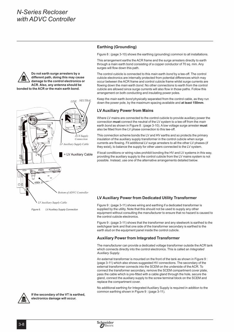
LV Auxiliary Power from Mains
Where LV mains are connected to the control cubicle to provide auxiliary power the connection must connect the neutral of the LV system to a tee-off from the main earth bond as shown in Figure 8 : (page 3-10). A low voltage surge arrester must also be fitted from the LV phase connection to this tee-off.
This connection scheme bonds the LV and HV earths and so protects the primary insulation of the auxiliary supply transformer in the control cubicle when surge currents are flowing. Fit additional LV surge arresters to all the other LV phases (if they exist), to balance the supply for other users connected to the LV system.
If local conditions or wiring rules prohibit bonding the HV and LV systems in this way, providing the auxiliary supply to the control cubicle from the LV mains system is not possible. Instead, use one of the alternative arrangements detailed below.
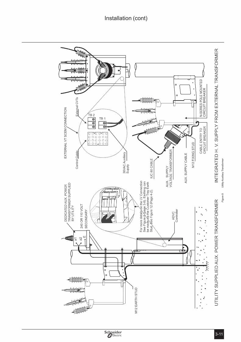
LV Auxiliary Power from Dedicated Utility transformer
Figure 9 : (page 3-11) shows wiring and earthing if a dedicated transformer is supplied by the utility. Note that this should not be used to supply any other equipment without consulting the manufacturer to ensure that no hazard is caused to the control cubicle electronics.
Figure 9 : (page 3-11) shows that the transformer and any steelwork is earthed to the switchgear tank and that one side of the transformer secondary is earthed to the earth stud on the equipment panel inside the control cubicle.
Auxiliary Power from Integrated transformer
The manufacturer can provide a dedicated voltage transformer outside the ACR tank which connects directly into the control electronics. This is called an Integrated Auxiliary Supply.
An external transformer is mounted on the front of the tank as shown in Figure 9 : (page 3-11) which also shows suggested HV connections. The secondary of the external transformer connects into the SCEM on the underside of the ACR. To connect the transformer secondary, remove the SCEM compartment cover plate, pass the cable which is pre-fitted with a cable gland through the hole, secure the gland, connect the auxiliary supply to the screw terminal block on the SCEM and replace the compartment cover.
No additional earthing for Integrated Auxiliary Supply is required in addition to the common earthing shown in Figure 9 : (page 3-11).
Do not earth surge arresters by a different path, doing this may cause damage to the control electronics or ACR� Also, any antenna should be
bonded to the ACR or the main earth bond�
If the secondary of the Vt is earthed, electronics damage will occur�
LV Auxiliary Supply ConnectionFigure 6.
Bottom of ADVC Controller
LV Auxiliary Supply Cable
LINE NEUTRAL
AUX Supply Connection
LV Auxiliary Supply Cable
3-9
AC
R M
ount
ing
and
Dim
ensi
ons
Figu
re 7
.
Installation (cont)
3-10
N-Series Recloser with ADVC Controller
Com
mon
Ear
thin
g an
d LV
Sup
ply
Figu
re 8
.
3-11
Util
ity A
uxili
ary
Tran
sfor
mer
Figu
re 9
.
Installation (cont)
3-12
N-Series Recloser with ADVC Controller
HV
term
inat
ion
Figu
re 1
0.
4-1
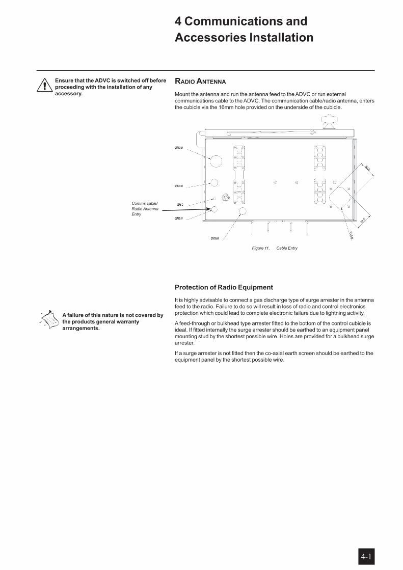
raDio antenna
Mount the antenna and run the antenna feed to the ADVC or run external communications cable to the ADVC. The communication cable/radio antenna, enters the cubicle via the 16mm hole provided on the underside of the cubicle.
Cable EntryFigure 11.
Protection of Radio equipment
It is highly advisable to connect a gas discharge type of surge arrester in the antenna feed to the radio. Failure to do so will result in loss of radio and control electronics protection which could lead to complete electronic failure due to lightning activity.
A feed-through or bulkhead type arrester fitted to the bottom of the control cubicle is ideal. If fitted internally the surge arrester should be earthed to an equipment panel mounting stud by the shortest possible wire. Holes are provided for a bulkhead surge arrester.
If a surge arrester is not fitted then the co-axial earth screen should be earthed to the equipment panel by the shortest possible wire.
Comms cable/Radio Antenna Entry
A failure of this nature is not covered by the products general warranty arrangements�
4 Communications and Accessories Installation
ensure that the ADVC is switched off before proceeding with the installation of any accessory�
4-2
N-Series Recloser with ADVC Controller
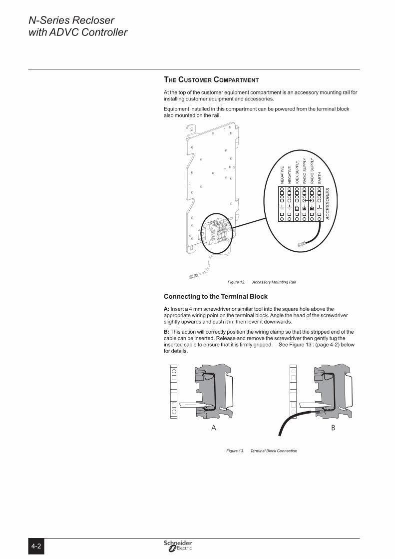
the cuStoMer coMpartMent
At the top of the customer equipment compartment is an accessory mounting rail for installing customer equipment and accessories.
Equipment installed in this compartment can be powered from the terminal block also mounted on the rail.
Accessory Mounting RailFigure 12.
Connecting to the terminal Block
A: Insert a 4 mm screwdriver or similar tool into the square hole above the appropriate wiring point on the terminal block. Angle the head of the screwdriver slightly upwards and push it in, then lever it downwards.
B: This action will correctly position the wiring clamp so that the stripped end of the cable can be inserted. Release and remove the screwdriver then gently tug the inserted cable to ensure that it is firmly gripped. See Figure 13 : (page 4-2) below for details.
Terminal Block ConnectionFigure 13.
4-3
Radio/Modem Power
The battery-backed power supply for a radio/modem is provided on the terminal block as described above1. See Figure 12 : (page 4-2) for the correct radio connection point.
The radio/modem power supply voltage is set by the user in the following menu page
SYSTEM STATUS - RADIO - S: Radio Supply 12 Volts
ENGINEER MENU - CONFIGURATION MENU - RADIO SETTINGS - Radio Supply Voltage
This is a password protected parameter.
If the auxiliary power fails, battery power can be conserved by automatically shutting down the radio/modem power supply. The shutdown takes place after the radio holdup time, set in:
System Status - RADIO - S: Radio Hold 60 min.
ENGINEER MENU - CONFIGURATION MENU - RADIO SETTINGS - Radio Hold Time
has elapsed. If the Radio Hold time is set to zero then the radio supply will not shutdown, except under special circumstances or until the unit powers down. The radio/modem power supply is restored when the auxiliary supply returns to normal.
The radio/modem power supply can be turned on or off by the operator for radio maintenance without passwords in:
System Status RADIO - S: Radio Supply ON
ENGINEER MENU - CONFIGURATION MENU - RADIO SETTINGS - Radio Supply ON/OFF
If the radio supply has shutdown it will be indicated on these pages.
1 The power supply is not isolated.
Communications and Accessories Installation (cont)
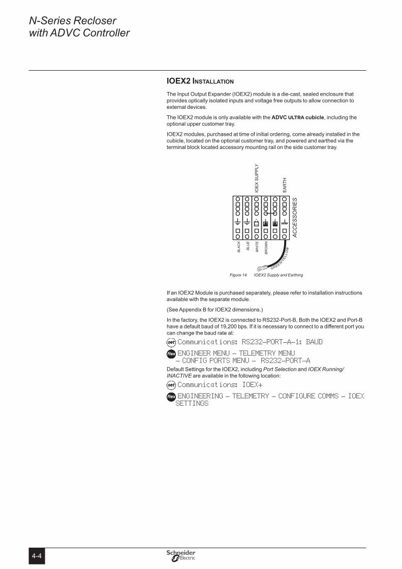
4-4
N-Series Recloser with ADVC Controller
ioeX2 inStallation
The Input Output Expander (IOEX2) module is a die-cast, sealed enclosure that provides optically isolated inputs and voltage free outputs to allow connection to external devices.
The IOEX2 module is only available with the ADVC ULTRA cubicle, including the optional upper customer tray.
IOEX2 modules, purchased at time of initial ordering, come already installed in the cubicle, located on the optional customer tray, and powered and earthed via the terminal block located accessory mounting rail on the side customer tray.
GREEN/YEL
LOWBL
ACK
BLU
E
WH
ITE
BRO
WN
If an IOEX2 Module is purchased separately, please refer to installation instructions available with the separate module.
(See Appendix B for IOEX2 dimensions.)
In the factory, the IOEX2 is connected to RS232-Port-B, Both the IOEX2 and Port-B have a default baud of 19,200 bps. If it is necessary to connect to a different port you can change the baud rate at:
Communications: RS232-PORT-A-1: BAUD
ENGINEER MENU - TELEMETRY MENU - CONFIG PORTS MENU - RS232-PORT-A
Default Settings for the IOEX2, including Port Selection and IOEX Running/INACTIVE are available in the following location:
Communications: IOEX+
ENGINEERING - TELEMETRY - CONFIGURE COMMS - IOEX SETTINGS
IOEX2 Supply and EarthingFigure 14.
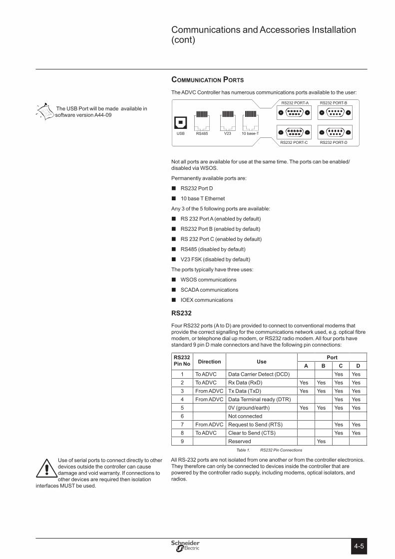
4-5
coMMunication portS
The ADVC Controller has numerous communications ports available to the user:
Not all ports are available for use at the same time. The ports can be enabled/disabled via WSOS.
Permanently available ports are:
RS232 Port D �
10 base T Ethernet �
Any 3 of the 5 following ports are available:
RS 232 Port A (enabled by default) �
RS232 Port B (enabled by default) �
RS 232 Port C (enabled by default) �
RS485 (disabled by default) �
V23 FSK (disabled by default) �
The ports typically have three uses:
WSOS communications �
SCADA communications �
IOEX communications �
Rs232
Four RS232 ports (A to D) are provided to connect to conventional modems that provide the correct signalling for the communications network used, e.g. optical fibre modem, or telephone dial up modem, or RS232 radio modem. All four ports have standard 9 pin D male connectors and have the following pin connections:
Rs232 Pin No Direction Use
PortA B C D
1 To ADVC Data Carrier Detect (DCD) Yes Yes2 To ADVC Rx Data (RxD) Yes Yes Yes Yes3 From ADVC Tx Data (TxD) Yes Yes Yes Yes4 From ADVC Data Terminal ready (DTR) Yes Yes5 0V (ground/earth) Yes Yes Yes Yes6 Not connected7 From ADVC Request to Send (RTS) Yes Yes8 To ADVC Clear to Send (CTS) Yes Yes9 Reserved Yes
RS232 Pin ConnectionsTable 1.
All RS-232 ports are not isolated from one another or from the controller electronics. They therefore can only be connected to devices inside the controller that are powered by the controller radio supply, including modems, optical isolators, and radios.
Use of serial ports to connect directly to other devices outside the controller can cause damage and void warranty. If connections to other devices are required then isolation
interfaces MUST be used.
The USB Port will be made available in software version A44-09
Communications and Accessories Installation (cont)
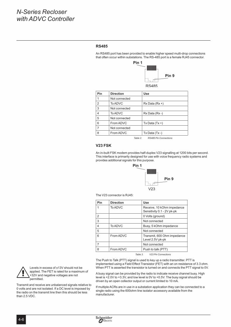
4-6
N-Series Recloser with ADVC Controller
Rs485
An RS485 port has been provided to enable higher speed multi-drop connections that often occur within substations. The RS-485 port is a female RJ45 connector.
Pin Direction Use1 Not connected2 To ADVC Rx Data (Rx +)3 Not connected4 To ADVC Rx Data (Rx -)5 Not connected6 From ADVC Tx Data (Tx +)7 Not connected8 From ADVC Tx Data (Tx -)
RS485 Pin ConnectionsTable 2.
V23 FsK
An in-built FSK modem provides half-duplex V23 signalling at 1200 bits per second. This interface is primarily designed for use with voice frequency radio systems and provides additional signals for this purpose.
The V23 connector is RJ45:
Pin Direction Use1 To ADVC Receive, 10 kOhm impedance
Sensitivity 0.1 - 2V pk-pk2 0 Volts (ground)3 Not connected4 To ADVC Busy, 5 kOhm impedance5 Not connected6 From ADVC Transmit, 600 Ohm impedance
Level 2.5V pk-pk7 Not connected8 From ADVC Push to talk (PTT)
V23 Pin ConnectionsTable 3.
The Push to Talk (PTT) signal is used to key up a radio transmitter. PTT is implemented using a Field Effect Transistor (FET) with an on resistance of 3.3 ohm. When PTT is asserted the transistor is turned on and connects the PTT signal to 0V.
A busy signal can be provided by the radio to indicate receive channel busy. High level is +2.0V to +3.3V, and low level is 0V to +0.5V. The busy signal should be driven by an open collector output or current limited to 10 mA.
If multiple ACRs are in use in a substation application they can be connected to a single radio using the 600ohm line isolator accessory available from the manufacturer.
Levels in excess of ±13V should not be applied. The FET is rated for a maximum of +32V and negative voltages are not permitted.
Transmit and receive are unbalanced signals relative to 0 volts and are not isolated. If a DC level is imposed by the radio on the transmit line then this should be less than 2.5 VDC.
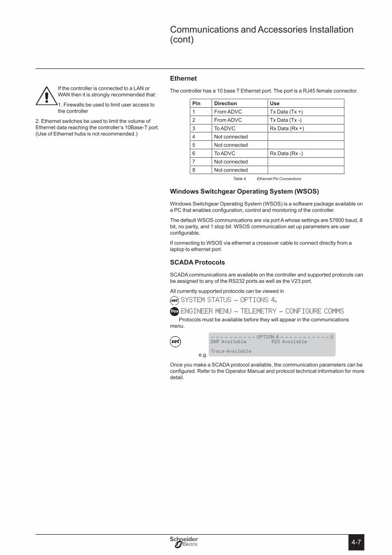
4-7
ethernet
The controller has a 10 base T Ethernet port. The port is a RJ45 female connector.
Pin Direction Use1 From ADVC Tx Data (Tx +)2 From ADVC Tx Data (Tx -)3 To ADVC Rx Data (Rx +)4 Not connected5 Not connected6 To ADVC Rx Data (Rx -)7 Not connected8 Not connected
Ethernet Pin ConnectionsTable 4.
Windows switchgear operating system (Wsos)
Windows Switchgear Operating System (WSOS) is a software package available on a PC that enables configuration, control and monitoring of the controller.
The default WSOS communications are via port A whose settings are 57600 baud, 8 bit, no parity, and 1 stop bit. WSOS communication set up parameters are user configurable.
If connecting to WSOS via ethernet a crossover cable to connect directly from a laptop to ethernet port.
sCADA Protocols
SCADA communications are available on the controller and supported protocols can be assigned to any of the RS232 ports as well as the V23 port.
All currently supported protocols can be viewed in
SYSTEM STATUS - OPTIONS 4.
ENGINEER MENU - TELEMETRY - CONFIGURE COMMSProtocols must be available before they will appear in the communications
menu.
e.g.
- - - - - - - - - - OPTION 4 - - - - - - - - - - - S DNP Available RDI Available
Trace Available
Once you make a SCADA protocol available, the communication parameters can be configured. Refer to the Operator Manual and protocol technical information for more detail.
If the controller is connected to a LAN or WAN then it is strongly recommended that:
1. Firewalls be used to limit user access to the controller
2. Ethernet switches be used to limit the volume of Ethernet data reaching the controller’s 10Base-T port. (Use of Ethernet hubs is not recommended.)
Communications and Accessories Installation (cont)

4-8
N-Series Recloser with ADVC Controller
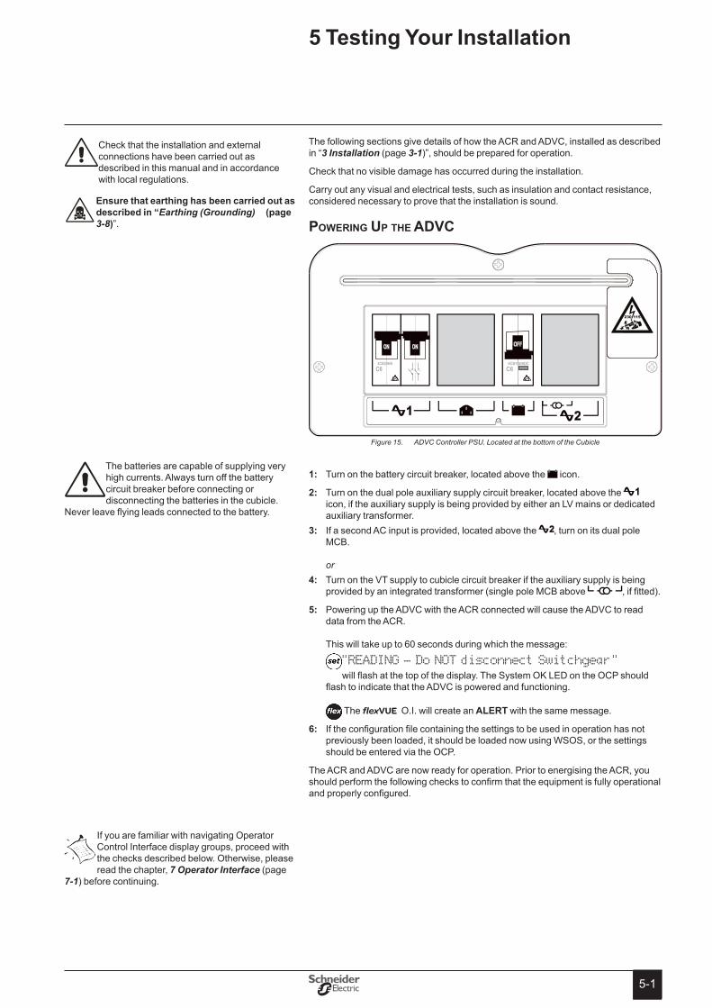
5-15-1
The following sections give details of how the ACR and ADVC, installed as described in “3 Installation (page 3-1)”, should be prepared for operation.
Check that no visible damage has occurred during the installation.
Carry out any visual and electrical tests, such as insulation and contact resistance, considered necessary to prove that the installation is sound.
powering up the aDvc
Turn on the battery circuit breaker, located above the 1: icon.
Turn on the dual pole auxiliary supply circuit breaker, located above the 2: icon, if the auxiliary supply is being provided by either an LV mains or dedicated auxiliary transformer. If a second AC input is provided, located above the 3: , turn on its dual pole MCB. or Turn on the VT supply to cubicle circuit breaker if the auxiliary supply is being 4: provided by an integrated transformer (single pole MCB above , if fitted).
Powering up the ADVC with the ACR connected will cause the ADVC to read 5: data from the ACR. This will take up to 60 seconds during which the message:
"READING - Do NOT disconnect Switchgear" will flash at the top of the display. The System OK LED on the OCP should
flash to indicate that the ADVC is powered and functioning.
The flexVUE O.I. will create an ALeRt with the same message.
If the configuration file containing the settings to be used in operation has not 6: previously been loaded, it should be loaded now using WSOS, or the settings should be entered via the OCP.
The ACR and ADVC are now ready for operation. Prior to energising the ACR, you should perform the following checks to confirm that the equipment is fully operational and properly configured.
Check that the installation and external connections have been carried out as described in this manual and in accordance with local regulations.
ensure that earthing has been carried out as described in “Earthing (Grounding) (page 3-8)”.
If you are familiar with navigating Operator Control Interface display groups, proceed with the checks described below. Otherwise, please read the chapter, 7 Operator Interface (page
7-1) before continuing.
5 testing Your Installation
The batteries are capable of supplying very high currents. Always turn off the battery circuit breaker before connecting or disconnecting the batteries in the cubicle.
Never leave flying leads connected to the battery.
ADVC Controller PSU. Located at the bottom of the CubicleFigure 15.
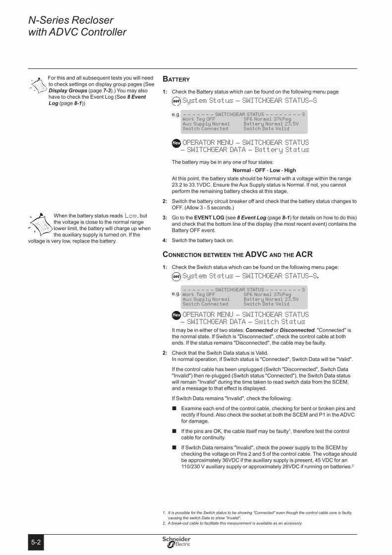
5-2
N-Series Recloser with ADVC Controller
Battery
Check the Battery status which can be found on the following menu page1: System Status - SWITCHGEAR STATUS-S
e.g.
- - - - - - - SWITCHGEAR STATUS - - - - - - - - S Work Tag OFF SF6 Normal 37kPag Aux Supply Normal Battery Normal 27.5V Switch Connected Switch Data Valid
OPERATOR MENU - SWITCHGEAR STATUS - SWITCHGEAR DATA - Battery Status
The battery may be in any one of four states:Normal - oFF - Low - High
At this point, the battery state should be Normal with a voltage within the range 23.2 to 33.1VDC. Ensure the Aux Supply status is Normal. If not, you cannot perform the remaining battery checks at this stage.
Switch the battery circuit breaker off and check that the battery status changes to 2: OFF. (Allow 3 - 5 seconds.)
3: Go to the eVeNt LoG (see 8 Event Log (page 8-1) for details on how to do this) and check that the bottom line of the display (the most recent event) contains the Battery OFF event.
Switch the battery back on.4:
connection Between the aDvc anD the acrCheck the Switch status which can be found on the following menu page:1:
System Status - SWITCHGEAR STATUS-S.
e.g.
- - - - - - - SWITCHGEAR STATUS - - - - - - - - S Work Tag OFF SF6 Normal 37kPag Aux Supply Normal Battery Normal 27.5V Switch Connected Switch Data Valid
OPERATOR MENU - SWITCHGEAR STATUS - SWITCHGEAR DATA - Switch Status
It may be in either of two states: Connected or Disconnected. "Connected" is the normal state. If Switch is "Disconnected", check the control cable at both ends. If the status remains "Disconnected", the cable may be faulty.
Check that the Switch Data status is Valid. 2: In normal operation, if Switch status is "Connected", Switch Data will be "Valid".
If the control cable has been unplugged (Switch "Disconnected", Switch Data "Invalid") then re-plugged (Switch status "Connected"), the Switch Data status will remain "Invalid" during the time taken to read switch data from the SCEM, and a message to that effect is displayed.
If Switch Data remains "Invalid", check the following:
� Examine each end of the control cable, checking for bent or broken pins and rectify if found. Also check the socket at both the SCEM and P1 in the ADVC for damage.
� If the pins are OK, the cable itself may be faulty1, therefore test the control cable for continuity.
� If Switch Data remains "Invalid", check the power supply to the SCEM by checking the voltage on Pins 2 and 5 of the control cable. The voltage should be approximately 36VDC if the auxiliary supply is present, 45 VDC for an 110/230 V auxiliary supply or approximately 26VDC if running on batteries.2
1. It is possible for the Switch status to be showing "Connected" even though the control cable core is faulty, causing the switch Data to show "Invalid".
2. A break-out cable to facilitate this measurement is available as an accessory.
When the battery status reads Low, but the voltage is close to the normal range lower limit, the battery will charge up when the auxiliary supply is turned on. If the
voltage is very low, replace the battery.
For this and all subsequent tests you will need to check settings on display group pages (See Display Groups (page 7-3).) You may also have to check the Event Log (See 8 Event Log (page 8-1))
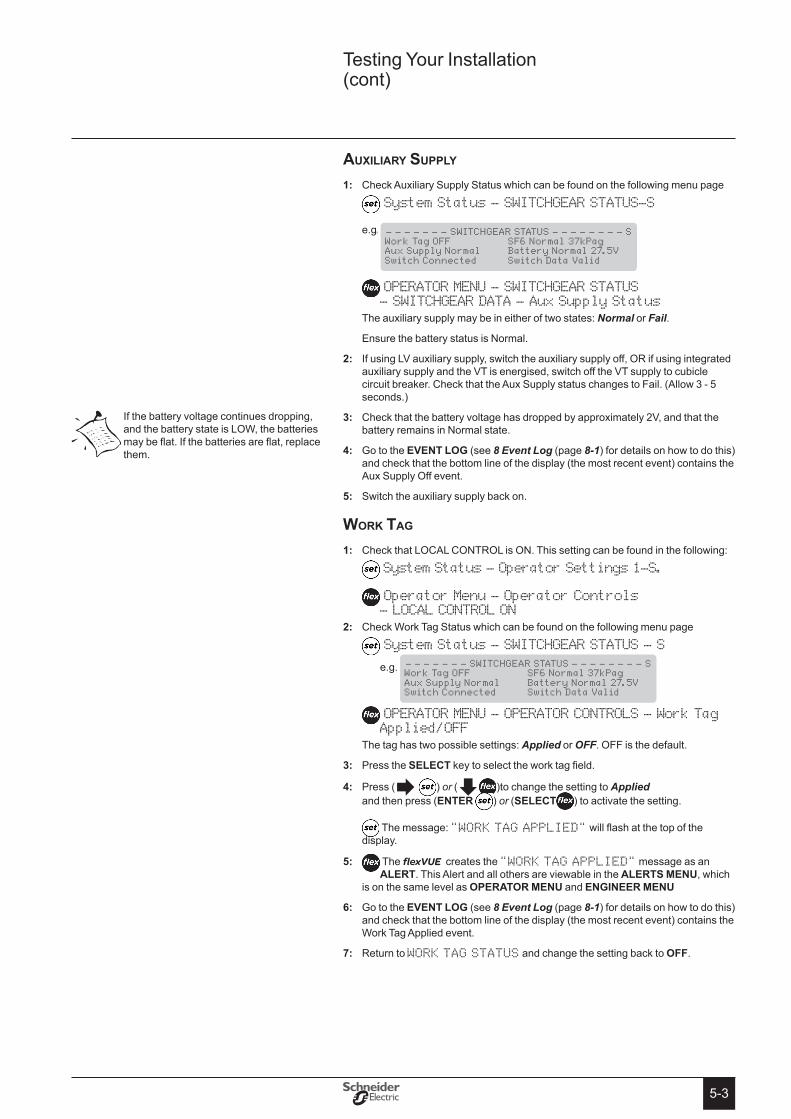
5-3
auXiliary Supply
Check Auxiliary Supply Status which can be found on the following menu page1: System Status - SWITCHGEAR STATUS-S
e.g.
- - - - - - - SWITCHGEAR STATUS - - - - - - - - S Work Tag OFF SF6 Normal 37kPag Aux Supply Normal Battery Normal 27.5V Switch Connected Switch Data Valid
OPERATOR MENU - SWITCHGEAR STATUS - SWITCHGEAR DATA - Aux Supply Status
The auxiliary supply may be in either of two states: Normal or Fail.
Ensure the battery status is Normal.
If using LV auxiliary supply, switch the auxiliary supply off, OR if using integrated 2: auxiliary supply and the VT is energised, switch off the VT supply to cubicle circuit breaker. Check that the Aux Supply status changes to Fail. (Allow 3 - 5 seconds.)
3: Check that the battery voltage has dropped by approximately 2V, and that the battery remains in Normal state.
Go to the 4: eVeNt LoG (see 8 Event Log (page 8-1) for details on how to do this) and check that the bottom line of the display (the most recent event) contains the Aux Supply Off event.
Switch the auxiliary supply back on.5:
work tag
Check that LOCAL CONTROL is ON. This setting can be found in the following:1: System Status - Operator Settings 1-S.
Operator Menu - Operator Controls - LOCAL CONTROL ON
Check Work Tag Status which can be found on the following menu page2: System Status - SWITCHGEAR STATUS - S
e.g.
- - - - - - - SWITCHGEAR STATUS - - - - - - - - S Work Tag OFF SF6 Normal 37kPag Aux Supply Normal Battery Normal 27.5V Switch Connected Switch Data Valid
OPERATOR MENU - OPERATOR CONTROLS - Work Tag Applied/OFF
The tag has two possible settings: Applied or OFF. OFF is the default.
Press the 3: seLeCt key to select the work tag field.
Press (4: ) or ( )to change the setting to Applied and then press (eNteR ) or (seLeCt ) to activate the setting.
The message: "WORK TAG APPLIED" will flash at the top of the display.
5: The flexVUE creates the "WORK TAG APPLIED" message as an ALeRt. This Alert and all others are viewable in the ALeRts MeNU, which
is on the same level as oPeRAtoR MeNU and eNGINeeR MeNU
Go to the 6: eVeNt LoG (see 8 Event Log (page 8-1) for details on how to do this) and check that the bottom line of the display (the most recent event) contains the Work Tag Applied event.
Return to 7: WORK TAG STATUS and change the setting back to oFF.
If the battery voltage continues dropping, and the battery state is LOW, the batteries may be flat. If the batteries are flat, replace them.
Testing Your Installation (cont)
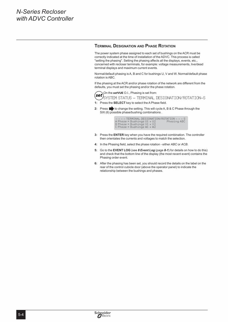
5-4
N-Series Recloser with ADVC Controller
terMinal DeSignation anD phaSe rotation
The power system phase assigned to each set of bushings on the ACR must be correctly indicated at the time of installation of the ADVC. This process is called "setting the phasing". Setting the phasing affects all the displays, events, etc., concerned with recloser terminals, for example: voltage measurements, live/dead terminal displays and maximum current events.
Normal/default phasing is A, B and C for bushings U, V and W. Normal/default phase rotation is ABC.
If the phasing at the ACR and/or phase rotation of the network are different from the defaults, you must set the phasing and/or the phase rotation.
On the setVUE O.I., Phasing is set from:
SYSTEM STATUS - TERMINAL DESIGNATION/ROTATION-SPress the 1: seLeCt key to select the A Phase field.
Press 2: to change the setting. This will cycle A, B & C Phase through the SIX (6) possible phase/bushing combinations .
- - - - TERMINAL DESIGNATION/ROTATION - - - S A Phase = Bushings U1 + U2 Phasing ABC B Phase = Bushings V1 + V2 C Phase = Bushings W1 + W2
Press the 3: eNteR key when you have the required combination. The controller then orientates the currents and voltages to match the selection.
In the Phasing field, select the phase rotation - either 4: ABC or ACB.
Go to the 5: eVeNt LoG (see 8 Event Log (page 8-1) for details on how to do this) and check that the bottom line of the display (the most recent event) contains the Phasing order event.
After the phasing has been set, you should record the details on the label on the 6: rear of the control cubicle door (above the operator panel) to indicate the relationship between the bushings and phases.

5-5
On the flexVUE O.I., Terminal Designation is set from:
ENGINEER MENU - CONFIGURATION MENU - SYSTEM SETTINGS- NETWORK PARAMETERS
-TERMINAL DESIGNATION/ROTATIONUse the 1: &to find the A-PHASE and press the seLeCt key to edit it.
2: Press &keys to change the bushing designation.
You will only see the A-Phase Bushing designation changing.
TERMINAL DESIGNATION/R... A Phase = Bushings U
TERMINAL DESIGNATION/R... A Phase = Bushings V
TERMINAL DESIGNATION/R... A Phase = Bushings W
TERMINAL DESIGNATION/R... A Phase = Bushings V
TERMINAL DESIGNATION/R... A Phase = Bushings W
TERMINAL DESIGNATION/R... A Phase = Bushings U
1
2
3
4
5
6
Press the 3: seLeCt key when you have the required combination. The controller then orientates the currents and voltages to match the selection.
4: Use the &to scroll to the Phasing ABC option at:ENGINEER MENU - CONFIGURATION MENU - SYSTEM SETTINGS - NETWORK PARAMETERS - TERMINAL DESIGNATION/ROTATION - Phasing ABC
and select the phase rotation - either ABC or ACB.
Go to the 5: eVeNt LoG (see 8 Event Log (page 8-1) for details on how to do this) and check that the bottom line of the display (the most recent event) contains the Phasing order event.
After the phasing has been set, you should record the details on the label on the 6: rear of the control cubicle door (above the operator panel) to indicate the relationship between the bushings and phases.
power flow Direction Setting
The ACR is a symmetrical device meaning that either side can be connected to the power source.
Consequently, after installation, the controller must be configured to designate the source side.
The power flow direction is configured on page
SYSTEM STATUS - PHASE VOLTAGE and POWER FLOW: or ENGINEER MENU - CONFIGURATION MENU - SYSTEM SETTINGS - METERING PARAMETERS
- Source 1, Load 2and may be either source 1, Load 2 or source 2, Load 1� When changed, this reverses the power flow direction but not the phasing.
Power flow direction setting is used to determine:
Whether the source or load corresponds to (1) or (2) on the voltage �measurement displays.
Which direction is positive power flow for use on the kWh totals in the Maximum �Weekly and Monthly Demand display and APGS.
Which is the source or load for Live Load Blocking. �
Which is the source or load for Directional Blocking/Protection. �
Only A-Phase is allowed to be edited. Changing this phase will change B & C Phases in the following rotation:
1: A-B-C = U-V-W 2: A-B-C = W-V-U 3: A-B-C = V-W-U 4: A-B-C = W-U-V 5: A-B-C = V-U-W 6: A-B-C = U-W-V
YOU MUST CHECK B&C-PHASE TERMINAL DESIGNATION after you have set A-Phase.
Incorrect terminal designation may cause incorrect operation, false trips or even damage to the switch gear or controller.
Testing Your Installation (cont)
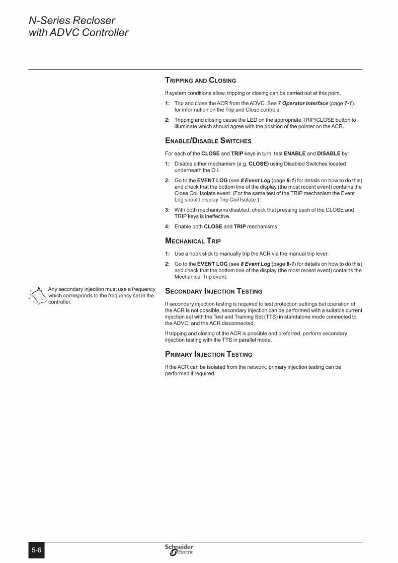
5-6
N-Series Recloser with ADVC Controller
tripping anD cloSing
If system conditions allow, tripping or closing can be carried out at this point.
Trip and close the ACR from the ADVC. See 1: 7 Operator Interface (page 7-1). for information on the Trip and Close controls.
Tripping and closing cause the LED on the appropriate TRIP/CLOSE button to 2: illuminate which should agree with the position of the pointer on the ACR.
enaBle/DiSaBle SwitcheS
For each of the CLose and tRIP keys in turn, test eNABLe and DIsABLe by:
Disable either mechanism (e.g. 1: CLose) using Disabled Switches located underneath the O.I.
Go to the 2: eVeNt LoG (see 8 Event Log (page 8-1) for details on how to do this) and check that the bottom line of the display (the most recent event) contains the Close Coil Isolate event. (For the same test of the TRIP mechanism the Event Log should display Trip Coil Isolate.)
With both mechanisms disabled, check that pressing each of the CLOSE and 3: TRIP keys is ineffective.
Enable both 4: CLose and tRIP mechanisms.
Mechanical trip
Use a hook stick to manually trip the ACR via the manual trip lever.1:
Go to the 2: eVeNt LoG (see 8 Event Log (page 8-1) for details on how to do this) and check that the bottom line of the display (the most recent event) contains the Mechanical Trip event.
SeconDary injection teSting
If secondary injection testing is required to test protection settings but operation of the ACR is not possible, secondary injection can be performed with a suitable current injection set with the Test and Training Set (TTS) in standalone mode connected to the ADVC, and the ACR disconnected.
If tripping and closing of the ACR is possible and preferred, perform secondary injection testing with the TTS in parallel mode.
priMary injection teSting
If the ACR can be isolated from the network, primary injection testing can be performed if required.
Any secondary injection must use a frequency which corresponds to the frequency set in the controller.
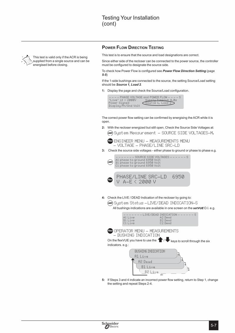
5-7
power flow Direction teSting
This test is to ensure that the source and load designations are correct.
Since either side of the recloser can be connected to the power source, the controller must be configured to designate the source side.
To check how Power Flow is configured see Power Flow Direction Setting (page 5-5)
If the 1-side bushings are connected to the source, the setting Source/Load setting should be Source 1, Load 2.
Display the page and check the Source/Load configuration.1:
- - - - PHASE VOLTAGE and POWER FLOW - - - - S "Live" if > 2000V Supply Timeout 4.0s Power Signed Source 1, Load 2 Display Ph/Gnd Volt
The correct power flow setting can be confirmed by energising the ACR while it is open.
With the recloser energized but still open, Check the Source Side Voltages at:2:
System Measurement - SOURCE SIDE VOLTAGES-M.
ENGINEER MENU - MEASUREMENTS MENU - VOLTAGE - PHASE/LINE SRC-LD Check the source side voltages - either phase to ground or phase to phase e.g.3:
- - - - - - - SOURCE SIDE VOLTAGES - - - - - - S A1 phase to ground 6950 Volt B1 phase to ground 6950 Volt C1 phase to ground 6950 Volt
PHASE/LINE SRC-LD 6950 V A-E < 2000 V
Check the LIVE / DEAD Indication of the recloser by going to:4:
System Status - LIVE/DEAD INDICATION-SAll bushings indications are available in one screen on the setVUE O.I. e.g.
- - - - - - - LIVE/DEAD INDICATION - - - - - - S A1 Live A2 Dead B1 Live B2 Dead C1 Live C2 Dead
OPERATOR MENU - MEASUREMENTS - BUSHING INDICATIONOn the flexVUE you have to use the /keys to scroll through the six indicators. e.g.:
BUSHING INDICATION B 2 L iv e
BUSHING INDICATION B 1 L iv e
BUSHING INDICATION A 2 D ea d
BUSHING INDICATION A 1 L iv e
etc
If Steps 3 and 4 indicate an incorrect power flow setting, return to Step 1, change 5: the setting and repeat Steps 2-4.
This test is valid only if the ACR is being supplied from a single source and can be energised before closing.
Testing Your Installation (cont)
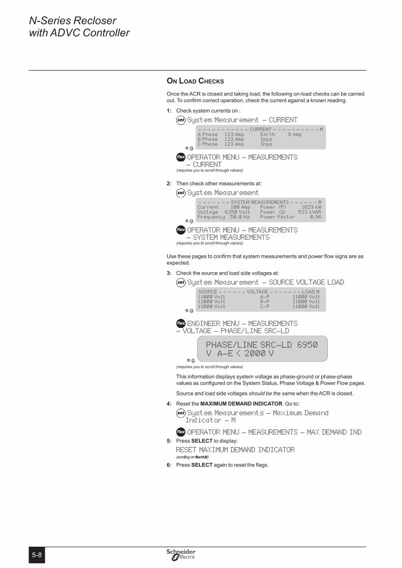
5-8
N-Series Recloser with ADVC Controller
on loaD checkS
Once the ACR is closed and taking load, the following on-load checks can be carried out. To confirm correct operation, check the current against a known reading.
Check system currents on :1:
System Measurement - CURRENT
e.g.
- - - - - - - - - - - CURRENT - - - - - - - - - - M A Phase 123 Amp Earth 8 Amp B Phase 123 Amp Ipps C Phase 123 Amp Inps
OPERATOR MENU - MEASUREMENTS - CURRENT(requires you to scroll through values)
Then check other measurements at:2:
System Measurement
e.g.
- - - - - - - SYSTEM MEASUREMENTS - - - - - - M Current 100 Amp Power (P) 1829 kW Voltage 6350 Volt Power (Q) 533 kVAR Frequency 50.0 Hz Power Factor 0.96
OPERATOR MENU - MEASUREMENTS - SYSTEM MEASUREMENTS(requires you to scroll through values)
Use these pages to confirm that system measurements and power flow signs are as expected.
Check the source and load side voltages at: 3:
System Measurement - SOURCE VOLTAGE LOAD
e.g.
SOURCE - - - - - - VOLTAGE - - - - - - - LOAD M 11000 Volt A-P 11000 Volt 11000 Volt B-P 11000 Volt 11000 Volt C-P 11000 Volt
ENGINEER MENU - MEASUREMENTS - VOLTAGE - PHASE/LINE SRC-LD
e.g.
PHASE/LINE SRC-LD 6950 V A-E < 2000 V
(requires you to scroll through values)
This information displays system voltage as phase-ground or phase-phase values as configured on the System Status, Phase Voltage & Power Flow pages.
Source and load side voltages should be the same when the ACR is closed.
Reset the 4: MAXIMUM DeMAND INDICAtoR. Go to:
System Measurements - Maximum Demand Indicator - M
OPERATOR MENU - MEASUREMENTS - MAX DEMAND IND Press 5: seLeCt to display:
RESET MAXIMUM DEMAND INDICATOR (scrolling on flexVUE)
Press 6: seLeCt again to reset the flags.
6-16-1
The ADVC is designed for outdoor pole mounted operation. Both the ULTRA and CompACT cubicles are vented and insulated to minimise internal temperature variation and maximise battery life. Cubicle dimensions are given in Figure 30 : (page B-2).
Sealing & conDenSation
All cubicle vents are screened against vermin entry and the cubicle door is sealed with replaceable foam tape.
Complete sealing against water entry under all conditions is not expected e.g. during operation in the rain. Instead, the design is such that if any water does enter, it will drain out of the bottom without affecting the electrical or electronic parts. A rain sheild on the PSU will protect MCBs if the door is open during driving rain. The extensive use of stainless steel and other corrosion proof materials ensures that the presence of moisture has no detrimental effects.
Condensation can be expected to form under some atmospheric conditions such as tropical storms. However, condensation will be on metal surfaces where it is of no consequence. The water runs out in the same way as any other water entering the cubicle. Condensation will run out of the bottom or be dried by ventilation and self heating.
All electronic modules are fully sealed to IP65 and are self heating.
auXiliary power Source
The auxiliary supply is used to maintain charge on the sealed lead-acid batteries that provide stand-by power when auxiliary power is lost. The controller monitors the status of both the auxiliary and battery supplies.
A low power mode is activated when the batteries are nearly exhausted due to loss of the auxiliary supply. This mode minimises power consumption while still maintaining basic functionality.
controller
The controller consists of three modules. (See Figure 16 (page 6-3) and Figure 17 (page 6-3)):
Power supply unit (PSU) �
Control and protection enclosure (CAPE) with Operator Interface (O.I.) �
Customer Compartment �
The ADVC block diagram is given in Figure 18 (page 6-4).
PsU Module
The PSU module supplies power to the CAPE, and controls the supply from external auxiliary sources
The power supply module encloses all 115/230 Vac mains connections. Internally it provides terminals for auxiliary power supply connection. Cable-tie points are provided to secure the auxiliary supply cables. Circuit breakers are used to protect and switch the battery and auxiliary power supplies on/off. A durable cover is used to enclose all the terminations.
CAPe Module
The main module of control electronics is the Control and Protection Enclosure (CAPE). The CAPE digitises the current transformer (CT) signals and capacitive voltage transformer (CVT) signals from the recloser. These are used to provide a variety of data for the operator.
The CAPE module contains the PCOM board, PSSM board, trip/close capacitors and O.I. assembled into a housing that provides protection from the environment, sealing and EMC shielding.
The CAPE performs the following functions:
Holding & operating the O.I. �
Operating the external communications interface to allow monitoring and control �from a remote computer or operator over a communications link.
6 Control electronics operation

6-2
N-Series Recloser with ADVC Controller
Switchgear Monitoring and Control �
Controlling WSOS5 over an RS232 link. RS232 Port A is by default configured �for WSOS connection. A USB socket is currently located on the CAPE. This port is reserved for future USB connectivity.
Supply power to all electronic circuits and the customer compartment �
cuStoMer coMpartMent
The compartment is fitted with a panel tray that facilitates the mounting of your equipment e.g. a radio or modem including any special interfaces. See Figure 18 : (page 6-4). The compartment has a terminal block for the radio supply and power for accessories such as an IOEX2. An accessory heater can also be fitted which is controlled by the PSU.
PRoteCtIoN AND CoMMUNICAtIoN sUBMoDULe (PCoM)
The PCOM submodule contains a digital signal processor (DSP) which samples the current and voltage signals from the switchgear and processes them to derive the basic power system information such as current/voltage/frequency/real power/reactive power etc. This is then used by the general-purpose processor (GPP) to provide protection and communications functions e.g. over-current protection. It also presents this data to the outside world via various communications protocols.
PoWeR sUPPLY AND sWItCHGeAR MoDULe (PssM)
The PSSM fulfils power supply and switchgear functionality.
The power supply function controls and filters the supply from external auxiliary supplies. Power is supplied to all the electronic submodules in the ADVC Controller and customer compartment. It also manages the battery power level and performs battery testing.
The switchgear interface function provides controlled pulses of current to trip and close the switchgear.
operator interface/Door aSSeMBly
The O.I. is mounted on the CAPE and is accessed by opening the cubicle door. Operators can view switchgear and system data, control and configure the system via the O.I. The O.I. has its own electronic processing and driver circuit, LCD, membrane keyboard and status LEDs.
Wsos5 Interface
To use WSOS5 to upload or download data, connect your PC serial port to Port A located above the operator interface. Use an RS232, DB9 female to DB9 female, Crossover (also known as Null Modem).
By default, WSOS is configured to run on RS-232 Port A, but can be configured to run on RS-232 Port B, C or D.

6-3
cuStoMer coMpartMent(S)The CompACT cubicle compartment is fitted with an accessory tray that facilitates the mounting of your equipment e.g. a radio or modem. Figure 16 (page 6-3)
The ULTRA cubicle has one standard, and one optional accessory compartment to allow for more equipment. and Figure 17 (page 6-3). The standard compartment has a terminal block for the radio power supply and power for accessories such as an IOEX2.
Customer Compartment
Control and Protection
Enclsure (CAPE) (Including O.I.)
Power Supply Unit (Under Rain Sheild)
Batteries
Door Stay Latch
flexVUE Operator Interface (O.I.)
Standard Customer Compartment Optional Customer Compartment
Control and Protection
Enclosure (CAPE) (Including O.I.)
Power Supply Unit (Under Rain Sheild)
Door Stay Latch
Batteries
CompACTFigure 16. ADVC (with flexVUE O.I.)
ULTRA Figure 17. ADVC (with flexVUE O.I.)
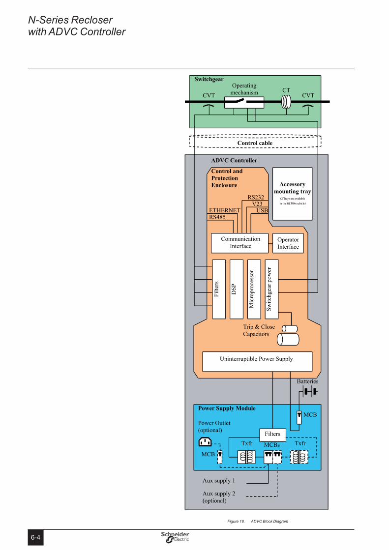
6-4
N-Series Recloser with ADVC Controller
ADVC Block DiagramFigure 18.

7-17-1
7 operator Interface
The ADVC can be remote controlled via modems or other communications devices, controlled using a laptop computer connected directly via serial or USB connections to the ADVC, or by the Operator Interface. (O.I.). The O.I. offers full functionality to change settings, trip and close the switchgear or display current values or past events related to the switchgears function.
The Operator Interface (O.I.) is mounted on the CAPE inside the ADVC Controller and accessed by opening the cubicle door. The O.I. consists of a liquid crystal display (LCD) and key pad and light emitting diodes (LEDs). Together these hardware features provide a user interface to monitor and control the ACR.
Two styles provide different functionality depending on the operators requirements. These two styles are as follows:
setVUEA traditional O.I. that provides a 4 × 40 character LCD and simple navigation with four user configurable quick keys.
DETECTGROUP
WORKTAG
SECTIONON/OFF
flexVUEThis O.I. provides the user with 20 indicator lights and 12 Quick Action Keys (Each with configurable LEDs) that are totally configurable by the user through WSOS5. This provides the user with instant feedback about the switchgear, and minimises the need to navigate through layers of menu structure.
Both the setVUE and flexVUE O.I.’s, and their operation are described in detail on the following pages.
If the door proximity switch is installed, the O.I. turns ON automatically when the door is opened and OFF and when it is closed. The O.I. also turns OFF automatically if no keys are pressed for 10 minutes. Pressing the PANeL oN key will reactivate the panel.
This manual contains examples of display interface screens. In general, the language chosen for these examples is International English. In some cases, screen text will differ if the configured language is English (USA).
More information about the functions of the panels and the operations of the buttons can be found in the ADVC Controller Operations Manual. Contact your distributor
for further details.
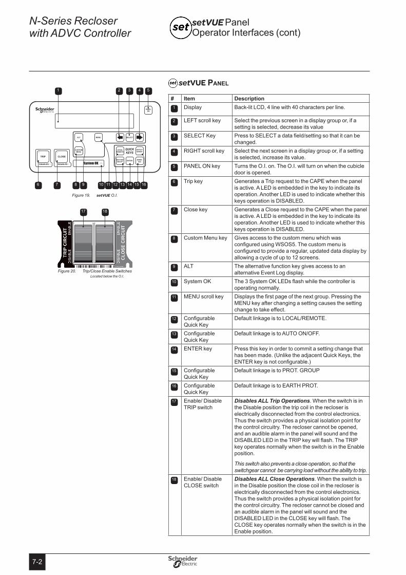
7-2
N-Series Recloser with ADVC Controller
setVUE panel
# Item Description1 Display Back-lit LCD, 4 line with 40 characters per line.
2 LEFT scroll key Select the previous screen in a display group or, if a setting is selected, decrease its value
3 SELECT Key Press to SELECT a data field/setting so that it can be changed.
4 RIGHT scroll key Select the next screen in a display group or, if a setting is selected, increase its value.
5 PANEL ON key Turns the O.I. on. The O.I. will turn on when the cubicle door is opened.
6 Trip key Generates a Trip request to the CAPE when the panel is active. A LED is embedded in the key to indicate its operation. Another LED is used to indicate whether this keys operation is DISABLED.
7 Close key Generates a Close request to the CAPE when the panel is active. A LED is embedded in the key to indicate its operation. Another LED is used to indicate whether this keys operation is DISABLED.
8 Custom Menu key Gives access to the custom menu which was configured using WSOS5. The custom menu is configured to provide a regular, updated data display by allowing a cycle of up to 12 screens.
9 ALT The alternative function key gives access to an alternative Event Log display.
10 System OK The 3 System OK LEDs flash while the controller is operating normally.
11 MENU scroll key Displays the first page of the next group. Pressing the MENU key after changing a setting causes the setting change to take effect.
12 Configurable Quick Key
Default linkage is to LOCAL/REMOTE.
13 Configurable Quick Key
Default linkage is to AUTO ON/OFF.
14 ENTER key Press this key in order to commit a setting change that has been made. (Unlike the adjacent Quick Keys, the ENTER key is not configurable.)
15 Configurable Quick Key
Default linkage is to PROT. GROUP
16 Configurable Quick Key
Default linkage is to EARTH PROT.
17 Enable/ Disable TRIP switch
Disables ALL Trip Operations. When the switch is in the Disable position the trip coil in the recloser is electrically disconnected from the control electronics. Thus the switch provides a physical isolation point for the control circuitry. The recloser cannot be opened, and an audible alarm in the panel will sound and the DISABLED LED in the TRIP key will flash. The TRIP key operates normally when the switch is in the Enable position.
This switch also prevents a close operation, so that the switchgear cannot be carrying load without the ability to trip.
18 Enable/ Disable CLOSE switch
Disables ALL Close Operations. When the switch is in the Disable position the close coil in the recloser is electrically disconnected from the control electronics. Thus the switch provides a physical isolation point for the control circuitry. The recloser cannot be closed and an audible alarm in the panel will sound and the DISABLED LED in the CLOSE key will flash. The CLOSE key operates normally when the switch is in the Enable position.
setVUE Panel Operator Interfaces (cont)
DETECTGROUP
WORKTAG
SECTIONON/OFF
1 52 3 4
6 7 8 10 12 159 11 13 1614
setVUEFigure 19. O.I.
Trip/Close Enable Switches Figure 20. Located below the O.I.
1817
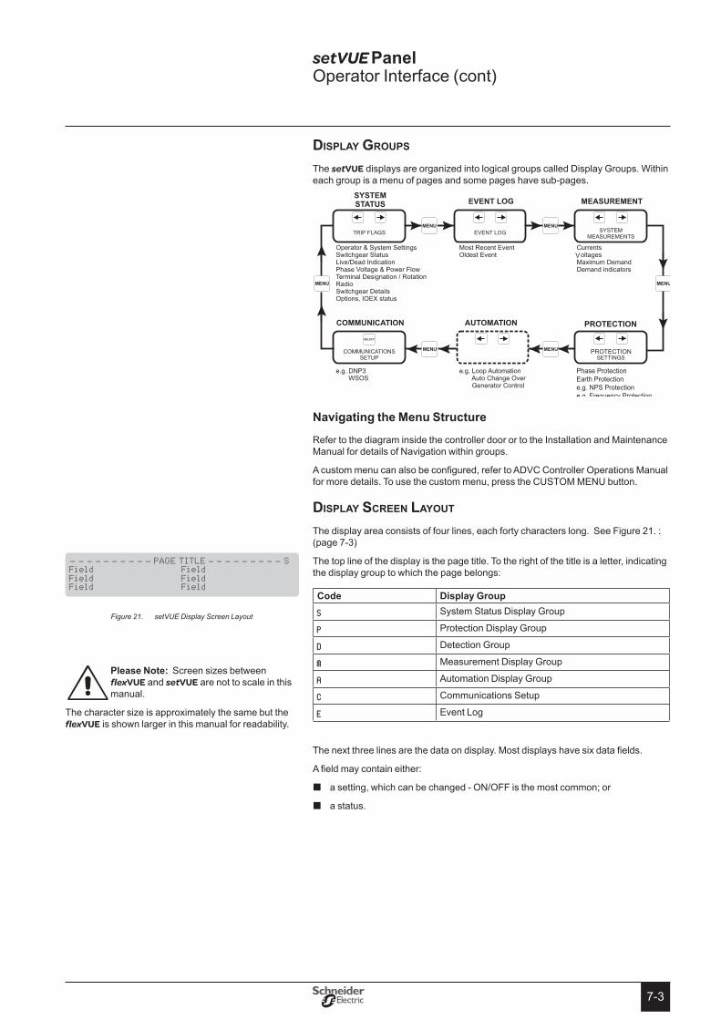
7-3
DiSplay groupS
The setVUE displays are organized into logical groups called Display Groups. Within each group is a menu of pages and some pages have sub-pages.
PROTECTION
Phase ProtectionEarth Protectione.g. NPS Protectione.g. Frequency Protection
PROTECTION
Navigating the Menu structure
Refer to the diagram inside the controller door or to the Installation and Maintenance Manual for details of Navigation within groups.
A custom menu can also be configured, refer to ADVC Controller Operations Manual for more details. To use the custom menu, press the CUSTOM MENU button.
DiSplay Screen layout The display area consists of four lines, each forty characters long. See Figure 21. : (page 7-3)
The top line of the display is the page title. To the right of the title is a letter, indicating the display group to which the page belongs:
Code Display Group
S System Status Display Group
P Protection Display Group
D Detection Group
M Measurement Display Group
A Automation Display Group
C Communications Setup
E Event Log
The next three lines are the data on display. Most displays have six data fields.
A field may contain either:
a setting, which can be changed - ON/OFF is the most common; or �
a status. �
setVUE Panel Operator Interface (cont)
Please Note: Screen sizes between flexVUE and setVUE are not to scale in this manual.
The character size is approximately the same but the flexVUE is shown larger in this manual for readability.
- - - - - - - - - - PAGE TITLE - - - - - - - - - S Field Field Field Field Field Field
setVUE Display Screen LayoutFigure 21.
7-4
N-Series Recloser with ADVC Controller
changing SettingS
Three types of settings can be changed:
Operator settings �
Password protected settings �
Protection settings �
operator settings
Find the display page containing the setting to be changed:
Press the 1: MeNU key to display the group you require.
Communications Group (only) is divided into subgroups for different protocols. 2: Press seLeCt to display the subgroup you require.
Press 3: to display the page you require.
Press 4: seLeCt to highlight the setting. A highlighted setting “blinks”. Alternatively, if a QUICK KEY is linked to the setting, you can use it to go directly to the relevant display page where you will find the highlighted setting.
Once you have selected the setting to be changed, use 5: or to change its setting.
Press 6: eNteR to activate the new setting.
Password Protected settings
Some settings are password protected. You will be prompted for a password before you can change the setting. To enter the password:
Press either of the 1: / keys until the first character of the password is displayed.
Press the 2: seLeCt key.
Repeat Steps 1 and 2 until the password is complete. 3:
Press 4: eNteR.
While the operator panel is ON you will not be required to enter the password again.
The default factory password is AAAA but you can change it using the Windows Switchgear Operator System (WSOS5) program. The factory password does not have to be remembered - the controller prompts you for it automatically.

7-5
Protection settings
Protection settings are password protected. To change a protection setting, follow the steps detailed in the Operator Settings section above but, in addition, enter the password when prompted. When you have completed the setting change by pressing eNteR, the following message will flash at the top of the screen:
Active Protection Setting has changed. At this point, the changed setting will be displayed but not in service. If further setting changes are required, they can be made now.
When you have completed making all the setting changes you require, press eNteR. The following text will be displayed:
CHANGED ACTIVE PROTECTION SETTING [A] The changed active PROTECTION SETTINGS are now in service.
Select the MENU or ENTER key to continue. The changed settings are now in service. Press MeNU or eNteR to return to the normal menu display.
Quick keyS
The operator settings that you will frequently change can each be linked to a QUICK KEY. You use a QUICK KEY for instant display and selection of the linked setting which, otherwise, you would have to find by navigation.
You can link operator settings to individual Quick Keys using the Operator Interface or WSOS5.
A QUICK Key can be set to Blank, if it is not required.
Otherwise, any one of the settings tabled below can be linked to one of the four Quick Keys.
setting Default statusLOCAL/Remote / Hit & Run Default setting,
upper left keyLoop Auto ON/OFF ConfigurableProt Group Default setting,
lower right keyReset Flags ConfigurableWork Tag ON/OFF ConfigurableAuto ON/OFF Protection OFF
Default setting, lower left key
Cold Load ON/OFF ConfigurableEarth Prot Default setting,
upper right keyLive Block ConfigurableNegative Phase Sequence Protection OFF/ON/Alarm
Configurable
Detection Group ConfigurableEarth Detection ConfigurableSection ON/OFF Configurable
How to configure the Quick keys is described in the ADVC Controller Operations manual.
setVUE Panel Operator Interface (cont)
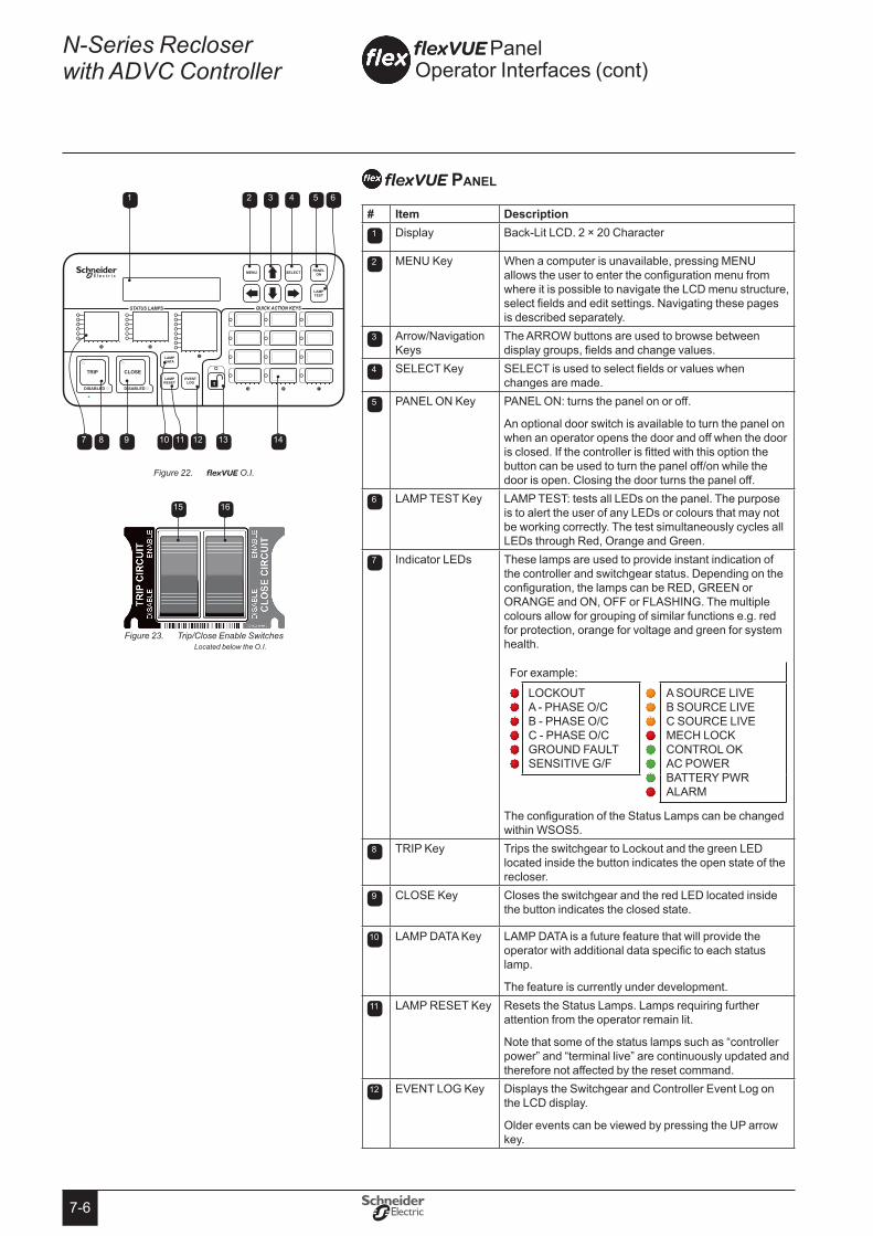
7-6
N-Series Recloser with ADVC Controller
flexVUE panel
# Item Description1 Display Back-Lit LCD. 2 × 20 Character
2 MENU Key When a computer is unavailable, pressing MENU allows the user to enter the configuration menu from where it is possible to navigate the LCD menu structure, select fields and edit settings. Navigating these pages is described separately.
3 Arrow/Navigation Keys
The ARROW buttons are used to browse between display groups, fields and change values.
4 SELECT Key SELECT is used to select fields or values when changes are made.
5 PANEL ON Key PANEL ON: turns the panel on or off.
An optional door switch is available to turn the panel on when an operator opens the door and off when the door is closed. If the controller is fitted with this option the button can be used to turn the panel off/on while the door is open. Closing the door turns the panel off.
6 LAMP TEST Key LAMP TEST: tests all LEDs on the panel. The purpose is to alert the user of any LEDs or colours that may not be working correctly. The test simultaneously cycles all LEDs through Red, Orange and Green.
7 Indicator LEDs These lamps are used to provide instant indication of the controller and switchgear status. Depending on the configuration, the lamps can be RED, GREEN or ORANGE and ON, OFF or FLASHING. The multiple colours allow for grouping of similar functions e.g. red for protection, orange for voltage and green for system health.
For example:
LOCKOUT A - PHASE O/C B - PHASE O/C C - PHASE O/C GROUND FAULT SENSITIVE G/F
A SOURCE LIVE B SOURCE LIVE C SOURCE LIVE MECH LOCK CONTROL OK AC POWER BATTERY PWR ALARM
The configuration of the Status Lamps can be changed within WSOS5.
8 TRIP Key Trips the switchgear to Lockout and the green LED located inside the button indicates the open state of the recloser.
9 CLOSE Key Closes the switchgear and the red LED located inside the button indicates the closed state.
10 LAMP DATA Key LAMP DATA is a future feature that will provide the operator with additional data specific to each status lamp.
The feature is currently under development.11 LAMP RESET Key Resets the Status Lamps. Lamps requiring further
attention from the operator remain lit.
Note that some of the status lamps such as “controller power” and “terminal live” are continuously updated and therefore not affected by the reset command.
12 EVENT LOG Key Displays the Switchgear and Controller Event Log on the LCD display.
Older events can be viewed by pressing the UP arrow key.
flexVUE Panel Operator Interfaces (cont)
1
7 8 9 10 11 12 13 14
2 3 4 5 6
flexVUEFigure 22. O.I.
Trip/Close Enable Switches Figure 23. Located below the O.I.
15 16
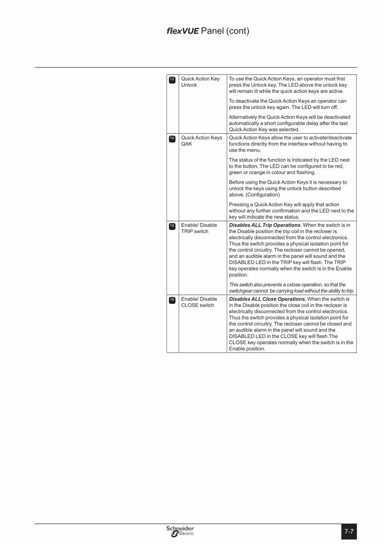
7-7
13 Quick Action Key Unlock
To use the Quick Action Keys, an operator must first press the Unlock key. The LED above the unlock key will remain lit while the quick action keys are active.
To deactivate the Quick Action Keys an operator can press the unlock key again. The LED will turn off.
Alternatively the Quick Action Keys will be deactivated automatically a short configurable delay after the last Quick Action Key was selected.
14 Quick Action Keys QAK
Quick Action Keys allow the user to activate/deactivate functions directly from the interface without having to use the menu.
The status of the function is indicated by the LED next to the button. The LED can be configured to be red, green or orange in colour and flashing.
Before using the Quick Action Keys it is necessary to unlock the keys using the unlock button described above. (Configuration)
Pressing a Quick Action Key will apply that action without any further confirmation and the LED next to the key will indicate the new status.
15 Enable/ Disable TRIP switch
Disables ALL Trip Operations. When the switch is in the Disable position the trip coil in the recloser is electrically disconnected from the control electronics. Thus the switch provides a physical isolation point for the control circuitry. The recloser cannot be opened, and an audible alarm in the panel will sound and the DISABLED LED in the TRIP key will flash. The TRIP key operates normally when the switch is in the Enable position.
This switch also prevents a cxlose operation, so that the switchgear cannot be carrying load without the ability to trip.
16 Enable/ Disable CLOSE switch
Disables ALL Close Operations� When the switch is in the Disable position the close coil in the recloser is electrically disconnected from the control electronics. Thus the switch provides a physical isolation point for the control circuitry. The recloser cannot be closed and an audible alarm in the panel will sound and the DISABLED LED in the CLOSE key will flash.The CLOSE key operates normally when the switch is in the Enable position.
flexVUE Panel (cont)
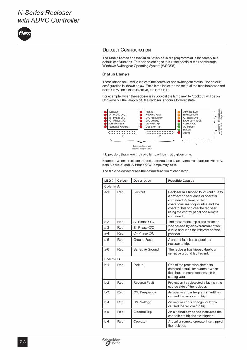
7-8
N-Series Recloser with ADVC Controller
Default configuration
The Status Lamps and the Quick Action Keys are programmed in the factory to a default configuration. This can be changed to suit the needs of the user through Windows Switchgear Operating System (WSOS5).
status Lamps
These lamps are used to indicate the controller and switchgear status. The default configuration is shown below. Each lamp indicates the state of the function described next to it. When a state is active, the lamp is lit.
For example, when the recloser is in Lockout the lamp next to “Lockout” will be on. Conversely if the lamp is off, the recloser is not in a lockout state.
Sw
itchg
ear &
Ov
erhe
ad sy
stem
co
ntroll
er st
atus
volta
ge st
atus
Lockout A - Phase O/C B - Phase O/C C - Phase O/C Ground Fault Sensitive Ground
Pickup Reverse Fault O/U Frequency O/U Voltage External Trip Operator Trip
A Phase Live B Phase Live C Phase Live Load Current ON System OK AC Power Battery Alarm
a
b
Protection Status and
cause of Tripped Status
c
It is possible that more than one lamp will be lit at a given time.
Example, when a recloser tripped to lockout due to an overcurrent fault on Phase A, both “Lockout” and “A-Phase O/C” lamps may be lit.
The table below describes the default function of each lamp.
LeD # Colour Description Possible CausesColumn Aa-1 Red Lockout Recloser has tripped to lockout due to
a protection sequence or operator command. Automatic close operations are not possible and the operator has to close the recloser using the control panel or a remote command.
a-2 Red A - Phase O/C The most recent trip of the recloser was caused by an overcurrent event due to a fault on the relevant network phase/s.
a-3 Red B - Phase O/C
a-4 Red C - Phase O/C
a-5 Red Ground Fault A ground fault has caused the recloser to trip.
a-6 Red Sensitive Ground The recloser has tripped due to a sensitive ground fault event.
Column Bb-1 Red Pickup One of the protection elements
detected a fault, for example when the phase current exceeds the trip setting value.
b-2 Red Reverse Fault Protection has detected a fault on the source side of the recloser.
b-3 Red O/U Frequency An over or under frequency fault has caused the recloser to trip.
b-4 Red O/U Voltage An over or under voltage fault has caused the recloser to trip.
b-5 Red External Trip An external device has instructed the controller to trip the switchgear.
b-6 Red Operator A local or remote operator has tripped the recloser.
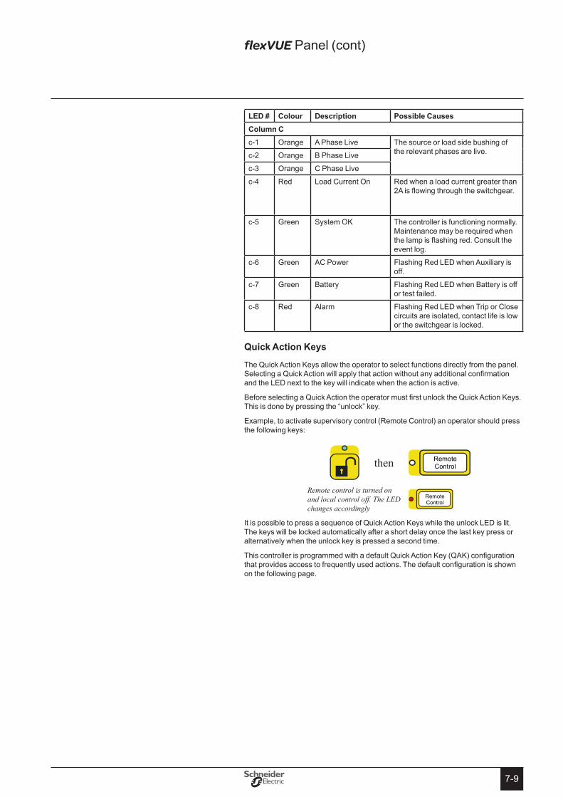
7-9
LeD # Colour Description Possible CausesColumn Cc-1 Orange A Phase Live The source or load side bushing of
the relevant phases are live.c-2 Orange B Phase Live
c-3 Orange C Phase Live
c-4 Red Load Current On Red when a load current greater than 2A is flowing through the switchgear.
c-5 Green System OK The controller is functioning normally. Maintenance may be required when the lamp is flashing red. Consult the event log.
c-6 Green AC Power Flashing Red LED when Auxiliary is off.
c-7 Green Battery Flashing Red LED when Battery is off or test failed.
c-8 Red Alarm Flashing Red LED when Trip or Close circuits are isolated, contact life is low or the switchgear is locked.
Quick Action Keys
The Quick Action Keys allow the operator to select functions directly from the panel. Selecting a Quick Action will apply that action without any additional confirmation and the LED next to the key will indicate when the action is active.
Before selecting a Quick Action the operator must first unlock the Quick Action Keys. This is done by pressing the “unlock” key.
Example, to activate supervisory control (Remote Control) an operator should press the following keys:
then Remote
Control
Remote control is turned on and local control off. The LED changes accordingly
Remote Control
It is possible to press a sequence of Quick Action Keys while the unlock LED is lit. The keys will be locked automatically after a short delay once the last key press or alternatively when the unlock key is pressed a second time.
This controller is programmed with a default Quick Action Key (QAK) configuration that provides access to frequently used actions. The default configuration is shown on the following page.
flexVUE Panel (cont)
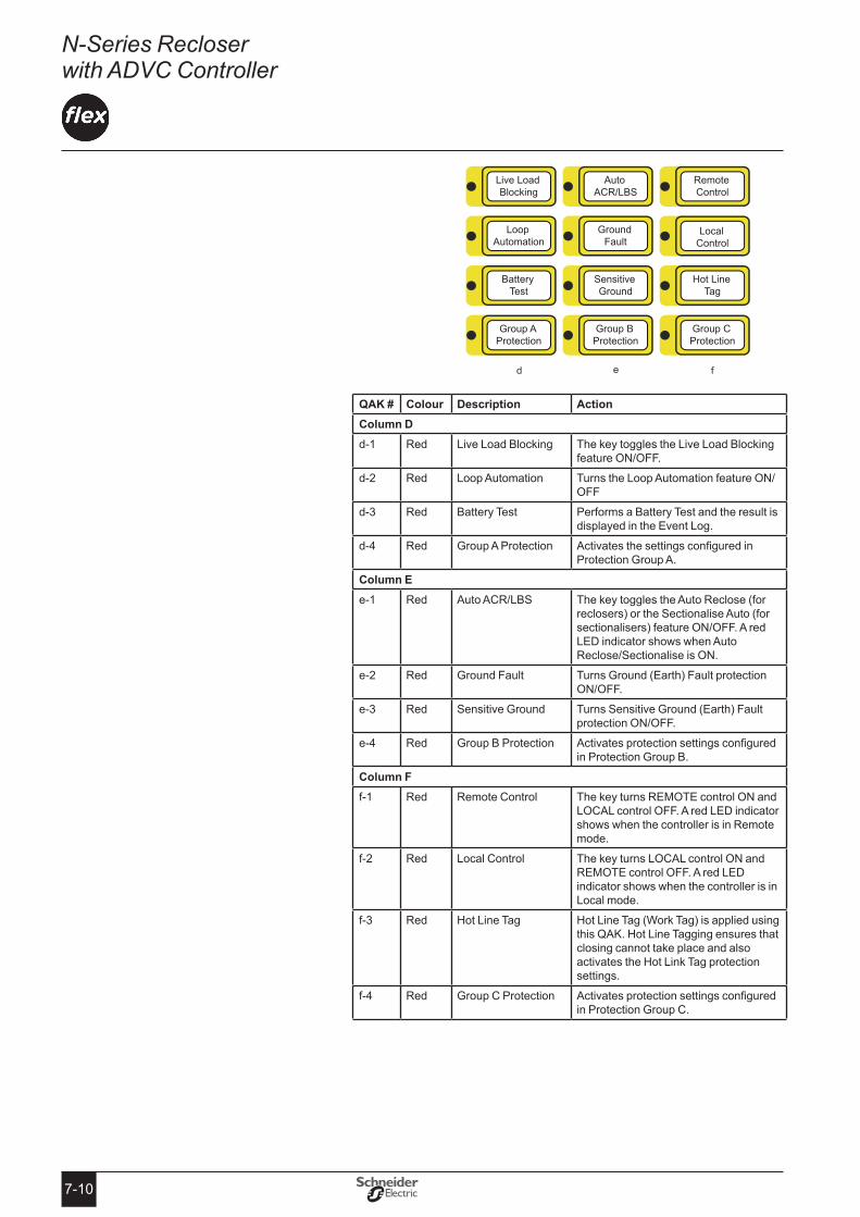
7-10
N-Series Recloser with ADVC Controller
Group A Protection
Group B Protection
Group C Protection
Battery Test
Sensitive Ground
Hot Line Tag
Loop Automation
Ground Fault
Local Control
Live Load Blocking
Auto ACR/LBS
Remote Control
QAK # Colour Description ActionColumn Dd-1 Red Live Load Blocking The key toggles the Live Load Blocking
feature ON/OFF.
d-2 Red Loop Automation Turns the Loop Automation feature ON/OFF
d-3 Red Battery Test Performs a Battery Test and the result is displayed in the Event Log.
d-4 Red Group A Protection Activates the settings configured in Protection Group A.
Column ee-1 Red Auto ACR/LBS The key toggles the Auto Reclose (for
reclosers) or the Sectionalise Auto (for sectionalisers) feature ON/OFF. A red LED indicator shows when Auto Reclose/Sectionalise is ON.
e-2 Red Ground Fault Turns Ground (Earth) Fault protection ON/OFF.
e-3 Red Sensitive Ground Turns Sensitive Ground (Earth) Fault protection ON/OFF.
e-4 Red Group B Protection Activates protection settings configured in Protection Group B.
Column Ff-1 Red Remote Control The key turns REMOTE control ON and
LOCAL control OFF. A red LED indicator shows when the controller is in Remote mode.
f-2 Red Local Control The key turns LOCAL control ON and REMOTE control OFF. A red LED indicator shows when the controller is in Local mode.
f-3 Red Hot Line Tag Hot Line Tag (Work Tag) is applied using this QAK. Hot Line Tagging ensures that closing cannot take place and also activates the Hot Link Tag protection settings.
f-4 Red Group C Protection Activates protection settings configured in Protection Group C.
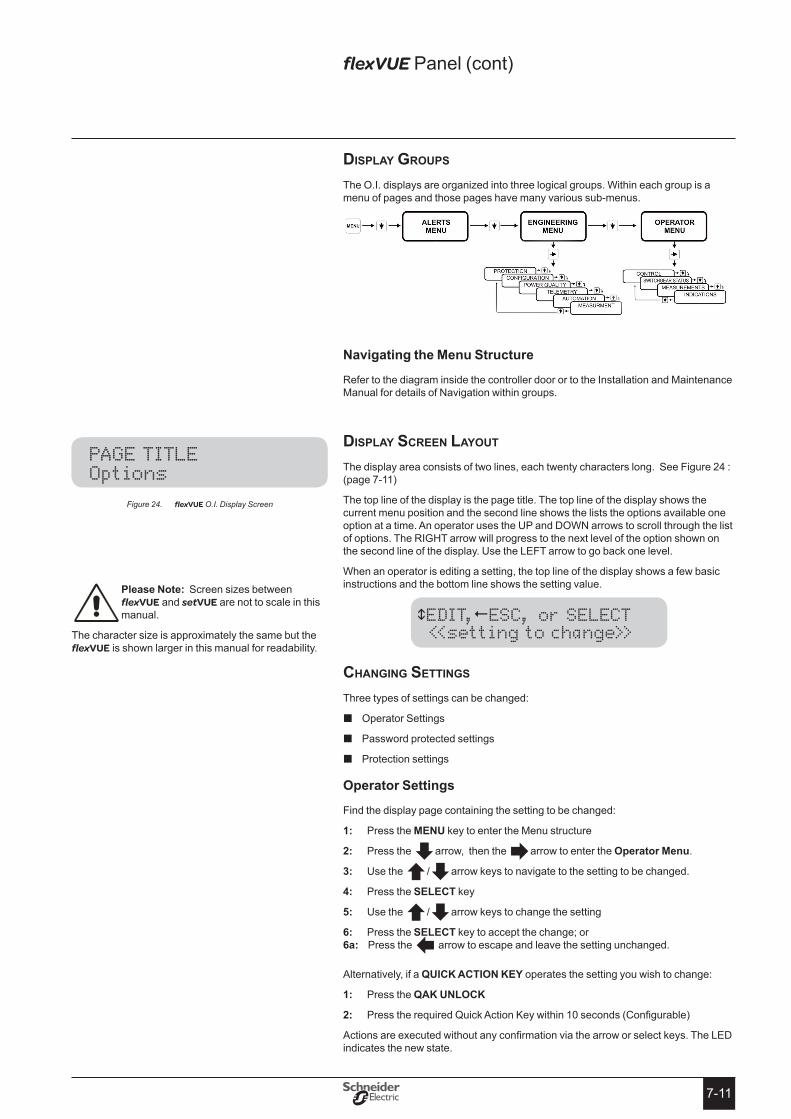
7-11
DiSplay groupS
The O.I. displays are organized into three logical groups. Within each group is a menu of pages and those pages have many various sub-menus.
Navigating the Menu structure
Refer to the diagram inside the controller door or to the Installation and Maintenance Manual for details of Navigation within groups.
DiSplay Screen layout The display area consists of two lines, each twenty characters long. See Figure 24 : (page 7-11)
The top line of the display is the page title. The top line of the display shows the current menu position and the second line shows the lists the options available one option at a time. An operator uses the UP and DOWN arrows to scroll through the list of options. The RIGHT arrow will progress to the next level of the option shown on the second line of the display. Use the LEFT arrow to go back one level.
When an operator is editing a setting, the top line of the display shows a few basic instructions and the bottom line shows the setting value.
EDIT,ESC, or SELECT <<setting to change>>
changing SettingS
Three types of settings can be changed:
Operator Settings �
Password protected settings �
Protection settings �
operator settings
Find the display page containing the setting to be changed:
Press the 1: MeNU key to enter the Menu structure
Press the 2: arrow, then the arrow to enter the operator Menu.
Use the 3: /arrow keys to navigate to the setting to be changed.
Press the 4: seLeCt key
Use the 5: /arrow keys to change the setting
Press the 6: seLeCt key to accept the change; or6a: Press the arrow to escape and leave the setting unchanged.
Alternatively, if a QUICK ACtIoN KeY operates the setting you wish to change:
Press the 1: QAK UNLoCK
Press the required Quick Action Key within 10 seconds (Configurable)2:
Actions are executed without any confirmation via the arrow or select keys. The LED indicates the new state.
PAGE TITLE Options
flexVUE Panel (cont)
flexFigure 24. VUE O.I. Display Screen
Please Note: Screen sizes between flexVUE and setVUE are not to scale in this manual.
The character size is approximately the same but the flexVUE is shown larger in this manual for readability.
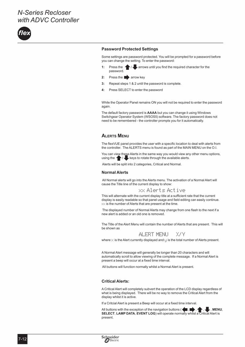
7-12
N-Series Recloser with ADVC Controller
Password Protected settings
Some settings are password protected. You will be prompted for a password before you can change the setting. To enter the password:
Press the 1: /arrows until you find the required character for the password.
Press the 2: arrow key
Repeat steps 1 & 2 until the password is complete.3:
Press SELECT to enter the password4:
While the Operator Panel remains ON you will not be required to enter the password again.
The default factory password is AAAA but you can change it using Windows Switchgear Operator System (WSOS5) software. The factory password does not need to be remembered - the controller prompts you for it automatically.
alertS Menu
The flexVUE panel provides the user with a specific location to deal with alerts from the controller. The ALERTS menu is found as part of the MAIN MENU on the O.I.
You can view these Alerts in the same way you would view any other menu options, using the /keys to rotate through the available alerts.
Alerts will be split into 2 categories, Critical and Normal.
Normal Alerts
All Normal alerts will go into the Alerts menu. The activation of a Normal Alert will cause the Title line of the current display to show:
xx Alerts Active This will alternate with the current display title at a sufficient rate that the current display is easily readable so that panel usage and field editing can easily continue. xx is the number of Alerts that are present at the time.
The displayed number of Normal Alerts may change from one flash to the next if a new alert is added or an old one is removed.
The Title of the Alert Menu will contain the number of Alerts that are present. This will be shown as
ALERT MENU X/Ywhere x is the Alert currently displayed and y is the total number of Alerts present.
A Normal Alert message will generally be longer than 20 characters and will automatically scroll to allow viewing of the complete message. If a Normal Alert is present a beep will occur at a fixed time interval.
All buttons will function normally whilst a Normal Alert is present.
Critical Alerts:
A Critical Alert will completely subvert the operation of the LCD display regardless of what is being displayed. There will be no way to remove the Critical Alert from the display whilst it is active.
If a Critcial Alert is present a Beep will occur at a fixed time interval.
All buttons with the exception of the navigation buttons (,,,, MeNU, seLeCt, LAMP DAtA, eVeNt LoG) will operate normally whilst a Critical Alert is present.

7-13
ACtIVAtING Protection settings
When settings are changed in the Active protection group (via the flexVUE O.I.) those new settings will be saved but will not be put into service until they are made
.
When changing Active Protection Group settings, once the first setting is changed the following screen will appear: (scrolling)
Settings Changed
SELECT to activate, continue change
This message will be displayed if:
Settings are changed within the ACTIVE PROTECTION GROUP �
The current setting is the first one to be changed. �
Before changing this setting - all the current settings were ACTIVE in service �
Once this message is displayed there are 3 options.
NO ACTION: 1: The new setting will automatically go in service if the operator ignores the above message, turns the operator interface off or the interface turns off automatically.
PRESS 2: seLeCt: If the operator presses the seLeCt key, the new setting is put in service. The operator can continue to browse the menu. With all the current settings in active service, if the operator makes another setting change the above message will be prompted when the first of the new settings is saved.
PRESS THE 3: ARRoW: This will allow the operator to browse settings and allow them to be changed.
exiting the Protection Menu
The operator will not be prompted to ACTIVATE the settings again until they try to exit the PRoteCtIoN MeNU, when the following screen will appear:
Settings Changed Activate? Y/N
The operator has to press the UP or DoWN ARROW key. That will display the following:
EDIT, or SELECT ACTIVATE? Yes
or EDIT, or SELECT
ACTIVATE? No
When the operator scrolls to YES and presses seLeCt, the settings are put in service. If the operator selects NO and presses the seLeCt key, the following message is displayed: (scrolling)
Continue Settings activate on panel shutdown
Re-entering the Protection Menu
If the operator exits the Protection Menu without activating the saved settings, when the Protection Menu is re-entered at a later point in time, providing the settings haven’t been put into service by a panel shutdown, the process will run through the same activation sequence as shown in “Exiting the Protection Menu (page 7-13)” .
flexVUE Panel (cont)

7-14
N-Series Recloser with ADVC Controller
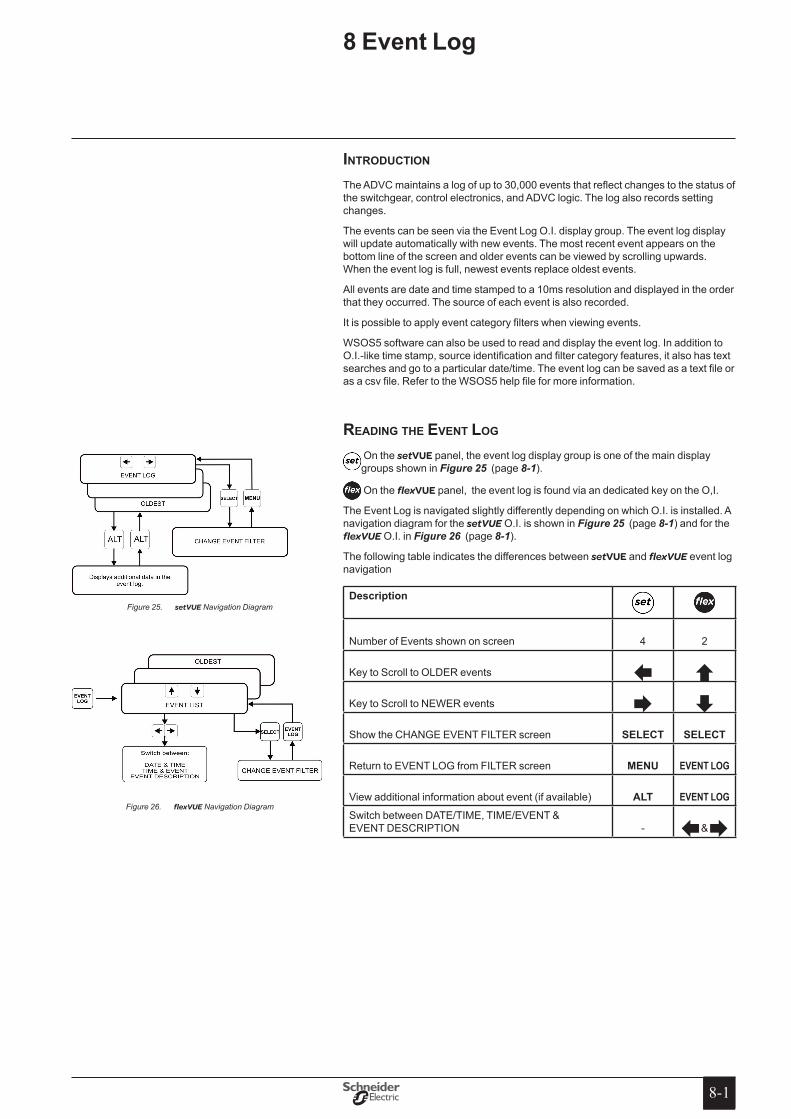
8-18-1
8 event Log
introDuction The ADVC maintains a log of up to 30,000 events that reflect changes to the status of the switchgear, control electronics, and ADVC logic. The log also records setting changes.
The events can be seen via the Event Log O.I. display group. The event log display will update automatically with new events. The most recent event appears on the bottom line of the screen and older events can be viewed by scrolling upwards. When the event log is full, newest events replace oldest events.
All events are date and time stamped to a 10ms resolution and displayed in the order that they occurred. The source of each event is also recorded.
It is possible to apply event category filters when viewing events.
WSOS5 software can also be used to read and display the event log. In addition to O.I.-like time stamp, source identification and filter category features, it also has text searches and go to a particular date/time. The event log can be saved as a text file or as a csv file. Refer to the WSOS5 help file for more information.
reaDing the event log
On the setVUE panel, the event log display group is one of the main display groups shown in Figure 25 (page 8-1).
On the flexVUE panel, the event log is found via an dedicated key on the O,I.
The Event Log is navigated slightly differently depending on which O.I. is installed. A navigation diagram for the setVUE O.I. is shown in Figure 25 (page 8-1) and for the flexVUE O.I. in Figure 26 (page 8-1).
The following table indicates the differences between setVUE and flexVUE event log navigation
Description
Number of Events shown on screen 4 2
Key to Scroll to OLDER events Key to Scroll to NEWER events Show the CHANGE EVENT FILTER screen seLeCt seLeCt
Return to EVENT LOG from FILTER screen MeNU EVENT LOG
View additional information about event (if available) ALt EVENT LOGSwitch between DATE/TIME, TIME/EVENT & EVENT DESCRIPTION - &
setVUEFigure 25. Navigation Diagram
flexVUEFigure 26. Navigation Diagram
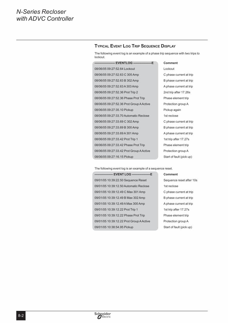
8-2
N-Series Recloser with ADVC Controller
typical event log trip SeQuence DiSplay The following event log is an example of a phase trip sequence with two trips to lockout.
-------------------- eVeNtLoG ------------------e Comment
08/06/05 09:27:52.64 Lockout Lockout
08/06/05 09:27:52.63 C 305 Amp C phase current at trip
08/06/05 09:27:52.63 B 302 Amp B phase current at trip
08/06/05 09:27:52.63 A 303 Amp A phase current at trip
08/06/05 09:27:52.36 Prot Trip 2 2nd trip after 17.26s
08/06/05 09:27:52.36 Phase Prot Trip Phase element trip
08/06/05 09:27:52.36 Prot Group A Active Protection group A
08/06/05 09:27:35.10 Pickup Pickup again
08/06/05 09:27:33.70 Automatic Reclose 1st reclose
08/06/05 09:27:33.69 C 302 Amp C phase current at trip
08/06/05 09:27:33.69 B 300 Amp B phase current at trip
08/06/05 09:27:33.69 A 301 Amp A phase current at trip
08/06/05 09:27:33.42 Prot Trip 1 1st trip after 17.27s
08/06/05 09:27:33.42 Phase Prot Trip Phase element trip
08/06/05 09:27:33.42 Prot Group A Active Protection group A
08/06/05 09:27:16.15 Pickup Start of fault (pick up)
The following event log is an example of a sequence reset.
------------------ eVeNt LoG ------------------e Comment
09/01/05 10:39:22.50 Sequence Reset Sequence reset after 10s
09/01/05 10:39:12.50 Automatic Reclose 1st reclose
09/01/05 10:39:12.49 C Max 301 Amp C phase current at trip
09/01/05 10:39:12.49 B Max 302 Amp B phase current at trip
09/01/05 10:39:12.49 A Max 300 Amp A phase current at trip
09/01/05 10:39:12.22 Prot Trip 1 1st trip after 17.27s
09/01/05 10:39:12.22 Phase Prot Trip Phase element trip
09/01/05 10:39:12.22 Prot Group A Active Protection group A
09/01/05 10:38:54.95 Pickup Start of fault (pick up)

8-3
Event Log (cont)
Display of events
The difference in the display on the setVUE and flexVUE are shown in the following example.
Consider the following events, as shown on the setVUE:
09/01/05 10:39:12.49 B Max 302 Amp 09/01/05 10:39:12.49 C Max 301 Amp 09/01/05 10:39:12.50 Automatic Reclose 09/01/05 10:39:22.50 Sequence Reset
The flexVUE, by default, would display the bottom two lines (the most recent) first. See below:
10:39 Automatic Recl 10:39 Sequence Reset
From this screen, a complete TIME or EVENT DESCRIPTION is available by pressing the or keys respectively:
For the TIME press :
09/01/05 10:39:12.50 09/01/05 10:39:22.50
For the EVENT DESCRIPTION press :
Automatic Reclose Sequence Reset
In this example, pressing the twice would scroll to the next two events.
10:39 B Max 302 Amp 10:39 C Max 301 Amp
setting Change events
A settings change can come from a variety of sources - WSOS5, Operator Interface, SCADA protocol, and IOEX. The controller includes in its log, information regarding the source of each setting change.
If the ALt key ( ) or eVeNt LoG key ( ) is pressed whilst the event log is on the display then the date and time details are replaced with extra information that includes the setting source and, if applicable, the protection group, curve, and trip number. Pressing the ALt ( ) or eVeNt LoG ( )key again will redisplay the date and time information.
The identification codes for sources are:
Identifier Settingschangesource WSOS WSOS5 change OCP Operator Control Panel (Operator Interface) change PTCL SCADA protocol change IOEX IOEX change
As it is possible for multiple WSOS5 applications to be simultaneously connected to the controller via Ethernet, a source identification of “WSOS” can be insufficient information. For WSOS5 over Ethernet connections the first four letters of the PC’s login name are logged. The usage of “WSOS” is therefore restricted to serial port point to point communication links only.
Please Note: Screen sizes between flexVUE and setVUE are not to scale in this manual.
The character size is approximately the same but the flexVUE is shown larger in this manual for readability.

8-4
N-Series Recloser with ADVC Controller
For example, a setVUE event log display may look like this:
08/06/06 11:05:50.25 Very Inv IEC255 08/06/06 11:07:15.66 Parity EVEN 08/06/06 11:09:23.03 Work Tag Applied 08/06/06 11:10:35.19 Load Supply ON
becomes:
WSOS Phase Trip 2 D Very Inv IEC255 OCP RS232-B Parity EVEN PTCL Work Tag Applied Load Supply ON
when you press the ALt key.
In the above example it can be seen that:
WSOS5 has been used to set a Very Inverse IEC255 curve for phase trip 2, �group D
the O.I. has been used to set the controller’s RS-232 Port B communications �parity to EVEN
the work tag has been applied via a SCADA protocol communications link �
the controller has detected restoration of load supply. There is no setting change �source.
The flexVUE screen might look like this:
11:05 Very Inv IEC255 11:07 Parity EVEN
pressing eVeNt LoG would change it to:
WSOS Phase Trip 2 D OCP RS232-B
9-19-1
The current transformer (CT) signals and voltage screen (CVT) signals from the recloser are digitised by the ADVC Controller and used to provide a variety of data for the operator.
The ADVC Controller measures up to 10 power system components:
A, B, C, phase and spill currents, �
phase-earth voltage on all six terminals. �
The ADVC Controller uses the above measurements to derive many system measurements including:
� frequency,
phase to phase voltages, �
total and per phase power (kW, kVA, kVAR), �
total and per phase power factor, �
harmonics, �
earth current, and �
sequence components. �
In addition, the ADVC Controller also measures internal values such as:
CAPE temperature, �
switchgear temperature � 1
auxiliary voltage, �
gas pressure, �
battery voltage. �
power SySteM freQuency
The controller must be set for the correct power system frequency – either 50 or 60 Hz. This can be set on page:
SYSTEM STATUS - PHASE VOLTAGE and POWER FLOW.
ENGINEER MENU - CONFIGURATION MENU - SYSTEM SETTINGS - NETWORK PARAMETERS - System Freq 50Hz/60Hz
1 The ADVC measures the temperature of the SCEM in the ACR and from that, calculates the switchgear temperature.
9 Power system Measurements
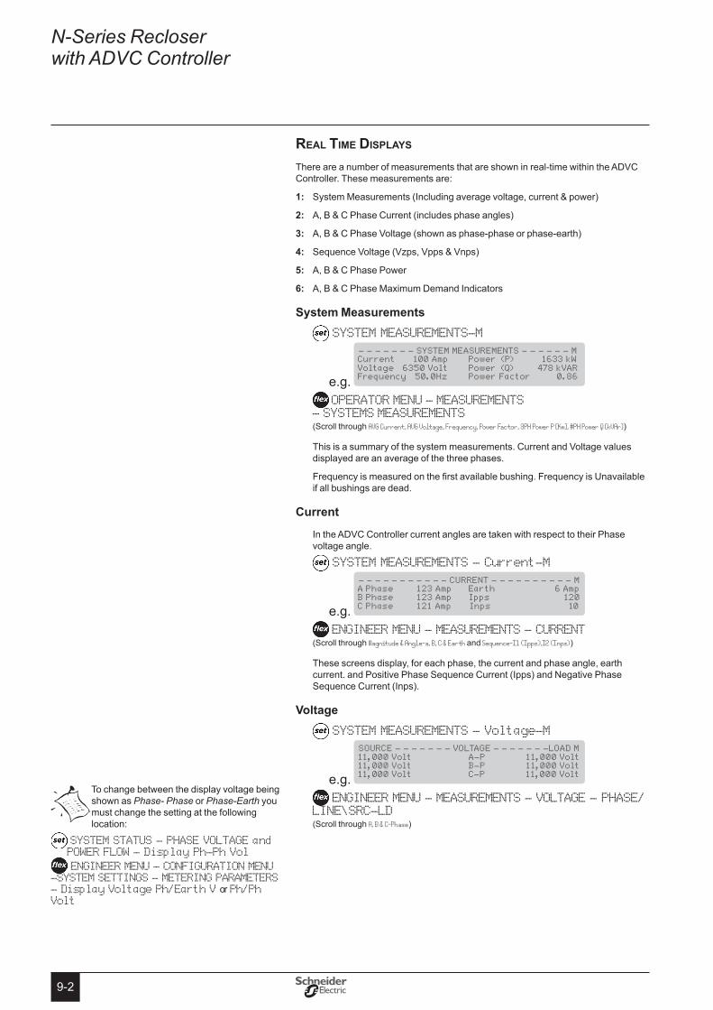
9-2
N-Series Recloser with ADVC Controller
real tiMe DiSplayS
There are a number of measurements that are shown in real-time within the ADVC Controller. These measurements are:
System Measurements (Including average voltage, current & power)1:
A, B & C Phase Current (includes phase angles)2:
A, B & C Phase Voltage (shown as phase-phase or phase-earth)3:
Sequence Voltage (Vzps, Vpps & Vnps)4:
A, B & C Phase Power 5:
A, B & C Phase Maximum Demand Indicators6:
system Measurements SYSTEM MEASUREMENTS-M
e.g.
- - - - - - - SYSTEM MEASUREMENTS - - - - - - M Current 100 Amp Power (P) 1633 kW Voltage 6350 Volt Power (Q) 478 kVAR Frequency 50.0Hz Power Factor 0.86
OPERATOR MENU - MEASUREMENTS - SYSTEMS MEASUREMENTS(Scroll through AVG Current, AVG Voltage, Frequency, Power Factor, 3PH Power P [Kw], #PH Power Q [kVAr])
This is a summary of the system measurements. Current and Voltage values displayed are an average of the three phases.
Frequency is measured on the first available bushing. Frequency is Unavailable if all bushings are dead.
Current
In the ADVC Controller current angles are taken with respect to their Phase voltage angle.
SYSTEM MEASUREMENTS - Current-M
e.g.
- - - - - - - - - - - CURRENT - - - - - - - - - - M A Phase 123 Amp Earth 6 Amp B Phase 123 Amp Ipps 120 C Phase 121 Amp Inps 10
ENGINEER MENU - MEASUREMENTS - CURRENT(Scroll through Magnitude & Angle-a, B, C & Earth and Sequence-I1 (Ipps),I2 (Inps))
These screens display, for each phase, the current and phase angle, earth current. and Positive Phase Sequence Current (Ipps) and Negative Phase Sequence Current (Inps).
Voltage SYSTEM MEASUREMENTS - Voltage-M
e.g.
SOURCE - - - - - - - VOLTAGE - - - - - - -LOAD M 11,000 Volt A-P 11,000 Volt 11,000 Volt B-P 11,000 Volt 11,000 Volt C-P 11,000 Volt
ENGINEER MENU - MEASUREMENTS - VOLTAGE - PHASE/LINE\SRC-LD(Scroll through A, B & C-Phase)
To change between the display voltage being shown as Phase- Phase or Phase-Earth you must change the setting at the following location:
SYSTEM STATUS - PHASE VOLTAGE and POWER FLOW - Display Ph-Ph Vol
ENGINEER MENU - CONFIGURATION MENU -SYSTEM SETTINGS - METERING PARAMETERS - Display Voltage Ph/Earth V or Ph/Ph Volt

9-3
Power System Measurements (cont)
sequence Voltage SYSTEM MEASUREMENTS - Sequence Voltage-M
e.g.
- - - - - - - - SEQUENCE VOLTAGE - - - - - - - M Vzps 100 Volt Vpps 11,000 Volt Vnps 200 Volt
ENGINEER MENU - MEASUREMENTS - VOLTAGE - SEQUENCE(Scroll through Vpps, Vnps & Vzps)
These screens display the Zero, Positive and Negative phase sequence voltages.
Power SYSTEM MEASUREMENTS - Power-M
e.g.
- - - - - - - - - - - - POWER - - - - - - - - - - M A P 540 kW Q 158 kVAR PF 0.88 B P 549 kW Q 166 kVAR PF 0.88 C P 546 kW Q 156 kVAR PF 0.88
ENGINEER MENU - MEASUREMENTS - POWER - 3-PHASE, A,B & C-PHASE(Scroll through Real Power, Apparent & Reactive Power, Power Factor)
These screens display real and reactive power, as well as the power factor on a per phase basis.
Real Power (kW) is a signed quantity unless Power Flow Unsigned has been selected on page:
SYSTEM STATUS - PHASE VOLTAGE and POWER FLOW: Power Flow Signed/Unsigned
ENGINEER MENU - CONFIGURATION MENU - SYSTEM SETTINGS - METERING PARAMETERS - Power Signed/Unsigned
Power Factor (PF) is an unsigned quantity.
Maximum Demand Indicators SYSTEM MEASUREMENTS - Daily, Weekly, Monthly, Maximum Demand-M
ENGINEER MENU - MEASUREMENTS MENU - DEMAND - DAILY, WEEKLY, MONTHLY MAX DEMAND(Scroll through Date, Total kWh, Peak Period, Power/PF)
The Maximum Demand Indicator on the flexVUE panel is available in a different location at the following menu:
OPERATOR MENU - MEASUREMENTS MENU - MAX DEMAND IND
(Scroll through A, B, C Phase Max & Time and Reset MDI)
These screens display real and reactive power, as well as the power factor on a per phase basis.
Daily, Weekly and Monthly Demand Indicators display collected historical data, while the Maximum Demand Indicator contains a mixture of real-time and historical data.

9-4
N-Series Recloser with ADVC Controller
10-110-1
Maintenance can be carried out using standard electricians’ and mechanics’ tools.
acr Maintenance
No user maintenance of the ACR mechanism is required.
The ACR should be returned to the manufacturer for refurbishment if the mechanical duty or breaking duty is exceeded. This is checked by examining the remaining contact life on the Operator interface. When the remaining contact life in any phase approaches zero, the ACR has reached the end of its life and must be replaced.
Every five years the bushing boots should be checked, cleaned if necessary and the pointer checked to ensure it is free from mechanical obstructions. In areas of high atmospheric pollution more frequent cleaning may be appropriate.
At suitable intervals check the gas low alarm is not showing on the operator interface. If gas low is showing, this may indicate a leak which must be found. Recharging the ACR SF6 using a gas fill adaptor is described below.
acr Sf6 recharging
The ACR is refilled to a pressure of 35kPa on the gauge corrected by +0.46kPa for every degree Celsius above 20° Celsius and -0.46kPa for every degree below 20° Celsius. For altitudes above 1000m the gauge pressure should be corrected for altitude.
safety Removal from Service
The gas fill valve is located between the ACR body and the mounting bracket.
Ensure that the ACR is removed from service before fitting the gauge and taking a reading.
SulphurHexafluoride(SF6) safety Data sheet
See “Appendix C Safety Data Sheet - Sulphur Hexafluoride (SF6) (page C-1)” for reproduction of original Material Safety Data Sheet.
Equipment Required
ACR SF6 recharging is carried out using a Gas Fill Adaptor (GFA) and Tool, and a standard size-D SF6 cylinder. See “Appendix A Replaceable Parts & Tools (page A-1)” for these part numbers.
A warning is displayed in the event log when the remaining contact life reaches 20%.
10 Maintenance
Be careful to ensure that if working on the ADVC with the door open in heavy rain, water does not enter the circuit breakers or general power outlet�
Do not attempt to recharge the gas without firstremovingtheACRfromservice.
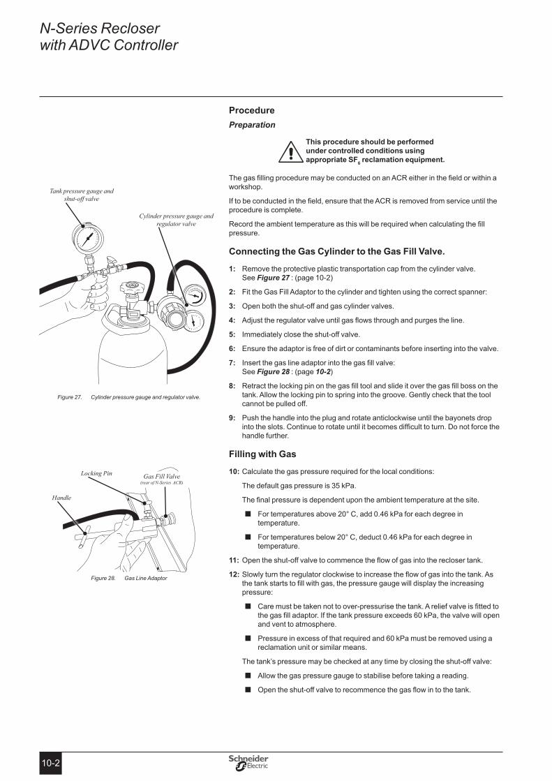
10-2
N-Series Recloser with ADVC Controller
ProcedurePreparation
this procedure should be performed under controlled conditions using appropriate sF6 reclamation equipment�
The gas filling procedure may be conducted on an ACR either in the field or within a workshop.
If to be conducted in the field, ensure that the ACR is removed from service until the procedure is complete.
Record the ambient temperature as this will be required when calculating the fill pressure.
Connecting the Gas Cylinder to the Gas Fill Valve�
Remove the protective plastic transportation cap from the cylinder valve. 1: See Figure 27 : (page 10-2)
Fit the Gas Fill Adaptor to the cylinder and tighten using the correct spanner:2:
Open both the shut-off and gas cylinder valves.3:
Adjust the regulator valve until gas flows through and purges the line.4:
Immediately close the shut-off valve.5:
Ensure the adaptor is free of dirt or contaminants before inserting into the valve.6:
Insert the gas line adaptor into the gas fill valve: 7: See Figure 28 : (page 10-2)
Retract the locking pin on the gas fill tool and slide it over the gas fill boss on the 8: tank. Allow the locking pin to spring into the groove. Gently check that the tool cannot be pulled off.
Push the handle into the plug and rotate anticlockwise until the bayonets drop 9: into the slots. Continue to rotate until it becomes difficult to turn. Do not force the handle further.
Filling with Gas
Calculate the gas pressure required for the local conditions: 10:
The default gas pressure is 35 kPa.
The final pressure is dependent upon the ambient temperature at the site.
For temperatures above 20° C, add 0.46 kPa for each degree in �temperature.
For temperatures below 20° C, deduct 0.46 kPa for each degree in �temperature.
Open the shut-off valve to commence the flow of gas into the recloser tank.11:
Slowly turn the regulator clockwise to increase the flow of gas into the tank. As 12: the tank starts to fill with gas, the pressure gauge will display the increasing pressure:
� Care must be taken not to over-pressurise the tank. A relief valve is fitted to the gas fill adaptor. If the tank pressure exceeds 60 kPa, the valve will open and vent to atmosphere.
� Pressure in excess of that required and 60 kPa must be removed using a reclamation unit or similar means.
The tank’s pressure may be checked at any time by closing the shut-off valve:
Allow the gas pressure gauge to stabilise before taking a reading. �
� Open the shut-off valve to recommence the gas flow in to the tank.
Cylinder pressure gauge and regulator valve.Figure 27.
Gas Line Adaptor Figure 28.
Tank pressure gauge and shut-off valve
Cylinder pressure gauge and regulator valve
Handle
Locking Pin Gas Fill Valve (rear of N-Series ACR)
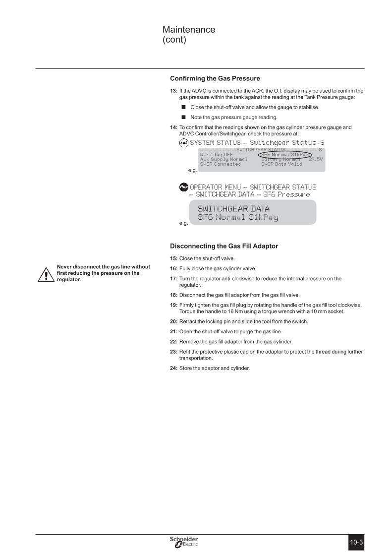
10-3
ConfirmingtheGasPressure
If the ADVC is connected to the ACR, the O.I. display may be used to confirm the 13: gas pressure within the tank against the reading at the Tank Pressure gauge:
Close the shut-off valve and allow the gauge to stabilise. �
� Note the gas pressure gauge reading.
To confirm that the readings shown on the gas cylinder pressure gauge and 14: ADVC Controller/Switchgear, check the pressure at:
SYSTEM STATUS - Switchgear Status-S
e.g.
- - - - - - - - SWITCHGEAR STATUS - - - - - - - S Work Tag OFF SF6 Normal 31kPag Aux Supply Normal Battery Normal 27.5V SWGR Connected SWGR Data Valid
OPERATOR MENU - SWITCHGEAR STATUS - SWITCHGEAR DATA - SF6 Pressure
e.g.
SWITCHGEAR DATA SF6 Normal 31kPag
Disconnecting the Gas Fill Adaptor
Close the shut-off valve.15:
Fully close the gas cylinder valve.16:
Turn the regulator anti-clockwise to reduce the internal pressure on the 17: regulator.:
Disconnect the gas fill adaptor from the gas fill valve.18:
Firmly tighten the gas fill plug by rotating the handle of the gas fill tool clockwise. 19: Torque the handle to 16 Nm using a torque wrench with a 10 mm socket.
Retract the locking pin and slide the tool from the switch.20:
Open the shut-off valve to purge the gas line.21:
Remove the gas fill adaptor from the gas cylinder.22:
Refit the protective plastic cap on the adaptor to protect the thread during further 23: transportation.
Store the adaptor and cylinder.24:
Never disconnect the gas line without firstreducingthepressureontheregulator�
Maintenance (cont)
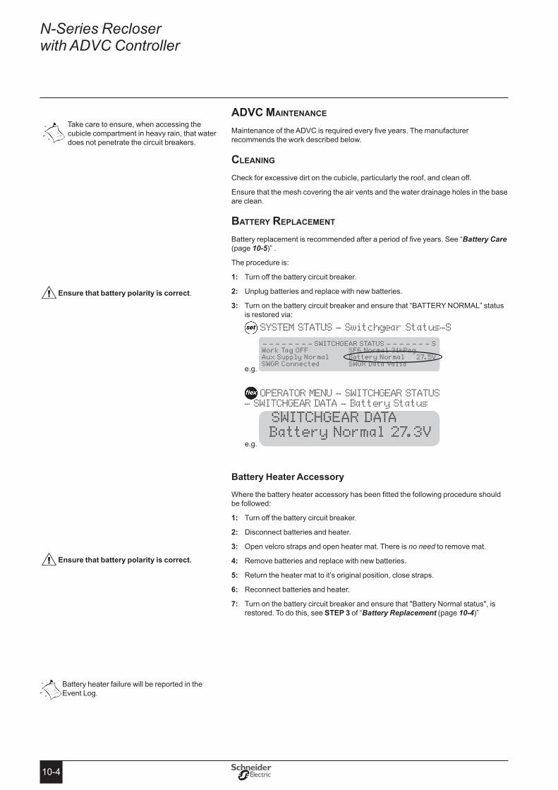
10-4
N-Series Recloser with ADVC Controller
aDvc Maintenance
Maintenance of the ADVC is required every five years. The manufacturer recommends the work described below.
cleaning
Check for excessive dirt on the cubicle, particularly the roof, and clean off.
Ensure that the mesh covering the air vents and the water drainage holes in the base are clean.
Battery replaceMent
Battery replacement is recommended after a period of five years. See “Battery Care (page 10-5)” .
The procedure is:
Turn off the battery circuit breaker.1:
Unplug batteries and replace with new batteries.2:
Turn on the battery circuit breaker and ensure that “BATTERY NORMAL” status 3: is restored via:
SYSTEM STATUS - Switchgear Status-S
e.g.
- - - - - - - - SWITCHGEAR STATUS - - - - - - - S Work Tag OFF SF6 Normal 31kPag Aux Supply Normal Battery Normal 27.5V SWGR Connected SWGR Data Valid
OPERATOR MENU - SWITCHGEAR STATUS - SWITCHGEAR DATA - Battery Status
e.g.
SWITCHGEAR DATA Battery Normal 27.3V
Battery Heater Accessory
Where the battery heater accessory has been fitted the following procedure should be followed:
Turn off the battery circuit breaker.1:
Disconnect batteries and heater.2:
Open velcro straps and open heater mat. There is 3: no need to remove mat.
Remove batteries and replace with new batteries.4:
Return the heater mat to it’s original position, close straps.5:
Reconnect batteries and heater.6:
Turn on the battery circuit breaker and ensure that "Battery Normal status", is 7: restored. To do this, see steP 3 of “Battery Replacement (page 10-4)”
ensure that battery polarity is correct.
ensure that battery polarity is correct�
Take care to ensure, when accessing the cubicle compartment in heavy rain, that water does not penetrate the circuit breakers.
Battery heater failure will be reported in the Event Log.

10-5
Door seal
Check the door sealing rubber for perishing or undue hardening. If necessary renew the seal.
Battery care
The battery is predicted to provide good performance for the recommended five year service period. This is based on the battery manufacturer’s data. No battery warranty is given by the manufacturer of the ADVC.
Once in service, batteries need little care. Procedures for storage and other contingencies are as follows:
� Batteries should be stored at a temperature of between 0°C to 30°C (32°F to 86°F) and cycled every six months. Batteries should be stored for a maximum of one year.
� Batteries should be cycled prior to putting into service if they have not been cycled within three months. When shipped by the manufacturer the batteries will have been cycled within the previous 30 days.
� If the batteries become exhausted in service and are left for more than two weeks without auxiliary supply being restored to the ADVC they should be taken out, cycled and have their capacity checked before being returned to service.
To cycle a battery, discharge with a 10 Ohm 15 Watt resistor to a terminal voltage of 10V. Next, recharge it with a voltage regulated DC supply set to 13.8V. A 3A current limited supply is appropriate.
More information on the battery care is available from the battery manufacturer.
aBnorMal operating conDitionS
The operation of the capacitor charging inverter can be affected under abnormal conditions such as when the battery capacity is very low. The following features are used to protect the ADVC in this situation while still allowing the ACR to keep operating.
Low Power Mode
When the batteries are nearly exhausted, the ADVC will change its capacitor charging mode from normal to low power. In low power mode the controller takes longer to charge the capacitors and the radio supply is shut down. A "Low Power Mode" event is logged whenever this happens.
Operator close and trip operations can be performed, but at a longer time interval than normal. If an operator trip or close request is denied, a "Cap Chrg" event will be logged.
To return to normal power mode, the auxiliary supply must have been switched back on for a minimum of 15 minutes, and the batteries may have to be replaced.
excess Close operations
During testing it is possible to carry out so many trip/close operations that the capacitor charging inverter shuts itself down before it overheats. It takes more than 20 operations within a minute to do this and is not going to happen while in service (it only happens during excessive testing).
When this happens the inverter shuts down for 5 minutes and a "Cap Excess Closes" event is logged. During this time all trip/close requests will be denied.
these batteries are capable of supplying very high currents� Always turn off the battery circuit breaker before connecting or disconnecting the batteries in the cubicle� Never leaveflyingleadsconnectedtothebattery�
Maintenance (cont)
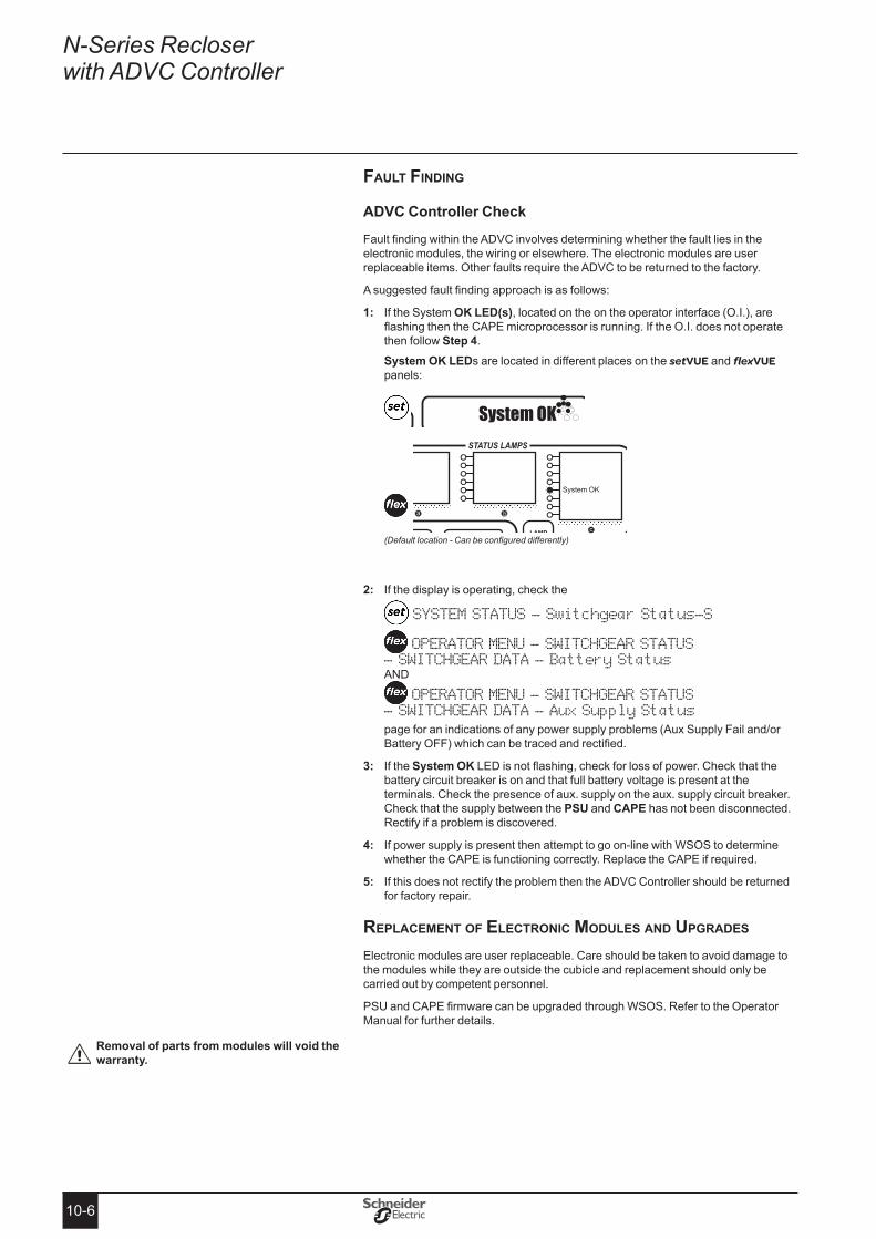
10-6
N-Series Recloser with ADVC Controller
fault finDing
ADVC Controller Check
Fault finding within the ADVC involves determining whether the fault lies in the electronic modules, the wiring or elsewhere. The electronic modules are user replaceable items. Other faults require the ADVC to be returned to the factory.
A suggested fault finding approach is as follows:
1: If the System oK LeD(s), located on the on the operator interface (O.I.), are flashing then the CAPE microprocessor is running. If the O.I. does not operate then follow step 4.
system oK LeDs are located in different places on the setVUE and flexVUE panels:
DETECTGROUP
WORKTAG
SECTIONON/OFF
System OK
(Default location - Can be configured differently)
2: If the display is operating, check the
SYSTEM STATUS - Switchgear Status-S
OPERATOR MENU - SWITCHGEAR STATUS - SWITCHGEAR DATA - Battery StatusAND
OPERATOR MENU - SWITCHGEAR STATUS - SWITCHGEAR DATA - Aux Supply Statuspage for an indications of any power supply problems (Aux Supply Fail and/or Battery OFF) which can be traced and rectified.
3: If the system oK LED is not flashing, check for loss of power. Check that the battery circuit breaker is on and that full battery voltage is present at the terminals. Check the presence of aux. supply on the aux. supply circuit breaker. Check that the supply between the PsU and CAPe has not been disconnected. Rectify if a problem is discovered.
4: If power supply is present then attempt to go on-line with WSOS to determine whether the CAPE is functioning correctly. Replace the CAPE if required.
5: If this does not rectify the problem then the ADVC Controller should be returned for factory repair.
replaceMent of electronic MoDuleS anD upgraDeS
Electronic modules are user replaceable. Care should be taken to avoid damage to the modules while they are outside the cubicle and replacement should only be carried out by competent personnel.
PSU and CAPE firmware can be upgraded through WSOS. Refer to the Operator Manual for further details.
Removal of parts from modules will void the warranty�
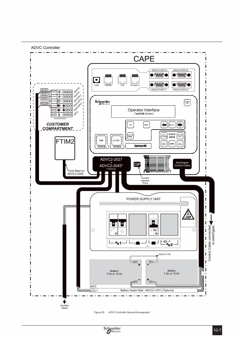
10-7
ADVC Controller General ArrangementFigure 29.
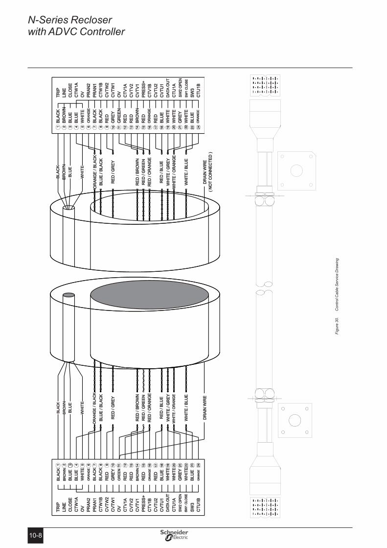
10-8
N-Series Recloser with ADVC Controller
SW
ITC
HG
EA
R E
ND
CO
NTR
OL
CU
BIC
LE E
ND
Con
trol C
able
Ser
vice
Dra
win
gFi
gure
30.

11-111-1
eQuipMent anD crating DiMenSionS
equipment WeightsPart Weight kg (lbs)Control cable. Weight is given for the standard length of 7m. Other lengths from 4m to 20m (in 1m increments) are available upon request.
6 (12)
Control cubicle 37 (81) (without accessories and with 7Ah batteries)
HV cables set of 6, standard length per cable is 3m, other lengths available upon request:
250A 400A 630A 800A
9 (19) 16 (35) 20 (43) 57 (126)
Bushing boots set of 6:
27kV 38kV
10 (22) 14 (31)
Pole Mounted ACR 225 (495)Pole mounting bracket 24 (53)Sundry Mounting items 8 (18)Gross weight of crate 404 (890)Dimensions mm (ins)Cubicle (See Appendix B) CompACT 730mm × 420mm ×
301mm (28.7" × 16.5" × 11.9")
Ultra 960mm × 450mm × 301mm (37.8” × 17.7” × 11.9”)
Crate DimensionsWidth 1160mm (45.7")Depth 730mm (28.7")Height 1640mm (64.6")
acrRated VoltageN15 15.5 kVN27 27 kVN38a 38 kVRated Continuous Current 800 AmpEmergency Load Current - carrying capability (8 Hours) 850 AmpRated Frequency 50/60 HzRated Load Breaking Current 800 AmpRated Cable Charging Breaking Current (N15 and N27) 25 AmpRated Cable Charging Breaking Current (N38) 40 AmpRated Single Capacitor Bank Breaking Current 250 AmpRated No-Load Transformer Breaking Current 22 AmpRated Symmetrical Interrupting Current 12.5 kARated Asymmetrical Short-circuit Making Current (peak) 31.5 kARated Symmetrical Making Current (rms) 12.5 kARated Short-time Withstand Current (rms) 12.5 kARated Duration of Short-circuit 3 secRated Peak Withstand Current (peak) 31.5 kAShort Time Current Recovery Time 180 sec
11RatingsandSpecifications
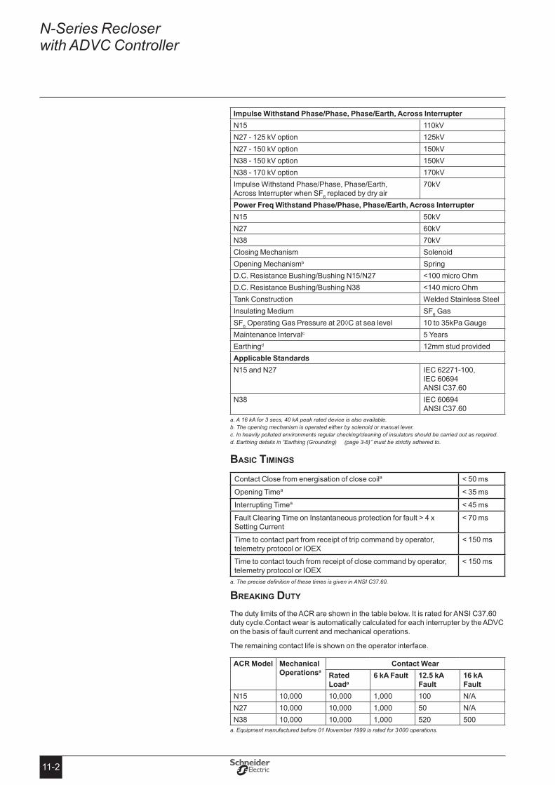
11-2
N-Series Recloser with ADVC Controller
Impulse Withstand Phase/Phase, Phase/earth, Across InterrupterN15 110kVN27 - 125 kV option 125kVN27 - 150 kV option 150kVN38 - 150 kV option 150kVN38 - 170 kV option 170kVImpulse Withstand Phase/Phase, Phase/Earth, Across Interrupter when SF6 replaced by dry air
70kV
Power Freq Withstand Phase/Phase, Phase/earth, Across InterrupterN15 50kVN27 60kVN38 70kVClosing Mechanism SolenoidOpening Mechanismb SpringD.C. Resistance Bushing/Bushing N15/N27 <100 micro OhmD.C. Resistance Bushing/Bushing N38 <140 micro OhmTank Construction Welded Stainless SteelInsulating Medium SF6 GasSF6 Operating Gas Pressure at 20◊C at sea level 10 to 35kPa GaugeMaintenance Intervalc 5 YearsEarthingd 12mm stud providedApplicable standardsN15 and N27 IEC 62271-100,
IEC 60694 ANSI C37.60
N38 IEC 60694 ANSI C37.60
a. A 16 kA for 3 secs, 40 kA peak rated device is also available. b. The opening mechanism is operated either by solenoid or manual lever. c. In heavily polluted environments regular checking/cleaning of insulators should be carried out as required.d. Earthing details in “Earthing (Grounding) (page 3-8)” must be strictly adhered to.
BaSic tiMingS
Contact Close from energisation of close coila < 50 ms
Opening Timea < 35 ms
Interrupting Timea < 45 ms
Fault Clearing Time on Instantaneous protection for fault > 4 x Setting Current
< 70 ms
Time to contact part from receipt of trip command by operator, telemetry protocol or IOEX
< 150 ms
Time to contact touch from receipt of close command by operator, telemetry protocol or IOEX
< 150 ms
a. The precise definition of these times is given in ANSI C37.60.
Breaking Duty
The duty limits of the ACR are shown in the table below. It is rated for ANSI C37.60 duty cycle.Contact wear is automatically calculated for each interrupter by the ADVC on the basis of fault current and mechanical operations.
The remaining contact life is shown on the operator interface.
ACR Model Mechanical operationsa
Contact WearRated Loada
6 kA Fault 12�5 kA Fault
16 kA Fault
N15 10,000 10,000 1,000 100 N/AN27 10,000 10,000 1,000 50 N/AN38 10,000 10,000 1,000 520 500
a. Equipment manufactured before 01 November 1999 is rated for 3 000 operations.
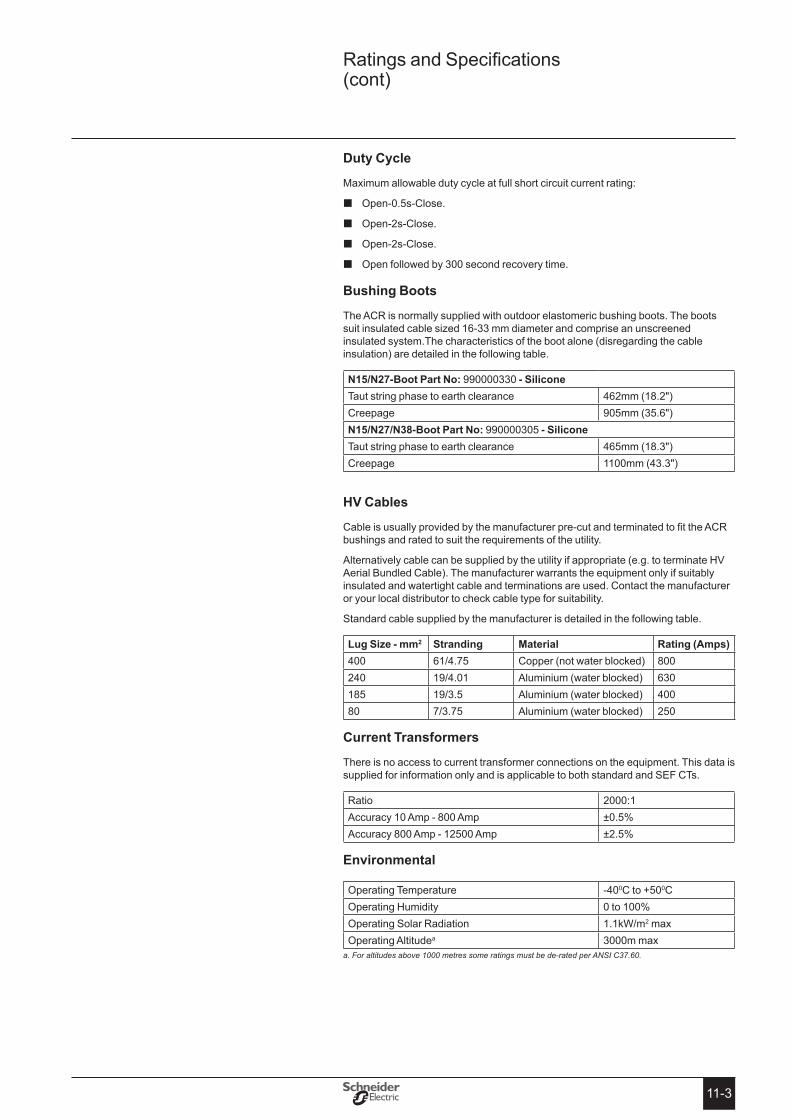
11-3
Ratings and Specifications (cont)
Duty Cycle
Maximum allowable duty cycle at full short circuit current rating:
� Open-0.5s-Close.
Open-2s-Close. �
Open-2s-Close. �
Open followed by 300 second recovery time. �
Bushing Boots
The ACR is normally supplied with outdoor elastomeric bushing boots. The boots suit insulated cable sized 16-33 mm diameter and comprise an unscreened insulated system.The characteristics of the boot alone (disregarding the cable insulation) are detailed in the following table.
N15/N27-Boot Part No: 990000330 - siliconeTaut string phase to earth clearance 462mm (18.2")Creepage 905mm (35.6")N15/N27/N38-Boot Part No: 990000305 - siliconeTaut string phase to earth clearance 465mm (18.3")Creepage 1100mm (43.3")
HV Cables
Cable is usually provided by the manufacturer pre-cut and terminated to fit the ACR bushings and rated to suit the requirements of the utility.
Alternatively cable can be supplied by the utility if appropriate (e.g. to terminate HV Aerial Bundled Cable). The manufacturer warrants the equipment only if suitably insulated and watertight cable and terminations are used. Contact the manufacturer or your local distributor to check cable type for suitability.
Standard cable supplied by the manufacturer is detailed in the following table.
Lug size - mm2 stranding Material Rating (Amps)400 61/4.75 Copper (not water blocked) 800240 19/4.01 Aluminium (water blocked) 630185 19/3.5 Aluminium (water blocked) 40080 7/3.75 Aluminium (water blocked) 250
Current transformers
There is no access to current transformer connections on the equipment. This data is supplied for information only and is applicable to both standard and SEF CTs.
Ratio 2000:1Accuracy 10 Amp - 800 Amp ±0.5%Accuracy 800 Amp - 12500 Amp ±2.5%
environmental
Operating Temperature -400C to +500COperating Humidity 0 to 100%Operating Solar Radiation 1.1kW/m2 maxOperating Altitudea 3000m max
a. For altitudes above 1000 metres some ratings must be de-rated per ANSI C37.60.
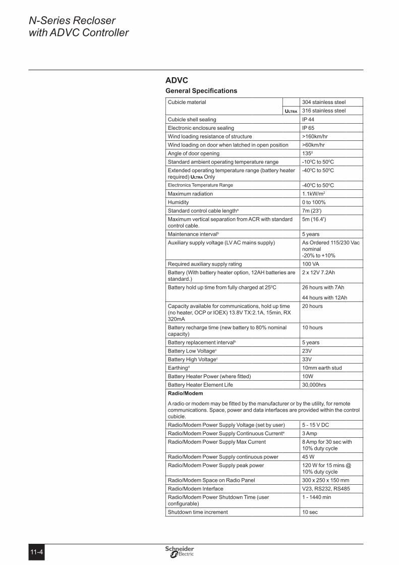
11-4
N-Series Recloser with ADVC Controller
aDvcGeneralSpecificationsCubicle material 304 stainless steel
ULTRA 316 stainless steelCubicle shell sealing IP 44Electronic enclosure sealing IP 65Wind loading resistance of structure >160km/hrWind loading on door when latched in open position >60km/hrAngle of door opening 1350
Standard ambient operating temperature range -100C to 500CExtended operating temperature range (battery heater required) ULTRA Only
-400C to 500C
Electronics Temperature Range -400C to 500CMaximum radiation 1.1kW/m2
Humidity 0 to 100%Standard control cable lengtha 7m (23')Maximum vertical separation from ACR with standard control cable.
5m (16.4')
Maintenance intervalb 5 yearsAuxiliary supply voltage (LV AC mains supply) As Ordered 115/230 Vac
nominal -20% to +10%
Required auxiliary supply rating 100 VABattery (With battery heater option, 12AH batteries are standard.)
2 x 12V 7.2Ah
Battery hold up time from fully charged at 250C 26 hours with 7Ah
44 hours with 12AhCapacity available for communications, hold up time (no heater, OCP or IOEX) 13.8V TX:2.1A, 15min, RX 320mA
20 hours
Battery recharge time (new battery to 80% nominal capacity)
10 hours
Battery replacement intervalb 5 yearsBattery Low Voltagec 23VBattery High Voltagec 33VEarthingd 10mm earth studBattery Heater Power (where fitted) 10WBattery Heater Element Life 30,000hrsRadio/Modem
A radio or modem may be fitted by the manufacturer or by the utility, for remote communications. Space, power and data interfaces are provided within the control cubicle.Radio/Modem Power Supply Voltage (set by user) 5 - 15 V DCRadio/Modem Power Supply Continuous Currente 3 AmpRadio/Modem Power Supply Max Current 8 Amp for 30 sec with
10% duty cycleRadio/Modem Power Supply continuous power 45 WRadio/Modem Power Supply peak power 120 W for 15 mins @
10% duty cycleRadio/Modem Space on Radio Panel 300 x 250 x 150 mmRadio/Modem Interface V23, RS232, RS485 Radio/Modem Power Shutdown Time (user configurable)
1 - 1440 min
Shutdown time increment 10 sec
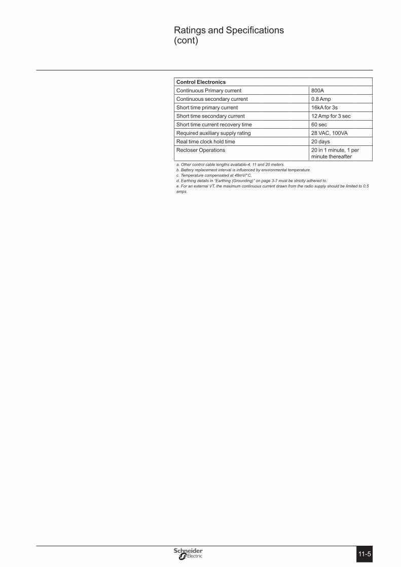
11-5
Control electronics Continuous Primary current 800AContinuous secondary current 0.8 AmpShort time primary current 16kA for 3sShort time secondary current 12 Amp for 3 secShort time current recovery time 60 secRequired auxiliary supply rating 28 VAC, 100VAReal time clock hold time 20 daysRecloser Operations 20 in 1 minute, 1 per
minute thereaftera. Other control cable lengths available-4, 11 and 20 meters. b. Battery replacement interval is influenced by environmental temperature. c. Temperature compensated at 48mV/°C. d. Earthing details in “Earthing (Grounding)” on page 3-7 must be strictly adhered to. e. For an external VT, the maximum continuous current drawn from the radio supply should be limited to 0.5 amps.
Ratings and Specifications (cont)

11-6
N-Series Recloser with ADVC Controller
controller eMc type teStS IeC 61000-4-x IMMUNItY tYPe tests
standard Description Application test Level Severity Level
IEC 61000-4-2 Electrostatic Discharge
Enclosure Contact +/- 8kV 4Enclosure Air +/- 15kV 4
IEC 61000-4-3 Radiated Electromagnetic Fielda
Four faces 10V/m, 80 MHz - 1000 MHz
3
3V/m, 1000 MHz - 2700 MHz
2
Front face only 10V/m, 1000 MHz - 2700 MHz
3
IEC 61000-4-4 Fast Transient A.C. Power Port +/- 4kV 4RS232 (Port A,B,C & D) +/- 4kV Xb
RS485 +/- 4kV Xb
Ethernet +/- 4kV Xb
Umbilical port +/- 4kV Xb
IOEX2 port +/- 4kV Xb
FTIM2 port +/- 4kV Xb
IEC 61000-4-5 Surge A.C. Power Port +/- 4kV line-to-earth, +/- 2kV line-to-line, 1.25/50usec
4
RS232 (Port A,B,C & D) +/- 4kV, 1.25/50usec 4RS485 +/- 4kV, 10/700usec 4Ethernet +/- 4kV, 10/700usec 4Umbilical port +/- 4kV, 1.25/50usec 4IOEX2 port +/- 4kV, 1.25/50usec 4FTIM2 port +/- 4kV, 1.25/50usec 4
IEC 61000-4-6 Conduced Disturbances
A.C. Power Port 10V RMS 3RS232 (Port A,B,C & D) 10V RMS 3RS485 10V RMS 3Ethernet 10V RMS 3Umbilical port 10V RMS 3IOEX2 port 10V RMS 3FTIM2 port 10V RMS 3
IEC 61000-4-8 Power Frequency Magnetic Fielda
Three axis X, Y, Z 100A/m continuous, 1000A/m for 1s
5
IEC 61000-4-11 Voltage Dips and Interruptions
A.C. Power Port Volt dips - 0% for 1 cycle 40% for 10 cycles 70% for 25 cycles 80% for 250 cycles
3
Voltage interruptions - 0% for 250 cycles
3
IEC 61000-4-16 Conducted Common mode disturbances 0-150kHz
A.C. Power Port 30V continuous, 300V 1 sec, 50/60Hz
4
Umbilical port 30V continuous, 300V 1 sec, 50/60Hz
4
IEC 61000-4-18 Damped Oscillatory Wave
A.C. Power Port 2.5kV common mode, 1kV diff@100kHz & 1MHz
3
Umbilical port 2.5kV common mode @ 100kHz and 1MHz
3
a Tests conducted with Cubicle Door b Open Level. Exceeds maximum test level defined in the standard.
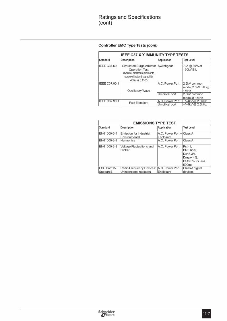
11-7
Controller eMC type tests (cont)
Ieee C37�X�X IMMUNItY tYPe testsStandard Description Application Test Level
IEEE C37.60 Simulated Surge Arrestor Operation Test
Switchgear 7kA @ 80% of 150kV BIL
(Control electronic elements surge withstand capability
- Clause 6.13.2)IEEE C37.90.1
Oscillatory Wave
A.C. Power Port 2.5kV common mode, 2.5kV diff. @ 1MHz
Umbilical port 2.5kV common mode @ 1MHz
IEEE C37.90.1 Fast Transient A.C. Power Port +/- 4kV @ 2.5kHzUmbilical port +/- 4kV @ 2.5kHz
eMIssIoNs tYPe testStandard Description Application Test Level
EN61000-6-4 Emission for Industrial Environmental
A.C. Power Port + Enclosure
Class A
EN61000-3-2 Harmonics A.C. Power Port Class A
EN61000-3-3 Voltage Fluctuations and Flicker
A.C. Power Port Pst<1, Pl<0.65%, Dc<3.3%, Dmax<4%, Dt<3.3% for less 500ms
FCC Part 15 Subpart B
Radio Frequency Devices: Unintentional radiators
A.C. Power Port + Enclosure
Class A digital devices
Ratings and Specifications (cont)

11-8
N-Series Recloser with ADVC Controller
power SySteM MeaSureMentS
HV line measurements on all three phases are made as follows:
Voltage Range (RMS Phase/Earth) N15/N27 2 - 15kVVoltage Range (RMS Phase/Earth) N38 2 - 25kVVoltage Resolution 1VVoltage Accuracya 2.5% ±25VLive Terminal Threshold Voltage rangeb 2 - 15kVLive Terminal Threshold Voltage setting resolutionb 1VLive Terminal Threshold Voltage accuracya.b 5% ±250VLive Terminal Threshold Hysteresis -20%Phase Current Range (True RMS) 2.5 - 800 AmpEarth Current Range (True RMS) 1 - 800 AmpCurrent Resolution 1 AmpPhase Current Accuracya ±1.0% ±1 Amp over
range 10 - 800 AmpEarth Current Accuracya ±1.0% ±1 Amp
over range 1 - 800 AmpApparent Power Range 0 - 54 MVAApparent Power Resolution 1 kVAApparent Power Accuracya ±3% over range 20 - 800
AmpReal Power Range c.d -54 MW - +54 MWReal Power Accuracya.c.d ±3% at PF > 0.9
Real Power Resolution 1 kWReactive Power Rangec -54 MVAr - +54 MVARReactive Power Resolution 1 kVARReactive Power Accuracya ±4% at PF < 0.5Unsigned Power Factor 0.5 - 1.0Power Factor Resolution 0.01Power Factor Accuracy ±0.05Measurement Filter Time Constant (Step Response) 2 secMeasurement Update Rate 0.5 sec
a. Includes accuracy of switchgear current and voltage transformers. b. Used for Live/Dead display, Live Load Blocking and Loss Of Supply detection. c. In database for transmission by a protocol. d. Used to accumulate kWh reading for weekly maximum demand data.
Sf6 gaS preSSure MeaSureMent
Nominal Pressure at 200C 35 kPa GaugeGas Pressure Display Resolution 1 kPaGas Pressure Display Accuracy ±5 kPaGas Low Alarm Setting 15 kPa Gauge @ 20◊ CGas Low Alarm Accuracy ±5 kPa
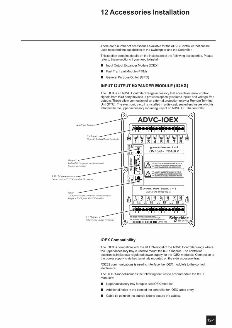
12-1
There are a number of accessories available for the ADVC Controller that can be used to extend the capabilities of the Switchgear and the Controller.
This section contains details on the installation of the following accessories. Please refer to these sections if you need to install:
Input Output Expander Module (IOEX) �
Fast Trip Input Module (FTIM) �
General Purpose Outlet (GPO) �
input output expander module (ioex)The IOEX is an ADVC Controller Range accessory that accepts external control signals from third party devices. It provides optically isolated inputs and voltage-free outputs. These allow connection of an external protection relay or Remote Terminal Unit (RTU). The electronic circuit is installed in a die cast, sealed enclosure which is attached to the upper accessory mounting tray of an ADVC ULTRA controller.
IoeX Compatibility
The IOEX is compatible with the ULTRA model of the ADVC Controller range where the upper accessory tray is used to mount the IOEX module. The controller electronics includes a regulated power supply for the IOEX module/s. Connection to the power supply is via two terminals mounted on the side accessory tray.
RS232 communications is used to interface the IOEX module/s to the control electronics.
The ULTRA model includes the following features to accommodate the IOEX module/s:
Upper accessory tray for up to two IOEX modules �
Additional holes in the base of the controller for IOEX cable entry. �
Cable tie point on the cubicle side to secure the cables. �
IOEX enclosure
8 × Inputs Optically Isolated Input Terminals
8 × Outputs Voltage-free Output Terminals
Output Isolated 12Vdc power supply terminals to external switches
Input IOEX power supply terminals supply terminals Supply to IOEX from ADVC Controller
RS232 Communications Connection to ADVC Controller Electronics
12 Accessories Installation
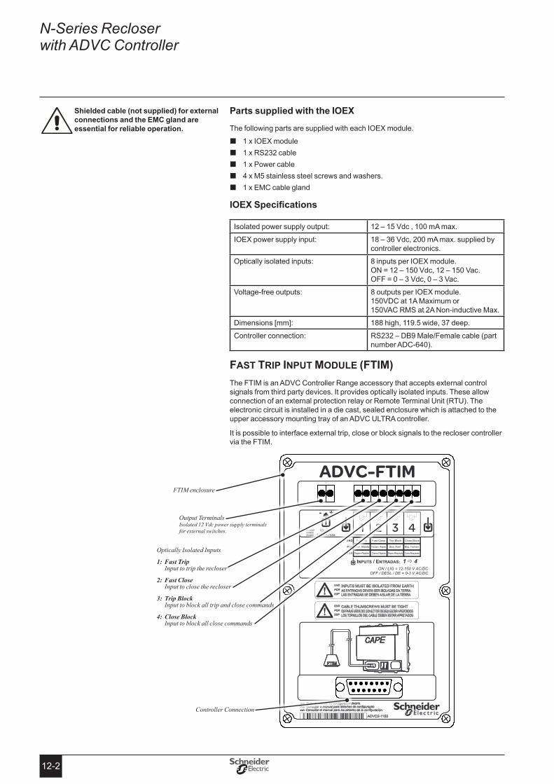
12-2
N-Series Recloser with ADVC Controller
Parts supplied with the IoeX
The following parts are supplied with each IOEX module.
1 x IOEX module �1 x RS232 cable �1 x Power cable �4 x M5 stainless steel screws and washers. �1 x EMC cable gland �
IOEXSpecifications
Isolated power supply output: 12 – 15 Vdc , 100 mA max.
IOEX power supply input: 18 – 36 Vdc, 200 mA max. supplied by controller electronics.
Optically isolated inputs: 8 inputs per IOEX module. ON = 12 – 150 Vdc, 12 – 150 Vac. OFF = 0 – 3 Vdc, 0 – 3 Vac.
Voltage-free outputs: 8 outputs per IOEX module. 150VDC at 1A Maximum or 150VAC RMS at 2A Non-inductive Max.
Dimensions [mm]: 188 high, 119.5 wide, 37 deep.
Controller connection: RS232 – DB9 Male/Female cable (part number ADC-640).
fast trip input module (ftim)The FTIM is an ADVC Controller Range accessory that accepts external control signals from third party devices. It provides optically isolated inputs. These allow connection of an external protection relay or Remote Terminal Unit (RTU). The electronic circuit is installed in a die cast, sealed enclosure which is attached to the upper accessory mounting tray of an ADVC ULTRA controller.
It is possible to interface external trip, close or block signals to the recloser controller via the FTIM.
shielded cable (not supplied) for external connections and the eMC gland are essential for reliable operation�
FTIM enclosure
Output Terminals Isolated 12 Vdc power supply terminals for external switches.
Optically Isolated Inputs
1: Fast Trip Input to trip the recloser
2: Fast Close Input to close the recloser
3: Trip Block Input to block all trip and close commands
4: Close Block Input to block all close commands
Controller Connection
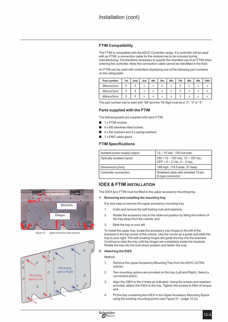
12-3
Installation (cont)
FtIM Compatibility
The FTIM is compatible with the ADVC Controller range. If a controller will be used with an FTIM, a connection cable for the module has to be included during manufacturing. It is therefore necessary to specify the intended use of an FTIM when ordering the controller. Note this connection cable cannot be retrofitted in the field.
An FTIM can be used with controllers displaying one of the following part numbers on the rating plate:
Part number 1st 2nd 3rd 4th 5th 6th 7th 8th 9th 10th
88xxxx2xxx 8 8 x x x x 2 x x x
88xxxx3xxx 8 8 x x x x 3 x x x
88xxxx5xxx 8 8 x x x x 5 x x x
The part number has to start with “88” and the 7th digit must be a “2”, “3” or “5”.
Parts supplied with the FtIM
The following parts are supplied with each FTIM.
1 x FTIM module �4 x M5 stainless steel screws �4 x flat washers and 4 x spring washers �1 x EMC cable gland �
FTIMSpecifications
Isolated power supply output: 12 – 15 Vdc , 100 mA max.
Optically isolated inputs: ON = 12 – 150 Vdc, 12 – 150 Vac. OFF = 0 – 3 Vdc, 0 – 3 Vac.
Dimensions [mm]: 188 high, 119.5 wide, 37 deep.
Controller connection: Shielded cable with shielded 15 pin D-type connector.
ioex & ftim installation
The IOEX &/or FTIM must be fitted to the upper accessory mounting tray.
Removing and installing the mounting tray1:
It is very easy to remove the upper accessory mounting tray:
1. Undo and remove the self locking nuts and washers;
2. Rotate the accessory tray to the slide-out position by lifting the bottom of the tray away from the cubicle; and
3. Slide the tray to your left.
To install the upper tray, locate the accessory tray hinges to the left of the brackets in the top corner of the cubicle. Use the corner as a guide and slide the tray to your right. The self-locating hinges will guide the tray into the brackets. Continue to slide the tray until the hinges are completely inside the brackets. Rotate the tray into the lock-down position and fasten the nuts.
Attaching the IoeX2:
Method:
1. Remove the Upper Accessory Mounting Tray from the ADVC ULTRA cubicle;
2. Two mounting options are provided on the tray (Left and Right). Select a convenient option;
3. Align the IOEX to the 4 holes as indicated. Using the screws and washers provided, attach the IOEX to the tray. Tighten the screws to 4Nm of torque; and
4. Fit the tray containing the IOEX in the Upper Accessory Mounting Space using the existing mounting points (see Figure 31.: (page 12-2)).
1 1 2
3
Hinges
Brackets
Upper accessory tray removalFigure 31.
Mounting option Left
Mounting option Right

12-4
N-Series Recloser with ADVC Controller
IF CoNNeCtING AN IoeX
Connect the IoeX to the controller3:
1. Connect the IOEX power supply lead to the terminals on the side accessory tray. The terminals are marked with the following symbols.
Ground terminal
IOEX Positive power terminal
Side Accessory Tray IOEX
2. Using the RS233 cable (ADC-640), connect one of the RS232 ports (A, B, C or D) on the ADVC Controller to the IOEX.
3. Before you can use the IOEX, make “IOEX available” in the WSOS Feature Selection tool, download the configuration map and select the IOEX communication port. Please see: ADVC Operation Guide (ADVC2-1160) and Configurable IOEX manual (N00-685).
IF CoNNeCtING AN FtIM
3: Connect the FtIM to the controller
1. Turn all power to the controller OFF. (See PSU photo below).
2. Connect the shielded 15 pin D connector to the FTIM. Fasten the connector properly to ensure a reliable connection.
3. Turn all power to the controller ON when the installation is complete.
Failure to power oFF the controller when connecting the FtIM to CAPe may cause unwanted trip/close operation�
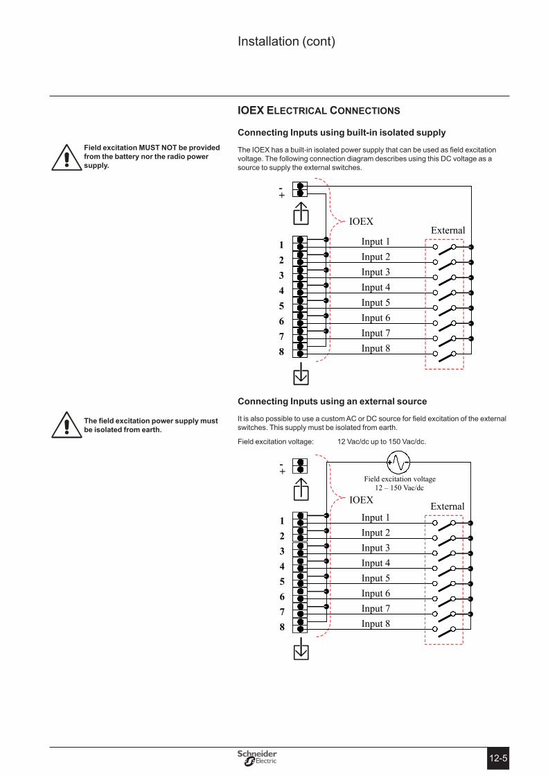
12-5
ioex electrical connections
Connecting Inputs using built-in isolated supply
The IOEX has a built-in isolated power supply that can be used as field excitation voltage. The following connection diagram describes using this DC voltage as a source to supply the external switches.
Connecting Inputs using an external source
It is also possible to use a custom AC or DC source for field excitation of the external switches. This supply must be isolated from earth.
Field excitation voltage: 12 Vac/dc up to 150 Vac/dc.
Field excitation MUst Not be provided from the battery nor the radio power supply�
Thefieldexcitationpowersupplymustbe isolated from earth�
Installation (cont)

12-6
N-Series Recloser with ADVC Controller
Voltage-free outputs
IOEX Outputs
1 2 3 4 5 6 7 8
Internal
Output 1 Output 2 Output 3 Output 4 Output 5 Output 6 Output 7 Output 8
Field excitation voltage 12 – 150 Vac/dc
A B C D E F G H
External device inputs
ftim electrical connections
Using the built-in isolated supply
The FTIM has a built-in isolated power supply that can be used as field excitation voltage. The following connection diagram describes using this DC voltage as a source to supply the external switches.
Field excitation MUst Not be provided from the battery nor the radio power supply�
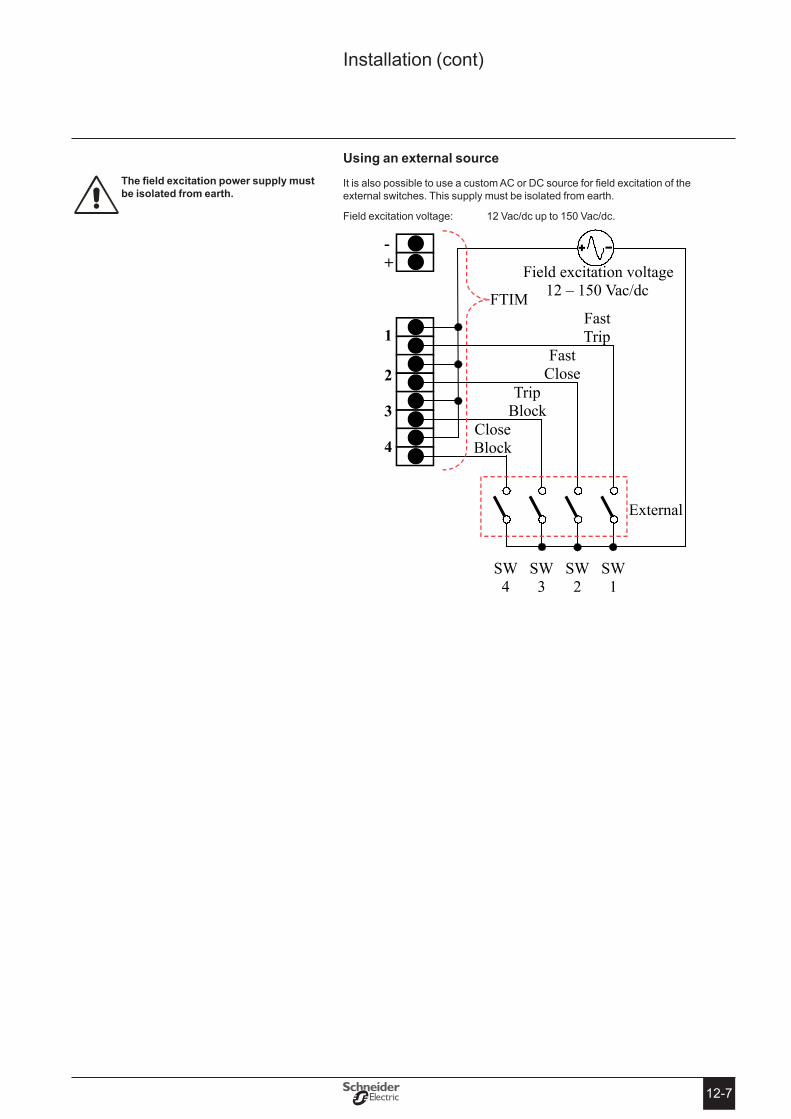
12-7
Using an external source
It is also possible to use a custom AC or DC source for field excitation of the external switches. This supply must be isolated from earth.
Field excitation voltage: 12 Vac/dc up to 150 Vac/dc.
Installation (cont)
Thefieldexcitationpowersupplymustbe isolated from earth�
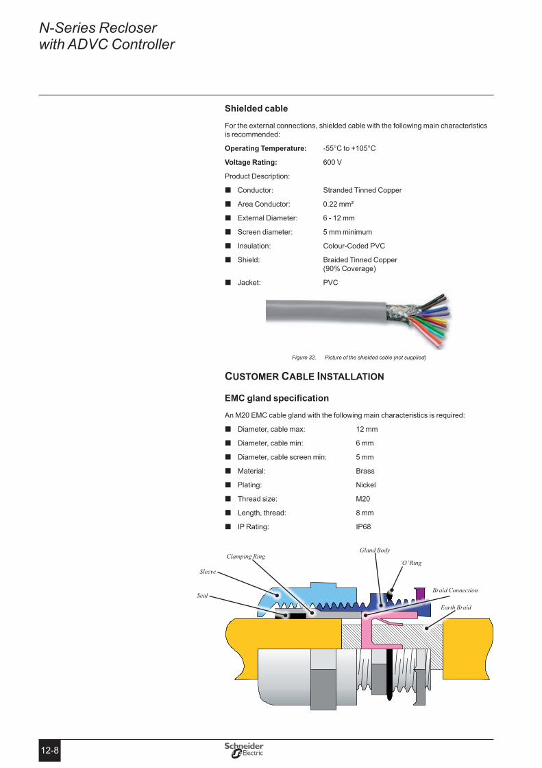
12-8
N-Series Recloser with ADVC Controller
shielded cable
For the external connections, shielded cable with the following main characteristics is recommended:
operating temperature: -55°C to +105°C
Voltage Rating: 600 V
Product Description:
Conductor: Stranded Tinned Copper �
Area Conductor: 0.22 mm² �
External Diameter: 6 - 12 mm �
Screen diameter: 5 mm minimum �
Insulation: Colour-Coded PVC �
Shield: Braided Tinned Copper � (90% Coverage)
Jacket: PVC �
Picture of the shielded cable (not supplied)Figure 32.
customer cable installation
EMCglandspecification
An M20 EMC cable gland with the following main characteristics is required:
Diameter, cable max: 12 mm �
Diameter, cable min: 6 mm �
Diameter, cable screen min: 5 mm �
Material: Brass �
Plating: Nickel �
Thread size: M20 �
Length, thread: 8 mm �
IP Rating: IP68 �
Sleeve
Clamping RingGland Body
‘O’ Ring
Braid Connection
Earth Braid
Seal
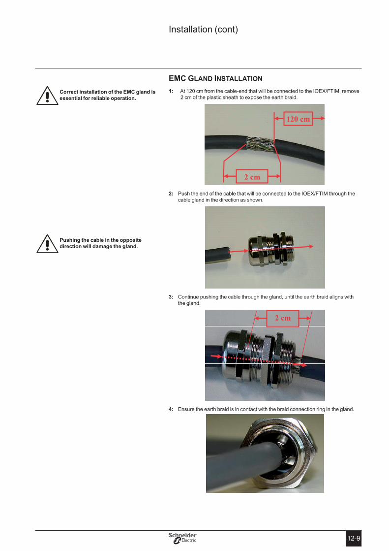
12-9
Installation (cont)
emc Gland installation
1: At 120 cm from the cable-end that will be connected to the IOEX/FTIM, remove 2 cm of the plastic sheath to expose the earth braid.
2 cm
120 cm
2: Push the end of the cable that will be connected to the IOEX/FTIM through the cable gland in the direction as shown.
Continue pushing the cable through the gland, until the earth braid aligns with 3: the gland.
2 cm
Ensure the earth braid is in contact with the braid connection ring in the gland.4:
Correct installation of the eMC gland is essential for reliable operation�
Pushing the cable in the opposite direction will damage the gland�

12-10
N-Series Recloser with ADVC Controller
Ensure the seal and clamping mechanism is overlapping with the plastic sheath. 5: Tighten the gland sleeve to firmly grip the cable in place.
Select a 20mm hole in the base of the controller. The two holes on the right hand 6: side are provided for this purpose.
FTIM and IOEX cable holes
Remove the plug and fit the cable with gland.
Cable termination
Use cable ties to secure the cable to the cubicle wall.1.
Cut the cable to the appropriate length, and terminate the cable at the IOEX/2. FTIM connectors.
shielded cable is essential for reliable operation� see “shielded cable (page 12-5)”
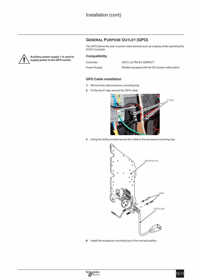
12-11
Installation (cont)
General purpose outlet (Gpo)The GPO allows the user to power extra devices such as a laptop while operating the AVDC Controller.
Compatibility
Controller: ADVC ULTRA & COMPACT
Power Supply: Models equipped with the IEC power outlet option.
GPo Cable installation
Remove the side accessory mounting tray. 1:
Fit the two P-clips around the GPO cable. 2:
Using the bolts provided secure the cable to the accessory mounting tray. 3:
Install the accessory mounting tray in the normal position. 4:
Auxiliary power supply 1 is used to supply power to the GPo socket�
P-Clips
Mounting Tray
GPO Cable
Bolts
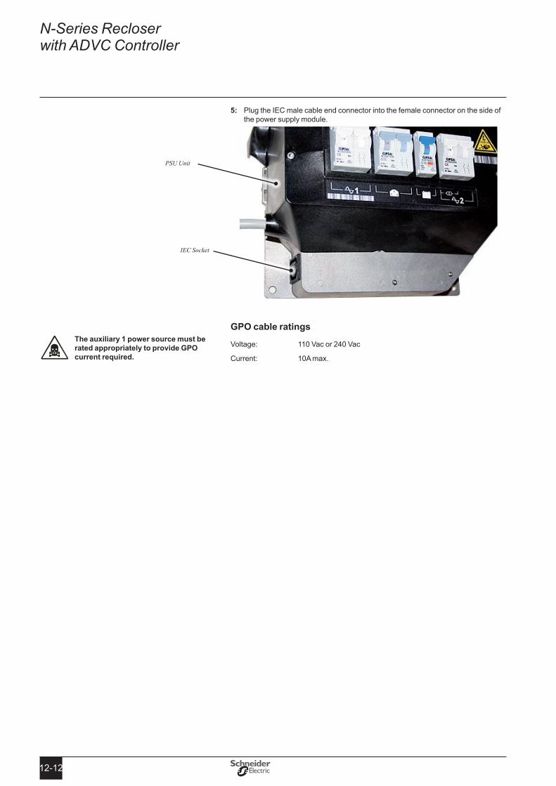
12-12
N-Series Recloser with ADVC Controller
Plug the IEC male cable end connector into the female connector on the side of 5: the power supply module.
GPo cable ratings
Voltage: 110 Vac or 240 Vac
Current: 10A max.
IEC Socket
PSU Unit
the auxiliary 1 power source must be rated appropriately to provide GPo current required�
A-1A-1
All replacement parts listed in the following table are available from the manufacturer.
ACR Part stock or Part Number1100mm Bushing Boot Silicone (38kV) 990000305905mm Bushing Boot Silicone (15kV, 27kV) 990000330Cable Tail Kit: Quantity 6 of 250 Amp, 3m cable fitted with bushing boot, lug and cable palm
990000600
Cable Tail Kit: Quantity 6 of 400 Amp, 3m cable fitted with bushing boot, lug and cable palm
990000640
Cable Tail Kit: Quantity 6 of 630 Amp, 3m cable fitted with bushing boot and screw termination
990003100
Cable Tail Kit: Quantity 6 of 800 Amp, 3m cable fitted with bushing boot, lug and cable palm
990000115
Control Cable 7m 990001015Control Cable 11m 990001030Control Cable 20m 990001035Gas Fill Adaptor Kit 990003050Manual Operation Set 990003055Silicone Grease for boot installation - 300g tube 990000350
ADVC Part stock or Part NumberBattery 12 V 7.2 Ah Sealed Lead Acid, set of 2 997000000Battery 12 V 12 Ah Sealed Lead Acid, set of 2 998000055IOEX2 998000080Test and Training Set (TTS) 990003000USB Cable for ADVC 998001045
Appendix A Replaceable Parts & tools

A-2
N-Series Recloser with ADVC Controller

B-1B-1
Appendix B Dimensions
acr DiMenSionS
ACR top View
ACR side View
ACR DimensionsFigure 33.
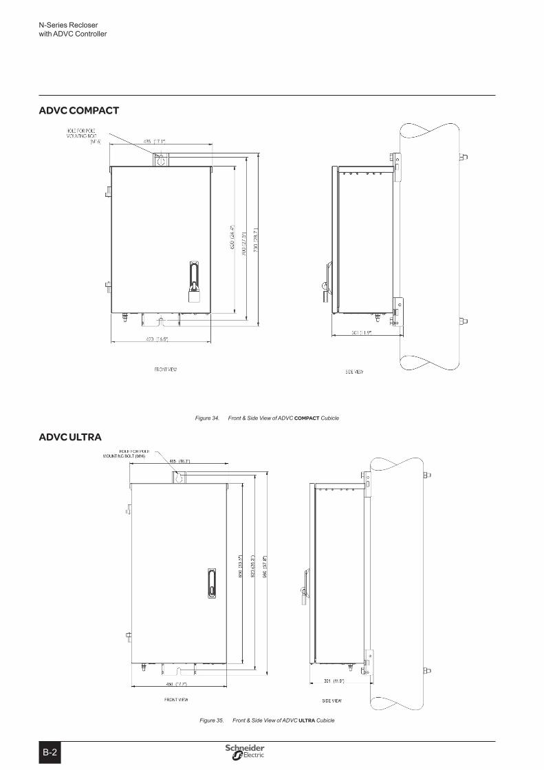
B-2
N-Series Recloser with ADVC Controller
ADVC CompACT
Front & Side View of ADVC Figure 34. CompACT Cubicle
ADVC ULTRA
Front & Side View of ADVC Figure 35. ULTRA Cubicle
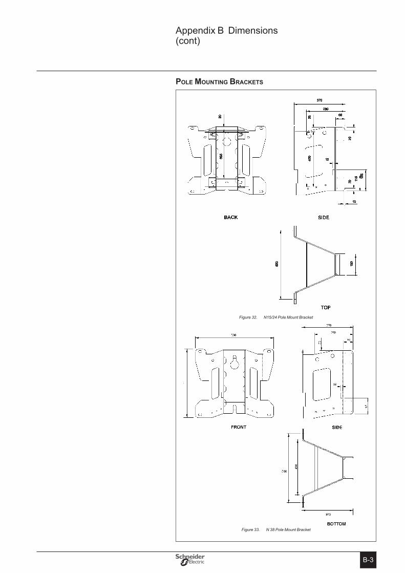
B-3
Appendix B Dimensions (cont)
pole Mounting BracketS
N15/24 Pole Mount BracketFigure 32.
B-3
Pole Mounting Brackets
Figure 24: N15/24 Pole Mount Bracket
Figure 24: N 38 Pole Mount Bracket
B-3
Pole Mounting Brackets
Figure 24: N15/24 Pole Mount Bracket
Figure 24: N 38 Pole Mount BracketN 38 Pole Mount BracketFigure 33.

B-4
N-Series Recloser with ADVC Controller
ioeX2 DiMenSionS
IOE
X 2
Dim
ensi
ons
Figu
re 3
8.

C-1C-1
Appendix C safety Data sheet - SulphurHexafluoride(SF6)
safety data sheet sulphur hexafluoride
Creation date : 19.05.2006 Version : 1.0 DE / E SDS No. : 8327 Revision date : 19.05.2006 page 1 / 2
8327 / EDV / 05.04.2006
Gas and engineeringLinde Gas Division
1 IDeNtIFICAtIoN oF tHe sUBstANCe/PRePARAtIoN AND oF tHe CoMPANY
Product name Sulphur hexafluorideChemical formula SF6Known usesNot known. Company identificationLinde AG, Gas and Engineering, Linde Gas Division Seitnerstraße 70, D-82049 Pullach emergency phone numbers: +49-89-7446-0
2 CoMPosItIoN/INFoRMAtIoN oN INGReDIeNts substance/Preparation: Substance Components/Impurities CAs Nr: 2551-62-4 eeC Nr (from eINeCs) : 219-854-2 Contains no other components or impurities which will influence the classification of the product.
3 HAZARDs IDeNtIFICAtIoN ClassificationAsphyxiant in high concentrations. Risk advice to man and the environment Liquefied gasIn high concentrations may cause asphyxiation.
4 FIRst AID MeAsURes InhalationIn high concentrations may cause asphyxiation. Symptoms may include loss of mobility/consciousness. Victim may not be aware of asphyxiation. Remove victim to uncontaminated area wearing self contained breathing apparatus. Keep victim warm and rested. Call a doctor. Apply artificial respiration if breathing stopped. skin/eye contact For liquid spillage - flush with water for at least 15 minutes In case of frostbite spray with water for at least 15 minutes. Apply a sterile dressing. Obtain medical assistance Ingestion Ingestion is not considered a potential route of exposure.
5 FIRe FIGHtING MeAsURes specific hazards Exposure to fire may cause containers to rupture/explode. Non flammableHazardous combustion products If involved in a fire the following toxic and/or corrosive fumes may be produced by thermal decomposition:suitable extinguishing media All known extinguishants can be used. specific methods If possible, stop flow of product. Move container away or cool with water from a protected position. special protective equipment for fire fighters Use self-contained breathing apparatus and chemically protective clothing.
6 ACCIDeNtAL ReLeAse MeAsURes Personal precautions Evacuate area. Wear self-contained breathing apparatus when entering area unless atmosphere is proved to be safe. Ensure adequate air ventilation. environmental precautions Try to stop release. Prevent from entering sewers, basements and workpits, or any place where its accumulation can be dangerous. Clean up methods
Ventilate area.
7 HANDLING AND stoRAGe Handling and storage Suck back of water into the container must be prevented. Do not allow backfeed into the container. Use only properly specified equipment which is suitable for this product, its supply pressure and temperature. Contact your gas supplier if in doubt. Refer to supplier's container handling instructions. Prevent bottles from falling down. Keep container below 50°C in a well ventilated place. Observe "Technische Regeln Druckgase (TRG) 280 Ziffer 5"
8 eXPosURe CoNtRoLs/PeRsoNAL PRoteCtIoN exposure limit value Value type value NoteGermany - MAK 1.000 ppm TRGS 900 Personal protection Protect eyes, face and skin from liquid splashes. Ensure adequate ventilation.
9 PHYsICAL AND CHeMICAL PRoPeRtIes General information Appearance/Colour: Colourless gasodour: No odour warning properties.Important information on environment, health and safety Molecular weight: 146 g/mol Melting point: -50,8 °C sublimation point: -64 °C Critical temperature: 45,5 °C Autoignition temperature: Not applicable Flammability range: Not applicableRelative density, gas: 5 Relative density, liquid: 1,4 Maximum filling pressure (bar): 21 bar other data Gas/vapour heavier than air. May accumulate in confined spaces, particularly at or below ground level.
10 stABILItY AND ReACtIVItY stability and reactivity Thermal decomposition yields toxic products whichcan be corrosive in the presence of moisture.
11 toXICoLoGICAL INFoRMAtIoN General No known toxicological effects from this product.
12 eCoLoGICAL INFoRMAtIoN General When discharged in large quantities may contribute to the greenhouse effect.
13 DIsPosAL CoNsIDeRAtIoNs General Do not discharge into any place where its accumulation could be dangerous. Contact supplier if guidance is required.eWC Nr� 16 05 05
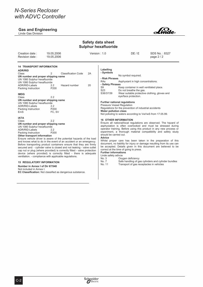
C-2
N-Series Recloser with ADVC Controller
safety data sheet sulphur hexafluoride
Creation date : 19.05.2006 Version : 1.0 DE / E SDS No. : 8327 Revision date : 19.05.2006 page 2 / 2
8327 / EDV / 05.04.2006
Gas and engineeringLinde Gas Division
14 tRANsPoRt INFoRMAtIoN ADR/RID Class 2 Classification Code 2AUN number and proper shipping nameUN 1080 Sulphur hexafluoride UN 1080 Sulphur hexafluoride ADR/RID-Labels 2.2 Hazard number 20Packing Instruction P200
IMDGClass 2.2UN number and proper shipping nameUN 1080 Sulphur hexafluoride ADR/RID-Labels 2.2Packing Instruction P200EmS FC, SV
IAtA Class 2.2UN number and proper shipping nameUN 1080 Sulphur hexafluoride ADR/RID-Labels 2.2Packing Instruction P200other transport information Ensure vehicle driver is aware of the potential hazards of the load and knows what to do in the event of an accident or an emergency. Before transporting product containers ensure that they are firmly secured and: - cylinder valve is closed and not leaking - valve outlet cap nut or plug (where provided) is correctly fitted - valve protection device (where provided) is correctly fitted - there is adequate ventilation. - compliance with applicable regulations.
15 ReGULAtoRY INFoRMAtIoN Number in Annex I of Dir 67/548 Not included in Annex I.eC Classification: Not classified as dangerous substance.
Labelling - symbols
No symbol required. - Risk Phrases RAs Asphyxiant in high concentrations. - safety Phrases S9 Keep container in well ventilated place. S23 Do not breathe the gas. S36/37/39 Wear suitable protective clothing, gloves and
eye/face protection.
Further national regulations Pressure Vessel Regulation Regulations for the prevention of industrial accidents Water pollution class Not polluting to waters according to VwVwS from 17.05.99.
16 otHeR INFoRMAtIoNEnsure all national/local regulations are observed. The hazard of asphyxiation is often overlooked and must be stressed during operator training. Before using this product in any new process or experiment, a thorough material compatibility and safety study should be carried out.Advice Whilst proper care has been taken in the preparation of this document, no liability for injury or damage resulting from its use can be accepted. Details given in this document are believed to be correct at the time of going to press.Further informations Linde safety adivce No. 3 Oxygen deficiency No. 7 Safe handling of gas cylinders and cylinder bundles No. 11 Transport of gas receptacles in vehicles
end of document
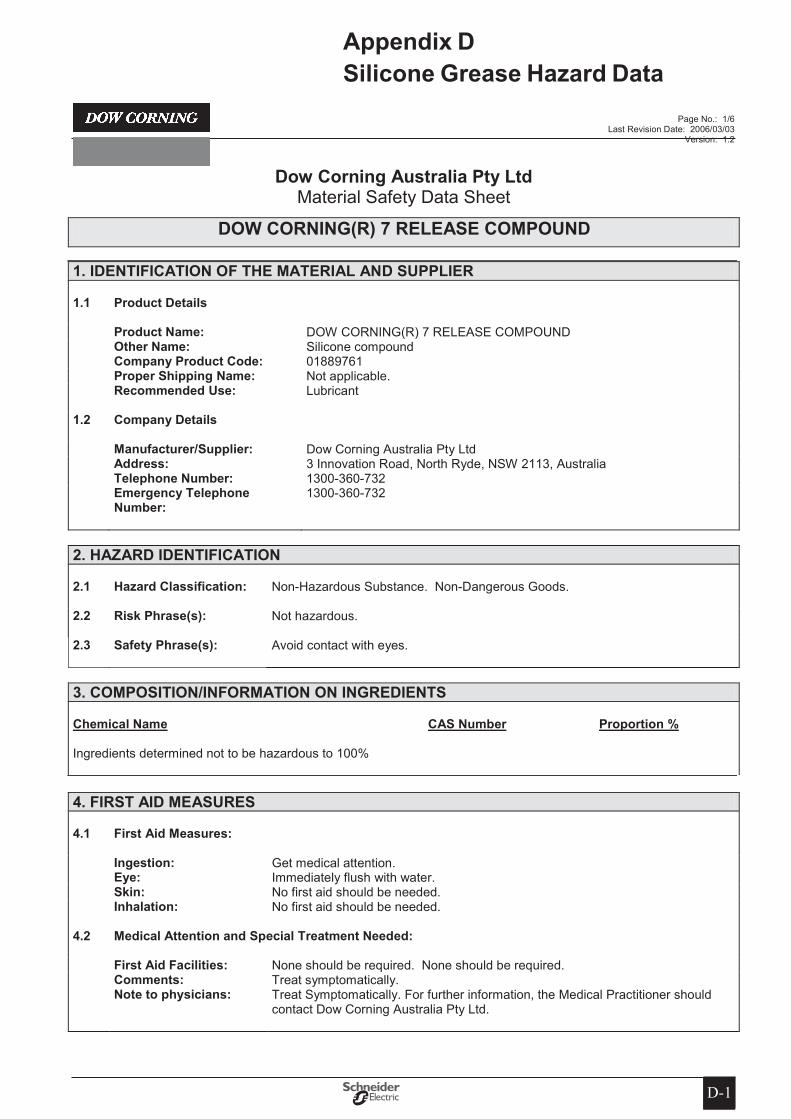
D-1D-1
Appendix D silicone Grease Hazard Data
Page No.: 1/6 Last Revision Date: 2006/03/03
Version: 1.2
Dow Corning Australia Pty Ltd Material Safety Data Sheet
DoW CoRNING(R) 7 ReLeAse CoMPoUND
1� IDeNtIFICAtIoN oF tHe MAteRIAL AND sUPPLIeR
1�1 Product Details
Product Name: DOW CORNING(R) 7 RELEASE COMPOUND other Name: Silicone compound Company Product Code: 01889761 Proper shipping Name: Not applicable. Recommended Use: Lubricant
1�2 Company Details
Manufacturer/supplier: Dow Corning Australia Pty Ltd Address: 3 Innovation Road, North Ryde, NSW 2113, Australia telephone Number: 1300-360-732 emergency telephone
Number:1300-360-732
2� HAZARD IDeNtIFICAtIoN
2�1 Hazard Classification: Non-Hazardous Substance. Non-Dangerous Goods.
2�2 Risk Phrase(s): Not hazardous.
2�3 safety Phrase(s): Avoid contact with eyes.
3� CoMPosItIoN/INFoRMAtIoN oN INGReDIeNts
Chemical Name CAs Number Proportion %
Ingredients determined not to be hazardous to 100%
4� FIRst AID MeAsURes
4�1 First Aid Measures:
Ingestion: Get medical attention. eye: Immediately flush with water. skin: No first aid should be needed. Inhalation: No first aid should be needed.
4�2 Medical Attention and special treatment Needed:
First Aid Facilities: None should be required. None should be required. Comments: Treat symptomatically. Note to physicians: Treat Symptomatically. For further information, the Medical Practitioner should
contact Dow Corning Australia Pty Ltd.

D-2
N-Series Recloser with ADVC Controller
Page No.: 2/6 Last Revision Date: 2006/03/03
Version: 1.2
Dow Corning Australia Pty Ltd Material Safety Data Sheet
DoW CoRNING(R) 7 ReLeAse CoMPoUND
5� FIRe FIGHtING MeAsURes
5�1 suitable extinguishing Media:
On large fires use dry chemical, foam or water spray. On small fires use carbon dioxide (CO2), dry chemical or water spray. Water can be used to cool fire exposed containers.
5�2 Hazards From Combustion Products:
Carbon oxides and traces of incompletely burned carbon compounds. Silicon dioxide. Formaldehyde.
5�3 Precautions For Fire Fighters and special Protective equipment:
Determine the need to evacuate or isolate the area according to your local emergency plan. Use water spray to keep fire exposed containers cool. Self-contained breathing apparatus and protective clothing should be worn in fighting large fires involving chemicals.
5�4 Hazchem Code: Not applicable.
6� ACCIDeNtAL ReLeAse MeAsURes
6�1 emergency Procedures: Not applicable.
6�2 Methods and Materials for Containment and Clean Up Procedures:
Determine whether to evacuate or isolate the area according to your local emergency plan. Observe all personal protective equipment recommendations described in this MSDS. If diked material can be pumped, store recovered material in appropriate container. Clean up remaining materials from spill with suitable absorbant. Clean area as appropriate since spilled materials, even in small quantities, may present a slip hazard. Final cleaning may require use of steam, solvents or detergents. Dispose of saturated absorbant or cleaning materials appropriately, since spontaneous heating may occur. Laws and regulations may apply to releases and disposal of this material, as well as those materials and items employed in the cleanup of releases. You will need to determine which laws and regulations are applicable.
7� HANDLING AND stoRAGe
7�1 Precautions for safe Handling:
Use with adequate ventilation. Avoid eye contact. Do not take internally. Exercise good industrial hygiene practice. Wash after handling, especially before eating, drinking or smoking.
7�2 Conditions for safe storage:
Use reasonable care and store away from oxidizing materials.
8� eXPosURe CoNtRoLs/PeRsoNAL PRoteCtIoN
8�1 exposure standards:
Ingredients exposure Limits
None known.

D-3
Appendix D Silicone Grease Hazard Data (cont)
Page No.: 3/6 Last Revision Date: 2006/03/03
Version: 1.2
Dow Corning Australia Pty Ltd Material Safety Data Sheet
DoW CoRNING(R) 7 ReLeAse CoMPoUND
8�2 engineering Controls:
Local Ventilation: None should be needed. General Ventilation: Recommended.
8�3 Personal Protective equipment:
Respiratory: No respiratory protection should be needed. suitable Respirator: None should be needed. Hand: No special protection needed. eye: Use proper protection - safety glasses as a minimum. skin: Washing at mealtime and end of shift is adequate.
Note: These precautions are for room temperature handling. Use at elevated temperature or aerosol/spray applications may require added precautions. For further information regarding aerosol inhalation toxicity, please refer to the guidance document regarding the use of silicone-based materials in aerosol applications that has been developed by the silicone industry (www.SEHSC.com) or contact the Dow Corning customer service group.
9� PHYsICAL AND CHeMICAL PRoPeRtIes
9�1 Physical Form: Viscous Liquid 9�2 Colour: Translucent white 9�3 odour: Some odor 9�4 pH: Not determined. 9�5 Vapour Pressure @
25°C:Not determined.
9�6 Vapour Density (air=1): Not determined. 9�7 Boiling Point: > 65 °C 9�8 Melting Point: Not determined. 9�9 solubility in Water: Not determined. 9�10 specific Gravity @ 25°C: 1.19�11 Flash Point: > 101.1 °C (Closed Cup) 9�12 Upper Flammability
Limit:Not determined.
9�13 Lower Flammability Limit:
Not determined.
9�14 Autoignition temperature:
Not determined.
9�15 Viscosity: 500000 cSt
The above information is not intended for use in preparing product specifications. Contact Dow Corning before writing specifications.
10� stABILItY AND ReACtIVItY
10�1 Chemical stability: Stable.
10�2 Conditions to avoid: None.
10�3 Incompatible Materials: Can react with strong oxidising agents.
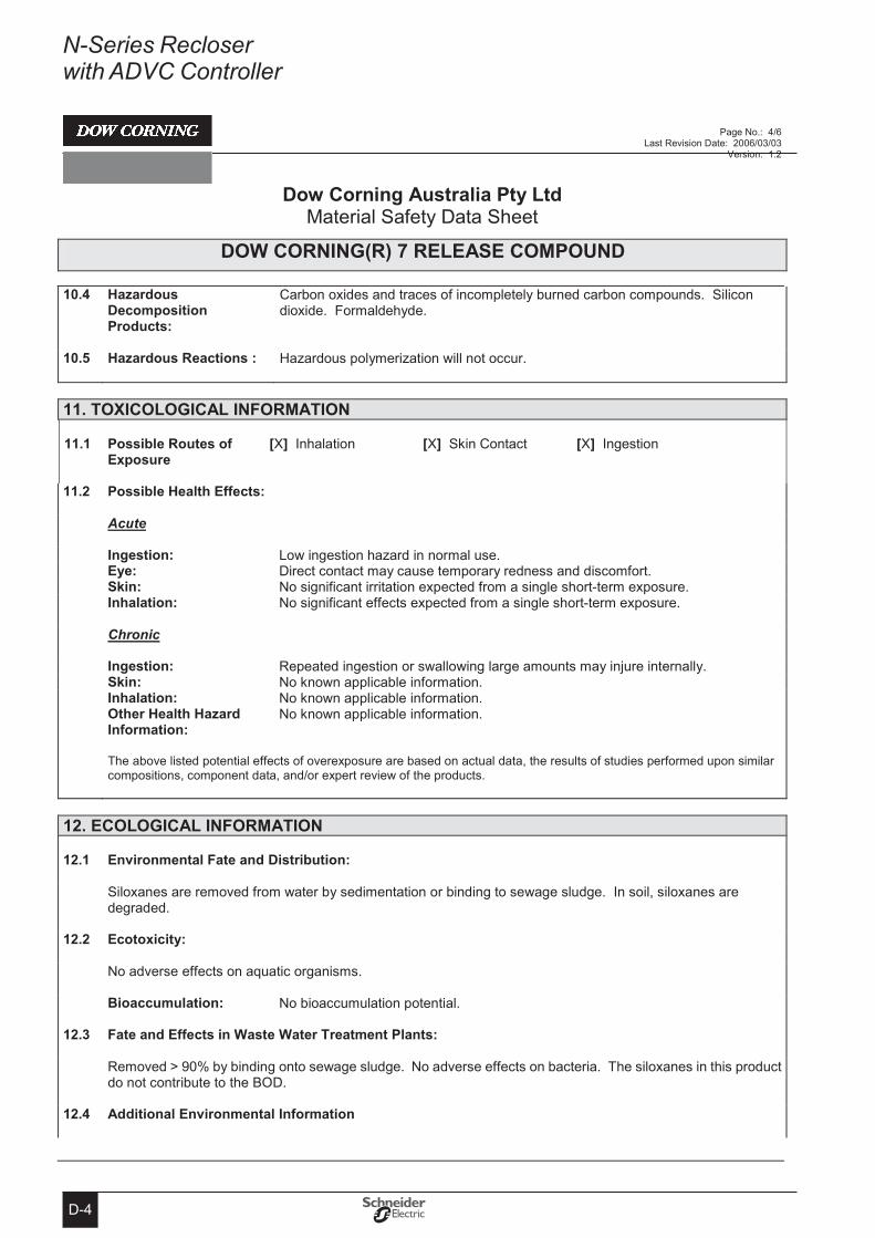
D-4
N-Series Recloser with ADVC Controller
Page No.: 4/6 Last Revision Date: 2006/03/03
Version: 1.2
Dow Corning Australia Pty Ltd Material Safety Data Sheet
DoW CoRNING(R) 7 ReLeAse CoMPoUND
10�4 Hazardous Decomposition Products:
Carbon oxides and traces of incompletely burned carbon compounds. Silicon dioxide. Formaldehyde.
10�5 Hazardous Reactions : Hazardous polymerization will not occur.
11� toXICoLoGICAL INFoRMAtIoN
11�1 Possible Routes of exposure
[X] Inhalation [X] Skin Contact [X] Ingestion
11�2 Possible Health effects:
Acute
Ingestion: Low ingestion hazard in normal use. eye: Direct contact may cause temporary redness and discomfort. skin: No significant irritation expected from a single short-term exposure. Inhalation: No significant effects expected from a single short-term exposure.
Chronic
Ingestion: Repeated ingestion or swallowing large amounts may injure internally. skin: No known applicable information. Inhalation: No known applicable information. other Health Hazard
Information:No known applicable information.
The above listed potential effects of overexposure are based on actual data, the results of studies performed upon similar compositions, component data, and/or expert review of the products.
12� eCoLoGICAL INFoRMAtIoN
12�1 environmental Fate and Distribution:
Siloxanes are removed from water by sedimentation or binding to sewage sludge. In soil, siloxanes are degraded.
12�2 ecotoxicity:
No adverse effects on aquatic organisms.
Bioaccumulation: No bioaccumulation potential.
12�3 Fate and effects in Waste Water treatment Plants:
Removed > 90% by binding onto sewage sludge. No adverse effects on bacteria. The siloxanes in this product do not contribute to the BOD.
12�4 Additional environmental Information
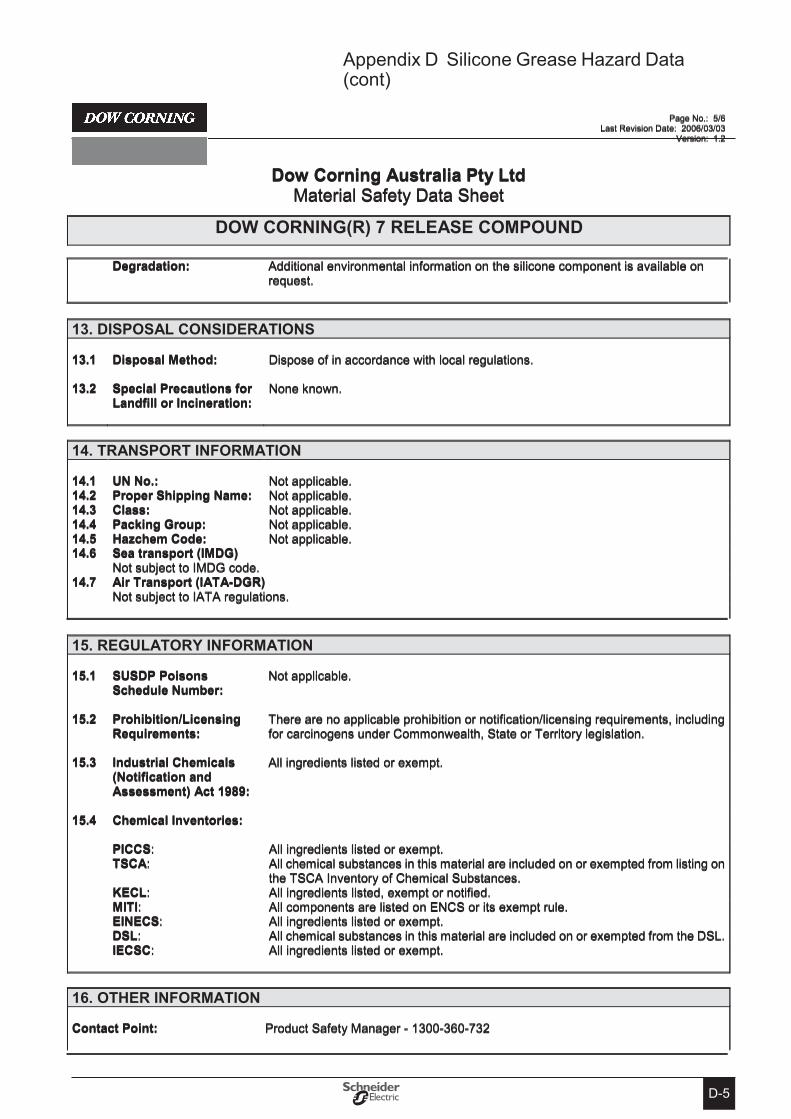
D-5
Appendix D Silicone Grease Hazard Data (cont)
Page No.: 5/6 Last Revision Date: 2006/03/03
Version: 1.2
Dow Corning Australia Pty Ltd Material Safety Data Sheet
DoW CoRNING(R) 7 ReLeAse CoMPoUND
Degradation: Additional environmental information on the silicone component is available on request.
13� DIsPosAL CoNsIDeRAtIoNs
13�1 Disposal Method: Dispose of in accordance with local regulations.
13�2 special Precautions for Landfill or Incineration:
None known.
14� tRANsPoRt INFoRMAtIoN
14�1 UN No�: Not applicable. 14�2 Proper shipping Name: Not applicable. 14�3 Class: Not applicable. 14�4 Packing Group: Not applicable. 14�5 Hazchem Code: Not applicable. 14�6 sea transport (IMDG)
Not subject to IMDG code. 14�7 Air transport (IAtA-DGR)
Not subject to IATA regulations.
15� ReGULAtoRY INFoRMAtIoN
15�1 sUsDP Poisons schedule Number:
Not applicable.
15�2 Prohibition/Licensing Requirements:
There are no applicable prohibition or notification/licensing requirements, including for carcinogens under Commonwealth, State or Territory legislation.
15�3 Industrial Chemicals (Notification and Assessment) Act 1989:
All ingredients listed or exempt.
15�4 Chemical Inventories:
PICCs: All ingredients listed or exempt.tsCA: All chemical substances in this material are included on or exempted from listing on
the TSCA Inventory of Chemical Substances.KeCL: All ingredients listed, exempt or notified.MItI: All components are listed on ENCS or its exempt rule.eINeCs: All ingredients listed or exempt.DsL: All chemical substances in this material are included on or exempted from the DSL.IeCsC: All ingredients listed or exempt.
16� otHeR INFoRMAtIoN
Contact Point: Product Safety Manager - 1300-360-732
N-Series Recloser with ADVC Controller
D-6
Notes
Page No.: 6/6 Last Revision Date: 2006/03/03
Version: 1.2
Dow Corning Australia Pty Ltd Material Safety Data Sheet
DoW CoRNING(R) 7 ReLeAse CoMPoUND
Prepared by: Dow Corning Australia Pty Ltd
This MSDS summarises our best knowledge of the health and safety hazard information of the product and how to safely handle and use the product in the workplace. Each user should read this MSDS and consider the information in the context of how the product will be handled and used in the workplace including in conjunction with other products. If clarification or further information is needed to ensure that an appropriate risk assessment can be made, the user should contact this Company. Our responsibility for products sold is subject to our standard terms and conditions, a copy of which is sent to our customers and is also available on request.
(R) indicates Registered Trademark

Notes

N-Series Recloser with ADVC Controller
Notes
Related Documents