Advant Controller 31 Intelligent Decentralized Automation System Networking Advant Controller 31 – Tailor-made network Communication module 07 KP 90 R0303 8.1 Communication module 07 MK 92 R1161 8.2 Communication processor 07 KP 93 R1161 8.3 PDnet 8.4 ARCNET-SST 8.5 Communication processor 07 KP 95 R0101 8.6 8.7 8.8 8.9 Advant Controller 31 / Issued: 08.99 AS-i gateway

Welcome message from author
This document is posted to help you gain knowledge. Please leave a comment to let me know what you think about it! Share it to your friends and learn new things together.
Transcript
Advant Controller 31
Intelligent DecentralizedAutomation System
Networking
Advant Controller 31 –Tailor-made network
Communication module07 KP 90 R0303
8.1
Communication module07 MK 92 R1161
8.2
Communication processor07 KP 93 R1161 8.3
PDnet 8.4
ARCNET-SST 8.5
Communication processor07 KP 95 R0101 8.6
8.7
8.8
8.9Advant Controller 31 / Issued: 08.99
AS-i gateway

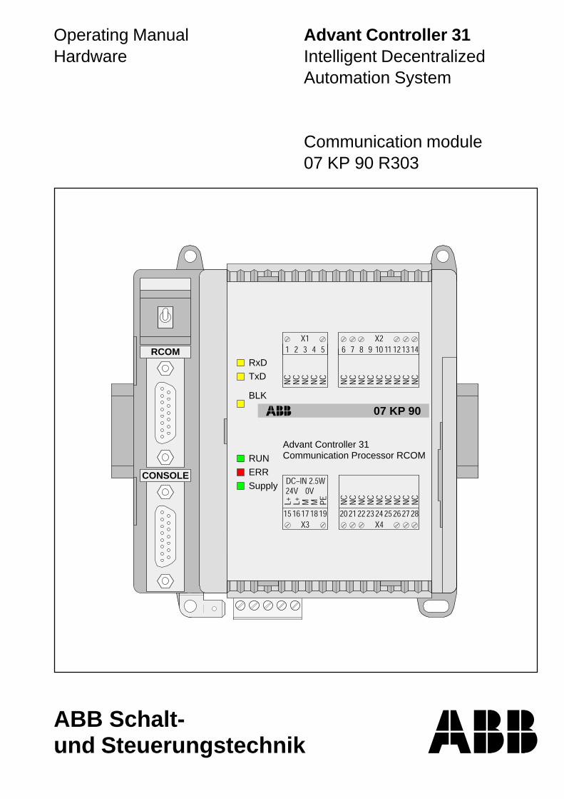
Operating ManualHardware
Advant Controller 31Intelligent DecentralizedAutomation System
Communication module07 KP 90 R303
ABB Schalt-und Steuerungstechnik
RCOM
CONSOLE
Communication Processor RCOMAdvant Controller 31
07 KP 90
RUNERRSupply
TxDRxD
BLK


Advant Controller 31 / Issued: 03.99 1 Hardware 07 KP 90 R303 8 .1
Contents
1.1 Brief description................................................. 11.2 Features ............................................................ 11.3 Planning with the 907 KP 90 R202
software package .............................................. 21.4 Structure of the front panel elements ................. 31.5 Electrical connection.......................................... 41.5.1 Application example .......................................... 41.5.2 Connection of the supply voltage ....................... 61.5.3 Electrical isolation and earthing instructions ...... 61.5.4 Serial interfaces................................................. 81.5.5 Networking interface .......................................... 91.6 Diagnosis ........................................................ 101.7 Technical data ..................................................111.8 System cables and adaptors ........................... 14
1.1 Brief description
The 07 KP 90 R303 RCOM communication module canbe connected as an expansion unit to basic units such as07 KR 91 R353, 07 KT 92, 07 KT 93, 07 KT 94 of thedecentralized automation system Advant Controller 31.
The 07 KP 90 R303 communication module permits com-munication via the RCOM protocol. Using this protocol itpermits data exchange
• between ABB MasterPiece 200 control systems, ABBProcontic T200 systems and Advant Controller 31 sys-tems or
• between Advant Controller 31 systems amongst them-selves.
One advantage is that RCOM (Remote COMmunication)permits large distances to be spanned.
Communication can be performed via various transmis-sion media, such as:
• leased or private dedicated lines
• existing cable paths,
• telephone lines (dial-up connections).
Adaptation to the required transmission path can be per-formed by selection of various modems (e.g. VF or cur-rent loop modems, telephone modems, multidrop mo-dems).
An RCOM network always consists of the master and oneor more slaves, with the following data transmission op-tions:
• master transmits data to a slave,
• master reads data from a slave,
• event-driven transmission: a slave can store processevents with a time stamp and transfer them to themaster on request (event polling).
1.2 Features
• The RCOM 07 KP 90 R303 communication modulecan be planned as RCOM master or slave.
• A network may have up to 254 RCOM slaves (max.8 slaves if using MasterPiece 200, max. 30 slaves incase of dial-up mode).
1 Communication module 07 KP 90 R303Communication via RCOM protocol
Comm. Processor RCOMAdvant Controller 31
07 KP 90
RUNERRSupp.
TxDRxD
BLK
Fig. 1: Communication module 07 KP 90 R303

2 Advant Controller 31 / Issued: 03.99Hardware 07 KP 90 R3038 .1
• The RCOM protocol is compatible with MP200/1 withDSCA 180A. All RCOM services are available (coldstart, warm start, normalization, clock synchronization,write data, read data, event polling).
• The RCOM interface for connection of the modemcomplies with EIA RS-232. It can also be used as anEIA RS-485 interface.
• An additional operator interface (CONSOLE) comply-ing with EIA RS-232 is provided as a commissioningaid (indication of the communication sequence, plan-ning telephone numbers etc.)
• Software clock; time can be used in the PLC program.
• Differences between RCOM and RCOM+, see volume3, chapter 2.6.
All other features of RCOM which are not mentionedin the chapter “Differences” apply correspondingly forRCOM+.
• The connection element RCOM+ can be used with thecommunication module 07 KP 90 from index b up.
1.3 Planning with the 907 KP 90 R202software package
The communication sequence is planned with connec-tion elements contained in the 907 KP 90 R202 docu-mentation and software package (see also Ordering in-formation). This package also contains the manual for theRCOM 07 KP 90 R303 communication module and plan-ning examples.

Advant Controller 31 / Issued: 03.99 3 Hardware 07 KP 90 R303 8 .1
1.4 Structure of the front panel elements
Fig. 2: Communication module 07 KP 90 R303 with reference points (see below for explanation)
2 2
2
43
1
7
8
6
5
Comm. Processor RCOMAdvant Controller 31
07 KP 90
RUNERRSupp.
TxDRxD
BLK
9
10
2
1 Mounting the unit on a DIN rail
2 Mounting the unit with screws
3 6.3 mm Faston earthing terminal
4 24 V DC supply voltage
5 Serial interface CONSOLE
6 Serial interface RCOM
7 Networking interface to the Advant Controller 31central unit
8 Switch
9 LED indicators see below
10 LED indicators see below
The switch has no function.
RxD
TxD
BLK
RUN
ERR
Supply
10
9
07 KP 90 is receiving an RCOMtelegram
07 KP 90 is transmitting data viathe RCOM interface
Transmission of user datablocked as the result of commu-nication error
07 KP 90 R303 is ready forRCOM communication (running)RCOM communication errorSupply voltage present
yellowyellow
yellow
green
redgreen
Refer to Section 1.6 Diagnosis for further information

4 Advant Controller 31 / Issued: 03.99Hardware 07 KP 90 R3038 .1
1.5 Electrical connection
1.5.1 Application example for connectingthe inputs and outputs
The following illustration shows an application examplewith the 07 KT 93 which utilizes various possibilities forconnecting inputs and outputs. Attention must be paid tothe following in detail:
• The earthing measures
• Connection of the communication module07 KP 90 R303
• Looping through the supply voltage (24 V DC) fromthe 07 KT 93 to the 07 KP 90 R303
• Earthing the switch cabinet mains socket
• Handling serial interfaces

Advant Controller 31 / Issued: 03.99 5 Hardware 07 KP 90 R303 8 .1
07 KT 94
Basic UnitAdvant Controller 31
+
L+
M
PE
RC
OM
CO
NS
OLE
3
2
1
1
2
3
Comm. Processor RCOMAdvant Controller 31
07 KP 90
RUNERRSupp.
TxDRxD
BLK
Outputloads for24 V DC
Switch-gear cabinetearthing
Switch-gear cabinetmains socket
Earth connection:Use supplied parts (see Fig. 6)
Supply voltage:Short, direct connection between the modules,wires 15 cm, 2.5 mm2 (see Fig. 6)
Cable shields:In the case of permanent wiring at the switch-gear cabinet inlet,earth via clamps and do not put shield in the plug. Otherwise,lay the cable shield in the plug to PGND.
Fig. 3: Application example:Communication module 07 KP 90 R303 at the basic unit 07 KT 94(Chapter 1.5 Electrical connection applies similarly to 07 KR 91, 07 KT 92 and 07 KT 93)

6 Advant Controller 31 / Issued: 03.99Hardware 07 KP 90 R3038 .1
1.5.2 Connecting the 24 V DC supply voltage
The supply voltage is fed in via a 5-pole detachable termi-nal block.
Important:Plug and unplug terminal block only with power isoff!
1.5.3 Electrical isolation and notes on earthing
The following illustration shows which circuit parts of theunit are electrically isolated from each other and whichinternal connections exist. Here, both the clearances andcreepage distances and also the test voltages used cor-respond to DIN/VDE 0160.
The unit is connected via the 6.3 mm Faston terminal (bot-tom left) to the functional earth (switch cabinet earth) viaa wire with a cross section of 6 mm2 (also see Figure 6).
15 16 17 18 19
24V DC–IN max. 2,5 W
L+ M PEL+ M
4
Supply voltage
Signal nameTerminal number
Terminal designation:
15 L+ *) Supply voltage +24 V DC16 L+ *) Supply voltage +24 V DC17 M *) Reference potential (0V)18 M *) Reference potential (0V)19 PE Protective earth terminal,
connected with the Faston termi-nal inside the device.Do not cause earth loops.Connect PE and Faston to thesame earthing potential!
*) Exclusively for connection to the AdvantController 31 basic unit (also see Figure 6).
Fig. 4: Assignment of the terminal blockfor the 24 V DC-IN supply voltage
24VDC-IN
PE
CO
NS
OLE
RC
OM
36 mm2
cross section
Fig. 5: Electrical isolation and noteson earthing
Connect to theFaston of thebasic unit (seeFigure 6)

Advant Controller 31 / Issued: 03.99 7 Hardware 07 KP 90 R303 8 .1
6 mm2
07 KP 90 R303 07 KT 94
PE
L+ / +24 V DC
M / 0 V
15 cm long, 2.5 mm2
Use supplied connection parts
Switch-gear cabinet earth
Fig. 6: Earthing connections and voltage supply for 07 KP 90 R303
8 Advant Controller 31 / Issued: 03.99Hardware 07 KP 90 R3038 .1
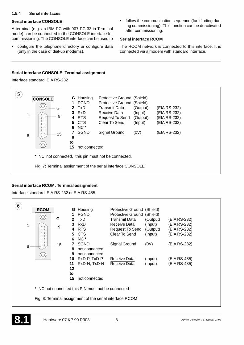
1.5.4 Serial interfaces
Serial interface CONSOLE
A terminal (e.g. an IBM-PC with 907 PC 33 in Terminalmode) can be connected to the CONSOLE interface forcommissioning. The CONSOLE interface can be used to
• configure the telephone directory or configure data(only in the case of dial-up modems),
• follow the communication sequence (faultfinding dur-ing commissioning). This function can be deactivatedafter commissioning.
Serial interface RCOM
The RCOM network is connected to this interface. It isconnected via a modem with standard interface.
Serial interface CONSOLE: Terminal assignment
Interface standard: EIA RS-232
5
G
9
158
1
CONSOLE G Housing Protective Ground (Shield) 1 PGND Protective Ground (Shield) 2 TxD Transmit Data (Output) (EIA RS-232) 3 RxD Receive Data (Input) (EIA RS-232) 4 RTS Request To Send (Output) (EIA RS-232) 5 CTS Clear To Send (Input) (EIA RS-232) 6 NC * 7 SGND Signal Ground (0V) (EIA RS-232) 8to15 not connected
* NC not connected, this pin must not be connected.
Fig. 7: Terminal assignment of the serial interface CONSOLE
G Housing Protective Ground (Shield) 1 PGND Protective Ground (Shield) 2 TxD Transmit Data (Output) (EIA RS-232) 3 RxD Receive Data (Input) (EIA RS-232) 4 RTS Request To Send (Output) (EIA RS-232) 5 CTS Clear To Send (Input) (EIA RS-232) 6 NC * 7 SGND Signal Ground (0V) (EIA RS-232) 8 not connected 9 not connected10 RxD-P, TxD-P Receive Data (Input) (EIA RS-485)11 RxD-N, TxD-N Receive Data (Input) (EIA RS-485)12to15 not connected
* NC not connected this PIN must not be connected
Fig. 8: Terminal assignment of the serial interface RCOM
Serial interface RCOM: Terminal assignment
Interface standard: EIA RS-232 or EIA RS-485
RCOM6
G
9
158
1

Advant Controller 31 / Issued: 03.99 9 Hardware 07 KP 90 R303 8 .1
1.5.5 Networking interface
The networking interface, a special parallel interface, al-lows the 07 KP 90 R303 communication module to beconnected to AC31 basic units (such as 07 KR 91 R353,07 KT 92, 07 KT 93, 07 KT 94). The housing of the com-
07 KT 94
Basic UnitAdvant Controller 31
Comm. Processor RCOMAdvant Controller 31
07 KP 90
RUNERRSupp.
TxDRxD
BLK
40-p
ole
ribbo
n ca
ble
Connection part Note: Attachment and disconnection of units on the networkinginterface may only be performed when all supply voltagesare switched off.
Fig. 9: Example: Connecting 07 KP 90 R303 with 07 KT 94
7munication module is connected to the housing of theAC31 basic unit by a snap-fit connection. The electricalconnection is via a 40-pole ribbon cable with socket con-nector, soldered onto the 07 KP 90 R303 side.
Mounting the expansion housing
1. Detach the cover on basic unit 07 KT 94 from the net-working interface.
2. Plug the socket strip of the 40-pole ribbon cable se-cured to the 07 KP 90 R303 onto the networking con-nector of the 07 KT 94.
3. Place both units on a level surface and slide them to-gether so that they engage.
4. Slide in the connection part to fix the housing in posi-tion.
Note: Mounting of the 07 KP 90 R303 to 07 KR 91 /07 KT 92 / 07 KT 93 takes place in a similar way.

10 Advant Controller 31 / Issued: 03.99Hardware 07 KP 90 R3038 .1
1.6 Diagnosis
LED displays for RCOM system messages LED displays for RUN, ERR and Supply
RUN
ERR
Supply
109 RxD
TxD
BLK
yellow
yellow
yellow
RxD: 07 KP 90 is receiving an RCOM telegram.
TxD: 07 KP 90 is transmitting data via theRCOM interface.
BLK: Transmission of user data blocked as theresult of communication error. After normali-zation LED 'BLK' goes out again.
Fig. 10: LED displays for RCOM systemmessages
green
green
red
RUN: 07 KP 90 is ready for RCOMcommunication (is running).
ERR: A RCOM communication error has occurred.In the case of recoverable errors, the LEDgoes out again after a short time. In the caseof fatal errors, the LED remains ON conti-nuously. The 'RUN' LED also goes out.
Supply: Supply voltage is present.
Fig. 11: LED displays for RUN, ERR and Supply
Operating states, error displays
gn ye ye ye gn rd Meaning Remedy
! ! ! ! ! ! Supply voltage not present. • Switch on supply voltage.• Check supply voltage.
! ! ! ! ! Supply voltage present. • Switch supply voltage of 07 KP 90 R30307 KP 90 not ready for communication and 07 KT 94 off and on again.• during device reset or• after fatal error.
! ! ! ! 07 KP 90 R303 is ready for communication. – –
! ! ! 07 KP 90 R303 is receiving a data telegram. – –
! ! ! 07 KP 90 R303 is transmitting a data telegram. – –
X X ! ! RCOM operation – –
X X ! Transmission of user data not possible owing • Normalizationto the communication sequence.
X X ! RCOM communication error. • The ERR LED goes out again automa-cally in the case of recoverable errors.
! ! ! ! Fatal RCOM communication error. • Switch the supply voltage of 07 KP 90and 07 KT 94 off and then on again.
X X Hardware error, • Switch the supply voltage of 07 KP 90(RAM, EPROM, DP-RAM) and 07 KT 94 off and then on again.
! = LED off, = LED on, " = LED flashes, X = LED on or off, ye = yellow, gn = green, rd = red
RU
N
RxD
TxD
BLK
Sup
ply
ER
R
Fig. 12: Signalling operating states and error display

Advant Controller 31 / Issued: 03.99 11 Hardware 07 KP 90 R303 8 .1
1.7 Technical data
In general, the details in section 1 ”System data and system structure” of volume 2 of the system description ”AdvantController 31” apply as technical data. Supplementary and deviating data is listed below.
1.7.1 General data
Number of serial interfaces 2
Number of parallel interfaces 1 networking interface for connecting to theAdvant Controller 31 basic unit
Operating and error displays 6 LEDs: RUN, ERR, Supply, RxD, TxD, BLK
Conductor cross section for the max. 2.5 mm2
removable terminal blocks
1.7.2 Power supply for 07 KP 90 R303
Rated supply voltage 24 V DC
Power dissipation typ. 2.5 W
max. current consumptionwith rated voltage 210 mAwith a supply voltage of 30 V 170 mA
Protection against reversed terminal connection yes
1.7.3 Serial interfaces RCOM and CONSOLE
Interface standard EIA RS-232 or EIA RS-485 (RCOM only)
Electrical isolation yes, RCOM interface with respect to the rest of the unit(see also Fig. 5)
Potential differences So that no earthing potential differences arise betweenthe 07 KP 90 R303 and the peripheral units connectedto RCOM and CONSOLE, the latter are supplied fromthe switch-gear cabinet mains socket (also see earthingconnections in Figure 5).
Transmission speed (Baud rate)RCOM 300...19200 BaudCONSOLE 9600 Baud
Terminal assignment and descriptionof the interfaces RCOM, CONSOLE see page 8 onwards
1.7.4 LED displays
LEDs for operating and error displays:
– Supply voltage present (Supply) 1 green LED– Fatal or serious error occurred (ERR) 1 red LED– Ready for RCOM communication (running), (RUN) 1 green LED
– Interface signals RxD, TxD 2 yellow LEDs– Protocol status BLK 1 yellow LED

12 Advant Controller 31 / Issued: 03.99Hardware 07 KP 90 R3038 .1
1.7.5 Mechanical data
Mounting on DIN rail in accordance with DIN EN 50022–35, 15 mm deep.The DIN rail is located in the middle between the upperand the lower edges of the module.
Fastening by screws using 4 M4 screws.
Width x height x depth 140 x 120 x 85 mm
Wiring method by removable terminal blocks with screw-typeterminals, max. 2.5 mm2
Weight 450 g
Dimensions for mounting see the following drawing
594
94120
6513
014
0
65
111
75
20
1.7.6 Mounting hints
Mounting position vertical, terminals above and below
Cooling The natural convection cooling must not be hindered bycable ducts or other material mounted in the switch-gear cabinet.
The device is 85 mm deep. The interface connectors RCOM and CONSOLE are set deeper so that the mount-ing depth required does not become any larger even with detachable interface cables. If, however, a DIN rail isused, the mounting depth is increased by the overall depth of the rail.
Fig. 13: Dimensions of the Communications module 07 KP 90 R303,front view, the dimensions for assembly bore holes are printed in bold
All dimensions in mm.
Advant Controller 31 / Issued: 03.99 13 Hardware 07 KP 90 R303 8 .1
1.7.7 Ordering data
Communication module 07 KP 90 R303 Order No. GJR5 2510 00 R0303
Scope of delivery Communication module 07 KP 90 R3031 5-pole terminal block (5.08 mm grid)Cable including terminals for making theearth connectionEarthing instructions enclosed
Further literature
System description Advant Controller 31, English Order No. FPTN 4400 04 R0201
System description ABB Procontic T200, English Order No. GATS 1314 99 R2001
Software
907 KP 90 R202, English documentation,CE library and example programs, Order No. GJP5 2051 00 R0202 b

14 Advant Controller 31 / Issued: 03.99Hardware 07 KP 90 R3038 .1
23
5CTS
SGND
4RTS
07 KP 90 R303
7SGND
RTSCTS
1PGNDTxDRxD
TxDRxD
23
54
76
DTR20
DSR
1.8 System cables and adaptors
1.8.1 CONSOLE to PC (25-pole) for commissioning
23
234
DTR
5 56
CTS
SGNDDSR
4RTS
07 KP 90 R303
7 7SGND
RTS
8
CTS
DSR Data Set ReadyDTR Data Terminal ReadyCD Carrier DetectSGND Signal Ground
1PGND
PC
PGND Protective GroundTxD Transmit DataRxD Receive DataRTS Request To SendCTS Clear To Send
1
20
CD
RxDTxD
RxDTxD
15-polemale
25-polefemale
Shield
Fig. 14: Connecting CONSOLE to PC (25-pole) for commissioning
1.8.2 RCOM as EIA RS-232 to modem
15-polemale
Shield
Fig. 15: Connecting RCOM as EIA RS–232 to modem

Advant Controller 31 / Issued: 03.99 15 Hardware 07 KP 90 R303 8 .1
1.8.3 RCOM as EIA RS-485
1011
07 KP 90 R303
1PGND
RxD–P, TxD–PRxD–N, TxD–N
Bus–PBus–N
15-polemale
Shield
1.8.4 Adaptor 15-pole / 9-pole
25 mm234
1234
TxDRxDRTS
PGNDTxDRxDRTS
5678
5678
CTSProgSGNDSGND
CTSProgSGND
9
1PGND
9
D-Sub 9-pole female
D-Sub 15-pole male
Terminal assignment
D-Sub 9-polefemale
D-Sub 15-polemale
Fig. 17: Adaptor 15-pole / 9-pole, terminal assignment
Fig. 16: Connecting RCOM as EIA RS–485

16 Advant Controller 31 / Issued: 03.99Hardware 07 KP 90 R3038 .1


ABB Schalt- und Steuerungstechnik GmbHEppelheimer Straße 82 Postfach 10 50 09D-69123 Heidelberg D-69040 Heidelberg
Telephone +49 6221 777-0Telefax +49 6221 777-111E-Mail [email protected] http://www.abb-sst.de Printed in the Federal Republic of Germany (07.99)
Printed on chlorine-free bleached paper

Communication module07 MK 92 R1161
ABB Schalt-und Steuerungstechnik
RUN
COM4
COM3
Serial Communication ProcessorAdvant Controller 31
07 MK 92
RUNERRSupply
234
1LED
Operating ManualHardware
Advant Controller 31Intelligent DecentralizedAutomation System


Advant Controller 31 / Issued: 07.99 1 Hardware 07 MK 92 R1161 8 .2
Contents
1.1 Brief description................................................. 11.2 Structure of the front panel elements ................. 21.3 Electrical connection.......................................... 31.3.1 Application example .......................................... 31.3.2 Connecting the supply voltage ........................... 51.3.3 Electrical isolation and earthing instructions ...... 51.3.4 Serial interfaces................................................. 71.3.5 Networking interface ........................................ 101.4 Diagnosis .........................................................111.5 Programming and test software 907 MK 92......111.6 Technical data ................................................. 121.7 System cables ................................................. 151.8 Memory areas in 07 MK 92.............................. 181.9 LED control ..................................................... 181.10 Allocation of the ports ...................................... 18
1.1 Brief description
The 07 MK 92 R1161 communication module is a freelyprogrammable interface module with 4 serial interfaces.
The communication module allows external units to beconnected to the Advant Controller 31 system via a serialinterface.
The communications protocols and transmission typescan be freely defined by the user.
Programming is performed on a PC with the program-ming and test software 907 MK 92.
1 Communication module 07 MK 92 R1161Connecting external units
Fig. 1: Communication module 07 MK 92 R1161
Serial Comm. ProcessorAdvant Controller 31
07 MK 92
RUNERRSupp.
234
1LED
The communication module is connected to AC31 basicunits via the networking interface, e.g. 07 KR 91 R353,07 KT 92 (index i onwards) 07 KT 93 or 07 KT 94.
The most important features of the communication modu-le are:
• 4 serial interfaces:
– 2 of them are serial interfaces, optionally con-figurable in accordance with EIA RS-232 orEIA RS-422 or EIA RS-485 (COM3, COM4)
– 2 of them are interfaces in accordance withEIA RS-232 (COM5, COM6)
• Freely programmable with a comprehensive functionlibrary
• Communication with AC31 basic unit via connectionelements
• Configurable LEDs for diagnosis
• Programming and testing on a PC via COM3
• Saving applications in a Flash EPROM
Processing of the serial interfaces and the networking in-terface is provided for in an applications program.
Programming is in the standard language ”C”.
The exchange of data between the serial communicationmodule and the AC31 basic unit is realized by connectionelements in the basic unit.

2 Advant Controller 31 / Issued: 07.99Hardware 07 MK 92 R11618 .2
1 Mounting the unit on a DIN rail
2 Mounting the unit with screws
3 6.3 mm Faston earthing terminal
4 24 V DC supply voltage
5 Configurable serial interface COM3
6 Configurable serial interface COM4
7 Serial interface COM5
8 Serial interface COM6
9 Networking interface for the AdvantController 31 basic unit
10 Switch for RUN/STOP operation
Fig. 2: Communication module 07 MK 92 R1161 with reference points (see below for explanation)
1.2 Structure of the front panel elements
2
2 2
2
43
1
9
10 7
8
6
5
Serial Comm. Processor Advant Controller 31
07 MK 92
RUNERRSupp.
234
1LED
12
11
RUN
STOP
The status of the application program is indicated by theLED RUN: The LED RUN lights up while the program isbeing processed. If an error occurred during loading (e.g.program not present), the LED RUN remains OFF.
RUN –> STOP
If the switch is switched from RUN to STOP, the programprocessing is aborted. The LED RUN goes out.
11 LED displays for system messages
12 LED displays freely configurable
The RUN/STOP switch controls theprocessing of the user application.
STOP –> RUN
If the switch is switched from STOP to RUN, the userapplication is loaded into the main memory and process-ing of the application program is started.
Application program is runningFatal or serious errorSupply voltage present
LED1
LED2
LED3
LED4
RUN
ERR
Supply
12
11
Refer to Section 1.4 Diagnosis for further information
yellowyellowyellowyellow
greenredgreen
Advant Controller 31 / Issued: 07.99 3 Hardware 07 MK 92 R1161 8 .2
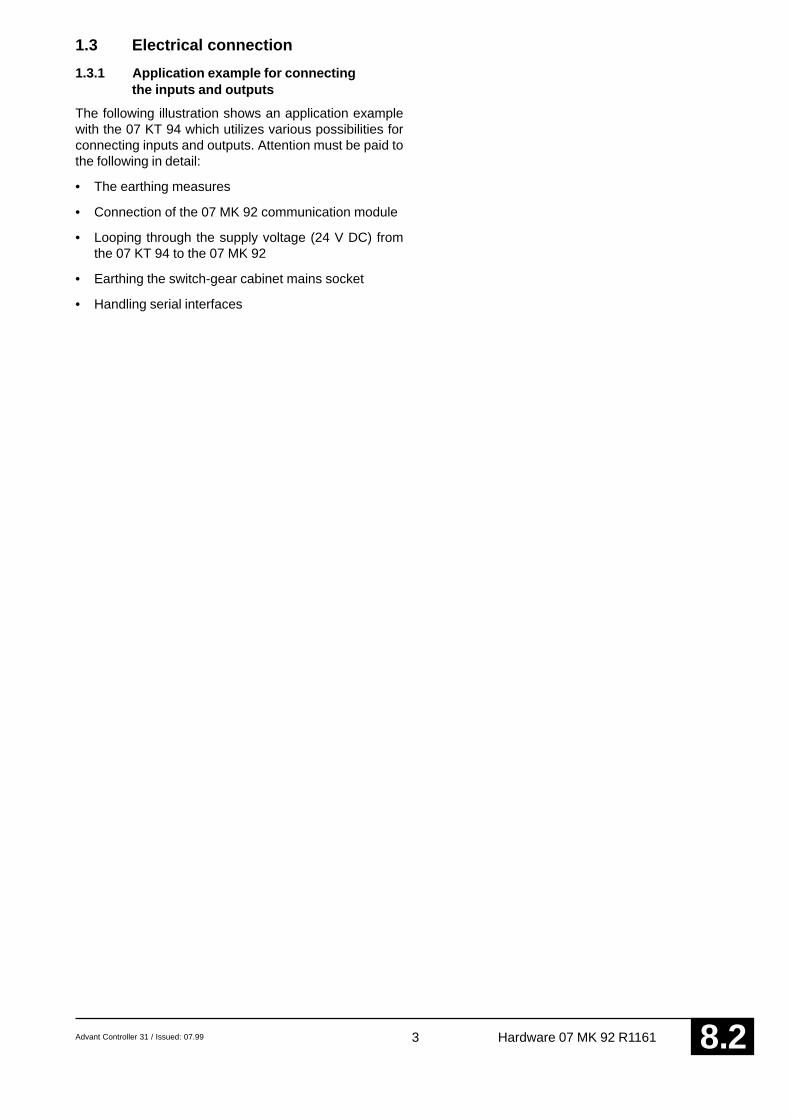
1.3 Electrical connection
1.3.1 Application example for connectingthe inputs and outputs
The following illustration shows an application examplewith the 07 KT 94 which utilizes various possibilities forconnecting inputs and outputs. Attention must be paid tothe following in detail:
• The earthing measures
• Connection of the 07 MK 92 communication module
• Looping through the supply voltage (24 V DC) fromthe 07 KT 94 to the 07 MK 92
• Earthing the switch-gear cabinet mains socket
• Handling serial interfaces

4 Advant Controller 31 / Issued: 07.99Hardware 07 MK 92 R11618 .2
07 KT 94
Basic UnitAdvant Controller 31
+
L+
M
PE
CO
M4
CO
M3
COM5
COM6
3
2
1
1
2
3
Serial Comm. Processor Advant Controller 31
07 MK 92
RUNERRSupp.
234
1LED
Fig. 3: Application example:Communication module 07 MK 92 at basic unit 07 KT 94(Section 1.3 Electrical connection applies in the same way to 07 KR 91, 07 KT 92 and 07 KT 93.)
Outputloads for24 V DC
Earth connection:Use supplied parts (see Figure 6)
Supply voltage:Short, direct connection between the modules,wires 15 cm, 2.5 mm2 (see Figure 6)
Cable shields:In the case of permanent wiring at the switchgear cabinetinlet, earth via clamps and do not put shield in the plug.Otherwise, lay the cable shield in the plug to PGND.
Switch-gear cabinet earthing
Switch-gearcabinetmains socket
Advant Controller 31 / Issued: 07.99 5 Hardware 07 MK 92 R1161 8 .2
24VDC-IN
PE
COM6
CO
M3
CO
M4
3 PGND
PGND COM515 16 17 18 19
24V DC–IN max. 2,5 W
L+ M PEL+ M
4
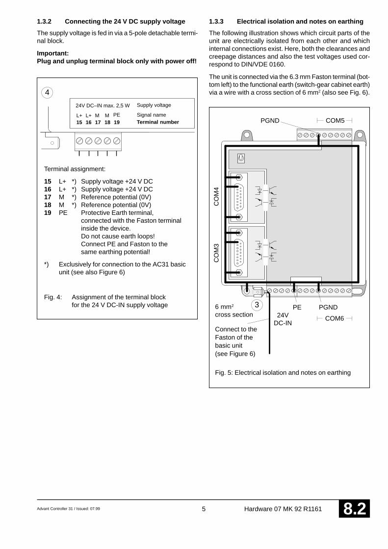
1.3.2 Connecting the 24 V DC supply voltage
The supply voltage is fed in via a 5-pole detachable termi-nal block.
Important:Plug and unplug terminal block only with power off!
1.3.3 Electrical isolation and notes on earthing
The following illustration shows which circuit parts of theunit are electrically isolated from each other and whichinternal connections exist. Here, both the clearances andcreepage distances and also the test voltages used cor-respond to DIN/VDE 0160.
The unit is connected via the 6.3 mm Faston terminal (bot-tom left) to the functional earth (switch-gear cabinet earth)via a wire with a cross section of 6 mm2 (also see Fig. 6).
6 mm2
cross section
Fig. 5: Electrical isolation and notes on earthing
Connect to theFaston of thebasic unit(see Figure 6)
Terminal assignment:
15 L+ *) Supply voltage +24 V DC16 L+ *) Supply voltage +24 V DC17 M *) Reference potential (0V)18 M *) Reference potential (0V)19 PE Protective Earth terminal,
connected with the Faston terminalinside the device.Do not cause earth loops!Connect PE and Faston to thesame earthing potential!
*) Exclusively for connection to the AC31 basicunit (see also Figure 6)
Fig. 4: Assignment of the terminal blockfor the 24 V DC-IN supply voltage
Supply voltage
Signal nameTerminal number

6 Advant Controller 31 / Issued: 07.99Hardware 07 MK 92 R11618 .2
6 mm2
07 MK 92 07 KT 94
PE
L+ / +24 V DC
M / 0 V
15 cm long, 2.5 mm2
Use supplied connection parts
Switch-gear cabinet earth
Fig. 6: Earthing connections and voltage supply for 07 MK 92
Advant Controller 31 / Issued: 07.99 7 Hardware 07 MK 92 R1161 8 .2
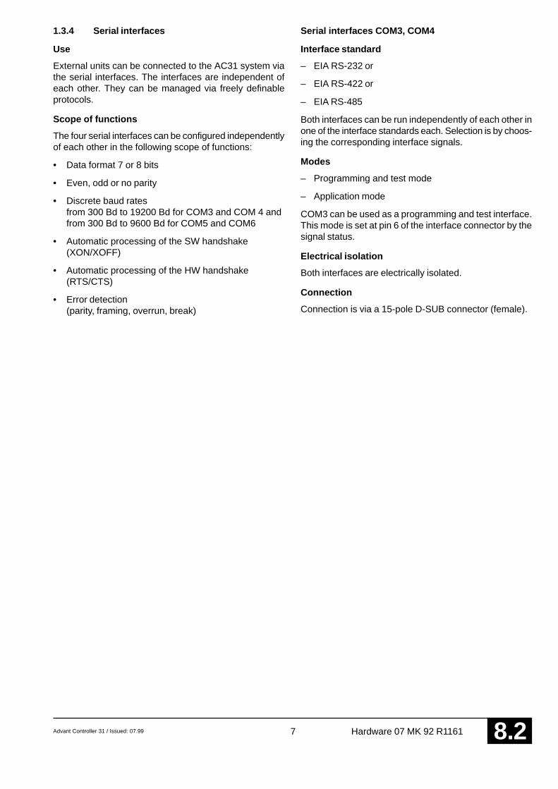
1.3.4 Serial interfaces
Use
External units can be connected to the AC31 system viathe serial interfaces. The interfaces are independent ofeach other. They can be managed via freely definableprotocols.
Scope of functions
The four serial interfaces can be configured independentlyof each other in the following scope of functions:
• Data format 7 or 8 bits
• Even, odd or no parity
• Discrete baud ratesfrom 300 Bd to 19200 Bd for COM3 and COM 4 andfrom 300 Bd to 9600 Bd for COM5 and COM6
• Automatic processing of the SW handshake(XON/XOFF)
• Automatic processing of the HW handshake(RTS/CTS)
• Error detection(parity, framing, overrun, break)
Serial interfaces COM3, COM4
Interface standard
– EIA RS-232 or
– EIA RS-422 or
– EIA RS-485
Both interfaces can be run independently of each other inone of the interface standards each. Selection is by choos-ing the corresponding interface signals.
Modes
– Programming and test mode
– Application mode
COM3 can be used as a programming and test interface.This mode is set at pin 6 of the interface connector by thesignal status.
Electrical isolation
Both interfaces are electrically isolated.
Connection
Connection is via a 15-pole D-SUB connector (female).

8 Advant Controller 31 / Issued: 07.99Hardware 07 MK 92 R11618 .2
Serial interface COM3: Terminal assignment
Interface standard: EIA RS-232, EIA RS-422, EIA RS-485
Fig. 7: Terminal assignment for the serial interface COM3
5COM3
G
9
158
1
* Programming and test mode Pin 6 openApplication mode Pin 6 jumpered in the interface connector with pin 7 (0V SGND)
Serial interface COM4: Terminal assignment
Interface standard: EIA RS-232, EIA RS-422, EIA RS-485
G Chassis Protective Ground (Shield)1 PGND Protective Ground (Shield)2 TxD Transmit Data (Output) (EIA RS-232)3 RxD Receive Data (Input) (EIA RS-232)4 RTS Request To Send (Output) (EIA RS-232)5 CTS Clear To Send (Input) (EIA RS-232)6 PROG *7 SGND Signal Ground (0V) (EIA RS-232)8 TxD-P Transmit Data (Output) (EIA RS-422)9 TxD-N Transmit Data (Output) (EIA RS-422)10 RxD-P Receive Data (Input) (EIA-RS-422 / EIA RS-485)11 RxD-N Receive Data (Input) (EIA-RS-422 / EIA RS-485)12 RTS-P Request To Send (Output) (EIA RS-422)13 RTS-N Request To Send (Output) (EIA RS-422)14 CTS-P Clear To Send (Input) (EIA RS-422)15 CTS-N Clear To Send (Input) (EIA RS-422)
Fig. 8: Terminal assignment for the serial interface COM4
* Programming and test mode This mode is not used with COM4. (Pin 6 open)Application mode Pin 6 jumpered in the interface connector with pin 7 (0V SGND)
G Chassis Protective Ground (Shield)1 PGND Protective Ground (Shield)2 TxD Transmit Data (Output) (EIA RS-232)3 RxD Receive Data (Input) (EIA RS-232)4 RTS Request To Send (Output) (EIA RS-232)5 CTS Clear To Send (Input) (EIA RS-232)6 PROG *7 SGND Signal Ground (0V) (EIA RS-232)8 TxD-P Transmit Data (Output) (EIA RS-422)9 TxD-N Transmit Data (Output) (EIA RS-422)10 RxD-P Receive Data (Input) (EIA-RS-422 / EIA RS-485)11 RxD-N Receive Data (Input) (EIA-RS-422 / EIA RS-485)12 RTS-P Request To Send (Output) (EIA RS-422)13 RTS-N Request To Send (Output) (EIA RS-422)14 CTS-P Clear To Send (Input) (EIA RS-422)15 CTS-N Clear To Send (Output) (EIA RS-422)
6COM4
G
9
158
1

Advant Controller 31 / Issued: 07.99 9 Hardware 07 MK 92 R1161 8 .2
Serial interfaces COM5, COM6
Interface standard
EIA RS-232
Mode
Application mode
Electrical isolation
Both interfaces are not electrically isolated.
Connection
Connection is via removable screw-type terminalblocks.
Serial interface COM5: Terminal assignment
Interface standard: EIA RS-232
7
9 PGND Protective Ground (Shield)
10 TxD Transmit Data (Output)
11 RxD Receive Data (Input)
12 RTS Request To Send (Output)
13 CTS Clear To Send (Input)
14 SGND Signal Ground (0V)
Fig. 9: Terminal assignment of theserial interface COM5
Serial interface COM6: Terminal assignment
Interface standard: EIA RS-232
23 PGND Protective Ground (Shield)
24 TxD Transmit Data (Output)
25 RxD Receive Data (Input)
26 RTS Request To Send (Output)
27 CTS Clear To Send (Input)
28 SGND Signal Ground (0V)
Fig. 10: Terminal assignment of theserial interface COM6
8

10 Advant Controller 31 / Issued: 07.99Hardware 07 MK 92 R11618 .2
07 KT 94
Basic UnitAdvant Controller 31
Serial Comm. ProcessorAdvant Controller 31
07 MK 92
RUNERRSupp.
234
1LED
40-p
ole
ribbo
n ca
ble
Connection partNote: Attachment and disconnection of units on the networking
interface may only be performed when all supply voltagesare switched off.
Fig. 11: Example: Connecting 07 MK 92 with 07 KT 94
Mounting the expansion housing
1. Detach the cover on unit 07 KT 94 from the network-ing interface.
2. Plug the socket strip of the 40-pole ribbon cable se-cured to the 07 MK 92 onto the networking connectorof the 07 KT 94.
3. Place both units on a level surface and slide them to-gether so that they engage.
4. Slide in the connection part to fix the housing in posi-tion.
Note: Mounting of the 07 MK 92 to 07 KR 91 / 07 KT 92 /07 KT 93 takes place in the same way.
91.3.5 Networking interface
The networking interface, a special parallel interface, al-lows the 07 MK 92 communication module to be connectedto AC31 basic units (such as 07 KR 91 R353, 07 KT 92,07 KT 93, 07 KT 94). The housing of the communication
module is connected to the housing of the AC31 basicunit by a snap-fit connection. The electrical connection isvia a 40-pole ribbon cable with socket connector, solderedonto the 07 MK 92 side.

Advant Controller 31 / Issued: 07.99 11 Hardware 07 MK 92 R1161 8 .2
LED1
LED2
LED3
LED4
12RUN
ERR
Supply
11
1.4 Diagnosis
LED displays for system messages RUN, ERR,Supply
LED displays, freely configurable
The yellow LEDs ”LED1...LED4” are configurable. Theycan be controlled by the application program.
green
green
The green LED ”RUN” lights up when the user ap-plication is being processed.
The red LED ”ERR” lights up when a fatal error (RAMerror, DP-RAM error, EPROM error, Flash EPROMerror) or a serious error is present.
The green LED ”Supply” indicates the presence ofthe supply voltage.
Fig. 12: LED displays for system messagesRUN, ERR, Supply
red
Fig. 13: LED displays, freely configurable
yellowyellowyellowyellow
gn rd gn Meaning Remedy
Supply voltage not present. Switch on supply voltage. Check supply voltage.
Supply voltage present.07 MK 92 is ready to process the userapplication.
– Load user application with 907 MK 92.– Start processing of application:
Switch RUN/STOP switch to RUN.
The user application is running.
X A serious error is present which caused the user Read out error and remedy if this is possible.application to abort automatically.
Initialization procedure. Voltage ON.
= LED off, = LED on, X = LED on or off, gn = green, rd = red
Fig. 14: Signalling operating states and error display
Operating states, error display
The communication module is programmed with the pro-gramming and test software 907 MK 92. This softwarecan be run on an IBM-compatible PC. The PC is con-nected with the COM3 interface of the communicationmodule.
Sup
ply
ER
R
RU
N
In addition to the programming and test software, the pack-age 907 MK 92 contains documentation of the communi-cation module 07 MK 92, the CE library and configurationexamples.
1.5 Programming and test software907 MK 92

12 Advant Controller 31 / Issued: 07.99Hardware 07 MK 92 R11618 .2
1.6 Technical data
In general, the details in section 1 ”System data and system structure” of volume 2 of the system description ”AdvantController 31” apply as technical data. Supplementary and deviating data is listed below.
1.6.1 General data
Number of serial interfaces 4
Number of parallel interfaces 1 networking interface for connecting to theAdvant Controller 31 basic unit
Built-in application software memory Flash EPROM 128 kbytes
Diagnosis 4 configurable LEDs: LED1...4(controlled by the application program)
Operating and error displays 3 LEDs: RUN, ERR, Supply
Conductor cross section for the max. 2.5 mm2
removable terminals
1.6.2 Supply voltage for 07 MK 92 R1161
Rated supply voltage 24 V DC
Power dissipation typ. 2.5 W
Max. current consumptionwith rated voltage 210 mAwith supply voltage 30 V 170 mA
Protection against reversed terminal connection yes (only when units with electrically isolated interfacesare connected to COM5/COM6)
1.6.3 Connection of serial interfaces COM3, COM4
Interface standard EIA RS-232 or EIA RS-422 or EIA RS-485
Programming with 907 MK 92 via IBM-PC (or compatible)
Man-machine communication yes, e.g. with an operating station
Electrical isolation yes, interfaces with respect to each other and withrespect to the rest of the unit (also see Figure 5)
Potential differences So that no earthing potential differences arise betweenthe 07 MK 92 and the peripheral units connected toCOM3 and COM4, the latter are supplied from theswitch-gear cabinet mains socket (also see earthingconnections in Figure 5).
Terminal assignment anddescription of the interfaces COM3, COM4 see page 7 onwards
1.6.4 Connection of serial interfaces COM5, COM6
Interface standard EIA RS-232
Man-machine communication yes, e.g. with an operating station
Electrical isolation none
Potential differences see COM3, COM4
Terminal assignment anddescription of the interfaces COM5, COM6 see page 9 onwards

Advant Controller 31 / Issued: 07.99 13 Hardware 07 MK 92 R1161 8 .2
1.6.5 LED displays
LEDs for operating and error displays:– Supply voltage present (Supply) 1 green LED– Fatal or serious error occurred (ERR) 1 red LED– Application program processing running (RUN) 1 green LED
Configurable LEDs for diagnosis: LED1...LED4 4 yellow LEDs
1.6.6 Mechanical data
Mounting on DIN rail in accordance with DIN EN 50022–35, 15 mm deep.The DIN rail is located in the middle between the upperand the lower edges of the module.
Fastening by screws using 4 M4 screws.
Width x height x depth 140 x 120 x 85 mm
Wiring method by removeable terminal blocks with screw-typeterminals, max. 2.5 mm2
Weight 450 g
Dimensions for mounting see the following drawing
1.6.7 Mounting hints
Mounting position vertical, terminals above and below
Cooling The natural convection cooling must not be hindered bycable ducts or other material mounted in the switch-gear cabinet.
The device is 85 mm deep. The interface connectors COM3 and COM4 are set deeper so that the mountingdepth required does not become any larger even with detachable interface cables. If, however, a DIN rail is used,the mounting depth is increased by the overall depth of the rail.
Fig. 15: Dimensions of the communication module 07 MK 92,front view, the dimensions for assembly bore holes are printed in bold
All dimensions in mm.5
94
94120
6513
014
0
65
111
75
20

14 Advant Controller 31 / Issued: 07.99Hardware 07 MK 92 R11618 .2
1.6.8 Ordering data
Communication module 07 MK 92 R1161 Order No. GJR5 2533 00 R1161
Scope of delivery Communication module 07 MK 92 R11612 9-pole terminal blocks (5.08 mm grid)1 5-pole terminal block (5.08 mm grid)Cable including terminals for making the
earth connection
Further literature
System description Advant Controller 31, English Order No. 1SAC 1316 99 R 0201
Software
Programming and test software 907 MK 92 Order No. GJP5 2074 00 R0102
907 MK 92 consists of: – Documentation– Software
– Basic functions for 07 MK 92 R1161– Paradigm Locate V 3.21
Advant Controller 31 / Issued: 07.99 15 Hardware 07 MK 92 R1161 8 .2
23
234 DTR
5 56
CTS SGNDDSR
4RTS
07 MK 92
7 7SGND RTS8 CTS
DSR Data Set ReadyDTR Data Terminal ReadyCD Carrier DetectSGND Signal Ground
1PGND
PC
PGND Protective GroundTxD Transmit DataRxD Receive DataRTS Request To SendCTS Clear To Send
TxDRxD TxD
RxD1 CD
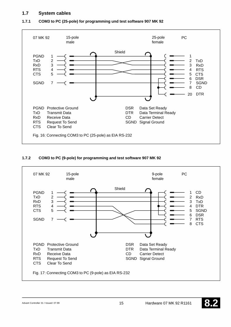
1.7 System cables
1.7.1 COM3 to PC (25-pole) for programming und test software 907 MK 92
23
234
DTR
5 56
CTS
SGNDDSR
4RTS
07 MK 92
7 7SGND
RTS
8
CTS
DSR Data Set ReadyDTR Data Terminal ReadyCD Carrier DetectSGND Signal Ground
1PGND
PC
PGND Protective GroundTxD Transmit DataRxD Receive DataRTS Request To SendCTS Clear To Send
TxDRxD
TxDRxD
1
20
CD
Shield
15-polemale
25-polefemale
Fig. 16: Connecting COM3 to PC (25-pole) as EIA RS-232
Shield
15-polemale
9-polefemale
Fig. 17: Connecting COM3 to PC (9-pole) as EIA RS-232
1.7.2 COM3 to PC (9-pole) for programming and test software 907 MK 92
16 Advant Controller 31 / Issued: 07.99Hardware 07 MK 92 R11618 .2
1011
07 MK 92
7SGND
1PGND
RxD–P, TxD–PRxD–N, TxD–N
6PROG
Bus–PBus–N
89
07 MK 92
7SGND
1PGND
TxD–PTxD–N
6PROG
10RxD–P11RxD–N
TxD–PTxD–NRxD–PRxD–N
12131415
RTS–PRTS–NCTS–PCTS–N
RTS–PRTS–NCTS–PCTS–N
23
5CTS
SGND
4RTS
07 MK 92
7SGND
RTSCTS
1PGNDTxDRxD RxD
TxD
6PROG
Shield
15polig, male
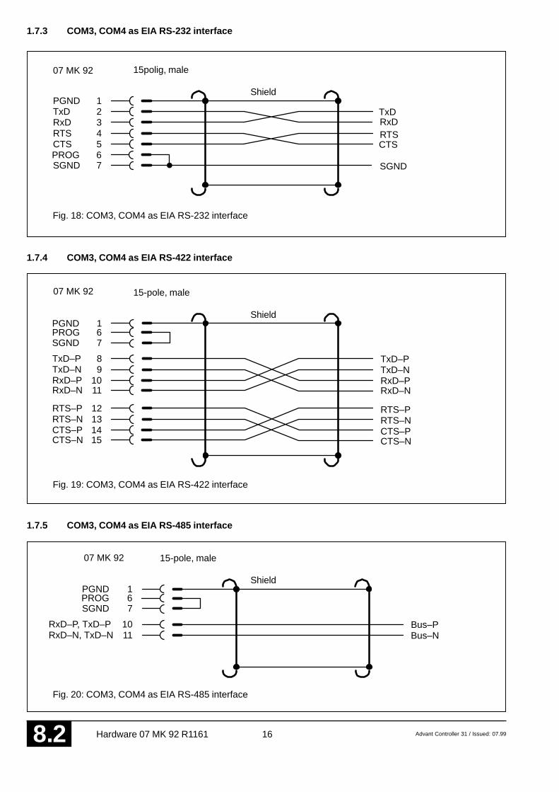
Fig. 18: COM3, COM4 as EIA RS-232 interface
1.7.3 COM3, COM4 as EIA RS-232 interface
Shield
15-pole, male
Fig. 19: COM3, COM4 as EIA RS-422 interface
1.7.4 COM3, COM4 as EIA RS-422 interface
Shield
15-pole, male
Fig. 20: COM3, COM4 as EIA RS-485 interface
1.7.5 COM3, COM4 as EIA RS-485 interface

Advant Controller 31 / Issued: 07.99 17 Hardware 07 MK 92 R1161 8 .2
2425
27CTS
SGND
26RTS
28SGND
RTSCTS
23PGND
TxDRxD RxD
TxD
1011
13CTS
SGND
12RTS
14SGND
RTSCTS
9PGND
TxDRxD RxD
TxD
Shield
Terminals 07 MK 92
Fig. 21: COM5 as EIA RS-232 interface
1.7.6 COM5 as EIA RS-232 interface
Signal
Shield
Terminals 07 MK 92
Fig. 22: COM6 as EIA RS-232 interface
1.7.7 COM6 as EIA RS-232 interface
Signal

18 Advant Controller 31 / Issued: 07.99Hardware 07 MK 92 R11618 .2
1.8 Memory areas in 07 MK 92
FFFFF (128 kB EPROM)FE000
FDFFFE0000
DFFFFC0000
BFFFF (128 kB)A0000
9FFFF99000
98FFF98000
97FFF90800
907FF (2 kB)90000
8FFFF80000
7FFFF (512 kB RAM)00B00
00AFF00000
Used EPROM area
Free EPROM area
Not used
Flash EPROM
Not used
LEDs
Not used
Dual Port RAM
Not used
Free RAM area
Used RAM area
1.9 LED control
Addressing: Segment: 9800Offset: 0 LED1
1 LED22 LED33 LED44 LED RUN
(Flash programming voltage 5 EEPROM - Vpp)6 LED ERR
1.10 Allocation of the ports
Port P2PIN Bit 5 RUN / STOP (1 = STOP, 0 = RUN)
Port P2PIN Bit 6 Status of pin 6 at COM3Port P2PIN Bit 7 Status of pin 6 at COM4
Port P1LTCH Bit 5 Control of RTS COM3Port P1LTCH Bit 7 RS-485 change-over COM3
Port P1LTCH Bit 3 Control of RTS COM4Port P1LTCH Bit 6 RS-485 change-over COM4
The addresses of the ports are listed in the file MK92HW.H


ABB Schalt- und Steuerungstechnik GmbHEppelheimer Straße 82 Postfach 10 50 09D-69123 Heidelberg D-69040 Heidelberg
Telephone +49 6221 777-0Telefax +49 6221 777-111E-Mail [email protected] http://www.abb-sst.de Printed in the Federal Republic of Germany (07.99)
Printed on chlorine-free bleached paper

RUN
COM4
COM3
Advant Controller 31
07 KP 93
RUNERRSupply
234
1LED
Do not connectDo notconnect
Do not connect
MODBUS
ABB Schalt-und Steuerungstechnik
Operating ManualHardware
Advant Controller 31Intelligent DecentralizedAutomation System
Communication processorMODBUS 07 KP 93 R1161

Advant Controller 31 / Issued: 07.99 1 Hardware 07 KP 93 R1161 8 .3
Contents
1.1 Brief description................................................. 11.2 Structure of the front panel elements ................. 21.3 Electrical connection.......................................... 21.3.1 Application example .......................................... 31.3.2 Connecting the supply voltage ........................... 41.3.3 Electrical isolation and earthing instructions ...... 41.3.4 Serial interfaces................................................. 61.3.5 Networking interface .......................................... 71.4 Diagnosis .......................................................... 81.5 Technical data ................................................... 91.6 System cables ................................................. 121.7 MODBUS RTU ................................................ 131.8 MODBUS protocol ........................................... 161.9 Function blocks ............................................... 18
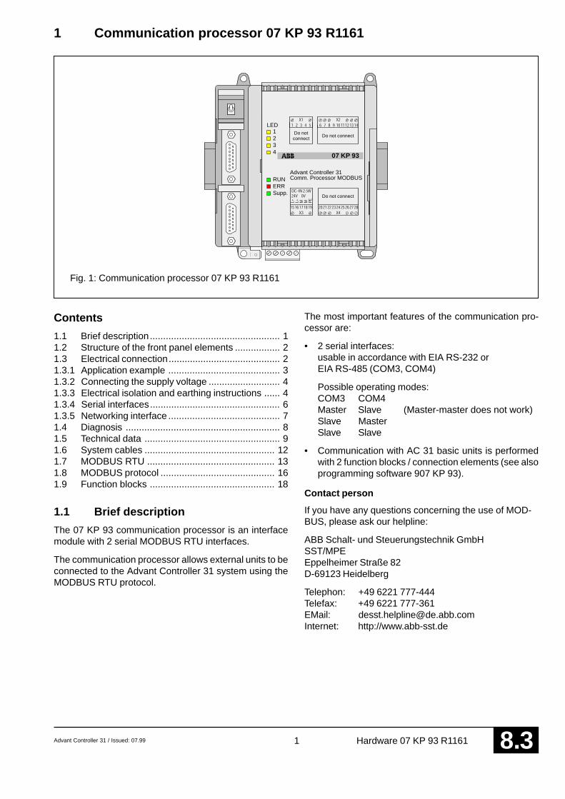
1.1 Brief description
The 07 KP 93 communication processor is an interfacemodule with 2 serial MODBUS RTU interfaces.
The communication processor allows external units to beconnected to the Advant Controller 31 system using theMODBUS RTU protocol.
The most important features of the communication pro-cessor are:
• 2 serial interfaces:usable in accordance with EIA RS-232 orEIA RS-485 (COM3, COM4)
Possible operating modes:COM3 COM4Master Slave (Master-master does not work)Slave MasterSlave Slave
• Communication with AC 31 basic units is performedwith 2 function blocks / connection elements (see alsoprogramming software 907 KP 93).
Contact person
If you have any questions concerning the use of MOD-BUS, please ask our helpline:
ABB Schalt- und Steuerungstechnik GmbHSST/MPEEppelheimer Straße 82D-69123 Heidelberg
Telephon: +49 6221 777-444Telefax: +49 6221 777-361EMail: [email protected]: http://www.abb-sst.de
1 Communication processor 07 KP 93 R1161
Fig. 1: Communication processor 07 KP 93 R1161
Comm. Processor MODBUSAdvant Controller 31
07 KP 93
RUNERRSupp.
234
1LED
Do not connectDo not
connect
Do not connect

2 Advant Controller 31 / Issued: 07.99Hardware 07 KP 93 R11618 .3
1.3 Electrical connection
1.3.1 Application example
The following illustration shows an application examplewith the 07 KT 94 basic unit.
1 Mounting the unit on a DIN rail
2 Mounting the unit with screws
3 6.3 mm Faston earthing terminal
4 24 V DC supply voltage
5 Serial interface COM3
6 Serial interface COM4
9 Networking interface for the AdvantController 31 basic unit
10 Switch not used
11 LED displays for system messagesRefer to chapter 1.4 Diagnosis for furtherinformation
12 LED displays for system messagesRefer to chapter 1.4 Diagnosis for furtherinformation
Fig. 2: Communication processor 07 KP 93 R1161 with reference points
1.2 Structure of the front panel
2
2 2
2
43
1
9
10
6
5
Comm. Processor MODBUSAdvant Controller 31
07 KP 93
RUNERRSupp.
234
1LED
Do not connectDo not
connect
Do not connect
11
12
LED1
LED2
LED3
LED4
RUN
ERR
Supply
yellow
yellow
yellowyellow
redgreen
green
11
12

Advant Controller 31 / Issued: 07.99 3 Hardware 07 KP 93 R1161 8 .3
Fig. 3: Application example:Communication processor 07 KP 93 R1161 at basic unit 07 KT 94
07 KT 94
Basic UnitAdvant Controller 31
+
L+
M
PE
CO
M4
CO
M3
3
2
1
Advant Controller 31
07 KP 93
RUNERRSupp.
234
1LED
Do not connectDo notconnect
Do not connect
Outputloads for24 V DC
Earth connection:Use supplied parts (see Figure 6)1
Supply voltage:Short, direct connection between the modules,wires 15 cm, 2.5 mm2 (see Figure 6)
2
Cable shields:In the case of permanent wiring at the switchgear inlet,earth via clamps and do not put shield in the plug.Otherwise, lay the cable shield in the plug to PGND.
3
Switch cabinet earthing
Switch cabinetmains socket

4 Advant Controller 31 / Issued: 07.99Hardware 07 KP 93 R11618 .3
24VDC-IN
PE
CO
M3
CO
M4
3
15 16 17 18 19
24V DC–IN max. 2,5 W
L+ M PEL+ M
4
1.3.2 Connecting the 24 V DC supply voltage
The supply voltage is fed in via a 5-pole detachable termi-nal block.
Important:Plug and unplug terminal block only with power isoff!
1.3.3 Electrical isolation and notes on earthing
The Protective Earth is connected to the 6.3 mm Fastonterminal via a wire with a cross section of 6 mm2 (maxi-mum length 25 cm).
The signals of the interfaces COM3 and COM4 are elec-trically isolated from each other and also from the internalelectronics of the unit.
The following illustration shows which parts of the unit areconnected to PE/PGND.
Supply voltage
Signal nameTerminal number
Terminal assignment:
15 L+ *) Supply voltage +24 V DC16 L+ *) Supply voltage +24 V DC17 M *) Reference potential (0V)18 M *) Reference potential (0V)19 PE Protective Earth terminal,
connected with the Faston terminalinside the device.Do not cause earth loops!Connect PE and Faston to thesame earthing potential!
*) Exclusively for connection to the AC31 basicunit (see also Figure 6)
Fig. 4: Assignment of the terminal blockfor the 24 V DC-IN supply voltage
6 mm2
cross section
Fig. 5: Electrical isolation andnotes on earthing
Connect to theFaston con-nector of thebasic unit(see Fig. 6)

Advant Controller 31 / Issued: 07.99 5 Hardware 07 KP 93 R1161 8 .3
6 mm2
07 KP 93 07 KT 94
PE
L+ / +24 V DC
M / 0 V
15 cm long, 2.5 mm2
Use provided connectionparts
Switch-gear cabinet earth
Fig. 6: Earthing connections and voltage supply for 07 KP 93 R1161

6 Advant Controller 31 / Issued: 07.99Hardware 07 KP 93 R11618 .3
1.3.4 Serial interfaces COM3 and COM4: Pin assignment
Interface standard: EIA RS-232, EIA RS-422, EIA RS-485
G Housing Protective Ground (Shield)
1 PGND Protective Ground (Shield)
2 TxD Transmit Data (Output) (EIA RS–232)
3 RxD Receive Data (Input) (EIA RS–232)
4 RTS Request To Send (Output) (EIA RS–232)
5 CTS Clear To Send (Input) (EIA RS–232)
6 not used
7 SGND Signal Ground (0V) (EIA RS–232)
8 not used
9 not used
10 TxD-P/RxD-P Transmit Data / Receive Data (EIA RS–485)
11 TxD-N/RxD-N Transmit Data / Receive Data (EIA RS–485)
12 not used
13 not used
14 not used
15 not used
Fig. 7: Pin assignment of the serial interfaces COM3 and COM4
5COM3
G
9
158
1

Advant Controller 31 / Issued: 07.99 7 Hardware 07 KP 93 R1161 8 .3
07 KT 94
Basic UnitAdvant Controller 31Advant Controller 31
07 KP 93
RUNERRSupp.
234
1LED
Do not connectDo notconnect
Do not connect
1.3.5 Networking interface
The communication processor can be connected to AC31basic units of the 90 series which have a networking in-terface. The housing of the communication processor is
40-p
ole
ribbo
n ca
ble
Connection part Note: Attachment and disconnection of units on the networkinginterface may only be performed when all supply voltagesare switched off.
Fig. 8: Example: Connecting 07 KP 93 with 07 KT 94
Mounting the expansion housing
1. Detach the cover on unit 07 KT 94 from the network-ing interface.
2. Plug the socket strip of the 40-pole ribbon cable se-cured to the 07 KP 93 onto the networking connectorof the 07 KT 94.
3. Place both units on a level surface and slide them to-gether so that they engage.
4. Slide in the connection part to fix the housing in posi-tion.
9connected to the housing of the AC31 basic unit by a snap-fit connection. The electrical connection is via a 40-poleribbon cable with socket connector, soldered onto the07 KP 93 side.
8 Advant Controller 31 / Issued: 07.99Hardware 07 KP 93 R11618 .3
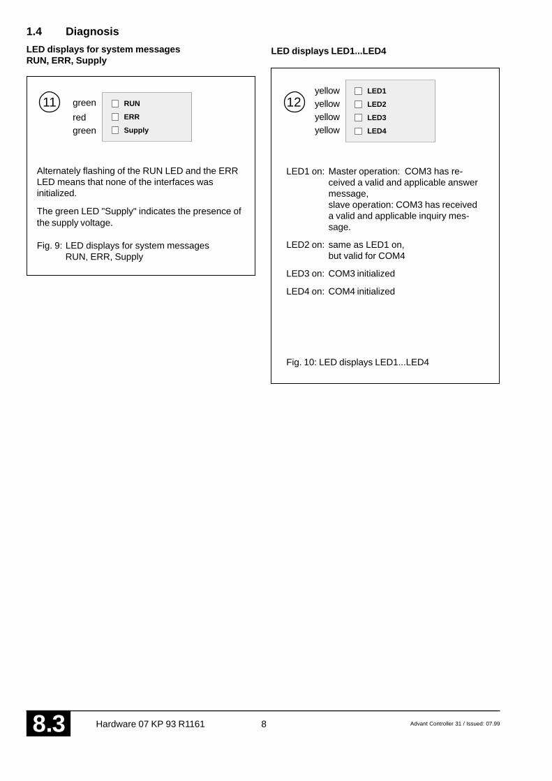
1.4 Diagnosis
LED displays for system messagesRUN, ERR, Supply
LED displays LED1...LED4
green
green
Alternately flashing of the RUN LED and the ERRLED means that none of the interfaces wasinitialized.
The green LED "Supply" indicates the presence ofthe supply voltage.
Fig. 9: LED displays for system messages RUN, ERR, Supply
yellowRUN
ERR
Supply
11red
LED1 on: Master operation: COM3 has re-ceived a valid and applicable answermessage,slave operation: COM3 has receiveda valid and applicable inquiry mes-sage.
LED2 on: same as LED1 on,but valid for COM4
LED3 on: COM3 initialized
LED4 on: COM4 initialized
Fig. 10: LED displays LED1...LED4
yellowyellowyellow
LED1
LED2
LED3
LED4
12

Advant Controller 31 / Issued: 07.99 9 Hardware 07 KP 93 R1161 8 .3
1.5 Technical data
In general, the details in section 1 ”System data and system structure” of volume 2 of the system description ”AdvantController 31” apply as technical data. Supplementary and deviating data is listed below.
1.5.1 General data
Number of serial interfaces 2
Number of parallel interfaces 1 networking interface for connecting to theAdvant Controller 31 basic unit
Diagnosis 4 LEDs: LED1...LED4
Operating and error displays 3 LEDs: RUN, ERR, Supply
Conductor cross sectionfor the removable terminal blocks max. 2.5 mm2
1.5.2 Supply voltage for 07 KP 93 R1161
Rated supply voltage 24 V DC
Power dissipation typ. 2.5 W (max. 5W)
Max. current consumptionwith rated voltage 210 mAwith supply voltage 30 V 170 mA
Protection against reversed terminal connection yes
1.5.3 Connection serial interface COM3, COM4
Interface standard EIA RS–232 or EIA RS–485
Electrical isolation yes, interfaces with respect to each other and withrespect to the rest of the unit (also see Figure 5)
Terminal assignment anddescription of the interfaces COM3, COM4 see page 6
1.5.4 LED displays
– Supply 1 green LED
– ERR 1 red LED
– RUN 1 green LED
– LED1...LED4 4 yellow LEDs
description see chapter 1.4 Diagnosis

10 Advant Controller 31 / Issued: 07.99Hardware 07 KP 93 R11618 .3
1.5.5 Mechanical data
Mounting on DIN rail in accordance with DIN EN 50022–35, 15 mm deep.The DIN rail is located in the middle between the upperand the lower edges of the module.
Fastening by screws using 4 M4 screws.
Width x height x depth 140 x 120 x 85 mm
Wiring method by removeable terminal blocks with screw-typeterminals, max. 2.5 mm2
Weight 450 g
Dimensions for mounting see the following drawing
1.5.6 Mounting hints
Mounting position vertical, terminals above and below
Cooling The natural convection cooling must not hindered bycable ducts or other material mounted in the switch-gear cabinet.
The device is 85 mm deep. The interface connectors COM3 and COM4 are set deeper so that the mountingdepth required does not become any larger even with detachable interface cables. If, however, a DIN rail is used,the mounting depth is increased by the overall depth of the rail.
Fig. 11: Dimensions of the communication processor module 07 KP 93,front view, the dimensions for assembly bore holes are printed in bold
All dimensions in mm.
594
94120
6513
014
0
65
111
75
20

Advant Controller 31 / Issued: 07.99 11 Hardware 07 KP 93 R1161 8 .3
1.5.7 Ordering data
Communication processor 07 KP 93 R1161 Order No. GJR5 2532 00 R1161
Scope of delivery Communication processor 07 KP 93 R11611 5-pole terminal block (5.08 mm grid),cable including terminals for making theearth connection
Further literature
System description Advant Controller 31, English Order No. 1SAC 1316 99 R0201
System description ABB Procontic T200 Order No. GATS 1314 99 R2001
Software
Software 907 KP 93 Order No. GJP5 2072 00 R0102

12 Advant Controller 31 / Issued: 07.99Hardware 07 KP 93 R11618 .3
1011
07 KP 93
7SGND
1PGND
RxD–P, TxD–PRxD–N, TxD–N
6NC
Bus–N
23
SGND
07 KP 93
7SGND
1PGND
6NC
TxDRxD
TxDRxD
1.6 System cables
1.6.1 COM3, COM4 as EIA RS-232 interfaces
15-polemale
Shield
Fig. 12: Connecting COM3, COM4 as EIA RS-232 interfaces
1.6.2 COM3, COM4 as EIA RS-485 interfaces
15-polemale
Shield
The earthing of the shield is carried out in the same way as with the CS31 system bus (see volume 2,chapter 1). The shield is not connected to pin 1 of the plug.
Fig. 13: Connecting COM3, COM4 as EIA RS-485 interfaces

Advant Controller 31 / Issued: 07.99 13 Hardware 07 KP 93 R1161 8 .3
07 MK 62
NCC485 NCC485
Advant Controller 31ABB Procon-tic T200
MODBUSRS–232
07 KT 9307 KT 9207 KR 91 R353
MODBUS RS–485
07 KT 94
07 KP 93
07 KT 94
07 KT 94
07 KT 94
07 AC 91
07 AC 91
NCC485
1.7 MODBUS-RTU
Overview
Brief description, field of application
MODBUS-RTU is an international widely known standard.The main application is the coupling in the local area for:
• Automation systems and PLCs,
• Operating terminals
• PC operating stations / master terminals
Short data
• Number of user stations with EIA RS-485: 32Distance with EIA RS-485: max. 1.2 km
• Connection of dedicated-line modems is possible
Networking alternatives
Multi-point line up to 1.2 km
Coupler
With Advant Controller 31 aswell as with ABB ProconticT200, the MODBUS mastercan be located at any positionon the bus line.
CS31system bus
CS31system bus
I/O modules
I/O modules
Fig. 14
EIA RS-485, 2-wire, max. 1.2 km
alternativelyAC31series 50

14 Advant Controller 31 / Issued: 07.99Hardware 07 KP 93 R11618 .3
07 MK 62
Modem Modem Modem
max. 20 km max. 20 km
07 KP 93 07 KT 94
07 KT 9307 KT 9207 KR 91 R353
07 KT 94
07 KT 94
Installation example
Point-to-point without converter
EIA RS–232
max. 15 m
07 KP 93 07 KT 9407 KT 94 COM2
CS31system bus
CS31system bus
Fig. 15
Multi-point line
COM2 of 07 KT 94
Coupler
4 wires 4 wires
e.g. Hedin Tex LH-1V• Multi-point remote connections only with 4 wires
• MODBUS master only at the beginning of the transmission line
Fig. 16
Point-to-point, max. 1200 bits/s, 4 wires
EIARS–232
20 km
23 WT 90 23 WT 90
EIARS–232
07 KP 93 07 KT 9407 KT 94 4 wires
up to ca.
CS31system bus
CS31system bus
Fig. 17

Advant Controller 31 / Issued: 07.99 15 Hardware 07 KP 93 R1161 8 .3
Separate connection of an operating terminal and an operating station via MODBUS
Use is made of the fact that the coupler 07 KP 93 R1161 has 2 MODBUS interfaces when used as slave (only as slave)
MODBUS–RTU,EIA RS–232
07 KP 93 07 KT 94
07 KT 9307 KT 9207 KR 91 R353
07 KT 94
07 KP 93 07 KT 94
07 KT 9307 KT 9207 KR 91 R353
07 KT 94
07 KT 94
NCC485
CS31system bus
CS31system bus
CS31system bus
I/Omodules
I/Omodules
Operating terminalOperatingstation
MODBUS-RTU, EIA RS-485, 2 wires, max. 1.2 km
Fig. 18

16 Advant Controller 31 / Issued: 07.99Hardware 07 KP 93 R11618 .3


ABB Schalt- und Steuerungstechnik GmbHEppelheimer Straße 82 Postfach 10 50 09D-69123 Heidelberg D-69040 Heidelberg
Telephone +49 6221 777-0Telefax +49 6221 777-111E-Mail [email protected] http://www.abb-sst.de Printed in the Federal Republic of Germany (07.99)
Printed on chlorine-free bleached paper

Advant Controller 31 / Issued: 07.99 1 PDnet 8 .4
Higher-level fast networking with PDnetfor Advant Controller 31 and ABB Procontic T200
Used couplers 07 KP 66 (T200) and 07 KP 96 (AC31)
PDnet
Advant Controller 31ABB Procontic T200
AR
CN
ET
PC
93 Ω 93 Ω
CS31
VME buscomputer
CouplerCoupler
Coupler07 KP 66
Basic unitAC31
Coupler07 KP 96
Basic unitAC31
Othersystems
system busFigure: Configuration example with PDnet
Brief description, field of application
PDnet is a higher-level fast networking(LAN = Local Area Network) of
• T200 and AC31 with one another
• T200 and AC31 with other systems
• T200 and AC31 with PCs
The powerful software planning aid NetPro with comfort-able desktop allows you to easy create connections evento other systems.
The connection to PDnet is carried out via a separate cou-pler. Concerning the AC31 basic units 07 KT 92, 07 KT 93and 07 KT 94, the advantage is that the ARCNET-SSTnetworking can be employed at the same time.
PDnet is based on ARCNET. Complex networking (line orstar configuration etc., single or with redundancy) can bebuilt using coaxial cable or optical fibre.

2 Advant Controller 31 / Issued: 07.99PDnet8 .4
Short data
• Very short access times due to high data rate of2.5 Mbit/s.
• Bus length up to ca. 300 m, using repeaters/couplersfor star configuration up to ca. 6 km.
• Token master, without repeater up to ca. 10 partici-pants, with repeaters and couplers in star configura-tion up to 255 participants.
Hardware
• Coupler for T200 07 KP 66
• Coupler for AC31 07 KP 96
• Coupler for PC 07 CM 96
• Various coupler for other systems
Software
• Configuration software NetPro
• Diagnosis software NetDiag
• Software package(configuration + diagnosis) NetPD
Documentation
The corresponding documentation is provided with thehardware and software products.
Our Helpline address
For information concerning the networking with PDnetplease contact our Helpline as follows:
ABB Schalt- und Steuerungstechnik GmbHSST/MPEEppelheimer Straße 82D–69123 Heidelberg
Telephone: +49 6221 777–444Telefax: +49 6221 777–361

ABB Schalt-und Steuerungstechnik
ARCNET–SST
Operating ManualHardware
Advant Controller 31Intelligent DecentralizedAutomation System
Networking withARCNET-SST


Advant Controller 31 / Issued: 06.99 1 ARCNET-SST 8 .5
ARCNET–SST
93 Ω
93 Ω
07 KT 94 R0161 07 KT 94 R0161 07 KT 94 R0161
07 KT 92...9407 KR 91 R353
07 KT 92...9407 KR 91 R353
07 KT 92...9407 KR 91 R353
1 ARCNET-SST
Overview
Brief description, field of application
The ARCNET–SST serves – in accordance with the de-centralized intelligence – as a fast networking betweenAC31 basic units.
Input and output modules as well as additional prepro-cessors (AC31 basic units, converters etc.) can be con-nected to these networked basic units.
The coupler is integrated in the AC31 basic unit 07 KT 94R161. The communication interface is not used, it can forinstance be used for the connection of an RCOM coupler07 KP 90 for long-distance transmission or for a PDnetcoupler 07 KP 96.
Networking configurations
Multi-point line
1. The operation of the ARCNET isalso possible without PCs.
2. Operating software (not binding):WIZCON-DOS and WIZCON-OS2contain the ARCNET driver.
3. Programming over ARCNETsee 907 PC 331 R402
CS31system bus
CS31system bus
CS31system bus
I/Omodules
I/Omodules
The configuration is easy and the amount of program issmall.
Short data
• Very short access times due to high data rate of2.5 Mbit/s.
• Bus length of 300 m, using repeaters / couplers forstar configuration up to ca. 6 km.
• Token master, without repeater up to 9 participants,with repeaters and couplers in star configuration up to255 participants.
• Programming over the ARCNET bussee 907 PC 331 R402
IBM PC

2 Advant Controller 31 / Issued: 06.99ARCNET-SST8 .5
Multi-point line, long distances, star
93 Ω93 Ω
93 Ω
93 Ω
93 Ω
93 Ω
93 Ω 93 Ω
07 KT 94 R0161 07 KT 94 R0161 07 KT 94 R0161
07 KT 94 R0161
07 KT 94 R016107 KT 94 R016107 KT 94 R0161
*1 The maximum distance goes down withincreasing number of participants:
No. of parti- Max. cablecipants length
2 425 m 4 385 m 6 340 m 8 300 m10 255 m12 210 m14 165 m16 125 m19 (max.) 60 m
Important: at least 2 m cable lengthbetween the bus interfaces
max. 300 m *1
max.425 m
Active star couplerHUB
max. 425 mPoint-to-pointHITbus segment
Point-to-pointLANDstarsegment
max.600 m
RepeaterHUBI amplifier
Multi-pointHIT / bus segmentmax. 300 m *1

Advant Controller 31 / Issued: 06.99 3 ARCNET-SST 8 .5
Conversion from COAX to optical fiber
LWL–ARCNETInterfaceF–SMA
LWL–ARCNETInterfaceF–SMA
F–SMA93 Ω 93 Ω
07 KT 94 R016107 KT 94 R016107 KT 94 R0161
Glass optical fiber up to2000 m,plastic optical fiber up to90 m
COAX
CS31system bus
CS31system bus
CS31system bus
COAX
Supplier for optical fiber parts:
Harting Elektronik GmbHD-32339 EspelkampTelephone: +49 5772/47–263Telefax: +49 5772/47–461
Optical fiber to ARCNET–Interface:Order No. 20 40 002 3711
F-SMA plug 50/125:Order No. 20 10 125 1212
F–SMA plug 50/125 glass:Order No. 20 20 050 1022
Other cables, e.g. for laying underground (on request)up to ca. 5.32/m
For questions concerning the optical fiber techniqueplease contact
Fa. Harting (Telephone: +49 5772/47–225).
Laying and connecting optical fiber requires high-skilledpersonnel. Company with experience in installing opticalfibers:
Magronic in München (Munich)Telephone: +49 89/3838–650

4 Advant Controller 31 / Issued: 06.99ARCNET-SST8 .5
Stations with an additional coupler
Connection of 3 substations to the telephone network
93 Ω 93 ΩARCNET–SST
07 KP 90 07 KT 94 R0161 07 KT 94 R0161 07 KT 94 R0161
CS31system bus
CS31system bus
Telephonenetwork
ModemLGH9600H1
I/O modules I/O modules
I/O modules I/O modules

Advant Controller 31 / Issued: 06.99 5 ARCNET-SST 8 .5
Networking program in the PLC
N2
N1
N0
#JOB
AREC
RECO
DIAG
NODE
0/1
AINIT
N0
#JOB
ASEND
N0
ASEND+
AREC
APOLL
ARCNET NODE 1 ARCNET NODE 2
AINIT once per station.
The NODE No. (addressof the participant) is set ona DIL switch and outputhere.
Powerful diagnosis.
Shows, that the busconfigures anew aftera failure of a participant.
ASEND once, for the firstsending telegram
#JOB = Total numberof configured jobs inASEND and all followingASEND+.NO = NODE No. of thereceiver(s).
Directly following anASEND+ each for everyfurther telegram at thesame NODE and forfurther NODES.
APOLL at least once withinthe program.
Starts sending procedureimmediately.
AREC once per NODE.For further telegramsduplication of the inputs.
#JOB = Number oftelegrams to be received.
NO = NODE of thetransmitter (can beduplicated).
RECO
DIAG
NODE
0/1
AINIT
6 Advant Controller 31 / Issued: 06.99ARCNET-SST8 .5
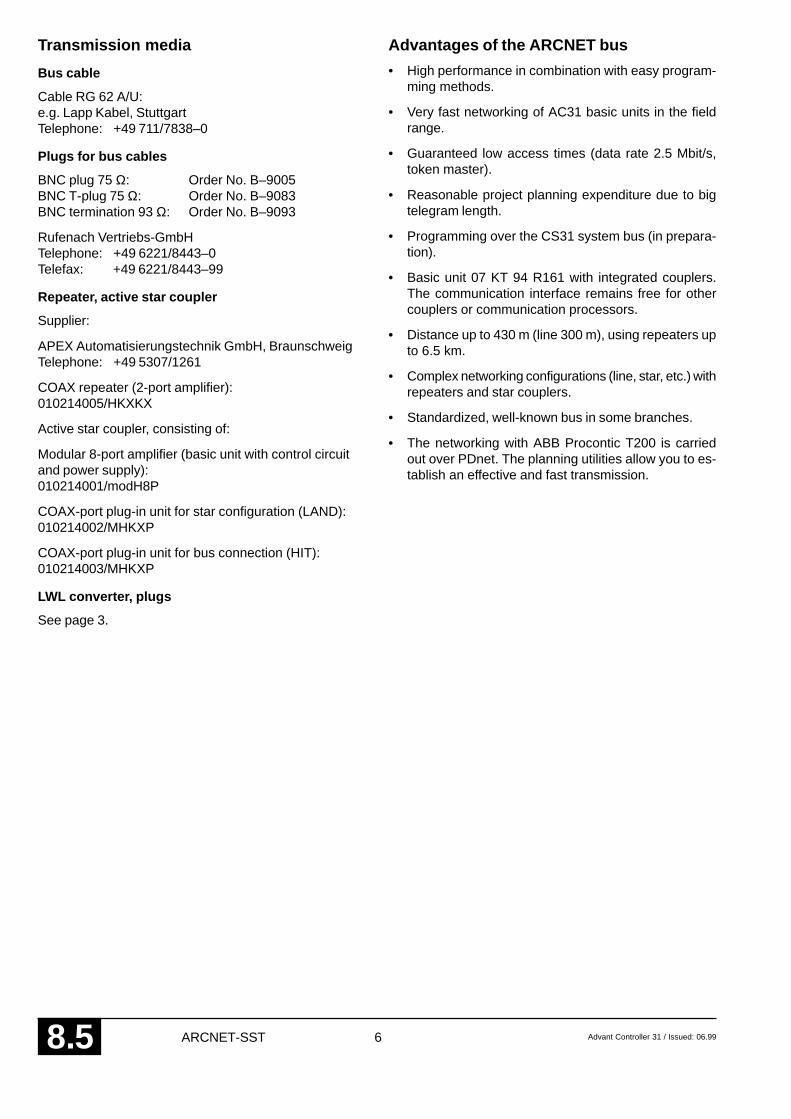
Transmission media
Bus cable
Cable RG 62 A/U:e.g. Lapp Kabel, StuttgartTelephone: +49 711/7838–0
Plugs for bus cables
BNC plug 75 Ω: Order No. B–9005BNC T-plug 75 Ω: Order No. B–9083BNC termination 93 Ω: Order No. B–9093
Rufenach Vertriebs-GmbHTelephone: +49 6221/8443–0Telefax: +49 6221/8443–99
Repeater, active star coupler
Supplier:
APEX Automatisierungstechnik GmbH, BraunschweigTelephone: +49 5307/1261
COAX repeater (2-port amplifier):010214005/HKXKX
Active star coupler, consisting of:
Modular 8-port amplifier (basic unit with control circuitand power supply):010214001/modH8P
COAX-port plug-in unit for star configuration (LAND):010214002/MHKXP
COAX-port plug-in unit for bus connection (HIT):010214003/MHKXP
LWL converter, plugs
See page 3.
Advantages of the ARCNET bus
• High performance in combination with easy program-ming methods.
• Very fast networking of AC31 basic units in the fieldrange.
• Guaranteed low access times (data rate 2.5 Mbit/s,token master).
• Reasonable project planning expenditure due to bigtelegram length.
• Programming over the CS31 system bus (in prepara-tion).
• Basic unit 07 KT 94 R161 with integrated couplers.The communication interface remains free for othercouplers or communication processors.
• Distance up to 430 m (line 300 m), using repeaters upto 6.5 km.
• Complex networking configurations (line, star, etc.) withrepeaters and star couplers.
• Standardized, well-known bus in some branches.
• The networking with ABB Procontic T200 is carriedout over PDnet. The planning utilities allow you to es-tablish an effective and fast transmission.


ABB Schalt- und Steuerungstechnik GmbHEppelheimer Straße 82 Postfach 10 50 09D-69123 Heidelberg D-69040 Heidelberg
Telephone +49 6221 777-0Telefax +49 6221 777-111E-Mail [email protected] http://www.abb-sst.de Printed in the Federal Republic of Germany (07.99)
Printed on chlorine-free bleached paper

ABB Schalt-und Steuerungstechnik
CI520
F R
X8
CH1
X9
CH2
07KP95
Operating ManualHardware
Advant Controller 31Intelligent DecentralizedAutomation System
Communication processor07 KP 95 R101


Advant Controller 31 / Issued: 03.99 1 Hardware 07 KP 95 R101 8 .6
Contents
1.1 Brief description................................................. 11.2 Features of the unit 07 KP 95 ............................ 11.3 Survey of Advant Fieldbus (AF100),
07 KP 95 and Advant Controller 31 .................... 21.4 Structure of the front panel ................................ 21.5 Electrical connection.......................................... 21.5.1 Application examples for AF100
coupling with modem, coupler 07 KP 95and basic unit .................................................... 2
1.5.2 Connection of the supply voltage ....................... 51.5.3 Networking interface .......................................... 51.5.4 Measures for RFI............................................... 51.6 Technical data ................................................... 61.7 Ordering data .................................................... 8
1.1 Brief description
The communication processor 07 KP 95 allows interfac-ing of AC31 to the AF100 (Advant Fieldbus 100). The com-munication processor 07 KP 95 needs additionally a com-munication interface CI520 and an appropriate bus mo-dem. The 07 KP 95 contains the carrier board for the CI520(similar to the Submodule Carrier Board with the AdvantController 450, but the 07 KP 95 has only one slot for oneCI520).
The programming of the communication processor is car-ried out in the PLC program with a PC using the program-ming and test system 907 PC 331.
1 Communication processor 07 KP 95 R101Communication via the Advant Fieldbus 100
Fig. 1: Communication processor 07 KP 95 R101
F R
07KP95
CI520
The programming software 907 KP 95 R102 provides allconnection elements necessary for operating the com-munication processor 07 KP 95:
• AF100
• DSPIN
• DSPOUT
• DWREAL
• REALDW
1.2 Features of the unit 07 KP 95
The following functions are supported by the 07 KP 95:
– master or slave at the AF100 (function block AF100)
– single-channel or redundant configuration of the AF100(selectable via the function block AF100)
– transmission of cyclic data using the function blocksDSPIN and DSPOUT (max. 475 DSPs with 8 DATs,max. 250 DSPIN and 249 DSPOUT)
– service data: station, type, version, status
– no event handling
– no time-sync
– no program-load

2 Advant Controller 31 / Issued: 03.99Hardware 07 KP 95 R1018 .6
1.4 Structure of the front panel
F R
07KP95
CI520
2
4
3
1
7
5
6
1 Fixing screws above and belowfor fastening on the earthed mounting surface. With thisfastening the earthing for the coupler is also performed.
2 Supply voltage 24 V DC (red = L+, blue = M)
3 Networking interface for the AC31 basic unit(e.g. 07 KT 94)
4 Communication interface CI520
5 Serial interface for modem coupling
6 Second serial interface for another modem(in case of redundant operation)
7 LEDsred (F) = Faultgreen (R) = Ready
Fig. 2: Communication processor 07 KP 95 with reference points
1.5 Electrical connection
1.5.1 Application examples for AF100 couplingwith modem, coupler 07 KP 95 and basicunit
The following figures show two application examples forsingle-channel and redundant configuration. Attentionmust be paid to the following in detail:
• The earthing measures
• The connection of the communication processor07 KP 95 to the modem(s).
• Looping through the supply voltage (24 V DC) fromthe 07 KT 94 to the 07 KP 95 R101
• Earthing the switch cabinet mains sockets
• Using the AF100 bus with coaxial cable
connection between the coupler and the AF100 bus,an appropriate modem must be selected.
– For the transmission of cyclic data on the Advant Con-troller side, the data base element DSP (Data Set Pe-ripheral) is available. Each DSP can contain up to 8 dataelements (DATs) of the types boolean, integer, longinteger or real. In the data base element, the followingis given: the number of DATs, the transmission inter-val, the direction (sending or receiving DSP), the iden-tification and the station number.
– Analog to that, on the AC31 side there are the functionblocks DSPIN (receiving DSP) and DSPOUT (send-ing DSP). As a maximum, a number of 475 DSPs with8 DATs each can be configured. The max. number offunction blocks is 250 DSPINs and 249 DSPOUTs.
– For initialization, the function block AF100 is available(station number, master/slave, AF100 bus single/re-dundant).
1.3 Survey of Advant Fieldbus (AF100),07 KP 95 and Advant Controller 31
– The AF100 is a field bus, to which a maximum of 80AF100 stations (nodes) can be connected. Each sta-tion can be a master or a slave. At least one mastermust be connected to an AF100, several masters arepossible.
– The AF100 distinguishes between process data, whichare transmitted cyclically (Cyclic Data Packages) andmessages (diagnosis data, events), which are onlytransmitted if necessary.
– The AF100 can be configured in single-channel modeor redundant. In the redundant configuration, the dataare always sent via both busses. The data, however,are only received from one bus. The switch-over tothe bus, from which the data is received, is performedautomatically by the hardware.
– The transmission medium for the AF100 can be atwisted pair, a coaxial cable or an optical fiber. For the

Advant C
ontroller 31 / Issued: 03.993
Hardw
are 07 KP
95 R101
8 .6
07 KT 94
Basic UnitAdvant Controller 31
F R
TC625SB512 07KP95
CI520
AF100
L+M
PE
Modem 07 KP 95
+
–
L1N
230 VAC / 24 VDC
Fig. 3: Application example of an AF100 coupling with modem, coupler and basic unit (typical switch-gear cabinet configuration)
Mounting on the switch-gear cabinet rear panelTermination resistor earthed
Power supply for modem
Switch-gear cabinetearthing
Switch-gear cabinet earthingSwitch-gear cabinetmains socket forPC, auxiliarydevices etc.
Switch-gearcabinet mainssocket for themodem powersupply

4A
dvant Controller 31 / Issued: 03.99
Hardw
are 07 KP
95 R101
8 .6
07 KT 94
Basic UnitAdvant Controller 31
F R
TC625SB512 07KP95TC625SB512
CI520
AF100 AF100
L+M
PE
Modem Modem 07 KP 95
+
–
L1N
230 VAC / 24 VDC
Power supplyfor modem
Powersupply formodem
Fig. 4: Application example of an AF100 coupling with modems, coupler and basic unit, redundant configuration (typical switch-gear cabinet configuration)
Mounting on the switch-gear cabinet rear panel
Switch-gear cabinet eart-hing (mounting surface)
Switch-gear cabinet earthingSwitch-gear cabinetmains socket forPC, auxiliarydevices etc.
Switch-gearcabinet mainssocket for themodem powersupply

Advant Controller 31 / Issued: 03.99 5 Hardware 07 KP 95 R101 8 .6
1.5.2 Connection of the supply voltage 24 V DC
As shown in Fig. 3 and Fig. 4, the supply voltage for the07 KP 95 is looped through from the AC31 basic unit (redwire = L+, blue wire = M).
1.5.3 Networking interface
The networking interface, a special parallel interface, al-lows the 07 KP 95 communication processor to be con-nected to AC31 basic units 07 KT 93 and 07 KT 94. Thehousing of the communication processor is connected tothe housing of the ABB Procontic basic unit by a snap-fitconnection. The electrical connection is via a 40-pole rib-bon cable with socket connector, soldered onto the07 KP 95 R101 side.
Note: Attachment and disconnection of units on the net-working interface may only be performed when all supplyvoltages are switched off.
Mounting the communication processor at the net-working interface
1. Detach the cover on the basic unit (e.g. 07 KT 94)from the networking interface.
2. Plug the socket strip of the 40-pole ribbon cable se-cured to the 07 KP 95 R101 onto the networking con-nector of the AC31 basic unit.
3. Slide both units together.
4. Slide the replacement cover provided with the 07 KP 95unit with its cut-out onto the networking interface.
1.5.4 Measures for RFI(Radio Frequency Interference)
– Installation in a metallic switch-gear cabinet
– Mains filters

6 Advant Controller 31 / Issued: 03.99Hardware 07 KP 95 R1018 .6
1.7 Technical data
In general, the details in Section 1 ”System data and system structure” of volume 2 of the system description ”Ad-vant Controller 31” apply as technical data. Supplementary and deviating data is listed below.
1.7.1 General data
Number of parallel interfaces 1 networking interface for connecting to theAC31 basic unit
1 interface for communication interface CI520
Note: The communication interface CI520 must be orderedseparately and is not supplied together with the07 KP 95
1.7.2 Supply voltage 07 KP 95 R101
Rated supply voltage 24 V DC
Power dissipation typ. 6 W
Max. current consumptionwith rated voltage 250 mAwith supply voltage 30 V 200 mA
Protection against reversed terminal connection yes
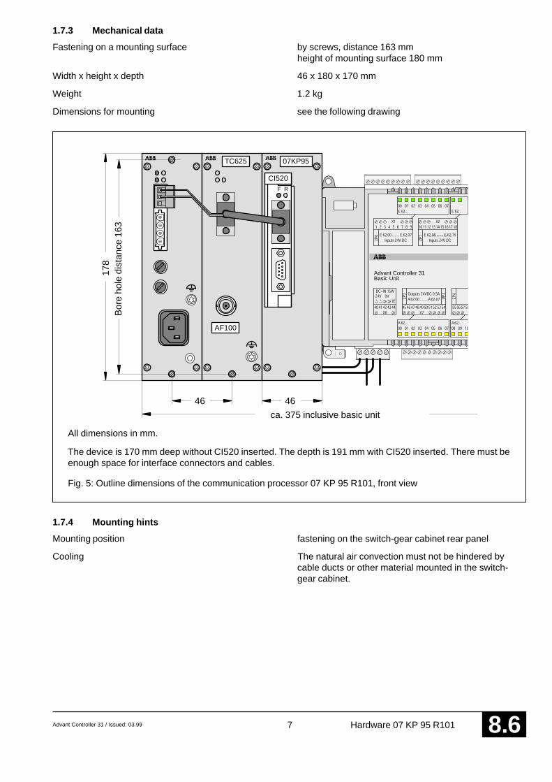
Advant Controller 31 / Issued: 03.99 7 Hardware 07 KP 95 R101 8 .6
1.7.3 Mechanical data
Fastening on a mounting surface by screws, distance 163 mmheight of mounting surface 180 mm
Width x height x depth 46 x 180 x 170 mm
Weight 1.2 kg
Dimensions for mounting see the following drawing
F R
TC625 07KP95
CI520
AF100
46
178
46
Basic UnitAdvant Controller 31
ca. 375 inclusive basic unit
Bor
e ho
le d
ista
nce
163
All dimensions in mm.
The device is 170 mm deep without CI520 inserted. The depth is 191 mm with CI520 inserted. There must beenough space for interface connectors and cables.
Fig. 5: Outline dimensions of the communication processor 07 KP 95 R101, front view
1.7.4 Mounting hints
Mounting position fastening on the switch-gear cabinet rear panel
Cooling The natural air convection must not be hindered bycable ducts or other material mounted in the switch-gear cabinet.

8 Advant Controller 31 / Issued: 03.99Hardware 07 KP 95 R1018 .6
1.8 Ordering data
Communication processor 07 KP 95 R101 Order No. GJR5 2520 00 R0101
Scope of delivery Communication processor 07 KP 95 R0101Earthing instructionsReplacement cover for the networking interface
Further literature
System description Advant Controller 31, English 1SAC 1316 99 R0201
Software
907 KP 95 R0102, Documentation, CE library GJP5 2065 00 R0102 (German documentation)GJP5 2066 00 R0102 (English documentation)
Additional components (see also Figures 3 and 4)
CI520 Communication interface
TC625 AF100 modem for coaxial cable (contains interface cable CI520 <–> TC625)
TC512 AF100 modem for twisted pair (contains interface cable CI520 <–> TC512)
SB512 Power supply unit for modem
These components can be ordered under the following address:
ABB Industrietechnik AGAbteilung IND / OMDudenstraße 44–46D-68167 MannheimTel.: +49 621 381 1847 (Mr. Bräuler)
Additional literature
User’s Guide Advant Fieldbus 100 Document 3BSE 000 506R0101 (English)
Installation Rules Document 3BSE 009 178R0001 (English)


ABB Schalt- und Steuerungstechnik GmbHEppelheimer Straße 82 Postfach 10 50 09D-69123 Heidelberg D-69040 Heidelberg
Telephone +49 6221 777-0Telefax +49 6221 777-111E-Mail [email protected] http://www.abb-sst.de Printed in the Federal Republic of Germany (07.99)
Printed on chlorine-free bleached paper
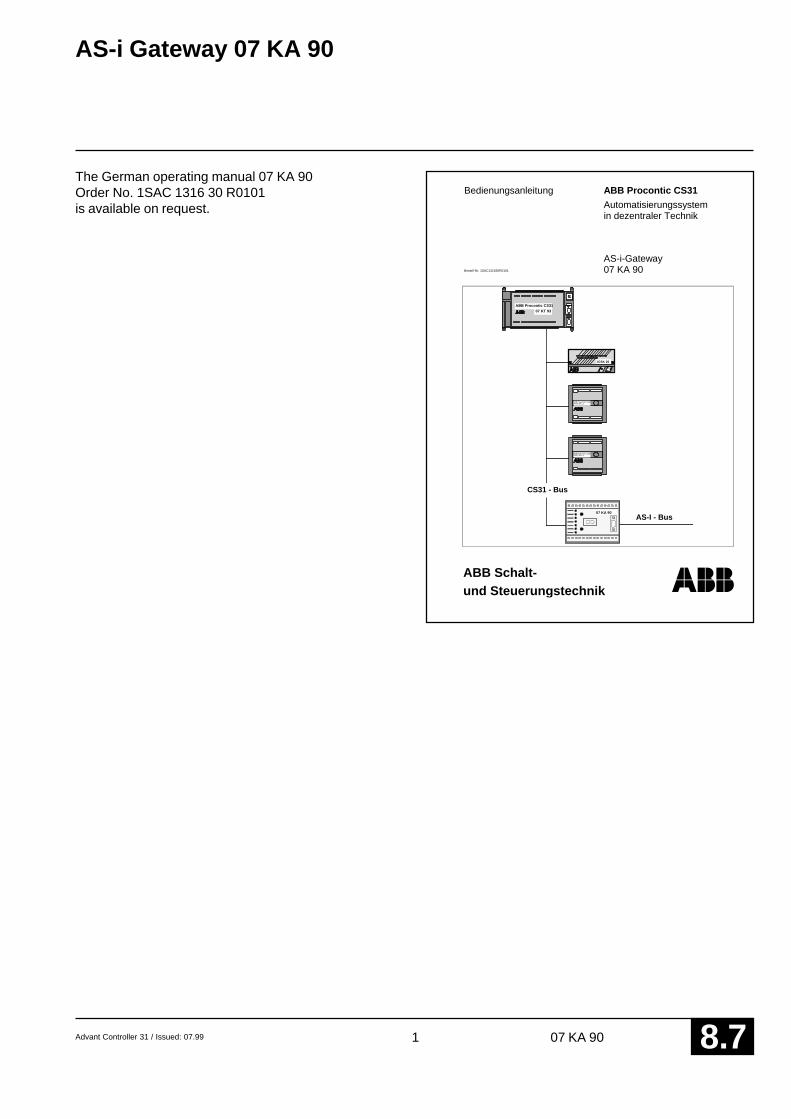
Advant Controller 31 / Issued: 07.99 1 07 KA 90 8 .7
AS-i Gateway 07 KA 90
The German operating manual 07 KA 90Order No. 1SAC 1316 30 R0101is available on request.
ABB Schalt-und Steuerungstechnik
Bedienungsanleitung ABB Procontic CS31
Automatisierungssystemin dezentraler Technik
AS-i-Gateway07 KA 90
ABB Procontic CS31ICDG 32 L1
ABB Procontic CS3107 KT 93
ICSK 20
ABB Procontic CS31ICDG 32 L1
CS31/AS-iAS-I - Bus
CS31 - Bus
Bestell-Nr. 1SAC131630R0101
07 KA 90

2 Advant Controller 31 / Issued: 07.9907 KA 908 .7
Related Documents