JOURNAL OF ELECTRON MICROSCOPY TECHNIQUE 3~177-210 (1986) Advances in Ultrarapid Freezing for the Preservation of Cellular Ultrastructure JOHN C. GILKEY AND L. ANDREW STAEHELIN Department of Molecular, Cellular, and Developmental Biology, University of Colorado, Boulder KEY WORDS Cellular ultrastructure, Ultrarapid freezing, Cryoprotection, Ice crystal formation ABSTRACT Most of our current knowledge of cellular ultrastructure is derived from studies of chemically fixed and chemically cryoprotected prepa- rations. In the first part of this review, we document the many artifacts associated with chemical techniques that render them unsuitable for further refinement of our understanding of cellular ultrastructure. The best method currently available for the preservation of cellular ultrastructure is ultrarapid freezing. The second part of this review is a consideration of the physics of ice crystal formation in biological systems, which suggests that ice crystals will be present in any frozen, uncryoprotected specimen. We define an ultrarapidly frozen preparation as one in which the ice crystals are so small as to be invisible at the electron microscopic level. Improvements in the ease of appli- cation and reliability of ultrarapid freezing techniques have reached the point that these techniques can be used by anyone requiring the best achievable preservation of cellular ultrastructure. In the third part of this review, we describe and critique the five methods of ultrarapid freezing in current use. INTRODUCTION Ultrarapid freezing, when used in conjunc- tion with appropriate accessory processing methods, has long been recognized to provide preservation of ultrastructure that is supe- rior to that obtainable through conventional, chemical fixation techniques and the use of cryoprotectants. Further, it is the only pro- cedure currently available for reproducibly capturing events that occur on a time scale of less than a few seconds. Successful ultra- rapid freezing requires that heat be with- drawn so rapidly from an unfixed, uncryo- protected sample that no ice crystal damage is visible at the electron microscopic level of analysis. This is not a trivial undertaking, and until recently, the improvements gained through ultrarapid freezing were often paid for in terms of decreased productivity. This caused most investigators to opt for the more “efficient” methods of conventional chemical fixation, despite their known limitations. However, over the last several years, im- provements in methodology and the intro- duction of refined equipment for the ultrarapid freezing of biological samples has significantly improved both the ease of appli- cation of the technique and the yield of well preserved samples. The goal of this review is to help researchers interested in cell struc- ture and function evaluate current ultra- rapid freezing techniques (a) by providing a critical discussion of the limitations of con- ventional chemical methods of fixation and cryoprotection, (b) by providing an up-to-date introduction to the physics of ice crystal for- mation in biological systems, and (c) by de- scribing and critiquing the five methods currently used to freeze biological samples ultrarapidly . PART I WHY IS ULTRARAPID FREEZING NECESSARY? THE ARTIFACTS ASSOCIATED WITH CONVENTIONAL CHEMICAL TECHNIQUES OF FIXATION AND CRYOPROTECTION Because no techniques exist as yet for high resolution, in vivo observation of most as- pects of ultrastructural transformations, bi- Received December 27, 1984; accepted June 28, 1985. Address reprint requests to L. Andrew Staehelin, Department of Molecular, Cellular, and Developmental BiolobT, Porter Bio- sciences Building, Campus Box 347, University of Colorado, Boulder, CO 80309. 0 1986 ALAN R. LISS, INC.

Welcome message from author
This document is posted to help you gain knowledge. Please leave a comment to let me know what you think about it! Share it to your friends and learn new things together.
Transcript
JOURNAL OF ELECTRON MICROSCOPY TECHNIQUE 3~177-210 (1986)
Advances in Ultrarapid Freezing for the Preservation of Cellular Ultrastructure
JOHN C. GILKEY AND L. ANDREW STAEHELIN Department of Molecular, Cellular, and Developmental Biology, University of Colorado, Boulder
KEY WORDS Cellular ultrastructure, Ultrarapid freezing, Cryoprotection, Ice crystal formation
ABSTRACT Most of our current knowledge of cellular ultrastructure is derived from studies of chemically fixed and chemically cryoprotected prepa- rations. In the first part of this review, we document the many artifacts associated with chemical techniques that render them unsuitable for further refinement of our understanding of cellular ultrastructure. The best method currently available for the preservation of cellular ultrastructure is ultrarapid freezing. The second part of this review is a consideration of the physics of ice crystal formation in biological systems, which suggests that ice crystals will be present in any frozen, uncryoprotected specimen. We define an ultrarapidly frozen preparation as one in which the ice crystals are so small as to be invisible at the electron microscopic level. Improvements in the ease of appli- cation and reliability of ultrarapid freezing techniques have reached the point that these techniques can be used by anyone requiring the best achievable preservation of cellular ultrastructure. In the third part of this review, we describe and critique the five methods of ultrarapid freezing in current use.
INTRODUCTION
Ultrarapid freezing, when used in conjunc- tion with appropriate accessory processing methods, has long been recognized to provide preservation of ultrastructure that is supe- rior to that obtainable through conventional, chemical fixation techniques and the use of cryoprotectants. Further, it is the only pro- cedure currently available for reproducibly capturing events that occur on a time scale of less than a few seconds. Successful ultra- rapid freezing requires that heat be with- drawn so rapidly from an unfixed, uncryo- protected sample that no ice crystal damage is visible at the electron microscopic level of analysis. This is not a trivial undertaking, and until recently, the improvements gained through ultrarapid freezing were often paid for in terms of decreased productivity. This caused most investigators to opt for the more “efficient” methods of conventional chemical fixation, despite their known limitations. However, over the last several years, im- provements in methodology and the intro- duction of refined equipment for the ultrarapid freezing of biological samples has significantly improved both the ease of appli- cation of the technique and the yield of well
preserved samples. The goal of this review is to help researchers interested in cell struc- ture and function evaluate current ultra- rapid freezing techniques (a) by providing a critical discussion of the limitations of con- ventional chemical methods of fixation and cryoprotection, (b) by providing an up-to-date introduction to the physics of ice crystal for- mation in biological systems, and (c) by de- scribing and critiquing the five methods currently used to freeze biological samples ultrarapidly .
PART I WHY IS ULTRARAPID FREEZING NECESSARY? THE ARTIFACTS ASSOCIATED
WITH CONVENTIONAL CHEMICAL TECHNIQUES OF FIXATION AND
CRYOPROTECTION
Because no techniques exist as yet for high resolution, in vivo observation of most as- pects of ultrastructural transformations, bi-
Received December 27, 1984; accepted June 28, 1985. Address reprint requests to L. Andrew Staehelin, Department
of Molecular, Cellular, and Developmental BiolobT, Porter Bio- sciences Building, Campus Box 347, University of Colorado, Boulder, CO 80309.
0 1986 ALAN R. LISS, INC.
178 J.C. GILKEY AND L.A. STAEHELIN
ologists must be satisfied with attempts to “freeze the action” and obtain a series of static images of dead cells. An ideal fixation technique would preserve the natural state by instantaneously capturing and fixing in place every atom and molecule in a sample. What criteria can be used to judge the degree to which a given fixation regimen ap- proaches this ideal, in the absence of a priori knowledge of the ultrastructure of the living state? We believe that, on the basis of intui- tion, common sense, and the cumulative ex- perience of 40 years of progress in ultra- structural studies, it is possible to define a few reasonable conditions that must be met by a fixation technique if it is to yield a good approximation of the “true nature” of the living state.
A fixative must act quickly. How fast is chemical fwation?
No fixation technique available at present can act instantaneously. The best perfor- mance we can hope for would be that vir- tually all relevant monatomic and molecular translational movement would cease within the region of interest in the shortest possible time. Penetration of any chemical fixative into a sample must occur by diffusion of the fixative from bulk solution, which is a rela- tively slow process. A simple calculation, based upon a diffusion coefficient of lop5 cm21 sec in bulk solution (a reasonable value for most fixatives, which are relatively small molecules), suggests that while a chemical fixative might require only a few millise- conds to completely penetrate a highly permeable planar sample of 1 pm thickness, at least 1 sec would be required to penetrate a thicker sample to a depth of 40 pm. In fact, due to the presence of diffusion barriers, such as membranes, the observed rate of penetra- tion of fixatives into cells is considerably slower, on the order of 1-2 pm per second (Mersey and McCully, 1978).
All modern chemical fixatives are multi- functional reagents that crosslink some pop- ulation of the molecules in the sample to form a rigid three-dimensional matrix. After a fixative enters a sample and achieves an effective concentration, additional time is re- quired for the crosslinking reaction to take place. This relative slowness of chemical fix- ation is illustrated by the following direct light microscopic observation: (a) 3% glutar- aldehyde plus 3% acrolein requires 2 sec to stop all movement of the axoneme of the
protozoan Prysonymapha (Fitzharris et al., 1972). (b) 3% Glutaraldehyde requires 9 sec to stop vesicle-mediated transcytoplasmic transport of horseradish peroxidase from the luminal to the abluminal front of capillary and venular epithelium (Boyles et al., 1981). (c) 3% Glutaraldehyde requires 30-45 sec to immobilize all cytoplasmic inclusions in cul- tured chick embryo cells; furthermore, glu- taraldehyde-induced vesiculation of the endoplasmic reticulum continues for up to 2.5 min (Buckley, 1973). (d) 3.1% Glutaralde- hyde requires 10-30 sec to immobilize all cytoplasmic inclusions in Haemanthus endo- sperm cells (Bajer and Mole-Bajer, 1969, 1971). (el Immobilization of actively stream- ing cytoplasm in tomato petiolar hair cells requires 15 min with 1.5-5.3% glutaralde- hyde, 9 min with 5% acrolein, 6 min with 2% acrolein plus 5% glutaraldehyde and 15 min with 1% osmium tetroxide plus 2% glutaral- dehyde (Mersey and McCully, 1978); these fixatives also caused extensive vesiculation of the endoplasmic reticulum. Obviously, chemical fixatives are of questionable value in studies of phenomena that occur on a time scale of a few seconds or less.
A fixative should immobilize all of the atoms and molecules in the cell. How thorough is
chemical fixation? Even if a chemical fixative could act in-
stantaneously, the likelihood that it would be able to crosslink all of the types of mole- cules found in living cells seems remote. Al- dehyde fixatives, for example, can crosslink only those molecules with free amino groups, and react inefficiently with lipids and nucleic acids (Bullock, 1984). Osmium tetroxide can crosslink lipids and other molecules with double bonds, but reacts inefficiently with proteins, nucleic acids, and saturated lipids (Bullock, 1984). These limitations may ac- count in part for the observed slowness of chemical fixation in the immobilization of cytoplasmic inclusions: Those structures that cannot be directly crosslinked into the ma- trix formed by the fixative must be gradually trapped in this matrix. Another consequence of these limitations is that migration andor interaction of unfixed or partially fixed mol- ecules or structures can and does occur even after a fixative has captured all reactive sites. For example, 3% glutaraldehyde plus 2% formaldehyde is unable to prevent the fusion of synaptic vesicles with the plasma mem- brane in presynaptic terminals of electrical-
ADVANCES IN ULTRARAPID FREEZING 179
ly stimulated frog neuromuscular junction (Heuser et al., 1974; Smith and Reese, 1980). Further, some enzymes, notably lytic ones, retain significant activity following alde- hyde fixation (Sabatini et al, 19631, and, as detailed below, can introduce secondary changes in cell ultrastructure. Furthermore, both glutaraldehyde and osmium tetroxide are known to disrupt the permeability bar- rier afforded by biological membranes. This allows monatomic ions and unreactive small molecules to escape from the compartments in which they were sequestered and redis- tribute within the cell or be lost to the ba- thing medium. Reliable localization of these species becomes essentially impossible under such conditions (Hall, 1984).
A fiative should not alter the morphology existing before fixation. Artifacts associated
with chemical fixation Although good preservation of a cellular
structure by a chemical fixative is a prereq- uisite for its analysis, preservation alone does not guarantee that the image is a true rep- resentation of the natural state. The follow- ing examples highlight some of the causes and types of artifacts seen in chemically fixed specimens: (a) The osmotic stresses imposed upon a sample during penetration of a chem- ical fixative have long been recognized to cause swelling or shrinkage of cells and or- ganelles (Lee et al., 1982), leading to the wavy membrane contours and flaccid organelles commonly observed in chemically fixed prep- arations. Osmotic forces might also be re- sponsible for the vesiculation of the endo- plasmic reticulum that occurs during fixa- tion of cultured chick embryo cells (Buckley, 1973) and tomato petiolar hair cells (Mersey and McCulley, 1978), and for vesiculation of stacked chloroplast membranes in a variety of fixed plant cells (Langenberg, 1978).
(b) The vesiculation of membrane at sites of vesicle/plasma membrane fusion in sea ur- chin eggs (Chandler and Heuser, 1979; Chan- dler, 19841, the formation of myelin figures in rat heart cells (Wetzel and Scow, 19801, and the formation of intramembrane parti- cle-free blisters and multivesicular bodies in the plasma membrane of fibroblast (Hasty and Hay, 1978; Hay and Hasty, 1979) and chick embryo (Stolinsky et al., 1978) cells have all been shown to be artifacts of glutar- aldehyde fixation. Glutaraldehyde can also cause artifactual fusion of vesicles with the plasma membrane of tissue culture cells (Bretscher and Whytock, 1977). These arti-
facts have been attributed to the destabiliz- ing effects of fatty acids and lysophos- pholipids produced by the action of fixed but still active lipases on membrane lipids (Wetzel and Scow, 1980). Reexamination of other systems in which similar structures have been reported may reveal these to also be fixation artifacts (see discussions in Chan- dler and Heuser, 1979 and Chandler, 1984).
(c) Because glutaraldehyde requires oxy- gen as a reactant during fixation (Johnson and Rash, 1980), deeper portions of a large sample might become anoxic before they are fixed, and so exhibit corresponding artifac- tual changes in ultrastructure.
Another problem associated with the slow- ness and selective reactivity of chemical fix- atives is their inability to preserve the relative positions of all molecules or struc- tures in a given region; that is, the cessation of translation of adjacent molecules or struc- tures can occur at different rates, so that the cellular machinery comes to a “grinding halt.” This is clearly demonstrated in the light microscopic studies of the time required for chemical fixatives to immobilize cyto- plasmic inclusions or other structures in a variety of organisms, as detailed above. In addition, chromosomes in dividing Haeman- thus cells have been observed to continue to move as much as 0.5 pm while fixation was in progress (Bajer and Mole-Bajer, 1971). In giant algal cells with cytoplasmic streaming rates as high as 100 pdsec, even greater displacements have been observed (Koop, personal communication). Thus, even the best known chemical fixatives permit substantial relative movement of molecules during fixa- tion, even if the analysis is limited to those species with which the fixative can react.
An overall evaluation of chemical fixation Based upon the above observations, it is
certainly appropriate to question the validity of the images of chemically fixed cells, partic- ularly of structures that are known to undergo signifcant changes on a time scale of a few seconds or less. Despite these short- comings of chemical fixatives, however, there is no question that they can successfully pre- serve the ultrastructure of cells to a remark- able extent. Indeed, most of our current knowledge of cellular organization is based upon information derived from chemically fixed cells and tissues. Furthermore, where it has been possible to compare the structure of chemically fixed and ultrarapidly frozen
ADVANCES IN ULTRARAPID FREEZING 181
cells (Howard and Aist, 1979; Menco, 19841, many of the observed differences are of a minor nature. Thus, most of the information derived from the analysis of chemically sta- bilized cells will probably be confirmed in the future in studies of ultrarapidly frozen speci- mens. At the same time, it is becoming in- creasingly obvious that if real progress is to be made in refining our current knowledge of the supramolecular organization and func- tion of cellular structures, more researchers will have to switch to ultrarapid freezing methods to preserve critical components in their natural configuration.
Chemical cryoprotection and associated artifacts
Most samples examined by freeze-fracture electron microscopy are treated with a cry- oprotectant such as glycerol prior to freezing. This is necessary to suppress the formation of visible ice crystals in the relatively large samples (typically a microliter or more), dur- ing dip-freezing in liquid Freon 12 or 22, or propane. Initially, cells and tissues were transferred directly into glycerol-containing buffers (Moor and Mulethaler, 1963). How- ever, as researchers became aware of the fact that glycerol impregnation often produced artifactual changes in cellular structures (see below), a glutaraldehyde fixation step was introduced prior to glycerination of the sam- ples to improve their general structural pres- ervation. While this type of prefixation can significantly reduce some glycerol-induced artifacts, others remain unaffected and some new ones may even be created. The following is a brief discussion of cryoprotectants and their effects on cellular ultrastructure (for an expanded discussion, see the review by Skaer, 1981).
Cryoprotectants were originally employed to protect cells from damage during very slow freezing (less than -100°C per minute) and subsequent thawing; the term cryoprotection thus refers to the enhancement of the sur- vival of cells subjected to a freeze-thaw regi-
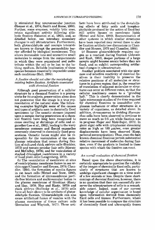
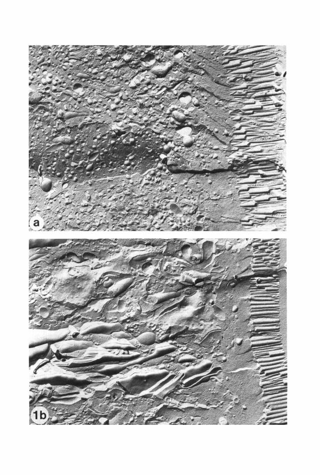
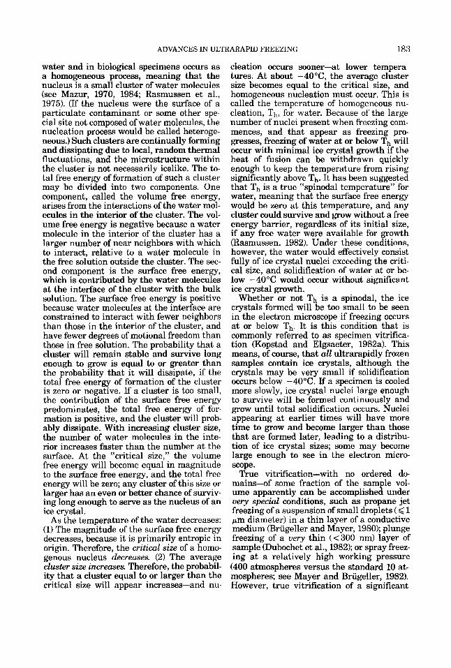
Fig. 1. (a) Rat intestinal epithelial cell infiltrated with glycerol, fixed with glutaraldehyde, and frozen by plung- ing into melting Freon. The many small spherical vesi- cles are the remnants of the endoplasmic reticulum and other internal membrane systems that disrupted during the glycerination and fixation steps (magnification, X 12,800). (b) Similar to (a), except that the cell was fixed with glutaraldehyde before glycerol infiltration. Note that the internal membrane systems are structurally distinct and well defined (magnification, x 13,500).
men. It should be noted, however, that reagents capable of enhancing cell survival at low cooling rates often do not afford such protection at the high cooling rates achieved during ultrarapid freezing, and in some cases the survivability of the treated cells is ac- tually decreased (Farrant et al., 1977). The terms cryoprotection and cryoprotectant are therefore not strictly applicable to the phe- nomenon of suppression of ice crystal forma- tion by these reagents under conditions of ultrarapid freezing. Nevertheless, because this usage of these terms is so firmly en- trenched in the literature, we will continue to use them in this way in this article.
At high cooling rates, chemical cryoprotec- tants may act (1) by increasing the number of ice crystal nuclei of critical size present at a given temperature (see next section), lead- ing to the formation of a large number of small crystals, andor (2) by decreasing the chemical potential of the water or increasing the viscosity of the medium, thus slowing the growth of ice crystals from whatever nuclei are present. The available evidence suggests that the primary mechanism is the viscosity increase (A.P. MacKenzie, personal commu- nication; also, see MacKenzie, 1977). High concentrations, typically 10-30%, of both penetrating and nonpenetrating molecules have been used as cryoprotectants. Penetrat- ing cryoprotectants, such as MeOH, EtOH, dimethyl sulfoxide, ethylene glycol, or glyc- erol, cross cellular membranes and so di- rectly prevent the formation of large intracellular ice crystals. However, glycerol, which is by far the most commonly used cry- oprotectant, can cause osmotic disruption of the plasma membrane and of intracellular membrane systems (Fig. l), even in a fixed sample (Skaer, 1981). This is especially true if infiltration is performed too quickly (Moor, 1971; Plattner et al., 1972; Niedermeyer et al., 1977; and Staehelin, unpublished re- sults). Furthermore, glycerination has been shown to give rise to artifadual formation of single-layered membrane diaphragms, once thought to be natural intermediate struc- tures in membrane fusion events. Such “dia- phragms” have been observed both at regions of contact between membranes that do fuse under physiological conditions, and between membranes that do not normally fuse (Chan- dler and Heuser, 1979). Glycerol can also give rise to Hexagonal Type I1 lipidic particles at sites of membrane fusion (Bearer et al., 1982) and to clustering of intramembrane particles
182 J.C. GILKEY AND L.A. STAEHELIN
(Gilula et al., 1975; Niedermeyer et al., 1977). All of the penetrating cryoprotectants alter membrane permeability, and so are unsuita- ble for studies designed to determine the dis- tribution of soluble ions and molecules using microanalytical and cytochemical techniques (see Skaer, 1981). Finally, most of the pene- trating cryoprotectants are toxic to cells at the concentrations required for cryoprotec- tion (Farrant et al., 1977).
One can avoid some of these problems by using cryoprotectants that do not enter the cells within the time period that the cells are typically exposed to them. The formation of extracellular ice crystals can somehow seed the growth of intracellular ice (Mazur, 1970, 1984; Rasmussen et al., 1975; MacKenzie, 1977). Nonpenetrating cryoprotectants, such as sucrose, serum albumin, dextran, polyvi- nylpyrrolidone, polyethylene glycol, and hy- droxyethyl starch, can serve to suppress the formation of extracellular ice, allowing su- percooling of the cell’s cytoplasm. However, these chemicals can also cause cell shrinkage through colligative or noncolligative osmotic pressure effects (Skaer, 1981; Niedermeyer et al., 1977). Furthermore, not all of these mol- ecules are physiologically inert; polyvinyl- pyrrolidone has been shown to be toxic to some cells (Skaer, 19811, and polyethylene glycol can cause cell-cell fusion (Lucy, 1970).
In Part 11, we will explore the nature of ultrarapid freezing in more detail.
PART I1 WHAT IS ULTRARAPID FREEZING? THE PHYSICS OF ICE CRYSTAL FORMATION IN
BIOLOGICAL SPECIMENS Ultrarapid freezing: An operational
definition The prefix “ultra” may seem to be super-
fluous, even in an era of rampant overuse of superlatives. But the term “rapid freezing” has come to refer to the relatively slow cool- ing, usually by plunging into liquid nitrogen, of large (> 1 p1) samples for purposes other than the preservation of ultrastructure. The prefix “ultra” is therefore used to emphasize the truly extreme rapidity of cooling that is necessary to preserve the fine structure of a biological specimen. Since successful ultra- rapid freezing is dependent upon many fac- tors, we believe that ultrarapid freezing is best defined in an operational sense: A given region of an unfixed, nonchemically cryopro- tected sample has been ultrarapidly frozen if heat has been withdrawn so rapidly that no
microscopic level of analysis. Among the fac- tors that determine whether or not ultra- rapid freezing is achieved are (1) the rate at which heat can be withdrawn from the re- gion of interest, which is in part dependent upon sample size and geometry and the depth, measured from the nearest cooled sur- face, of this region; (2) the initial tempera- ture of the sample; and (3) the presence of natural cryoprotectants in the sample. For example, if a sample is very small (1-2 pm) in one dimension, such as a monolayer of tissue culture cells from which most of the culture medium has been drained, simple hand dipping in liquid propane can cool the sample rapidly enough to achieve ultrarapid freezing throughout its volume (Porter and Anderson, 1982). The same is true for a some- what larger sample if it contains a high con- centration of salt or natural organic cryo- protectants in the cytoplasm. However, as soon as the smallest dimension of a planar specimen exceeds about 40 pm, even the fast- est achievable rate of extraction of heat through the specimen surface at atmospheric pressure will be inadequate to prevent the formation of visible ice crystals. Under con- ditions of high pressure, this critical thick- ness is increased to about 0.5 mm (see Part nu.
The physics of ice crystal formation in biological systems
Implicit in the operational definition of UI- trarapid freezing given above is the observa- tion that ice crystal size is the most critical parameter affecting the preservation of ul- trastructure in a frozen sample. How quickly must heat be withdrawn from a region of a biological specimen to achieve ultrarapid freezing in the absence of a cryoprotectant? What is the physical state of the water in an ultrarapidly frozen specimen? Answers to these questions may be derived from a con- sideration of theoretical analyses of ice crys- tal formation in pure water under conditions of ultrarapid cooling (Kopstad and Elgsaeter, 1982a; Rasmussen, 19821, and from observa- tions of the quality of preservation of cells cooled at known rates.
Classical nucleation theory, with some modification, can be used to describe ice crys- tal formation in water (see Angell, 1982; Franks, 1982). In brief, the growth of ice crys- tals requires the presence of a “nucleus” of critical size or larger (see below). to which
ice crystal damage is visible a t the electron monomers are adaed. Nucleation in pure
ADVANCES IN ULTRARAPID FREEZING 183
water and in biological specimens occurs as a homogeneous process, meaning that the nucleus is a small cluster of water molecules (see Mazur, 1970, 1984; Rasmussen et al., 1975). (If the nucleus were the surface of a particulate contaminant or some other spe- cial site not composed of water molecules, the nucleation process would be called heteroge- neous.) Such clusters are continually forming and dissipating due to local, random thermal fluctuations, and the microstructure within the cluster is not necessarily icelike. The to- tal free energy of formation of such a cluster may be divided into two components. One component, called the volume free energy, arises from the interactions of the water mol- ecules in the interior of the cluster. The vol- ume free energy is negative because a water molecule in the interior of the cluster has a larger number of near neighbors with which to interact, relative to a water molecule in the free solution outside the cluster. The sec- ond component is the surface free energy, which is contributed by the water molecules at the interface of the cluster with the bulk solution. The surface free energy is positive because water molecules at the interface are constrained to interact with fewer neighbors than those in the interior of the cluster, and have fewer degrees of motional freedom than those in free solution. The probability that a cluster will remain stable and survive long enough to grow is equal to or greater than the probability that it will dissipate, if the total free energy of formation of the cluster is zero or negative. If a cluster is too small, the contribution of the surface free energy predominates, the total free energy of for- mation is positive, and the cluster will prob- ably dissipate. With increasing cluster size, the number of water molecules in the inte- rior increases faster than the number at the surface. At the “critical size,” the volume free energy will become equal in magnitude to the surface free energy, and the total free energy will be zero; any cluster of this size or larger has an even or better chance of surviv- ing long enough to serve as the nucleus of an ice crystal.
As the temperature of the water decreases: (1) The magnitude of the surface free energy decreases, because it is primarily entropic in origin. Therefore, the critical size of a homo- genous nucleus decreases. (2) The average cluster size increases. Therefore, the probabil- ity that a cluster equal to or larger than the critical size will appear increases-and nu-
cleation occurs sooner-at lower tempera- tures. At about -4O”C, the average cluster size becomes equal to the critical size, and homogeneous nucleation must occur. This is called the temperature of homogeneous nu- cleation, Th, for water. Because of the large number of nuclei present when freezing com- mences, and that appear as freezing pro- gresses, freezing of water at or below Th will occur with minimal ice crystal growth if the heat of fusion can be withdrawn quickly enough to keep the temperature from rising significantly above Th. It has been suggested that Th is a true “spinodal temperature” for water, meaning that the surface free energy would be zero at this temperature, and any cluster could survive and grow without a free energy barrier, regardless of its initial size, if any free water were available for growth masmussen, 1982). Under these conditions, however, the water would effectively consist fully of ice crystal nuclei exceeding the criti- cal size, and solidification of water at or be- low -40°C would occur without significant ice crystal growth.
Whether or not Th is a spinodal, the ice crystals formed will be too small to be seen in the electron microscope if freezing occurs at or below Th. It is this condition that is commonly referred to as specimen vitrifica- tion (Kopstad and Elgsaeter, 1982a). This means, of course, that all ultrarapidly frozen samples contain ice crystals, although the crystals may be very small if solidification occurs below -40°C. If a specimen is cooled more slowly, ice crystal nuclei large enough to survive will be formed continuously and grow until total solidification occurs. Nuclei appearing at earlier times will have more time to grow and become larger than those that are formed later, leading to a distribu- tion of ice crystal sizes; some may become large enough to see in the electron micro- scope.
True vitrification-with no ordered do- mains-of some fraction of the sample vol- ume apparently can be accomplished under very special conditions, such as propane jet freezing of a suspension of small droplets ( < 1 pm diameter) in a thin layer of a conductive medium (Brugeller and Mayer, 1980); plunge freezing of a very thin (<300 nm) layer of sample (Dubochet et al., 1982); or spray freez- ing at a relatively high working pressure (400 atmospheres versus the standard 10 at- mospheres; see Mayer and Briigeller, 1982). However, true vitrification of a significant
184 J.C. GILKEY AND L.A. STAEHELIN
fraction of a specimen probably never occurs under the conditions suitable for ultrarapid freezing of biological specimens.
The preceding discussion leads to the con- clusion that, in order to achieve ultrarapid freezing in a given region of a biological sam- ple, that region must be (a) cooled so rapidly that Th is attained before nucleation occurs, and (b) maintained at or below Th while soli- dification occurs. Theoretical considerations suggest that the required cooling rate should be of the order of lo4 to 105"K per second for an uncryoprotected sample at atmospheric pressure (Moor, 1964, 1973; Riehle, 1968; Riehle and Hochli, 1973; see discussion in Franks, 1977). In fact, direct observation of the quality of preservation of specimens fro- zen by any one of several different tech- niques, under conditions for which the rates of cooling have been measured, confirms that the required cooling rate is indeed within this range (see Part 111).
The effect of specimen and cooling geometry on the quality of freezing
With present technology, heat can only be removed from a sample through its surface by contact with a cooler medium. This se- verely limits the depth to which ultrarapid freezing may be accomplished in an uncry- oprotected biological specimen, because the low thermal conductivity of the water in the specimen substantially lowers the rate of cooling in the interior. Therefore, at some depth from the surface, the rate of cooling will become too low to prevent the nucleation and growth of ice crystals. Once this occurs, the release of the heat of fusion by the grow- ing ice crystals will further slow the rate of cooling in deeper regions. In practice, ultra- rapid freezing can only be accomplished to a depth of about 10 pm from the surface of a large sample under the best conditions (see Part III). The depth of good freezing is also a function of specimen geometry, as predicted by theoretical considerations (see Moor, 1973) and common sense. For example, simultane- ous cooling of both sides of a thin planar specimen allows heat to be withdrawn from the central region quickly enough to achieve ultrarapid freezing of the entire volume of a specimen of up to about 40 pm in thickness; this is about four times the depth achievable when only one side is cooled, as predicted. If the sample is thicker than this, the center cannot be cooled rapidly enough to prevent
restricting the zone of ultrarapid freezing to the first 10 pm from each surface. Finally, if a way could be found to uniformly cool the entire surface of a spherical sample, theoret- ically, one should be able to ultrarapidly freeze the entire volume of such a sample with a diameter seven times the depth achievable with a planar sample cooled on only one side.
The e f i k t s of natural biochemical, artificial chemical, and physical cryoprotection on the
quality of freezing Obviously, when one is freezing samples a t
atmospheric pressure, ultrarapid freezing throughout the sample volume can only be accomplished with relatively small or thin samples. This is adequate for emulsions, mi- cellar suspensions, cellular suspensions or monolayers, etc. The peripheral regions of thicker samples, such as whole tissue or an excised tissue block, may also be well pre- served under such conditions. Ultrarapid freezing of deeper regions cannot be accom- plished unless the nucleation and/or growth of ice crystals in the specimen is somehow repressed. We have seen that artificial chem- ical cryoprotectants are not ideal for this pur- pose because they alter cellular ultra- structure. Another undesirable method is to increase the solute concentration by par- tially dehydrating the specimen. This ap- proach has been used by Rebhun and Sander (1971) to enhance the depth of good freezing in marine eggs. However, more often than is generally acknowledged, partial dehydration occurs inadvertently as a sample air dries while being prepared for freezing. This ex- plains why beginners often seem to be able to produce better frozen freeze-etch samples than more experienced researchers. Because dehydration will not necessarily affect the entire volume of the sample uniformly, and because of its many undesirable structural and physiological side effects, we recommend that it be avoided. However, the cells of some marine, halophilic and halotolerant organ- isms naturally contain a relatively high sol- ute concentration, and many plant cells contain natural cryoprotectants; such speci- mens can be well frozen to depths severalfold greater than the limits given above.
A very promising method for extending the depth of good freezing in most samples is the application of hydrostatic pressure, which has long been known to reduce the rate of nucleation and mowth of ice crvstals in
nucleation and growth oi' ice crystals, ihereby aqueous samples&iehle, 1968; Mior, 1973;
ADVANCES IN ULTRARAPID FREEZING 185
Riehle and Hochli, 1973). A pressure of 2045 atmospheres maximal suppression of ice crystal nucleation and growth, and low- ers the rate of cooling necessary to achieve ultrarapid freezing to about 100°K per sec- ond. In theory, this approach should allow planar samples of up to 0.5 mm thickness, and of spherical samples up to 1 mm thick, to be ultrarapidly frozen throughout the en- tire volume. A more detailed discussion of this potentially very powerful technique is presented below in Part III.
Recrystallization Once a sample has been ultrarapidly fro-
zen, “recrystallization,” or growth of larger ice crystals at the expense of smaller ones, will occur if the sample is allowed to warm above a certain temperature (MacKenzie, 1977; Mazur, 1984). Many authors have sug- gested that ultrarapidly frozen samples must be quickly brought to and kept below about -100°C to prevent changes in the physical state of the sample (see Rash, 1983). This postulate was based on the assumption that ultrarapidly frozen samples are truly vitri- fied. Indeed, vitrified pure water will devi- trify, that is, rearrange to form ice crystals, at about -130°C. Addition of solutes raises the devitrification temperature. The figure of -100°C for biological samples is an esti- mate based upon a best guess of the nature and concentration of the solutes in the cytoplasm.
However, because only an insignificant fraction of the volume of cells is likely to be vitrified by ultrarapid freezing techniques, the relevant parameter is the temperature of recrystallization, T,. T, is also affected by the nature and concentration of solutes in the specimen (MacKenzie, 1977; Franks, 1982). In general, T, is higher in the presence of higher molecular weight solutes. One could attempt to derive an expected value of T, for cytoplasm from the estimated concentrations of cytoplasmic constituents, but a more direct approach is simply to raise ultrarapidly fro- zen cells to a given temperature for a reason- able time period, and look for changes in ultrastructure. Yeast cells treated in this manner and subsequently freeze fractured show no evidence of ice crystal damage after 24 hr at -50°C (Bank, 1973). This is appar- ently just below T, for yeast, because some recrystallization was visible after only 30 min at -45°C and extensive damage had occurred after 5 min at -20°C. Light micro-
scopic observations of the change in light scattering that accompanies recrystalliza- tion in frozen, slowly warmed mouse em- bryos suggest that T, in these cells is also about -50°C mall et al., 1984). Freeze drying and freeze substitution experiments are rou- tinely carried out at dry ice temperature (-78.5”C) with no effect on ultrastructure that can be attributed to temperature per se. We and other workers have found no evi- dence of recrystallization in a wide variety of samples substituted at temperatures be- tween -95 and -50°C. The observation that ice crystal damage is found in vitrified gly- cerinated samples raised briefly to -90°C has been cited as support for the figure of -100°C cited above (Rash, 1983). However, the presence of certain artificial cryoprotec- tants can significantly lower T,, as demon- strated by the observation that T, for a suspension of red blood cells is higher than -30°C in the absence of cryoprotectant, but falls to -80°C in the presence of 30% glyc- erol (Nei, 1973)! A similar result was ob- tained in a light microscopic study of frozen frog’s bIood T, was about -10°C in un- treated blood, but fell to -60°C in the pres- ence of 10% glycerol (Rapatz and Luyet, 1960). These results suggest that recrystalli- zation of the ice in uncryoprotected, ultra- rapidly frozen samples will not be a problem in most studies involving ultrarapidly frozen material, since most techniques call for ma- nipulation of the sample at temperatures well below T,.
Recognition of Freezing Artifacts The artifact most commonly observed in
unfixed, uncryoprotected, frozen samples is the formation of ice crystals large enough to be seen in the electron microscope. Fortu- nately, this artifact is easily recognized (see Fig. 2). Mild ice crystal damage is visible in freeze fractured material as slight lumpiness or uneveness of membrane contours. Ice crys- tals may also be visualized by light etching of freeze-fractured samples. In freeze-dried or freeze-substituted material, ice damage ap- pears as small “holes” or clear spaces in the cytoplasm or in organellar matrices. The f i - brillar material outlining such clear spaces consists of proteins, salts, and other cyto- plasmic constituents that have been ex- cluded from and pushed to the periphery of the growing ice crystals. The crystals appear as clear spaces because they contain no elec- tron dense or stainable material after drying
186 J.C. GILKEY AND L.A. STAEHELIN
ADVANCES IN ULTRARAPID FREEZING 187
or substitution. Mild damage also causes col- lapse of microtubules and disruption of the microtrabecular lattice (Porter and Ander- son, 19821, and the fibrillar material some- times resembles the microtrabecular lattice in freeze-dried preparations (Miller et al., 1983; Bridgeman and Reese, 1984). In more slowly frozen regions, the ice crystals are larger. The network of fibrillar material seen in dried or substituted preparations becomes coarser as the clear regions become larger. A corresponding reticulated network of poorly etchable, excluded material surrounding etchable ice crystals becomes visible in freeze- fracture preparations. Still larger ice crys- tals crowd and distort organelles. In very poorly frozen preparations, only a small number of nucleation sites appear, usually in the extracellular matrix. These extracellular ice crystals become very large and dehydrate the cytoplasm of the cells as they grow, lead- ing to shrunken and sometimes damaged cells containing no or only a few large ice crystals.
A "prefreezing" artifact is sometimes ob- served in preparations frozen in such a way that the sample passes slowly through a re- gion of cold gas before contacting the cry- ogen. This can occur when plunge, cold metal block, or jet freezing techniques are care- lessly employed (see Part III). The prefreez- ing artifact is characterized by poor freezing in the outer few micrometers of the sample, better preservation in the next few microm- eters, and poor freezing throughout the rest
of the volume. The outer layer is poorly fro- zen during passage through the cold gas be- cause inefficient cooling by the cold gas causes slow freezing in this layer. The sam- ple then contacts the cryogen, leading to bet- ter preservation of the next few micrometers because of efficient cooling through the outer layer of the ice (the thermal conductivity of ice is higher than that of water, so heat can be extracted through this layer rapidly enough to ultrarapidly freeze the second layer). The deeper layers are poorly frozen because of inefficient conduction of heat through the water of the second layer before this layer freezes.
Ultrarapid freezing-A superior method of f i a t ion
In Part I we specified several conditions that must be met by a fixation method if it is to preserve cellular ultrastructure in its nat- ural state. We shall now use these criteria to evaluate ultrarapid freezing as a fixation method.
First, a fixative must act quickly. A simple calculation shows that, at the required cool- ing rate of 104-105"C per second, the region undergoing ultrarapid freezing is brought from room temperature to below Th within a few milliseconds. This has been confirmed by direct experimental measurements (see Heu- ser et al., 1979; Van Harreveld and Trubatch, 1979). Thus, ultrarapid freezing can stabilize biological samples at least three orders of magnitude faster than chemical fixatives.
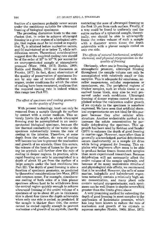
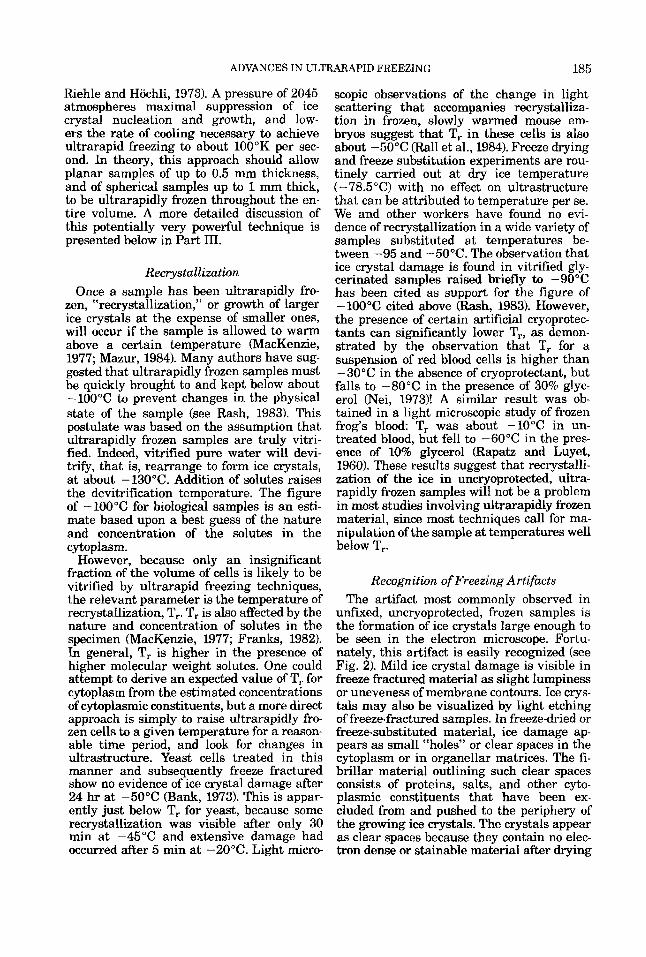
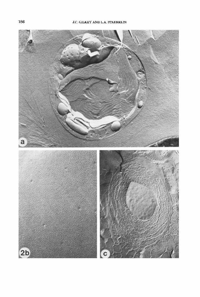
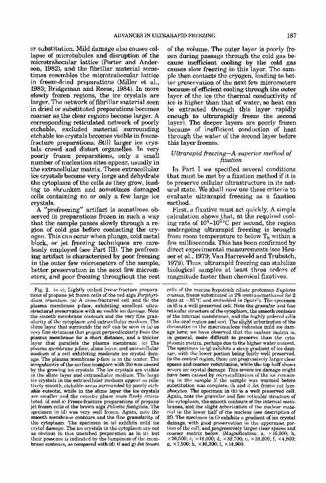
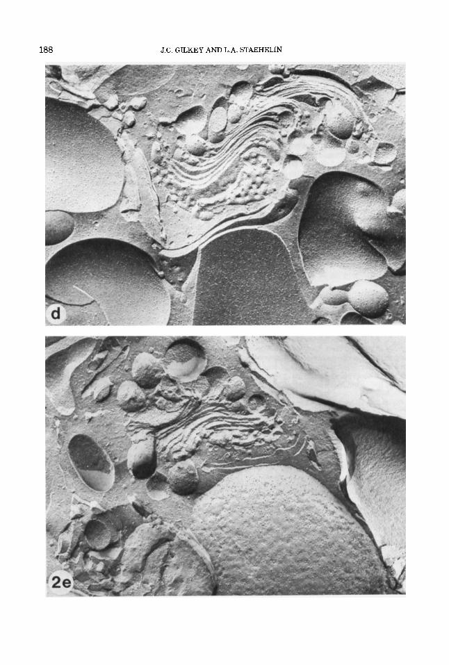
Fig. 2. (a+), Lightly etched freeze-fracture prepara- tions of propane jet frozen cells of the red alga Porphyri- dium cruenturn. (a) A cross-fractured cell and (b) the plasma membrane p-face, exhibiting excellent ultra- structural preservation with no visible ice damage. Note the smooth membrane contours and the very fine gran- ularity of the cytoplasm and extracellular medium. The slime layer that surrounds the cell can be seen in (a) as very fine striations that project perpendicularly from the plasma membrane for a short distance, and a thicker layer that parallels the plasma membrane. (c) The plasma membrane p-face, slime layer, and extracellular medium of a cell exhibiting moderate ice crystal dam- age. The plasma membrane p-face is in the center. The irregularitiy of the surface (compare with 2b) was caused by the growing ice crystals. The ice crystals are visible in the slime layer and extracellular medium. The large ice crystals in the extracellular medium appear as rela- tively smooth, etchable areas surrounded by poorly etch- able eutectic, while in the slime layer the ice crystals are smaller and the eutectic phase more finely reticu- lated. (d and e) Freeze-fracture preparations of propane jet frozen cells of the brown alga Pelvetia fastigiatu. The specimen in (d) was very well frozen. Again, note the smooth membrane contours and the fine granularity of the cytoplasm. The specimen in (e) exhibits mild ice crytal damage. The ice crystals in the cytoplasm are not as obvious in this unetched preparation as in (c), but their presence is indicated by the lumpiness of the mem- brane contours, as compared with (d). (f and g) Jet frozen
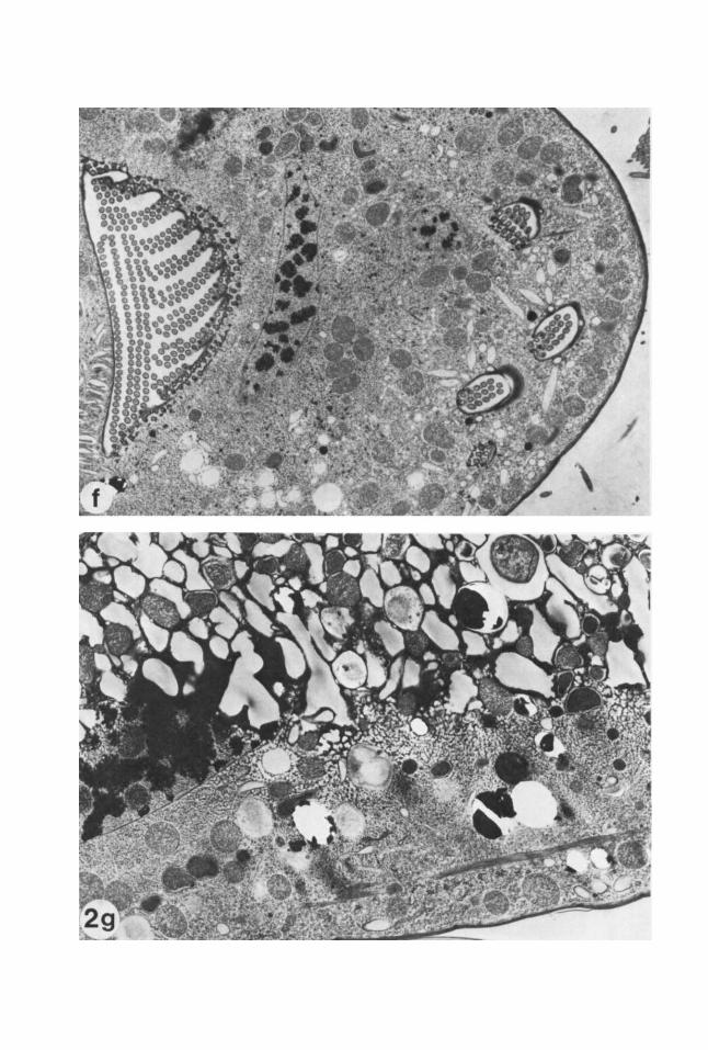
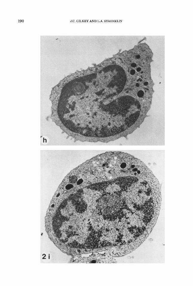
cells of the marine hypotrich ciliate protozoan Euplotes crassus, freeze substituted in 2% osmiudmethanol for 2 days at -85°C and embedded in Spurr's. The specimen in (0 is a well preserved cell. Note the granular and fine reticular structure of the cytoplasm, the smooth contours of the internal membranes, and the highly ordered cilia in the oral region and seri. The slight arborization of the chromatin in the macronucleus indicates mild ice dam- age here; we have observed that the nuclear matrix is, in general, more difficult to preserve than the cyto- plasmic matrix, perhaps due to the higher water content. The specimen in (g) exhibits a steep gradient of ice dam- age, with the lower portion being fairly well preserved. In the central region, there are progressively larger clear spaces and coarser reticulation, while the top half shows severe ice crystal damage. This severe ice damage might have been caused by recrystallization of the ice remain- ing in the sample if the sample was warmed before substitution was complete. (h and i) Jet frozen rat lym- phocytes. The specimen in (h) is a well preserved cell. Again, note the granular and fine reticular structure of the cytoplasm, the smooth contours of the internal mem- branes, and the slight arborization of the nuclear mate- rial in the lower half of the nucleus (see description of 20. The specimen in (i) exhibits a gradient of ice crystal damage, with good preservation in the uppermost por- tion of the cell, and progressively larger clear spaces and coarser matrix below. (Magnification: a, x 16,000; b, ~ 2 6 , 5 0 0 ; c, ~16,000; d, ~39,700; e, ~39,600; f, ~4,800; g, ~7,500; h, x 16,300; i, x 14,900.
188 J.C. GILKEY AND L.A. STAEHELIN
190 J.C. GILKEY AND L.A. STAEHELIN
ADVANCES IN ULTRARAPID FREEZING 191
Second, a fixative should immobilize every atom and molecule in the sample. Ultrarapid freezing will accomplish this. Further, be- cause this immobilization occurs so quickly, the spatial relationships among molecules and structures will be preserved very well indeed.
Finally, a fixation method should not intro- duce artifactual changes in ultrastructure. Possible artifacts associated with ultrarapid freezing are (a) dehydration of the sample during preparation for freezing, (b) the for- mation of visible ice crystals and accompa- nying distortions of ultrastructure (by definition, however, ultrarapidly frozen re- gions contain no visible ice crystals), and (c) recrystallization of the ice in the frozen sam- ple. Artifacts (a) and (c) can be readily avoided, while cb) is easily recognized.
The conclusion to be drawn from this anal- ysis is obvious: Ultrarapid freezing is supe- rior to chemical fixation in its ability to preserve the native ultrastructure of biologi- cal systems.
PART 111: THE METHODOLOGY OF ULTRARAPID FREEZING
All ultrarapid freezing techniques are based upon one of two simple modes of cool- ing the sample. One mode involves bringing the sample rapidly into contact with a pol- ished metal surface held at liquid nitrogen or liquid helium temperature. The technique that uses this mode is called cold metal block freezing, or, in popular parlance, “slam freez- ing.” This technique provides a large ther- mal gradient between the sample and the cold surface; the gradient is maintained by the high thermal conductivity and large heat capacity of the metal.
The other, more common mode achieves a high rate of heat transfer by rapidly moving a cold liquid cryogen over the sample surface. This may be accomplished either by forcing the sample to move quickly through the cry- ogen, or by spraying the cryogen onto the sample at high velocity. The boiling point of the most commonly used cryogenic liquids is well below the freezing point of water, and so well below the temperature of the sample. When the sample makes contact with the cryogen, radiative transfer of heat can cause the cryogen to vaporize at the interface. Be- cause the heat capacity and thermal conduc- tivity of gases are much lower than those of liquids at atmospheric pressure, the micro- scopic vapor barrier so created between the
sample and the cryogen will substantially slow the rate of transfer of heat from the sample. This problem can be reduced by rapid relative movement of the sample with re- spect to the cryogen, which will sweep away the vapor barrier and continuously replace liquid that has been warmed by the sample with cold liquid. This keeps the rate of trans- fer of heat high enough to accomplish ultra- rapid freezing.
Clearly, the three properties to be sought in a liquid cryogen are (1) a very low freezing point, so that the thermal gradient between the sample and the liquid can be made large, (2) a relatively high boiling point, to mini- mize vapor barrier formation, and (3) a large heat capacity and high thermal conductivity, again to lessen the probability of vaporiza- tion and to help maintain the thermal gra- dient. For example, liquefied gases of low molecular weight, such as liquid nitrogen or liquid helium, perform very poorly as cry- ogens for ultrarapid freezing at atmospheric pressure because they are at or very near their boiling point before the sample enters. Consequently, it is virtually impossible to prevent the formation of a vapor barrier, and the rate of cooling is too low to accomplish ultrarapid freezing. We should note here that the lack of visible or audible signs of boiling when the sample is inserted does not rule out the possibility that a microscopic vapor bar- rier has been formed. At the other extreme, propane boils at -4O”C, yet can be super- cooled to liquid nitrogen temperature. Fur- thermore, its “useful heat sink capacity” is higher than that of all other commonly used liquid cryogens (see Table I in Plattner and Bachmann, 1982). Accordingly, it is an excel- lent cryogen for ultrarapid freezing, al- though great care must be exercised in its use due to its flammable nature. In particu- lar, when working with propane near liquid nitrogen temperature, the user must be care- ful not to allow atmospheric oxygen @.p. -183°C) to condense in the vessel holding the propane; liquid oxygen in contact with or mixed with liquid propane constitutes a bomb. As discussed in Part 11, one can sup- press the nucleation and growth of ice crys- tals in relatively large samples by pressurizing the sample before applying a cryogen. Under such conditions liquid nitro- gen can be used as the cryogen, because the pressure achieved during freezing is above the critical pressure of nitrogen, so no vapor- ization can occur.
192 J.C. GILKEY AND L.A. STAEHELIN
a
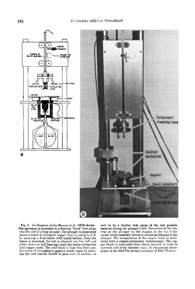
Fig. 3. (a) Diagram of the Heuser et al. (1979) device. The specimen is mounted on a freezing “head’ that plugs into the end of a long plunger. The plunger is suspended above a block of ultrapure copper that is cooled to 4°K by spraying it from below with liquid helium. Once the tissue is mounted, the rod is released into free fall and glides down on ball bearings until the tissue strikes the cold copper block. The cold block is kept free from con- densation of atmospheric gases or water vapor by allow- ing the cold helium boiloff to pass over its surface, as
well as by a shutter that opens at the last possible moment during the plunger’s fall. Attraction of the iron ring on the plunger by the magnet at the lip of the copper block assembly serves to minimize rebound of the plunger. The temperature of the copper block is moni- tored with a copper-constantan thermocouple. The cop- per block is removable from above, because it must be warmed and dried between runs. (b) Annotated photo- graph of the Med-Vac freezer (courtesy of John Heuser).
ADVANCES IN ULTRARAPID FREEZING 193
A
DAMPER DAMPER
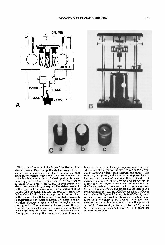
Fig. 4. (A) Diagram of the Boyne “Gentleman Jim” device (Boyne, 1979). Atop the striker assembly is a damper assembly, consisting of a horizontal bar that rides on two vertical slides and a vertical plunger. This assembly is supported in its “raised” position by a col- umn of glycerol in the striker assembly. The specimen is mounted on a “probe” (see C) that is then attached to the striker assembly by a magnet. The striker assembly is then released and accelerates from a height of about 11 cm. The specimen contacts the cooling surface just before the solid shoulders of the probe hit the periphery of the cooling block. Rebounding of the striker assembly is suppressed by the damper system. The damper and its attached plunger do not stop when the probe contacts the copper bar. Their momentum forces glycerol through two narrow throats, thereby transferring sufficient downward pressure to the striker to prevent rebound. After passage through the throats, the glycerol accumu-
lates in two air chambers by compressing air bubbles. At the end of the plunger stroke, the air bubbles reex- pand, passing glycerol back through the throats and resetting the system, while continuing to press the stri- ker down. At the end of this cycle, there is insufficient energy remaining to lift both striker and damper off the copper bar. The striker is lifted and the probe, bearing the frozen specimen, is removed and the specimen trans- ferred to liquid nitrogen. The copper bar is replaced in a preparation for the next run. (B) Photograph of the Boyne device (from Philips and Boyne, 1984). (C) Two types of probes permit three configurations for handling speci- mens. (a) Filter paper glued to foam is used for freeze substitution. (b) A circular piece of foam with a planchet is used for freeze etching or freeze fracture. (c) A pin that fits the chuck is mounted directly in a probe for ultracryomicrotomy.
194 J.C. GILKEY AND L.A. STAEHELIN
In the remainder of this paper, we will dis- cuss the five most commonly used ultrarapid freezing techniques in greater detail. The discussion will include a brief historical ac- count, a general protocol, a listing of specific artifacts, and a comparative evaluation of each method in terms of advantages, limita- tions, reliability, yield, and ease of application.
Cold metal block freezing This technique is popularly known as
“slam freezing,” because in the most com- mon mode of application the sample is rap- idly brought into contact with a cold metal surface. The ultrarapid freezing of samples against a cold metal surface was first at- tempted in the early forties (Simpson, 1941), but two decades passed before serious devel- opment of the technique and its application to a biological specimen for electron micro- scopic analysis was accomplished (Van Har- reveld and Crowell, 1964; Van Harreveld et al., 1965). Since then, the ease of application and the reliability of the technique have been greatly improved (Heuser et al., 1976, 1979; Boyne, 1979; Escaig, 1982; Philips and Boyne, 1984; Heath, 1984). Schematic diagrams and photographs of the Heuser and Boyne de- vices are shown in Figures 3 and 4, respectively.
The general operating procedure is as fol- lows: The freezing surface is a polished cop- per (or silver) block that has been cooled to liquid nitrogen or liquid helium tempera- ture, and that is enclosed in an insulating container. At liquid helium temperature, the sample can be cooled more rapidly because (a) the initial temperature gradient is larger and (b) the temperature rise in the copper in the region of contact is decreased, copper being a superconductor a t this temperature (although silver might be superior; see Bald, 1983). Under ideal conditions the increase in cooling rate achieved by the use of copper near liquid helium temperature, rather than at liquid nitrogen temperature, should be no more than 30-40% (Kopstad and Elgsaeter, 198213). The measured increase in cooling rate under working conditions is about 50% (Heu- ser et al., 19791, which should correspond to a decrease in ice crystal size of about the same magnitude (Kopstad and Elgsaeter, 1982a). However, this degree of improvement might not offset the cost and difficulty of working with liquid helium. The metal sur- face is protected from condensation of frost and atmospheric oxygen by passing a stream
of cryogen boil-off gas over the surface. The sample is mounted on a specimen carrier, which can be a piece of buffer soaked (to prevent dehydration of the sample) filter pa- per for freeze substitution samples, or a flat metal planchette designed to fit on a modi- fied stage of a freeze etch device. The carrier is then mounted on the sample holder assem- bly of the freezing device, backed by a cush- ion of fixed liver or lung tissue, or a piece of rubber or plastic foam. The cushion prevents the sample from being crushed when it is forced against the metal block. The sample holder assembly is then allowed to free fall along its guidance system toward the pol- ished metal block. Prefreezing artifact is avoided by minimizing the thickness of the layer of cold gas above the metal surface and by the fast movement of the sample through this layer. Once the sample has contacted the cold copper block, a magnetic clamping sys- tem or an inertial device is used to apply downward pressure to prevent the rebound of the sample from the copper surface. Re- bounding can both slow freezing and, if mul- tiple rebounds occur, cause severe damage to lateral movement of the sample on the cop- per surface, to reduce shearing damage to the sample. Once frozen, the sample is re- moved for storage or further processing. The copper block is cleaned or changed and al- lowed to come to temperature before the next sample is frozen.
The cold metal block freezing technique was first developed to freeze tissues, and in- deed it is very well suited for this purpose (Heuser et al., 1979; Hirokawa and Kirino, 1980; Ichikawa et al., 1980; Ornberg and Reese, 1980; Hirokawa and Heuser, 1981; Terracio et al., 1981; Hirokawa, 1982; Schnapp and Reese, 1982; McGuire and Twietmeyer, 1983; Philips and Boyne, 1984; Menco, 1984). However, it has also been used to freeze cellular suspensions (Chandler and Heuser, 1979,1980; Ornberg and Reese, 1981; Chandler, 1984; Wagner and Andrews, 1985), and in principle, it should be applicable to any sample type that can be ultrarapidly frozen by other means. This is also the only technique that is well suited for studies re- quiring the precise timing of stirnulatable physiological events in the millisecond range (see Heuser et al., 1979). The method pro- vides cooling rates in the zone of good freez- ing of -25,000 to -50,00O0C/sec (Plattner and Bachmann, 1982; derived from data in Heuser et al., 19791, but as in any method that cools a sample from only one side, good
ADVANCES IN ULTRARAPID FREEZING 195
freezing can in general only be achieved to a depth of 10-15 pm from the sample surface. This is adequate for many purposes.
Damage to the sample due to crushing, shearing, and bounce, sometimes observed in the early stage of development of the tech- nique, probably contributed to the popular appellation of the terms “slam freezing” to the method and “slammer” to the device it- self. These terms, with their negative conno- tations, continue to be used to refer to the technique, even though the sophisticated shock absorbing and guidance systems incor- porated into modern instruments have largely eliminated the sources of such dam- age. This type of damage also has led Pinto da Silva and Kachar (1980) to suggest that the compression of the sample upon impact with the metal surface may be sufficient to lead to certain rather subtle artifacts. It would seem, however, that the energy im- parted to the sample is insufficient to cause such artifacts (see Rash, 1983).
Over the years, a number of simple vari- ants of the method have been described in the literature, including mounting the sam- ple on the end of a rod and ramming it by hand onto the cold metal surface (Christen- sen, 1971; Dempsey and Bullivant, 19761, clamping the sample between the jaws of modified pliers precooled to liquid nitrogen temperature (Eranko, 1954, Wollenberger et al., 19601, and crushing the sample between two precooled silver hammers (Sjostrom et al., 1974). Although all of these methods have yielded usable results and are less costly and demanding than the devices described above, the very fact that their usage has not become widespread suggests that good results cannot be as reproducibly achieved as with the more sophisticated instruments. Indeed, as with all ultrarapid freezing devices discussed in this article, the basic design of the Heuser et al. (1979) and Boyne (1979) freezers is rather straightforward, but the differences in qual- ity and reproducibility of freezing relate to subtle design parameters that are easily overlooked. Commercial models are avail- able from Med-vac, Inc., St. Louis, MO, and Polaron Corp. (based upon the design of Heu- ser et al., 1979); Ted Pella, Inc., Tustin, CA (based upon the design of Boyne, 1979); and RMC, Inc., Tucson, AZ. The initial purchase price of these devices is very reasonable, but, with the exception of the RMC device, the operational costs can be substantial if liquid helium is used as coolant.
We consider cold metal block freezing to be
second only to propane jet freezing as a gen- eral method of accomplishing ultrarapid freezing.
Plunge freezing Plunge freezing, or quench freezing, was
being used to prepare samples for electron microscopic analysis by the early 1950’s (Glick and Malmstrom, 1952). It is the sim- plest, least expensive, and most widely used of all the techniques of ultrarapid freezing. Plunge freezing is accomplished by literally plunging a bulk sample into a liquid cry- ogen. The protocols used for plunging range from simply dipping the specimen by hand (Rebhun, 1961; Moor and Muhlethaler, 1963; Bank, 1973; Bank and Mazur, 1973; Howard and Aist, 1979, 1980; Allen, 1980; Hoch and Howard, 1980; Gupta and Hall, 1981; How- ard, 1981; Rick et al., 1981; Steinbrecht, 1980, 1982; Porter and Anderson, 1982; Silvester et al., 1982; Severs and Green, 1983) to more elaborate ones in which the rate of travel of the sample through the liquid is increased by mounting it on a gravity-driven or a spring- or rubber band-loaded plunger (Reb- hun, 1972; Glover and Garvitch, 1974; Bald and Robards, 1978; Costello and Corless, 1978; Schwabe and Terracio, 1980; Handley et al., 1981, McDowall et al., 1983; Bridg- man and Reese, 1984; Haug and Altner, 1984; Marchese-Ragona, 1984; Steinbrecht and Zierold, 1984; Lee et al., 1985). In one case, a 30-06 caliber cartridge was used to propel a cannula through the sample into the cryogen at 400 d s e c (Monroe et al., 1968). Unfortu- nately, even under the best conditions, the rates of cooling achievable by this method are the slowest of all the current techniques, except for very thin samples (see Table I11 of Plattner and Bachman, 1982, for a compre- hensive compilation of the rates of cooling achieved by plunging into various cryogens and by other ultrarapid freezing techniques). Most plunge freezing studies have been per- formed with samples that were larger in their smallest dimension than the largest sam- ple-a few micrometers thick-that one could reasonably hope to freeze ultrarapidly throughout its volume by this technique. Furthermore, with few exceptions, sample geometry has been suboptimal for heat ex- change, and specimen carriers have often been so massive as to slow the cooling of the sample significantly. Correspondingly, most of the measurements of cooling rates achieved during plunge freezing have been
196 J.C. GILKEY AND L.A. STAEHELIN
to pump spray
U /I \ / I \
I I \
a b C d e
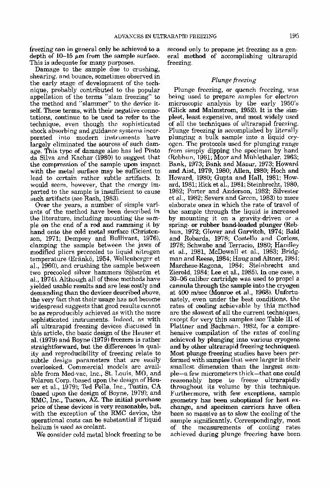
Fig. 5. Protocol of spray freezing. (a) The sample is sprayed through a commercial airbrush into about 0.7 ml liquid propane at about -190°C. The vessel is then transferred to a temperature-controlled block kept at -85"C, in a glovebox, and the propane is evaporated under reduced pressure, leaving behind the frozen drop- lets of sample as a fine powder. (c) The sample powder is
made with samples and even thermocouples too large to allow a fair evaluation of the technique. Thus, the measured rates of cool- ing-generally 1-2 x 10³"K per second-are slower than that required to ultrarapidly freeze the entire sample. However, in those studies in which thermocouple size, specimen carrier design and sample geometry have been optimized (Escaig et al., 1977, Costello and Corless, 1978; Costello, 1980; Costello et al., 1982), rates of cooling on the order of 1-2 x 10⁴"K per second have been recorded.
These studies have led to the formulation of the following guidelines for optimizing the rate of cooling of plunge frozen samples: In general, the sample should have a maximal surface to volume ratio. Some samples, such as moth antennae (Steinbrecht, 1982) or a monolayer of cells growing on a thin sub- strate of low heat capacity (Howard and Aist, 1979; Heath and Rethoret, 1982; Porter and Anderson, 1982), already meet this criterion. For other sample types, such as thin slices of tissue or cellular suspensions, this condition is most easily achieved by sandwiching the sample as a very thin layer (less than 20 pm) between two thin (50 pm or less) metal spec-
mixed with a drop of cold (-85°C) butylbenzene. Small aliquots of this mixture are transferred with a cold plat- inum wire onto precooled conventional specimen holders (d), which are then dropped into liquid nitrogen to solid- ify the butylbenzene (e). From Bachmann and Schmitt- Fumian (197313).
imen carriers. The sandwich or other sample type should be oriented so that its smallest cross sectional area and most streamlined profile is presented to the liquid during plunging. This promotes a maximal rate of fluid exchange over the larger surfaces of the sample and thus optimizes the rate of cool- ing. The faster the sample is moved through the liquid, the higher the rate of cooling.
The ultimate criterion to use when evalu- ating the efficacy of an ultrarapid freezing regimen is the quality of preservation of the sample. On this basis, in keeping with the observation that the rate of cooling achieved by plunge freezing is relatively slow, only samples of a few micrometers thickness, such as a monolayer of tissue culture cells (1-2 pm; Porter and Anderson, 1982; Bridgman and Reese, 1984) or fungal hyphae (,<3 pm; Howard and Aist, 1979,1980; Howard, 1981) can be ultrarapidly frozen throughout the sample volume by this method. For thicker samples, the depth of good freezing will be confined to an even thinner superficial layer (Feder and Sidman, 1958; Schwabe and Ter- racio, 1980), except in very favorable cases in which the cells probably contain a natural
ADVANCES IN ULTRARAPID FREEZING
cryoprotectant (Steinbrecht, 1980, 1982). A notable exception is the truly astounding (and questionable?) report of Handley et al. (1981) that a suspension of red blood cells sandwiched between two sheets of 4-pm thick titanium foil could be well frozen to a depth of 25-30 pm from each surface. Despite its obvious limitations, the relative simplicity and low cost of the plunge freezing method justify trying it before moving on to more costly or demanding methods.
Spray freezing The technique of spray freezing was intro-
duced by Williams in 1954, and refined by Bachmann and co-workers in the early 1970's (Bachmann and Schmidt, 1971a,b; Bach- mann et al., 1972; Plattner et al., 1972,1973; Bachmann and Schmitt-Fumian, 1973a,b). Ultrarapid cooling is achieved in the refined technique by dividing an aqueous suspension of the sample into fine droplets (ca. 10-30 pm in diameter), and propelling these droplets at high velocity into liquid propane near its freezing point (Fig. 5). This is accomplished by spraying the suspension into the propane with commercial airbrush. The high surface to volume ratio of the small droplets and the speed with which they move through the pro- pane serve to maximize the rate of heat transfer. The finely divided frozen sample is recovered by transferring the vessel contain- ing the propane and sample to a controlled temperature block at -85°C and evapora- ting the propane under vacuum, leaving a fine "powder" of frozen sample droplets on the bottom and sides of the vessel. Butylben- zene, precooled to -85°C' is then added to the powderlike sample to make a paste; bu- tylbenzene is used because it has a low freez- ing point ( - 95 "C) but does not begin to freeze substitute the frozen sample during the short time it is allowed to remain liquid. This paste is transferred to precooled specimen carriers and the butylbenzene is frozen by dipping the carriers into liquid nitrogen. The sam- ples may then be freeze fractured. Alterna- tively, the powder can be processed directly by freeze substitution. Bachmann and Schmitt tried two simple variations of the refined technique (Bachmann and Schmitt, 1971a). In one, the sample was sprayed onto a metal block held at liquid nitrogen temper- ature to form a thin layer (as in Williams' original method), which was subsequently scraped off under liquid nitrogen and pro- cessed as above. In the other, the sample was
197 - Propane
LN2 in
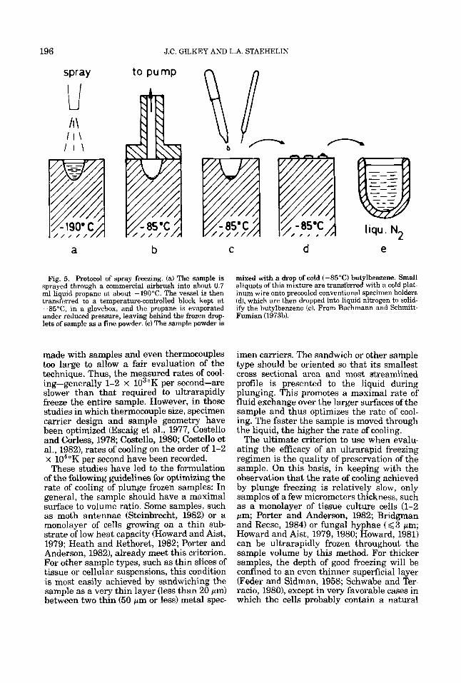
Fig. 6. Diagram of our propane jet-freezing device (based upon the design of Miiller et al., 1979). A liquid nitrogen level controller (LC; Balzers model BPV 14500) sets the level 6, liquid nitrogen level sensor) of liquid nitrogen (LN2) in a dewar, partially immersing a hollow metal cylinder (C). When the cylinder has cooled to near liquid nitrogen temperature, gaseous propane is admit- ted to the cylinder through a one-way check valve (PV) slowly enough that is can condense and fill the cylinder. While the propane (P) is cooling to near liquid nitrogen temperature, the specimen is prepared. When the speci- men is ready, it is positioned between the jets and the gaseous nitrogen solenoid valve (NV) is opened (this is a three-way valve that connects the cylinder to the atmos- phere when not actuated, so that the cylinder can be filled with propane). This presurizes the cylinder to about 150 psi, forcing the propane out the jets (4 and onto the sample. About 40 mi of liquid propane are forced through the jets (J, in about 0.5 sec, at a jet velocity of about 100 dsec . The operator then has about 10 sec to transfer the frozen sample to liquid nitrogen.
sprayed onto liquid nitrogen cooled specimen carriers, a little at a time to allow cooling of each layer, until a small mound was formed. Such samples can be used directly for freeze fracture or other processing techniques. The authors note that both of these procedures are more difficult than the one using liquid propane.
A great advantage of the spray freezing technique is that it can apparently provide rates of cooling that are higher than those attainable with any other technique (2 100,000"C/sec; Mayer and Bruggeler, 1982). This is reflected in the very smooth appearance of freeze etched aqueous media and in the excellent ultrastructural preser- vation that can be achieved with the method.
198 J.C. GILKEY AND L.A. STAEHELIN
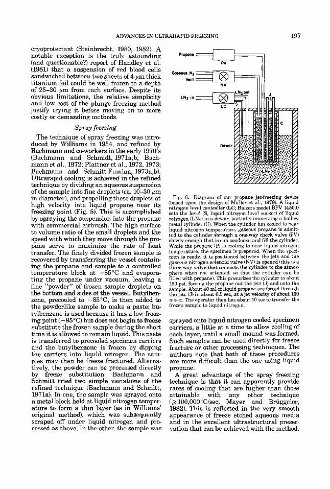
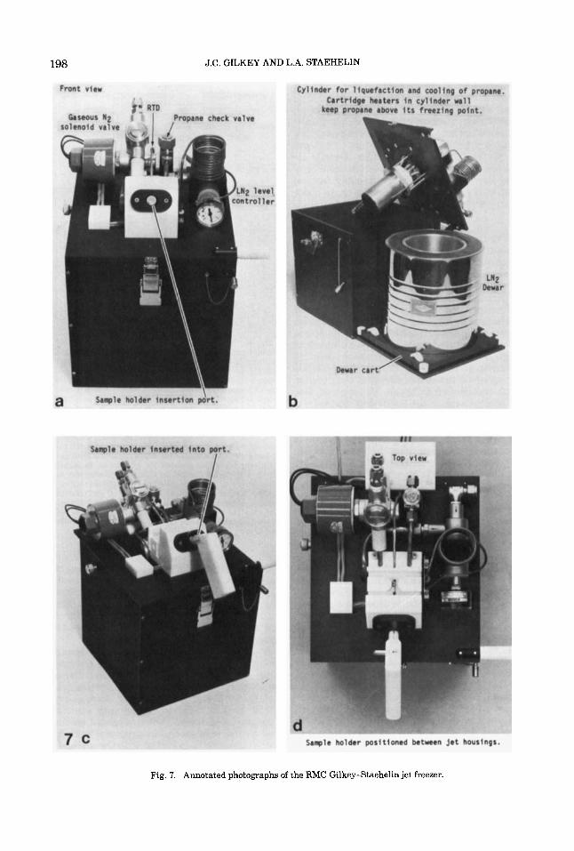
Fig. 7. Annotated photographs of the RMC Gilkey-Staehelin jet freezer.
ADVANCES IN ULTRARAPID FREEZING 199
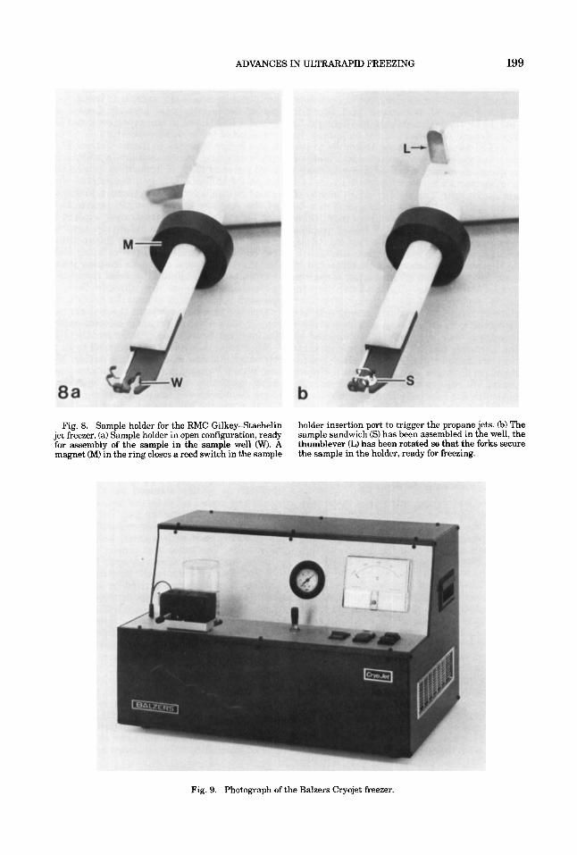
Fig. 8. Sample holder for the RMC Gilkey-Staehelin jet freezer. (a) Sample holder in open configuration, ready for assembly of the sample in the sample well (W). A magnet (M) in the ring closes a reed switch in the sample
holder insertion port to trigger the propane jets. 6) The sample sandwich (S) has been assembled in the well, the thumblever (L) has been rotated so that the forks secure the sample in the holder, ready for freezing.
Fig. 9. Photograph of the Balzers Cryojet freezer.
200 J.C. GILKEY AND L.A. STAEHELIN
Unfortunately, our experience with a com- mercial spray freezing device built according to the design of Bachmann and Schmidt (1971a) by the Balzers Corp. has brought to light several drawbacks of the technique. In practical terms, the method is limited to use with homogeneous solutions, emulsions, or suspensions of very small cells (e.g. bacteria) or other particulates not larger than about 1 pm in diameter. The yield of useful images of larger cells (5-10 pm in diameter) can be frustratingly small in any given replica due to (a) the limited number of frozen droplets encountered in a given fracture plane through the frozen butylbenzene suspension, (b) the limited number of cells contained in each frozen droplet, (c) fracturing along the droplet surface, and (d) microtome knife-in- duced smearing of the butylbenzene over fracture faces. Furthermore, unless cells are protected by a strong wall or an equivalent structure, they are frequently damaged by the shearing forces imposed upon them as they are forced through the airbrush (which seems to function like a miniature French press). We believe that these problems, cou- pled with the relatively high cost of the com- merical apparatus and the fairly tedious nature of the method, make spray freezing suitable only for specialized applications. However, when everything works, very beau- tifully preserved cells can be observed.
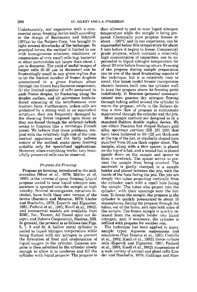
Propane Jet Freezing Propane jet freezing, introduced in the mid-
seventies (Moor et al., 1976; Muller et al, 19801, is the inverse of spray freezing: Liquid propane cooled to near liquid nitrogen tem- perature is sprayed onto the sample at high velocity. Several investigators, ourselves in- cluded, have built their own version of the device (Burstein and Maurice, 1979; Linder and Staehelin, 1978; Espevik and Elgsaeter, 1981; Pscheid et al., 1981; Knoll et al., 19821, and commercial models are available from RMC, Inc., Tucson, AZ (based upon our de- sign), and Balzers Corporation, Nashua, NH. In general, the protocol is as follows (see Figs. 6, 7, 8 and 9): A hollow metal cylinder is cooled to liquid nitrogen temperature while being flushed with dry nitrogen to prevent the formation of frost and condensation of liquid oxygen in the cylinder. Gaseous pro- pane is then admitted to the cylinder slowly enough to allow it to condense and fill the cylinder with liquid propane. The propane is
then allowed to cool to near liquid nitrogen temperature while the sample is being pre- pared. Chemically pure propane freezes at about - 190°C and in our experience, can be supercooled below this temperature for about 5 min before it begins to freeze. Commercial grade propane, which contains a relatively high concentration of impurities, can be su- percooled to liquid nitrogen temperature for about 20 min before freezing occurs. Freezing of the propane during sample preparation can be one of the most frustrating aspects of the technique, but it is relatively easy to avoid. Our latest model freezer incorporates electric heaters built into the cylinder wall to keep the propane above its freezing point indefinitely. D. Branton (personal communi- cation) uses gaseous dry nitrogen flowing through tubing coiled around the cylinder to warm the propane, while in the Balzers de- vice a slow flow of propane is continously maintained through the cylinder and the jets.
Most sample carriers are designed to fit a standard Balzers double replica device. We use either Panama hat shaped Balzers gold alloy speciman carriers (BB 187 280) that have been hollowed to 50-125 pm thickness at the top of the hat, or similarly shaped hats punched from 50-pm thick copper sheet. The sample, along with a thin spacer, is placed on the top of a hat, and a second hat is placed upside down on the sample and spacer to form a sandwich. The spacer serves to pre- vent the sample from being crushed. The sandwich is gently clamped in a sample holder and placed between the jets, with the inside of the hats facing the jets. The jets are simply two tubes projecting vertically from the cylinder, each with a small hole facing the sample. The tubes also project into the cylinder, with their openings near the bot- tom. To freeze the sample, the propane in the cylinder is quickly pressurized to about 10 atmospheres, forcing the propane through the tubes, out of the holes, and onto both sides of the sample. The frozen sample is quickly re- leased from the sample holder into liquid nitrogen, and, if necessary, the cylinder is refilled with propane for another run.
The technique has been applied to many sample types: Aqueous suspensions and emulsions (Van Venetie et al., 1981; Costello et al., 1982; Knoll et al., 1982); tissue culture cells (Espevik and Elgsaeter, 1981; Pscheid et al., 1981; Knoll et al., 1982); suspensions of a wide variety of animal and plant cells &in- der and Staehelin, 1978; Giddings and Stae-
ADVANCES IN ULTRARAPID FREEZING 201
helin, 1980; Gilkey and Staehelin, 1980, and unpublished results; Ebersold et al., 1981; Knoll et al., 1982; Schmidt et al., 1983); and tissues (Cantino and Pollack, 1983, 1984; Swales and Lane, 1983; Hays et al., 1985; Arnn and Staehelin, unpublished results). We have found that a sandwich preparation is the best format for most sample types, be- cause it eliminates the possibility that the sample will be damaged or blown away by the force of the propane jet. The type of spacer to be used will depend upon the nature of the specimen. In general, the spacer should be kept as thin as possible to ensure good freez- ing. If the sample consists of rigid cells no larger than 12-15 pm in diameter, or some- what larger cells that can be slightly com- pressed without damage, then 300 mesh electron microscope grids of gold (about 12 pm thick) or copper (about 15 pm thick) can be used as spacers; a hole punched in the center of the grid will decrease the probabil- ity that cells will be crushed between a grid bar and a hat. Larger cells can be protected by gold (about 35 pm thick) or copper (about 70 pm thick) slot grids. If the sample is large and sturdy enough that it can be supported at its periphery, such as a piece of tissue, a regenerating Acetabularia stalk, or a muscle fiber, a hole can be made in one or both of the hats to allow the propane to contact the specimen directly. Handling samples in this manner can be quite tedious, however. Fur- thermore, theoretical considerations (Kop- stad and Elgsaeter, 1982b) and practical experience gained in our laboratory (Arnn, Koop, Gilkey and Staehelin, unpublished re- sults) indicate that little is gained by this modification.
"Open-faced" specimens for knife cutting or freeze substitution may be prepared in the following manner: The spacer can be glued to one hat with a small quantity of 0.5% formvar in ethylene dichloride or a dilute solution of rubber cement in xylene. The sample-facing surface of this hat-spacer com- bination is then coated with a very thin layer of 0.1% lecithin in chloroform and the solvent allowed to evaporate, leaving behind a very thin layer of lecithin. This treated hat is then used with an unmodified one to produce a jet- frozen sandwich of the specimen. When the hats are separated under liquid nitrogen, the fracture plane will pass through the lecithin, leaving the sample projecting from the sur- face of the untreated hat to a height equiva- lent to the thickness of the spacer.
The measured rates of cooling achieved with the technique are quite high, in the vicinity of -30,000"C/sec (Costello et al., 19821, because the high velocity propane jet (approximately 100 d s e c with our device) provides more efficient heat exchange than can be achieved by plunging. This is fast enough to capture labile structures formed in certain types of membrane-membrane in- teractions (Linder and Staehelin, 1978; Gilkey and Staehelin, 1980 and unpublished results; Dewit and Staehelin, unpublished results) that are not seen in chemically fixed material, and to prevent the liquid crystal- line to ordered gel transition of dilaurylleci- thin bilayers, which has been shown to be a rather sensitive indicator of relative cooling rate (Costello et al., 1982). Furthermore, be- cause heat is withdrawn from both sides of the specimen at once, one can achieve ultra- rapid freezing in a sample four times as thick as would be possible if only one side were cooled, as in cold metal block freezing (Riehle, 1968). In our experience, this corresponds to a specimen thickness of about 40 pm for the average cell; more if the cells contain natural cryoprotectants; and less if the cells are dif- ficult to freeze well. If the sample is too thick, heat cannot be withdrawn from its interior rapidly enough to prevent ice crystal growth and the concomitant production of heat of fusion, so only the outer 10 pm or so of each side will be ultrarapidly frozen. Good freez- ing is also limited to about 10 pm in samples frozen with a propane jet applied from only one side (Burstein and Maurice, 1978; Espe- vik and Elgsaeter, 1981; Pscheid, et al., 1981; Knoll et al., 1982).
The problems we have encountered with the technique are: (a) Freezing is not always uniform throughout the sample (a common problem with all ultrarapid freezing tech- niques). (b) When jet-frozen samples are freeze-fractured and the fracture plane passes close to the metal carrier, the replica often tends to adhere tightly to surface of the car- rier upon thawing of the sample. Copper sup- ports are more troublesome in this respect than gold. We have found that the replica can be freed from the copper support in rela- tively large pieces by immersing the support in 25% fuming nitric acid (the reaction is too vigorous at higher concentrations, and too slow at lower concentrations, so the replica is shredded under these conditions). If the support is coated with a thin (less than 1 pm) layer of formvar prior to use, the replica can
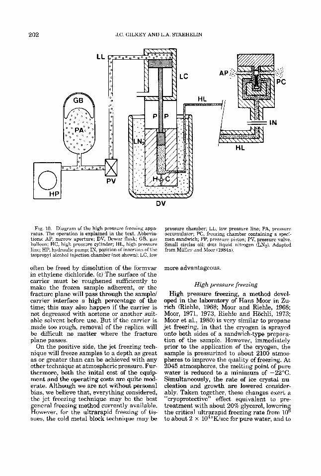
202 J.C. GILKEY AND L.A. STAEHELIN
DV
Fig. 10. Diagram of the high pressure freezing appa- ratus. The operation is explained in the text. Abbevia- tions: AP, narrow aperture; DV, Dewar flask; GB, gas balloon; HC, high pressure cylinder; HL, high pressure line; HP, hydraulic pump; IN, position of insertion of the isopropyl alcohol injection chamber (not shown); LC, low
pressure chamber; LL, low pressure line; PA, pressure accumulator; PC, freezing chamber containing a speci- men sandwich; PP, pressure piston; PV, pressure valve. Small circles oil; dots liquid nitrogen (LN2). Adapted from Miiller and Moor (1984a).
often be freed by dissolution of the formvar in ethylene dichloride. (c) The surface of the carrier must be roughened sufficiently to make the frozen sample adherent, or the fracture plane will pass through the sample/ carrier interface a high percentage of the time; this may also happen if the carrier is not degreased with acetone or another suit- able solvent before use. But if the carrier is made too rough, removal of the replica will be difficult no matter where the fracture plane passes.
On the positive side, the jet freezing tech- nique will freeze samples to a depth as great as or greater than can be achieved with any other technique at atmospheric pressure. Fur- thermore, both the inital cost of the equip- ment and the operating costs are quite mod- erate. Although we are not without personal bias, we believe that, everything considered, the jet freezing technique may be the best general freezing method currently available. However, for the ultrarapid freezing of tis- sues, the cold metal block technique may be
more advantageous.
High pressure freezing High pressure freezing, a method devel-
oped in the laboratory of Hans Moor in Zu- rich (Riehle, 1968; Moor and Riehle, 1968; Moor, 1971, 1973, Riehle and Hochli, 1973; Moor et al., 1980) is very similar to propane jet freezing, in that the cryogen is sprayed onto both sides of a sandwich-type prepara- tion of the sample. However, immediately prior to the application of the cryogen, the sample is pressurized to about 2100 atmos- pheres to improve the quality of freezing. At 2045 atmospheres, the melting point of pure water is reduced to a minimum of -22°C. Simultaneously, the rate of ice crystal nu- cleation and growth are lowered consider- ably. Taken together, these changes exert a "cryoprotective" effect equivalent to pre- treatment with about 20% glycerol, lowerin the critical ultrarapid freezing rate from 10 to about 2 x 10⁴"Wsec for pure water, and to
s
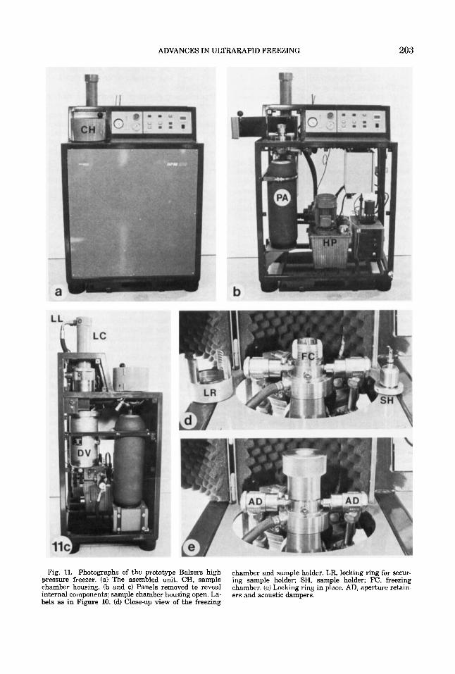
ADVANCES IN ULTRARAPID FREEZING 203
Fig. 11. Photographs of the prototype Balzers high pressure freezer. (a) The asembled unit. CH, sample chamber housing. (b and c) Panels removed to reveal internal components; sample chamber housing open. La- bels as in Figure 10. (d) Close-up view of the freezing
chamber and sample holder. LR, locking ring for secur- ing sample holder; SH, sample holder; FC, freezing chamber. (e) Locking ring in place. AD, aperture retain- ers and acoustic dampers.
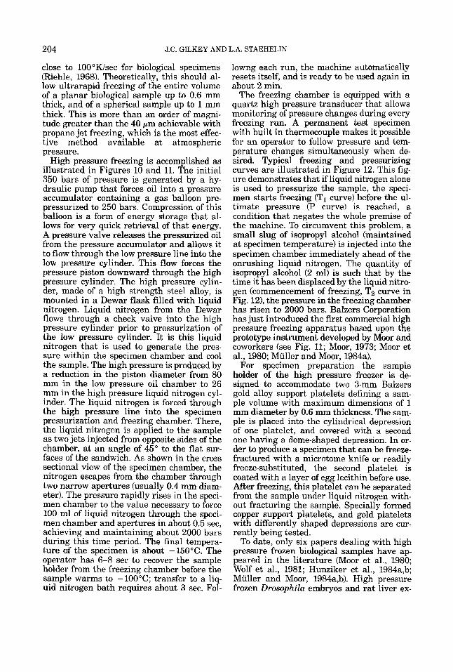
204 J.C. GILKEY AND L.A. STAEHELIN
close to 100"Wsec for biological specimens (Riehle, 1968). Theoretically, this should al- low ultrarapid freezing of the entire volume of a planar biological sample up to 0.6 mm thick, and of a spherical sample up to 1 mm thick. This is more than an order of magni- tude greater than the 40 pm achievable with propane jet freezing, which is the most effec- tive method available at atmospheric pressure.
High pressure freezing is accomplished as illustrated in Figures 10 and 11. The initial 350 bars of pressure is generated by a hy- draulic pump that forces oil into a pressure accumulator containing a gas balloon pre- pressurized to 250 bars. Compression of this balloon is a form of energy storage that al- lows for very quick retrieval of that energy. A pressure valve releases the pressurized oil from the pressure accumulator and allows it to flow through the low pressure line into the low pressure cylinder. This flow forces the pressure piston downward through the high pressure cylinder. The high pressure cylin- der, made of a high strength steel alloy, is mounted in a Dewar flask filled with liquid nitrogen. Liquid nitrogen from the Dewar flows through a check valve into the high pressure cylinder prior to pressurization of the low pressure cylinder. It is this liquid nitrogen that is used to generate the pres- sure within the specimen chamber and cool the sample. The high pressure is produced by a reduction in the piston diameter from 80 mm in the low pressure oil chamber to 26 mm in the high pressure liquid nitrogen cyl- inder. The liquid nitrogen is forced through the high pressure line into the specimen pressurization and freezing chamber. There, the liquid nitrogen is applied to the sample as two jets injected from opposite sides of the chamber, at an angle of 45" to the flat sur- faces of the sandwich. As shown in the cross sectional view of the specimen chamber, the nitrogen escapes from the chamber through two narrow apertures (usually 0.4 mm diam- eter). The pressure rapidly rises in the speci- men chamber to the value necessary to force 100 ml of liquid nitrogen through the speci- men chamber and apertures in about 0.5 sec, achieving and maintaining about 2000 bars during this time period. The final tempera- ture of the specimen is about -150°C. The operator has 6-8 sec to recover the sample holder from the freezing chamber before the sample warms to -100°C; transfer to a liq- uid nitrogen bath requires about 3 sec. Fol-
lowng each run, the machine automatically resets itself, and is ready to be used again in about 2 min.
The freezing chamber is equipped with a quartz high pressure transducer that allows monitoring of pressure changes during every freezing run. A permanent test specimen with built in thermocouple makes it possible for an operator to follow pressure and tem- perature changes simultaneously when de- sired. Typical freezing and pressurizing curves are illustrated in Figure 12. This fig- ure demonstrates that if liquid nitrogen alone is used to pressurize the sample, the speci- men starts freezing (TI curve) before the ul- timate pressure (P curve) is reached, a condition that negates the whole premise of the machine. To circumvent this problem, a small slug of isopropyl alcohol (maintained at specimen temperature) is injected into the specimen chamber immediately ahead of the onrushing liquid nitrogen. The quantity of isopropyl alcohol (2 ml) is such that by the time it has been displaced by the liquid nitro- gen (commencement of freezing, Tz curve in Fig. 121, the pressure in the freezing chamber has risen to 2000 bars. Balzers Corporation has just introduced the first commercial high pressure freezing apparatus based upon the prototype instrument developed by Moor and coworkers (see Fig. 11; Moor, 1973; Moor et al., 1980; Muller and Moor, 1984a).
For specimen preparation the sample holder of the high pressure freezer is de- signed to accommodate two 3-mm Balzers gold alloy support platelets defining a sam- ple volume with maximum dimensions of 1 mm diameter by 0.6 mm thickness. The sam- ple is placed into the cylindrical depression of one platelet, and covered with a second one having a dome-shaped depression. In or- der to produce a specimen that can be freeze- fractured with a microtome knife or readily freeze-substituted, the second platelet is coated with a layer of egg lecithin before use. After freezing, this platelet can be separated from the sample under liquid nitrogen with- out fracturing the sample. Specially formed copper support platelets, and gold platelets with differently shaped depressions are cur- rently being tested.
To date, only six papers dealing with high pressure frozen biological samples have ap- peared in the literature (Moor et al., 1980; Wolf et al., 1981; Hunziker et al., 1984a,b; Muller and Moor, 1984a,b). High pressure frozen Drosophila embryos and rat liver ex-
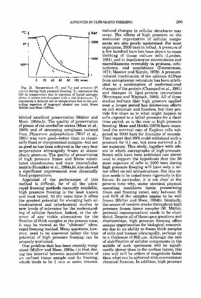
ADVANCES IN ULTRARAPID FREEZING 205
. . o 20 40 60 80 100 mscc
Fig. 12. Temperature (TI and Tz) and pressure (P) curves during high pressure freezing. TI represents the fall in temperature due to injection of liquid nitrogen alone; it occurs simultaneous with a rise in pressure. Tz represents a delayed fall in temperature due to the pre- ceding injection of isopropyl alcohol (see text). From Muller and Moor (1984a1.
hibited excellent preservation (Muller and Moor, 1984a,b). The quality of preservation of pieces of rat cerebellar cortex (Moor et al., 1980) and of streaming cytoplasm isolated from Physarum polycephalum (Wolf et al., 1981) was very good-better than in chemi- cally fixed or cryoprotected samples-but not as good as has been achieved in the very best preparations ultrarapidly frozen at atmos- pheric pressure. The quality of preservation of high pressure frozen and freeze substi- tuted chondrocytes and their intercellular matrix (Hunziker et al., 1984a,b), also showed a significant improvement over chemically fixed preparations.
Appraisal of the performance of this method is difficult, for of all the ultra- rapid freezing methods currently available, high pressure freezing is the least known and least tested. At the same time it offers the greatest potential for elevating both ul- trastructural and cytochemical studies to new levels of relevance for the understand- ing of cellular function. Indeed, in the ab- sence of any viable alternatives for the fixation of thick samples at the present time, it may be viewed as the “ultimate” ultra- rapid freezing method. Many questions, how- ever, need to be answered before the true potential of high pressure freezing can be properly evaluated.
One problem that has been recently recog nized (Muller and Moor, 1984a ) is that dur- ing the interval between microdissection of an unfixed tissue sample and its freezing, which tends to be 1 min or more, trauma-
induced changes in cellular structures may occur. The effects of high pressure on the molecular organization of cellular compo- nents are also poorly understood. For most organisms, 2000 bars in lethal. A pressure of a few hundred bars has been shown to cause blebbing of tissue culture cells (Landau, 19611, and to depolymerize microtubules and microfilaments reversibly in protozoa, echi- noderms, and amphibians (Zimmerman, 1971; Messier and Seguin, 1978). A pressure- induced inactivation of the calcium ATPase from sarcoplasmic reticulum has been attrib- uted to a combination of conformational changes of the protein (Champeil et al., 1981) and changes in lipid-protein interactions (Heremans and Wuytack, 1980). All of these studies indicate that high pressure applied over a longer period has deleterious effects on cell structure and function, but they pro- vide few clues as to what might happen to cells exposed to a lethal pressure for a short time period, as is the case in high pressure freezing. Moor and Hochli (1970) have exam- ined the survival rate of Euglena cells sub- jected to 2000 bars for fractions of seconds. They report that 90% could withstand such a pressure for 0.1 sec, but none survived a 2- sec exposure. This study, together with oth- ers in which micrographs of high-pressure- frozen cells have been published (see above) tend to support the hypothesis that the 20 msec exposure of cells to 2000 bars during high pressure freezing will have only a mi- nor effect on cell ultrastructure. But this no- tion needs to be tested more rigorously in the future. In particular, it is not clear at the present time why, under identical physical operating conditions (same pressurizing times and freezing rates), only between 30 and 60% of the samples appear to be well frozen (Muller and Moor, 1984b). Similarly, the source of random cracks throughout high pressure frozen tissue samples (M. Muller, personal communication) needs to be eluci- dated. Despite all of these open questions and shortcomings, high pressure freezing offers unique opportunities for biological research- ers due to its ability to freeze thick samples of cells and tissues ultrarapidly, perhaps up to a thickness of 600 pm. Although the rate of stabilization of cellular components in the middle of such specimens will be signifi- cantly slower than in the surface layers, this rate will still be orders of magnitude faster than what can be achieved with conventional chemical fixation. In addition, high pressure
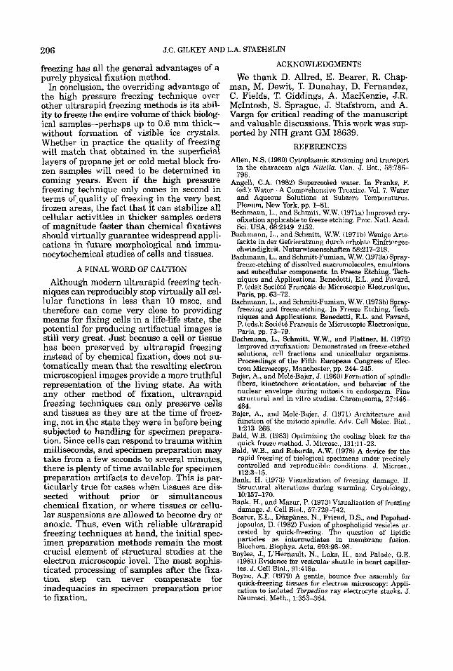
206 J.C. GILKEY AND L.A. STAEHELIN
freezing has all the general advantages of a purely physical fixation method.
In conclusion, the overriding advantage of the high pressure freezing technique over other ultrarapid freezing methods is its abil- ity to freeze the entire volume of thick biolog- ical samples-perhaps up to 0.6 mm thick- without formation of visible ice crystals. Whether in practice the quality of freezing will match that obtained in the superficial layers of propane jet or cold metal block fro- zen samples will need to be determined in coming years. Even if the high pressure freezing technique only comes in second in terms of-quality of freezing in the very best frozen areas, the fact that it can stabilize all cellular activities in thicker samples orders of magnitude faster than chemical fixatives should virtually guarantee widespread appli- cations in future morphological and immu- nocytochemical studies of cells and tissues.
A FINAL WORD OF CAUTION Although modern ultrarapid freezing tech-
niques can reproducibly stop virtually all cel- lular functions in less than 10 msec, and therefore can come very close to providing means for fixing cells in a life-life state, the potential for producing artifactual images is still very great. Just because a cell or tissue has been preserved by ultrarapid freezing instead of by chemical fixation, does not au- tomatically mean that the resulting electron microscopical images provide a more truthful representation of the living state. As with any other method of fixation, ultrarapid freezing techniques can only preserve cells and tissues as they are at the time of freez- ing, not in the state they were in before being subjected to handling for specimen prepara- tion. Since cells can respond to trauma within milliseconds, and specimen preparation may take from a few seconds to several minutes, there is plenty of time available for specimen preparation artifacts to develop. This is par- ticularly true for cases when tissues are dis- sected without prior or simultaneous chemical fixation, or where tissues or cellu- lar suspensions are allowed to become dry or anoxic. Thus, even with reliable ultrarapid freezing techniques at hand, the initial spec- imen preparation methods remain the most crucial element of structural studies at the electron microscopic level. The most sophis- ticated processing of samples after the fixa- tion step can never compensate for inadequacies in specimen preparation prior to fixation.
ACKNOWLEDGMENTS
We thank D. Allred, E. Bearer, R. Chap- man, M. Dewit, T. Dunahay, D. Fernandez, C. Fields, T. Giddings, A. MacKenzie, J.R. McIntosh, S. Sprague, J. Stafstrom, and A. Varga for critical reading of the manuscript and valuable discussions. This work was sup- ported by NIH grant GM 18639.
REFERENCES
Allen, N.S. (1980) Cytoplasmic streaming and transport in the characean alga Nitella. Can. J. Bot., 58:786- 796.
Angell, C.A. (1982) Supercooled water. In Franks, F. (ed.): Water-A Comprehensive Treatise. Vol. 7. Water and Aqueous Solutions at Subzero Temperatures. Plenum, New York, pp. 1-81.
Bechmann, L., and Schmitt, W.W. (1971a) Improved cry- ofixation applicable to freeze etching. Proc. Natl. Acad. Sci. USA, 68:2149-2152.
Bachmann, L., and Schmitt, W.W. (1971b) Wenige Arte- fackte in der Gefrieratzung durch erhohte Einfrierges- chwindigkeit. Naturwissenschaften 58:217-218.
Bachmann, L., and Schmitt-Fumian, W.W. (1973a) Spray- freeze-etching of dissolved macromolecules, emulsions and subcellular components. In Freeze Etching. Tech- niques and Applications. Benedetti, E.L. ,and Favard, P. (eds): Soci6t6 Franqais de Microscopie Electronique, Paris, pp. 63-72.
Bachmann, L., and Schmitt-Fumian, W.W. (1973b) Spray- freezing and freeze-etching. In Freeze Etching. Tech- niques and Applications. Benedetti, E.L. ,and Favard, P. (eds.): Socidt6 Franqais de Microscopie Electronigue, Paris, pp. 73-79.
Bachmann, L., Schmitt, W.W.. and Plattner. H. (1972) Improved cryofixation: Demo'nstrated on freeze-etched solutions, cell fractions and unicellular organisms. Proceedings of the Fifth European Congress of Elec- tron Microscopy, Manchester, pp. 244-245.
Bajer, A,, and Mole-Bajer, J. (1969) Formation of spindle fibers, kinetochore orientation, and behavior of the nuclear envelope during mitosis in endosperm. Fine structural and in vitro studies. Chromosoma, 27:448- 484.
Bajer, A,, and Mole-Bajer, J. (1971) Architecture and function of the mitotic spindle. Adv. Cell Molec. Biol., 1:213-266.
Bald, W.B. (1983) Optimizing the cooling block for the quick freeze method. J. Microsc., 131:ll-23.
Bald, W.B., and Robards, A.W. (1978) A device for the rapid freezing of biological specimens under precisely controlled and reproducible conditions. J. Microsc., 112:3-15.
Bank, H. (1973) Visualization of freezine damage. 11. Structural alterations during warming; CryoGlogy, 10:157-170.
Bank, H., and Mazur, P. (1973) Visualization of freezing damage. J. Cell Biol., 57:729-742.
Bearer, E.L., Diizgunes, N., Friend, D.S., and Papahad- jopoulos, D. (1982) Fusion of phospholipid vesicles ar- rested by quick-freezing. The question of lipidic particles as intermediates in membrane fusion. Biochem. Biophys. Acta, 693:93-98.
Boyles, J., L'Hernault, N., Laks, H., and Palade, G.E. (1981) Evidence for vesicular shuttle in heart capillar- ies. J. Cell Biol., 91:418a.
Boyne, A.F. (1979) A gentle, bounce free assembly for quick-freezing tissues for electron microscopy: Appli- cation to isolated Torpedine ray electrocyte stacks. J. Neurosci. Meth., 1:353-364.
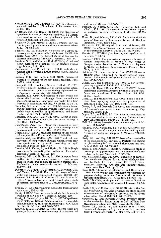
ADVANCES IN UL? ’RARAPID FREEZING 207
Bretscher, M.S., and Whytock, S. (1977) Membrane-as- sociated vesicles in fibroblasts. J. Ultrastruc. Res., 61:215-217.
Bridgman, P.C., and Reese, T.S. (1984) The structure of cytoplasm in directly frozen cultured cells. I. Filamen- tous meshworks and the cytoplasmic ground sub- stance. J. Cell Biol., 99:1655-1668.
Briigeller, P., and Mayer, E. (1980) Complete vitrifica- tion in pure liquid water and dilute aqueous solutions. Nature, 288:569-571.
Buckley, I.K. (1973) Studies in fixation for electron mi- croscopy using cultured cells. Lab. Invest,, 29:398-410.
Bullock, G.R. (1984) The current status of fixation for electron microscopy: A review. J. Microsc., 133:l-15.
Burstein, N.C., and Maurice, D.M. (1979) Cryofixation of tissue surfaces by a propane jet for electron micros- copy. Micron, 9:191-198.
Cantino, M.E., and Pollack, G.H. (1983) Cross-bridges in relaxed and activated skinned muscle fibers. Biophys. J., 41:A264.
Cantino. M.E.. and Pollack. G.H. (1984) Prooane-iet - I
freezing of muscle fibers for freeze fracture. Proc. EMSA, 1984;llO-11.
Champeil, P.H., Buschlen, S., and Guillain, F. (1981) Pressure-induced inactivation of sarcoplasmic reticu- lum adenosine triphosphatase during high-speed cen- trifugation. Biochemistry, 20:1520-1524.
Chandler, D.E. (1984) Comparison of quick-frozen and chemically fixed sea urchin eggs: Structural evidence that cortical granule exocytosis is preceded by a local increase in membrane mobility. J . Cell Sci., 72:23-36.
Chandler, D.E., and Heuser, J. (1979) Membrane fusion during secretion. Cortical granule exocytosis in sea urchin eggs as studied by quick-freezing and freeze- fracture. J. Cell Biol., 83:91-108.
Chandler, D.E., and Heuser, J.E. (1980) Arrest of mem- brane fusion events in mast cells by quick freezing. J. Cell Biol., 86:666-674.
Christensen, A.K. (1971) Frozen thin sections of fresh tissue for electron microscopy, with a description of pancreas and liver. J. Cell Biol., 51:772-804.
Costello, M.J. (1980) Ultra-rapid freezing of thin biologi- cal samples. Scan. Electron Microsc., 2:361-370.
Costello, M.J., and Corless, J.M. (1978) The direct mea- surement of temperature changes within freeze frac- ture specimens during rapid quenching in liquid coolants. J. Microsc., 112:17-37.
Costello, M.J., Fetter, R., and Hochli, M. (1982) Simple procedures for evaluating the cryofixation of biological samples. J . Microsc., 125:125-136.
Dempsey, G.P., and Bullivant, S. (1976) A copper block method for freezing non-cryoprotected tissue to pro- duce ice-crystal-free regions for electron microscopy. I. Evaluation using freeze-substitution. J. Microsc., 106:251-260.
Dubochet, J., Lepault, J., Freeman, R., Berriman, J.A., and Homo, J.C. (1982) Electron microscopy of frozen water and aqueous solutions. J . Microsc., 128:219-237.
Ebersold, H.R., Liithy, P., Cordier, J.L., and Muller, M. (1981) A freeze-substitution and freeze-fracture study of bacterial spore structures. J. Ultrastruct. Res., 76:71- 81.
Eranko, 0. (1954) Quenching of tissues for freeze-drying. Acta Anat., 22:331-336.
Escaig, J. (1982) New instruments which facilitate rapid freezing at 83K and 6K. J Microsc., 126:221-229.
Escaig, J., Geraud, G., and Nicolas, G. (1977) Rapid freez- ing of biological tissues. Temperature and freezing data measurements by thin-film thermocouple. C.R. Acad. Sci. Ser. D., Sci. Nat., 284:2289-2292.
Espevik, T., and Elgsaeter, A. (1981) In situ liquid pro- pane jet-freezing and freeze-etching of monolayer cell
cultures. J. Microsc., 123:105-110. Farrant, J., Walter, C.A., Lee, H., Morris, G.J., and
Clarke, K.J. (1977) Structural and functional aspects of biological freezing techniques. J. Microsc., 111:17- 34.
Feder, N., and Sidman, R.C. (1958) Methods and princi- ples of fixation by freeze-substitution. J. Biophys. Biochem. Cytol., 4:593-602.
Fitzharris, T.P., Bloodgood, R.A., and McIntosh, J.R. (1972) The effect of fixation on the wave propagation of the protozoan axostyle. Tissue Cell, 4:219-225.
Franks, F. (1977) Biological freezing and cryofixation. J. Microsc., 111:3-16.
Franks, F. (1982) The properties of aqueous solutions at subzero temperatures. In Franks, F. (ed.): Water-A Comprehensive Treatise. Vol. 7. Water and Aqueous Solutions at Subzero Temperatures. Plenum, New York, pp. 215-338.
Giddings, T.H., and Staehelin, L.A. (1980) Ribosome binding sites visualized on freeze-fractured mem- branes of the rough endoplasmic reticulum. J. Cell Biol., 85:147-152.
Gilkey, J.C., and Staehelin, L.A. (1980) A new osmore- gulatory organelle? J. Cell Biol., 87:209a.
Gilula, N.B., Eger, R.B., and Rifkin, D.B. (1975) Plasma membrane alteration associated with malignant trans- formation in culture. Proc. Natl. Acad. Sci. USA, 72:3594-3598.
Glick, D., and Malmstrom, B.G. (1952) Simple and effi- cient freezing-drying apparatus for preparation of embedded tissue. Exp. Cell Res., 3:125-135.
Glover, A.J., and Garvitch, Z.S. (1974) The freezing rate of freeze-etch specimens for electron microscopy. Cry- obiology, 11:248-254.
Gupta, B.J., and Hall, T.A. The x-ray microanalysis of frozen-hydrated sections in scanning electron micros- copy: An evaluation. Tissue Cell, 13:623-643.
Hall, T.A. (1984) Biological x-ray microanalysis. J. Mi- crosc., 117:145-163.
Handley, D.A., Alexander, J.T., and Chen, S. (1981) The design and use of a simple device for rapid quench- freezing of biological samples. J. Microsc., 121:273- 282.
Hasty, D.L., and Hay, E.D. (1978) Freeze-fracture studies of the developing cell surface. 11. Particle-free blisters on glutaraldehyde-fixed corneal fibroblasts are arti- facts. J. Cell Biol., 78:756-768.
Haug, T., and Altner, H. (1984) A cryofixation study of presumptive hygroreceptors on the antennule of a ter- restrial arthropod. Tiss. Cell, 16:377-391.
Hay, E.D., and Hasty, D.L. (1979) Extrusion of particle- free membrane blisters during glutaraldehyde fixa- tion. In Rash, J.E., and Hudson, C.S. (eds.): Freeze Fracture: Methods, Artifacts and Interpretations. Raven Press, New York, pp. 59-69.
Hays, R.M., Chevalier, J., Gobin, R., and Bourguet, J. (1985). Fusion images and intramembrane particle ag- gregates during the action of antidiuretic hormone. A rapid-freezing study. Cell Tissue Res., 240:433-439.
Heath, I.B. (1984) A simple and inexpensive liquid he- lium cooled “slam freezing” device. J. Microsc., 13575- 82.
Heath, I.B., and Rethoret, K. (1982) Mitosis in the fun- gus Zygorynchus moelleri: Evidence for stage specific enhancement of microtubule preservation by freeze substitution. Eur. J . Cell Biol., 28:180-189.
Heremans, K., and Wuytack, F. (1980) Pressure effects on the Arrhenius discontinuity in Ca2+-ATPase from sarcoplasmic reticulum. FEBS Lett., 117:161-163.
Heuser, J.E., Reese, T.S., and Landis, D.M.D. (1974) Functional changes in frog neuromuscular junctions studied with freeze-fracture. J . Neurocytol., 3:108-131.
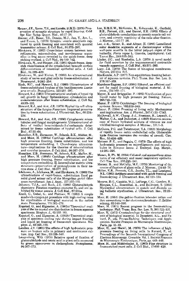
208 J.C. GILKEY AND L.A. STAEHELIN
Heuser, J.E., Reese, T.S., and Landis, D.M.D. (1976)Pres- ervation of synaptic structure by rapid freezing. Cold Spr. Har. Symp. Quant. Biol., 40:17-24.
Heuser, J.E., Reese, T.S., Dennis, M.J., Jan, Y., Jan, L., and Evans, L. (1979) Synaptic vesicle exocytosis cap- tured by quick freezing and correlated with quanta1 transmitter release. J. Cell Biol., 81:275-297.
Hirokawa, N. (1982) Cross-linker system between neu- rofilaments, microtubules, and membranous organ- elles in frog axons revealed by the quick-freeze, deep etching method. J. Cell Biol., 94:129-142.
Hirokawa, N., and Heuser, J.E. (1981) Quick-freeze, deep etch visualization of the cytoskeleton beneath surface differentiations of intestinal epithelial cells. J. Cell Biol., 91:399-409.
Hirokawa, N., and Kirino, T. (1980) An ultrastructural study of nerve and glial cells by freeze-substitution. J. Neurocytol., 9:243-254.
Hoch, H.C., and Howard, R.J. (1980) Ultrastructure of freeze-substituted hyphae of the basidiomycete Laetis- aria arualis. Protoplasma, 103:281-297.
Howard, R.J. (1981) Ultrastructural analysis of hypal tip cell growth in fungi: Spitzenkorper, cytoskeleton and endomembranes after freeze-substitution. J. Cell Sci. 4889-103.
Howard, R.J., and Aist, J.R. (1979) Hyphal tip cell ultra- structure of the fungus Fusarium: Improved preserva- tion by freeze substitution. J. Ultrastruct. Res., 66224- 234.
Howard, R.J., and Aist, J.R. (1980) Cytoplasmic micro- tubules and fungal morphogenesis: Ultrastructural ef- fects of methyl benzimidazole-2-ylcarbamate deter- mined by freeze substitution of hyphal cells. J. Cell Biol., 87:55-64.
Hunziker, E.B., Hermann, W., Schenk, R.K., Miiller, M., and Moor, H. (1984a) Cartilage ultrastructure after high pressure freezing, freeze substitution, and low temperature embedding. I. Chondrocyte ultrastruc- ture-implications for the theories of mineralization and vascular invasion. J . Cell Biol., 98:267-276.
Hunziker, E.B., Hermann, W., Schenk, R.K., Muller, M., and Moor, H. (1984b) Cartilage ultrastructure after high pressure freezing, freeze substitution, and low temperature embedding. 11. Intercellular matrix ultra- structure-preservation of proteoglycans in their na- tive state. J. Cell Biol., 98:277-282.
Ichikawa, A., Ichikawa, M., and Hirokawa, N. (1980) The ultrastructure of rapid-frozen, substitution fixed pa- rotid gland acinar cells of the Mongolian gerbil (Mer iones meridianus). Am J. Anat., 157:107-110.
Johnson, T.J.A., and Rash, J.E. (1980) Glutaraldehyde chemistry: Fixation reactions consume 0 2 and are in- hibited by tissue anoxia. J. Cell Biol., 87:231a.
Knoll, G., Gebel, G., and Plattner, H. (1982) A simple sandwich-cryogen-jet procedure with high cooling rates for cryofixation of biological material in the native state. Protoplasma, 111:161-176.
Kopstad, G., and Elgsaeter, A. (1982a) Theoretical anal- ysis of the ice crystal size distribution in frozen aqueous specimens. Biophys. J., 40:155-161.
Kopstad, G., and Elgsaeter, A. (198213) Theoretical anal- ysis of specimen cooling rate during impact freezing and liquid jet freezing of freeze-etch specimens. Bio- phys. J., 40:163-170.
Landau, J.V. (1961) The effects of high hydrostatic pres- sure on human cells in primary and continuous cul- ture. Exp. Cell Res., 23:538-548.
Langenberg, W.G. (1978) Relative speed of fixation of glutaraldehyde and osmic acid in plant cells measured by grana appearance in choloroplasts. Protoplasma, 94:167-173.
Lee, R.M.K.W., McKenzie, R., Kobayashi, K., Garfield, R.E., Forrest, J.B., and Daniel, E.E. (1982) Effects of glutaraldehyde osmolarities on smooth muscle cell vol- ume, and osmotic reactivity of the cells after fixation. J . Microsc., 125:77-88.
Lee, J.-K., Selzer, R., and Altner, H. (1985) Lamellated outer dendritic segments of a chemoreceptor within wall-pore sensilla in the labial palp-pit organ of the butterfly, Pieris rapae L. (Insecta, Lepidoptera). Cell Tissue Res., 240:333-342.
Linder, J.C., and Staehelin, L.A. (1979) A novel model for fluid secretion by the trypanosomatid contractile vacuole aunaratus. J. Cell Biol.. 83:371-382.
Lucy, J.A. ii970) The fusion of biological membranes.
MacKenzie, A.P. (1977) Non-equilibrium freezing behav- Nature, 227:814-817.
ior of aqueous systems. Phii. Trans. Roy. Soc.Lon. B, 278:167-189.
Marchese-Ragona, S.P. (1984) Ethanol, an efficient cool- ant for rapid freezing of biological material. J. Mi- crosc., 134:169-171.
Maver, E. and Briiegeller, P. (1982) Vitrification of oure liquid water by -high pressure jet freezing. Nature, 2987 15-718.
Mazur, P. (1970) Cryobiology: The freezing of biological systems. Science, 168:939-949.
Mazur, P. (1984) Freezing of living cells: Mechanisms and implications. Am. J. Physiol., 247:C125-C142.
McDowall, A.W., Chang, J.-J., Freeman, R., Lepault, J., Walter, C.A., and Dubochet, J. (1983) Electron micros- copy of frozen hydrated sections of vitreous ice and vitrified biological samples. J. Microsc., 131:l-9.
McGuire, P.G. and Twietmeyer, T.A. (1983) Morphology of rapidly frozen aortic endothelial cells. Glutaralde- hyde fixation increases the number of caveoli. Circ. Res., 53:424-429.
Meisser. P.-E., and Seguin, C. (1978) The effects of high hydrostatic pressure on microfilaments and microtu- bules in Xenopus laeuis. J. Embryol. Exp. Morph., 44:281-295.
Menco, B. Ph. M. (1984) Ciliated and microvillous struc- tures of rat olfactory and nasal respiratory epithelia. Cell Tiss. Res., 235225-241,
Mersey, B., and McCully, M.E. (1978) Monitoring of the course of fixation of plant cells. J. Microsc., 114:49-76.
Miller, K.R., Prescott, C.S., Jacobs, T.L., and Lassignol, N.L. (1983) Artifacts associated with quick-freezing and freeze-drying. J . Ultrastruct. Res., 82123-133.
Monroe, R.G., Gamble, W.J., LaFarge, C.G., Gambra, R., Morgan, C.L., Rosenthal, A., and Bullivant, S. (1968) Myocardial ultrastructure in systole and diastole us- ing ballistic cryofixation. J . Ultrastruct. Res., 22:22- 36.
Moor, H. (1964) Die gefrier-fixation lebender zellen und ihre anwendung in der electronmikroskopie. Z. Zellfor- schung, 62546-580,
Moor, H. (1971) Recent progress in the freeze-etching technique. Phil. Trans. Roy. SOC. Lon. B, 261:121-131.
Moor, H. (1973) Cryotechnology for the structural anal- ysis of biological material. In Benedetti, E.L., and Fa- vard, P., eds. Freeze-Etching. Techniques and Appli- cations. Societe Franqais de Microscopie Electronique, Paris, pp. 11-19.
Moor. H.. and Hochli. M. (1970) The influence of hieh- pressure freezing on living cells. In Favard, P., i d . Proceedings of the Seventh International Congress of Electron Microscopy. Grenoble. Vol. 1. Societe Francais de Microscopie Electronique, Paris, pp: 445-446.
Moor, H., and Miihlethaler, K. (1963) Fine structure in frozen-etched yeast cells. J. Cell Biol., 17:609-628.
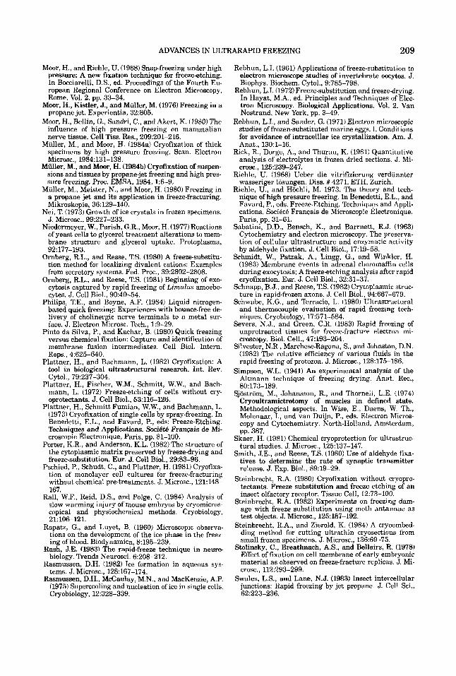
ADVANCES IN ULTRARAPID FREEZING 209
Moor, H., and Riehle, U. (1968) Snap-freezing under high pressure: A new fixation technique for freeze-etching. In Bocciarelli, D.S., ed. Proceedings of the Fourth Eu- ropean Regional Conference on Electron Microscopy, Rome. Vol. 2. pp. 33-34.
Moor, H., Kistler, J., and Muller, M. (1976) Freezing in a propane jet. Experientia, 32905.
Moor, H., Bellin, G., Sandri, C., and Akert, K. (1980) The influence of high pressure freezing on mammalian nerve tissue. Cell Tiss. Res., 209:201-216.
Muller, M., and Moor, H. (1984a) Cryofixation of thick specimens by high pressure freezing. Scan. Electron Microsc., 1984131-138.
Muller, M., and Moor, H. (1984b) Cryofixation of suspen- sions and tissues by propane-jet freezing and high pres- sure freezing, Proc. EMSA, 1984, 15-9.
Miiller, M., Meister, N., and Moor, H. (1980) Freezing in a propane jet and its application in freeze-fracturing. Mikroskopie, 36:129-140.
Nei, T. (1973) Growth of ice crystals in frozen specimens. J . Microsc., 99:227-233.
Niedermeyer, W., Parish, G.R., Moor, H. (1977) Reactions of yeast cells to glycerol treatment alterations to mem- brane structure and glycerol uptake. Protoplasma, 92:177-193.
Ornberg, R.L., and Resse, T.S. (1980) A freeze-substitu- tion method for localizing divalent cations: Examples from secretory systems. Fed. Proc., 39:2802-2808.
Ornberg, R.L., and Reese, T.S. (1981) Beginning of exo- cytosis captured by rapid freezing of Limulus amoebo- cytes. J. Cell Biol., 90:40-54.
Philips, T.E., and Boyne, A.F. (1984) Liquid nitrogen- based quick freezing: Experiences with bounce-free de- livery of cholinergic nerve terminals to a metal sur- face. J. Electron Microsc. Tech., 1:9-29.
Pinto da Silva, P., and Kachar, B. (1980) Quick freezing versus chemical fixation: Capture and identification of membrane fusion intermediates. Cell Biol. Intern. Reps., 4525-640.
Plattner, H., and Bachmann, L. (1982) Cryofixation: A tool in biological ultrastructural research. Int. Rev.
Plattner, H., Fischer, W.M., Schmitt, W.W., and Bach- mann, L. (1972) Freeze-etching of cells without cry- oprotectants. J. Cell Biol., 53:116-126.
Plattner, H., Schmitt-Fumian, W.W., and Bachmann, L. (1973) Cryofixation of single cells by spray-freezing. In Benedetti, E.L., and Favard, P., eds: Freeze-Etching. Techniques and Applications. Soci6t.5 Franqais de Mi- croscopie Electronique, Paris, pp. 81-100.
Porter, K.R., and Anderson, K.L. (1982) The structure of the cytoplasmic matrix preserved by freeze-drying and freeze-substitution. Eur. J. Cell Biol., 29:83-96.
Pschied, P., Schudt, C., and Plattner, H. (1981) Cryofixa- tion of monolayer cell cultures for freeze-fracturing without chemical pre-treatments. J. Microsc., 121:148- 167.
Rall, W.F., Reid, D.S., and Polge, C. (1984) Analysis of slow warming injury of mouse embryos by cryomicros- copical and physiochemical methods. Cryobiology, 21:106-121.
Rapatz, G., and Luyet, B. (1960) Microscopic observa- tions on the development of the ice phase in the freez- ing of blood. Biodynamica, 8195-239.
Rash, J.E. (1983) The rapid-freeze technique in neuro- biology. Trends Neurosci. 6:208-212.
Rasmussen, D.H. (1982) Ice formation in aqueous sys- tems. J. Microsc., 128:167-174.
Rasmussen, D.H., McCaulay, M.N., and MacKenzie, A.P. (1975) Supercooling and nucleation of ice in single cells. Cryobiology, 12:328-339.
Cytol., 79:237-304.
Rebhun, L.I. (1961) Applications of freeze-substitution to electron microscope studies of invertebrate oocytes. J. Biophys. Biochem. Cytol., 9:785-798.
Rebhun, L.I. (1972) Freeze-substitution and freeze-drying. In Hayat, M.A., ed. Principles and Techniques of Elec- tron Microscopy. Biological Applications. Vol. 2. Van Nostrand, New York, pp. 3-49.
Rebhun, L.I., and Sander, G. (1971) Electron microscopic studies of frozen-substituted marine eggs. I. Conditions for avoidance of intracelllar ice crystallization. Am. J. Anat., 13O:l-16.
Rick, R., Dorge, A., and Thurau, K. (1981) Quantitative analysis of electrolytes in frozen dried sections. J. Mi- crosc., 125:239-247.
Riehle, U. (1968) Ueber die vitrifizierung verdunnter wasseriger losungen. Diss. # 4271, ETH, Zurich.
Riehle, U., and Hochli, M. 1973. The theory and tech- nique of high pressure freezing. In Benedetti, E.L., and Favard, P., eds. Freeze-Etching. Techniques and Appli- cations. Societe Franqais de Microscopie Electronique, Paris, pp. 31-61.
Sabatini. D.D., Bensch, K., and Barrnett, R.J. (1963) Cytochemistry and electron microscopy. The preserva- tion of cellular ultrastructure and enzymatic activity by aldehyde fixation. J. Cell Biol., 17:19-58.
Schmidt, W., Patzak, A,, Lingg, G., and Winkler, H. (1983) Membrane events in adrenal choromafin cells during exocytosis; A freeze-etching analysis after rapid cryofixation. Eur. J. Cell Biol., 32:31-37.
Schnapp, B.J., and Reese, T.S. (1982) Crytoplasmic struc- ture in rapid-frozen axons. J. Cell Biol., 94:667-679.
Schwabe, K.G., and Terracio, L. (1980) Ultrastructural and thermocouple evaluation of rapid freezing tech- niques. Cryobiology, 17:571-584.
Severs, N.J., and Green, C.R. (1983) Rapid freezing of unpretreated tissues for freeze-fracture electron mi- croscopy. Biol. Cell., 47:193-204.
Silvester, N.R., Marchese-Ragona, S., and Johnston, D.N. (1982) The relative efficiency of various fluids in the rapid freezing of protozoa. J. Microsc., 128:175-186.
Simpson, W.L. (1941) An experimental analysis of the Altmann technique of freezing drying. Anat. Rec., 80:173-189.
Sjostrom, M., Johansson, R., and Thornell, L.E. (1974) Cryoultramictrotomy of muscles in defined state. Methodological aspects. In Wise, E., Daens, W. Th., Molenaar, I., and van Duijn, P., eds. Electron Micros- copy and Cytochemistry. North-Holland, Amsterdam, pp. 387.
Skaer. H. (1981) Chemical crvoorotection for ultrastruc- tural studies. J. Microsc., 155r137-147.
Smith, J.E., and Reese, T.S. (1980) Use of aldehyde fixa- tives to determine the rate of synaptic transmitter release. J . Exp. Biol., 89:19-29.
Steinbrecht, R.A. (1980) Cryofixation without cryopro- tectants. Freeze substitution and freeze etching of an insect olfactory receptor. Tissue Cell, 12:73-100.
Steinbrecht, R.A. (1982) Experiments on freezing dam- age with freeze substitution using moth antannae as test objects. J. Microsc., 125:187-192.
Steinbrecht, R.A., and Zierold, K. (1984) A cryoembed- ding method for cutting ultrathin cryosections from small frozen specimens. J. Microsc., 13659-75.
Stolinsky, C., Breathnach, A.S., and Bellairs, R. (1978) Effect of fixation on cell membrane of early embryonic material as observed on freeze-fracture replicas. J. Mi- crosc., 112:293-299.
Swales, L.S., and Lane, N.J. (1983) Insect intercellular junctions: Rapid freezing by jet propane. J. Cell Sci., 62:223-236.
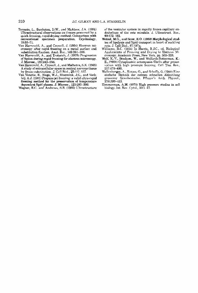
210 J.C. GILKEY AND L.A. STAEHELIN
Terracio, L., Bankston, D.W., and McAteer, J.A. (1981) Ultrastructural observations on tissues processed by a quick-freezing, rapid-drying method Comparison with conventional specimen preparation. Cryobiology, 18:55-71.
Van Harreveld, A,, and Crowell, J. (1964) Electron mi- croscopy after rapid freezing on a metal surface and substitution fixation. Anat. Rec., 149:381-386.
Van Harreveld, A,, and Trubatch, J. (1979) Progression of fusion during rapid freezing for electron microscopy. J. Microsc., 115243-256.
Van Harreveld, A., Crowell, J., and Malhotra, S.K. (1965) A study of extracellular space in central nervous tissue by freeze-substitution. J . Cell Biol., 25:117-137.
Van Venetie, R., Hage, W.J., Bluemink, J.G., and Verk- leij, A.J. (1981) Propane jet freezing: a valid ultra-rapid freezing method for the preservation of temperature dependent lipid phases. J. Microsc., 123287-292.
Wagner, R.C. and Andrews, S.B. (1985) Ultrastructure
of the vesicular system in rapidly frozen capillary en- dothelium of the rete mirabile. J . Ultrastruct. Res., 90172-182.
Wetzel, M.G., and Scow, R.O. (1980) Morphological stnd- ies of lipolysis and lipid transport in heart of suckling rats. J. Cell Biol., 87:197a.
Williams, R.C. (1954) In Harris, R.J.C., ed. Biological Applications of Freezing and Drying to Electron Mi- croscopy. Academic Press, New York, pp. 303-328.
Wolf, K.-V., Stockem, W., and Wolfarth-Botterman, K.- E., (1981) Cytoplasmic actomyosin fibrils after preser- vation with high pressure freezing. Cell Tiss. Res., 217:479-495.
Wollenberger, A,, Ristau, O., and Schoffa, G. (1960) Eine einfache Technik der extrem schnellen Abkuhlung grosserer Gewebestucke. Pfluger’s Arch. Physiol., 270:399-412.
Zimmerman, A.M. (1971) High pressure studies in cell biology. Int. Rev. Cytol., 3O:l-47.
Related Documents