1 Chapter 1 Advances in Modern Radiation Therapy Jacob Van Dyk 1.1 Introduction 2 1.2 Historical Review of Radiation Therapy and IMRT 2 1.3 The New Process of Radiation Treatment 2 1.3.1 Patient positioning, immobilization, and adaptive treatment 5 1.3.2 Imaging for target delineation 6 1.3.3 Definition of constraints 6 1.3.4 Forward or inverse planning 7 1.3.5 Data transfer and dosimetry confirmation 8 1.3.6 Treatment setup confirmation 8 1.3.7 Dose delivery 9 1.4 Potential Impact of the Modern Technology of Radiation Oncology on Predicted Treatment Outcome 9 1.5 QA Considerations 13 1.5.1 Treatment accuracy in modern radiation therapy 13 1.5.2 The avoidance of errors in radiation treatment 16 1.6 The Future of the Modern Technology of Radiation Oncology 18 1.6.1 Improved imaging technologies for target and normal tissue definition 20 1.6.2 Increased use of image registration/fusion technologies 21 1.6.3 Increased use of IMRT with improved optimization algorithms 21 1.6.4 Increased use of 4-D imaging and breathing-controlled treatment 21 1.6.5 Increased use of image guidance for reproducible patient setups 21 1.6.6 Increased use of particle therapy 21 1.6.7 Increased use of brachytherapy 22 1.6.8 Increased quality assurance 22 1.6.9 Increased need for medical physicists 22 1.7 Summary 25 Acknowledgments 25 References 26

Welcome message from author
This document is posted to help you gain knowledge. Please leave a comment to let me know what you think about it! Share it to your friends and learn new things together.
Transcript

1
Chapter 1
Advances in ModernRadiation TherapyJacob Van Dyk
1.1 Introduction 21.2 Historical Review of Radiation Therapy and IMRT 21.3 The New Process of Radiation Treatment 2
1.3.1 Patient positioning, immobilization, and adaptive treatment 51.3.2 Imaging for target delineation 61.3.3 Definition of constraints 61.3.4 Forward or inverse planning 71.3.5 Data transfer and dosimetry confirmation 81.3.6 Treatment setup confirmation 81.3.7 Dose delivery 9
1.4 Potential Impact of the Modern Technology of Radiation Oncology on Predicted Treatment Outcome 9
1.5 QA Considerations 131.5.1 Treatment accuracy in modern radiation therapy 131.5.2 The avoidance of errors in radiation treatment 16
1.6 The Future of the Modern Technology of Radiation Oncology 181.6.1 Improved imaging technologies for target and normal
tissue definition 201.6.2 Increased use of image registration/fusion technologies 211.6.3 Increased use of IMRT with improved optimization algorithms 211.6.4 Increased use of 4-D imaging and breathing-controlled treatment 211.6.5 Increased use of image guidance for reproducible patient setups 211.6.6 Increased use of particle therapy 211.6.7 Increased use of brachytherapy 221.6.8 Increased quality assurance 221.6.9 Increased need for medical physicists 22
1.7 Summary 25Acknowledgments 25References 26

1.1 Introduction
Modern radiation therapy continues to progress at anunprecedented rate. The present rapid evolution is pri-marily related to the very significant advances in themodern technology of radiation oncology. This devel-opment is strongly linked to the evolution of computertechnology and the corresponding advances in diagnos-tic imaging equipment. New “buzz words” haveevolved in the last two decades, such as “three-dimen-sional conformal radiation therapy” (3-D CRT), “4-Dradiation therapy,” “intensity-modulated radiation ther-apy” (IMRT), “tomotherapy,” “treatment gating,”“breathing control,” “adaptive radiation treatment,”“inverse treatment planning,” “multileaf collimation,”and “image segmentation.” Volume 1 of The ModernTechnology of Radiation Oncology: A Compendium forMedical Physicists and Radiation Oncologists [85] pro-vides a detailed description of all the technologies asso-ciated with radiation oncology, including the designdetails, as well as procedures for acceptance, commis-sioning, and quality assurance. This book, volume 2,provides an update on the recent evolution of the tech-nology of radiation oncology, especially the advancesthat have taken place in the last 3 to 5 years. This chap-ter provides an overview of some of the recentadvances, while subsequent chapters address the majordevelopments in significant detail.
1.2 Historical Review of Radiation Therapyand IMRT
A brief historical review of radiation therapy was pro-vided in chapter 1 of volume 1 [84]. In this section, amore detailed review is given specifically of the evolu-tion of IMRT, today’s standard for state-of-the-art radia-tion treatment. The goal of radiation therapy has alwaysbeen to maximize the probability of controlling thetumor and minimizing normal tissue complications. Theachievement of this goal is the key component drivingthe technological developments. While the increases inthe energies of radiation producing machines fromorthovoltage x-rays to cobalt-60 gamma rays and mega-voltage accelerators have been a major component ofthese technological developments, field shaping anddynamic beam motions have contributed as well. Histor-ically, five phases of radiation therapy development havebeen described [83]. These have evolved at differentrates in different countries or even different institutionswithin the same country (Table 1.1).
It is interesting to note that it was not long after theimplementation of megavoltage radiation therapy in the1950s that sophisticated dose delivery and field shaping
concepts were described in the literature. Johns et al.[35] described the development of isocentric rotationalcobalt-60 machines. As early as 1965, Takahashi [77],in Japan, described some of the important concepts of3-D CRT and IMRT delivery. He described the first useof a multileaf collimator (MLC), which he called a“geared sectional diaphragm” (Figure 1.1). The groupat the Massachusetts Institute of Technology first devel-oped asynchronous beam shaping devices [65,93]. InEngland the group at the Royal Northern Hospital [23]developed the tracking cobalt unit using simultaneousmoving couch and gantry to generate conformal dosedistributions. This was later extended by Davy andBrace in the 1970s and 1980s [17]. Similar work wasalso performed by the group at the Joint Center inBoston, using a linear accelerator [5].
From a conceptual perspective, Brahme andcoworkers [6] and Cormack [9] independently pre-sented many of the basic concepts related to developingshaped or intensity-modulated dose distributions. Someof the concepts were implemented in Sweden on a 50MeV racetrack microtron. The actual “routine” imple-mentation of IMRT was made possible by the commer-cial availability of computer-controlled MLCs and thecorresponding inverse planning software required todefine the multiple positions of each leaf during a seg-mented or dynamic delivery procedure [26]. Today,IMRT with inverse treatment planning is available inmultiple institutions even in the smaller nonacademicclinics, especially in the United States, where signifi-cant reimbursement is available for such complex treat-ment procedures. Chapter 6 of this volume gives adetailed review of the present status of IMRT. Theincrease of IMRT activity in the past decade can beseen in Figure 1.2, which shows a plot of the numberof publications on IMRT versus year.
1.3 The New Process ofRadiation Treatment
The steps in the process of conventional radiation ther-apy, the technologies used, and the professionalsinvolved were described in detail in chapter 1 of volume1 of The Modern Technology of Radiation Oncology[84]. This section highlights the differences between 3-D CRT and IMRT. Figure 1.3 is a block diagram show-ing the major steps in the radiation therapy planning andtreatment process for both conventional 3-D CRT andIMRT. The white boxes indicate that these specific stepsare very similar, although with IMRT and escalatingdoses, there are greater concerns for precision and accu-racy in patient immobilization, and a greater need forbetter resolution in all dimensions when imaging the
2 THE MODERN TECHNOLOGY OF RADIATION ONCOLOGY VOLUME 2

CHAPTER 1: ADVANCES IN MODERN RADIATION THERAPY 3
Table 1.1
The Major Phases of Major Technological Developments in RadiationOncology [Adapted with permission from [83].]
PHASE TIME TECHNOLOGY ISSUES/BENEFITS
1 1895–1940s 100–400 kV x-rays Nonuniform doses to deep-seated tumors; skintoxicity; bone toxicity
2 1950s Cobalt-60 Megavoltage photons provide skin sparing; 4–8 MeV linacs improved dose uniformity in the target and reduced 20–30 MeV betatrons doses to normal tissues; increased manual
treatment planning
3 1960s–1970s Multimodality linacs Increased availability of linacs; increased use of Computerized radiation treatment computerized treatment planning; introduction of planning systems simulators; increased physics human resources to Simulators support the technologies; more systematized and
comprehensive quality assurance
4 1970s–1980s CT1 combined with 3-D treatment Improved targeting; reduced complications; planning improved dose computations
5 1980s–present Development of computer- Allows dose escalation with increased probability controlled dynamic treatments of tumour control and reduced probabilities of (IMRT2) normal tissue complicationsFurther improvements in imaging with CT simulators, MRI,3 PET,4
PET-CT
1 CT�computerized tomography.2 IMRT�intensity modulated radiation therapy.3 MRI�magnetic resonance imaging.4 PET�positron emission tomography.
patient, allowing for better target volume delineationand 3-D display. The gray-shaded boxes indicate com-ponents in the process that have significant differencesbetween 3-D CRT and IMRT. Thus, the definition oftreatment planning constraints for IMRT is dependenton the mathematical objective functions that are usedand their dependence on “importance” factors or“weighting” factors associated with normal tissue con-straints. (See chapters 4 and 5 of this volume.)
IMRT differs from 3-D CRT in two very significantways. First, IMRT uses an iterative plan optimizationprocess, generally known as “inverse planning.” Sec-ond, it uses intensity-modulated beams that can bedelivered in a dynamic MLC (dMLC) mode or in a seg-mented MLC (sMLC) mode (i.e., multiple stationaryfields with different MLC configurations). Both theinverse planning and the IMRT delivery are shown as“black boxes” to illustrate that, from a user’s perspec-
tive, it is a “hidden” automated process by which theoptimization is performed and the dose is delivered.Thus, while in the past the treatment planner wouldplace the beam directions on the plan “manually” andperform the relative beam weightings and insert theappropriate beam modifiers, the new process provides afully optimized plan automatically. Of course, theresults of this automated process are very dependent onthe constraints provided by the user. Similarly, in thepast, radiation therapists (technologists) have posi-tioned the patient and rotated the gantry to generate therequired beam directions. The IMRT approach mayrequire the therapist to set beam directions, but the dosedelivery is with multiple beam segments or dMLCdelivery. It can also be delivered while both the MLCand the gantry are moving dynamically. Thus, again,from a radiation therapist’s perspective, he or she has tobelieve that it is being delivered accurately; hence, the

4 THE MODERN TECHNOLOGY OF RADIATION ONCOLOGY VOLUME 2
Figure 1.1(a) Schematic of early (1965) MLC concept called “geared sectional diaphragm.” (b) Picture of “sectional diaphragm.”[Reproduced with permission from [77].]
Figure 1.2The number of publications on IMRT by year. These data were obtained by performing a PubMed search on the NationalLibrary of Medicine Web site for “intensity modulated radiation therapy OR IMRT OR intensity modulated radiotherapy”in May 2005.

“black box” concept for both the inverse planning anddose delivery parts of the new radiation treatment process.
1.3.1 Patient positioning, immobilization,
and adaptive treatment
Since IMRT provides more controlled and better-shaped dose distributions with large dose gradients
between the target and the critical tissues, higher dosescan be delivered to the tumor while at the same timeproviding adequate sparing of the normal tissues. Thisdose escalation, however, also requires improved preci-sion in patient setup to ensure that the higher doses donot inadvertently irradiate normal tissues or that thetumor is underdosed. Thus, a lot of effort is generatedto improve precision.
CHAPTER 1: ADVANCES IN MODERN RADIATION THERAPY 5
Figure 1.3Comparison of the steps in the radiation treatment planning and dose delivery procedures for 3-D CRT and IMRT. Thegray shading indicates that there are differences between the corresponding steps in 3-D CRT and IMRT. The blackemphasizes that there are things that happen automatically and from the user’s perspective behave like a “black box.”

Verhey and Bentel, in chapter 3 of volume 1 [89],have described various methods of patient positioningand immobilization in detail. The implementation ofthese methods has not changed much in the last fiveyears. However, what has advanced is the use of variousimaging techniques to guide patient setup on a daily basis(see chapter 7 of this volume). Thus, ultrasound is nowused in many clinics to guide the localization of theprostate on a daily basis [39]. Some larger academicinstitutions have installed a computed tomography (CT)scanner in the therapy room so that the patient is scannedbefore treatment to localize the tumor and to realign thepatient (or the treatment) if necessary. An automatedcouch registration procedure is used to move the patientfrom the CT scanner to the therapy machine [96]. Mostrecently CT scanning capabilities have been imple-mented on the radiation therapy machines. Helicaltomotherapy is one such modality that uses the mega-voltage x-rays from the same source both to image and totreat [48,60]. This has been described in chapter 15 ofvolume 1 [60]. Cone beam CT is now also commerciallyavailable (see chapter 7 of this volume). It uses a separatekilovoltage x-ray source and flat panel detector to meas-ure the transmitted radiation through the patient in a 360°rotation to generate kilovoltage CT images. These meth-ods of daily online imaging provide the capability ofadapting the treatment to the “target of the day.” Thisapproach has become known as “image-guided radiationtherapy.” While these procedures are now in clinicalpractice in some institutions, the next level of sophistica-tion is to reoptimize the treatment based on the “target ofthe day” and the location of the normal tissues of the day.This will be true “adaptive radiation therapy.”
Today’s software and computer technology are notyet fast enough to do this in real time, at least not forexternal beam therapy. Real-time optimization is nowbeing practiced for prostate brachytherapy, where dosedistributions are automatically updated as new radioac-tive seeds are injected into the patient (see chapter 10 ofthis volume). As computer technology advances we canexpect that real-time reoptimization with new MLCand/or IMRT configurations will also be developed forthe optimized treatment of the day.
1.3.2 Imaging for target delineation
One of the very important steps of the radiation treat-ment planning process is the definition of the target thatis to receive a high radiation dose. Multiple studies haveshown that there can be tremendous inter- and intraob-server variation in the definition of the gross tumor vol-ume (GTV), clinical target volume (CTV), and plan-ning target volume (PTV), dependent on the individualphysicians, the clinical treatment site, the imaging
modality that is used, and the training of the physicians[41,45,75,76,81,94]. Indeed, it can be argued that this isone of the greatest uncertainties in the total radiationtreatment process as defined in Figure 1.3. Table 1.2 isadapted from Battista and Bauman [4] and summarizesthe various imaging techniques in a matrix of contribu-tions to radiation oncology, with new and expandingroles of functional diagnostic imaging [7,78] (see chap-ter 2 of this volume), verification imaging (see chapter13 of volume 1 [58] and chapter 7 of this volume), anddosimetric imaging. These ideas have been furtherexpanded by the concept of biological target volume(BTV) as proposed by Ling et al. [42], where differentdoses (“dose sculpting” or “dose painting”) can bedelivered to subvolumes of the malignant target,dependent on their metabolic, functional, physiological,genotypic, and phenotypic makeup as determined byvarious imaging modalities. The new imaging technolo-gies now come in combination gantries (e.g., PET/CT,SPECT/CT), facilitating direct image registration (seechapter 2 of this volume). Much research is now under-way in molecular imaging to develop means of assess-ing tumor signaling pathways to gain further insight asto the nature of the disease.
1.3.3 Definition of constraints
Developing an optimum treatment plan, which maxi-mizes tumor control and minimizes normal tissue com-plications, involves the definition of the goals of the plan.Usually, a physician defines the dose to be delivered tothe tumor, perhaps with a range of acceptability, e.g., 70Gy with upper and lower limits of �7% and �5%. Alongwith the tumor prescription, the physician also definesthe dose limits to normal tissues. In the past, physicianswould often indicate a maximum tolerable dose, e.g., nomore than 50 Gy in 20 fractions to the spinal cord. With3-D CRT, much more dosimetric information is providedby dose-volume histograms (DVHs), which present rele-vant dose data in 3-D as a function of organ or tumor vol-ume. With this 3-D information, it has become muchmore plausible to define partial volume constraints, e.g.,no more than 25 Gy to 25% of the lung. This can beextended even further by defining constraints that repre-sent several points on a DVH. With 3-D CRT, these con-straints are met by comparing several plans with alteredbeam configurations that have been calculated by a for-ward planning process. With IMRT, forward planning ismuch more difficult, if not impossible, in view of all thepossible field configurations that can be defined by thecomputer-controlled location of the MLCs. Because ofthe automated nature of inverse planning (see section1.3.4), even the constraints can be defined as “hard” con-straints, i.e., very important, or “soft” constraints, i.e.,
6 THE MODERN TECHNOLOGY OF RADIATION ONCOLOGY VOLUME 2

would like but not absolutely essential. Thus constraintsfor specific normal tissues can also be given “weighting”factors or “importance” factors that are then used by thealgorithm to aid with the automated optimizationprocess. It is interesting that inverse treatment planninguses an objective function to allow for an automated opti-mization process. However, the definition of constraintsthat include weighting factors or importance factors isstill a very subjective process. Often these constraintsmust be developed specifically for individual techniquesto yield plans that are acceptable to the radiation oncolo-gist. These “class solutions” are an important aid to makethe optimization process more efficient.
1.3.4 Forward or inverse planning
Conventional planning is considered a forward plan-ning process, i.e., the dose is calculated to tissues within
the body using relevant information about the patientand the radiation beam. Then an optimal treatment planis chosen by comparing a series of forward-planneddose distributions and selecting the one that best meetsthe criteria defined by the radiation oncologist, i.e., theconstraints of the plan. In forward planning, the opti-mization is considered a “manual” process, since thetreatment planner has to make specific adjustments tothe treatment variables, such as beam directions,shapes, wedges, and compensators. In inverse planning,a desired dose distribution is defined (i.e., by the defi-nition of constraints), and the computer calculates therequired beam intensities and shapes to best meet thespecified dose distribution or treatment objectives. Withinverse planning, the user does not directly optimize orreadjust beam intensities. If, however, the optimizedplan is not considered acceptable, then the planner hasto modify the dose-volume constraints and restart the
CHAPTER 1: ADVANCES IN MODERN RADIATION THERAPY 7
Table 1.2
Multimodality Imaging [Adapted with permission from [4].]
SPECT PORTAL
FEATURE SIMULATOR CT MRI MRS PET ULTRASOUND IMAGING
Open gantry ✔ (✔) ✔ (✔) ✔
Projection ✔ ✔ (✔) ✔
Tomography ✔* ✔ ✔ ✔ ✔
Beam’s-eye view ✔ ✔ ✔ ✔
Fluoroscopy ✔ ✔ (✔)
Surface contours ✔ ✔ ✔ ✔
Electron densities ✔
Vasculature ✔ ✔ ✔ ✔
Gross tumor volume ✔ ✔ ✔ ✔ ✔ (✔)
Organs at risk ✔ ✔ ✔ ✔ ✔ (✔)
Clinical target volume ✔ ✔
Planning target volume ✔ ✔ (✔)
Biological target volume ✔ ✔ ✔
Verification ✔ ✔ ✔
3-D dosimetry ✔ ✔ (✔)
Bracketed (✔) denotes “under development” and ✔* denotes that it is available in a limited form.
CT�Computed tomographyMRI�Magnetic resonance imagingMRS�Magnetic resonance spectroscopySPECT�Single photon emission computed tomographyPET�Positron emission tomography

optimization process. The forward planning processyields dose distributions that are much more intuitivelyobvious, as opposed to inverse planning, where a com-puter algorithm defines the “optimum” dose distribu-tion. It is for this reason that Figure 1.3 shows inverseplanning as a “black box.”
Central to the inverse planning algorithm is anobjective function—a mathematical function thatdescribes the quality of a treatment plan. Various math-ematical procedures have been developed to minimizethe objective function, usually by going through sometype of iterative process. Objective functions can bebased on dose criteria, dose-volume criteria, or biolog-ical criteria (see chapter 5 in this volume for the latter).While the use of a biologically based objective functionis more relevant in principle, it is generally recognizedthat the state of biological modeling needs furtherenhancement and that radiobiological response dataneed reduced uncertainties before these are used rou-tinely in the clinical environment.
1.3.5 Data transfer and
dosimetry confirmation
Once the optimized treatment plan has been developedand approved by the radiation oncologist, the plan mustbe documented and the plan parameters must be trans-ferred to the treatment unit. Because IMRT treatmentplans involve very many MLC settings in addition tomultiple other machine-related parameters, a wealth ofinformation must be transferred from the treatmentplanning computer to treatment machine. Thus, there isa major dependence on electronic data exchange. Thisdata exchange is greatly facilitated by the DICOM andDICOM-RT standards. However, integrity of the trans-ferred data must be evaluated routinely, if not for everyplan that is produced.
IMRT quality assurance (QA) consists of twomajor components [46]. First, machine QA must be per-formed as part of the commissioning process and thencontinuously reviewed to ensure consistency is main-tained. Second, patient-specific QA must be performedto verify the intensity-modulated fields for an IMRTdelivery for individual patients. This can be done in anumber of ways. One approach is to recalculate thedose distribution on a phantom using all the treatmentparameters that were determined for the patient plan.Using the patient plan data and transferring them to themachine, a plan can be delivered to the phantom afterappropriate dosimeters (e.g., film, ionization chambers,thermoluminescent dosimeters (TLD), MOSFETs,diodes) have been placed in the phantom. The resultingmeasurements after the dose is delivered can then becompared directly to the calculations performed on the
phantom. This tests the total treatment process. Alterna-tively, one can compare measured and calculated pointdoses on a flat homogeneous phantom for each of theindividual patient fields [46]. This provides a monitorunit (MU) check, although it does not check the valid-ity of the total plan in its composite form. Anotherprocess for assessing the MU accuracy is to use an inde-pendent software package to generate MUs for specificfield configurations.
1.3.6 Treatment setup confirmation
It is obvious that the patient position that was used dur-ing the imaging for radiation therapy planning must bereproduced at the time of treatment for each individualtreatment fraction. It is also well recognized that this isone of the major challenges in radiation treatment.Patients, being fairly elastic and pliable, tend to changeshape from day to day, especially over a course of treat-ment with 30 to 40 fractions given over 6 to 8 weeks.This results in considerable uncertainty in locating thebeam on the target and avoiding unwanted normal tis-sue irradiation. This uncertainty has been accommo-dated by leaving a margin around the region to receivea high dose using the PTV concept [30]. However, if themargin size can be reduced, less normal tissue will beirradiated, with the potential for escalating the tumordose. There are various methods available to aid patientsetup reproducibility. The conventional approach is touse three-point laser alignment on specific skin marksor tattoos. This, however, does not address internaltumor or organ motion. The next level of sophisticationis to use portal imaging, either with film or with an elec-tronic portal imager, to align the beam with respect tobony anatomy (see chapter 13 of volume 1 [58]). If filmis used, then, for practical reasons, this alignment canonly be used a few times during a course of treatment.If real-time electronic portal imaging is used, then thisalignment can be performed on a daily basis. With suchbony alignment, the tumor and normal tissue positionsdo not always remain constant with respect to the posi-tion of the bony structures. For this reason, some tumorsites use radiopaque fiducial markers, such as metallicseeds, injected in the target tissues, to truly assess thealignment of the target on an electronic portal image.An example of this is the use of gold seeds within theprostate, as published by Alasti et al. [3]. The use ofsuch fiducial markers allows for online corrections tolocalize the tumor within the high-dose region of thebeams on a daily basis. However, neither variation intarget shape nor the location of critical normal tissuescan be assessed on a daily basis using this approach.
As indicated in section 1.3.1, the most sophisti-cated approach is to generate daily 3-D image data of
8 THE MODERN TECHNOLOGY OF RADIATION ONCOLOGY VOLUME 2

the entire region requiring irradiation. The variousapproaches for this are addressed in detail in chapter 7of this volume. In brief, several options are possible.One approach is to place a conventional CT scanner inthe room with the accelerator [38]. A full set of CTimages is taken to determine the location of the targetand the normal tissues in three dimensions. Kuriyama etal. [38] report a positional accuracy of under 0.5 mm.Another approach is to generate CT images directly onthe radiation therapy machine. To this end, variousauthors have reported on the development of generatingmegavoltage CT scans on a conventional linear acceler-ator used for radiation treatment, either using a singleslice approach [59,69] or using a cone beam technique[56]. More recently, a cone beam CT approach has beendescribed in which an independent kilovoltage x-raybeam and detector system was mounted on the gantry ofa standard linear accelerator [33]. Perhaps the mostsophisticated approach has been developed by Mackieand his group [48,60], in which the machine is speciallydesigned for both IMRT delivery and onboard CTimaging. The technology is known as helical tomother-apy, reflecting its helical slice imaging and deliverycapabilities. Each of these in-room or onboard CTimaging capabilities allows for the daily alignment, inthree dimensions, of the target and normal tissues withrespect to the original planning images. While thesetechnologies allow the alignment of targets and normaltissues within the patient, they do not yet account forthe possible changes of shape of the target or the normaltissues. Ideally, one would like to be able to generate areal-time reoptimized treatment plan to account for theshape and location of the target and the normal tissuesof the day. While this is not achievable with today’soptimization algorithms due to their slowness, it isanticipated that this will be a major focus for researchand probably will become reality in the future.
1.3.7 Dose delivery
Again considering Figure 1.3, in conventional dosedelivery procedures, the radiation therapist sets up thepatient and each individual beam direction. The fieldshape may be determined by the MLC settings. If nec-essary any ancillary devices (e.g., wedges, compen-sators, shields, bolus) are inserted into the beam, thenumber of MUs is set on the control console, and thepatient is treated. From a QA perspective, the radiationtherapist (technologist) can observe each setup parame-ter and confirm that these make sense and are consistentwith the treatment plan.
For IMRT dose delivery, this QA check by the ther-apist is much more difficult. The treatment may involvemoving MLCs while the beam is on and, for some tech-
niques, while the gantry is moving. Clearly this makes itimpossible for the therapist to check that the delivery isgiven as intended. Hence, this component of the treat-ment process, as shown on Figure 1.3, is shown as a“black box.” For this process, it is important that there isa pretreatment confirmation of the plan, as describedearlier, and that there is sufficient electronic redundancyto ensure that the delivery is carried out as intended.
In addition to the assurance that the treatment is car-ried out as intended, there also has to be sufficient pre-treatment commissioning to account for issues related tothe dosimetry associated with small fields when usingMLCs, e.g., MLC curved ends, MLC transmission bothinter- and intraleaf, MLC leaf speeds, MLC position cal-ibration, head scatter, etc. These issues are discussed indetail in chapter 6 of this volume.
1.4 Potential Impact of theModern Technology ofRadiation Oncology onPredicted TreatmentOutcome
Our group at the London Regional Cancer Program(London, Ontario, Canada) has been performingresearch on optimizing radiation therapy by the assess-ment and reduction of treatment-related uncertainties.We hypothesize that modeling the propagation of theseuncertainties will allow (1) for the identification ofthose uncertainties that most significantly impact clini-cal outcome, and (2) simulation of strategies to reduceuncertainties and improve the therapeutic ratio to allowa safe increase in tumor control probability (TCP) whileminimizing normal tissue complication probabilities(NTCP). Our overall goal is to develop and implementa methodology that is capable of incorporating uncer-tainty information in the clinical treatment plan evalua-tion process and in the prediction of clinical outcome,thus providing a tool to aid the optimization process.
We have modeled organ motion and patient setupuncertainties especially for external beam treatment ofcancer of the prostate [11–13,15]. Table 1.3 provides abrief overview of some of the research results that pro-vide input into the overall radiation therapy optimiza-tion process.
Our recent research has evaluated the impact ofvariations in patient setup from day to day on the actualdose delivered to specific tissue voxels and then theconversion of this “real” dose delivery to a radiobiolog-ical response. By using this methodology we were ableto determine the potential clinical benefits of differentpatient setup and image guidance strategies. By way ofexample, a brief summary of one component of this
CHAPTER 1: ADVANCES IN MODERN RADIATION THERAPY 9

10 THE MODERN TECHNOLOGY OF RADIATION ONCOLOGY VOLUME 2
Table 1.3
Summary of Uncertainty Analysis for Various Situations in the Radiation TreatmentProcess as Performed by Our Group at the London Regional Cancer Program
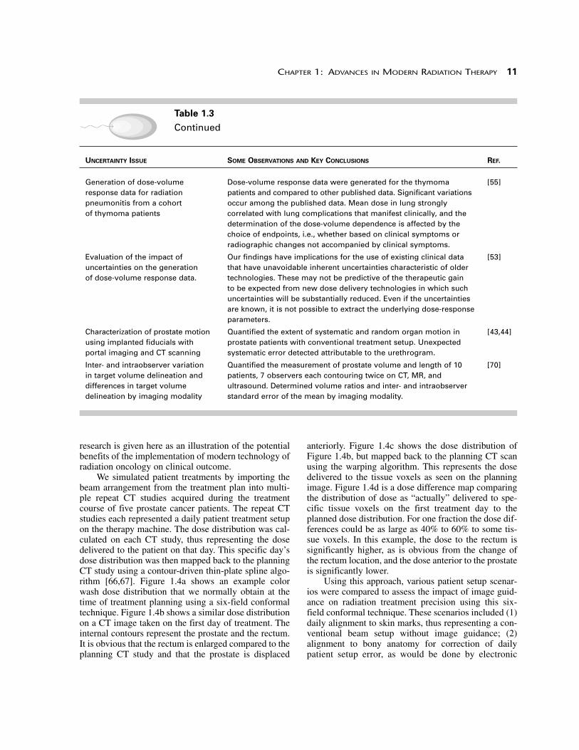
UNCERTAINTY ISSUE SOME OBSERVATIONS AND KEY CONCLUSIONS REF.
Definition of margins for defining Effects of systematic uncertainties are not always linear. Effects of [11]target volumes accounting systematic uncertainties when small are negligible but predominate for random and systematic when large; therefore, should attempt to minimize systematic uncertainties uncertainties to predefined levels. Non-uniform margins should be
used where geometric uncertainties are anisotropic and/or organs at risk may be spared.
Limitations in convolution Errors near the patient surface are significant (>20%). Our [12]calculations due to the shift modification to the convolution method greatly improves accuracy invariance assumption near surfaces (<5%). Especially relevant for targets in the head
and neck and breast regions.
Limitations in convolution For conventional fractionation schemes, the error in using [13]calculations due to the assumption convolution to generate plan evaluation parameters is smaller than of infinite number of fractions the maximum error in the dose distribution.
Impact of geometric uncertainties Intuitively one expects that geometric uncertainties will have greater [15]on hypofractionated external beam impact when fewer fractions are used. This analysis suggests that prostate treatments the magnitude of the impact is small. It does not appear that
geometric uncertainties will limit the potential therapeutic gains ofhypofractionated external beam prostate treatments.
Impact of treatment uncertainties Contrary to the widely held belief, conformal dose distributions [15,16]on modern IMRT compared to with steep dose gradients, such as the IMRT plans, are not always 3-D CRT deteriorated by random geometric uncertainties. The consideration
of geometric uncertainties can change the perception of a treatment plan considerably.
Generation of composite dose By using an image warping technique, we have been able to [68]distributions accounting for organ generate composite dose distributions to individual tissue voxels motion in daily setups accounting for daily variation in patient setup. For a clinical prostate
case, we demonstrate that there are significant localized dose differences (>10%) in a single fraction, as well as in 15 cumulative fractions, when compared to the planning dose distribution, assuming no changes in anatomy.
Treatment plan optimization Whenever the preferred Lyman scheme [47] was used to reduce the [54]using different DVH reduction DVH, competing plans were indistinguishable as long as the mean schemes and different dose was constant. The effective volume DVH reduction scheme radiobiological models did allow us to distinguish between these competing treatment
plans. However, plan ranking depended on the radiobiological model used and its input parameters.
Evaluation of the assumption in A differential response in different lung regions was evaluated in [52]radiobiological NTCP calculations rodents. If the existence of these effects is proven in humans, it will of uniform effect per unit volume. require the incorporation of geometrical and directional information
in normal tissue complication probability calculations for lung—considerations that are ignored in present approaches using conventional DVHs.
Continued
research is given here as an illustration of the potentialbenefits of the implementation of modern technology ofradiation oncology on clinical outcome.
We simulated patient treatments by importing thebeam arrangement from the treatment plan into multi-ple repeat CT studies acquired during the treatmentcourse of five prostate cancer patients. The repeat CTstudies each represented a daily patient treatment setupon the therapy machine. The dose distribution was cal-culated on each CT study, thus representing the dosedelivered to the patient on that day. This specific day’sdose distribution was then mapped back to the planningCT study using a contour-driven thin-plate spline algo-rithm [66,67]. Figure 1.4a shows an example colorwash dose distribution that we normally obtain at thetime of treatment planning using a six-field conformaltechnique. Figure 1.4b shows a similar dose distributionon a CT image taken on the first day of treatment. Theinternal contours represent the prostate and the rectum.It is obvious that the rectum is enlarged compared to theplanning CT study and that the prostate is displaced
anteriorly. Figure 1.4c shows the dose distribution ofFigure 1.4b, but mapped back to the planning CT scanusing the warping algorithm. This represents the dosedelivered to the tissue voxels as seen on the planningimage. Figure 1.4d is a dose difference map comparingthe distribution of dose as “actually” delivered to spe-cific tissue voxels on the first treatment day to theplanned dose distribution. For one fraction the dose dif-ferences could be as large as 40% to 60% to some tis-sue voxels. In this example, the dose to the rectum issignificantly higher, as is obvious from the change ofthe rectum location, and the dose anterior to the prostateis significantly lower.
Using this approach, various patient setup scenar-ios were compared to assess the impact of image guid-ance on radiation treatment precision using this six-field conformal technique. These scenarios included (1)daily alignment to skin marks, thus representing a con-ventional beam setup without image guidance; (2)alignment to bony anatomy for correction of dailypatient setup error, as would be done by electronic
CHAPTER 1: ADVANCES IN MODERN RADIATION THERAPY 11
Table 1.3
Continued
UNCERTAINTY ISSUE SOME OBSERVATIONS AND KEY CONCLUSIONS REF.
Generation of dose-volume Dose-volume response data were generated for the thymoma [55]response data for radiation patients and compared to other published data. Significant variations pneumonitis from a cohort occur among the published data. Mean dose in lung strongly of thymoma patients correlated with lung complications that manifest clinically, and the
determination of the dose-volume dependence is affected by the choice of endpoints, i.e., whether based on clinical symptoms or radiographic changes not accompanied by clinical symptoms.
Evaluation of the impact of Our findings have implications for the use of existing clinical data [53]uncertainties on the generation that have unavoidable inherent uncertainties characteristic of older of dose-volume response data. technologies. These may not be predictive of the therapeutic gain
to be expected from new dose delivery technologies in which suchuncertainties will be substantially reduced. Even if the uncertainties are known, it is not possible to extract the underlying dose-responseparameters.
Characterization of prostate motion Quantified the extent of systematic and random organ motion in [43,44]using implanted fiducials with prostate patients with conventional treatment setup. Unexpected portal imaging and CT scanning systematic error detected attributable to the urethrogram.
Inter- and intraobserver variation Quantified the measurement of prostate volume and length of 10 [70]in target volume delineation and patients, 7 observers each contouring twice on CT, MR, and differences in target volume ultrasound. Determined volume ratios and inter- and intraobserver delineation by imaging modality standard error of the mean by imaging modality.

portal imaging; and (3) alignment to the “CTV of theday” for correction of interfraction tumor motion. Afourth situation was also assessed by repeating treat-ment scenario (3) with a reduced CTV to PTV margin.Figure 1.5 shows the impact of different image guid-ance strategies using dose difference maps for (a) dailyalignment to laser marks, (b) daily alignment to bonylandmarks using, for example, electronic portal imag-ing, and (c) some form of image guidance to align thebeams to the CTV. These data, however, are for onefraction only. Table 1.4 shows the results when suchdata are accumulated over 15 fractions (only 15 sets oftreatment CT studies were available in this analysis).Clearly, there are very significant differences in dose tothe patient as determined from the calculation obtainedduring conventional treatment planning compared towhat is actually delivered to the patient when account-ing for daily geometric changes that occur as a result oforgan motion and deformation.
The use of daily realignment gives the opportunityto reduce the margin size since, in principle, the beamswill more closely align with the target. Daily realign-
ment to the tumor combined with reducing the marginsize from 1.0 cm to 0.5 cm resulted in an average esca-lation in tumor dose of 9.0 Gy in an original prescrip-tion dose of 70 Gy for all static plans while keeping thenormal tissue constraints the same. However, the esca-lated prescription dose was 13.8 Gy when accountingfor changes in anatomy by accumulating daily dosesusing nonlinear image registration techniques. Theresults from this work provide quantitative informationon the effectiveness of image-guided treatments andmay guide decisions as to when and how to implementadaptive treatments.
A further evaluation of the quantitative benefits ofimage guidance was performed by our group [73]. Thepurpose of this specific study was to evaluate variousimage-guided target localization techniques for dailypatient setup, as described above, and their potentialimpact on the outcome of prostate cancer radiation ther-apy to mitigate against geometric uncertainties, in termsof TCP and NTCP. Figure 1.6 summarizes results of adose escalation analysis considering conventional frac-tionation. For the TCP calculations, the results were
12 THE MODERN TECHNOLOGY OF RADIATION ONCOLOGY VOLUME 2
Figure 1.4(a) Dose distribution as obtained at treatment planning. Note the prostate and rectal contours. (b) The dose distributionas obtained on the first day of treatment. (c) The dose distribution from (b) as mapped onto the planning CT studyusing the warping algorithm. (d) The dose difference distribution by subtracting the distribution in (c) from that in (a).SEE COLOR PLATE 1.

generally quite consistent for each setup guidance tech-nique except when the margin was reduced with the tat-too setup technique, which resulted in a significantlylower TCP. For NTCP of the rectum, it is clear that the
image-guided technique (“CTV align”) with reducedmargin size results in the lowest NTCPs. Thus, asexpected, the most effective way to reduce NTCP wasto reduce the margin size from 10 to 5 mm combinedwith the use of image guidance. If one assumes that a5% rectal complication rate is acceptable for prostatetreatments, then it can be seen on the figure that signif-icant target dose escalation is possible with a corre-sponding increase in TCP using more advanced imageguidance procedures.
It is studies such as these that will ultimately pro-vide the optimized form of radiation treatment. Clearly,the use of image guidance along with accurate radiobi-ological models for treatment optimization will becomestandard practice in radiation treatment.
1.5 QA Considerations
The increased complexity of the modern technology ofradiation oncology places greater pressures on QA andquality control to ensure that patients are treated safely.The International Organization for Standardization(ISO) defines QA as “all those planned and systematicactions necessary to provide adequate confidence that aproduct or process will satisfy given requirements forquality” [32]. There are two major components to thisdefinition of QA. The first is that there has to be somequantitative measure that determines whether a productor process has met the desired standard. Second, if theproduct does not comply with the standard, then theremust be a defined process to bring the product in linewith the standard. ISO also defines quality control (QC)as “the regulatory process through which the actual per-formance is measured, compared to existing standardsand finally the actions necessary to keep or regain con-formance to the standard” [32]. Thus, QA is the planand definition of systematic actions and QC is theactual measurement and assessment process.
While the ISO has provided a generic definition ofQA and QC for any product or process, for radiation ther-apy there are two very major considerations. The first ofthese is that the treatment is carried out accurately andthat all uncertainties are kept to acceptable levels. Thesecond consideration relates to the avoidance of treat-ment errors or treatment misadministrations.
1.5.1 Treatment accuracy in modern
radiation therapy
It is generally well recognized that the goal of radia-tion therapy is to deliver a dose of radiation to the tar-get volume with an overall accuracy of 5%[19,29,51]. (See also chapter 9 of this volume.) How-ever, there are several issues to consider when the
CHAPTER 1: ADVANCES IN MODERN RADIATION THERAPY 13
Figure 1.5Dose difference maps for one fraction comparingtreatment on day one to the planned dose distribution for(a) daily alignment to laser marks, (b) daily alignment tobony landmarks using, for example, electronic portalimaging, and (c) some form of image guidance to alignthe beams to the CTV. SEE COLOR PLATE 2.

accuracy of 5% is quoted. First, while, in general, 5%is the desired goal, there may be circumstances where5% accuracy is not entirely necessary or where itmight be quite “costly” to achieve. “Costly” herecould consider the financial cost of treatment or itcould consider the cost to the patient in terms ofpreparation time or setup time for a more accurate
treatment. For example, one could argue that a quickemergency treatment for palliation purposes mightnot need the rigor required for a high-dose, radicaltreatment. A philosophy that is analogous to theALARA principle in radiation safety could be consid-ered in radiation therapy (i.e., in radiation safety, oneplans to allow radiation doses to any individual to be
14 THE MODERN TECHNOLOGY OF RADIATION ONCOLOGY VOLUME 2
Table 1.4
Percent Dose Differences Comparing Planning Dose Data to Specific TissueVolumes over a Course of 15 Fractions [Data from [67].]
STRUCTURE LASER SETUP SETUP CORRECTED CTV REALIGNMENT
Prostate1 �5.5 �1.4 �1.4
Rectum2 �32.7 �19.5 �5.9
Bladder2 �35.7 �35.2 �39.2
1 For a single voxel.2 For a 2 cm3 volume.
Figure 1.6Comparison of TCP and NTCP calculations for various patient setup and image guidance strategies. “Tattoo align” refersto daily setup using lasers to skin tattoo marks, and “CTV align” refers to the use of some image guidance techniquesuch as “on board” kilovoltage CT, or megavoltage CT as provided by helical tomotherapy, or ultrasound. Significanttarget dose increases are possible if rectal complication level is held constant, thus resulting in the potential ofsignificant increases in TCP.

“as low as reasonably achievable [ALARA], socialand economic factors being taken in to account”).Thus, we should use a philosophy of “as accurate asis reasonably achievable (AAARA or A3RA), techni-cal and biological factors being taken into account.” 1
This implies that perhaps 5% accuracy is not requiredunder all circumstances. Under some conditions theaccuracy should be better than 5% and under othercircumstances a larger uncertainty might be accept-able or realistic. Examples of the latter could includetotal body irradiation (although one wants to ensurethat the dose to some critical organs at risk is under-stood to an accuracy of 5% or better), some palliativetreatments (e.g., spinal cord compression or half bodyirradiation for widespread disease), and some formsof brachytherapy. Furthermore, in some regions ofdose delivery, a 5% accuracy in dose delivery will bevery difficult to achieve. Examples of this includeregions near, or in, the penumbra, or regions outsideof the penumbra where the dose is rather low, or in thebuildup region where the issues of electron contami-nation are very difficult to model accurately. Indeed,different ranges of accuracy have been quoted by var-ious reports defining criteria of acceptability for treat-ment planning computers [21,27,86,88]. Also, the cri-teria of acceptability for regions with rapidlychanging dose gradients are quoted in spatial units ofdistance to agreement (in millimeters) rather than inunits of relative dose. Note that the AAARA principle
is not an argument for “sloppy” radiation therapy.Rather it is an argument for the realistic issues asso-ciated with radiation treatment and a recognition thatthe determination of the radiation dose delivered toany point in the patient to an accuracy of 5%, at thepresent time, is unrealistic.
However, when we do aim to achieve an overallaccuracy of 5% in dose delivery to a reference point inthe patient, there are a number of subcomponents to thetreatment process that each will require its own level ofaccuracy. One relatively simple example of this is illus-trated in Table 1.5. The numbers in Table 1.5 refer pri-marily to dose delivery within high-dose regions suchas the PTV. The “overall uncertainty” is determined byadding the uncertainties associated with each subcom-ponent in quadrature.
In view of these comments about dose deliveryaccuracy, a question needs to be asked about whetherthere are any changes in accuracy requirements withmodern radiation therapy using such techniques as 3-DCRT or IMRT. As we reduce our safety margins aroundthe CTV to generate the PTV, and as we escalate pre-scription doses, there is an increased concern aboutnormal tissue complications. As a result, the spatialaccuracy associated with beam direction and dosedelivery to specific tissue volume elements (voxels)needs to be better than it has been for conventionaltherapy. Thus, improved immobilization procedures arerequired. Techniques for this have been discussed indetail by Verhey and Bentel (see chapter 3 of volume 1[89]). Furthermore, chapter 8 of this volume describesissues associated especially with thoracic treatmentswhere the effects of breathing motion are considerable.Methods of mitigating against these effects aredescribed in detail in that chapter and are now beingimplemented by a number of cancer centers.
CHAPTER 1: ADVANCES IN MODERN RADIATION THERAPY 15
[1] A similar concept was described by Van Dyk in 1983 [82] in thecontext of large-field radiation therapy. At that time, it was describedas the APARA (as precise as reasonably achievable) principle; how-ever, for interinstitutional comparison, accuracy is more importantthan precision.
Table 1.5
Examples of Accuracy Requirements in Subcomponents of RadiationTherapy Dose Determination Process
UNCERTAINTY TYPE ESTIMATED UNCERTAINTY (%)
1 Absorbed dose to reference point in water 2.5
2 Determination of relative dose (measurement away from reference point) 2.5
3 Relative dose calculation (using the treatment planning computer) 2.5
4 Patient irradiation 2.5
Overall uncertainty in dose delivery 5.0

1.5.2 The avoidance of errors
in radiation treatment
As indicated above, there are two considerations thatrationalize the need for QA in radiation therapy: thefirst has to do with ensuring treatment accuracy and thesecond deals with the avoidance of treatment errors.
Treatment errors in medicine go by various namesincluding “treatment misadministrations,” “treatmentincidents,” “treatment accidents,” “unusual occur-rences,” “treatment discrepencies,” and “adverseevents.” In 2000, the Institute of Medicine in the UnitedStates published a detailed report on treatment errors inmedicine, in general, entitled “To Err is Human: Build-ing a Safer Health System” [37]. They define treatmenterrors as “the failure of planned action to be completedas intended” (i.e., error of execution) or “the use of awrong plan to achieve an aim” (i.e., error of planning).They estimate that there are about 44,000 to 98,000people in the United States who die annually from med-ical errors. These deaths represent more than annualdeaths from motor vehicle accidents, or patients whodie from breast cancer, or deaths from AIDS. The esti-mated total annual cost of these errors is $38 to $50 bil-lion per year. The most common types of errors are cat-egorized as being related to “technical” (44%),“diagnosis” (17%), “failure to prevent injury” (12%),and “use of drugs” (10%).
The discussion of medical errors has become morepublic in recent years. This is clear from two majorreports on errors in medicine in the United States pub-lished in the early 2000s [37,72]. Similar trends have
been observed in radiation therapy. Indeed, the 2001European Society of Therapeutic Radiation Oncology(ESTRO) Gold Medal Lecture was entitled “IrradiationAccidents: Lessons for Oncology?” [10] Furthermore,the International Atomic Energy Agency (IAEA) and theInternational Commission on Radiological Protection(ICRP) published reports in 2000 on “lessons learnedfrom accidental exposures” and “prevention of acciden-tal exposures” in radiation therapy, respectively [28,31].More recently, individual institutions have publishedsummaries of their own recorded/reported error rates[24,95]. Huang et al. [24] concluded that new technol-ogy can produce new ways for errors to occur, necessi-tating ongoing evaluation of QA for radiation therapy.
The recent reviews of accidental exposures in radi-ation therapy by international committees [28,31] pro-vide some clear lessons that should be recognized by theprofessionals involved in prescribing, calculating, anddelivering radiation treatments. The IAEA report [28]describes 92 accidental exposures in radiation therapyand highlights some lessons that can be learned from thereview of these accidental exposures. Table 1.6 summa-rizes the number of specific types of errors that theyreviewed. The information on these accidental expo-sures was derived from reports to regulatory authorities,professional associations, or scientific journals, or theincidents became known through other publications.
Similarly, the ICRP report [31] reviews a numberof case histories of major accidental exposures ofpatients undergoing radiation treatment, with theintent of preventing such accidents from recurring inother institutions.
16 THE MODERN TECHNOLOGY OF RADIATION ONCOLOGY VOLUME 2
Table 1.6
Summary of Types of Accidental Exposures Reported by the IAEA [Data from [28].]
CATEGORIES NUMBER OF ACCIDENTS
Radiation measurement systems 5
Machine commissioning/calibration 15
External beam: treatment planning, patient setup, treatment 26
Decommissioning of teletherapy equipment 2
Mechanical/electrical malfunctions 4
Brachytherapy low dose rate sources/applicators 29
Brachytherapy high dose rate 3
Unsealed sources 8
Total 92

It is not possible to address the details of the IAEAand ICRP reports in this chapter; however, it is possibleto highlight the broad issues associated with occurrenceof such accidents:
• Insufficient education• Lack of procedures/protocols as part of a compre-
hensive QA program• Lack of supervision of compliance with a QA pro-
gram• Lack of training for “unusual” situations• Lack of a “safety culture”
Insufficient education will result in lack of aware-ness. Accidents can happen due to inattention to detailsand lack of alertness. This can be exacerbated by situa-tions where personnel work in less than ideal condi-tions, in understaffed departments with long workinghours and high patient throughput.
Accidents are also more likely to happen whenthere is a lack of policies, procedures, and checks inthe treatment system. Furthermore, there needs to beconstant vigilance to ensure that the procedures thathave been developed are fully implemented, or if theprocedures are changed, that the documentation isupdated appropriately.
Errors are also more likely to happen when the staffare not trained appropriately or lack proper qualifica-tions. Furthermore, staff at all levels need to be madeaware of the distinction between standard proceduresand unusual situations. Whenever unusual situationsoccur, staff should always be encouraged to ask ques-tions, and no question should be considered a “stupid”question. An open attitude to uninhibited questionsleads to a positive safety culture. A discouragement ofquestions or a negative attitude to questions leads to anegative safety culture.
It is also important that responsibilities and lines ofauthority are defined clearly so that there are no gaps orambiguities as to who is responsible for specific tasks.In chapter 2 of volume 1 [87], a clear description wasgiven of the need for a QA committee that includes rep-resentation of the major professionals involved in radi-ation treatment.
Radiation professionals need to realize that majorradiation accidents are possible in any clinic. The mini-mization of such accidents is strongly dependent on theQA structure of the clinic, on the professional educationof the staff, on onsite training for the use of new tech-nologies as they are brought into the clinic, and on theattitude related to QA, especially by those who have moreresponsibility and authority. The combination of theseissues generates a very positive radiation safety culture,with the result that there will be due diligence by all staffinvolved in treating patients with radiation therapy.
One approach to minimize the possibility of acci-dents is to use “defense in depth.” This is defined as theapplication of more than one single protective measurefor a given safety objective such that the objective isachieved even if one of the protective measures fails.Defense in depth can be viewed as several layers ofsafety provisions, such as physical components and pro-cedures. For this multilayered accident prevention towork, these layers need to be independent of each other.The following is an example of such multilayers for aspecific incident. One of the reported errors consisted ofmistakenly inverting the SSD correction in the MU cal-culation. If only one calculation is done before the patientis treated then this would be considered a single layerbetween the actual calculation and the dose delivery. Alayer can be added by performing an independent checkof the MU calculation by another individual. A furtherlayer can be added by doing a weekly chart check for“reasonability” of the result. In vivo dosimetry wouldadd a further layer. Having a detailed write-up on MUcalculation procedures would be equivalent to anotherlayer, assuming, of course, that the written proceduresare referred to regularly. Another layer would be added ifthe staff are well trained in recognizing that a shortertreatment distance means less MUs for the same dose.
The following is a series of questions that serve asa checklist for accident or error prevention in radiationtherapy. These evolved out of the IAEA report [28].Note that these are only examples of some of the issuesthat need to be considered.
• Organization, Functions, and Responsibilities■ Have all necessary functions and responsibilities
been allocated?■ Are all functions and responsibilities understood?■ Is the number of staff commensurate to workload?■ Is this number reassessed when workload increases,
or when new equipment is purchased?
• Education and Training■ Is every member of staff educated and trained
according to their responsibilities? Is this educa-tion and training documented?
■ Is there a program for continuing and individualdevelopment?
■ Are lessons from accidents and their preventionincluded in continued training?
■ Are there provisions for additional training (newequipment, new procedures)?
■ Are emergency plans exercised as part of thetraining?
• Acceptance Testing and Commissioning■ Is there a program for formal acceptance of
equipment in place?
CHAPTER 1: ADVANCES IN MODERN RADIATION THERAPY 17

■ Is it carried out according to international ornational standards?
■ Is there a program of commissioning in place?■ Does it include treatment equipment as well as
treatment planning systems, simulators, andother ancillary equipment?
• QA Program■ Is a program of QA established?■ Is the program based on accepted protocols?
Which ones?■ Are all tasks associated with QA clearly assigned
to the right persons?■ Are the necessary tools and instruments available?■ Are audits part of the QA program?
• Communication■ Is a communication policy in place and under-
stood by staff?■ Is reporting of unusual equipment behavior
required?■ Is reporting of unusual patient reactions required?■ Are procedures in place for equipment transfer
from maintenance back into clinical use?
• Patient and Site Identification■ Are there procedures to ensure correct identifica-
tion of the patient and clinical treatment site?■ Is there a protocol for the patient’s chart check?
• External Beam Calibration■ Are there provisions for initial beam calibration?■ Is independent verification in place, foreseen,
and planned?■ Is there an accepted protocol? Which one?■ Is a program for follow-up calibration in place?■ Is participation in an audit program part of the
QA program?
• External Beam Treatment Planning and In VivoDosimetry■ Are treatment planning systems included in the
program of acceptance and testing?■ Is treatment planning documented according to
accepted protocols?■ Are crosschecks and redundant and independent
verification included?■ Has a system for in vivo dosimetry been con-
sidered?
As summarized in IAEA TRS-430 [27], the majorissues that relate to QA and avoidance of errors in radi-ation therapy can be summarized by four key words:
1. Education2. Verification3. Documentation4. Communication
Education
In the treatment planning context, education is requiredboth at the technical/professional level, in terms ofusage of the treatment planning system, and at the orga-nizational level, with respect to institutional policiesand procedures. A very important component of educa-tion relates to understanding software capabilities andlimitations. Especially relevant here are issues thatrelate to dose calculation normalization procedures,treatment setup parameters as used by the computercompared to the actual treatment machine, time or MUcalculations, and inhomogeneity corrections. A misin-terpretation of any of these calculation procedures canpotentially yield significant treatment errors. Inbrachytherapy, issues of significant concern relate tosource activity specification and how the algorithm usesthis specification.
Verification
Nearly 60% of the reported errors that related to treat-ment planning involved a lack of an appropriate inde-pendent secondary check of the treatment plan or dosecalculation. Clearly, verification is also required whencalibrating radiation therapy machines, especially fornewly installed machines in the department. Such cali-brations should be repeated completely independently,with an independent person and an independent detec-tor/electrometer system (see chapter 9 of this volume).
Documentation
Clear documentation is required of each patient’s indi-vidual treatment plan, and of departmental policies andprocedures.
Communication
Open communication among staff members is essen-tial for all aspects of treatment, since various people atvarious professional levels are involved in the treat-ment process. Poor communication was a key factor ina number of the errors reported.
1.6 The Future of theModern Technology ofRadiation Oncology
In its simplest form, the aim of radiation therapy is tocure the tumor without harming the patient. The scienceand technology involved in achieving this aim are mul-tidisciplinary and multifaceted. While the aim of radia-tion therapy has not changed since the discovery of ion-izing radiation in 1895, the focus and emphasis haschanged dramatically over the years, depending on thestate of understanding of the biology and on the avail-
18 THE MODERN TECHNOLOGY OF RADIATION ONCOLOGY VOLUME 2

ability of the latest technology. Earlier in this chapter,reference was made to the five phases in the evolution ofthe technology of radiation oncology (Table 1.1). Duringthis period there has also been an evolution in the under-standing of the basic biology of cancer, the radiobiologyof the treatment of this disease, and the clinical resultsassociated with treatment advances. We are now evolv-ing into a phase in which advances will take placethrough an integration of knowledge from basic biology,radiation oncology, technology, and clinical medicine.In a summary of the International Conference on Trans-lational Research held in 2003, Coleman [8] referred tothe five components of radiation oncology that, whenbrought together, provide advances in cancer treatmentand prevention. He categorized these areas of expertiseinto basic science, imaging, mathematical and biologicalmodels, biology-based therapy, and technology. Figure1.7 is reproduced from his paper and summarizes thecontents of each of these “pillars.”
As shown in Figure 1.7, underpinning the entirefield are education, training, and mentoring—particularlyfor trainees and young faculty—and service, collabora-
tion, and dedication to mission—intangibles that addvalue for patients and society. Coleman goes on todescribe each of these pillars in significant detail basedon the deliberations at this conference. It is interesting tonote that even in this and the previous volume of TheModern Technology of Radiation Oncology [85], each ofthese pillars has been addressed to different degrees.Components of basic biology are a necessary under-standing for radiobiological modeling in treatment plan-ning (chapter 5, this volume). Imaging for therapy plan-ning plays a major role in radiation therapy (“If you can’tsee it, you can’t hit it. If you can’t hit it, you can’t cureit.”2) and is addressed in chapters 5 and 7 of volume 1and in chapter 2 of this volume. Of course modeling isinvolved in dose computations, as is radiobiologicalmodeling (chapters 8, 12, and 15 of volume 1 and chap-ters 3, 4, 5, 6, and 10 of volume 2). Biological treatmentwas addressed in chapters 22, 23, 24, and 25 of volume 1.
CHAPTER 1: ADVANCES IN MODERN RADIATION THERAPY 19
Figure 1.7Coleman’s pillars for advances in clinical care. The five areas that support patient care are basic science, imaging,mathematical and biological models, biologically based therapy, and technology. [Figure reproduced with permissionfrom [8].]
2 This is a quote that was often used by the late William E. Powers(internationally recognized radiation oncologist) and the late HaroldE. Johns (internationally recognized medical physicist).

Finally, the technology of radiation oncology is addressedthroughout both volumes of this series. As Colemanpoints out, while the five pillars are partly “self-sustainingfields,” the common goal is clinical care.
So what is it that we can expect to see in the nextdecade? Predicting the future, of course, is based onpast experience and how this may be projected into thefuture. There have been a number of workshops withinthe last few years that have addressed future researchdirections and priorities in radiation oncology. A reviewof these workshops will give some sense as to the direc-tion that the field is taking, although there is very littlesense as to how fast we will get there. Battista andBauman [4] provided an interesting perspective on thefuture of IMRT in the proceedings of the 2003 AAPMSummer School on Intensity Modulated RadiationTherapy: The State of the Art. They first point out thatthe underlying hypothesis of advanced technologiessuch as IMRT is that loco-regional control of cancerremains a significant barrier to cancer cure for manycommon cancers [40,79]. They looked at the cost-ben-efit ratio as a good prognostic indicator for thelongevity of a new product, process, or service. Figure1.8 is adapted from their chapter and illustrates a quali-tative ranking of various technologies and techniques,including IMRT, versus the technical complexity andcost required for implementation. The evolution fromthe kilovoltage era to the megavoltage era resulted insignificant gains at a relatively low cost. As indicated inTable 1.1, the advent of x-ray CT scanning led the wayfor 3-D imaging and treatment planning. Computer-controlled accelerator technology with MLCs allowedthe capability of intensity-modulated arc therapy in aforward-planned mode (SIMAT) [92] or using inverseplanning (IMAT, IMRT) [26,97]. Finally, the move intohigh linear energy transfer (LET) particles offers radio-biological advantages with relative radiobiologicaleffectiveness (RBE) and oxygen enhancement ratio(OER) differentials.
In 2001, Herman Suit [74] appropriately pointedout that there are two basic strategies to increase theefficacy of radiation therapy. The first is to reduce thetreatment volume, i.e., irradiate a smaller volume ofnormal tissue while irradiating the defined target vol-ume in each treatment session. This strategy not onlyincludes techniques of treatment planning and delivery,but also the ability to define the anatomic margins andtopographic distribution of clonogen number and radia-tion resistant foci in the tumor. The second is to increasethe differential response between tumor and normal tis-sue by taking advantage of things like chemotherapeu-tic drugs, biologic agents, and genetic and proteomictechniques. The former are within the realm of nearfuture reality, i.e., in the next 10 years. The latter could
potentially result in larger gains but are likely to yieldresults in the more distant future.
So what are the factors that are likely to be imple-mented in the next decade, which will aid in the reduc-tion of treatment volumes with the correspondingpotential for increases in target doses?
1.6.1 Improved imaging technologies for
target and normal tissue definition
Section 1.3.2 and Table 1.2 have already summarizedthe potential gains from using a variety of imaging tech-nologies dependent upon specific clinical situations.Many of the imaging modalities listed in Table 1.2 arebecoming more readily available to radiation oncolo-gists. PET/CT units, MRI, MRS, and ultrasound will beused selectively for specific clinical sites to aid in targetdefinition and definition of subregions within the tumorthat may need a preferential increased dose compared tothe rest of the target volume. Chapter 2 of this volumeclearly defines the advantages of these various imagingmodalities. It is likely that within the decade, many can-cer patients will be imaged by more than one modalityto aid in the definition of regions to be irradiated and
20 THE MODERN TECHNOLOGY OF RADIATION ONCOLOGY VOLUME 2
Figure 1.8Schematic of benefit versus cost achieved with technicaladvances in radiation therapy. kV, kilovoltage x-rays; MV,megavoltage x-rays; 3-D CRT, 3-D conformal radiationtherapy; SIMAT, simplified intensity-modulated arctherapy (forward planned); IMAT, intensity-modulated arctherapy (inverse planned); IMRT, intensity-modulatedradiation therapy; Hi LET, High LET charged particleradiation therapy; Hi LET IMRT, High LET charged particleintensity-modulated radiation therapy. [Adapted withpermission from [4].]

regions to be spared. What is not clear yet is how spe-cific these imaging technologies will be. For example,will imaging allow for the clear definition of hypoxicregions for many tumors within the decade?
1.6.2 Increased use of image
registration/fusion technologies
Based on the use of multiple imaging modalities, it isclear that software is required to correlate and registerthese images, such that they can be compared directly.This software already exists and is being used routinelyfor combined modality scanners such as PET-CT scan-ners. Furthermore, most virtual simulation softwarenow allows the import of images from different sourcesfor direct comparison using image registration/fusiontechniques. Added to this is imaging for therapy verifi-cation using image guidance technologies, each ofwhich will require image registration comparing thepatient setup (image) of the day with the planningimages. We already see these technologies in clinicalpractice with the use of megavoltage CT on helicaltomotherapy, with cone beam kilo- or megavolotage CTon conventional accelerators, and with ultrasound guid-ance. It is likely that within the decade, many of ourpatients will be treated with the application of imageregistration either as part of the planning process or aspart of the dose delivery process.
1.6.3 Increased use of IMRT with improved
optimization algorithms
IMRT is now a technology that is potentially availablein various forms in the vast majority of clinics in NorthAmerica. In this volume, chapter 4 describes the recentadvances in inverse planning algorithms, and chapter 6describes the clinical application of IMRT. It isexpected that IMRT will be standard practice within thedecade and that the majority of radical cases will betreated with some form of IMRT.
One of the major issues in optimizing treatmentplans using inverse planning is the definition of objec-tive functions and corresponding constraints for theseobjective functions. To date, most of these functionsand constraints are based on dose-volume objectives(see chapter 4). It is intuitively clear, however, thatradiobiological relevance exists within radiobiologicalmodels and the use of radiobiological objectives. Asindicated in chapter 5 in this volume, these models arebeing developed at a rapid rate; however, at this stagethey should be used guardedly and certainly not yet forroutine treatment planning. The knowledge of clinicaldata remains limited, such that the predictive capabili-ties tend to be assessed over only a small range of con-
ditions. Furthermore, the uncertainties in the predictedclinical responses are still very large. For the presenttime these models should be used only with the fullunderstanding of the ramifications of the model predic-tions. While it is likely that their use will be increasedover the next decade, especially in the context of devel-oping dose-escalation protocols, it is not clear thatenough new radiobiological data will be generated withsufficiently small uncertainties to allow them to be usedroutinely in all clinical settings.
As part of the enhancements of optimization mod-els, more emphasis will be placed on uncertainty esti-mates, both for patient cohorts and for individualpatient treatments. An example of such analysis wasdescribed by Deasy et al. [18] in the context of theeffect of plan evaluation of uncertainty in tolerance lim-its. This is an area of research by our group, as well asat other academic institutions. The results of thisresearch should provide a significant aid to the opti-mization process over the next decade.
1.6.4 Increased use of 4-D imaging and
breathing-controlled treatment
The technology now exists for 4-D CT scanning suchthat we can obtain images of the patient during individ-ual phases of the breathing cycle (see chapter 8, thisvolume). Furthermore, these data can be used todevelop treatment plans for patients with reduced CTVto PTV margins, thereby reducing normal tissue irradi-ation, thus allowing for increased target doses. Further-more, the application of breathing control or gatedtreatment is possible. Thus, while these technologiesexist, albeit at an embryonic stage, their application willbe greatly increased over the next decade.
1.6.5 Increased use of image guidance for
reproducible patient setups
As has already been alluded to in this chapter, imageguidance is playing an increasing role as part of thedaily patient setup procedure. Chapter 7 of this volumeprovides a recent update on chapters 13 [58] and 15[60] of volume 1. These techniques have become anessential component of reducing the volume of normaltissues irradiated and allowing dose escalation withIMRT treatments.
1.6.6 Increased use of particle therapy
Herman Suit [74] argues strongly that the use of inten-sity-modulated proton therapy (IMPT) is the ultimate inlow-LET external beam radiation therapy. The physics ofproton therapy has been discussed in detail by Moyers in
CHAPTER 1: ADVANCES IN MODERN RADIATION THERAPY 21

chapter 20 of volume 1 [57]. With the added capabilityof IMPT, Suit [74] argues that because of the dose dis-tribution advantages of proton beams, it is likely thatthey will replace photon beams over the next two tothree decades. This trend appears to already be inprogress considering the number of new proton therapyfacilities that have recently been implemented or are tobe implemented in the near future (in 2003, 23 protonfacilities were in existence and 22 were being planned[50]). However, at this time the cost of proton therapyremains prohibitive, and unless new and less expensiveproton sources are obtained, it will take a significanttime before photon beam therapy is replaced by protonbeams. However, recent research by Fourkal et al. [20]indicates the possibility for laser-generated IMPT as apotential for making proton therapy cost-effective.
While heavy ion therapy is another evolving tech-nology that has been pursued by the Germans and Japan-ese [34], there is a growing interest by the Europeans inlight ion therapy [80]. Light ion beam therapy may allowa somewhat better geometric precision in dose deliverycompared with proton beams, since the penumbra andthe Bragg peak decrease with increasing atomic number.Turesson et al. [80] give three reasons why therapy withlight ion beams with atomic numbers in the range of Z �2 to Z � 6 might be more advantageous than heavy ionbeams with Z � 7. First, the LET for heavier ions is quitehigh, also in regions of normal tissue irradiation, thusincreasing the risk of complications. Second, heavy ionsfragment into lighter ions that have ranges beyond theBragg peak, thus leaving a “tail” in the depth-dose distri-bution. Third, it is argued that there is an increasing riskthat higher LET radiation could result in “cold spots” inthe dose distribution, thus risking tumor recurrence. Amajor concern about ion beams with particles heavierthan protons is that their RBE is not as well understood.Indeed, the RBE is dependent on the cell types being irra-diated and on the location within the depth-dose curve.Thus, while light ion beams are being developed andimplemented in a number of European centers, they willnot likely comprise a large component of radiation ther-apy treatments over the next decade.
1.6.7 Increased use of brachytherapy
Battista and Bauman [4] indicated that brachytherapywas the first method to achieve “conformal radiationtherapy,” and well before external beam CRT. The useof high-dose-rate brachytherapy technology (see chap-ter 18, volume 1 [22]), as well as low dose rateimplants, especially as used for prostate cancer treat-ments (see chapter 10, this volume), has increased sig-nificantly in the last decade and is likely to increaseeven more in the next decade. Brachytherapy for partial
breast irradiation is also a growing trend [62,64,90].Vicini and Arthur [90] conclude that accelerated partialbreast irradiation using brachytherapy has great poten-tial to overcome many of the barriers that have pre-vented women from pursuing standard breast-conserv-ing therapy and thus could find a significant increase inusage during the next decade.
The use of 3-D ultrasound (see chapter 7 of volume1 [63]) combined with the introduction of robotics pro-vides the potential for advancing brachytherapy appli-cations even further [91].
1.6.8 Increased QA
As a result of the increased complexity of the multiplecomponents associated with the modern technology ofradiation oncology, there is clearly a need for increasedactivity associated with the commissioning and QA ofthese new technologies. QA was addressed in a genericsense in chapter 2 of volume 1 [87], and some recentissues were addressed in section 1.5 above. Moderntools for commissioning and QA are evolving toaddress the 3-D and 4-D nature of the new treatmenttechniques. Figures 1.9 through 1.13 demonstrate newphantoms and techniques developed by our group asexamples of addressing QA associated with the newtechnologies. Figure 1.9 shows a commercial phantomused to assess the image display components of beamgeometries as used on 3-D virtual simulators and treat-ment planning software [14,49]. Figure 1.10 shows amulticomponent “body” phantom used for volumeassessments as would be used in DVH determination,for autocontouring tools, for automargining tools, forIMRT dose delivery assessment, for patient-specificdosimetry, for CT number to electron density conver-sion, and a number of other tests. Figure 1.11 shows anIMRT verification phantom that can hold films or ion-ization chambers. Figure 1.12 shows the prototypemodel of a moving “lung” phantom for assessing gatingcapabilities and reproducibility. It is clear that withIMRT, individualized, patient-specific QA is requiredlargely to address the concerns of the “black boxes” inFigure 1.3. Either the commissioning or the patient-spe-cific QA can be aided by the use of 3-D dosimetry. Fig-ure 1.13 shows the latest commercial tools for 3-D geldosimetry using optical CT as the readout process togenerate 3-D dose distributions [36]. Clearly, tools ofthis nature will continue to evolve as treatment technol-ogy becomes more complex.
1.6.9 Increased need for medical physicists
It is clear from the earlier parts of this chapter that theneed for well-trained and highly specialized medical
22 THE MODERN TECHNOLOGY OF RADIATION ONCOLOGY VOLUME 2

CHAPTER 1: ADVANCES IN MODERN RADIATION THERAPY 23
Figure 1.9Phantom used to assess beam display accuracy on CT-simulator virtual simulation stations or on treatmentplanning computers [14,49]. [Picture courtesy of ModusMedical Devices, Inc.]
Figure 1.10Phantom for assessing multiple nondosimetric as well asdosimetric components of treatment planning systems.The following are some nondosimetric features that canbe assessed: geometric accuracy of 2-D images and 3-Dimage reconstructions; 2-D and 3-D measurement toolsincluding volume calculation accuracy; automatic,semiautomatic, and manual boundary identification tools;automargining tools; representation and manipulation ofcontoured patient anatomy; DVHs; conversion of CTnumbers to relative electron densities; comparison ofdisplay on CT simulators, radiation treatment planningsystems, and other imaging work stations; image transfer,storage, retrieval, DICOM tools on all workstations. Thefollowing dosimetric components are also possible: ionchamber locations include on-axis and multiple off-axislocations for measurements in low- and high-dosegradient regions; blank acrylic inserts for homogeneousdensity tests; two lung equivalent inserts and a spineequivalent rod for a variety of inhomogeneous densitytests with precisely determined, near anthropomorphicgeometry; a sphere representing a prostate volume forcontouring and automargining assessment; light fieldalignment tests. [Picture courtesy of Modus MedicalDevices, Inc.] SEE COLOR PLATE 3.
physicists is increasing. Not only is the technologybecoming extremely complex, but, in addition, the patientpopulation continues to increase as well, especially as aresult of the postwar baby boom and an aging population.As Battista and Bauman [4] have indicated, the expectedpatient population growth rate is approximately 2.5% peryear over the next decade, while medical physics staffgrowth rates may be more realistically estimated at 5%per year to account for the increased workload associatedwith the increased sophistication and complexity of themodern technology of radiation oncology.
In a recent “point/counterpoint” in the journalMedical Physics, the proposition was, “Over the fore-seeable future, the growth in technical complexity ofradiation therapy will continue to drive the demand formore medical physicists.” Arguing for the propositionwas Saiful Huq [25], and against the proposition, JasonSohn [71]. Huq [25] quoted from the American Collegeof Radiology survey [61] in the United States, whichshowed that between 1983 and 1994 the number of full-time equivalent (FTE) physicists increased by 60%. TheAbt studies of medical physicist work values [1,2]showed that between 1995 and 2003, practices offeringremote-controlled afterloading brachytherapy increasedfrom 46% to 66%, the availability of MLCs increasedfrom 19% to 79%, and electronic portal imaging rose from20% to 53%. Technology-intensive procedures such asprostate seed brachytherapy rose to 89%, 3-D CRT(non-IMRT) to 92%, coronary vascular brachytherapyto 74%, and record and verify systems to 87%. The
median relative work estimates for a qualified medicalphysicists increased by a factor of 12 for IMRT treat-ment planning, 14 for special medical physics consulta-tion, and 16 for IMRT special physics consultation [2].As Huq points out, these numbers indicate that the dis-cipline of radiation oncology is continually changing inresponse to technology, practice, and state and federalregulations. However, Sohn [71] contends that as theradiation therapy technologies mature, convergingtreatment systems will be less complicated, require lessspace, and eventually reduce the demand on physicists.Thus, streamlining of physics activities will decreasethe demand for physicists. While these are interestingconjectures, experience over the last three decades—three decades in which we have experienced tremen-dous technological developments—has shown contin-

24 THE MODERN TECHNOLOGY OF RADIATION ONCOLOGY VOLUME 2
Figure 1.11The verification phantom comprises a cylindrical phantom, a film cassette, and several inserts for holding andpositioning an ion chamber at any point along the diameter of the phantom. The film cassette holds half-sized sheets offilm and can hold either one or two of these sheets at a time. Inserts are available for ion chambers from several majorsuppliers. The 360° rotation of the cylinder allows the films to be placed orthogonal to the beam direction or ionchambers to be placed at any desired location. [Picture courtesy of Modus Medical Devices, Inc.]
Figure 1.12Prototype model of a moving “lung” phantomfor assessing gating capabilities andreproducibility. The white platform near thecenter of the phantom is for positioning theVarian RPM® (Varian Medical Sysyems, PaloAlto, CA) gating block normally placed on thepatient’s chest. By using different cams underthis platform, different breathing styles can besimulated. The moving “lung” has an insertfor small dosimeters such as MOSFETs toassess the quality of the gating system on thelinear accelerator. [Picture courtesy of ModusMedical Devices, Inc.]

CHAPTER 1: ADVANCES IN MODERN RADIATION THERAPY 25
ued increase in the demands on medical physicists andthe increased need for medical physicists. Based onthese three decades and based on the advancing natureof the complexity of the technology of radiation oncol-ogy, it is likely that there will be a greater demand for,and demand on, medical physicists.
1.7 Summary
The modern technology of radiation oncology continuesto progress at an unprecedented rate. The need for theseadvancements is based on the underlying assumptionthat the new, complex technologies will improve loco-regional control of cancer and therefore cure morepatients. Research has shown that improvements inpatient setups using image guidance technologies hasthe potential for dose escalation, with a correspondingincrease in predicted local control, while maintainingthe same level of normal tissue complications. Althoughclear proof of improvements in long-term survivalremain to be obtained, examples of improvement in bio-chemical control for prostate cancer while reducing rec-tal complications have been published [40,79].
The new technologies result in new demands on thetotal QA process for radiation treatment. Additionalsteps and more accuracy are required in patient setup.QA procedures need to be enhanced because significantcomponents of the treatment process are performed“automatically,” resulting in dose delivery techniquesthat are no longer intuitively obvious. Thus, the userneeds to develop confidence that the class solutions toQA procedures will be sufficient to check the built-insafety devices on modern treatment technologies. Espe-
cially because of these added complexities, significantemphasis needs to be placed on four key components ofany QA program: education, verification, documenta-tion, and communication. Furthermore, it is importantthat a “safety culture” be nurtured within the radiationprogram and throughout the organization.
Predictions over the next decade project anincreased use of imaging for therapy planning, anincreased use of software tools to register images frommultiple imaging sources, and an increased demand forIMRT with the application of image guidance for dailysetups. 4-D imaging with breathing-controlled or gatedtherapy will be applied more frequently to thoracictumors. There will likely be increased applications ofbrachytherapy. Particle therapy, especially protons, willalso gain in activity, although these will likely be lim-ited to larger academic institutions since the costs arestill prohibitive. Significant expansions in these pro-grams are likely to occur beyond the next decade.
All of these advances in modern technology, and agrowing patient population, will place greater demandson the number of medical physicists required, as well asthe need for sophistication of education and training todeal with these advanced technologies.
Ultimately these advances in the technology ofradiation oncology will benefit the cancer patient byimproving the likelihood of cure with reduced compli-cations, resulting in a better quality of life.
Acknowledgments
Some of the work presented in this chapter is based onresearch from our group at the London Regional Cancer
(a) (b)
Figure 1.13(a) Picture of the optical CT scanner used for generating 3-D dose distributions from gel dosimetry [36]. [Picture courtesyof Modus Medical Devices, Inc.] (b) Gel showing color change due to 3-D dose delivery. [Picture courtesy of Kevin Jordanand Jerry Battista.] SEE COLOR PLATE 4.

Program, London, Ontario, Canada. I would especiallylike to acknowledge the following students and col-leagues for their contributions to this research: Glenn
Bauman, Jerry Battista, Tim Craig, Tomas Kron,Andrea McNiven, Vitali Moiseenko, Bryan Schaly, andWilliam Song.
26 THE MODERN TECHNOLOGY OF RADIATION ONCOLOGY VOLUME 2
References
1. Abt Associates Inc. “The Abt Study of Medical Physicist Work Values for Radiation Oncology Services.” Prepared for theAmerican College of Medical Physicists (ACMP) and the American Association of Physicists in Medicine (AAPM), 3 Octo-ber 1995.
2. Abt Associates Inc. “The Abt Study of Medical Physicist Work Values for Radiation Oncology Physics Services.” Preparedfor the American College of Medical Physics (ACMP) and the American Association of Physicists in Medicine (AAPM),June 2003.
3. Alasti, H., M. P. Petric, C. N. Catton, P. R. Warde. “Portal imaging for evaluation of daily on-line setup errors and off-lineorgan motion during conformal irradiation of carcinoma of the prostate.” Int. J. Radiat. Oncol. Biol. Phys. 49:869–884(2001).
4. Battista, J. J., and G. S. Bauman. “The Future of IMRT.” In Intensity-Modulated Radiation Therapy. J. R. Palta and T. R.Mackie (Eds.). (Madison, WI: Medical Physics Publishing), pp. 843–873, 2003.
5. Bjarngard, B., P. Kijewski, C. Pashby. “Description of a computer-controlled machine.” Int. J. Radiat. Oncol. Biol. Phys.2:142 (1977).
6. Brahme, A., J. E. Roos, I. Lax. “Solution of an integral equation encountered in rotation therapy.” Phys. Med. Biol.27:1221–1229 (1982).
7. Chapman, J. D., J. D. Bradley, J. F. Eary, R. Haubner, S. M. Larson, J. M. Michalski, P. G. Okunieff, H. W. Strauss, Y. C.Ung, M. J. Welch. “Molecular (functional) imaging for radiotherapy applications: An RTOG symposium.” Int. J. Radiat.Oncol. Biol. Phys. 55:294–301 (2003).
8. Coleman, C. N. “International conference on translational research ICTR 2003, conference summary: Marshalling resourcesin a complex time.” Int. J. Radiat. Oncol. Biol. Phys. 58:307–319 (2004).
9. Cormack, A. M., and R. A. Cormack. “A problem in rotation therapy with X-rays: Dose distributions with an axis of sym-metry.” Int. J. Radiat. Oncol. Biol. Phys. 13:1921–1925 (1987).
10. Cosset, J. M. “ESTRO Breur Gold Medal Award Lecture 2001. Irradiation accidents: Lessons for oncology?” Radiother.Oncol. 63:1–10 (2002).
11. Craig, T., J. Battista, V. Moiseenko, J. Van Dyk. “Considerations for the implementation of target volume protocols in radi-ation therapy.” Int. J. Radiat. Oncol. Biol. Phys. 49:241–250 (2001).
12. Craig, T., J. Battista, J. Van Dyk. “Limitations of a convolution method for modeling geometric uncertainties in radiationtherapy. I. The effect of shift invariance.” Med. Phys. 30:2001–2011 (2003).
13. Craig, T., J. Battista, J. Van Dyk. “Limitations of a convolution method for modeling geometric uncertainties in radiationtherapy. II. The effect of a finite number of fractions.” Med. Phys. 30:2012–2020 (2003).
14. Craig, T., D. Brochu, J. Van Dyk. “A quality assurance phantom for three-dimensional radiation treatment planning.” Int. J.Radiat. Oncol. Biol. Phys. 44:955–966 (1999).
15. Craig, T., V. Moiseenko, J. Battista, J. Van Dyk. “The impact of geometric uncertainty on hypofractionated external beamradiation therapy of prostate cancer.” Int. J. Radiat. Oncol. Biol. Phys. 57:833–842 (2003).
16. Craig, T., E. Wong, G. Bauman, J. Battista, J. Van Dyk. “Geometric uncertainties in the evaluation of prostate treatmentplans.” (Abstract). Med. Phys. 30:1506–1507 (2003).
17. Davey, T. J., and J. A. Brace. “Dynamic 3-D treatment using a computer-controlled machine.” Br. J. Radiol. 53:612–616(1979).
18. Deasy, J. O., A. Niemierko, D. Herbert, D. Yan, A. Jackson, R. K. Ten Haken, M. Langer, S. Sapareto. “Methodological issuesin radiation dose-volume outcome analyses: Summary of a joint AAPM/NIH workshop.” Med. Phys. 29:2109–2127 (2002).
19. Dutreix, A. “When and how can we improve precision in radiotherapy?” Radiother. Oncol. 2:275–292 (1984).20. Fourkal, E., J. S. Li, W. Xiong, A. Nahum, C. M. Ma. “Intensity modulated radiation therapy using laser-accelerated protons:
A Monte Carlo dosimetric study.” Phys. Med. Biol. 48:3977–4000 (2003).21. Fraass, B., K. Doppke, M. Hunt, G. Kutcher, G. Starkschall, R. Stern, J. Van Dyk. “American Association of Physicists in Med-
icine Radiation Therapy Committee Task Group 53: Quality assurance for clinical radiotherapy treatment planning.” Med.Phys. 25:1773–1829 (1998).
22. Glasgow, G. P. “Brachytherapy.” In: The Modern Technology of Radiation Oncology: A Compendium for Medical Physicistsand Radiation Oncologists. J. Van Dyk (Ed.). (Madison, WI: Medical Physics Publishing) pp. 695–752, 1999.

23. Green, A. “Tracking cobalt project.” Nature 207:1311 (1965).24. Huang, G., G. Medlam, J. Lee, S. Billingsley, J. P. Bissonnette, J. Ringash, G. Kane, D. C. Hodgson. “Error in the delivery
of radiation therapy: Results of a quality assurance review.” Int. J. Radiat. Oncol. Biol. Phys. 61:1590–1595 (2005).25. Huq, M. S. “Over the foreseeable future, the growth in technical complexity of radiation therapy will continue to drive the
demand for more medical physicists.” Med. Phys. 31:2939–2940 (2004).26. Intensity Modulated Radiation Therapy Work Group. “Intensity-modulated radiotherapy: Current status and issues of inter-
est.” Int. J. Radiat. Oncol. Biol. Phys. 51:880–914 (2001).27. International Atomic Energy Agency. “Commissioning and Quality Assurance of Computerized Planning Systems for Radi-
ation Treatment of Cancer.” IAEA TRS-430. (Vienna: IAEA), 2004.28. International Atomic Energy Agency. “Lessons Learned from Accidental Exposures in Radiotherapy.” IAEA SRS-17.
(Vienna: IAEA), 2000.29. International Commission on Radiation Units and Measurements. “ICRU report 24: Determination of absorbed dose in a
patient irradiated by beams of x or gamma rays in radiotherapy procedures.” (Bethesda, MD: ICRU), 1976. 30. International Commission on Radiation Units and Measurements. “ICRU Report 50: Prescribing, recording, and reporting
photon beam therapy.” (Bethesda, MD: ICRU), 1993. 31. International Commission on Radiological Protection. “Prevention of Accidental Exposures to Patients Undergoing Radia-
tion Therapy.” ICRP Publication 86. (New York: Pergamon), 2000.32. International Organization for Standardization. “Quality Management and Quality Assurance Standards. Part 1. Guidelines
for Selection and Use.” ISO 9000. (Geneva: ISO), 1994. 33. Jaffray, D. A., J. H. Siewerdsen, J. W. Wong, A. A. Martinez. “Flat-panel cone-beam computed tomography for image-guided
radiation therapy.” Int. J. Radiat. Oncol. Biol. Phys. 53:1337–1349 (2002).34. Jakel, O., D. Schulz-Ertner, C. P. Karger, A. Nikoghosyan, J. Debus. “Heavy ion therapy: Status and perspectives.” Technol.
Cancer Res. Treat. 2:377–387 (2003).35. Johns, H. E., and J. R. Cunningham. “A precision cobalt-60 unit for fixed field and rotation therapy.” Am. J. Roentgenol.
Radium Ther. Nucl. Med. 81:4–12 (1959).36. Kelly, R. G., K. J. Jordan, J. J. Battista. “Optical CT reconstruction of 3D dose distributions using the ferrous-benzoic-
xylenol (FBX) gel dosimeter.” Med. Phys. 25:1741–1750 (1998).37. Kohn, L. T., J. M. Corrigan, M. S. Donaldson (Eds.). “To Err Is Human: Building a Safer Health System.” (Washington, DC:
National Academy Press), 2000.38. Kuriyama, K., H. Onishi, N. Sano, K. Komiyama, Y. Aikawa, Y. Tateda, T. Araki, M. Uematsu. “A new irradiation unit con-
structed of self-moving gantry-CT and linac. Int. J. Radiat. Oncol. Biol. Phys. 55:428–435 (2003).39. Lattanzi, J., S. McNeeley, W. Pinover, E. Horwitz, I. Das, T. E. Schultheiss, G. E. Hanks. “A comparison of daily CT local-
ization to a daily ultrasound-based system in prostate cancer.” Int. J. Radiat. Oncol. Biol. Phys. 43:719–725 (1999).40. Leibel, S. A., Z. Fuks, M. J. Zelefsky, S. L. Wolden, K. E. Rosenzweig, K. M. Alektiar, M. A. Hunt, E. D. Yorke, L. X. Hong,
H. I. Amols, C. M. Burman, A. Jackson, G. S. Mageras, T. LoSasso, L. Happersett, S. V. Spirou, C. S. Chui, C. C. Ling.“Intensity-modulated radiotherapy.” Cancer J. 8:164–176 (2002).
41. Leunens, G., J. Menten, C. Weltens, J. Verstraete, S. E. van der Schueren. “Quality assessment of medical decision makingin radiation oncology: Variability in target volume delineation for brain tumours.” Radiother. Oncol. 29:169–175 (1993).
42. Ling, C. C., J. Humm, S. Larson, H. Amols, Z. Fuks, S. Leibel, J. A. Koutcher. “Towards multidimensional radiotherapy(MD-CRT): Biological imaging and biological conformality.” Int. J. Radiat. Oncol. Biol. Phys. 47:551–560 (2000).
43. Lock, M., E. M. Wong, E. Paradis, D. Downey, D. D’Souza, G. Rodrigues, V. Venkatesan, G. Bauman. “A comparison of CTand port films using implanted fiducial markers.” (Abstract). Med. Phys. 30:1476 (2003).
44. Lock, M., E. Wong, E. Paradis, V. Moiseenko, G. Rodrigues, D. D’Souza, V. Venkatesan, D. Downey, R. Ash, G. Bauman.“Impact of urethrography on geometric uncertainty in prostate cancer radiotherapy.” (Abstract). Int. J. Radiat. Oncol. Biol.Phys. 57:S331 (2003).
45. Logue, J. P., C. L. Sharrock, R. A. Cowan, G. Read, J. Marrs, D. Mott. “Clinical variability of target volume description inconformal radiotherapy planning.” Int. J. Radiat. Oncol. Biol. Phys. 41:929–931 (1998).
46. LoSasso, T. J. “Quality Assurance of IMRT.” In A Practical Guide to Intensity-Modulated Radiation Therapy. Z. Fuks, S.A. Leibel, C. C. Ling (Eds.). (Madison, WI: Medical Physics Publishing) pp. 147–167, 2003.
47. Lyman, J. T., and A. B. Wolbarst. “Optimization of radiation therapy. IV. A dose-volume histogram reduction algorithm.” Int.J. Radiat. Oncol. Biol. Phys. 17:433–436 (1989).
48. Mackie, T. R., T. Holmes, S. Swerdloff, P. Reckwerdt, J. O. Deasy, J. Yang, B. Paliwal, T. Kinsella. “Tomotherapy: A newconcept for the delivery of dynamic conformal radiotherapy.” Med. Phys. 20:1709–1719 (1993).
CHAPTER 1: ADVANCES IN MODERN RADIATION THERAPY 27

49. McNiven, A., T. Kron, J. Van Dyk. “A multileaf collimator phantom for the quality assurance of radiation therapy planningsystems and CT simulators.” Int. J. Radiat. Oncol. Biol. Phys. 60:994–1001 (2004).
50. Metz, J. “History of Proton Therapy.” OncoLink, Abrahamson Cancer Center of the University of Pennsylvania, 2003,www.oncolink.org/treatment/article.cfm?c=9&s=70&id=209.
51. Mijnheer, B. J., J. J. Battermann, A. Wambersie. “What degree of accuracy is required and can be achieved in photon andneutron therapy?” Radiother. Oncol. 8:237–252 (1987).
52. Moiseenko, V. V., J. J. Battista, R. P. Hill, E. L. Travis, J. Van Dyk. “In-field and out-of-field effects in partial volume lungirradiation in rodents: Possible correlation between early DNA damage and functional endpoints.” Int. J. Radiat. Oncol. Biol.Phys. 48:1539–1548 (2000).
53. Moiseenko, V., J. Battista, J. Van Dyk. “Derivation of Dose-Volume Response Data in Radiation Therapy: Consequences ofUncertainties and Evolving Technologies.” Internal Report, London Regional Cancer Program, London, Ontario, 2003.
54. Moiseenko, V., J. Battista, J. Van Dyk. “Normal tissue complication probabilities: Dependence on choice of biological modeland dose-volume histogram reduction scheme.” Int. J. Radiat. Oncol. Biol. Phys. 46:983–993 (2000).
55. Moiseenko, V., T. Craig, A. Bezjak, J. Van Dyk. “Dose-volume analysis of lung complications in the radiation treatment ofmalignant thymoma: A retrospective review.” Radiother. Oncol. 67:265–274 (2003).
56. Mosleh-Shirazi, M. A., P. M. Evans, W. Swindell, S. Webb, M. Partridge. “A cone-beam megavoltage CT scanner for treat-ment verification in conformal radiotherapy.” Radiother. Oncol. 48:319–328 (1998).
57. Moyers, M. F. “Proton Therapy.” In The Modern Technology of Radiation Oncology: A Compendium for Medical Physicistsand Radiation Oncologists. J. Van Dyk (Ed.). (Madison, WI: Medical Physics Publishing), pp. 823–869, 1999.
58. Munro, P. “Megavoltage Radiography for Treatment Verification.” In The Modern Technology of Radiation Oncology: ACompendium for Medical Physicists and Radiation Oncologists. J. Van Dyk (Ed.). (Madison, WI: Medical Physics Publish-ing), pp. 481–508, 1999.
59. Nakagawa, K., Y. Aoki, M. Tago, A. Terahara, K. Ohtomo. “Megavoltage CT-assisted stereotactic radiosurgery for thoracictumors: Original research in the treatment of thoracic neoplasms.” Int. J. Radiat. Oncol. Biol. Phys. 48:449–457 (2000).
60. Olivera, G. H., D. M. Shepard, K. Ruchala, J. S. Aldridge, J. Kapatoes, E. E. Fitchard, P. J. Reckwerdt, G. Fang, J. Balog, J.Zachman, T. R. Mackie. “Tomotherapy.” In The Modern Technology of Radiation Oncology: A Compendium for MedicalPhysicists and Radiation Oncologists. J. Van Dyk (Ed.). (Madison, WI: Medical Physics Publishing), pp. 521–587, 1999.
61. Owen, J. B., L. R. Coia, G. E. Hanks. “The structure of radiation oncology in the United States in 1994.” Int. J. Radiat. Oncol.Biol. Phys. 39:179–185 (1997).
62. Perera, F., J. Engel, R. Holliday, L. Scott, M. Girotti, D. Girvan, F. Chisela, V. Venkatesan. “Local resection and brachyther-apy confined to the lumpectomy site for early breast cancer: A pilot study.” J. Surg. Oncol. 65:263–267 (1997).
63. Peters, T. M., P. J. Slomka, A. Fenster. “Imaging for Radiation Therapy Planning (MRI, Nuclear Medicine, Ultrasound).” InThe Modern Technology of Radiation Oncology: A Compendium for Medical Physicists and Radiation Oncologists. J. VanDyk (Ed.). (Madison, WI: Medical Physics Publishing), pp. 191–229, 1999.
64. Polgar, C., V. Strnad, T. Major. “Brachytherapy for partial breast irradiation: The European experience.” Semin. Radiat.Oncol. 15:116–122 (2005).
65. Proimos, B. S. “Synchronous field shaping in rotational megavoltage therapy.” Radiology 74:753–757 (1960).66. Schaly, B., G. S. Bauman, J. J. Battista, J. Van Dyk. “Validation of contour-driven thin-plate splines for tracking fraction-to-
fraction changes in anatomy and radiation therapy dose mapping.” Phys. Med. Biol. 50:459–475 (2005).67. Schaly, B., J. A. Kempe, G. S. Bauman, J. J. Battista, J. Van Dyk. “Tracking the dose distribution in radiation therapy by
accounting for variable anatomy.” Phys. Med. Biol. 49:791–805 (2004).68. Schaly, B., J. Kempe, G. S. Bauman, J. Van Dyk, J. Battista. “The use of image warping techniques to account for variable
anatomy in radiation therapy dose distributions.” Phys. Med. Biol. 49:791–785 (2003).69. Simpson, R. G., C. T. Chen, E. A. Grubbs, W. Swindell. “A 4-MV CT scanner for radiation therapy: The prototype system.”
Med. Phys. 9:574–579 (1982).70. Smith, W. L., C. Lewis, G. Bauman, G. Rodrigues, D. D’Souza, D. Ho, V. Venkatesan, D. Downey, A. Fenster. “Prostate vol-
ume estimation: Regional trends in contouring variability on 3DUS, MR and CT.” Radiother. Oncol. 69(Suppl. 1):S25(2003).
71. Sohn, J. W. “Over the foreseeable future, the growth in technical complexity of radiation therapy will continue to drive thedemand for more medical physicists.” Med. Phys. 31:2940–2941 (2004).
72. Sokol, A. J., and C. J. Molzen. “The changing standard of care in medicine: E-health, medical errors, and technology addnew obstacles.” J. Leg. Med. 23:449–490 (2002).
73. Song, W. Y., B. Schaly, G. Bauman, J. J. Battista, J. Van Dyk. “Image-guided adaptive radiation therapy (IGART): Radiobi-ological and dose escalation considerations for localized carcinoma of the prostate.” Med. Phys. (In press) (2005).
28 THE MODERN TECHNOLOGY OF RADIATION ONCOLOGY VOLUME 2

74. Suit, H. “The Gray Lecture 2001: Coming technical advances in radiation oncology.” Int. J. Radiat. Oncol. Biol. Phys.53:798–809 (2002).
75. Tai, P., J. Van Dyk, J. Battista, E. Yu, L. Stitt, J. Tonita, O. Agboola, J. Brierley, R. Dar, C. Leighton, S. Malone, B. Strang,P. Truong, G. Videtic, C. S. Wong, R. Wong, Y. Youssef. “Improving the consistency in cervical esophageal target volumedefinition by special training.” Int. J. Radiat. Oncol. Biol. Phys. 53:766–774 (2002).
76. Tai, P., J. Van Dyk, E. Yu, J. Battista, L. Stitt, T. Coad. “Variability of target volume delineation in cervical esophageal can-cer.” Int. J. Radiat. Oncol. Biol. Phys. 42:277–288 (1998).
77. Takahashi, S. “Conformation radiotherapy: Rotation techniques as applied to radiography and radiotherapy.” Acta Radiol.Suppl. 242:1–42 (1965).
78. Tepper, J. “Functional Imaging and Its Applications to Radiation Oncology.” Semin. Radiat. Oncol. 11 (2001).79. Tepper, J. (Ed.). “Intensity Modulated Radiation Therapy: A Clinical Perspective.” Semin. Radiat. Oncol. 12 (2002).80. Turesson, I., K. A. Johansson, S. Mattsson. “The potential of proton and light ion beams in radiotherapy.” Acta Oncol.
42:107–114 (2003).81. Valicenti, R. K., J. W. Sweet, W. W. Hauck, R. S. Hudes, T. Lee, A. P. Dicker, F. M. Waterman, P. R. Anne, B. W. Corn,
J. M. Galvin. “Variation of clinical target volume definition in three-dimensional conformal radiation therapy for prostatecancer.” Int. J. Radiat. Oncol. Biol. Phys. 44:931–935 (1999).
82. Van Dyk, J. “Magna-field irradiation: Physical considerations.” Int. J. Radiat. Oncol. Biol. Phys. 9:1913–1918 (1983).83. Van Dyk, J. “Megavoltage Radiation Therapy: Meeting the Technological Needs.” In Standards and Codes of Practice in
Medical Radiation Dosimetry. Vol. 1. IAEA (Ed.). (Vienna: International Atomic Energy Agency), pp. 205–219, 2003.84. Van Dyk, J. “Radiation Oncology Overview.” In The Modern Technology of Radiation Oncology: A Compendium for Med-
ical Physicists and Radiation Oncologists. J. Van Dyk (Ed.). (Madison, WI: Medical Physics Publishing), pp. 1–17, 1999.85. Van Dyk, J. (Ed.). The Modern Technology of Radiation Oncology: A Compendium for Medical Physicists and Radiation
Oncologists. (Madison, WI: Medical Physics Publishing), 1999.86. Van Dyk, J., R. B. Barnett, J. E. Cygler, P. C. Shragge. “Commissioning and quality assurance of treatment planning com-
puters.” Int. J. Radiat. Oncol. Biol. Phys. 26:261–273 (1993).87. Van Dyk, J., and J. A. Purdy. “Clinical Implementation of Technology and the Quality Assurance Process.” In The Modern
Technology of Radiation Oncology: A Compendium for Medical Physicists and Radiation Oncologists. J. Van Dyk (Ed.).(Madison, WI: Medical Physics Publishing), pp. 19–51, 1999.
88. Venselaar, J., H. Welleweerd, B. Mijnheer. “Tolerances for the accuracy of photon beam dose calculations of treatmentplanning systems.” Radiother. Oncol. 60:191–201 (2001).
89. Verhey, L., and G. Bentel. “Patient Immobilization.” In The Modern Technology of Radiation Oncology: A Compendium forMedical Physicists and Radiation Oncologists. J. Van Dyk (Ed.). (Madison, WI: Medical Physics Publishing), pp. 53–94,1999.
90. Vicini, F. A., and D. W. Arthur. “Breast brachytherapy: North American experience.” Semin. Radiat. Oncol. 15:108–115(2005).
91. Wei, Z., G. Wan, L. Gardi, G. Mills, D. Downey, A. Fenster. “Robot-assisted 3D-TRUS guided prostate brachytherapy:System integration and validation.” Med. Phys. 31:539–548 (2004).
92. Wong, E., J. Z. Chen, J. Greenland. “Intensity-modulated arc therapy simplified.” Int. J. Radiat. Oncol. Biol. Phys.53:222–235 (2002).
93. Wright, K. A., B. S. Proimos, J. G. Trump, et al. “Field shaping and selective protection in megavoltage therapy.” Radiology72:101 (1959).
94. Yamamoto, M., Y. Nagata, K. Okajima, T. Ishigaki, R. Murata, T. Mizowaki, M. Kokubo, M. Hiraoka. “Differences in targetoutline delineation from CT scans of brain tumours using different methods and different observers.” Radiother. Oncol.50:151–156 (1999).
95. Yeung, T. K., K. Bortolotto, S. Cosby, M. Hoar, E. Lederer. “Quality assurance in radiotherapy: Evaluation of errors and inci-dents recorded over a 10 year period.” Radiother. Oncol. 74:283–291 (2005).
96. Yorke, E., and D. M. Lovelock. “Advanced Treatment Techniques I.” In A Practical Guide To Intensity-Modulated RadiationTherapy. Z. Fuks, S. Leibel, C. C. Ling (Eds.). (Madison, WI: Medical Physics Publishing), pp. 357–385, 2003.
97. Yu, C. X., X. A. Li, L. Ma, D. Chen, S. Naqvi, D. Shepard, M. Sarfaraz, T. W. Holmes, M. Suntharalingam, C. M. Mans-field. “Clinical implementation of intensity-modulated arc therapy.” Int. J. Radiat. Oncol. Biol. Phys. 53:453–463 (2002).
CHAPTER 1: ADVANCES IN MODERN RADIATION THERAPY 29

Related Documents