Advances In High Harmonic Fast Wave Heating of NSTX H-mode Plasmas P. M. Ryan, J-W Ahn, G. Chen, D. L. Green, E. F. Jaeger, R. Maingi, J. B. Wilgen - Oak Ridge National Laboratory, Oak Ridge, TN, USA R. E. Bell, J. C. Hosea, S. M. Kaye, B. P. LeBlanc, C. K. Phillips, M. Podestá, G. Taylor, J. R. Wilson - Princeton Plasma Physics Laboratory, Princeton, NJ, USA P. T. Bonoli - MIT Plasma Science and Fusion Center, Cambridge, MA, USA R. W. Harvey - CompX, Del Mar, CA, USA • Goal was to bring system voltage limit with plasma (~15 kV) up to its vacuum limit (~25 kV), thus increasing the power limit by a factor of ~2.8. • For a given strap current – Peak strap voltage would be halved. – Peak voltage on vacuum side of feedthrough would be reduced by ~30%. – Peak system voltage in transmission line would remain unchanged. • Tests whether electric fields in strap/Faraday shield region or the strap/antenna frame currents set the limit for plasma operation 12 Antenna Straps 30 MHz RF Power Sources 5 Port Cubes Decoupler Elements HHFW antenna extends toroidally 90º • 12 straps are connected to form two adjacent 6-element arrays, 180º out of phase with each other. • For phase shifts of 30º, 90º, and 150º, it operates as a 12-element array with a single highly directional peak. 3λ/4 (7.5 m) λ/2 (5 m) λ/2 (5 m) Transmitter powe 5λ/4 (12.5 m) Original Upgrade Transmitter powe Original RF Feeds Original RF Feeds Previous Ground Previous Ground New Ground New Ground New Feeds New Feeds Antenna Upgraded To Reduce Peak Voltages on the Straps Extensive Antenna Conditioning Needed For Li Operation Dual Liquid Lithium Evaporators ~ Dual Lithium Powder Droppers Liquid Lithium Divertor Observation of Arcs During Plasma Conditioning • Li deposited on antenna contributed to arcing and had to be cleaned by plasma conditioning • Three visible light cameras (1000, 2000, and >30,000 fps) observing antenna during plasma condtioning in He, L-mode plasma. • Shot 135242 had three transmitter trips during a 200 ms, 2.6 MW pulse at -90º phasing. 0.188s 0.418s RF Power (MW) Transmitter 1 (straps 1 & 7) trips off at 188.1 ms 8 9 10 11 12 12 3 45 6 7 8 9 189.755 ms 191.755 ms 193.755 ms 195.755 ms 189.749 ms 191.751 ms 193.753 ms 195.755 ms 189.742 ms 191.742 ms 193.742 ms 195.742 ms 2000 fps 38,460 fps 1000 fps Standard camera sees straps 6- 12 Fast camera sees straps 8- 12 Additiona l camera sees straps 1- 9 Transmitter 5 (straps 5 & 11) trips off at 418.1 ms 414.655 ms 416.655 ms 419.655 ms 414.649 ms 416.651 ms 419.615 ms Ohmically-Heated Helium Target Plasma Transitions to H-Mode During 2.6 MW HHFW Pulse k = -8 m -1 •GENRAY ray tracing simulation predicts HHFW power deposited on electrons inside ~ 0.5. •Broader power deposition during H-mode. • Negligible damping on He predicted, some H minority heating (1 MW, k = -8 m -1 , He with 3% H minority) H-mode Initiated & Maintained Through ELMs with P RF ~ 2.7 MW During ~ 2 MW D 2 NBI (Shot 135340) • Transition to H-mode occurs after RF turn on and without RF arc. • With reflection coefficient trip level set to 0.7, RF stays on during ELMing plasma. k = - 13 m -1 Li Operation Improves Power Coupling to the Core RECORD T e

Advances In High Harmonic Fast Wave Heating of NSTX H-mode Plasmas
Dec 31, 2015
Original RF Feeds. Decoupler Elements. 30 MHz RF Power Sources. 5 Port Cubes. New Ground. RF Power (MW). 12 Antenna Straps. New Feeds. Previous Ground. Antenna Upgraded To Reduce Peak Voltages on the Straps. 0.188s. 0.418s. HHFW antenna extends toroidally 90º. - PowerPoint PPT Presentation
Welcome message from author
This document is posted to help you gain knowledge. Please leave a comment to let me know what you think about it! Share it to your friends and learn new things together.
Transcript
Advances In High Harmonic Fast Wave Heating of NSTX H-mode Plasmas
P. M. Ryan, J-W Ahn, G. Chen, D. L. Green, E. F. Jaeger, R. Maingi, J. B. Wilgen - Oak Ridge National Laboratory, Oak Ridge, TN, USAR. E. Bell, J. C. Hosea, S. M. Kaye, B. P. LeBlanc, C. K. Phillips, M. Podestá, G. Taylor, J. R. Wilson - Princeton Plasma Physics Laboratory, Princeton, NJ, USAP. T. Bonoli - MIT Plasma Science and Fusion Center, Cambridge, MA, USAR. W. Harvey - CompX, Del Mar, CA, USA
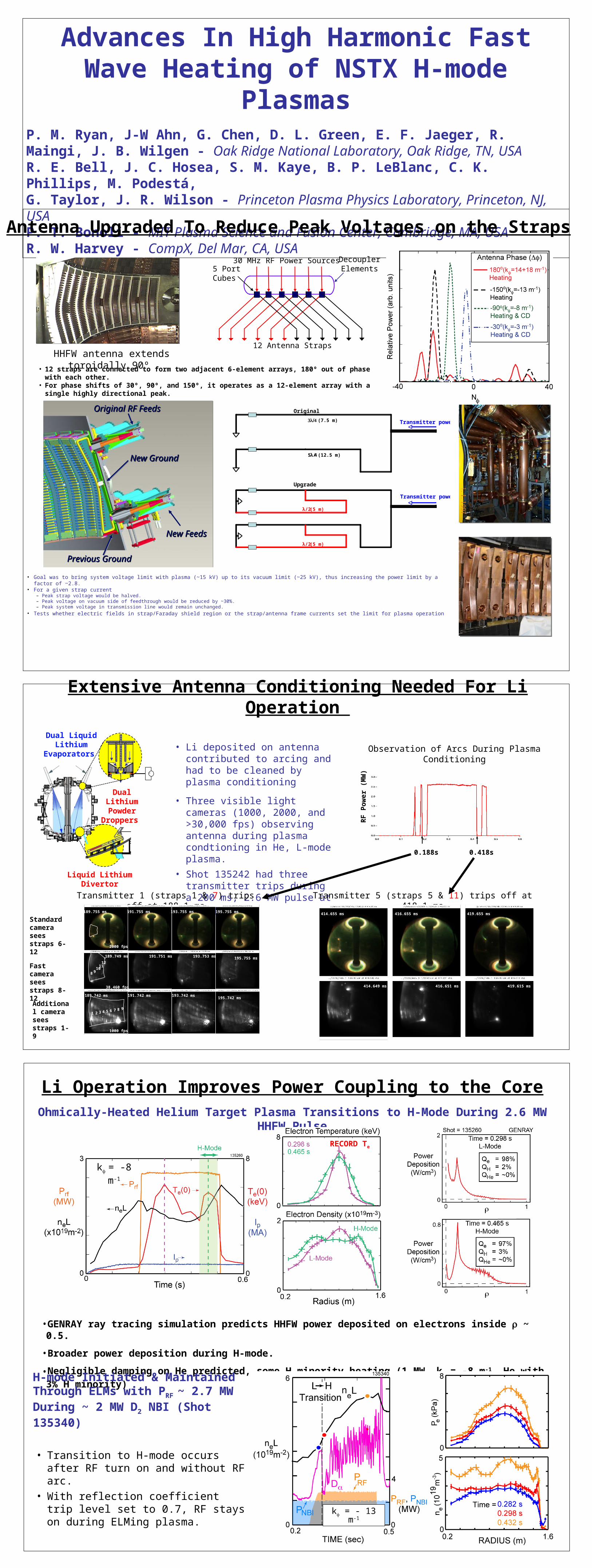
• Goal was to bring system voltage limit with plasma (~15 kV) up to its vacuum limit (~25 kV), thus increasing the power limit by a factor of ~2.8.• For a given strap current
– Peak strap voltage would be halved.– Peak voltage on vacuum side of feedthrough would be reduced by ~30%.– Peak system voltage in transmission line would remain unchanged.
• Tests whether electric fields in strap/Faraday shield region or the strap/antenna frame currents set the limit for plasma operation
12 Antenna Straps
30 MHz RF Power Sources5 PortCubes
DecouplerElements
HHFW antenna extends toroidally 90º
• 12 straps are connected to form two adjacent 6-element arrays, 180º out of phase with each other.• For phase shifts of 30º, 90º, and 150º, it operates as a 12-element array with a single highly directional
peak.
3λ/4 (7.5 m)
λ/2 (5 m)
λ/2 (5 m)
Transmitter power
5λ/4 (12.5 m)
Original
Upgrade
Transmitter power
Original RF Feeds Original RF Feeds Original RF Feeds Original RF Feeds
Previous GroundPrevious Ground Previous GroundPrevious Ground
New Ground New Ground New Ground New Ground
New FeedsNew FeedsNew FeedsNew Feeds
Antenna Upgraded To Reduce Peak Voltages on the Straps
Extensive Antenna Conditioning Needed For Li Operation
Dual Liquid Lithium
Evaporators
~
Dual Lithium Powder
Droppers
Liquid Lithium Divertor
Observation of Arcs During Plasma Conditioning• Li deposited on antenna
contributed to arcing and had to be cleaned by plasma conditioning
• Three visible light cameras (1000, 2000, and >30,000 fps) observing antenna during plasma condtioning in He, L-mode plasma.
• Shot 135242 had three transmitter trips during a 200 ms, 2.6 MW pulse at -90º phasing.
0.188s 0.418s
RF
Po
wer
(M
W)
Transmitter 1 (straps 1 & 7) trips off at 188.1 ms
8 910
1112
1 2 3 4 5 6 7 8 9
189.755 ms 191.755 ms 193.755 ms 195.755 ms
189.749 ms 191.751 ms 193.753 ms 195.755 ms
189.742 ms 191.742 ms 193.742 ms195.742 ms
2000 fps
38,460 fps
1000 fps
Standard camera sees straps 6-12
Fast camera sees straps 8-12
Additional camera sees straps 1-9
Transmitter 5 (straps 5 & 11) trips off at 418.1 ms414.655 ms 416.655 ms 419.655 ms
414.649 ms 416.651 ms 419.615 ms
Ohmically-Heated Helium Target Plasma Transitions to H-Mode During 2.6 MW HHFW Pulse
k = -8 m-1
•GENRAY ray tracing simulation predicts HHFW power deposited on electrons inside ~ 0.5.
•Broader power deposition during H-mode.
•Negligible damping on He predicted, some H minority heating (1 MW, k = -8 m-1, He with 3% H minority)
H-mode Initiated & Maintained Through ELMs with PRF ~ 2.7 MW During ~ 2 MW D2 NBI (Shot 135340)
• Transition to H-mode occurs after RF turn on and without RF arc.
• With reflection coefficient trip level set to 0.7, RF stays on during ELMing plasma.
k = - 13 m-1
Li Operation Improves Power Coupling to the Core
RECORD Te
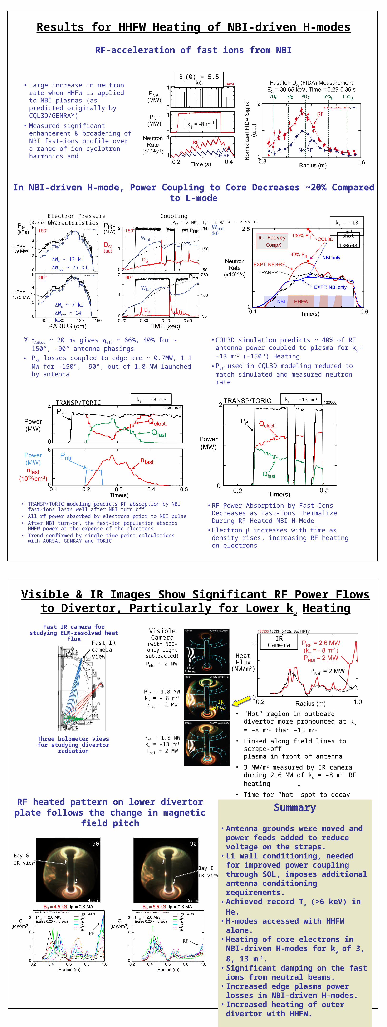
• CQL3D simulation predicts ~ 40% of RF antenna power coupled to plasma for k = -13 m-1 (-150º) Heating
• Prf used in CQL3D modeling reduced to match simulated and measured neutron rate
In NBI-driven H-mode, Power Coupling to Core Decreases ~20% Compared to L-mode
Electron Pressure Coupling Characteristics
We ~ 13 kJ
Wtot ~ 25 kJ
We ~ 7 kJ
Wtot ~ 14 kJ
(0.353 sec) (PNB = 2 MW, IP = 1 MA,BT = 0.55 T)
R. Harvey
CompX
Shot
130608
k = -13 m-1
• TRANSP/TORIC modeling predicts RF absorption by NBI fast-ions lasts well after NBI turn off
• All rf power absorbed by electrons prior to NBI pulse• After NBI turn-on, the fast-ion population absorbs HHFW power at
the expense of the electrons• Trend confirmed by single time point calculations with AORSA,
GENRAY and TORIC
TRANSP/TORIC
• RF Power Absorption by Fast-Ions Decreases as Fast-Ions Thermalize During RF-Heated NBI H-Mode
• Electron increases with time as density rises, increasing RF heating on electrons
k = -13 m-1
BT(0) = 5.5 kG
Results for HHFW Heating of NBI-driven H-modes
k = -8 m-1
RF-acceleration of fast ions from NBI
Fast IR camera for studying ELM-resolved heat flux
ORNL
Three bolometer views for studying divertor radiation
Fast IR camera view
• "Hot" region in outboard divertor more pronounced at k = –8 m-1 than –13 m-1
• Linked along field lines to scrape-off plasma in front of antenna
• 3 MW/m2 measured by IR cameraduring 2.6 MW of k = –8 m-1 RF heating
• Time for “hot” spot to decay away is ~ 20 ms at –8 m-1 and ~ 8 ms at –13 m-1
Visible & IR Images Show Significant RF Power Flows to Divertor, Particularly for Lower k Heating
Pnbi = 2 MW
Prf = 1.8 MWk = - 8 m-1
Pnbi = 2 MW IR View IR View
Prf = 1.8 MWk = -13 m-1
Pnbi = 2 MW
Visible Camera
(with NBI-only light subtracted)
IR Camera•
HeatFlux
(MW/m2)
3
Bay I
IR view
Bay G
IR view
439.64 – 439.31 ms
RF
RF
-90° -90°
452 ms 455 ms
RF heated pattern on lower divertor plate follows the change in magnetic field pitch
• Large increase in neutron rate when HHFW is applied to NBI plasmas (as predicted originally by CQL3D/GENRAY)
• Measured significant enhancement & broadening of NBI fast-ions profile over a range of ion cyclotron harmonics and
Wtot ~ 20 ms gives eff ~ 66%, 40% for -150°, -90° antenna phasings
• PRF losses coupled to edge are ~ 0.7MW, 1.1 MW for -150°, -90°, out of 1.8 MW launched by antenna
Summary
• Antenna grounds were moved and power feeds added to reduce voltage on the straps.
• Li wall conditioning, needed for improved power coupling through SOL, imposes additional antenna conditioning requirements.
• Achieved record Te (>6 keV) in He.• H-modes accessed with HHFW alone.• Heating of core electrons in NBI-driven
H-modes for k of 3, 8, 13 m-1.• Significant damping on the fast ions
from neutral beams.• Increased edge plasma power losses in
NBI-driven H-modes.• Increased heating of outer divertor with
HHFW.
Related Documents


