ADVANCES IN AERONAUTICAL RESEARCH AND DEVELOPMENT

Welcome message from author
This document is posted to help you gain knowledge. Please leave a comment to let me know what you think about it! Share it to your friends and learn new things together.
Transcript

ADVANCESINaEronautical rEsEarch
and dEvElopmEnt
CRE
ATIVEVISION–082
338
374
2
The CSIR’s suite of wind tunnels has provided a scientific research
andexperimentalfoundationtotheaerodynamicdesigneffortsof
the South African aeronautics industry for many years. The suite was
installedinthemid-1960sandhasbecomeapopulartestcapability
in the Southern hemisphere.
A wide variety of airframes have been tested successfully in
these facilities. This includes subsonic types such as gyrocopters,
helicopters, unmanned aerial systems and military trainers, as
well as transonic airframes, (i.e. bombs and combat aircraft), and
supersonic airframes of high-speed missiles and projectiles flying
at more than four times the speed of sound. Data collected at the
facilities are used for airframe characterisation, aerodynamic design
andtopopulatecomplexmodellingandsimulationenvironmentsfor
mission simulation, doctrine development and training.
WindTunnelTesting
The Council for Scientific and Industrial Research
(CSIR) is home to leading aeronautical research
and development. Engineers and scientists,
access to specialist infrastructure and
equipment, and global technology collaborations contribute to the CSIR’s status as a world-class aeronautics capability.
hIgh-SPEED WIND TUNNEL – MAX SPEED: MAch 4.0
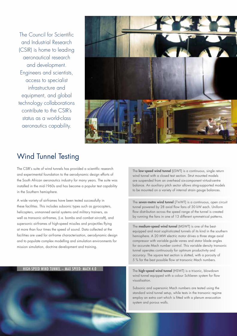
The low-speed wind tunnel (LSWT)isacontinuous,singlereturnwind tunnel with a closed test section. Strut mounted models aresuspendedfromanoverheadsix-componentvirtual-centrebalance.Anauxiliarypitchsectorallowssting-supportedmodelsto be mounted on a variety of internal strain gauge balances.
The high-speed wind tunnel(HSWT)isatrisonic,blowdownwind tunnel equipped with a colour Schlieren system for flow visualisation.
SubsonicandsupersonicMachnumbersaretestedusingthestandard wind tunnel setup, while tests in the transonic regime employanextracartwhichisfittedwithaplenumevacuationsystem and porous walls.
The medium-speed wind tunnel(MSWT)isoneofthebest-equipped and most sophisticated tunnels of its kind in the southern hemisphere.A20MWelectricmotordrivesathreestageaxialcompressor with variable guide vanes and stator blade angles foraccurateMachnumbercontrol.Thisvariabledensitytransonictunnel operates continuously for optimum productivity and accuracy. The square test section is slotted, with a porosity of 5%forthebestpossibleflowattransonicMachnumbers.
The seven-metre wind tunnel(7mWT)isacontinuous,opencircuittunnelpoweredby28axialflowfansof30kWeach.Uniformflow distribution across the speed range of the tunnel is created byrunningthefansinoneof13differentsymmetricalpatterns.
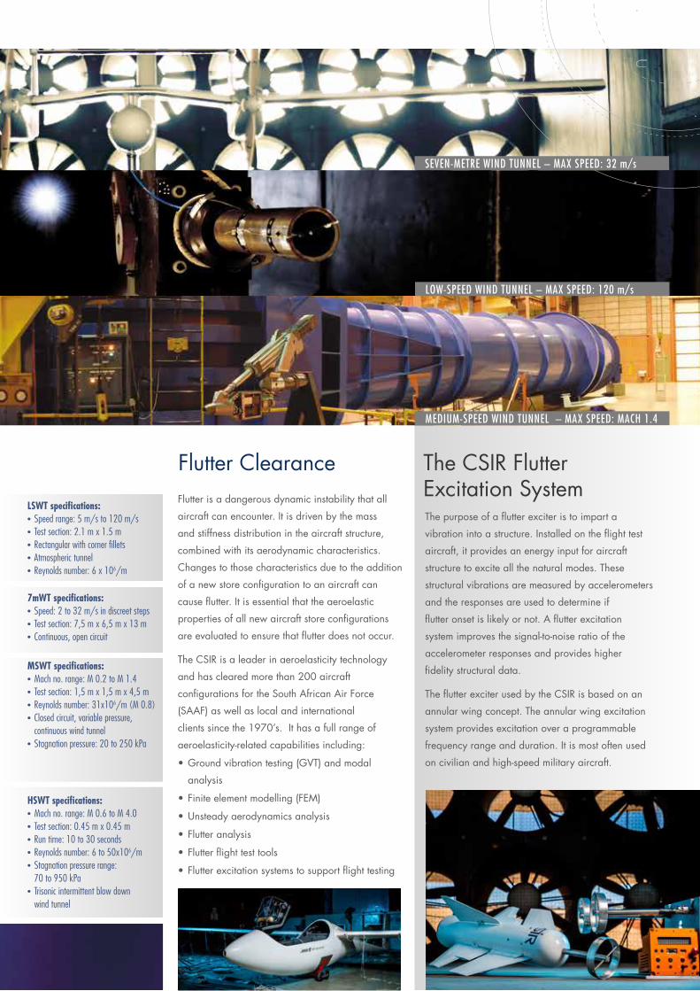
Flutter is a dangerous dynamic instability that all
aircraft can encounter. It is driven by the mass
and stiffness distribution in the aircraft structure,
combined with its aerodynamic characteristics.
Changes to those characteristics due to the addition
of a new store configuration to an aircraft can
cause flutter. It is essential that the aeroelastic
properties of all new aircraft store configurations
are evaluated to ensure that flutter does not occur.
The CSIR is a leader in aeroelasticity technology
and has cleared more than 200 aircraft
configurations for the South African Air Force
(SAAF) as well as local and international
clients since the 1970’s. It has a full range of
aeroelasticity-related capabilities including:
•Groundvibrationtesting(GVT)andmodal
analysis
•Finiteelementmodelling(FEM)
•Unsteadyaerodynamicsanalysis
•Flutteranalysis
•Flutterflighttesttools
•Flutterexcitationsystemstosupportflighttesting
Flutter Clearance
LSWT specifications:• Speed range: 5 m/s to 120 m/s • Test section: 2.1 m x 1.5 m • Rectangular with corner fillets• Atmospheric tunnel• Reynolds number: 6 x 10⁶/m
MSWT specifications:• Mach no. range: M 0.2 to M 1.4• Test section: 1,5 m x 1,5 m x 4,5 m• Reynolds number: 31x106/m (M 0.8)• Closed circuit, variable pressure,
continuous wind tunnel• Stagnation pressure: 20 to 250 kPa
HSWT specifications:• Mach no. range: M 0.6 to M 4.0• Test section: 0.45 m x 0.45 m• Run time: 10 to 30 seconds• Reynolds number: 6 to 50x106/m• Stagnation pressure range:
70 to 950 kPa• Trisonic intermittent blow down
wind tunnel
7mWT specifications:• Speed: 2 to 32 m/s in discreet steps• Test section: 7,5 m x 6,5 m x 13 m• Continuous, open circuit
The CSIR Flutter ExcitationSystemThepurposeofaflutterexciteristoimparta
vibration into a structure. Installed on the flight test
aircraft, it provides an energy input for aircraft
structuretoexciteallthenaturalmodes.These
structural vibrations are measured by accelerometers
and the responses are used to determine if
flutteronsetislikelyornot.Aflutterexcitation
system improves the signal-to-noise ratio of the
accelerometer responses and provides higher
fidelity structural data.
TheflutterexciterusedbytheCSIRisbasedonan
annularwingconcept.Theannularwingexcitation
systemprovidesexcitationoveraprogrammable
frequency range and duration. It is most often used
on civilian and high-speed military aircraft.
MEDIUM-SPEED WIND TUNNEL – MAX SPEED: MAch 1.4
LOW-SPEED WIND TUNNEL – MAX SPEED: 120 m/s
SEVEN-METRE WIND TUNNEL – MAX SPEED: 32 m/s

Indizaisasmall,ruggedandhighlyefficienthand-launchedUAS(UnmannedAircraftSystem). The fuselage is fitted with a modular payload system which can support a number of interchangeable cameras or other systems. TheairframecontainstheGPSbasedautopilot,radio modem and video transmitter. The ground-based equipment currently consists of a laptop-based mission planner and tracking antenna system for the video and data links. There is an optional radio control transmitter and airborne receiver for man-in-the-loop control of both the airframe and the camera system.
The system has been used to provide photographic and video information in the border safeguarding environments.
The airframe can accommodate a number of generic camera pods. These interchangeable pods consist of three different types of camera systems including:
•Apan,tiltandstowtwin-camerasystem
•Astowable high-definition wide-angle video camera
•A3Gcellphonebasedcamera
TheCSIR’sR&DportfolioinUnmannedAircraftSystems(UAS)hasgrown
considerably with increasing demand for the use of its research platforms as well
asitsaerodynamicdesignandoptimisationcapability.TheCSIRhousesaUAS
laboratory which incorporates high-fidelity flight simulators with aircraft sub-system
hardware-in-the-loop, such as autopilots and control surface servo actuators.
UnmannedAircraftSystemsIndiza
SySTeM SpecificaTion:• Span: 2 m• Maximum mass: 3.5 kg• Maximum payload: 0.5 kg• Duration: 1 hour• Launch: Hand-launched
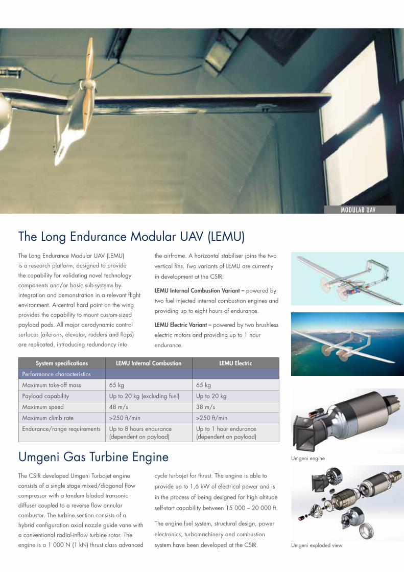
TheLongEnduranceModularUAV(LEMU)
is a research platform, designed to provide
the capability for validating novel technology
components and/or basic sub-systems by
integration and demonstration in a relevant flight
environment. A central hard point on the wing
providesthecapabilitytomountcustom-sized
payload pods. All major aerodynamic control
surfaces (ailerons, elevator, rudders and flaps)
are replicated, introducing redundancy into
system specifications lEmu internal combustion lEmu Electric
Performance characteristics
Maximumtake-offmass 65kg 65kg
Payload capability Upto20kg(excludingfuel) Upto20kg
Maximumspeed 48m/s 38m/s
Maximumclimbrate >250 ft/min >250 ft/min
Endurance/rangerequirements Upto8hoursendurance (dependent on payload)
Upto1hourendurance (dependent on payload)
TheCSIRdevelopedUmgeniTurbojetengine
consistsofasinglestagemixed/diagonalflow
compressor with a tandem bladed transonic
diffuser coupled to a reverse flow annular
combustor. The turbine section consists of a
hybridconfigurationaxialnozzleguidevanewith
a conventional radial-inflow turbine rotor. The
engineisa1000N(1kN)thrustclassadvanced
theairframe.Ahorizontalstabiliserjoinsthetwo
verticalfins.TwovariantsofLEMUarecurrently
in development at the CSIR:
lEmu internal combustion variant – powered by
two fuel injected internal combustion engines and
providing up to eight hours of endurance.
lEmu Electric variant – powered by two brushless
electric motors and providing up to 1 hour
endurance.
cycle turbojet for thrust. The engine is able to
provideupto1,6kWofelectricalpowerandis
in the process of being designed for high altitude
self-startcapabilitybetween15000–20000ft.
The engine fuel system, structural design, power
electronics, turbomachinery and combustion
system have been developed at the CSIR.
UnmannedAircraftSystems TheLongEnduranceModularUAV(LEMU)
UmgeniGasTurbineEngine
MODULAR UAV
Umgeniengine
Umgeniexplodedview

The CSIR has the capability to integrate the client’s store with any aircraft. This includes functional
integration as well as compatibility evaluation for airworthiness certification. A systems
engineering approach is followed that complies with military and airworthiness standards.
TheCSIRhasparticularexpertiseinevaluatingtheaero/mechanicalimpactsofintegrating
storeswiththeaircraft.ThisworkisdoneincompliancewithMIL-HDBK-1763andcovers
the following aspects; aeroelasticity (flutter); store separation behaviour; loads on aircraft
during carriage and impact on aircraft performance and handling characteristics.
These aspects are summarised below:
Store Integration
PHOTOCREDIT: John Stupart, http://www.africandefence.net/ rheinmetall-denel-defence-day-in-pictures/.
store separation analysisStores that are individually stable can behave
differently in the flowfield of an aircraft.
Thiscanresultinunexpecteddynamicswith
the store possibly colliding with the aircraft.
It is essential to verify that stores can be
released safely over the full release and
jettison envelopes.
Storeseparationanalysesareverycomplex
and require the use of advanced computational
andexperimentaltools.TheCSIRhas
developed store separation analysis tools
in-house and leads the field in South Africa.
These tools include:
•In-housepanelcode
•Computationalfluiddynamicscodes
•TheMedium-Speedwindtunnelfitted
with a captive trajectory system
•TheAnalyseEjectioncodesystem
carriage loads analysisStoresexertloadsontheaircraftstructure
while it is being carried. These loads include:
•Aerodynamic
•Manoeuvre
It is important to ensure that the aircraft structure is
not overstressed at any point. The CSIR performs
analyses in compliance with the applicable
regulations using a range of aerodynamic,
simulation and dynamics tools.
performance and handling analysisCarrying a store affects the performance and
handling of the aircraft. It is important to compare
the actual performance envelopes against the
specifications for the configurations with the store.
It is also necessary to ensure that the aircraft is
controllable and has acceptable handling in all
phases of flight. The CSIR performs analyses in
compliance with applicable regulations.
•Landing
•Ejection
Othercorecapabilitiesthe mission simulation Framework (msF) is a scenario simulation
tool capable of simulating the interactions between a large number of land or
air based entities. It runs faster than real-time with optional visualisation that
can be run at a large range of speeds. Its primary purpose is to provide
insight into the outcome of various engagement scenarios including air-to-air
and air-to-ground missions.
TwotypesofmodelsarecurrentlyutilisedinMSF.Genericmodelsexist
of aircraft, missiles, radars, guns, launchers, fire control systems and data
links. Specific system models have been created from open information
sources,throughconsultationwithexpertsintherelevantfieldsand
physics modelling.
Terrain modelling is included to model line of sight link limitations for
scenarios that have terrain based sensors.
decoy rockets Ballistic rockets fired as decoys are used to protect high-value
vessels against the threat of anti-craft radar missiles. The CSIR undertakes concept
development,design,prototypingandtesting–uptothepointwhereactual,
measured performance during a flight test can be correlated to theoretical
intentions.
csir aircraft design and Evaluation capabilities The CSIR has
developed a number of aircraft in the past, starting with the SARA series
ofgyrocopters,theallcarbonfibremilitaryturboproptrainerACEandthe
Hummingbird, a very low speed observation light aircraft. The CSIR undertakes
conceptual design, detailed design, aerodynamic characterisation through wind
tunnel testing or through computational methods.
Variousotherscientificexperimenttechniquesareused,aswellashighfidelity
man-in-the-loopsimulationsofbothfixedandrotarywingedaircraftforvalidation
of flight data and the evaluation and optimisation of handling qualities
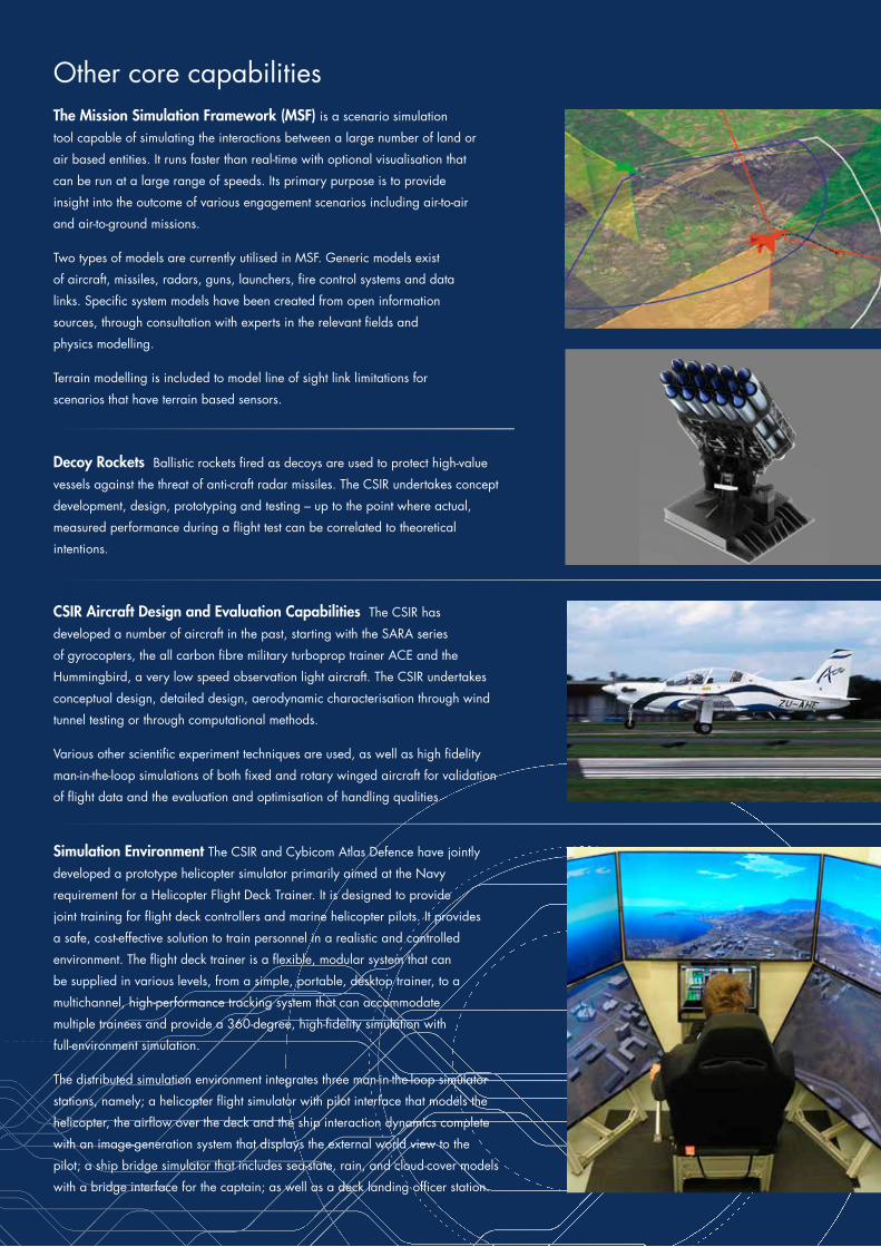
simulation Environment The CSIR and Cybicom Atlas Defence have jointly
developedaprototypehelicoptersimulatorprimarilyaimedattheNavy
requirement for a Helicopter Flight Deck Trainer. It is designed to provide
joint training for flight deck controllers and marine helicopter pilots. It provides
a safe, cost-effective solution to train personnel in a realistic and controlled
environment.Theflightdecktrainerisaflexible,modularsystemthatcan
be supplied in various levels, from a simple, portable, desktop trainer, to a
multichannel, high-performance tracking system that can accommodate
multipletraineesandprovidea360-degree,high-fidelitysimulationwith
full-environment simulation.
The distributed simulation environment integrates three man-in-the-loop simulator
stations, namely; a helicopter flight simulator with pilot interface that models the
helicopter, the airflow over the deck and the ship interaction dynamics complete
withanimage-generationsystemthatdisplaystheexternalworldviewtothe
pilot; a ship bridge simulator that includes sea-state, rain, and cloud-cover models
with a bridge interface for the captain; as well as a deck landing officer station.
PHOTOCREDIT: John Stupart, http://www.africandefence.net/ rheinmetall-denel-defence-day-in-pictures/.

CRE
ATIVEVISION–082
338
374
2
CSIR Scientia CampusMeiringNaudéRoadBrummeriaPretoria
Enquiries:
• JohnMorgan Contract Research and Development Manager Tel:0128412738 Email:[email protected]
• Kimal Hiralall Contract Research and Development Manager Tel:0128413187 Email:[email protected]
www.csir.co.za
The CSIR is a statutory research council established by government undertheScientificResearchCouncilAct(No46of1988).TheCSIR’srole is to undertake research and technology development to enhance industrial and government capabilities and contribute optimally to improve the quality of life of South Africans. All output is founded on acoreofexcellenceinscienceandengineering.Parliamentarygrantfunding is invested in research programmes and research infrastructure as well as substantial, ongoing research and development (R&D) skills development. The CSIR earns income by performing contract R&D for the public and private sectors, locally and internationally.
The CSIR’s R&D and innovation efforts are channelled into specific impact areas. These are: Health; Defence and Security; Built Environment;NaturalEnvironment;Industry;andEnergy.Workissupported by sets of core technologies including: Information and CommunicationsTechnology,Sensors,Modelling,Photonics,Materialsand Robotics, and significant research facilities and infrastructure.
Related Documents
![Micro Air Vehicle [MAV] Research & Development at Aeronautical Development Establishment [ADE] - Overview](https://static.cupdf.com/doc/110x72/55720a1d497959fc0b8bff33/micro-air-vehicle-mav-research-development-at-aeronautical-development-establishment-ade-overview.jpg)