Review Advanced Thermoplastic Composite Manufacturing by In-Situ Consolidation: A Review Isabel Martin 1 , Diego Saenz del Castillo 1 , Antonio Fernandez 2 and Alfredo Güemes 2, * 1 FIDAMC, Foundation for the Research, Development and Application of Composite Materials, Avda. Rita Levi Montalcini 29, Tecnogetafe, Getafe, 28906 Madrid, Spain; Maria-Isabel.Martin@fidamc.es (I.M.); Diego.Saenz@fidamc.es (D.S.d.C.) 2 E.T.S.I. Aeronáutica y del Espacio, Universidad Politécnica de Madrid, Pza. de Cardenal Cisneros 3, 28040 Madrid, Spain; [email protected] * Correspondence: [email protected] Received: 23 August 2020; Accepted: 10 October 2020; Published: 13 October 2020 Abstract: This article provides an overview of the evolution of the in-situ consolidation (ISC) process over time. This evolution is intimately linked with the advancements in each of the steps of the ISC manufacturing process, is additive in nature, and is limited by the orthotropic nature of composite materials and the physicochemical behavior of the thermoplastic matrix. This review covers four key topics: (a) Thermal models—simulation tools are critical to understand a process with such large spatial gradients and fast changes. Heating systems once marked a turning point in the development of industrial ISC systems. Today, lasers are the most recent trend, and there are three key issues being studied: The absorption of energy of light by the material, the laser profile, and the laser focusing. Several approaches have been proposed for the distributed temperature measurements, given the strong temperature gradients. (b) Adhesion—this refers to two subsequent mechanisms. In the first place, the process of intimate contact is one by which two surfaces of thermoplastic pre-impregnated composite materials are brought into contact under pressure and temperature. This enables closure of the existing gaps between the two microscopic irregular surfaces. This process is then followed by the healing or diffusion of polymer molecules across the interface. (c) Crystallinity—mostly influenced by the cooling rate, and strongly affects the mechanical properties. (d) Degradation—this refers to the potential irreversible changes in the polymer structure caused by the high temperatures required for the process. Degradation can be avoided through adequate control of the process parameters. The end goal of the ISC manufacturing process is to achieve a high product quality with a high deposition rate through an industrial process competitive with the current manufacturing process for thermoset composites. Keywords: thermoplastic composites; automatic lamination; in-situ consolidation; aircraft structures; laser assisted tape placement 1. Introduction The key properties that justify the wide use of composite materials in the aeronautical industry were described in [1] including weight savings due to the increase of specific resistance and stiffness, which leads to reductions in fuel consumption and, consequently, allows an increase in aircraft payload. Furthermore, the specific properties are not the only driver for material selection for aerospace applications—costs are also important. It is necessary to demonstrate how affordable it is to manufacture and use materials during operation. Any selected material must also have the ability to withstand stresses in the presence of typical damages, durability, resistance to fatigue, and environmental degradation. J. Compos. Sci. 2020, 4, 149; doi:10.3390/jcs4040149 www.mdpi.com/journal/jcs

Welcome message from author
This document is posted to help you gain knowledge. Please leave a comment to let me know what you think about it! Share it to your friends and learn new things together.
Transcript
Review
Advanced Thermoplastic Composite Manufacturingby In-Situ Consolidation: A Review
Isabel Martin 1, Diego Saenz del Castillo 1 , Antonio Fernandez 2 and Alfredo Güemes 2,*1 FIDAMC, Foundation for the Research, Development and Application of Composite Materials,
Avda. Rita Levi Montalcini 29, Tecnogetafe, Getafe, 28906 Madrid, Spain;[email protected] (I.M.); [email protected] (D.S.d.C.)
2 E.T.S.I. Aeronáutica y del Espacio, Universidad Politécnica de Madrid, Pza. de Cardenal Cisneros 3,28040 Madrid, Spain; [email protected]
* Correspondence: [email protected]
Received: 23 August 2020; Accepted: 10 October 2020; Published: 13 October 2020�����������������
Abstract: This article provides an overview of the evolution of the in-situ consolidation (ISC) processover time. This evolution is intimately linked with the advancements in each of the steps of the ISCmanufacturing process, is additive in nature, and is limited by the orthotropic nature of compositematerials and the physicochemical behavior of the thermoplastic matrix. This review covers four keytopics: (a) Thermal models—simulation tools are critical to understand a process with such largespatial gradients and fast changes. Heating systems once marked a turning point in the developmentof industrial ISC systems. Today, lasers are the most recent trend, and there are three key issues beingstudied: The absorption of energy of light by the material, the laser profile, and the laser focusing.Several approaches have been proposed for the distributed temperature measurements, given thestrong temperature gradients. (b) Adhesion—this refers to two subsequent mechanisms. In the firstplace, the process of intimate contact is one by which two surfaces of thermoplastic pre-impregnatedcomposite materials are brought into contact under pressure and temperature. This enables closure ofthe existing gaps between the two microscopic irregular surfaces. This process is then followed by thehealing or diffusion of polymer molecules across the interface. (c) Crystallinity—mostly influencedby the cooling rate, and strongly affects the mechanical properties. (d) Degradation—this refers to thepotential irreversible changes in the polymer structure caused by the high temperatures requiredfor the process. Degradation can be avoided through adequate control of the process parameters.The end goal of the ISC manufacturing process is to achieve a high product quality with a highdeposition rate through an industrial process competitive with the current manufacturing process forthermoset composites.
Keywords: thermoplastic composites; automatic lamination; in-situ consolidation; aircraft structures;laser assisted tape placement
1. Introduction
The key properties that justify the wide use of composite materials in the aeronautical industrywere described in [1] including weight savings due to the increase of specific resistance and stiffness,which leads to reductions in fuel consumption and, consequently, allows an increase in aircraftpayload. Furthermore, the specific properties are not the only driver for material selection foraerospace applications—costs are also important. It is necessary to demonstrate how affordable itis to manufacture and use materials during operation. Any selected material must also have theability to withstand stresses in the presence of typical damages, durability, resistance to fatigue,and environmental degradation.
J. Compos. Sci. 2020, 4, 149; doi:10.3390/jcs4040149 www.mdpi.com/journal/jcs
J. Compos. Sci. 2020, 4, 149 2 of 36
The carbon–thermoset matrix composite materials meet the vast majority of the requirementsdescribed above, improving the performances over typical light metal alloys. Despite its potential,the application of these materials to aeronautical parts has been very progressive until full confidenceon the in-service behavior has been demonstrated, and the strict certification process required for thecomposite structures is fulfilled.
The application of thermoplastic polymeric matrix materials has not currently reached the samelevels of development as those already attained with thermosets. The high process temperaturerequirements and the lower productivity achieved with thermoplastics are among the possible reasonsfor this delay. In thermoplastic composite reinforced materials, at room temperatures the materialis in solid state and has no tackiness, a crucial property for the thermoset automatic layup process.Additionally, at temperatures above the melting point, the viscosity values are still very high, as thematrix is already in a polymerized state. This makes higher temperatures and pressures necessary and,therefore, the processes have higher costs than thermosets.
Positive properties for the development of thermoplastic material include the possibility ofmanufacturing structures with high levels of integration, avoiding the need for subsequent assemblyprocesses, and practically unlimited life without the need for refrigeration and low risk of contaminationor toxicity in human manipulation as the polymer has already been polymerized [2]. Currently, aspectssuch as sustainability and environmental conservation are also important [3]; thermoplastic materialshave the capability to be recycled. The possibility of making a future where the parts of retired aircraftscan be reused represents a point in favor of the incorporation of this type of material.
To achieve similar application levels to thermosets in the aeronautical industry, it is necessaryto develop new processes for thermoplastics that simplify or reduce costs with respect to currentmanufacturing processes. Currently, for the manufacturing of large structures with thermoset material,automated layup is used, with layup speeds of the order of 50 m/min. As the material is partially cured,it preserves its adhesiveness, making it possible to join the different plies. After layup, stacks requireshaping and/or vacuum bags for a subsequent autoclave curing step. For their part, thermoplasticreinforced materials have not been able to undergo the same sequence due to the important differencesthat automatic layup processes have between them.
Shorter cycles are a clear advantage of thermoplastic composite materials compared to conventionalones with thermosets. The lack of tackiness among layers at room temperatures requires an increase intheir temperatures to values over their melting point (semi-crystalline) or glass transition (amorphous).However, it also allows the lay-up to be done and simultaneously creates high-quality bonding amonglayers, suppressing the next curing stages in the oven or autoclave.
Using this idea, the developments that led to the automatic layup process and in-situ consolidationwere established, where a heating source heats surfaces of thermoplastic material, subsequentlycontacting them under the action of a compacting element. This process involves multiple physicalparameters that take place simultaneously and whose control is essential to enable the applicationof improvements in the product. In order to apply this process in a profitable way for the industry,it is necessary to ensure that it is possible to achieve high degrees of consolidation without the needfor a second cycle of re-consolidation in the stove or autoclave; references such as [2] report degreesof consolidation around 80–90%; however, current results from the Automated Dynamics companyconfirm the possibility of reaching compaction levels comparable to those obtained in stove andautoclave cycles with speeds suitable for industrial production. In the application of the reinforcedthermoplastics to aeronautical parts, Ref. [4] points out the need to use them in applications wherethe temperature limits are close to their glass transition minus 30 K, since over this temperature thesoftening of the material occurs, modifying its mechanical properties.
The use of thermoplastic composites for long size composite structures requires the developmentof in-situ consolidation, as it is considered the most promising manufacturing process capable ofreducing manufacturing time and cost. The first patent referring to this process dates from 1986,associated with DuPont [5] (layup method and equipment patent), where the outstanding point is the
J. Compos. Sci. 2020, 4, 149 3 of 36
approach of applying the automatic layup to a thermoplastic material using a secondary pre-heatingsource on the substrate and a main source that acts between said substrate and the material beingsupplied, with an energy distribution between the substrate and incoming tape of 20–80%. NorthropCorporation, the American aircraft manufacturer, issued a patent on this topic in 1991 [6]. Among theparticularities of its proposal, it presents the use of a heated roller, a cooling system just at the exitof the roller (compactor foot), and the interposition of a sheet of material between the roller and thematerial to be taped to avoid adhesion between them. The patent also presents a working system forthe first layer layup based on the use of a perforated tool from which a vacuum will be applied to thetaped material, between the tool and the piece a layer of insulating glass and a film of Kapton.
In 1997, the Boeing Company was the assignee of a patent on a multi-wick wrapping machine(at least two wicks of material). A detailed description of each of the components of the equipmentwas reported in the patent, giving specific details about the compaction roller. The proposed systemconsisted of cavities with air circulating for cooling, equipped with a component that allowed it tobe tilted (axis of rotation in the direction of the layup) to enable the application of pressure on allthe tows in non-flat layup conditions. The Boeing Company in 2002 also protected its work on theheating method and the heating control system in the process of layup of composite materials, withoutspecifying the type [7]. In the previous patent, the heating system used was a group of diode lasersthat allowed control of the energy supplied in the longitudinal and transverse directions of the layup,favoring concave–convex tapes and with different inclinations of the substrate. As a control systemthey used a thermography measurement system.
Aerospatiale, the French aerospace company which would later become part of the Europeanbusiness conglomerate, Airbus, filed a patent in 2003 which protected the development of a layup withintegration, with a technology known as co-consolidation [8]. The patent considers the laminationof a skin on the stiffeners the consolidated skin and the stiffeners joined by diffusion/conductionwelding, indicating a preferred application of this system in the manufacture of fuselage segments orengine covers.
The already-formed Airbus patented another methodology for thermoplastic layup in 2011 [9],in which a part of the layup tool was made of porous material. The proposal included the use of amicroporous aluminum positioned on the surface of a larger non-porous tool. The size of the cavitieswas small enough so that, together with the high viscosity of the polymer, they cannot block or affectthe surface quality of the part. This system can also help in the de-molding stage, if the change fromnegative to positive pressure on the part is carried out.
Machine manufacturers have also protected their advances with patents. Cincinnati Milacron,Inc. protected heating control in the thermoplastic layup process [10], and Automated Dynamicsprotected their technology with various patents [11–15], related to the layup equipment, layup material,and manufacturing technology for the incorporation of lightning protection systems. For its part,in 2008 Accudyne Systems, Inc. launched a patent for equipment and processes for the layup ofthermoplastic composite material [16] highlighting the proposal for the use of a flexible compactionsystem consisting of segments that apply pressure independently. The company that produces roboticcells for the layup of composite materials, Coriolis Composites, patented in 2016 [17] an innovativesolution for the compaction roller, in line with the solution proposed by Accudyne. The solution wasbased on the fact that each of the segments that make up the roller are in turn cylinders with an interiormade up of elements with curvatures that give it greater flexibility.
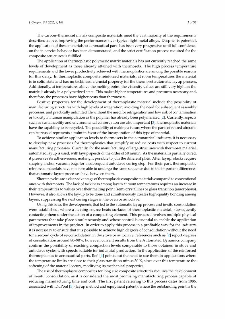
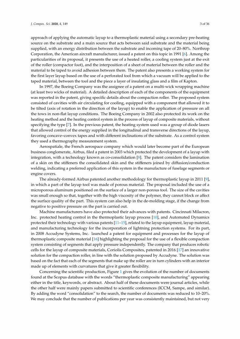
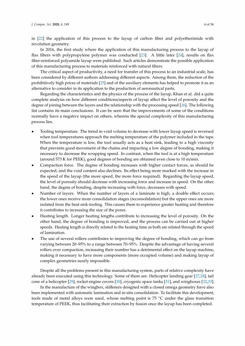
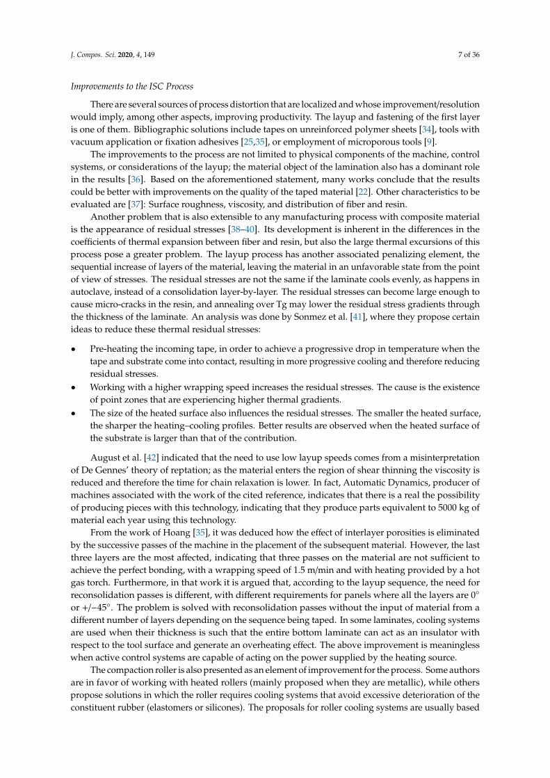
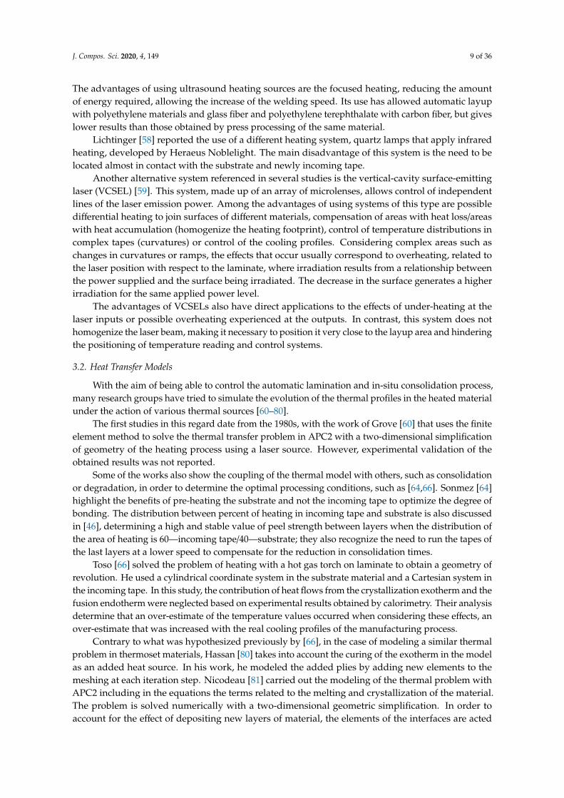
Concerning the scientific production, Figure 1 gives the evolution of the number of documentsfound at the Scopus database with the words “thermoplastic composite manufacturing” appearingeither in the title, keywords, or abstract. About half of these documents were journal articles, whilethe other half were mainly papers submitted to scientific conferences (ICCM, Sampe, and similar).By adding the word “consolidation” to the search, the number of documents was reduced to 10–20%.We may conclude that the number of publications per year was consistently maintained, but not very
J. Compos. Sci. 2020, 4, 149 4 of 36
high compared to other topics in Composites. Most of these papers have been reviewed for this work,and roughly half of them are included in the reference list.
J. Compos. Sci. 2020, 4, x 5 of 45
reduced to 10–20%. We may conclude that the number of publications per year was consistently maintained, but not very high compared to other topics in Composites. Most of these papers have been reviewed for this work, and roughly half of them are included in the reference list.
(a)
(b)
Figure 1. Documents in the Scopus database under “thermoplastic composite manufacturing” (a) and “thermoplastic composite manufacturing consolidation” (b).
This article is organized as follows: After the Introduction, Section 2 details of the ISC machines, its evolution over time, and the reasons for it. Section 3 is called “Thermal Models”, because it was recognized early that a process with such a large spatial gradients and very fast changes (the material melts and cool within seconds in a small region of the laminate) could not be understood without the help of simulation tools. A point of interest was the heating systems, and the absorption of light energy by the material, as lasers are a recent trend, driven by the need of
Figure 1. Documents in the Scopus database under “thermoplastic composite manufacturing” (a) and“thermoplastic composite manufacturing consolidation” (b).
This article is organized as follows: After the Introduction, Section 2 details of the ISC machines,its evolution over time, and the reasons for it. Section 3 is called “Thermal Models”, because it wasrecognized early that a process with such a large spatial gradients and very fast changes (the materialmelts and cool within seconds in a small region of the laminate) could not be understood withoutthe help of simulation tools. A point of interest was the heating systems, and the absorption of lightenergy by the material, as lasers are a recent trend, driven by the need of focusing the power input.Different solutions have been proposed for the distributed temperature measurements, because of thelocalized large gradients. Next, Section 4 is a review on the “Adhesion”, or mechanisms by whichtwo surfaces of thermoplastic composite materials brought into contact, by the application of pressure
J. Compos. Sci. 2020, 4, 149 5 of 36
and temperature, are able to close the existing gaps due to the inherent irregularity of the surfaces ofthe material before its manufacturing process. Two other quite important related topics are Sections 5and 6, respectively: (5) Crystallization, a characteristic of some thermoplastic materials that benefits itsmechanical properties, particularly toughness, and solvent resistance; the percentage of crystallinityand morphology is linked to the thermal profile. (6) Degradation, when a polymer is exposed to veryhigh temperatures over the melting point, even for seconds.
This article has been extracted from the Doctoral Thesis of the first author, written in Spanish andavailable in Ref. [18]. This survey has been kept opened to every fiber/thermoplastic matrix system,even though carbon fiber/PEEK is the system that has received more attention. Poly-ether-ether-ketone,commonly referred to as PEEK, is a semi-crystalline polymer with a glass transition temperature of143 ◦C, and a melting point of 343 ◦C. Worthy to remember that processing temperature needs to behigher than melting point, while Tg is the maximum service temperature as a composite material,because the drop of stiffness in the matrix for temperatures higher than this value implies a drop oflongitudinal compressive strength of the laminate.
2. Automatic Lamination and In-Situ Consolidation (ISC)
The automatic lamination and in-situ consolidation process with thermoplastic reinforced materialhas been studied since the 1980s [19]. Most of the initial references based on this process refer to thedevelopment of laminates where it is not possible to obtain a total degree of bonding between theparts, making a second consolidation stage necessary [20]. It was estimated that the speeds required toobtain a real in-situ consolidation were about 0.5 m/s.
The reasons that lead to consideration of this manufacturing process as advantageous are thereduction of costs due to a limited amount of scrap or excess material in the tapes, improvements inthe positioning of the material, repetitive results, and lower labor costs. It is also an essential step forthe development of large structures [21].
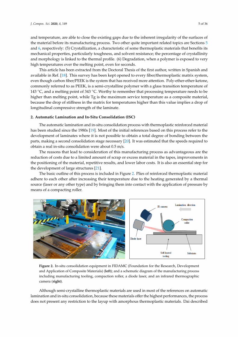
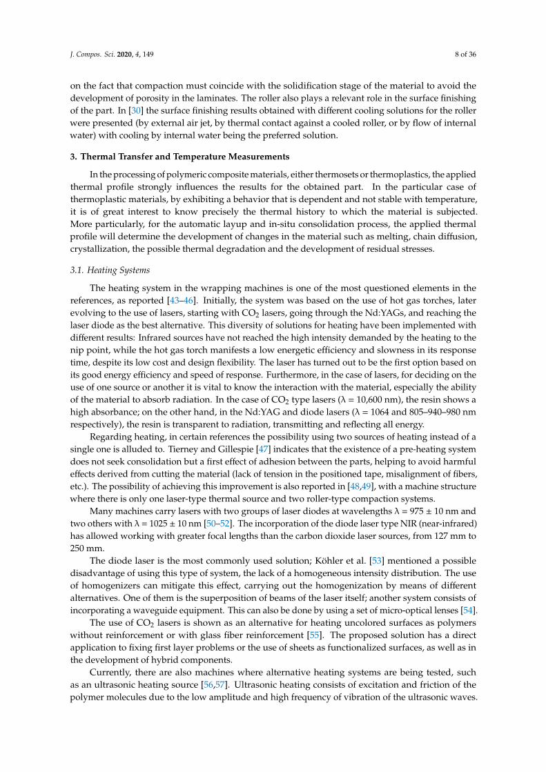
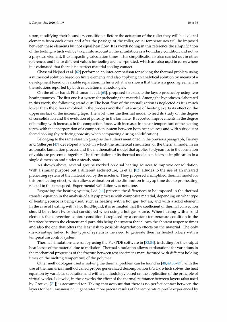
The basic outline of this process is included in Figure 2. Plies of reinforced thermoplastic materialadhere to each other after increasing their temperature due to the heating generated by a thermalsource (laser or any other type) and by bringing them into contact with the application of pressure bymeans of a compacting roller.J. Compos. Sci. 2020, 4, x 7 of 45
Figure 2. In-situ consolidation equipment in FIDAMC (Foundation for the Research, Development and Application of Composite Materials) (left); and a schematic diagram of the manufacturing process including manufacturing tooling, compaction roller, a diode laser, and an infrared thermographic camera (right).
Although semi-crystalline thermoplastic materials are used in most of the references on automatic lamination and in-situ consolidation, because these materials offer the highest performances, the process does not present any restriction to the layup with amorphous thermoplastic materials. Dai described in [22] the application of this process to the layup of carbon fiber and polyetherimide with revolution geometry.
In 2016, the first study where the application of this manufacturing process to the layup of flax fibers with polypropylene polymer was conducted [23]. A little later [24], results on flax fiber-reinforced polyamide layup were published. Such articles demonstrate the possible application of this manufacturing process to materials reinforced with natural fibers.
The critical aspect of productivity, a need for transfer of this process to an industrial scale, has been considered by different authors addressing different aspects. Among them, the reduction of the prohibitively high prices of materials [25] and of the auxiliary elements has helped to promote it as an alternative to consider in its application to the production of aeronautical parts.
Regarding the characteristics and the physics of the process of the layup, Khan et al. did a quite complete analysis on how different conditions/aspects of layup affect the level of porosity and the degree of joining between the layers and the relationship with the processing speed [26]. The following list contains its main conclusions. It can be seen that the improvements of some of the conditions normally have a negative impact on others, wherein the special complexity of this manufacturing process lies.
• Tooling temperature. The trend in void volume to decrease with lower layup speed is reversed when tool temperatures approach the melting temperature of the polymer included in the tape. When the temperature is low, the tool usually acts as a heat sink, leading to a high viscosity that prevents good movement of the chains and impacting a low degree of bonding, making it necessary to decrease the wrapping speed. In contrast, when the tool is at a high
Figure 2. In-situ consolidation equipment in FIDAMC (Foundation for the Research, Developmentand Application of Composite Materials) (left); and a schematic diagram of the manufacturing processincluding manufacturing tooling, compaction roller, a diode laser, and an infrared thermographiccamera (right).
Although semi-crystalline thermoplastic materials are used in most of the references on automaticlamination and in-situ consolidation, because these materials offer the highest performances, the processdoes not present any restriction to the layup with amorphous thermoplastic materials. Dai described
J. Compos. Sci. 2020, 4, 149 6 of 36
in [22] the application of this process to the layup of carbon fiber and polyetherimide withrevolution geometry.
In 2016, the first study where the application of this manufacturing process to the layup offlax fibers with polypropylene polymer was conducted [23]. A little later [24], results on flaxfiber-reinforced polyamide layup were published. Such articles demonstrate the possible applicationof this manufacturing process to materials reinforced with natural fibers.
The critical aspect of productivity, a need for transfer of this process to an industrial scale, hasbeen considered by different authors addressing different aspects. Among them, the reduction of theprohibitively high prices of materials [25] and of the auxiliary elements has helped to promote it as analternative to consider in its application to the production of aeronautical parts.
Regarding the characteristics and the physics of the process of the layup, Khan et al. did a quitecomplete analysis on how different conditions/aspects of layup affect the level of porosity and thedegree of joining between the layers and the relationship with the processing speed [26]. The followinglist contains its main conclusions. It can be seen that the improvements of some of the conditionsnormally have a negative impact on others, wherein the special complexity of this manufacturingprocess lies.
• Tooling temperature. The trend in void volume to decrease with lower layup speed is reversedwhen tool temperatures approach the melting temperature of the polymer included in the tape.When the temperature is low, the tool usually acts as a heat sink, leading to a high viscositythat prevents good movement of the chains and impacting a low degree of bonding, making itnecessary to decrease the wrapping speed. In contrast, when the tool is at a high temperature(around 573 K for PEEK), good degrees of bonding are obtained even close to 10 m/min.
• Compaction force. The degree of bonding increases with higher contact forces, as should beexpected, and the void content also declines. Its effect being more marked with the increase inthe speed of the layup (the more speed, the more force required). Regarding the layup speed,the level of porosity should decrease with increasing force and increase in speed. On the otherhand, the degree of bonding, despite increasing with force, decreases with speed.
• Number of layers. When the number of layers of a laminate is high, a double effect occurs;the lower ones receive more consolidation stages (reconsolidation) but the upper ones are moreisolated from the heat sink-tooling. This causes them to experience greater heating and thereforeit contributes to increasing the size of the pores.
• Heating length. Longer heating lengths contribute to increasing the level of porosity. On theother hand, the degree of bonding is improved, and the process can be carried out at higherspeeds. Heating length is directly related to the heating time as both are related through the speedof lamination.
• The use of several rollers contributes to improving the degree of bonding, which can go fromvarying between 20–95% to a range between 70–95%. Despite the advantage of having severalrollers over compaction, increasing their number has a detrimental effect on the layup machine,making it necessary to have more components (more occupied volume) and making layup ofcomplex geometries nearly impossible.
Despite all the problems present in this manufacturing system, parts of relative complexity havealready been executed using this technology. Some of them are: Helicopter landing gear [27,28], tailcone of a helicopter [29], rocket engine covers [30], cryogenic space tanks [31], and wingboxes [32,33].
In the manufacture of the wingbox, stiffeners designed with a closed omega geometry have alsobeen implemented with automatic lamination and in-situ consolidation. To facilitate this development,tools made of metal alloys were used, whose melting point is 75 ◦C under the glass transitiontemperature of PEEK, thus facilitating their extraction by fusion once the layup has been completed.
J. Compos. Sci. 2020, 4, 149 7 of 36
Improvements to the ISC Process
There are several sources of process distortion that are localized and whose improvement/resolutionwould imply, among other aspects, improving productivity. The layup and fastening of the first layeris one of them. Bibliographic solutions include tapes on unreinforced polymer sheets [34], tools withvacuum application or fixation adhesives [25,35], or employment of microporous tools [9].
The improvements to the process are not limited to physical components of the machine, controlsystems, or considerations of the layup; the material object of the lamination also has a dominant rolein the results [36]. Based on the aforementioned statement, many works conclude that the resultscould be better with improvements on the quality of the taped material [22]. Other characteristics to beevaluated are [37]: Surface roughness, viscosity, and distribution of fiber and resin.
Another problem that is also extensible to any manufacturing process with composite materialis the appearance of residual stresses [38–40]. Its development is inherent in the differences in thecoefficients of thermal expansion between fiber and resin, but also the large thermal excursions of thisprocess pose a greater problem. The layup process has another associated penalizing element, thesequential increase of layers of the material, leaving the material in an unfavorable state from the pointof view of stresses. The residual stresses are not the same if the laminate cools evenly, as happens inautoclave, instead of a consolidation layer-by-layer. The residual stresses can become large enough tocause micro-cracks in the resin, and annealing over Tg may lower the residual stress gradients throughthe thickness of the laminate. An analysis was done by Sonmez et al. [41], where they propose certainideas to reduce these thermal residual stresses:
• Pre-heating the incoming tape, in order to achieve a progressive drop in temperature when thetape and substrate come into contact, resulting in more progressive cooling and therefore reducingresidual stresses.
• Working with a higher wrapping speed increases the residual stresses. The cause is the existenceof point zones that are experiencing higher thermal gradients.
• The size of the heated surface also influences the residual stresses. The smaller the heated surface,the sharper the heating–cooling profiles. Better results are observed when the heated surface ofthe substrate is larger than that of the contribution.
August et al. [42] indicated that the need to use low layup speeds comes from a misinterpretationof De Gennes’ theory of reptation; as the material enters the region of shear thinning the viscosity isreduced and therefore the time for chain relaxation is lower. In fact, Automatic Dynamics, producer ofmachines associated with the work of the cited reference, indicates that there is a real the possibilityof producing pieces with this technology, indicating that they produce parts equivalent to 5000 kg ofmaterial each year using this technology.
From the work of Hoang [35], it was deduced how the effect of interlayer porosities is eliminatedby the successive passes of the machine in the placement of the subsequent material. However, the lastthree layers are the most affected, indicating that three passes on the material are not sufficient toachieve the perfect bonding, with a wrapping speed of 1.5 m/min and with heating provided by a hotgas torch. Furthermore, in that work it is argued that, according to the layup sequence, the need forreconsolidation passes is different, with different requirements for panels where all the layers are 0◦
or +/−45◦. The problem is solved with reconsolidation passes without the input of material from adifferent number of layers depending on the sequence being taped. In some laminates, cooling systemsare used when their thickness is such that the entire bottom laminate can act as an insulator withrespect to the tool surface and generate an overheating effect. The above improvement is meaninglesswhen active control systems are capable of acting on the power supplied by the heating source.
The compaction roller is also presented as an element of improvement for the process. Some authorsare in favor of working with heated rollers (mainly proposed when they are metallic), while otherspropose solutions in which the roller requires cooling systems that avoid excessive deterioration of theconstituent rubber (elastomers or silicones). The proposals for roller cooling systems are usually based
J. Compos. Sci. 2020, 4, 149 8 of 36
on the fact that compaction must coincide with the solidification stage of the material to avoid thedevelopment of porosity in the laminates. The roller also plays a relevant role in the surface finishingof the part. In [30] the surface finishing results obtained with different cooling solutions for the rollerwere presented (by external air jet, by thermal contact against a cooled roller, or by flow of internalwater) with cooling by internal water being the preferred solution.
3. Thermal Transfer and Temperature Measurements
In the processing of polymeric composite materials, either thermosets or thermoplastics, the appliedthermal profile strongly influences the results for the obtained part. In the particular case ofthermoplastic materials, by exhibiting a behavior that is dependent and not stable with temperature,it is of great interest to know precisely the thermal history to which the material is subjected.More particularly, for the automatic layup and in-situ consolidation process, the applied thermalprofile will determine the development of changes in the material such as melting, chain diffusion,crystallization, the possible thermal degradation and the development of residual stresses.
3.1. Heating Systems
The heating system in the wrapping machines is one of the most questioned elements in thereferences, as reported [43–46]. Initially, the system was based on the use of hot gas torches, laterevolving to the use of lasers, starting with CO2 lasers, going through the Nd:YAGs, and reaching thelaser diode as the best alternative. This diversity of solutions for heating have been implemented withdifferent results: Infrared sources have not reached the high intensity demanded by the heating to thenip point, while the hot gas torch manifests a low energetic efficiency and slowness in its responsetime, despite its low cost and design flexibility. The laser has turned out to be the first option based onits good energy efficiency and speed of response. Furthermore, in the case of lasers, for deciding on theuse of one source or another it is vital to know the interaction with the material, especially the abilityof the material to absorb radiation. In the case of CO2 type lasers (λ = 10,600 nm), the resin shows ahigh absorbance; on the other hand, in the Nd:YAG and diode lasers (λ = 1064 and 805–940–980 nmrespectively), the resin is transparent to radiation, transmitting and reflecting all energy.
Regarding heating, in certain references the possibility using two sources of heating instead of asingle one is alluded to. Tierney and Gillespie [47] indicates that the existence of a pre-heating systemdoes not seek consolidation but a first effect of adhesion between the parts, helping to avoid harmfuleffects derived from cutting the material (lack of tension in the positioned tape, misalignment of fibers,etc.). The possibility of achieving this improvement is also reported in [48,49], with a machine structurewhere there is only one laser-type thermal source and two roller-type compaction systems.
Many machines carry lasers with two groups of laser diodes at wavelengths λ = 975 ± 10 nm andtwo others with λ = 1025 ± 10 nm [50–52]. The incorporation of the diode laser type NIR (near-infrared)has allowed working with greater focal lengths than the carbon dioxide laser sources, from 127 mm to250 mm.
The diode laser is the most commonly used solution; Köhler et al. [53] mentioned a possibledisadvantage of using this type of system, the lack of a homogeneous intensity distribution. The useof homogenizers can mitigate this effect, carrying out the homogenization by means of differentalternatives. One of them is the superposition of beams of the laser itself; another system consists ofincorporating a waveguide equipment. This can also be done by using a set of micro-optical lenses [54].
The use of CO2 lasers is shown as an alternative for heating uncolored surfaces as polymerswithout reinforcement or with glass fiber reinforcement [55]. The proposed solution has a directapplication to fixing first layer problems or the use of sheets as functionalized surfaces, as well as inthe development of hybrid components.
Currently, there are also machines where alternative heating systems are being tested, suchas an ultrasonic heating source [56,57]. Ultrasonic heating consists of excitation and friction of thepolymer molecules due to the low amplitude and high frequency of vibration of the ultrasonic waves.
J. Compos. Sci. 2020, 4, 149 9 of 36
The advantages of using ultrasound heating sources are the focused heating, reducing the amountof energy required, allowing the increase of the welding speed. Its use has allowed automatic layupwith polyethylene materials and glass fiber and polyethylene terephthalate with carbon fiber, but giveslower results than those obtained by press processing of the same material.
Lichtinger [58] reported the use of a different heating system, quartz lamps that apply infraredheating, developed by Heraeus Noblelight. The main disadvantage of this system is the need to belocated almost in contact with the substrate and newly incoming tape.
Another alternative system referenced in several studies is the vertical-cavity surface-emittinglaser (VCSEL) [59]. This system, made up of an array of microlenses, allows control of independentlines of the laser emission power. Among the advantages of using systems of this type are possibledifferential heating to join surfaces of different materials, compensation of areas with heat loss/areaswith heat accumulation (homogenize the heating footprint), control of temperature distributions incomplex tapes (curvatures) or control of the cooling profiles. Considering complex areas such aschanges in curvatures or ramps, the effects that occur usually correspond to overheating, related tothe laser position with respect to the laminate, where irradiation results from a relationship betweenthe power supplied and the surface being irradiated. The decrease in the surface generates a higherirradiation for the same applied power level.
The advantages of VCSELs also have direct applications to the effects of under-heating at thelaser inputs or possible overheating experienced at the outputs. In contrast, this system does nothomogenize the laser beam, making it necessary to position it very close to the layup area and hinderingthe positioning of temperature reading and control systems.
3.2. Heat Transfer Models
With the aim of being able to control the automatic lamination and in-situ consolidation process,many research groups have tried to simulate the evolution of the thermal profiles in the heated materialunder the action of various thermal sources [60–80].
The first studies in this regard date from the 1980s, with the work of Grove [60] that uses the finiteelement method to solve the thermal transfer problem in APC2 with a two-dimensional simplificationof geometry of the heating process using a laser source. However, experimental validation of theobtained results was not reported.
Some of the works also show the coupling of the thermal model with others, such as consolidationor degradation, in order to determine the optimal processing conditions, such as [64,66]. Sonmez [64]highlight the benefits of pre-heating the substrate and not the incoming tape to optimize the degree ofbonding. The distribution between percent of heating in incoming tape and substrate is also discussedin [46], determining a high and stable value of peel strength between layers when the distribution ofthe area of heating is 60—incoming tape/40—substrate; they also recognize the need to run the tapes ofthe last layers at a lower speed to compensate for the reduction in consolidation times.
Toso [66] solved the problem of heating with a hot gas torch on laminate to obtain a geometry ofrevolution. He used a cylindrical coordinate system in the substrate material and a Cartesian system inthe incoming tape. In this study, the contribution of heat flows from the crystallization exotherm and thefusion endotherm were neglected based on experimental results obtained by calorimetry. Their analysisdetermine that an over-estimate of the temperature values occurred when considering these effects, anover-estimate that was increased with the real cooling profiles of the manufacturing process.
Contrary to what was hypothesized previously by [66], in the case of modeling a similar thermalproblem in thermoset materials, Hassan [80] takes into account the curing of the exotherm in the modelas an added heat source. In his work, he modeled the added plies by adding new elements to themeshing at each iteration step. Nicodeau [81] carried out the modeling of the thermal problem withAPC2 including in the equations the terms related to the melting and crystallization of the material.The problem is solved numerically with a two-dimensional geometric simplification. In order toaccount for the effect of depositing new layers of material, the elements of the interfaces are acted
J. Compos. Sci. 2020, 4, 149 10 of 36
upon, modifying their boundary conditions: Before the actuation of the roller they will be isolatedelements from each other and after the passage of the roller, equal temperatures will be imposedbetween these elements but not equal heat flow. It is worth noting in this reference the simplificationof the tooling, which will be taken into account in the simulation as a boundary condition and not asa physical element, thus impacting calculation times. This simplification is also carried out in otherreferences and hence different values for tooling are incorporated, which are also used in cases whereit is estimated that there is no perfect material-tooling contact.
Ghasemi Nejhad et al. [62] performed an inter-comparison for solving the thermal problem usinga numerical solution based on finite elements and also applying an analytical solution by means of adevelopment based on variable separation. In his work it was shown that there is a good agreement inthe solutions reported by both calculation methodologies.
On the other hand, Pitchumani et al. [63], proposed to execute the layup process by using twoheating sources. The first one is a system for preheating the material. Among the hypotheses elaboratedin this work, the following stand out: The heat flow of the crystallization is neglected as it is muchlower than the others involved in the process and the first source of heating exerts its effect on theupper surface of the incoming tape. The work uses the thermal model to feed its study on the degreeof consolidation and the evolution of porosity in the laminate. It reported improvements in the degreeof bonding with increases in the compaction force, with increases in the air temperature of the heatingtorch, with the incorporation of a compaction system between both heat sources and with subsequentforced cooling (by reducing porosity when compacting during solidification).
Belonging to the same research group as the authors mentioned in the previous paragraph, Tierneyand Gillespie [47] developed a work in which the numerical simulation of the thermal model in anautomatic lamination process and the mathematical model that applies to dynamics in the formationof voids are presented together. The formulation of its thermal model considers a simplification in asingle dimension and under a steady state.
As shown above, several groups worked on dual heating sources to improve consolidation.With a similar purpose but a different architecture, Li et al. [82] alludes to the use of an infraredpreheating system of the material fed by the machine. They proposed a simplified thermal model forthis pre-heating effect, which allows estimation of the diminution in layup time due to pre-heating,related to the tape speed. Experimental validation was not done.
Regarding the heating system, Lee [44] presents the differences to be imposed in the thermaltransfer equation in the analysis of a layup process with composite material, depending on what typeof heating source is being used, such as heating with a hot gas, hot air, and with a solid element.In the case of heating with a hot fluid/liquid, it is estimated that the coefficient of thermal convectionshould be at least twice that considered when using a hot gas source. When heating with a solidelement, the convection contour condition is replaced by a constant temperature condition in theinterface between the element and part, this being the system that allows the shortest response timesand also the one that offers the least risk to possible degradation effects on the material. The onlydisadvantage linked to this type of system is the need to generate them as heated rollers with atemperature control system.
Thermal simulations are run by using the FlexPDE software in [83,84], including for the outputheat losses of the material due to radiation. Thermal simulation allows explanations for variations inthe mechanical properties of the fracture between test specimens manufactured with different holdingtimes on the melting temperature of the polymer.
Other methodologies used in solving the thermal problem can be found in [48,49,85–87], with theuse of the numerical method called proper generalized decomposition (PGD), which solves the heatequation by variables separation and with a methodology based on the application of the principle ofvirtual works. Likewise, in these works the effect of the thermal resistance between layers (also usedby Grouve, [71]) is accounted for. Taking into account that there is no perfect contact between thelayers for heat transmission, it generates more precise results of the temperature profile experienced by
J. Compos. Sci. 2020, 4, 149 11 of 36
the material, especially improving the precision of the adjustment in the cooling phase. The resistivitycondition between the layers acts in such a way that it considers that there is a blockage to the heattransmission to the lower layers and therefore the cooling is more impeded and is therefore moreprogressive. In other studies, by contrast, this effect is considered negligible for simulation [88].
In some works [48], a correlation between heat transmission and the mechanisms of diffusionand degradation by cross-linking in the material is also presented (without considering the effect ofintimate contact, assuming perfect contact), reporting a beneficial effect by keeping the tool heated ata temperature of 473 K, a condition in which 100% adhesion is obtained with a minimum cross-linkvalue. Normally, the tooling temperature should be kept at a value between the glass transitionand crystallization peak of the material. In the case of a material such as PEEK, PEKK, or LMPAEK(well-known as high performance thermoplastics), 473 K is a conventional temperature that has provento improve the quality of the final part.
Appling a layup process with an electromagnetic inductor-type heating source, Duhovic et al. [72]presented a resolution of the thermal model using the finite element method. His study highlightsthe possibility of executing hybrid metal–carbon composite or –carbon fiber composite joints againstanother counterpart using an intermediate susceptor. The special feature of this simulation was theneed to add cooling on the upper surface to avoid its excessive heating, because the objective was tojoin an interface far away from this surface area. The simulation has also made it possible to reachconclusions regarding the correct adhesion of the elements, indicating that to achieve a correct joint,the compaction step must take place in the temperature range of 653 K to 553 K, since it corresponds tothe interval in which the re-crystallization/solidification of the polymer takes place.
In the model of Li et al. [74] the novelty lies in the methodology used to simulate the sequentialaddition of layers to the laminate in a layup with a hot gas torch. The strategy is based on theprogramming of an algorithm in ANSYS that gradually activates the elements with the evolution ofthe layup. It does not mean that the elements of the model appear and disappear, but rather theyare multiplied by certain factors so that during the layup of layer 1, the highest layers do not haveinfluence on the model; their contribution appears upon reaching the layup to them and so on. Amonghis hypotheses, it is worth highlighting they ignore the effect of heat dissipation towards the roller, asimplification not carried out by most of the works consulted. In one of his conclusions it was indicatedthat increasing the layup speed decreases the temperature in the nip point, presenting a trend that isnot linear between both parameters.
Contrary to neglecting the roller as a participant in the simulation, Kergomard, [76], proposesthe development of a mechanical simulation that allows calculation of the deformation of the rollerunder the state of loads to which it is subjected, then evaluation of the thermal model. In this way,less uncertainty is generated about the area of the roller’s action in the thermal model.
The thermal study carried out by Stokes-Griffin et al. [51,89,90] alludes to an effect penalizingheating in automatic lamination compared to heating obtained by filament winding; the shadow ofthe roller is an effect to be included in simulations. Due to the positions that each of the elementsmust occupy in the machine head and the deformation of the elastomeric rollers, a reduced areais generated where the laser is not capable of heating, a few millimeters before the contact of theincoming tape with the substrate (nip point). The experimental validations as well as the models showa temperature drop in this shadowed region, greater for the substrate than for the incoming tape dueto the greater heat losses at the substrate. The author of the work indicates that said shadow effectaffects the subsequent consolidation area (started from the nip point) and therefore, each machine willbe subjected to very different results only due to differences in this simple element of the machine.In its development, the roller is counted as a physical body, including its geometry in the finite elementmodel applied to solve the heat equation, unlike the vast majority of previous references where theroller is considered a boundary condition. The condition that applies between roller and laminate is athermal conduction condition which includes the possibility of considering a thermal resistance effect;the higher this thermal resistance, the less the heat sink effect of the roller. The value that best adjusts
J. Compos. Sci. 2020, 4, 149 12 of 36
the roller–laminate thermal resistance in this investigation corresponds to: 1–2 [m2K/kW], a typicalvalue in stainless steel–silicone interactions.
In the thermal model proposal of the previous reference, velocity terms are included in theleft-hand side of the heat equation, which is not normally considered, to include the effect of masstransport of heat due to moving elements, proposing Equation (1).
ρc(∂T∂t
+ vx∂T∂x
+ vy∂T∂y
)=
..q +
∂∂x
(Kx∂T∂x
)+
∂∂y
(Ky∂T∂y
)(1)
Furthermore, this study analyzes the need for mesh reinforcement for the validity of the simulation.To do this, it reports thermal diffusivity values of the different components of the modeled geometry,using this parameter to calculate the Peclet number, which establishes the limit of the size of the meshelements. Because of the results, a greater number of elements are required in the area of the rollerdirectly in contact with the laminated material.
In [69,89] the effect of the multiple passes experienced by a layer of material on the final resultof the laminates is considered. Ref. [69] considers that approximately two layers below the layuparea the material is still melted, while several more layers experience temperatures between the glasstransition and the melting (considering layup speeds of 1.2 to 4.8 m/min). This effect implies, accordingto the authors, an increase in the degree of contact between the parts that evolve from 0.75 to 0.9 in thejoint line after only three layup passes, thus making it necessary to re-consolidate the upper layers toobtain a homogeneous laminate. Ref. [89] reports that at speeds of 6 and 24 m/min with AS4/PEEK150.Only the layer that is being laminated with the 673 K set point undergoes fusion, the bonding processesbeing conditioned by these thermal profiles.
The same author of the previous article published a study [91] with a new methodology that seeksto obtain the requirements of heat flow on the laminate by imposing the temperature that is desired togovern the interface region. In this way, the power that would be required for that specific result canbe estimated. The work highlights the statements made on the “heat soak”, which is described by theauthor as the time the material is kept at the set temperature; when the “heat soak” value is reduced,the material spends less time at the maximum temperature and the cooling profiles are slower, whichpositively affects crystallization.
Pignon et al. [92] couples the contribution of the heat flow generated by the crystallization of thematerial in an injection molding process to the thermal model. They apply the Nakamura model forthe crystallization process.
Di Francesco et al. [34], proposed an analytical and a semi-empirical approach of the thermalproblem, applied to a machine able to tape thermoplastic and dry fiber prepreg. An equation ispresented in his work to estimate the temperature of the nip point, as a function of the layup speed(V), the power (P), material parameters (K), and the machine set-up (K) (heating footprint), showing alinear trend with the variation of power (Equation (2)). Some deviations from linearity happen due tothe dependency of the material properties and the temperature, but experimental errors are lower than10%, so its validity is demonstrated. Its development has allowed establishment of an open controlloop to adjust the parameters of power–speed–temperature of lamination.
TVNP = KV−0.5P + T0 (2)
Weiler et al. [77] proposed an analytical resolution of the thermal Equation (1) considering thatit is the most effective/fastest method to establish online control of the automatic layup and in-situconsolidation. Numerical solutions used to be more accurate, but less flexible and more time consumingthan analytical solutions, which require some simplifications in the problem statement, in order to besolved. Among the novel hypotheses and considerations that appear in this work are those listed below:
• The thermal resistance to heating of the laser source is determined to be of infinitely small value,hence the advantage of this type of heating over others.
J. Compos. Sci. 2020, 4, 149 13 of 36
• The temperature-dependent properties of the material are simplified using its average value inthe temperature range considered.
• Even executing an analysis of the layup process of a curved geometry, the author proposes tosimplify the material as a plate geometry.
• The depth of penetration of the laser is considered to be less than the depth of penetration of theheat flux.
The validity of these hypotheses has been proven by comparison of the analytical predictionswith the numerical results for eight different cases. The article proposes two control models for theprocess, one based on an open loop system (a system that is not based on any external reading but onpreviously calculated solutions) and another a closed-loop system (using readings on the back of thefed material obtained with pyrometers).
The power supplied by the source will be included in the models as a heat flow estimated fromthe value of the power in (W) and its application area.
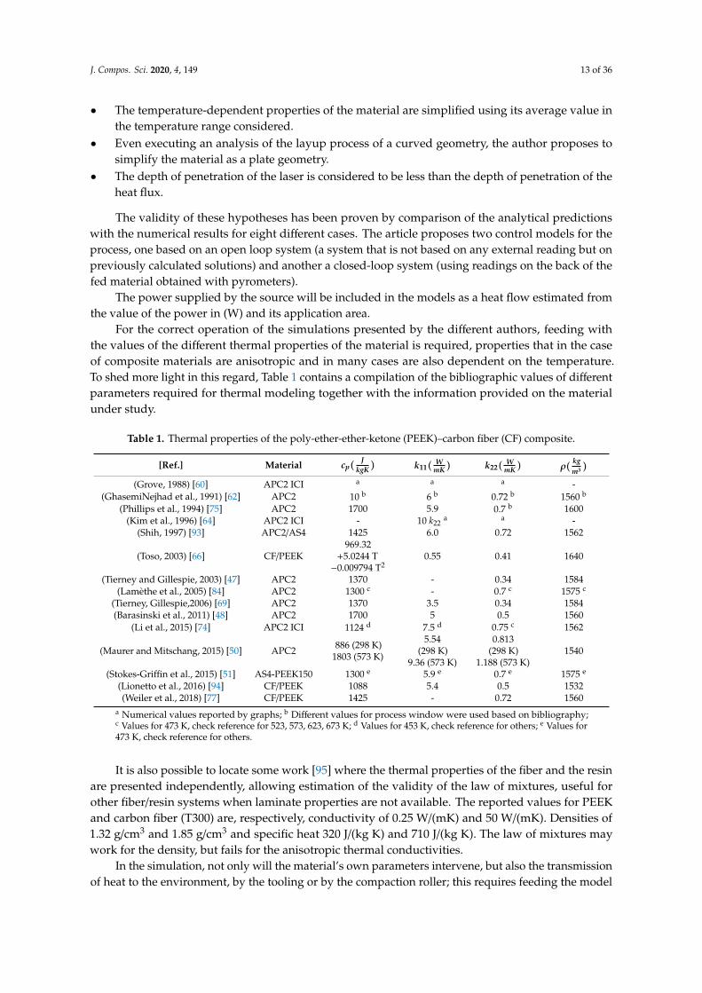
For the correct operation of the simulations presented by the different authors, feeding withthe values of the different thermal properties of the material is required, properties that in the caseof composite materials are anisotropic and in many cases are also dependent on the temperature.To shed more light in this regard, Table 1 contains a compilation of the bibliographic values of differentparameters required for thermal modeling together with the information provided on the materialunder study.
Table 1. Thermal properties of the poly-ether-ether-ketone (PEEK)–carbon fiber (CF) composite.
[Ref.] Material cp(J
kgK ) k11(W
mK ) k22(W
mK ) ρ(kgm3 )
(Grove, 1988) [60] APC2 ICI a a a -(GhasemiNejhad et al., 1991) [62] APC2 10 b 6 b 0.72 b 1560 b
(Phillips et al., 1994) [75] APC2 1700 5.9 0.7 b 1600(Kim et al., 1996) [64] APC2 ICI - 10 k22
a a -(Shih, 1997) [93] APC2/AS4 1425 6.0 0.72 1562
(Toso, 2003) [66] CF/PEEK969.32
+5.0244 T−0.009794 T2
0.55 0.41 1640
(Tierney and Gillespie, 2003) [47] APC2 1370 - 0.34 1584(Lamèthe et al., 2005) [84] APC2 1300 c - 0.7 c 1575 c
(Tierney, Gillespie,2006) [69] APC2 1370 3.5 0.34 1584(Barasinski et al., 2011) [48] APC2 1700 5 0.5 1560
(Li et al., 2015) [74] APC2 ICI 1124 d 7.5 d 0.75 c 1562
(Maurer and Mitschang, 2015) [50] APC2 886 (298 K)1803 (573 K)
5.54(298 K)
9.36 (573 K)
0.813(298 K)
1.188 (573 K)1540
(Stokes-Griffin et al., 2015) [51] AS4-PEEK150 1300 e 5.9 e 0.7 e 1575 e
(Lionetto et al., 2016) [94] CF/PEEK 1088 5.4 0.5 1532(Weiler et al., 2018) [77] CF/PEEK 1425 - 0.72 1560
a Numerical values reported by graphs; b Different values for process window were used based on bibliography;c Values for 473 K, check reference for 523, 573, 623, 673 K; d Values for 453 K, check reference for others; e Values for473 K, check reference for others.
It is also possible to locate some work [95] where the thermal properties of the fiber and the resinare presented independently, allowing estimation of the validity of the law of mixtures, useful forother fiber/resin systems when laminate properties are not available. The reported values for PEEKand carbon fiber (T300) are, respectively, conductivity of 0.25 W/(mK) and 50 W/(mK). Densities of1.32 g/cm3 and 1.85 g/cm3 and specific heat 320 J/(kg K) and 710 J/(kg K). The law of mixtures maywork for the density, but fails for the anisotropic thermal conductivities.
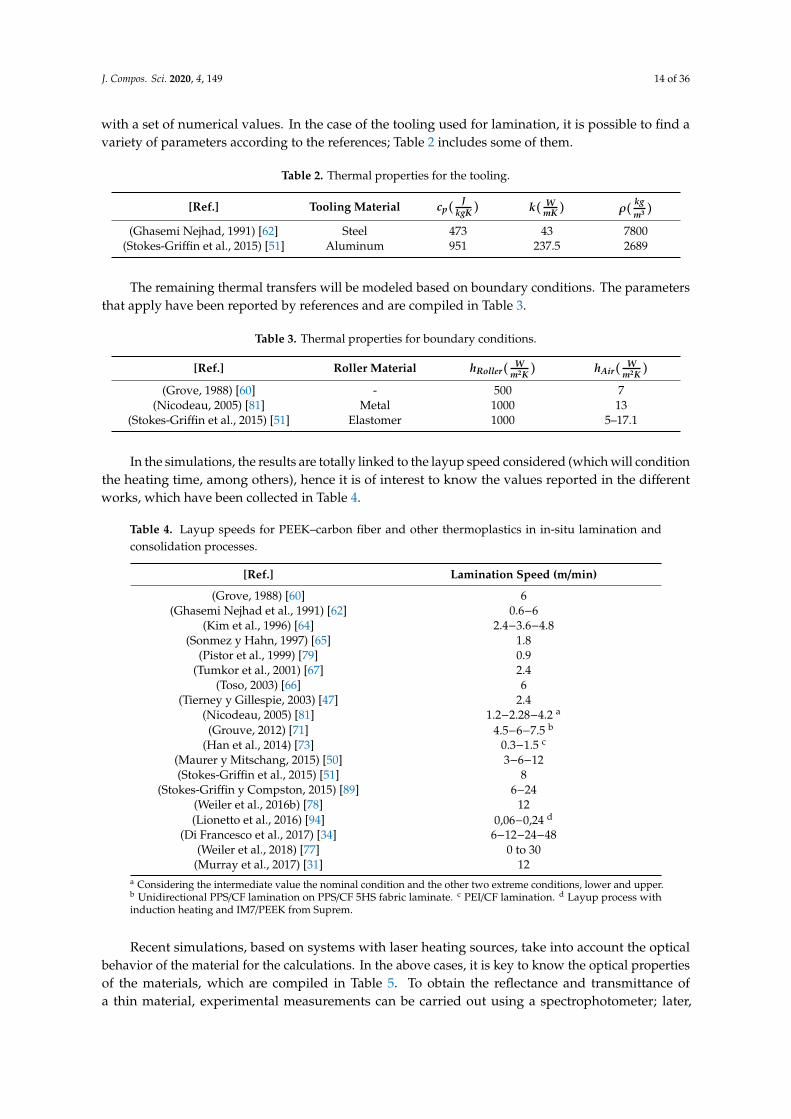
In the simulation, not only will the material’s own parameters intervene, but also the transmissionof heat to the environment, by the tooling or by the compaction roller; this requires feeding the model
J. Compos. Sci. 2020, 4, 149 14 of 36
with a set of numerical values. In the case of the tooling used for lamination, it is possible to find avariety of parameters according to the references; Table 2 includes some of them.
Table 2. Thermal properties for the tooling.
[Ref.] Tooling Material cp(J
kgK ) k( WmK ) ρ(
kgm3 )
(Ghasemi Nejhad, 1991) [62] Steel 473 43 7800(Stokes-Griffin et al., 2015) [51] Aluminum 951 237.5 2689
The remaining thermal transfers will be modeled based on boundary conditions. The parametersthat apply have been reported by references and are compiled in Table 3.
Table 3. Thermal properties for boundary conditions.
[Ref.] Roller Material hRoller(W
m2K ) hAir(W
m2K )
(Grove, 1988) [60] - 500 7(Nicodeau, 2005) [81] Metal 1000 13
(Stokes-Griffin et al., 2015) [51] Elastomer 1000 5–17.1
In the simulations, the results are totally linked to the layup speed considered (which will conditionthe heating time, among others), hence it is of interest to know the values reported in the differentworks, which have been collected in Table 4.
Table 4. Layup speeds for PEEK–carbon fiber and other thermoplastics in in-situ lamination andconsolidation processes.
[Ref.] Lamination Speed (m/min)
(Grove, 1988) [60] 6(Ghasemi Nejhad et al., 1991) [62] 0.6−6
(Kim et al., 1996) [64] 2.4−3.6−4.8(Sonmez y Hahn, 1997) [65] 1.8
(Pistor et al., 1999) [79] 0.9(Tumkor et al., 2001) [67] 2.4
(Toso, 2003) [66] 6(Tierney y Gillespie, 2003) [47] 2.4
(Nicodeau, 2005) [81] 1.2−2.28−4.2 a
(Grouve, 2012) [71] 4.5−6−7.5 b
(Han et al., 2014) [73] 0.3−1.5 c
(Maurer y Mitschang, 2015) [50] 3−6−12(Stokes-Griffin et al., 2015) [51] 8
(Stokes-Griffin y Compston, 2015) [89] 6−24(Weiler et al., 2016b) [78] 12(Lionetto et al., 2016) [94] 0,06−0,24 d
(Di Francesco et al., 2017) [34] 6−12−24−48(Weiler et al., 2018) [77] 0 to 30
(Murray et al., 2017) [31] 12a Considering the intermediate value the nominal condition and the other two extreme conditions, lower and upper.b Unidirectional PPS/CF lamination on PPS/CF 5HS fabric laminate. c PEI/CF lamination. d Layup process withinduction heating and IM7/PEEK from Suprem.
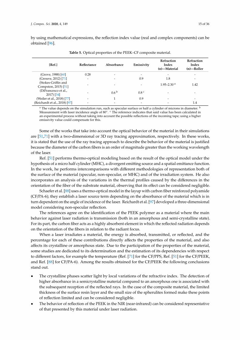
Recent simulations, based on systems with laser heating sources, take into account the opticalbehavior of the material for the calculations. In the above cases, it is key to know the optical propertiesof the materials, which are compiled in Table 5. To obtain the reflectance and transmittance ofa thin material, experimental measurements can be carried out using a spectrophotometer; later,
J. Compos. Sci. 2020, 4, 149 15 of 36
by using mathematical expressions, the reflection index value (real and complex components) can beobtained [96].
Table 5. Optical properties of the PEEK–CF composite material.
[Ref.] Reflectance Absorbance EmissivityRefraction
Index(n)—Material
RefractionIndex
(n)—Roller
(Grove, 1988) [60] 0.28 - - - -(Grouve, 2012) [71] - - 0.9 1.8 -(Stokes-Griffin and
Compston, 2015) [51] - - - 1.95–2.30 a 1.42
(DiFrancesco et al.,2017) [34] - 0.6 b 0.8 c - -
(Weiler et al., 2018) [77] - 1 0.9 - -(Reichardt et al., 2018) [97] - - - - 1.4
a The value depends on the simulation run, such as specular surface or half a cylinder of microns in diameter. b
Measurement with laser incidence angle of 80◦. c The reference indicates that said value has been calculated inan experimental process without taking into account the possible reflections of the incoming tape; using a higheremissivity value could compensate for this.
Some of the works that take into account the optical behavior of the material in their simulationsare [51,71] with a two-dimensional or 3D ray tracing approximation, respectively. In these works,it is stated that the use of the ray tracing approach to describe the behavior of the material is justifiedbecause the diameter of the carbon fibers is an order of magnitude greater than the working wavelengthof the laser.
Ref. [51] performs thermo-optical modeling based on the result of the optical model under thehypothesis of a micro half cylinder (MHC), a divergent emitting source and a spatial emittance function.In the work, he performs intercomparisons with different methodologies of representation both ofthe surface of the material (specular, non-specular, or MHC) and of the irradiation system. He alsoincorporates an analysis of the variations in the thermal profiles caused by the differences in theorientation of the fiber of the substrate material, observing that its effect can be considered negligible.
Schaefer et al. [88] uses a thermo-optical model in the layup with carbon fiber reinforced polyamide(CF/PA-6); they establish a laser source term depending on the absorbance of the material which is inturn dependent on the angle of incidence of the laser. Reichardt et al. [97] developed a three-dimensionalmodel considering non-specular reflection.
The references agree on the identification of the PEEK polymer as a material where the mainbehavior against laser radiation is transmission (both in an amorphous and semi-crystalline state).For its part, the carbon fiber acts as a highly absorbent element in which the reflected radiation dependson the orientation of the fibers in relation to the radiant focus.
When a laser irradiates a material, the energy is absorbed, transmitted, or reflected, and thepercentage for each of these contributions directly affects the properties of the material, and alsoaffects its crystalline or amorphous state. Due to the participation of the properties of the material,some studies are dedicated to its determination and the estimation of its dependencies with respectto different factors, for example the temperature (Ref. [71] for the CF/PPS, Ref. [51] for the CF/PEEK,and Ref. [88] for CF/PA-6). Among the results obtained for the CF/PEEK the following conclusionsstand out.
• The crystalline phases scatter light by local variations of the refractive index. The detection ofhigher absorbance in a semicrystalline material compared to an amorphous one is associated withthe subsequent reception of the reflected rays. In the case of the composite material, the limitedthickness of the surface resin layer and the small size of the spherulites formed make these pointsof reflection limited and can be considered negligible.
• The behavior of reflection of the PEEK in the NIR (near-infrared) can be considered representativeof that presented by this material under laser radiation.
J. Compos. Sci. 2020, 4, 149 16 of 36
• The refractive index of the resin is estimated to be dependent on temperature inversely to thedependence of the coefficient of thermal expansion.
• The optical properties of the carbon fiber can be considered constant in the range of temperaturesexperienced during the in-situ consolidation and lamination process.
• Radiance is considered to be proportional to the irradiance in this material.• The transmittance can be considered negligible for the CF/PEEK. The polymer, which in the
amorphous state would have a high transmittance of laser energy, being reinforced by the fiber,would have a negligible effect on the whole. Transmittance can be neglected in calculations.
• In the composite material, the reflection depends on the orientation of the fiber with respect to theemitting focus, showing special reflection patterns.
• Knowing the angle of incidence of the laser, it is possible to estimate the angle of reflection byapplying Snell’s law.
• It can be estimated that most of the incident light is both absorbed and reflected by the first carbonfiber layer of the surface and this allows the analysis to be simplified to a surface to run models ofmacroscopic behavior.
• It is possible to consider the refractive index in the composite material only for its real part asthere is practically no absorption.
• In radiation simulation, choosing a collimated beam with the geometry of a hat-shaped profile isnot appropriate when working with NIR lasers with the inclinations required by the ISC process;it is essential to consider the beam divergence.
• After two beam reflections, the irradiation intensity becomes negligible. To realistically modelheat transfer, the laser incidence profile should also account for these first two reflections.
Once the optical model is developed, the next step is to perform its coupling with the thermal model.In the bibliography, the importance of elaborating these thermo-optical simulations is highlighteddue to the underestimation that conventional thermal models make of the real energy required by thematerial for heating, since they do not take into account the reflectance of the material. Weiler et al. [78]compiled information from different works where the previous statement is supported, but also fromothers, where it is indicated that the laser radiation impacts on the substrate and incoming tape, whichare reflected from each other and, therefore, leave a final balance in which there is no loss or energy gain.The author presents a variation in absorbance and reflectance depending on the angle of incidenceof the heating source where it can be seen that once the incidence angles of 60◦ have been exceeded,the reflectance begins to be important, estimating that its impact on radiant exposure (integration intime of radiation exposure) is approximately 16%.
Referring to the thermo-optical coupling, Grouve [71] did his model under the assumptionthat the speed of heat conduction in the forward direction of the layup is much lower than thedisplacement of the machine. Under these conditions, the process is governed by conduction throughthickness, proposing a methodology for solving the energy balance based on a pseudospectral orplacement method. Also, Reichardt et al. [97] coupled their optical and thermal models, with the specialcharacteristic of describing the reaction of the material to radiation with a micro-model, the reflectionsobtained from its application are extrapolated to the macro- model.
To take into account the orientations of the reflected rays, Reichardt et al. [97] uses a bidirectionalreflectance distribution function, solving the thermo-optical problem numerically. It is also the firstwork we identified where the problem was solved in an analytical way, comparing the results of theapplication of both methodologies. The numerical and analytical results are very similar when specularreflection of light is taken into account in the numerical solution.
Weiler et al. [78] proposed an optical model for a VCSEL heating source. The work carries outa first view on the generalities of laser heating and the requirements to simulate it by consideringthe distribution of angular intensity, irradiance, and absorbed intensity, but leaving the depth ofpenetration of the laser out of the study. In the simulation, a calculation is carried out to consider the
J. Compos. Sci. 2020, 4, 149 17 of 36
superposition of the effect of the independent lamps constituting the VCSEL, demonstrating that theirradiation decays towards the nip point in the substrate and increases towards the nip point in theincoming tape.
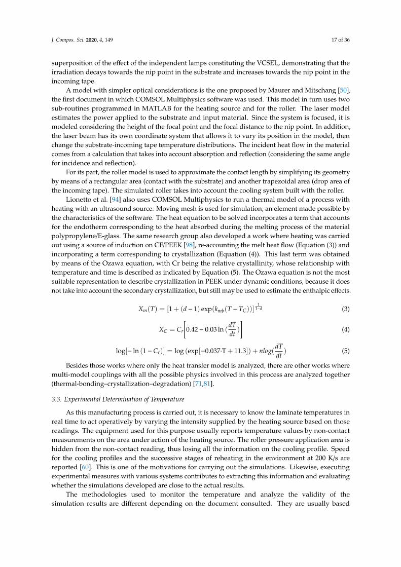
A model with simpler optical considerations is the one proposed by Maurer and Mitschang [50],the first document in which COMSOL Multiphysics software was used. This model in turn uses twosub-routines programmed in MATLAB for the heating source and for the roller. The laser modelestimates the power applied to the substrate and input material. Since the system is focused, it ismodeled considering the height of the focal point and the focal distance to the nip point. In addition,the laser beam has its own coordinate system that allows it to vary its position in the model, thenchange the substrate-incoming tape temperature distributions. The incident heat flow in the materialcomes from a calculation that takes into account absorption and reflection (considering the same anglefor incidence and reflection).
For its part, the roller model is used to approximate the contact length by simplifying its geometryby means of a rectangular area (contact with the substrate) and another trapezoidal area (drop area ofthe incoming tape). The simulated roller takes into account the cooling system built with the roller.
Lionetto et al. [94] also uses COMSOL Multiphysics to run a thermal model of a process withheating with an ultrasound source. Moving mesh is used for simulation, an element made possible bythe characteristics of the software. The heat equation to be solved incorporates a term that accountsfor the endotherm corresponding to the heat absorbed during the melting process of the materialpolypropylene/E-glass. The same research group also developed a work where heating was carriedout using a source of induction on CF/PEEK [98], re-accounting the melt heat flow (Equation (3)) andincorporating a term corresponding to crystallization (Equation (4)). This last term was obtainedby means of the Ozawa equation, with Cr being the relative crystallinity, whose relationship withtemperature and time is described as indicated by Equation (5). The Ozawa equation is not the mostsuitable representation to describe crystallization in PEEK under dynamic conditions, because it doesnot take into account the secondary crystallization, but still may be used to estimate the enthalpic effects.
Xm(T) = [1 + (d− 1) exp(kmb(T − TC))]1
1−d (3)
XC = Cr
[0.42− 0.03 ln (
dTdt
)
](4)
log[− ln (1−Cr)] = log (exp[−0.037·T + 11.3]) + nlog(dTdt
) (5)
Besides those works where only the heat transfer model is analyzed, there are other works wheremulti-model couplings with all the possible physics involved in this process are analyzed together(thermal-bonding–crystallization–degradation) [71,81].
3.3. Experimental Determination of Temperature
As this manufacturing process is carried out, it is necessary to know the laminate temperatures inreal time to act operatively by varying the intensity supplied by the heating source based on thosereadings. The equipment used for this purpose usually reports temperature values by non-contactmeasurements on the area under action of the heating source. The roller pressure application area ishidden from the non-contact reading, thus losing all the information on the cooling profile. Speedfor the cooling profiles and the successive stages of reheating in the environment at 200 K/s arereported [60]. This is one of the motivations for carrying out the simulations. Likewise, executingexperimental measures with various systems contributes to extracting this information and evaluatingwhether the simulations developed are close to the actual results.
The methodologies used to monitor the temperature and analyze the validity of thesimulation results are different depending on the document consulted. They are usually based
J. Compos. Sci. 2020, 4, 149 18 of 36
on thermocouple-type temperature probe readings as reported in [48,51,61,64,70,80,81,88,93],pyrometers [63], or thermal imaging cameras [71].
In verifying the thermocouple readings of the thermal profiles, there are several references thatdiscard the results of the first tapes on the thermocouple. The ruling out of these measures is based onthe unfavorable effects of direct laser irradiation on the thermocouple [88], which can be surroundedby air after the first tapes on it. As the layup evolves, the thermocouple embedding improves, makingthe data more rigorous. The simulations may later serve to complement the information of thosemeasurements that were considered unreliable.
Seeking to correct this negative effect of the measurement, [51] analyzed the temperature recordedby the thermocouple at a location. Taking a point at the same distance from the nip point as thethermocouple, the differences between the thermography and thermocouple reading were estimated.These differences were used to propose a correction of the temperature value of the thermocouple,which was applied to understanding what happens in areas where thermography cannot be used as ameasurement system.
In relation to the control through a thermography camera, the former authors [89] established thepolluting effect of the reflections of the material being taped on the thermal reading in the substratematerial. This causes the readings on the thermal imager to be higher than the real values presented bythe laminate.
Taking into account the positions of the incoming tape and substrate, the bibliography indicatesthe impossibility of monitoring the temperature for both in the same way. The substrate may supportthermocouple monitoring; however, the incoming tape is limited to thermography measurements.
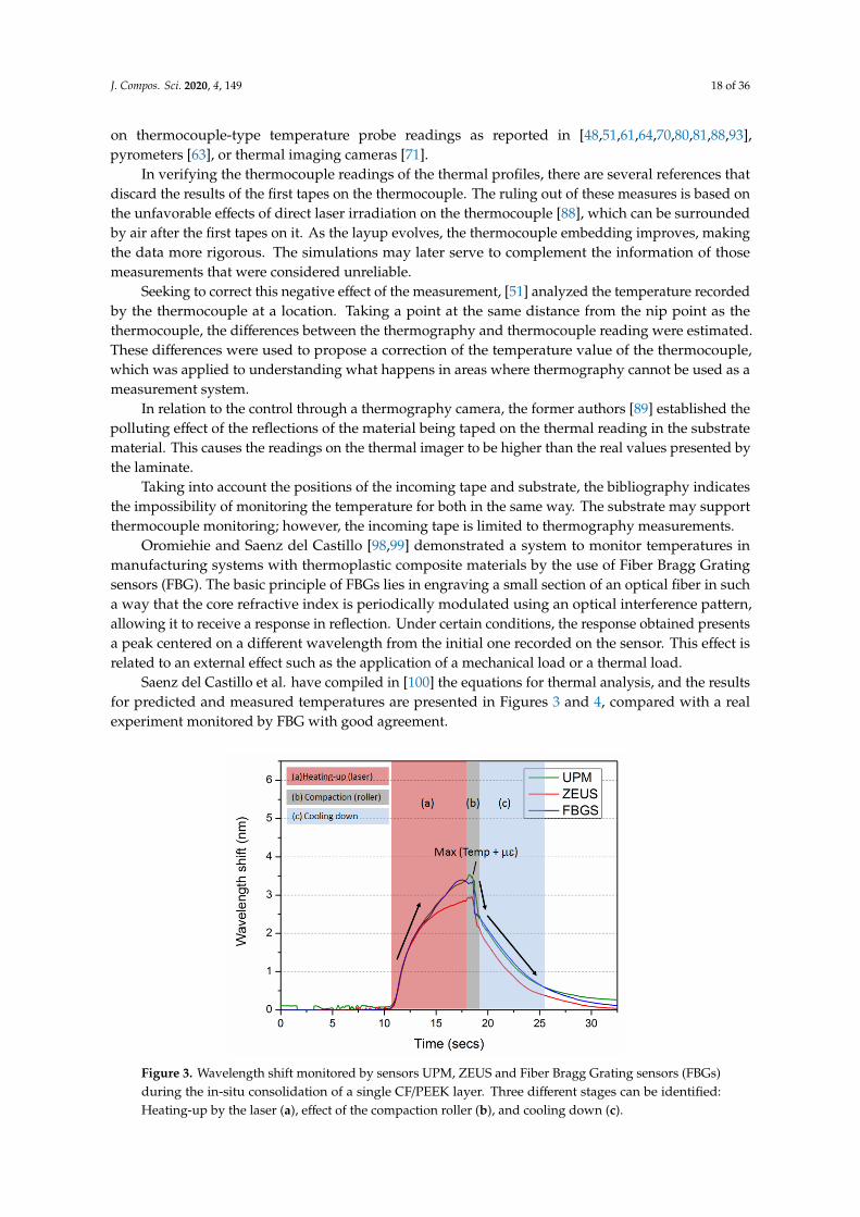
Oromiehie and Saenz del Castillo [98,99] demonstrated a system to monitor temperatures inmanufacturing systems with thermoplastic composite materials by the use of Fiber Bragg Gratingsensors (FBG). The basic principle of FBGs lies in engraving a small section of an optical fiber in sucha way that the core refractive index is periodically modulated using an optical interference pattern,allowing it to receive a response in reflection. Under certain conditions, the response obtained presentsa peak centered on a different wavelength from the initial one recorded on the sensor. This effect isrelated to an external effect such as the application of a mechanical load or a thermal load.
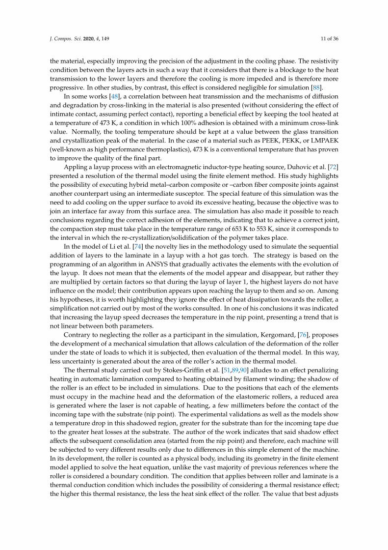
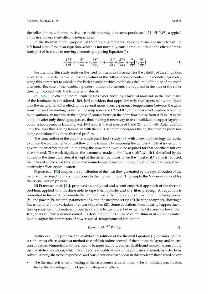
Saenz del Castillo et al. have compiled in [100] the equations for thermal analysis, and the resultsfor predicted and measured temperatures are presented in Figures 3 and 4, compared with a realexperiment monitored by FBG with good agreement.
J. Compos. Sci. 2020, 4, x 25 of 45
Figure 3. Wavelength shift monitored by sensors UPM, ZEUS and Fiber Bragg Grating sensors (FBGs) during the in-situ consolidation of a single CF/PEEK layer. Three different stages can be identified: Heating-up by the laser (a), effect of the compaction roller (b), and cooling down (c).
Figure 4. Comparison of thermal profiles provided by FBG process monitoring and thermal model simulation.
3.4. Control Systems
Thermal models determine the temperatures experienced by any point of the laminate during the layup process. Another objective for the development of the model is to enable control over the wrapping equipment, seeking that it can autonomously carry out modifications to the power signal sent by the laser and that it is simultaneously capable of extracting information about the consolidation states, crystallinity, residual stress, or degradation effects.
Obtaining information on what happens in lower layers than the positioned one allows establishment of a possible quality status in the piece; however, for active control it seems logical that the system uses a fundamental criterion for the control
Figure 3. Wavelength shift monitored by sensors UPM, ZEUS and Fiber Bragg Grating sensors (FBGs)during the in-situ consolidation of a single CF/PEEK layer. Three different stages can be identified:Heating-up by the laser (a), effect of the compaction roller (b), and cooling down (c).
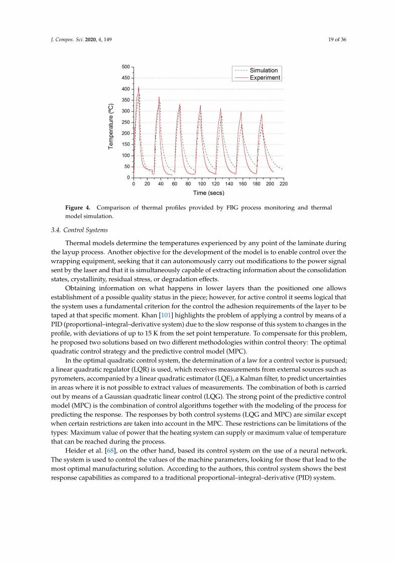
J. Compos. Sci. 2020, 4, 149 19 of 36
J. Compos. Sci. 2020, 4, x 25 of 45
Figure 3. Wavelength shift monitored by sensors UPM, ZEUS and Fiber Bragg Grating sensors (FBGs) during the in-situ consolidation of a single CF/PEEK layer. Three different stages can be identified: Heating-up by the laser (a), effect of the compaction roller (b), and cooling down (c).
Figure 4. Comparison of thermal profiles provided by FBG process monitoring and thermal model simulation.
3.4. Control Systems
Thermal models determine the temperatures experienced by any point of the laminate during the layup process. Another objective for the development of the model is to enable control over the wrapping equipment, seeking that it can autonomously carry out modifications to the power signal sent by the laser and that it is simultaneously capable of extracting information about the consolidation states, crystallinity, residual stress, or degradation effects.
Obtaining information on what happens in lower layers than the positioned one allows establishment of a possible quality status in the piece; however, for active control it seems logical that the system uses a fundamental criterion for the control
Figure 4. Comparison of thermal profiles provided by FBG process monitoring and thermalmodel simulation.
3.4. Control Systems
Thermal models determine the temperatures experienced by any point of the laminate duringthe layup process. Another objective for the development of the model is to enable control over thewrapping equipment, seeking that it can autonomously carry out modifications to the power signalsent by the laser and that it is simultaneously capable of extracting information about the consolidationstates, crystallinity, residual stress, or degradation effects.
Obtaining information on what happens in lower layers than the positioned one allowsestablishment of a possible quality status in the piece; however, for active control it seems logical thatthe system uses a fundamental criterion for the control the adhesion requirements of the layer to betaped at that specific moment. Khan [101] highlights the problem of applying a control by means of aPID (proportional–integral–derivative system) due to the slow response of this system to changes in theprofile, with deviations of up to 15 K from the set point temperature. To compensate for this problem,he proposed two solutions based on two different methodologies within control theory: The optimalquadratic control strategy and the predictive control model (MPC).
In the optimal quadratic control system, the determination of a law for a control vector is pursued;a linear quadratic regulator (LQR) is used, which receives measurements from external sources such aspyrometers, accompanied by a linear quadratic estimator (LQE), a Kalman filter, to predict uncertaintiesin areas where it is not possible to extract values of measurements. The combination of both is carriedout by means of a Gaussian quadratic linear control (LQG). The strong point of the predictive controlmodel (MPC) is the combination of control algorithms together with the modeling of the process forpredicting the response. The responses by both control systems (LQG and MPC) are similar exceptwhen certain restrictions are taken into account in the MPC. These restrictions can be limitations of thetypes: Maximum value of power that the heating system can supply or maximum value of temperaturethat can be reached during the process.
Heider et al. [68], on the other hand, based its control system on the use of a neural network.The system is used to control the values of the machine parameters, looking for those that lead to themost optimal manufacturing solution. According to the authors, this control system shows the bestresponse capabilities as compared to a traditional proportional–integral–derivative (PID) system.
J. Compos. Sci. 2020, 4, 149 20 of 36
4. Adhesion
In the analysis of the adhesion mechanism between the layers of the composite material, the processmust be described taking into account two factors: On one hand, the elimination of surface roughnessin the incoming material to allow the displacement of the polymer chains and, on the other hand,the mechanism that controls this movement of chains.
4.1. Intimate Contact Theory
Between two surfaces of thermoplastic pre-impregnated composite materials brought into contact,without the application of pressure or temperature, there are gaps due to the inherent irregularity ofthe surfaces of the material. The high viscosity values of thermoplastic resins mean that they have alimited ability to cover these areas only by natural flow of the polymer, making it necessary to force thecontact of both surfaces by physical means (application of pressure). In order to account for the effectof this contact and the evolution of the destruction of the irregularities, models of “intimate contact”emerge, the starting point of which is to characterize the surface state of the material.
It should be pointed out that the time required to achieve contact between the surfaces willincrease the greater the irregularity carried by the material, hence the importance of characterizing andcontrolling this effect, whose impact on the productivity of the process is decisive.
4.1.1. Representation of the Material Surfaces
The starting point for modeling the removal of roughness in the material is to know its initialstate. In the bibliography, it is possible to locate different references where models of representation ofthe material are included, taking into account different geometric approximations of its surface. Woo IlLee and Springer [19] proposed to model the surface of these materials as a succession of identicalrectangles. On the other hand, Loos and Dara [102] used a histogram of heights measured on thesurface of the material to represent its irregularity using a Weibull-type distribution function.
Pitchumani et al. [63] used a surface model of rectangles. In this work, the temperature andpressure profiles developed in the automatic layup process were used to evaluate the evolution of theroughness state of the material, unlike values used by other works where average estimated values intemperature were used.
Yang and Pitchumani [103–106] proposed a representation using fractal surfaces, a model also usedin [107,108] that lead to Equation (6). This approach is based on proposing that the surface irregularityexists on different scales. In [107] the need for re-consolidation passes on the material to achieve highvalues of intimate contact is analyzed. The work concluded that at least three reconsolidation passesare required without material input to achieve 100% degree of contact.
Dnic(t) =
1f n [
54
(hr
Lr
)2 f2nD2−D+n+4
( f + 1] 2
∫ t
tn+1
Papp
µm fdt + 1]
1/5
(6)
Equation (6) is the one used for the evolution of the degree of intimate contact. D is the fractaldimension, f the scaling factor, n the number of irregularities, Lr the total length to establish the Cantorset, Papp the applied pressure, t the duration of pressure of the roller, ηmf the viscosity of the compound,and hr the depth break of the first generation of irregularities found. A summary of the mentionedsurface representation methodologies is presented in [109]. The authors carry out the application ofthe models of identical rectangles and fractal surfaces for the analysis of the degree of intimate contactin polyamide (PA6) reinforced with carbon fiber. Regarding the application of fractal models, it isindicated that with them it is possible to obtain the parameters required by the model by means ofsimple profilometric measurements, an important fact compared to models that use rectangles as theyare supported by approximations with mathematical adjustments. In return, these models are not
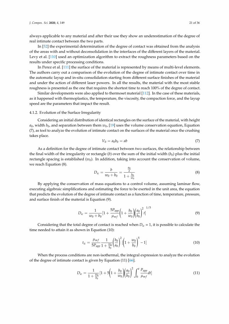
J. Compos. Sci. 2020, 4, 149 21 of 36
always applicable to any material and after their use they show an underestimation of the degree ofreal intimate contact between the two parts.
In [52] the experimental determination of the degree of contact was obtained from the analysisof the areas with and without deconsolidation in the interfaces of the different layers of the material.Levy et al. [110] used an optimization algorithm to extract the roughness parameters based on theresults under specific processing conditions.
In Perez et al. [111] the surface of the material is represented by means of multi-level elements.The authors carry out a comparison of the evolution of the degree of intimate contact over time inthe automatic layup and in-situ consolidation starting from different surface finishes of the materialand under the action of different laser powers. In all the results, the material with the most stableroughness is presented as the one that requires the shortest time to reach 100% of the degree of contact.
Similar developments were also applied to thermoset material [112]. In the case of these materials,as it happened with thermoplastics, the temperature, the viscosity, the compaction force, and the layupspeed are the parameters that impact the result.
4.1.2. Evolution of the Surface Irregularity
Considering an initial distribution of identical rectangles on the surface of the material, with heighta0, width b0, and separation between them w0, [19] uses the volume conservation equation, Equation(7), as tool to analyze the evolution of intimate contact on the surfaces of the material once the crushingtakes place.
V0 = a0b0 = ab (7)
As a definition for the degree of intimate contact between two surfaces, the relationship betweenthe final width of the irregularity or rectangle (b) over the sum of the initial width (b0) plus the initialrectangle spacing is established (w0). In addition, taking into account the conservation of volume,we reach Equation (8).
Dic =b
w0 + b0=
a0a
1 + b0w0
(8)
By applying the conservation of mass equations to a control volume, assuming laminar flow,executing algebraic simplifications and estimating the force to be exerted in the unit area, the equationthat predicts the evolution of the degree of intimate contact as a function of time, temperature, pressure,and surface finish of the material is Equation (9).
Dic =1
w0 + b0[1 +
5Papp
µm f
(1 +
b0
w0
)(a0
b0
)2
t]1/5
(9)
Considering that the total degree of contact is reached when Dic = 1, it is possible to calculate thetime needed to attain it as shown in Equation (10):
tic =µm f
5Papp
11 + w0
b0
(b0
a0
)2
[
(1 +
w0
b0
)5
− 1] (10)
When the process conditions are non-isothermal, the integral expression to analyze the evolutionof the degree of intimate contact is given by Equation (11) [66].
Dic =1
1 + w0b0
[1 + 5(1 +
b0
w0
)(a0
b0
)2 ∫ t
0
Papp
µm fdt] (11)
J. Compos. Sci. 2020, 4, 149 22 of 36
The expression shown in [63] appears simplified as Equation (12).
Dic = a∗[∫ tb
0
Papp
µm fdt]
1/5
(12)
Adopting a a* value of 0.29 in the case of APC2/AS4.As can be inferred from the previous equations, the calculation requires knowledge of the viscosity
of the fiber–resin composite material. The surface of this material is primarily polymer. The viscosityis determined as the value obtained from the zero shear rate at different temperatures, assuming thatthe cutting speed does not intervene in the automatic layup process.
In the case of APC2/AS4 material, Table 6 shows the equations from different bibliographysources. The matrix-fiber viscosities were obtained by measuring the thickness change of sampleswhen compressed at different temperatures in the interval of interest (340–400 ◦C for PEEK), for agiven compaction force and time (details are given in [107]) then adjusting the values to an Arrheniuskinetics. Significant differences happen among these equations, suggesting a strong dependence onthe tape characteristics.
Table 6. Definition of bibliographic parameters for the intimate contact degree equations.
[Ref.] µm[Pa.s] µmf[Pa.s]
Woo Il Lee, Springer 1987 [19](Marchello, Messier, 1996) [113]
1.13 ·10−10[exp
(19100
T
)]PEEK 150P
1.14 ·10−12[exp
(26300
T
)](Mantell, Springer, 1992) [114] 1.13 ·10−10
[exp
(19100
T
)]132.95
[exp
(2969
T
)](Sonmez, Hahn, 1997) [65] - 132.95
[exp
(2969
T
)](Khan, Schledjewski, 2009) [107] - 643
[exp
(4367
T
)]4.2. Polymeric Chain Movement Theories of Self-Adherence
When two polymeric surfaces come into contact with each other, their temperature over theirglass transition, a diffusion of the polymer chains occurs in the interface, commonly known as healing,diffusion, or self-adhesion. In the development of a resistant joint, a correct diffusion of the chainsmust be developed so that the interface can become indistinguishable.
The basic theory for explaining the mechanism of chain diffusion at the interface is De Gennes’theory of reptation [115,116]. A description of this theory is beyond the scope of this article; it can befound elsewhere [117].
Moving now towards the adhesion mechanism between two surfaces of material during automaticlayup and considering chain reptation, it is necessary to take into account the movement of thewell-known minor chains [118]. Initially, a chain is surrounded entirely by a tube (topologicalrestrictions). For a time t1, the chain begins to leave the tube, mainly at the ends, and those initialportions that have evacuated the tube are called minor chains. The length of the chain leaving thetube l(t) is an increasing function over time; this magnitude will be the main control mechanism in thedevelopment of the binding resistance.
Depending on the capacity of interpenetration of the polymer chain in the face of the material,it is possible to develop a more or less resistant bonding, which is a direct cause of the mechanicalbehavior of the joint.
The relationship of diffusion/healing is directly alluded to the mechanical properties developedby the interface of the material, presenting the following dependencies for resistance and energy offracture with time [104,118] (Equation (13)) and the estimation of the value of the degree of diffusion(Equation (14)).
σσ∞
= (ttr)
1/4;
GIc
GIc∞= (
ttr)
1/4(13)
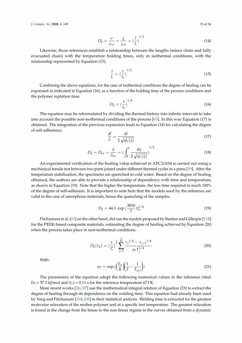
J. Compos. Sci. 2020, 4, 149 23 of 36
Dh =σσ∞
=χχ∞
= (lL)
1/2(14)
Likewise, those references establish a relationship between the lengths (minor chain and fullyevacuated chain) with the temperature holding times, only in isothermal conditions, with therelationship represented by Equation (15).
lL= (
ttr)
1/2(15)
Combining the above equations, for the case of isothermal conditions the degree of healing can beexpressed as indicated in Equation (16), as a function of the holding time of the process conditions andthe polymer reptation time.
Dh = (ttr)
1/4(16)
The equation may be reformulated by dividing the thermal history into infinite intervals to takeinto account the possible non-isothermal conditions of the process [65]. In this way Equation (17) isobtained. The integration of the previous expression leads to Equation (18) for calculating the degreeof self-adherence.
dlL
=dt
2√ηtr(η)
(17)
Dh = Dau =S
S∞= (
∫ t
0
dη
2√ηtr(η)
)
1/2
(18)
An experimental verification of the healing value achieved in APC2/AS4 is carried out using amechanical tensile test between two parts joined under different thermal cycles in a press [19]. After thetemperature stabilization, the specimens are quenched in cold water. Based on the degree of healingobtained, the authors are able to provide a relationship of dependency with time and temperature,as shown in Equation (19). Note that the higher the temperature, the less time required to reach 100%of the degree of self-adhesion. It is important to note here that the models used by the reference arevalid in the case of amorphous materials, hence the quenching of the samples.
Dh = 44.1· exp (3810
T)t1/4
a (19)
Pitchumani et al. [63] on the other hand, did use the models proposed by Bastien and Gillespie [118]for the PEEK-based composite materials, estimating the degree of healing achieved by Equation (20)when the process takes place in non-isothermal conditions.
Dh(τh) = (1t∗r)
14
τh∆τ∑
j=1
τ j1/4− τ j−1
1/4
aTT1/4j
(20)
With:
aT = exp ((Ea
R
)( 1T−
1Tre f
)) (21)
The parameters of the equation adopt the following numerical values in the reference cited:Ea = 57.3 kJ/mol and (tr) = 0.11 s for the reference temperature 673 K.
More recent works [26,107] use the mathematical integral relation of Equation (23) to extract thedegree of healing through its dependence on the welding time. This equation had already been usedby Yang and Pitchumani [104,106] in their statistical analysis. Welding time is extracted for the greatestmolecular relaxation of the molten polymer and at a specific test temperature. The greatest relaxationis found in the change from the linear to the non-linear regime in the curves obtained from a dynamic
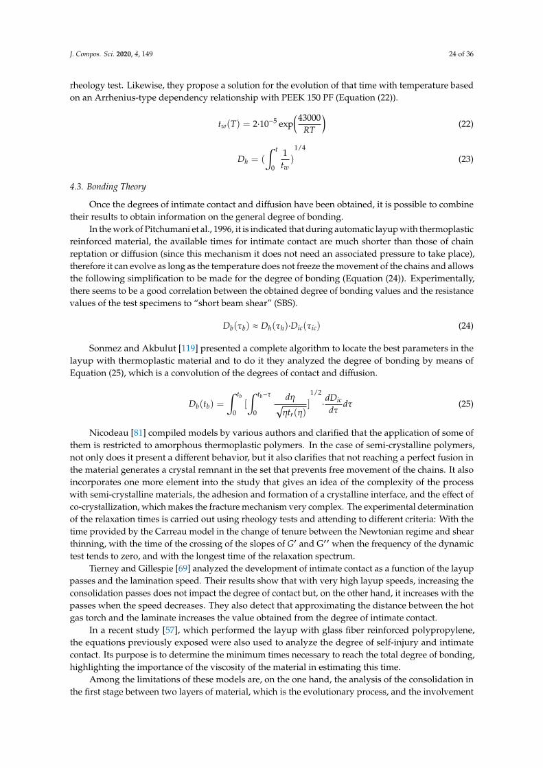
J. Compos. Sci. 2020, 4, 149 24 of 36
rheology test. Likewise, they propose a solution for the evolution of that time with temperature basedon an Arrhenius-type dependency relationship with PEEK 150 PF (Equation (22)).
tw(T) = 2·10−5 exp(43000
RT
)(22)
Dh = (
∫ t
0
1tw
)
1/4
(23)
4.3. Bonding Theory
Once the degrees of intimate contact and diffusion have been obtained, it is possible to combinetheir results to obtain information on the general degree of bonding.
In the work of Pitchumani et al., 1996, it is indicated that during automatic layup with thermoplasticreinforced material, the available times for intimate contact are much shorter than those of chainreptation or diffusion (since this mechanism it does not need an associated pressure to take place),therefore it can evolve as long as the temperature does not freeze the movement of the chains and allowsthe following simplification to be made for the degree of bonding (Equation (24)). Experimentally,there seems to be a good correlation between the obtained degree of bonding values and the resistancevalues of the test specimens to “short beam shear” (SBS).
Db(τb) ≈ Dh(τh)·Dic(τic) (24)
Sonmez and Akbulut [119] presented a complete algorithm to locate the best parameters in thelayup with thermoplastic material and to do it they analyzed the degree of bonding by means ofEquation (25), which is a convolution of the degrees of contact and diffusion.
Db(tb) =
∫ tb
0[
∫ tb−τ
0
dη√ηtr(η)
]
1/2
·dDicdτ
dτ (25)
Nicodeau [81] compiled models by various authors and clarified that the application of some ofthem is restricted to amorphous thermoplastic polymers. In the case of semi-crystalline polymers,not only does it present a different behavior, but it also clarifies that not reaching a perfect fusion inthe material generates a crystal remnant in the set that prevents free movement of the chains. It alsoincorporates one more element into the study that gives an idea of the complexity of the processwith semi-crystalline materials, the adhesion and formation of a crystalline interface, and the effect ofco-crystallization, which makes the fracture mechanism very complex. The experimental determinationof the relaxation times is carried out using rheology tests and attending to different criteria: With thetime provided by the Carreau model in the change of tenure between the Newtonian regime and shearthinning, with the time of the crossing of the slopes of G′ and G′′ when the frequency of the dynamictest tends to zero, and with the longest time of the relaxation spectrum.
Tierney and Gillespie [69] analyzed the development of intimate contact as a function of the layuppasses and the lamination speed. Their results show that with very high layup speeds, increasing theconsolidation passes does not impact the degree of contact but, on the other hand, it increases with thepasses when the speed decreases. They also detect that approximating the distance between the hotgas torch and the laminate increases the value obtained from the degree of intimate contact.
In a recent study [57], which performed the layup with glass fiber reinforced polypropylene,the equations previously exposed were also used to analyze the degree of self-injury and intimatecontact. Its purpose is to determine the minimum times necessary to reach the total degree of bonding,highlighting the importance of the viscosity of the material in estimating this time.
Among the limitations of these models are, on the one hand, the analysis of the consolidation inthe first stage between two layers of material, which is the evolutionary process, and the involvement
J. Compos. Sci. 2020, 4, 149 25 of 36
of the bond of multiple layers impacting time after time on the lower ones. Zhao et al. [120] presents awork that tries to cover this problem, presenting an equation for the analysis of the pressure on the nthlayer and the relationship of the degree of contact with the evolution of the layup. The work is carriedout under the assumption that viscosity of the composite material can be approximated by that of theresin, since this is the most superficial component of the ply.
The times described above for both intimate contact and diffusion or healing can be high ifextrapolated to the industrial application of the automatic layup and consolidation process in situ,as they result in very high conservative values.
5. Crystallization
Crystallization is probably one of the most important topics for polymer science. It is out of thescope of this review to attempt to summarize the state-of-the-art methods. We just included someworks dealing with specific aspects of crystallization during ISC and its consequences on mechanicalproperties. It is worth mentioning that, when cooled from melt, some thermoplastic polymers such asPEEK can arrange in a partially ordered crystalline structure, called lamellae, about 10–20 nm thickand formed by folding the polymer chain. In a bulk polymer these lamellae grow radially from anucleation point, creating spherical crystalline regions called spherulites. In the presence of fibers, newphenomena appear.
5.1. Transcrystallization
Transcrystallization consists of a process of crystal growth affected by restricted space. Interfacialcrystallization, or transcrystallization, offers a new possibility to improve the interaction betweenthe polymer and the reinforcement in a composite material. The reinforcement acts as a nucleus thatinduces crystal growth, as occurs with PEEK on carbon fiber reinforcements. The presence of thereinforcement forces growth to take place in a direction perpendicular to the surface of the fibers, untilthe crystals collide with those generated in the bulk [121].
This crystalline formation has a fundamental impact on the mechanical behavior of the material.In the case of longitudinal properties, an improvement is reported with the interaction of thetrans-crystalline layer, since the matrix in the direction of the fiber has greater strength and stiffnessand its thermal expansion is reduced, which directly impacts on the residual stresses. Transversally,an example is reported for glass fiber reinforced polyamide, where there is a maximum in the tensilestrength and in the modulus for cases where slow cooling leads to better transcrystalline layers.More information regarding the effect of this layer on mechanical properties is included in the sectionon the relationship between mechanical properties and crystallization.
There are several studies that analyze the crystallization phenomenon in the PEEK polymer andin the PEEK thermoplastic matrix composite materials, for the particular process of automatic layupand in-situ consolidation [122,123].
5.2. Crystallization and Mechanical Properties
Despite the fact that there are numerous effects conditioning the final mechanical behavior of partsmanufactured with composite materials of thermoplastic matrixes (porosity, residual stresses, etc.),crystallization is one of the most highlighted factors in the references consulted as a key element inthe development of some mechanical or other properties [124–127]. Its findings are linked to thethermal profiles to which the part was subjected. The references analyze the impact of the crystallinitypercentage, such as the impact of the crystal morphology and the mechanical property under analysis.
The impact of the crystallinity of the polymer on the mechanical properties requires independentpresentation for the net and reinforced polymer. In the composite material, the contribution of thefiber as a nucleating agent and the impact of the transcrystalline layer on the result under differentmechanical stresses must be considered.
J. Compos. Sci. 2020, 4, 149 26 of 36
5.2.1. Crystallization and Mechanical Properties in PEEK
Cebe et al. [128] analyzed the mechanical behavior affected by crystallinity for the net PEEKpolymer, using tensile tests on samples that were, respectively: Abruptly cooled to obtain an amorphousstate, crystallized from the amorphous state, and crystallized at fast and slow speeds from the melt.In addition, the tests were run at three different temperatures below the glass transition. The samplescrystallized in the conditions of slow cooling from the melt, and in all test cases a zone of plasticbehavior with the lowest values of deformation at break and resistance to final failure was present.
5.2.2. Crystallization and Mechanical Properties in Composite Material
Lee et al. [129] analyzed glass fiber and polypropylene composite materials under different coolingprofiles, drawing conclusions against different states of mechanical stress. In unidirectional traction,the highest value is obtained in the case of lower cooling speed due to the good adhesion achievedbetween resin and fiber. On the other hand, in a fracture (mode I, mode II and mixed), interlaminarshear (ILSS), and impact, the behavior improves at a higher cooling rate. However, it should beemphasized here that the tests were carried out with cooling programs at 1, 10, and 20 K/min, withranges very close to each other and not very representative of the large values observed in automaticlamination and consolidation in-situ.
One of the causes for the variations in mechanical properties is the correct or incorrect developmentof the transcrystalline layer during cooling of the material [130]. This work draws different conclusionsabout the effects of applying different “annealing” conditions on samples with polyamide 6 andpolyamide 6 with continuous reinforcements of carbon fiber. Among their conclusions, they mentionedan increased thermal conductivity with crystallization since it is a property that depends on thevibration of the structure of the crystalline lattice.
Gao and Kim [130,131] show a correlation between crystallinity and properties such as interfacialshear strength (IFSS) or short beam shear (SBS). According to their analysis, there is a marked differencebetween specimens that have undergone cooling at 1 K/min over those that have undergone cooling at600 K/min, reflecting a decrease both in mechanical properties and in the measured value of crystallinityby calorimetry. The study of the fracture gap also shows a cohesive behavior when cooling wasslow and a cohesive–adhesive (matrix-open) behavior when cooling was abrupt. These same authorsextended their investigations to the analysis of the effect of crystallinity on the interlaminar fracturetoughness in laminates with PEEK and carbon fiber [132]. In mode I, the conclusions were that thecrack propagation is more stable as the cooling rate increases, as a cause of the plastic behavior ofthe resin in the peel gap. Likewise, for greater cooling speeds, the crack length is also shorter fora given opening displacement. In both failure modes, I and II, the energy decays with increasingcrystallinity, which is equivalent to increases in energy with increasing cooling speed; however, theseincreases are not as high as when the net resin was subjected to these cooling profiles. Possible causesfor differences in toughness with the resin are associated with the non-plastic behavior of the fiberand also the weak fiber-resin interface generated in rapid cooling. A third extension of the work [133]analyzes the relationship between crystallinity and impact damage behavior in samples crystallizedin the range of 1 to 80 K/min. According to the tests carried out, laminates with a lower crystallinepercentage (higher cooling speed and smaller spherulite size) are characterized by being more ductileand having a greater capacity to resist the onset of delamination and absorption of impact energy.
These findings were in agreement with those presented by D. Ray et al. [134]. They found thatmode I fracture toughness is 60–80% higher for the LATP (laser assisted tape placement) processedspecimens than for the autoclave processed specimens. The higher fracture toughness of the LATPprocessed specimens is partially due to significant plastic deformation in the interior of plies duringthe DCB (Duble Cantilever Beam) test, because of the lower crystallinity.
Not every mechanical property was improved. Regarding the tensile and flexural behavior andthe effect of crystallinity on these properties, Gao et al. published a study [135] where the results fortransverse and longitudinal specimens were shown. Except for the longitudinal traction, influenced by
J. Compos. Sci. 2020, 4, 149 27 of 36
the fiber, the other tests showed a decreasing trend with the decrease in crystallinity, and the flexuralproperties were much more affected. The samples that underwent rapid cooling contained a matrixrich in amorphous phase, unable to bear the bending load, particularly the compression component.Furthermore, the authors reported a limit value on the cooling rate of 600 K/min, above which therewere no variations in the results.
El Kadi and Denault [136] proposed to analyze the variation of mechanical properties, both staticand fatigue, in laminates where the presence and absence of spherulites was confirmed. In thiswork they alluded to other bibliographic references where it was indicated that the variation inmechanical properties with rapid cooling is more associated with an increase in residual stressesthan with the modifications of crystalline structure, as well as the possibility of obtaining similarcrystallinity percentages with totally different crystal morphologies. In fatigue, there does not seem tobe a significant effect of the characteristics of the matrix, but, on the other hand, in static conditions itdoes not occur in this way and the important effect of the fiber–matrix interface is again mentioned.
In line with the effect on the mechanical properties of crystallization, there is also an effectof crystallinity on the glass transition and on the enthalpic relationship, as proposed by Toft [137].The crystal–amorphous interface is indicated to have a remarkable role in the response to thermalaging in the vicinity of the glass transition, detectable through enthalpic relaxation. Higher degreesof crystallinity imply a greater number of chains with restriction and therefore the need for highertemperatures to get those chains to move.
6. Thermal Degradation
The impact of thermal degradation on the consolidation of the material in its application tothe automatic wrapping and in situ consolidation process was analyzed in [138], one of the firstworks to deal with this issue. The degradation analysis was carried out by analyzing the results ofinterlaminar shear strength (ILSS) in test specimens manufactured under different heating conditions.They concluded that there are two competing mechanisms governing laminate ILSS: Bonding amonglayers and degradation. At very high temperatures (laminates of PEKK were exposed for a shorttime to a gas torch with temperatures ranging 700–900 ◦C) a degradation effect is induced in thepolymer, creating voids at the surface, that cannot be compensated for in the successive passes andcausing the strength values to drop. Microscopic examinations were also done. A higher void contentwas found at the two extremes of the temperature interval: At low temperatures because of poorbonding, and at high temperatures and long dwell times because of degradation. The former referenceis purely empirical, and more insight was needed to address this issue; it can be found in the next setof references.
By definition, the thermal degradation of a polymer consists of a process such that, due to theaction of heat or high temperature, an irreversible loss of physical, mechanical, or electrical propertiesoccurs [139].
In the degradation process of a polymeric material, the long molecules are usually broken downinto smaller segments capable of volatilization. The lighter the fragments, the greater their capacityto evaporate as soon as they are generated; meanwhile, the rest of the molecules will remain in thecondensed phase (liquid or solid) and will continue to undergo decomposition until the fragments areappropriately sized. Some of the waste generated may remain in the form of carbonaceous residue,not volatilizing. The atmosphere in which the process takes place has an important role; when oxygenintervenes (oxidative atmosphere) it can produce changes both in the reaction rate and in the order ofthe reaction. It can also decrease the minimum temperature required for degradation.
The mechanisms that apply in the thermal decomposition of a polymer are:
• Random excision of chains. Breakage occurs at apparently random positions on the chain.• Excision at the end of the chain. Individual monomer units are successively removed from the
end of the chain.
J. Compos. Sci. 2020, 4, 149 28 of 36
• Stripped from the chain. Atoms or groups thereof are broken which are not part of the backboneof the polymer.
• Crosslinking. Links between chains of the polymer are formed.
For manufacturing processes where it is required to raise the temperature of the polymersapproaching their degradation, it is important to analyze their thermal resistance. Hancox [140] dida review on the main decomposition mechanisms of polymeric materials. In the particular case ofPEEK, the reference indicates that for a material with an aromatic structure, its reaction to thermaldegradation is more stable than other polymers. The work indicates that the degradation of the first1–2% in the material takes place by means of an autocatalytic mechanism.
The works of Nicodeau [81] and Patel et al. [141] analyze the possible products obtained inthe degradation process in PEEK. The first of the works make hypotheses about the two possibleroutes in which material degradation is expected to occur in an oxidative atmosphere. In the firsthypothesis, degradation is considered to take place by breaking the constituent bonds of the polymerchain (breaking in ether or ketone bonds) and a second hypothesis is that the radicals that initiate thereaction come from peroxides that can exist in the polymer structure (possibly generated during theimpregnation process of the material). Starting from the polymer, oxygen can act by removing thehydrogens from the CH aromatic bonds, leaving a structure with a free position to react, generatingcrosslinking and attraction between the different positions that have been left free in the chain.
The second of the works [141] studied the PEEK response to fire. In this work, the analysis carriedout on how chain linkage breaks and recombines is highlighted. In the process, both in oxidativeand inert atmospheres, there are two fundamental mechanisms where the presence of reinforcementssuch as carbon fiber provide stability by slowing down the degradation process. Contrary to whatwas reported by other works, the authors indicate that the process begins with the breaking of thecarbonyl–ketone bond and continues with the breaking of the carbonyl–ether bond.
The previously referenced working group also presents a PEEK decomposition analysis usingthermogravimetry [141]. The document alludes to the existence of two stages of degradation in thedecomposition process of the polymer in an oxidative atmosphere. The first stage is based on thecleavage of the ether and ketone bonds and the second stage is associated with the oxidation of thecarbonaceous residue. In the work, calorimetry tests were developed at different speeds. With thesetests it is possible to observe that the first of the processes is not affected by speed, the same with thesecond, which has a marked dependence on speed. Furthermore, in the intercomparison between theoxidative and inert atmospheres they carry out, the behavior of the polymer reflects an early startof degradation for the oxidative case with a difference of about 100 K compared to the inert case;however, in the first stage of degradation in inert conditions there is a drop 10% higher than that of theoxidative case.
In line with these observations made on the thermogravimetry curves in PEEK, Ref. [142] showsthe short temperature interval between the degradation of 5% by mass and the maximum degradationpeak of the material (this interval being the equivalent of about 10 K). This result shows that, despitethis material having a high temperature of degradation, the speed at which it occurs is very high andonce the appearance of volatiles has been generated, the evolution of polymer degradation is rapid.
The effects of degradation on samples subjected to short heating cycles are analyzed in theworks of Bayerl et al. [143] and Tsotra et al. [144]. Ref. [143] conducted a study on the possiblethermal degradation experienced by carbon fiber reinforced PEEK under the action of a laser-typeheating source (wavelength 980 nm) and temperature maintenance times of the millisecond order.The experimental techniques used for the analysis were differential scanning calorimetry, electronmicroscopy, and infrared spectroscopy by Fourier transform. Infrared spectroscopy lead to theconclusion that decomposition begins with the breakdown of the phenyl bond, the ether bond, andthe aromatic hydrogen, with new peaks appearing that are the result of new associations of thecleaved chains.
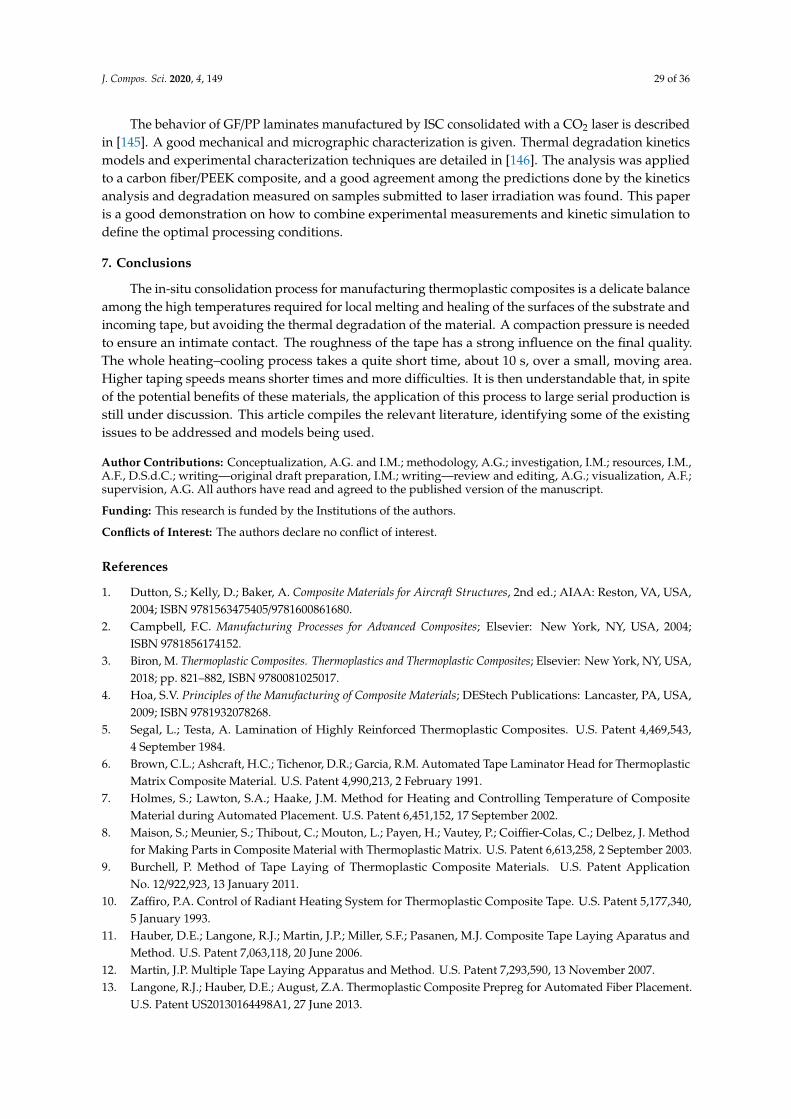
J. Compos. Sci. 2020, 4, 149 29 of 36
The behavior of GF/PP laminates manufactured by ISC consolidated with a CO2 laser is describedin [145]. A good mechanical and micrographic characterization is given. Thermal degradation kineticsmodels and experimental characterization techniques are detailed in [146]. The analysis was appliedto a carbon fiber/PEEK composite, and a good agreement among the predictions done by the kineticsanalysis and degradation measured on samples submitted to laser irradiation was found. This paperis a good demonstration on how to combine experimental measurements and kinetic simulation todefine the optimal processing conditions.
7. Conclusions
The in-situ consolidation process for manufacturing thermoplastic composites is a delicate balanceamong the high temperatures required for local melting and healing of the surfaces of the substrate andincoming tape, but avoiding the thermal degradation of the material. A compaction pressure is neededto ensure an intimate contact. The roughness of the tape has a strong influence on the final quality.The whole heating–cooling process takes a quite short time, about 10 s, over a small, moving area.Higher taping speeds means shorter times and more difficulties. It is then understandable that, in spiteof the potential benefits of these materials, the application of this process to large serial production isstill under discussion. This article compiles the relevant literature, identifying some of the existingissues to be addressed and models being used.
Author Contributions: Conceptualization, A.G. and I.M.; methodology, A.G.; investigation, I.M.; resources, I.M.,A.F., D.S.d.C.; writing—original draft preparation, I.M.; writing—review and editing, A.G.; visualization, A.F.;supervision, A.G. All authors have read and agreed to the published version of the manuscript.
Funding: This research is funded by the Institutions of the authors.
Conflicts of Interest: The authors declare no conflict of interest.
References
1. Dutton, S.; Kelly, D.; Baker, A. Composite Materials for Aircraft Structures, 2nd ed.; AIAA: Reston, VA, USA,2004; ISBN 9781563475405/9781600861680.
2. Campbell, F.C. Manufacturing Processes for Advanced Composites; Elsevier: New York, NY, USA, 2004;ISBN 9781856174152.
3. Biron, M. Thermoplastic Composites. Thermoplastics and Thermoplastic Composites; Elsevier: New York, NY, USA,2018; pp. 821–882, ISBN 9780081025017.
4. Hoa, S.V. Principles of the Manufacturing of Composite Materials; DEStech Publications: Lancaster, PA, USA,2009; ISBN 9781932078268.
5. Segal, L.; Testa, A. Lamination of Highly Reinforced Thermoplastic Composites. U.S. Patent 4,469,543,4 September 1984.
6. Brown, C.L.; Ashcraft, H.C.; Tichenor, D.R.; Garcia, R.M. Automated Tape Laminator Head for ThermoplasticMatrix Composite Material. U.S. Patent 4,990,213, 2 February 1991.
7. Holmes, S.; Lawton, S.A.; Haake, J.M. Method for Heating and Controlling Temperature of CompositeMaterial during Automated Placement. U.S. Patent 6,451,152, 17 September 2002.
8. Maison, S.; Meunier, S.; Thibout, C.; Mouton, L.; Payen, H.; Vautey, P.; Coiffier-Colas, C.; Delbez, J. Methodfor Making Parts in Composite Material with Thermoplastic Matrix. U.S. Patent 6,613,258, 2 September 2003.
9. Burchell, P. Method of Tape Laying of Thermoplastic Composite Materials. U.S. Patent ApplicationNo. 12/922,923, 13 January 2011.
10. Zaffiro, P.A. Control of Radiant Heating System for Thermoplastic Composite Tape. U.S. Patent 5,177,340,5 January 1993.
11. Hauber, D.E.; Langone, R.J.; Martin, J.P.; Miller, S.F.; Pasanen, M.J. Composite Tape Laying Aparatus andMethod. U.S. Patent 7,063,118, 20 June 2006.
12. Martin, J.P. Multiple Tape Laying Apparatus and Method. U.S. Patent 7,293,590, 13 November 2007.13. Langone, R.J.; Hauber, D.E.; August, Z.A. Thermoplastic Composite Prepreg for Automated Fiber Placement.
U.S. Patent US20130164498A1, 27 June 2013.
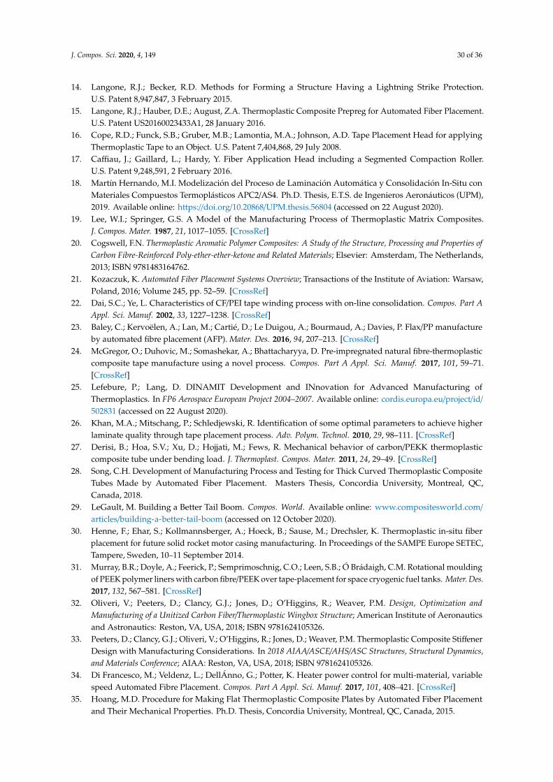
J. Compos. Sci. 2020, 4, 149 30 of 36
14. Langone, R.J.; Becker, R.D. Methods for Forming a Structure Having a Lightning Strike Protection.U.S. Patent 8,947,847, 3 February 2015.
15. Langone, R.J.; Hauber, D.E.; August, Z.A. Thermoplastic Composite Prepreg for Automated Fiber Placement.U.S. Patent US20160023433A1, 28 January 2016.
16. Cope, R.D.; Funck, S.B.; Gruber, M.B.; Lamontia, M.A.; Johnson, A.D. Tape Placement Head for applyingThermoplastic Tape to an Object. U.S. Patent 7,404,868, 29 July 2008.
17. Caffiau, J.; Gaillard, L.; Hardy, Y. Fiber Application Head including a Segmented Compaction Roller.U.S. Patent 9,248,591, 2 February 2016.
18. Martín Hernando, M.I. Modelización del Proceso de Laminación Automática y Consolidación In-Situ conMateriales Compuestos Termoplásticos APC2/AS4. Ph.D. Thesis, E.T.S. de Ingenieros Aeronáuticos (UPM),2019. Available online: https://doi.org/10.20868/UPM.thesis.56804 (accessed on 22 August 2020).
19. Lee, W.I.; Springer, G.S. A Model of the Manufacturing Process of Thermoplastic Matrix Composites.J. Compos. Mater. 1987, 21, 1017–1055. [CrossRef]
20. Cogswell, F.N. Thermoplastic Aromatic Polymer Composites: A Study of the Structure, Processing and Properties ofCarbon Fibre-Reinforced Poly-ether-ether-ketone and Related Materials; Elsevier: Amsterdam, The Netherlands,2013; ISBN 9781483164762.
21. Kozaczuk, K. Automated Fiber Placement Systems Overview; Transactions of the Institute of Aviation: Warsaw,Poland, 2016; Volume 245, pp. 52–59. [CrossRef]
22. Dai, S.C.; Ye, L. Characteristics of CF/PEI tape winding process with on-line consolidation. Compos. Part AAppl. Sci. Manuf. 2002, 33, 1227–1238. [CrossRef]
23. Baley, C.; Kervoëlen, A.; Lan, M.; Cartié, D.; Le Duigou, A.; Bourmaud, A.; Davies, P. Flax/PP manufactureby automated fibre placement (AFP). Mater. Des. 2016, 94, 207–213. [CrossRef]
24. McGregor, O.; Duhovic, M.; Somashekar, A.; Bhattacharyya, D. Pre-impregnated natural fibre-thermoplasticcomposite tape manufacture using a novel process. Compos. Part A Appl. Sci. Manuf. 2017, 101, 59–71.[CrossRef]
25. Lefebure, P.; Lang, D. DINAMIT Development and INnovation for Advanced Manufacturing ofThermoplastics. In FP6 Aerospace European Project 2004–2007. Available online: cordis.europa.eu/project/id/
502831 (accessed on 22 August 2020).26. Khan, M.A.; Mitschang, P.; Schledjewski, R. Identification of some optimal parameters to achieve higher
laminate quality through tape placement process. Adv. Polym. Technol. 2010, 29, 98–111. [CrossRef]27. Derisi, B.; Hoa, S.V.; Xu, D.; Hojjati, M.; Fews, R. Mechanical behavior of carbon/PEKK thermoplastic
composite tube under bending load. J. Thermoplast. Compos. Mater. 2011, 24, 29–49. [CrossRef]28. Song, C.H. Development of Manufacturing Process and Testing for Thick Curved Thermoplastic Composite
Tubes Made by Automated Fiber Placement. Masters Thesis, Concordia University, Montreal, QC,Canada, 2018.
29. LeGault, M. Building a Better Tail Boom. Compos. World. Available online: www.compositesworld.com/
articles/building-a-better-tail-boom (accessed on 12 October 2020).30. Henne, F.; Ehar, S.; Kollmannsberger, A.; Hoeck, B.; Sause, M.; Drechsler, K. Thermoplastic in-situ fiber
placement for future solid rocket motor casing manufacturing. In Proceedings of the SAMPE Europe SETEC,Tampere, Sweden, 10–11 September 2014.
31. Murray, B.R.; Doyle, A.; Feerick, P.; Semprimoschnig, C.O.; Leen, S.B.; Ó Brádaigh, C.M. Rotational mouldingof PEEK polymer liners with carbon fibre/PEEK over tape-placement for space cryogenic fuel tanks. Mater. Des.2017, 132, 567–581. [CrossRef]
32. Oliveri, V.; Peeters, D.; Clancy, G.J.; Jones, D.; O’Higgins, R.; Weaver, P.M. Design, Optimization andManufacturing of a Unitized Carbon Fiber/Thermoplastic Wingbox Structure; American Institute of Aeronauticsand Astronautics: Reston, VA, USA, 2018; ISBN 9781624105326.
33. Peeters, D.; Clancy, G.J.; Oliveri, V.; O’Higgins, R.; Jones, D.; Weaver, P.M. Thermoplastic Composite StiffenerDesign with Manufacturing Considerations. In 2018 AIAA/ASCE/AHS/ASC Structures, Structural Dynamics,and Materials Conference; AIAA: Reston, VA, USA, 2018; ISBN 9781624105326.
34. Di Francesco, M.; Veldenz, L.; DellÁnno, G.; Potter, K. Heater power control for multi-material, variablespeed Automated Fibre Placement. Compos. Part A Appl. Sci. Manuf. 2017, 101, 408–421. [CrossRef]
35. Hoang, M.D. Procedure for Making Flat Thermoplastic Composite Plates by Automated Fiber Placementand Their Mechanical Properties. Ph.D. Thesis, Concordia University, Montreal, QC, Canada, 2015.
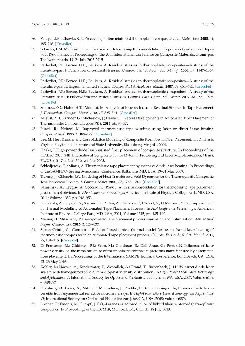
J. Compos. Sci. 2020, 4, 149 31 of 36
36. Vaidya, U.K.; Chawla, K.K. Processing of fibre reinforced thermoplastic composites. Int. Mater. Rev. 2008, 53,185–218. [CrossRef]
37. Schaefer, P.M. Material characterization for determining the consolidation properties of carbon fiber tapeswith PA-6 matrix. In Proceedings of the 20th International Conference on Composite Materials, Groningen,The Netherlands, 19–24 July 2015 2015.
38. Parlevliet, P.P.; Bersee, H.E.; Beukers, A. Residual stresses in thermoplastic composites—A study of theliterature-part I: Formation of residual stresses. Compos. Part A Appl. Sci. Manuf. 2006, 37, 1847–1857.[CrossRef]
39. Parlevliet, P.P.; Bersee, H.E.; Beukers, A. Residual stresses in thermoplastic composites—A study of theliterature-part II: Experimental techniques. Compos. Part A Appl. Sci. Manuf. 2007, 38, 651–665. [CrossRef]
40. Parlevliet, P.P.; Bersee, H.E.; Beukers, A. Residual stresses in thermoplastic composites—A study of theliterature-part III: Effects of thermal residual stresses. Compos. Part A Appl. Sci. Manuf. 2007, 38, 1581–1596.[CrossRef]
41. Sonmez, F.O.; Hahn, H.T.; Akbulut, M. Analysis of Process-Induced Residual Stresses in Tape Placement.J. Thermoplast. Compos. Mater. 2002, 15, 525–544. [CrossRef]
42. August, Z.; Ostrander, G.; Michasiow, J.; Hauber, D. Recent Developments in Automated Fiber Placement ofThermoplastic Composites. SAMPE J. 2014, 50, 30–37.
43. Funck, R.; Neitzel, M. Improved thermoplastic tape winding using laser or direct-flame heating.Compos. Manuf. 1995, 6, 189–192. [CrossRef]
44. Lee, M. Heat Transfer and Consolidation Modeling of Composite Fiber Tow in Fiber Placement. Ph.D. Thesis,Virginia Polytechnic Institute and State University, Blacksburg, Virginia, 2004.
45. Haake, J. High power diode laser-assisted fiber placement of composite structure. In Proceedings of theICALEO 2005: 24th International Congress on Laser Materials Processing and Laser Microfabrication, Miami,FL, USA, 31 October–3 November 2005.
46. Schledjewski, R.; Miaris, A. Thermoplastic tape placement by means of diode laser heating. In Proceedingsof the SAMPE’09 Spring Symposium Conference, Baltimore, MD, USA, 19–21 May 2009.
47. Tierney, J.; Gillespie, J.W. Modeling of Heat Transfer and Void Dynamics for the Thermoplastic CompositeTow-Placement Process. J. Compos. Mater. 2003, 37, 1745–1768. [CrossRef]
48. Barasinski, A.; Leygue, A.; Soccard, E.; Poitou, A. In situ consolidation for thermoplastic tape placementprocess is not obvious. In AIP Conference Proceedings; American Institute of Physics: College Park, MD, USA,2011; Volume 1353, pp. 948–953.
49. Barasinski, A.; Leygue, A.; Soccard, E.; Poitou, A.; Chinesta, F.; Chastel, Y.; El Mansori, M. An Improvementin Thermal Modelling of Automated Tape Placement Process. In AIP Conference Proceedings; AmericanInstitute of Physics: College Park, MD, USA, 2011; Volume 1315, pp. 185–190.
50. Maurer, D.; Mitschang, P. Laser-powered tape placement process simulation and optimization. Adv. Manuf.Polym. Compos. Sci. 2015, 1, 129–137.
51. Stokes-Griffin, C.; Compston, P. A combined optical-thermal model for near-infrared laser heating ofthermoplastic composites in an automated tape placement process. Compos. Part A Appl. Sci. Manuf. 2015,75, 104–115. [CrossRef]
52. Di Francesco, M.; Giddings, P.F.; Scott, M.; Goodman, E.; Dell Ánno, G.; Potter, K. Influence of laserpower density on the meso-structure of thermoplastic composite preforms manufactured by automatedfibre placement. In Proceedings of the International SAMPE Technical Conference, Long Beach, CA, USA,23–26 May 2016.
53. Köhler, B.; Noeske, A.; Kindervater, T.; Wessollek, A.; Brand, T.; Biesenbach, J. 11-kW direct diode lasersystem with homogenized 55 × 20 mm 2 top-hat intensity distribution. In High-Power Diode Laser Technologyand Applications V; International Society for Optics and Photonics: Bellingham, WA, USA, 2007; Volume 6456,p. 64560O.
54. Homburg, O.; Bayer, A.; Mitra, T.; Meinschien, J.; Aschke, L. Beam shaping of high power diode lasersbenefits from asymmetrical refractive microlens arrays. In High-Power Diode Laser Technology and ApplicationsVI; International Society for Optics and Photonics: San Jose, CA, USA, 2008; Volume 6876.
55. Brecher, C.; Emonts, M.; Stimpfl, J. CO2-Laser-assisted production of hybrid fiber-reinforced thermoplasticcomposites. In Proceedings of the ICCM19, Montréal, QC, Canada, 28 July 2013.
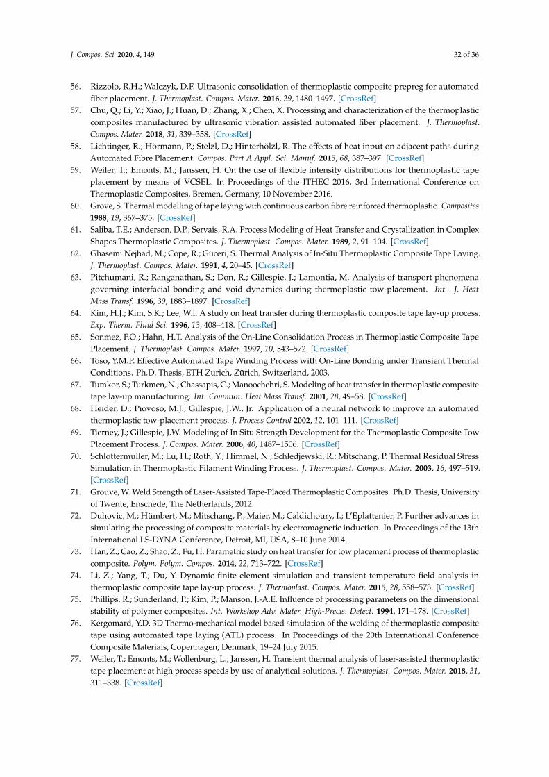
J. Compos. Sci. 2020, 4, 149 32 of 36
56. Rizzolo, R.H.; Walczyk, D.F. Ultrasonic consolidation of thermoplastic composite prepreg for automatedfiber placement. J. Thermoplast. Compos. Mater. 2016, 29, 1480–1497. [CrossRef]
57. Chu, Q.; Li, Y.; Xiao, J.; Huan, D.; Zhang, X.; Chen, X. Processing and characterization of the thermoplasticcomposites manufactured by ultrasonic vibration assisted automated fiber placement. J. Thermoplast.Compos. Mater. 2018, 31, 339–358. [CrossRef]
58. Lichtinger, R.; Hörmann, P.; Stelzl, D.; Hinterhölzl, R. The effects of heat input on adjacent paths duringAutomated Fibre Placement. Compos. Part A Appl. Sci. Manuf. 2015, 68, 387–397. [CrossRef]
59. Weiler, T.; Emonts, M.; Janssen, H. On the use of flexible intensity distributions for thermoplastic tapeplacement by means of VCSEL. In Proceedings of the ITHEC 2016, 3rd International Conference onThermoplastic Composites, Bremen, Germany, 10 November 2016.
60. Grove, S. Thermal modelling of tape laying with continuous carbon fibre reinforced thermoplastic. Composites1988, 19, 367–375. [CrossRef]
61. Saliba, T.E.; Anderson, D.P.; Servais, R.A. Process Modeling of Heat Transfer and Crystallization in ComplexShapes Thermoplastic Composites. J. Thermoplast. Compos. Mater. 1989, 2, 91–104. [CrossRef]
62. Ghasemi Nejhad, M.; Cope, R.; Güceri, S. Thermal Analysis of In-Situ Thermoplastic Composite Tape Laying.J. Thermoplast. Compos. Mater. 1991, 4, 20–45. [CrossRef]
63. Pitchumani, R.; Ranganathan, S.; Don, R.; Gillespie, J.; Lamontia, M. Analysis of transport phenomenagoverning interfacial bonding and void dynamics during thermoplastic tow-placement. Int. J. HeatMass Transf. 1996, 39, 1883–1897. [CrossRef]
64. Kim, H.J.; Kim, S.K.; Lee, W.I. A study on heat transfer during thermoplastic composite tape lay-up process.Exp. Therm. Fluid Sci. 1996, 13, 408–418. [CrossRef]
65. Sonmez, F.O.; Hahn, H.T. Analysis of the On-Line Consolidation Process in Thermoplastic Composite TapePlacement. J. Thermoplast. Compos. Mater. 1997, 10, 543–572. [CrossRef]
66. Toso, Y.M.P. Effective Automated Tape Winding Process with On-Line Bonding under Transient ThermalConditions. Ph.D. Thesis, ETH Zurich, Zürich, Switzerland, 2003.
67. Tumkor, S.; Turkmen, N.; Chassapis, C.; Manoochehri, S. Modeling of heat transfer in thermoplastic compositetape lay-up manufacturing. Int. Commun. Heat Mass Transf. 2001, 28, 49–58. [CrossRef]
68. Heider, D.; Piovoso, M.J.; Gillespie, J.W., Jr. Application of a neural network to improve an automatedthermoplastic tow-placement process. J. Process Control 2002, 12, 101–111. [CrossRef]
69. Tierney, J.; Gillespie, J.W. Modeling of In Situ Strength Development for the Thermoplastic Composite TowPlacement Process. J. Compos. Mater. 2006, 40, 1487–1506. [CrossRef]
70. Schlottermuller, M.; Lu, H.; Roth, Y.; Himmel, N.; Schledjewski, R.; Mitschang, P. Thermal Residual StressSimulation in Thermoplastic Filament Winding Process. J. Thermoplast. Compos. Mater. 2003, 16, 497–519.[CrossRef]
71. Grouve, W. Weld Strength of Laser-Assisted Tape-Placed Thermoplastic Composites. Ph.D. Thesis, Universityof Twente, Enschede, The Netherlands, 2012.
72. Duhovic, M.; Hümbert, M.; Mitschang, P.; Maier, M.; Caldichoury, I.; L’Eplattenier, P. Further advances insimulating the processing of composite materials by electromagnetic induction. In Proceedings of the 13thInternational LS-DYNA Conference, Detroit, MI, USA, 8–10 June 2014.
73. Han, Z.; Cao, Z.; Shao, Z.; Fu, H. Parametric study on heat transfer for tow placement process of thermoplasticcomposite. Polym. Polym. Compos. 2014, 22, 713–722. [CrossRef]
74. Li, Z.; Yang, T.; Du, Y. Dynamic finite element simulation and transient temperature field analysis inthermoplastic composite tape lay-up process. J. Thermoplast. Compos. Mater. 2015, 28, 558–573. [CrossRef]
75. Phillips, R.; Sunderland, P.; Kim, P.; Manson, J.-A.E. Influence of processing parameters on the dimensionalstability of polymer composites. Int. Workshop Adv. Mater. High-Precis. Detect. 1994, 171–178. [CrossRef]
76. Kergomard, Y.D. 3D Thermo-mechanical model based simulation of the welding of thermoplastic compositetape using automated tape laying (ATL) process. In Proceedings of the 20th International ConferenceComposite Materials, Copenhagen, Denmark, 19–24 July 2015.
77. Weiler, T.; Emonts, M.; Wollenburg, L.; Janssen, H. Transient thermal analysis of laser-assisted thermoplastictape placement at high process speeds by use of analytical solutions. J. Thermoplast. Compos. Mater. 2018, 31,311–338. [CrossRef]
J. Compos. Sci. 2020, 4, 149 33 of 36
78. Weiler, T.; Emonts, M.; Striet, P.; Gronenborn, S.; Janssen, H. Optical modelling of VCSEL assisted thermoplastictape placement. In Proceedings of the 17th European Conference on Composite Materials, (ECCM17),Munich, Germany, 26–30 June 2016.
79. Pistor, C.; Yardimci, M.; Güçeri, S. On-line consolidation of thermoplastic composites using laser scanning.Compos. Part A Appl. Sci. Manuf. 1999, 30, 1149–1157. [CrossRef]
80. Hassan, N.; Thompson, J.E.; Batra, R.C.; Hulcher, A.B.; Song, X.; Loos, A.C. A Heat Transfer Analysis of theFiber Placement Composite Manufacturing Process. J. Reinf. Plast. Compos. 2005, 24, 869–888. [CrossRef]
81. Nicodeau, C. Modélisation du Soudage en Continu de Composites à Matrice Thermoplastique. Ph.D. Thesis,ENSAM, Paris, France, 2005.
82. Li, Y.H.; Fu, H.Y.; Shao, Z.X. The Influence of Preheating on Automated Fiber Placement Speed. Adv. Mater.Res. 2011, 213, 136–142. [CrossRef]
83. Lamèthe, J.-F. Etude de L’adhésion de Composites Thermoplastiques Semi-Cristallins; Application à la Miseen Oeuvre par Soudure. Ph.D. Thesis, Université Pierre et Marie Curie-Paris VI, Paris, France, 2004.
84. Lamèthe, J.-F.; Beauchêne, P.; Léger, L. Polymer dynamics applied to PEEK matrix composite welding.Aerosp. Sci. Technol. 2005, 9, 233–240. [CrossRef]
85. Barasinski, A.; Leygue, A.; Soccard, E.; Poitou, A. Identification of non-uniform thermal contact resistance inautomated tape placement process. Int. J. Mater. Form. 2014, 7, 479–486. [CrossRef]
86. Bur, N.; Joyot, P.; Ghnatios, C.; Villon, P.; Cueto, E.; Chinesta, F. On the use of model order reduction forsimulating automated fibre placement processes. Adv. Modeling Simul. Eng. Sci. 2016, 3, 1–8. [CrossRef]
87. Perez, M.; Barasinski, A.; Courtemanche, B.; Ghnatios, C.; Abisset-Chavanne, E.; Chinesta, F. Simulation ducomportement thermique du procédé d‘enroulement filamentaire de composites thermoplastiques assistépar chauffage laser. Journées Nationale Composites 2017.
88. Schaefer, P.; Gierszewski, D.; Kollmannsberger, A.; Zaremba, S.; Drechsler, K. Analysis and improved processresponse prediction of laser-assisted automated tape placement with PA-6/carbon tapes using Design ofExperiments and numerical simulations. Compos. Part A Appl. Sci. Manuf. 2017, 96, 137–146. [CrossRef]
89. Stokes-Griffin, C.; Compston, P. The effect of processing temperature and placement rate on the short beamstrength of carbon fibre/PEEK manufactured using a laser tape placement process. Compos. Part A Appl.Sci. Manuf. 2015, 78, 274–283. [CrossRef]
90. Stokes-Griffin, C.; Compston, P. Optical characterization and modelling for oblique near-infrared laserheating of carbon fibre reinforced thermoplastic composites. Opt. Lasers Eng. 2015, 72, 1–11. [CrossRef]
91. Stokes-Griffin, C.; Compston, P. An inverse model for optimisation of laser heat flux distributions in anautomated laser tape placement process for carbon fibre/PEEK. Compos. Part A Appl. Sci. Manuf. 2016, 88,190–197. [CrossRef]
92. Pignon, B.; Boyard, N.; Sobotka, V.; Delaunay, D. Heat transfer analysis at high cooling rate on the surface ofthermoplastic parts. Int. J. Heat Mass Transf. 2017, 106, 253–262. [CrossRef]
93. Shih, P.-J. On-Line Consolidation of Thermoplastic Composites. Ph.D. Thesis, Virginia Tech, Blacksburg, VA,USA, 1997.
94. Lionetto, F.; Dell’Anna, R.; Montagna, F.; Maffezzoli, A. Modeling of continuous ultrasonic impregnationand consolidation of thermoplastic matrix composites. Compos. Part A Appl. Sci. Manuf. 2016, 82, 119–129.[CrossRef]
95. Romoli, L.; Fischer, F.; Kling, R. A study on UV laser drilling of PEEK reinforced with carbon fibers. Opt.Lasers Eng. 2012, 50, 449–457. [CrossRef]
96. Nichelatti, E. Complex refractive index of a slab from reflectance and transmittance: Analytical solution.J. Opt. A Pure Appl. Opt. 2002, 4, 400–403. [CrossRef]
97. Reichardt, J.; Baran, I.; Akkerman, R. New analytical and numerical optical model for the laser assisted tapewinding process. Compos. Part A Appl. Sci. Manuf. 2018, 107, 647–656. [CrossRef]
98. Oromiehie, E.; Prusty, B.G.; Compston, P.; Rajan, G. In situ process monitoring for automated fibre placementusing fibre Bragg grating sensors. Struct. Health Monit. Int. J. 2016, 15, 706–714. [CrossRef]
99. del Saenz Castillo, D.; Martin, I.; Rodriguez-Lence, F.; Güemes, A. On-line monitoring of a laser assisted fiberplacement process with CFR thermoplastic matrix by using Fiber Bragg Gratings. In Proceedings of the 8thEuropean Workshop on Structural Health Monitoring (EWSHM 2016), Bilbao, Spain, 5–8 July 2016.
J. Compos. Sci. 2020, 4, 149 34 of 36
100. del Saenz Castillo, D.; Martin, I.; Calvo, S.; Güemes, A. Real-time monitoring of thermal history ofthermoplastic automatic lamination with FBG sensors and process modelling validation. Smart Mater. Struct.2020, 29, 115004. [CrossRef]
101. Khan, S. Thermal Control System Design for Automated Fiber Placement Process. Ph.D. Thesis, ConcordiaUniversity, Montreal, QC, Canada, 2011.
102. Loos, A.C.; Dara, P.H. Processing of thermoplastic matrix composites. In Review of Progress inQuantitative Nondestructive Evaluation; Springer: Berlin/Heidelberg, Germany, 1987; pp. 1257–1265,ISBN 9781461290544/9781461318934.
103. Yang, F.; Pitchumani, R. A fractal Cantor set based description of interlaminar contact evolution duringthermoplastic composites processing. J. Mater. Sci. 2001, 36, 4661–4671. [CrossRef]
104. Yang, F.; Pitchumani, R. Healing of Thermoplastic Polymers at an Interface under Nonisothermal Conditions.Macromolecules 2002, 35, 3213–3224. [CrossRef]
105. Yang, F.; Pitchumani, R. Interlaminar contact development during thermoplastic fusion bonding. Polym. Eng.Sci. 2002, 42, 424–438. [CrossRef]
106. Yang, F.; Pitchumani, R. Nonisothermal healing and interlaminar bond strength evolution duringthermoplastic matrix composites processing. Polym. Compos. 2003, 24, 263–278. [CrossRef]
107. Khan, M.A.; Schledjewski, R. Influencing factors for an online consolidating thermoplastic tape placementprocess. In Proceedings of the 17th International Conference on Composite Materials, ICCM-17, Edinburgh,UK, 27–31 July 2009.
108. Stokes-Griffin, C.; Compston, P. Investigation of sub-melt temperature bonding of carbon fibre/PEEK in anautomated laser tape placement process. Compos. Part A Appl. Sci. Manuf. 2016, 84, 17–25. [CrossRef]
109. Schaefer, P.; Guglhoer, T.; Sause, M.; Drechsler, K. Development of intimate contact during processing ofcarbon fiber reinforced Polyamide-6 tapes. J. Reinf. Plast. Compos. 2017, 36, 593–607. [CrossRef]
110. Levy, A.; Heider, D.; Tierney, J.; Gillespie, J.W. Inter-layer thermal contact resistance evolution with thedegree of intimate contact in the processing of thermoplastic composite laminates. J. Compos. Mater. 2014, 48,491–503. [CrossRef]
111. Perez, M.; Leon, A.; Dedieu, C.; Argerich, C.; Defoort, B.; Dupillier, J.M.; Soccard r Barasinski, A.; Chinesta, F.Keys for designing the most efficient and robust in-situ TP ATP. In Proceedings of the 6th InternationalCarbon Composites Conference, Arcachon, France, 4–6 June 2018.
112. Yu, T.; Shi, Y.; He, X.; Kang, C.; Deng, B. Modeling and optimization of interlaminar bond strength forcomposite tape winding process. J. Reinf. Plast. Compos. 2017, 36, 579–592. [CrossRef]
113. Marchello, J.M.; Messier, B.C. Effect of Pressure in Thermoplastic Ribbon Thermal Welding; NASA–TR-20040110360Langley Research Center: Hampton, VA, USA, 1996.
114. Mantell, S.C.; Springer, G.S. Manufacturing Process Models for Thermoplastic Composites. J. Compos. Mater.1992, 26, 2348–2377. [CrossRef]
115. de Gennes, P.G. Reptation of a Polymer Chain in the Presence of Fixed Obstacles. J. Chem. Phys. 1971, 55,572–579. [CrossRef]
116. De Gennes, P.; Leger, L. Dynamics of entangled polymer chains. Annu. Rev. Phys. Chem. 1982, 33, 49–61.[CrossRef]
117. Reptation and Tube Model. Available online: http://polymerdatabase.com/polymer%20physics/Reptation.html (accessed on 22 August 2020).
118. Bastien, L.J.; Gillespie, J.W. A non-isothermal healing model for strength and toughness of fusion bondedjoints of amorphous thermoplastics. Polym. Eng. Sci. 1991, 31, 1720–1730. [CrossRef]
119. Sonmez, F.O.; Akbulut, M. Process optimization of tape placement for thermoplastic composites. Compos. PartA Appl. Sci. Manuf. 2007, 38, 2013–2023. [CrossRef]
120. Zhao, P.; Shirinzadeh, B.; Shi, Y.; Cheuk, S.; Clark, L. Multi-pass layup process for thermoplastic compositesusing robotic fiber placement. Robot. Comput. Integr. Manuf. 2018, 49, 277–284. [CrossRef]
121. Quan, H.; Li, Z.-M.; Yang, M.-B.; Huang, R. On transcrystallinity in semi-crystalline polymer composites.Compos. Sci. Technol. 2005, 65, 999–1021. [CrossRef]
122. Tierney, J.J.; Gillespie, J., Jr. Crystallization kinetics behavior of PEEK based composites exposed to highheating and cooling rates. Compos. Part A Appl. Sci. Manuf. 2004, 35, 547–558. [CrossRef]
J. Compos. Sci. 2020, 4, 149 35 of 36
123. Guan, X.; Pitchumani, R. Modeling of spherulitic crystallization in thermoplastic tow-placement process:Spherulitic microstructure evolution. Compos. Sci. Technol. 2004, 64, 1363–1374. [CrossRef]
124. Lee, K.; Weitsman, Y. Effects of Nonuniform Crystallinity on Stress Distributions in Cross-Ply Graphite/PEEK(APC-2] Laminates. J. Compos. Mater. 1991, 25, 1143–1157. [CrossRef]
125. Yu, T.; Wu, C.M.; Chang, C.Y.; Wang, C.Y.; Rwei, S.P. Effects of crystalline morphologies on the mechanicalproperties of carbon fiber reinforcing polymerized cyclic butylene terephthalate composites. Express Polym.Lett. 2012, 6, 318–328. [CrossRef]
126. Regis, M.; Bellare, A.; Pascolini, T.; Bracco, P. Characterization of thermally annealed PEEK and CFR-PEEKcomposites: Structure-properties relationships. Polym. Degrad. Stab. 2017, 136, 121–130. [CrossRef]
127. Tregub, A.; Harel, H.; Marom, G.; Migliaresi, C. The influence of thermal history on the mechanical propertiesof poly(ether ether ketone) matrix composite materials. Compos. Sci. Technol. 1993, 48, 185–190. [CrossRef]
128. Cebe, P.; Chung, S.Y.; Hong, S.-D. Effect of thermal history on mechanical properties of polyetheretherketonebelow the glass transition temperature. J. Appl. Polym. Sci. 1987, 33, 487–503. [CrossRef]
129. Lee, I.-G.; Kim, D.-H.; Jung, K.-H.; Kim, H.-J.; Kim, H.-S. Effect of the cooling rate on the mechanicalproperties of glass fiber reinforced thermoplastic composites. Compos. Struct. 2017, 177, 28–37. [CrossRef]
130. Gao, S.-L.; Kim, J.-K. Crystallinity and interphase properties of carbon fiber/PEEK matrix composites.In Proceedings of the 12th International Conference Composite Materials (ICCM-12), Paris, France,5–9 July 1999.
131. Gao, S.-L.; Kim, J.-K. Cooling rate influences in carbon fibre/PEEK composites. Part I. Crystallinity andinterface adhesion. Compos. Part A Appl. Sci. Manuf. 2000, 31, 517–530. [CrossRef]
132. Gao, S.-L.; Kim, J.-K. Cooling rate influences in carbon fibre/PEEK composites. Part II: Interlaminar fracturetoughness. Compos. Part A Appl. Sci. Manuf. 2001, 32, 763–774. [CrossRef]
133. Gao, S.-L.; Kim, J.-K. Cooling rate influences in carbon fibre/PEEK composites. Part III: Impact damageperformance. Compos. Part A Appl. Sci. Manuf. 2001, 32, 775–785. [CrossRef]
134. Ray, D.; Comer, A.J.; Lyons, J.; Obande, W.; Jones, D.; Higgins, R.M.; McCarthy, M.A. Fracture toughness ofcarbon fiber/polyether ether ketone composites manufactured by autoclave and laser-assisted automatedtape placement. J. Appl. Polym. Sci. 2014, 132, 41643. [CrossRef]
135. Gao, S.-L.; Kim, J.-K. Correlation among crystalline morphology of PEEK, interface bond strength, andin-plane mechanical properties of carbon/PEEK composites. J. Appl. Polym. Sci. 2002, 84, 1155–1167.[CrossRef]
136. El Kadi, H.; Denault, J. Effects of Processing Conditions on the Mechanical Behavior ofCarbon-Fiber-Reinforced PEEK. J. Thermoplast. Compos. Mater. 2001, 14, 34–53. [CrossRef]
137. Toft, M. The Effect of Crystalline Morphology on the Glass Transition and Enthalpic Relaxation in Poly(Ether-Ether-Ketone). Ph.D. Thesis, University of Birmingham, Birmingham, UK, 2012.
138. Fink, B.K.; Gillespie, J.W., Jr.; Ersoy, N.B. Thermal degradation effects on consolidation and bonding in thethermoplastic fibre-placement process. In Report nb ARL-TR-2238; Army Research Lab., Aberdeen ProvingGround: Adelphi, MD, USA, 2000.
139. Beyler, C.L.; Hirschler, M.M. Thermal decomposition of polymers. In SFPE Handbook of Fire ProtectionEngineering; Springer: New York, NY, USA, 2002; Volume 2, pp. 111–131, ISBN 978-1-4939-2565-0.
140. Hancox, N. Thermal effects on polymer matrix composites: Part 2. Thermal degradation. Mater. Des. 1998,19, 93–97. [CrossRef]
141. Patel, P.; Hull, T.R.; McCabe, R.W.; Flath, D.; Grasmeder, J.; Percy, M. Mechanism of thermal decompositionof poly(ether ether ketone) (PEEK) from a review of decomposition studies. Polym. Degrad. Stab. 2010, 95,709–718. [CrossRef]
142. Nandan, B.; Kandpal, L.; Mathur, G. Poly(ether ether keto-ne)/poly(aryl ether sulphone) blends: Thermaldegradation behaviour. Eur. Polym. J. 2003, 39, 193–198. [CrossRef]
143. Bayerl, T.; Brzeski, M.; Martínez-Tafalla, M.; Schledjewski, R.; Mitschang, P. Thermal degradation analysis ofshort-time heated polymers. J. Thermoplast. Compos. Mater. 2015, 28, 390–414. [CrossRef]
144. Tsotra, P.; Toma, M.; Pascual, A.; Schadt, F.; Brauner, C.; Dransfeld, C. Thermo-oxidative degradation of PEEKat high temperatures. In Proceedings of the 18th European Conference on Composite Materials, ECCM18,Athens, Greece, 25–28 June 2018.

J. Compos. Sci. 2020, 4, 149 36 of 36
145. Parandoush, P.; Tucker, L.; Zhou, C.; Lin, D. Laser assisted additive manufacturing of continuous fiberreinforced thermoplastic composites. Mater. Des. 2017, 131, 186–195. [CrossRef]
146. Martin, M.I.; Rodríguez-Lence, F.; Güemes, A.; Fernández-López, A.; Pérez-Maqueda, L.A.; Perejón, A.On the determination of thermal degradation effects and detection techniques for thermoplastic compositesobtained by automatic lamination. Compos. Part A Appl. Sci. Manuf. 2018, 111, 23–32. [CrossRef]
© 2020 by the authors. Licensee MDPI, Basel, Switzerland. This article is an open accessarticle distributed under the terms and conditions of the Creative Commons Attribution(CC BY) license (http://creativecommons.org/licenses/by/4.0/).
Related Documents