Advanced Test Reactor User Guide

Welcome message from author
This document is posted to help you gain knowledge. Please leave a comment to let me know what you think about it! Share it to your friends and learn new things together.
Transcript
20-50097
Advanced Test Reactor
User Guide


Advanced Test Reactor User Guide iii
Contents1 INTRODUCTION 1
2 OVERVIEW OF THE ATR AND ITS SUPPORT FACILITIES 3
3 ATR DESCRIPTION 4
3.1 Pertinent ATR Design Features 4
3.2 ATR Thermal Power and Flux 4
3.3 Experiment Positions 8
3.4 Operating Practice 10
4 OVERVIEW OF THE PROCESS FOR EXPERIMENT INSERTION 12
4.1 Proposal Process 12
4.2 Prepare and Submit Proposal 12
4.3 Develop User Agreement and Project Schedule 14
4.4 Definition of Experiment Requirements 14
4.5 Preparation of Irradiation Test Plan 16
4.6 Neutronic, Thermal, and Structural Analysis 17
4.7 ATR Critical Facility 17
4.8 Preparation of Experiment Safety Assurance Package 17
4.9 Design Verification 17
4.10 Target Fabrication and As-Built Chemistry 18
4.11 Nuclear Safety Documentation and Approvals 18
4.12 Target Encapsulation 18
4.13 Target Packaging and Transport 18
4.14 Insertion of Experiment Assembly into ATR 18
4.15 Irradiation 19
4.16 As-run Target/Capsule Neutronic Analysis 19
4.17 Experiment Assembly Removal from Reactor 19
4.18 Transport of Irradiated Capsule for PIE 19
4.19 End of Irradiation As-Run Neutronics Report 19
4.20 Post-Irradiation Examination 20
4.21 Disposition of Capsule and Target 20
4.22 Preparation and Submittal of PIE Report 20
5 ATR EXPERIMENT CONFIGURATIONS 21
5.1 Static Capsule Experiment 21
5.2 Instrumented Lead Experiments 23
5.3 Pressurized Water Loop 25
5.4 Gamma Facility 27
5.5 ATR Critical Facility 27
6 REACTOR POSITIONS OFFERED 29
6.1 A Positions: A1 through A16 29
6.2 B Positions: B1 through B12 30
6.3 H Positions: H1 through H16 30
6.4 I Positions: I1 through I24 31
7 AVAILABLE SUPPORT SERVICES, EQUIPMENT, AND SPECIALIZED FACILITIES 33
7.1 Target/Capsule Design and Engineering 33
7.2 Chemical Analysis 33
7.3 Target Fabrication 33
7.4 Packaging and Transportation 34
7.5 Quality Assurance 35
7.6 Post-Irradiation Examination 35
7.7 Transient Testing 37
8 BEGIN YOUR JOURNEY 38
9 APPENDIX: THE PAST, PRESENT AND FUTURE OF INL TEST REACTORS 39
Acronyms 43
User Guide Advanced Test Reactoriv
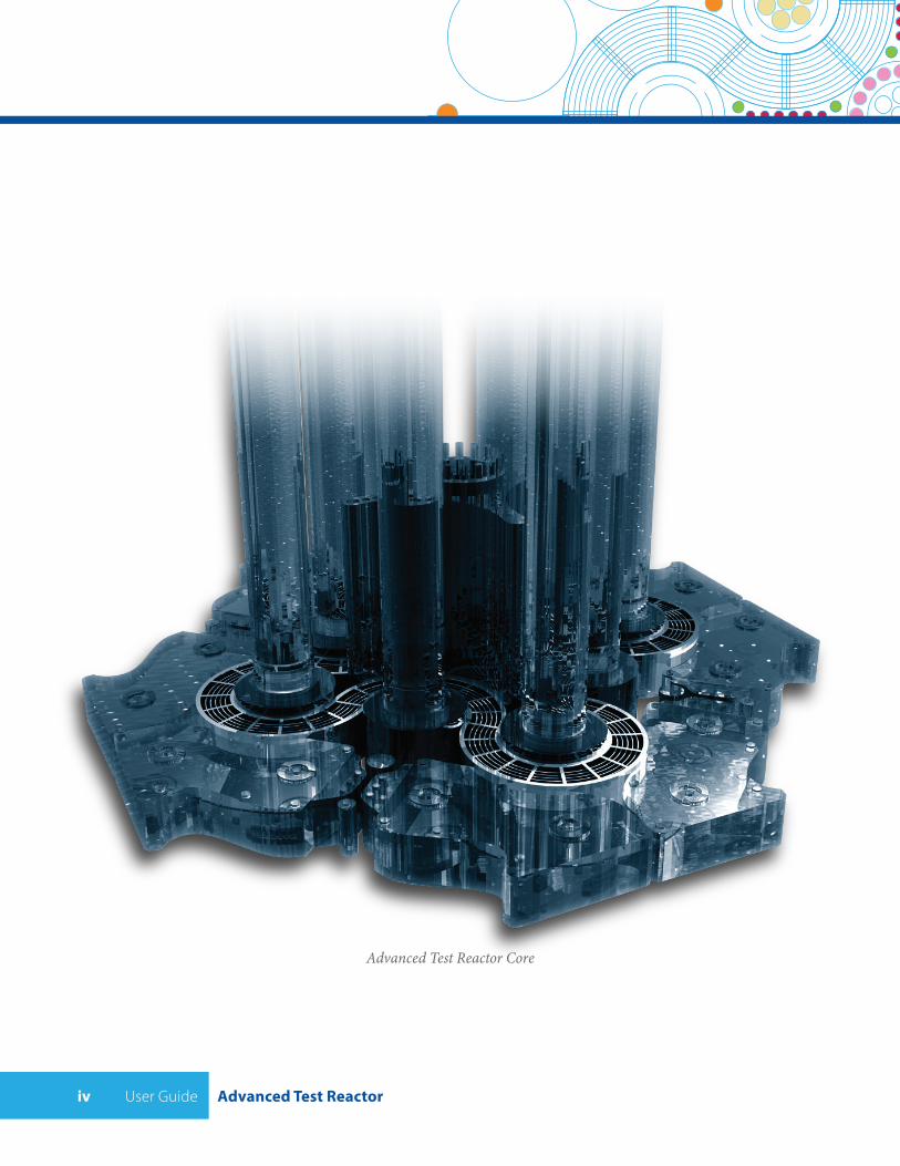
Advanced Test Reactor Core
Advanced Test Reactor User Guide 1
1 INTRODUCTION
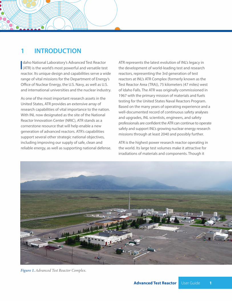
Idaho National Laboratory’s Advanced Test Reactor (ATR) is the world’s most powerful and versatile test
reactor. Its unique design and capabilities serve a wide range of vital missions for the Department of Energy’s Office of Nuclear Energy, the U.S. Navy, as well as U.S. and international universities and the nuclear industry.
As one of the most important research assets in the United States, ATR provides an extensive array of research capabilities of vital importance to the nation. With INL now designated as the site of the National Reactor Innovation Center (NRIC), ATR stands as a cornerstone resource that will help enable a new generation of advanced reactors. ATR’s capabilities support several other strategic national objectives, including improving our supply of safe, clean and reliable energy, as well as supporting national defense.
ATR represents the latest evolution of INL’s legacy in the development of world-leading test and research reactors, representing the 3rd generation of test reactors at INL’s ATR Complex (formerly known as the Test Reactor Area (TRA)), 75 kilometers (47 miles) west of Idaho Falls. The ATR was originally commissioned in 1967 with the primary mission of materials and fuels testing for the United States Naval Reactors Program. Based on the many years of operating experience and a well-documented record of continuous safety analyses and upgrades, INL scientists, engineers, and safety professionals are confident the ATR can continue to operate safely and support INL’s growing nuclear energy research missions through at least 2040 and possibly further.
ATR is the highest power research reactor operating in the world. Its large test volumes make it attractive for irradiations of materials and components. Though it
Figure 1. Advanced Test Reactor Complex.
User Guide Advanced Test Reactor2
has been operating for more than 40 years, the ATR is expected to remain operational until at least the year 2040. The ATR is designed to evaluate the effects of intense radiation on material samples, especially nuclear fuels. Other uses include isotope production for medical, industrial, environmental, agricultural and research applications. The ATR is the nation’s only source of high specific activity Cobalt-60 for medical applications, and in the past has provided a large fraction of the Ir-192 used in U.S. commercial radiography. The ATR provides unmatched, national priority nuclear fuel and materials testing capacities for military, federal, university, and industry partners and customers. Demand has grown significantly in recent years; ATR is currently operating at nearly 90% of its experiment loading capacity.
Collaborative development of nuclear energy science and technology by three major sectors— academia, the commercial nuclear power industry, and the federal government—is key to meeting challenges in the development of nuclear energy. All three share a common need for experimental capabilities, whether for basic science investigations, applied research in nuclear fuels and materials or validation of data. In April 2007, to fill this need, the U.S. Department of Energy (DOE) Deputy Secretary of Energy designated the Advanced Test Reactor (ATR) at the Idaho National Laboratory (INL) as a National Scientific User Facility (NSUF). The Office of Nuclear Energy (NE), the Office of Science, and Office of
Naval Nuclear Propulsion Programs, or Naval Reactors (NR) strongly endorsed the action. While functioning as a NSUF, the ATR will continue to support its current national missions. Since that time, the original NSUF has expanded and is now known as the Nuclear Science User Facilities program. In addition to NSUF, access to ATR capabilities can be achieved through other programs and initiatives, including the Gateway for Accelerated Innovation in Nuclear (GAIN), the Nuclear Reactor Innovation Center (NRIC), and others.
This document provides a guide for prospective experimenters interested in performing irradiation research in the ATR. The following contains a description of the ATR and its experiment capabilities, the ancillary capabilities of the INL to support irradiation experiment development and Post Irradiation Examination (PIE), the process for users to follow to conduct an irradiation experiment, the conditions that apply to experimenters, and the technical requirements for materials inserted into the ATR test positions. This document is not intended to provide all the necessary information required to perform an experiment in the ATR, but will serve as a guide to concept development and initial experiment planning. An experienced team of INL researchers will work with experimenters to ensure that all experiments comply with all INL and ATR requirements. Points of contact are listed in the final chapter of this Guide.
ATR VISION:
ATR will be the national and international materials and fuels irradiation
testing facility of choice
ATR MISSION:
Provide unique irradiation capabilities for nuclear technology research and
development
Advanced Test Reactor User Guide 3
2 OVERVIEW OF ATR AND ITS SUPPORT FACILITIES
ATR provides a resource for meeting national imperatives to secure reliable energy sources and
protect the environment. ATR is supported by other facilities within the ATR Complex, including the ATR Critical Facility, the Test Train Assembly Facility, and others. In addition, while some PIE capabilities exist at the ATR Complex, ATR experiments are also supported by capabilities at INL’s nearby Materials and Fuels Complex (MFC). MFC facilities for experiment and fuel fabrication, PIE and experiment analysis include Hot Fuel Examination Facility (HFEF), and science and engineering support for experiments.
ATR is a premier facility for scientific investigation of nuclear fuels and materials for energy and propulsion systems, isotope production and other uses. ATR’s mission is to provide unique irradiation capabilities for nuclear technology research and development. The ATR team will accomplish this mission by offering state-of-the-art
experimental irradiation testing and PIE facilities and technical assistance in design and safety analysis of reactor experiments. ATR capabilities are available to:
• Support both basic and applied research and development
• Increase the effectiveness and decrease the uncertainty associated with development of new fuels and materials for existing and advanced reactor concepts
• Facilitate the development and validation of new analytical models to improve nuclear energy systems
• Encourage research collaboration on high-quality scientific experiments using the ATR and assure that unique research capabilities are made available to a broader scientific community using traditional collaborations
• Provide access to the ATR for production of medical, research, and industrial isotopes including the production of short-lived isotopes
• Provide a platform for educating and training nuclear scientists, radiochemists, engineers, and the various technical trades critical to the nuclear industry
• Support new nuclear programs at universities that do not have a dedicated research reactor and augment those programs that do have research reactors.
In-piletubes
Fuelassembly
Neckshim rods
NeckShim RodHousing
Controldrums
Flux trap guidetubes
“I”Positions
“A”Positions
“B”Positions
“H”Positions
I-1 I-2I-20I-3I-19
I-4I-18
I-17
I-16
I-15
I-14
I-11 I-10I-9
I-12I-13
I-7
I-8
I-6
I-5
B1B8 B9
B2
B3B10
I21
I22I23
I24
B11
B12
B7
B6
B4B5
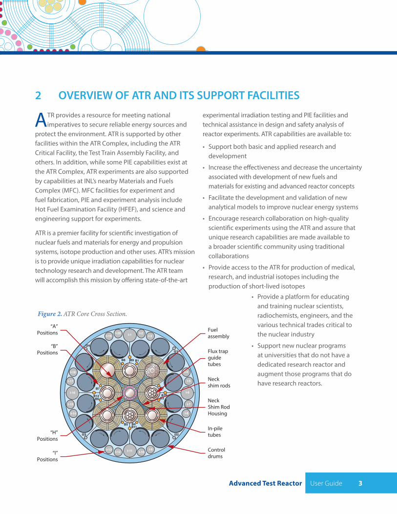
Figure 2. ATR Core Cross Section.
User Guide Advanced Test Reactor4
3 ATR DESCRIPTION
The following sections present design and operating information about the ATR that would be helpful
to prospective experimenters. Experimenters are encouraged to contact INL personnel if they need additional information during proposal development. Points of contact are listed in the final chapter of this Guide.
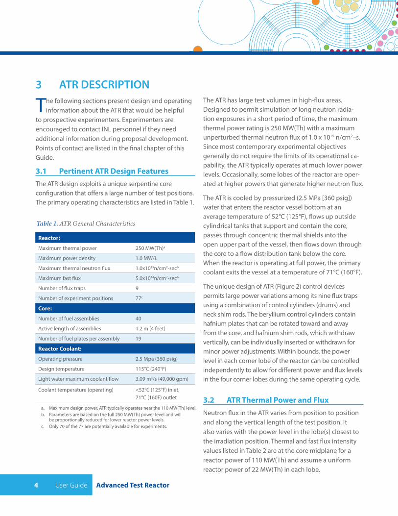
3.1 Pertinent ATR Design FeaturesThe ATR design exploits a unique serpentine core configuration that offers a large number of test positions. The primary operating characteristics are listed in Table 1.
The ATR has large test volumes in high-flux areas. Designed to permit simulation of long neutron radia-tion exposures in a short period of time, the maximum thermal power rating is 250 MW(Th) with a maximum unperturbed thermal neutron flux of 1.0 x 10¹⁵ n/cm2–s. Since most contemporary experimental objectives generally do not require the limits of its operational ca-pability, the ATR typically operates at much lower power levels. Occasionally, some lobes of the reactor are oper-ated at higher powers that generate higher neutron flux.
The ATR is cooled by pressurized (2.5 MPa [360 psig]) water that enters the reactor vessel bottom at an average temperature of 52°C (125°F), flows up outside cylindrical tanks that support and contain the core, passes through concentric thermal shields into the open upper part of the vessel, then flows down through the core to a flow distribution tank below the core. When the reactor is operating at full power, the primary coolant exits the vessel at a temperature of 71°C (160°F).
The unique design of ATR (Figure 2) control devices permits large power variations among its nine flux traps using a combination of control cylinders (drums) and neck shim rods. The beryllium control cylinders contain hafnium plates that can be rotated toward and away from the core, and hafnium shim rods, which withdraw vertically, can be individually inserted or withdrawn for minor power adjustments. Within bounds, the power level in each corner lobe of the reactor can be controlled independently to allow for different power and flux levels in the four corner lobes during the same operating cycle.
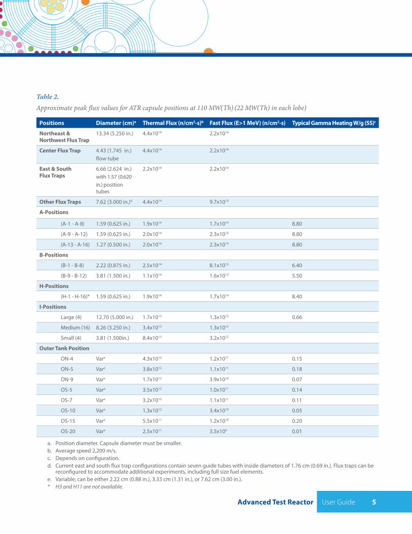
3.2 ATR Thermal Power and FluxNeutron flux in the ATR varies from position to position and along the vertical length of the test position. It also varies with the power level in the lobe(s) closest to the irradiation position. Thermal and fast flux intensity values listed in Table 2 are at the core midplane for a reactor power of 110 MW(Th) and assume a uniform reactor power of 22 MW(Th) in each lobe.
Reactor:Maximum thermal power 250 MW(Th)a
Maximum power density 1.0 MW/L
Maximum thermal neutron flux 1.0x10¹⁵n/cm2-secb
Maximum fast flux 5.0x10¹⁴n/cm2-secb
Number of flux traps 9
Number of experiment positions 77c
Core:
Number of fuel assemblies 40
Active length of assemblies 1.2 m (4 feet)
Number of fuel plates per assembly 19
Reactor Coolant:
Operating pressure 2.5 Mpa (360 psig)
Design temperature 115°C (240°F)
Light water maximum coolant flow 3.09 m3/s (49,000 gpm)
Coolant temperature (operating) <52°C (125°F) inlet, 71°C (160F) outlet
Table 1. ATR General Characteristics
a. Maximum design power. ATR typically operates near the 110 MW(Th) level.b. Parameters are based on the full 250 MW(Th) power level and will
be proportionally reduced for lower reactor power levels.c. Only 70 of the 77 are potentially available for experiments.
Advanced Test Reactor User Guide 5
Positions Diameter (cm)a Thermal Flux (n/cm2-s)b Fast Flux (E>1 MeV) (n/cm2-s) Typical Gamma Heating W/g (SS)c
Northeast & Northwest Flux Trap
13.34 (5.250 in.) 4.4x10¹⁴ 2.2x10¹⁴
Center Flux Trap 4.43 (1.745 in.)flow tube
4.4x10¹⁴ 2.2x10¹⁴
East & South Flux Traps
6.66 (2.624 in.) with 1.57 (0.620 in.) position tubes
2.2x10¹⁴ 2.2x10¹⁴
Other Flux Traps 7.62 (3.000 in.)d 4.4x10¹⁴ 9.7x10¹³
A-Positions
(A-1 - A-8) 1.59 (0.625 in.) 1.9x10¹⁴ 1.7x10¹⁴ 8.80
(A-9 - A-12) 1.59 (0.625 in.) 2.0x10¹⁴ 2.3x10¹⁴ 8.80
(A-13 - A-16) 1.27 (0.500 in.) 2.0x10¹⁴ 2.3x10¹⁴ 8.80
B-Positions
(B-1 - B-8) 2.22 (0.875 in.) 2.5x10¹⁴ 8.1x10¹³ 6.40
(B-9 - B-12) 3.81 (1.500 in.) 1.1x10¹⁴ 1.6x10¹³ 5.50
H-Positions
(H-1 - H-16)* 1.59 (0.625 in.) 1.9x10¹⁴ 1.7x10¹⁴ 8.40
I-Positions
Large (4) 12.70 (5.000 in.) 1.7x10¹³ 1.3x10¹² 0.66
Medium (16) 8.26 (3.250 in.) 3.4x10¹³ 1.3x10¹²
Small (4) 3.81 (1.500in.) 8.4x10¹³ 3.2x10¹²
Outer Tank Position
ON-4 Vare 4.3x10¹² 1.2x10¹¹ 0.15
ON-5 Vare 3.8x10¹² 1.1x10¹¹ 0.18
ON-9 Vare 1.7x10¹² 3.9x10¹⁰ 0.07
OS-5 Vare 3.5x10¹² 1.0x10¹¹ 0.14
OS-7 Vare 3.2x10¹² 1.1x10¹¹ 0.11
OS-10 Vare 1.3x10¹² 3.4x10¹⁰ 0.05
OS-15 Vare 5.5x10¹¹ 1.2x10¹⁰ 0.20
OS-20 Vare 2.5x10¹¹ 3.5x10⁹ 0.01
Table 2.Approximate peak flux values for ATR capsule positions at 110 MW(Th) (22 MW(Th) in each lobe)
a. Position diameter. Capsule diameter must be smaller.b. Average speed 2,200 m/s.c. Depends on configuration.d. Current east and south flux trap configurations contain seven guide tubes with inside diameters of 1.76 cm (0.69 in.). Flux traps can be
reconfigured to accommodate additional experiments, including full size fuel elements.e. Variable; can be either 2.22 cm (0.88 in.), 3.33 cm (1.31 in.), or 7.62 cm (3.00 in.).* H3 and H11 are not available.
User Guide Advanced Test Reactor6
1.E+13
1.E+14
1.E+15
Axial Core Height (cm)
5.37E-7 - 5.53E-3 MeV0.1 - 1.0 MeV1.0 - 2.0 MeV
5.53E-3 - 0.1 MeV0 - 5.37E-7 MeV
Top
of A
ctiv
e Co
re
Act
ive
Core
Mid
plan
e0 20 40 60 80 100 120
Neu
tron
Flu
x (n
/cm
2 s)
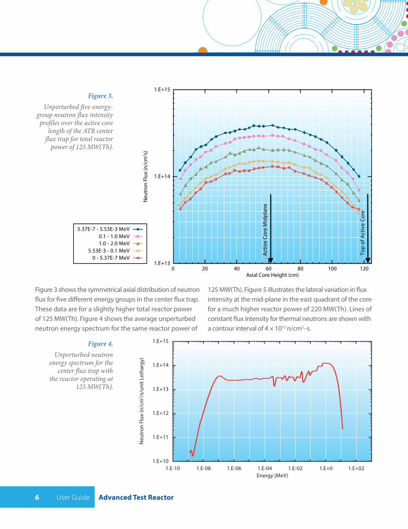
Figure 3. Unperturbed five-energy-
group neutron flux intensity profiles over the active core
length of the ATR center flux trap for total reactor power of 125 MW(Th).
Figure 4. Unperturbed neutron
energy spectrum for the center flux trap with
the reactor operating at 125 MW(Th).
1.E+10
1.E+11
1.E+12
1.E+13
1.E+14
1.E+15
Energy (MeV)1.E-10 1.E-08 1.E-06 1.E-04 1.E-02 1.E+0 1.E+02
Neu
tron
Flu
x (n
/cm
2 /s/u
nit L
etha
rgy)
Figure 3 shows the symmetrical axial distribution of neutron flux for five different energy groups in the center flux trap. These data are for a slightly higher total reactor power of 125 MW(Th). Figure 4 shows the average unperturbed neutron energy spectrum for the same reactor power of
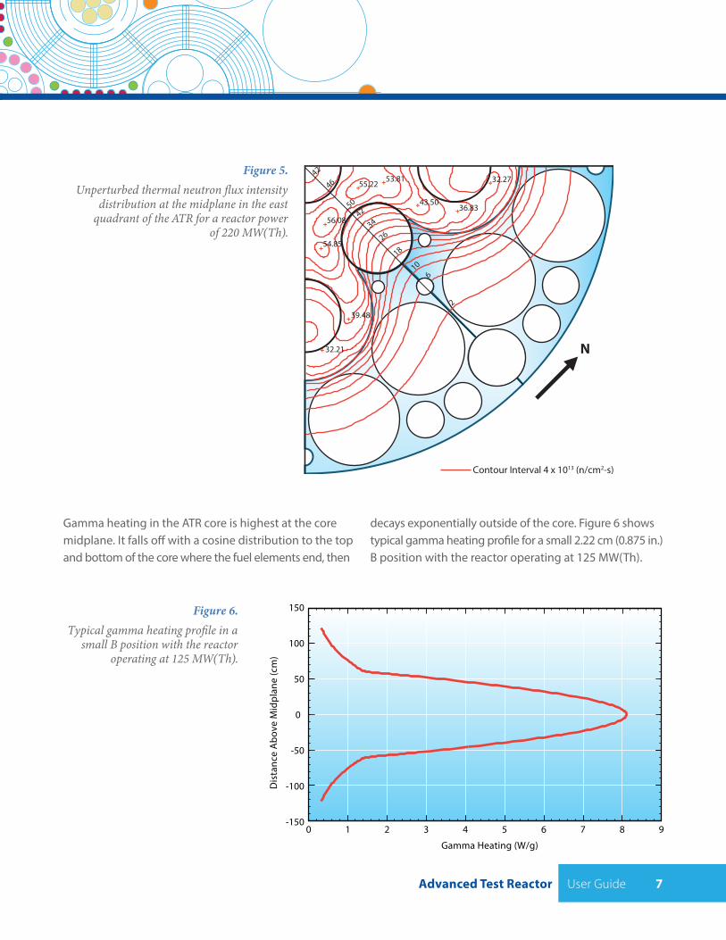
125 MW(Th). Figure 5 illustrates the lateral variation in flux intensity at the mid-plane in the east quadrant of the core for a much higher reactor power of 220 MW(Th). Lines of constant flux intensity for thermal neutrons are shown with a contour interval of 4 × 10¹³ n/cm2–s.
Advanced Test Reactor User Guide 7
Figure 5. Unperturbed thermal neutron flux intensity
distribution at the midplane in the east quadrant of the ATR for a reactor power
of 220 MW(Th).
Figure 6. Typical gamma heating profile in a
small B position with the reactor operating at 125 MW(Th).
2
6
1018
2634
4250
46
56.08
55.22
36.8343.50
39.48
42
32.21
54.85
53.81 32.27
Contour Interval 4 x 10¹³ (n/cm2-s)
N
Gamma heating in the ATR core is highest at the core midplane. It falls off with a cosine distribution to the top and bottom of the core where the fuel elements end, then
decays exponentially outside of the core. Figure 6 shows typical gamma heating profile for a small 2.22 cm (0.875 in.) B position with the reactor operating at 125 MW(Th).
-150
-100
-50
0
50
100
150
0 1 2 3 4 5 6 7 8 9
Gamma Heating (W/g)
Dis
tanc
e A
bove
Mid
plan
e (c
m)
User Guide Advanced Test Reactor8
In-piletubes
Fuelassembly
Neckshim rods
NeckShim RodHousing
Controldrums
Flux trap guidetubes
“I” Positions
“A” Positions
“B” Positions
“H” Positions
CapsuleIrradiationTank
OS-1
I-1 I-2I-20I-3I-19
I-4I-18
I-17
I-16
I-15
I-14
I-11 I-10I-9
I-12I-13
I-7
I-8
I-6
I-5
B1B8 B9
B2
B3B10
I21
I22I23
I24
B11
B12
B7
B6
B4B5
OS-3
OS-8
OS-13
OS-18
OS-4
OS-9
OS-14
OS-19
OS-5
OS-10
OS-15
OS-20
OS-6
OS-11
OS-16
OS-21
OS-7
OS-12
OS-17
OS-22
OS-2
ON-8
ON-3
ON-9
ON-4
ON-10
ON-5
ON-11
ON-6
ON-12
ON-7
ON-1 ON-2
In-vessel PostAccident
MonitoringSystem
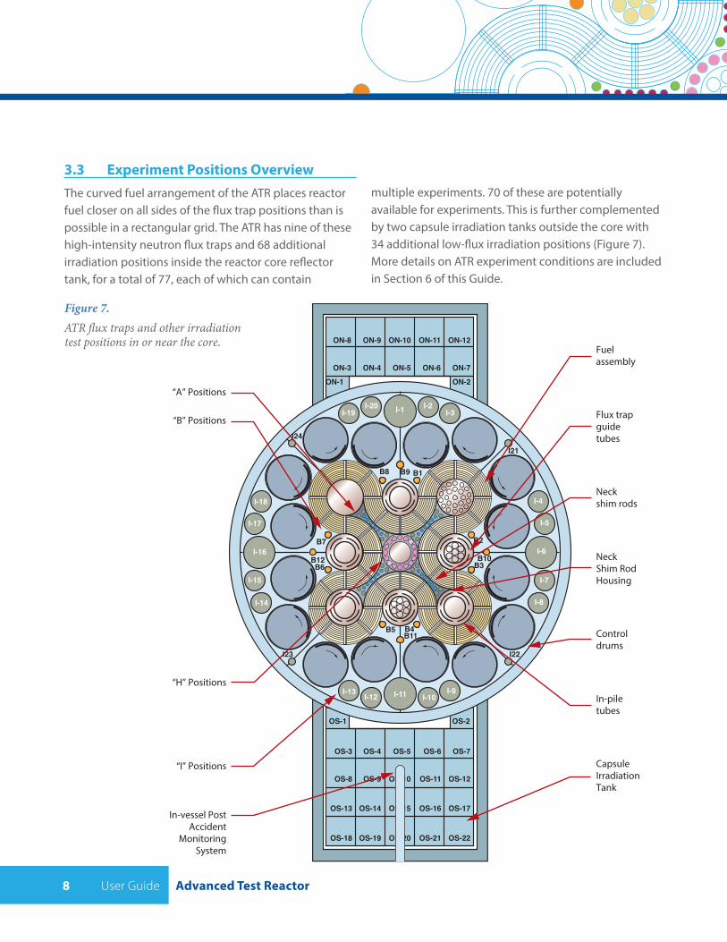
3.3 Experiment Positions OverviewThe curved fuel arrangement of the ATR places reactor fuel closer on all sides of the flux trap positions than is possible in a rectangular grid. The ATR has nine of these high-intensity neutron flux traps and 68 additional irradiation positions inside the reactor core reflector tank, for a total of 77, each of which can contain
Figure 7. ATR flux traps and other irradiation test positions in or near the core.
multiple experiments. 70 of these are potentially available for experiments. This is further complemented by two capsule irradiation tanks outside the core with 34 additional low-flux irradiation positions (Figure 7). More details on ATR experiment conditions are included in Section 6 of this Guide.
Advanced Test Reactor User Guide 9
The physical dimensions of the available test positions in the ATR range in size from 1.27 cm (0.5 in.) in diameter to 12.7 cm (5.00 in.) in diameter. Sizes and typical flux levels for positions in flux traps, neck shim housing and reflector are listed in Table 2, with additional detail in Section 6 of this Guide. Fluence achieved in each cycle is the integral of the lobe power curve over the days of operation.
Targets are inserted into the ATR inside “experiment assemblies.” The components of these assemblies are the targets, the capsule, and the basket. The capsule serves to provide a boundary to contain the target material and isolate it from the reactor primary coolant. The capsule is designed with an internal annulus generally filled with an inert gas such as helium or argon. The basket serves as the housing of the capsule(s) and is designed to mate with the irradiation position in the reactor.
Experimenters will use baskets and capsules supplied by INL where feasible. Designs for these baskets and capsules have already been qualified within the ATR safety and operational envelope. When required for the experiment’s needs, users can work with INL to develop new capsule and basket designs. Like all proposed experiments, such new designs must undergo analysis to ensure that the experiment can be completed within the ATR safety basis.
ATR experimenters are encouraged to design and/or manufacture targets to fit within the capsule designated for the position(s) into which the targets are intended to be inserted. Further details about these positions are in Section 6 of this Guide. The following experiment positions are available:
• Group A positions are in the cruciform-shaped neck shim rod housing (see Figure 8); the inner eight positions (A-1 to A-8) are used mainly for long-term irradiations due to limited accessibility.
• Group B positions are located in the beryllium reflector surrounding the core (Figure 7), near the rotating control cylinders. The smaller B positions are located close to the fuel elements and, as Table 2 indicates, have considerably higher neutron flux than the larger B positions. A Hydraulic Shuttle Irradiation System has been used in space B-7 in the past and may be re-installed at a future date if a need is identified.
• The I positions are in the periphery of the beryllium reflector, outside the rotating control cylinders, thus the flux is lower than the other ATR positions, but these positions are larger than most others in the ATR.
• Group H positions are in the center flux trap assembly (Figure 8). Positions H-3 and H-11 are used for N-16 monitors and are not available for irradiations. The other 14 H positions extend 15 cm (6.0 in.) below the active core for a total length of 272 cm (107 in.). They are all being used at this time and there is no H unused irradiation space at this time.
• The Outer Irradiation Tank positions (ON-1 to ON-12 and OS-1 to OS-22) are constructed with three variable diameters to enable simultaneous irradiation tests of differing dimensions.
User Guide Advanced Test Reactor10
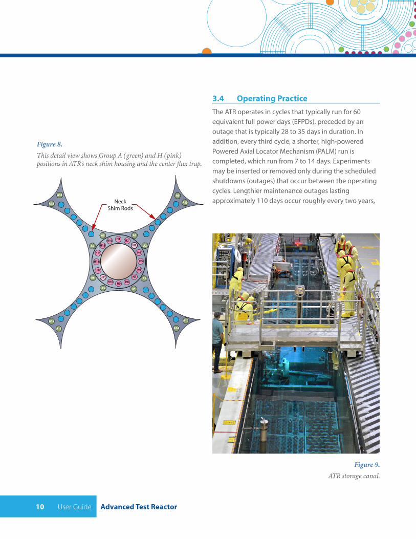
3.4 Operating PracticeThe ATR operates in cycles that typically run for 60 equivalent full power days (EFPDs), preceded by an outage that is typically 28 to 35 days in duration. In addition, every third cycle, a shorter, high-powered Powered Axial Locator Mechanism (PALM) run is completed, which run from 7 to 14 days. Experiments may be inserted or removed only during the scheduled shutdowns (outages) that occur between the operating cycles. Lengthier maintenance outages lasting approximately 110 days occur roughly every two years,
A1
A2
A3
A4A5
A6
A7
A8H1 H2
H3
H4
H5
H6
H7H8H9H10
H11
H12
H13
H14
H15H16
A11
A10
A12
A9
NeckShim Rods
A13
A14
A15
A16
Figure 8. This detail view shows Group A (green) and H (pink) positions in ATR’s neck shim housing and the center flux trap.
Figure 9. ATR storage canal.
Advanced Test Reactor User Guide 11
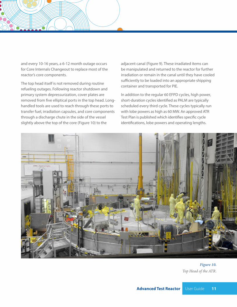
Figure 10. Top Head of the ATR.
and every 10-16 years, a 6-12 month outage occurs for Core Internals Changeout to replace most of the reactor’s core components.
The top head itself is not removed during routine refueling outages. Following reactor shutdown and primary system depressurization, cover plates are removed from five elliptical ports in the top head. Long-handled tools are used to reach through these ports to transfer fuel, irradiation capsules, and core components through a discharge chute in the side of the vessel slightly above the top of the core (Figure 10) to the
adjacent canal (Figure 9). These irradiated items can be manipulated and returned to the reactor for further irradiation or remain in the canal until they have cooled sufficiently to be loaded into an appropriate shipping container and transported for PIE.
In addition to the regular 60 EFPD cycles, high power, short-duration cycles identified as PALM are typically scheduled every third cycle. These cycles typically run with lobe powers as high as 60 MW. An approved ATR Test Plan is published which identifies specific cycle identifications, lobe powers and operating lengths.
User Guide Advanced Test Reactor12
4 OVERVIEW OF THE PROCESS FOR EXPERIMENT INSERTION
This section contains an overview of the experiment process, from inception of a user experiment to
final disposition of the target and capsule. In order to provide context for the timeline for execution and to highlight critical opportunities for technical and strategic collaboration during the process, all steps of this process are discussed here, not just those that directly involve the user.
A central tenet of INL and ATR operations is a collaborative innovation approach with user organizations. To fully realize the potential of this approach, the work must be performed by integrated task teams. Target design should be a combined exercise with input from INL experts; safety analyses should include user input and comment; and Post-Irradiation examination should be represented by experts from both the INL and user. Similarly, interpretation of results and the planning of follow-on work should be a joint enterprise.
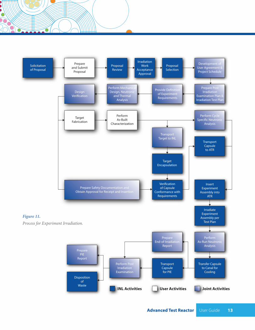
Figure 11 is a roadmap of the process for performing user experiments. The following subsections provide a brief discussion of each step, including purpose, party responsible for execution, typical order of events, general methodology, and location at which each element takes place. The length of time to complete an experiment will vary depending on the complexity of the irradiation test (i.e., capsule design), irradiation duration, and PIE complexity. As a matter of routine, the minimum time necessary to complete the initial experiment definition, design, and fabrication for a simple static capsule experiment is six months. Use of standard hardware and previously analyzed configurations can shorten this process, however, changes during the design phase of the project will tend to extend this schedule.
4.1 Proposal ProcessProposals will be requested annually from prospective users for experiments to be conducted in the ATR. Evaluation against clearly defined criteria and selection will be performed by a peer review team. The purpose of conducting this exercise annually is to stimulate creative thinking and to expand the opportunities to participate as widely as possible. Most experiments will require more than one year for completion.
Because industry and academic capabilities and interests are generally quite different in scope and available resources, solicitation and selection of proposals for these two user groups may be treated separately.
4.2 Prepare and Submit ProposalProposals must conform in content and format to specifications in the solicitation. Proposal due dates may be extended but proposals received after the published due date will not be considered. Clarity of purpose and potential experimental value are of greater weight in eventual selection than over elaboration of credentials or prior accomplishments of the user. Emphasis in proposals should be given to explaining the phenomena or attributes to be tested and verified or disproved. Meaningful performance metrics and practical means of accurate measurement are important to clearly convey to the selection team.
Prospective users may propose irradiation in a specific position, however, the INL project team, in consultation with the user, will make the final determination in consideration of all relevant operating factors. Users are also encouraged to consult the INL staff in proposal preparation to ensure that the experiment proposed can be performed as envisioned.
Advanced Test Reactor User Guide 13
DesignVeri�cation
TargetFabrication
Solicitationof Proposal
Prepareand Submit
Proposal
Development ofUser Agreement &Project Schedule
ProposalSelection
IrradiationWork
AcceptanceApproval
ProposalReview
Perform MechanicalDesign, Neutronic
and ThermalAnalysis
PerformAs-Built
Characterization
Provide De�nitionof ExperimentRequirements
Prepare PostIrradiation
Examination Plan &Irradiation Test Plan
INL Activities User Activities Joint Activities
Perform CycleSpeci�c Neutronic
Analysis
TransportTarget to INL
TransportCapsuleto ATR
Veri�cationof Capsule
Conformance withRequirements
TargetEncapsulation
IrradiateExperiment
Assembly perTest Plan
InsertExperiment
Assembly intoATR
PerformAs-Run Neutronic
Analysis
PrepareEnd-of-Irradiation
Report
Dispositionof
Waste
Transfer Capsuleto Canal for
Cooling
TransportCapsulefor PIE
Perform PostIrradiation
Examination
PreparePIE
Report
Prepare Safety Documentation andObtain Approval for Receipt and Insertion
Figure 11. Process for Experiment Irradiation.
User Guide Advanced Test Reactor14
4.4 Develop User Agreement and Project Schedule
After proposals are awarded, NSUF management and the awardees will jointly develop a user agreement. The user agreement contains standard language required to perform work with (and at) INL, and also contains a statement of work which includes specific information about the preparation and delivery of test specimens, and a budget spreadsheet. The user agreement (and corresponding documents) must be signed prior to INL staff starting the technical design work. This information will be sent to the NSUF Program Administrator.
An INL project manager (PM), principal investigator (PI), and key project team members will be identified; the INL PM and PI will work with the user PI to establish the preliminary schedule in parallel with the negotiation of the user agreement. Technical assistance (engineering, neutron physics analysis, development of the safety case, irradiated fuel shipments, procedures, etc.) will be provided by the INL experiment project team as required and delineated in the user agreement. Membership in the experiment team should remain as consistent as possible for the duration of the experiment. The irradiation schedule will be established by working with the ATR UWG to ensure that the individual experiment needs are aligned with the ATR integrated operating schedule. The INL PM will be the interface between the INL project team and the UWG. Some of the preliminary schedule information will be included in the user agreement, to be sure that both parties agree on the proposed schedule, so the user agreement and preliminary schedule will be developed simultaneously.
4.3 Irradiation Work Acceptance Approval
Prior to a proposal being selected, review and approval by the Irradiation Work Acceptance Committee (IWAC) is required. The IWAC will be comprised of two committees, the Executive Committee (EC) and the Screening Committee (SC). The SC will evaluate all prospective nuclear fuels and materials irradiation work consistent with the defined scope and will make a recommendation to the EC. This recommendation will be based on 1) technical feasibility and alignment with Division missions, 2) INL capabilities, and 3) resource availability. The EC will make the final work acceptance determination. This determination will be based on strategic INL mission alignment, SC recommendations, Lab priorities, resource allocations, and/or required capabilities necessary to perform the work.
Irradiation Work Acceptance Packages will be prepared and submitted by an INL work advocate. Evaluations of all proposed irradiation work will be made prior to selection of an internal or external funding opportunity, i.e., DOE R&D programs, LDRD, SBIRs, CINR, or GAIN Voucher, etc., or making any commitments to perform irradiation work. Generally, work will be accepted if the scope is strategically aligned with the INL mission, is technically feasible, the technology is available or can be made available to perform the experiment, and resources (qualified personnel, equipment, and funding) are available. If the experiment does not meet the general acceptance criteria, the SC may recommend alternative options for consideration.
Advanced Test Reactor User Guide 15
• Explosive materials with an equivalent of ≥25 mg of TNT. (Explosive material is a solid or liquid which has an explosion hazard in water or steam and is used in a configuration that can detonate and produce a shock wave.
• Cryogenic liquids.
4.5.1.2 Evaluation of Material
The following materials are not used in experiments unless such usage is shown to be in compliance with the primary experiment safety analyses criterion and the compliance analyses are completed prior to insertion in the reactor vessel or canal.
• Radiologically hazardous activation products, if post-irradiation handling cannot be performed within facility and personnel safety limits.
• Radiation sensitive materials, if the radiation effects result in a challenge to the safety basis (such as a structural deformation leading to a capsule failure).
• Highly flammable or toxic materials, per se or as by-products of radiation sensitive materials.
• Reactive materials which are defined as any solid or liquid which has a reactivity index of 2 in National Fire Protection Association Publication 704 (NFPA 2001) or has a disaster or fire hazard indicating detrimental reactions in water or steam (Lewis 1990).
4.5.1.3 Containment of Materials
Materials that are incompatible with the reactor fuel element cladding, the reactor primary coolant, canal water coolant, or with the reactor Primary Coolant System (PCS) structural materials must be contained to ensure they are not released to the PCS or canal.
4.5 Definition of Experiment Requirements
Although general information regarding available irradiation positions and the corresponding assemblies is provided in this document, target design requires an exact definition of requirements. INL staff, with the user, will identify the ATR irradiation location where the experiment will be placed and the reactor cycle(s) during which the experiment will be irradiated. Once this determination is made, the INL project team, in conjunction with the user, will compile a detailed list of requirements, including capsule dimensions, expected flux and fluence, and safety limits. These will be formally documented, in the Technical and Functional Requirements (TFR) and Irradiation Test Plan (ITP) for the experiment, in accordance with INL design control processes.
Irradiation location and cycle determination in turn defines the capsule and basket that will comprise the complete experiment assembly. The INL project team formally documents all relevant requirements ranging from capsule inside dimensions to temperature and pressure limitations and communicates these in writing to the user. Users will proceed with detailed target design based on this information. Additional considerations and restrictions, per ATR safety requirements are discussed below.
4.5.1 Target Materials Requirements
The following material requirements will apply.
4.5.1.1 Prohibited Materials
The following materials are not permitted in an ATR experiment or loop facility within the reactor biological shielding.
• Unknown Materials. No experiment shall be performed unless the material content, with the exception of trace constituents, is known.
User Guide Advanced Test Reactor16
4.6 Preparation of the Post Irradiation Examination Plan and Experiment Execution PlanAfter award, the INL PI, working with the user PI, prepares the EEP to identify experiment objectives, milestones, and decision points. In their proposals, prospective users outlined the phenomena of interest, expected results (with reference to the bases for these results), proposed metrics (and required level of accuracy) for determining results and the means necessary for practical measurement, materials to be used to construct the target, fabrication parameters critical to achieving desired results, irradiation parameters required, any relevant considerations for handling or analysis, and an irradiation strategy to meet experimental objectives. The EEP should correspond to the material provided in the proposal that formed the basis for selection, however, the level of detail required in the EEP goes well beyond that requested in the proposal. All relevant parameters that are expected to change and which are examined as a consequence of irradiation will be described in a Post Irradiation Examination Plan. Metrics for calibrating effects must be provided, along with tolerances on measurement accuracy. All relevant means and methods for performing measurements must be described in the Plan. The PIE Plan will be formally checked and certified by an authorized user representative as accurate and complete.
The user PI works with the INL project team to determine detailed technical information such as neutron energy, total fluence, pressure, temperature, and linear heat generation rates. Known uncertainties will be identified and potential impacts (schedule, cost, data quality, operating conditions, etc.) will be evaluated. User work elements are defined and commitments are mutually agreed upon prior to commencement of the project. This information will enable the INL project team to identify and perform the necessary activities to ensure that all INL and user requirements are met. This plan is the primary reference document for managing and coordinating activities associated with the irradiation experiment. The INL PM is responsible for ensuring
Incompatible materials must be secured to minimize the likelihood of being released into the reactor PCS. The following are examples of materials which are chemically incompatible with the PCS: mercury, gold, copper, silver, and chlorides. Gold, silver, or other properly reviewed materials may be used as activation monitors, provided they are secured so that the material cannot be released into the reactor PCS. The preceding materials list is not all inclusive, as there are other materials not listed that are incompatible with the reactor fuel element cladding. As experiment designs are finalized, all material interactions will be evaluated to ensure compliance with applicable safety basis documentation.
4.5.2 Margins between Programmatic Objectives and Safety Limits
Users are advised that experiment condition targets will be set below Safety Limits. Positions and cycles that provide adequate safety margin will be selected in conjunction with the user.
4.5.3 Dimensional Limitations by Position
Once a position has been assigned for irradiation of a specific experiment, the irradiation capsule will be designed. The target size will depend on the capsule size and the need for temperature insulation. Once the target specimens size has been determined, target fabrication must conform to these dimensions.
4.5.4 Limits on Fissile and Fertile Elements
Certain ATR positions offered have specific limitations on fissile and fertile elements that can be contained in target materials. Limitations are noted and clearly defined.
Advanced Test Reactor User Guide 17
4.7 Mechanical, Neutronic, Thermal, and Structural AnalysisNeutronic performance predictions are necessary to ensure that programmatic and safety objectives can be achieved during irradiation. Users are encouraged to perform their own calculations, however, final validation that experiments meet reactor safety requirements will be performed by INL staff. Each experiment assembly is modeled in the designated irradiation position at planned reactor conditions for the particular cycle to predict performance characteristics. Verified and Validated (V&V) computer codes are used to calculate burn-up, gas generation, fluence, linear heat generation rates and other experiment parameters. If capsules and baskets selected for a specific experiment have not been previously analyzed, hydraulic parameters and core physics parameters must be calculated and compared to the reactor operating and safety envelope.
The INL project team is responsible for the adequacy and accuracy of supporting analyses submitted by experimenter organizations. The operation of each experiment is compared with the design specification to ensure that it is properly enveloped. Each experiment is compared to the safety envelope identified in the Experiment Safety Assurance Package (ESAP) to ensure consistency with the assumptions made in the analyses.
4.8 ATR Critical FacilityFor some experiments, a “pre-test” is required to validate the reactivity estimate for the experiment.
This is performed in the ATR Critical facility (ATRC), by the INL Nuclear Engineering staff. The determination of whether this test is required for a specific experiment is also the responsibility of the Nuclear Engineering staff. The ATRC core is a heterogeneous, pool-type reactor,
that the INL project team successfully executes the requirements within this Test Plan and reports progress on a monthly basis. The following subsections provide more detail about the parameters that need to be defined to enable the INL project team to design and irradiate the material to achieve the scientific objectives.
4.6.1 Target Material Composition and Physical Characteristics
The chemical composition of all proposed target materials must be described in terms of chemical element or compound, tolerances on respective proportions, and allowable levels of trace contaminants. Physical characteristics such as crystal structure, porosity, friability, malleability, compressibility, tensile strength, and thermal properties need to be identified.
4.6.2 Flux, Fluence, and Neutron Energy Requirements
Specific requirements or constraints on instantaneous flux, total fluence, and/or neutron energy must be defined. This information is used by the INL project team to determine optimal test position in the ATR and the plausibility of achieving spectral adjustments to meet experimental requirements.
4.6.3 Geometric and Configurational Requirements
User intentions to examine unique geometric alignments (for example, to exploit the reactor flux profile) or target orientations must be clearly defined in terms of spatial relationships and allowable tolerances for the target material.
4.6.4 Special Shielding, Selective Absorption, or Dispersion Requirements
Phenomena that require special shielding, selective absorption to shift neutron spectra, or devices to disperse or diffract neutrons may be of limited plausibility in the ATR. Users requiring these to achieve specific irradiation effects must clearly define ranges to enable the INL project team to determine if achievable through use of absorptive material in baskets.
User Guide Advanced Test Reactor18
4.11 Target Fabrication and As-Built CharacterizationTargets for irradiation will be fabricated by the user unless other arrangements are negotiated with the INL and agreed to in the User Agreement. Finished targets must meet specifications agreed to in the experiment description documents (e.g., EEP and TFR). Extra targets may be required for destructive testing to determine the as-built chemistry, the uniformity of composition, and other key parameters. The as-built chemistry analysis will be compared to the design specification to ensure that the bounding uncertainties have not been exceeded so that the ESAP is not invalidated.
4.12 Nuclear Safety Documentation and ApprovalsAll experiments must meet the established nuclear safety requirements for ATR. INL personnel are responsible to ensure that all ATR insertion requirements are met. The analytical results are compiled in required formal safety documentation, the ESAP, reviewed by the Safety and Operations Review Committee (SORC), and, subject to resolution of comments, approved. The SORC reviews all safety and support documentation to ensure compliance with nuclear safety requirements.
4.13 Target EncapsulationThe target specimens will be encapsulated at the INL by INL staff. The INL will procure the materials for construction and fabricate the capsule(s) and basket(s) in accordance with the schedule required to insert the target in the
dimensionally proportional to ATR, and typically operates at power levels of 600 watts or less. If an ATRC test is required, the INL project team will work with the users to ensure necessary information is obtained and that the ATRC work is scheduled in the experiment planning.
In addition to its role supporting ATR, ATRC is a valuable tool on its own for physics testing of experiments and low power testing of instruments, such as low power fission detectors and high-temperature thermocouples.
4.9 Preparation of Experiment Safety Assurance PackageAn ESAP, prepared for all irradiation experiments at the ATR, addresses safety basis requirements. The purpose of the ESAP is to provide information needed to determine whether the proposed activities conform with applicable facility safety documentation (i.e., Technical Safety Requirements for the Advanced Test Reactor, Safety Analysis Report, Design Analyses), or pose an Unreviewed Safety Question (USQ).
For future user experiments, some of the capsules and baskets have been analyzed and documented in previously approved ESAPs. Use of these experiment configurations will reduce the experiment preparation time.
4.10 Design VerificationOnce the necessary analyses and the design documents are completed, the INL project team will verify that the approved design meets the experiment specification and that the as-built experiment is within the appropriate safety limits for insertion into the ATR.
Advanced Test Reactor User Guide 19
4.16 IrradiationA continuous record of operating power in each ATR lobe is maintained throughout the cycle including any adjustments required. This information is then used by INL analysts to calculate as-run irradiation parameters (including burn-up if the target contains fissile material) for each cycle and to determine the number of irradiation cycles required to achieve experiment objectives.
4.17 As-run Target/Capsule Neutronic AnalysisUsing the as-built data obtained from physical and chemical analysis of user supplied representative targets, along with the actual ATR cycle operating data, INL staff will calculate the as-built expected performance of the full experimental assembly in the designated position during the assigned cycle(s). These results are compared to the design predictions and to identify specific limits that may reflect anomalies in fabrication.
4.18 Experiment Assembly Removal from ReactorExperiments that have completed irradiation are transferred to designated positions in the ATR canal for cooling. ATR Operations staff performs handling of experiments and fuels during shutdown. During outages, visual examination of experimental assemblies can be performed. Completed tests remain in the ATR canal until activation and fission product decay is sufficient to permit loading into a cask for transport to PIE facilities. INL packaging and transportation personnel are responsible for determining and verifying when radiation levels from the experiment assembly are sufficiently low to allow for safe handling and transport.
designated operating cycle. Because the capsule also fits inside a basket that provides the experiment interface and support within the reactor position, procurement of materials to make the basket and fabrication are conducted in parallel with the activities for building the capsule.
Users will have the option of encapsulating their own target material and providing the sealed capsules to the INL if adequate QA requirements are in place for materials that will be in contact with the ATR primary coolant system.
No experiment may be inserted into the ATR without demonstration of capsule integrity to ensure that there are no leaks or mechanical flaws. The INL will perform required pressure and leak testing and will prepare associated confirmatory documentation.
4.14 Target Packaging and TransportUnless provided for by agreement with the INL, users are responsible for shipment of experiment material in appropriate containers to the INL. Experiments should arrive at INL one to two months before insertion into the ATR, depending on reactor operating schedule, experiment complexity, and ESAP approval schedule.
4.15 Insertion of Experiment Assembly into ATRATR Operations staff inserts experiments into assigned positions during ATR outages. These insertions are documented in the reactor loading record.
User Guide Advanced Test Reactor20
4.22 Disposition of Capsule and TargetCapsules, targets, and baskets are activated during the irradiation process and require disposition as radioactive waste unless re-used. During the proposal development and feasibility review process, verification that there is a disposition path for any waste generated by the experiment will be performed. Normally, wastes from the experiments can be inserted into the ATR Complex or MFC established waste streams. If there are other waste disposal paths needed for specific experiment material, the user will be required to identify the approved waste disposal path and fund the disposition of the materials. The user is responsible for proper disposition of the target materials unless separate prior arrangements have been made through the user agreement.
4.23 Preparation and Submittal of PIE ReportThe INL PI, in conjunction with the user PI, will interpret the PIE results in the context of the as-run data. All conclusions, calculations, rationale, and supporting data are compiled in a PIE report that is subject to peer review and comment prior to formal issuance. Unless designated as proprietary in accordance with the user agreement with the NSUF, this report is published and made available to the general public.
4.19 Transport of Irradiated Capsule for PIEAfter experiment assemblies have cooled sufficiently to permit safe handling and transport, the capsule is removed from the basket and placed inside an NRC approved shipping container by ATR Canal Operations. This cask is provided by the INL; loading and transport to PIE facilities are conducted by INL staff in accordance with the Transportation Plan for the specific experiment. If the user desires that the PIE will be performed outside the INL, this information needs to be included in the user agreement and the ITP, so the appropriate plans can be incorporated into the schedule.
4.20 End of Irradiation As-Run Neutronics ReportProper interpretation of PIE results is only possible with a knowledge of the actual irradiation conditions experienced in the ATR. INL technical personnel calculate the expected neutronic effects using the same codes employed for predicting performance and the as-run irradiation analysis from the ATR. These calculations are documented in a report after irradiation is complete.
4.21 Post-Irradiation ExaminationPIE performed at the INL (in the HFEF or other labs) is carried out by INL personnel using the instruments appropriate for determination of irradiation effects. It is normally possible for users to participate in PIE data reduction and to observe and direct examinations. This work is done within shielded remote cells in the HFEF that are equipped with proper remote access devices. Examinations are performed in isolation from other experiments to prevent unintended effects or cross-contamination. Alternatively, examination at another PIE facility can be arranged by the user.
Advanced Test Reactor User Guide 21
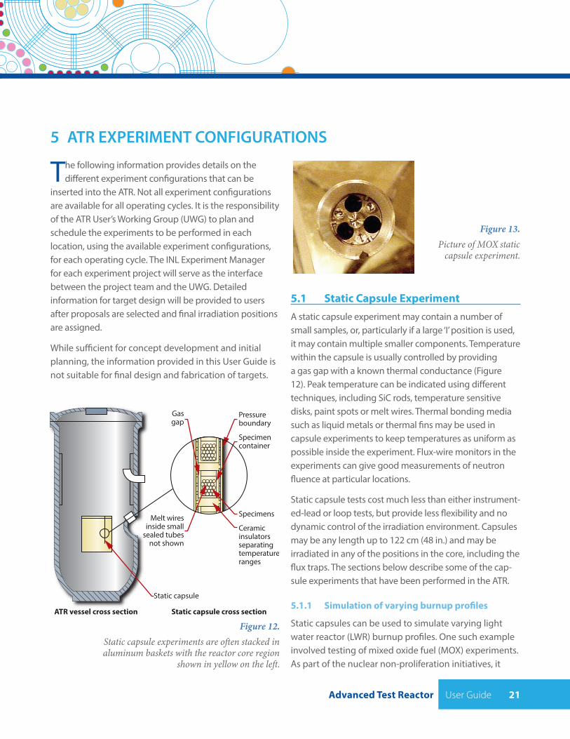
Figure 12. Static capsule experiments are often stacked in aluminum baskets with the reactor core region
shown in yellow on the left.
The following information provides details on the different experiment configurations that can be
inserted into the ATR. Not all experiment configurations are available for all operating cycles. It is the responsibility of the ATR User’s Working Group (UWG) to plan and schedule the experiments to be performed in each location, using the available experiment configurations, for each operating cycle. The INL Experiment Manager for each experiment project will serve as the interface between the project team and the UWG. Detailed information for target design will be provided to users after proposals are selected and final irradiation positions are assigned.
While sufficient for concept development and initial planning, the information provided in this User Guide is not suitable for final design and fabrication of targets.
ATR vessel cross section
Static capsule
Gasgap
Melt wiresinside small
sealed tubesnot shown
Pressureboundary
Specimencontainer
Specimens
Ceramicinsulatorsseparatingtemperatureranges
Static capsule cross section
Figure 13. Picture of MOX static capsule experiment.
5.1 Static Capsule ExperimentA static capsule experiment may contain a number of small samples, or, particularly if a large ‘I’ position is used, it may contain multiple smaller components. Temperature within the capsule is usually controlled by providing a gas gap with a known thermal conductance (Figure 12). Peak temperature can be indicated using different techniques, including SiC rods, temperature sensitive disks, paint spots or melt wires. Thermal bonding media such as liquid metals or thermal fins may be used in capsule experiments to keep temperatures as uniform as possible inside the experiment. Flux-wire monitors in the experiments can give good measurements of neutron fluence at particular locations.
Static capsule tests cost much less than either instrument-ed-lead or loop tests, but provide less flexibility and no dynamic control of the irradiation environment. Capsules may be any length up to 122 cm (48 in.) and may be irradiated in any of the positions in the core, including the flux traps. The sections below describe some of the cap-sule experiments that have been performed in the ATR.
5.1.1 Simulation of varying burnup profiles
Static capsules can be used to simulate varying light water reactor (LWR) burnup profiles. One such example involved testing of mixed oxide fuel (MOX) experiments. As part of the nuclear non-proliferation initiatives, it
5 ATR EXPERIMENT CONFIGURATIONS
User Guide Advanced Test Reactor22
static capsule configurations, using plate geometry rather than cylindrical pellets, and the fuel plate cladding is in contact with the ATR primary coolant system. These tests are performed in reflector and flux trap positions.
5.1.3 Testing with increased fast neutron flux ratios
Thermal neutron flux filtering can be employed in some configurations to achieve a higher fast-to-thermal neutron flux ratio. On one such example, samples for DOE’s Fuel Cycle Research Development (FCRD) program is irradiating different fuel types in ATR experiment positions. The objective of the tests is to support development of fuels to minimize the spent fuel volume needed to be stored in a long-term repository. Some of these past experiments were conducted in one of ATR’s positions with a high thermal flux, so a cadmium lined basket was used to reduce the thermal flux, and therefore reduce the fission rate in the fuel. This approach also increases the fast to thermal flux ratio to be a more representative value of future fast reactors. Some of the current FCRD program experiments utilize the outer A, B positions, and I positions. The experiments in the outer A and B positions still utilize a cadmium basket.
was proposed that weapons grade plutonium could be mixed with commercial uranium oxide and burned in current LWRs. Some testing was needed on the MOX samples. A simple capsule was prepared to contain nine fuel samples, with each exposed to a variety of burnup levels. The capsules were moved from one experiment position in the ATR to another position during the irradiation duration to enable a more stable fuel burnup rate during the experiment. Preliminary fuel analysis results were sufficient to enable commercial nuclear power companies to pursue further development.
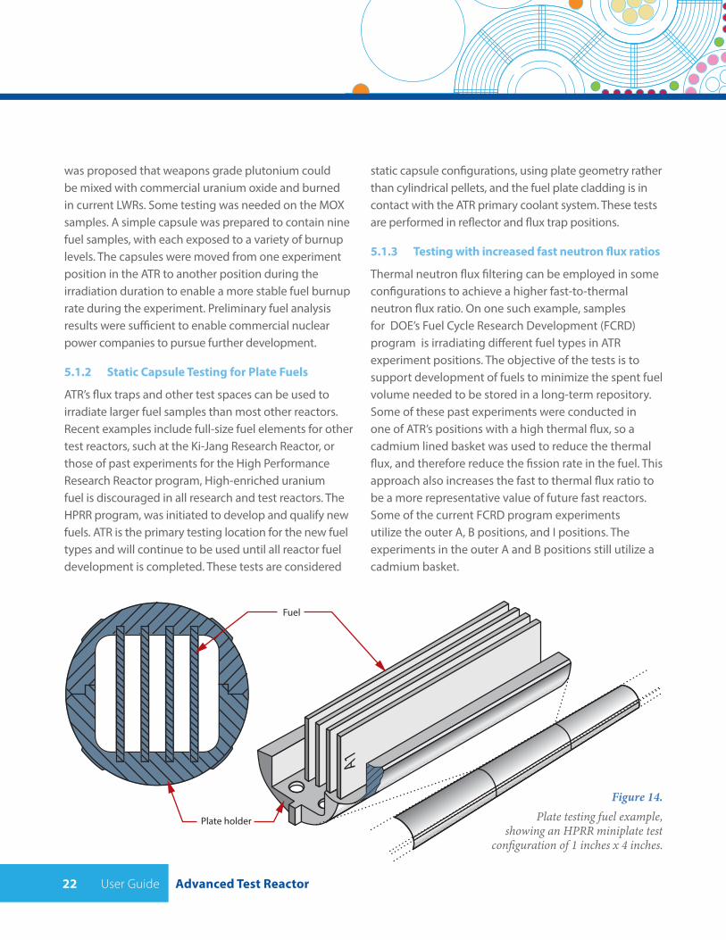
5.1.2 Static Capsule Testing for Plate Fuels
ATR’s flux traps and other test spaces can be used to irradiate larger fuel samples than most other reactors. Recent examples include full-size fuel elements for other test reactors, such at the Ki-Jang Research Reactor, or those of past experiments for the High Performance Research Reactor program, High-enriched uranium fuel is discouraged in all research and test reactors. The HPRR program, was initiated to develop and qualify new fuels. ATR is the primary testing location for the new fuel types and will continue to be used until all reactor fuel development is completed. These tests are considered
Fuel
Plate holder
Figure 14. Plate testing fuel example,
showing an HPRR miniplate test configuration of 1 inches x 4 inches.
Advanced Test Reactor User Guide 23
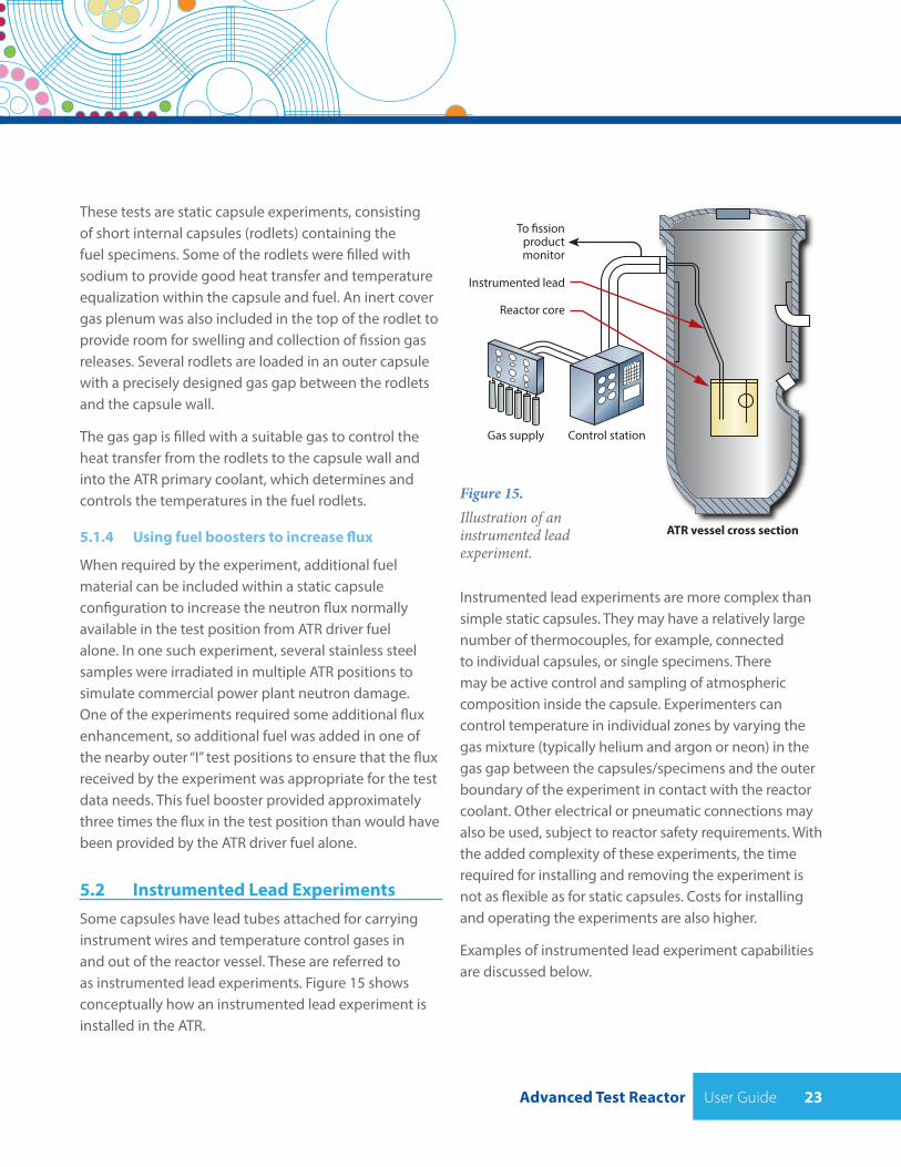
These tests are static capsule experiments, consisting of short internal capsules (rodlets) containing the fuel specimens. Some of the rodlets were filled with sodium to provide good heat transfer and temperature equalization within the capsule and fuel. An inert cover gas plenum was also included in the top of the rodlet to provide room for swelling and collection of fission gas releases. Several rodlets are loaded in an outer capsule with a precisely designed gas gap between the rodlets and the capsule wall.
The gas gap is filled with a suitable gas to control the heat transfer from the rodlets to the capsule wall and into the ATR primary coolant, which determines and controls the temperatures in the fuel rodlets.
5.1.4 Using fuel boosters to increase flux
When required by the experiment, additional fuel material can be included within a static capsule configuration to increase the neutron flux normally available in the test position from ATR driver fuel alone. In one such experiment, several stainless steel samples were irradiated in multiple ATR positions to simulate commercial power plant neutron damage. One of the experiments required some additional flux enhancement, so additional fuel was added in one of the nearby outer “I” test positions to ensure that the flux received by the experiment was appropriate for the test data needs. This fuel booster provided approximately three times the flux in the test position than would have been provided by the ATR driver fuel alone.
5.2 Instrumented Lead ExperimentsSome capsules have lead tubes attached for carrying instrument wires and temperature control gases in and out of the reactor vessel. These are referred to as instrumented lead experiments. Figure 15 shows conceptually how an instrumented lead experiment is installed in the ATR.
ATR vessel cross section
Reactor core
Control stationGas supply
To �ssionproductmonitor
Instrumented lead
Figure 15. Illustration of an instrumented lead experiment.
Instrumented lead experiments are more complex than simple static capsules. They may have a relatively large number of thermocouples, for example, connected to individual capsules, or single specimens. There may be active control and sampling of atmospheric composition inside the capsule. Experimenters can control temperature in individual zones by varying the gas mixture (typically helium and argon or neon) in the gas gap between the capsules/specimens and the outer boundary of the experiment in contact with the reactor coolant. Other electrical or pneumatic connections may also be used, subject to reactor safety requirements. With the added complexity of these experiments, the time required for installing and removing the experiment is not as flexible as for static capsules. Costs for installing and operating the experiments are also higher.
Examples of instrumented lead experiment capabilities are discussed below.
User Guide Advanced Test Reactor24
5.2.1 Precise experiment temperature control
In this example, graphite samples were irradiated to high-density losses due to radiolytic oxidation in a gas controlled, high temperature environment for the Magnox reactor, in support of life extension studies. This was a temperature controlled, instrumented experiment, nominally within a 5° C temperature band. Some samples were irradiated in an inert environment, and others were in a CO2 environment to assess the environmental effect on the density loss. The experiment successfully achieved the results the customer wanted - one set of samples was extremely degraded due to oxidation, and the other set of samples in the inert environment was relatively intact.
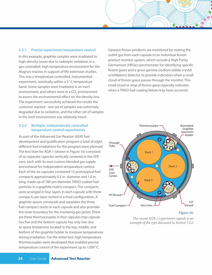
5.2.2 Multiple, independently controlled temperature control experiments
As part of the Advanced Gas Reactor (AGR) fuel development and qualification program a total of eight different fuel irradiations for the program were planned. The test train for AGR-1 (shown in Figure 16) consisted of six separate capsules vertically centered in the ATR core, each with its own custom blended gas supply and exhaust for independent temperature control. Each of the six capsules contained 12 prototypical fuel compacts approximately 0.5 in. diameter and 1.0 in. long, made up of 780 μm diameter TRISO-coated fuel particles in a graphite matrix compact. The compacts were arranged in four layers in each capsule with three compacts per layer nested in a triad configuration. A graphite spacer surrounds and separates the three fuel compact stacks in each capsule and also provides the inner boundary for the insulating gas jacket. There are three thermocouples in four capsules (top capsule has five and the bottom capsule has only two due to space limitations) located in the top, middle, and bottom of the graphite holder to measure temperatures during irradiation. For the initial test, high temperature thermocouples were developed that enabled precise temperature control of the experiment up to 1200° C.
Gaseous fission products are monitored by routing the outlet gas from each capsule to an individual fission product monitor system, which include a High Purity Germanium (HPGe) spectrometer for identifying specific fission gases and a gross gamma (sodium iodide crystal scintillation) detector to provide indication when a small cloud of fission gases passes through the monitor. This small cloud or wisp of fission gases typically indicates when a TRISO fuel coating failure may have occurred.
Figure 16.The recent AGR-1 experiment capsule is an
example of the type discussed in Section 7.2.2.
BoronatedGraphite
SpecimenHolder
Thermocouples
ThroughTube
ATRCoreCenter
Hf Shroud
Fuel Compact Gas LinesSST
Shroud
Stack 1
Stack 2
Stack 3
Advanced Test Reactor User Guide 25
5.3 Pressurized Water LoopSix of the nine flux traps in the ATR are equipped with pressurized water loops, which are used for materials and fuels testing. Each of the six water loops can be operated at different temperatures, pressures, flow rates and water chemistry conditions, though only loop 2A is currently available for new ATR customers. These loops can operate above the standard temperature and pressure of a current commercial pressurized water reactor power plant. The great advantage of loop tests is the ease with which a variety of samples can be subjected to conditions specified for any pressurized water reactor design. Many samples can be tested at once (in several loops or one loop, depending on the size of samples) with variation in the samples, thickness of cladding, etc., and the samples can be compared afterward for optimum design. Materials and fuels designers rely heavily on such tests.
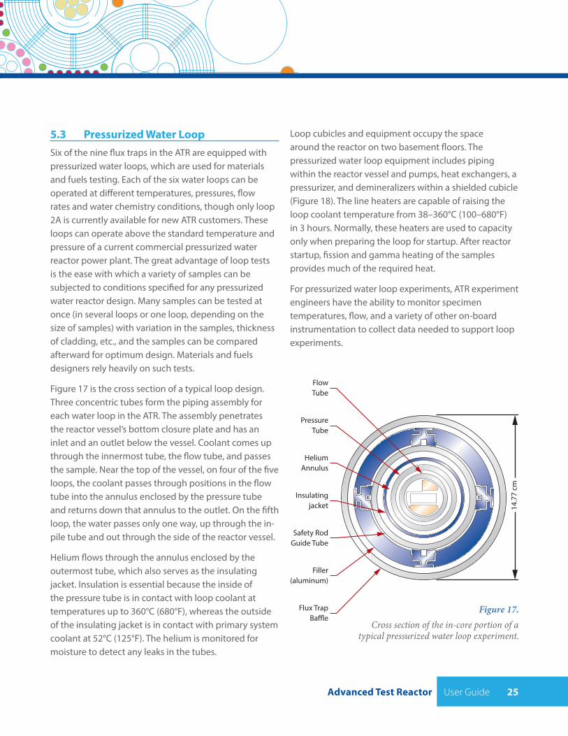
Figure 17 is the cross section of a typical loop design. Three concentric tubes form the piping assembly for each water loop in the ATR. The assembly penetrates the reactor vessel’s bottom closure plate and has an inlet and an outlet below the vessel. Coolant comes up through the innermost tube, the flow tube, and passes the sample. Near the top of the vessel, on four of the five loops, the coolant passes through positions in the flow tube into the annulus enclosed by the pressure tube and returns down that annulus to the outlet. On the fifth loop, the water passes only one way, up through the in-pile tube and out through the side of the reactor vessel.
Helium flows through the annulus enclosed by the outermost tube, which also serves as the insulating jacket. Insulation is essential because the inside of the pressure tube is in contact with loop coolant at temperatures up to 360°C (680°F), whereas the outside of the insulating jacket is in contact with primary system coolant at 52°C (125°F). The helium is monitored for moisture to detect any leaks in the tubes.
PressureTube
FlowTube
HeliumAnnulus
Insulatingjacket
Safety RodGuide Tube
Filler(aluminum)
Flux TrapBa�e
14.7
7 cm
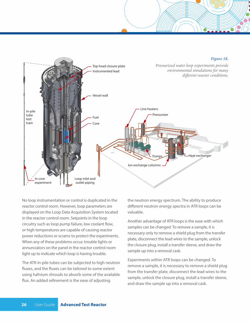
Loop cubicles and equipment occupy the space around the reactor on two basement floors. The pressurized water loop equipment includes piping within the reactor vessel and pumps, heat exchangers, a pressurizer, and demineralizers within a shielded cubicle (Figure 18). The line heaters are capable of raising the loop coolant temperature from 38–360°C (100–680°F) in 3 hours. Normally, these heaters are used to capacity only when preparing the loop for startup. After reactor startup, fission and gamma heating of the samples provides much of the required heat.
For pressurized water loop experiments, ATR experiment engineers have the ability to monitor specimen temperatures, flow, and a variety of other on-board instrumentation to collect data needed to support loop experiments.
Figure 17.Cross section of the in-core portion of a
typical pressurized water loop experiment.
User Guide Advanced Test Reactor26
Instrumented leadTop head closure plate
Vessel wall
Fuel
Core
In-coreexperiment
In-piletubetesttrain
Pressurizer
Line heaters
Ion exchange columns
Heat exchangerPumps
Loop inlet andoutlet piping
Figure 18. Pressurized water loop experiments provide
environmental simulations for many different reactor conditions.
No loop instrumentation or control is duplicated in the reactor control room. However, loop parameters are displayed on the Loop Data Acquisition System located in the reactor control room. Setpoints in the loop circuitry such as loop pump failure, low coolant flow, or high temperatures are capable of causing reactor power reductions or scrams to protect the experiments. When any of these problems occur, trouble lights or annunciators on the panel in the reactor control room light up to indicate which loop is having trouble.
The ATR in-pile tubes can be subjected to high neutron fluxes, and the fluxes can be tailored to some extent using hafnium shrouds to absorb some of the available flux. An added refinement is the ease of adjusting
the neutron energy spectrum. The ability to produce different neutron energy spectra in ATR loops can be valuable.
Another advantage of ATR loops is the ease with which samples can be changed. To remove a sample, it is necessary only to remove a shield plug from the transfer plate, disconnect the lead wires to the sample, unlock the closure plug, install a transfer sleeve, and draw the sample up into a removal cask.
Experiments within ATR loops can be changed. To remove a sample, it is necessary to remove a shield plug from the transfer plate, disconnect the lead wires to the sample, unlock the closure plug, install a transfer sleeve, and draw the sample up into a removal cask.
Advanced Test Reactor User Guide 27
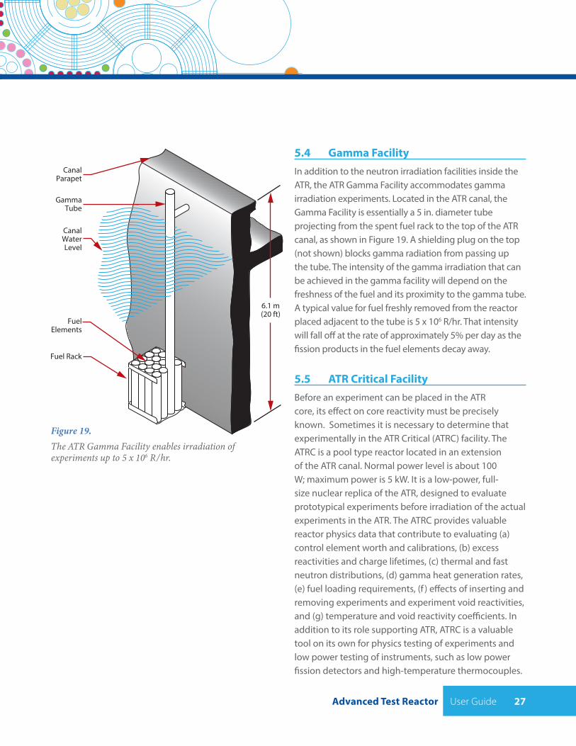
5.4 Gamma FacilityIn addition to the neutron irradiation facilities inside the ATR, the ATR Gamma Facility accommodates gamma irradiation experiments. Located in the ATR canal, the Gamma Facility is essentially a 5 in. diameter tube projecting from the spent fuel rack to the top of the ATR canal, as shown in Figure 19. A shielding plug on the top (not shown) blocks gamma radiation from passing up the tube. The intensity of the gamma irradiation that can be achieved in the gamma facility will depend on the freshness of the fuel and its proximity to the gamma tube. A typical value for fuel freshly removed from the reactor placed adjacent to the tube is 5 x 10⁶ R/hr. That intensity will fall off at the rate of approximately 5% per day as the fission products in the fuel elements decay away.
5.5 ATR Critical FacilityBefore an experiment can be placed in the ATR core, its effect on core reactivity must be precisely known. Sometimes it is necessary to determine that experimentally in the ATR Critical (ATRC) facility. The ATRC is a pool type reactor located in an extension of the ATR canal. Normal power level is about 100 W; maximum power is 5 kW. It is a low-power, full-size nuclear replica of the ATR, designed to evaluate prototypical experiments before irradiation of the actual experiments in the ATR. The ATRC provides valuable reactor physics data that contribute to evaluating (a) control element worth and calibrations, (b) excess reactivities and charge lifetimes, (c) thermal and fast neutron distributions, (d) gamma heat generation rates, (e) fuel loading requirements, (f ) effects of inserting and removing experiments and experiment void reactivities, and (g) temperature and void reactivity coefficients. In addition to its role supporting ATR, ATRC is a valuable tool on its own for physics testing of experiments and low power testing of instruments, such as low power fission detectors and high-temperature thermocouples.
6.1 m(20 ft)
CanalParapet
GammaTube
CanalWaterLevel
FuelElements
Fuel Rack
Figure 19. The ATR Gamma Facility enables irradiation of experiments up to 5 x 10⁶ R/hr.
User Guide Advanced Test Reactor28
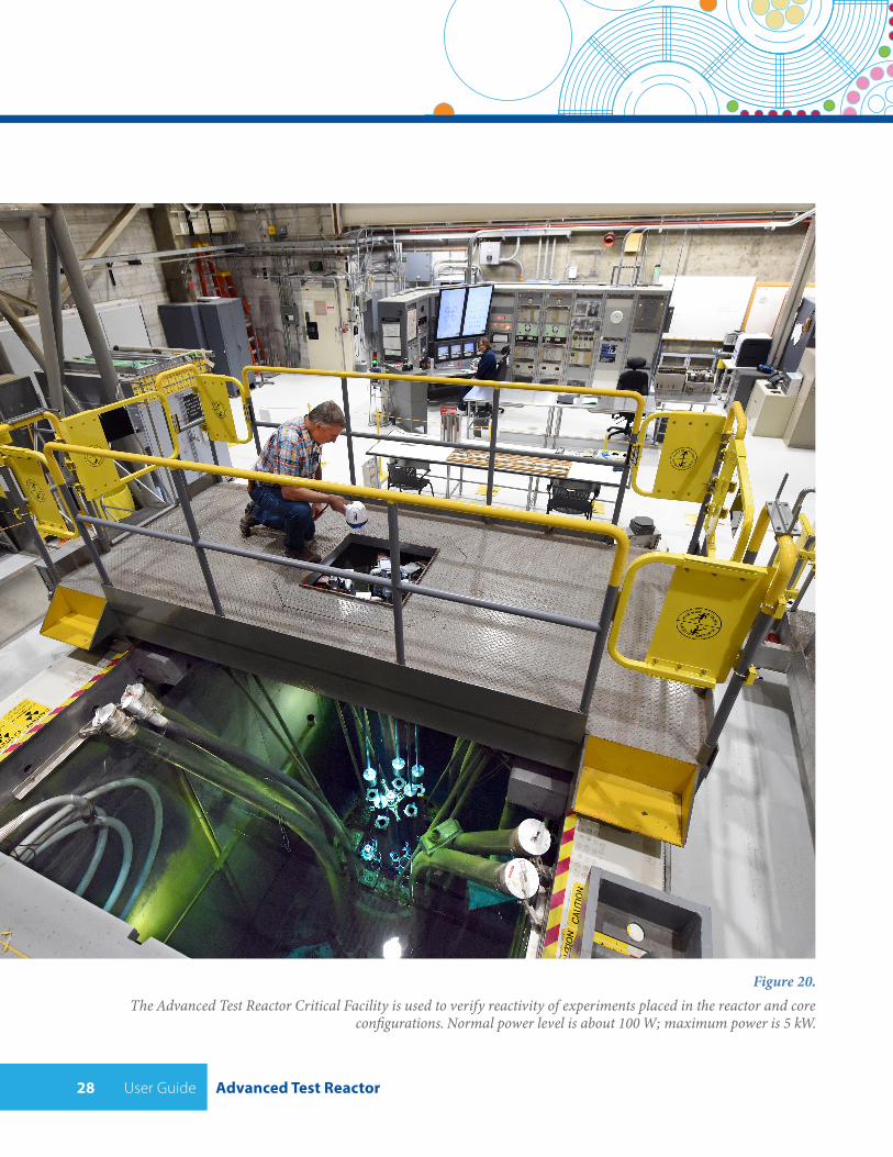
Figure 20.The Advanced Test Reactor Critical Facility is used to verify reactivity of experiments placed in the reactor and core
configurations. Normal power level is about 100 W; maximum power is 5 kW.
Advanced Test Reactor User Guide 29
6 REACTOR POSITIONS OFFERED
The The following sections describe the ATR experi-ment positions that are available to experimenters.
The information provided in this section reflects exper-iments that have been previously performed in these experiment positions. There are some ATR experiment positions that have not been used for experiments, thus there is neither specification information nor an ESAP. This will require the INL project team to perform all the required safety analyses for the experiment. Final spec-ification of the irradiation position will be determined following proposal selection during experiment design. Experiment configurations are described in detail in Section 5 of this Guide.
Flux information for all positions is based on an ATR total power average of 110 MWth, 22 MWth in each lobe. Individual operating cycles and lobe power levels can vary.
For all positions:
• Target materials must not create an unacceptable radiological hazard and adequacy of the specified shipping container for the irradiated experiment must be demonstrated.
• Capsule void volumes are normally filled with helium at one atmosphere during fabrication. Other inert fill gases at one atmosphere may be acceptable but will require evaluation.
• For positions that allow fissionable material (B, H and I positions), the peak allowable heat flux for the capsule will apply and associated gas release into the capsule will require evaluation of the capsule integrity for potential internal gas pressure. Any target material capable of causing gas release into the capsule requires a capsule integrity evaluation and must not result in a potential internal gas pressure exceeding 235 psig.
• Target materials must be designed such that neither thermal nor radiation induced expansion will cause mechanical stresses that could result in failure of the experiment containment.
• Target materials must not create an unacceptable radiological hazard and adequacy of the specified shipping container for the irradiated experiment must be demonstrated.
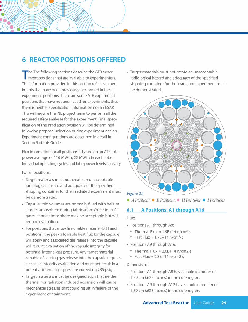
Figure 21 A Positions, B Positions, H Positions, I Positions
6.1 A Positions: A1 through A16 Flux:
• Positions A1 through A8:
º Thermal Flux ≈ 1.9E+14 n/cm2-s º Fast Flux ≈ 1.7E+14 n/cm2-s
• Positions A9 through A16:
º Thermal Flux ≈ 2.0E+14 n/cm2-s º Fast Flux ≈ 2.3E+14 n/cm2-s
Dimensions:
• Positions A1 through A8 have a hole diameter of 1.59 cm (.625 inches) in the core region.
• Positions A9 through A12 have a hole diameter of 1.59 cm (.625 inches) in the core region.
User Guide Advanced Test Reactor30
• Positions A13 through A16 have a hole diameter of 1.27 cm (.5 inches) in the core region.
• All A-positions span the entire 121.9 cm (48 inches) of active fuel in the core region.
• Positions A1 through A8 are approximately 153.7 cm (60.5 inches) deep, extending approximately 16.5 cm (6.5 inches) below and 14.9 cm (5.9 inches) above the active core region.
• Positions A9 through A12 are approximately 153.7 cm (60.5 inches) deep, extending approximately 16.5 cm (6.5 inches) below and 15.2 cm (6 inches) above the active core region.
• Positions A13 through A16 are approximately 153.7 cm (60.5 inches) deep, extending approximately 16.5 cm (6.5 inches) below and 15.2 cm (6 inches) above the active core region.
Experiment Construction:
• Fissile material not allowed in A positions.
• Only drop-in capsule type experiments can be irradiated in the A positions.
• Maximum heat flux at capsule surface is 49.5 W/cm2.
• Space available for fuel or material specimens will be limited by the necessary capsule/ containment bound-ary for the experiment, an anulus around the experi-ment to allow coolant flow through the position, and allowances for a basket (if used) to handle capsules.
• As a point of reference, past experiments had containment inner diameters of roughly 1.24 cm (0.49 inches) for inner A positions and 0.9 cm (0.37 inches) for outer A positions.
6.2 B Positions: B1 through B12Flux:
• Positions B1 through B8: º Thermal Flux ≈ 2.5E+14 n/cm2-s º Fast Flux ≈ 8.1E+13 n/cm2-s
• Positions B9 through B12: º Thermal Flux ≈ 1.1E+14 n/cm2-s º Fast Flux ≈ 1.6E+13 n/cm2-s
Dimensions:
• Positions B1 through B8 have a hole diameter of 2.22 cm (.875 inches) in the core region.
• Positions B9 through B12 have a hole diameter of 3.81 cm (1.5 inches) in the core region.
• All B-positions span the entire 121.9 cm (48 inches) of active fuel in the core region.
• Positions B1 through B8 are approximately 152 cm (60 inches) deep, extending approximately 12.7 cm (5 inches) below and 17.3 cm (6.8 inches) above the active core region.
• Positions B9 through B12 are approximately 151 cm (59.5 inches) deep, extending approximately 3.6 cm (1.4 inches) below and 25.5 cm (10.1 inches) above the active core region.
Experiment Construction:
• Fissile material allowed.
• Either instrumented lead-out or drop-in capsule type experiments can be irradiated in the B positions.
• Space available for fuel or material specimens will be limited by the necessary capsule/containment boundary for the experiment, an anulus around the experiment to allow coolant flow through the position, and allowances for a basket (if used) to handle capsules.
• As a point of reference, past experiments had containment inner diameters of roughly 1.15 cm (0.45 inches) and 2.9 cm (1.14 inches) for positions B1 through B8 and positions B9 through B12 respectively.
6.3 H Positions: H1 through H16Flux:
• Positions H1-H2, H4-H10, and H12-16 (H3 and H11 are not available):
º Thermal Flux ≈ 1.9E+14 n/cm2-s º Fast Flux ≈ 1.7E+14 n/cm2-s
Advanced Test Reactor User Guide 31
Dimensions:
• Positions H1 through H16 have a hole diameter of 1.59 cm (.625 inches) in the core region.
• All H-positions span the entire 121.9 cm (48 inches) of active fuel in the core region.
• Positions H1 through H16 are approximately 276.9 cm (109 inches) deep, extending approximately 5 cm (2 inches) below and 142.2 cm (56 inches) above the active core region.
Experiment Construction:
• Fissile material allowed.
• Either instrumented lead-out or drop-in capsule type experiments can be irradiated in the H positions.
• Maximum heat flux at capsule surface is 23.7 W/cm2.
• Space available for fuel or material specimens will be limited by the necessary capsule/containment boundary for the experiment, an anulus around the experiment to allow coolant flow through the position, and allowances for a basket (if used) to handle capsules.
• As a point of reference, past experiments had contain-ment inner diameters of roughly 1 cm (0.4 inches).
6.4 I Positions: I1 through I24 Flux:
• Large I positions I1, I6, I11 and I16: º Thermal Flux ≈ 1.7E+13 n/cm2-s º Fast Flux ≈ 1.3E+12 n/cm2-s
• Medium I positions I2-I5, I7-I10, I12-I15 and I17-I20: º Thermal Flux ≈ 3.4E+13 n/cm2-s º Fast Flux ≈ 1.3E+12 n/cm2-s
• Small I positions I21-I24: º Thermal Flux ≈ 8.4E+13 n/cm2-s º Fast Flux ≈ 3.2E+12 n/cm2-s
Dimensions:
• Large I Positions I1, I6, I11 and I16 have a hole diameter of 12.7 cm (5 inches) in the core region.
• Medium I Positions I2-I5, I7-I10, I12-I15 and I17-I20 have a hole diameter of 8.26 cm (3.25 inches) in the core region.
• Small I Positions I21-I24 have a hole diameter of 3.81 cm (1.5 inches) in the core region.
• All I-positions span the entire 121.9 cm (48 inches) of active fuel in the core region.
• Large I Positions are approximately 134.6 cm (53 inches) deep, extending approximately 5.7 cm (2.3 inches) below and 5 cm (2 inches) above the active core region.
• Medium I Positions are approximately 134.6 cm (53 inches) deep, extending approximately 5.7 cm (2.3 inches) below and 5 cm (2 inches) above the active core region.
• Small I Positions are approximately 153 cm (60.25 inches) deep, extending approximately 0 cm (0 inches) below and 28.7 cm (11.3 inches) above the active core region.
Experiment Construction:
• Fissile material allowed.
• Target material must be contained in a single capsule that extends from the ATR gear box support beam vertical support base (at ATR reference elevation of 25.27 m (82 ft 10.94 in.) downward through the I irradiation position.
• Maximum heat flux at capsule surface is 39.4 W/cm2.
• Capsules will have a total length of 153.0 cm (60.25 in.). The available target space in the capsule will be at least 122 cm (48.0 in.) in length and will be positioned such that the 122 cm (48.0 in.) target is centered at approximately the elevation of the ATR core mid- plane. The capsule inside diameter is to be determined but is not expected to exceed 3.42 cm (1.35 in.).
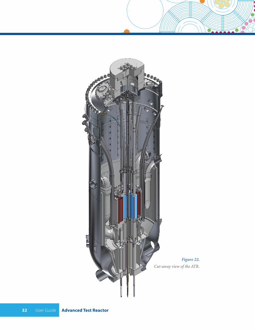
User Guide Advanced Test Reactor32
Figure 22. Cut-away view of the ATR.
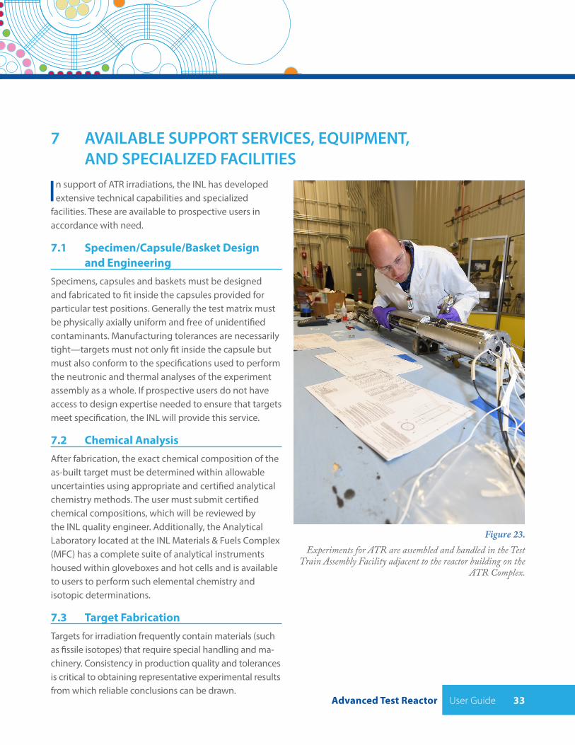
Advanced Test Reactor User Guide 33
7 AVAILABLE SUPPORT SERVICES, EQUIPMENT, AND SPECIALIZED FACILITIES
In support of ATR irradiations, the INL has developed extensive technical capabilities and specialized
facilities. These are available to prospective users in accordance with need.
7.1 Specimen/Capsule/Basket Design and EngineeringSpecimens, capsules and baskets must be designed and fabricated to fit inside the capsules provided for particular test positions. Generally the test matrix must be physically axially uniform and free of unidentified contaminants. Manufacturing tolerances are necessarily tight—targets must not only fit inside the capsule but must also conform to the specifications used to perform the neutronic and thermal analyses of the experiment assembly as a whole. If prospective users do not have access to design expertise needed to ensure that targets meet specification, the INL will provide this service.
7.2 Chemical AnalysisAfter fabrication, the exact chemical composition of the as-built target must be determined within allowable uncertainties using appropriate and certified analytical chemistry methods. The user must submit certified chemical compositions, which will be reviewed by the INL quality engineer. Additionally, the Analytical Laboratory located at the INL Materials & Fuels Complex (MFC) has a complete suite of analytical instruments housed within gloveboxes and hot cells and is available to users to perform such elemental chemistry and isotopic determinations.
7.3 Target FabricationTargets for irradiation frequently contain materials (such as fissile isotopes) that require special handling and ma-chinery. Consistency in production quality and tolerances is critical to obtaining representative experimental results from which reliable conclusions can be drawn.
Figure 23. Experiments for ATR are assembled and handled in the Test
Train Assembly Facility adjacent to the reactor building on the ATR Complex.
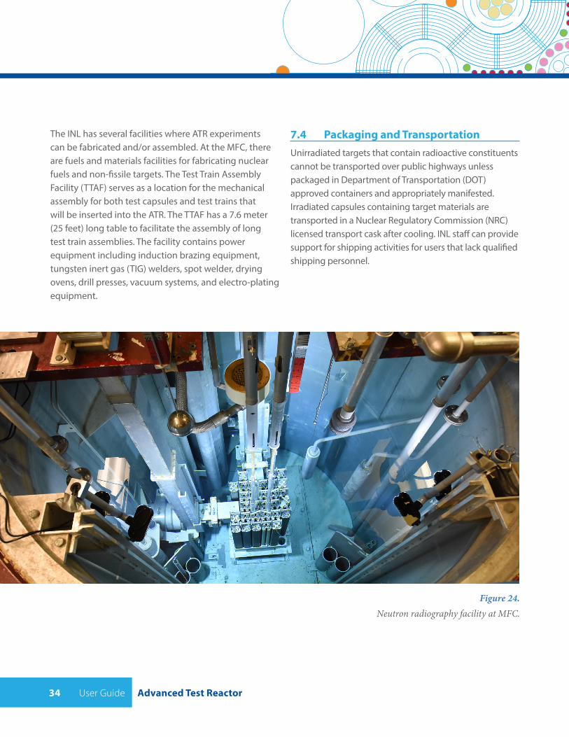
User Guide Advanced Test Reactor34
The INL has several facilities where ATR experiments can be fabricated and/or assembled. At the MFC, there are fuels and materials facilities for fabricating nuclear fuels and non-fissile targets. The Test Train Assembly Facility (TTAF) serves as a location for the mechanical assembly for both test capsules and test trains that will be inserted into the ATR. The TTAF has a 7.6 meter (25 feet) long table to facilitate the assembly of long test train assemblies. The facility contains power equipment including induction brazing equipment, tungsten inert gas (TIG) welders, spot welder, drying ovens, drill presses, vacuum systems, and electro-plating equipment.
Figure 24. Neutron radiography facility at MFC.
7.4 Packaging and TransportationUnirradiated targets that contain radioactive constituents cannot be transported over public highways unless packaged in Department of Transportation (DOT) approved containers and appropriately manifested. Irradiated capsules containing target materials are transported in a Nuclear Regulatory Commission (NRC) licensed transport cask after cooling. INL staff can provide support for shipping activities for users that lack qualified shipping personnel.
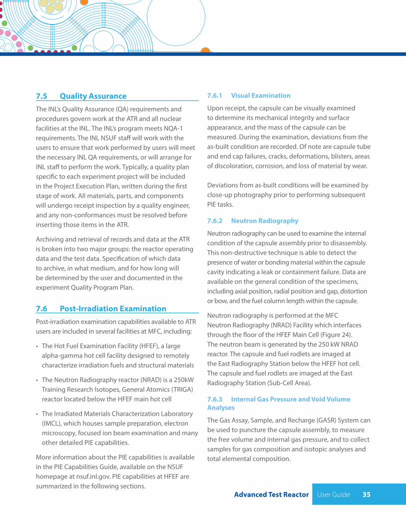
Advanced Test Reactor User Guide 35
7.5 Quality AssuranceThe INL’s Quality Assurance (QA) requirements and procedures govern work at the ATR and all nuclear facilities at the INL. The INL’s program meets NQA-1 requirements. The INL NSUF staff will work with the users to ensure that work performed by users will meet the necessary INL QA requirements, or will arrange for INL staff to perform the work. Typically, a quality plan specific to each experiment project will be included in the Project Execution Plan, written during the first stage of work. All materials, parts, and components will undergo receipt inspection by a quality engineer, and any non-conformances must be resolved before inserting those items in the ATR.
Archiving and retrieval of records and data at the ATR is broken into two major groups: the reactor operating data and the test data. Specification of which data to archive, in what medium, and for how long will be determined by the user and documented in the experiment Quality Program Plan.
7.6 Post-Irradiation ExaminationPost-irradiation examination capabilities available to ATR users are included in several facilities at MFC, including:
• The Hot Fuel Examination Facility (HFEF), a large alpha-gamma hot cell facility designed to remotely characterize irradiation fuels and structural materials
• The Neutron Radiography reactor (NRAD) is a 250kW Training Research Isotopes, General Atomics (TRIGA) reactor located below the HFEF main hot cell
• The Irradiated Materials Characterization Laboratory (IMCL), which houses sample preparation, electron microscopy, focused ion beam examination and many other detailed PIE capabilities.
More information about the PIE capabilities is available in the PIE Capabilities Guide, available on the NSUF homepage at nsuf.inl.gov. PIE capabilities at HFEF are summarized in the following sections.
7.6.1 Visual Examination
Upon receipt, the capsule can be visually examined to determine its mechanical integrity and surface appearance, and the mass of the capsule can be measured. During the examination, deviations from the as-built condition are recorded. Of note are capsule tube and end cap failures, cracks, deformations, blisters, areas of discoloration, corrosion, and loss of material by wear. Deviations from as-built conditions will be examined by close-up photography prior to performing subsequent PIE tasks.
7.6.2 Neutron Radiography
Neutron radiography can be used to examine the internal condition of the capsule assembly prior to disassembly. This non-destructive technique is able to detect the presence of water or bonding material within the capsule cavity indicating a leak or containment failure. Data are available on the general condition of the specimens, including axial position, radial position and gap, distortion or bow, and the fuel column length within the capsule.
Neutron radiography is performed at the MFC Neutron Radiography (NRAD) Facility which interfaces through the floor of the HFEF Main Cell (Figure 24). The neutron beam is generated by the 250 kW NRAD reactor. The capsule and fuel rodlets are imaged at the East Radiography Station below the HFEF hot cell. The capsule and fuel rodlets are imaged at the East Radiography Station (Sub-Cell Area).
7.6.3 Internal Gas Pressure and Void Volume Analyses
The Gas Assay, Sample, and Recharge (GASR) System can be used to puncture the capsule assembly, to measure the free volume and internal gas pressure, and to collect samples for gas composition and isotopic analyses and total elemental composition.
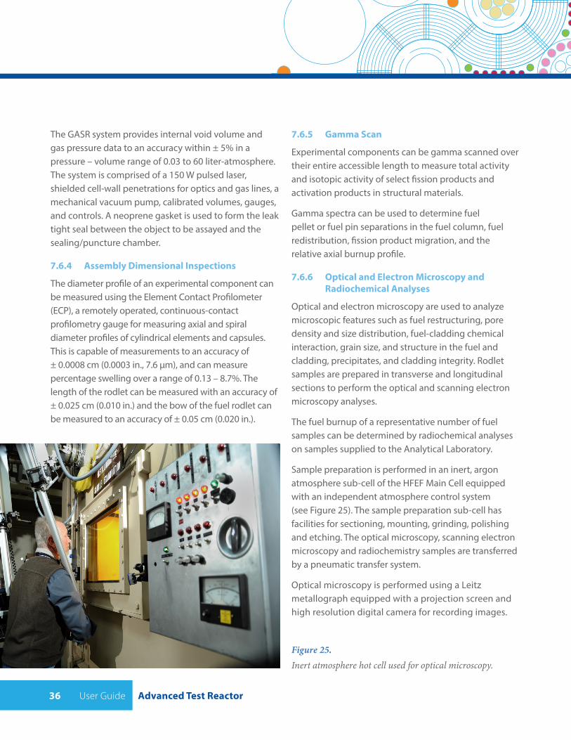
User Guide Advanced Test Reactor36
The GASR system provides internal void volume and gas pressure data to an accuracy within ± 5% in a pressure – volume range of 0.03 to 60 liter-atmosphere. The system is comprised of a 150 W pulsed laser, shielded cell-wall penetrations for optics and gas lines, a mechanical vacuum pump, calibrated volumes, gauges, and controls. A neoprene gasket is used to form the leak tight seal between the object to be assayed and the sealing/puncture chamber.
7.6.4 Assembly Dimensional Inspections
The diameter profile of an experimental component can be measured using the Element Contact Profilometer (ECP), a remotely operated, continuous-contact profilometry gauge for measuring axial and spiral diameter profiles of cylindrical elements and capsules. This is capable of measurements to an accuracy of ± 0.0008 cm (0.0003 in., 7.6 µm), and can measure percentage swelling over a range of 0.13 – 8.7%. The length of the rodlet can be measured with an accuracy of ± 0.025 cm (0.010 in.) and the bow of the fuel rodlet can be measured to an accuracy of ± 0.05 cm (0.020 in.).
Figure 25. Inert atmosphere hot cell used for optical microscopy.
7.6.5 Gamma Scan
Experimental components can be gamma scanned over their entire accessible length to measure total activity and isotopic activity of select fission products and activation products in structural materials.
Gamma spectra can be used to determine fuel pellet or fuel pin separations in the fuel column, fuel redistribution, fission product migration, and the relative axial burnup profile.
7.6.6 Optical and Electron Microscopy and Radiochemical Analyses
Optical and electron microscopy are used to analyze microscopic features such as fuel restructuring, pore density and size distribution, fuel-cladding chemical interaction, grain size, and structure in the fuel and cladding, precipitates, and cladding integrity. Rodlet samples are prepared in transverse and longitudinal sections to perform the optical and scanning electron microscopy analyses.
The fuel burnup of a representative number of fuel samples can be determined by radiochemical analyses on samples supplied to the Analytical Laboratory.
Sample preparation is performed in an inert, argon atmosphere sub-cell of the HFEF Main Cell equipped with an independent atmosphere control system (see Figure 25). The sample preparation sub-cell has facilities for sectioning, mounting, grinding, polishing and etching. The optical microscopy, scanning electron microscopy and radiochemistry samples are transferred by a pneumatic transfer system.
Optical microscopy is performed using a Leitz metallograph equipped with a projection screen and high resolution digital camera for recording images.
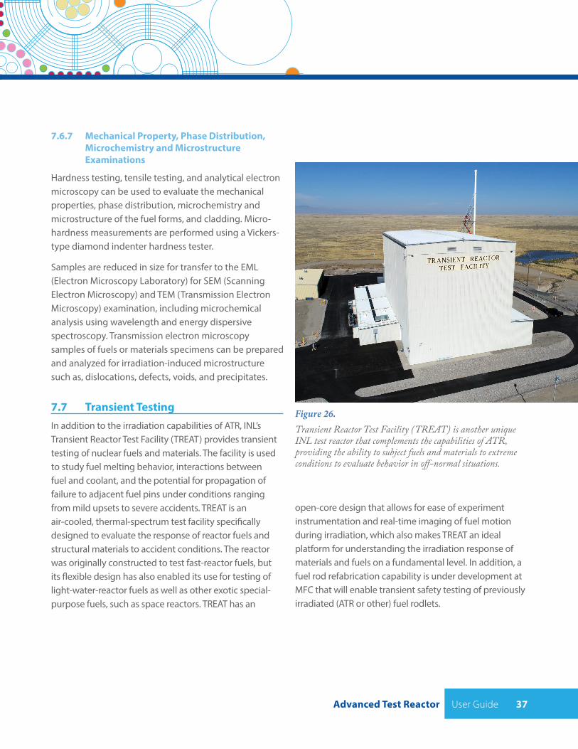
Advanced Test Reactor User Guide 37
7.6.7 Mechanical Property, Phase Distribution, Microchemistry and Microstructure Examinations
Hardness testing, tensile testing, and analytical electron microscopy can be used to evaluate the mechanical properties, phase distribution, microchemistry and microstructure of the fuel forms, and cladding. Micro-hardness measurements are performed using a Vickers-type diamond indenter hardness tester.
Samples are reduced in size for transfer to the EML (Electron Microscopy Laboratory) for SEM (Scanning Electron Microscopy) and TEM (Transmission Electron Microscopy) examination, including microchemical analysis using wavelength and energy dispersive spectroscopy. Transmission electron microscopy samples of fuels or materials specimens can be prepared and analyzed for irradiation-induced microstructure such as, dislocations, defects, voids, and precipitates.
7.7 Transient TestingIn addition to the irradiation capabilities of ATR, INL’s Transient Reactor Test Facility (TREAT) provides transient testing of nuclear fuels and materials. The facility is used to study fuel melting behavior, interactions between fuel and coolant, and the potential for propagation of failure to adjacent fuel pins under conditions ranging from mild upsets to severe accidents. TREAT is an air-cooled, thermal-spectrum test facility specifically designed to evaluate the response of reactor fuels and structural materials to accident conditions. The reactor was originally constructed to test fast-reactor fuels, but its flexible design has also enabled its use for testing of light-water-reactor fuels as well as other exotic special-purpose fuels, such as space reactors. TREAT has an
Figure 26. Transient Reactor Test Facility (TREAT) is another unique INL test reactor that complements the capabilities of ATR, providing the ability to subject fuels and materials to extreme conditions to evaluate behavior in off-normal situations.
open-core design that allows for ease of experiment instrumentation and real-time imaging of fuel motion during irradiation, which also makes TREAT an ideal platform for understanding the irradiation response of materials and fuels on a fundamental level. In addition, a fuel rod refabrication capability is under development at MFC that will enable transient safety testing of previously irradiated (ATR or other) fuel rodlets.
User Guide Advanced Test Reactor38
8 BEGIN YOUR JOURNEY
Prospective experimenters interested in ATR may contact INL’s Nuclear Fuels and Materials division at
For detailed questions about ATR and its requirements, contact the ATR User’s Working Group (UWG) at [email protected]. The UWG is responsible for evaluating, integrating, and approving plans and schedules for using ATR facilities and approving the test schedules detailed in the ATR Integrated Strategic Operational Plan (ISOP). The ISOP is updated regularly as operational considerations force the need to adjust schedules.
For industry developers of advanced reactors seeking ATR access through a Nuclear Energy voucher, contact the Gateway for Accelerated Innovation in Nuclear at [email protected] or visit gain.inl.gov.
For university researchers using ATR through the Nuclear Science User Facilities program, visit nsuf.inl.gov or email [email protected] for the latest information.
The National Reactor Innovation Center (NRIC) is a national DOE program charged with aiding developers committed to demonstrating ad-vanced reactors. Questions about assistance through NRIC can be sent to [email protected], or visit nric.inl.gov for more information.
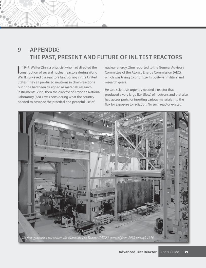
Advanced Test Reactor Users Guide 39
9 APPENDIX: THE PAST, PRESENT AND FUTURE OF INL TEST REACTORS
In 1947, Walter Zinn, a physicist who had directed the construction of several nuclear reactors during World
War II, surveyed the reactors functioning in the United States. They all produced neutrons in chain reactions but none had been designed as materials research instruments. Zinn, then the director of Argonne National Laboratory (ANL), was considering what the country needed to advance the practical and peaceful use of
nuclear energy. Zinn reported to the General Advisory Committee of the Atomic Energy Commission (AEC), which was trying to prioritize its post-war military and research goals.
He said scientists urgently needed a reactor that produced a very large flux (flow) of neutrons and that also had access ports for inserting various materials into the flux for exposure to radiation. No such reactor existed.
The first-generation test reactor, the Materials Test Reactor (MTR) operated from 1952 through 1970.
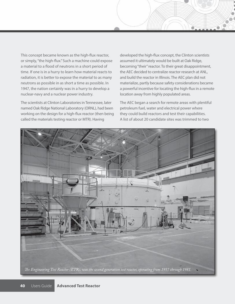
Users Guide Advanced Test Reactor40
This concept became known as the high-flux reactor, or simply, “the high-flux.” Such a machine could expose a material to a flood of neutrons in a short period of time. If one is in a hurry to learn how material reacts to radiation, it is better to expose the material to as many neutrons as possible in as short a time as possible. In 1947, the nation certainly was in a hurry to develop a nuclear-navy and a nuclear power industry.
The scientists at Clinton Laboratories in Tennessee, later named Oak Ridge National Laboratory (ORNL), had been working on the design for a high-flux reactor (then being called the materials testing reactor or MTR). Having
developed the high-flux concept, the Clinton scientists assumed it ultimately would be built at Oak Ridge, becoming “their” reactor. To their great disappointment, the AEC decided to centralize reactor research at ANL, and build the reactor in Illinois. The AEC plan did not materialize, partly because safety considerations became a powerful incentive for locating the high-flux in a remote location away from highly populated areas.
The AEC began a search for remote areas with plentiful petroleum fuel, water and electrical power where they could build reactors and test their capabilities. A list of about 20 candidate sites was trimmed to two
The Engineering Test Reactor (ETR), was the second generation test reactor, operating from 1957 through 1981.
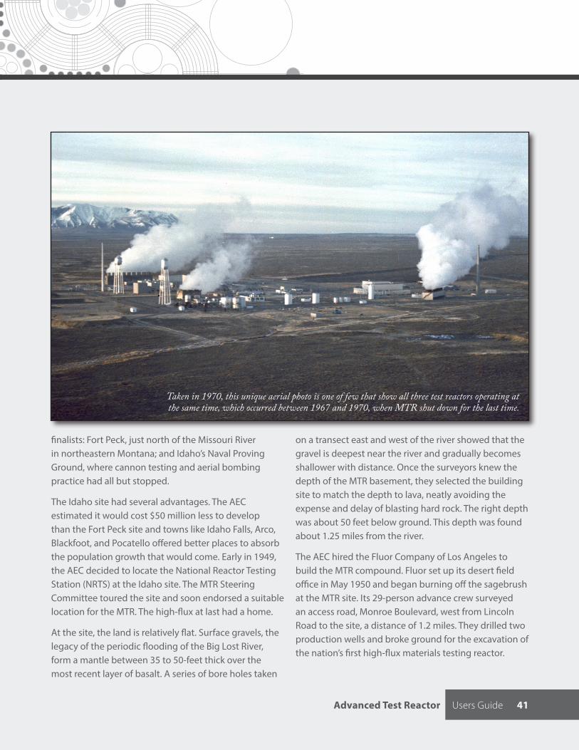
Advanced Test Reactor Users Guide 41
finalists: Fort Peck, just north of the Missouri River in northeastern Montana; and Idaho’s Naval Proving Ground, where cannon testing and aerial bombing practice had all but stopped.
The Idaho site had several advantages. The AEC estimated it would cost $50 million less to develop than the Fort Peck site and towns like Idaho Falls, Arco, Blackfoot, and Pocatello offered better places to absorb the population growth that would come. Early in 1949, the AEC decided to locate the National Reactor Testing Station (NRTS) at the Idaho site. The MTR Steering Committee toured the site and soon endorsed a suitable location for the MTR. The high-flux at last had a home.
At the site, the land is relatively flat. Surface gravels, the legacy of the periodic flooding of the Big Lost River, form a mantle between 35 to 50-feet thick over the most recent layer of basalt. A series of bore holes taken
on a transect east and west of the river showed that the gravel is deepest near the river and gradually becomes shallower with distance. Once the surveyors knew the depth of the MTR basement, they selected the building site to match the depth to lava, neatly avoiding the expense and delay of blasting hard rock. The right depth was about 50 feet below ground. This depth was found about 1.25 miles from the river.
The AEC hired the Fluor Company of Los Angeles to build the MTR compound. Fluor set up its desert field office in May 1950 and began burning off the sagebrush at the MTR site. Its 29-person advance crew surveyed an access road, Monroe Boulevard, west from Lincoln Road to the site, a distance of 1.2 miles. They drilled two production wells and broke ground for the excavation of the nation’s first high-flux materials testing reactor.
Taken in 1970, this unique aerial photo is one of few that show all three test reactors operating at the same time, which occurred between 1967 and 1970, when MTR shut down for the last time.
Users Guide Advanced Test Reactor42
The ultimate tribute to MTR’s success was that commercial and military interest rapidly grew beyond the MTR’s capabilities and called for a second high-flux reactor. The Engineering Test Reactor (ETR) went under construction in 1956 at the MTR site. The construction schedule was so accelerated that often construction had
At the time it entered service, ETR was the largest,
most advanced nuclear fuels and materials test
reactor in the United States at 175 MW.
to wait while drawings were drafted. The MTR site plan had considered the possibility of expansion, and the ETR reactor building was situated in a new quadrant south of the MTR. In the NRTS geographical coding system, this new section was numbered 532, to differentiate it from the MTR Area 531, a feature noticeable on the numbering of engineering drawings. (Later, the ATR was designated area 533.) With two high-flux reactors, the complex could no longer be called the MTR Area; it became the Test Reactor Area (TRA).
At a symposium dedicating the ETR in October 1957, one of the speakers said the difference between the MTR and the ETR was “that the materials testing reactor is more suitable for tests on small samples of materials and experiments which fall in the research classification while the engineering test reactor is able to irradiate much larger quantities of materials and is more suitable for experiments designed to provide engineering information and performance data.” At the time it entered service, ETR was the largest, most advanced nuclear fuels and materials test reactor in the United States at 175 MW.
In 1957 the Navy was emerging as a NRTS major customer. The Navy wanted a test reactor with more
precision, more space, and higher flux than the ETR could provide. It wanted a reactor able to test full scale fuel elements, which were getting larger and thicker. Also it wanted faster results, which meant having space in the reactor to run several tests at the same time and expose them to a very high flux. The Navy needed a unique reactor design offering many large test holes and operated with a consistent flux symmetry. Native ingenuity at NRTS from a young physicist named deBoisblanc envisioned an advanced reactor design fitting the Navy’s desires in 1959. Preliminary tests in the ETR critical facility proved the elegant design was viable.
In 1961 construction of the NRTS’ third high-flux reactor, the Advanced Test Reactor (ATR), began northwest of MTR. The reactor was the 47th reactor built at the NRTS and the 8th reactor at the TRA site. The construction project was the largest construction project in Idaho history at $40 million. ATR went critical in July 1967, after a substantial investment in designing and building the third-generation high flux reactor. The ATR increased the density of neutron flux to unprecedented levels (1 x 10¹⁵ thermal) and became the world’s premier test reactor for studying the effects of intense neutron and gamma radiation on reactor materials and fuels. With three operating high-flux test reactors, the TRA site was truly the center for nuclear research. In 2005 the area was renamed the Reactor Technologies Complex (RTC) and in 2008 the area became the ATR Complex.
In 2020, with the Department of Energy’s Offices of Nuclear Energy and the U.S. Navy’s need for irradiation space projected to growing well into the future, INL is evaluating options for extending ATR operations through the 2040 timeframe, in addition to what capabilities can be further enhanced through construction of a fourth generation test reactor at the ATR Complex.
Advanced Test Reactor User Guide 43
AcronymsAFCI Advanced Fuel Cycle Initiative
AGR Advanced Gas Reactor
AL Analytical Laboratory
ATR Advanced Test Reactor
ATRC ATR Critical Facility
DOE Department of Energy
DOE-ID Department of Energy Idaho Operations Office
DOT Department of Transportation
EML Electron Microscopy Laboratory
ESAP Experiment Safety Assurance Package
FY fiscal year
GASR gas assay, sample, and recharge
HFEF Hot Fuel Examination Facility
HSIS Hydraulic Shuttle Irradiation System
INL Idaho National Laboratory
ITP Irradiation Test Plan
IU irradiation unit
LANL Los Alamos National Laboratory
LWR Light Water Reactor
MFC Materials and Fuels Complex
NE Office of Nuclear Energy
NR Naval Reactors Program
NRAD neutron radiography reactor
NRC Nuclear Regulatory Commission
NSUF Nuclear Science User Facilities
ORNL Oak Ridge National Laboratory
PALM powered axial locator mechanism
PCS primary coolant system
PI principal investigator
PIE post-irradiation examination
PM project manager
QA quality assurance
R&D research and development
RERTR Reduced Enrichment for Research and Test Reactors
SEM scanning electron microscopy
SORC Safety and Operations Review Committee
TEM transmission electron microscopy
TFR technical and functional requirements
TIG tungsten inert gas
TREAT Transient Reactor Test Facility
TRIGA Training Research Isotope General Atomics
TTAF test train assembly facility
USQ unreviewed safety question
UWG User’s Working Group
V&V verified and validated
20-50097
20-50097
Advanced Test Reactor
User Guide
Related Documents