Advanced Test Equipment Rentals www.atecorp.com 800-404-ATEC (2832) ® E s t a blishe d 1 9 8 1

Welcome message from author
This document is posted to help you gain knowledge. Please leave a comment to let me know what you think about it! Share it to your friends and learn new things together.
Transcript

Advanced Test Equipment Rentalswww.atecorp.com 800-404-ATEC (2832)
®
Established 1981
SPECTRACOM CORPORATION 320 N. Washington Street
Rochester, N e w York 14625
WARRANTY REGISTRATION
Dear Customer ,
Spectracorn occasionally contacts customers regarding our products. W e must know t o whom we should send manual updates, change not i ce s , and n e w p r o d u c t information. Because people some times change j o b a s s i g n m e n t s , we request d e p a r t m e n t , m a i l station, and t i t l e infor- mation t o ensure that correspondence in future years will reach e i ther t h e u s e r of our produc t s o r 11 i sJher s u p e r v i s o r . In f i 1 ling out t h e registrat i o n , p l e a s e use t h e t i t lelmail s t a t i o n / d e p a r t r n e n t of the supervisor most interested in keeping the equipment and its dacumen- t a t ion up-to-date. Thank you.
E!ame Title
Department Mail Stop
Company Model Murnber
Address Ser ia l No.
City Date installed
S t a t e Zip
Phone Ext . Remarks : (Problems , Suggen ions , e t c .I

CERTIFICATE OF TRACEABILITY
SPECTRACOM CORPORATION hereby c e r t i f i e s t h a t i t s Model 81 63 N8S Frequency Standard Receiver provides d i r e c t traceability t o the National Bureau o f Standards re fe rence frequency as t r a n s m i t t e d by s t a t i o n WWVB i n Fort C o l l i n s , Colorado, w i t h c a r r i e r frequency o f 60 KHz.
Automatic v e r i f i c a t i o n i s provided by the s t a t i o n - i d e n t i f y i n g phase s h i f t o f 45' t h a t appears on the c a r r i e r s ignal a t 10 minutes a f t e r each hour, re turn ing to normal f i ve minutes l a t e r . T h i s phase s h i f t appears i n the readout as an o f f s e t o f about 2.1 micro- seconds on the front panel meter and on the s t r i p chart recorder t race .
When proper ly i n s t a l l e d and maintained, the Model 8163 provides measurement accuracy and resolution as published i n t he equipment's instruct ion manual.
SPECTWCOM CORPORATION

WARRANTY
Spectracorn c o r p o r a t i o n w a r r a n t s t o the o r i g i n a l purchaser each new ins t rumen t t o be f r e e f rom d e f e c t s i n m a t e r i a l and workmanship f o r a p e r i o d o f one y e a r a f t e r sh ipment . Repa i r o r rep lacemen t , a t our o p t i o n , w i l l be m a d e when our e x a m i n a t i o n i n d i c a t e s t h a t defects a r e due to w o r k m a rr s h i p o r m a t e r i a l s . E l e c t r o n tubes , b a t t e r i e s , f u s e s , and lamps t h a t have g i v e n normal service a r e e x c l u d e d from war ran ty coverage A1 l war ran ty r e t u r n s must f i r s t be a u t h o r i z e d i n w r i t i n g b y t h e f a c t o r y .
T h i s w a r r a n t y d o e 5 not app ly t o any o f our p roduc ts wh ich have been repa i red o r a1 t e r P d b y persons no t a u t h o r i z e d by Spect racom Corp . or not i n accordance w i t h i n s t r u c t i o n s f u r n i s h e d by us . I f the i n s t r u - ment i s defect i v e a s a r e s u l t o f misuse, improper r e p a i r , or abnor - mal cond i t i ons o r o p e r a t i o n s , or i f any s e r i a l number or seal has been removed or a 1 t e r e d , the w a r r a n t y i s v o i d and r e p a i r s w i I 1 be b i 1 led a t c o s t .
T h i s w a r r a n t y i s t n l i e u o f a l l otherobligationsorliabilities expressed o r i m p 1 i e d and Spectracom Corp. n e i t h e r assumes n o r a u t h o r i z e s any p e r s o n t o assume for them, any other 1 i a b i l i t y i n cotinection w i t h s a l e s o f i t s p r o d u c t s .
AND MA l NTENANC E -
Inst rumen ts shoul d be r e t u r n e d o n l y upon pr io r w r i t t e n au tho r i za t i on from Spectracorn C o r p . or i t s a u t h o r i z e d s a l e s and s e r v i c e represen- t a t i v e . W a r r a n t y r e p a i r w i l l b e m a d e u p o n w r i t t e n request . Please provide t h e f o l l ow i ng i n f o r m a t i o n i n o r d e r t o enab le us t o s e r v e you e f f i c i e n t l y :
1 . Model Number and type 2 . S e r i a l Number 3. Desc r i p t i on o f t rouble 4 . Cond i t ions and hours of use
Upon receipt o f t h i s i n f o r m a t ion our service depar tment w i 1 l s e n d you service d a t a o r s h i p p i n g i n s t r u c t i o n s . T r a n s p o r t a t ion t o t h e fac tory i s to b e p r e p a i d by pu rchaser .
For a s s i s t a n c e c o r~ t a c t your n e a r e s t Spect racom s a l e s r e p r e s e n t a t i ve .
i i i

TABLE OF CONTERTS -- PAGE - SECTION 1 INSTALLATION . . . . . . . . . . . . . . . . . . . . . 1-0
1.0 I ntroduct ian 2 .0 Unpacking 3.0 Reshipment 4.0 Antenna Location 5.0 Antenna l n s t a l l a t i o n 6.0 TM- 500 Y a i n f rame
S E C T I O N 2 OP ERAT I ON. . . . . . . . . . . . . . . . . . . . . . . 2- 0
l n t roduct i on I n i t i a l Turn-On Measuring Frequency WWVB I d e n t i f i c a t i o n Sample Frequency Error Ca 1 c u l a t ions and Traces F r o n t Panel Controls and indicators l nterna l S w i tches TV- 500 Connector Specifications
SECTION 3 OPT1 ONS AND A C C E S S O R I E S . . . . . . . . . . . . . . . . 3-0 1.0 Option 05 - Time Code Output 2.0 Model 8206 Loop Antenna 3 . 0 Model 8211 A n t e n n a Mount 4.0 Model 8207 LinePreamplifier - 60 KHz 5.0 Model 8210 Chart Recorder
SECTION 4 P R l NCl PLES OF OPERATION. . . . . . . . . . . . . . . . 4-0
1.0 I n t r o d u c t i o n 2 .0 Block Diagram 3.0 S i g n a l S t r e n g t h Measurement 4.0 RF A r n p l i f i e r A l , P/N 001100 5.0 Receiver Assembly A2, P/N 008200
SECTION 5 MA I NTEN,4tiCE. . . . . . . . . . . . . . . . . . . . . . 5-0
1 . O l n t r o d u c t i o n 2,O C a l i b r a t i o n o f WWVB Receiver 3 . 0 T e s t Equipment 4.0 T e s t S e t - V p 5.0 T e s t Procedure 6 . 0 Model 8 2 0 7 P r e a r n p I i f i e r ~ l i g n m e n t
SECTION 6 REPLACEABLE PARTS L 1 ST . . . . . . . . . . . . . . . . 6-0

L l ST OF I LLUSTRAT I O N 5
F i g u r e 1 - 1 G r e a t C i r c l e Map Centered on Ft. Col l i n s , Colorado
1-2 Antenna Hount Model 8211
1 - 3 Measured F i e l d l n t e n s i t y Contours: WWVB @ 13 KW ERP
F i g u r e 2-1
2- 2
2-3
2- 4
2- 5 2- 6
2-7
2- 8
2- 9
Trace 1 ( ~ r e q u e n c y Error i s ~ i g h )
Trace 2 ( ~ r e ~ u e n c y E r r o r i s LOW)
Trace 3 ( D i u r n a l s h i f t )
Trace 4 (Overnight S i g n a l Degradat ion G Phase S h i f t )
Trace 5 (~ornentary ~n lock)
Trace 6 (Noisy Oay)
Trace 7 (Sun flares)
Error C a l c u l a t i o n Char t
T!l-500 Connector P i n Assignments
F i g u r e 3-1 T ime Code Format - O p t i o n 35
3 - 2 Antenna Mount Mode! 8211
Figure 4-1 8163 WWVB Receiver Block Diagram
4-2 RF Amp1 i f i e r , A l , Schematic
4-3 RF Amplifier, Al, Assembly D r a w i n g
4-4 Receiver, A 2 , Schematic, Sheet 1
4 - 5 Receiver, A2 , Schematic, Sheet 2
4-6 Receiver, d2, Schematic, Sheet 3 4-7 Receiver, A 2 , Assembly 3rawing
Figure 5-1 T e s t Set-Up
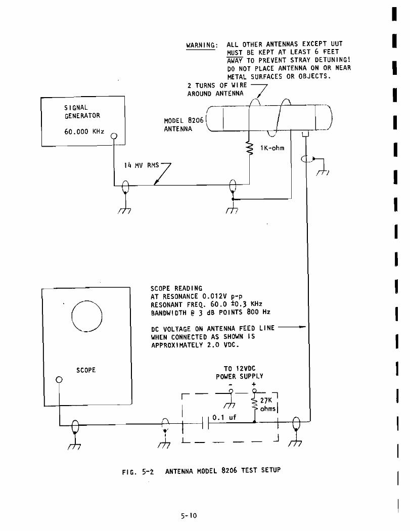
5 - 2 Antenna Yodel 8206 Test Set-up
5-3 Hodel 8207 P r e a m p l i f i e r Alignment
TABLES
T a b l e 5-1 RecommendedTestEquiprnent
PAGE -

SECTION 1
I NSTALLATI ON
1 , a Introduction
2 , 0 Unpacking
3 - Q Reshipment
4 , O Antenna Location
5 - O Antenna Installation
6 , O TM-500Mainframe
1.0 l NTRODUCT l ON
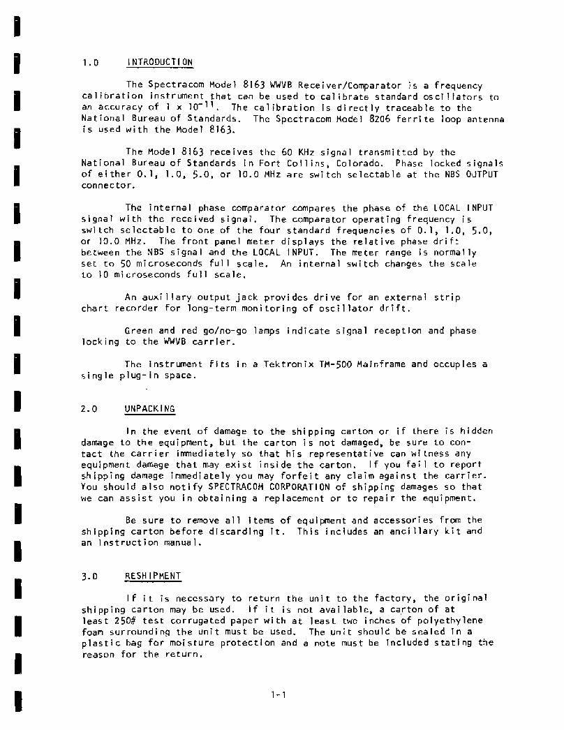
The Spectracom Mode 1 81 63 WWVB Recei ver/Cornparator i s a frequency cal i b r a t i o n instrument tha t can be used t o c a l i b r a t e standard osci 1 I a t o r s to an accuracy of 1 x IO-". The c a l i b r a t i o n i s d i r e c t l y t r a c e a b l e t o t h e Nat ional Bureau of Standards. The Spectracom Model 8206 f e r r i t e loop antenna i s used w i t h the Model 8163.
The Model 8163 receives t h e 60 KHz s ignal t r a n s m i t t e d by the Nat iona l Bureau o f Standards i n For t Co l l i n s , Colorado. Phase locked signals of e i t h e r 0.1, 1 . 0 , 5.0, or 10.0 MHz a r e swi tch selectable a t the NBS OUTPUT connector.
The i n t e r n a l phase comparator compares the phase of the LOCAL l NPUT s i gna l w i t h the rece i ved s igna l . The comparator operat ing frequency i s swi tch se lec tab le t o one of the four standard frequencies o f 0.1, 1 .0 , 5 .0 , or 10.0 MHz. The f r o n t panel meter d isp lays the r e l a t i v e phase d r i f t between the NBS s igna l and the LOCAL INPUT. The meter range i s normally set t o 50 microseconds f u l l scale. An in te rna l swi tch changes the s c a l e t o 10 microseconds f u l l sca le .
An auxi l l a r y output jack prov ides d r i v e f o r an ex te rna l s t r i p char t recorder for long-term moni to r ing o f o s c i l l a t o r d r i f t .
Green and red go/no-go lamps i nd i ca te s igna l recept ion and phase l o c k i n g t o t he WWVB c a r r i e r .
The instrument f i t s i n a Tek t ron ix TM-500 Mainframe and occupies a s i n g l e p l u g - i n space.
2.0 UNPACK l NG
I n the event o f damage t o the shipping carton or i f there i s hidden damage t o t h e equipment, b u t the carton i s no t damaged, be s u r e t o con- t a c t the c a r r i e r immedia te ly so that h i s representa t i ve can w i t n e s s any equipment damage t h a t may e x i s t i n s i d e the carton. I f you f a i l t o repor t sh ipp ing damage immediately you may f o r f e i t any c la im against the c a r r i e r . You should a l s o notify SPECTRACOH CORPORATION of shipping damages s o t ha t we can a s s i s t you i n ob ta in ing a replacement or t o r e p a i r the equipment.
Be s u r e t o remove a1 1 i terns of equi pment and accessori es from t h e shipping car ton b e f o r e d i sca rd i ng i t . This inc ludes an a n c i l l a r y k i t and an i ns t r u c t i on rnanua 1.
3 .0 RESH l PMENT
I f i t i s necessary to r e t u r n t h e u n i t t o t h e factory , the o r i g i n a l sh ipping car ton may be used. I f i t i s not avai lab le, a ca,rton o f a t l e a s t 2506 t e s t c o r r u g a t e d paper w i t h a t least two inches o f polyethylene foam s u r r o u n d i n g t h e u n i t must be used. The u n i t should be sealed i n a p l a s t i c bag for moisture p r o t e c t i o n and a note must be inc luded s t a t i n g the reason for the re tu rn .

4.0 ANTENNA LOCATI ON
The antenna shou ld be mounted a m i n i m u m o f 25 f e e t f rom t h e r e c e i v e r t o p reven t r e g e n e r a t i o n . The antenna MUST NOT be p o s i t i o n e d n e x t t o t he r e c e i v e r o r on top<o f i t , I f I t i s , r e s u l t s o b t a i n e d w i t h the equipment a r e meaningless even though t h e green lock 1 amp on t h e r e c e i v e r f r o n t pane l may be l i t .
The antenna must be a t l e a s t three fee t from any s t e e l beams, roof decking, p i p e s , etc., as metal w i l l detune t h e antenna and can cause as much a5 20 dB d e g r a d a t i o n o f the s i g n a l - t o - n o i s e r a t i o . The antenna m u s t n o t be mounted under a meta l roof o r i n s i d e a b u i l d i n g w i t h heavy s t e e l s t r u c t u r a l suppor ts , as these shield the antenna f r o m t h e s i g n a l . Roof tops are generally good i f a c l e a r s h o t t oward For t C o l l i n s i s a v a i l a b l e w i t h o u t be ing blocked by a l a r g e s t e e l s t r u c t u r e . A t t i c s are i d e a l s i tes i f the r o o f and r a f t e r s a r e not m e t a l l i c . The s i g n a l - t o - n o i s e r a t i o w i l l be o p t i m i z e d i f t h e antenna i s l o c a t e d as f a r as p o s s i b l e f rom local RF noise sources such as l a r g e e l e c t r i c motors , power l i n e s , o s c i l l o s c o p e s , TV s e t s , or fluorescent or neon lamps t ha t b l i nk or s p u t t e r on and o f f , Any equipment c o n t a i n i n g a s w i t c h i n g pmer supp ly i s a p r o b a b l e cause o f i n t e r f e r e n c e .
ANTENNA l NSTALLAT l ON
The antenna shou ld be mounted where i t w i l l n o t be d i s t u r b e d , supper ted by a non-me ta l 1 i c p i pe such as one- i n c h PVC w a t e r p i pe. Hol d i ng the antenna two or t h r e e f e e t o f f t h e ground o r r o o f t o p i s adequate i n most cases. The t u b u l a r hous ing m u s t be p o s i t i o n e d b r o a d s i d e t o Fo r t C o l l i n s , Colorado, where the t ransmi t te r i s located (see F i g u r e s 1 - 1 and 1-2) , and h o r i z o n t a l t o t h e ground, t o a l l o w maximum s i g n a l r e c e p t i o n . No s i g n a l w i l l be rece ived i f the tube p o i n t s d i r e c t l y toward the t r a n s m i t t e r s i t e , as t h e antenna p a t t e r n nu1 l s are l o c a t e d o f f the ends o f the tube. The antenna p o s i t i o n may be o p t i m i z e d using the s i g n a l s t r e n g t h measurement d e s c r i b e d i n the O p e r a t i o n Sect ion o f t h i s manual.
When the 1 ead- i n coax ia l c a b l e ( R G - ~ ~ / u i s recommended) i s connected from t h e Bt4C connec to r on the antenna to t he B N C c o n n e c t o r on the r e c e i v e r the system i s ready for use, i f the antenna has been i n s t a l l e d and aimed p r o p e r l y . The antenna has a b u i l t - i n p r e a m p l i f i e r i n s i d e i t s h o u s i n g t h a t r e c e i v e s i t s DC o p e r a t i n g v o l t a g e through the coaxia l caibe, t h e r e - fore both the center conductor and the s h i e l d o f t h e cable must be con- t inuous from t h e antenna t o the r e c e i v e r . A short c i r c u i t i n t h i s l i n e w i l l not harm the equipment as the power supp ly i s adequa te l y p r o t e c t e d .
6 . 0 TH-500 MAINFRAME
The Hodel 8163 f i t s i n t o a s i n g l e p l u g - i n space i n a T e k t r o n i x TM-500 Mainframe.

0 - 4m 6.000 STAT. # ILES I.-
TO A I M ANTENNA AT FORT COLLINS, COLORADO, DETERMINE COMPASS HEADING FROM T H I S MAP.
D r a w a s t r a i g h t f i n e f r o m the rece iver location t h r o u g h Fort Collins, Colo. at t h e center o f the map. Cont inue until the l i n e i n t e r s e c t s the ou te r r i n g . The po in t a t which the l i n e i n t e r s e c t s the outer r i n g i n d i c a t e s t h e compass heading f o r Fort Col I ins from your location.
F I G . 1 - 1 GREAT CIRCLE MAP CENTERED ON FORT C O L L I N S , COLORADO

SECTION 2
8 16 3
OPE3ATI ON
I n t roduc t i on
I n i t i a l Turn-On
Measuring Frequency
WUVB Identification
Sample Frequency Error Calculations and Traces
Front Panel Con t rols and I nd i cators
Internal S w i t c h e s
TM-500 Connector
Specifi cat ions

T h i s sect io- d e s c r i b e s how to use the Model 8163 t o cmpa re standard o s c i l l a t o r 7 t-- equencies w i h the N a t i o n a l Bureau o f Standards WWVB s i g n a l . A c c u r a c i e s r f parts i n l o4 a r e e a s i l y ob ta ined over a measurement t ime o f a few hours. A c c u r a c i e s o f p a r t s i n 1011 are p o s s i b l e i f t h e measurement t i m e i s F x t e n d s d to 8 to 2 4 hours.
2.0 I N I T I A L T U R N - ON
A f t e r t h e r-- c e i v e r has been i n s t a l l e d i n the TM-500 Hainfrsme and t h e antenna inst- 3 1 e d and o r i en ted , connect the antenna t o the ANTENNA i n p u t c o n n e c l o r on the f r o n t pane l and t u r n the TM-500 power swi tch on. the gree-m LQCK lamp w i l l come on w i t h i n one minute . I f the r e d UNLOCK 1 i g h t stab-- s I i t, i n s u f f i c i e n t s i g n a l i s be i ng r e c e i v e d p r o b a b l y due to impr- p e r antenna p l a c i n g or a l ignment .
Connect t h e 1 0 c a l s i g n a l That you wish to c a l i b r a t e t o the LOCAL INPUT connector . De-D r e s s the FREQUENCY button corresponding t o the input frequency be ing comp- d . The f requencies t h a t may b e compared are 0.1 MHz, 1.0 MHz, 5.0 MHz, an.- 10.0 MHz.
Changes i n T We phase r e l a t i o n s h i p between t h e local i npu t s i g n a l and t he reference s i -3 -a1 show up as meter movement. I f t he meter i s p e r f e c t l y c o n s t a n t , f i e r e i s zero d r i f t i r ! the phase r e l a t i o n s h i p and the local signal i s - xactly on frequency. The r a t e a t which the meter moves measures the f r e q u e n c y er ror .
A PHASE S H I FT E N C Y E R R O R =
For examp 1 L- - i f i t takes 50 seconds f o r the meter t o deflect 50 m i croseconds ( f u l 3 s c a l e ) , then the frequency error o f the local s i g n a l i s
- 6 F R E Q I ' E N C Y ERROR = 50 x 10 sec
50 sec
I f the met- r d e f l e c t s l e f t to r i g h t , then t h e local i nput f requency i s h i g h e r han the NBS reference. I f t h e Tocal i n p u t i s lower than the refe- - 3 n c e , t h e n the m e t e r w i l l d e f l e c t f rom r i g h t t o l e f t .
The s c a l e m a y be changed from 50 microsecond f u l l s c a l e t o 10 microsecond f u l l s c a l e b y a s w i t c h i n s i d e the u n i t . Normal ly t h e swi tch i s l e f t i n t 50 m i crosecond f u l 1 s c a l e pos i t i o n .
I f you a r e a d j u s t i n g your l o c a l o s c i l l a t o r , s e t i t so the meter i s no t moving. The l o r - r s e r t h e phase d r i f t i s monitored, the greater p rec i s i on o f the c a l i b r a t i o n . For observa t ions over periods of hours or days, a 0-1 ma char t r e c o r d r should be connected to the AUX OUTPUT. The Spectracom Model 8210 Char t R e - o r d e r or e q u i v a l e n t i s recommended.

When the local frequency i s i n e r r o r by a l a r g e amount, the phase read ing may be changing too r a p i d l y for t h e meter t o follow. I n t h i s case, the f r o n t pane 1 AUX OUTPUT o f t he phase comparator may be v i ewed w i t h a n osci 1 loscope. A d j u s t your l o c a l o s c i l l a t o r 50 t he f requency o f t h i s sawtooth s i gna 1 i s as low as poss i b l e , then use the meter when i t i s mov ing more s l o w l y .
4 . 0 WWVB IDENTI F l CATION
WWVB i d e n t i f i e s i t s e l f by advancing i t s c a r r i e r phase 45' a t 10 m inu tes a f t e r every hour and r e t u r n i n g the normal phase a t 15 minutes a f t e r t h e hour. These phase changes w i l I show up as me te r d e f l e c t i o n of 2 microseconds.
5 .0 SAMP t E FREQYENCY E R R O R CALCULATI ON AND SAMPLE TRACES
T h i s s e c t i o n desc r i bes a f requency e r r o r c a l c u l a t i o n u s i n g a c h a r t recorder connected t o t h e A U X O'JTPUT. T y p i c a l s t r i p c h a r t r e c o r d i n g s t h a t show t he d i u r n a l s h i f t , a n o i s y day t r a c e , and sun f 1are.j a r e d i scussed .
F i g u r e 2- 1 TRACE 1 shows t h a t t h e frequency o f t he o s c i 1 l a t o r under t e s t i s h i g h w i t h r e s p e c t t o NBS. The f requency e r r o r is c a l c u l a t e d below:
A t FREQUENCY ERROR = - T
- ~1 x 10⁻⁶ sec - 3600 5ec
T h i s c a l c u l a t i o n may be made mental l y by no t ing t he phase d r i f t i n microseconds t h a t occurs i n one hour and i v i d i n g i t b y 3 . 6 t o o b t a i n 5' the frequency e r r o r expressed i n p a r t s i n 10 .
F i g u r e 2 -2 TRACE 2 shows an o s c i l l a t o r which d r i f t e d low i n f requency b y a l m o s t 1 x 10⁻⁹ i n a 9-hour period. Note the 2-microsecond phase s h i f t t h a t occurs once per hour. They i d e n t i f y the s i gna l b e i n g r e c e i v e d as WWVB .
F i g u r e 2-3 TRACE 3 i s a 24-hour t r a c e showing t he d i u r n a l s h i f t and some s i g n a l degradat ion d u r i n g the n i g h t . A f t e r s u n r i s e the t r a c e shows t he o s c i l l a t o r e r r o r t o be only a f e w p a r t s i n 1 0 - 1 ' .
F i g u r e 2-4 TRACE 4 i l l u s t r a t e s o v e r n i g h t s i g n a l degradation and phase s h i f t caused by sunset and sunr ise . The d i u r n a l phase s h i f t w i l l v a r y w i t h geographic l o c a t i o n and w i t h t i m e o f year.
F i g u r e 2 -5 TRACE 5 shows a momentary un lock c o n d i t i o n due t o n o i s e b u r s t s , s i g n a l f a d i n g or paor antenna l oca t i on . When r e c e i v e r phase lock i s re-establ ished, the trace s t a r t s a t a new posi t i o n on the s c a l e . Long-
term measurement i s no t upset by t h i s o f f s e t because the o v e r a l l s lope o f the l ine i s s t i 1 1 eas i l y determi ned.
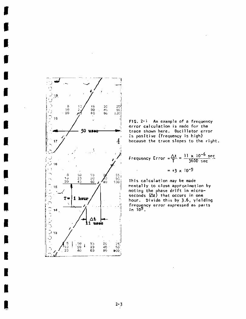
FIG. 2 - 1 An example of a frequency error calculation i s made for the trace shown here. Oscillator error i s positive (frequency i s high) because the trace slopes to the r i g h t .
~t I I x 10-6 sec Frequency Error = - = -- T 3600 sec
T h i s calculation may be made mentally t o close approximat ion by noting the phase d r i f t i n micro- seconds &) that occurs i n one hour. D i v i d e t h i s by 3 .6 , yielding frequency e r ro r expressed as par ts i n 109.

FIG. 2 - 2 TRACE 2 shows an osci l la tor which drifted low i n frequency by a l m s t 1 x 10⁻⁹ i n a 9-hour period.
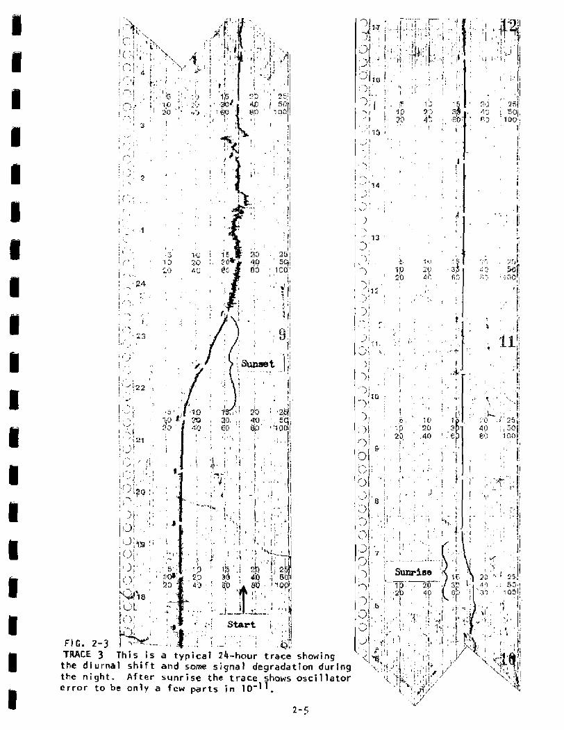
FIG. 2-3 TRACE 3 the d lurna the n i g h t . er ror t o b
T h i s i s a typical 24-hour trace showing \
1 s h i f t and some signal degradation during A f t e r sunrise the trace shows oscillator
e o n l y a few p a r t s i n 10-1'.
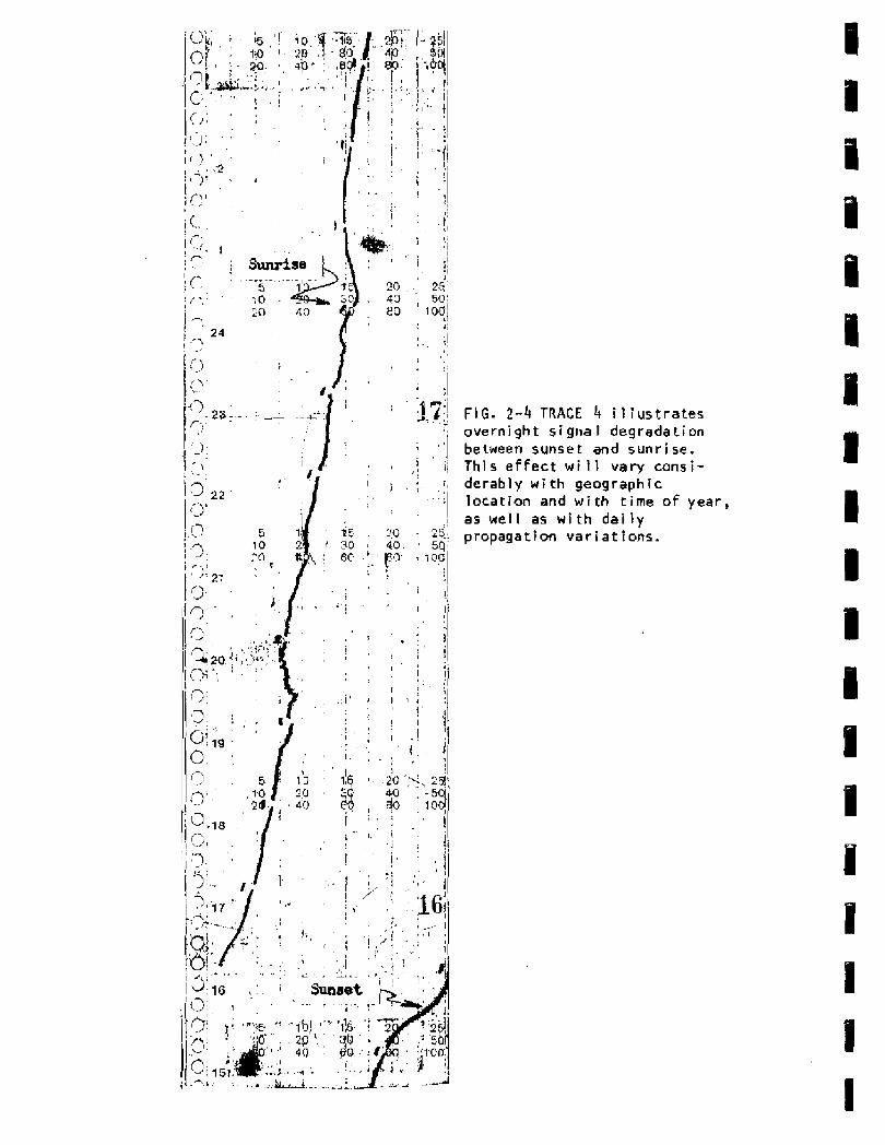
FIG. 2 -4 TRACE 4 illustrates overnight signal degradation be tween sunset and s u n r i se. f h l s ef fect w i 11 vary cansi- derably w i t h geographic location and with time o f year , as well as w i t h d a i l y propagation variations.
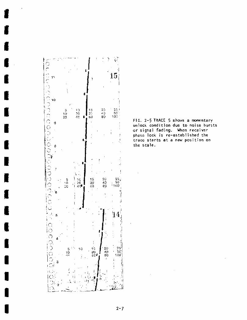
FI G. 2-5 TRACE 5 shows a momentary unlock condi t ion due to noise bursts or s i g n a l fading. When receiver phase lock i s re-es tab l i shed t h e t r ace s t a r t s a t a new p o s i t i o n on the scale.
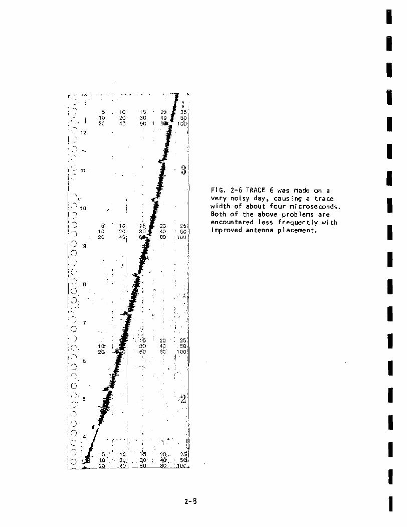
FI G . 2-6 f RACE 6 was made on a very noisy day, causing a trace w i d t h of about four microseconds. Both o f t h e above problems are encountered less f requent ly w i t h i mp roved antenna p l acemen t .

,
1 / - ,
, a n
Sun F lare i . .
--. .
--"-- --
1
C: -- -. . -- - - 1 -1 I
I j
I I :
Sun Flare I I
'I -w-m- -...-r-.mnl! I \
,- i i i
' I !
:!- 13 i - 8
1 / 0 1 I I
' j '--I
C 1 i . L ' . .
11
i . -- I
! I
5
20 , c ' s . . ,
: C
- \
FIG. 2 - 7 TRACE 7 was on a day w i t h frequent f lares .
made 5 un

F igu re 2-6 TRAIE 6 was made on a very n o i s y day, causi ng a t r a c e w i d t h o f about 4 microseconds.
F igure 2-7 TRACE 7 was made dur ing an a c t i v e sun f l a r e per iod.
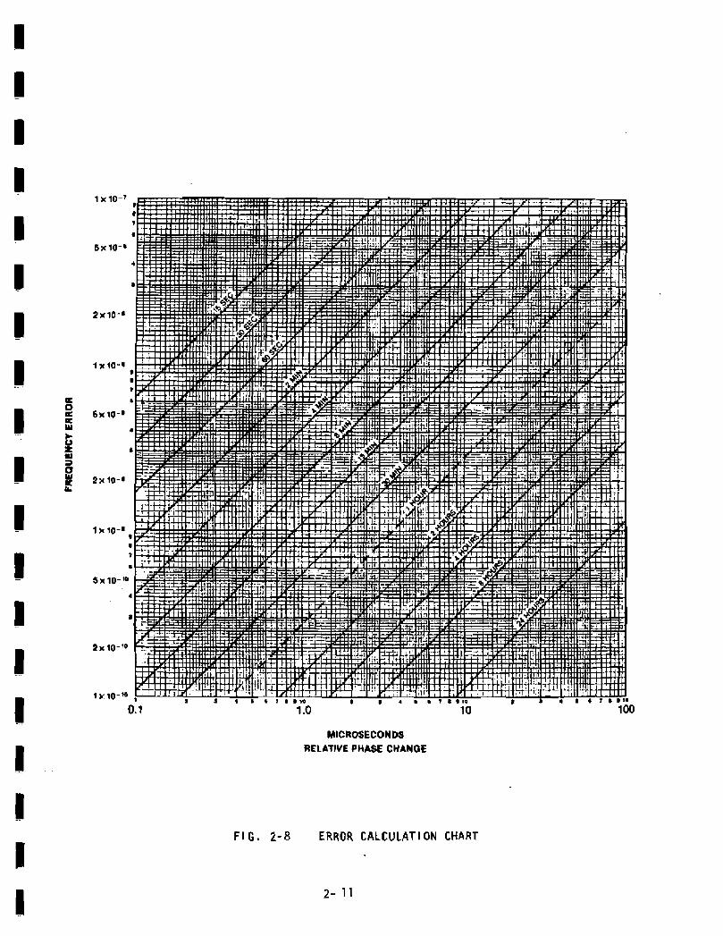
The ERROR CALCULATl ON CHART i n Fi gure 2-8 can be used t o f i n d t h e frequency e r r o r as a function o f phase change and t ime.
6.0 FRONT PANEL CONTROLS AND l NDl CATORS
Phase Comparison Mete r : Ncrmal readout i s i n microseconds o f Relative Time, 0-10 or 0-50, se l ec ted by i n t e r n a l s w i t c h A251 ( a c c e s s i b l e a f t e r removing r i g h t s i d e cover- ) . Fo r d i a g n o s t i c purposes, t h e me te r may be s w i tched to read VCO lock vol tage, by i n t e r n a l s w i tch A 2 5 2 ( located below ~ 2 ~ 1 ) .
Antenna Connector: For use o n l y d i t h Model 8206 Loop Antenna or Model 8207 Antenna Preamplifier.
Aux O u t p u t : For use w i t h external 0- 1 ma chart recorder, for long term phase compar i sons . Ful l s c a l e c a l i b r a t i o n provided by i n t e r n a l cont ro l ~ 2 ~ 8 0 (ground A2TP7, located above A2S2 , w h i i e ad jus t i ng ~ 2 ~ 8 0 ) .
HBS Output Connector: Provides an ou tpu t frequency, as selected by the Frequency push-huttons, p h a s e locked t o the NBS c a r r i e r .
Local I nput : Phase Comparator input, 100 mV nin., 10 V P-P max. F r ~ q u z n c y should be that selected 3y the Frequency Push-but tons.
Lock/Unlock L E D ' S : I n d i c a t e s u f f i c i e n t signal and proper 3hase lock t o WWVB. NBS Output and Local Input should not be used when r e d UFILOCK LED i 5 l i t , as i npu t s i g n a l i s de fec t i ve , or absent .
INTERNAL SWITCHES
There are three i n t e r n a l slide switches:
A/P Switch: T h i s switch i s located on the RF Amplifier board ( t he smal l e t o f the two boards) . I f the sw i tch i s i n the A (antenna) pos i t ion , +12V i s fed to l h e arltenna through a 27K s e r i e s l i m i t i n g r e s i s t o r . I f the s w i t c h i s i n the P ( p r e a m p l i f i e r ) p o s i t i q n , +12V i s f e d out the antenna connector through a 5.6K s e r i e s l i m i t i n g resistor. The s w i ~ c h 3hould b e i n the A pasi t i on u n l e s s the Model 8207 L i ne Pre- a m p l i f i e r i s be ing used. The switch i s set at the f a c t o r y to A.
50/10 Swi tch : T h i s s w i t c h i s l n c a t e d on the Receiver board. I n the 50 p o s i t i o n t h e meter full scale deflection represents a 50-microsecond phase d r i f t between t h e l oca l i n p u t and WWVB. I n t h e 10 pos i t i on full sca le d e f l e c t i o n represen ts a 10 microsecond phase d r i f t between the local i n p u t and W W V B . T h i s s w i t c h a l s o a f f e c t s the f u l l s c a l e d e f i n i t i o n of the AUX OUTPUT. The sw i t ch i s set at the f a c t o r y to 50.
MICROSECONDS RELATJVE PHASE CHANGE
F I G . 2- 8 ERROR CALCULAT l ON CHART

V / Q S w i t c h : Th i 5 swi t ch i s l oca ted on the Rece iver board , I n the V p o s i t i o n the front panel meter d i s p l a y s V C O lock v o l t s . I n the 0 position i t displays the relative phase d i f f e r e n c e i n microseconds between the LOCAL INPUT and WVB. The s w i t c h i s s e t a t t h e f a c t o r y t o fj.
8.0 TM-500 CONNECTOR
F igure 2-9 s h w s the TM-500 connector as viewed from t h e f r o n t o f t h e Mainf rame. Signal names a r e l i s t e d n e x t t o t h e i r p i n assignments.
T i m e Code Output (Optional)
Chart Recorder Output 0-1 ma Chart Recorder GNO
Pad not used
Pad not used I . 0 MHz GND
1.0 MHz Output
+33.5v oc Base MFQl
Emit ter MFQl
-33.5v D C Emi t te r t4F@
Base MFQ2
Lock/Time Code t X D Lock Outpu t (~~tional)
Pad not used
Pad no t used
Pad not used GND
Col l e c t o r MFQ2
GN9
Col l e c t o r MFQl
NOTE: The board i s keyed between p ins 6 and 7 and 21 and 22 . HFQ 1 r e f e r s to Main Frame t r a n s i s t o r Q1.
F I G. 2-9 714- 500 CONEJECTOR P I N ASS I SN!ZE?4TS

SPECIFICATIONS
Received Standard Frequency: 60 KHz, HBS S t a t i o n WWVB i n F t , Collins, Colorado.
S e n s i t i v i t y : 0.4 ulr rms i n t o 50 ohms. M i n i m u m f i e l d s t r e n g t h a t Model 8206 Antenna, 30 uV p e r meter.
Phase Locked Outputs: 0,1, 1.0 , 5.0, o r 10.0 MHz, f r o n t pane l s e l e c t a b l e . TTC c o m p a t i b l e ( fan out , 2 max.) 3 . 4 V r e c t a n g u l a r pos i t i v e pul ses i n t o 93 ohms o r greater r e s i s t i v e laad or c a b l e . Phase locked to WVB c a r r i e r .
P h a s e Compara tor : F r o n t pane l me te r i n d i c a t e s phase changes of local i nput s i g n a l w i t h respec t t o i n t e r n a l phase locked o s c i l l a t o r . Selectable s c a l e s o f 50 usec and 10 usec r e l a t i v e t ime. Panel j ack p rov ides dr ive t o e x t e r n a l s t r i p c h a r t reco rde r w i t h 0- 1 ma movement.
Comparator Loca l Input : 0.1, 1.0, 5.0, 10.0 MHz, f r o n t panel s e l e c t a b l e , 100 mV rms minimum i n t o 1000 ohms.
Phase Lock I n d i c a t i o n : Green panel lamp indicates phase lock. Red p a n e l lamp i n d i c a t e s phase un lock due t o antenna m i s d i r e c t i o n or disconnect, i n s u f f i c i e n t s i g n a l s t r e n g t h , e t c .
Accuracy : 1 x l o - ' ' , as l i m i t e d by t h e WWVB s i g n a l . Resolut ion limitations are avoided by using longer measurement t imes , so t h a t t he e f fec ts of atmospheric noise a r e m i n imized.
Model 8206 Loop Antenna: High g a i n d i r e c t i o n a l f e r r i t e loop i n t u b u l a r h o u s i n g 14iL x 2-3/4 D i a . ( i n c h e s ) , 368L x 70 D i a . (mm). B u i l t - i n preamp1 i f i e r r e c e i v e s i t s DL p w e r over t h e coaxi a1 cable cen t e r conductor from the r ece i ve r . Equiva lent e l e c t r i c a l h e i g h t 5 .0 cm.
Power Source: TM- 500 Ha i n f rame
Operat i ng Temperature: 0 - 50'~.
SECTION 3
OPT1 OHS AND ACCESSOR1 ES
1.0 Opt ion 05 - T i me Code Output
2.0 Mode l 8206 Loop Antenna
3.0 Model 8211 Antenna Mount
4.0 Model 8207 L i n e Preamplifier - 60 KHz
5 . 0 Hode J 8210 Char t Recorder

1.0 OPTION05 - TIME C O D E O U T P U T
Time code modulat ion i s provided on the WVB c a r r i e r for use i n synchronizing accurate clocks and o t h e r timekeeping equipment. The modulation c o n s i s t s o f once-per-second pu lsed amplitude reduc t ions of 10 dB, l a s t i n g e i t h e r 200, 500, or 800 rnillIseconds. Decoding a
I o n e - m i n u t e d a t a stream of t h i s BCD time code yields date, time of day, and a c o r r e c t i o n f a c t o r for converting from atomic t i m e (Coordinated U n i v e r s a l Time o r UTC) t o c e l e s t i a l time (uTI ) . ( s e e F i g u r e 3 - 1 , TIME CODE FORMAT - O P T I O N 05.)
Atmospheric noise levels at 60 KHz a r e frequently very bad, and w i l l cause f a l s e pulses to appear on t h e demodulated t i m e code o u t p u t .
I The noise levels a r e v a r i a b l e , depending on f a c t o r s such as season, time o f day and geographical Iocat ion. Noise i s lower i n the northern l a t i tudes dur ing w i n t e r daytime hours, and h i g h e r at n i g h t dur ing t h e
P summer in s o u t h e r n lati tudes. I n U , S . coas ta l areas for example, where the W V B signal strength i s nomina l l y 100 microvo \ ts per mete r , the signal-*to-noise ratio may be a s bad as -23 dB i n a I KHz bandwidth. The Spectracorn r e c e i v e r , due t o i t s unique synchronous detector w i th
I extremely narrow bandwi d t h w i 1 1 s t a y phase locked to the WVB carrier w i t h s i g n a l - t o - n o i s e r a t i o s as poor as - 3 5 38. T i m e code e r r o r s w i l l occur on bad d a y s , and error detec t ion techniques a r e necessary i f t h e o u t p u t
I data is to be useful.
The 10 dB reduct ion o f the WV8 carrier i s inver ted i n the demo- d u l a t i o n process and appears a t the o u t p u t as a p o s i t i v e - g o i n g TTt-compatible
I pulse w i t h a fan out o f 2 . W i t h option 05 the s i g n a l i s a v a i lable a t p in 2 8 ~ o f the r e a r edge connector P 1 on the A2 b c e i v e r Assembly.
I U T C b T P O I N T J b T l A T P O l Y T 1 8 : U R R Y C O D E D E f C I M A L T I M t - O F - T E A R CDLt d a R O ( 2 3 D I 5 l T S : 258 C A Y 5 2 5 6 LA?: C O Y T R O L F i l H C T I C , V S (1' : ClG1:S) v 5 E D C C R u l : C O ~ Q ~ C : I O Y S 18 nljrqs l e ~ C L P S 6 FPM PCSITlOR I D E N T l F I E R P A R K E R 5 IhD P U L S E S [ P o T h R t P , ) 4 2 Y l h L I T I S 4 1 ."14s:ES
iRfDuCF0 C R R R I L Q 0.8 S E L P N D O u A A ~ l O N F L J ~ 0.2 S E C O N D O U R A T I O N P U L S E ) 59.3 S i C G N D S u . dE!GhTED C O C I O l G i T : i L R a I E P R E S T C a l a I n 0.5 S L L 3 N O - siHanr O H € )
I U - L ~ % W I I G ~ ~ I D C O D E D ! 5 1 T i C a R R I E R R E ' T O R E D I N 0 . 2 S E C S l D - B t Y h R r Z E R O )
u N O T E . B E G I H M l U G O F P U L S E IS R C P U E S E H T E D B Y M E G A T l V E - G O l N G EDGE
I F I G . 1-1 W W V B T l M E CODE FORMAT - OPTION 05

MODEL 8206 LOOP ANTENNA
F i g u r e 3-2 shows t h e Hodel 8206 Loop Antenna mounted on the Mode I 821 1 Antenna ,Mount.
The Model 8206 i s a high g a i n d i r e c t i o n a l f e r r i t e loop antenna housed in a tubular housing 14jt x 2-314 U i a . ( inches) . I t con ta ins a built-in preamplifier which receives i t s DL power f r o m t h e receiver over the coax ia l cable center conductor. The antenna equ iva len t e l e c t r i c a l he igh t i s 5.0 cm.
3 - 0 MODEL 821 1 ANTENNA MOUNT
The Model 8211 Antenna Wount consists o f two Z t sections of 1 " P V C p i p e w i t h m a l e and female adapters. The base conta ins a mounting f lange and two cross members. I f the antenna to PVC p i p e connection i s t i g h t , spray both pieces w i t h a s i l i con l u b r i c a n t . I f only one o f t h e 2-foot mast sections i s used, the center of g r a v i t y w i l l be lower, thus in iproving the mounting s t a b i l i t y .
The Spect racom Mode I 8207 Preamp I i f i cr i s a low no l se , tuned, 60 KHz l ine amplifier used i n the antenna feed l i n t wherever the WWVB s i g n a l s t reng th i s less than 50 u V / m t e r a t t h e Model 8206 Loop Antenna or less than 0.3 uV a t the receiver antenna terminal, t y p i c a l locat ions l ~ h e r e the Preamplifier i s probably required are Hawaii, Alaska, Puerto Rico, and the Canal Zone. The Model 8207 Preamplifier provides approxi- mately 40 dB of g a i n between the antenna and receiver, increas ing sensi- t i v l t y to 3 .0 nanovol ts.
The preamp1 i f i e r i s connected i n the antenna feed l i n e w i t h input connected t o t h e antenna and output connected to the receiver . Because o f the h igh gain of the system, i t i s recommended that the preamplifier be located a t least 10 feet away from the rece iver , perhaps where the antenna l i n e en te rs the room where the receiver i s located. The antenna m u s t be a t least 25 feet beyond the P r e a m p l i f i e r f r o m the Receiver. S w i t c h A f S l of the receiver RF Amplifier must be set a t i t s r i g h t - h a n d posi t ion , marked PREAHP or P, prior to equipment turn-on, t o apply DC voltage to the Model 8207 on theantenna feed l i n e . I f the preamplifier i s removed fran the s y s t e m , the switch m u s t b e placed i n the left-hand p o s i t i o n , marked ANT or A p r i o r t o turn-on.
t t i s s t r o n g l y recommended that no i n t e r n a l a d j u s t m e n t of t h e Preamplifier be made without consult ing the factory.

f T COLLINS,
A Y T E M Y A
MODEL 1 2 0 6
MODEL 8211
FREESTAMOI HG A U T E W H A M O U N T HEIGHT 4 F T OR B A S E 2 1 2 f T
F I G . 3-2 ANTENNA MOUNT MODEL 821 1

5.0 MODEL 8210 CHART RECORDER
The Model 8210 Cha r t Recorder i s a 0-1 milliampere low-speed s t r i p chart recorder w h i c h p r o v i d e s a r e c o r d i n g by making sequential impressions on a gressure-sensitive char t paper. The c h a r t speed i s 1 inch/hour. One r o l l o f c h a r t paper w i l l l a s t a month. T h e p a r t number for t h e chart paper i s ~ P 0 0 0 2 4 .
The u n i t operates on 100-135 volts AC, 60 Hz power. The o v e r a l l dim dimensions a r e 3-5/8W x 5-5/8H x 5 - 3 / 8 D ( inches) .

SECTION 4
8183
P R I NC 1 PLES OF OPERA71 ON
1.0 Introduct ion
2.0 Block Diagram
3 . 0 S i g n a l s t r e n g t h Measurement
4.0 RF Amplifier A l , P/?4 001100
5.0 Receiver Assembly A 2 , P/N 008200

1.0 INTRODUCTION
T h i s sec t ion d e s c r i b e s Lhe Model 8163. A b l o c k diagram, s c h e m a t i c s and assembly drawings o f the RF Ampl i f i e r and Receiver Assembly a r e i nc luded .
2.0 3L0 CK D l AGRAM
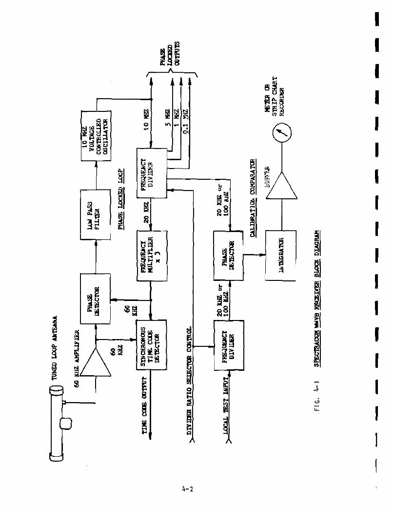
F igu re 4 -1 8163 WWVB TrECEIVER BLOCK D I A G R A M s h m ~ s the logical b u i l d i n g b l o c k s of the r e c e i v e r . The 60 KHz WWVB s i g n a l i s a m p l i f i e d and f i l t e r e d by t h e R F A m p l i f i e r assembly A l . A 10 MHz v o l t a g e - c o n t r o l l e d c r y s t a l osci 1 l a t o r i s phase l o c k e d tn t he 60 KHz s i g n a l . The d i v i d e r in the phase locked loop p r o v i d e s s w i t c h s e l e c t a b l e ou tpu ts o f 10.0, 5.0, 1 . 0 and 0. 1 MHz. These s ignals a r e ava i l a b le a t the NBS OUTPUT connector on t h e f ron t p a n e l . Some noise w i l l appear on these s i g n a l s i n the form of p u l s e j i t t e r due to a tmospher i c n o i s e a t the receiver a r i t en ia . The l ong t e r m accuracy may be cons idered as good a s t h a t o f t he WVB c a r r i e r s i g n a l . The frequency o f W W V B i s n o r m a l l y w i t h i n i t s p resc r ibed value t o b e t t e r than 1 p a r t i n 100 b i l l i o n . The ou tpu t impedance of the NBS OUTPUT i s 93 ohms. A 93 ohm te rmina ted cable should be used f o r long runs where waveform m u s t be p rese rved .
I f Option 05 i s presenr, the the t ime code modula t ion on the WWVB c a r r i e r i s synchronously detected and brought ou t on the p r i n t e d c i r c u i t hoard connec to r t h a t DI ugs in to t h e TH-500. The WVB time code i s generated a t the t r a n s m i t t e r by e r e d u c t i o n of the c a r r i e r power o f 10 dB a t the b e g i n n i n g o f each second. I t i s restored to ful l power 200 m i l l i - seconds l a t e r for a binary zero, 500 milliseconds l a t e r f o r a b i n a r y one, and 8 f l O m i l l i s e c o n d s l a t e r for a p o s i t i o n - i . d e n t i f i e r . Decoding a one- m inu te s t ream y i e l d s t he day of the year , time of day, and a correction f ac to r f o r converting from atomic t ime, UTC, t o ea r t h t i m e , UT1. F i g u r e 3- 1 WWVB T I ME CODE FORYAT shows the coded data i n a one m i nu te stream.
The 10 dB reduction o f WWVB c a r r i e r p w e r i s i n v e r t e d i n the demodulation process and appears as a posi t ive-going TTL-compat ib le s i g n a l a t t h e r e a r connector when Option 05 i s present . See Sec t ion 3, GPTION 05 - T I M E CODE OUTPUT f o r a d d i t i o n a l i n f o r m a t i o n .
The lower h a l f o f the b l o c k diagram c o n t a i n s the l o g i c a l b l o c k s t h a t make up the phase comparator. The local s i g n a l that i s to be compared a g a i n s t WWVB must be one of the four s tandard frequencies, 0.1, 1.0, 5.0 o r 10.0 MHz. The s e l e c t i o n i s made by t h e f r o n t p a n e l swi tches. These sw i tches cont ro l the D I V I D E R which d i v i d e s t h e i n p u t s i g n a l down t o e i t he r 20 or 100 KHz. For f u l l 5ca l e d e f l e c t i o n of 50 m i croseconds , the compar ison i s made a t 20 KHz. F o r f u l l s c a l e d e f l e c t i o n o f 10 mic ro - seconds, comparison i s made a t 100 KHz. T h i s i s s e l e c t a b l e by s w i t c h S 1 on t h e Receiver Assembly , A 2 . The s w i t c h i s s e t a t the f a c t o r y f o r f u l l s c a l e d e f l e c t i o n o f 50 microseconds. Th is i s the recommended s w i t c h s e t t i n g fo r most a p p l i c a t i o n s . The output o f the comparator i s f e d t o an i n t e g r a t o r which d r i v e s a b u f f e r amp1 i f i e r whose o u t p u t drives t h e f ront panel meter and AUX OUTPUT.

The r e c e i v e r may be used t o measure r e l a t i v e f i e l d s t r e n g t h of t he 60 KHz s igna l . T h i s neasurement may be used to o p t i m i z e the location and o r i en t a t i on of the antenna .
The WWVR r e c e i v e r employs synchronous AGC which responds to the 60 KHz s i gnal on1 y and i s not a f f e c t e d b y noi se. The A G C leve I i s an i n d i c a t i o n of s i g n a l s t rengzh.
To measure the AGC v o l t age , open the cover of the receiver and f i n d test p o i n t s T P 3 and TP6 on the A2 R e c e i v e r board . Place the nega t i ve lead of a h i g h impedance DC voltmeter on TP3 (orange) and t he pos i t i v e l e a d on TP6 (b1 ue) .
I n a f i e l d s t r e n g t h o f 100 m i c r o v o l t s / m e t e r , t h i s AGC vo l tage w i 11 be about +2.0 vdc when us i ng a properly o r i e n t e d Hodel 8206 Antenna. The A G C v o l t a g e will be h igher i n stronger s i g n a l l o c a t i o n s , r i s i n g to a l i m i - t i n g va lue of +3.0 v o l t s o r more as f ront end input volta~e c l i m b s above 100 m i c r o v o l t s .
A s the s i g n a l s t r e n g t h decreases to t h e r e c e i v e r ' s phase lock threshold of about 0.2 m i c r o v o l t s , t h e AGC vol tage w i 1 1 decrease to about +1,0 vdc . Belw that l e v e l , t h e red UNLOCK panel i n d i c a t o r w i l i come on.
I f t h e i npu t s i g n a l i s removed c o m p l e t e l y , the A G C v o l t a g e w i 1 1 decretise to a va ry i ng l e v e l around zero. As s ignal i s r e a p p l i e d and increased, t h e r e c e i v e r will aga in l o c k at an AGC l e v e l o f about +1.0 v o l t .
To use the AGC v o l t a g e t o a i d antenna o r i e n t a t i o n , place the antenna so t h a t A G C voltage i s maximi zed. The c i rcui r t h a t produces the AGC vol tage has a very l o n g t ime constant, so apause o f 30 t o 60 seconds i s necessa ry a f t e r each move o f the antenna t o a1 low the .4GC to s t a b i l i r e a t i t s new level .
A f e w m i n u t e s of exper imenta t ion shau ld produce good antenna o r i e n t a t i o n . The f o l l o w i n g t i p s w i l l he lp :
1. The antenna must be a t least 2 5 f e e t away from the rece i ve r . I f i t i s not, the a n t e n n a w i l l g e t s i g n a l s from the r e c e i v e r as w e l l as f rornVWV6, a n d r e s u l t s w i l l be poor. I f the r c c e i v e r and antenna are too close together , t h e r c c e i v e r can ac tua l ly lock t o i t s e l f .
2. A i m the antenna broadside t o the t ransmi t te r , as s h w n i n Sect i o n 1, and KEEP I T AT LEAST 2 FEET FROM ANY METAL. I f t h e antenna i s r e s t i n g on a metal w i n d m s i 1 1 , a metal s h e l f , or metal roof decking, i t will be detuned and poor r e c e p t i o n will r e s u l t .
3 . I f the antenna i s dropped, t he f e r r i t e core can crack and s e v e r e l y d e t u n e the antenna. HANDLE WITH CARE, and i n s t a l l i n a l oca t ion where i t won't f a l l or be knocked down.
4. I f the antenna i s p l a c e d ins ide a building t h a t has s t e e l structural members o r a m e t a l roo f , the WllV3 s i g n a l w i l l be a t t e n u a t e d , and poor r e c e p t i o n may r e s u 1 t . N o i s e be i ng g e n e r a t e d i ns i d e t h e b u i l d i n g may a l s o i n t e r f e r e w i t h good r e c e p t i o n . Fo r these reasons we recommend i n s t a l l i ng the antenna outdoors above t h e r o o f where t h e r e i s a cIear l i n e of s i g h t toward the t r a n s m i t t e r . Here, the metal frame o f the b u i l d i n g h e l p s s h i e l d i n t e r n a l b u i l d i n g no ise f rom the antenna.
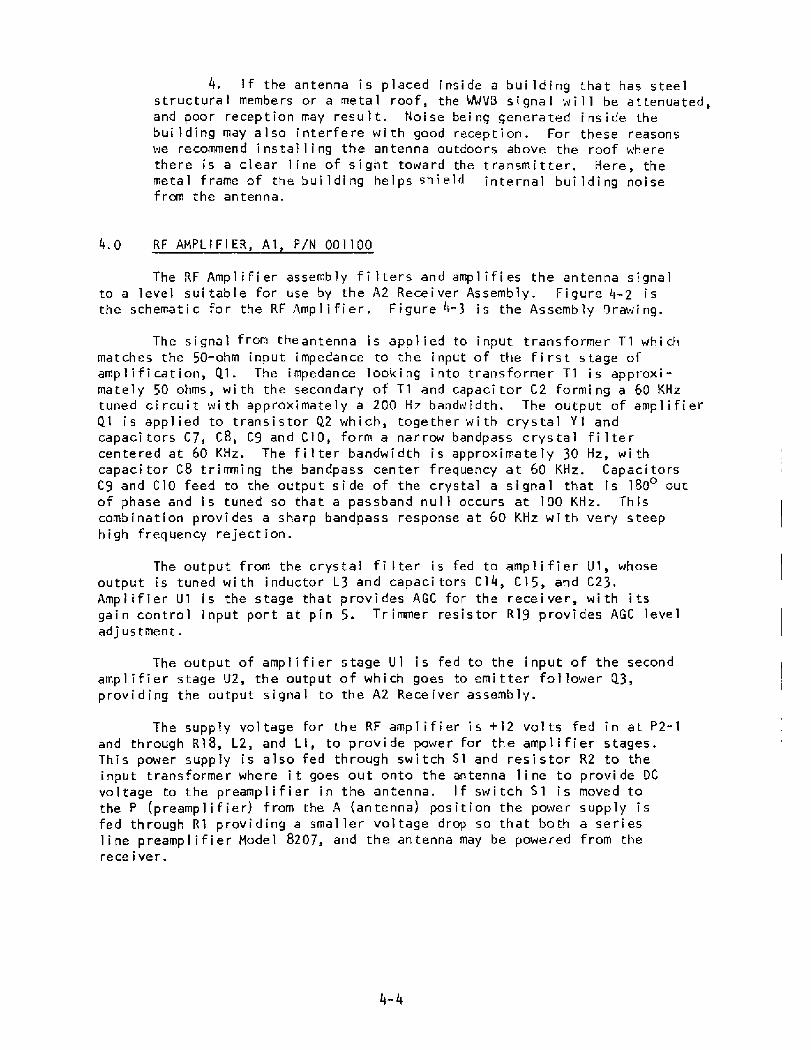
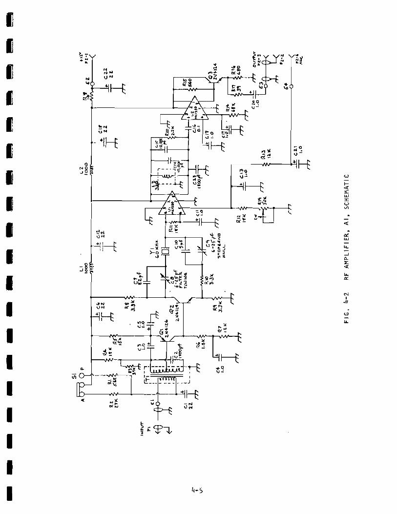
The RF A m p l i f i e r assembly f i l t e r s and a m p l i f i e s the antenna s i g n a l t o a l e v e l s u i t a b l e f o r use by t he A 2 Rece iver Assembly. F i g u r e 4 - 2 i s the schemat ic f o r t h e R F . % r ~ p l i f i e r . F i g u r e h - 3 i s the Assembly '3rawing.
The s i gna l from t hean tenna i s a p p l i e d t o i n p u t t r a n s f o r m e r T I which matches the 50-ohm i npu t impedance to t h e input o f t h e f i r s t s t a g e o f amp 1 i f i cat i on , QI. The impedance l o o k i n g i n t o t r a n s f o r m e r T I i s approxi - m a t e l y 50 ohms, w i t h t h e secondary o f T I and c a p a c i t o r C2 f o r m i n g a 60 KHz tuned circuit w i t h approx ima te l y a 200 Hz bandwidth. The output o f a m p l i f i e r Q 1 i s a p p l i e d t o t r a n s i s t o r Q2 which, t o g e t h e r w i t h c r y s t a l Y 1 and c a p a c i t o r s C 7 , C8, C9 and ClO, f o rm a nar row bandpass c r y s t a l f i l t e r c e n t e r e d a t 60 KHz. The f i l t e r bandw id th i s approximately 30 Hz, w i t h capac i to r C 8 t r i m n i n q the bandpass c e n t e r frequency a t 60 KHz. Capac i to rs C9 and C10 feed to the output s i d e o f t he crysta l a s i g n a l that i s 180' out o f phase and i s tuned so t h a t a passband n u l l occurs a t 100 K H z . T h i s comb i n a t i o n p r o v i des a sharp bandpass response a t 60 KHz wi t h very s t e e p h igh f requency r e j e c t i o n .
The o u t p u t f r o m the c r y s t a l f i l t e r i s fed t o a m p l i f i e r U 1 , whose o u t p u t i s tuned w i t h inductor L 3 and capac i to rs ~ 1 4 , C15, and C23. A m p l i f i e r U 1 i s the stage t h a t p r o v i d e s A G C f o r t h e receiver , w i t h i t s g a i n c o n t r o l i npu t p o r t a t p i n 5. Trimmer r e s i s t o r Rlg p r o v i d e s A G C level adjustment.
The o u t p u t o f amp1 i f i e r s tage U 1 i s f e d t o the i n p u t o f t h e second amp1 i f i e r s tage U2, t h e o u t p u t o f wh ich goes to e m i t t e r fo t lower Q3, p r o v i d i n g the ou tpu t signal to t h e A2 Receiver assembly.
The supp ly v o l t a g e for t he RF a m p l i f i e r i s +I2 v o l t s f e d i n a t P 2 - I and through R18, L2, and L1, to p r o v i d e power for the a m p l i f i e r s t a g e s . T h i s power supp ly is a l s o fed th rough s w i t c h S 1 and r e s i s t o r R2 to t h e i n p u t t ransformer where i t goes o u t onto t he antenna 1 i ne t o p r o v i de DC vol tage to t h e p r e a m p l i f i e r i n the antenna. I f s w i t c h S 1 i s moved t o the P f rom the ,4 (antenna) pos i t ion t h e power supply i s f e d th rough R 1 provid ing a s m a l l e r v o l t a g e drop so t h a t both a s e r i e s l i n e p r e a m p l i f i e r Model 8207, and t h e antenna may be powered f r o m the rece i ver.

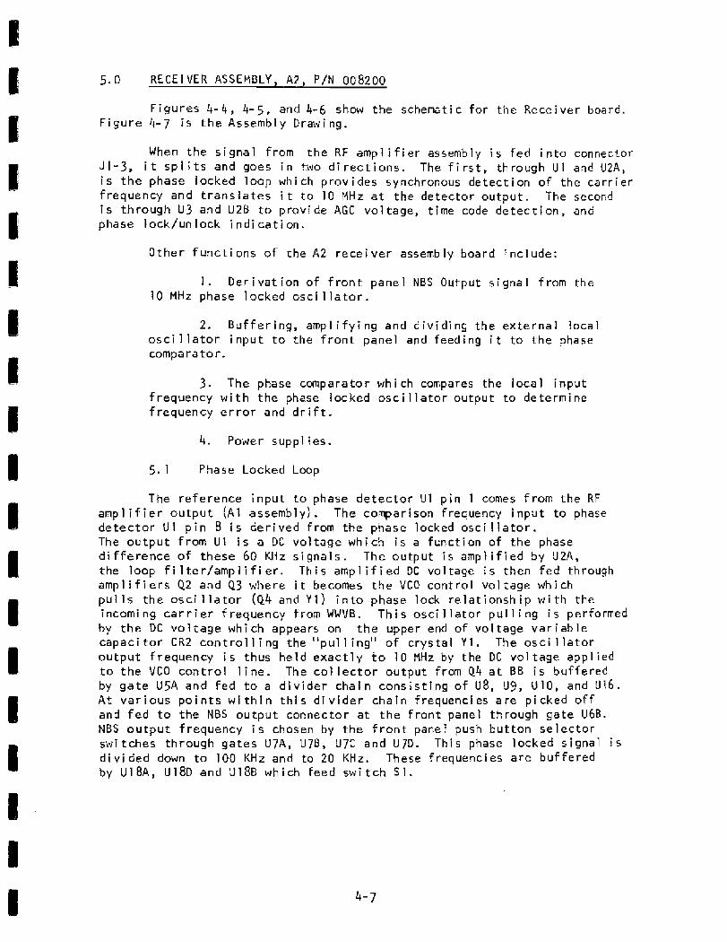
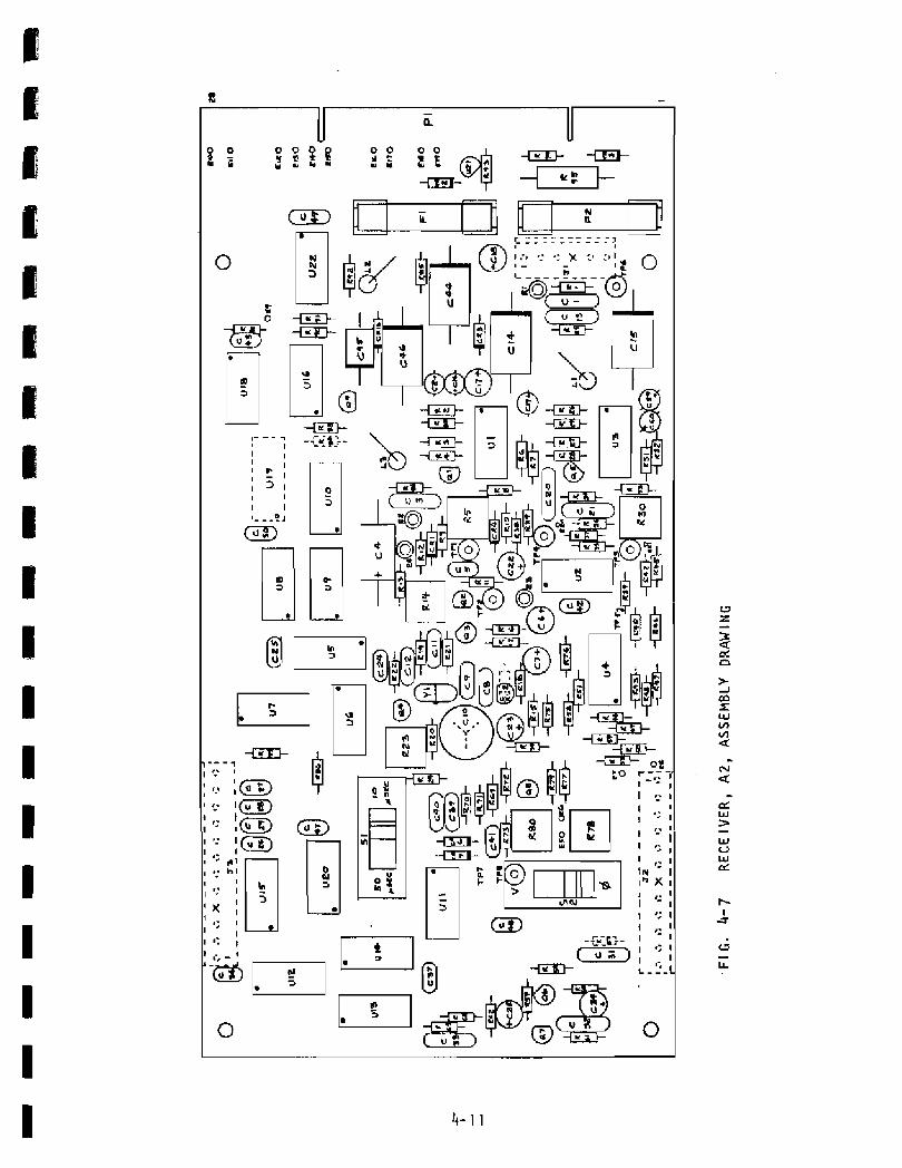
5.0 R E C E I V E R A S S E M B L Y , A 2 , P/N 008200
F i g u r e s 4 - 4 , 4-5, and 4-6 show t h e schematic for t h e Rece ive r board. F i g u r e 4-7 i s t he Assembly Drawing,
When the s i g n a l from t h e RF amp1 i f i e r assembly i s f e d i n t o connector J I - 3 , i t s p l i t s and goes i n two d i r e c t i o n s . The f i r s t , t h rough U 1 and UZA, i s t h e phase locked l o o p w h i c h p r o v i d e s synchronous d e t e c t i o n o f t h e c a r r i e r f requency and t r a n s l a t e s i t t o 10 HHz a t t h e d e t e c t o r o u t p u t . The second i s t h r o u g h U 3 and U2B t o p r o v i d e AGC vo l tage , t i m e code d e t e c t i o n , a n d phase I o c k / u n l o c k i n d i c a t i o n .
Other f u n c t i o n s of t h e A2 rece i ve r assembly board i n c l u d e :
1 . D e r i v a t i o n o f f r o n t panel NBS Output s i g n a l f rom t h e 10 MHz phase l o c k e d o s c i l l a t o r .
2. B u f f e r i n g , amp1 i f y i ng and d i v i d i n g t h e e x t e r n a l l o c a l o s c i l l a t o r i n p u t t o t h e f r on t pane l and f e e d i n g i t t o the phase comparator .
3 . The phase c m p a r a t o r whi ch compares the local i n p u t f requency w i t h t h e phase locked o s c i l l a t o r o u t p u t t o de te rm ine f requency e r r o r and d r i f t .
4. Power suppl ies .
The re fe rence i n p u t t o phase detector U 1 p i n 1 comes from t h e RF a m p l i f i e r o u t p u t ( A 1 assembly) . The comparison f requency i n p u t to phase d e t e c t o r U 1 p i n 8 i s d e r i v e d from the phase locked o s c i l l a r o r . The o u t p u t from U 1 i s a DC v o l t a g e w h i c h i s a f u n c t i o n o f t h e phase d i f f e r e n c e of these 60 KHz s i g n a l s . T h e output i s a m p l i f i e d by U 2 A , the loop f i l t e r / a m p I i f i e r . T h i s a m p l i f i e d DC vo l tage i s then fed t h r o u g h a m p l i f i e r s Q2 and 43 where i t becomes t h e VCO c o n t r o l v o l t a g e w h i c h p u l l s t he o s c i l l a t o r (44 and Y 1 ) i n t o phase l o & r e l a t i o n s h i p w i t h the incomi ng car r i er f r e q u e n c y from WWVB. Th i s o s c i 1 l a t o r p u l l i ng i s performed by t h e DC v o l t a g e w h i c h appears on the upper end o f vo l tage v a r i a b l e c a p a c i t o r C R 2 c o n t r o l l i n g t h e " p u l l i n g " o f c r y s t a l Y 1 . The o s c i l l a t o r o u t p u t f requency i s thus he ld e x a c t l y t o 10 MHz by t h e DC v o l t a g e a p p l i e d t o t he V C O control l i n e . The c o l l e c t o r o u t p u t frm 44 a t BE i s bu f fe red by g a t e USA and f e d t o a d i v i d e r cha in c o n s i s t i n g o f U8, U9, U 1 0 , and 916 . A t v a r i o u s p o i n t s w i t h i n t h i s d i v i d e r c h a i n f requencies a r e p i c k e d o f f and f e d t o the NBS o u t p u t connec to r a t t h e f r o n t panel t h rough ga te U6B. NBS output f r equency i s chosen by the f r o n t pane1 push bu t ton s e l e c t o r s w i t c h e s t h r o u g h gates U 7 A , U7B, U7: a n d U7D. T h i s phase locked s i g n a l i s d i v i d e d down t o 100 KHz and to 20 KHz. These f requenc ies a r e bu f fe red by U 1 8 A , ~ 1 8 ~ and U l S B which feed s w i t c h S I .


The 20 KHz o u t p u t from U 1 6 i s fed to the t r i p l e r s tage Q9 where t h e ou tpu t a t 60 KHz i s f i l t e r e d and f e d back a: p o i n t AA i n t o t h e comparison i n p u t o f phase d e t e c t o r U 1 , p i n 8. Thus, the phase l ocked loop t r a n s l a t e s t h e incoming 60 KHz c a r r i e r f requency f rom WWVB t o 10 MHz a t the c r y s t a l o s c i l l a t o r o u t p u t , and d i v i d e s i t down t o 60 KHz for compar ison i n the phase d e t e c t o r .
5.2 A G C Loop
The i n p u t from t h e RF a m p l i f i e r a l s o goes t o p i n 1 o f p h a s e de tec to r U 3 a f t e r b e i n g s h i f t e d i n phase by 90' by C 1 4 , C I S , and L1. Thus, U 3 becomes a quadra tu re phase de tec to r whose ou tpu t a t p i n 6 goes h igh o n l y when the i n p u t s a t p i n 1 and p i n 8 a r e i n quadra tu re w i t h each o t h e r a t 60 KHz. The o u t p u t l e v e l from t h i s phase d e t e c t o r i s p r o p o r t i o n a l t o the l e v e l o f the incoming c a r r i e r , and thus p rov ides t h e b a s i s f o r t i m e code amp l i t ude d e t e c t i o n , and for AGC v o l t a g e g e n e r a t i o n .
The phase d e t e c t o r o u t p u t i s amp1 i f i e d by U26, whose t i m e cons tan t i s app rox ima te l y 15 m i l l i s e c o n d s . The o u t p u t of U 2 B i s s p l i t and i s f e d i n two d i r e c t i o n s : f i r s t th rough R 3 9 t o v o l tage comparator U4A where smal l a m p l i t u d e v a r i a t i o n s i n t h e s i g n a l a r e d e t e c t e d and p r o v i d e t h e t i m e code o u t p u t . Time code ou tpu t i s p r o v i d e d a5 O p t i o n 05 and i s n o t p resen t i n a l l r e c e i v e r s .
The o u t p u t of U2B i s f ed t h r o u g h R89 to amp l i f i e r U2C wh ich has an i n t e g r a t i n g t ime cons tan t o f a p p r o x i m a t e l y 2 5 seconds. The s l o w l y v a r y i ng output o f U2C i s used a s the AGC v o l t a g e and i s f e d back t o the RF a m p l i f i e r to c o n t r o l t h e g a i n o f the inpu t s t a g e .
Because t h e AGC v o l t a g e i s d e r i v e d from t h e o u t p u t o f a quadra tu re d e t e c t o r , i t i s p resen t o n l y a f t e r phase lock i s ach ieved, and thus becomes t he b a s i s f o r a synchronous AGC. The g a i n o f t h e a m p l i f i e r i n the f r o n t end o f the r e c e i v e r i s r u n n i n g w ide open u n t i l phase l o c k occurs. A f t e r phase l o c k i s acqu i red the i n p u t amp1 i f i e r g a i n i s reduced to a l e v e l just s u f f i c i e n t t o p r o v i d e a r e f e r e n c e f o r the phase locked loop and o t h e r s tages i n the A2 r e c e i v e r assembly . Thus, no stages i n t he A 2 r ece i ve r assembly a r e a l l o w e d t o s a t u r a t e o r be overdr i ven i n strong s i g n a l con- d i t i o n s .
T e s t p o i n t 3 i s l oca ted a t the r e f e r e n c e v o l tage aga i ns t which AGC a m p l i f i e r U2C ope ra tes . Thus, t he vo l t age measured f r o m TP3 t o TP6 i s p r o p o r t i o n a l t o the i n p u t s i g n a l l e v e l and can be used as an i n d i c a t i o n of s i g n a l s t r e n g t h . I f t he antenna i s a d j u s t e d and aimed t o max imize t h i s AGC v o l t a g e , optimum r e c e i v e r o p e r a t i o n i s ob ta ined .
The AGC v o l t a g e i s a l s o s e n t t o v o l t a g e comparators U48, U4C, and U4D a5 a means o f i n d i c a t i n g phase lock . When the AGC v o l tage measured between t e s t p o i n t s 3 and 6 r i s e s t o approx ima te l y 1.0 v o l t D C , t h e o u t p u t of comparator U 4 B goes h i g h t u r n i n g o f f the red UNLOCK pane l i n d i c a t o r on t h e f r o n t pane l . When lock i s a c q u i r e d , t h e green l i g h t goes on. The output o f U40 goes h igh and p r o v i d e s an o u t p u t a t J2 -2 showing t h a t phase lock has been acqu i red. T h i s can be connected to p i n 270 on the r e a r connector t o p r o v i d e a remote i n d i c a t i o n o f phase l o c k .

5 .3 Phase D e t e c t o r Ba lance Adj us trnents
The o u t p u t of phase d e t e c t o r U I for the phase locked loop c o n t r o l i s ba lanced by a d j u s t m e n t o f t r immer p o t e n t i o m e t e r R 5 . The o u t p u t o f t h e q u a d r a t u r e phase de tec tor U3 i s ba lanced by a d j u s t m e n t o f t r immer p o t e n t i o m e t e r R30.
5 .4 Phase Compa r a t o r
When l o c a l o s c i 1 l a t o r s t o b e c a l i b r a t e d a re f e d i n t o t h e l o c a l i n p u t j a c k on t he f r o n t pane1 they appear a t J 2 p i n 1 1 . The b u f f e r a m p l i f i e r Q6-Q7 feeds t h i s s i g n a l t o g a t e U 1 I D where i t i s t hen d i v i d e d i n frequency b y LJ13 and U14. Gates U 1 5 A , U l50, U15C and U15D a r e used t o s e l e c t t h e a p p r o p r i a t e d i v i d e r ou tpu t t o p r o v i d e a 100 Ktiz s igna l t o S 1 and d i v i d e r U20.
I f t he phase comparator s e l e c t o r s w i t c h , S t , i s placed i n t h e 50 p o s i t i o n then t he i n p u t s to the phase de tec to r U l l B and U l l A w i l l be 20 KHz d e r i v e d from the NBS received s i g n a l and 20 KHz from t h e s i g n a l b e i n g measured. The phase d e t e c t o r o u t p u t w i 1 l cause the meter t o read 50 m i cro- seconds f u l l s c a l e .
I f t h e phase comparator selector s w i t c h , 51, i s p l a c e d i n t h e 10 p o s i t i o n then the i n p u t s t o t h e phase de tec to r w i l l be 100 KHz d e r i v e d from the N05 s i g n a l and 100 KHz d e r i v e d from t h e s i g n a l b e i n g measured. The phase d e t e c t o r output w i l l cause t h e meter t o read 10 microseconds f u l l scale.
Ul l A and UllB a r e connected as a f l i p - f l o p phase d e t e c t o r whose o u t p u t p u l s e w i d t h i s p r o p o r t i o n a l t o t h e r e l a t i v e phase r e l a t i o n s h i p between t h e t w o i n p u t s i g n a l p u l s e s . B u f f e r i n g o f t h i s o u t p u t p u l s e is p r o v i d e d by Q8, and i n t e g r a t i o n o f t h e output p u l s e by R75 and C42. Buf fer amp1 i f i e r U 2 D t h e n d r i v e s t h e f r o n t panel m e t e r and the AUX OUTPUT for an e x t e r n a l me te r or c h a r t recorder . Fu l 1 s c a l e ad jus tmen ts of ba th a r e made by a d j u s t i ng t h e c u r r e n t t o ground t h r o u g h a m i 1 l iammeter a t each o u t p u t to e x a c t l y 1 . O r n A w i t h no l o c a l s i g n a l i n p u t and w i t h TP7 grounded, causing the phase d e t e c t o r t o i n d i c a t e f u l l s c a l e . Trimmer r e s i s t o r R80 a d j u s t s f u l l s c a l e s e t t i n g o f AUX OUTPUT and 278 i s used to a d j u s t the f r o n t panel f u l 1 s c a l e me te r reading.
T h e power supp ly i s shown i n F i g u r e 4-6. The + 5 V i s p r o v i d e d by v o l t a g e r e g u l a t o r U21, PNP t r a n s i s t o r HFQ1 loca ted i n t h e TM-500 Mainframe and Zener d iode V R 2 . A 3/8A AGC l o c a t e d on t h e A 2 board fuses t h e i npu t s i de o f t h e r e g u l a t o r .
The +12 v o l t s i s p r o v i d e d by vol t a g e r e g u l a t o r U22 and NPN t r a n - s i s to r MFQ2. Fuse F1, 1/8A AGC, i s i n s e r i e s w i t h t h e i n p u t t o the regu la to r .
The -12 v o l t s i s p r o v i d e d by s e r i e s r e s i s t o r R95 and Zener d iode V R 3 .
SECTION 5
MA I NTENANCE
1 .O Introduct ion
2.0 Gal i b r a t i o n
3.0 Test Equipment
4.0 T e s t Set-Up
5.0 Test Procedure
6 . 0 Model 8207 Antenna Preamp A1 ignment

1.0 INTRODUCTION
T h i s s e c t i o n describes t h e c a l i b r a t i o n , a l ignment and t e s t i n g o f the Model 8163.
P e r i o d i c c a l i b r a t i o n o f a WWVB r e c e i v e r , i n the usual sense t h a t an i ns t rumen t m u s t be sent t o the Bureau o f Standards o r c a l i b r a t e d aga ins t a t r a c e a b l e s t a n d a r d , i s unnecessary. Time and frequency a r e t h e o n l y t w o measurable q u a n t i t i e s t h a t can be t r a n s m i t t e d v i a a r a d i o s i g n a l . Because o f t h i s , i t i s p o s s i b l e to be "connected" di rec t l y t o t h e Bureau o f Standards v i a a r a d i o s i g n a l f o r c a l i b r a t i o n o f both t ime and f requency.
We can draw a s i m p l e ana logy by c o n s i d e r i n g a secondary voltage s tandard , o r s t a n d a r d c e l l , wh ich i s used f o r v o l t a g e c a l i b r a t i o n . S tandard ce 11s are usual ly r e t u r n e d to t h e Bureau o f Standards or a secondary s tandards l aboratory where they a r e c a l i b r a t e d and c e r t i f i e d t r a c e a b l e t o the Bureau o f Standards . I f i t were possible to have a p a i r of w i r e s connec ted from y o u r l a b o r a t o r y d i r e c t l y t o t h e "s tandard v o l t " a t the Bureau o f Standards, i t would be unnecessary t o r e t u r n your v o l t a g e c e l l p e r i o d i c a l l y t o t h e Bureau o f S t a n d a r d s f o r c a l i b r a t i o n . T h i s i s exac t ly t h e s i t u a t i o n t h a t we f i n d w i t h t i m e and frequency b e i n g r e c e i v e d by a r a d i o s i gnal d i r e c t 1 y from the Bureau o f S t-andards. P e r i o d i c " ca l i b r a t ion" o f t h e instrument i s unnecessary because i t s output i s be ing d e r i v e d d i r e c t l y f rom t h e Bureau o f S t a n d a r d s . The o n l y p e r i o d i c checks t h a t a r e necessary a r e ones t o d e t e r m i n e t h a t t h e r e c e i v e r Is o p e r a t i n g p r o p e r l y and t h a t t h e c o r r e c t s i g n a l i s be ing rece ived,
The p rocedure f o r v e r i f y i ng p r o p e r equipment o p e r a t i o n i s d e s c r i b e d b e low.
1. Check to see t h a t the green lock l i g h t i s l i t on the f r o n t pane l o f the r e c e i v e r . T h i s e s t a b l i s h e s t h a t t h e r e c e i v e r i s phase locked t o a 60 KHz s i g n a l b e i ng r e c e i v e d v i a the antenna.
LOCK LAMP Old
2. Check to see t h a t t h e h o u r l y o f f s e t of a p p r o x i m a t e l y 2. 1 mic roseconds i s occur r ing a t 10 minutes a f t e r t h e hour . These o f f s e t s occur due t o t h e 45O phase s h i f t t h a t i 5 app l i ed t o the s igna l a t t h e t r a n s m i t t e r a t 10 m i n u t e s a f t e r the hour , r e t u r n i n g t o normal 15 m inu tes a f t e r the hour . The presence o f those o f f s e t s both i d e n t i f i e s the s t a t i o n and g i v e s hour ly " t i m e t icks" on a c h a r t r e c o r d e r t race o f the phase comparator o u t p u t . The i r presence i n d i c a t e s t h a t the char t reco rder 1,i ne can be coming o n l y frm t h e N a t i o n a l Bureau o f Standards.
OFFSET (PHASE S H I F T ) o f 2.1 usec a t 10 and 15 m inu tes a f t e r each hour

3. Move t h e V / O lock vo l t age s w i t c h on the A2 board t o the " lock voltage" p o s i t i o n , V , and observe that the f r o n t pane l me te r r e a d i n g i s a t or near center scale. I f t h i s r ead ing i s reaching t h e outer boundar ies of t he m i d d l e one - th i r d of the s c a l e when the green lock l i g h t i s on,
' a t r immer adjustment s h o u l d be made on the A2 circuit board i n the recei vet- t o recen te r t h e meter r ead ing . To o b t a i n a center scale reading, f i r s t v e r i f y t h a t t h e green lock l i g h t i s I i t due to an antenna 5 i gna l , then a d j u s t
A 2 C 1 0 t o o b t a i n a center scale r e a d i n g . T h i s i s a very touchy a d j u s t m e n t , and m u s t be made very slowly i n extremely small increments. The long time cons t an t i n the phase locked loop w i 1 l preven t the m e t e r readi ng from changing r a p i d l y , and a t l e a s t 30 seconds must be a l l w e d between ad jus tmen ts f o r the phase locked loop to settle down. Th i s adjus tment compensates for the l o n g - term a g i n g of the I0 MHz c r y s t a l A271 which i s phase locked t o t h e WVB c a r r i e r frequency. I n a p r o p e r l y func t ion ing rece iver , this adjustment should not be required more o f t e n than every 6 months.
LOCK VOLTAGE NEAR CENTER SCALE
I f the answers t o the three i t e m s on t h e checklist are yes, assurance i s established that the receiver i s operat ing p r o p e r l y , and t h a t c a l i b r a t i o n made w i t h i t a r e t r aceab le d i r e c t l y to the Bureau o f Standards.
3.0 TEST EQUl PMEWT
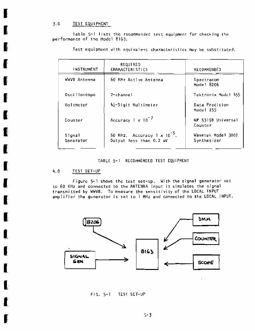
T a b l e 5-1 l i s t s t h e recommended t e s t equipment f o r checking t h e performance o f t he Model 8163.
T e s t equipment w i t h equivalent characteristics may be substituted.
TABLE 5- 1 RECOMMENDED TEST EQU I PMENl
l NSTRUMENT
WWVB Antenna
Osci 1 loscope
Vo l tmeter
Counter
Signal Genera tor
4.0 T E S T SET-UP
F igure 5-1 shows the t e s t set-up. W i t h the signal generator s e t to 60 KHz and connected to t h e ANTENNA input i t s i m u l a t e s the signal t r a n s m i t t e d by W V B . To measure t he s e n s i t i v i t y o f the LOCAL INPUT amp1 i f i e r the generator i s s e t to 1 MHz and connected t o the LOCAL I NPUT.
REQUl RED C H A U C T E R I ST I CS
60 KHz A c t i v e Antenna
2-channe l
If-Digit Mu1 t i m e t e r
Accuracy 1 x I0 - 7
- 5 60 K H z . Accuracy 1 x 10 . Output less than 0.2 uV
SIGN 4L L
RE COMMENDED
Spec t r a c m Mode 1 8206
T e k t r o n i x Model 455
Data P r e c i s ion Mode1 255
HP 53156 Universal Counter
Wavetek Model 3002 Syn thes i zer
-
F I G. 5-1 TEST SET-UP
5- 3
5 .0 TEST PROCEDURES
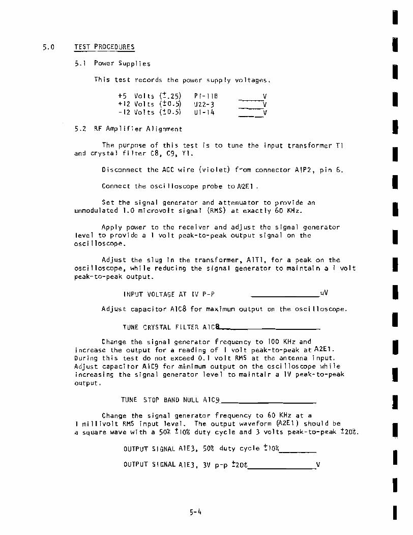
5 . 1 Power Supp l i es
Th i s t e s t r e c o r d s the power s u p p l y voltages.
+ 5 Volts f f . 2 5 ) P I - 1 1 8 V +I2 Val ts (20.5) U Z 2 - 3 V -12 V o l t s ( f0 .5) U I - 1 4 v
5.2 R F A m p l i f i e r Alignment
The purpose of t h i s t e s t i s to tune the i n p u t t ransformer T1 and c r y s t a l filter C8, C9, Y 1 .
Disconnect t h e AGC wire ( v i o l e t ) from connector ~ 1 P 2 , p i n 6.
Connect: t h e osci I Ioscope probe to AQE I .
Set the signal generator and attenuator t o prov ide an unrnodulated 1.0 rn ic rovo i t s i g n a l (RMS) a t e x a c t l y 60 KHz.
Apply power t o t h e rece iver and a d j u s t the s i g n a l generator level to prov ide a I v o l t peak-to-peak o u t p u t signal on the oscil loscope.
A d j u s t t he s l u g i n the transformer, A l T 1 , for a peak on t h e oscjlloscope, w h i l e reducing the s i g n a l generator t o maintain a 1 v o l t peak-to-peak output .
IHPUT VOLTAGE AT I V P-P UV
A d j u s t capacitor A I C 8 for maximum output on t h e osci l loscope.
TUNE CRYSTAL F l LTER A I C P
Change the s i g n a l generator frequency t o 100 KHz and i ncrease the o u t p u t f o r a read i ng of 1 vol t peak-to-peak a t A 2 E 1 . Dur ing t h i s t e s t do not exceed 0.1 volt RMS at the antenna i n p u t . A d j u s t capaci tor A l C g f o r mi:nimurn o u t p u t on the osc i lloscope w h i l e increasing the s igna l generator l e v e l to m a i n t a i n a 1 V peak-to-peak output.
TUNE STOP BAND NULL AlCg
Change the s i g n a l generator frequency to 60 KHz a t a I millivolt RMS i n p u t l e v e l . The output waveform ( A 2 E l J should be a square wave w i t h a 50% '10% duty c y c l e and 3 v o l t s peak-to-peak '20%.
OUTPUT 51 GNAL A 1 E 3 , 50% duty cycle 210%
OUTPUT SIGNAL A l E 3 , 3 V p-p *20% V

Change the signal generator so the input to the 8163 is 5 mi crovo 1 ts RMS . The o u t p u t amp 1 i tude shoul d be equal t o or g rea te r than 1.5V peak-to-peak. The ou tpu t w i 1 1 be a s i n e wave u n t i I the clipping p o i n t i s reached a t approximately 3 volts peak- to- peak.
OUTPUT SIGNAL, A2E1 , 1 . 5 V p-p V
T h i s completes the alignment of the RF Amplifier. The AGC p o t e n t iorneter adjustment i s described i n TEST 5 . 9 .
5.3 Q u a d Detector and Phase Detector Balance
Th i s test a d j u s t s potentiometers A2R30 and A 2 R 5 . Rermve the i npu t signal to the antenna input. Preset the ad jus tments on the A 2 Receiver board as fo l lows. The controls may be lef t as i s if t h e receiver has been previously a l i g n e d .
1 . A d j u s t R 5 , R14, R23, R30, R78,R80 t o c e n t e r range. A d j u s t C10 to center range ( l i n e the adjustment slot up w i t h ~ 9 ) . A d j u s t t h e p a n e l meter t o zero u s i n g t h e zero a d j u s t on the m e t e r .
2 . Connect a cl i p l e a d from A2E2 t o A2E3. Connect the negat ive lead of t h e DVH to A 2 i P 3 , and t h e p o s i t i v e lead t o A2TP4. Set the DVM to +2v f u l 1 scale. Make no connect i o n to the antenna input.
3. Apply power to the receiver and adjus t A2R30 f o r a zero r e a d i n g on the D V M . S l i g h t d i g i t changes may be no t i ced , b u t s h o u l d be less than ?5 mv, Move the positive DVM lead from A 2 T P 4 to A2TP6 . The reading should be less than ?500 mv. Glyptol A2R30.
QUAD DE TE CTOR BALANCE
4. Connect the negative DVM lead t o A 2 T P I and the p o s i t i v e 1 ead t o A2TP2. A d j u s t A Z R 5 for a zero rad i ng on the D V M . Changes o f f 5 mv or less may be not i ced.
PHASE DETECTOR BALANCE
T h i s test a d j u s t s A2R14. Move the cl i p lead from A2E3 to A 2 E 4 . Set the meter sw i t c h A 2 S 2 to read lock volts ( V pos i t i on), A d j u s t A2R14 for a meter r e a d i n g o f 80% full scale. Glyptal A2F114.
L O C K VOLTS (80% full scale)


Related Documents