Errata Title & Document Type: Manual Part Number: Revision Date: HP References in this Manual This manual may contain references to HP or Hewlett-Packard. Please note that Hewlett- Packard's former test and measurement, semiconductor products and chemical analysis businesses are now part of Agilent Technologies. We have made no changes to this manual copy. The HP XXXX referred to in this document is now the Agilent XXXX. For example, model number HP8648A is now model number Agilent 8648A. About this Manual We’ve added this manual to the Agilent website in an effort to help you support your product. This manual provides the best information we could find. It may be incomplete or contain dated information, and the scan quality may not be ideal. If we find a better copy in the future, we will add it to the Agilent website. Support for Your Product Agilent no longer sells or supports this product. You will find any other available product information on the Agilent Test & Measurement website: www.tm.agilent.com Search for the model number of this product, and the resulting product page will guide you to any available information. Our service centers may be able to perform calibration if no repair parts are needed, but no other support from Agilent is available. Advanced Test Equipment Rentals www.atecorp.com 800-404-ATEC (2832) ® E s t a blishe d 1 9 8 1 Downloaded from www.Manualslib.com manuals search engine

Welcome message from author
This document is posted to help you gain knowledge. Please leave a comment to let me know what you think about it! Share it to your friends and learn new things together.
Transcript
Errata
Title & Document Type:
Manual Part Number:
Revision Date:
HP References in this Manual This manual may contain references to HP or Hewlett-Packard. Please note that Hewlett-Packard's former test and measurement, semiconductor products and chemical analysis businesses are now part of Agilent Technologies. We have made no changes to this manual copy. The HP XXXX referred to in this document is now the Agilent XXXX. For example, model number HP8648A is now model number Agilent 8648A.
About this Manual We’ve added this manual to the Agilent website in an effort to help you support your product. This manual provides the best information we could find. It may be incomplete or contain dated information, and the scan quality may not be ideal. If we find a better copy in the future, we will add it to the Agilent website.
Support for Your Product Agilent no longer sells or supports this product. You will find any other available product information on the Agilent Test & Measurement website:
www.tm.agilent.com Search for the model number of this product, and the resulting product page will guide you to any available information. Our service centers may be able to perform calibration if no repair parts are needed, but no other support from Agilent is available.
Advanced Test Equipment Rentalswww.atecorp.com 800-404-ATEC (2832)
®
Established 1981
Downloaded from www.Manualslib.com manuals search engine

Programming Reference
HP 1652B/HP 1653B Logic Analyzers
E!ia HEWLETTPACKARD
@Copyright Hewlett-Packard Company 1989
Manual Number 0165240903 Printed in the U.S.A. December 1989
Downloaded from www.Manualslib.com manuals search engine
Printing History
New editions are complete revisions of the manual. Update packages,which are issued between editions, contain additional and replacementpages to be merged into the manual by the customer. The dates on thetitle page change only when a new edition or a new update is published.No information is incorporated into a reprinting unless it appears as aprior update; the edition does not change when an update is incorporated.
A software code may be printed before the date; this indicates the versionlevel of the software product at the time of the manual or update wasissued. Many product updates and fmes do not require manual changesand, conversely, manual corrections may be done without accompanyingproduct changes. Therefore, do not expect a one to one correspondencebetween product updates and manual updates.
Edition 1 December 1989 0165240903
Downloaded from www.Manualslib.com manuals search engine

List of Effective Pages
The List of Effective Pages gives the data of the current edition and of anypages changed in updates to that edition. Within the manual, any pagechanged since the last edition will have the date the changes were madeprinted on the bottom of the page. If an update is incorporated when anew edition of the manual is printed, the change dates are removed fromthe bottom of the pages and the new edition date is listed in PrintingHistory and on the title page.
Pages Effective Date
All December 1989
Downloaded from www.Manualslib.com manuals search engine

Contents
Chapter 1 Introduction to Programming an InstrumentIntroduction . . . . . . . . . . . . . . . . . . . . . . . . . . . . . . . . . . . . . . . . . . . . . . ..l- 1AboutThisManuaI . . . . . . . . . . . . . . . . . . . . . . . . . . . . . . . . . . . . . . . . ..l- 1ProgrammingSyntax . . . . . . . . . . . . . . . . . . . . . . . . . . . . . . . . . . . . . . ..l- 2
Talking to the Instrument . . . . . . . . . . . . . . . . . . . . . . . . . . . . . . . . . . l-2Instruct ion Syntax . . . . . . . . . . . . . . . . . . . . . . . . . . . . . . . . . . . . . . . . .l-2Output Command . . . . . . . . . . . . . . . . . . . . . . . . . . . . . . . . . . . . . . . . . l-3DeviceAddress...........................................l- 3Instruct ions . . . . . . . . . . . . . . . . . . . . . . . . . . . . . . . . . . . . . . . . . . . . ..l- 3Instruction Header . . . . . . . . . . . . . . . . . . . . . . . . . . . . . . . . . . . . . . . . l-3WhiteSpace..............................................l- 4Instruction Parameters. . . . . . . . . . . . . . . . . . . . . . . . . . . . . . . . . . . . *l-4HeaderTypes . . . . . . . . . . . . . . . . . . . . . . . . . . . . . . . . . . . . . . . . . . ..l- 4Combining Commands from the Same Subsystem . . . . . . . . . . . . . . l-5Duplicate Keywords . . . . . . . . . . . . . . . . . . . . . . . . . . . . . . . . . . . . . . . l-5QueryUsage . . . . . . . . . . . . . . . . . . . . . . . . . . . . . . . . . . . . . . . . . . . ..l- 6Program Header Options . . . . . . . . . . . . . . . . . . . . . . . . . . . . . . . . . . l-7Parameter Syntax Rules . . . . . . . . . . . . . . . . . . . . . . . . . . . . . . . . . . . . l-7Instruction Terminator . . . . . . . . . . . . . . . . . . . . . . . . . . . . . . . . . . . . l-9Select ing Mul t ip le Subsystems . . . . . . . . . . . . . . . . . . . . . . . . . . . . . .1-9
Programming an Instrument . . . . . . . . . . . . . . . . . . . . . . . . . . . . . . . . . l-10Initialization . . . . . . . . . . . . . . . . . . . . . . . . . . . . . . . . . . . . . . . . . . . . . l-10ExampleProgram........................................l-llProgramOverview . . . . . . . . . . . . . . . . . . . . . . . . . . . . . . . . . . . . . ..l-11Receiving Information from the Instrument . . . . . . . . . . . . . . . . . . l-11Response Header Options . . . . . . . . . . . . . . . . . . . . . . . . . . . . . . . . l-12Response Data Formats . . . . . . . . . . . . . . . . . . . . . . . . . . . . . . . . . . l-13String Variables . . . . . . . . . . . . . . . . . . . . . . . . . . . . . . . . . . . . . . . . . 1-14NumericBase . . . . . . . . . . . . . . . . . . . . . . . . . . . . . . . . . . . . . . . . . ..l-15Numeric Variables . . . . . . . . . . . . . . . . . . . . . . . . . . . . . . . . . . . . . . . l-15Definite-Length Block Response Data . . . . . . . . . . . . . . . . . . . . . . l-16Multiple Queries . . . . . . . . . . . . . . . . . . . . . . . . . . . . . . . . . . . . . . . . . l-17InstrumentStatus . . . . . . . . . . . . . . . . . . . . . . . . . . . . . . . . . . . . . . ..l-17
HP 16528/1653BProgramming Reference
Contents - 1
Downloaded from www.Manualslib.com manuals search engine

Chapter 2 Programming Over HP-IBIntroduction . . . . . . . . . . . . . . . . . . . . . . . . . . . . . . . . . . . . . . . . . . . . . . ..2- 1Interface Capabilities . . . . . . . . . . . . . . . . . . . . . . . . . . . . . . . . . . . . . . . .2-lCommand and Data Concepts . . . . . . . . . . . . . . . . . . . . . . . . . . . . . . . . .2-lAddressing . . . . . . . . . . . . . . . . . . . . . . . . . . . . . . . . . . . . . . . . . . . . . . . ..2- 1Communicating Over the HP-IB Bus (HP 9000 Series 200/300Controller) . . . . . . . . . . . . . . . . . . . . . . . . . . . . . . . . . . . . . . . . . . . . . . . ..2- 2Local, Remote, and Local Lockout . . . . . . . . . . . . . . . . . . . . . . . . . . . . .2-2BusCommands . . . . . . . . . . . . . . . . . . . . . . . . . . . . . . . . . . . . . . . . . . . ..2- 3
DeviceClear . . . . . . . . . . . . . . . . . . . . . . . . . . . . . . . . . . . . . . . . . . . ..2- 3Group Execute Trigger (GET) . . . . . . . . . . . . . . . . . . . . . . . . . . . . . .2-3Interface Clear (IFC) . . . . . . . . . . . . . . . . . . . . . . . . . . . . . . . . . . . . . .2-3
Chapter 3 Programming Over RS-232CIntroduction . . . . . . . . . . . . . . . . . . . . . . . . . . . . . . . . . . . . . . . . . . . . . . ..3- 1Interface Operation . . . . . . . . . . . . . . . . . . . . . . . . . . . . . . . . . . . . . . . . . .3-lCables . . . . . . . . . . . . . . . . . . . . . . . . . . . . . . . . . . . . . . . . . . . . . . . . . . . ..3- 2Minimum Three-Wire Interface with Software Protocol . . . . . . . . . . .3-2Extended Interface with Hardware Handshake . . . . . . . . . . . . . . . . . .3-3CableExample..............................................3- 4Configuring the Instrument Interface . . . . . . . . . . . . . . . . . . . . . . . . . . .3-5Interface Capabilities . . . . . . . . . . . . . . . . . . . . . . . . . . . . . . . . . . . . . . . .3-S
Protocol . . . . . . . . . . . . . . . . . . . . . . . . . . . . . . . . . . . . . . . . . . . . . . . ..3- 5DataBits . . . . . . . . . . . . . . . . . . . . . . . . . . . . . . . . . . . . . . . . . . . . . . ..3- 6
Communicating Over the RS-232C Bus (HP 9000 Series 200/300Controller) . . . . . . . . . . . . . . . . . . . . . . . . . . . . . . . . . . . . . . . . . . . . . . . ..3- 6LockoutCommand . . . . . . . . . . . . . . . . . . . . . . . . . . . . . . . . . . . . . . . . ..3- 7
Chapter 4 Programming and Documentation ConventionsIntroduction . . . . . . . . . . . . . . . . . . . . . . . . . . . . . .Truncation Rule . . . . . . . . . . . . . . . . . . . . . . . . . . .Infinity Representation . . . . . . . . . . . . . . . . . . . . .Sequential and Overlapped Commands . . . . . . .Response Generation . . . . . . . . . . . . . . . . . . . . . .Syntax Diagrams . . . . . . . . . . . . . . . . . . . . . . . . . .Notat ion Convent ions and Defini t ions . . . . . . . .The Command Tree . . . . . . . . . . . . . . . . . . . . . . .
. . .
. . .
............. 4-l
. . . . . . . . . . . . . 4-l
. . . . . . . . . . . . . 4-2
. . . . . . . . . . . . . 4-2. . . . . . . . . . . . . 4-2. . . . . . . . . . . . . 4-2. . . . . . . . . . . . . 4-3. . . . . . . . . . . . . 4-4
Contents - 2 HP 16528/1653BProgramming Reference
Downloaded from www.Manualslib.com manuals search engine

Command Types . . . . . . . . . . . . . . . . . . . . . . . . . . . . . . . . . . . . . . . . . . 4-4Tree Traversal Rules . . . . . . . . . . . . . . . . . . . . . . . . . . . . . . . . . . . . . .4-4Examples . . . . . . . . . . . . . . . . . . . . . . . . . . . . . . . . . . . . . . . . . . . . . . . . 4 5
Command Set Organization . . . . . . . . . . . . . . . . . . . . . . . . . . . . . . . . . .4-10Subsystems..............................................4-10
ProgramExamples . . . . . . . . . . . . . . . . . . . . . . . . . . . . . . . . . . . . . . . ..4-11
Chapter 5 Common CommandsIntroduction.. . . . . . . . . . . . . . . . . . . . . . . . . . . . . . . . . . . . . . . . . . . . . ..5- 1
+cL.s . . . . . . . . . . . . . . . . . . . . . . . . . . . . . . . . . . . . . . . . . . . . . . . . .5-3*ESE . . . . . . . . . . . . . . . . . . . . . . . . . . . . . . . . . . . . . . . . . . . . . . . ..5- 4*ESR . . . . . . . . . . . . . . . . . . . . . . . . . . . . . . . . . . . . . . . . . . . . . . . . . 5-6*IDN . . . . . . . . . . . . . . . . . . . . . . . . . . . . . . . . . . . . . . . . . . . . . . . ..5- 8*opt . . . . . . . . . . . . . . . . . . . . . . . . . . . . . . . . . . . . . . . . . . . . . . . . . 5-9*RST . . . . . . . . . . . . . . . . . . . . . . . . . . . . . . . . . . . . . . . . . . . . . ..5-10*SRE . . . . . . . . . . . . . . . . . . . . . . . . . . . . . . . . . . . . . . . . . . . . . . . . 5-11*STB . . . . . . . . . . . . . . . . . . . . . . . . . . . . . . . . . . . . . . . . . . . . . . . . 5-13*wAI . . . . . . . . . . . . . . . . . . . . . . . . . . . . . . . . . . . . . . . . . . . . . . . .5-15
Chapter 6 System CommandsIntroduction . . . . . . . . . . . . . . . . . . . . . . . . . . . . . . . . . . . . . . . . . . . . . . . . 6-l
ARMBnc . . . . . . . . . . . . . . . . . . . . . . . . . . . . . . . . . . . . . . . . . . . . . 6-4DATA . . . . . . . . . . . . . . . . . . . . . . . . . . . . . . . . . . . . . . . . . . . . . . . . 6-5
Logic Analyzer Block Data . . . . . . . . . . . . . . . . . . . . . . . . . . . . . . . . . . . 6-8Section Header Descriptiod . . . . . . . . . . . . . . . . . . . . . . . . . . . . . . . .6-8SectionData . . . . . . . . . . . . . . . . . . . . . . . . . . . . . . . . . . . . . . . . . . . ..6- 8Data Preamble Description . . . . . . . . . . . . . . . . . . . . . . . . . . . . . . . . .6-8Acquisition Data Description . . . . . . . . . . . . . . . . . . . . . . . . . . . . . -6-11
Oscilloscope Block Data . . . . . . . . . . . . . . . . . . . . . . . . . . . . . . . . . . . . .6-18OsciUoscope Data Section . . . . . . . . . . . . . . . . . . . . . . . . . . . . . . . . . . .6-18
Section Header Description . . . . . . . . . . . . . . . . . . . . . . . . . . . . . . .6-18SectionData . . . . . . . . . . . . . . . . . . . . . . . . . . . . . . . . . . . . . . . . . . ..6-18
OsciIIoscope Display Data Section . . . . . . . . . . . . . . . . . . . . . . . . . . . .6-19DSP . . . . . . . . . . . . . . . . . . . . . . . . . . . . . . . . . . . . . . . . . . . . . . . . .6-20ERRor...............................................6-2 1HEADer . . . . . . . . . . . . . . . . . . . . . . . . . . . . . . . . . . . . . . . . . . . ..6-2 2KEY.................................................6-2 3LER.................................................6-2 5LOCKout . . . . . . . . . . . . . . . . . . . . . . . . . . . . . . . . . . . . . . . . . . ..6-2 6
HP 16626/16538 Contents - 3
Downloaded from www.Manualslib.com manuals search engine
LONGform...........................................6-2 7MENU . . . . . . . . . . . . . . . . . . . . . . . . . . . . . . . . . . . . . . . . . . . . . .6-BMESE . . . . . . . . . . . . . . . . . . . . . . . . . . . . . . . . . . . . . . . . . . . . . . .6-29MESR . . . . . . . . . . . . . . . . . . . . . . . . . . . . . . . . . . . . . . . . . . . . . . .6-31PPOWer . . . . . . . . . . . . . . . . . . . . . . . . . . . . . . . . . . . . . . . . . . . ..6-3 3PRINt . . . . . . . . . . . . . . . . . . . . . . . . . . . . . . . . . . . . . . . . . . . . . ..6- 34RMODe . . . . . . . . . . . . . . . . . . . . . . . . . . . . . . . . . . . . . . . . . . . . .6-35SETup...............................................6- 36STARt . . . . . . . . . . . . . . . . . . . . . . . . . . . . . . . . . . . . . . . . . . . . . . . 6-38STOP................................................6-3 9
Chapter 7 MMEMory SubsystemIntroduction . . . . . . . . . . . . . . . . . . . . . . . . . . . . . . . . . . . . . . . . . . . . . . ..7- 1
AUToload . . . . . . . . . . . . . . . . . . . . . . . . . . . . . . . . . . . . . . . . . . ..7- 4CATalog . . . . . . . . . . . . . . . . . . . . . . . . . . . . . . . . . . . . . . . . . . . . ..7- 5COPY . . . . . . . . . . . . . . . . . . . . . . . . . . . . . . . . . . . . . . . . . . . . . . . .7-6DOWNload . . . . . . . . . . . . . . . . . . . . . . . . . . . . . . . . . . . . . . . . . ..7- 7INITialize . . . . . . . . . . . . . . . . . . . . . . . . . . . . . . . . . . . . . . . . . . . ..7- 8L O A D . . . . . . . . . . . . . . . . . . . . . . . . . . . . . . . . . . . . . . . . . . . . . . ..7- 9L O A D . . . . . . . . . . . . . . . . . . . . . . . . . . . . . . . . . . . . . . . . . . . . . ..7-10PACK . . . . . . . . . . . . . . . . . . . . . . . . . . . . . . . . . . . . . . . . . . . . . ..7-11PURGe.. . . . . . . . . . . . . . . . . . . . . . . . . . . . . . . . . . . . . . . . . . . ..7-12REName.. . . . . . . . . . . . . . . . . . . . . . . . . . . . . . . . . . . . . . . . . . ..7-13STORe . . . . . . . . . . . . . . . . . . . . . . . . . . . . . . . . . . . . . . . . . . . . . . 7-14UPLoad . . . . . . . . . . . . . . . . . . . . . . . . . . . . . . . . . . . . . . . . . . . . . 7-15
Chapter 8 DLlSt SubsystemIntroduction.. . . . . . . . . . . . . . . . . . . . . . . . . . . . . . . . . . . . . . . . . . . . . ..8- 1
DLISt.................................................8- 2COLumn..............................................8- 3LINE. . . . . . . . . . . . . . . . . . . . . . . . . . . . . . . . . . . . . . . . . . . . . . . ..8- 5
Contents - 4 HP 16528/1653BProgramming Reference
Downloaded from www.Manualslib.com manuals search engine

Chapter 9 WLlSt SubsystemIntroduction . . . .
wL1st . . . .OSTate . . .XSTate . . .OTIMe . . .XTIMe . . .
. .
. .
. .
. .
. .
. .
. . .
. . .
. . .
. . .
. . .
. . .
. . . .
. . . .
. . . .
. . . .
. . . .
. . . .
. . . . ....... .9-l
. . . . ....... .9-2
. . . . ........ 9-3. . . . ....... .9-4. . . . ........ 9-5
. . * . ........ 9-6
Chapter 10 MACHine SubsystemIntroduction . . . . . . . . . . . . . . . . . . . . . . . . . . . . . . . . . . . . . . . . . . . . . . .10-l
MACHine . . . . . . . . . . . . . . . . . . . . . . . . . . . . . . . . . . . . . . . . . ..lO- 3ARM . . . . . . . . . . . . . . . . . . . . . . . . . . . . . . . . . . . . . . . . . . . . . . ..lO- 4ASSign...............................................lO- 5AUToscale . . . . . . . . . . . . . . . . . . . . . . . . . . . . . . . . . . . . . . . . . ..lO- 6NAME . . . . . . . . . . . . . . . . . . . . . . . . . . . . . . . . . . . . . . . . . . . . ..lO- 7TYPE . . . . . . . . . . . . . . . . . . . . . . . . . . . . . . . . . . . . . . . . . . . . . ..lO- 8
Chapter 11 SFORmat SubsystemIntroduction . . . . . . . . . . . . . . . . . . . . . . . . . . . . . . . . . . . . . . . . . . . . . ..ll- 1
SFORmat . . . . . . . . . . . . . . . . . . . . . . . . . . . . . . . . . . . . . . . . . . ..ll- 3CLOCk . . . . . . . . . . . . . . . . . . . . . . . . . . . . . . . . . . . . . . . . . . . . ..ll- 4CPERiod . . . . . . . . . . . . . . . . . . . . . . . . . . . . . . . . . . . . . . . . . . ..ll- 5LABel . . . . . . . . . . . . . . . . . . . . . . . . . . . . . . . . . . . . . . . . . . . . . . ..ll- 6MASTer . . . . . . . . . . . . . . . . . . . . . . . . . . . . . . . . . . . . . . . . . . . ..ll- 8REMove . . . . . . . . . . . . . . . . . . . . . . . . . . . . . . . . . . . . . . . . . . . ..ll- 9SLAVe . . . . . . . . . . . . . . . . . . . . . . . . . . . . . . . . . . . . . . . . . . . ..ll-10THReshold . . . . . . . . . . . . . . . . . . . . . . . . . . . . . . . . . . . . . . . ..ll-11
Chapter 12 STRace SubsystemIntroduction . . . . . . . . . . . . . . . . . . . . . . . . . . . . . . . . . . . . . . . . . . . . . ..12- 1
STRace . . . . . . . . . . . . . . . . . . . . . . . . . . . . . . . . . . . . . . . . . . . . ..12- 4BRANch . . . . . . . . . . . . . . . . . . . . . . . . . . . . . . . . . . . . . . . . . . . ..12- 5F I N D . . . . . . . . . . . . . . . . . . . . . . . . . . . . . . . . . . . . . . . . . . . . . . ..12- 8PREStore . . . . . . . . . . . . . . . . . . . . . . . . . . . . . . . . . . . . . . . . . ..12-10RANGe . . . . . . . . . . . . . . . . . . . . . . . . . . . . . . . . . . . . . . . . . . ..12-12
HP 16528/l 6538Programming Reference
Contents - 5
Downloaded from www.Manualslib.com manuals search engine
RESTart . . . . . . . . . . . . . . . . . . . . . . . . . . . . . . . . . . . . . . . . . . ..12-14SEQuence . . . . . . . . . . . . . . . . . . . . . . . . . . . . . . . . . . . . . . . . ..l2-16STORe . . . . . . . . . . . . . . . . . . . . . . . . . . . . . . . . . . . . . . . . . . . . .l2-17TAG . . . . . . . . . . . . . . . . . . . . . . . . . . . . . . . . . . . . . . . . . . . . . ..12-19TERM . . . . . . . . . . . . . . . . . . . . . . . . . . . . . . . . . . . . . . . . . . . . .12-21
Chapter 13 SLlSt SubsystemIntroduction . . . . . . . . . . . . . . . . . . . . . . . . . . . . . . . . . . . . . . . . . . . . . ..13- 1
SLISt . . . . . . . . . . . . . . . . . . . . . . . . . . . . . . . . . . . . . . . . . . . . . . . .13-5COLumn . . . . . . . . . . . . . . . . . . . . . . . . . . . . . . . . . . . . . . . . . . ..l3- 6DATA . . . . . . . . . . . . . . . . . . . . . . . . . . . . . . . . . . . . . . . . . . . . ..13- 8LINE . . . . . . . . . . . . . . . . . . . . . . . . . . . . . . . . . . . . . . . . . . . . . ..13- 9MMODe . . . . . . . . . . . . . . . . . . . . . . . . . . . . . . . . . . . . . . . . . ..13-10OPATtern . . . . . . . . . . . . . . . . . . . . . . . . . . . . . . . . . . . . . . . . ..13-11OSEarch . . . . . . . . . . . . . . . . . . . . . . . . . . . . . . . . . . . . . . . . . ..13-13OSTate . . . . . . . . . . . . . . . . . . . . . . . . . . . . . . . . . . . . . . . . . . . ..13-14OTAG . . . . . . . . . . . . . . . . . . . . . . . . . . . . . . . . . . . . . . . . . . . . . 13-15RUNTil . . . . . . . . . . . . . . . . . . . . . . . . . . . . . . . . . . . . . . . . . . ..13-16TAVerage . . . . . . . . . . . . . . . . . . . . . . . . . . . . . . . . . . . . . . . . ..13-18TMAXimum . . . . . . . . . . . . . . . . . . . . . . . . . . . . . . . . . . . . . . ..13-19TMINimum . . . . . . . . . . . . . . . . . . . . . . . . . . . . . . . . . . . . . . . ..13- 20VRUNs . . . . . . . . . . . . . . . . . . . . . . . . . . . . . . . . . . . . . . . . . . ..l3-2 1XOTag . . . . . . . . . . . . . . . . . . . . . . . . . . . . . . . . . . . . . . . . . . . ..13-2 2XPATtem . . . . . . . . . . . . . . . . . . . . . . . . . . . . . . . . . . . . . . . . ..13-2 3XSEarch . . . . . . . . . . . . . . . . . . . . . . . . . . . . . . . . . . . . . . . . . . ..13-2 5XSTate . . . . . . . . . . . . . . . . . . . . . . . . . . . . . . . . . . . . . . . . . . . ..13- 26XTAG . . . . . . . . . . . . . . . . . . . . . . . . . . . . . . . . . . . . . . . . . . . . .13-27
Chapter 14 SWAVeform SubsystemIntroduction.. . . . . . . . . . . . . . . . . . . . . . . . . . . . . . . . . . . . . . . . . . . . ..l~ 1
SWAVeform . . . . . . . . . . . . . . . . . . . . . . . . . . . . . . . . . . . . . . . . . .14-3Accumulate . . . . . . . . . . . . . . . . . . . . . . . . . . . . . . . . . . . . . . . ..14- 4DELay...............................................14- 5INSert . . . . . . . . . . . . . . . . . . . . . . . . . . . . . . . . . . . . . . . . . . . . . ..14- 6RANGe..............................................14- 7REMove . . . . . . . . . . . . . . . . . . . . . . . . . . . . . . . . . . . . . . . . . . . ..14- 8
Contents - 6 HP 16528/l 6538Programming Reference
Downloaded from www.Manualslib.com manuals search engine

Chapter 15 SCHart SubsystemIntroduction . . . . . . . . . . . . . . . . . . . . . . . . . . . . . . . . . . . . . . . . . . . . . ..15- 1
SCHart . . . . . . . . . . . . . . . . . . . . . . . . . . . . . . . . . . . . . . . . . . . . ..15- 3Accumulate . . . . . . . . . . . . . . . . . . . . . . . . . . . . . . . . . . . . . . . ..l5- 4HAxis . . . . . . . . . . . . . . . . . . . . . . . . . . . . . . . . . . . . . . . . . . . . . . .15-sVAxis . . . . . . . . . . . . . . . . . . . . . . . . . . . . . . . . . . . . . . . . . . . . . ..15- 7
Chapter 16 COMPare SubsystemIntroduction . . . . . . . . . . . . . . . . . . . . . . . . . . . . . . . . . . . . . . . . . . . . . ..16- 1
COMPare . . . . . . . . . . . . . . . . . . . . . . . . . . . . . . . . . . . . . . . . . . ..16- 3CMASk.. . . . . . . . . . . . . . . . . . . . . . . . . . . . . . . . . . . . . . . . . . . ..16- 4COPY . . . . . . . . . . . . . . . . . . . . . . . . . . . . . . . . . . . . . . . . . . . . . ..16- 5DATA...............................................16- 6FIND . . . . . . . . . . . . . . . . . . . . . . . . . . . . . . . . . . . . . . . . . . . . . . . . 16-8RANGe..............................................16- 9RUN-IX . . . . . . . . . . . . . . . . . . . . . . . . . . . . . . . . . . . . . . . . . . . . . 16-10
Chapter 17 TFORmat SubsystemIntroduction . . . . . . . . . . . . . . . . . . . . . . . . . . . . . . . . . . . . . . . . . . . . . . .17-l
TFORmat . . . . . . . . . . . . . . . . . . . . . . . . . . . . . . . . . . . . . . . . . . ..17- 2LABel . . . . . . . . . . . . . . . . . . . . . . . . . . . . . . . . . . . . . . . . . . . . . ..17- 3REMove . . . . . . . . . . . . . . . . . . . . . . . . . . . . . . . . . . . . . . . . . . . ..17- 5THReshold...........................................17- 6
Chapter 18 lTRace SubsystemIntroduction . . . . . . . . . . .
TIRace . . . . . . . . .AMODe . . . . . . . . .DURation . . . . . . .EDGE . . . . . . . . . .GLITch . . . . . . . . .PAlTern . . . . . . . .
........
........
........
........
........
........
........
. .
. .
. .
. .* .. .
. .. .. .. .. .. .. .
. . . . . . . . 18-1, . . . . . . . 18-3. . . . . . . . 18-4. . . . . . . . 18-5. . . . . . . . 18-6. . . . . . . . 18-8. . . . . . . . 18-9
HP 16628/1653BProgramming Reference
Contents - 7
Downloaded from www.Manualslib.com manuals search engine

Chapter 19 TWAVeform SubsystemIntroduction . . . . . . . . . . . . . . . . . . . . . . . . . . . . . . . . . . . . . . . . . . . . . ..19- 1
TWAVeform . . . . . . . . . . . . . . . . . . . . . . . . . . . . . . . . . . . . . . . ..19- 5Accumulate . . . . . . . . . . . . . . . . . . . . . . . . . . . . . . . . . . . . . . . . . 19-6DELay . . . . . . . . . . . . . . . . . . . . . . . . . . . . . . . . . . . . . . . . . . . . . . 19-7INSert . . . . . . . . . . . . . . . . . . . . . . . . . . . . . . . . . . . . . . . . . . . . . ..19- 8MMODe . . . . . . . . . . . . . . . . . . . . . . . . . . . . . . . . . . . . . . . . . . ..19- 9OCONdition . . . . . . . . . . . . . . . . . . . . . . . . . . . . . . . . . . . . . . . . 19-10OPATtern . . . . . . . . . . . . . . . . . . . . . . . . . . . . . . . . . . . . . . . . . . 19-11OSEarch . . . . . . . . . . . . . . . . . . . . . . . . . . . . . . . . . . . . . . . . . ..19-13OTIMe . . . . . . . . . . . . . . . . . . . . . . . . . . . . . . . . . . . . . . . . . . . ..19-14RANGe . . . . . . . . . . . . . . . . . . . . . . . . . . . . . . . . . . . . . . . . . . ..19-15REMove . . . . . . . . . . . . . . . . . . . . . . . . . . . . . . . . . . . . . . . . . . ..19-16RUNTil . . . . . . . . . . . . . . . . . . . . . . . . . . . . . . . . . . . . . . . . . . ..19-17SPERiod.. . . . . . . . . . . . . . . . . . . . . . . . . . . . . . . . . . . . . . . . . ..19-19TAVerage . . . . . . . . . . . . . . . . . . . . . . . . . . . . . . . . . . . . . . . . ..19-2 0TMAXimum . . . . . . . . . . . . . . . . . . . . . . . . . . . . . . . . . . . . . . ..19-2 1TMINimum . . . . . . . . . . . . . . . . . . . . . . . . . . . . . . . . . . . . . . . ..19-2 2VRUNs . . . . . . . . . . . . . . . . . . . . . . . . . . . . . . . . . . . . . . . . . . ..19-2 3XCONdition . . . . . . . . . . . . . . . . . . . . . . . . . . . . . . . . . . . . . . ..19-2 4XOTime . . . . . . . . . . . . . . . . . . . . . . . . . . . . . . . . . . . . . . . . . . ..19- 25XPATtern . . . . . . . . . . . . . . . . . . . . . . . . . . . . . . . . . . . . . . . . ..19- 26XSEarch . . . . . . . . . . . . . . . . . . . . . . . . . . . . . . . . . . . . . . . . . . ..19- 28XTIMe . . . . . . . . . . . . . . . . . . . . . . . . . . . . . . . . . . . . . . . . . . . ..19-2 9
Chapter 20 SYMBol SubsystemIntroduction . . . . . . . . . . . . . . . . . . . . . . . . . . . . . . . . . . . . . . . . . . . . . . .20-l
SYMBol . . . . . . . . . . . . . . . . . . . . . . . . . . . . . . . . . . . . . . . . . . . ..20- 3BASE . . . . . . . . . . . . . . . . . . . . . . . . . . . . . . . . . . . . . . . . . . . . . . . 20-4PAlTern . . . . . . . . . . . . . . . . . . . . . . . . . . . . . . . . . . . . . . . . . . ..20- 5RANGe . . . . . . . . . . . . . . . . . . . . . . . . . . . . . . . . . . . . . . . . . . . ..2O- 6REMove . . . . . . . . . . . . . . . . . . . . . . . . . . . . . . . . . . . . . . . . . . . ..20- 7WIDTh . . . . . . . . . . . . . . . . . . . . . . . . . . . . . . . . . . . . . . . . . . . . ..20- 8
Contents - 8 HP 16526/1653BProgramming Reference
Downloaded from www.Manualslib.com manuals search engine
Chapter 21 SCOPe SubsystemIntroduction . . . . . . . . . . . . . . . . . . . . . . . . . . . . . . . . . . . . . . . . . . . . . . . 21-1
SCOPe...............................................21- 2AUToscale . . . . . . . . . . . . . . . . . . . . . . . . . . . . . . . . . . . . . . . . . ..21- 3SMODe . . . . . . . . . . . . . . . . . . . . . . . . . . . . . . . . . . . . . . . . . . . . . . 21-4
Chapter 22 CHANnel SubsystemIntroduction . . . . . . . . . . . . . . . . . . . . . . . . . . . . . . . . . . . . . . . . . . . . . ..~- 1
CHANnel . . . . . . . . . . . . . . . . . . . . . . . . . . . . . . . . . . . . . . . . . . ..22- 3COUPling............................................22- 4OFFSet . . . . . . . . . . . . . . . . . . . . . . . . . . . . . . . . . . . . . . . . . . . . ..22- 5PROBe . . . . . . . . . . . . . . . . . . . . . . . . . . . . . . . . . . . . . . . . . . . . ..22- 6RANGe..............................................22- 7
Chapter 23 TRlGger SubsystemIntroduction . . . . . . . . . . . . . . . . . . . . . . . . . . . . . . . . . . . . . . . . . . . . . ..23- 1
The EdgeTriggerMode . . . . . . . . . . . . . . . . . . . . . . . . . . . . . . . . . . . . . . . . . ..23- 1The Immediate Trigger Mode . . . . . . . . . . . . . . . . . . . . . . . . . . . . .23-l
TRIGger . . . . . . . . . . . . . . . . . . . . . . . . . . . . . . . . . . . . . . . . . . . ..23- 3LEVEL..............................................23- 4MODE . . . . . . . . . . . . . . . . . . . . . . . . . . . . . . . . . . . . . . . . . . . . . .23-5SLOPe.....................................,.........23- 6SOURce . . . . . . . . . . . . . . . . . . . . . . . . . . . . . . . . . . . . . . . . . . . ..23- 7
Chapter 24 ACQuire SubsystemIntroduction . . . . . . . . . . . . . . . . . . . . . . . . . . . . . . . . . . . . . . . . . . . . . ..2~ 1Acquisition Type Normal . . . . . . . . . . . . . . . . . . . . . . . . . . . . . . . . . . . .24-2Acquisit ion Type Average . . . . . . . . . . . . . . . . . . . . . . . . . . . . . . . . . . . 24-2
ACQuire.. . . . . . . . . . . . . . . . . . . . . . . . . . . . . . . . . . . . . . . . . . ..24- 3COUNt . . . . . . . . . . . . . . . . . . . . . . . . . . . . . . . . . . . . . . . . . . . . ..24- 4TYPE . . . . . . . . . . . . . . . . . . . . . . . . . . . . . . . . . . . . . . . . . . . . . ..24- 5
HP 16528/16538 Contents - 9
Downloaded from www.Manualslib.com manuals search engine

Chapter 25 TIMebase Subsystemintroduction . . . . . . . . . . . . . . . . . . . . . . . . . . . . . . . . . . . . . . . . . . . . . . . 25-l
TIMebase . . . . . . . . . . . . . . . . . . . . . . . . . . . . . . . . . . . . . . . . . . ..25- 2DELAY . . . . . . . . . . . . . . . . . . . . . . . . . . . . . . . . . . . . . . . . . . . . .25-3MODE . . . . . . . . . . . . . . . . . . . . . . . . . . . . . . . . . . . . . . . . . . . . . .25-4RANGe..............................................25- 6
Chapter 26 WAVeform SubsystemIntroduction . . . . . . . . . . . . . . . . . . . . . . . . . . . . . . . . . . . . . . . . . . . . . . . 26-lWaveformRecord . . . . . . . . . . . . . . . . . . . . . . . . . . . . . . . . . . . . . . . . . . . . . . . . . ..~- 3Data Acquisit ion Types . . . . . . . . . . . . . . . . . . . . . . . . . . . . . . . . . . . . .26-3
NormalMode . . . . . . . . . . . . . . . . . . . . . . . . . . . . . . . . . . . . . . . . . ..26- 3AverageMode...........................................26- 3
Format for Data Transfer . . . . . . . . . . . . . . . . . . . . . . . . . . . . . . . . . . . .26-4BYTEFormat...........................................26- 4WORD Format . . . . . . . . . . . . . . . . . . . . . . . . . . . . . . . . . . . . . . . . . .26-5ASCIIFormat . . . . . . . . . . . . . . . . . . . . . . . . . . . . . . . . . . . . . . . . . ..%- 5
Data Conversion . . . . . . . . . . . . . . . . . . . . . . . . . . . . . . . . . . . . . . . . . . .2&6Conversion from Data Value to Voltage . . . . . . . . . . . . . . . . . . . . .26-6Conversion from Data Value to Time . . . . . . . . . . . . . . . . . . . . . . .26-6Conversion from Data Value to Trigger Point . . . . . . . . . . . . . . . .26-6
WAVeform . . . . . . . . . . . . . . . . . . . . . . . . . . . . . . . . . . . . . . . . . . .26-7COUNt . . . . . . . . . . . . . . . . . . . . . . . . . . . . . . . . . . . . . . . . . . . . ..~- 8DATA...............................................26- 9FORMat . . . . . . . . . . . . . . . . . . . . . . . . . . . . . . . . . . . . . . . . . . ..26-10POINts . . . . . . . . . . . . . . . . . . . . . . . . . . . . . . . . . . . . . . . . . . . ..~-11PREAmble.. . . . . . . . . . . . . . . . . . . . . . . . . . . . . . . . . . . . . . . ..26-12RECord . . . . . . . . . . . . . . . . . . . . . . . . . . . . . . . . . . . . . . . . . . ..26-13SOURce . . . . . . . . . . . . . . . . . . . . . . . . . . . . . . . . . . . . . . . . . . ..26-14TYPE . . . . . . . . . . . . . . . . . . . . . . . . . . . . . . . . . . . . . . . . . . . . ..~-15VALid.. . . . . . . . . . . . . . . . . . . . . . . . . . . . . . . . . . . . . . . . . . . ..~-16XINCrement . . . . . . . . . . . . . . . . . . . . . . . . . . . . . . . . . . . . . . ..26-17XORigin . . . . . . . . . . . . . . . . . . . . . . . . . . . . . . . . . . . . . . . . . . ..26-18XREFerence . . . . . . . . . . . . . . . . . . . . . . . . . . . . . . . . . . . . . . ..26-19YINCrement.........................................26-2 0YORigin . . . . . . . . . . . . . . . . . . . . . . . . . . . . . . . . . . . . . . . . . . ..26-2 1YREFerence . . . . . . . . . . . . . . . . . . . . . . . . . . . . . . . . . . . . . . ..26-2 2
Contents - 10 HP 16528/1653BProgramming Reference
Downloaded from www.Manualslib.com manuals search engine
Chapter 27 MEASure SubsystemIntroduction . . . . . . . . . . . . . . . . . . . . . . . . . . . . . . . . . . . . . . . . . . . . . . . 27-l
Frequency . . . . . . . . . . . . . . . . . . . . . . . . . . . . . . . . . . . . . . . . . . . . . . 27-2Period . . . . . . . . . . . . . . . . . . . . . . . . . . . . . . . . . . . . . . . . . . . . . . . . . . 27-2Peak-to-Peak............................................27- 2Positive Pulse Width. . . . . . . . . . . . . . . . . . . . . . . . . . . . . . . . . . . . . .27-2Negative Puke Width . . . . . . . . . . . . . . . . . . . . . . . . . . . . . . . . . . . . .27-2Risetime . . . . . . . . . . . . . . . . . . . . . . . . . . . . . . . . . . . . . . . . . . . . . . . . 27-2FaIItime . . . . . . . . . . . . . . . . . . . . . . . . . . . . . . . . . . . . . . . . . . . . . . ..27- 2Preshoot and Overshoot . . . . . . . . . . . . . . . . . . . . . . . . . . . . . . . . . .27-2Preshoot................................................27- 2Overshoot . . . . . . . . . . . . . . . . . . . . . . . . . . . . . . . . . . . . . . . . . . . . ..27- 2
MEASure . . . . . . . . . . . . . . . . . . . . . . . . . . . . . . . . . . . . . . . . . . ..27- 4ALL . . . . . . . . . . . . . . . . . . . . . . . . . . . . . . . . . . . . . . . . . . . . . . . . .27-5FALLTime.. . . . . . . . . . . . . . . . . . . . . . . . . . . . . . . . . . . . . . . . ..27- 6FREQuency . . . . . . . . . . . . . . . . . . . . . . . . . . . . . . . . . . . . . . . . ..27- 7NWIDth . . . . . . . . . . . . . . . . . . . . . . . . . . . . . . . . . . . . . . . . . . . . .27-BOVERShoot . . . . . . . . . . . . . . . . . . . . . . . . . . . . . . . . . . . . . . . . . .27-9PERiod . . . . . . . . . . . . . . . . . . . . . . . . . . . . . . . . . . . . . . . . . . . ..27-10PRESHoot . . . . . . . . . . . . . . . . . . . . . . . . . . . . . . . . . . . . . . . . ..27-11PWIDth . . . . . . . . . . . . . . . . . . . . . . . . . . . . . . . . . . . . . . . . . . . . .27-12RISETIme . . . . . . . . . . . . . . . . . . . . . . . . . . . . . . . . . . . . . . . . ..27-13SOURce . . . . . . . . . . . . . . . . . . . . . . . . . . . . . . . . . . . . . . . . . . . . 27-14VAMPlitude.........................................27-15VBASe . . . . . . . . . . . . . . . . . . . . . . . . . . . . . . . . . . . . . . . . . . . ...27-16VMAX . . . . . . . . . . . . . . . . . . . . . . . . . . . . . . . . . . . . . . . . . . . . .27-17VMIN . . . . . . . . . . . . . . . . . . . . . . . . . . . . . . . . . . . . . . . . . . . . . . 27-18VPP . . . . . . . . . . . . . . . . . . . . . . . . . . . . . . . . . . . . . . . . . . . . . . . .27-19VTOP . . . . . . . . . . . . . . . . . . . . . . . . . . . . . . . . . . . . . . . . . . . . ..27- .
Appendix A Message Communication and System Functions
Introduction . . . . . . . . . . . . . . . . . . . . . . . . . . . . . . . . . . . . . . . . . . . . . ..A- 1P r o t o c o l s . . . . . . . . . . . . . . . . . . . . . . . . . . . . . . . . . . . . . . . . . . . . . . . . . . A - 2
Functional Elements . . . . . . . . . . . . . . . . . . . . . . . . . . . . . . . . . . . . . A-2Protocol Overview . . . . . . . . . . . . . . . . . . . . . . . . . . . . . . . . . . . . . . . A-3Protocol Operation . . . . . . . . . . . . . . . . . . . . . . . . . . . . . . . . . . . . . . . A-3Protocol Exceptions . . . . . . . . . . . . . . . . . . . . . . . . . . . . . . . . . . . . . . A-4
Syntax Diagrams . . . . . . . . . . . . . . . . . . . . . . . . . . . . . . . . . . . . . . . . . . . A-S
HP 10528/16538Programming Reference
Contents - 11
Downloaded from www.Manualslib.com manuals search engine

Syntax Overview . . . . . . . . . . . . . . . . . . . . . . . . . . . . . . . . . . . . . . . . . . . . A-5Device Listening Syntax . . . . . . . . . . . . . . . . . . . . . . . . . . . . . . . . . . . A - gDeviceTalkingSyntax . . . . . . . . . . . . . . . . . . . . . . . . . . . . . . . . . ..A-2 1
Common Commands . . . . . . . . . . . . . . . . . . . . . . . . . . . . . . . . . . . . . . . A-27
Appendix B Status ReportingIntroduction . . . . . . . . . . . . . . . . . . . . . . . . . . . . . . . . . . . . . . . . . . . . . . . B-l
Event Status Register . . . . . . . . . . . . . . . . . . . . . . . . . . . . . . . . . . . . . B-3Service Request Enable Register . . . . . . . . . . . . . . . . . . . . . . . . . . . B-3Bit Definitions . . . . . . . . . . . . . . . . . . . . . . . . . . . . . . . . . . . . . . . . . . . B-3KeyFeatures . . . . . . . . . . . . . . . . . . . . . . . . . . . . . . . . . . . . . . . . . . . . B-4
SerialPoll . . . . . . . . . . . . . . . . . . . . . . . . . . . . . . . . . . . . . . . . . . . . . . . . . B-6Using Serial Poll (HP-IB) . . . . . . . . . . . . . . . . . . . . . . . . . . . . . . . . . B-6
ParallelPoll . . . . . . . . . . . . . . . . . . . . . . . . . . . . . . . . . . . . . . . . . . . . . . . B-8PolliugHP-IBDevices.. . . . . . . . . . . . . . . . . . . . . . . . . . . . . . . . . . B-10Configuring Parallel Poll Responses . . . . . . . . . . . . . . . . . . . . . . . B-10Conducting a Parallel Poll . . . . . . . . . . . . . . . . . . . . . . . . . . . . . . . . B-11Disabling Parallel Poll Responses . . . . . . . . . . . . . . . . . . . . . . . . . B-11HP-IBCommands . . . . . . . . . . . . . . . . . . . . . . . . . . . . . . . . . . . . . . B-12
Appendix C Error MessagesDevice Dependent Errors . . . . . . . . . . . . . . . . . . . . . . . . . . . . . . . . . . . C-lCommandErrors . . . . . . . . . . . . . . . . . . . . . . . . . . . . . . . . . . . . . . . . . . . C-2Execution Errors . . . . . . . . . . . . . . . . . . . . . . . . . . . . . . . . . . . . . . . . . . . C-3InternalErrors . . . . . . . . . . . . . . . . . . . . . . . . . . . . . . . . . . . . . . . . . . . . . C-4QueryErrors . . . . . . . . . . . . . . . . . . . . . . . . . . . . . . . . . . . . . . . . . . . . . . C-5
Index
Contents - 12 HP 16528/1653BProgramming Reference
Downloaded from www.Manualslib.com manuals search engine

Introduction toProgramming an Instrument
1
Introduction This chapter introduces you to the basics of remote programming. Theprogramming instructions explained in this book conform to theIEEE 488.2 Standard Digital Interface for ProgrammableInstrumentation. These programming instructions provide a means ofremotely controlling the HP 1652B/53B. There are three generalcategories of use. You can:
l Set up the instrument and start measurementsl Retrieve setup information and measurement resultsl Send measurement data to the instrument
The instructions listed in this manual give you access to the measurementsand front panel features of the HP 1652B153B. The complexity of yourprograms and the tasks they accomplish are limited only by yourimagination. This programming reference is designed to provide aconcise descript ion of each instruction.
About ThisManual
This manual is organized in 27 chapters. Chapter 1 is divided into twosections. The first section (pages 2 through 9) concentrates on programsyntax, and the second section (pages 10 through 17) discussesprogramming an instrument. Read either chapter 2, “Programming OverHP-IB,” or chapter 3, “Programminn Over RS-232C” for informationconcerning the physical connection between the HP 1652B/53B and yourcontroller. Chapter 4, “Programming and Documentation Conventions,”gives an overview of al l instruct ions and also explains the notat ionconventions used in our syntax definitions and examples. The remainingchapters 5 through 27 are used to explain each group of instructions.
HP 16528/1653B Introduction to Programming an InstrumentProgramming Reference l-l
Downloaded from www.Manualslib.com manuals search engine
ProgrammingSyntax
Talking to the In general, computers acting as controllers communicate with theInstrument instrument by sending and receiving messages over a remote interface,
such as HP-IB or RS-232C. Instructions for programming the HP1652B/53B will normally appear as ASCII character strings embeddedinside the output statements of a “host” language available on yourcontroller. The host language’s input statements are used to read inresponses from the HP 1652B/53B.
For example, HP 9000 Series 2W300 BASIC uses the OUTPUTstatement for sending commands and queries to the HP 1652B/53B. Aftera query is sent, the response is usually read in using the ENTERstatement. All programming examples in this manual are presented inBASIC. The following BASIC statement sends a command which causesthe HP 1652B/53B’s machine 1 to be a state analyzer:
OUTPUT XXX:":MACHINEl:TYPE STATE" <terminator>
Each part of the above statement is explained in the following pages.
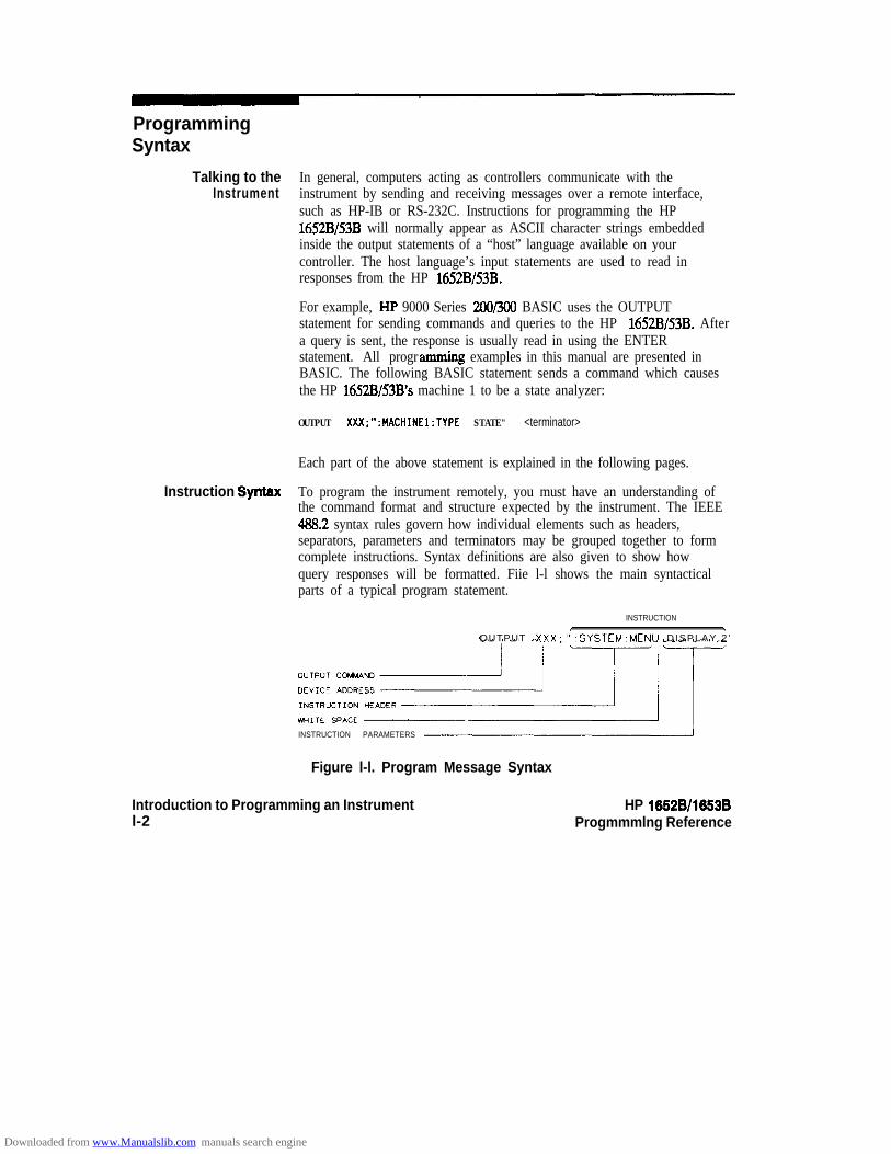
Instruction Syntax To program the instrument remotely, you must have an understanding ofthe command format and structure expected by the instrument. The IEEE483.2 syntax rules govern how individual elements such as headers,separators, parameters and terminators may be grouped together to formcomplete instructions. Syntax definitions are also given to show howquery responses will be formatted. Fiie l-l shows the main syntacticalparts of a typical program statement.
INSTRUCTIONI
OUTPUT XXX;“:SYSTEM:MENU D ISPLAY .2 ’
INSTRUCTION PARAMETERS
Figure l-l. Program Message Syntax
Introduction to Programming an Instrument HP 16528/1653Bl-2 Progmmmlng Reference
Downloaded from www.Manualslib.com manuals search engine
Output Command The output command is entirely dependant on the language you choose touse. Throughout this manual HP !%OO Series 2W300 BASIC 4.0 is used inthe programming examples. People using another language will need tofind the equivalents of BASIC commands like OUTPUT, ENTER andCLEAR in order to convert the examples. The instructions for theHP 1652B/53B are always shown between the double-quotes.
Device Address The location where the device address must be specified is also dependenton the host language which you are using. In some languages, this couldbe specified outside the output command. In BASIC, this is alwaysspecified after the keyword OUTPUT. The examples in this manual use ageneric address of XXX. When writing programs, the number you usewill depend on the cable you use in addition to the actual address. If youare using an HP-IB, see chapter 2. RS-232C users should refer tochapter 3, “Programming Over RS-232C.”
Instructions Instructions (both commands and queries) normally appear as a stringembedded in a statement of your host language, such as BASIC, Pascal orC. The only time a parameter is not meant to be expressed as a string iswhen the instruction’s syntax definition specifies <block data > . Thereare only five instructions which use block data.
Instructions are composed of two main parts: The header, which specifiesthe command or query to be sent; and the parameters, which provideadditional data needed to clarify the meaning of the instruction.
instruction Header The instruction header is one or more keywords separated by colons (:).The command tree in figure 4-l illustrates how all the keywords can bejoined together to form a complete header (see chapter 4, “Programmingand Documentation Conventions”).
The example in figure l-l shows a command. Queries are indicated byadding a question mark (?) to the end of the header. Many instructionscan be used as either commands or queries, depending on whether or notyou have included the question mark. The command and query forms ofan instruction usually have different parameters. Many queries do not useany parameters.
When you look up a query in this programming reference, you’ll fmd aparagraph labeled “Returned Format” under the one labeled “QuerySyntax.” The syntax definition by “Returned format” will always show theinstruction header in square brackets, like (:SYSTem:MENU]. What this
Introduction to Programming an Instrument1-3
Downloaded from www.Manualslib.com manuals search engine
White Space
Instruction Parameters
Header Types
really means is that the text between the brackets is optional, but it’s also aquick way to see what the header looks like.
White space is used to separate the instruction header from theinstruction parameters. If the instruction does not use any parameters,you do not need to include any white space. White space is defined as oneor more spaces. ASCII defines a space to be character 32 (in decimal).Tabs can be used only if your controller first converts them to spacecharacters before sending the string to the instrument.
Instruction parameters are used to clarify the meaning of the command orquery. They provide necessary data, such as whether a function should beon or off, which waveform is to be displayed, or which pattern is to belooked for. Each instruction’s syntax deli&ion shows the parameters, aswell as the values they accept. This chapter’s “Parameter Syntax Rules”section has all of the general rules about acceptable values.
When there is more than one parameter they are separated bycommas (,). You are allowed to add spaces around the commas.
There are three types of headers: Simple Command; CompoundCommand; and Common Command.
Simple Command Header. Simple command headers contain a singlekeyword. START and STOP are examples of simple command headerstypically used in this instrument. The syntax is:
cfunction > c terminator >
When parameters (indicated by c data z= ) must be included with thesimple command header (for example, :RMODE SINGLE) the syntax is:
cfunction> cwhits space > <data> cterminator >
Compound Command Header. Compound command headers are acombination of two or more program keywords. The first keyword selectsthe subsystem, and the last keyword selects the function within thatsubsystem. Sometimes you may need to list more than one subsystembefore being allowed to specify the function. The keywords within thecompound header are separated by colons. For example:
To execute a single function within a subsystem, use the following:
Introduction to Progmmming an Instrument HP 16628/1653Bl-4 Programming Reference
Downloaded from www.Manualslib.com manuals search engine

: c subsystem > : c function w <white space > <data > <terminator >
(For example :SYSTEM:LONGFORM ON)
To traverse down a level of a subsystem to execute a subsystem within thatsubsystem:
: <subsystem > : c subsystem > : <function > c white space > -z data > <terminator >
(For example :MMEMORY:LOAD:CONFIG “FILE-“)
Common Command Header. Common command headers control IEEE488.2 functions within the instrument (such as clear status, etc.). Theirsyntax is:
*-z command header > c terminator >
No space or separator is allowed between the asterisk and the commandheader. *CLS is an example of a common command header.
Combining To execute more than one function within the same subsystem aCommands from the semi-colon (;) is used to separate the functions:
Same Subsystem:<subsystem>:4unction> <white space> <data>:
-Z function z- -z white space z- < data z -c terminator >
(For example :SYSTEM:LONGFORM 0N;HEADER ON)
Duplicate Keywords Identical function keywords can be used for more than one subsystem.For example, the function keyword MMODE may be used to specify themarker mode in the subsystem for state listing or the timing waveforms:
SLISTMMODE PATIERN - sets the marker mode to pattern in the statelisting.
:TWAVEFORM:MMODE TIME - sets the marker mode to time in the timingwaveforms.
SLIST and TWAVEFORM are subsystem selectors and determine whichmarker mode is being modified.
HP 16528/1653BProgramming Reference
Introduction to Programming an Instrumentl-5
Downloaded from www.Manualslib.com manuals search engine

Query Usage Command headers immediately followed by a question mark (?) arequeries. After receiving a query, the instrument interrogates therequested function and places the response in its output queue. Theoutput message remains in the queue until it is read or another commandis issued. When read, the message is transmitted across the bus to thedesignated listener (typically a controller). For example, the logicanalyzer query :MACHINEl:TWAVEFORM:RANGE? places thecurrent seconds per division full scale range for machine 1 in the outputqueue. In BASIC, the input statement
ENTER XXX; Range
passes the value across the bus to the controller and places it in thevariable Range.
Query commands are used to find out how the instrument is currentlyconfigured. They are also used to get results of measurements made bythe instrument. For example, the command
:MACHINEl:lWAVEFORM:XOTIME?
instructs the instrument to place the X to 0 time in the output queue.
NoteThe output queue must be read before the next program message is sent.For example, when you send the query :TWAVEFORM:XOTIME? youmust follow that with an input statement. In BASIC, this is usually donewith an ENTER statement.
Sending another command before reading the result of the query willcause the output buffer to be cleared and the current response to be lost.This will also generate a “QUERY UNTERMINATED” error in theerror queue.
Introduction to Programming an Instrument HP 1662Bll663B1-6 Programming Reference
Downloaded from www.Manualslib.com manuals search engine

Program Header Program headers can be sent using any combination of uppercase orOptions lowercase ASCII characters. Instrument responses, however, are always
returned in uppercase.
Both program command and query headers may be sent in eitherlongform (complete spelling), shortform (abbreviated spelling), or anycombination of longform and shortform. Either of the following examplesturns on the headers and longform.
OUTPUT XXX;":SYSTEM:HEAOER 0N;LONGFORM ON" - longform
OUTPUT XXX;" :SYST:HEAO 0N;LONG ON" - shortform
Programs written in longform are easily read and are almost
self-documenting. The shortform syntax conserves the amount ofcontroller memory needed for program storage and reduces the amountof I/O activity.
Note dThe rules for shortform syntax are shown in chapter 4 “Programming andDocumentation Conventions.”
Parameter Syntax There are three main types of data which are used in parameters. TheyRules are numeric, string, and keyword. A fourth type, block data, is used only
for five instructions: the DATA and SETup instructions in the SYSTemsubsystem (see chapter 6); the CATalog, UPLoad, and DOWNloadinstructions in the MMEMory subsystem (see chapter 7). These syntaxrules also show how data may be formatted when sent back from theHP 1652B/53B as a response.
The parameter list always follows the instruction header and is separatedfrom it by white space. When more than one parameter is used, they areseparated by commas. You are allowed to include one or more spacesaround the commas, but it is not mandatory.
HP 1662Bll653BProgramming Reference
Introduction to Programming an Instrument1-7
Downloaded from www.Manualslib.com manuals search engine
Numeric data. For numeric data, you have the option of usingexponent ial notat ion or using suff ixes to indicate which uni t is being used.Tables A-l and A-2 in appendix A list all available suffixes. Do notcombine an exponent with a unit. The following numbers are all equal:28 = 0.2SE2 = 2SOe-1 = 2MOOm = 0.02%.
The base of a number is shown with a prefuL The available bases arebinary (#B), octal (#Q), hexadecimal (#H) and decimal (default). Forexample, #BlllOO = #Q34 = #HlC = 28. You may not specify abase in conjunction with either exponents or unit suffixes. Additionally,negative numbers must be expressed in decimal.
When a syntax definition specifies that a number is an integer, that meansthat the number should be whole. Any fractional part would be ignored,truncating the number. Numeric parameters which accept fractionalvalues are called real numbers.
All numbers are expected to be strings of ASCII characters. Thus, whensending the number 9, you would send a byte representing the ASCII codefor the character “9” (which is 57, or 00111001 in binary). A three-digitnumber like 102 would take up three bytes (ASCII codes 49,4S and 50).This is taken care of automatically when you include the entire instructionin a s t r ing .
String data. String data may be delimited with either single (‘) or double(“) quotes. String parameters representing labels are case-sensitive. Forinstance, the labels “Bus A” and “bus a” are unique and should not be usedindiscriminately. Also pay attention to the presence of spaces, since theyact as legal characters just like any other. So the labels “In” and ” In” arealso two separate labels.
Keyword data. In many cases a parameter must be a keyword. Theavailable keywords are always included with the instruction’s syntaxdefinition. When sending commands, either the longform or shortform (ifone exists) may be used. Upper-case and lower-case letters may be mixedfreely. When receiving responses, upper-case letters will be usedexclusively. The use of longform or shortform in a response depends onthe setting you last specified via the SYSTem:LONGform command (seechapter 6).
Introduction to Programming an Instrumentl-8
HP 18528/1883BProgremming Reference
Downloaded from www.Manualslib.com manuals search engine

Instruction Terminator An instruction is executed after the instruction terminator is received.The terminator is the NL (New Line) character. The NL character is anASCII linefeed character (decimal 10).
Note dThe NL (New Line) terminator has the same function as an EOS (End OfString) and EOT (End Of Text) terminator.
Selecting Multiple You can send multiple program commands and program queries forSubsystems different subsystems on the same line by separating each command with a
semicolon. The colon following the semicolon enables you to enter a newsubsystem. For example:
< instruction header > <data > ;: c instruction header > <data > <terminator >
:MACHINEl:ASSIGNP;:SYSTEM:HEADERS ON
,I4Note 4Multiple commands may be any combination of simple, compound andcommon commands.
HP 16528/1653B Introduction to Programming an Instrument1-9
Downloaded from www.Manualslib.com manuals search engine

Programmingan Instrument
Initialization To make sure the bus and all appropriate interfaces are in a known state,begin every program with an initialization statement. BASIC provides aCLEAR command which clears the interface buffer. If you’re usingHP-IB, CLEAR will also reset the HP 1652B/53B’s parser. The parser isthe program which reads in the instructions which you send it.
After clearing the interface, load a predefmed configuration file from thedisk to preset the instrument to a known state. For example:
OUTPUT XXX;" :MMEMORY:LOAD:CONFIG 'DEFAULT-"'
This BASIC statement would load the configuration file “DEFAULT-”(if it exists) into the HP 1652B/53B. Refer to the chapter “MMEMorySubsystem” for more information on the LOAD command.
Note ‘dRefer to your controller manual and programming language referencemanual for information on initializing the interface.
Introduction to Programming an Instrumentl-10
HP 16528/1663B
Downloaded from www.Manualslib.com manuals search engine

Example Progrem This program demonstrates the basic command structure used to programthe HP 16XXV53B.
10 CLEAR XXX !Initialize instrument interface
20 OUTPUT XXX;" :SYSTEM:HEADER ON" !Turn headers on30 OUTPUT XXX; ":SYSTEM:LONGFORM ON" !Turn longfonn on
40 OUTPUT XXX;" :MMEM:LOAD:CONFIG 'TEST-E'" !Load configuration file
50 OUTPUT XXX;":MENU FORMAT,l" !Select Format menu for machine 1
60 OUTPUT XXX;":RMODE SINGLE" !Select run mode
70 OUTPUT XXX;":START" !Run the measurement
Program Overview Line 10 initializes the instrument interface to a known stateLines 20 and 30 turn the headers and longform on.Line 40 loads the configuration file “TEST E” from the disc drive.Line 50 displays the Format menu for machine 1.Lines 60 and 70 tell the analyzer to run the measurement configured bythe fde “TEST-E” one time.
Receiving Information After receiving a query (command header followed by a question mark),from the Instrument the instrument interrogates the requested function and places the answer
in its output queue. The answer remains in the output queue until it isread or another command is issued. When read, the message istransmitted across the bus to the designated listener (typically acontroller). The input statement for receiving a response message froman instrument’s output queue typically has two parameters;the deviceaddress and a format specification for handling the response message.For example, to read the result of the query command:SYSTEM:LONGFORM? you could execute the BASIC statement:
ENTER W Setting
where XXX represents the address of your device. This would enter thecurrent setting for the longform command in the numeric variable Sefting.
HP 1652B/l653BProgmmming Reference
Introduction to Programming an Instrumentl-11
Downloaded from www.Manualslib.com manuals search engine

NoteAll results for queries sent in a program message must be read beforeanother program message is sent. For example, when you send the query:MACHINEl:ASSIGN?, you must follow that query with an inputstatement. In BASIC, this is usually done with an ENTER statement.
The format specification for handling the response messages is dependenton both the controller and the programming language.
Response Header The format of the returned ASCII string depends on the current settingsOptions of the SYSTEM HEADER and LONGFORM commands. The general
format is:
c instruction header > <space > <data > c terminator >
The header identifies the data that follows (the parameters) and iscontrolled by issuing a :SYSTEM:HEADER ON/OFF command. If thestate of the header command is OFF, only the data is returned by thequery.
The format of the header is controlled by the :SYSTEM:LONGFORMON/OFF command. If longform is OFF, the header will be in itsshortform and the header will vary in length depending on the particularquery. The separator between the header and the data always consists ofone space.
The following examples show some possible responses for a:MACHINEl:SFORMAT:THRESHOLD2? query:
l with HEADER OFF:<data> <terminator>
l with HEADER ON and LONGFORM OFF::MACHl:SFOR:THR2 <space > <data > <terminator z-
l with HEADER ON and LONGFORM ON::MACHINEl:SFORMAT:THRESHOLD2 <space> <data> <terminator>
Introduction to Programming an Instrument HP 16628/1653B1-12 Programming Reference
Downloaded from www.Manualslib.com manuals search engine
Note 3
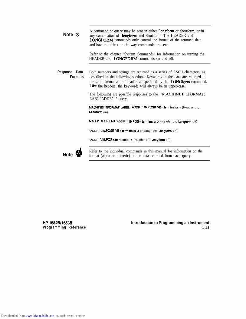
Response DataFormats
Note d
A command or query may be sent in either longform or shortform, or inany combination of longform and shortform. The HEADER andLONGFORM commands only control the format of the returned dataand have no effect on the way commands are sent.
Refer to the chapter “System Commands” for information on turning theHEADER and LONGFORM commands on and off.
Both numbers and strings are returned as a series of ASCII characters, asdescribed in the following sections. Keywords in the data are returned inthe same format as the header, as specified by the LONGform command.Lie the headers, the keywords will always be in upper-case.
The following are possible responses to the “MACHINEl: TFORMAT:LAB? ‘ADDR’ ” query.
MACHINEl:TFORMAT:lABEL “ADDR “,19.POSITIVE-zterminator~ (Header on;
Longform on)
MACH1:TFOR:lAB “ADDR “,lS,POS-zterminator > (Header on; Longform off)
“ADDR ‘,19,POSlTlVEcterminator > (Header off; Longform on)
“ADDR ‘, lS,POScterminator > (Header off; Longform off)
Refer to the individual commands in this manual for information on theformat (alpha or numeric) of the data returned from each query.
HP 1652B/l653BProgramming Reference
Introduction to Programming an Instrument1-13
Downloaded from www.Manualslib.com manuals search engine

String Variables Since there are so many ways to code numbers, the HP 1652B/53Bhandles almost all data as ASCII strings. Depending on your hostlanguage, you may be able to use other types when reading in responses.
Sometimes i t is helpful to use s t r ing variables in place of constants to sendinstructions to the HP 1652B/53B. The example below combines variablesand constants in order to make it easier to switch from MACHINE1 toMACHINE2. In BASIC, the & operator is used for string concatenation.
10 LET MachineS = ":MACHINEZ" !Send all instructions to machine 2
20 OUTPUT XXX; MachineS & ":TYPE STATE" !Make machine a state analyzer
30 ! Assign all labels to be positive40 OUTPUT XXX; Machine$ & ":SFORMAT:LABEL 'CHAN 1'. POS"
50 OUTPUT XXX; Machine$ & ":SFORMAT:LABEL 'CHAN 2'. POS"
60 OUTPUT XXX; MachineS & ":SFORMAT:LABEL 'OUT', POS"
99 END
If you want to observe the headers for queries, you must bring thereturned data into a string variable. Reading queries into string variablesrequires little attention to formatting. For example:
ENTER XXX;Result$
places the output of the query in the str ing variable Result%.
Noted3 In the language used for this book (HP BASIC 4.0), string variables are
case sensitive and must be expressed exactly the same each time they areused.
The output of the instrument may be numeric or character datadepending on what is queried. Refer to the specific commands for theformats and types of data returned from queries.
Introduction to Programming an Instrumentl-14
HP 1652W1653BProgramming Reference
Downloaded from www.Manualslib.com manuals search engine

The following example shows logic analyzer data beii returned to astring variable with headers off:
10 OUTPUT XXX;" :SYSTEM:HEAOER OFF"20 DIM Rang$[30]
30 OUTPUT XXX;":MACHINEl:TWAVEFORM:RANGE?"
40 ENTER XXX;RangS50 PRINT Rang$
60 END
After running this program, the controller displays:
+ 1.OOOOOE-05
Numeric Base Most numeric data will be returned in the same base as shown on screen.When the prefut #B precedes the returned data, the value is in the biibase. Likewise, #Q is the octal base and #H is the hexadecimal base. Ifno prefa precedes the returned numeric data, then the value is in thedecimal base.
Numeric Variables If your host language can convert from ASCII to a numeric format, thenyou can use numeric variables. Turning off the response headers will helpyou avoid accidently trying to convert the header into a number.
The following example shows logic analyzer data being returned to anumeric variable.
10 OUTPUT XXX;":SYSTEM:HEADER OFF"20 OUTPUT XXX;": MACHINEl:TWAVEFORM:RANGE?"30 ENTER XXX;Rang40 PRINT Rang
50 END
This time the format of the number (such as whether or not exponentialnotation is used) is dependant upon your host language. In BASIC, theoutput would look like:
l.E-5
HP 16528/1653BProgramming Reference
Introduction to Programming an Instrumentl-15
Downloaded from www.Manualslib.com manuals search engine
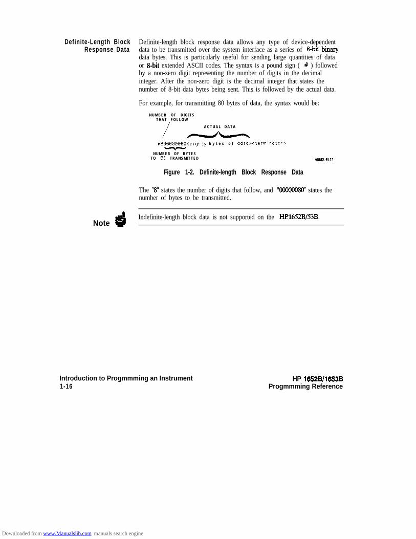
Definite-Length Block Definite-length block response data allows any type of device-dependentResponse Data data to be transmitted over the system interface as a series of 8-bit binary
data bytes. This is particularly useful for sending large quantities of dataor 8-bit extended ASCII codes. The syntax is a pound sign ( # ) followedby a non-zero digit representing the number of digits in the decimalinteger. After the non-zero digit is the decimal integer that states thenumber of 8-bit data bytes being sent. This is followed by the actual data.
For example, for transmitting 80 bytes of data, the syntax would be:
N U M B E R O F D I G I T ST H A T F O L L O W
A C T U A L D A T A
i -#800000080<eighty b y t e s o f data><terminator>
N U M B E R O F B Y T E ST O BE TRANSMITTED 1IJBBIBLZZ
Figure 1-2. Definite-length Block Response Data
The “8” states the number of digits that follow, and ‘WOOOO80” states thenumber of bytes to be transmitted.
NoteIndefinite-length block data is not supported on the HI?1652B/53B.
Introduction to Progmmming an Instrument HP 16528/1653B1-16 Progmmming Reference
Downloaded from www.Manualslib.com manuals search engine

Multiple Queries
Note
Instrument Status
HP 16528/1653B
You can send multiple queries to the instrument within a single programmessage, but you must also read them back within a single programmessage. This can be accomplished by either reading them back into astring variable or into multiple numeric variables. For example, you couldread the result of the query :SYSTEM:HEADER?;LONGFORM? intothe string variable Results$ with the command:
ENTER XXX: Results$
When you read the result of multiple queries into string variables, eachresponse is separated by a semicolon. For example, the response of thequery :SYSTEM:HEADER?:LONGFORM? with HEADER andLONGFORM on would be:
:SYSTEM:HEADERl;:SYSTEM:LONGFORMl
If you do not need to see the headers when the numeric values arereturned, then you could use following program message to read the query:SYSTEM:HEADERS?;LONGFORM? into multiple numeric variables:
ENTER XXX; Resultl. Result2
When you are receiving numeric data into numeric variables, the headersshould be turned off. Otherwise the headers may cause misinterpretationof returned data.
Status registers track the current status of the instrument. By checking theinstrument s tatus, you can find out whether an operation has beencompleted, whether the instrument is receiving triggers, and more.Appendix B, “Status Report ing,” explains how to check the status of theinstrument.
Introduction to Programming an Instrument1-17
Downloaded from www.Manualslib.com manuals search engine

Programming Over HP-IB 2Introduction This section describes the interface functions and some general concepts
of the HP-IB. In general, these functions are defined by IEEE 488.1(HP-IB bus standard). They deal with general bus management issues, aswell as messages which can be sent over the bus as bus commands.
InterfaceCapabilities
The interface capabilities of the HP 1652B/53B, as defined by IEEE 488.1are SHl, AHl, T5, TEO, L3, LEO, SRl, RLl, PPl, DCl, DTl, CO, and E2.
Command and The HP-IB has two modes of operation: command mode and data mode.
Data Concepts The bus is in command mode when the ATN line is true. The commandmode is used to send talk and l is ten addresses and various bus commands,such as a group execute trigger (GET). The bus is in the data mode whenthe ATN line is false. The data mode is used to convey device-dependentmessages across the bus. These device-dependent messages include all ofthe instrument commands and responses found in chapters 5 through 27of this manual.
Addressing By using the front-panel I/O and SELECT keys, the HP-IB interface canbe placed in either talk only mode “Printer connected to HP-IB” oraddressed talk/listen mode “Controller connected to HP-IB” (see “I/OPort Configuration” in Chapter 5 of the HP 1652BIHP 16538 Front-PanelReference manual Talk only mode must be used when you want theinstrument to talk directly to a printer without the aid of a controller.Addressed talk/listen mode is used when the instrument will operate inconjunction with a controller. When the instrument is in the addressedtalk/listen mode, the following is true:
l Each device on the HP-IB resides at a particular address rangingfrom 0 to 30.
l The active controller specifies which devices will talk, and whichwill listen.
l An instrument, therefore, may be talk addressed, listen addressed,or unaddressed by the controller.
HP 16528/16538Programming Reference
Programming Over HP-IB2-1
Downloaded from www.Manualslib.com manuals search engine
If the controller addresses the instrument to talk, it will remain configuredto talk until it receives an interface clear message (IFC), anotherinstrument’s talk address (OTA), its own listen address (MIA), or auniversal untalk (UNT) command.
If the controller addresses the instrument to listen, it will remainconfigured to listen until it receives an interface clear message (IFC) itsown talk address (MTA), or a universal unlisten (UNL) command.
Communicating s ince HP-IB can address multiple devices through the same interface
Over the HP-IB card, the device address passed with the program message must include
Bus (HP 9000not only the correct instrument address, but also the correct interfacec o d e .
Series 200/300Controller) Interface Select Code (Selects Interface). Each interface card has its own
interface select code. This code is used by the controller to directcommands and communications to the proper interface. The default isalways “7” for HP-IB controllers.
Instrument Address (Selects Instrument). Each instrument on theHP-IB port must have a unique instrument address between decimal 0and 30. The device address passed with the program message mustinclude not only the correct instrument address, but also the correctinterface select code.
DEVICE ADDRESS = (Interface Select Code) X 100 + (Instrument Address)
For example, if the instrument address for the HP 1652B/53B is 4 and theinterface select code is 7, when the program message is passed, theroutine performs its function on the instrument at device address 704.
Local, Remote, The local, remote, and remote with local lockout modes may be used for
and Local various degrees of front-panel control while a program is running. The
Lockoutinstrument will accept and execute bus commands while in local mode,and the front panel will also be entirely active. If the HP 1652B/53B is inremote mode, the instrument will go from remote to local with any frontpanel activity. In remote with local lockout mode, all controls (except thepower switch) are entirely locked out. Local control can only be restoredby the controller.
Programming Over HP-IB HP 16528/1653B2-2 Programming Reference
Downloaded from www.Manualslib.com manuals search engine
NoteCycling the power will also restore local control, but this will also resetcertain HP-IB states.
The instrument is placed in remote mode by setting the REN (RemoteEnable) bus control line true, and then addressing the instrument tolisten. The instrument can be placed in local lockout mode by sending thelocal lockout (LLO) command (see SYSTem:LOCKout in chapter 6).The instrument can be returned to local mode by either setting the RENline false, or sending the instrument the go to local (GTL) command.
Bus Commands
Device Clear
Group ExecuteTrigger (GET)
Interface Clear (IFC)
HP 16526/l 6536 Programming Over HP-IBProgramming Reference 2-3
The following commands are IEEE 488.1 bus commands (ATN true).IEEE 488.2 defmes many of the actions which are taken when thesecommands are received by an instrument.
The device clear (DCL) or selected device clear (SDC) commands clearthe input and output buffers, reset the parser, clear any pendingcommands, and clear the Request-OPC flag.
The group execute trigger command will cause the same action as theSTART command for Group Run: the instrument will acquire data forthe active waveform and l ist ing display(s) ,
This command halts all bus activity. This includes unaddressing alllisteners and the talker, disabling serial poll on all devices, and returningcontrol to the system controller.
Downloaded from www.Manualslib.com manuals search engine
Programming Over RS-232C
Introduction This section describes the interface functions and some general conceptsof the RS-232C. The RS-232C interface on this instrument isHewlett-Packard’s implementation of EIA Recommended StandardRS-232C, “Interface Between Data Terminal Equipment and DataCommunications Equipment Employing Serial Binary Data Interchange.”With this interface, data is sent one bit at a time and characters are notsynchronized with preceding or subsequent data characters. Eachcharacter is sent as a complete entity without relationship to other events.
InterfaceOperation
The HP 1652B/53B can be programmed with a controller over RS-232Cus ing e i the r a minimum three-wire or extended hardwire interface. Theoperation and exact connections for these interfaces are described inmore detail in the following sections. When you are programming anHP 1652B/53B over RS-232C with a controller, you are normallyoperating directly between two DTE (Data Terminal Equipment) devicesas compared to operating between a DTE device and a DCE (DataCommunications Equipment) device.
When operating directly between two DTE devices, certainconsiderations must be taken into account. For three-wire operation,XON/XOFF must be used to handle protocol between the devices. Forextended hardwire operation, protocol may be handled either withXON/XOFF or by manipulating the CTS and RTS lines of the RS-232Clink. For both three-wire and extended hardwire operation, the DCD andDSR inputs to the HP 1652B/53B must remain high for proper operation.
With extended hardwire operation, a high on the CI’S input allows the HP1652B/53B to send data and a low on this line disables the HP 1652B/53Bdata transmission. Likewise, a high on the RTS line allows the controllerto send data and a low on this line signals a request for the controller todisable data transmission. Since three-wire operation has no control overthe CTS input, internal pull-up resistors in the HP 1652B/53B assure thatthis line remains high for proper three-wire operation.
HP 16528/l 6538 Programming Over RS-232C3-l
Downloaded from www.Manualslib.com manuals search engine

Cables Selecting a cable for the RS-232C interface is dependent on your specificapplication. The following paragraphs describe which lines of theHP 1652B/53B are used to control the operation of the RS-232C relativeto the HP 1652B/53B. To locate the proper cable for your application,refer to the reference manual for your controller. This manual shouldaddress the exact method your controller uses to operate over theRS-232C bus.
Minimum With a three-wire interface, the software (as compared to interface
Three-WireInterface withSoftwareProtocol
hardware) controls the data flow between the HP 1652B/53B and thecontroller. This provides a much simpler connection between devicessince you can ignore hardware handshake requirements. TheHP 1652B/53B uses the following connections on its RS-232C interface forthree-wire communication:
l Pin 7 SGND (Signal Ground)l Pin 2 TD (Transmit Data from HP 1652B/53B)l Pin 3 RD (Receive Data into HP 1652B/53B)
The TD (Transmit Data) line from the HP 1652B/53B must connect to theRD (Receive Data) line on the controller.‘Likewise, the RD line from theHP 1652B/53B must connect to the TD line on the controller. Internalpull-up resistors in the HP 1652B/53B assure the DCD, DSR, and CISlines remain high when you are using a three-wire interface.
NoteThe three-wire interface provides no hardware means to control data flowbetween the controller and the HP 1652B/53B. XON/OPP protocol is theonly means to control this data flow.
Programming Over RS-232C3-2
HP 16526/1663B
Downloaded from www.Manualslib.com manuals search engine

Extended With the extended interface, both the software and the hardware canInterface with control the data flow between the HP 1652B/53B and the controller. This
HardwareHandshake
allows you to have more control of data flow between devices. TheHP 1652B/53B uses the following connections on its RS-232C interface forextended interface communication:
l Pin 7 SGND (Signal Ground)l Pm 2 TD (Transmit Data from HP 1652B/53B)l Pin 3 RD (Receive Data into HP 1652B/53B)
The additional lines you use depends on your controller’s implementationof the extended hardwire interface.
l Pin 4 RTS (Request To Send) is an output from theHP 1652B/53B which can be used to control incoming data flow.
l Pin 5 CTS (Clear To Send) is an input to the HP 1652B/53Bwhich controls data flow from the HP 1652B/53B.
l Pm 6 DSR (Data Set Ready) is an input to the HP 1652B/53Bwhich controls data flow from the HP 1652B/53B within two bytes.
l Pin 8 DCD (Data Carrier Detect) is an input to the HP1652B/53B which controls data flow from the HP 1652B/53B withintwo bytes.
l Pin 20 DTR (Data Terminal Ready) is an output from theHP 1652B/53B which is enabled as long as the HP 1652B/53B isturned on.
The TD (Transmit Data) line from the HP 1652B/53B must connect to theRD (Receive Data) line on the controller. Likewise, the RD line from theHP 1652B/53B must connect to the TD line on the controller.
HP 16528/1653BProgramming Reference
PrOgn3mming Over RS-232C3-3
Downloaded from www.Manualslib.com manuals search engine

The RTS (Request To Send), is an output from the HP 1652B/53B whichcan be used to control incoming data flow. A true on the RTS line allowsthe controller to send data and a false on this line signals a request for thecontroller to disable data transmission.
The CTS (Clear To Send), DSR (Data Set Ready), and DCD (DataCarrier Detect) lines are inputs to the HP 1652B/53B which control dataflow from the HP 1652B/53B (Pin 2). internal pull-up resistors in theHP 1652B/53B assure the DCD and DSR lines remain high when they arenot connected. If DCD or DSR are connected to the controller, thecontroller must keep these lines and the CTS line high to enable theHP 1652B/53B to send data to the controller. A low on any one of theselines will disable the HP 1652B/53B data transmission. Dropping the CTSline low during data transmission will stop HP 1652B/53B datatransmission immediately. Dropping either the DSR or DCD line lowduring data transmission will stop HP 1652B/53B data transmission, but asmany as two additional bytes may be transmitted from the HP 1652B/53B.
Cable Example Fiie 3-l is an example of how to connect the HP 1652B/53B to theHP 9S62SA Interface card of an HP 9000 series 2W3OO controller. Formore information on cabling, refer to the reference manual for yourspecific controller.
NoteI(4 Since this example does not have the correct connections for hardware
handshake, XON/XOFP protocol must be used when connecting theHP 1652B/53B as shown in figure 3-l
Programming Over RS232C3-4
Figure 3-l . Cable Example
HP 16528/16538Programming Reference
Downloaded from www.Manualslib.com manuals search engine

Configuring the The front-panel I/O menu key allows you access to the RS-232CInstrument Configuration menu where the RS-232C interface is configured.
Interface If you are not familiar with how to conf’iie the RS-232C interface, referto the HP 165281538 Front-panel Reference manual.
InterfaceCapabilities
The baud rate, stop bits, parity, protocol, and data bits must be configuredexactly the same for both the controller and the HP 1652B/53B toproperly communicate over the RS-232C bus. The HP 1652B/53BRS-232C interface capabilities are listed below:
l Baud Rate: 110,300,600,1200,2400,4800,9600, or 19.2 kl Stop Bits: 1, 1.5, or 2l Parity: None, Odd, or Evenl Protocol: None or XON/XOPPl Data Bits: 8
Protocol NONE. With a three-wire interface, selecting NONE for the protocoldoes not allow the sending or receiving device to control data flow. Nocontrol over the data flow increases the possibility of missing data ortransferring incomplete data.
With an extended hardwire interface, selecting NONE allows a hardwarehandshake to occur. With hardware handshake, hardware signals controldata flow.
XON/XOFF. XON/XOPP stands for Transmit On/Transmit Off. Withthis mode the receiver (controller or HP 1652B/53B) controls data flowand can request that the sender (HP 1652B/53B or controller) stop dataflow. By sending XOPP (ASCII 19) over its transmit data line, thereceiver requests that the sender disables data transmission. Asubsequent XON (ASCII 17) allows the sending device to resume datatransmission.
Programming Over RS-232C3-5
Downloaded from www.Manualslib.com manuals search engine

Data Bits
Note d
Data bits are the number of bits sent and received per character thatrepresent the binary code of that character. Characters consist of either 7or 8 bits, depending on the application. The HP 1652B/53B supports 8 bitonly.
8 Bit Mode. Information is usually stored in bytes (8 bits at a time). With8-bit mode, you can send and receive data just as it is stored, without theneed to convert the data.
The controller and the HP 1652B/53B must be in the same bit mode toproperly communicate over the RS-232C. This means that both thecontroller and the HP 1652B/53B must have the capability to send andreceive 8 bit data.
For more information on the RS-232C interface, refer to theHP 1652BlHP 1653B Front-Panel Reference Manual. For information onRS-232C voltage levels and connector pinouts, refer to the HP 165281538Service Manual.
Communicating Each RS-232C interface card has its own interface select code. This codeOver the. is used by the controller to direct commands and communications to the
RS-232C Busproper interface by specifying the correct interface code for the deviceaddress.
(HP 9000Series 200/300 Generally, the interface select code can be any decimal value between 0
Controller)and 31, except for those interface codes which are reserved by thecontroller for internal peripherals and other internal interfaces. Thisvalue can be selected through switches on the interface card. For moreinformation, refer to the reference manual for your interface card orcontroller.
For example, if your RS-232C interface select code is 9, the deviceaddress required to communicate over the RS-232C bus is 9.
Programming Over RS-232C HP 16528/l 65383-6 Programming Reference
Downloaded from www.Manualslib.com manuals search engine

LockoutCommand
To lockout the front panel controls use the SYSTem command LOCKout.When this function is on, all controls (except the power switch) areentirely locked out. Local control can only be restored by sending thecommand :LOCKout OFF. For more information on this command seethe chapter “System Commands” in this manual.
Note ”3Cycling the power will also restore local control, but this will also resetcertain RS-232C states.
HP 16528/16538 Programming Over AS-232CProgramming Reference 3-7
Downloaded from www.Manualslib.com manuals search engine


Programming andDocumentation Conventions
4
Introduction This section covers the progr amming conventions used in programmingthe instrument, as well as the documentations conventions used in thismanual. This chapter also contains a detailed description of the commandtree and command tree traversal.
Truncation Rllk The truncation rule for the keywords used in headers and parameters is:
If the longform has four or fewer characters, there is no change in theshortform. When the longform has more than four characters theshortfonn is just the first four characters, unless the fourth character isa vowel. In that case only the first three characters are used.
NoteThere are some commands that do not conform to the truncation rule bydesign. These will be noted in their respective description pages.
Some examples of how the truncation rule is applied to various commandsare shown in table 4-1.
HP 16528/1653BProgramming Reference
Longform Shortform
OFF OFFDATA DATASTART STARLONGFORM LONGDELAY DELACCUMULATE ACC
Table 4-l. Keyword Truncation
Programming and Documentation Conventions4-l
Downloaded from www.Manualslib.com manuals search engine

Infinity The representation of infinity is 9.9E + 37 for real numbers and 32767 forRepresentation integers. This is also the value returned when a measurement cannot be
made.
Sequential and IEEE 488.2 makes the distinction between sequential and overlapped
Overlapped commands. Sequential commands finish their task before the execution of
Commandsthe next command starts. Overlapped commands run concurrently, andtherefore the command following an overlapped command may be startedbefore the overlapped command is completed. The overlapped commandsfor the HP 1652B/53B are STARt, STOP, and AUToscale.
ResponseGeneration
IEEE 488.2 defines two times at which query responses may be buffered.The first is when the query is parsed by the instrument and the second iswhen the controller addresses the instrument to talk so that it may readthe response. The HP 1652B/53B will buffer responses to a query when itis parsed.
syntax Diagrams At the be-g of each of the following chapters are syntax diagramsshowing the proper syntax for each command. All characters contained ina circle or oblong are literals, and must be entered exactly as shown.Words and phrases contained in rectangles are names of items used withthe command and are described in the accompanying text of eachcommand. Each line can only be entered from one direction as indicatedby the arrow on the entry line. Any combination of commands andarguments that can be generated by following the lines in the properdirection is syntactically correct. An argument is optional if there is apath around it. When there is a rectangle which contains the word“space,” a white space character must be entered. White space is optionalin many other places.
Programming and Documentation Conventions HP 16528/1653B4-2 Programming Reference
Downloaded from www.Manualslib.com manuals search engine

Notation The fol lowing conventions are used in this manual when describingConventions and Programming rules ~de~ples:
Definitions <>
:: =
. . .
[I
0
Angular brackets enclose words or characters that are usedto symbolize a program code parameter or a bus command.
“is defined as.” For example, A :: = B indicates that Acan be replaced by B in any statement containing A .
“or”: indicates a choice of one element from a list. Forexample, A 1 B indicates A or B, but not both.
An ellipsis (trailing dots) is used to indicate that thepreceding element may be repeated one or more times.
Square brackets indicate that the enclosed items are optional.
When several i tems are enclosed by braces and separatedby 1 s, one, and only one of these elements must be selected.
Three Xs after an ENTER or OUTPUT statementrepresent the device address required by your controller.
In addition, the following definition is used:
<NL> :: = Linefeed (ASCII decimal 10).
HP 16!528/1653BProgramming Reference
Programming and Documentation Conventions4-3
Downloaded from www.Manualslib.com manuals search engine

The Command The command tree (figure 4-l) shows all commands in the HP 1652B/53B
Tree logic analyzers and the relationship of the commands to each other.Parameters are not shown in this figure. The command tree allows you tosee what the HP 1652B/53B’s parser expects to receive. All legal headerscan be created by traversing down the tree, adding keywords until the endof a branch has been reached.
Command Types As shown in chapter l’s “Header Types” section, there are three types ofheaders. Each header has a corresponding command type. This sectionshows how they relate to the command tree.
System Commands. The system commands reside at the top level of thecommand tree. These commands are always parsable if they occur at thebeginning of a program message, or are preceded by a colon. START andSTOP are examples of system commands.
Subsystem Commands. Subsystem commands are grouped togetherunder a common node of the tree, such as the MMEMORY commands.
Common Commands. Common commands are independent of the tree,and do not affect the position of the parser within the tree. *CLS and+RST are examples of common commands.
Tree Traversal Rules Command headers are created by traversing down the command tree. Foreach group of keywords not separated by a branch, one keyword must beselected. As shown on the tree, branches are always preceded by colons.Do not add spaces around the colons. The following two rules apply totraversing the tree:
A leading colon (the first character of a header) or a < terminator >places the parser at the root of the command tree.
Executing a subsystem command places you in that subsystem (until aleading colon or a < terminator > is found). The parser will stay at thecolon above the keyword where the last header terminated. Anycommand below that point can be sent within the current programmessage without sending the keywords(s) which appear above them.
Programming and Documentation Conventions4-4
HP 16528/1653BProgramming Reference
Downloaded from www.Manualslib.com manuals search engine

Examples
Example 1
Example 2
Example 3
HP 16!528/1653BProgramming Reference
The following examples are written using HP BASIC 4.0 on a HP !%OOSeries 2W300 Controller. The quoted string is placed on the bus,followed by a carriage return and linefeed (CRLF).
The three Xs (XXX) shown in this manual after an ENTER or OUTPUTstatement represents the device address required by your controller.
OUTPUT XXXf:SYSTEM:HEADER 0N;LONGFORM ON”
In example 1, the colon between SYSTEM and HEADER is necessarysince SYSTEM:HEADER is a compound command. The semicolonbetween the HEADER command and the LONGFORM command is therequired < program message unit separator > . The LONGFORMcommand does not need SYSTEM preceding it, since theSYSTEM:HEADER command sets the parser to the SYSTEM node inthe tree.
OUTPUT XXX;“:MMEMOFlY:INITlALlZE;STORE ‘FILE-‘,‘FILE DESCRIPTION”’
or
OUTPUT XXX;“:MMEMORY:INITlALlZE”OUTPUT XXX;“:MMEMORY:STORE ‘FILE-‘,‘FILE DESCRIPTION”’
In the frrst line of example 2, the “subsystem selector” is implied for theSTORE command in the compound command. The STORE commandmust be in the same program message as the INITIALIZE command,since the -z program message terminator > will place the parser back atthe root of the command tree.
A second way to send these commands is by placing “MMEMORY:”before the STORE command as shown in the fourth line of example 2.
OUTPUT ~“:MMEM:CATALOG?;:SYSTEM:PRlNT ALL”
In example 3, the leading colon before SYSTEM tells the parser to goback to the root of the command tree. The parser can then see theSYSTEM:PRINT command.
Programming and Documentation Conventions4-5
Downloaded from www.Manualslib.com manuals search engine

I I I I IPPOWer RMODe STARt S T O P M M E M : M A C H
I
I IAUTu I oad LdAD : STORe :
CATalogc OP ‘Y
CO& i g COljlF i g
@OWNloadASSemb I e r
INITializePACrPURGe
RENameUFLoad
I ISFORmo t STRoce :
CL OCkCPER i odLABe I
MASTerREMoveSL AVeTHReshol d
BRANchF I N DPREStore
RANGeRESTar tSEQuenceSTORe
ISLISt.
COL umnD A T AL I N E
MMODeOPATternOSEarchOSTate
TAGTERM
OTAGRUNT i ITAVer a g eTMAX i mumT M I N imum
VRUNsXOTagXPATtern
XSEarchXSTateXTAG
I I
CoMpla r e :SCHort:
I
l-ir
I I I 4-w
lef112). DLISt: WLISt: SYSTem-I
COLumn XST’a t eI
ARMBnc
L I N E OSTa t e D A T AOTIMe DSPXTIMe ERRo r
HEADe r
KEY
ARM
ASS i gnAlJTosca I eNAME
T Y P E
L E RLOCKou t
LONGformMENUMESEMESR
PRINtSETup
I I ITFORMat: TTRace : TWAVeform:
LABe I AMADeI
ACCumulateREMove DURat i o n DELoyTHReshold EDGE INSer t
GLITch MMODePATTern OCONdition
OPATtern
OSEarchOTIMeRANGeREMoveRUNT i ISPERiod
TAVerageTMAX i mumTMINimum
VRUNsXCONdition
XOT i meXPATtern
I ISWAVeform: SYMBOL :
XSEarch
I I XTIMeCMASk Accumulate Accumulate BASECOPY HAX i s DELoy PATTern
D A T A VAX i s INSer t RANGeF I N D RANGe REMoveRANGe REMove WIDThRUNT, I
Figure 4-i. HP 16!528/53B Command Tree
Programming and Documentation Conventions4-6
HP 16528/16538Programming Reference
Downloaded from www.Manualslib.com manuals search engine

SCOPe :
IAUTosco I eSMODe
I I I I ICHANne I : TRIGger AC0uir.e: TIMebose: WAVeform: MEASur e :
I I I Icow I n g LEVe I CO”llr t DELay COUPA ALLOFFSet MODE T Y P E MODE D A T A FALLt ImePROBe SLOPe RANGe FORMa t FREOuencyRANGe S O U R c e POINts NWIDth
PREomb I e OVERshoo tRECord PERiodS O U R c e PREShoo tTYPE PWIDthVAL i d RISet imeXINCrement SOURceXOR i g i n VAMPlitudeXREFerence VBASeYINCrement VMAXYORigin VMIN
01650851 YREFerence VPPV T O P
Figure 41. HP 16528/53B Command Tree (continued)
HP 16528/1653B Progmmming and Documentation Conventions4-7
Downloaded from www.Manualslib.com manuals search engine
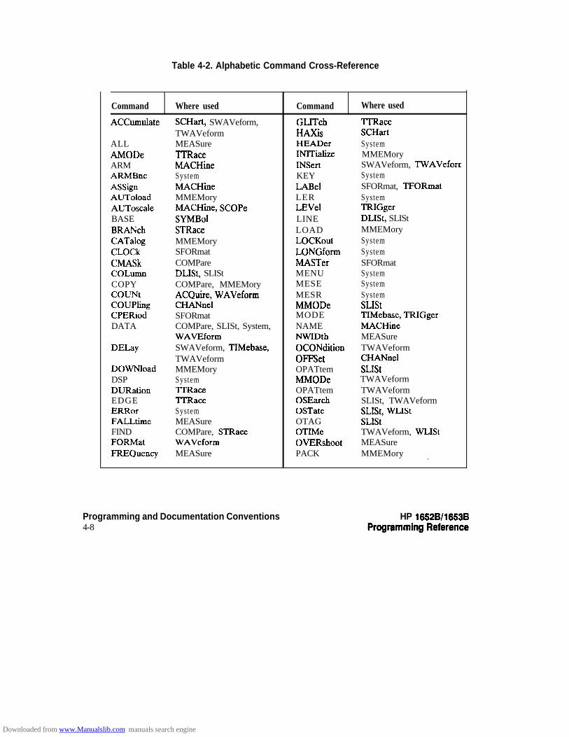
Table 4-2. Alphabetic Command Cross-Reference
Command Where used Command Where used
ACCumulate SCHart, SWAVeform, GLITch TIRaccTWAVeform HA2cis SCHart
ALL MEASure HEADer SystemAMODe ‘ITRace INITialize MMEMoryARM MACHine INSert SWAVeform, TWAVefornARMBnc System KEY SystemASSign MACHine LABel SFORmat, TFORmatAUToload MMEMory LER SystemAUToscale MACHine, SCOPe LEVel TRIGgerBASE SYMBol LINE DLISt, SLIStBRANch STRace LOAD MMEMoryCATalog MMEMory LOCKout SystemCLOCk SFORmat LONGform SystemCMASk COMPare MASTer SFORmatCOLumn DLISt, SLISt MENU SystemCOPY COMPare, MMEMory MESE SystemCOUNt ACQuire, WAVeform MESR SystemCOUPling CHANnel MMODe SLIStCPERiod SFORmat MODE TIMebase, TRIGgerDATA COMPare, SLISt, System, NAME MACHine
WAVEform NWIDth MEASureDELay SWAVeform, TIMebase, OCONdition TWAVeform
TWAVeform OFFSet CHANnelDOWNload MMEMory OPATtem SLIStDSP System MMODe TWAVeformDURation TIXace OPATtem TWAVeformEDGE 7TRacc OSEarch SLISt, TWAVeformERRor System OSTate SLIS& WL1stFALLtime MEASure OTAG SLIStFIND COMPare, STRace OTIMe TWAVeform, WLIStFORMat WAVeform OVERshoot MEASureFREQuency MEASure PACK MMEMory (
Programming and Documentation Conventions4-8
HP 18828/1853B
Downloaded from www.Manualslib.com manuals search engine
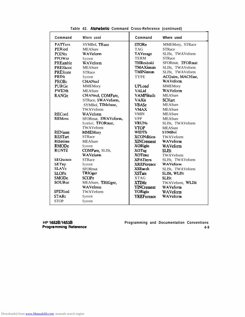
Table 42. Alohabetic Command Cross-Reference (continued)
Command Where used
PATTernPERiodPOINtsPPOWerPREamblePREShootPREStorePRINtPROBePURGePWIDthRANGe
RECordREMove
RENameRESTartRISetimeRMODeRUNTil
SEQuenceSETupSLAVeSLOPeSMODeSOURce
SPERiodSTARtSTOP
SYMBol, TRaceMEASureWAVeformSystemWAVeformMEASureSTRaceSystemCHANnelMMEMoryMEASureCHANnel, COMPare,STRace, SWAVeform,SYMBol, TIMebase,
TWAVeformWAVeformSFORmat, SWAVeform,Symbol , TFORmat,TWAVeformMMEMorySTRaceMEASureSystemCOMPare, SLISt,WAVeformSTRaceSystemSFORmatTRIGgerSCOPeMEASure, TRIGger,WAVeformTWAVeformSystemSystem
Command Where used
STOReTAGTAVerageTERMTHResholdTMAXiIIlunlTMINimumTYPE
UPLoadVALidVAMPlitudeVAXkVBASe
VMINVPPVRUNsVTOPWIDThXCONditionXINCrementXORiginXOTagXOTimeXPATtemXREFerenceXSEarchXSTateXTAGXTIMeYINCrementYORiginYREFerence
MMEMory, STRaceSTRaceSLISt, TWAVeformSTRaceSFORmat, TFORmatSLISt, TWAVeformSLISt, TWAVeformACQuire, MACHine,WAVeformMMEMoryWAVeformMEASureSCHartMEASureMEASureMEASureMEASureSLISt, TWAVeformMEASureSYMBolTWAVeformWAVeformWAVeformSLIStTWAVeformSLISt, TWAVeformWAVeformSLISt, TWAVeformSLISt, WL1stSLIStTWAVeform, WLIStWAVeformWAVeformWAVeform
3
HP 16528/1653B Programming and Documentation Conventions4-9
Downloaded from www.Manualslib.com manuals search engine
Command SetOrganization
The command set for the HP 1652B/53B logic analyzer is divided into 24separate groups: common commands, system commands and 22 sets ofsubsystem commands. Each of the 24 groups of commands is described inthe following chapters. Each of the chapters contain a brief description ofthe subsystem, a set of syntax diagrams for those commands, and f inal ly,the commands for that subsystem in alphabetical order. The commandsare shown in the longform and shortform using upper and lowercaseletters. As an example AUToload indicates that the longform of thecommand is AUTOLOAD and the shortform of the command is AUT.Each of the commands contain a description of the command and itsarguments, the command syntax, and a programming example.
Subsystems There are 19 subsystems in this instrument. In the command tree (figure4-l) they are shown as branches, with the node above showing the name ofthe subsystem. Only one subsystem may be selected at a t ime. At poweron, the command parser is set to the root of the command tree, andtherefore no subsystem is selected. The 22 subsystems in theHP 1652B/53B are:
l
l
l
l
l
l
l
l
l
l
l
l
l
l
l
l
l
.
l
SYSTem - controls some basic functions of the instrument.MMEMory - provides access to the internal disk drive.DLISt - a l lows access to the dual l is t ing funct ion of two s tateanalyzers.WLISt - allows access to the mixed (timing/state) functions.MACHine - provides access to analyzer functions and subsystems.SFORmat - allows access to the state format functions.STRace - al lows access to the state trace functions.SLISt - a l lows access to the s ta te l is t ing funct ions.SWAVeform - al lows access to the state waveforms functions.SCHart - al lows access to the state chart functions.COMPare - allows access to the compare functions.TFORmat - allows access to the timing format functions.‘ITRace - allows access to the timing trace functions.TWAVeform - al lows access to the t iming waveforms funct ions.SYMBol - a l lows access to the symbol specif icat ion funct ions.SCOPe - provides access to osci l loscope funct ions and subsystems.CI-IANnel - provides access to the vert ical axis of the oscil loscopeTRIGger - allows control of the trigger conditionsACQuire - al lows changes to the set t ings for the DIGitizecommand.
Programming and Documentation Conventions HP 16528/1653B4-10 Programming Reference
Downloaded from www.Manualslib.com manuals search engine
l TIMebase - allows control of the timebase (horizontal axis) of theoscilloscope.
l WAVeform - allows access to data transfer commands.l MEASure - allows you to control automated measurements.
ProgramExamples
The program examples given for each command in the following chaptersand appendices were written on an HP 9000 Series m/300 controllerusing the HP BASIC 4.0 language. The programs always assume a genericaddress for the HP 1652/53B of XXX.
In the following examples, special attention should be paid to the ways inwhich the command and/or query can be sent. Keywords can be sentusing either the longform or shortform (if one exists for that word). Withthe exception of some string parameters, the parser is not case-sensitive.Upper-case (capital) and lower-case (small) letters may be mixed freely.System commands like HEADer and LONGform allow you to dictatewhat forms the responses take, but have no affect on how you muststructure your commands and queries.
The following commands all set Timing Waveform Delay to 100 ms.
l keywords in longform, numbers using the decimal format.
OUTPUT XXX:":MACHINEl:TWAVEFORM:OELAY .l"
l keywords in shortform, numbers using an exponential format.
OUTPUT XXX;":MACHl:TWAV:OEL lE-1”
l keywords in shortform using lower-case letters, numbers using aSUffiX.
OUTPUT XXX;":machl:twav:del 10Qns"
NoteIn these examples, the colon shown as the first character of the commandis optional on the HP 1652B/53B.
The space between DELay and the argument is required.
HP 1662B/l653B Programming and Documentation Conventions4-11
Downloaded from www.Manualslib.com manuals search engine

Common Commands 5Introduction The common commands are defined by the IEEE 488.2 standard. These
commands will be common to all instruments that comply with thisstandard.
The common commands control some of the basic instrument functions,such as instrument identification and reset, how status is read and cleared,and how commands and queries are received and processed by theinstrument.
Common commands can be received and processed by the HP 1652B/53Bwhether they are sent over the bus by themselves or as part of amultiple-command string. If an instrument subsystem has been selectedand a common command is received by the instrument, the instrument willremain in the selected subsystem. For example, if the instruction
“:MMEMORY:INITlALlZE;‘CLS; STORE ‘FILE_‘,‘DESCRIPTION”’
is received by the instrument, the instrument will initialize the disk andstore the file; and clear the status information. This would not be the caseif some other type of command were received within the programmessage. For example, the program message
‘:MMEMORY:INITlALlZE;:SYSTEM:HEADERS 0N:MMEMORY:STORE ‘FI1E_‘;DESCRIPTlON’”
would initialize the disk, turn headers on, then store the file. In thisexample :MMEMORY must be sent again in order to reenter themmemory subsystem and store the file.
HP 1652B/l653B Common CommandsProgmmming Reference s-1
Downloaded from www.Manualslib.com manuals search engine

Each status register has an associated status enable (mask) register. Bysetting the bits in the mask value you can select the status information youwish to use. Any status bits that have not been masked (enabled in theenable register) will not be used to report status summary information tobits in other status registers.
Refer to appendix B, “Status Reporting,” for a complete discussion of howto read the status registers and how to use the status information availablefrom this instrument.
Refer to figure 5-l for the common commands syntax diagram.
c
mask = An integer, 0 through 255. 73is number is the sum of all the bits inthe mask corresponding to conditions that are enabled. Refer to the*ESE and *SRE commandr for bit definitions in the enable registerA.
Figure 5-l. Common Commands Syntax Diagram
Common Commands5-2
HP 16528/10538
Downloaded from www.Manualslib.com manuals search engine

“CLS
“CLS
Command Syntax:
Example:
Note uI’
HP 1652Bll6536
(Clear Status) command
The *CLS common command clears the status data structures, includingthe device defined error queue. If the l CLS command immediatelyfollows a <terminator > , the output queue and the MAV (MessageAvailable) bit will be cleared.
'CLS
OUTPUT XXX;"*CLS"
Refer to appendix B, “Status Reporting,” for a complete discussion ofstatus.
Common Commandss-3
Downloaded from www.Manualslib.com manuals search engine

*ESE
*ESE (Event Status Enable) command/query
Note rl4
The *ESE command sets the Standard Event Status Enable Register bits.The Standard Event Status Enable Register contains a mask value for thebits to be enabled in the Standard Event Status Register. A one in theStandard Event Status Enable Register will enable the corresponding bitin the Standard Event Status Register. A zero will disable the bit. Referto table 4-l for information about the Standard Event Status EnableRegister bits, bit weights, and what each bit masks.
The *ESE query returns the current contents of the enable register.
Refer to appendix B, “Status Reporting,” for a complete discussion ofstatus.
Command SyntaX: *ESE <mask >
where:
-z mask z :: = integer from 0 to 255
Example: OUTPUT XXX;"*ESE 32"
In this example, the *ESE 32 command will enable CME (CommandError), bit 5 of the Standard Event Status Enable Register. Therefore,when a command error occurs, the event summary bit (ESB) in the StatusByte Register will also be set.
Common Commands6-4
HP 16528/16538Programming Reference
Downloaded from www.Manualslib.com manuals search engine

*ESE
Qlle~+ttU: *ESE?
&WrwClFo~t: cmask><NL>
Example: 10 DIM Event$[lOO]
20 OUTPUT XXX;"*ESE?"30 ENTER XXX;Event$
40 PRINT EventJ50 END
Table 51. Standard Event Status Enable Register
B i t
IWeight
1286432168421 t
Enables
PON - Power OnURQ - User RequestChE - Command ErrorEXE - Execution ErrorDDE - Device Dependent ErrorQYE - Query ErrorRQC - Request ControlOPC - Operation Complete
High- enables the ESR bit
HP 16526/16538 Common CommandsProgramming Reference !5-5
Downloaded from www.Manualslib.com manuals search engine

*ESR
*ESR (Event Status Register) query
The *ESR query returns the contents of the Standard Event StatusRegister. Reading the register clears the Standard Event Status Register.
Note ”4The bits iu this register must be set by sending the *ESE command beforesending the *ESR query (see “*ESE command/query” on page 5-4).
QUefy Syntax: *ES??
Returned Format: -Z status > c NL >
where:
<status > :: = integer from 0 to 255
Example: 10 DIM Esr-event$[lOO]20 OUTPUT XXX;"*ESR?"30 ENTER XXX;Esr-events40 PRINT Esr-events
50 END
With the example, if a command error has occurred the variable“Esr-event” will have bit 5 (the CME bit) set.
Table 4-2 shows the Standard Event Status Register. The table showseach bit in the Standard Event Status Register, and the bit weight. Whenyou read Standard Event Status Register, the value returned is the total bitweights of all bits that are high at the time you read the byte.
Common Commands5-6
HP 16528/1653B
Downloaded from www.Manualslib.com manuals search engine

*ESR
Table 52. The Standard Event Status Register.
BITWEErr NEE
CONDITION--
7 128 PON 0 = Register read - not in power up mode1 = Power up
6 64 URQ 0 = user request - not used - always zero5 32 CME 0 = no command errors
1 = a command error has been detected4 16 EXE 0 = no execution errors
1 = an execution error has been detected3 8 DDE 0 = no device dependent errors
1 = a device dependent error has been detected2 4 Q Y E 0 = no query errors
1 = a query error has been detected1 2 RQC 0 = request control - NOT used - always 00 1 OPC 0 = operation is not complete
1 = operation is complete
=: False = Low1 =: True = High
Common Commands5-7
Downloaded from www.Manualslib.com manuals search engine

“IDN
*IDN (Identification Number) query
The *IDN? query allows the instrument to identify itself. It returns thestring:
"HEWLETT-PACKARD.l6526,D,REV <revision code>”
An *IDN? query must be the last query in a message. Any queries afterthe *IDN? in the program message will be ignored.
Query Syntax: l lDN?
Returned Format: HEWLETT-PACKARD,1652B,O,REV <revision code>
where:
<revision code > : : = f o u r - d i g i t code r e p r e s e n t i n g R O M r e v i s i o n
Example: 10 DIM Id$[lOO]20 OUTPUT XXX;"*ION?"30 ENTER XXX;Id$
40 PRINT Idf50 END
Common Commands58
HP 18528/1853BProgramming Reference
Downloaded from www.Manualslib.com manuals search engine

*opt
*opt (Operation Complete) command/query
The *OPC command will cause the instrument to set the operationcomplete bit in the Standard Event Status Register when all pendingdevice operations have finished. The commands which affect this bit arethe Overlapped Commands. An Overlapped Command is a commandthat allows execution of subsequent commands while the deviceoperations initiated by the Overlapped Command are still in progress.The overlapped commands for the HP 1652B/53B are:
STARtSTOP
AUToscale
The * OPC query places an ASCII “1” in the output queue when allpending device operations have been completed.
Command Syntax: l OPC
Example: OUTPUT XXX;"*OPC"
Query Syntax: l opc7
Returned Format: i < Nb
Example: 10 DIM Status$[lOO]20 OUTPUT XXX;"*OPC?"30 ENTER XXX;Status$40 PRINT StatusJ
50 END
HP 1052B/1653BProgramming Reference
Common Commands59
Downloaded from www.Manualslib.com manuals search engine
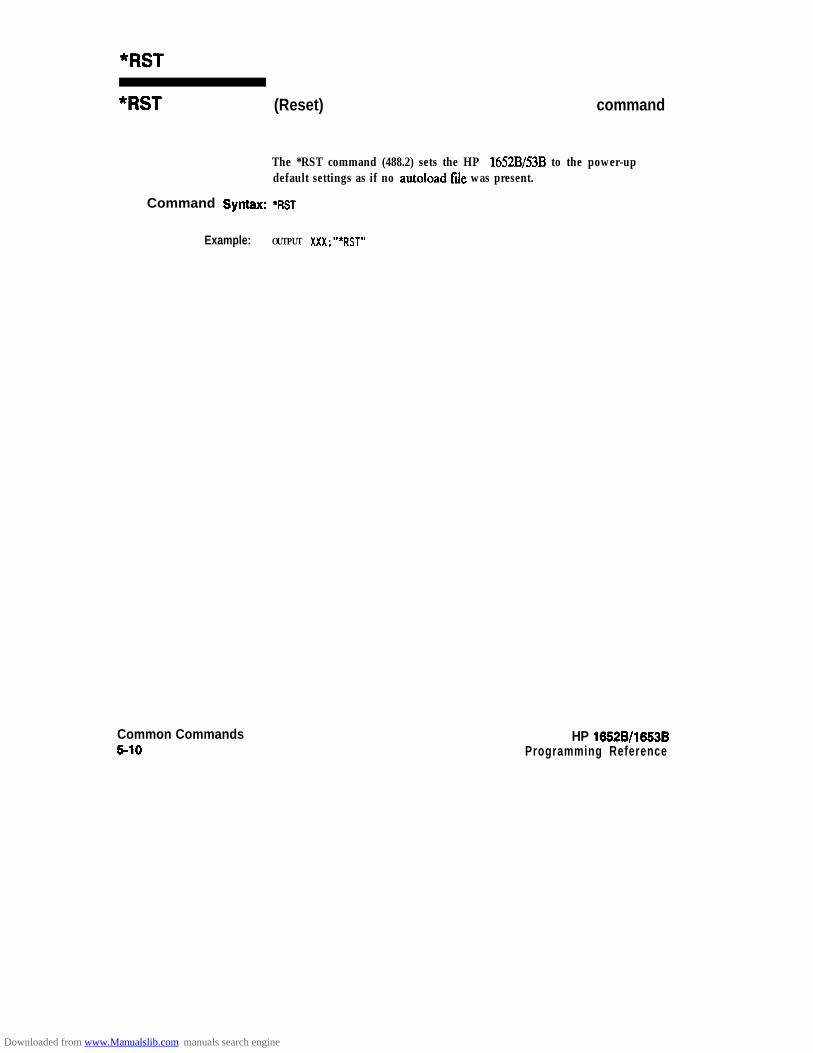
“RST
“RST (Reset) command
The *RST command (488.2) sets the HP 1652B/53B to the power-updefault settings as if no autoload file was present.
Command Syntax: *RST
Example: OUTPUT XXX;"*RST"
Common Commands5-10
HP 10528/1653BProgramming Reference
Downloaded from www.Manualslib.com manuals search engine

*SRE
*SRE (Service Request Enable) command/query
The *SRE command sets the Service Request Enable Register bits. TheService Request Enable Register contains a mask value for the bits to beenabled in the Status Byte Register. A one in the Service Request EnableRegister will enable the corresponding bit in the Status Byte Register. Azero will disable the bit. Refer to table 5-3 for the bits in the ServiceRequest Enable Register and what they mask.
The *SRE query returns the current value.
Note d status.Refer to appendix B, “Status Reporting,” for a complete discussion of
Command Syntax: *sRE c mask >
where:
c mask > :: = integer from 0 to 255
Example: OUTPUT XXX; “*SRE 16”
This example forces the h4AV bit high (see table 5-3).
HP 16528/l 6538Programming Reference
Common Commands511
Downloaded from www.Manualslib.com manuals search engine
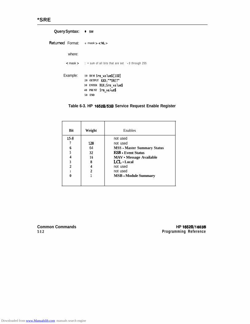
*SRE
Query Syntax: l sw
RetUrrled Format: c mask > c NL>
where:
-Z mask > : : = s u m o f a l l b i t s t h a t a r e s e t - 0 t h r o u g h 2 5 5
Example: 10 DIM Sre-value$[lOO]20 OUTPUT XXX;"*SRE?"
30 ENTER XXX;Sre-value$
40 PRINT Sre-value$
50 END
Table 6-3. HP 16528/53B Service Request Enable Register
Bit
15-B76543210
Weight Enables
12864321 68421
not usednot usedMSS - Master Summary StatusESB - Event StatusMAV - Message AvailableLCL - Localnot usednot usedMSB - Module Summary
Common Commands HP 16528/l 6538512 Programming Reference
Downloaded from www.Manualslib.com manuals search engine

“ST6
*STB (Status Byte) query
The *SIB query returns the current value of the instrument’s status byte.The MSS (Master Summary Status) bit and not RQS (Request Service)bit is reported on bit 6. The MSS indicates whether or not the device hasat least one reason for requesting service. Refer to table 5-4 for themeaning of the bits in the status byte.
Note aI?e Refer to appendix B, “Status Reporting,” for a complete discussion ofstatus.
Query Syntax: *sm
Returned Format: <value > c NL>
where:
<value> ::= integer from Oto 255
Example: 10 DIM Stb-value$[lOO]
20 OUTPUT XXX;"*STB?"30 ENTER XXX;Stb-value$40 PRINT Stb-values
50 END
HP 16528/1653BProgramming Reference
Common Commandss-13
Downloaded from www.Manualslib.com manuals search engine

“STB
Table 5-4. The Status Byte Register
BIT BIT BIT CONDITIONWEIGHT NAME
7 128 --- 0 = not used6 64 MSS 0 = instrument has no reason for service
1 = instrument is requesting service5 32 ESB 0 = no event status conditions have occurred
1 = an enabled event status condition has occured4 16 MAV 0 = no output messages are ready
1 = an output message is ready3 8 LCL 0 = a remote-to-local transition has not occurred
1 = a remote-to-local transition has occurred2 4 _-- not used1 2 _-- not used0 1 MSB 0 = HP 1652B/1653B has activity to report
1 = no activity to report
0 = False =: Low1 = True = High
Common Commands514
HP 16528/1653B
Downloaded from www.Manualslib.com manuals search engine
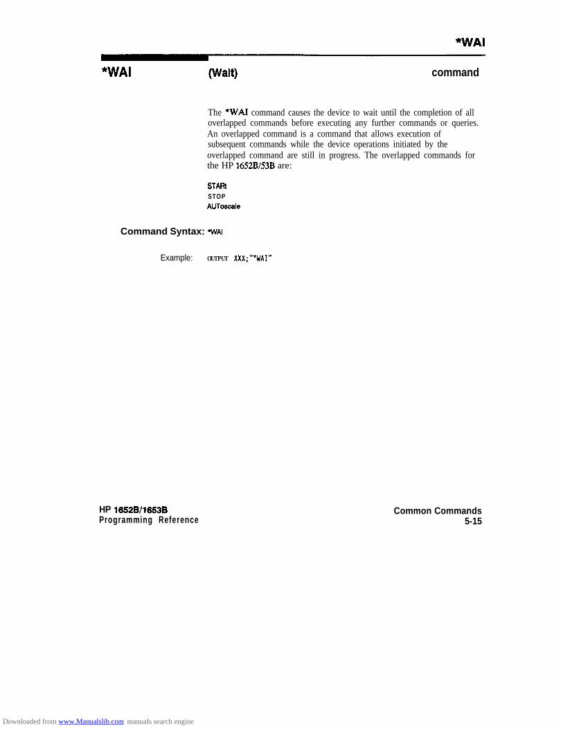
*WAI
*WAI command
The *WAI command causes the device to wait until the completion of alloverlapped commands before executing any further commands or queries.An overlapped command is a command that allows execution ofsubsequent commands while the device operations initiated by theoverlapped command are still in progress. The overlapped commands forthe HP 1652B/53B are:
STAFiiSTOPAUToscale
Command Syntax: WAI
Example: OUTPUT XXX;"*WAI"
HP 1652Bll653B Common CommandsProgramming Reference 5-15
Downloaded from www.Manualslib.com manuals search engine
System Commands 6Introduction System commands control the basic operation of the instrument including
formatting query responses and enabling reading and writing to theadvisory l ine of the instrument’s display. They can be called at anytime.The HP 1652B/53B System commands are:
ARMBncDATADSP (display)ERRorHEADerKEYLER (Local Event Register)LOCKoutLONGformMENDMESEMESRPRINtSETup
In addition to the system commands, there is are three run controlcommands and a preprocessor power supply condition query. Thesecommands are:
0 PPOWerl RMODel STARtl STOP
The run control commands can be called at anytime and also control thebasic operation of the logic analyzer. These commands are at the samelevel in the command tree as SYSTem; therefore they are not preceded bythe :SYSTem header.
HP 16528/1653BProgramming Reference
System Commands61
Downloaded from www.Manualslib.com manuals search engine

System Commands HP 16528/165386-2 Programming Reference
math-num
ARMBnc? c
k e y - c o d e
Figure 81. System Commands Syntax Diagram
Downloaded from www.Manualslib.com manuals search engine
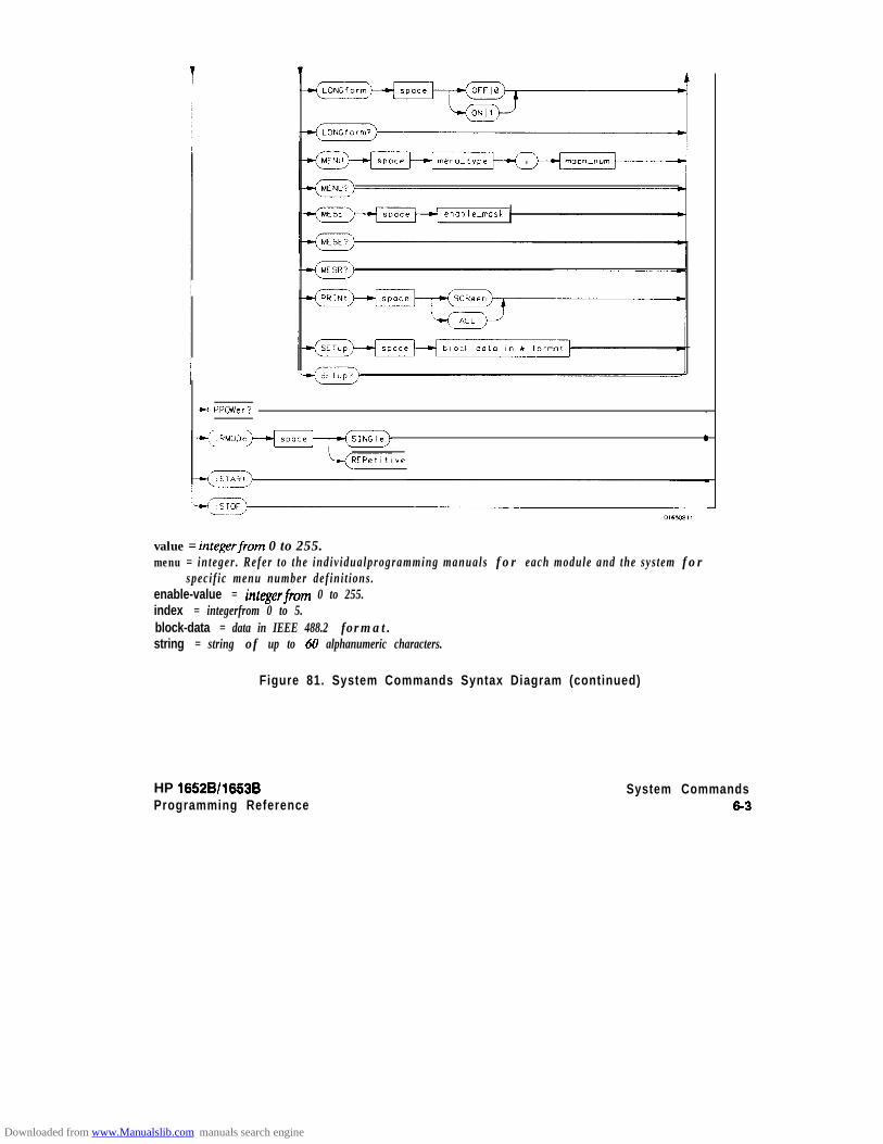
enable-mask
ci PPcwcr? .
.
REPetihve
value = integerfrom 0 to 255.menu = integer . Refer to the indiv idualprogramming manuals for each module and the system for
specif ic menu number def ini t ions.enable-value = integerfiom 0 to 255.index = integerfrom 0 to 5.block-data = data in IEEE 488.2 format.string = string of up to 60 alphanumeric characters.
Figure 81. System Commands Syntax Diagram (continued)
HP 1652Bll663B System CommandsProgramming Reference 6-3
Downloaded from www.Manualslib.com manuals search engine
ARMBnc
ARMBnc command/query
The ARMBnc command selects the source that will generate the arm outsignal that will appear on the rear panel BNC labelled External Triggerout.
The ARMBnc query returns the source currently selected.
Command Syntax: :SYSTem:ARMBnc { MACHine{ 112) 1 SCOPe 1 NONE}
Example: OUTPUT XXX;":SYSTEM:ARMBNC MACHINEl"
Query Syntax: : S Y S T e m : A R M B n c ?
RetUrned Format: [:SYSTem:ARMBnc] { MACHine{ 112) ) SCOPe I NONE} c NL>
Example: 10 DIM Mode$[lOO]20 OUTPUT XXX;":ARMBNC?"
30 ENTER XXX;Mode$
40 PRINT Mode$50 END
System Commands6 4
HP 16528/16538Programming Reference
Downloaded from www.Manualslib.com manuals search engine

DATA
DATA
Note #b
Note ‘$
command/query
The DATA command allows you to send and receive acquired data to andfrom a controller in block form. This helps saving block data for:
l Re-loading to the logic analyzerl Processing data laterl Processing data in the controller.
The format and length of block data depends on the instruction beingused and the configuration of the instrument. This section describes eachpart of the block data as it will appear when used by the DATAinstruction. The beginning byte number, the length in bytes, and a shortdescription is given for each part of the block data. This is intended to beused primarily for processing of data in the controller.
Do not change the block data in the controller if you intend to send theblock data back into the logic analyzer for later processing. Changesmade to the block data in the controller could have unpredictable resultswhen sent back to the logic analyer.
The SYSTem:DATA query returns the block data.
The data sent by the SYSTem:DATA query reflects the configuration ofthe machines when the last run was performed. Any changes made sincethen through either front-panel operations or programming commands donot affect the stored configuration.
HP 16628/1653BProgramming Reference
System Commands6 5
Downloaded from www.Manualslib.com manuals search engine

DATA
System Commands6-6
For the DATA instruction, block data consists of either 14506 bytescontaining logic analyzer only information or 26794 bytes containing bothlogic analyzer and oscilloscope information. This information is capturedby the acquisition systems. The information for the logic analyzer will bein one of four formats depending on the type of data captured. The logicanalyzer format is described in the “Acquisition Data Description” sectionin “Logic Analyzer Block Data.” The oscilloscope format is described inthe “Acquisi t ion Data Description” section in “Oscil loscope Block Data.”Since no parameter checking is performed, out-of-range values couldcause instrument lockup; therefore, care should be taken whentransferring the data string into the HP 1652B/53B.
The < block data > parameter can be broken down into a< block length specifier > and a variable number of < section > s.
The <block length specifier > always takes the form #8DDDDDDDD.Each D represents a digit (ASCII characters “0” through “9”). The value ofthe eight digits represents the total length of the block (all sections). Forexample, if the total length of the block is 14522 bytes, the block lengthspecifier would be “#800014522”.
Each < section > consists of a <section header > and < section data > .The < section data > format varies for each section and may be anylength. For this instruction, the < section data > section is composed of adata preamble section and an acquisition data section.
HP 16528/16538Programming Reference
Downloaded from www.Manualslib.com manuals search engine
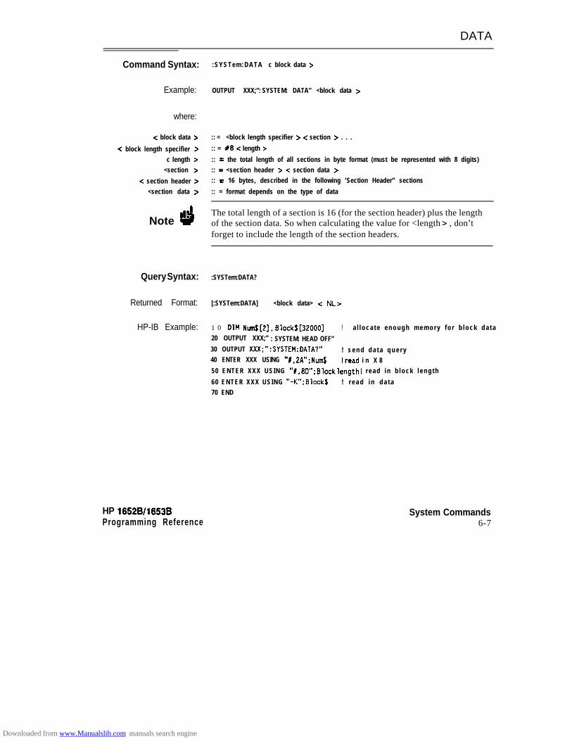
DATA
Command Syntax:
Example:
where:
-z block data >
-z block length specifier >c length >
<section >
-z section header ><section data >
Note ‘6
Query Syntax:
Returned Format:
HP-IB Example:
HP 16528/1653BProgramming Reference
:SYSTem:DATA c block data >
OUTPUT XXX;“: SYSTEM: DATA” <block data >
:: = <block length specifier > c section > . . .
:: = #8 < length >
:: = the total length of all sections in byte format (must be represented with 8 digits):: = <section header > -z section data >:: = 16 bytes, described in the following ‘Section Header” sections
:: = format depends on the type of data
The total length of a section is 16 (for the section header) plus the lengthof the section data. So when calculating the value for <length > , don’tforget to include the length of the section headers.
:SYSTem:DATA?
[:SYSTem:DATA] <block data> < NL>
1 0 DIM Nrm1$[2], 81ockS[32000] ! a l l o c a t e e n o u g h m e m o r y f o r b l o c k d a t a20 OUTPUT XXX;” : SYSTEM: HEAD OFF”30 OUTPUT XXX;“:SYSTEM:DATA?” ! s e n d d a t a q u e r y40 ENTER XXX USING “#.2A”;Num$ !read i n X 850 ENTER XXX USING “#,8D”;8locklength! read in b lock l eng th
60 ENTER XXX USING “-K”;Ellock$ ! r e a d i n d a t a70 END
System Commands6-7
Downloaded from www.Manualslib.com manuals search engine
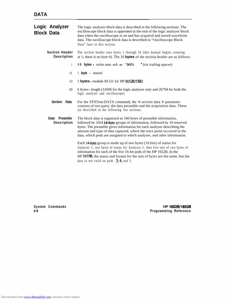
DATA
Logic AnalyzerBlock Data
Section HeaderDescription
1
11
12
13
Section Data
Data PreambleDescription
The logic analyzer block data is described in the following sections. Theoscilloscope block data is appended at the end of the logic analyzer blockdata when the oscilloscope is on and has acquired and stored waveformdata. The oscilloscope block data is described in “Oscilloscope BlockData” later in this sect ion.
The sect ion header uses bytes 1 through 16 ( this manual begins countingat 1; there is no byte 0). The 16 bytes of the section header are as follows:
10 bytes - section name, such as "DATA
1 byte - reserved
’ (six trailing spaces)
1 bytes - module ID (31 for HP 1652B/53B)
4 bytes - length (14506 for the logic analyzer only and 26794 for both thelogic analyzer and oscil loscope).
For the SYSTem:DATA command, the < section data > parameterconsists of two parts: the data preamble and the acquisition data. Theseare described in the fol lowing two sect ions.
The block data is organized as 160 bytes of preamble information,followed by 1024 14byte groups of information, followed by 10 reservedbytes. The preamble gives information for each analyzer describing theamount and type of data captured, where the trace point occurred in thedata, which pods are assigned to which analyzer, and other information.
Each 1Cbyte group is made up of two bytes (16 bits) of status forAnalyzer 1, two bytes of status for Analyzer 2, then five sets of two bytes ofinformation for each of the five 16-bit pods of the HP 1652B. In theHP 1653B, the status and format for the sets of bytes are the same, but thedata in not val id on pods 3,4, and 5 .
System Commands HP 16528/1663B68 Programming Reference
Downloaded from www.Manualslib.com manuals search engine
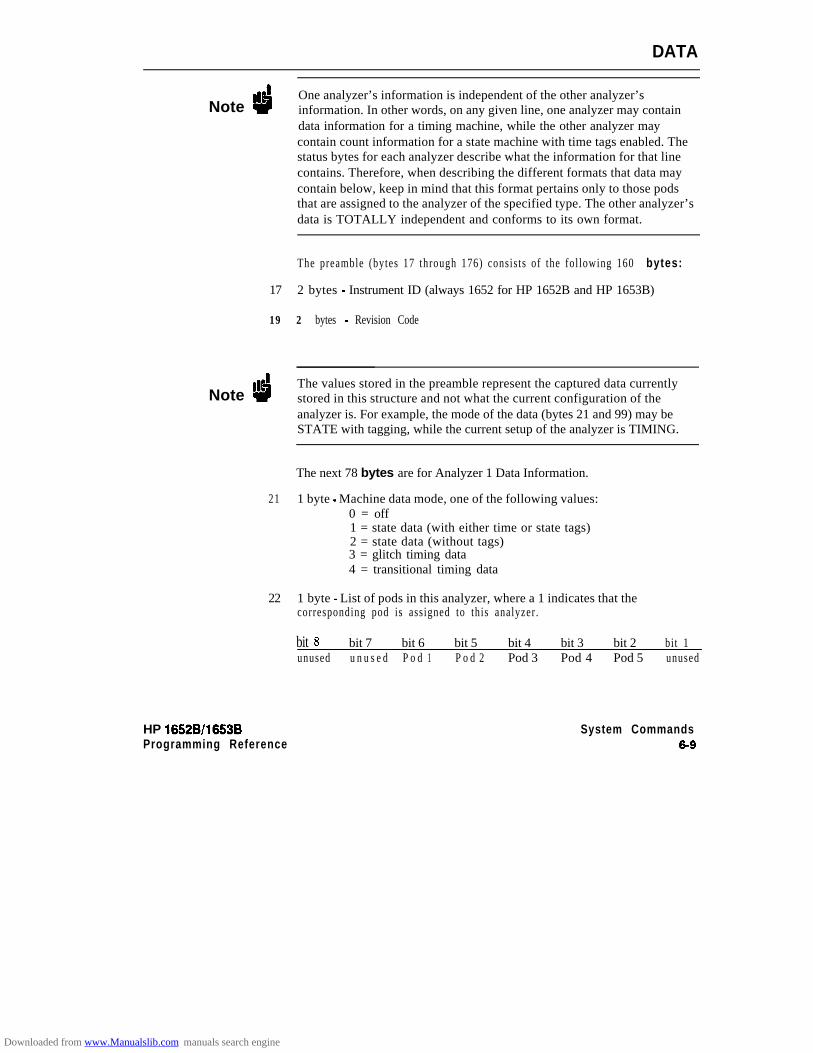
DATA
Note dOne analyzer’s information is independent of the other analyzer’sinformation. In other words, on any given line, one analyzer may containdata information for a timing machine, while the other analyzer maycontain count information for a state machine with time tags enabled. Thestatus bytes for each analyzer describe what the information for that linecontains. Therefore, when describing the different formats that data maycontain below, keep in mind that this format pertains only to those podsthat are assigned to the analyzer of the specified type. The other analyzer’sdata is TOTALLY independent and conforms to its own format.
The preamble (bytes 17 through 176) consists of the fol lowing 160 bytes:
17 2 bytes - Instrument ID (always 1652 for HP 1652B and HP 1653B)
19 2 bytes - Revision Code
Note dThe values stored in the preamble represent the captured data currentlystored in this structure and not what the current configuration of theanalyzer is. For example, the mode of the data (bytes 21 and 99) may beSTATE with tagging, while the current setup of the analyzer is TIMING.
The next 78 bytes are for Analyzer 1 Data Information.
21 1 byte - Machine data mode, one of the following values:0 = off1 = state data (with either time or state tags)2 = state data (without tags)3 = glitch timing data4 = transitional timing data
22 1 byte - List of pods in this analyzer, where a 1 indicates that thecorresponding pod is assigned to this analyzer.
bit 8 bit 7 bit 6 bit 5 bit 4 bit 3 bit 2 bit 1unused u n u s e d P o d 1 P o d 2 Pod 3 Pod 4 Pod 5 unused
HP 16528/1663BProgramming Reference
System Commands89
Downloaded from www.Manualslib.com manuals search engine

DATA
23
24
25
35
36
37
47
51
52
53
1 byte - Master chip in this analyzer - When several chips are groupedtogether in a single analyzer, one chip is designated as a master chip. Thisbyte identifies the master chip. A value of 4 represents POD 1,3 for POD2,2 for POD 3,1 for POD 4, and 0 for POD 5.
1 byte - Reserved
10 bytes - Number of rows of valid data for this analyzer - Indicates thenumber of rows of valid data for each of the five pods. Two bytes are usedto store each pod value, with the ftrst 2 bytes used to hold POD 5 value,the next 2 for POD 4 value, and so on.
1 byte - Trace point seen in this analyzer - Was a trace point seen (value= 1) or forced (value = 0)
1 byte - Reserved
10 bytes - Trace point location for this analyzer - Indicates the rownumber in which the trace point was found for each of the five pods. Twobytes are used to store each pod value, with the f irst 2 bytes used to holdPOD 5 value, the next 2 for POD 4 value, and so on.
4 bytes - Time from arm to trigger for this analyzer - The number of 40 nsticks that have taken place from the arm of this machine to the trigger ofthis machine. A value of -1 (all 32 bits set to 1) indicates counter overflow.
1 byte - Armer of this analyzer - Indicates what armed this analyzer (1 =RUN, 2 = BNC, 3 = other analyzer)
1 byte - Devices armed by this analyzer - Bitmap of devices armed by thismachine
bitt3 bi t 7 bit 6 b i t 5 bit 4 bi t 3 bit 2 bi t 1unused unused unused unused SCOPE BNC out Mach. 2 Mach.
A 1 in a given bit position implies that this analyzer arms that device,while a 0 means the device is not armed by this analyzer.
4 bytes - Sample period for this analyzer (timing only) - Sample period atwhich data was acquired. Value represents the number of nanosecondsbetween samples.
System Commands HP 16528/1663B810 Programming Reference
Downloaded from www.Manualslib.com manuals search engine
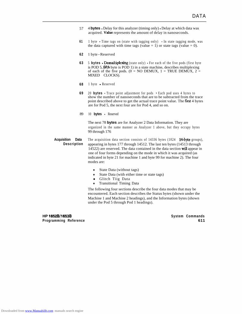
DATA
57
6 1
62
63
68
69
89
Acquisition DataDescription
HP 16528/16538Programming Reference
4 bytes - Delay for this analyzer (timing only) - Delay at which data wasacquired. Value represents the amount of delay in nanoseconds.
1 byte - Time tags on (s tate with tagging only) - In state tagging mode, wasthe data captured with time tags (value = 1) or state tags (value = 0).
1 byte - Reserved
5 bytes - Demuhiplexing (state only) - For each of the f ive pods (f irs t byteis POD 5, fifth byte is POD 1) in a state machine, describes multiplexingof each of the five pods. (0 = NO DEMUX, 1 = TRUE DEMUX, 2 =MIXED CLOCKS).
1 byte - Reserved
20 bytes - Trace point adjustment for pods - Each pod uses 4 bytes toshow the number of nanoseconds that are to be subtracted from the tracepoint described above to get the actual trace point value. The first 4 bytesare for Pod 5, the next four are for Pod 4, and so on.
10 bytes - Reserved
The next 78 bytes are for Analyzer 2 Data Information. They areorganized in the same manner as Analyzer 1 above, but they occupy bytes99 through 176
The acquisi t ion data sect ion consists of 14336 bytes (1024 1Cbyte groups),appearing in bytes 177 through 14512. The last ten bytes (14513 through14522) are reserved. The data contained in the data section will appear inone of four forms depending on the mode in which it was acquired (asindicated in byte 21 for machine 1 and byte 99 for machine 2). The fourmodes are:
l State Data (without tags)l State Data (with either time or state tags)l Glitch Tiig Datal Transitional Timing Data
The following four sections describe the four data modes that may beencountered. Each section describes the Status bytes (shown under theMachine 1 and Machine 2 headings), and the Information bytes (shownunder the Pod 5 through Pod 1 headings).
System Commands611
Downloaded from www.Manualslib.com manuals search engine
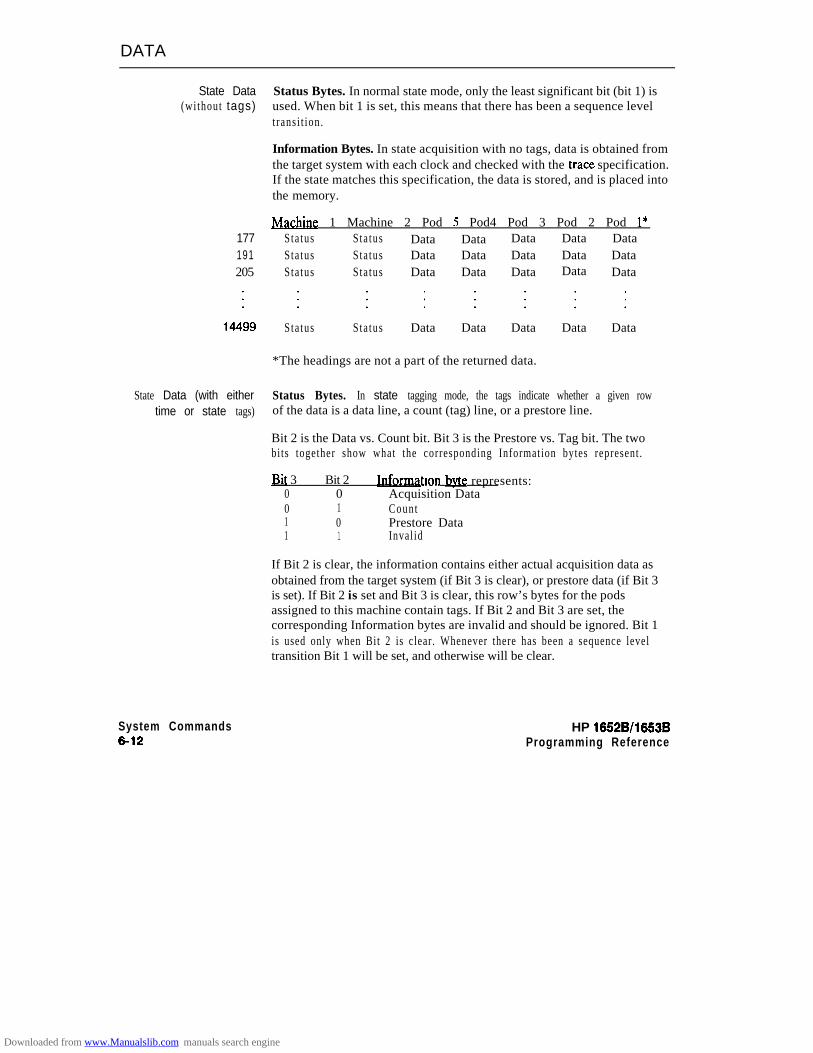
DATA
State Data Status Bytes. In normal state mode, only the least significant bit (bit 1) is(without tags) used. When bit 1 is set, this means that there has been a sequence level
t rans i t ion .
Information Bytes. In state acquisition with no tags, data is obtained fromthe target system with each clock and checked with the trace specification.If the state matches this specification, the data is stored, and is placed intothe memory.
JvIachine 1 Machine 2 Pod 5 Pod4 Pod 3 Pod 2 Pod l*177 Sta tus Sta tus Data Data Data Data Data191 Sta tus Sta tus Data Data Data Data Data205 Sta tus Sta tus Data Data Data Data Data
Sta tus Sta tus Data Data Data Data Data
*The headings are not a part of the returned data.
State Data (with either Status Bytes. In state tagging mode, the tags indicate whether a given rowtime or state tags) of the data is a data line, a count (tag) line, or a prestore line.
Bit 2 is the Data vs. Count bit. Bit 3 is the Prestore vs. Tag bit. The twobits together show what the corresponding Information bytes represent .
Bit 3 Bit 2 tion bvte represents:0 0 Acquisition Data0 1 Count1 0 Prestore Data1 1 Inval id
If Bit 2 is clear, the information contains either actual acquisition data asobtained from the target system (if Bit 3 is clear), or prestore data (if Bit 3is set). If Bit 2 is set and Bit 3 is clear, this row’s bytes for the podsassigned to this machine contain tags. If Bit 2 and Bit 3 are set, thecorresponding Information bytes are invalid and should be ignored. Bit 1is used only when Bit 2 is clear. Whenever there has been a sequence leveltransition Bit 1 will be set, and otherwise will be clear.
System Commands6-12
HP 16528/16538Programming Reference
Downloaded from www.Manualslib.com manuals search engine

DATA
Information Bytes. In the State acquisition mode with tags, data isobtained from the target system with each clock and checked with thetrace specification. If the state does not match the trace specification, it ischecked against the prestore qualifier. If it matches the prestore qualifier,then it is placed in the prestore buffer. If the state does not match eitherthe sequencer qualifier or the prestore qualifier, it is discarded.
The type of information in the bytes labeled Data depends on the Prestorevs. Tags bit. When the Data bytes are used for prestore information, thefollowing Count bytes (in the same column) should be ignored. When theData bytes are used for tags, the Count bytes are formatted asfloating-point numbers in the following fashion:
13 b i t s 11throueh 1EEEEE MMMMMMMMMMM
The live most-significant bits (EEEEE) store the exponent, and the elevenleast-significant bits (MMMMMMMMMMM) store the mantissa. Theactual value for Count is given by the equation:
Count = (2048 + mantissa) X 2exponent -2048
Since the counts are relative counts from one state to the one previous, thecount for the first state in the data structure is invalid.
If time tagging is on, the count value represents the number of 40nanosecond t icks that have elapsed between the two stored states. In thecase of state tagging, the count represents the number of qualified statesthat were encountered between the stored states.
If a state matches the sequencer qualifiers, the prestore buffer is checked.If there are any states in the prestore buffer at this time, these prestorestates are first placed in memory, along with a dummy count row. Afterthis check, the qualified state is placed in memory, followed by the countrow which specified how many states (or 40 ns ticks) have elapsed sincethe last stored state. If this is the first stored state in memory, then thecount information that is stored should be discarded.
HP 16528/16538 System Commands6-13
Downloaded from www.Manualslib.com manuals search engine
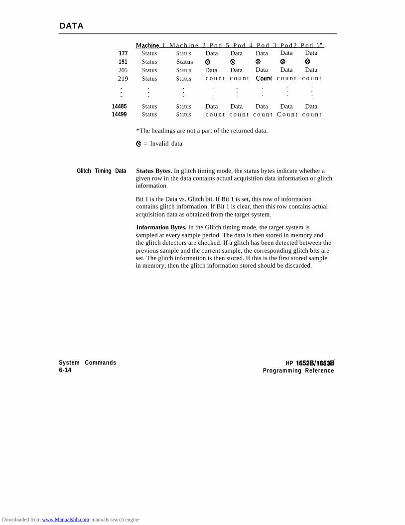
DATA
JvIachine 1 M a c h i n e 2 P o d 5 P o d 4 P o d 3 P o d 2 P o d l*177 Sta tus Sta tus Data Data Data Data Data1 9 1 Sta tus Status @ @ @ @ @205 Sta tus Sta tus Data Data Data Data Data219 Sta tus Sta tus c o u n t c o u n t Count c o u n t c o u n t
14485 Sta tus14499 Sta tus
Sta tusSta tus
Data Data Data Data Datac o u n t c o u n t c o u n t C o u n t c o u n t
*The headings are not a part of the returned data.
@ = Invalid data
Glitch Timing Data Status Bytes. In glitch timing mode, the status bytes indicate whether agiven row in the data contains actual acquisition data information or glitchinformation.
Bit 1 is the Data vs. Glitch bit. If Bit 1 is set, this row of informationcontains glitch information. If Bit 1 is clear, then this row contains actualacquisition data as obtained from the target system.
Information Bytes. In the Glitch timing mode, the target system issampled at every sample period. The data is then stored in memory andthe glitch detectors are checked. If a glitch has been detected between theprevious sample and the current sample, the corresponding glitch bits areset. The glitch information is then stored. If this is the first stored samplein memory, then the glitch information stored should be discarded.
System Commands6-14
HP 16528/16!538’Programming Reference
Downloaded from www.Manualslib.com manuals search engine

DATA
Machine 1 Machine 2 Pod 5 Pod4 Pod 3 Pod 2 Pod I*177 Sta tus Sta tus Data Data Data Data Data191 Sta tus Status @ co @ @ @205 Sta tus Sta tus Data Data Data Data Data219 Sta tus Sta tus Glitch Glitch Glitch Glitch Glitch
14405 Sta tus Sta tus Data Data Data Data Data14499 Sta tus Sta tus Glitch Glitch Glitch Glitch Glitch
*The headings are not a part of the returned data.
@ = Invalid data
Transitional Timing Data Status Bytes. In transitional timing mode, the status bytes indicatewhether a given row in the data contains acquisition information ortransition count information.
10-9 bi ts 8-7 bi ts 6-5 bits43 bi t s 2-lPod 5 Pod 4 Pod 3 Pod 2 P o d 1
Each pod uses two bits to show what is being represented in thecorresponding Information bytes. Bits 10,8,6,4 and 2 are set when theappropiate pod’s Information bytes represent acquisition data. When thatbit is clear, the next bit shows if the Information bytes represent the firstword of a count. Together there are three possible combinations:
10 - This pods Information bytes contain acquisition data as obtained fromthe target system.
01 - This pod’s Information bytes contain the f i rs t word of a count .00 - This pod’s Information bytes contain part of a count other than the
firs t word.
HP 16528/1653BProgramming Reference
System Commands615
Downloaded from www.Manualslib.com manuals search engine
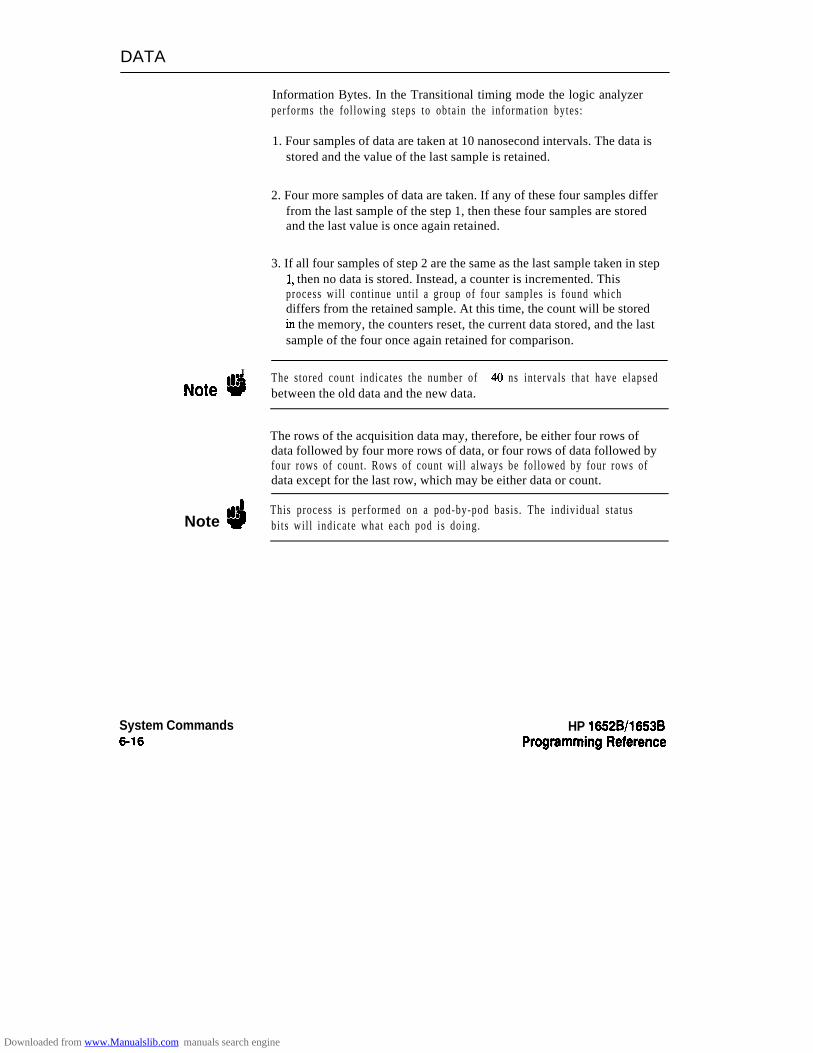
DATA
Information Bytes. In the Transitional timing mode the logic analyzerperforms the fol lowing s teps to obtain the information bytes:
1. Four samples of data are taken at 10 nanosecond intervals. The data isstored and the value of the last sample is retained.
2. Four more samples of data are taken. If any of these four samples differfrom the last sample of the step 1, then these four samples are storedand the last value is once again retained.
3. If all four samples of step 2 are the same as the last sample taken in step1, then no data is stored. Instead, a counter is incremented. Thisprocess wil l continue unti l a group of four samples is found whichdiffers from the retained sample. At this time, the count will be storedin the memory, the counters reset, the current data stored, and the lastsample of the four once again retained for comparison.
I
Note uThe stored count indicates the number of 40 ns intervals that have elapsedbetween the old data and the new data.
The rows of the acquisition data may, therefore, be either four rows ofdata followed by four more rows of data, or four rows of data followed byfour rows of count. Rows of count will always be followed by four rows ofdata except for the last row, which may be either data or count.
Note dThis process is performed on a pod-by-pod basis . The individual s tatusbi ts wil l indicate what each pod is doing.
System Commands6-16
HP 1652B/l653B
Downloaded from www.Manualslib.com manuals search engine
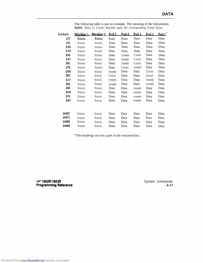
DATA
Example :1771 9 1205219233247261275289303317331345359373387
11*
S t a t u s S t a t u s Data Data Data Data DataSta tus Sta tus Data Data Data Data DataSta tus Sta tus Data Data Data Data DataSta tus Sta tus Data Data Data Data DataSta tus Sta tus Data count Count Data DataSta tus Sta tus Data count Count Data DataSta tus Sta tus Data count Count Data DataSta tus Sta tus Data Count count Data DataSta tus Sta tus count Data Data Count DataSta tus Sta tus Count Data Data Count DataSta tus Sta tus count Data Data count DataSta tus Sta tus count Data Data count DataSta tus Sta tus Data Data count Data DataSta tus Sta tus Data Data count Data DataSta tus Sta tus Data Data count Data DataSta tus Sta tus Data Data count Data Data
14457 Sta tus Sta tus Data Data Data Data Data14471 Sta tus Sta tus Data Data Data Data Data14485 Sta tus Sta tus Data Data Data Data Data14499 Sta tus Sta tus Data Data Data Data Data
The following table is just an example. The meaning of the Informationbytes (Data or Count) depends upon the corresponding Status bytes.
*The headings are not a part of the returned data.
HP 16528/1663B System Commands6-17
Downloaded from www.Manualslib.com manuals search engine
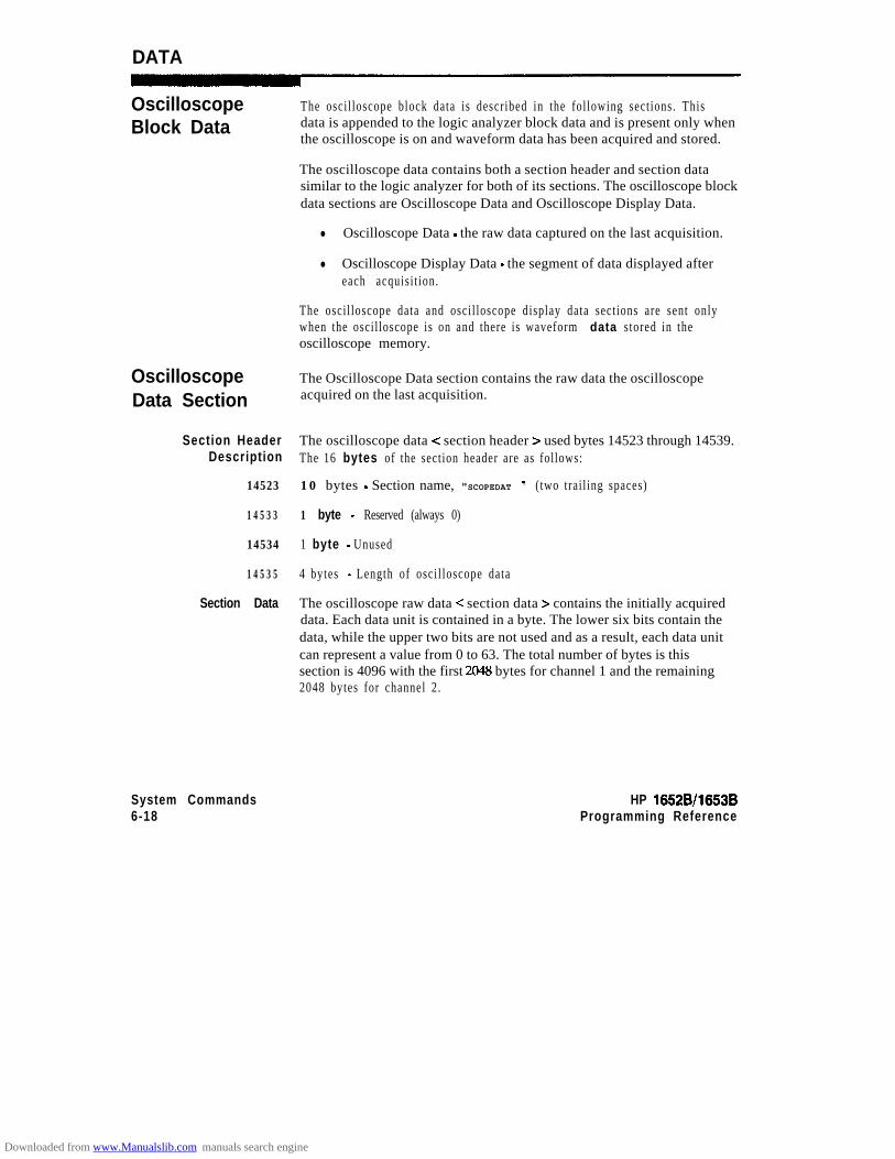
DATA
OscilloscopeBlock Data
OscilloscopeData Section
Section HeaderDescription
14523
14533
14534
14535
Section Data
The osci l loscope block data is described in the fol lowing sect ions. Thisdata is appended to the logic analyzer block data and is present only whenthe oscilloscope is on and waveform data has been acquired and stored.
The oscilloscope data contains both a section header and section datasimilar to the logic analyzer for both of its sections. The oscilloscope blockdata sections are Oscilloscope Data and Oscilloscope Display Data.
l Oscilloscope Data - the raw data captured on the last acquisition.
l Oscilloscope Display Data - the segment of data displayed aftereach acquisi t ion.
The oscil loscope data and oscil loscope display data sect ions are sent onlywhen the oscil loscope is on and there is waveform data stored in theoscilloscope memory.
The Oscilloscope Data section contains the raw data the oscilloscopeacquired on the last acquisition.
The oscilloscope data < section header > used bytes 14523 through 14539.The 16 bytes of the section header are as follows:
10 bytes - Section name, "SCOPEDAT " ( two trai l ing spaces)
1 byte - Reserved (always 0)
1 byte - Unused
4 bytes - Length of osci l loscope data
The oscilloscope raw data < section data > contains the initially acquireddata. Each data unit is contained in a byte. The lower six bits contain thedata, while the upper two bits are not used and as a result, each data unitcan represent a value from 0 to 63. The total number of bytes is thissection is 4096 with the first 2048 bytes for channel 1 and the remaining2048 bytes for channel 2.
System Commands6-18
HP 18528/1653BProgramming Reference
Downloaded from www.Manualslib.com manuals search engine

DATA
14539
16587
OscilloscopeDisplay DataSection
Note ‘d
18635
22731
HP 16628/16538Programming Reference
2048 bytes - raw oscilloscope data for channel 1.
2048 bytes - raw oscilloscope data for channel 1.
The display data section < section data > contains the initial datadisplayed after an acquisition. Each data unit is represented by a 16 bitvalue which is generated by taking the raw oscilloscope data and shifting itthe the left by 8 bits.
Changing the seconds-per-division after the oscilloscope has stopped willchange the data displayed on the screen but it will not change the displaydata in this section.
4096 bytes - Displayed oscilloscope data for channel 1
4096 bytes - Displayed oscilloscope data for channel 2
System Commands6-19
Downloaded from www.Manualslib.com manuals search engine
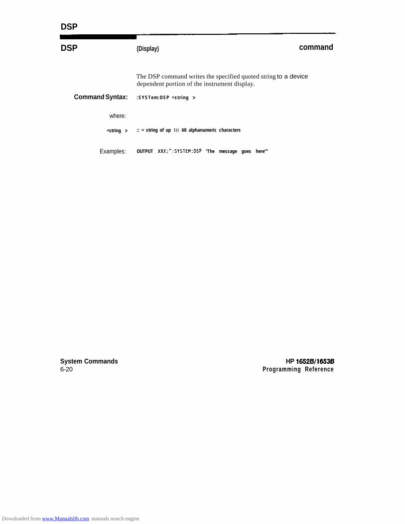
DSP
DSP (Display) command
The DSP command writes the specified quoted string to a devicedependent portion of the instrument display.
Command Syntax: :SYSTem:DSP <str ing >
where:
<string > :: = string of up to 60 alphanumeric characters
Examples: OUTPUT XXX;“:SYSTEM:DSP ‘The message goes here”’
System Commands6-20
HP 16528/1653BProgramming Reference
Downloaded from www.Manualslib.com manuals search engine

ERRorA
ERRor
query
The ERRor query returns the oldest error number from the error queue.A complete list of error numbers for the HP 1652B/53B is shown inappendix C, “Error Messages.” If no errors are present in the error queue,a zero is returned.
Query Syntax: :SYSTem:ERRoR
Returned Format: [:SYSTem:EFWor] <error number> <NL>
Example: 10 OUTPUT XXX;":SYSTEM:ERROR?"
20 ENTER XXX;Err-num30 PRINT Err-num
40 END
HP 16526/16636 System Commands621
Downloaded from www.Manualslib.com manuals search engine

HEADer
HEADer command/query
The HEADER command tells the instrument whether or not to output aheader for query responses. When HEADer is set to ON, queryresponses will include the command header.
The HEADer query returns the current state of the HEADer command.
Command Syntax: :SYSTem:HEADer {{ON~l}~{OFF~O}}
Example: OUTPUT XXX;":SYSTEM:HEADER ON"
QUety Command: :SYSTem:HEADer?
Returned Format: [:SYSTem:HEADer] { 1 lo} < NL>
Example: 10 DIM Mode$[lOO]20 OUTPUT XXX:":SYSTEM:HEAOER?"
30 ENTER XXX;Mode$
40 PRINT Mode$50 END
Note dHeaders should be turned off when returning values to numeric variables.
System Commands822
HP 16528/16538Programming Reference
Downloaded from www.Manualslib.com manuals search engine

KEY
KEY command/query
Note #b
The KEY command allows you to simulate pressing a specifiedfront-panel key. Key commands may be sent over the bus in any orderthat is legal from the front panel. Be sure the instrument is in a desiredsetup before executing the KEY command. Key codes range from 0 to 36with 99 representing no key (returned at power-up). See table 6-l for keycodes.
The external KEY buffer is only two keys deep; therefore, attempting tosend KEY commands too rapidly will cause a KEY buffer overflow errorto be displayed on the HP 1652B/53B screen.
The KEY query returns the key code for the last front- panel key pressedor the last s imulated key press over the bus.
Command Syntax: :SYSTem:KCI <key-code >
where:
< key-code z :: = integer from 0 to 36
Example: OUTPUT XXX;“:SYSTEM:KEY 24”
HP 16528/1663B System Commands6-23
Downloaded from www.Manualslib.com manuals search engine
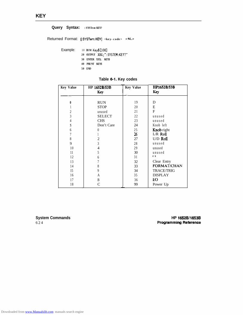
KEY
Query Syntax: :SYSTem:KEY?
Returned Format: [:SYSTem:KPI] <key-code> -cNL>
Example: 10 DIM Key$[lOO]20 OUTPUT XXX;":SYSTEM:KEY?"
30 ENTER XXX; KEY$40 PRINT KEY$
50 END
Table 6-l. Key codes
Key Value HP 1652B/53BKey
Key Value
-
0 RUN 191 STOP 202 unused 213 SELECT 224 CHS 235 Don’t Care 246 0 257 1 268 2 279 3 2810 4 2911 5 3012 6 3113 7 3214 8 3315 9 3416 A 3517 B 3618 C 99
L
HP1652BE3BKey
DEFu n u s e du n u s e dKnob leftKnob rightL/R RoIIU/D RolIu n u s e dunusedu n u s e d,! ,t
Clear EntryFORMAT/CHANTRACE/TRIGDISPLAYI/OPower Up
System Commands6 2 4
HP 16528/16638
Downloaded from www.Manualslib.com manuals search engine

LER
LER (LCL Event Register) wry
The LER query allows the LCL (local) Event Register to be read. Afterthe LCL Event Register is read, it is cleared. A one indicates aremote-to-local transition has taken place. A zero indicates aremote-to-local transition has not taken place.
QIJWy Syntax: :SYSTem:LER?
Returned Format: [:SYSTem:LERJ {OIl}-zNL>
Example: 10 DIM Event$[lOO]20 OUTPUT XXX;":SYSTEM:LER?"
30 ENTER XXX;Event$
40 PRINT Event$
50 END
HP 1652B/l653B System Commands6-25
Downloaded from www.Manualslib.com manuals search engine
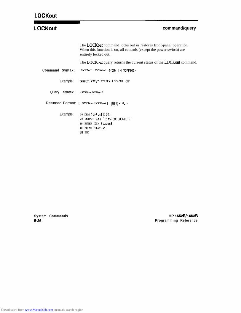
LOCKout
LOCKout command/query
The LOCKout command locks out or restores front-panel operation.When this function is on, all controls (except the power switch) areentirely locked out.
The LOCKout query returns the current status of the LOCKout command.
Command Syntax: :SYSTem:LOCKout {{ON~l}~{OFF~O}}
Example: OUTPUT XXX;":SYSTEM:LOCKOUT ON"
Query Syntax: :SYSTem:LOCKout?
Returned Format: [:SYSTem:LOCKout] {OIl}<NL>
Example: 10 DIM Status$[lOO]20 OUTPUT XXX;":SYSTEM:LOCKOUT?"
30 ENTER XXX;Status$40 PRINT Status$50 END
System Commands6-26
HP 16528/1663BProgramming Reference
Downloaded from www.Manualslib.com manuals search engine
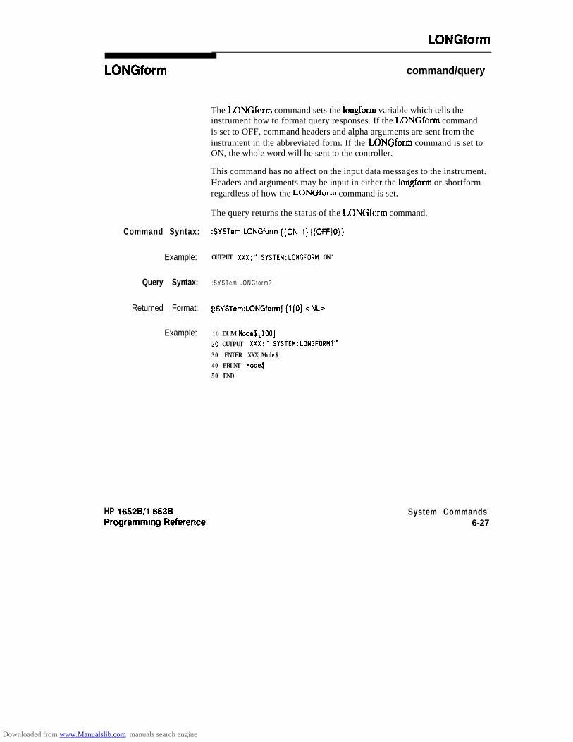
LONGform
LONGform command/query
The LONGform command sets the longform variable which tells theinstrument how to format query responses. If the LONGform commandis set to OFF, command headers and alpha arguments are sent from theinstrument in the abbreviated form. If the LONGform command is set toON, the whole word will be sent to the controller.
This command has no affect on the input data messages to the instrument.Headers and arguments may be input in either the longform or shortformregardless of how the LONGform command is set.
The query returns the status of the LONGform command.
Command Syntax: :SYSTem:LONGform {{ON~1}~{OFF~O}}
Example: OUTPUT XXX;":SYSTEM:LONGFORM ON"
Query Syntax: : S Y S T e m : L O N G f o r m ?
Returned Format: [:SYSTem:LONGform] (1 IO} < NL>
Example: 10 DIM Mode$[lOO]20 OUTPUT XXX;":SYSTEM:LONGFDRM?"
30 ENTER XXX;Mode$40 PRINT Moded50 END
HP 16528/l 6538 System Commands6-27
Downloaded from www.Manualslib.com manuals search engine
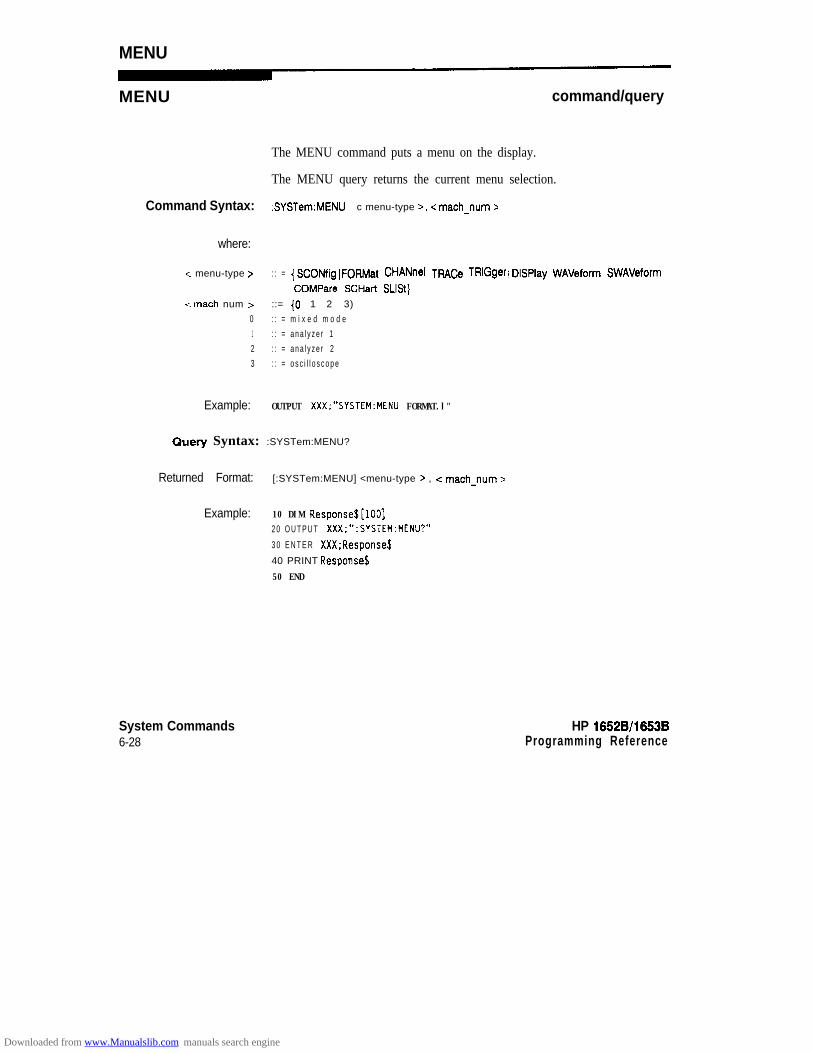
MENU
MENU command/query
The MENU command puts a menu on the display.
The MENU query returns the current menu selection.
Command Syntax: :SYSTem:MENU c menu-type >, < math-num >
where:
-= menu-type > : : = { SCONfig 1 FORMat 1CHANnel 1TRACe 1TRlGger 1DlSPlay 1WAVeform I SWAVeform 1
COMPare I SCHart 1 SLISt}cmach num > ::= {O 1 1 1 2 1 3)
0 : : = m i x e d m o d e1 : : = a n a l y z e r 12 : : = a n a l y z e r 23 : : = o s c i l l o s c o p e
Example: OUTPUT XXX;"SYSTEM:MENU FORMAT.l"
Query Syntax: :SYSTem:MENU?
Returned Format: [:SYSTem:MENU] <menu-type r , < math-num >
Example: 10 DIM Response$[lOO]2 0 O U T P U T XXX;“:SYSTEM:MENU?”
3 0 E N T E R XXX;Response$
40 PRINT Response$
50 END
System Commands6-28
HP 16528/1653BProgramming Reference
Downloaded from www.Manualslib.com manuals search engine

MESE
MESE command/query
The MESE command sets the Module Event Status Enable Register bits.The MESE register contains a mask value for the bits enabled in theMESR register. A one in the MESE will enable the corresponding bit inthe MESR, a zero will disable the bit.
The MESE query returns the current setting.
Refer to table 6-2 for information about the Module Event Status Enableregister bits, bit weights, and what each bit masks for the logic analyzer.
Command Syntax: :SYSTem:MESE <enable -mask>
where:
-C enable mask > :: = integer from 0 to 255
Example: OUTPUT XXX;” :SYSTEM:MESE 1”
HP 16528/1653BProgramming Reference
System Commands629
Downloaded from www.Manualslib.com manuals search engine
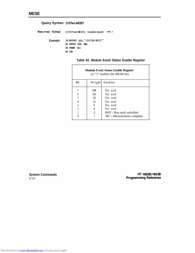
MESE
Query Syntax: :SYSTem:MESE?
RetUrned Format: [ :SYSTem:MESE] <enable -mask> <NL>
Example: 10 OUTPUT XXX;“:SYSTEM:MESE?”20 ENTER XXX; Mes
30 PRINT M e s
40 END
Table 62. Module Event Status Enable Register
Module Event Status Enable Register(A “1” enables the MESR bit)
Bit Weight Enables
7 128 Not used6 64 Not used5 32 Not used4 16 Not used3 8 Not used2 4 Not used1 2 RNT - Run until satisified0 1 MC - Measurement complete
System Commands6 3 0
HP 16528/1653B
Downloaded from www.Manualslib.com manuals search engine

MESR
MESR query
The MESR query returns the contents of the Module Event Statusregister.
Note dReading the register clears the Module Event Status Register.
Table 6-3 shows each bit in Module Event Status Register and their bitweights for the logic analyzer. When you read the MESR, the valuereturned is the total bit weights of all bits that are set at the time theregister is read.
Query Syntax: :SYSTem:MESW)
Returned Format: [ :SYSTem:MESR] -c status > < NL>
where:
c status > :: = integer from 0 to 255
Example: 10 OUTPUT XXX;“:SYSTem:MESR?”
20 ENTER XXX; Mer30 PRINT Mer
40 END
HP 16528/1663B System Commands631
Downloaded from www.Manualslib.com manuals search engine
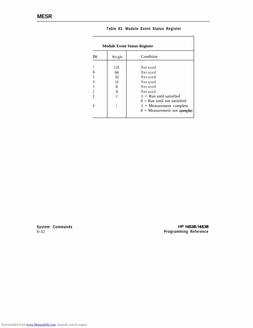
MESR
System Commands HP 16528/165386-32 Programming Reference
Table 83. Module Event Status Register
Module Event Status Register
Bit Weight Condition
7 1286 645 324 163 82 41 2
0 1
N o t u s e dN o t u s e dN o t u s e dN o t u s e dN o t u s e dN o t u s e d1 = Run until satisified0 = Run until not satisified1 = Measurement complete0 = Measurement not complet
Downloaded from www.Manualslib.com manuals search engine

PPOWer
PPOWer query
The PPOWer (preprocessor power) query returns the current status ofthe HP 1652BE3B’s high-current limit circuit. If it is functioning properly,0 is returned. If the current draw is too high, 1 is returned until theproblem is corrected and the circuit automatically resets.
Query Syntax: :PPOWer?
l?eturned Format: [:PPOWer] {o 1 I}
Example: 10 DIM Response$[lO]20 OUTPUT XXX;":PPOWER?"
30 ENTER XXX; Response$
40 PRINT Response%50 END
HP 16528/16538Programming Reference
System Commands633
Downloaded from www.Manualslib.com manuals search engine

PRlNt
PRlNt command
The PRINt command initiates a print of the screen or print all over theRS-232C bus. The PRINt parameters SCReen or ALL specify how thescreen data is sent to the controller. PRINt SCReen transfers the data tothe controller in a printer specific graphics format. PRINt ALL transfersthe data in a raster format for the following menus:
l State and Timing Format menus
l Disk menu
l State and Timing Symbol menus
0 State Listing menu
l State Trace
0 State Compare
Command Syntax: :SYSTem:PRINt {SCReen 1 ALL}
Example: OUTPUT XXX;“:SYSTEM:PRINT SCREEN”
System Commands6 - 3 4
HP 16528/16538Programming Reference
Downloaded from www.Manualslib.com manuals search engine

RMODe
RMODe command/query
The RMODe command is a run control command that specifies the runmode for logic analyzer and oscilloscope. It is at the same level in thecommand tree as SYSTem; therefore, it is not preceded by :SYSTem.
The query returns the current setting.
Note dAfter specifying the run mode, use the STARt command to start theacquis i t ion .
Command Syntax: :RMODe {SINGle 1 REPetitive}
Example: OUTPUT XXX;“:RMOOE SINGLE”
Query Syntax: :RMoDe?
Returned Format: [:RMODe] {SINGle 1 REPetitive} c NL>
Example: 10 DIM Mode$[lOO]20 OUTPUT XXX;“:RMODE?”
30 ENTER XXX;Mode$40 PRINT Hode$50 END
HP 16526/1653BProgramming Reference
System Commands6-35
Downloaded from www.Manualslib.com manuals search engine

SETup
SETup command/query
The SYStem:SETup command configures the logic analyzer module asdefined by the block data sent by the controller.
The SYStem:SETup query returns a block of data that contains thecurrent configuration to the controller.
There are three data sections which are always returned and a fourthheader when the oscilloscope is on and has acquired and stored waveformdata. These are the strings which would be included in the section header:
0 "CONFIG "
0 "1650 RS232"
0 "1650 DISP "0 "1650 DISP2"
0 "SCOPECNF "
Addit ional ly, the fol lowing sect ions may also be included, depending onwhat’s loaded:
0 "SYMBOLS A -
0 "SYMBOLS B "0 "SPA DATA A"
l "SPA DATA 8"l "INVASH A "0 "INVASM B "
0 "COMPARE -
System Commands6-36
HP 16528/1653BProgramming Reference
Downloaded from www.Manualslib.com manuals search engine
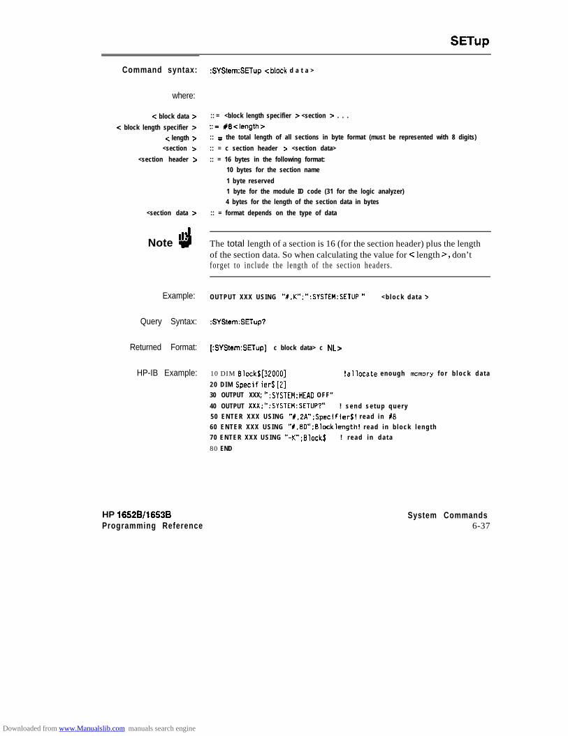
SETup
Command syntax:
where:
< block data z=
-z block length specifier >c length >
<section >
<section header >
<section data z
Note d
Example:
Query Syntax:
Returned Format:
HP-IB Example:
:SYStem:SETup <block d a t a >
:: = <block length specifier > <section > . . .
::= #8<length>:: = the total length of all sections in byte format (must be represented with 8 digits)
:: = c section header > <section data>
:: = 16 bytes in the following format:10 bytes for the section name
1 byte reserved1 byte for the module ID code (31 for the logic analyzer)4 bytes for the length of the section data in bytes
:: = format depends on the type of data
The total length of a section is 16 (for the section header) plus the lengthof the section data. So when calculating the value for c length >, don’tforget to include the length of the section headers.
OUTPUT XXX USING “%,K”;“:SYSTEH:SETllP ” < b l o c k d a t a >
:SYStem:SETup?
[:SYStem:SETup] c block data> c NL>
10 DIM Block$ [32000] !allocate enough memory f o r b l o c k d a t a
2 0 D I M Specif ier$ [2]30 OUTPUT XXX; “:SYSTEM:HEAD OFF”
40 OUTPUT XXX;“:SYSTEM:SETUP?” ! s e n d s e t u p q u e r y50 ENTER XXX USING “#.ZA”;Specifier$! r e a d i n 1860 ENTER XXX USING “#.8D”;Blocklength! read in b lock l eng th70 ENTER XXX USING “-K”;Block$ ! r e a d i n d a t a
80 END
HP 16528/1653BProgramming Reference
System Commands6-37
Downloaded from www.Manualslib.com manuals search engine
STARt
STARt
Note ‘4
Command Syntax:
Example:
System Commands6-38
command
The STARt command is a run control command that starts the logicanalyzer running in the spccificd run mode (see RMODe). The STARtcommand is on the same level in the command tree as SYSTem; therefore,it is not preceded by :SYSTem.
The STARt command is an Overlapped Command. An OverlappedCommand is a command that allows execution of subsequent commandswhile the device operations initiated by the Overlapped Command are stillin progress .
:STAR
OUTPUT XXX;":START"
HP 18528/18538Programming Reference
Downloaded from www.Manualslib.com manuals search engine

ASTOP
STOP
Note d
command
The STOP command is a run control command that stops the logicanalyzer. The STOP command is on the same level in the command treeas SYSTem; therefore, it is not preceded by :SYSTem.
The STOP command is an Overlapped Command. An OverlappedCommand is a command that allows execution of subsequent commandswhile the device operations initiated by the Overlapped Command are stillin progress .
Command Syntax: :STOP
Example: OUTPUT m”:STOP
HP 16528/l 6538Programming Reference
System Commands6-39
Downloaded from www.Manualslib.com manuals search engine
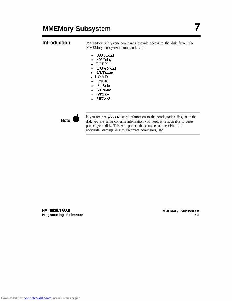
MMEMory Subsystem
Introduction MMEMory subsystem commands provide access to the disk drive. TheMMEMory subsystem commands are:
l AUToloadl CATalog0 C O P Yl DOWNload0 INITialize0 L O A Dl PACKl PURGel RENamel STORel UPLoad
NoteIf you are not going,to store information to the configuration disk, or if thedisk you are using contains information you need, it is advisable to writeprotect your disk. This will protect the contents of the disk fromaccidental damage due to incorrect commands, etc.
HP 16528/1653BProgramming Reference
MMEMory Subsystem7-l
Downloaded from www.Manualslib.com manuals search engine

I f /
type block-dot0
Figure 7-1. MMEMory Subsystem Commands Syntax Diagram
MMEMory Subsystem HP 16528/165387-2 Programming Reference
Downloaded from www.Manualslib.com manuals search engine

auto-file = string of up to 10 olphanumen’c characters reptesenting a validfile name.name = string of up to 10 alphanumeric characters representing a valid file name.description = string of up to 32 alphanumeric characters.type = integer, refer to table 7-l.block-data = data in IEEE 4W2 #format.ia-name = string of up to 10 alphanumeric characters representing a vaIid file name.new-name = string of up to 10 alphanumetic characters representing a valid file name
Figure 7-1. MMEMory Subsystem Commands Syntax Diagram (continued)
Note 1’4 Refer to “Disk Operations” in chapter 5 of the HP 1652Bl53B LogicAnalyzes Reference manual for a description of a valid file name.
HP 1652B/l653BProgramming Reference
MMEMory Subsystem7-3
Downloaded from www.Manualslib.com manuals search engine
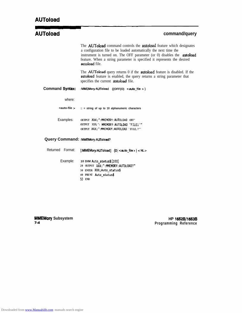
AUToload
AUToload command/query
The AUToload command controls the autoload feature which designatesa configuration file to be loaded automatically the next time theinstrument is turned on. The OFF parameter (or 0) disables the autoloadfeature. When a string parameter is specified it represents the desiredautoload file.
The AUToload query returns 0 if the autoload feature is disabled. If theautoload feature is enabled, the query returns a string parameter thatspecifies the current autoload file.
Command Syntax: :MMEMory:AUToload {{OFF(O) ) <auto-file > }
where:
<auto-file > :: = string of up to 10 alphanumeric characters
Examples: OUTPUT XXX;":MMEMORY:AUTOLOAD OFF"OUTPUT XXX;": MMEMORY:AUTOLOAD 'FILEl"OUTPUT XXX;":MMEMORY:AUTOLOAD 'FILE,?"'
Query Command: :MMEMory:AUToload?
Returned Format: [:MMEMory:AUToload] (0) <auto-file > } < NL>
Example: 10 DIM Auto-status$[lOO]20 OUTPUT XXX;":MMEMORY:AUTOLOAD?"
30 ENTER XXX;Auto-status$40 PRINT Auto-status$50 END
MMEMory Subsystem7-4
HP 1652Bll653BProgramming Reference
Downloaded from www.Manualslib.com manuals search engine

CATalogA
CATalog
wry
The CATalog query returns the directory of the disk in block data format.The directory consists of a S-character string for each file on the disk.Each file entry is formatted as follows:
“NNNNNNNNNN TTTlTIl DDDDDDDDDDDDDDDDDDDDDDDDDDDDDDDD
where N is the filename, T is the file type (a number), and D is the filedescription.
Query Syntax: :MMEMory:CATalog?
&Wrned Format: [:MMEMoty:CATalog] <b lock s i ze> <blockdata>
where:
<block size Z- : : = X8dddddddd (X8followed b y a n e i g h t d i g i t n u m b e r )
<blockdata> :: = [<filename > <file type C= <file description >I...
Example: 10 D I M File$[51]
2 0 D I M Specifier$[Z]30 OUTPUT XXX;“:SYSTEM:HEAD OFF”40 OUTPUT XXX;” :MMEMORY:CATALDG?” !send c a t a l o g q u e r y50 ENTER XXX USING “#.2A”;Specifier$ !read i n #8
60 ENTER XXX USING “#,8D”;Length !read i n l e n g t h
70 FOR I=1 TO Length STEP 51 !read and pr in t each f i l e
80 ENTER XXX USING “#,51A”;File$
90 PRINT Files100 NEXT I
110 ENTER XXX USING “A”;Specifier$ !read i n f i n a l l i n e f e e d
120 END
HP 16528/1653B MMEMoIY SubsystemProgramming Reference 7-5
Downloaded from www.Manualslib.com manuals search engine
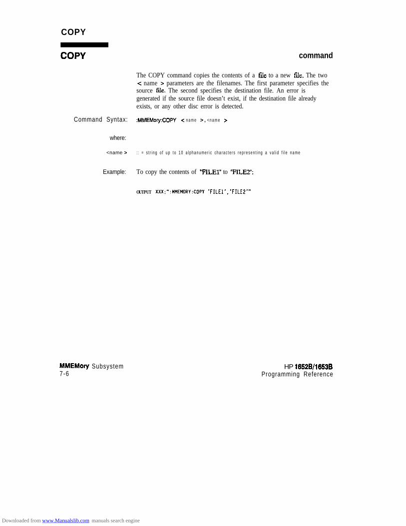
COPY
command
The COPY command copies the contents of a Gle to a new file. The twoc name > parameters are the filenames. The first parameter specifies thesource file. The second specifies the destination file. An error isgenerated if the source file doesn’t exist, if the destination file alreadyexists, or any other disc error is detected.
Command Syntax: :MMEMory:COPY < n a m e 5, < n a m e >
where:
<name > : : = s t r i n g o f u p t o 1 0 a l p h a n u m e r i c c h a r a c t e r s r e p r e s e n t i n g a v a l i d f i l e n a m e
Example: To copy the contents of “FILEl” to “FILE2”:
OUTPUT XXX;":MMEMORY:COPY 'FILEl','FILEE'"
MMEMory Subsystem7-6
HP 16528/16!53BProgramming Reference
Downloaded from www.Manualslib.com manuals search engine

DOWNload
DOWNload command
The DOWNload command downloads a file to the disk. The < name >parameter specifies the filename, the c description > parameter specifiesthe file description, and the < block-data > contains the contents of thefile to be downloaded.
Table 7-l lists the file types for the < type > parameter.
Command Syntax: :MMEMory:DOWNload <name >, <description >, <type 7, <block-data 7
where:
c name > :: = string of up to 10 alphanumeric characters representing a valid file name
<description > :: = string of up to 32 alphanumeric characters
<type7 :: = integer (see Table 7-1)-z block-data > :: = contents of file in block data format
Example: OUTPUT XXX;“:MMEMORY:DOWNLOAD ‘SETUP-‘;‘FILE CREATED FROM SETUP
QUERY’ ,-16127,#600000643.. .”
Table 7-l. File Types
File File ‘Qpe
HP 1652f3 SYSTEM -163831652J3 CONFIG -16Q96AUTOLOAD TYF’E -15615INVERSE ASSEMBLER -15614TEXTTYPE -15610
HP 16528/16538Progmmming Reference
MMEMory Subsystem7-7
Downloaded from www.Manualslib.com manuals search engine

INlTialize
INlTialize command
The INITialize command formats the disk.
Note d
Command Syntax:
Example:
MMEMory Subsystem7-8
Once executed, the initialize command formats the specitied disk,permanently erasing all existing information from the disk. After that,there is no way to retrieve the original information.
:MMEMory:INITialize
OUTPUT XXX;":MMEMORY:INITIALIZE"
HP 18828/1883BProgramming Reference
Downloaded from www.Manualslib.com manuals search engine
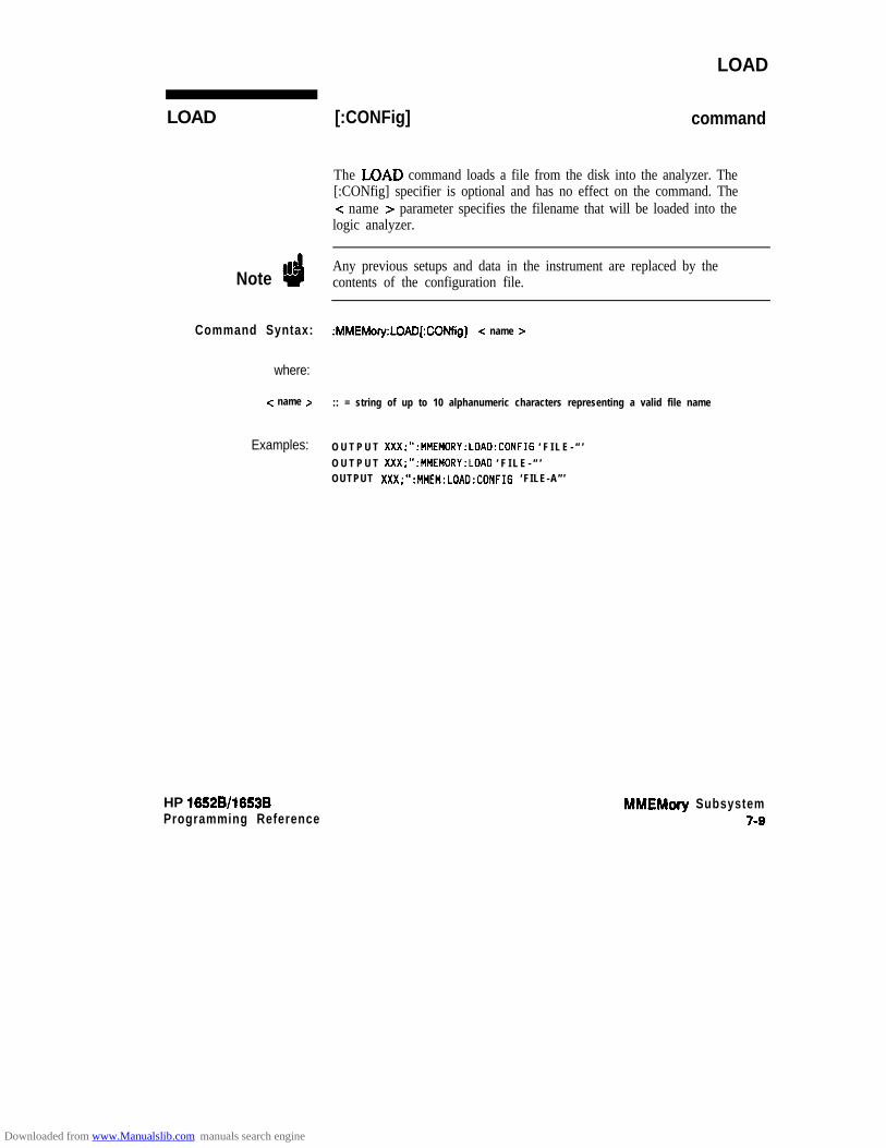
LOAD
LOAD
Note d
Command Syntax: :MMEMory:LOAD[:CONfig] -z name >
where:
-z name > :: = string of up to 10 alphanumeric characters representing a valid file name
Examples:
HP 16528/1653BProgramming Reference
[:CONFig] command
The LOAD command loads a file from the disk into the analyzer. The[:CONfig] specifier is optional and has no effect on the command. Thec name > parameter specifies the filename that will be loaded into thelogic analyzer.
Any previous setups and data in the instrument are replaced by thecontents of the configuration file.
O U T P U T XXX;“:MMEMORY:LOAD:CONFIG ‘ F I L E - “ ’O U T P U T XXX;“:MMEMORY:LOAD ‘ F I L E - “ ’OUTPUT XXX;“:MMEM:LOAD:CONFIG ‘FILE-A”’
MMEMory Subsystem7-9
Downloaded from www.Manualslib.com manuals search engine

LOAD [:IASSembler] command
This variation of the LOAD command allows inverse assembler files to beloaded into analyzer 1 or analyzer 2 of the HP 1652BD653B. The< IA-name > parameter specifies the inverse assembler filename. Theparameter after the c IA-name > parameter specifies into whichmachine the inverse assembler is loaded.
tbI’ Inverse assembler files should only be loaded into the state analyzer. If anNote inverse assembler file is loaded into the timing analyzer no error will be
generated; however, i t will not be accessible.
Command Syntax: :MMEMory:LOAD:lASSembler c IA-name > ,{ 112)
where:
<IA name> :: = string of up to 10 alphanumeric characters representing a valid file name
Examples: OUTPUT xxx;" :MMEMORY:LOAD:IASSEMBLER '16602O_IP',l"
OUTPUT XXX;" :MMEM:LOAD:IASS '168020-IP'l"
MMEMory Subsystem7-10
HP 16528/16538
Downloaded from www.Manualslib.com manuals search engine

PACK
PACK command
The PACK command packs the files on a disk in the disk drive.
Command Syntax: :MMEMO~~:PACK
Example: OUTPUT XXX;" :HMEMORY:PACK"
HP 1652B/l653BProgmmming Reference
MMEMory Subsystem7-11
Downloaded from www.Manualslib.com manuals search engine

PURGe
PURGe
Note d
Command Syntax:
where:
< name z-
Examples:
MMEMory Subsystem7-12
command
The PURGe command deletes a file from the disk. The < name >parameter specifies the filename to be deleted.
Once executed, the purge command permanently erases all the existinginformation from the specified file. After that, there is no way to retrievethe original information.
:MMEMory:PlJRGe c name >
:: = string of up to 10 alphanumeric characters representing a valid file name
OUTPUT XXX;“:MMEMORY:PlJRGE ‘FILEl”’
HP 16528/16538Programming Reference
Downloaded from www.Manualslib.com manuals search engine

REName
REName
Note d
Command Syntax:
where:
c name z
<new-name z
Examples:
HP 16528/1663BProgramming Reference
command
The REName command renames a file on the disk. The < name >parameter specifies the filename to be changed and the -z new-name >parameter specifies the new fdename.
You cannot rename a file to an already existing filename.
:MMEMory:REName -z name z- , <new-name 5
:: = string of up to 10 alphanumeric characters representing a valid file name:: = string of up to 10 alphanumeric characters representing a valid file name
OUTPUT XXX;“:MMEMORY:RENAME ‘OLDFILE’,‘NEWFILE’”
MMEMory Subsystem7-13
Downloaded from www.Manualslib.com manuals search engine
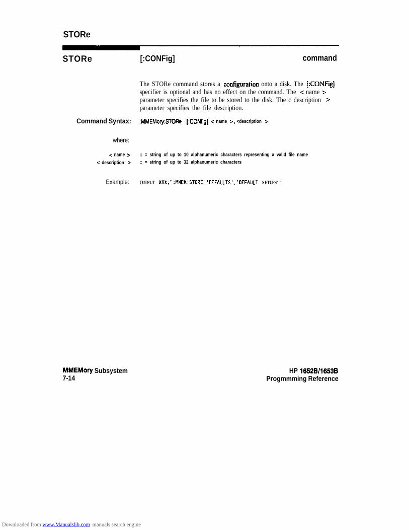
STORe
STORe [:CONFig] command
The STORe command stores a cmfiguration onto a disk. The [:CONFii]specifier is optional and has no effect on the command. The < name >parameter specifies the file to be stored to the disk. The c description >parameter specifies the file description.
Command Syntax: :MMEMory:STORe [:CONfig] < name >, <description >
where:
-z name > :: = string of up to 10 alphanumeric characters representing a valid file name
<: description > :: = string of up to 32 alphanumeric characters
Example: OUTPUT XXX;":MMEM:STORE 'DEFAULTS','DEFAlJLT SETUPS'"
MMEMory Subsystem7-14
HP 16528/1653BProgmmming Reference
Downloaded from www.Manualslib.com manuals search engine

UPLoadA
UPLoad
wry
The UPLoad query uploads a file. The < name > parameter specifies thefde to be uploaded from the disk. The contents of the file are sent out ofthe instrument in block data form.
Query Syntax: :MMEhWy:UPLoad? <name >
where:
tnamez :: = string of up to 10 alphanumeric characters representing a valid file name
Returned Format: [:MMEMory:UPLoad] <block-date> cNL>
Example: 10 DIM Block$[32000] !allocate enough memory for block data
20 DIM Specifier$[2]
30 OUTPUT XXX;":SYSTEM HEAD OFF"
40 OUTPUT XXX;":MMEMORY:UPLOAD? 'FILEl" !send upload query50 ENTER XXX USING "#.2A":Specifier$ !read in 1860 ENTER XXX USING "#,8D";Length !read in block length
70 ENTER XXX USING "-K";Block$ !read in file80 END
HP 16528/1653B MMEMory SubsystemProgramming Reference 7-15
Downloaded from www.Manualslib.com manuals search engine

DLISt Subsystem 8
Introduction The DLISt (dual list) subsystem contains the commands in the dual statelisting menu. These commands are:
0 COLumn0 L I N E
col-num = integerfrom 1 to 8label-name = a sbing of up to 6 alphanumeric charactersbase = {BINary 1 HEXacecimaI 1 OcTal 1 DECimal IASCii ISXUBol}macb-num = {I 12)line-num-mid-screen = integerfrom -1023 to + 1023
Figure 8-l. DUSt Subsystem Syntax Diagram
HP 16528/1653BProgramming Reference
DLlSt Subsystem8-l
Downloaded from www.Manualslib.com manuals search engine

DLlSt
DLlSt selector
The DLISt selector (dual list) is used as part of a compound header toaccess those settings normally found in the Dual State Listing menu. Thedual list displays data when two state analyzers are run simultaneously.
Command Syntax: :DLISt
Example: OUTPUT XXX;" :OLIST:LINE 0.1"
DUSt Subsystem6-2
HP 16528/16538Programming Reference
Downloaded from www.Manualslib.com manuals search engine

COLumn
COLumn command/query
The COLumn command allows you to configure the state analyzer listdisplay by assigning a label name and base to one of eight vertical columnsin the menu. The machine number parameter is required since the samelabel name can occur in both state machines at once. A column numberof 1 refers to the left-most column. When a label is assigned to a columnit replaces the original label in that column. The label originally in thespecified column is placed in the column the specified label is moved from.
When “TAGS” is the label name, the TAGS column is assumed and thenext parameter must specify RELative or ABSolute. The machinenumber should be 1.
The COLumn query returns the column number, label name, and base forthe specified column.
Command Syntax: :DLISt:COLumn <col-num > ,{“TAGS”,{RELative 1 ABSolute} (
<label-name >, -z base z }, < math-num >
where:
< col-num > ::= {1~2~3~4~5)6~7~6}<label-name > :: = a string of up to 6 alphanumeric characters
<base> :: = (BINary (HEXadecimal IOCTal ( DECimal ( ASCii ISYMBol)i math-num > ::= (112)
Example: OUTPUT XXX;": DLIST:COLUMN 4,'DATA',HEXADECIMAL,l"
HP 16528/16538Programming Reference
DUSt Subsystem8-3
Downloaded from www.Manualslib.com manuals search engine

COLumn
Query syntax: :DLISt:COLumn? <col-num >
Returned Format: [:DLISt:COLumn] < col-num > , c label-name >, <base > , < math-num r < NL >
Example: 1 0 D I M cl.$[loo]
20 OUTPUT XXX;” :DLIST:COLUMN? 4 ”30 E N T E R XXX;Cl$40 PRINT Clf
5 0 END
DLlSt Subsystem8-4
HP 16528/16538
Downloaded from www.Manualslib.com manuals search engine

LINE
LINE command/query
The LINE command allows you to scroll the state analyzer listingvertically. The command specifies the state line number relative to thetrigger that the specified analyzer will h&hlight at center screen.
The LINE query returns the line number for the state currently in the boxat center screen and the machine number to which it belongs.
Command Syntax: :DLISt:LINE c line-num-mid-screen >, -z math-num z-
where:
-Z line-num-mid-screen > :: = integer from -1023 to + 1023-C math-num t : : = (112)
Example: OUTPUT XXX;“:DLIST:LINE 511.1”
Query syntax: :DLISt:LINE?
Returned Format: [DLWLINE] -z line-num-mid-screen >, -z maoh-num 7 < NL>
Example: 10 DIM Ln$[lOOl2 0 OUTPUT XXX;“:DLIST:LINE?”
30 ENTER XXX;Ln$40 PRINT Ln$50 END
DUSt Subsystem5-5
Downloaded from www.Manualslib.com manuals search engine

WLlSt Subsystem
Introduction Two commands in the WLJSt subsystem control the X and 0 markerplacement on the waveforms portion of the Timing/State mixed modedisplay. These commands are XTIMe and OTIMe. The XSTate andOSTate queries return what states the X and 0 markers are on. Since themarkers can only be placed on the timing waveforms, the queries returnwhat state (state acquisition memory location) the marked pattern isstored in.
NoteIn order to have mixed mode, one machine must be a timing analyzer andthe other must be a state analyzer with time tagging on (useMACHine < N > :STFLace:TAG TIME).
time-value = real number
Figure 91. WLlSt Subsystem Syntax Diagram
HP 16528/16538 WUSt SubsystemProgmmming Reference 91
Downloaded from www.Manualslib.com manuals search engine
WLlSt selector
The WLISt (Waveforms/listing) selector is used as a part of a compoundheader to access the settings normally found in the Mixed Mode menu.Since the WLISt command is a root level command, it will always appearas the first element of a compound header.
Note dThe WLISt Subsystem is only available when one state analyzer (with timetag&g on) and one timing analyzer are specified.
Command Syntax: :wust
Example : OUTPUT XXX;":WLIST:XTIME 40.OE-6"
WUSt Subsystem HP 16528/1653B0-2 Programming Reference
Downloaded from www.Manualslib.com manuals search engine

OSTate
OSTate query
The OSTate query returns the state where the 0 Marker is positioned. I fdata is not valid, the query returns 32767.
Query Syntax: :WLISt:OSTate?
f%3tUrrEd Format: [:WLISt:OSTate] <state-num > <NL>
where:
<state num> :: = integer
Example: 10 DIM s0$[100120 OUTPUT XXX;":WLIST:OSTATE?"
30 ENTER XXX;So$40 PRINT So$
50 END
HP 16528/1653B WUSt Subsystem9-3
Downloaded from www.Manualslib.com manuals search engine

XSTate
XSTate
Query Syntax:
Example:
Returned Format:
where:
<: state-num >
Example:
WUSt Subsystem9-4
query
The XSTate query returns the state where the X Marker is positioned. Ifdata is not valid, the query returns 32767.
:WUSt:XSTate?
OUTPUT XXX,":WLIST:XSTATE?
[:WLISt:XSTate] < state-num > < NL>
:: = integer
10 DIM Sx$[lOO]
20 OUTPUT XXX;":WLIST:XSTATE?"30 ENTER XXX;Sx$40 PRINT Sx$50 END
HP 16528/1653BProgramming Reference
Downloaded from www.Manualslib.com manuals search engine
OTIMe
OTIMe command/query
The OTIMe command positions the 0 Marker on the timing waveforms inthe mixed mode display. If the data is not valid, the command performsno action.
The OTIMe query returns the 0 Marker position in time. If data is notvalid, the query returns 9.9E37.
Command Syntax: :WLlSt:OTIMe <time-value z-
where:
<time value > : : = r e a l n u m b e r
Example: OUTPUT XXX,":WLIST:OTIME 40.0~~6"
Query Syntax: :WLISt:OTIMe?
RetUrned Format: [:WLISt:OTIMe] <time-value> c NL>
Example: 10 DIM To$[lOO]20 OUTPUT XXX;":WLIST:OTIME?"30 ENTER XXX;To$
40 PRINT To$50 END
HP 1652B/l653BProgramming Reference
WLlSt SubsystemQ-5
Downloaded from www.Manualslib.com manuals search engine

XTIMe
XTIMe command/query
The XTIMe command positions the X Marker on the timing waveforms inthe mixed mode display. If the data is not valid, the command performsno action.
The XTIMe query returns the X Marker position in time. If data is notvalid, the query returns 9.9E37.
Command Syntax: :WLISt:XTIMe <time-value >
where:
c time value > :: = real number-
Example: OUTPUT XXX.":WLIST:XTIME 40.OE-6"
Query Syntax: :WLISt:XTIMe?
Returned Format: [:WLISt:XTIMe] c time-value > c NL>
Example: 10 DIM Tx$[lOO]20 OUTPUT XXX;":WLIST:XTIME?"
30 ENTER XXX;TxS40 PRINT Tx$50 END
WLlSt Subsystem9-6
HP 16528/1653B
Downloaded from www.Manualslib.com manuals search engine

MACHine Subsystem 1 0Introduction The MACHine subsystem contains the commands available for the
State/lYming Configuration menu. These commands are:
l ARMw ASSignl AUToscaIe (Timing Analyzer only)l NAMEa T Y P E
There are actually hvo MACHine subsystems: MACHinel andMACHine2. Unless noted, they are identical. In the syntax definitionsyou will see MACHme{ 112) anytime the subject is applicable to bothsubsystems.
Additionally, the following subsystems are a part of the MACHinesubsystem. Each is explained in a separate chapter.
SFORmat subsystemSTRace subsystemSLISt subsystemSWAVeform subsystemSCHart subsystemCOMPare subsystemTFORmat subsystem‘ITRace subsystemTWAVeform subsystemSYMBoI subsystem
(chapter 11)(chapter 12)(chapter 13)(chapter 14)(chapter 15)(chapter 16)(chapter 17)(chapter 18)(chapter 19)(chapter 20)
MACHine Subsystemlo-l
Downloaded from www.Manualslib.com manuals search engine

space p o d - l i s t 9
AUToscale I
math i ne-name
MACHine Subsystemlo-2
arm-source = {RUN / MACHine {I 12))pod-list = (NONE 1 <pod-num > [, <pod-num >I...}pod-num = (I 1 2 1 3 1 4 ( 5)machine-name = string of up to 10 alphanumeric characters
Figure 10-l. Machine Subsystem Syntax Diagram
HP 16528/1653B
Downloaded from www.Manualslib.com manuals search engine

MACHine
MACHine selector
The MACHine c N > selector specifies which of the two analyzers(machines) available in the HP 1652B/53B the commands or queriesfollowing will refer to. Since the MACHine < N > command is a rootlevel command, it will normally appear as the first element of a compoundheader.
Command Syntax: :MACHine < N z-
where:
<N> :: = (112) (the number of the machine)
Example: OUTPUT XXX; “:MACHINEl:NAME ‘DRAMTEST’”
HP 16529/1653B MACHine Subsystemlo-3
Downloaded from www.Manualslib.com manuals search engine
ARM
ARM command/query
The ARM command specifies the arming source of the specified analyzer(machine).
The ARM query returns the source that the current analyzer (machine)will be armed by.
Command Syntax: :MACHine{ 112):ARM c arm-source >
where:
<arm source > : := {RlJN~MACHine{l~2}~BNC~SCOPe}
Example: OUTPUT XXX;":MACHINEl:ARM MACHINE2"
Query Syntax: :MACHine { 1 I2}:ARM?
Returned Format: [:MACHine { 1 I P):ARM] <arm-source > < NL>
Example: 1 0 D I M String$ [lOO]2 0 O U T P U T m ‘:MACHINEl:ARM?”
3 0 E N T E R >ooc; StringS40 P R I N T String$50 E N D
MACHine Subsystem10-4
HP 1652BD653BProgramming Reference
Downloaded from www.Manualslib.com manuals search engine
ASSign
ASSign command/query
The ASSign command assigns pods to a particular analyzer (machine).
The ASSign query returns which pods are assigned to the current analyzer(machine).
Command Syntax: :MACHine{l (2):ASSign <pod-list>
where:
-z pod-list > ::= {NONE]cpodY>[, <pod#>]...)<pod #> ::= (112131415)
Example: OUTPUT XXX;":MACHINEl:ASSIGN 5. 2, 1"
Query Syntax: MACHine { 1 IP}:ASSign’l
Returned Format: [MACHINE { 1 IP):ASSign] <pod-list > c NL>
Example: 10 DIM String$ [lDD]20 OUTPUT XXX;" :MACHINEl:ASSIGN?”
30 ENTER XXX;String$40 PRINT String$
50 END
HP 1652B/1653BProgramming Reference
MACHine Subsystemlo-5
Downloaded from www.Manualslib.com manuals search engine

AUToscale
AUToscale
Note d
Command Syntax:
Example:
MACHine Subsystem10-6
command
The AUToscale command causes the current analyzer (machine) toautoscale if the current machine is a timing analyzer. If the currentmachine is not a timing analyzer, the AUToscale command is ignored.
AUToscale is an Overlapped Command. Overlapped Commands allowexecution of subsequent commands while the logic analyzer operationsinitiated by the Overlapped Command are still in progress. Commandoverlapping can be avoided by using the *OPC and *WAI commands inconjunction with AUToscale (see chapter 5, “Common Commands.“)
When the AUToscale command is issued, existing timing analyzerconfigurations are erased and the other analyzer is turned off.
:MACHine{ 1 IP}:AUToscale
OUTPUT XXX;":MACHINEl:AUTOSCALE"
HP 16528/1663BProgmmming Reference
Downloaded from www.Manualslib.com manuals search engine
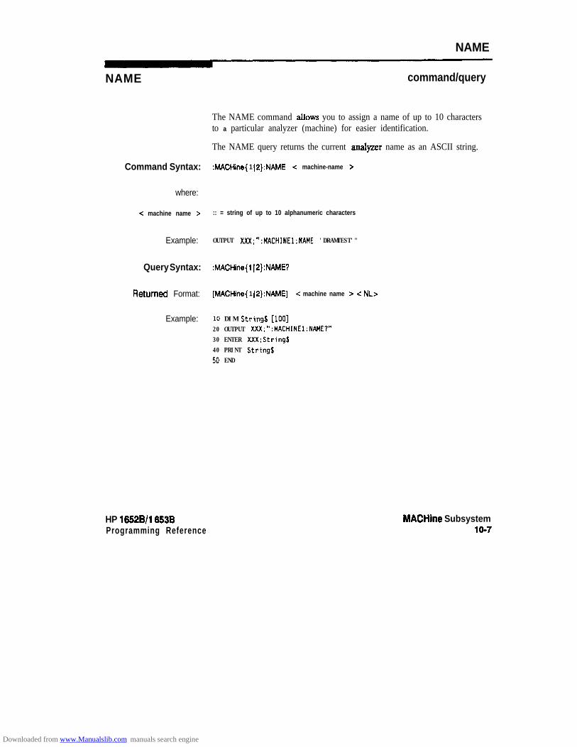
NAME
NAME command/query
The NAME command allows you to assign a name of up to 10 charactersto a particular analyzer (machine) for easier identification.
The NAME query returns the current analyzer name as an ASCII string.
Command Syntax: :MACHine{ 1 IP):NAME <: machine-name >
where:
-z machine name > :: = string of up to 10 alphanumeric characters
Example: OUTPUT XXX;":MACHINEl:NAME 'DRAMTEST'"
Query Syntax: :MACHine{l IP):NAME?
RetWEd Format: [MACHine{ 1 (P}:NAME] c machine name > -Z NL>
Example: 10 DIM String$ [lOO]20 OUTPUT XXX;“:MACHINEl:NAME?”30 ENTER XXX;String$40 PRINT String$50 END
HP 16528/l 8538Programming Reference
MACHine Subsystemlo-7
Downloaded from www.Manualslib.com manuals search engine

TYPE
TYPE
Note uI’
command/query
The TYPE command specifies what type a specified analyzer (machine)will be. The analyzer types are state or timing. The TYPE command alsoallows you to turn off a particular machine.
Only one of the two analyzers can be specified as a timing analyzer at onetime.
Command Syntax:
where:
<analyzertype>
Example:
Query Syntax:
Returned Format:
Example:
MACHine Subsystem10-8
The TYF’E query returns the current analyzer type for the specifiedanalyzer.
:MACHine{ 1 IP}:TYPE <analyzer type >
::= {OFFISTATeITIMing}
OUTPUT XXX:": MACHINEl:TYPE STATE"
:MACHine{ 112):TYPE?
[MACHine{ (2}:TYPE] <analyzer type z < NL>
10 DIM String$ [loo]20 OUTPUT XXX;":MACHINEl:TYPE?"
30 ENTER XXX;String$40 PRINT String$
50 END
HP 1882B/l883BProgramming Reference
Downloaded from www.Manualslib.com manuals search engine

SFORmat Subsystem 1 1Introduction The SFORmat subsystem contains the commands available for the State
Format menu in the HP 1652B/53B logic analyzer. These commands are:
l CLOCkl CPERiod0 LABell MASTerl REMove0 SLAVel THReshold
Figure 1 l-l. SFORmat Subsystem Syntax Diagram
HP 16528/1653B SFORmat Subsystem11-l
Downloaded from www.Manualslib.com manuals search engine

c l o c k - i d
space c l o c k - i d
space *
space clock-Id c
3pOCe c l o c k - i d c
THReshold<N>T
<N> = {I 12 ) 3 14 15)GT = Greater i%an 60 nsLT = Less Than 60 nsname = string of up to 6 alphanumeric characterspolarity = {POSitive 1 NEGative}pod-specification = format (integerfrom 0 to 65535) for a pod (pods are assigned in decreasing order)clock-id = {J) K 1 L 1 M 1 N}clock-spec = {OFF 1 ZUSing I FALLing I BOTH I LOW I HIGH}value = vol tage (real number) -9 .9 to + 9 .9
Figure 1 l-l. SFORmat Subsystem Syntax Diagram (continued)
SFORmat Subsystem HP 16528/1653B11-2 Programming Reference
Downloaded from www.Manualslib.com manuals search engine
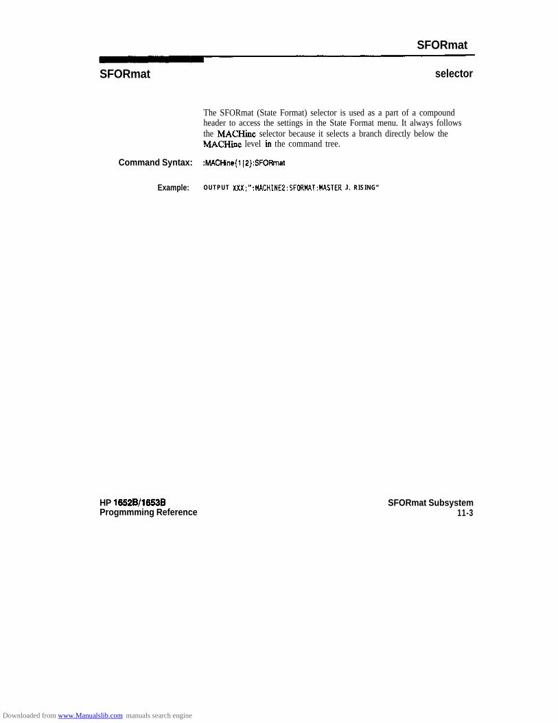
SFORmat
SFORmat selector
The SFORmat (State Format) selector is used as a part of a compoundheader to access the settings in the State Format menu. It always followsthe MACHine selector because it selects a branch directly below theMACHine level iu the command tree.
Command Syntax: :MACHine{l IP}:SFORmat
Example: OUTPUT XXX;“:MACHINE2:SFORMAT:MASTER J, RISING”
HP 16528/1653BProgmmming Reference
SFORmat Subsystem11-3
Downloaded from www.Manualslib.com manuals search engine

CLOCk
CLOCk command/query
The CLOCk command selects the clocking mode for a given pod when thepod is assigned to the state analyzer. When the NORMal option isspecified, the pod will sample all 16 channels on the master clock. Whenthe MIXed option is specified, the upper 8 bits will be sampled by themaster clock and the lower 8 bits will be sampled by the slave clock.When the DEMultiplex option is specified, the lower 8 bits will besampled on the slave clock and then sampled again on the master clock.The master clock always follows the slave clock when both are used.
The CLOCk query returns the current clocking mode for a given pod.
Command Syntax: :MACHine{ 1 IP}:SFORmat:CLOCk -z N > < c l o c k - m o d e >
where:
<N> : := Pod { I 1213(415}-Z clock mode z- : : = {NORMal 1 MIXed I DEMultiplex}
Example : OUTPUT XXX;“:MACHINEl:SFORMAT:CLOCKL NORMAL”
Query Syntax: :MACHine{l IP}:SFORmat:CLOCk<N>?
Returned Format: [ :MACHine{ l I2}:SFORmat:CLOCK<Nz] < c l o c k - m o d e > <NL>
Example: 10 DIM String$ [loo]20 OUTPUT XXX; “:MACHINEl:SFDRMAT:CLDCK2?”30 ENTER XXX; String$
40 PRINT String$50 END
SFORmat Subsystem11-4
HP 16628/1663BProgramming Reference
Downloaded from www.Manualslib.com manuals search engine
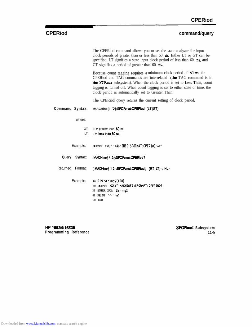
CPERiod
CPERiod command/query
The CPERiod command allows you to set the state analyzer for inputclock periods of greater than or less than 60 11s. Either LT or GT can bespecified. LT signifies a state input clock period of less than 60 ns, andGT signifies a period of greater than 60 11s.
Because count tagging requires a minimum clock period of 60 ns, theCPERiod and TAG commands are interrelated (the TAG command is inthe STRace subsystem). When the clock period is set to Less Than, counttagging is turned off. When count tagging is set to either state or time, theclock period is automatically set to Greater Than.
The CPERiod query returns the current setting of clock period.
Command Syntax: :MACHine{l 12):SFORmat:CPERiod (LTIGT}
where:
GT :: = greater than SO ns
LT ::= IessthanWns
Example: OUTPUT XXX;" :MACHINE2:SFORMAT:CPERIOD GT”
Query Syntax: :MACHine{ 1 JP}:SFOFtmat:CPEWod?
Returned Format: (:MACHine{l (P}:SFORmat:CPERiod] {GT(LT) c NL>
Example: 10 DIM String$[lOO]20 OUTPUT XXX;":MACHINE2:SFORMAT:CPERIOD?30 ENTER XXX; Strings
40 PRINT String$50 END
HP 15526/1553BProgramming Reference
SFORmat Subsystem11-5
Downloaded from www.Manualslib.com manuals search engine
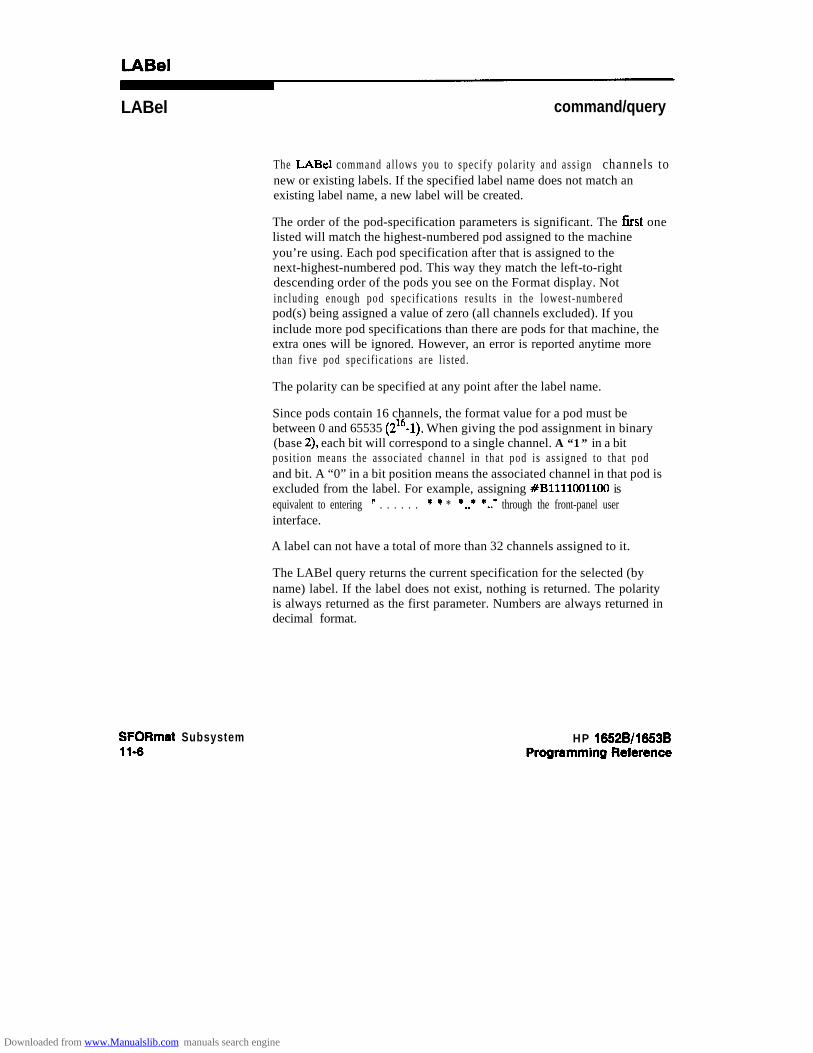
LABel command/query
The LABel command al lows you to specify polari ty and assign channels tonew or existing labels. If the specified label name does not match anexisting label name, a new label will be created.
The order of the pod-specification parameters is significant. The Iirst onelisted will match the highest-numbered pod assigned to the machineyou’re using. Each pod specification after that is assigned to thenext-highest-numbered pod. This way they match the left-to-rightdescending order of the pods you see on the Format display. Notincluding enough pod specif icat ions resul ts in the lowest-numberedpod(s) being assigned a value of zero (all channels excluded). If youinclude more pod specifications than there are pods for that machine, theextra ones will be ignored. However, an error is reported anytime morethan f ive pod specif icat ions are l is ted.
The polarity can be specified at any point after the label name.
Since pods contain 16 channels, the format value for a pod must bebetween 0 and 65535 (216-1). When giving the pod assignment in binary(base 2), each bit will correspond to a single channel. A “1” in a bitposi t ion means the associated channel in that pod is assigned to that podand bit. A “0” in a bit position means the associated channel in that pod isexcluded from the label. For example, assigning #B1111001100 isequivalent to entering ” . . . . . . * * * *..+ *..’ through the front-panel userinterface.
A label can not have a total of more than 32 channels assigned to it.
The LABel query returns the current specification for the selected (byname) label. If the label does not exist, nothing is returned. The polarityis always returned as the first parameter. Numbers are always returned indecimal format.
SFORmat Subsystem11-6
HP 16528/1653B
Downloaded from www.Manualslib.com manuals search engine

LABel
Command Syntax: :MACHine(l (2):SFOFtmat:lABel <name > [, {c polarity> ( <assignment>)]...
where:
-z n a m e > : : = s t r i n g o f u p t o 6 a l p h a n u m e r i c c h a r a c t e r s< p o l a r i t y > :: = (Positive ) NEGative}
-z a s s i g n m e n t > : : = f o r m a t ( i n t e g e r f r o m 0 t o 6 6 6 3 6 ) f o r a p o d ( p o d s a r e a s s i g n e d i n d e c r e a s i n g o r d e r )
Examples: OUTPUT XXX;“:MACHINE2:SFORMAT:LABEL ‘STAT’, POSITIVE. 65535,127.40312”
OUTPUT XXX;":MACHINE2:SFORMAT:LABEL ‘SIG l’, 64, 12, 0, 20, NEGATIVE"
OUTPUT XXX;":MACHINEl:SFORMAT:LABEL 'AOOR', NEG, #B0011110010101010”
Query Syntax: :MACHine{l~2}:SFOPmat:LABel?cname z=
RelUrrled Format: [ :MACHine{l]2}:SFOFimat:LABel] <name> ,<polarity> [, <assignment>]... cNL>
Example: 10 DIM String$[lOO]20 OUTPUT XXX;" :MACHINE2:SFORMAT:LABEL? 'DATA"
30 ENTER XXX String$40 PRINT Strings5 0 END
HP 16528/1653B SFORmat Subsystem11-7
Downloaded from www.Manualslib.com manuals search engine

MASTer
MASTer command/query
The MASTer clock command allows you to specify a master clock for agiven machine. The master clock is used in all clocking modes (Normal,Mixed, and Demultiplexed). Each command deals with only one clock(J,K,L,M,N); therefore, a complete clock specification requires fivecommands, one for each clock. Edge specifications (RISing, FALL@, orBOTH) are ORed. Level specifications (LOW or HIGH) are ANDed.
Note dAt least one clock edge must be specified.
The MASTer query returns the clock specification for the specified clock.
Command Syntax: :MACHine{ 1 IO}:SFORmat:MASTer -z clock-id >, c clock-spec >
where:
c clock id > : : = (JIKIL1MjN)< clock-spec > :: = (OFF1 Wing 1 FALLing 1 BOTH 1 LOW) HIGH}
Example: OUTPUT XXX ; ” :MACHINE2:SFORMAT:MASTER J , R I S I N G ”
Query Syntax: :MACHine{l (P]:SFORmat:MASTeR <clock-id>
Returned Format: [:MACHine{l (P):SFORmat:MABTer] <clock-id >, <clock-spec r < NL>
Example: 10 DIM String$[100]20 OUTPUT XXX;“:MACHINE2:SFORMAT:MASTER?<clock_id>*’30 ENTER XXX String$40 PRINT String$50 END
SFORmat Subsystem11-8
HP 16528/1653BProgramming Reference
Downloaded from www.Manualslib.com manuals search engine

REMove
REMove command
The REMove command allows you to delete all labels or any one label fora given machine.
Command Syntax: :MACHine{l J2):SFORmat:REMove {<name> JALL}
where:
c name > :: = string of up to 6 alphanumeric characters
Examples: OUTPUT XXX;":MACHINE2:SFORMAT:REMOVE 'A"'OUTPUT XXX;":MACHINE2:SFORMAT:REHOVE ALL"
HP 1652Bll6536Programming Reference
SFORmat Subsystem11-9
Downloaded from www.Manualslib.com manuals search engine
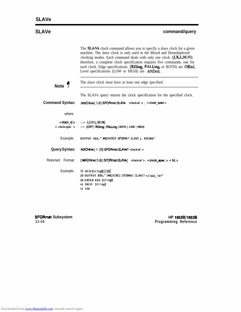
SLAVe
SLAVe command/query
The SI.AVe clock command allows you to specify a slave clock for a givenmachine. The slave clock is only used in the Mixed and Demultiplexedclocking modes. Each command deals with only one clock (J,K,L,M,N);therefore, a complete clock specification requires five commands, one foreach clock. Edge specifications (RISing, FALLing, or BOTH) are ORed.Level specifications (LOW or HIGH) are ANDed.
Noteu3
The slave clock must have at least one edge specified.
The SLAVe query returns the clock specification for the specified clock.
Command Syntax: :MACHine{ I l2):SFOFlmat:SLAVe <clock-id z , <clock-spec>
where:
<clock-id > : : = {JJKILJM(N}< clock-spec > :: = (OFF1 RlSing 1 FALLlng ) BOTH I LOW I HIGH)
Example: OUTPUT XXX;“:MACHINEZ:SFORMAT:SLAVE J, RISING”
Query Syntax: :MACHine{ 1 (P}:SFOFhat:SLAVe? <clock-id >
Returned Format: [:MACHine{ 1(2}:SFORmat:SLAVe] <clock-id >, cclock-spec > < NL>
Example: 10 DIM String$[lDD]20 OUTPUT XXX;“:MACHINE2:SFORMAT:SLAVE? <clock-id>"
30 ENTER XXX String$40 PRINT String$50 END
SFORmat Subsystem11-10
HP 16528/1653BProgramming Reference
Downloaded from www.Manualslib.com manuals search engine

THReshold
THReshold command/query
The THReshold command allows you to set the voltage threshold for agiven pod to ECL, TI’L, or a specific voltage from -99V to + 9.9V in 0.1volt increments.
Note ”dlOn the HP 1652B, the pod thresholds of pods 1,2 and 3 can be setindependently. The pod thresholds of pods 4 and 5 are slaved together;therefore, when you set the threshold on either pod 4 or 5, both thresholdswill be changed to the specified value. On the HP 1653B, pods 1 and 2 canbe set independently.
Command Syntax:
where:
<N>
c value >TTLECL
Example:
Query Syntax:
Returned Format:
Example:
HP 1652B/l653BProgmmming Reference
The THReshold query returns the current threshold for a given pod.
:MACHine{l]2}:SFORmat:THReshold<N> (TTLIECL] cvalue>}
::= pod number \1]2]3]4]5}:: = voltage (real number) -9.9 to +9.9:: = default value of + 1.6V:: = default value of -1.3V
OUTPUT XXX;“:MACHINE1:SFORMAT:THRESHOLOl 4 . 0 ”
:MACHine{l(2}:SFORrnat:THReshold<N>7
[:MACHine{l)2}:SFORmat:THResholdc N>] < v a l u e > <NL>
1 0 D I M Value$ [loo]20 OUTPUT XXX;“:MACHINE1:SFORMAT:THRESHOLO4?”30 ENTER XXX;Value$40 PRINT Valued
50 END
SFORmat Subsystem11-11
Downloaded from www.Manualslib.com manuals search engine
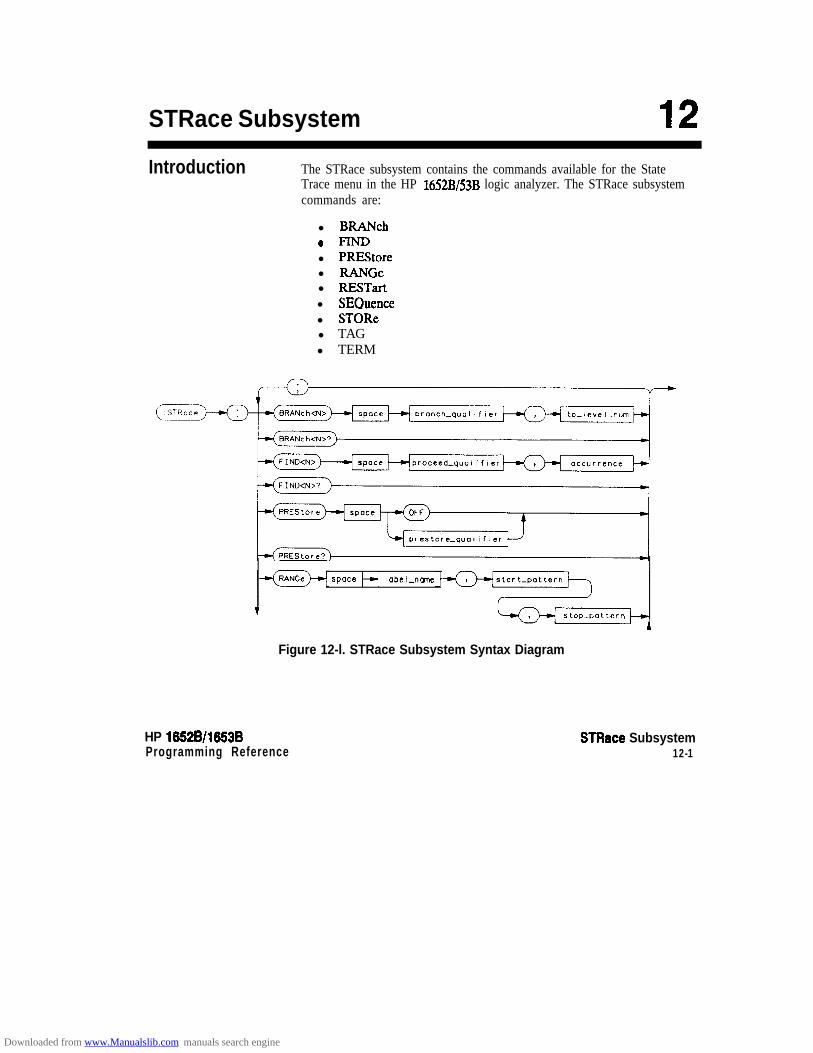
STRace Subsystem 12Introduction The STRace subsystem contains the commands available for the State
Trace menu in the HP 1652B/53B logic analyzer. The STRace subsystemcommands are:
l BRANch0 FINDl PREStorel RANGe
l RESTartl SEQuencel STORel TAGl TERM
space label-nme
stop-pattern
Figure 12-l. STRace Subsystem Syntax Diagram
HP 1652B/l653BProgramming Reference
STFIace Subsystem12-1
Downloaded from www.Manualslib.com manuals search engine

RESTor t c
SEQuence? c
store-quahfier c
K---JSTORe<N>?
p a t t e r n
Figure 12-l. STRace Subsystem Syntax Diagram (continued)
STRace Subsystem HP 16528/1653B12-2 Programming Reference
Downloaded from www.Manualslib.com manuals search engine

branch-qualifier = < qualifier >to-lev-num = integer from 1 to trieget level when < N P- is less than or equal to the trigger level, or
from (trigger level + I) to <num-of-levels > when c N :, is greater than the trigger levelproceed-qualifier = c qualifier >occurrence = numberfrom 1 to 65535prestore-qua1 = -z qualifier >label-uame = strtng of up to 6 alphanumeric charactersstartgattem = “{#B{O(l} . . . (
~Qt~l~l~l~l~l~l~l~~~~~ I#H{O~Z~2~3~4~5~6~7~8)9~A~B~C~DIE~F}. . . 1(O~Z~2~3~4~5~6~7~8~9). . . }”
stopgattem = “{#B{OI 1). . . 1#Qt~l~1213l415l617~~~ - I#H{~~l~2~3~4~5~6~7~8I91AJBJCJDJEJF). . . )(O~Z~2~3~4~5~6~7~8~9). . . }”
restart-qualifier = c qualifier >num-of levels = integerfrom 2 to 8 when ARM is RUN orfrom 2 to 7 otherwiselev-of-t& = integerfrom 1 to (number of existing sequence levels - I)store_qualifier = < qualifier >state-tagqualifier = < qualifier >term-id = {AIBICIDJEIFIG(H}pattern = “{#B{OIZ/X}. . . I
~Q~~l~l~l~l~l~l~l~l~~. . . I#H{OlZ~2~3~4lSl6l7lSl9lA~BlC~DlEIF~X}. . . I(0~Z~2~3~4~5~6~7~8~9). . . }”
qualifier = { ANYSrate ( NOSTate I <any-term > I (expressionl[{AND I OR} cexpession2>]) )(eqression2[{AND I OR} <expression Z >I) }
any-term = { < or-terml > I c and-tennl > I < or-term2 > I and_tennZ}expression1 = { <or-tetml>[OR <or-tennZ> J... 1 cand-tennZ>[AND <and-termI>]...}expression2 = { < or-term2 > [OR < or-term2 >I... I < ar@term2 > [AND < and-tern12 >I... }or-term1 = {AIB(C(D(ZNZ&ngeIOuTRange}and-term1 = (NOTA 1 NO223 1 NOTCI NOTD (ZNRange ( OUZYRange}or-term2 = {EIFIGIH}and-term2 = (NOTE ) NOW ) NOTG ) NOTH}
Figure 12-l. STRace Subsystem Syntax Diagram (continued)
HP 1652B/l553BProgramming Reference
STRace Subsystem12-3
Downloaded from www.Manualslib.com manuals search engine

STRace
STRace selector
The STRace (State Trace) selector is used as a part of a compoundheader to access the settings found in the State Trace menu. It alwaysfollows the MACHine selector because it selects a branch directly belowthe MACHine level in the command tree.
Command Syntax: :MACHine{ 1 IP}:STRace
Example : OUTPUT XXX;":MACHINEl:STRACE:TAG TIME"
STRace Subsystem124
HP 16528/16538
Downloaded from www.Manualslib.com manuals search engine

BRANch
BRANch
Note d
Note #I
command/query
The BRANch command defines the branch qualifier for a given sequencelevel. When this branch qualifier is matched, it will cause the sequencerto jump to the specified sequence level.
“RESTART PERLEVEL” must have been invoked for this command tohave an effect (see RESTart command).
The terms used by the branch qualifter (A through H) are defined by theTERM command. The meaning of INRange and OUTRange isdetermined by the RANGe command.
Within the l imita t ions shown by the syntax def ini t ions , complexexpressions may be formed using the AND and OR operators.Expressions are limited to what you could manually enter through thefront panel. Regarding parentheses, the syntax definitions on the nextpage show only the required ones. Additional parentheses are allowed aslong as the meaning of the expression is not changed. For example, thefollowing two statements are both correct and have the same meaning.Notice that the conventional rules for precedence are not followed.
OUTPUT XXX;": MACHINEl:STRACE:BRANCHl (C OR D AN0 F OR G). 1"OUTPUT XXX:":MACHINEl:STRACE:BRANCHl ((C OR D) AND (F OR G)), 1"
Fiie 12-2 shows a complex expression as seen on the Format display.
Branching across the trigger level is not allowed. Therefore, the values for< N z= and < to-level-num > must both be either on or before the triggerlevel, or they must both be after the trigger level. The trigger level isdetermined through the SEQuence command.
The BRANch query returns the current branch qualifier specification fora given sequence level.
HP 16528/1653BProgmmming Reference
STRace Subsystem12-5
Downloaded from www.Manualslib.com manuals search engine
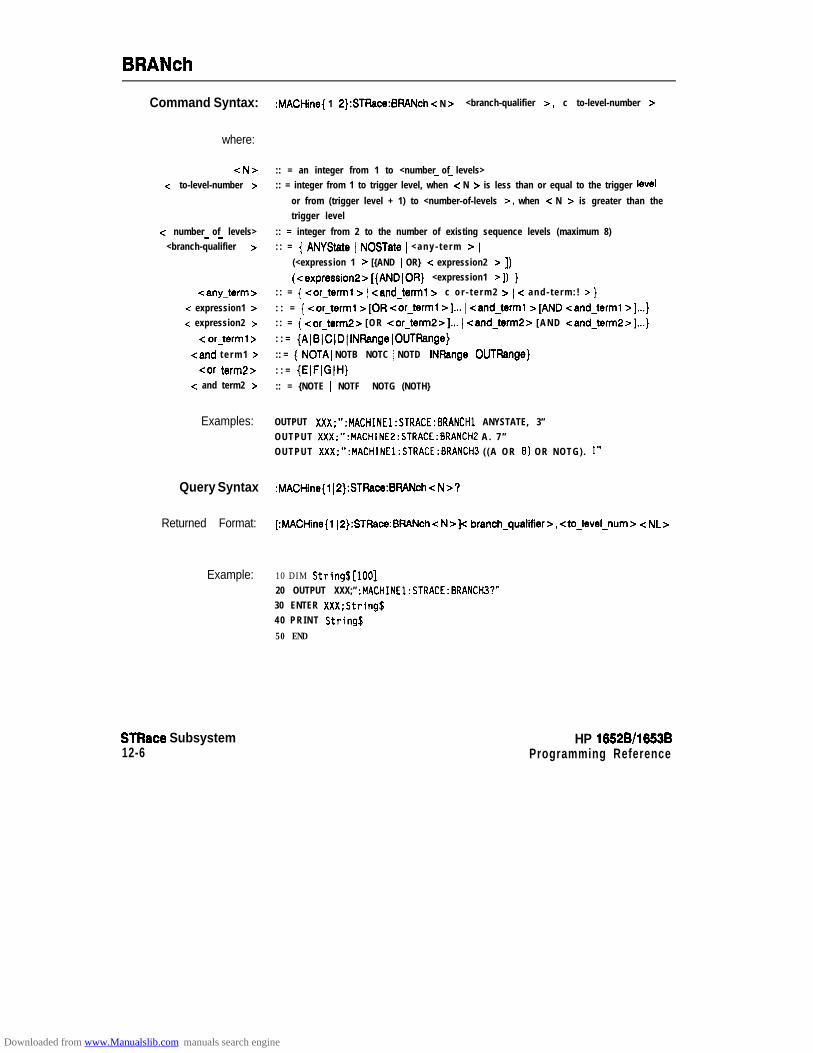
BRANch
Command Syntax:
where:
<N>c to-level-number >
-z number of levels>- -<branch-qualifier >
-zany-term >< expression1 >< expression2 >
< or-term1 >
<and t e r m 1 >
car termi!><: and term2 >
Examples:
Query Syntax
Returned Format:
Example:
STRace Subsystem12-6
:MACHine{ 1 i 2):STRace:BBANch < N > <branch-qualifier >, c to-level-number >
:: = an integer from 1 to <number of levels>- -:: = integer from 1 to trigger level, when c N > is less than or equal to the trigger level
or from (trigger level + 1) to <number-of-levels >, when < N > is greater than thetrigger level
:: = integer from 2 to the number of existing sequence levels (maximum 8): : = { ANYState i NOSTate i < a n y - t e r m Z= i
(<expression 1 > [{AND i OR} < expression2 z= 1) i(cexpression2>[{ANDlOFt} <expression1 >I) )
: : = { <or-term1 z= i <and-term1 > i c o r - t e r m 2 > i -z a n d - t e r m : ! > }
: : = { <or-term1 >[OR car-term1 >I... i <and-term1 >[AND <and-term1 >I...}: : = { cor_term2> [OR <or_term2>]... ) <and_term2> [AND <and_term2>]...}
: : = {AiBiCiDiINRangeiOUTFlange}
:: = { NOTAl NOTB i NOTC i NOTD I INRange i OLlTBange)
: : = {EiFiGiH)
:: = {NOTE i NOTF i NOTG (NOTH}
OUTPUT XXX;“:MACHINEl:STRACE:BRANCHl ANYSTATE, 3”OUTPUT XXX:“:MACHINE2:STRACE:BRANCHE A . 7 ”OUTPUT XXX:“:MACHINEl:STRACE:BRANCHJ ( (A OR 6) OR NOTG). 1”
:MACHine{l i2):STRace:BBANch -zN>‘?
[MACHine{ i2}:STBace:BBANch<N>jc branch~qualifier>,eto~level~num~ <NL>
10 DIM String$[lOO]20 OUTPUT XXX;” :MACHINEl:STRACE:BRANCH3?”30 ENTER XXX;String$40 PRINT String$
50 END
HP 16628/1663BProgramming Reference
Downloaded from www.Manualslib.com manuals search engine

BRANch
‘igure 12-2. Complex qualifier
Fiie 12-2 is a front panel representation of the complex qualifier(a Orb) And (+e And A). The following example would be used tospecify this complex qualifier.
OUTPUT XXX;" :MACHINEl:STRACE:BRANCHl ((A OR 6) AND (NOTE AND NDTH)), 2"
Terms A through D and RANGE must be grouped together and termsE through I-I must be grouped together. In the first level, terms fromone group may not be mixed with terms from the other. For example, theexpression ((A OR INRANGE) AND (C OR H)) is not allowed becausethe term C cannot be specified in the E through H group.
Keep in mind that, at the first level, the operator you use determineswhich terms are available. When AND is chosen, only the NOT termsmay be used. Either AND or OR may be used at the second level to jointhe two groups together. It is acceptable for a group to consist of a singleterm. Thus, an expression like (B AND G) is legal, since the twooperands are both simple terms from separate groups.
HP 16528/1653BProgramming Reference
STRace Subsystem12-7
Downloaded from www.Manualslib.com manuals search engine

FIND
FIND command/query
The FIND command defines the proceed qualifier for a given sequencelevel. The qualifier tells the state analyzer when to proceed to the nextsequence level. When this proceed qualifier is matched the specifiednumber of times, the sequencer will proceed to the next sequence level.The state that causes the sequencer to switch levels is automatically storedin memory whether it matches the associated store qualifier or not. In thesequence level where the trigger is specified, the FIND commandspecifies the trigger qualifier (see SEQuence command).
The terms A through H are defined by the TERM command. Themeaning of INRange and OUTRange is determined by the RANGecommand. Expressions are limited to what you could manually enterthrough the Format menu. Regarding parentheses, the syntax definitionsbelow show only the required ones. Additional parentheses are allowedas long as the meaning of the expression is not changed. See figure 6-2 fora detailed example.
The FIND query returns the current proceed qualifier specification for agiven sequence level.
Command Syntax: :MACHine{ 1]2):STRaoe:FlND< N > <: proceed-qualifier z , c ooourrenoe r
where:
cN>< ooourrenoe >
-z proceed-qualifier >
-zany-term z--z expression 15-z expression2 >
<or-term1 >-z and-term 1~
-z or-term2 >
< and-term2 >
:: = integer from 1 to the number of existing sequence levels (maximum 8)
:: = integer from 1 to 88885
:: = { ANYState ] NOSTate ] <any-term > ](<expression1 > [{ANDIOR} <expression2>]) ]
( < expression2 r [{AND ( OR} -z expression 1 z- 1) }: : = {<or-terml> I <and-terml> ) <or_term2> I <and_term2>}:: = { <or-term1 > [OR <or-term1 >I.., ) <and-term1 > [AND cand-term1 >I...}:: = (-zor_term2> [OR <or-termi!>]... I <and_term2> [AND -=and_term2>]...}::= {A]B]CJD(INRange]OUTRange}:: = { NOTAJ NOTB ] NOTC) NOTD I INRange ] OUTRange}::= {EIFJGIH)
:: = {NOTE I NOTF I NOTG I NOTH}
STRace Subsystem12-8
HP 16528/1653B
Downloaded from www.Manualslib.com manuals search engine

FIND
Examples: OUTPUT xxx ;" :HACHINEl:STRACE:FINDl ANYSTATE. 1”
OUTPUT XXX;" :MACHINEl:STRACE:FIND2 A, 512"
OUTPUT XXX;":MACHINEl:STRACE:FIND3 ((NDTA AND NDTB) OR G), 1"
Query Syntax: :MACHlns{l~2}:STRace:FIND47
Returned Format: [:MACHtne{l JP}:STFWe:FIND<N>] <proceed-qualifier >, coccurrencez <NL>
Example: 10 DIM String$[lDD]20 OUTPUT XXX;" :MACHINEl:STRACE:FIND<N>?"30 ENTER XXX;String$40 PRINT Strings
50 END
HP 16528/1’6538Programming Reference
STRace Subsystem12-9
Downloaded from www.Manualslib.com manuals search engine
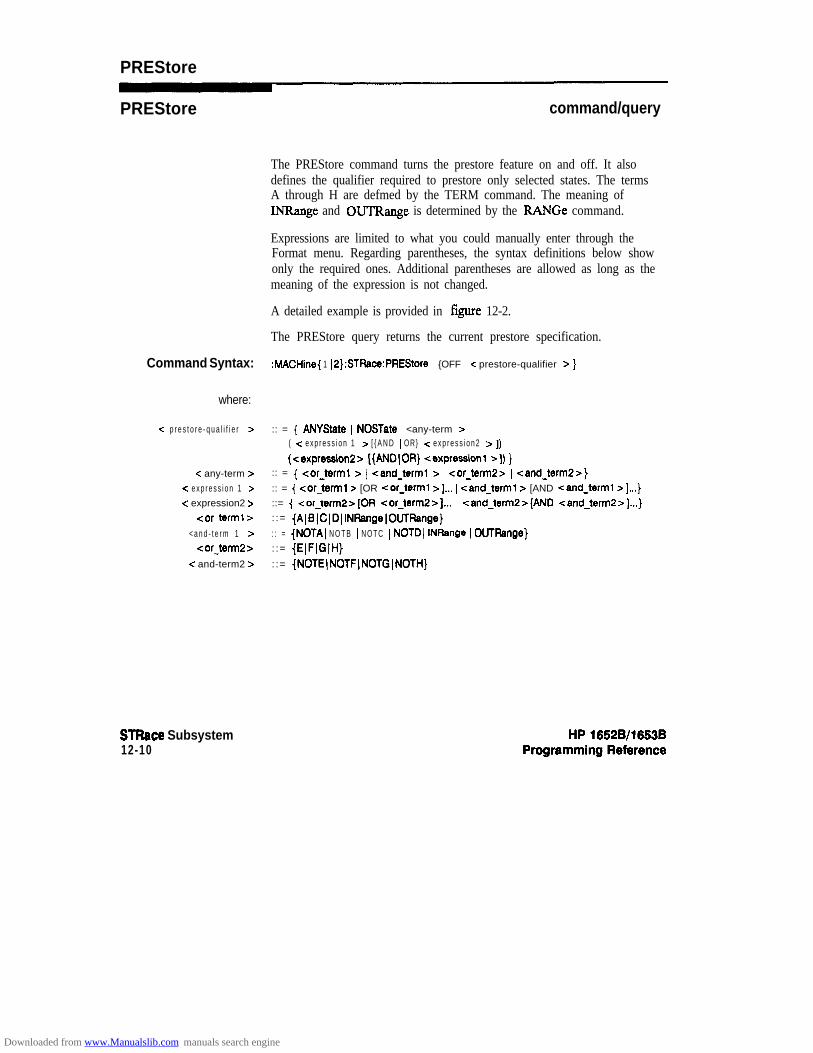
PREStore
PREStore command/query
The PREStore command turns the prestore feature on and off. It alsodefines the qualifier required to prestore only selected states. The termsA through H are defmed by the TERM command. The meaning ofINRange and OUTRange is determined by the RANGe command.
Expressions are limited to what you could manually enter through theFormat menu. Regarding parentheses, the syntax definitions below showonly the required ones. Additional parentheses are allowed as long as themeaning of the expression is not changed.
A detailed example is provided in figure 12-2.
The PREStore query returns the current prestore specification.
Command Syntax: :MACHine{ 1 IP}:STRace:PREStore {OFF 1 < prestore-qualifier > }
where:
-c p r e s t o r e - q u a l i f i e r > :: = { ANYState 1 NOSTate 1 <any-term > I( -z e x p r e s s i o n 1 z [ { A N D I OR} -z e x p r e s s i o n 2 z 1) I
(csxpression2> [{ANDJOR) <expression1 >I) }c any-term > :: = { <or-term1 > I <and-term1 z I cor_term2> ) <and_term2>}
< e x p r e s s i o n 1 > :: = { <or-term1 > [OR <or-term1 >I... I <and-term1 > [AND <and-term1 >I...}< expression2 > ::= { -zor_term2>[OR <or_term2>]... I cand_term2>[AND <and_term2>]...}
car terml> : := {AIB~C~DIINRange~OUTRange}
< a n d - t e r m 1 > : : = (NOTAl N O T B I NOTC I NOTD) INRange I OUTRange}<or-term:!> : := (EIFIGIH}
< and-term2 > : := {NOTE(NOTF(NOTG(NOTH]
STRace Subsystem12-10
Downloaded from www.Manualslib.com manuals search engine

PREStore
Examples: OUTPUT XXX;":MACHINEl:STRACE:PRESTORE OFF"OUTPUT XXX;":MACHINEl:STRACE:PRESTORE ANYSTATE"
OUTPUT XXX;":MACHINEl:STRACE:PRESTORE (E)"
OUTPUT XXX;":MACHINEl:STRACE:PRESTORE (A OR B OR II OR F OR H)"
Query Syntax: :MACHine{l IP}:STRace:PREStore?
~eturrled Format: [ :MACHine{ 1[2}:STFiace:PREStore] {Off 1-c prestore-qualifier > ) -z NL >
Example: 10 DIM String$[lOO]20 OUTPUT XXX;":MACHINEl:STRACE:PRESTORE?"
30 ENTER XXX;String$40 PRINT String$
50 END
HP 1652Wl653BProgramming Reference
STFiacs Subsystem12-l 1
Downloaded from www.Manualslib.com manuals search engine

RANGe
RANGe command/query
The RANGe command allows you to specify a range recognizer term inthe specified machine. Since a range can only be defined across one labeland, since a label must contain 32 or less bits, the value of the start patternor stop pattern will be between (232)-1 and 0.
Note dSince a label can only be defined across a maximum of two pods, a rangeterm is only available across a single label; therefore, the end points of therange Cannot be split between labels.
Note d
When these values are expressed in binary, they represent the bit valuesfor the label at one of the range recognizers’ end points. Don’t cares arenot allowed in the end point pattern specifications. Since only one rangerecognizer exists, it is always used by the first state machine defmed.
The FMNGe query returns the range recognizer end point specificationsfor the range.
When two state analyzers are on, the RANGe term is not available in thesecond state analyzer assigned and there are only 4 pattern recognizersper analyzer.
STRace Subsystem12-12
HP 1652~/1663B
Downloaded from www.Manualslib.com manuals search engine
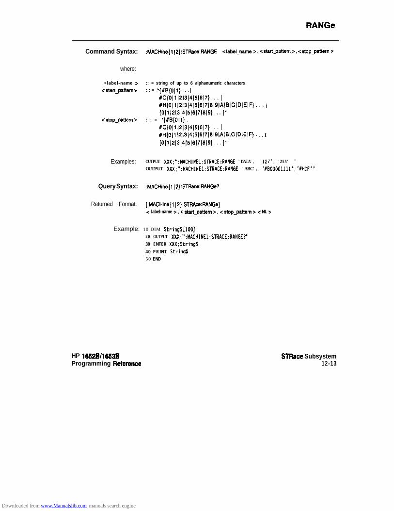
FlANGe
Command Syntax: :MACHine(l(2):STRace:RANGE clabelpame 7, <startJattern 7,4Opgattern 7
where:
< labe l -name > :: = string of up to 6 alphanumeric characters< startgattern > : : = “{#B{0l1}. *. 1
#Q{Oll)2)3)4)5)617}. . . 1
#H{Oll~2~3~4~5~6~7~8~9~A)BICIDIEIF). . . /{0(1~2~3~4(5(6~7~8(9}. . . )”
-z stopgaltern z : : = “{#B{OIl} . I
XQ{OIl~2~3(4(5~6~7}. . . 1
#H{Oll l2~3~4~5l6l7~8~9~A~BIC(D(E(F). . . I
(~1~1~1~1~1~161~1~1~). . . I”
Examples: OUTPUT XXX;":MACHINEl:STRACE:RANGE 'DATA', '127', '255' wOUTPUT XXX;":MACHINEl:STRACE:RANGE 'ABC', ‘XBOOOO1111’, ‘#HCF’ I’
Query Syntax: :MACHine{l I2):STRace:RANGe?
Returned Format: [:MACHine(l IP}:STFWce:FWGe]< label-name > , c startgattern 7, e stopgattern 7 < NL >
Example: 10 DIM String$[lOO]20 OUTPUT XXX;“:MACHINEl:STRACE:RANGE?”
30 ENTER XXX;String$
40 PRINT Strings50 END
HP 1652B/l653BProgramming Reterence
STRace Subsystem12-13
Downloaded from www.Manualslib.com manuals search engine

RESTatt
RESTart command/query
The RESTart command selects the type of restart to be enabled duringthe trace sequence. It also defines the global restart qualifier that restartsthe sequence in global restart mode. The qualifier may be a single term ora complex expression. The terms A through H are defined by the TERMcommand. The meaning of INRange and OUTRange is determined bythe RANGe command.
Expressions are limited to what you could manually enter through theFormat menu. Regarding parentheses, the syntax definitions below showonly the required ones. Additional parentheses are allowed as long as themeaning of the expression is not changed.
A detailed example is provided in figure 12-2.
The RESTart query returns the current restart specification.
Command Syntax: :MACHine{l IP}:STRace:RESTart {OFF 1 PERLevel 1 <restart-qualifier>}
where:
< restar?_qualifier >
c any-term >< e x p r e s s i o n 1~
< e x p r e s s i o n 2 >< or-term1 >
<and term1 1<or term2s
<and term2 z
:: = { ANYState 1 NOSTate 1 <any-term > 1
( < expression1 > [{AND 1 OR} c expression2 r ]) ((cexpression2> ({AND)OR} <expression1 z-1) }
:: = { <or-term1 z= I <and-term1 > I <or_term2> I -zand_term2>}
:: = {<or-term1 > [OR <or-term1 a]... I <and-term1 5 [AND <and-term1 a]...)::= {cor_term2>[0R <or-term:!>]... I <and_term2>[AND <and_term2>]...}
::= {AIBJCIDIINRangelOUTRange}: : = { NOTA I NOTB I NOTC ) NOTD I INRange I OUTRange}: := {EIFJGIH}: := {NOTEINOTFINOTGINOTH}
Examples: OUTPUT XXX;" :MACHINEl:STRACE:RESTART OFF"
OUTPUT XXX;":MACHINEl:STRACE:RESTART PERLEVEL"
OUTPUT XXX;**:MACHINE~:STRACE:RESTART (NOTA AND NOTE AND INRANGE)"OUTPUT XXX;":MACHINEl:STRACE:RESTART (B OR (NOTE AND NOTF))"
STRace Subsystem12-14
HP 16528/1653B
Downloaded from www.Manualslib.com manuals search engine

RESTart
Query Syntax: :MACHine{l ~2):STFiace:RESTaK)
Returned Format: [:hdACHine{l IP}:STFtace:RESTart] {OFF 1 PERLevel [ <restart-qualifier>) -zNL>
Example: 10 DIM String$[lOO]20 OUTPUT XXX;" :MACHINEl:STRACE:RESTART?"
30 ENTER XXX;String$
40 PRINT Strings
50 END
HP 1652Bll653BProgmmming Reference
STRace Subsystem12-15
Downloaded from www.Manualslib.com manuals search engine

SEQuence
SEQuence command/query
The SEQuence command redefines the state analyzer trace sequence.Fist, it deletes the current trace sequence. Then it inserts the number oflevels specified, with default settings, and assigns the trigger to be at aspecitied sequence level. The number of levels can be between 2 and 8when the analyzer is armed by the RUN key, When armed by the BNC orthe other machine, a level is used by the arm in; therefore, only sevenlevels are available in the sequence.
The SEQuence query returns the current sequence specification.
Command Syntax: :MACHine{ 1 ~2):STRaoe:SEQuence < number-of-levels z , <level-of-trigger >
where:
<number o f l e v e l s >- - :: = integer from 2 to 8 when ARM is RUN or from 2 to 7 otherwise
<level of trigger>- - :: = integer from 1 to (number of existing sequence levels - 1)
Example: OUTPUT XXX;” :MACHINEl:STRACE:SEQUENCE 4 . 3 ”
Query Syntax: :MACHine(l~2):STRaae:SEOuence?
Returned Format: [:MACHine{ 1 l2}:STRace:SEQuence]< number of levels >, <level of- - trigger > < NL >- -
Example: 10 DIM String$[lOO]20 OUTPUT XXX;“:MACHINEl:STRACE:SEQUENCE?”30 ENTER XXX;String$40 PRINT StringS
50 END
STRace Subsystem12-16
HP 16528/16538Programming Reference
Downloaded from www.Manualslib.com manuals search engine

STORe
STORe command/query
The STORe command defines the store qualitier for a given sequencelevel. Any data matching the STORe qualifier will actually be stored inmemory as part of the current trace data. The qualifier may be a singleterm or a complex expression. The terms A through H are defined by theTERM command. The meaning of INRange and OUTRange isdetermined by the RANGe command.
Expressions are limited to what you could manually enter through theFormat menu. Regarding parentheses, the syntax definitions below showonly the required ones. Additional parentheses are allowed as long as themeaning of the expression is not changed.
A detailed example is provided in figure 12-2.
The STORe query returns the current store qualifier specification for agiven sequence level < N > .
Command Syntax: :MACHine{ 1 )P}:STFtaoe:STOFte c N > <store-qualifier >
where:
cN>c store-qualifier >
-zany-term >
<expression 1 >< expression2 5
<or term1 >-z and-term 1~
car term2><and-term:! >
:: = an integer from 1 to the number of existing sequence levels (maximum 8)
:: = { ANYState 1 NOSTate ( <any-term > 1( -z expression 1 > [{AND I OR} <expression2 > 1) )
( < expression2 > [{AND 1 OR} c expression 1~ ]) }:: = { <or-term1 > I <and-term1 z= I <or-term2 > I <and_term2> }:: = { <or-term1 > [OR <or_terml >I... 1 <and-term1 > [AND <and-term1 >I...)
::= {<or-ten2>(OR cor_term2>]... ( cand_term2>[AND <and_term2>]...}::= {A~BICIDIINRange(OUTFlange)
:: = { NOTAJ NOTB I NOTC I NOTD( INRange I OUTRange}::= {EIFIGJH}::= (NOTEINOTFINOTG~NOTH}
HP 1652B/leSSBProgmmming Reference
STRace Subsystem12-17
Downloaded from www.Manualslib.com manuals search engine

STORe
fhamph?S: OUTPUT XXX;" :MACHINEl:STRACE:STOREl ANYSTATE"OUTPUT XXX;":MACHINEl:STRACE:STORE2 OUTRANGE"OUTPUT XXX;":MACHINEl:STRACE:STORE% (NOTC AND NOTD AND NOTH)"
Query Syntax: :MACHine{l(2}:STFtace:STORe~N~?
Returned Format: [:MACHine{ 1 J2):STFtace:STORe c N z-1 <store-qualifier > c NL>
Example: 10 DIM String$[lOO]20 OUTPUT XXX;":MACHINEl:STRACE:STORE4?"
30 ENTER XXX;String$40 PRINT Strings50 END
STRace Subsystem12-18
HP 18528/1883BProgramming Reference
Downloaded from www.Manualslib.com manuals search engine

TAG command/query
The TAG command selects the type of count tagging (state or time) to beperformed during data acquisition. State tagging is indicated when theparameter is the state tag qualifier, which will be counted in the qualifiedstate mode. The qualifier may be a single term or a complex expression.The terms A through H are defined by the TERM command. The termsINRange and OUTRange are defined by the RANGe command.
Expressions are limited to what you could manually enter through theFormat menu. Regarding parentheses, the syntax definitions below showonly the required ones. Additional parentheses are allowed as long as themeaning of the expression is not changed. A detailed example is providedin figure 12-2.
Because count tagging requires a minimum clock period of 60 ns, theCPERiod and TAG commands are interrelated (the CPERiod commandis in the SFORmat subsystem). When the clock period is set to LessThan count tagging is turned off. When count tagging is set to either stateor time, the clock period is automatically set to Greater Than.
The TAG query returns the current count tag specification.
Command Syntax: MACHine{ IP}:STFlace:TAG {OFF ) TIME ) <state-tag-qualifier>)
where:
<state-tag-qualifier > :: = ( ANVState 1 NOSTate 1 -zany-term > I
c any-term ><expression 1 zc expression2 z
<or-term1 ><and-term 1 >
< or-term2 >c and term2 >
HP 19528/1653BProgramming Reference
(<expression1 > [{ANDJOR} <expression2>]) )(cexpression2> [{ANDIOR} cexpressionl >I) }
:: = { <or-term1 > I <and-term1 > 1 <or_term2> I <and-term2 z- }:: = { <or-term1 > [OR <or-term1 >I... ) <and-term1 >[AND <and-term1 z-l...):: = { -zor_term2> [OR <or_term2z]... I <andterm2> [AND <and_term2>]...}
::= {AIBICIDIINRangeIOUTRsnge):: = { NOTAJ NOTB I NOTC I NOTD I INRange 1 OUTRange}
::= {EIFIGIH}::= {NOTEINOTFINOTGINOTH}
STRace Subsystem12-19
Downloaded from www.Manualslib.com manuals search engine
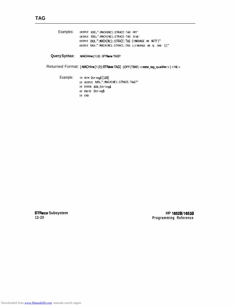
TAG
Examples: OUTPUT XXX;":MACHINEl:STRACE:TAG OFF"
OUTPUT XXX;":MACHINEl:STRACE:TAG TIME"OUTPUT XXX;":MACHINEl:STRACE:TAG (INRANGE OR NOTF)"
OUTPUT XXX;":MACHINEl:STRACE:TAG ((INRANGE OR A) AND E)"
Query Syntax: :MACHine{lJ2}:STRace:TAG?
Returned Format: [:MACHine{lI2}:STRace:TAG] {OFFJTIME]<state-tag-qualifier>}cNLs
Example: 10 DIM String$[lOO]
20 OUTPUT XXX;":MACHINEl:STRACE:TAG?"30 ENTER XXX;String$
40 PRINT Stringf50 END
STRace Subsystem12-20
HP 1652Wl663BProgramming Reference
Downloaded from www.Manualslib.com manuals search engine
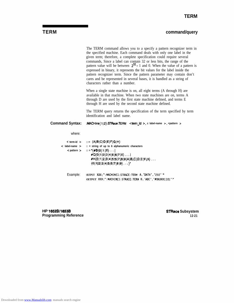
TERM
TERM command/query
The TERM command allows you to a specify a pattern recognizer term inthe specified machine. Each command deals with only one label in thegiven term; therefore, a complete specification could require severalcommands, Since a label can contain 32 or less bits, the range of thepattern value will be between 232 - 1 and 0. When the value of a pattern isexpressed in binary, it represents the bit values for the label inside thepattern recognizer term. Since the pattern parameter may contain don’tcares and be represented in several bases, it is handled as a string ofcharacters rather than a number.
When a single state machine is on, all eight terms (A through H) areavailable in that machine. When two state machines are on, terms Athrough D are used by the first state machine defmed, and terms Ethrough H are used by the second state machine defined.
The TERM query returns the specification of the term specified by termidentification and label name.
Command Syntax: :hlACHine{ 1 jP):STRace:TERM <term-id >, c label-name >, <pattern >
where:
-z term-id > ::= (AIBJCJDIEIFIGIH}-z label-name z :: = string of up to 6 alphanumeric characters
c pattern > :: = ‘{#B{O) 1 IX) . . . 1
+Q{O~l~2~3l4~SlSl7lX}. . . (
#H{OIl~2~3(4~5~6~7~6~g~AlB(clolEIF~X}. . . I{Oil ~2~3~4~5(6)7~8~9}. . , }’
Example: OUTPUT XXX;":HACHINEl:STRACE:TERM A,'DATA','255' -
OUTPUT XXX;":MACHINEl:STRACE:TERM B,‘ABC’,‘#BXXXXllOl’ 11
HP 16528/1653BProgramming Reference
STRace Subsystem12-21
Downloaded from www.Manualslib.com manuals search engine

TERM
Query Syntax: :MACHine{l ~P}:STFke:TERM? <term-id z=, -c label-name >
Returned Format: [MACHine{ 1 I2):STRAce:TERM] <term-id z=, <label-name > , c pattern > < NL>
Example: 10 DIM String$[lOO]20 OUTPUT XXX;":MACHINEl:STRACE:TERM? B.'DATA' w
30 ENTER XXX;String$40 PRINT String$
50 END
STRace Subsystem12-22
HP 16528/1653B
Downloaded from www.Manualslib.com manuals search engine

SLISt Subsystem 1 3Introduction The SLISt subsystem contains the commands available for the State
Listing menu in the HP 1652B/53B logic analyzer. These commands are:
0 COLumIll DATA0 LINE!l MMODel OPATteml OSEarchl OSTatel OTAGl RUNTill TAVeragel TMAXimuml TMINimuml VRUNsl XOTagl XPATteml XSEarchl XSTatel XTAG
HP 16528/16538Programming Reference
SUST Subsystem13-l
Downloaded from www.Manualslib.com manuals search engine

4- l a b e l - n a m e
l i n e - n u m b e r
4 L I N E ? ) I
PATTer n
STATe~ E3TIME
MSTots
MODe?
Figure 13-l. SLlSt Subsystem Syntax Diagram
SLIST Subsystem13-2
HP 16528/1653B
Downloaded from www.Manualslib.com manuals search engine
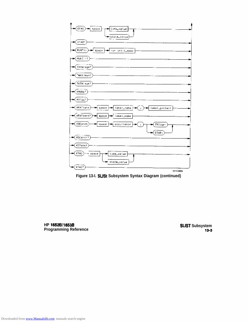
time-value
Figure 13-l. SLlSt Subsystem Syntax Diagram (continued)
HP 1652B/l653BProgramming Reference
SLIST Subsystem13-3
Downloaded from www.Manualslib.com manuals search engine

module-num = {11213)4/5}math-num = { 112)col-uum = {1(2(314(5(6(718}line-number == integerfrom -1023 to + 1023label-name = a strirtg of up to 6 alphanumeric characterbase = { BINary 1 HEXadecimal ) OCTul 1 DECimal 1 ASCii 1 SMMBol IL4SSembler) for labels or
{ABSolute IRELative} for tagsline~num~mid~screen = integerfrom -1023 to + 1023labelqatteru = “( #B(OJ 11X). . . )
~Q~~l~1~l~l~l~l~l~l~~. . . I#H{0(1~2~3~4~5~6)7)8~9~AJBICIDIE(F(X}. . . 1(0~1~2~3~4~5~6~7~8~9). . . }”
occurrence = integerfrom -1023 to + 1023time-value = real numberstate-value = real numberrun-until-spec = (OFF I LT, < value > ) GT, < value > I INRange, -z value >, < value > I
OUTRange, < value >, < value > }value = real number
Figure 13-l. SLlSt Subsystem Syntax Diagram (continued)
SUST Subsystem13-4
HP 16528/16538Programming Reference
Downloaded from www.Manualslib.com manuals search engine
SLlst
SLlSt selector
The SLISt selector is used as part of a compound header to access thosesettings normally found in the State Listing menu. It always follows theMACHine selector because it selects a branch directly below theMACHine level in the command tree.
Command Syntax: :MACHine{l p}:sust
Example: OUTPUT XXX;" :MACHINEl:SLIST:LINE 256"
HP 16528/16538 SUST SubsystemProgramming Reference 185
Downloaded from www.Manualslib.com manuals search engine
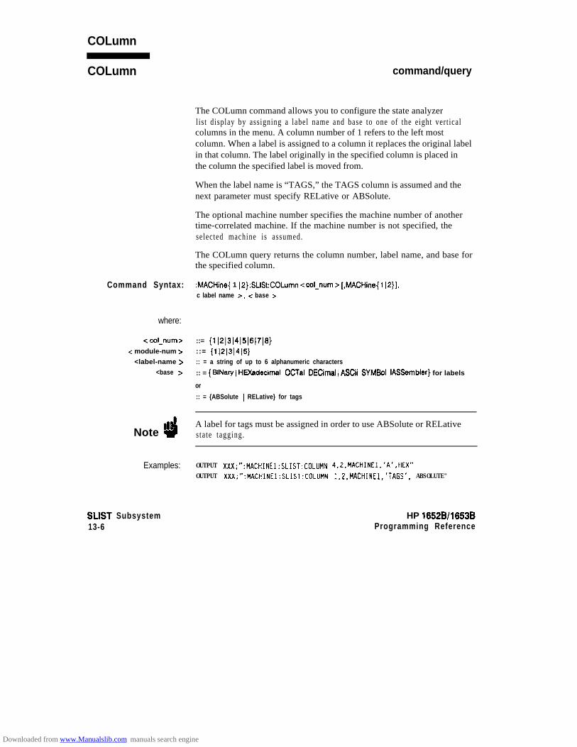
COLumn
COLumn
Command Syntax:
where:
< col-num >< module-num >
<label-name ><base z-
command/query
The COLumn command allows you to configure the state analyzerlist display by assigning a label name and base to one of the eight vert icalcolumns in the menu. A column number of 1 refers to the left mostcolumn. When a label is assigned to a column it replaces the original labelin that column. The label originally in the specified column is placed inthe column the specified label is moved from.
When the label name is “TAGS,” the TAGS column is assumed and thenext parameter must specify RELative or ABSolute.
The optional machine number specifies the machine number of anothertime-correlated machine. If the machine number is not specified, theselected machine is assumed.
The COLumn query returns the column number, label name, and base forthe specified column.
:MACHine{ 1 IP}:SLISt:COLumn ccol-num > [,MACHine{ 112}],c label name >, < base >
::= {1~2~3~4~5~6~7~8}::= {11213)415}:: = a string of up to 6 alphanumeric characters
:: = { BlNary ( HEXadecimal I OCTal I DECimal 1 ASCii I SYMBol I IASSembler} for labels
or
:: = {ABSolute 1 RELative} for tags
Note ”4A label for tags must be assigned in order to use ABSolute or RELativestate tagging.
Examples: OUTPUT XXX;":MACHINEl:SLIST:COLUMN 4,2,MACHINEl.'A',HEX"OUTPUT XXX;":MACHINEl:SLIST:COLUMN 1,2,MACHINEl,'TAGS'. ABSOLUTE"
SLIST Subsystem13-6
HP 16528/1653BProgramming Reference
Downloaded from www.Manualslib.com manuals search engine

COLumn
Query Syntax: :MACHine{ 1 jP}:SLISt:COLumn? c col-num >
Returned Format: [:MACHine{ 1 IP}:SLISt:COLumn] <cot-num > ,MACHine{ 112},
<label-name >, c base > -c NL>
Example: 10 DIM c1$[100]20 OUTPUT XXX;” :MACHINEl:SLIST:COLUMN? 4 ”30 E N T E R XXX;Cl$
40 PRINT Cl$5 0 END
HP 16528/1653B SLIST Subsystem13-7
Downloaded from www.Manualslib.com manuals search engine
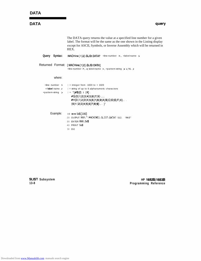
DATA
DATA query
The DATA query returns the value at a specified line number for a givenlabel. The format will be the same as the one shown in the Listing displayexcept for ASCII, Symbols, or Inverse Assembly which will be returned inHEX.
Query Syntax: :MACHine{ 1[2}:SLISt:DATA? <line-number B, <label-name >
Returned Format: [:MACHine{lI2}:SLISt:DATA]
<line-number >, < label-name >, <pattern-string > c NL >
where:
<line number > :: = integer from -1023 to + 1023
<label name > :: = string of up to 6 alphanumeric characters
<pattern-string > :: = “{#El{01 1 IX} . 1
#~{Oll~2~3~4~5~6~7IX}... 1#H{Oll~2~3~4~5~6~7~8~9(AlBICIDIEIFIX). . I
{Oil ~2~3~4~5~6~7~8~9). . }”
Example: 10 DIM Sd$[lOO]2 0 OUTPUT XXX;“:MACHINEl:SLIST:OATA? 512. ‘RAS’”
3 0 ENTER XXX;Sd$
4 0 PRINT Sd$
5 0 E N D
SLIST Subsystem13-8
HP 18528/1653BProgramming Reference
Downloaded from www.Manualslib.com manuals search engine
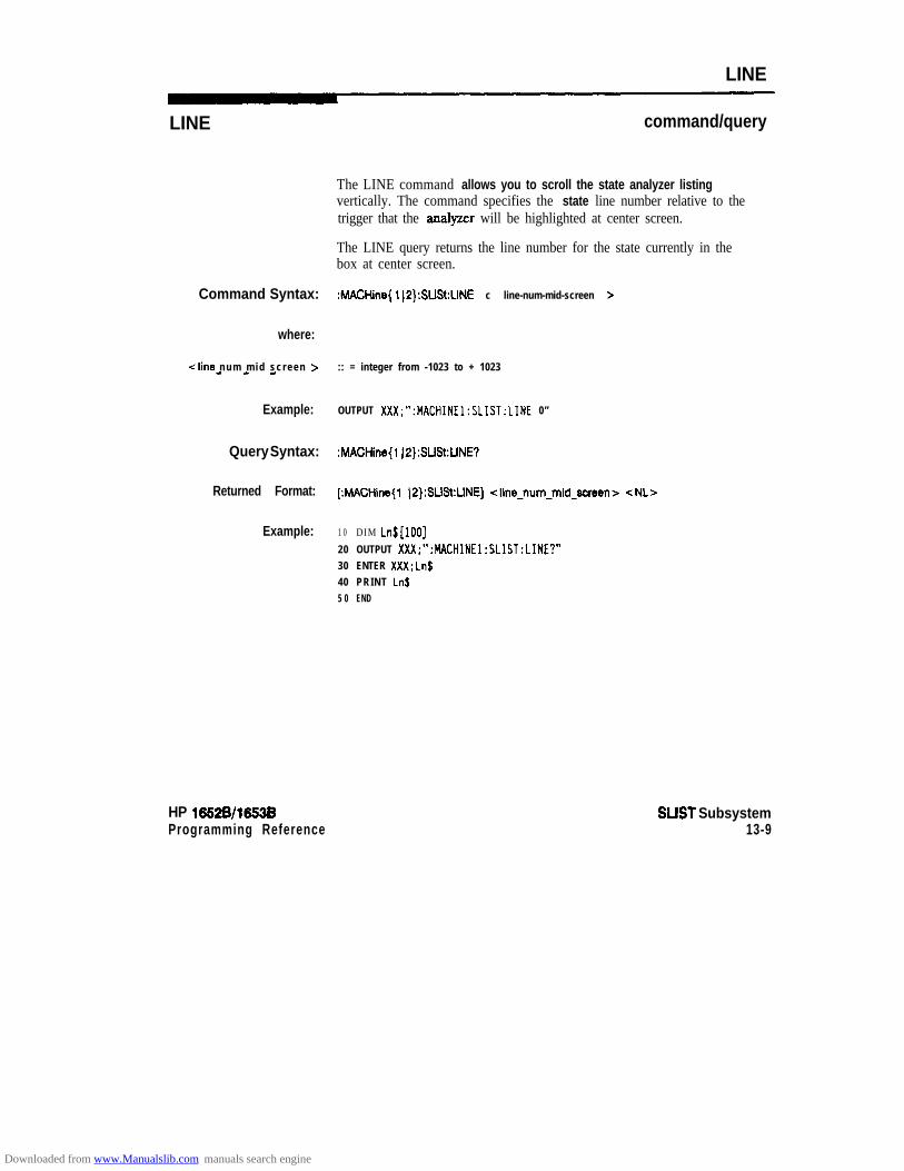
LINE
LINE
Command Syntax:
where:
cline num mid sc reen >- - -
Example:
Query Syntax:
Returned Format:
Example:
HP 16!526/1653BProgramming Reference
command/query
The LINE command allows you to scroll the state analyzer listingvertically. The command specifies the state line number relative to thetrigger that the analyzer will be highlighted at center screen.
The LINE query returns the line number for the state currently in thebox at center screen.
:MACHine{ lI2}:SLISt:LINE c line-num-mid-screen >
:: = integer from -1023 to + 1023
OUTPUT XXX;“:MACHINEl:SLIST:LINE 0”
:MACHine{l IP):SLISt:LINE?
[MACHine{ jP}:SLlSt:LINE] ~line~num~mid~soreen> <NL>
1 0 DIM Ln$[lOO]
20 OUTPUT XXX;“:MACHINEl:SLIST:LINE?”30 ENTER XXX:Ln$40 PRINT Ln$5 0 END
SLIST Subsystem13-9
Downloaded from www.Manualslib.com manuals search engine
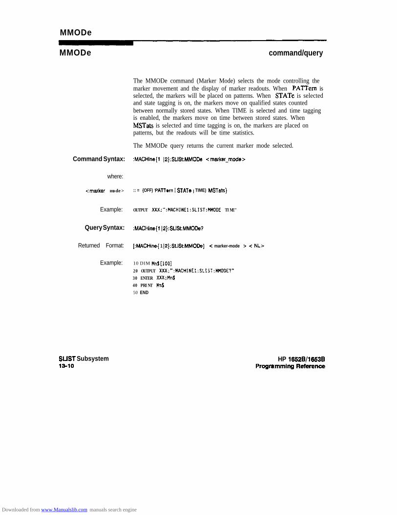
MMODe
MMODe command/query
The MMODe command (Marker Mode) selects the mode controlling themarker movement and the display of marker readouts. When PAlTern isselected, the markers will be placed on patterns. When STATe is selectedand state tagging is on, the markers move on qualified states countedbetween normally stored states. When TIME is selected and time taggingis enabled, the markers move on time between stored states. WhenMSTats is selected and time tagging is on, the markers are placed onpatterns, but the readouts will be time statistics.
The MMODe query returns the current marker mode selected.
Command Syntax: :MACHine{l I2):SLISt:MMODe <marker-mode>
where:
<marker mode> :: = {OFF) PATTern 1 STATe 1 TIME) MSTats}
Example: OUTPUT XXX;":MACHINE1:SLIST:MMODE TIME"
Query Syntax: :MACHine{l j2):SLISt:MMODe?
Returned Format: [:MACHine{ 1 I2):SLlSt:MMODe] c marker-mode > -z NL>
Example: 10 DIM Mn$[lOO]
20 OUTPUT XXX;":MACHINE1:SLIST:MMOOE?"30 ENTER XXX;Mn$40 PRINT Mn$50 END
SUST Subsystem13-10
HP 1652B/l653B
Downloaded from www.Manualslib.com manuals search engine

OPATtern
OPATtern command/query
The OPATtem command allows you to construct a pattern recognizerterm for the 0 Marker which is then used with the OSEarch criteria whenmoving the marker on patterns. Since this command deals with only onelabel at a time, a complete specification could require several invocations.
When the value of a pattern is expressed in biiary, it represents the bitvalues for the label inside the pattern reco@zer term. In whatever baseis used, the value must be between 0 and 2 - 1, since a label may not havemore than 32 bits. Because the c labelgattern > parameter may containdon’t cares, it is handled as a string of characters rather than a number.
The OPATtern query returns the pattern specification for a given labelname.
Command Syntax: :MACHine{ 1 IP}:SLISt:OPATtern <label-name z=, < labelgattern >
where:
c label-name > :: = string of up to 6 alphanumeric characters< labelgattern > :: = “{#B{OI 1 IX} . . . 1
XQ{O~1~2~3(4~5~6~7~X}. . . 1XH{O~1~2~3~4~5~6~7~8ISIAIBICIDIE(FIX). . . I(Oll~2~3~4~5~6~7~8~9). . . }”
Examples: O U T P U T XXX;“:MACHINEl:SLIST:OPATTERN ‘OATA’,’ 1,
OUTPUT XXX;“:MACHINEl:SLIST:OPATTERN ‘ABC’.‘#BXXXXllOl’ 11
HP 16528/1663BProgramming Reference
SLIST Subsystem13-11
Downloaded from www.Manualslib.com manuals search engine

OPATtern
Query Syntax: :MACHine{ 1 IP}:SLISt:OPATtern? c label-name >
fbturned Format: [:MACHine{ 1 JP}:SLISt:OPATtern] c label-name > , -z label-pattern z- -z NL>
Example: 10 DIM Dp$[lOO]20 OUTPUT XXX;" :MACHINEl:SLIST:OPATTERN? 'A"'
30 ENTER XXX;Op$40 PRINT Op$
50 END
SUST Subsystem13-12
HP 16528/16538
Downloaded from www.Manualslib.com manuals search engine

OSEarch
OSEarch command/query
The OSEarch command defines the search criteria for the 0 marker,which is then used with associated OPATtem recognizcrspecification when moving the markers on patterns. The origin parametertells the marker to begin a search with the trigger, the start of data, or withthe X marker. The actual occurrence the marker searches for isdetermined by the occurrence parameter of the OPATtemrecognizer specification, relative to the origin. An occurrence of 0 placesthe marker on the selected origin. With a negative occurrence, the markersearches before the origin. With a positive occurrence, the markersearches after the origin.
The OSEarch query returns the search criteria for the 0 marker.
Command Syntax: :MACHine{ 1 I2):SLISt:OSEarch <occurrence >, < origin >
where:
<occurrence z- :: = integer from -1023 to + 1023<origin > :: = {TRIGger 1 STARt IXMARker}
Example: OUTPUT XXX;“:MACHINEl:SLIST:OSEARCH +lO,TRIGGER”
Query Syntax: :MACHine{ 1 IP}:SLISt:OSEarch?
f%?tUrIWd Format: [:MACHine{ 1 )P):SLISt:OSEarch] <occunence> , <origin > -z NL>
Example: 10 OIM 0s$[100]20 OUTPUT XXX;“: MACHINEl:SLIST:OSEARCH?”30 E N T E R XXX:Os$40 PRINT Os$5 0 END
HP 16528/1653BProgramming Reference
SUST Subsystem13-13
Downloaded from www.Manualslib.com manuals search engine

OSTate
OSTate wry
The OSTate query returns the line number in the listing where the 0marker resides (-1023 to + 1023). If data is not valid, the query returns32767.
Query Syntax: :hWHine{l ~P}:SLlst:OSTate?
fl&.lrIWd Format: (:MACHine{l (P):SLlSt:OSTate] <state-num > -zNL>
where:
c state-num > :: = an integer from -1023 to + 1023, or 32767
Example: 10 DIM o~S[loo]'20 OUTPUT XXX;":MACHINEl:SLIST:OSTATE?"
30 ENTER XXX;Os$40 PRINT Os$
50 END
SUST Subsystem13-14
HP 1652B/l653BProgramming Reference
Downloaded from www.Manualslib.com manuals search engine

OTAG
OTAG command/query
The OTAG command specifies the tag value on which the 0 Markershould be placed. The tag value is time when time tagging is on or stateswhen state tagging is on. If the data is not valid tagged data, no action isperformed.
The OTAG query returns the 0 Marker position in time when timetagging is on or in states when state tagging is on, regardless of whetherthe marker was positioned in time or through a pattern search. If data isnot valid, the query returns 9.9E37 for time tagging, 32767 for statetagging.
Command Syntax: :MACHine{l(2):SLlSt:OTAG { dime-value7 1 estate-value 7)
4 time value 7 :: = real number-z state-value > :: = integer
Example: :OUTPUT XXX;" :MACHINEl:SLIST:OTAG 40.OE-6"
Query Syntax: :MACHine{l J2}:SLlSt:OTAG?
Returned Format: (:MACHine{l(2):SLlSt:OTAG] { dime-value.7 ( <state-value 7) < NL>
Example: 10 DIM OtS[loo]20 OUTPUT XXX:":MACHINEl:SLIST:OTAG?"
30 ENTER XXX;Ot$40 PRINT Ot$50 END
HP 1652B/l653BProgmmming Reference
SUST Subsystem13-15
Downloaded from www.Manualslib.com manuals search engine

RUNTiI
RUNTil command/query
The RUNTil (run until) command allows you to defme a stop conditionwhen the trace mode is repetitive. Specifying OFF causes the analyzer tomake runs until either the display’s STOP field is touched or the STOPcommand is issued.
There are four conditions based on the time between the X and 0markers. Using this difference in the condition is effective only when timetags have been turned on (see the TAG command in the STRacesubsystem). These four conditions are as follows:
l The difference is less than (LT) some value.l The difference is greater than (GT) some value.l The difference is inside some range (INRange).l The difference is outside some range (OUTRange).
End points for the INRange and OUTRange should be at least 10 ns apartsince this is the minimum time resolution of the time tag counter.
There are two conditions which are based on a comparison of theacquired state data and the compare data image. You can run until one ofthe following conditions is true:
l Compare Equal (EQUal) - Every channel of every label has thesame value.
l Compare not equal (h’EQual) - Any channel of any label has adifferent value.
The RUNTil query returns the current stop criteria.
Note fl3
The RUNTil instruction (for state analysis) is available in both the SLIStand COMPare subsystems.
SLIST Subsystem13-16
HP 16528/1653BProgramming Reference
Downloaded from www.Manualslib.com manuals search engine

RUNTil
Command Syntax: :MACHine{ 1 ~2):SLISt:RUNTil <run-until-spec>
where: I
c run-until-spec > :: = (OFF1 LT, <value z= JGT, <value > 1 INRange, <value >, <value >IOUTRange, <value>,<value> IEOUaljNEQual}
<value> :: = real number from -9E9 to +9E9
Example: OUTPUT XXX;":MACHINEl:SLIST:RUNTIL GT,800.OE-6"
Query Syntax: :hMCHine{l ~2}:SLISt:RUNTil?
Returned Format: [ :MACHine{ 1 I2}:SLISt:RUNTil] <run-until-spec> c NL>
Example: 10 DIM Ru$[lOO]20 OUTPUT XXX;":MACHINEl:SLIST:RUNTIL?"
30 ENTER XXX;Ru$40 PRINT Ru$
50 END
HP 16528/16538 SUST Subsystem13-17
Downloaded from www.Manualslib.com manuals search engine
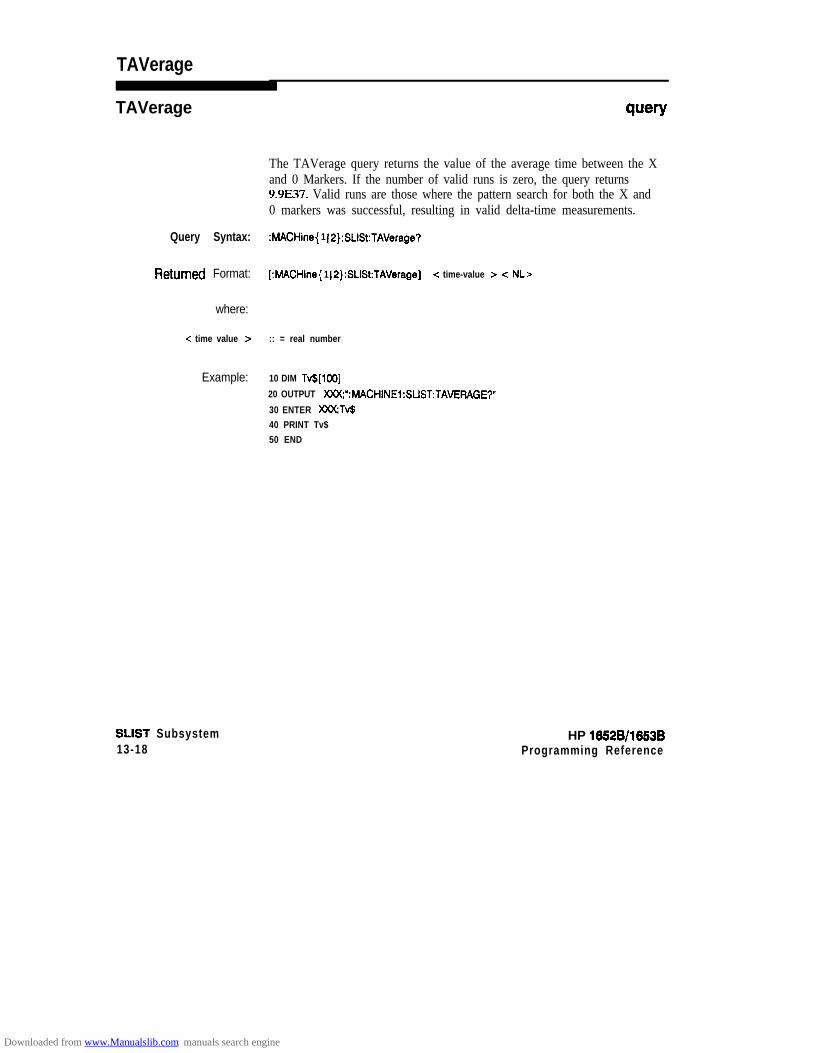
TAVerage
TAVerage query
The TAVerage query returns the value of the average time between the Xand 0 Markers. If the number of valid runs is zero, the query returns9.9E37. Valid runs are those where the pattern search for both the X and0 markers was successful, resulting in valid delta-time measurements.
Query Syntax: :MACHine{ 1 IP}:SLISt:TAVerage?
RetUrtIed Format: [:MACHine{ 1 IP}:SLISt:TAVerage] -z time-value > -z NL>
where:
c time value > :: = real number
Example: 10 DIM Tv$[lOO]
20 OUTPUT XXX;“:MACHINEl:SLIST:TAVERAGE?”
30 ENTER WTv$40 PRINT Tv$50 END
SLIST Subsystem13-18
HP 1882B/l883BProgramming Reference
Downloaded from www.Manualslib.com manuals search engine

TMAXimumA
TMAXimum
Query Syntax:
Returned Format:
where:
-z time-value >
Example:
HP 1652B/1653BProgmmmhg Reference
query
The TMAXimum query returns the value of the maximum time betweenthe X and 0 Markers. If data is not valid, the query returns 9.9E37.
:MACHine{l ~P}:SUSt:TMAXimum?
[:MACHine{l~2}:SUSt:TMAXimum] dime-value> <NLr
:: = real number
10 DIM Tx$[lOO]
20 OUTPUT XXX;":MACHINE1:SLIST:TMAXIMlJM?"
30 ENTER XXX;Tx$40 PRINT Tx$
50 END
SUST Subsystem13-19
Downloaded from www.Manualslib.com manuals search engine
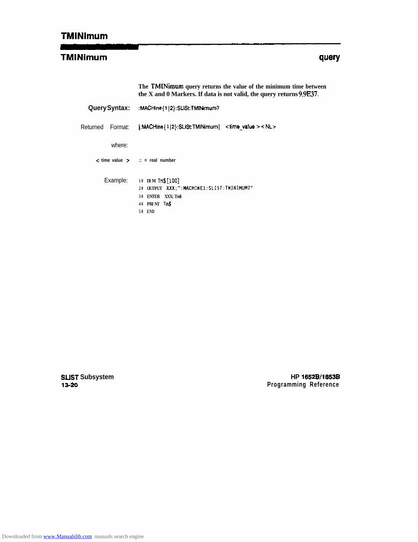
TMlNlmum
TMlNimum
Query Syntax:
Returned Format:
where:
c time value x-
Example:
SLIST Subsystem13-20
query
The TMINiium query returns the value of the minimum time betweenthe X and 0 Markers. If data is not valid, the query returns 9.9E37.
:MACHine{l ~P}:SLISt:TMINimum?
[:MACHine{ 1 JP}:SLISt:TMINimum] <time-value z= -z NLr
:: = real number
10 DIM Tm$[lOO]20 OUTPUT XXX;":MACHINEI:SLIST:TMINIMlJM?"
30 ENTER XXX;Tm$40 PRINT Tm$50 END
HP 1652Bll653BProgramming Reference
Downloaded from www.Manualslib.com manuals search engine

VRUNs
VRUNs query
The VRUNs query returns the number of valid runs and total number ofruns made. Valid runs are those where the pattern search for both the Xand 0 markers was successful resulting in valid delta time measurements.
Query Syntax: :MACHine{ 1)2}:SLISt:VFIUNs?
k3tUrmd Format: [:MACHine{l~2}:SLlSt:VRUNs] <valid-runs>, <total-runs> c NL>
where:
<val id runs >
<total runs >
:: = zero or positive integer
: : = z e r o o r p o s i t i v e i n t e g e r
Example: 10 DIM Vr$[100120 OUTPUT XXX;":MACHINEl:SLIST:VRUNS?"30 ENTER XXX;Vr$40 PRINT VrJ50 END
SLIST Subsystem13-21
Downloaded from www.Manualslib.com manuals search engine
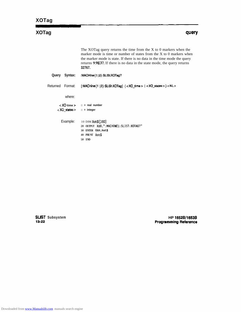
XOTag
XOTag q”=w
The XOTag query returns the time from the X to 0 markers when themarker mode is time or number of states from the X to 0 markers whenthe marker mode is state. If there is no data in the time mode the queryreturns 9.9E37. If there is no data in the state mode, the query returns32767.
Query Syntax: :MACHine{l I2):SLISt:XOTag?
Returned Format: [:MACHine{l (O}:SLISt:XOTag] (<X0-time> 1 -cXO_states>)<NL>
where:
c X0 time > :: = real number
c X0-states 5 :: = integer
Example: 10 DIM xot$[lool20 OUTPUT XXX;":MACHINEl:SLIST:XOTAG?"30 ENTER XXX;Xot$40 PRINT Xot$
50 END
SLIST Subsystem1342
HP 16528/1663B
Downloaded from www.Manualslib.com manuals search engine

XPATtern
XPATtern command/query
The XPATtem command allows you to construct a pattern recognizerterm for the X Marker which is then used with the XSEarch criteria whenmoving the marker on patterns. Since this command deals with only onelabel at a time, a complete specification could require several invocations.
When the value of a pattern is expressed in binary, it represents the bitvalues for the label inside the pattern reco @zer term. In whatever baseis used, the value must be between 0 and 2 - 1, since a label may not havemore than 32 bits. Because the c labelqattem > parameter may containdon’t cares, it is handled as a string of characters rather than a number.
The XPATtem query returns the pattern specification for a given labelname.
Command Syntax: :MACHine{l (2):SLISt:XPATtern d label-name >, < labelgattern B
where:
c label-name > :: = string of up to 6 alphanumeric characters< labelgattern > ::= ~{#B{O(l IX). . . 1
rUQ{OI112)3)41516)7)X}. . . 1
#H(O)1 ~2~3(4~5~6~7(6~9)A)6JCIDIE(FIX). . . I{Oll(2(3(4(5(6(7(8(9). . . 1”
Examples: OUTPUT xxx; ** : HACHINEl:SLIST:XPATTERN 'OATA'.'255' -OUTPUT XXX;" :MACHINEl:SLIST:XPATTERN ‘ABC’.‘#BXXXXIlOl’ -
HP 16!528/1653BProgramming Reference
SLIST Subsystem13-23
Downloaded from www.Manualslib.com manuals search engine

XPATtern
Query Syntax: :MACHine{l ~P]:SUSt%PATtem? -zlabel-name>
RetlNtled Format: [:MACHine{ 1 l2}:SUSt:XPATtern] <label-name > , < labelgattern > -c NL>
Example: 10 DIM Xp$[lOO]
20 OUTPUT XXX;“:MACHINEl:SLIST:XPATTERN? ‘A”’30 ENTER XXX;Xp$
40 PRINT Xp$50 END
SUST Subsystem13-24
HP 16528/16538
Downloaded from www.Manualslib.com manuals search engine

XSEarch
XSEarch command/query
The XSEarch command defines the search criteria for the X Marker,which is then with associated XPATtem recognizer specification whenmoving the markers on patterns. The origin parameter tells the Markerto begin a search with the trigger or with the start of data. Theoccurrence parameter determines which occurrence of the XPATtemrecognizer specification, relative to the origin, the marker actuallysearches for. An occurrence of 0 places a marker on the selected origin.
The XSEarch query returns the search criteria for the X marker.
Command Syntax: :MACHine{ 1 JP}:SLISt:XSEarch <occurrence > , <origin >
where:
< ocfxrrence >
<origin >
:: = integer from -1023 to + 1023
:: = (TRIGger 1 STAR}
Example: OUTPUT XXX;":MACHINEl:SLIST:XSEARCH +lO,TRIGGER"
Query Syntax: :MACHine{l(2):SLlSt:XSEarch?
Returned Format: [:MACHine{ 1 IP}:SLISt:XSEarch] <occurrence 7, <origin 7 c NL>
Example: 10 DIM Xs$[100120 OUTPUT XXX;":MACHINEl:SLIST:XSEARCH?"
30 ENTER XXX;Xs.$40 PRINT Xs$
50 END
HP 16526/16538Programming Reference
SUST Subsystem13-25
Downloaded from www.Manualslib.com manuals search engine
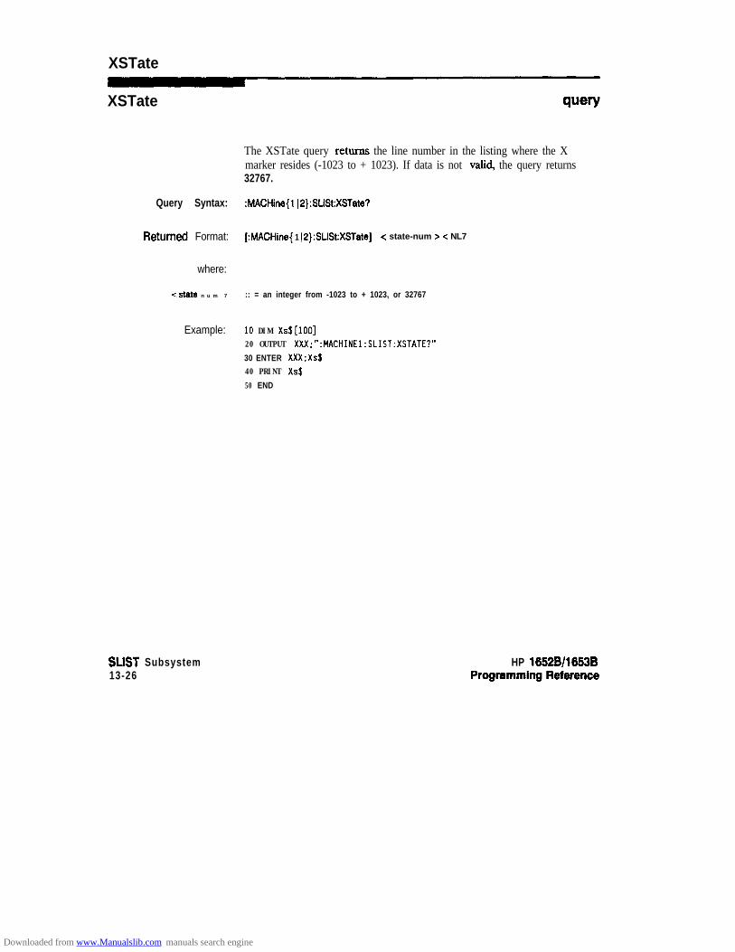
XSTate
XSTate
The XSTate query returns the line number in the listing where the Xmarker resides (-1023 to + 1023). If data is not valid, the query returns32767.
Query Syntax: :MACHine{l IP):SLlSt:XSTate?
RetUrfWd Format: [:MACHine{ 1 JP}:SLISt:XSTate] < state-num B -Z NL7
where:
<state n u m 7 :: = an integer from -1023 to + 1023, or 32767
Example: 10 DIM xs$[lool20 OUTPUT XXX;":MACHINEl:SLIST:XSTATE?"
30 ENTER XXX;Xs$40 PRINT Xs$
50 END
SLIST Subsystem13-26
HP 16628/1663B
Downloaded from www.Manualslib.com manuals search engine
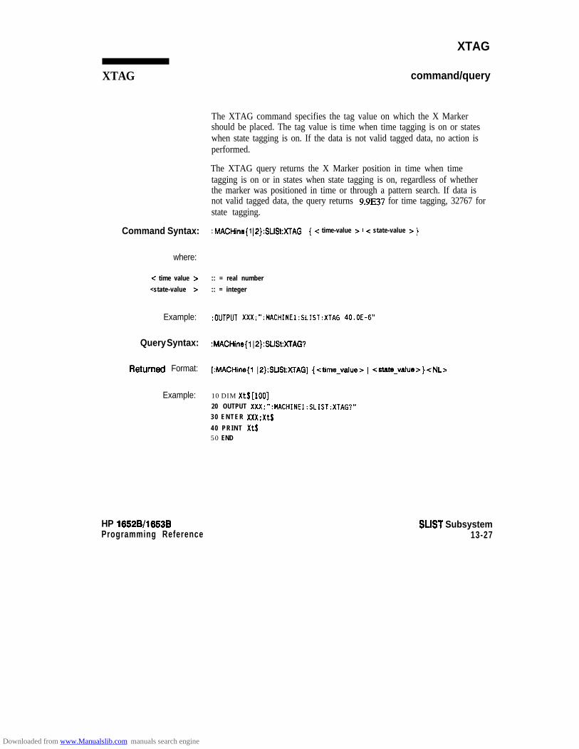
XTAG
XTAG command/query
The XTAG command specifies the tag value on which the X Markershould be placed. The tag value is time when time tagging is on or stateswhen state tagging is on. If the data is not valid tagged data, no action isperformed.
The XTAG query returns the X Marker position in time when timetagging is on or in states when state tagging is on, regardless of whetherthe marker was positioned in time or through a pattern search. If data isnot valid tagged data, the query returns 9.9E37 for time tagging, 32767 forstate tagging.
Command Syntax: : MACHine{ 1 IP}:SLlSt:XTAG { -z time-value > ) -z state-value z )
where:
c time value z :: = real number
<state-value > :: = integer
Example: :OUTPUT XXX;“:MACHINEl:SLIST:XTAG 40.OE-6”
Query Syntax: :MACHine(l ~P}:SUSt:XTAG’?
k3tUrnd Format: [MACHine{ IP}:SLlSt:XTAG] {<time-value> ) <state-value>}<NL>
Example: 10 DIM Xt$[lOO]20 OUTPUT XXX;“:MACHINEl:SLIST:XTAG?”30 ENTER XXX;Xt$
40 PRINT Xt$50 END
HP 16528/1653BProgramming Reference
SLIST Subsystem13-27
Downloaded from www.Manualslib.com manuals search engine
SWAVeform Subsystem 14Introduction The commands in the State Waveform subsystem allow you to configure
the display so that you can view state data as waveforms on up to 24channels identified by label name and bit number. The five commands areanalogous to their counterparts in the Tii Waveform subsystem.However, in this subsystem the x-axis is restricted to representing onlysamples (states), regardless of whether time tagging is on or off. As aresult, the only commands which can be used for scaling are DELay andRANge.
The way to manipulate the X and 0 markers on the Waveform display isthrough the State Listing (SLISt) subsystem. Using the marker commandsfrom the SLISt subsystem will affect the markers on the Waveform display.
The commands in the SWAVeform subsystem are:
l ACCumulatel DELayl INSertl RANGe
l REMove
HP 1652B/1653BProgramming Reference
SWAVeform Subsystem14-1
Downloaded from www.Manualslib.com manuals search engine

label-name
number of- -samples = integerfrom -1023 to + 1024label-name = (sting of up to 6 alphanumeric charactersbit-id = (OlERlay 1 c bit-num > }bit-num = integer representing a label bitfrom 0 to 31
Figure 14-l. SWAVeform Subsystem Syntax Diagram
SWAVeform Subsystem14-2
HP 16526/l 6538Programming Reference
Downloaded from www.Manualslib.com manuals search engine

SWAVeform
SWAVeform selector
The SWAVeform (State Waveform) selector is used as part of acompound header to access the settings in the State Waveform menu. Italways follows the MACHine selector because it selects a branch directlybelow the MACHine level in the command tree.
Command Syntax: :hdACHine{ 1 JP}:SWAVeform
Example: OUTPUT XXX;":MACHINEZ:SWAVEFORM:RANGE 4"
HP 16526/1653B SWAVeform Subsystem14-3
Downloaded from www.Manualslib.com manuals search engine
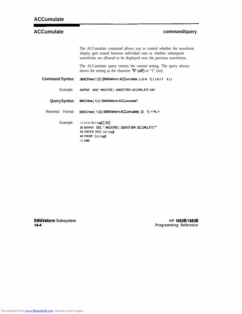
ACCumulate
ACCumulate command/query
The ACCumulate command allows you to control whether the waveformdisplay gets erased between individual runs or whether subsequentwaveforms are allowed to be displayed over the previous waveforms.
The ACCumulate query returns the current setting. The query alwaysshows the setting as the character “0” (off) or “1” (on).
Command Syntax: :MACHine{lj2}:SWAVeform:ACCumulate { { O N 1 1) 1 { O F F 1 0 ) }
Example: OUTPUT XXX;” :MACHINEl:SWAVEFORM:ACCUMULATE ON”
Query Syntax: MACHine{ 1 [2}:SWAVeform:ACCumulate?
Returned Format: [MACHine{ 112}:SWAVeform:ACCumulate] (0 1 1) cNL>
Example: 10 DIM String$[lOO]
20 OUTPUT XXX;“:MACHINEl:SWAVEFORM:ACCUMULATE?”30 ENTER XXX; Stringa40 PRINT Strings50 END
SWAVeform Subsystem14-4
HP 16528/1663BProgramming Reference
Downloaded from www.Manualslib.com manuals search engine

DELay
DELay
Command Syntax:
where:
< n u m b e r o f- - s a m p l e s >
Example:
Query Syntax:
Returned Format:
Example:
command/query
The DELay command allows you to specify the number of samplesbetween the tim@ trigger and the horizontal center of the screen for thewaveform display. The allowed number of samples is from -1023 to+ 1024.
The DELay query returns the current sample offset value.
:MACHine{ l IP}:SWAVeform:DELay < n u m b e r - o f - s a m p l e s >
:: = integer from -1023 to + 1024
OUTPUT XXX;“:MACHINE2:SWAVEFORM:DEtAY 127”
MACHine{ 12}:SWAVeform:DELay?
[MACHine{ lI2):SWAVeform:DELayl < n u m b e r - o f - s a m p l e s > <NL>
1 0 D I M String$[lOO]20 OUTPUT XXX;“:MACHINEl:SWAVEFORM:DELAY?”30 ENTER XXX;String.$40 PRINT StringJ50 END
HP 16!529/16538 SWAVeform Subsystemw-5
Downloaded from www.Manualslib.com manuals search engine
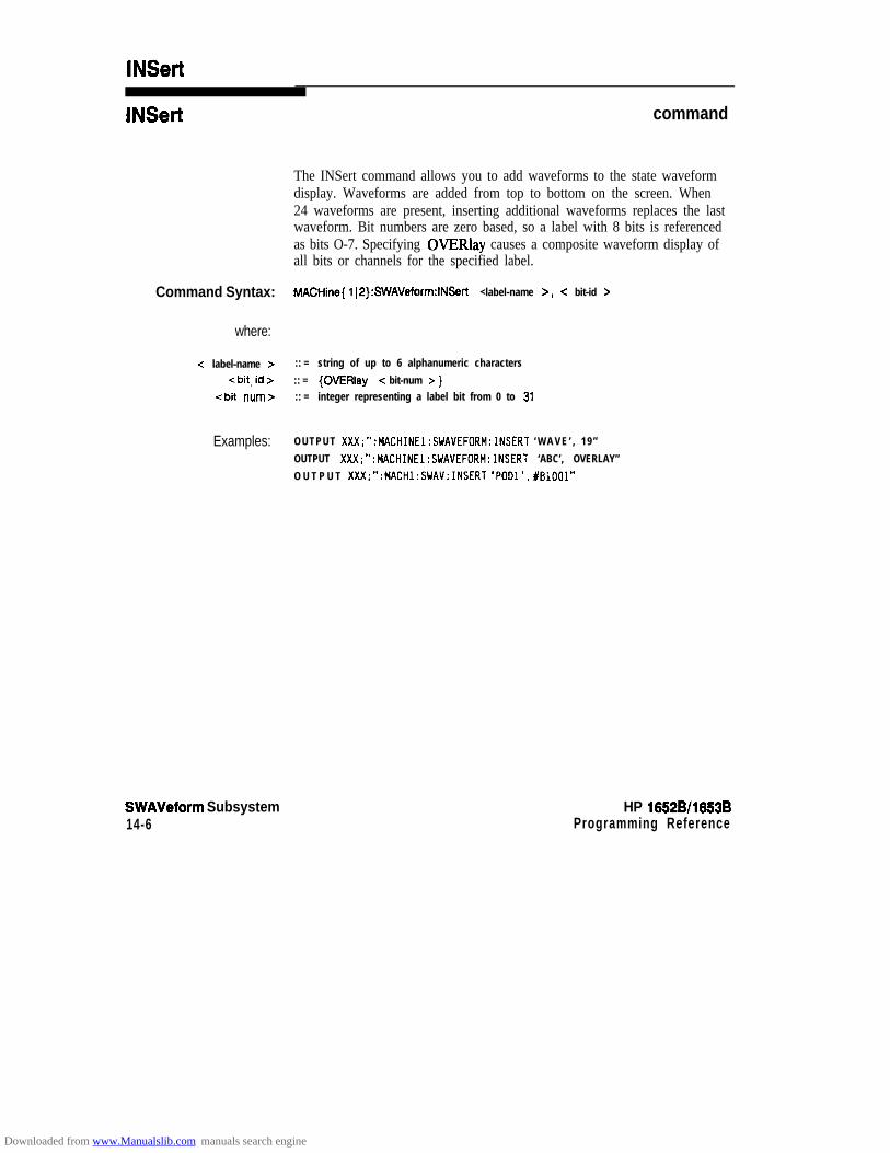
INSert
INSert command
The INSert command allows you to add waveforms to the state waveformdisplay. Waveforms are added from top to bottom on the screen. When24 waveforms are present, inserting additional waveforms replaces the lastwaveform. Bit numbers are zero based, so a label with 8 bits is referencedas bits O-7. Specifying OVERlay causes a composite waveform display ofall bits or channels for the specified label.
Command Syntax: MACHine{ 1 IP}:SWAVeform:INSerf <label-name >, < bit-id z=
where:
-z label-name > :: = string of up to 6 alphanumeric characters
(bit-id > :: = {OVERlay 1 < bit-num > }<bit num> :: = integer representing a label bit from 0 to 31
Examples: OUTPUT XXX;“:MACHINEl:SWAVEFORM:INSERT ‘WAVE’ , 19”
OUTPUT XXX;“:MACHINEl:SWAVEFORM:INSERT ‘ABC’, OVERLAY”
O U T P U T XXX;“:MACHl:SWAV:INSERT ‘Pool’. #BlOOl”
SWAVeform Subsystem14-6
HP 1652B/l663BProgramming Reference
Downloaded from www.Manualslib.com manuals search engine

RANGe
RANGe command/query
The RANGe command allows you to specify the number of samplesacross the screen on the State Waveform display. It is equivalent to tentimes the states per division setting (st/Div) on the front panel. A numberbetween 10 and 1040 may be entered.
The RANGe query returns the current range value.
Command Syntax: MACHine{ 1 IO}:SWAVeform:RANGe <number of- -samples >
where:
(number of- -samples> :: = integer from 10 to 1040
Example: OUTPUT XXX;":MACHINE2:SWAVEFORM:RANGE 80"
Query Syntax: MACHine( 1 ~P}:SWAVeform:RANGe7
Returned Format: [MACHine{ 1 IP}:SWAVeform:FIANGe] c number-of-samples > < NL>
Example: 10 DIM String$[lOO]20 OUTPUT XXX;":MACHINE2:SWAVEFORM:RANGE?"30 ENTER Xxi; String$40 PRINT String$
50 END
HP 1652Bll653BProgramming Reference
SWAVeform Subsystem14-7
Downloaded from www.Manualslib.com manuals search engine

REMove
REMove command
The REMove command allows you to clear the waveform display beforebuilding a new display.
Command Syntax: :MACHine{ 1 jP}:SWAVeform:REMove
Example: OUTPUT XXX;":MACHINEl:SWAVEFORM:REMOVE"
SWAVeform Subsystem14-8
HP 16528/1653B
Downloaded from www.Manualslib.com manuals search engine

SCHart Subsystem 15Introduction The State Chart subsystem provides the commands necessary for
programming the HP 1652B/53B’s Chart display. The commands allowyou to bui ld charts of label act ivi ty, using data normally found in theList ing display. The chart’s y-axis is used to show data values for the labelof your choice. The x-axis can be used in two different ways. In one, thex-axis represents states (shown as rows in the State Listing display). In theother, the x-axis represents the data values for another label. When statesare plotted along the x-axis, X and 0 markers are available. Since theState Chart display is simply an alternative way of looking at the data inthe State Listing, the X and 0 markers can be manipulated through theSLISt subsystem. In fact, because the programming commands do notforce the menus to switch, you can position the markers in the SLIStsubsystem and see the effects in the State Chart display.
The commands in the SCHart subsystem are:
l ACCumulateOHAxis. VA%
HP 16528116538 SCHarl Subsystem15-1
Downloaded from www.Manualslib.com manuals search engine
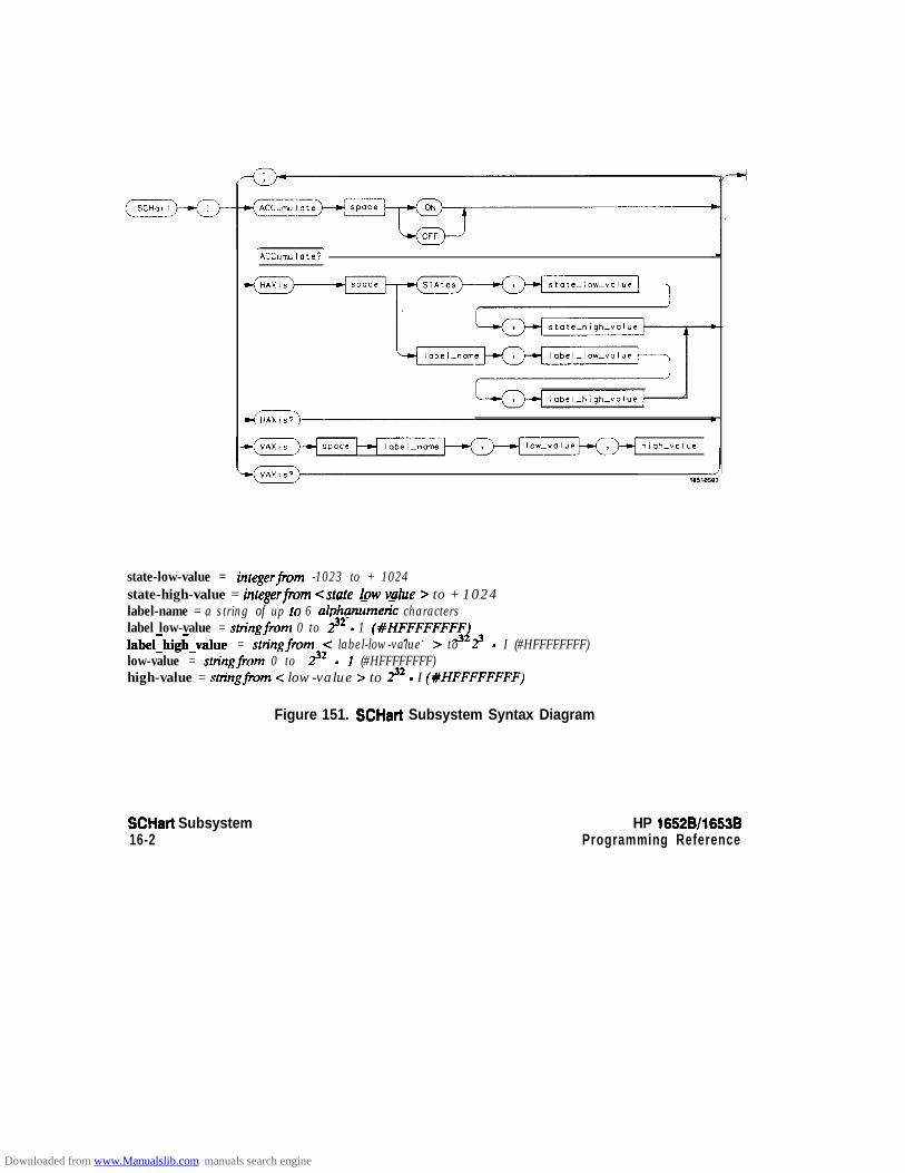
Accumulate? .
hlqh-value
state-low-value = integerfrom -1023 to + 1024state-high-value = integerfrom <state-low v&e > to + 1024label-name = a string of up fo 6 alphanume& characterslabel low-value = stringfrom 0 to y2 - 1 (XHFFFFFFFFilabelrhigh-value = stringfrom -z label-low-value > to 23 - I (#HFFFFFFFF)low-value = sttingfrom 0 to y2 - 1 (#HFFFFFFFF)high-value = sm’ngfrom c low-value > to y2 - I (#HFFFFFFFF)
SCHart Subsystem HP 16528/1653B16-2 Programming Reference
Figure 151. SCHart Subsystem Syntax Diagram
Downloaded from www.Manualslib.com manuals search engine

SCHatt
SCHart selector
The SCHart selector is used as part of a compound header to access thesettings found in the State Chart menu. It always follows the MACHineselector because it selects a branch below the MACHine level in thecommand tree.
Command Syntax: :MACHine{l~2}:SCHari
E x a m p l e : OuTPuT XXX;“:MACHINE~:SCHART:VAXIS *A’, ‘0’. ‘g***
HP 16528/1653BProgramming Reference
SCHart Subsystem153
Downloaded from www.Manualslib.com manuals search engine

ACCumulate
ACCumulate command/query
The Accumulate command allows you to control whether the chartdisplay gets erased between each individual run or whether subsequentwaveforms are allowed to be displayed over the previous waveforms.
The Accumulate query returns the current setting. The query alwaysshows the setting as the character “0” (off) or “1” (on).
Command Syntax: MACHine(l12):SCHart:ACCumulate {{ON 1 1) 1 {OFF ) O}}
Example: OUTPUT XXX;":MACHINEl:SCHART:ACCUMULATE OFF"
Query Syntax: MACHine{ 1 12}:SCHatt:ACCumulate?
RetUrned Format: [MACHine{ 1 J2):SCHart:ACCumulateJ {o ) 1) -Z NL>
Example: 10 DIM String$[lOO]20 OUTPUT XXX;":MACHINEl:SCHART:ACCUMULATE?"30 ENTER XXX; String$40 PRINT String$50 END
SCHart Subsystem15-4
HP 16528/16538
Downloaded from www.Manualslib.com manuals search engine

HAXis
HAXis command/query
The HAXis command allows you to select whether states or a label’svalues will be plotted on the horizontal axis of the chart. The axis is scaledby specifying the high and low values.
Note ”3The shortform for STATES is STA. This is an intentional deviation fromthe normal trunctation rules.
Command Syntax:
where:
c state-low value > :: = integer from -1023 to 1024-Z state high-value > :: = Integer from <state-low-value > to + 1024
(label n a m e > :: = a string of up to 6 alphanumeric characters.c label-low value z- :: = string from 0 to p-1 (#HFFFFFFFF)
<label-high-value > :: = string from c label-low-value Z= to p-1 (#HFFFFFFFF)
Examples:
The HAXis query returns the current horizontal axis label assignment andscal ing.
MACHine{ 1 IP}:SCHart:HAXis {STATES, <state-low-value >, <state-high-value > (
<label-name > , < label-low-value >, <label-high-value > )
OUTPUT XXX;“:MACHINEl:SCHART:HAXIS STATES, - 100 , 100”OUTPUT XXX;“:MACHINEl:SCHART:HAXIS ‘DATA’, ‘ -511 ’ . ‘511” ’
HP 15528/16538 SCHart Subsystem155
Downloaded from www.Manualslib.com manuals search engine

HAXis
Query Syntax: MACHine{l I2}:SCHart:HAXis?
Returned Format: [MACHine{ 1~2}:SCHart:HA%is] {STATES, c state-low-value >, -z state-high-value Z= 1c l a b e l - n a m e > , < l a b e l - l o w - v a l u e > , < l a b e l - h i g h - v a l u e > }
Example: 10 DIM String$[lOO]
20 OUTPUT XXX;":MACHINEl:SCHART:HAXIS?"
30 ENTER XXX; String$40 PRINT String$
50 END
SCHart Subsystem16-6
HP 16528/1663BProgramming Reference
Downloaded from www.Manualslib.com manuals search engine
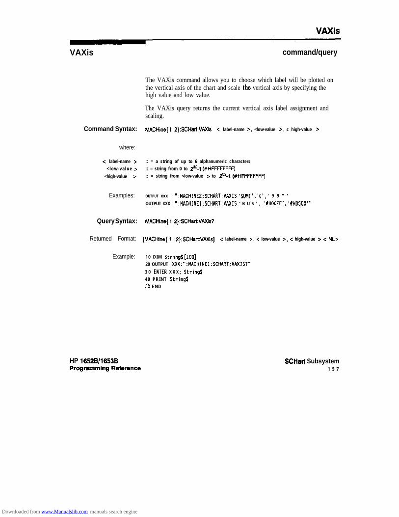
VAxis
VAXis command/query
The VAXis command allows you to choose which label will be plotted onthe vertical axis of the chart and scale the vertical axis by specifying thehigh value and low value.
The VAXis query returns the current vertical axis label assignment andscaling.
Command Syntax: MACHine{ 1~2):SCHart:VAXis < label-name >, <low-value >, c high-value >
where:
c label-name > :: = a string of up to 6 alphanumeric characters< low-va lue > :: = string from 0 to p-1 (XHFFFFFFFF)
<high-value > :: = string from <low-value > to p-1 (XHFFFFFFFF)
Examples: OUTPUT xxx ; *I :MACHINE2:SCHART:VAXIS ‘SlJMl’, ‘O’, ‘ 9 9 ” ’
OUTPUT XXX ; *’ :MACHINEl:SCHART:VAXIS ‘ B U S ’ , ‘#HOOFF’, ‘IH0500’”
Query Syntax: tvlACHine{ 1 ~P):SCHart:VAXis7
Returned Format: [MACHine{ 1 ~P}:SCHart:VAXis] -z label-name >, c low-value >, < high-value > < NL>
Example: 1 0 D I M String$[lOO]20 OUTPUT XXX;“:MACHINEl:SCHART:VAXIS?”
3 0 ENTER X X X ; Strings40 PRINT Stringf50 END
HP 16528/16538 SCHart Subsystem1 5 7
Downloaded from www.Manualslib.com manuals search engine
COMPare Subsystem 16Introduction Commands in the state COMPare subsystem provide the abiity to do a
bit-by-bit comparison between the acquired state data listing and acompare data image. The commands are:
0 C O P Yl DATAa CMASkl RANGe
l RUNTil0 FIND
HP 16526/16538 COMPare Subsystem161
Downloaded from www.Manualslib.com manuals search engine

space label-nom c
label-name = sting of up to 6 characterscare-spec = stringojchuructers “{*I.}...”* = care. = don’t careline-num = integerfrom -1023 to + 1023dataqattern - “{#B{OIIIX}. . . 1
~Q~~l~l~l~l~l~l~l~l~~. . . I#H{O~1(2~3)4~5~6~7~8~9~AIBICIDIEIFIX}... I(0~1~2~3~4~5~6~7~8~9). . . }”
difference-occurence = integerfrom 1 to 1024start-line = integerfrom -1023 to +I023stop-line = integerfrom <start-line > to + 1023
Figure 161. COMPare Subsystem Syntax Diagram
COMPare Subsystem HP 16528/1663B16-2 Programming Reference
Downloaded from www.Manualslib.com manuals search engine

COMPare
COMPare selector
The COMPare selector is used as part of a compound header to accessthe settings found in the Compare menu. It always follows the MACHineselector because it selects a branch directly below the MACHine level inthe command tree.
Command Syntax: :MACHine{l I2):COMPare
Example: OUTPUT XXX;":MACHINEl:COMPARE:FINO? 819"
HP 1662B/l653B COMPare Subsystem16-3
Downloaded from www.Manualslib.com manuals search engine
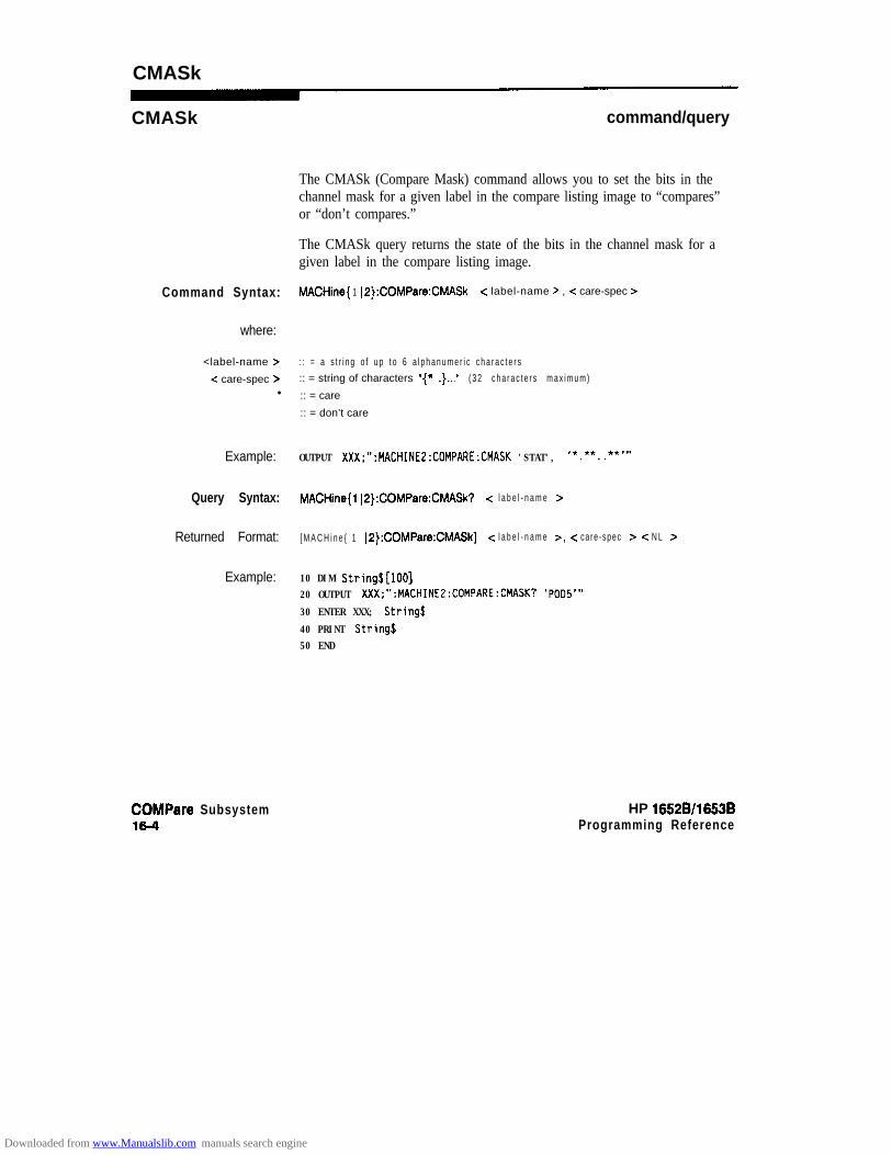
CMASk
CMASk command/query
The CMASk (Compare Mask) command allows you to set the bits in thechannel mask for a given label in the compare listing image to “compares”or “don’t compares.”
The CMASk query returns the state of the bits in the channel mask for agiven label in the compare listing image.
Command Syntax: MACHine{ 1 IP}:COMPare:CMASk c label-name > , -z care-spec >
where:
<label-name > : : = a s t r i n g o f u p t o 6 a l p h a n u m e r i c c h a r a c t e r s
<: care-spec z :: = string of characters “{* 1 .}...I’ ( 3 2 c h a r a c t e r s m a x i m u m )l :: = care
:: = don’t care
Example: OUTPUT XXX;":MACHINE2:COMPARE:CMASK 'STAT', I*.**..**"'
Query Syntax: MACHine{ l l2}:COMPare:CMASk? -z l a b e l - n a m e >
Returned Format: [ M A C H i n e { 1 IP):COMPare:CMASk] < l a b e l - n a m e >, c ca re -spec z- < N L z
Example: 10 DIM String$[lOO]20 OUTPUT XXX;":MACHINE2:COMPARE:CMASK? 'POO5'"
30 ENTER XXX; String$
40 PRINT String$50 END
COMPare Subsystem16-4
HP 16628/1653BProgramming Reference
Downloaded from www.Manualslib.com manuals search engine

COPY
COPY command
The COPY command copies the current acquired State Listing for thespecified machine into the Compare Listing template. It does not affectthe compare range or channel mask settings.
Command Syntax: MACHine{ 1IP):COMPare:COPY
Example: OUTPUT XXX;":MACHINEZ:COMPARE:COPY"
HP 15528/1553BProgramming Reference
COMPare Subsystem15-5
Downloaded from www.Manualslib.com manuals search engine
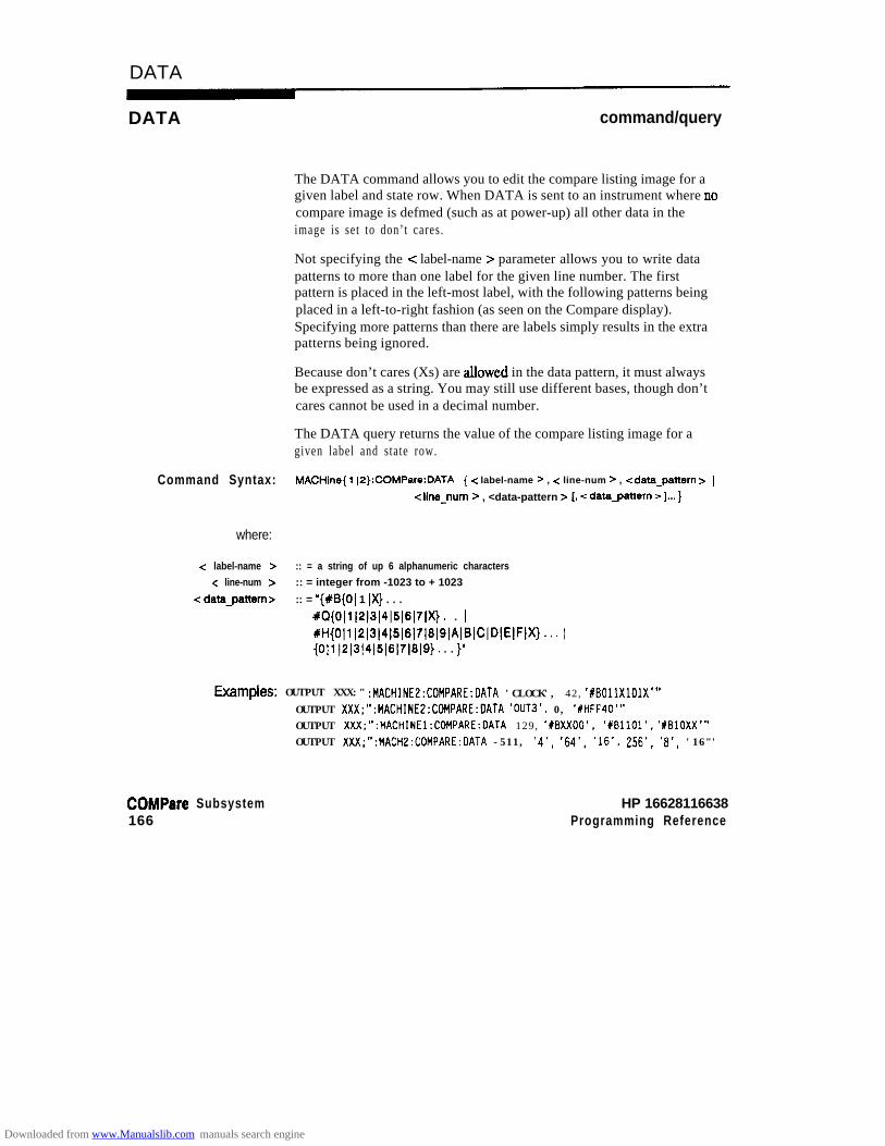
DATA
DATA command/query
The DATA command allows you to edit the compare listing image for agiven label and state row. When DATA is sent to an instrument where no
compare image is defmed (such as at power-up) all other data in theimage is set to don’t cares.
Not specifying the -z label-name > parameter allows you to write datapatterns to more than one label for the given line number. The firstpattern is placed in the left-most label, with the following patterns beingplaced in a left-to-right fashion (as seen on the Compare display).Specifying more patterns than there are labels simply results in the extrapatterns being ignored.
Because don’t cares (Xs) are atlowed in the data pattern, it must alwaysbe expressed as a string. You may still use different bases, though don’tcares cannot be used in a decimal number.
The DATA query returns the value of the compare listing image for agiven label and state row.
Command Syntax: MACHine{ 112):COMPare:DATA { -z label-name z , -z line-num z , <data-pattern z (
<line-num > , <data-pattern > [, cdatagattern >I... }
where:
-Z label-name > :: = a string of up 6 alphanumeric charactersc line-num > :: = integer from -1023 to + 1023
< datagattern Z- :: = “{#El{OI 1 IX} . . . I
#Q{O~l~2~3~4~5~6~7~X). . /
#H{Olll2~3l4~5l6l71819)A181CIDIEIFIX)... 1{0~1(2~3(4~5(6~7~6~9}. . . }”
hatTl@?S: OUTPUT XXX:" :MACHINEZ:COMPARE:DATA 'CLOCK', 42, ‘XBDllXlOlX’”OUTPUT XXX;":MACHINE2:COMPARE:DATA 'DUT3'. 0, 'XHFF40"OUTPUT XXX;":MACHINEl:CDMPARE:DATA 129, 'XBXXOO'. ‘#BllOl’, ‘YBlOXX’”OUTPUT XXX;":MACH2:COMPARE:DATA -511, '4', '64', '16', 256', 'a', '16"'
COMPare Subsystem166
HP 16628116638Programming Reference
Downloaded from www.Manualslib.com manuals search engine

DATA
Query Syntax: MACHine{ 1 (P}:COMPare:DATA7 <label-name > , < line-num >
Returned Format: [MACHine{ IP}:COMPare:DATA]c label-name >, c line-num >, -z datagattern > c NL >
Example: 10 DIM Labels [S] , ResponseJ [80]15 PRINT "This program shows the values for a signal's Compare listing"
20 INPUT “Enter signal label: ", LabelS25 OUTPUT XXX;":SYSTEM:HEAOER OFF" !Turn headers off (from responses)30 OUTPUT XXX;":MACHINE2:COMPARE:RANGE?"
35 ENTER XXX; First, Last !Read in the range's end-points
40 PRINT "LINE W", "VALUE of "; Label$
45 FOR State = First TO Last !Print compare value for each state
50 OUTPUT XXX;":MACH2:COMPARE:DATA? '1) & Label$ & "'," & VAL$(State)
55 ENTER XXX; Responsej60 PRINT State, Response$
6 5 NEXT State70 END
HP 1652B/l653BProgramming Reference
COMPare Subsystem16-7
Downloaded from www.Manualslib.com manuals search engine
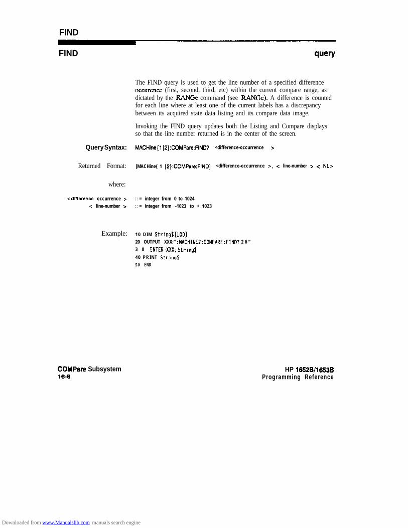
FIND
FIND query
Query Syntax:
Returned Format:
where:
cdifference occurrence >c line-number >
Example:
COMPare Subsystem16-8
The FIND query is used to get the line number of a specified differenceoccurence (first, second, third, etc) within the current compare range, asdictated by the RANGe command (see RANGe). A difference is countedfor each line where at least one of the current labels has a discrepancybetween its acquired state data listing and its compare data image.
Invoking the FIND query updates both the Listing and Compare displaysso that the line number returned is in the center of the screen.
MACHine{ 112}:COMPare:FIND? <difference-occurrence >
[MACHine{ 1 IP}:COMPare:FIND] <difference-occurrence >, c line-number > < NLz-
: : = integer from 0 to 1024: : = integer from -1023 to + 1023
1 0 D I M String$[lOO]20 OUTPUT XXX;” :MACHINE2:COMPARE:FIND? 2 6 ”3 0 ENTERdXXX; String$
40 PRINT String$50 END
HP 1652B/l653BProgramming Reference
Downloaded from www.Manualslib.com manuals search engine

RANGe
RANGe command/query
The RANGe command allows you to define the boundaries for thecomparison. The range entered must be a subset of the lines in theaquisition memory.
The RANGe query returns the current boundaries for the comparison.
Command Syntax: MACHine{ 1 IO}:COMPare:RANGe (FULL 1 PARTial, <start-line >, c stop-line > )
where:
-zstart l ine> ::= integer from -1023to +1023
<stop-line > :: = integer from -z start-line > to + 1023
Examples: OUTPUT xxx;" :MACHINE2:COMPARE:RANGE P A R T I A L , - 5 1 1 , 5 1 2 ”OUTPUT XXX:“:MACHINEZ:COMPARE:RANGE FULL”
Query Syntax: hMCHine{ 1 IP):COMPare:RANGe?
Returned Format: [MACHine{l (P}:COMPare:RANGe] { F U L L 1 PAFtTial,<start-line>,<stop-line>}cNLr
Example: 10 DIM String$[100]20 OUTPUT XXX;” :MACHINE4:COHPARE:RANGE?”30 ENTER XXX; String$
40 REM See if substring "FULL" occurs in response string:50 PRINT "Range is ";
60 IF POS(String$,"FULL") > 0 THEN PRINT "Full" ELSE PRINT "Partial"
70 END
HP 16!528/1653BProgramming Reference
COMPare Subsystem169
Downloaded from www.Manualslib.com manuals search engine

RUNTiI
RUNTil command/query
The RUNTil (run until) command allows you to define a stop conditionwhen the trace mode is repetitive. Specifying OFF causes the analyzer tomake rtms until either the display’s STOP field is touched or the STOPcommand is i ssued.
Note d
There are four conditions based on the time between the X and 0markers. Using this difference in the condition is effective only when timetags have been turned on (see the TAG command in the STRacesubsystem). These four conditions are as follows:
l The difference is less than (LT) some value.l The difference is greater than (GT) some value.l The difference is inside some range (INRange).l The difference is outside some range (OUTRange).
End points for the INRange and OUTRange should be at least 10 ns apart.
There are two conditions which are based on a comparison of theacquired state data and the compare data image. You can run until one ofthe following conditions is true:
l Compare equal (EQUal) - Every channel of every label has thesame value.
l Compare not equal (NEQual) - Any channel of any label has adifferent value .
The RUNTil query returns the current stop criteria for the comparisonwhen running in repetitive trace mode.
The RUNTil instruction (for state analysis) is available in both the SLIStand COMPare subsys tems.
COMPare Subsystem1610
HP 1652Bll653BProgramming Reference
Downloaded from www.Manualslib.com manuals search engine

RUNTiI
Command Syntax: MACHine(1 l2):COMPare:RUNTil {OFFILT,cvalue> IGT,<value> 1INFlange, <value >, <value > (OUTRange, <value >, <value > 1 EQUal (NE&al}
Example: OUTPUT XXX;" :MACHINE2:COMPARE:RUNTIL EQUAL"
Query Syntax: hlACHine{ 1~2):COMPare:RUNTil?
Returned Format: [MACHine{l ~P}:COMPare:RUNTil] {OFF JLT,<value> lGT,<value> )
INRange, c value >, -Z value > 1 OUTRange, <value > , <value > ( EQUal 1 NEQual) < NL>
Example: 10 DIM String$[lOO]20 OUTPUT XXX;":MACHINE2:COMPARE:RUNTIL?"
30 ENTER XXX; String$40 PRINT String$
50 EN0
HP 1652Bll6536 COMPare Subsystem16-11
Downloaded from www.Manualslib.com manuals search engine

TFORmat Subsystem 17Introduction The TFORmat subsystem contains the commands available for the Tiig
Format menu in the HP 1652B/53B logic analyzer. These commands are:
0 LABell REMovel THReshold
pod-specification
-
name = sh’ng of up to 6 alphanumeric characterspolarity =: {POSitive I NEGative}pod-specification = format (integerfrom 0 to 65535) for a pod @oak are assigned in &creasing order)value = vol tage (real number) -9 .9 to + 9 .9
Figure 17-1. TFORmat Subsystem Syntax Diagram
HP 16528/1653BProgmmming Reference
TFORmat Subsystem17-1
Downloaded from www.Manualslib.com manuals search engine

TFORmat
TFORmat selector
The TFORmat selector is used as part of a compound header to accessthose settings normally found in the Timing Format menu. It alwaysfollows the MACHine selector because it selects a branch directly belowthe MACHine level in the language tree.
Command Syntax: :MACHine{ 1 IP}:TFORmat
Example: OUTPUT ~~X;“:MACHINE~:TFORMAT:LAEIEL?”
TFORmat Subsystem17-2
HP 16528/1663BProgramming Reference
Downloaded from www.Manualslib.com manuals search engine

LABel
LABel command/query
The LABel command allows you to specify polarity and assign channels tonew or existing labels. If the specified label name does not match anexisting label name, a new label will be created.
The order of the pod-specification parameters is significant. The first onelisted will match the highest-numbered pod assigned to the machineyou’re using. Each pod specification after that is assigned to thenext-highest-numbered pod. This way they match the left-to-rightdescending order of the pods you see on the Format display. Notincluding enough pod specifications results in the lowest-numberedpod(s) being assigned a value of zero (all channels excluded). If youinclude more pod specifications than there are pods for that machine, theextra ones will be ignored. However, an error is reported anytime morethan five pod specifications are listed.
The polarity can be specified at any point after the label name.
Since pods contain 16 channels, the format value for a pod must bebetween 0 and 65535 (216-1). When giving the pod assignment in binary(base 2), each bit will correspond to a single channel. A “1” in a bitposition me? the associated channel in that pod is assigned to that podand bit. A “0” m a bit position means the associated channel in that pod isexcluded from the label. For example, assigning #B1111001100 isequivalent to entering ’ . . . . . . * * * * ..* * ..’ through the front-panel userinterface.
A label can not have a total of more than 32 channels assigned to it.
The LABel query returns the current specification for the selected (byname) label. If the label does not exist, nothing is returned. Numbers arealways returned in decimal format.
HP 1052B/1653B TFORmat Subsystem17-3
Downloaded from www.Manualslib.com manuals search engine

Command Syntax: :MACHine{l iP}:TFORmat:iABel < n a m e > [, { < p o l a r i t y > 1 <assignment>}]...
where:
< n a m e > :: = string of up to 6 alphanumeric characters< polarity > : : = {Positive 1 NEGative)
<:as.signment > :: = format (integer from 0 to 65535) for a pod (pods are assigned in decreasing order)
Examples: OUTPUT XXX;“:MACHINEE:TFORMAT:LABEL ‘ D A T A ’ , P O S , 6 5 5 3 5 . 1 2 7 . 4 0 3 1 2 ”OUTPUT XXX ; ” :MACHINE2:TFORMAT:LABEL ‘STAT’, 1 , 6096, POSITIVE”
OUTPUT XXX;“:MACHINEl:TFORMAT:LABEL ‘ADDR’, NEGATIVE, #B11110010101010”
Query Syntax: MACHine{ l~2}:TFORmat:iAW? c name >
Returned Format: [:MACHine{l iP}:TFORmat:LABel] < n a m e > [, <assignment>]...,<polarity> < NL>
Example: 1 0 D I M String$[lOO]20 OUTPUT XXX;“:MACHINE2:TFORMAT:LAEiEL? ‘DATA”’
30 ENTER XXX String$
40 PRINT String$50 END
TFORmat Subsystem17-4
HP 16628/1653B
Downloaded from www.Manualslib.com manuals search engine

REMove
REMove command
The REMove command allows you to delete all labels or any one labelspecified by name for a given machine.
Command Syntax: :MACHine{l IP}:TFOFtmat:REMove {<name> [ALL}
where:
< n a m e > :: = string of up to 6 alphanumeric characters
&ttJlpkS: OUTPUT XXX;” :MACHINEl:TFORMAT:REMOVE ‘ A ” ’
OUTPUT XXX;“:MACHINEl:TFORMAT:REMOVE ALL”
HP 1652Bll653B TFORmat Subsystem17-s
Downloaded from www.Manualslib.com manuals search engine

THReshold
THReshold
Note ”4
Command Syntax:
where:
<N><value z
nL
ECL
Example:
Query Syntax:
Returned Format:
Example:
command/query
The THReshold command allows you to set the voltage threshold for agiven pod to ECL, ‘ITL or a specific voltage from -9.9V to + 9.9V in 0.1volt increments.
On the HP 1652B, the pod thresholds of pods 1,2, and 3 can be setindependently. The pod thresholds of pods 4 and 5 are slaved together;therefore, when you set the threshold on pod 4 or 5, both thresholds willbe changed to the specified value. On the HP 1653B, both pods 1 and 2can be set independently.
The THReshold query returns the current threshold for a given pod.
:MACHine{ 112}:TFORmat:THFleshold -z N > (TTL 1 ECL 1 -z value > }
::= podnumber(112131415):: = voltage (real number) -9.9 to +9.9
:: = default value of + 1.6V:: = default value of -1.3V
OUTPUT ~“:MACHINE1:TFORMAT:THRESHOLD14.o”
:MACHine{ l(2}:TFORrnat:THReshold < N >?
[:MACHine{ 1 J2):TFORmat:THReshold <N >] (value z- < NL>
10 DIM Value$ [loo]20 OUTPUT XXX;":MACHINE1:TFORMAT:THRESHOLO2?"30 ENTER XXX;Value$
40 PRINT Value$
50 EN0
TFORmat Subsystem17-6
Downloaded from www.Manualslib.com manuals search engine
TTRace Subsystem 18Introduction The ‘ITRace subsystem contains the commands available for the Timing
Trace menu in the HP 1652B/53B logic analyzer. These commands are:
l AMODel DURationl EDGEl GLITchl PAlTern
HP 16528/1653BProgramming Reference
lTRace Subsystem18-1
Downloaded from www.Manualslib.com manuals search engine

s p a c e4 r
TRANsitional
duration-value
SpO‘e l a b e l - n a m e glrtch-spec
s p a c e l a b e l - n a m e
space label-nom?
GT = greater thanLT = fess thanduration-value = real numberlabel-name = sting of up to 6 alphanumeric charactersedge-spec = sting of characters “{R 1 F 1 TIX}...”R = rising edgeF = falling edgeT = toggling or either edgeX = don’t care or ignore this channelglitch-spec = stringofchuructers “{*I.}...”* = search for a glitch on this channel- ignore this channel
&tern spec := “{ #I?{01 Z IX}. . . 1#~{0~1~2~3~4~5~6~7~X}. . . 1#H{O~1~2~3~4~5~6~7~8~9~AIBIC~DIEIFIX}. . . 1{O~l~2~:~~4lSl6~7lSl9}. . . }”
Figure 18-l. TTRace Subsystem Syntax Diagram
TTRace Subsystem HP 1652Bll653B18-2 Programming Reference
Downloaded from www.Manualslib.com manuals search engine

lTRace
lTRace selector
The Trace selector is used as part of a compound header to access thesettings found in the Timing Trace menu. It always follows the MACHineselector because it selects a branch directly below the MACHine level inthe language tree.
Command Syntax: :MACHine{ll2}:TTRace
Example: OUTPUT XXX;":MACHINEl:TTRACE:GLITCH 'ABC', '....****"'
HP 16!528/16538Programming Reference
mace Subsystem18-3
Downloaded from www.Manualslib.com manuals search engine
AMODe
AMODe
Command Syntax:
where:
-z acquisition-mode >
Example:
Query syntax:
Returned Format:
Example:
command/query
The AMODe command allows you to select the acquisition mode used fora particular timing trace. The acquisition modes available areTRANsitional and GLITch.
The AMODe query returns the current acquisition mode.
:MACHine{ 1~2):lTRace:AMODe c acquisition-mode >
:: = {GLlTch ITRANsitional)
OUTPUT XXX; “:MACHINEl:TTRACE:AMODE GLITCH"
:tvlACHinel:l7Race:AMODe?
1 0 D I M M$[lOO]20 OUTPUT XXX; “:MACHINEl:TTRACE:AMODE?”30 ENTER XXX;Mf40 PRINT M$50 END
TTRace Subsystem18-4
HP 16528116538
Downloaded from www.Manualslib.com manuals search engine
DURation
DURation command/query
The DURation command allows you to specify the duration qualifier to beused with the pattern recognizer term in generating the timing trigger.The duration value can be specified in 10 11s increments within thefollowing ranges:
l Greater than (GT) qualification - 30 11s to 10 msl Less than (LT) qualification - 40 ns to 10 ms.
The DURation query returns the current pattern duration qualifierspecification.
Command Syntax: :MACHine{l l2):lTRaoe:DURation {GTILT}, <duration-value7
where:
G T :: = greater than
LT :: = less thanc duration-value 7 :: = real number
Example: OUTPUT XXX; “:MACHINE1:TTRACE:OllRATION G T , 40.OE-9”
Query Syntax: :MACHine{l ~P}:?lRaoe:DURation?
f?etllmed Format: [:MACHine{l ~P):lViaoe:DUFtation] (GTILT), <duration-value7 cNL7
Example: 10 DIM D$[lOO]20 OUTPUT XXX; “:MACHINE1:TTRACE:DURATION?”30 ENTER XXX;D$40 PRINT O$50 EN0
HP 16528/1653BProgramming Reference
lTRace Subsystemla-5
Downloaded from www.Manualslib.com manuals search engine

EDGE
EDGE command/query
The EDGE command allows you to specify the edge recognizer term forthe timing analyzer trigger on a per label basis. Each command deals withonly one label in the given edge specification; therefore, a completespecification could require several commands. The edge specification usesthe characters R, F, T, X to indicate the edges or don’t cares as follows:
R = rising edgeF = falling edgeT = toggling or either edgeX = don’t care or ignore the channel
The position of these characters in the string corresponds with theposition of the channels within the label. All channels without “X” areORed together to form the edge trigger specification.
The EDGE query returns the edge specification for the specified label.
Command Syntax: MACHine{ 1 J2):llRace:EDGE c label-name >, <edge-spec Z=
where:
<label-name > :: = string or up to 6 alphanumeric characters< edge-spec > :: = string of characters “(RIFIT(X}...’
Example: OUTPUT XXX; “:MACHINEl:TTRACE:EOGE ‘POOl’;XXXXXXXR’”
lTFiace Subsystem16-6
HP 16528/1663BProgramming Reference
Downloaded from www.Manualslib.com manuals search engine

EDGE
Query Syntax: :MACHine{l)2):llRace:EDGE? < l a b e l - n a m e >
&?tUrtled Format: [:MACHine{l~2}:TTRace:] <label_namer,<edge_spec> <NL>
Example: 1 0 D I M E$[lOO]20 OUTPUT XXX; “:MACHINEl:TTRACE:EDGE? ‘PODl’”30 ENTER XXX;E$40 PRINT E$
50 END
HP 16526/16538Programming Reference
lTRace Subsystem18-7
Downloaded from www.Manualslib.com manuals search engine

GLlTch
GLlTch command/query
The GLITch command allows you to specify the glitch recognizer term forthe timing analyzer trigger on a per label basis. Each command deals withonly one label in a given glitch specXcation, and, therefore a completespecification could require several commands. The glitch specificationuses the characters “*” and “.” as follows:
“*’ (asterisk) = search for a glitch on this channel
“.” (period) = ignore this channel
The posit ion of these characters in the str ing corresponds with theposition of the channels within the label. All channels with the ‘*‘I areORed together to form the glitch trigger specification.
The GLITch query returns the glitch specification for the specified label.
Command Syntax: :MACHine{l I2):lTRace:GLlTch -Z label-name >, <glitch-spec >
where:
c label name > :: = string of up to 6 alphanumeric characters
<: glitch-spec z- :: = string of characters “{*I.}...”
Example: OUTPUT XXX; ":MACHINEl:TTRACE:GLITCH 'PODI','**.......*'"
Query Syntax: :MACHinel:TTRace:GLITch? <label-name>
Returned Format: [:MACHinel :llRace:GLlTch] <label-name >, < glitch-spec > e NL>
Example: 10 DIM G$[lOO]20 OUTPUT XXX; ":MACHINEl:TTRACE:GLITCH? ‘PODl’”
30 ENTER XXX;G$40 PRINT Gf50 END
mace Subsystem16-6
HP 16528/1663BProgramming Reference
Downloaded from www.Manualslib.com manuals search engine
PATTern
PAlTern command/query
The PAlTern command allows you to construct a pattern recognizer termfor the timing analyzer trigger on a per label basis. Each command dealswith only one label in the given pattern; therefore, a complete timing tracespecification could require several commands. Since a label can containup to 32 bits, the range of the pattern value will be between 0 and (232)-1,The value may be expressed in binary (#B), octal (#a), hexadecimal(#H) or decimal (default). When the value of a pattern is expressed inbinary, it represents the bit values for the label inside the patternrecognizer term. Since a pattern value can contain don’t cares, thepattern specification parameter is handled as a string of charactersinstead of a number.
The PAlTern query returns the pattern specification for the specifiedlabel in the base previously defmed for the label.
Command Syntax: :MACHine{ 1 IP}:lTRace:PATTern -z label-name > , < pattern-spec >
where:
c label name > :: = string of up to 6 alphanumeric characters
< pattern-spec > :: = “{#B(OI 1 IX) . . 1
#a{011 ~2~3~4~5~6~7~X). . . IXH{O~1~2~3~4~5~6~7~6ISIAIBICJDIEJFIX)... I{O/l ~2~3~4~5~6~7~6~9). . .)”
Example: OUTPUT XXX; ":MACHINEl:TTRACE:PATTERN 'DATA', '255'"
HP 1652B/l653BProgramming Reference
mace Subsystem19-9
Downloaded from www.Manualslib.com manuals search engine

PAlTern
Query Syntax: :MACHine{ 1 JP):~Fhe:PATTern? -z label-name r
RetlNtlC?d Format: [:MACHine{ 1 ~P}:lTRace:PATTern] <label-name >, < pattern-spec> c NL>
Example: 10 DIM P$[lOO]
20 OUTPUT XXX; “:MACHINEZ:TTRACE:PATTERN? ‘DATA”’
30 ENTER XXX;P$
40 P R I N T P$50 END
llRace Subsystem18-10
HP 16528/l 6538Programming Reference
Downloaded from www.Manualslib.com manuals search engine

TWAVeform Subsystem 1 9Introduction The TWAVeform subsystem contains the commands available for the
Timing Waveforms menu in the HP 1652B/53B. These commands are:
l ACCumulatel DELayl INSertl MMODel OCONditionl OPATternl OSEarchl OTIMel RANGe
l REMovel RUNTill SPERiodl TAVeragel TMAXimuml TMINimum. VRUNsl XCONdition
l XOTimel XPATteml XSEarchl XTIMe
HP 1652Bll653B TWAVeform Subsystem19-l
Downloaded from www.Manualslib.com manuals search engine

OSEarch
Figure 19-l. TWAVeform Subsystem Syntax Diagram
WAVeform Subsystem192
HP 16528/1653BProgramming Reference
Downloaded from www.Manualslib.com manuals search engine
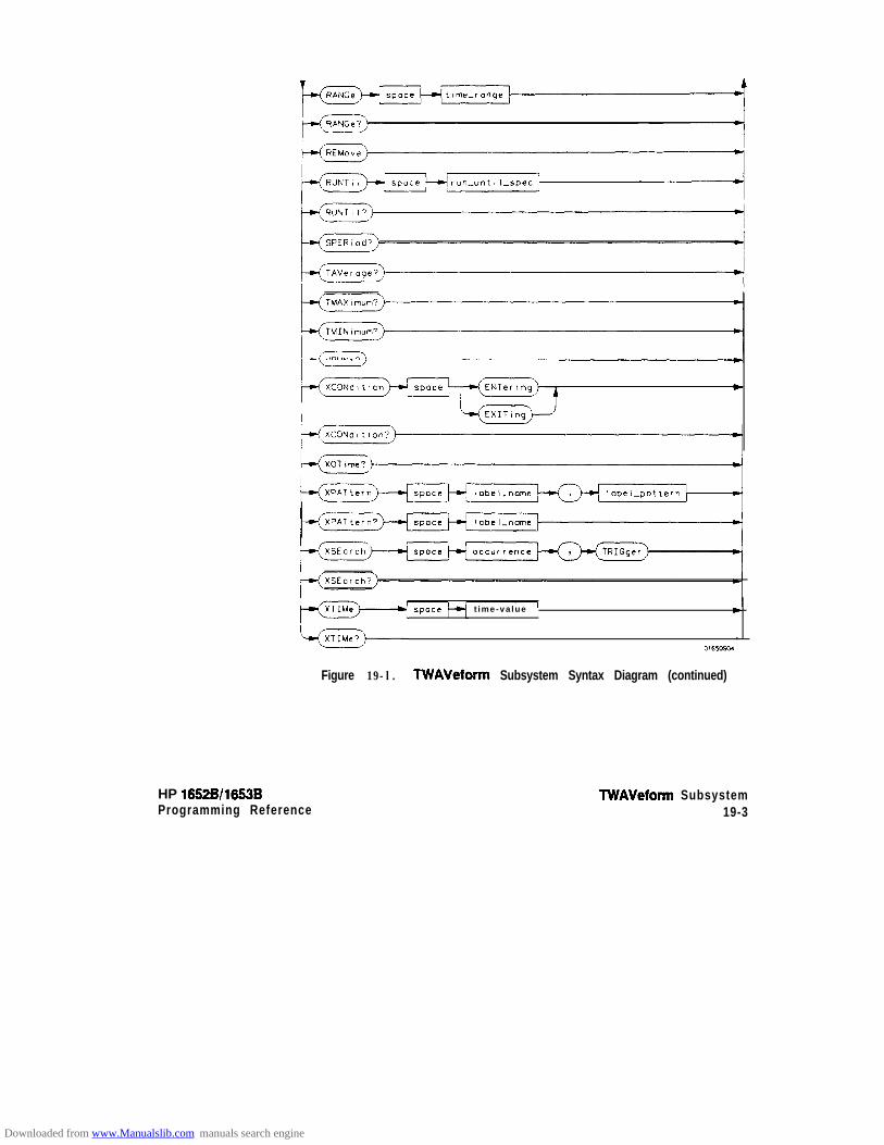
c
space t ime-va lue c
,O,CO%4
Figure 19-l. TWAVeform Subsystem Syntax Diagram (continued)
HP 16526/1653BProgramming Reference
lWAVeform Subsystem19-3
Downloaded from www.Manualslib.com manuals search engine

delay-value =’ real number between -2500 s and + 2500 smodule-spec = {11213(4(5}bit-id = integerftom 0 to 31waveform = string containing < acquisition-spec > {I 12)acquisition-spec = {A 1 B ) Cl D JE} (slot where acquisition card is located)label-name = string of up to 6 alphanumeric characterslabelgatteru = “{#B{OIIIX}. . . I
~Q~~l~l~l~l~l~l~l~l~~. -. I#H{O~1~2~3~4~5~6~7~8I9JAIBICJDJEIFIX).. . I{0~1~2~:?~4~5(6~7~8~9}. . . }”
occurrence = integertime-value = real numberlabel-id = sting of one alpha and one numeric charactermodule-num = slot number in which the timebase card is installedtime-range = real number between 100 ns and 10 ksrun-until-spec = (OFF I LT, ( value > I GT, < value > ( ZNRange < value > , c value > I
OUTRange < value >, < value > }GT = greater thanLT = less thanvalue = real number
Figure 191. TWAVeform Subsystem Syntax Diagram (continued)
lWAVeform Subsystem19-4
HP 16528/1653BProgramming Reference
Downloaded from www.Manualslib.com manuals search engine

WAVeform
TWAVeform Selector
The TWAVeform selector is used as part of a compound header to accessthe settings found in the Tiig Waveforms menu. It always follows theMACHine selector because it selects a branch below the MACHine levelin the command tree.
Command Syntax: :MACHine{ 1 J2):TWAVeform
Example: OUTPUT XXX;":MACHINEl:TWAVEFORM:OELAY lOOE-9"
HP 10528/1653BProgramming Reference
TWAVeform Subsystem19-5
Downloaded from www.Manualslib.com manuals search engine

ACCumulate
ACCumulate command/query
The Accumulate command allows you to control whether the chartdisplay gets erased between each individual run or whether subsequentwaveforms are allowed to be displayed over the previous ones.
The ACCumulate query returns the current setting. The query alwaysshows the setting as the character “0” (off) or “1” (on).
Command Syntax: :MACHine{ 1 J2):TWAVeform:ACCumulate c setting >
where:
c setting > : : = {OIOFF} o r (1 (ON)
Example: OUTPUT XXX;“:MACHINEl:TWAVEFORM:ACCUMULATE ON”
Query Syntax: :MACHine{l ~2):TWAVeform:ACCumulate?
Returned Format: [:MACHine{ 1~2}:TWAVeform:ACCumulate] (0 11) -c NL>
Example: 10 DIM P$ [iool20 OUTPUT XXX;“:MACHINEl:TWAVEFORM:ACCUMULATE?”30 ENTER XXX; P$40 PRINT P$
50 END
TWAVeform Subsystem19-6
HP 16528/1663B
Downloaded from www.Manualslib.com manuals search engine
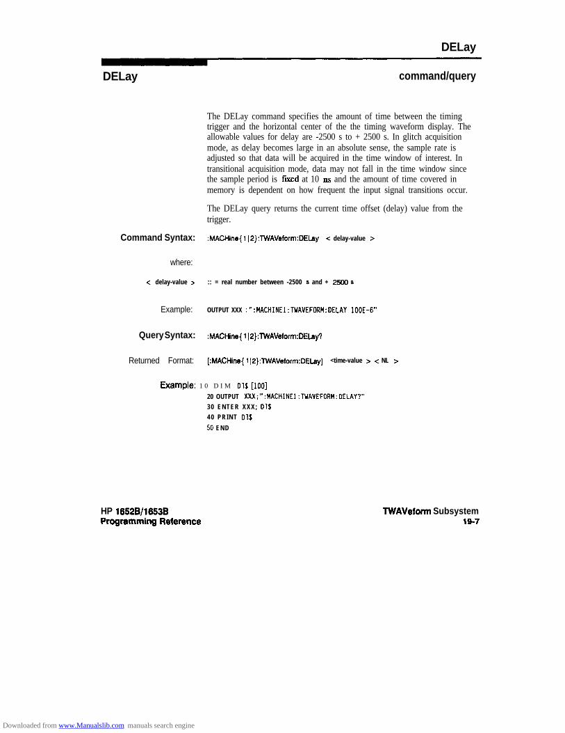
DELay
DELay command/query
The DELay command specifies the amount of time between the timingtrigger and the horizontal center of the the timing waveform display. Theallowable values for delay are -2500 s to + 2500 s. In glitch acquisitionmode, as delay becomes large in an absolute sense, the sample rate isadjusted so that data will be acquired in the time window of interest. Intransitional acquisition mode, data may not fall in the time window sincethe sample period is ftved at 10 11s and the amount of time covered inmemory is dependent on how frequent the input signal transitions occur.
The DELay query returns the current time offset (delay) value from thetrigger.
Command Syntax: :MACHine{ iI2):lWAVeform:DELay -c delay-value >
where:
c delay-value > :: = real number between -2500 s and + 2!500 8
Example: OUTPUT XXX ; ” :MACHINEl:TWAVEFORM:DELAY lOOE-6”
Query Syntax: MACHine{ 1 JP}:lWAVeform:DELa~
Returned Format: [:MACHine{ 1 IO}:TWAVeform:DELay] <time-value > < NL >
t%W’llpk!: 1 0 D I M 01s [loo]
20 OUTPUT XXX;“:MACHINEl:TWAVEFORM:DELAY?”30 ENTER XXX; Ol$40 PRINT 01s
50 END
HP 16528/1663B TWAVeform Subsystem19-7
Downloaded from www.Manualslib.com manuals search engine

INSert
INSert command
The INSert command inserts waveforms in the timing waveform display.The waveforms are added from top to bottom. When 24 waveforms arepresent, inserting additional waveforms replaces the last waveform .
The first parameter specifies the label name that will be inserted. Thesecond parameter specifies the label bit number or overlay.
If OVERLAY is specified, all the bits of the label are displayed as acomposite overlaid waveform.
Command Syntax: :MACHine{ 112):TWAVeform:INSertc label-name > { -z bit-id > 1 OVERlay}
where:
c label name > :: = string of up to 6 alphanumeric characters-z bit-id > :: = integer from 0 to 31
Example: OUTPUT XXX;“:MACHINEl:TWAVEFORM:INSERT ‘WAVE’,lO”
TWAVeform Subsystem188
HP 16528/1653BProgmmming Reference
Downloaded from www.Manualslib.com manuals search engine
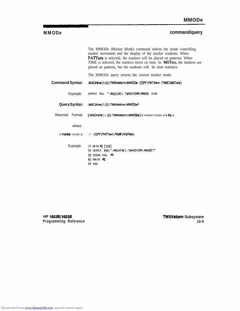
MMODe
MMODe
Command Syntax:
Example:
Query Syntax:
Returned Format:
where:
(marker mode Z=
Example:
HP 1652Bll653BProgramming Reference
command/query
The MMODe (Marker Mode) command selects the mode controllingmarker movement and the display of the marker readouts. WhenPATTern is selected, the markers will be placed on patterns. WhenTIME is selected, the markers move on time. In MSTats, the markers areplaced on patterns, but the readouts will be time statistics.
The MMODe query returns the current marker mode.
:MACHine{l~2}:TWAVeform:MMODa {OFFJPATTern lTlMEIMSTats}
OUTPUT XXX; ":MACHINEl:TWAVEFORH:MMODE TIME"
:MACHine{l(2):TWAVeform:MMODe?
[:MACHine{ 1 IP):TWAVeform:MMODe] c marker-mode > < NL>
::= {OFFIPATTernITlMEIMSTats}
10 DIM M$ [loo]20 OUTPUT XXX;":MACHINEl:TWAVEFORM:MMODE?"
30 ENTER XXX; MS40 PRINT M$50 END
TWAVeform Subsystem19-9
Downloaded from www.Manualslib.com manuals search engine

OCONdition
OCONdition command/query
The OCONdition command specifies where the 0 marker is placed. The0 marker can be placed on the entry or exit point of the OPATtem whenin the PATTern marker mode.
The OCONdition query returns the current setting.
Command Syntax: :MACHine{ 1~2):TWAVeform:OCONdition {ENTering 1 MITing}
Example: OUTPUT XXX; “:MACHINE1:TWAVEFORM:OCONDITION ENTERING”
Query Syntax: :MACHine{ 1)2}:TWAVeform:OCONdition?
&?tUrned Format: [:MACHine{ 112}:TWAVeform:OCONdition] (ENTering 1 EXITing} < NL>
Example: 1 0 D I M Oc$ [loo]20 OUTPUT XXX;” :MACHINE1:TWAVEFORM:OCONDITION?”30 ENTER XXX; Oc$40 PRINT Oc$
50 END
TWAVeform Subsystem19-10
HP 16528/1653BProgramming Reference
Downloaded from www.Manualslib.com manuals search engine

OPATtern
OPATtern command/query
The OPATtem command allows you to construct a pattern recognizerterm for the 0 marker which is then used with the OSEarch criteria andOCONdition when moving the marker on patterns. Since this commanddeals with only one label at a time, a complete specification could requireseveral invocations.
When the value of a pattern is expressed in binary, it represents the bitvalues for the label inside the pattern reco@zer term. In whatever baseis used, the value must be between 0 and 2 - 1, since a label may not havemore than 32 bits. Because the < labelpattern > parameter may containdon’t cares, it is handled as a string of characters rather than a number.
The OPATtem query, in pattern marker mode, returns the patternspecification for a given label name. In the time marker mode, the queryreturns the pattern under the 0 marker for a given label. If the 0 markeris not placed on valid data, don’t cares (XX...X) are returned.
Command Syntax: :MACHine{ 1 I2):TWAVeform:OPATtern <label-name > , c label-pattern >
where:
< labe l -name > :: = string of up to 6 alphanumeric charactersc label-pattern > :: = “{#B{Oj 1 IX} . . . 1
#0{0~1~2~3~4~5~6~7~X}. . . I
XH{OIl~2~3~4~5(6~7)6~9)A~BICIDIEIFIX). . . I{Oil ~2~3~4~5)6~7~6~9}. . . }”
Example: OUTPUT XXX: “:MACHINEl:TWAVEFORM:OPATTERN ‘A’,‘511’”
TWAVeform Subsystem19-11
Downloaded from www.Manualslib.com manuals search engine

OPATterrw
Query Syntax: :MACHine{l J2}:TWAVeform:OPATtem? <label-name >
RetllrMd Format: [:MACHine{ 1~2}:lWAVeform:OPATtern] < label-name > , clabelgattern > c NL>
Example: lo DIM op$ [loo]20 OUTPUT XXX;":MACHINEl:TWAVEFORM:OPATTERN? 'A"'
30 ENTER XXX; Op$
40 PRINT Op$50 END
TWAVeform Subsystem19-12
HP 10528/1653BProgramming Reference
Downloaded from www.Manualslib.com manuals search engine

OSEarch
OSEarch command/query
The OSEarch command defines the search criteria for the 0 markerwhich is then used with the associated OPATtem recognizer specificationand the OCONdition when moving markers on patterns. The originparameter tells the marker to begin a search with the trigger or with the Xmarker. The actual occurrence the marker searches for is determined bythe occurrence parameter of the OPATtem recognizer specification,relative to the origin. An occurrence of 0 places a marker on the selectedorigin. With a negative occurrence, the marker searches before the origin.With a positive occurrence, the marker searches after the origin.
The OSEarch query returns the search criteria for the 0 marker.
Command Syntax: :MACHine{l~2):TWAVeform:OSEarch coccumzinoe z=, <origin z=
where:
c origin > :: = {TRIGger JXMAFMr}<occurrence > :: = integer from -9999 to +99%l
Example: OUTPUT XXX; “:MACHINEl:TWAVEFORM:OSEARCH +lO.TRIGGER”
Query Syntax: :MACHine{ 112}:TWAVeform:OSEarch?
Returned Format: [:MACHine{ 112}:lWAVeform:OSEarch] <occurrence >, <origin > c NL>
Example: 10 D I M OS$ [ loo]20 OUTPUT XXX;“:MACHINEl:TWAVEFORM:OSEARCH?”
30 ENTER XXX; Os$40 PRINT Os$50 END
HP 16528/1663BProgramming Reference
TWAVeform Subsystem1813
Downloaded from www.Manualslib.com manuals search engine
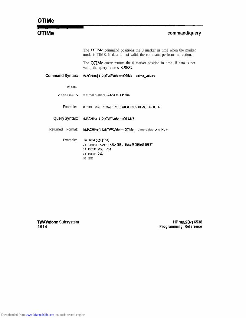
OTlMe
OTlMe command/query
The OTIMe command positions the 0 marker in time when the markermode is TIME. If data is not valid, the command performs no action.
The OTIMe query returns the 0 marker position in time. If data is notvalid, the query returns 9.9E37.
Command Syntax: :MACHine{ l(2):TWAVeform:OTIMe <time-value >
where:
.: t i m e - v a l u e z :: = real number -2.SKs to +2.5Ks
Example: OUTPUT XXX; ":MACHINEl:TWAVEFORM:OTIME 30.OE-6"
Query Syntax: :MACHine{l (P}:TWAVeform:OTIMe?
Returned Format: [ :MACHine{ 1 IP}:TWAVeform:OTIMe] dime-value z- c NL>
Example: 10 DIM ots [loo]20 OUTPUT XXX;" :MACHINEl:TWAVEFORM:OTIME?"30 ENTER XXX; Ot$
40 PRINT Ot$50 END
TWAVeform Subsystem1914
HP 16528/l 6538Programming Reference
Downloaded from www.Manualslib.com manuals search engine
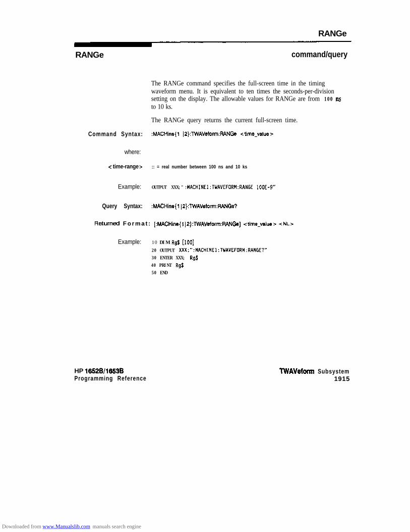
RANGe
RANGe command/query
The RANGe command specifies the full-screen time in the timingwaveform menu. It is equivalent to ten times the seconds-per-divisionsetting on the display. The allowable values for RANGe are from 100 nsto 10 ks.
The RANGe query returns the current full-screen time.
Command Syntax: :MACHine{l JP}:TWAVeform:RANGe <time-value>
where:
-c time-range > :: = real number between 100 ns and 10 ks
Example: OUTPUT XXX;" :MACHINEl:TWAVEFORM:RANGE lOOE-9"
Query Syntax: :MACHine(l ~P}:lWAVeform:WGe?
Returned F o r m a t : [:MACHine{l~2}:lWAVeform:FWNGe] <time-value> cNL>
Example: 10 DIM Rgj [loo]
20 OUTPUT XXX;":MACHINEl:TWAVEFDRM:RANGE?"30 ENTER XXX; RgS40 PRINT Rg$50 END
HP 1652W16538Programming Reference
TWAVeform Subsystem1915
Downloaded from www.Manualslib.com manuals search engine

REMove
REMove command
The REMove command deletes all waveforms from the display.
Command Syntax: :MACHine{l~P):TWAVeform:REMove
Example: OUTPUT XXX;" :MACHINEl:TWAVEFORM:REMOVE"
TWAVeform Subsystem1916
HP 16526/1653B
Downloaded from www.Manualslib.com manuals search engine
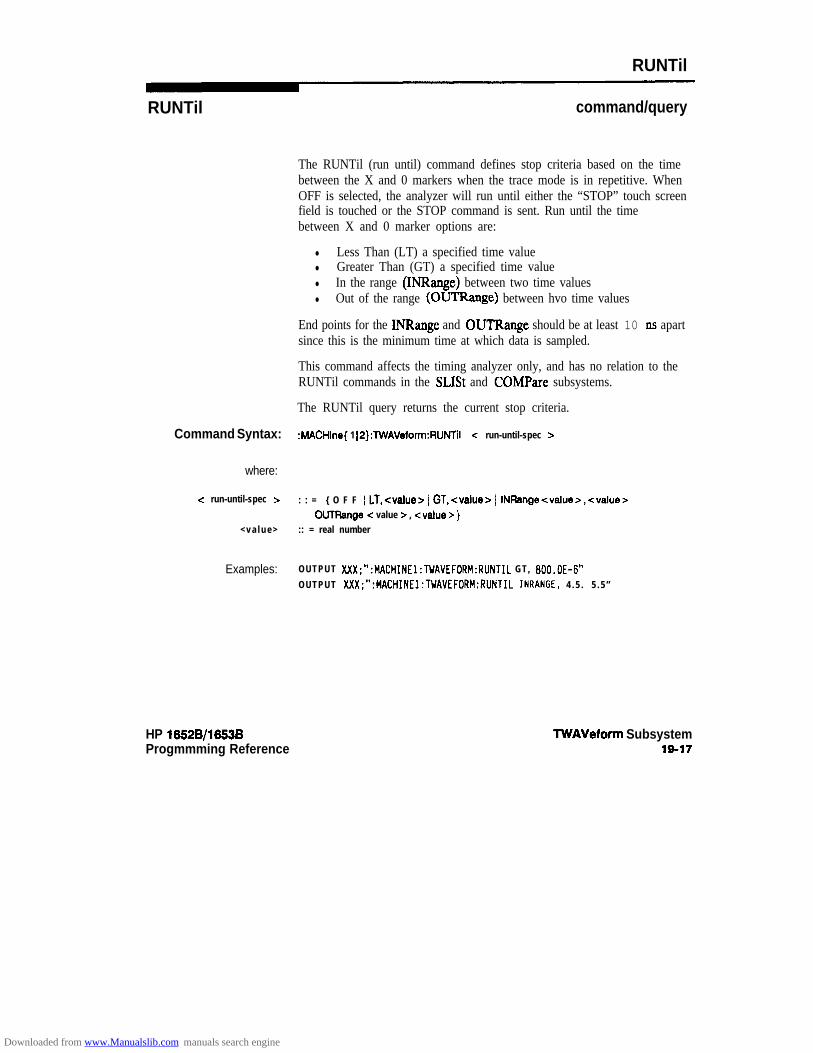
RUNTil
RUNTil command/query
The RUNTil (run until) command defines stop criteria based on the timebetween the X and 0 markers when the trace mode is in repetitive. WhenOFF is selected, the analyzer will run until either the “STOP” touch screenfield is touched or the STOP command is sent. Run until the timebetween X and 0 marker options are:
l Less Than (LT) a specified time valuel Greater Than (GT) a specified time valuel In the range (INRange) between two time valuesl Out of the range (OUTRange) between hvo time values
End points for the INRange and OUTRange should be at least 10 ns apartsince this is the minimum time at which data is sampled.
This command affects the timing analyzer only, and has no relation to theRUNTil commands in the SLISt and COMPare subsystems.
The RUNTil query returns the current stop criteria.
Command Syntax: MACHine{ 1 IP}:lWAVeform:RUNTil -z run-until-spec >
where:
< run-until-spec > : : = { O F F 1 LT,cvalues 1 GT,<value> 1 lNFhge<value>,<value> 1OUTRange -z value z , <value > }
< v a l u e > :: = real number
Examples: OUTPUT XXX;“:MACHINEl:TWAVEFORM:RUNTIL GT, 800.OE-6”
OUTPUT XXX;“:MACHINE1:TWAVEFORM:RLlNTIL INRANGE, 4 . 5 . 5 . 5 ”
HP 16528/1653BProgmmming Reference
TWAVeform Subsystem19-17
Downloaded from www.Manualslib.com manuals search engine

RUNTil
Query Syntax: :MACHine{ 1~2):WAVeform:RUNTII?
Returned Format: [:MACHine{l(2):TWAVeform:RUNTil] <run-until-spec> <NL>
Example: 10 DIM Ru$ [lDO]
20 OUTPUT XXX;":MACHINEl:TWAVEFORM:RUNTIL?"30 ENTER XXX; Ru$
40 PRINT Ru.$50 END
TWAVeform Subsystem1918
HP 1852Bll883BProgramming Reference
Downloaded from www.Manualslib.com manuals search engine

SPERiod
SPERiod wry
The SPERiod query returns the sample period of the last run.
Query Syntax: :MACHine{l~2}:TWAVeform:SPERiod?
Returned Format: [:MACHine{ 1 12):TWAVeform:SPERiodJ <time-value> cNL>
where:
<t ime value > : : = r e a l n u m b e r
Example: 10 DIM sp$ [IOO]20 OUTPUT XXX;":MACHINE1:TWAVEFORM:SPERIOO?"30 ENTER XXX; Sp$40 PRINT Sp$
50 EN0
HP 1652B/1653BProgtamming Reference
TWAVeform Subsystem19-19
Downloaded from www.Manualslib.com manuals search engine
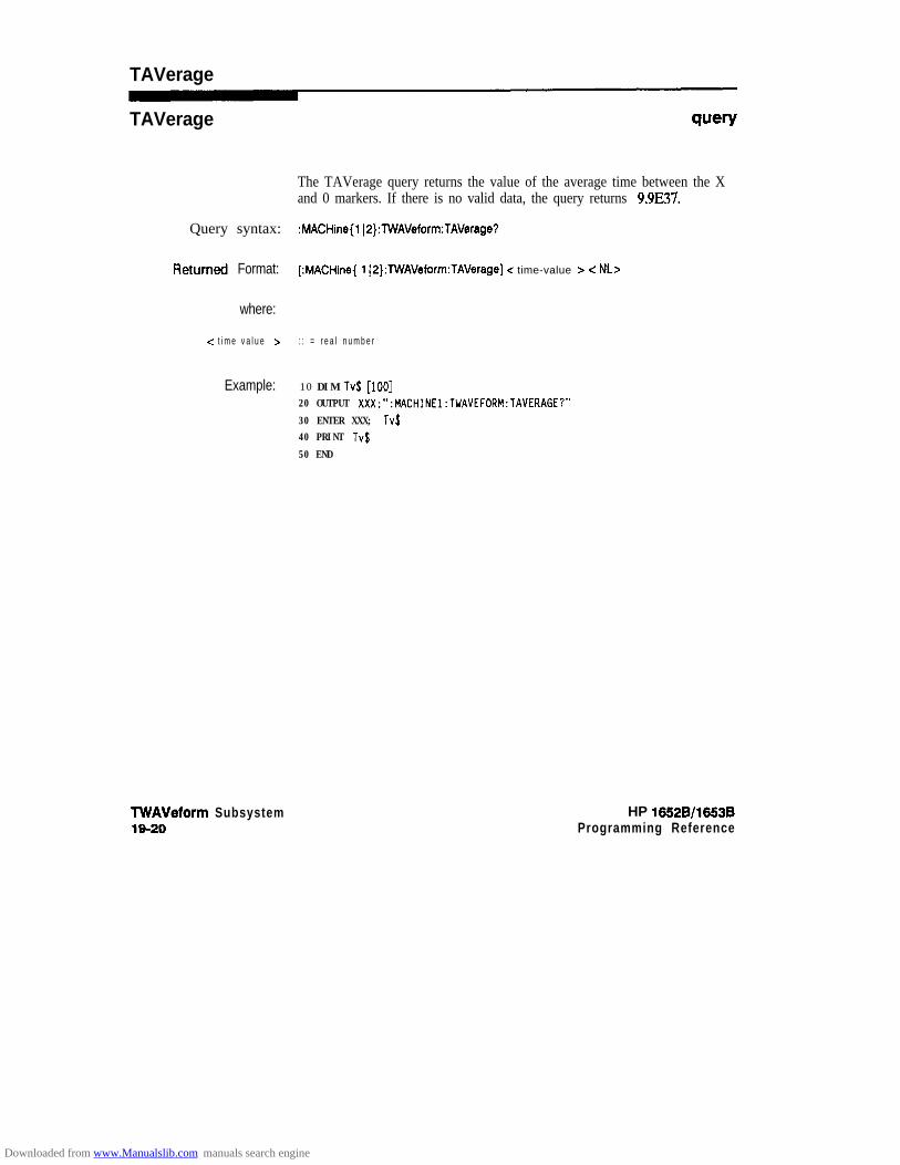
TAVerage
TAVerage wry
The TAVerage query returns the value of the average time between the Xand 0 markers. If there is no valid data, the query returns 9.9E37.
Query syntax: :MACHine{l 12}:TWAVeform:TAVerage?
h3tURIed Format: [:MACHine{ l I2}:TWAVeform:TAVerage] -Z time-value > -c NL>
where:
-c t i m e v a l u e > : : = r e a l n u m b e r
Example: 10 DIM Tv$ [loo]20 OUTPUT XXX;":MACHINEl:TWAVEFORM:TAVERAGE?"
30 ENTER XXX; Tv$40 PRINT Tv$
50 END
TWAVeform Subsystemm-20
HP 16528/1653BProgramming Reference
Downloaded from www.Manualslib.com manuals search engine

TMAXimum
TMAXimum
Query Syntax:
Returned Format:
where
c time value >
Example:
HP 16528/1653BProgramming Reference
query
The TMAXimum query returns the value of the maximum time betweenthe X and 0 markers. If there is no valid data, the query returns 9.9E37.
:MACHine{ 1~2}:TWAVeform:TMAXimum?
[:MACHine{l12}:TWAVeform:TMAJGmum] c time-value > c NL>
:: = real number
10 DIM Tx$ [loo]
20 OUTPUT XXX;":MACHINEl:TWAVEFORM:TMAXIMUM?"
30 ENTER XXX; Tx$4 0 PRINT Tx$
50 END
TWAVeform Subsystem19-21
Downloaded from www.Manualslib.com manuals search engine

TMlNimum
TMINimum
Query Syntax:
Returned Format:
where:
<: time-value >
Example:
TWAVeform Subsystem1942
The TMINimum query returns the value of the minimum time betweenthe X and 0 markers. If there is no valid data, the query returns 9.9E37.
:fdACHine{l J2):TWAVeform:TMINimum?
[:MACHine{ 1(2}:TWAVeform:TMINimum] <time-value > c NLr
:: = real number
10 DIM Tm$ [loo]20 OUTPUT XXX;":MACHINEl:TWAVEFDRM:TMINIMUM?"
30 ENTER XXX; Tm$4 0 PRINT Tm$
50 END
HP 16528/1663B
Downloaded from www.Manualslib.com manuals search engine
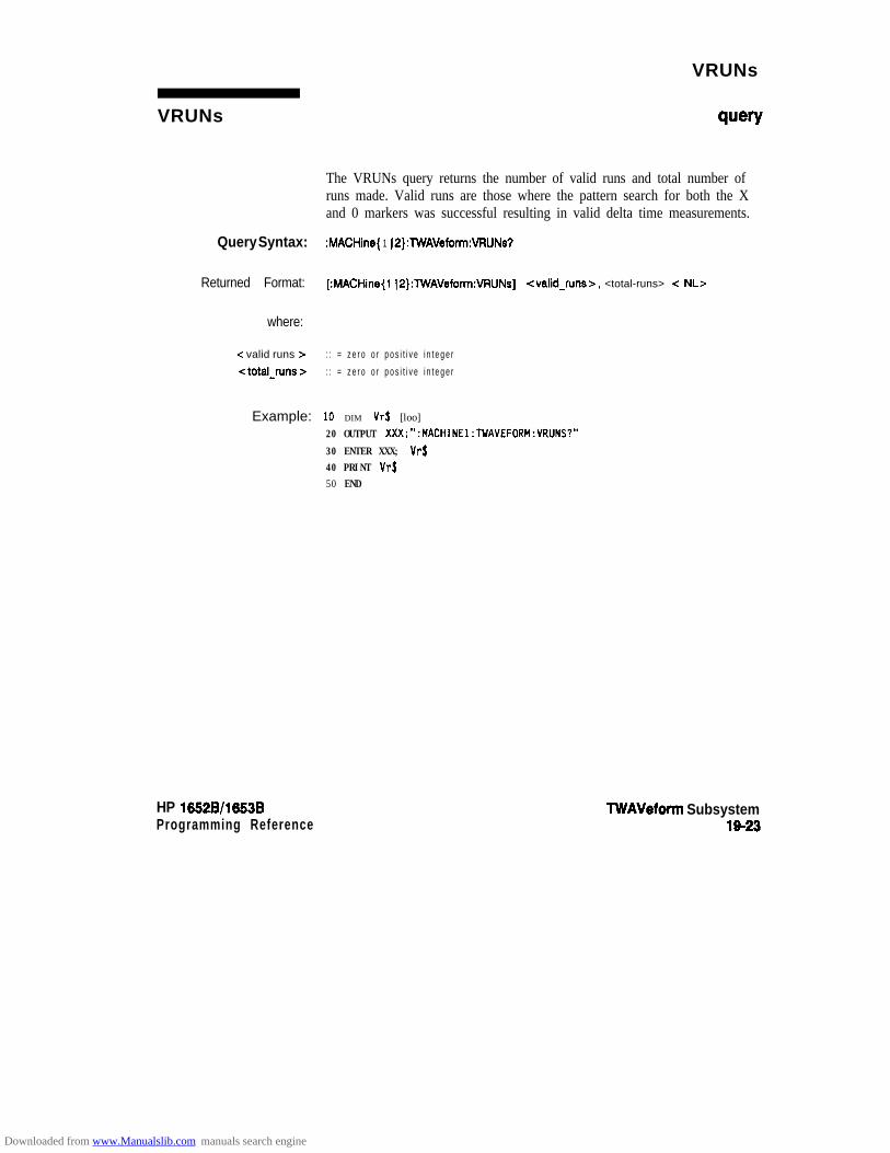
VRUNs
VRUNs ww
The VRUNs query returns the number of valid runs and total number ofruns made. Valid runs are those where the pattern search for both the Xand 0 markers was successful resulting in valid delta time measurements.
Query Syntax: :MACHine{ 1 JS}:TWAVeform:VRlJNs?
Returned Format: [:MACHine(l ~P}:lWAVeform:VFtUNs] <valid-runs>, <total-runs> c NL>
where:
-z valid runs >
<total-runs z-
: : = z e r o o r p o s i t i v e i n t e g e r
: : = z e r o o r p o s i t i v e i n t e g e r
Example: lo DIM vrS [loo]20 OUTPUT XXX;":MACHINEl:TWAVEFORM:VRUNS?"
30 ENTER XXX; Vr$40 PRINT Vr$50 END
HP 1652B/l653BProgramming Reference
TWAVeform Subsystem19-23
Downloaded from www.Manualslib.com manuals search engine
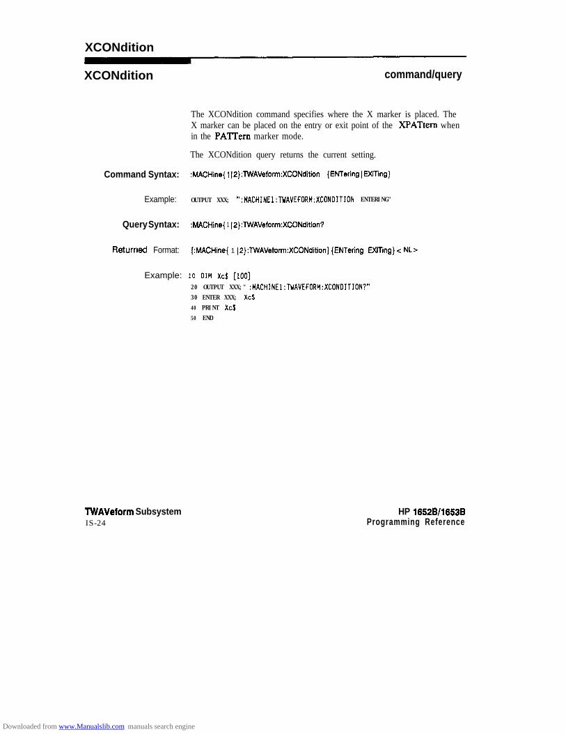
XCONdition
XCONdition command/query
The XCONdition command specifies where the X marker is placed. TheX marker can be placed on the entry or exit point of the XPATtem whenin the PATTern marker mode.
The XCONdition query returns the current setting.
Command Syntax: MACHine{ 1 12):TWAVeform:XCONdition {ENTering 1 EXITing)
Example: OUTPUT XXX; ":MACHINE1:TWAVEFORM:XCONDITION ENTERING"
Query Syntax: :MACHine{ 1 12):TWAVeform:XCONdition?
h3tUtTled Format: [ :MACHine{ 1 I2):TWAVeform:XCONditionl {ENTering 1 EXITing} -z NL>
Example: 10 DIM XcS [lo0120 OUTPUT XXX;" :MACHINE1:TWAVEFORM:XCONDITION?"30 ENTER XXX; Xc$40 PRINT Xc$50 END
TWAVeform SubsystemIS-24
HP 1652B/l653BProgramming Reference
Downloaded from www.Manualslib.com manuals search engine

XOTime
XOTime
Query syntax:
Returned Format:
where:
<time-value >
Example:
HP 10528/1653BProgramming Reference
query
The XOTime query returns the time from the X marker to the 0 marker.If data is not valid, the query returns 9.9E37.
:MACHine{l~2):TWAVeform:XOTime?
[:MACHine{ 1) 2):TWAVeform:XOTime) -z time-value > c NL>
:: = real number
10 DIM XotS [loo]20 OUTPUT XXX;":MACHINEl:TWAVEFORM:XOTIME?"
30 ENTER XXX; Xot$40 PRINT Xot$
50 END
WAVeform Subsystem19-25
Downloaded from www.Manualslib.com manuals search engine

XPATtern
XPATtern
Command Syntax:
where:
<iabel name>clabelgattemz-
Example:
command/query
The XPATtem command allows you to construct a pattern recognizerterm for the X marker which is then used with the XSEarch criteria andXCONdition when moving the marker on patterns. Since this commanddeals with only one label at a time, a complete specification could requireseveral invocations.
When the value of a pattern is expressed in binary, it represents the bitvalues for the label inside the pattern reco@zer term. In whatever baseis used, the value must be between 0 and 2 - 1, since a label may not havemore than 32 bits. Because the < labelqattem > parameter may containdon’t cares, it is handled as a string of characters rather than a number.
The XPATtem query, in pattern marker mode, returns the patternspecification for a given label name. In the time marker mode, the queryreturns the pattern under the X marker for a given label. If the X markeris not placed on valid data, don’t cares (XX...X) are returned.
:MACHine{ l(2):TWAVeform:XPATtern <label-name > , < label-pattern >
:: = string of up to 6 alphanumeric characters:: = “(#B(O)1 IX} . (
SQ{Oll12)3)4)5)6)7)X). . )
+H(Olll2~3~4~5l6l7l8ISIAIBICIDIEIFIX)... I(0~1)2~3)4~5~6)7~8~9}. . }”
OUTPUT XXX; ":MACHINEl:TWAVEFORM:XPATTERN 'A'.'511'"
TWAVeform Subsystem1826
HP 1652Wl653B
Downloaded from www.Manualslib.com manuals search engine

XPATtern
Query Syntax: :MACHine{ 1(2}:TWAVeform:XPATtem? -z label-name >
&?tWled Format: [:MACHine{ 1~2}:TWAVeform:XPATtern] c label-name > , -z labelgattern z < NL>
Example: 10 DIM Xp$ [lOD]20 OUTPUT XXX;":MACHINEl:TWAVEFORM:XPATTERN? 'A"'
30 ENTER XXX; Xp$
40 PRINT Xp$50 END
HP 16526/1653BProgramming Reference
TWAVeform Subsystem19-27
Downloaded from www.Manualslib.com manuals search engine

XSEarch
XSEarch command/query
The XSEarch command defines the search criteria for the X markerwhich is then used with the associated XPATtern recogaizer specificationand the XCONdition when moving markers on patterns. The originparameter tells the marker to begin a search with the trigger. Theoccurrence parameter determines which occurrence of the XF’ATtemrecognizer specification, relative to the origin, the marker actuallysearches for. An occurrence of 0 (zero) places a marker on the origin.
The XSEarch query returns the search criteria for the X marker.
Command Syntax: :MACHine{ 1 12):lWAVeform:XSEarch <occurrenoe >, <origin >
where:
<origin > :: = TRlGgerc. occurrence > :: = integer from -9999 to +9999
Example: OUTPUT XXX; “:MACHINE1:TWAVEFORM:XSEARCH,+10.TRIGGER”
Query syntax: :MACHine(l(2}:TWAVeform:XSEarch? c occurrence > , <origin >
Returned Format: [:MACHine{ 1 12):TWAVeform:XSEarchl <occurrence >, <origin z= < NL>
Example: 1 0 D I M Xs$ [loo]20 OUTPUT XXX;” :MACHINEl:TWAVEFORM:XSEARCH?”
30 ENTER XXX; Xs$40 PRINT Xs$50 END
TWAVeform Subsystem19-28
HP 1652B/1653B
Downloaded from www.Manualslib.com manuals search engine
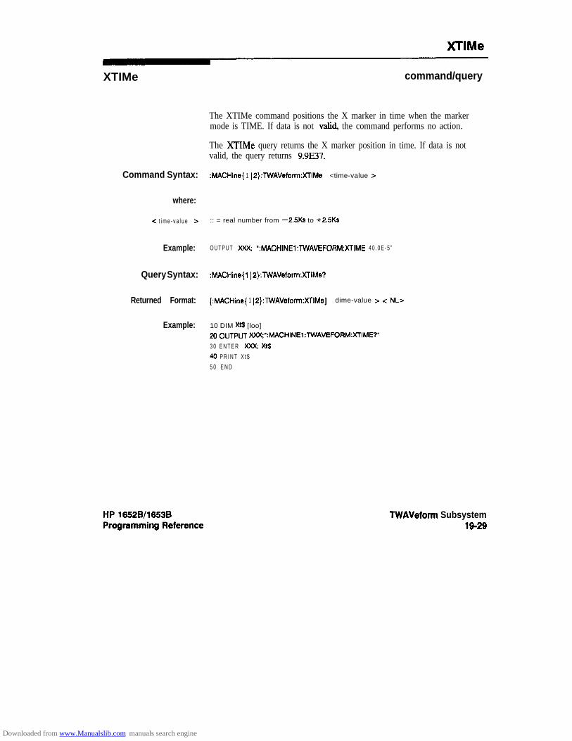
XTlMe
XTIMe
Command Syntax:
where:
-z t i m e - v a l u e >
Example:
Query Syntax:
Returned Format:
Example:
command/query
The XTIMe command positions the X marker in time when the markermode is TIME. If data is not valid, the command performs no action.
The XTIMe query returns the X marker position in time. If data is notvalid, the query returns 9.9E37.
:MACHine{ 1 IP}:TWAVeform:XTIMe <time-value >
:: = real number from -2SKs to +2.5Ks
O U T P U T m “:MACHINEl: lWAVEFORM:XTIME 4 0 . 0 E - 5 ”
:MACHine{l JP}:TWAVeform:XlIMe?
[:MACHine{ 1 IP}:TWAVeform:XTIMe] dime-value > c NL>
10 DIM Xt$ [loo]20 OUTPUT )(XX;“:MACHINEl:TWAVEFORM:XTIME?”
3 0 E N T E R W Xt$40 P R I N T X t $5 0 E N D
TWAVeform Subsystem19-29
Downloaded from www.Manualslib.com manuals search engine

SYMBol Subsystem
Introduction The SYMBol subsystem contains the commands that allow you to definesymbols on the controller and download them to the HP 1652Bb3B logicanalyzer. The commands in this subsystem are:
l BASEl PAlTernl RANGe
l REMovel WIDTh
s p a c e l a b e l - n a m e1
Figure 20-l. SYMBol Subsystem Diagram
HP 16528/16538Programming Reference
SYMBol Subsystem20-l
Downloaded from www.Manualslib.com manuals search engine

label-name == s t ing of up to 6 alphanumeric characterssymbol-name = smhg of up to 16 alphanumeric characterspattern-value = “{#B{OI1JX}. . . 1
~Q~~l~l~1~l~l~l~l~l~~~~~ I#H{OI1~2(3~4~5)6(7~8(9~A~BIC~DIE~FIX}. . . ((0~2~21314~5l6~7~8~9). . . }”
start-value =: “{#B{OII}. . . 1#Q{O~1~2~3~4~5~6~7}. . . 1#H{OIj’~2~3~4~5~6~7~8~9~AIBJCIDIEIF}. . . 1(0~1~2~3~4~5~6~7~8~9). . . }”
stop-value = “{#B{OII}. . . I#Q~~l~1213l4~l617~. . - I#H(~l~(2~3~4~5~6~7~8I9JAJBJCIDJEJF). . . 1{0~1~2~3~4~5~6~7~8~9}... }”
width-value = integerfrom I to 16
Figure 20-l. SYMBol Subsystem Syntax Diagram (continued)
SYMBol Subsystem20-2
HP 16528/1653BProgramming Reference
Downloaded from www.Manualslib.com manuals search engine

SYMBol
SYMBol selector
The SYMBol selector is used as a part of a compound header to accessthe commands used to create symbols. It always follows the h4ACHiaeselector because it selects a branch directly below the MACHine level inthe command tree.
Command Syntax: :MACHine{l(2}:SYMBol
Example: OUTPUT XXX;":MACHINEl:SYMBOL:BASE 'DATA', BINARY"
HP 16528/1653B SYMBol Subsystem20-3
Downloaded from www.Manualslib.com manuals search engine
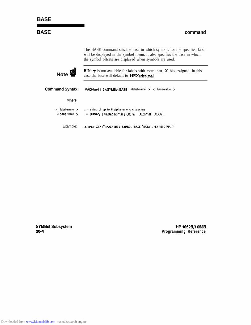
BASE
BASE
Note ”4
Command Syntax:
where:
-Z label-name 1<base value >
Example:
SYMBol Subsystem20-4
command
The BASE command sets the base in which symbols for the specified labelwill be displayed in the symbol menu. It also specifies the base in whichthe symbol offsets are displayed when symbols are used.
BINary is not available for labels with more than 20 bits assigned. In thiscase the base will default to HEXadecimal.
MACHine{ 1 I2):SYMBol:BASE <label-name >, < base-value 5
:: = string of up to 6 alphanumeric characters
:: = {BINary 1H&decimal ) OCTal 1DECimal 1ASCii}
OUTPUT XXX;":MACHINEl:SYMBOL:BASE 'DATA',HEXADECIMAL"
HP 16528/l 6638Programming Reference
Downloaded from www.Manualslib.com manuals search engine

PAlTern
PAlTern command
The PATTern command allows you to create a pattern symbol for thespecified label.
Because don’t cares (X) are allowed in the pattern value, it must always beexpressed as a string. You may still use different bases, though don’t carescannot be used in a decimal number.
Command Syntax: MACHine{ 1 ( ~}:SYMB~~:PATT~~~K l a b e l - n a m e >, -z s y m b o l - n a m e >, < p a t t e r n - v a l u e >
where:
-z l a b e l - n a m e > : : = s t r i n g o f u p t o 6 a l p h a n u m e r i c c h a r a c t e r s
-Z symbol-name Z- : : = s t r i n g o f u p t o 1 6 a l p h a n u m e r i c c h a r a c t e r sc p a t t e r n v a l u e > ::= “{#e{o~l~x). . . 1
XQ(O~l~2l3l4~5~6l7lX). . . I
XH(O(l~2~3~4~5~6~7~8~9~AlBICIDIEIFIX). . . I{Oil (2~3~4~5)6~7~8)9}. . . }”
Example: OUTPUT XXX;":MACHINEl:SYMBOL:PATTERN 'STAT', 'MEM~RO'.'#HOlXX'"
HP 16528/1653B SYMBol Subsystem20-5
Downloaded from www.Manualslib.com manuals search engine
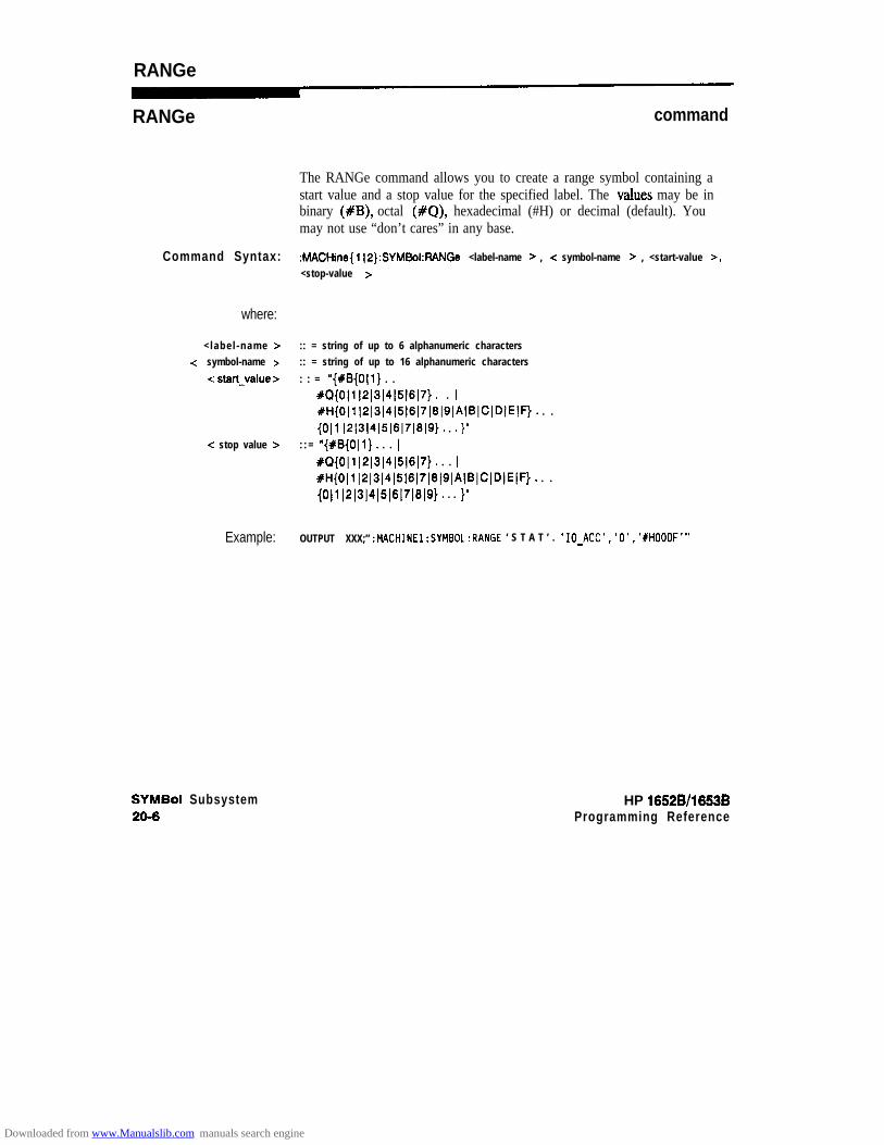
RANGe
RANGe command
The RANGe command allows you to create a range symbol containing astart value and a stop value for the specified label. The va!ues may be inbinary (#B), octal (#a), hexadecimal (#H) or decimal (default). Youmay not use “don’t cares” in any base.
Command Syntax: :MACHine{ l(2):SYMBol:RANGe <label-name > , e symbol-name > , <start-value >,<stop-value >
where:
< labe l -name > :: = string of up to 6 alphanumeric characters-Z symbol-name > :: = string of up to 16 alphanumeric characters
<: start_value > : : = ‘@{#B{OIl}. . 1#Q{O(l~2~3)4~5~6~7). . I#H{Olll2~3~4~5l6l7~slSIAIBICIDIEIF). . . I
{Oil ~2~3~4~5~6~7~8~9). . .I”<: stop value > : : = “{#B{Oll}. . . I
%0{0~1~2~3~4~5~6~7}. . . I#H{Oll~2~3~4~5(6~7~8~9~A(BICID1EIF). . . I(Oll~2~3~4~5~6~7~8~9). . . }”
Example: OUTPUT XXX;” :MACHINEl:SYMBOL:RANGE ‘ S T A T ’ . ‘IO~ACC’.‘O’.‘#HOOOF’”
SYMBol Subsystem20-6
HP 1652B/l663BProgramming Reference
Downloaded from www.Manualslib.com manuals search engine

REMove
REMove command
The RJZMove command deletes all symbols from a specified machine.
Commend Syntax: :MACHine{l~2}:SYMBol:REMove
bmlpk: OUTPUT XXX;":MACHINEl:SYMBOL:REMOVE"
HP 1052B/1653BProgramming Reference
SYMBol Subsystem20-7
Downloaded from www.Manualslib.com manuals search engine

WIDTh
WIDTh
Note #i
command
The WIDTh command specifies the width (number of characters) inwhich the symbol names will be displayed when symbols are used.
The WIDTh command does not affect the displayed length of the symboloffset value.
Command Syntax:
where:
<: label-name 5c width value z-
SYMBol Subsystem20-a
:MACHine{ 1 I2):SYMBol:WIDTh <label-name>, <width-value >
:: = string of up to 6 alphanumeric characters
:: = integer from 1 to 16
OUTPUT XXX;" :MACHINEl:SYMBOL:WIDTH 'DATA',9 -
HP 16528/16!53BProgramming Reference
Downloaded from www.Manualslib.com manuals search engine
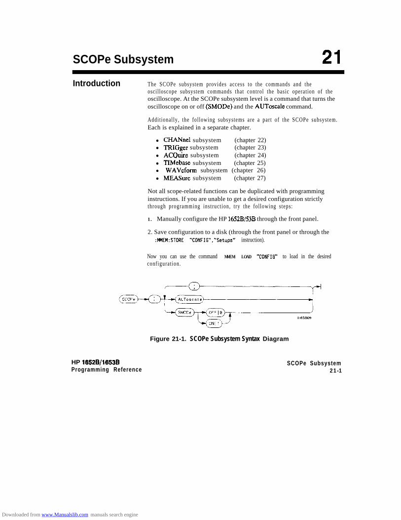
SCOPe Subsystem 21Introduction The SCOPe subsystem provides access to the commands and the
osci l loscope subsystem commands that control the basic operat ion of theoscilloscope. At the SCOPe subsystem level is a command that turns theoscilloscope on or off (SMODe) and the AUToscale command.
Addit ional ly , the fol lowing subsystems are a par t of the SCOPe subsystem.Each is explained in a separate chapter.
l CHANnel subsystem (chapter 22)l TRIGger subsystem (chapter 23)l ACQuire subsystem (chapter 24)l TIMebase subsystem (chapter 25)l WAVeform subsystem (chapter 26)l MEASure subsystem (chapter 27)
Not all scope-related functions can be duplicated with programminginstructions. If you are unable to get a desired configuration strictlythrough programming instruct ion, t ry the fol lowing s teps:
1. Manually configure the HP 1652B/53B through the front panel.
2. Save configuration to a disk (through the front panel or through the:MMEM:STORE "CONFIG","Setups" instruction).
Now you can use the command MMEM: LOAD "CONFIG" to load in the desiredconfigurat ion.
Figure 21-1. SCOPe Subsystem Syntax Diagram
HP 16528/16538Programming Reference
SCOPe Subsystem21-1
Downloaded from www.Manualslib.com manuals search engine

SCOPe
SCOPe selector
The SCOPe selector is used to indicate the beginning of a compoundcommand (or query) for a function within the SCOPe subsystem. SinceSCOPe is a root-level command, it will normally appear as the firstelement of a compound header.
Command Syntax: :SCOPe
Example: OUTPUT XXX; ":SCOPE:TRIGGER:SLOPE NEGATIVE"
SCOPe Subsystem21-2
HP 16528/16538
Downloaded from www.Manualslib.com manuals search engine

AUToscale
AUToscale command
The AUToscale command causes the oscilloscope to automatically selectthe vert ical sensit ivity, vert ical offset , t r igger level and timebase se t t ingsfor optimum viewing of any input s ignals . The tr igger source is the lowestchannel on which the trigger was found. If no trigger is found, theoscil loscope defaults to auto-tr igger.
Command syntax: :SCOPe:AUToscale
Example: OUTPUT XXX;":SCOPE:AUTOSCALE"
HP 16528/1653B SCOPe Subsystem21-3
Downloaded from www.Manualslib.com manuals search engine

SMODe
SMODe command/query
The SMODe command allows the oscilloscope to be turned on or off overthe bus.
The SMODe query returns the current status of the oscillosocpe.
Command Syntax: :SCOPe:SMODe {ON)OFF}
Example: OUTPUT XXX;“:SCOPe:SMOOe ON”
Query Syntax: :SCOPe:SMODe?
Returned Format: [:SCOPe:SMODe] {ON IOFF) < NL>
Example: 10 DIM Sm$[lOO]20 OUTPUT XXX;“:SCOPE:SMODE?”
30 ENTER XXX;Sm$40 PRINT Sm$50 END
SCOPe Subsystem21-4
HP 16528/1653BProgramming Reference
Downloaded from www.Manualslib.com manuals search engine
CHANnel Subsystem 22Introduction The CHANnel subsystem commands control the channel display and the
vertical axis of the oscilloscope. Each channel must be programmedindependently for all offset, range and probe functions. The commandsare:
0 C H A N n e l0 COUPling0 OFFSetl PROBel RANGe
HP 1652Bll653BProgramming Reference
CHANnel Subsystem22-l
Downloaded from www.Manualslib.com manuals search engine
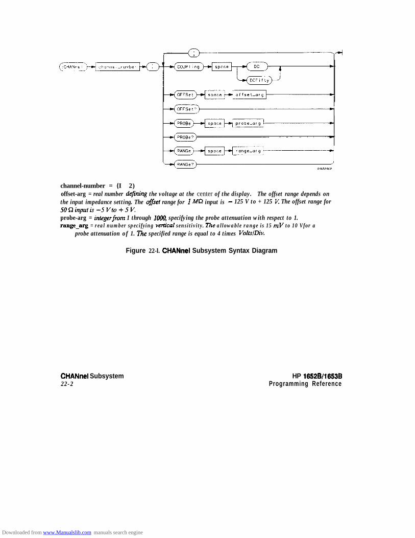
channel-number = {I 1 2)offset-arg = real number dtjining the voltage at the center of the display. The offset range depends onthe input impedance setting. The of/set range for 1 MC? input is - 125 V to + 125 K The offset range for50Qinputis-5Vto+5V.probe-arg = integerftom 1 through lOlW, specifying the probe attenuation with respect to 1.range-arg = real number specifying vemCal sensitivity. The allowable range is 15 mV to 10 Vfor a
probe attenuation of 1. The specified range is equal to 4 times VoltslDiv.
Figure 22-l. CHANnel Subsystem Syntax Diagram
CHANnel Subsystem22-2
HP 16528/1653BProgramming Reference
Downloaded from www.Manualslib.com manuals search engine

CHANnel
CHANnel selector
The CHANnel selector is used as part of a compound command header toaccess the settings found in oscilloscope’s CHANnel menu. It alwaysfollows the SCOPe selector because it selects a branch below the SCOPelevel in the command tree.
Command Syntax: :SCOP~:CHAN~~I < N >
where:
cN> ::= {l 12)
Example: OUTPUT XXX; ":SCOPE:CHANNEL2:OFFSET 2.5"
HP 10526/1653BProgramming Reference
CHANnel Subsystem22-3
Downloaded from www.Manualslib.com manuals search engine

COUPling
COUPling command/query
The COUPling command sets the input impedance for the selectedchannel. The choices are either 1M Ohm (DC) or 50 Ohms (DCFifIy).
The query returns the current input impedance for the specified channel.
Command Syntax: :SCOPe:CHANnel{ 1 I2):COUPling {DC) DCFifty}
Example: OUTPUT XXX ; ” :SCOPE:CHANNELl:COUPLING DC”
Query Syntax: :SCOPe:CHANnel{ 1 IP}:COUPling?
k3tIJrrWd Format: [:SCOPe:CHANnel{l I2):COUPlingl { D C 1 DCFifty} c NL>
Example: 1 0 DIM cct[lool20 OUTPUT XXX;“:SCOPE:CHANNELl:COUPLING?”
30 ENTER XXX;Cc$40 PRINT Cc$50 END
CHANnel Subsystem22-4
HP 16528/1653B
Downloaded from www.Manualslib.com manuals search engine

OFFSet
OFFSet command/query
The OFFSet command sets the voltage that is represented at centerscreen for the selected channel. The allowable offsets for 1:l probes are:
42VcSOmVldiv4 10 V at 100 mV/div and 200 mV/div2 SOV at 50 mV/div and 1 Vldiv4 250 V L 2 Vldiv
The allowable offset is -t5 V for any vertical range when the inputimpedance is set to 50 R.
The offset value is recompensated whenever the probe attenuation factoris changed.
The query returns the current value for the selected channel.
Command Syntax: :SCOPe:CHANnel{ 1 IP}:OFFSet <value >
where:
cl value > ::= {-2~Vto+~Vmax.atlMR 1 -~vto+5vat~sL}
Example: OUTPUT XXX;":SCOP:CHANl:OFFS 1.5"
Query Syntax: :SCOPe:CHANnel{l JP}:OFFSet?
f%?tUrMd Format: [:SCOPe:CHANnel{ 1 I2):OFFSeq <value > c NL>
Example: 10 DIM Co$[lOO]20 OUTPUT XXX;":SCOPE:CHANNELl:OFFSET?"
30 ENTER XXX;Co$40 PRINT Co$
50 END
HP 16528/1663BProgramming Reference
CHANnel Subsystem22-5
Downloaded from www.Manualslib.com manuals search engine

PROBe
PROBe command/query
The PROBe command specifies the attenuation factor for an externalprobe connected to a channel. The command changes the channel voltagereferences such as range, offset, trigger levels and automaticmeasurements. The actual sensitivity is not changed at the channel input.The allowable probe attenuation factor is an integer from 1 to 1ooO.
The query returns the probe attenuation factor for the selected channel.
Command Syntax: :SCOPe:CHANnel{l I2):PROBe catten>
where:
c atten > :: = integer from 1 to loo0
Example: OUTPUT XXX;":SCOPe:CHANl:PROB 10"
Query Syntax: :SCOPe:CHANnel{ 1)2}:PROBe?
Returned Format: [:SCOPe:CktANnel{ 1 I2}:PROBe] <atten > <NL>
Example: 10 DIM Att$[lOO]20 OUTPUT XXX;": SCOPE:CHANNELl:PROEE?"
30 ENTER XXX;Att$40 PRINT AttJ50 END
CHANnel Subsystem22-6
Downloaded from www.Manualslib.com manuals search engine
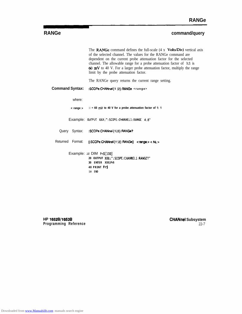
RANGe
RANGe command/query
The FMNGe command defines the full-scale (4 x Volts/Div) vertical axisof the selected channel. The values for the RANGe command aredependent on the current probe attenuation factor for the selectedchannel. The allowable range for a probe attenuation factor of 1:l is60 mV to 40 V. For a larger probe attenuation factor, multiply the rangelimit by the probe attenuation factor.
The RANGe query returns the current range setting.
Command Syntax: :SCOPe:CHANnel{l J2):FlANGe < r a n g e >
where:
-c range > :: = 60 mV to 40 V for a probe attenuation factor of 1: 1
Example: ouTPuT ~X~;":~COPE:CHANNEL~:RANGE 4.8"
Query Syntax: :SCOPe:CHANnel{l~2}:RANGe?
Returned Format: [:SCOPe:CHANnel{l I2):FtANGe] <ranger -Z NL>
Example: 10 DIM PrS[loo]20 OUTPUT XXX;“:SCOPE:CHANNELl:RANGE?”30 ENTER XXX;Pr$
40 PRINT PrS50 END
HP 16528/1653BProgramming Reference
CHANnel Subsystem22-7
Downloaded from www.Manualslib.com manuals search engine
TRlGger Subsystem 23Introduction The commands of the TRIGger subsystem allow you to se t ah the tr igger
conditions necessary for generating a trigger. There are two triggermodes: Edge and Immediate. If a command is valid for the chosen triggermode, then that setting wiII be accepted by the oscilloscope. However, ifthe command is not valid for the trigger mode, an error wih be generated.None of the commands of this subsystem are used in conjunct ion withImmediate trigger mode. See Figure 23-l for the TRIGger subsystemsyntax diagram.
The Edge In the Edge trigger mode, the oscilloscope triggers on an edge of aTrigger Mode waveform, specified by the SOURce, LEVel, and SLOPe commands. If a
source is not specified, then the current source is assumed.
‘The Immediate In the Immediate trigger mode, the oscilloscope wiII trigger by itself whenTrigger Mode the arming requirements are met.
HP 165213/1663BProgramming Reference
TRlGger Subsystem23-l
Downloaded from www.Manualslib.com manuals search engine
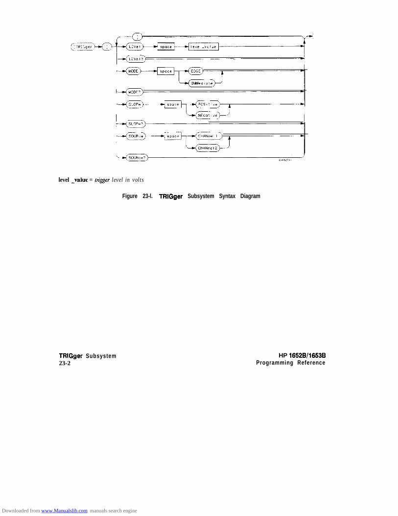
level -value = trigger level in volts
Figure 23-l. TRlGger Subsystem Syntax Diagram
TRlGger Subsystem23-2
HP 16528/1653BProgramming Reference
Downloaded from www.Manualslib.com manuals search engine

TRIGger
TRlGger selector
The TRIGger selector is used as part of a compound command header toaccess the settings found in oscilloscope’s Trigger menu. It always followsthe SCOPe selector because it selects a branch below the SCOPe level inthe command tree.
Command Syntax: :SCOPe:TRIGger
Example: OUTPUT XXX; ":SCOPE:TRIGGER:CHANNELi;LEVEL 2.0"
HP 16528/16536Programming Reference
TRlGger Subsystem23-3
Downloaded from www.Manualslib.com manuals search engine
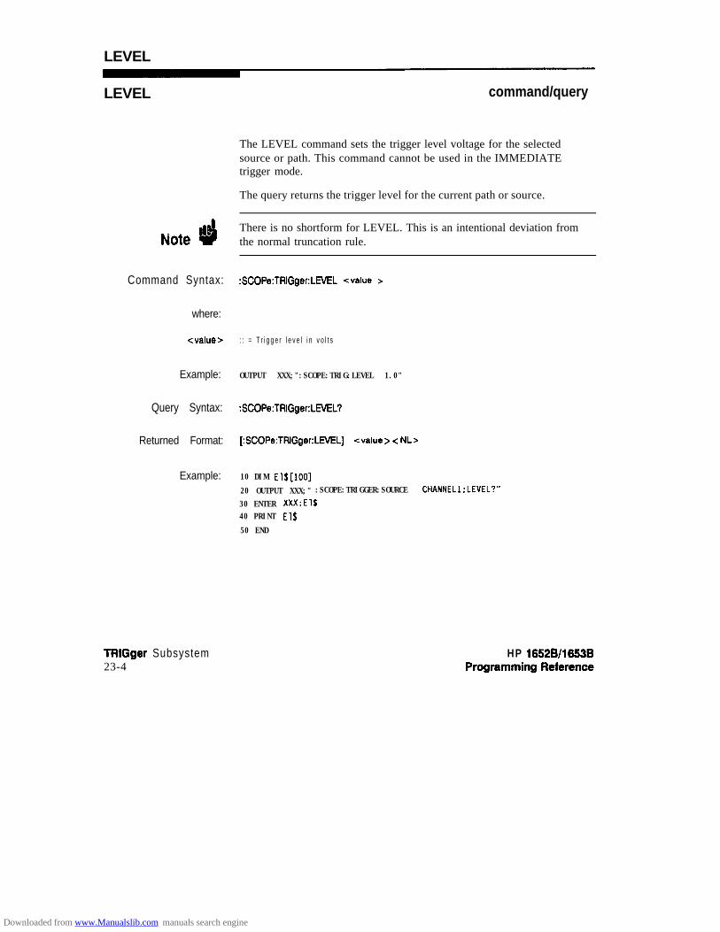
LEVEL
LEVEL command/query
The LEVEL command sets the trigger level voltage for the selectedsource or path. This command cannot be used in the IMMEDIATEtrigger mode.
The query returns the trigger level for the current path or source.
Note dThere is no shortform for LEVEL. This is an intentional deviation fromthe normal truncation rule.
Command Syntax: :SCOPe:TRIGger:LML <value >
where:
<value > : : = T r i g g e r l e v e l i n v o l t s
Example: OUTPUT XXX;":SCOPE:TRIG:LEVEL 1.0"
Query Syntax: :SCOPe:TRIGger:LML?
Returned Format: [:SCOPe:TRIGger:LEVEL] <value > < NL>
Example: 10 DIM El$[lOO]
20 OUTPUT XXX;" :SCOPE:TRIGGER:SOURCE CHANNELl;LEVEL?"
30 ENTER XXX;El$40 PRINT El$
50 END
TRiGger Subsystem23-4
HP 16526/1663B
Downloaded from www.Manualslib.com manuals search engine

MODE
MODE command/query
The MODE command allows you to select the trigger mode for theoscilloscope. The EDGE mode will trigger the oscilloscope on an edgewhose slope is determined by the SLOPe command at a voltage set by theLEVEL command. In the IMMediate trigger mode, the oscilloscope goesto a freerun mode and does not wait for a trigger. The IMMediate mode isused in armed-by other machine applications.
The query returns the current mode.
Command Syntax: :SCOPe:TRIGger:MODE {EDGE 1 IMMediate}
Example: OUTPUT XXX;":SCOPE:TRIGGER:MOOE EDGE"
Query Syntax: :SCOPe:TRIGger:MODE?
Returned Format: [:SCOPe:TRIGger:MODE] {EDGE)IMMediate}<NL>
Example: 10 DIM Md$[lOO]20 OUTPUT XXX;":SCOPE:TRIGGER:MOOE?"
30 ENTER XXX;Md$
40 PRINT Md$
50 END
HP 16528/16538Programming Reference
TRlGger Subsystem23-5
Downloaded from www.Manualslib.com manuals search engine
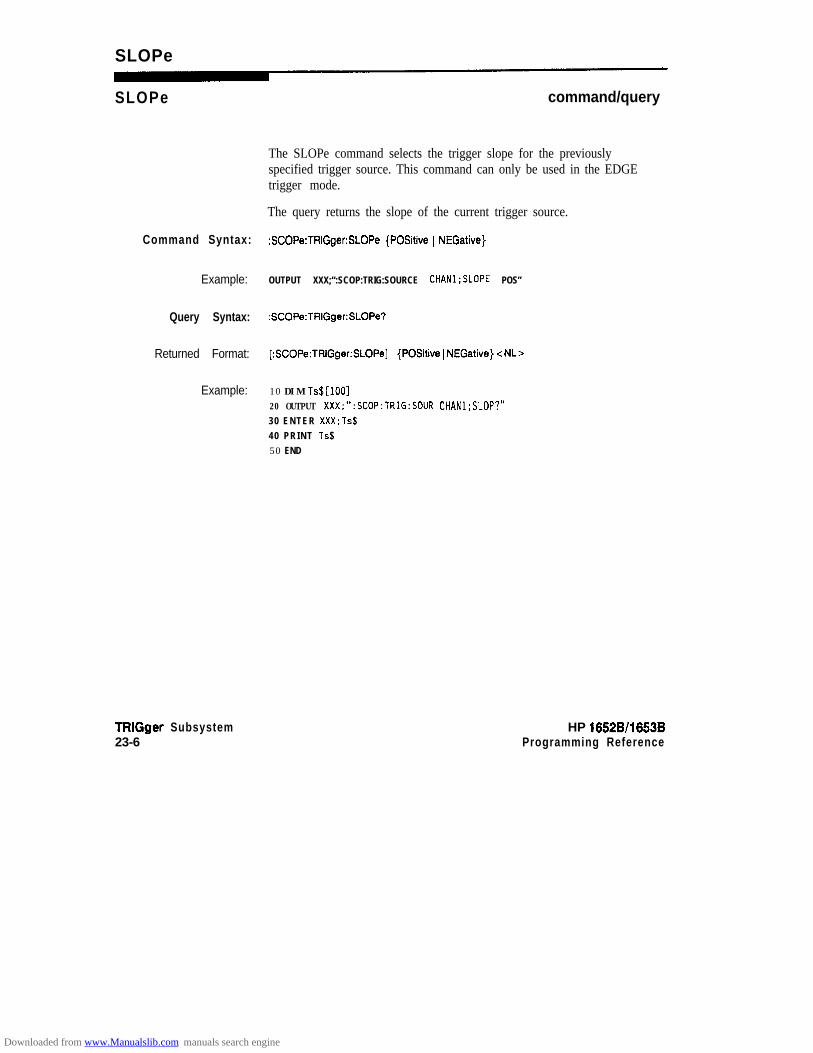
SLOPe
SLOPe command/query
The SLOPe command selects the trigger slope for the previouslyspecified trigger source. This command can only be used in the EDGEtrigger mode.
The query returns the slope of the current trigger source.
Command Syntax: :SCOPe:TRIGger:SLOPe {Positive 1 NEGative}
Example: OUTPUT XXX;“:SCOP:TRIG:SOURCE CHANl;SLOPE POS”
Query Syntax: :SCOPe:TRIGger:SLOPe?
Returned Format: [:SCOPe:TRIGger:SLOPe] {Positive 1 NEGative} -c NLr
Example: 10 DIM Ts$[lOO]20 OUTPUT XXX;":SCOP:TRIG:SOlJR CHANl;SLOP?"30 ENTER XXX;Ts$40 PRINT Ts$50 END
TRlGger Subsystem23-6
HP 16528/1653BProgramming Reference
Downloaded from www.Manualslib.com manuals search engine

SOURce
SOURce command/query
The SOURce command is used to select the trigger source and is used forany subsequent SLOPe and LEVEL commands. This command can onlybe used in the EDGE trigger mode.
The query returns the current trigger source.
Command Syntax: :SCOPe:TRIGger:SOURce {CHANnel{l12})
Example: OUTPUT xxx;":SCOP:TRIG:SOUR CHANl"
Query Syntax: :SCOPe:TRIGger:SOURce?
Returned Format: [:SCOPe:TRIGger:SOUFice] {CHANnel{ 112)) < NL >
Example: 10 DIM Tso$[lOO)20 OUTPUT XXX;":SCOPE:TRIGGER:SOURCE?"30 ENTER XXX;Tso$40 PRINT Tso$
50 END
HP 16528/1653BProgramming Reference
TRlGger Subsystem23-7
Downloaded from www.Manualslib.com manuals search engine

ACQuire Subsystem 24Introduction The ACQuire subsystem commands are used to select the type of
acquisition and the number of averages to be taken if the average type ischosen. The commands are:
0 couNt
l TYPE
/-dCOUNt?) I
count-alp: = (2 14 18 I16 I32 ) 64 I128 1256) An integer that specifies the number of averages to be taken ofeach time point.
Figure 24-l. ACQuire Subsystem Syntax Diagram
HP 16528/16538 ACQuire SubsystemProgramming Reference 24-1
Downloaded from www.Manualslib.com manuals search engine
Acquisition Type In the Normal mode, with the ACCumulate command OFF, the
Normal oscilloscope acquires waveform data and then displays the waveform.When the oscilloscope makes a new acquisition, the previously acquiredwaveform is erased from the display and replaced by the newly acquiredwaveform.
When the Accumulate command is ON, the oscilloscope displays all thewaveform acquisitions without erasing the previously acquired waveform.
Acquisition Type In the Average mode, the oscilloscope averages the data points on the
Average waveform with previously acquired data. Averaging helps eliminaterandom noise from the displayed waveform. In this mode theAccumulate command is OPP. When Average mode is selected, thenumber of averages must also be specified using the COUNt command.Previously averaged waveform data is erased from the display and thenewly averaged waveform is displayed.
ACQuire Subsystem24-2
HP 16528/1663BProgramming Reference
Downloaded from www.Manualslib.com manuals search engine

ACQuire
ACQulre selector
The ACQuire selector is used as part of a compound command header toaccess the sett ings found in oscil loscope’s Acquire menu. I t alwaysfollows the SCOPe selector because it selects a branch below the SCOPelevel in the command tree.
Command Syntax: :SCOPe:ACQuire
bmpk?: OUTPUT XXX: ":SCOPE:ACQUIRE:TYPE NORMAL"
HP 16528/1653BProgramming Reference
ACQuire Subsystem24-3
Downloaded from www.Manualslib.com manuals search engine

COUNt
COUNt command/query
The COUNt command specifies the number of acquisitions for therunning weighted average. This command generates an error if Normalacquisition mode is specified.
The query returns the last specified count.
Command Syntax: :SCOPe:ACQuire:COUNt <count >
where
Zcount > : := {2~4~8~16~32~s4~128~25s)
&Hllpk OUTPUT XXX;":SCOPE:ACQUIRE:COUNT 16"
Query Syntax: :SCOPe:ACQuire:COUNt?
RetUrIWd Format [:SCOPe:ACQuire:COUNt] -Z count z -Z NLs
Example: 10 DIM A~$[100120 OUTPUT XXX;":SCOPE:ACQ:COUN?"
30 ENTER XXX;Ac$40 PRINT Acf
50 END
ACQuire Subsystem24-4
HP 16528/16636
Downloaded from www.Manualslib.com manuals search engine

TYPE
TYPE command/query
The TYPE command selects the type of acquisition that is to take placewhen the STARt command is executed. One of three acquisition typesmay be selected: the NORMal, AVERage, or Accumulate mode.
The query returns the last specified type.
Command Syntax :SCOPe:ACQuire:TYPE {NORMal 1 AVERage 1 ACCumulate}
&Ntlpk: OUTPUT XXX;": SCOPE:ACQUIRE:TYPE NORMAL”
Query Syntax: :SCOPe:ACQuire:TYPE?
f%?turned Format: [:SCOPe:ACQuire:TYPE] {NORMal 1 AVERage} < NL>
&KrIp~e: 10 DIM At$[lOO]20 OUTPUT XXX;“:SCOPE:ACQUIRE:TYPE?”30 ENTER XXX;At$40 PRINT AtS
50 END
HP 15528/1653B ACQuire Subsystem24-5
Downloaded from www.Manualslib.com manuals search engine
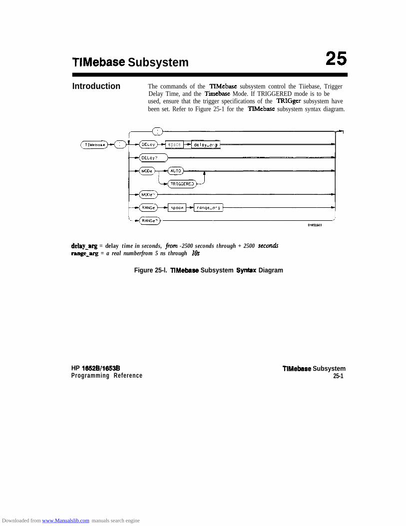
TIMebase Subsystem
Introduction The commands of the TIMebase subsystem control the Tiiebase, TriggerDelay Time, and the Timebase Mode. If TRIGGERED mode is to beused, ensure that the trigger specifications of the TRIGger subsystem havebeen set. Refer to Figure 25-1 for the TIMebase subsystem syntax diagram.
space delay-org
delay-arg = delay time in seconds, ftom -2500 seconds through + 2500 secondsrange-q = a real numberfrom 5 ns through 10s
Figure 25-l. TIMebase Subsystem Synfax Diagram
HP 16528/1653B TIMebase SubsystemProgramming Reference 25-1
Downloaded from www.Manualslib.com manuals search engine

TiMebase
TIMebase selector
The TIMebase selector is used as part of a compound command header toaccess the settings found in oscilloscqe’s Timebase menu. It alwaysfollows the SCOPe selector because it selects a branch below the SCOPelevel in the command tree.
Command SyntSx: :SCO~e:~l~ebase
Example: OUTPUT XXX; ":SCOPE:TIHEBASE:MOOE AUTO"
TIMebase Subsystem252
HP 10528/1653BProgramming Reference
Downloaded from www.Manualslib.com manuals search engine

DELAY
DELAY
Note ”4
Command Syntax:
where:
-z delay time z-
Example:
Query Syntax:
Returned Format:
Example:
command/query
The DELAY command sets the time between the trigger and the centerof the screen if the trigger events count is zero. If the trigger events countis non-zero, the center of the screen is the tr igger events count plus thedelay time.
The query returns the current delay setting.
The DELAY command in the TIMebase subsystem has no shortform.This is an intentional deviation from the normal truncation rules.
:SCOPe:TIMebase:DELAY -c delay time >
:: = delay time in seconds
OUTPUT XXX:":SCOPe:TIMebase:OELAY ZUS"
:SCOPe:TIMebase:DELAY?
[:SCOPe:TIMebase:DELAY] <value > < NL>
10 DIM Dt$[lOO]20 OUTPUT XXX;":SCOPe:TIMebase:DELAY?"
30 ENTER XXX;Dt$40 PRINT Dt$
50 END
HP 16528/1653B TIMebase Subsystem2 5 3
Downloaded from www.Manualslib.com manuals search engine

MODE
MODE
Note ”4
Command Syntax:
Example:
TIMebase Subsystem25-4
command/query
The MODE command sets the oscilloscope timebase to either Auto orTriggered mode. When the AUTO mode is chosen, the oscilloscope waitsapproximately one second for a trigger to occur. If a trigger is notgenerated within that time, then auto trigger is executed. If a signal is notapplied to the input , a baseline is displayed. If there is a s ignal at the inputand the specified trigger conditions have not been met within one second,the waveform display will not be synchronized to a trigger.
When the TRIGGERED mode is chosen, the oscilloscope waits until atrigger is received before data is acquired. The TRIGGERED modeshould be used when the tr igger source signal is less than at a 40 Hzrepetition rate.
The Auto-Trig On field in the trigger menu is the same as the AUTOmode over HP-IB or RS-232C. Setting the mode to TRIGgered is thesame as the Auto-Trig Off on the front panel.
The query returns the current TIMebase mode.
The TRIGGERED argument for MODE has no shortform. This is anintentional deviation from the normal truncation rule.
:SCOPe:TIMebase:MODE (TRIGGERED(AUT0)
OUTPUT XXX;“:SCOPE:TIME:MODE AUTO
HP 16528/1653BProgramming Reference
Downloaded from www.Manualslib.com manuals search engine

MODE
Query Syntax: :SCOPe:TlMebase:MODE?
RetUrned Format: [:SCOPe:TIMebase:MODE] {AUTOITRIGGERED} cNL>
Example: 10 DIM Tm$[lOO]20 OUTPUT XXX;“:SCOPe:TIMEBASE:MOOE?”
30 ENTER XXX;Tm$
40 PRINT Tm$
50 END
HP 1652B/l653BProgramming Reference
TIMebase Subsystem255
Downloaded from www.Manualslib.com manuals search engine
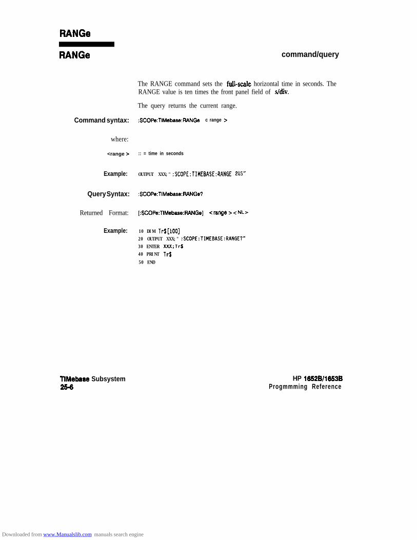
RANGe
RANGe command/query
The RANGE command sets the fbll-scale horizontal time in seconds. TheRANGE value is ten times the front panel field of s/div.
The query returns the current range.
Command syntax: :SCOPe:TIMrbase:RANGe c range z-
where:
<range > :: = time in seconds
Example: OUTPUT XXX;" :SCOPE:TIMEBASE:RANGE 2US"
Query Syntax: :SCOPe:TIMebase:RANGe?
Returned Format: [:SCOPe:TIMebase:FWNGe] <range > -z NL>
Example: 10 DIM Tr$[lOO]20 OUTPUT XXX;" :SCOPE:TIMEBASE:RANGE?"30 ENTER XXX;Tr$40 PRINT Tr$
50 END
TIMebase Subsystem256
HP 16528/1553BProgmmming Reference
Downloaded from www.Manualslib.com manuals search engine
WAVeform Subsystem
Introduction The commands of the WAVeform subsystem are used to transferwaveform data from the oscilloscope to a controller. The commands are:
l COUNtl DATAl FORMatl POINtsl PREamblel RECordl SOURcel TYPel Validl XINCrementl XORiginl XREFerencel YINCrementl YORiginl YREFerence
HP 1652B/1663B WAVeform Subsystem26-l
Downloaded from www.Manualslib.com manuals search engine

channel-# = (112)
\ /
PREamb I e”
RECord
POINtsl
PREamb I e”
c
c
c
c
c
c
XINCrement7 c
Figure 26-l. WAVeform Subsystem Syntax Diagram
WAVeform Subsystem HP 16528/1653B262 Programming Reference
Downloaded from www.Manualslib.com manuals search engine
WaveformRecord
The waveform record is actually contained in two portions; the waveformdata and preamble. The waveform data is the actual data acquired foreach point. The preamble contains the information for interpretingwaveform data. Data in the preamble includes number of points acquired,format of acquired data, average count and the type of acquired data.The preamble also contains the X and Y increments, origins, andreferences for the acquired data for translation to time and voltage values.
The values set in the preamble are based on the settings of the variables inthe ACQuire, WAVeform, CHANnel, and TIMebase subsystems. TheACQuire subsystem determines the acquisition type and the averagecount, the WAVeform subsystem sets the number of points and the formatmode for sending waveform data over the remote interface and theCHANnel and TIMebase subsystems set all the X - Y parameters.
Data AcquisitionTypes
Normal Mode
Average Mode
The two acquisition types that may be chosen are Normal and Average.
In the Normal mode, with Accumulate command OFF, the oscihoscopeacquires waveform data and then displays the waveform. When theoscil loscope takes a new acquisi t ion, the previously acquired waveform iserased from the display and replaced by the newly acquired waveform.
When ACCumulate is set ON, the oscil loscope displays al l the waveformacquisi t ions without erasing the previously acquired waveform.
In the Average mode, the oscil loscope averages the data points on thewaveform with previously acquired data. Averaging helps eliminaterandom noise from the displayed waveform. in this mode ACCumulate isset to OFF. When Average mode is selected the number of averages mustalso be specified using the COUNt command. Previously displayedwaveform data is erased from the display and the newly averagedwaveform is displayed.
HP 16529/16539 WAVeform Subsystem26-3
Downloaded from www.Manualslib.com manuals search engine

Format for Data ohere are three formats for transferring waveform data over the remote
Transfer interface. The formats are WORD, BYTE, and ASCII.
WORD and BYTE formatted waveform records are transmitted using thearbitrary block program data format specified in IEEE-488.2. When youuse this format, the ASCII character string “#8-z DDDDDDDD > ” is sentbefore the actual data. Each D represents an ASCII digit. The eight-digitnumber represents the number of bytes to follow.
For example, if 2048 points of data are to be transmitted, the ASCII string#800002048 would be sent.
BYTE Format In BYTE format, the six least significant bits represent the waveform data.This means that the display is divided into 64 vertical increments. Themost significant bit is not used. The second most significant bit is theoverflow bit. If this bit is set to “1” and all data bits are set to “0” then thewaveform is clipped at the top of the screen. If all “0”s are returned, thenthe waveform is clipped on the bottom of the display (see figure 26-2).
N O R M A L A N D A V E R A G E ACOUISITION TYPE
128 64 32 16 8 4 2
“8
OVERFLOW ,~53oIBL*O
Figure 262. Byte Date Structure
The data returned in BYTE format are the same for either Normal orAverage acquisition types. The data transfer rate in this format is fasterthan the other two formats.
WAVeform Subsystem2 6 4
HP 16528/1653BProgmmming Reference
Downloaded from www.Manualslib.com manuals search engine

WORD Format Word data is two bytes wide with the most s ignif icant byte of each wordbeing transmitted first. Each 16-bit value effectively places a data point onscreen. The screen therefore is divided into 16384 vertical increments. TheWORD data structure for normal and average acquisition types are shownin figure 26-3.
The relationship between BYTE and WORD formats are similar. Bytedata values equal word data values divided by 256. This is the reason thatthe least s ignif icant byte in the normal acquisi t ion mode always contains“0”s. In the average acquisition mode, the extra bits of resolution gained byaveraging occupy the least significant byte of the word. However, this isonly true when RECord type is set to WIND OW .
NORMAL ACQUISITION TYPE
AVERAGE ACQUISITION TYPE
MSB LSB32768 16384 6192 4896 Pa-38 ,024 512 256 128 6 4 32 1 6 s 4 2 1
DATA (FRACTION)-
Figure 26-3. Word Data Structure
ASCII Format ASCII formatted waveform records are transmitted one value at a time,separated by a comma. The data values transmitted are the same as wouldbe sent in the WORD format except that they are converted to an integerASCII format (six or less characters) before being transmitted. Theheader before the data is not included in this format.
HP 16528/1653BProgramming Reference
WAVeform Subsystem26-5
Downloaded from www.Manualslib.com manuals search engine
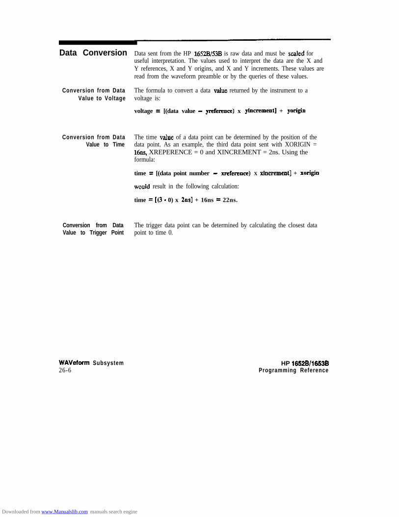
Data Conversion
Conversion from DataValue to Voltage
Conversion from DataValue to Time
Conversion from DataValue to Trigger Point
WAVeform Subsystem26-6
Data sent from the HP 1652B/53B is raw data and must be scaled foruseful interpretation. The values used to interpret the data are the X andY references, X and Y origins, and X and Y increments. These values areread from the waveform preamble or by the queries of these values.
The formula to convert a data value returned by the instrument to avoltage is:
voltage = [(data value - yreference) x yincrement] + yorigin
The time value of a data point can be determined by the position of thedata point. As an example, the third data point sent with XORIGIN =16ns, XREPERENCE = 0 and XINCREMENT = 2ns. Using theformula:
time = [(data point number - xreference) X xincrement] + xorigin
would result in the following calculation:
time = [(3 - 0) x 2ns] + 16ns = 22ns.
The trigger data point can be determined by calculating the closest datapoint to time 0.
HP 16528/1653BProgramming Reference
Downloaded from www.Manualslib.com manuals search engine

WAVeform
WAVeform selector
The WAVeform selector is used as part of a compound command headerto access the settings found in oscilloscope’s Waveform menu. It alwaysfollows the SCOPe selector because it selects a branch below the SCOPelevel in the command tree.
Command Syntax: :SCOPe:WAVeform
Example: OUTPUT XXX; ":SCOPE:WAVEFORM:"
HP 16528/16.538 WAVeform Subsystem2G7
Downloaded from www.Manualslib.com manuals search engine

COUNt
The COUNt query returns the AVERage count that was last specified inthe Acquire subsystem. If the display mode is either NORMal orAccumulate, a 1 is returned. If the display mode is AVERage, theaverage number is returned.
Query Syntax: :SCOPe:WAVeform:COUNt?
Returned Format: [:SCOPe:WAVeform:COUNt] < c o u n t > cNL>
where:
< c o u n t > : : = {2~4~8~16~32~64~128~266)
Example: 10 DIM Ac$[lOO]20 OUTPUT XXX;" :SCOPE:WAVEFORM COUNT?”
30 ENTER XXX;Ac$40 PRINT Ac$
50 END
WAVeform Subsystem28-8
HP 18828/1883BProgramming Reference
Downloaded from www.Manualslib.com manuals search engine
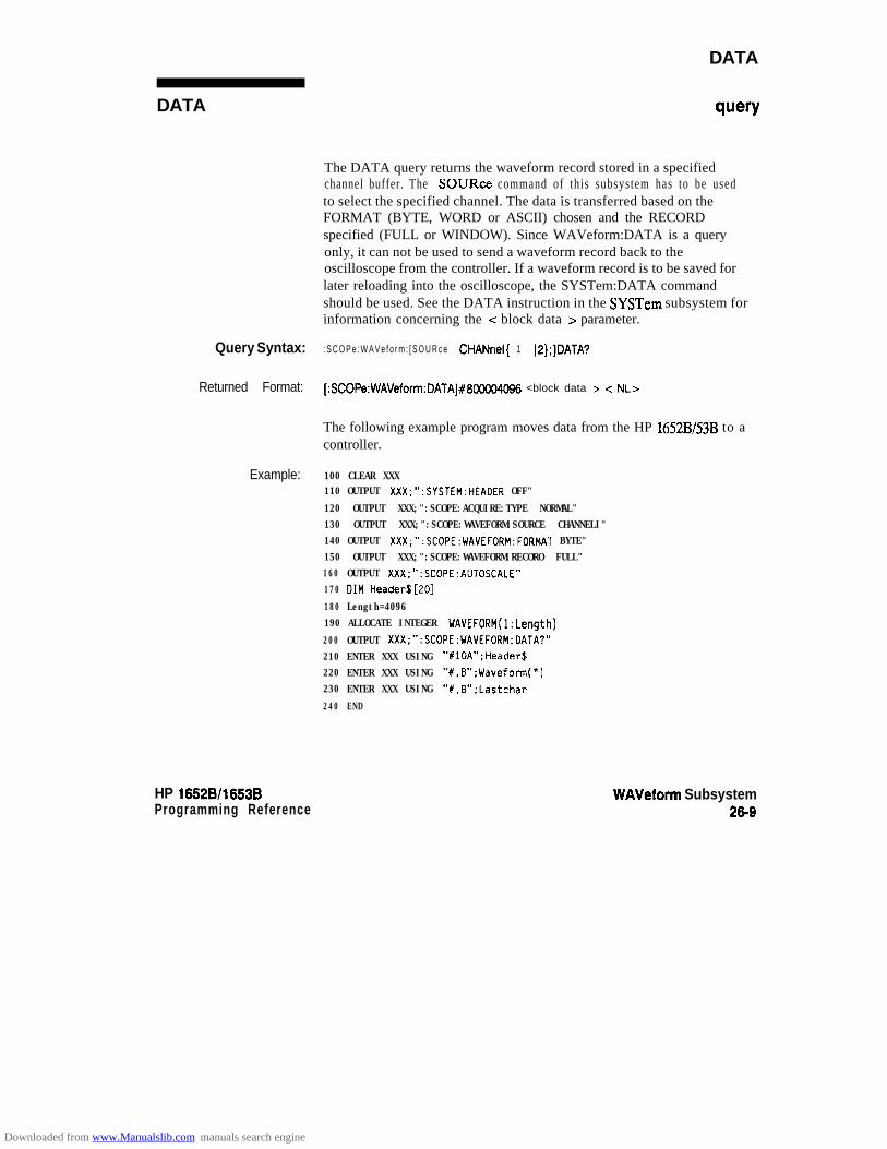
DATA
DATA query
The DATA query returns the waveform record stored in a specifiedchannel buffer. The SOURce command of this subsystem has to be usedto select the specified channel. The data is transferred based on theFORMAT (BYTE, WORD or ASCII) chosen and the RECORDspecified (FULL or WINDOW). Since WAVeform:DATA is a queryonly, it can not be used to send a waveform record back to theoscilloscope from the controller. If a waveform record is to be saved forlater reloading into the oscilloscope, the SYSTem:DATA commandshould be used. See the DATA instruction in the SYSTem subsystem forinformation concerning the -Z block data > parameter.
Query Syntax: : S C O P e : W A V e f o r m : [ S O U R c e CHANnel{ 1 IP};]DATA?
Returned Format: [:SCOPe:WAVeform:DATA]#800004096 <block data > < NL>
The following example program moves data from the HP 1652B/53B to acontroller.
Example: 100 CLEAR XXX110 OUTPUT XXX:":SYSTEM:HEAOER OFF"
120 OUTPUT XXX;":SCOPE:ACQUIRE:TYPE NORMAL"130 OUTPUT XXX;":SCOPE:WAVEFORM:SOURCE CHANNELI"140 OUTPUT XXX;":SCOPE:WAVEFORM:FORMAT BYTE"150 OUTPUT XXX;":SCOPE:WAVEFORM:RECORO FULL"160 OUTPUT XXX;":SCOPE:AUTOSCALE"170 DIM Header$[EO]
180 Length=4096190 ALLOCATE INTEGER WAVEFORM(l:Length)
200 OUTPUT XXX;":SCOPE:WAVEFORM:OATA?"210 ENTER XXX USING "XlOA";Header$220 ENTER XXX USING "X.B";Waveform(*)230 ENTER XXX USING "#.B";Lastchar
240 END
HP 1652B/l653BProgramming Reference
WAVeform Subsystem26-9
Downloaded from www.Manualslib.com manuals search engine
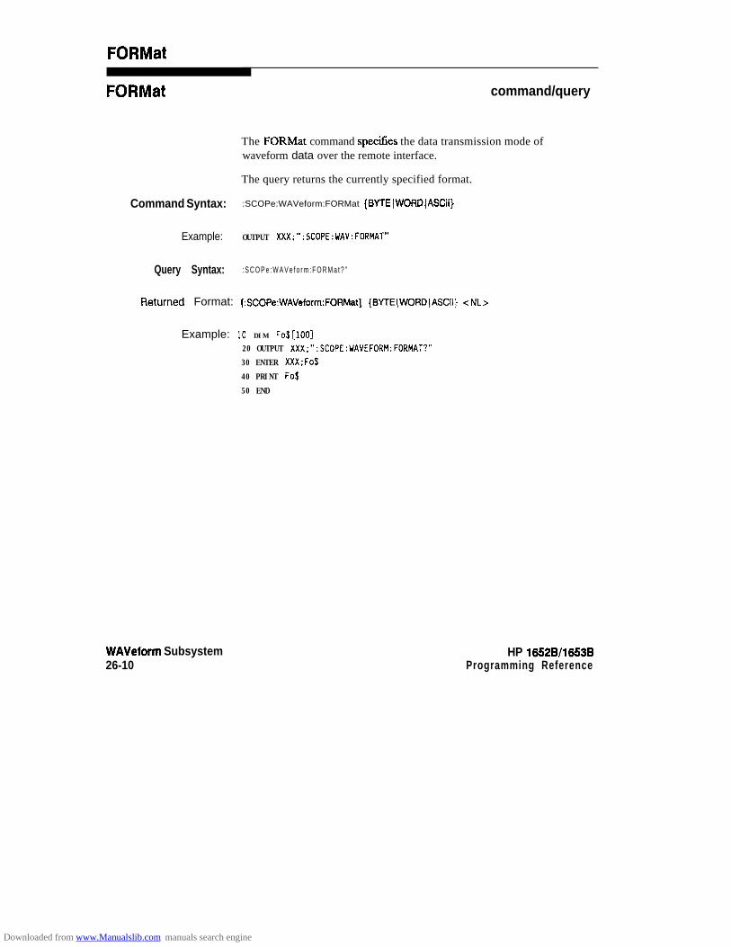
FORMat
FORMat command/query
The FORMat command speciGes the data transmission mode ofwaveform data over the remote interface.
The query returns the currently specified format.
Command Syntax: :SCOPe:WAVeform:FORMat {BYTEIWORDIASCii)
Example: OUTPUT XXX;":SCOPE:WAV:FORMAT"
Query Syntax: : S C O P e : W A V e f o r m : F O R M a t ? ”
%?tUW?d Format: [:SCOPe:WAVeform:FORMat] {BYlE(WORD(ASCii] cNL>
Example: 10 DIM FO$[~OO]20 OUTPUT XXX;":SCOPE:WAVEFORM:FORMAT?"
30 ENTER XXX;Fo$
40 PRINT Fo$
50 END
WAVeform Subsystem26-10
HP 16528/16538Programming Reference
Downloaded from www.Manualslib.com manuals search engine

POINts
POINts w=w
When WAVeform RECord is set to PULL, the POINts query alwaysreturns a value of 2048 points. When WAVeform RECord is set toWINDOW, then the query returns the number of points displayed onscreen.
Query Syntax: :SCOPe:WAVeform:POIN?
Returned Format: [:SCOPe:WAVeform:POINts] <points> <NL>
where:
<points > :: = number of points depending on setting of WAVeform FECord command
Example: 10 DIM Po$[lOO]20 OUTPUT XXX;":SCOPE:WAVEFORM:POINTS?"
30 ENTER XXX;Po$40 PRINT Po$
50 END
HP 16528/1653BProgramming Reference
WAVeform Subsystem26-11
Downloaded from www.Manualslib.com manuals search engine
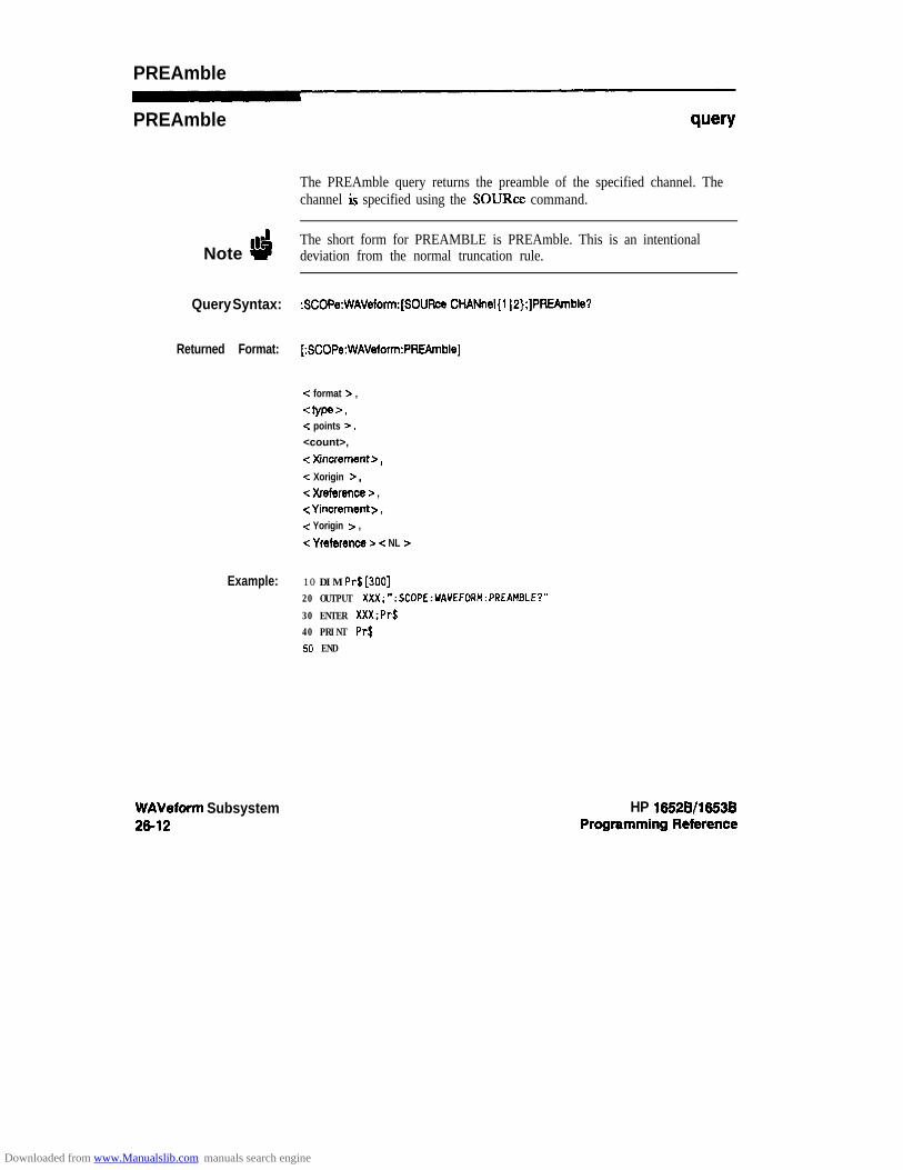
PREAmble
PREAmble query
The PREAmble query returns the preamble of the specified channel. Thechannel is specified using the SOURce command.
Note dThe short form for PREAMBLE is PREAmble. This is an intentionaldeviation from the normal truncation rule.
Query Syntax: :SCOPe:WAVeform:[SOURce CHANnel(1 )P);]PREAmble?
Returned Format: [:SCOPe:WAVeform:PRf3rnble]
c. format z ,
awe=-,c points B,<count>,
c Xincrement >,
-=z Xorigin >,c Xreference z ,-z Yincrement > ,c Yorigin > ,
< Yreference > -z NL >
Example: 10 DIM Pr$[300]20 OUTPUT XXX;":SCOPE:UAVEFORM:PREAMBLE?"
30 ENTER XXX;Pr$40 PRINT Pr$50 END
WAVeform Subsystem2(i-12
HP 16!528/16538
Downloaded from www.Manualslib.com manuals search engine

RECord
RECord command/query
The RECord command specifies the data you want to receive over thebus. The choices are FULL or WINDOW. When FULL is chosen theentire 2048 point record of the specified channel is transmitted over thebus. In WINDOW mode, only the data displayed on screen will bereturned. Use the SOURce command to select the channel of interest.The query returns the present mode chosen.
Command Syntax: :SCOPe:WAVeform:RECord {FULL(WINDow}
Example: OUTPUT XXX;":SCOPE:WAV:SOUR CHANl:REC FULL"
Query Syntax: : S C O P e : W A V e f o r m : R E C o r d ?
Returned Format: [:SCOPe:WAVeform:RECord] {FULLIWINDow} cNL>
Example: 10 DIM Wr$[lDO]
20 OUTPUT XXX;":SCOPE:WAVEFORM:SOURCE CHANNELl:RECORD?"
30 ENTER XXX;Wr$
40 PRINT Wr$
50 END
HP 1652Bll653BProgramming Reference
WAVeform Subsystem2813
Downloaded from www.Manualslib.com manuals search engine

SOURce
SOURce
Commend Synfex:
Example:
Query Syntax:
Returned Format:
Example:
WAVeform Subsystem2&14
command/query
The SOURce command specifies the channel that is to be used for allsubsequent waveform ummands.
The query returns the presently selected channel.
:SCOPe:WAVeform:SOUR CHANnel(l j2)
OUTPUT XXX;" :SCOPE:UAVEFORM:SOURCE CHANNELl"
:SCOPe:WAVeforrn:SOUR?
[:SCOPe:WAVefon:SOUR] CHANnel c N > < NL>
10 DIM Ws$[lOO]20 OUTPUT XXX;" :SCOPE:WAVEFORM:SOURCE?"
30 ENTER XXX:Ws$40 PRINT Ws$50 END
HP 1652B/l653BProgramming Reference
Downloaded from www.Manualslib.com manuals search engine

TYPE query
The TYPE query returns the present acquisition type which was specifiedin the ACQuire subsystem.
Query Syntsx: :SCOPe:WAVeform:lYPE?
~etutned Format: [:SCOPe:WAVeform:TYPE](NORmal (AVERage JACCumulate} -Z NL>
Example: 10 DIM wt$[loo]20 OUTPUT XXX;" :SCOPE:WAVEFORM:TYPE?"30 ENTER XXX;Wt$40 PRINT Wt$
50 EN0
HP 165213/1653BProgramming Reference
WAVeform Subsystem2815
Downloaded from www.Manualslib.com manuals search engine
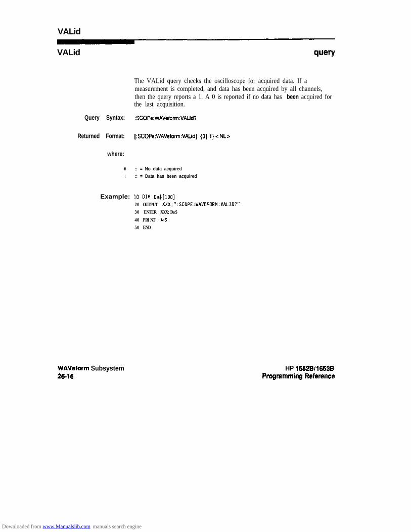
VALid
VALid
The VALid query checks the oscilloscope for acquired data. If ameasurement is completed, and data has been acquired by all channels,then the query reports a 1. A 0 is reported if no data has been acquired forthe last acquisition.
Query Syntax: :SCOPe:WAVeform:VALid?
Returned Format: [:SCOPe:WAVeform:VALid] (01 l}<NL>
where:
0 :: = No data acquired1 :: = Data has been acquired
Example: 10 DIM Da$[lOO]20 OUTPUT XXX;":SCOPE:VAVEFORM:VALID?"30 ENTER XXX;Da$
40 PRINT Da$50 END
WAVeform Subsystem2&16
HP 16628/1663B
Downloaded from www.Manualslib.com manuals search engine

XINCrement
XlNCrement query
The XINCrement query returns the X-increment currently in thepreamble. This value is the time between the consecutive data points.
Query Syntax: :SCOPe:WAVeform:XINCrement?
&?tUrt’Ied Format: [:SCOPe:WAVeform:XINCrement] <value > -Z NL>
where:
- c v a l u e > : : = X - i n c r e m e n t v a l u e c u r r e n t l y i n p r e a m b l e
Example: IO DIM Xi$[lOO]
20 OUTPUT XXX;":SCOPE:WAVEFORM:XINCREMENT?"
30 ENTER XXX;Xi$
40 PRINT Xi$
50 END
HP 1662S/l6536Programming Reference
WAVeform Subsystem2617
Downloaded from www.Manualslib.com manuals search engine

XORigin
XORigin query
The XORigin query returns the X-origin value currently in the preamble.The value represents the time of the first data point in memory withrespect to the trigger point.
Query Syntax: : S C O P e : W A V e f o r m : X O R i g i n ?
Returned Format: [ : S C O P e : W A V e f o r m : X O R i g i n ] <value> < NL>
where:
<value B : : = X - o r i g i n v a l u e c u r r e n t l y i n p r e a m b l e
Example: 10 DIM Xo$[lOO]20 OUTPUT XXX;":SCOPE:WAVEFORM:XORigin?"
30 ENTER XXX;Xo$
40 PRINT Xo$
50 END
WAVeform Subsystem2618
HP 16528/1653B
Downloaded from www.Manualslib.com manuals search engine
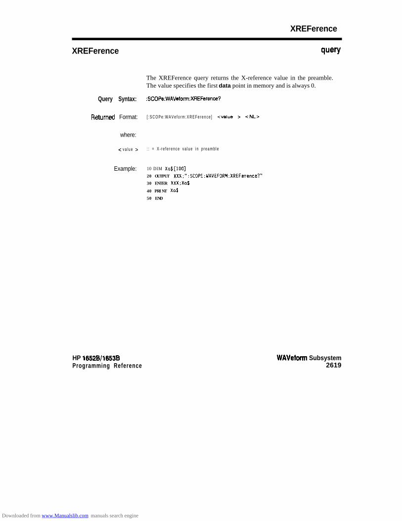
XREFerence
XREFerence query
The XREFerence query returns the X-reference value in the preamble.The value specifies the first data point in memory and is always 0.
Query Syntax: :SCOPe:WAVeform:XREFerence?
h3tUrrld Format: [ : S C O P e : W A V e f o r m : X R E F e r e n c e ] <value > <NL>
where:
-c v a l u e > : : = X - r e f e r e n c e v a l u e i n p r e a m b l e
Example: 10 DIM Xo$[lOO]20 OUTPUT XXX;":SCOPE:WAVEFORM:XREFerence?"
30 ENTER XXX;Xo$
40 PRINT Xo$
50 END
HP 16528/1653BProgramming Reference
WAVeform Subsystem2619
Downloaded from www.Manualslib.com manuals search engine

YlNCrement
YlNCrement query
The YINCrement query returns the Y-increment currently in thepreamble. This value is the voltage difference between consecutive datavalues .
Query Syntax: :SCOPe:WAVeform:YINCrement?
RetUrned Format: [:SCOPe:WAVeform:YlNCrement] <value> c NL>
where:
c v a l u e > : : = Y - i n c r e m e n t v a l u e c u r r e n t l y i n p r e a m b l e
Example: 10 DIM Yi$[lOO]20 OUTPUT XXX;":SCOPE:WAVEFORM:YINCREMENT?"
30 ENTER XXX;Yi$
40 PRINT Yi$
50 END
WAVeform Subsystem26-20
HP 16528/1663BProgramming Reference
Downloaded from www.Manualslib.com manuals search engine
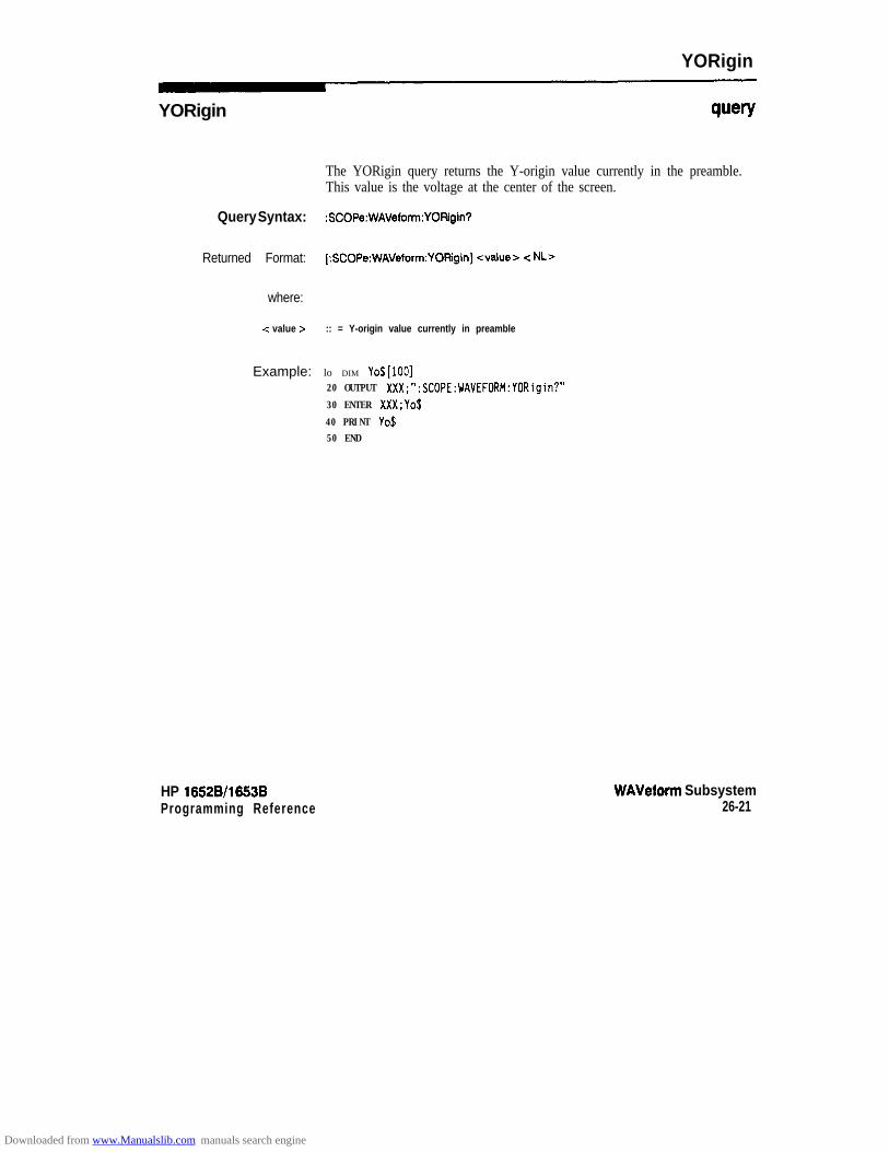
YORigin
YORigin wry
The YORigin query returns the Y-origin value currently in the preamble.This value is the voltage at the center of the screen.
Query Syntax: :SCOPe:WAVeform:YO!4igin?
Returned Format: [:SCOPe:WAVeform:YORgin] <value> c NL>
where:
c value > :: = Y-origin value currently in preamble
Example: lo DIM YO$[IOO]20 OUTPUT XXX;":SCOPE:WAVEFORM:YORigin?"
30 ENTER XXX;Yo$
40 PRINT Yo$50 END
HP 16528/1663B WAVeform SubsystemProgramming Reference 26-21
Downloaded from www.Manualslib.com manuals search engine

YREFerence
YREFerence query
The YREFerence query returns the Y-reference value in the preamble.The value specifies the data value at center screen where Y-origin occurs.
Query Syntax: :SCOPe:WAVeform:YREFerence?
Returned Format: [ : S C O P e : W A V e f o r m : Y R E F e r e n o e ] c v a l u e > < NL>
where:
<value > : : = Y - r e f e r e n c e v a l u e i n p r e a m b l e
Example: 10 DIM ~o$[iODl
20 OUTPUT XXX;":SCOPE:WAVEFORM:YREFerence?"
30 ENTER XXX;Yo$
40 PRINT Yo$
50 END
WAVeform Subsystem2622
HP 16528/1663BProgramming Reference
Downloaded from www.Manualslib.com manuals search engine
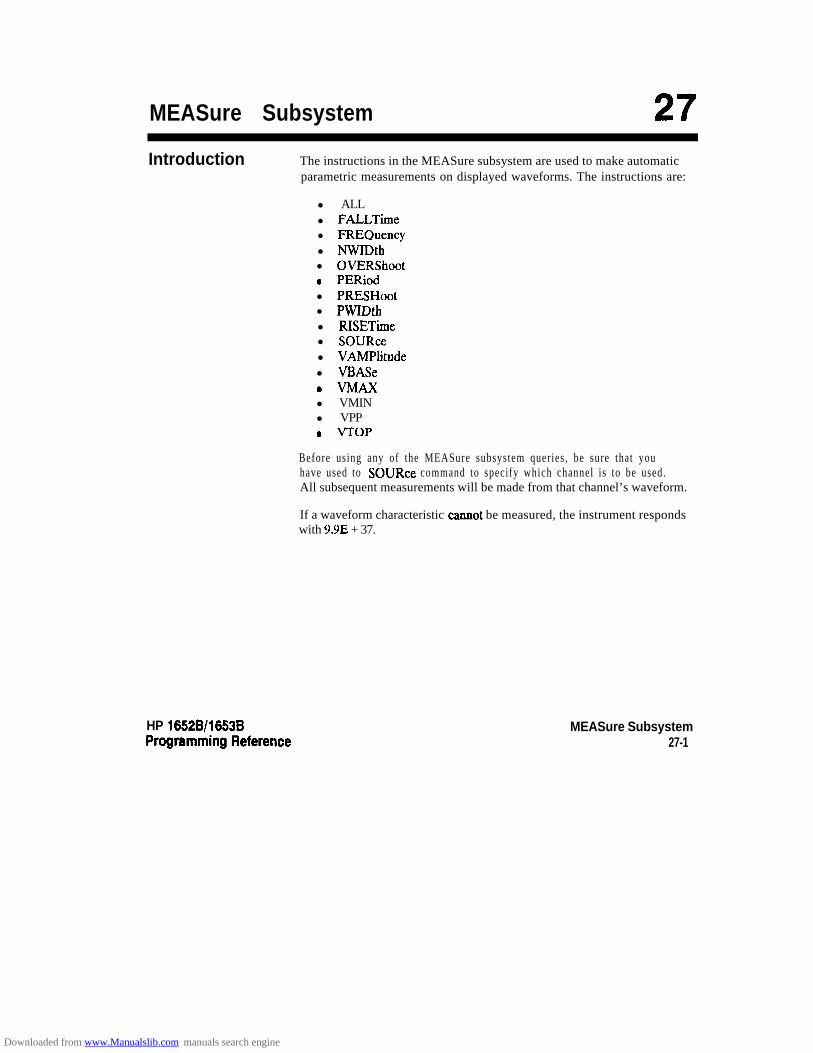
MEASure Subsystem 27Introduction The instructions in the MEASure subsystem are used to make automatic
parametric measurements on displayed waveforms. The instructions are:
l ALLl FALLTimel FREQuencyl NWIDthl OVERShoota PERiodl PRESHootl PWIDthl RISETimel SOURcel VAMPlitudel VBASe@vIaAxl VMINl VPP0 VTOP
Before using any of the MEASure subsystem queries, be sure that youhave used to SOURce command to specify which channel is to be used.All subsequent measurements will be made from that channel’s waveform.
If a waveform characteristic cannot be measured, the instrument respondswith 9.9E + 37.
HP 16528/1663B MEASure Subsystem27-1
Downloaded from www.Manualslib.com manuals search engine
The following characteristics can be measured:
The frequency of the first complete cycle displayed is measured using the50% level.
Frequency
Period
Peak-to-Peak
Positive Pulse Width
Negative Pulse Width
Risetime
Falltime
Preshoot andOvershoot
Preshoot
Overshoot
MEASure Subsystem27-2
The period of the first displayed waveform is measured at the 50% level.
The absolute minimum and the maximum voltages for the selected sourceare measured.
Pulse width is measured at the 50% level of the first displayed pulse.
Pulse width is measured at the 50% level of the first displayed pulse.
The risetime of the first displayed rising edge is measured. To obtain thebest possible measurement accuracy, select the fastest sweep speed whilekeeping the rising edge on the display. The risetime is determined bymeasuring time at the 10% and the 90% voltage points of the rising edge.
Falltime is measured between the 10% and the 90% points of the firstdisplayed falling edge. To obtain the best possible measurement accuracy,select the fastest sweep speed possible while keeping the fal l ing edge onthe display.
Preshoot and overshoot measure the perturbation on a waveform above orbelow the top and base voltages.
is a perturbation before a rising or a falling edge and measured as apercentage of the top-base voltage.
is a perturbation after a rising or falling edge and is measured as apercentage of the top-base voltage.
For complete details of the measurement algorithms, refer to theFront-panel Operating Reference Manual.
Refer to figure 27-l for the MEASure subsystem syntax diagram.
HP 16528/1653BProgramming Reference
Downloaded from www.Manualslib.com manuals search engine

channel-# = un infeger { 2 1 2).
Figure 27-l. MEASure Subsystem Syntax Diagram
HP 16528/16538Programming Reference
MEASure Subsystem27-3
Downloaded from www.Manualslib.com manuals search engine

MEASure
MEASure
Command Syntax:
Example:
selector
The MEASure selector is used as part of a compound command headerto access the set t ings found in oscil loscope’s Measure menu. I t alwaysfollows the SCOPe selector because it selects a branch below the SCOPelevel in the command tree.
:SCOPe:MEASure
OUTPUT XXX; ":SCOPE:MEASURE:SOURCE CHANZ"
Note dAll queries in this subsystem return the measurement results of the lastchannel specified by the SOURce command. If you want measurementresults from the other channel, you must use the SOURce commandbefore using any of the queries.
MEASure Subsystem27-4
HP 16526/l 6538Programming Reference
Downloaded from www.Manualslib.com manuals search engine

ALL
ALL
Query Syntax:
Returned Format:
Example:
query
The ALL query makes a set of measurements on the displayed waveformusing the selected source.
:SCOPe:MEASure:[SOURce CHANnel(1 IP};]ALL?
[:SCOPe:MEASure:ALL PERiod] <real number > ;
[RISETime] <real number > ;
[FALLTime] <real number > ;
(FREOuency] <real number > ;
[PWIDtH] c real number > ;
[NWIMH] <real number > ;
[VPP] c real number > ;PAMPlitude] -c real number > ;
[PRESHoot] <real number > ;
[OVERShoot] c real number > -c NL>
10 DIM Query$[30D]2 0 !PRINTER IS 701 !THIS LINE SENDS RESULTS TO PRINTER30 OUTPUT XXX;” :SCOPE:MEASURE:SOUR CHANI”
40 OUTPUT XXX;” :SCOPE:MEASURE:ALL?”
50 ENTER XXX;Query$60 Query$=Query$[POS(Query$,“;“)+l]70 LOOP80 I=POS(Query$.“:“)90 EXIT IF NOT I100 PRINT Query$ [l, I-l]110 Query$=Query$ [ I+l]
120 END LOOP130 PRINT Query$
140 PRINTER IS 1150 END
HP 16528/1653B MEASure Subsystem27-5
Downloaded from www.Manualslib.com manuals search engine

FALLTime
FALLTimeA
query
The FALLTime query makes a falI time measurement on the selectedchannel. The measurement is made between the 90% to the 10% voltagepoint of the f irs t fal l ing edge displayed on screen.
Note 6The short form of FALLTIME is FALLTime. This is an intentionaldeviation of the normal truncation rule.
Query Syntax: :SCOPe:MEASure:[SOUR CHANnel{l 12};]FALLTime?
Returned Format: [:SCOPe:MEASure:FALLTime] <value > c NL>
where:
c value > :: = time in seconds between 10% and 90% voltage points
Example: 10 DIM Ft$[lOO]20 OUTPUT XXX;":SCOPE:MEASURE:SOURCE CHANNELE;FALLTIME?"
30 ENTER XXX;Ft$
40 PRINT Ft$
50 END
MEASure Subsystem27-6
HP 16528/1653B
Downloaded from www.Manualslib.com manuals search engine

FREQuency
FREQuency query
The FREQency query makes a frequency measurement on the selectedchannel. The measurement is made using the first complete displayedcycle at the 50% voltage level .
Query Syntax: :SCOPe:MEASure:[SOUR CHANnel{lI2};]FREQuency?
k?turned Format: [:MEAsure:FREOuency] <value> <NL>
where:
<value > :: = frequency in HerQ
Example: 10 DIM Frcy$[lOO]20 OUTPUT XXX;":SCOPE:MEASURE:SOUR CHANl;FREQ?"
30 ENTER XXX;Frcy$
40 PRINT Frcy$
50 END
HP 16528/16538 MEASure Subsystem27-7
Downloaded from www.Manualslib.com manuals search engine

NWIDth
NWIDth query
The NWIDth query makes a negative width time measurement on theselected channel. The measurement is made between the 50% points ofthe first falling and the next rising edge displayed on screen.
Query Syntax: :SCOPe:MEASure:[SOU!%e CHANnel{l JP};]NWlMh?
Returned Format: [:SCOPe:MEASure:NWIDth] <value> <NL>
where:
<value B :: = negative pulse width in seconds
Example: 10 DIM Nw$[lOO]20 OUTPUT XXX; ":SCOPE:MEASURE:SOURCE CHANP;NWID?"30 ENTER XXX;Nw$
40 PRINT Nw$
50 END
MEASure Subsystem27-8
HP 18528/1853BProgramming Reference
Downloaded from www.Manualslib.com manuals search engine
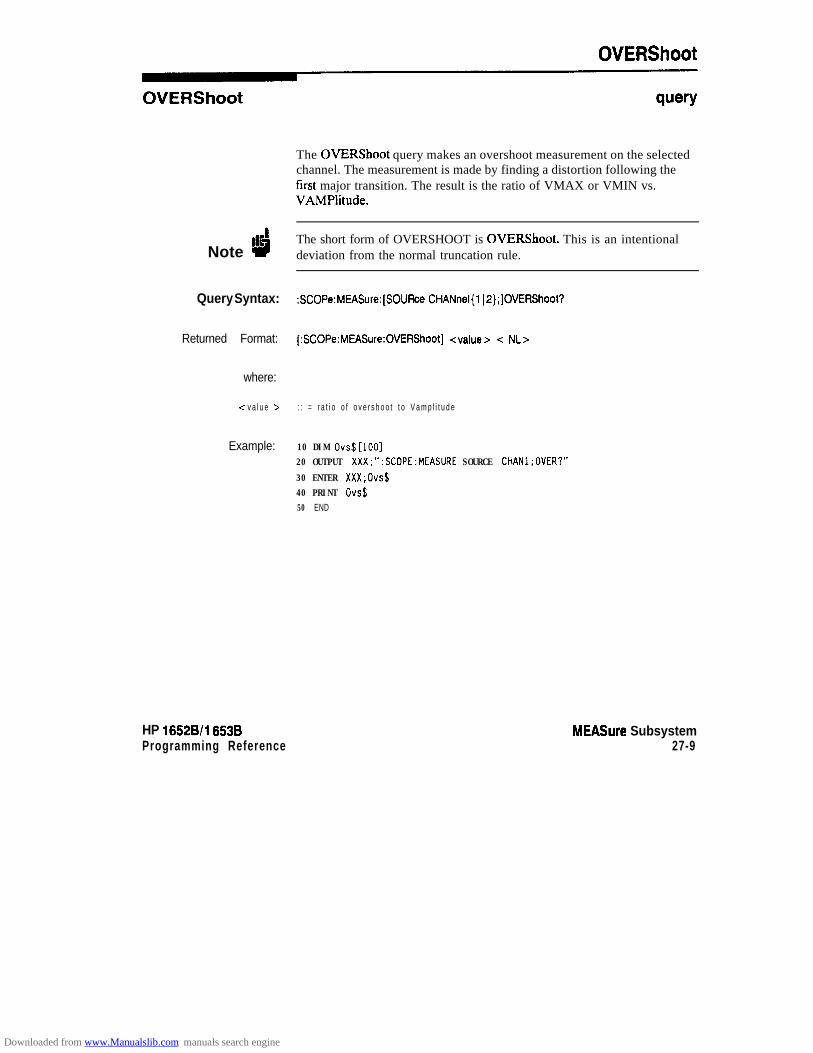
OVERShoot
OVERShoot query
The OVERShoot query makes an overshoot measurement on the selectedchannel. The measurement is made by finding a distortion following thefirst major transition. The result is the ratio of VMAX or VMIN vs.VAMPlitude.
Note dThe short form of OVERSHOOT is OVERShoot. This is an intentionaldeviation from the normal truncation rule.
Query Syntax: :SCOPe:MEASure:[SOURce CHANnel{lI2};]OVERShoot?
Returned Format: [:SCOPe:MEASure:OVERShoot] <value> -= NL>
where:
-= v a l u e > : : = r a t i o o f o v e r s h o o t t o V a m p l i t u d e
Example: 10 DIM Ovs$[lOO]20 OUTPUT XXX;":SCOPE:MEASURE SOURCE CHANl;OVER?"
30 ENTER XXX;Ovs$40 PRINT Ovs$50 END
HP 165218/l 6538Programming Reference
MEASure Subsystem27-9
Downloaded from www.Manualslib.com manuals search engine

PERiod
PERiod query
The PERiod query makes a period measurement on the selected channel.The measurement equivalent to the inverse of frequency.
Query Syntax: :SCOPe:MEASure:[SOURce CHANnel{l jP};]PERiod?
Returned Format: (:SCOPe:MEASure:PERiod] <value> c NLz-
where:
<value > :: = waveform period in seconds
Example: lo DIM Pd$[lOOl20 OUTPUT XXX;":SCOPE:MEASURE:SOURCE CHANNELl;PERIDD?"
30 ENTER XXX;Pd$
40 PRINT Pd$
50 END
MEASure Subsystem27-10
HP 16528/1653B
Downloaded from www.Manualslib.com manuals search engine
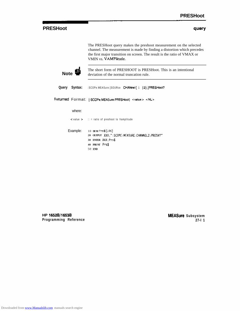
PRESHoot
PRESHoot query
The PRESHoot query makes the preshoot measurement on the selectedchannel. The measurement is made by finding a distortion which precedesthe first major transition on screen. The result is the ratio of VMAX orVMIN vs. VAMPlitude.
Note dThe short form of PRESHOOT is PRESHoot. This is an intentionaldeviation of the normal truncation rule.
Query Syntax: : S C O P e : M E A S u r e : [ S O U R c e CHANnel{ 1 I2};]PRESHoot?
Rf?tUrtWd Format: [:SCOPe:MEASure:PRESHoot] <value> <NL>
where:
c v a l u e > : : = r a t i o o f p r e s h o o t t o V a m p l i t u d e
Example: 10 DIM Prs$[lOO]20 OUTPUT XXX;":SCOPE:MEASURE:CHANNELZ:PRESH?"
30 ENTER XXX:Prs$
40 PRINT Prs$
50 END
HP 1652B/l653BProgramming Reference
MEASure Subsystem27-l 1
Downloaded from www.Manualslib.com manuals search engine
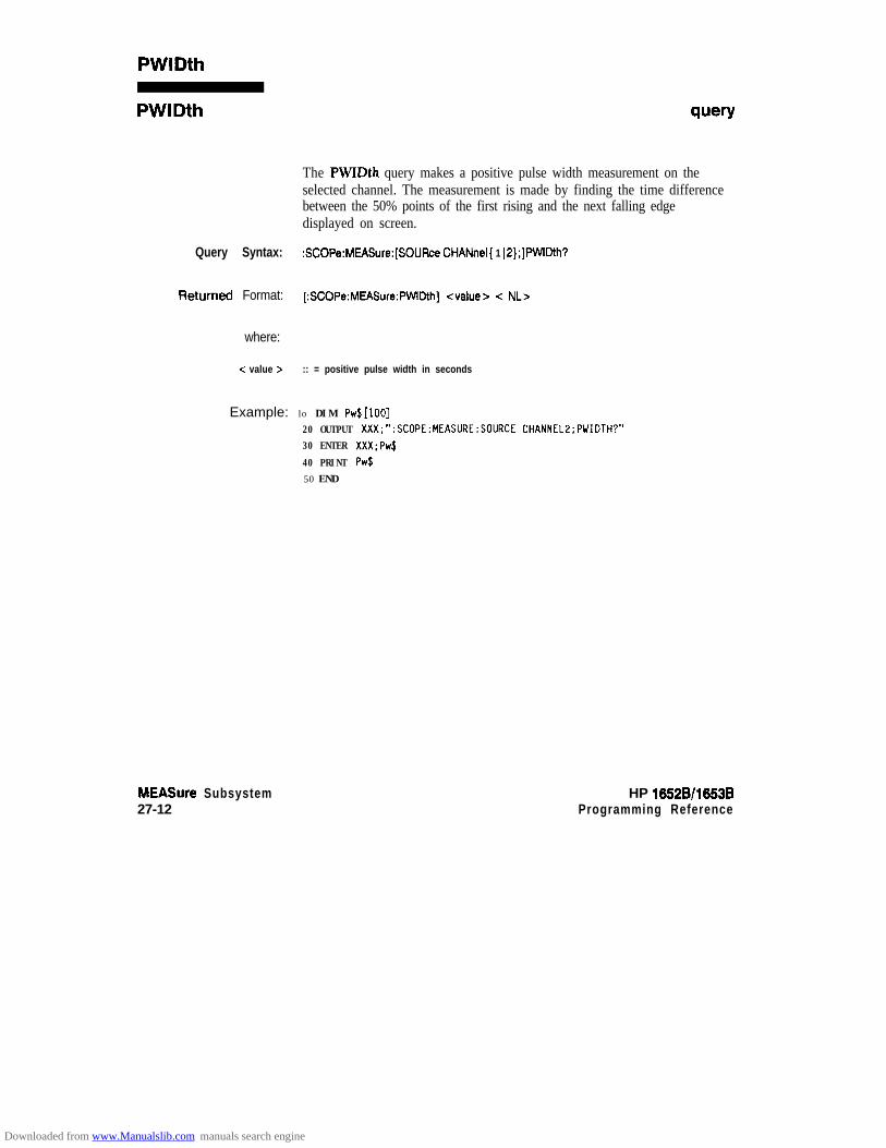
PWlDth
PWIDth wry
The PWIDth query makes a positive pulse width measurement on theselected channel. The measurement is made by finding the time differencebetween the 50% points of the first rising and the next falling edgedisplayed on screen.
Query Syntax: :SCOPe:MEASure:[SOUFtca CHANnelI 1 IP};]PWIMh?
RetUrned Format: [:SCOPe:MEASure:PWIDth] <value> c NL>
where:
c value r :: = positive pulse width in seconds
Example: lo DIM Pw$[lOO]20 OUTPUT XXX;":SCOPE:MEASURE:SOURCE CHANNELZ;PWIOTH?"30 ENTER XXX;Pw$
40 PRINT Pw$50 END
MEASure Subsystem27-12
HP 16528/1663BProgramming Reference
Downloaded from www.Manualslib.com manuals search engine

RISETime
RISETime query
The RISETime query makes a risetime measurement on the selectedchannel by finding the 10% and 90% voltage levels of the first rising edgedisplayed on screen.
Note dThe short form of RISETIME is RISETime. This is an intentionaldeviation from the normal truncation rule.
Query Syntax: :SCOPe:MEASure:[SOURe CHANnel(1 IS};]RISETime?
Returned Format: [:SCOPe:MEASure:RISETime] <value > c NL >
where:
<value > :: = risetime in seconds
Example: 10 DIM Tr$[lOO]20 OUTPUT XXX;":SCOPE:MEASURE:SOlJRCE CHANNELl;RISETIME?"
30 ENTER XXX;Tr$40 PRINT Tr$
50 END
HP 16528/1653BProgramming Reference
MEASure Subsystem27-13
Downloaded from www.Manualslib.com manuals search engine
SOURce
SOURce
Command Syntax:
where:
c source >
Example:
Query Syntax:
Returned Format:
Example:
MEASure Subsystem27-14
command/query
The SOURce command specifies the source to be used for subsequentmeasurements. If the source is not specified, the last waveform source isassumed.
The query returns the presently specified channel.
:SCOPe:MEASure:SOUR <source>
::= {l 12)
OUTPUT XXX;":SCOPE:MEASlJRE:SOURCE CHANI"
: S C O P e : M E A S u r e : S O U R c e ?
[:SCOPe:MEASure:SOUFke] CHANnel -z N> c NL>
10 DIM so$[loo]20 OUTPUT XXX;" :SCOPE:MEASURE:SOURCE?"3 0 E N T E R XXX;So$
40 PRINT So$50 END
HP 16528/1663BProgramming Reference
Downloaded from www.Manualslib.com manuals search engine

VAMPlitude
VAM Plitude query
The VAMPlitude query makes a voltage measurement on the selectedchannel. The measurement is made by finding the relative maximum andminimum points on screen.
Query Syntax: :SCOPe:MEASure:[SOlJFce CHANnel{l IP};]VAMPlitude?
Returned Format: [:SCOPe:MEASure:VAMPlitude] <value > < NL>
where:
<value > : : = d i f f e r e n c e b e t w e e n t o p a n d b a s e v o l t a g e
Example: 10 DIM Va$[lOO]20 OUTPUT XXX;":SCOPE:MEASURE:SDURCE CHANNELZ;VAMP?"30 ENTER XXX;Va$40 PRINT Va$
50 END
HP 16528/l 6538Programming Reference
MEASure Subsystem27-15
Downloaded from www.Manualslib.com manuals search engine
VBASe
VBASe query
The VBASe query returns the base voltage (relative minimum) of adisplayed waveform. The measurement is made on the selected source.
Query Syntax: :SCOPe:MEASure:[SOURce CHANnel(1 12};]VBASe?
Returned Format: [:SCOPe:MEASure:VBASe] <value > c NL>
where:
c v a l u e > : : = v o l t a g e a t b a s e l e v e l o f s e l e c t e d w a v e f o r m
Example: 10 DIM Vb$[lOO]
20 OUTPUT XXX;":SCOPE:MEASlJRE:SOURCE CHANl;VBAS?"30 ENTER XXX;Vb$
40 PRINT Vb$
50 END
MEASure Subsystem27-16
HP 16526/l 6538Programming Reference
Downloaded from www.Manualslib.com manuals search engine

VMAX
V M A X query
The Vh4AX query returns the absolute maximum voltage of the selectedsource.
Query Syntax: :SCOPe:MEASure:(SOUR CHANnel{l (P};]VMAX?
k!turWd Format: (:SCOPe:MEASure:VMAX] <value > < NLT-
where:
<value > :: = maximum voltage of selected waveform
Example: 10 DIM Vma$[lOO]
20 OUTPUT XXX;":SCOPE:MEASURE:SOURCE CHANL;VMAX?"
30 ENTER XXX;Vma$40 PRINT Vma$
50 END
HP 16528/l 6538 MEASure Subsystem27-17
Downloaded from www.Manualslib.com manuals search engine

VMIN
VMIN
The Vh4IN query returns the absolute minimum voltage present on theselected source.
Query Syntax: :SCOPe:MEASure:[SOUFke CHANnel{l~2};]VMIN?
Returned Format: [:SCOPe:MEASure VMIN] -z value > c NL 5
where:
c value > :: = minimum voltage of selected waveform
Example: 10 DIM Vmi$[lOO]20 OUTPUT XXX;":SCOPE:MEASURE:SOURCE CHANl;VMIN?"
30 ENTER XXX;Vmi$
40 PRINT Vmi$
50 END
MEASure Subsystem27-18
HP 18526/1653B
Downloaded from www.Manualslib.com manuals search engine
VPP
VPP
query
The VPP query makes a peak-to-peak voltage measurement on theselected source. The measurement is made by finding the absolutemaximum and minimum points on the displayed waveform.
Query Syntax: :SCOPe:MEASure:[SOUR CHANnel{lI2};]VPP?
Returned Format: [:SCOPe:MEASure:VPP] cvaluez <NL>
where:
<value> : : = p e a k t o p e a k v o l t a g e o f s e l e c t e d w a v e f o r m
Example: 10 DIM Vpp$[lOO]20 OUTPUT XXX;":SCOPE:MEASURE:SOURCE CHANl;VPP?"
30 ENTER XXX;Vpp$
40 PRINT Vpp$50 END
HP 16528/1653B MEASure Subsystem27-19
Downloaded from www.Manualslib.com manuals search engine
VTOP
VTOP
The VTOP query returns the voltage at the top (relative maximum) ofwaveform on the selected source.
Query Syntax: :SCOPe:MEASure:[SOLJRce CHANnel{l I2};]VTOP7
Returt’d F o r m a t : [:SCOPe:MEASure:VTOP] <value> <NL>
where:
c value > :: = voltage at the top of the selected waveform
Example: 10 DIM vt$[lool20 OUTPUT XXX;“:SCOPE:MEASURE:SOURCE CHAN2;VTOP?”30 ENTER XXX;Vt$40 PRINT Vt$
50 END
MEASure Subsystem27-20
HP 16528/1653BProgramming Reference
Downloaded from www.Manualslib.com manuals search engine

Message Communicationand System Functions
A
Introduction This appendix describes the operation of instruments that operate incompliance with the IEEE 488.2 (syntax) standard. Although theHP 1652B and HP 1653B logic analyzers are RS-232C instruments, theywere designed to be compatible with other Hewlett-Packard IEEE 488.2compatible instruments.
The IEEE 488.2 standard is a new standard. Instruments that arecompatible with IEEE 488.2 must also be compatible with IEEE 488.1(HP-IB bus standard); however, IEEE 488.1 compatible instruments mayor may not conform to the IEEE 488.2 standard. The IEEE 488.2standard defines the message exchange protocols by which the instrumentand the controller will communicate. It also defines some commoncapabilities, which are found in all IEEE 488.2 instruments. Thisappendix also contains a few items which are not specifically defined byIBEE 488.2, but deal with message communication or system functions.
Note dThe syntax and protocol for RS-232C program messages and responsemessages for the HP 1652B/1653B are structured very similar to thosedescribed by 488.2. In most cases, the same structure shown in thisappendix for 488.2 will also work for RS-232C. Because of this, noadditional information has been included for RS-232C.
HP 1652B/l653B Message Communication and System FunctionsProgremming Reference A-l
Downloaded from www.Manualslib.com manuals search engine

Protocols The protocols of IEEE 488.2 define the overall scheme used by thecontroller and the instrument to communicate. This includes definingwhen it is appropriate for devices to talk or listen, and what happens whenthe protocol is not followed.
Functional Elements Before proceeding with the description of the protocol, a few systemcomponents should be understood.
Input Buffer. The input buffer of the instrument is the memory areawhere commands and queries are stored prior to being parsed andexecuted. It allows a controller to send a string of commands to theinstrument which could take some time to execute, and then proceed totalk to another instrument while the first instrument is parsing andexecuting commands.
Output Queue. The output queue of the instrument is the memory areawhere all output data ( -C response messages > ) are stored until read bythe controller.
Parser. The instrument’s parser is the component that interprets thecommands sent to the instrument and decides what act ions should betaken. “Parsing” refers to the action taken by the parser to achieve thisgoal. Parsing and executing of commands begins when either theinstrument recognizes a c program message terminator > (defined laterin this appendix) or the input buffer becomes full. If you wish to send along sequence of commands to be executed and then talk to anotherinstrument while they are executing, you should send all the commandsbefore sending the c program message terminator > .
Message Communication and System Functions HP 16528/1653BA-2 Programming Reference
Downloaded from www.Manualslib.com manuals search engine
Protocol Overview The instrument and controller communicate using < program message > sand < response message > s. These messages serve as the containers intowhich sets of program commands or instrument responses are placed.c program message > s are sent by the controller to the instrument, andc response message z= s are sent from the instrument to the controller inresponse to a query message. A < query message > is defined as being a< program message > which contains one or more queries. Theinstrument will only talk when it has received a valid query message, andtherefore has something to say. The controller should only attempt toread a response after sending a complete query message, but beforesending another c program message > . The basic rule to remember isthat the instrument will only talk when prompted to, and it then expects totalk before being told to do something else.
Protocol Operation When the instrument is turned on, the input buffer and output queue arecleared, and the parser is reset to the root level of the command tree.
The instrument and the controller communicate by exchanging complete< program message > s and < response message > s. This means that thecontroller should always terminate a < program message > beforeattempting to read a response. The instrument will terminate -z responsemessage > s except during a hardcopy output.
If a query message is sent , the next message passing over the bus shouldbe the < response message > . The controller should always read thecomplete < response message > associated with a query message beforesending another < program message > to the same instrument.
The instrument allows the controller to send multiple queries in one querymessage. This is referred to as sending a “compound query.” As will benoted later in this appendix, multiple queries in a query message areseparated by semicolons. The responses to each of the queries in acompound query wil l also be separated by semicolons.
Commands are executed in the order they are received.
HP 1662B11653BProgramming Reference
Message Communication and System FunctionsA-3
Downloaded from www.Manualslib.com manuals search engine

Protocol Exceptions If an error occurs during the information exchange, the exchange may notbe completed in a normal manner. Some of the protocol exceptions areshown below.
Command Error. A command error will be reported if the instrumentdetects a syntax error or an unrecognized command header.
Execution Error. An execution error will be reported if a parameter isfound to be out of range, or if the current settings do not allow executionof a requested command or query.
Device-specific Error. A device-specilic error will be reported if theinstrument is unable to execute a command for a strictly device dependentreason.
Query Error. A query error will be reported if the proper protocol forreading a query is not followed. This includes the interrupted andunterminated conditions described in the following paragraphs.
Message Communication and System FunctionsA-4
HP 16528/1653BProgramming Reference
Downloaded from www.Manualslib.com manuals search engine

SyntaxDiagrams
The syntax diagrams in this appendix are similar to the syntax diagrams inthe IEEE 488.2 specification. Commands and queries are sent to theinstrument as a sequence of data bytes. The allowable byte sequence foreach functional element is defined by the syntax diagram that is shownwith the element description.
The allowable byte sequence can be determined by following a path in thesyntax diagram. The proper path through the syntax diagram is any paththat follows the direction of the arrows. If there is a path around anelement, that element is optional. If there is a path from right to leftaround one or more elements, that element or those elements may berepeated as many times as desired.
SyntaxOverview
This overview is intended to give a quick glance at the syntax defined byIEEE 488.2. It should allow you to understand many of the things aboutthe syntax you need to know. This appendix also contains the details ofthe IEEE 488.2 defined syntax.
IEEE 488.2 defines the blocks used to build messages which are sent tothe instrument. A whole string of commands can therefore be broken upinto individual components .
Figure A-l shows a breakdown of an example c program message > .There are a few key items to notice:
1. A semicolon separates commands from one another. Each< program message unit > serves as a container for one command.The < program message unit > s are separated by a semicolon.
2. A < program message > is terminated by a < NL > (new line). T h erecognition of the < program message terminator > , or < PMT > ,by the parser serves as a signal for the parser to begin execution ofcommands. The < PMT > also affects command tree traversal (seethe Programming and Documentation Conventions chapter).
3. Multiple data parameters are separated by a comma.,
HP 16528/1653B Message Communication and System FunctionsProgramming Reference A-5
Downloaded from www.Manualslib.com manuals search engine

4. The first data parameter is separated from the header with one ormore spaces.
5. The header MACHINEl:ASSIGN 2,3 is an example of a compoundheader. It places the parser in the machine subsystem until the< NL > is encountered.
6. A colon preceding the command header returns you to the top of thecommand tree.
Message Communication and System FunctionsA-6
HP 16528/16538Programming Reference
Downloaded from www.Manualslib.com manuals search engine

: T W A V E F O R M : O S E A R C H 3 0 , T R I G G E R ; D E L A Y 3 8 ns <NL>
>T----F--I=------4
<program message unit>
I 1
TWAVEFORM~OSEARCH 30,TRIGGER
<<ownand program header>~~~progra\l~~‘~
< w h i t e space> <white s p a c e >
/q rogrnm m n e m o n i c > : <program mnemon,c> <progrm data> <program data separator> <program doto>
TWAVE FORM OSEARCH 30 TRIGGER-
<dec!mal numeric p r o g r a m d a t a > <program data>30 TRIGGER
DELAY
<uh, le space> <declmaI p r o g r a m doto>
<program message termlnctor>S P <NL>
<white SDOC~> N L
dota>
----l< s u f f i x program dot&
38 SP “5
/7\<white space> <suffix multiplier> <SUfflX tInIt>
” s
Figure A-l. < program message > Parse Tree
HP 16628/1653BProgramming Reference
Message Communication and System FunctionsA-7
Downloaded from www.Manualslib.com manuals search engine
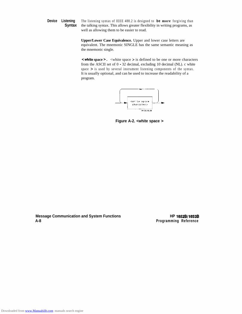
Device Listening The l is tening syntax of IEEE 488.2 is designed to be more forgiving thanSyntax the talking syntax. This allows greater flexibility in writing programs, as
well as allowing them to be easier to read.
Upper/Lower Case Equivalence. Upper and lower case letters areequivalent. The mnemonic SINGLE has the same semantic meaning asthe mnemonic single.
<white space > . <white space > is defined to be one or more charactersfrom the ASCII set of 0 - 32 decimal, excluding 10 decimal (NL). c whitespace > is used by several instrument l is tening components of the syntax.It is usually optional, and can be used to increase the readability of aprogram.
Figure A-2. <white space >
Message Communication and System FunctionsA-8
HP 16528/1653BProgramming Reference
Downloaded from www.Manualslib.com manuals search engine
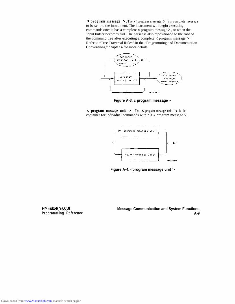
HP 16!52B/l653BProgramming Reference
< program message >. The (: program message > is a complete messageto be sent to the instrument. The instrument will begin executingcommands once it has a complete -E program message > , or when theinput buffer becomes full. The parser is also repositioned to the root ofthe command tree after executing a complete c program message 7.
Refer to “Tree Traversal Rules” in the “Programming and DocumentationConventions,” chapter 4 for more details.
<programmessage uwt
separator>
I?, piiii-z-B
Figure A-3. c program message >
C program message unit > . The < program message unit > is thecontainer for individual commands within a < program message 7.
Figure A-4. <program message unit >
Message Communication and System FunctionsA-9
Downloaded from www.Manualslib.com manuals search engine
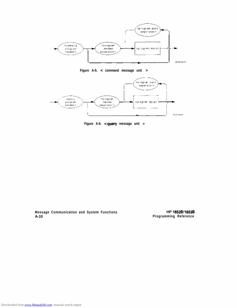
Figure A-5. c command message unit >
<program doto>
Figure A-6. <query message unit >
Message Communication and System FunctionsA-10
HP 16528/16538Programming Reference
Downloaded from www.Manualslib.com manuals search engine
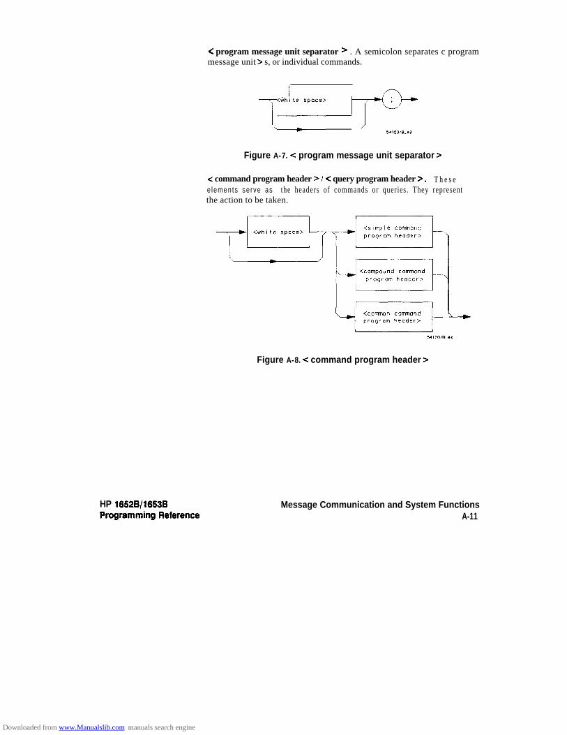
HP 16528/16538
< program message unit separator > . A semicolon separates c programmessage unit > s, or individual commands.
ii<whityace> /---+E
Figure A-7. < program message unit separator >
< command program header > / < query program header 7. T h e s ee lemen ts se rve as the headers of commands or queries. They representthe action to be taken.
‘-i
<comran cormmndprogro” header>
c
Figure A-8. < command program header 7
Message Communication and System FunctionsA-11
Downloaded from www.Manualslib.com manuals search engine
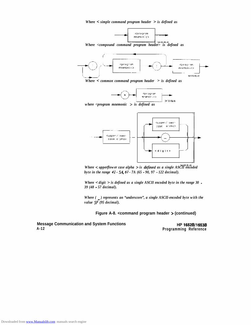
Where c simple command program header > is defined as
Where <compound command program header> is defined as
Where < common command program header > is defined as
+y--GG-r.541*O/BL45
where <program mnemonic > is defined as
tupper/lower- case alpha> 7
b < d i g i t > -
Where < upperflower case alpha > is defined as a single ASCII encodedbyte in the range 41- 5A, 61- 7A (65 - 90, 97 - 122 decimal).
Where < digit > is defined as a single ASCII encoded byte in the range 30 -39 (48 - 57 decimal).
Where ( _ ) represents an “underscore”, a single ASCII-encoded byte with thevalue SF (95 decimal).
Figure A-8. <command program header > (continued)
Message Communication and System FunctionsA-12
HP 16528/1663BProgramming Reference
Downloaded from www.Manualslib.com manuals search engine

Y
<Comnon q u e r y
program header>
Where <simple quevprogram header > is defined as
- m”emo”lc> /---+p
< p r o g r a m
Where -C compound query program header > is defined as
l-a-, 54lZwBL45Where < common query program header > is defined as
HP 16528/1653BProgramming Reference
l--+3--Figure A-9. <query program header >
Message Communication and System FunctionsA-13
Downloaded from www.Manualslib.com manuals search engine
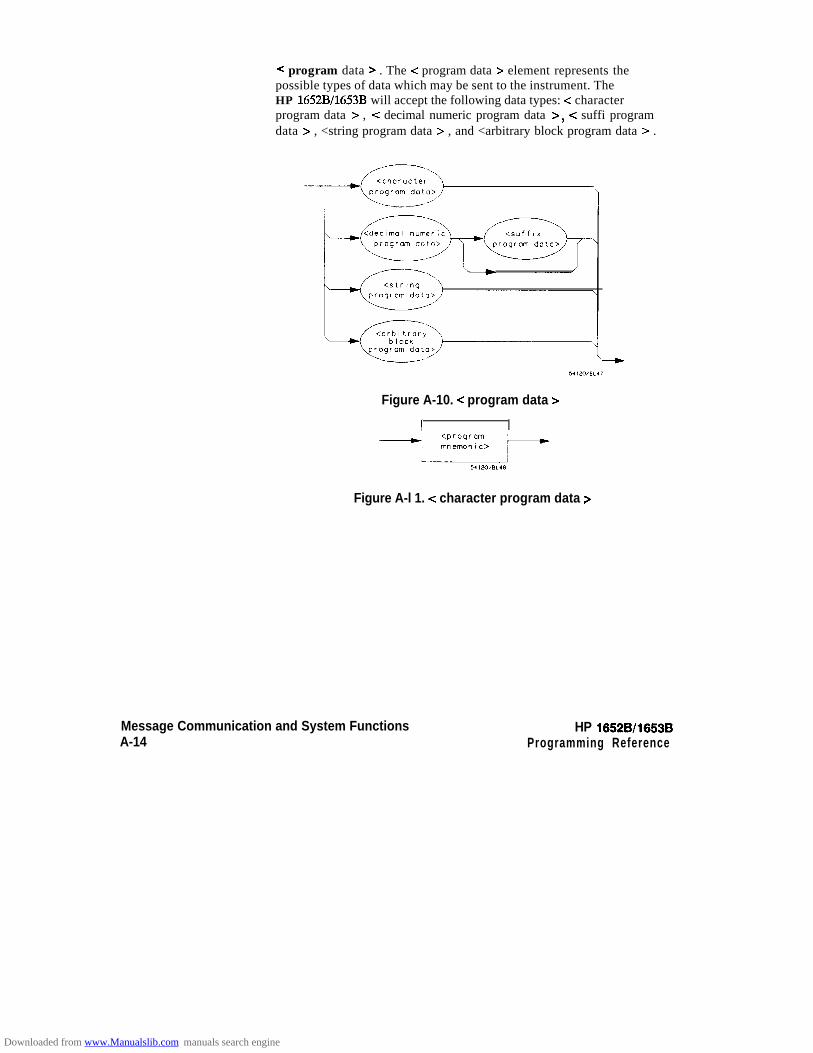
< program data > . The < program data > element represents thepossible types of data which may be sent to the instrument. TheHP 1652B/1653B will accept the following data types: < characterprogram data > , -Z decimal numeric program data >, < suffi programdata > , <string program data > , and <arbitrary block program data > .
Figure A-10. < program data >
1
Figure A-l 1. < character program data >
Message Communication and System FunctionsA-14
HP 16528/16538Programming Reference
Downloaded from www.Manualslib.com manuals search engine

U%ere c mantissa > is defined as
Where c optional digits > is defined as
(y---z&jWhere < exponent > is defined as
Figure A-12. c decimal numeric program data >
HP 16628/16536Programming Reference
Message Communication and System FunctionsA-15
Downloaded from www.Manualslib.com manuals search engine
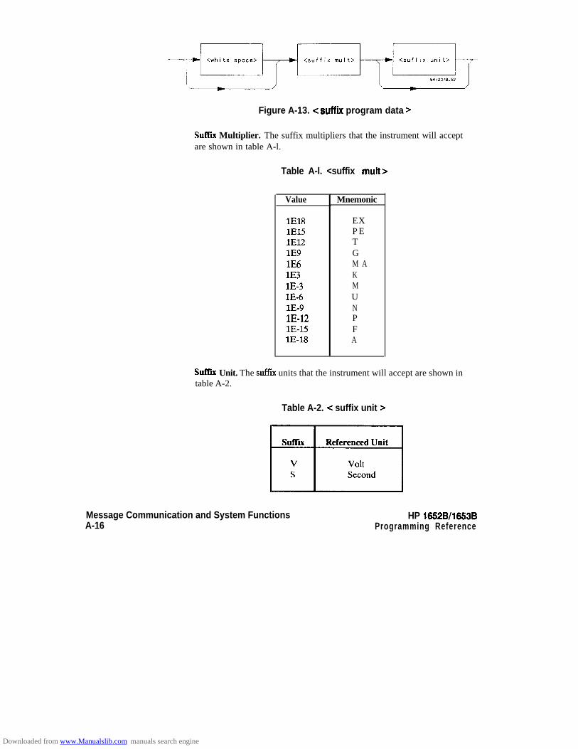
-$iyz-;::+sb
Figure A-13. <suffix program data >
Suffer Multiplier. The suffix multipliers that the instrument will acceptare shown in table A-l.
Table A-l. <suffix mutt>
Value
lE18lE1.5lE12lE9lE6lE3lE-3lE-6l.E-9lE-12lE-15lE-18
Mnemonic
EXP ETGM AKMUNPFA
Suffer Unit. The suffix units that the instrument will accept are shown intable A-2.
Table A-2. < suffix unit >
Message Communication and System FunctionsA-16
HP 16528/1653BProgramming Reference
Downloaded from www.Manualslib.com manuals search engine

HP 16628/l 6538Programming Reference
< i n s e r t e d ’ > --,
\ <non-single J) q u o t e char>
I I
where <inserted ‘> is defined as a single ASCII character with the value 27(39 decimal).
Where +z non-single quote char > is defined as a single ASCII character ofany value except 27 (39 decimal).
Where c inserted “> is defined as a single ASCII character with the value 22(34 decimal).
Where <non-double quote char > is defined as a single ASCII character ofany value except 22 (34 decimal)
Figure A-14. <string program data >
Message Communication and System FunctionsA-17
Downloaded from www.Manualslib.com manuals search engine
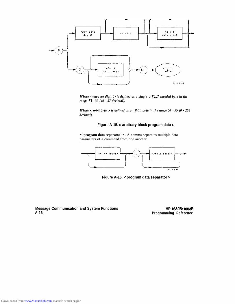
Where <non-zero digit > is defined as a single ASCII encoded byte in therange 31- 39 (49 - 57 decimal).
Where < &bit byte > is defined as an &bit byte in the range 00 - FF (0 - 255decimal).
Figure A-15. c arbitrary block program data >
C program data separator > . A comma separates multiple dataparameters of a command from one another.
Figure A-16. < program data separator >
Message Communication and System FunctionsA-16
HP 16528/1663BProgramming Reference
Downloaded from www.Manualslib.com manuals search engine

HP 16528/1653BProgramming Reference
< program header separator > . A space separates the header from thefirst or only parameter of the command.
Figure A-17. < program header separator >
< program message terminator > . The < program message terminator >or < PMT > serves as the terminator to a complete < programmessage > . When the parser sees a complete c program message > itwill begin execution of the commands within that message. The -C PMT >also resets the parser to the root of the command tree.
~--y----b <whi te space>
where < NL > is defined as a single ASCII-encoded byte Q4 (10 decimal).
Figure A-18. < program message terminator >
Message Communication and System FunctionsA-19
Downloaded from www.Manualslib.com manuals search engine
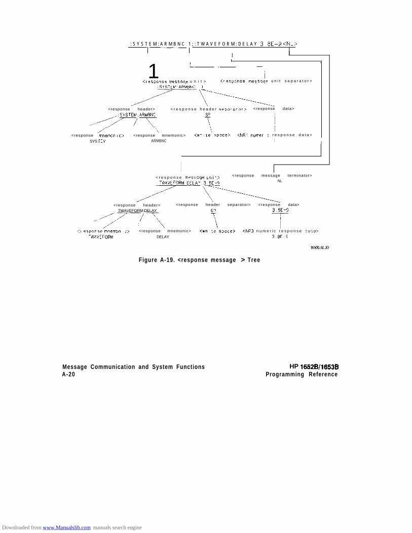
: S Y S T E M : A R M B N C 1 ; : T W A V E F O R M : D E L A Y 3.8E-9 <NL>-1 I
I I I II I I I
1 -CresDc~nse messor~e u n i t > <resoonse message u n i t s e p a r a t o r >
<response header> < r e s p o n s e h e a d e r separator> <response data>
,~,+YSTE;AR~,C SP 1
.,A \ T 1<response rn”l3llO”lC> <response mnemonic> <white space> <NRl numeric r e s p o n s e d a t a >
SYS IEM ARMBNC 1I
< r e s p o n s e message unit> <response message terminator>
TWAVEFORM.DELAY 3.8E-9 NL
<response header> <response header separator> <response data>TWAVEFORM:DELAY 3.8EG9
~:r esponse mnemon I c> <response mnemonic> <white space> <NR3 n u m e r i c r e s p o n s e data>TWAVEFORM DELAY 3.8E-9
Figure A-19. <response message > Tree
Message Communication and System Functions HP 16528/1653BA-20 Programming Reference
Downloaded from www.Manualslib.com manuals search engine
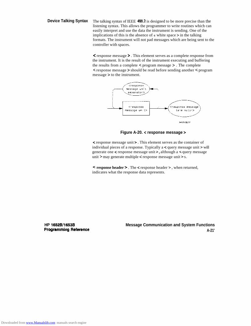
Device Talking Syntax The talking syntax of IEEE 488.2 is designed to be more precise than thelistening syntax. This allows the programmer to write routines which caneasily interpret and use the data the instrument is sending. One of theimplications of this is the absence of c white space > in the talkingformats. The instrument will not pad messages which are being sent to thecontroller with spaces.
HP 16528/1653B
< response message > . This element serves as a complete response fromthe instrument. It is the result of the instrument executing and bufferingthe results from a complete -C program message > . The completec response message > should be read before sending another c programmessage > to the instrument.
Figure A-20. e response message >
< response message unit > . This element serves as the container ofindividual pieces of a response. Typically a < query message unit > willgenerate one < response message unit >, although a < query messageunit > may generate multiple c response message unit > s.
< response header > . The c response header > , when returned,indicates what the response data represents.
Message Communication and System FunctionsA-21’
Downloaded from www.Manualslib.com manuals search engine

?Vhere <simple response mnemonic > is defined as
where < compound response header > is defined as
pf*Fk&i_LI:--1-54120/&60
Where < common response header Y is defined as
Figure A-21. <response message unit >
Message Communication and System FunctionsA-22
HP 16528/1653BProgramming Reference
Downloaded from www.Manualslib.com manuals search engine
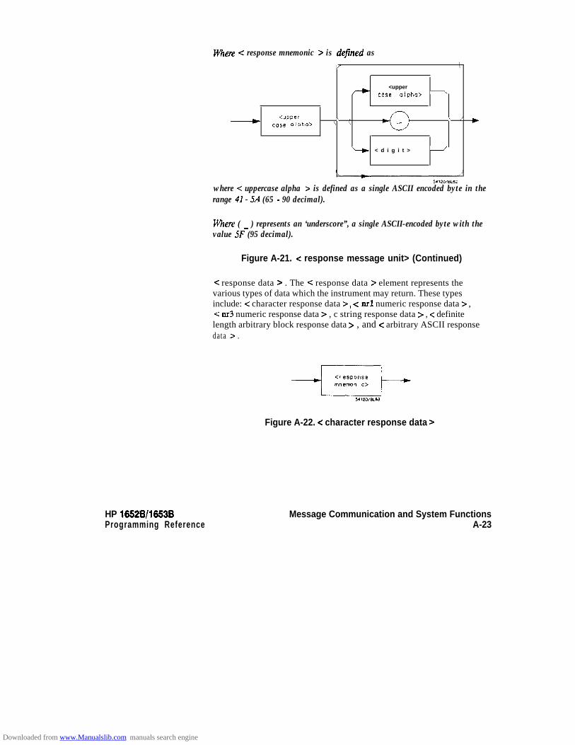
Where -z response mnemonic > is defined as/ \
<upper- case alpha> -
<upper \ ,case alpha> \ \
\ / )
it < d i g i t > -
where < uppercase alpha > is defined as a single ASCII encoded byte in therange 41- 5A (65 - 90 decimal).
mere ( _ ) represents an ‘underscore”, a single ASCII-encoded byte with thevalue 5F (95 decimal).
Figure A-21. < response message unit> (Continued)
< response data > . The < response data > element represents thevarious types of data which the instrument may return. These typesinclude: < character response data >, < nrl numeric response data > ,< 1x3 numeric response data > , c string response data > , < definitelength arbitrary block response data > , and c arbitrary ASCII responsedata > .
Figure A-22. =z character response data >
HP 165218/16538Programming Reference
Message Communication and System FunctionsA-23
Downloaded from www.Manualslib.com manuals search engine
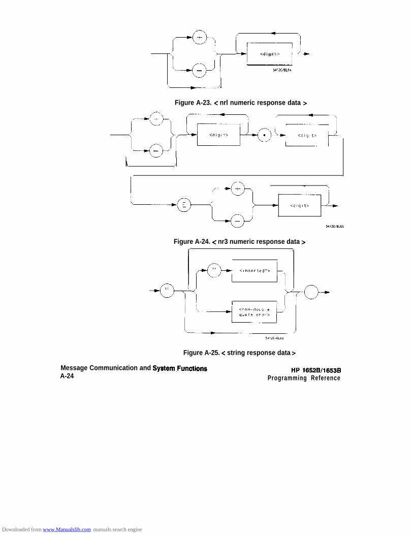
E)/ F:_<digit>
- Y120/8L64
\A
Figure A-23. < nrl numeric response data >
,a, ;_..;wR
-
\ /
Figure A-24. < nr3 numeric response data z-
II_:_ <Inserted”> \
I I
Figure A-25. < string response data >
Message Communication and System,FunctionsA-24
HP 16528/1653BProgramming Reference
Downloaded from www.Manualslib.com manuals search engine

HP 16528116538
Figure A-26. <definite length arbitrary block response data >\
Where <ASCII data byte > represents any ASCII-encoded data byte exceptc NL > (OA, 10 decimal).
Notes
1. The END message provides an unambiguous termination to anelement that contains arbitrary ASCII characters.
2. The IEEE 488.1 END message serves the dual function ofterminating this element as well as terminating the < RESPONSEMESSAGE > . It is only sent once with the last byte of the indefiniteblock data. The NL is present for consistency with the< RESPONSE MESSAGE TERMINATOR > . Indefinite blockdata format is not supported in the HP 1652BD653B.
Figure A-27. <arbitrary ASCII response data >
Message Communication and System FunctionsA-25
Downloaded from www.Manualslib.com manuals search engine
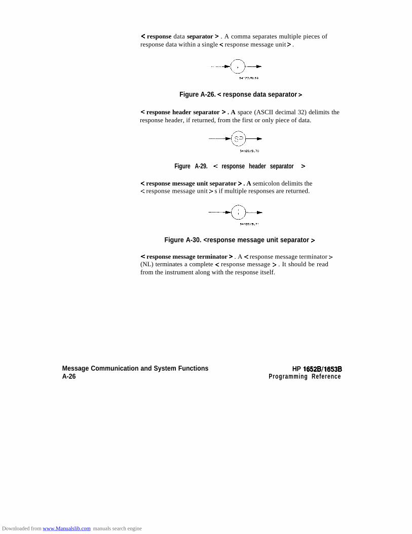
< response data separator > . A comma separates multiple pieces ofresponse data within a single c response message unit > .
Figure A-26. < response data separator >
< response header separator > . A space (ASCII decimal 32) delimits theresponse header, if returned, from the first or only piece of data.
Figure A-29. < response header separator >
< response message unit separator > . A semicolon delimits the< response message unit > s if multiple responses are returned.
Figure A-30. <response message unit separator >
=Z response message terminator > . A c response message terminator >(NL) terminates a complete < response message > . It should be readfrom the instrument along with the response itself.
Message Communication and System FunctionsA-26
HP 16528/1653BProgramming Reference
Downloaded from www.Manualslib.com manuals search engine

CommonCommands
IEEE 488.2 defines a set of common commands. These commandsperform functions which are common to any type of instrument. They cantherefore be implemented in a standard way across a wide variety ofinstrumentation. All the common commands of IEEE 488.2 begin with anasterisk. There is one key difference between the IEEE 488.2 commoncommands and the rest of the commands found in this instrument. TheIEEE 488.2 common commands do not affect the parser’s position withinthe command tree. More information about the command tree and treetraversal can be found in the Programming and DocumentationConventions chapter .
Table A-3. HP 16528/538’s Common Commands
Command Command Name
*cLS*ESE*ESE?*ESR?*IDN?*opt‘OPC?*RST*SRE*SRE?* S T B ?‘WAI
Clear Status CommandEvent Status Enable CommandEvent Status Enable QueryEvent Status Register QueryIdentification QueryOperation Complete CommandOperation Complete QueryReset (not implemented on HP 1652B/1653B)Service Request Enable CommandService Request Enable QueryRead Status Byte QueryWait-to-Continue Command
HP 16528/1653BProgramming Reference
Message Communication and System FunctionsA-27
Downloaded from www.Manualslib.com manuals search engine

Status Reporting B
Introduction The status reporting feature available over the bus is the serial poll. IEEE488.2 defines data structures, commands, and common bit definitions.There are also instrument defined structures and bits.
HP 1052Bll553B
The bits in the status byte act as summary bits for the data structuresresiding behind them. In the case of queues, the summary bit is set if thequeue is not empty. For registers, the summary bit is set if any enabled bitin the event register is set. The events are enabled via the correspondingevent enable register. Events captured by an event register remain setuntil the register is read or cleared. Registers are read with theirassociated commands. The “*CLS’ command clears all event registersand all queues except the output queue. If “*CL!!?’ is sent immediatelyfollowing a c program message terminator > , the output queue will alsobe cleared.
Status ReportingB-l
Downloaded from www.Manualslib.com manuals search engine

Status ReportingB-2
ENABLEF;;;;;ER
L O G I C A L O R
---r
1
mi i F+ERS
N O T E . U R O A N D RQC NOT IMPLEMENTED
mi 0 pgFER5
1 LOGICAL OR )
QUEUES :O - O U T P U TM-MESSAGE
1M R E M LSOSAC z
S T A T U S
GSBVLBYTEC *STE)
S E R V I C EREQUESTENABLE 16500802REGISTER(*SRE)
Figure B-l. Status Byte Structures and Concepts
HP 16528/16538
Downloaded from www.Manualslib.com manuals search engine

Event Status Register
Service RequestEnable Register
Bit Definitions
Note d
HP 16526/1663BProgrsmming Reference
The Event Status Register is a 488.2 defined register. The bits in thisregister are “latched.” That is, once an event happens which sets a bit , thatbit will only be cleared if the register is read.
The Service Request Enable Register is an 8-bit register. Each bit enablesthe corresponding bit in the status byte to cause a service request. Thesixth bit does not logically exist and is always returned as a zero. To readand write to this register use the *SRE? and *SRE commands.
The following mnemonics are used in figure B-l and in the “CommonCommands” chapter:
MAV - message available. Indicates whether there is a response in theoutput queue.
ESB - event status bit. Indicates if any of the conditions in the StandardEvent Status Register are set and enabled.
MSS - master summary status. Indicates whether the device has a reasonfor requesting service. This bit is returned for the *STB? query.
RQS - request service. Indicates if the device is requesting service. Thisbit is returned during a serial poll. RQS will be set to 0 after being readvia a ser ial pol l (MSS is not reset by *STB?).
MSG - message. Indicates whether there is a message in the messageq u e u e .
PON - power on. Indicates power has been turned on.
URQ - user request. Always 0 on the HP 1652B/1653B.
CME - command error. Indicates whether the parser detected an error.
The error numbers and/or strings for CME, EXE, DDE, and QYE can beread from a device defined queue (which is not part of 488.2) with thequery :SYSTEM:ERROR?.
Status RepottingB-3
Downloaded from www.Manualslib.com manuals search engine
EXE - execution error. Indicates whether a parameter was out of range,or inconsis tent with current set t ings .
DDE - device specific error. Indicates whether the device was unable tocomplete an operation for device dependent reasons.
QYE - query error. Indicates whether the protocol for queries has beenviola ted.
RQC - request control. Always 0 on the HP 1652B/1653B.
OPC - operation complete. Indicates whether the device has completedall pending operations. OPC is controlled by the *OPC commoncommand. Because this command can appear after any other command,it serves as a general purpose operation complete message generator.
LCL - remote to local. Indicates whether a remote to local transition hasoccurred.
MSB - module summary bit. Indicates that an enable event in one of themodules Status registers has occurred.
Key Features A few of the most important features of Status Reporting are listed in thefollowing paragraphs.
Operation Complete. The IEEE 488.2 structure provides one techniquewhich can be used to find out if any operation is finished. The *OPCcommand, when sent to the instrument after the operation of interest, willset the OPC bit in the Standard Event Status Register. If the OPC bit andthe RQS bit have been enabled a service request will be generated. Thecommands which affect the OPC bit are the overlapped commands.
OUTPUT XXX;“*SRE 32 ; *ESE 1’ lenables an OPC service request
Status ReportingB-4
HP 1662B/l653B
Downloaded from www.Manualslib.com manuals search engine

Status Byte. The Status Byte contains the basic status information whichis sent over the bus in a serial poll. If the device is requesting service(RQS set), and the controller serial polls the device, the RQS bit iscleared. The MSS (Master Summary Status) bit (read with *STB?) andother bits of the Status Byte are not be cleared by reading them. Only theRQS bit is cleared when read.
The Status Byte is cleared with the *CLS common command.
,--55TATUS SUMMARY MESSAGES-
SERVICEREOUEST 4
GENERATION
- READ BY SERIAL POLL
t
STATUS BYTE REGISTER
- READ BY rSTB7
HP 16628/16538 Status ReportingProgramming Reference B-5
0 SERVICE REOUESTENABLE REGISTER
Figure B-2. Service Request Enabling
Downloaded from www.Manualslib.com manuals search engine

Serial Poll The HP 1652B/1653B supports the IEEE 488.1 serial poII feature. Whena serial poll of the instrument is requested, the RQS bit is returned on bit6 of the status byte.
Using Serial Poll This example wil l show how to use the service request by conduct ing a(HP-16) serial poll of ah instruments on the HP-IB bus. In this example, assume
that there are two instruments on the bus; a Logic Analyzer at address 7and a printer at address 1.
The program command for serial poIl using HP BASIC 4.0 is Stat =SPOLL(707). The address 707 is the address of the oscilloscope in thethis example. The command for checking the printer is Stat =SPOLL(701) because the address of that instrument is 01 on bus address7. This command reads the contents of the HP-IB Status Register into thevariable called Stat. At that time bit 6 of the variable Stat can be tested tosee if it is set (bit 6 = 1).
The serial polI operation can be conducted in the following manner:
1. Enable interrupts on the bus. This allows the controller to “see” theSRQ line.
2. Disable interrupts on the bus.
3. If the SRQ line is high (some instrument is requesting service) thencheck the instrument at address 1 to see if bit 6 of its status registeri s h igh .
Status Reporting HP 16528/1653BB-6 Programming Reference
Downloaded from www.Manualslib.com manuals search engine

HP 16528/1653BProgramming Reference
4. To check whether bi t 6 of an instruments s tatus register is high, usethe following Basic statement:
I F B I T ( S t a t , 6 ) T H E N
5. If bit 6 of the instrument at address 1 is not high, then check theinstrument a t address 7 to see i f bi t 6 of i ts s ta tus regis ter is high.
6. As soon as the instrument with s tatus bi t 6 high is found check therest of the status bits to determine what is required.
The SPOLL(707) command causes much more to happen on the bus thansimply reading the register. This command clears the bus automatically,addresses the talker and listener, sends SPE (serial poll enable) and SPD(serial poll disable) bus commands, and reads the data. For moreinformation about serial poll, refer to your controller manual, andprogramming language reference manuals.
After the serial poll is completed, the RQS bit in the HP 1652B/1653BStatus Byte Register will be reset if it was set. Once a bit in the StatusByte Register is set, it will remain set until the status is cleared with a*CLS command, or the instrument is reset.
Status ReportingB-7
Downloaded from www.Manualslib.com manuals search engine

Parallel Poll Parallel poll is a controller initiated operation which is used to obtaininformation from several devices simultaneously. When a controllerinitiates a Parallel Poll, each device returns a Status Bit via one of the DIOdata lines. Device DIO assignments are made by the controller using thePPC (Parallel Poll Configure) sequence. Devices respond eitherindividually, each on a separate DIO line; collectively on a single DIOline; or any combination of these two ways. When responding collect ively,the result is a logical AND (True High) or logical OR (True Low) of thegroups of s ta tus b i ts .
Figure B-2 shows the Parallel Poll Data Structure. The summary bit issent in response to a Parallel Poll. This summary bit is the “ist” (individualstatus) local message.
The Parallel Poll Enable Register determines which events aresummarized in the ist. The *PRE command is used to write to the enableregister and the *PRE? query is used to read the register. The *IST?query can be used to read the “ist” without doing a parallel poll.
Status ReportingB-8
HP 18528/1853B
Downloaded from www.Manualslib.com manuals search engine
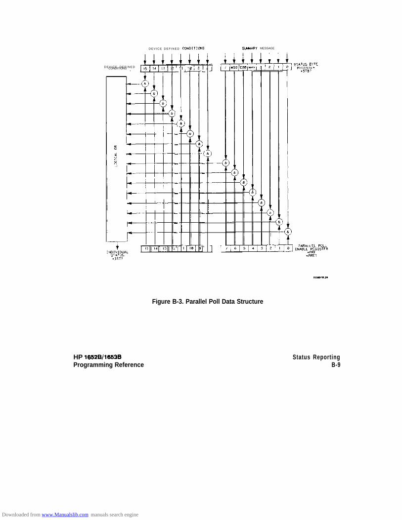
D E V I C E D E F I N E D COtdDITIONS
D E V I C E D E F I N E DCONDITIONS 15 14 13 12 I 11 I10 8L I 9 IL
IL
;
-
-
-
-
-
-
-
-
-
-
-
7
I
i
-
-
-
-
-
-
-
-
T 11
SUNMARY MESSAGE
Figure B-3. Parallel Poll Data Structure
HP 16528/1653BProgramming Reference
Status ReportingB-9
Downloaded from www.Manualslib.com manuals search engine
Polling HP-16 Devices Parallel Poll is the fastest means of gathering device status when severaldevices are connected to the bus. Each device (with this capability) canbe programmed to respond with one bit of status when parallel polled.This makes i t possible to obtain the s tatus of several devices in oneoperation. If a device responds affirmatively to a parallel poll, moreinformation about i ts specific status can be obtained by conducting a serialpoll of the device.
Configuring Parallel Certain devices, including the HP 1652B/1653B, can be remotelyPoll Responses programmed by a controller to respond to a parallel poll. A device which
is currently configured for a parallel poll responds to the poll by placingits current status on one of the bus data lines. The response and thedata-bit number can then be programmed by the PPC (parallel PollConfigure) statement. No multiple listeners can be specified in thisstatement. If more than one device is to respond on a single bit, eachdevice must be configured with a separate PPC statement.
Example: A S S I G N @ D e v i c e T O 7 0 7P P O L L C O N F I G U R E @Device;Mask
The value of Mask (any’numeric expression can be specified) is firstrounded andthen used to configure the device’s parallel response. Theleast significant 3 bits (bits 0 through 2) of the expression are used todetermine which data line the device is to respond on (place its status on).Bit 3 specifies the “true” state of the parallel poll response bit of thedevice. A value of 0 implies that the device’s response is 0 when i ts s tatusbit message is t rue.
Example: The following statement configures the device at address 07 on theinterface select code 7 to respond by placing a 0 on bit 4 when i ts s tatusresponse is “true.”
P P O L L C O N F I G U R E 707;4
Status ReportingB-10
HP 16528/1663BProgramming Reference
Downloaded from www.Manualslib.com manuals search engine

Conducting a Parallel The PPOLL (Parallel Poll) function returns a single byte containing up toPoll 8 status bi t messages for al l devices on the bus capable of responding to
the poll. Each bit returned by the function corresponds to the status bit ofthe device(s) configured to respond to the parallel poll (one or moredevices can respond on a single line). The PPOLL function can only beexecuted by the controller. It is initiated by the simultaneous assertion ofATN and EOI.
Example: Response = PPOLL(7)
Disabling Parallel Poll The PPU (Parallel Poll Unconfigure) statement gives the controller theResponses capability of disabling the parallel poll responses of one or more devices
on the bus .
Examples: The fol lowing statement disables device 5 only:
P P O L L U N C O N F I G U R E 7 0 5
This statement disables all devices on interface select code 8 fromresponding to a parallel poll
P P O L L U N C O N F I G U R E 8
If no primary address is specified, all bus devices are disabled fromresponding to a parallel poll. If a primary address is specified, only thespecified devices (which have the parallel poll configure capability) aredisabled.
HP 1652~/1653B Status ReportingB-l 1
Downloaded from www.Manualslib.com manuals search engine
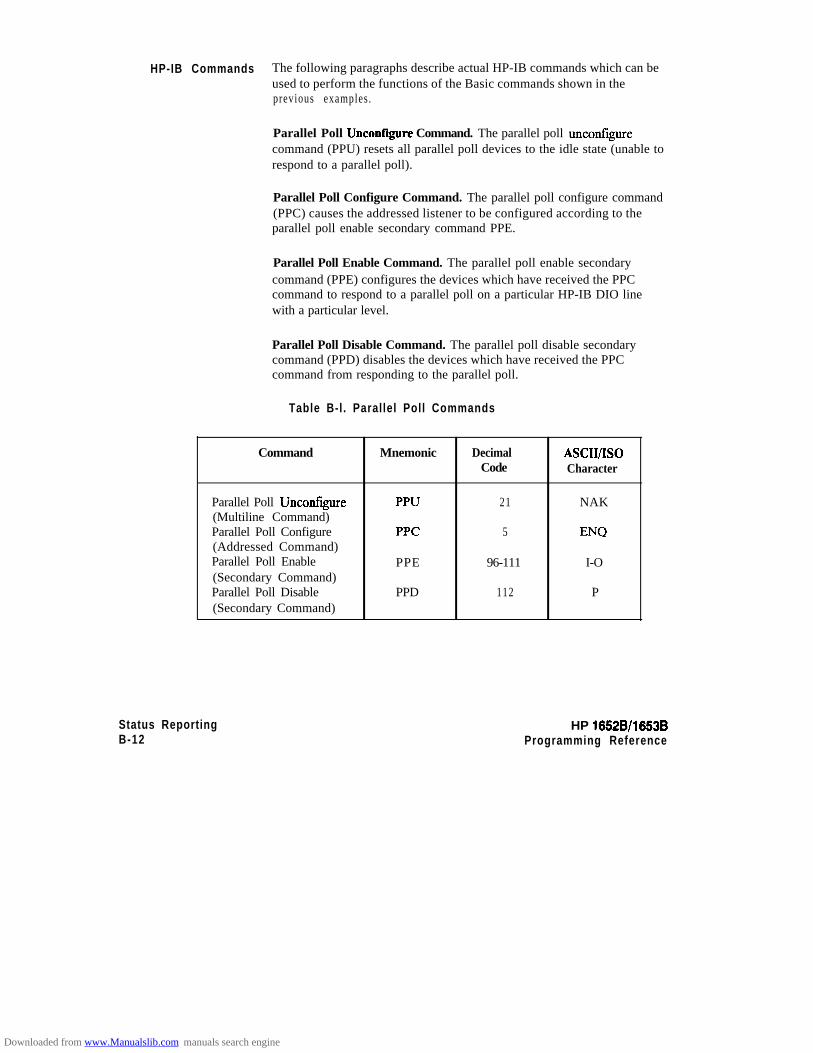
HP-IB Commands The following paragraphs describe actual HP-IB commands which can beused to perform the functions of the Basic commands shown in theprevious examples.
Parallel Poll Uncontigure Command. The parallel poll unconfigurecommand (PPU) resets all parallel poll devices to the idle state (unable torespond to a parallel poll).
Parallel Poll Configure Command. The parallel poll configure command(PPC) causes the addressed listener to be configured according to theparallel poll enable secondary command PPE.
Parallel Poll Enable Command. The parallel poll enable secondarycommand (PPE) configures the devices which have received the PPCcommand to respond to a parallel poll on a particular HP-IB DIO linewith a particular level.
Parallel Poll Disable Command. The parallel poll disable secondarycommand (PPD) disables the devices which have received the PPCcommand from responding to the parallel poll.
Table B-l. Parallel Poll Commands
Command Mnemonic DecimalCode
A!xIuIsoCharacter
Parallel Poll Unconfigure(Multiline Command)Parallel Poll Configure(Addressed Command)Parallel Poll Enable(Secondary Command)Parallel Poll Disable(Secondary Command)
PPU
PPC
PPE
PPD
21 NAK
5 ENQ
96-111 I-O
112 P
Status ReportingB-12
HP 1652B/l653BProgramming Reference
Downloaded from www.Manualslib.com manuals search engine

Error Messages C
DeviceDependentErrors
HP 16526/16538Programming Reference
This section covers the error messages that relate to the HP 1652B/53BLogic Analyzers.
200 Label not found
201 Pattern string invalid
202 Qualifier invalid
203 Data not available
300 RS-232C error
Error MessagesC-l
Downloaded from www.Manualslib.com manuals search engine

CommandErrors
-100 Command error (unknown command)(generic error)
-101 Invalid character received
-110 Command header error
-111 Header delimiter error
-120 Numeric argument error
-121 Wrong data type (numeric expected)
-123 Numeric overflow
-129 Missing numeric argument
-130 Non numeric argument error (character,string, or block)
-131 Wrong data type (character expected)
-132 Wrong data type (string expected)
-133 Wrong data type (block type #D required)
-134 Data overflow (string or block too long)
-139 Missing non numeric argument
-142 Too many arguments
-143 Argument delimiter error
-144 Invalid message unit delimiter
Error Messagesc-2
HP 16528116638
Downloaded from www.Manualslib.com manuals search engine
ExecutionErrors
HP 16528/16538Programming Reference
-200 No Can Do (generic execution error)
-201 Not executable in Local Mode
-202 Settings lost due to return-to-local or power on
-203 Trigger ignored
-211 Legal command, but settings couflict
-212 Argument out of range
-221 Busy doing something else
-222 Insuffkient capability or configuration
-232 Output buffer full or overflow
-240 Mass Memory error (generic)
-241 Mass storage device not present
-242 No media
-243 Bad media
-244 Media full
-245 Directory full
-246 File name not found
-247 Duplicate file name
-248 Media protected
Error Messagesc - 3
Downloaded from www.Manualslib.com manuals search engine
Internal Errors -300 Device Failure (generic hardware error)
-301 Interrupt fault
-302 System Error
-303 Time out
-310 RAM error
-311 RAM failure (hardware error)
-312 RAM data loss (software error)
-313 Calibration data loss
-320 ROM error
-321 ROM checksum
-322 Hardware and Firmware incompatible
-330 Power on test failed
-340 Self Test failed
-350 Too Many Errors (Error queue overflow)
Error MessagesC-4
HP 1652B/1653BProgremming Reterence
Downloaded from www.Manualslib.com manuals search engine

Query Errors -400 Query Error (generic)
-410 Query INTERRUPTED
-420 Query UNTERMINATED
-421 Query received. lndeftite block response in progress
-422 Addressed to Talk, Nothing to Say
-430 Query DEADLOCKED
HP 165218/16538 Error MessagesC-5
Downloaded from www.Manualslib.com manuals search engine

Index
*CLS command S-3*ESE command S-4*ESR command S-6*IDN command S-8*OPC cammand S - 9*RST command S-10*SRE command S-11*STB command S-13*WA1 command S-15.~. 4-332767 4-29.9E + 37 4-2:: = 4-3[ 1 4-3{} 4 - 3I 4-3
A
ACCumuIate command/query 144,15-4, 19-6Acquisition data 6-11Addressed taIk/Iisten mode 2-lALL 27-SAMODe command/query 18-4Analyzer 1 Data Information 6-9Analyzer 2 Data Information 6-11Angular brackets 4-3Arguments l-4ARM command/query 10-4ARMBnc command 6-4ASCII Format 26-SASSign mmmand/query 10-5
AUToload command/query 7-4AUToscale 21 -3AUToscale command 10-6Average Mode 24-2,26-3
B
BASE command 20-4Bases l-8BASIC l-2Baud rate 3-SBit definitions B-3Block data 1-3, l-16,6-6Block length specifier 6-6Block length specifier 6-7,6-37Braces 4-3BRANch command/query 12-S - 12-7BYTE Format 26-4
C
CableRS-232C 3-2
CATaIog query 7-Schart display 15-lClear To Send (CTS) 3-4CLOCk command/query 11-4CMASk command/query 16-4CME B-3COLumn command/query B-3,13-6 - 13-7Combining commands l-5
HP 16628/l 6628Programming Reference
index-l
Downloaded from www.Manualslib.com manuals search engine

Comma l-7Command l--3,1-13
*cLs 5 - 3‘ESE 5 - 4*opt 5 - 9* R S T 5-1.0* S R E 5-21*WA1 5-15ACCumuIate 14-4,15-4, 19 -6AMODe 18-4A R M 10-4ARMBnc 6 - 4ASSign 10-5AUToload 7 - 4AUToscaIt: lo-6,21-3B A S E 20-4BRANch 12-5CLOCk 1.1-4CMASk :16-4COLumn g-3,13-6COMPare 16-3CONFig ‘7-9,7-14COPY 7-6, 16-5COUNt 24-4COUPling 22-4CPERiod 11-5D A T A 6-5,16-6DELay 14-5,19-7,25-3DOWNload 7 - 7DSP 6-WDURation 18-5EDGE 18-6FIND 12-8FORMat 26-10GLITch 1.8-8HAXis 15-5HEADer l-12,6-22IASSembler 7 -10INITiaIize 7 - 8INSert 14-6, 19-8
Command (continued)KEY 6-23LABel ll-6,17-3LEVel 23 -4LINE 8-5, U-9LOAD:CONFig 7-9LOAD:IASSembler 7 -10LOCKout 3-7,6-ZLONGform l-12,6-27MACHine 10-3MASTer 11 -8MENU 6-28MESE 6-29MMODe 13-10,19-9M O D E 23-5,25-4N A M E 10-7OCONdition 19-10OF’FXet 22 -5OPATtern 13-11,19-11OSEarch 13-13,19-13OTAG 13-15OTIMe 9-5,19-14PACK 7-11PAlTern l&9,20-5PREstore 12-10PRINt 6 -34PROBe 22-6PURGe 7 -12RANGe 12-12, 14-7, 16-9, 19-l5,20-6,22-7,25-6RECord 26-13REMove 11-9,14-g, 17-5,19-16,20-7REName 7 -13RESTart 12 -14RMODe 6 -35Run Control 6-lRUNTiI l3-16,16-10,19-17SCHart 15 -3SEQuence 12-16SETup 6 -36SFORmat 11 -3
Index-2 HP 16528/1552BProgramming Reference
Downloaded from www.Manualslib.com manuals search engine
Command (continued)SLAVe 11-10SLISt 13 -5SLOPe 23-6SMODe 21-4SOURce 23-7,26-14,27-14STARt 6 -38STOP 6-39STORe 12-17STORe:CONFig 7-14STRace 12-4SWAVeform 14-3SYMBol 20-3SYStem:DATA 6-5SYStem:SETup 6 -36TAG 12-19TERM 12-21TFORmat 17 -2THReshold 11-11, 17-6‘ITRate 18 -3TWAVeform 19-5T Y P E lo-8,24-5VAXis 15-7WIDTh 20-8WLISt 9 - 2XCONdition 19-24XPATtern 13-23,19-26XSEarch 13-25,19-28XTAG, 13-27XTIMe 9-6,19-29
Command errors C-2Command mode 2-lCommand set organization 4-10Command structure l-11Command tree 4-4Command types 4-4Common commands l-5,4-4,5-1, A-27Communication l-2COMPare selector 16-3COMPare Subsystem 16-1Complex qualifier 12-7
Compound commands l-4CONFig command 7-9,7-14Confiiation file l-10 - l-11Controller mode 2-lControllers 1-2Conventions 4-3COPY command 7-6, 16-5COUNt 2 4 - 4COUNt query 26-8COUPhng 22-4CPERiod command/query 11-5
D
D A T A 6-5,26-9command 6-5State (no tags ) 6-12State (with either time or state tags) 6-12Timing Glitch 6-14Transitional Timing 6-15
Data bits 3-5 - 3-68-Bit mode 3-6
Data blockAcquisition data 6-11Analyzer 1 data 6-9Analyzer 2 data 6-11Data preamble 6-8Section data 6-8Section header 6-8
Data Carrier Detect (DCD) 3-4DATA command/query 6-5 - 6-19,16-6 - 16-7Data Communications Equipment 3-lData mode 2-lData preamble 6-8DATA query 13-8Data Set Ready (DSR) 3-4Data Terminal Equipment 3-lData Terminal Ready (DTR) 3-3DCE 3- lDCL 2-3
HP 16528/16528Programming Reference
Index-3
Downloaded from www.Manualslib.com manuals search engine

DDE B-4Definite-length block response data 1-16Definitions 4-3DELay 25-3DELay command/query 145,19-7Device address l-3
HP-IB 2-2RS-232C 3-6
Device clear 2-3Device dependent errors C-lDLISt
Command 8-2DLISt selector 8-2DLISt Subsystem 8-lDocumentation conventions 4-3DOWNload command 7-7DSP command 6-20DTE 3-1Duplicate keywords l-5DURation command/query 18-5
E
EDGE command/query 18-6 - 18-7EDGE Trigger Mode 23-lEllipsis 4 - 3Embedded strings l-2 - l-3Enter statement l-2Error messages C-lERRor query 6-21ESB B-3Event Status Register B-3EXE B-4Execution errors C-3Exponents 1-8Extended interface 3-3
F
FALLtime 27-6FIND command/query 12-8 - 12-9FIND query 16-8FORMat 26-10Fractional values 1-8FREQuency 27-7
G
GET 2-3GLITch command/query 18-8Glitch Timing Data 6-14Group execute trigger 2-3
H
HAXis command/query 15-5 - 15-6HEADer command 1-12HEADer command/query 6-22Headers l-3 - l-4, l-7Host language l-3HP-IB 2-1, B-6HP-II3 address 2-lHP-IB commands B-12HP-IB device address 2-2HP-IB interface 2-lHP-IB interface code 2-2HP-IB interface functions 2-l
Index-4 HP 16628/1652B
Downloaded from www.Manualslib.com manuals search engine

I L
IASSembler command 7-10IEEE 488.1 2-1, A-lIEEE 488.1 bus commands 2-3IEEE 488.2 A-lIEEE 488.2 Standard l - lIFC 2-3InIinity 4 - 2Initialization l-10INITiaIize command 7-8Input buffer A-2INSert command 146,19-8Instruction headers l-3Instruction parameters l-4Instruction syntax l-2Instruction terminator l-9Instructions l-3Instrument address 2-2Interface capabilities 2-1
RS-232C 3-5Interface clear 2-3Interface code
HP-IB 2-2Interface select code
RS-23:!C 3 - 6Internal errors C-4
K
KEY command/query 6-23Keyword data l-8Keywords 4-l
LABel command/query 11-6 - ll-7,17-3 - 17-4LCL B-4LERquery 6-2.5LEVel 23 -4LINE command/query 8-513-9Linefeed l -9 ,4 -3Listening syntax A-8LOAD:CONFig command 7-9LOADIASSembler command 7-10Local 2-2Local lockout 2-2LOCKout command 3-7LOCKout command/query 6-26Longform l - 7LONGform command 1-12LONGform command/query 6-27Lowercase 1-7
M
Machine selector 10-3MACHine Subsystem 10-lMASTer command/query 11-8MAV B-3MENU command/query 6-28MESE command/query 6-29MESR query 6-31- 6-32MMEMory subsystem 7-lMMODe command/query U-10,19-9Mnemonics 1-8,4-lM O D E 23-5,254 - Z-5Module Level Commands 21-1MSB B-4MSG B-3MSS B-3
HP 16528/16.528Programming Reference
Index-5
Downloaded from www.Manualslib.com manuals search engine

Multiple numeric variables 1-17Multiple program commands l-9Multiple queries 1-17Multiple subsystems l-9
Overlapped command 5-9,5-l5,6-38 - 6-39Overlapped commands 4-2OVERshoot 27 -9
PN
NAME command/query 10-7New Line character l-9N L l-9,4-3Normal Mode 24-2,26-3Notation conventions 4-3Numeric base 1-15Numeric bases l-8Numeric data l-8Numeric variables 1-15NWIDth 27-8
0
OCONdition command/query 19-10OFFSet 22 -5OPATtern command/query l3-ll- 13-X&19-1119-12OPC B-4Operation Complete B-4OR notation 4-3oscilloscope 21-1Oscilloscope Subsystem commands 21-1OSEarch command/query l3-l3,19-13OSTate 13-14OSTate query 9-3OTAG command/query U-15OTIMe command/query 9-5,19-14Output buffer l-6Output command 1-3Output queue A-2OUTPUT statement l-2
PACK command 7-11Parallel poll B-8Parallel poll commands B-12Parameter syntax rules l-7Parameters l-4Parity 3-5Parse tree A-7Parser A-2PATTern command 20-5PATTern command/query 18-9 - 18-10PATTern Trigger Mode 23-lPERiod 27-10POINts query 26-11PON B-3PPC B-12PPD B-12PPE B-12PPOWer query 6-33PPU B-12PREamble 26-12Preamble description 6-8PREShoot 27-11PREstore command/query 12-10 - 12-11PRINt command 6-34Printer mode 2-1PROBe 22-6Program data A-14Program examples 4-11Program message A-9Program message syntax l-2Program message terminator l-9Program syntax 1-2Programming conventions 4-3Protocol 3-5, A-3
Index-6 HP 16628/16626Programming Reference
Downloaded from www.Manualslib.com manuals search engine

None 3-5XON/XOFF 3-5
Protocol exceptions A-4Protocols A-2PURGe command 7-12PWIDth 27-12
Q
Query l-3,1-6, 1-13*ESE 5-4*ESR 5-6*IDN 5-8*opt 5 - 9*SRE 5 -11*STB 5-13Accumulate 14-4,15-4,19-6ALL 27-5AMODe 18-4A R M 10-4ARMBnc 6 - 4ASSign 10-5AUToload 7 - 4BRANch 12-5CATalog 7 - 5CLOCk 11-4CMASk 16-4COLumn 8-3, 13-6COUNt 244,26-8COUPIing 22-4CPERiod 11-5D A T A 6-5,13-8,16-6,26-9DELay 14-5,19-7,25-3DURa tion 18-5EDGE 18-6ERRor 6 -21FALLtime 27-6F I N D 12-8,16-8FORMat X-10FREQuency 27-7
Query (co&wed)GLITch 18-8HAxis 15-5HEADer 6 -22KEY 6-23LABel 11-6, 17-3LER 6-25LEVel 23 -4L I N E 8-5,X3-9LOCKout 6 -26LONGform 6 -27MASTer 11 -8MENU 6-28MESE 6-29MESR 6-31MMODe 13-10,19-9M O D E 23-5,25-4N A M E 10-7NWIDth 27-8OCONdition 19-10OFFSet 22 -5OPATtem 13-l&19-11OSEarch 13-l3,19-13OSTate 9-3,13-14O T A G U-15OTIMe 9-5,19-14OVERshoot 27 -9PAlTern 18-9PERiod 27-10POINts 26-11PPOWer 6 -33PREamble 26-12PREShoot 27 -11PROBe 22-6PWIDth 27-12RANGe 12-12,14-7,16-9,19-15,22-7,25-6RECord 26-13RESTart 12 -14RISetime 2 7 - URMODe 6 -35RUNTil 13-16,16-10,19-17
HP 16528/1652BProgramming Reference
Index-7
Downloaded from www.Manualslib.com manuals search engine
Query (continued)SEQuence 12-16SETup 6 -36SLAVe l : l -10SLOPe 23-6SMODe 21-4SOURce 23-7,26-14,27-14SPERiod 19-19STORe 12-17SYSTem:DATA 6-5SYStem:SETup 6-36TAG 12-19TAVerage 13-18,19-20TERM 12-21THReshold 11-11, 17-6TMAXimum 13-19,19-21TMINimum 13-20,19-22T Y P E lo-8,24-5,26-15UPLoad 7 -15VALid 26-16VAMPIitude 27-15VAX& 15-7VBASe 27-16VMAX 27-17VMIN 27-18V P P 27-l!>VRUNs 13-21,19-23V T O P 27-20XCONdition 19-24XINCrement 26-17XORigin 26-18XOTag 13-22XOTime 19-25XPATtern 13-23,19-26XREFerence 26-19XSEarch U-25,19-28XSTate 9 -4 , 13-26XTAG 13-27XTIMe 9-6,19-29YINCrement 26-20YORigin 26-21
Query (continued)YREFerence 26-22
Query errors C-5Query responses l-11,4-2Question mark l-6QYE B-4
R
R A N G e 22-7,25-6RANGe command 20-6RANGe command/query 12-12 - 12-13,147,16-9,19-15Receive Data (RD) 3-2 - 3-3record 26-13
waveform 26-3Remote 2-2Remote enable 2-3REMove command ll-9,14-8,17-5,19-16,20-7REN 2-3REName command 7-13Request To Send (RTS) 3-4Response data 1-16Response message A-21Responses 1-12RESTart command/query 12-14 - 12-15RISetime 27-13RMODe command/query 6-35Root 4-4RQC B-4RQS B-3RS-232C 3-1,3-6, A-lRun Control Commands 6-lRUNTil command/query 13-16 - l3-17,16-10 -16-11.19-17 - 19-18
index-6 HP 16528/1662BProgramming Reference
Downloaded from www.Manualslib.com manuals search engine
S
SCHart selector 15-3SCHart Subsystem 15-1SCOPe Subsystem 21-1SDC 2-3Section data 6-8Section data format 6-6Section header 6-8Selected device clear 2-3Separator A-18SEQuence command/query 12-16Sequential commands 4-2Serial poll B-6Service R.equest Enable Register B-3SETup 6 -36SETup command/query 6-36 - 6-37SF0Rma.t selector 11-3SFORmat Subsystem 11-lShortform l-7Simple commands l-4SLAVe command/query 11-10SLISt selector U-5SLISt Subsystem U-1SLOPe 23-6SMODe command 21-4SMODe query 21-4SOURce 23-7,26-14,27-14Spaces l-4SPERiod query 19-19Square brackets 4-3STARt command 6-38State data
with either time or state tags 6-12without tags 6-12
Status l-17,5-2, B-lStatus byte B-5Status registers 1-17Status reporting B-l
Stop bits 3-5STOP command 6-39STORe command/query 12-17 - 12-18STORe:CONFii command 7-14STRace selector 12-4STRace Subsystem 12-1String data l-8String variables 1-14Subsystem
ACQuire 2 4 - lCHANnel 2 2 - lCOMPare 16-1DLIST 8-lMACHine 1 0 - lMEASure 27-1MMEMory 7 - lS C H a r t 15-lSCOPe 21-1SFORmat 1 1 - lSLISt 13 -1STRace 12-1SWAVeform 14-1SYMBol 20-lTFORmat 17 -1TIMebase 25-lTRIGger 2 3 - lTTRace 18-1TWAVeform 19-1WAVeform 26-lWLISt 9 - l
Subsystem commands 4-4Suffix multiplier A-16Suffix units A-16SWAVeforrn selector 14-3SWAVeform Subsystem 14-1SYMBol selector 20-3SYMBol Subsystem 20-lsyntax A-8Syntax diagram
ACQuire Subsystem 24-lCHANnel Subsystem 22-2
HP 16528/1662BProgramming Reference
Index-9
Downloaded from www.Manualslib.com manuals search engine

Syntax Diagram (continued)Common commands 5-2COMPare Subsystem 16-2DLISt Subsystem 8-lMACHine Subsystem 10-2MEASure Subsystem 27-3MMEMory subsystem 7-2 - 7-3SCHart Subsystem 15-2SCOPe Subsystem 21-1SFORmat Subsystem 11-lSLISt Subsystem 13-2STRace Subsystem 12-lSWAVeform Subsystem 14-2SYMBol Subsystem 20-2System commands 6-3TFORmat Subsystem 17-1TIMebase Subsystem 25-lTRIGger Subsystem 23-2‘ITRace Subsystem 18-2TWAVeform Subsystem 19-2WAVeform Subsystem 26-2WLISt Subsystem 9-l
Syntax diagrams 4-2IEEE 488.2 A-5
System commands 4-4,6-l
T
TAG command/query 12-19 - 12-20Talk only mode 2-lTalking syntax A-21TAVerage query 13-18,19-20TERM command/query 12-21- 12-22Terminator 1-9, A-26TFORmat selector 17-2TFORmat Subsystem 17-1Three-wire InI erface 3-2Threshold command/query 11-l&17-6Timing Glitch Data 6-14TMAXimum query X+-19,19-21
TMINimum query l3-20,19-22TraiIingdots 4 - 3Transitional Timing Data 6-15Transmit Data (TD) 3-2 - 3-3Truncation rule 4-l‘ITRace selector 18-3‘ITRace Subsystem 18-1TWAVeform selector 19-5TWAVeform Subsystem 19-1TYPE 24-5TYPE command/query 10-BTYPE query 26-15
U
Units l-8UPLoad query 7-15Uppercase 1-7URQ B-3
V
VALid 26-16VAMPIitude 27-15VAXis command/query 15-7VBASe 27-16VMAX 27-17VMIN 27-18VPP 27-19VRUNs query U-21,19-23V T O P 27-20
W
waveformrecord 26-3
White space l-4
Index-l 0 HP 16628/1652BProgramming Reference
Downloaded from www.Manualslib.com manuals search engine

WIDTh command 20-8WLISt selector 9-2WLISt Subsystem 9-lWORD Format 26-5
X
XCONdition command/query 19-24XINCrement query 26-17XORigjn query 26-18XOTag query 13-22XOTime query 19-25XPATtern command/query 13-23 - 13-24,19-26 -19-27XREFerence query 26-19XSEarch command/query 13-25,19-BXSTate query 9-4, 13-26XTAG command/query 13-27XTIMe command/query 9-6,19-29xxx 4-3, 4-5XXX (meaning of) 1-3
Y
YINCrement query 26-20YORigin query 26-21YREFerence query 26-22
HP 1652)3/l 6528Programming Reference
Index-l 1
Downloaded from www.Manualslib.com manuals search engine
Related Documents